WO2019053993A1 - Acoustic processing device and acoustic processing method - Google Patents
Acoustic processing device and acoustic processing method Download PDFInfo
- Publication number
- WO2019053993A1 WO2019053993A1 PCT/JP2018/023774 JP2018023774W WO2019053993A1 WO 2019053993 A1 WO2019053993 A1 WO 2019053993A1 JP 2018023774 W JP2018023774 W JP 2018023774W WO 2019053993 A1 WO2019053993 A1 WO 2019053993A1
- Authority
- WO
- WIPO (PCT)
- Prior art keywords
- sound
- ear canal
- microphone
- unit
- ear
- Prior art date
Links
- 0 *CC1CCCC1 Chemical compound *CC1CCCC1 0.000 description 5
Images


Classifications
-
- H—ELECTRICITY
- H04—ELECTRIC COMMUNICATION TECHNIQUE
- H04R—LOUDSPEAKERS, MICROPHONES, GRAMOPHONE PICK-UPS OR LIKE ACOUSTIC ELECTROMECHANICAL TRANSDUCERS; DEAF-AID SETS; PUBLIC ADDRESS SYSTEMS
- H04R1/00—Details of transducers, loudspeakers or microphones
- H04R1/10—Earpieces; Attachments therefor ; Earphones; Monophonic headphones
- H04R1/1016—Earpieces of the intra-aural type
-
- A—HUMAN NECESSITIES
- A61—MEDICAL OR VETERINARY SCIENCE; HYGIENE
- A61B—DIAGNOSIS; SURGERY; IDENTIFICATION
- A61B5/00—Measuring for diagnostic purposes; Identification of persons
- A61B5/72—Signal processing specially adapted for physiological signals or for diagnostic purposes
- A61B5/7203—Signal processing specially adapted for physiological signals or for diagnostic purposes for noise prevention, reduction or removal
-
- G—PHYSICS
- G10—MUSICAL INSTRUMENTS; ACOUSTICS
- G10K—SOUND-PRODUCING DEVICES; METHODS OR DEVICES FOR PROTECTING AGAINST, OR FOR DAMPING, NOISE OR OTHER ACOUSTIC WAVES IN GENERAL; ACOUSTICS NOT OTHERWISE PROVIDED FOR
- G10K11/00—Methods or devices for transmitting, conducting or directing sound in general; Methods or devices for protecting against, or for damping, noise or other acoustic waves in general
- G10K11/16—Methods or devices for protecting against, or for damping, noise or other acoustic waves in general
- G10K11/175—Methods or devices for protecting against, or for damping, noise or other acoustic waves in general using interference effects; Masking sound
- G10K11/178—Methods or devices for protecting against, or for damping, noise or other acoustic waves in general using interference effects; Masking sound by electro-acoustically regenerating the original acoustic waves in anti-phase
- G10K11/1783—Methods or devices for protecting against, or for damping, noise or other acoustic waves in general using interference effects; Masking sound by electro-acoustically regenerating the original acoustic waves in anti-phase handling or detecting of non-standard events or conditions, e.g. changing operating modes under specific operating conditions
- G10K11/17837—Methods or devices for protecting against, or for damping, noise or other acoustic waves in general using interference effects; Masking sound by electro-acoustically regenerating the original acoustic waves in anti-phase handling or detecting of non-standard events or conditions, e.g. changing operating modes under specific operating conditions by retaining part of the ambient acoustic environment, e.g. speech or alarm signals that the user needs to hear
-
- G—PHYSICS
- G10—MUSICAL INSTRUMENTS; ACOUSTICS
- G10K—SOUND-PRODUCING DEVICES; METHODS OR DEVICES FOR PROTECTING AGAINST, OR FOR DAMPING, NOISE OR OTHER ACOUSTIC WAVES IN GENERAL; ACOUSTICS NOT OTHERWISE PROVIDED FOR
- G10K11/00—Methods or devices for transmitting, conducting or directing sound in general; Methods or devices for protecting against, or for damping, noise or other acoustic waves in general
- G10K11/16—Methods or devices for protecting against, or for damping, noise or other acoustic waves in general
- G10K11/175—Methods or devices for protecting against, or for damping, noise or other acoustic waves in general using interference effects; Masking sound
- G10K11/178—Methods or devices for protecting against, or for damping, noise or other acoustic waves in general using interference effects; Masking sound by electro-acoustically regenerating the original acoustic waves in anti-phase
- G10K11/1785—Methods, e.g. algorithms; Devices
- G10K11/17857—Geometric disposition, e.g. placement of microphones
-
- G—PHYSICS
- G10—MUSICAL INSTRUMENTS; ACOUSTICS
- G10K—SOUND-PRODUCING DEVICES; METHODS OR DEVICES FOR PROTECTING AGAINST, OR FOR DAMPING, NOISE OR OTHER ACOUSTIC WAVES IN GENERAL; ACOUSTICS NOT OTHERWISE PROVIDED FOR
- G10K11/00—Methods or devices for transmitting, conducting or directing sound in general; Methods or devices for protecting against, or for damping, noise or other acoustic waves in general
- G10K11/16—Methods or devices for protecting against, or for damping, noise or other acoustic waves in general
- G10K11/175—Methods or devices for protecting against, or for damping, noise or other acoustic waves in general using interference effects; Masking sound
- G10K11/178—Methods or devices for protecting against, or for damping, noise or other acoustic waves in general using interference effects; Masking sound by electro-acoustically regenerating the original acoustic waves in anti-phase
- G10K11/1787—General system configurations
- G10K11/17879—General system configurations using both a reference signal and an error signal
- G10K11/17881—General system configurations using both a reference signal and an error signal the reference signal being an acoustic signal, e.g. recorded with a microphone
-
- G—PHYSICS
- G10—MUSICAL INSTRUMENTS; ACOUSTICS
- G10L—SPEECH ANALYSIS OR SYNTHESIS; SPEECH RECOGNITION; SPEECH OR VOICE PROCESSING; SPEECH OR AUDIO CODING OR DECODING
- G10L21/00—Processing of the speech or voice signal to produce another audible or non-audible signal, e.g. visual or tactile, in order to modify its quality or its intelligibility
- G10L21/02—Speech enhancement, e.g. noise reduction or echo cancellation
- G10L21/0208—Noise filtering
-
- G—PHYSICS
- G10—MUSICAL INSTRUMENTS; ACOUSTICS
- G10L—SPEECH ANALYSIS OR SYNTHESIS; SPEECH RECOGNITION; SPEECH OR VOICE PROCESSING; SPEECH OR AUDIO CODING OR DECODING
- G10L21/00—Processing of the speech or voice signal to produce another audible or non-audible signal, e.g. visual or tactile, in order to modify its quality or its intelligibility
- G10L21/02—Speech enhancement, e.g. noise reduction or echo cancellation
- G10L21/0272—Voice signal separating
-
- H—ELECTRICITY
- H04—ELECTRIC COMMUNICATION TECHNIQUE
- H04R—LOUDSPEAKERS, MICROPHONES, GRAMOPHONE PICK-UPS OR LIKE ACOUSTIC ELECTROMECHANICAL TRANSDUCERS; DEAF-AID SETS; PUBLIC ADDRESS SYSTEMS
- H04R1/00—Details of transducers, loudspeakers or microphones
- H04R1/10—Earpieces; Attachments therefor ; Earphones; Monophonic headphones
- H04R1/105—Earpiece supports, e.g. ear hooks
-
- H—ELECTRICITY
- H04—ELECTRIC COMMUNICATION TECHNIQUE
- H04R—LOUDSPEAKERS, MICROPHONES, GRAMOPHONE PICK-UPS OR LIKE ACOUSTIC ELECTROMECHANICAL TRANSDUCERS; DEAF-AID SETS; PUBLIC ADDRESS SYSTEMS
- H04R1/00—Details of transducers, loudspeakers or microphones
- H04R1/10—Earpieces; Attachments therefor ; Earphones; Monophonic headphones
- H04R1/1083—Reduction of ambient noise
-
- H—ELECTRICITY
- H04—ELECTRIC COMMUNICATION TECHNIQUE
- H04R—LOUDSPEAKERS, MICROPHONES, GRAMOPHONE PICK-UPS OR LIKE ACOUSTIC ELECTROMECHANICAL TRANSDUCERS; DEAF-AID SETS; PUBLIC ADDRESS SYSTEMS
- H04R3/00—Circuits for transducers, loudspeakers or microphones
- H04R3/04—Circuits for transducers, loudspeakers or microphones for correcting frequency response
-
- H—ELECTRICITY
- H04—ELECTRIC COMMUNICATION TECHNIQUE
- H04R—LOUDSPEAKERS, MICROPHONES, GRAMOPHONE PICK-UPS OR LIKE ACOUSTIC ELECTROMECHANICAL TRANSDUCERS; DEAF-AID SETS; PUBLIC ADDRESS SYSTEMS
- H04R5/00—Stereophonic arrangements
- H04R5/04—Circuit arrangements, e.g. for selective connection of amplifier inputs/outputs to loudspeakers, for loudspeaker detection, or for adaptation of settings to personal preferences or hearing impairments
-
- A—HUMAN NECESSITIES
- A61—MEDICAL OR VETERINARY SCIENCE; HYGIENE
- A61B—DIAGNOSIS; SURGERY; IDENTIFICATION
- A61B5/00—Measuring for diagnostic purposes; Identification of persons
- A61B5/68—Arrangements of detecting, measuring or recording means, e.g. sensors, in relation to patient
- A61B5/6801—Arrangements of detecting, measuring or recording means, e.g. sensors, in relation to patient specially adapted to be attached to or worn on the body surface
- A61B5/6813—Specially adapted to be attached to a specific body part
- A61B5/6814—Head
- A61B5/6815—Ear
- A61B5/6817—Ear canal
-
- G—PHYSICS
- G10—MUSICAL INSTRUMENTS; ACOUSTICS
- G10K—SOUND-PRODUCING DEVICES; METHODS OR DEVICES FOR PROTECTING AGAINST, OR FOR DAMPING, NOISE OR OTHER ACOUSTIC WAVES IN GENERAL; ACOUSTICS NOT OTHERWISE PROVIDED FOR
- G10K2210/00—Details of active noise control [ANC] covered by G10K11/178 but not provided for in any of its subgroups
- G10K2210/10—Applications
- G10K2210/108—Communication systems, e.g. where useful sound is kept and noise is cancelled
- G10K2210/1081—Earphones, e.g. for telephones, ear protectors or headsets
-
- H—ELECTRICITY
- H04—ELECTRIC COMMUNICATION TECHNIQUE
- H04R—LOUDSPEAKERS, MICROPHONES, GRAMOPHONE PICK-UPS OR LIKE ACOUSTIC ELECTROMECHANICAL TRANSDUCERS; DEAF-AID SETS; PUBLIC ADDRESS SYSTEMS
- H04R1/00—Details of transducers, loudspeakers or microphones
- H04R1/10—Earpieces; Attachments therefor ; Earphones; Monophonic headphones
- H04R1/1008—Earpieces of the supra-aural or circum-aural type
-
- H—ELECTRICITY
- H04—ELECTRIC COMMUNICATION TECHNIQUE
- H04R—LOUDSPEAKERS, MICROPHONES, GRAMOPHONE PICK-UPS OR LIKE ACOUSTIC ELECTROMECHANICAL TRANSDUCERS; DEAF-AID SETS; PUBLIC ADDRESS SYSTEMS
- H04R1/00—Details of transducers, loudspeakers or microphones
- H04R1/10—Earpieces; Attachments therefor ; Earphones; Monophonic headphones
- H04R1/1033—Cables or cables storage, e.g. cable reels
-
- H—ELECTRICITY
- H04—ELECTRIC COMMUNICATION TECHNIQUE
- H04R—LOUDSPEAKERS, MICROPHONES, GRAMOPHONE PICK-UPS OR LIKE ACOUSTIC ELECTROMECHANICAL TRANSDUCERS; DEAF-AID SETS; PUBLIC ADDRESS SYSTEMS
- H04R1/00—Details of transducers, loudspeakers or microphones
- H04R1/10—Earpieces; Attachments therefor ; Earphones; Monophonic headphones
- H04R1/1041—Mechanical or electronic switches, or control elements
-
- H—ELECTRICITY
- H04—ELECTRIC COMMUNICATION TECHNIQUE
- H04R—LOUDSPEAKERS, MICROPHONES, GRAMOPHONE PICK-UPS OR LIKE ACOUSTIC ELECTROMECHANICAL TRANSDUCERS; DEAF-AID SETS; PUBLIC ADDRESS SYSTEMS
- H04R2201/00—Details of transducers, loudspeakers or microphones covered by H04R1/00 but not provided for in any of its subgroups
- H04R2201/10—Details of earpieces, attachments therefor, earphones or monophonic headphones covered by H04R1/10 but not provided for in any of its subgroups
- H04R2201/107—Monophonic and stereophonic headphones with microphone for two-way hands free communication
-
- H—ELECTRICITY
- H04—ELECTRIC COMMUNICATION TECHNIQUE
- H04R—LOUDSPEAKERS, MICROPHONES, GRAMOPHONE PICK-UPS OR LIKE ACOUSTIC ELECTROMECHANICAL TRANSDUCERS; DEAF-AID SETS; PUBLIC ADDRESS SYSTEMS
- H04R23/00—Transducers other than those covered by groups H04R9/00 - H04R21/00
- H04R23/008—Transducers other than those covered by groups H04R9/00 - H04R21/00 using optical signals for detecting or generating sound
-
- H—ELECTRICITY
- H04—ELECTRIC COMMUNICATION TECHNIQUE
- H04R—LOUDSPEAKERS, MICROPHONES, GRAMOPHONE PICK-UPS OR LIKE ACOUSTIC ELECTROMECHANICAL TRANSDUCERS; DEAF-AID SETS; PUBLIC ADDRESS SYSTEMS
- H04R2420/00—Details of connection covered by H04R, not provided for in its groups
- H04R2420/07—Applications of wireless loudspeakers or wireless microphones
-
- H—ELECTRICITY
- H04—ELECTRIC COMMUNICATION TECHNIQUE
- H04R—LOUDSPEAKERS, MICROPHONES, GRAMOPHONE PICK-UPS OR LIKE ACOUSTIC ELECTROMECHANICAL TRANSDUCERS; DEAF-AID SETS; PUBLIC ADDRESS SYSTEMS
- H04R2460/00—Details of hearing devices, i.e. of ear- or headphones covered by H04R1/10 or H04R5/033 but not provided for in any of their subgroups, or of hearing aids covered by H04R25/00 but not provided for in any of its subgroups
- H04R2460/01—Hearing devices using active noise cancellation
-
- H—ELECTRICITY
- H04—ELECTRIC COMMUNICATION TECHNIQUE
- H04R—LOUDSPEAKERS, MICROPHONES, GRAMOPHONE PICK-UPS OR LIKE ACOUSTIC ELECTROMECHANICAL TRANSDUCERS; DEAF-AID SETS; PUBLIC ADDRESS SYSTEMS
- H04R2460/00—Details of hearing devices, i.e. of ear- or headphones covered by H04R1/10 or H04R5/033 but not provided for in any of their subgroups, or of hearing aids covered by H04R25/00 but not provided for in any of its subgroups
- H04R2460/09—Non-occlusive ear tips, i.e. leaving the ear canal open, for both custom and non-custom tips
-
- H—ELECTRICITY
- H04—ELECTRIC COMMUNICATION TECHNIQUE
- H04R—LOUDSPEAKERS, MICROPHONES, GRAMOPHONE PICK-UPS OR LIKE ACOUSTIC ELECTROMECHANICAL TRANSDUCERS; DEAF-AID SETS; PUBLIC ADDRESS SYSTEMS
- H04R2460/00—Details of hearing devices, i.e. of ear- or headphones covered by H04R1/10 or H04R5/033 but not provided for in any of their subgroups, or of hearing aids covered by H04R25/00 but not provided for in any of its subgroups
- H04R2460/17—Hearing device specific tools used for storing or handling hearing devices or parts thereof, e.g. placement in the ear, replacement of cerumen barriers, repair, cleaning hearing devices
-
- H—ELECTRICITY
- H04—ELECTRIC COMMUNICATION TECHNIQUE
- H04R—LOUDSPEAKERS, MICROPHONES, GRAMOPHONE PICK-UPS OR LIKE ACOUSTIC ELECTROMECHANICAL TRANSDUCERS; DEAF-AID SETS; PUBLIC ADDRESS SYSTEMS
- H04R3/00—Circuits for transducers, loudspeakers or microphones
- H04R3/005—Circuits for transducers, loudspeakers or microphones for combining the signals of two or more microphones
-
- H—ELECTRICITY
- H04—ELECTRIC COMMUNICATION TECHNIQUE
- H04R—LOUDSPEAKERS, MICROPHONES, GRAMOPHONE PICK-UPS OR LIKE ACOUSTIC ELECTROMECHANICAL TRANSDUCERS; DEAF-AID SETS; PUBLIC ADDRESS SYSTEMS
- H04R5/00—Stereophonic arrangements
- H04R5/033—Headphones for stereophonic communication
Definitions
- the present disclosure relates to an audio processing device and an audio processing method.
- noise cancellation (NC) technology has been widely developed. According to the noise cancellation technique, it is possible to cancel noise by outputting an audio (audio) that reduces (i.e. cancels) external noise (noise).
- audio audio
- reduces i.e. cancels
- Noise cancellation systems are often mounted on devices worn on the ear, such as headphones or earphones.
- the noise cancellation system installed in these devices is a type that performs noise cancellation (hereinafter referred to as FF-NC) of FF (Feed Forward) method, and a type that performs noise cancellation (hereinafter referred to as FB-NC) of FB type (Feedback) Or a combination of FF-NC and FB-NC.
- FF-NC noise cancellation
- FB-NC noise cancellation
- an FF-NC microphone is provided on the outside (external side) of the device.
- a microphone for FB-NC is provided on the inner side of the device (the space side formed by the device and the user's head or the like).
- both of these microphones are provided.
- the combination type has high noise cancellation performance utilizing the features of each of FF-NC and FB-NC, and basically, each control can be designed independently. Therefore, in recent years, high-end devices are equipped with a combined noise cancellation system.
- a combined noise cancellation system is disclosed in Patent Document 1 below.
- Patent Document 2 proposes a method for suppressing the influence of digital delay in a filter circuit for FB-NC, taking into consideration the merit of digitization.
- Patent Documents 1 and 2 are directed to so-called closed-type sound processing devices. Therefore, the application of the techniques disclosed in the above-mentioned Patent Documents 1 and 2 is not assumed for the sound processing apparatus which has been released in recent years and which opens the ear hole to the outside in the wearing state.
- the present disclosure proposes a mechanism capable of performing noise cancellation processing in an open-ear sound processing apparatus.
- the acoustic information acquisition unit for acquiring acoustic information and the acoustical acquisition unit contact with the concha cavity or the inner wall of the ear canal in a state of being worn by the user, in the space closer to the tympanic membrane than the tragus.
- An acoustic processing apparatus comprising: a holding unit for holding an information acquisition unit; an opening for opening an ear hole to the outside; and a signal processing unit for generating a noise cancellation signal based on acoustic information acquired by the acoustic information acquisition unit.
- an acoustic processing method including acquiring acoustic information by an acoustic information acquisition device, and generating a noise cancellation signal based on the acquired acoustic information.
- a mechanism capable of performing noise cancellation processing in an open-ear sound processing apparatus is provided.
- the above-mentioned effects are not necessarily limited, and, along with or in place of the above-mentioned effects, any of the effects shown in the present specification, or other effects that can be grasped from the present specification May be played.
- FIG. 56 It is a figure which shows the structure which looked at the headphones shown in FIG. 56 from another viewpoint. It is a figure which shows the structure which looked at the headphones shown in FIG. 56 from another viewpoint. It is a figure which shows an example of a structure of the headphone which concerns on the embodiment. It is a figure which shows the structure which looked at the headphones shown in FIG. 60 from another viewpoint. It is a figure which shows an example of a structure of the headphones concerning the embodiment. It is a figure which shows an example of a structure of the headphones concerning the embodiment. It is a figure which shows an example of a structure of the headphone which concerns on the embodiment. It is a figure which shows an example of an internal structure of the ear canal opening device which concerns on 3rd Embodiment.
- FIG. 1 It is a sequence diagram which shows an example of the flow of a process in case the noise cancellation process which concerns on the embodiment is started based on non-contact electric power feeding from an earhole open device to a headphone. It is a figure for demonstrating the mutual apparatus detection using NFMI by the ear opening device and the headphone which concern on the embodiment. It is a figure for demonstrating the mutual apparatus detection using NFMI by the ear opening device and the headphone which concern on the embodiment. It is a figure for demonstrating the mutual apparatus detection using NFMI by the ear opening device and the headphone which concern on the embodiment. It is a figure for demonstrating the mutual apparatus detection using NFMI by the ear opening device and the headphone which concern on the embodiment.
- the present embodiment relates to noise cancellation processing by an acoustic processing apparatus (ear-hole opening device) having an acoustic information acquisition unit disposed near the entrance of the ear canal.
- noise cancellation processing by active processing suitable for an open-ear device is disclosed.
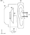
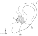
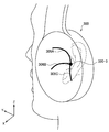
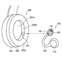
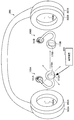
- FIG. 1 is a view for explaining an example of the appearance configuration of the ear opening device according to the present embodiment.
- the ear canal opening device 100 is used by being attached to one ear of a listener (ie, a user).
- FIG. 1 shows the appearance of the ear opening device 100 attached to the right ear as an example.
- the Y axis is a coordinate axis with positive forward in the horizontal direction (eye direction)
- the X axis is a coordinate axis with positive left hand side of the horizontal direction
- the Z axis is a coordinate axis with negative vertical direction. .
- These coordinate axes are also used in the following figures.
- the ear canal opening device 100 includes an acoustic output unit 110 that outputs (generates) an acoustic, a acoustic conductor 120 that takes in the acoustic generated by the acoustic output unit 110 from one end 121, and an acoustic conductor 120. Is held near the other end 122.
- the sound guiding portion 120 is made of a hollow tube, and both ends thereof are open ends.
- One end 121 of the sound conductor 120 is an acoustic input hole for the sound generated from the acoustic output unit 110, and the other end 122 is the acoustic output hole. Therefore, the one end 121 is attached to the sound output unit 110, and the sound guiding unit 120 is in an open state on one side.
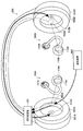
- the holding unit 130 engages with the vicinity of the entrance of the ear canal (for example, inter-juvenile notch), and the sound guiding unit 120 is fixed so that the sound output hole of the other end 122 of the sound guiding unit 120 faces the far side of the ear canal Support near end 122.
- the outer diameter near at least the other end 122 of the sound guiding portion 120 is formed to be smaller than the inner diameter of the ear canal (the entrance of the ear canal 5). Therefore, even if the other end 122 of the sound guiding unit 120 is held by the holding unit 130 in the vicinity of the entrance of the ear canal, the ear hole of the listener is not closed. That is, the ear holes are open.
- the ear opening device 100 can be said to be an ear opening type earphone, unlike a typical earphone.
- the holding part 130 is provided with the opening part 131 which open
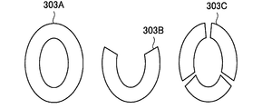
- the holding portion 130 is a ring-shaped structure, and the acoustic information acquisition portion 140 is provided in the portion where the rod-like support members 132 provided in the ring inner direction are combined near the ring center.
- the other parts of the ring structure are all openings 131.
- the holding part 130 is not limited to a ring-shaped structure, and if it has a hollow structure, the holding part 130 supports the other end 122 of the sound conducting part 120 and has an arbitrary shape in which the acoustic information acquisition part 140 is provided. Good.
- the tubular sound guiding unit 120 When the sound generated from the sound output unit 110 is taken into the tube from one end 121 thereof, the tubular sound guiding unit 120 propagates the air vibration, and the other end 122 held near the entrance of the ear canal by the holding unit 130. It radiates toward the ear canal and transmits to the tympanic membrane.
- the holding unit 130 that holds the vicinity of the other end 122 of the sound guiding unit 120 includes the opening 131 that opens the entrance (ear hole) of the ear canal to the outside world. Therefore, even when the earhole opening device 100 is worn, the listener's earhole is not blocked. The listener can listen sufficiently to the ambient sound through the opening 131 while wearing the ear canal opening device 100 and listening to the sound output from the sound output unit 110.
- the ear hole opening device 100 opens the ear hole, it is possible to reduce the leakage of the generated sound from the sound output unit 110 (that is, the reproduction sound) to the outside.
- the reason is that the other end 122 of the sound guiding unit 120 is attached near the entrance of the ear canal so as to face the back of the ear canal, and sufficient sound quality can be obtained even if the output of the sound output unit 110 is small.
- the directivity of the air vibration radiated from the other end 122 of the sound guiding portion 120 can also contribute to the prevention of sound leakage.
- the sound conduction part 120 has a bending shape that is folded back from the back side to the front side of the pinna in the middle part.
- This bent portion is a pinch portion 123 having an open / close structure, and by holding the earlobe by generating a pinch force, it is possible to maintain the wearing of the earhole opening device 100 to the listener.
- the acoustic information acquisition unit 140 provided in the vicinity of the ring center of the ring-shaped holding unit 130 is provided so as to face the eardrum opposite side.
- the acoustic information acquisition unit 140 typically includes an acoustic input unit (i.e., a microphone), and mainly detects (i.e., picks up) ambient sound. That is, the sound input unit is provided in the opposite direction to the other end 122 disposed facing the back side of the ear canal. Therefore, the influence of the sound generated from the sound output unit 110 output from the other end 122 on the sound collection result by the sound input unit is reduced.
- the acoustic information acquisition unit 140 functions as a so-called error microphone for noise cancellation, and the detection result by the acoustic information acquisition unit 140 is treated as an error signal. Since the acoustic information acquisition unit 140 is disposed near the ear canal, that is, near the tympanic membrane, high noise cancellation performance is expected.
- the ear hole opening device 100 shown in FIG. 1 is comprised supposing mounting
- the ear hole opening device 100 for left ear wearing is comprised symmetrically with this.
- the open ear device 100 may be configured for binaural including both for the right ear and for the left ear.
- the ear canal opening device 100 for the right ear and the ear canal opening device 100 for the left ear may be configured separately and independently from each other and may communicate with each other.
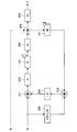
- FIG. 2 is a view showing an example of the internal configuration of the ear canal opening device 100 according to the present embodiment.
- the ear canal opening device 100 includes an acoustic output unit 110, an acoustic information acquisition unit 140, and a control unit 150.
- the sound output unit 110 has a function of outputting sound based on the sound signal.
- the sound output unit 110 may also be referred to as a driver.
- the driver 110 outputs sound to space based on the output signal output from the signal processing unit 151.
- the acoustic information acquisition unit 140 has a function of acquiring acoustic information.
- the acoustic information acquisition unit 140 includes an acoustic input unit 141 and a tympanic sound pressure acquisition unit 142.
- the sound input unit 141 includes a microphone (hereinafter, also simply referred to as a microphone) that detects an ambient sound, and generates a sound signal indicating a sound collection result by the microphone. That is, the acoustic information may be an acoustic signal indicating the sound collection result by the microphone.
- the tympanic sound pressure acquisition unit 142 estimates the sound pressure of the tympanic membrane and generates sound pressure information of the tympanic membrane. That is, the acoustic information may be sound pressure information of the tympanic membrane.
- the tympanic sound pressure acquisition unit 142 measures, for example, the vibration of the tympanic membrane to directly estimate the tympanic sound pressure. The configuration of the eardrum sound pressure acquisition unit 142 will be described in detail later.
- the tympanic sound pressure may not be measured directly.
- the tympanic sound pressure may be approximated by the sound pressure near the entrance of the ear canal.
- the sound input unit 141 sound information acquisition unit 140
- the sound signal generated by the sound input unit 141 is also captured as information indicating tympanic membrane sound pressure. It is possible.
- Control unit 150 functions as an arithmetic processing unit and a control unit, and controls the overall processing by the ear canal opening device 100 according to various programs.
- the control unit 150 is realized by an electronic circuit such as, for example, a central processing unit (CPU), a micro-processing unit (MPU), or a demand-side platform (DSP).
- the control unit 150 may include a ROM (Read Only Memory) that stores programs to be used, operation parameters, and the like, and a RAM (Random Access Memory) that temporarily stores parameters and the like that change as appropriate.
- ROM Read Only Memory
- RAM Random Access Memory
- control unit 150 includes a signal processing unit 151, an operation control unit 153, and an authentication unit 155.
- the signal processing unit 151 has a function of generating a noise cancellation signal for noise based on the acoustic information (acoustic signal or sound pressure information of the eardrum) acquired by the acoustic information acquisition unit 140. For example, the signal processing unit 151 performs noise cancellation processing of the FB method or the FF method using acoustic information as an error signal, and generates a noise cancellation signal. The signal processing unit 151 generates an acoustic signal (hereinafter also referred to as an output signal) based on the noise cancellation signal, and outputs the acoustic signal to the acoustic output unit 110 as an output.
- an acoustic signal hereinafter also referred to as an output signal
- the output signal may be the noise cancellation signal as it is, or may be a synthesized signal in which another acoustic signal such as a music signal acquired from a sound source and the noise cancellation signal are synthesized.
- the signal processing unit 151 includes various components for the noise cancellation process described with reference to FIGS. 8 to 13 and the like.
- the signal processing unit 151 includes various filter circuits for generating a noise cancellation signal, an adaptive control unit for adaptively controlling the filter circuits, an adder for combining signals, and a self voice extraction unit described later And internal models etc.
- the signal processing unit 151 also includes circuits such as an amplifier, an ADC (Analog Digital Converter), and a DAC (Digital Analog Converter).
- the signal processing unit 151 further emphasizes the high region of the sound information included in the sound information (sound signal or sound pressure information of the tympanic membrane) acquired by the sound information acquisition unit 140, or reverberation. Processing such as adding may be performed. This makes it easier to hear surrounding sounds. That is, the technology according to the present embodiment is also applicable to a noise canceling technology in an open space or a hearing aid.
- the operation control unit 153 has a function of controlling the operation mode of the ear canal opening device 100. For example, the operation control unit 153 stops or activates a part or all of the functions of the ear canal opening device 100.
- the authentication unit 155 has a function of identifying and authenticating the user wearing the in-ear device 100.
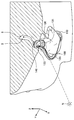
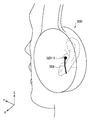
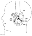
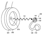
- FIG. 3 is a view for explaining an outline of noise cancellation processing using the ear opening device 100 according to the present embodiment.
- FIG. 3 a cross-sectional view of the head of a user wearing the in-ear device 100 in the left ear is shown in the ear canal.
- the noise N reaches the acoustic information acquisition unit 140 and passes through the opening 131 to reach the eardrum 9 through the ear canal 5.
- the ear canal opening device 100 generates a noise cancellation signal based on the noise N acquired by the acoustic information acquisition unit 140.
- the sound output unit 110 outputs sound based on the sound signal generated based on the noise cancellation signal.
- the sound output from the sound output unit 110 propagates through the sound conductor 120 and is emitted from the other end 122 to cancel the noise N.
- the position of the acoustic information acquisition unit 140 is near the entrance of the ear canal 5, that is, near the eardrum 9.
- the microphone 141 can collect sound in the vicinity of the tympanic membrane 9.
- the eardrum sound pressure acquisition unit 142 can acquire sound pressure information of the eardrum 9 from the vicinity of the eardrum 9. Thereby, the accuracy of the sound pressure information is enhanced, which can contribute to the improvement of the noise cancellation performance.
- the holding unit 130 maintains the relative positional relationship between the sound information acquisition unit 140 and the other end 122 which is an output hole of the sound output from the sound output unit 110. That is, the characteristics of the space between the sound output unit 110 and the sound information acquisition unit 140 (characteristics H 1 described later) are fixed. Thereby, the noise cancellation performance can be stabilized.
- the maintenance of the relative positional relationship is realized by the holding unit 130 holding both the sound guiding unit 120 and the acoustic information acquiring unit 140.
- the mounting position of the ear opening device will be described with reference to FIGS. 4 to 7.
- the following description will be given assuming that the microphone 141 is mounted as the acoustic information acquisition unit 140 in the ear canal opening device 100.
- FIG. 4 is a view for explaining the structure of a typical human ear.
- the auricle 2 forms a unique unevenness, reflects the sound from various directions, and guides it to the ear canal 5.
- the ear canal 5 is an acoustic passage, and the sound passing through the ear canal 5 reaches the tympanic membrane at the back of the ear canal 5.
- the ear ring leg 3 Around the external auditory canal 5, there are the ear ring leg 3, the concha cavity 4, the tragus 6, the intervaginal notch 7 and the antitragus 8.
- FIG. 5 is a diagram for explaining the noise N arriving at the human ear.
- the noise N arrives at the human ear 1 from all directions in the horizontal direction.
- FIG. 5 shows the left ear, the same applies to the right ear.
- the noise collected by the microphone 141 has frequency characteristics depending on the arrival direction of the noise. For example, the influence of the reflection received from the pinna 2 differs between noise coming from the front of the user (i.e. the Y-axis positive side) and noise coming from the back (i.e. the Y-axis negative side). Therefore, depending on the arrangement of the microphone 141, even if noise from a specific direction can be sufficiently canceled, an event may occur in which noise from another direction can not be sufficiently canceled. This is not limited only to the horizontal direction, and the same applies to the elevation direction.
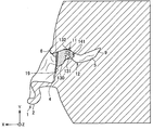
- FIG. 6 is a view for explaining the arrangement of the microphones 141 of the ear opening device 100 according to the present embodiment.
- FIG. 6 a cross-sectional view showing the appearance of the ear canal is shown.
- the ear canal 5 has an S shape bent at each of the first curve 11 and the second curve 12, and the eardrum 9 is at the back of the ear canal 5. If the space is closer to the tympanic membrane 9 than the tragus 6, the dependence of the frequency characteristic on the direction of arrival of the noise described above with reference to FIG. 5 is considered to be relatively small. Therefore, it is desirable that the microphone 141 be disposed in a space closer to the tympanic membrane 9 than the tragus 6.
- the microphone 141 be disposed inside the ear canal 5, that is, in a space on the tympanic membrane 9 side from the boundary 19 between the concha cavity 4 and the ear canal 5. Thereby, particularly high noise cancellation performance can be realized.
- the microphone 141 is disposed in a space from the boundary 19 of the concha cavity 4 and the ear canal 5 to the side of the tympanic membrane 15 by 15 mm, or in a space from the border 19 of the concha caudal cavity 4 and the ear canal 5 to the side of the eardrum 9 by 15 mm It is desirable to be done.
- the holder 130 is a space up to 15 mm from the boundary 19 of the concha cavity 4 and the external auditory canal 5 to the tympanic membrane 9 or the concha cavity 4 and the external ear canal in a state where the ear canal opening device 100 is worn by the user.
- the microphone 141 It is desirable to hold the microphone 141 in a space up to 15 mm from the boundary 19 of 5 to the tympanic membrane 9 and opposite side.
- the difference between the frequency characteristic at the position of the microphone 141 and the frequency characteristic at the position of the eardrum 9 decreases as the microphone 141 is closer to the eardrum 9. Therefore, it is desirable that the position of the microphone 141 be closer to the tympanic membrane 9.
- the space from the boundary 19 to the opposite side to the tympanic membrane 9 is 15 mm, the difference in the frequency characteristics can be within the allowable range, and a predetermined noise cancellation performance can be secured.
- the position of the microphone 141 is compared with the case where the microphone 141 is disposed in the space opposite to the tympanic membrane 9 from the boundary 19 It can be close to the tympanic membrane 9. Furthermore, at least the microphone 141 can be prevented from coming into contact with the tympanic membrane 9 to damage the tympanic membrane 9, thereby ensuring safety.
- the microphone positions Ma and Mb are in a space of 15 mm from the boundary 19 to the tympanic membrane 9 side. Specifically, the microphone position Ma is between the first curve 11 and the second curve 12 of the ear canal 5. The microphone position Mb is between the boundary 19 and the first curve 11 of the ear canal 5. Also, the microphone position Mc is in a space of up to 15 mm from the boundary 19 opposite to the tympanic membrane 9. A predetermined noise cancellation performance can be secured at any of these microphone positions. In particular, the microphone position Ma is most desirable in that the dependence of the frequency characteristic on the direction of arrival can be minimized.
- FIG. 7 is a view showing how the ear canal opening device 100 according to the present embodiment is worn by the user.
- the holding unit 130 is in contact with the inner wall of the ear canal 5 of one ear in a state in which the earhole opening device 100 is worn by the user.
- the holding unit 130 holds the microphone 141 in a space closer to the tympanic membrane 9 than the tragus 6 and in a space up to 15 mm from the boundary 19 between the concha cavity 4 and the ear canal 5 to the tympanic membrane 9 side. More specifically, the holding unit 130 holds the microphone 141 at the microphone position Ma shown in FIG.
- the position of the microphone 141 (that is, the cancellation point) can be set to a position where the difference in frequency characteristics from the position of the eardrum 9 is small, and high noise cancellation performance can be realized.
- the place where the holder 130 abuts is not limited to the inner wall of the ear canal 5.
- the holder 130 may abut on the concha cavity 4, for example.
- noise cancellation processing by the ear opening device 100 according to the present embodiment will be described.
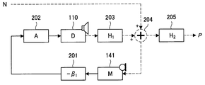
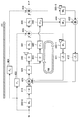
- FIG. 8 is a view showing an example of a model configuration of noise cancellation processing of the classical control FB method by the ear opening device 100 according to the present embodiment.
- Symbols of blocks shown in the model configuration example as shown in FIG. 8 indicate characteristics (that is, transfer functions) corresponding to specific circuit parts or circuits in the system of the noise cancellation system. As the sound signal (or sound) passes through each block, the characteristics shown in the block are applied.
- the meanings of the symbols of the blocks shown in FIGS. 8 to 13 are as follows.
- H 1 Characteristic of the space 203 from the driver 110 to the microphone 141
- H 2 Characteristic of the space 205 from the microphone 141 to the tympanic membrane (spatial characteristic of the ear canal)
- M characteristics of the microphone 141
- A characteristics of the amplifier 202 D: characteristics of the driver 110
- F characteristics of the passive sound barrier 220
- M ′ simulation characteristics of the M of the microphone 141
- a ′ simulation characteristics of the amplifier 202 D ′: of the driver 110
- Simulated characteristics H ′ Simulated characteristics of the space 203
- M ′ Characteristics of the internal model 208
- N indicates noise
- M indicates a music signal
- P indicates the sound pressure at the eardrum position
- V indicates the user's voice (self-voice).
- the microphone 141 picks up the sound and generates an acoustic signal.
- the acoustic signal generated by the microphone 141 is input to the first FB filter 201.
- the first FB filter 201 is a filter circuit that performs noise cancellation processing of the FB method.
- the first FB filter 201 performs noise cancellation processing with the microphone 141 as a cancellation point based on the acoustic signal input from the microphone 141, and generates a noise cancellation signal.
- the acoustic signal that has passed through the first FB filter 201 is input to the amplifier 202.
- the amplifier 202 is a power amplifier that amplifies and outputs the input acoustic signal.
- the amplifier 202 amplifies and outputs the acoustic signal input from the first FB filter 201.
- the acoustic signal passed through the amplifier 202 is input to the driver 110.
- the driver 110 outputs a sound into space based on the input sound signal.
- the sound output from the driver 110 first interferes with the noise N in the space 204 after passing through the space 203 and cancels the noise N.
- the noise N that can not be canceled is collected by the microphone 141. Furthermore, the noise N that can not be canceled passes through the opening 131, passes through the space 205, and reaches the tympanic membrane position as the tympanic sound pressure P.
- the microphone 141 is a point that minimizes noise (ie, a cancellation point). Therefore, it is desirable that the arrangement position of the microphone 141 be closer to the tympanic membrane.
- the ear hole opening device 100 is configured as an earphone (closed noise cancellation earphone) having no opening 131
- a noise cancellation process in the case where the ear hole opening device 100 is configured as an earphone (closed noise cancellation earphone) having no opening 131 will be described with reference to FIG.
- FIG. 9 is a view showing an example of a model configuration of noise cancellation processing of the classical control FB system by the closed type noise cancellation earphone according to the comparative example.
- the example of the model configuration shown in FIG. 9 is the same as the example of the model configuration shown in FIG. 8 except that the passive sound insulation element 220 is included.
- a passive sound insulation element 220 such as a closed housing or an earpiece is present between the noise N and the microphone 141. Therefore, the noise N is attenuated by the influence of the passive sound insulation element 220 and then collected by the microphone 141.
- relatively large noise is collected in the open ear device 100 as compared to the closed noise cancellation earphone. Therefore, it is desirable that an amplifier and a driver with a large output as compared with the closed noise cancellation earphone be used for the ear canal opening device 100 according to the present embodiment.
- an acoustic signal input to the driver 110 is y.
- the sound pressure P at the position of the microphone 141 is defined by the following formula (A1).
- the acoustic signal y is defined by the following equation (A2).
- the sound pressure P is derived as shown by the following equation (A3) by the equation (A1) and the equation (A2).
- the coefficient applied to the noise N in equation (A3) is also referred to as a sensitivity function.
- the characteristic ⁇ 1 of the first FB filter 201 is a parameter that can be designed.
- the denominator of the sensitivity coefficient is maximized, the sensitivity coefficient is minimized, as a result, the sound pressure P is minimized.
- the beta 1 reduces the sound pressure at the eardrum, noise is greater canceled.
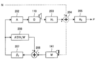
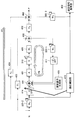
- FIG. 10 is a view showing an example of a model configuration of noise cancellation processing of the internal model control FB method by the ear canal opening device 100 according to the present embodiment.
- the example of the model configuration shown in FIG. 10 is different from the example of the model configuration shown in FIG. 8 in that it has a second FB filter 207 instead of the first FB filter 201, and an internal model 208 and an adder 206. It is different. In the following, differences from the model configuration example shown in FIG. 8 will be mainly described.
- the second FB filter 207 is a filter circuit that performs noise cancellation processing of the FB method.
- the second FB filter 207 performs noise cancellation processing with the microphone 141 as a cancellation point based on the input acoustic signal, and generates a noise cancellation signal.
- the acoustic signal that has passed through the second FB filter 207 is input to the amplifier 202 and also input to the internal model 208.
- Internal model 208 corresponds to the internal model of ear opening device 100.
- the internal model is a path inside signal processing, and is a model having characteristics simulating a secondary path.
- the secondary path is a physical space transfer characteristic from the secondary sound source to the error microphone.
- the internal model 208 here simulates the characteristic until the noise cancellation signal output from the second FB filter 207 is output from the driver 110 and collected by the microphone 141 and returned to the second FB filter. It has a characteristic.
- Internal model 208 in the model configuration example shown in FIG. 10 has the property of A'D'H 1'M'.
- the acoustic signal passed through the internal model 208 is input to the adder 206.
- the adder 206 subtracts and synthesizes the acoustic signal having passed through the internal model 208 from the acoustic signal generated by the microphone 141.
- the composite signal is input to the second FB filter 207.
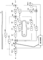
- FIG. 11 is a view showing an example of a model configuration of noise cancellation processing using both the classical control FB method and the internal model control FB method by the ear opening device 100 according to the present embodiment.
- the model configuration example shown in FIG. 11 is obtained by adding a first FB filter (characteristic: - ⁇ 1 ) and an adder 209 to the model configuration example shown in FIG.
- a first FB filter characteristic: - ⁇ 1
- an adder 209 an adder 209
- the acoustic signal input by the microphone 141 is input to the adder 206 and also input to the first FB filter 201.
- the first FB filter 201 generates a noise cancellation signal based on the input acoustic signal.
- the acoustic signal that has passed through each of the first FB filter 201 and the second FB filter 207 is input to the adder 209 and synthesized.
- the combined signal is input to the internal model 208 and output from the driver 110 via the amplifier 202.
- the ear canal opening device 100 may perform the FF type noise cancellation processing together with or instead of the FB type noise cancellation processing. In that case, it is desirable that the earhole opening device 100 measure in advance the acoustic characteristics when worn by the user and set the characteristics of the FF filter.
- FIG. 12 is a view showing an example of a model configuration of noise cancellation processing of the classical control FB system at the time of music reproduction by the ear opening device 100 according to the present embodiment.
- an internal model 208, an adder 210 and an adder 211 are added to the model configuration example shown in FIG. 8, and an acoustic signal M is further input.
- components newly added from the model configuration example shown in FIG. 8 will be mainly described.
- the music signal M is input to the internal model 208 and the adder 211.
- the music signal passed through the internal model 208 is input to the adder 210.
- the acoustic signal generated by the microphone 141 is input to the adder 210.
- the adder 210 subtracts the music signal having passed through the internal model 208 from the sound signal generated by the microphone 141 and synthesizes it.
- the composite signal is input to the first FB filter 201.
- the acoustic signal that has passed through the first FB filter 201 is input to the adder 211.
- the adder 211 combines the audio signal passed through the first FB filter 201 and the music signal M.
- the synthesized signal is output from the driver 110 via the amplifier 202.
- the FB filter is applied after subtracting the component of the music signal from the acoustic signal including noise output from the microphone 141. This can prevent the music to be reproduced from being reduced along with the noise.
- the signal processing unit 151 extracts the user's own voice based on the acoustic information acquired by each of the pair of acoustic information acquiring units 140 for both ears, and the extracted user
- the voice of the voice is synthesized into the noise cancellation signal.
- the noise cancellation signal includes a component for canceling the user's own voice.
- the user's own voice is synthesized at the ear by being synthesized with the noise cancellation signal. Therefore, it can be prevented that the user's voice is canceled as noise, giving the user the feeling that the user's voice is far away.
- the process of extracting the own voice and combining it with the noise cancellation signal will be described in detail below with reference to FIG.
- FIG. 13 is a view showing a model configuration example of noise control processing of the classical control FB system including the self voice extraction by the ear canal opening device 100 according to the present embodiment.
- the model configuration example shown in FIG. 13 is obtained by adding the own voice extraction unit 212, the equalizer 213, the adder 214, and the space 215 to the model configuration example shown in FIG.
- the incoming noise N is the sound in which the noise source NS and the user's voice V (ie, his own voice) are synthesized in the space 215.
- the model configuration example shown in FIG. 13 shows a model configuration example on the left ear side, and the right ear side is omitted.
- components newly added from the model configuration example shown in FIG. 8 will be mainly described.
- the microphone 141 for the left ear picks up the noise N passing through the space 204 to generate an acoustic signal. The same is true for the right ear.
- the acoustic signals generated by the left and right microphones 141 are input to the own voice extraction unit 212.
- the own voice extraction unit 212 extracts the own voice V based on the input acoustic signal. For example, the own voice extraction unit 212 extracts the own voice V by extracting the in-phase signal component from the input acoustic signal.
- the own voice extraction unit 212 outputs an acoustic signal indicating the extracted own voice V to the left and right adders 214.
- the acoustic signal generated by the microphone 141 is also input to the first FB filter 201.
- the noise cancellation signal generated by the first FB filter 201 is input to the adder 214.
- the music signal M is input to the equalizer 213.
- the equalizer 213 adjusts the sound quality of the input music signal M based on the characteristic E.
- the music signal passed through the equalizer 213 is input to the adder 214.
- the adder 214 synthesizes the acoustic signal input from each of the own voice extraction unit 212, the first FB filter 201, and the equalizer 213.
- the synthesized signal is output from the driver 110 via the amplifier 202.
- the own voice V extracted by the own voice extraction unit 212 is output from the driver 110.
- the user's voice is canceled as noise and giving the user an uncomfortable feeling that the user's voice is far away.
- the ear canal opening device 100 may further include a microphone for collecting the user's own voice as the acoustic information acquisition unit 140.
- the ear canal opening device 100 may include such a microphone in the vicinity of the pinch portion 123 shown in FIG.
- the self-voice extraction unit 212 extracts the user's own voice based on the acoustic signal generated by the microphone. Thereby, the self-voice extraction unit 212 can extract the user's own voice with higher accuracy.
- the ear canal opening device 100 may perform noise cancellation processing based on sound pressure information of the eardrum.
- the acoustic information acquisition unit 140 acquires sound pressure information of the eardrum as the acoustic information.
- the signal processing unit 151 converts the sound signal generated by the microphone 141 into noise cancellation processing based on sound pressure information on the eardrum.
- the signal processing unit 151 may perform the noise cancellation process using the acoustic signal generated by the microphone 141 and the eardrum sound pressure information acquired by the eardrum sound pressure acquisition unit 142 in combination.
- the eardrum sound pressure acquiring unit 142 is mounted as the acoustic information acquiring unit 140 in the ear canal opening device 100.
- the tympanic sound pressure acquisition unit 142 has a function of acquiring vibration information of the ear canal or tympanic membrane, and acquiring sound pressure information of the cancellation point based on the acquired vibration information.
- the eardrum sound pressure acquisition unit 142 transmits a transmission wave, acquires a reflection wave on which the transmission wave is reflected, and acquires vibration information indicating displacement or speed at a reflection point.
- a frequency change proportional to the moving speed of the reflection point occurs.
- the tympanic sound pressure acquisition unit 142 estimates the displacement or speed of the reflection point based on the frequency difference between the transmission wave and the reflection wave.
- the transmitted wave is transmitted to the ear canal or tympanic membrane and is reflected to any reflection point on the ear canal or tympanic membrane.
- the reflection point may be the same as or different from the cancellation point.
- the tympanic sound pressure acquisition unit 142 may be realized by a laser range finder, and the transmission wave may be a laser.
- the eardrum sound pressure acquisition unit 142 may be realized by an ultrasonic distance measuring device, in which case the transmission wave is an ultrasonic wave.
- the transmission wave be a laser.
- the laser light source may emit light intermittently instead of emitting light continuously.
- the light emission frequency may be equal to the sampling rate for acquiring the reflected wave. Power consumption can be reduced by these.
- the tympanic sound pressure acquisition part 142 is demonstrated as what is implement
- the eardrum sound pressure acquisition unit 142 can also measure the distance between the eardrum sound pressure acquisition unit 142 and the reflection point.
- the laser distance measuring device measures the distance between the laser distance measuring device and the reflection point based on the time from the transmission of the laser to the reception of the laser reflected by the reflection point.
- Such a measurement method is also referred to as a ToF (Time of Flight) method.
- a device for transmitting and receiving at least the transmission wave in the tympanic sound pressure acquisition unit 142 may be held by the holding unit 130, and a device for estimating and acquiring the tympanic sound pressure based on the vibration information, etc.
- the arrangement of is not particularly limited.
- the cancellation point is one point of the tympanic membrane. That is, the tympanic sound pressure acquisition unit 142 acquires sound pressure information of the tympanic membrane. By using the sound pressure information of the eardrum for the noise cancellation process, high noise cancellation performance can be realized.
- the reflection point is also one point of the tympanic membrane.
- the eardrum sound pressure acquisition unit 142 can acquire the sound pressure information of the eardrum based on the vibration information of the eardrum. Therefore, sound pressure information on the eardrum can be estimated with high accuracy.
- the reflection point may be on the inner wall of the ear canal.
- the eardrum sound pressure acquisition unit 142 estimates the eardrum sound pressure information based on the vibration information of two or more points on the inner wall of the ear canal.
- the tympanic sound pressure acquisition unit 142 estimates vibration information of the tympanic membrane based on vibration information of two or more points of the inner wall of the ear canal with reference to a model of correlation between the vibration of the inner wall of the ear canal Do. Then, based on the estimation result of the vibration information of the eardrum, the sound pressure information of the eardrum is estimated.
- the tympanic sound pressure acquisition unit 142 may measure vibration information of the tympanic membrane and vibration information of the inner wall of the ear canal, and estimate sound pressure information of the tympanic membrane position based on the measurement results. In this case, sound pressure information on the tympanic membrane position can be estimated with higher accuracy.
- the tympanic sound pressure acquisition unit 142 can measure a self-generated sound (for example, a self-voice) by meat conduction based on vibration information of the inner wall of the ear canal.
- the eardrum sound pressure acquisition unit 142 can measure the self-generated sound based on the air propagation sound wave information on the left and right in addition to the vibration information on the inner wall of the ear canal.
- Whether the reflection point is the tympanic membrane or the inner wall of the ear canal can be determined based on, for example, information indicating a three-dimensional shape described later.
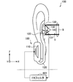
- FIG. 14 is a cross-sectional view showing the inside of the ear canal of the left ear of the user. As shown in FIG. 14, the tympanic membrane vibration surface 14 forms a predetermined angle with the lower wall 13 of the ear canal. In the case of an adult, the tympanic membrane vibration surface 14 forms an angle of about 50 degrees with the lower wall 13 of the ear canal.
- FIGS. 15 to 17 are diagrams showing that the inside of the external ear canal of the left ear of the user shown in FIG. 14 is irradiated with the laser by the open ear device 100.
- FIG. 15 is a view of the same view as FIG. 14,
- FIG. 16 is a view of a view looking down from the Z-axis positive direction to the Z-axis negative direction, and
- FIG. 17 is an intermediate between the X-axis positive direction and the Z-axis positive direction. It is a figure of the viewpoint which goes to origin from near.
- the laser 16 is irradiated toward the tympanic membrane 9 by the tympanic sound pressure acquisition unit 142 (laser distance measuring device).
- FIGS. 15 laser distance measuring device
- the irradiation direction 17 of the laser 16 and the vibration direction 15 of the tympanic membrane 9 can intersect at a specific angle.
- the correction of the angle difference may be performed by logical calculation or may be performed by physical control of the irradiation direction of the laser described later.
- the holding unit 130 preferably holds the tympanic sound pressure acquisition unit 142 at a position where the inner wall of the ear canal 5 does not exist on the straight line between the tympanic sound pressure acquisition unit 142 and the tympanic membrane 9 .
- the eardrum sound pressure acquisition portion 142 be held at a position where there is no obstacle between the eardrum sound pressure acquisition portion 142 and the eardrum 9. Thereby, it becomes possible to directly reflect the laser irradiated from the tympanic sound pressure acquisition unit 142 to one point on the tympanic membrane 9.
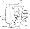
- FIG. 18 is a diagram for describing a model configuration example of an eardrum sound pressure estimation process according to the present embodiment.
- the laser diode 230 generates and emits a laser.
- the laser emitted from the laser diode 230 is split into two directions by the beam splitter 231, and one of the beams passes through the beam splitter 232 and the focusing lens 233 to reach the tympanic membrane 9.
- the laser reflected by the tympanic membrane 9 passes through the focusing lens 233, is reflected by the beam splitter 232 and the mirror 234, passes through the beam splitter 237, and is input to the photoelectric converter 238.
- the other one of the lasers emitted from the laser diode 230 and separated by the beam splitter 231 is input to the optical frequency converter 236.
- the signal oscillated at the reference frequency by the reference frequency oscillator 235 is also input to the optical frequency converter 236.
- the optical frequency converter 236 modulates the frequency of the laser irradiated from the laser diode 230 to a reference frequency and outputs it.
- the laser output from the optical frequency converter 236 is reflected by the beam splitter 237 and input to the photoelectric converter 238.
- the laser having passed through the beam splitter 237 is converted into an intensity signal of light by the photoelectric converter 238.
- the light intensity signal indicates the tympanic oscillation frequency frequency-modulated at the reference frequency.
- the light intensity signal is converted into a frequency domain signal by the frequency voltage converter 239, the band limiting filter 240 is applied, and the speed acceleration converter 241 is input.
- the signal to which the band limiting filter processing by the band limiting filter 240 is applied is a velocity signal of tympanic membrane vibration.
- the velocity acceleration converter 241 converts the velocity of the tympanic membrane into the acceleration of the tympanic membrane based on the velocity signal of the tympanic membrane, and outputs a signal indicating the acceleration of the tympanic membrane to the tympanic sound pressure estimation unit 242.
- the eardrum sound pressure estimation unit 242 estimates the eardrum sound pressure (sound pressure information of the eardrum 9) based on the acceleration of the eardrum.
- a [m / s 2 ] is an acceleration signal obtained by the velocity acceleration converter 241.
- K [kg / m 2 ] is a constant comprising the area, mass, tension of the tympanic membrane, a correction coefficient by the penetration angle of the laser into the tympanic membrane, and the like.
- at least part of the process of acquiring the eardrum sound pressure may be performed by a digital circuit.
- the processing of the velocity acceleration converter 241 and the tympanic sound pressure estimation unit 242 may be performed by a digital circuit.
- the tympanic sound pressure estimation unit 242 may include a function as the velocity acceleration converter 241.
- the shape of the ear in particular the shape of the ear canal and the arrangement of the tympanic membrane differ depending on the person. Therefore, the laser irradiation point (that is, the reflection point) is not necessarily located at the center of the tympanic membrane in a state where the user has the ear opening device 100 attached.
- the eardrum sound pressure acquisition unit 142 may estimate the eardrum sound pressure information further based on the information indicating the three-dimensional shape of the user's ear canal. For example, the tympanic sound pressure acquisition unit 142 controls the irradiation direction of the laser based on the information indicating the three-dimensional shape of the ear canal, and sets the tympanic membrane as a reflection point. As a result, the tympanic sound pressure can be directly estimated, so that the accuracy can be improved.
- the eardrum sound pressure acquisition unit 142 acquires information indicating the three-dimensional shape of the ear canal by scanning the ear canal while changing the transmission direction of the transmission wave. Specifically, the tympanum sound pressure acquisition unit 142 acquires a map of the distance between the tympanum sound pressure acquisition unit 142 and the reflection point as a scan result by measuring distance while sequentially changing the irradiation direction of the laser. The map of this distance is information indicating the three-dimensional shape of the ear canal with reference to the eardrum sound pressure acquisition unit 142.
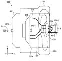
- FIG. 19 is a view showing a state of scanning of the ear canal by the ear opening device 100 according to the present embodiment.
- the laser 16 is emitted from the eardrum sound pressure acquisition unit 142 while changing the irradiation direction.
- the ear canal opening device 100 acquires information indicating the three-dimensional shape of the area 18 irradiated with the laser.
- the tympanic sound pressure acquisition unit 142 can search for a direction in which the tympanic membrane 9 can be irradiated with the laser directly.
- the mechanism for acquiring information indicating the three-dimensional shape of the ear canal can be realized, for example, as a MEMS (Micro Electro Mechanical Systems) scanner.
- MEMS Micro Electro Mechanical Systems
- FIG. 20 processing for estimating the tympanic sound pressure using the MEMS scanner will be described.
- FIG. 20 is a diagram for describing a model configuration example of the process of estimating the tympanic sound pressure according to the present embodiment.
- the model configuration example shown in FIG. 20 includes the MEMS scanner 243 between the beam splitter 232 and the focus lens 233 in the model configuration example shown in FIG.
- the MEMS scanner 243 functions as an irradiation angle correction unit that corrects and outputs the irradiation angle of the input laser.
- the MEMS scanner 243 can change the irradiation direction of the laser input from the beam splitter 232.
- the eardrum sound pressure acquisition unit 142 acquires information indicating the three-dimensional shape of the ear canal by controlling the MEMS scanner 243 so as to sequentially change the irradiation direction of the laser.
- the tympanic sound pressure acquisition unit 142 controls the MEMS scanner 243 so that the laser is emitted in the direction in which the tympanic membrane becomes a reflection point.
- the personal authentication authentication unit 155 may authenticate the user based on the information indicating the three-dimensional shape of the ear canal acquired by the eardrum sound pressure acquisition unit 142. For example, the authentication unit 155 compares the feature amount of information indicating the three-dimensional shape of the user's ear canal stored in advance with the feature amount of information indicating the three-dimensional shape of the ear canal acquired by the eardrum sound pressure acquiring unit 142 Do. The authentication unit 155 determines, based on the comparison result, whether or not the attached user matches the pre-registered user. Since the shape of the ear canal differs depending on the person, the authentication is possible.
- the authentication unit 155 can further improve the authentication accuracy by performing the above-mentioned comparison with respect to the left and right ears.
- the signal processing unit 151 may perform signal processing based on the authentication result. For example, the signal processing unit 151 may perform the noise cancellation process using the filter characteristics set in advance for each user.
- FIG. 21 is a sequence diagram showing an example of the flow of the personal identification process performed by the ear canal opening device 100 and the terminal device according to the present embodiment. As shown in FIG. 21, this sequence involves the ear canal opening device 100 and the terminal device 800.
- the terminal device 800 is any device such as a smartphone, a tablet terminal, or an agent device.
- the ear canal opening device 100 is not yet worn by the user, and is in a wearing standby state (step S102). Further, the terminal device 800 is not connected to the ear canal opening device 100, and is in a state of waiting for connection (step S104).
- the ear canal opening device 100 determines whether or not the distance measurement distance is within a predetermined value (step S106).
- the predetermined value here is, for example, the maximum value of the length of the ear canal. If within the predetermined value, it is known that distance measurement has been performed at least in the ear canal. If it is determined that the distance measurement distance is not within the predetermined value (step S106 / NO), the process returns to step S106 again, and the state of attachment waiting is continued.
- the ear canal opening device 100 acquires information indicating the three-dimensional shape in the ear canal, and extracts the feature amount (step S108).
- the open ear device 100 compares the extracted feature amount with the feature amount stored in advance, and determines whether or not they match (S110). If it is determined that they do not match (step S110 / NO), the process returns to step S106 again.
- the open ear device 100 transmits authentication information indicating that the user authentication is completed to the terminal device 800 (step S112).
- the terminal device 800 receives and confirms the authentication information from the open ear device 100 (step S114), performs connection processing, and transmits a connection completion notification to the open ear device 100 (step S116).
- the terminal device 800 is in the connection completed state.
- the open ear device 100 receives the connection completion notification from the terminal device 800 (step S118). Thereby, the ear canal opening device 100 is in the connection complete state.
- the operation control unit 153 determines whether the ear canal opening device 100 is worn based on the information indicating the three-dimensional shape acquired by the tympanic sound pressure acquisition unit 142. For example, the operation control unit 153 determines that the distance measurement distance by the eardrum sound pressure acquisition unit 142 is within the predetermined value, and determines that the distance measurement distance does not exceed the predetermined value.
- the predetermined value here is, for example, the maximum value of the length of the ear canal. Then, the operation control unit 153 controls the operation of the ear canal opening device 100 based on the determination result. For example, the operation control unit 153 may cause the signal processing unit 151 to start generation of a noise cancellation signal when it is determined that the ear canal opening device 100 is attached.
- the operation control unit 153 may cause the driver 110 to start output of an output signal when it is determined that the ear canal opening device 100 is attached.
- the operation control unit 153 may stop the generation of the noise cancellation signal and the output of the output signal. Thereby, since the operation of the ear canal opening device 100 is stopped or partially stopped when not worn, it is possible to prevent wasteful power consumption.
- the signal processing unit 151 may adjust the sound quality of the output signal output from the driver 110 based on the information indicating the three-dimensional shape of the ear canal. For example, based on the information indicating the three-dimensional shape of the ear canal, the signal processing unit 151 attenuates the sound of the frequency that excessively resonates and emphasizes the sound of the frequency that is excessively reduced. As a result, it is possible to provide the user with the optimum sound quality according to the three-dimensional shape of the user's ear canal.
- the ear canal opening device 100 can obtain a transfer characteristic from the driver 110 to the microphone 141 by outputting a predetermined calibration signal from the driver 110 and collecting the calibration signal by the microphone 141. This transmission characteristic depends on the shape and wearing condition of the wearer's individual ear. Therefore, the ear canal opening device 100 can perform a more suitable output configuration of the driver 110 by actually measuring the transfer characteristic from the driver 110 to the microphone 141 in a state of being worn by the user. The ear canal opening device 100 can also perform output configuration adaptively using the output signal and the actual acoustic signal collected from the microphone 141.
- the earhole opening device 100 includes the acoustic information acquisition unit 140 for acquiring acoustic information from the tragus by the holding unit 130 that abuts against the concha cavity or the inner wall of the ear canal The ear hole is opened to the outside by the opening 131 while being held in the space on the tympanic membrane side. Then, the open ear device 100 generates a noise cancellation signal based on the acoustic information acquired by the acoustic information acquisition unit 140.
- the ear canal opening device 100 performs a noise cancellation process with the position of the acoustic information acquisition unit 140 or the eardrum position as a cancellation point. Since the position close to the tympanic membrane or the tympanic membrane is a cancellation point, high noise cancellation performance can be realized.
- noises of air conditioning in the office and running noise of a train or a car leaking from outside the office are flooded with noise of a lower frequency than speech.
- the ear opening device 100 cancels this noise.
- the user wearing the ear canal opening device 100 can communicate more smoothly with the other person, and mental and physical loads are reduced.
- the speech is not canceled and the ear holes are opened, so that the speech reaches the eardrum as it is. Therefore, a user wearing the ear canal opening device 100 does not have to remove the ear canal opening device 100 to talk.
- the middle frequency band such as speech as a target of noise cancellation
- the ear canal opening device 100 is uncomfortable for the user due to the humidity and temperature in the ear canal. Thus, the user can wear the ear canal opening device 100 for a long time.
- the ear canal opening device 100 can increase the signal to noise ratio by reducing ambient noise. This means that the user can easily listen to the target sound, even for music or voice of the same volume. In other words, the volume of music or voice to be output to maintain the same signal to noise ratio is suppressed. Therefore, it is possible to reduce the leaked sound of the music or the sound outputted by the open ear device 100 to the surroundings.
- the ear holes are open, the user's own voice (self voice), heartbeat sound, stuttering sound, sound when swallowing, blood flow sound, breathing sound, vibration sound transmitted through the body during walking, cable, etc.
- self voice self voice
- heartbeat sound heartbeat sound
- stuttering sound sound when swallowing
- blood flow sound blood flow sound
- breathing sound vibration sound transmitted through the body during walking, cable, etc.
- the noises of clothes rubbing and the friction noise of the part where the earpiece contacts the ear canal are not emphasized.
- the second embodiment relates to noise cancellation processing by a sound processing apparatus (headphones) having a microphone disposed near the entrance of the ear canal.
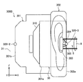
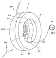
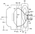
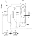
- FIG. 22 is a diagram showing a configuration example of the headphone 380-1 with the FB-NC function.
- the headphone 380-1 with the FB-NC function includes a housing 381 and an ear pad 382.
- the housing 381 and the ear pad 382 cover (typically seal) one ear of the user wearing the headphone 380-1 with the FB-NC function.
- the housing 381 stores various devices for signal processing such as the driver (speaker) 383, the microphone 384 for FB-NC, and the FB filter 385 (characteristic: ⁇ ).
- the FB-NC microphone 384 picks up ambient sound and generates an acoustic signal.
- the FB filter 385 generates a noise cancellation signal by the noise cancellation processing of the FB method based on the acoustic signal generated by the microphone 384 for FB-NC.
- the driver 383 outputs sound based on the noise cancellation signal generated by the FB filter 385.
- FIG. 23 is a diagram showing a model configuration example of noise cancellation processing by the headphone 380-1 with the FB-NC function shown in FIG. 23 Symbols of blocks shown in the example of model configuration as shown in FIG. 23 indicate characteristics (that is, transfer functions) corresponding to specific circuit parts or circuits in the system of the noise cancellation system. The meaning of each symbol is as follows.
- H Space characteristics of space 392 from driver 383 to microphone 384 for FB-NC
- M Characteristics of microphone 384 for FB-NC
- A Characteristics of amplifier 391
- D Characteristics of driver 383
- F Characteristics of passive sound insulation element 393- ⁇
- N indicates noise
- P indicates sound pressure at the position of the tympanic membrane.
- the acoustic signal generated by the FB-NC microphone 384 is input to the FB filter 385.
- the FB filter 385 generates a noise cancellation signal based on the input acoustic signal.
- the noise cancellation signal generated by the FB filter 385 is amplified by the amplifier 391 and output from the driver 383.
- the sound output from the driver 383 passes through the space 392, and then interferes with the noise N through the passive sound insulation element 393 in the space 394 to cancel the noise N.
- the noise N that could not be canceled is collected by the FB-NC microphone 384 and transmitted to the tympanic membrane as the tympanic membrane position sound pressure P.
- the cancellation point is at the position of the FB-NC microphone 384.
- the sensitivity function is calculated as follows.
- the FB filter 385 includes an ADC and a DAC.
- system delays such as digital processing delays by ADCs and DACs
- FB-NC performance is improved.
- parameters that contribute to the delay include, in addition to the delay of the system, a delay of distance in the acoustic space. The delay of this distance also influences the performance of the FB-NC.
- FIG. 24 is a diagram showing an example of phase characteristics according to the distance from the headphone driver to the microphone for FB-NC.
- FIG. 24 shows phase characteristics when the distance from the headphone driver to the FB-NC is 20 mm, 50 mm, or 100 mm.
- the phase rotation increases.
- the limit performance of the FB-NC degrades. From the above, it can be said that it is desirable to reduce the distance between the driver and the one for FB-NC in order to prevent the performance deterioration of the FB-NC due to the delay of the distance.
- the microphone 384 for FB-NC is disposed at a position near the driver 383 in the housing 381. Therefore, the delay of the above-mentioned distance is small.
- the position of the FB-NC microphone 384 is apart from the position of the eardrum 9, which is the point where the sound pressure (sound pressure caused by noise) is most desired to be minimized. Therefore, the minimization of the sound pressure at the position of the microphone 384 for FB-NC does not necessarily lead to the sound pressure minimization at the position of the tympanic membrane 9. That is, there was a risk that the performance of the FB-NC would be degraded.
- FIG. 25 is a view showing an example of the headphone 380-2 with the FB-NC function.
- the headphone 380-2 with the FB-NC function has a microphone 384 for FB-NC disposed near the tympanic membrane 9. Therefore, the minimization of the sound pressure at the position of the microphone 384 for FB-NC easily leads to the sound pressure minimization at the position of the tympanic membrane 9, and the deterioration of the performance of the FB-NC can be suppressed.
- the distance between the driver 383 and the FB-NC microphone 384 is large, there is a possibility that the performance of the FB-NC may be deteriorated due to the above-mentioned delay of the distance.
- the microphone 384 for FB-NC shown in FIG. 22 while the phase delay derived from the distance is small, the sound pressure at the tympanic membrane position is not necessarily minimized.
- the arrangement of the microphone 384 for FB-NC shown in FIG. 25 while the sound pressure at the tympanic membrane position is fed back, the phase delay derived from the distance is large.
- Second pointer Set the cancellation point near the tympanic membrane: Place the microphone for FB-NC farther from the driver
- the mechanism of the noise cancellation process which eliminated the said contradiction is proposed.
- a mechanism for noise cancellation processing is proposed in which an error microphone installed near the tympanic membrane position is used in addition to the microphone for FB-NC installed near the driver. According to this mechanism, it is possible to minimize the sound pressure at the cancel point near the tympanic membrane position by using the error microphone while suppressing the delay of the distance by using the microphone for FB-NC.
- the headphones with an NC function include, in addition to the above-described FB type, an FF type and a combination type of FB and FF.
- the combination type headphone with NC function has the highest NC performance of each of these types.
- the combination type headphone with NC function will be described with reference to FIG. 26 and FIG.
- FIG. 26 is a diagram showing a configuration example of the headphone 380-3 with the combined use NC function.
- the headphone 380-3 with combination type NC function has a microphone 386 for FF-NC for FF-NC and a characteristic - ⁇ . Is provided with an FF filter 387 having
- FIG. 27 is a diagram showing an example of a model configuration of noise cancellation processing by the combination type headphone with headphone function 380-3 shown in FIG.
- components for FF-NC are added to the model configuration example shown in FIG.
- the added block will be described.
- the meanings of the symbols of the added blocks are as follows.
- M 1 Characteristics of the microphone 384 for FB-NC
- M 2 Characteristics of the microphone 386 for FF-NC- ⁇ : Characteristics of the FF filter 387
- an acoustic signal generated based on the noise N collected by the FF-NC microphone 386 is input to the FF filter 387.
- the FF filter 387 generates a noise cancellation signal by the FF type noise cancellation processing based on the input acoustic signal.
- the adder 395 combines the noise cancellation signal generated by the FF filter 387 and the noise cancellation signal generated by the FB filter 385 to generate a synthesized signal.
- the synthesized signal is output from the driver 383 via the amplifier 391.
- the sound output from the driver 383 passes through the space 392, and then interferes with the noise N through the passive sound insulation element 393 in the space 394 to cancel the noise N.
- the noise N that could not be canceled is collected by the FB-NC microphone 384 and transmitted to the tympanic membrane as the tympanic membrane position sound pressure P.
- FIG. 28 and FIG. 29 are diagrams for explaining an example of the appearance configuration of the headphone 300 according to the present embodiment.
- FIG. 28 shows an appearance configuration in a state where the headphone 300 is worn by the user.
- FIG. 29 shows an appearance of the headphones 300 shown in FIG. 28 as viewed from the inner space 30 shown in FIG.
- the external configuration of the headphone 300 will be described mainly with reference to FIG.
- the headphone 300 includes a housing 301 and an ear pad 302.
- the housing 301 and the ear pad 302 cover (typically seal) one ear of the user wearing the headphone 300.
- the housing 301 stores various devices for signal processing, such as the sound output unit 310, the sound input units 320-1 and 320-2, and the filter circuit.
- the ear pad 302 contacts the head of the user at the contact surface 302 a.
- the ear pad 302 is formed of an elastic material such as a sponge, and is in close contact with the user's head while being deformed according to the user's head to form an inner space 30.
- the inner space 30 is a space formed by the housing 301, the ear pad 302, and the head of the user.
- the inner space 30 may be a sealed space isolated from the outer space 31 which is a space on the outer world side, or may be connected to the outer space 31.
- the inner space 30 receives noise after passive sound insulation by the passive sound insulation elements such as the housing 301, the ear pad 302, and the head of the user.
- the wall 301 a of the housing 301 is in contact with the inner space 30, and the outer wall 301 b of the housing 301 is in contact with the outer space 31.
- the sound output unit 310 outputs sound to space based on the sound signal.
- the sound output unit 310 may also be referred to as a driver.
- the driver 310 is provided on the housing 301. Then, the driver 310 outputs sound toward the inner space 30 which is a space closer to the tympanic membrane than the housing 301. For example, the driver 310 outputs sound to space based on the noise cancellation signal generated based on the sound collection result by the sound input units 320-1 to 320-3. Thereby, the noise that has arrived in the inner space 30 can be canceled.
- the sound input units 320 (320-1 to 320-3) collect ambient sounds to generate sound signals. As shown in FIG. 28, three sound input units 320 are arranged on the one ear side of the user in a state of being worn by the user.
- the sound input unit 320-1 is a microphone that picks up sound for FB-NC (ie, a microphone for FB-NC).
- the FB-NC microphone 320-1 is disposed at a position where the distance from the user's tympanic membrane 9 is shorter than the acoustic input unit 320-2 and longer than the acoustic input unit 320-3 with the headphone 300 attached to the user. Ru. More specifically, the FB-NC microphone 320-1 is disposed at a position where noise is collected through passive noise, that is, passively sound-insulated, with the headphones 300 attached to the user. Furthermore, it is desirable that the FB-NC microphone 320-1 be disposed between the user's eardrum 9 and the driver 310.
- the shield here is a passive sound insulation element, and corresponds to the housing 301, the ear pad 302, and the head of the user.
- the FB-NC microphone 320-1 is provided on a wall 301 a of the housing 301 on the inner space 30 side. Then, the FB-NC microphone 320-1 picks up the sound of the inner space 30, and generates a sound signal. The sound collected at this time includes noise after passive sound insulation by the passive sound insulation element.
- the FB-NC microphone 320-1 corresponds to a first acoustic input unit, and the acoustic signal generated by the FB-NC microphone 320-1 may also be referred to as a first acoustic signal.
- the acoustic signal generated by the FB-NC microphone 320-1 is input to the FB filter and used to generate a noise cancellation signal.
- the sound input unit 320-2 is a microphone that picks up sound for FF-NC (ie, a microphone for FF-NC). Further, the FF-NC microphone 320-2 is disposed at a position where the distance from the user's eardrum 9 is the longest in a state where the headphone 300 is attached to the user. More specifically, the FF-NC microphone 320-2 is disposed at a position where noise is collected without passing through the shield, that is, without passive sound insulation, with the headphone 300 attached to the user. . As shown in FIG. 28, the FF-NC microphone 320-2 is provided on the wall portion 301 b on the outer space 31 side of the housing 301.
- the FF-NC microphone 320-2 picks up the sound of the outer space 31 and generates an acoustic signal.
- the sound collected at this time includes noise that has arrived in the outer space 31.
- the FF microphone 320-2 corresponds to a second sound input unit, and the sound signal generated by the FF microphone 320-2 may also be referred to as a second sound signal.
- the FF-NC microphone 320-2 may or may not be exposed to the outer space 31.
- the FF-NC microphone 320-2 may be embedded in the housing 301, and may pick up the sound transmitted through a wrap around sound or a cover such as a cloth.
- the acoustic signal generated by the FF-NC microphone 320-2 is input to the FF filter and used to generate a noise cancellation signal.
- the sound input unit 320-3 is a sound input unit disposed apart from the housing 301, and a microphone (hereinafter also referred to as an ear canal microphone) arranged near the entrance of the ear canal 5 with the headphone 300 attached to the user Is called).
- the ear canal microphone 320-3 is disposed at a position where the distance from the user's tympanic membrane 9 is the shortest with the headphones 300 attached to the user.
- the ear canal microphone 320-3 is disposed at a position where noise is picked up through the shield in a state where the headphones 300 are worn by the user. As shown in FIG. 28, the ear canal microphone 320-3 is disposed in the inner space 30.
- the ear canal microphone 320-3 is held by the holding unit 303 near the entrance of the user's ear canal 5. Then, the ear canal microphone 320-3 picks up the noise after the passive sound insulation by the passive sound insulation element, and generates an acoustic signal.
- the ear canal microphone 320-3 corresponds to a third sound input unit, and the sound signal generated by the ear canal microphone 320-3 may also be referred to as a third sound signal.
- the acoustic signal generated by the ear canal microphone 320-3 is used to generate a noise cancellation signal.
- the holding unit 303 engages with the vicinity of the entrance of the ear canal 5 (for example, the intervaginal notch) and holds the ear canal microphone 320-3 near the entrance of the ear canal 5.
- the outer diameter of the ear canal microphone 320-3 is formed to be much smaller than the inner diameter of the ear canal. Therefore, even when the ear canal microphone 320-3 is held by the holding unit 303 near the entrance of the ear canal 5, the ear canal of the listener is not blocked.
- the holding unit 303 also has an opening 304 for opening the entrance (ear hole) of the ear canal 5 to the outside even when holding the ear canal microphone 320-3.
- the external world here is a space where noise is passively isolated, and is the inner space 30.
- the holding portion 303 is a ring-shaped structure, and the ear canal microphone 320-3 is provided in a portion where the rod-like first support members 305 provided in the ring inner direction are combined near the ring center.
- the other parts of the ring structure are all openings 304.
- the rod-shaped first support member 305 is gently curved, and a hemispherical shape is formed by the plurality of first support members 305 and the holding portion 303 with the holding portion 303 as a split plane.
- the holder 303 abuts on the inner wall of the concha cavity 4 or the ear canal 5 of one ear of the user while the headphone 300 is worn by the user. Then, the holding unit 303 holds the ear canal microphone 320-3 in a space closer to the tympanic membrane 9 than the tragus 6.
- the configuration of such a holding unit 303 is the same as the configuration of the holding unit 130 in the first embodiment.
- the holding portion 303 is not limited to a ring-like structure, and may have any shape provided with the ear canal microphone 320-3 as long as it has a hollow structure.
- An example of the shape of the holding portion 303 is shown in FIG.
- FIG. 30 is a view showing an example of the shape of the holding portion 303 of the headphone 300 according to the present embodiment.
- the holding portion 303A has a ring-shaped structure
- the holding portion 303B has a ring-shaped structure in which a portion is cut and removed
- the holding portion 303C has a ring-shaped structure divided into three.
- the shape of the holding portion 303 may be a ring-like structure or its type.
- the second support member 306 is a structure in which one end is connected to the housing 301 and the other end is connected to the holding unit 303. As shown in FIG. 28, the second support member 306 may be a rod-like structure curved in an S-shape. Also, a plurality of second support members 306 may be provided.
- the external configuration on the right ear side of the headphone 300 is shown, but the external configuration on the left ear side is configured to be symmetrical with the external configuration on the right ear side.
- the headphones 300 may be separately and independently configured on the right ear side and the left ear side, or may be integrally configured.
- the headphone 300 may have any structure such as a closed type, an open type, an overhead type, a neck band type, and a hooked type.
- FIG. 31 is a view showing an example of the internal configuration of the headphone 300 according to the present embodiment.
- the headphone 300 includes an acoustic output unit 310, an acoustic input unit 320, a control unit 330, and a sensor unit 370.
- the sound output unit 310 (driver) has a function of outputting sound based on the sound signal.
- the driver 310 outputs the sound to space based on the output signal output from the signal processing unit 331.
- the sound input unit 320 includes a microphone (hereinafter, also simply referred to as a microphone) that detects an ambient sound, and generates a sound signal indicating a detection result by the microphone.
- a microphone hereinafter, also simply referred to as a microphone
- Control unit 330 functions as an arithmetic processing unit and a control unit, and controls overall processing by the headphone 300 according to various programs.
- the control unit 330 is realized by an electronic circuit such as, for example, a central processing unit (CPU), a micro-processing unit (MPU), or a demand-side platform (DSP).
- the control unit 330 may include a ROM (Read Only Memory) that stores programs to be used, operation parameters, and the like, and a RAM (Random Access Memory) that temporarily stores parameters and the like that change appropriately.
- the control unit 330 is typically stored in the housing 301.
- control unit 330 includes a signal processing unit 331 and an operation control unit 333.
- the signal processing unit 331 has a function of generating a noise cancellation signal for noise based on the acoustic signal generated by the acoustic input unit 320.
- the signal processing unit 331 generates a plurality of noise cancellation signals based on the three acoustic signals generated by the three acoustic input units 320-1 to 320-3.
- the signal processing unit 331 performs at least one of FB noise cancellation processing and FF noise cancellation processing to generate a plurality of noise cancellation signals.
- the signal processing unit 331 generates an acoustic signal (hereinafter also referred to as an output signal) based on the plurality of generated noise cancellation signals, and outputs the acoustic signal to the driver 110.
- the output signal may be a signal obtained by combining a plurality of noise cancellation signals, or may be a combined signal obtained by combining another acoustic signal such as a music signal acquired from a sound source with the noise cancellation signal.
- the signal processing unit 331 includes various components for the noise cancellation process described with reference to FIGS. 32 to 37 and the like.
- the signal processing unit 331 includes various filter circuits for generating a noise cancellation signal, an adaptive control unit for adaptively controlling the filter circuits, an adder for combining signals, an internal model, and a measurement signal to be described later. Including devices for generating and analyzing
- the signal processing unit 331 also includes circuits such as an amplifier, an ADC, and a DAC.
- Operation control unit 333 has a function of controlling the operation mode of the headphone 300.
- the operation control unit 333 stops or activates a part or all of the functions of the headphone 300.
- the operation control unit 333 controls stop / start of the function of the headphone 300 based on the detection result of the sensor unit 370.
- the sensor unit 370 is a device that detects information related to the headphone 300 or information related to the user wearing the headphone 300.
- the sensor unit 370 may include various sensor devices such as a pressure sensor, a gyro sensor, an acceleration sensor, and a body temperature sensor.
- the sensor unit 370 detects deformation of a member constituting the headphone 300 such as the ear pad 302 using a pressure sensor. Thereby, the wearing / non-wearing of the headphone 300 can be determined.
- the first noise canceling process includes a process of using the ear canal microphone 320-3 as an error microphone of FB-NC. Specifically, the signal processing unit 331 generates a third noise cancellation signal by FB-NC with the ear canal microphone 320-3 as a cancellation point, based on the third acoustic signal generated by the ear canal microphone 320-3. . Since the ear canal microphone 320-3 is disposed near the tympanic membrane 9, the cancellation point of the FB-NC can be close to the tympanic membrane 9. That is, the second guideline is satisfied.
- the first noise cancellation process includes a process of using the FB-NC microphone 320-1 as an error microphone of the FB-NC. Specifically, based on the first acoustic signal generated by the FB-NC microphone 320-1, the signal processing unit 331 performs a first FB-NC operation using the FB-NC microphone 320-1 as a cancellation point. Generate a noise cancellation signal. Since the FB-NC microphone 320-1 is disposed near the driver 310, phase rotation due to the above-described distance is reduced. That is, the first guideline is satisfied.
- the first noise cancellation process it is possible to satisfy both the first and second guidelines. Therefore, according to the first noise cancellation process, it is possible to minimize the sound pressure at the cancellation point close to the tympanic membrane position while suppressing the delay of the distance.
- the details of the first noise cancellation process will be described with reference to FIG.
- FIG. 32 is a diagram showing a model configuration example of the first noise cancellation process by the headphone 300 according to the present embodiment.
- the meanings of the symbols of the blocks shown in FIGS. 32 to 37 are as follows.
- H 1 Characteristic of the space 401 from the driver 310 to the microphone 320-1 for FB-NC
- H 2 Characteristic of the space 402 from the microphone 320-1 for FB-NC to the external ear canal microphone 320-3 (more precisely, the driver Difference characteristics between the space from 310 to the microphone 320-1 for FB-NC and the space characteristic from the driver 310 to the ear canal microphone 320-3)
- F 1 Characteristic of space 403 from noise source to microphone 320-1 for FB-NC
- F 2 Characteristic of space 404 from noise source to ear canal microphone 320-3
- M 1 Characteristic of microphone 320-1 for FB-NC
- M 2 characteristics of the microphone 320-2 for FF-NC
- M 3 characteristics of the ear canal microphone 320-3
- A characteristics of the amplifier 4
- noise cancellation processing relating to the first FB filter 411 will be described.
- An acoustic signal generated based on the sound collected by the FB-NC microphone 320-1 is input to the first FB filter 411.
- the first FB filter 411 performs the noise cancellation processing of the FB method using the FB-NC microphone 320-1 as the cancellation point based on the input acoustic signal, and generates a noise cancellation signal (first noise cancellation signal).
- the noise cancellation signal generated by the first FB filter 411 is combined with the noise cancellation signal generated by the second FB filter 412 and the FF filter 414 by the adder 431.
- the composite signal is amplified by the amplifier 421 and output from the driver 310.
- noise cancellation processing for the FF filter 414 will be described.
- An acoustic signal generated based on the sound collected by the FF-NC microphone 320-2 is input to the FF filter 414.
- the FF filter 414 generates a noise cancellation signal (second noise cancellation signal) by the noise cancellation processing of the FF method based on the input acoustic signal.
- the noise cancellation signal generated by the FF filter 414 is synthesized by the adder 431 with the noise cancellation signal generated by the first FB filter 411 and the second FB filter 412.
- the composite signal is amplified by the amplifier 421 and output from the driver 310.
- the ear canal microphone 320-3 picks up the sound and generates an acoustic signal.
- the adder 432 adds internal models (characteristics: D ′, H 1 ′, and so on) shown in blocks 441, 442, 443 and 444 to output signals input to the driver 310 from acoustic signals generated by the ear canal microphone 320-3.
- the signals applied with H 2 ′ and M 3 ′) are subtracted and synthesized.
- the internal model here has a characteristic that simulates the characteristic from when the output signal is input to the driver 310 until the third acoustic signal is generated.
- the synthesized signal is input to the second FB filter 412.
- the second FB filter 412 performs a noise cancellation process of the FB method using the external ear canal microphone 320-3 as a cancellation point based on the input acoustic signal, and generates a noise cancellation signal (third noise cancellation signal).
- the noise cancellation signal generated by the second FB filter 412 is combined with the noise cancellation signal generated by the first FB filter 411 and the FF filter 414 by the adder 431.
- the composite signal is amplified by the amplifier 421 and output from the driver 310.
- the sound output from the driver 310 first passes through the space 401 and then interferes with the noise N passing through the space 403 in the space 405 to cancel the noise N.
- the noise N that can not be canceled is collected by the FB-NC microphone 320-1.
- the sound output from the driver 310 interferes with the noise N passing through the space 404 in the space 406, and cancels the noise N.
- the noise N that could not be canceled is collected by the ear canal microphone 320-3 and transmitted to the tympanic membrane as the tympanic membrane position sound pressure P.
- the sensitivity function P at the position of the ear canal microphone 320-3 is expressed by the following expression.
- the sensitivity function P can be minimized by maximizing ⁇ 1 according to the above equation (B12). That is, it is understood that the sensitivity function at the position of the ear canal microphone 320-3 closer to the tympanic membrane can be minimized by maximizing the gain of the system having the FB-NC microphone 320-1 with less delay. As described above, it can be said that noise can be canceled at the position of the ear canal microphone 320-3 closer to the tympanic membrane by introducing the internal model.
- the second noise canceling process is a process using the ear canal microphone 320-3 for FF-NC.
- the ear canal microphone 320-3 may be used as an error microphone for adaptive FF-NC, or used to set a fixed FF-NC filter. It is also good. Hereinafter, these will be described in order.
- the ear canal microphone 320-3 may be used as an error microphone for adaptive processing in FF-NC.
- the adaptive processing is a method of adaptively changing the filter characteristic so as to minimize the error signal at the error microphone position.
- the signal processing unit 331 generates a second noise cancellation signal by FF-NC based on the second acoustic signal generated by the FF-NC microphone 320-2.
- the signal processing unit 331 adaptively controls the filter characteristics of the FF filter used for the FF-NC based on the third acoustic signal generated by the ear canal microphone 320-3.
- FIG. 33 is a diagram showing a model configuration example of the second noise cancellation process by the headphones 300 according to the present embodiment.
- the noise cancellation process for the first FB filter 411 is as described above with reference to FIG. 32, and thus the description thereof is omitted here.
- the adaptive control unit 415 includes an acoustic signal generated based on the sound collected by the FF-NC microphone 320-2 and an acoustic signal generated based on the sound collected by the ear canal microphone 320-3. Is input. Then, the adaptive control unit 415 adaptively controls the characteristic - ⁇ of the FF filter 414 based on these acoustic signals.
- the FF filter 414 Under the adaptive control by the adaptive control unit 415, the FF filter 414 generates a noise cancellation signal (second noise cancellation signal) by the noise cancellation processing of the FF method based on the input acoustic signal.
- the noise cancellation signal generated by the FF filter 414 is synthesized by the adder 431 with the noise cancellation signal generated by the first FB filter 411.
- the composite signal is amplified by the amplifier 421 and output from the driver 310.
- the ear canal microphone 320-3 is used as an error microphone has been described in detail.
- LMS Least Mean Square
- Filtered-X LMS may be used as an algorithm of the adaptive control unit 415 . It may be desirable to improve noise cancellation performance that the characteristics from the secondary sound source to the error microphone (also referred to as secondary path or secondary path characteristics) be used for control by the adaptive control unit 415 .
- the secondary path characteristic in the model configuration example shown in FIG. 33 corresponds to ADH 1 H 2 which is a characteristic from the driver 310 to the ear canal microphone 320-3.
- the secondary path characteristic may be measured using a measurement signal when the user wears headphones, or a general measurement value measured in advance may be used.
- a measurement signal when the user wears headphones
- a general measurement value measured in advance may be used.
- FIG. 34 is a diagram showing an example of a model configuration of measurement processing of secondary path characteristics by the headphones 300 according to the present embodiment.
- a measurement signal generation unit 451 and a measurement signal analysis unit 452 are added to the model configuration example shown in FIG.
- the first FB filter 411 and the FF filter 414 are both turned off to stop the operation.
- the measurement signal generation unit 451 and the measurement signal analysis unit 452 will be described in detail.
- the measurement signal generation unit 451 generates a measurement signal.
- the measurement signal for example, any sequence such as a TSP (Time Stretched Pulse) signal, white noise, or an M-sequence signal may be used.
- the measurement signal generated by the measurement signal generation unit 451 is amplified by the amplifier 421, input to the driver 310, and output as sound.
- the sound output from the driver 310 is picked up by the ear canal microphone 320-3 via the spaces 401 and 402.
- the acoustic signal generated by the ear canal microphone 320-3 is input to the measurement signal analysis unit 452.
- the acoustic signal input to the measurement signal analysis unit 452 is obtained by applying the characteristic ADH 1 H 2 M 3 to the measurement signal.
- the measurement signal analysis unit 452 calculates the secondary path characteristic ADH 1 H 2 based on the measurement signal generated by the measurement signal generation unit 451, the acoustic signal obtained by the ear canal microphone 320-3, and the known M 3. Do.
- the adaptive control unit 415 can improve the noise cancellation performance by controlling the characteristic - ⁇ of the FF filter based on the secondary path characteristic measured in advance by the above-described processing.
- the characteristics H 1 and H 2 are different for each user due to the characteristics of the ear canal 5 and the physical features such as the shape of the auricle 2. Therefore, when a fixed filter is used, it is desirable that the correction of the filter characteristic based on the secondary path characteristic ADH 1 H 2 of the user individual measured using the measurement signal be performed. Below, this point is explained in detail.
- ADH 1 personal H 2 personal be the secondary pathway characteristic of the user individual, including the effects due to the characteristics of the ear canal 5 and the physical characteristics such as the shape of the auricle 2.
- the differential characteristic of a general secondary path characteristic ADH 1common H 2common and user personal secondary path characteristic ADH 1personal H 2personlal and [Delta] H. ⁇ H is defined as the following equation.
- the FF-NC is designed to minimize the sound pressure at the tympanic membrane position for leak signals. That is, the characteristic ⁇ of the FF filter is designed such that the following equation is satisfied.
- Fixed filter of FF-NC is designed based on the common secondary path characteristic DH 1common H 2common. That is, the characteristic ⁇ of the FF filter is designed to be fixed as follows.
- the signal processing unit 331 can personalize the filter characteristic and absorb individual differences by multiplying the filter characteristic of the fixed filter by ⁇ H as the correction characteristic.
- the filter characteristic obtained by multiplying the filter characteristic of the fixed filter by the correction characteristic ⁇ H is expressed by the following equation.
- the signal processing unit 331 can absorb the individual difference of the user by multiplying the fixed filter of FF-NC by the correction characteristic. Therefore, it is possible to improve the noise cancellation performance as compared with the case where a fixed filter designed based on a general secondary path characteristic is used as it is.
- the third noise canceling process includes the first noise canceling process described above with reference to FIG. 32 and the second noise canceling process described above with reference to FIG. It is a combined process. That is, in the third noise cancellation process, an error microphone for adaptive control of the FF-NC by the FF filter 414 while using the ear canal microphone 320-3 as an error microphone of the FB-NC by the second FB filter 412 Is a process used as In the third noise cancellation process, since the effects of both the first noise cancellation process and the second noise cancellation process are exhibited, a noise cancellation effect higher than either one is expected.
- the details of the third noise cancellation process will be described with reference to FIG.
- FIG. 35 is a view showing a model configuration example of the third noise cancellation process by the headphone 300 according to the present embodiment.
- the ear canal microphone 320-3 picks up sound to generate an acoustic signal.
- the acoustic signal is input to the second FB filter 412 via the adder 432 and is also input to the adaptive control unit 415.
- the ear canal microphone 320-3 functions as an error microphone for the FB-NC by the second FB filter 412, and also functions as an error microphone for the adaptive control of the FF-NC by the FF filter 414.
- the detailed signal processing is as described above with reference to FIG. 32 and FIG. 33, so the description here is omitted.
- the ear canal microphone 320-3 may be used to correct the filter characteristics of the fixed filter. That is, the ear canal microphone 320-3 may be used for measurement processing of the secondary path characteristic, and the correction characteristic based on the measurement result may be applied to the fixed filter. As a result, since individual differences in secondary path characteristics can be absorbed, noise cancellation performance can be improved.
- the fourth noise canceling process is a process of performing IMC (Internal model control) type FB-NC using the ear canal microphone 320-3.
- the IMC type FB-NC is a method of maximizing the noise cancellation effect by minimizing the numerator of the sensitivity function (that is, the numerator of the coefficient applied to the noise N in the above equation (A3)). It is.
- the IMC type FB-NC will be referred to as IMC-FB.
- the signal processing unit 331 In the fourth noise cancellation process, the signal processing unit 331 generates a fourth noise cancellation signal by IMC-FB based on the first acoustic signal generated by the FB-NC microphone 320-1.
- the signal processing unit 331 adaptively controls the filter characteristic of the FB filter 413 used for the IMC-FB based on the third acoustic signal generated by the ear canal microphone 320-3. According to this method, since the error microphone position of IMC-FB is close to the eardrum 9, a high noise cancellation effect is expected.
- the details of the fourth noise cancellation processing will be described with reference to FIG.
- FIG. 36 is a diagram showing a model configuration example of the fourth noise cancellation process by the headphone 300 according to the present embodiment.
- the model configuration example shown in FIG. 36 has a point that the third FB filter 413 is substituted for the first FB filter 411, and the third FB filter 413 is applied It differs in that it has an adaptive control unit 416 that The noise cancellation process related to the FF filter 414 is as described above with reference to FIG. 33, and thus detailed description thereof will be omitted.
- the noise cancellation processing (IMC-FB) relating to the third FB filter 413 will be described in detail below.
- the FB-NC microphone 320-1 picks up the sound and generates an acoustic signal.
- the adder 433 converts the acoustic signal generated by the microphone 320-1 for FB-NC into the output signal input to the driver 310, as shown by the internal models (: characteristics D ′, H 1 shown in blocks 441, 442 and 445.
- the signals to which 'and M 1 ') are applied are subtracted and synthesized.
- the present internal model has a characteristic that simulates the characteristic from when the output signal is input to the driver 310 until the first acoustic signal is generated.
- the composite signal is input to the third FB filter 413 and to the adaptive control unit 416.
- an acoustic signal generated based on the sound collected by the ear canal microphone 320-3 is also input to the adaptive control unit 416.
- the adaptive control unit 416 adaptively controls the characteristic - ⁇ 3 of the third FB filter 413 based on the input acoustic signals.
- the third FB filter 413 generates a noise cancellation signal by noise cancellation processing of the FB system based on the input acoustic signal.
- the noise cancellation signal generated by the third FB filter 413 is synthesized by the adder 431 with the noise cancellation signal generated by the FF filter 414.
- the composite signal is amplified by the amplifier 421 and output from the driver 310.
- the ear canal microphone 320-3 may be used to correct the filter characteristics of the fixed filter. That is, the ear canal microphone 320-3 may be used for measurement processing of the secondary path characteristic, and the correction characteristic based on the measurement result may be applied to the fixed filter. As a result, since individual differences in secondary path characteristics can be absorbed, noise cancellation performance can be improved.
- FIG. 37 is a view showing a model configuration example of the fifth noise cancellation process by the headphone 300 according to the present embodiment.
- the ear canal microphone 320-3 picks up sound and generates an acoustic signal.
- the acoustic signal is input to the second FB filter 412 via the adder 432, input to the adaptive control unit 415, and input to the adaptive control unit 416.
- the ear canal microphone 320-3 functions as the above-described three types of error microphones.
- the detailed signal processing is as described above with reference to FIGS. 32 and 36, and thus the description thereof is omitted here.
- the headphone 300 may not have any one of the microphones 320-1 for FB-NC or the microphone 320-2 for FF-NC among the three sound input units 320.
- the noise cancellation process using the FF filter 414 is omitted from the above-described first to fifth noise cancellation processes.
- the noise cancellation processing using the first FB filter 411 and the third FB filter 413 from the first to fifth noise cancellation processing described above Is omitted.
- at least the position of the error microphone is close to the tympanic membrane 9, so a high noise cancellation effect is expected.
- FIG. 38 is a diagram for describing an example of the configuration of the headphone 300 according to the present embodiment.
- FIG. 38 shows a configuration in which the headphone 300 is worn by the user.
- the headphone 300 includes a housing 301 and an ear pad 302.
- a driver 310, a microphone 320-1 for FB-NC, and a microphone 320-2 for FF-NC are provided in the housing 301.
- the ear canal microphone 320-3 is disposed at a position away from the housing 301.
- the configuration of each of these components is as described above with reference to FIG.
- the headphone 300 may not have either the FB-NC microphone 320-1 or the FF-NC microphone 320-2.
- FIG. 39 shows an example of the configuration of a headphone 300A that does not have the FF-NC microphone 320-2 but has the FB-NC microphone 320-1 and the ear canal microphone 320-3.
- FIG. 40 shows an example of the configuration of a headphone 300 B that does not have the FB-NC microphone 320-1 and has the FF-NC microphone 320-2 and the ear canal microphone 320-3.
- FIG. 41 is a diagram showing an example of the configuration of the holding unit 303 of the headphone 300 according to the present embodiment.
- the holding portion 303 may be a ring-shaped structure forming a circle.
- the ear canal microphone 320-3 is provided at the tip of the rod-like first support member 305 provided in the ring inward direction of the holding portion 303, and all the other parts of the ring-shaped structure become the opening 304. There is.
- FIG. 42 is a diagram showing an example of the configuration of the holding unit 303 of the headphone 300 according to the present embodiment.
- the holding portion 303 may be a ring-shaped structure forming an oval.
- the ear canal microphone 320-3 is provided at the tip of the rod-like first support member 305 provided in the ring inward direction of the holding portion 303, and all the other parts of the ring-shaped structure become the opening 304. There is.
- FIG. 43 is a diagram showing an example of the configuration of the holding unit 303 of the headphone 300 according to the present embodiment.
- the holding portion 303 may be a structure in which each side of a triangle is formed of a rod-like structure.
- the ear canal microphone 320-3 is provided at the tip of the rod-like first support member 305 provided in the triangle inward direction of the holding portion 303, and all other portions of the triangular structure become the opening 304. There is.
- FIG. 44 is a diagram showing an example of the configuration of the holding unit 303 of the headphone 300 according to the present embodiment.
- the holding portion 303 is a structure in which a holding portion 303A formed of a ring-shaped structure forming a circle and a holding portion 303B formed of a ring-shaped structure forming an oval are connected. It may be.
- the ear canal microphone 320-3 is provided at the tip of the rod-like first support member 305 provided in the ring inward direction of the holding portion 303 A, and all the other parts of the ring-shaped structure are the opening 304. There is.
- the holding portion 303 has an opening 304.
- the holding unit 303 may not have the opening 304.
- FIG. 45 is a diagram showing an example of the configuration of the holding unit 303 of the headphone 300 according to the present embodiment.
- the holding portion 303 may be a sponge-like structure forming a circle.
- the ear canal microphone 320-3 is provided at the center of the holding unit 303.
- FIG. 46 is a diagram showing an example of the configuration of the holding unit 303 of the headphone 300 according to the present embodiment.
- the holding portion 303 is an umbrella-like structure in which the outer diameter in the insertion direction (X-axis negative direction) to the external auditory canal 5 is narrow and the outer diameter on the opposite side (X-axis positive direction) is wide. It may be.
- the ear canal microphone 320-3 is provided at the center of the holding unit 303.
- the holding portion 303 may be formed of an elastic body such as rubber, silicon or sponge.
- the ear canal microphone 320-3 be disposed at the same position as the microphone 141 described with reference to FIG. 6 and the like in the first embodiment. That is, the external auditory canal microphone 320-3 is a space from the boundary 19 of the concha cavity 4 and the external auditory canal 5 to the eardrum 9 side by 15 mm, or from the boundary 19 of the concha shell 4 and the external ear canal 15 mm to the opposite side It is desirable to be placed in the space of In other words, when the headphones 300 are worn by the user, the holding unit 303 is a space up to 15 mm from the boundary 19 of the concha cavity 4 and the external ear canal 5 to the tympanic membrane 9 side, or the concha cavity 4 and the external ear canal 5.
- the ear canal microphone 320-3 It is desirable to hold the ear canal microphone 320-3 in a space up to 15 mm away from the boundary 19 to the tympanic membrane 9.
- the difference between the frequency characteristic at the position of the ear canal microphone 320-3 and the frequency characteristic at the position of the eardrum 9 decreases as the ear canal microphone 320-3 is closer to the eardrum 9. Therefore, it is desirable that the position of the ear canal microphone 320-3 be closer to the eardrum 9.
- the space from the boundary 19 to the opposite side to the tympanic membrane 9 is 15 mm, the difference in the frequency characteristics can be within the allowable range, and a predetermined noise cancellation performance can be secured.
- the microphone 141 is compared to the case where the microphone 141 is disposed in the space opposite to the tympanic membrane 9 from the boundary 19. Can be close to the tympanic membrane 9. Furthermore, at least the microphone 141 can be prevented from coming into contact with the tympanic membrane 9 to damage the tympanic membrane 9, thereby ensuring safety.
- FIG. 47 is a diagram showing an example of the configuration of the headphone 300 according to the present embodiment.
- FIG. 48 is a diagram showing the configuration of the headphone 300 shown in FIG. 47 as viewed from another point of view.
- the headphone 300 has a wired connection 340.
- the wired connection unit 340 connects the housing 301 and the ear canal microphone 320-3 by wire. More specifically, the wired connection unit 340 connects the signal processing unit 331 stored in the housing 301 and the ear canal microphone 320-3 by wire.
- the wired connection portion 340 is formed of a member capable of transmitting a signal, such as an electric wire or an optical fiber.
- the headphone 300 has a winding unit 341 that winds up the wired connection unit 340.
- the winding unit 341 has, for example, a winding core around which the wire connection unit 340 is wound, a support unit that rotatably supports the winding core, and a drive unit that rotates the winding core in the direction of winding the wire connection unit 340 And including.
- the drive unit includes a spiral spring, a motor, etc., and drives the wire connection portion 340 delivered from the winding core portion to be wound around the winding core portion.
- the winding unit 341 may include a stopper mechanism that changes the winding amount of the wired connection unit 340 in accordance with the user, a device that controls the rotation of the drive unit, and the like. Although the optimal amount of winding can vary depending on the size of the user's ear, etc., this configuration can optimize the amount of winding.
- the wired connection portion 340 is freely sent out from the winding portion 341.
- the user can pull out the wired connection portion 340 and mount the holding portion 303 before mounting the headphone 300, and can then mount the headphone 300 while winding the wired connection portion 340 on the winding portion 341.
- FIG. 49 is a diagram showing an example of the configuration of a headphone 300 according to the present embodiment.
- the housing 301 may be provided on the inner space 30 side with a recess 342 capable of accommodating at least a part of the holding portion 303 and the ear canal microphone 320-3.
- the recess 342 is formed in the wall portion 301 a on the inner space 30 side of the housing 301.
- the recess 342 has a groove shaped to match the shape of the holding portion 303 and the ear canal microphone 320-3, and when not mounted, the holding portion 303 and the ear canal microphone 320-3 are accommodated in the groove.
- the recess 342 may be provided in the ear pad 302.
- the headphone 300 can include the second support member 306.
- the configuration of the second support member 306 will be described with reference to FIGS. 50 to 62.
- FIG. 50 is a diagram showing an example of the configuration of a headphone 300 according to the present embodiment.
- 51 to 53 are diagrams showing the configuration of the headphone 300 shown in FIG. 50 as viewed from another viewpoint.
- the headphone 300 includes a second support member 306 having one end 306 a connected to the housing 301 and the other end 306 b connected to the holding portion 303.
- the second support member 306 may be an S-shaped curved rod-like structure.
- the second support member 306 is formed to project from the housing 301 to the ear of the user by an elastic body such as silicon or rubber.
- the second support member 306 follows the shape, size, and size of the head of the user's ear to hold the holding portion 303 in the ear canal 5 of the user. Gently push and fix near the entrance.
- the second support member 306 may be formed of a thermoplastic resin, in which case the holder 303 can be prevented from being pressed excessively by the user's ear.
- FIG. 54 is a diagram showing a configuration when the headphone 300 shown in FIG. 50 is not worn.
- the holding portion 303 protrudes outward beyond the contact surface 302 a of the ear pad 302 with the head of the user.
- the second support member 306 is elastically deformed, and the holding portion 303 is pressed to the user's ear by the stress caused by the elastic deformation.
- the length by which the holding portion 303 protrudes beyond the contact surface 302a is desirably 30 mm or less. This can prevent the holding unit 303 from being pressed excessively by the user's ear.
- the holder 303 can be prevented from being excessively inserted into the ear canal 5 of the user.
- FIG. 55 is a diagram showing an example of the configuration of a headphone 300 according to the present embodiment.
- the wired connection portion 340 is stored inside the second support member 306.
- the time and effort for pulling out or winding the wire connection portion 340 from the winding portion 341 is omitted, and the convenience of the user is improved.
- FIG. 56 is a diagram showing an example of the configuration of the headphone 300 according to the present embodiment.
- FIGS. 57 to 59 are diagrams showing the configuration of the headphone 300 shown in FIG. 56 as viewed from another point of view.
- the headphone 300 includes a plurality of second support members 306A to 306C.
- One ends 306Aa to 306Ca of the second support members 306A to 306C are connected to the housing 301 at different positions.
- the other ends 306Ab to 306Cb of the second support members 306A to 306C are connected to the holding portion 303 at different positions.
- the relative positional relationship becomes constant, it is not necessary to update the noise cancellation ring filter for each wearing of the headphones 300, or the update amount can be suppressed. Further, with such a configuration, the position of the ear canal microphone 320-3 is less likely to be shifted from the ear hole while the headphone 300 is worn. This makes it possible to stabilize the noise cancellation process while the headphone 300 is worn.
- FIG. 60 is a diagram showing an example of the configuration of the headphone 300 according to the present embodiment.
- FIG. 61 is a diagram showing the configuration of the headphone 300 shown in FIG. 60 as viewed from another viewpoint.
- the second support member 306 has a link structure. Specifically, the second support member 306 includes links 350a and 350b and a joint 351 movably connecting the links 350a and 350b.
- the link 350 may be formed of an elastic body, or may be formed of an elastic-plastic body or a plastic body such as plastic, metal or wood.
- the second support member 306 may have one degree of freedom or may have multiple degrees of freedom. For example, the second support member 306 may have three or more links 350.
- the joint portion 351 may be a pin that rotatably connects the links 350 in one degree of freedom, or may be a ball and socket connected in two or more degrees of freedom.
- the holder 303 can be fitted to the user having various ear shapes.
- each of the links 350a and 350b is connected by a restraining member 352, and the movable range is restrained within a predetermined range.
- the restraint member 352 is formed of, for example, an elastic body such as rubber or a spring.
- the constraining member 352 can constrain the direction in which the holding unit 303 and the ear canal microphone 320-3 face to a predetermined range by restraining the movable range of the link 350 in the predetermined range.
- the restraint member 352 can restrain the direction in which the holder 303 and the ear canal microphone 320-3 face in the direction of the user's ear.
- the second support member 306 may have a sliding mechanism.
- one end 306a of the second support member 306 is connected to a sliding member 353 sliding on the wall 301a of the housing 301.
- the sliding member 353 slides on a rail 354 provided on the wall portion 301 a of the inner space 30.
- the rail 354 is, for example, a groove-like structure, and is formed so as to partially surround the driver 310.
- the movable area of the holder 303 and the ear canal microphone 320-3 is within 40 mm in the head front-rear direction (approximately Y-axis direction) of the user within a plane parallel to the contact surface 302a. It is desirable to limit the head up and down direction (approximately Z-axis direction) to within 70 mm. Such limitation is realized, for example, by the length of the link 350, the movable area of the joint 351, and the arrangement of the rail 354. By such limitation of the range of motion, the range of motion of the holder 303 and the ear canal microphone 320-3 can be limited to a range that can be fitted to the user's ear.
- the headphone 300 includes second support members 306A and 306B having a link structure.
- the headphones 300 include second support members 306A, 306B and 306C having a link structure.
- the second support member 306A is connected to a sliding member 353A that slides on the rail 354A.
- the second support member 306B is coupled to a sliding member 353B that slides on the rail 354B.
- the second support member 306C is coupled to a sliding member 353C that slides on the rail 354C.
- the headphone 300 may include a plurality of second support members 306 having a link structure.
- the relative positional relationship between the ear canal microphone 320-3 and the driver 310 is unlikely to change every time the headphones 300 are worn. Since the relative positional relationship becomes constant, it is not necessary to update the noise cancellation ring filter for each wearing of the headphones 300, or the update amount can be suppressed. Further, with such a configuration, the position of the ear canal microphone 320-3 is less likely to be shifted from the ear hole while the headphone 300 is worn. Thereby, the effect of the noise cancellation process during wearing of the headphone 300 can be stabilized.
- FIG. 64 is a diagram showing an example of the configuration of the headphone 300 according to the present embodiment.
- the headphone 300 includes an attitude control device 360 that controls the attitude of the second support member 306.
- the attitude control device 360 includes an operating body 361, a link 362, and a joint portion 363.
- the link 362 is disposed through a through hole that penetrates the housing 301 from the inner space 30 to the outer space 31.
- One end of the link 362 protruding into the inner space 30 is movably connected to the second support member 306 by the joint portion 363.
- the other end of the link 362 on the outer space 31 side is connected to the operation body 361.
- the operating body 361 is movably disposed with at least a portion thereof exposed to the outer space 31.
- the movement is transmitted to the second support member 306 via the link 362 and the joint portion 363.
- the user can move or deform the posture of the second support member 306 by holding the operating body 361 and moving it in three axial directions. This allows the user to move the second support member 306 while wearing the headphone 300, that is, without putting the hand in the inner space 30.
- the holding unit 303, the ear canal microphone 320-3, or the second support member 306 is hooked to the ear when attaching or detaching the headphone 300, the user easily cancels the hook by operating the posture control device 360. can do. Therefore, it is possible to prevent the member caught by the user from being damaged or the user from being injured.
- the attitude control device 360 may include power such as a motor, and such power may be used to control the attitude of the second support member 306. For example, when the attachment / detachment of the headphones 300 is detected, the attitude control device 360 automatically controls the attitude of the second support member 306.
- the operation control unit 333 determines wearing / non-wearing of the headphone 300.
- the operation control unit 333 determines the wearing / non-wearing of the headphone 300 based on whether or not the holding unit 303 and the ear canal microphone 320-3 are accommodated in the recess 342. For example, when the holding unit 303 and the ear canal microphone 320-3 are not accommodated in the recess 342, the operation control unit 333 determines that the headphone 300 is attached. In addition, when the holding unit 303 and the ear canal microphone 320-3 are accommodated in the recess 342, the operation control unit 333 determines that the headphone 300 is not attached.
- a sensor or a switch for detecting whether or not the holding portion 303 and the ear canal microphone 320-3 are accommodated in the concave portion 342 may be provided in the concave portion 342 or the winding portion 341.
- the operation control unit 333 may determine the attachment / non-attachment of the headphones 300 based on whether or not the deformation of the second support member 306 is detected. . Further, in the example shown in FIG. 64, the operation control unit 333 mounts the headphones 300 based on whether or not there is a user operation input to the posture control device 360, whether or not deformation of the ear pad 302 is detected, etc. It may be determined whether or not it is worn.
- the operation control unit 333 controls the operation of the headphone 300 based on the determination result of the wearing / non-wearing of the headphone 300. For example, the operation control unit 333 may cause the signal processing unit 331 to start generation of a noise cancellation signal when it is determined that the headphone 300 is attached. In addition, the operation control unit 333 may cause the driver 310 to start output of an output signal when it is determined that the headphone 300 is attached. As a result, when the user wears the headphone 300, the operation of the ear canal opening device 100 is automatically started, so that the operation burden on the user is reduced. In addition, when it is determined that the headphone 300 is not attached, the operation control unit 333 may stop the generation of the noise cancellation signal and the output of the output signal. As a result, since the operation of the headphone 300 is automatically stopped or partially stopped when not worn, wasteful power consumption can be prevented.
- the headphone 300 includes the microphone 320-1 for FB-NC, the microphone 320-2 for FF-NC, and the ear canal microphone 320-3.
- Noise cancellation processing is performed based on the received acoustic signal.
- the ear canal microphone 320-3 is used as an error microphone of FB-NC
- the cancellation point of the FB-NC is close to the tympanic membrane 9, so a high noise cancellation effect is expected.
- both the first and second pointers can be satisfied. That is, it is possible to minimize the sound pressure at the cancel point near the tympanic membrane position while suppressing the delay of the distance.
- the ear canal microphone 320-3 may be used as an error microphone for adaptive processing in FF-NC or IMC-FB. In any case, since the error microphone is disposed near the tympanic membrane 9, improvement in noise cancellation performance is expected.
- the ear canal microphone 320-3 may be used in a measurement process for calculating the correction characteristic of the fixed filter.
- noise cancellation performance can be improved as compared to the case where noise cancellation processing is performed using the fixed filter as it is. it can.
- the noise cancellation processing described in the second embodiment is realized by the cooperation of the first sound processing apparatus and the second sound processing apparatus.
- the first sound processing apparatus may be an earphone such as the open ear device 100 described in the first embodiment.
- the second sound processing apparatus may be a headphone 500 or the like described below. Note that two sound processing apparatuses that cooperate with each other are not limited to the combination of the earphone and the headphone, as long as they can be partially or entirely overlapped and mounted.
- FIG. 65 is a view showing an example of the internal configuration of the ear canal opening device 100 according to the present embodiment.
- the ear canal opening device 100 includes a driver 110, an acoustic information acquisition unit 140, a control unit 150, a sensor unit 160, and a wireless communication unit 170.
- the configuration of the driver 110 is as described above in the first embodiment.
- the configuration of the acoustic information acquisition unit 140 is as described above in the first embodiment.
- the control unit 150 includes the signal processing unit 151 and the operation control unit 153 described above in the first embodiment, and includes a communication control unit 157 instead of the authentication unit 155.
- the configurations of the signal processing unit 151 and the operation control unit 153 are as described above in the first embodiment.
- the communication control unit 157 has a function of controlling wireless communication processing by the wireless communication unit 170. Specifically, the communication control unit 157 controls the selection of the communication partner and the transmission / reception processing of communication data.
- the control unit 150 according to the present embodiment may have the authentication unit 155.
- the sensor unit 160 is a device that detects information related to the ear canal opening device 100, information related to a user wearing the ear canal opening device 100, or information related to a headphone 500 worn overlapping with the ear canal opening device 100.
- the sensor unit 160 may include various sensor devices such as a pressure sensor, a gyro sensor, an acceleration sensor, and a body temperature sensor.
- the sensor unit 160 may include a magnetic sensor.
- the sensor unit 160 may include an RFID device such as a radio frequency identifier (RFID) tag or a reader.
- RFID radio frequency identifier
- the internal configuration of the ear canal opening device 100 has been described above. Subsequently, the external configuration and basic internal processing of the ear canal opening device 100 will be described with reference to FIG.
- FIG. 66 is a diagram for describing an overview of the ear canal opening device 100 according to the present embodiment.
- the upper part of FIG. 66 shows the appearance of the open ear device 100.
- the ear canal opening device 100 has an appearance configuration as described above in the first embodiment.
- the microphone 141 is used as the acoustic information acquisition unit 140
- the tympanic sound pressure acquisition unit 142 may be used as the acoustic information acquisition unit 140.
- FIG. 66 shows an outline of internal processing when the earhole opening device 100 operates alone.
- the acoustic signal generated by the microphone 141 is input to the FB filter 601.
- the FB filter 601 performs noise cancellation processing of the FB method based on the input acoustic signal to generate a noise cancellation signal, and outputs the noise cancellation signal to the driver 110.
- the driver 110 outputs sound based on the input noise cancellation signal. In this manner, the noise cancellation processing of the FB system in which the microphone 141 is a cancellation point is performed.
- the detailed signal processing is as described above with reference to FIG.
- the FB filter 601 corresponds to the first FB filter 201.
- the FB filter 601 performs the noise cancellation process of the FB system which makes the microphone 141 a cancellation point.
- FIG. 67 is a diagram showing an example of the internal configuration of the headphone 500 according to the present embodiment.
- the headphone 500 includes an acoustic output unit 510, an acoustic input unit 520, a control unit 530, a sensor unit 540, and a wireless communication unit 550.
- the sound output unit 510 (driver) has a function of outputting a sound based on the sound signal. For example, the driver 510 outputs sound to space based on the output signal output from the signal processing unit 531.
- the sound input unit 520 includes a microphone (hereinafter, also simply referred to as a microphone) that detects an ambient sound, and generates a sound signal indicating a detection result by the microphone.
- a microphone hereinafter, also simply referred to as a microphone
- Control unit 530 functions as an arithmetic processing unit and a control unit, and controls overall processing by the headphone 500 in accordance with various programs.
- the control unit 530 is realized by an electronic circuit such as, for example, a central processing unit (CPU), a micro-processing unit (MPU), or a demand-side platform (DSP).
- Control unit 530 may include a ROM (Read Only Memory) that stores programs to be used, operation parameters, and the like, and a RAM (Random Access Memory) that temporarily stores parameters and the like that change appropriately.
- the control unit 530 is stored in a housing.
- control unit 530 includes a signal processing unit 531, an operation control unit 533 and a communication control unit 535.
- the signal processing unit 531 has a function of generating a noise cancellation signal for noise based on the acoustic signal generated by the acoustic input unit 520 and the acoustic signal received from the open ear device 100 by the wireless communication unit 550. .
- the signal processing unit 531 may generate a plurality of noise cancellation signals.
- the signal processing unit 531 performs at least one of FB noise cancellation processing and FF noise cancellation processing to generate a plurality of noise cancellation signals.
- the signal processing unit 531 generates an acoustic signal (hereinafter also referred to as an output signal) based on the generated plurality of noise cancellation signals, and outputs the acoustic signal to the driver 510.
- the output signal may be a signal obtained by combining a plurality of noise cancellation signals, or may be a combined signal obtained by combining another acoustic signal such as a music signal acquired from a sound source with the noise cancellation signal.
- the signal processing unit 531 includes various components for noise cancellation processing described with reference to FIGS. 68 to 74 and the like.
- the signal processing unit 531 includes various filter circuits for generating a noise cancellation signal, an adaptive control unit for adaptively controlling the filter circuits, an adder for combining signals, and the like.
- the signal processing unit 531 also includes circuits such as an amplifier, an ADC, and a DAC.
- the operation control unit 533 has a function of controlling the operation mode of the headphone 500.
- the operation control unit 533 stops or activates some or all of the functions of the headphone 500.
- the operation control unit 533 controls stop / start of the function of the headphone 500 based on the detection result of the sensor unit 540.
- the sensor unit 540 is a device that detects information related to the headphone 500, information related to the user wearing the headphone 500, or information related to the ear canal opening device 100 mounted over the headphone 500.
- the sensor unit 540 may include various sensor devices such as a pressure sensor, a gyro sensor, an acceleration sensor, and a body temperature sensor.
- the sensor unit 540 may include an RFID device such as a magnetic sensor or an RFID (radio frequency identifier) tag or reader.
- the wireless communication unit 550 is an interface for wireless communication between the headphone 500 and the ear canal opening device 100.
- the wireless communication unit 550 may perform wireless communication in any manner.
- the wireless communication unit 550 may perform wireless communication by optical communication. Optical communication can realize ultra-low delay.
- the wireless communication unit 550 may perform wireless communication by an analog method similar to radio broadcasting such as FM (Frequency Modulation) or AM (amplitude modulation). These analog approaches can also achieve low delays.
- the wireless communication unit 550 is a wireless communication compliant with so-called 2.4 GHz wireless communication standards such as Wi-Fi (registered trademark), Bluetooth (registered trademark), or BLE (Bluetooth Low Energy (registered trademark)). Communication may be performed.
- the wireless communication unit 550 may perform wireless communication by a method using magnetic resonance, such as near field magnetic induction (NFMI).
- NFMI near field magnetic induction
- FIG. 68 is a diagram for describing an overview of the headphones 500 according to the present embodiment.
- the upper part of FIG. 68 shows the external configuration of the headphone 500.
- the headphone 500 has a configuration obtained by removing the ear canal microphone 320-3 from the headphone 300 described above in the second embodiment. Details will be described below.
- the headphone 500 includes a housing 501 and an ear pad 502.
- the housing 501 and the ear pad 502 cover (typically seal) one ear of the user wearing the headphone 500.
- the housing 501 stores various devices for signal processing such as the driver 510, the sound input units 520-1 and 520-2, and the filter circuit.
- Ear pad 502 contacts the head of the user at contact surface 502 a.
- the ear pad 502 is formed of an elastic material such as a sponge, and is in close contact with the user's head while being deformed according to the user's head, thereby forming an inner space 30.
- the inner space 30 is a space formed by the housing 501, the ear pad 502, and the head of the user.
- the inner space 30 may be a sealed space isolated from the outer space 31 which is a space on the outer world side, or may be connected to the outer space 31.
- the inner space 30 receives noise after passive sound insulation by the passive sound insulation elements such as the housing 501, the ear pad 502, and the head of the user.
- the wall portion 501 a of the housing 501 contacts the inner space 30, and the outer wall portion 501 b of the housing 501 contacts the outer space 31.
- the driver 510 outputs sound to space based on the sound signal.
- the driver 510 is provided in the housing 501. Then, the driver 510 outputs sound toward the inner space 30 which is a space closer to the tympanic membrane than the housing 501. For example, the driver 510 outputs sound to space based on the noise cancellation signal. Thereby, the noise that has arrived in the inner space 30 can be canceled.
- the sound input unit 520 (520-1, 520-2) picks up ambient sound and generates a sound signal. As shown in FIG. 68, two sound input units 520 are arranged on the one ear side of the user in a state of being worn by the user.
- the sound input unit 520-1 is a microphone that picks up sound for FB-NC (ie, a microphone for FB-NC).
- the FB-NC microphone 520-1 is disposed at a position at which the distance from the user's eardrum 9 is shorter than that of the sound input unit 320-2 with the headphone 500 attached to the user. More specifically, the microphone 520-1 for FB-NC is disposed at a position where noise is collected through passive light, that is, passively sound-insulated, with the headphone 500 attached to the user. Furthermore, it is desirable that the FB-NC microphone 520-1 be disposed between the user's eardrum 9 and the driver 510.
- the shield here is a passive sound insulation element, and corresponds to the housing 501, the ear pad 502, and the head of the user.
- the FB-NC microphone 520-1 is provided on a wall 501 a of the housing 501 on the inner space 30 side. Then, the FB-NC microphone 520-1 picks up the sound of the inner space 30, and generates an acoustic signal. The sound collected at this time includes noise after passive sound insulation by the passive sound insulation element.
- the FB-NC microphone 520-1 corresponds to a first acoustic input unit, and the acoustic signal generated by the FB-NC microphone 520-1 may also be referred to as a first acoustic signal.
- the acoustic signal generated by the FB-NC microphone 520-1 is input to the FB filter and used to generate a noise cancellation signal.
- the sound input unit 520-2 is a microphone that picks up sound for FF-NC (ie, a microphone for FF-NC). Further, the FF-NC microphone 520-2 is disposed at a position at which the distance from the user's tympanic membrane 9 is longer than that of the FB-NC microphone 520-1 while the headphone 500 is worn by the user. More specifically, the FF-NC microphone 520-2 is disposed at a position where noise is collected without passing through the shield, that is, without passive sound insulation, with the headphone 500 attached to the user . As shown in FIG. 68, the FF-NC microphone 520-2 is provided on the wall portion 501 b on the outer space 31 side of the housing 501.
- the FF-NC microphone 520-2 picks up the sound of the outer space 31 and generates an acoustic signal.
- the sound collected at this time includes noise that has arrived in the outer space 31.
- the FF microphone 520-2 corresponds to a second sound input unit, and the sound signal generated by the FF microphone 520-2 may also be referred to as a second sound signal.
- the FF-NC microphone 520-2 may or may not be exposed to the outer space 31.
- the FF-NC microphone 520-2 may be embedded in the housing 501, and may pick up the sound transmitted through a wrap around sound or a cover such as a cloth.
- the acoustic signal generated by the FF-NC microphone 520-2 is input to the FF filter and used to generate a noise cancellation signal.
- the external configuration on the right ear side of the headphone 500 is shown in FIG. 68, the external configuration on the left ear side is configured in left-right symmetry with the external configuration on the right ear side.
- the headphones 500 may be configured to be separated and independent from each other on the right ear side and the left ear side, or may be configured integrally.
- the headphones 500 may have any structure such as an overhead type, a neck band type, and an ear type.
- the lower part of FIG. 68 shows an outline of internal processing in the case where the headphone 500 operates alone.
- the acoustic signal generated by the FB-NC microphone 520-1 is input to the FB filter 701.
- the FB filter 701 performs a noise cancellation process of the FB method using the FB-NC microphone 520-1 as a cancellation point based on the input acoustic signal, and generates a noise cancellation signal.
- the generated noise cancellation signal is input to the adder 703.
- the acoustic signal generated by the FF-NC microphone 520-2 is input to the FF filter 702.
- the FF filter 702 performs FF type noise cancellation processing based on the input acoustic signal to generate a noise cancellation signal.
- the generated noise cancellation signal is input to the adder 703.
- the adder 703 combines the noise cancellation signal input from each of the FB filter 701 and the FF filter 702, and outputs the combined signal to the driver 110.
- the driver 110 outputs sound based on the input composite signal. In this way, the combined noise cancellation process is performed.
- the FB filter 701 corresponds to the FB filter 385
- the FF filter 702 corresponds to the FF filter 387.
- noise cancellation processing The user may wear additional headphones 500 while wearing the ear canal opening device 100. In this case, the noise cancellation effect can be improved as compared to using either the ear canal opening device 100 or the headphone 500 alone.
- noise cancellation processing in the case where the ear canal opening device 100 and the headphone 500 are used in combination will be described with reference to FIGS. 69 to 74.
- a first combination example is an example in which the ear canal opening device 100 and the headphone 500 perform noise cancellation processing independently of each other. This example will be described with reference to FIG.
- FIG. 69 is a diagram for describing a first combined example of the ear canal opening device 100 and the headphone 500 according to the present embodiment.
- the ear canal opening device 100 and the headphone 500 are overlapped and worn.
- the ear opening device 100 is overlapped and mounted on the inside (the user's ear side, that is, the positive direction of the X-axis) of the headphones 500 worn by the user.
- the headphones 500 are superimposed on the outer side (opposite to the user's ear, that is, the negative direction of the X-axis) of the ear opening device 100 worn by the user.
- the fact that the headphones 500 and the ear canal opening device 100 are overlapped and attached means that the inner space 30 of the headphone 500 includes at least the microphone 141 of the ear canal opening device 100.
- the inner space 30 of the headphone 500 may include all or only a part of the ear canal opening device 100.
- the ear canal opening device 100 and the headphone 500 are not in communication. That is, each of the noise cancellation processes described above with reference to FIGS. 66 and 68 is performed independently. In this case, the noise that can not be canceled by the noise cancellation processing described above with reference to FIG. 68 is canceled by the noise cancellation processing described above with reference to FIG. Therefore, the noise cancellation effect can be improved more than using either the ear canal opening device 100 or the headphone 500 alone.
- the noise cancellation effect is improved even when the ear canal opening device 100 and the headphone 500 operate independently.
- the noise cancellation effect can be further improved by the ear hole opening device 100 and the headphones 500 operating in cooperation with each other.
- a case where the ear canal opening device 100 and the headphone 500 operate in cooperation with each other will be described with reference to FIGS. 70 to 74.
- Second combination example is an example in which the headphone 500 performs the noise cancellation processing of the FB method based on the acoustic signal received from the open ear device 100. This example will be described with reference to FIG.
- FIG. 70 is a diagram for describing a second combined example of the ear opening device 100 and the headphones 500 according to the present embodiment.
- the ear canal opening device 100 and the headphone 500 are overlapped and worn.
- the wireless communication unit 170 of the ear canal opening device 100 and the wireless communication unit 550 of the headphone 500 perform wireless communication.
- the ear canal opening device 100 and the headphone 500 cooperate with each other to perform noise cancellation processing.
- the acoustic signal generated by the microphone 141 is input to the wireless communication unit 170.
- the wireless communication unit 170 wirelessly transmits the acoustic signal generated by the microphone 141 to the headphone 500.
- the wireless communication unit 550 receives an acoustic signal wirelessly transmitted from the ear canal opening device 100.
- the wireless communication unit 550 outputs the received acoustic signal to the FB filter 704.
- the FB filter 704 performs a noise cancellation process of the FB method using the microphone 141 as a cancellation point based on the input acoustic signal, and generates a noise cancellation signal.
- the generated noise cancellation signal is input to the adder 703.
- the adder 703 combines the noise cancellation signal input from the FB filter 704 in addition to the noise cancellation signal input from each of the FB filter 701 and the FF filter 702, and outputs the synthesized signal to the driver 110.
- the driver 110 outputs sound based on the input composite signal.
- FF filter 702 corresponds to the FF filter 414
- FB filter 701 corresponds to the first FB filter 411
- FB filter 704 corresponds to the second FB filter 412.
- present example is different from the first noise cancellation processing described above with reference to FIG. 32 in that the internal models shown in blocks 441, 442, 443 and 444 in FIG. 32 are not included.
- the noise cancellation process on the side of the ear canal opening device 100 is not shown, but of course the noise cancellation process may be performed on the side of the ear canal opening device 100 as well.
- the ear canal opening device 100 generates a noise cancellation signal based on the acoustic signal generated by the microphone 141 and outputs the noise cancellation signal from the driver 110. The same applies to each subsequent combination example.
- the present technology is not limited to such an example.
- another device may be interposed between the ear canal opening device 100 and the headphone 500.
- the headphone 500 may transmit an acoustic signal generated by the microphone 520-1 for FB-NC and / or the microphone 520-2 for FF-NC to the ear canal opening device 100. The same applies to each subsequent combination example.
- a third combination example is an example in which the headphone 500 performs the noise cancellation processing of the FB method to which the internal model is applied, based on the acoustic signal received from the open ear device 100. This example will be described with reference to FIG.
- FIG. 71 is a diagram for describing a third combined example of the ear canal opening device 100 and the headphones 500 according to the present embodiment.
- an internal model 705 and an adder 706 are added to the processing block shown in FIG.
- the output signal output from the adder 703 is input to the internal model 705.
- the internal model 705 has a characteristic that simulates a characteristic from when an output signal is input to the driver 510 until when an acoustic signal is generated by the microphone 141.
- the acoustic signal passed through the internal model 705 is input to the adder 706.
- the adder 706 subtracts and synthesizes the signal passing through the internal model 705 from the acoustic signal generated by the microphone 141. Then, the adder 706 outputs the combined signal to the FB filter 704.
- the FF filter 702 corresponds to the FF filter 414
- the FB filter 701 corresponds to the first FB filter 411
- the FB filter 704 corresponds to the second FB filter 412.
- the internal model 705 corresponds to the blocks 441, 442, 443 and 444
- the adder 706 corresponds to the adder 432.
- a fourth combined example is an example in which the headphone 500 performs adaptive FF noise cancellation processing based on an acoustic signal received from the ear canal opening device 100. This example will be described with reference to FIG.
- FIG. 72 is a diagram for describing a fourth combined example of the ear opening device 100 and the headphone 500 according to the present embodiment.
- an adaptive control unit 707 is added instead of the FB filter 704 from the processing block shown in FIG.
- the adaptive control unit 707 receives an acoustic signal generated based on the sound collected by the FF-NC microphone 520-2 and an acoustic signal received by the wireless communication unit 550. Then, the adaptive control unit 707 adaptively controls the characteristics of the FF filter 702 based on these acoustic signals.
- the FF filter 702 Under adaptive control by the adaptive control unit 707, the FF filter 702 generates a noise cancellation signal by noise cancellation processing of the FF method based on the input acoustic signal.
- the noise cancellation signal generated by the FF filter 702 is synthesized by the adder 703 with the noise cancellation signal generated by the FB filter 701.
- the composite signal is output from the driver 510.
- the FF filter 702 corresponds to the FF filter 414
- the FB filter 701 corresponds to the first FB filter 411
- the adaptive control unit 707 corresponds to the adaptive control unit 415.
- the fifth combination example is a combination of the third combination example and the fourth combination example. This example will be described with reference to FIG.
- FIG. 73 is a diagram for describing a fifth combined example of the ear opening device 100 and the headphone 500 according to the present embodiment.
- the processing block shown in FIG. 73 includes the internal model 705 and the adder 706 shown in FIG. 71, and the adaptive control unit 707 shown in FIG.
- the FF filter 702 corresponds to the FF filter 414
- the FB filter 701 corresponds to the first FB filter 411
- the FB filter 704 corresponds to the second FB filter 412
- the adaptive control unit 707 corresponds to the adaptive control unit 415.
- the internal model 705 corresponds to the blocks 441, 442, 443 and 444
- the adder 706 corresponds to the adder 432.
- a sixth combination example is an example in which the noise cancellation signal is output on the side of the open ear device 100 in addition to the fifth combination example. This example will be described with reference to FIG.
- FIG. 74 is a diagram for describing a sixth combined example of the ear opening device 100 and the headphone 500 according to the present embodiment.
- an FB filter 601 is added to the processing block shown in FIG.
- the operation of the FB filter 601 is as described above with reference to FIG.
- sound based on the noise cancellation signal is output from both the driver 110 and the driver 310. It is assumed that the diaphragm of the driver 110 is smaller than the driver 310, given that the ear canal opening device 100 can always be worn by the user. Therefore, the ear canal opening device 100 generates a noise cancellation signal for noise in a region higher than a predetermined frequency, and outputs sound based on the noise cancellation signal. On the other hand, the headphone 500 generates a noise cancellation signal for noise lower than a predetermined frequency, and outputs sound based on the noise cancellation signal. For example, the ear canal opening device 100 targets middle to high frequency, and the headphone 500 targets low frequency. Note that the bands targeted by both may overlap. Such sharing can reduce the power consumption of both.
- the ear canal opening device 100 may have, for example, a second balanced acoustic type acoustic output unit at a position near the holding unit 130 in the sound guiding unit 120. Then, the ear canal opening device 100 may output a sound based on the noise cancellation signal from the second sound output unit.
- the second sound output unit since the second sound output unit is closer to the microphone 141 than the driver 110, the phase delay according to the distance is reduced. Furthermore, the second sound output unit is closer to the microphone 141 than the driver 310. Therefore, it is desirable that the second sound output unit output sound based on the noise cancellation signal for the high frequency band. Thereby, the noise cancellation performance to the high frequency noise can be improved.
- the ear canal opening device 100 and the headphone 500 may perform wireless communication in any manner.
- wireless communication processing using optical communication will be described with reference to FIGS. 75 to 77.
- wireless communication processing using NFMI will be described with reference to FIG.
- the ear canal opening device 100 and the headphone 500 each have an active battery and a circuit.
- the device is wirelessly transmitted from the ear canal opening device 100 to the headphone 500.
- FIG. 75 is a diagram for describing an example of wireless communication processing using light of the ear opening device 100 and the headphone 500 according to the present embodiment.
- FIG. 75 shows processing blocks for transmission in an analog system.
- An acoustic signal (analog signal) generated by the microphone 141 is input to the amplifier 613 through the capacitor 611 and the resistor 612.
- the acoustic signal is amplified by the amplifier 613 and emitted as light from the light transmitting unit 615 through the resistor 614.
- the process of the headphone 500 on the receiving side will be described.
- the light reception unit 711 receives the light emitted from the light transmission unit 615, and outputs a signal indicating the reception result.
- a signal indicating the reception result is input to the resistor 712.
- the voltage at the microphone 141 and the voltage generated at the resistor 712 have a proportional relationship. Therefore, the headphone 500 acquires an acoustic signal generated by the microphone 141 based on the voltage at the resistor 712.
- FIG. 76 is a diagram for describing an example of a wireless communication process using light of the ear opening device 100 and the headphones 500 according to the present embodiment.
- FIG. 76 shows processing blocks for transmission in a digital system.
- An acoustic signal (analog signal) generated by the microphone 141 is input to the ADC 621 via the capacitor 611.
- the acoustic signal is converted to a digital signal by the ADC 621, modulated by the digital modulation unit 622, and then converted to an analog signal by the DAC 623.
- the light reception unit 711 receives the light emitted from the light transmission unit 615, and outputs a signal indicating the reception result.
- the signal indicating the reception result is input to the ADC 722 via the capacitor 721 in parallel with the resistor 712.
- the ADC 722 converts the input signal into a digital signal and outputs the digital signal to the digital demodulation unit 723.
- the digital demodulation unit 723 demodulates the input signal.
- the headphone 500 acquires the acoustic signal generated by the microphone 141 as a digital signal.
- FIG. 77 is a diagram for describing an example of wireless communication processing using light of the ear canal opening device 100 and the headphones 500 according to the present embodiment.
- FIG. 77 shows a processing block using delta sigma modulation.
- An acoustic signal (analog signal) generated by the microphone 141 is input to the delta sigma modulator 631 via the capacitor 611, and delta sigma modulation is applied.
- the delta sigma modulation unit 631 converts an acoustic signal that is an analog signal into a 1-bit signal and outputs it.
- the signal output from the delta sigma modulation unit 631 is emitted as light from the light transmission unit 615 through the capacitor 632, the amplifier 613 and the resistor 614.
- the light reception unit 711 receives the light emitted from the light transmission unit 615, and outputs a signal indicating the reception result.
- the signal indicating the reception result is demodulated to a digital signal by the digital modulation unit 732 via the capacitor 731 in parallel with the resistor 712, and downsampled by the downsampling unit 733.
- the headphone 500 acquires the acoustic signal generated by the microphone 141 as a digital signal. According to the wireless communication processing shown in FIG.
- the headphone 500 can receive an acoustic signal generated by the microphone 141 with an extremely low delay and can be used for noise cancellation processing.
- FIG. 78 is a diagram for describing an example of a wireless communication process using the NFMI of the ear canal opening device 100 and the headphone 500 according to the present embodiment.
- the open ear device 100 includes a resistor 641, a capacitor 642 and an inductor 643.
- the acoustic signal (analog signal) generated by the microphone 141 is input to the capacitor 642 and the inductor 643 after passing through the resistor 641.
- the inductor 643 generates magnetism in accordance with the input signal.
- the process of the headphone 500 on the receiving side will be described. As shown in FIG.
- the headphone 500 includes a resistor 741, a capacitor 742 and an inductor 743.
- the inductor 743 resonates with the magnetism generated by the inductor 643 to generate and output a signal similar to the signal input to the inductor 643.
- the headphone 500 acquires an acoustic signal generated by the microphone 141.
- the noise cancellation process according to any one of the first to sixth combination examples described above is started. Is desirable. Therefore, when the ear canal opening device 100 and the headphone 500 are worn in a pile, they detect each other's devices and start noise cancellation processing. For example, if one of the power supplies is off, the power is turned on. Also, if wireless communication is not performed, wireless communication is started. That is, the ear canal opening device 100 starts transmitting the acoustic signal generated by the microphone 141 to the headphone 500, and the headphone 500 starts receiving such acoustic signal from the ear canal opening device 100. As a result, the user can automatically enjoy a strong noise cancellation effect only by wearing the headphones 500 over the ear canal opening device 100. Below, this point is explained in detail.
- the headphone 500 includes a non-contact power supply unit that performs non-contact power supply to the ear opening device 100.
- the contactless power supply unit attempts contactless power supply to the ear canal opening device 100.
- the non-contact power feeding unit may try non-contact power feeding triggered by the detection that the ear canal opening device 100 and the headphone 500 are worn in an overlapping manner, or may periodically try without using the trigger.
- the wireless communication unit 550 outputs an acoustic signal generated by the microphone 141 from the open-ear device 100. Start receiving.
- the headphone 500 may be turned on when noncontact feeding from the earhole opening device 100 is performed in the power-off state.
- the operation control unit 533 is first activated.
- the operation control unit 533 turns on the power of the headphone 500 using the power of the battery of the headphone 500 itself.
- the operation control unit 533 causes the sensor unit 540 to start wireless communication.
- the wireless communication unit 550 starts receiving the acoustic signal generated by the microphone 141.
- the ear canal opening device 100 includes a non-contact power feeding unit that performs non-contact power feeding on the headphones 500.
- the non-contact power feeding unit attempts non-contact power feeding to the headphone 500.
- the non-contact power feeding unit may try non-contact power feeding triggered by the detection that the ear canal opening device 100 and the headphone 500 are worn in an overlapping manner, or may periodically try without using the trigger.
- the wireless communication unit 170 starts transmission of the acoustic signal generated by the microphone 141 to the headphone 500 when the non-contact power feeding unit performs non-contact power feeding on the headphone 500 (that is, when non-contact power feeding succeeds). .
- the non-contact power feeding described above can be performed by an RFID device.
- the RF tag When the reader reads an RF tag, the RF tag is energized by radio waves emitted from the reader. Thus, the side having the RF tag detects the device having the reader.
- the tag data stored in the RF tag is sent back from the RF tag to the reader side when the RF tag is energized as a trigger. Thus, the side having the reader detects the device having the RF tag.
- any method such as an electromagnetic induction method or a magnetic field resonance method may be adopted other than the radio wave reception method such as the RFID device.
- FIG. 79 a configuration in which the ear canal opening device 100 and the headphone 500 include an RFID device will be described.
- FIG. 79 is a diagram for describing mutual device detection using the RFID device with the ear canal opening device 100 and the headphone 500 according to the present embodiment.
- the RFID device 541 is provided on the side wall 502b inside the contact surface 502a of the ear pad.
- an RFID device 161 is provided in the vicinity of the holding unit 130 of the sound guiding unit 120. Contactless power feeding from the headphone 500 to the ear canal opening device 100 is realized when the RFID device 541 is a reader and the RFID device 161 is an RF tag.
- non-contact power feeding from the ear canal opening device 100 to the headphone 500 is realized when the RFID device 161 is a reader and the RFID device 541 is an RF tag.
- Each of the RFID device 541 and the RFID device 161 may have both a reader and an RF tag.
- the RFID device 541 and the RFID device 161 are in proximity. As a result, energization and reading are performed between the RF tag and the RF reader, and mutual device detection is performed.
- FIG. 80 is a sequence diagram showing an example of a process flow when noise cancellation processing according to the present embodiment is started based on non-contact power feeding from the headphone 500 to the ear canal opening device 100. As shown in FIG. 80, this sequence involves the open ear device 100 and the headphones 500. This sequence is a sequence in the case where the open ear device 100 has an RF tag and the headphone 500 has a reader.
- the headphone 500 is in the power ON state (step S202), and the ear opening device 100 is in either the power OFF state or the power ON state (step S302).
- the headphone 500 starts reading an RF tag by the reader (step S204). Power is supplied to the RF tag by the reader, and the RF tag of the ear canal opening device 100 is energized (step S304), and tag data is returned from the RF tag to the reader side (step S306).
- the ear canal opening device 100 is triggered by the fact that the RF tag is energized, and the power is turned on in the power-off state (step S308). Thereafter, the open ear device 100 wirelessly connects to the headphone 500 (step S310). Then, the open ear device 100 transmits microphone data (that is, an acoustic signal generated by the microphone 141) to the headphone 500 (step S312). Thereafter, the ear canal opening device 100 performs a prescribed operation regarding the above-described noise cancellation process.
- microphone data that is, an acoustic signal generated by the microphone 14
- the headphone 500 determines whether tag data from the RF tag has been read (step S206). If it is determined that the tag data from the RF tag can not be read (step S206 / NO), the headphone 500 increments the reading failure count (step S208). Next, the headphone 500 determines whether the reading failure count has reached a predetermined number (step S210). If it is determined that the reading failure count has reached the predetermined number (step S210 / YES), the process ends. On the other hand, when it is determined that the reading failure count has not reached the predetermined number (step S210 / NO), the process returns to step S204 again.
- the headphone 500 wirelessly connects to the ear canal opening device 100 (step S212). Then, the headphone 500 receives the microphone data from the ear opening device 100 (step S312). Thereafter, the headphone 500 performs a prescribed operation regarding the above-described noise cancellation process.
- FIG. 81 is a sequence diagram showing an example of a process flow when noise cancellation processing according to the present embodiment is started based on non-contact power feeding from the ear canal opening device 100 to the headphones 500. As shown in FIG. 81, this sequence involves the open ear device 100 and the headphone 500. In this sequence, the sequence is the case where the open ear device 100 has a reader and the headphone 500 has an RF tag.
- the headphone 500 is in the power OFF state (step S222), and the ear opening device 100 is in the power ON state (step S322).
- the open ear device 100 starts reading the RF tag by the reader (step S324).
- Power is supplied to the RF tag by the reader, and the RF tag of the headphone 500 is energized (step S224), and tag data is sent back from the RF tag to the reader (step S226).
- the open ear device 100 determines whether tag data from the RF tag has been read (step S326). If it is determined that the tag data from the RF tag can not be read (step S326 / NO), the ear canal opening device 100 increments the reading failure count (step S328). Next, the open ear device 100 determines whether the reading failure count has reached a predetermined number (step S330). If it is determined that the reading failure count has reached the predetermined number (step S330 / YES), the process ends. On the other hand, when it is determined that the reading failure count has not reached the predetermined number (step S330 / NO), the process returns to step S324 again.
- the ear canal opening device 100 wirelessly connects to the headphone 500 (step S332), and microphone data (ie, generated by the microphone 141) The sound signal is transmitted to the headphone 500 (step S334). Thereafter, the ear canal opening device 100 performs a prescribed operation regarding the above-described noise cancellation process.
- the headphone 500 is powered on using the power of the RF tag as a trigger (step S228). Thereafter, the headphone 500 is wirelessly connected to the ear canal opening device 100 (step S230). Then, the headphone 500 receives microphone data (that is, an acoustic signal generated by the microphone 141) from the ear canal opening device 100 (step S334). Thereafter, the headphone 500 performs a prescribed operation regarding the above-described noise cancellation process.
- microphone data that is, an acoustic signal generated by the microphone 141
- the attachment of the headphones 500 to the outside of the ear canal opening device 100 may be detected based on the fact that magnetic resonance is performed between the ear canal opening device 100 and the headphones 500.
- the ear canal opening devices 100 are attached to the left and right ears, the left and right ear canal opening devices 100 can transmit and receive music signals and the like by the NFMI.
- the headphones 500 are mounted on the left and right ear hole opening devices 100, the headphones 500 may detect communication between the left and right ear hole opening devices 100 according to the NFMI and start noise cancellation processing. This point will be described below with reference to FIGS. 82 to 85.
- 82 to 85 are diagrams for describing mutual device detection using NFMI by the ear opening device 100 and the headphone 500 according to the present embodiment.
- 82 to 85 "A” is attached to the end of the reference numeral of the component of the ear canal opening device 100A, and “B” is attached to the end of the reference numeral of the component of the ear canal opening device 100B.
- “A” is attached to the end of the reference symbol of the component close to the ear opening device 100A
- “B” is attached to the end of the reference symbol to the component approaching the ear opening device 100B.
- the terminal device 800 is any device such as a tablet terminal, a smartphone or an agent device.
- the terminal device 800 transmits a music signal using any communication method such as Bluetooth or Wi-Fi.
- the wireless communication unit 170A receives the music signal transmitted by the terminal device 800, and the driver 110A outputs music based on the received music signal. Also, the wireless communication unit 170A transfers the music signal to the open ear device 100B using NFMI.
- the wireless communication unit 170B receives the transferred music signal, and the driver 110B outputs music based on the received music signal.
- the user wears the headphone 500 so as to overlap the ear canal opening devices 100A and 100B.
- the NFMI transceivers of the wireless communication units 550A and 550B of the headphone 500 also resonate by the music signal transmitted by the in-ear open device 100A to the in-ear open device 100B using the NFMI.
- the headphones 500 detect that they are superimposed on the ear canal opening devices 100A and 100B by such magnetic resonance.
- the ear canal opening devices 100A and 100B also detect that the headphones 500 are overlapped and attached.
- the headphone 500 and the ear canal opening devices 100A and 100B start noise cancellation processing.
- the open ear device 100A transmits the microphone data generated by the microphone 141A by the wireless communication unit 170A.
- the wireless communication unit 170A stops the transfer of the music signal using the NFMI, and transmits the microphone data using the NFMI.
- the microphone data transmitted from the wireless communication unit 170A is received by the wireless communication unit 550A in proximity to the wireless communication unit 170A.
- the headphone 500 performs noise cancellation processing based on the received acoustic signal, and outputs the generated noise cancellation signal from the driver 510A. The same applies to the ear canal opening device 100B.
- the headphone 500 may substitute for receiving the music signal and distributing the music signal to the left and right.
- the wireless communication unit 550A receives the music signal transmitted from the terminal device 800.
- the wireless communication unit 550A outputs the music signal received from the terminal device 800 and the microphone data received from the open ear device 100A to the signal processing unit 531.
- the wireless communication unit 550B outputs the microphone data received from the open ear device 100B to the signal processing unit 531.
- the signal processing unit 531 generates a noise cancellation signal based on the microphone data received from the ear canal opening devices 100A and 100B, and generates a synthetic signal obtained by synthesizing the music signal with the generated noise cancellation signal.
- Such a synthesized signal is input to the driver 510A and the driver 510B and output as sound.
- it is possible to realize a seamless transition based on music reproduction without giving the user a sense of discomfort such as interruption of music reproduction before and after wearing the headphones 500.
- NFMI does not particularly require pairing and the like.
- paired devices may be targets for mutual device detection.
- FIG. 86 is a sequence diagram showing an example of a process flow in the case where the noise cancellation process according to the present embodiment is started based on the magnetic resonance of the ear canal opening device 100 and the headphone 500. As shown in FIG. 86, this sequence involves the open ear device 100 and the headphone 500.
- the headphone 500 is in the power-on state (step S242).
- the ear canal opening device 100 is in a power-on state (step S342), and performs NFMI communication with another ear canal opening device 100 (step S344).
- the open ear device 100 determines whether or not a defined signal transmitted by the NFMI is detected during the NFMI communication (step S346). If it is determined that the defined signal transmitted by the NFMI is not detected (step S346 / NO), the process returns to step S346 again. On the other hand, when it is determined that the defined signal transmitted by the NFMI is detected (step S346 / YES), the open ear device 100 communicates with the headphone 500 from the operation mode for performing the NFMI communication with another open ear device 100. The operation mode is changed to the operation mode for performing NFMI communication, and wireless connection is established between the headphone 500 and the NFMI (step S348).
- the open ear device 100 transmits microphone data (that is, an acoustic signal generated by the microphone 141) to the headphone 500 (step S350). Thereafter, the ear canal opening device 100 performs a prescribed operation regarding the above-described noise cancellation process.
- the headphone 500 starts the detection of the NFMI communication (step S244), and determines whether the NFMI communication is detected (step S246). When it is determined that the NFMI communication is not detected (step S246 / NO), the headphone 500 increments the reading failure count (step S248). Next, the headphone 500 determines whether the reading failure count has reached a predetermined number (step S250). If it is determined that the reading failure count has reached the predetermined number (step S250 / YES), the process ends. On the other hand, when it is determined that the reading failure count has not reached the predetermined number (step S250 / NO), the process returns to step S244 again.
- the headphone 500 transmits a definition signal by the NFMI (Step S252). Then, the headphone 500 is wirelessly connected to the ear canal opening device 100 via the NFMI (step S254), and receives microphone data from the ear canal opening device 100 (step S350). Thereafter, the headphone 500 performs a prescribed operation regarding the above-described noise cancellation process.
- FIG. 87 is a diagram for describing mutual device detection using sound by the ear opening device 100 and the headphones 500 according to the present embodiment.
- the headphone 500 outputs a predetermined sound when it is detected that the headphone 500 is worn by the user.
- the attachment / non-attachment to the user may be detected based on the deformation of the ear pad 502 detected by, for example, a pressure sensor.
- the ear canal opening device 100 detects that the headphones 500 are repeatedly worn.
- the predetermined sound may be a sound in an ultrasonic range above the audible range. In that case, mutual device detection can be performed without giving the user a sense of discomfort.
- the ear canal opening device 100 may output a predetermined sound, and the headphone 500 may collect sound.
- the attachment of the headphone 500 to the outside of the ear canal opening device 100 may be detected based on the detection of a predetermined magnetism by the ear canal opening device 100 or the headphone 500. This point will be described with reference to FIG.
- FIG. 88 is a diagram for describing mutual device detection using magnetism by the ear canal opening device 100 and the headphones 500 according to the present embodiment.
- a magnetic sensor 162 is provided in the vicinity of the holding portion 130 of the sound guiding portion 120.
- the driver 510 of the headphone 500 includes a magnet and emits magnetism 751.
- the ear canal opening device 100 detects that the headphones 500 have been worn in an overlapping manner based on the fact that the magnetic sensor 751 detects the magnetism 751.
- the headphone 500 may be provided with a magnetic sensor, and the magnetism from the driver 110 of the ear canal opening device 100 may be detected.
- the ear canal opening device 100 and the headphone 500 which are worn in piles on the user, can cooperate by wireless communication.
- the open ear device 100 transmits the acoustic signal generated by the acoustic input unit 141 to the headphone 500.
- the headphone 500 performs noise cancellation processing based on the received acoustic signal.
- the headphone 500 can perform noise cancellation processing based on the sound collection result at a position close to the tympanic membrane, so high noise cancellation performance can be realized.
- FIG. 89 is a block diagram showing an example of a hardware configuration of the information processing apparatus according to the present embodiment.
- the information processing apparatus 900 shown in FIG. 89 includes, for example, the ear hole opening device 100 shown in FIG. 3, the headphones 300 shown in FIG. 31, the ear hole opening device 100 shown in FIG. 65, and the headphones 500 shown in FIG. Can be realized.
- Information processing by the ear opening device 100, the headphone 300 or the headphone 500 according to the present embodiment is realized by cooperation of software and hardware described below.
- the information processing apparatus 900 includes a central processing unit (CPU) 901, a read only memory (ROM) 902, a random access memory (RAM) 903 and a host bus 904a.
- the information processing apparatus 900 further includes a bridge 904, an external bus 904 b, an interface 905, an input device 906, an output device 907, a storage device 908, a drive 909, a connection port 911, and a communication device 913.
- the information processing apparatus 900 may have a processing circuit such as an electric circuit, a DSP, or an ASIC instead of or in addition to the CPU 901.
- the CPU 901 functions as an arithmetic processing unit and a control unit, and controls the overall operation in the information processing apparatus 900 according to various programs. Also, the CPU 901 may be a microprocessor.
- the ROM 902 stores programs used by the CPU 901, calculation parameters, and the like.
- the RAM 903 temporarily stores programs used in the execution of the CPU 901, parameters and the like that appropriately change in the execution.
- the CPU 901 can form, for example, the control unit 150 shown in FIG. 3, the control unit 330 shown in FIG. 31, the control unit 150 shown in FIG. 65, or the control unit 530 shown in FIG.
- the CPU 901, the ROM 902, and the RAM 903 are mutually connected by a host bus 904a including a CPU bus and the like.
- the host bus 904 a is connected to an external bus 904 b such as a peripheral component interconnect / interface (PCI) bus via the bridge 904.
- PCI peripheral component interconnect / interface
- the host bus 904a, the bridge 904, and the external bus 904b do not necessarily need to be separately configured, and these functions may be implemented on one bus.
- the input device 906 is realized by, for example, a device such as a microphone or an array microphone capable of picking up sound and generating an audio signal. Besides, the input device 906 includes a distance measuring sensor and a circuit for processing vibration information obtained by the distance measuring sensor, and is realized by a device capable of acquiring sound pressure information at a distant position. These input devices 906 can form, for example, the acoustic information acquisition unit 140 shown in FIG. 3, the acoustic input unit 320 shown in FIG. 31, the acoustic information acquisition unit 140 shown in FIG. 65 or the acoustic input unit 520 shown in FIG. .
- the input device 906 may be formed by a device that detects various information.
- the input device 906 includes an image sensor (for example, a camera), a depth sensor (for example, a stereo camera), an acceleration sensor, a gyro sensor, a magnetic sensor, a geomagnetic sensor, an optical sensor, a sound sensor, a distance sensor, a force sensor, etc.
- Various sensors may be included.
- the input device 906 includes information on the state of the information processing apparatus 900 itself, such as the attitude and movement speed of the information processing apparatus 900, and information on the surrounding environment of the information processing apparatus 900 such as brightness and noise around the information processing apparatus 900.
- the input device 906 receives GNSS signals (for example, GPS signals from GPS (Global Positioning System) satellites) from Global Navigation Satellite System (GNSS) satellites, and provides position information including latitude, longitude, and altitude of the device. It may include a GNSS module to measure. Further, regarding the position information, the input device 906 may detect the position by transmission / reception with Wi-Fi (registered trademark), a mobile phone, a PHS, a smart phone, or the like, near distance communication, or the like.
- GNSS signals for example, GPS signals from GPS (Global Positioning System) satellites
- GNSS Global Navigation Satellite System
- the input device 906 may detect the position by transmission / reception with Wi-Fi (registered trademark), a mobile phone, a PHS, a smart phone, or the like, near distance communication, or the like.
- Wi-Fi registered trademark
- These input devices 906 may form, for example, the sensor unit 370 shown in FIG. 31, the sensor unit 160 shown in FIG. 65, or the sensor
- the output device 907 is formed of a sound output device capable of outputting sound, such as a speaker, a directional speaker, or a bone conduction speaker.
- the output device 907 may form, for example, the sound output unit 110 shown in FIG. 3, the sound output unit 310 shown in FIG. 31, the sound output unit 110 shown in FIG. 65, or the sound output unit 510 shown in FIG.
- the storage device 908 is a device for data storage formed as an example of a storage unit of the information processing device 900.
- the storage device 908 is realized by, for example, a magnetic storage unit device such as an HDD, a semiconductor storage device, an optical storage device, a magneto-optical storage device, or the like.
- the storage device 908 may include a storage medium, a recording device that records data in the storage medium, a reading device that reads data from the storage medium, and a deletion device that deletes data recorded in the storage medium.
- the storage device 908 stores programs executed by the CPU 901, various data, various data acquired from the outside, and the like.
- the drive 909 is a reader / writer for a storage medium, and is built in or externally attached to the information processing apparatus 900.
- the drive 909 reads out information recorded in a removable storage medium such as a mounted magnetic disk, optical disk, magneto-optical disk, or semiconductor memory, and outputs the information to the RAM 903.
- the drive 909 can also write information to the removable storage medium.
- connection port 911 is an interface connected to an external device, and is a connection port to an external device capable of data transmission by USB (Universal Serial Bus), for example.
- USB Universal Serial Bus
- the communication device 913 is, for example, a communication interface formed of a communication device or the like for connecting to the network 920.
- the communication device 913 is, for example, a communication card for wired or wireless Local Area Network (LAN), Long Term Evolution (LTE), Bluetooth (registered trademark), or WUSB (Wireless USB).
- the communication device 913 may be a router for optical communication, a router for asymmetric digital subscriber line (ADSL), a modem for various communications, or the like.
- the communication device 913 can transmit and receive signals and the like according to a predetermined protocol such as TCP / IP, for example, with the Internet or another communication device.
- the communication device 913 may form, for example, the wireless communication unit 170 shown in FIG. 65 or the wireless communication unit 550 shown in FIG.
- the network 920 is a wired or wireless transmission path of information transmitted from a device connected to the network 920.
- the network 920 may include the Internet, a public network such as a telephone network, a satellite communication network, various LANs (Local Area Networks) including Ethernet (registered trademark), a WAN (Wide Area Network), or the like.
- the network 920 may include a leased line network such as an Internet Protocol-Virtual Private Network (IP-VPN).
- IP-VPN Internet Protocol-Virtual Private Network
- a computer program for realizing each function of the information processing apparatus 900 according to the present embodiment as described above can be created and implemented on a PC or the like.
- a computer readable recording medium in which such a computer program is stored can be provided.
- the recording medium is, for example, a magnetic disk, an optical disk, a magneto-optical disk, a flash memory or the like.
- the above computer program may be distributed via, for example, a network without using a recording medium.
- the acoustic information acquisition unit 140 for acquiring acoustic information is placed in the space on the eardrum side of the trachea by the holding unit 130 that abuts on the concha cavity or the inner wall of the ear canal While holding it, the ear hole is opened to the outside by the opening 131. Then, the open ear device 100 generates a noise cancellation signal based on the acoustic information acquired by the acoustic information acquisition unit 140. For example, the ear canal opening device 100 performs a noise cancellation process with the position of the acoustic information acquisition unit 140 or the eardrum position as a cancellation point. Since the position close to the tympanic membrane or the tympanic membrane is a cancellation point, high noise cancellation performance can be realized.
- the headphone 300 has three microphones 320-1 to 320-3 disposed on one ear side of the user in a state of being worn by the user. Then, the headphone 300 performs noise cancellation processing for generating a plurality of noise cancellation signals based on the three acoustic signals generated by the three microphones 320-1 to 320-3.
- the headphone 300 has three microphones, although the number of microphones is up to two in a typical noise cancellation function-equipped headphone.
- the ear canal microphone 320-3 is placed near the entrance of the ear canal in the worn state. Therefore, the headphone 300 can perform noise cancellation processing based on appropriate information such as an acoustic signal generated by many microphones or an acoustic signal generated by a microphone disposed near the entrance of the ear canal. .
- the headphone 300 includes a housing 301, an ear pad 302, an ear canal microphone 320-3, and a driver 310. Then, the headphone 300 is held by the holding unit 130 that abuts against the concha cavity or the inner wall of the ear canal in the wearing state, while the ear canal microphone 320-3 is held in the space on the tympanic membrane side than the tragus The ear hole is opened to the inner space of the headphone 300. With such a configuration, the ear canal microphone 320-3 is held in the space on the tympanic membrane side of the tragus. Therefore, the headphone 300 can position the cancellation point of the noise cancellation process closer to the user's eardrum as compared to a typical headphone having a combined noise cancellation function.
- the ear canal opening device 100 wirelessly communicates with the headphones 500 mounted over the outside of the ear canal opening device 100 worn by the user.
- the headphones 300 according to the third embodiment wirelessly communicate with the ear canal opening device 100 mounted so as to overlap inside the headphones 500 worn by the user.
- the overlapped and worn ear canal opening device 100 and the headphones 500 can communicate wirelessly and cooperate.
- the open ear device 100 transmits the acoustic signal generated by the acoustic input unit 141 to the headphone 500.
- the headphone 500 performs noise cancellation processing based on the received acoustic signal.
- the headphone 500 can perform noise cancellation processing based on the sound collection result at a position close to the tympanic membrane, so high noise cancellation performance can be realized.
- An acoustic information acquisition unit that acquires acoustic information
- a signal processing unit that generates a noise cancellation signal based on the acoustic information acquired by the acoustic information acquisition unit;
- a sound processing apparatus comprising: (2)
- the holding portion is a space from the boundary between the concha tube and the ear canal to a distance of 15 mm from the boundary of the ear canal, or a space from the boundary between the concha cavity and the ear canal to a distance from the boundary to the eardrum of 15 mm
- the sound processing device according to (1), which holds the sound information acquisition unit.
- the sound processing apparatus further includes a sound output unit that outputs sound based on an output signal generated based on the noise cancellation signal, The sound processing device according to (1) or (2), wherein the holding unit maintains a relative positional relationship between the sound information acquisition unit and an output hole of sound output from the sound output unit.
- the holding unit holds the acoustic information acquisition unit at a position where the inner wall of the ear canal does not exist on a straight line between the acoustic information acquisition unit and the tympanic membrane. Sound processing apparatus as described.
- the acoustic information acquisition unit acquires vibration information of the ear canal or the tympanic membrane, and acquires sound pressure information of a cancellation point based on the acquired vibration information.
- the sound processing apparatus as described in. (6) The sound processing apparatus according to (5), wherein the cancellation point is one point of the tympanic membrane. (7) The acoustic processing device according to (5) or (6), wherein the acoustic information acquisition unit estimates sound pressure information of the cancellation point based on the vibration information of two or more points of the inner wall of the ear canal. (8) The acoustic information acquisition unit transmits a transmission wave, acquires a reflected wave from which the transmission wave is reflected, and acquires the vibration information indicating a displacement or a velocity at a reflection point. Sound processing apparatus according to any one of the preceding claims.
- the acoustic processing device (9) The acoustic processing device according to (8), wherein the acoustic information acquisition unit estimates sound pressure information of the cancellation point based on information indicating a three-dimensional shape of the ear canal. (10) The acoustic processing device according to (9), wherein the acoustic information acquisition unit acquires information indicating a three-dimensional shape of the ear canal by scanning the ear canal while changing the transmission direction of the transmission wave. (11) The sound processing apparatus according to (10), further comprising: an authentication unit that authenticates the user based on information indicating a three-dimensional shape of the ear canal.
- the sound processing apparatus further includes a sound output unit that outputs sound based on an output signal generated based on the noise cancellation signal, The sound processing device according to any one of (5) to (11), wherein the signal processing unit adjusts the sound quality of the output signal based on information indicating a three-dimensional shape of the ear canal.
- the sound processing apparatus further includes an operation control unit that determines whether the sound processing apparatus is attached by the user based on the sound information, and controls an operation of the sound processing apparatus based on a determination result.
- the sound processing apparatus according to any one of (5) to (12).
- the signal processing unit extracts the user's own voice based on the acoustic information acquired by each of the pair of acoustic information acquiring units for both ears, and the extracted user's own voice is the noise cancellation signal
- the sound processing apparatus according to any one of the above (1) to (12), wherein (15)
- the sound processing apparatus further includes another sound information acquisition unit for collecting the user's own voice;
- the sound processing device according to (13), wherein the signal processing unit extracts the user's own voice based on the sound information acquired by the other sound information acquiring unit.
- the acoustic information acquisition device held in contact with the concha cavity or the inner wall of the external auditory canal and opened to the outside in the space on the tympanic membrane side than the tragus To get Generating a noise cancellation signal based on the acquired acoustic information; Sound processing method including:
Abstract
[Problem] To propose an arrangement which enables noise cancellation to be carried out in an open-canal type acoustic processing device. [Solution] An acoustic processing device is provided with: an acoustic information acquisition part for acquiring acoustic information; a holding part for holding the acoustic information acquisition part, when worn by a user, in a space more toward the eardrum than the tragus by means of abutting the concha cavity or the inner wall of the external auditory canal; an opening for causing the earhole to be open to the outside; and a signal processing part for generating a noise-cancellation signal on the basis of the acoustic information acquired by the acoustic information acquisition part.
Description
本開示は、音響処理装置及び音響処理方法に関する。
The present disclosure relates to an audio processing device and an audio processing method.
近年、ノイズキャンセル(NC)技術が広く開発されている。ノイズキャンセル技術によれば、外来音(ノイズ)を低減(即ち、キャンセル)する音響(audio)をスピーカから出力することにより、ノイズをキャンセルすることが可能である。
In recent years, noise cancellation (NC) technology has been widely developed. According to the noise cancellation technique, it is possible to cancel noise by outputting an audio (audio) that reduces (i.e. cancels) external noise (noise).
ノイズキャンセルシステムは、ヘッドホン又はイヤホン等の耳に装着されるデバイスに搭載されることが多い。これらのデバイスに搭載されるノイズキャンセルシステムは、FF(Feed Forward)方式のノイズキャンセル(以下、FF-NC)を行う型、FB方式(Feedback)のノイズキャンセル(以下、FB-NC)を行う型、又はFF-NCとFB-NCの併用型に大別される。FF-NC型のノイズキャンセルシステムが搭載される場合、デバイスの外側(外界側)にFF-NC用マイクが設けられる。FB-NC型のノイズキャンセルシステムが搭載される場合、デバイスの内側(デバイスとユーザ頭部等により形成される空間側)にFB-NC用マイクが設けられる。併用型であれば、これら双方のマイクが設けられる。とりわけ併用型は、FF-NC及びFB-NCの各々の特徴を生かした高いノイズキャンセル性能を有する上に、基本的には各々の制御を独立に設計可能である。そのため、近年では、ハイエンドのデバイスには併用型のノイズキャンセルシステムが搭載されている。例えば、併用型のノイズキャンセルシステムについては、下記特許文献1に開示されている。
Noise cancellation systems are often mounted on devices worn on the ear, such as headphones or earphones. The noise cancellation system installed in these devices is a type that performs noise cancellation (hereinafter referred to as FF-NC) of FF (Feed Forward) method, and a type that performs noise cancellation (hereinafter referred to as FB-NC) of FB type (Feedback) Or a combination of FF-NC and FB-NC. When the FF-NC noise cancellation system is installed, an FF-NC microphone is provided on the outside (external side) of the device. When the FB-NC type noise cancellation system is mounted, a microphone for FB-NC is provided on the inner side of the device (the space side formed by the device and the user's head or the like). In the case of the combined type, both of these microphones are provided. In particular, the combination type has high noise cancellation performance utilizing the features of each of FF-NC and FB-NC, and basically, each control can be designed independently. Therefore, in recent years, high-end devices are equipped with a combined noise cancellation system. For example, a combined noise cancellation system is disclosed in Patent Document 1 below.
また、FF-NC型、FB-NC型又は併用型を問わず、ノイズキャンセル性能のさらなる向上が望まれている。例えば、下記特許文献2では、FB-NCのためのフィルタ回路において、デジタル化のメリットを考慮しつつ、デジタル遅延の影響を抑える手法が提案されている。
Further, regardless of the FF-NC type, the FB-NC type, or the combination type, further improvement of the noise cancellation performance is desired. For example, Patent Document 2 below proposes a method for suppressing the influence of digital delay in a filter circuit for FB-NC, taking into consideration the merit of digitization.
しかし、上記特許文献に開示された技術には、さらなる性能向上の余地がある。例えば、上記特許文献1及び2に開示された技術は、いわゆる密閉型の音響処理装置を対象としている。そのため、近年登場した、装着状態で耳穴を外界に開放する音響処理装置には、上記特許文献1及び2に開示された技術の適用は想定されていない。
However, the techniques disclosed in the above patent documents have room for further performance improvement. For example, the techniques disclosed in Patent Documents 1 and 2 are directed to so-called closed-type sound processing devices. Therefore, the application of the techniques disclosed in the above-mentioned Patent Documents 1 and 2 is not assumed for the sound processing apparatus which has been released in recent years and which opens the ear hole to the outside in the wearing state.
そこで、本開示では、耳穴開放型の音響処理装置においてノイズキャンセル処理を行うことが可能な仕組みを提案する。
Thus, the present disclosure proposes a mechanism capable of performing noise cancellation processing in an open-ear sound processing apparatus.
本開示によれば、音響情報を取得する音響情報取得部と、ユーザに装着された状態で、耳甲介腔、又は外耳道の内壁に当接して、耳珠よりも鼓膜側の空間に前記音響情報取得部を保持する保持部と、耳穴を外界に開放する開口部と、前記音響情報取得部により取得された音響情報に基づいてノイズキャンセル信号を生成する信号処理部と、を備える音響処理装置が提供される。
According to the present disclosure, the acoustic information acquisition unit for acquiring acoustic information and the acoustical acquisition unit contact with the concha cavity or the inner wall of the ear canal in a state of being worn by the user, in the space closer to the tympanic membrane than the tragus. An acoustic processing apparatus comprising: a holding unit for holding an information acquisition unit; an opening for opening an ear hole to the outside; and a signal processing unit for generating a noise cancellation signal based on acoustic information acquired by the acoustic information acquisition unit. Is provided.
また、本開示によれば、ユーザに装着された状態で、耳甲介腔、又は外耳道の内壁に当接して、耳珠よりも鼓膜側の空間に、耳穴を外界に開放しながら保持された音響情報取得装置により音響情報を取得することと、取得された前記音響情報に基づいてノイズキャンセル信号を生成することと、を含む音響処理方法が提供される。
Further, according to the present disclosure, in a state of being worn by the user, the ear canal is held in contact with the inner wall of the concha or the ear canal and opened in the space on the tympanic membrane side than the trachea to the outside There is provided an acoustic processing method including acquiring acoustic information by an acoustic information acquisition device, and generating a noise cancellation signal based on the acquired acoustic information.
以上説明したように本開示によれば、耳穴開放型の音響処理装置においてノイズキャンセル処理を行うことが可能な仕組みが提供される。なお、上記の効果は必ずしも限定的なものではなく、上記の効果とともに、または上記の効果に代えて、本明細書に示されたいずれかの効果、または本明細書から把握され得る他の効果が奏されてもよい。
As described above, according to the present disclosure, a mechanism capable of performing noise cancellation processing in an open-ear sound processing apparatus is provided. Note that the above-mentioned effects are not necessarily limited, and, along with or in place of the above-mentioned effects, any of the effects shown in the present specification, or other effects that can be grasped from the present specification May be played.
以下に添付図面を参照しながら、本開示の好適な実施の形態について詳細に説明する。なお、本明細書及び図面において、実質的に同一の機能構成を有する構成要素については、同一の符号を付することにより重複説明を省略する。
Hereinafter, preferred embodiments of the present disclosure will be described in detail with reference to the accompanying drawings. In the present specification and the drawings, components having substantially the same functional configuration will be assigned the same reference numerals and redundant description will be omitted.
なお、説明は以下の順序で行うものとする。
1.第1の実施形態
2.第2の実施形態
3.第3の実施形態
4.ハードウェア構成例
5.まとめ The description will be made in the following order.
1.First embodiment 2. Second embodiment 3. Third embodiment 4. Hardware configuration example Summary
1.第1の実施形態
2.第2の実施形態
3.第3の実施形態
4.ハードウェア構成例
5.まとめ The description will be made in the following order.
1.
<<1.第1の実施形態>>
本実施形態は、外耳道の入り口付近に配置される音響情報取得部を有する音響処理装置(耳穴開放デバイス)によるノイズキャンセル処理に関する。 << 1. First embodiment >>
The present embodiment relates to noise cancellation processing by an acoustic processing apparatus (ear-hole opening device) having an acoustic information acquisition unit disposed near the entrance of the ear canal.
<1.1.技術的課題>
近年では、常時装着することが想定される様々なウェアラブルデバイスが開発されている。例えば、近年、装着状態において耳穴(外耳道の入り口)を密閉しない耳穴開放デバイスが登場した。耳穴開放デバイスは、いわゆるイヤホン装置の一種であり、イヤホン装置と同様にユーザに装着されて使用される。ただし、耳穴開放デバイスは、装着状態において耳穴を密閉しないので、非装着時と同等の周囲音の聴取特性を実現する。しかし、耳穴開放デバイスでは、耳がイヤーパッド等により密閉されないので、パッシブな遮音によるノイズキャンセルは期待できない。従って、耳穴開放デバイスに、アクティブ処理によるノイズキャンセル機能が付加されることが望ましい。しかしながら、上記特許文献1及び2では、密閉型のイヤホン/ヘッドホンにおけるノイズキャンセル処理について開示されているのみであった。 <1.1. Technical issues>
In recent years, various wearable devices assumed to be always worn have been developed. For example, in recent years, an earhole opening device has appeared that does not seal the earhole (the entrance of the ear canal) in the wearing state. The ear canal opening device is a kind of so-called earphone device, and is worn and used by the user like the earphone device. However, since the ear canal opening device does not seal the ear canal in the wearing state, it realizes an ambient sound listening characteristic equivalent to that in the non-wearing state. However, in the ear opening device, noise cancellation due to passive sound insulation can not be expected because the ear is not sealed by the ear pad or the like. Therefore, it is desirable that a noise cancellation function by active processing be added to the ear canal opening device. However, Patent Documents 1 and 2 only disclose noise cancellation processing in a closed type earphone / headphone.
そこで、本実施形態では、耳穴開放型デバイスに適したアクティブ処理によるノノイズキャンセル処理について開示する。
Therefore, in the present embodiment, noise cancellation processing by active processing suitable for an open-ear device is disclosed.
<1.2.耳穴開放デバイスの外観構成>
図1は、本実施形態に係る耳穴開放デバイスの外観構成の一例を説明するための図である。図1に示すように、耳穴開放デバイス100は、聴取者(即ち、ユーザ)の片耳に装着されて用いられる。図1では、一例として右耳に装着された耳穴開放デバイス100の外観を示している。Y軸は水平方向前方(目の方向)を正とする座標軸であり、X軸は水平方向のうち人の左手側を正とする座標軸であり、Z軸は鉛直方向を負とする座標軸である。以降の図においても、これらの座標軸を用いるものとする。 <1.2. Appearance Configuration of Ear Hole Open Device>
FIG. 1 is a view for explaining an example of the appearance configuration of the ear opening device according to the present embodiment. As shown in FIG. 1, the earcanal opening device 100 is used by being attached to one ear of a listener (ie, a user). FIG. 1 shows the appearance of the ear opening device 100 attached to the right ear as an example. The Y axis is a coordinate axis with positive forward in the horizontal direction (eye direction), the X axis is a coordinate axis with positive left hand side of the horizontal direction, and the Z axis is a coordinate axis with negative vertical direction. . These coordinate axes are also used in the following figures.
図1は、本実施形態に係る耳穴開放デバイスの外観構成の一例を説明するための図である。図1に示すように、耳穴開放デバイス100は、聴取者(即ち、ユーザ)の片耳に装着されて用いられる。図1では、一例として右耳に装着された耳穴開放デバイス100の外観を示している。Y軸は水平方向前方(目の方向)を正とする座標軸であり、X軸は水平方向のうち人の左手側を正とする座標軸であり、Z軸は鉛直方向を負とする座標軸である。以降の図においても、これらの座標軸を用いるものとする。 <1.2. Appearance Configuration of Ear Hole Open Device>
FIG. 1 is a view for explaining an example of the appearance configuration of the ear opening device according to the present embodiment. As shown in FIG. 1, the ear
図1に示すように、耳穴開放デバイス100は、音響を出力(発生)する音響出力部110と、音響出力部110により発生される音響を一端121から取り込む音導部120と、音導部120を他端122付近で保持する保持部130を備えている。音導部120は、中空の管材から成り、その両端は共に開放端である。音導部120の一端121は、音響出力部110からの発生音の音響入力孔であり、他端122はその音響出力孔である。従って、一端121が音響出力部110に取り付けられることで、音導部120は片側開放状態となっている。
As shown in FIG. 1, the ear canal opening device 100 includes an acoustic output unit 110 that outputs (generates) an acoustic, a acoustic conductor 120 that takes in the acoustic generated by the acoustic output unit 110 from one end 121, and an acoustic conductor 120. Is held near the other end 122. The sound guiding portion 120 is made of a hollow tube, and both ends thereof are open ends. One end 121 of the sound conductor 120 is an acoustic input hole for the sound generated from the acoustic output unit 110, and the other end 122 is the acoustic output hole. Therefore, the one end 121 is attached to the sound output unit 110, and the sound guiding unit 120 is in an open state on one side.
保持部130は、外耳道の入り口付近(例えば、珠間切痕)と係合して、音導部120の他端122の音響出力孔が外耳道の奥側を向くように、音導部120をその他端122付近で支持する。音導部120の少なくとも他端122付近の外径は、耳穴(外耳道5の入り口)の内径よりも小さくなるように形成されている。従って、音導部120の他端122が保持部130によって外耳道の入り口付近で保持されている状態でも、聴取者の耳穴を塞ぐことはない。すなわち、耳穴は開放されている。耳穴開放デバイス100は、典型的なイヤホンとは異なり、耳穴開放型のイヤホンであると言える。
The holding unit 130 engages with the vicinity of the entrance of the ear canal (for example, inter-juvenile notch), and the sound guiding unit 120 is fixed so that the sound output hole of the other end 122 of the sound guiding unit 120 faces the far side of the ear canal Support near end 122. The outer diameter near at least the other end 122 of the sound guiding portion 120 is formed to be smaller than the inner diameter of the ear canal (the entrance of the ear canal 5). Therefore, even if the other end 122 of the sound guiding unit 120 is held by the holding unit 130 in the vicinity of the entrance of the ear canal, the ear hole of the listener is not closed. That is, the ear holes are open. The ear opening device 100 can be said to be an ear opening type earphone, unlike a typical earphone.
また、保持部130は、音導部120を保持した状態でも、耳穴を外界に開放する開口部131を備えている。図1に示した例では、保持部130はリング状の構造体であり、リング内側方向へ設けられた棒状の支持部材132がリング中心付近で合わさる部分に音響情報取得部140が設けられており、リング状構造体のそれ以外の部分はすべて開口部131となっている。なお、保持部130は、リング状構造に限定されるものではなく、中空構造を備えていれば、音導部120の他端122を支持し、音響情報取得部140を設けられる任意の形状でよい。
Moreover, the holding part 130 is provided with the opening part 131 which open | releases an ear hole to the exterior, also in the state holding the sound conduction part 120. As shown in FIG. In the example shown in FIG. 1, the holding portion 130 is a ring-shaped structure, and the acoustic information acquisition portion 140 is provided in the portion where the rod-like support members 132 provided in the ring inner direction are combined near the ring center. The other parts of the ring structure are all openings 131. In addition, the holding part 130 is not limited to a ring-shaped structure, and if it has a hollow structure, the holding part 130 supports the other end 122 of the sound conducting part 120 and has an arbitrary shape in which the acoustic information acquisition part 140 is provided. Good.
管状の音導部120は、音響出力部110から発生される音響をその一端121から管内に取り込むと、その空気振動を伝搬して、保持部130によって外耳道の入り口付近に保持された他端122から外耳道に向けて放射して、鼓膜に伝える。
When the sound generated from the sound output unit 110 is taken into the tube from one end 121 thereof, the tubular sound guiding unit 120 propagates the air vibration, and the other end 122 held near the entrance of the ear canal by the holding unit 130. It radiates toward the ear canal and transmits to the tympanic membrane.
上述したように、音導部120の他端122付近を保持する保持部130は、外耳道の入り口(耳穴)を外界に開放する開口部131を備えている。従って、耳穴開放デバイス100を装着した状態でも、聴取者の耳穴が塞がれることはない。聴取者は、耳穴開放デバイス100を装着して音響出力部110から出力される音響を聴取している間も、開口部131を介して周囲音を十分に聴取することができる。
As described above, the holding unit 130 that holds the vicinity of the other end 122 of the sound guiding unit 120 includes the opening 131 that opens the entrance (ear hole) of the ear canal to the outside world. Therefore, even when the earhole opening device 100 is worn, the listener's earhole is not blocked. The listener can listen sufficiently to the ambient sound through the opening 131 while wearing the ear canal opening device 100 and listening to the sound output from the sound output unit 110.
また、本実施形態に係る耳穴開放デバイス100は、耳穴を開放しているが、音響出力部110からの発生音(即ち、再生音)の外部への漏れを低減することができる。なぜならば、音導部120の他端122が外耳道の入り口付近で外耳道の奥を向くように取り付けられ、音響出力部110の出力が小さくても十分な音質を得ることができるからである。また、音導部120の他端122から放射される空気振動の指向性も、音漏れの防止に寄与し得る。
Further, although the ear hole opening device 100 according to the present embodiment opens the ear hole, it is possible to reduce the leakage of the generated sound from the sound output unit 110 (that is, the reproduction sound) to the outside. The reason is that the other end 122 of the sound guiding unit 120 is attached near the entrance of the ear canal so as to face the back of the ear canal, and sufficient sound quality can be obtained even if the output of the sound output unit 110 is small. In addition, the directivity of the air vibration radiated from the other end 122 of the sound guiding portion 120 can also contribute to the prevention of sound leakage.
音導部120は、中間部分に、耳介の背面側から正面側に折り返す屈曲形状を有している。この屈曲部分は、開閉構造を有するピンチ部123となっており、ピンチ力を発生して耳垂を挟持することで、耳穴開放デバイス100の聴取者への装着を維持することが可能である。
The sound conduction part 120 has a bending shape that is folded back from the back side to the front side of the pinna in the middle part. This bent portion is a pinch portion 123 having an open / close structure, and by holding the earlobe by generating a pinch force, it is possible to maintain the wearing of the earhole opening device 100 to the listener.
リング状の保持部130のリング中心付近に設けられる音響情報取得部140は、鼓膜と反対側を向いて設けられる。音響情報取得部140は、典型的には音響入力部(即ち、マイク)を含み、周囲音を主に検出(即ち、収音)する。即ち、音響入力部は、外耳道の奥側を向いて配置される他端122と逆方向を向いて設けられる。そのため、音響入力部による収音結果への、他端122から出力される音響出力部110からの発生音の影響が軽減される。
The acoustic information acquisition unit 140 provided in the vicinity of the ring center of the ring-shaped holding unit 130 is provided so as to face the eardrum opposite side. The acoustic information acquisition unit 140 typically includes an acoustic input unit (i.e., a microphone), and mainly detects (i.e., picks up) ambient sound. That is, the sound input unit is provided in the opposite direction to the other end 122 disposed facing the back side of the ear canal. Therefore, the influence of the sound generated from the sound output unit 110 output from the other end 122 on the sound collection result by the sound input unit is reduced.
音響情報取得部140は、ノイズキャンセルのためのいわゆるエラーマイクとして機能し、音響情報取得部140による検出結果はエラー信号として扱われる。音響情報取得部140が耳穴付近、即ち鼓膜付近に配置されるので、高いノイズキャンセル性能が期待される。
The acoustic information acquisition unit 140 functions as a so-called error microphone for noise cancellation, and the detection result by the acoustic information acquisition unit 140 is treated as an error signal. Since the acoustic information acquisition unit 140 is disposed near the ear canal, that is, near the tympanic membrane, high noise cancellation performance is expected.
なお、図1に示した耳穴開放デバイス100は、右耳に装着されることを想定して構成されているが、左耳装着用の耳穴開放デバイス100は、これとは左右対称に構成される。また、耳穴開放デバイス100は、右耳用と左耳用との両方を含む両耳用として構成されてもよい。両耳用に構成される場合、右耳用の耳穴開放デバイス100と左耳用の耳穴開放デバイス100とが互いに分離独立して構成され、相互に通信してもよい。
In addition, although the ear hole opening device 100 shown in FIG. 1 is comprised supposing mounting | wearing with a right ear, the ear hole opening device 100 for left ear wearing is comprised symmetrically with this. . Also, the open ear device 100 may be configured for binaural including both for the right ear and for the left ear. When configured for binaural use, the ear canal opening device 100 for the right ear and the ear canal opening device 100 for the left ear may be configured separately and independently from each other and may communicate with each other.
<1.3.耳穴開放デバイスの内部構成>
図2は、本実施形態に係る耳穴開放デバイス100の内部構成の一例を示す図である。図2に示すように、耳穴開放デバイス100は、音響出力部110、音響情報取得部140、及び制御部150を含む。 <1.3. Internal Configuration of Ear Open Device>
FIG. 2 is a view showing an example of the internal configuration of the earcanal opening device 100 according to the present embodiment. As shown in FIG. 2, the ear canal opening device 100 includes an acoustic output unit 110, an acoustic information acquisition unit 140, and a control unit 150.
図2は、本実施形態に係る耳穴開放デバイス100の内部構成の一例を示す図である。図2に示すように、耳穴開放デバイス100は、音響出力部110、音響情報取得部140、及び制御部150を含む。 <1.3. Internal Configuration of Ear Open Device>
FIG. 2 is a view showing an example of the internal configuration of the ear
・音響出力部110
音響出力部110は、音響信号に基づいて音響を出力する機能を有する。音響出力部110は、ドライバとも称され得る。ドライバ110は、信号処理部151から出力された出力信号に基づいて音響を空間に出力する。 ・Sound output unit 110
Thesound output unit 110 has a function of outputting sound based on the sound signal. The sound output unit 110 may also be referred to as a driver. The driver 110 outputs sound to space based on the output signal output from the signal processing unit 151.
音響出力部110は、音響信号に基づいて音響を出力する機能を有する。音響出力部110は、ドライバとも称され得る。ドライバ110は、信号処理部151から出力された出力信号に基づいて音響を空間に出力する。 ・
The
・音響情報取得部140
音響情報取得部140は、音響情報を取得する機能を有する。音響情報取得部140は、音響入力部141及び鼓膜音圧取得部142を含む。 ・ Acousticinformation acquisition unit 140
The acousticinformation acquisition unit 140 has a function of acquiring acoustic information. The acoustic information acquisition unit 140 includes an acoustic input unit 141 and a tympanic sound pressure acquisition unit 142.
音響情報取得部140は、音響情報を取得する機能を有する。音響情報取得部140は、音響入力部141及び鼓膜音圧取得部142を含む。 ・ Acoustic
The acoustic
音響入力部141は、周囲音を検出するマイクロホン(以下、単にマイクとも称する)を含み、マイクによる収音結果を示す音響信号を生成する。即ち、音響情報は、マイクによる収音結果を示す音響信号であってもよい。鼓膜音圧取得部142は、鼓膜の音圧を推定して、鼓膜の音圧情報を生成する。即ち、音響情報は、鼓膜の音圧情報であってもよい。鼓膜音圧取得部142は、例えば鼓膜の振動を測定して鼓膜音圧を直接的に推定する。鼓膜音圧取得部142の構成については、後に詳しく説明する。
The sound input unit 141 includes a microphone (hereinafter, also simply referred to as a microphone) that detects an ambient sound, and generates a sound signal indicating a sound collection result by the microphone. That is, the acoustic information may be an acoustic signal indicating the sound collection result by the microphone. The tympanic sound pressure acquisition unit 142 estimates the sound pressure of the tympanic membrane and generates sound pressure information of the tympanic membrane. That is, the acoustic information may be sound pressure information of the tympanic membrane. The tympanic sound pressure acquisition unit 142 measures, for example, the vibration of the tympanic membrane to directly estimate the tympanic sound pressure. The configuration of the eardrum sound pressure acquisition unit 142 will be described in detail later.
なお、鼓膜音圧は、直接的に測定されなくてもよい。例えば、鼓膜音圧は、外耳道入り口付近の音圧を以て近似されてもよい。図1に示したように、音響入力部141(音響情報取得部140)は外耳道の入り口付近に保持されるので、音響入力部141により生成される音響信号も、鼓膜音圧を示す情報として捉えることが可能である。
The tympanic sound pressure may not be measured directly. For example, the tympanic sound pressure may be approximated by the sound pressure near the entrance of the ear canal. As shown in FIG. 1, since the sound input unit 141 (sound information acquisition unit 140) is held near the entrance of the ear canal, the sound signal generated by the sound input unit 141 is also captured as information indicating tympanic membrane sound pressure. It is possible.
・制御部150
制御部150は、演算処理装置及び制御装置として機能し、各種プログラムに従って耳穴開放デバイス100による処理全般を制御する。制御部150は、例えばCPU(Central Processing Unit)、MPU(Micro-processing unit)、DSP(Demand-Side Platform)等の電子回路によって実現される。なお、制御部150は、使用するプログラムや演算パラメータ等を記憶するROM(Read Only Memory)、及び適宜変化するパラメータ等を一時記憶するRAM(Random Access Memory)を含んでいてもよい。 ·Control unit 150
Thecontrol unit 150 functions as an arithmetic processing unit and a control unit, and controls the overall processing by the ear canal opening device 100 according to various programs. The control unit 150 is realized by an electronic circuit such as, for example, a central processing unit (CPU), a micro-processing unit (MPU), or a demand-side platform (DSP). The control unit 150 may include a ROM (Read Only Memory) that stores programs to be used, operation parameters, and the like, and a RAM (Random Access Memory) that temporarily stores parameters and the like that change as appropriate.
制御部150は、演算処理装置及び制御装置として機能し、各種プログラムに従って耳穴開放デバイス100による処理全般を制御する。制御部150は、例えばCPU(Central Processing Unit)、MPU(Micro-processing unit)、DSP(Demand-Side Platform)等の電子回路によって実現される。なお、制御部150は、使用するプログラムや演算パラメータ等を記憶するROM(Read Only Memory)、及び適宜変化するパラメータ等を一時記憶するRAM(Random Access Memory)を含んでいてもよい。 ·
The
図2に示すように、制御部150は、信号処理部151、動作制御部153及び認証部155を含む。
As shown in FIG. 2, the control unit 150 includes a signal processing unit 151, an operation control unit 153, and an authentication unit 155.
信号処理部151は、音響情報取得部140により取得された音響情報(音響信号又は鼓膜の音圧情報)に基づいて、ノイズを対象とするノイズキャンセル信号を生成する機能を有する。例えば、信号処理部151は、音響情報をエラー信号としてFB方式又はFF方式のノイズキャンセル処理を行い、ノイズキャンセル信号を生成する。信号処理部151は、ノイズキャンセル信号に基づいて音響信号(以下、出力信号とも称する)を生成し、音響出力部110に出力に出力する。出力信号は、ノイズキャンセル信号そのままであってもよいし、音源から取得された音楽信号等の他の音響信号とノイズキャンセル信号とが合成された合成信号であってもよい。信号処理部151は、図8~図13等を参照して説明するノイズキャンセル処理のための各種構成要素を含む。例えば、信号処理部151は、ノイズキャンセル信号を生成するための各種フィルタ回路、フィルタ回路を適応的に制御するための適応制御部、信号を合成するための加算器、並びに後述する自声抽出部、及び内部モデル等を含む。また、信号処理部151は、アンプ、ADC(Analog Digital Converter)及びDAC(Digital Analog Converter)等の回路も含む。信号処理部151は、ノイズキャンセリング処理に加えて、音響情報取得部140により取得された音響情報(音響信号又は鼓膜の音圧情報)に含まれる音声情報の高域をより強調したり、残響を付加したりする等の処理を行ってもよい。これにより、周囲の音を聞き取りやすくすることができる。即ち、本実施形態に係る技術は、開放空間におけるノイズキャンセリング技術、又は補聴器にも適用可能である。
The signal processing unit 151 has a function of generating a noise cancellation signal for noise based on the acoustic information (acoustic signal or sound pressure information of the eardrum) acquired by the acoustic information acquisition unit 140. For example, the signal processing unit 151 performs noise cancellation processing of the FB method or the FF method using acoustic information as an error signal, and generates a noise cancellation signal. The signal processing unit 151 generates an acoustic signal (hereinafter also referred to as an output signal) based on the noise cancellation signal, and outputs the acoustic signal to the acoustic output unit 110 as an output. The output signal may be the noise cancellation signal as it is, or may be a synthesized signal in which another acoustic signal such as a music signal acquired from a sound source and the noise cancellation signal are synthesized. The signal processing unit 151 includes various components for the noise cancellation process described with reference to FIGS. 8 to 13 and the like. For example, the signal processing unit 151 includes various filter circuits for generating a noise cancellation signal, an adaptive control unit for adaptively controlling the filter circuits, an adder for combining signals, and a self voice extraction unit described later And internal models etc. The signal processing unit 151 also includes circuits such as an amplifier, an ADC (Analog Digital Converter), and a DAC (Digital Analog Converter). In addition to the noise canceling process, the signal processing unit 151 further emphasizes the high region of the sound information included in the sound information (sound signal or sound pressure information of the tympanic membrane) acquired by the sound information acquisition unit 140, or reverberation. Processing such as adding may be performed. This makes it easier to hear surrounding sounds. That is, the technology according to the present embodiment is also applicable to a noise canceling technology in an open space or a hearing aid.
動作制御部153は、耳穴開放デバイス100の動作モードを制御する機能を有する。例えば、動作制御部153は、耳穴開放デバイス100の機能の一部又は全部を停止させたり起動させたりする。
The operation control unit 153 has a function of controlling the operation mode of the ear canal opening device 100. For example, the operation control unit 153 stops or activates a part or all of the functions of the ear canal opening device 100.
認証部155は、耳穴開放デバイス100を装着したユーザを識別し、認証する機能を有する。
The authentication unit 155 has a function of identifying and authenticating the user wearing the in-ear device 100.
<1.4.耳穴開放デバイスの装着態様>
図3は、本実施形態に係る耳穴開放デバイス100を用いたノイズキャンセル処理の概要を説明するための図である。図3では、耳穴開放デバイス100を左耳に装着したユーザの頭部の、外耳道における断面図が示されている。図3に示すように、ノイズNは、音響情報取得部140に到達すると共に、開口部131を通過して、外耳道5を通って鼓膜9に到達する。耳穴開放デバイス100は、音響情報取得部140により取得されたノイズNに基づいてノイズキャンセル信号を生成する。音響出力部110は、ノイズキャンセル信号に基づいて生成される音響信号に基づいて音響を出力する。音響出力部110から出力された音響は、音導部120を伝搬して他端122から放出され、ノイズNをキャンセルする。 <1.4. Mounting Method of Ear Hole Open Device>
FIG. 3 is a view for explaining an outline of noise cancellation processing using theear opening device 100 according to the present embodiment. In FIG. 3, a cross-sectional view of the head of a user wearing the in-ear device 100 in the left ear is shown in the ear canal. As shown in FIG. 3, the noise N reaches the acoustic information acquisition unit 140 and passes through the opening 131 to reach the eardrum 9 through the ear canal 5. The ear canal opening device 100 generates a noise cancellation signal based on the noise N acquired by the acoustic information acquisition unit 140. The sound output unit 110 outputs sound based on the sound signal generated based on the noise cancellation signal. The sound output from the sound output unit 110 propagates through the sound conductor 120 and is emitted from the other end 122 to cancel the noise N.
図3は、本実施形態に係る耳穴開放デバイス100を用いたノイズキャンセル処理の概要を説明するための図である。図3では、耳穴開放デバイス100を左耳に装着したユーザの頭部の、外耳道における断面図が示されている。図3に示すように、ノイズNは、音響情報取得部140に到達すると共に、開口部131を通過して、外耳道5を通って鼓膜9に到達する。耳穴開放デバイス100は、音響情報取得部140により取得されたノイズNに基づいてノイズキャンセル信号を生成する。音響出力部110は、ノイズキャンセル信号に基づいて生成される音響信号に基づいて音響を出力する。音響出力部110から出力された音響は、音導部120を伝搬して他端122から放出され、ノイズNをキャンセルする。 <1.4. Mounting Method of Ear Hole Open Device>
FIG. 3 is a view for explaining an outline of noise cancellation processing using the
図3に示すように、音響情報取得部140の位置は、外耳道5の入り口付近、即ち鼓膜9付近である。このため、マイク141は、鼓膜9付近の音響を収音することができる。マイク141をキャンセルポイントとするノイズキャンセル処理が行われる場合には、高いノイズキャンセル性能が実現される。また、鼓膜音圧取得部142は、鼓膜9付近から鼓膜9の音圧情報を取得することができる。これにより、音圧情報の精度が高まるので、ノイズキャンセル性能の向上に寄与することができる。
As shown in FIG. 3, the position of the acoustic information acquisition unit 140 is near the entrance of the ear canal 5, that is, near the eardrum 9. For this reason, the microphone 141 can collect sound in the vicinity of the tympanic membrane 9. When noise cancellation processing is performed with the microphone 141 as the cancellation point, high noise cancellation performance is realized. In addition, the eardrum sound pressure acquisition unit 142 can acquire sound pressure information of the eardrum 9 from the vicinity of the eardrum 9. Thereby, the accuracy of the sound pressure information is enhanced, which can contribute to the improvement of the noise cancellation performance.
保持部130は、音響情報取得部140と音響出力部110から出力される音響の出力孔である他端122との相対的位置関係を維持する。即ち、音響出力部110と音響情報取得部140との間の空間の特性(後述する特性H1)が固定化される。これにより、ノイズキャンセル性能を安定化させることができる。なお、相対的位置関係の維持は、保持部130が音導部120と音響情報取得部140とを共に保持することにより、実現される。
The holding unit 130 maintains the relative positional relationship between the sound information acquisition unit 140 and the other end 122 which is an output hole of the sound output from the sound output unit 110. That is, the characteristics of the space between the sound output unit 110 and the sound information acquisition unit 140 (characteristics H 1 described later) are fixed. Thereby, the noise cancellation performance can be stabilized. The maintenance of the relative positional relationship is realized by the holding unit 130 holding both the sound guiding unit 120 and the acoustic information acquiring unit 140.
続いて、図4~図7を参照して、耳穴開放デバイスの装着位置について説明する。以下では、耳穴開放デバイス100に、音響情報取得部140として、マイク141が搭載されるものとして説明する。
Subsequently, the mounting position of the ear opening device will be described with reference to FIGS. 4 to 7. The following description will be given assuming that the microphone 141 is mounted as the acoustic information acquisition unit 140 in the ear canal opening device 100.
図4は、人の典型的な耳の構造を説明するための図である。図4に示すように、人の耳1において耳介2は特有の凹凸を形づくり、様々な方向からの音響を反射して外耳道5に導く。外耳道5は、音響の通路であり、外耳道5を通過した音響は外耳道5の奥にある鼓膜に到達する。外耳道5周りには、耳輪脚3、耳甲介腔4、耳珠6、珠間切痕7及び対珠8がある。
FIG. 4 is a view for explaining the structure of a typical human ear. As shown in FIG. 4, in the human ear 1, the auricle 2 forms a unique unevenness, reflects the sound from various directions, and guides it to the ear canal 5. The ear canal 5 is an acoustic passage, and the sound passing through the ear canal 5 reaches the tympanic membrane at the back of the ear canal 5. Around the external auditory canal 5, there are the ear ring leg 3, the concha cavity 4, the tragus 6, the intervaginal notch 7 and the antitragus 8.
図5は、人の耳に到来するノイズNを説明するための図である。図5に示すように、ノイズNは、水平方向のあらゆる方向から人の耳1に到来する。図5では左耳について示されているが、右耳についても同様である。マイク141の配置によっては、マイク141により収音されるノイズは、ノイズの到来方向に依存した周波数特性を持つ。例えば、ユーザの正面(即ち、Y軸正側)から到来したノイズと、背面(即ち、Y軸負側)から到来したノイズとで、耳介2から受ける反射の影響は異なる。そのため、マイク141の配置によっては、特定の方向からのノイズを十分にキャンセルできても、別の方向からのノイズを十分にキャンセルできない事象が発生し得る。このことは、水平方向のみに限定されず、仰角方向についても同様である。
FIG. 5 is a diagram for explaining the noise N arriving at the human ear. As shown in FIG. 5, the noise N arrives at the human ear 1 from all directions in the horizontal direction. Although FIG. 5 shows the left ear, the same applies to the right ear. Depending on the arrangement of the microphone 141, the noise collected by the microphone 141 has frequency characteristics depending on the arrival direction of the noise. For example, the influence of the reflection received from the pinna 2 differs between noise coming from the front of the user (i.e. the Y-axis positive side) and noise coming from the back (i.e. the Y-axis negative side). Therefore, depending on the arrangement of the microphone 141, even if noise from a specific direction can be sufficiently canceled, an event may occur in which noise from another direction can not be sufficiently canceled. This is not limited only to the horizontal direction, and the same applies to the elevation direction.
図6は、本実施形態に係る耳穴開放デバイス100のマイク141の配置を説明するための図である。図6では、外耳道の様子を示す断面図が示されている。図6に示すように、外耳道5は、第1カーブ11及び第2カーブ12の各々で屈曲するS字形状を有し、外耳道5の奥に鼓膜9がある。耳珠6よりも鼓膜9側の空間であれば、図5を参照して上記説明したノイズの到来方向への周波数特性の依存性は比較的少ないと考えられる。そのため、マイク141は、耳珠6より鼓膜9側の空間に配置されることが望ましい。さらに言えば、マイク141は、外耳道5の内部、即ち、耳甲介腔4と外耳道5との境界19より鼓膜9側の空間に配置されることが望ましい。これにより、特に高いノイズキャンセル性能を実現することができる。
FIG. 6 is a view for explaining the arrangement of the microphones 141 of the ear opening device 100 according to the present embodiment. In FIG. 6, a cross-sectional view showing the appearance of the ear canal is shown. As shown in FIG. 6, the ear canal 5 has an S shape bent at each of the first curve 11 and the second curve 12, and the eardrum 9 is at the back of the ear canal 5. If the space is closer to the tympanic membrane 9 than the tragus 6, the dependence of the frequency characteristic on the direction of arrival of the noise described above with reference to FIG. 5 is considered to be relatively small. Therefore, it is desirable that the microphone 141 be disposed in a space closer to the tympanic membrane 9 than the tragus 6. Furthermore, it is desirable that the microphone 141 be disposed inside the ear canal 5, that is, in a space on the tympanic membrane 9 side from the boundary 19 between the concha cavity 4 and the ear canal 5. Thereby, particularly high noise cancellation performance can be realized.
マイク141は、耳甲介腔4と外耳道5の境界19から鼓膜9側に15mmまでの空間、又は耳甲介腔4と外耳道5の境界19から鼓膜9と反対側に15mmまでの空間に配置されることが望ましい。換言すると、保持部130は、耳穴開放デバイス100がユーザに装着された状態で、耳甲介腔4と外耳道5の境界19から鼓膜9側に15mmまでの空間、又は耳甲介腔4と外耳道5の境界19から鼓膜9と反対側に15mmまでの空間にマイク141を保持することが望ましい。ここで、マイク141の位置における周波数特性と鼓膜9の位置における周波数特性との差は、マイク141が鼓膜9に近いほど少なくなる。従って、マイク141の位置は鼓膜9に近いほど望ましい。この点、境界19から鼓膜9と反対側に15mmまでの空間であれば、上記周波数特性の差は許容可能な範囲に収めることができ、所定のノイズキャンセル性能を担保することができる。また、境界19から鼓膜9側に15mm以内の範囲にマイク141が配置される場合、境界19から鼓膜9と反対側の空間にマイク141が配置される場合と比較して、マイク141の位置を鼓膜9の近くにすることができる。さらに、少なくともマイク141が鼓膜9に接触して鼓膜9を傷つけることを防止し、安全性を担保することができる。
The microphone 141 is disposed in a space from the boundary 19 of the concha cavity 4 and the ear canal 5 to the side of the tympanic membrane 15 by 15 mm, or in a space from the border 19 of the concha caudal cavity 4 and the ear canal 5 to the side of the eardrum 9 by 15 mm It is desirable to be done. In other words, the holder 130 is a space up to 15 mm from the boundary 19 of the concha cavity 4 and the external auditory canal 5 to the tympanic membrane 9 or the concha cavity 4 and the external ear canal in a state where the ear canal opening device 100 is worn by the user. It is desirable to hold the microphone 141 in a space up to 15 mm from the boundary 19 of 5 to the tympanic membrane 9 and opposite side. Here, the difference between the frequency characteristic at the position of the microphone 141 and the frequency characteristic at the position of the eardrum 9 decreases as the microphone 141 is closer to the eardrum 9. Therefore, it is desirable that the position of the microphone 141 be closer to the tympanic membrane 9. In this point, if the space from the boundary 19 to the opposite side to the tympanic membrane 9 is 15 mm, the difference in the frequency characteristics can be within the allowable range, and a predetermined noise cancellation performance can be secured. In addition, when the microphone 141 is disposed within a range of 15 mm from the boundary 19 to the tympanic membrane 9 side, the position of the microphone 141 is compared with the case where the microphone 141 is disposed in the space opposite to the tympanic membrane 9 from the boundary 19 It can be close to the tympanic membrane 9. Furthermore, at least the microphone 141 can be prevented from coming into contact with the tympanic membrane 9 to damage the tympanic membrane 9, thereby ensuring safety.
マイク位置M-a及びM-bは、境界19から鼓膜9側に15mmまでの空間にある。詳しくは、マイク位置M-aは、外耳道5の第1カーブ11と第2カーブ12との間にある。マイク位置M-bは、境界19と外耳道5の第1カーブ11との間にある。また、マイク位置M-cは、境界19から鼓膜9と反対側に15mmまでの空間にある。これらのいずれのマイク位置においても、所定のノイズキャンセル性能を担保することができる。とりわけ、上記周波数特性の到来方向への依存性を最小化できる点で、マイク位置M-aが最も望ましい。
The microphone positions Ma and Mb are in a space of 15 mm from the boundary 19 to the tympanic membrane 9 side. Specifically, the microphone position Ma is between the first curve 11 and the second curve 12 of the ear canal 5. The microphone position Mb is between the boundary 19 and the first curve 11 of the ear canal 5. Also, the microphone position Mc is in a space of up to 15 mm from the boundary 19 opposite to the tympanic membrane 9. A predetermined noise cancellation performance can be secured at any of these microphone positions. In particular, the microphone position Ma is most desirable in that the dependence of the frequency characteristic on the direction of arrival can be minimized.
図7は、本実施形態に係る耳穴開放デバイス100がユーザに装着された様子を示す図である。図7に示すように、保持部130は、耳穴開放デバイス100がユーザに装着された状態で、片耳の外耳道5の内壁に当接している。そして、保持部130は、マイク141を、耳珠6より鼓膜9側の空間であって、耳甲介腔4と外耳道5の境界19から鼓膜9側に15mmまでの空間に保持している。さらに詳しく言えば、保持部130は、マイク141を、図6に示したマイク位置M-aに保持している。このような配置により、マイク141(即ち、キャンセルポイント)の位置を、鼓膜9の位置との周波数特性の差が小さい位置にすることができ、高いノイズキャンセル性能を実現することができる。なお、保持部130が当接する場所は外耳道5の内壁に限定されない。保持部130は、例えば耳甲介腔4に当接してもよい。
FIG. 7 is a view showing how the ear canal opening device 100 according to the present embodiment is worn by the user. As shown in FIG. 7, the holding unit 130 is in contact with the inner wall of the ear canal 5 of one ear in a state in which the earhole opening device 100 is worn by the user. The holding unit 130 holds the microphone 141 in a space closer to the tympanic membrane 9 than the tragus 6 and in a space up to 15 mm from the boundary 19 between the concha cavity 4 and the ear canal 5 to the tympanic membrane 9 side. More specifically, the holding unit 130 holds the microphone 141 at the microphone position Ma shown in FIG. With such an arrangement, the position of the microphone 141 (that is, the cancellation point) can be set to a position where the difference in frequency characteristics from the position of the eardrum 9 is small, and high noise cancellation performance can be realized. The place where the holder 130 abuts is not limited to the inner wall of the ear canal 5. The holder 130 may abut on the concha cavity 4, for example.
<1.5.ノイズキャンセル処理の詳細>
以下、本実施形態に係る耳穴開放デバイス100によるノイズキャンセル処理について説明する。 <1.5. Details of noise cancellation processing>
Hereinafter, noise cancellation processing by theear opening device 100 according to the present embodiment will be described.
以下、本実施形態に係る耳穴開放デバイス100によるノイズキャンセル処理について説明する。 <1.5. Details of noise cancellation processing>
Hereinafter, noise cancellation processing by the
(1)古典制御FB方式
まず、図8及び図9を参照しながら、古典制御FB方式について説明する。 (1) Classical Control FB Method First, the classical control FB method will be described with reference to FIGS. 8 and 9.
まず、図8及び図9を参照しながら、古典制御FB方式について説明する。 (1) Classical Control FB Method First, the classical control FB method will be described with reference to FIGS. 8 and 9.
図8は、本実施形態に係る耳穴開放デバイス100による古典制御FB方式のノイズキャンセル処理のモデル構成例を示す図である。図8に示すようなモデル構成例において示されるブロックの記号は、ノイズキャンセルシステムの系における特定の回路部位又は回路系等に対応する特性(即ち、伝達関数)を示すものである。音響信号(若しくは音響)は、各ブロックを経由するごとに、当該ブロックにおいて示されている特性が適用される。図8~図13に示す各ブロックの記号の意味は、次の通りである。
H1:ドライバ110からマイク141までの空間203の特性
H2:マイク141から鼓膜までの空間205の特性(外耳道の空間特性)
M:マイク141の特性
A:アンプ202の特性
D:ドライバ110の特性
F:パッシブ遮音素子220の特性
M´:マイク141のMの模擬特性
A´:アンプ202の模擬特性
D´:ドライバ110の模擬特性
H´:空間203の模擬特性
A´D´H1´M´:内部モデル208の特性
-β1:第1のFBフィルタ201の特性
β2:第2のFBフィルタ207の特性
E:イコライザ213の特性
また、Nはノイズを示し、Mは音楽信号を示し、Pは鼓膜位置の音圧を示し、Vはユーザの声(自声)を示す。 FIG. 8 is a view showing an example of a model configuration of noise cancellation processing of the classical control FB method by theear opening device 100 according to the present embodiment. Symbols of blocks shown in the model configuration example as shown in FIG. 8 indicate characteristics (that is, transfer functions) corresponding to specific circuit parts or circuits in the system of the noise cancellation system. As the sound signal (or sound) passes through each block, the characteristics shown in the block are applied. The meanings of the symbols of the blocks shown in FIGS. 8 to 13 are as follows.
H 1 : Characteristic of thespace 203 from the driver 110 to the microphone 141 H 2 : Characteristic of the space 205 from the microphone 141 to the tympanic membrane (spatial characteristic of the ear canal)
M: characteristics of themicrophone 141 A: characteristics of the amplifier 202 D: characteristics of the driver 110 F: characteristics of the passive sound barrier 220 M ′: simulation characteristics of the M of the microphone 141 A ′: simulation characteristics of the amplifier 202 D ′: of the driver 110 Simulated characteristics H ′: Simulated characteristics of the space 203 A′D′H 1 ′ M ′: Characteristics of the internal model 208 −β 1 : Characteristics of the first FB filter 201 β 2 : Characteristics of the second FB filter 207 E: Further, N indicates noise, M indicates a music signal, P indicates the sound pressure at the eardrum position, and V indicates the user's voice (self-voice).
H1:ドライバ110からマイク141までの空間203の特性
H2:マイク141から鼓膜までの空間205の特性(外耳道の空間特性)
M:マイク141の特性
A:アンプ202の特性
D:ドライバ110の特性
F:パッシブ遮音素子220の特性
M´:マイク141のMの模擬特性
A´:アンプ202の模擬特性
D´:ドライバ110の模擬特性
H´:空間203の模擬特性
A´D´H1´M´:内部モデル208の特性
-β1:第1のFBフィルタ201の特性
β2:第2のFBフィルタ207の特性
E:イコライザ213の特性
また、Nはノイズを示し、Mは音楽信号を示し、Pは鼓膜位置の音圧を示し、Vはユーザの声(自声)を示す。 FIG. 8 is a view showing an example of a model configuration of noise cancellation processing of the classical control FB method by the
H 1 : Characteristic of the
M: characteristics of the
マイク141は、音響を収音し、音響信号を生成する。マイク141が生成した音響信号は、第1のFBフィルタ201に入力される。
The microphone 141 picks up the sound and generates an acoustic signal. The acoustic signal generated by the microphone 141 is input to the first FB filter 201.
第1のFBフィルタ201は、FB方式のノイズキャンセル処理を行うフィルタ回路である。第1のFBフィルタ201は、マイク141から入力された音響信号に基づき、マイク141をキャンセルポイントとするノイズキャンセル処理を行い、ノイズキャンセル信号を生成する。第1のFBフィルタ201を経由した音響信号は、アンプ202に入力される。
The first FB filter 201 is a filter circuit that performs noise cancellation processing of the FB method. The first FB filter 201 performs noise cancellation processing with the microphone 141 as a cancellation point based on the acoustic signal input from the microphone 141, and generates a noise cancellation signal. The acoustic signal that has passed through the first FB filter 201 is input to the amplifier 202.
アンプ202は、入力された音響信号を増幅して出力するパワーアンプである。アンプ202は、第1のFBフィルタ201から入力された音響信号を増幅して出力する。アンプ202を経由した音響信号は、ドライバ110に入力される。
The amplifier 202 is a power amplifier that amplifies and outputs the input acoustic signal. The amplifier 202 amplifies and outputs the acoustic signal input from the first FB filter 201. The acoustic signal passed through the amplifier 202 is input to the driver 110.
ドライバ110は、入力された音響信号に基づいて、空間内に音響を出力する。
The driver 110 outputs a sound into space based on the input sound signal.
ドライバ110から出力された音響は、まず、空間203を経由後、空間204においてノイズNと干渉し、ノイズNをキャンセルする。キャンセルされきれなかったノイズNは、マイク141により収音される。さらに、キャンセルされきれなかったノイズNは、開口部131を通過して、空間205を経由し、鼓膜音圧Pとして鼓膜位置に到達する。
The sound output from the driver 110 first interferes with the noise N in the space 204 after passing through the space 203 and cancels the noise N. The noise N that can not be canceled is collected by the microphone 141. Furthermore, the noise N that can not be canceled passes through the opening 131, passes through the space 205, and reaches the tympanic membrane position as the tympanic sound pressure P.
マイク141は、ノイズを最小化するポイント(即ち、キャンセルポイント)である。そのため、マイク141の配置位置は、鼓膜に近いほど望ましい。
The microphone 141 is a point that minimizes noise (ie, a cancellation point). Therefore, it is desirable that the arrangement position of the microphone 141 be closer to the tympanic membrane.
ここで、比較例として、耳穴開放デバイス100が、開口部131を有さないイヤホン(密閉型ノイズキャンセルイヤホン)として構成される場合のノイズキャンセル処理について、図9を参照して説明する。
Here, as a comparative example, a noise cancellation process in the case where the ear hole opening device 100 is configured as an earphone (closed noise cancellation earphone) having no opening 131 will be described with reference to FIG.
図9は、比較例に係る密閉型ノイズキャンセルイヤホンによる古典制御FB方式のノイズキャンセル処理のモデル構成例を示す図である。図9に示すモデル構成例は、パッシブ遮音素子220を有する点を除き、図8に示したモデル構成例と同様である。密閉型ノイズキャンセルイヤホンでは、密閉されたハウジング又はイヤーピース等のパッシブ遮音素子220が、ノイズNからマイク141までの間に存在することになる。このため、ノイズNはパッシブ遮音素子220の影響で減衰し、その後マイク141により収音される。換言すると、耳穴開放デバイス100では、密閉型ノイズキャンセルイヤホンと比較して、相対的に大きなノイズが収音される。従って、本実施形態に係る耳穴開放デバイス100には、密閉型ノイズキャンセルイヤホンと比較して出力が大きいアンプ及びドライバが用いられることが望ましい。
FIG. 9 is a view showing an example of a model configuration of noise cancellation processing of the classical control FB system by the closed type noise cancellation earphone according to the comparative example. The example of the model configuration shown in FIG. 9 is the same as the example of the model configuration shown in FIG. 8 except that the passive sound insulation element 220 is included. In the closed noise cancellation earphone, a passive sound insulation element 220 such as a closed housing or an earpiece is present between the noise N and the microphone 141. Therefore, the noise N is attenuated by the influence of the passive sound insulation element 220 and then collected by the microphone 141. In other words, relatively large noise is collected in the open ear device 100 as compared to the closed noise cancellation earphone. Therefore, it is desirable that an amplifier and a driver with a large output as compared with the closed noise cancellation earphone be used for the ear canal opening device 100 according to the present embodiment.
ここで、図8を参照して説明した、耳穴開放デバイス100による古典制御FB方式のノイズキャンセル処理について考察する。
Here, the noise cancellation process of the classical control FB system by the ear canal opening device 100 described with reference to FIG. 8 will be considered.
まず、ドライバ110に入力される音響信号をyとする。すると、マイク141の位置での音圧Pは、次の数式(A1)で定義される。
First, an acoustic signal input to the driver 110 is y. Then, the sound pressure P at the position of the microphone 141 is defined by the following formula (A1).

音響信号yは、次の数式(A2)で定義される。
The acoustic signal y is defined by the following equation (A2).
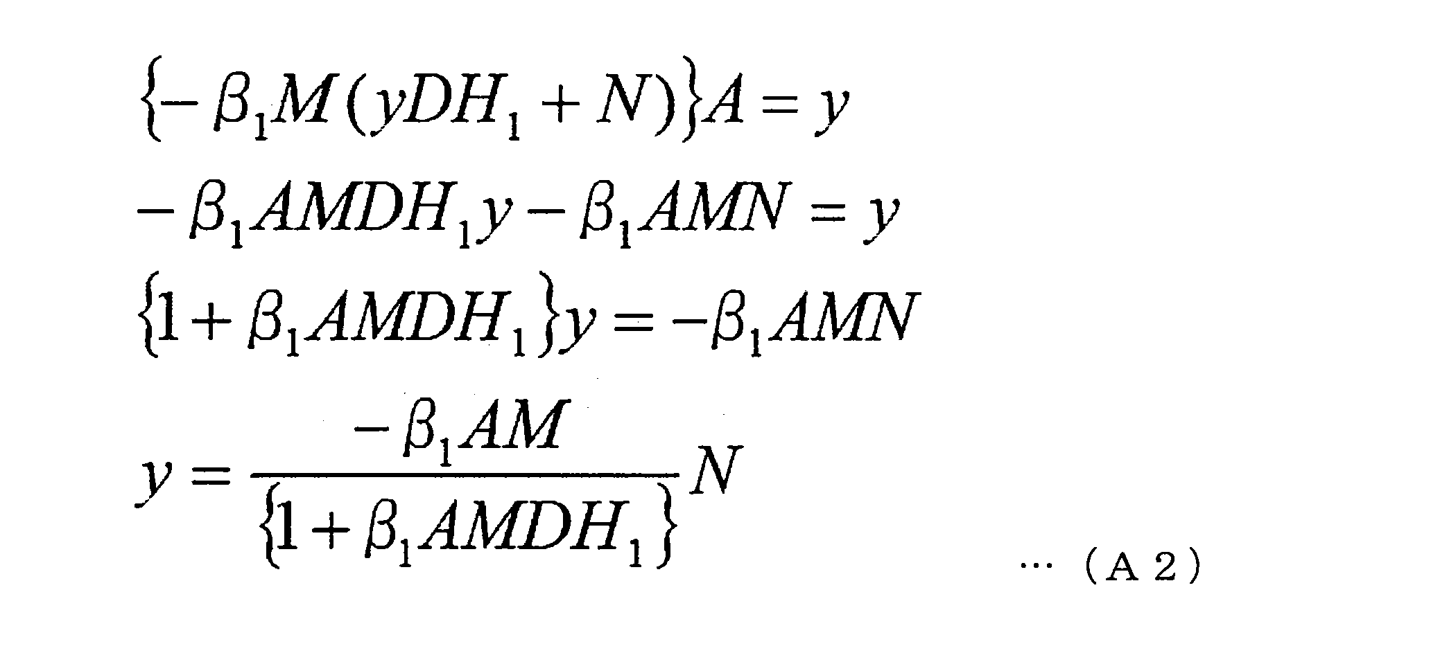
数式(A1)及び数式(A2)により、音圧Pは、次式(A3)のように導かれる。
The sound pressure P is derived as shown by the following equation (A3) by the equation (A1) and the equation (A2).

ここで、数式(A3)のノイズNにかかる係数は、感度関数とも称される。第1のFBフィルタ201の特性β1は、設計可能なパラメータである。β1を最大化することにより、感度係数の分母は最大となり、感度係数は最小となり、その結果、音圧Pは最小化される。即ち、β1を最大化することにより、鼓膜位置における音圧が減少し、ノイズがより大きくキャンセルされる。
Here, the coefficient applied to the noise N in equation (A3) is also referred to as a sensitivity function. The characteristic β 1 of the first FB filter 201 is a parameter that can be designed. By maximizing the beta 1, the denominator of the sensitivity coefficient is maximized, the sensitivity coefficient is minimized, as a result, the sound pressure P is minimized. In other words, by maximizing the beta 1, reduces the sound pressure at the eardrum, noise is greater canceled.
(2)内部モデル制御FB方式
続いて、図10を参照しながら、内部モデル制御FB方式(IMC(Inter Model Control)方式)について説明する。 (2) Internal Model Control FB Method Next, with reference to FIG. 10, an internal model control FB method (IMC (Inter Model Control) method) will be described.
続いて、図10を参照しながら、内部モデル制御FB方式(IMC(Inter Model Control)方式)について説明する。 (2) Internal Model Control FB Method Next, with reference to FIG. 10, an internal model control FB method (IMC (Inter Model Control) method) will be described.
図10は、本実施形態に係る耳穴開放デバイス100による内部モデル制御FB方式のノイズキャンセル処理のモデル構成例を示す図である。図10に示すモデル構成例は、第1のFBフィルタ201に代えて第2のFBフィルタ207を有する点、及び内部モデル208及び加算器206を有する点で、図8に示したモデル構成例と相違する。以下では、図8に示すモデル構成例との相違に関して主に説明する。
FIG. 10 is a view showing an example of a model configuration of noise cancellation processing of the internal model control FB method by the ear canal opening device 100 according to the present embodiment. The example of the model configuration shown in FIG. 10 is different from the example of the model configuration shown in FIG. 8 in that it has a second FB filter 207 instead of the first FB filter 201, and an internal model 208 and an adder 206. It is different. In the following, differences from the model configuration example shown in FIG. 8 will be mainly described.
第2のFBフィルタ207は、FB方式のノイズキャンセル処理を行うフィルタ回路である。第2のFBフィルタ207は、入力された音響信号に基づき、マイク141をキャンセルポイントとするノイズキャンセル処理を行い、ノイズキャンセル信号を生成する。第2のFBフィルタ207を経由した音響信号は、アンプ202に入力されると共に、内部モデル208にも入力される。
The second FB filter 207 is a filter circuit that performs noise cancellation processing of the FB method. The second FB filter 207 performs noise cancellation processing with the microphone 141 as a cancellation point based on the input acoustic signal, and generates a noise cancellation signal. The acoustic signal that has passed through the second FB filter 207 is input to the amplifier 202 and also input to the internal model 208.
内部モデル208は、耳穴開放デバイス100の内部モデルに対応する。内部モデルとは、信号処理内部の経路であり、2次経路(Secondary Path)を模擬した特性を有するモデルである。なお、2次経路とは、2次音源からエラーマイクまでの、物理的な空間伝達特性である。ここでの内部モデル208は、第2のFBフィルタ207から出力されたノイズキャンセル信号がドライバ110から出力されてマイク141により収音され、第2のFBフィルタに戻ってくるまでの特性を模擬した特性を有する。図10に示したモデル構成例における内部モデル208は、A´D´H1´M´の特性を有する。内部モデル208を経由した音響信号は、加算器206に入力される。加算器206は、マイク141により生成された音響信号から、内部モデル208を経由した音響信号を、減算して合成する。かかる合成信号は、第2のFBフィルタ207に入力される。
Internal model 208 corresponds to the internal model of ear opening device 100. The internal model is a path inside signal processing, and is a model having characteristics simulating a secondary path. The secondary path is a physical space transfer characteristic from the secondary sound source to the error microphone. The internal model 208 here simulates the characteristic until the noise cancellation signal output from the second FB filter 207 is output from the driver 110 and collected by the microphone 141 and returned to the second FB filter. It has a characteristic. Internal model 208 in the model configuration example shown in FIG. 10 has the property of A'D'H 1'M'. The acoustic signal passed through the internal model 208 is input to the adder 206. The adder 206 subtracts and synthesizes the acoustic signal having passed through the internal model 208 from the acoustic signal generated by the microphone 141. The composite signal is input to the second FB filter 207.
(3)古典制御FB方式と内部モデル制御FB方式の併用
続いて、図11を参照しながら、古典制御FB方式と内部モデル制御FB方式とを併用する場合について説明する。 (3) Combined Use of Classical Control FB Method and Internal Model Control FB Method Subsequently, a case where the classical control FB method and the internal model control FB method are used in combination will be described with reference to FIG.
続いて、図11を参照しながら、古典制御FB方式と内部モデル制御FB方式とを併用する場合について説明する。 (3) Combined Use of Classical Control FB Method and Internal Model Control FB Method Subsequently, a case where the classical control FB method and the internal model control FB method are used in combination will be described with reference to FIG.
図11は、本実施形態に係る耳穴開放デバイス100による古典制御FB方式と内部モデル制御FB方式とを併用するノイズキャンセル処理のモデル構成例を示す図である。図11に示すモデル構成例は、図10に示したモデル構成例に、第1のFBフィルタ(特性:-β1)及び加算器209を加えたものである。以下では、図10に示すモデル構成例から新たに追加された構成要素に関して主に説明する。
FIG. 11 is a view showing an example of a model configuration of noise cancellation processing using both the classical control FB method and the internal model control FB method by the ear opening device 100 according to the present embodiment. The model configuration example shown in FIG. 11 is obtained by adding a first FB filter (characteristic: -β 1 ) and an adder 209 to the model configuration example shown in FIG. In the following, components newly added from the model configuration example shown in FIG. 10 will be mainly described.
マイク141により入力された音響信号は、加算器206に入力されると共に、第1のFBフィルタ201に入力される。第1のFBフィルタ201は、上述したように、入力された音響信号に基づいてノイズキャンセル信号を生成する。
The acoustic signal input by the microphone 141 is input to the adder 206 and also input to the first FB filter 201. As described above, the first FB filter 201 generates a noise cancellation signal based on the input acoustic signal.
第1のFBフィルタ201及び第2のFBフィルタ207の各々を経由した音響信号は、加算器209に入力されて、合成される。かかる合成信号は、内部モデル208に入力されると共に、アンプ202を経由してドライバ110から出力される。
The acoustic signal that has passed through each of the first FB filter 201 and the second FB filter 207 is input to the adder 209 and synthesized. The combined signal is input to the internal model 208 and output from the driver 110 via the amplifier 202.
以上、FB方式のノイズキャンセル処理について説明したが、本技術はかかる例に限定されない。耳穴開放デバイス100は、FB方式のノイズキャンセル処理と共に、又は代えて、FF方式のノイズキャンセル処理を行ってもよい。その場合、耳穴開放デバイス100は、ユーザに装着された際の音響特性を事前に測定し、FFフィルタの特性を設定しておくことが望ましい。
Although the noise cancellation processing of the FB method has been described above, the present technology is not limited to such an example. The ear canal opening device 100 may perform the FF type noise cancellation processing together with or instead of the FB type noise cancellation processing. In that case, it is desirable that the earhole opening device 100 measure in advance the acoustic characteristics when worn by the user and set the characteristics of the FF filter.
(4)音楽を再生する場合の処理
図12は、本実施形態に係る耳穴開放デバイス100による音楽再生時の古典制御FB方式のノイズキャンセル処理のモデル構成例を示す図である。図12に示すモデル構成例は、図8に示したモデル構成例に、内部モデル208、加算器210及び加算器211を加え、さらに音響信号Mが入力されるものである。以下では、図8に示すモデル構成例から新たに追加された構成要素に関して主に説明する。 (4) Process for Reproducing Music FIG. 12 is a view showing an example of a model configuration of noise cancellation processing of the classical control FB system at the time of music reproduction by theear opening device 100 according to the present embodiment. In the example of the model configuration shown in FIG. 12, an internal model 208, an adder 210 and an adder 211 are added to the model configuration example shown in FIG. 8, and an acoustic signal M is further input. In the following, components newly added from the model configuration example shown in FIG. 8 will be mainly described.
図12は、本実施形態に係る耳穴開放デバイス100による音楽再生時の古典制御FB方式のノイズキャンセル処理のモデル構成例を示す図である。図12に示すモデル構成例は、図8に示したモデル構成例に、内部モデル208、加算器210及び加算器211を加え、さらに音響信号Mが入力されるものである。以下では、図8に示すモデル構成例から新たに追加された構成要素に関して主に説明する。 (4) Process for Reproducing Music FIG. 12 is a view showing an example of a model configuration of noise cancellation processing of the classical control FB system at the time of music reproduction by the
音楽信号Mは、内部モデル208及び加算器211に入力される。内部モデル208を経由した音楽信号は、加算器210に入力される。また、加算器210には、マイク141により生成された音響信号が入力される。加算器210は、マイク141により生成された音響信号から、内部モデル208を経由した音楽信号を減算して合成する。そして、かかる合成信号が、第1のFBフィルタ201に入力される。第1のFBフィルタ201を経由した音響信号は、加算器211に入力される。加算器211は、第1のFBフィルタ201を経由した音響信号と音楽信号Mとを合成する。かかる合成信号は、アンプ202を経由してドライバ110から出力される。
The music signal M is input to the internal model 208 and the adder 211. The music signal passed through the internal model 208 is input to the adder 210. Further, the acoustic signal generated by the microphone 141 is input to the adder 210. The adder 210 subtracts the music signal having passed through the internal model 208 from the sound signal generated by the microphone 141 and synthesizes it. Then, the composite signal is input to the first FB filter 201. The acoustic signal that has passed through the first FB filter 201 is input to the adder 211. The adder 211 combines the audio signal passed through the first FB filter 201 and the music signal M. The synthesized signal is output from the driver 110 via the amplifier 202.
このように、本ノイズキャンセル処理では、マイク141から出力される、ノイズを含む音響信号から音楽信号の成分を差し引いた上で、FBフィルタが適用される。これにより、再生すべき音楽が、ノイズとともに低減されることを防止することができる。
As described above, in the noise cancellation process, the FB filter is applied after subtracting the component of the music signal from the acoustic signal including noise output from the microphone 141. This can prevent the music to be reproduced from being reduced along with the noise.
(5)自声を抽出する場合の処理
信号処理部151は、両耳用の一対の音響情報取得部140の各々により取得された音響情報に基づいてユーザの自声を抽出し、抽出したユーザの自声をノイズキャンセル信号に合成する。ユーザの自声も含んでノイズが収音される場合、ノイズキャンセル信号は、ユーザの自声をキャンセルする成分を含む。この点、ユーザの自声がノイズキャンセル信号に合成されることで、ユーザの自声が耳元で出力されるようになる。よって、自分の声がノイズとしてキャンセルされて、自分の声が遠くなったような違和感をユーザに与えることを、防止することができる。以下、図13を参照して、自声を抽出してノイズキャンセル信号に合成する処理について詳細に説明する。 (5) Processing for Extracting Own Voice Thesignal processing unit 151 extracts the user's own voice based on the acoustic information acquired by each of the pair of acoustic information acquiring units 140 for both ears, and the extracted user The voice of the voice is synthesized into the noise cancellation signal. When noise is collected including the user's own voice, the noise cancellation signal includes a component for canceling the user's own voice. In this regard, the user's own voice is synthesized at the ear by being synthesized with the noise cancellation signal. Therefore, it can be prevented that the user's voice is canceled as noise, giving the user the feeling that the user's voice is far away. The process of extracting the own voice and combining it with the noise cancellation signal will be described in detail below with reference to FIG.
信号処理部151は、両耳用の一対の音響情報取得部140の各々により取得された音響情報に基づいてユーザの自声を抽出し、抽出したユーザの自声をノイズキャンセル信号に合成する。ユーザの自声も含んでノイズが収音される場合、ノイズキャンセル信号は、ユーザの自声をキャンセルする成分を含む。この点、ユーザの自声がノイズキャンセル信号に合成されることで、ユーザの自声が耳元で出力されるようになる。よって、自分の声がノイズとしてキャンセルされて、自分の声が遠くなったような違和感をユーザに与えることを、防止することができる。以下、図13を参照して、自声を抽出してノイズキャンセル信号に合成する処理について詳細に説明する。 (5) Processing for Extracting Own Voice The
図13は、本実施形態に係る耳穴開放デバイス100による自声抽出を含む古典制御FB方式のノイズキャンセル処理のモデル構成例を示す図である。図13に示すモデル構成例は、図8に示したモデル構成例に、自声抽出部212、イコライザ213、加算器214、空間215を加えたものである。到来するノイズNは、ノイズソースNS及びユーザの話声V(即ち、自声)が空間215において合成された音響である。ただし、図13に示したモデル構成例は、左耳側のモデル構成例を示しており、右耳側は省略されている。以下では、図13に示したモデル構成例において、図8に示すモデル構成例から新たに追加された構成要素に関して主に説明する。
FIG. 13 is a view showing a model configuration example of noise control processing of the classical control FB system including the self voice extraction by the ear canal opening device 100 according to the present embodiment. The model configuration example shown in FIG. 13 is obtained by adding the own voice extraction unit 212, the equalizer 213, the adder 214, and the space 215 to the model configuration example shown in FIG. The incoming noise N is the sound in which the noise source NS and the user's voice V (ie, his own voice) are synthesized in the space 215. However, the model configuration example shown in FIG. 13 shows a model configuration example on the left ear side, and the right ear side is omitted. In the following, in the model configuration example shown in FIG. 13, components newly added from the model configuration example shown in FIG. 8 will be mainly described.
左耳用のマイク141は、空間204を経由したノイズNを収音し、音響信号を生成する。右耳に関しても同様である。左右各々のマイク141により生成された音響信号は、自声抽出部212に入力される。自声抽出部212は、入力された音響信号に基づいて、自声Vを抽出する。例えば、自声抽出部212は、入力された音響信号から同相信号成分を抽出することで、自声Vを抽出する。自声抽出部212は、抽出した自声Vを示す音響信号を、左右各々の加算器214に出力する。
The microphone 141 for the left ear picks up the noise N passing through the space 204 to generate an acoustic signal. The same is true for the right ear. The acoustic signals generated by the left and right microphones 141 are input to the own voice extraction unit 212. The own voice extraction unit 212 extracts the own voice V based on the input acoustic signal. For example, the own voice extraction unit 212 extracts the own voice V by extracting the in-phase signal component from the input acoustic signal. The own voice extraction unit 212 outputs an acoustic signal indicating the extracted own voice V to the left and right adders 214.
一方で、マイク141により生成された音響信号は、第1のFBフィルタ201にも入力される。第1のFBフィルタ201により生成されたノイズキャンセル信号は、加算器214に入力される。また、音楽信号Mは、イコライザ213に入力される。イコライザ213は、入力された音楽信号Mの音質を特性Eに基づき調整する。イコライザ213を経由した音楽信号は加算器214に入力される。
On the other hand, the acoustic signal generated by the microphone 141 is also input to the first FB filter 201. The noise cancellation signal generated by the first FB filter 201 is input to the adder 214. Also, the music signal M is input to the equalizer 213. The equalizer 213 adjusts the sound quality of the input music signal M based on the characteristic E. The music signal passed through the equalizer 213 is input to the adder 214.
加算器214は、自声抽出部212、第1のFBフィルタ201及びイコライザ213の各々から入力された音響信号を合成する。かかる合成信号は、アンプ202を経由してドライバ110から出力される。
The adder 214 synthesizes the acoustic signal input from each of the own voice extraction unit 212, the first FB filter 201, and the equalizer 213. The synthesized signal is output from the driver 110 via the amplifier 202.
これにより、開口部131を通過した自声Vがノイズキャンセル信号によりキャンセルされても、自声抽出部212により抽出された自声Vがドライバ110から出力されることになる。これにより、自分の声がノイズとしてキャンセルされて、自分の声が遠くなったような違和感をユーザに与えることを、防止することができる。
Thus, even if the own voice V that has passed through the opening 131 is canceled by the noise cancellation signal, the own voice V extracted by the own voice extraction unit 212 is output from the driver 110. As a result, it is possible to prevent the user's voice from being canceled as noise and giving the user an uncomfortable feeling that the user's voice is far away.
なお、耳穴開放デバイス100は、音響情報取得部140として、保持部130により保持されるマイク141の他に、ユーザの自声を収音するためのマイクをさらに備えていてもよい。例えば、耳穴開放デバイス100は、図1に示すピンチ部123付近にかかるマイクを備え得る。その場合、自声抽出部212は、当該マイクにより生成された音響信号にさらに基づいてユーザの自声を抽出する。これにより、自声抽出部212は、より高い精度でユーザの自声を抽出することができる。
In addition to the microphone 141 held by the holding unit 130, the ear canal opening device 100 may further include a microphone for collecting the user's own voice as the acoustic information acquisition unit 140. For example, the ear canal opening device 100 may include such a microphone in the vicinity of the pinch portion 123 shown in FIG. In this case, the self-voice extraction unit 212 extracts the user's own voice based on the acoustic signal generated by the microphone. Thereby, the self-voice extraction unit 212 can extract the user's own voice with higher accuracy.
<1.6.鼓膜の音圧情報に基づくノイズキャンセル処理>
耳穴開放デバイス100は、鼓膜の音圧情報に基づいてノイズキャンセル処理を行ってもよい。その場合、音響情報取得部140は、音響情報として、鼓膜の音圧情報を取得する。そして、信号処理部151は、マイク141により生成される音響信号に変えて、鼓膜の音圧情報に基づいてノイズキャンセル処理を行う。もちろん、信号処理部151は、マイク141により生成される音響信号と鼓膜音圧取得部142により取得される鼓膜の音圧情報とを併用して、ノイズキャンセル処理を行ってもよい。以下では、耳穴開放デバイス100に、音響情報取得部140として、鼓膜音圧取得部142が搭載されるものとして説明する。 <1.6. Noise cancellation processing based on sound pressure information of tympanic membrane>
The earcanal opening device 100 may perform noise cancellation processing based on sound pressure information of the eardrum. In that case, the acoustic information acquisition unit 140 acquires sound pressure information of the eardrum as the acoustic information. Then, the signal processing unit 151 converts the sound signal generated by the microphone 141 into noise cancellation processing based on sound pressure information on the eardrum. Of course, the signal processing unit 151 may perform the noise cancellation process using the acoustic signal generated by the microphone 141 and the eardrum sound pressure information acquired by the eardrum sound pressure acquisition unit 142 in combination. In the following, it is assumed that the eardrum sound pressure acquiring unit 142 is mounted as the acoustic information acquiring unit 140 in the ear canal opening device 100.
耳穴開放デバイス100は、鼓膜の音圧情報に基づいてノイズキャンセル処理を行ってもよい。その場合、音響情報取得部140は、音響情報として、鼓膜の音圧情報を取得する。そして、信号処理部151は、マイク141により生成される音響信号に変えて、鼓膜の音圧情報に基づいてノイズキャンセル処理を行う。もちろん、信号処理部151は、マイク141により生成される音響信号と鼓膜音圧取得部142により取得される鼓膜の音圧情報とを併用して、ノイズキャンセル処理を行ってもよい。以下では、耳穴開放デバイス100に、音響情報取得部140として、鼓膜音圧取得部142が搭載されるものとして説明する。 <1.6. Noise cancellation processing based on sound pressure information of tympanic membrane>
The ear
(1)鼓膜音圧取得部142の構成
鼓膜音圧取得部142は、外耳道又は鼓膜の振動情報を取得し、取得した振動情報に基づいてキャンセルポイントの音圧情報を取得する機能を有する。 (1) Configuration of tympanic soundpressure acquisition unit 142 The tympanic sound pressure acquisition unit 142 has a function of acquiring vibration information of the ear canal or tympanic membrane, and acquiring sound pressure information of the cancellation point based on the acquired vibration information.
鼓膜音圧取得部142は、外耳道又は鼓膜の振動情報を取得し、取得した振動情報に基づいてキャンセルポイントの音圧情報を取得する機能を有する。 (1) Configuration of tympanic sound
詳しくは、鼓膜音圧取得部142は、送信波を送信し、当該送信波が反射された反射波を取得して、反射点における変位又は速度を示す振動情報を取得する。反射波には、反射点の移動速度に比例した周波数変化が発生する。具体的には、物体が近づく場合に反射波の周波数は高くなり、物体が遠ざかる場合に周波数が低くなる。鼓膜音圧取得部142は、送信波と反射波との周波数差分に基づいて、反射点の変位又は速度を推定する。送信波は、外耳道又は鼓膜に送信され、外耳道又は鼓膜における任意の反射点に反射される。反射点は、キャンセルポイントと同一であってもよいし、異なっていてもよい。
Specifically, the eardrum sound pressure acquisition unit 142 transmits a transmission wave, acquires a reflection wave on which the transmission wave is reflected, and acquires vibration information indicating displacement or speed at a reflection point. In the reflected wave, a frequency change proportional to the moving speed of the reflection point occurs. Specifically, when the object approaches, the frequency of the reflected wave increases, and when the object moves away, the frequency decreases. The tympanic sound pressure acquisition unit 142 estimates the displacement or speed of the reflection point based on the frequency difference between the transmission wave and the reflection wave. The transmitted wave is transmitted to the ear canal or tympanic membrane and is reflected to any reflection point on the ear canal or tympanic membrane. The reflection point may be the same as or different from the cancellation point.
例えば、鼓膜音圧取得部142はレーザー測距装置により実現されてもよく、送信波はレーザーであってもよい。他にも鼓膜音圧取得部142は、超音波測距装置により実現されてもよく、その場合、送信波は超音波である。ただし、干渉の観点から、送信波はレーザーである方が望ましい。レーザーを用いる場合、マイク141における風切り音の収音が原理的に発生しないメリットがある。なお、レーザー光源は、連続的に発光せず、間欠的に発光してもよい。また、発光頻度は、反射波取得に係るサンプリングレートと同等でよい。これらにより、消費電力を低減することができる。以下では、鼓膜音圧取得部142は、レーザー測距装置により実現されるものとして説明する。
For example, the tympanic sound pressure acquisition unit 142 may be realized by a laser range finder, and the transmission wave may be a laser. Alternatively, the eardrum sound pressure acquisition unit 142 may be realized by an ultrasonic distance measuring device, in which case the transmission wave is an ultrasonic wave. However, from the viewpoint of interference, it is desirable that the transmission wave be a laser. When a laser is used, there is an advantage that sound collection of the wind noise by the microphone 141 is not generated in principle. The laser light source may emit light intermittently instead of emitting light continuously. Also, the light emission frequency may be equal to the sampling rate for acquiring the reflected wave. Power consumption can be reduced by these. Below, the tympanic sound pressure acquisition part 142 is demonstrated as what is implement | achieved by the laser ranging apparatus.
鼓膜音圧取得部142は、鼓膜音圧取得部142と反射点との間の距離を測定することも可能である。例えば、レーザー測距装置は、レーザーを送信してから、反射点により反射されたレーザーを受信するまでの時間に基づいて、レーザー測距装置と反射点との距離を測定する。このような測定方法は、ToF(Time of Flight)方式とも称される。なお、鼓膜音圧取得部142のうち、少なくとも送信波を送信し受信波を受信する装置が保持部130により保持されていればよく、振動情報に基づいて鼓膜音圧を推定及び取得する装置等の配置は特に限定されない。
The eardrum sound pressure acquisition unit 142 can also measure the distance between the eardrum sound pressure acquisition unit 142 and the reflection point. For example, the laser distance measuring device measures the distance between the laser distance measuring device and the reflection point based on the time from the transmission of the laser to the reception of the laser reflected by the reflection point. Such a measurement method is also referred to as a ToF (Time of Flight) method. A device for transmitting and receiving at least the transmission wave in the tympanic sound pressure acquisition unit 142 may be held by the holding unit 130, and a device for estimating and acquiring the tympanic sound pressure based on the vibration information, etc. The arrangement of is not particularly limited.
キャンセルポイントは、鼓膜の1点である。即ち、鼓膜音圧取得部142は、鼓膜の音圧情報を取得する。鼓膜の音圧情報がノイズキャンセル処理に用いられることで、高いノイズキャンセル性能を実現することができる。
The cancellation point is one point of the tympanic membrane. That is, the tympanic sound pressure acquisition unit 142 acquires sound pressure information of the tympanic membrane. By using the sound pressure information of the eardrum for the noise cancellation process, high noise cancellation performance can be realized.
反射点も、鼓膜の1点であることが望ましい。この場合、鼓膜の振動情報が直接的に取得されるので、鼓膜音圧取得部142は、鼓膜の振動情報に基づいて鼓膜の音圧情報を取得することができる。よって、鼓膜の音圧情報を高い精度で推定することができる。
It is desirable that the reflection point is also one point of the tympanic membrane. In this case, since the vibration information of the eardrum is directly obtained, the eardrum sound pressure acquisition unit 142 can acquire the sound pressure information of the eardrum based on the vibration information of the eardrum. Therefore, sound pressure information on the eardrum can be estimated with high accuracy.
一方で、反射点は、外耳道の内壁にあってもよい。その場合、鼓膜音圧取得部142は外耳道の内壁の2以上の点の振動情報に基づいて、鼓膜の音圧情報を推定する。例えば、鼓膜音圧取得部142は、外耳道の内壁の振動と鼓膜の振動との相関関係のモデルを参照して、外耳道の内壁の2以上の点の振動情報に基づいて鼓膜の振動情報を推定する。そして、鼓膜の振動情報の推定結果に基づいて、鼓膜の音圧情報を推定する。これにより、鼓膜に直接レーザーが照射されない場合であっても、鼓膜の音圧情報を用いたノイズキャンセル処理を実行することが可能となる。また、鼓膜音圧取得部142は、鼓膜の振動情報と外耳道の内壁の振動情報とを測定し、これらの測定結果に基づいて鼓膜位置の音圧情報を推定してもよい。この場合、鼓膜位置の音圧情報をより高精度に推定することができる。
On the other hand, the reflection point may be on the inner wall of the ear canal. In that case, the eardrum sound pressure acquisition unit 142 estimates the eardrum sound pressure information based on the vibration information of two or more points on the inner wall of the ear canal. For example, the tympanic sound pressure acquisition unit 142 estimates vibration information of the tympanic membrane based on vibration information of two or more points of the inner wall of the ear canal with reference to a model of correlation between the vibration of the inner wall of the ear canal Do. Then, based on the estimation result of the vibration information of the eardrum, the sound pressure information of the eardrum is estimated. Thus, even if the tympanic membrane is not directly irradiated with the laser, it is possible to execute the noise cancellation process using the sound pressure information of the tympanic membrane. The tympanic sound pressure acquisition unit 142 may measure vibration information of the tympanic membrane and vibration information of the inner wall of the ear canal, and estimate sound pressure information of the tympanic membrane position based on the measurement results. In this case, sound pressure information on the tympanic membrane position can be estimated with higher accuracy.
また、鼓膜音圧取得部142は、外耳道の内壁の振動情報に基づいて、肉伝導による自発生音(例えば、自声)を測定することができる。鼓膜音圧取得部142は、外耳道の内壁の振動情報に加え、左右の空気伝搬音波情報に基づいて、自発生音を測定することができる。
In addition, the tympanic sound pressure acquisition unit 142 can measure a self-generated sound (for example, a self-voice) by meat conduction based on vibration information of the inner wall of the ear canal. The eardrum sound pressure acquisition unit 142 can measure the self-generated sound based on the air propagation sound wave information on the left and right in addition to the vibration information on the inner wall of the ear canal.
なお、反射点が鼓膜であるか外耳道の内壁であるかは、例えば後述する三次元形状を示す情報に基づいて判断され得る。
Whether the reflection point is the tympanic membrane or the inner wall of the ear canal can be determined based on, for example, information indicating a three-dimensional shape described later.
以下、図14~図17を参照して、レーザー測距装置として実現される鼓膜音圧取得部142による測距の様子を詳しく説明する。
Hereinafter, with reference to FIG. 14 to FIG. 17, an aspect of distance measurement by the eardrum sound pressure acquisition unit 142 realized as a laser distance measuring device will be described in detail.
図14は、ユーザの左耳の外耳道内部の様子を示す断面図である。図14に示すように、鼓膜振動面14は外耳道下壁13に対して、所定の角度を成している。成人の場合、鼓膜振動面14は外耳道下壁13に対して、約50度の角度をなしている。
FIG. 14 is a cross-sectional view showing the inside of the ear canal of the left ear of the user. As shown in FIG. 14, the tympanic membrane vibration surface 14 forms a predetermined angle with the lower wall 13 of the ear canal. In the case of an adult, the tympanic membrane vibration surface 14 forms an angle of about 50 degrees with the lower wall 13 of the ear canal.
図15~図17は、図14に示したユーザの左耳の外耳道内部に耳穴開放デバイス100によりレーザーが照射された様子を示す図である。図15は、図14と同じ視点の図であり、図16は、Z軸正方向からZ軸負方向へ見下ろす視点の図であり、図17は、X軸正方向とZ軸正方向の中間付近から原点へ向かう視点の図である。図15~図17に示すように、鼓膜音圧取得部142(レーザー測距装置)によりレーザー16が鼓膜9に向けて照射されている。図15及び図16に示すように、レーザー16の照射方向17と鼓膜9の振動方向15とは、特定の角度を持って交わり得る。鼓膜9の音圧情報を精度よく推定するためには、この角度差を補正することが望ましい。この角度差の補正は、論理的な計算により行われてもよいし、後述するレーザーの照射方向の物理的な制御により行われてもよい。
FIGS. 15 to 17 are diagrams showing that the inside of the external ear canal of the left ear of the user shown in FIG. 14 is irradiated with the laser by the open ear device 100. FIG. 15 is a view of the same view as FIG. 14, FIG. 16 is a view of a view looking down from the Z-axis positive direction to the Z-axis negative direction, and FIG. 17 is an intermediate between the X-axis positive direction and the Z-axis positive direction. It is a figure of the viewpoint which goes to origin from near. As shown in FIG. 15 to FIG. 17, the laser 16 is irradiated toward the tympanic membrane 9 by the tympanic sound pressure acquisition unit 142 (laser distance measuring device). As shown in FIGS. 15 and 16, the irradiation direction 17 of the laser 16 and the vibration direction 15 of the tympanic membrane 9 can intersect at a specific angle. In order to accurately estimate the sound pressure information of the eardrum 9, it is desirable to correct this angular difference. The correction of the angle difference may be performed by logical calculation or may be performed by physical control of the irradiation direction of the laser described later.
図15及び図16に示すように、保持部130は、鼓膜音圧取得部142と鼓膜9との直線上に外耳道5の内壁が存在しない位置に鼓膜音圧取得部142を保持することが望ましい。換言すると、鼓膜音圧取得部142から鼓膜9までの間に障害物がない位置に鼓膜音圧取得部142が保持されることが望ましい。これにより、鼓膜音圧取得部142から照射されたレーザーを鼓膜9上の1点に直接反射させることが可能となる。
As shown in FIGS. 15 and 16, the holding unit 130 preferably holds the tympanic sound pressure acquisition unit 142 at a position where the inner wall of the ear canal 5 does not exist on the straight line between the tympanic sound pressure acquisition unit 142 and the tympanic membrane 9 . In other words, it is desirable that the eardrum sound pressure acquisition portion 142 be held at a position where there is no obstacle between the eardrum sound pressure acquisition portion 142 and the eardrum 9. Thereby, it becomes possible to directly reflect the laser irradiated from the tympanic sound pressure acquisition unit 142 to one point on the tympanic membrane 9.
(2)鼓膜音圧の取得処理
以下、図18~図20を参照して、鼓膜音圧の取得処理を説明する。 (2) Acquisition process of tympanic sound pressure Hereinafter, the acquisition process of tympanic sound pressure will be described with reference to FIGS. 18 to 20.
以下、図18~図20を参照して、鼓膜音圧の取得処理を説明する。 (2) Acquisition process of tympanic sound pressure Hereinafter, the acquisition process of tympanic sound pressure will be described with reference to FIGS. 18 to 20.
・第1の例
図18は、本実施形態に係る鼓膜音圧の推定処理のモデル構成例を説明するための図である。 First Example FIG. 18 is a diagram for describing a model configuration example of an eardrum sound pressure estimation process according to the present embodiment.
図18は、本実施形態に係る鼓膜音圧の推定処理のモデル構成例を説明するための図である。 First Example FIG. 18 is a diagram for describing a model configuration example of an eardrum sound pressure estimation process according to the present embodiment.
レーザーダイオード230は、レーザーを生成し、照射する。レーザーダイオード230から照射されたレーザーは、ビームスプリッタ231により2つの方向に分離され、そのうち一方のビームがビームスプリッタ232及びフォーカスレンズ233を通過して鼓膜9に到達する。鼓膜9により反射されたレーザーは、フォーカスレンズ233を通過して、ビームスプリッタ232及びミラー234に反射され、ビームスプリッタ237を通過して光電気変換器238に入力される。
The laser diode 230 generates and emits a laser. The laser emitted from the laser diode 230 is split into two directions by the beam splitter 231, and one of the beams passes through the beam splitter 232 and the focusing lens 233 to reach the tympanic membrane 9. The laser reflected by the tympanic membrane 9 passes through the focusing lens 233, is reflected by the beam splitter 232 and the mirror 234, passes through the beam splitter 237, and is input to the photoelectric converter 238.
一方で、レーザーダイオード230から照射されたレーザーのうちビームスプリッタ231により分離された他の一方のビームは、光学周波数変換器236に入力される。基準周波数発振器235により基準周波数で発振された信号も、光学周波数変換器236に入力される。光学周波数変換器236は、レーザーダイオード230から照射されたレーザーの周波数を基準周波数に変調して出力する。光学周波数変換器236から出力されたレーザーは、ビームスプリッタ237により反射されて、光電気変換器238に入力される。
On the other hand, the other one of the lasers emitted from the laser diode 230 and separated by the beam splitter 231 is input to the optical frequency converter 236. The signal oscillated at the reference frequency by the reference frequency oscillator 235 is also input to the optical frequency converter 236. The optical frequency converter 236 modulates the frequency of the laser irradiated from the laser diode 230 to a reference frequency and outputs it. The laser output from the optical frequency converter 236 is reflected by the beam splitter 237 and input to the photoelectric converter 238.
ビームスプリッタ237を経由したレーザーは、光電気変換器238により光の強度信号に変換される。光の強度信号は、基準周波数で周波数変調された鼓膜振動周波数を示す。光の強度信号は、周波数電圧変換器239により周波数領域の信号に変換され、帯域制限フィルタ240が適用され、速度加速度変換器241に入力される。帯域制限フィルタ240による帯域制限フィルタ処理が適用された信号は、鼓膜振動の速度信号である。速度加速度変換器241は、鼓膜の速度信号に基づいて、鼓膜の速度を鼓膜の加速度に変換し、鼓膜の加速度を示す信号を鼓膜音圧推定部242に出力する。鼓膜音圧推定部242は、鼓膜の加速度に基づいて、鼓膜音圧(鼓膜9の音圧情報)を推定する。なお、鼓膜音圧は、下記の式により推定される。
鼓膜音圧PD=K・a The laser having passed through thebeam splitter 237 is converted into an intensity signal of light by the photoelectric converter 238. The light intensity signal indicates the tympanic oscillation frequency frequency-modulated at the reference frequency. The light intensity signal is converted into a frequency domain signal by the frequency voltage converter 239, the band limiting filter 240 is applied, and the speed acceleration converter 241 is input. The signal to which the band limiting filter processing by the band limiting filter 240 is applied is a velocity signal of tympanic membrane vibration. The velocity acceleration converter 241 converts the velocity of the tympanic membrane into the acceleration of the tympanic membrane based on the velocity signal of the tympanic membrane, and outputs a signal indicating the acceleration of the tympanic membrane to the tympanic sound pressure estimation unit 242. The eardrum sound pressure estimation unit 242 estimates the eardrum sound pressure (sound pressure information of the eardrum 9) based on the acceleration of the eardrum. The eardrum sound pressure is estimated by the following equation.
Tympanic sound pressure P D = K · a
鼓膜音圧PD=K・a The laser having passed through the
Tympanic sound pressure P D = K · a
ただし、a[m/s2]は、速度加速度変換器241にて得られる加速度信号である。K[kg/m2]は、鼓膜の面積、質量、張力、及びレーザーの鼓膜への侵入角による補正係数等からなる定数である。なお、鼓膜音圧の取得処理の少なくとも一部は、デジタル回路により行われてもよい。例えば、速度加速度変換器241及び鼓膜音圧推定部242の処理がデジタル回路により行われてもよい。また、鼓膜音圧推定部242が、速度加速度変換器241としての機能を含んでいてもよい。
However, a [m / s 2 ] is an acceleration signal obtained by the velocity acceleration converter 241. K [kg / m 2 ] is a constant comprising the area, mass, tension of the tympanic membrane, a correction coefficient by the penetration angle of the laser into the tympanic membrane, and the like. Note that at least part of the process of acquiring the eardrum sound pressure may be performed by a digital circuit. For example, the processing of the velocity acceleration converter 241 and the tympanic sound pressure estimation unit 242 may be performed by a digital circuit. In addition, the tympanic sound pressure estimation unit 242 may include a function as the velocity acceleration converter 241.
・第2の例
人によって、耳の形状、とりわけ外耳道の形状及び鼓膜の配置は異なる。そのため、ユーザに耳穴開放デバイス100が装着された状態で、必ずしもレーザーの照射点(即ち、反射点)が鼓膜の中心に位置するとは限らない。 Second Example The shape of the ear, in particular the shape of the ear canal and the arrangement of the tympanic membrane differ depending on the person. Therefore, the laser irradiation point (that is, the reflection point) is not necessarily located at the center of the tympanic membrane in a state where the user has theear opening device 100 attached.
人によって、耳の形状、とりわけ外耳道の形状及び鼓膜の配置は異なる。そのため、ユーザに耳穴開放デバイス100が装着された状態で、必ずしもレーザーの照射点(即ち、反射点)が鼓膜の中心に位置するとは限らない。 Second Example The shape of the ear, in particular the shape of the ear canal and the arrangement of the tympanic membrane differ depending on the person. Therefore, the laser irradiation point (that is, the reflection point) is not necessarily located at the center of the tympanic membrane in a state where the user has the
そこで、鼓膜音圧取得部142は、ユーザの外耳道の三次元形状を示す情報にさらに基づいて鼓膜の音圧情報を推定してもよい。例えば、鼓膜音圧取得部142は、外耳道の三次元形状を示す情報に基づいてレーザーの照射方向を制御し、鼓膜を反射点とする。これにより、鼓膜音圧を直接的に推定することができるので、精度を向上させることができる。
Therefore, the eardrum sound pressure acquisition unit 142 may estimate the eardrum sound pressure information further based on the information indicating the three-dimensional shape of the user's ear canal. For example, the tympanic sound pressure acquisition unit 142 controls the irradiation direction of the laser based on the information indicating the three-dimensional shape of the ear canal, and sets the tympanic membrane as a reflection point. As a result, the tympanic sound pressure can be directly estimated, so that the accuracy can be improved.
鼓膜音圧取得部142は、送信波の送信方向を変更しながら外耳道を走査することで外耳道の三次元形状を示す情報を取得する。詳しくは、鼓膜音圧取得部142は、レーザーの照射方向を逐次的に変更しながら測距することで、鼓膜音圧取得部142と反射点との距離のマップを、走査結果として取得する。この距離のマップは、鼓膜音圧取得部142を基準とする外耳道の三次元形状を示す情報である。
The eardrum sound pressure acquisition unit 142 acquires information indicating the three-dimensional shape of the ear canal by scanning the ear canal while changing the transmission direction of the transmission wave. Specifically, the tympanum sound pressure acquisition unit 142 acquires a map of the distance between the tympanum sound pressure acquisition unit 142 and the reflection point as a scan result by measuring distance while sequentially changing the irradiation direction of the laser. The map of this distance is information indicating the three-dimensional shape of the ear canal with reference to the eardrum sound pressure acquisition unit 142.
図19は、本実施形態に係る耳穴開放デバイス100による外耳道の走査の様子を示す図である。図19に示すように、鼓膜音圧取得部142から照射方向を変えながらレーザー16が照射されている。耳穴開放デバイス100は、レーザーが照射された範囲18の三次元形状を示す情報を取得する。よって、例えば鼓膜音圧取得部142は、鼓膜9に直接レーザーを照射可能な方向を探索することができる。
FIG. 19 is a view showing a state of scanning of the ear canal by the ear opening device 100 according to the present embodiment. As shown in FIG. 19, the laser 16 is emitted from the eardrum sound pressure acquisition unit 142 while changing the irradiation direction. The ear canal opening device 100 acquires information indicating the three-dimensional shape of the area 18 irradiated with the laser. Thus, for example, the tympanic sound pressure acquisition unit 142 can search for a direction in which the tympanic membrane 9 can be irradiated with the laser directly.
外耳道の三次元形状を示す情報を取得するための機構は、例えばMEMS(Micro Electro Mechanical Systems)スキャナとして実現され得る。以下、図20を参照して、MEMSスキャナを用いて鼓膜音圧を推定する処理を説明する。
The mechanism for acquiring information indicating the three-dimensional shape of the ear canal can be realized, for example, as a MEMS (Micro Electro Mechanical Systems) scanner. Hereinafter, with reference to FIG. 20, processing for estimating the tympanic sound pressure using the MEMS scanner will be described.
図20は、本実施形態に係る鼓膜音圧の推定処理のモデル構成例を説明するための図である。図20に示すモデル構成例は、図18に示したモデル構成例における、ビームスプリッタ232とフォーカスレンズ233との間にMEMSスキャナ243を含むものである。MEMSスキャナ243は、入力されたレーザーの照射角を補正して出力する、照射角補正部として機能する。MEMSスキャナ243は、ビームスプリッタ232から入力されたレーザーの照射方向を変更することができる。鼓膜音圧取得部142は、レーザーの照射方向を逐次的に変更するようMEMSスキャナ243を制御することで、外耳道の三次元形状を示す情報を取得する。そして、鼓膜音圧取得部142は、外耳道の三次元形状を示す情報に基づいて、鼓膜が反射点となる方向にレーザーが照射されるよう、MEMSスキャナ243を制御する。
FIG. 20 is a diagram for describing a model configuration example of the process of estimating the tympanic sound pressure according to the present embodiment. The model configuration example shown in FIG. 20 includes the MEMS scanner 243 between the beam splitter 232 and the focus lens 233 in the model configuration example shown in FIG. The MEMS scanner 243 functions as an irradiation angle correction unit that corrects and outputs the irradiation angle of the input laser. The MEMS scanner 243 can change the irradiation direction of the laser input from the beam splitter 232. The eardrum sound pressure acquisition unit 142 acquires information indicating the three-dimensional shape of the ear canal by controlling the MEMS scanner 243 so as to sequentially change the irradiation direction of the laser. Then, based on the information indicating the three-dimensional shape of the ear canal, the tympanic sound pressure acquisition unit 142 controls the MEMS scanner 243 so that the laser is emitted in the direction in which the tympanic membrane becomes a reflection point.
(3)三次元形状を示す情報の活用
・個人認証
認証部155は、鼓膜音圧取得部142により取得された外耳道の三次元形状を示す情報に基づいて、ユーザを認証してもよい。例えば、認証部155は、予め記憶されたユーザの外耳道の三次元形状を示す情報の特徴量と、鼓膜音圧取得部142により取得された外耳道の三次元形状を示す情報の特徴量とを比較する。認証部155は、この比較結果に基づいて、装着したユーザが事前登録されたユーザと一致するか否かを判定する。外耳道の形状は、人によって異なるため、当該認証が可能となる。人間の耳は一個人においても左右の耳の形状がことなるため、認証部155は、左右両耳に関し上記比較を行うことで、認証精度をより一層向上させることもできる。信号処理部151は、認証結果に基づく信号処理を行ってもよい。例えば、信号処理部151は、ユーザごとに予め設定されたフィルタの特性を用いてノイズキャンセル処理を行ってもよい。 (3) Utilization of Information Indicating Three-Dimensional Shape-The personalauthentication authentication unit 155 may authenticate the user based on the information indicating the three-dimensional shape of the ear canal acquired by the eardrum sound pressure acquisition unit 142. For example, the authentication unit 155 compares the feature amount of information indicating the three-dimensional shape of the user's ear canal stored in advance with the feature amount of information indicating the three-dimensional shape of the ear canal acquired by the eardrum sound pressure acquiring unit 142 Do. The authentication unit 155 determines, based on the comparison result, whether or not the attached user matches the pre-registered user. Since the shape of the ear canal differs depending on the person, the authentication is possible. Since the shapes of the left and right ears of a human are different even in one individual, the authentication unit 155 can further improve the authentication accuracy by performing the above-mentioned comparison with respect to the left and right ears. The signal processing unit 151 may perform signal processing based on the authentication result. For example, the signal processing unit 151 may perform the noise cancellation process using the filter characteristics set in advance for each user.
・個人認証
認証部155は、鼓膜音圧取得部142により取得された外耳道の三次元形状を示す情報に基づいて、ユーザを認証してもよい。例えば、認証部155は、予め記憶されたユーザの外耳道の三次元形状を示す情報の特徴量と、鼓膜音圧取得部142により取得された外耳道の三次元形状を示す情報の特徴量とを比較する。認証部155は、この比較結果に基づいて、装着したユーザが事前登録されたユーザと一致するか否かを判定する。外耳道の形状は、人によって異なるため、当該認証が可能となる。人間の耳は一個人においても左右の耳の形状がことなるため、認証部155は、左右両耳に関し上記比較を行うことで、認証精度をより一層向上させることもできる。信号処理部151は、認証結果に基づく信号処理を行ってもよい。例えば、信号処理部151は、ユーザごとに予め設定されたフィルタの特性を用いてノイズキャンセル処理を行ってもよい。 (3) Utilization of Information Indicating Three-Dimensional Shape-The personal
以下、図21を参照して、外耳道の三次元形状を示す情報を用いた個人認証処理について説明する。
Hereinafter, with reference to FIG. 21, a personal authentication process using information indicating the three-dimensional shape of the ear canal will be described.
図21は、本実施形態に係る耳穴開放デバイス100及び端末装置により実行される個人認証処理の流れの一例を示すシーケンス図である。図21に示すように、本シーケンスには耳穴開放デバイス100及び端末装置800が関与する。端末装置800は、スマートフォン、タブレット端末又はエージェント機器等の任意の装置である。
FIG. 21 is a sequence diagram showing an example of the flow of the personal identification process performed by the ear canal opening device 100 and the terminal device according to the present embodiment. As shown in FIG. 21, this sequence involves the ear canal opening device 100 and the terminal device 800. The terminal device 800 is any device such as a smartphone, a tablet terminal, or an agent device.
図21に示すように、耳穴開放デバイス100は、まだユーザに装着されておらず、装着待ち状態にある(ステップS102)。また、端末装置800は、耳穴開放デバイス100と接続しておらず、接続待ちの状態にある(ステップS104)。
As shown in FIG. 21, the ear canal opening device 100 is not yet worn by the user, and is in a wearing standby state (step S102). Further, the terminal device 800 is not connected to the ear canal opening device 100, and is in a state of waiting for connection (step S104).
図21に示すように、まず、耳穴開放デバイス100は、測距距離が所定値以内であるか否かを判定する(ステップS106)。ここでの所定値は、例えば、外耳道の長さの最大値である。所定値以内であれば、少なくとも外耳道内で測距が行われたことが分かる。測距距離が所定値以内ではないと判定された場合(ステップS106/NO)、処理は再度ステップS106に戻り、装着待ちの状態が継続される。
As shown in FIG. 21, first, the ear canal opening device 100 determines whether or not the distance measurement distance is within a predetermined value (step S106). The predetermined value here is, for example, the maximum value of the length of the ear canal. If within the predetermined value, it is known that distance measurement has been performed at least in the ear canal. If it is determined that the distance measurement distance is not within the predetermined value (step S106 / NO), the process returns to step S106 again, and the state of attachment waiting is continued.
一方で、測距距離が所定値以内であると判定された場合(ステップS106/YES)、耳穴開放デバイス100は、外耳道内の三次元形状を示す情報を取得し、特徴量を抽出する(ステップS108)。
On the other hand, when it is determined that the distance measurement distance is within the predetermined value (step S106 / YES), the ear canal opening device 100 acquires information indicating the three-dimensional shape in the ear canal, and extracts the feature amount (step S108).
次いで、耳穴開放デバイス100は、抽出した特徴量と、事前に記憶した特徴量とを比較し、一致するか否かを判定する(S110)。一致しないと判定された場合(ステップS110/NO)、処理は再度ステップS106に戻る。
Next, the open ear device 100 compares the extracted feature amount with the feature amount stored in advance, and determines whether or not they match (S110). If it is determined that they do not match (step S110 / NO), the process returns to step S106 again.
一致すると判定された場合(ステップS110/YES)、耳穴開放デバイス100は、ユーザ認証が完了したことを示す認証情報を端末装置800に送信する(ステップS112)。端末装置800は、耳穴開放デバイス100から認証情報を受信及び確認して(ステップS114)、接続処理を行い、接続完了通知を耳穴開放デバイス100に送信する(ステップS116)。これにより、端末装置800は、接続完了状態となる。耳穴開放デバイス100は、端末装置800から接続完了通知を受信する(ステップS118)。これにより、耳穴開放デバイス100は、接続完了状態となる。
If it is determined that they match (step S110 / YES), the open ear device 100 transmits authentication information indicating that the user authentication is completed to the terminal device 800 (step S112). The terminal device 800 receives and confirms the authentication information from the open ear device 100 (step S114), performs connection processing, and transmits a connection completion notification to the open ear device 100 (step S116). Thus, the terminal device 800 is in the connection completed state. The open ear device 100 receives the connection completion notification from the terminal device 800 (step S118). Thereby, the ear canal opening device 100 is in the connection complete state.
・装着検出
動作制御部153は、鼓膜音圧取得部142により取得された三次元形状を示す情報に基づいて、耳穴開放デバイス100が装着されているか否かを判定する。例えば、動作制御部153は、鼓膜音圧取得部142による測距距離が、所定値以内である場合に装着されたと判定し、所定値を超える場合に装着されていないと判定する。ここでの所定値は、例えば、外耳道の長さの最大値である。そして、動作制御部153は、判定結果に基づいて、耳穴開放デバイス100の動作を制御する。例えば、動作制御部153は、耳穴開放デバイス100が装着されていると判定した場合に、信号処理部151にノイズキャンセル信号の生成を開始させてもよい。また、動作制御部153は、耳穴開放デバイス100が装着されていると判定した場合に、ドライバ110に出力信号の出力を開始させてもよい。これにより、ユーザが耳穴開放デバイス100を装着すると自動的に耳穴開放デバイス100の動作が開始されるので、ユーザの操作負担が軽減される。また、動作制御部153は、耳穴開放デバイス100が装着されていないと判定した場合、ノイズキャンセル信号の生成及び出力信号の出力を停止させてもよい。これにより、非装着時には耳穴開放デバイス100の動作が停止又は一部停止されるので、無駄な電力消費を防止することができる。 Wear Detection Theoperation control unit 153 determines whether the ear canal opening device 100 is worn based on the information indicating the three-dimensional shape acquired by the tympanic sound pressure acquisition unit 142. For example, the operation control unit 153 determines that the distance measurement distance by the eardrum sound pressure acquisition unit 142 is within the predetermined value, and determines that the distance measurement distance does not exceed the predetermined value. The predetermined value here is, for example, the maximum value of the length of the ear canal. Then, the operation control unit 153 controls the operation of the ear canal opening device 100 based on the determination result. For example, the operation control unit 153 may cause the signal processing unit 151 to start generation of a noise cancellation signal when it is determined that the ear canal opening device 100 is attached. In addition, the operation control unit 153 may cause the driver 110 to start output of an output signal when it is determined that the ear canal opening device 100 is attached. As a result, when the user wears the earhole opening device 100, the operation of the earhole opening device 100 is automatically started, so that the operation burden on the user is reduced. In addition, when the operation control unit 153 determines that the ear canal opening device 100 is not attached, the operation control unit 153 may stop the generation of the noise cancellation signal and the output of the output signal. Thereby, since the operation of the ear canal opening device 100 is stopped or partially stopped when not worn, it is possible to prevent wasteful power consumption.
動作制御部153は、鼓膜音圧取得部142により取得された三次元形状を示す情報に基づいて、耳穴開放デバイス100が装着されているか否かを判定する。例えば、動作制御部153は、鼓膜音圧取得部142による測距距離が、所定値以内である場合に装着されたと判定し、所定値を超える場合に装着されていないと判定する。ここでの所定値は、例えば、外耳道の長さの最大値である。そして、動作制御部153は、判定結果に基づいて、耳穴開放デバイス100の動作を制御する。例えば、動作制御部153は、耳穴開放デバイス100が装着されていると判定した場合に、信号処理部151にノイズキャンセル信号の生成を開始させてもよい。また、動作制御部153は、耳穴開放デバイス100が装着されていると判定した場合に、ドライバ110に出力信号の出力を開始させてもよい。これにより、ユーザが耳穴開放デバイス100を装着すると自動的に耳穴開放デバイス100の動作が開始されるので、ユーザの操作負担が軽減される。また、動作制御部153は、耳穴開放デバイス100が装着されていないと判定した場合、ノイズキャンセル信号の生成及び出力信号の出力を停止させてもよい。これにより、非装着時には耳穴開放デバイス100の動作が停止又は一部停止されるので、無駄な電力消費を防止することができる。 Wear Detection The
・再生音の補正
信号処理部151は、外耳道の三次元形状を示す情報に基づいて、ドライバ110から出力される出力信号の音質を調整してもよい。例えば、信号処理部151は、外耳道の三次元形状を示す情報に基づいて、過度に反響する周波数の音を減衰させ、過度に低減される周波数の音を強調する処理を行う。これにより、ユーザの外耳道の三次元形状に応じた最適な音質を、ユーザに提供することが可能となる。 Correction of Reproduction Sound Thesignal processing unit 151 may adjust the sound quality of the output signal output from the driver 110 based on the information indicating the three-dimensional shape of the ear canal. For example, based on the information indicating the three-dimensional shape of the ear canal, the signal processing unit 151 attenuates the sound of the frequency that excessively resonates and emphasizes the sound of the frequency that is excessively reduced. As a result, it is possible to provide the user with the optimum sound quality according to the three-dimensional shape of the user's ear canal.
信号処理部151は、外耳道の三次元形状を示す情報に基づいて、ドライバ110から出力される出力信号の音質を調整してもよい。例えば、信号処理部151は、外耳道の三次元形状を示す情報に基づいて、過度に反響する周波数の音を減衰させ、過度に低減される周波数の音を強調する処理を行う。これにより、ユーザの外耳道の三次元形状に応じた最適な音質を、ユーザに提供することが可能となる。 Correction of Reproduction Sound The
(4)その他
・ハウリングキャンセラ
耳穴開放デバイス100は、ドライバ110により出力される音響をマイク141が収音した際に発生する、ハウリングを検出してもよい。そして、耳穴開放デバイス100は、ハウリングを検出した際に、ドライバ110からの出力、またはノイズキャンセリング処理を停止、または一時停止させ、停止したことを装着に通知してもよい。また、ハウリングの発生した状況を、後述の無線通信部170を介して外部に送信してもよい。 (4) Others Howling Canceller Theear opening device 100 may detect howling that occurs when the microphone 141 picks up the sound output by the driver 110. Then, when the ear canal opening device 100 detects howling, the output from the driver 110 or the noise canceling process may be stopped or paused, and the wearing may be notified of the stopping. In addition, the state in which howling has occurred may be transmitted to the outside via the wireless communication unit 170 described later.
・ハウリングキャンセラ
耳穴開放デバイス100は、ドライバ110により出力される音響をマイク141が収音した際に発生する、ハウリングを検出してもよい。そして、耳穴開放デバイス100は、ハウリングを検出した際に、ドライバ110からの出力、またはノイズキャンセリング処理を停止、または一時停止させ、停止したことを装着に通知してもよい。また、ハウリングの発生した状況を、後述の無線通信部170を介して外部に送信してもよい。 (4) Others Howling Canceller The
・校正信号
耳穴開放デバイス100は、ドライバ110から既定の校正信号を出力し、マイク141によりかかる校正信号を収音することで、ドライバ110からマイク141までの伝達特性を得ることができる。この伝達特性は、装着者個々の耳の形状及び装着状態に依存する。そのため、耳穴開放デバイス100は、ユーザに装着された状態で、ドライバ110からマイク141までの伝達特性を実際に測定することで、より適したドライバ110の出力構成を行うことが可能である。また、耳穴開放デバイス100は、出力信号と、マイク141から収音した実際の音響信号とを用いて、適応的に出力構成を行うこともできる。 Calibration Signal The earcanal opening device 100 can obtain a transfer characteristic from the driver 110 to the microphone 141 by outputting a predetermined calibration signal from the driver 110 and collecting the calibration signal by the microphone 141. This transmission characteristic depends on the shape and wearing condition of the wearer's individual ear. Therefore, the ear canal opening device 100 can perform a more suitable output configuration of the driver 110 by actually measuring the transfer characteristic from the driver 110 to the microphone 141 in a state of being worn by the user. The ear canal opening device 100 can also perform output configuration adaptively using the output signal and the actual acoustic signal collected from the microphone 141.
耳穴開放デバイス100は、ドライバ110から既定の校正信号を出力し、マイク141によりかかる校正信号を収音することで、ドライバ110からマイク141までの伝達特性を得ることができる。この伝達特性は、装着者個々の耳の形状及び装着状態に依存する。そのため、耳穴開放デバイス100は、ユーザに装着された状態で、ドライバ110からマイク141までの伝達特性を実際に測定することで、より適したドライバ110の出力構成を行うことが可能である。また、耳穴開放デバイス100は、出力信号と、マイク141から収音した実際の音響信号とを用いて、適応的に出力構成を行うこともできる。 Calibration Signal The ear
<1.7.まとめ>
以上、第1の実施形態について詳細に説明した。上記説明したように、第1の実施形態に係る耳穴開放デバイス100は、耳甲介腔、又は外耳道の内壁に当接する保持部130により、音響情報を取得する音響情報取得部140を耳珠よりも鼓膜側の空間に保持しつつも、開口部131により耳穴を外界に開放する。そして、耳穴開放デバイス100は、当該音響情報取得部140により取得された音響情報に基づいてノイズキャンセル信号を生成する。例えば、耳穴開放デバイス100は、音響情報取得部140の位置又は鼓膜位置をキャンセルポイントとするノイズキャンセル処理を行う。鼓膜に近い位置又は鼓膜がキャンセルポイントになるので、高いノイズキャンセル性能を実現することができる。 <1.7. Summary>
The first embodiment has been described in detail above. As described above, theearhole opening device 100 according to the first embodiment includes the acoustic information acquisition unit 140 for acquiring acoustic information from the tragus by the holding unit 130 that abuts against the concha cavity or the inner wall of the ear canal The ear hole is opened to the outside by the opening 131 while being held in the space on the tympanic membrane side. Then, the open ear device 100 generates a noise cancellation signal based on the acoustic information acquired by the acoustic information acquisition unit 140. For example, the ear canal opening device 100 performs a noise cancellation process with the position of the acoustic information acquisition unit 140 or the eardrum position as a cancellation point. Since the position close to the tympanic membrane or the tympanic membrane is a cancellation point, high noise cancellation performance can be realized.
以上、第1の実施形態について詳細に説明した。上記説明したように、第1の実施形態に係る耳穴開放デバイス100は、耳甲介腔、又は外耳道の内壁に当接する保持部130により、音響情報を取得する音響情報取得部140を耳珠よりも鼓膜側の空間に保持しつつも、開口部131により耳穴を外界に開放する。そして、耳穴開放デバイス100は、当該音響情報取得部140により取得された音響情報に基づいてノイズキャンセル信号を生成する。例えば、耳穴開放デバイス100は、音響情報取得部140の位置又は鼓膜位置をキャンセルポイントとするノイズキャンセル処理を行う。鼓膜に近い位置又は鼓膜がキャンセルポイントになるので、高いノイズキャンセル性能を実現することができる。 <1.7. Summary>
The first embodiment has been described in detail above. As described above, the
耳穴開放デバイス100に、このようなアクティブ処理によるノイズキャンセル機能が搭載されることにより、様々な効果が奏される。以下、本実施形態において奏される効果について具体例を挙げて説明する。
By mounting the noise cancellation function by such active processing in the ear canal opening device 100, various effects are achieved. Hereinafter, the effects achieved in the present embodiment will be described by way of specific examples.
例えば、オフィスなどでは、オフィス内の空調の音、並びにオフィス外から漏れ込んでくる電車又は自動車の走行音等の、話声などと比べて低い周波数のノイズであふれている。耳穴開放デバイス100は、このノイズをキャンセルする。この場合、耳穴開放デイバス100を装着したユーザは、他者とより円滑にコミュニケーションをとることが可能であるし、精神的負荷及び肉体的負荷が軽減される。
For example, in an office or the like, noises of air conditioning in the office and running noise of a train or a car leaking from outside the office are flooded with noise of a lower frequency than speech. The ear opening device 100 cancels this noise. In this case, the user wearing the ear canal opening device 100 can communicate more smoothly with the other person, and mental and physical loads are reduced.
また、話声のような中域の周波数帯域をノイズキャンセルの対象外とすることで、話声はキャンセルされず、さらに耳穴が開放されているので、話声はそのまま鼓膜に到達する。このため、耳穴開放デバイス100を装着したユーザは、会話をするために耳穴開放デバイス100を都度外さずにすむ。
In addition, by excluding the middle frequency band such as speech as a target of noise cancellation, the speech is not canceled and the ear holes are opened, so that the speech reaches the eardrum as it is. Therefore, a user wearing the ear canal opening device 100 does not have to remove the ear canal opening device 100 to talk.
また、耳穴が開放されているので、外耳道内外の空気は自由に移動することができる。このため、耳穴開放デバイス100は、外耳道内の湿度及び温度に起因する不快感をユーザに与え辛い。よって、ユーザは、耳穴開放デバイス100を長時間装着することができる。
Also, since the ear canal is open, air inside and outside the ear canal can move freely. For this reason, the ear canal opening device 100 is uncomfortable for the user due to the humidity and temperature in the ear canal. Thus, the user can wear the ear canal opening device 100 for a long time.
また、耳穴開放デバイス100は、音楽又は音声を出力する場合に、周囲のノイズを低減することで、信号対雑音比を大きくとることができる。このことは、同じ音量の音楽又は音声であっても、ユーザは目的音の聴取がしやすいことを意味する。裏を返せば、同等の信号対雑音比を維持するために出力すべき音楽又は音声の音量は抑制される。したがって、耳穴開放デバイス100により出力される音楽又は音声の、周囲への漏れ音を低減することができる。
Also, when outputting music or voice, the ear canal opening device 100 can increase the signal to noise ratio by reducing ambient noise. This means that the user can easily listen to the target sound, even for music or voice of the same volume. In other words, the volume of music or voice to be output to maintain the same signal to noise ratio is suppressed. Therefore, it is possible to reduce the leaked sound of the music or the sound outputted by the open ear device 100 to the surroundings.
さらに、耳穴が開放されているので、ユーザ自身の声(自声)、鼓動音、咀嚼音、唾をのみこむときの音、血流音、呼吸音、歩行時の体を伝わる振動音、ケーブル等の衣擦れ音、及びイヤーピースが外耳道と接触する部分の摩擦音等が、強調されない。
Furthermore, since the ear holes are open, the user's own voice (self voice), heartbeat sound, stuttering sound, sound when swallowing, blood flow sound, breathing sound, vibration sound transmitted through the body during walking, cable, etc. The noises of clothes rubbing and the friction noise of the part where the earpiece contacts the ear canal are not emphasized.
<<2.第2の実施形態>>
第2の実施形態は、外耳道の入り口付近に配置されるマイクを有する音響処理装置(ヘッドホン)によるノイズキャンセル処理に関する。 << 2. Second embodiment >>
The second embodiment relates to noise cancellation processing by a sound processing apparatus (headphones) having a microphone disposed near the entrance of the ear canal.
第2の実施形態は、外耳道の入り口付近に配置されるマイクを有する音響処理装置(ヘッドホン)によるノイズキャンセル処理に関する。 << 2. Second embodiment >>
The second embodiment relates to noise cancellation processing by a sound processing apparatus (headphones) having a microphone disposed near the entrance of the ear canal.
<2.1.技術的課題>
まず、図22~図27を参照して、比較例に係るヘッドホンによるノイズキャンセル処理を説明し、本実施形態の技術的課題を説明する。 <2.1. Technical issues>
First, noise cancellation processing by headphones according to the comparative example will be described with reference to FIGS. 22 to 27, and technical problems of the present embodiment will be described.
まず、図22~図27を参照して、比較例に係るヘッドホンによるノイズキャンセル処理を説明し、本実施形態の技術的課題を説明する。 <2.1. Technical issues>
First, noise cancellation processing by headphones according to the comparative example will be described with reference to FIGS. 22 to 27, and technical problems of the present embodiment will be described.
図22は、FB-NC機能付きヘッドホン380-1の構成例を示す図である。図22に示すように、FB-NC機能付きヘッドホン380-1は、ハウジング381及びイヤーパッド382を含む。ハウジング381及びイヤーパッド382により、FB-NC機能付きヘッドホン380-1を装着したユーザの片耳は覆われる(典型的には、密閉される)。ハウジング381には、ドライバ(スピーカ)383、FB-NC用マイク384及びFBフィルタ385(特性:-β)等の信号処理のための各種装置が格納される。
FIG. 22 is a diagram showing a configuration example of the headphone 380-1 with the FB-NC function. As shown in FIG. 22, the headphone 380-1 with the FB-NC function includes a housing 381 and an ear pad 382. The housing 381 and the ear pad 382 cover (typically seal) one ear of the user wearing the headphone 380-1 with the FB-NC function. The housing 381 stores various devices for signal processing such as the driver (speaker) 383, the microphone 384 for FB-NC, and the FB filter 385 (characteristic: −β).
FB-NC用マイク384は、周囲音を収音して音響信号を生成する。FBフィルタ385は、FB-NC用マイク384により生成された音響信号に基づくFB方式のノイズキャンセル処理により、ノイズキャンセル信号を生成する。ドライバ383は、FBフィルタ385により生成されたノイズキャンセル信号に基づいて音響を出力する。これにより、ハウジング381、イヤーパッド382、及びユーザの頭部等のパッシブ遮音素子によるパッシブ遮音後のノイズをキャンセルすることができる。このようなノイズキャンセル処理について、図23を参照して詳しく説明する。
The FB-NC microphone 384 picks up ambient sound and generates an acoustic signal. The FB filter 385 generates a noise cancellation signal by the noise cancellation processing of the FB method based on the acoustic signal generated by the microphone 384 for FB-NC. The driver 383 outputs sound based on the noise cancellation signal generated by the FB filter 385. Thereby, noise after passive sound insulation by the housing 381, the ear pad 382, and passive sound insulation elements such as the head of the user can be canceled. Such noise cancellation processing will be described in detail with reference to FIG.
図23は、図22に示したFB-NC機能付きヘッドホン380-1によるノイズキャンセル処理のモデル構成例を示す図である。図23に示すようなモデル構成例において示されるブロックの記号は、ノイズキャンセルシステムの系における特定の回路部位又は回路系等に対応する特性(即ち、伝達関数)を示すものである。各記号の意味は次の通りである。
H:ドライバ383からFB-NC用マイク384までの空間392の空間特性
M:FB-NC用マイク384の特性
A:アンプ391の特性
D:ドライバ383の特性
F:パッシブ遮音素子393の特性
-β:FBフィルタ385の特性
また、Nはノイズを示し、Pは鼓膜位置の音圧を示す。 FIG. 23 is a diagram showing a model configuration example of noise cancellation processing by the headphone 380-1 with the FB-NC function shown in FIG. Symbols of blocks shown in the example of model configuration as shown in FIG. 23 indicate characteristics (that is, transfer functions) corresponding to specific circuit parts or circuits in the system of the noise cancellation system. The meaning of each symbol is as follows.
H: Space characteristics ofspace 392 from driver 383 to microphone 384 for FB-NC M: Characteristics of microphone 384 for FB-NC A: Characteristics of amplifier 391 D: Characteristics of driver 383 F: Characteristics of passive sound insulation element 393-β Further, N indicates noise, and P indicates sound pressure at the position of the tympanic membrane.
H:ドライバ383からFB-NC用マイク384までの空間392の空間特性
M:FB-NC用マイク384の特性
A:アンプ391の特性
D:ドライバ383の特性
F:パッシブ遮音素子393の特性
-β:FBフィルタ385の特性
また、Nはノイズを示し、Pは鼓膜位置の音圧を示す。 FIG. 23 is a diagram showing a model configuration example of noise cancellation processing by the headphone 380-1 with the FB-NC function shown in FIG. Symbols of blocks shown in the example of model configuration as shown in FIG. 23 indicate characteristics (that is, transfer functions) corresponding to specific circuit parts or circuits in the system of the noise cancellation system. The meaning of each symbol is as follows.
H: Space characteristics of
図23に示すように、FB-NC用マイク384により生成された音響信号は、FBフィルタ385に入力される。FBフィルタ385は、入力された音響信号に基づいてノイズキャンセル信号を生成する。FBフィルタ385により生成されたノイズキャンセル信号は、アンプ391により増幅されて、ドライバ383から出力される。ドライバ383から出力された音響は、空間392を経由後、空間394においてパッシブ遮音素子393を経由したノイズNと干渉し、ノイズNをキャンセルする。キャンセルされきれなかったノイズNは、FB-NC用マイク384に収音されると共に、鼓膜位置音圧Pとして鼓膜に伝達される。
As shown in FIG. 23, the acoustic signal generated by the FB-NC microphone 384 is input to the FB filter 385. The FB filter 385 generates a noise cancellation signal based on the input acoustic signal. The noise cancellation signal generated by the FB filter 385 is amplified by the amplifier 391 and output from the driver 383. The sound output from the driver 383 passes through the space 392, and then interferes with the noise N through the passive sound insulation element 393 in the space 394 to cancel the noise N. The noise N that could not be canceled is collected by the FB-NC microphone 384 and transmitted to the tympanic membrane as the tympanic membrane position sound pressure P.
キャンセルポイントはFB-NC用マイク384の位置になる。FB-NC用マイク384の位置における残差信号r(residual noise)について、感度関数を算出すると次式の通りとなる。
The cancellation point is at the position of the FB-NC microphone 384. For the residual signal r (residual noise) at the position of the FB-NC microphone 384, the sensitivity function is calculated as follows.

上記数式(B1)に示すように、感度関数は、NCフィルタβを大きくすることにより、最小化される。
As shown in the above equation (B1), the sensitivity function is minimized by increasing the NC filter β.
ここで、FBフィルタ385は、ADC及びDACを含むものとする。ADC及びDACによるデジタル処理の遅延等の、システムの遅延による影響を抑制することで、FB-NCの性能は向上する。一方で、遅延に寄与するパラメータとしては、システムの遅延の他に、音響空間における距離の遅延がある。この距離の遅延も、FB-NCの性能を左右する。
Here, the FB filter 385 includes an ADC and a DAC. By suppressing the effects of system delays, such as digital processing delays by ADCs and DACs, FB-NC performance is improved. On the other hand, parameters that contribute to the delay include, in addition to the delay of the system, a delay of distance in the acoustic space. The delay of this distance also influences the performance of the FB-NC.
図24は、ヘッドホンドライバからFB-NC用マイクまでの距離に応じた位相特性の一例を示す図である。図24では、ヘッドホンドライバからFB-NC用までの距離が、20mm、50mm、又は100mmである場合の位相特性が示されている。図24に示すように、ヘッドホンドライバからFB-NC用までの距離が長くなるに従い、位相回転が大きくなる。そして、位相回転が大きくなるほど、FB-NCの限界性能は劣化する。以上から、距離の遅延に起因するFB-NCの性能劣化を防止するためには、ドライバとFB-NC用との間の距離を小さくすることが望ましいと言える。
FIG. 24 is a diagram showing an example of phase characteristics according to the distance from the headphone driver to the microphone for FB-NC. FIG. 24 shows phase characteristics when the distance from the headphone driver to the FB-NC is 20 mm, 50 mm, or 100 mm. As shown in FIG. 24, as the distance from the headphone driver to the FB-NC increases, the phase rotation increases. As the phase rotation increases, the limit performance of the FB-NC degrades. From the above, it can be said that it is desirable to reduce the distance between the driver and the one for FB-NC in order to prevent the performance deterioration of the FB-NC due to the delay of the distance.
図22に示したFB-NC機能付きヘッドホン380-1では、ハウジング381内のドライバ383に近い位置にFB-NC用マイク384が配置されている。よって、上述した距離の遅延は少ない。しかし、FB-NC用マイク384の位置は、最も音圧(ノイズに起因する音圧)を最小化したいポイントである鼓膜9の位置と離れている。そのため、FB-NC用マイク384の位置における音圧の最小化が、鼓膜9の位置での音圧最小化に繋がるとは限らなかった。即ち、FB-NCの性能が劣化するおそれがあった。
In the headphone 380-1 with the FB-NC function shown in FIG. 22, the microphone 384 for FB-NC is disposed at a position near the driver 383 in the housing 381. Therefore, the delay of the above-mentioned distance is small. However, the position of the FB-NC microphone 384 is apart from the position of the eardrum 9, which is the point where the sound pressure (sound pressure caused by noise) is most desired to be minimized. Therefore, the minimization of the sound pressure at the position of the microphone 384 for FB-NC does not necessarily lead to the sound pressure minimization at the position of the tympanic membrane 9. That is, there was a risk that the performance of the FB-NC would be degraded.
理想的には、鼓膜9の位置にFB-NC用マイクを配置することにより、上述した距離の遅延を解消することが可能であると考えられる。そのようなFB-NC機能付きヘッドホンについて、図25を参照して説明する。
Ideally, by disposing the microphone for FB-NC at the position of the eardrum 9, it is considered possible to eliminate the above-mentioned delay in distance. Such headphones with the FB-NC function will be described with reference to FIG.
図25は、FB-NC機能付きヘッドホン380-2の一例を示す図である。図25に示すように、FB-NC機能付きヘッドホン380-2は、鼓膜9付近に配置されるFB-NC用マイク384を有する。そのため、FB-NC用マイク384の位置における音圧の最小化が、鼓膜9の位置での音圧最小化に繋がりやすく、FB-NCの性能の劣化を抑制することができる。しかし、ドライバ383とFB-NC用マイク384との距離が大きいので、上述した距離の遅延の影響でFB-NCの性能が劣化するおそれがあった。
FIG. 25 is a view showing an example of the headphone 380-2 with the FB-NC function. As shown in FIG. 25, the headphone 380-2 with the FB-NC function has a microphone 384 for FB-NC disposed near the tympanic membrane 9. Therefore, the minimization of the sound pressure at the position of the microphone 384 for FB-NC easily leads to the sound pressure minimization at the position of the tympanic membrane 9, and the deterioration of the performance of the FB-NC can be suppressed. However, since the distance between the driver 383 and the FB-NC microphone 384 is large, there is a possibility that the performance of the FB-NC may be deteriorated due to the above-mentioned delay of the distance.
まとめると、図22に示したFB-NC用マイク384の配置によれば、距離由来の位相遅延は少ない一方で、鼓膜位置の音圧が最小化されるとは限らない。一方で、図25に示したFB-NC用マイク384の配置によれば、鼓膜位置の音圧がフィードバックされる一方で、距離由来の位相遅延が大きい。
In summary, according to the arrangement of the microphone 384 for FB-NC shown in FIG. 22, while the phase delay derived from the distance is small, the sound pressure at the tympanic membrane position is not necessarily minimized. On the other hand, according to the arrangement of the microphone 384 for FB-NC shown in FIG. 25, while the sound pressure at the tympanic membrane position is fed back, the phase delay derived from the distance is large.
以上説明したように、ヘッドホンにおけるFB-NCの性能を向上させるためには、以下の2つの指針が考えられるものの、ドライバの位置が固定されているという前提でこれらの指針は矛盾していた。
第1の指針:距離の遅延を抑える:FB-NC用マイクをドライバの近くに配置する
第2の指針:キャンセルポイントを鼓膜近くにする:FB-NC用マイクをドライバから遠くに配置する As described above, in order to improve the performance of FB-NC in headphones, although the following two guidelines can be considered, these guidelines contradictory on the premise that the position of the driver is fixed.
First pointer: Reduce distance delay: Place the microphone for FB-NC close to the driver Second pointer: Set the cancellation point near the tympanic membrane: Place the microphone for FB-NC farther from the driver
そこで、本実施形態では、上記矛盾を解消したノイズキャンセル処理の仕組みを提案する。詳しくは、本実施形態では、ドライバの付近に設置されたFB-NC用マイクに加えて、鼓膜位置付近に設置されたエラーマイクを併用する、ノイズキャンセル処理の仕組みを提案する。かかる仕組みによれば、FB-NC用マイクを用いて距離の遅延を抑制しつつ、エラーマイクを用いて鼓膜位置に近いキャンセルポイントの音圧を最小化することが可能である。
So, in this embodiment, the mechanism of the noise cancellation process which eliminated the said contradiction is proposed. Specifically, in the present embodiment, a mechanism for noise cancellation processing is proposed in which an error microphone installed near the tympanic membrane position is used in addition to the microphone for FB-NC installed near the driver. According to this mechanism, it is possible to minimize the sound pressure at the cancel point near the tympanic membrane position by using the error microphone while suppressing the delay of the distance by using the microphone for FB-NC.
NC機能付きヘッドホンには、上述したFB型に加えて、FF型、並びにFB及びFFの併用型がある。一般的には、併用型のNC機能付きヘッドホンが、これらの各型のうち最も高いNC性能を有すると言われている。参考のため、併用型のNC機能付きヘッドホンについて、図26及び図27を参照して説明する。
The headphones with an NC function include, in addition to the above-described FB type, an FF type and a combination type of FB and FF. In general, it is said that the combination type headphone with NC function has the highest NC performance of each of these types. For reference, the combination type headphone with NC function will be described with reference to FIG. 26 and FIG.
図26は、併用型NC機能付きのヘッドホン380-3の構成例を示す図である。図26に示すように、併用型NC機能付きのヘッドホン380-3には、図22に示した380-1の構成に加えて、FF-NCのためのFF-NC用マイク386及び特性-αを有するFFフィルタ387が設けられている
FIG. 26 is a diagram showing a configuration example of the headphone 380-3 with the combined use NC function. As shown in FIG. 26, in addition to the configuration of 380-1 shown in FIG. 22, the headphone 380-3 with combination type NC function has a microphone 386 for FF-NC for FF-NC and a characteristic -α. Is provided with an FF filter 387 having
図27は、図26に示した併用型NC機能付きヘッドホン380-3によるノイズキャンセル処理のモデル構成例を示す図である。図27に示すモデル構成例は、図23に示したモデル構成例に、FF-NCのための構成要素が追加されている。以下では、当該追加されたブロックについて説明する。追加されたブロックの記号の意味は次の通りである。
M1:FB-NC用マイク384の特性
M2:FF-NC用マイク386の特性
-α:FFフィルタ387の特性 FIG. 27 is a diagram showing an example of a model configuration of noise cancellation processing by the combination type headphone with headphone function 380-3 shown in FIG. In the model configuration example shown in FIG. 27, components for FF-NC are added to the model configuration example shown in FIG. Hereinafter, the added block will be described. The meanings of the symbols of the added blocks are as follows.
M 1 : Characteristics of themicrophone 384 for FB-NC M 2 : Characteristics of the microphone 386 for FF-NC-α: Characteristics of the FF filter 387
M1:FB-NC用マイク384の特性
M2:FF-NC用マイク386の特性
-α:FFフィルタ387の特性 FIG. 27 is a diagram showing an example of a model configuration of noise cancellation processing by the combination type headphone with headphone function 380-3 shown in FIG. In the model configuration example shown in FIG. 27, components for FF-NC are added to the model configuration example shown in FIG. Hereinafter, the added block will be described. The meanings of the symbols of the added blocks are as follows.
M 1 : Characteristics of the
図27に示すように、FF-NC用マイク386により収音されたノイズNに基づいて生成された音響信号は、FFフィルタ387に入力される。FFフィルタ387は、入力された音響信号に基づくFF方式のノイズキャンセル処理により、ノイズキャンセル信号を生成する。加算器395は、FFフィルタ387により生成されたノイズキャンセル信号、及びFBフィルタ385により生成されたノイズキャンセル信号を合成して合成信号を生成する。かかる合成信号は、アンプ391を経由してドライバ383から出力される。ドライバ383から出力された音響は、空間392を経由後、空間394においてパッシブ遮音素子393を経由したノイズNと干渉し、ノイズNをキャンセルする。キャンセルされきれなかったノイズNは、FB-NC用マイク384に収音されると共に、鼓膜位置音圧Pとして鼓膜に伝達される。
As shown in FIG. 27, an acoustic signal generated based on the noise N collected by the FF-NC microphone 386 is input to the FF filter 387. The FF filter 387 generates a noise cancellation signal by the FF type noise cancellation processing based on the input acoustic signal. The adder 395 combines the noise cancellation signal generated by the FF filter 387 and the noise cancellation signal generated by the FB filter 385 to generate a synthesized signal. The synthesized signal is output from the driver 383 via the amplifier 391. The sound output from the driver 383 passes through the space 392, and then interferes with the noise N through the passive sound insulation element 393 in the space 394 to cancel the noise N. The noise N that could not be canceled is collected by the FB-NC microphone 384 and transmitted to the tympanic membrane as the tympanic membrane position sound pressure P.
<2.2.ヘッドホンの外観構成>
以下、図28~図30を参照して、本実施形態に係る音響処理装置(ヘッドホン)の外観構成の一例を説明する。 <2.2. Appearance configuration of headphones>
Hereinafter, with reference to FIGS. 28 to 30, an example of the appearance configuration of the sound processing apparatus (headphones) according to the present embodiment will be described.
以下、図28~図30を参照して、本実施形態に係る音響処理装置(ヘッドホン)の外観構成の一例を説明する。 <2.2. Appearance configuration of headphones>
Hereinafter, with reference to FIGS. 28 to 30, an example of the appearance configuration of the sound processing apparatus (headphones) according to the present embodiment will be described.
図28及び図29は、本実施形態に係るヘッドホン300の外観構成の一例を説明するための図である。図28は、ヘッドホン300がユーザに装着された状態の外観構成を示している。図29は、図28に示したヘッドホン300を、図28に示す内側空間30から見た外観構成を示している。以下では、主に図28を参照しながら、ヘッドホン300の外観構成を説明する。
FIG. 28 and FIG. 29 are diagrams for explaining an example of the appearance configuration of the headphone 300 according to the present embodiment. FIG. 28 shows an appearance configuration in a state where the headphone 300 is worn by the user. FIG. 29 shows an appearance of the headphones 300 shown in FIG. 28 as viewed from the inner space 30 shown in FIG. Hereinafter, the external configuration of the headphone 300 will be described mainly with reference to FIG.
図28に示すように、ヘッドホン300は、ハウジング301及びイヤーパッド302を含む。ハウジング301及びイヤーパッド302により、ヘッドホン300を装着したユーザの片耳は覆われる(典型的には、密閉される)。ハウジング301には、音響出力部310、音響入力部320-1及び320-2及びフィルタ回路等の信号処理のための各種装置が格納される。イヤーパッド302は、ユーザの頭部と接触面302aで接触する。イヤーパッド302は、スポンジ等の弾性体により形成され、ユーザの頭部に合わせて変形しながらユーザの頭部に密着し、内側空間30を形成する。内側空間30は、ハウジング301、イヤーパッド302及びユーザの頭部により形成される空間である。内側空間30は、外界側の空間である外側空間31と隔絶した密閉空間であってもよいし、外側空間31と繋がっていてもよい。内側空間30には、ハウジング301、イヤーパッド302及びユーザの頭部等のパッシブ遮音素子によるパッシブ遮音後のノイズが到来する。ハウジング301の壁部301aは内側空間30と接し、ハウジング301の外側の壁部301bは外側空間31と接する。
As shown in FIG. 28, the headphone 300 includes a housing 301 and an ear pad 302. The housing 301 and the ear pad 302 cover (typically seal) one ear of the user wearing the headphone 300. The housing 301 stores various devices for signal processing, such as the sound output unit 310, the sound input units 320-1 and 320-2, and the filter circuit. The ear pad 302 contacts the head of the user at the contact surface 302 a. The ear pad 302 is formed of an elastic material such as a sponge, and is in close contact with the user's head while being deformed according to the user's head to form an inner space 30. The inner space 30 is a space formed by the housing 301, the ear pad 302, and the head of the user. The inner space 30 may be a sealed space isolated from the outer space 31 which is a space on the outer world side, or may be connected to the outer space 31. The inner space 30 receives noise after passive sound insulation by the passive sound insulation elements such as the housing 301, the ear pad 302, and the head of the user. The wall 301 a of the housing 301 is in contact with the inner space 30, and the outer wall 301 b of the housing 301 is in contact with the outer space 31.
音響出力部310は、音響信号に基づいて音響を空間に出力する。音響出力部310は、ドライバとも称され得る。ドライバ310は、ハウジング301に設けられる。そして、ドライバ310は、ハウジング301よりも鼓膜側の空間である内側空間30に向けて音響を出力する。例えば、ドライバ310は、音響入力部320-1~320-3による収音結果に基づいて生成されたノイズキャンセル信号に基づいて、音響を空間に出力する。これにより、内側空間30に到来したノイズをキャンセルすることができる。
The sound output unit 310 outputs sound to space based on the sound signal. The sound output unit 310 may also be referred to as a driver. The driver 310 is provided on the housing 301. Then, the driver 310 outputs sound toward the inner space 30 which is a space closer to the tympanic membrane than the housing 301. For example, the driver 310 outputs sound to space based on the noise cancellation signal generated based on the sound collection result by the sound input units 320-1 to 320-3. Thereby, the noise that has arrived in the inner space 30 can be canceled.
音響入力部320(320-1~320-3)は、周囲音を収音して音響信号を生成する。図28に示すように、音響入力部320は、ユーザに装着された状態でユーザの片耳側に3つ配置される。
The sound input units 320 (320-1 to 320-3) collect ambient sounds to generate sound signals. As shown in FIG. 28, three sound input units 320 are arranged on the one ear side of the user in a state of being worn by the user.
音響入力部320-1は、FB-NCのための収音を行うマイク(即ち、FB-NC用マイク)である。FB-NC用マイク320-1は、ヘッドホン300がユーザに装着された状態で、ユーザの鼓膜9からの距離が、音響入力部320-2より短く音響入力部320-3より長い位置に配置される。より具体的には、FB-NC用マイク320-1は、ヘッドホン300がユーザに装着された状態で、ノイズが遮蔽物を介して、即ちパッシブ遮音されて収音される位置に配置される。さらには、FB-NC用マイク320-1は、ユーザの鼓膜9とドライバ310との間に配置されることが望ましい。ここでの遮蔽物とは、パッシブ遮音素子であり、ハウジング301、イヤーパッド302及びユーザの頭部に相当する。図28に示すように、FB-NC用マイク320-1は、ハウジング301の内側空間30側の壁部301aに設けられる。そして、FB-NC用マイク320-1は、内側空間30の音響を収音し、音響信号を生成する。このとき収音される音響は、パッシブ遮音素子によるパッシブ遮音後のノイズを含む。FB-NC用マイク320-1は、第1の音響入力部に相当し、FB-NC用マイク320-1により生成される音響信号は第1の音響信号とも称され得る。FB-NC用マイク320-1により生成された音響信号は、FBフィルタに入力されて、ノイズキャンセル信号の生成に用いられる。
The sound input unit 320-1 is a microphone that picks up sound for FB-NC (ie, a microphone for FB-NC). The FB-NC microphone 320-1 is disposed at a position where the distance from the user's tympanic membrane 9 is shorter than the acoustic input unit 320-2 and longer than the acoustic input unit 320-3 with the headphone 300 attached to the user. Ru. More specifically, the FB-NC microphone 320-1 is disposed at a position where noise is collected through passive noise, that is, passively sound-insulated, with the headphones 300 attached to the user. Furthermore, it is desirable that the FB-NC microphone 320-1 be disposed between the user's eardrum 9 and the driver 310. The shield here is a passive sound insulation element, and corresponds to the housing 301, the ear pad 302, and the head of the user. As shown in FIG. 28, the FB-NC microphone 320-1 is provided on a wall 301 a of the housing 301 on the inner space 30 side. Then, the FB-NC microphone 320-1 picks up the sound of the inner space 30, and generates a sound signal. The sound collected at this time includes noise after passive sound insulation by the passive sound insulation element. The FB-NC microphone 320-1 corresponds to a first acoustic input unit, and the acoustic signal generated by the FB-NC microphone 320-1 may also be referred to as a first acoustic signal. The acoustic signal generated by the FB-NC microphone 320-1 is input to the FB filter and used to generate a noise cancellation signal.
音響入力部320-2は、FF-NCのための収音を行うマイク(即ち、FF-NC用マイク)である。また、FF-NC用マイク320-2は、ヘッドホン300がユーザに装着された状態で、ユーザの鼓膜9からの距離が最も長い位置に配置される。より具体的には、FF-NC用マイク320-2は、ヘッドホン300がユーザに装着された状態で、ノイズが遮蔽物を介さないで、即ちパッシブ遮音されないで収音される位置に配置される。図28に示すように、FF-NC用マイク320-2は、ハウジング301の外側空間31側の壁部301bに設けられる。そして、FF-NC用マイク320-2は、外側空間31の音響を収音し、音響信号を生成する。このとき収音される音響は、外側空間31に到来したノイズを含む。FFマイク320-2は、第2の音響入力部に相当し、FFマイク320-2により生成される音響信号は第2の音響信号とも称され得る。ここで、FF-NC用マイク320-2は、外側空間31に露出していてもよいし、露出していなくてもよい。例えば、FF-NC用マイク320-2は、ハウジング301に埋め込まれていてもよく、回り込み音又は布地等のカバーを透過した音を収音してもよい。FF-NC用マイク320-2により生成された音響信号は、FFフィルタに入力されて、ノイズキャンセル信号の生成に用いられる。
The sound input unit 320-2 is a microphone that picks up sound for FF-NC (ie, a microphone for FF-NC). Further, the FF-NC microphone 320-2 is disposed at a position where the distance from the user's eardrum 9 is the longest in a state where the headphone 300 is attached to the user. More specifically, the FF-NC microphone 320-2 is disposed at a position where noise is collected without passing through the shield, that is, without passive sound insulation, with the headphone 300 attached to the user. . As shown in FIG. 28, the FF-NC microphone 320-2 is provided on the wall portion 301 b on the outer space 31 side of the housing 301. Then, the FF-NC microphone 320-2 picks up the sound of the outer space 31 and generates an acoustic signal. The sound collected at this time includes noise that has arrived in the outer space 31. The FF microphone 320-2 corresponds to a second sound input unit, and the sound signal generated by the FF microphone 320-2 may also be referred to as a second sound signal. Here, the FF-NC microphone 320-2 may or may not be exposed to the outer space 31. For example, the FF-NC microphone 320-2 may be embedded in the housing 301, and may pick up the sound transmitted through a wrap around sound or a cover such as a cloth. The acoustic signal generated by the FF-NC microphone 320-2 is input to the FF filter and used to generate a noise cancellation signal.
音響入力部320-3は、ハウジング301と離隔して配置される音響入力部であって、ヘッドホン300がユーザに装着された状態で外耳道5の入り口付近に配置されるマイク(以下、外耳道マイクとも称する)である。外耳道マイク320-3は、ヘッドホン300がユーザに装着された状態で、ユーザの鼓膜9からの距離が最も短い位置に配置される。外耳道マイク320-3は、ヘッドホン300がユーザに装着された状態で、ノイズが遮蔽物を介して収音される位置に配置される。図28に示すように、外耳道マイク320-3は、内側空間30に配置されている。ここで、外耳道マイク320-3は、保持部303によりユーザの外耳道5の入り口付近に保持される。そして、外耳道マイク320-3は、パッシブ遮音素子によるパッシブ遮音後のノイズを収音し、音響信号を生成する。外耳道マイク320-3は、第3の音響入力部に相当し、外耳道マイク320-3により生成される音響信号は第3の音響信号とも称され得る。外耳道マイク320-3により生成された音響信号は、ノイズキャンセル信号の生成に用いられる。
The sound input unit 320-3 is a sound input unit disposed apart from the housing 301, and a microphone (hereinafter also referred to as an ear canal microphone) arranged near the entrance of the ear canal 5 with the headphone 300 attached to the user Is called). The ear canal microphone 320-3 is disposed at a position where the distance from the user's tympanic membrane 9 is the shortest with the headphones 300 attached to the user. The ear canal microphone 320-3 is disposed at a position where noise is picked up through the shield in a state where the headphones 300 are worn by the user. As shown in FIG. 28, the ear canal microphone 320-3 is disposed in the inner space 30. Here, the ear canal microphone 320-3 is held by the holding unit 303 near the entrance of the user's ear canal 5. Then, the ear canal microphone 320-3 picks up the noise after the passive sound insulation by the passive sound insulation element, and generates an acoustic signal. The ear canal microphone 320-3 corresponds to a third sound input unit, and the sound signal generated by the ear canal microphone 320-3 may also be referred to as a third sound signal. The acoustic signal generated by the ear canal microphone 320-3 is used to generate a noise cancellation signal.
保持部303は、外耳道5の入り口付近(例えば、珠間切痕)と係合して、外耳道マイク320-3を外耳道5の入り口付近に保持する。外耳道マイク320-3の外径は、耳穴の内径よりもはるかに小さくなるように形成されている。従って、外耳道マイク320-3が保持部303によって外耳道5の入り口付近で保持されている状態でも、聴取者の耳穴を塞ぐことはない。
The holding unit 303 engages with the vicinity of the entrance of the ear canal 5 (for example, the intervaginal notch) and holds the ear canal microphone 320-3 near the entrance of the ear canal 5. The outer diameter of the ear canal microphone 320-3 is formed to be much smaller than the inner diameter of the ear canal. Therefore, even when the ear canal microphone 320-3 is held by the holding unit 303 near the entrance of the ear canal 5, the ear canal of the listener is not blocked.
また、保持部303は、外耳道マイク320-3を保持した状態でも、外耳道5の入り口(耳穴)を外界に開放する開口部304を備えている。ここでの外界とは、ノイズがパッシブ遮音される空間であり、内側空間30である。図28に示した例では、保持部303はリング状の構造体であり、リング内側方向に設けられた棒状の第1の支持部材305がリング中心付近で合わさる部分に外耳道マイク320-3が設けられており、リング状構造体のそれ以外の部分はすべて開口部304となっている。棒状の第1の支持部材305は、緩やかに湾曲しており、複数の第1の支持部材305及び保持部303により、保持部303を割平面とする半球状の形状が形作られる。保持部303は、ヘッドホン300がユーザに装着された状態で、ユーザの片耳の耳甲介腔4又は外耳道5の内壁に当接する。そして、保持部303は、外耳道マイク320-3を、耳珠6より鼓膜9側の空間に保持する。このような保持部303の構成は、第1の実施形態における保持部130の構成と同様である。なお、保持部303は、リング状構造に限定されるものではなく、中空構造を備えていれば、外耳道マイク320-3を設けられる任意の形状でよい。保持部303の形状の一例を、図30に示した。図30は、本実施形態に係るヘッドホン300の保持部303の形状の一例を示す図である。図30に示すように、保持部303Aはリング状構造を有し、保持部303Bは一部が切断され除去されたリング状構造を有し、保持部303Cは3つに分割されたリング状構造を有する。このように、保持部303の形状は、リング状構造又はその類型であってもよい。
The holding unit 303 also has an opening 304 for opening the entrance (ear hole) of the ear canal 5 to the outside even when holding the ear canal microphone 320-3. The external world here is a space where noise is passively isolated, and is the inner space 30. In the example shown in FIG. 28, the holding portion 303 is a ring-shaped structure, and the ear canal microphone 320-3 is provided in a portion where the rod-like first support members 305 provided in the ring inner direction are combined near the ring center. The other parts of the ring structure are all openings 304. The rod-shaped first support member 305 is gently curved, and a hemispherical shape is formed by the plurality of first support members 305 and the holding portion 303 with the holding portion 303 as a split plane. The holder 303 abuts on the inner wall of the concha cavity 4 or the ear canal 5 of one ear of the user while the headphone 300 is worn by the user. Then, the holding unit 303 holds the ear canal microphone 320-3 in a space closer to the tympanic membrane 9 than the tragus 6. The configuration of such a holding unit 303 is the same as the configuration of the holding unit 130 in the first embodiment. The holding portion 303 is not limited to a ring-like structure, and may have any shape provided with the ear canal microphone 320-3 as long as it has a hollow structure. An example of the shape of the holding portion 303 is shown in FIG. FIG. 30 is a view showing an example of the shape of the holding portion 303 of the headphone 300 according to the present embodiment. As shown in FIG. 30, the holding portion 303A has a ring-shaped structure, the holding portion 303B has a ring-shaped structure in which a portion is cut and removed, and the holding portion 303C has a ring-shaped structure divided into three. Have. Thus, the shape of the holding portion 303 may be a ring-like structure or its type.
第2の支持部材306は、一端がハウジング301と連結され、他端が保持部303と連結される構造体である。図28に示すように、第2の支持部材306は、S字状に湾曲した棒状の構造体であってもよい。また、複数の第2の支持部材306が設けられてもよい。
The second support member 306 is a structure in which one end is connected to the housing 301 and the other end is connected to the holding unit 303. As shown in FIG. 28, the second support member 306 may be a rod-like structure curved in an S-shape. Also, a plurality of second support members 306 may be provided.
なお、図28及び図29では、ヘッドホン300の右耳側の外観構成が示されているが、左耳側の外観構成は右耳側の外観構成と左右対称に構成される。ヘッドホン300は、右耳側と左耳側とで互いに分離独立して構成されてもよいし、一体的に構成されてもよい。また、ヘッドホン300は、密閉型、開放型、オーバーヘッド型、ネックバンド型、耳かけ型等の任意の構造を有し得る。
In FIGS. 28 and 29, the external configuration on the right ear side of the headphone 300 is shown, but the external configuration on the left ear side is configured to be symmetrical with the external configuration on the right ear side. The headphones 300 may be separately and independently configured on the right ear side and the left ear side, or may be integrally configured. In addition, the headphone 300 may have any structure such as a closed type, an open type, an overhead type, a neck band type, and a hooked type.
<2.3.ヘッドホンの内部構成>
図31は、本実施形態に係るヘッドホン300の内部構成の一例を示す図である。図31に示すように、ヘッドホン300は、音響出力部310、音響入力部320、制御部330、及びセンサ部370を含む。 <2.3. Internal configuration of headphones>
FIG. 31 is a view showing an example of the internal configuration of theheadphone 300 according to the present embodiment. As shown in FIG. 31, the headphone 300 includes an acoustic output unit 310, an acoustic input unit 320, a control unit 330, and a sensor unit 370.
図31は、本実施形態に係るヘッドホン300の内部構成の一例を示す図である。図31に示すように、ヘッドホン300は、音響出力部310、音響入力部320、制御部330、及びセンサ部370を含む。 <2.3. Internal configuration of headphones>
FIG. 31 is a view showing an example of the internal configuration of the
・音響出力部310
音響出力部310(ドライバ)は、音響信号に基づいて音響を出力する機能を有する。ドライバ310は、信号処理部331から出力された出力信号に基づいて音響を空間に出力する。 ・Sound output unit 310
The sound output unit 310 (driver) has a function of outputting sound based on the sound signal. Thedriver 310 outputs the sound to space based on the output signal output from the signal processing unit 331.
音響出力部310(ドライバ)は、音響信号に基づいて音響を出力する機能を有する。ドライバ310は、信号処理部331から出力された出力信号に基づいて音響を空間に出力する。 ・
The sound output unit 310 (driver) has a function of outputting sound based on the sound signal. The
・音響入力部320
音響入力部320は、周囲音を検出するマイクロホン(以下、単にマイクとも称する)を含み、マイクによる検出結果を示す音響信号を生成する。 ・Sound input unit 320
Thesound input unit 320 includes a microphone (hereinafter, also simply referred to as a microphone) that detects an ambient sound, and generates a sound signal indicating a detection result by the microphone.
音響入力部320は、周囲音を検出するマイクロホン(以下、単にマイクとも称する)を含み、マイクによる検出結果を示す音響信号を生成する。 ・
The
・制御部330
制御部330は、演算処理装置及び制御装置として機能し、各種プログラムに従ってヘッドホン300による処理全般を制御する。制御部330は、例えばCPU(Central Processing Unit)、MPU(Micro-processing unit)、DSP(Demand-Side Platform)等の電子回路によって実現される。なお、制御部330は、使用するプログラムや演算パラメータ等を記憶するROM(Read Only Memory)、及び適宜変化するパラメータ等を一時記憶するRAM(Random Access Memory)を含んでいてもよい。典型的には、制御部330は、ハウジング301に格納される。 ・Control unit 330
Thecontrol unit 330 functions as an arithmetic processing unit and a control unit, and controls overall processing by the headphone 300 according to various programs. The control unit 330 is realized by an electronic circuit such as, for example, a central processing unit (CPU), a micro-processing unit (MPU), or a demand-side platform (DSP). The control unit 330 may include a ROM (Read Only Memory) that stores programs to be used, operation parameters, and the like, and a RAM (Random Access Memory) that temporarily stores parameters and the like that change appropriately. The control unit 330 is typically stored in the housing 301.
制御部330は、演算処理装置及び制御装置として機能し、各種プログラムに従ってヘッドホン300による処理全般を制御する。制御部330は、例えばCPU(Central Processing Unit)、MPU(Micro-processing unit)、DSP(Demand-Side Platform)等の電子回路によって実現される。なお、制御部330は、使用するプログラムや演算パラメータ等を記憶するROM(Read Only Memory)、及び適宜変化するパラメータ等を一時記憶するRAM(Random Access Memory)を含んでいてもよい。典型的には、制御部330は、ハウジング301に格納される。 ・
The
図31に示すように、制御部330は、信号処理部331及び動作制御部333を含む。
As shown in FIG. 31, the control unit 330 includes a signal processing unit 331 and an operation control unit 333.
信号処理部331は、音響入力部320により生成された音響信号に基づいて、ノイズを対象とするノイズキャンセル信号を生成する機能を有する。信号処理部331は、3つの音響入力部320-1~320-3により生成された3つの音響信号に基づいて、複数のノイズキャンセル信号を生成する。例えば、信号処理部331は、FB方式のノイズキャンセル処理又はFF方式のノイズキャンセル処理の少なくともいずれかを行い、複数のノイズキャンセル信号を生成する。信号処理部331は、生成した複数のノイズキャンセル信号に基づいて音響信号(以下、出力信号とも称する)を生成し、ドライバ110に出力する。例えば、出力信号は、複数のノイズキャンセル信号を合成した信号であってもよいし、音源から取得された音楽信号等の他の音響信号とノイズキャンセル信号とが合成された合成信号であってもよい。信号処理部331は、図32~図37等を参照して説明するノイズキャンセル処理のための各種構成要素を含む。例えば、信号処理部331は、ノイズキャンセル信号を生成するための各種フィルタ回路、フィルタ回路を適応的に制御するための適応制御部、信号を合成するための加算器、内部モデル並びに後述する測定信号を生成及び解析するための装置等を含む。また、信号処理部331は、アンプ、ADC及びDAC等の回路も含む。
The signal processing unit 331 has a function of generating a noise cancellation signal for noise based on the acoustic signal generated by the acoustic input unit 320. The signal processing unit 331 generates a plurality of noise cancellation signals based on the three acoustic signals generated by the three acoustic input units 320-1 to 320-3. For example, the signal processing unit 331 performs at least one of FB noise cancellation processing and FF noise cancellation processing to generate a plurality of noise cancellation signals. The signal processing unit 331 generates an acoustic signal (hereinafter also referred to as an output signal) based on the plurality of generated noise cancellation signals, and outputs the acoustic signal to the driver 110. For example, the output signal may be a signal obtained by combining a plurality of noise cancellation signals, or may be a combined signal obtained by combining another acoustic signal such as a music signal acquired from a sound source with the noise cancellation signal. Good. The signal processing unit 331 includes various components for the noise cancellation process described with reference to FIGS. 32 to 37 and the like. For example, the signal processing unit 331 includes various filter circuits for generating a noise cancellation signal, an adaptive control unit for adaptively controlling the filter circuits, an adder for combining signals, an internal model, and a measurement signal to be described later. Including devices for generating and analyzing The signal processing unit 331 also includes circuits such as an amplifier, an ADC, and a DAC.
・動作制御部333
動作制御部333は、ヘッドホン300の動作モードを制御する機能を有する。動作制御部333は、ヘッドホン300の機能の一部又は全部を停止させたり起動させたりする。例えば、動作制御部333は、センサ部370による検出結果に基づいて、ヘッドホン300の機能の停止/起動を制御する。Operation control unit 333
Theoperation control unit 333 has a function of controlling the operation mode of the headphone 300. The operation control unit 333 stops or activates a part or all of the functions of the headphone 300. For example, the operation control unit 333 controls stop / start of the function of the headphone 300 based on the detection result of the sensor unit 370.
動作制御部333は、ヘッドホン300の動作モードを制御する機能を有する。動作制御部333は、ヘッドホン300の機能の一部又は全部を停止させたり起動させたりする。例えば、動作制御部333は、センサ部370による検出結果に基づいて、ヘッドホン300の機能の停止/起動を制御する。
The
・センサ部370
センサ部370は、ヘッドホン300に関する情報又はヘッドホン300を装着したユーザに関する情報を検出する装置である。センサ部370は、感圧センサ、ジャイロセンサ、加速度センサ、及び体温センサ等の各種センサ装置を含み得る。例えば、センサ部370は、感圧センサにより、イヤーパッド302等のヘッドホン300を構成する部材の変形を検出する。これにより、ヘッドホン300の装着/非装着が判定され得る。 ・Sensor unit 370
Thesensor unit 370 is a device that detects information related to the headphone 300 or information related to the user wearing the headphone 300. The sensor unit 370 may include various sensor devices such as a pressure sensor, a gyro sensor, an acceleration sensor, and a body temperature sensor. For example, the sensor unit 370 detects deformation of a member constituting the headphone 300 such as the ear pad 302 using a pressure sensor. Thereby, the wearing / non-wearing of the headphone 300 can be determined.
センサ部370は、ヘッドホン300に関する情報又はヘッドホン300を装着したユーザに関する情報を検出する装置である。センサ部370は、感圧センサ、ジャイロセンサ、加速度センサ、及び体温センサ等の各種センサ装置を含み得る。例えば、センサ部370は、感圧センサにより、イヤーパッド302等のヘッドホン300を構成する部材の変形を検出する。これにより、ヘッドホン300の装着/非装着が判定され得る。 ・
The
<2.4.ノイズキャンセル処理の詳細>
(1)第1のノイズキャンセル処理
第1のノイズキャンセル処理は、外耳道マイク320-3をFB-NCのエラーマイクとして用いる処理を含む。詳しくは、信号処理部331は、外耳道マイク320-3により生成された第3の音響信号に基づいて、外耳道マイク320-3をキャンセルポイントとするFB-NCにより第3のノイズキャンセル信号を生成する。外耳道マイク320-3は、鼓膜9の近くに配置されるので、FB-NCのキャンセルポイントを鼓膜9の近くにすることができる。即ち、上記第2の指針が満たされる。 <2.4. Details of noise cancellation processing>
(1) First Noise Canceling Process The first noise canceling process includes a process of using the ear canal microphone 320-3 as an error microphone of FB-NC. Specifically, thesignal processing unit 331 generates a third noise cancellation signal by FB-NC with the ear canal microphone 320-3 as a cancellation point, based on the third acoustic signal generated by the ear canal microphone 320-3. . Since the ear canal microphone 320-3 is disposed near the tympanic membrane 9, the cancellation point of the FB-NC can be close to the tympanic membrane 9. That is, the second guideline is satisfied.
(1)第1のノイズキャンセル処理
第1のノイズキャンセル処理は、外耳道マイク320-3をFB-NCのエラーマイクとして用いる処理を含む。詳しくは、信号処理部331は、外耳道マイク320-3により生成された第3の音響信号に基づいて、外耳道マイク320-3をキャンセルポイントとするFB-NCにより第3のノイズキャンセル信号を生成する。外耳道マイク320-3は、鼓膜9の近くに配置されるので、FB-NCのキャンセルポイントを鼓膜9の近くにすることができる。即ち、上記第2の指針が満たされる。 <2.4. Details of noise cancellation processing>
(1) First Noise Canceling Process The first noise canceling process includes a process of using the ear canal microphone 320-3 as an error microphone of FB-NC. Specifically, the
さらに、第1のノイズキャンセル処理は、FB-NC用マイク320-1をFB-NCのエラーマイクとして用いる処理を含む。詳しくは、信号処理部331は、FB-NC用マイク320-1により生成された第1の音響信号に基づいて、FB-NC用マイク320-1をキャンセルポイントとするFB-NCにより第1のノイズキャンセル信号を生成する。FB-NC用マイク320-1は、ドライバ310の近くに配置されるので、上述した距離に起因する位相回転が少なくなる。即ち、上記第1の指針が満たされる。
Furthermore, the first noise cancellation process includes a process of using the FB-NC microphone 320-1 as an error microphone of the FB-NC. Specifically, based on the first acoustic signal generated by the FB-NC microphone 320-1, the signal processing unit 331 performs a first FB-NC operation using the FB-NC microphone 320-1 as a cancellation point. Generate a noise cancellation signal. Since the FB-NC microphone 320-1 is disposed near the driver 310, phase rotation due to the above-described distance is reduced. That is, the first guideline is satisfied.
このように、第1のノイズキャンセル処理によれば、上記第1の指針及び第2の指針を共に満たすことが可能である。したがって、第1のノイズキャンセル処理によれば、距離の遅延を抑制しつつ、鼓膜位置に近いキャンセルポイントの音圧を最小化することが可能である。以下、第1のノイズキャンセル処理の詳細について、図32を参照して説明する。
As described above, according to the first noise cancellation process, it is possible to satisfy both the first and second guidelines. Therefore, according to the first noise cancellation process, it is possible to minimize the sound pressure at the cancellation point close to the tympanic membrane position while suppressing the delay of the distance. Hereinafter, the details of the first noise cancellation process will be described with reference to FIG.
図32は、本実施形態に係るヘッドホン300による第1のノイズキャンセル処理のモデル構成例を示す図である。図32~図37に示す各ブロックの記号の意味は、次の通りである。
H1:ドライバ310からFB-NC用マイク320-1までの空間401の特性
H2:FB-NC用マイク320-1から外耳道マイク320-3までの空間402の特性(より正確には、ドライバ310からFB-NC用マイク320-1までの空間と、ドライバ310から外耳道マイク320-3までの空間特性との間の、差分特性)
F1:ノイズ源からFB-NC用マイク320-1までの空間403の特性
F2:ノイズ源から外耳道マイク320-3までの空間404の特性
M1:FB-NC用マイク320-1の特性
M2:FF-NC用マイク320-2の特性
M3:外耳道マイク320-3の特性
A:アンプ421の特性
D:ドライバ310の特性
-α:FFフィルタ414の特性
-β1:第1のFBフィルタ411の特性
-β2:第2のFBフィルタ412の特性
-β3:第3のFBフィルタ413の特性
H1´:空間401の模擬特性
H2´:空間402の模擬特性
M1´:FB-NC用マイク320-1の模擬特性
M3´:外耳道マイク320-3の模擬特性
また、Nはノイズを示し、Pは鼓膜位置の音圧を示す。 FIG. 32 is a diagram showing a model configuration example of the first noise cancellation process by theheadphone 300 according to the present embodiment. The meanings of the symbols of the blocks shown in FIGS. 32 to 37 are as follows.
H 1 : Characteristic of thespace 401 from the driver 310 to the microphone 320-1 for FB-NC H 2 : Characteristic of the space 402 from the microphone 320-1 for FB-NC to the external ear canal microphone 320-3 (more precisely, the driver Difference characteristics between the space from 310 to the microphone 320-1 for FB-NC and the space characteristic from the driver 310 to the ear canal microphone 320-3)
F 1 : Characteristic ofspace 403 from noise source to microphone 320-1 for FB-NC F 2 : Characteristic of space 404 from noise source to ear canal microphone 320-3 M 1 : Characteristic of microphone 320-1 for FB-NC M 2 : characteristics of the microphone 320-2 for FF-NC M 3 : characteristics of the ear canal microphone 320-3 A: characteristics of the amplifier 421 D: characteristics of the driver 310-α: characteristics of the FF filter 414-β 1 : first Characteristics of the FB filter 411-β 2 : Characteristics of the second FB filter 412-β 3 : Characteristics of the third FB filter 413 H 1 ': simulated characteristics of the space 401 H 2 ': simulated characteristics of the space 402 M 1 ' : simulated characteristics M 3 of FB-NC microphone 320-1 ': simulated characteristics of the external auditory canal microphone 320-3 also, N is the indicated noise, P is shows the sound pressure of the eardrum.
H1:ドライバ310からFB-NC用マイク320-1までの空間401の特性
H2:FB-NC用マイク320-1から外耳道マイク320-3までの空間402の特性(より正確には、ドライバ310からFB-NC用マイク320-1までの空間と、ドライバ310から外耳道マイク320-3までの空間特性との間の、差分特性)
F1:ノイズ源からFB-NC用マイク320-1までの空間403の特性
F2:ノイズ源から外耳道マイク320-3までの空間404の特性
M1:FB-NC用マイク320-1の特性
M2:FF-NC用マイク320-2の特性
M3:外耳道マイク320-3の特性
A:アンプ421の特性
D:ドライバ310の特性
-α:FFフィルタ414の特性
-β1:第1のFBフィルタ411の特性
-β2:第2のFBフィルタ412の特性
-β3:第3のFBフィルタ413の特性
H1´:空間401の模擬特性
H2´:空間402の模擬特性
M1´:FB-NC用マイク320-1の模擬特性
M3´:外耳道マイク320-3の模擬特性
また、Nはノイズを示し、Pは鼓膜位置の音圧を示す。 FIG. 32 is a diagram showing a model configuration example of the first noise cancellation process by the
H 1 : Characteristic of the
F 1 : Characteristic of
まず、第1のFBフィルタ411に関するノイズキャンセル処理について説明する。FB-NC用マイク320-1により収音された音響に基づいて生成された音響信号は、第1のFBフィルタ411に入力される。第1のFBフィルタ411は、入力された音響信号に基づき、FB-NC用マイク320-1をキャンセルポイントとするFB方式のノイズキャンセル処理を行い、ノイズキャンセル信号(第1のノイズキャンセル信号)を生成する。第1のFBフィルタ411により生成されたノイズキャンセル信号は、加算器431により、第2のFBフィルタ412及びFFフィルタ414により生成されたノイズキャンセル信号と合成される。かかる合成信号は、アンプ421により増幅されてドライバ310から出力される。
First, noise cancellation processing relating to the first FB filter 411 will be described. An acoustic signal generated based on the sound collected by the FB-NC microphone 320-1 is input to the first FB filter 411. The first FB filter 411 performs the noise cancellation processing of the FB method using the FB-NC microphone 320-1 as the cancellation point based on the input acoustic signal, and generates a noise cancellation signal (first noise cancellation signal). Generate The noise cancellation signal generated by the first FB filter 411 is combined with the noise cancellation signal generated by the second FB filter 412 and the FF filter 414 by the adder 431. The composite signal is amplified by the amplifier 421 and output from the driver 310.
次いで、FFフィルタ414に関するノイズキャンセル処理について説明する。FF-NC用マイク320-2により収音された音響に基づいて生成された音響信号は、FFフィルタ414に入力される。FFフィルタ414は、入力された音響信号に基づくFF方式のノイズキャンセル処理により、ノイズキャンセル信号(第2のノイズキャンセル信号)を生成する。FFフィルタ414により生成されたノイズキャンセル信号は、加算器431により、第1のFBフィルタ411及び第2のFBフィルタ412により生成されたノイズキャンセル信号と合成される。かかる合成信号は、アンプ421により増幅されてドライバ310から出力される。
Next, noise cancellation processing for the FF filter 414 will be described. An acoustic signal generated based on the sound collected by the FF-NC microphone 320-2 is input to the FF filter 414. The FF filter 414 generates a noise cancellation signal (second noise cancellation signal) by the noise cancellation processing of the FF method based on the input acoustic signal. The noise cancellation signal generated by the FF filter 414 is synthesized by the adder 431 with the noise cancellation signal generated by the first FB filter 411 and the second FB filter 412. The composite signal is amplified by the amplifier 421 and output from the driver 310.
最後に、第2のFBフィルタ412に関するノイズキャンセル処理について説明する。外耳道マイク320-3は、音響を収音して、音響信号を生成する。加算器432は、外耳道マイク320-3により生成された音響信号から、ドライバ310に入力される出力信号に、ブロック441、442、443及び444に示す内部モデル(特性:D´、H1´、H2´及びM3´)を適用した信号を、減算して合成する。ここでの内部モデルは、出力信号がドライバ310に入力されてから第3の音響信号が生成されるまでの間の特性を模擬した特性を有する。かかる合成信号は、第2のFBフィルタ412に入力される。第2のFBフィルタ412は、入力された音響信号に基づき、外耳道マイク320-3をキャンセルポイントとするFB方式のノイズキャンセル処理を行い、ノイズキャンセル信号(第3のノイズキャンセル信号)を生成する。第2のFBフィルタ412により生成されたノイズキャンセル信号は、加算器431により、第1のFBフィルタ411及びFFフィルタ414により生成されたノイズキャンセル信号と合成される。かかる合成信号は、アンプ421により増幅されてドライバ310から出力される。
Finally, noise cancellation processing for the second FB filter 412 will be described. The ear canal microphone 320-3 picks up the sound and generates an acoustic signal. The adder 432 adds internal models (characteristics: D ′, H 1 ′, and so on) shown in blocks 441, 442, 443 and 444 to output signals input to the driver 310 from acoustic signals generated by the ear canal microphone 320-3. The signals applied with H 2 ′ and M 3 ′) are subtracted and synthesized. The internal model here has a characteristic that simulates the characteristic from when the output signal is input to the driver 310 until the third acoustic signal is generated. The synthesized signal is input to the second FB filter 412. The second FB filter 412 performs a noise cancellation process of the FB method using the external ear canal microphone 320-3 as a cancellation point based on the input acoustic signal, and generates a noise cancellation signal (third noise cancellation signal). The noise cancellation signal generated by the second FB filter 412 is combined with the noise cancellation signal generated by the first FB filter 411 and the FF filter 414 by the adder 431. The composite signal is amplified by the amplifier 421 and output from the driver 310.
ドライバ310から出力された音響は、まず、空間401を経由後、空間405において空間403を経由したノイズNと干渉し、ノイズNをキャンセルする。キャンセルされきれなかったノイズNは、FB-NC用マイク320-1に収音される。また、ドライバ310から出力された音響は、さらに空間402を経由後、空間406において、空間404を経由したノイズNと干渉し、ノイズNをキャンセルする。キャンセルされきれなかったノイズNは、外耳道マイク320-3に収音されると共に、鼓膜位置音圧Pとして鼓膜に伝達される。
The sound output from the driver 310 first passes through the space 401 and then interferes with the noise N passing through the space 403 in the space 405 to cancel the noise N. The noise N that can not be canceled is collected by the FB-NC microphone 320-1. Further, after passing through the space 402, the sound output from the driver 310 interferes with the noise N passing through the space 404 in the space 406, and cancels the noise N. The noise N that could not be canceled is collected by the ear canal microphone 320-3 and transmitted to the tympanic membrane as the tympanic membrane position sound pressure P.
以上、第1のノイズキャンセル処理の詳細を説明した。第1のノイズキャンセル処理によれば、内部モデルが導入されている。以下では、内部モデルを導入することにより、ノイズキャンセル性能が向上し得ることについて詳しく説明する。
The details of the first noise cancellation process have been described above. According to the first noise cancellation process, an internal model is introduced. In the following, it will be described in detail that noise cancellation performance can be improved by introducing an internal model.
まず、ドライバ310に入力される出力信号をyと定義する。すると、外耳道マイク320-3の位置での音圧Pは、次式のようになる。
First, an output signal input to the driver 310 is defined as y. Then, the sound pressure P at the position of the ear canal microphone 320-3 is expressed by the following equation.

続いて、出力信号yを算出する数式を以下により求める。
Subsequently, an equation for calculating the output signal y is obtained by the following.

以上により、出力信号yは、次式のように表記される。
From the above, the output signal y is expressed as the following equation.
数式(B2)及び数式(B6)により、外耳道マイク320-3の位置での感度関数Pは、次式のようになる。
From Expression (B2) and Expression (B6), the sensitivity function P at the position of the ear canal microphone 320-3 is expressed by the following expression.
数式(B7)に示した感度関数Pのうち、次の数式(B8)に示す項は、内部モデルに含まれる各模擬特性が一致するならば、即ちM3=M3´、D=D´、H1=H1´、H2=H2´である場合、省略可能である。
Of the sensitivity function P shown in the equation (B7), the term shown in the following equation (B8) corresponds to each of the simulation characteristics included in the internal model, that is, M 3 = M 3 ′, D = D ′ , H 1 = H 1 'and H 2 = H 2 ' can be omitted.

一方で、数式(B7)に示した感度関数Pのうち、次の数式(B9)に示す項は、設計可能なパラメータであるβ2を次の数式(B10)の通り設計することにより省略可能である。
On the other hand, in the sensitivity function P shown in the equation (B7), the term shown in the following equation (B9) can be omitted by designing the designable parameter β 2 as the following equation (B10) It is.

数式(B10)の通り設計したβ2を数式(B9)に代入すると、次式のようになる。
Substituting β 2 designed according to equation (B10) into equation (B9), the following equation is obtained.

以上により、省略された項を数式(B7)から除くと、感度関数Pは次式のようになる。
From the above, when the omitted term is removed from the equation (B7), the sensitivity function P is expressed by the following equation.
上記数式(B12)により、β1を最大化することにより、感度関数Pを最小化できることが分かる。即ち、遅延の少ないFB-NC用マイク320-1を有する系のゲインを最大化することにより、鼓膜により近い外耳道マイク320-3の位置における感度関数を最小化できることが分かる。以上説明したように、内部モデルを導入することにより、鼓膜により近い外耳道マイク320-3の位置においてノイズをキャンセルすることが可能であると言える。
It can be seen that the sensitivity function P can be minimized by maximizing β 1 according to the above equation (B12). That is, it is understood that the sensitivity function at the position of the ear canal microphone 320-3 closer to the tympanic membrane can be minimized by maximizing the gain of the system having the FB-NC microphone 320-1 with less delay. As described above, it can be said that noise can be canceled at the position of the ear canal microphone 320-3 closer to the tympanic membrane by introducing the internal model.
(2)第2のノイズキャンセル処理
第2のノイズキャンセル処理は、外耳道マイク320-3を、FF-NCのために用いる処理である。第2のノイズキャンセル処理として、外耳道マイク320-3は、適応的なFF-NCのためのエラーマイクとして用いられてもよいし、固定的なFF-NCのフィルタを設定するために用いられてもよい。以下、これらについて順に説明する。 (2) Second Noise Canceling Process The second noise canceling process is a process using the ear canal microphone 320-3 for FF-NC. As a second noise cancellation process, the ear canal microphone 320-3 may be used as an error microphone for adaptive FF-NC, or used to set a fixed FF-NC filter. It is also good. Hereinafter, these will be described in order.
第2のノイズキャンセル処理は、外耳道マイク320-3を、FF-NCのために用いる処理である。第2のノイズキャンセル処理として、外耳道マイク320-3は、適応的なFF-NCのためのエラーマイクとして用いられてもよいし、固定的なFF-NCのフィルタを設定するために用いられてもよい。以下、これらについて順に説明する。 (2) Second Noise Canceling Process The second noise canceling process is a process using the ear canal microphone 320-3 for FF-NC. As a second noise cancellation process, the ear canal microphone 320-3 may be used as an error microphone for adaptive FF-NC, or used to set a fixed FF-NC filter. It is also good. Hereinafter, these will be described in order.
-外耳道マイク320-3をエラーマイクとして用いる場合
外耳道マイク320-3は、FF-NCにおける適応処理のためのエラーマイクとして用いられてもよい。適応処理とは、エラーマイク位置での誤差信号を最小化するようにフィルタ特性を適応的に変化させる手法である。詳しくは、信号処理部331は、FF-NC用マイク320-2により生成された第2の音響信号に基づいて、FF-NCにより第2のノイズキャンセル信号を生成する。信号処理部331は、このFF-NCに用いられるFFフィルタのフィルタ特性を、外耳道マイク320-3により生成された第3の音響信号に基づいて適応的に制御する。本手法によれば、FF-NCのエラーマイク位置が鼓膜9の近くになるので、高いノイズキャンセル効果が期待される。外耳道マイク320-3をエラーマイクとして用いる場合の第2のノイズキャンセル処理の詳細について、図33を参照して説明する。 When the ear canal microphone 320-3 is used as an error microphone: The ear canal microphone 320-3 may be used as an error microphone for adaptive processing in FF-NC. The adaptive processing is a method of adaptively changing the filter characteristic so as to minimize the error signal at the error microphone position. Specifically, thesignal processing unit 331 generates a second noise cancellation signal by FF-NC based on the second acoustic signal generated by the FF-NC microphone 320-2. The signal processing unit 331 adaptively controls the filter characteristics of the FF filter used for the FF-NC based on the third acoustic signal generated by the ear canal microphone 320-3. According to this method, since the error microphone position of FF-NC is close to the tympanic membrane 9, a high noise cancellation effect is expected. Details of the second noise cancellation process in the case of using the ear canal microphone 320-3 as an error microphone will be described with reference to FIG.
外耳道マイク320-3は、FF-NCにおける適応処理のためのエラーマイクとして用いられてもよい。適応処理とは、エラーマイク位置での誤差信号を最小化するようにフィルタ特性を適応的に変化させる手法である。詳しくは、信号処理部331は、FF-NC用マイク320-2により生成された第2の音響信号に基づいて、FF-NCにより第2のノイズキャンセル信号を生成する。信号処理部331は、このFF-NCに用いられるFFフィルタのフィルタ特性を、外耳道マイク320-3により生成された第3の音響信号に基づいて適応的に制御する。本手法によれば、FF-NCのエラーマイク位置が鼓膜9の近くになるので、高いノイズキャンセル効果が期待される。外耳道マイク320-3をエラーマイクとして用いる場合の第2のノイズキャンセル処理の詳細について、図33を参照して説明する。 When the ear canal microphone 320-3 is used as an error microphone: The ear canal microphone 320-3 may be used as an error microphone for adaptive processing in FF-NC. The adaptive processing is a method of adaptively changing the filter characteristic so as to minimize the error signal at the error microphone position. Specifically, the
図33は、本実施形態に係るヘッドホン300による第2のノイズキャンセル処理のモデル構成例を示す図である。第1のFBフィルタ411に関するノイズキャンセル処理については、図32を参照して上記説明した通りであるので、ここでの説明は省略する。
FIG. 33 is a diagram showing a model configuration example of the second noise cancellation process by the headphones 300 according to the present embodiment. The noise cancellation process for the first FB filter 411 is as described above with reference to FIG. 32, and thus the description thereof is omitted here.
以下では、FFフィルタ414に関するノイズキャンセル処理について説明する。FF-NC用マイク320-2により収音された音響に基づいて生成された音響信号は、FFフィルタ414に入力される。適応制御部415には、FF-NC用マイク320-2により収音された音響に基づいて生成された音響信号、及び外耳道マイク320-3により収音された音響に基づいて生成された音響信号が入力される。そして、適応制御部415は、これらの音響信号に基づいて、FFフィルタ414の特性-αを適応的に制御する。適応制御部415による適応的な制御の元、FFフィルタ414は、入力された音響信号に基づくFF方式のノイズキャンセル処理により、ノイズキャンセル信号(第2のノイズキャンセル信号)を生成する。FFフィルタ414により生成されたノイズキャンセル信号は、加算器431により、第1のFBフィルタ411により生成されたノイズキャンセル信号と合成される。かかる合成信号は、アンプ421により増幅されてドライバ310から出力される。
In the following, noise cancellation processing relating to the FF filter 414 will be described. An acoustic signal generated based on the sound collected by the FF-NC microphone 320-2 is input to the FF filter 414. The adaptive control unit 415 includes an acoustic signal generated based on the sound collected by the FF-NC microphone 320-2 and an acoustic signal generated based on the sound collected by the ear canal microphone 320-3. Is input. Then, the adaptive control unit 415 adaptively controls the characteristic -α of the FF filter 414 based on these acoustic signals. Under the adaptive control by the adaptive control unit 415, the FF filter 414 generates a noise cancellation signal (second noise cancellation signal) by the noise cancellation processing of the FF method based on the input acoustic signal. The noise cancellation signal generated by the FF filter 414 is synthesized by the adder 431 with the noise cancellation signal generated by the first FB filter 411. The composite signal is amplified by the amplifier 421 and output from the driver 310.
以上、外耳道マイク320-3をエラーマイクとして用いる場合について詳細に説明した。適応制御部415のアルゴリズムとしては、例えばLMS(Least Mean Square)又はFiltered-X LMS等が用いられ得る。適応制御部415による制御に、2次音源からエラーマイクまでの特性(2次経路又は2次経路特性とも称される)が用いられることが、ノイズキャンセル性能の向上のためには望ましい場合がある。図33に示したモデル構成例における2次経路特性は、ドライバ310から外耳道マイク320-3までの特性である、ADH1H2に相当する。
In the above, the case where the ear canal microphone 320-3 is used as an error microphone has been described in detail. As an algorithm of the adaptive control unit 415, for example, LMS (Least Mean Square) or Filtered-X LMS may be used. It may be desirable to improve noise cancellation performance that the characteristics from the secondary sound source to the error microphone (also referred to as secondary path or secondary path characteristics) be used for control by the adaptive control unit 415 . The secondary path characteristic in the model configuration example shown in FIG. 33 corresponds to ADH 1 H 2 which is a characteristic from the driver 310 to the ear canal microphone 320-3.
2次経路特性は、ユーザがヘッドホンを装着している時に測定信号を用いて測定されてもよいし、事前に測定された一般的な測定値が用いられてもよい。以下では、図34を参照して、測定信号を用いて2次経路特性を測定する信号処理について説明する。
The secondary path characteristic may be measured using a measurement signal when the user wears headphones, or a general measurement value measured in advance may be used. Hereinafter, with reference to FIG. 34, signal processing for measuring secondary path characteristics using a measurement signal will be described.
図34は、本実施形態に係るヘッドホン300による2次経路特性の測定処理のモデル構成例を示す図である。図34に示したモデル構成例は、図33に示したモデル構成例に、測定信号生成部451及び測定信号解析部452が追加されている。また、第1のFBフィルタ411及びFFフィルタ414は、共にOFFにされ、動作を停止している。以下、測定信号生成部451及び測定信号解析部452について詳しく説明する。
FIG. 34 is a diagram showing an example of a model configuration of measurement processing of secondary path characteristics by the headphones 300 according to the present embodiment. In the model configuration example shown in FIG. 34, a measurement signal generation unit 451 and a measurement signal analysis unit 452 are added to the model configuration example shown in FIG. In addition, the first FB filter 411 and the FF filter 414 are both turned off to stop the operation. Hereinafter, the measurement signal generation unit 451 and the measurement signal analysis unit 452 will be described in detail.
測定信号生成部451は、測定信号を生成する。測定信号としては、例えばTSP(Time Stretched Pulse)信号、ホワイトノイズ、又はM系列信号等の任意の系列が用いられ得る。測定信号生成部451により生成された測定信号は、アンプ421により増幅されてドライバ310に入力され、音響として出力される。ドライバ310から出力された音響は、空間401及び402を経由して、外耳道マイク320-3に収音される。そして、外耳道マイク320-3により生成された音響信号が、測定信号解析部452に入力される。以上により、測定信号解析部452に入力される音響信号は、測定信号に、特性ADH1H2M3を適用したものとなる。測定信号解析部452は、測定信号生成部451により生成された測定信号、外耳道マイク320-3により得られた音響信号、及び既知のM3に基づいて、2次経路特性ADH1H2を計算する。
The measurement signal generation unit 451 generates a measurement signal. As the measurement signal, for example, any sequence such as a TSP (Time Stretched Pulse) signal, white noise, or an M-sequence signal may be used. The measurement signal generated by the measurement signal generation unit 451 is amplified by the amplifier 421, input to the driver 310, and output as sound. The sound output from the driver 310 is picked up by the ear canal microphone 320-3 via the spaces 401 and 402. Then, the acoustic signal generated by the ear canal microphone 320-3 is input to the measurement signal analysis unit 452. As described above, the acoustic signal input to the measurement signal analysis unit 452 is obtained by applying the characteristic ADH 1 H 2 M 3 to the measurement signal. The measurement signal analysis unit 452 calculates the secondary path characteristic ADH 1 H 2 based on the measurement signal generated by the measurement signal generation unit 451, the acoustic signal obtained by the ear canal microphone 320-3, and the known M 3. Do.
このようにして、2次経路特性ADH1H2を測定することができる。適応制御部415は、上述した処理により予め測定した2次経路特性に基づいてFFフィルタの特性-αを制御することで、ノイズキャンセル性能を向上させることができる。
In this way, secondary pathway characteristics ADH 1 H 2 can be measured. The adaptive control unit 415 can improve the noise cancellation performance by controlling the characteristic -α of the FF filter based on the secondary path characteristic measured in advance by the above-described processing.
ここで、特性H1及びH2は、外耳道5の特性及び耳介2の形状等の身体的特徴に起因して、ユーザごとに異なる。そこで、固定フィルタが用いられる場合には、測定信号を用いて測定されたユーザ個人の2次経路特性ADH1H2に基づくフィルタ特性の補正が行われることが望ましい。以下では、この点について詳しく説明する。
Here, the characteristics H 1 and H 2 are different for each user due to the characteristics of the ear canal 5 and the physical features such as the shape of the auricle 2. Therefore, when a fixed filter is used, it is desirable that the correction of the filter characteristic based on the secondary path characteristic ADH 1 H 2 of the user individual measured using the measurement signal be performed. Below, this point is explained in detail.
-外耳道マイク320-3を用いて固定フィルタを補正する場合
外耳道マイク320-3は、NCの固定フィルタを補正するために用いられてもよい。詳しくは、信号処理部331は、上述した測定信号生成部451及び測定信号解析部452を用いた測定処理により、2次経路特性ADH1H2を測定する。そして、信号処理部331は、測定した2次経路特性ADH1H2に基づいて、ノイズキャンセル信号を生成するための固定フィルタの特性(即ち、フィルタ係数)を補正する。固定フィルタの特性は、一般的な2次経路特性に基づいて設計されるところ、ヘッドホン300を装着したユーザに関し測定された2次経路特性に基づいてフィルタ特性を補正することで、ユーザの個人差を吸収することができる。これにより、ノイズキャンセル性能を向上させることができる。補正対象の固定フィルタは、FFフィルタであってもよいし、FBフィルタであってもよい。以下では、補正対象の固定フィルタが図34に示すFFフィルタ414である例を説明する。 When correcting a fixed filter using an ear canal microphone 320-3 The outer ear canal microphone 320-3 may be used to correct an NC fixed filter. Specifically, thesignal processing unit 331 measures the secondary path characteristic ADH 1 H 2 by measurement processing using the measurement signal generation unit 451 and the measurement signal analysis unit 452 described above. Then, the signal processing unit 331 corrects the characteristic (that is, the filter coefficient) of the fixed filter for generating the noise cancellation signal based on the measured secondary path characteristic ADH 1 H 2 . The characteristic of the fixed filter is designed based on the general secondary path characteristic, and the individual difference of the user is achieved by correcting the filter characteristic based on the secondary path characteristic measured for the user wearing the headphone 300 Can be absorbed. Thereby, noise cancellation performance can be improved. The fixed filter to be corrected may be an FF filter or an FB filter. Hereinafter, an example in which the fixed filter to be corrected is the FF filter 414 shown in FIG. 34 will be described.
外耳道マイク320-3は、NCの固定フィルタを補正するために用いられてもよい。詳しくは、信号処理部331は、上述した測定信号生成部451及び測定信号解析部452を用いた測定処理により、2次経路特性ADH1H2を測定する。そして、信号処理部331は、測定した2次経路特性ADH1H2に基づいて、ノイズキャンセル信号を生成するための固定フィルタの特性(即ち、フィルタ係数)を補正する。固定フィルタの特性は、一般的な2次経路特性に基づいて設計されるところ、ヘッドホン300を装着したユーザに関し測定された2次経路特性に基づいてフィルタ特性を補正することで、ユーザの個人差を吸収することができる。これにより、ノイズキャンセル性能を向上させることができる。補正対象の固定フィルタは、FFフィルタであってもよいし、FBフィルタであってもよい。以下では、補正対象の固定フィルタが図34に示すFFフィルタ414である例を説明する。 When correcting a fixed filter using an ear canal microphone 320-3 The outer ear canal microphone 320-3 may be used to correct an NC fixed filter. Specifically, the
事前に測定された一般的な2次経路特性を、ADH1commonH2commonとする。また、外耳道5の特性及び耳介2の形状等の身体的特徴に起因する影響を含む、ユーザ個人の2次経路特性を、ADH1personalH2personlalとする。
General secondary path characteristics measured in advance, and ADH 1common H 2common. Also, let ADH 1 personal H 2 personal be the secondary pathway characteristic of the user individual, including the effects due to the characteristics of the ear canal 5 and the physical characteristics such as the shape of the auricle 2.
一般的な2次経路特性ADH1commonH2commonとユーザ個人の2次経路特性ADH1personalH2personlalとの差分特性をΔHとする。ΔHは、次式のように定義される。
The differential characteristic of a general secondary path characteristic ADH 1common H 2common and user personal secondary path characteristic ADH 1personal H 2personlal and [Delta] H. ΔH is defined as the following equation.

FF-NCは、漏れこみ信号に対して鼓膜位置での音圧を最小化するように設計される。即ち、次式が満たされるように、FFフィルタの特性αが設計される。
The FF-NC is designed to minimize the sound pressure at the tympanic membrane position for leak signals. That is, the characteristic α of the FF filter is designed such that the following equation is satisfied.

FF-NCの固定フィルタは、一般的な2次経路特性DH1commonH2commonに基づいて設計される。即ち、FFフィルタの特性αは次式のように固定的に設計される。
Fixed filter of FF-NC is designed based on the common secondary path characteristic DH 1common H 2common. That is, the characteristic α of the FF filter is designed to be fixed as follows.

一般的な2次経路特性DH1commonH2commonに基づいて設計された固定フィルタが用いられる場合、身体的特徴の個人差に起因するFF-NCの残差は、数式(B14)で求めたフィルタ特性を数式(B13)に代入することにより、次式の通りに表現される。
If general secondary path characteristic DH 1common H fixed filter designed based on 2common is used, the residual of FF-NC due to individual differences in physical characteristics, the filter characteristics obtained by the equation (B14) Is substituted into the equation (B13), it is expressed as the following equation.

ここで、一般的な2次経路特性とユーザ個人の2次経路特性が同一であれば、即ちADH1personalH2personlal=ADH1commonH2commonであれば、鼓膜位置の音圧は最小化される。しかし、一般的な次経路特性とユーザ個人の2次経路特性とに間には差があることが多い。よって、信号処理部331は、固定フィルタのフィルタ特性に対して、ΔHを補正特性として乗ずることにより、フィルタ特性を個人化して、個人差を吸収することができる。固定フィルタのフィルタ特性に補正特性ΔHを乗じたフィルタ特性は、次式で表される。
Here, if the general secondary path characteristic and the secondary path characteristic of the user individual are identical, that is, if ADH 1 personal H 2 personal = ADH 1 common H 2 common , the sound pressure at the tympanic membrane position is minimized. However, there are often differences between the general next-path characteristics and the secondary-path characteristics of the individual user. Therefore, the signal processing unit 331 can personalize the filter characteristic and absorb individual differences by multiplying the filter characteristic of the fixed filter by ΔH as the correction characteristic. The filter characteristic obtained by multiplying the filter characteristic of the fixed filter by the correction characteristic ΔH is expressed by the following equation.

数式(B16)に示すように、信号処理部331は、FF-NCの固定フィルタに補正特性を乗じて、ユーザの個人差を吸収することができる。従って、一般的な2次経路特性に基づき設計された固定フィルタをそのまま用いる場合と比較して、ノイズキャンセル性能を向上させることが可能である。
As shown in Equation (B16), the signal processing unit 331 can absorb the individual difference of the user by multiplying the fixed filter of FF-NC by the correction characteristic. Therefore, it is possible to improve the noise cancellation performance as compared with the case where a fixed filter designed based on a general secondary path characteristic is used as it is.
(3)第3のノイズキャンセル処理
第3のノイズキャンセル処理は、図32を参照して上記説明した第1のノイズキャンセル処理と図33を参照して上記説明した第2のノイズキャンセル処理とを組み合わせた処理である。即ち、第3のノイズキャンセル処理は、外耳道マイク320-3を、第2のFBフィルタ412によるFB-NCのエラーマイクとして用いつつ、及びFFフィルタ414によるFF-NCの適応制御のためのエラーマイクとして用いる処理である。第3のノイズキャンセル処理では、第1のノイズキャンセル処理と第2のノイズキャンセル処理の双方の効果が奏されるので、いずか一方よりも高いノイズキャンセル効果が期待される。以下、第3のノイズキャンセル処理の詳細について、図35を参照して説明する。 (3) Third Noise Canceling Process The third noise canceling process includes the first noise canceling process described above with reference to FIG. 32 and the second noise canceling process described above with reference to FIG. It is a combined process. That is, in the third noise cancellation process, an error microphone for adaptive control of the FF-NC by theFF filter 414 while using the ear canal microphone 320-3 as an error microphone of the FB-NC by the second FB filter 412 Is a process used as In the third noise cancellation process, since the effects of both the first noise cancellation process and the second noise cancellation process are exhibited, a noise cancellation effect higher than either one is expected. Hereinafter, the details of the third noise cancellation process will be described with reference to FIG.
第3のノイズキャンセル処理は、図32を参照して上記説明した第1のノイズキャンセル処理と図33を参照して上記説明した第2のノイズキャンセル処理とを組み合わせた処理である。即ち、第3のノイズキャンセル処理は、外耳道マイク320-3を、第2のFBフィルタ412によるFB-NCのエラーマイクとして用いつつ、及びFFフィルタ414によるFF-NCの適応制御のためのエラーマイクとして用いる処理である。第3のノイズキャンセル処理では、第1のノイズキャンセル処理と第2のノイズキャンセル処理の双方の効果が奏されるので、いずか一方よりも高いノイズキャンセル効果が期待される。以下、第3のノイズキャンセル処理の詳細について、図35を参照して説明する。 (3) Third Noise Canceling Process The third noise canceling process includes the first noise canceling process described above with reference to FIG. 32 and the second noise canceling process described above with reference to FIG. It is a combined process. That is, in the third noise cancellation process, an error microphone for adaptive control of the FF-NC by the
図35は、本実施形態に係るヘッドホン300による第3のノイズキャンセル処理のモデル構成例を示す図である。図35に示すように、外耳道マイク320-3は、音響を収音して、音響信号を生成する。この音響信号は、加算器432を経由して第2のFBフィルタ412に入力されると共に、適応制御部415にも入力される。このようにして、外耳道マイク320-3が、第2のFBフィルタ412によるFB-NCのエラーマイクとして機能しつつ、FFフィルタ414によるFF-NCの適応制御のためのエラーマイクとして機能する。詳細な信号処理については、図32及び図33を参照して上記説明した通りであるので、ここでの説明は省略する。
FIG. 35 is a view showing a model configuration example of the third noise cancellation process by the headphone 300 according to the present embodiment. As shown in FIG. 35, the ear canal microphone 320-3 picks up sound to generate an acoustic signal. The acoustic signal is input to the second FB filter 412 via the adder 432 and is also input to the adaptive control unit 415. In this manner, the ear canal microphone 320-3 functions as an error microphone for the FB-NC by the second FB filter 412, and also functions as an error microphone for the adaptive control of the FF-NC by the FF filter 414. The detailed signal processing is as described above with reference to FIG. 32 and FIG. 33, so the description here is omitted.
なお、FFフィルタ414が固定フィルタとして設計される場合、外耳道マイク320-3は、かかる固定フィルタのフィルタ特性を補正するために用いられてもよい。即ち、外耳道マイク320-3は、2次経路特性の測定処理に用いられ、測定結果に基づく補正特性が固定フィルタに適用されてもよい。これにより、2次経路特性の個人差を吸収することができるので、ノイズキャンセル性能を向上させることができる。
When the FF filter 414 is designed as a fixed filter, the ear canal microphone 320-3 may be used to correct the filter characteristics of the fixed filter. That is, the ear canal microphone 320-3 may be used for measurement processing of the secondary path characteristic, and the correction characteristic based on the measurement result may be applied to the fixed filter. As a result, since individual differences in secondary path characteristics can be absorbed, noise cancellation performance can be improved.
(4)第4のノイズキャンセル処理
第4のノイズキャンセル処理は、外耳道マイク320-3を用いてIMC(Internal model control)型のFB-NCを行う処理である。IMC型のFB-NCは、FF-NCと同様に、感度関数の分子(即ち、上記数式(A3)のノイズNにかかる係数の分子)を最小化することによりノイズキャンセル効果を最大化する手法である。以下では、特性βを用いて上記数式(1)の分母を最大化するFB-NCと区別するために、IMC型のFB-NCをIMC-FBと称するものとする。第4のノイズキャンセル処理では、信号処理部331は、FB-NC用マイク320-1により生成された第1の音響信号に基づいて、IMC-FBにより第4のノイズキャンセル信号を生成する。信号処理部331は、このIMC-FBに用いられるFBフィルタ413のフィルタ特性を、外耳道マイク320-3により生成された第3の音響信号に基づいて適応的に制御する。本手法によれば、IMC-FBのエラーマイク位置が鼓膜9の近くになるので、高いノイズキャンセル効果が期待される。以下、第4のノイズキャンセル処理の詳細について、図36を参照して説明する。 (4) Fourth Noise Canceling Process The fourth noise canceling process is a process of performing IMC (Internal model control) type FB-NC using the ear canal microphone 320-3. Like the FF-NC, the IMC type FB-NC is a method of maximizing the noise cancellation effect by minimizing the numerator of the sensitivity function (that is, the numerator of the coefficient applied to the noise N in the above equation (A3)). It is. Hereinafter, in order to distinguish from the FB-NC that maximizes the denominator of the equation (1) using the characteristic β, the IMC type FB-NC will be referred to as IMC-FB. In the fourth noise cancellation process, thesignal processing unit 331 generates a fourth noise cancellation signal by IMC-FB based on the first acoustic signal generated by the FB-NC microphone 320-1. The signal processing unit 331 adaptively controls the filter characteristic of the FB filter 413 used for the IMC-FB based on the third acoustic signal generated by the ear canal microphone 320-3. According to this method, since the error microphone position of IMC-FB is close to the eardrum 9, a high noise cancellation effect is expected. Hereinafter, the details of the fourth noise cancellation processing will be described with reference to FIG.
第4のノイズキャンセル処理は、外耳道マイク320-3を用いてIMC(Internal model control)型のFB-NCを行う処理である。IMC型のFB-NCは、FF-NCと同様に、感度関数の分子(即ち、上記数式(A3)のノイズNにかかる係数の分子)を最小化することによりノイズキャンセル効果を最大化する手法である。以下では、特性βを用いて上記数式(1)の分母を最大化するFB-NCと区別するために、IMC型のFB-NCをIMC-FBと称するものとする。第4のノイズキャンセル処理では、信号処理部331は、FB-NC用マイク320-1により生成された第1の音響信号に基づいて、IMC-FBにより第4のノイズキャンセル信号を生成する。信号処理部331は、このIMC-FBに用いられるFBフィルタ413のフィルタ特性を、外耳道マイク320-3により生成された第3の音響信号に基づいて適応的に制御する。本手法によれば、IMC-FBのエラーマイク位置が鼓膜9の近くになるので、高いノイズキャンセル効果が期待される。以下、第4のノイズキャンセル処理の詳細について、図36を参照して説明する。 (4) Fourth Noise Canceling Process The fourth noise canceling process is a process of performing IMC (Internal model control) type FB-NC using the ear canal microphone 320-3. Like the FF-NC, the IMC type FB-NC is a method of maximizing the noise cancellation effect by minimizing the numerator of the sensitivity function (that is, the numerator of the coefficient applied to the noise N in the above equation (A3)). It is. Hereinafter, in order to distinguish from the FB-NC that maximizes the denominator of the equation (1) using the characteristic β, the IMC type FB-NC will be referred to as IMC-FB. In the fourth noise cancellation process, the
図36は、本実施形態に係るヘッドホン300による第4のノイズキャンセル処理のモデル構成例を示す図である。図36に示すモデル構成例は、図33に示したモデル構成例と比較して、第1のFBフィルタ411に代えて第3のFBフィルタ413を有する点、及び第3のFBフィルタ413を適応的に制御する適応制御部416を有する点で相違する。FFフィルタ414に関するノイズキャンセル処理については、図33を参照して上記説明した通りであるので、ここでの詳細な説明は省略する。以下では、第3のFBフィルタ413に関するノイズキャンセル処理(IMC-FB)について詳しく説明する。
FIG. 36 is a diagram showing a model configuration example of the fourth noise cancellation process by the headphone 300 according to the present embodiment. Compared with the model configuration example shown in FIG. 33, the model configuration example shown in FIG. 36 has a point that the third FB filter 413 is substituted for the first FB filter 411, and the third FB filter 413 is applied It differs in that it has an adaptive control unit 416 that The noise cancellation process related to the FF filter 414 is as described above with reference to FIG. 33, and thus detailed description thereof will be omitted. The noise cancellation processing (IMC-FB) relating to the third FB filter 413 will be described in detail below.
FB-NC用マイク320-1は、音響を収音して、音響信号を生成する。加算器433は、FB-NC用マイク320-1により生成された音響信号から、ドライバ310に入力される出力信号に、ブロック441、442、及び445に示す内部モデル(:特性D´、H1´及びM1´)を適用した信号を、減算して合成する。本内部モデルは、出力信号がドライバ310に入力されてから第1の音響信号が生成されるまでの間の特性を模擬した特性を有する。かかる合成信号は、第3のFBフィルタ413に入力されると共に、適応制御部416に入力される。一方で、外耳道マイク320-3により収音された音響に基づいて生成された音響信号も、適応制御部416に入力される。適応制御部416は、入力されたこれらの音響信号に基づいて、第3のFBフィルタ413の特性-β3を適応的に制御する。適応制御部416による適応的な制御の元、第3のFBフィルタ413は、入力された音響信号に基づくFB方式のノイズキャンセル処理により、ノイズキャンセル信号を生成する。第3のFBフィルタ413により生成されたノイズキャンセル信号は、加算器431により、FFフィルタ414により生成されたノイズキャンセル信号と合成される。かかる合成信号は、アンプ421により増幅されてドライバ310から出力される。
The FB-NC microphone 320-1 picks up the sound and generates an acoustic signal. The adder 433 converts the acoustic signal generated by the microphone 320-1 for FB-NC into the output signal input to the driver 310, as shown by the internal models (: characteristics D ′, H 1 shown in blocks 441, 442 and 445. The signals to which 'and M 1 ') are applied are subtracted and synthesized. The present internal model has a characteristic that simulates the characteristic from when the output signal is input to the driver 310 until the first acoustic signal is generated. The composite signal is input to the third FB filter 413 and to the adaptive control unit 416. Meanwhile, an acoustic signal generated based on the sound collected by the ear canal microphone 320-3 is also input to the adaptive control unit 416. The adaptive control unit 416 adaptively controls the characteristic -β3 of the third FB filter 413 based on the input acoustic signals. Under adaptive control by the adaptive control unit 416, the third FB filter 413 generates a noise cancellation signal by noise cancellation processing of the FB system based on the input acoustic signal. The noise cancellation signal generated by the third FB filter 413 is synthesized by the adder 431 with the noise cancellation signal generated by the FF filter 414. The composite signal is amplified by the amplifier 421 and output from the driver 310.
なお、第3のFBフィルタ413が固定フィルタとして設計される場合、外耳道マイク320-3は、かかる固定フィルタのフィルタ特性を補正するために用いられてもよい。即ち、外耳道マイク320-3は、2次経路特性の測定処理に用いられ、測定結果に基づく補正特性が固定フィルタに適用されてもよい。これにより、2次経路特性の個人差を吸収することができるので、ノイズキャンセル性能を向上させることができる。
When the third FB filter 413 is designed as a fixed filter, the ear canal microphone 320-3 may be used to correct the filter characteristics of the fixed filter. That is, the ear canal microphone 320-3 may be used for measurement processing of the secondary path characteristic, and the correction characteristic based on the measurement result may be applied to the fixed filter. As a result, since individual differences in secondary path characteristics can be absorbed, noise cancellation performance can be improved.
(5)第5のノイズキャンセル処理
第5のノイズキャンセル処理は、図32を参照して上記説明した第1のノイズキャンセル処理と図36を参照して上記説明した第4のノイズキャンセル処理とを組み合わせた処理である。即ち、第5のノイズキャンセル処理は、外耳道マイク320-3を、次の3種類のエラーマイクとして用いる処理である。第1に、外耳道マイク320-3は、適応制御部415によるFF-NCの適応制御のためのエラーマイクとして用いられる。第2に、外耳道マイク320-3は、第2のFBフィルタ412によるFB-NCのエラーマイクとして用いられる。第3に、外耳道マイク320-3は、適応制御部416によるIMC-FBの適応制御のためのエラーマイクとして用いられる。第5のノイズキャンセル処理では、第1のノイズキャンセル処理と第4のノイズキャンセル処理の双方の効果が奏されるので、いずか一方よりもより高いノイズキャンセル効果が期待される。以下、第5のノイズキャンセル処理の詳細について、図37を参照して説明する。 (5) Fifth Noise Canceling Process The fifth noise canceling process includes the first noise canceling process described above with reference to FIG. 32 and the fourth noise canceling process described above with reference to FIG. It is a combined process. That is, the fifth noise cancellation process is a process using the ear canal microphone 320-3 as the following three types of error microphones. First, the ear canal microphone 320-3 is used as an error microphone for adaptive control of the FF-NC by theadaptive control unit 415. Second, the ear canal microphone 320-3 is used as an error microphone of FB-NC by the second FB filter 412. Third, the ear canal microphone 320-3 is used as an error microphone for adaptive control of the IMC-FB by the adaptive control unit 416. In the fifth noise cancellation process, the effects of both the first noise cancellation process and the fourth noise cancellation process are exhibited, so a noise cancellation effect higher than either one is expected. The details of the fifth noise cancellation process will be described below with reference to FIG.
第5のノイズキャンセル処理は、図32を参照して上記説明した第1のノイズキャンセル処理と図36を参照して上記説明した第4のノイズキャンセル処理とを組み合わせた処理である。即ち、第5のノイズキャンセル処理は、外耳道マイク320-3を、次の3種類のエラーマイクとして用いる処理である。第1に、外耳道マイク320-3は、適応制御部415によるFF-NCの適応制御のためのエラーマイクとして用いられる。第2に、外耳道マイク320-3は、第2のFBフィルタ412によるFB-NCのエラーマイクとして用いられる。第3に、外耳道マイク320-3は、適応制御部416によるIMC-FBの適応制御のためのエラーマイクとして用いられる。第5のノイズキャンセル処理では、第1のノイズキャンセル処理と第4のノイズキャンセル処理の双方の効果が奏されるので、いずか一方よりもより高いノイズキャンセル効果が期待される。以下、第5のノイズキャンセル処理の詳細について、図37を参照して説明する。 (5) Fifth Noise Canceling Process The fifth noise canceling process includes the first noise canceling process described above with reference to FIG. 32 and the fourth noise canceling process described above with reference to FIG. It is a combined process. That is, the fifth noise cancellation process is a process using the ear canal microphone 320-3 as the following three types of error microphones. First, the ear canal microphone 320-3 is used as an error microphone for adaptive control of the FF-NC by the
図37は、本実施形態に係るヘッドホン300による第5のノイズキャンセル処理のモデル構成例を示す図である。図37に示すように、外耳道マイク320-3は、音響を収音して、音響信号を生成する。この音響信号は、加算器432を経由して第2のFBフィルタ412に入力され、適応制御部415に入力され、且つ適応制御部416に入力される。このようにして、外耳道マイク320-3が、上述した3種類のエラーマイクとして機能する。詳細な信号処理については、図32及び図36を参照して上記説明した通りであるので、ここでの説明は省略する。
FIG. 37 is a view showing a model configuration example of the fifth noise cancellation process by the headphone 300 according to the present embodiment. As shown in FIG. 37, the ear canal microphone 320-3 picks up sound and generates an acoustic signal. The acoustic signal is input to the second FB filter 412 via the adder 432, input to the adaptive control unit 415, and input to the adaptive control unit 416. Thus, the ear canal microphone 320-3 functions as the above-described three types of error microphones. The detailed signal processing is as described above with reference to FIGS. 32 and 36, and thus the description thereof is omitted here.
(6)補足
上記では、本実施形態に係るヘッドホン300が3つの音響入力部320を有することを前提に説明したが、本実施形態はかかる例に限定されない。ヘッドホン300は、3つの音響入力部320のうち、FB-NC用マイク320-1又はFF-NC用マイク320-2のいずれか一方を有していなくてもよい。ヘッドホン300がFF-NC用マイク320-2を有していない場合、上述した第1~第5のノイズキャンセル処理から、FFフィルタ414を用いたノイズキャンセル処理が省略される。ヘッドホン300がFB-NC用マイク320-1を有していない場合、上述した第1~第5のノイズキャンセル処理から、第1のFBフィルタ411及び第3のFBフィルタ413を用いたノイズキャンセル処理が省略される。いずれの場合も、少なくともエラーマイクの位置が鼓膜9の近くになるので、高いノイズキャンセル効果が期待される。 (6) Supplement In the above, although it explained on the assumption thatheadphone 300 concerning this embodiment has three sound input parts 320, this embodiment is not limited to this example. The headphone 300 may not have any one of the microphones 320-1 for FB-NC or the microphone 320-2 for FF-NC among the three sound input units 320. When the headphone 300 does not have the FF-NC microphone 320-2, the noise cancellation process using the FF filter 414 is omitted from the above-described first to fifth noise cancellation processes. When the headphone 300 does not have the FB-NC microphone 320-1, the noise cancellation processing using the first FB filter 411 and the third FB filter 413 from the first to fifth noise cancellation processing described above Is omitted. In any case, at least the position of the error microphone is close to the tympanic membrane 9, so a high noise cancellation effect is expected.
上記では、本実施形態に係るヘッドホン300が3つの音響入力部320を有することを前提に説明したが、本実施形態はかかる例に限定されない。ヘッドホン300は、3つの音響入力部320のうち、FB-NC用マイク320-1又はFF-NC用マイク320-2のいずれか一方を有していなくてもよい。ヘッドホン300がFF-NC用マイク320-2を有していない場合、上述した第1~第5のノイズキャンセル処理から、FFフィルタ414を用いたノイズキャンセル処理が省略される。ヘッドホン300がFB-NC用マイク320-1を有していない場合、上述した第1~第5のノイズキャンセル処理から、第1のFBフィルタ411及び第3のFBフィルタ413を用いたノイズキャンセル処理が省略される。いずれの場合も、少なくともエラーマイクの位置が鼓膜9の近くになるので、高いノイズキャンセル効果が期待される。 (6) Supplement In the above, although it explained on the assumption that
<2.5.ヘッドホン300の構造の詳細>
以下、本実施形態に係るヘッドホン300の構造について詳細に説明する。 <2.5. Details of the structure of theheadphone 300>
Hereinafter, the structure of theheadphone 300 according to the present embodiment will be described in detail.
以下、本実施形態に係るヘッドホン300の構造について詳細に説明する。 <2.5. Details of the structure of the
Hereinafter, the structure of the
(1)音響入力部の配置
まず、図38~図39を参照して、ヘッドホン300が有する音響入力部320の配置について説明する。 (1) Arrangement of Sound Input Unit First, the arrangement of thesound input unit 320 of the headphone 300 will be described with reference to FIGS. 38 to 39.
まず、図38~図39を参照して、ヘッドホン300が有する音響入力部320の配置について説明する。 (1) Arrangement of Sound Input Unit First, the arrangement of the
図38は、本実施形態に係るヘッドホン300の構成の一例を説明するための図である。図38は、ヘッドホン300がユーザに装着された状態の構成を示している。図38に示すように、ヘッドホン300は、ハウジング301及びイヤーパッド302を含む。ハウジング301には、ドライバ310、FB-NC用マイク320-1及びFF-NC用マイク320-2が設けられる。また、図38に示すように、ハウジング301から離れた位置に外耳道マイク320-3が配置される。これらの各構成要素の構成は、図28等を参照して上記説明した通りである。
FIG. 38 is a diagram for describing an example of the configuration of the headphone 300 according to the present embodiment. FIG. 38 shows a configuration in which the headphone 300 is worn by the user. As shown in FIG. 38, the headphone 300 includes a housing 301 and an ear pad 302. In the housing 301, a driver 310, a microphone 320-1 for FB-NC, and a microphone 320-2 for FF-NC are provided. Further, as shown in FIG. 38, the ear canal microphone 320-3 is disposed at a position away from the housing 301. The configuration of each of these components is as described above with reference to FIG.
上述したように、ヘッドホン300は、FB-NC用マイク320-1又はFF-NC用マイク320-2のいずれか一方を有していなくてもよい。図39に、FF-NC用マイク320-2を有さず、FB-NC用マイク320-1及び外耳道マイク320-3を有するヘッドホン300Aの構成の一例を示した。図40に、FB-NC用マイク320-1を有さず、FF-NC用マイク320-2及び外耳道マイク320-3を有するヘッドホン300Bの構成の一例を示した。
As described above, the headphone 300 may not have either the FB-NC microphone 320-1 or the FF-NC microphone 320-2. FIG. 39 shows an example of the configuration of a headphone 300A that does not have the FF-NC microphone 320-2 but has the FB-NC microphone 320-1 and the ear canal microphone 320-3. FIG. 40 shows an example of the configuration of a headphone 300 B that does not have the FB-NC microphone 320-1 and has the FF-NC microphone 320-2 and the ear canal microphone 320-3.
(2)保持部の形状
以下、図41~図46を参照して、保持部303の形状のバリエーションを説明する。 (2) Shape of Holding Portion Hereinafter, variations of the shape of the holdingportion 303 will be described with reference to FIG. 41 to FIG.
以下、図41~図46を参照して、保持部303の形状のバリエーションを説明する。 (2) Shape of Holding Portion Hereinafter, variations of the shape of the holding
図41は、本実施形態に係るヘッドホン300の保持部303の構成の一例を示す図である。図41に示すように、保持部303は、円形を形成するリング状の構造体であってもよい。保持部303のリング内側方向へ設けられた棒状の第1の支持部材305の先端に外耳道マイク320-3が設けられており、リング状構造体のそれ以外の部分はすべて開口部304となっている。
FIG. 41 is a diagram showing an example of the configuration of the holding unit 303 of the headphone 300 according to the present embodiment. As shown in FIG. 41, the holding portion 303 may be a ring-shaped structure forming a circle. The ear canal microphone 320-3 is provided at the tip of the rod-like first support member 305 provided in the ring inward direction of the holding portion 303, and all the other parts of the ring-shaped structure become the opening 304. There is.
図42は、本実施形態に係るヘッドホン300の保持部303の構成の一例を示す図である。図42に示すように、保持部303は、楕円形を形成するリング状の構造体であってもよい。保持部303のリング内側方向へ設けられた棒状の第1の支持部材305の先端に外耳道マイク320-3が設けられており、リング状構造体のそれ以外の部分はすべて開口部304となっている。
FIG. 42 is a diagram showing an example of the configuration of the holding unit 303 of the headphone 300 according to the present embodiment. As shown in FIG. 42, the holding portion 303 may be a ring-shaped structure forming an oval. The ear canal microphone 320-3 is provided at the tip of the rod-like first support member 305 provided in the ring inward direction of the holding portion 303, and all the other parts of the ring-shaped structure become the opening 304. There is.
図43は、本実施形態に係るヘッドホン300の保持部303の構成の一例を示す図である。図43に示すように、保持部303は、棒状の構造体で三角形の各辺を形成した構造体であってもよい。保持部303の三角形内側方向へ設けられた棒状の第1の支持部材305の先端に外耳道マイク320-3が設けられており、三角形状構造体のそれ以外の部分はすべて開口部304となっている。
FIG. 43 is a diagram showing an example of the configuration of the holding unit 303 of the headphone 300 according to the present embodiment. As shown in FIG. 43, the holding portion 303 may be a structure in which each side of a triangle is formed of a rod-like structure. The ear canal microphone 320-3 is provided at the tip of the rod-like first support member 305 provided in the triangle inward direction of the holding portion 303, and all other portions of the triangular structure become the opening 304. There is.
図44は、本実施形態に係るヘッドホン300の保持部303の構成の一例を示す図である。図44に示すように、保持部303は、円形を形成するリング状の構造体から成る保持部303Aと楕円形を形成するリング状の構造体から成る保持部303Bとが連結された構造体であってもよい。保持部303Aのリング内側方向へ設けられた棒状の第1の支持部材305の先端に外耳道マイク320-3が設けられており、リング状構造体のそれ以外の部分はすべて開口部304となっている。
FIG. 44 is a diagram showing an example of the configuration of the holding unit 303 of the headphone 300 according to the present embodiment. As shown in FIG. 44, the holding portion 303 is a structure in which a holding portion 303A formed of a ring-shaped structure forming a circle and a holding portion 303B formed of a ring-shaped structure forming an oval are connected. It may be. The ear canal microphone 320-3 is provided at the tip of the rod-like first support member 305 provided in the ring inward direction of the holding portion 303 A, and all the other parts of the ring-shaped structure are the opening 304. There is.
図41~図44に示した例では、保持部303は、開口部304を有する。一方で、図45及び図46に示すように、保持部303は、開口部304を有さなくてもよい。
In the example shown in FIGS. 41 to 44, the holding portion 303 has an opening 304. On the other hand, as shown in FIGS. 45 and 46, the holding unit 303 may not have the opening 304.
図45は、本実施形態に係るヘッドホン300の保持部303の構成の一例を示す図である。図45に示すように、保持部303は、円形を形成するスポンジ状の構造体であってもよい。外耳道マイク320-3は、保持部303の中央に設けられている。
FIG. 45 is a diagram showing an example of the configuration of the holding unit 303 of the headphone 300 according to the present embodiment. As shown in FIG. 45, the holding portion 303 may be a sponge-like structure forming a circle. The ear canal microphone 320-3 is provided at the center of the holding unit 303.
図46は、本実施形態に係るヘッドホン300の保持部303の構成の一例を示す図である。図46に示すように、保持部303は、外耳道5への挿入方向(X軸負方向)の外径が狭く、反対側(X軸正方向)の外径が広い、傘状の構造体であってもよい。外耳道マイク320-3は、保持部303の中央に設けられている。
FIG. 46 is a diagram showing an example of the configuration of the holding unit 303 of the headphone 300 according to the present embodiment. As shown in FIG. 46, the holding portion 303 is an umbrella-like structure in which the outer diameter in the insertion direction (X-axis negative direction) to the external auditory canal 5 is narrow and the outer diameter on the opposite side (X-axis positive direction) is wide. It may be. The ear canal microphone 320-3 is provided at the center of the holding unit 303.
以上、保持部303の形状の一例を説明した。なお、保持部303は、ゴム、シリコン又はスポンジ等の弾性体により形成され得る。
Heretofore, an example of the shape of the holding portion 303 has been described. The holding portion 303 may be formed of an elastic body such as rubber, silicon or sponge.
外耳道マイク320-3は、第1の実施形態において図6等を参照して説明した、マイク141と同様の位置に配置されることが望ましい。即ち、外耳道マイク320-3は、耳甲介腔4と外耳道5の境界19から鼓膜9側に15mmまでの空間、又は耳甲介腔4と外耳道5の境界19から鼓膜9と反対側に15mmまでの空間に配置されることが望ましい。換言すると、保持部303は、ヘッドホン300がユーザに装着された状態で、耳甲介腔4と外耳道5の境界19から鼓膜9側に15mmまでの空間、又は耳甲介腔4と外耳道5の境界19から鼓膜9と反対側に15mmまでの空間に外耳道マイク320-3を保持することが望ましい。ここで、外耳道マイク320-3の位置における周波数特性と鼓膜9の位置における周波数特性との差は、外耳道マイク320-3が鼓膜9に近いほど少なくなる。従って、外耳道マイク320-3の位置は鼓膜9の近いほど望ましい。この点、境界19から鼓膜9と反対側に15mmまでの空間であれば、上記周波数特性の差は許容可能な範囲に収めることができ、所定のノイズキャンセル性能を担保することができる。また、境界19から鼓膜9側に15mm以内の範囲に外耳道マイク320-3が配置される場合、境界19から鼓膜9と反対側の空間にマイク141が配置される場合と比較して、マイク141の位置を鼓膜9の近くにすることができる。さらに、少なくともマイク141が鼓膜9に接触して鼓膜9を傷つけることを防止し、安全性を担保することができる。
It is desirable that the ear canal microphone 320-3 be disposed at the same position as the microphone 141 described with reference to FIG. 6 and the like in the first embodiment. That is, the external auditory canal microphone 320-3 is a space from the boundary 19 of the concha cavity 4 and the external auditory canal 5 to the eardrum 9 side by 15 mm, or from the boundary 19 of the concha shell 4 and the external ear canal 15 mm to the opposite side It is desirable to be placed in the space of In other words, when the headphones 300 are worn by the user, the holding unit 303 is a space up to 15 mm from the boundary 19 of the concha cavity 4 and the external ear canal 5 to the tympanic membrane 9 side, or the concha cavity 4 and the external ear canal 5. It is desirable to hold the ear canal microphone 320-3 in a space up to 15 mm away from the boundary 19 to the tympanic membrane 9. Here, the difference between the frequency characteristic at the position of the ear canal microphone 320-3 and the frequency characteristic at the position of the eardrum 9 decreases as the ear canal microphone 320-3 is closer to the eardrum 9. Therefore, it is desirable that the position of the ear canal microphone 320-3 be closer to the eardrum 9. In this point, if the space from the boundary 19 to the opposite side to the tympanic membrane 9 is 15 mm, the difference in the frequency characteristics can be within the allowable range, and a predetermined noise cancellation performance can be secured. Further, when the ear canal microphone 320-3 is disposed within a range of 15 mm from the boundary 19 to the tympanic membrane 9 side, the microphone 141 is compared to the case where the microphone 141 is disposed in the space opposite to the tympanic membrane 9 from the boundary 19. Can be close to the tympanic membrane 9. Furthermore, at least the microphone 141 can be prevented from coming into contact with the tympanic membrane 9 to damage the tympanic membrane 9, thereby ensuring safety.
(3)有線接続部
続いて、図47~図49を参照して、ハウジング301と外耳道マイク320-3との接続について説明する。 (3) Wired Connection Unit Next, the connection between thehousing 301 and the ear canal microphone 320-3 will be described with reference to FIGS.
続いて、図47~図49を参照して、ハウジング301と外耳道マイク320-3との接続について説明する。 (3) Wired Connection Unit Next, the connection between the
図47は、本実施形態に係るヘッドホン300の構成の一例を示す図である。図48は、図47に示したヘッドホン300を、別の視点から見た構成を示す図である。図47に示した例では、ヘッドホン300は、有線接続部340を有する。有線接続部340は、ハウジング301と外耳道マイク320-3とを有線で接続する。さらに詳しくは、有線接続部340は、ハウジング301に格納される信号処理部331と外耳道マイク320-3とを有線で接続する。有線接続部340は、電線又は光ファイバ等の、信号を伝達可能な部材により形成される。
FIG. 47 is a diagram showing an example of the configuration of the headphone 300 according to the present embodiment. FIG. 48 is a diagram showing the configuration of the headphone 300 shown in FIG. 47 as viewed from another point of view. In the example shown in FIG. 47, the headphone 300 has a wired connection 340. The wired connection unit 340 connects the housing 301 and the ear canal microphone 320-3 by wire. More specifically, the wired connection unit 340 connects the signal processing unit 331 stored in the housing 301 and the ear canal microphone 320-3 by wire. The wired connection portion 340 is formed of a member capable of transmitting a signal, such as an electric wire or an optical fiber.
さらに、ヘッドホン300は、有線接続部340を巻き取る巻き取り部341を有する。巻き取り部341は、例えば、有線接続部340が巻き付けられる巻芯部と、巻芯部を回転可能に支持する支持部と、有線接続部340を巻き取る方向に巻芯部を回転させる駆動部とを含んで構成される。駆動部は、ゼンマイバネ又はモータ等を含み、巻芯部から送り出された有線接続部340を、巻芯部に巻き取るよう駆動する。これにより、内側空間30内に有線接続部340が余分に送り出されたままになることが防止される。よって、有線接続部340の絡まりが防止される。また、ユーザがヘッドホン300を装着した際に、有線接続部340がイヤーパッド302とユーザの頭部とに挟まれることを防止することができる。
Furthermore, the headphone 300 has a winding unit 341 that winds up the wired connection unit 340. The winding unit 341 has, for example, a winding core around which the wire connection unit 340 is wound, a support unit that rotatably supports the winding core, and a drive unit that rotates the winding core in the direction of winding the wire connection unit 340 And including. The drive unit includes a spiral spring, a motor, etc., and drives the wire connection portion 340 delivered from the winding core portion to be wound around the winding core portion. As a result, it is possible to prevent the wired connection portion 340 from being excessively sent out in the inner space 30. Therefore, the wire connection unit 340 is prevented from being entangled. In addition, when the user wears the headphone 300, the wired connection portion 340 can be prevented from being caught between the ear pad 302 and the head of the user.
巻き取り部341は、ユーザに合わせて有線接続部340の巻き取り量を変えるストッパー機構、及び駆動部の回転を制御する装置等を含んでいてもよい。ユーザの耳の大きさ等により最適な巻き取り量が異なり得るところ、かかる構成により巻き取り量を最適にすることができる。
The winding unit 341 may include a stopper mechanism that changes the winding amount of the wired connection unit 340 in accordance with the user, a device that controls the rotation of the drive unit, and the like. Although the optimal amount of winding can vary depending on the size of the user's ear, etc., this configuration can optimize the amount of winding.
有線接続部340は、巻き取り部341から自在に送り出される。ユーザは、ヘッドホン300を装着する前に有線接続部340を引き出して保持部303を装着した上で、有線接続部340を巻き取り部341に巻き取らせながらヘッドホン300を装着することができる。
The wired connection portion 340 is freely sent out from the winding portion 341. The user can pull out the wired connection portion 340 and mount the holding portion 303 before mounting the headphone 300, and can then mount the headphone 300 while winding the wired connection portion 340 on the winding portion 341.
図49は、本実施形態に係るヘッドホン300の構成の一例を示す図である。図49に示すように、ハウジング301は、内側空間30側に、保持部303及び外耳道マイク320-3の少なくとも一部を収容可能な凹部342を備えていてもよい。凹部342は、ハウジング301の内側空間30側の壁部301aに形成される。例えば、凹部342は、保持部303及び外耳道マイク320-3の形状に合致する形状の溝を有し、非装着時には、当該溝に保持部303及び外耳道マイク320-3を収容する。なお、凹部342は、イヤーパッド302に設けられてもよい。
FIG. 49 is a diagram showing an example of the configuration of a headphone 300 according to the present embodiment. As shown in FIG. 49, the housing 301 may be provided on the inner space 30 side with a recess 342 capable of accommodating at least a part of the holding portion 303 and the ear canal microphone 320-3. The recess 342 is formed in the wall portion 301 a on the inner space 30 side of the housing 301. For example, the recess 342 has a groove shaped to match the shape of the holding portion 303 and the ear canal microphone 320-3, and when not mounted, the holding portion 303 and the ear canal microphone 320-3 are accommodated in the groove. The recess 342 may be provided in the ear pad 302.
(4)第2の支持部材
図28等を参照して上記説明したように、ヘッドホン300は、第2の支持部材306を含み得る。以下では、第2の支持部材306の構成について、図50~図62を参照して説明する。 (4) Second Support Member As described above with reference to FIG. 28 and the like, theheadphone 300 can include the second support member 306. Hereinafter, the configuration of the second support member 306 will be described with reference to FIGS. 50 to 62.
図28等を参照して上記説明したように、ヘッドホン300は、第2の支持部材306を含み得る。以下では、第2の支持部材306の構成について、図50~図62を参照して説明する。 (4) Second Support Member As described above with reference to FIG. 28 and the like, the
図50は、本実施形態に係るヘッドホン300の構成の一例を示す図である。図51~図53は、図50に示したヘッドホン300を、別の視点から見た構成を示す図である。図50に示した例では、ヘッドホン300は、一端306aがハウジング301と連結され、他端306bが保持部303と連結される第2の支持部材306を含む。図50に示すように、第2の支持部材306は、S字状に湾曲した棒状の構造体であってもよい。第2の支持部材306は、例えばシリコン又はゴム等の弾性体により、ハウジング301からユーザの耳側に突出するよう形成される。これにより、ヘッドホン300がユーザに装着されると、第2の支持部材306は、ユーザの耳の形状、大きさ、及び頭部の大きさに追従して、保持部303をユーザの外耳道5の入り口付近に緩やかに押接して固定する。また、第2の支持部材306は、熱可塑性樹脂により形成されてもよく、その場合、保持部303がユーザの耳に過度に押接されることを防止することができる。
FIG. 50 is a diagram showing an example of the configuration of a headphone 300 according to the present embodiment. 51 to 53 are diagrams showing the configuration of the headphone 300 shown in FIG. 50 as viewed from another viewpoint. In the example shown in FIG. 50, the headphone 300 includes a second support member 306 having one end 306 a connected to the housing 301 and the other end 306 b connected to the holding portion 303. As shown in FIG. 50, the second support member 306 may be an S-shaped curved rod-like structure. The second support member 306 is formed to project from the housing 301 to the ear of the user by an elastic body such as silicon or rubber. As a result, when the headphone 300 is worn by the user, the second support member 306 follows the shape, size, and size of the head of the user's ear to hold the holding portion 303 in the ear canal 5 of the user. Gently push and fix near the entrance. In addition, the second support member 306 may be formed of a thermoplastic resin, in which case the holder 303 can be prevented from being pressed excessively by the user's ear.
図54は、図50に示したヘッドホン300の、非装着時の構成を示す図である。図54に示すように、保持部303は、イヤーパッド302のユーザの頭部との接触面302aを超えて外側に突出する。これにより、ヘッドホン300がユーザに装着される際に、第2の支持部材306が弾性変形しつつ、弾性変形に起因する応力により保持部303がユーザの耳に押接される。保持部303が接触面302aを超えて突出する長さは、30mm以下であることが望ましい。これにより、保持部303がユーザの耳に過度に押接されることを防止することができる。また、保持部303がユーザの外耳道5の内部に過度に挿入されることを防止することができる。
FIG. 54 is a diagram showing a configuration when the headphone 300 shown in FIG. 50 is not worn. As shown in FIG. 54, the holding portion 303 protrudes outward beyond the contact surface 302 a of the ear pad 302 with the head of the user. Accordingly, when the headphone 300 is worn by the user, the second support member 306 is elastically deformed, and the holding portion 303 is pressed to the user's ear by the stress caused by the elastic deformation. The length by which the holding portion 303 protrudes beyond the contact surface 302a is desirably 30 mm or less. This can prevent the holding unit 303 from being pressed excessively by the user's ear. In addition, the holder 303 can be prevented from being excessively inserted into the ear canal 5 of the user.
図55は、本実施形態に係るヘッドホン300の構成の一例を示す図である。図55に示した例では、第2の支持部材306の内部に有線接続部340が格納される。この場合、内側空間30に有線接続部340が露出しなくなるので、有線接続部340を巻き取り部341から引き出したり、巻き取らせたりする手間が省略され、ユーザの利便性が向上する。
FIG. 55 is a diagram showing an example of the configuration of a headphone 300 according to the present embodiment. In the example shown in FIG. 55, the wired connection portion 340 is stored inside the second support member 306. In this case, since the wire connection portion 340 is not exposed in the inner space 30, the time and effort for pulling out or winding the wire connection portion 340 from the winding portion 341 is omitted, and the convenience of the user is improved.
図56は、本実施形態に係るヘッドホン300の構成の一例を示す図である。図57~図59は、図56に示したヘッドホン300を、別の視点から見た構成を示す図である。図56に示した例では、ヘッドホン300は、複数の第2の支持部材306A~306Cを含む。第2の支持部材306A~306Cの一端306Aa~306Caは、互いに異なる位置でハウジング301と連結される。また、第2の支持部材306A~306Cの他端306Ab~306Cbは、互いに異なる位置で保持部303と連結される。かかる構成により、外耳道マイク320-3とドライバ310との相対的位置関係が、ヘッドホン300の装着毎に変わり難くなる。相対的位置関係が一定となるので、ヘッドホン300の装着毎にノイズキャンセルリングフィルタの更新を行わなくても済む、又は更新量を抑制することができる。また、かかる構成により、ヘッドホン300の装着中に外耳道マイク320-3の位置が耳穴からずれに難くなる。これにより、ヘッドホン300の装着中のノイズキャンセル処理を安定化することができる。
FIG. 56 is a diagram showing an example of the configuration of the headphone 300 according to the present embodiment. FIGS. 57 to 59 are diagrams showing the configuration of the headphone 300 shown in FIG. 56 as viewed from another point of view. In the example shown in FIG. 56, the headphone 300 includes a plurality of second support members 306A to 306C. One ends 306Aa to 306Ca of the second support members 306A to 306C are connected to the housing 301 at different positions. The other ends 306Ab to 306Cb of the second support members 306A to 306C are connected to the holding portion 303 at different positions. With this configuration, the relative positional relationship between the ear canal microphone 320-3 and the driver 310 is unlikely to change every time the headphones 300 are worn. Since the relative positional relationship becomes constant, it is not necessary to update the noise cancellation ring filter for each wearing of the headphones 300, or the update amount can be suppressed. Further, with such a configuration, the position of the ear canal microphone 320-3 is less likely to be shifted from the ear hole while the headphone 300 is worn. This makes it possible to stabilize the noise cancellation process while the headphone 300 is worn.
図60は、本実施形態に係るヘッドホン300の構成の一例を示す図である。図61は、図60に示したヘッドホン300を、別の視点から見た構成を示す図である。図60に示した例では、第2の支持部材306は、リンク構造を有する。詳しくは、第2の支持部材306は、リンク350a及び350bと、リンク350a及び350bを可動に接続するジョイント部351とを含んで構成される。リンク350は、弾性体により形成されていてもよいし、プラスチック、金属又は木材等の弾塑性体又は塑性体により形成されてもよい。第2の支持部材306は、1自由度を有していてもよいし、複数の自由度を有していてもよい。例えば、第2の支持部材306は、3以上の複数のリンク350を有していてもよい。また、ジョイント部351は、各リンク350を1自由度で回転可能に接続するピンであってもよいし、2以上の自由度で接続するボール及びソケットであってもよい。高い自由度を有するリンク構造の第2の支持部材306が用いられることで、様々な耳の形状を有するユーザに保持部303をフィットさせることができる。
FIG. 60 is a diagram showing an example of the configuration of the headphone 300 according to the present embodiment. FIG. 61 is a diagram showing the configuration of the headphone 300 shown in FIG. 60 as viewed from another viewpoint. In the example shown in FIG. 60, the second support member 306 has a link structure. Specifically, the second support member 306 includes links 350a and 350b and a joint 351 movably connecting the links 350a and 350b. The link 350 may be formed of an elastic body, or may be formed of an elastic-plastic body or a plastic body such as plastic, metal or wood. The second support member 306 may have one degree of freedom or may have multiple degrees of freedom. For example, the second support member 306 may have three or more links 350. The joint portion 351 may be a pin that rotatably connects the links 350 in one degree of freedom, or may be a ball and socket connected in two or more degrees of freedom. By using the second support member 306 of the link structure having a high degree of freedom, the holder 303 can be fitted to the user having various ear shapes.
また、図60を参照すると、リンク350a及び350bの各々が拘束部材352により接続され、可動域が所定範囲に拘束されている。拘束部材352は、例えばゴム又はバネ等の弾性体により形成される。拘束部材352は、リンク350の可動域を所定範囲に拘束することで、保持部303及び外耳道マイク320-3が向く方向を所定範囲に拘束することができる。例えば、拘束部材352は、保持部303及び外耳道マイク320-3が向く方向をユーザの耳の方向に拘束することができる。
Further, referring to FIG. 60, each of the links 350a and 350b is connected by a restraining member 352, and the movable range is restrained within a predetermined range. The restraint member 352 is formed of, for example, an elastic body such as rubber or a spring. The constraining member 352 can constrain the direction in which the holding unit 303 and the ear canal microphone 320-3 face to a predetermined range by restraining the movable range of the link 350 in the predetermined range. For example, the restraint member 352 can restrain the direction in which the holder 303 and the ear canal microphone 320-3 face in the direction of the user's ear.
また、第2の支持部材306は、スライド機構を有していてもよい。図61を参照すると、第2の支持部材306の一端306aは、ハウジング301の壁部301aを滑動する滑動部材353に連結される。滑動部材353は、内側空間30の壁部301aに設けられたレール354に係り合わされて滑動する。レール354は、例えば溝状の構造体であり、ドライバ310の周りを一部囲むように形成される。第2の支持部材306がスライド機構を有することにより、保持部303及び外耳道マイク320-3の可動域が広くなるので、様々な耳の形状を有するユーザに保持部303をフィットさせることができる。
Also, the second support member 306 may have a sliding mechanism. Referring to FIG. 61, one end 306a of the second support member 306 is connected to a sliding member 353 sliding on the wall 301a of the housing 301. The sliding member 353 slides on a rail 354 provided on the wall portion 301 a of the inner space 30. The rail 354 is, for example, a groove-like structure, and is formed so as to partially surround the driver 310. When the second support member 306 has a slide mechanism, the movable range of the holder 303 and the ear canal microphone 320-3 becomes wider, so that the holder 303 can be fitted to users having various ear shapes.
なお、図61に示すように、保持部303及び外耳道マイク320-3の可動域は、接触面302aと平行な平面内で、ユーザの頭部前後方向(略Y軸方向)に40mm以内、ユーザの頭部上下方向(略Z軸方向)に70mm以内に制限されることが望ましい。かかる制限は、例えば、リンク350の長さ、ジョイント部351の可動域、並びにレール354の配置等により実現される。このような可動域の制限により、保持部303及び外耳道マイク320-3の可動域を、ユーザの耳にフィット可能な範囲に制限することができる。
As shown in FIG. 61, the movable area of the holder 303 and the ear canal microphone 320-3 is within 40 mm in the head front-rear direction (approximately Y-axis direction) of the user within a plane parallel to the contact surface 302a. It is desirable to limit the head up and down direction (approximately Z-axis direction) to within 70 mm. Such limitation is realized, for example, by the length of the link 350, the movable area of the joint 351, and the arrangement of the rail 354. By such limitation of the range of motion, the range of motion of the holder 303 and the ear canal microphone 320-3 can be limited to a range that can be fitted to the user's ear.
図62及び図63は、本実施形態に係るヘッドホン300の構成の一例を示す図である。図62に示した例では、ヘッドホン300は、リンク構造を有する第2の支持部材306A及び306Bを含んでいる。図63に示した例では、ヘッドホン300は、リンク構造を有する第2の支持部材306A、306B及び306Cを含んでいる。第2の支持部材306Aは、レール354Aを滑動する滑動部材353Aに連結される。第2の支持部材306Bは、レール354Bを滑動する滑動部材353Bに連結される。第2の支持部材306Cは、レール354Cを滑動する滑動部材353Cに連結される。このように、ヘッドホン300は、リンク構造を有する第2の支持部材306を複数含んでいてもよい。かかる構成により、外耳道マイク320-3とドライバ310との相対的位置関係が、ヘッドホン300の装着毎に変わり難くなる。相対的位置関係が一定となるので、ヘッドホン300の装着毎にノイズキャンセルリングフィルタの更新を行わなくても済む、又は更新量を抑制することができる。また、かかる構成により、ヘッドホン300の装着中に外耳道マイク320-3の位置が耳穴からずれに難くなる。これにより、ヘッドホン300の装着中のノイズキャンセル処理の効果を安定化することができる。
62 and 63 are diagrams showing an example of the configuration of the headphone 300 according to the present embodiment. In the example shown in FIG. 62, the headphone 300 includes second support members 306A and 306B having a link structure. In the example shown in FIG. 63, the headphones 300 include second support members 306A, 306B and 306C having a link structure. The second support member 306A is connected to a sliding member 353A that slides on the rail 354A. The second support member 306B is coupled to a sliding member 353B that slides on the rail 354B. The second support member 306C is coupled to a sliding member 353C that slides on the rail 354C. Thus, the headphone 300 may include a plurality of second support members 306 having a link structure. With this configuration, the relative positional relationship between the ear canal microphone 320-3 and the driver 310 is unlikely to change every time the headphones 300 are worn. Since the relative positional relationship becomes constant, it is not necessary to update the noise cancellation ring filter for each wearing of the headphones 300, or the update amount can be suppressed. Further, with such a configuration, the position of the ear canal microphone 320-3 is less likely to be shifted from the ear hole while the headphone 300 is worn. Thereby, the effect of the noise cancellation process during wearing of the headphone 300 can be stabilized.
図64は、本実施形態に係るヘッドホン300の構成の一例を示す図である。図64に示した例では、ヘッドホン300は、第2の支持部材306の姿勢を制御する姿勢制御装置360を含む。姿勢制御装置360は、操作体361と、リンク362と、ジョイント部363とを含む。リンク362は、ハウジング301を内側空間30から外側空間31まで貫通する貫通孔を通って配置される。内側空間30に突出したリンク362の一端は、ジョイント部363により第2の支持部材306と可動に接続される。外側空間31側のリンク362の他端は、操作体361に接続される。操作体361は、少なくとも一部が外側空間31に露出して、可動に配置される。操作体361が動かされると、その動きがリンク362及びジョイント部363を介して第2の支持部材306に伝達される。ユーザは、操作体361をつまんで3軸方向に動かすことで、第2の支持部材306の姿勢を動かしたり、変形させたりすることができる。これにより、ユーザは、ヘッドホン300を装着したまま、即ち内側空間30に手をいれなくても、第2の支持部材306を動かすことが可能となる。また、ヘッドホン300の着脱時に、保持部303、外耳道マイク320-3又は第2の支持部材306が耳に引っ掛かっても、ユーザは、姿勢制御装置360を操作することで、容易にこの引っ掛かりを解消することができる。よって、ユーザに引っ掛かった部材が破損したり、ユーザが怪我をしたりすることを防止することができる。姿勢制御装置360は、モータ等の動力を含んでいてもよく、かかる動力を用いて第2の支持部材306の姿勢を制御してもよい。例えば、姿勢制御装置360は、ヘッドホン300の着脱が検出された場合に、自動的に第2の支持部材306の姿勢を制御する。
FIG. 64 is a diagram showing an example of the configuration of the headphone 300 according to the present embodiment. In the example shown in FIG. 64, the headphone 300 includes an attitude control device 360 that controls the attitude of the second support member 306. The attitude control device 360 includes an operating body 361, a link 362, and a joint portion 363. The link 362 is disposed through a through hole that penetrates the housing 301 from the inner space 30 to the outer space 31. One end of the link 362 protruding into the inner space 30 is movably connected to the second support member 306 by the joint portion 363. The other end of the link 362 on the outer space 31 side is connected to the operation body 361. The operating body 361 is movably disposed with at least a portion thereof exposed to the outer space 31. When the operation body 361 is moved, the movement is transmitted to the second support member 306 via the link 362 and the joint portion 363. The user can move or deform the posture of the second support member 306 by holding the operating body 361 and moving it in three axial directions. This allows the user to move the second support member 306 while wearing the headphone 300, that is, without putting the hand in the inner space 30. In addition, even when the holding unit 303, the ear canal microphone 320-3, or the second support member 306 is hooked to the ear when attaching or detaching the headphone 300, the user easily cancels the hook by operating the posture control device 360. can do. Therefore, it is possible to prevent the member caught by the user from being damaged or the user from being injured. The attitude control device 360 may include power such as a motor, and such power may be used to control the attitude of the second support member 306. For example, when the attachment / detachment of the headphones 300 is detected, the attitude control device 360 automatically controls the attitude of the second support member 306.
<2.6.ヘッドホン300の装着/非装着に応じた制御>
動作制御部333は、ヘッドホン300の装着/非装着を判定する。 <2.6. Control according to wearing / non-wearing of theheadphone 300>
Theoperation control unit 333 determines wearing / non-wearing of the headphone 300.
動作制御部333は、ヘッドホン300の装着/非装着を判定する。 <2.6. Control according to wearing / non-wearing of the
The
例えば、図49に示した例では、動作制御部333は凹部342に保持部303及び外耳道マイク320-3が収容されているか否かに基づいて、ヘッドホン300の装着/非装着を判定する。例えば、動作制御部333は、凹部342に保持部303及び外耳道マイク320-3が収容されていない場合、ヘッドホン300が装着されていると判定する。また、動作制御部333は、凹部342に保持部303及び外耳道マイク320-3が収容されている場合、ヘッドホン300が装着されていないと判定する。なお、凹部342に保持部303及び外耳道マイク320-3が収容されているか否かを検出するセンサ又はスイッチが、凹部342又は巻き取り部341に設けられ得る。
For example, in the example shown in FIG. 49, the operation control unit 333 determines the wearing / non-wearing of the headphone 300 based on whether or not the holding unit 303 and the ear canal microphone 320-3 are accommodated in the recess 342. For example, when the holding unit 303 and the ear canal microphone 320-3 are not accommodated in the recess 342, the operation control unit 333 determines that the headphone 300 is attached. In addition, when the holding unit 303 and the ear canal microphone 320-3 are accommodated in the recess 342, the operation control unit 333 determines that the headphone 300 is not attached. A sensor or a switch for detecting whether or not the holding portion 303 and the ear canal microphone 320-3 are accommodated in the concave portion 342 may be provided in the concave portion 342 or the winding portion 341.
他にも、図50に示した例では、動作制御部333は、第2の支持部材306の変形が検出されたか否か等に基づいて、ヘッドホン300の装着/非装着を判定してもよい。また、図64に示した例では、動作制御部333は、姿勢制御装置360へのユーザの操作入力があったか否か、イヤーパッド302の変形が検出されたか否か等に基づいて、ヘッドホン300の装着/非装着を判定してもよい。
In addition, in the example illustrated in FIG. 50, the operation control unit 333 may determine the attachment / non-attachment of the headphones 300 based on whether or not the deformation of the second support member 306 is detected. . Further, in the example shown in FIG. 64, the operation control unit 333 mounts the headphones 300 based on whether or not there is a user operation input to the posture control device 360, whether or not deformation of the ear pad 302 is detected, etc. It may be determined whether or not it is worn.
そして、動作制御部333は、ヘッドホン300の装着/非装着の判定結果に基づいて、ヘッドホン300の動作を制御する。例えば、動作制御部333は、ヘッドホン300が装着されていると判定した場合に、信号処理部331にノイズキャンセル信号の生成を開始させてもよい。また、動作制御部333は、ヘッドホン300が装着されていると判定した場合に、ドライバ310に出力信号の出力を開始させてもよい。これにより、ユーザがヘッドホン300を装着すると自動的に耳穴開放デバイス100の動作が開始されるので、ユーザの操作負担が軽減される。また、動作制御部333は、ヘッドホン300が装着されていないと判定した場合、ノイズキャンセル信号の生成及び出力信号の出力を停止させてもよい。これにより、非装着時にはヘッドホン300の動作が自動的に停止又は一部停止されるので、無駄な電力消費を防止することができる。
Then, the operation control unit 333 controls the operation of the headphone 300 based on the determination result of the wearing / non-wearing of the headphone 300. For example, the operation control unit 333 may cause the signal processing unit 331 to start generation of a noise cancellation signal when it is determined that the headphone 300 is attached. In addition, the operation control unit 333 may cause the driver 310 to start output of an output signal when it is determined that the headphone 300 is attached. As a result, when the user wears the headphone 300, the operation of the ear canal opening device 100 is automatically started, so that the operation burden on the user is reduced. In addition, when it is determined that the headphone 300 is not attached, the operation control unit 333 may stop the generation of the noise cancellation signal and the output of the output signal. As a result, since the operation of the headphone 300 is automatically stopped or partially stopped when not worn, wasteful power consumption can be prevented.
<2.7.まとめ>
以上、第2の実施形態について詳細に説明した。上記説明したように、第2の実施形態に係るヘッドホン300は、FB-NC用マイク320-1、FF-NC用マイク320-2及び外耳道マイク320-3を有し、これらのマイクにより生成された音響信号に基づいてノイズキャンセル処理を行う。外耳道マイク320-3がFB-NCのエラーマイクとして用いられる場合、FB-NCのキャンセルポイントが鼓膜9の近くになるので、高いノイズキャンセル効果が期待される。さらに、FB-NCのエラーマイクとしてFB-NC用マイク320-1が併用される場合、上記第1の指針及び第2の指針を共に満たすことができる。即ち、距離の遅延を抑制しつつ、鼓膜位置に近いキャンセルポイントの音圧を最小化することが可能となる。 2.7. Summary>
The second embodiment has been described above in detail. As described above, theheadphone 300 according to the second embodiment includes the microphone 320-1 for FB-NC, the microphone 320-2 for FF-NC, and the ear canal microphone 320-3. Noise cancellation processing is performed based on the received acoustic signal. When the ear canal microphone 320-3 is used as an error microphone of FB-NC, the cancellation point of the FB-NC is close to the tympanic membrane 9, so a high noise cancellation effect is expected. Furthermore, when the microphone for FB-NC 320-1 is used in combination as an error microphone for FB-NC, both the first and second pointers can be satisfied. That is, it is possible to minimize the sound pressure at the cancel point near the tympanic membrane position while suppressing the delay of the distance.
以上、第2の実施形態について詳細に説明した。上記説明したように、第2の実施形態に係るヘッドホン300は、FB-NC用マイク320-1、FF-NC用マイク320-2及び外耳道マイク320-3を有し、これらのマイクにより生成された音響信号に基づいてノイズキャンセル処理を行う。外耳道マイク320-3がFB-NCのエラーマイクとして用いられる場合、FB-NCのキャンセルポイントが鼓膜9の近くになるので、高いノイズキャンセル効果が期待される。さらに、FB-NCのエラーマイクとしてFB-NC用マイク320-1が併用される場合、上記第1の指針及び第2の指針を共に満たすことができる。即ち、距離の遅延を抑制しつつ、鼓膜位置に近いキャンセルポイントの音圧を最小化することが可能となる。 2.7. Summary>
The second embodiment has been described above in detail. As described above, the
また、外耳道マイク320-3は、FF-NC又はIMC-FBにおける適応処理のためのエラーマイクとして使用されてもよい。いずれにしろ、鼓膜9の近くにエラーマイクが配置されるので、ノイズキャンセル性能の向上が期待される。
Also, the ear canal microphone 320-3 may be used as an error microphone for adaptive processing in FF-NC or IMC-FB. In any case, since the error microphone is disposed near the tympanic membrane 9, improvement in noise cancellation performance is expected.
また、外耳道マイク320-3は、固定フィルタの補正特性の計算のための測定処理に用いられてもよい。この場合、ヘッドホン300を装着したユーザの身体的特徴に起因する個人差を吸収することができるので、固定フィルタをそのまま用いてノイズキャンセル処理を行う場合と比較し、ノイズキャンセル性能を向上させることができる。
In addition, the ear canal microphone 320-3 may be used in a measurement process for calculating the correction characteristic of the fixed filter. In this case, since individual differences resulting from physical characteristics of the user wearing the headphone 300 can be absorbed, noise cancellation performance can be improved as compared to the case where noise cancellation processing is performed using the fixed filter as it is. it can.
<<3.第3の実施形態>>
第3の実施形態は、第2の実施形態において説明したノイズキャンセル処理を、第1の音響処理装置及び第2の音響処理装置の協働により実現する形態である。例えば、第1の音響処理装置は、第1の実施形態において説明した耳穴開放デバイス100等のイヤホンであってもよい。また、第2の音響処理装置は、以下に説明するヘッドホン500等であってもよい。なお、協働する2つの音響処理装置は、互いに一部又は全部を重ねて装着可能であれば、イヤホンとヘッドホンとの組み合わせに限定されない。 << 3. Third embodiment >>
In the third embodiment, the noise cancellation processing described in the second embodiment is realized by the cooperation of the first sound processing apparatus and the second sound processing apparatus. For example, the first sound processing apparatus may be an earphone such as theopen ear device 100 described in the first embodiment. In addition, the second sound processing apparatus may be a headphone 500 or the like described below. Note that two sound processing apparatuses that cooperate with each other are not limited to the combination of the earphone and the headphone, as long as they can be partially or entirely overlapped and mounted.
第3の実施形態は、第2の実施形態において説明したノイズキャンセル処理を、第1の音響処理装置及び第2の音響処理装置の協働により実現する形態である。例えば、第1の音響処理装置は、第1の実施形態において説明した耳穴開放デバイス100等のイヤホンであってもよい。また、第2の音響処理装置は、以下に説明するヘッドホン500等であってもよい。なお、協働する2つの音響処理装置は、互いに一部又は全部を重ねて装着可能であれば、イヤホンとヘッドホンとの組み合わせに限定されない。 << 3. Third embodiment >>
In the third embodiment, the noise cancellation processing described in the second embodiment is realized by the cooperation of the first sound processing apparatus and the second sound processing apparatus. For example, the first sound processing apparatus may be an earphone such as the
<3.1.耳穴開放デバイスの基本構成>
まず、図65及び図66を参照して、本実施形態に係る耳穴開放デバイス100の基本構成を説明する。 <3.1. Basic Configuration of Ear Hole Open Device>
First, with reference to FIGS. 65 and 66, the basic configuration of the earcanal opening device 100 according to the present embodiment will be described.
まず、図65及び図66を参照して、本実施形態に係る耳穴開放デバイス100の基本構成を説明する。 <3.1. Basic Configuration of Ear Hole Open Device>
First, with reference to FIGS. 65 and 66, the basic configuration of the ear
図65は、本実施形態に係る耳穴開放デバイス100の内部構成の一例を示す図である。図65に示すように、耳穴開放デバイス100は、ドライバ110、音響情報取得部140、制御部150、センサ部160及び無線通信部170を含む。
FIG. 65 is a view showing an example of the internal configuration of the ear canal opening device 100 according to the present embodiment. As shown in FIG. 65, the ear canal opening device 100 includes a driver 110, an acoustic information acquisition unit 140, a control unit 150, a sensor unit 160, and a wireless communication unit 170.
ドライバ110の構成は、第1の実施形態において上記説明した通りである。
The configuration of the driver 110 is as described above in the first embodiment.
音響情報取得部140の構成は、第1の実施形態において上記説明した通りである。
The configuration of the acoustic information acquisition unit 140 is as described above in the first embodiment.
制御部150は、第1の実施形態において上記説明した信号処理部151、及び動作制御部153を含み、認証部155に代えて通信制御部157を含む。信号処理部151及び動作制御部153の構成は、第1の実施形態において上記説明した通りである。通信制御部157は、無線通信部170による無線通信処理を制御する機能を有する。具体的には、通信制御部157は、通信相手の選択、及び通信データの送受信処理を制御する。本実施形態に係る制御部150は、認証部155を有していてもよい。
The control unit 150 includes the signal processing unit 151 and the operation control unit 153 described above in the first embodiment, and includes a communication control unit 157 instead of the authentication unit 155. The configurations of the signal processing unit 151 and the operation control unit 153 are as described above in the first embodiment. The communication control unit 157 has a function of controlling wireless communication processing by the wireless communication unit 170. Specifically, the communication control unit 157 controls the selection of the communication partner and the transmission / reception processing of communication data. The control unit 150 according to the present embodiment may have the authentication unit 155.
センサ部160は、耳穴開放デバイス100に関する情報、耳穴開放デバイス100を装着したユーザに関する情報、又は耳穴開放デバイス100と重ねて装着されるヘッドホン500に関する情報を検出する装置である。センサ部160は、感圧センサ、ジャイロセンサ、加速度センサ、及び体温センサ等の各種センサ装置を含み得る。また、センサ部160は、磁気センサを含み得る。また、センサ部160は、RFID(radio frequency identifier)タグ若しくはリーダ等のRFID装置を含み得る。
The sensor unit 160 is a device that detects information related to the ear canal opening device 100, information related to a user wearing the ear canal opening device 100, or information related to a headphone 500 worn overlapping with the ear canal opening device 100. The sensor unit 160 may include various sensor devices such as a pressure sensor, a gyro sensor, an acceleration sensor, and a body temperature sensor. Also, the sensor unit 160 may include a magnetic sensor. Also, the sensor unit 160 may include an RFID device such as a radio frequency identifier (RFID) tag or a reader.
無線通信部170は、耳穴開放デバイス100とヘッドホン500との無線通信のためのインタフェースである。無線通信部170は、任意の方式で無線通信を行い得る。例えば、無線通信部170は、光通信によって無線通信を行ってもよい。光通信は、超低遅延を実現可能である。また、無線通信部170は、FM(Frequency Modulation)又はAM(amplitude modulation)等のラジオ放送と同様のアナログ手法で無線通信を行ってもよい。これらのアナログ手法も、低遅延を実現可能である。他にも、無線通信部170は、Wi-Fi(登録商標)、Bluetooth(登録商標)、又はBLE(Bluetooth Low Energy(登録商標))等のいわゆる2.4GHz帯の無線通信規格に準拠した無線通信を行ってもよい。また、無線通信部170は、NFMI(Near Field Magnetic Induction)等の、磁気共鳴を利用した方法で無線通信を行ってもよい。もちろん、通信方式、帯域及び変調方式は、上記の例に限定されない。
The wireless communication unit 170 is an interface for wireless communication between the ear canal opening device 100 and the headphones 500. The wireless communication unit 170 may perform wireless communication in any manner. For example, the wireless communication unit 170 may perform wireless communication by optical communication. Optical communication can realize ultra-low delay. In addition, the wireless communication unit 170 may perform wireless communication by an analog method similar to radio broadcasting such as FM (Frequency Modulation) or AM (amplitude modulation). These analog approaches can also achieve low delays. In addition, the wireless communication unit 170 may use a wireless communication standard based on a so-called 2.4 GHz band wireless communication standard such as Wi-Fi (registered trademark), Bluetooth (registered trademark), or BLE (Bluetooth Low Energy (registered trademark)). Communication may be performed. Further, the wireless communication unit 170 may perform wireless communication by a method using magnetic resonance, such as near field magnetic induction (NFMI). Of course, the communication scheme, the band and the modulation scheme are not limited to the above examples.
以上、耳穴開放デバイス100の内部構成を説明した。続いて、図66を参照して、耳穴開放デバイス100の外観構成及び基本的な内部処理を説明する。
The internal configuration of the ear canal opening device 100 has been described above. Subsequently, the external configuration and basic internal processing of the ear canal opening device 100 will be described with reference to FIG.
図66は、本実施形態に係る耳穴開放デバイス100の概要を説明するための図である。図66の上段の図は耳穴開放デバイス100の外観構成を示している。図66の上段に示すように、耳穴開放デバイス100は、第1の実施形態において上記説明した通りの外観構成を有する。本実施形態では、音響情報取得部140としてマイク141が用いられる例を前提に説明するが、音響情報取得部140として鼓膜音圧取得部142が用いられてもよい。
FIG. 66 is a diagram for describing an overview of the ear canal opening device 100 according to the present embodiment. The upper part of FIG. 66 shows the appearance of the open ear device 100. As shown in FIG. As shown in the upper part of FIG. 66, the ear canal opening device 100 has an appearance configuration as described above in the first embodiment. In the present embodiment, although an example in which the microphone 141 is used as the acoustic information acquisition unit 140 is described, the tympanic sound pressure acquisition unit 142 may be used as the acoustic information acquisition unit 140.
図66の下段は、耳穴開放デバイス100が単体で動作する場合の内部処理の概略を示している。マイク141により生成された音響信号は、FBフィルタ601に入力される。FBフィルタ601は、入力された音響信号に基づいてFB方式のノイズキャンセル処理を行ってノイズキャンセル信号を生成し、ノイズキャンセル信号をドライバ110に出力する。ドライバ110は、入力されたノイズキャンセル信号に基づいて音響を出力する。このようにして、マイク141をキャンセルポイントとするFB方式のノイズキャンセル処理が行われる。
The lower part of FIG. 66 shows an outline of internal processing when the earhole opening device 100 operates alone. The acoustic signal generated by the microphone 141 is input to the FB filter 601. The FB filter 601 performs noise cancellation processing of the FB method based on the input acoustic signal to generate a noise cancellation signal, and outputs the noise cancellation signal to the driver 110. The driver 110 outputs sound based on the input noise cancellation signal. In this manner, the noise cancellation processing of the FB system in which the microphone 141 is a cancellation point is performed.
詳細な信号処理については、図8を参照して上記説明した通りである。FBフィルタ601は、第1のFBフィルタ201に相当する。詳しくは、FBフィルタ601は、マイク141をキャンセルポイントとするFB方式のノイズキャンセル処理を行う。
The detailed signal processing is as described above with reference to FIG. The FB filter 601 corresponds to the first FB filter 201. In detail, the FB filter 601 performs the noise cancellation process of the FB system which makes the microphone 141 a cancellation point.
<3.2.ヘッドホン500の基本構成>
続いて、図67及び図68を参照して、本実施形態に係るヘッドホン500の基本構成を説明する。 <3.2. Basic Configuration ofHeadphones 500>
Subsequently, the basic configuration of theheadphone 500 according to the present embodiment will be described with reference to FIGS. 67 and 68.
続いて、図67及び図68を参照して、本実施形態に係るヘッドホン500の基本構成を説明する。 <3.2. Basic Configuration of
Subsequently, the basic configuration of the
図67は、本実施形態に係るヘッドホン500の内部構成の一例を示す図である。図67に示すように、ヘッドホン500は、音響出力部510、音響入力部520、制御部530、センサ部540及び無線通信部550を含む。
FIG. 67 is a diagram showing an example of the internal configuration of the headphone 500 according to the present embodiment. As shown in FIG. 67, the headphone 500 includes an acoustic output unit 510, an acoustic input unit 520, a control unit 530, a sensor unit 540, and a wireless communication unit 550.
・音響出力部510
音響出力部510(ドライバ)は、音響信号に基づいて音響を出力する機能を有する。例えば、ドライバ510は、信号処理部531から出力された出力信号に基づいて音響を空間に出力する。 ・Sound output unit 510
The sound output unit 510 (driver) has a function of outputting a sound based on the sound signal. For example, thedriver 510 outputs sound to space based on the output signal output from the signal processing unit 531.
音響出力部510(ドライバ)は、音響信号に基づいて音響を出力する機能を有する。例えば、ドライバ510は、信号処理部531から出力された出力信号に基づいて音響を空間に出力する。 ・
The sound output unit 510 (driver) has a function of outputting a sound based on the sound signal. For example, the
・音響入力部520
音響入力部520は、周囲音を検出するマイクロホン(以下、単にマイクとも称する)を含み、マイクによる検出結果を示す音響信号を生成する。 ・Sound input unit 520
Thesound input unit 520 includes a microphone (hereinafter, also simply referred to as a microphone) that detects an ambient sound, and generates a sound signal indicating a detection result by the microphone.
音響入力部520は、周囲音を検出するマイクロホン(以下、単にマイクとも称する)を含み、マイクによる検出結果を示す音響信号を生成する。 ・
The
・制御部530
制御部530は、演算処理装置及び制御装置として機能し、各種プログラムに従ってヘッドホン500による処理全般を制御する。制御部530は、例えばCPU(Central Processing Unit)、MPU(Micro-processing unit)、DSP(Demand-Side Platform)等の電子回路によって実現される。なお、制御部530は、使用するプログラムや演算パラメータ等を記憶するROM(Read Only Memory)、及び適宜変化するパラメータ等を一時記憶するRAM(Random Access Memory)を含んでいてもよい。典型的には、制御部530は、ハウジングに格納される。Control unit 530
Thecontrol unit 530 functions as an arithmetic processing unit and a control unit, and controls overall processing by the headphone 500 in accordance with various programs. The control unit 530 is realized by an electronic circuit such as, for example, a central processing unit (CPU), a micro-processing unit (MPU), or a demand-side platform (DSP). Control unit 530 may include a ROM (Read Only Memory) that stores programs to be used, operation parameters, and the like, and a RAM (Random Access Memory) that temporarily stores parameters and the like that change appropriately. Typically, the control unit 530 is stored in a housing.
制御部530は、演算処理装置及び制御装置として機能し、各種プログラムに従ってヘッドホン500による処理全般を制御する。制御部530は、例えばCPU(Central Processing Unit)、MPU(Micro-processing unit)、DSP(Demand-Side Platform)等の電子回路によって実現される。なお、制御部530は、使用するプログラムや演算パラメータ等を記憶するROM(Read Only Memory)、及び適宜変化するパラメータ等を一時記憶するRAM(Random Access Memory)を含んでいてもよい。典型的には、制御部530は、ハウジングに格納される。
The
図67に示すように、制御部530は、信号処理部531、動作制御部533及び通信制御部535を含む。
As shown in FIG. 67, control unit 530 includes a signal processing unit 531, an operation control unit 533 and a communication control unit 535.
信号処理部531は、音響入力部520により生成された音響信号及び無線通信部550により耳穴開放デバイス100から受信された音響信号に基づいて、ノイズを対象とするノイズキャンセル信号を生成する機能を有する。信号処理部531は、複数のノイズキャンセル信号を生成し得る。例えば、信号処理部531は、FB方式のノイズキャンセル処理又はFF方式のノイズキャンセル処理の少なくともいずれかを行い、複数のノイズキャンセル信号を生成する。信号処理部531は、生成した複数のノイズキャンセル信号に基づいて音響信号(以下、出力信号とも称する)を生成し、ドライバ510に出力する。例えば、出力信号は、複数のノイズキャンセル信号を合成した信号であってもよいし、音源から取得された音楽信号等の他の音響信号とノイズキャンセル信号とが合成された合成信号であってもよい。信号処理部531は、図68~図74等を参照して説明するノイズキャンセル処理のための各種構成要素を含む。例えば、信号処理部531は、ノイズキャンセル信号を生成するための各種フィルタ回路、フィルタ回路を適応的に制御するための適応制御部、信号を合成するための加算器等を含む。また、信号処理部531は、アンプ、ADC及びDAC等の回路も含む。
The signal processing unit 531 has a function of generating a noise cancellation signal for noise based on the acoustic signal generated by the acoustic input unit 520 and the acoustic signal received from the open ear device 100 by the wireless communication unit 550. . The signal processing unit 531 may generate a plurality of noise cancellation signals. For example, the signal processing unit 531 performs at least one of FB noise cancellation processing and FF noise cancellation processing to generate a plurality of noise cancellation signals. The signal processing unit 531 generates an acoustic signal (hereinafter also referred to as an output signal) based on the generated plurality of noise cancellation signals, and outputs the acoustic signal to the driver 510. For example, the output signal may be a signal obtained by combining a plurality of noise cancellation signals, or may be a combined signal obtained by combining another acoustic signal such as a music signal acquired from a sound source with the noise cancellation signal. Good. The signal processing unit 531 includes various components for noise cancellation processing described with reference to FIGS. 68 to 74 and the like. For example, the signal processing unit 531 includes various filter circuits for generating a noise cancellation signal, an adaptive control unit for adaptively controlling the filter circuits, an adder for combining signals, and the like. The signal processing unit 531 also includes circuits such as an amplifier, an ADC, and a DAC.
動作制御部533は、ヘッドホン500の動作モードを制御する機能を有する。動作制御部533は、ヘッドホン500の機能の一部又は全部を停止させたり起動させたりする。例えば、動作制御部533は、センサ部540による検出結果に基づいて、ヘッドホン500の機能の停止/起動を制御する。
The operation control unit 533 has a function of controlling the operation mode of the headphone 500. The operation control unit 533 stops or activates some or all of the functions of the headphone 500. For example, the operation control unit 533 controls stop / start of the function of the headphone 500 based on the detection result of the sensor unit 540.
・センサ部540
センサ部540は、ヘッドホン500に関する情報、ヘッドホン500を装着したユーザに関する情報、又はヘッドホン500と重ねて装着される耳穴開放デバイス100に関する情報を検出する装置である。センサ部540は、感圧センサ、ジャイロセンサ、加速度センサ、及び体温センサ等の各種センサ装置を含み得る。また、センサ部540は、磁気センサ又はRFID(radio frequency identifier)タグ若しくはリーダ等のRFID装置を含み得る。 ・Sensor unit 540
Thesensor unit 540 is a device that detects information related to the headphone 500, information related to the user wearing the headphone 500, or information related to the ear canal opening device 100 mounted over the headphone 500. The sensor unit 540 may include various sensor devices such as a pressure sensor, a gyro sensor, an acceleration sensor, and a body temperature sensor. Also, the sensor unit 540 may include an RFID device such as a magnetic sensor or an RFID (radio frequency identifier) tag or reader.
センサ部540は、ヘッドホン500に関する情報、ヘッドホン500を装着したユーザに関する情報、又はヘッドホン500と重ねて装着される耳穴開放デバイス100に関する情報を検出する装置である。センサ部540は、感圧センサ、ジャイロセンサ、加速度センサ、及び体温センサ等の各種センサ装置を含み得る。また、センサ部540は、磁気センサ又はRFID(radio frequency identifier)タグ若しくはリーダ等のRFID装置を含み得る。 ・
The
・無線通信部550
無線通信部550は、ヘッドホン500と耳穴開放デバイス100との無線通信のためのインタフェースである。無線通信部550は、任意の方式で無線通信を行い得る。例えば、無線通信部550は、光通信によって無線通信を行ってもよい。光通信は、超低遅延を実現可能である。また、無線通信部550は、FM(Frequency Modulation)又はAM(amplitude modulation)等のラジオ放送と同様のアナログ手法で無線通信を行ってもよい。これらのアナログ手法も、低遅延を実現可能である。他にも、無線通信部550は、Wi-Fi(登録商標)、Bluetooth(登録商標)、又はBLE(Bluetooth Low Energy(登録商標))等のいわゆる2.4GHz帯の無線通信規格に準拠した無線通信を行ってもよい。また、無線通信部550は、NFMI(Near Field Magnetic Induction)等の、磁気共鳴を利用した方法で無線通信を行ってもよい。もちろん、通信方式、帯域及び変調方式は、上記の例に限定されない。 ・Wireless communication unit 550
Thewireless communication unit 550 is an interface for wireless communication between the headphone 500 and the ear canal opening device 100. The wireless communication unit 550 may perform wireless communication in any manner. For example, the wireless communication unit 550 may perform wireless communication by optical communication. Optical communication can realize ultra-low delay. In addition, the wireless communication unit 550 may perform wireless communication by an analog method similar to radio broadcasting such as FM (Frequency Modulation) or AM (amplitude modulation). These analog approaches can also achieve low delays. In addition, the wireless communication unit 550 is a wireless communication compliant with so-called 2.4 GHz wireless communication standards such as Wi-Fi (registered trademark), Bluetooth (registered trademark), or BLE (Bluetooth Low Energy (registered trademark)). Communication may be performed. Further, the wireless communication unit 550 may perform wireless communication by a method using magnetic resonance, such as near field magnetic induction (NFMI). Of course, the communication scheme, the band and the modulation scheme are not limited to the above examples.
無線通信部550は、ヘッドホン500と耳穴開放デバイス100との無線通信のためのインタフェースである。無線通信部550は、任意の方式で無線通信を行い得る。例えば、無線通信部550は、光通信によって無線通信を行ってもよい。光通信は、超低遅延を実現可能である。また、無線通信部550は、FM(Frequency Modulation)又はAM(amplitude modulation)等のラジオ放送と同様のアナログ手法で無線通信を行ってもよい。これらのアナログ手法も、低遅延を実現可能である。他にも、無線通信部550は、Wi-Fi(登録商標)、Bluetooth(登録商標)、又はBLE(Bluetooth Low Energy(登録商標))等のいわゆる2.4GHz帯の無線通信規格に準拠した無線通信を行ってもよい。また、無線通信部550は、NFMI(Near Field Magnetic Induction)等の、磁気共鳴を利用した方法で無線通信を行ってもよい。もちろん、通信方式、帯域及び変調方式は、上記の例に限定されない。 ・
The
以上、ヘッドホン500の内部構成を説明した。続いて、図68を参照して、ヘッドホン500の外観構成及び基本的な内部処理を説明する。
The internal configuration of the headphone 500 has been described above. Subsequently, the external configuration and basic internal processing of the headphone 500 will be described with reference to FIG.
図68は、本実施形態に係るヘッドホン500の概要を説明するための図である。図68の上段の図はヘッドホン500の外観構成を示している。図68の上段に示すように、ヘッドホン500は、第2の実施形態において上記説明したヘッドホン300から、外耳道マイク320-3を除いた構成を有する。以下に詳しく説明する。
FIG. 68 is a diagram for describing an overview of the headphones 500 according to the present embodiment. The upper part of FIG. 68 shows the external configuration of the headphone 500. As shown in the upper part of FIG. 68, the headphone 500 has a configuration obtained by removing the ear canal microphone 320-3 from the headphone 300 described above in the second embodiment. Details will be described below.
図68の上段に示すように、ヘッドホン500は、ハウジング501及びイヤーパッド502を含む。ハウジング501及びイヤーパッド502により、ヘッドホン500を装着したユーザの片耳は覆われる(典型的には、密閉される)。ハウジング501には、ドライバ510、音響入力部520-1及び520-2及びフィルタ回路等の信号処理のための各種装置が格納される。イヤーパッド502は、ユーザの頭部と接触面502aで接触する。イヤーパッド502は、スポンジ等の弾性体により形成され、ユーザの頭部に合わせて変形しながらユーザの頭部に密着し、内側空間30を形成する。内側空間30は、ハウジング501、イヤーパッド502及びユーザの頭部により形成される空間である。内側空間30は、外界側の空間である外側空間31と隔絶した密閉空間であってもよいし、外側空間31と繋がっていてもよい。内側空間30には、ハウジング501、イヤーパッド502及びユーザの頭部等のパッシブ遮音素子によるパッシブ遮音後のノイズが到来する。ハウジング501の壁部501aは内側空間30と接し、ハウジング501の外側の壁部501bは外側空間31と接する。
As shown in the upper part of FIG. 68, the headphone 500 includes a housing 501 and an ear pad 502. The housing 501 and the ear pad 502 cover (typically seal) one ear of the user wearing the headphone 500. The housing 501 stores various devices for signal processing such as the driver 510, the sound input units 520-1 and 520-2, and the filter circuit. Ear pad 502 contacts the head of the user at contact surface 502 a. The ear pad 502 is formed of an elastic material such as a sponge, and is in close contact with the user's head while being deformed according to the user's head, thereby forming an inner space 30. The inner space 30 is a space formed by the housing 501, the ear pad 502, and the head of the user. The inner space 30 may be a sealed space isolated from the outer space 31 which is a space on the outer world side, or may be connected to the outer space 31. The inner space 30 receives noise after passive sound insulation by the passive sound insulation elements such as the housing 501, the ear pad 502, and the head of the user. The wall portion 501 a of the housing 501 contacts the inner space 30, and the outer wall portion 501 b of the housing 501 contacts the outer space 31.
ドライバ510は、音響信号に基づいて音響を空間に出力する。ドライバ510は、ハウジング501に設けられる。そして、ドライバ510は、ハウジング501よりも鼓膜側の空間である内側空間30に向けて音響を出力する。例えば、ドライバ510は、ノイズキャンセル信号に基づいて音響を空間に出力する。これにより、内側空間30に到来したノイズをキャンセルすることができる。
The driver 510 outputs sound to space based on the sound signal. The driver 510 is provided in the housing 501. Then, the driver 510 outputs sound toward the inner space 30 which is a space closer to the tympanic membrane than the housing 501. For example, the driver 510 outputs sound to space based on the noise cancellation signal. Thereby, the noise that has arrived in the inner space 30 can be canceled.
音響入力部520(520-1、520-2)は、周囲音を収音して音響信号を生成する。図68に示すように、音響入力部520は、ユーザに装着された状態でユーザの片耳側に2つ配置される。
The sound input unit 520 (520-1, 520-2) picks up ambient sound and generates a sound signal. As shown in FIG. 68, two sound input units 520 are arranged on the one ear side of the user in a state of being worn by the user.
音響入力部520-1は、FB-NCのための収音を行うマイク(即ち、FB-NC用マイク)である。FB-NC用マイク520-1は、ヘッドホン500がユーザに装着された状態で、ユーザの鼓膜9からの距離が、音響入力部320-2より短い位置に配置される。より具体的には、FB-NC用マイク520-1は、ヘッドホン500がユーザに装着された状態で、ノイズが遮蔽物を介して、即ちパッシブ遮音されて収音される位置に配置される。さらには、FB-NC用マイク520-1は、ユーザの鼓膜9とドライバ510との間に配置されることが望ましい。ここでの遮蔽物とは、パッシブ遮音素子であり、ハウジング501、イヤーパッド502及びユーザの頭部に相当する。図68に示すように、FB-NC用マイク520-1は、ハウジング501の内側空間30側の壁部501aに設けられる。そして、FB-NC用マイク520-1は、内側空間30の音響を収音し、音響信号を生成する。このとき収音される音響は、パッシブ遮音素子によるパッシブ遮音後のノイズを含む。FB-NC用マイク520-1は、第1の音響入力部に相当し、FB-NC用マイク520-1により生成される音響信号は第1の音響信号とも称され得る。FB-NC用マイク520-1により生成された音響信号は、FBフィルタに入力されて、ノイズキャンセル信号の生成に用いられる。
The sound input unit 520-1 is a microphone that picks up sound for FB-NC (ie, a microphone for FB-NC). The FB-NC microphone 520-1 is disposed at a position at which the distance from the user's eardrum 9 is shorter than that of the sound input unit 320-2 with the headphone 500 attached to the user. More specifically, the microphone 520-1 for FB-NC is disposed at a position where noise is collected through passive light, that is, passively sound-insulated, with the headphone 500 attached to the user. Furthermore, it is desirable that the FB-NC microphone 520-1 be disposed between the user's eardrum 9 and the driver 510. The shield here is a passive sound insulation element, and corresponds to the housing 501, the ear pad 502, and the head of the user. As shown in FIG. 68, the FB-NC microphone 520-1 is provided on a wall 501 a of the housing 501 on the inner space 30 side. Then, the FB-NC microphone 520-1 picks up the sound of the inner space 30, and generates an acoustic signal. The sound collected at this time includes noise after passive sound insulation by the passive sound insulation element. The FB-NC microphone 520-1 corresponds to a first acoustic input unit, and the acoustic signal generated by the FB-NC microphone 520-1 may also be referred to as a first acoustic signal. The acoustic signal generated by the FB-NC microphone 520-1 is input to the FB filter and used to generate a noise cancellation signal.
音響入力部520-2は、FF-NCのための収音を行うマイク(即ち、FF-NC用マイク)である。また、FF-NC用マイク520-2は、ヘッドホン500がユーザに装着された状態で、ユーザの鼓膜9からの距離がFB-NC用マイク520-1よりも長い位置に配置される。より具体的には、FF-NC用マイク520-2は、ヘッドホン500がユーザに装着された状態で、ノイズが遮蔽物を介さないで、即ちパッシブ遮音されないで収音される位置に配置される。図68に示すように、FF-NC用マイク520-2は、ハウジング501の外側空間31側の壁部501bに設けられる。そして、FF-NC用マイク520-2は、外側空間31の音響を収音し、音響信号を生成する。このとき収音される音響は、外側空間31に到来したノイズを含む。FFマイク520-2は、第2の音響入力部に相当し、FFマイク520-2により生成される音響信号は第2の音響信号とも称され得る。ここで、FF-NC用マイク520-2は、外側空間31に露出していてもよいし、露出していなくてもよい。例えば、FF-NC用マイク520-2は、ハウジング501に埋め込まれていてもよく、回り込み音又は布地等のカバーを透過した音を収音してもよい。FF-NC用マイク520-2により生成された音響信号は、FFフィルタに入力されて、ノイズキャンセル信号の生成に用いられる。
The sound input unit 520-2 is a microphone that picks up sound for FF-NC (ie, a microphone for FF-NC). Further, the FF-NC microphone 520-2 is disposed at a position at which the distance from the user's tympanic membrane 9 is longer than that of the FB-NC microphone 520-1 while the headphone 500 is worn by the user. More specifically, the FF-NC microphone 520-2 is disposed at a position where noise is collected without passing through the shield, that is, without passive sound insulation, with the headphone 500 attached to the user . As shown in FIG. 68, the FF-NC microphone 520-2 is provided on the wall portion 501 b on the outer space 31 side of the housing 501. Then, the FF-NC microphone 520-2 picks up the sound of the outer space 31 and generates an acoustic signal. The sound collected at this time includes noise that has arrived in the outer space 31. The FF microphone 520-2 corresponds to a second sound input unit, and the sound signal generated by the FF microphone 520-2 may also be referred to as a second sound signal. Here, the FF-NC microphone 520-2 may or may not be exposed to the outer space 31. For example, the FF-NC microphone 520-2 may be embedded in the housing 501, and may pick up the sound transmitted through a wrap around sound or a cover such as a cloth. The acoustic signal generated by the FF-NC microphone 520-2 is input to the FF filter and used to generate a noise cancellation signal.
なお、図68では、ヘッドホン500の右耳側の外観構成が示されているが、左耳側の外観構成は右耳側の外観構成と左右対称に構成される。ヘッドホン500は、右耳側と左耳側とで互いに分離独立して構成されてもよいし、一体的に構成されてもよい。また、ヘッドホン500は、オーバーヘッド型、ネックバンド型、耳かけ型等の任意の構造を有し得る。
Although the external configuration on the right ear side of the headphone 500 is shown in FIG. 68, the external configuration on the left ear side is configured in left-right symmetry with the external configuration on the right ear side. The headphones 500 may be configured to be separated and independent from each other on the right ear side and the left ear side, or may be configured integrally. In addition, the headphones 500 may have any structure such as an overhead type, a neck band type, and an ear type.
以上、ヘッドホン500の外観構成を説明した。引き続き図68を参照して、ヘッドホン500が単体で動作する場合の内部処理を説明する。
Heretofore, the external configuration of the headphone 500 has been described. Continuing with FIG. 68, internal processing when the headphone 500 operates alone will be described.
図68の下段は、ヘッドホン500が単体で動作する場合の内部処理の概略を示している。FB-NC用マイク520-1により生成された音響信号は、FBフィルタ701に入力される。FBフィルタ701は、入力された音響信号に基づいて、FB-NC用マイク520-1をキャンセルポイントとするFB方式のノイズキャンセル処理を行い、ノイズキャンセル信号を生成する。生成されたノイズキャンセル信号は、加算器703に入力される。一方で、FF-NC用マイク520-2により生成された音響信号は、FFフィルタ702に入力される。FFフィルタ702は、入力された音響信号に基づいてFF方式のノイズキャンセル処理を行ってノイズキャンセル信号を生成する。生成されたノイズキャンセル信号は、加算器703に入力される。加算器703は、FBフィルタ701及びFFフィルタ702の各々から入力されたノイズキャンセル信号を合成して、かかる合成信号をドライバ110に出力する。ドライバ110は、入力された合成信号に基づいて音響を出力する。このようにして、併用型のノイズキャンセル処理が行われる。
The lower part of FIG. 68 shows an outline of internal processing in the case where the headphone 500 operates alone. The acoustic signal generated by the FB-NC microphone 520-1 is input to the FB filter 701. The FB filter 701 performs a noise cancellation process of the FB method using the FB-NC microphone 520-1 as a cancellation point based on the input acoustic signal, and generates a noise cancellation signal. The generated noise cancellation signal is input to the adder 703. On the other hand, the acoustic signal generated by the FF-NC microphone 520-2 is input to the FF filter 702. The FF filter 702 performs FF type noise cancellation processing based on the input acoustic signal to generate a noise cancellation signal. The generated noise cancellation signal is input to the adder 703. The adder 703 combines the noise cancellation signal input from each of the FB filter 701 and the FF filter 702, and outputs the combined signal to the driver 110. The driver 110 outputs sound based on the input composite signal. In this way, the combined noise cancellation process is performed.
詳細な信号処理については、図27を参照して上記説明した通りである。詳しくは、FBフィルタ701はFBフィルタ385に相当し、FFフィルタ702はFFフィルタ387に相当する。
Detailed signal processing is as described above with reference to FIG. Specifically, the FB filter 701 corresponds to the FB filter 385, and the FF filter 702 corresponds to the FF filter 387.
<3.3.ノイズキャンセル処理の詳細>
ユーザは、耳穴開放デバイス100を装着しつつ、さらに追加でヘッドホン500を装着し得る。この場合、耳穴開放デバイス100又はヘッドホン500のいずれか一方を単体で用いるよりも、ノイズキャンセル効果を向上させることができる。以下、図69~図74を参照して、耳穴開放デバイス100とヘッドホン500とが併用される場合のノイズキャンセル処理について説明する。 <3.3. Details of noise cancellation processing>
The user may wearadditional headphones 500 while wearing the ear canal opening device 100. In this case, the noise cancellation effect can be improved as compared to using either the ear canal opening device 100 or the headphone 500 alone. Hereinafter, noise cancellation processing in the case where the ear canal opening device 100 and the headphone 500 are used in combination will be described with reference to FIGS. 69 to 74.
ユーザは、耳穴開放デバイス100を装着しつつ、さらに追加でヘッドホン500を装着し得る。この場合、耳穴開放デバイス100又はヘッドホン500のいずれか一方を単体で用いるよりも、ノイズキャンセル効果を向上させることができる。以下、図69~図74を参照して、耳穴開放デバイス100とヘッドホン500とが併用される場合のノイズキャンセル処理について説明する。 <3.3. Details of noise cancellation processing>
The user may wear
(1)第1の併用例
第1の併用例は、耳穴開放デバイス100とヘッドホン500とが互いに独立してノイズキャンセル処理を行う例である。本例について、図69を参照して説明する。 (1) First combination example A first combination example is an example in which the earcanal opening device 100 and the headphone 500 perform noise cancellation processing independently of each other. This example will be described with reference to FIG.
第1の併用例は、耳穴開放デバイス100とヘッドホン500とが互いに独立してノイズキャンセル処理を行う例である。本例について、図69を参照して説明する。 (1) First combination example A first combination example is an example in which the ear
図69は、本実施形態に係る耳穴開放デバイス100とヘッドホン500との第1の併用例を説明するための図である。図69に示すように、耳穴開放デバイス100とヘッドホン500とが重ねて装着されている。詳しくは、耳穴開放デバイス100は、ユーザに装着されたヘッドホン500の内側(ユーザの耳側、即ちX軸正方向)に、重ねて装着されている。ヘッドホン500は、ユーザに装着された耳穴開放デバイス100の外側(ユーザの耳と反対側、即ちX軸負方向)に重ねて装着されている。ヘッドホン500と耳穴開放デバイス100とが重ねて装着されるとは、ヘッドホン500の内側空間30に、少なくとも耳穴開放デバイス100のマイク141が含まれていることを指す。ヘッドホン500の内側空間30に耳穴開放デバイス100が全て含まれてもよいし、一部のみ含まれてもよい。
FIG. 69 is a diagram for describing a first combined example of the ear canal opening device 100 and the headphone 500 according to the present embodiment. As shown in FIG. 69, the ear canal opening device 100 and the headphone 500 are overlapped and worn. In detail, the ear opening device 100 is overlapped and mounted on the inside (the user's ear side, that is, the positive direction of the X-axis) of the headphones 500 worn by the user. The headphones 500 are superimposed on the outer side (opposite to the user's ear, that is, the negative direction of the X-axis) of the ear opening device 100 worn by the user. The fact that the headphones 500 and the ear canal opening device 100 are overlapped and attached means that the inner space 30 of the headphone 500 includes at least the microphone 141 of the ear canal opening device 100. The inner space 30 of the headphone 500 may include all or only a part of the ear canal opening device 100.
ここで、本例では、耳穴開放デバイス100とヘッドホン500とは通信していない。即ち、図66及び図68を参照して上記説明したノイズキャンセル処理の各々が独立して行われる。この場合、図68を参照して上記説明したノイズキャンセル処理によりキャンセルし切れなかったノイズが、図66を参照して上記説明したノイズキャンセル処理によりキャンセルされる。そのため、耳穴開放デバイス100又はヘッドホン500のいずれか一方を単体で用いるよりも、ノイズキャンセル効果を向上させることができる。
Here, in this example, the ear canal opening device 100 and the headphone 500 are not in communication. That is, each of the noise cancellation processes described above with reference to FIGS. 66 and 68 is performed independently. In this case, the noise that can not be canceled by the noise cancellation processing described above with reference to FIG. 68 is canceled by the noise cancellation processing described above with reference to FIG. Therefore, the noise cancellation effect can be improved more than using either the ear canal opening device 100 or the headphone 500 alone.
上記説明したように、耳穴開放デバイス100とヘッドホン500とが独立して動作する場合も、ノイズキャンセル効果は向上する。しかし、耳穴開放デバイス100とヘッドホン500とが協働して動作することで、さらにノイズキャンセル効果を向上させることが可能である。以下、図70~図74を参照して、耳穴開放デバイス100とヘッドホン500とが協働して動作する場合について説明する。
As described above, the noise cancellation effect is improved even when the ear canal opening device 100 and the headphone 500 operate independently. However, the noise cancellation effect can be further improved by the ear hole opening device 100 and the headphones 500 operating in cooperation with each other. Hereinafter, a case where the ear canal opening device 100 and the headphone 500 operate in cooperation with each other will be described with reference to FIGS. 70 to 74.
(2)第2の併用例
第2の併用例は、ヘッドホン500が、耳穴開放デバイス100から受信した音響信号に基づいてFB方式のノイズキャンセル処理を行う例である。本例について、図70を参照して説明する。 (2) Second combination example A second combination example is an example in which theheadphone 500 performs the noise cancellation processing of the FB method based on the acoustic signal received from the open ear device 100. This example will be described with reference to FIG.
第2の併用例は、ヘッドホン500が、耳穴開放デバイス100から受信した音響信号に基づいてFB方式のノイズキャンセル処理を行う例である。本例について、図70を参照して説明する。 (2) Second combination example A second combination example is an example in which the
図70は、本実施形態に係る耳穴開放デバイス100とヘッドホン500との第2の併用例を説明するための図である。図70に示すように、耳穴開放デバイス100とヘッドホン500とが重ねて装着されている。このように装着された場合、耳穴開放デバイス100の無線通信部170とヘッドホン500の無線通信部550とは、無線通信を行う。そして、耳穴開放デバイス100とヘッドホン500とは協働してノイズキャンセル処理を行う。詳しくは、図70に示すように、マイク141により生成された音響信号は、無線通信部170に入力される。そして、無線通信部170は、マイク141により生成された音響信号をヘッドホン500に無線送信する。無線通信部550は、耳穴開放デバイス100から無線送信された音響信号を受信する。無線通信部550は、受信した音響信号をFBフィルタ704に出力する。FBフィルタ704は、入力された音響信号に基づいて、マイク141をキャンセルポイントとするFB方式のノイズキャンセル処理を行い、ノイズキャンセル信号を生成する。生成されたノイズキャンセル信号は、加算器703に入力される。加算器703は、FBフィルタ701及びFFフィルタ702の各々から入力されたノイズキャンセル信号に加えて、FBフィルタ704から入力されたノイズキャンセル信号を合成して、かかる合成信号をドライバ110に出力する。ドライバ110は、入力された合成信号に基づいて音響を出力する。
FIG. 70 is a diagram for describing a second combined example of the ear opening device 100 and the headphones 500 according to the present embodiment. As shown in FIG. 70, the ear canal opening device 100 and the headphone 500 are overlapped and worn. When worn in this manner, the wireless communication unit 170 of the ear canal opening device 100 and the wireless communication unit 550 of the headphone 500 perform wireless communication. Then, the ear canal opening device 100 and the headphone 500 cooperate with each other to perform noise cancellation processing. Specifically, as shown in FIG. 70, the acoustic signal generated by the microphone 141 is input to the wireless communication unit 170. Then, the wireless communication unit 170 wirelessly transmits the acoustic signal generated by the microphone 141 to the headphone 500. The wireless communication unit 550 receives an acoustic signal wirelessly transmitted from the ear canal opening device 100. The wireless communication unit 550 outputs the received acoustic signal to the FB filter 704. The FB filter 704 performs a noise cancellation process of the FB method using the microphone 141 as a cancellation point based on the input acoustic signal, and generates a noise cancellation signal. The generated noise cancellation signal is input to the adder 703. The adder 703 combines the noise cancellation signal input from the FB filter 704 in addition to the noise cancellation signal input from each of the FB filter 701 and the FF filter 702, and outputs the synthesized signal to the driver 110. The driver 110 outputs sound based on the input composite signal.
詳細な信号処理は、図32を参照して上記説明した第1のノイズキャンセル処理とほぼ同様である。即ち、FFフィルタ702はFFフィルタ414に相当し、FBフィルタ701は第1のFBフィルタ411に相当し、FBフィルタ704は第2のFBフィルタ412に相当する。ただし、本例では、図32のブロック441、442、443及び444に示す内部モデルが含まれていない点で、図32を参照して上記説明した第1のノイズキャンセル処理と相違する。
Detailed signal processing is substantially the same as the first noise cancellation processing described above with reference to FIG. That is, the FF filter 702 corresponds to the FF filter 414, the FB filter 701 corresponds to the first FB filter 411, and the FB filter 704 corresponds to the second FB filter 412. However, the present example is different from the first noise cancellation processing described above with reference to FIG. 32 in that the internal models shown in blocks 441, 442, 443 and 444 in FIG. 32 are not included.
なお、図70では、耳穴開放デバイス100側でのノイズキャンセル処理は図示されていないが、もちろん耳穴開放デバイス100側でもノイズキャンセル処理が行われてもよい。例えば、耳穴開放デバイス100は、マイク141により生成された音響信号に基づきノイズキャンセル信号を生成し、ドライバ110から出力する。以降の各併用例でも同様である。
In FIG. 70, the noise cancellation process on the side of the ear canal opening device 100 is not shown, but of course the noise cancellation process may be performed on the side of the ear canal opening device 100 as well. For example, the ear canal opening device 100 generates a noise cancellation signal based on the acoustic signal generated by the microphone 141 and outputs the noise cancellation signal from the driver 110. The same applies to each subsequent combination example.
また、本実施形態では、耳穴開放デバイス100が、マイク141により生成した音響信号をヘッドホン500に送信する場合について説明するが、本技術は係る例に限定されない。例えば、耳穴開放デバイス100とヘッドホン500との間に他の装置が介在していてもよい。また、ヘッドホン500が、FB-NC用マイク520-1及び/又はFF-NC用マイク520-2により生成された音響信号を耳穴開放デバイス100に送信してもよい。以降の各併用例でも同様である。
Moreover, although the case where the ear canal opening device 100 transmits an acoustic signal generated by the microphone 141 to the headphone 500 is described in the present embodiment, the present technology is not limited to such an example. For example, another device may be interposed between the ear canal opening device 100 and the headphone 500. In addition, the headphone 500 may transmit an acoustic signal generated by the microphone 520-1 for FB-NC and / or the microphone 520-2 for FF-NC to the ear canal opening device 100. The same applies to each subsequent combination example.
(3)第3の併用例
第3の併用例は、ヘッドホン500が、耳穴開放デバイス100から受信した音響信号に基づいて、内部モデルを適用したFB方式のノイズキャンセル処理を行う例である。本例について、図71を参照して説明する。 (3) Third combination example A third combination example is an example in which theheadphone 500 performs the noise cancellation processing of the FB method to which the internal model is applied, based on the acoustic signal received from the open ear device 100. This example will be described with reference to FIG.
第3の併用例は、ヘッドホン500が、耳穴開放デバイス100から受信した音響信号に基づいて、内部モデルを適用したFB方式のノイズキャンセル処理を行う例である。本例について、図71を参照して説明する。 (3) Third combination example A third combination example is an example in which the
図71は、本実施形態に係る耳穴開放デバイス100とヘッドホン500との第3の併用例を説明するための図である。図71に示す処理ブロックは、図70に示した処理ブロックに内部モデル705及び加算器706が追加されている。加算器703から出力された出力信号は、内部モデル705に入力される。内部モデル705は、出力信号がドライバ510に入力されてからマイク141により音響信号が生成されるまでの間の特性を模擬した特性を有する。内部モデル705を経由した音響信号は、加算器706に入力される。加算器706は、マイク141により生成された音響信号から、内部モデル705を経由した信号を、減算して合成する。そして、加算器706は、かかる合成信号をFBフィルタ704に出力する。
FIG. 71 is a diagram for describing a third combined example of the ear canal opening device 100 and the headphones 500 according to the present embodiment. In the processing block shown in FIG. 71, an internal model 705 and an adder 706 are added to the processing block shown in FIG. The output signal output from the adder 703 is input to the internal model 705. The internal model 705 has a characteristic that simulates a characteristic from when an output signal is input to the driver 510 until when an acoustic signal is generated by the microphone 141. The acoustic signal passed through the internal model 705 is input to the adder 706. The adder 706 subtracts and synthesizes the signal passing through the internal model 705 from the acoustic signal generated by the microphone 141. Then, the adder 706 outputs the combined signal to the FB filter 704.
詳細な信号処理は、図32を参照して上記説明した第1のノイズキャンセル処理と同様である。即ち、FFフィルタ702はFFフィルタ414に相当し、FBフィルタ701は第1のFBフィルタ411に相当し、FBフィルタ704は第2のFBフィルタ412に相当する。また、内部モデル705は、ブロック441、442、443及び444に相当し、加算器706は加算器432に相当する。
Detailed signal processing is the same as the first noise cancellation processing described above with reference to FIG. That is, the FF filter 702 corresponds to the FF filter 414, the FB filter 701 corresponds to the first FB filter 411, and the FB filter 704 corresponds to the second FB filter 412. Also, the internal model 705 corresponds to the blocks 441, 442, 443 and 444, and the adder 706 corresponds to the adder 432.
(4)第4の併用例
第4の併用例は、ヘッドホン500が、耳穴開放デバイス100から受信した音響信号に基づいて、適応型のFF方式のノイズキャンセル処理を行う例である。本例について、図72を参照して説明する。 (4) Fourth Combined Example A fourth combined example is an example in which theheadphone 500 performs adaptive FF noise cancellation processing based on an acoustic signal received from the ear canal opening device 100. This example will be described with reference to FIG.
第4の併用例は、ヘッドホン500が、耳穴開放デバイス100から受信した音響信号に基づいて、適応型のFF方式のノイズキャンセル処理を行う例である。本例について、図72を参照して説明する。 (4) Fourth Combined Example A fourth combined example is an example in which the
図72は、本実施形態に係る耳穴開放デバイス100とヘッドホン500との第4の併用例を説明するための図である。図72に示す処理ブロックは、図70に示した処理ブロックから、FBフィルタ704に代えて適応制御部707が追加されている。適応制御部707には、FF-NC用マイク520-2により収音された音響に基づいて生成された音響信号、及び無線通信部550により受信された音響信号が入力される。そして、適応制御部707は、これらの音響信号に基づいて、FFフィルタ702の特性を適応的に制御する。適応制御部707による適応的な制御の元、FFフィルタ702は、入力された音響信号に基づくFF方式のノイズキャンセル処理により、ノイズキャンセル信号を生成する。FFフィルタ702により生成されたノイズキャンセル信号は、加算器703により、FBフィルタ701により生成されたノイズキャンセル信号と合成される。かかる合成信号は、ドライバ510から出力される。
FIG. 72 is a diagram for describing a fourth combined example of the ear opening device 100 and the headphone 500 according to the present embodiment. In the processing block shown in FIG. 72, an adaptive control unit 707 is added instead of the FB filter 704 from the processing block shown in FIG. The adaptive control unit 707 receives an acoustic signal generated based on the sound collected by the FF-NC microphone 520-2 and an acoustic signal received by the wireless communication unit 550. Then, the adaptive control unit 707 adaptively controls the characteristics of the FF filter 702 based on these acoustic signals. Under adaptive control by the adaptive control unit 707, the FF filter 702 generates a noise cancellation signal by noise cancellation processing of the FF method based on the input acoustic signal. The noise cancellation signal generated by the FF filter 702 is synthesized by the adder 703 with the noise cancellation signal generated by the FB filter 701. The composite signal is output from the driver 510.
詳細な信号処理は、図33を参照して上記説明した第2のノイズキャンセル処理と同様である。即ち、FFフィルタ702はFFフィルタ414に相当し、FBフィルタ701は第1のFBフィルタ411に相当し、適応制御部707は適応制御部415に相当する。
Detailed signal processing is the same as the second noise cancellation processing described above with reference to FIG. That is, the FF filter 702 corresponds to the FF filter 414, the FB filter 701 corresponds to the first FB filter 411, and the adaptive control unit 707 corresponds to the adaptive control unit 415.
(5)第5の併用例
第5の併用例は、上記第3の併用例と上記第4の併用例との組み合わせである。本例について、図73を参照して説明する。 (5) Fifth combination example The fifth combination example is a combination of the third combination example and the fourth combination example. This example will be described with reference to FIG.
第5の併用例は、上記第3の併用例と上記第4の併用例との組み合わせである。本例について、図73を参照して説明する。 (5) Fifth combination example The fifth combination example is a combination of the third combination example and the fourth combination example. This example will be described with reference to FIG.
図73は、本実施形態に係る耳穴開放デバイス100とヘッドホン500との第5の併用例を説明するための図である。図73に示す処理ブロックは、図71に示した内部モデル705及び加算器706、並びに図72に示した適応制御部707を含む。
FIG. 73 is a diagram for describing a fifth combined example of the ear opening device 100 and the headphone 500 according to the present embodiment. The processing block shown in FIG. 73 includes the internal model 705 and the adder 706 shown in FIG. 71, and the adaptive control unit 707 shown in FIG.
詳細な信号処理は、図35を参照して上記説明した第3のノイズキャンセル処理と同様である。即ち、FFフィルタ702はFFフィルタ414に相当し、FBフィルタ701は第1のFBフィルタ411に相当し、FBフィルタ704は第2のFBフィルタ412に相当し、適応制御部707は適応制御部415に相当する。また、内部モデル705は、ブロック441、442、443及び444に相当し、加算器706は加算器432に相当する。
Detailed signal processing is the same as the third noise cancellation processing described above with reference to FIG. That is, the FF filter 702 corresponds to the FF filter 414, the FB filter 701 corresponds to the first FB filter 411, the FB filter 704 corresponds to the second FB filter 412, and the adaptive control unit 707 corresponds to the adaptive control unit 415. It corresponds to Also, the internal model 705 corresponds to the blocks 441, 442, 443 and 444, and the adder 706 corresponds to the adder 432.
(6)第6の併用例
第6の併用例は、上記第5の併用例に加えて、耳穴開放デバイス100側でのノイズキャンセル信号の出力が行われる例である。本例について、図74を参照して説明する。 (6) Sixth combination example A sixth combination example is an example in which the noise cancellation signal is output on the side of theopen ear device 100 in addition to the fifth combination example. This example will be described with reference to FIG.
第6の併用例は、上記第5の併用例に加えて、耳穴開放デバイス100側でのノイズキャンセル信号の出力が行われる例である。本例について、図74を参照して説明する。 (6) Sixth combination example A sixth combination example is an example in which the noise cancellation signal is output on the side of the
図74は、本実施形態に係る耳穴開放デバイス100とヘッドホン500との第6の併用例を説明するための図である。図74に示す処理ブロックは、図73に示した処理ブロックに、FBフィルタ601が追加されている。FBフィルタ601の動作については、図66を参照して上記説明した通りである。
FIG. 74 is a diagram for describing a sixth combined example of the ear opening device 100 and the headphone 500 according to the present embodiment. In the processing block shown in FIG. 74, an FB filter 601 is added to the processing block shown in FIG. The operation of the FB filter 601 is as described above with reference to FIG.
本例では、ドライバ110及びドライバ310の双方からノイズキャンセル信号に基づく音響が出力される。耳穴開放デバイス100がユーザに常時装着され得ることを考慮すれば、ドライバ110の振動板は、ドライバ310よりも小さいことが想定される。そこで、耳穴開放デバイス100は、所定の周波数よりも高域のノイズを対象にしたノイズキャンセル信号を生成し、かかるノイズキャンセル信号に基づく音響を出力する。他方、ヘッドホン500は、所定の周波数よりも低域のノイズを対象にしたノイズキャンセル信号を生成し、かかるノイズキャンセル信号に基づく音響を出力する。例えば、耳穴開放デバイス100が中高域を対象とし、ヘッドホン500が低域を対象とする。なお、双方が対象とする帯域は重複していてもよい。このような分担により、双方の消費電力を低減することができる。
In this example, sound based on the noise cancellation signal is output from both the driver 110 and the driver 310. It is assumed that the diaphragm of the driver 110 is smaller than the driver 310, given that the ear canal opening device 100 can always be worn by the user. Therefore, the ear canal opening device 100 generates a noise cancellation signal for noise in a region higher than a predetermined frequency, and outputs sound based on the noise cancellation signal. On the other hand, the headphone 500 generates a noise cancellation signal for noise lower than a predetermined frequency, and outputs sound based on the noise cancellation signal. For example, the ear canal opening device 100 targets middle to high frequency, and the headphone 500 targets low frequency. Note that the bands targeted by both may overlap. Such sharing can reduce the power consumption of both.
ここで、耳穴開放デバイス100では、ドライバ110から出力された音響が音導部120を介して耳穴付近で放射される。そのため、ドライバ110とマイク141との間の距離に応じた位相遅延が生じ得る。そこで、耳穴開放デバイス100は、例えば、音導部120のうち保持部130に近い位置に、バランスドアーマチャー(Balanced armature type)型の第2の音響出力部を有していてもよい。そして、耳穴開放デバイス100は、第2の音響出力部からノイズキャンセル信号に基づく音響を出力してもよい。この場合、第2の音響出力部は、ドライバ110よりもマイク141に近いので、距離に応じた位相遅延が少なくなる。さらには、第2の音響出力部は、ドライバ310よりもよりもマイク141に近い。従って、第2の音響出力部により、高域を対象にしたノイズキャンセル信号に基づく音響が出力されることが望ましい。これにより、高域のノイズに対するノイズキャンセル性能を向上させることができる。
Here, in the ear canal opening device 100, the sound output from the driver 110 is emitted near the ear canal through the sound conductor 120. Therefore, phase delay may occur depending on the distance between the driver 110 and the microphone 141. Therefore, the ear canal opening device 100 may have, for example, a second balanced acoustic type acoustic output unit at a position near the holding unit 130 in the sound guiding unit 120. Then, the ear canal opening device 100 may output a sound based on the noise cancellation signal from the second sound output unit. In this case, since the second sound output unit is closer to the microphone 141 than the driver 110, the phase delay according to the distance is reduced. Furthermore, the second sound output unit is closer to the microphone 141 than the driver 310. Therefore, it is desirable that the second sound output unit output sound based on the noise cancellation signal for the high frequency band. Thereby, the noise cancellation performance to the high frequency noise can be improved.
(7)まとめ
以上、各併用例について説明した。これらの各併用例によれば、第2の実施形態において説明した効果と同様の効果が奏される。さらに、本実施形態によれば、ユーザは、第2の実施形態において説明した外耳道マイク320-3を有するヘッドホン300を用意せずとも、耳穴開放デバイス100にヘッドホン500を重ねて装着することで、簡易に同様の効果を得ることができる。 (7) Conclusion In the above, each combined example was demonstrated. According to each of the examples of combined use, the same effect as the effect described in the second embodiment is exhibited. Furthermore, according to the present embodiment, the user can wear theheadphone 500 over the ear hole opening device 100 without preparing the headphone 300 having the ear canal microphone 320-3 described in the second embodiment. Similar effects can be easily obtained.
以上、各併用例について説明した。これらの各併用例によれば、第2の実施形態において説明した効果と同様の効果が奏される。さらに、本実施形態によれば、ユーザは、第2の実施形態において説明した外耳道マイク320-3を有するヘッドホン300を用意せずとも、耳穴開放デバイス100にヘッドホン500を重ねて装着することで、簡易に同様の効果を得ることができる。 (7) Conclusion In the above, each combined example was demonstrated. According to each of the examples of combined use, the same effect as the effect described in the second embodiment is exhibited. Furthermore, according to the present embodiment, the user can wear the
<3.4.無線通信のバリエーション>
耳穴開放デバイス100とヘッドホン500とは、任意の方式で無線通信を行い得る。ここでは一例として、光通信を用いた無線通信処理について、図75~図77を参照して説明する。その後、NFMIを用いた無線通信処理について、図78を参照して説明する。なお、以下の説明では、耳穴開放デバイス100及びヘッドホン500は、それぞれアクティブな電池及び回路を持つものとする。また、耳穴開放デバイス100からヘッドホン500へ無線送信されるものとして説明する。 <3.4. Variations of wireless communication>
The earcanal opening device 100 and the headphone 500 may perform wireless communication in any manner. Here, as an example, wireless communication processing using optical communication will be described with reference to FIGS. 75 to 77. Thereafter, wireless communication processing using NFMI will be described with reference to FIG. In the following description, it is assumed that the ear canal opening device 100 and the headphone 500 each have an active battery and a circuit. Also, it is assumed that the device is wirelessly transmitted from the ear canal opening device 100 to the headphone 500.
耳穴開放デバイス100とヘッドホン500とは、任意の方式で無線通信を行い得る。ここでは一例として、光通信を用いた無線通信処理について、図75~図77を参照して説明する。その後、NFMIを用いた無線通信処理について、図78を参照して説明する。なお、以下の説明では、耳穴開放デバイス100及びヘッドホン500は、それぞれアクティブな電池及び回路を持つものとする。また、耳穴開放デバイス100からヘッドホン500へ無線送信されるものとして説明する。 <3.4. Variations of wireless communication>
The ear
(1)光を用いた通信の場合
図75は、本実施形態に係る耳穴開放デバイス100とヘッドホン500との光を用いた無線通信処理の一例を説明するための図である。とりわけ、図75では、アナログシステムにおける伝送のための処理ブロックが示されている。まず、送信側である耳穴開放デバイス100の処理について説明する。マイク141により生成された音響信号(アナログ信号)は、コンデンサ611及び抵抗612を介してアンプ613に入力される。音響信号は、アンプ613により増幅され、抵抗614を介して光送信部615から光として放射される。次いで、受信側であるヘッドホン500の処理について説明する。光受信部711は、光送信部615から放射された光を受信して、受信結果を示す信号を出力する。受信結果を示す信号は抵抗712に入力される。マイク141における電圧と、抵抗712に生じる電圧とが、比例関係を有する。そこで、ヘッドホン500は、抵抗712における電圧に基づき、マイク141により生成された音響信号を取得する。 (1) In the Case of Communication Using Light FIG. 75 is a diagram for describing an example of wireless communication processing using light of theear opening device 100 and the headphone 500 according to the present embodiment. In particular, FIG. 75 shows processing blocks for transmission in an analog system. First, the process of the ear canal opening device 100 on the transmission side will be described. An acoustic signal (analog signal) generated by the microphone 141 is input to the amplifier 613 through the capacitor 611 and the resistor 612. The acoustic signal is amplified by the amplifier 613 and emitted as light from the light transmitting unit 615 through the resistor 614. Next, the process of the headphone 500 on the receiving side will be described. The light reception unit 711 receives the light emitted from the light transmission unit 615, and outputs a signal indicating the reception result. A signal indicating the reception result is input to the resistor 712. The voltage at the microphone 141 and the voltage generated at the resistor 712 have a proportional relationship. Therefore, the headphone 500 acquires an acoustic signal generated by the microphone 141 based on the voltage at the resistor 712.
図75は、本実施形態に係る耳穴開放デバイス100とヘッドホン500との光を用いた無線通信処理の一例を説明するための図である。とりわけ、図75では、アナログシステムにおける伝送のための処理ブロックが示されている。まず、送信側である耳穴開放デバイス100の処理について説明する。マイク141により生成された音響信号(アナログ信号)は、コンデンサ611及び抵抗612を介してアンプ613に入力される。音響信号は、アンプ613により増幅され、抵抗614を介して光送信部615から光として放射される。次いで、受信側であるヘッドホン500の処理について説明する。光受信部711は、光送信部615から放射された光を受信して、受信結果を示す信号を出力する。受信結果を示す信号は抵抗712に入力される。マイク141における電圧と、抵抗712に生じる電圧とが、比例関係を有する。そこで、ヘッドホン500は、抵抗712における電圧に基づき、マイク141により生成された音響信号を取得する。 (1) In the Case of Communication Using Light FIG. 75 is a diagram for describing an example of wireless communication processing using light of the
図76は、本実施形態に係る耳穴開放デバイス100とヘッドホン500との光を用いた無線通信処理の一例を説明するための図である。とりわけ、図76では、デジタルシステムにおける伝送のための処理ブロックが示されている。まず、送信側である耳穴開放デバイス100の処理について説明する。マイク141により生成された音響信号(アナログ信号)は、コンデンサ611を介してADC621に入力される。音響信号は、ADC621によりデジタル信号に変換されて、デジタル変調部622により変調され、その後DAC623によりアナログ信号に変換される。その後、音響信号は、コンデンサ624、アンプ613及び抵抗614を介して光送信部615から光として放射される。次いで、受信側であるヘッドホン500の処理について説明する。光受信部711は、光送信部615から放射された光を受信して、受信結果を示す信号を出力する。受信結果を示す信号は、抵抗712に並列するコンデンサ721を経由し、ADC722に入力される。ADC722は、入力された信号をデジタル信号に変換して、デジタル復調部723に出力する。デジタル復調部723は、入力された信号を復調する。このようにして、ヘッドホン500は、マイク141により生成された音響信号を、デジタル信号として取得する。
FIG. 76 is a diagram for describing an example of a wireless communication process using light of the ear opening device 100 and the headphones 500 according to the present embodiment. In particular, FIG. 76 shows processing blocks for transmission in a digital system. First, the process of the ear canal opening device 100 on the transmission side will be described. An acoustic signal (analog signal) generated by the microphone 141 is input to the ADC 621 via the capacitor 611. The acoustic signal is converted to a digital signal by the ADC 621, modulated by the digital modulation unit 622, and then converted to an analog signal by the DAC 623. Thereafter, the acoustic signal is emitted as light from the light transmitting unit 615 through the capacitor 624, the amplifier 613 and the resistor 614. Next, the process of the headphone 500 on the receiving side will be described. The light reception unit 711 receives the light emitted from the light transmission unit 615, and outputs a signal indicating the reception result. The signal indicating the reception result is input to the ADC 722 via the capacitor 721 in parallel with the resistor 712. The ADC 722 converts the input signal into a digital signal and outputs the digital signal to the digital demodulation unit 723. The digital demodulation unit 723 demodulates the input signal. Thus, the headphone 500 acquires the acoustic signal generated by the microphone 141 as a digital signal.
図77は、本実施形態に係る耳穴開放デバイス100とヘッドホン500との光を用いた無線通信処理の一例を説明するための図である。とりわけ、図77では、デルタシグマ変調を用いる処理ブロックが示されている。まず、送信側である耳穴開放デバイス100の処理について説明する。マイク141により生成された音響信号(アナログ信号)は、コンデンサ611を介してデルタシグマ変調部631に入力されて、デルタシグマ変調が適用される。デルタシグマ変調部631により、アナログ信号であった音響信号が1ビット信号に変換されて出力される。デルタシグマ変調部631から出力された信号は、コンデンサ632、アンプ613及び抵抗614を介して光送信部615から光として放射される。次いで、受信側であるヘッドホン500の処理について説明する。光受信部711は、光送信部615から放射された光を受信して、受信結果を示す信号を出力する。受信結果を示す信号は、抵抗712に並列するコンデンサ731を経由して、デジタル変調部732によりデジタル信号に復調され、ダウンサンプリング部733によりダウンサンプリングされる。このようにして、ヘッドホン500は、マイク141により生成された音響信号を、デジタル信号として取得する。図77に示した無線通信処理によれば、デルタシグマ変調が用いられるので、図76に示した無線通信処理と比較して、変調に掛かる演算時間も少ない上に、数MHz/bitでの高速伝送が可能である。このため、ヘッドホン500は、超低遅延で、マイク141により生成された音響信号を受信し、ノイズキャンセル処理に用いることができる。
FIG. 77 is a diagram for describing an example of wireless communication processing using light of the ear canal opening device 100 and the headphones 500 according to the present embodiment. In particular, FIG. 77 shows a processing block using delta sigma modulation. First, the process of the ear canal opening device 100 on the transmission side will be described. An acoustic signal (analog signal) generated by the microphone 141 is input to the delta sigma modulator 631 via the capacitor 611, and delta sigma modulation is applied. The delta sigma modulation unit 631 converts an acoustic signal that is an analog signal into a 1-bit signal and outputs it. The signal output from the delta sigma modulation unit 631 is emitted as light from the light transmission unit 615 through the capacitor 632, the amplifier 613 and the resistor 614. Next, the process of the headphone 500 on the receiving side will be described. The light reception unit 711 receives the light emitted from the light transmission unit 615, and outputs a signal indicating the reception result. The signal indicating the reception result is demodulated to a digital signal by the digital modulation unit 732 via the capacitor 731 in parallel with the resistor 712, and downsampled by the downsampling unit 733. Thus, the headphone 500 acquires the acoustic signal generated by the microphone 141 as a digital signal. According to the wireless communication processing shown in FIG. 77, since delta sigma modulation is used, compared with the wireless communication processing shown in FIG. 76, the calculation time required for modulation is also short and high speed at several MHz / bit. Transmission is possible. Therefore, the headphone 500 can receive an acoustic signal generated by the microphone 141 with an extremely low delay and can be used for noise cancellation processing.
(2)NFMIを用いた通信の場合
図78は、本実施形態に係る耳穴開放デバイス100とヘッドホン500とのNFMIを用いた無線通信処理の一例を説明するための図である。まず、送信側である耳穴開放デバイス100の処理について説明する。図78に示すように、耳穴開放デバイス100は、抵抗641、コンデンサ642及びインダクタ643を含む。マイク141により生成された音響信号(アナログ信号)は、抵抗641を経由後、コンデンサ642及びインダクタ643に入力される。インダクタ643では、入力された信号に応じた磁気を発生する。次いで、受信側であるヘッドホン500の処理について説明する。図78に示すように、ヘッドホン500は、抵抗741、コンデンサ742及びインダクタ743を含む。インダクタ743は、インダクタ643により発生された磁気に共鳴して、インダクタ643に入力された信号と同様の信号を生成し、出力する。このようにして、ヘッドホン500は、マイク141により生成された音響信号を取得する。 (2) In the Case of Communication Using NFMI FIG. 78 is a diagram for describing an example of a wireless communication process using the NFMI of the earcanal opening device 100 and the headphone 500 according to the present embodiment. First, the process of the ear canal opening device 100 on the transmission side will be described. As shown in FIG. 78, the open ear device 100 includes a resistor 641, a capacitor 642 and an inductor 643. The acoustic signal (analog signal) generated by the microphone 141 is input to the capacitor 642 and the inductor 643 after passing through the resistor 641. The inductor 643 generates magnetism in accordance with the input signal. Next, the process of the headphone 500 on the receiving side will be described. As shown in FIG. 78, the headphone 500 includes a resistor 741, a capacitor 742 and an inductor 743. The inductor 743 resonates with the magnetism generated by the inductor 643 to generate and output a signal similar to the signal input to the inductor 643. Thus, the headphone 500 acquires an acoustic signal generated by the microphone 141.
図78は、本実施形態に係る耳穴開放デバイス100とヘッドホン500とのNFMIを用いた無線通信処理の一例を説明するための図である。まず、送信側である耳穴開放デバイス100の処理について説明する。図78に示すように、耳穴開放デバイス100は、抵抗641、コンデンサ642及びインダクタ643を含む。マイク141により生成された音響信号(アナログ信号)は、抵抗641を経由後、コンデンサ642及びインダクタ643に入力される。インダクタ643では、入力された信号に応じた磁気を発生する。次いで、受信側であるヘッドホン500の処理について説明する。図78に示すように、ヘッドホン500は、抵抗741、コンデンサ742及びインダクタ743を含む。インダクタ743は、インダクタ643により発生された磁気に共鳴して、インダクタ643に入力された信号と同様の信号を生成し、出力する。このようにして、ヘッドホン500は、マイク141により生成された音響信号を取得する。 (2) In the Case of Communication Using NFMI FIG. 78 is a diagram for describing an example of a wireless communication process using the NFMI of the ear
<3.5.相互機器検出>
ユーザは、耳穴開放デバイス100を装着している状態から、さらに重ねてヘッドホン500を装着する。その動機として考えられることは、耳穴開放デバイス100単体よりもさらに強いノイズキャンセル効果を望んだことである。 <3.5. Mutual device detection>
The user wears theheadphones 500 in an overlapping manner from the state where the ear canal opening device 100 is worn. What is considered as the motive is that it desires a stronger noise cancellation effect than the ear canal opening device 100 alone.
ユーザは、耳穴開放デバイス100を装着している状態から、さらに重ねてヘッドホン500を装着する。その動機として考えられることは、耳穴開放デバイス100単体よりもさらに強いノイズキャンセル効果を望んだことである。 <3.5. Mutual device detection>
The user wears the
そこで、耳穴開放デバイス100の外側にヘッドホン500が装着されたことが検出された場合には、上述した第1の併用例~第6の併用例のいずれかに係るノイズキャンセル処理が開始されることが望ましい。そこで、耳穴開放デバイス100及びヘッドホン500は、重ねて装着された場合に相互の機器を検出し、ノイズキャンセル処理を開始する。例えば、いずれか一方の電源がOFFであれば電源ONにされる。また、無線通信が行われていなければ、無線通信が開始される。即ち、耳穴開放デバイス100は、マイク141により生成された音響信号のヘッドホン500への送信を開始し、ヘッドホン500は、かかる音響信号の耳穴開放デバイス100からの受信を開始する。これにより、ユーザは、耳穴開放デバイス100に重ねてヘッドホン500を装着するだけで、自動的に強いノイズキャンセル効果を享受することができる。以下では、この点について詳しく説明する。
Therefore, when it is detected that the headphone 500 is attached to the outside of the ear canal opening device 100, the noise cancellation process according to any one of the first to sixth combination examples described above is started. Is desirable. Therefore, when the ear canal opening device 100 and the headphone 500 are worn in a pile, they detect each other's devices and start noise cancellation processing. For example, if one of the power supplies is off, the power is turned on. Also, if wireless communication is not performed, wireless communication is started. That is, the ear canal opening device 100 starts transmitting the acoustic signal generated by the microphone 141 to the headphone 500, and the headphone 500 starts receiving such acoustic signal from the ear canal opening device 100. As a result, the user can automatically enjoy a strong noise cancellation effect only by wearing the headphones 500 over the ear canal opening device 100. Below, this point is explained in detail.
(1)非接触給電
耳穴開放デバイス100の外側にヘッドホン500が装着されたことは、耳穴開放デバイス100とヘッドホン500との間で非接触給電が行われたことに基づいて検出されてもよい。非接触給電は、ヘッドホン500から耳穴開放デバイス100へ行われてもよいし、耳穴開放デバイス100からヘッドホン500へ行われてもよい。以下では、これらの2通りについて説明する。 (1) Non-Contact Power Supplying The attachment of theheadphones 500 to the outside of the ear opening device 100 may be detected based on non-contact power supply between the ear opening device 100 and the headphones 500. The non-contact power feeding may be performed from the headphone 500 to the ear canal opening device 100 or may be performed from the ear canal opening device 100 to the headphone 500. These two will be described below.
耳穴開放デバイス100の外側にヘッドホン500が装着されたことは、耳穴開放デバイス100とヘッドホン500との間で非接触給電が行われたことに基づいて検出されてもよい。非接触給電は、ヘッドホン500から耳穴開放デバイス100へ行われてもよいし、耳穴開放デバイス100からヘッドホン500へ行われてもよい。以下では、これらの2通りについて説明する。 (1) Non-Contact Power Supplying The attachment of the
・ヘッドホン500から耳穴開放デバイス100への非接触給電
耳穴開放デバイス100は、電源OFF状態でヘッドホン500からの非接触給電があった場合に、電源ONしてもよい。例えば、ヘッドホン500からの非接触給電があった場合に、動作制御部153がまず起動する。次いで、動作制御部153は、耳穴開放デバイス100自身が有する電池の電力を用いて耳穴開放デバイス100の電源をONにする。その後、動作制御部153は、無線通信部170による無線通信を開始させる。無線通信部170は、マイク141により生成された音響信号のヘッドホン500への送信を開始する。 Non-Contact Power Supply fromHeadphone 500 to Ear Hole Open Device 100 The ear hole open device 100 may be turned on when non-contact power supply from the headphone 500 is performed in the power-off state. For example, when non-contact power feeding from the headphone 500 is performed, the operation control unit 153 is first activated. Next, the operation control unit 153 turns on the power of the earhole opening device 100 using the battery power of the earhole opening device 100 itself. Thereafter, the operation control unit 153 causes the wireless communication unit 170 to start wireless communication. The wireless communication unit 170 starts transmission of the acoustic signal generated by the microphone 141 to the headphone 500.
耳穴開放デバイス100は、電源OFF状態でヘッドホン500からの非接触給電があった場合に、電源ONしてもよい。例えば、ヘッドホン500からの非接触給電があった場合に、動作制御部153がまず起動する。次いで、動作制御部153は、耳穴開放デバイス100自身が有する電池の電力を用いて耳穴開放デバイス100の電源をONにする。その後、動作制御部153は、無線通信部170による無線通信を開始させる。無線通信部170は、マイク141により生成された音響信号のヘッドホン500への送信を開始する。 Non-Contact Power Supply from
ヘッドホン500は、耳穴開放デバイス100に非接触給電を行う非接触給電部を含む。非接触給電部は、耳穴開放デバイス100への非接触給電を試みる。非接触給電部は、耳穴開放デバイス100及びヘッドホン500が重ねて装着されたことが検出されたことをトリガとして非接触給電を試みてもよいし、当該トリガなしに周期的に試みてもよい。無線通信部550は、非接触給電部が耳穴開放デバイス100に非接触給電を行った場合(即ち、非接触給電に成功した場合)、マイク141により生成された音響信号の耳穴開放デバイス100からの受信を開始する。
The headphone 500 includes a non-contact power supply unit that performs non-contact power supply to the ear opening device 100. The contactless power supply unit attempts contactless power supply to the ear canal opening device 100. The non-contact power feeding unit may try non-contact power feeding triggered by the detection that the ear canal opening device 100 and the headphone 500 are worn in an overlapping manner, or may periodically try without using the trigger. When the non-contact power feeding unit performs non-contact power feeding to the open-ear device 100 (that is, when the non-contact power feeding succeeds), the wireless communication unit 550 outputs an acoustic signal generated by the microphone 141 from the open-ear device 100. Start receiving.
・耳穴開放デバイス100からヘッドホン500への非接触給電
ヘッドホン500は、電源OFF状態で耳穴開放デバイス100からの非接触給電があった場合に、電源ONしてもよい。例えば、耳穴開放デバイス100からの非接触給電があった場合に、動作制御部533がまず起動する。次いで、動作制御部533は、ヘッドホン500自身が有する電池の電力を用いてヘッドホン500の電源をONにする。その後、動作制御部533は、センサ部540による無線通信を開始させる。例えば、無線通信部550は、マイク141により生成された音響信号の受信を開始する。 -Non-contact power feeding from theearhole opening device 100 to the headphone 500 The headphone 500 may be turned on when noncontact feeding from the earhole opening device 100 is performed in the power-off state. For example, when non-contact power feeding from the ear canal opening device 100 is performed, the operation control unit 533 is first activated. Next, the operation control unit 533 turns on the power of the headphone 500 using the power of the battery of the headphone 500 itself. Thereafter, the operation control unit 533 causes the sensor unit 540 to start wireless communication. For example, the wireless communication unit 550 starts receiving the acoustic signal generated by the microphone 141.
ヘッドホン500は、電源OFF状態で耳穴開放デバイス100からの非接触給電があった場合に、電源ONしてもよい。例えば、耳穴開放デバイス100からの非接触給電があった場合に、動作制御部533がまず起動する。次いで、動作制御部533は、ヘッドホン500自身が有する電池の電力を用いてヘッドホン500の電源をONにする。その後、動作制御部533は、センサ部540による無線通信を開始させる。例えば、無線通信部550は、マイク141により生成された音響信号の受信を開始する。 -Non-contact power feeding from the
耳穴開放デバイス100は、ヘッドホン500に非接触給電を行う非接触給電部を含む。非接触給電部は、ヘッドホン500への非接触給電を試みる。非接触給電部は、耳穴開放デバイス100及びヘッドホン500が重ねて装着されたことが検出されたことをトリガとして非接触給電を試みてもよいし、当該トリガなしに周期的に試みてもよい。無線通信部170は、非接触給電部がヘッドホン500に非接触給電を行った場合(即ち、非接触給電に成功した場合)、マイク141により生成された音響信号のヘッドホン500への送信を開始する。
The ear canal opening device 100 includes a non-contact power feeding unit that performs non-contact power feeding on the headphones 500. The non-contact power feeding unit attempts non-contact power feeding to the headphone 500. The non-contact power feeding unit may try non-contact power feeding triggered by the detection that the ear canal opening device 100 and the headphone 500 are worn in an overlapping manner, or may periodically try without using the trigger. The wireless communication unit 170 starts transmission of the acoustic signal generated by the microphone 141 to the headphone 500 when the non-contact power feeding unit performs non-contact power feeding on the headphone 500 (that is, when non-contact power feeding succeeds). .
・RFID装置による非接触給電の例
上述した非接触給電は、RFID装置により行われ得る。リーダがRFタグの読み取りを行う際に、リーダから放射された電波によりRFタグが通電する。これにより、RFタグを有する側は、リーダを有する装置を検出する。一方で、RFタグに通電したことをトリガとして、RFタグからリーダ側にRFタグに格納されたタグデータが返信される。これにより、リーダを有する側は、RFタグを有する装置を検出する。非接触給電は、RFID装置のような電波受信方式の他にも、電磁誘導方式又は磁界共鳴方式等の任意の方式が採用され得る。以下では、図79を参照して、耳穴開放デバイス100及びヘッドホン500がRFID装置を含む構成を説明する。 -Example of non-contact power feeding by RFID device The non-contact power feeding described above can be performed by an RFID device. When the reader reads an RF tag, the RF tag is energized by radio waves emitted from the reader. Thus, the side having the RF tag detects the device having the reader. On the other hand, the tag data stored in the RF tag is sent back from the RF tag to the reader side when the RF tag is energized as a trigger. Thus, the side having the reader detects the device having the RF tag. For non-contact power feeding, any method such as an electromagnetic induction method or a magnetic field resonance method may be adopted other than the radio wave reception method such as the RFID device. Hereinafter, with reference to FIG. 79, a configuration in which the earcanal opening device 100 and the headphone 500 include an RFID device will be described.
上述した非接触給電は、RFID装置により行われ得る。リーダがRFタグの読み取りを行う際に、リーダから放射された電波によりRFタグが通電する。これにより、RFタグを有する側は、リーダを有する装置を検出する。一方で、RFタグに通電したことをトリガとして、RFタグからリーダ側にRFタグに格納されたタグデータが返信される。これにより、リーダを有する側は、RFタグを有する装置を検出する。非接触給電は、RFID装置のような電波受信方式の他にも、電磁誘導方式又は磁界共鳴方式等の任意の方式が採用され得る。以下では、図79を参照して、耳穴開放デバイス100及びヘッドホン500がRFID装置を含む構成を説明する。 -Example of non-contact power feeding by RFID device The non-contact power feeding described above can be performed by an RFID device. When the reader reads an RF tag, the RF tag is energized by radio waves emitted from the reader. Thus, the side having the RF tag detects the device having the reader. On the other hand, the tag data stored in the RF tag is sent back from the RF tag to the reader side when the RF tag is energized as a trigger. Thus, the side having the reader detects the device having the RF tag. For non-contact power feeding, any method such as an electromagnetic induction method or a magnetic field resonance method may be adopted other than the radio wave reception method such as the RFID device. Hereinafter, with reference to FIG. 79, a configuration in which the ear
図79は、本実施形態に係る耳穴開放デバイス100及びヘッドホン500によるRFID装置を用いた相互機器検出を説明するための図である。図79に示すように、ヘッドホン500には、イヤーパッドの接触面502aよりも内側の側壁502bに、RFID装置541が設けられている。また、耳穴開放デバイス100には、音導部120の保持部130の付近に、RFID装置161が設けられている。ヘッドホン500から耳穴開放デバイス100への非接触給電は、RFID装置541がリーダであり、RFID装置161がRFタグである場合に実現される。一方で、耳穴開放デバイス100からヘッドホン500への非接触給電は、RFID装置161がリーダであり、RFID装置541がRFタグである場合に実現される。RFID装置541及びRFID装置161の各々は、リーダ及びRFタグの双方を有していてもよい。耳穴開放デバイス100とヘッドホン500とが重ねて装着されると、RFID装置541及びRFID装置161が近接することにある。これにより、RFタグとRFリーダとの間で通電及び読み取りが行われ、相互機器検出が行われる。
FIG. 79 is a diagram for describing mutual device detection using the RFID device with the ear canal opening device 100 and the headphone 500 according to the present embodiment. As shown in FIG. 79, in the headphone 500, the RFID device 541 is provided on the side wall 502b inside the contact surface 502a of the ear pad. Further, in the ear canal opening device 100, an RFID device 161 is provided in the vicinity of the holding unit 130 of the sound guiding unit 120. Contactless power feeding from the headphone 500 to the ear canal opening device 100 is realized when the RFID device 541 is a reader and the RFID device 161 is an RF tag. On the other hand, non-contact power feeding from the ear canal opening device 100 to the headphone 500 is realized when the RFID device 161 is a reader and the RFID device 541 is an RF tag. Each of the RFID device 541 and the RFID device 161 may have both a reader and an RF tag. When the ear canal opening device 100 and the headphone 500 are overlapped and mounted, the RFID device 541 and the RFID device 161 are in proximity. As a result, energization and reading are performed between the RF tag and the RF reader, and mutual device detection is performed.
以下では、図80を参照して、ヘッドホン500から耳穴開放デバイス100への非接触給電に基づいて、ノイズキャンセル処理が開始される場合の処理の流れの一例を説明する。
In the following, with reference to FIG. 80, an example of a process flow when noise cancellation processing is started based on non-contact power feeding from the headphone 500 to the ear canal opening device 100 will be described.
図80は、本実施形態に係るノイズキャンセル処理が、ヘッドホン500から耳穴開放デバイス100への非接触給電に基づいて開始される場合の処理の流れの一例を示すシーケンス図である。図80に示すように、本シーケンスには耳穴開放デバイス100及びヘッドホン500が関与する。本シーケンスは、耳穴開放デバイス100がRFタグを有し、ヘッドホン500がリーダを有する場合のシーケンスである。
FIG. 80 is a sequence diagram showing an example of a process flow when noise cancellation processing according to the present embodiment is started based on non-contact power feeding from the headphone 500 to the ear canal opening device 100. As shown in FIG. 80, this sequence involves the open ear device 100 and the headphones 500. This sequence is a sequence in the case where the open ear device 100 has an RF tag and the headphone 500 has a reader.
開始時点で、ヘッドホン500は電源ON状態であり(ステップS202)、耳穴開放デバイス100は電源OFF状態又は電源ON状態のいずれかであるものとする(ステップS302)。ヘッドホン500は、リーダによりRFタグの読み取りを開始する(ステップS204)。リーダによりRFタグに電力が供給されて、耳穴開放デバイス100のRFタグが通電し(ステップS304)、RFタグからリーダ側にタグデータが返信される(ステップS306)。
At the start time, the headphone 500 is in the power ON state (step S202), and the ear opening device 100 is in either the power OFF state or the power ON state (step S302). The headphone 500 starts reading an RF tag by the reader (step S204). Power is supplied to the RF tag by the reader, and the RF tag of the ear canal opening device 100 is energized (step S304), and tag data is returned from the RF tag to the reader side (step S306).
耳穴開放デバイス100は、RFタグが通電したことをトリガとして、電源OFF状態の場合は電源ONする(ステップS308)。その後、耳穴開放デバイス100は、ヘッドホン500と無線接続する(ステップS310)。そして、耳穴開放デバイス100は、マイクデータ(即ち、マイク141により生成された音響信号)をヘッドホン500に送信する(ステップS312)。その後、耳穴開放デバイス100は、上述したノイズキャンセル処理に関する規定動作を行う。
The ear canal opening device 100 is triggered by the fact that the RF tag is energized, and the power is turned on in the power-off state (step S308). Thereafter, the open ear device 100 wirelessly connects to the headphone 500 (step S310). Then, the open ear device 100 transmits microphone data (that is, an acoustic signal generated by the microphone 141) to the headphone 500 (step S312). Thereafter, the ear canal opening device 100 performs a prescribed operation regarding the above-described noise cancellation process.
ヘッドホン500は、RFタグからのタグデータが読み取れたか否かを判定する(ステップS206)。RFタグからのタグデータが読み取れないと判定された場合(ステップS206/NO)、ヘッドホン500は、読み取り失敗カウントをインクリメントする(ステップS208)。次いで、ヘッドホン500は、読み取り失敗カウントが既定回数に達したか否かを判定する(ステップS210)。読み取り失敗カウントが既定回数に達したと判定された場合(ステップS210/YES)、処理は終了する。一方で、読み取り失敗カウントが既定回数に達していないと判定された場合(ステップS210/NO)、処理は再度ステップS204に戻る。また、RFタグからのタグデータが読み取れたと判定された場合(ステップS206/YES)、ヘッドホン500は、耳穴開放デバイス100と無線接続する(ステップS212)。そして、ヘッドホン500は、耳穴開放デバイス100からマイクデータを受信する(ステップS312)。その後、ヘッドホン500は、上述したノイズキャンセル処理に関する規定動作を行う。
The headphone 500 determines whether tag data from the RF tag has been read (step S206). If it is determined that the tag data from the RF tag can not be read (step S206 / NO), the headphone 500 increments the reading failure count (step S208). Next, the headphone 500 determines whether the reading failure count has reached a predetermined number (step S210). If it is determined that the reading failure count has reached the predetermined number (step S210 / YES), the process ends. On the other hand, when it is determined that the reading failure count has not reached the predetermined number (step S210 / NO), the process returns to step S204 again. If it is determined that the tag data from the RF tag has been read (step S206 / YES), the headphone 500 wirelessly connects to the ear canal opening device 100 (step S212). Then, the headphone 500 receives the microphone data from the ear opening device 100 (step S312). Thereafter, the headphone 500 performs a prescribed operation regarding the above-described noise cancellation process.
次いで、図81を参照して、耳穴開放デバイス100からヘッドホン500への非接触給電に基づいて、ノイズキャンセル処理が開始される場合の処理の流れの一例を説明する。
Next, with reference to FIG. 81, an example of processing flow when noise cancellation processing is started based on non-contact power feeding from the ear canal opening device 100 to the headphone 500 will be described.
図81は、本実施形態に係るノイズキャンセル処理が、耳穴開放デバイス100からヘッドホン500への非接触給電に基づいて開始される場合の処理の流れの一例を示すシーケンス図である。図81に示すように、本シーケンスには耳穴開放デバイス100及びヘッドホン500が関与する。本シーケンスでは、耳穴開放デバイス100がリーダを有し、ヘッドホン500がRFタグを有する場合のシーケンスである。
FIG. 81 is a sequence diagram showing an example of a process flow when noise cancellation processing according to the present embodiment is started based on non-contact power feeding from the ear canal opening device 100 to the headphones 500. As shown in FIG. 81, this sequence involves the open ear device 100 and the headphone 500. In this sequence, the sequence is the case where the open ear device 100 has a reader and the headphone 500 has an RF tag.
開始時点で、ヘッドホン500は電源OFF状態であり(ステップS222)、耳穴開放デバイス100は電源ON状態であるものとする(ステップS322)。耳穴開放デバイス100は、リーダによりRFタグの読み取りを開始する(ステップS324)。リーダによりRFタグに電力が供給されて、ヘッドホン500のRFタグが通電し(ステップS224)、RFタグからリーダ側にタグデータが返信される(ステップS226)。
At the start time, the headphone 500 is in the power OFF state (step S222), and the ear opening device 100 is in the power ON state (step S322). The open ear device 100 starts reading the RF tag by the reader (step S324). Power is supplied to the RF tag by the reader, and the RF tag of the headphone 500 is energized (step S224), and tag data is sent back from the RF tag to the reader (step S226).
耳穴開放デバイス100は、RFタグからのタグデータが読み取れたか否かを判定する(ステップS326)。RFタグからのタグデータが読み取れないと判定された場合(ステップS326/NO)、耳穴開放デバイス100は、読み取り失敗カウントをインクリメントする(ステップS328)。次いで、耳穴開放デバイス100は、読み取り失敗カウントが既定回数に達したか否かを判定する(ステップS330)。読み取り失敗カウントが既定回数に達したと判定された場合(ステップS330/YES)、処理は終了する。一方で、読み取り失敗カウントが既定回数に達していないと判定された場合(ステップS330/NO)、処理は再度ステップS324に戻る。また、RFタグからのタグデータが読み取れたと判定された場合(ステップS326/YES)、耳穴開放デバイス100は、ヘッドホン500と無線接続し(ステップS332)、マイクデータ(即ち、マイク141により生成された音響信号)をヘッドホン500に送信する(ステップS334)。その後、耳穴開放デバイス100は、上述したノイズキャンセル処理に関する規定動作を行う。
The open ear device 100 determines whether tag data from the RF tag has been read (step S326). If it is determined that the tag data from the RF tag can not be read (step S326 / NO), the ear canal opening device 100 increments the reading failure count (step S328). Next, the open ear device 100 determines whether the reading failure count has reached a predetermined number (step S330). If it is determined that the reading failure count has reached the predetermined number (step S330 / YES), the process ends. On the other hand, when it is determined that the reading failure count has not reached the predetermined number (step S330 / NO), the process returns to step S324 again. If it is determined that tag data has been read from the RF tag (step S326 / YES), the ear canal opening device 100 wirelessly connects to the headphone 500 (step S332), and microphone data (ie, generated by the microphone 141) The sound signal is transmitted to the headphone 500 (step S334). Thereafter, the ear canal opening device 100 performs a prescribed operation regarding the above-described noise cancellation process.
ヘッドホン500は、RFタグが通電したことをトリガとして、電源ONする(ステップS228)。その後、ヘッドホン500は、耳穴開放デバイス100と無線接続する(ステップS230)。そして、ヘッドホン500は、マイクデータ(即ち、マイク141により生成された音響信号)を耳穴開放デバイス100から受信する(ステップS334)。その後、ヘッドホン500は、上述したノイズキャンセル処理に関する規定動作を行う。
The headphone 500 is powered on using the power of the RF tag as a trigger (step S228). Thereafter, the headphone 500 is wirelessly connected to the ear canal opening device 100 (step S230). Then, the headphone 500 receives microphone data (that is, an acoustic signal generated by the microphone 141) from the ear canal opening device 100 (step S334). Thereafter, the headphone 500 performs a prescribed operation regarding the above-described noise cancellation process.
(2)NFMI
耳穴開放デバイス100の外側にヘッドホン500が装着されたことは、耳穴開放デバイス100とヘッドホン500との間で磁気共鳴が行われたことに基づいて検出されてもよい。左右両耳に耳穴開放デバイス100が装着されている場合、左右の耳穴開放デバイス100同士はNFMIにより音楽信号等を送受信し得る。左右の耳穴開放デバイス100に重ねてヘッドホン500が装着された場合、ヘッドホン500は、このNFMIによる左右の耳穴開放デバイス100同士の通信を検出して、ノイズキャンセル処理を開始してもよい。以下、図82~図85を参照して、この点について説明する。 (2) NFMI
The attachment of theheadphones 500 to the outside of the ear canal opening device 100 may be detected based on the fact that magnetic resonance is performed between the ear canal opening device 100 and the headphones 500. When the ear canal opening devices 100 are attached to the left and right ears, the left and right ear canal opening devices 100 can transmit and receive music signals and the like by the NFMI. When the headphones 500 are mounted on the left and right ear hole opening devices 100, the headphones 500 may detect communication between the left and right ear hole opening devices 100 according to the NFMI and start noise cancellation processing. This point will be described below with reference to FIGS. 82 to 85.
耳穴開放デバイス100の外側にヘッドホン500が装着されたことは、耳穴開放デバイス100とヘッドホン500との間で磁気共鳴が行われたことに基づいて検出されてもよい。左右両耳に耳穴開放デバイス100が装着されている場合、左右の耳穴開放デバイス100同士はNFMIにより音楽信号等を送受信し得る。左右の耳穴開放デバイス100に重ねてヘッドホン500が装着された場合、ヘッドホン500は、このNFMIによる左右の耳穴開放デバイス100同士の通信を検出して、ノイズキャンセル処理を開始してもよい。以下、図82~図85を参照して、この点について説明する。 (2) NFMI
The attachment of the
図82~図85は、本実施形態に係る耳穴開放デバイス100及びヘッドホン500によるNFMIを用いた相互機器検出を説明するための図である。図82~図85においては、耳穴開放デバイス100Aの構成要素の符号の末尾に「A」を付し、耳穴開放デバイス100Bの構成要素の符号の末尾に「B」を付すものとする。また、ヘッドホン500の構成要素のうち、耳穴開放デバイス100Aに近接する構成要素の符号の末尾に「A」を付し、耳穴開放デバイス100Bに近接する構成要素の符号の末尾に「B」を付すものとする。端末装置800は、例えばタブレット端末、スマートフォン又はエージェント機器等の任意の装置である。
82 to 85 are diagrams for describing mutual device detection using NFMI by the ear opening device 100 and the headphone 500 according to the present embodiment. 82 to 85, "A" is attached to the end of the reference numeral of the component of the ear canal opening device 100A, and "B" is attached to the end of the reference numeral of the component of the ear canal opening device 100B. Further, among components of the headphone 500, “A” is attached to the end of the reference symbol of the component close to the ear opening device 100A, and “B” is attached to the end of the reference symbol to the component approaching the ear opening device 100B. It shall be. The terminal device 800 is any device such as a tablet terminal, a smartphone or an agent device.
図82に示すように、ユーザは、片耳に耳穴開放デバイス100Aを装着し、他方の片耳に耳穴開放デバイス100Bを装着しているものとする。端末装置800は、Bluetooth又はWi-Fi等の任意の通信方式を用いて音楽信号を送信する。無線通信部170Aは、端末装置800により送信された音楽信号を受信し、ドライバ110Aは、受信された音楽信号に基づき音楽を出力する。また、無線通信部170Aは、NFMIを用いて音楽信号を耳穴開放デバイス100Bに転送する。無線通信部170Bは、転送された音楽信号を受信し、ドライバ110Bは、受信された音楽信号に基づき音楽を出力する。
As shown in FIG. 82, it is assumed that the user wears the earhole opening device 100A in one ear and wears the earhole opening device 100B in the other ear. The terminal device 800 transmits a music signal using any communication method such as Bluetooth or Wi-Fi. The wireless communication unit 170A receives the music signal transmitted by the terminal device 800, and the driver 110A outputs music based on the received music signal. Also, the wireless communication unit 170A transfers the music signal to the open ear device 100B using NFMI. The wireless communication unit 170B receives the transferred music signal, and the driver 110B outputs music based on the received music signal.
次いで、図83に示すように、ユーザは、ヘッドホン500を、耳穴開放デバイス100A及び100Bに重ねて装着したものとする。この場合、耳穴開放デバイス100Aが耳穴開放デバイス100B宛てにNFMIを用いて送信した音楽信号により、ヘッドホン500の無線通信部550A及び550BのNFMI送受信器も共鳴する。ヘッドホン500は、このような磁気共鳴により、耳穴開放デバイス100A及び100Bに重ねて装着されたことを検出する。同様に耳穴開放デバイス100A及び100Bも、ヘッドホン500が重ねて装着されたことを検出する。
Next, as shown in FIG. 83, it is assumed that the user wears the headphone 500 so as to overlap the ear canal opening devices 100A and 100B. In this case, the NFMI transceivers of the wireless communication units 550A and 550B of the headphone 500 also resonate by the music signal transmitted by the in-ear open device 100A to the in-ear open device 100B using the NFMI. The headphones 500 detect that they are superimposed on the ear canal opening devices 100A and 100B by such magnetic resonance. Similarly, the ear canal opening devices 100A and 100B also detect that the headphones 500 are overlapped and attached.
その後、図84に示すように、ヘッドホン500と耳穴開放デバイス100A及び100Bとは、ノイズキャンセル処理を開始する。詳しくは、耳穴開放デバイス100Aは、マイク141Aにより生成したマイクデータを、無線通信部170Aにより送信する。例えば、無線通信部170Aは、NFMIを用いた音楽信号の転送を停止し、NFMIを用いてマイクデータを送信する。無線通信部170Aから送信されたマイクデータは、無線通信部170Aに近接する無線通信部550Aにより受信される。ヘッドホン500は、受信した音響信号に基づいてノイズキャンセル処理を行い、生成したノイズキャンセル信号をドライバ510Aから出力する。耳穴開放デバイス100Bに関しても同様である。
Thereafter, as shown in FIG. 84, the headphone 500 and the ear canal opening devices 100A and 100B start noise cancellation processing. Specifically, the open ear device 100A transmits the microphone data generated by the microphone 141A by the wireless communication unit 170A. For example, the wireless communication unit 170A stops the transfer of the music signal using the NFMI, and transmits the microphone data using the NFMI. The microphone data transmitted from the wireless communication unit 170A is received by the wireless communication unit 550A in proximity to the wireless communication unit 170A. The headphone 500 performs noise cancellation processing based on the received acoustic signal, and outputs the generated noise cancellation signal from the driver 510A. The same applies to the ear canal opening device 100B.
図85に示すように、ヘッドホン500が、音楽信号の受信及び左右への音楽信号の配信を代行してもよい。詳しくは、まず、無線通信部550Aが、端末装置800から送信された音楽信号を受信する。無線通信部550Aは、端末装置800から受信した音楽信号、及び耳穴開放デバイス100Aから受信したマイクデータを信号処理部531に出力する。また、無線通信部550Bは、耳穴開放デバイス100Bから受信したマイクデータを信号処理部531に出力する。信号処理部531は、耳穴開放デバイス100A及び100Bから受信されたマイクデータに基づいてノイズキャンセル信号を生成し、生成したノイズキャンセル信号に音楽信号を合成した合成信号を生成する。かかる合成信号は、ドライバ510A及びドライバ510Bに入力され、音響として出力される。このような処理により、ヘッドホン500の装着前後で、音楽再生が途切れる等の違和感をユーザに与えることがない、音楽再生主体のシームレスな移行を実現することができる。
As shown in FIG. 85, the headphone 500 may substitute for receiving the music signal and distributing the music signal to the left and right. Specifically, first, the wireless communication unit 550A receives the music signal transmitted from the terminal device 800. The wireless communication unit 550A outputs the music signal received from the terminal device 800 and the microphone data received from the open ear device 100A to the signal processing unit 531. Further, the wireless communication unit 550B outputs the microphone data received from the open ear device 100B to the signal processing unit 531. The signal processing unit 531 generates a noise cancellation signal based on the microphone data received from the ear canal opening devices 100A and 100B, and generates a synthetic signal obtained by synthesizing the music signal with the generated noise cancellation signal. Such a synthesized signal is input to the driver 510A and the driver 510B and output as sound. By such processing, it is possible to realize a seamless transition based on music reproduction without giving the user a sense of discomfort such as interruption of music reproduction before and after wearing the headphones 500.
NFMIは、特にペアリング等を要さないので、このような相互機器検出が可能である。もちろん、ペアリングされた機器のみが、相互機器検出の対象となってもよい。
Such mutual device detection is possible because NFMI does not particularly require pairing and the like. Of course, only paired devices may be targets for mutual device detection.
以下、図86を参照して、耳穴開放デバイス100とヘッドホン500との磁気共鳴に基づいてノイズキャンセル処理が開始される場合の処理の流れの一例を説明する。
Hereinafter, with reference to FIG. 86, an example of a process flow when noise cancellation processing is started based on magnetic resonance between the ear canal opening device 100 and the headphone 500 will be described.
図86は、本実施形態に係るノイズキャンセル処理が、耳穴開放デバイス100とヘッドホン500との磁気共鳴に基づいて開始される場合の処理の流れの一例を示すシーケンス図である。図86に示すように、本シーケンスには耳穴開放デバイス100及びヘッドホン500が関与する。
FIG. 86 is a sequence diagram showing an example of a process flow in the case where the noise cancellation process according to the present embodiment is started based on the magnetic resonance of the ear canal opening device 100 and the headphone 500. As shown in FIG. 86, this sequence involves the open ear device 100 and the headphone 500.
開始時点で、ヘッドホン500は電源ON状態である(ステップS242)。また、耳穴開放デバイス100は、電源ON状態であり(ステップS342)、他の耳穴開放デバイス100とNFMI通信を行っている(ステップS344)。
At the start time, the headphone 500 is in the power-on state (step S242). In addition, the ear canal opening device 100 is in a power-on state (step S342), and performs NFMI communication with another ear canal opening device 100 (step S344).
耳穴開放デバイス100は、NFMI通信中に、NFMIで送信された規定信号を検出したか否かを判定する(ステップS346)。NFMIで送信された規定信号を検出していないと判定された場合(ステップS346/NO)、処理は再度ステップS346に戻る。一方で、NFMIで送信された規定信号を検出したと判定された場合(ステップS346/YES)、耳穴開放デバイス100は、他の耳穴開放デバイス100とのNFMI通信を行う動作モードからヘッドホン500とのNFMI通信を行う動作モードへ動作モードを変更し、ヘッドホン500とNFMIで無線接続する(ステップS348)。そして、耳穴開放デバイス100は、マイクデータ(即ち、マイク141により生成された音響信号)をヘッドホン500に送信する(ステップS350)。その後、耳穴開放デバイス100は、上述したノイズキャンセル処理に関する規定動作を行う。
The open ear device 100 determines whether or not a defined signal transmitted by the NFMI is detected during the NFMI communication (step S346). If it is determined that the defined signal transmitted by the NFMI is not detected (step S346 / NO), the process returns to step S346 again. On the other hand, when it is determined that the defined signal transmitted by the NFMI is detected (step S346 / YES), the open ear device 100 communicates with the headphone 500 from the operation mode for performing the NFMI communication with another open ear device 100. The operation mode is changed to the operation mode for performing NFMI communication, and wireless connection is established between the headphone 500 and the NFMI (step S348). Then, the open ear device 100 transmits microphone data (that is, an acoustic signal generated by the microphone 141) to the headphone 500 (step S350). Thereafter, the ear canal opening device 100 performs a prescribed operation regarding the above-described noise cancellation process.
ヘッドホン500は、NFMI通信の検出を開始し(ステップS244)、NFMI通信を検出したか否かを判定する(ステップS246)。NFMI通信を検出していないと判定された場合(ステップS246/NO)、ヘッドホン500は、読み取り失敗カウントをインクリメントする(ステップS248)。次いで、ヘッドホン500は、読み取り失敗カウントが既定回数に達したか否かを判定する(ステップS250)。読み取り失敗カウントが既定回数に達したと判定された場合(ステップS250/YES)、処理は終了する。一方で、読み取り失敗カウントが既定回数に達していないと判定された場合(ステップS250/NO)、処理は再度ステップS244に戻る。また、FMI通信を検出したと判定された場合(ステップS246/YES)、ヘッドホン500は、規定信号をNFMIで送信する(ステップS252)。そして、ヘッドホン500は、耳穴開放デバイス100とNFMIで無線接続し(ステップS254)、耳穴開放デバイス100からマイクデータを受信する(ステップS350)。その後、ヘッドホン500は、上述したノイズキャンセル処理に関する規定動作を行う。
The headphone 500 starts the detection of the NFMI communication (step S244), and determines whether the NFMI communication is detected (step S246). When it is determined that the NFMI communication is not detected (step S246 / NO), the headphone 500 increments the reading failure count (step S248). Next, the headphone 500 determines whether the reading failure count has reached a predetermined number (step S250). If it is determined that the reading failure count has reached the predetermined number (step S250 / YES), the process ends. On the other hand, when it is determined that the reading failure count has not reached the predetermined number (step S250 / NO), the process returns to step S244 again. In addition, when it is determined that the FMI communication is detected (Step S246 / YES), the headphone 500 transmits a definition signal by the NFMI (Step S252). Then, the headphone 500 is wirelessly connected to the ear canal opening device 100 via the NFMI (step S254), and receives microphone data from the ear canal opening device 100 (step S350). Thereafter, the headphone 500 performs a prescribed operation regarding the above-described noise cancellation process.
(3)音響
耳穴開放デバイス100の外側にヘッドホン500が装着されたことは、耳穴開放デバイス100又はヘッドホン500が所定の音響を収音したことに基づいて検出されてもよい。この点について、図87を参照して説明する。 (3) Sound The attachment of theheadphones 500 to the outside of the ear opening device 100 may be detected based on the fact that the ear opening device 100 or the headphones 500 has collected a predetermined sound. This point will be described with reference to FIG.
耳穴開放デバイス100の外側にヘッドホン500が装着されたことは、耳穴開放デバイス100又はヘッドホン500が所定の音響を収音したことに基づいて検出されてもよい。この点について、図87を参照して説明する。 (3) Sound The attachment of the
図87は、本実施形態に係る耳穴開放デバイス100及びヘッドホン500による音響を用いた相互機器検出を説明するための図である。例えば、ヘッドホン500は、ヘッドホン500がユーザに装着されたことが検出された場合に、所定の音響を出力する。ユーザへの装着/非装着は、例えば感圧センサにより検出されるイヤーパッド502の変形に基づいて検出され得る。耳穴開放デバイス100は、かかる所定の音響がマイク141により収音された場合に、ヘッドホン500が重ねて装着されたことを検出する。この所定の音響は、可聴帯域以上の超音波領域の音響であってもよい。その場合、ユーザに不快感を与えずに、相互機器検出を行うことが可能となる。また、図87に示した例とは逆に、耳穴開放デバイス100が所定の音響を出力し、ヘッドホン500が収音してもよい。
FIG. 87 is a diagram for describing mutual device detection using sound by the ear opening device 100 and the headphones 500 according to the present embodiment. For example, the headphone 500 outputs a predetermined sound when it is detected that the headphone 500 is worn by the user. The attachment / non-attachment to the user may be detected based on the deformation of the ear pad 502 detected by, for example, a pressure sensor. When the predetermined sound is picked up by the microphone 141, the ear canal opening device 100 detects that the headphones 500 are repeatedly worn. The predetermined sound may be a sound in an ultrasonic range above the audible range. In that case, mutual device detection can be performed without giving the user a sense of discomfort. Further, contrary to the example shown in FIG. 87, the ear canal opening device 100 may output a predetermined sound, and the headphone 500 may collect sound.
(4)ドライバの磁気
耳穴開放デバイス100の外側にヘッドホン500が装着されたことは、耳穴開放デバイス100又はヘッドホン500が所定の磁気を検出したことに基づいて検出されてもよい。この点について、図88を参照して説明する。 (4) Magnet of Driver The attachment of theheadphone 500 to the outside of the ear canal opening device 100 may be detected based on the detection of a predetermined magnetism by the ear canal opening device 100 or the headphone 500. This point will be described with reference to FIG.
耳穴開放デバイス100の外側にヘッドホン500が装着されたことは、耳穴開放デバイス100又はヘッドホン500が所定の磁気を検出したことに基づいて検出されてもよい。この点について、図88を参照して説明する。 (4) Magnet of Driver The attachment of the
図88は、本実施形態に係る耳穴開放デバイス100及びヘッドホン500による磁気を用いた相互機器検出を説明するための図である。例えば、耳穴開放デバイス100には、音導部120の保持部130の付近に、磁気センサ162が設けられている。ヘッドホン500のドライバ510には、磁石が含まれており磁気751を発する。そこで、耳穴開放デバイス100は、磁気センサ162により磁気751が検出されたことに基づいて、ヘッドホン500が重ねて装着されたことを検出する。なお、図88に示した例とは逆に、ヘッドホン500に磁気センサが設けられ、耳穴開放デバイス100のドライバ110からの磁気を検出してもよい。
FIG. 88 is a diagram for describing mutual device detection using magnetism by the ear canal opening device 100 and the headphones 500 according to the present embodiment. For example, in the ear canal opening device 100, a magnetic sensor 162 is provided in the vicinity of the holding portion 130 of the sound guiding portion 120. The driver 510 of the headphone 500 includes a magnet and emits magnetism 751. Thus, the ear canal opening device 100 detects that the headphones 500 have been worn in an overlapping manner based on the fact that the magnetic sensor 751 detects the magnetism 751. It should be noted that, contrary to the example shown in FIG. 88, the headphone 500 may be provided with a magnetic sensor, and the magnetism from the driver 110 of the ear canal opening device 100 may be detected.
<3.6.まとめ>
以上、第3の実施形態について詳細に説明した。上記説明したように、第3の実施形態によれば、ユーザに重ねて装着された耳穴開放デバイス100とヘッドホン500とは、無線通信して協働することができる。具体的には、耳穴開放デバイス100は、音響入力部141により生成した音響信号をヘッドホン500に送信する。そして、ヘッドホン500は、受信した音響信号に基づいてノイズキャンセル処理を行う。ヘッドホン500は、鼓膜に近い位置の収音結果に基づいてノイズキャンセル処理行うことができるので、高いノイズキャンセル性能を実現することができる。 <3.6. Summary>
The third embodiment has been described above in detail. As described above, according to the third embodiment, the earcanal opening device 100 and the headphone 500, which are worn in piles on the user, can cooperate by wireless communication. Specifically, the open ear device 100 transmits the acoustic signal generated by the acoustic input unit 141 to the headphone 500. Then, the headphone 500 performs noise cancellation processing based on the received acoustic signal. The headphone 500 can perform noise cancellation processing based on the sound collection result at a position close to the tympanic membrane, so high noise cancellation performance can be realized.
以上、第3の実施形態について詳細に説明した。上記説明したように、第3の実施形態によれば、ユーザに重ねて装着された耳穴開放デバイス100とヘッドホン500とは、無線通信して協働することができる。具体的には、耳穴開放デバイス100は、音響入力部141により生成した音響信号をヘッドホン500に送信する。そして、ヘッドホン500は、受信した音響信号に基づいてノイズキャンセル処理を行う。ヘッドホン500は、鼓膜に近い位置の収音結果に基づいてノイズキャンセル処理行うことができるので、高いノイズキャンセル性能を実現することができる。 <3.6. Summary>
The third embodiment has been described above in detail. As described above, according to the third embodiment, the ear
<<4.ハードウェア構成例>>
最後に、図89を参照して、各実施形態に係る情報処理装置のハードウェア構成について説明する。図89は、本実施形態に係る情報処理装置のハードウェア構成の一例を示すブロック図である。なお、図89に示す情報処理装置900は、例えば、図3に示した耳穴開放デバイス100、図31に示したヘッドホン300、図65に示した耳穴開放デバイス100、及び図67に示したヘッドホン500を実現し得る。本実施形態に係る耳穴開放デバイス100、ヘッドホン300又はヘッドホン500による情報処理は、ソフトウェアと、以下に説明するハードウェアとの協働により実現される。 << 4. Hardware configuration example >>
Finally, the hardware configuration of the information processing apparatus according to each embodiment will be described with reference to FIG. FIG. 89 is a block diagram showing an example of a hardware configuration of the information processing apparatus according to the present embodiment. Theinformation processing apparatus 900 shown in FIG. 89 includes, for example, the ear hole opening device 100 shown in FIG. 3, the headphones 300 shown in FIG. 31, the ear hole opening device 100 shown in FIG. 65, and the headphones 500 shown in FIG. Can be realized. Information processing by the ear opening device 100, the headphone 300 or the headphone 500 according to the present embodiment is realized by cooperation of software and hardware described below.
最後に、図89を参照して、各実施形態に係る情報処理装置のハードウェア構成について説明する。図89は、本実施形態に係る情報処理装置のハードウェア構成の一例を示すブロック図である。なお、図89に示す情報処理装置900は、例えば、図3に示した耳穴開放デバイス100、図31に示したヘッドホン300、図65に示した耳穴開放デバイス100、及び図67に示したヘッドホン500を実現し得る。本実施形態に係る耳穴開放デバイス100、ヘッドホン300又はヘッドホン500による情報処理は、ソフトウェアと、以下に説明するハードウェアとの協働により実現される。 << 4. Hardware configuration example >>
Finally, the hardware configuration of the information processing apparatus according to each embodiment will be described with reference to FIG. FIG. 89 is a block diagram showing an example of a hardware configuration of the information processing apparatus according to the present embodiment. The
図89に示すように、情報処理装置900は、CPU(Central Processing Unit)901、ROM(Read Only Memory)902、RAM(Random Access Memory)903及びホストバス904aを備える。また、情報処理装置900は、ブリッジ904、外部バス904b、インタフェース905、入力装置906、出力装置907、ストレージ装置908、ドライブ909、接続ポート911及び通信装置913を備える。情報処理装置900は、CPU901に代えて、又はこれとともに、電気回路、DSP若しくはASIC等の処理回路を有してもよい。
As shown in FIG. 89, the information processing apparatus 900 includes a central processing unit (CPU) 901, a read only memory (ROM) 902, a random access memory (RAM) 903 and a host bus 904a. The information processing apparatus 900 further includes a bridge 904, an external bus 904 b, an interface 905, an input device 906, an output device 907, a storage device 908, a drive 909, a connection port 911, and a communication device 913. The information processing apparatus 900 may have a processing circuit such as an electric circuit, a DSP, or an ASIC instead of or in addition to the CPU 901.
CPU901は、演算処理装置および制御装置として機能し、各種プログラムに従って情報処理装置900内の動作全般を制御する。また、CPU901は、マイクロプロセッサであってもよい。ROM902は、CPU901が使用するプログラムや演算パラメータ等を記憶する。RAM903は、CPU901の実行において使用するプログラムや、その実行において適宜変化するパラメータ等を一時記憶する。CPU901は、例えば、図3に示す制御部150、図31に示す制御部330、図65に示す制御部150又は図67に示す制御部530を形成し得る。
The CPU 901 functions as an arithmetic processing unit and a control unit, and controls the overall operation in the information processing apparatus 900 according to various programs. Also, the CPU 901 may be a microprocessor. The ROM 902 stores programs used by the CPU 901, calculation parameters, and the like. The RAM 903 temporarily stores programs used in the execution of the CPU 901, parameters and the like that appropriately change in the execution. The CPU 901 can form, for example, the control unit 150 shown in FIG. 3, the control unit 330 shown in FIG. 31, the control unit 150 shown in FIG. 65, or the control unit 530 shown in FIG.
CPU901、ROM902及びRAM903は、CPUバスなどを含むホストバス904aにより相互に接続されている。ホストバス904aは、ブリッジ904を介して、PCI(Peripheral Component Interconnect/Interface)バスなどの外部バス904bに接続されている。なお、必ずしもホストバス904a、ブリッジ904および外部バス904bを分離構成する必要はなく、1つのバスにこれらの機能を実装してもよい。
The CPU 901, the ROM 902, and the RAM 903 are mutually connected by a host bus 904a including a CPU bus and the like. The host bus 904 a is connected to an external bus 904 b such as a peripheral component interconnect / interface (PCI) bus via the bridge 904. The host bus 904a, the bridge 904, and the external bus 904b do not necessarily need to be separately configured, and these functions may be implemented on one bus.
入力装置906は、例えば、マイク又はアレイマイク等の音響を収音し、音響信号を生成することが可能な装置によって実現される。他にも、入力装置906は、測距センサ及び測距センサにより得られた振動情報を処理する回路を含み、離れた位置の音圧情報を取得可能な装置によって実現される。これらの入力装置906は、例えば、図3に示す音響情報取得部140、図31に示す音響入力部320、図65に示す音響情報取得部140又は図67に示す音響入力部520を形成し得る。
The input device 906 is realized by, for example, a device such as a microphone or an array microphone capable of picking up sound and generating an audio signal. Besides, the input device 906 includes a distance measuring sensor and a circuit for processing vibration information obtained by the distance measuring sensor, and is realized by a device capable of acquiring sound pressure information at a distant position. These input devices 906 can form, for example, the acoustic information acquisition unit 140 shown in FIG. 3, the acoustic input unit 320 shown in FIG. 31, the acoustic information acquisition unit 140 shown in FIG. 65 or the acoustic input unit 520 shown in FIG. .
他にも、入力装置906は、各種情報を検出する装置により形成され得る。例えば、入力装置906は、画像センサ(例えば、カメラ)、深度センサ(例えば、ステレオカメラ)、加速度センサ、ジャイロセンサ、磁気センサ、地磁気センサ、光センサ、音センサ、測距センサ、力センサ等の各種のセンサを含み得る。また、入力装置906は、情報処理装置900の姿勢、移動速度等、情報処理装置900自身の状態に関する情報や、情報処理装置900の周辺の明るさや騒音等、情報処理装置900の周辺環境に関する情報を取得してもよい。また、入力装置906は、GNSS(Global Navigation Satellite System)衛星からのGNSS信号(例えば、GPS(Global Positioning System)衛星からのGPS信号)を受信して装置の緯度、経度及び高度を含む位置情報を測定するGNSSモジュールを含んでもよい。また、位置情報に関しては、入力装置906は、Wi-Fi(登録商標)、携帯電話・PHS・スマートフォン等との送受信、または近距離通信等により位置を検出するものであってもよい。これらの入力装置906は、例えば、図31に示すセンサ部370、図65に示すセンサ部160又は図67に示すセンサ部540を形成し得る。
Besides, the input device 906 may be formed by a device that detects various information. For example, the input device 906 includes an image sensor (for example, a camera), a depth sensor (for example, a stereo camera), an acceleration sensor, a gyro sensor, a magnetic sensor, a geomagnetic sensor, an optical sensor, a sound sensor, a distance sensor, a force sensor, etc. Various sensors may be included. In addition, the input device 906 includes information on the state of the information processing apparatus 900 itself, such as the attitude and movement speed of the information processing apparatus 900, and information on the surrounding environment of the information processing apparatus 900 such as brightness and noise around the information processing apparatus 900. You may get In addition, the input device 906 receives GNSS signals (for example, GPS signals from GPS (Global Positioning System) satellites) from Global Navigation Satellite System (GNSS) satellites, and provides position information including latitude, longitude, and altitude of the device. It may include a GNSS module to measure. Further, regarding the position information, the input device 906 may detect the position by transmission / reception with Wi-Fi (registered trademark), a mobile phone, a PHS, a smart phone, or the like, near distance communication, or the like. These input devices 906 may form, for example, the sensor unit 370 shown in FIG. 31, the sensor unit 160 shown in FIG. 65, or the sensor unit 540 shown in FIG.
出力装置907は、スピーカ、指向性スピーカ、又は骨伝導スピーカ等の、音響を出力可能な音響出出力装置で形成される。出力装置907は、例えば、図3に示す音響出力部110、図31に示す音響出力部310、図65に示す音響出力部110又は図67に示す音響出力部510を形成し得る。
The output device 907 is formed of a sound output device capable of outputting sound, such as a speaker, a directional speaker, or a bone conduction speaker. The output device 907 may form, for example, the sound output unit 110 shown in FIG. 3, the sound output unit 310 shown in FIG. 31, the sound output unit 110 shown in FIG. 65, or the sound output unit 510 shown in FIG.
ストレージ装置908は、情報処理装置900の記憶部の一例として形成されたデータ格納用の装置である。ストレージ装置908は、例えば、HDD等の磁気記憶部デバイス、半導体記憶デバイス、光記憶デバイス又は光磁気記憶デバイス等により実現される。ストレージ装置908は、記憶媒体、記憶媒体にデータを記録する記録装置、記憶媒体からデータを読み出す読出し装置および記憶媒体に記録されたデータを削除する削除装置などを含んでもよい。このストレージ装置908は、CPU901が実行するプログラムや各種データ及び外部から取得した各種のデータ等を格納する。
The storage device 908 is a device for data storage formed as an example of a storage unit of the information processing device 900. The storage device 908 is realized by, for example, a magnetic storage unit device such as an HDD, a semiconductor storage device, an optical storage device, a magneto-optical storage device, or the like. The storage device 908 may include a storage medium, a recording device that records data in the storage medium, a reading device that reads data from the storage medium, and a deletion device that deletes data recorded in the storage medium. The storage device 908 stores programs executed by the CPU 901, various data, various data acquired from the outside, and the like.
ドライブ909は、記憶媒体用リーダライタであり、情報処理装置900に内蔵、あるいは外付けされる。ドライブ909は、装着されている磁気ディスク、光ディスク、光磁気ディスク、または半導体メモリ等のリムーバブル記憶媒体に記録されている情報を読み出して、RAM903に出力する。また、ドライブ909は、リムーバブル記憶媒体に情報を書き込むこともできる。
The drive 909 is a reader / writer for a storage medium, and is built in or externally attached to the information processing apparatus 900. The drive 909 reads out information recorded in a removable storage medium such as a mounted magnetic disk, optical disk, magneto-optical disk, or semiconductor memory, and outputs the information to the RAM 903. The drive 909 can also write information to the removable storage medium.
接続ポート911は、外部機器と接続されるインタフェースであって、例えばUSB(Universal Serial Bus)などによりデータ伝送可能な外部機器との接続口である。
The connection port 911 is an interface connected to an external device, and is a connection port to an external device capable of data transmission by USB (Universal Serial Bus), for example.
通信装置913は、例えば、ネットワーク920に接続するための通信デバイス等で形成された通信インタフェースである。通信装置913は、例えば、有線若しくは無線LAN(Local Area Network)、LTE(Long Term Evolution)、Bluetooth(登録商標)又はWUSB(Wireless USB)用の通信カード等である。また、通信装置913は、光通信用のルータ、ADSL(Asymmetric Digital Subscriber Line)用のルータ又は各種通信用のモデム等であってもよい。この通信装置913は、例えば、インターネットや他の通信機器との間で、例えばTCP/IP等の所定のプロトコルに則して信号等を送受信することができる。通信装置913は、例えば、図65に示す無線通信部170又は図67に示す無線通信部550を形成し得る。
The communication device 913 is, for example, a communication interface formed of a communication device or the like for connecting to the network 920. The communication device 913 is, for example, a communication card for wired or wireless Local Area Network (LAN), Long Term Evolution (LTE), Bluetooth (registered trademark), or WUSB (Wireless USB). Further, the communication device 913 may be a router for optical communication, a router for asymmetric digital subscriber line (ADSL), a modem for various communications, or the like. The communication device 913 can transmit and receive signals and the like according to a predetermined protocol such as TCP / IP, for example, with the Internet or another communication device. The communication device 913 may form, for example, the wireless communication unit 170 shown in FIG. 65 or the wireless communication unit 550 shown in FIG.
なお、ネットワーク920は、ネットワーク920に接続されている装置から送信される情報の有線、または無線の伝送路である。例えば、ネットワーク920は、インターネット、電話回線網、衛星通信網などの公衆回線網や、Ethernet(登録商標)を含む各種のLAN(Local Area Network)、WAN(Wide Area Network)などを含んでもよい。また、ネットワーク920は、IP-VPN(Internet Protocol-Virtual Private Network)などの専用回線網を含んでもよい。
The network 920 is a wired or wireless transmission path of information transmitted from a device connected to the network 920. For example, the network 920 may include the Internet, a public network such as a telephone network, a satellite communication network, various LANs (Local Area Networks) including Ethernet (registered trademark), a WAN (Wide Area Network), or the like. Also, the network 920 may include a leased line network such as an Internet Protocol-Virtual Private Network (IP-VPN).
以上、本実施形態に係る情報処理装置900の機能を実現可能なハードウェア構成の一例を示した。上記の各構成要素は、汎用的な部材を用いて実現されていてもよいし、各構成要素の機能に特化したハードウェアにより実現されていてもよい。従って、本実施形態を実施する時々の技術レベルに応じて、適宜、利用するハードウェア構成を変更することが可能である。
Heretofore, an example of the hardware configuration capable of realizing the functions of the information processing apparatus 900 according to the present embodiment has been shown. Each component described above may be realized using a general-purpose member, or may be realized by hardware specialized for the function of each component. Therefore, it is possible to change the hardware configuration to be used as appropriate according to the technical level of the time of carrying out the present embodiment.
なお、上述のような本実施形態に係る情報処理装置900の各機能を実現するためのコンピュータプログラムを作製し、PC等に実装することが可能である。また、このようなコンピュータプログラムが格納された、コンピュータで読み取り可能な記録媒体も提供することができる。記録媒体は、例えば、磁気ディスク、光ディスク、光磁気ディスク、フラッシュメモリ等である。また、上記のコンピュータプログラムは、記録媒体を用いずに、例えばネットワークを介して配信されてもよい。
A computer program for realizing each function of the information processing apparatus 900 according to the present embodiment as described above can be created and implemented on a PC or the like. In addition, a computer readable recording medium in which such a computer program is stored can be provided. The recording medium is, for example, a magnetic disk, an optical disk, a magneto-optical disk, a flash memory or the like. Also, the above computer program may be distributed via, for example, a network without using a recording medium.
<<5.まとめ>>
以上、図1~図89を参照して、本開示の各実施形態について説明した。 << 5. Summary >>
The embodiments of the present disclosure have been described above with reference to FIGS. 1 to 89.
以上、図1~図89を参照して、本開示の各実施形態について説明した。 << 5. Summary >>
The embodiments of the present disclosure have been described above with reference to FIGS. 1 to 89.
第1の実施形態に係る耳穴開放デバイス100は、耳甲介腔、又は外耳道の内壁に当接する保持部130により、音響情報を取得する音響情報取得部140を耳珠よりも鼓膜側の空間に保持しつつも、開口部131により耳穴を外界に開放する。そして、耳穴開放デバイス100は、当該音響情報取得部140により取得された音響情報に基づいてノイズキャンセル信号を生成する。例えば、耳穴開放デバイス100は、音響情報取得部140の位置又は鼓膜位置をキャンセルポイントとするノイズキャンセル処理を行う。鼓膜に近い位置又は鼓膜がキャンセルポイントになるので、高いノイズキャンセル性能を実現することができる。
In the ear hole opening device 100 according to the first embodiment, the acoustic information acquisition unit 140 for acquiring acoustic information is placed in the space on the eardrum side of the trachea by the holding unit 130 that abuts on the concha cavity or the inner wall of the ear canal While holding it, the ear hole is opened to the outside by the opening 131. Then, the open ear device 100 generates a noise cancellation signal based on the acoustic information acquired by the acoustic information acquisition unit 140. For example, the ear canal opening device 100 performs a noise cancellation process with the position of the acoustic information acquisition unit 140 or the eardrum position as a cancellation point. Since the position close to the tympanic membrane or the tympanic membrane is a cancellation point, high noise cancellation performance can be realized.
第2の実施形態に係るヘッドホン300は、ユーザに装着された状態でユーザの片耳側に配置される3つのマイク320-1~320-3を有する。そして、ヘッドホン300は、3つのマイク320-1~320-3により生成された3つの音響信号に基づいて、複数のノイズキャンセル信号を生成するノイズキャンセル処理を行う。典型的なノイズキャンセル機能搭載型のヘッドホンではマイクの数が最大2つであったところ、ヘッドホン300は3つのマイクを有する。とりわけ、外耳道マイク320-3は、装着状態で外耳道の入り口付近に配置される。そのため、ヘッドホン300は、多くのマイクにより生成された音響信号、又は外耳道の入り口付近に配置されたマイクにより生成された音響信号という、適切な情報に基づいてノイズキャンセル処理を行うことが可能である。
The headphone 300 according to the second embodiment has three microphones 320-1 to 320-3 disposed on one ear side of the user in a state of being worn by the user. Then, the headphone 300 performs noise cancellation processing for generating a plurality of noise cancellation signals based on the three acoustic signals generated by the three microphones 320-1 to 320-3. The headphone 300 has three microphones, although the number of microphones is up to two in a typical noise cancellation function-equipped headphone. In particular, the ear canal microphone 320-3 is placed near the entrance of the ear canal in the worn state. Therefore, the headphone 300 can perform noise cancellation processing based on appropriate information such as an acoustic signal generated by many microphones or an acoustic signal generated by a microphone disposed near the entrance of the ear canal. .
また、第2の実施形態に係るヘッドホン300は、ハウジング301と、イヤーパッド302と、外耳道マイク320-3と、ドライバ310とを含む。そして、ヘッドホン300は、装着状態で耳甲介腔、又は外耳道の内壁に当接する保持部130により、外耳道マイク320-3を耳珠よりも鼓膜側の空間に保持しつつも、開口部304により耳穴をヘッドホン300の内側空間に開放する。このような構成により、外耳道マイク320-3が耳珠よりも鼓膜側の空間に保持される。従って、ヘッドホン300は、併用型のノイズキャンセル機能を有する典型的なヘッドホンと比較して、ノイズキャンセル処理のキャンセルポイントをユーザの鼓膜により近い位置にすることが可能である。
The headphone 300 according to the second embodiment includes a housing 301, an ear pad 302, an ear canal microphone 320-3, and a driver 310. Then, the headphone 300 is held by the holding unit 130 that abuts against the concha cavity or the inner wall of the ear canal in the wearing state, while the ear canal microphone 320-3 is held in the space on the tympanic membrane side than the tragus The ear hole is opened to the inner space of the headphone 300. With such a configuration, the ear canal microphone 320-3 is held in the space on the tympanic membrane side of the tragus. Therefore, the headphone 300 can position the cancellation point of the noise cancellation process closer to the user's eardrum as compared to a typical headphone having a combined noise cancellation function.
第3の実施形態に係る耳穴開放デバイス100は、ユーザに装着された耳穴開放デバイス100の外側に重ねて装着されたヘッドホン500と無線通信する。同様に、第3の実施形態に係るヘッドホン300は、ユーザに装着されたヘッドホン500よりも内側に重ねて装着された耳穴開放デバイス100と無線通信する。このように、重ねて装着された耳穴開放デバイス100とヘッドホン500とは、無線通信して協働することができる。具体的には、耳穴開放デバイス100は、音響入力部141により生成した音響信号をヘッドホン500に送信する。そして、ヘッドホン500は、受信した音響信号に基づいてノイズキャンセル処理を行う。ヘッドホン500は、鼓膜に近い位置の収音結果に基づいてノイズキャンセル処理行うことができるので、高いノイズキャンセル性能を実現することができる。
The ear canal opening device 100 according to the third embodiment wirelessly communicates with the headphones 500 mounted over the outside of the ear canal opening device 100 worn by the user. Similarly, the headphones 300 according to the third embodiment wirelessly communicate with the ear canal opening device 100 mounted so as to overlap inside the headphones 500 worn by the user. In this manner, the overlapped and worn ear canal opening device 100 and the headphones 500 can communicate wirelessly and cooperate. Specifically, the open ear device 100 transmits the acoustic signal generated by the acoustic input unit 141 to the headphone 500. Then, the headphone 500 performs noise cancellation processing based on the received acoustic signal. The headphone 500 can perform noise cancellation processing based on the sound collection result at a position close to the tympanic membrane, so high noise cancellation performance can be realized.
以上、添付図面を参照しながら本開示の好適な実施形態について詳細に説明したが、本開示の技術的範囲はかかる例に限定されない。本開示の技術分野における通常の知識を有する者であれば、請求の範囲に記載された技術的思想の範疇内において、各種の変更例または修正例に想到し得ることは明らかであり、これらについても、当然に本開示の技術的範囲に属するものと了解される。
The preferred embodiments of the present disclosure have been described in detail with reference to the accompanying drawings, but the technical scope of the present disclosure is not limited to such examples. It will be apparent to those skilled in the art of the present disclosure that various modifications and alterations can be conceived within the scope of the technical idea described in the claims. It is naturally understood that the technical scope of the present disclosure is also included.
また、本明細書においてフローチャート及びシーケンス図を用いて説明した処理は、必ずしも図示された順序で実行されなくてもよい。いくつかの処理ステップは、並列的に実行されてもよい。また、追加的な処理ステップが採用されてもよく、一部の処理ステップが省略されてもよい。
In addition, the processes described using the flowchart and the sequence diagram in the present specification may not necessarily be performed in the illustrated order. Several processing steps may be performed in parallel. Also, additional processing steps may be employed and some processing steps may be omitted.
また、本明細書に記載された効果は、あくまで説明的または例示的なものであって限定的ではない。つまり、本開示に係る技術は、上記の効果とともに、または上記の効果に代えて、本明細書の記載から当業者には明らかな他の効果を奏しうる。
In addition, the effects described in the present specification are merely illustrative or exemplary, and not limiting. That is, the technology according to the present disclosure can exhibit other effects apparent to those skilled in the art from the description of the present specification, in addition to or instead of the effects described above.
なお、以下のような構成も本開示の技術的範囲に属する。
(1)
音響情報を取得する音響情報取得部と、
ユーザに装着された状態で、耳甲介腔、又は外耳道の内壁に当接して、耳珠よりも鼓膜側の空間に前記音響情報取得部を保持する保持部と、
耳穴を外界に開放する開口部と、
前記音響情報取得部により取得された音響情報に基づいてノイズキャンセル信号を生成する信号処理部と、
を備える音響処理装置。
(2)
前記保持部は、前記耳甲介腔と前記外耳道の境界から前記鼓膜側に15mmまでの空間、又は前記耳甲介腔と前記外耳道との前記境界から前記鼓膜と反対側に15mmまでの空間に前記音響情報取得部を保持する、前記(1)に記載の音響処理装置。
(3)
前記音響処理装置は、前記ノイズキャンセル信号に基づいて生成される出力信号に基づいて音響を出力する音響出力部をさらに備え、
前記保持部は、前記音響情報取得部と前記音響出力部から出力される音響の出力孔との相対的位置関係を維持する、前記(1)又は(2)に記載の音響処理装置。
(4)
前記保持部は、前記音響情報取得部と前記鼓膜との直線上に前記外耳道の内壁が存在しない位置に前記音響情報取得部を保持する、前記(1)~(3)のいずれか一項に記載の音響処理装置。
(5)
前記音響情報取得部は、前記外耳道又は前記鼓膜の振動情報を取得し、取得した前記振動情報に基づいてキャンセルポイントの音圧情報を取得する、前記(1)~(4)のいずれか一項に記載の音響処理装置。
(6)
前記キャンセルポイントは、前記鼓膜の1点である、前記(5)に記載の音響処理装置。
(7)
前記音響情報取得部は、前記外耳道の内壁の2以上の点の前記振動情報に基づいて前記キャンセルポイントの音圧情報を推定する、前記(5)又は(6)に記載の音響処理装置。
(8)
前記音響情報取得部は、送信波を送信し、前記送信波が反射された反射波を取得して、反射点における変位又は速度を示す前記振動情報を取得する、前記(5)~(7)のいずれか一項に記載の音響処理装置。
(9)
前記音響情報取得部は、前記外耳道の三次元形状を示す情報に基づいて前記キャンセルポイントの音圧情報を推定する、前記(8)に記載の音響処理装置。
(10)
前記音響情報取得部は、前記送信波の送信方向を変更しながら前記外耳道を走査することで前記外耳道の三次元形状を示す情報を取得する、前記(9)に記載の音響処理装置。
(11)
前記音響処理装置は、前記外耳道の三次元形状を示す情報に基づいて前記ユーザを認証する認証部をさらに備える、前記(10)に記載の音響処理装置。
(12)
前記音響処理装置は、前記ノイズキャンセル信号に基づいて生成される出力信号に基づいて音響を出力する音響出力部をさらに備え、
前記信号処理部は、前記外耳道の三次元形状を示す情報に基づいて前記出力信号の音質を調整する、前記(5)~(11)のいずれか一項に記載の音響処理装置。
(13)
前記音響処理装置は、前記音響情報に基づいて前記ユーザにより前記音響処理装置が装着されているか否かを判定し、判定結果に基づいて前記音響処理装置の動作を制御する動作制御部をさらに備える、前記(5)~(12)のいずれか一項に記載の音響処理装置。
(14)
前記信号処理部は、両耳用の一対の前記音響情報取得部の各々により取得された前記音響情報に基づいて前記ユーザの自声を抽出し、抽出した前記ユーザの自声を前記ノイズキャンセル信号に合成する、前記(1)~(12)のいずれか一項に記載の音響処理装置。
(15)
前記音響処理装置は、前記ユーザの自声を収音するための他の音響情報取得部をさらに備え、
前記信号処理部は、前記他の音響情報取得部により取得された音響情報にさらに基づいて前記ユーザの自声を抽出する、前記(13)に記載の音響処理装置。
(16)
ユーザに装着された状態で、耳甲介腔、又は外耳道の内壁に当接して、耳珠よりも鼓膜側の空間に、耳穴を外界に開放しながら保持された音響情報取得装置により音響情報を取得することと、
取得された前記音響情報に基づいてノイズキャンセル信号を生成することと、
を含む音響処理方法。 The following configurations are also within the technical scope of the present disclosure.
(1)
An acoustic information acquisition unit that acquires acoustic information;
A holder for holding the acoustic information acquisition unit in a space on the tympanic membrane side relative to the tragus, in contact with the concha cavity or the inner wall of the ear canal in a state of being worn by the user;
An opening that opens the ear to the outside world,
A signal processing unit that generates a noise cancellation signal based on the acoustic information acquired by the acoustic information acquisition unit;
A sound processing apparatus comprising:
(2)
The holding portion is a space from the boundary between the concha tube and the ear canal to a distance of 15 mm from the boundary of the ear canal, or a space from the boundary between the concha cavity and the ear canal to a distance from the boundary to the eardrum of 15 mm The sound processing device according to (1), which holds the sound information acquisition unit.
(3)
The sound processing apparatus further includes a sound output unit that outputs sound based on an output signal generated based on the noise cancellation signal,
The sound processing device according to (1) or (2), wherein the holding unit maintains a relative positional relationship between the sound information acquisition unit and an output hole of sound output from the sound output unit.
(4)
In any one of (1) to (3), the holding unit holds the acoustic information acquisition unit at a position where the inner wall of the ear canal does not exist on a straight line between the acoustic information acquisition unit and the tympanic membrane. Sound processing apparatus as described.
(5)
The acoustic information acquisition unit acquires vibration information of the ear canal or the tympanic membrane, and acquires sound pressure information of a cancellation point based on the acquired vibration information. The sound processing apparatus as described in.
(6)
The sound processing apparatus according to (5), wherein the cancellation point is one point of the tympanic membrane.
(7)
The acoustic processing device according to (5) or (6), wherein the acoustic information acquisition unit estimates sound pressure information of the cancellation point based on the vibration information of two or more points of the inner wall of the ear canal.
(8)
The acoustic information acquisition unit transmits a transmission wave, acquires a reflected wave from which the transmission wave is reflected, and acquires the vibration information indicating a displacement or a velocity at a reflection point. Sound processing apparatus according to any one of the preceding claims.
(9)
The acoustic processing device according to (8), wherein the acoustic information acquisition unit estimates sound pressure information of the cancellation point based on information indicating a three-dimensional shape of the ear canal.
(10)
The acoustic processing device according to (9), wherein the acoustic information acquisition unit acquires information indicating a three-dimensional shape of the ear canal by scanning the ear canal while changing the transmission direction of the transmission wave.
(11)
The sound processing apparatus according to (10), further comprising: an authentication unit that authenticates the user based on information indicating a three-dimensional shape of the ear canal.
(12)
The sound processing apparatus further includes a sound output unit that outputs sound based on an output signal generated based on the noise cancellation signal,
The sound processing device according to any one of (5) to (11), wherein the signal processing unit adjusts the sound quality of the output signal based on information indicating a three-dimensional shape of the ear canal.
(13)
The sound processing apparatus further includes an operation control unit that determines whether the sound processing apparatus is attached by the user based on the sound information, and controls an operation of the sound processing apparatus based on a determination result. The sound processing apparatus according to any one of (5) to (12).
(14)
The signal processing unit extracts the user's own voice based on the acoustic information acquired by each of the pair of acoustic information acquiring units for both ears, and the extracted user's own voice is the noise cancellation signal The sound processing apparatus according to any one of the above (1) to (12), wherein
(15)
The sound processing apparatus further includes another sound information acquisition unit for collecting the user's own voice;
The sound processing device according to (13), wherein the signal processing unit extracts the user's own voice based on the sound information acquired by the other sound information acquiring unit.
(16)
In the state of being worn by the user, the acoustic information is acquired by the acoustic information acquisition device held in contact with the concha cavity or the inner wall of the external auditory canal and opened to the outside in the space on the tympanic membrane side than the tragus To get
Generating a noise cancellation signal based on the acquired acoustic information;
Sound processing method including:
(1)
音響情報を取得する音響情報取得部と、
ユーザに装着された状態で、耳甲介腔、又は外耳道の内壁に当接して、耳珠よりも鼓膜側の空間に前記音響情報取得部を保持する保持部と、
耳穴を外界に開放する開口部と、
前記音響情報取得部により取得された音響情報に基づいてノイズキャンセル信号を生成する信号処理部と、
を備える音響処理装置。
(2)
前記保持部は、前記耳甲介腔と前記外耳道の境界から前記鼓膜側に15mmまでの空間、又は前記耳甲介腔と前記外耳道との前記境界から前記鼓膜と反対側に15mmまでの空間に前記音響情報取得部を保持する、前記(1)に記載の音響処理装置。
(3)
前記音響処理装置は、前記ノイズキャンセル信号に基づいて生成される出力信号に基づいて音響を出力する音響出力部をさらに備え、
前記保持部は、前記音響情報取得部と前記音響出力部から出力される音響の出力孔との相対的位置関係を維持する、前記(1)又は(2)に記載の音響処理装置。
(4)
前記保持部は、前記音響情報取得部と前記鼓膜との直線上に前記外耳道の内壁が存在しない位置に前記音響情報取得部を保持する、前記(1)~(3)のいずれか一項に記載の音響処理装置。
(5)
前記音響情報取得部は、前記外耳道又は前記鼓膜の振動情報を取得し、取得した前記振動情報に基づいてキャンセルポイントの音圧情報を取得する、前記(1)~(4)のいずれか一項に記載の音響処理装置。
(6)
前記キャンセルポイントは、前記鼓膜の1点である、前記(5)に記載の音響処理装置。
(7)
前記音響情報取得部は、前記外耳道の内壁の2以上の点の前記振動情報に基づいて前記キャンセルポイントの音圧情報を推定する、前記(5)又は(6)に記載の音響処理装置。
(8)
前記音響情報取得部は、送信波を送信し、前記送信波が反射された反射波を取得して、反射点における変位又は速度を示す前記振動情報を取得する、前記(5)~(7)のいずれか一項に記載の音響処理装置。
(9)
前記音響情報取得部は、前記外耳道の三次元形状を示す情報に基づいて前記キャンセルポイントの音圧情報を推定する、前記(8)に記載の音響処理装置。
(10)
前記音響情報取得部は、前記送信波の送信方向を変更しながら前記外耳道を走査することで前記外耳道の三次元形状を示す情報を取得する、前記(9)に記載の音響処理装置。
(11)
前記音響処理装置は、前記外耳道の三次元形状を示す情報に基づいて前記ユーザを認証する認証部をさらに備える、前記(10)に記載の音響処理装置。
(12)
前記音響処理装置は、前記ノイズキャンセル信号に基づいて生成される出力信号に基づいて音響を出力する音響出力部をさらに備え、
前記信号処理部は、前記外耳道の三次元形状を示す情報に基づいて前記出力信号の音質を調整する、前記(5)~(11)のいずれか一項に記載の音響処理装置。
(13)
前記音響処理装置は、前記音響情報に基づいて前記ユーザにより前記音響処理装置が装着されているか否かを判定し、判定結果に基づいて前記音響処理装置の動作を制御する動作制御部をさらに備える、前記(5)~(12)のいずれか一項に記載の音響処理装置。
(14)
前記信号処理部は、両耳用の一対の前記音響情報取得部の各々により取得された前記音響情報に基づいて前記ユーザの自声を抽出し、抽出した前記ユーザの自声を前記ノイズキャンセル信号に合成する、前記(1)~(12)のいずれか一項に記載の音響処理装置。
(15)
前記音響処理装置は、前記ユーザの自声を収音するための他の音響情報取得部をさらに備え、
前記信号処理部は、前記他の音響情報取得部により取得された音響情報にさらに基づいて前記ユーザの自声を抽出する、前記(13)に記載の音響処理装置。
(16)
ユーザに装着された状態で、耳甲介腔、又は外耳道の内壁に当接して、耳珠よりも鼓膜側の空間に、耳穴を外界に開放しながら保持された音響情報取得装置により音響情報を取得することと、
取得された前記音響情報に基づいてノイズキャンセル信号を生成することと、
を含む音響処理方法。 The following configurations are also within the technical scope of the present disclosure.
(1)
An acoustic information acquisition unit that acquires acoustic information;
A holder for holding the acoustic information acquisition unit in a space on the tympanic membrane side relative to the tragus, in contact with the concha cavity or the inner wall of the ear canal in a state of being worn by the user;
An opening that opens the ear to the outside world,
A signal processing unit that generates a noise cancellation signal based on the acoustic information acquired by the acoustic information acquisition unit;
A sound processing apparatus comprising:
(2)
The holding portion is a space from the boundary between the concha tube and the ear canal to a distance of 15 mm from the boundary of the ear canal, or a space from the boundary between the concha cavity and the ear canal to a distance from the boundary to the eardrum of 15 mm The sound processing device according to (1), which holds the sound information acquisition unit.
(3)
The sound processing apparatus further includes a sound output unit that outputs sound based on an output signal generated based on the noise cancellation signal,
The sound processing device according to (1) or (2), wherein the holding unit maintains a relative positional relationship between the sound information acquisition unit and an output hole of sound output from the sound output unit.
(4)
In any one of (1) to (3), the holding unit holds the acoustic information acquisition unit at a position where the inner wall of the ear canal does not exist on a straight line between the acoustic information acquisition unit and the tympanic membrane. Sound processing apparatus as described.
(5)
The acoustic information acquisition unit acquires vibration information of the ear canal or the tympanic membrane, and acquires sound pressure information of a cancellation point based on the acquired vibration information. The sound processing apparatus as described in.
(6)
The sound processing apparatus according to (5), wherein the cancellation point is one point of the tympanic membrane.
(7)
The acoustic processing device according to (5) or (6), wherein the acoustic information acquisition unit estimates sound pressure information of the cancellation point based on the vibration information of two or more points of the inner wall of the ear canal.
(8)
The acoustic information acquisition unit transmits a transmission wave, acquires a reflected wave from which the transmission wave is reflected, and acquires the vibration information indicating a displacement or a velocity at a reflection point. Sound processing apparatus according to any one of the preceding claims.
(9)
The acoustic processing device according to (8), wherein the acoustic information acquisition unit estimates sound pressure information of the cancellation point based on information indicating a three-dimensional shape of the ear canal.
(10)
The acoustic processing device according to (9), wherein the acoustic information acquisition unit acquires information indicating a three-dimensional shape of the ear canal by scanning the ear canal while changing the transmission direction of the transmission wave.
(11)
The sound processing apparatus according to (10), further comprising: an authentication unit that authenticates the user based on information indicating a three-dimensional shape of the ear canal.
(12)
The sound processing apparatus further includes a sound output unit that outputs sound based on an output signal generated based on the noise cancellation signal,
The sound processing device according to any one of (5) to (11), wherein the signal processing unit adjusts the sound quality of the output signal based on information indicating a three-dimensional shape of the ear canal.
(13)
The sound processing apparatus further includes an operation control unit that determines whether the sound processing apparatus is attached by the user based on the sound information, and controls an operation of the sound processing apparatus based on a determination result. The sound processing apparatus according to any one of (5) to (12).
(14)
The signal processing unit extracts the user's own voice based on the acoustic information acquired by each of the pair of acoustic information acquiring units for both ears, and the extracted user's own voice is the noise cancellation signal The sound processing apparatus according to any one of the above (1) to (12), wherein
(15)
The sound processing apparatus further includes another sound information acquisition unit for collecting the user's own voice;
The sound processing device according to (13), wherein the signal processing unit extracts the user's own voice based on the sound information acquired by the other sound information acquiring unit.
(16)
In the state of being worn by the user, the acoustic information is acquired by the acoustic information acquisition device held in contact with the concha cavity or the inner wall of the external auditory canal and opened to the outside in the space on the tympanic membrane side than the tragus To get
Generating a noise cancellation signal based on the acquired acoustic information;
Sound processing method including:
1 耳
2 耳介
3 耳輪脚
4 耳甲介腔
5 外耳道
6 耳珠
7 珠間切痕
8 対珠
9 鼓膜
11 第1カーブ
12 第2カーブ
19 耳甲介腔と外耳道との境界
30 内側空間
31 外側空間
100 耳穴開放デバイス
110 音響出力部、ドライバ
120 音導部
121 一端
122 他端
123 ピンチ部
130 保持部
131 開口部
132 支持部材
140 音響情報取得部
141 音響入力部、マイク
142 鼓膜音圧取得部
150 制御部
151 信号処理部
153 動作制御部
155 認証部
157 通信制御部
160 センサ部
161 RFID装置
162 磁気センサ
170 無線通信部
300 ヘッドホン
301 ハウジング
302 イヤーパッド
303 保持部
304 開口部
305 第1の支持部材
306 第2の支持部材
307 リンク
310 音響出力部、ドライバ
320 音響入力部、マイク
330 制御部
331 信号処理部
333 動作制御部
340 有線接続部
341 巻き取り部
342 凹部
350 リンク
351 ジョイント部
352 拘束部材
353 滑動部材
354 レール
360 姿勢制御装置
361 操作体
362 リンク
363 ジョイント部
370 センサ部
500 ヘッドホン
501 ハウジング
502 イヤーパッド
510 音響出力部、ドライバ
520 音響入力部、マイク
530 制御部
531 信号処理部
533 動作制御部
535 通信制御部
540 センサ部
541 RFID装置
550 無線通信部
800 端末装置 Reference Signs List 1 ear 2 auricle 3 ear ring leg 4 ear concha cavity 5 external ear canal 6 tragus 7 scar interstices 8 stab ball 9 eardrum 11 first curve 12 second curve 19 boundary between ear concha cavity and external ear canal 30 inner space 31 outer Space 100 Ear hole opening device 110 Sound output portion, Driver 120 Sound conductor portion 121 One end 122 Other end 123 Pinch portion 130 Holding portion 131 Opening portion 132 Support member 140 Sound information acquisition portion 141 Sound input portion, microphone 142 Drum sound pressure acquisition portion 150 Control unit 151 Signal processing unit 153 Operation control unit 155 Authentication unit 157 Communication control unit 160 Sensor unit 161 RFID device 162 Magnetic sensor 170 Wireless communication unit 300 Headphones 301 Housing 302 Ear pad 303 Holding unit 304 Opening 305 First support member 306 2 Holding member 307 link 310 sound output unit, driver 320 sound input unit, microphone 330 control unit 331 signal processing unit 333 operation control unit 340 wire connection unit 341 winding unit 342 recess 350 link 351 joint unit 352 restraint member 353 sliding member 354 rail 360 posture control device 361 operation body 362 link 363 joint unit 370 sensor unit 500 headphone 501 housing 502 ear pad 510 acoustic output unit, driver 520 acoustic input unit, microphone 530 control unit 531 signal processing unit 533 operation control unit 535 communication control unit 540 sensor Part 541 RFID device 550 wireless communication part 800 terminal device
Claims (16)
- 音響情報を取得する音響情報取得部と、
ユーザに装着された状態で、耳甲介腔、又は外耳道の内壁に当接して、耳珠よりも鼓膜側の空間に前記音響情報取得部を保持する保持部と、
耳穴を外界に開放する開口部と、
前記音響情報取得部により取得された音響情報に基づいてノイズキャンセル信号を生成する信号処理部と、
を備える音響処理装置。 An acoustic information acquisition unit that acquires acoustic information;
A holder for holding the acoustic information acquisition unit in a space on the tympanic membrane side relative to the tragus, in contact with the concha cavity or the inner wall of the ear canal in a state of being worn by the user;
An opening that opens the ear to the outside world,
A signal processing unit that generates a noise cancellation signal based on the acoustic information acquired by the acoustic information acquisition unit;
A sound processing apparatus comprising: - 前記保持部は、前記耳甲介腔と前記外耳道の境界から前記鼓膜側に15mmまでの空間、又は前記耳甲介腔と前記外耳道との前記境界から前記鼓膜と反対側に15mmまでの空間に前記音響情報取得部を保持する、請求項1に記載の音響処理装置。 The holding portion is a space from the boundary between the concha tube and the ear canal to a distance of 15 mm from the boundary of the ear canal, or a space from the boundary between the concha cavity and the ear canal to a distance from the boundary to the eardrum of 15 mm The sound processing apparatus according to claim 1, wherein the sound information acquisition unit is held.
- 前記音響処理装置は、前記ノイズキャンセル信号に基づいて生成される出力信号に基づいて音響を出力する音響出力部をさらに備え、
前記保持部は、前記音響情報取得部と前記音響出力部から出力される音響の出力孔との相対的位置関係を維持する、請求項1に記載の音響処理装置。 The sound processing apparatus further includes a sound output unit that outputs sound based on an output signal generated based on the noise cancellation signal,
The sound processing apparatus according to claim 1, wherein the holding unit maintains a relative positional relationship between the sound information acquisition unit and an output hole of sound output from the sound output unit. - 前記保持部は、前記音響情報取得部と前記鼓膜との直線上に前記外耳道の内壁が存在しない位置に前記音響情報取得部を保持する、請求項1に記載の音響処理装置。 The sound processing apparatus according to claim 1, wherein the holding unit holds the acoustic information acquisition unit at a position where the inner wall of the ear canal does not exist on a straight line between the acoustic information acquisition unit and the tympanic membrane.
- 前記音響情報取得部は、前記外耳道又は前記鼓膜の振動情報を取得し、取得した前記振動情報に基づいてキャンセルポイントの音圧情報を取得する、請求項1に記載の音響処理装置。 The sound processing apparatus according to claim 1, wherein the sound information acquisition unit acquires vibration information of the ear canal or the tympanic membrane, and acquires sound pressure information of a cancellation point based on the acquired vibration information.
- 前記キャンセルポイントは、前記鼓膜の1点である、請求項5に記載の音響処理装置。 The sound processing apparatus according to claim 5, wherein the cancel point is one point of the tympanic membrane.
- 前記音響情報取得部は、前記外耳道の内壁の2以上の点の前記振動情報に基づいて前記キャンセルポイントの音圧情報を推定する、請求項5に記載の音響処理装置。 The sound processing apparatus according to claim 5, wherein the sound information acquisition unit estimates sound pressure information of the cancellation point based on the vibration information of two or more points of the inner wall of the ear canal.
- 前記音響情報取得部は、送信波を送信し、前記送信波が反射された反射波を取得して、反射点における変位又は速度を示す前記振動情報を取得する、請求項5に記載の音響処理装置。 The acoustic processing according to claim 5, wherein the acoustic information acquisition unit transmits a transmission wave, acquires a reflection wave on which the transmission wave is reflected, and acquires the vibration information indicating a displacement or a velocity at a reflection point. apparatus.
- 前記音響情報取得部は、前記外耳道の三次元形状を示す情報に基づいて前記キャンセルポイントの音圧情報を推定する、請求項8に記載の音響処理装置。 The sound processing apparatus according to claim 8, wherein the sound information acquisition unit estimates sound pressure information of the cancellation point based on information indicating a three-dimensional shape of the ear canal.
- 前記音響情報取得部は、前記送信波の送信方向を変更しながら前記外耳道を走査することで前記外耳道の三次元形状を示す情報を取得する、請求項9に記載の音響処理装置。 The sound processing apparatus according to claim 9, wherein the sound information acquisition unit acquires information indicating a three-dimensional shape of the ear canal by scanning the ear canal while changing the transmission direction of the transmission wave.
- 前記音響処理装置は、前記外耳道の三次元形状を示す情報に基づいて前記ユーザを認証する認証部をさらに備える、請求項10に記載の音響処理装置。 The sound processing apparatus according to claim 10, wherein the sound processing apparatus further comprises an authentication unit that authenticates the user based on information indicating a three-dimensional shape of the ear canal.
- 前記音響処理装置は、前記ノイズキャンセル信号に基づいて生成される出力信号に基づいて音響を出力する音響出力部をさらに備え、
前記信号処理部は、前記外耳道の三次元形状を示す情報に基づいて前記出力信号の音質を調整する、請求項5に記載の音響処理装置。 The sound processing apparatus further includes a sound output unit that outputs sound based on an output signal generated based on the noise cancellation signal,
The sound processing apparatus according to claim 5, wherein the signal processing unit adjusts the sound quality of the output signal based on information indicating a three-dimensional shape of the ear canal. - 前記音響処理装置は、前記音響情報に基づいて前記ユーザにより前記音響処理装置が装着されているか否かを判定し、判定結果に基づいて前記音響処理装置の動作を制御する動作制御部をさらに備える、請求項5に記載の音響処理装置。 The sound processing apparatus further includes an operation control unit that determines whether the sound processing apparatus is attached by the user based on the sound information, and controls an operation of the sound processing apparatus based on a determination result. The sound processing apparatus according to claim 5.
- 前記信号処理部は、両耳用の一対の前記音響情報取得部の各々により取得された前記音響情報に基づいて前記ユーザの自声を抽出し、抽出した前記ユーザの自声を前記ノイズキャンセル信号に合成する、請求項1に記載の音響処理装置。 The signal processing unit extracts the user's own voice based on the acoustic information acquired by each of the pair of acoustic information acquiring units for both ears, and the extracted user's own voice is the noise cancellation signal The sound processing apparatus according to claim 1, wherein
- 前記音響処理装置は、前記ユーザの自声を収音するための他の音響情報取得部をさらに備え、
前記信号処理部は、前記他の音響情報取得部により取得された音響情報にさらに基づいて前記ユーザの自声を抽出する、請求項13に記載の音響処理装置。 The sound processing apparatus further includes another sound information acquisition unit for collecting the user's own voice;
The sound processing apparatus according to claim 13, wherein the signal processing unit extracts the user's own voice based on the sound information acquired by the other sound information acquiring unit. - ユーザに装着された状態で、耳甲介腔、又は外耳道の内壁に当接して、耳珠よりも鼓膜側の空間に、耳穴を外界に開放しながら保持された音響情報取得装置により音響情報を取得することと、
取得された前記音響情報に基づいてノイズキャンセル信号を生成することと、
を含む音響処理方法。 In the state of being worn by the user, the acoustic information is acquired by the acoustic information acquisition device held in contact with the concha cavity or the inner wall of the external auditory canal and opened to the outside in the space on the tympanic membrane side than the tragus To get
Generating a noise cancellation signal based on the acquired acoustic information;
Sound processing method including:
Priority Applications (4)
| Application Number | Priority Date | Filing Date | Title |
|---|---|---|---|
| JP2019541906A JP7070576B2 (en) | 2017-09-13 | 2018-06-22 | Sound processing equipment and sound processing method |
| US16/644,287 US11445289B2 (en) | 2017-09-13 | 2018-06-22 | Audio processing device and audio processing method |
| CN201880055636.2A CN111034217A (en) | 2017-09-13 | 2018-06-22 | Audio processing apparatus and audio processing method |
| EP18856161.7A EP3684073A4 (en) | 2017-09-13 | 2018-06-22 | Acoustic processing device and acoustic processing method |
Applications Claiming Priority (2)
| Application Number | Priority Date | Filing Date | Title |
|---|---|---|---|
| JP2017175747 | 2017-09-13 | ||
| JP2017-175747 | 2017-09-13 |
Publications (1)
| Publication Number | Publication Date |
|---|---|
| WO2019053993A1 true WO2019053993A1 (en) | 2019-03-21 |
Family
ID=65722647
Family Applications (1)
| Application Number | Title | Priority Date | Filing Date |
|---|---|---|---|
| PCT/JP2018/023774 WO2019053993A1 (en) | 2017-09-13 | 2018-06-22 | Acoustic processing device and acoustic processing method |
Country Status (5)
| Country | Link |
|---|---|
| US (1) | US11445289B2 (en) |
| EP (1) | EP3684073A4 (en) |
| JP (1) | JP7070576B2 (en) |
| CN (1) | CN111034217A (en) |
| WO (1) | WO2019053993A1 (en) |
Cited By (4)
| Publication number | Priority date | Publication date | Assignee | Title |
|---|---|---|---|---|
| KR20210008329A (en) * | 2019-07-08 | 2021-01-21 | 애플 인크. | Systems, methods, and user interfaces for headphone feet adjustment and audio output control |
| JP2021052272A (en) * | 2019-09-24 | 2021-04-01 | 株式会社Jvcケンウッド | Filter generation method, sound collection device, and filter generation device |
| WO2023095757A1 (en) * | 2021-11-26 | 2023-06-01 | クレプシードラ株式会社 | Acoustic apparatus |
| US11941319B2 (en) | 2020-07-20 | 2024-03-26 | Apple Inc. | Systems, methods, and graphical user interfaces for selecting audio output modes of wearable audio output devices |
Families Citing this family (4)
| Publication number | Priority date | Publication date | Assignee | Title |
|---|---|---|---|---|
| US11240585B2 (en) * | 2019-09-18 | 2022-02-01 | Apple Inc. | Identification of cushioning members in personal audio devices |
| WO2022016511A1 (en) * | 2020-07-24 | 2022-01-27 | 华为技术有限公司 | Active noise cancellation method and apparatus |
| WO2022155489A1 (en) * | 2021-01-15 | 2022-07-21 | Hed Technologies Sarl | Systems, headphones and methods for interchangeable ear cup cushions on headphones with rfid sensing for automated sound performance configuration |
| WO2023009100A1 (en) * | 2021-07-26 | 2023-02-02 | Hewlett-Packard Development Company, L.P. | Audio signals output |
Citations (6)
| Publication number | Priority date | Publication date | Assignee | Title |
|---|---|---|---|---|
| JP2008116782A (en) | 2006-11-07 | 2008-05-22 | Sony Corp | Noise canceling system and noise canceling method |
| JP2008124792A (en) | 2006-11-13 | 2008-05-29 | Sony Corp | Filter circuit for noise cancellation, noise reduction signal production method, and noise-cancellation system |
| US20140126756A1 (en) * | 2012-11-02 | 2014-05-08 | Daniel M. Gauger, Jr. | Binaural Telepresence |
| JP2017011383A (en) * | 2015-06-17 | 2017-01-12 | リオン株式会社 | Muffled sound reduction device, hearing aid having the same, audio earphone, earplug and electric acoustic converter |
| JP2017028718A (en) * | 2016-09-14 | 2017-02-02 | ソニー株式会社 | Auricle mounted sound collecting device, signal processing device, and sound collecting method |
| WO2017134973A1 (en) * | 2016-02-01 | 2017-08-10 | ソニー株式会社 | Audio output device, audio output method, program, and audio system |
Family Cites Families (8)
| Publication number | Priority date | Publication date | Assignee | Title |
|---|---|---|---|---|
| US4809708A (en) | 1987-08-12 | 1989-03-07 | Nicolet Instrument Corporation | Method and apparatus for real bar measurements |
| US7914468B2 (en) | 2004-09-22 | 2011-03-29 | Svip 4 Llc | Systems and methods for monitoring and modifying behavior |
| CN101217828B (en) | 2007-01-04 | 2011-10-12 | 财团法人工业技术研究院 | A noise suppression device and method |
| EP2208367B1 (en) | 2007-10-12 | 2017-09-27 | Earlens Corporation | Multifunction system and method for integrated hearing and communiction with noise cancellation and feedback management |
| US9082388B2 (en) * | 2012-05-25 | 2015-07-14 | Bose Corporation | In-ear active noise reduction earphone |
| US9774941B2 (en) * | 2016-01-19 | 2017-09-26 | Apple Inc. | In-ear speaker hybrid audio transparency system |
| US10720138B2 (en) * | 2017-04-24 | 2020-07-21 | Cirrus Logic, Inc. | SDR-based adaptive noise cancellation (ANC) system |
| GB201801532D0 (en) * | 2017-07-07 | 2018-03-14 | Cirrus Logic Int Semiconductor Ltd | Methods, apparatus and systems for audio playback |
-
2018
- 2018-06-22 US US16/644,287 patent/US11445289B2/en active Active
- 2018-06-22 CN CN201880055636.2A patent/CN111034217A/en active Pending
- 2018-06-22 WO PCT/JP2018/023774 patent/WO2019053993A1/en unknown
- 2018-06-22 JP JP2019541906A patent/JP7070576B2/en active Active
- 2018-06-22 EP EP18856161.7A patent/EP3684073A4/en not_active Withdrawn
Patent Citations (6)
| Publication number | Priority date | Publication date | Assignee | Title |
|---|---|---|---|---|
| JP2008116782A (en) | 2006-11-07 | 2008-05-22 | Sony Corp | Noise canceling system and noise canceling method |
| JP2008124792A (en) | 2006-11-13 | 2008-05-29 | Sony Corp | Filter circuit for noise cancellation, noise reduction signal production method, and noise-cancellation system |
| US20140126756A1 (en) * | 2012-11-02 | 2014-05-08 | Daniel M. Gauger, Jr. | Binaural Telepresence |
| JP2017011383A (en) * | 2015-06-17 | 2017-01-12 | リオン株式会社 | Muffled sound reduction device, hearing aid having the same, audio earphone, earplug and electric acoustic converter |
| WO2017134973A1 (en) * | 2016-02-01 | 2017-08-10 | ソニー株式会社 | Audio output device, audio output method, program, and audio system |
| JP2017028718A (en) * | 2016-09-14 | 2017-02-02 | ソニー株式会社 | Auricle mounted sound collecting device, signal processing device, and sound collecting method |
Non-Patent Citations (1)
| Title |
|---|
| See also references of EP3684073A4 |
Cited By (7)
| Publication number | Priority date | Publication date | Assignee | Title |
|---|---|---|---|---|
| KR20210008329A (en) * | 2019-07-08 | 2021-01-21 | 애플 인크. | Systems, methods, and user interfaces for headphone feet adjustment and audio output control |
| JP2021533585A (en) * | 2019-07-08 | 2021-12-02 | アップル インコーポレイテッドApple Inc. | Systems, methods, and user interfaces for headphone fit adjustment and audio output control |
| JP7191114B2 (en) | 2019-07-08 | 2022-12-16 | アップル インコーポレイテッド | System, method and user interface for headphone fit adjustment and audio output control |
| KR102572005B1 (en) | 2019-07-08 | 2023-08-30 | 애플 인크. | System, Method, and User Interface for Adjusting Headphone Fit and Controlling Audio Output |
| JP2021052272A (en) * | 2019-09-24 | 2021-04-01 | 株式会社Jvcケンウッド | Filter generation method, sound collection device, and filter generation device |
| US11941319B2 (en) | 2020-07-20 | 2024-03-26 | Apple Inc. | Systems, methods, and graphical user interfaces for selecting audio output modes of wearable audio output devices |
| WO2023095757A1 (en) * | 2021-11-26 | 2023-06-01 | クレプシードラ株式会社 | Acoustic apparatus |
Also Published As
| Publication number | Publication date |
|---|---|
| JP7070576B2 (en) | 2022-05-18 |
| EP3684073A4 (en) | 2021-02-17 |
| US20200245057A1 (en) | 2020-07-30 |
| EP3684073A1 (en) | 2020-07-22 |
| US11445289B2 (en) | 2022-09-13 |
| CN111034217A (en) | 2020-04-17 |
| JPWO2019053993A1 (en) | 2020-08-27 |
Similar Documents
| Publication | Publication Date | Title |
|---|---|---|
| US11741938B2 (en) | Earphone device, headphone device, and method | |
| JP7070576B2 (en) | Sound processing equipment and sound processing method | |
| US11350203B2 (en) | Headphone device | |
| US9980055B2 (en) | Hearing device and a hearing system configured to localize a sound source | |
| JP7176674B2 (en) | Modular in-ear device | |
| TW202242855A (en) | Acoustic device | |
| JP7031668B2 (en) | Information processing equipment, information processing system, information processing method and program | |
| CN110100456B (en) | Sound collection device | |
| WO2019053994A1 (en) | Audio processing device and audio processing method | |
| WO2023087572A1 (en) | Acoustic apparatus and transfer function determination method therefor | |
| WO2022226792A1 (en) | Acoustic input and output device | |
| US10805705B2 (en) | Open-canal in-ear device | |
| KR20150032391A (en) | Compensating a hearing impairment apparatus with external microphone | |
| US20230275617A1 (en) | Audio device with hall effect sensor proximity detection and independent coupling | |
| US11856370B2 (en) | System for audio rendering comprising a binaural hearing device and an external device | |
| CN115250395A (en) | Acoustic input-output device | |
| CN115250392A (en) | Acoustic input-output device |
Legal Events
| Date | Code | Title | Description |
|---|---|---|---|
| 121 | Ep: the epo has been informed by wipo that ep was designated in this application |
Ref document number: 18856161 Country of ref document: EP Kind code of ref document: A1 |
|
| ENP | Entry into the national phase |
Ref document number: 2019541906 Country of ref document: JP Kind code of ref document: A |
|
| NENP | Non-entry into the national phase |
Ref country code: DE |
|
| ENP | Entry into the national phase |
Ref document number: 2018856161 Country of ref document: EP Effective date: 20200414 |