WO2019053879A1 - Refrigerator and evaporation tray for refrigerator - Google Patents
Refrigerator and evaporation tray for refrigerator Download PDFInfo
- Publication number
- WO2019053879A1 WO2019053879A1 PCT/JP2017/033451 JP2017033451W WO2019053879A1 WO 2019053879 A1 WO2019053879 A1 WO 2019053879A1 JP 2017033451 W JP2017033451 W JP 2017033451W WO 2019053879 A1 WO2019053879 A1 WO 2019053879A1
- Authority
- WO
- WIPO (PCT)
- Prior art keywords
- water storage
- compressor
- evaporator
- refrigerator
- water
- Prior art date
Links
Images


Classifications
-
- F—MECHANICAL ENGINEERING; LIGHTING; HEATING; WEAPONS; BLASTING
- F25—REFRIGERATION OR COOLING; COMBINED HEATING AND REFRIGERATION SYSTEMS; HEAT PUMP SYSTEMS; MANUFACTURE OR STORAGE OF ICE; LIQUEFACTION SOLIDIFICATION OF GASES
- F25D—REFRIGERATORS; COLD ROOMS; ICE-BOXES; COOLING OR FREEZING APPARATUS NOT OTHERWISE PROVIDED FOR
- F25D21/00—Defrosting; Preventing frosting; Removing condensed or defrost water
- F25D21/14—Collecting or removing condensed and defrost water; Drip trays
Definitions
- the present invention relates to a refrigerator equipped with an evaporation dish for storing defrost water generated when the evaporator is defrosted and an evaporation dish of the refrigerator.
- a refrigerator is known to have a storage room, a cooling room and a machine room inside a main body.
- the cooling room and the machine room are provided on the back side of the storage room.
- the cooling chamber is disposed above the machine chamber, and is provided with an evaporator that constitutes a part of a refrigeration cycle for keeping the storage chamber cool.
- the machine room is provided with a compressor, a condenser and the like that constitute a part of the refrigeration cycle.
- the machine room is provided with an evaporation pan, which is disposed above the compressor and stores, in the water storage section, the defrost water generated when the evaporator is defrosted. The defrost water stored in the evaporation pan is evaporated using the operating heat of the compressor.
- a rib is provided on the bottom surface of the evaporation dish to surround the top of the compressor.
- This refrigerator is configured to evaporate the defrost water stored in the evaporating dish by retaining the operation heat of the compressor in the area surrounded by the ribs.
- the rib is shaped so as to surround the top surface portion of the compressor, and the evaporation effect is enhanced only in a part of the water storage portion of the evaporation pan. Therefore, with this refrigerator, the operating heat of the compressor can not be sufficiently transmitted to the defrost water that has flowed to the outside of the portion corresponding to the range in which the rib is provided in the water storage section, and the defrost water is evaporated It takes time to cause it to evaporate, or there is a possibility that defrost water may remain in the water storage section.
- the present invention has been made to solve the problems as described above, and provides a refrigerator and an evaporating dish for the refrigerator, which can effectively evaporate the defrost water generated when the evaporator is defrosted.
- the purpose is to
- the refrigerator according to the present invention includes a main body having a cooling chamber and a machine chamber inside, an evaporator provided in the cooling chamber, a compressor provided in the machine chamber, and the compressor in the machine chamber.
- An evaporation dish disposed above and storing defrost water generated when the evaporator is defrosted, the evaporation dish having a shape in which a bottom surface is concaved toward the evaporator side
- a water storage portion having a shape for storing the upper portion of the compressor on the recessed bottom surface, and a rib provided along the outer peripheral edge of the water storage portion and protruding from the bottom surface toward the compressor
- the water storage portion is formed with a step-like stepped portion which descends toward the compressor side around a central portion where the defrosted water first flows in, and the adjacent step is formed by a partition wall It is divided.
- the water storage portion of the evaporation dish is a step-like shape which descends toward the compressor side around the central portion where defrost water generated when defrosting the evaporator first flows in. Since the step portion is formed and the step portions vertically adjacent to each other are partitioned by the partition walls, the defrost water can be effectively evaporated first on the top floor, and when the amount of defrost water increases, from the top floor It can be discharged in stages to the lower floor, and can be efficiently evaporated in order from the upper floor with high evaporation effect.
- the evaporating dish is provided along the outer peripheral edge of the water storage section and has a rib projecting from the bottom toward the compressor side, the operating heat of the compressor can be retained on the bottom of the evaporating dish.
- the defrost water stored in the reservoir can be effectively evaporated.
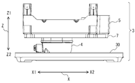
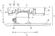
- FIG. 1 is a perspective view showing an internal structure of a machine room of a refrigerator according to an embodiment of the present invention.
- FIG. 2 is a front view of FIG. 1 as viewed from the front and showing only main components.
- FIG. 3 is a longitudinal sectional view of FIG.
- FIG. 4 is a longitudinal sectional view of FIG. 2 as viewed from the side.
- the X axis in the drawing indicates the width direction of the refrigerator 100.
- the Y axis in the figure indicates the depth direction of the refrigerator 100.
- the Z-axis in the figure indicates the vertical direction of the refrigerator 100.
- the refrigerator 100 which concerns on this Embodiment has an opening in the front surface, and is provided with the main-body part 1 in which the inside was divided by several partition members and the storage chamber 10 of multiple steps
- the storage room 10 is, for example, a freezer room, a refrigerator room, a vegetable room or the like.
- a space sealed with a resin inner box inside the refrigerator 100 and a steel plate outer box outside the refrigerator 100 is formed in the main body 1.
- a vacuum heat insulating material is installed in the inside sealed by the inner case and the outer case, and the foam heat insulating material such as urethane foam is filled.
- a cooling chamber 2 and a machine chamber 3 are provided vertically adjacent to each other on the back side of the storage chamber 10.
- the cooling chamber 2 is disposed above the machine chamber 3, and an air passage for circulating the air in each storage chamber 10 is formed.
- an evaporator 20 which constitutes a part of a refrigeration cycle for keeping the storage chamber 10 cool is provided.
- an evaporator fan (not shown) for blowing the air cooled by the evaporator 20 into the storage chambers 10 is provided.
- the evaporator 20 is a fin and tube heat exchanger provided with a copper or aluminum heat transfer tube and a large number of fins made of aluminum, for example.
- the evaporator 20 periodically performs a defrosting operation in which frost is melted using a defrost heater in order to avoid a decrease in the cooling performance of the refrigerator 100 due to frost formation.
- Defrosted water generated by the defrosting of the evaporator 20 is drained to the evaporating dish 5 of the machine room 3 through the drain pipe 21 provided at the lower part of the cooling room 2.
- the machine room 3 is provided below the cooling room 2 as shown in FIGS. 1 and 2.
- the machine room 3 is provided with a compressor 4 and a condenser (not shown) that constitute a part of the refrigeration cycle.
- a machine room fan (not shown) for blowing air to the compressor 4 and the condenser, and an evaporation tray 5 for storing defrost water generated when the evaporator 20 is defrosted. , Is provided.
- the compressor 4 compresses the low-temperature low-pressure gas refrigerant flowing out of the evaporator 20 into a high-temperature high-pressure gas refrigerant.
- the compressor 4 is fixed to the upper surface of the bottom plate 30 via a rubber pedestal 40.
- the rubber pedestal 40 is provided to absorb the vibration generated during the operation of the compressor 4.
- the condenser is connected to the refrigerant discharge port of the compressor 4 through a condensation pipe, and condenses the high temperature and high pressure gas refrigerant discharged from the compressor 4 into a low temperature and high pressure liquid refrigerant.
- the condensed liquid refrigerant is depressurized by the depressurizing device.
- the evaporation pan 5 is disposed above the compressor 4 and is fixed to the main body 1.
- the evaporation dish 5 is formed by indenting the bottom surface 51 convexly toward the evaporator 20 side, and is configured to store the upper portion of the compressor 4 in the depressed bottom portion. Part 6 is provided.
- FIG. 5 is a perspective view of the evaporating dish of the refrigerator according to the embodiment of the present invention as viewed from the top side.
- FIG. 6 is a perspective view of the evaporating dish of the refrigerator according to the embodiment of the present invention as viewed from the lower side.
- FIG. 7 is a refrigerator which concerns on embodiment of this invention, Comprising: It is explanatory drawing which showed typically the flow of the defrost water which flowed in the evaporating dish.
- the water storage section 6 of the evaporation pan 5 has a compressor 4 around the central area where defrost water generated when defrosting the evaporator 20 first flows in.
- a step-like stepped portion which descends toward the side is formed, and adjacent stepped portions are partitioned by the partitions 60 and 61.
- the water storage unit 6 is configured of a first water storage unit 6A, a second water storage unit 6B, and a third water storage unit 6C having a height difference.
- the first water storage portion 6A is formed so as to be surrounded by the first partition wall 60, and defrost water generated when the evaporator 20 is defrosted is first introduced. As shown in FIG. 7, the first water storage portion 6A communicates with the drainage receiving portion 62 located immediately below the drainage pipe 21. Defrosted water flows in through the drainage receiving portion 62.
- the first water storage section 6A is formed at a position facing the top surface of the compressor 4.
- the operation heat generated by the compressor 4 is convected (see the arrow A) in the lower part, the evaporation efficiency of the defrost water is high, and the evaporation can be performed most effectively.
- the first water storage portion 6A is formed in a curved surface shape in which the bottom surface is recessed toward the compressor 4 side. This is to efficiently evaporate the defrost water flowing to the first water storage section 6A by collecting it at the central portion closest to the position immediately above the compressor 4 whose upper surface is curved.
- the evaporation pan 5 may be inclined when assembled and fixed to the main body 1 or may be inclined depending on the installation place. Even in such a situation, the evaporating dish 5 can collect the defrost water which has flowed to the first water storage section 6A at the central part, so that the evaporating dish 5 is not affected by the assembled state or the installation place. Water can be evaporated.
- the first water storage portion 6A may be formed in an inclined surface shape in which the bottom surface is recessed toward the compressor 4 side. Further, the first water storage section 6A may be configured to be flat without forming the bottom surface in a curved surface or an inclined surface.
- the second water storage section 6B is disposed lower than the first water storage section 6A, and is formed so as to be surrounded by the second partition wall 61. That is, the bottom surface of the second water storage section 6B is located closer to the compressor 4 than the bottom surface of the first water storage section 6A. As shown in FIG. 7, the second water storage section 6B is provided as a pan when the defrost water stored in the first water storage section 6A overflows. As shown in FIG. 3 and FIG. 4 also, the defrosting water flowing into the second water storage section 6B is transferred to the bottom surface and the step surface of the second water storage section 6B and the operating heat generated by the compressor 4 evaporates efficiently. be able to.
- the third water storage section 6C is disposed on the lower floor than the second water storage section 6B, and is formed so as to be surrounded by the outer peripheral wall 50 of the evaporating dish 5. That is, the bottom surface of the third water storage section 6C is located closer to the compressor 4 than the bottom surface of the second water storage section 6B. As shown in FIG. 7, the third water storage section 6C is provided as a pan when the defrost water stored in the second water storage section 6B overflows. As shown in FIG. 3 and FIG. 4, the defrosting water flowing into the third water storage section 6C is also transferred to the bottom surface and the step surface of the third water storage section 6C to efficiently evaporate the heat generated by the compressor 4 Can.
- the evaporation dish 5 is provided along the outer peripheral edge of the water storage portion 6, and provided with a rib 7 which protrudes from the bottom surface toward the compressor 4 side.
- the rib 7 is provided along the outer peripheral edge of the third water storage portion 6C corresponding to the position where the outer peripheral wall 50 is provided.
- the evaporation dish 5 can retain the operation heat of the compressor 4 in the area surrounded by the ribs 7, and the defrosted water stored in the first water storage portion 6A, the second water storage portion 6B and the third water storage portion 6C It can be effectively evaporated.
- the rib 7 also functions as a reinforcing material that prevents the deformation of the evaporating dish 5.
- the rib 7 may be provided so as to surround a part of the outer periphery of the compressor 4 as shown in FIGS. 5 and 6, and although the detailed illustration is omitted, the outer periphery of the compressor 4 You may provide it cyclically
- the bottom surface 51 of the evaporation dish 5 is shaped so as to be convexly depressed toward the evaporator 20 side. It has the water storage part 6 of the shape which accommodates an upper part. And the water storage part 6 forms the step-like stepped part which descends toward the compressor 4 side around the center part centering on the center part which defrost water generated when defrosting the evaporator 20 initially flows in The step portions adjacent to each other in the upper and lower direction are divided into the partition walls 60 and 61.
- defrost water can be effectively evaporated on the top floor, and when the amount of defrost water increases, it is made to flow out stepwise from the top floor to the lower floor, and from the upper floor with high evaporation effect in order It can be evaporated efficiently.
- the refrigerator 100 is provided along the outer peripheral edge of the water storage section 6 and has the rib 7 protruding toward the compressor 4 from the bottom surface, the operating heat of the compressor 4 is retained on the bottom surface 51 of the evaporation dish 5
- the defrost water stored in the water storage section 6 of each floor can be effectively evaporated.
- the refrigerator 100 is formed as a curved surface or inclined surface so that the bottom surface of the first water storage portion 6A is recessed toward the compressor 4 side. Therefore, the refrigerator 100 can collect the defrost water which flowed to the 1st water storage section 6A in the central part, and can evaporate efficiently with the operation heat of compressor 4.
- evaporation dish 5 may be inclined when assembled and fixed to main body 1 or may be inclined depending on the installation location, but the defrost water flowing to first water storage section 6A may be collected in the central area As it is possible, the defrost water can be effectively evaporated without being influenced by the assembled state or the installation place.
- the present invention has been described above based on the embodiment, the present invention is not limited to the configuration of the embodiment described above.
- the configuration of the illustrated refrigerator 100 is merely an example, and the present invention is not limited to the above-described content, and the present invention can be similarly applied to a refrigerator including other components.
- the water storage part 6 is not limited to three water storage parts shown in figure, What is necessary is just to have two or more water storage parts. In short, the scope of the various modifications, applications, and uses that the so-called person skilled in the art makes as needed is mentioned in the scope of the present invention (the technical scope).
Abstract
A refrigerator comprising: a main body section having in the interior thereof a cooling chamber and a machine chamber; an evaporator provided in the cooling chamber; a compressor provided in the machine chamber; and an evaporation tray that is arranged above the compressor in the machine chamber, and that collects defrost water produced when the evaporator is defrosted. The evaporation tray has: a water storage section having a shape wherein a bottom surface thereof is indented in a convex shape toward the evaporator, the upper part of the compressor being accommodated in the indented bottom surface; and ribs provided along the outer peripheral edge of the water storage section and protruding from the bottom surface toward the compressor. The water storage section is configured such that step-like step sections dropping down toward the compressor are formed centered around a central section into which the defrost water produced during defrosting of the evaporator initially flows, and adjacent step sections are separated by means of partition walls.
Description
本発明は、蒸発器を除霜した際に発生する除霜水を貯留するための蒸発皿を備えた冷蔵庫及び冷蔵庫の蒸発皿に関するものである。
BACKGROUND OF THE INVENTION Field of the Invention The present invention relates to a refrigerator equipped with an evaporation dish for storing defrost water generated when the evaporator is defrosted and an evaporation dish of the refrigerator.
従来、冷蔵庫は、本体部の内部に、貯蔵室、冷却室及び機械室を有する構成が知られている。冷却室及び機械室は、貯蔵室の背面側に設けられている。冷却室は、機械室の上方に配置されており、貯蔵室を保冷するための冷凍サイクルの一部を構成する蒸発器が設けられている。機械室は、冷凍サイクルの一部を構成する圧縮機及び凝縮器等が設けられている。そして、機械室には、圧縮機の上部に配置され、蒸発器を除霜した際に発生する除霜水を貯水部に貯留させる蒸発皿が設けられている。蒸発皿で貯留した除霜水は、圧縮機の動作熱を利用して蒸発させる。
Heretofore, a refrigerator is known to have a storage room, a cooling room and a machine room inside a main body. The cooling room and the machine room are provided on the back side of the storage room. The cooling chamber is disposed above the machine chamber, and is provided with an evaporator that constitutes a part of a refrigeration cycle for keeping the storage chamber cool. The machine room is provided with a compressor, a condenser and the like that constitute a part of the refrigeration cycle. The machine room is provided with an evaporation pan, which is disposed above the compressor and stores, in the water storage section, the defrost water generated when the evaporator is defrosted. The defrost water stored in the evaporation pan is evaporated using the operating heat of the compressor.
例えば特許文献1に開示された冷蔵庫では、蒸発皿の底面に、圧縮機の天面部の周囲を囲うリブが設けられている。この冷蔵庫は、圧縮機の動作熱を、リブによって囲まれた領域に滞留させることで、蒸発皿に貯留した除霜水を蒸発させる構成である。
For example, in the refrigerator disclosed in Patent Document 1, a rib is provided on the bottom surface of the evaporation dish to surround the top of the compressor. This refrigerator is configured to evaporate the defrost water stored in the evaporating dish by retaining the operation heat of the compressor in the area surrounded by the ribs.
特許文献1に開示された冷蔵庫では、リブが圧縮機の天面部を囲む形状であり、蒸発皿の貯水部の一部にのみ蒸発効果を高めたものである。そのため、この冷蔵庫では、貯水部の中でリブを設けた範囲に相当する部分の外側に流れた除霜水に、圧縮機の動作熱を十分に伝えることができず、当該除霜水を蒸発させることに時間を要するか、或いは十分に蒸発させることができずに除霜水が貯水部に残る虞がある。
In the refrigerator disclosed in Patent Document 1, the rib is shaped so as to surround the top surface portion of the compressor, and the evaporation effect is enhanced only in a part of the water storage portion of the evaporation pan. Therefore, with this refrigerator, the operating heat of the compressor can not be sufficiently transmitted to the defrost water that has flowed to the outside of the portion corresponding to the range in which the rib is provided in the water storage section, and the defrost water is evaporated It takes time to cause it to evaporate, or there is a possibility that defrost water may remain in the water storage section.
本発明は、上記のような課題を解決するためになされたもので、蒸発器を除霜した際に発生する除霜水を効果的に蒸発させることができる、冷蔵庫及び冷蔵庫の蒸発皿を提供することを目的とする。
The present invention has been made to solve the problems as described above, and provides a refrigerator and an evaporating dish for the refrigerator, which can effectively evaporate the defrost water generated when the evaporator is defrosted. The purpose is to
本発明に係る冷蔵庫は、冷却室及び機械室を内部に有する本体部と、前記冷却室に設けられた蒸発器と、前記機械室に設けられた圧縮機と、前記機械室において前記圧縮機の上方に配置され、前記蒸発器を除霜した際に発生する除霜水を貯留する蒸発皿と、を備え、前記蒸発皿は、底面を前記蒸発器側に向かって凸状に窪ませた形状であり、該窪ませた底面に前記圧縮機の上部を収納させる形状の貯水部と、前記貯水部の外周縁に沿って設けられ、底面から前記圧縮機側に向かって突き出すリブと、を有し、前記貯水部は、前記除霜水が最初に流入する中央部を中心に、その周囲を前記圧縮機側に向かって下る階段状の段差部が形成され、隣接する前記段差部が隔壁によって仕切られたものである。
The refrigerator according to the present invention includes a main body having a cooling chamber and a machine chamber inside, an evaporator provided in the cooling chamber, a compressor provided in the machine chamber, and the compressor in the machine chamber. An evaporation dish disposed above and storing defrost water generated when the evaporator is defrosted, the evaporation dish having a shape in which a bottom surface is concaved toward the evaporator side A water storage portion having a shape for storing the upper portion of the compressor on the recessed bottom surface, and a rib provided along the outer peripheral edge of the water storage portion and protruding from the bottom surface toward the compressor The water storage portion is formed with a step-like stepped portion which descends toward the compressor side around a central portion where the defrosted water first flows in, and the adjacent step is formed by a partition wall It is divided.
本発明によれば、蒸発皿の貯水部は、蒸発器を除霜した際に発生する除霜水が最初に流入する中央部を中心に、その周囲を圧縮機側に向かって下る階段状の段差部が形成され、上下に隣接する段差部が隔壁によって仕切られた構成なので、先ずは最上階で除霜水を効果的に蒸発させることができ、除霜水の量が増えると最上階から下階に段階的に流出させて、蒸発効果の高い上階から順に効率良く蒸発させることができる。しかも、蒸発皿は、貯水部の外周縁に沿って設けられ、底面から圧縮機側に向かって突き出すリブを有するので、圧縮機の動作熱を蒸発皿の底面に滞留させることができ、各階の貯水部に貯留した除霜水を効果的に蒸発させることができる。
According to the present invention, the water storage portion of the evaporation dish is a step-like shape which descends toward the compressor side around the central portion where defrost water generated when defrosting the evaporator first flows in. Since the step portion is formed and the step portions vertically adjacent to each other are partitioned by the partition walls, the defrost water can be effectively evaporated first on the top floor, and when the amount of defrost water increases, from the top floor It can be discharged in stages to the lower floor, and can be efficiently evaporated in order from the upper floor with high evaporation effect. Moreover, since the evaporating dish is provided along the outer peripheral edge of the water storage section and has a rib projecting from the bottom toward the compressor side, the operating heat of the compressor can be retained on the bottom of the evaporating dish. The defrost water stored in the reservoir can be effectively evaporated.
以下、図面を参照して、本発明の実施の形態について説明する。なお、各図中、同一又は相当する部分には、同一符号を付して、その説明を適宜省略又は簡略化する。また、各図に記載の構成について、その形状、大きさ、及び配置等は、本発明の範囲内で適宜変更することができる。
Hereinafter, embodiments of the present invention will be described with reference to the drawings. In the drawings, the same or corresponding parts will be denoted by the same reference numerals, and the description thereof will be appropriately omitted or simplified. Further, the configuration, size, arrangement and the like of the configuration described in each drawing can be appropriately changed within the scope of the present invention.
実施の形態.
図1は、本発明の実施の形態に係る冷蔵庫の機械室の内部構造を示した斜視図である。図2は、図1を正面方向から見た状態であって、主要な構成部材のみを示した正面図である。図3は、図2の縦断面図である。図4は、図2を側面方向から見た縦断面図である。図中のX軸は、冷蔵庫100の幅方向を示している。図中のY軸は、冷蔵庫100の奥行方向を示している。図中のZ軸は、冷蔵庫100の上下方向を示している。 Embodiment.
FIG. 1 is a perspective view showing an internal structure of a machine room of a refrigerator according to an embodiment of the present invention. FIG. 2 is a front view of FIG. 1 as viewed from the front and showing only main components. FIG. 3 is a longitudinal sectional view of FIG. FIG. 4 is a longitudinal sectional view of FIG. 2 as viewed from the side. The X axis in the drawing indicates the width direction of therefrigerator 100. The Y axis in the figure indicates the depth direction of the refrigerator 100. The Z-axis in the figure indicates the vertical direction of the refrigerator 100.
図1は、本発明の実施の形態に係る冷蔵庫の機械室の内部構造を示した斜視図である。図2は、図1を正面方向から見た状態であって、主要な構成部材のみを示した正面図である。図3は、図2の縦断面図である。図4は、図2を側面方向から見た縦断面図である。図中のX軸は、冷蔵庫100の幅方向を示している。図中のY軸は、冷蔵庫100の奥行方向を示している。図中のZ軸は、冷蔵庫100の上下方向を示している。 Embodiment.
FIG. 1 is a perspective view showing an internal structure of a machine room of a refrigerator according to an embodiment of the present invention. FIG. 2 is a front view of FIG. 1 as viewed from the front and showing only main components. FIG. 3 is a longitudinal sectional view of FIG. FIG. 4 is a longitudinal sectional view of FIG. 2 as viewed from the side. The X axis in the drawing indicates the width direction of the
本実施の形態に係る冷蔵庫100は、前面に開口を有し、内部を複数の仕切り部材で仕切られて複数段の貯蔵室10が形成された本体部1を備えている。貯蔵室10とは、例えば冷凍室、冷蔵室、野菜室等である。本体部1には、冷蔵庫100の内側である樹脂製の内箱と、冷蔵庫100の外側である鋼板製の外箱とで密封された空間が形成されている。内箱と外箱とで密閉された内部には、真空断熱材が設置され、ウレタンフォームなどの発泡断熱材が充填されている。
The refrigerator 100 which concerns on this Embodiment has an opening in the front surface, and is provided with the main-body part 1 in which the inside was divided by several partition members and the storage chamber 10 of multiple steps | stages was formed. The storage room 10 is, for example, a freezer room, a refrigerator room, a vegetable room or the like. A space sealed with a resin inner box inside the refrigerator 100 and a steel plate outer box outside the refrigerator 100 is formed in the main body 1. A vacuum heat insulating material is installed in the inside sealed by the inner case and the outer case, and the foam heat insulating material such as urethane foam is filled.
本体部1の内部には、貯蔵室10の背面側に、冷却室2と機械室3とが上下に隣接させて設けられている。冷却室2は、機械室3の上方に配置されており、各貯蔵室10内の空気を循環させる風路が形成されている。冷却室2の風路の中央には、貯蔵室10を保冷するための冷凍サイクルの一部を構成する蒸発器20が設けられている。蒸発器20の上方には、蒸発器20で冷却された空気を各貯蔵室10内に送風する蒸発器用ファン(図示は省略)が設けられている。
Inside the main body portion 1, a cooling chamber 2 and a machine chamber 3 are provided vertically adjacent to each other on the back side of the storage chamber 10. The cooling chamber 2 is disposed above the machine chamber 3, and an air passage for circulating the air in each storage chamber 10 is formed. At the center of the air passage of the cooling chamber 2, an evaporator 20 which constitutes a part of a refrigeration cycle for keeping the storage chamber 10 cool is provided. Above the evaporator 20, an evaporator fan (not shown) for blowing the air cooled by the evaporator 20 into the storage chambers 10 is provided.
蒸発器20は、一例として銅製又はアルミニウム製の伝熱管と、アルミニウム製の多数のフィンと、を備えたフィン・アンド・チューブ型熱交換器である。蒸発器20は、着霜による冷蔵庫100の冷却性能の低下を回避するため、除霜ヒーターを用いて霜を融解させる除霜運転を定期的に行っている。蒸発器20の除霜により発生した除霜水は、冷却室2の下部に設けられた排水管21を通じて機械室3の蒸発皿5に排水される。
The evaporator 20 is a fin and tube heat exchanger provided with a copper or aluminum heat transfer tube and a large number of fins made of aluminum, for example. The evaporator 20 periodically performs a defrosting operation in which frost is melted using a defrost heater in order to avoid a decrease in the cooling performance of the refrigerator 100 due to frost formation. Defrosted water generated by the defrosting of the evaporator 20 is drained to the evaporating dish 5 of the machine room 3 through the drain pipe 21 provided at the lower part of the cooling room 2.
機械室3は、図1及び図2に示すように、冷却室2の下方に設けられている。機械室3には、冷凍サイクルの一部を構成する圧縮機4と凝縮器(図示は省略)等が設けられている。また、機械室3には、圧縮機4及び凝縮器に対して送風する機械室ファン(図示は省略)と、蒸発器20を除霜した際に発生する除霜水を貯留する蒸発皿5と、が設けられている。
The machine room 3 is provided below the cooling room 2 as shown in FIGS. 1 and 2. The machine room 3 is provided with a compressor 4 and a condenser (not shown) that constitute a part of the refrigeration cycle. In the machine room 3, a machine room fan (not shown) for blowing air to the compressor 4 and the condenser, and an evaporation tray 5 for storing defrost water generated when the evaporator 20 is defrosted. , Is provided.
圧縮機4は、蒸発器20から流出した低温低圧のガス冷媒を高温高圧のガス冷媒に圧縮するものである。圧縮機4は、底面板30の上面にゴム台座40を介して固定されている。ゴム台座40は、圧縮機4の運転中に発生する振動を吸収するために設けられている。
The compressor 4 compresses the low-temperature low-pressure gas refrigerant flowing out of the evaporator 20 into a high-temperature high-pressure gas refrigerant. The compressor 4 is fixed to the upper surface of the bottom plate 30 via a rubber pedestal 40. The rubber pedestal 40 is provided to absorb the vibration generated during the operation of the compressor 4.
凝縮器は、凝縮パイプを介して圧縮機4の冷媒吐出口と接続されており、圧縮機4から吐出された高温高圧のガス冷媒を低温高圧の液冷媒に凝縮させるものである。凝縮された液冷媒は、減圧装置で減圧される。
The condenser is connected to the refrigerant discharge port of the compressor 4 through a condensation pipe, and condenses the high temperature and high pressure gas refrigerant discharged from the compressor 4 into a low temperature and high pressure liquid refrigerant. The condensed liquid refrigerant is depressurized by the depressurizing device.
蒸発皿5は、図1に示すように、圧縮機4の上方に配置されており、本体部1に固定されている。蒸発皿5は、図3及び図4に示すように、底面51を蒸発器20側に向かって凸状に窪ませて形成され、窪ませた底部に圧縮機4の上部を収納させる形状の貯水部6が設けられている。
As shown in FIG. 1, the evaporation pan 5 is disposed above the compressor 4 and is fixed to the main body 1. As shown in FIGS. 3 and 4, the evaporation dish 5 is formed by indenting the bottom surface 51 convexly toward the evaporator 20 side, and is configured to store the upper portion of the compressor 4 in the depressed bottom portion. Part 6 is provided.
次に、図1~図4を参照しつつ、図5~図7に基づいて、蒸発皿5の構成を具体的に説明する。図5は、本発明の実施の形態に係る冷蔵庫の蒸発皿を上面側から見た斜視図である。図6は、本発明の実施の形態に係る冷蔵庫の蒸発皿を下面側から見た斜視図である。図7は、本発明の実施の形態に係る冷蔵庫であって、蒸発皿に流入した除霜水の流れを模式的に示した説明図である。
Next, the configuration of the evaporating dish 5 will be specifically described based on FIGS. 5 to 7 with reference to FIGS. 1 to 4. FIG. 5 is a perspective view of the evaporating dish of the refrigerator according to the embodiment of the present invention as viewed from the top side. FIG. 6 is a perspective view of the evaporating dish of the refrigerator according to the embodiment of the present invention as viewed from the lower side. FIG. 7: is a refrigerator which concerns on embodiment of this invention, Comprising: It is explanatory drawing which showed typically the flow of the defrost water which flowed in the evaporating dish.
蒸発皿5の貯水部6は、図5及び図6に示すように、蒸発器20を除霜した際に発生する除霜水が最初に流入する中央部を中心に、その周囲を圧縮機4側に向かって下る階段状の段差部が形成され、隣接する段差部が隔壁60及び61によって仕切られた構成である。具体的には、貯水部6は、高低差を有する第1貯水部6A、第2貯水部6B、及び第3貯水部6Cで構成されている。
As shown in FIGS. 5 and 6, the water storage section 6 of the evaporation pan 5 has a compressor 4 around the central area where defrost water generated when defrosting the evaporator 20 first flows in. A step-like stepped portion which descends toward the side is formed, and adjacent stepped portions are partitioned by the partitions 60 and 61. Specifically, the water storage unit 6 is configured of a first water storage unit 6A, a second water storage unit 6B, and a third water storage unit 6C having a height difference.
第1貯水部6Aは、周囲を第1隔壁60によって囲まれて形成され、蒸発器20を除霜した際に発生する除霜水が最初に流入される。第1貯水部6Aは、図7に示すように、排水管21の直下に位置する排水受け部62と連通しており、排水受け部62を通じて除霜水が流入される。
The first water storage portion 6A is formed so as to be surrounded by the first partition wall 60, and defrost water generated when the evaporator 20 is defrosted is first introduced. As shown in FIG. 7, the first water storage portion 6A communicates with the drainage receiving portion 62 located immediately below the drainage pipe 21. Defrosted water flows in through the drainage receiving portion 62.
第1貯水部6Aは、図3及び図4に示すように、圧縮機4の天面と対向する位置に形成されている。第1貯水部6Aでは、下方において圧縮機4が発生する動作熱が対流(矢印Aを参照)しているので、除霜水の蒸発効率が高く、最も効果的に蒸発させることができる。
As shown in FIGS. 3 and 4, the first water storage section 6A is formed at a position facing the top surface of the compressor 4. In the first water storage section 6A, since the operation heat generated by the compressor 4 is convected (see the arrow A) in the lower part, the evaporation efficiency of the defrost water is high, and the evaporation can be performed most effectively.
また、第1貯水部6Aは、図3及び図4に示すように、底面が圧縮機4側に向かって窪む湾曲面状に形成されている。これは、第1貯水部6Aに流れた除霜水を、上面が湾曲する圧縮機4の直上位置に最も近接する中央部に集めることで、効率良く蒸発させるためである。また、蒸発皿5は、本体部1に組み付けて固定する際に傾いたり、又は設置場所によって傾いたりする虞がある。このような状況であっても、蒸発皿5は、第1貯水部6Aに流れた除霜水を中央部に集めることができるので、組み付け状態又は設置場所に影響されず、効果的に除霜水を蒸発させることができる。なお、詳細に図示することは省略したが、第1貯水部6Aは、底面が圧縮機4側に向かって窪む傾斜面状に形成された構成でもよい。また、第1貯水部6Aは、底面を湾曲面状又は傾斜面状に形成することなく、平面状とした構成でもよい。
Further, as shown in FIGS. 3 and 4, the first water storage portion 6A is formed in a curved surface shape in which the bottom surface is recessed toward the compressor 4 side. This is to efficiently evaporate the defrost water flowing to the first water storage section 6A by collecting it at the central portion closest to the position immediately above the compressor 4 whose upper surface is curved. In addition, the evaporation pan 5 may be inclined when assembled and fixed to the main body 1 or may be inclined depending on the installation place. Even in such a situation, the evaporating dish 5 can collect the defrost water which has flowed to the first water storage section 6A at the central part, so that the evaporating dish 5 is not affected by the assembled state or the installation place. Water can be evaporated. Although not shown in detail, the first water storage portion 6A may be formed in an inclined surface shape in which the bottom surface is recessed toward the compressor 4 side. Further, the first water storage section 6A may be configured to be flat without forming the bottom surface in a curved surface or an inclined surface.
第2貯水部6Bは、第1貯水部6Aよりも下階に配置され、周囲を第2隔壁61によって囲まれて形成されている。つまり、第2貯水部6Bの底面は、第1貯水部6Aの底面よりも圧縮機4側に位置している。第2貯水部6Bは、図7に示すように、第1貯水部6Aによって貯留した除霜水が溢れた際の受け皿として設けられている。第2貯水部6Bに流入した除霜水も、図3及び図4に示すように、圧縮機4が発生する動作熱が、第2貯水部6Bの底面及び段差面に伝わり、効率良く蒸発させることができる。
The second water storage section 6B is disposed lower than the first water storage section 6A, and is formed so as to be surrounded by the second partition wall 61. That is, the bottom surface of the second water storage section 6B is located closer to the compressor 4 than the bottom surface of the first water storage section 6A. As shown in FIG. 7, the second water storage section 6B is provided as a pan when the defrost water stored in the first water storage section 6A overflows. As shown in FIG. 3 and FIG. 4 also, the defrosting water flowing into the second water storage section 6B is transferred to the bottom surface and the step surface of the second water storage section 6B and the operating heat generated by the compressor 4 evaporates efficiently. be able to.
第3貯水部6Cは、第2貯水部6Bよりも下階に配置され、周囲を蒸発皿5の外周壁50によって囲まれて形成されている。つまり、第3貯水部6Cの底面は、第2貯水部6Bの底面よりも圧縮機4側に位置している。第3貯水部6Cは、図7に示すように、第2貯水部6Bによって貯留した除霜水が溢れた際の受け皿として設けられている。第3貯水部6Cに流入した除霜水も、図3及び図4に示すように、圧縮機4が発生する動作熱が第3貯水部6Cの底面及び段差面に伝わり、効率良く蒸発させることができる。
The third water storage section 6C is disposed on the lower floor than the second water storage section 6B, and is formed so as to be surrounded by the outer peripheral wall 50 of the evaporating dish 5. That is, the bottom surface of the third water storage section 6C is located closer to the compressor 4 than the bottom surface of the second water storage section 6B. As shown in FIG. 7, the third water storage section 6C is provided as a pan when the defrost water stored in the second water storage section 6B overflows. As shown in FIG. 3 and FIG. 4, the defrosting water flowing into the third water storage section 6C is also transferred to the bottom surface and the step surface of the third water storage section 6C to efficiently evaporate the heat generated by the compressor 4 Can.
また、蒸発皿5には、貯水部6の外周縁に沿って設けられ、底面から圧縮機4側に向かって突き出すリブ7が設けられている。リブ7は、外周壁50が設けられた位置に相当する第3貯水部6Cの外周縁に沿って設けられている。蒸発皿5は、圧縮機4の動作熱をリブ7で囲まれた領域に滞留させることができ、第1貯水部6A、第2貯水部6B及び第3貯水部6Cにおいて貯留した除霜水を効果的に蒸発させることができる。また、リブ7は、蒸発皿5の変形を防止する補強材としても機能する。
Further, the evaporation dish 5 is provided along the outer peripheral edge of the water storage portion 6, and provided with a rib 7 which protrudes from the bottom surface toward the compressor 4 side. The rib 7 is provided along the outer peripheral edge of the third water storage portion 6C corresponding to the position where the outer peripheral wall 50 is provided. The evaporation dish 5 can retain the operation heat of the compressor 4 in the area surrounded by the ribs 7, and the defrosted water stored in the first water storage portion 6A, the second water storage portion 6B and the third water storage portion 6C It can be effectively evaporated. In addition, the rib 7 also functions as a reinforcing material that prevents the deformation of the evaporating dish 5.
なお、リブ7は、図5及び図6に示すように、圧縮機4の外周の一部を囲うように設けてもよいし、詳細に図示することは省略したが、圧縮機4の外周を囲うように環状に設けてよい。
The rib 7 may be provided so as to surround a part of the outer periphery of the compressor 4 as shown in FIGS. 5 and 6, and although the detailed illustration is omitted, the outer periphery of the compressor 4 You may provide it cyclically | annularly so that it may enclose.
上記したように、本実施の形態に係る冷蔵庫100では、蒸発皿5の底面51が蒸発器20側に向かって凸状に窪ませた形状であり、該窪ませた底面51に圧縮機4の上部を収納させる形状の貯水部6を有している。そして、貯水部6は、蒸発器20を除霜した際に発生する除霜水が最初に流入する中央部を中心に、その周囲を圧縮機4側に向かって下る階段状の段差部が形成され、上下に隣接する段差部が隔壁60及び61に仕切られた構成である。よって、先ずは、最上階で除霜水を効果的に蒸発させることができ、除霜水の量が増えると最上階から下階に段階的に流出させて、蒸発効果の高い上階から順に効率良く蒸発させることができる。しかも、この冷蔵庫100は、貯水部6の外周縁に沿って設けられ、底面から圧縮機4側に向かって突き出すリブ7を有するので、圧縮機4の動作熱を蒸発皿5の底面51に滞留させることができ、各階の貯水部6に貯留した除霜水を効果的に蒸発させることができる。
As described above, in the refrigerator 100 according to the present embodiment, the bottom surface 51 of the evaporation dish 5 is shaped so as to be convexly depressed toward the evaporator 20 side. It has the water storage part 6 of the shape which accommodates an upper part. And the water storage part 6 forms the step-like stepped part which descends toward the compressor 4 side around the center part centering on the center part which defrost water generated when defrosting the evaporator 20 initially flows in The step portions adjacent to each other in the upper and lower direction are divided into the partition walls 60 and 61. Therefore, first, defrost water can be effectively evaporated on the top floor, and when the amount of defrost water increases, it is made to flow out stepwise from the top floor to the lower floor, and from the upper floor with high evaporation effect in order It can be evaporated efficiently. Moreover, since the refrigerator 100 is provided along the outer peripheral edge of the water storage section 6 and has the rib 7 protruding toward the compressor 4 from the bottom surface, the operating heat of the compressor 4 is retained on the bottom surface 51 of the evaporation dish 5 The defrost water stored in the water storage section 6 of each floor can be effectively evaporated.
また、冷蔵庫100は、第1貯水部6Aの底面が、圧縮機4側に向かって窪むように湾曲面状又は傾斜面状として形成されている。よって、冷蔵庫100は、第1貯水部6Aに流れた除霜水を中央部に集めて、圧縮機4の動作熱で効率良く蒸発させることができる。また、蒸発皿5は、本体部1に組み付けて固定する際に傾いたり、又は設置場所によって傾いたりする場合があるが、第1貯水部6Aに流れた除霜水を中央部に集めることができるので、組み付け状態又は設置場所に影響されず、効果的に除霜水を蒸発させることができる。
Moreover, the refrigerator 100 is formed as a curved surface or inclined surface so that the bottom surface of the first water storage portion 6A is recessed toward the compressor 4 side. Therefore, the refrigerator 100 can collect the defrost water which flowed to the 1st water storage section 6A in the central part, and can evaporate efficiently with the operation heat of compressor 4. In addition, evaporation dish 5 may be inclined when assembled and fixed to main body 1 or may be inclined depending on the installation location, but the defrost water flowing to first water storage section 6A may be collected in the central area As it is possible, the defrost water can be effectively evaporated without being influenced by the assembled state or the installation place.
以上に本発明を実施の形態に基づいて説明したが、本発明は上述した実施の形態の構成に限定されるものではない。例えば、図示した冷蔵庫100の構成は、一例であって、上述した内容に限定されるものではなく、他の構成要素を含んだ冷蔵庫であっても同様に実施することができる。また、貯水部6は、図示した3つの貯水部に限定されず、2つ以上の貯水部を有していればよい。要するに、いわゆる当業者が必要に応じてなす種々なる変更、応用、利用の範囲をも本発明の要旨(技術的範囲)に含むことを念のため申し添える。
Although the present invention has been described above based on the embodiment, the present invention is not limited to the configuration of the embodiment described above. For example, the configuration of the illustrated refrigerator 100 is merely an example, and the present invention is not limited to the above-described content, and the present invention can be similarly applied to a refrigerator including other components. Moreover, the water storage part 6 is not limited to three water storage parts shown in figure, What is necessary is just to have two or more water storage parts. In short, the scope of the various modifications, applications, and uses that the so-called person skilled in the art makes as needed is mentioned in the scope of the present invention (the technical scope).
1 本体部、2 冷却室、3 機械室、4 圧縮機、5 蒸発皿、6 貯水部、6A 第1貯水部、6B 第2貯水部、6C 第3貯水部、7 リブ、10 貯蔵室、20 蒸発器、21 排水管、30 底面板、40 ゴム台座、50 外周壁、51 底面、60 第1隔壁、61 第2隔壁、62 排水受け部、100 冷蔵庫。
DESCRIPTION OF SYMBOLS 1 main-body part, 2 cooling chamber, 3 machine room, 4 compressor, 5 evaporation pan, 6 water storage part, 6A 1st water storage part, 6B 2nd water storage part, 6C 3rd water storage part, 7 ribs, 10 storage rooms, 20 Evaporator, 21 drainage pipe, 30 bottom plate, 40 rubber pedestal, 50 outer peripheral wall, 51 bottom surface, 60 first partition, 61 second partition, 62 drainage receiver, 100 refrigerator.
Claims (4)
- 冷却室及び機械室を内部に有する本体部と、
前記冷却室に設けられた蒸発器と、
前記機械室に設けられた圧縮機と、
前記機械室において前記圧縮機の上方に配置され、前記蒸発器を除霜した際に発生する除霜水を貯留する蒸発皿と、を備え、
前記蒸発皿は、
底面を前記蒸発器側に向かって凸状に窪ませた形状であり、該窪ませた底面に前記圧縮機の上部を収納させる形状の貯水部と、
前記貯水部の外周縁に沿って設けられ、底面から前記圧縮機側に向かって突き出すリブと、を有し、
前記貯水部は、前記除霜水が最初に流入する中央部を中心に、その周囲を前記圧縮機側に向かって下る階段状の段差部が形成され、隣接する前記段差部が隔壁によって仕切られた構成である、冷蔵庫。 A main body having a cooling room and a machine room inside;
An evaporator provided in the cooling chamber;
A compressor provided in the machine room,
And an evaporation pan disposed in the machine room above the compressor and storing defrost water generated when the evaporator is defrosted.
The evaporation dish is
A water storage portion having a shape in which a bottom surface is concaved in a convex shape toward the evaporator, and the concave bottom surface is configured to store an upper portion of the compressor;
And a rib provided along the outer peripheral edge of the water storage portion and protruding from the bottom toward the compressor.
The water storage portion is formed with a step-like stepped portion which descends toward the compressor side around the central portion where the defrosted water first flows in, and the adjacent step portions are partitioned by the partition wall The configuration is refrigerator. - 前記貯水部は、
周囲を第1隔壁によって囲まれ、前記除霜水が最初に流入する第1貯水部と、
前記第1貯水部よりも下階に配置され、周囲を第2隔壁によって囲まれた第2貯水部と、
前記第2貯水部よりも下階に配置され、周囲を前記蒸発皿の外周壁によって囲まれた第3貯水部と、で構成されている、請求項1に記載の冷蔵庫。 The water storage section is
A first water storage section which is surrounded by a first partition wall and into which the defrosted water first flows;
A second water storage unit disposed on a lower floor than the first water storage unit and surrounded by a second partition;
The refrigerator according to claim 1, further comprising: a third water storage unit disposed on a lower floor than the second water storage unit and surrounded by an outer peripheral wall of the evaporating dish. - 前記第1貯水部は、底面が前記圧縮機側に向かって窪むように湾曲面状又は傾斜面状として形成されている、請求項2に記載の冷蔵庫。 The refrigerator according to claim 2, wherein the first water storage portion is formed as a curved surface or an inclined surface so that a bottom surface is recessed toward the compressor.
- 冷却室及び機械室を内部に有する本体部と、前記冷却室に設けられた蒸発器と、前記機械室に設けられた圧縮機と、を備えた冷蔵庫の前記機械室に設けられ、前記圧縮機の上方に配置されて前記蒸発器を除霜した際に発生する除霜水を貯留する蒸発皿であって、
底面が前記蒸発器側に向かって凸状に窪ませた形状であり、該窪ませた底面に前記圧縮機の上部を収納させる形状の貯水部と、
前記貯水部の外周縁に沿って設けられ、底面から前記圧縮機側に向かって突き出すリブと、を有し、
前記貯水部は、前記除霜水が最初に流入する中央部を中心に、その周囲を前記圧縮機側に向かって下る階段状の段差部が形成され、隣接する前記段差部が隔壁によって仕切られた構成である、冷蔵庫の蒸発皿。 Provided in the machine chamber of a refrigerator comprising: a main body having a cooling chamber and a machine chamber inside; an evaporator provided in the cooling chamber; and a compressor provided in the machine chamber, the compressor An evaporation dish, which is disposed above and stores defrost water generated when the evaporator is defrosted,
A bottom portion having a shape which is concaved in a convex shape toward the evaporator side, and a water storage portion having a shape in which the upper portion of the compressor is accommodated in the concave bottom surface;
And a rib provided along the outer peripheral edge of the water storage portion and protruding from the bottom toward the compressor.
The water storage portion is formed with a step-like stepped portion which descends toward the compressor side around the central portion where the defrosted water first flows in, and the adjacent step portions are partitioned by the partition wall The configuration is the refrigerator evaporation dish.
Priority Applications (1)
| Application Number | Priority Date | Filing Date | Title |
|---|---|---|---|
| PCT/JP2017/033451 WO2019053879A1 (en) | 2017-09-15 | 2017-09-15 | Refrigerator and evaporation tray for refrigerator |
Applications Claiming Priority (1)
| Application Number | Priority Date | Filing Date | Title |
|---|---|---|---|
| PCT/JP2017/033451 WO2019053879A1 (en) | 2017-09-15 | 2017-09-15 | Refrigerator and evaporation tray for refrigerator |
Publications (1)
| Publication Number | Publication Date |
|---|---|
| WO2019053879A1 true WO2019053879A1 (en) | 2019-03-21 |
Family
ID=65723296
Family Applications (1)
| Application Number | Title | Priority Date | Filing Date |
|---|---|---|---|
| PCT/JP2017/033451 WO2019053879A1 (en) | 2017-09-15 | 2017-09-15 | Refrigerator and evaporation tray for refrigerator |
Country Status (1)
| Country | Link |
|---|---|
| WO (1) | WO2019053879A1 (en) |
Cited By (2)
| Publication number | Priority date | Publication date | Assignee | Title |
|---|---|---|---|---|
| CN114459195A (en) * | 2022-01-10 | 2022-05-10 | 青岛海尔电冰箱有限公司 | Evaporating dish and refrigeration equipment with same |
| DE102021214061A1 (en) | 2021-12-09 | 2023-06-15 | BSH Hausgeräte GmbH | Refrigeration device, evaporation arrangement for a refrigeration device and method and set for producing the evaporation arrangement |
Citations (8)
| Publication number | Priority date | Publication date | Assignee | Title |
|---|---|---|---|---|
| FR1595334A (en) * | 1968-03-22 | 1970-06-08 | ||
| JPS55166382U (en) * | 1979-05-18 | 1980-11-29 | ||
| JPS61192283U (en) * | 1985-05-20 | 1986-11-29 | ||
| JPS6280184U (en) * | 1985-11-07 | 1987-05-22 | ||
| JPS641390U (en) * | 1987-06-22 | 1989-01-06 | ||
| JPH0510977U (en) * | 1991-07-29 | 1993-02-12 | 株式会社東芝 | Refrigerator evaporating dish |
| DE102013207862A1 (en) * | 2013-04-30 | 2014-10-30 | BSH Bosch und Siemens Hausgeräte GmbH | Domestic refrigerating appliance with a compressor in a waste heat collecting housing |
| JP2015117905A (en) * | 2013-12-19 | 2015-06-25 | 株式会社東芝 | Refrigerator |
-
2017
- 2017-09-15 WO PCT/JP2017/033451 patent/WO2019053879A1/en active Application Filing
Patent Citations (8)
| Publication number | Priority date | Publication date | Assignee | Title |
|---|---|---|---|---|
| FR1595334A (en) * | 1968-03-22 | 1970-06-08 | ||
| JPS55166382U (en) * | 1979-05-18 | 1980-11-29 | ||
| JPS61192283U (en) * | 1985-05-20 | 1986-11-29 | ||
| JPS6280184U (en) * | 1985-11-07 | 1987-05-22 | ||
| JPS641390U (en) * | 1987-06-22 | 1989-01-06 | ||
| JPH0510977U (en) * | 1991-07-29 | 1993-02-12 | 株式会社東芝 | Refrigerator evaporating dish |
| DE102013207862A1 (en) * | 2013-04-30 | 2014-10-30 | BSH Bosch und Siemens Hausgeräte GmbH | Domestic refrigerating appliance with a compressor in a waste heat collecting housing |
| JP2015117905A (en) * | 2013-12-19 | 2015-06-25 | 株式会社東芝 | Refrigerator |
Cited By (3)
| Publication number | Priority date | Publication date | Assignee | Title |
|---|---|---|---|---|
| DE102021214061A1 (en) | 2021-12-09 | 2023-06-15 | BSH Hausgeräte GmbH | Refrigeration device, evaporation arrangement for a refrigeration device and method and set for producing the evaporation arrangement |
| CN114459195A (en) * | 2022-01-10 | 2022-05-10 | 青岛海尔电冰箱有限公司 | Evaporating dish and refrigeration equipment with same |
| CN114459195B (en) * | 2022-01-10 | 2024-04-09 | 重庆海尔制冷电器有限公司 | Evaporating dish and refrigeration equipment with same |
Similar Documents
| Publication | Publication Date | Title |
|---|---|---|
| US9267725B2 (en) | Refrigerator | |
| JP5677737B2 (en) | refrigerator | |
| US9726417B2 (en) | Refrigerator | |
| KR101660042B1 (en) | Refrigerator | |
| CN106257212A (en) | The assemble method of the ice machine of refrigerator and refrigerator | |
| JP2013257114A (en) | Refrigerator | |
| JP5847198B2 (en) | refrigerator | |
| WO2019053879A1 (en) | Refrigerator and evaporation tray for refrigerator | |
| RU2603888C2 (en) | Refrigerator | |
| KR20090080240A (en) | Machinery room of a refrigerator and method for manufacturing thereof | |
| JP5964702B2 (en) | Refrigerator | |
| JP5985942B2 (en) | Refrigerator | |
| EP3063481B1 (en) | Refrigeration appliance having an improved defrost water collection receptacle | |
| JP2012098010A (en) | Cooling storage | |
| JP2003172575A (en) | Refrigerator | |
| JP5624365B2 (en) | refrigerator | |
| JP7249056B2 (en) | refrigerator | |
| WO2006041246A1 (en) | Refrigerator | |
| JP5922541B2 (en) | Refrigerator | |
| JP7412446B2 (en) | refrigerator | |
| KR20070107355A (en) | A refrigerator | |
| JP2003097883A (en) | Refrigerator | |
| JP2006078054A (en) | Refrigerator | |
| JP2022047883A (en) | refrigerator | |
| JP5624363B2 (en) | refrigerator |
Legal Events
| Date | Code | Title | Description |
|---|---|---|---|
| 121 | Ep: the epo has been informed by wipo that ep was designated in this application |
Ref document number: 17924831 Country of ref document: EP Kind code of ref document: A1 |
|
| NENP | Non-entry into the national phase |
Ref country code: DE |
|
| 122 | Ep: pct application non-entry in european phase |
Ref document number: 17924831 Country of ref document: EP Kind code of ref document: A1 |
|
| NENP | Non-entry into the national phase |
Ref country code: JP |