WO2019047134A1 - 一种高生物拟真性语音处理滤波器与语音识别设备 - Google Patents
一种高生物拟真性语音处理滤波器与语音识别设备 Download PDFInfo
- Publication number
- WO2019047134A1 WO2019047134A1 PCT/CN2017/100975 CN2017100975W WO2019047134A1 WO 2019047134 A1 WO2019047134 A1 WO 2019047134A1 CN 2017100975 W CN2017100975 W CN 2017100975W WO 2019047134 A1 WO2019047134 A1 WO 2019047134A1
- Authority
- WO
- WIPO (PCT)
- Prior art keywords
- transconductance amplifier
- inverting input
- filter
- output
- transconductance
- Prior art date
- Legal status (The legal status is an assumption and is not a legal conclusion. Google has not performed a legal analysis and makes no representation as to the accuracy of the status listed.)
- Ceased
Links
Images


Classifications
-
- G—PHYSICS
- G10—MUSICAL INSTRUMENTS; ACOUSTICS
- G10L—SPEECH ANALYSIS TECHNIQUES OR SPEECH SYNTHESIS; SPEECH RECOGNITION; SPEECH OR VOICE PROCESSING TECHNIQUES; SPEECH OR AUDIO CODING OR DECODING
- G10L21/00—Speech or voice signal processing techniques to produce another audible or non-audible signal, e.g. visual or tactile, in order to modify its quality or its intelligibility
- G10L21/02—Speech enhancement, e.g. noise reduction or echo cancellation
- G10L21/0208—Noise filtering
-
- H—ELECTRICITY
- H03—ELECTRONIC CIRCUITRY
- H03H—IMPEDANCE NETWORKS, e.g. RESONANT CIRCUITS; RESONATORS
- H03H17/00—Networks using digital techniques
-
- H—ELECTRICITY
- H03—ELECTRONIC CIRCUITRY
- H03H—IMPEDANCE NETWORKS, e.g. RESONANT CIRCUITS; RESONATORS
- H03H17/00—Networks using digital techniques
- H03H17/02—Frequency selective networks
Definitions
- the invention relates to the field of speech recognition, in particular to a high bio-realistic speech processing filter and a speech recognition device.
- the key part of human perception of sound is the cochlea of the ear.
- the cochlear perception of sound is different for different frequencies.
- the frequency distribution from the cusp to the volute is from about 20 Hz to 20 kHz.
- the biological cochlear has a specific frequency response curve to the sound.
- the current speech processing filter basically adopts an ordinary analog band pass filter or a digital filter, and does not consider the sound frequency response characteristic of the biological cochlea.
- the object of the present invention is to provide a high bio-realistic speech processing filter and a speech recognition device, which aim to solve the problem that when the existing analog band pass filter or digital filter performs speech processing on human voice, the recognition effect is poor and easy. Distortion problem.
- the present invention provides a high bio-realistic speech processing filter, the filter being a nine-order filter constructed by a cascade of a band pass filtering unit, a low pass filtering unit, and an elliptical low pass filtering unit.
- the center frequency of the ninth order filter is adjusted by the low pass filtering unit.
- the high bio-realistic speech processing filter provided by the invention adopts advanced low-power analog integrated circuit technology, combined with the frequency response characteristic of the biological cochlear, the sound response curve near a specific center frequency can be subdivided into a relatively slow passive segment, The active selective phase and the abrupt steep transition phase are treated with bandpass filtering in the slower passive segments and low-pass filtering in the active selective phase, with sudden abrupt changes.
- an elliptical low-pass filter unit is used for processing, thereby realizing speech processing with high bio-realism and low power consumption.
- FIG. 1 is a schematic block diagram of a high biological immersive speech processing filter according to an embodiment of the present invention
- Figure 2 is a frequency response curve of the cochlea to sound
- FIG. 3 is a circuit schematic diagram of a transconductance amplifier according to an embodiment of the present invention.
- FIG. 4 is a schematic circuit diagram of a band pass filtering unit of the high-reality immersive speech processing filter shown in FIG. 1;
- FIG. 5 is a schematic diagram of a low-pass filter unit circuit of the high-reality immersive speech processing filter shown in FIG. 1;
- FIG. 6 is a schematic circuit diagram of an elliptical low-pass filter unit of the high-reality immersive speech processing filter shown in FIG. 1;
- FIG. 7 is a high frequency 12 KHz frequency response simulation curve of the high bio-realistic speech processing filter shown in FIG. 1;
- FIG. 8 is a low frequency 20 Hz frequency response simulation curve of the high bio-realistic speech processing filter shown in FIG. 1.
- FIG. 8 is a low frequency 20 Hz frequency response simulation curve of the high bio-realistic speech processing filter shown in FIG. 1.
- the high bio-realistic speech processing filter in the embodiment of the present invention can be applied to a speech recognition device such as a cochlear implant, a hearing aid, etc.
- the high bio-realistic speech processing filter is a band pass filtering unit 10 (Band Pass Filter, BPF), low pass filter unit 20 (Low Pass Filter, LPF) and elliptical low pass filter unit 30 (Elliptic Filter, ELF) are sequentially cascaded to construct a 9th order filter, wherein the 9th order filter The center frequency can be adjusted by the low pass filtering unit 20.
- the sound response curve for a particular center frequency can be subdivided into three phases, the first being a slower passive phase, where the bandpass filtering unit 10 is used for processing, and the second is the active selective phase. At this time, the processing is performed using the low-pass filter unit 20, and the third is the cut-off phase of sudden abrupt change, at which time the processing is performed using the elliptical low-pass filter unit 30.
- the nine-order filter adopts a G m -C form, wherein G m is a transconductance value of a transconductance (Operation) amplifier (OTA), and C is a capacitance.
- G m is a transconductance value of a transconductance (Operation) amplifier (OTA), and C is a capacitance.
- OTA transconductance
- the G m -C filter path constituent unit mainly has a transconductance amplifier and a capacitor.
- the transconductance operational amplifier includes a first POMS tube M1, a second PMOS transistor M2, a third PMOS transistor M3, a fourth PMOS transistor M4, a first NMOS transistor M5, and a second NMOS.
- the gate of the first POMS tube M1 and the gate of the second PMOS transistor M2 are connected to the voltage source VDD.
- the source of the first POMS tube M1 and the source of the second PMOS tube M2 are connected to the adjustable bias current ISS.
- the center frequency of the corresponding filter can be changed by changing the magnitude of the bias current ISS.
- the drain of the first POMS tube M1 is connected to the source of the third PMOS transistor M3, the drain of the second PMOS transistor M2 is connected to the source of the fourth PMOS transistor M4, and the gate of the third PMOS transistor M3 is used as a transconductance operational amplifier.
- the inverting input terminal has a drain of the third PMOS transistor M3 connected to the drain of the first NMOS transistor M5 and serves as a non-inverting input terminal of the transconductance operational amplifier.
- the source of the first NMOS transistor M5, the drain of the third NMOS transistor M7, the gate of the third NMOS transistor M7, and the gate of the fourth NMOS transistor M8 are connected in common, and the source of the third NMOS transistor M7 is grounded;
- the drain of the PMOS transistor M2 is connected to the source of the fourth PMOS transistor M4, and the fourth PMOS
- the gate of transistor M4 acts as the output of the transconductance operational amplifier.
- the drain of the fourth PMOS transistor M4 is connected in common with the drain of the second NMOS transistor M6, the gate of the second NMOS transistor M6, and the gate of the first NMOS transistor M5.
- the source of the second NMOS transistor M6 is connected to the drain of the fourth NMOS transistor M8, and the drain of the fourth NMOS transistor M8 is grounded.
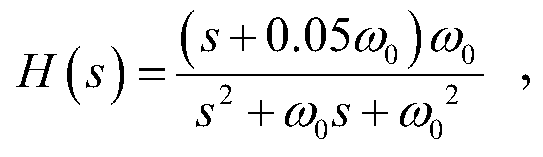
- the transfer function of the band pass filtering unit 10 is expressed as:
- the transfer function of the low pass filtering unit 20 is expressed as:
- the transfer function of the elliptical low pass filtering unit 30 is expressed as:
- ⁇ 0 is the center frequency of the ninth-order filter
- s represents the complex field
- ⁇ is the gain variable
- the transconductance value G m ⁇ 0 C 0 of each transconductance amplifier in the band pass filtering unit 10, where ⁇ 0 is the center frequency of the ninth order filter, and C 0 is the capacity of the reference capacitor.
- the band pass filtering unit 10 includes a first transconductance amplifier Gm1, a second transconductance amplifier Gm2, a third transconductance amplifier Gm3, a first capacitor C1, and a second capacitor C2.
- the non-inverting input terminal of the first transconductance amplifier Gm1 is connected to the initial input signal V i
- the inverting input terminal of the first transconductance amplifier Gm1 is connected to the inverting input terminal of the second transconductance amplifier Gm2
- the first transconductance amplifier Gm1 The output terminal is connected to the non-inverting input terminal of the second transconductance amplifier Gm2 and grounded through the first capacitor C1
- the inverting input terminal of the second transconductance amplifier Gm2 is connected to the output terminal thereof, and is grounded through the second capacitor C2, the third transconductance
- the inverting input terminal of the amplifier Gm3 is connected to the reference voltage signal V ref
- the non-inverting input terminal of the third transconductance amplifier Gm3 is connected to the initial input signal V i
- the output end of the third transconductance amplifier Gm3 is connected to the second transconductance amplifier Gm2
- the capacity of the first capacitor C1 and the second capacitor C2 is C 0
- the low pass filtering unit 20 includes two low pass filters 201 connected in series, and the low pass filter 201 includes a fourth transconductance amplifier Gm4, a fifth transconductance amplifier Gm5, a third capacitor C3, and a fourth capacitor. C4.
- the non-inverting input terminal of the fourth transconductance amplifier Gm4 is connected to the input signal, that is, the non-inverting input terminal of the fourth transconductance amplifier Gm4 of the low-pass filter 201 of the preceding stage is connected to the primary filtered signal V 0 , and the fourth transconductance amplifier Gm4
- the inverting input terminal is connected to the inverting input terminal of the fifth transconductance amplifier Gm5, and the output end of the fourth transconductance amplifier Gm4 is connected to the non-inverting input terminal of the fifth transconductance amplifier Gm5 and grounded through the third capacitor C3, the fifth span
- the output terminal of the lead amplifier Gm5 is connected to its inverting input terminal, and is grounded through the fourth capacitor C4.
- the output end of the fifth transconductance amplifier Gm5 serves as the output end of the low pass filter 201, that is, the secondary low pass filter 201.
- the output of the fifth transconductance amplifier Gm5 outputs a secondary filtered
- the capacity of the third capacitor C3 and the fourth capacitor C4 in the low pass filter 201 is 0.6667C 0
- the elliptical low pass filtering unit 30 includes a first elliptical filter 301 and a second elliptical filter 302 connected in series.
- the first elliptical filter 301 includes a sixth transconductance amplifier Gm6, a seventh transconductance amplifier Gm7, a fifth capacitance C5, a sixth capacitance C6, and a seventh capacitance C7.
- the non-inverting input of the sixth transconductance amplifier Gm6 is connected to the output signal of the low-pass filter unit 20 (secondary filtered signal V 1 ), and the inverting input terminal of the sixth transconductance amplifier Gm6 is connected to the inversion of the seventh transconductance amplifier Gm7.
- the output of the fifth transconductance amplifier Gm5 is connected to the non-inverting input terminal of the seventh transconductance amplifier Gm7 and grounded through the fifth capacitor C5, and the output end of the seventh transconductance amplifier Gm7 is connected to its inverting input terminal, and
- the sixth transconductance amplifier Gm6 is connected to the output terminal of the seventh transconductance amplifier Gm7 through the seventh capacitor C7, and the output terminal of the seventh transconductance amplifier Gm7 is connected to the second elliptic filter 302. Input.
- the capacities of the fifth capacitor C5 and the sixth capacitor C6 are respectively 0.3016C 0 and 1.467C 0 .
- the second elliptical filter 302 includes an eighth transconductance amplifier Gm8, a ninth transconductance amplifier Gn9, and an eighth capacitance C8.
- the forward input terminal of the eighth transconductance amplifier Gm8 is connected to the output signal of the first elliptical filter 301, and the inverting input terminal of the eighth transconductance amplifier Gm8 is connected to the reference voltage signal V ref , and the output terminal of the eighth transconductance amplifier Gm8 is connected.
- the inverting input terminal and the output terminal of the ninth transconductance amplifier Gn9, the forward input terminal of the ninth transconductance amplifier Gn9 is connected to the reference voltage signal V ref , and the ninth transconductance amplifier Gn9 is grounded through the eighth capacitor C8 and serves as an ellipse
- the output of the low pass filtering unit 30 outputs the cubic filtered signal V 2 .
- the capacity of the eighth capacitor C8 is 1.27C 0 .
- the signal passes through the BPF, LPF, and ELF in sequence.
- ⁇ B , ⁇ L and ⁇ E represent the natural frequencies of BPF, LPF and ELF, respectively
- Q B and Q L represent the quality factors of BPF and LPF, respectively
- ELF is 1 dB according to the pass band ripple. Designed with a third-order low-pass elliptical filter with 40dB attenuation.
- the above filter transfer function related parameters are set based on the latest physiological experiment data.
- Q B is set to 1.
- ⁇ L and ⁇ E are set to 1.5 ⁇ B according to the center frequency position of the biological cochlear frequency response curve.
- ⁇ B is represented by ⁇ 0
- its size can be changed between 20Hz and 20KHz
- Q L is represented by 1/ ⁇ , and its value can be performed according to sound stimulation of different intensities. Adjust to determine the filter quality factor for various sound intensities.
- the ninth-order filter frequency of the embodiment of the present invention is adjustable from 20 Hz to 12 kHz
- the gain at the center frequency ⁇ 0 is adjustable
- the gain range at 20 Hz is from 1.431 dB to 31.81 dB
- the quality factor Q is The range is from 4.635 to 11.54
- the gain range is from 6.495dB to 34.05dB at 12KHz
- the quality factor Q ranges from 0.48 to 14.96
- the cutoff frequency is above 300dB/dec, even up to 392.39dB/dec, which is in good agreement with the biocochlear response curve. .
Landscapes
- Engineering & Computer Science (AREA)
- Physics & Mathematics (AREA)
- Signal Processing (AREA)
- Mathematical Physics (AREA)
- Computational Linguistics (AREA)
- Quality & Reliability (AREA)
- Computer Hardware Design (AREA)
- Health & Medical Sciences (AREA)
- Audiology, Speech & Language Pathology (AREA)
- Human Computer Interaction (AREA)
- Acoustics & Sound (AREA)
- Multimedia (AREA)
- Networks Using Active Elements (AREA)
Abstract
Description


Claims (14)
- 一种高生物拟真性语音处理滤波器,其特征在于,所述滤波器为由带通滤波单元、低通滤波单元及椭圆低通滤波单元依次级联构建的九阶滤波器,所述九阶滤波器的中心频率通过所述低通滤波单元来调整。
- 如权利要求1所述的高生物拟真性语音处理滤波器,其特征在于,所述九阶滤波器采用Gm-C形式,其中Gm为跨导放大器的跨导值,C为电容。
- 如权利要求1所述的高生物拟真性语音处理滤波器,其特征在于,所述带通滤波单元的传递函数表示为:其中,ω0为所述中心频率,s表示复数域。
- 如权利要求1-3任一所述的高生物拟真性语音处理滤波器,其特征在于,所述带通滤波单元中各个跨导放大器的跨导值Gm=ω0C0,其中,ω0为所述中心频率,C0为基准电容的容量。
- 如权利要求4所述的高生物拟真性语音处理滤波器,其特征在于,所述带通滤波单元包括第一跨导放大器、第二跨导放大器、第三跨导放大器、第一电容和第二电容,其中:所述第一跨导放大器的正相输入端接入初始输入信号,所述第一跨导放大器的反相输入端接所述第二跨导放大器的反相输入端,所述第一跨导放大器的输出端接所述第二跨导放大器的正相输入端且通过所述第一电容接地,所述第二跨导放大器的反相输入端接其输出端,并通过所述第二电容接地,所述第三跨导放大器的反相输入端接入所述基准电压信号,所述第三跨导放大器的正相输入端接初始输入信号,所述第三跨导放大器的输出端接所述第二跨导放大器的输出端,且所述第二跨导放大器的输出端作为所述带通滤波单元的输出端。
- 如权利要求1所述的高生物拟真性语音处理滤波器,其特征在于,所述低通滤波单元的传递函数表示为:其中,ω0为所述中心频率,s表示复数域,β为增益变量。

- 如权利要求1、2或6所述的高生物拟真性语音处理滤波器,其特征在于,所述低通滤波单元包括两个串联连接的低通滤波器。
- 如权利要求7所述的高生物拟真性语音处理滤波器,其特征在于,所述低通滤波器包括第四跨导放大器、第五跨导放大器、第三电容和第四电容,其中:所述第四跨导放大器的正相输入端接输入信号,所述第四跨导放大器的反相输入端接所述第五跨导放大器的反相输入端,所述第四跨导放大器的输出端接所述第五跨导放大器的正相输入端且通过所述第三电容接地,所述第五跨导放大器的输出端并接其反相输入端,且通过所述第四电容接地,所述第五跨导放大器的输出端作为所述低通滤波器的输出端。
- 如权利要求8所述的高生物拟真性语音处理滤波器,其特征在于,所述第四跨导放大器的跨导值所述第五跨导放大器的跨导值Gm5=βω0C0,其中,ω0为所述中心频率,C0为基准电容的容量,β为增益变量。

- 如权利要求1所述的高生物拟真性语音处理滤波器,其特征在于,所述椭圆低通滤波单元的传递函数表示为:其中,ω0为所述中心频率,s表示复数域。

- 如权利要求10所述的高生物拟真性语音处理滤波器,其特征在于,所述椭圆低通滤波单元包括串联连接的第一椭圆滤波器和第二椭圆滤波器。
- 如权利要求11所述的高生物拟真性语音处理滤波器,其特征在于,所述第一椭圆滤波器包括第六跨导放大器、第七跨导放大器、第五电容、第六电容和第七电容,其中:所述第六跨导放大器的正相输入端接所述低通滤波单元的输出信号,所述第六跨导放大器的反向输入端接所述第七跨导放大器的反相输入端,所述第五跨导放大器的输出端接所述第七跨导放大器的正相输入端且通过所述第五电容接地,所述第七跨导放大器的输出端并接其反相输入端,且通过所述第六电容接地,所述第六跨导放大器的正相输入端通过所述第七电容接所述第七跨导放大器的输出端,所述第七跨导放大器的输出端接所述第二椭圆滤波器。
- 如权利要求12所述的高生物拟真性语音处理滤波器,其特征在于,所述第二椭圆滤波器包括第八跨导放大器、第九跨导放大器和第八电容,其中:所述第八跨导放大器的正向输入端接所述第一椭圆滤波器的输出信号,所述第八跨导放大器的反相输入端接基准电压信号,所述第八跨导放大器的输出端接所述第九跨导放大器的反相输入端和输出端,所述第九跨导放大器的正向输入端接所述基准电压信号,所述第九跨导放大器的通过所述第八电容接地,且作为椭圆低通滤波单元的输出端。
- 一种语音识别设备,其特征在于,包括权利要求1至13任一项所述高生物拟真性语音处理滤波器。
Priority Applications (1)
| Application Number | Priority Date | Filing Date | Title |
|---|---|---|---|
| PCT/CN2017/100975 WO2019047134A1 (zh) | 2017-09-08 | 2017-09-08 | 一种高生物拟真性语音处理滤波器与语音识别设备 |
Applications Claiming Priority (1)
| Application Number | Priority Date | Filing Date | Title |
|---|---|---|---|
| PCT/CN2017/100975 WO2019047134A1 (zh) | 2017-09-08 | 2017-09-08 | 一种高生物拟真性语音处理滤波器与语音识别设备 |
Publications (1)
| Publication Number | Publication Date |
|---|---|
| WO2019047134A1 true WO2019047134A1 (zh) | 2019-03-14 |
Family
ID=65634705
Family Applications (1)
| Application Number | Title | Priority Date | Filing Date |
|---|---|---|---|
| PCT/CN2017/100975 Ceased WO2019047134A1 (zh) | 2017-09-08 | 2017-09-08 | 一种高生物拟真性语音处理滤波器与语音识别设备 |
Country Status (1)
| Country | Link |
|---|---|
| WO (1) | WO2019047134A1 (zh) |
Citations (5)
| Publication number | Priority date | Publication date | Assignee | Title |
|---|---|---|---|---|
| CN2105140U (zh) * | 1991-11-05 | 1992-05-20 | 国营成都宏明无线电器材总厂 | 有源滤波器 |
| JP2002156997A (ja) * | 2000-11-21 | 2002-05-31 | Sharp Corp | 音声検出制御装置 |
| JP2005128132A (ja) * | 2003-10-22 | 2005-05-19 | Matsushita Electric Ind Co Ltd | 話速変換方法及び話速変換装置 |
| CN101656079A (zh) * | 2009-07-20 | 2010-02-24 | 霍桂馨 | 一种便携式汉语声调学习机的语音处理方法 |
| CN107799122A (zh) * | 2017-09-08 | 2018-03-13 | 中国科学院深圳先进技术研究院 | 一种高生物拟真性语音处理滤波器与语音识别设备 |
-
2017
- 2017-09-08 WO PCT/CN2017/100975 patent/WO2019047134A1/zh not_active Ceased
Patent Citations (5)
| Publication number | Priority date | Publication date | Assignee | Title |
|---|---|---|---|---|
| CN2105140U (zh) * | 1991-11-05 | 1992-05-20 | 国营成都宏明无线电器材总厂 | 有源滤波器 |
| JP2002156997A (ja) * | 2000-11-21 | 2002-05-31 | Sharp Corp | 音声検出制御装置 |
| JP2005128132A (ja) * | 2003-10-22 | 2005-05-19 | Matsushita Electric Ind Co Ltd | 話速変換方法及び話速変換装置 |
| CN101656079A (zh) * | 2009-07-20 | 2010-02-24 | 霍桂馨 | 一种便携式汉语声调学习机的语音处理方法 |
| CN107799122A (zh) * | 2017-09-08 | 2018-03-13 | 中国科学院深圳先进技术研究院 | 一种高生物拟真性语音处理滤波器与语音识别设备 |
Similar Documents
| Publication | Publication Date | Title |
|---|---|---|
| Lyon et al. | History and future of auditory filter models | |
| Kumngern et al. | 0.5 V sixth-order Chebyshev band-pass filter based on multiple-input bulk-driven OTA | |
| CN107799122B (zh) | 一种高生物拟真性语音处理滤波器与语音识别设备 | |
| CN102497168A (zh) | 智能音量限制装置及方法 | |
| Kumngern et al. | Voltage-mode multifunction biquadratic filters using new ultra-low-power differential difference current conveyors | |
| CN105048989A (zh) | 具有共模噪声消减的低通滤波器 | |
| Kumngern et al. | 31.3 nW, 0.5 V bulk-driven OTA for biosignal processing | |
| CN108769851B (zh) | 一种数字耳机 | |
| JP6750901B2 (ja) | チャンネル選択フィルタを備えた高線形性WiGigベースバンドアンプ | |
| CN203596803U (zh) | 一种频率补偿的装置 | |
| WO2019047134A1 (zh) | 一种高生物拟真性语音处理滤波器与语音识别设备 | |
| CN108462479B (zh) | 基于改进型Gm-C的镜像抑制滤波器及其构建方法 | |
| CN106658299B (zh) | 音频处理电路及终端设备 | |
| CN106249793B (zh) | 电源稳压器电路 | |
| CN113965197A (zh) | 一种rtr分频方法及电路 | |
| CN102395077B (zh) | 一种抗干扰耳机 | |
| Wang et al. | A floating active inductor based CMOS cochlea filter with high tunability and sharp cut-off | |
| Wei et al. | A computationally efficient non-uniform digital FIR filter bank for hearing aid | |
| CN206894870U (zh) | 音频解码装置及其音频输出电路 | |
| CN204859532U (zh) | 一种模拟类麦克风回音降噪压缩处理电路 | |
| CN203912166U (zh) | 一种有源带阻滤波电路 | |
| CN108235189A (zh) | 一种语音信号的回声消除装置及电视机 | |
| CN115664369A (zh) | 一种基于自偏置伪电阻的可调低通滤波器电路 | |
| Maghami et al. | Compact, programmable, two-Stage configuration for implantable biopotential recording amplifiers | |
| Kambalimath et al. | FPGA based implementation of comb filters for use in binaural hearing aids for reducing intraspeech spectral masking |
Legal Events
| Date | Code | Title | Description |
|---|---|---|---|
| 121 | Ep: the epo has been informed by wipo that ep was designated in this application |
Ref document number: 17924582 Country of ref document: EP Kind code of ref document: A1 |
|
| NENP | Non-entry into the national phase |
Ref country code: DE |
|
| 122 | Ep: pct application non-entry in european phase |
Ref document number: 17924582 Country of ref document: EP Kind code of ref document: A1 |
|
| 32PN | Ep: public notification in the ep bulletin as address of the adressee cannot be established |
Free format text: NOTING OF LOSS OF RIGHTS PURSUANT TO RULE 112(1) EPC (EPO FORM 1205A DATED 22.09.2020) |
|
| 122 | Ep: pct application non-entry in european phase |
Ref document number: 17924582 Country of ref document: EP Kind code of ref document: A1 |