WO2019044113A1 - 車両用クリーナユニットおよび車両用クリーナユニットを備える車両 - Google Patents
車両用クリーナユニットおよび車両用クリーナユニットを備える車両 Download PDFInfo
- Publication number
- WO2019044113A1 WO2019044113A1 PCT/JP2018/022370 JP2018022370W WO2019044113A1 WO 2019044113 A1 WO2019044113 A1 WO 2019044113A1 JP 2018022370 W JP2018022370 W JP 2018022370W WO 2019044113 A1 WO2019044113 A1 WO 2019044113A1
- Authority
- WO
- WIPO (PCT)
- Prior art keywords
- vehicle
- cleaner unit
- longitudinal direction
- high pressure
- vehicle cleaner
- Prior art date
- Legal status (The legal status is an assumption and is not a legal conclusion. Google has not performed a legal analysis and makes no representation as to the accuracy of the status listed.)
- Ceased
Links
Images





Classifications
-
- B—PERFORMING OPERATIONS; TRANSPORTING
- B60—VEHICLES IN GENERAL
- B60S—SERVICING, CLEANING, REPAIRING, SUPPORTING, LIFTING, OR MANOEUVRING OF VEHICLES, NOT OTHERWISE PROVIDED FOR
- B60S1/00—Cleaning of vehicles
- B60S1/02—Cleaning windscreens, windows or optical devices
- B60S1/56—Cleaning windscreens, windows or optical devices specially adapted for cleaning other parts or devices than front windows or windscreens
- B60S1/60—Cleaning windscreens, windows or optical devices specially adapted for cleaning other parts or devices than front windows or windscreens for signalling devices, e.g. reflectors
- B60S1/603—Cleaning windscreens, windows or optical devices specially adapted for cleaning other parts or devices than front windows or windscreens for signalling devices, e.g. reflectors the operation of at least a part of the cleaning means being controlled by electric means
-
- B—PERFORMING OPERATIONS; TRANSPORTING
- B60—VEHICLES IN GENERAL
- B60S—SERVICING, CLEANING, REPAIRING, SUPPORTING, LIFTING, OR MANOEUVRING OF VEHICLES, NOT OTHERWISE PROVIDED FOR
- B60S1/00—Cleaning of vehicles
- B60S1/02—Cleaning windscreens, windows or optical devices
- B60S1/54—Cleaning windscreens, windows or optical devices using gas, e.g. hot air
-
- B—PERFORMING OPERATIONS; TRANSPORTING
- B08—CLEANING
- B08B—CLEANING IN GENERAL; PREVENTION OF FOULING IN GENERAL
- B08B5/00—Cleaning by methods involving the use of air flow or gas flow
- B08B5/02—Cleaning by the force of jets, e.g. blowing-out cavities
-
- B—PERFORMING OPERATIONS; TRANSPORTING
- B60—VEHICLES IN GENERAL
- B60S—SERVICING, CLEANING, REPAIRING, SUPPORTING, LIFTING, OR MANOEUVRING OF VEHICLES, NOT OTHERWISE PROVIDED FOR
- B60S1/00—Cleaning of vehicles
- B60S1/02—Cleaning windscreens, windows or optical devices
- B60S1/56—Cleaning windscreens, windows or optical devices specially adapted for cleaning other parts or devices than front windows or windscreens
-
- F—MECHANICAL ENGINEERING; LIGHTING; HEATING; WEAPONS; BLASTING
- F04—POSITIVE - DISPLACEMENT MACHINES FOR LIQUIDS; PUMPS FOR LIQUIDS OR ELASTIC FLUIDS
- F04B—POSITIVE-DISPLACEMENT MACHINES FOR LIQUIDS; PUMPS
- F04B17/00—Pumps characterised by combination with, or adaptation to, specific driving engines or motors
- F04B17/03—Pumps characterised by combination with, or adaptation to, specific driving engines or motors driven by electric motors
-
- F—MECHANICAL ENGINEERING; LIGHTING; HEATING; WEAPONS; BLASTING
- F04—POSITIVE - DISPLACEMENT MACHINES FOR LIQUIDS; PUMPS FOR LIQUIDS OR ELASTIC FLUIDS
- F04B—POSITIVE-DISPLACEMENT MACHINES FOR LIQUIDS; PUMPS
- F04B9/00—Piston machines or pumps characterised by the driving or driven means to or from their working members
- F04B9/02—Piston machines or pumps characterised by the driving or driven means to or from their working members the means being mechanical
-
- F—MECHANICAL ENGINEERING; LIGHTING; HEATING; WEAPONS; BLASTING
- F04—POSITIVE - DISPLACEMENT MACHINES FOR LIQUIDS; PUMPS FOR LIQUIDS OR ELASTIC FLUIDS
- F04B—POSITIVE-DISPLACEMENT MACHINES FOR LIQUIDS; PUMPS
- F04B9/00—Piston machines or pumps characterised by the driving or driven means to or from their working members
- F04B9/02—Piston machines or pumps characterised by the driving or driven means to or from their working members the means being mechanical
- F04B9/04—Piston machines or pumps characterised by the driving or driven means to or from their working members the means being mechanical the means being cams, eccentrics or pin-and-slot mechanisms
- F04B9/047—Piston machines or pumps characterised by the driving or driven means to or from their working members the means being mechanical the means being cams, eccentrics or pin-and-slot mechanisms the means being pin-and-slot mechanisms
Definitions
- the present invention relates to a vehicle cleaner unit for cleaning an object to be cleaned and a vehicle including the vehicle cleaner unit.
- Patent Document 1 a compressed air generation unit is installed in the vicinity of an on-vehicle camera, and the compressed air of the compressed air generation unit is jetted from a nozzle to blow high-pressure air on the front glass of the on-vehicle camera.
- a configuration for removing water droplets adhering to the front glass has been proposed (see Patent Document 1).
- Patent Document 1 a compressed air generating unit and the like are configured separately from the on-vehicle camera, and there is room for improvement in workability and space saving when attaching them to a vehicle.
- an object of this invention is to provide the vehicle provided with the cleaner unit for vehicles which can implement
- Another object of the present invention is to provide a vehicle cleaner unit capable of realizing improvement in mounting workability and space saving.
- the vehicle cleaner unit of the present invention is: A vehicle cleaner unit for cleaning an object to be cleaned mounted on a vehicle, comprising: With a single motor, A cylinder which extends in the longitudinal direction of the vehicle cleaner unit and into which air is introduced, and which can linearly move in the longitudinal direction inside the cylinder so that the air is subjected to high pressure to the outside of the vehicle cleaner unit A single pump having a delivery piston; A biasing member for biasing the piston in the first longitudinal direction; A single worm mechanism for transmitting rotational motion of the single motor to linearly move the piston in a second direction opposite to the first direction; The axis of rotation of the single motor and the longitudinal direction are parallel; The single motor and the single pump are located on the same side in the longitudinal direction with respect to the worm mechanism.
- a circuit board for controlling the single motor may be disposed inside the housing of the vehicle cleaner unit.
- a circuit board for controlling the motor is disposed in the vehicle cleaner unit.
- the circuit board may be disposed along the longitudinal direction.
- a circuit board for controlling the motor is disposed in the vehicle cleaner unit.
- the single motor may be disposed between the circuit board and the cylinder.
- a circuit board for controlling the motor is disposed in the vehicle cleaner unit.
- the vehicle cleaner unit of the present invention is: A vehicle cleaner unit for cleaning an object to be cleaned mounted on a vehicle, comprising: A base member supporting the object to be cleaned; A pump for generating high pressure air, and a high pressure air generation unit provided with a power source for driving the pump; A nozzle for injecting the high pressure air toward the cleaning surface of the object to be cleaned; The discharge port of the nozzle is provided on the side of the base member opposite to the side on which the high pressure air generating unit is provided.
- the nozzle may be integrated with the base member.
- the operation of attaching the nozzle to the base member can be omitted, and the operation efficiency can be improved.
- a vehicle provided with the vehicle cleaner unit of the present invention is: A vehicle cleaner unit having any of the above configurations is provided.
- FIG. 5 is a cross-sectional view taken along line AA of FIG. 4; It is a perspective view showing the high pressure air generation part of the cleaner unit for vehicles. It is a figure which shows the inside of the motive power source of the high pressure air production
- “left and right direction”, “front and back direction”, and “upper and lower direction” will be referred to as appropriate. These directions are relative directions set for the vehicle V shown in FIG.
- the “upper and lower direction” is a direction including “upper direction” and “lower direction”.
- the “front-rear direction” is a direction including the “front direction” and the “rear direction”.
- the “left-right direction” is a direction including the “left direction” and the “right direction”.
- the vehicle cleaner unit of the present invention is applied as a unit for cleaning foreign matter such as water droplets, mud, dust and the like adhering to an on-vehicle sensor or the like (an example of the object to be cleaned) mounted on a vehicle using high pressure air.
- FIG. 1 shows a side view of the rear of a vehicle provided with a vehicle cleaner unit.
- the vehicle cleaner unit 1 is attached to, for example, a back door 200 of the vehicle V. Specifically, it is attached to, for example, a vehicle body panel 200 a of the back door 200.
- the body panel 200a includes a body panel, a garnish and the like.
- the vehicle cleaner unit 1 includes a drive unit, and the power supply terminal of the drive unit is connected to the power supply line of the vehicle V.
- the vehicle cleaner unit 1 may be attached to, for example, a rear bumper of the vehicle V or the like.
- an on-vehicle camera 100 for confirming the rear of the vehicle V can be mentioned.
- the on-vehicle camera 100 of this example is attached to the vehicle cleaner unit 1 in a state where the camera lens is exposed to the rear of the vehicle V and the outside.
- the on-vehicle camera 100 is not limited to the rear of the vehicle V, and may be attached to, for example, the front or side of the vehicle V.
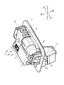
- FIG. 2 is a perspective view showing the vehicle cleaner unit 1 attached to the vehicle body panel 200 a of the back door 200.
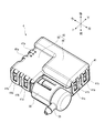
- FIG. 3 is a perspective view of the vehicle cleaner unit 1 observed from the front side of the vehicle.
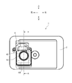
- 4 is a front view of the vehicle cleaner unit 1
- FIG. 5 is a cross-sectional view taken along line AA of FIG.
- the vehicle cleaner unit 1 uses the base member 2 for supporting the on-vehicle camera 100, the high-pressure air generation unit 4 for generating high-pressure air, and the generated high-pressure air to the on-vehicle camera 100. It has a nozzle 6 for directing and injecting.
- the base member 2 is a bracket for attaching the vehicle cleaner unit 1 to the vehicle body panel 200a, and is configured, for example, in a substantially angular shape.
- a high pressure air generation unit 4 is provided on the back of the base member 2 on the vehicle front side.
- the base member 2 is provided with a support portion 21 for supporting the high pressure air generation portion 4, and the high pressure air generation portion 4 is detachably provided on the back side of the base member 2 via the support portion 21. It is done.
- the high pressure air generating unit 4 is mounted such that the longitudinal direction L1 thereof is along the longitudinal direction (left and right direction in FIG. 3) of the vehicle cleaner unit 1.
- the high pressure air generation unit 4 includes a pump 30 that compresses air to generate high pressure air, and a power source 40 that drives the pump 30.
- the power source 40 includes a motor 45 that drives the pump 30 by rotational movement, and a worm mechanism 50 that transmits the rotational movement of the motor 45 to the pump 30.
- the high pressure air generating unit 4 will be further described later with reference to FIGS. 6 to 8.
- a nozzle 6 is provided on a front portion on the vehicle rear side of the base member 2.
- the nozzle 6 is integrated with the base member 2 by, for example, integral molding or adhesion.
- the nozzle 6 is located on the upper side of the in-vehicle camera 100 and is provided to be exposed to the rear of the vehicle V so as to be aligned with the in-vehicle camera 100.
- a communication passage 61 of high pressure air which extends from the side of the base member 2 to the rear side of the vehicle V, is provided inside the nozzle 6 along the upper surface of the on-vehicle camera 100.
- a discharge port 62 opened toward the camera lens 101 (an example of the cleaning surface) of the on-vehicle camera 100 is provided.
- the high pressure air delivered from the high pressure air generating unit 4 is for the vehicle from the discharge port 62 of the nozzle 6 provided on the opposite side to the side where the high pressure air generating unit 4 of the base member 2 is provided. It is discharged to the outside of the cleaner unit 1.
- a mounting arm 22 for mounting the vehicle cleaner unit 1 to the vehicle body panel 200a is provided at the back of the base member 2.
- the mounting arm 22 is provided with a claw 22a, and the claw 22a is engaged with, for example, an opening 201 formed in the vehicle body panel 200a, whereby the vehicle cleaner unit 1 is attached to the vehicle body panel 200a.
- the vehicle cleaner unit 1 inserts the base member 2 into the opening 201 of the vehicle body panel 200a, and the high pressure air generating unit 4 attached to the base member 2 is disposed inside the vehicle body panel 200a on the vehicle body panel 200a. It is attached.
- FIG. 6 shows a perspective view of the high pressure air generator 4.
- FIG. 7 shows an internal configuration of the power source 40.
- FIG. 8 shows a cross-sectional view along the longitudinal direction of the high pressure air generating unit 4.
- the side seen on the front side of the paper surface is the side attached to the base member 2.
- the emission port 35 of the pump 30 is directed to the upper side of the high pressure air generating unit 4 for the sake of explanation.
- the pump 30 and the power source 40 which constitute the high pressure air generating unit 4 are integrally combined.
- a lid 41 is detachably provided to the pump 30, the motor 45 and the worm mechanism 50.
- the lid 41 is provided with a plurality of locking arms 41 a.
- a plurality of claws 41 b are provided on the outside of the housing 42 accommodating the pump 30, the motor 45 and the worm mechanism 50.
- the cover 41 is attached to the pump 30, the motor 45, and the worm mechanism 50 by the claws 41 b being engaged with the locking arms 41 a of the cover 41.
- the power source 40 includes a single motor 45 and a single worm mechanism 50.
- the motor 45 is disposed such that its rotational axis L2 is along the longitudinal direction L1 of the high-pressure air generating unit 4.
- the worm mechanism 50 is fixed to the rotation shaft 46 of the motor 45 and is rotated with the rotation of the motor 45.
- the worm mechanism 50 is engaged with the worm 51 and rotated with the rotation of the worm 51. And a wheel 52.
- the worm mechanism 50 has a pinion 53 axially supported coaxially with the worm wheel 52 (see FIG. 7).
- the pinion 53 is rotated with the worm wheel 52.
- the pump 30 includes a cylinder 31 into which air is introduced, a piston 32 that delivers air to the outside, a biasing spring 33 (an example of a biasing member) that biases the piston 32, and a piston 32. And an outlet 35 from which air is emitted.
- the cylinder 31 is disposed to extend along the longitudinal direction L1 of the high pressure air generating unit 4.
- the piston 32 is provided inside the cylinder 31 so as to be capable of reciprocating linear motion in the longitudinal direction of the cylinder 31.
- the biasing spring 33 is provided inside the cylinder 31 to bias the piston 32 in the first longitudinal direction of the cylinder 31.
- the first direction in this example means the direction in which the piston 32 moves (the left direction in FIG. 8) when the air in the cylinder 31 is discharged to the outside.
- the air in the cylinder 31 is compressed and becomes high pressure, and is emitted from the emission port 35.
- the end of the cylinder 31 provided with the emission port 35 is rotatably formed around the central axis L3 of the pump 30, and can change the direction of the emission port 35.
- the cylinder 31 may have a configuration in which the direction of the emission port 35 is fixed.
- the rack 34 is integrally formed with the piston 32 and provided along the longitudinal direction L1 of the high-pressure air generating unit 4 in a state where the rack 34 protrudes from the cylinder 31 in which the piston 32 is accommodated.
- the rack 34 is provided with rack teeth 34 a.
- the rack 34 is reciprocated linearly with the piston 32 in the longitudinal direction of the cylinder 31.
- the rack teeth 34 a are configured to be able to mesh with the pinion 53 of the worm mechanism 50.
- the pinion 53 meshes with the rack teeth 34 a to move the rack 34 in the second longitudinal direction of the cylinder 31.
- the second direction in this example means a direction (right direction in FIG. 8) opposite to the first direction biased by the biasing spring 33. That is, the second direction is the direction opposite to the direction in which the piston 32 moves when the air in the cylinder 31 is sent out.
- the rack 34 is moved in the second direction, the piston 32 linearly moves in the second direction with the rack 34 against the bias of the biasing spring 33.
- a circuit board 43 for controlling the operation of the motor 45 is provided inside the housing 42 of the high pressure air generating unit 4.
- the circuit board 43 is arranged side by side with the motor 45 and along the longitudinal direction L1 of the high pressure air generating unit 4.
- the circuit board 43 is disposed such that the motor 45 is located between the circuit board 43 and the pump 30 (cylinder 31).
- the circuit board 43 is connected to, for example, a vehicle ECU (Electronic Control Unit) of the vehicle V, and controls the operation of the motor 45 by a signal from the vehicle ECU.
- the pump 30 is disposed such that the central axis L3 thereof is along the longitudinal direction L1 of the high pressure air generating unit 4. That is, in the high pressure air generating unit 4, the motor 45 and the pump 30 are arranged such that the rotation axis L 2 of the motor 45 and the central axis L 3 of the pump 30 are substantially parallel.
- the motor 45 and the pump 30 are disposed on the same side (left side in FIGS. 7 and 8) with respect to the worm mechanism 50 in the longitudinal direction L1 of the high-pressure air generating unit 4.
- the discharge port 62 of the nozzle 6 is provided on one side of the base member 2 across the base member 2 and the high pressure air generating unit 4 is discharged. It is provided on the opposite side to the side on which the outlet 62 is provided. As a result, the components constituting the vehicle cleaner unit 1 can be efficiently laid out, and space saving can be realized.
- the nozzle 6 is integrated with the base member 2, the work of attaching the nozzle 6 to the base member 2 can be omitted in the manufacturing process, and the working efficiency can be improved.
- the motor 45 and the pump 30 are disposed substantially in parallel so that the rotation axis L2 of the motor 45 and the central axis L3 of the pump 30 are along the longitudinal direction L1 of the high pressure air generating unit 4. ing.
- the motor 45 and the pump 30 are disposed on the same side with respect to the worm mechanism 50 in the longitudinal direction L1 of the high-pressure air generating unit 4. For this reason, the components which comprise the high pressure air production
- circuit board 43 for controlling the motor 45 is disposed inside the housing 42 of the high pressure air generating unit 4, further space saving can be realized.
- the present invention is not limited to the above-described embodiment, and appropriate modifications, improvements, and the like can be made.
- the materials, shapes, dimensions, numerical values, forms, numbers, arrangement places and the like of each component in the above-described embodiment are arbitrary and not limited as long as the present invention can be achieved.
Landscapes
- Engineering & Computer Science (AREA)
- Mechanical Engineering (AREA)
- General Engineering & Computer Science (AREA)
- Nozzles (AREA)
- Cleaning In General (AREA)
Abstract
車両に搭載された洗浄対象物を洗浄する車両用クリーナユニットであって、単一のモータ(45)と、車両用クリーナユニットの長手方向(L1)に延びてその内部に空気が流入されるシリンダ(31)と、シリンダ(31)の内部において長手方向(L1)に直線運動可能であって空気を高圧で車両用クリーナユニットの外部へ送り出すピストン(32)とを有する単一のポンプ(30)と、ピストン(32)を長手方向(L1)の第一方向に付勢させる付勢バネ(33)と、モータ(45)の回転運動を伝達してピストン(32)を第一方向とは逆の第二方向へ直線運動させる単一のウォーム機構(50)とを備え、モータ(45)の回転軸線(L2)と長手方向(L1)とが平行であり、モータ(45)とポンプ(30)がウォーム機構(50)に対して長手方向(L1)において同じ側に位置している。
Description
本発明は、洗浄対象物を洗浄する車両用クリーナユニットおよび車両用クリーナユニットを備える車両に関する。
近年、車両周囲の状況を撮影する車載カメラが搭載された車両が増えてきている。車載カメラは、撮像面であるレンズが雨や泥等で汚れてしまう場合がある。このため、従来、レンズ上に付着した水滴等の異物を除去するために、車載カメラのレンズに洗浄液や圧縮空気等を吹き付けて異物を除去する装置が知られている。
例えば、特許文献1には、車載カメラの近傍に圧縮空気発生ユニットを設置し、圧縮空気発生ユニットの圧縮空気をノズルから噴射して車載カメラの前面ガラスに高圧の空気を吹き付けるようにすることで前面ガラスに付着した水滴を取り除く構成が提案されている(特許文献1参照)。
ところで、更なる省スペース化のためには、クリーナの構成部品のレイアウトに工夫の余地がある。
また、特許文献1の構成では、車載カメラとは別体として圧縮空気発生ユニット等が構成されており、これらを車両に取り付ける際に作業性や省スペース化に改善の余地がある。
そこで、本発明は、効率的な部品のレイアウトにより省スペース化を実現可能な車両用クリーナユニットおよび車両用クリーナユニットを備える車両を提供することを目的とする。
また、本発明は、取り付け作業性の向上や省スペース化を実現可能な車両用クリーナユニットを提供することを目的とする。
上記目的を達成するために、本発明の車両用クリーナユニットは、
車両に搭載された洗浄対象物を洗浄するための車両用クリーナユニットであって、
単一のモータと、
前記車両用クリーナユニットの長手方向に延びてその内部に空気が流入されるシリンダと、前記シリンダの内部において前記長手方向に直線運動可能であって前記空気を高圧で前記車両用クリーナユニットの外部へ送り出すピストンと、を有する単一のポンプと、
前記ピストンを前記長手方向の第一方向に付勢させる付勢部材と、
前記単一のモータの回転運動を伝達して前記ピストンを前記第一方向とは逆の第二方向へ直線運動させる単一のウォーム機構と、を備え、
前記単一のモータの回転軸線と前記長手方向とが平行であり、
前記単一のモータと前記単一のポンプが前記ウォーム機構に対して前記長手方向において同じ側に位置している。
車両に搭載された洗浄対象物を洗浄するための車両用クリーナユニットであって、
単一のモータと、
前記車両用クリーナユニットの長手方向に延びてその内部に空気が流入されるシリンダと、前記シリンダの内部において前記長手方向に直線運動可能であって前記空気を高圧で前記車両用クリーナユニットの外部へ送り出すピストンと、を有する単一のポンプと、
前記ピストンを前記長手方向の第一方向に付勢させる付勢部材と、
前記単一のモータの回転運動を伝達して前記ピストンを前記第一方向とは逆の第二方向へ直線運動させる単一のウォーム機構と、を備え、
前記単一のモータの回転軸線と前記長手方向とが平行であり、
前記単一のモータと前記単一のポンプが前記ウォーム機構に対して前記長手方向において同じ側に位置している。
上記構成によれば、効率的な部品のレイアウトにより省スペース化を実現可能である。
また、本発明の車両用クリーナユニットにおいて、
前記単一のモータを制御するための回路基板が、前記車両用クリーナユニットのハウジングの内部に配置されていてもよい。
前記単一のモータを制御するための回路基板が、前記車両用クリーナユニットのハウジングの内部に配置されていてもよい。
更なる省スペース化のため、モータを制御するための回路基板が車両用クリーナユニット内に配置されていることが好ましい。
また、本発明の車両用クリーナユニットにおいて、
前記回路基板は、前記長手方向に沿って配置されていてもよい。
前記回路基板は、前記長手方向に沿って配置されていてもよい。
更なる省スペース化のため、モータを制御するための回路基板が車両用クリーナユニット内に配置されていることが好ましい。
また、本発明の車両用クリーナユニットにおいて、
前記単一のモータは、前記回路基板と前記シリンダとの間に配置されていてもよい。
前記単一のモータは、前記回路基板と前記シリンダとの間に配置されていてもよい。
更なる省スペース化のため、モータを制御するための回路基板が車両用クリーナユニット内に配置されていることが好ましい。
また、上記目的を達成するために、本発明の車両用クリーナユニットは、
車両に搭載された洗浄対象物を洗浄するための車両用クリーナユニットであって、
前記洗浄対象物を支持するベース部材と、
高圧空気を生成するポンプ、および前記ポンプを駆動する動力源を備えた高圧空気生成部と、
前記高圧空気を前記洗浄対象物の洗浄面に向けて噴射するノズルと、を備え、
前記ノズルの吐出口は、前記ベース部材の前記高圧空気生成部が設けられた側とは反対側に設けられている。
車両に搭載された洗浄対象物を洗浄するための車両用クリーナユニットであって、
前記洗浄対象物を支持するベース部材と、
高圧空気を生成するポンプ、および前記ポンプを駆動する動力源を備えた高圧空気生成部と、
前記高圧空気を前記洗浄対象物の洗浄面に向けて噴射するノズルと、を備え、
前記ノズルの吐出口は、前記ベース部材の前記高圧空気生成部が設けられた側とは反対側に設けられている。
上記構成によれば、効率的な部品のレイアウトにより省スペース化を実現可能である。
また、本発明の車両用クリーナユニットにおいて、
前記ノズルは、前記ベース部材と一体化されていてもよい。
前記ノズルは、前記ベース部材と一体化されていてもよい。
上記構成によれば、ベース部材にノズルを取り付ける作業を省略することができ、作業効率を向上させることができる。
また、本発明の車両用クリーナユニットを備える車両は、
上記いずれかの構成を有する車両用クリーナユニットを備えている。
上記いずれかの構成を有する車両用クリーナユニットを備えている。
上記構成によれば、効率的な部品のレイアウトにより省スペース化を実現可能である。
本発明の車両用クリーナユニットおよび車両用クリーナユニットを備える車両によれば、効率的な部品のレイアウトにより省スペース化を実現することができる。
また、本発明の車両用クリーナユニットおよび車両用クリーナユニットを備える車両によれば、取り付け作業性の向上を実現することができる。
以下、本発明の第一実施形態について図面を参照しながら説明する。尚、本実施形態の説明において既に説明された部材と同一の参照番号を有する部材については、説明の便宜上、その説明は省略する。また、本図面に示された各部材の寸法は、説明の便宜上、実際の各部材の寸法とは異なる場合がある。
また、本実施形態の説明では、説明の便宜上、「左右方向」、「前後方向」、「上下方向」について適宜言及する。これらの方向は、図1に示す車両Vについて設定された相対的な方向である。ここで、「上下方向」は、「上方向」及び「下方向」を含む方向である。「前後方向」は、「前方向」及び「後方向」を含む方向である。「左右方向」は、「左方向」及び「右方向」を含む方向である。
本発明の車両用クリーナユニットは、車両に搭載された車載センサ等(洗浄対象物の一例)に付着する水滴や泥や塵埃等の異物を、高圧空気を用いて洗浄するユニットとして適用される。
図1は、車両用クリーナユニットを備える車両の後部の側面図を示す。図1に示すように、車両用クリーナユニット1は、車両Vの例えばバックドア200に取り付けられている。具体的にはバックドア200の例えば車体パネル200aに取り付けられている。車体パネル200aにはボディパネル、ガーニッシュ等が含まれる。車両用クリーナユニット1は、駆動部を備えており、駆動部の電源端子が車両Vの電源ラインに接続されている。なお、車両用クリーナユニット1は、例えば車両Vのリアバンパー等に取り付けられるようにしてもよい。
洗浄対象物の車載センサとしては、例えば車両Vの後方を確認するための車載カメラ100を挙げることができる。本例の車載カメラ100は、カメラレンズを車両Vの後方に向けて外側へ露出させた状態で車両用クリーナユニット1に取り付けられている。なお、車載カメラ100は、車両Vの後部に限定されず、例えば車両Vの前部や側部等に取り付けられるものであってもよい。
図2は、車両用クリーナユニット1がバックドア200の車体パネル200aに取り付けられている状態を示す斜視図である。図3は、車両用クリーナユニット1を車両前方側から観察した斜視図である。また、図4は車両用クリーナユニット1の正面図であり、図5は図4のA-Aにおける断面図である。
図2から図5に示すように、車両用クリーナユニット1は、車載カメラ100を支持するベース部材2と、高圧空気を生成する高圧空気生成部4と、生成された高圧空気を車載カメラ100に向けて噴射するノズル6とを備えている。
ベース部材2は、車両用クリーナユニット1を車体パネル200aに取り付けるためのブラケットであって、例えば略角形状に構成されている。ベース部材2の車両前方側である背部には、高圧空気生成部4が設けられている。ベース部材2には高圧空気生成部4を支持するための支持部21が設けられており、高圧空気生成部4は、この支持部21を介して、ベース部材2の背面側に着脱可能に設けられている。高圧空気生成部4は、その長手方向L1が車両用クリーナユニット1の長手方向(図3の左右方向)に沿うように装着される。
高圧空気生成部4は、空気を圧縮して高圧空気を生成するポンプ30と、ポンプ30を駆動する動力源40とを備えている。動力源40は、回転運動によりポンプ30を駆動させるモータ45と、モータ45の回転運動をポンプ30へ伝達するウォーム機構50とを備えている。高圧空気生成部4については、図6から図8を参照してさらに後述する。
ベース部材2の車両後方側である正面部には、ノズル6が設けられている。ノズル6は、ベース部材2と例えば一体成形によりあるいは接着により一体化されている。ノズル6は、車載カメラ100の上側に位置し、車載カメラ100と並ぶように車両Vの後方に向けて外側へ露出するように設けられている。
ノズル6の内部には、車載カメラ100の上面に沿うように、ベース部材2側から車両Vの後方側へ延びる、高圧空気の連通路61が設けられている。連通路61の先端には、車載カメラ100のカメラレンズ101(洗浄面の一例)に向けて開口する吐出口62が設けられている。高圧空気生成部4が支持部21を介してベース部材2に取り付けられると、高圧空気を出射するポンプ30の出射口35がノズル6の連通路61に連結されるように構成されている。これにより、高圧空気生成部4から送り出された高圧空気は、ベース部材2の高圧空気生成部4が設けられている側とは反対側に設けられているノズル6の吐出口62から、車両用クリーナユニット1の外部へ吐出される。
また、ベース部材2の背部には、車両用クリーナユニット1を車体パネル200aに取り付けるための取付腕部22が設けられている。取付腕部22には爪部22aが設けられており、この爪部22aが車体パネル200aに形成された例えば開口部201に係合されることで車両用クリーナユニット1が車体パネル200aに取り付けられる。車両用クリーナユニット1は、車体パネル200aの開口部201にベース部材2を挿通させ、ベース部材2に取り付けられた高圧空気生成部4が車体パネル200aの内側に配置された状態で車体パネル200aに取り付けられている。
図6は、高圧空気生成部4の斜視図を示す。図7は、動力源40の内部構成を示す。図8は、高圧空気生成部4の長手方向に沿った断面図を示す。なお、図6に示す高圧空気生成部4において、紙面の表側に見えている側(後述の蓋部41側)は、ベース部材2に取り付けられる側である。また、図6~図8においては、説明のため、ポンプ30の出射口35は、高圧空気生成部4の上方側に向けられている。
図6に示すように、高圧空気生成部4を構成するポンプ30と動力源40(モータ45,ウォーム機構50)とは、一体的に組み合わされている。ポンプ30とモータ45とウォーム機構50に対しては、蓋部41が着脱可能に設けられている。蓋部41には、複数の係止腕41aが設けられている。ポンプ30、モータ45およびウォーム機構50を収容するハウジング42の外側には複数の爪部41bが設けられている。各爪部41bが蓋部41の各係止腕41aに係止することで、ポンプ30とモータ45とウォーム機構50に対して、蓋部41が取り付けられる。
図7に示すように、動力源40は、単一のモータ45と、単一のウォーム機構50とを備えている。モータ45は、その回転軸線L2が高圧空気生成部4の長手方向L1に沿うように配置されている。ウォーム機構50は、モータ45の回転軸46に固定されモータ45の回転に伴って回転される単一のウォーム51と、ウォーム51に噛合されウォーム51の回転に伴って回転される単一のウォームホイール52とを有している。
また、ウォーム機構50は、図8に示すように、ウォームホイール52(図7参照)と同軸に軸支されるピニオン53を有している。ピニオン53は、ウォームホイール52と共に回転される。
図8に示すように、ポンプ30は、空気が流入されるシリンダ31と、空気を外部へ送り出すピストン32と、ピストン32を付勢する付勢バネ33(付勢部材の一例)と、ピストン32に連続して延びるラック34と、空気が出射される出射口35とを備えている。
シリンダ31は、高圧空気生成部4の長手方向L1へ沿って延びるように配置されている。ピストン32は、シリンダ31の内部においてシリンダ31の長手方向へ往復直線運動が可能に設けられている。付勢バネ33は、シリンダ31の内部において、ピストン32をシリンダ31の長手方向の第一方向へ付勢するように設けられている。本例における第一方向とは、シリンダ31内の空気を外部へ送り出す際にピストン32が移動する方向(図8の左方向)を意味する。
ピストン32が付勢バネ33の付勢により第一方向(図8の左方向)へ移動することで、シリンダ31内の空気が圧縮され高圧となって出射口35から出射される。出射口35が設けられているシリンダ31の端部は、ポンプ30の中心軸線L3の周りに回転可能に形成されており、出射口35の向きを変化させ得る。なお、シリンダ31は、出射口35の向きが固定される構成であってもよい。
ラック34は、ピストン32と一体的に形成され、ピストン32が収容されているシリンダ31から外部へ飛び出した状態で、高圧空気生成部4の長手方向L1に沿うように設けられている。ラック34には、ラック歯34aが設けられている。ラック34は、ピストン32と共にシリンダ31の長手方向へ往復直線運動される。
ラック歯34aは、ウォーム機構50のピニオン53に噛合可能に構成されている。ピニオン53が回転されると、ピニオン53がラック歯34aに噛合して、ラック34をシリンダ31の長手方向の第二方向へ移動させる。本例における第二方向とは、上記付勢バネ33で付勢される第一方向とは逆の方向(図8の右方向)を意味する。すなわち、第二方向とは、シリンダ31内の空気を外部へ送り出す際にピストン32が移動する方向とは逆の方向である。ラック34が上記第二方向へ移動されると、ピストン32は、付勢バネ33の付勢に反して、ラック34と共に第二方向へ直線運動する。
また、図8に示すように、高圧空気生成部4のハウジング42の内部には、モータ45の動作を制御するための回路基板43が設けられている。回路基板43は、モータ45に並んで、高圧空気生成部4の長手方向L1に沿うように配置されている。回路基板43は、モータ45が回路基板43とポンプ30(シリンダ31)との間に位置されるように配置されている。回路基板43は、例えば、車両Vの車両ECU(Electronic Control Unit)に接続されており、車両ECUからの信号によりモータ45の動作を制御する。
このように、ポンプ30は、その中心軸線L3が高圧空気生成部4の長手方向L1に沿うように配置されている。すなわち、高圧空気生成部4において、モータ45とポンプ30とは、モータ45の回転軸線L2とポンプ30の中心軸線L3とが略平行になるように配置されている。また、モータ45とポンプ30とは、高圧空気生成部4の長手方向L1において、ウォーム機構50に対して同じ側(図7および図8において左側)に配置されている。
上記構成の車両用クリーナユニット1およびそれを備える車両Vによれば、ベース部材2を挟んで、ノズル6の吐出口62はベース部材2の一方の側に設けられ、高圧空気生成部4は吐出口62が設けられている側とは反対側に設けられている。これにより、車両用クリーナユニット1を構成する部品を効率的にレイアウトすることができ、省スペース化を実現することができる。
また、ノズル6がベース部材2と一体化された構成になっているので、製造工程においてベース部材2にノズル6を取り付ける作業を省略することができ、作業効率を向上させることができる。
また、高圧空気生成部4において、モータ45の回転軸線L2とポンプ30の中心軸線L3とが高圧空気生成部4の長手方向L1に沿うように、モータ45とポンプ30とが略平行に配置されている。そして、これらのモータ45とポンプ30とは、高圧空気生成部4の長手方向L1において、ウォーム機構50に対して同じ側に配置されている。このため、高圧空気生成部4を構成する部品を効率的にレイアウトすることができ、省スペース化を実現することができる。
また、モータ45を制御するための回路基板43が高圧空気生成部4のハウジング42の内部に配置されているので、更なる省スペース化を実現することができる。
なお、本発明は、上述した実施形態に限定されず、適宜、変形、改良等が自在である。その他、上述した実施形態における各構成要素の材質、形状、寸法、数値、形態、数、配置場所等は、本発明を達成できるものであれば任意であり、限定されない。
本出願は、2017年8月30日出願の日本特許出願2017-165447号、および2017年8月30日出願の日本特許出願2017-165449号に基づくものであり、その内容はここに参照として取り込まれる。
Claims (7)
- 車両に搭載された洗浄対象物を洗浄するための車両用クリーナユニットであって、
単一のモータと、
前記車両用クリーナユニットの長手方向に延びてその内部に空気が流入されるシリンダと、前記シリンダの内部において前記長手方向に直線運動可能であって前記空気を高圧で前記車両用クリーナユニットの外部へ送り出すピストンと、を有する単一のポンプと、
前記ピストンを前記長手方向の第一方向に付勢させる付勢部材と、
前記単一のモータの回転運動を伝達して前記ピストンを前記第一方向とは逆の第二方向へ直線運動させる単一のウォーム機構と、を備え、
前記単一のモータの回転軸線と前記長手方向とが平行であり、
前記単一のモータと前記単一のポンプが前記ウォーム機構に対して前記長手方向において同じ側に位置している、車両用クリーナユニット。 - 前記単一のモータを制御するための回路基板が、前記車両用クリーナユニットのハウジングの内部に配置されている、請求項1に記載の車両用クリーナユニット。
- 前記回路基板は、前記長手方向に沿って配置されている、請求項2に記載の車両用クリーナユニット。
- 前記単一のモータは、前記回路基板と前記シリンダとの間に配置されている、請求項2または3に記載の車両用クリーナユニット。
- 車両に搭載された洗浄対象物を洗浄するための車両用クリーナユニットであって、
前記洗浄対象物を支持するベース部材と、
高圧空気を生成するポンプ、および前記ポンプを駆動する動力源を備えた高圧空気生成部と、
前記高圧空気を前記洗浄対象物の洗浄面に向けて噴射するノズルと、を備え、
前記ノズルの吐出口は、前記ベース部材の前記高圧空気生成部が設けられた側とは反対側に設けられている、車両用クリーナユニット。 - 前記ノズルは、前記ベース部材と一体化されている、請求項5に記載の車両用クリーナユニット。
- 請求項1から6のいずれか一項に記載の車両用クリーナユニットを備えた、車両。
Priority Applications (3)
| Application Number | Priority Date | Filing Date | Title |
|---|---|---|---|
| CN201880056212.8A CN111032452B (zh) | 2017-08-30 | 2018-06-12 | 车辆用清洁单元及具备车辆用清洁单元的车辆 |
| US16/642,487 US11738720B2 (en) | 2017-08-30 | 2018-06-12 | Vehicle cleaner unit and vehicle provided with vehicle cleaner unit |
| JP2019538997A JP7269880B2 (ja) | 2017-08-30 | 2018-06-12 | 車両用クリーナユニットおよび車両用クリーナユニットを備える車両 |
Applications Claiming Priority (4)
| Application Number | Priority Date | Filing Date | Title |
|---|---|---|---|
| JP2017165449 | 2017-08-30 | ||
| JP2017-165447 | 2017-08-30 | ||
| JP2017-165449 | 2017-08-30 | ||
| JP2017165447 | 2017-08-30 |
Publications (1)
| Publication Number | Publication Date |
|---|---|
| WO2019044113A1 true WO2019044113A1 (ja) | 2019-03-07 |
Family
ID=65527321
Family Applications (1)
| Application Number | Title | Priority Date | Filing Date |
|---|---|---|---|
| PCT/JP2018/022370 Ceased WO2019044113A1 (ja) | 2017-08-30 | 2018-06-12 | 車両用クリーナユニットおよび車両用クリーナユニットを備える車両 |
Country Status (4)
| Country | Link |
|---|---|
| US (1) | US11738720B2 (ja) |
| JP (1) | JP7269880B2 (ja) |
| CN (1) | CN111032452B (ja) |
| WO (1) | WO2019044113A1 (ja) |
Cited By (1)
| Publication number | Priority date | Publication date | Assignee | Title |
|---|---|---|---|---|
| JP2020157964A (ja) * | 2019-03-27 | 2020-10-01 | ダイハツ工業株式会社 | 車体開口の閉塞構造 |
Families Citing this family (3)
| Publication number | Priority date | Publication date | Assignee | Title |
|---|---|---|---|---|
| DE102018130159A1 (de) * | 2018-11-28 | 2020-05-28 | Bayerische Motoren Werke Aktiengesellschaft | Reinigungseinheit |
| JP7003946B2 (ja) * | 2019-02-26 | 2022-01-21 | オムロン株式会社 | エアパージユニット |
| FR3096001B1 (fr) * | 2019-05-17 | 2022-04-15 | A Raymond Et Cie | Agencement de montage d’un système optique sur un élément de carrosserie d’un véhicule |
Citations (4)
| Publication number | Priority date | Publication date | Assignee | Title |
|---|---|---|---|---|
| JP2015083830A (ja) * | 2013-09-19 | 2015-04-30 | アスモ株式会社 | 電動ポンプ、及び車載光学センサ洗浄装置 |
| JP2015224032A (ja) * | 2014-05-27 | 2015-12-14 | フィコ トランスパー,ソシエダ アノニマ | 車載光学レンズの洗浄システムおよび洗浄方法 |
| WO2017002878A1 (ja) * | 2015-06-30 | 2017-01-05 | 株式会社小糸製作所 | 異物除去装置および当該異物除去装置を備える車両 |
| JP2018118717A (ja) * | 2017-01-20 | 2018-08-02 | 株式会社ニフコ | 車両用カメラに対する流体の吹き付け装置 |
Family Cites Families (9)
| Publication number | Priority date | Publication date | Assignee | Title |
|---|---|---|---|---|
| JP2001171491A (ja) | 1999-12-16 | 2001-06-26 | Matsushita Electric Ind Co Ltd | 車載カメラ装置及び車載カメラの洗浄方法 |
| WO2014010579A1 (ja) * | 2012-07-11 | 2014-01-16 | 日産自動車株式会社 | 車載カメラの洗浄装置 |
| BR112015000243B1 (pt) * | 2012-07-11 | 2021-07-13 | Nissan Motor Co., Ltd | Dispositivo de limpeza para câmera montada em veículo e método de limpar câmera montada em veículo |
| US10882495B2 (en) | 2014-05-27 | 2021-01-05 | Fico Transpar, S.A. | System and method for cleaning a vehicle-mounted sensor |
| WO2017080614A1 (en) * | 2015-11-13 | 2017-05-18 | Fico Transpar, S.A. | System for cleaning a vehicle-mounted sensor |
| FR3027008B1 (fr) * | 2014-10-10 | 2017-12-08 | Valeo Systemes Dessuyage | Dispositif de nettoyage d’une camera d’aide a la conduite d’un vehicule automobile |
| FR3039114B1 (fr) * | 2015-07-22 | 2017-07-28 | Valeo Systemes Dessuyage | Dispositif de nettoyage d'un capteur pour vehicule automobile |
| JP6772618B2 (ja) * | 2015-11-19 | 2020-10-21 | 株式会社デンソー | 電動エアポンプ |
| WO2018135322A1 (ja) * | 2017-01-20 | 2018-07-26 | 株式会社ニフコ | 車両用カメラに対する流体の吹き付け装置 |
-
2018
- 2018-06-12 US US16/642,487 patent/US11738720B2/en active Active
- 2018-06-12 CN CN201880056212.8A patent/CN111032452B/zh active Active
- 2018-06-12 JP JP2019538997A patent/JP7269880B2/ja active Active
- 2018-06-12 WO PCT/JP2018/022370 patent/WO2019044113A1/ja not_active Ceased
Patent Citations (4)
| Publication number | Priority date | Publication date | Assignee | Title |
|---|---|---|---|---|
| JP2015083830A (ja) * | 2013-09-19 | 2015-04-30 | アスモ株式会社 | 電動ポンプ、及び車載光学センサ洗浄装置 |
| JP2015224032A (ja) * | 2014-05-27 | 2015-12-14 | フィコ トランスパー,ソシエダ アノニマ | 車載光学レンズの洗浄システムおよび洗浄方法 |
| WO2017002878A1 (ja) * | 2015-06-30 | 2017-01-05 | 株式会社小糸製作所 | 異物除去装置および当該異物除去装置を備える車両 |
| JP2018118717A (ja) * | 2017-01-20 | 2018-08-02 | 株式会社ニフコ | 車両用カメラに対する流体の吹き付け装置 |
Cited By (2)
| Publication number | Priority date | Publication date | Assignee | Title |
|---|---|---|---|---|
| JP2020157964A (ja) * | 2019-03-27 | 2020-10-01 | ダイハツ工業株式会社 | 車体開口の閉塞構造 |
| JP7289593B2 (ja) | 2019-03-27 | 2023-06-12 | ダイハツ工業株式会社 | 車体開口の閉塞構造 |
Also Published As
| Publication number | Publication date |
|---|---|
| JPWO2019044113A1 (ja) | 2020-08-20 |
| US11738720B2 (en) | 2023-08-29 |
| US20200254980A1 (en) | 2020-08-13 |
| CN111032452B (zh) | 2024-03-08 |
| JP7269880B2 (ja) | 2023-05-09 |
| CN111032452A (zh) | 2020-04-17 |
Similar Documents
| Publication | Publication Date | Title |
|---|---|---|
| JP7663646B2 (ja) | 車両用クリーナシステムおよび車両用クリーナシステムを備える車両 | |
| WO2019044113A1 (ja) | 車両用クリーナユニットおよび車両用クリーナユニットを備える車両 | |
| CN107709107B (zh) | 异物去除装置及具备该异物去除装置的车辆 | |
| JP7555707B2 (ja) | ライセンスプレートランプユニットおよびライセンスプレートランプユニットを備える車両 | |
| JP6641369B2 (ja) | 異物除去装置および当該異物除去装置を備える車両 | |
| JP6370507B2 (ja) | 異物除去装置および当該異物除去装置を備える車両 | |
| CN106163888B (zh) | 异物除去装置 | |
| US10587784B2 (en) | Cleaner and vehicle with cleaner | |
| US5083339A (en) | Apparatus for cleaning headlight lens and similar surfaces | |
| CN111867897B (zh) | 车辆用的带清洁器的传感器系统 |
Legal Events
| Date | Code | Title | Description |
|---|---|---|---|
| 121 | Ep: the epo has been informed by wipo that ep was designated in this application |
Ref document number: 18850148 Country of ref document: EP Kind code of ref document: A1 |
|
| ENP | Entry into the national phase |
Ref document number: 2019538997 Country of ref document: JP Kind code of ref document: A |
|
| NENP | Non-entry into the national phase |
Ref country code: DE |
|
| 122 | Ep: pct application non-entry in european phase |
Ref document number: 18850148 Country of ref document: EP Kind code of ref document: A1 |