WO2019039401A1 - 凝縮器 - Google Patents
凝縮器 Download PDFInfo
- Publication number
- WO2019039401A1 WO2019039401A1 PCT/JP2018/030522 JP2018030522W WO2019039401A1 WO 2019039401 A1 WO2019039401 A1 WO 2019039401A1 JP 2018030522 W JP2018030522 W JP 2018030522W WO 2019039401 A1 WO2019039401 A1 WO 2019039401A1
- Authority
- WO
- WIPO (PCT)
- Prior art keywords
- flat tube
- tube group
- header
- flat
- refrigerant
- Prior art date
- Legal status (The legal status is an assumption and is not a legal conclusion. Google has not performed a legal analysis and makes no representation as to the accuracy of the status listed.)
- Ceased
Links
Images
Classifications
-
- F—MECHANICAL ENGINEERING; LIGHTING; HEATING; WEAPONS; BLASTING
- F25—REFRIGERATION OR COOLING; COMBINED HEATING AND REFRIGERATION SYSTEMS; HEAT PUMP SYSTEMS; MANUFACTURE OR STORAGE OF ICE; LIQUEFACTION SOLIDIFICATION OF GASES
- F25B—REFRIGERATION MACHINES, PLANTS OR SYSTEMS; COMBINED HEATING AND REFRIGERATION SYSTEMS; HEAT PUMP SYSTEMS
- F25B39/00—Evaporators; Condensers
- F25B39/04—Condensers
-
- F—MECHANICAL ENGINEERING; LIGHTING; HEATING; WEAPONS; BLASTING
- F28—HEAT EXCHANGE IN GENERAL
- F28D—HEAT-EXCHANGE APPARATUS, NOT PROVIDED FOR IN ANOTHER SUBCLASS, IN WHICH THE HEAT-EXCHANGE MEDIA DO NOT COME INTO DIRECT CONTACT
- F28D1/00—Heat-exchange apparatus having stationary conduit assemblies for one heat-exchange medium only, the media being in contact with different sides of the conduit wall, in which the other heat-exchange medium is a large body of fluid, e.g. domestic or motor car radiators
- F28D1/02—Heat-exchange apparatus having stationary conduit assemblies for one heat-exchange medium only, the media being in contact with different sides of the conduit wall, in which the other heat-exchange medium is a large body of fluid, e.g. domestic or motor car radiators with heat-exchange conduits immersed in the body of fluid
- F28D1/04—Heat-exchange apparatus having stationary conduit assemblies for one heat-exchange medium only, the media being in contact with different sides of the conduit wall, in which the other heat-exchange medium is a large body of fluid, e.g. domestic or motor car radiators with heat-exchange conduits immersed in the body of fluid with tubular conduits
- F28D1/053—Heat-exchange apparatus having stationary conduit assemblies for one heat-exchange medium only, the media being in contact with different sides of the conduit wall, in which the other heat-exchange medium is a large body of fluid, e.g. domestic or motor car radiators with heat-exchange conduits immersed in the body of fluid with tubular conduits the conduits being straight
-
- F—MECHANICAL ENGINEERING; LIGHTING; HEATING; WEAPONS; BLASTING
- F28—HEAT EXCHANGE IN GENERAL
- F28F—DETAILS OF HEAT-EXCHANGE AND HEAT-TRANSFER APPARATUS, OF GENERAL APPLICATION
- F28F1/00—Tubular elements; Assemblies of tubular elements
- F28F1/02—Tubular elements of cross-section which is non-circular
-
- F—MECHANICAL ENGINEERING; LIGHTING; HEATING; WEAPONS; BLASTING
- F28—HEAT EXCHANGE IN GENERAL
- F28F—DETAILS OF HEAT-EXCHANGE AND HEAT-TRANSFER APPARATUS, OF GENERAL APPLICATION
- F28F9/00—Casings; Header boxes; Auxiliary supports for elements; Auxiliary members within casings
- F28F9/02—Header boxes; End plates
Definitions
- the present invention relates to a condenser.
- a heat exchanger configured to function as a condenser during cooling operation and to function as an evaporator during heating operation is incorporated in the outdoor unit of this type of air conditioner.
- Patent Document 1 describes a parallel flow type heat exchanger including two vertical header pipes and a plurality of horizontal flat tubes connecting the header pipes.
- a partition plate is provided in the header pipe to divide the flat tube into a plurality of groups.
- the heat exchanger incorporated in the outdoor unit of the air conditioning apparatus only needs to have only a function as a condenser for condensing the high temperature / high pressure refrigerant gas supplied from the compressor.
- the heat exchanger of Patent Document 1 is configured to function as a condenser during cooling operation and to function as an evaporator during heating operation, it has low pressure loss both during cooling operation and during heating operation. It is required to be compatible with a high heat exchange amount. Therefore, there is still room for improvement in the heat exchange performance as a condenser.
- the present invention has been made in view of the above background, and an object of the present invention is to provide a condenser that has excellent heat exchange performance and is suitable for an air conditioner dedicated to cooling operation.
- One aspect of the present invention is a core in which a plurality of flat tubes for circulating a refrigerant are arranged in parallel via fins, and the flat tubes and the fins are alternately stacked in the vertical direction.
- a first header disposed at one end of the core in the longitudinal direction of the flat tube;
- a second header disposed at the other end of the core in the longitudinal direction;
- the plurality of flat tubes are divided into a first flat tube group, a second flat tube group, a third flat tube group, and a fourth flat tube group in order from the top,
- the first header is An inlet connected to the first flat tube group and the refrigerant supply pipe;
- a first partition plate for partitioning between the inlet portion and the second turn portion, and between the second turn portion and the
- Another aspect of the present invention is a condenser satisfying the following formulas (6) to (7) instead of the formulas (4) to (5) in the condenser of the above-mentioned aspect. 0.22 ⁇ a / A ⁇ (A-6.825) / A (6) ⁇ 0.47 ⁇ (B ⁇ 6.825-12.825) +12.825 ⁇ / B ⁇ b / B ⁇ (B ⁇ 6.825) / B (7)
- the ratio A / L of the inlet portion occupied in the first header And the ratio B / L of the outlet part occupied in the first header satisfies the above formulas (2) to (3).
- the heat transfer area in the first flat tube group can be made in an appropriate range.
- the high-temperature, high-pressure gaseous refrigerant that has flowed from the compressor into the first flat tube group via the inlet can be efficiently cooled.
- the refrigerant flow path in the refrigerant discharge pipe, the outlet, and the fourth flat pipe group can be easily secured in the manufacturing process of the condenser. can do.
- the ratio a / A of the distance a from the upper end of the first header to the end length of the refrigerant supply pipe to the length A of the inlet portion, and the length a of the outlet portion The ratio b / B of the distance from the lower end of the first header to the end of the refrigerant discharge pipe satisfies the expressions (4) to (5). Thereby, the amount of heat exchange can be increased while suppressing an increase in pressure loss of the condenser.
- the ratio a of the distance a from the upper end of the first header to the end of the refrigerant supply pipe with respect to the length A of the inlet instead of the expressions (4) to (5)
- the ratio b / B of the distance from the lower end of the first header to the end of the refrigerant discharge pipe with respect to the length of the outlet portion satisfy the expressions (6) to (7).
- the structure of the first header, the connection position of the refrigerant supply pipe and the connection position of the refrigerant discharge pipe are optimized. This can improve the performance as a condenser as compared to a condenser configured to also function as an evaporator. Both the condenser of the first aspect and the condenser of the second aspect are suitable for an air conditioner dedicated to cooling operation.
- the condenser is configured as a so-called parallel flow type heat exchanger in which a refrigerant flows in a flat pipe extending in the horizontal direction. Further, the condenser is disposed in a direction in which the first flat tube group is upward and the fourth flat tube group is downward.
- the high temperature and high pressure refrigerant supplied from the refrigerant supply pipe flows into the inlet of the first header and is distributed to the first flat pipe group.
- the refrigerant that has passed through the first flat tube group flows into the first turn portion of the second header and is distributed to the second flat tube group.
- the flow direction of the refrigerant in the second flat tube group is opposite to the flow direction of the refrigerant in the first flat tube group.
- the refrigerant passes sequentially through the second turn portion of the first header, the third flat tube group, the third turn portion of the second header, and the fourth flat tube group.
- the refrigerant that has flowed out of the fourth flat tube group to the outlet portion is discharged to the outside of the condenser via the refrigerant discharge pipe.
- the number of flat tubes belonging to the first flat tube group is larger than that of the second flat tube group, and the number of flat tubes belonging to the second flat tube group is larger than that of the third flat tube group, the third flat tube group It is preferable that the number of flat tubes belonging to is larger than that of the fourth flat tube group.
- the refrigerant that has flowed into the first flat tube group from the inlet is a high-temperature, high-pressure gas, and therefore has a low density. Therefore, in order to efficiently remove heat from the refrigerant flowing into the first flat tube group, it is necessary to widen the heat transfer area. By maximizing the number of flat tubes in the first flat tube group, the heat transfer area in the first flat tube group can be sufficiently secured, and heat can be efficiently removed from the high-temperature, high-pressure gaseous refrigerant.
- the refrigerant moving in the condenser is cooled by heat exchange with the outside air and gradually condenses. Therefore, the flow of the refrigerant in the condenser becomes a single-phase gas phase flow at the inlet, and changes to a two-phase gas-liquid flow in which the gas phase and the liquid phase are mixed as it moves downstream. The proportion of the liquid phase in the gas-liquid two-phase flow increases toward the downstream side, and eventually becomes a single-phase flow of the liquid phase.
- the liquid phase refrigerant has a higher density than the gas phase refrigerant, heat can be efficiently removed with a smaller heat transfer area than the gas phase refrigerant. Therefore, by reducing the number of flat tubes in the order of the second flat tube group, the third flat tube group, and the fourth flat tube group, a sufficient heat transfer area is secured according to the increase in the proportion of the liquid phase, Heat exchange between the refrigerant and the outside air can be performed efficiently.
- the number of flat tubes belonging to the first flat tube group disposed on the upstream side is maximized, and the number of flat tubes in the order of the second flat tube group, the third flat tube group, and the fourth flat tube group By reducing the heat exchange amount of the condenser.
- the number of flat tubes belonging to the first flat tube group is 35 to 45%
- the second flat The number of flat tubes belonging to the tube group is 25 to 35%
- the number of flat tubes belonging to the third flat tube group is 15 to 25%
- the number of flat tubes belonging to the fourth flat tube group is 5 to 15% It is further preferable to do.
- the first header has an inlet located at the upper side, an outlet located at the lower side, and a second turn located between the inlet and the outlet.
- the inlet and the second turn and the second and the outlet are separated by the first partition plate.
- the length L [mm] of the first header in the vertical direction that is, the stacking direction of the flat tube and the fin satisfies the following formula (1). 400 ⁇ L ⁇ 1500 (1)
- the condenser satisfying the formula (1) conforms to the size of the outdoor unit in a home or business air conditioner, and can be easily incorporated into the outdoor unit.
- the upper portion of the first header is configured as an inlet for distributing the refrigerant supplied from the refrigerant supply pipe to the first flat tube group.
- the ratio A / L of the length A [mm] of the inlet to the length L [mm] of the first header in the vertical direction satisfies the following formula (2). 0.4 ⁇ A / L ⁇ 0.75 (2)
- the length of the inlet portion can be appropriately increased.
- the number of flat tubes connected to the inlet that is, the number of flat tubes belonging to the first flat tube group can be sufficiently increased.
- the heat exchange amount of the condenser can be increased.
- the value of A / L is less than 0.4, the number of flat tubes belonging to the first flat tube group is insufficient, which may lead to a decrease in the heat exchange amount of the condenser.
- the value of A / L exceeds 0.7, the number of flat tubes belonging to the first flat tube group increases, so the flat members belonging to the second flat tube group to the fourth flat tube group relatively The total number of tubes is reduced. As a result, the pressure loss of the condenser may increase.
- a refrigerant supply pipe for supplying a refrigerant into the condenser is connected to the inlet portion.
- the distance in the vertical direction from the center of the end portion of the refrigerant supply pipe connected to the inlet portion to the upper end of the first header is a [mm]
- the value of a / A satisfies the following formula (6) doing. 0.22 ⁇ a / A ⁇ (A-6.825) / A (6)
- the refrigerant supply pipe is connected to a position appropriately separated from the upper end of the first header, and the deviation of the refrigerant between the flat tubes belonging to the first flat tube group is obtained. It can be reduced. As a result, the amount of heat exchange can be increased while suppressing an increase in pressure loss.
- the value of a / A is less than 0.22, the bias of the refrigerant among the flat tubes belonging to the first flat tube group becomes large, and the heat exchange amount of the condenser may be reduced.
- the value of a / A is set to (A ⁇ 6.825) / A or less, it is possible to avoid the deterioration of the dimensional accuracy of the first header.
- the value of a / A exceeds (A ⁇ 6.825) / A, the distance in the vertical direction from the center of the end of the refrigerant supply pipe to the center of the first partition plate is less than 6.825 mm.
- the first header is deformed when processing for attaching the refrigerant supply pipe and the first partition plate to the first header.
- the dimensional accuracy of the header may deteriorate. Also, in some cases, it may be difficult to make a condenser.
- a / A preferably satisfies the following formula (4). 0.22 ⁇ a / A ⁇ 0.64 (4)
- the refrigerant supply pipe can be connected to a position appropriately separated from the upper end of the first header and also appropriately separated from the first partition plate.
- the pressure of the refrigerant in the inlet portion is maximum at the end of the refrigerant supply pipe and decreases with distance from the refrigerant supply pipe. Therefore, the flow velocity of the refrigerant flowing in the flat tube belonging to the first flat tube group tends to be higher as it is closer to the refrigerant supply tube and to be slower as it is away from the refrigerant supply tube.
- the refrigerant in the flat pipe disposed above among the flat pipes belonging to the first flat pipe group Flow velocity tends to be fast.
- the refrigerant passing through the flat tube disposed above has a longer moving distance until reaching the second flat tube group than the refrigerant passing through the flat tube disposed below.
- heat exchange with the outside of the condenser can be promoted by reducing the value of a / A and increasing the flow velocity of the refrigerant passing through the flat tube disposed above.
- the heat exchange amount of the entire condenser can be increased.
- the value of a / A is small, the average moving distance of the refrigerant becomes long, which may cause an increase in pressure loss.
- the lower portion of the first header is configured as an outlet for leading the refrigerant flowing out of the fourth flat tube group to the refrigerant discharge pipe.
- the length B [mm] of the outlet part with respect to the length L [mm] of the first header in the vertical direction satisfies the following formula (3). 30.275 / L ⁇ B / L ⁇ (L ⁇ A) / 3 L (3)
- the length of the exit can be appropriately increased. Thereby, the amount of heat exchange can be increased while suppressing an increase in pressure loss of the condenser.
- the length of the outlet becomes excessively short. Therefore, when brazing is performed in the manufacturing process of the condenser, unnecessary wax may flow into the refrigerant discharge pipe, the outlet portion, and the fourth flat pipe group, and the refrigerant flow path may be narrowed. As a result, the pressure loss of the condenser may increase and the heat exchange amount may decrease.
- the value of B / L exceeds the specific range, the length of the outlet becomes excessively long, so the lengths of the inlet and the second turn become relatively short. As a result, the total of the flat tubes belonging to the first flat tube group to the third flat tube group runs short, and the heat exchange amount of the condenser may be reduced.
- a refrigerant discharge pipe for discharging the refrigerant in the condenser to the outside is connected to the outlet portion.
- the value of b / B satisfies the following formula (5) doing. ⁇ 0.09 ⁇ (B-6.825-12.825) +12.825 ⁇ / B ⁇ b / B ⁇ (B-6.825) / B (5)
- the value of b / B By setting the value of b / B to (B ⁇ 6.825) / B or less, deterioration in the dimensional accuracy of the first header can be avoided.
- the value of b / B exceeds (B ⁇ 6.825) / B, the distance in the vertical direction from the center of the end of the refrigerant discharge pipe to the center of the first partition plate is less than 6.825 mm.
- the first header is deformed when processing for attaching the refrigerant discharge pipe and the first partition plate to the first header.
- the dimensional accuracy of the header may deteriorate. Also, in some cases, it may be difficult to make a condenser.
- the pressure of the refrigerant in the outlet is minimal at the end of the refrigerant outlet and increases with distance from the refrigerant outlet. Therefore, the flow velocity of the refrigerant flowing in the flat tube belonging to the fourth flat tube group tends to be higher as it is closer to the refrigerant discharge pipe, and tends to be slower as it is away from the refrigerant discharge pipe.
- the flow velocity of the gas phase refrigerant is usually different from the flow velocity of the liquid phase refrigerant. Therefore, at the interface between the gas phase refrigerant and the liquid phase refrigerant, a shear force causing pressure loss is generated due to the difference in flow velocity between the two.
- reducing the ratio of the gas-liquid two-phase flow it is possible to reduce the influence of the above-described shear force and to suppress an increase in pressure loss of the condenser.
- the deformation of the first header is made in the same manner as in the case where the refrigerant discharge pipe is connected in the vicinity of the first partition plate. There is a risk of In order to avoid such a problem, it is necessary to connect the refrigerant discharge pipe at a position at least 12.825 mm away in the vertical direction from the lower end of the first header.
- the distance between the refrigerant discharge pipe and the lower end of the first header is 12. Further, after securing 825 mm or more, the refrigerant discharge pipe can be appropriately separated from the lower end of the first header and connected. As a result, it is possible to avoid the deformation of the first header, to suppress the increase in the ratio of the gas-liquid two-phase flow described above, and to suppress the increase in pressure loss.
- b / B preferably satisfies the following formula (7). ⁇ 0.47 ⁇ (B ⁇ 6.825-12.825) +12.825 ⁇ / B ⁇ b / B ⁇ (B ⁇ 6.825) / B (7)
- the refrigerant discharge pipe can be connected further upward.
- the ratio of the gas-liquid two-phase flow can be further reduced, and the pressure loss of the condenser can be further reduced.
- a known refrigerant for an air conditioner can be used.
- a refrigerant such as R410A, R32, R1234yf, R1123 or the like.
- R32 it is particularly effective to use R32.
- Example 1 An embodiment of the condenser will be described with reference to the drawings.
- the specific aspect of the condenser which concerns on this invention is not limited to the aspect of an Example, It can change suitably in the range which does not impair the meaning of this invention.
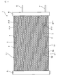
- a plurality of flat tubes 2 for circulating a refrigerant are arranged in parallel via the fins 3, and the flat tubes 2 and the fins 3 are alternately stacked in the vertical direction
- the core 11 is connected to a first header 4 disposed at one end of the core 11 in the longitudinal direction of the flat tube 2, a second header 5 disposed at the other end of the core 11 in the longitudinal direction, and the first header 4
- the refrigerant supply pipe 6 and the refrigerant discharge pipe 7 are provided.
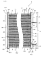
- the plurality of flat tubes 2 are divided into a first flat tube group 21, a second flat tube group 22, a third flat tube group 23, and a fourth flat tube group 24 in order from the top .
- the first header 4 has an inlet 41 connected to the first flat tube group 21 and the refrigerant supply tube 6, and a second turn 42 connected to the second flat tube group 22 and the third flat tube group 23.
- the second header 5 includes a first turn portion 51 connected to the first flat tube group 21 and the second flat tube group 22, and a second turn connected to the third flat tube group 23 and the fourth flat tube group 24.
- a third turn portion 52 and a second partition plate 53 that divides the first turn portion 51 and the third turn portion 52 are provided.
- the condenser 1 of this example satisfies the following formulas (1) to (3), and a combination of the following formula (4) and the following formula (5), or the following formula (6) and the following formula ( 7) and any combination of the combination is satisfied.
- the core 11 has a plurality of flat tubes 2 spaced apart in the vertical direction, and fins 3 interposed between the flat tubes 2.
- the flat tube 2 and the fins 3 are joined by brazing.
- the number of flat tubes 2 can be appropriately set according to the required heat exchange amount and pressure loss, and can be, for example, 30 to 160.
- the core 11 in this example further includes a side sheet 111 made of a plate material of aluminum or aluminum alloy.
- the side sheet 111 is joined to the flat tube 2 a disposed at the upper end of the plurality of flat tubes 2 and the flat tube 2 b disposed at the lower end via the fins 3.
- the plurality of flat tubes 2 includes four flat tubes of a first flat tube group 21, a second flat tube group 22, a third flat tube group 23 and a fourth flat tube group 24 in order from the top It is divided into tube groups.
- the number of flat tubes 2 belonging to the first flat tube group 21 can be, for example, 35 to 45% of the total number of flat tubes 2.
- the number of flat tubes 2 belonging to the second flat tube group 22 can be, for example, 25 to 35% of the total number of flat tubes 2.
- the number of flat tubes 2 belonging to the third flat tube group 23 can be, for example, 15 to 25% of the total number of flat tubes 2.
- the number of flat tubes 2 belonging to the fourth flat tube group 24 can be, for example, 5 to 15% of the total number of flat tubes 2.
- the flat tube 2 is made of aluminum or an aluminum alloy. Although not shown in the drawings, the cross section of the flat tube 2 viewed from the longitudinal direction has an oval shape or a rectangular shape. Further, as shown in FIG. 1, the upper surface 211 and the lower surface 212 of the flat tube 2 are formed of flat surfaces, and the fins 3 are joined to the upper surface 211 and the lower surface 212.
- the outer dimensions of the flat tube 2 can be set appropriately from, for example, a thickness of 1.1 to 3.0 mm and a width of 6 to 20 mm.
- the flat tube 2 may be a single-hole tube having a single refrigerant flow passage inside, or may be a multi-hole tube having a plurality of refrigerant flow passages.
- the number of refrigerant channels in the multi-hole pipe can be, for example, 4 to 20.
- corrugated fins made of aluminum or an aluminum alloy can be used as the fins 3.
- the thickness of the fins 3 can be, for example, 0.06 to 0.12 mm.
- the height of the fins 3 in the vertical direction can be 6 to 8 mm.
- louver protruding in the thickness direction of the fins 3 may be provided on the flat portions 31 (see FIG. 1) of the fins 3, that is, the portions between the bent portions 32 joined to the flat tube 2.
- the number of louvers can be 6 to 16 per flat portion.
- the louvers can be extended in a direction inclined 20 to 60 degrees with respect to the width direction of the fins 3.
- ruber was abbreviate
- the first header 4 is made of aluminum or an aluminum alloy. As shown in FIG. 2, the first header 4 has a cylindrical header body 46 extending in the vertical direction, ie, the stacking direction of the cores 11, and caps 47 and 48 for closing the upper end and the lower end of the header body 46. And.
- a cylindrical tube having an outer diameter of 15 to 25 mm and a wall thickness of 1.0 to 2.5 mm can be used as the header body 46, but the present invention is not limited to this shape.
- the caps 47 and 48 and the first partition plates 44 and 45 are joined to the header main body 46 by brazing.
- description of the caps 47 and 48 was abbreviate
- the internal space of the first header 4 surrounded by the header body 46 and the caps 47 and 48 is divided into three spaces by two first partition plates 44 and 45.
- the portion from the upper end 411 of the first header 4 to the first partition plate 44 disposed above constitutes the inlet 41 of the first header 4.
- the end of the flat tube 2 belonging to the first flat tube group 21 is inserted into the inlet portion 41.
- a refrigerant supply pipe 6 for supplying a refrigerant into the condenser 1 is connected to the inlet 41.
- the end 61 of the refrigerant supply pipe 6 is inserted into the inlet 41.
- the refrigerant supply pipe 6 is extended outward from the end portion 61 in the longitudinal direction of the flat pipe 2. Thereby, the first flat tube group 21 and the refrigerant supply pipe 6 are connected via the inlet 41.
- the portion of the first header 4 from the first partition plate 44 disposed above to the first partition plate 45 disposed below constitutes a second turn portion 42.
- the end portion of the flat tube 2 belonging to the second flat tube group 22 and the third flat tube group 23 is inserted into the second turn portion 42.
- the 2nd flat pipe group 22 and the 3rd flat pipe group 23 are connected via the 2nd turn part 42. As shown in FIG.
- the portion from the lower end 412 of the first header 4 to the first partition plate 45 disposed below constitutes an outlet 43.
- the end of the flat tube 2 belonging to the fourth flat tube group 24 is inserted into the outlet 43.
- a refrigerant discharge pipe 7 for discharging the refrigerant in the condenser 1 to the outside is connected to the outlet portion 43.
- the end 71 of the refrigerant discharge pipe 7 is inserted into the outlet 43.
- the refrigerant discharge pipe 7 is extended outward from the end portion 71 in the longitudinal direction of the flat pipe 2.
- the fourth flat tube group 24 and the refrigerant discharge pipe 7 are connected via the outlet 43.
- the flat tube 2 inserted into the first header 4, the refrigerant supply pipe 6 and the refrigerant discharge pipe 7 are joined to the header main body 46 of the first header 4 by brazing.
- the second header 5 is made of aluminum or an aluminum alloy, and has a tubular header body 56 extending in the vertical direction, that is, the stacking direction of the cores 11, and a cap closing the upper end and the lower end of the header body 56. 57 and 58 are included. Further, the internal space of the second header 5 surrounded by the header body 56 and the caps 57 and 58 is divided into two spaces by one second partition plate 53.
- a cylindrical tube having an outer diameter of 15 to 25 mm and a wall thickness of 1.0 to 2.5 mm can be used as the header body 56, but the shape is limited to this It is not something to be done. Also, the caps 57 and 58 and the second partition plate 53 are joined to the header main body 56 by brazing.
- the portion from the upper end 511 of the second header 5 to the second partition plate 53 constitutes a first turn portion 51.
- the end portions of the flat tubes 2 belonging to the first flat tube group 21 and the second flat tube group 22 are inserted into the first turn portion 51. Thereby, the first flat tube group 21 and the second flat tube group 22 are connected via the first turn portion 51.
- the portion from the lower end 512 of the second header 5 to the second partition plate 53 constitutes a third turn portion 52.
- the end portion of the flat tube 2 belonging to the third flat tube group 23 and the fourth flat tube group 24 is inserted into the third turn portion 52. Thereby, the third flat tube group 23 and the fourth flat tube group 24 are connected via the third turn portion 52.
- the flat tube 2 inserted into the second header 5 is joined to the header body 56 of the second header 5 by brazing.
- the condenser 1 of this example is an inlet occupying the first header 4 on the premise that the total length L of the first header 4 in the vertical direction, that is, the stacking direction of the cores 11 is 400 to 1500 mm (the formula (1)).
- the ratio A / L of the part 41 and the ratio B / L of the outlet 43 occupying the first header 4 satisfy the expressions (2) to (3).
- the heat transfer area in the first flat tube group 21 can be made in an appropriate range.
- the high-temperature, high-pressure gaseous refrigerant that has flowed from the compressor into the first flat tube group 21 via the inlet 41 can be efficiently cooled. Further, by setting the value of B / L in the range specified by the equation (3), in the manufacturing process of the condenser 1, the flow path of the refrigerant in the refrigerant discharge pipe 7, the outlet portion 43, and the fourth flat tube group 24 Can be easily secured.
- the value of a / A and the value of b / B may be a combination of the formula (4) and the formula (5), or the formula (6) and the formula (7). Satisfy any combination of combinations.
- the first partition plate 44 disposed at an appropriate distance from the upper end 411 of the first header 4 and above the refrigerant supply pipe 6 , 45 can also be connected at a suitable distance. Thereby, the bias of the refrigerant between the flat tubes 2 belonging to the first flat tube group 21 can be further reduced, and the heat exchange amount can be further increased.
- the value of b / B satisfies the above equation (5)
- the distance between the refrigerant discharge pipe 7 and the lower end 412 of the first header 4 is secured by 12.825 mm or more, and then the refrigerant is further added.
- the discharge pipe 7 can be connected at a suitable distance from the lower end 412 of the first header 4. As a result, an increase in pressure loss can be suppressed.
- the refrigerant supply pipe 6 can be connected to a position appropriately separated from the upper end 411 of the first header 4. Thereby, the bias of the refrigerant between the flat tubes 2 belonging to the first flat tube group 21 can be reduced, and the reduction of the heat exchange amount can be avoided. Further, when the value of b / B satisfies the equation (7), the refrigerant discharge pipe 7 can be connected relatively above the outlet 43. Thereby, the ratio of the gas-liquid two-phase flow which flows into the 4th flat tube group 24 can be reduced more, and the pressure loss of condenser 1 can be reduced more.
- Example 2 This example is an example in which the connection position of the refrigerant supply pipe 6 and the connection position of the refrigerant discharge pipe 7 are variously changed.
- the same reference numerals as those used in the previous embodiments indicate the same constituent elements as those in the first embodiment unless otherwise specified.
- the manufacturability of the condenser 1 (specimen 1 to 36) in which the value of a / A and the value of b / B were set was evaluated. Further, the amount of heat exchange and the pressure loss were measured for the test pieces 1 to 25 for which the condenser 1 could be produced. Moreover, as a standard of the heat exchange amount and the pressure loss, the value of a / A is 0.15, and the value of b / B is 0.40.
- the condenser 1 (test body R) was produced.
- the test body R is a test body in which the refrigerant supply pipe 6 and the refrigerant discharge pipe 7 are connected to a general position in the heat exchanger of the on-vehicle air conditioner.
- test body of this example is as follows.
- Thickness of flat tube 2 1.3mm Flat tube 2 width 14 mm Number 15 of refrigerant channels in flat tube 2 Cross-sectional shape of refrigerant channels in flat tube 2 Rectangle
- Second header 4 Outer diameter of header body 46 18 mm Header body 46 thickness 1.2 mm Total length L 464 mm of the first header 4 in the vertical direction Length A 192.5 mm of the inlet 41 in the vertical direction Length B 59.5 mm of the outlet 43 in the vertical direction
- the method of evaluating the manufacturability, the method of measuring the amount of heat exchange, and the method of measuring the pressure loss are as follows.
- the heat exchange amount and pressure loss of each test body were measured by a method according to the outdoor air enthalpy test method defined in JIS B 8615-1: 2013 Annex G. Specifically, the test body was installed in a wind tunnel apparatus provided in a constant temperature and humidity test room, and the air temperature in the test room was set to a dry bulb temperature of 35 ° C. and a wet bulb temperature of 24 ° C. While blowing air at a wind speed of 1.6 m / sec from the wind tunnel device to the test body, the refrigerant R32 is circulated into the test body so that the temperature in the refrigerant supply pipe 6 is 65 ° C.
- the test bodies 1 to 4 and the test bodies 9 to 12 satisfying the above formulas (1) to (5) are compared with the test body R while suppressing an increase in pressure loss. Heat exchange amount could be increased. Further, in the test pieces 1 to 8 satisfying the above formulas (1) to (3) and the above formulas (6) to (7), the pressure loss compared with the test body R while avoiding the decrease in the heat exchange amount could be reduced.
- test bodies 1 to 12 the test bodies 1 to 4 satisfying the above formulas (1) to (3), the above formula (4) and the above formula (7) are compared to the test body R.
- the pressure loss can be reduced and the amount of heat exchange can be increased.
- the value of a / A is small, and the refrigerant supply pipe 6 is disposed excessively upward, so the bias of the refrigerant among the flat tubes 2 belonging to the first flat tube group 21 is increased . As a result, the amount of heat exchange decreased.
- the value of b / B was small and the refrigerant discharge pipe 7 was disposed excessively downward, the ratio of the gas-liquid two-phase flow flowing through the fourth flat tube group 24 increased. As a result, an increase in pressure loss was caused.
- the value of b / B was increased to try to connect the refrigerant discharge pipe 7 in the immediate vicinity of the first partition plate 45.
- the value of a / A was increased to try to connect the refrigerant supply pipe 6 in the immediate vicinity of the first partition plate 44.
Landscapes
- Engineering & Computer Science (AREA)
- Physics & Mathematics (AREA)
- Thermal Sciences (AREA)
- Mechanical Engineering (AREA)
- General Engineering & Computer Science (AREA)
- Geometry (AREA)
- Heat-Exchange Devices With Radiators And Conduit Assemblies (AREA)
Abstract
優れた熱交換性能を有し、冷房運転専用の空気調和装置に好適な凝縮器(1)を提供する。凝縮器(1)は、扁平管(2)とフィン(3)とが交互に積層されたコア(11)、コア(11)の一端に配置された第1ヘッダ(4)、コア(11)の他端に配置された第2ヘッダ(5)、第1ヘッダ(4)に接続された冷媒供給管(6)及び冷媒排出管(7)を有している。第1ヘッダ(4)は、冷媒供給管(6)に連結された入口部(41)と、第2ターン部(42)と、冷媒排出管(7)に連結された出口部(43)とを有している。凝縮器(1)は下記式(1)~式(5)を満足している。 400≦L≦1500 ・・・(1) 0.4≦A/L≦0.75 ・・・(2) 30.275/L≦B/L≦(L-A)/3L ・・・(3) 0.22≦a/A≦0.64 ・・・(4) {0.09×(B-6.825-12.825)+12.825}/B≦b/B≦(B-6.825)/B ・・・(5)
Description
本発明は、凝縮器に関する。
家庭用や業務用の空気調和装置としては、冷房運転及び暖房運転の両方を行うことができるように構成されているものが多用されている。この種の空気調和装置の室外機には、冷房運転時には凝縮器として機能し、暖房運転時には蒸発器として機能するように構成された熱交換器が組み込まれている。
例えば特許文献1には、2本の垂直方向ヘッダパイプと、ヘッダパイプ同士を連結する複数本の水平方向偏平チューブを備えたパラレルフロー型熱交換器が記載されている。ヘッダパイプ内には偏平チューブを複数のグループに区分する仕切り板が設けられている。
例えば、中東地域や東南アジア地域等の、一年を通じて比較的気温が高い地域においては、冷房運転のみを行う空気調和装置が求められることがある。この場合、空気調和装置の室外機に組み込まれる熱交換器は、圧縮機から供給された高温高圧の冷媒のガスを凝縮させる凝縮器としての機能のみを有していればよい。しかし、特許文献1の熱交換器は、冷房運転時には凝縮器として機能し、暖房運転時には蒸発器として機能するよう構成されているため、冷房運転時及び暖房運転時の両方において、低い圧力損失と高い熱交換量とを両立させることが求められている。そのため、凝縮器としての熱交換性能には未だ改善の余地がある。
本発明は、かかる背景に鑑みてなされたものであり、優れた熱交換性能を有し、冷房運転専用の空気調和装置に好適な凝縮器を提供しようとするものである。
本発明の一態様は、冷媒を流通させる複数の扁平管がフィンを介して平行に配列され、前記扁平管と前記フィンとが上下方向に交互に積層されたコアと、
前記扁平管の長手方向における前記コアの一端に配置された第1ヘッダと、
前記長手方向における前記コアの他端に配置された第2ヘッダと、
前記第1ヘッダに接続された冷媒供給管及び冷媒排出管と、を有し、
複数の前記扁平管は、上方から順に、第1扁平管群、第2扁平管群、第3扁平管群及び第4扁平管群に区分されており、
前記第1ヘッダは、
前記第1扁平管群と前記冷媒供給管とに連結された入口部と、
前記第2扁平管群と前記第3扁平管群とに連結された第2ターン部と、
前記第4扁平管群と前記冷媒排出管とに連結された出口部と、
前記入口部と前記第2ターン部との間、及び、前記第2ターン部と前記出口部との間を仕切る第1仕切り板と、を有し、
前記第2ヘッダは、
前記第1扁平管群と前記第2扁平管群とに連結された第1ターン部と、
前記第3扁平管群と前記第4扁平管群とに連結された第3ターン部と、
前記第1ターン部と前記第3ターン部との間を仕切る第2仕切り板と、を有し、
上下方向における、前記第1ヘッダの全長をL[mm]、前記入口部の長さをA[mm]、前記出口部の長さをB[mm]、前記入口部に接続された前記冷媒供給管の端部の中心から前記第1ヘッダの上端までの距離をa[mm]、前記出口部に接続された前記冷媒排出管の端部の中心から前記第1ヘッダの下端までの距離をb[mm]とした場合に、下記式(1)~式(5)を満足する、凝縮器にある。
前記扁平管の長手方向における前記コアの一端に配置された第1ヘッダと、
前記長手方向における前記コアの他端に配置された第2ヘッダと、
前記第1ヘッダに接続された冷媒供給管及び冷媒排出管と、を有し、
複数の前記扁平管は、上方から順に、第1扁平管群、第2扁平管群、第3扁平管群及び第4扁平管群に区分されており、
前記第1ヘッダは、
前記第1扁平管群と前記冷媒供給管とに連結された入口部と、
前記第2扁平管群と前記第3扁平管群とに連結された第2ターン部と、
前記第4扁平管群と前記冷媒排出管とに連結された出口部と、
前記入口部と前記第2ターン部との間、及び、前記第2ターン部と前記出口部との間を仕切る第1仕切り板と、を有し、
前記第2ヘッダは、
前記第1扁平管群と前記第2扁平管群とに連結された第1ターン部と、
前記第3扁平管群と前記第4扁平管群とに連結された第3ターン部と、
前記第1ターン部と前記第3ターン部との間を仕切る第2仕切り板と、を有し、
上下方向における、前記第1ヘッダの全長をL[mm]、前記入口部の長さをA[mm]、前記出口部の長さをB[mm]、前記入口部に接続された前記冷媒供給管の端部の中心から前記第1ヘッダの上端までの距離をa[mm]、前記出口部に接続された前記冷媒排出管の端部の中心から前記第1ヘッダの下端までの距離をb[mm]とした場合に、下記式(1)~式(5)を満足する、凝縮器にある。
400≦L≦1500 ・・・(1)
0.4≦A/L≦0.75 ・・・(2)
30.275/L≦B/L≦(L-A)/3L ・・・(3)
0.22≦a/A≦0.64 ・・・(4)
{0.09×(B-6.825-12.825)+12.825}/B≦b/B≦(B-6.825)/B ・・・(5)
0.4≦A/L≦0.75 ・・・(2)
30.275/L≦B/L≦(L-A)/3L ・・・(3)
0.22≦a/A≦0.64 ・・・(4)
{0.09×(B-6.825-12.825)+12.825}/B≦b/B≦(B-6.825)/B ・・・(5)
本発明の他の態様は、前記の態様の凝縮器において、前記式(4)~式(5)に代えて下記式(6)~式(7)を満足する、凝縮器にある。
0.22≦a/A≦(A-6.825)/A ・・・(6)
{0.47×(B-6.825-12.825)+12.825}/B≦b/B≦(B-6.825)/B ・・・(7)
0.22≦a/A≦(A-6.825)/A ・・・(6)
{0.47×(B-6.825-12.825)+12.825}/B≦b/B≦(B-6.825)/B ・・・(7)
前記凝縮器の第1の態様においては、上下方向における第1ヘッダの全長Lが400~1500mm(前記式(1))であることを前提として、第1ヘッダに占める入口部の比率A/L及び第1ヘッダに占める出口部の比率B/Lが前記式(2)~式(3)を満足している。A/Lの値を前記式(2)で特定する範囲とすることにより、第1扁平管群における伝熱面積を適正な範囲にすることができる。これにより、圧縮機から入口部を介して第1扁平管群に流入した高温高圧のガス状の冷媒を効率よく冷却することができる。また、B/Lの値を前記式(3)で特定する範囲とすることにより、凝縮器の製造過程において、冷媒排出管や出口部、第4扁平管群における冷媒の流路を容易に確保することができる。
また、前記第1の態様においては、更に、入口部の長さAに対する第1ヘッダの上端から冷媒供給管の端部までの距離aの比率a/A、及び、出口部の長さに対する第1ヘッダの下端から冷媒排出管の端部までの距離の比率b/Bが前記式(4)~式(5)を満足している。これにより、凝縮器の圧力損失の増大を抑制しつつ、熱交換量を大きくすることができる。
また、前記第2の態様においては、前記式(4)~式(5)に代えて、入口部の長さAに対する第1ヘッダの上端から冷媒供給管の端部までの距離aの比率a/A、及び、出口部の長さに対する第1ヘッダの下端から冷媒排出管の端部までの距離の比率b/Bが前記式(6)~式(7)を満足している。これにより、熱交換量の減少を抑制しつつ、圧力損失を低減することができる。
このように、前記第1の態様の凝縮器及び前記第2の態様の凝縮器においては、第1ヘッダの構造、冷媒供給管の接続位置及び冷媒排出管の接続位置が最適化されている。これにより、蒸発器としても機能し得るように構成された凝縮器に比べて、凝縮器としての性能を向上させることができる。前記第1の態様の凝縮器及び前記第2の態様の凝縮器は、いずれも、冷房運転専用の空気調和装置に好適である。
前記凝縮器は、水平方向に延設された扁平管内を冷媒が流通する、いわゆるパラレルフロー型の熱交換器として構成されている。また、前記凝縮器は、第1扁平管群が上方となり、第4扁平管群が下方となる向きに配置される。
前記凝縮器において、冷媒供給管から供給された高温高圧の冷媒は、第1ヘッダの入口部内に流入し、第1扁平管群に分配される。第1扁平管群を通過した冷媒は、第2ヘッダの第1ターン部に流入し、第2扁平管群に分配される。第2扁平管群における冷媒の流れの向きは、第1扁平管群における冷媒の流れの向きとは反対方向となる。以降、冷媒は、第1ヘッダの第2ターン部、第3扁平管群、第2ヘッダの第3ターン部及び第4扁平管群を順次通過する。第4扁平管群から出口部に流出した冷媒は、冷媒排出管を介して凝縮器の外部へ排出される。
第1扁平管群に属する扁平管の数は第2扁平管群よりも多く、前記第2扁平管群に属する扁平管の数は前記第3扁平管群よりも多く、前記第3扁平管群に属する扁平管の数は前記第4扁平管群よりも多いことが好ましい。入口部から第1扁平管群に流入した冷媒は、高温高圧の気体であるため、密度が低い。そのため、第1扁平管群に流入した冷媒から効率よく熱を除去するためには、伝熱面積を広くする必要がある。第1扁平管群の扁平管の数を最も多くすることにより、第1扁平管群における伝熱面積を十分に確保し、高温高圧のガス状の冷媒から効率よく熱を除去することができる。
また、凝縮器内を移動する冷媒は、外気との熱交換によって冷却され、徐々に凝縮する。そのため、凝縮器内の冷媒の流れは、入口部においては気相の単相流となり、下流へ移動するにつれて気相と液相とが混在している気液二相流に変化する。気液二相流における液相の割合は下流側ほど大きくなり、最終的には液相の単相流となる。
液相の冷媒は気相の冷媒に比べて密度が高いため、気相の冷媒に比べて少ない伝熱面積で効率よく熱を除去することができる。それ故、第2扁平管群、第3扁平管群、第4扁平管群の順に扁平管の数を少なくすることにより、液相の割合の増加に応じて十分な伝熱面積を確保し、冷媒と外気との熱交換を効率よく行うことができる。
以上のように、上流側に配置される第1扁平管群に属する扁平管の数を最も多くし、第2扁平管群、第3扁平管群、第4扁平管群の順に扁平管の数を少なくすることにより、凝縮器の熱交換量をより大きくすることができる。
凝縮器の熱交換量をより大きくする観点からは、複数の扁平管群の総数を100%とした場合に、第1扁平管群に属する扁平管の数を35~45%とし、第2扁平管群に属する扁平管の数を25~35%とし、第3扁平管群に属する扁平管の数を15~25%とし、第4扁平管群に属する扁平管の数を5~15%とすることがさらに好ましい。
第1ヘッダは、上方に配置された入口部と、下方に配置された出口部と、入口部と出口部との間に配置された第2ターン部とを有している。入口部と第2ターン部との間及び第2ターン部と出口部との間は、第1仕切り板によって隔てられている。
上下方向、即ち扁平管とフィンとの積層方向における第1ヘッダの長さL[mm]は、下記式(1)を満たしている。
400≦L≦1500 ・・・(1)
400≦L≦1500 ・・・(1)
前記式(1)を満足する凝縮器は、家庭用や業務用の空気調和装置における室外機の寸法に合致しており、かかる室外機に容易に組み込むことができる。
第1ヘッダの上方部分は、冷媒供給管から供給された冷媒を第1扁平管群に分配する入口部として構成されている。上下方向における、第1ヘッダの長さL[mm]に対する入口部の長さA[mm]の比率A/Lは、下記式(2)を満足している。
0.4≦A/L≦0.75 ・・・(2)
0.4≦A/L≦0.75 ・・・(2)
第1ヘッダに占める入口部の割合A/Lを前記特定の範囲とすることにより、入口部の長さを適度に長くすることができる。これにより、入口部に連結される扁平管の数、即ち第1扁平管群に属する扁平管の数を十分に多くすることができる。その結果、第1扁平管群における伝熱面積を広くし、入口部を介して流入した高温高圧のガス状の冷媒を効率よく冷却することができる。その結果、凝縮器の熱交換量を大きくすることができる。
A/Lの値が0.4未満の場合には、第1扁平管群に属する扁平管の数が不足するため、凝縮器の熱交換量の低下を招くおそれがある。また、A/Lの値が0.7を超える場合には、第1扁平管群に属する扁平管の数が多くなるため、相対的に第2扁平管群~第4扁平管群に属する扁平管の合計が少なくなる。その結果、凝縮器の圧力損失の増大を招くおそれがある。
入口部には、凝縮器内に冷媒を供給するための冷媒供給管が接続されている。入口部に接続された冷媒供給管の端部の中心から第1ヘッダの上端までの上下方向における距離をa[mm]とした場合に、a/Aの値は、下記式(6)を満足している。
0.22≦a/A≦(A-6.825)/A ・・・(6)
0.22≦a/A≦(A-6.825)/A ・・・(6)
a/Aの値を0.22以上とすることにより、冷媒供給管を第1ヘッダの上端から適度に離れた位置に接続し、第1扁平管群に属する扁平管の間の冷媒の偏りを軽減することができる。その結果、圧力損失の増大を抑制しつつ、熱交換量を大きくすることができる。a/Aの値が0.22未満の場合には、第1扁平管群に属する扁平管の間の冷媒の偏りが大きくなり、かえって凝縮器の熱交換量の低下を招くおそれがある。
また、a/Aの値を(A-6.825)/A以下とすることにより、第1ヘッダの寸法精度の悪化を回避することができる。a/Aの値が(A-6.825)/Aを超える場合には、冷媒供給管の端部の中心から第1仕切り板の中心までの上下方向における距離が6.825mm未満となる。このように冷媒供給管を第1仕切り板のごく近傍に接続しようとする場合、第1ヘッダに冷媒供給管や第1仕切り板を取り付けるための加工を行う際に第1ヘッダが変形し、第1ヘッダの寸法精度の悪化を招くおそれがある。また、場合によっては凝縮器を作製することが難しくなるおそれもある。
a/Aの値は、下記式(4)を満足することが好ましい。
0.22≦a/A≦0.64 ・・・(4)
0.22≦a/A≦0.64 ・・・(4)
この場合には、冷媒供給管を、第1ヘッダの上端から適度に離れ、かつ、第1仕切り板からも適度に離れた位置に接続することができる。これにより、第1扁平管群に属する扁平管の間の冷媒の偏りをより軽減し、圧力損失の低減と、熱交換量の増大とを両立させることができる。この理由は、以下の通りである。
入口部内における冷媒の圧力は、冷媒供給管の端部において最大となり、冷媒供給管から離れるほど低下する。そのため、第1扁平管群に属する扁平管内を流れる冷媒の流速は、冷媒供給管に近いほど速くなり、冷媒供給管から離れるほど遅くなる傾向がある。
a/Aの値が小さい場合、即ち冷媒供給管が入口部の比較的上方に接続されている場合には、第1扁平管群に属する扁平管のうち、上方に配置された扁平管における冷媒の流速が速くなりやすい。また、上方に配置された扁平管を通過する冷媒は、下方に配置された扁平管を通過する冷媒に比べて第2扁平管群に到達するまでの移動距離が長い。
そのため、a/Aの値を小さくし、上方に配置された扁平管を通過する冷媒の流速を速くすることにより、凝縮器の外部との間での熱交換を促進することができる。その結果、凝縮器全体の熱交換量を大きくすることができる。その反面、a/Aの値が小さい場合には、冷媒の平均的な移動距離が長くなるため、圧力損失の増大を招くおそれがある。
一方、a/Aの値が大きい場合、即ち冷媒供給管が入口部の比較的下方に接続されている場合には、第1扁平管群に属する扁平管のうち、下方に配置された扁平管における冷媒の流速が速くなりやすい。下方に配置された扁平管を通過する冷媒は、上方に配置された扁平管を通過する冷媒に比べて第2扁平管群に到達するまでの移動距離が短い。そのため、a/Aの値が小さい場合には、圧力損失を低減することができる。その反面、a/Aの値が小さい場合には、上方に配置された扁平管を通過する冷媒の流速が遅くなりやすいため、熱交換量の低下を招くおそれがある。
従って、a/Aの値が下記式(4)を満たすように冷媒供給管を接続することにより、圧力損失の低減と、熱交換量の増大とを両立させることができる。
第1ヘッダの下方部分は、第4扁平管群から流出した冷媒を冷媒排出管へ導く出口部として構成されている。上下方向における、第1ヘッダの長さL[mm]に対する出口部の長さB[mm]は、下記式(3)を満足している。
30.275/L≦B/L≦(L-A)/3L ・・・(3)
30.275/L≦B/L≦(L-A)/3L ・・・(3)
第1ヘッダに占める出口部の割合B/Lを前記特定の範囲とすることにより、出口部の長さを適度に長くすることができる。これにより、凝縮器の圧力損失の増大を抑制しつつ、熱交換量を大きくすることができる。
B/Lの値が前記特定の範囲未満の場合には、出口部の長さが過度に短くなる。そのため、凝縮器の製造過程においてろう付を行う際に、冷媒排出管や出口部、第4扁平管群に不要なろうが流れ込み、冷媒流路が狭くなるおそれがある。その結果、凝縮器の圧力損失の増大や熱交換量の低下を招くおそれがある。また、B/Lの値が前記特定の範囲を超える場合には、出口部の長さが過度に長くなるため、相対的に入口部及び第2ターン部の長さが短くなる。その結果、第1扁平管群~第3扁平管群に属する扁平管の合計が不足し、凝縮器の熱交換量の低下を招くおそれがある。
出口部には、凝縮器内の冷媒を外部に排出するための冷媒排出管が接続されている。出口部に接続された冷媒排出管の端部の中心から第1ヘッダの下端までの上下方向における距離をb[mm]とした場合に、b/Bの値は、下記式(5)を満足している。
{0.09×(B-6.825-12.825)+12.825}/B≦b/B≦(B-6.825)/B ・・・(5)
{0.09×(B-6.825-12.825)+12.825}/B≦b/B≦(B-6.825)/B ・・・(5)
b/Bの値を(B-6.825)/B以下とすることにより、第1ヘッダの寸法精度の悪化を回避することができる。b/Bの値が(B-6.825)/Bを超える場合には、冷媒排出管の端部の中心から第1仕切り板の中心までの上下方向における距離が6.825mm未満となる。このように冷媒排出管を第1仕切り板のごく近傍に接続しようとする場合、第1ヘッダに冷媒排出管や第1仕切り板を取り付けるための加工を行う際に第1ヘッダが変形し、第1ヘッダの寸法精度の悪化を招くおそれがある。また、場合によっては凝縮器を作製することが難しくなるおそれもある。
また、b/Bの値を{0.09×(B-6.825-12.825)+12.825}/B以上とすることにより、圧力損失の増大を抑制することができる。b/Bの値が{0.09×(B-6.825-12.825)+12.825}/B未満の場合には、圧力損失の増大を招くおそれがある。この理由は、以下の通りである。
出口部内における冷媒の圧力は、冷媒排出管の端部において最小となり、冷媒排出管から離れるほど増大する。そのため、第4扁平管群に属する扁平管内を流れる冷媒の流速は、冷媒排出管に近いほど速くなり、冷媒排出管から離れるほど遅くなる傾向がある。
b/Bの値が大きい場合、即ち冷媒排出管が出口部の比較的上方に接続されている場合には、第4扁平管群に属する扁平管のうち、上方に配置された扁平管における冷媒の流速が速くなりやすい。上方に配置された扁平管には、比較的密度の高い液相の冷媒と、比較的密度の低い気相の冷媒とが混在している気液二相流が流れている。この気液二相流の流速を速くすることにより、気液二相流中の気相の冷媒を効率的に凝縮させ、扁平管の出口部側において、気液二相流を液相の単相流に変化させることができる。
それ故、b/Bの値が大きい場合には、第4扁平管群を流れる気液二相流の割合を低減することができる。
また、気液二相流において、気相の冷媒の流速は、通常、液相の冷媒の流速とは異なっている。そのため、気相の冷媒と液相の冷媒との界面には、両者の流速差に起因して、圧力損失の原因となるせん断力が発生する。気液二相流の割合を低減することにより、上述したせん断力の影響を低減し、ひいては凝縮器の圧力損失の増大を抑制することができる。
これに対し、b/Bの値が小さい場合、即ち冷媒排出管が出口部の比較的下方に接続されている場合には、b/Bの値が大きい場合とは逆に、上方に配置された扁平管における冷媒の流速が遅くなりやすい。そのため、気液二相流の流速が遅くなり、気液二相流中の気相の冷媒が凝縮しにくくなる。それ故、この場合には、b/Bの値が大きい場合に比べて第4扁平管群を流れる気液二相流の割合が多くなり、圧力損失の増大を招くおそれがある。
また、冷媒排出管を第1ヘッダの下端のごく近傍に接続しようとする場合には、冷媒排出管を第1仕切り板のごく近傍に接続しようとする場合と同様に、第1ヘッダの変形を招くおそれがある。かかる問題を回避するためには、冷媒排出管を第1ヘッダの下端から上下方向に12.825mm以上離れた位置に接続する必要がある。
b/Bの値が{0.09×(B-6.825-12.825)+12.825}/B以上である場合には、冷媒排出管と第1ヘッダの下端との距離を12.825mm以上確保した上で、更に、冷媒排出管を第1ヘッダの下端から適度に離して接続することができる。その結果、第1ヘッダの変形を回避するとともに、上述した気液二相流の割合の増大を抑制し、圧力損失の増大を抑制することができる。
b/Bの値は、下記式(7)を満足することが好ましい。
{0.47×(B-6.825-12.825)+12.825}/B≦b/B≦(B-6.825)/B ・・・(7)
{0.47×(B-6.825-12.825)+12.825}/B≦b/B≦(B-6.825)/B ・・・(7)
この場合には、冷媒排出管をより上方に接続することができる。これにより、気液二相流の割合をより低減し、凝縮器の圧力損失をより低減することができる。
前記凝縮器には、空気調和装置用として公知の冷媒を使用することができる。熱交換量の増大及び圧力損失の低減の効果を得るためには、例えば、R410A、R32、R1234yf、R1123等の冷媒を使用することが有効である。これらの中でも、R32を使用することが特に有効である。
(実施例1)
前記凝縮器の実施例を、図を用いて説明する。なお、本発明に係る凝縮器の具体的な態様は、実施例の態様に限定されるものではなく、本発明の趣旨を損なわない範囲で適宜変更することができる。
前記凝縮器の実施例を、図を用いて説明する。なお、本発明に係る凝縮器の具体的な態様は、実施例の態様に限定されるものではなく、本発明の趣旨を損なわない範囲で適宜変更することができる。
図1に示すように、本例の凝縮器1は、冷媒を流通させる複数の扁平管2がフィン3を介して平行に配列され、扁平管2とフィン3とが上下方向に交互に積層されたコア11と、扁平管2の長手方向におけるコア11の一端に配置された第1ヘッダ4と、長手方向におけるコア11の他端に配置された第2ヘッダ5と、第1ヘッダ4に接続された冷媒供給管6及び冷媒排出管7とを有している。図2に示すように、複数の扁平管2は、上方から順に、第1扁平管群21、第2扁平管群22、第3扁平管群23及び第4扁平管群24に区分されている。
第1ヘッダ4は、第1扁平管群21と冷媒供給管6とに連結された入口部41と、第2扁平管群22と第3扁平管群23とに連結された第2ターン部42と、第4扁平管群24と冷媒排出管7とに連結された出口部43と、入口部41と第2ターン部42との間、及び、第2ターン部42と出口部43との間を仕切る第1仕切り板44、45とを有している。第2ヘッダ5は、第1扁平管群21と第2扁平管群22とに連結された第1ターン部51と、第3扁平管群23と第4扁平管群24とに連結された第3ターン部52と、第1ターン部51と第3ターン部52との間を仕切る第2仕切り板53とを有している。
本例の凝縮器1は、下記式(1)~式(3)を満足し、かつ、下記式(4)と下記式(5)との組み合わせ、または、下記式(6)と下記式(7)との組み合わせのいずれかの組合せを満足している。
400≦L≦1500 ・・・(1)
0.4≦A/L≦0.75 ・・・(2)
30.275/L≦B/L≦(L-A)/3L ・・・(3)
0.4≦A/L≦0.75 ・・・(2)
30.275/L≦B/L≦(L-A)/3L ・・・(3)
0.22≦a/A≦0.64 ・・・(4)
{0.09×(B-6.825-12.825)+12.825}/B≦b/B≦(B-6.825)/B ・・・(5)
{0.09×(B-6.825-12.825)+12.825}/B≦b/B≦(B-6.825)/B ・・・(5)
0.22≦a/A≦(A-6.825)/A ・・・(6)
{0.47×(B-6.825-12.825)+12.825}/B≦b/B≦(B-6.825)/B ・・・(7)
{0.47×(B-6.825-12.825)+12.825}/B≦b/B≦(B-6.825)/B ・・・(7)
ここで、前記式(1)~式(7)において使用した記号の意味は以下の通りである(図2参照)。
L[mm]:上下方向における第1ヘッダ4の全長
A[mm]:上下方向における入口部41の長さ
B[mm]:上下方向における出口部43の長さ
a[mm]:入口部41に接続された冷媒供給管6の端部61の中心から第1ヘッダ4の上端411までの上下方向における距離
b[mm]:出口部43に接続された冷媒排出管7の端部71の中心から第1ヘッダ4の下端412までの上下方向における距離
L[mm]:上下方向における第1ヘッダ4の全長
A[mm]:上下方向における入口部41の長さ
B[mm]:上下方向における出口部43の長さ
a[mm]:入口部41に接続された冷媒供給管6の端部61の中心から第1ヘッダ4の上端411までの上下方向における距離
b[mm]:出口部43に接続された冷媒排出管7の端部71の中心から第1ヘッダ4の下端412までの上下方向における距離
以下、本例の凝縮器1の各部をより詳細に説明する。
図1及び図2に示すように、コア11は、上下方向に間隔を開けて配置された複数本の扁平管2と、扁平管2同士の間に介在するフィン3とを有している。扁平管2とフィン3とは、ろう付によって接合されている。扁平管2の本数は、要求される熱交換量や圧力損失に応じて適宜設定することができ、例えば、30~160本とすることができる。
本例のコア11は、更に、アルミニウム又はアルミニウム合金の板材からなるサイドシート111を有している。サイドシート111は、複数本の扁平管2のうち上端に配置された扁平管2a及び下端に配置された扁平管2bにフィン3を介して接合されている。
図2に示すように、複数本の扁平管2は、上方から順に、第1扁平管群21、第2扁平管群22、第3扁平管群23及び第4扁平管群24の4つの扁平管群に区分されている。第1扁平管群21に属する扁平管2の数は、例えば、扁平管2の総数の35~45%とすることができる。第2扁平管群22に属する扁平管2の数は、例えば、扁平管2の総数の25~35%とすることができる。第3扁平管群23に属する扁平管2の数は、例えば、扁平管2の総数の15~25%とすることができる。第4扁平管群24に属する扁平管2の数は、例えば、扁平管2の総数の5~15%とすることができる。
扁平管2は、アルミニウムまたはアルミニウム合金から構成されている。図には示さないが、長手方向から視た扁平管2の断面は長円状または矩形状を呈している。また、図1に示すように、扁平管2の上面211及び下面212は平坦面から構成されており、上面211及び下面212にフィン3が接合されている。
扁平管2の外寸法は、例えば、厚み1.1~3.0mm、幅6~20mmの範囲から適宜設定することができる。また、扁平管2は、その内部に1本の冷媒流路を有する単穴管であってもよいし、複数本の冷媒流路を有する多穴管であってもよい。多穴管における冷媒流路の数は、例えば、4~20本とすることができる。
図1及び図2に示すように、フィン3としては、アルミニウムまたはアルミニウム合金から構成されたコルゲートフィンを使用することができる。フィン3の板厚は、例えば、0.06~0.12mmとすることができる。また、上下方向におけるフィン3の高さは、6~8mmとすることができる。
フィン3における平坦部31(図1参照)、即ち、扁平管2に接合された屈曲部32の間の部分には、フィン3の厚み方向に突出したルーバーが設けられていてもよい。ルーバーの数は、平坦部1か所当たり6~16本とすることができる。また、ルーバーは、フィン3の幅方向に対して20~60度傾いた方向に延設することができる。なお、図1及び図2においては、便宜上、ルーバーの記載を省略した。
第1ヘッダ4は、アルミニウム又はアルミニウム合金から構成されている。図2に示すように、第1ヘッダ4は、上下方向、即ちコア11の積層方向に延設された筒状を呈するヘッダ本体46と、ヘッダ本体46の上端及び下端を閉鎖するキャップ47、48とを有している。
ヘッダ本体46としては、例えば、外径15~25mm、肉厚1.0~2.5mmの円筒管を使用することができるが、この形状に限定されるものではない。また、キャップ47、48及び第1仕切り板44、45は、ろう付によりヘッダ本体46に接合されている。なお、図1においては、便宜上、キャップ47、48の記載を省略した。
ヘッダ本体46とキャップ47、48とにより囲まれた第1ヘッダ4の内部空間は、2枚の第1仕切り板44、45により、3つの空間に区画されている。第1ヘッダ4の上端411から上方に配置された第1仕切り板44までの部分は、第1ヘッダ4の入口部41を構成している。入口部41には第1扁平管群21に属する扁平管2の端部が挿入されている。
また、入口部41には、凝縮器1内に冷媒を供給するための冷媒供給管6が接続されている。冷媒供給管6の端部61は入口部41内に挿入されている。また、冷媒供給管6は、端部61から扁平管2の長手方向における外方に延設されている。これにより、第1扁平管群21と冷媒供給管6とが入口部41を介して連結されている。
第1ヘッダ4における、上方に配置された第1仕切り板44から下方に配置された第1仕切り板45までの部分は第2ターン部42を構成している。第2ターン部42には、第2扁平管群22及び第3扁平管群23に属する扁平管2の端部が挿入されている。これにより、第2扁平管群22と第3扁平管群23とが第2ターン部42を介して連結されている。
第1ヘッダ4の下端412から下方に配置された第1仕切り板45までの部分は出口部43を構成している。出口部43には、第4扁平管群24に属する扁平管2の端部が挿入されている。
また、出口部43には、凝縮器1内の冷媒を外部に排出するための冷媒排出管7が接続されている。冷媒排出管7の端部71は、出口部43内に挿入されている。また、冷媒排出管7は、端部71から扁平管2の長手方向における外方に延設されている。これにより、第4扁平管群24と冷媒排出管7とが出口部43を介して連結されている。
第1ヘッダ4に挿入された扁平管2、冷媒供給管6及び冷媒排出管7は、ろう付により第1ヘッダ4のヘッダ本体46に接合されている。
第2ヘッダ5は、アルミニウム又はアルミニウム合金から構成されており、上下方向、即ちコア11の積層方向に延設された筒状を呈するヘッダ本体56と、ヘッダ本体56の上端及び下端を閉鎖するキャップ57、58とを有している。また、ヘッダ本体56とキャップ57、58とにより囲まれた第2ヘッダ5の内部空間は、1枚の第2仕切り板53により、2つの空間に区画されている。
ヘッダ本体56としては、第1ヘッダ4のヘッダ本体46と同様に、例えば、外径15~25mm、肉厚1.0~2.5mmの円筒管を使用することができるが、この形状に限定されるものではない。また、キャップ57、58及び第2仕切り板53は、ろう付によりヘッダ本体56に接合されている。
第2ヘッダ5の上端511から第2仕切り板53までの部分は第1ターン部51を構成している。第1ターン部51には第1扁平管群21及び第2扁平管群22に属する扁平管2の端部が挿入されている。これにより、第1扁平管群21と第2扁平管群22とが第1ターン部51を介して連結されている。
第2ヘッダ5の下端512から第2仕切り板53までの部分は第3ターン部52を構成している。第3ターン部52には、第3扁平管群23及び第4扁平管群24に属する扁平管2の端部が挿入されている。これにより、第3扁平管群23と第4扁平管群24とが第3ターン部52を介して連結されている。
第2ヘッダ5に挿入された扁平管2は、ろう付により第2ヘッダ5のヘッダ本体56に接合されている。
次に、本例の凝縮器1の作用効果を説明する。本例の凝縮器1は、上下方向、即ちコア11の積層方向における第1ヘッダ4の全長Lが400~1500mm(前記式(1))であることを前提として、第1ヘッダ4に占める入口部41の比率A/L及び第1ヘッダ4に占める出口部43の比率B/Lが前記式(2)~式(3)を満足している。A/Lの値を前記式(2)で特定する範囲とすることにより、第1扁平管群21における伝熱面積を適正な範囲にすることができる。これにより、圧縮機から入口部41を介して第1扁平管群21に流入した高温高圧のガス状の冷媒を効率よく冷却することができる。また、B/Lの値を前記式(3)で特定する範囲とすることにより、凝縮器1の製造過程において、冷媒排出管7や出口部43、第4扁平管群24における冷媒の流路を容易に確保することができる。
また、凝縮器1は、更に、a/Aの値及びb/Bの値が前記式(4)と前記式(5)との組み合わせ、または前記式(6)と前記式(7)との組み合わせのいずれかの組合せを満足している。
a/Aの値が前記式(4)を満足している場合には、冷媒供給管6を、第1ヘッダ4の上端411から適度に離れ、かつ、上方に配置された第1仕切り板44、45からも適度に離れた位置に接続することができる。これにより、第1扁平管群21に属する扁平管2の間の冷媒の偏りをより軽減し、熱交換量をより大きくすることができる。また、b/Bの値が前記式(5)を満足している場合には、冷媒排出管7と第1ヘッダ4の下端412との距離を12.825mm以上確保した上で、更に、冷媒排出管7を第1ヘッダ4の下端412から適度に離して接続することができる。その結果、圧力損失の増大を抑制することができる。
従って、a/Aの値とb/Bの値とが前記式(4)~式(5)を満足している場合には、この場合には、凝縮器1の圧力損失の増大を抑制しつつ、熱交換量をより大きくすることができる。
一方、a/Aの値が前記式(6)を満足している場合には、冷媒供給管6を、第1ヘッダ4の上端411から適度に離れた位置に接続することができる。これにより、第1扁平管群21に属する扁平管2の間の冷媒の偏りを軽減し、熱交換量の低下を回避することができる。また、b/Bの値が前記式(7)を満足している場合には、冷媒排出管7を、出口部43の比較的上方に接続することができる。これにより、第4扁平管群24に流れる気液二相流の割合をより低減し、凝縮器1の圧力損失をより低減することができる。
従って、a/Aの値とb/Bの値とが前記式(6)~式(7)を満足している場合には、凝縮器1の熱交換量の低下を回避しつつ、圧力損失をより低減することができる。
(実施例2)
本例は、冷媒供給管6の接続位置及び冷媒排出管7の接続位置を種々変更した例である。なお、本実施例以降において使用する符号のうち、既出の実施例において使用された符号と同一のものは、特に説明のない限り実施例1と同様の構成要素等を示す。
本例は、冷媒供給管6の接続位置及び冷媒排出管7の接続位置を種々変更した例である。なお、本実施例以降において使用する符号のうち、既出の実施例において使用された符号と同一のものは、特に説明のない限り実施例1と同様の構成要素等を示す。
本例においては、表1に示すようにa/Aの値及びb/Bの値を設定した凝縮器1(試験体1~36)の製造性を評価した。また、凝縮器1を作製することができた試験体1~25について、熱交換量及び圧力損失を測定した。また、熱交換量及び圧力損失の基準として、a/Aの値が0.15であり、b/Bの値が0.40である凝縮器1(試験体R)を作製した。試験体Rは、冷媒供給管6及び冷媒排出管7を、車載用空調装置の熱交換器において一般的な位置に接続した試験体である。
表1における「式(4)」の欄には、各試験体のa/Aの値が前記式(4)を満足している場合には記号「〇」を、満足していない場合には記号「×」を記載した。同様に、「式(6)」の欄には、各試験体のa/Aの値が前記式(6)を満足している場合には記号「〇」を、満足していない場合には記号「×」を記載した。
また、表1における「式(5)」の欄には、各試験体のb/Bの値が前記式(5)を満足している場合には記号「〇」を、満足していない場合には記号「×」を記載した。同様に、「式(7)」の欄には、各試験体のb/Bの値が前記式(7)を満足している場合には記号「〇」を、満足していない場合には記号「×」を記載した。
本例の試験体の詳細な構成は、以下の通りである。
・凝縮器1の外寸法
上下方向 464mm
扁平管2の長手方向 720mm
扁平管2の幅方向 14mm
上下方向 464mm
扁平管2の長手方向 720mm
扁平管2の幅方向 14mm
・扁平管2
扁平管2の総数 50本
第1扁平管群21に属する扁平管2の数 20本
第2扁平管群22に属する扁平管2の数 15本
第3扁平管群23に属する扁平管2の数 10本
第4扁平管群24に属する扁平管2の数 5本
扁平管2の総数 50本
第1扁平管群21に属する扁平管2の数 20本
第2扁平管群22に属する扁平管2の数 15本
第3扁平管群23に属する扁平管2の数 10本
第4扁平管群24に属する扁平管2の数 5本
扁平管2の厚み 1.3mm
扁平管2の幅 14mm
扁平管2内の冷媒流路の数 15個
扁平管2内の冷媒流路の断面形状 矩形
扁平管2の幅 14mm
扁平管2内の冷媒流路の数 15個
扁平管2内の冷媒流路の断面形状 矩形
・フィン3
高さ 7.5mm
板厚 0.08mm
ルーバーの角度 30度
平坦部31ごとのルーバーの数 6本
高さ 7.5mm
板厚 0.08mm
ルーバーの角度 30度
平坦部31ごとのルーバーの数 6本
・第1ヘッダ4
ヘッダ本体46の外径 18mm
ヘッダ本体46の肉厚 1.2mm
上下方向における第1ヘッダ4の全長L 464mm
上下方向における入口部41の長さA 192.5mm
上下方向における出口部43の長さB 59.5mm
ヘッダ本体46の外径 18mm
ヘッダ本体46の肉厚 1.2mm
上下方向における第1ヘッダ4の全長L 464mm
上下方向における入口部41の長さA 192.5mm
上下方向における出口部43の長さB 59.5mm

製造性の評価方法、熱交換量の測定方法及び圧力損失の測定方法は、以下の通りである。
・製造性
ヘッダ本体46となる円筒管に扁平管2、第1仕切り板44、45、冷媒供給管6及び冷媒排出管7を挿入するための貫通穴を形成した。貫通穴を形成した後の円筒管を目視により観察し、円筒管が変形しなかった場合には表2の「製造性」欄に記号「A」を、円筒管に陥没等の変形が発生した場合には同欄に記号「B」を記載した。
ヘッダ本体46となる円筒管に扁平管2、第1仕切り板44、45、冷媒供給管6及び冷媒排出管7を挿入するための貫通穴を形成した。貫通穴を形成した後の円筒管を目視により観察し、円筒管が変形しなかった場合には表2の「製造性」欄に記号「A」を、円筒管に陥没等の変形が発生した場合には同欄に記号「B」を記載した。
製造性の評価においては、円筒管に変形が発生しなかった記号「A」の場合を合格と判定し、円筒管に変形が発生した記号「B」の場合を不合格と判定した。なお、円筒管に変形が発生した場合には、試験体の作製を中止した。
・熱交換量及び圧力損失の測定
JIS B8615-1:2013 附属書Gに規定された室外側空気エンタルピー試験法に準じた方法により、各試験体の熱交換量及び圧力損失を測定した。具体的には、試験体を恒温恒湿試験室内に設けられた風洞装置に設置し、試験室内の空気温度を、乾球温度35℃、湿球温度24℃とした。風洞装置から試験体に風速1.6m/秒の風を送風しながら、試験体内に、冷媒供給管6における温度が65℃、冷媒排出管7における温度が40℃となるように冷媒R32を流通させた。そして、空気と冷媒との熱バランスが定常状態に達した時点での熱交換量及び圧力損失を測定した。各試験体の定常状態における熱交換量Q及び圧力損失ΔPは、表2に示した通りであった。
JIS B8615-1:2013 附属書Gに規定された室外側空気エンタルピー試験法に準じた方法により、各試験体の熱交換量及び圧力損失を測定した。具体的には、試験体を恒温恒湿試験室内に設けられた風洞装置に設置し、試験室内の空気温度を、乾球温度35℃、湿球温度24℃とした。風洞装置から試験体に風速1.6m/秒の風を送風しながら、試験体内に、冷媒供給管6における温度が65℃、冷媒排出管7における温度が40℃となるように冷媒R32を流通させた。そして、空気と冷媒との熱バランスが定常状態に達した時点での熱交換量及び圧力損失を測定した。各試験体の定常状態における熱交換量Q及び圧力損失ΔPは、表2に示した通りであった。
なお、表2には、熱交換量Q及び圧力損失ΔPの測定値とともに、試験体Rの熱交換量Q及び圧力損失ΔPを100%としたときの、試験体1~25の熱交換量Q及び圧力損失ΔPの比率を記載した。
熱交換量の評価においては、試験体の熱交換量Qが基準としての試験体Rの103%以上であった場合には「評価」欄に記号「A+」を、101%以上103%未満であった場合には記号「A」を、101%未満であった場合には記号「B」を記載した。そして、試験体の熱交換量Qが試験体Rの101%以上となった記号「A」「A+」の場合を、熱交換性能に優れているため合格と判定し、101%未満となった記号「B」の場合を、熱交換性能に劣るため不合格と判定した。
圧力損失の評価においては、試験体の圧力損失ΔPが基準としての試験体Rの95%以下であった場合には「評価」欄に記号「A+」を、95%超え103%以下であった場合には記号「A」を、103%を超えた場合には記号「B」を記載した。そして、試験体の圧力損失ΔPが試験体Rの103%以下となった記号「A」「A+」の場合を、圧力損失の増大を抑制できたため合格と判定し、103%を超えた記号「B」の場合を、圧力損失が増大したため不合格と判定した。
なお、製造性の評価において円筒管に変形が発生した試験体26~35については、熱交換量及び圧力損失の評価は実施しなかった。これらの試験体については、表2の「熱交換量」及び「圧力損失」の欄に記号「-」を記載した。
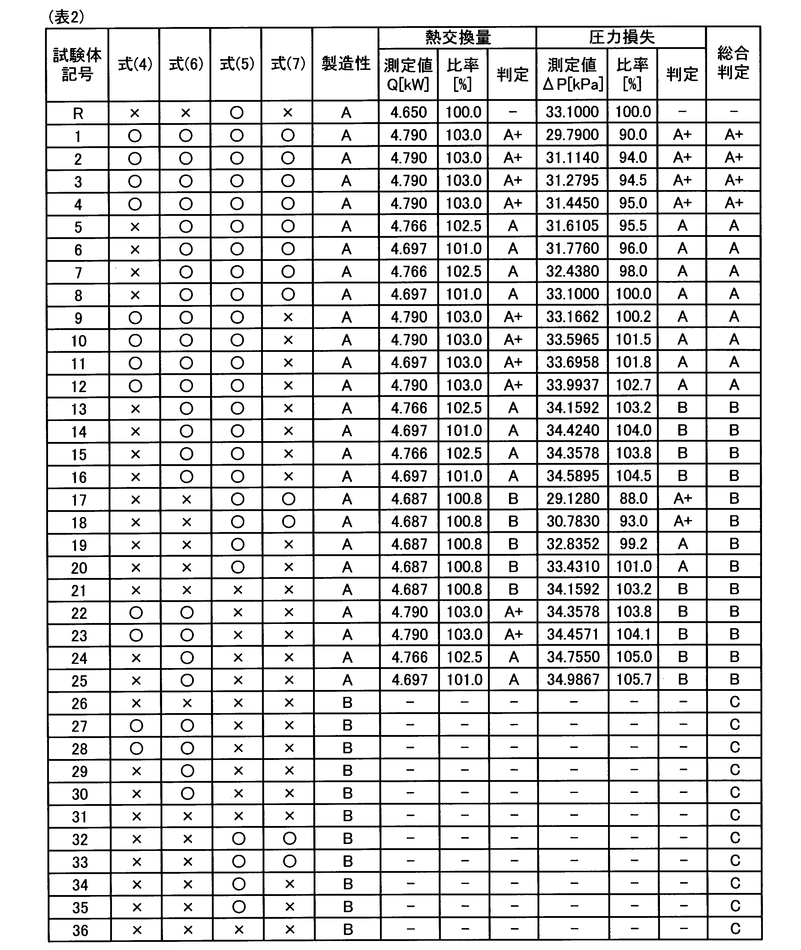
表1及び表2に示したように、前記式(1)~式(5)を満足する試験体1~4及び試験体9~12は、圧力損失の増大を抑制しつつ試験体Rに比べて熱交換量を大きくすることができた。また、前記式(1)~式(3)及び前記式(6)~式(7)を満足する試験体1~8は、熱交換量の低下を回避しつつ試験体Rに比べて圧力損失を低減することができた。
更に、これらの試験体1~12の中でも、前記式(1)~式(3)、前記式(4)及び前記式(7)を満足する試験体1~4は、試験体Rに比べて、圧力損失を低減するとともに熱交換量を大きくすることができた。
一方、試験体13~16については、熱交換量を大きくすることができたものの、圧力損失が増大した。これは、冷媒供給管6及び冷媒排出管7の両方が比較的下方に配置されたため、前記式(4)と前記式(5)との組合せ、及び、前記式(6)と前記式(7)との組合せのいずれの組合せも満足しなかったことが原因と考えられる。
試験体17~21については、a/Aの値が小さく、冷媒供給管6が過度に上方に配置されたため、第1扁平管群21に属する扁平管2の間の冷媒の偏りが大きくなった。その結果、熱交換量の低下を招いた。
試験体21~25については、b/Bの値が小さく、冷媒排出管7が過度に下方に配置されたため、第4扁平管群24を流れる気液二相流の割合が増大した。その結果、圧力損失の増大を招いた。
試験体21~25については、b/Bの値が小さく、冷媒排出管7が過度に下方に配置されたため、第4扁平管群24を流れる気液二相流の割合が増大した。その結果、圧力損失の増大を招いた。
試験体26~31については、b/Bの値を大きくして、冷媒排出管7を第1仕切り板45のごく近傍に接続しようとした。しかし、ヘッダ本体46となる円筒管に貫通穴を形成した後に、円筒管に変形が発生した。
試験体31~36については、a/Aの値を大きくして、冷媒供給管6を第1仕切り板44のごく近傍に接続しようとした。しかし、ヘッダ本体46となる円筒管に貫通穴を形成した後に、円筒管に変形が発生した。
試験体31~36については、a/Aの値を大きくして、冷媒供給管6を第1仕切り板44のごく近傍に接続しようとした。しかし、ヘッダ本体46となる円筒管に貫通穴を形成した後に、円筒管に変形が発生した。
Claims (6)
- 冷媒を流通させる複数の扁平管がフィンを介して平行に配列され、前記扁平管と前記フィンとが上下方向に交互に積層されたコアと、
前記扁平管の長手方向における前記コアの一端に配置された第1ヘッダと、
前記長手方向における前記コアの他端に配置された第2ヘッダと、
前記第1ヘッダに接続された冷媒供給管及び冷媒排出管と、を有し、
複数の前記扁平管は、上方から順に、第1扁平管群、第2扁平管群、第3扁平管群及び第4扁平管群に区分されており、
前記第1ヘッダは、
前記第1扁平管群と前記冷媒供給管とに連結された入口部と、
前記第2扁平管群と前記第3扁平管群とに連結された第2ターン部と、
前記第4扁平管群と前記冷媒排出管とに連結された出口部と、
前記入口部と前記第2ターン部との間、及び、前記第2ターン部と前記出口部との間を仕切る第1仕切り板と、を有し、
前記第2ヘッダは、
前記第1扁平管群と前記第2扁平管群とに連結された第1ターン部と、
前記第3扁平管群と前記第4扁平管群とに連結された第3ターン部と、
前記第1ターン部と前記第3ターン部との間を仕切る第2仕切り板と、を有し、
上下方向における、前記第1ヘッダの全長をL[mm]、前記入口部の長さをA[mm]、前記出口部の長さをB[mm]、前記入口部に接続された前記冷媒供給管の端部の中心から前記第1ヘッダの上端までの距離をa[mm]、前記出口部に接続された前記冷媒排出管の端部の中心から前記第1ヘッダの下端までの距離をb[mm]とした場合に、下記式(1)~式(5)を満足する、凝縮器。
400≦L≦1500 ・・・(1)
0.4≦A/L≦0.75 ・・・(2)
30.275/L≦B/L≦(L-A)/3L ・・・(3)
0.22≦a/A≦0.64 ・・・(4)
{0.09×(B-6.825-12.825)+12.825}/B≦b/B≦(B-6.825)/B ・・・(5) - 冷媒を流通させる複数の扁平管がフィンを介して平行に配列され、前記扁平管と前記フィンとが上下方向に交互に積層されたコアと、
前記扁平管の長手方向における前記コアの一端に配置された第1ヘッダと、
前記長手方向における前記コアの他端に配置された第2ヘッダと、
前記第1ヘッダに接続された冷媒供給管及び冷媒排出管と、を有し、
複数の前記扁平管は、上方から順に、第1扁平管群、第2扁平管群、第3扁平管群及び第4扁平管群に区分されており、
前記第1ヘッダは、
前記第1扁平管群と前記冷媒供給管とに連結された入口部と、
前記第2扁平管群と前記第3扁平管群とに連結された第2ターン部と、
前記第4扁平管群と前記冷媒排出管とに連結された出口部と、
前記入口部と前記第2ターン部との間、及び、前記第2ターン部と前記出口部との間を仕切る第1仕切り板と、を有し、
前記第2ヘッダは、
前記第1扁平管群と前記第2扁平管群とに連結された第1ターン部と、
前記第3扁平管群と前記第4扁平管群とに連結された第3ターン部と、
前記第1ターン部と前記第3ターン部との間を仕切る第2仕切り板と、を有し、
上下方向における、前記第1ヘッダの全長をL[mm]、前記入口部の長さをA[mm]、前記出口部の長さをB[mm]、前記入口部に接続された前記冷媒供給管の端部の中心から前記第1ヘッダの上端までの距離をa[mm]、前記出口部に接続された前記冷媒排出管の端部の中心から前記第1ヘッダの下端までの距離をb[mm]とした場合に、下記式(1)~式(3)及び下記式(6)~式(7)を満足する、凝縮器。
400≦L≦1500 ・・・(1)
0.4≦A/L≦0.75 ・・・(2)
30.275/L≦B/L≦(L-A)/3L ・・・(3)
0.22≦a/A≦(A-6.825)/A ・・・(6)
{0.47×(B-6.825-12.825)+12.825}/B≦b/B≦(B-6.825)/B ・・・(7) - 前記式(1)~式(3)を満足するとともに、下記式(4)と下記式(7)との組合せを満足する、請求項1または2に記載の凝縮器。
0.22≦a/A≦0.64 ・・・(4)
{0.47×(B-6.825-12.825)+12.825}/B≦b/B≦(B-6.825)/B ・・・(7) - 前記第1扁平管群に属する前記扁平管の数は前記第2扁平管群よりも多く、前記第2扁平管群に属する扁平管の数は前記第3扁平管群よりも多く、前記第3扁平管群に属する扁平管の数は前記第4扁平管群よりも多い、請求項1~3のいずれか1項に記載の凝縮器。
- 複数の前記扁平管の総数を100%とした場合に、前記第1扁平管群に属する扁平管の数が35~45%であり、前記第2扁平管群に属する扁平管の数が25~35%であり、前記第3扁平管群に属する扁平管の数が15~25%であり、前記第4扁平管群に属する扁平管の数が5~15%である、請求項1~4のいずれか1項に記載の凝縮器。
- 前記第4扁平管群に属する扁平管の数が2本以上である、請求項1~5のいずれか1項に記載の凝縮器。
Priority Applications (1)
| Application Number | Priority Date | Filing Date | Title |
|---|---|---|---|
| CN201880046519.XA CN110869690B (zh) | 2017-08-21 | 2018-08-17 | 冷凝器 |
Applications Claiming Priority (2)
| Application Number | Priority Date | Filing Date | Title |
|---|---|---|---|
| JP2017-158675 | 2017-08-21 | ||
| JP2017158675A JP2019035559A (ja) | 2017-08-21 | 2017-08-21 | 凝縮器 |
Publications (1)
| Publication Number | Publication Date |
|---|---|
| WO2019039401A1 true WO2019039401A1 (ja) | 2019-02-28 |
Family
ID=65439857
Family Applications (1)
| Application Number | Title | Priority Date | Filing Date |
|---|---|---|---|
| PCT/JP2018/030522 Ceased WO2019039401A1 (ja) | 2017-08-21 | 2018-08-17 | 凝縮器 |
Country Status (3)
| Country | Link |
|---|---|
| JP (1) | JP2019035559A (ja) |
| CN (1) | CN110869690B (ja) |
| WO (1) | WO2019039401A1 (ja) |
Cited By (1)
| Publication number | Priority date | Publication date | Assignee | Title |
|---|---|---|---|---|
| CN112413933A (zh) * | 2020-12-10 | 2021-02-26 | 珠海格力电器股份有限公司 | 微通道换热器和空调器 |
Families Citing this family (4)
| Publication number | Priority date | Publication date | Assignee | Title |
|---|---|---|---|---|
| JP7383935B2 (ja) * | 2019-08-29 | 2023-11-21 | 株式会社デンソー | 熱交換器 |
| JP7394722B2 (ja) * | 2020-07-28 | 2023-12-08 | 三菱電機株式会社 | 除湿装置 |
| JP7550573B2 (ja) | 2020-09-02 | 2024-09-13 | 株式会社Uacj | 空気調和機 |
| WO2023144917A1 (ja) * | 2022-01-26 | 2023-08-03 | 株式会社Uacj | パラレルフロー型熱交換器及び空気調和機 |
Citations (1)
| Publication number | Priority date | Publication date | Assignee | Title |
|---|---|---|---|---|
| JP2016053473A (ja) * | 2016-01-22 | 2016-04-14 | 三菱電機株式会社 | 熱交換器及び冷凍サイクル装置 |
Family Cites Families (6)
| Publication number | Priority date | Publication date | Assignee | Title |
|---|---|---|---|---|
| US6003592A (en) * | 1992-11-25 | 1999-12-21 | Denso Corporation | Refrigerant condenser |
| JPH1089883A (ja) * | 1996-09-17 | 1998-04-10 | Zexel Corp | 熱交換器用ヘッダーパイプとその製造装置 |
| KR100264815B1 (ko) * | 1997-06-16 | 2000-09-01 | 신영주 | 다단기액분리형응축기 |
| JP2001165532A (ja) * | 1999-12-09 | 2001-06-22 | Denso Corp | 冷媒凝縮器 |
| CN201476625U (zh) * | 2009-06-15 | 2010-05-19 | 浙江康盛股份有限公司 | 微通道冷凝器 |
| EP2769163B1 (en) * | 2011-10-19 | 2020-12-30 | Carrier Corporation | Flattened tube finned heat exchanger and fabrication method |
-
2017
- 2017-08-21 JP JP2017158675A patent/JP2019035559A/ja active Pending
-
2018
- 2018-08-17 CN CN201880046519.XA patent/CN110869690B/zh active Active
- 2018-08-17 WO PCT/JP2018/030522 patent/WO2019039401A1/ja not_active Ceased
Patent Citations (1)
| Publication number | Priority date | Publication date | Assignee | Title |
|---|---|---|---|---|
| JP2016053473A (ja) * | 2016-01-22 | 2016-04-14 | 三菱電機株式会社 | 熱交換器及び冷凍サイクル装置 |
Cited By (1)
| Publication number | Priority date | Publication date | Assignee | Title |
|---|---|---|---|---|
| CN112413933A (zh) * | 2020-12-10 | 2021-02-26 | 珠海格力电器股份有限公司 | 微通道换热器和空调器 |
Also Published As
| Publication number | Publication date |
|---|---|
| JP2019035559A (ja) | 2019-03-07 |
| CN110869690B (zh) | 2021-06-15 |
| CN110869690A (zh) | 2020-03-06 |
Similar Documents
| Publication | Publication Date | Title |
|---|---|---|
| US9651317B2 (en) | Heat exchanger and air conditioner | |
| WO2019039401A1 (ja) | 凝縮器 | |
| US8205470B2 (en) | Indoor unit for air conditioner | |
| JP4679542B2 (ja) | フィンチューブ熱交換器、およびそれを用いた熱交換器ユニット並びに空気調和機 | |
| JP7026830B2 (ja) | アルミニウム製押出扁平多穴管及び熱交換器 | |
| CN104246414B (zh) | 热交换器 | |
| EP2853843A1 (en) | Coolant distributor, and heat exchanger equipped with coolant distributor | |
| US20160033182A1 (en) | Heat exchanger for air-cooled chiller | |
| JPWO2014115240A1 (ja) | 冷媒分配器及びこの冷媒分配器を用いたヒートポンプ装置 | |
| WO2018116929A1 (ja) | 熱交換器及び空気調和機 | |
| KR20170067351A (ko) | 열교환기 | |
| JP5030932B2 (ja) | 熱交換器並びに空調冷凍装置 | |
| AU2019460046B2 (en) | Heat exchanger and refrigeration cycle apparatus | |
| JP2014137177A (ja) | 熱交換器および冷凍装置 | |
| EP4317811A1 (en) | Air conditioning device | |
| CN205747598U (zh) | 换热装置及空调器、热泵 | |
| JP2020112274A (ja) | 熱交換器 | |
| JP2020115070A (ja) | 熱交換器 | |
| US20230147134A1 (en) | Heat exchanger and air-conditioning apparatus | |
| JP7550573B2 (ja) | 空気調和機 | |
| JP2020165578A (ja) | 熱交換器分流器 | |
| WO2014125997A1 (ja) | 熱交換装置およびこれを備えた冷凍サイクル装置 | |
| JP7566155B2 (ja) | 熱交換器及び空気調和装置 | |
| KR100606332B1 (ko) | 공조기기의 열교환기용 납작튜브 | |
| JP7290396B2 (ja) | 熱交換器 |
Legal Events
| Date | Code | Title | Description |
|---|---|---|---|
| 121 | Ep: the epo has been informed by wipo that ep was designated in this application |
Ref document number: 18848173 Country of ref document: EP Kind code of ref document: A1 |
|
| NENP | Non-entry into the national phase |
Ref country code: DE |
|
| 122 | Ep: pct application non-entry in european phase |
Ref document number: 18848173 Country of ref document: EP Kind code of ref document: A1 |