WO2019039157A1 - 車両周辺の小物体領域を識別する装置及び方法 - Google Patents
車両周辺の小物体領域を識別する装置及び方法 Download PDFInfo
- Publication number
- WO2019039157A1 WO2019039157A1 PCT/JP2018/027259 JP2018027259W WO2019039157A1 WO 2019039157 A1 WO2019039157 A1 WO 2019039157A1 JP 2018027259 W JP2018027259 W JP 2018027259W WO 2019039157 A1 WO2019039157 A1 WO 2019039157A1
- Authority
- WO
- WIPO (PCT)
- Prior art keywords
- information
- sub
- pixel size
- image
- vehicle
- Prior art date
- Legal status (The legal status is an assumption and is not a legal conclusion. Google has not performed a legal analysis and makes no representation as to the accuracy of the status listed.)
- Ceased
Links
Images



Classifications
-
- G—PHYSICS
- G06—COMPUTING OR CALCULATING; COUNTING
- G06V—IMAGE OR VIDEO RECOGNITION OR UNDERSTANDING
- G06V20/00—Scenes; Scene-specific elements
- G06V20/50—Context or environment of the image
- G06V20/56—Context or environment of the image exterior to a vehicle by using sensors mounted on the vehicle
- G06V20/58—Recognition of moving objects or obstacles, e.g. vehicles or pedestrians; Recognition of traffic objects, e.g. traffic signs, traffic lights or roads
-
- G—PHYSICS
- G06—COMPUTING OR CALCULATING; COUNTING
- G06T—IMAGE DATA PROCESSING OR GENERATION, IN GENERAL
- G06T7/00—Image analysis
-
- G—PHYSICS
- G06—COMPUTING OR CALCULATING; COUNTING
- G06V—IMAGE OR VIDEO RECOGNITION OR UNDERSTANDING
- G06V40/00—Recognition of biometric, human-related or animal-related patterns in image or video data
- G06V40/10—Human or animal bodies, e.g. vehicle occupants or pedestrians; Body parts, e.g. hands
Definitions
- the present invention relates to an apparatus and method for identifying small object areas around a vehicle.
- the small object in the present application means an object whose pixel size occupied in the last layer is less than the effective analysis pixel size as a result of analysis for each layer by the depth learning image processing method, or a predetermined training pixel size according to the machine learning method
- a small object means an object that is less than, and also includes a small object that is far from a small object in the vicinity.
- the slide window method in target detection is a general technique, but in this method, computing time is required to detect a small object with a predetermined accuracy.
- Image scaling techniques solve some problems and reduce some computation time to some extent, but the information essential to detect small objects is lost.
- the pyramid hierarchy scaling method has a noticeable effect on multi-size detection, but it is difficult to detect objects of small shape and far distance. Although the accuracy can be improved by increasing the size of the feature map partition, it is slow and disadvantageous for detecting the presence of small objects.
- Patent Document 1 discloses a small object detection algorithm that detects a region of interest of a small object in a video frame using a statistical histogram.
- Patent Document 1 uses up / down frame information about loss of small objects during video stream transmission, and the method is unsuitable for on-vehicle real-time video processing. Therefore, there is a problem that the small object area can not be identified in real time and quickly, and furthermore, the small object can not be detected in real time and quickly.
- the present invention provides an apparatus and method for identifying a small object area around a vehicle that can detect a small object around the vehicle in real time and quickly.
- an apparatus for identifying a small object area around a vehicle an image acquisition unit for acquiring an image around the vehicle from an imaging apparatus of the vehicle, and history information and / or related to the image
- An identification unit that acquires vehicle information of the vehicle and identifies the small object region from the image based on at least one of the image, the history information, and the vehicle information.
- the small object means an object whose pixel size occupied in the last layer is less than the effective analysis pixel size as a result of analysis for each layer by the depth learning image processing method, or a pixel size occupied is less than a predetermined training pixel size by the machine learning method Meaning an object that is
- the identification unit further comprises A first information acquisition unit for acquiring the history information including a plurality of pieces of object position information including a center position and a pixel size of each object; A position discrimination unit in which the center position of an object whose pixel size is larger than the predetermined training pixel size is set as the center position of a large object, with the center position of an object whose pixel size is smaller than the predetermined training pixel size; , A first division unit that divides the image into a plurality of first sub-regions such that the first sub-region having a pixel size larger than the predetermined training pixel size includes the center position of the small object or the center position of a large object; When, And a first classification unit that classifies a first sub-region including a center position of the small object as the small-object region.
- the identification unit further A second information acquisition unit that acquires the vehicle information including road surface information and a vehicle speed from the image; A setting unit configured to set a detection area in the image based on the road surface information; A second division unit that divides the detection area into a plurality of second sub areas based on the vehicle speed; And a second classification unit that classifies a second subregion having a pixel size equal to or less than a predetermined training pixel among the plurality of second subregions as the small object region.
- the road surface information includes lane information, lane junction point information is acquired based on the lane information, and the setting unit sets the detection area based on the lane junction point information.
- the identification unit further comprises A third information acquisition unit for acquiring the vehicle information including the depth value of each pixel in the image and the vehicle speed based on the image; A third division unit that divides the image into a plurality of third sub-regions based on the vehicle speed such that the pixel size of each third sub-region of the plurality of third sub-regions is larger than the predetermined training pixel size; A calculation unit for calculating an average depth value of a plurality of pixels in each third sub region of the plurality of third sub regions; And a third classification unit for classifying a third sub-region having an average depth value equal to or more than a predetermined value as the small object region.
- the identification unit further comprises A fourth information acquisition unit that acquires the history information, which is history analysis data corresponding to the vehicle information including position information of the vehicle and history information corresponding to the position information; A determination unit that determines whether a first predetermined area exists in the image based on the position information, and determines whether a second predetermined area exists in the image based on the history analysis data; , A part of the fourth subregions among the plurality of fourth subregions includes the first predetermined region or the second predetermined region, and the pixel size of each fourth subregion is larger than the predetermined training pixel size.
- a fourth division unit that divides the image into a plurality of fourth sub-regions; And a fourth classification unit that classifies a fourth sub-region including the first predetermined region or the second predetermined region as the small object region.
- the first predetermined area is an area including a school
- the second predetermined area is an area in which an object is likely to fall.
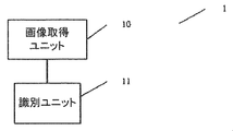
- FIG. 1 is a schematic view of an apparatus for identifying a small object area around a vehicle according to an embodiment of the present invention.
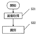
- 5 is a flowchart of a method of identifying a small object area around a vehicle according to an embodiment of the present invention.
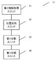
- It is a schematic diagram of the identification unit of Example 1 which concerns on one Example of this invention.
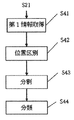
- 5 is a flowchart of an identification step according to Embodiment 1.
- 7 is a flowchart of an identification step according to Embodiment 2.
- It is a schematic diagram of the identification unit of Example 3 which concerns on the other Example of this invention.
- 15 is a flowchart of an identification step according to Embodiment 3.
- FIG. 15 is a flowchart of an identification step according to Embodiment 4. It is a schematic diagram of a part of training data which has label box G in a part of actual scene. It is a schematic diagram of the center position of a small object, and the center position of a large object.
- FIG. 5 is a schematic view of a plurality of first sub-regions according to Embodiment 1 of the present invention. It is a schematic diagram of the lane information in an image. It is a schematic diagram of the detection area
- FIG. 18 is a schematic view of a plurality of third sub-regions according to Embodiment 3.
- FIG. 18 is a schematic view of a plurality of fourth sub-regions according to a fourth embodiment.
- FIG. 1 is a schematic view of an apparatus for identifying a small object area around a vehicle according to an embodiment of the present invention.
- an apparatus 1 for identifying a small object area around a vehicle according to an embodiment of the present invention comprises an image acquisition unit 10 and an identification unit 11.
- FIG. 2 is a flowchart of a method of identifying a small object area around a vehicle according to an embodiment of the present invention.
- the image acquisition unit 10 acquires an image of the area around the vehicle shown in FIGS. 13 to 18 from an imaging device (not shown) in the vehicle.
- the photographing device (not shown) is a camera system mounted at an appropriate position of the vehicle (which may be disposed on the upper end of the vehicle windshield, at the tail rear end, on both sides of the vehicle, on the roof) It may be one or more camera systems that collect and store image information from both sides.
- the camera system usually includes an optical system and a camera.
- the optical system may have a zoom function, an autofocus function, and the like, and the camera may use a color CCD (charge coupled device) camera.
- CCD charge coupled device
- step S22 the identification unit 11 acquires history information related to the image and / or vehicle information of the vehicle, and identifies the small object area from the image based on at least one of the image, the history information, and the vehicle information. Do.
- the small object is an object whose pixel size occupied in the last layer is less than the effective analysis pixel size N1 as a result of analyzing layer by layer by the depth learning image processing method, or a predetermined training pixel size N2 of the pixel size occupied by the machine learning method Means an object that is less than.
- the effective analysis pixel size N1 is, for example, 2 ⁇ 2 pixels
- the predetermined training pixel size N2 is, for example, 20 ⁇ 20 pixels.
- the identification unit 11 is realized by, for example, a processor such as a CPU (Central Processing Unit) not shown, a ROM storing various programs, a RAM temporarily storing data of calculation processes, and a storage device such as an external storage device.
- a processor such as a CPU reads and executes various programs stored in the ROM, and stores the calculation result as the execution result in the RAM or an external storage device.
- FIG. 3 is a schematic view of the identification unit 11 according to the first embodiment of the present invention.
- the identification unit 11 includes a first information acquisition unit 31, a position discrimination unit 32, a first division unit 33, and a first classification unit 34.
- the first information acquisition unit 31, the position discrimination unit 32, the first division unit 33, and the first classification unit 34 for example, a processor such as a CPU (not shown), a ROM for storing various programs, data of operation processes
- a processor such as a CPU reads and executes various programs stored in a ROM, while being realized by a storage device such as a RAM and an external storage device that are temporarily stored, and the calculation result as the execution result is a RAM or an external storage device Store in
- the 1st information acquisition unit 31, the position discrimination unit 32, the 1st division unit 33, and the 1st classification unit 34 are single calculation. It may be a part, or may be configured to integrate desired functional blocks.
- FIG. 4 is a flowchart of the identification step according to the present embodiment.
- the first information acquisition unit 31 acquires history information including a plurality of pieces of object position information including the center position and the pixel size of each object.
- FIG. 11 is a schematic view of some training data having label boxes G in some actual scenes.
- each training data has a label box G, and each label box G includes the center position of the object and the pixel size.
- Each label box G indicates object position information of each object, that is, each object position information includes the center position and pixel size of each object, and the pixel size of each object is, for example, the pixel width and pixel height of each object , That is, the width and height of the label box G.
- step S42 the first information acquisition unit 31 sets the center position of an object having a pixel size equal to or less than a predetermined training pixel size N2 as the center position of a small object, and increases the center position of an object having a pixel size larger than a predetermined training pixel size N2. The center position of the object.
- FIG. 12 is a schematic view of the center position of the small object and the center position of the large object. As shown in FIG. 12, for example, a black circle indicates the center position of each small object, and a white circle indicates the center position of each large object.
- step S43 the first division unit 33 performs a plurality of first image processing so that the center position of the small object or the center position of the large object is included in each first sub-region whose pixel size is larger than the predetermined training pixel size N2. Divide into subregions.
- FIG. 13 is a schematic view of a plurality of first sub-regions according to the first embodiment of the present invention, and as shown in FIG. 13, an image acquired by the image acquisition unit 10 is divided into a plurality of first sub-regions; Each different sized box indicates each first sub-region.
- the first sub-region includes the center position of the small object shown in FIG. 12 or the center position of the large object.
- the first classification unit 34 classifies the first sub region including the center position of the small object as the small object region.
- the first sub-regions A1 and A2 shown in FIG. 13 each include the center position of the small object, that is, the first sub-regions A1 and A2 are classified as small object regions. In this way, small object areas in the image can be identified quickly.
- FIG. 5 is a schematic view of an identification unit 11 of a second embodiment according to another embodiment of the present invention.
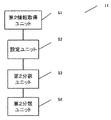
- the identification unit 11 includes a second information acquisition unit 51, a setting unit 52, a second division unit 53, and a second classification unit 54.
- the second information acquisition unit 51, the setting unit 52, the second division unit 53, and the second classification unit 54 are, for example, a processor such as a CPU (not shown), a ROM for storing various programs, and temporary data of operation processes.
- a storage device such as a RAM and an external storage device
- a processor such as a CPU reads and executes various programs stored in the ROM, and the calculation result as the execution result is stored in the RAM or the external storage device. Store.
- the 2nd information acquisition unit 51, the setting unit 52, the 2nd division unit 53, and the 2nd classification unit 54 are one calculating part It is also possible to integrate desired functional blocks.
- FIG. 6 is a flowchart of the identification step according to the second embodiment.
- the second information acquisition unit 51 acquires vehicle information including road surface information and vehicle speed from the image.
- An on-vehicle sensor (not shown) of the vehicle detects the vehicle speed and is acquired by the second information acquisition unit 51.
- step S62 the setting unit 52 sets a detection area in the image based on the road surface information.
- the road surface information includes lane information, acquires lane junction point information based on the lane information, and the setting unit 52 sets a detection area based on the lane junction point information.
- FIG. 14 is a schematic view of lane information in an image
- FIG. 15 is a schematic view of a detection area in the image.
- the lane information is indicated by two lanes L1 and L2, and as shown in FIG. 15, the intersection C of the extension lines of the two lanes L1 and L2 is a lane junction. It becomes point C. That is, the position of the lane junction point C is lane junction point information.
- an area from the lane junction C to the vehicle in the image is set as a detection area D.
- the setting unit 52 can also be provided in the other embodiments.
- the detection region is set based on the lane junction point information, it is acquired by the identification unit 11 based on the maximum region of interest of the on-vehicle camera.
- a detection area in the image for example, a range of 150 m around the vehicle may be set. Beyond this range, the division of the small object area is unnecessary. A duplicate description is omitted below.
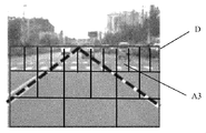
- the second division unit 53 divides the detection area D into a plurality of second sub-areas based on the vehicle speed.
- FIG. 16 is a schematic view of a plurality of second sub-regions according to the second embodiment. For example, as the vehicle speed increases, the number of second sub-regions increases. Further, in the detection area D, the number of second sub-regions increases as the region is further from the vehicle, and the number of second sub-regions decreases as the region is closer to the vehicle. As shown in FIG. 16, in the direction away from the vehicle along the lanes L1 and L2, the division ratio of the second sub-region is, for example, 1: 2: 4.
- the second classification unit 54 classifies, as the small object area, the second sub area in which the pixel size in the plurality of second sub areas is equal to or smaller than the predetermined training pixel N2. For example, if the pixel size of the second sub-region A3 is N2 or less, the second sub-region A3 is classified as a small object region. Since the detection area D is a partial area of the image, the detection range of the small object is reduced to improve the detection speed.
- FIG. 7 is a schematic view of an identification unit 11 according to a third embodiment of the present invention.
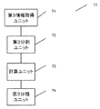
- the identification unit 11 includes a third information acquisition unit 71, a third division unit 72, a calculation unit 73, and a third classification unit 74.
- the third information acquisition unit 71, the third division unit 72, the calculation unit 73, and the third classification unit 74 are, for example, a processor such as a CPU (not shown), a ROM for storing various programs, and temporary data of operation processes. Is realized by a storage device such as a RAM and an external storage device, and a processor such as a CPU reads and executes various programs stored in the ROM, and the calculation result as the execution result is stored in the RAM or the external storage device. Store.
- the 3rd information acquisition unit 71, the 3rd division unit 72, the calculation unit 73, and the 3rd classification unit 74 are one calculating part. It is also possible to integrate desired functional blocks.
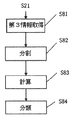
- FIG. 8 is a flowchart of the identification step according to the third embodiment.
- the third information acquisition unit 71 acquires vehicle information including the depth value of each pixel in the image and the vehicle speed based on the image.
- An on-vehicle sensor (not shown) of the vehicle detects the vehicle speed and is acquired by the third information acquisition unit 71.
- the third information acquisition unit 71 calculates image information captured by a multi-view camera to acquire a depth value of each pixel, or directly acquires a pixel depth value with a distance measurement sensor such as radar or laser. Do.
- the depth value of each pixel is the distance between each pixel in the image and the vehicle. Specifically, the method of acquiring the depth value is the same as in the prior art, and the detailed description is omitted here.
- step S82 the third division unit 72 divides the image into a plurality of third sub-regions based on the vehicle speed.
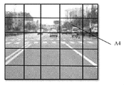
- FIG. 17 is a schematic view of a plurality of third sub-regions according to the third embodiment.
- the pixel size of the third sub-region of each of the plurality of third sub-regions is larger than the predetermined training pixel size N2. The higher the vehicle speed, the greater the number of third sub-regions.
- step S83 the calculation unit 73 calculates an average depth value of a plurality of pixels in each third sub region of the plurality of third sub regions.
- an average depth value of the plurality of pixels is calculated to obtain an average depth value of each third sub-region.
- the third classification unit 74 classifies the third sub-region whose average depth value is equal to or more than a predetermined value as a small object region. For example, if the predetermined value is 10 meters, the third classification unit 74 classifies the third sub-region having an average depth value of 10 meters or more as the small object region, for example, the third sub-region A4 in FIG. Classify as object area.
- the average depth value is equal to or more than the predetermined value by calculating the average depth value of the plurality of pixels in each third sub region of the plurality of third sub regions in the calculation unit 73 It is possible to classify the third sub-region of H as a small object region.
- FIG. 9 is a schematic view of an identification unit 11 according to a fourth embodiment of the present invention.
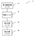
- the identification unit 11 includes a fourth information acquisition unit 91, a determination unit 92, a fourth division unit 93, and a fourth classification unit 94.
- the fourth information acquisition unit 91, the determination unit 92, the fourth division unit 93, and the fourth classification unit 94 are, for example, a processor such as a CPU (not shown), a ROM for storing various programs, and temporary data of operation processes. Is realized by a storage device such as a RAM and an external storage device, and a processor such as a CPU reads and executes various programs stored in the ROM, and the calculation result as the execution result is stored in the RAM or the external storage device.
- the 4th information acquisition unit 91, the judgment unit 92, the 4th division unit 93, and the 4th classification unit 94 are one calculating part. It is also possible to integrate desired functional blocks.
- FIG. 10 is a flowchart of the identification step according to the fourth embodiment.
- the fourth information acquisition unit 91 acquires vehicle information including vehicle traveling direction information and the like of the vehicle, and history information which is history analysis data corresponding to position information. .
- the position information of the vehicle is the current geographical position information of the vehicle, is detected by an on-vehicle positioning system such as GPS (Global Positioning System), Beidou satellite positioning system, and acquired by the fourth information acquisition unit 91 Ru.
- GPS Global Positioning System
- Beidou satellite positioning system Beidou satellite positioning system
- step S102 the determination unit 92 determines whether or not the first predetermined area exists in the image based on the position information, and determines whether the second predetermined area exists in the image based on the history analysis data. to decide.
- the first predetermined area is an area including a school, for example, an area including a kindergarten, a nursery, etc. People with small height and volume present in these areas become small objects in the present invention.
- step S103 the fourth division unit 93 divides the image into a plurality of fourth sub-regions
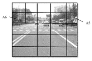
- FIG. 18 is a schematic view of the plurality of fourth sub-regions according to the fourth embodiment.
- a part of the fourth sub-regions includes the first predetermined region or the second predetermined region
- the pixel size of each fourth sub-region of the plurality of fourth sub-regions is Larger than a predetermined training pixel size.
- division can be performed based on the vehicle travel direction information acquired by the fourth information acquisition unit 91. For example, when the vehicle turns left, the divisible sub-regions increase in the left region of the image.
- the fourth classification unit 94 classifies the fourth sub-region including the first predetermined region or the second predetermined region as the small object region.
- the fourth sub-region A5 includes, for example, a kindergarten
- the fourth sub-region A6 includes a region in which an object is likely to fall.
- the fourth classification unit 94 The fourth sub-region A5 and the fourth sub-region A6 are classified as small object regions.
- the dimensions and shapes of the first subregion, the second subregion, the third subregion, and the fourth subregion are arbitrary and are not limited.
- small object detection may be performed only on these small object areas, and it is not necessary to perform small object detection on the entire image. In this way, small objects can be detected in real time and quickly.
- small object detection may be performed only on these small object regions, and small object detection need not be performed on the entire image. It becomes possible to detect a small object quickly.
- DESCRIPTION OF SYMBOLS 1 ...
- the apparatus which identifies the small object area
Landscapes
- Engineering & Computer Science (AREA)
- Physics & Mathematics (AREA)
- General Physics & Mathematics (AREA)
- Theoretical Computer Science (AREA)
- Multimedia (AREA)
- Human Computer Interaction (AREA)
- Computer Vision & Pattern Recognition (AREA)
- Image Analysis (AREA)
- Traffic Control Systems (AREA)
Abstract
本発明は、車両周辺の小物体をリアルタイム且つ迅速に検出し得る車両周辺の小物体領域を識別する装置及び方法を提供する。本発明に係る車両周辺の小物体領域を識別する装置は、車両の撮影装置から前記車両周辺の画像を取得する画像取得ユニットと、前記画像に関連する履歴情報及び/又は前記車両の車両情報を取得して、前記画像、前記履歴情報、前記車両情報のうちの少なくとも1つに基づき、前記画像から前記小物体領域を識別する識別ユニットとを備える。
Description
本発明は車両周辺の小物体領域を識別する装置及び方法に関する。
自律走行を実現するのに、様々なタイプの物体を同時に検出する必要があり、現在、機械学習、特に深層学習に基づく検出器は、モバイルカメラのシーンでの物体検出及び追跡精度について大幅に向上しており、単眼/両眼/多眼カメラを用いて車両走行領域の周囲について効果的に物体識別と追跡を行うことができる。しかしながら、従来の検出器は、検出形状が小さく且つ距離が遠い物体については検出しにくく、小物体検出精度が低い。小物体自体の画素が処理過程に失われるため、物体の識別精度に悪影響を与えて、運転の危険性増加につながる。
本願における小物体とは、深層学習画像処理方法でレイヤーごとに分析した結果、最後レイヤーに占める画素寸法が有効分析画素寸法未満である物体、又は、占める画素寸法が機械学習方法による所定訓練画素寸法未満である物体を意味し、且つ、小物体は、近所にある小物体も遠い所にある小物体も含む。
目標検出におけるスライドウィンドウ方法は一般的な技術であるが、該方法では、所定精度で小物体を検出するのに演算時間がかかる。画像スケーリング技術により一部の問題を解決して、一部の演算時間をある程度短縮できるが、小物体を検出するのに必須な情報が失われてしまう。ピラミッド階層スケーリング方法は、マルチサイズ検出について顕著な効果を示すが、形状が小さく且つ距離が遠い物体を検出しにくい。特徴マップ(feature map)分割の大きさを増加する方法で、正確性を向上できるものの、速度が低く、小物体存在の検出に不利である。
従来技術では、特許文献1において、統計ヒストグラムを用いてビデオフレームにおける小物体の関心領域を検出する小物体検出アルゴリズムが開示されている。
しかしながら、特許文献1に記載される技術では、ビデオストリーム伝送中に小物体が失われることについて、アップ/ダウンフレーム情報を用い、該方法は車載リアルタイムビデオ処理に不適である。従って、リアルタイム且つ迅速に小物体領域を識別できず、さらにリアルタイム且つ迅速に小物体を検出できないという課題を有する。
そこで、本発明は、車両周辺の小物体をリアルタイム且つ迅速に検出し得る車両周辺の小物体領域を識別する装置及び方法を提供する。
上記課題を解決するため、本発明に係る車両周辺の小物体領域を識別する装置、車両の撮影装置から前記車両周辺の画像を取得する画像取得ユニットと、前記画像に関連する履歴情報及び/又は前記車両の車両情報を取得して、前記画像、前記履歴情報、前記車両情報のうちの少なくとも1つに基づき、前記画像から前記小物体領域を識別する識別ユニットと、を備えることを特徴とする。
前記小物体とは、深層学習画像処理方法でレイヤーごとに分析した結果、最後レイヤーに占める画素寸法が有効分析画素寸法未満である物体、又は、占める画素寸法が機械学習方法による所定訓練画素寸法未満である物体を意味することを特徴とする。
前記識別ユニットはさらに、
各物体の中心位置と画素寸法を含む物体位置情報を複数含む前記履歴情報を取得する第1情報取得ユニットと、
前記画素寸法が前記所定訓練画素寸法以下の物体の中心位置を小物体の中心位置として、前記画素寸法が前記所定訓練画素寸法より大きい物体の中心位置を大物体の中心位置とする位置区別ユニットと、
画素寸法が前記所定訓練画素寸法より大きい各々の第1サブ領域に前記小物体の中心位置又は大物体の中心位置を含むように、前記画像を複数の第1サブ領域に分割する第1分割ユニットと、
前記小物体の中心位置を含む第1サブ領域を前記小物体領域として分類する第1分類ユニットとを含むことを特徴とする。
各物体の中心位置と画素寸法を含む物体位置情報を複数含む前記履歴情報を取得する第1情報取得ユニットと、
前記画素寸法が前記所定訓練画素寸法以下の物体の中心位置を小物体の中心位置として、前記画素寸法が前記所定訓練画素寸法より大きい物体の中心位置を大物体の中心位置とする位置区別ユニットと、
画素寸法が前記所定訓練画素寸法より大きい各々の第1サブ領域に前記小物体の中心位置又は大物体の中心位置を含むように、前記画像を複数の第1サブ領域に分割する第1分割ユニットと、
前記小物体の中心位置を含む第1サブ領域を前記小物体領域として分類する第1分類ユニットとを含むことを特徴とする。
また、前記識別ユニットはさらに、
前記画像から、路面情報及び車速を含む前記車両情報を取得する第2情報取得ユニットと、
前記路面情報に基づいて前記画像における検出領域を設定する設定ユニットと、
前記車速に基づき、前記検出領域を複数の第2サブ領域に分割する第2分割ユニットと、
前記複数の第2サブ領域のうち画素寸法が所定訓練画素以下の第2サブ領域を前記小物体領域として分類する第2分類ユニットとを含むことを特徴とする。
前記画像から、路面情報及び車速を含む前記車両情報を取得する第2情報取得ユニットと、
前記路面情報に基づいて前記画像における検出領域を設定する設定ユニットと、
前記車速に基づき、前記検出領域を複数の第2サブ領域に分割する第2分割ユニットと、
前記複数の第2サブ領域のうち画素寸法が所定訓練画素以下の第2サブ領域を前記小物体領域として分類する第2分類ユニットとを含むことを特徴とする。
前記路面情報は車線情報を含み、前記車線情報に基づいて車線接合点情報を取得して、前記設定ユニットは前記車線接合点情報に基づいて前記検出領域を設定することを特徴とする。
前記識別ユニットはさらに、
前記画像に基づいて、前記画像における各画素の深度値及び車速を含む前記車両情報を取得する第3情報取得ユニットと、
複数の第3サブ領域のうち各第3サブ領域の画素寸法が前記所定訓練画素寸法より大きいように、前記車速に基づき、前記画像を複数の第3サブ領域に分割する第3分割ユニットと、
前記複数の第3サブ領域のうち各々の第3サブ領域における複数の画素の平均深度値を計算する計算ユニットと、
平均深度値が所定値以上の第3サブ領域を前記小物体領域として分類する第3分類ユニットとを含むことを特徴とする。
前記画像に基づいて、前記画像における各画素の深度値及び車速を含む前記車両情報を取得する第3情報取得ユニットと、
複数の第3サブ領域のうち各第3サブ領域の画素寸法が前記所定訓練画素寸法より大きいように、前記車速に基づき、前記画像を複数の第3サブ領域に分割する第3分割ユニットと、
前記複数の第3サブ領域のうち各々の第3サブ領域における複数の画素の平均深度値を計算する計算ユニットと、
平均深度値が所定値以上の第3サブ領域を前記小物体領域として分類する第3分類ユニットとを含むことを特徴とする。
前記識別ユニットはさらに、
前記車両の位置情報を含む前記車両情報、及び前記位置情報に対応した履歴分析データである前記履歴情報を取得する第4情報取得ユニットと、
前記位置情報に基づいて前記画像に第1所定領域が存在するか否かを判断するとともに、上記履歴分析データに基づいて前記画像に第2所定領域が存在するか否かを判断する判断ユニットと、
複数の第4サブ領域のうち一部の第4サブ領域がそれぞれ前記第1所定領域又は前記第2所定領域を含み、各々の第4サブ領域の画素寸法が前記所定訓練画素寸法より大きいように、前記画像を複数の第4サブ領域に分割する第4分割ユニットと、
前記第1所定領域又は前記第2所定領域を含む第4サブ領域を前記小物体領域として分類する第4分類ユニットとを含むことを特徴とする。
前記第1所定領域は学校を含む領域、前記第2所定領域は物体が落ちやすい領域を含むことを特徴とする。
また、本発明に係る車両周辺の小物体領域を識別する方法は、車両の撮影装置から前記車両周辺の画像を取得する画像取得ステップと、前記画像に関連する履歴情報及び/又は前記車両の車速を取得して、前記画像、前記履歴情報、前記車両情報のうちの少なくとも1つに基づき、前記画像から前記小物体領域を識別する識別ステップと、を含むことを特徴とする。
本発明によれば、車両周辺の小物体をリアルタイム且つ迅速に検出し得る車両周辺の小物体領域を識別する装置及び方法を提供することが可能となる。
上記した以外の課題、構成及び効果は、以下の実施形態の説明により明らかにされる。
上記した以外の課題、構成及び効果は、以下の実施形態の説明により明らかにされる。
以下、図面を参照しながら、本発明について詳細に説明する。
図1は、本発明の実施例に係る車両周辺の小物体領域を識別する装置の模式図である。図1に示すように、本発明の実施例に係る車両周辺の小物体領域を識別する装置1は、画像取得ユニット10と識別ユニット11を備える。図2は、本発明の実施例に係る車両周辺の小物体領域を識別する方法のフローチャートである。
図1は、本発明の実施例に係る車両周辺の小物体領域を識別する装置の模式図である。図1に示すように、本発明の実施例に係る車両周辺の小物体領域を識別する装置1は、画像取得ユニット10と識別ユニット11を備える。図2は、本発明の実施例に係る車両周辺の小物体領域を識別する方法のフローチャートである。
図2に示されるように、ステップS21において、画像取得ユニット10は、車両中の撮影装置(図示せず)から図13~図18に示される車両周辺の画像を取得する。撮影装置(図示せず)は車両の適切な位置(車両フロントガラスの上端、テール後端、車体両側、ルーフに配置されても良い)に取り付けられたカメラシステムであり、車体の前方、後方、両側方からの画像情報を収集して記憶する1つ又は複数のカメラシステムであっても良い。カメラシステムは、通常、光学系とカメラからなり、光学系はズーム機能、オートフォーカス機能等を備え、カメラはカラーCCD(電荷結合素子)カメラを使用しても良い。
ステップS22において、識別ユニット11は、画像に関連する履歴情報及び/又は車両の車両情報を取得し、画像、履歴情報、車両情報のうちの少なくとも1つに基づいて、画像から小物体領域を識別する。
小物体とは、深層学習画像処理方法でレイヤーごとに分析した結果、最後レイヤーに占める画素寸法が有効分析画素寸法N1未満である物体、又は、占める画素寸法が機械学習方法による所定訓練画素寸法N2未満である物体を意味する。ここで、有効分析画素寸法N1は、たとえば2×2個の画素、所定訓練画素寸法N2は、たとえば20×20個の画素である。
以下、識別ユニット11のステップS22での具体的な操作の各実施例を詳細に説明する。なお、識別ユニット11は、例えば、図示しないCPU(Central Processing Unit)などのプロセッサ、各種プログラムを格納するROM、演算過程のデータを一時的に格納するRAM、外部記憶装置などの記憶装置にて実現されると共に、CPUなどのプロセッサがROMに格納された各種プログラムを読み出し実行し、実行結果である演算結果をRAM又は外部記憶装置に格納する。
図3は、本発明の一実施例に係る実施例1の識別ユニット11の模式図である。図3に示されるように、識別ユニット11は、第1情報取得ユニット31、位置区別ユニット32、第1分割ユニット33、第1分類ユニット34を含む。ここで、第1情報取得ユニット31、位置区別ユニット32、第1分割ユニット33、及び第1分類ユニット34は、例えば、図示しないCPUなどのプロセッサ、各種プログラムを格納するROM、演算過程のデータを一時的に格納するRAM、外部記憶装置などの記憶装置にて実現されると共に、CPUなどのプロセッサがROMに格納された各種プログラムを読み出し実行し、実行結果である演算結果をRAM又は外部記憶装置に格納する。なお、説明を解り易くするため、各機能ブロックに分割して示しているが、第1情報取得ユニット31、位置区別ユニット32、第1分割ユニット33、及び第1分類ユニット34を、1つの演算部としても良く、また、所望の機能ブロックを統合する構成としても良い。
図4は、本実施例に係る識別ステップのフローチャートである。
図4に示されるように、ステップS41において、第1情報取得ユニット31は、各物体の中心位置と画素寸法を含む物体位置情報を複数含む履歴情報を取得する。
図4に示されるように、ステップS41において、第1情報取得ユニット31は、各物体の中心位置と画素寸法を含む物体位置情報を複数含む履歴情報を取得する。
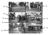
高速道路、都市路面、農村道路、橋の下のトンネル部分、トンネル等を含む各実際シーンにおけるラベルボックスを有する大量の訓練データを取得する。図11は、一部の実際シーンにおけるラベルボックスGを有する一部の訓練データの模式図である。図11中、6個の実際シーンが例示的に示されており、それぞれの訓練データはラベルボックスGを有し、各ラベルボックスGは、物体の中心位置と画素寸法を含む。各ラベルボックスGは、各物体の物体位置情報を示し、すなわち、各物体位置情報は各物体の中心位置と画素寸法を含み、各物体の画素寸法は、たとえば各物体の画素幅と画素高さ、すなわちラベルボックスGの幅と高さである。
ステップS42において、第1情報取得ユニット31は、画素寸法が所定訓練画素寸法N2以下の物体の中心位置を小物体の中心位置とし、画素寸法が所定訓練画素寸法N2より大きい物体の中心位置を大物体の中心位置とする。
各物体の画素寸法と所定訓練画素寸法N2とを比較して、異なる位置での物体を大物体と小物体に区別し、すなわち、大物体の中心位置を大物体、小物体の中心位置を小物体に対応させる。図12は、小物体の中心位置と大物体の中心位置の模式図である。図12に示されるように、例えば、黒丸は各小物体の中心位置、白丸は各大物体の中心位置を示す。
ステップS43において、第1分割ユニット33は、画素寸法が所定訓練画素寸法N2より大きい各々の第1サブ領域に小物体の中心位置又は大物体の中心位置を含むように、画像を複数の第1サブ領域に分割する。
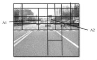
図13は、本発明の実施例1による複数の第1サブ領域の模式図であり、図13に示されるように、画像取得ユニット10で取得した画像を複数の第1サブ領域に分割し、各異なる大きさのボックスは各第1サブ領域を示す。第1サブ領域は、図12に示される小物体の中心位置又は大物体の中心位置を含む。
ステップS43において、第1分類ユニット34は、小物体の中心位置を含む第1サブ領域を小物体領域として分類する。例えば、図13に示される第1サブ領域A1とA2は、それぞれ小物体の中心位置を含み、すなわち、第1サブ領域A1とA2は小物体領域として分類される。このように、画像中の小物体領域が迅速に識別できる。
以上の通り本実施例によれば、車両周辺の小物体をリアルタイム且つ迅速に検出し得る車両周辺の小物体領域を識別する装置及び方法を提供することが可能となる。
図5は、本発明の他の実施例に係る実施例2の識別ユニット11の模式図である。図5に示されるように、識別ユニット11は、第2情報取得ユニット51、設定ユニット52、第2分割ユニット53、第2分類ユニット54を含む。ここで、第2情報取得ユニット51、設定ユニット52、第2分割ユニット53、及び第2分類ユニット54は、例えば、図示しないCPUなどのプロセッサ、各種プログラムを格納するROM、演算過程のデータを一時的に格納するRAM、外部記憶装置などの記憶装置にて実現されると共に、CPUなどのプロセッサがROMに格納された各種プログラムを読み出し実行し、実行結果である演算結果をRAM又は外部記憶装置に格納する。なお、説明を解り易くするため、各機能ブロックに分割して示しているが、第2情報取得ユニット51、設定ユニット52、第2分割ユニット53、及び第2分類ユニット54を、1つの演算部としても良く、また、所望の機能ブロックを統合する構成としても良い。
図6は、実施例2に係る識別ステップのフローチャートである。
図6に示されるように、ステップS61において、第2情報取得ユニット51は、画像から路面情報及び車速を含む車両情報を取得する。車両の車載センサ(図示せず)は、車速を検出して、第2情報取得ユニット51により取得される。
図6に示されるように、ステップS61において、第2情報取得ユニット51は、画像から路面情報及び車速を含む車両情報を取得する。車両の車載センサ(図示せず)は、車速を検出して、第2情報取得ユニット51により取得される。
ステップS62において、設定ユニット52は路面情報に基づいて画像における検出領域を設定する。ここで、路面情報は車線情報を含み、車線情報に基づいて車線接合点情報を取得し、設定ユニット52は車線接合点情報に基づいて検出領域を設定する。
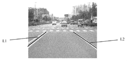
図14は、画像における車線情報の模式図であり、図15は、画像における検出領域の模式図である。図14に示されるように、車線情報は、2本の車線L1とL2により示されており、図15に示されるように、この2本の車線L1とL2の延長線の交点Cは車線接合点Cになる。すなわち、車線接合点Cの位置は車線接合点情報である。図15のボックスDに示されるように、画像における車線接合点Cから車両までの領域を検出領域Dとする。なお、設定ユニット52は、他の実施例にも備えることができ、ここで、車線接合点情報に基づいて検出領域を設定したが、車載カメラの最大関心領域に基づいて識別ユニット11で取得した画像における検出領域、例えば、車両周辺150mの範囲を設定しても良い。この範囲を超えると、小物体領域の分割が不要である。以下では重複説明を省略する。
第2分割ユニット53は、車速に基づき、検出領域Dを複数の第2サブ領域に分割する。図16は、実施例2による複数の第2サブ領域の模式図である。例えば、車速が速いほど、第2サブ領域の数は多くなる。また、該検出領域Dでは、車両から遠い領域であるほど、第2サブ領域の数は多くなり、車両に近い領域であるほど、第2サブ領域の数は少なくなる。図16に示されるように、車線L1とL2に沿って車両から離れた方向において、第2サブ領域の分割比率はたとえば1:2:4である。
ステップS64において、第2分類ユニット54は、複数の第2サブ領域における画素寸法が所定訓練画素N2以下の第2サブ領域を小物体領域として分類する。例えば、第2サブ領域A3の画素寸法がN2以下であると、第2サブ領域A3を小物体領域として分類する。
検出領域Dは画像の一部の領域であるため、小物体の検出範囲を減少させて、検出速度を向上させる。
検出領域Dは画像の一部の領域であるため、小物体の検出範囲を減少させて、検出速度を向上させる。
以上の通り本実施例によれば、実施例1の効果に加え、小物体の検出範囲を減少させて、検出速度を向上させることが可能となる。
図7は、本発明の他の実施例に係る実施例3の識別ユニット11の模式図である。図7に示されるように、識別ユニット11は、第3情報取得ユニット71、第3分割ユニット72、計算ユニット73、第3分類ユニット74を含む。ここで、第3情報取得ユニット71、第3分割ユニット72、計算ユニット73、及び第3分類ユニット74は、例えば、図示しないCPUなどのプロセッサ、各種プログラムを格納するROM、演算過程のデータを一時的に格納するRAM、外部記憶装置などの記憶装置にて実現されると共に、CPUなどのプロセッサがROMに格納された各種プログラムを読み出し実行し、実行結果である演算結果をRAM又は外部記憶装置に格納する。なお、説明を解り易くするため、各機能ブロックに分割して示しているが、第3情報取得ユニット71、第3分割ユニット72、計算ユニット73、及び第3分類ユニット74を、1つの演算部としても良く、また、所望の機能ブロックを統合する構成としても良い。
図8は、実施例3に係る識別ステップのフローチャートである。
図8に示されるように、ステップS81において、第3情報取得ユニット71は、画像に基づいて、画像における各画素の深度値及び車速を含む車両情報を取得する。車両の車載センサ(図示せず)は車速を検出して、第3情報取得ユニット71により取得される。
図8に示されるように、ステップS81において、第3情報取得ユニット71は、画像に基づいて、画像における各画素の深度値及び車速を含む車両情報を取得する。車両の車載センサ(図示せず)は車速を検出して、第3情報取得ユニット71により取得される。
また、第3情報取得ユニット71は、多眼カメラにより撮影された画像情報を計算して各画素の深度値を取得し、又は、レーダー、レーザ等の測距センサで画素の深度値を直接取得する。各画素の深度値は、画像における各画素と車両の間の距離であり、具体的に、深度値の取得方式は、従来技術と同様であり、ここで詳細な説明を省略する。
ステップS82において、第3分割ユニット72は、車速に基づいて、画像を複数の第3サブ領域に分割する。図17は、実施例3による複数の第3サブ領域の模式図である。複数の第3サブ領域のうち各々の第3サブ領域の画素寸法は所定訓練画素寸法N2より大きい。車速が高いほど、第3サブ領域の数は多くなる。
ステップS83において、計算ユニット73は、複数の第3サブ領域のうち各々の第3サブ領域における複数の画素の平均深度値を計算する。ここで、各々の第3サブ領域に複数の画素があり、複数の画素の平均深度値を計算して、各々の第3サブ領域の平均深度値を取得する。
ステップS84において、第3分類ユニット74は、平均深度値が所定値以上の第3サブ領域を小物体領域として分類する。例えば、所定値が10メートルであれば、第3分類ユニット74は、平均深度値が10メートル以上の第3サブ領域を小物体領域として分類し、例えば、図17における第3サブ領域A4を小物体領域として分類する。
以上の通り本実施例によれば、計算ユニット73にて複数の第3サブ領域のうち各々の第3サブ領域における複数の画素の平均深度値を計算することにより、平均深度値が所定値以上の第3サブ領域を小物体領域として分類することが可能となる。
図9は、本発明の他の実施例に係る実施例4による識別ユニット11の模式図である。図9に示されるように、識別ユニット11は、第4情報取得ユニット91、判断ユニット92、第4分割ユニット93、第4分類ユニット94を含む。ここで、第4情報取得ユニット91、判断ユニット92、第4分割ユニット93、及び第4分類ユニット94は、例えば、図示しないCPUなどのプロセッサ、各種プログラムを格納するROM、演算過程のデータを一時的に格納するRAM、外部記憶装置などの記憶装置にて実現されると共に、CPUなどのプロセッサがROMに格納された各種プログラムを読み出し実行し、実行結果である演算結果をRAM又は外部記憶装置に格納する。なお、説明を解り易くするため、各機能ブロックに分割して示しているが、第4情報取得ユニット91、判断ユニット92、第4分割ユニット93、及び第4分類ユニット94を、1つの演算部としても良く、また、所望の機能ブロックを統合する構成としても良い。
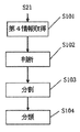
図10は、実施例4に係る識別ステップのフローチャートである。
図10に示されるように、ステップS101において、第4情報取得ユニット91は、車両の、車両走行方向情報等を含む車両情報、及び、位置情報に対応した履歴分析データである履歴情報を取得する。
図10に示されるように、ステップS101において、第4情報取得ユニット91は、車両の、車両走行方向情報等を含む車両情報、及び、位置情報に対応した履歴分析データである履歴情報を取得する。
車両の位置情報とは、車両の現在の地理上の位置情報であり、GPS(全地球測位システム)、北斗衛星測位システム等の車載測位システムにより検出されて、第4情報取得ユニット91により取得される。
ステップS102において、判断ユニット92は、位置情報に基づいて画像に第1所定領域が存在するか否かを判断するとともに、履歴分析データに基づいて画像に第2所定領域が存在するか否かを判断する。
第1所定領域は、学校を含む領域、例えば幼稚園、保育所等を含む領域であり、これら領域に存在する身長や体積の小さい人々は、本発明における小物体となる。また、第2所定領域は、物体が落ちやすい領域、例えば、履歴分析データ(すなわち、ビッグデータ分析データ)に基づいて、物体が落ちやすい領域であるか否かを判断できる。
ステップS103において、第4分割ユニット93は、画像を複数の第4サブ領域に分割し、図18は、実施例4による複数の第4サブ領域の模式図である。複数の第4サブ領域のうち、一部の第4サブ領域はそれぞれ第1所定領域又は第2所定領域を含み、複数の第4サブ領域のうち、各々の第4サブ領域の画素寸法が前記所定訓練画素寸法より大きい。この場合、第4情報取得ユニット91で取得した車両走行方向情報に基づいて分割することができ、例えば、車両が左折する場合、画像の左側領域では分割可能なサブ領域は多くなる。
ステップS104において、第4分類ユニット94は、第1所定領域又は第2所定領域を含む第4サブ領域を小物体領域として分類する。例えば、図18に示されるように、第4サブ領域A5に、例えば幼稚園が含まれ、第4サブ領域A6は、物体が落ちやすい領域を含み、このように、第4分類ユニット94は、第4サブ領域A5と第4サブ領域A6を小物体領域として分類する。
上記第1サブ領域、第2サブ領域、第3サブ領域、第4サブ領域の寸法、形状は任意であり、制限がない。
上記第1サブ領域、第2サブ領域、第3サブ領域、第4サブ領域の寸法、形状は任意であり、制限がない。
また、画像における小物体領域が識別された後、これら小物体領域について小物体検出を行うだけで良く、画像全体について小物体検出を行う必要がない。このようにして、リアルタイム且つ迅速に小物体を検出できる。
以上の通り本実施例によれば、画像における小物体領域が識別された後、これら小物体領域について小物体検出を行うだけで良く、画像全体について小物体検出を行う必要がないため、リアルタイム且つ迅速に小物体を検出することが可能となる。
実施例1乃至実施例4を参照して本発明を説明したが、当業者によって、上述の説明に基づいて行う多数の置換、変更や変化は自明なことである。従って、このような置換、変更や変化は、添付した特許請求の範囲の主旨と範囲を逸脱しない限り、本発明に含まれる。
1…車両周辺の小物体領域を識別する装置、10…画像取得ユニット、11…識別ユニット、31…第1情報取得ユニット、32…位置区別ユニット、33…第1分割ユニット、34…第1分類ユニット、51…第2情報取得ユニット、52…設定ユニット、53…第2分割ユニット、54…第2分類ユニット、71…第3情報取得ユニット、72…第3分割ユニット、73…計算ユニット、74…第3分類ユニット、91…第4情報取得ユニット、92…判断ユニット、93…第4分割ユニット、94…第4分類ユニット
Claims (16)
- 車両周辺の小物体領域を識別する装置であって、
車両の撮影装置から前記車両周辺の画像を取得する画像取得ユニットと、
前記画像に関連する履歴情報及び/又は前記車両の車両情報を取得して、前記画像、前記履歴情報、前記車両情報のうちの少なくとも1つに基づき、前記画像から前記小物体領域を識別する識別ユニットと、を備えることを特徴とする装置。 - 前記小物体とは、深層学習画像処理方法でレイヤーごとに分析した結果、最後レイヤーに占める画素寸法が有効分析画素寸法未満である物体、又は、占める画素寸法が深層学習方法による所定訓練画素寸法未満である物体を意味することを特徴とする請求項1に記載の装置。
- 前記識別ユニットはさらに、
各物体の中心位置と画素寸法を含む物体位置情報を複数含む前記履歴情報を取得する第1情報取得ユニットと、
前記画素寸法が前記所定訓練画素寸法以下の物体の中心位置を小物体の中心位置として、前記画素寸法が前記所定訓練画素寸法より大きい物体の中心位置を大物体の中心位置とする位置区別ユニットと、
画素寸法が前記所定訓練画素寸法より大きい各々の第1サブ領域に前記小物体の中心位置又は大物体の中心位置を含むように、前記画像を複数の第1サブ領域に分割する第1分割ユニットと、
前記小物体の中心位置を含む第1サブ領域を前記小物体領域として分類する第1分類ユニットとを含むことを特徴とする請求項2に記載の装置。 - 前記識別ユニットはさらに、
前記画像から、路面情報及び車速を含む前記車両情報を取得する第2情報取得ユニットと、
前記路面情報に基づいて前記画像における検出領域を設定する設定ユニットと、
前記車速に基づき、前記検出領域を複数の第2サブ領域に分割する第2分割ユニットと、
前記複数の第2サブ領域のうち画素寸法が所定訓練画素以下の第2サブ領域を前記小物体領域として分類する第2分類ユニットとを含むことを特徴とする請求項2に記載の装置。 - 前記路面情報は車線情報を含み、前記車線情報に基づいて車線接合点情報を取得して、前記設定ユニットは前記車線接合点情報に基づいて前記検出領域を設定することを特徴とする請求項4に記載の装置。
- 前記識別ユニットはさらに、
前記画像に基づいて、前記画像における各画素の深度値及び車速を含む前記車両情報を取得する第3情報取得ユニットと、
複数の第3サブ領域のうち各第3サブ領域の画素寸法が前記所定訓練画素寸法より大きいように、前記車速に基づき、前記画像を複数の第3サブ領域に分割する第3分割ユニットと、
前記複数の第3サブ領域のうち各々の第3サブ領域における複数の画素の平均深度値を計算する計算ユニットと、
平均深度値が所定値以上の第3サブ領域を前記小物体領域として分類する第3分類ユニットとを含むことを特徴とする請求項2に記載の装置。 - 前記識別ユニットはさらに、
前記車両の位置情報を含む前記車両情報、及び前記位置情報に対応した履歴分析データである前記履歴情報を取得する第4情報取得ユニットと、
前記位置情報に基づいて前記画像に第1所定領域が存在するか否かを判断するとともに、上記履歴分析データに基づいて前記画像に第2所定領域が存在するか否かを判断する判断ユニットと、
複数の第4サブ領域のうち一部の第4サブ領域がそれぞれ前記第1所定領域又は前記第2所定領域を含み、各々の第4サブ領域の画素寸法が前記所定訓練画素寸法より大きいように、前記画像を複数の第4サブ領域に分割する第4分割ユニットと、
前記第1所定領域又は前記第2所定領域を含む第4サブ領域を前記小物体領域として分類する第4分類ユニットとを含むことを特徴とする請求項2に記載の装置。 - 前記第1所定領域は学校を含む領域、前記第2所定領域は物体が落ちやすい領域を含むことを特徴とする請求項7に記載の装置。
- 車両周辺の小物体領域を識別する方法であって、
車両の撮影装置から前記車両周辺の画像を取得する画像取得ステップと、
前記画像に関連する履歴情報及び/又は前記車両の車速を取得して、前記画像、前記履歴情報、前記車両情報のうちの少なくとも1つに基づき、前記画像から前記小物体領域を識別する識別ステップと、を含むことを特徴とする方法。 - 前記小物体とは、深層学習画像処理方法でレイヤーごとに分析した結果、最後レイヤーに占める画素寸法が有効分析画素寸法未満である物体、又は、占める画素寸法が深層学習方法による所定訓練画素寸法未満である物体を意味することを特徴とする請求項9に記載の方法。
- 前記識別ステップはさらに、
各物体の中心位置と画素寸法を含む物体位置情報を複数含む前記履歴情報を取得する第1情報取得ステップと、
前記画素寸法が前記所定訓練画素寸法以下の物体の中心位置を小物体の中心位置として、前記画素寸法が前記所定訓練画素寸法より大きい物体の中心位置を大物体の中心位置とする位置区別ステップと、
各々の第1サブ領域に前記小物体の中心位置又は大物体の中心位置を含み、各第1サブ領域の画素寸法が前記所定訓練画素寸法より大きいように、前記画像を複数の第1サブ領域に分割する第1分割ステップと、
前記小物体の中心位置を含む第1サブ領域を前記小物体領域として分類する第1分類ステップとを含むことを特徴とする請求項10に記載の方法。 - 前記識別ステップはさらに、
前記画像から、路面情報及び車速を含む車両情報を取得する第2情報取得ステップと、
前記路面情報に基づいて前記画像における検出領域を設定する設定ステップと、
前記車速に基づき、前記検出領域を複数の第2サブ領域に分割する第2分割ステップと、
前記複数の第2サブ領域のうち画素寸法が所定訓練画素以下の第2サブ領域を前記小物体領域として分類する第2分類ステップとを含むことを特徴とする請求項10に記載の方法。 - 前記路面情報は車線情報を含み、上記車線情報に基づいて車線接合点情報を取得し、前記設定ステップは前記車線接合点情報に基づいて前記検出領域を設定することを特徴とする請求項12に記載の方法。
- 前記識別ステップはさらに、
前記画像情報に基づいて、前記画像における各画素の深度値及び車速を含む前記車両情報を取得する第3情報取得ステップと、
各々の第3サブ領域の画素寸法が前記所定訓練画素寸法より大きいように、前記車速に基づき、前記画像を複数の第3サブ領域に分割する第3分割ステップと、
前記複数の第3サブ領域のうち各々の第3サブ領域における複数の画素の平均深度値を計算する計算ステップと、
平均深度値が所定値以上の第3サブ領域を前記小物体領域として分類する第3分類ステップとを含むことを特徴とする請求項10に記載の方法。 - 前記識別ステップはさらに、
前記車両の位置情報を含む前記車両情報、及び、前記位置情報に対応した履歴分析データである前記履歴情報を取得する第4情報取得ステップと、
前記位置情報に基づいて前記画像に第1所定領域が存在するか否かを判断するとともに、上記履歴分析データに基づいて前記画像に第2所定領域が存在するか否かを判断する判断ステップと、
複数の第4サブ領域のうち一部の第4サブ領域がそれぞれ前記第1所定領域又は前記第2所定領域を含み、各々の第4サブ領域の画素寸法が前記所定訓練画素寸法より大きいように、前記画像を複数の第4サブ領域に分割する第4分割ステップと、
前記第1所定領域又は前記第2所定領域を含む第4サブ領域を前記小物体領域として分類する第4分類ステップとを含むことを特徴とする請求項10に記載の方法。 - 前記第1所定領域は学校を含む領域、前記第2所定領域は物体が落ちやすい領域を含むことを特徴とする請求項15に記載の方法。
Priority Applications (1)
| Application Number | Priority Date | Filing Date | Title |
|---|---|---|---|
| JP2019537997A JP6718025B2 (ja) | 2017-08-24 | 2018-07-20 | 車両周辺の小物体領域を識別する装置及び方法 |
Applications Claiming Priority (2)
| Application Number | Priority Date | Filing Date | Title |
|---|---|---|---|
| CN201710734273.2A CN109426771A (zh) | 2017-08-24 | 2017-08-24 | 对车辆周围的小物体区域进行识别的装置和方法 |
| CN201710734273.2 | 2017-08-24 |
Publications (1)
| Publication Number | Publication Date |
|---|---|
| WO2019039157A1 true WO2019039157A1 (ja) | 2019-02-28 |
Family
ID=65438695
Family Applications (1)
| Application Number | Title | Priority Date | Filing Date |
|---|---|---|---|
| PCT/JP2018/027259 Ceased WO2019039157A1 (ja) | 2017-08-24 | 2018-07-20 | 車両周辺の小物体領域を識別する装置及び方法 |
Country Status (3)
| Country | Link |
|---|---|
| JP (1) | JP6718025B2 (ja) |
| CN (1) | CN109426771A (ja) |
| WO (1) | WO2019039157A1 (ja) |
Cited By (2)
| Publication number | Priority date | Publication date | Assignee | Title |
|---|---|---|---|---|
| CN113160050A (zh) * | 2021-03-25 | 2021-07-23 | 哈尔滨工业大学 | 基于时空神经网络的小目标识别方法及系统 |
| JP2022116122A (ja) * | 2019-02-25 | 2022-08-09 | Dmg森精機株式会社 | 情報処理装置、情報処理方法およびプログラム |
Citations (4)
| Publication number | Priority date | Publication date | Assignee | Title |
|---|---|---|---|---|
| JP2006185406A (ja) * | 2004-11-30 | 2006-07-13 | Nissan Motor Co Ltd | 物体検出装置、および方法 |
| JP2006285335A (ja) * | 2005-03-31 | 2006-10-19 | Nissan Motor Co Ltd | 障害物検出装置及び障害物検出方法 |
| JP2010128919A (ja) * | 2008-11-28 | 2010-06-10 | Hitachi Automotive Systems Ltd | 物体検知装置 |
| WO2016095117A1 (en) * | 2014-12-17 | 2016-06-23 | Nokia Technologies Oy | Object detection with neural network |
Family Cites Families (3)
| Publication number | Priority date | Publication date | Assignee | Title |
|---|---|---|---|---|
| CN104952254B (zh) * | 2014-03-31 | 2018-01-23 | 比亚迪股份有限公司 | 车辆识别方法、装置和车辆 |
| CN106096512B (zh) * | 2016-05-31 | 2020-08-25 | 上海美迪索科电子科技有限公司 | 利用深度摄像头对车辆或行人进行识别的检测装置及方法 |
| CN106128115B (zh) * | 2016-08-01 | 2018-11-30 | 青岛理工大学 | 一种基于双摄像机检测道路交通信息的融合方法 |
-
2017
- 2017-08-24 CN CN201710734273.2A patent/CN109426771A/zh active Pending
-
2018
- 2018-07-20 WO PCT/JP2018/027259 patent/WO2019039157A1/ja not_active Ceased
- 2018-07-20 JP JP2019537997A patent/JP6718025B2/ja active Active
Patent Citations (4)
| Publication number | Priority date | Publication date | Assignee | Title |
|---|---|---|---|---|
| JP2006185406A (ja) * | 2004-11-30 | 2006-07-13 | Nissan Motor Co Ltd | 物体検出装置、および方法 |
| JP2006285335A (ja) * | 2005-03-31 | 2006-10-19 | Nissan Motor Co Ltd | 障害物検出装置及び障害物検出方法 |
| JP2010128919A (ja) * | 2008-11-28 | 2010-06-10 | Hitachi Automotive Systems Ltd | 物体検知装置 |
| WO2016095117A1 (en) * | 2014-12-17 | 2016-06-23 | Nokia Technologies Oy | Object detection with neural network |
Cited By (4)
| Publication number | Priority date | Publication date | Assignee | Title |
|---|---|---|---|---|
| JP2022116122A (ja) * | 2019-02-25 | 2022-08-09 | Dmg森精機株式会社 | 情報処理装置、情報処理方法およびプログラム |
| JP7503593B2 (ja) | 2019-02-25 | 2024-06-20 | Dmg森精機株式会社 | 情報処理装置、情報処理方法およびプログラム |
| CN113160050A (zh) * | 2021-03-25 | 2021-07-23 | 哈尔滨工业大学 | 基于时空神经网络的小目标识别方法及系统 |
| CN113160050B (zh) * | 2021-03-25 | 2023-08-25 | 哈尔滨工业大学 | 基于时空神经网络的小目标识别方法及系统 |
Also Published As
| Publication number | Publication date |
|---|---|
| JP6718025B2 (ja) | 2020-07-08 |
| CN109426771A (zh) | 2019-03-05 |
| JPWO2019039157A1 (ja) | 2020-04-23 |
Similar Documents
| Publication | Publication Date | Title |
|---|---|---|
| US11854272B2 (en) | Hazard detection from a camera in a scene with moving shadows | |
| Ohgushi et al. | Road obstacle detection method based on an autoencoder with semantic segmentation | |
| CN109034047B (zh) | 一种车道线检测方法及装置 | |
| US11085775B2 (en) | Methods and systems for generating and using localisation reference data | |
| Negru et al. | Image based fog detection and visibility estimation for driving assistance systems | |
| CN112819895B (zh) | 一种摄像机标定方法及装置 | |
| JP6626410B2 (ja) | 自車位置特定装置、自車位置特定方法 | |
| JP7454685B2 (ja) | 車両走行路内のデブリの検出 | |
| CN111091037A (zh) | 用于确定驾驶信息的方法和设备 | |
| US8559727B1 (en) | Temporal coherence in clear path detection | |
| JP2018112887A (ja) | 情報処理装置、情報処理方法、および情報処理プログラム | |
| KR102003387B1 (ko) | 조감도 이미지를 이용한 교통 장애물의 검출 및 거리 측정 방법, 교통 장애물을 검출하고 거리를 측정하는 프로그램을 저장한 컴퓨터 판독가능 기록매체 | |
| CN113689505A (zh) | 一种基于定位信息调整车载摄像头曝光参数的方法及装置 | |
| JP2019146012A (ja) | 撮像装置 | |
| Kotha et al. | Potsense: Pothole detection on indian roads using smartphone sensors | |
| Nguyen et al. | Compensating background for noise due to camera vibration in uncalibrated-camera-based vehicle speed measurement system | |
| JP2007147564A (ja) | 画像認識装置及び方法、並びに自車位置認識装置及び方法 | |
| Kühnl et al. | Visual ego-vehicle lane assignment using spatial ray features | |
| CN103577790B (zh) | 道路转弯类型检测方法和装置 | |
| CN116129383B (zh) | 一种可行驶区域检测方法、装置和电子设备、存储介质 | |
| JP6718025B2 (ja) | 車両周辺の小物体領域を識別する装置及び方法 | |
| CN112016366B (zh) | 一种障碍物定位方法及装置 | |
| JP7195200B2 (ja) | 車載装置、車載システムおよび周辺監視方法 | |
| Negru et al. | Assisting navigation in homogenous fog | |
| Barua et al. | An efficient method of lane detection and tracking for highway safety |
Legal Events
| Date | Code | Title | Description |
|---|---|---|---|
| 121 | Ep: the epo has been informed by wipo that ep was designated in this application |
Ref document number: 18848542 Country of ref document: EP Kind code of ref document: A1 |
|
| ENP | Entry into the national phase |
Ref document number: 2019537997 Country of ref document: JP Kind code of ref document: A |
|
| NENP | Non-entry into the national phase |
Ref country code: DE |
|
| 122 | Ep: pct application non-entry in european phase |
Ref document number: 18848542 Country of ref document: EP Kind code of ref document: A1 |