WO2019038986A1 - Air bag device for saddle-type vehicles - Google Patents
Air bag device for saddle-type vehicles Download PDFInfo
- Publication number
- WO2019038986A1 WO2019038986A1 PCT/JP2018/015448 JP2018015448W WO2019038986A1 WO 2019038986 A1 WO2019038986 A1 WO 2019038986A1 JP 2018015448 W JP2018015448 W JP 2018015448W WO 2019038986 A1 WO2019038986 A1 WO 2019038986A1
- Authority
- WO
- WIPO (PCT)
- Prior art keywords
- air bag
- extending
- inflator
- retainer
- guide
- Prior art date
Links
Images


Classifications
-
- B—PERFORMING OPERATIONS; TRANSPORTING
- B62—LAND VEHICLES FOR TRAVELLING OTHERWISE THAN ON RAILS
- B62J—CYCLE SADDLES OR SEATS; AUXILIARY DEVICES OR ACCESSORIES SPECIALLY ADAPTED TO CYCLES AND NOT OTHERWISE PROVIDED FOR, e.g. ARTICLE CARRIERS OR CYCLE PROTECTORS
- B62J27/00—Safety equipment
- B62J27/20—Airbags specially adapted for motorcycles or the like
-
- B—PERFORMING OPERATIONS; TRANSPORTING
- B60—VEHICLES IN GENERAL
- B60R—VEHICLES, VEHICLE FITTINGS, OR VEHICLE PARTS, NOT OTHERWISE PROVIDED FOR
- B60R21/00—Arrangements or fittings on vehicles for protecting or preventing injuries to occupants or pedestrians in case of accidents or other traffic risks
- B60R21/02—Occupant safety arrangements or fittings, e.g. crash pads
- B60R21/16—Inflatable occupant restraints or confinements designed to inflate upon impact or impending impact, e.g. air bags
- B60R21/26—Inflatable occupant restraints or confinements designed to inflate upon impact or impending impact, e.g. air bags characterised by the inflation fluid source or means to control inflation fluid flow
- B60R21/261—Inflatable occupant restraints or confinements designed to inflate upon impact or impending impact, e.g. air bags characterised by the inflation fluid source or means to control inflation fluid flow with means other than bag structure to diffuse or guide inflation fluid
Definitions
- the present invention relates to an airbag device for a saddle-ride type vehicle.
- the air bag device tends to be large in the front-rear direction.
- an air bag device of a saddle-ride type vehicle it is desirable to arrange the air bag device compactly back and forth and to deploy the air bag vertically as vertically as possible for appropriate protection of the occupant.
- the present invention has been made in view of the above-described circumstances, and in an airbag device for a saddle-ride type vehicle, the airbag device can be compactly arranged in the front-rear direction, and the airbag can be deployed vertically upward
- the purpose is to
- a retainer (41) provided in front of a seat (13) for an occupant, an inflator (43), and the retainer (41) are accommodated and inflated by gas released by the inflator (43).
- the retainer (41) is a gas released from the inflator (43) into the airbag (42).
- the guide (95,295,395) for guiding the deployment of the is provided.
- the bent portion (90) which bends the passage (48) in an L shape is an inner bent which forms an L-shaped corner and an outer bent portion (91) which forms an L-shaped corner.
- a portion (92), and the guide (95, 295, 395) may be provided at the inner bending portion (92).
- the guide (95, 295, 395) may extend downward from the wall (53) of the passage (48).
- the guide (95, 295) may be provided with a lower extending surface (297) extending downward along the upper extending portion (47).
- the guide (95, 395) is inclined downward from the upper wall (53c) side of the left and right extension (46) in the left and right direction in the left and right direction. And sloped surfaces (96, 396) extending in Further, in the above invention, the guide (95) obliquely extends downward from the upper wall (53c) side of the left and right extension (46) in the left and right direction in the left and right direction.
- An inclined surface (96) and a downwardly extending surface (97) extending downwardly along the upwardly extending portion (47) may be provided.
- the lower extending surface (97) and the inclined surface (96) may be integrally provided.
- the inflator (43) formed in a tubular shape may be disposed in a direction in which the axis (43c) thereof is directed in the longitudinal direction of the vehicle. According to this configuration, the inflator (43) formed in a tubular shape may be disposed in a direction in which the axis (43c) thereof is directed in the longitudinal direction of the vehicle.
- the airbag apparatus of the saddle-ride type vehicle is accommodated in the retainer provided in front of the passenger seat, the inflator, and the retainer, and the inflator releases An airbag that is inflated by gas and deployed forward of the occupant
- the retainer includes a deflection unit that deflects the gas released from the inflator into the airbag from the flow in the lateral direction to the upward flow;
- the portion includes a left and right extending portion extending in the left and right direction from the inflator side, and an upper extending portion extending in the upward direction from the left and right extending portion to form an L-shaped passage, which protrudes into the passage.
- a guide is provided to guide the deployment.
- the inflator and the airbag can be disposed by utilizing the space in the left and right direction and the up and down direction by the L-shaped passage provided with the left and right extension parts and the upper extension part. Can be arranged compactly. Further, since the deployment of the air bag can be guided by the guide projecting into the L-shaped passage, the air bag can be deployed vertically upward.
- the bent portion for bending the passage in an L shape includes an outer bent portion forming an L-shaped corner and an inner bent portion forming an L-shaped corner, and the guide is an inner bent It may be provided in a unit. According to this configuration, since the guide is provided at the inward bending portion, the air bag can be properly guided by the guide at the inward bending portion where the length of the passage tends to be shorter than the outward bending portion. It can be expanded. In addition, since the portion of the air bag which is turned upside down from the left and right can be guided by the guide, it is easy to control the direction of the air bag by the guide. In the above invention, the guide may extend downward from the wall of the passage. According to this configuration, since the upper and lower lengths of the passage can be made longer by the guides, the airbag can be deployed vertically upward.
- the guide may include a downward extending surface extending downward along the upward extending portion. According to this configuration, since the air bag can be guided in the vertical direction below the upper extending portion by the lower extending surface, the air bag can be deployed vertically upward.
- the guide may have an inclined surface which obliquely extends downward and downward in the left-right direction from the upper wall side of the left and right extension. According to this configuration, the passage from the left and right extension to the upper extension can be gradually narrowed by the inclined surface, directivity can be easily given in the deployment direction of the airbag, and the deployment direction of the airbag can be determined by the guide. It can control.
- the guide extends downward along the upwardly extending portion and the inclined surface extending obliquely downward in the left and right direction from the upper wall portion side of the left and right extending portion in the left and right direction.
- a downward extending surface may be provided. According to this configuration, by gradually squeezing the passage from the left and right extending portions toward the upper extending portion by the inclined surface, directivity can be imparted in the deployment direction of the airbag, and the upward extension by the downward extending surface The air bag can be vertically guided below the head. Therefore, the airbag can be deployed vertically upward.
- the downward extending surface and the inclined surface may be integrally provided.
- the guide can be easily provided, and the strength and rigidity of the guide can be improved.
- the tubular inflator may be disposed such that its axis is directed in the longitudinal direction of the vehicle. According to this configuration, the inflator can be compactly provided in the front-rear direction, and the airbag apparatus can be compacted in the front-rear direction.
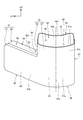
- FIG. 1 is a left side view of a motorcycle according to a first embodiment of the present invention.
- FIG. 2 is a view of the periphery of the inner cover as viewed from the rear side.
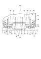
- FIG. 3 is a front view of the airbag apparatus as viewed from the rear side.
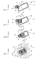
- FIG. 4 is a left side view of the airbag apparatus.
- FIG. 5 is a view of the airbag apparatus as viewed from above.
- FIG. 6 is a view of the airbag apparatus as viewed from below.
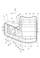
- FIG. 7 is a rear view of the case.
- FIG. 8 is a front view of the airbag apparatus as viewed from the rear side with the lid member removed.
- FIG. 9 is a left side view of the airbag device with the lid member removed.
- FIG. 1 is a left side view of a motorcycle according to a first embodiment of the present invention.
- FIG. 2 is a view of the periphery of the inner cover as viewed from the rear side.
- FIG. 3 is
- FIG. 10 is a cross-sectional view showing the attached state of the inflator.
- FIG. 11 is a diagram showing the deployed state of the airbag in time series.
- FIG. 12 is a view showing the deployed state of the airbag viewed from the side in time series.
- FIG. 13 is a rear view of the case in the second embodiment.
- FIG. 14 is a rear view of the case in the third embodiment.
- FIG. 1 is a left side view of a motorcycle 1 according to a first embodiment of the present invention.
- FIG. 1 shows a state in which an air bag 42 described later is inflated and deployed.
- the motorcycle 1 includes a body frame 10, a steering system 11 for supporting the front wheels 2 in a steerable manner, a power unit 12 supported at the rear of the body frame 10, a rear wheel 3, and a seat for seating by an occupant.
- 13 is a scooter type saddle-ride type vehicle including
- the body frame 10 has a head pipe 14 provided at the front end thereof, a main frame 15 extending rearward and downward from the head pipe 14, a lower frame 16 extending rearward from the lower end of the main frame 15, and a rearward upward A pair of left and right rear frames 17 and 17 are provided.
- the head pipe 14 is disposed at the center of the vehicle width.
- the steering system 11 is fixed to the steering shaft 20 supported by the head pipe 14, a pair of left and right front forks 21 and 21 disposed on the left and right sides of the front wheel 2 to support the front wheel 2, and the lower end of the steering shaft 20 And a handle 23 fixed to the upper end of the steering shaft 20.
- the bridge member 22 connects the upper portions of the left and right front forks 21 and 21 to each other.
- the steering wheel 23 is connected to the steering shaft 20 via a steering wheel post 23 a fixed to the upper end of the steering shaft 20.
- the head pipe 14 is inclined rearward with respect to the vertical direction by a predetermined caster angle set in the motorcycle 1.
- the steering shaft 20 is inserted into and supported by the head pipe 14 and is disposed to be inclined rearward in a side view of the vehicle.
- the steering shaft 20 is located at the center of the vehicle width.
- the power unit 12 is a unit swing engine having a function of an engine as a drive source of the rear wheel 3 and a swing arm supporting the rear wheel 3.
- the power unit 12 is pivotally supported by the vehicle body frame 10 pivotably via a link member 24 provided at its front end.
- the seat 13 is provided above the rear frame 17.
- the seat 13 integrally includes a front seat 13a on which a driver is seated and a rear seat 13b on which a passenger is seated.
- the step floors 25, 25 on which the driver places the left and right feet are provided in pairs at the left and right positions of the lower frame 16 located at the center of the vehicle width.
- the motorcycle 1 includes a vehicle body cover 26 that covers the vehicle body such as the vehicle body frame 10 and the like.
- the body cover 26 is continuous with the front cover 27 which covers the head pipe 14 and the upper part of the steering system 11 from the front and the right and left sides and the rear edge of the front cover 27 and covers the upper part of the head pipe 14 and the steering system 11 from the rear.
- an inner cover 28 is included in the body cover 26 .
- the body cover 26 includes a center cover 29 located below the front side seat 13a, an under cover 30 that covers the vehicle body from below the step floors 25 and 25, and rear frames 17 and 17 below the seat 13.
- the motorcycle 1 includes a front fender 32 and a rear fender 33.
- the front portion of the center cover 29 is continuous with the lower portion of the inner cover 28.
- the center cover 29 is located inside the driver's left and right legs extended from the front seat 13a to the step floors 25, 25.
- the upper edge 29a of the center cover 29 is located below the front side sheet 13a.
- a straddle space 34 recessed downward is defined by the rear surface of the inner cover 28, the upper edge 29a of the center cover 29, and the front surface of the front seat 13a. The passenger can straddle the motorcycle 1 via the straddling space 34 when getting on and off the motorcycle 1.
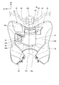
- FIG. 2 is a view of the periphery of the inner cover 28 as viewed from the rear side.
- the motorcycle 1 is provided with an airbag device 40 for protecting the occupant from impact.
- the airbag device 40 is provided on the rear surface of the inner cover 28 and is located in front of the driver seated on the front seat 13a.
- the air bag device 40 is provided behind the steering shaft 20 and below the handle 23 and is located at the front of the straddling space 34.
- the rear surface of the inner cover 28 is provided substantially parallel to the steering shaft 20 in a side view of the vehicle, and is inclined rearward along the steering shaft 20. Further, as shown in FIGS. 1 and 2, in the upper part of the rear surface of the inner cover 28, the central portion 28a in the vehicle width direction located rearward of the steering shaft 20 is located the rearmost and is located left and right of the central portion 28a.
- the side portions 28b, 28b are inclined so as to be positioned on the front side as going to the outside in the vehicle width direction.
- FIG. 3 is a front view of the airbag device 40 as viewed from the rear side (driver side).
- the airbag device 40 includes a box-shaped retainer 41 provided in front of an occupant seated on the seat 13, an airbag 42 accommodated in the retainer 41, an inflator 43 for releasing gas into the airbag 42, and a retainer 41. And a lid member 44 attached to the top of the housing.
- FIG. 4 is a left side view of the airbag device 40.
- FIG. 5 is a view of the airbag device 40 as viewed from above.
- FIG. 6 is a view of the airbag device 40 as viewed from below.
- the retainer 41 is a box-like member formed in an inverted L shape when viewed from the occupant side (rear side).
- L means that the retainer 41 is L-shaped when viewed from the front or rear.
- the retainer 41 has an inverted L shape when viewed from the rear, but can be said to be formed in an L shape.
- the retainer 41 is located in front of the front side sheet 13a and faces the front side of the front side sheet 13a.
- the retainer 41 includes a left and right extending portion 46 extending in the left and right direction (vehicle width direction), and an upper extending portion 47 extending upward from the left and right extending portion 46.
- the left and right extending portion 46 is a box-like portion extending in the vehicle width direction.
- the outer end 46a in the vehicle width direction of the left and right extending portion 46 is located on the outer side in the vehicle width direction than the steering shaft 20 located at the center of the vehicle width.
- the left and right extending portions 46 extend from the outer end 46 a along the rear surface of the side portion 28 b of the inner cover 28 to the center of the vehicle width.
- the upper extension portion 47 is a box-like portion extending in the vertical direction along the steering shaft 20, and is inclined rearward in a vehicle side view. The upper extension portion 47 is located at the center of the vehicle width and covers the central portion 28 a of the inner cover 28 from the rear.
- a center line 47 c of the upper extending portion 47 extending up and down through the center of the upper extending portion 47 is provided rearward of the steering shaft 20 so as to be substantially parallel to the steering shaft 20 and inclined rearward.
- the center line 47c is located at the center of the vehicle width.
- An inner end portion of the left and right extending portions 46 in the vehicle width direction is connected to the outer side surface of the lower portion of the upper extending portion 47. That is, the retainer 41 is formed in an L-shape by the upper extension portion 47 extending upward from the inner end portion of the left and right extension portion 46. Inside the retainer 41, an L-shaped air bag passage 48 (passage) is formed which is formed by the internal space of the left and right extension portions 46 and the internal space of the upper extension portion 47. An upper surface opening 49 is formed on the upper surface of the upper extension 47 to expose the air bag passage 48 upward. The air bag 42 is deployed upward from the top opening 49. The opening surface of the upper surface opening 49 is substantially orthogonal to the center line 47 c of the upper extension 47. The upper surface opening 49 is closed by the lid member 44.
- the retainer 41 is formed by combining a box-like case 50 having a rear surface (a surface on the occupant side) open and a cover 51 covering the rear surface opening 50a (FIG. 7) of the case 50.
- the case 50 and the cover 51 are made of, for example, a metal material.
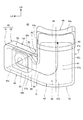
- FIG. 7 is a view of the case 50 viewed from the rear.
- the case 50 includes a retainer front surface 52 formed in an L shape, and a peripheral wall portion 53 (wall portion) erected rearward from the entire periphery of the periphery of the retainer front surface 52 other than the portion of the case top surface opening 55a described later. Prepare.
- the rear opening 50 a is partitioned by the rear edge of the peripheral wall 53.
- the case 50 integrally includes a left and right extension case portion 54 which constitutes a front portion of the left and right extension portions 46 and a vertically extending case portion 55 which constitutes a front portion of the upper extension portion 47.
- a case upper surface opening 55a which is an opening without the peripheral wall portion 53 is formed.
- the case upper surface opening 55 a constitutes most of the upper surface opening 49.
- a portion of the vertically extending case portion 55 in the retainer front surface 52 is a front curved surface portion 52 a that curves so as to be convex toward the rear when viewed from above.
- the front curved surface portion 52 a is provided over substantially the entire length of the upper extension portion 47.
- a portion of the left and right extending case portion 54 in the retainer front surface 52 is a front flat portion 52 b extending along the side portion 28 b (FIG. 2) of the inner cover 28.
- the case 50 includes a bending portion 90 that bends the air bag passage 48 in an L shape.
- the bending portion 90 is constituted by an outer bending portion 91 forming an L-shaped bending corner of the air bag passage 48 and an inner bending portion 92 forming an L-shaped bending corner.
- the outer bent portion 91 is a side wall 53 b of the lower wall 53 a of the left and right extension case 54 and the upper extension 47 (right side Face) intersects in an L-shape.
- the inward bent portion 92 intersects the upper wall portion 53c of the left and right extension case portion 54 and the other side wall portion 53d (left side surface) of the upward extension portion 47 in an L shape. It is a part.
- the inward bent portion 92 is formed in a curved surface so that the direction of the peripheral wall portion 53 gradually changes from the left-right direction to the upper direction.
- the upper wall 53 c and the lower wall 53 a of the peripheral wall 53 are substantially parallel.
- the one side wall 53b and the other side wall 53d are substantially parallel.
- FIG. 8 is a front view of the airbag device 40 viewed from the rear side with the lid member 44 removed.
- FIG. 9 is a left side view of the airbag device 40 with the lid member 44 removed.
- the cover 51 of the retainer 41 includes a retainer rear surface 57 facing the occupant and the seat 13 from the front side, and a rib 58 erected forward from the entire periphery of the periphery of the retainer rear surface 57 other than the upper end. Similar to the retainer front surface 52, the retainer rear surface 57 is formed in an L shape, and faces the retainer front surface 52 from the rear.
- the cover 51 is coupled to the case 50 by engaging the rib 58 with the peripheral wall portion 53 of the case 50 from the outside.
- the cover 51 is coupled to the case 50 by, for example, a weld bead along the rib 58.
- the retainer rear surface 57 of the cover 51 integrally includes a left and right extended cover portion 60 that configures a rear surface of the left and right extension portions 46 and an upper and lower extended cover portion 61 that configures a rear surface of the upper extension portion 47.
- the vertically extending cover portion 61 is a rear side curved surface portion 57a (curved surface portion) facing the front curved surface portion 52a (FIGS. 7 and 8) of the case 50 from the rear.
- the rear curved surface portion 57a is formed in a curved surface shape that is curved so as to be convex toward the rear when viewed from above.
- the rear curved surface portion 57a is provided over substantially the entire length of the rear surface 57 of the retainer.
- the left and right extended cover portion 60 is a rear side flat portion 57 b facing the front side flat portion 52 b (FIG. 7) of the case 50 from the rear side.
- the upper extension portion 47 of the retainer 41 includes a frame-shaped upper peripheral wall portion 47a at the upper end when viewed from above.
- the upper surface opening 49 is divided by the upper peripheral wall 47 a.
- the upper extension portion 47 of the retainer 41 is provided with an occupant side opening 62 opening toward the rear occupant side.
- the occupant side opening 62 is formed by cutting the upper end of the rear surface of the upper peripheral wall 47a downward, and communicates the upper end of the air bag passage 48 to the rear.
- the passenger side opening 62 is located rearward of the upper surface opening 49 and is in communication with the upper surface opening 49.
- the occupant side opening 62 is formed by the upper end 61 a of the vertically extending cover 61 of the rear surface 57 of the retainer of the cover 51 and the upper 55 a of the vertically extending case 55 of the retainer front 52 of the case 50. It is formed to be cut out below the upper end 55b.
- the occupant side opening 62 is formed over the entire upper end of the vertically extending cover portion 61 in the width direction.
- the size of the step between the upper end 61 a of the vertically extending cover portion 61 and the upper end 55 b of the vertically extending case portion 55 is substantially the same across the entire width direction of the vertically extending cover portion 61.
- the upper end 61 a is also the upper end of the rear surface portion of the upper peripheral wall portion 47 a of the retainer 41.
- the retainer 41 is provided with a guide 95 for guiding the deployment of the air bag 42.
- the guide 95 is provided on the inner surface of the retainer 41 and protrudes into the air bag passage 48.
- the guide 95 is fixed to the inner surface of the inward bent portion 92 in the peripheral wall portion 53 of the case 50 and extends downward from the inward bent portion 92.
- the guide 95 includes an inclined surface 96 obliquely extending downward from the upper wall 53 c of the left and right extending case portion 54 in the left and right direction, and an upper extending portion 47.
- a downward extending surface 97 extending downward along the other side wall portion 53 d and a fixing surface 98 bent along the inner surface of the inner bent portion 92 are integrally provided.
- the inclined surface 96, the lower extending surface 97, and the fixing surface 98 are constituted by the plate surface of the plate material.
- the lower extending surface 97 of the guide 95 extends substantially vertically from the lower end of the other side wall 53 d so as to extend the other side wall 53 d downward.
- the lower end portion 95 a of the guide 95 is a portion where the lower end of the lower extending surface 97 and the lower end of the inclined surface 96 are connected.
- the lower end 95a is formed in a curved shape so as not to be a sharp edge.
- the inclined surface 96 and the lower extending surface 97 are integrally formed, for example, by bending one plate material at a lower end portion 95 a in a V-shape.
- the fixing surface 98 of the guide 95 extends from the upper end of the lower extending surface 97 to the upper end side of the inclined surface 96 along the inner surface of the inner bent portion 92.
- the guide 95 is fixed to the retainer 41 by the upper end of the inclined surface 96, the upper end of the lower extending surface 97, and the fixing surface 98 being coupled to the inner surface of the peripheral wall portion 53.
- the size of the passage through which the air bag 42 passes is reduced in the vertical direction.
- the inclined surface 96 is inclined downward toward the upper extension 47, the cross-sectional area of the air bag passage 48 becomes smaller from the upper end to the lower end of the inclined surface 96. That is, in the air bag passage 48, a throttling portion 99 is formed between the inclined surface 96 of the guide 95 and the lower wall portion 53a where the flow path of the air bag passage 48 is squeezed toward the downstream side.
- the lower end portion 95a of the guide 95 is positioned above the middle portion in the vertical direction of the air bag passage 48 of the left and right extension portions 46 and below the upper wall portion 53c. Further, the lower extending surface 97 is provided to extend the other side wall portion 53d, and is substantially parallel to the one side wall portion 53b. For this reason, the lateral width of the air bag passage 48 of the upper extending portion 47 is substantially equal between the portion of the lower extending surface 97 of the guide 95 and the portion of the other side wall portion 53 d.
- the lid member 44 integrally includes a lid upper surface portion 44a covering the upper surface opening 49 from above and a lid peripheral wall portion 44b fitted to the upper peripheral wall portion 47a of the upper extending portion 47.
- the lid member 44 is attached to the retainer 41 by fitting the inner peripheral surface of the lid peripheral wall portion 44b to the outer peripheral surface of the upper peripheral wall portion 47a.
- the top opening 49 and the passenger side opening 62 are closed by the lid member 44.
- a recess 44c (FIG. 5) which is recessed downward so as to avoid the handle post 23a (FIG. 1) is formed at the front of the lid top surface 44a.
- the inflator 43 is provided in the air bag passage 48 and located at the upstream end of the deployment path of the air bag 42 in the air bag passage 48. Specifically, the inflator 43 is provided on the side of the outer end 46a (FIG. 5) in the left and right extending case portion 54 of the left and right extending portion 46 and is provided to the left and right with respect to the steering shaft 20 located at the center It is arranged offset in the direction (left side). The inflator 43 is attached to the front flat portion 52 b (FIG. 7) of the retainer front surface 52 of the left and right extension case portion 54.
- FIG. 10 is a cross-sectional view showing the attached state of the inflator 43.
- the inflator 43 includes a cylindrical (cylindrical) housing 43a. Inside the housing 43a, a gas generating agent and an initiator for initiating a reaction of generating a gas in the gas generating agent are provided.
- the initiator comprises an igniter.
- that by which the end surface of the axial direction of the housing 43a is closed is contained in a cylinder shape.
- the housing 43a is provided with a gas discharge port 43b on the outer peripheral surface.
- a plurality of gas discharge ports 43b are provided side by side in the circumferential direction of the housing 43a.
- An annular member 65 is integrally coupled to the outer peripheral surface of the housing 43a.
- the annular member 65 includes a flange portion 65a extending in the radial direction from the outer peripheral surface of the housing 43a, and a peripheral wall portion 65b extending in the axial direction of the inflator 43 from the outer peripheral edge of the flange portion 65a.
- the housing 43 a of the inflator 43 is inserted into the inflator support hole 52 c formed in the retainer front surface 52 from the inside of the left and right extending case portion 54.
- the housing 43 a is positioned in the axial direction of the inflator 43 by the flange portion 65 a abutting on the inner surface of the retainer front surface 52.
- the inflator 43 is fastened to the retainer front surface 52 by a bolt 66 inserted through the flange portion 65 a and the retainer front surface 52 and a nut 66 a screwed to the bolt 66.
- a plurality of bolts 66 and nuts 66a are provided in the circumferential direction of the flange portion 65a.
- the flange portion 65 a has a rectangular outer shape when viewed in the direction of the axis 43 c of the inflator 43.
- the peripheral wall portion 65b of the annular member 65 is formed in a rectangular frame shape as viewed in the axial direction of the axis line 43c, and surrounds the outer peripheral surface of the inflator 43 from the outside.
- the peripheral wall portion 65b surrounds the plurality of gas discharge ports 43b from the outside.
- the inflator 43 radially discharges the gas G radially outward from the plurality of gas discharge ports 43 b, and the gas G changes its direction by hitting the inner peripheral surface of the peripheral wall portion 65 b, and the direction of the axis 43 c of the inflator 43 Ejected in the direction.
- the discharge direction of the gas G of the inflator 43 into the air bag 42 is the extension direction of the axis 43 c.
- the annular member 65 functions as a guide member that controls the discharge direction of the gas G.
- the inflator 43 is disposed in a direction in which the axis 43c points in the front-rear direction of the vehicle. As described above, by orienting the axis 43c in the back and forth direction, even if the inflator 43 has a large diameter, the space occupied by the inflator 43 in the back and forth direction of the vehicle can be reduced, and the inflator 43 can be compactly provided back and forth.
- the upstream end 42 a of the air bag 42 in the flow of the gas G is fixed to the retainer 41 by being held between the flange portion 65 a of the annular member 65 and the retainer front surface 52.
- the air bag 42 is also fixed to the retainer 41 by the bolt 66 being inserted through the upstream end 42 a.
- the circumferential wall portion 65 b of the annular member 65 is located between the gas discharge port 43 b and the upstream end 42 a of the airbag 42 in the radial direction of the inflator 43. This prevents the gas G released from the gas discharge port 43 b from directly contacting the upstream end 42 a of the air bag 42, and the air bag 42 is protected against the gas G.
- the front end portion 43 d of the inflator 43 protrudes from the inflator support hole 52 c toward the inner cover 28 on the front side of the retainer front surface 52. Since the inflator 43 is disposed on the inner cover 28 side, it is possible to prevent the inflator 43 from being noticeable and to prevent the inflator 43 from protruding to the straddle space 34 side.
- the air bag 42 is housed in an L-shaped air bag passage 48, and is provided from the left and right extending portion 46 to the upper extending portion 47.
- the air bag passage 48 is an air bag storage space.
- the air bag 42 has the upstream end 42 a (FIG. 10) connected to the inflator 43 in the left and right extension 46.
- the air bag 42 is a bag-like portion 42b extending from the upstream end 42a to a position below the guide 95 while remaining in a bag-like shape, and a folded portion 42c located downstream of the bag-like portion 42b in the flow direction of the gas G.
- the bag-like portion 42 b extends in the left-right direction in the left and right extending portion 46.
- the folding portion 42 c is located in the upper extending portion 47 and is located downstream of the guide 95 in the flow direction of the gas G.
- the folding portion 42 c has a portion in which the bag is folded to compactly store the air bag 42.
- the motorcycle 1 includes an acceleration sensor (not shown) that detects an impact acting on the motorcycle 1.
- the acceleration sensor is electrically connected to a control unit (not shown) of the motorcycle 1, and the control unit is electrically connected to the inflator 43.
- the control unit determines whether the air bag device 40 is activated or deactivated based on the detected acceleration.
- the control unit operates the inflator 43 to release gas into the air bag 42 when the air bag device 40 is operated.
- the air bag 42 is inflated by the pressure of the gas and deployed upward.
- FIG. 11 is a diagram showing the deployed state of the airbag 42 in time series.
- the horizontal axis indicates the elapsed time T.
- the time Ts indicates the actuation timing of the inflator 43, and the time Tf indicates the timing at which the deployment is completed.
- the air bag 42 is expanded so as to extend upward by inflating in the order of the lower part, the middle part, and the upper part.
- the inflator 43 releases the gas G into the airbag 42 toward the rear of the vehicle along the axis 43 c. That is, the discharge direction of the gas G of the inflator 43 is the extension direction of the axis 43c. In addition, it can be said that the inflator 43 releases the gas G to the driver side along the axis 43c.
- the inflator 43 is disposed to be inclined in accordance with the inclination of the inner cover 28 side portion 28b, and releases the gas G in the direction of the inclined axis 43c.
- the axis 43c of the inflator 43 is inclined so as to be positioned outward and downward in the vehicle width direction as the axis 43c goes to the rear side.
- the inflator 43 releases the gas G rearward along the axis 43c, but the direction may not be directly behind, but may be inclined within a predetermined angle range. good.
- the axis 43c of the inflator 43 may be inclined at an angle of 45 ° in the vertical direction with respect to the horizontal line extending rearward in a side view of the vehicle.
- the axis 43c may be inclined at an angle of 45 ° to the left and right with respect to the center line of the vehicle width in the top view of the vehicle.
- the gas G released from the inflator 43 into the air bag 42 is guided by the left and right extension 46, the guide 95, and the upper extension 47, and the air bag passage 48 is It flows in an L-shape inside.
- the gas G discharged rearward from the inflator 43 into the bag-like portion 42b of the air bag 42 strikes the inner surface of the left and right extended cover portion 60 via the inner surface of the air bag 42 and Flows in the right direction) and reaches the lower part of the upper extending part 47 through the throttling part 99.
- the gas G is rectified by passing through the throttling portion 99 in the air bag 42, and the directivity of the flow of the gas G becomes stronger in the direction of flow to the upper extension portion 47.
- the gas G flows through the throttling portion 99 to the folding portion 42 c housed in the upper extending portion 47.
- the gas G flows through the throttling portion 99 to the folding portion 42c, it strikes the inner surface of the rear curved surface portion 57a of the vertically extending cover portion 61 via the inner surface of the air bag 42, and smoothly along the rear curved surface portion 57a.
- the front curved surface portion 52a is also in a curved shape, so that the gas G can be guided smoothly.
- the flow in the left-right direction changes from the flow in the left-right direction to the upward flow and flows upward in the upper extension part 47. That is, the left and right extension portions 46 and the upper extension portion 47 constitute a deflection portion 70 that deflects the flow of the gas G from the left-right direction to the upward flow.
- the gas G is guided to the one side wall 53b via the inner surface of the air bag 42, and the other side of the left and right sides is the lower extension surface 97 of the guide 95 It is guided by the other side wall 53d and flows upward.
- the lid member 44 When the air bag 42 is expanded upward by the gas G flowing upward in the upper extending portion 47, the lid member 44 is pushed by the air bag 42 and is split.
- the air bag 42 is expanded upward from the upper surface opening 49 by the gas G flowing upward.
- the gas G is rectified by the throttling portion 99 formed by the guide 95, and the flow of the gas G becomes more directional in one direction.
- the gas G can be suppressed from flowing upward while swirling. Therefore, when the air bag 42 expands upward, it is possible to suppress the occurrence of twisting of the air bag 42 whose rotation axis is in the vertical direction, and the air bag 42 can be expanded upward appropriately.
- the length for guiding the air bag 42 and the gas G upward on the side of the upper extension portion 47 becomes longer near the inward bent portion 92. Therefore, the left and right of the airbag 42 can be prevented from falling down when the airbag 42 is deployed upward, and the airbag 42 can be deployed vertically upward.
- FIG. 12 is a diagram showing the deployed state of the air bag 42 viewed from the side in time series.
- the horizontal axis indicates the elapsed time T.
- the vehicle body frame 10 is shown only in the state of time T1.
- the state in the upper extending part 47 is illustrated.
- the retainer 41 is supported on the vehicle body frame 10 by a stay 10 a provided on the vehicle body frame 10.
- the folding portion 42 c of the air bag 42 includes a first folding portion 71 provided along the bottom surface of the upper extending portion 47 and a second folding portion 72 provided downstream of the first folding portion 71 (upstream And a third folding portion 73 provided downstream of the second folding portion 72, and a fourth folding portion 74 (downstream side folding portion) provided downstream of the third folding portion 73.
- the second folding portion 72 extends upward from the downstream end 71 a of the first folding portion 71 along the inner surface of the retainer rear surface 57 to the vicinity of the occupant side opening 62.
- the third folding portion 73 is a downwardly extending portion 73 a which is folded back and forth at the downstream end 72 a of the second folding portion 72 and extends downward along the second folding portion 72, and a third extending portion 73 a And a forwardly extending portion 73b bent at the lower end and extending forward along the upper surface of the first folding portion 71.
- the fourth fold 74 extends upward from the downstream end 73 c of the third fold 73.
- the fourth fold portion 74 extends upward by stacking a plurality of fold portions folded in a bellows shape (zigzag shape) in a side view.
- the fourth fold 74 extends upward along the center line 47 c of the upper extension 47 and is housed between the second fold 72 and the inner surface of the retainer front surface 52.
- the first folding portion 71 further bulges upward, and the second folding portion 72 bulges.
- the downward extension surface 97 of the guide 95 abuts the air bag 42 from the side and guides the air bag 42 upward.
- the second folding portion 72 expands upward from the occupant side opening 62 and extends upward beyond the top opening 49.
- the second folding portion 72 expands, the second folding portion 72 expands back and forth and up and down, and pushes the rear surface of the lower portion of the fourth folding portion 74 forward.
- the fourth folding unit 74 that has been tilted backward has a vertical posture.
- the expansion of the upper portion of the second folding portion 72 is unlikely to be hindered by the upper end portion of the retainer rear surface 57. Therefore, the upper part of the second folding part 72 can be smoothly inflated, and the fourth folding part 74 can be pushed forward by the second folding part 72.
- the fourth folding portion 74 moves further upward. Thereafter, when the gas G reaches the fourth folding portion 74, the fourth folding portion 74 is deployed vertically upward, and the deployment of the airbag 42 is completed.
- the airbag 42 can be expanded vertically by correcting the posture of the fourth folding part 74 vertically by the expansion of the second folding part 72. Furthermore, in the first embodiment, since the gas G is rectified by the throttling portion 99, the twist of the air bag 42 is suppressed when the first to fourth folding portions 71 to 74 expand upward. The air bag 42 can be deployed vertically.
- a main switch 80 is provided to switch on / off the power supply of the motorcycle 1.
- Main switch 80 is provided to be embedded in side portion 28 b of inner cover 28.
- a storage box 81 is provided above the inflator 43.
- the storage box 81 is provided on the opposite side of the main switch 80 across the upper extension 47 of the retainer 41.
- the storage box 81 includes a storage portion (not shown) provided in a manner such that the side portion 28b of the inner cover 28 is recessed forward, and a lid 81a that covers the storage portion so as to be capable of opening and closing. Since the storage box 81 is positioned above the left and right extension portions 46 and outside the upper extension portion 47, the storage box 81 can be easily opened and closed even when the airbag device 40 is attached to the inner cover 28.
- the airbag device 40 of the motorcycle 1 includes the retainer 41 provided in front of the passenger seat 13, the inflator 43, and the retainer 41 includes an air bag 42 which is inflated by the gas G emitted by the inflator 43 and deployed in front of the occupant, and the retainer 41 holds the gas G released from the inflator 43 into the air bag 42 in the left-right direction.
- the deflecting unit 70 includes a left and right extending portion 46 extending in the left and right direction from the inflator 43 side, and an upward extending portion extending in the upward direction from the left and right extending portion 46.
- the L-shaped airbag passage 48 including the left and right extending portions 46 and the upper extending portion 47 can arrange the inflator 43 and the airbag 42 by utilizing the space in the left and right direction and the up and down direction.
- the air bag device 40 can be compactly arranged in the front-rear direction. Further, since the deployment of the airbag 42 can be guided by the guide 95 projecting into the L-shaped airbag passage 48, the airbag 42 can be deployed vertically upward.
- the bending portion 90 for bending the air bag passage 48 into an L-shape includes an outer bending portion 91 forming a corner of the L-shape and an inner bending portion 92 forming a corner of the L-shape. , And the inner bent portion 92.
- the guide 95 since the guide 95 is provided in the inward bent portion 92, the air bag 42 is properly guided by the guide 95 by the inward bent portion 92 in which the length of the air bag passage 48 tends to be shorter than the outward bent portion 91.
- the air bag 42 can be deployed vertically upward.
- the guide 95 can guide a portion of the air bag 42 that turns up and down from the left and right, it is easy to control the direction of the air bag 42 by the guide 95.
- the guide 95 extends downward from the circumferential wall 53 of the air bag passage 48. As a result, the upper and lower lengths of the air bag passage 48 can be made longer by the guide 95, so the air bag 42 can be deployed vertically upward.
- the guide 95 includes a lower extending surface 97 extending downward along the upper extending portion 47.
- the air bag 42 can be vertically guided below the upper extending portion 47 by the lower extending surface 97, so that the air bag 42 can be deployed vertically upward.
- the guide 95 includes an inclined surface 96 obliquely extending downward from the upper wall 53c of the left and right extending portion 46 in the left-right direction.
- the air bag passage 48 from the left and right extending portion 46 toward the upper extending portion 47 can be gradually narrowed by the inclined surface 96 and directivity can be easily given in the deployment direction of the air bag 42.
- the deployment direction of the bag 42 can be controlled.
- the inward bent portion 92 of the retainer 41 may be said to be a part of the upper wall portion 53 c, and the inclined surface 96 may extend obliquely from the inward bent portion 92.
- the lower extending surface 97 of the guide 95 and the inclined surface 96 may be integrally provided. According to this configuration, the guide 95 can be easily provided, and the strength and rigidity of the guide 95 can be improved. Further, the inflator 43 formed in a tubular shape is disposed in a direction in which the axis 43c thereof is directed in the longitudinal direction of the vehicle. As a result, the inflator 43 can be compactly provided in the front-rear direction, and the airbag device 40 can be made compact in the front-rear direction.
- the airbag device 40 of the motorcycle 1 is accommodated in the retainer 41, the inflator 43, and the retainer 41 provided in front of the passenger seat 13.
- the retainer 41 includes an upper surface opening 49 through which the airbag 42 expanded upward passes, and the upper surface opening 49 , Is disposed behind the steering shaft 20.
- the retainer 41 includes an occupant side opening 62 communicating with the upper surface opening 49 and opening on the rear side of the seat 13.
- the air bag 42 deployed upward from the upper surface opening 49 by the gas G released by the inflator 43 is easily expanded on the occupant side opening 62 side. Since the air bag 42 can be made to move to the front side by preferentially inflating the air bag 42 on the occupant side opening 62 side, the air bag 42 can be deployed vertically upward. Further, depending on the size of the occupant side opening 62, the inflation behavior of the airbag 42 at the occupant side opening 62 changes. Therefore, by adjusting the size of the occupant side opening 62, it is possible to adjust the movement of the airbag 42 to fall forward.
- the retainer 41 is disposed to be inclined along the steering shaft 20 in a side view. Thereby, the retainer 41 can be compactly arranged along the steering shaft 20. Furthermore, the airbag 42 deployed upward from the retainer 41 disposed at an angle can be deployed vertically upward by tilting it forward. Further, the retainer 41 is formed in a box shape having an upper surface opening 49 on the upper surface thereof, and includes a retainer rear surface 57 facing the seat 13 side and a retainer front surface 52 facing the retainer rear surface 57. Are folded and stored in the retainer 41.
- the air bag 42 includes a second folding portion 72 and a fourth folding portion 74 located downstream of the second folding portion 72 in the gas G flow, and the second folding portion 72 has a retainer rear surface.
- a fourth fold 74 is housed between the second fold 72 and the retainer front 52.
- the fourth folding portion 74 is turned forward by the second folding portion 72 that is deployed first. For this reason, even if the retainer 41 is arranged to be inclined along the steering shaft 20, the airbag 42 can be deployed vertically upward.
- the occupant side opening 62 is formed by cutting off the upper end 61 a of the rear surface of the upper peripheral wall 47 a of the retainer 41 that defines the upper surface opening 49.
- the passenger side opening 62 can be provided with a simple structure in which the upper end 61 a of the upper peripheral wall 47 a of the retainer 41 is cut away.
- the retainer 41 includes a box-like case 50 whose rear surface is open, and a cover 51 which covers the rear surface opening 50a of the case 50, and the occupant side opening 62 has an upper end 61a of the cover 51 cut away. It is.
- the retainer 41 can be formed into a box shape whose rear face is closed by the cover 51, and the occupant side opening 62 can be provided with a simple structure in which the upper end 61a of the cover 51 is cut out.
- the top opening 49 and the passenger side opening 62 are closed by the lid member 44 attached to the upper end of the retainer 41.
- the upper surface opening 49 and the passenger side opening 62 can be hidden by the lid member 44, the appearance can be improved, and foreign matter such as dust can be prevented from entering the retainer 41.
- the airbag device 40 of the motorcycle 1 is accommodated in the retainer 41, the inflator 43, and the retainer 41 provided in front of the passenger seat 13.
- the inflator 43 formed in a tubular shape is disposed in such a direction that its axis 43c is directed in the longitudinal direction of the vehicle, and the airbag 43 has a tubular shape and is inflated by the gas G emitted by the inflator 43 and deployed in front of the occupant.
- the retainer 41 includes a deflector 70 that deflects the gas G released from the inflator 43 into the air bag 42 from the flow in the left-right direction to the flow in the upward direction.
- the inflator 43 can be disposed in a space-saving manner in the front-rear direction, and the airbag device 40 can be compactly provided in the front-rear direction. Furthermore, since the gas G of the inflator 43 is deflected from the flow in the left-right direction to the flow in the upward direction by the deflecting unit 70, the air bag 42 can be deployed upward.
- the deflecting portion 70 includes a left and right extending portion 46 extending in the left and right direction from the inflator 43 side, and an upper extending portion 47 extending in the upward direction from the left and right extending portion 46.
- the gas G released from the inflator 43 can be guided in the left-right direction by the left and right extension parts 46 and can be guided upward by the upper extension parts 47, and the air bag 42 can be expanded upward.
- the upper extension portion 47 is disposed rearward of the steering shaft 20, and the inflator 43 and the main switch 80 of the motorcycle 1 are divided into right and left with the upper extension portion 47 interposed therebetween.
- the air bag 42 can be deployed upward from the steering shaft 20 side, and the inflator 43 and the main switch 80 can be efficiently arranged on the left and right of the upper extending portion 47.
- the storage box 81 is disposed above the inflator 43. Accordingly, the storage box 81 can be provided by utilizing the space above the inflator 43.
- the upper extension portion 47 includes a rear curved surface portion 57 a that receives the gas G flowing from the left and right extension portions 46 into the upper extension portion 47. Thereby, by receiving the gas G flowing from the left and right extending portions 46 into the upper extending portion 47 by the rear curved surface portion 57a, the gas G can be smoothly flowed upward, and the air bag 42 is efficiently upward. It can be expanded.
- the inflator 43 and the airbag 42 are fixed to the retainer 41 via the annular member 65 surrounding the inflator 43 from the periphery, and the annular member 65 is the inflator 43 And the air bag 42.
- the inflator 43 and the airbag 42 can be fixed by the annular member 65 with a simple structure.
- the annular member 65 positioned between the inflator 43 and the air bag 42 can control the discharge direction of the gas G and can prevent the gas G discharged from the inflator 43 from directly contacting the air bag 42.
- the body cover 26 of the motorcycle 1 is provided with an inner cover 28 that covers the steering shaft 20 from the rear and faces the seat 13 from the front, and the retainer 41 is provided on the rear surface of the inner cover 28.
- the airbag device 40 can be provided at an appropriate position in front of the occupant.
- the retainer 41 is formed in a box shape, and includes a retainer rear surface 57 facing the seat 13 side, and a retainer front surface 52 facing the retainer rear surface 57, and the inflator 43 is fixed to the retainer front surface 52. .
- the inflator 43 is fixed to the retainer front surface 52 and hardly visible from the occupant side, so the appearance is good. Further, the inflator 43 can be prevented from coming up on the retainer rear surface 57 side, a large space can be secured between the occupant and the airbag apparatus 40, and the comfort of the occupant can be improved.
- the inflator 43 is disposed offset in the left-right direction with respect to the center of the vehicle width.
- the size in the front-rear direction of the retainer 41 at the vehicle width center can be reduced, and a large space between the occupant at the vehicle width center and the airbag device 40 can be secured.
- the inflator 43 is provided along the side portion 28b of the inner cover 28 which is inclined so as to be positioned on the front side as it goes to the outer side in the vehicle width direction, the inflator 43 can be compactly arranged back and forth. Therefore, a space can be secured between the airbag device 40 and the occupant.
- the gas G released from the inflator 43 is guided by the retainer 41 so as to change the direction from the left to the right in the vertical direction, and the air bag 42 is expanded upward from the center of the vehicle width.
- the air bag 42 can be expanded upward from the center of the vehicle width by the retainer 41 guiding the gas G.
- the second embodiment is different from the first embodiment in that a guide 295 having a shape different from that of the guide 95 is provided.
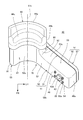
- FIG. 13 is a rear view of the case 50 in the second embodiment.
- the inner bent portion 92 of the retainer 41 is provided with a guide 295 for guiding the deployment of the air bag 42.
- the guide 295 includes a downwardly extending surface 297 extending downwardly along the other side wall 53 d of the upwardly extending portion 47. That is, the guide 295 includes only the lower extending surface 97 of the first embodiment.
- a throttling portion 299 for throttling the flow path of the air bag passage 48 is formed between the lower end portion 295 a of the guide 295 and the lower wall portion 53 a.
- the air bag 42 can be expanded upward appropriately. Furthermore, by providing the downward extension surface 297 of the guide 295, the length for guiding the air bag 42 and the gas G upward on the side of the upper extension portion 47 becomes longer near the inward bent portion 92. Therefore, the left and right of the airbag 42 can be prevented from falling down when the airbag 42 is deployed upward, and the airbag 42 can be deployed vertically upward.
- the third embodiment is different from the first embodiment in that a guide 395 having a shape different from that of the guide 95 is provided.
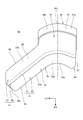
- FIG. 14 is a rear view of the case 50 in the third embodiment.
- the inner bent portion 92 of the retainer 41 is provided with a guide 395 for guiding the deployment of the air bag 42.
- the guide 395 is provided with an inclined surface 396 obliquely extending downward from the upper wall 53 c of the left and right extending case portion 54 in the left-right direction on the upper extending portion 47 side (right side) and downward. That is, the guide 395 includes only the inclined surface 96 of the first embodiment.
- a throttling portion 399 is formed between the inclined surface 396 of the guide 395 and the lower wall portion 53a where the flow path of the air bag passage 48 is squeezed toward the downstream side.
- the lower end portion 395a of the guide 395 is located on an extension line L extending downward along the other side wall portion 53d, and guides the airbag 42 deployed upward through the upper extension portion 47.
- the left and right of the air bag 42 when the air bag 42 expands upward can be prevented from falling down by the lower end portion 395a of the guide 395, and the air bag 42 can be expanded vertically upward.
- the guides 95, 295, and 395 are described as being coupled to the inner surface of the peripheral wall portion 53 of the case 50, but the present invention is not limited to this.
- the guide may be provided integrally with the retainer 41 such that a portion of the wall of the retainer 41 protrudes into the air bag passage 48.
- the guides 95, 295, 395 may be coupled to the cover 51 side instead of the case 50 side.
- the inflator 43 is described as releasing gas G into the air bag 42 along the axis 43c toward the rear of the vehicle, but the present invention is not limited to this.
- the inflator 43 may be provided on the cover 51 side, and the gas may be discharged forward of the vehicle along the axis 43c.
- the retainer may be provided in an L shape opposite to that in FIG. 2 with reference to the center line 47c, and gas flowing in the retainer from the right to the center of the vehicle width may be deflected upward.
- the inflator 43 is described as being inserted into the inflator support hole 52c of the retainer front surface 52 from the inside of the left and right extending case portion 54, but the invention is limited thereto.
- the housing 43a may be inserted into the inflator support hole 52c from the outside of the left and right extending case portion 54.
- the inflator 43 is positioned in the axial direction of the inflator 43 when the flange portion provided on the outer periphery of the housing 43a abuts on the outer surface of the retainer front surface 52, and is inserted from the outside of the left and right extended case 54 It is fixed to the retainer front face 52 by a bolt. According to this configuration, the inflator 43 can be attached and detached from the outside of the retainer 41, and the assemblability is good. Moreover, in the said embodiment, although the inflator 43 is formed in the cylinder shape centering on the axis line 43c of the housing 43a formed cylindrically, this invention is not limited to this.
- the inflator 43 may be formed into a polygonal tubular shape such as a square, and the axis of the inflator 43 may be oriented in the longitudinal direction of the vehicle. Furthermore, although the motorcycle 1 has been described as an example of the saddle-ride type vehicle in the above embodiment, the present invention is not limited to this, and the present invention has three front wheels or two rear wheels. The present invention is applicable to straddle-type vehicles with wheels and straddle-type vehicles equipped with four or more wheels.
Abstract
In this air bag device for saddle-type vehicles, the air bag device is disposed compactly in the front-rear direction, and an air bag is allowed to be deployed vertically upward. The air bag device for saddle-type vehicles is provided with: a retainer 41 provided on the front side of an occupant seat; an inflator 43; and an air bag 42 which is stored in the retainer 41 and which is inflated by gas emitted from the inflator 43 and is deployed in front of an occupant. The retainer 41 is provided with a deflection part 70 which deflects the rightward-leftward flow of gas emitted from the inflator 43 into the air bag 42, to an upward flow. The deflection part 70 is provided with a leftward-rightward extending portion 46 extending in the leftward-rightward direction from the inflator 43 side, and an upward extending part 47 extending in the upward direction from the leftward-rightward extending portion 46, so as to form an L-like air bag passage 48. A guide 95 for guiding deployment of the air bag 42 is provided so as to project into the air bag passage 48.
Description
本発明は、鞍乗り型車両のエアバッグ装置に関する。
The present invention relates to an airbag device for a saddle-ride type vehicle.
従来、鞍乗り型車両のエアバッグ装置において、エアバッグ装置の底部に設けたインフレータからガスを上方に放出することで、エアバッグを上方に展開させ易くしたものが知られている(例えば、特許文献1参照)。
Heretofore, there has been known an airbag apparatus for a saddle-ride type vehicle, in which the airbag is easily expanded upward by discharging gas upward from an inflator provided at the bottom of the airbag apparatus (for example, a patent) Reference 1).
しかしながら、上記従来のようにインフレータからガスが上方に放出する向きでインフレータを配置すると、エアバッグ装置が前後方向に大型になり易い。鞍乗り型車両のエアバッグ装置では、エアバッグ装置を前後にコンパクトに配置し、且つ、乗員の適切な保護のためにエアバッグをできるだけ鉛直に上方へ展開することが望まれる。
本発明は、上述した事情に鑑みてなされたものであり、鞍乗り型車両のエアバッグ装置において、エアバッグ装置を前後方向にコンパクトに配置し、且つ、エアバッグを鉛直に上方へ展開できるようにすることを目的とする。 However, if the inflator is disposed in the direction in which the gas is discharged upward from the inflator as in the above-described conventional case, the air bag device tends to be large in the front-rear direction. In an air bag device of a saddle-ride type vehicle, it is desirable to arrange the air bag device compactly back and forth and to deploy the air bag vertically as vertically as possible for appropriate protection of the occupant.
The present invention has been made in view of the above-described circumstances, and in an airbag device for a saddle-ride type vehicle, the airbag device can be compactly arranged in the front-rear direction, and the airbag can be deployed vertically upward The purpose is to
この明細書には、2017年8月23日に出願された日本国特許出願・特願2017-160230の全ての内容が含まれる。
本発明は、乗員用のシート(13)の前方に設けられるリテーナ(41)と、インフレータ(43)と、前記リテーナ(41)に収納され、前記インフレータ(43)が放出するガスによって膨張して乗員の前方で展開するエアバッグ(42)とを備える鞍乗り型車両のエアバッグ装置において、前記リテーナ(41)は、前記インフレータ(43)から前記エアバッグ(42)内に放出される前記ガスを、左右方向の流れから上方向の流れに偏向させる偏向部(70)を備え、前記偏向部(70)は、前記インフレータ(43)側から左右方向に延びる左右延在部(46)と、前記左右延在部(46)から上方向に延びる上方延在部(47)とを備えてL字状の通路(48)を形成し、前記通路(48)内に突出して前記エアバッグ(42)の展開を案内するガイド(95,295,395)が設けられることを特徴とする。 This specification includes the entire contents of Japanese Patent Application No. 2017-160230 filed on Aug. 23, 2017.
In the present invention, a retainer (41) provided in front of a seat (13) for an occupant, an inflator (43), and the retainer (41) are accommodated and inflated by gas released by the inflator (43). In an airbag apparatus of a saddle-ride type vehicle including an airbag (42) deployed in front of a passenger, the retainer (41) is a gas released from the inflator (43) into the airbag (42). A deflection unit (70) for deflecting the flow from the flow in the left-right direction to the flow in the upward direction, the deflection unit (70) being a left-right extension (46) extending in the left-right direction from the inflator (43) side; And an upward extending portion (47) extending upward from the left and right extending portions (46) to form an L-shaped passage (48), and projecting into the passage (48) to form the air bag (42). Characterized in that the guide (95,295,395) for guiding the deployment of the is provided.
また、上記発明において、前記通路(48)をL字状に曲げる屈曲部(90)は、L字の角部を形成する外側屈曲部(91)と、L字の隅部を形成する内側屈曲部(92)とを備え、前記ガイド(95,295,395)は、前記内側屈曲部(92)に設けられても良い。
また、上記発明において、前記ガイド(95,295,395)は、前記通路(48)の壁部(53)から下方に延びても良い。
さらに、上記発明において、前記ガイド(95,295)は、前記上方延在部(47)に沿うように下方に延びる下方延出面(297)を備えても良い。 In the above invention, the bent portion (90) which bends the passage (48) in an L shape is an inner bent which forms an L-shaped corner and an outer bent portion (91) which forms an L-shaped corner. A portion (92), and the guide (95, 295, 395) may be provided at the inner bending portion (92).
In the above invention, the guide (95, 295, 395) may extend downward from the wall (53) of the passage (48).
Furthermore, in the above-mentioned invention, the guide (95, 295) may be provided with a lower extending surface (297) extending downward along the upper extending portion (47).
また、上記発明において、前記ガイド(95,395)は、前記左右延在部(46)の上壁部(53c)側から左右方向において前記上方延在部(47)側、且つ、下方へ斜めに延びる傾斜面(96,396)を備えても良い。
また、上記発明において、前記ガイド(95)は、前記左右延在部(46)の上壁部(53c)側から左右方向において前記上方延在部(47)側、且つ、下方へ斜めに延びる傾斜面(96)と、前記上方延在部(47)に沿うように下方に延びる下方延出面(97)と、を備えても良い。
また、上記発明において、前記下方延出面(97)と前記傾斜面(96)とは一体に設けられても良い。
また、上記発明において、筒状に形成される前記インフレータ(43)は、その軸線(43c)が車両前後方向に指向する向きで配置されても良い。この構成によれば、筒状に形成される前記インフレータ(43)は、その軸線(43c)が車両前後方向に指向する向きで配置されても良い。 In the above invention, the guide (95, 395) is inclined downward from the upper wall (53c) side of the left and right extension (46) in the left and right direction in the left and right direction. And sloped surfaces (96, 396) extending in
Further, in the above invention, the guide (95) obliquely extends downward from the upper wall (53c) side of the left and right extension (46) in the left and right direction in the left and right direction. An inclined surface (96) and a downwardly extending surface (97) extending downwardly along the upwardly extending portion (47) may be provided.
In the above invention, the lower extending surface (97) and the inclined surface (96) may be integrally provided.
Further, in the above invention, the inflator (43) formed in a tubular shape may be disposed in a direction in which the axis (43c) thereof is directed in the longitudinal direction of the vehicle. According to this configuration, the inflator (43) formed in a tubular shape may be disposed in a direction in which the axis (43c) thereof is directed in the longitudinal direction of the vehicle.
本発明に係る鞍乗り型車両のエアバッグ装置によれば、鞍乗り型車両のエアバッグ装置は、乗員用のシートの前方に設けられるリテーナと、インフレータと、リテーナに収納され、インフレータが放出するガスによって膨張して乗員の前方で展開するエアバッグとを備え、リテーナは、インフレータからエアバッグ内に放出されるガスを、左右方向の流れから上方向の流れに偏向させる偏向部を備え、偏向部は、インフレータ側から左右方向に延びる左右延在部と、左右延在部から上方向に延びる上方延在部とを備えてL字状の通路を形成し、通路内に突出してエアバッグの展開を案内するガイドが設けられる。
この構成によれば、左右延在部及び上方延在部を備えるL字状の通路により、左右方向及び上下方向のスペースを活用してインフレータ及びエアバッグを配置できるため、エアバッグ装置を前後方向にコンパクトに配置できる。また、L字状の通路内に突出するガイドによってエアバッグの展開を案内できるため、エアバッグを鉛直に上方へ展開できる。 According to the airbag apparatus of the saddle-ride type vehicle according to the present invention, the airbag apparatus of the saddle-ride type vehicle is accommodated in the retainer provided in front of the passenger seat, the inflator, and the retainer, and the inflator releases An airbag that is inflated by gas and deployed forward of the occupant, the retainer includes a deflection unit that deflects the gas released from the inflator into the airbag from the flow in the lateral direction to the upward flow; The portion includes a left and right extending portion extending in the left and right direction from the inflator side, and an upper extending portion extending in the upward direction from the left and right extending portion to form an L-shaped passage, which protrudes into the passage. A guide is provided to guide the deployment.
According to this configuration, the inflator and the airbag can be disposed by utilizing the space in the left and right direction and the up and down direction by the L-shaped passage provided with the left and right extension parts and the upper extension part. Can be arranged compactly. Further, since the deployment of the air bag can be guided by the guide projecting into the L-shaped passage, the air bag can be deployed vertically upward.
また、上記発明において、通路をL字状に曲げる屈曲部は、L字の角部を形成する外側屈曲部と、L字の隅部を形成する内側屈曲部とを備え、ガイドは、内側屈曲部に設けられても良い。この構成によれば、ガイドが内側屈曲部に設けられるため、通路の長さが外側屈曲部よりも短くなり易い内側屈曲部でガイドによってエアバッグを適切に案内でき、エアバッグを鉛直に上方へ展開できる。また、エアバッグが左右から上下に向きを変える部分をガイドで案内できるため、ガイドによってエアバッグの向きを制御し易い。
また、上記発明において、ガイドは、通路の壁部から下方に延びても良い。この構成によれば、通路の上下の長さをガイドによって長くできるため、エアバッグを鉛直に上方へ展開できる。 In the above invention, the bent portion for bending the passage in an L shape includes an outer bent portion forming an L-shaped corner and an inner bent portion forming an L-shaped corner, and the guide is an inner bent It may be provided in a unit. According to this configuration, since the guide is provided at the inward bending portion, the air bag can be properly guided by the guide at the inward bending portion where the length of the passage tends to be shorter than the outward bending portion. It can be expanded. In addition, since the portion of the air bag which is turned upside down from the left and right can be guided by the guide, it is easy to control the direction of the air bag by the guide.
In the above invention, the guide may extend downward from the wall of the passage. According to this configuration, since the upper and lower lengths of the passage can be made longer by the guides, the airbag can be deployed vertically upward.
さらに、上記発明において、ガイドは、上方延在部に沿うように下方に延びる下方延出面を備えても良い。この構成によれば、下方延出面によって上方延在部の下方でエアバッグを上下方向に案内できるため、エアバッグを鉛直に上方へ展開できる。
また、上記発明において、ガイドは、左右延在部の上壁部側から左右方向において上方延在部側、且つ、下方へ斜めに延びる傾斜面を備えても良い。この構成によれば、左右延在部から上方延在部に向かう通路を傾斜面によって徐々に絞ることができ、エアバッグの展開方向に指向性を付し易く、ガイドによってエアバッグの展開方向を制御できる。 Furthermore, in the above invention, the guide may include a downward extending surface extending downward along the upward extending portion. According to this configuration, since the air bag can be guided in the vertical direction below the upper extending portion by the lower extending surface, the air bag can be deployed vertically upward.
In the above invention, the guide may have an inclined surface which obliquely extends downward and downward in the left-right direction from the upper wall side of the left and right extension. According to this configuration, the passage from the left and right extension to the upper extension can be gradually narrowed by the inclined surface, directivity can be easily given in the deployment direction of the airbag, and the deployment direction of the airbag can be determined by the guide. It can control.
また、上記発明において、ガイドは、左右延在部の上壁部側から左右方向において上方延在部側、且つ、下方へ斜めに延びる傾斜面と、上方延在部に沿うように下方に延びる下方延出面と、を備えても良い。この構成によれば、左右延在部から上方延在部に向かう通路を傾斜面によって徐々に絞ることで、エアバッグの展開方向に指向性を付すことができるとともに、下方延出面によって上方延在部の下方でエアバッグを上下方向に案内できる。このため、エアバッグを鉛直に上方へ展開できる。
また、上記発明において、下方延出面と傾斜面とは一体に設けられても良い。この構成によれば、ガイドを容易に設けることができるとともに、ガイドの強度及び剛性を向上できる。
また、上記発明において、筒状に形成される前記インフレータは、その軸線が車両前後方向に指向する向きで配置されても良い。この構成によれば、インフレータを前後方向にコンパクトに設けることができ、エアバッグ装置を前後方向にコンパクト化できる。 Further, in the above invention, the guide extends downward along the upwardly extending portion and the inclined surface extending obliquely downward in the left and right direction from the upper wall portion side of the left and right extending portion in the left and right direction. A downward extending surface may be provided. According to this configuration, by gradually squeezing the passage from the left and right extending portions toward the upper extending portion by the inclined surface, directivity can be imparted in the deployment direction of the airbag, and the upward extension by the downward extending surface The air bag can be vertically guided below the head. Therefore, the airbag can be deployed vertically upward.
In the above invention, the downward extending surface and the inclined surface may be integrally provided. According to this configuration, the guide can be easily provided, and the strength and rigidity of the guide can be improved.
Further, in the above invention, the tubular inflator may be disposed such that its axis is directed in the longitudinal direction of the vehicle. According to this configuration, the inflator can be compactly provided in the front-rear direction, and the airbag apparatus can be compacted in the front-rear direction.
以下、図面を参照して本発明の一実施形態について説明する。なお、説明中、前後左右および上下といった方向の記載は、特に記載がなければ車体に対する方向と同一とする。また、各図に示す符号FRは車体前方を示し、符号UPは車体上方を示し、符号LHは車体左方を示している。
Hereinafter, an embodiment of the present invention will be described with reference to the drawings. In the description, the directions such as front, rear, left, right and up and down are the same as the directions with respect to the vehicle body unless otherwise specified. Further, a symbol FR shown in each drawing indicates the front of the vehicle body, a symbol UP indicates the upper portion of the vehicle body, and a symbol LH indicates the left side of the vehicle body.
[第1の実施の形態]
図1は、本発明の第1の実施の形態に係る自動二輪車1の左側面図である。図1では、後述のエアバッグ42が膨張して展開した状態が示されている。なお、図1では、左右一対で設けられるものは、符号を含め左側のものだけが図示されている。
自動二輪車1は、車体フレーム10と、前輪2を操舵可能に支持する操舵系11と、車体フレーム10の後部に支持されるパワーユニット12と、後輪3と、乗員が跨るようにして着座するシート13とを備えるスクータ型の鞍乗り型車両である。 First Embodiment
FIG. 1 is a left side view of amotorcycle 1 according to a first embodiment of the present invention. FIG. 1 shows a state in which an air bag 42 described later is inflated and deployed. In addition, in FIG. 1, only the left side including the reference numerals is illustrated in the left and right pair.
Themotorcycle 1 includes a body frame 10, a steering system 11 for supporting the front wheels 2 in a steerable manner, a power unit 12 supported at the rear of the body frame 10, a rear wheel 3, and a seat for seating by an occupant. 13 is a scooter type saddle-ride type vehicle including
図1は、本発明の第1の実施の形態に係る自動二輪車1の左側面図である。図1では、後述のエアバッグ42が膨張して展開した状態が示されている。なお、図1では、左右一対で設けられるものは、符号を含め左側のものだけが図示されている。
自動二輪車1は、車体フレーム10と、前輪2を操舵可能に支持する操舵系11と、車体フレーム10の後部に支持されるパワーユニット12と、後輪3と、乗員が跨るようにして着座するシート13とを備えるスクータ型の鞍乗り型車両である。 First Embodiment
FIG. 1 is a left side view of a
The
車体フレーム10は、その前端に設けられるヘッドパイプ14と、ヘッドパイプ14から後下方に延びるメインフレーム15と、メインフレーム15の下端から後方に延びるロアフレーム16と、ロアフレーム16から後上がりに後方へ延びる左右一対のリアフレーム17,17とを備える。ヘッドパイプ14は車幅の中央に配置される。
The body frame 10 has a head pipe 14 provided at the front end thereof, a main frame 15 extending rearward and downward from the head pipe 14, a lower frame 16 extending rearward from the lower end of the main frame 15, and a rearward upward A pair of left and right rear frames 17 and 17 are provided. The head pipe 14 is disposed at the center of the vehicle width.
操舵系11は、ヘッドパイプ14に軸支されるステアリングシャフト20と、前輪2の左右の両側に配置されて前輪2を支持する左右一対のフロントフォーク21,21と、ステアリングシャフト20の下端に固定され左右のフロントフォーク21,21の上部を連結するブリッジ部材22と、ステアリングシャフト20の上端に固定されるハンドル23とを備える。ハンドル23は、ステアリングシャフト20の上端に固定されるハンドルポスト23aを介してステアリングシャフト20に接続される。
車両側面視において、ヘッドパイプ14は、自動二輪車1に設定される所定のキャスター角の分だけ鉛直方向に対し後傾している。ステアリングシャフト20は、ヘッドパイプ14に挿通されて軸支され、車両側面視で後傾して配置される。ステアリングシャフト20は車幅の中央に位置する。 Thesteering system 11 is fixed to the steering shaft 20 supported by the head pipe 14, a pair of left and right front forks 21 and 21 disposed on the left and right sides of the front wheel 2 to support the front wheel 2, and the lower end of the steering shaft 20 And a handle 23 fixed to the upper end of the steering shaft 20. The bridge member 22 connects the upper portions of the left and right front forks 21 and 21 to each other. The steering wheel 23 is connected to the steering shaft 20 via a steering wheel post 23 a fixed to the upper end of the steering shaft 20.
In a side view of the vehicle, thehead pipe 14 is inclined rearward with respect to the vertical direction by a predetermined caster angle set in the motorcycle 1. The steering shaft 20 is inserted into and supported by the head pipe 14 and is disposed to be inclined rearward in a side view of the vehicle. The steering shaft 20 is located at the center of the vehicle width.
車両側面視において、ヘッドパイプ14は、自動二輪車1に設定される所定のキャスター角の分だけ鉛直方向に対し後傾している。ステアリングシャフト20は、ヘッドパイプ14に挿通されて軸支され、車両側面視で後傾して配置される。ステアリングシャフト20は車幅の中央に位置する。 The
In a side view of the vehicle, the
パワーユニット12は、後輪3の駆動源としてのエンジンと後輪3を支持するスイングアームとの機能を備えたユニットスイングエンジンである。パワーユニット12は、その前端部に設けられるリンク部材24を介して揺動自在に車体フレーム10に軸支される。
シート13は、リアフレーム17の上方に設けられる。シート13は、運転者が着座する前側シート13aと、同乗者が着座する後側シート13bとを一体に備える。
運転者が左右の足を置くステップフロア25,25は、車幅の中央に位置するロアフレーム16の左右の位置に一対で設けられる。 Thepower unit 12 is a unit swing engine having a function of an engine as a drive source of the rear wheel 3 and a swing arm supporting the rear wheel 3. The power unit 12 is pivotally supported by the vehicle body frame 10 pivotably via a link member 24 provided at its front end.
Theseat 13 is provided above the rear frame 17. The seat 13 integrally includes a front seat 13a on which a driver is seated and a rear seat 13b on which a passenger is seated.
The step floors 25, 25 on which the driver places the left and right feet are provided in pairs at the left and right positions of the lower frame 16 located at the center of the vehicle width.
シート13は、リアフレーム17の上方に設けられる。シート13は、運転者が着座する前側シート13aと、同乗者が着座する後側シート13bとを一体に備える。
運転者が左右の足を置くステップフロア25,25は、車幅の中央に位置するロアフレーム16の左右の位置に一対で設けられる。 The
The
The
自動二輪車1は、車体フレーム10等の車体を覆う車体カバー26を備える。
車体カバー26は、ヘッドパイプ14及び操舵系11の上部を前方及び左右側方から覆うフロントカバー27と、フロントカバー27の後縁に連続し、ヘッドパイプ14及び操舵系11の上部を後方から覆うインナーカバー28とを備える。
また、車体カバー26は、前側シート13aの前下方に位置するセンターカバー29と、ステップフロア25,25の下方で車体を下方から覆うアンダーカバー30と、シート13の下方でリアフレーム17,17を側方から覆うリアサイドカバー31とを備える。
自動二輪車1は、フロントフェンダー32及びリアフェンダー33を備える。 Themotorcycle 1 includes a vehicle body cover 26 that covers the vehicle body such as the vehicle body frame 10 and the like.
The body cover 26 is continuous with thefront cover 27 which covers the head pipe 14 and the upper part of the steering system 11 from the front and the right and left sides and the rear edge of the front cover 27 and covers the upper part of the head pipe 14 and the steering system 11 from the rear. And an inner cover 28.
Further, thebody cover 26 includes a center cover 29 located below the front side seat 13a, an under cover 30 that covers the vehicle body from below the step floors 25 and 25, and rear frames 17 and 17 below the seat 13. And a rear side cover 31 covering from the side.
Themotorcycle 1 includes a front fender 32 and a rear fender 33.
車体カバー26は、ヘッドパイプ14及び操舵系11の上部を前方及び左右側方から覆うフロントカバー27と、フロントカバー27の後縁に連続し、ヘッドパイプ14及び操舵系11の上部を後方から覆うインナーカバー28とを備える。
また、車体カバー26は、前側シート13aの前下方に位置するセンターカバー29と、ステップフロア25,25の下方で車体を下方から覆うアンダーカバー30と、シート13の下方でリアフレーム17,17を側方から覆うリアサイドカバー31とを備える。
自動二輪車1は、フロントフェンダー32及びリアフェンダー33を備える。 The
The body cover 26 is continuous with the
Further, the
The
センターカバー29の前部は、インナーカバー28の下部に連続する。センターカバー29は、前側シート13aからステップフロア25,25に伸ばされた運転者の左右の脚の内側に位置する。センターカバー29の上縁29aは、前側シート13aの下方に位置する。
車両側面視では、インナーカバー28の後面、センターカバー29の上縁29a及び前側シート13aの前面によって、下方に窪む跨ぎ空間34が区画される。乗員は、自動二輪車1に乗降する際に、跨ぎ空間34を介して自動二輪車1を跨ぐことができる。 The front portion of thecenter cover 29 is continuous with the lower portion of the inner cover 28. The center cover 29 is located inside the driver's left and right legs extended from the front seat 13a to the step floors 25, 25. The upper edge 29a of the center cover 29 is located below the front side sheet 13a.
In a side view of the vehicle, astraddle space 34 recessed downward is defined by the rear surface of the inner cover 28, the upper edge 29a of the center cover 29, and the front surface of the front seat 13a. The passenger can straddle the motorcycle 1 via the straddling space 34 when getting on and off the motorcycle 1.
車両側面視では、インナーカバー28の後面、センターカバー29の上縁29a及び前側シート13aの前面によって、下方に窪む跨ぎ空間34が区画される。乗員は、自動二輪車1に乗降する際に、跨ぎ空間34を介して自動二輪車1を跨ぐことができる。 The front portion of the
In a side view of the vehicle, a
図2は、インナーカバー28の周辺部を後方側から見た図である。
図1及び図2に示すように、自動二輪車1は、乗員を衝撃から保護するエアバッグ装置40を備える。エアバッグ装置40は、インナーカバー28の後面に設けられ、前側シート13aに着座する運転者の前方に位置する。また、エアバッグ装置40は、ステアリングシャフト20の後方でハンドル23の下方に設けられ、跨ぎ空間34の前部に位置する。 FIG. 2 is a view of the periphery of theinner cover 28 as viewed from the rear side.
As shown in FIG. 1 and FIG. 2, themotorcycle 1 is provided with an airbag device 40 for protecting the occupant from impact. The airbag device 40 is provided on the rear surface of the inner cover 28 and is located in front of the driver seated on the front seat 13a. In addition, the air bag device 40 is provided behind the steering shaft 20 and below the handle 23 and is located at the front of the straddling space 34.
図1及び図2に示すように、自動二輪車1は、乗員を衝撃から保護するエアバッグ装置40を備える。エアバッグ装置40は、インナーカバー28の後面に設けられ、前側シート13aに着座する運転者の前方に位置する。また、エアバッグ装置40は、ステアリングシャフト20の後方でハンドル23の下方に設けられ、跨ぎ空間34の前部に位置する。 FIG. 2 is a view of the periphery of the
As shown in FIG. 1 and FIG. 2, the
インナーカバー28の後面は、車両側面視では、ステアリングシャフト20に対し略平行に設けられ、ステアリングシャフト20に沿って後傾している。
また、インナーカバー28の後面の上部は、図1及び図2に示すように、ステアリングシャフト20の後方に位置する車幅方向の中央部28aが最も後方に位置し、中央部28aの左右に位置する側部28b,28bは、車幅方向外側に行くほど前側に位置するように傾斜している。 The rear surface of theinner cover 28 is provided substantially parallel to the steering shaft 20 in a side view of the vehicle, and is inclined rearward along the steering shaft 20.
Further, as shown in FIGS. 1 and 2, in the upper part of the rear surface of theinner cover 28, the central portion 28a in the vehicle width direction located rearward of the steering shaft 20 is located the rearmost and is located left and right of the central portion 28a. The side portions 28b, 28b are inclined so as to be positioned on the front side as going to the outside in the vehicle width direction.
また、インナーカバー28の後面の上部は、図1及び図2に示すように、ステアリングシャフト20の後方に位置する車幅方向の中央部28aが最も後方に位置し、中央部28aの左右に位置する側部28b,28bは、車幅方向外側に行くほど前側に位置するように傾斜している。 The rear surface of the
Further, as shown in FIGS. 1 and 2, in the upper part of the rear surface of the
図3は、エアバッグ装置40を後方側(運転者側)から見た正面図である。
エアバッグ装置40は、シート13に着座する乗員の前方に設けられる箱状のリテーナ41と、リテーナ41に収納されるエアバッグ42と、エアバッグ42内にガスを放出するインフレータ43と、リテーナ41の上部に取り付けられる蓋部材44とを備える。 FIG. 3 is a front view of theairbag device 40 as viewed from the rear side (driver side).
Theairbag device 40 includes a box-shaped retainer 41 provided in front of an occupant seated on the seat 13, an airbag 42 accommodated in the retainer 41, an inflator 43 for releasing gas into the airbag 42, and a retainer 41. And a lid member 44 attached to the top of the housing.
エアバッグ装置40は、シート13に着座する乗員の前方に設けられる箱状のリテーナ41と、リテーナ41に収納されるエアバッグ42と、エアバッグ42内にガスを放出するインフレータ43と、リテーナ41の上部に取り付けられる蓋部材44とを備える。 FIG. 3 is a front view of the
The
図4は、エアバッグ装置40の左側面図である。図5は、エアバッグ装置40を上方から見た図である。図6は、エアバッグ装置40を下方から見た図である。
図2~図6を参照し、リテーナ41は、乗員側(後方側)から見た場合、逆L字状に形成された箱状部材である。なお、以下の説明でL字とは、リテーナ41を前方または後方から見た場合にL字状であることを意味する。リテーナ41は、後方から見た場合に逆L字であるが、L字状に形成されていると言える。
リテーナ41は、前側シート13aの前方に位置し、前側シート13aの前面に対向する。
リテーナ41は、左右方向(車幅方向)に延びる左右延在部46と、左右延在部46から上方向に延びる上方延在部47とを備える。 FIG. 4 is a left side view of theairbag device 40. As shown in FIG. FIG. 5 is a view of the airbag device 40 as viewed from above. FIG. 6 is a view of the airbag device 40 as viewed from below.
Referring to FIGS. 2 to 6, theretainer 41 is a box-like member formed in an inverted L shape when viewed from the occupant side (rear side). In the following description, “L” means that the retainer 41 is L-shaped when viewed from the front or rear. The retainer 41 has an inverted L shape when viewed from the rear, but can be said to be formed in an L shape.
Theretainer 41 is located in front of the front side sheet 13a and faces the front side of the front side sheet 13a.
Theretainer 41 includes a left and right extending portion 46 extending in the left and right direction (vehicle width direction), and an upper extending portion 47 extending upward from the left and right extending portion 46.
図2~図6を参照し、リテーナ41は、乗員側(後方側)から見た場合、逆L字状に形成された箱状部材である。なお、以下の説明でL字とは、リテーナ41を前方または後方から見た場合にL字状であることを意味する。リテーナ41は、後方から見た場合に逆L字であるが、L字状に形成されていると言える。
リテーナ41は、前側シート13aの前方に位置し、前側シート13aの前面に対向する。
リテーナ41は、左右方向(車幅方向)に延びる左右延在部46と、左右延在部46から上方向に延びる上方延在部47とを備える。 FIG. 4 is a left side view of the
Referring to FIGS. 2 to 6, the
The
The
左右延在部46は、車幅方向に延びる箱状部である。左右延在部46の車幅方向の外端部46aは、車幅中央に位置するステアリングシャフト20よりも車幅方向外側に位置する。左右延在部46は、外端部46aから、インナーカバー28の側部28bの後面に沿って車幅中央に延びる。
上方延在部47は、ステアリングシャフト20に沿って上下方向に延びる箱状部であり、車両側面視では後傾している。上方延在部47は、車幅中央に位置し、インナーカバー28の中央部28aを後方から覆う。
上方延在部47の中心を通って上下に延びる上方延在部47の中心線47cは、ステアリングシャフト20の後方でステアリングシャフト20と略平行に設けられて後傾している。中心線47cは車幅の中央に位置する。 The left and right extendingportion 46 is a box-like portion extending in the vehicle width direction. The outer end 46a in the vehicle width direction of the left and right extending portion 46 is located on the outer side in the vehicle width direction than the steering shaft 20 located at the center of the vehicle width. The left and right extending portions 46 extend from the outer end 46 a along the rear surface of the side portion 28 b of the inner cover 28 to the center of the vehicle width.
Theupper extension portion 47 is a box-like portion extending in the vertical direction along the steering shaft 20, and is inclined rearward in a vehicle side view. The upper extension portion 47 is located at the center of the vehicle width and covers the central portion 28 a of the inner cover 28 from the rear.
Acenter line 47 c of the upper extending portion 47 extending up and down through the center of the upper extending portion 47 is provided rearward of the steering shaft 20 so as to be substantially parallel to the steering shaft 20 and inclined rearward. The center line 47c is located at the center of the vehicle width.
上方延在部47は、ステアリングシャフト20に沿って上下方向に延びる箱状部であり、車両側面視では後傾している。上方延在部47は、車幅中央に位置し、インナーカバー28の中央部28aを後方から覆う。
上方延在部47の中心を通って上下に延びる上方延在部47の中心線47cは、ステアリングシャフト20の後方でステアリングシャフト20と略平行に設けられて後傾している。中心線47cは車幅の中央に位置する。 The left and right extending
The
A
上方延在部47の下部の外側面には、左右延在部46の車幅方向の内端部が接続されている。すなわち、リテーナ41は、左右延在部46の内端部から上方延在部47が上方に延出することで、L字状に形成される。リテーナ41の内部には、左右延在部46の内部空間及び上方延在部47の内部空間によって形成されるL字状のエアバッグ通路48(通路)が形成される。
上方延在部47の上面には、エアバッグ通路48を上方に露出させる上面開口部49が形成されている。エアバッグ42は、上面開口部49から上方へ展開される。上面開口部49の開口面は、上方延在部47の中心線47cに略直交する。上面開口部49は、蓋部材44によって塞がれている。 An inner end portion of the left and right extendingportions 46 in the vehicle width direction is connected to the outer side surface of the lower portion of the upper extending portion 47. That is, the retainer 41 is formed in an L-shape by the upper extension portion 47 extending upward from the inner end portion of the left and right extension portion 46. Inside the retainer 41, an L-shaped air bag passage 48 (passage) is formed which is formed by the internal space of the left and right extension portions 46 and the internal space of the upper extension portion 47.
An upper surface opening 49 is formed on the upper surface of theupper extension 47 to expose the air bag passage 48 upward. The air bag 42 is deployed upward from the top opening 49. The opening surface of the upper surface opening 49 is substantially orthogonal to the center line 47 c of the upper extension 47. The upper surface opening 49 is closed by the lid member 44.
上方延在部47の上面には、エアバッグ通路48を上方に露出させる上面開口部49が形成されている。エアバッグ42は、上面開口部49から上方へ展開される。上面開口部49の開口面は、上方延在部47の中心線47cに略直交する。上面開口部49は、蓋部材44によって塞がれている。 An inner end portion of the left and right extending
An upper surface opening 49 is formed on the upper surface of the
リテーナ41は、その後面(乗員側の面)が開口した箱状のケース50と、ケース50の後面開口50a(図7)を覆うカバー51とを結合させて形成される。ケース50及びカバー51は、例えば金属材料で構成される。
図7は、ケース50を後方から見た図である。
ケース50は、L字状に形成されるリテーナ前面52と、後述するケース上面開口55aの部分以外のリテーナ前面52の周縁の全周から後方に立設される周壁部53(壁部)とを備える。後面開口50aは、周壁部53の後縁部によって区画される。
ケース50は、左右延在部46の前部を構成する左右延在ケース部54と、上方延在部47の前部を構成する上下延在ケース部55とを一体に備える。
上下延在ケース部55の上端には、周壁部53を設けずに開口とされたケース上面開口55aが形成されている。ケース上面開口55aは上面開口部49の大部分を構成する。 Theretainer 41 is formed by combining a box-like case 50 having a rear surface (a surface on the occupant side) open and a cover 51 covering the rear surface opening 50a (FIG. 7) of the case 50. The case 50 and the cover 51 are made of, for example, a metal material.
FIG. 7 is a view of thecase 50 viewed from the rear.
Thecase 50 includes a retainer front surface 52 formed in an L shape, and a peripheral wall portion 53 (wall portion) erected rearward from the entire periphery of the periphery of the retainer front surface 52 other than the portion of the case top surface opening 55a described later. Prepare. The rear opening 50 a is partitioned by the rear edge of the peripheral wall 53.
Thecase 50 integrally includes a left and right extension case portion 54 which constitutes a front portion of the left and right extension portions 46 and a vertically extending case portion 55 which constitutes a front portion of the upper extension portion 47.
At the upper end of the vertically extendingcase portion 55, a case upper surface opening 55a which is an opening without the peripheral wall portion 53 is formed. The case upper surface opening 55 a constitutes most of the upper surface opening 49.
図7は、ケース50を後方から見た図である。
ケース50は、L字状に形成されるリテーナ前面52と、後述するケース上面開口55aの部分以外のリテーナ前面52の周縁の全周から後方に立設される周壁部53(壁部)とを備える。後面開口50aは、周壁部53の後縁部によって区画される。
ケース50は、左右延在部46の前部を構成する左右延在ケース部54と、上方延在部47の前部を構成する上下延在ケース部55とを一体に備える。
上下延在ケース部55の上端には、周壁部53を設けずに開口とされたケース上面開口55aが形成されている。ケース上面開口55aは上面開口部49の大部分を構成する。 The
FIG. 7 is a view of the
The
The
At the upper end of the vertically extending
リテーナ前面52における上下延在ケース部55の部分は、上方から見た場合に後方に向けて凸となるように湾曲する前側曲面部52aになっている。前側曲面部52aは、上方延在部47の上下の略全長に亘り設けられる。
リテーナ前面52における左右延在ケース部54の部分は、インナーカバー28の側部28b(図2)に沿って延びる前側平坦部52bになっている。 A portion of the vertically extendingcase portion 55 in the retainer front surface 52 is a front curved surface portion 52 a that curves so as to be convex toward the rear when viewed from above. The front curved surface portion 52 a is provided over substantially the entire length of the upper extension portion 47.
A portion of the left and right extendingcase portion 54 in the retainer front surface 52 is a front flat portion 52 b extending along the side portion 28 b (FIG. 2) of the inner cover 28.
リテーナ前面52における左右延在ケース部54の部分は、インナーカバー28の側部28b(図2)に沿って延びる前側平坦部52bになっている。 A portion of the vertically extending
A portion of the left and right extending
図7に示すように、ケース50は、エアバッグ通路48をL字状に曲げる屈曲部90を備える。屈曲部90は、エアバッグ通路48のL字の曲がりの角部を形成する外側屈曲部91と、L字の曲がりの隅部を形成する内側屈曲部92とによって構成される。
詳細には、図7に示すように、外側屈曲部91は、ケース50の周壁部53において、左右延在ケース部54の下壁部53aと上方延在部47の一側側壁部53b(右側面)とがL字状に交わる部分である。
また、内側屈曲部92は、ケース50の周壁部53において、左右延在ケース部54の上壁部53cと上方延在部47の他側側壁部53d(左側面)とがL字状に交わる部分である。内側屈曲部92は、周壁部53の向きが左右方向から上方向に緩やかに変わるように曲面状に形成されている。
ここで、周壁部53の上壁部53cと下壁部53aとは略平行である。また、一側側壁部53bと他側側壁部53dとは略平行である。 As shown in FIG. 7, thecase 50 includes a bending portion 90 that bends the air bag passage 48 in an L shape. The bending portion 90 is constituted by an outer bending portion 91 forming an L-shaped bending corner of the air bag passage 48 and an inner bending portion 92 forming an L-shaped bending corner.
Specifically, as shown in FIG. 7, in theperipheral wall 53 of the case 50, the outer bent portion 91 is a side wall 53 b of the lower wall 53 a of the left and right extension case 54 and the upper extension 47 (right side Face) intersects in an L-shape.
Further, in the circumferentiallycurved portion 53 of the case 50, the inward bent portion 92 intersects the upper wall portion 53c of the left and right extension case portion 54 and the other side wall portion 53d (left side surface) of the upward extension portion 47 in an L shape. It is a part. The inward bent portion 92 is formed in a curved surface so that the direction of the peripheral wall portion 53 gradually changes from the left-right direction to the upper direction.
Here, theupper wall 53 c and the lower wall 53 a of the peripheral wall 53 are substantially parallel. The one side wall 53b and the other side wall 53d are substantially parallel.
詳細には、図7に示すように、外側屈曲部91は、ケース50の周壁部53において、左右延在ケース部54の下壁部53aと上方延在部47の一側側壁部53b(右側面)とがL字状に交わる部分である。
また、内側屈曲部92は、ケース50の周壁部53において、左右延在ケース部54の上壁部53cと上方延在部47の他側側壁部53d(左側面)とがL字状に交わる部分である。内側屈曲部92は、周壁部53の向きが左右方向から上方向に緩やかに変わるように曲面状に形成されている。
ここで、周壁部53の上壁部53cと下壁部53aとは略平行である。また、一側側壁部53bと他側側壁部53dとは略平行である。 As shown in FIG. 7, the
Specifically, as shown in FIG. 7, in the
Further, in the circumferentially
Here, the
図8は、蓋部材44を取り外した状態でエアバッグ装置40を後方側から見た正面図である。図9は、蓋部材44を取り外した状態におけるエアバッグ装置40の左側面図である。
リテーナ41のカバー51は、乗員及びシート13に前方側から面するリテーナ後面57と、上端以外のリテーナ後面57の周縁の全周から前方に立設されるリブ58とを備える。
リテーナ後面57は、リテーナ前面52と同様にL字状に形成されており、リテーナ前面52に後方から対向する。
カバー51は、リブ58がケース50の周壁部53に外側から重なるように係合することでケース50に結合される。カバー51は、例えば、リブ58に沿う溶接ビードによってケース50に結合される。 FIG. 8 is a front view of theairbag device 40 viewed from the rear side with the lid member 44 removed. FIG. 9 is a left side view of the airbag device 40 with the lid member 44 removed.
Thecover 51 of the retainer 41 includes a retainer rear surface 57 facing the occupant and the seat 13 from the front side, and a rib 58 erected forward from the entire periphery of the periphery of the retainer rear surface 57 other than the upper end.
Similar to theretainer front surface 52, the retainer rear surface 57 is formed in an L shape, and faces the retainer front surface 52 from the rear.
Thecover 51 is coupled to the case 50 by engaging the rib 58 with the peripheral wall portion 53 of the case 50 from the outside. The cover 51 is coupled to the case 50 by, for example, a weld bead along the rib 58.
リテーナ41のカバー51は、乗員及びシート13に前方側から面するリテーナ後面57と、上端以外のリテーナ後面57の周縁の全周から前方に立設されるリブ58とを備える。
リテーナ後面57は、リテーナ前面52と同様にL字状に形成されており、リテーナ前面52に後方から対向する。
カバー51は、リブ58がケース50の周壁部53に外側から重なるように係合することでケース50に結合される。カバー51は、例えば、リブ58に沿う溶接ビードによってケース50に結合される。 FIG. 8 is a front view of the
The
Similar to the
The
カバー51のリテーナ後面57は、左右延在部46の後面を構成する左右延在カバー部60と、上方延在部47の後面を構成する上下延在カバー部61とを一体に備える。
上下延在カバー部61は、ケース50の前側曲面部52a(図7、図8)に後方から対向する後側曲面部57a(曲面部)になっている。後側曲面部57aは、上方から見た場合に、後方に向けて凸となるように湾曲する曲面状に形成されている。後側曲面部57aは、リテーナ後面57の上下の略全長に亘り設けられる。
左右延在カバー部60は、ケース50の前側平坦部52b(図7)に後方から対向する後側平坦部57bになっている。 The retainerrear surface 57 of the cover 51 integrally includes a left and right extended cover portion 60 that configures a rear surface of the left and right extension portions 46 and an upper and lower extended cover portion 61 that configures a rear surface of the upper extension portion 47.
The vertically extendingcover portion 61 is a rear side curved surface portion 57a (curved surface portion) facing the front curved surface portion 52a (FIGS. 7 and 8) of the case 50 from the rear. The rear curved surface portion 57a is formed in a curved surface shape that is curved so as to be convex toward the rear when viewed from above. The rear curved surface portion 57a is provided over substantially the entire length of the rear surface 57 of the retainer.
The left and rightextended cover portion 60 is a rear side flat portion 57 b facing the front side flat portion 52 b (FIG. 7) of the case 50 from the rear side.
上下延在カバー部61は、ケース50の前側曲面部52a(図7、図8)に後方から対向する後側曲面部57a(曲面部)になっている。後側曲面部57aは、上方から見た場合に、後方に向けて凸となるように湾曲する曲面状に形成されている。後側曲面部57aは、リテーナ後面57の上下の略全長に亘り設けられる。
左右延在カバー部60は、ケース50の前側平坦部52b(図7)に後方から対向する後側平坦部57bになっている。 The retainer
The vertically extending
The left and right
リテーナ41の上方延在部47は、上方から見て枠状の上部周壁部47aを上端に備える。上面開口部49は、上部周壁部47aによって区画される。
リテーナ41の上方延在部47には、後方の乗員側に向けて開口する乗員側開口部62が設けられている。乗員側開口部62は、上部周壁部47aの後面部の上端が下方に切り欠かれたものであり、エアバッグ通路48の上端部を後方に連通させる。乗員側開口部62は、上面開口部49の後方に位置し、上面開口部49に連通している。 Theupper extension portion 47 of the retainer 41 includes a frame-shaped upper peripheral wall portion 47a at the upper end when viewed from above. The upper surface opening 49 is divided by the upper peripheral wall 47 a.
Theupper extension portion 47 of the retainer 41 is provided with an occupant side opening 62 opening toward the rear occupant side. The occupant side opening 62 is formed by cutting the upper end of the rear surface of the upper peripheral wall 47a downward, and communicates the upper end of the air bag passage 48 to the rear. The passenger side opening 62 is located rearward of the upper surface opening 49 and is in communication with the upper surface opening 49.
リテーナ41の上方延在部47には、後方の乗員側に向けて開口する乗員側開口部62が設けられている。乗員側開口部62は、上部周壁部47aの後面部の上端が下方に切り欠かれたものであり、エアバッグ通路48の上端部を後方に連通させる。乗員側開口部62は、上面開口部49の後方に位置し、上面開口部49に連通している。 The
The
詳細には、図8に示すように、乗員側開口部62は、カバー51のリテーナ後面57の上下延在カバー部61の上端61aを、ケース50のリテーナ前面52の上下延在ケース部55の上端55bよりも下方に切り欠くようにして形成されている。乗員側開口部62は、上下延在カバー部61の上端の幅方向の全体に亘って形成される。上下延在カバー部61の上端61aと上下延在ケース部55の上端55bとの段差の大きさは、上下延在カバー部61の幅方向の全体に亘って略同一である。
なお、上端61aは、リテーナ41の上部周壁部47aの後面部の上端でもある。 Specifically, as shown in FIG. 8, theoccupant side opening 62 is formed by the upper end 61 a of the vertically extending cover 61 of the rear surface 57 of the retainer of the cover 51 and the upper 55 a of the vertically extending case 55 of the retainer front 52 of the case 50. It is formed to be cut out below the upper end 55b. The occupant side opening 62 is formed over the entire upper end of the vertically extending cover portion 61 in the width direction. The size of the step between the upper end 61 a of the vertically extending cover portion 61 and the upper end 55 b of the vertically extending case portion 55 is substantially the same across the entire width direction of the vertically extending cover portion 61.
Theupper end 61 a is also the upper end of the rear surface portion of the upper peripheral wall portion 47 a of the retainer 41.
なお、上端61aは、リテーナ41の上部周壁部47aの後面部の上端でもある。 Specifically, as shown in FIG. 8, the
The
図7に示すように、リテーナ41には、エアバッグ42の展開を案内するガイド95が設けられる。ガイド95は、リテーナ41の内面に設けられ、エアバッグ通路48内に突出する。
ガイド95は、ケース50の周壁部53における内側屈曲部92の内面に固定され、内側屈曲部92から下方に延出する。
詳細には、ガイド95は、左右延在ケース部54の上壁部53cから左右方向において上方延在部47側(右側)、且つ、下方へ斜めに延びる傾斜面96と、上方延在部47の他側側壁部53dに沿うように下方に延びる下方延出面97と、内側屈曲部92の内面に沿って屈曲する固定面98とを一体に備える。傾斜面96、下方延出面97、及び固定面98は板材の板面により構成される。 As shown in FIG. 7, theretainer 41 is provided with a guide 95 for guiding the deployment of the air bag 42. The guide 95 is provided on the inner surface of the retainer 41 and protrudes into the air bag passage 48.
Theguide 95 is fixed to the inner surface of the inward bent portion 92 in the peripheral wall portion 53 of the case 50 and extends downward from the inward bent portion 92.
Specifically, theguide 95 includes an inclined surface 96 obliquely extending downward from the upper wall 53 c of the left and right extending case portion 54 in the left and right direction, and an upper extending portion 47. A downward extending surface 97 extending downward along the other side wall portion 53 d and a fixing surface 98 bent along the inner surface of the inner bent portion 92 are integrally provided. The inclined surface 96, the lower extending surface 97, and the fixing surface 98 are constituted by the plate surface of the plate material.
ガイド95は、ケース50の周壁部53における内側屈曲部92の内面に固定され、内側屈曲部92から下方に延出する。
詳細には、ガイド95は、左右延在ケース部54の上壁部53cから左右方向において上方延在部47側(右側)、且つ、下方へ斜めに延びる傾斜面96と、上方延在部47の他側側壁部53dに沿うように下方に延びる下方延出面97と、内側屈曲部92の内面に沿って屈曲する固定面98とを一体に備える。傾斜面96、下方延出面97、及び固定面98は板材の板面により構成される。 As shown in FIG. 7, the
The
Specifically, the
ガイド95の下方延出面97は、他側側壁部53dの下端から他側側壁部53dを下方に延長するように略鉛直に延びる。ガイド95の下端部95aは、下方延出面97の下端と傾斜面96の下端とが接続される部分である。下端部95aは、鋭いエッジにならないように曲面状に形成される。
傾斜面96及び下方延出面97は、例えば、1枚の板材を下端部95aでV字状に曲げることで一体に形成される。 The lower extendingsurface 97 of the guide 95 extends substantially vertically from the lower end of the other side wall 53 d so as to extend the other side wall 53 d downward. The lower end portion 95 a of the guide 95 is a portion where the lower end of the lower extending surface 97 and the lower end of the inclined surface 96 are connected. The lower end 95a is formed in a curved shape so as not to be a sharp edge.
Theinclined surface 96 and the lower extending surface 97 are integrally formed, for example, by bending one plate material at a lower end portion 95 a in a V-shape.
傾斜面96及び下方延出面97は、例えば、1枚の板材を下端部95aでV字状に曲げることで一体に形成される。 The lower extending
The
ガイド95の固定面98は、下方延出面97の上端から内側屈曲部92の内面に沿って傾斜面96の上端側へ延びる。
ガイド95は、傾斜面96の上端、下方延出面97の上端、及び固定面98が、周壁部53の内面に結合されることでリテーナ41に固定される。 The fixingsurface 98 of the guide 95 extends from the upper end of the lower extending surface 97 to the upper end side of the inclined surface 96 along the inner surface of the inner bent portion 92.
Theguide 95 is fixed to the retainer 41 by the upper end of the inclined surface 96, the upper end of the lower extending surface 97, and the fixing surface 98 being coupled to the inner surface of the peripheral wall portion 53.
ガイド95は、傾斜面96の上端、下方延出面97の上端、及び固定面98が、周壁部53の内面に結合されることでリテーナ41に固定される。 The fixing
The
左右延在部46のエアバッグ通路48内においてガイド95が設けられた部分では、エアバッグ42が通る通路の大きさが上下方向に小さくなる。詳細には、傾斜面96が上方延在部47側へ下方に傾斜しているため、エアバッグ通路48の断面積は、傾斜面96の上端から下端側に行くほど小さくなる。すなわち、エアバッグ通路48内には、ガイド95の傾斜面96と下壁部53aとの間に、エアバッグ通路48の流路が下流側に向かって絞られる絞り部99が形成される。本実施の形態では、ガイド95の下端部95aは、左右延在部46のエアバッグ通路48の上下方向の中間部よりも上方、且つ、上壁部53cよりも下方に位置する。
また、下方延出面97は、他側側壁部53dを延長するように設けられており、一側側壁部53bと略平行である。このため、上方延在部47のエアバッグ通路48の横幅は、ガイド95の下方延出面97の部分と他側側壁部53dの部分とで略等しい。 In the portion of theair bag passage 48 of the left and right extending portion 46 where the guide 95 is provided, the size of the passage through which the air bag 42 passes is reduced in the vertical direction. In detail, since the inclined surface 96 is inclined downward toward the upper extension 47, the cross-sectional area of the air bag passage 48 becomes smaller from the upper end to the lower end of the inclined surface 96. That is, in the air bag passage 48, a throttling portion 99 is formed between the inclined surface 96 of the guide 95 and the lower wall portion 53a where the flow path of the air bag passage 48 is squeezed toward the downstream side. In the present embodiment, the lower end portion 95a of the guide 95 is positioned above the middle portion in the vertical direction of the air bag passage 48 of the left and right extension portions 46 and below the upper wall portion 53c.
Further, the lower extendingsurface 97 is provided to extend the other side wall portion 53d, and is substantially parallel to the one side wall portion 53b. For this reason, the lateral width of the air bag passage 48 of the upper extending portion 47 is substantially equal between the portion of the lower extending surface 97 of the guide 95 and the portion of the other side wall portion 53 d.
また、下方延出面97は、他側側壁部53dを延長するように設けられており、一側側壁部53bと略平行である。このため、上方延在部47のエアバッグ通路48の横幅は、ガイド95の下方延出面97の部分と他側側壁部53dの部分とで略等しい。 In the portion of the
Further, the lower extending
図3~図6を参照し、蓋部材44は、上面開口部49を上方から覆う蓋上面部44aと、上方延在部47の上部周壁部47aに嵌合する蓋周壁部44bとを一体に備える。
蓋部材44は、蓋周壁部44bの内周面が上部周壁部47aの外周面に嵌合することでリテーナ41に取り付けられている。上面開口部49及び乗員側開口部62は、蓋部材44によって塞がれる。
また、蓋上面部44aの前部には、ハンドルポスト23a(図1)を避けるように下方に窪む凹部44c(図5)が形成されている。 With reference to FIGS. 3 to 6, thelid member 44 integrally includes a lid upper surface portion 44a covering the upper surface opening 49 from above and a lid peripheral wall portion 44b fitted to the upper peripheral wall portion 47a of the upper extending portion 47. Prepare.
Thelid member 44 is attached to the retainer 41 by fitting the inner peripheral surface of the lid peripheral wall portion 44b to the outer peripheral surface of the upper peripheral wall portion 47a. The top opening 49 and the passenger side opening 62 are closed by the lid member 44.
Further, arecess 44c (FIG. 5) which is recessed downward so as to avoid the handle post 23a (FIG. 1) is formed at the front of the lid top surface 44a.
蓋部材44は、蓋周壁部44bの内周面が上部周壁部47aの外周面に嵌合することでリテーナ41に取り付けられている。上面開口部49及び乗員側開口部62は、蓋部材44によって塞がれる。
また、蓋上面部44aの前部には、ハンドルポスト23a(図1)を避けるように下方に窪む凹部44c(図5)が形成されている。 With reference to FIGS. 3 to 6, the
The
Further, a
図2、図3、図5及び図7を参照し、インフレータ43は、エアバッグ通路48内に設けられ、エアバッグ通路48におけるエアバッグ42の展開経路の上流端に位置する。詳細には、インフレータ43は、左右延在部46の左右延在ケース部54内において外端部46a(図5)側に寄せて設けられ、車幅中央に位置するステアリングシャフト20に対して左右方向(左側)にオフセットして配置される。
インフレータ43は、左右延在ケース部54のリテーナ前面52の前側平坦部52b(図7)に取り付けられる。 Referring to FIGS. 2, 3, 5 and 7, theinflator 43 is provided in the air bag passage 48 and located at the upstream end of the deployment path of the air bag 42 in the air bag passage 48. Specifically, the inflator 43 is provided on the side of the outer end 46a (FIG. 5) in the left and right extending case portion 54 of the left and right extending portion 46 and is provided to the left and right with respect to the steering shaft 20 located at the center It is arranged offset in the direction (left side).
The inflator 43 is attached to the frontflat portion 52 b (FIG. 7) of the retainer front surface 52 of the left and right extension case portion 54.
インフレータ43は、左右延在ケース部54のリテーナ前面52の前側平坦部52b(図7)に取り付けられる。 Referring to FIGS. 2, 3, 5 and 7, the
The inflator 43 is attached to the front
図10は、インフレータ43の取り付け状態を示す断面図である。
インフレータ43は、円筒状(筒状)に形成されたハウジング43aを備える。ハウジング43aの内部には、ガス発生剤、及び、このガス発生剤にガスを発生する反応を開始させるイニシエータが設けられる。イニシエータは点火装置を備える。なお、ハウジング43aの軸方向の端面が閉じているものも筒状に含まれる。ハウジング43aは、外周面にガス放出口43bを備える。ガス放出口43bは、ハウジング43aの周方向に並べて複数設けられる。 FIG. 10 is a cross-sectional view showing the attached state of theinflator 43. As shown in FIG.
The inflator 43 includes a cylindrical (cylindrical)housing 43a. Inside the housing 43a, a gas generating agent and an initiator for initiating a reaction of generating a gas in the gas generating agent are provided. The initiator comprises an igniter. In addition, that by which the end surface of the axial direction of the housing 43a is closed is contained in a cylinder shape. The housing 43a is provided with a gas discharge port 43b on the outer peripheral surface. A plurality of gas discharge ports 43b are provided side by side in the circumferential direction of the housing 43a.
インフレータ43は、円筒状(筒状)に形成されたハウジング43aを備える。ハウジング43aの内部には、ガス発生剤、及び、このガス発生剤にガスを発生する反応を開始させるイニシエータが設けられる。イニシエータは点火装置を備える。なお、ハウジング43aの軸方向の端面が閉じているものも筒状に含まれる。ハウジング43aは、外周面にガス放出口43bを備える。ガス放出口43bは、ハウジング43aの周方向に並べて複数設けられる。 FIG. 10 is a cross-sectional view showing the attached state of the
The inflator 43 includes a cylindrical (cylindrical)
ハウジング43aの外周面には、環状部材65が一体に結合されている。環状部材65は、ハウジング43aの外周面から径方向に延びるフランジ部65aと、フランジ部65aの外周縁からインフレータ43の軸方向に延出する周壁部65bとを備える。
インフレータ43のハウジング43aは、リテーナ前面52に形成されたインフレータ支持孔52cに、左右延在ケース部54の内側から挿入される。ハウジング43aは、フランジ部65aがリテーナ前面52の内面に当接することで、インフレータ43の軸方向に位置決めされる。
インフレータ43は、フランジ部65a及びリテーナ前面52に挿通されるボルト66と、ボルト66に螺合するナット66aとによってリテーナ前面52に締結される。ボルト66及びナット66aは、フランジ部65aの周方向に複数設けられる。 Anannular member 65 is integrally coupled to the outer peripheral surface of the housing 43a. The annular member 65 includes a flange portion 65a extending in the radial direction from the outer peripheral surface of the housing 43a, and a peripheral wall portion 65b extending in the axial direction of the inflator 43 from the outer peripheral edge of the flange portion 65a.
Thehousing 43 a of the inflator 43 is inserted into the inflator support hole 52 c formed in the retainer front surface 52 from the inside of the left and right extending case portion 54. The housing 43 a is positioned in the axial direction of the inflator 43 by the flange portion 65 a abutting on the inner surface of the retainer front surface 52.
The inflator 43 is fastened to theretainer front surface 52 by a bolt 66 inserted through the flange portion 65 a and the retainer front surface 52 and a nut 66 a screwed to the bolt 66. A plurality of bolts 66 and nuts 66a are provided in the circumferential direction of the flange portion 65a.
インフレータ43のハウジング43aは、リテーナ前面52に形成されたインフレータ支持孔52cに、左右延在ケース部54の内側から挿入される。ハウジング43aは、フランジ部65aがリテーナ前面52の内面に当接することで、インフレータ43の軸方向に位置決めされる。
インフレータ43は、フランジ部65a及びリテーナ前面52に挿通されるボルト66と、ボルト66に螺合するナット66aとによってリテーナ前面52に締結される。ボルト66及びナット66aは、フランジ部65aの周方向に複数設けられる。 An
The
The inflator 43 is fastened to the
フランジ部65aは、インフレータ43の軸線43cの方向に見た場合、外形が矩形に形成されている。
環状部材65の周壁部65bは、軸線43cの軸方向視で矩形の枠状に形成されており、インフレータ43の外周面を外側から囲う。詳細には、周壁部65bは、複数のガス放出口43bを外側から囲う。
インフレータ43は、複数のガス放出口43bから径方向外側に向かって放射状にガスGを放出し、このガスGは、周壁部65bの内周面に当たることで向きを変え、インフレータ43の軸線43cの方向に放出される。すなわち、エアバッグ42内へのインフレータ43のガスGの放出方向は、軸線43cの延在方向である。環状部材65は、ガスGの放出方向を制御するガイド部材として機能する。
インフレータ43は、軸線43cが車両の前後方向を指向する向きで配置される。このように、軸線43cを前後に指向させることで、インフレータ43が大径であっても、インフレータ43が車両の前後方向に占めるスペースを小さくでき、インフレータ43を前後にコンパクトに設けることができる。 Theflange portion 65 a has a rectangular outer shape when viewed in the direction of the axis 43 c of the inflator 43.
Theperipheral wall portion 65b of the annular member 65 is formed in a rectangular frame shape as viewed in the axial direction of the axis line 43c, and surrounds the outer peripheral surface of the inflator 43 from the outside. In detail, the peripheral wall portion 65b surrounds the plurality of gas discharge ports 43b from the outside.
The inflator 43 radially discharges the gas G radially outward from the plurality ofgas discharge ports 43 b, and the gas G changes its direction by hitting the inner peripheral surface of the peripheral wall portion 65 b, and the direction of the axis 43 c of the inflator 43 Ejected in the direction. That is, the discharge direction of the gas G of the inflator 43 into the air bag 42 is the extension direction of the axis 43 c. The annular member 65 functions as a guide member that controls the discharge direction of the gas G.
The inflator 43 is disposed in a direction in which theaxis 43c points in the front-rear direction of the vehicle. As described above, by orienting the axis 43c in the back and forth direction, even if the inflator 43 has a large diameter, the space occupied by the inflator 43 in the back and forth direction of the vehicle can be reduced, and the inflator 43 can be compactly provided back and forth.
環状部材65の周壁部65bは、軸線43cの軸方向視で矩形の枠状に形成されており、インフレータ43の外周面を外側から囲う。詳細には、周壁部65bは、複数のガス放出口43bを外側から囲う。
インフレータ43は、複数のガス放出口43bから径方向外側に向かって放射状にガスGを放出し、このガスGは、周壁部65bの内周面に当たることで向きを変え、インフレータ43の軸線43cの方向に放出される。すなわち、エアバッグ42内へのインフレータ43のガスGの放出方向は、軸線43cの延在方向である。環状部材65は、ガスGの放出方向を制御するガイド部材として機能する。
インフレータ43は、軸線43cが車両の前後方向を指向する向きで配置される。このように、軸線43cを前後に指向させることで、インフレータ43が大径であっても、インフレータ43が車両の前後方向に占めるスペースを小さくでき、インフレータ43を前後にコンパクトに設けることができる。 The
The
The inflator 43 radially discharges the gas G radially outward from the plurality of
The inflator 43 is disposed in a direction in which the
ガスGの流れにおけるエアバッグ42の上流端42aは、環状部材65のフランジ部65aとリテーナ前面52との間に狭持されることでリテーナ41に固定されている。また、エアバッグ42は、上流端42aにボルト66が挿通されることによっても、リテーナ41に固定されている。
環状部材65の周壁部65bは、インフレータ43の径方向において、ガス放出口43bとエアバッグ42の上流端42aとの間に位置する。これにより、ガス放出口43bから放出されるガスGがエアバッグ42の上流端42aに直接当たることが防止され、エアバッグ42がガスGに対し保護される。 Theupstream end 42 a of the air bag 42 in the flow of the gas G is fixed to the retainer 41 by being held between the flange portion 65 a of the annular member 65 and the retainer front surface 52. The air bag 42 is also fixed to the retainer 41 by the bolt 66 being inserted through the upstream end 42 a.
Thecircumferential wall portion 65 b of the annular member 65 is located between the gas discharge port 43 b and the upstream end 42 a of the airbag 42 in the radial direction of the inflator 43. This prevents the gas G released from the gas discharge port 43 b from directly contacting the upstream end 42 a of the air bag 42, and the air bag 42 is protected against the gas G.
環状部材65の周壁部65bは、インフレータ43の径方向において、ガス放出口43bとエアバッグ42の上流端42aとの間に位置する。これにより、ガス放出口43bから放出されるガスGがエアバッグ42の上流端42aに直接当たることが防止され、エアバッグ42がガスGに対し保護される。 The
The
インフレータ43の前端部43dは、インフレータ支持孔52cからリテーナ前面52の前方のインナーカバー28側に突出する。インフレータ43がインナーカバー28側に配置されるため、インフレータ43が目立つことを防止できるとともに、インフレータ43が跨ぎ空間34側に出っ張ることを防止できる。
The front end portion 43 d of the inflator 43 protrudes from the inflator support hole 52 c toward the inner cover 28 on the front side of the retainer front surface 52. Since the inflator 43 is disposed on the inner cover 28 side, it is possible to prevent the inflator 43 from being noticeable and to prevent the inflator 43 from protruding to the straddle space 34 side.
図3に示すように、エアバッグ42は、L字状のエアバッグ通路48内に収納されており、左右延在部46から上方延在部47までに亘って設けられる。エアバッグ通路48はエアバッグ収納空間である。
エアバッグ42は、上流端42a(図10)が左右延在部46内でインフレータ43に接続されている。詳細には、エアバッグ42は、上流端42aから袋状のままガイド95の下方の位置まで延びる袋状部42bと、ガスGの流れ方向において袋状部42bの下流側に位置する折り畳み部42cとを備える。袋状部42bは左右延在部46内を左右方向に延びる。折り畳み部42cは上方延在部47内に位置し、ガスGの流れ方向においてガイド95の下流側に位置する。折り畳み部42cは、エアバッグ42をコンパクトに収納するために袋が折り畳まれている部分を有する。 As shown in FIG. 3, theair bag 42 is housed in an L-shaped air bag passage 48, and is provided from the left and right extending portion 46 to the upper extending portion 47. The air bag passage 48 is an air bag storage space.
Theair bag 42 has the upstream end 42 a (FIG. 10) connected to the inflator 43 in the left and right extension 46. Specifically, the air bag 42 is a bag-like portion 42b extending from the upstream end 42a to a position below the guide 95 while remaining in a bag-like shape, and a folded portion 42c located downstream of the bag-like portion 42b in the flow direction of the gas G. And The bag-like portion 42 b extends in the left-right direction in the left and right extending portion 46. The folding portion 42 c is located in the upper extending portion 47 and is located downstream of the guide 95 in the flow direction of the gas G. The folding portion 42 c has a portion in which the bag is folded to compactly store the air bag 42.
エアバッグ42は、上流端42a(図10)が左右延在部46内でインフレータ43に接続されている。詳細には、エアバッグ42は、上流端42aから袋状のままガイド95の下方の位置まで延びる袋状部42bと、ガスGの流れ方向において袋状部42bの下流側に位置する折り畳み部42cとを備える。袋状部42bは左右延在部46内を左右方向に延びる。折り畳み部42cは上方延在部47内に位置し、ガスGの流れ方向においてガイド95の下流側に位置する。折り畳み部42cは、エアバッグ42をコンパクトに収納するために袋が折り畳まれている部分を有する。 As shown in FIG. 3, the
The
自動二輪車1は、自動二輪車1に作用する衝撃を検知する加速度センサ(不図示)を備える。この加速度センサは自動二輪車1の制御部(不図示)に電気的に接続され、制御部はインフレータ43に電気的に接続される。制御部は、検知された加速度に基づいてエアバッグ装置40の作動及び非作動を判断する。制御部は、エアバッグ装置40を作動させる場合、インフレータ43を作動させてエアバッグ42内にガスを放出する。エアバッグ42は、ガスの圧力で膨張し、上方に展開する。
The motorcycle 1 includes an acceleration sensor (not shown) that detects an impact acting on the motorcycle 1. The acceleration sensor is electrically connected to a control unit (not shown) of the motorcycle 1, and the control unit is electrically connected to the inflator 43. The control unit determines whether the air bag device 40 is activated or deactivated based on the detected acceleration. The control unit operates the inflator 43 to release gas into the air bag 42 when the air bag device 40 is operated. The air bag 42 is inflated by the pressure of the gas and deployed upward.
図11は、エアバッグ42の展開状態を時系列に示す図である。図11中、横軸は経過時間Tを示す。時間Tsはインフレータ43の作動タイミングを示し、時間Tfは展開が完了したタイミングを示す。
図11に示すように、時間が経過するに従って、エアバッグ42は、下部、中間部、及び上部の順で膨らむことで、上方に伸びるように展開される。 FIG. 11 is a diagram showing the deployed state of theairbag 42 in time series. In FIG. 11, the horizontal axis indicates the elapsed time T. The time Ts indicates the actuation timing of the inflator 43, and the time Tf indicates the timing at which the deployment is completed.
As shown in FIG. 11, as time passes, theair bag 42 is expanded so as to extend upward by inflating in the order of the lower part, the middle part, and the upper part.
図11に示すように、時間が経過するに従って、エアバッグ42は、下部、中間部、及び上部の順で膨らむことで、上方に伸びるように展開される。 FIG. 11 is a diagram showing the deployed state of the
As shown in FIG. 11, as time passes, the
ここで、インフレータ43から放出されるガスGの流れについて説明する。
図3に示すように、インフレータ43は、軸線43cに沿って車両後方に向かってエアバッグ42内にガスGを放出する。すなわち、インフレータ43のガスGの放出方向は、軸線43cの延在方向である。また、インフレータ43は、軸線43cに沿って運転者側にガスGを放出するとも言える。
詳細には、インフレータ43は、インナーカバー28側部28bの傾斜に合わせて傾斜して配置されており、傾斜した軸線43cの方向にガスGを放出する。インフレータ43の軸線43cは、軸線43cが後方側に行くほど車幅方向外側且つ下方に位置するように傾斜している。 Here, the flow of the gas G released from the inflator 43 will be described.
As shown in FIG. 3, the inflator 43 releases the gas G into theairbag 42 toward the rear of the vehicle along the axis 43 c. That is, the discharge direction of the gas G of the inflator 43 is the extension direction of the axis 43c. In addition, it can be said that the inflator 43 releases the gas G to the driver side along the axis 43c.
In detail, theinflator 43 is disposed to be inclined in accordance with the inclination of the inner cover 28 side portion 28b, and releases the gas G in the direction of the inclined axis 43c. The axis 43c of the inflator 43 is inclined so as to be positioned outward and downward in the vehicle width direction as the axis 43c goes to the rear side.
図3に示すように、インフレータ43は、軸線43cに沿って車両後方に向かってエアバッグ42内にガスGを放出する。すなわち、インフレータ43のガスGの放出方向は、軸線43cの延在方向である。また、インフレータ43は、軸線43cに沿って運転者側にガスGを放出するとも言える。
詳細には、インフレータ43は、インナーカバー28側部28bの傾斜に合わせて傾斜して配置されており、傾斜した軸線43cの方向にガスGを放出する。インフレータ43の軸線43cは、軸線43cが後方側に行くほど車幅方向外側且つ下方に位置するように傾斜している。 Here, the flow of the gas G released from the inflator 43 will be described.
As shown in FIG. 3, the inflator 43 releases the gas G into the
In detail, the
なお、本第1の実施の形態では、インフレータ43は、軸線43cに沿って後方にガスGを放出するが、その方向は、真後ろでなくとも良く、所定の角度範囲内に傾斜していても良い。例えば、インフレータ43の軸線43cは、車両側面視では、後方へ延びる水平線に対して上下にそれぞれ45°の範囲内で傾斜していても良い。また、軸線43cは、車両上面視では、車幅の中心線に対して左右にそれぞれ45°の範囲内で傾斜していても良い。
In the first embodiment, the inflator 43 releases the gas G rearward along the axis 43c, but the direction may not be directly behind, but may be inclined within a predetermined angle range. good. For example, the axis 43c of the inflator 43 may be inclined at an angle of 45 ° in the vertical direction with respect to the horizontal line extending rearward in a side view of the vehicle. Further, the axis 43c may be inclined at an angle of 45 ° to the left and right with respect to the center line of the vehicle width in the top view of the vehicle.
図3及び図7を参照し、インフレータ43からエアバッグ42内に放出されるガスGは、左右延在部46、ガイド95、及び上方延在部47によってその進路を案内され、エアバッグ通路48内をL字状に流れる。
インフレータ43からエアバッグ42の袋状部42b内へ後方に放出されるガスGは、エアバッグ42の内面を介して左右延在カバー部60の内面に当たり、左右延在部46内を左右方向(右方向)に流れ、絞り部99を通って上方延在部47の下部に達する。
ガスGは、エアバッグ42内において絞り部99を通ることで整流され、ガスGの流れの指向性は、上方延在部47に流れる方向に強くなる。ガスGは、絞り部99を通り、上方延在部47内に収納された折り畳み部42cに流れる。
ガスGは、絞り部99を通って折り畳み部42cに流れる際、エアバッグ42の内面を介して上下延在カバー部61の後側曲面部57aの内面に当たり、後側曲面部57aに沿ってスムーズに向きを変える。また、上方延在部47では、前側曲面部52aも曲面状であるため、ガスGをスムーズにガイドできる。 Referring to FIGS. 3 and 7, the gas G released from the inflator 43 into theair bag 42 is guided by the left and right extension 46, the guide 95, and the upper extension 47, and the air bag passage 48 is It flows in an L-shape inside.
The gas G discharged rearward from the inflator 43 into the bag-like portion 42b of the air bag 42 strikes the inner surface of the left and right extended cover portion 60 via the inner surface of the air bag 42 and Flows in the right direction) and reaches the lower part of the upper extending part 47 through the throttling part 99.
The gas G is rectified by passing through the throttlingportion 99 in the air bag 42, and the directivity of the flow of the gas G becomes stronger in the direction of flow to the upper extension portion 47. The gas G flows through the throttling portion 99 to the folding portion 42 c housed in the upper extending portion 47.
When the gas G flows through the throttlingportion 99 to the folding portion 42c, it strikes the inner surface of the rear curved surface portion 57a of the vertically extending cover portion 61 via the inner surface of the air bag 42, and smoothly along the rear curved surface portion 57a. Turn around. Further, in the upper extension portion 47, the front curved surface portion 52a is also in a curved shape, so that the gas G can be guided smoothly.
インフレータ43からエアバッグ42の袋状部42b内へ後方に放出されるガスGは、エアバッグ42の内面を介して左右延在カバー部60の内面に当たり、左右延在部46内を左右方向(右方向)に流れ、絞り部99を通って上方延在部47の下部に達する。
ガスGは、エアバッグ42内において絞り部99を通ることで整流され、ガスGの流れの指向性は、上方延在部47に流れる方向に強くなる。ガスGは、絞り部99を通り、上方延在部47内に収納された折り畳み部42cに流れる。
ガスGは、絞り部99を通って折り畳み部42cに流れる際、エアバッグ42の内面を介して上下延在カバー部61の後側曲面部57aの内面に当たり、後側曲面部57aに沿ってスムーズに向きを変える。また、上方延在部47では、前側曲面部52aも曲面状であるため、ガスGをスムーズにガイドできる。 Referring to FIGS. 3 and 7, the gas G released from the inflator 43 into the
The gas G discharged rearward from the inflator 43 into the bag-
The gas G is rectified by passing through the throttling
When the gas G flows through the throttling
ガスGは、左右延在部46から上方延在部47に流れると、左右方向の流れから上方向の流れに変わり、上方延在部47内を上方に流れる。すなわち、左右延在部46及び上方延在部47は、ガスGの流れを左右方向から上方向の流れに偏向させる偏向部70を構成する。
詳細には、上方延在部47では、ガスGは、エアバッグ42の内面を介し、左右の一方側を一側側壁部53bに案内され、左右の他方側をガイド95の下方延出面97及び他側側壁部53dによって案内され、上方に流れる。 When the gas G flows from the left andright extension parts 46 to the upper extension part 47, the flow in the left-right direction changes from the flow in the left-right direction to the upward flow and flows upward in the upper extension part 47. That is, the left and right extension portions 46 and the upper extension portion 47 constitute a deflection portion 70 that deflects the flow of the gas G from the left-right direction to the upward flow.
Specifically, in theupper extension portion 47, the gas G is guided to the one side wall 53b via the inner surface of the air bag 42, and the other side of the left and right sides is the lower extension surface 97 of the guide 95 It is guided by the other side wall 53d and flows upward.
詳細には、上方延在部47では、ガスGは、エアバッグ42の内面を介し、左右の一方側を一側側壁部53bに案内され、左右の他方側をガイド95の下方延出面97及び他側側壁部53dによって案内され、上方に流れる。 When the gas G flows from the left and
Specifically, in the
上方延在部47内を上方に流れるガスGによってエアバッグ42が上方に膨張すると、蓋部材44はエアバッグ42によって押されて開裂する。エアバッグ42は、上方に流れるガスGによって、上面開口部49から上方に展開する。
本実施の形態では、ガイド95によって形成される絞り部99により、ガスGが整流され、ガスGの流れは一方向への指向性が強くなる。これにより、ガスGが上方延在部47内を上方へ流れる際に、ガスGが旋回しながら上方へ流れることを抑制できる。このため、エアバッグ42が上方に展開する際に、上下方向を回転軸とするエアバッグ42のねじれの発生を抑制でき、エアバッグ42を適切に上方へ展開できる。
さらに、ガイド95の下方延出面97が設けられることで、上方延在部47側でエアバッグ42及びガスGを上方向に案内する長さが内側屈曲部92の近傍で長くなる。このため、エアバッグ42が上方に展開する際のエアバッグ42の左右の倒れを抑制でき、エアバッグ42を鉛直に上方へ展開できる。 When theair bag 42 is expanded upward by the gas G flowing upward in the upper extending portion 47, the lid member 44 is pushed by the air bag 42 and is split. The air bag 42 is expanded upward from the upper surface opening 49 by the gas G flowing upward.
In the present embodiment, the gas G is rectified by the throttlingportion 99 formed by the guide 95, and the flow of the gas G becomes more directional in one direction. As a result, when the gas G flows upward in the upper extending portion 47, the gas G can be suppressed from flowing upward while swirling. Therefore, when the air bag 42 expands upward, it is possible to suppress the occurrence of twisting of the air bag 42 whose rotation axis is in the vertical direction, and the air bag 42 can be expanded upward appropriately.
Furthermore, by providing the downward extendingsurface 97 of the guide 95, the length for guiding the air bag 42 and the gas G upward on the side of the upper extension portion 47 becomes longer near the inward bent portion 92. Therefore, the left and right of the airbag 42 can be prevented from falling down when the airbag 42 is deployed upward, and the airbag 42 can be deployed vertically upward.
本実施の形態では、ガイド95によって形成される絞り部99により、ガスGが整流され、ガスGの流れは一方向への指向性が強くなる。これにより、ガスGが上方延在部47内を上方へ流れる際に、ガスGが旋回しながら上方へ流れることを抑制できる。このため、エアバッグ42が上方に展開する際に、上下方向を回転軸とするエアバッグ42のねじれの発生を抑制でき、エアバッグ42を適切に上方へ展開できる。
さらに、ガイド95の下方延出面97が設けられることで、上方延在部47側でエアバッグ42及びガスGを上方向に案内する長さが内側屈曲部92の近傍で長くなる。このため、エアバッグ42が上方に展開する際のエアバッグ42の左右の倒れを抑制でき、エアバッグ42を鉛直に上方へ展開できる。 When the
In the present embodiment, the gas G is rectified by the throttling
Furthermore, by providing the downward extending
図12は、側方から見たエアバッグ42の展開状態を時系列に示す図である。図12では、横軸は経過時間Tを示す。なお、図12では、時間T1の状態にのみ車体フレーム10を図示している。また、図12では、上方延在部47内の状態が図示されている。
リテーナ41は、車体フレーム10に設けられるステー10aによって車体フレーム10に支持されている。 FIG. 12 is a diagram showing the deployed state of theair bag 42 viewed from the side in time series. In FIG. 12, the horizontal axis indicates the elapsed time T. In FIG. 12, the vehicle body frame 10 is shown only in the state of time T1. Moreover, in FIG. 12, the state in the upper extending part 47 is illustrated.
Theretainer 41 is supported on the vehicle body frame 10 by a stay 10 a provided on the vehicle body frame 10.
リテーナ41は、車体フレーム10に設けられるステー10aによって車体フレーム10に支持されている。 FIG. 12 is a diagram showing the deployed state of the
The
時間T1の状態は、エアバッグ42が非作動の状態を示す。
エアバッグ42の折り畳み部42cは、上方延在部47の底面に沿うように設けられる第1の折り畳み部71と、第1の折り畳み部71の下流に設けられる第2の折り畳み部72(上流側折り畳み部)と、第2の折り畳み部72の下流に設けられる第3の折り畳み部73と、第3の折り畳み部73の下流に設けられる第4の折り畳み部74(下流側折り畳み部)とを備える。
第2の折り畳み部72は、第1の折り畳み部71の下流端71aからリテーナ後面57の内面に沿って乗員側開口部62の近傍まで上方に延びる。 The state of time T1 indicates that theair bag 42 is inoperative.
The foldingportion 42 c of the air bag 42 includes a first folding portion 71 provided along the bottom surface of the upper extending portion 47 and a second folding portion 72 provided downstream of the first folding portion 71 (upstream And a third folding portion 73 provided downstream of the second folding portion 72, and a fourth folding portion 74 (downstream side folding portion) provided downstream of the third folding portion 73. .
Thesecond folding portion 72 extends upward from the downstream end 71 a of the first folding portion 71 along the inner surface of the retainer rear surface 57 to the vicinity of the occupant side opening 62.
エアバッグ42の折り畳み部42cは、上方延在部47の底面に沿うように設けられる第1の折り畳み部71と、第1の折り畳み部71の下流に設けられる第2の折り畳み部72(上流側折り畳み部)と、第2の折り畳み部72の下流に設けられる第3の折り畳み部73と、第3の折り畳み部73の下流に設けられる第4の折り畳み部74(下流側折り畳み部)とを備える。
第2の折り畳み部72は、第1の折り畳み部71の下流端71aからリテーナ後面57の内面に沿って乗員側開口部62の近傍まで上方に延びる。 The state of time T1 indicates that the
The folding
The
第3の折り畳み部73は、第2の折り畳み部72の下流端72aで前下方に折り返されて第2の折り畳み部72に沿って下方に延びる下方延出部73aと、下方延出部73aの下端で屈曲して第1の折り畳み部71の上面に沿って前方へ延びる前方延出部73bとを備える。
第4の折り畳み部74は、第3の折り畳み部73の下流端73cから上方に延びる。第4の折り畳み部74は、側面視で蛇腹状(ジグザグ状)に折られた折り部が複数積み重なることで上方に延びている。第4の折り畳み部74は、上方延在部47の中心線47cに沿って上方に延びるとともに、第2の折り畳み部72とリテーナ前面52の内面との間に収納されている。 Thethird folding portion 73 is a downwardly extending portion 73 a which is folded back and forth at the downstream end 72 a of the second folding portion 72 and extends downward along the second folding portion 72, and a third extending portion 73 a And a forwardly extending portion 73b bent at the lower end and extending forward along the upper surface of the first folding portion 71.
Thefourth fold 74 extends upward from the downstream end 73 c of the third fold 73. The fourth fold portion 74 extends upward by stacking a plurality of fold portions folded in a bellows shape (zigzag shape) in a side view. The fourth fold 74 extends upward along the center line 47 c of the upper extension 47 and is housed between the second fold 72 and the inner surface of the retainer front surface 52.
第4の折り畳み部74は、第3の折り畳み部73の下流端73cから上方に延びる。第4の折り畳み部74は、側面視で蛇腹状(ジグザグ状)に折られた折り部が複数積み重なることで上方に延びている。第4の折り畳み部74は、上方延在部47の中心線47cに沿って上方に延びるとともに、第2の折り畳み部72とリテーナ前面52の内面との間に収納されている。 The
The
ここで、エアバッグ42の展開状態の変化を説明する。
図12を参照し、時間T2では、インフレータ43からエアバッグ42内にガスGが放出され、上方延在部47内で第1の折り畳み部71が膨らんでいる。この状態では、第1の折り畳み部71が上方に膨らむことで、第2の折り畳み部72、第3の折り畳み部73及び第4の折り畳み部74も上方に移動し、蓋部材44が開裂する。また、第4の折り畳み部74は、上面開口部49よりも上方に移動している。 Here, changes in the deployed state of theair bag 42 will be described.
Referring to FIG. 12, at time T2, gas G is released from the inflator 43 into theair bag 42, and the first fold 71 is expanded in the upper extension 47. In this state, when the first folding portion 71 expands upward, the second folding portion 72, the third folding portion 73, and the fourth folding portion 74 also move upward, and the lid member 44 is separated. In addition, the fourth folding portion 74 is moved upward relative to the top opening 49.
図12を参照し、時間T2では、インフレータ43からエアバッグ42内にガスGが放出され、上方延在部47内で第1の折り畳み部71が膨らんでいる。この状態では、第1の折り畳み部71が上方に膨らむことで、第2の折り畳み部72、第3の折り畳み部73及び第4の折り畳み部74も上方に移動し、蓋部材44が開裂する。また、第4の折り畳み部74は、上面開口部49よりも上方に移動している。 Here, changes in the deployed state of the
Referring to FIG. 12, at time T2, gas G is released from the inflator 43 into the
時間T3では、第1の折り畳み部71がさらに上方に膨らむとともに、第2の折り畳み部72が膨らんでいる。第1の折り畳み部71及び第2の折り畳み部72の膨張の際、ガイド95の下方延出面97は、エアバッグ42に側方から当接し、エアバッグ42を上方に案内する。この状態では、第2の折り畳み部72は、乗員側開口部62側から上方に膨張し、上面開口部49よりも上方に延出している。詳細には、第2の折り畳み部72は、膨張する際、前後及び上下に膨張し、第4の折り畳み部74の下部の後面を前方側に押す。これにより、後傾していた第4の折り畳み部74は、鉛直な姿勢となる。
本実施の形態では、乗員側開口部62が設けられているため、第2の折り畳み部72の上部の膨張がリテーナ後面57の上端部によって妨げられ難い。このため、第2の折り畳み部72の上部をスムーズに膨張させて、第2の折り畳み部72によって第4の折り畳み部74を前方側に押すことができる。 At time T3, thefirst folding portion 71 further bulges upward, and the second folding portion 72 bulges. When the first folding portion 71 and the second folding portion 72 are inflated, the downward extension surface 97 of the guide 95 abuts the air bag 42 from the side and guides the air bag 42 upward. In this state, the second folding portion 72 expands upward from the occupant side opening 62 and extends upward beyond the top opening 49. Specifically, when the second folding portion 72 expands, the second folding portion 72 expands back and forth and up and down, and pushes the rear surface of the lower portion of the fourth folding portion 74 forward. As a result, the fourth folding unit 74 that has been tilted backward has a vertical posture.
In the present embodiment, since theoccupant side opening 62 is provided, the expansion of the upper portion of the second folding portion 72 is unlikely to be hindered by the upper end portion of the retainer rear surface 57. Therefore, the upper part of the second folding part 72 can be smoothly inflated, and the fourth folding part 74 can be pushed forward by the second folding part 72.
本実施の形態では、乗員側開口部62が設けられているため、第2の折り畳み部72の上部の膨張がリテーナ後面57の上端部によって妨げられ難い。このため、第2の折り畳み部72の上部をスムーズに膨張させて、第2の折り畳み部72によって第4の折り畳み部74を前方側に押すことができる。 At time T3, the
In the present embodiment, since the
時間T4では、第3の折り畳み部73が膨張することで、第4の折り畳み部74がさらに上方に移動している。
その後、ガスGが第4の折り畳み部74に到達することで、第4の折り畳み部74が上方へ鉛直に展開し、エアバッグ42の展開が完了する。
このように、第2の折り畳み部72の膨張によって第4の折り畳み部74の姿勢を鉛直に修正することで、エアバッグ42を鉛直に展開できる。
さらに、本第1の実施の形態では、絞り部99によってガスGが整流されるため、第1の折り畳み部71~第4の折り畳み部74が上方に膨張する際にエアバッグ42のねじれを抑制でき、エアバッグ42を鉛直に展開できる。 At time T4, as thethird folding portion 73 expands, the fourth folding portion 74 moves further upward.
Thereafter, when the gas G reaches thefourth folding portion 74, the fourth folding portion 74 is deployed vertically upward, and the deployment of the airbag 42 is completed.
As described above, theairbag 42 can be expanded vertically by correcting the posture of the fourth folding part 74 vertically by the expansion of the second folding part 72.
Furthermore, in the first embodiment, since the gas G is rectified by the throttlingportion 99, the twist of the air bag 42 is suppressed when the first to fourth folding portions 71 to 74 expand upward. The air bag 42 can be deployed vertically.
その後、ガスGが第4の折り畳み部74に到達することで、第4の折り畳み部74が上方へ鉛直に展開し、エアバッグ42の展開が完了する。
このように、第2の折り畳み部72の膨張によって第4の折り畳み部74の姿勢を鉛直に修正することで、エアバッグ42を鉛直に展開できる。
さらに、本第1の実施の形態では、絞り部99によってガスGが整流されるため、第1の折り畳み部71~第4の折り畳み部74が上方に膨張する際にエアバッグ42のねじれを抑制でき、エアバッグ42を鉛直に展開できる。 At time T4, as the
Thereafter, when the gas G reaches the
As described above, the
Furthermore, in the first embodiment, since the gas G is rectified by the throttling
図2に示すように、リテーナ41の上方延在部47を挟んでインフレータ43の反対側には、自動二輪車1の電源のオン・オフを切り替えるメインスイッチ80が設けられている。メインスイッチ80は、インナーカバー28の側部28bに埋め込むようにして設けられている。
また、インフレータ43の上方には、収納ボックス81が設けられている。収納ボックス81は、リテーナ41の上方延在部47を挟んでメインスイッチ80の反対側に設けられている。
収納ボックス81は、インナーカバー28の側部28bを前方に窪ませるようにして設けられる収納部(不図示)と、この収納部を開閉可能に覆うリッド81aとを備える。
収納ボックス81は、左右延在部46の上方且つ上方延在部47の外側方に位置するため、エアバッグ装置40をインナーカバー28に取り付けた状態であっても容易に開閉可能である。 As shown in FIG. 2, on the opposite side of the inflator 43 with the upperextended portion 47 of the retainer 41 interposed therebetween, a main switch 80 is provided to switch on / off the power supply of the motorcycle 1. Main switch 80 is provided to be embedded in side portion 28 b of inner cover 28.
Further, astorage box 81 is provided above the inflator 43. The storage box 81 is provided on the opposite side of the main switch 80 across the upper extension 47 of the retainer 41.
Thestorage box 81 includes a storage portion (not shown) provided in a manner such that the side portion 28b of the inner cover 28 is recessed forward, and a lid 81a that covers the storage portion so as to be capable of opening and closing.
Since thestorage box 81 is positioned above the left and right extension portions 46 and outside the upper extension portion 47, the storage box 81 can be easily opened and closed even when the airbag device 40 is attached to the inner cover 28.
また、インフレータ43の上方には、収納ボックス81が設けられている。収納ボックス81は、リテーナ41の上方延在部47を挟んでメインスイッチ80の反対側に設けられている。
収納ボックス81は、インナーカバー28の側部28bを前方に窪ませるようにして設けられる収納部(不図示)と、この収納部を開閉可能に覆うリッド81aとを備える。
収納ボックス81は、左右延在部46の上方且つ上方延在部47の外側方に位置するため、エアバッグ装置40をインナーカバー28に取り付けた状態であっても容易に開閉可能である。 As shown in FIG. 2, on the opposite side of the inflator 43 with the upper
Further, a
The
Since the
以上説明したように、本発明を適用した第1の実施の形態によれば、自動二輪車1のエアバッグ装置40は、乗員用のシート13の前方に設けられるリテーナ41と、インフレータ43と、リテーナ41に収納され、インフレータ43が放出するガスGによって膨張して乗員の前方で展開するエアバッグ42とを備え、リテーナ41は、インフレータ43からエアバッグ42内に放出されるガスGを、左右方向の流れから上方向の流れに偏向させる偏向部70を備え、偏向部70は、インフレータ43側から左右方向に延びる左右延在部46と、左右延在部46から上方向に延びる上方延在部47とを備えてL字状のエアバッグ通路48を形成し、エアバッグ通路48内に突出してエアバッグ42の展開を案内するガイド95が設けられる。
この構成によれば、左右延在部46及び上方延在部47を備えるL字状のエアバッグ通路48により、左右方向及び上下方向のスペースを活用してインフレータ43及びエアバッグ42を配置できるため、エアバッグ装置40を前後方向にコンパクトに配置できる。また、L字状のエアバッグ通路48内に突出するガイド95によってエアバッグ42の展開を案内できるため、エアバッグ42を鉛直に上方へ展開できる。 As described above, according to the first embodiment to which the present invention is applied, theairbag device 40 of the motorcycle 1 includes the retainer 41 provided in front of the passenger seat 13, the inflator 43, and the retainer 41 includes an air bag 42 which is inflated by the gas G emitted by the inflator 43 and deployed in front of the occupant, and the retainer 41 holds the gas G released from the inflator 43 into the air bag 42 in the left-right direction. And the deflecting unit 70 includes a left and right extending portion 46 extending in the left and right direction from the inflator 43 side, and an upward extending portion extending in the upward direction from the left and right extending portion 46. 47 to form an L-shaped air bag passage 48, and a guide 95 is provided which projects into the air bag passage 48 and guides the deployment of the air bag 42.
According to this configuration, the L-shapedairbag passage 48 including the left and right extending portions 46 and the upper extending portion 47 can arrange the inflator 43 and the airbag 42 by utilizing the space in the left and right direction and the up and down direction. The air bag device 40 can be compactly arranged in the front-rear direction. Further, since the deployment of the airbag 42 can be guided by the guide 95 projecting into the L-shaped airbag passage 48, the airbag 42 can be deployed vertically upward.
この構成によれば、左右延在部46及び上方延在部47を備えるL字状のエアバッグ通路48により、左右方向及び上下方向のスペースを活用してインフレータ43及びエアバッグ42を配置できるため、エアバッグ装置40を前後方向にコンパクトに配置できる。また、L字状のエアバッグ通路48内に突出するガイド95によってエアバッグ42の展開を案内できるため、エアバッグ42を鉛直に上方へ展開できる。 As described above, according to the first embodiment to which the present invention is applied, the
According to this configuration, the L-shaped
また、エアバッグ通路48をL字状に曲げる屈曲部90は、L字の角部を形成する外側屈曲部91と、L字の隅部を形成する内側屈曲部92とを備え、ガイド95は、内側屈曲部92に設けられる。この構成によれば、ガイド95が内側屈曲部92に設けられるため、エアバッグ通路48の長さが外側屈曲部91よりも短くなり易い内側屈曲部92でガイド95によってエアバッグ42を適切に案内でき、エアバッグ42を鉛直に上方へ展開できる。また、エアバッグ42が左右から上下に向きを変える部分をガイド95で案内できるため、ガイド95によってエアバッグ42の向きを制御し易い。
また、ガイド95は、エアバッグ通路48の周壁部53から下方に延びる。これにより、エアバッグ通路48の上下の長さをガイド95によって長くできるため、エアバッグ42を鉛直に上方へ展開できる。 The bendingportion 90 for bending the air bag passage 48 into an L-shape includes an outer bending portion 91 forming a corner of the L-shape and an inner bending portion 92 forming a corner of the L-shape. , And the inner bent portion 92. According to this configuration, since the guide 95 is provided in the inward bent portion 92, the air bag 42 is properly guided by the guide 95 by the inward bent portion 92 in which the length of the air bag passage 48 tends to be shorter than the outward bent portion 91. The air bag 42 can be deployed vertically upward. Further, since the guide 95 can guide a portion of the air bag 42 that turns up and down from the left and right, it is easy to control the direction of the air bag 42 by the guide 95.
Further, theguide 95 extends downward from the circumferential wall 53 of the air bag passage 48. As a result, the upper and lower lengths of the air bag passage 48 can be made longer by the guide 95, so the air bag 42 can be deployed vertically upward.
また、ガイド95は、エアバッグ通路48の周壁部53から下方に延びる。これにより、エアバッグ通路48の上下の長さをガイド95によって長くできるため、エアバッグ42を鉛直に上方へ展開できる。 The bending
Further, the
さらに、ガイド95は、上方延在部47に沿うように下方に延びる下方延出面97を備える。これにより、下方延出面97によって上方延在部47の下方でエアバッグ42を上下方向に案内できるため、エアバッグ42を鉛直に上方へ展開できる。
また、ガイド95は、左右延在部46の上壁部53c側から左右方向において上方延在部47側、且つ、下方へ斜めに延びる傾斜面96を備える。これにより、左右延在部46から上方延在部47に向かうエアバッグ通路48を傾斜面96によって徐々に絞ることができ、エアバッグ42の展開方向に指向性を付し易く、ガイド95によってエアバッグ42の展開方向を制御できる。なお、リテーナ41の内側屈曲部92は、上壁部53cの一部であると言え、傾斜面96は、内側屈曲部92から斜めに延びても良い。 Further, theguide 95 includes a lower extending surface 97 extending downward along the upper extending portion 47. As a result, the air bag 42 can be vertically guided below the upper extending portion 47 by the lower extending surface 97, so that the air bag 42 can be deployed vertically upward.
Further, theguide 95 includes an inclined surface 96 obliquely extending downward from the upper wall 53c of the left and right extending portion 46 in the left-right direction. As a result, the air bag passage 48 from the left and right extending portion 46 toward the upper extending portion 47 can be gradually narrowed by the inclined surface 96 and directivity can be easily given in the deployment direction of the air bag 42. The deployment direction of the bag 42 can be controlled. The inward bent portion 92 of the retainer 41 may be said to be a part of the upper wall portion 53 c, and the inclined surface 96 may extend obliquely from the inward bent portion 92.
また、ガイド95は、左右延在部46の上壁部53c側から左右方向において上方延在部47側、且つ、下方へ斜めに延びる傾斜面96を備える。これにより、左右延在部46から上方延在部47に向かうエアバッグ通路48を傾斜面96によって徐々に絞ることができ、エアバッグ42の展開方向に指向性を付し易く、ガイド95によってエアバッグ42の展開方向を制御できる。なお、リテーナ41の内側屈曲部92は、上壁部53cの一部であると言え、傾斜面96は、内側屈曲部92から斜めに延びても良い。 Further, the
Further, the
また、ガイド95の下方延出面97と傾斜面96とは一体に設けられても良い。この構成によれば、ガイド95を容易に設けることができるとともに、ガイド95の強度及び剛性を向上できる。
また、筒状に形成されるインフレータ43は、その軸線43cが車両前後方向に指向する向きで配置される。これにより、インフレータ43を前後方向にコンパクトに設けることができ、エアバッグ装置40を前後方向にコンパクト化できる。 Further, the lower extendingsurface 97 of the guide 95 and the inclined surface 96 may be integrally provided. According to this configuration, the guide 95 can be easily provided, and the strength and rigidity of the guide 95 can be improved.
Further, the inflator 43 formed in a tubular shape is disposed in a direction in which theaxis 43c thereof is directed in the longitudinal direction of the vehicle. As a result, the inflator 43 can be compactly provided in the front-rear direction, and the airbag device 40 can be made compact in the front-rear direction.
また、筒状に形成されるインフレータ43は、その軸線43cが車両前後方向に指向する向きで配置される。これにより、インフレータ43を前後方向にコンパクトに設けることができ、エアバッグ装置40を前後方向にコンパクト化できる。 Further, the lower extending
Further, the inflator 43 formed in a tubular shape is disposed in a direction in which the
また、本発明を適用した第1の実施の形態によれば、自動二輪車1のエアバッグ装置40は、乗員用のシート13の前方に設けられるリテーナ41と、インフレータ43と、リテーナ41に収納され、インフレータ43が放出するガスGによって膨張して乗員の前方で展開するエアバッグ42とを備え、リテーナ41は、上方に展開するエアバッグ42が通る上面開口部49を備え、上面開口部49は、ステアリングシャフト20の後方に配置される。リテーナ41は、上面開口部49に連通するとともに後方のシート13側に開口する乗員側開口部62を備える。これにより、ステアリングシャフト20の後方にリテーナ41をコンパクトに配置できる。さらに、インフレータ43が放出するガスGによって上面開口部49から上方に展開するエアバッグ42は、乗員側開口部62側で膨張し易い。乗員側開口部62側でエアバッグ42が優先的に膨張することで、エアバッグ42が前方側に倒れる動きを作り出すことができるため、エアバッグ42を鉛直に上方へ展開させることができる。また、乗員側開口部62の大きさによって、乗員側開口部62でのエアバッグ42の膨張の挙動は変化する。このため、乗員側開口部62の大きさを調整することで、エアバッグ42が前方側に倒れる動きを調整できる。
Further, according to the first embodiment to which the present invention is applied, the airbag device 40 of the motorcycle 1 is accommodated in the retainer 41, the inflator 43, and the retainer 41 provided in front of the passenger seat 13. And the airbag 42 inflated by the gas G released by the inflator 43 and deployed in front of the occupant, the retainer 41 includes an upper surface opening 49 through which the airbag 42 expanded upward passes, and the upper surface opening 49 , Is disposed behind the steering shaft 20. The retainer 41 includes an occupant side opening 62 communicating with the upper surface opening 49 and opening on the rear side of the seat 13. Thus, the retainer 41 can be compactly disposed behind the steering shaft 20. Further, the air bag 42 deployed upward from the upper surface opening 49 by the gas G released by the inflator 43 is easily expanded on the occupant side opening 62 side. Since the air bag 42 can be made to move to the front side by preferentially inflating the air bag 42 on the occupant side opening 62 side, the air bag 42 can be deployed vertically upward. Further, depending on the size of the occupant side opening 62, the inflation behavior of the airbag 42 at the occupant side opening 62 changes. Therefore, by adjusting the size of the occupant side opening 62, it is possible to adjust the movement of the airbag 42 to fall forward.
また、リテーナ41は、側面視においてステアリングシャフト20に沿って傾斜して配置されている。これにより、リテーナ41をステアリングシャフト20に沿わせてコンパクトに配置できる。さらに、傾斜して配置されるリテーナ41から上方に展開されるエアバッグ42を前方側に倒すようにして鉛直に上方へ展開させることができる。
また、リテーナ41は、その上面に上面開口部49を備える箱状に形成されるとともに、シート13側に面するリテーナ後面57と、リテーナ後面57に対向するリテーナ前面52とを備え、エアバッグ42は、折り畳まれてリテーナ41内に収納される。エアバッグ42は、第2の折り畳み部72と、第2の折り畳み部72よりもガスGの流れにおいて下流側にある第4の折り畳み部74とを備え、第2の折り畳み部72は、リテーナ後面57に沿って上下に延在し、第4の折り畳み部74は、第2の折り畳み部72とリテーナ前面52との間に収納されている。これにより、ガスGによってエアバッグ42が展開される際は、リテーナ後面57に沿って上下に延在する第2の折り畳み部72が、第4の折り畳み部74よりも先に展開される。第4の折り畳み部74は、先に展開する第2の折り畳み部72によって前方側に倒される。このため、リテーナ41がステアリングシャフト20に沿って傾斜して配置される構成であっても、エアバッグ42を鉛直に上方へ展開できる。
また、乗員側開口部62は、上面開口部49を区画するリテーナ41の上部周壁部47aの後面部の上端61aが切り欠かれたものである。これにより、リテーナ41の上部周壁部47aの上端61aが切り欠かれる簡単な構造で、乗員側開口部62を設けることができる。 Further, theretainer 41 is disposed to be inclined along the steering shaft 20 in a side view. Thereby, the retainer 41 can be compactly arranged along the steering shaft 20. Furthermore, the airbag 42 deployed upward from the retainer 41 disposed at an angle can be deployed vertically upward by tilting it forward.
Further, theretainer 41 is formed in a box shape having an upper surface opening 49 on the upper surface thereof, and includes a retainer rear surface 57 facing the seat 13 side and a retainer front surface 52 facing the retainer rear surface 57. Are folded and stored in the retainer 41. The air bag 42 includes a second folding portion 72 and a fourth folding portion 74 located downstream of the second folding portion 72 in the gas G flow, and the second folding portion 72 has a retainer rear surface. Extending up and down along 57, a fourth fold 74 is housed between the second fold 72 and the retainer front 52. As a result, when the air bag 42 is deployed by the gas G, the second folded portion 72 extending up and down along the retainer rear surface 57 is deployed earlier than the fourth folded portion 74. The fourth folding portion 74 is turned forward by the second folding portion 72 that is deployed first. For this reason, even if the retainer 41 is arranged to be inclined along the steering shaft 20, the airbag 42 can be deployed vertically upward.
Theoccupant side opening 62 is formed by cutting off the upper end 61 a of the rear surface of the upper peripheral wall 47 a of the retainer 41 that defines the upper surface opening 49. Thus, the passenger side opening 62 can be provided with a simple structure in which the upper end 61 a of the upper peripheral wall 47 a of the retainer 41 is cut away.
また、リテーナ41は、その上面に上面開口部49を備える箱状に形成されるとともに、シート13側に面するリテーナ後面57と、リテーナ後面57に対向するリテーナ前面52とを備え、エアバッグ42は、折り畳まれてリテーナ41内に収納される。エアバッグ42は、第2の折り畳み部72と、第2の折り畳み部72よりもガスGの流れにおいて下流側にある第4の折り畳み部74とを備え、第2の折り畳み部72は、リテーナ後面57に沿って上下に延在し、第4の折り畳み部74は、第2の折り畳み部72とリテーナ前面52との間に収納されている。これにより、ガスGによってエアバッグ42が展開される際は、リテーナ後面57に沿って上下に延在する第2の折り畳み部72が、第4の折り畳み部74よりも先に展開される。第4の折り畳み部74は、先に展開する第2の折り畳み部72によって前方側に倒される。このため、リテーナ41がステアリングシャフト20に沿って傾斜して配置される構成であっても、エアバッグ42を鉛直に上方へ展開できる。
また、乗員側開口部62は、上面開口部49を区画するリテーナ41の上部周壁部47aの後面部の上端61aが切り欠かれたものである。これにより、リテーナ41の上部周壁部47aの上端61aが切り欠かれる簡単な構造で、乗員側開口部62を設けることができる。 Further, the
Further, the
The
さらに、リテーナ41は、その後面が開口した箱状のケース50と、ケース50の後面開口50aを覆うカバー51とを備え、乗員側開口部62は、カバー51の上端61aが切り欠かれたものである。これにより、カバー51によってリテーナ41を後面が閉じた箱状にできるとともに、カバー51の上端61aを切り欠く簡単な構造で乗員側開口部62を設けることができる。
また、上面開口部49及び乗員側開口部62は、リテーナ41の上端部に取り付けられる蓋部材44によって塞がれる。これにより、上面開口部49及び乗員側開口部62を蓋部材44で隠すことができ、外観性を向上できるとともに、リテーナ41内にゴミ等の異物が入ることを防止できる。 Further, theretainer 41 includes a box-like case 50 whose rear surface is open, and a cover 51 which covers the rear surface opening 50a of the case 50, and the occupant side opening 62 has an upper end 61a of the cover 51 cut away. It is. As a result, the retainer 41 can be formed into a box shape whose rear face is closed by the cover 51, and the occupant side opening 62 can be provided with a simple structure in which the upper end 61a of the cover 51 is cut out.
Further, thetop opening 49 and the passenger side opening 62 are closed by the lid member 44 attached to the upper end of the retainer 41. As a result, the upper surface opening 49 and the passenger side opening 62 can be hidden by the lid member 44, the appearance can be improved, and foreign matter such as dust can be prevented from entering the retainer 41.
また、上面開口部49及び乗員側開口部62は、リテーナ41の上端部に取り付けられる蓋部材44によって塞がれる。これにより、上面開口部49及び乗員側開口部62を蓋部材44で隠すことができ、外観性を向上できるとともに、リテーナ41内にゴミ等の異物が入ることを防止できる。 Further, the
Further, the
また、本発明を適用した第1の実施の形態によれば、自動二輪車1のエアバッグ装置40は、乗員用のシート13の前方に設けられるリテーナ41と、インフレータ43と、リテーナ41に収納され、インフレータ43が放出するガスGによって膨張して乗員の前方で展開するエアバッグ42とを備え、筒状に形成されるインフレータ43は、その軸線43cが車両前後方向に指向する向きで配置され、リテーナ41は、インフレータ43からエアバッグ42内に放出されるガスGを、左右方向の流れから上方向の流れに偏向させる偏向部70を備える。これにより、インフレータ43を前後方向に省スペースに配置でき、エアバッグ装置40を前後方向にコンパクトに設けることができる。さらに、インフレータ43のガスGが偏向部70によって左右方向の流れから上方向の流れに偏向されるため、エアバッグ42を上方に展開できる。
Further, according to the first embodiment to which the present invention is applied, the airbag device 40 of the motorcycle 1 is accommodated in the retainer 41, the inflator 43, and the retainer 41 provided in front of the passenger seat 13. The inflator 43 formed in a tubular shape is disposed in such a direction that its axis 43c is directed in the longitudinal direction of the vehicle, and the airbag 43 has a tubular shape and is inflated by the gas G emitted by the inflator 43 and deployed in front of the occupant. The retainer 41 includes a deflector 70 that deflects the gas G released from the inflator 43 into the air bag 42 from the flow in the left-right direction to the flow in the upward direction. As a result, the inflator 43 can be disposed in a space-saving manner in the front-rear direction, and the airbag device 40 can be compactly provided in the front-rear direction. Furthermore, since the gas G of the inflator 43 is deflected from the flow in the left-right direction to the flow in the upward direction by the deflecting unit 70, the air bag 42 can be deployed upward.
また、偏向部70は、インフレータ43側から左右方向に延びる左右延在部46と、左右延在部46から上方向に延びる上方延在部47とを備える。これにより、インフレータ43から放出されたガスGを、左右延在部46によって左右方向にガイドし、上方延在部47によって上方にガイドでき、エアバッグ42を上方に展開できる。
また、上方延在部47は、ステアリングシャフト20の後方に配置され、上方延在部47を挟んでインフレータ43と自動二輪車1のメインスイッチ80とが左右に分けて配置される。これにより、ステアリングシャフト20側からエアバッグ42を上方に展開できるとともに、インフレータ43及びメインスイッチ80を上方延在部47の左右に効率良く配置できる。 Further, the deflectingportion 70 includes a left and right extending portion 46 extending in the left and right direction from the inflator 43 side, and an upper extending portion 47 extending in the upward direction from the left and right extending portion 46. Thereby, the gas G released from the inflator 43 can be guided in the left-right direction by the left and right extension parts 46 and can be guided upward by the upper extension parts 47, and the air bag 42 can be expanded upward.
Further, theupper extension portion 47 is disposed rearward of the steering shaft 20, and the inflator 43 and the main switch 80 of the motorcycle 1 are divided into right and left with the upper extension portion 47 interposed therebetween. Thus, the air bag 42 can be deployed upward from the steering shaft 20 side, and the inflator 43 and the main switch 80 can be efficiently arranged on the left and right of the upper extending portion 47.
また、上方延在部47は、ステアリングシャフト20の後方に配置され、上方延在部47を挟んでインフレータ43と自動二輪車1のメインスイッチ80とが左右に分けて配置される。これにより、ステアリングシャフト20側からエアバッグ42を上方に展開できるとともに、インフレータ43及びメインスイッチ80を上方延在部47の左右に効率良く配置できる。 Further, the deflecting
Further, the
さらに、収納ボックス81はインフレータ43の上方に配置される。これにより、インフレータ43の上方の空間を利用して、収納ボックス81を設けることができる。
また、上方延在部47は、左右延在部46から上方延在部47に流入するガスGを受ける後側曲面部57aを備える。これにより、左右延在部46から上方延在部47に流入するガスGを後側曲面部57aで受けることで、ガスGをスムーズに上方へ流すことができ、エアバッグ42を効率良く上方へ展開できる。 Furthermore, thestorage box 81 is disposed above the inflator 43. Accordingly, the storage box 81 can be provided by utilizing the space above the inflator 43.
Further, theupper extension portion 47 includes a rear curved surface portion 57 a that receives the gas G flowing from the left and right extension portions 46 into the upper extension portion 47. Thereby, by receiving the gas G flowing from the left and right extending portions 46 into the upper extending portion 47 by the rear curved surface portion 57a, the gas G can be smoothly flowed upward, and the air bag 42 is efficiently upward. It can be expanded.
また、上方延在部47は、左右延在部46から上方延在部47に流入するガスGを受ける後側曲面部57aを備える。これにより、左右延在部46から上方延在部47に流入するガスGを後側曲面部57aで受けることで、ガスGをスムーズに上方へ流すことができ、エアバッグ42を効率良く上方へ展開できる。 Furthermore, the
Further, the
また、本発明を適用した第1の実施の形態によれば、インフレータ43及びエアバッグ42は、インフレータ43を周囲から囲う環状部材65を介してリテーナ41に固定され、環状部材65は、インフレータ43とエアバッグ42との間に位置する。これにより、インフレータ43及びエアバッグ42を環状部材65によって簡単な構造で固定できる。また、インフレータ43とエアバッグ42との間に位置する環状部材65によって、ガスGの放出方向を制御できるとともに、インフレータ43から放出されるガスGがエアバッグ42に直接当たることを防止できる。
また、自動二輪車1の車体カバー26は、ステアリングシャフト20を後方から覆うとともにシート13に前方から面するインナーカバー28を備え、リテーナ41は、インナーカバー28の後面に設けられる。このように、シート13の前方でステアリングシャフト20を覆うインナーカバー28にリテーナ41を設けることで、乗員の前方の適切な位置にエアバッグ装置40を設けることができる。 Further, according to the first embodiment to which the present invention is applied, theinflator 43 and the airbag 42 are fixed to the retainer 41 via the annular member 65 surrounding the inflator 43 from the periphery, and the annular member 65 is the inflator 43 And the air bag 42. Thereby, the inflator 43 and the airbag 42 can be fixed by the annular member 65 with a simple structure. Further, the annular member 65 positioned between the inflator 43 and the air bag 42 can control the discharge direction of the gas G and can prevent the gas G discharged from the inflator 43 from directly contacting the air bag 42.
The body cover 26 of themotorcycle 1 is provided with an inner cover 28 that covers the steering shaft 20 from the rear and faces the seat 13 from the front, and the retainer 41 is provided on the rear surface of the inner cover 28. Thus, by providing the retainer 41 in the inner cover 28 covering the steering shaft 20 in front of the seat 13, the airbag device 40 can be provided at an appropriate position in front of the occupant.
また、自動二輪車1の車体カバー26は、ステアリングシャフト20を後方から覆うとともにシート13に前方から面するインナーカバー28を備え、リテーナ41は、インナーカバー28の後面に設けられる。このように、シート13の前方でステアリングシャフト20を覆うインナーカバー28にリテーナ41を設けることで、乗員の前方の適切な位置にエアバッグ装置40を設けることができる。 Further, according to the first embodiment to which the present invention is applied, the
The body cover 26 of the
さらに、リテーナ41は、箱状に形成されるとともに、シート13側に面するリテーナ後面57と、リテーナ後面57に対向するリテーナ前面52とを備え、インフレータ43は、リテーナ前面52に固定されている。これにより、インフレータ43がリテーナ前面52に固定されて乗員側から視認され難いため、外観性が良い。また、インフレータ43がリテーナ後面57側に出っ張ることを防止でき、乗員とエアバッグ装置40との間に大きなスペースを確保でき、乗員の快適性を向上できる。
また、インフレータ43は、車幅中央に対して左右方向にオフセットして配置される。これにより、車幅中央におけるリテーナ41の前後方向のサイズを小さくでき、車幅中央における乗員とエアバッグ装置40との間のスペースを大きく確保できる。ここで、インフレータ43は、車幅方向外側に行くほど前側に位置するように傾斜するインナーカバー28の側部28bに沿うように設けられるため、インフレータ43を前後にコンパクトに配置できる。このため、エアバッグ装置40と乗員との間にスペースを確保できる。 Furthermore, theretainer 41 is formed in a box shape, and includes a retainer rear surface 57 facing the seat 13 side, and a retainer front surface 52 facing the retainer rear surface 57, and the inflator 43 is fixed to the retainer front surface 52. . As a result, the inflator 43 is fixed to the retainer front surface 52 and hardly visible from the occupant side, so the appearance is good. Further, the inflator 43 can be prevented from coming up on the retainer rear surface 57 side, a large space can be secured between the occupant and the airbag apparatus 40, and the comfort of the occupant can be improved.
In addition, theinflator 43 is disposed offset in the left-right direction with respect to the center of the vehicle width. As a result, the size in the front-rear direction of the retainer 41 at the vehicle width center can be reduced, and a large space between the occupant at the vehicle width center and the airbag device 40 can be secured. Here, since the inflator 43 is provided along the side portion 28b of the inner cover 28 which is inclined so as to be positioned on the front side as it goes to the outer side in the vehicle width direction, the inflator 43 can be compactly arranged back and forth. Therefore, a space can be secured between the airbag device 40 and the occupant.
また、インフレータ43は、車幅中央に対して左右方向にオフセットして配置される。これにより、車幅中央におけるリテーナ41の前後方向のサイズを小さくでき、車幅中央における乗員とエアバッグ装置40との間のスペースを大きく確保できる。ここで、インフレータ43は、車幅方向外側に行くほど前側に位置するように傾斜するインナーカバー28の側部28bに沿うように設けられるため、インフレータ43を前後にコンパクトに配置できる。このため、エアバッグ装置40と乗員との間にスペースを確保できる。 Furthermore, the
In addition, the
また、インフレータ43から放出されるガスGは、リテーナ41によって左右方向から上下方向に向きを変えるようにガイドされ、車幅中央からエアバッグ42を上方に展開させる。これにより、インフレータ43を左右方向にオフセットして配置した構成であっても、リテーナ41がガスGをガイドすることで、車幅中央からエアバッグ42を上方に展開させることができる。
Further, the gas G released from the inflator 43 is guided by the retainer 41 so as to change the direction from the left to the right in the vertical direction, and the air bag 42 is expanded upward from the center of the vehicle width. As a result, even when the inflator 43 is disposed offset in the left-right direction, the air bag 42 can be expanded upward from the center of the vehicle width by the retainer 41 guiding the gas G.
[第2の実施の形態]
以下、図13を参照して、本発明を適用した第2の実施の形態について説明する。この第2の実施の形態において、上記第1の実施の形態と同様に構成される部分については、同符号を付して説明を省略する。
本第2の実施の形態は、ガイド95と異なる形状のガイド295が設けられる点が、上記第1の実施の形態と異なる。 Second Embodiment
Hereinafter, a second embodiment to which the present invention is applied will be described with reference to FIG. In the second embodiment, parts that are the same as in the first embodiment are given the same reference numerals, and descriptions thereof will be omitted.
The second embodiment is different from the first embodiment in that aguide 295 having a shape different from that of the guide 95 is provided.
以下、図13を参照して、本発明を適用した第2の実施の形態について説明する。この第2の実施の形態において、上記第1の実施の形態と同様に構成される部分については、同符号を付して説明を省略する。
本第2の実施の形態は、ガイド95と異なる形状のガイド295が設けられる点が、上記第1の実施の形態と異なる。 Second Embodiment
Hereinafter, a second embodiment to which the present invention is applied will be described with reference to FIG. In the second embodiment, parts that are the same as in the first embodiment are given the same reference numerals, and descriptions thereof will be omitted.
The second embodiment is different from the first embodiment in that a
図13は、第2の実施の形態においてケース50を後方から見た図である。
リテーナ41の内側屈曲部92には、エアバッグ42の展開を案内するガイド295が設けられる。ガイド295は、上方延在部47の他側側壁部53dに沿うように下方に延びる下方延出面297を備える。すなわち、ガイド295は、上記第1の実施の形態の下方延出面97のみを備えるものである。
ガイド295の下端部295aと下壁部53aとの間には、エアバッグ通路48の流路を絞る絞り部299が形成される。絞り部299によってガスGが整流されるため、エアバッグ42が上方に展開する際のエアバッグ42のねじれの発生を抑制でき、エアバッグ42を適切に上方へ展開できる。
さらに、ガイド295の下方延出面297が設けられることで、上方延在部47側でエアバッグ42及びガスGを上方向に案内する長さが内側屈曲部92の近傍で長くなる。このため、エアバッグ42が上方に展開する際のエアバッグ42の左右の倒れを抑制でき、エアバッグ42を鉛直に上方へ展開できる。 FIG. 13 is a rear view of thecase 50 in the second embodiment.
The innerbent portion 92 of the retainer 41 is provided with a guide 295 for guiding the deployment of the air bag 42. The guide 295 includes a downwardly extending surface 297 extending downwardly along the other side wall 53 d of the upwardly extending portion 47. That is, the guide 295 includes only the lower extending surface 97 of the first embodiment.
A throttlingportion 299 for throttling the flow path of the air bag passage 48 is formed between the lower end portion 295 a of the guide 295 and the lower wall portion 53 a. Since the gas G is rectified by the throttling portion 299, the occurrence of twisting of the air bag 42 when the air bag 42 expands upward can be suppressed, and the air bag 42 can be expanded upward appropriately.
Furthermore, by providing thedownward extension surface 297 of the guide 295, the length for guiding the air bag 42 and the gas G upward on the side of the upper extension portion 47 becomes longer near the inward bent portion 92. Therefore, the left and right of the airbag 42 can be prevented from falling down when the airbag 42 is deployed upward, and the airbag 42 can be deployed vertically upward.
リテーナ41の内側屈曲部92には、エアバッグ42の展開を案内するガイド295が設けられる。ガイド295は、上方延在部47の他側側壁部53dに沿うように下方に延びる下方延出面297を備える。すなわち、ガイド295は、上記第1の実施の形態の下方延出面97のみを備えるものである。
ガイド295の下端部295aと下壁部53aとの間には、エアバッグ通路48の流路を絞る絞り部299が形成される。絞り部299によってガスGが整流されるため、エアバッグ42が上方に展開する際のエアバッグ42のねじれの発生を抑制でき、エアバッグ42を適切に上方へ展開できる。
さらに、ガイド295の下方延出面297が設けられることで、上方延在部47側でエアバッグ42及びガスGを上方向に案内する長さが内側屈曲部92の近傍で長くなる。このため、エアバッグ42が上方に展開する際のエアバッグ42の左右の倒れを抑制でき、エアバッグ42を鉛直に上方へ展開できる。 FIG. 13 is a rear view of the
The inner
A throttling
Furthermore, by providing the
[第3の実施の形態]
以下、図14を参照して、本発明を適用した第3の実施の形態について説明する。この第3の実施の形態において、上記第1の実施の形態と同様に構成される部分については、同符号を付して説明を省略する。
本第3の実施の形態は、ガイド95と異なる形状のガイド395が設けられる点が、上記第1の実施の形態と異なる。 Third Embodiment
Hereinafter, a third embodiment to which the present invention is applied will be described with reference to FIG. In the third embodiment, parts that are the same as in the first embodiment are given the same reference numerals, and descriptions thereof will be omitted.
The third embodiment is different from the first embodiment in that aguide 395 having a shape different from that of the guide 95 is provided.
以下、図14を参照して、本発明を適用した第3の実施の形態について説明する。この第3の実施の形態において、上記第1の実施の形態と同様に構成される部分については、同符号を付して説明を省略する。
本第3の実施の形態は、ガイド95と異なる形状のガイド395が設けられる点が、上記第1の実施の形態と異なる。 Third Embodiment
Hereinafter, a third embodiment to which the present invention is applied will be described with reference to FIG. In the third embodiment, parts that are the same as in the first embodiment are given the same reference numerals, and descriptions thereof will be omitted.
The third embodiment is different from the first embodiment in that a
図14は、第3の実施の形態においてケース50を後方から見た図である。
リテーナ41の内側屈曲部92には、エアバッグ42の展開を案内するガイド395が設けられる。ガイド395は、左右延在ケース部54の上壁部53cから左右方向において上方延在部47側(右側)、且つ、下方へ斜めに延びる傾斜面396を備える。すなわち、ガイド395は、上記第1の実施の形態の傾斜面96のみを備えるものである。
エアバッグ通路48内には、ガイド395の傾斜面396と下壁部53aとの間に、エアバッグ通路48の流路が下流側に向かって絞られる絞り部399が形成される。
絞り部399によってガスGが整流されるため、エアバッグ42が上方に展開する際のエアバッグ42のねじれの発生を抑制でき、エアバッグ42を適切に上方へ展開できる。
ガイド395の下端部395aは、他側側壁部53dに沿って下方に延びる延長線L上に位置し、上方延在部47を通って上方に展開するエアバッグ42を案内する。これにより、エアバッグ42が上方に展開する際のエアバッグ42の左右の倒れをガイド395の下端部395aによって抑制でき、エアバッグ42を鉛直に上方へ展開できる。 FIG. 14 is a rear view of thecase 50 in the third embodiment.
The innerbent portion 92 of the retainer 41 is provided with a guide 395 for guiding the deployment of the air bag 42. The guide 395 is provided with an inclined surface 396 obliquely extending downward from the upper wall 53 c of the left and right extending case portion 54 in the left-right direction on the upper extending portion 47 side (right side) and downward. That is, the guide 395 includes only the inclined surface 96 of the first embodiment.
In theair bag passage 48, a throttling portion 399 is formed between the inclined surface 396 of the guide 395 and the lower wall portion 53a where the flow path of the air bag passage 48 is squeezed toward the downstream side.
Since the gas G is rectified by the narrowedportion 399, it is possible to suppress the occurrence of twisting of the air bag 42 when the air bag 42 is expanded upward, and the air bag 42 can be appropriately expanded upward.
Thelower end portion 395a of the guide 395 is located on an extension line L extending downward along the other side wall portion 53d, and guides the airbag 42 deployed upward through the upper extension portion 47. As a result, the left and right of the air bag 42 when the air bag 42 expands upward can be prevented from falling down by the lower end portion 395a of the guide 395, and the air bag 42 can be expanded vertically upward.
リテーナ41の内側屈曲部92には、エアバッグ42の展開を案内するガイド395が設けられる。ガイド395は、左右延在ケース部54の上壁部53cから左右方向において上方延在部47側(右側)、且つ、下方へ斜めに延びる傾斜面396を備える。すなわち、ガイド395は、上記第1の実施の形態の傾斜面96のみを備えるものである。
エアバッグ通路48内には、ガイド395の傾斜面396と下壁部53aとの間に、エアバッグ通路48の流路が下流側に向かって絞られる絞り部399が形成される。
絞り部399によってガスGが整流されるため、エアバッグ42が上方に展開する際のエアバッグ42のねじれの発生を抑制でき、エアバッグ42を適切に上方へ展開できる。
ガイド395の下端部395aは、他側側壁部53dに沿って下方に延びる延長線L上に位置し、上方延在部47を通って上方に展開するエアバッグ42を案内する。これにより、エアバッグ42が上方に展開する際のエアバッグ42の左右の倒れをガイド395の下端部395aによって抑制でき、エアバッグ42を鉛直に上方へ展開できる。 FIG. 14 is a rear view of the
The inner
In the
Since the gas G is rectified by the narrowed
The
なお、上記第1~第3の実施の形態は本発明を適用した一態様を示すものであって、本発明は上記実施の形態に限定されるものではない。
上記実施の形態では、ガイド95,295,395は、ケース50の周壁部53の内面に結合されるものとして説明したが、本発明はこれに限定されるものではない。例えば、ガイドは、リテーナ41の壁部の一部をエアバッグ通路48内に突出させるようにしてリテーナ41と一体に設けられても良い。また、ガイド95,295,395は、ケース50側ではなく、カバー51側に結合されても良い。
上記実施の形態では、インフレータ43は、軸線43cに沿って車両後方に向かってエアバッグ42内にガスGを放出するものとして説明したが、本発明はこれに限定されるものではない。例えば、インフレータ43をカバー51側に設け、軸線43cに沿って車両前方にガスを放出する構成としても良い。
また、リテーナを中心線47cを基準に図2とは反対向きのL字状に設け、リテーナ内を右側から車幅中央に流れるガスを上方に偏向させる構成としても良い。
また、上記実施の形態では、インフレータ43は、ハウジング43a(図10)がリテーナ前面52のインフレータ支持孔52cに、左右延在ケース部54の内側から挿入されるものとして説明したが、これに限らず、ハウジング43aを、インフレータ支持孔52cに左右延在ケース部54の外側から挿入する構成としても良い。この場合、例えば、インフレータ43は、ハウジング43aの外周に設けられたフランジ部がリテーナ前面52の外面に当接することで、インフレータ43の軸方向に位置決めされ、左右延在ケース部54の外側から挿通されるボルトでリテーナ前面52に固定される。この構成によれば、リテーナ41の外側からインフレータ43を着脱でき、組み立て性が良い。
また、上記実施の形態では、インフレータ43は、円筒状に形成されたハウジング43aの軸線43cを中心とする筒状に形成されているが、本発明はこれに限定されるものではない。インフレータ43を四角形等の多角形の筒状に形成し、その軸線を車両前後方向に指向させて配置しても良い。
さらに、上記実施の形態では鞍乗り型車両として自動二輪車1を例に挙げて説明したが、本発明はこれに限定されるものではなく、本発明は、前輪または後輪を2つ備えた3輪の鞍乗り型車両や4輪以上を備えた鞍乗り型車両などに適用可能である。 The above first to third embodiments show an aspect to which the present invention is applied, and the present invention is not limited to the above embodiments.
In the above embodiment, the guides 95, 295, and 395 are described as being coupled to the inner surface of the peripheral wall portion 53 of the case 50, but the present invention is not limited to this. For example, the guide may be provided integrally with the retainer 41 such that a portion of the wall of the retainer 41 protrudes into the air bag passage 48. Further, the guides 95, 295, 395 may be coupled to the cover 51 side instead of the case 50 side.
In the above embodiment, theinflator 43 is described as releasing gas G into the air bag 42 along the axis 43c toward the rear of the vehicle, but the present invention is not limited to this. For example, the inflator 43 may be provided on the cover 51 side, and the gas may be discharged forward of the vehicle along the axis 43c.
Further, the retainer may be provided in an L shape opposite to that in FIG. 2 with reference to thecenter line 47c, and gas flowing in the retainer from the right to the center of the vehicle width may be deflected upward.
In the above embodiment, theinflator 43 is described as being inserted into the inflator support hole 52c of the retainer front surface 52 from the inside of the left and right extending case portion 54, but the invention is limited thereto. Alternatively, the housing 43a may be inserted into the inflator support hole 52c from the outside of the left and right extending case portion 54. In this case, for example, the inflator 43 is positioned in the axial direction of the inflator 43 when the flange portion provided on the outer periphery of the housing 43a abuts on the outer surface of the retainer front surface 52, and is inserted from the outside of the left and right extended case 54 It is fixed to the retainer front face 52 by a bolt. According to this configuration, the inflator 43 can be attached and detached from the outside of the retainer 41, and the assemblability is good.
Moreover, in the said embodiment, although the inflator 43 is formed in the cylinder shape centering on theaxis line 43c of the housing 43a formed cylindrically, this invention is not limited to this. The inflator 43 may be formed into a polygonal tubular shape such as a square, and the axis of the inflator 43 may be oriented in the longitudinal direction of the vehicle.
Furthermore, although themotorcycle 1 has been described as an example of the saddle-ride type vehicle in the above embodiment, the present invention is not limited to this, and the present invention has three front wheels or two rear wheels. The present invention is applicable to straddle-type vehicles with wheels and straddle-type vehicles equipped with four or more wheels.
上記実施の形態では、ガイド95,295,395は、ケース50の周壁部53の内面に結合されるものとして説明したが、本発明はこれに限定されるものではない。例えば、ガイドは、リテーナ41の壁部の一部をエアバッグ通路48内に突出させるようにしてリテーナ41と一体に設けられても良い。また、ガイド95,295,395は、ケース50側ではなく、カバー51側に結合されても良い。
上記実施の形態では、インフレータ43は、軸線43cに沿って車両後方に向かってエアバッグ42内にガスGを放出するものとして説明したが、本発明はこれに限定されるものではない。例えば、インフレータ43をカバー51側に設け、軸線43cに沿って車両前方にガスを放出する構成としても良い。
また、リテーナを中心線47cを基準に図2とは反対向きのL字状に設け、リテーナ内を右側から車幅中央に流れるガスを上方に偏向させる構成としても良い。
また、上記実施の形態では、インフレータ43は、ハウジング43a(図10)がリテーナ前面52のインフレータ支持孔52cに、左右延在ケース部54の内側から挿入されるものとして説明したが、これに限らず、ハウジング43aを、インフレータ支持孔52cに左右延在ケース部54の外側から挿入する構成としても良い。この場合、例えば、インフレータ43は、ハウジング43aの外周に設けられたフランジ部がリテーナ前面52の外面に当接することで、インフレータ43の軸方向に位置決めされ、左右延在ケース部54の外側から挿通されるボルトでリテーナ前面52に固定される。この構成によれば、リテーナ41の外側からインフレータ43を着脱でき、組み立て性が良い。
また、上記実施の形態では、インフレータ43は、円筒状に形成されたハウジング43aの軸線43cを中心とする筒状に形成されているが、本発明はこれに限定されるものではない。インフレータ43を四角形等の多角形の筒状に形成し、その軸線を車両前後方向に指向させて配置しても良い。
さらに、上記実施の形態では鞍乗り型車両として自動二輪車1を例に挙げて説明したが、本発明はこれに限定されるものではなく、本発明は、前輪または後輪を2つ備えた3輪の鞍乗り型車両や4輪以上を備えた鞍乗り型車両などに適用可能である。 The above first to third embodiments show an aspect to which the present invention is applied, and the present invention is not limited to the above embodiments.
In the above embodiment, the
In the above embodiment, the
Further, the retainer may be provided in an L shape opposite to that in FIG. 2 with reference to the
In the above embodiment, the
Moreover, in the said embodiment, although the inflator 43 is formed in the cylinder shape centering on the
Furthermore, although the
1 自動二輪車(鞍乗り型車両)
13 シート
40 エアバッグ装置
41 リテーナ
42 エアバッグ
43 インフレータ
43c 軸線
46 左右延在部
47 上方延在部
48 エアバッグ通路(通路)
53 周壁部(壁部)
53c 上壁部
70 偏向部
90 屈曲部
91 外側屈曲部
92 内側屈曲部
95,295,395 ガイド
96,396 傾斜面
97,297 下方延出面 1 Motorcycles (saddle type vehicles)
13sheet 40 air bag device 41 retainer 42 air bag 43 inflator 43 c axis 46 left and right extension 47 upper extension 48 air bag passage
53 Peripheral wall (wall)
53c Upper wall 70 Deflection part 90 Bending part 91 Outer bending part 92 Bending part 95, 295, 395 Guide 96, 396 Inclined surface 97, 297 Lower extending surface
13 シート
40 エアバッグ装置
41 リテーナ
42 エアバッグ
43 インフレータ
43c 軸線
46 左右延在部
47 上方延在部
48 エアバッグ通路(通路)
53 周壁部(壁部)
53c 上壁部
70 偏向部
90 屈曲部
91 外側屈曲部
92 内側屈曲部
95,295,395 ガイド
96,396 傾斜面
97,297 下方延出面 1 Motorcycles (saddle type vehicles)
13
53 Peripheral wall (wall)
Claims (8)
- 乗員用のシート(13)の前方に設けられるリテーナ(41)と、インフレータ(43)と、前記リテーナ(41)に収納され、前記インフレータ(43)が放出するガスによって膨張して乗員の前方で展開するエアバッグ(42)とを備える鞍乗り型車両のエアバッグ装置において、
前記リテーナ(41)は、前記インフレータ(43)から前記エアバッグ(42)内に放出される前記ガスを、左右方向の流れから上方向の流れに偏向させる偏向部(70)を備え、
前記偏向部(70)は、前記インフレータ(43)側から左右方向に延びる左右延在部(46)と、前記左右延在部(46)から上方向に延びる上方延在部(47)とを備えてL字状の通路(48)を形成し、
前記通路(48)内に突出して前記エアバッグ(42)の展開を案内するガイド(95,295,395)が設けられることを特徴とする鞍乗り型車両のエアバッグ装置。 A retainer (41) provided in front of a seat (13) for an occupant, an inflator (43), and the retainer (41), which are inflated by gas released by the inflator (43) In an air bag device of a saddle-ride type vehicle provided with an air bag (42) to be expanded,
The retainer (41) includes a deflector (70) for deflecting the gas released from the inflator (43) into the air bag (42) from the flow in the left-right direction to the flow in the upward direction.
The deflection portion (70) includes a left and right extending portion (46) extending in the left and right direction from the inflator (43) side, and an upper extending portion (47) extending upward from the left and right extending portion (46). Form an L-shaped passage (48),
A airbag system for a saddle-ride type vehicle, comprising a guide (95, 295, 395) projecting into the passage (48) to guide the deployment of the airbag (42). - 前記通路(48)をL字状に曲げる屈曲部(90)は、L字の角部を形成する外側屈曲部(91)と、L字の隅部を形成する内側屈曲部(92)とを備え、
前記ガイド(95,295,395)は、前記内側屈曲部(92)に設けられることを特徴とする請求項1記載の鞍乗り型車両のエアバッグ装置。 The bent portion (90) which bends the passage (48) in an L shape includes an outer bent portion (91) forming an L-shaped corner and an inner bent portion (92) forming an L-shaped corner Equipped
The airbag apparatus of a saddle-ride type vehicle according to claim 1, wherein the guide (95, 295, 395) is provided at the inner bending portion (92). - 前記ガイド(95,295,395)は、前記通路(48)の壁部(53)から下方に延びることを特徴とする請求項1または2記載の鞍乗り型車両のエアバッグ装置。 3. A device according to claim 1, wherein the guide (95, 295, 395) extends downwardly from the wall (53) of the passage (48).
- 前記ガイド(95,295)は、前記上方延在部(47)に沿うように下方に延びる下方延出面(297)を備えることを特徴とする請求項3記載の鞍乗り型車両のエアバッグ装置。 The airbag apparatus of a saddle-ride type vehicle according to claim 3, characterized in that said guide (95, 295) comprises a downwardly extending surface (297) extending downwardly along said upwardly extending portion (47). .
- 前記ガイド(95,395)は、前記左右延在部(46)の上壁部(53c)側から左右方向において前記上方延在部(47)側、且つ、下方へ斜めに延びる傾斜面(96,396)を備えることを特徴とする請求項3記載の鞍乗り型車両のエアバッグ装置。 The guide (95, 395) is an inclined surface (96) obliquely extending downward from the upper wall portion (53c) side of the left and right extension portion (46) in the left and right direction and the lower extension portion (47) side. , 396), The airbag apparatus of the saddle-ride type vehicle according to claim 3, wherein
- 前記ガイド(95)は、前記左右延在部(46)の上壁部(53c)側から左右方向において前記上方延在部(47)側、且つ、下方へ斜めに延びる傾斜面(96)と、前記上方延在部(47)に沿うように下方に延びる下方延出面(97)と、を備えることを特徴とする請求項3記載の鞍乗り型車両のエアバッグ装置。 The guide (95) is an inclined surface (96) obliquely extending downward from the upper wall portion (53c) side of the left and right extension portion (46) in the left and right direction and the lower extension portion (47) 4. The air bag device for a saddle-ride type vehicle according to claim 3, further comprising: a lower extending surface (97) extending downward along the upper extending portion (47).
- 前記下方延出面(97)と前記傾斜面(96)とは一体に設けられることを特徴とする請求項6記載の鞍乗り型車両のエアバッグ装置。 The airbag apparatus for a saddle-ride type vehicle according to claim 6, characterized in that the lower extending surface (97) and the inclined surface (96) are integrally provided.
- 筒状に形成される前記インフレータ(43)は、その軸線(43c)が車両前後方向に指向する向きで配置されることを特徴とする請求項1から7のいずれかに記載の鞍乗り型車両のエアバッグ装置。 The saddle-ride type vehicle according to any one of claims 1 to 7, characterized in that said inflator (43) formed in a cylindrical shape is disposed in a direction in which its axis (43c) points in the longitudinal direction of the vehicle. Air bag equipment.
Priority Applications (2)
| Application Number | Priority Date | Filing Date | Title |
|---|---|---|---|
| JP2019537911A JP6708797B2 (en) | 2017-08-23 | 2018-04-12 | Airbag device for saddle type vehicles |
| EP18849257.3A EP3674191B1 (en) | 2017-08-23 | 2018-04-12 | Air bag device for saddle-type vehicles |
Applications Claiming Priority (2)
| Application Number | Priority Date | Filing Date | Title |
|---|---|---|---|
| JP2017-160230 | 2017-08-23 | ||
| JP2017160230 | 2017-08-23 |
Publications (1)
| Publication Number | Publication Date |
|---|---|
| WO2019038986A1 true WO2019038986A1 (en) | 2019-02-28 |
Family
ID=65438842
Family Applications (1)
| Application Number | Title | Priority Date | Filing Date |
|---|---|---|---|
| PCT/JP2018/015448 WO2019038986A1 (en) | 2017-08-23 | 2018-04-12 | Air bag device for saddle-type vehicles |
Country Status (3)
| Country | Link |
|---|---|
| EP (1) | EP3674191B1 (en) |
| JP (1) | JP6708797B2 (en) |
| WO (1) | WO2019038986A1 (en) |
Cited By (2)
| Publication number | Priority date | Publication date | Assignee | Title |
|---|---|---|---|---|
| WO2021064835A1 (en) * | 2019-09-30 | 2021-04-08 | 本田技研工業株式会社 | Airbag device for saddled vehicle |
| CN114450216B (en) * | 2019-09-30 | 2024-04-16 | 本田技研工业株式会社 | Airbag device for saddle-type vehicle |
Citations (6)
| Publication number | Priority date | Publication date | Assignee | Title |
|---|---|---|---|---|
| JP2002137778A (en) * | 2000-11-01 | 2002-05-14 | Toyoda Gosei Co Ltd | Saddle type airbag device for vehicle |
| JP2003104159A (en) * | 2001-10-02 | 2003-04-09 | Honda Motor Co Ltd | Airbag system |
| JP2005505464A (en) * | 2001-10-17 | 2005-02-24 | フォルクスワーゲン・アクチェンゲゼルシャフト | Airbag device in vehicle, particularly motor vehicle |
| JP2009208516A (en) * | 2008-02-29 | 2009-09-17 | Honda Motor Co Ltd | Air bag device for saddle-riding type vehicle, and air bag |
| JP2015145151A (en) | 2014-01-31 | 2015-08-13 | 本田技研工業株式会社 | Saddle-ride vehicle airbag device |
| JP2017160230A (en) | 2011-06-23 | 2017-09-14 | アブリンクス エン.ヴェー. | Technique for predicting, detecting and reducing nonspecific protein interference in assay involving immunoglobulin single variable domain |
Family Cites Families (4)
| Publication number | Priority date | Publication date | Assignee | Title |
|---|---|---|---|---|
| WO2018221178A1 (en) * | 2017-06-02 | 2018-12-06 | 本田技研工業株式会社 | Airbag device for saddle-type vehicle |
| WO2018221180A1 (en) * | 2017-06-02 | 2018-12-06 | 本田技研工業株式会社 | Airbag device for saddle-type vehicle |
| EP3636527B1 (en) * | 2017-06-02 | 2021-09-15 | Honda Motor Co., Ltd. | Airbag device for saddle-type vehicle |
| EP3689726B1 (en) * | 2017-09-29 | 2021-09-15 | Honda Motor Co., Ltd. | Saddle riding vehicle airbag device |
-
2018
- 2018-04-12 JP JP2019537911A patent/JP6708797B2/en active Active
- 2018-04-12 EP EP18849257.3A patent/EP3674191B1/en active Active
- 2018-04-12 WO PCT/JP2018/015448 patent/WO2019038986A1/en unknown
Patent Citations (6)
| Publication number | Priority date | Publication date | Assignee | Title |
|---|---|---|---|---|
| JP2002137778A (en) * | 2000-11-01 | 2002-05-14 | Toyoda Gosei Co Ltd | Saddle type airbag device for vehicle |
| JP2003104159A (en) * | 2001-10-02 | 2003-04-09 | Honda Motor Co Ltd | Airbag system |
| JP2005505464A (en) * | 2001-10-17 | 2005-02-24 | フォルクスワーゲン・アクチェンゲゼルシャフト | Airbag device in vehicle, particularly motor vehicle |
| JP2009208516A (en) * | 2008-02-29 | 2009-09-17 | Honda Motor Co Ltd | Air bag device for saddle-riding type vehicle, and air bag |
| JP2017160230A (en) | 2011-06-23 | 2017-09-14 | アブリンクス エン.ヴェー. | Technique for predicting, detecting and reducing nonspecific protein interference in assay involving immunoglobulin single variable domain |
| JP2015145151A (en) | 2014-01-31 | 2015-08-13 | 本田技研工業株式会社 | Saddle-ride vehicle airbag device |
Non-Patent Citations (1)
| Title |
|---|
| See also references of EP3674191A4 * |
Cited By (7)
| Publication number | Priority date | Publication date | Assignee | Title |
|---|---|---|---|---|
| WO2021064835A1 (en) * | 2019-09-30 | 2021-04-08 | 本田技研工業株式会社 | Airbag device for saddled vehicle |
| JPWO2021064835A1 (en) * | 2019-09-30 | 2021-04-08 | ||
| CN114450216A (en) * | 2019-09-30 | 2022-05-06 | 本田技研工业株式会社 | Airbag device for saddle-ride type vehicle |
| EP4039571A4 (en) * | 2019-09-30 | 2022-09-28 | Honda Motor Co., Ltd. | Airbag device for saddled vehicle |
| JP7260661B2 (en) | 2019-09-30 | 2023-04-18 | 本田技研工業株式会社 | Airbag device for saddle type vehicle |
| US11873049B2 (en) | 2019-09-30 | 2024-01-16 | Honda Motor Co., Ltd. | Airbag device for saddled vehicle |
| CN114450216B (en) * | 2019-09-30 | 2024-04-16 | 本田技研工业株式会社 | Airbag device for saddle-type vehicle |
Also Published As
| Publication number | Publication date |
|---|---|
| EP3674191A4 (en) | 2020-07-29 |
| JP6708797B2 (en) | 2020-06-10 |
| EP3674191B1 (en) | 2021-07-14 |
| EP3674191A1 (en) | 2020-07-01 |
| JPWO2019038986A1 (en) | 2020-06-11 |
Similar Documents
| Publication | Publication Date | Title |
|---|---|---|
| JP6948392B2 (en) | Airbag device for saddle-riding vehicles | |
| JP6941177B2 (en) | Airbag device for saddle-riding vehicles | |
| JP6736769B2 (en) | Airbag device for saddle type vehicles | |
| JP6357677B2 (en) | Airbag device for saddle riding type vehicle | |
| JP6964186B2 (en) | Airbag device for saddle-riding vehicles | |
| JP6901556B2 (en) | Airbag device for saddle-riding vehicles | |
| JP2015145152A (en) | Saddle-ride vehicle airbag device | |
| JP7089585B2 (en) | Airbag device for saddle-riding vehicles | |
| JP6708797B2 (en) | Airbag device for saddle type vehicles | |
| JP6964187B2 (en) | Airbag device for saddle-riding vehicles | |
| US20230127760A1 (en) | Saddle-ride type vehicle | |
| EP3828066B1 (en) | Airbag device for saddle-type vehicle | |
| JP6236659B2 (en) | Saddle riding vehicle |
Legal Events
| Date | Code | Title | Description |
|---|---|---|---|
| 121 | Ep: the epo has been informed by wipo that ep was designated in this application |
Ref document number: 18849257 Country of ref document: EP Kind code of ref document: A1 |
|
| ENP | Entry into the national phase |
Ref document number: 2019537911 Country of ref document: JP Kind code of ref document: A |
|
| NENP | Non-entry into the national phase |
Ref country code: DE |
|
| ENP | Entry into the national phase |
Ref document number: 2018849257 Country of ref document: EP Effective date: 20200323 |