WO2019031675A1 - Dispositif flexible pouvant être fixé - Google Patents
Dispositif flexible pouvant être fixé Download PDFInfo
- Publication number
- WO2019031675A1 WO2019031675A1 PCT/KR2018/003131 KR2018003131W WO2019031675A1 WO 2019031675 A1 WO2019031675 A1 WO 2019031675A1 KR 2018003131 W KR2018003131 W KR 2018003131W WO 2019031675 A1 WO2019031675 A1 WO 2019031675A1
- Authority
- WO
- WIPO (PCT)
- Prior art keywords
- stopper
- wire
- flexible device
- flexible
- moving
- Prior art date
Links
Images


Classifications
-
- A—HUMAN NECESSITIES
- A44—HABERDASHERY; JEWELLERY
- A44C—PERSONAL ADORNMENTS, e.g. JEWELLERY; COINS
- A44C5/00—Bracelets; Wrist-watch straps; Fastenings for bracelets or wrist-watch straps
- A44C5/14—Bracelets; Wrist-watch straps; Fastenings for bracelets or wrist-watch straps characterised by the way of fastening to a wrist-watch or the like
-
- H—ELECTRICITY
- H04—ELECTRIC COMMUNICATION TECHNIQUE
- H04M—TELEPHONIC COMMUNICATION
- H04M1/00—Substation equipment, e.g. for use by subscribers
- H04M1/02—Constructional features of telephone sets
- H04M1/0202—Portable telephone sets, e.g. cordless phones, mobile phones or bar type handsets
- H04M1/026—Details of the structure or mounting of specific components
- H04M1/0266—Details of the structure or mounting of specific components for a display module assembly
- H04M1/0268—Details of the structure or mounting of specific components for a display module assembly including a flexible display panel
-
- A—HUMAN NECESSITIES
- A44—HABERDASHERY; JEWELLERY
- A44C—PERSONAL ADORNMENTS, e.g. JEWELLERY; COINS
- A44C5/00—Bracelets; Wrist-watch straps; Fastenings for bracelets or wrist-watch straps
- A44C5/0007—Bracelets specially adapted for other functions or with means for attaching other articles
-
- A—HUMAN NECESSITIES
- A44—HABERDASHERY; JEWELLERY
- A44C—PERSONAL ADORNMENTS, e.g. JEWELLERY; COINS
- A44C5/00—Bracelets; Wrist-watch straps; Fastenings for bracelets or wrist-watch straps
- A44C5/0053—Flexible straps
-
- A—HUMAN NECESSITIES
- A44—HABERDASHERY; JEWELLERY
- A44C—PERSONAL ADORNMENTS, e.g. JEWELLERY; COINS
- A44C5/00—Bracelets; Wrist-watch straps; Fastenings for bracelets or wrist-watch straps
- A44C5/02—Link constructions
- A44C5/022—Link constructions with links threaded on at least one filamentary core
-
- G—PHYSICS
- G02—OPTICS
- G02F—OPTICAL DEVICES OR ARRANGEMENTS FOR THE CONTROL OF LIGHT BY MODIFICATION OF THE OPTICAL PROPERTIES OF THE MEDIA OF THE ELEMENTS INVOLVED THEREIN; NON-LINEAR OPTICS; FREQUENCY-CHANGING OF LIGHT; OPTICAL LOGIC ELEMENTS; OPTICAL ANALOGUE/DIGITAL CONVERTERS
- G02F1/00—Devices or arrangements for the control of the intensity, colour, phase, polarisation or direction of light arriving from an independent light source, e.g. switching, gating or modulating; Non-linear optics
- G02F1/01—Devices or arrangements for the control of the intensity, colour, phase, polarisation or direction of light arriving from an independent light source, e.g. switching, gating or modulating; Non-linear optics for the control of the intensity, phase, polarisation or colour
- G02F1/13—Devices or arrangements for the control of the intensity, colour, phase, polarisation or direction of light arriving from an independent light source, e.g. switching, gating or modulating; Non-linear optics for the control of the intensity, phase, polarisation or colour based on liquid crystals, e.g. single liquid crystal display cells
- G02F1/133—Constructional arrangements; Operation of liquid crystal cells; Circuit arrangements
- G02F1/1333—Constructional arrangements; Manufacturing methods
- G02F1/133305—Flexible substrates, e.g. plastics, organic film
-
- G—PHYSICS
- G04—HOROLOGY
- G04G—ELECTRONIC TIME-PIECES
- G04G17/00—Structural details; Housings
- G04G17/02—Component assemblies
- G04G17/04—Mounting of electronic components
- G04G17/045—Mounting of the display
-
- G—PHYSICS
- G04—HOROLOGY
- G04G—ELECTRONIC TIME-PIECES
- G04G17/00—Structural details; Housings
- G04G17/08—Housings
-
- G—PHYSICS
- G04—HOROLOGY
- G04G—ELECTRONIC TIME-PIECES
- G04G21/00—Input or output devices integrated in time-pieces
- G04G21/08—Touch switches specially adapted for time-pieces
-
- G—PHYSICS
- G06—COMPUTING; CALCULATING OR COUNTING
- G06F—ELECTRIC DIGITAL DATA PROCESSING
- G06F1/00—Details not covered by groups G06F3/00 - G06F13/00 and G06F21/00
- G06F1/16—Constructional details or arrangements
- G06F1/1613—Constructional details or arrangements for portable computers
- G06F1/163—Wearable computers, e.g. on a belt
-
- G—PHYSICS
- G06—COMPUTING; CALCULATING OR COUNTING
- G06F—ELECTRIC DIGITAL DATA PROCESSING
- G06F1/00—Details not covered by groups G06F3/00 - G06F13/00 and G06F21/00
- G06F1/16—Constructional details or arrangements
- G06F1/1613—Constructional details or arrangements for portable computers
- G06F1/1633—Constructional details or arrangements of portable computers not specific to the type of enclosures covered by groups G06F1/1615 - G06F1/1626
- G06F1/1637—Details related to the display arrangement, including those related to the mounting of the display in the housing
- G06F1/1652—Details related to the display arrangement, including those related to the mounting of the display in the housing the display being flexible, e.g. mimicking a sheet of paper, or rollable
-
- G—PHYSICS
- G06—COMPUTING; CALCULATING OR COUNTING
- G06F—ELECTRIC DIGITAL DATA PROCESSING
- G06F3/00—Input arrangements for transferring data to be processed into a form capable of being handled by the computer; Output arrangements for transferring data from processing unit to output unit, e.g. interface arrangements
- G06F3/01—Input arrangements or combined input and output arrangements for interaction between user and computer
- G06F3/011—Arrangements for interaction with the human body, e.g. for user immersion in virtual reality
- G06F3/014—Hand-worn input/output arrangements, e.g. data gloves
-
- G—PHYSICS
- G06—COMPUTING; CALCULATING OR COUNTING
- G06F—ELECTRIC DIGITAL DATA PROCESSING
- G06F3/00—Input arrangements for transferring data to be processed into a form capable of being handled by the computer; Output arrangements for transferring data from processing unit to output unit, e.g. interface arrangements
- G06F3/01—Input arrangements or combined input and output arrangements for interaction between user and computer
- G06F3/03—Arrangements for converting the position or the displacement of a member into a coded form
- G06F3/041—Digitisers, e.g. for touch screens or touch pads, characterised by the transducing means
- G06F3/0412—Digitisers structurally integrated in a display
-
- G—PHYSICS
- G06—COMPUTING; CALCULATING OR COUNTING
- G06F—ELECTRIC DIGITAL DATA PROCESSING
- G06F3/00—Input arrangements for transferring data to be processed into a form capable of being handled by the computer; Output arrangements for transferring data from processing unit to output unit, e.g. interface arrangements
- G06F3/01—Input arrangements or combined input and output arrangements for interaction between user and computer
- G06F3/048—Interaction techniques based on graphical user interfaces [GUI]
- G06F3/0487—Interaction techniques based on graphical user interfaces [GUI] using specific features provided by the input device, e.g. functions controlled by the rotation of a mouse with dual sensing arrangements, or of the nature of the input device, e.g. tap gestures based on pressure sensed by a digitiser
- G06F3/0488—Interaction techniques based on graphical user interfaces [GUI] using specific features provided by the input device, e.g. functions controlled by the rotation of a mouse with dual sensing arrangements, or of the nature of the input device, e.g. tap gestures based on pressure sensed by a digitiser using a touch-screen or digitiser, e.g. input of commands through traced gestures
- G06F3/04886—Interaction techniques based on graphical user interfaces [GUI] using specific features provided by the input device, e.g. functions controlled by the rotation of a mouse with dual sensing arrangements, or of the nature of the input device, e.g. tap gestures based on pressure sensed by a digitiser using a touch-screen or digitiser, e.g. input of commands through traced gestures by partitioning the display area of the touch-screen or the surface of the digitising tablet into independently controllable areas, e.g. virtual keyboards or menus
-
- G—PHYSICS
- G09—EDUCATION; CRYPTOGRAPHY; DISPLAY; ADVERTISING; SEALS
- G09F—DISPLAYING; ADVERTISING; SIGNS; LABELS OR NAME-PLATES; SEALS
- G09F9/00—Indicating arrangements for variable information in which the information is built-up on a support by selection or combination of individual elements
- G09F9/30—Indicating arrangements for variable information in which the information is built-up on a support by selection or combination of individual elements in which the desired character or characters are formed by combining individual elements
- G09F9/301—Indicating arrangements for variable information in which the information is built-up on a support by selection or combination of individual elements in which the desired character or characters are formed by combining individual elements flexible foldable or roll-able electronic displays, e.g. thin LCD, OLED
-
- G—PHYSICS
- G06—COMPUTING; CALCULATING OR COUNTING
- G06F—ELECTRIC DIGITAL DATA PROCESSING
- G06F1/00—Details not covered by groups G06F3/00 - G06F13/00 and G06F21/00
- G06F1/16—Constructional details or arrangements
- G06F1/1613—Constructional details or arrangements for portable computers
- G06F1/1626—Constructional details or arrangements for portable computers with a single-body enclosure integrating a flat display, e.g. Personal Digital Assistants [PDAs]
-
- G—PHYSICS
- G06—COMPUTING; CALCULATING OR COUNTING
- G06K—GRAPHICAL DATA READING; PRESENTATION OF DATA; RECORD CARRIERS; HANDLING RECORD CARRIERS
- G06K19/00—Record carriers for use with machines and with at least a part designed to carry digital markings
- G06K19/06—Record carriers for use with machines and with at least a part designed to carry digital markings characterised by the kind of the digital marking, e.g. shape, nature, code
- G06K19/067—Record carriers with conductive marks, printed circuits or semiconductor circuit elements, e.g. credit or identity cards also with resonating or responding marks without active components
- G06K19/07—Record carriers with conductive marks, printed circuits or semiconductor circuit elements, e.g. credit or identity cards also with resonating or responding marks without active components with integrated circuit chips
- G06K19/077—Constructional details, e.g. mounting of circuits in the carrier
- G06K19/07701—Constructional details, e.g. mounting of circuits in the carrier the record carrier comprising an interface suitable for human interaction
- G06K19/07703—Constructional details, e.g. mounting of circuits in the carrier the record carrier comprising an interface suitable for human interaction the interface being visual
-
- H—ELECTRICITY
- H05—ELECTRIC TECHNIQUES NOT OTHERWISE PROVIDED FOR
- H05K—PRINTED CIRCUITS; CASINGS OR CONSTRUCTIONAL DETAILS OF ELECTRIC APPARATUS; MANUFACTURE OF ASSEMBLAGES OF ELECTRICAL COMPONENTS
- H05K3/00—Apparatus or processes for manufacturing printed circuits
- H05K3/36—Assembling printed circuits with other printed circuits
- H05K3/361—Assembling flexible printed circuits with other printed circuits
-
- H—ELECTRICITY
- H05—ELECTRIC TECHNIQUES NOT OTHERWISE PROVIDED FOR
- H05K—PRINTED CIRCUITS; CASINGS OR CONSTRUCTIONAL DETAILS OF ELECTRIC APPARATUS; MANUFACTURE OF ASSEMBLAGES OF ELECTRICAL COMPONENTS
- H05K3/00—Apparatus or processes for manufacturing printed circuits
- H05K3/46—Manufacturing multilayer circuits
- H05K3/4688—Composite multilayer circuits, i.e. comprising insulating layers having different properties
- H05K3/4691—Rigid-flexible multilayer circuits comprising rigid and flexible layers, e.g. having in the bending regions only flexible layers
Definitions
- the present invention relates to a fixable flexible device capable of being brought into a state in which a flexible body on which a flexible display or the like can be mounted can be bent freely as required or fixed in a straightened state flexible device.
- Flexible displays are flexible because they are manufactured using a substrate made of a material such as plastic that can be bent instead of a glass substrate widely used in conventional displays. Accordingly, the flexible display can be installed naturally even in a curved wall surface or the like, and can be easily carried by folding or folding. Particularly, when the flexible display is applied to a wearable computer which has recently been popularized, the wearable computer can be used more conveniently by the characteristics of the flexible display which can be freely deformed according to the human body shape.
- the flexible display also has disadvantages as well as the above-mentioned advantages due to its flexibility.
- One of the most problematic disadvantages is that unintentional deformation can occur even with small external forces. Accordingly, a user who tries to operate a flexible display implemented with a touch screen method by touching with a finger may feel inconvenience compared to when touching a hard existing display. Therefore, it may be necessary to suppress the warping of the flexible display in some cases.
- the flexible display 1 is a view for explaining a conventional technique for suppressing the flexibility of a flexible display.
- the flexible display 1 can be fixed by being supported by a rigid rim 2.
- the method of FIG. 1 is simple to implement, the shape of the flexible display 1 is maintained only in the shape of the frame 2, so that flexibility inherent in the flexible display 1 can be excessively limited. That is, according to the method of Fig. 1, the degree of freedom of deformation of the flexible display 1 is reduced, and the advantage of the flexible display 1 capable of taking a shape suitable for various situations can be discolored.
- An object of the present invention is to provide an apparatus and a method for easily controlling the bending of a device in a flexible device including a flexible display according to circumstances.
- a fixable flexible device includes: a flexible member having flexibility; a support member provided on a path provided from one end of the flexible member to the other end along a longitudinal direction of the flexible member; A plurality of moving members arranged in a line and movable on the path, a stopper provided at one end of the flexible member, the stopper preventing the moving member from coming off the path through the one end, And a blocking member for blocking the deviation of the path from the path through the other end of the path, wherein each of the moving members is in close contact with an adjacent moving member on the path so as to form an integrated support body, The length of the portion existing in the second region can be adjusted.
- the flexible member is a flexible wire and each of the moving members has a through hole penetrated by the wire and is movable along the wire, And the shielding member has a passage penetrated by the wire but can prevent the moving member from moving in the direction of the other end of the wire through the passage .
- the length of the wire may be longer than the sum of the lengths of the through-holes of each of the moving members plus the length of the passage.
- a portion of the wire between the stopper and the blocking member may have a straight line shape.
- the flexible device may further include a positioning member provided at the other end of the wire and having a size that can not pass through the passage.
- the position adjusting member can adjust the length of the portion between the stopper and the blocking member among the wires by moving along the predetermined second path starting from the passage.
- the position adjustment member is fixed at a predetermined position on the second path, so that the support body can be maintained in a state in which it is in close contact with the stopper and the barrier member.
- the flexible device is located at a predetermined position on the second path and blocks the passage of the position adjustment member through the predetermined position through the movement in the direction of approaching the path on the second path, And the member may not be blocked from passing through the predetermined position through the movement in the direction away from the passage on the second path.
- Each of the stopper, the blocking member, and the moving member has a concavo-convex shape, and each of the moving members can be engaged with an adjacent moving member using the concave-convex shape, And the stopper can be engaged with the movable member adjacent to the stopper among the movable members.
- the flexible device may further include a through hole having a diameter that allows the stopper to pass therethrough, the through hole being one end of the second wire attached to the stopper and the second wire, And a plurality of second moving members arranged to be movable along the second wire, wherein the blocking member has a second passage penetrated by the second wire, and the second moving member is connected to the second passage It is possible to block the movement of the second wire in the other end direction.
- stopper may be attached to the blocking member.
- the flexible device may further include a connecting member for connecting the two moving members adjacent to each other so that an interval between the two moving members adjacent to each other among the moving members does not exceed a predetermined critical distance.
- the flexible device may further include a flexible body, one end of which is attached to the blocking member, and embedding the wire, the moving member, and the stopper, and extending in a direction away from the blocking member .
- the flexible device may further include a curvature control unit attached to the blocking member and extending from the blocking member in the longitudinal direction of the body to prevent the body from being bent beyond a predetermined critical curvature, .
- the curvature control unit may include a plurality of unit members coupled to each other in a row, and an arc formed by connecting centers of the unit members may be maintained such that the curvature does not exceed the critical curvature.
- the body may include a rigid fixing member provided at the other end of the body and an elastic member embedded in the body and having one end attached to the fixing member and the other end attached to the stopper, A restoring force in the direction of the fixing member can be applied to the stopper in a state in which the supporting body is in close contact with the stopper and the blocking member.
- the body includes a rigid fixation member provided at the other end of the body, and a rigid fixation member which is embedded in the body and has one end attached to the fixing member and the other end attached to the stopper, Prevention part may be included.
- the curvature-preventing portion includes a plurality of rod-shaped frames coupled to each other in a row, and adjacent two of the frames are coupled through a joint penetrating the adjacent two frames, May be possible.
- the flexible device may further include a non-moving member fixed at a predetermined position in the body and having a through hole penetrated by the wire, the through member having a size such that the moving member can not pass through, And a second stopper which is present between the blocking member and the non-moving member and has a size that can not pass through the through hole of the moving member and the through hole of the non-moving member, and a part of the plurality of moving members Between the blocking member and the second stopper on the wire, and the rest may be between the non-moving member and the stopper on the wire.
- the through hole of the non-moving member may be formed in a semicircular shape, and both ends of the through hole may be formed so as to face the blocking member.
- the stopper may be fixed to an arbitrary position in the body, and the blocking member may be moved or extended in the direction of the stopper so that the support body is brought into close contact with the blocking member and the stopper.
- the flexible device may further include a flexible linear rail member mounted inside the body for guiding movement of the moving member, the stopper, and the blocking member .
- a flexible display is attached to the outer surface of the body, and the flexible display is turned on only when the support is in close contact with the stopper and the blocking member, can do.
- the distance between the stopper and the blocking member may be shorter than the length of the path.
- the flexible member has a shape of a tube having a space therein and a space inside the flexible member is provided as a path through which the movable member can move, By applying a pushing force to the moving member, each of the moving members can form the supporting member.
- the moving member may be formed with a through hole parallel to the path.
- the flexible device has a wireless communication function.
- the flexible device When the flexible device is in a state in which the support body is in close contact with the stopper and the blocking member at the time of receiving a call request, .
- the flexible device may further include: a main body provided with the blocking member; a voice output unit outputting a voice transmitted to the flexible device via the call; and a voice to be transmitted to the communication terminal transmitting the call request through the call And one of the sound output unit and the sound input unit may be provided on the main body and the other one on the body.
- the flexible device it is possible to easily and easily adjust whether or not the flexible device can be warped through a method of adjusting the degree of freedom of movement of a plurality of movable members movable in a path provided by the flexible member.
- the flexible device according to an embodiment of the present invention has advantages not only in that the user can easily operate the device, but also the structure is simple, easy to implement, and can have various modifications, It also has the advantage of being able to have it.
- the flexible device according to an embodiment of the present invention can be easily mounted to a curved place such as a wrist of a person basically by its flexibility but can also be utilized as a conventional rigid device as the warping is suppressed if necessary have.
- the flexible device according to an embodiment of the present invention may further include means capable of achieving a uniform anti-warping effect over the entire area of the device, means capable of preventing torsion of the device in a state where warpage is suppressed, And a means for limiting the degree to which the device is bent to a certain level or less, so that it is possible to provide various applications and convenience to the user.
- the flexible display mounted on the flexible member of the flexible device according to the embodiment of the present invention can be operated differently depending on whether the flexible member can be bent or not. Through these various additional functions, the convenience of the user of the flexible device according to the embodiment of the present invention can be further improved.
- 1 is a view for explaining a conventional technique for suppressing warping of a flexible display.
- FIGS. 2A to 2C are views for explaining the basic concept of a flexible device according to an embodiment of the present invention.
- 3A to 3D are views for explaining an exemplary implementation of a flexible device according to an embodiment of the present invention.
- FIGS. 4A and 4B are diagrams for explaining the bending possibility control of a flexible device according to an embodiment of the present invention.
- 5A to 5C are views for explaining a structure for performing a function of pulling or loosening a wire in a flexible device according to an embodiment of the present invention.
- 6A and 6B are views for explaining an embodiment for restoring a flexible device according to an embodiment of the present invention from a straightened state to a restored state.
- FIG. 7A to 7D are views for explaining an embodiment for preventing distortion of a flexible device according to an embodiment of the present invention.
- FIGS. 8A to 8D are views for explaining an embodiment for preventing an excessive bending of a flexible device according to an embodiment of the present invention.
- FIGS. 9A to 9D are diagrams for explaining an embodiment for achieving the anti-curl effect in the entire area of the flexible device according to the embodiment of the present invention.
- FIGS. 10A and 10B are views for explaining another embodiment of a flexible device according to an embodiment of the present invention.
- 11A and 11B are views for explaining an embodiment in which a wire is not used among the flexible devices according to an embodiment of the present invention.
- 12A to 12C are diagrams for explaining switching of operation states of a flexible device according to an embodiment of the present invention.
- FIGS. 13A and 13B are views for explaining another embodiment of a flexible device according to an embodiment of the present invention.
- 2A to 2C are views for explaining the basic concept of a flexible device according to an embodiment of the present invention.
- 2A is a diagram for describing components of the flexible device 10 according to an embodiment of the present invention.
- the flexible device 10 of FIG. 2A may include a flexible member 11, a plurality of moving members 21, a stopper 31, and a blocking member 41.
- the flexible member 11 may extend in a predetermined direction so as to have an elongated shape such as a rod.
- the flexible member 11 having such a shape can be made of a material that can be bent, for example, a metal wire, a synthetic resin, or the like.
- the flexible member 11 can be flexed freely by an external force by having flexibility.
- the movable member 21 may be a member that can freely move on the path 12 provided along the longitudinal direction of the flexible member 11.
- the shifting member 21 is preferably made of a hard material that is not deformed by an external force, unlike the flexible member 11.
- the path 12 through which the movable member 21 can move is basically provided in a region between one end 13 and the other end 14 of the flexible member 11, 12 can not exceed the length of the flexible member 11. 2A to 2C, the movable member 21 can be pierced by the flexible member 11, thereby making it possible to move along the lengthwise direction of the flexible member 11. As shown in Figs.
- a plurality of such shifting members 21 may be present on the path 12. Since the path 12 is basically a one-dimensional path formed along the longitudinal direction of the flexible member 11, each of the plurality of movable members 21 is arranged in a line on the path 12, 1-dimensional motion can be performed. It should be noted that only one shifting member 21 is shown in FIGS. 2A to 2C for the sake of convenience.
- the stopper 31 is provided at one end 13 of the flexible member 11 so as to prevent the moving member 21 from coming off the path 12 through the one end 13.
- the blocking member 41 can block the shifting member 21 from escaping out of the path 12 through the other end 14 of the flexible member 11. [ That is, the stopper 31 and the blocking member 41 move the moving member 21 only along the path 12 without departing from the path 12 formed by the flexible member 11 .
- the stopper 31 and the blocking member 41 may be made of a hard material as in the case of the moving member 21, but the present invention is not limited thereto.
- the stopper 31 is present in a state of being coupled to one end 13 of the flexible member 11. That is, the movement of the one end 13 of the flexible member 11 is dependent on the movement of the stopper 31, whereby the one end 13 can be in a state of being stationary relative to the stopper 31.
- the blocking member 41 may remain unbonded to the other end 14 of the flexible member 11. The movement of the other end 14 of the flexible member 11 is not dependent on the movement of the blocking member 41. [ For example, the other end 14 of the flexible member 11 can freely move even in a state where the blocking member 41 is stopped.
- the movable member 21 may be present between the stopper 31 and the blocking member 41.
- the space 32 exists between the movable member 21 and the stopper 31 or when the space 42 exists between the movable member 21 and the blocking member 41, Can freely move between the stopper (31) and the blocking member (41) along the path (12) formed in the longitudinal direction of the member (11).
- the flexible member 11 can be bent in a direction which is deviated from the longitudinal direction as shown in (A) or (B) of FIG. 2B. More precisely, the flexible member 11 can be bent by the portion of the flexible member 11 where the spaces 32 and 42 are formed, not by the portion occupied by the movable member 21.
- the moving member 21 is in close contact with the stopper 31 and the blocking member 41, The portion between the stopper 31 and the blocking member 41 of the flexible member 11 can not be bent as the spaces 32 and 42 in Fig. 2B are removed.
- the bending of the flexible member 11 may or may not be possible by adjusting the distance between the stopper 31 and the blocking member 41 through the above-described bar.
- a principle is applied to attach the flexible display to the surface of the flexible outer casing having the flexible member 11, the plurality of movable members 21, the stopper 31 and the blocking member 41 incorporated therein, It is possible to conveniently control whether the flexible display is warped or not.
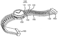
- 3A to 3D are views for explaining an exemplary implementation of a flexible device according to an embodiment of the present invention.
- the flexible device 100 is implemented in the form of a smart watch that can be worn on the wrist of a wearable computer.
- the present invention is not limited to the above embodiments.
- FIG. 3A is a view for explaining the detailed configuration of the flexible device 100
- FIG. 3B is an enlarged view showing a part of a circle represented by a two-dot chain line in FIG. 3A.
- a through hole 121 may be formed in each of the moving members 120, and a through hole 121 of each moving member 120 may be penetrated by the wire 110.
- FIG. Accordingly, each of the movable members 120 may be present in a line on the wire 110.
- the diameter of the through hole 121 may be set to be larger than the diameter of the wire 110, assuming that both the wire 110 and the through hole 121 are formed in a cylindrical shape. In this case, each moving member 120 can move freely on the wire 110 along the longitudinal direction of the wire 110, but can not move beyond the adjacent moving member 120.
- the stopper 130 provided at one end 111 of the wire 110 is fixed to one end 111 of the wire 110 so that the moving member 120 passes through one end 111 of the wire 110, (110).
- the stopper 130 may have a size that can not pass through the through hole 121 of the movable member 120.
- the blocking member 140 can prevent the moving member 120 from being detached from the wire 110 through the other end 112 of the wire 110.
- the stopper 130 and the blocking member 140 may perform similar functions at one end 111 and the other end 112 of the wire 110, respectively.
- the stopper 130 and the blocking member 140 may be structurally different from each other in terms of their function.
- the blocking member 140 is not attached to the other end 112 of the wire 110, unlike the stopper 130 Lt; / RTI >
- the barrier member 140 may be formed with a passage 141 through which the other end 112 of the wire 110 can freely pass.
- the passage 141 may be formed to a size such that the wire 110 can pass but not the moving member 120 so that the blocking member 140 moves the moving member 120 away from the wire 110 .
- the blocking member 140 may be formed in a polyhedral shape fixed to a predetermined position of the main body 150, but is not limited thereto.
- the blocking member 140 may be fixed to the main body 150 of the flexible device 100 to be described later.
- the passage 141 may be formed at a predetermined position of the blocking member 140 in the form of a through hole. When the blocking member 140 is formed in a polyhedral shape, the entrance of the passage 141 is connected to one of two mutually facing surfaces of the surface of the blocking member 140, Respectively.
- a position adjusting member 113 may be provided at the other end 112 of the wire 110.
- the position adjusting member 113 can prevent the other end 112 of the wire 110 from moving across the passage 141 of the blocking member 140. [ Accordingly, the wire 110 can be prevented from separating from the blocking member 140.
- the position adjusting member 113 can be coupled to the operating member 153. [ The user of the flexible device 100 moves the position adjusting member 113 by operating the operating member 153 so that the other end 112 of the wire 110 is moved away from the blocking member 140 110). More specific details of the operating member 153 and the position adjusting member 113 will be described with reference to FIGS. 5A to 5C, which will be described later.
- the operating member 153 can be formed in a circular ring shape so as to be easily mounted on the main body 150 of the flexible device 100.
- the shape of the operating member 153 shown in Fig. 3A is merely an example, it is also possible to implement the operating member 153 with a ring of a polygonal shape rather than a circular shape. Furthermore, it is also possible to implement the operating member 153 in a form other than the ring shape, which is suitable for moving the position adjusting member 113.
- the flexible device 100 may further include a main body 150, a fixing member 163, and a lower body 162. Assuming that the flexible device 100 is implemented in the form of a smart watch as described above, the main body 150 may be a part of the user's wrist which is in contact with the back of the user, .
- the lower body 162 may be formed of a flexible material such as leather so as to have an elongated shape.
- the main body 150 may be coupled to one end of the lower body 162 and the fixing member 163 may be coupled to the other end.
- the fixing member 163 is preferably formed of a hard material, but is not limited thereto. 3A, the lower body 162 and the fixing member 163 may be provided on both sides of the body 150, respectively.
- the blocking member 140 and the operating member 153 may be mounted on the main body 150 in a state where the main body 150, the fixing member 163 and the lower body 162 are coupled to each other as described above.
- a plurality of moving members 120 penetrating through the wire 110 and a stopper 130 coupled to one end 111 of the wire 110 may be placed on the lower body 162.
- a part of the wire 110 is allowed to pass through the passage 141 of the blocking member 140 so that the moving member 120 and the stopper 130 are disposed on one side with the passage 141 therebetween,
- the other end 112 of the wire 110 may be positioned.
- a structure composed of the wire 110, the movable member 120, and the stopper 130 (hereinafter referred to as " flexible frame " for convenience) One for each body 162.
- the blocking member 140 and the passageway 141 may also be provided, one for each flexible frame.
- the upper body 161 of the same material as the lower body 162 can cover the lower body 162 while the flexible frame is placed on the lower body 162 as described above.
- One end of the upper body 161 may be coupled to the main body 150 and the other end of the upper body 161 may be coupled to the fixing member 163, respectively. Accordingly, the upper body 161 and the lower body 162 may form a single body 160 having a space for mounting the flexible frame therein, as shown in FIG. 3C.
- the assembled flexible device 100 includes a main body 150, a flat display 151, a body 160 and a fixing member 163 provided on the front surface of the main body 150 And may be configured to be exposed to the outside. Accordingly, the wire 110, the moving member 120, the stopper 130, and the blocking member 140 are present inside the main body 150 or the body 160, and can not be seen from the outside.
- the operation member 153 may be provided so that all or a part of the operation member 153 can be exposed to the outside so that the user of the flexible device 100 can manually operate it. However, when the operation member 153 is automatically operated through a small motor (not shown) It may be arranged not to be exposed.
- the flexible device 100 of FIG. 3C can be worn on the wrist of a user by having a wristwatch or a smart watch shape, which is generally common.
- a flexible flexible display 170 is additionally attached to the surface of the body 160, more precisely the surface of the upper body 161, which is exposed to the outside when the user wears the flexible device 100 on the wrist .
- the flexible display 170 may be used for supplementing the flat display 151 provided in the main body 150. When the main body 150 is not provided with the flat display 151, . Exemplary operations that the flexible display 170 can perform in conjunction with other components of the flexible device 100 will be described later.
- the flexible display 170 can be implemented in a variety of ways from a functional or structural perspective.
- the flexible display 170 may include a touch input function.
- the flexible display 170 may be embodied as a flexible touch film on which a specific menu is printed.
- the implementation of the flexible device 100 not including the body 160 of FIG. 3C is also possible as shown in FIG. 3D.
- components such as the wire 110 and the movable member 120 may be exposed to the outside.
- the stopper 130 may be integrated with the fixing member 163 according to FIG. 3D.
- the movable member 120 may have a structure capable of supporting the flexible display 170 as shown in FIG. 3D.
- the flexible display 170 of FIGS. 3A and 3C is mounted on the flexible body 160, so that it can be bent together with the body 160 basically. However, depending on the actions of the wire 110, the moving member 120, the stopper 130, and the blocking member 140 included in the flexible device 100, the warping of the flexible display 170 may be suppressed.
- the principle of controlling the possibility of warping is described in detail with reference to FIGS. 2A and 2B, but will be described in detail with reference to FIGS. 4A and 4B.
- FIGS. 4A and 4B are diagrams for explaining the bending possibility control of a flexible device according to an embodiment of the present invention.
- the distance between the stopper 130 and the blocking member 140 is longer than the sum of the lengths of the through holes 121 of each of the moving members 120.
- the body 110 can be bent by the space and the body 160 for mounting the wire 110 therein and the flexible display 170 mounted on the surface of the body 160 are also flexible, And can be bent in a direction deviating from the longitudinal direction of the body (160).
- the wire 110 may be formed so that the length of the passage 141 formed in the blocking member 140 is added to the sum of the lengths of the through holes 121 of each of the moving members 120 It is required to have a long length.
- each of the movable members 120 can be formed in close contact with the adjacent movable member 120 to form the integrated support body 122.
- one end of the supporting body 122 is held in the stopper 130 and the other end is kept in tight contact with the blocking member 140, 130 and the blocking member 140 can not be bent while maintaining a linear shape. Accordingly, the body 160 and the flexible display 170 can be maintained in a non-warped state.
- the curvature of the flexible display 170 can be adjusted by a simple method of adjusting the distance between the stopper 130 and the blocking member 140 by pulling or loosening the wire 110.
- the system also has advantages of simple structure and easy implementation.
- 5A to 5C are views for explaining a structure for performing a function of pulling or loosening a wire in a flexible device according to an embodiment of the present invention.
- the position regulating member 113 can be fixedly coupled to the other end 112 of the wire 110. As shown in FIG. Accordingly, it is possible to pull the wire 110 in the direction of the main body 150 by pulling the position adjusting member 113 away from the blocking member 140.
- the position regulating member 113 may have a size that can not pass through the passage 141 of the blocking member 140. This prevents the movable member 120 from moving toward the other end 112 of the wire 110 by preventing the other end 112 of the wire 110 from moving to the space inside the body 160 through the passage 141 It is possible to prevent the wire 110 from being deviated.
- the position regulating member 113 can move along a predetermined second path 142 starting from the passage 141 of the blocking member 140.
- the second path 142 is preferably provided in the main body 150. 5A, the movement of the position adjusting member 113 may be guided by a guide 152 provided in the main body 150 and having an arc shape. In this case, the second path 142 may be a path in contact with the outer wall of the guide 152.
- the flexible device 100 may further include an operation member 153 for moving the position adjusting member 113 on the second path 142.
- the operating member 153 may be formed in a circular ring shape so that the position adjusting member 113 can move in the second path 142 having an arc shape along the shape of the guide 152.
- the position adjusting member 113 since the position adjusting member 113 can be attached to the operating member 153, by the rotational movement of the operating member 153 placed on the second path 142, the position adjusting member 113 may also be moved on the second path 142.
- All or a part of the operating member 153 may be exposed to the outside of the main body 150.
- the user of the flexible device 100 can control the pulling degree of the wire 110 by rotating the operating member 153 by using the portion exposed to the outside of the operating member 153, Can be controlled.
- the flexible device 100 may further include a latch 154.
- the pawl 154 is fixed to the position adjusting member 113 at a position on the second path 142 where the other end 112 of the wire 110 is placed with the wire 110 pulled up to the main body 150 .
- the latch 154 is located at a predetermined position on the second path 142.
- the latch 154 prevents the position adjustment member 113 from passing over the latch 154 through movement in the direction of approaching the passage 141 of the blocking member 140 on the second path 142,
- the control member 113 can perform the function of passing the passage through the latch 154 through the movement in the direction away from the passage 141 on the second passage 142.
- the position adjusting member 113 can not pass through the latch 154 through the movement in the direction of arrow (1) in FIG. 5B, but can pass the latch 154 through the movement in the direction of (2).
- first surface that abuts on the position adjusting member 113 that moves in the direction of the first direction in the surface of the polygonal-shaped latch 154 for performing the above- And may be formed to be perpendicular to the moving direction of the position adjusting member 113 at the moment when the position adjusting member 113 abuts.
- second surface the surface that comes into contact with the position adjusting member 113 that moves in the direction 2 & (Not shown) so as not to be perpendicular to the moving direction of the position adjusting member 113 of FIG.
- the inclination of the second surface may be formed so that the distance between the first surface and the second surface becomes closer as the distance from the center of the main body 150 increases.
- the guide 152 near the position where the latch 154 is installed as described above can be formed with the latch passageway 155 having a size such that the latch 154 can pass therethrough.
- the latch 154 may be positioned over the latch passage 155.
- the position adjusting member 113 moving in the (2) direction reaches the position where the latch 154 exists, the position adjusting member 113 pushes the latch 154 by the inclination formed on the second face, Direction.
- the latch 154 is pushed toward the center of the main body 150 through the latch passage 155 and the position adjusting member 113 can pass through the position where the latch 154 is present.
- the position adjusting member 113 moving in the direction of arrow 1 reaches the position where the latch 154 exists
- the first surface is perpendicular to the moving direction of the position adjusting member 113, unlike the second surface, 154 are not pushed toward the center of the main body 150 and are not pushed in the direction of movement of the position adjusting member 113 due to the guide 152.
- the position adjusting member 113 can not pass through the position where the latch 154 exists.
- the flexible device 100 may further include a push button 156 and an elastic body 157 for operation of the latch 154.
- One end of the push button 156 may contact the latch 154 within a range that does not disturb the movement of the position adjusting member 113 and the other end may be exposed to the outside of the main body 150 to the user of the flexible device 100 Lt; / RTI > Accordingly, the outer wall of the main body 150 may be provided with a hole for allowing the push button 156 to pass therethrough.
- One end of the elastic body 157 may be connected to the one end of the push button 156 and the other end may be connected to the outer wall of the main body 150, respectively.
- the elastic body 157 may be provided in the form of a spring that winds the portion of the push button 156 exposed outside the main body 150. Even if the push button 156 is pushed by the user in the direction of the center of the main body 150, the resilient force of the elastic body 157 releases the push button 156, together with the pawl 154, Will return to its original position before pressing.
- FIG. 5C a description will be given of a method of allowing or suppressing flexing of the flexible display 170 using the operating member 153 and the push button 156.
- FIG. 5C The flexible device 100 in FIG. 5C is in a state in which the flexible display 170 can be bent because the wire 110 is not sufficiently pulled in the direction of the main body 150.
- the operating member 153 may be operated so that the position adjusting member 113 passes the position where the latch 154 is mounted as shown in FIG. 5C.
- the latch 154 which has been pushed toward the center of the main body 150, can return to its original position by the restoring force of the elastic body 157.
- the returning latch 154 may block the position adjusting member 113 from moving the position where the latch 154 is present in the direction of arrow No. 1 in FIG. 5B.
- the wire 110 can be pulled up to the main body 150 as much as possible.
- the flexible display 170 can be naturally maintained in a state where it can not be bent.
- the user presses the push button 156 as shown in (C) of Figure 5C to move the pawl 154 in the direction of the center of the main body 150 .
- the position adjusting member 113 which has been blocked by movement of the latch 154 in the direction of the arrow 1, moves toward the blocking member 140 through the position where the latch 154 is located as shown in (D) Lt; / RTI >
- a space is created between the plurality of moving members 120 penetrated by the wire 110, resulting in a state in which the flexible display 170 can be bent.
- the push button 156 can return to the original position by the restoring force of the elastic body 157 as shown in (E) of FIG.
- FIGS. 6A and 6B are views for explaining an embodiment for restoring a flexible device according to an embodiment of the present invention from a straightened state to a restored state.
- the position adjusting member 113 is fixed by using the latch 154 , It is possible to prevent the flexible display 170 from being bent.
- the push button 156 is pushed to release the pawl 154 from the second path 142, The position adjusting member 113 can be moved toward the passage 141 of the blocking member 140 by using the operating member 153.
- the act of operating the operating member 153 may also be troublesome to the user. Even if the position adjusting member 113 is moved until the position adjusting member 113 is in close contact with the blocking member 140, the wire 110 does not necessarily return to the state before the wire 110 is pulled. This is because the pushing force of the wire 110 at the other end 112 of the wire 110 may not be transmitted to the end 111 of the wire 110 due to the flexibility of the wire 110.
- an elastic member 164 one end of which is connected to the fixing member 163 of the body 160 and the other end of which is connected to the stopper 130, (160). ≪ / RTI > The body 160 and the flexible device 170 can freely bend when an elastic force is not applied to the elastic member 164 as shown in FIG. 6A and the elastic member 164 has the original length.
- the stopper 130 When the wire 110 is pulled toward the main body 150, the distance between the stopper 130 and the fixing member 163 increases. Accordingly, the length of the elastic member 164 also increases, and the stopper 130 receives a force toward the fixing member 163 due to the restoring force of the elastic member 164.
- the stopper 130 does not actually move toward the fixing member 163.
- the pawl 154 can no longer restrict the movement of the position adjustment member 113. Accordingly, the stopper 130, which can not move due to the fixing of the position adjusting member 113, is also automatically moved toward the fixing member 163 by the restoring force of the elastic member 164. As a result, the flexible device 100 And returns to the state shown in FIG. 6A again.
- the flexible device 100 can be bent only by pushing the push button 156 in a state where the wire 110 is pulled to the maximum It can be conveniently returned to its original state.
- 7A to 7D are views for explaining an embodiment for preventing distortion of a flexible device according to an embodiment of the present invention.
- the support member 122 in which the moving members 120 are closely contacted, axis, a warpage may occur in the support 122 as shown in FIG. 7A.
- Such a warpage of the support member 122 may cause a distortion of the flexible display member 170, so a measure for preventing the support member 122 from being warped may be required.
- a method of adding irregularities to each moving member 120 can be considered.
- one of the convex shapes of the adjacent two moving members 120 can be coupled to the other concave shape.
- the blocking member 140 may also have a recessed shape so that the recessed shape of the blocking member 140 is mutually coupled with the iron shape of the moving member 120 adjacent to the blocking member 140.
- the stopper 130 is also provided with a recess or an iron so as to engage with the moving member 120 adjacent to the stopper 130.
- the movable member 120, the stopper 130, and the blocking member 140 are engaged with each other by the concavo-convex shape, so that the distortion of the flexible display 170 can be prevented as a result .
- a flexible second wire 114 is additionally connected to the stopper 130.
- the blocking member 140 may additionally have a second passageway 144 through which the second wire 114 passes.
- the plurality of second moving members 124 having the through holes 125 whose diameters are such that the stopper 130 can not pass through the through holes 125 are passed through the second wires 114, (130) and the blocking member (140).
- Each of the plurality of second moving members 124 can freely move along the second wire 114.
- the second wire 114 and the second moving member 124 may be made of the same material and shape as the wire 110 and the moving member 120, respectively.
- the second moving member 124 passes through the one end 115 of the second wire 114 because the stopper 130 has a size that can not pass through the through hole 125 of the second moving member 124 It is impossible to deviate from the second wire 114. Since the second moving member 124 has such a size that it can not pass through the second passage 144, the second moving member 124 passes through the other end (not shown) of the second wire 114, It is also impossible to deviate from the two wire 114.
- the user can maintain the pulled state of the wire 110 and the second wire 114 in the direction of the main body 150 as much as possible.
- the plurality of movable members 120 form the integrated support 122, and at the same time, a plurality of the second movable members 124 can be integrally formed with the support (not shown).
- two elongated supports of the same shape are formed, they can be more resistant to twisting than when only one support is provided.
- one of the moving members 120 may be formed in a shape different from that of the other moving member 120, as shown in FIG. 7D (A).
- One moving member 120 having such a different shape is referred to as an intermediate member 127 for the sake of convenience.
- the through hole 128 of the intermediate member 127 may be formed in a semicircular shape so that both ends of the through hole 128 are opposed to the blocking member 140 or the main body 150 .
- the outer shape of the intermediate member 127 itself may also be made to have a semicircular shape as shown in FIG. 7D.
- the stopper 130 attached to the blocking member 140 or the main body 150 and the stopper 130 attached to the main body 150 and the intermediate member 160 that changes the extension direction of the wire 110 can be formed by pulling the wire 110 as much as possible in the direction of the main body 150,
- the effect that the two support members 122 are attached to one blocking member 140 as shown in Fig. 7 (B) can be achieved. That is, an effect similar to that of the embodiment of FIG. 7C can be obtained through the embodiment of FIG. 7D.
- the distance between the passage 141 of the shut-off member 140 and the intermediate member 127 is set to be shorter than the distance between the stopper 140 and the intermediate member 127 in a state in which the wire 110 is pulled toward the main body 150 as much as possible, It is required to arrange the shifting member 120 so as to be equal to the distance between the intermediate member 130 and the intermediate member 127.
- FIG. 8A to 8D are views for explaining an embodiment for preventing an excessive bending of a flexible device according to an embodiment of the present invention.
- the moving member 120 can be pulled toward the stopper 130 as shown in FIG. 8A.
- a portion of the wire 110 that is not occupied by the movable member 120 may be sharply folded, which may cause the flexible display 170 to be folded to cause damage to the flexible display 170 Can result.
- a method of adjusting the distance between the moving members 120 moving on the wire 110 may be proposed.
- each moving member 120 is connected to the adjacent moving member 120 through the connecting member 129.
- a connecting member 129 is made of a material which is bent without resistance by a pressing force (compression force) in the longitudinal direction at both ends but does not extend by a force (tensile force) pulling in the longitudinal direction, It can be made of a non-stretched material. Accordingly, the gap between two adjacent moving members 120 can not exceed a predetermined critical gap defined by the length of the coupling member 129 as shown in FIG. 8 (A). On the other hand, as shown in FIG. 8B (B), the gap between the two moving members 120 adjacent to each other due to the flexibility of the connecting member 129 can be made narrower than the critical gap.
- FIG. 8B shows that two connecting members 129 can be used to connect the two adjacent moving members 120.
- the present invention is not limited thereto, so that three or more connecting members 129 may be used It is possible.
- the movable member 120 adjacent to the stopper 130 may be connected to the stopper 130 through the connecting member 129 and the movable member 120 adjacent to the blocking member 140 may be blocked And may be connected to the member 140 through the connecting member 129 as well.
- the degree of bending of the wire 110 may be limited to a certain level by the action of the connecting member 129, as shown in FIG. 8C.
- the flexible display 170 can be prevented from being excessively bent, thereby preventing the flexible display 170 from being damaged.
- FIG. 8C shows another embodiment for preventing excessive flexing of the flexible display 170.
- the connecting member 129 is not necessarily made of a flexible material, but can also be made of a hard material.
- a groove 123 is formed on a side surface of each moving member 120, and a connecting member 129 is inserted into the groove 123.
- the connecting member 129 inserted into the groove 123 formed in one of the two moving members 120 adjacent to each other is attached to the remaining one moving member 120, or the remaining one And can also be inserted into the groove 123 formed in the movable member 120.
- the interval between two adjacent moving members 120 can be adjusted to a predetermined critical interval or less.
- connection member 129 may be formed in a dumbbell-like structure surrounding the wire 110 as shown in FIG. 8C.
- the connecting member 129 can move along the wire 110 while being penetrated by the wire 110.
- the diameter of the central portion of the connecting member 129 may be smaller than the diameter of the inlet of the through hole 121 of the moving member 120.
- the diameter of the both ends of the connecting member 129 may be smaller than the diameter of the through hole 121 of the moving member 120, May be formed larger than the diameter of the inlet of the heat exchanger (121).
- a space enough to accommodate both ends of the connecting member 129 may be formed in the moving member 120.
- the inlet of the through hole 121 facing each other of the two adjacent shifting members 120 can be made to pass by the center portion of one connecting member 129 under the condition as described above.
- One end of each of the opposite ends of the connecting member 129 may be positioned inside one moving member 120 of the adjacent two moving members 120 and the other end may be positioned inside the other moving member 120, respectively.
- the distance between the adjacent two movable members 120 is not limited, but the maximum extendable range can be limited so as not to be greater than the distance between the opposite ends of the connecting member 129.
- a curvature control unit 180 extending in the direction of the stopper 130 may be attached to the blocking member 140 in parallel with the wire 110.
- the curvature adjusting unit 180 may include a plurality of unit members 181 coupled to each other in a row.
- each of the unit members 181 may have a polyhedral shape, and the curvature adjusting unit 180 may be formed in a straight shape so that the two unit members 181
- the shape of the unit member 181 can be adjusted so that the angle? Formed by the plane is less than or equal to a predetermined threshold angle.
- the degree of bending of the curvature adjusting unit 180 can be adjusted to a certain level or less. That is, the curvature of the arc formed by connecting the centers of the unit members 181 can be adjusted so as not to exceed the predetermined critical curvature.
- the curvature adjuster 180 may be mounted inside the body 160 to extend in the longitudinal direction of the body 160 and extend at least from the edge of the flexible display 170 to the farthest corner from the blocking member 140 . According to the operation of the curvature adjuster 180 as described above, the body 160 also does not bend beyond the critical curvature, and damage due to breakage of the flexible display 170 can be prevented.
- FIGS. 9A to 9D are diagrams for explaining an embodiment for achieving the anti-curl effect in the entire area of the flexible device according to the embodiment of the present invention. 8A to 8D that the flexible device 100 may be excessively bent when the wire 110 is not pulled in the direction of the main body 150.
- FIG. 9A since there is a space between the stopper 130 and the fixing member 163 even when the wire 110 is pulled to the maximum extent in the direction of the main body 150, The portion surrounding the space may be bent or folded.
- a curvature-preventing portion 190 made of a hard material is embedded in the body 160 and can be mounted between the stopper 130 and the fixing member 163.
- a structure of the curvature-preventing portion 190 a structure called “ bellows " may be employed in everyday life, but the present invention is not limited thereto.
- the curvature-preventing portion 190 may be constituted by a plurality of bar-shaped frames 191 coupled to each other in a row.
- Two adjacent frames 191 of the frame 191 may be coupled to each other by a joint 192. More specifically, two adjacent frames 191 may be positioned such that a portion of the end portions of the two adjacent frames 191 overlap each other, and the joint 192 may penetrate both of the adjacent two frames 191 in the overlapping region.
- the two frames 191 coupled through the joint 192 can perform rotational motion about the joint 192.
- One end of the anti-curling portion 190 configured as described above may be attached to the fixing member 163 and the other end thereof may be attached to the stopper 130, respectively.
- 9B a total of two curvature preventing portions 190 are shown between the stopper 130 and the fixing member 163, but the present invention is not limited thereto, and therefore, one or more curvature preventing portions 190 may exist.
- FIG. 9A shows the curvature-preventing portion 190 when the wire 110 is not pulled in the direction of the main body 150.
- FIG. 9B shows the folded curled elastic member 190 which is folded is also extended and extended .
- the curvature preventing portion 190 may be formed of a material that surrounds the space between the stopper 130 and the fixing member 163 in the body 160 It is possible to prevent warping or breaking.
- 9C shows another embodiment of the curvature-preventing portion 190.
- the curvature-preventing portion 190 can be anything as long as the distance from one end to the other end can be freely adjusted by an external force. It is also possible that the elastic member 164 described with reference to FIGS. 6A and 6B is mounted between the stopper 130 and the fixing member 163 together with the anti-curling portion 190.
- the non-moving member 193 of Fig. 9D can be considered in addition to the curvature-preventing portion 190.
- the non-moving member 193 may be fixed at a predetermined position in the body 160, and it is preferable that the non-moving member 193 is attached to the fixing member 163 in order to maximize the anti-warping effect.
- the non-moving member 193 may have a through hole 194 penetrated by the wire 110.
- the wire 110 can freely move within the through hole 194, but the moving member 120 can not pass through the through hole 194 due to its size.
- the through hole 194 of the non-moving member 193 may be formed in a semicircular shape. More specifically, both ends of the through hole 194 may be formed to face the blocking member 140 or the main body 150. Therefore, the outer shape of the non-moving member 193 itself can also be made to have a semicircular shape as shown in FIG. 9D.
- a portion of the wire 110 in the body 160 can be divided into two parts with the non-moving member 193 as a boundary.
- the portion between the blocking member 140 and the non-moving member 193 may be referred to as a first portion
- the portion between the non-moving member 193 and the stopper 130 may be referred to as a second portion.
- the movable member 120 may be divided into a first portion and a second portion as shown in Fig. 9D.
- a second stopper 131 separate from the stopper 130 that functions to restrict the movement of the moving member 120 similarly to the stopper 130 is provided on the first portion of the wire 110, And can be fixedly installed at a predetermined position.
- the second stopper 131 may have such a size that it can not pass through the through hole 121 of the moving member 120 and the through hole 194 of the non-moving member 193.
- 9A shows a state in which the wire 110 is not pulled in the direction of the main body 150 in the present embodiment using the non-moving member 193 and the second stopper 131. [ 9A, the wire 110 extending in the direction away from the blocking member 140 passes through the through hole 194 of the non-moving member 193, And reaches the stopper 130 as shown in FIG.
- each moving member 120 in the first part is moved in the direction 2 stopper 131, and each of the moving members 120 of the second portion will be in close contact with the stopper 130 and the non-moving member 193.
- a total of two supports 122 can be produced in parallel, one for each of the first and second portions.
- the lengths of the first portion and the second portion when the wire 110 is pulled in the direction of the main body 150 to the maximum are adjusted appropriately so that the support body 122 can be simultaneously produced in the first portion and the second portion
- the number of the movable members 120 present in each part also needs to be appropriately adjusted.
- FIGS. 10A and 10B are views for explaining another embodiment of a flexible device according to an embodiment of the present invention.
- the support body 122 made of the movable member 120 is formed by pulling the wire 110 in the direction of the main body 150.
- 10A by moving the blocking member 140 in the direction of the stopper 130 without pulling the wire 110, the plurality of moving members 120 are brought into close contact with each other to form the supporting body 122 .
- the flexible display 100 shown in FIG. 10A can basically have the same structure as the flexible display 100 described with reference to FIGS. 3A to 4B. However, when the stopper 130 is located at a predetermined position in the body 160 And the blocking member 140 can be moved or extended from the main body 150 toward the stopper 130. As shown in Fig. Specifically, without the movement of the wire 110, the blocking member 140 can be moved or extended by the operating member 153.
- the stopper 130 may be fixed to the fixing member 163 or may be fixed to the fixing member 163 It may be preferable to be integrally formed.
- FIG. 10B is a view showing a flexible device 100 further including a wire 110 and a rail member 165 surrounding the moving member 120.
- the rail member 165 may be made of a flexible material so as not to interfere with the warping of the wire 110 and the body 160, And can be mounted at a predetermined position.
- the movement of the moving member 120 or the blocking member 140 can be guided by the rail member 165 so that the wire 110 and the moving member 120 move in the direction of extension of the wire 110 It is possible to prevent it from oscillating in a vertical direction.
- a rail member 165 can be applied to the flexible device 100 shown in FIG. 10A as well as the flexible device 100 described with reference to the other drawings.
- the stopper 130 may be guided by the rail member 165, like the moving member 120.
- a space other than the minimum space in which the movable member 120 and the blocking member 140 can move in the space in the body 160 may be the same or similar to the body 160 It is also possible to fill with material.
- an elongated groove may be formed in the inner wall of the body 160, and the moving member 120 and the blocking member 140 may be moved within a range not deviating from the groove.
- FIGS. 11A and 11B are views for explaining an embodiment in which a wire is not used among the flexible devices according to an embodiment of the present invention.
- the flexible device 200 shown in FIGS. 11A and 11B may include a flexible member 210, a movable member 220, a stopper 230, and a blocking member 240.
- the flexible member 210 may have a tube shape having a space 213 therein, and may be freely bent in a direction opposite to the longitudinal direction due to flexibility.
- the flexible member 210 is formed in the shape of a cylinder having a circular cross section, but it is not necessarily limited to this.
- the shape of the inner space 213 of the flexible member 210 and the shape seen from the outside may be different from each other. For example, even if the internal space 213 of the flexible member 210 is cylindrical, the external shape may be a rectangular parallelepiped.
- a plurality of moving members 220 may be positioned in the inner space 213 of the flexible member 210.
- the plurality of moving members 220 may be arranged in a row in the inner space 213 and may move the inner space 213 in the longitudinal direction of the flexible member 210. That is, the inner space 213 may be a path through which the moving member 220 can move.
- the cross section of the movable member 220 can be made to have the same size and shape as the cross section of the internal space 213 of the flexible member 210. In this case, due to the pressure of the air between the adjacent movable members 220, The movement of the member 220 may not be smooth. In order to solve such a problem, each of the moving members 220 may be provided with a through hole 221.
- the through hole 221 is formed in parallel with the moving path of the moving member 220 moving in the inner space 213, so that the air in the inner space 213 can be smoothly flowed.
- the stopper 230 may be provided at one end 211 of the flexible member 210 to prevent the moving member 220 from separating from the inner space 213 of the flexible member 210.
- the stopper 230 formed of a hard material may be attached to one end 211 of the flexible member 210. 11A, the inner space 213 of the flexible member 210 can be prevented from being exposed to the outside through one end 211 of the flexible member 210.
- the blocking member 240 may be provided at the other end 212 of the flexible member 210 and may move or extend toward the inner space 213 of the flexible member 210 or toward the stopper 230. By moving or stretching the blocking member 240, the adjacent moving members 220 of the plurality of moving members 220 can be brought into close contact with each other.
- the plurality of movable members 220 may form a single support 222 and the support 222 may be in close contact with the stopper 230 and the blocking member 240.
- the movable member 220 and the blocking member 240 can be formed of a hard material so that when the supporting member 222 is in close contact with the stopper 230 and the blocking member 240, Can be suppressed. When the blocking member 240 moves away from the stopper 230 and returns to the original position, the flexible member 210 can be bent again.
- the flexible member 210 itself can serve as the body 160 of the flexible display 100 of Figs. 3A-B. Therefore, a flexible display (not shown) may be attached to the surface 214 of the flexible member 210 exposed to the outside.
- the flexible device 200 of FIG. 11A may have a simpler structure than the flexible display 100 of FIGS. 3A through 10B in which the wire 110 and the body 160 exist as separate components.
- the surface 214 of the flexible member 210 may be formed to have a flat shape instead of a curved surface.
- the flexible device 200 of FIG. 11B is in a state in which the adjacent moving members 220 are not in close contact with each other and the flexible member 210 can be bent. In this state, by pulling the flexible member 210, a plurality of movable members 220 can be formed to form one support 222, and as a result, warpage of the flexible member 210 can be suppressed.
- the flexible device 200 according to the embodiment of FIG. 11B is a subject of movement because the flexible member 210, which is relatively easy to manufacture with a relatively large volume as compared with the blocking member 240, Can be advantageous.
- FIGS. 12A to 12C are diagrams for explaining a state transition of a flexible device according to an embodiment of the present invention.
- the flexible device 100 of Figs. 12A to 12C is basically assumed to have the same configuration as that of the flexible device 100 shown in Figs. 3A to 3C.
- the flexible display 170 included in the flexible device 100 of FIGS. 12A to 12C is a flexible display device in which the movable member 120 is integrally formed with the support body 122 and is in close contact with the stopper 130 and the blocking member 140, It is possible to operate differently depending on whether bending of the body 170 is suppressed (or whether bending of the body 160 is suppressed when the flexible display 170 is not mounted on the body 160).
- the flexible display 170 can be operated to be in an ON state only in a state in which warpage is suppressed and in an OFF state in a state in which warpage is not suppressed.
- the type of the function that is activated only when the flexure of the flexible display 170 or the body 160 is suppressed is not limited to the on / off control of the flexible display 170.
- the function to be activated only in a state in which the warp is suppressed may be related to a component other than the flexible display 170 (for example, a display state change of the flat display 151) among the flexible devices 100.
- the flexible device 100 may further include a sensor unit (not shown) for detecting whether or not the flexure of the flexible display 170 is suppressed.
- a sensor unit for detecting whether or not the flexure of the flexible display 170 is suppressed. For example, when the wire 110 is pulled out in the direction of the main body 150, the position adjusting member 113 is positioned at a predetermined position where the position adjusting member 113 is positioned, It is possible to detect whether or not it exists. If the position adjusting member 113 exists at the predetermined position, the sensor unit can determine that the warping of the flexible display 170 is suppressed, and if it does not exist, it can be determined that the warping is not suppressed.
- the flexible device 100 may further include a control unit (not shown) implemented by a computing device such as a microprocessor.
- the control unit may generate a command for driving the flexible display 170 based on the sensing signal generated by the sensor unit and may further generate a command for controlling the flat display 151 Command can also be generated.
- the flexible display 170 can be operated differently depending on whether or not it is curled.
- the specific configuration and operation principle of the sensor unit and the control unit are obvious to those of ordinary skill in the art and will not be described in detail here.
- the flexible display 170 can operate in conjunction with the flat display 151 provided in the main body 150. 12A, in which flexing of the flexible display 170 is not restrained, the flexible display 170 may be in the OFF state so that all the functions or information for the user are displayed on the flat display 151. [ Lt; / RTI > However, in the state where the flexible display 170 is prevented from being warped as shown in FIG. 12A, the flexible display 170 is turned on, so that some of the functions or information provided through the flat display 151 And can be provided through the flexible display 170.
- FIG. 12B is a view for explaining another example of utilization of the flexible display 170.
- FIG. 12B shows a situation in which a text message arrives in a state in which the warpage of the flexible display 170 is not suppressed.
- the flat display 151 may output a notification message to notify that the text message has arrived.
- the flat display 151 displays the contents of the text message A display window may be output.
- the flexible display 170 may be provided with a touch input unit for generating a response message to the text message.
- the condition of suppressing warping of the flexible display 170 when the condition of suppressing warping of the flexible display 170 is satisfied, it is possible to set a predetermined function such as the ON state change of the flexible display 170 or the touch input unit output to be automatically activated.
- the user of the flexible device 100 can use the flexible device 100 more conveniently since the operation for restricting the bending of the flexible display 170 is not required for the activation.
- FIG. 12C is a diagram for explaining another embodiment related to the use of the smart watch type flexible device 100.
- a smart watch type flexible device 100 that can be worn on a user's wrist can have a function as a telephone, particularly as a portable wireless communication terminal capable of wireless communication.
- a screen informing that the phone has arrived at the flat display 151 may be output.
- the user can suppress the bending of the body 160 by rotating the operation member 153, so that the flexible device 100 can be in the same state as the hard device which can not be bent.
- the flexing of the body 160 of the flexible device 100 is suppressed and at the same time the flexible device 100 can initiate the call based on the incoming signal so that the user can make a call with the party have. That is, the user can obtain both of the results of the deformation of the flexible device 100 and the call initiation through one operation of rotation of the operating member 153.
- the main body 150 of the flexible device 100 is provided with a sound output unit 171 such as a speaker and an audio input unit such as a microphone 172 can be mounted. That is, the voice output unit 171 and the voice input unit 172 are spatially separated, so that the voice output unit 171 and the voice input unit 172 can be brought close to the user's ear and mouth, respectively. Accordingly, it is possible for the user to use the flexible device 100 whose warp is suppressed, as a general mobile phone.
- the sound output unit 171 is mounted on the body 160 and the sound input unit 172 is mounted on the main body 150, respectively. It is also possible that both the audio output unit 171 and the audio input unit 172 are mounted on either the main body 150 or the body 160 if the above spatial separation can be achieved.
- the position of the voice output unit 171 and the voice input unit 172 can be determined such that the flexible device 100 is separated from the flexible device 100 by a predetermined distance in a state in which the flexure of the flexible device 100 is suppressed.
- the operation of turning the operation member 153 that is, the operation of suppressing the flexing of the flexible device 100 and the operation of receiving the telephone can be unified, the kind of operation to be integrated with the anti- ≪ / RTI >
- the flexible device 100 when the user depresses the flexing of the flexible device 100 by turning the operating member 153, the flexible device 100 is simultaneously mounted on the body 160 A text input window for sending a reply to a text message can be output to the flexible display 170.
- functions such as the start of a call or the output of a character input window described with reference to Fig. 12C can be made to occur only in a state where the warping of the flexible device 100 is suppressed through the rotation of the operating member 153.
- the body 160 is straightened. This is similar to the situation where the flexing of the flexible device 100 is apparently suppressed. However, The body 160 may be bent, so that the function may not be expressed. With this feature, a malfunction of the flexible device 100 which is not intended by the user can be prevented.
- FIGS. 13A and 13B are views for explaining another embodiment of a flexible device according to an embodiment of the present invention.
- the flexible device 100 according to an exemplary embodiment of the present invention is not necessarily implemented as a smart watch, but may be implemented as a wearable phone as shown in FIGS. 13A and 13B.
- the wire 110, the movable member 120, the stopper 130, and the shielding member 140 can be mounted in the flexible body 160.
- An operation member 153 may be provided on a side surface of the body 160 and the wire 110 may be pulled or pulled by moving the operation member 153.
- the flexible device 170 may be attached to the surface of the body 160 as shown in FIG.
- the upper portion 166 of the body 160 of the flexible device 100 may be in a state in which warpage is always suppressed by a separate rigid member (not shown) provided inside the body 160.
- the lower portion 167 of the body 160 can be adjusted in its bendability by the action of the wire 110, the moving member 120, the stopper 130 and the blocking member 140 mounted therein have.
- the flexible display 170 can operate as a single display with the entire area turned on. With this function, the convenience of the flexible device 100 can be further improved.
- the flexible display 170 can be warped, it is not limited to whether the flexible display 170 is turned on, and various functions may be activated or deactivated depending on whether the flexible display 170 is warped or not. For example, when a text message is received by the flexible device 100, only when the flexible display 170 is switched to a state in which the flexible display 170 can not be bent, a dialog window for responding to the text message received via the flexible device 100, Or the like can be output to the flexible display 170. [
Landscapes
- Engineering & Computer Science (AREA)
- Physics & Mathematics (AREA)
- Theoretical Computer Science (AREA)
- General Physics & Mathematics (AREA)
- General Engineering & Computer Science (AREA)
- Human Computer Interaction (AREA)
- Computer Hardware Design (AREA)
- Nonlinear Science (AREA)
- Signal Processing (AREA)
- Mathematical Physics (AREA)
- Chemical & Material Sciences (AREA)
- Crystallography & Structural Chemistry (AREA)
- Optics & Photonics (AREA)
- Telephone Set Structure (AREA)
- Devices For Indicating Variable Information By Combining Individual Elements (AREA)
Abstract
Selon un mode de réalisation, la présente invention concerne un dispositif flexible pouvant être fixé comprenant : un élément flexible présentant une flexibilité ; une pluralité d'éléments mobiles agencés, sur une ligne, sur un chemin allant d'une extrémité à l'autre de l'élément flexible dans une direction longitudinale de l'élément flexible, et mobile sur le chemin ; un élément d'arrêt disposé au niveau d'une première extrémité de l'élément flexible de façon à empêcher les éléments mobiles de s'échapper du chemin par la première extrémité ; et un élément de blocage pour empêcher les éléments mobiles de s'échapper du chemin par l'autre extrémité de l'élément flexible, la longueur d'une partie existant entre l'élément de blocage et l'élément d'arrêt sur le chemin pouvant être réglée de telle sorte que chacun des éléments mobiles entre en contact étroit avec l'élément mobile adjacent au chemin de façon à former un corps de support intégré.
Priority Applications (1)
| Application Number | Priority Date | Filing Date | Title |
|---|---|---|---|
| US16/117,229 US10579104B2 (en) | 2017-08-07 | 2018-08-30 | Rigidifiable flexible device |
Applications Claiming Priority (2)
| Application Number | Priority Date | Filing Date | Title |
|---|---|---|---|
| KR1020170099704A KR101866507B1 (ko) | 2017-08-07 | 2017-08-07 | 고정 가능한 플렉서블 디바이스 |
| KR10-2017-0099704 | 2017-08-07 |
Related Child Applications (1)
| Application Number | Title | Priority Date | Filing Date |
|---|---|---|---|
| US16/117,229 Continuation US10579104B2 (en) | 2017-08-07 | 2018-08-30 | Rigidifiable flexible device |
Publications (1)
| Publication Number | Publication Date |
|---|---|
| WO2019031675A1 true WO2019031675A1 (fr) | 2019-02-14 |
Family
ID=62622435
Family Applications (1)
| Application Number | Title | Priority Date | Filing Date |
|---|---|---|---|
| PCT/KR2018/003131 WO2019031675A1 (fr) | 2017-08-07 | 2018-03-16 | Dispositif flexible pouvant être fixé |
Country Status (3)
| Country | Link |
|---|---|
| US (1) | US10579104B2 (fr) |
| KR (1) | KR101866507B1 (fr) |
| WO (1) | WO2019031675A1 (fr) |
Families Citing this family (5)
| Publication number | Priority date | Publication date | Assignee | Title |
|---|---|---|---|---|
| KR20200089783A (ko) | 2019-01-17 | 2020-07-28 | 삼성디스플레이 주식회사 | 표시 장치 |
| CN110010006B (zh) * | 2019-04-24 | 2021-01-08 | 深圳市群宇科技有限公司 | 一种手腕柔性显示屏 |
| CN110164313B (zh) * | 2019-05-31 | 2022-07-26 | 武汉天马微电子有限公司 | 一种显示设备 |
| KR102556942B1 (ko) * | 2021-11-19 | 2023-07-17 | 김중영 | 플렉시블 디스플레이 모듈 하우징 |
| US11706881B2 (en) | 2021-11-25 | 2023-07-18 | Jung Young Kim | Flexible display module housing |
Citations (5)
| Publication number | Priority date | Publication date | Assignee | Title |
|---|---|---|---|---|
| JPH0661113U (ja) * | 1992-03-25 | 1994-08-30 | 久雄 熊井 | ボールチェーン |
| KR19990013434U (ko) * | 1997-09-26 | 1999-04-15 | 박중제 | 손목시계줄 |
| JP2006346086A (ja) * | 2005-06-15 | 2006-12-28 | Takao Ito | 腕時計用バンド |
| KR20160094053A (ko) * | 2015-01-30 | 2016-08-09 | 순천향대학교 산학협력단 | 액세서리형 와치 디바이스 |
| KR20160139733A (ko) * | 2015-05-28 | 2016-12-07 | 엘지전자 주식회사 | 이동 단말기 |
Family Cites Families (5)
| Publication number | Priority date | Publication date | Assignee | Title |
|---|---|---|---|---|
| US2508147A (en) * | 1945-10-08 | 1950-05-16 | Dutch Emery | Double-acting slide fastener |
| US20130001263A1 (en) * | 2011-06-30 | 2013-01-03 | Advance Watch Company, Ltd., D/B/A, Geneva Watch Group | Wearable case for a mobile device |
| US9125460B2 (en) * | 2013-08-12 | 2015-09-08 | Timex Group Usa, Inc. | Wristworn device with a releasable locking arrangement |
| KR20160139344A (ko) | 2015-05-27 | 2016-12-07 | 엘지전자 주식회사 | 스마트 워치 |
| KR102459831B1 (ko) | 2015-12-28 | 2022-10-28 | 삼성전자주식회사 | 플렉서블 디스플레이를 포함하는 전자 장치 및 그 동작 방법 |
-
2017
- 2017-08-07 KR KR1020170099704A patent/KR101866507B1/ko active IP Right Grant
-
2018
- 2018-03-16 WO PCT/KR2018/003131 patent/WO2019031675A1/fr active Application Filing
- 2018-08-30 US US16/117,229 patent/US10579104B2/en active Active
Patent Citations (5)
| Publication number | Priority date | Publication date | Assignee | Title |
|---|---|---|---|---|
| JPH0661113U (ja) * | 1992-03-25 | 1994-08-30 | 久雄 熊井 | ボールチェーン |
| KR19990013434U (ko) * | 1997-09-26 | 1999-04-15 | 박중제 | 손목시계줄 |
| JP2006346086A (ja) * | 2005-06-15 | 2006-12-28 | Takao Ito | 腕時計用バンド |
| KR20160094053A (ko) * | 2015-01-30 | 2016-08-09 | 순천향대학교 산학협력단 | 액세서리형 와치 디바이스 |
| KR20160139733A (ko) * | 2015-05-28 | 2016-12-07 | 엘지전자 주식회사 | 이동 단말기 |
Also Published As
| Publication number | Publication date |
|---|---|
| US20190086964A1 (en) | 2019-03-21 |
| KR101866507B1 (ko) | 2018-06-12 |
| US10579104B2 (en) | 2020-03-03 |
Similar Documents
| Publication | Publication Date | Title |
|---|---|---|
| WO2019031675A1 (fr) | Dispositif flexible pouvant être fixé | |
| WO2021235732A1 (fr) | Dispositif électronique comprenant un écran coulissant | |
| WO2021210710A1 (fr) | Terminal mobile | |
| WO2021201315A1 (fr) | Terminal mobile permettant d'afficher une image et son procédé de commande | |
| WO2021112291A1 (fr) | Terminal mobile | |
| WO2021221180A1 (fr) | Terminal mobile pour afficher des contenus et son procédé de commande | |
| WO2021193993A1 (fr) | Terminal mobile | |
| WO2017014350A1 (fr) | Dispositif électronique | |
| WO2017111204A1 (fr) | Terminal mobile | |
| WO2020054883A1 (fr) | Terminal mobile | |
| WO2021246561A1 (fr) | Terminal mobile | |
| WO2015190641A1 (fr) | Récepteur sans fil et son procédé de commande | |
| WO2021149840A1 (fr) | Dispositif électronique d'affichage de contenu et procédé de commande associé | |
| WO2021080041A1 (fr) | Dispositif électronique comprenant un module de haut-parleur | |
| WO2017131331A1 (fr) | Terminal mobile | |
| WO2021225194A1 (fr) | Terminal mobile affichant du contenu et son procédé de commande | |
| WO2018124589A1 (fr) | Unité d'oreille et dispositif sonore portable | |
| WO2021045272A1 (fr) | Terminal mobile et dispositif auxiliaire couplé à celui-ci | |
| WO2022025324A1 (fr) | Terminal mobile | |
| WO2016056730A1 (fr) | Terminal mobile | |
| WO2022019358A1 (fr) | Terminal mobile | |
| WO2016190498A1 (fr) | Terminal mobile | |
| WO2020241926A1 (fr) | Terminal mobile | |
| WO2022158622A1 (fr) | Terminal mobile | |
| WO2017155187A1 (fr) | Terminal mobile |
Legal Events
| Date | Code | Title | Description |
|---|---|---|---|
| 121 | Ep: the epo has been informed by wipo that ep was designated in this application |
Ref document number: 18844293 Country of ref document: EP Kind code of ref document: A1 |
|
| NENP | Non-entry into the national phase |
Ref country code: DE |
|
| 122 | Ep: pct application non-entry in european phase |
Ref document number: 18844293 Country of ref document: EP Kind code of ref document: A1 |