WO2019031403A1 - Optical device - Google Patents
Optical device Download PDFInfo
- Publication number
- WO2019031403A1 WO2019031403A1 PCT/JP2018/029201 JP2018029201W WO2019031403A1 WO 2019031403 A1 WO2019031403 A1 WO 2019031403A1 JP 2018029201 W JP2018029201 W JP 2018029201W WO 2019031403 A1 WO2019031403 A1 WO 2019031403A1
- Authority
- WO
- WIPO (PCT)
- Prior art keywords
- light
- wavelength
- emitted
- information
- optical device
- Prior art date
Links
Images


Classifications
-
- G—PHYSICS
- G01—MEASURING; TESTING
- G01C—MEASURING DISTANCES, LEVELS OR BEARINGS; SURVEYING; NAVIGATION; GYROSCOPIC INSTRUMENTS; PHOTOGRAMMETRY OR VIDEOGRAMMETRY
- G01C3/00—Measuring distances in line of sight; Optical rangefinders
-
- G—PHYSICS
- G01—MEASURING; TESTING
- G01C—MEASURING DISTANCES, LEVELS OR BEARINGS; SURVEYING; NAVIGATION; GYROSCOPIC INSTRUMENTS; PHOTOGRAMMETRY OR VIDEOGRAMMETRY
- G01C3/00—Measuring distances in line of sight; Optical rangefinders
- G01C3/02—Details
- G01C3/06—Use of electric means to obtain final indication
-
- G—PHYSICS
- G01—MEASURING; TESTING
- G01S—RADIO DIRECTION-FINDING; RADIO NAVIGATION; DETERMINING DISTANCE OR VELOCITY BY USE OF RADIO WAVES; LOCATING OR PRESENCE-DETECTING BY USE OF THE REFLECTION OR RERADIATION OF RADIO WAVES; ANALOGOUS ARRANGEMENTS USING OTHER WAVES
- G01S7/00—Details of systems according to groups G01S13/00, G01S15/00, G01S17/00
- G01S7/48—Details of systems according to groups G01S13/00, G01S15/00, G01S17/00 of systems according to group G01S17/00
- G01S7/481—Constructional features, e.g. arrangements of optical elements
-
- G—PHYSICS
- G01—MEASURING; TESTING
- G01S—RADIO DIRECTION-FINDING; RADIO NAVIGATION; DETERMINING DISTANCE OR VELOCITY BY USE OF RADIO WAVES; LOCATING OR PRESENCE-DETECTING BY USE OF THE REFLECTION OR RERADIATION OF RADIO WAVES; ANALOGOUS ARRANGEMENTS USING OTHER WAVES
- G01S7/00—Details of systems according to groups G01S13/00, G01S15/00, G01S17/00
- G01S7/48—Details of systems according to groups G01S13/00, G01S15/00, G01S17/00 of systems according to group G01S17/00
- G01S7/497—Means for monitoring or calibrating
Definitions
- the present invention relates to an optical device that receives reflected light obtained by reflecting emitted light from an object.
- a band pass filter is used that transmits only light of the wavelength of the irradiated light.
- the N ratio is improved (see, for example, Patent Document 1).
- the band pass filter is used to cope with the wavelength fluctuation due to the temperature fluctuation of the light emitting element, it is to cope with the wavelength fluctuation of the light emitting element which it has. Therefore, when ambient light changes due to time zone, weather, etc., when the distribution or intensity of the wavelength of environmental light changes and the intensity of the same wavelength as the wavelength of the light emitting element increases, the reflected light of the light emitted by the light emitting element It may not be detected.
- One of the problems to be solved by the present invention is to cope with changes in the external environment as described above.
- the invention according to claim 1 made for the purpose of solving the above-mentioned problems is characterized in that irradiation means for irradiating the emitted light emitted from the emitting portion toward a predetermined range, and the emitted light exists in the predetermined range
- the light emitting unit emits light from the light emitting unit based on a light receiving unit that receives light reflected by an object and light including environmental light from a region including the object, and environmental light information that is information on the wavelength of the environmental light
- controlling means for controlling the wavelength or the light amount of the emitted light.
- FIG. 1st Example of this invention It is a schematic block diagram of the optical apparatus concerning the 1st Example of this invention. It is explanatory drawing which showed operation
- An optical device comprises: an irradiation unit that irradiates the emitted light emitted from the emitting portion toward a predetermined range; and the reflected light reflected by the object whose emitted light is present in the predetermined range And a light receiving unit that receives light including ambient light from a region including the target. Furthermore, it has a control means for controlling the wavelength or the light quantity of the emitted light emitted from the emitting unit based on the ambient light information which is the information on the wavelength of the ambient light. By doing this, ambient light information on the wavelength of ambient light can be obtained. Therefore, based on the information, it is possible to make the emitted light of the wavelength where the intensity of the environmental light is small. Therefore, the emitted light can be irradiated corresponding to the change of the external environment.
- the ambient light information may be information on the wavelength of the ambient light received by the light receiving unit when the emitting unit is not emitting the emitted light. By doing this, it is possible to obtain only information on the wavelength of ambient light.
- control means may change the wavelength of the ambient light to a wavelength smaller than the wavelength currently emitted by the emitting unit.
- the light receiving unit may have a plurality of light receiving elements and an optical element for guiding the light to any of the plurality of light receiving elements according to the wavelength of the incident light. By doing this, it is possible to easily acquire wavelength information of ambient light that has entered from the signals received by the plurality of light receiving elements.
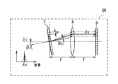
- the optical device 1 includes the variable wavelength light source 2, the collimator lens 3, the beam splitter 4, the MEMS mirror 5, the light emitting and receiving lens 6, and the diffraction grating 7.
- a condenser lens 8, a line sensor 9, and a control unit 10 are provided.
- the variable-wavelength light source 2 as the emission unit is configured of a variable-wavelength light source capable of changing the emitted laser light to a wavelength in a predetermined wavelength range.
- the wavelength variable light source 2 one using a well-known Littrow external resonator or Littman external resonator may be mentioned, but other methods may be used without particular limitation.
- the wavelength variable light source 2 intermittently emits (irradiates) laser light as pulse light.
- the collimator lens 3 converts the laser light emitted from the variable wavelength light source 2 into a parallel light flux.
- the beam splitter 4 outputs the laser light collimated by the collimator lens 3 to the MEMS mirror 5 and reflects reflected light and environmental light, which will be described later, reflected by the MEMS mirror 5 toward the diffraction grating 7.
- the MEMS mirror 5 as an irradiation means scans the laser light transmitted through the beam splitter 4 in the horizontal direction and the vertical direction in the region where the object 100 is present. Further, the MEMS mirror 5 reflects, to the beam splitter 4, the incident light that the laser light or the like reflected by the object 100 has entered the light emitting and receiving lens 6.
- the MEMS mirror 5 is a mirror configured by MEMS (Micro Electro Mechanical Systems), and is driven by an actuator (not shown) integrally formed with the mirror. Also, the MEMS mirror 5 may be another beam deflection means such as a galvano mirror or a polygon mirror.
- the light emitting and receiving lens 6 irradiates (projects) the laser light reflected by the MEMS mirror 5 to the area where the object 100 exists. Further, reflected light of laser light from the object 100 and environmental light such as sunlight (including light which is reflected by the object 100) enter the light emitting and receiving lens 6 as incident light (received). Further, in this embodiment, it is assumed that laser light emitted from another optical device as ambient light and reflected light of the laser light reflected by the object are also included.
- the diffraction grating 7 as an optical element diffracts the incident light from the beam splitter 4 to the line sensor 9 at a diffraction angle corresponding to the wavelength component of the incident light.
- a transmission-type diffraction grating will be described, it may be a reflection-type diffraction grating.
- the condenser lens 8 is provided between the diffraction grating 7 and the line sensor 9 and condenses the incident light diffracted by the diffraction grating 7 onto the line sensor 9.
- the line sensor 9 is a light receiving sensor in which a plurality of light receiving elements are formed in a line along a direction in which light incident on the diffraction grating 7 is diffracted. Each of the plurality of light receiving elements receives light of the incident light diffracted by the diffraction grating 7 according to the wavelength component. Each light receiving element of the line sensor 9 outputs a signal corresponding to the intensity (received light intensity) of the received light to the control unit 10. Further, the line sensor 9 can be configured by, for example, an avalanche photodiode (APD) as a light receiving element.
- APD avalanche photodiode
- the control unit 10 as a control means detects the reflected light of the laser light emitted from the variable wavelength light source 2 based on the signal indicating the light reception intensity of each light receiving element of the line sensor 9. Further, when the variable wavelength light source 2 does not emit the laser light, the control unit 10 emits the laser from the variable wavelength light source 2 based on the result of the line sensor 9 receiving the environmental light incident from the light receiving and receiving lens 6. Determine the wavelength of light.
- FIG. 2 is an explanatory view of the operation at the time of emission (light emitting system).
- laser light emitted in a pulse form from the variable wavelength light source 2 is collimated by the collimator lens 3, and then passes through the beam splitter 4 and enters the MEMS mirror 5. Then, the laser beam reflected by the MEMS mirror 5 is irradiated toward the outside of the optical device 1 by the light emitting and receiving lens 6. At this time, by changing the angle of the MEMS mirror 5 at each irradiation timing, it is possible to temporally change the position of the beam spot to be irradiated toward the region where the object 100 exists, in the horizontal direction and A vertical scan is performed.
- FIG. 3 shows the operation at the time of incidence (light receiving system).
- the laser light reflected (scattered) by the object 100 follows the light path opposite to that at the time of light projection through the light receiving and receiving lens 6, is reflected by the MEMS mirror 5, and is reflected by the beam splitter 4. It is incident on.
- the diffraction angle of the diffraction grating 7 is determined according to the groove pitch and the wavelength of the incident light.
- a laser beam is used, and the wavelength of the light incident on the diffraction grating 7 is single. Therefore, after being diffracted in a predetermined direction determined by the wavelength of the laser beam, the line sensor is conducted by the condensing lens 8 The light is collected on a predetermined light receiving element on the reference numeral 9.
- the above-described diffraction grating 7, condenser lens 8, and line sensor 9 constitute an ambient light information acquiring unit 20 as a light receiving unit.
- the ambient light information acquisition unit 20 is configured of the diffraction grating 7, the condenser lens 8, and the line sensor 9.
- a spectroscope using a prism or the like is not limited.
- the configuration may be such that the spectrum of sunlight according to the season, the weather, or the difference in time is held in advance as a table, and is used as ambient light information.
- the light receiving unit may have a function of acquiring wavelength information of ambient light separately.
- the table is stored in storage means (not shown), and a table according to the season, weather, and time when using the optical device 1 is used. By doing so, the wavelength of the laser light can be selected based on appropriate sunlight spectrum information.
- the light incident on the light emitting and receiving lens 6 is not only the reflected light of the laser light emitted from the wavelength variable light source 2. Any light that illuminates the object 100 such as sunlight or light on the street, or light that is reflected by the object 100 enters the light emitting / receiving lens 6 and enters the diffraction grating 7 via the MEMS mirror 5 .
- Ambient light such as sunlight is light including various wavelengths, and is diffracted in various directions by the diffraction grating 7 and is incident on a plurality of light receiving elements on the line sensor 9 according to the included wavelength range.
- the operation of the diffraction grating 7 (the ambient light information acquiring unit 20) will be described in detail with reference to FIGS. 4 to 6.
- the diffraction angle ⁇ 2 when monochromatic light of wavelength ⁇ 0 is made incident on the diffraction grating 7 with a groove spacing p from the direction of the angle ⁇ 1 is expressed by the following equation (1).
- the diffraction grating 7 diffracts only a specific direction theta 2 in a situation for entering the monochromatic light (laser beam).
- diffracted light means + 1st order diffracted light unless otherwise specified.
- a blazed diffraction grating having a sawtooth-like groove shape is used as the diffraction grating. The use of a blazed diffraction grating is desirable because the diffraction efficiency of + 1st order light can be theoretically made 100% by the blazed diffraction grating.
- FIG. 1st order light can be theoretically made 100% by the blazed diffraction grating.
- a condenser lens 8 is provided to condense the diffracted light diffracted by the diffraction grating 7 on the line sensor 9.
- the focal length of the focusing lens 8 is f
- the distance from the diffraction grating 7 to the focusing lens 8 and the distance from the focusing lens 8 to the line sensor 9 are both located at the focal length f (see FIG. 6 and FIG. 7)
- the diffracted light diffracted in the direction in which the line sensors 9 are aligned at a predetermined diffraction angle is collected at one point on the line sensor 9.
- the incident light is monochromatic light (laser light)
- laser light laser light
- the reflected light of the laser light emitted from the wavelength variable light source 2 is incident only on a specific light receiving element on the line sensor 9, and the environmental light is a plurality of light receiving elements corresponding to the included wavelength components. It will be incident.
- the focal length f may be set to have appropriate wavelength resolution in accordance with the size of the line sensor 9 to be used and the number of light receiving elements.
- ambient light information acquisition unit 20 having such a configuration, when the wavelength of the laser light emitted from the wavelength variable light source 2 is lambda 0, a wavelength longer than lambda 0 in addition to the reflected light having a wavelength of lambda 0 lambda Suppose that light of 0 'enters. In this case, the diffraction angle of the incident light of wavelength ⁇ 0 is ⁇ 2 , the diffraction angle of the incident light of wavelength ⁇ 0 ′ is ⁇ 2 ′, and the light receiving position on the line sensor 9 as shown by the solid line and broken line in FIG. Changes. Therefore, by measuring and grasping the relationship between the light receiving position and the wavelength in advance, it is possible to distinguish between the reflected light of the laser beam emitted by itself and the environmental light.
- the environmental light information acquisition unit 20 acquires wavelength information of environmental light when the variable wavelength light source 2 does not emit laser light at the time of initial startup or the like. As a result of acquisition, for example, as shown in the graph of FIG. 7, the same position on the line sensor 9 when the peak wavelength of the ambient light (dotted line) and the wavelength of the own signal (solid line) are the same or very close. Therefore, the S / N is deteriorated, and the reflected light of the laser light can not be detected.
- the control unit 10 changes the wavelength of the laser light emitted by itself to ⁇ 3 based on the acquired wavelength information.
- the S / N can be improved because signals are received at different positions on the line sensor 9. That is, the control unit 10 uses wavelength information related to the wavelength of the environmental light received by the line sensor 9 (light receiving unit) of the environmental light information acquiring unit 20 when the variable wavelength light source 2 (emitting unit) does not irradiate the emitted light. Based on this, the wavelength of the outgoing light emitted from the variable wavelength light source 2 (emitting part) is changed.
- the control unit 10 changes the wavelength of the ambient light to a wavelength smaller than the wavelength currently emitted by the variable wavelength light source 2 (emission unit).
- the optical device 1 is reflected by the MEMS mirror 5 that irradiates the laser light emitted from the wavelength variable light source 2 toward the predetermined range, and the object 100 in which the laser light is present in the predetermined range And a line sensor 9 for receiving light including ambient light from a region including the object 100. Furthermore, when the variable wavelength light source 2 does not irradiate the laser light, the control unit 10 controls the wavelength or the light quantity of the laser light emitted from the variable wavelength light source 2 based on the environmental light information which is information on the wavelength of the environmental light. Have.
- control unit 10 changes the wavelength of the environmental light to a wavelength smaller than the wavelength currently irradiated by the variable wavelength light source 2.
- the S / N can be improved because the intensity of ambient light is reduced compared to the present.
- the ambient light information acquisition unit 20 includes a line sensor 9 having a plurality of light receiving elements, and a diffraction grating 7 for guiding the light to any of the plurality of light receiving elements according to the wavelength of the incident light. ,have. By doing this, it is possible to easily acquire wavelength information of ambient light that has entered from the signals received by the plurality of light receiving elements.
- the present optical device can use the distance to the object for measurement. That is, the CPU or the like of the distance measuring device on which the optical device is mounted measures the time from when the light source emits laser light to when it is received by the light receiving element as reflected light reflected by the object 100. The distance from the device to the object can be measured.
- the ambient light is mainly described as light for illuminating the object 100 such as sunlight or street light, but when the optical device 1 is mounted on a movable body such as a vehicle, it is other than the own vehicle
- the laser beam emitted from the optical device 1 mounted on another vehicle or the reflected light may be incident.
- the wavelength of the laser beam emitted by itself and the wavelength of the laser beam emitted by the other optical device are the same, the reflected light of the laser beam emitted by itself and the laser beam emitted by the other optical device or its reflected light May not be distinguishable and may malfunction. Therefore, laser light and reflected light from such other optical devices are regarded as environmental light, and the above-mentioned embodiment is applied to change its wavelength to a wavelength different from that of the other optical devices 1 and cause malfunction. Can be prevented.
- FIG. 10 and 11 show an example where laser light from another optical device and its reflected light are incident.
- the solid line in FIG. 10 indicates the reflected light of the laser beam emitted by itself, and the broken line indicates the ambient light.
- the peaks overlapping with the solid line indicate the wavelengths of the laser light from the other optical device and the reflected light thereof.
- the wavelength ( ⁇ 3 ) of the laser beam emitted by itself overlaps with the wavelength of the laser beam emitted by another optical device. That is, the same light receiving element of the line sensor 9 receives the reflected light.
- the control unit 10 of the other wavelengths of the variable wavelength light source 2 from lambda 3 optical wavelength and the peak of such wavelength and solar laser beam of the device is changed to not lambda 4 which overlap.
- the light receiving element different from the line sensor 9 receives the own signal and the other signal, which makes it possible to prevent a malfunction.
- an example of acquiring wavelength information of ambient light at the first activation is shown, but for example, in a cycle of scanning a predetermined area by the MEMS mirror 5, a cycle not to irradiate the laser light is provided
- the wavelength information of the ambient light may be acquired at the time.
- the wavelength of the emitted light emitted by the variable-wavelength light source 2 (the output unit) is changed based on the wavelength information on the wavelength of the environmental light, but the light amount of the emitted light to be emitted is adjusted ) To make it easy to distinguish between the ambient light and the reflected light of the laser light.
- the present invention is not limited to the above embodiment. That is, those skilled in the art can carry out various modifications without departing from the gist of the present invention in accordance with conventionally known findings. As long as the configuration of the optical device of the present invention is provided even by such a modification, it is of course included in the scope of the present invention.
- Optical device 2 Tunable light source (emitting part) 5 MEMS mirror (irradiation means) 7 Diffraction grating (light receiving part) 8 Condenser Lens (Receiver) 9 Line sensor (light receiving unit) 10 Control unit (control means) 100 objects
Abstract
Provided is an optical device that can adapt to changes in the external environment. An optical device (1) comprises: a MEMS mirror (5) which radiates laser light emitted from a wavelength tunable light source (2) toward a prescribed region; and a line sensor (9) which receives light including reflected light comprising the laser light that has been reflected from a target object (100) present in the prescribed region, and ambient light from a region including the target object (100). In addition, the optical device (1) includes a control unit (10) which controls the wavelength or light intensity of the laser light emitted from the wavelength tunable light source (2), on the basis of ambient light information, which relates to the wavelength of the ambient light when the wavelength tunable light source (2) is not radiating the laser light.
Description
本発明は、出射した光が対象物で反射した反射光を受光する光学装置に関する。
The present invention relates to an optical device that receives reflected light obtained by reflecting emitted light from an object.
従来、光を対象物に照射して、反射した光が戻ってくるまでの往復の時間を基に対象物までの距離を測定する装置が実用化されている。
2. Description of the Related Art Conventionally, there has been put into practical use an apparatus that irradiates light onto an object and measures the distance to the object based on the round-trip time until the reflected light returns.
この種の装置では、この距離測定のために用いる反射光と、太陽光などの環境光とを分離するために、照射した光の波長の光のみを透過させるバンドパスフィルタを用いて、S/N比の向上を図っている(例えば特許文献1を参照)。
In this type of device, in order to separate reflected light used for this distance measurement from ambient light such as sunlight, a band pass filter is used that transmits only light of the wavelength of the irradiated light. The N ratio is improved (see, for example, Patent Document 1).
特許文献1に記載の発明では、バンドパスフィルタを用いて発光素子の温度変動による波長変動に対応させているが、あくまで自身が有する発光素子の波長変動に対応するものである。そのため、環境光が時間帯や天候等により変化した場合に環境光の波長の分布や強度が変化して発光素子の波長と同じ波長の強度が大きくなると、発光素子が出射した光の反射光が検出できなくなる場合がある。
In the invention described in Patent Document 1, although the band pass filter is used to cope with the wavelength fluctuation due to the temperature fluctuation of the light emitting element, it is to cope with the wavelength fluctuation of the light emitting element which it has. Therefore, when ambient light changes due to time zone, weather, etc., when the distribution or intensity of the wavelength of environmental light changes and the intensity of the same wavelength as the wavelength of the light emitting element increases, the reflected light of the light emitted by the light emitting element It may not be detected.
また、特許文献1に記載の発明に係る光学式レーダ装置が移動体に搭載された場合、他の移動体に搭載された光学式レーダ装置から出射した光やその光が物体に反射した反射光等が入射することが想定される。この場合、自身の出射光と他の装置の出射光の波長が同じであると、自身の出射光の反射光と他の装置の出射光やその反射光との区別がつかなくなってしまうことがあり得る。
Further, when the optical radar device according to the invention described in Patent Document 1 is mounted on a moving body, light emitted from an optical radar device mounted on another moving body or reflected light obtained by reflecting the light on the object It is assumed that etc. will be incident. In this case, if the wavelengths of the light emitted from the device itself and the light emitted from the other device are the same, the reflected light of the light emitted from the device itself can not be distinguished from the light emitted from the other device or the reflected light thereof. possible.
このように、特許文献1に記載の発明では、外部環境の変化に対応することが困難となることがあった。
As described above, in the invention described in Patent Document 1, there have been cases in which it has become difficult to cope with changes in the external environment.
本発明が解決しようとする課題としては、上述したような外部環境の変化に対応することが一例として挙げられる。
One of the problems to be solved by the present invention is to cope with changes in the external environment as described above.
上記課題を解決するためになされた請求項1に記載の発明は、出射部から出射される出射光を所定の範囲に向けて照射する照射手段と、前記出射光が前記所定の範囲に存在する対象物により反射した反射光、及び前記対象物を含む領域からの環境光を含む光を受光する受光部と、前記環境光の波長に関する情報である環境光情報に基づき、前記出射部から出射する出射光の波長又は光量を制御する制御手段と、を有することを特徴としている。
The invention according to claim 1 made for the purpose of solving the above-mentioned problems is characterized in that irradiation means for irradiating the emitted light emitted from the emitting portion toward a predetermined range, and the emitted light exists in the predetermined range The light emitting unit emits light from the light emitting unit based on a light receiving unit that receives light reflected by an object and light including environmental light from a region including the object, and environmental light information that is information on the wavelength of the environmental light And controlling means for controlling the wavelength or the light amount of the emitted light.
以下、本発明の一実施形態にかかる光学装置を説明する。本発明の一実施形態にかかる光学装置は、出射部から出射される出射光を所定の範囲に向けて照射する照射手段と、出射光が所定の範囲に存在する対象物により反射した反射光、及び対象物を含む領域からの環境光を含む光を受光する受光部と、を有している。さらに、環境光の波長に関する情報である環境光情報に基づき、出射部から出射する出射光の波長又は光量を制御する制御手段を有している。このようにすることにより、周囲の環境光の波長に関する環境光情報を取得することができる。そのため、その情報に基づいて環境光の強度が小さい波長の出射光とすることができる。したがって、外部環境の変化に対応して出射光を照射することができる。
Hereinafter, an optical device according to an embodiment of the present invention will be described. An optical device according to an embodiment of the present invention comprises: an irradiation unit that irradiates the emitted light emitted from the emitting portion toward a predetermined range; and the reflected light reflected by the object whose emitted light is present in the predetermined range And a light receiving unit that receives light including ambient light from a region including the target. Furthermore, it has a control means for controlling the wavelength or the light quantity of the emitted light emitted from the emitting unit based on the ambient light information which is the information on the wavelength of the ambient light. By doing this, ambient light information on the wavelength of ambient light can be obtained. Therefore, based on the information, it is possible to make the emitted light of the wavelength where the intensity of the environmental light is small. Therefore, the emitted light can be irradiated corresponding to the change of the external environment.
また、環境光情報は、出射部が出射光を照射していない際に受光部が受光した環境光の波長に関する情報としてもよい。このようにすることにより、環境光の波長に関する情報のみを取得することが可能となる。
Further, the ambient light information may be information on the wavelength of the ambient light received by the light receiving unit when the emitting unit is not emitting the emitted light. By doing this, it is possible to obtain only information on the wavelength of ambient light.
また、環境光情報として、季節/天気/時間帯の少なくともいずれかに応じた太陽光スペクトル情報を使用してもよい。このようにすることにより、適切な太陽光スペクトル情報に基づいて出射光の波長を選択することができる。
Moreover, you may use the sunlight spectrum information according to the season / weather / time zone as environmental light information. By doing this, the wavelength of the outgoing light can be selected based on the appropriate sunlight spectrum information.
また、制御手段は、現在出射部が照射している波長よりも環境光の強度が小さい波長へ変化させてもよい。このようにすることにより、現在よりも環境光の強度が低下するので、S/Nを改善することができる。
In addition, the control means may change the wavelength of the ambient light to a wavelength smaller than the wavelength currently emitted by the emitting unit. By doing this, the S / N can be improved because the intensity of ambient light is reduced compared to the present.
また、受光部は、複数の受光素子と、入射した光の波長に応じて、その光を複数の受光素子のうちいずれかの受光素子に導く光学素子と、を有していてもよい。このようにすることにより、複数の受光素子が受光した信号から入射した環境光の波長情報を容易に取得することができる。
Further, the light receiving unit may have a plurality of light receiving elements and an optical element for guiding the light to any of the plurality of light receiving elements according to the wavelength of the incident light. By doing this, it is possible to easily acquire wavelength information of ambient light that has entered from the signals received by the plurality of light receiving elements.
本発明の一実施例にかかる光学装置を図1~図9を参照して説明する。本実施例にかかる光学装置1は、図1に示したように、波長可変光源2と、コリメートレンズ3と、ビームスプリッタ4と、MEMSミラー5と、投受光レンズ6と、回折格子7と、集光レンズ8と、ラインセンサ9と、制御部10と、を備えている。
An optical apparatus according to an embodiment of the present invention will be described with reference to FIGS. As shown in FIG. 1, the optical device 1 according to the present embodiment includes the variable wavelength light source 2, the collimator lens 3, the beam splitter 4, the MEMS mirror 5, the light emitting and receiving lens 6, and the diffraction grating 7. A condenser lens 8, a line sensor 9, and a control unit 10 are provided.
出射部としての波長可変光源2は、出射するレーザ光を所定の波長範囲の波長に変化させることができる波長可変光源で構成されている。なお、波長可変光源2としては、周知のリトロー型外部共振器やリットマン型外部共振器を用いたものが挙げられるが、他の方式でもよく特に限定されない。また、波長可変光源2は、レーザ光をパルス光として間欠的に出射(照射)する。
The variable-wavelength light source 2 as the emission unit is configured of a variable-wavelength light source capable of changing the emitted laser light to a wavelength in a predetermined wavelength range. As the wavelength variable light source 2, one using a well-known Littrow external resonator or Littman external resonator may be mentioned, but other methods may be used without particular limitation. The wavelength variable light source 2 intermittently emits (irradiates) laser light as pulse light.
コリメートレンズ3は、波長可変光源2から出射されたレーザ光を平行光束にする。ビームスプリッタ4は、コリメートレンズ3で平行光にされたレーザ光をMEMSミラー5へ出力し、MEMSミラー5で反射された後述する反射光や環境光を回折格子7へ向けて反射する。
The collimator lens 3 converts the laser light emitted from the variable wavelength light source 2 into a parallel light flux. The beam splitter 4 outputs the laser light collimated by the collimator lens 3 to the MEMS mirror 5 and reflects reflected light and environmental light, which will be described later, reflected by the MEMS mirror 5 toward the diffraction grating 7.
照射手段としてのMEMSミラー5は、ビームスプリッタ4を透過したレーザ光を対象物100が存在する領域を水平方向および垂直方向に走査する。また、MEMSミラー5は、対象物100で反射したレーザ光等が投受光レンズ6に入射した入射光をビームスプリッタ4へ反射する。MEMSミラー5は、MEMS(Micro Electro Mechanical Systems)により構成されたミラーであり、ミラーと一体的に形成されたアクチュエータ(図示しない)によって駆動される。また、MEMSミラー5はガルバノミラーやポリゴンミラーなど他のビーム偏向手段でもよい。
The MEMS mirror 5 as an irradiation means scans the laser light transmitted through the beam splitter 4 in the horizontal direction and the vertical direction in the region where the object 100 is present. Further, the MEMS mirror 5 reflects, to the beam splitter 4, the incident light that the laser light or the like reflected by the object 100 has entered the light emitting and receiving lens 6. The MEMS mirror 5 is a mirror configured by MEMS (Micro Electro Mechanical Systems), and is driven by an actuator (not shown) integrally formed with the mirror. Also, the MEMS mirror 5 may be another beam deflection means such as a galvano mirror or a polygon mirror.
投受光レンズ6は、MEMSミラー5で反射されたレーザ光を対象物100が存在する領域へ照射(投光)する。また、投受光レンズ6には、対象物100からのレーザ光の反射光及び太陽光などの環境光(太陽光が対象物100で反射した光を含む)が入射光として入射(受光)する。また、本実施例では、環境光として他の光学装置から出射されたレーザ光やそのレーザ光が物体に反射された反射光も含むもとのとする。
The light emitting and receiving lens 6 irradiates (projects) the laser light reflected by the MEMS mirror 5 to the area where the object 100 exists. Further, reflected light of laser light from the object 100 and environmental light such as sunlight (including light which is reflected by the object 100) enter the light emitting and receiving lens 6 as incident light (received). Further, in this embodiment, it is assumed that laser light emitted from another optical device as ambient light and reflected light of the laser light reflected by the object are also included.
光学素子としての回折格子7は、ビームスプリッタ4から入射した入射光を、その入射光の有する波長成分に応じた回折角でラインセンサ9へ回折する。なお、本実施例では、透過型の回折格子で説明するが、反射型の回折格子であってもよい。
The diffraction grating 7 as an optical element diffracts the incident light from the beam splitter 4 to the line sensor 9 at a diffraction angle corresponding to the wavelength component of the incident light. In the present embodiment, although a transmission-type diffraction grating will be described, it may be a reflection-type diffraction grating.
集光レンズ8は、回折格子7とラインセンサ9との間に設けられ、回折格子7で回折された入射光をラインセンサ9へ集光する。
The condenser lens 8 is provided between the diffraction grating 7 and the line sensor 9 and condenses the incident light diffracted by the diffraction grating 7 onto the line sensor 9.
ラインセンサ9は、回折格子7に入射した光が回折される方向に沿って複数の受光素子が1列に並んで形成された受光センサである。これらの複数の受光素子の各々は、回折格子7で回折された入射光のうち、波長成分に応じた光を、それぞれ受光することになる。ラインセンサ9の各受光素子は、受光した光の強度(受光強度)に応じた信号を制御部10に出力する。また、ラインセンサ9は、例えば受光素子としてアバランシェフォトダイオード(APD)により構成することができる。
The line sensor 9 is a light receiving sensor in which a plurality of light receiving elements are formed in a line along a direction in which light incident on the diffraction grating 7 is diffracted. Each of the plurality of light receiving elements receives light of the incident light diffracted by the diffraction grating 7 according to the wavelength component. Each light receiving element of the line sensor 9 outputs a signal corresponding to the intensity (received light intensity) of the received light to the control unit 10. Further, the line sensor 9 can be configured by, for example, an avalanche photodiode (APD) as a light receiving element.
制御手段としての制御部10は、ラインセンサ9の各受光素子の受光強度を示す信号に基づいて波長可変光源2から出射したレーザ光の反射光を検出する。また、制御部10は、波長可変光源2がレーザ光を出射していないときにおいて、投受光レンズ6から入射した環境光をラインセンサ9が受光した結果に基づいて波長可変光源2から出射するレーザ光の波長を決定する。
The control unit 10 as a control means detects the reflected light of the laser light emitted from the variable wavelength light source 2 based on the signal indicating the light reception intensity of each light receiving element of the line sensor 9. Further, when the variable wavelength light source 2 does not emit the laser light, the control unit 10 emits the laser from the variable wavelength light source 2 based on the result of the line sensor 9 receiving the environmental light incident from the light receiving and receiving lens 6. Determine the wavelength of light.
次に、上述した構成の光学装置1における動作について図2及び図3を参照して説明する。図2は出射時(投光系)の動作の説明図である。
Next, the operation of the optical device 1 configured as described above will be described with reference to FIGS. 2 and 3. FIG. 2 is an explanatory view of the operation at the time of emission (light emitting system).
まず、波長可変光源2からパルス状に出射したレーザ光はコリメートレンズ3で平行光束とされた後、ビームスプリッタ4を経てMEMSミラー5に入射する。そして、MEMSミラー5で反射したレーザ光は投受光レンズ6により光学装置1の外部に向けて照射される。このとき、各々の照射のタイミング毎にMEMSミラー5の角度を変化させることにより対象物100が存在する領域に向けて照射されるビームスポットの位置を時間的に変化させることができ、水平方向および垂直方向の走査が行われる。
First, laser light emitted in a pulse form from the variable wavelength light source 2 is collimated by the collimator lens 3, and then passes through the beam splitter 4 and enters the MEMS mirror 5. Then, the laser beam reflected by the MEMS mirror 5 is irradiated toward the outside of the optical device 1 by the light emitting and receiving lens 6. At this time, by changing the angle of the MEMS mirror 5 at each irradiation timing, it is possible to temporally change the position of the beam spot to be irradiated toward the region where the object 100 exists, in the horizontal direction and A vertical scan is performed.
図3は、入射時(受光系)の動作である。対象物100で反射(散乱)したレーザ光は、投受光レンズ6を介して、投光時とは逆の光路をたどり、MEMSミラー5で反射され、ビームスプリッタ4で反射されて、回折格子7へと入射する。回折格子7は溝のピッチと入射光の波長に応じて回折角が決まる。本実施例ではレーザ光を使用しており回折格子7に入射する光の波長は単一であるので、そのレーザ光の波長で定まる所定の方向へと回折した後、集光レンズ8によりラインセンサ9上のある所定の受光素子に集光する。
FIG. 3 shows the operation at the time of incidence (light receiving system). The laser light reflected (scattered) by the object 100 follows the light path opposite to that at the time of light projection through the light receiving and receiving lens 6, is reflected by the MEMS mirror 5, and is reflected by the beam splitter 4. It is incident on. The diffraction angle of the diffraction grating 7 is determined according to the groove pitch and the wavelength of the incident light. In this embodiment, a laser beam is used, and the wavelength of the light incident on the diffraction grating 7 is single. Therefore, after being diffracted in a predetermined direction determined by the wavelength of the laser beam, the line sensor is conducted by the condensing lens 8 The light is collected on a predetermined light receiving element on the reference numeral 9.
上述した回折格子7、集光レンズ8、ラインセンサ9が受光部としての環境光情報取得部20となる。この環境光情報取得部20は、回折格子7、集光レンズ8、ラインセンサ9で構成されているが、例えばプリズムを利用した分光器等でもよく限定されない。要するに環境光の波長に関する情報が取得できる構成であれば他の構成であってもよい。 或いは、季節や天気、時刻の違いによる太陽光のスペクトルをあらかじめテーブルとして持ち、それを環境光情報として利用する構成でもよい。つまり、受光部とは別途に環境光の波長情報を取得する機能を有していてもよい。この場合、当該テーブルを図示しない記憶手段にて保有しておき、光学装置1を用いる際の季節や天気、時刻に応じたテーブルを用いることになる。このようにすることにより、適切な太陽光スペクトル情報に基づいてレーザ光の波長を選択することができる。
The above-described diffraction grating 7, condenser lens 8, and line sensor 9 constitute an ambient light information acquiring unit 20 as a light receiving unit. The ambient light information acquisition unit 20 is configured of the diffraction grating 7, the condenser lens 8, and the line sensor 9. However, for example, a spectroscope using a prism or the like is not limited. In other words, any other configuration may be used as long as it can acquire information on the wavelength of ambient light. Alternatively, the configuration may be such that the spectrum of sunlight according to the season, the weather, or the difference in time is held in advance as a table, and is used as ambient light information. That is, the light receiving unit may have a function of acquiring wavelength information of ambient light separately. In this case, the table is stored in storage means (not shown), and a table according to the season, weather, and time when using the optical device 1 is used. By doing so, the wavelength of the laser light can be selected based on appropriate sunlight spectrum information.
上述した構成の光学装置1において、投受光レンズ6に入射する光は波長可変光源2から発したレーザ光の反射光だけではない。太陽光や街頭の光など対象物100を照明するあらゆる光や、それらの光が対象物100で反射した光等が投受光レンズ6に入射し、MEMSミラー5を介して回折格子7に入射する。太陽光などの環境光は様々な波長を含む光であり、回折格子7により様々な方向に回折し、含まれる波長範囲に応じてラインセンサ9上の複数の受光素子へと入射する。 投受光レンズ6には様々な波長の光が入射するため、状況によって、自身が出射したレーザ光と同じ波長の高輝度(高強度)の光が入射する可能性がある。この場合、レーザ光の反射光を検出できなくなってしまう。そこで、自身が出射したレーザ光の波長を環境光の影響が小さくなる波長域に設定することで、環境光の影響を抑制することが可能となる(詳細は後述する)。
In the optical device 1 configured as described above, the light incident on the light emitting and receiving lens 6 is not only the reflected light of the laser light emitted from the wavelength variable light source 2. Any light that illuminates the object 100 such as sunlight or light on the street, or light that is reflected by the object 100 enters the light emitting / receiving lens 6 and enters the diffraction grating 7 via the MEMS mirror 5 . Ambient light such as sunlight is light including various wavelengths, and is diffracted in various directions by the diffraction grating 7 and is incident on a plurality of light receiving elements on the line sensor 9 according to the included wavelength range. Since light of various wavelengths is incident on the light emitting and receiving lens 6, light of high luminance (high intensity) having the same wavelength as the laser light emitted by itself may be incident depending on the situation. In this case, the reflected light of the laser light can not be detected. Therefore, by setting the wavelength of the laser beam emitted by itself to a wavelength range in which the influence of environmental light is reduced, the influence of environmental light can be suppressed (details will be described later).
回折格子7(環境光情報取得部20)の作用について図4~図6を参照して詳細に説明する。溝間隔pの回折格子7に波長λ0の単色光を角度θ1の方向から入射させた時の回折角θ2は、次の(1)式で表される。

The operation of the diffraction grating 7 (the ambient light information acquiring unit 20) will be described in detail with reference to FIGS. 4 to 6. The diffraction angle θ 2 when monochromatic light of wavelength λ 0 is made incident on the diffraction grating 7 with a groove spacing p from the direction of the angle θ 1 is expressed by the following equation (1).
図4のように、回折格子7は、単色光(レーザ光)を入射させる状況では特定の方向θ2のみに回折させる。なお以降において、特に断らない限り回折光は、+1次の回折光を意味することとする。また、本実施例では、回折格子として鋸歯状の溝形状を有するブレーズド回折格子を使用する。ブレーズド回折格子により+1次光の回折効率を理論上100%とすることが出来るため、ブレーズド回折格子の使用が望ましい。一方、図5のように、λ1~λ2の波長範囲を有する光を同じ回折格子7に入射させた場合、波長成分ごとに異なる方向へ回折する。即ち、回折格子7(光学素子)には、レーザ光の反射光及び環境光が入射光として入射し、当該入射光を波長に応じて複数の受光素子のうちいずれかの受光素子に導いている。
As shown in FIG. 4, the diffraction grating 7 diffracts only a specific direction theta 2 in a situation for entering the monochromatic light (laser beam). In the following, diffracted light means + 1st order diffracted light unless otherwise specified. Further, in the present embodiment, a blazed diffraction grating having a sawtooth-like groove shape is used as the diffraction grating. The use of a blazed diffraction grating is desirable because the diffraction efficiency of + 1st order light can be theoretically made 100% by the blazed diffraction grating. On the other hand, as shown in FIG. 5, when light having a wavelength range of λ 1 to λ 2 is made incident on the same diffraction grating 7, light is diffracted in different directions for each wavelength component. That is, reflected light of laser light and environmental light are incident as incident light to the diffraction grating 7 (optical element), and the incident light is guided to one of the plurality of light receiving elements according to the wavelength. .
次に、集光レンズ8の作用について説明する。レーザ光であっても、実際は所定の幅のビームであるので、本実施例では、回折格子7で回折した回折光をラインセンサ9に集光するために集光レンズ8を設けている。集光レンズ8の焦点距離をfとすると、回折格子7から集光レンズ8までの距離と集光レンズ8からラインセンサ9までの距離が共に焦点距離fとなる位置に配置することにより(図6及び図7参照)、所定の回折角でラインセンサ9の並んでいる方向に回折した回折光はラインセンサ9上の一点に集光する。入射光が単色光(レーザ光)の場合にはラインセンサ9上の特定の受光素子のみに入射し、ある波長範囲を持つ入射光の場合には複数の受光素子に入射する。つまり、回折光のうち、波長可変光源2から出射されたレーザ光の反射光はラインセンサ9上の特定の受光素子のみに入射し、環境光は含まれる波長成分に応じた複数の受光素子に入射する。
Next, the action of the condenser lens 8 will be described. Since even a laser beam is actually a beam having a predetermined width, in this embodiment, a condenser lens 8 is provided to condense the diffracted light diffracted by the diffraction grating 7 on the line sensor 9. Assuming that the focal length of the focusing lens 8 is f, the distance from the diffraction grating 7 to the focusing lens 8 and the distance from the focusing lens 8 to the line sensor 9 are both located at the focal length f (see FIG. 6 and FIG. 7), the diffracted light diffracted in the direction in which the line sensors 9 are aligned at a predetermined diffraction angle is collected at one point on the line sensor 9. When the incident light is monochromatic light (laser light), it is incident only on a specific light receiving element on the line sensor 9, and in the case of incident light having a certain wavelength range, it is incident on a plurality of light receiving elements. That is, of the diffracted light, the reflected light of the laser light emitted from the wavelength variable light source 2 is incident only on a specific light receiving element on the line sensor 9, and the environmental light is a plurality of light receiving elements corresponding to the included wavelength components. It will be incident.
この焦点距離fは、使用するラインセンサ9の大きさ、受光素子数に応じて適切な波長分解能となるように設定すればよい。
The focal length f may be set to have appropriate wavelength resolution in accordance with the size of the line sensor 9 to be used and the number of light receiving elements.
このような構成の環境光情報取得部20において、波長可変光源2から出射したレーザ光の波長がλ0であるときに、λ0の波長の反射光に加えてλ0より長波長であるλ0’の光が入射したとする。この場合、λ0の波長の入射光の回折角度はθ2、λ0’の波長の入射光の回折角度はθ2’となり、図6の実線と破線のようにラインセンサ9上で受光位置が変化する。したがって、受光位置と波長の関係を予め計測し、把握しておくことで自身が出射したレーザ光の反射光と環境光の区別が可能となる。
In ambient light information acquisition unit 20 having such a configuration, when the wavelength of the laser light emitted from the wavelength variable light source 2 is lambda 0, a wavelength longer than lambda 0 in addition to the reflected light having a wavelength of lambda 0 lambda Suppose that light of 0 'enters. In this case, the diffraction angle of the incident light of wavelength λ 0 is θ 2 , the diffraction angle of the incident light of wavelength λ 0 ′ is θ 2 ′, and the light receiving position on the line sensor 9 as shown by the solid line and broken line in FIG. Changes. Therefore, by measuring and grasping the relationship between the light receiving position and the wavelength in advance, it is possible to distinguish between the reflected light of the laser beam emitted by itself and the environmental light.
環境光情報取得部20は、初回起動時等の波長可変光源2がレーザ光を出射していない時に環境光の波長情報を取得する。取得の結果、例えば図7のグラフに示したように環境光(破線)のピーク波長と自信号(実線)との波長が同じ又は非常に近い波長であった場合、ラインセンサ9上で同じ位置で受信してしまうため、S/Nの劣化の原因となってしまい、レーザ光の反射光を検出できなくなってしまう。
The environmental light information acquisition unit 20 acquires wavelength information of environmental light when the variable wavelength light source 2 does not emit laser light at the time of initial startup or the like. As a result of acquisition, for example, as shown in the graph of FIG. 7, the same position on the line sensor 9 when the peak wavelength of the ambient light (dotted line) and the wavelength of the own signal (solid line) are the same or very close. Therefore, the S / N is deteriorated, and the reflected light of the laser light can not be detected.
そこで、制御部10は、図8のグラフに示したように、取得した波長情報に基づいて自身が出射したレーザ光の波長をλ3へ変化させる。このようにすることにより、ラインセンサ9上で異なる位置で受信するため、S/Nを改善することができる。即ち、制御部10は、波長可変光源2(出射部)が出射光を照射していない際に環境光情報取得部20のラインセンサ9(受光部)が受光した環境光の波長に関する波長情報に基づいて、波長可変光源2(出射部)が出射する出射光の波長を変化させている。
Therefore, as shown in the graph of FIG. 8, the control unit 10 changes the wavelength of the laser light emitted by itself to λ 3 based on the acquired wavelength information. By doing this, the S / N can be improved because signals are received at different positions on the line sensor 9. That is, the control unit 10 uses wavelength information related to the wavelength of the environmental light received by the line sensor 9 (light receiving unit) of the environmental light information acquiring unit 20 when the variable wavelength light source 2 (emitting unit) does not irradiate the emitted light. Based on this, the wavelength of the outgoing light emitted from the variable wavelength light source 2 (emitting part) is changed.
上述した説明を、図9に示した太陽光スペクトルに基づいて説明する。図9において、初期の波長可変光源2の出射するレーザ光がλ0(約1000μm)であった場合、ラインセンサ9の受光結果に基づいて太陽光の強度が小さいλ3(約930μm)に変更する。即ち、制御部10は、現在波長可変光源2(出射部)が出射している波長よりも環境光の強度が小さい波長へ変化させている。
The above description will be described based on the sunlight spectrum shown in FIG. 9 changes, if the laser beam emitted in the initial wavelength variable light source 2 was lambda 0 (about 1000 .mu.m), the intensity of the sunlight is small lambda 3 based on the reception result of the line sensor 9 (approximately 930μm) Do. That is, the control unit 10 changes the wavelength of the ambient light to a wavelength smaller than the wavelength currently emitted by the variable wavelength light source 2 (emission unit).
本実施例によれば、光学装置1は、波長可変光源2から出射されるレーザ光を所定の範囲に向けて照射するMEMSミラー5と、レーザ光が所定の範囲に存在する対象物100により反射した反射光、及び対象物100を含む領域からの環境光を含む光を受光するラインセンサ9と、を有している。さらに、波長可変光源2がレーザ光を照射していない際に環境光の波長に関する情報である環境光情報に基づき、波長可変光源2から出射するレーザ光の波長又は光量を制御する制御部10を有している。このようにすることにより、自身が未照射時における環境光情報を取得することができ、その情報に基づいて環境光の強度が少ない波長のレーザ光とすることができる。したがって、外部環境の変化に対応してレーザ光を照射することができる。
According to the present embodiment, the optical device 1 is reflected by the MEMS mirror 5 that irradiates the laser light emitted from the wavelength variable light source 2 toward the predetermined range, and the object 100 in which the laser light is present in the predetermined range And a line sensor 9 for receiving light including ambient light from a region including the object 100. Furthermore, when the variable wavelength light source 2 does not irradiate the laser light, the control unit 10 controls the wavelength or the light quantity of the laser light emitted from the variable wavelength light source 2 based on the environmental light information which is information on the wavelength of the environmental light. Have. By doing this, it is possible to obtain environmental light information when not irradiating itself, and based on the information, it is possible to obtain laser light of a wavelength having a small intensity of environmental light. Therefore, laser light can be emitted in response to changes in the external environment.
また、制御部10は、現在波長可変光源2が照射している波長よりも環境光の強度が小さい波長へ変化させている。このようにすることにより、現在よりも環境光の強度が低下するので、S/Nを改善することができる。
Further, the control unit 10 changes the wavelength of the environmental light to a wavelength smaller than the wavelength currently irradiated by the variable wavelength light source 2. By doing this, the S / N can be improved because the intensity of ambient light is reduced compared to the present.
また、環境光情報取得部20は、複数の受光素子を有するラインセンサ9と、入射した光の波長に応じて、その光を複数の受光素子のうちいずれかの受光素子に導く回折格子7と、を有している。このようにすることにより、複数の受光素子が受光した信号から入射した環境光の波長情報を容易に取得することができる。
In addition, the ambient light information acquisition unit 20 includes a line sensor 9 having a plurality of light receiving elements, and a diffraction grating 7 for guiding the light to any of the plurality of light receiving elements according to the wavelength of the incident light. ,have. By doing this, it is possible to easily acquire wavelength information of ambient light that has entered from the signals received by the plurality of light receiving elements.
また、本光学装置は対象物までの距離を測定に用いることができる。すなわち、本光学装置を搭載した距離測定装置のCPU等により、光源がレーザ光を出射してから対象物100で反射した反射光として受光素子に受光されるまでの時間を測定することで、光学装置から対象物までの距離を測定することができる。
Further, the present optical device can use the distance to the object for measurement. That is, the CPU or the like of the distance measuring device on which the optical device is mounted measures the time from when the light source emits laser light to when it is received by the light receiving element as reflected light reflected by the object 100. The distance from the device to the object can be measured.
なお、上述した実施例では、環境光として主に太陽光や街頭の光など対象物100を照明する光で説明したが、光学装置1が車両等の移動体に搭載される場合、自車以外の他車に搭載された光学装置1が出射したレーザ光やその反射光が入射する場合がある。そうすると、自身が出射するレーザ光の波長と他の光学装置が出射するレーザ光の波長が同じ場合、自身が出射したレーザ光の反射光と他の光学装置が出射したレーザ光やその反射光とを区別できなくなり誤動作する場合がありうる。そこで、このような他の光学装置からのレーザ光や反射光も環境光とみなして、上述した実施例を適用することにより、自身の波長を他の光学装置1と異なる波長に変化させて誤動作を防止することができる。
In the above-described embodiment, the ambient light is mainly described as light for illuminating the object 100 such as sunlight or street light, but when the optical device 1 is mounted on a movable body such as a vehicle, it is other than the own vehicle The laser beam emitted from the optical device 1 mounted on another vehicle or the reflected light may be incident. Then, if the wavelength of the laser beam emitted by itself and the wavelength of the laser beam emitted by the other optical device are the same, the reflected light of the laser beam emitted by itself and the laser beam emitted by the other optical device or its reflected light May not be distinguishable and may malfunction. Therefore, laser light and reflected light from such other optical devices are regarded as environmental light, and the above-mentioned embodiment is applied to change its wavelength to a wavelength different from that of the other optical devices 1 and cause malfunction. Can be prevented.
他の光学装置からのレーザ光やその反射光が入射した場合の例を図10及び図11を示す。図10の実線は自身が出射したレーザ光の反射光を示し、破線は環境光を示している。図10のグラフでは、破線のピークが2か所あるが、このうち実線と重なるピークは他の光学装置からのレーザ光やその反射光の波長を示している。この場合、自身が出射するレーザ光の波長(λ3)と他の光学装置が出射するレーザ光の波長とが重なってしまう。つまり、ラインセンサ9の同じ受光素子がこれらの反射光を受光することとなってしまう。
10 and 11 show an example where laser light from another optical device and its reflected light are incident. The solid line in FIG. 10 indicates the reflected light of the laser beam emitted by itself, and the broken line indicates the ambient light. In the graph of FIG. 10, although there are two peaks of broken lines, the peaks overlapping with the solid line indicate the wavelengths of the laser light from the other optical device and the reflected light thereof. In this case, the wavelength (λ 3 ) of the laser beam emitted by itself overlaps with the wavelength of the laser beam emitted by another optical device. That is, the same light receiving element of the line sensor 9 receives the reflected light.
そこで、図11に示すように、波長可変光源2がレーザ光を照射していない時に取得した環境光の波長情報に基づいて、制御部10が波長可変光源2の波長をλ3から他の光学装置のレーザ光の波長や太陽光等の波長とピークが重ならないλ4に変化させる。このようにすることにより、ラインセンサ9の異なる受光素子に自信号と他信号が受光されることとなり、誤動作を防止することが可能となる。
Therefore, as shown in FIG. 11, based on the acquired wavelength information of ambient light when the variable wavelength light source 2 is not irradiated with laser light, the control unit 10 of the other wavelengths of the variable wavelength light source 2 from lambda 3 optical wavelength and the peak of such wavelength and solar laser beam of the device is changed to not lambda 4 which overlap. By doing this, the light receiving element different from the line sensor 9 receives the own signal and the other signal, which makes it possible to prevent a malfunction.
なお、実施例では、初回起動時に環境光の波長情報を取得する例を示したが、例えば、MEMSミラー5によって所定の領域を走査するサイクルの中に、レーザ光を照射しないサイクルを設け、その際に環境光の波長情報を取得するようにしてもよい。
In the embodiment, an example of acquiring wavelength information of ambient light at the first activation is shown, but for example, in a cycle of scanning a predetermined area by the MEMS mirror 5, a cycle not to irradiate the laser light is provided The wavelength information of the ambient light may be acquired at the time.
なお、実施例では、環境光の波長に関する波長情報に基づいて、波長可変光源2(出射部)が出射する出射光の波長を変化させたが、出射する出射光の光量を調整(出力を上げる)ことで環境光とレーザ光の反射光とを区別しやすくするようにしても良い。
In the embodiment, the wavelength of the emitted light emitted by the variable-wavelength light source 2 (the output unit) is changed based on the wavelength information on the wavelength of the environmental light, but the light amount of the emitted light to be emitted is adjusted ) To make it easy to distinguish between the ambient light and the reflected light of the laser light.
また、本発明は上記実施例に限定されるものではない。即ち、当業者は、従来公知の知見に従い、本発明の骨子を逸脱しない範囲で種々変形して実施することができる。かかる変形によってもなお本発明の光学装置の構成を具備する限り、勿論、本発明の範疇に含まれるものである。
Further, the present invention is not limited to the above embodiment. That is, those skilled in the art can carry out various modifications without departing from the gist of the present invention in accordance with conventionally known findings. As long as the configuration of the optical device of the present invention is provided even by such a modification, it is of course included in the scope of the present invention.
1 光学装置
2 波長可変光源(出射部)
5 MEMSミラー(照射手段)
7 回折格子(受光部)
8 集光レンズ(受光部)
9 ラインセンサ(受光部)
10 制御部(制御手段)
100 対象物 1Optical device 2 Tunable light source (emitting part)
5 MEMS mirror (irradiation means)
7 Diffraction grating (light receiving part)
8 Condenser Lens (Receiver)
9 Line sensor (light receiving unit)
10 Control unit (control means)
100 objects
2 波長可変光源(出射部)
5 MEMSミラー(照射手段)
7 回折格子(受光部)
8 集光レンズ(受光部)
9 ラインセンサ(受光部)
10 制御部(制御手段)
100 対象物 1
5 MEMS mirror (irradiation means)
7 Diffraction grating (light receiving part)
8 Condenser Lens (Receiver)
9 Line sensor (light receiving unit)
10 Control unit (control means)
100 objects
Claims (6)
- 出射部から出射される出射光を所定の範囲に向けて照射する照射手段と、
前記出射光が前記所定の範囲に存在する対象物により反射した反射光、及び前記対象物を含む領域からの環境光を含む光を受光する受光部と、
前記環境光の波長に関する情報である環境光情報に基づき、前記出射部から出射する出射光の波長又は光量を制御する制御手段と、
を有することを特徴とする光学装置。 An irradiation unit that irradiates the emitted light emitted from the emission unit toward a predetermined range;
A light receiving unit that receives light reflected by the target whose emission light is present in the predetermined range and ambient light from a region including the target;
A control unit configured to control the wavelength or the light quantity of the emitted light emitted from the emission unit based on the ambient light information which is information on the wavelength of the ambient light;
An optical device comprising: - 前記環境光情報は、前記出射部が出射光を照射していない際に前記受光部が受光した前記環境光の波長に関する情報であることを特徴とする請求項1に記載の光学装置。 The optical device according to claim 1, wherein the ambient light information is information on a wavelength of the ambient light received by the light receiving unit when the emitting unit is not emitting the emitted light.
- 前記環境光情報として、季節/天気/時間帯の少なくともいずれかに応じた太陽光スペクトル情報を使用することを特徴とする請求項1に記載の光学装置。 The optical device according to claim 1, wherein sunlight spectrum information according to at least one of a season / weather / time zone is used as the ambient light information.
- 前記環境光情報は、環境光のスペクトルに関する情報であることを特徴とする請求項1に記載の光学装置。 The optical device according to claim 1, wherein the ambient light information is information on a spectrum of ambient light.
- 前記制御手段は、現在出射部が照射している波長よりも前記環境光の強度が小さい波長へ変化させることを特徴とする請求項1乃至4のうちいずれか一項に記載の光学装置。 The optical device according to any one of claims 1 to 4, wherein the control unit changes the wavelength of the ambient light to a wavelength smaller than the wavelength currently emitted by the emitting unit.
- 前記受光部は、
複数の受光素子と、
入射した光の波長に応じて、その光を前記複数の受光素子のうちいずれかの受光素子に導く光学素子と、
を有することを特徴とする請求項1乃至5のうちいずれか一項に記載の光学装置。 The light receiving unit is
A plurality of light receiving elements,
An optical element for guiding the light to one of the plurality of light receiving elements according to the wavelength of the incident light;
The optical device according to any one of claims 1 to 5, characterized in that
Applications Claiming Priority (2)
| Application Number | Priority Date | Filing Date | Title |
|---|---|---|---|
| JP2017154934 | 2017-08-10 | ||
| JP2017-154934 | 2017-08-10 |
Publications (1)
| Publication Number | Publication Date |
|---|---|
| WO2019031403A1 true WO2019031403A1 (en) | 2019-02-14 |
Family
ID=65271534
Family Applications (1)
| Application Number | Title | Priority Date | Filing Date |
|---|---|---|---|
| PCT/JP2018/029201 WO2019031403A1 (en) | 2017-08-10 | 2018-08-03 | Optical device |
Country Status (1)
| Country | Link |
|---|---|
| WO (1) | WO2019031403A1 (en) |
Cited By (2)
| Publication number | Priority date | Publication date | Assignee | Title |
|---|---|---|---|---|
| WO2021260950A1 (en) * | 2020-06-26 | 2021-12-30 | 三菱電機株式会社 | Optical scanning device and ranging apparatus |
| WO2021260949A1 (en) * | 2020-06-26 | 2021-12-30 | 三菱電機株式会社 | Optical scanning device and distance measurement apparatus |
Citations (5)
| Publication number | Priority date | Publication date | Assignee | Title |
|---|---|---|---|---|
| JP2009222690A (en) * | 2008-03-19 | 2009-10-01 | Soma Kogaku:Kk | Spectrometric measuring instrument and spectrometric measuring method |
| WO2010021090A1 (en) * | 2008-08-20 | 2010-02-25 | パナソニック株式会社 | Distance estimating device, distance estimating method, program, integrated circuit, and camera |
| WO2010137174A1 (en) * | 2009-05-29 | 2010-12-02 | トヨタ自動車 株式会社 | Spectrum measuring apparatus for mover |
| US20140253688A1 (en) * | 2013-03-11 | 2014-09-11 | Texas Instruments Incorporated | Time of Flight Sensor Binning |
| JP2016053566A (en) * | 2014-09-03 | 2016-04-14 | パナソニックIpマネジメント株式会社 | Measuring system |
-
2018
- 2018-08-03 WO PCT/JP2018/029201 patent/WO2019031403A1/en active Application Filing
Patent Citations (5)
| Publication number | Priority date | Publication date | Assignee | Title |
|---|---|---|---|---|
| JP2009222690A (en) * | 2008-03-19 | 2009-10-01 | Soma Kogaku:Kk | Spectrometric measuring instrument and spectrometric measuring method |
| WO2010021090A1 (en) * | 2008-08-20 | 2010-02-25 | パナソニック株式会社 | Distance estimating device, distance estimating method, program, integrated circuit, and camera |
| WO2010137174A1 (en) * | 2009-05-29 | 2010-12-02 | トヨタ自動車 株式会社 | Spectrum measuring apparatus for mover |
| US20140253688A1 (en) * | 2013-03-11 | 2014-09-11 | Texas Instruments Incorporated | Time of Flight Sensor Binning |
| JP2016053566A (en) * | 2014-09-03 | 2016-04-14 | パナソニックIpマネジメント株式会社 | Measuring system |
Cited By (5)
| Publication number | Priority date | Publication date | Assignee | Title |
|---|---|---|---|---|
| WO2021260950A1 (en) * | 2020-06-26 | 2021-12-30 | 三菱電機株式会社 | Optical scanning device and ranging apparatus |
| WO2021260949A1 (en) * | 2020-06-26 | 2021-12-30 | 三菱電機株式会社 | Optical scanning device and distance measurement apparatus |
| JPWO2021260949A1 (en) * | 2020-06-26 | 2021-12-30 | ||
| JPWO2021260950A1 (en) * | 2020-06-26 | 2021-12-30 | ||
| JP7109673B2 (en) | 2020-06-26 | 2022-07-29 | 三菱電機株式会社 | Optical scanning device and rangefinder |
Similar Documents
| Publication | Publication Date | Title |
|---|---|---|
| US11463675B2 (en) | Light-source characterizer and associated methods | |
| JP7117437B2 (en) | optical device | |
| US20230251084A1 (en) | Optical device | |
| US11703571B2 (en) | Optical device | |
| EP1037014A2 (en) | Electric level | |
| RU2015116588A (en) | SPECTROSCOPIC MEASURING DEVICE | |
| WO2019031403A1 (en) | Optical device | |
| JP6493018B2 (en) | Laser distance measuring device | |
| US9594253B2 (en) | Spectral apparatus, detection apparatus, light source apparatus, reaction apparatus, and measurement apparatus | |
| WO2019031327A1 (en) | Optical apparatus | |
| JP2024019680A (en) | Scanning device and photodetection device | |
| KR101604867B1 (en) | Sensing appratus for using diffraction grating | |
| WO2019017245A1 (en) | Optical device | |
| JP2020046341A (en) | Light projecting device, light projecting receiving device, and distance measuring device | |
| JP6876811B2 (en) | Optical device | |
| US20230400582A1 (en) | Coherent sensing system using a DOE | |
| US7180669B2 (en) | Method and system for generating substantially uniform speckle patterns | |
| JP2021124418A (en) | Distance measuring device | |
| JP2005172820A (en) | Photoelectric measuring device | |
| JP2020012782A (en) | Wavefront measurement device, wavefront measuring method, and manufacturing method |
Legal Events
| Date | Code | Title | Description |
|---|---|---|---|
| 121 | Ep: the epo has been informed by wipo that ep was designated in this application |
Ref document number: 18844594 Country of ref document: EP Kind code of ref document: A1 |
|
| NENP | Non-entry into the national phase |
Ref country code: DE |
|
| 122 | Ep: pct application non-entry in european phase |
Ref document number: 18844594 Country of ref document: EP Kind code of ref document: A1 |
|
| NENP | Non-entry into the national phase |
Ref country code: JP |