WO2019030836A1 - Electric motor drive device and air conditioner - Google Patents
Electric motor drive device and air conditioner Download PDFInfo
- Publication number
- WO2019030836A1 WO2019030836A1 PCT/JP2017/028828 JP2017028828W WO2019030836A1 WO 2019030836 A1 WO2019030836 A1 WO 2019030836A1 JP 2017028828 W JP2017028828 W JP 2017028828W WO 2019030836 A1 WO2019030836 A1 WO 2019030836A1
- Authority
- WO
- WIPO (PCT)
- Prior art keywords
- wiring
- motor
- connection
- phase
- noise
- Prior art date
Links
Images


Classifications
-
- H—ELECTRICITY
- H02—GENERATION; CONVERSION OR DISTRIBUTION OF ELECTRIC POWER
- H02P—CONTROL OR REGULATION OF ELECTRIC MOTORS, ELECTRIC GENERATORS OR DYNAMO-ELECTRIC CONVERTERS; CONTROLLING TRANSFORMERS, REACTORS OR CHOKE COILS
- H02P25/00—Arrangements or methods for the control of AC motors characterised by the kind of AC motor or by structural details
- H02P25/16—Arrangements or methods for the control of AC motors characterised by the kind of AC motor or by structural details characterised by the circuit arrangement or by the kind of wiring
- H02P25/18—Arrangements or methods for the control of AC motors characterised by the kind of AC motor or by structural details characterised by the circuit arrangement or by the kind of wiring with arrangements for switching the windings, e.g. with mechanical switches or relays
- H02P25/184—Arrangements or methods for the control of AC motors characterised by the kind of AC motor or by structural details characterised by the circuit arrangement or by the kind of wiring with arrangements for switching the windings, e.g. with mechanical switches or relays wherein the motor speed is changed by switching from a delta to a star, e.g. wye, connection of its windings, or vice versa
-
- F—MECHANICAL ENGINEERING; LIGHTING; HEATING; WEAPONS; BLASTING
- F25—REFRIGERATION OR COOLING; COMBINED HEATING AND REFRIGERATION SYSTEMS; HEAT PUMP SYSTEMS; MANUFACTURE OR STORAGE OF ICE; LIQUEFACTION SOLIDIFICATION OF GASES
- F25B—REFRIGERATION MACHINES, PLANTS OR SYSTEMS; COMBINED HEATING AND REFRIGERATION SYSTEMS; HEAT PUMP SYSTEMS
- F25B1/00—Compression machines, plants or systems with non-reversible cycle
-
- H—ELECTRICITY
- H02—GENERATION; CONVERSION OR DISTRIBUTION OF ELECTRIC POWER
- H02M—APPARATUS FOR CONVERSION BETWEEN AC AND AC, BETWEEN AC AND DC, OR BETWEEN DC AND DC, AND FOR USE WITH MAINS OR SIMILAR POWER SUPPLY SYSTEMS; CONVERSION OF DC OR AC INPUT POWER INTO SURGE OUTPUT POWER; CONTROL OR REGULATION THEREOF
- H02M7/00—Conversion of ac power input into dc power output; Conversion of dc power input into ac power output
- H02M7/42—Conversion of dc power input into ac power output without possibility of reversal
- H02M7/44—Conversion of dc power input into ac power output without possibility of reversal by static converters
- H02M7/48—Conversion of dc power input into ac power output without possibility of reversal by static converters using discharge tubes with control electrode or semiconductor devices with control electrode
- H02M7/53—Conversion of dc power input into ac power output without possibility of reversal by static converters using discharge tubes with control electrode or semiconductor devices with control electrode using devices of a triode or transistor type requiring continuous application of a control signal
- H02M7/537—Conversion of dc power input into ac power output without possibility of reversal by static converters using discharge tubes with control electrode or semiconductor devices with control electrode using devices of a triode or transistor type requiring continuous application of a control signal using semiconductor devices only, e.g. single switched pulse inverters
- H02M7/5387—Conversion of dc power input into ac power output without possibility of reversal by static converters using discharge tubes with control electrode or semiconductor devices with control electrode using devices of a triode or transistor type requiring continuous application of a control signal using semiconductor devices only, e.g. single switched pulse inverters in a bridge configuration
- H02M7/53871—Conversion of dc power input into ac power output without possibility of reversal by static converters using discharge tubes with control electrode or semiconductor devices with control electrode using devices of a triode or transistor type requiring continuous application of a control signal using semiconductor devices only, e.g. single switched pulse inverters in a bridge configuration with automatic control of output voltage or current
-
- H—ELECTRICITY
- H02—GENERATION; CONVERSION OR DISTRIBUTION OF ELECTRIC POWER
- H02P—CONTROL OR REGULATION OF ELECTRIC MOTORS, ELECTRIC GENERATORS OR DYNAMO-ELECTRIC CONVERTERS; CONTROLLING TRANSFORMERS, REACTORS OR CHOKE COILS
- H02P27/00—Arrangements or methods for the control of AC motors characterised by the kind of supply voltage
- H02P27/04—Arrangements or methods for the control of AC motors characterised by the kind of supply voltage using variable-frequency supply voltage, e.g. inverter or converter supply voltage
- H02P27/06—Arrangements or methods for the control of AC motors characterised by the kind of supply voltage using variable-frequency supply voltage, e.g. inverter or converter supply voltage using dc to ac converters or inverters
-
- H—ELECTRICITY
- H02—GENERATION; CONVERSION OR DISTRIBUTION OF ELECTRIC POWER
- H02M—APPARATUS FOR CONVERSION BETWEEN AC AND AC, BETWEEN AC AND DC, OR BETWEEN DC AND DC, AND FOR USE WITH MAINS OR SIMILAR POWER SUPPLY SYSTEMS; CONVERSION OF DC OR AC INPUT POWER INTO SURGE OUTPUT POWER; CONTROL OR REGULATION THEREOF
- H02M5/00—Conversion of ac power input into ac power output, e.g. for change of voltage, for change of frequency, for change of number of phases
- H02M5/40—Conversion of ac power input into ac power output, e.g. for change of voltage, for change of frequency, for change of number of phases with intermediate conversion into dc
- H02M5/42—Conversion of ac power input into ac power output, e.g. for change of voltage, for change of frequency, for change of number of phases with intermediate conversion into dc by static converters
- H02M5/44—Conversion of ac power input into ac power output, e.g. for change of voltage, for change of frequency, for change of number of phases with intermediate conversion into dc by static converters using discharge tubes or semiconductor devices to convert the intermediate dc into ac
- H02M5/453—Conversion of ac power input into ac power output, e.g. for change of voltage, for change of frequency, for change of number of phases with intermediate conversion into dc by static converters using discharge tubes or semiconductor devices to convert the intermediate dc into ac using devices of a triode or transistor type requiring continuous application of a control signal
- H02M5/458—Conversion of ac power input into ac power output, e.g. for change of voltage, for change of frequency, for change of number of phases with intermediate conversion into dc by static converters using discharge tubes or semiconductor devices to convert the intermediate dc into ac using devices of a triode or transistor type requiring continuous application of a control signal using semiconductor devices only
- H02M5/4585—Conversion of ac power input into ac power output, e.g. for change of voltage, for change of frequency, for change of number of phases with intermediate conversion into dc by static converters using discharge tubes or semiconductor devices to convert the intermediate dc into ac using devices of a triode or transistor type requiring continuous application of a control signal using semiconductor devices only having a rectifier with controlled elements
Abstract
An electric motor drive device (400) is provided with: an inverter (60); an inverter board (100); a wire connection switching unit (120); a control unit (70); and AC wiring (140) having one end electrically connected to the inverter (60) and the other end electrically connected to one end of windings of an electric motor (130). The electric motor drive device (400) is provided with: AC wiring (150) having one end electrically connected to the AC wiring (140) and the other end electrically connected to one end of the wire connection switching unit (120); and AC wiring (160) having one end electrically connected to the other end of the wire connection switching unit (120) and the other end electrically connected to the other end of the windings of the electric motor (130). The electric motor drive device (400) is provided with a noise suppression unit (110) provided at least on the AC wiring (140) and suppressing noise generated in the AC wiring (140).
Description
本発明は、電動機の駆動装置、及び電動機の駆動装置を備えた空気調和機に関する。
The present invention relates to a drive device for a motor and an air conditioner equipped with a drive device for the motor.
特許文献1に開示される電動機駆動装置は、結線切替装置を備える。結線切替装置は、電動機の回転速度に応じて電動機の巻線の結線状態を、スター結線又はデルタ結線に切替える。特許文献1に開示される電動機駆動装置では、電動機の巻線の結線状態を切替えることにより、電動機を低速運転時には高効率運転が可能であり、高速運転時には高出力運転が可能である。
The motor drive device disclosed in Patent Document 1 includes a wire connection switching device. The wire connection switching device switches the wire connection state of the windings of the motor to star connection or delta connection according to the rotational speed of the motor. In the motor drive device disclosed in Patent Document 1, high efficiency operation is possible at low speed operation of the motor by switching the wire connection state of the motor, and high power operation is possible at high speed operation.
特許文献2には、結線状態を特許文献1と同様に切替える交流電動機において、高速出力特性用の結線状態ではリアクトルを挿入し、低速出力特性用の結線状態ではリアクトルを外すことにより、高速出力特性用の結線状態において電源電圧に含まれる高調波電流を抑制する技術が開示されている。高速出力特性用の結線状態ではリアクトルを挿入し、低速出力特性用の結線状態ではリアクトルを外すことにより、電源電圧に含まれる高調波電流を、高速出力特性用の結線状態に限定して抑制している。特許文献2に記載の技術では、交流電動機の低速運転時における出力低下を抑えながら、交流電動機の高速運転時における発熱を抑えることができる。
Patent Document 2 describes an AC motor that switches the wire connection state in the same manner as Patent Document 1. In the wire connection state for high-speed output characteristics, a reactor is inserted, and in the wire connection state for low-speed output characteristics, the reactor is removed. Discloses a technique for suppressing harmonic current included in a power supply voltage in a connection state of By inserting a reactor in the connection state for high-speed output characteristics and removing the reactor in the connection state for low-speed output characteristics, the harmonic current included in the power supply voltage is limited to the connection state for high-speed output characteristics and suppressed. ing. According to the technology described in Patent Document 2, it is possible to suppress heat generation during high-speed operation of the AC motor while suppressing output decrease during low-speed operation of the AC motor.
特許文献1に開示される電動機駆動装置は、結線切替装置を持たない電動機駆動装置と比較して、インバータと電動機との間の配線数が増加する。従って、配線数が増加する程、EMC(ElectroMagnetic Compatibility)対策部品が増加することが想定される。そのため、EMC対策構造が複雑化することが懸念される。
In the motor drive device disclosed in Patent Document 1, the number of wires between the inverter and the motor is increased as compared to a motor drive device having no wire connection switching device. Therefore, it is assumed that EMC (ElectroMagnetic Compatibility) countermeasure parts increase as the number of wires increases. Therefore, there is a concern that the EMC countermeasure structure will be complicated.
特許文献2に開示される交流電動機では、Δ結線時に、電動機の三相巻線間を流れる循環電流に起因するノイズを抑制する対策がなされていない。また、特許文献2に開示される技術では、低速出力特性用の結線状態ではリアクトルが外されるため、EMC規格に適合させることが困難であり、またEMI(Electro Magnetic Interference)ノイズへの対策手段が必要となることが想定される。その場合、EMIノイズの対策用の部品が追加で必要になり、ノイズ対策構造が複雑化するという課題がある。
In the alternating current motor disclosed in Patent Document 2, no measure is taken to suppress noise caused by circulating current flowing between three-phase windings of the motor at the time of Δ connection. Further, in the technology disclosed in Patent Document 2, since the reactor is removed in the connection state for low speed output characteristics, it is difficult to conform to the EMC standard, and measures against EMI (Electro Magnetic Interference) noise are taken. Is expected to be necessary. In that case, an additional component for EMI noise control is required, and there is a problem that the noise countermeasure structure becomes complicated.
本発明は、上記に鑑みてなされたものであって、ノイズ対策構造を簡素化できる電動機の駆動装置を得ることを目的とする。
The present invention has been made in view of the above, and it is an object of the present invention to obtain a drive device for an electric motor which can simplify a noise countermeasure structure.
上述した課題を解決し、目的を達成するために、本発明に係る電動機の駆動装置は、巻線を有する電動機に交流電力を供給するインバータと、インバータが設けられる第1の基板と、巻線の結線状態を、Y結線からΔ結線に切替え又はΔ結線からY結線に切替える結線切替部と、インバータと結線切替部とを制御する制御部とを備える。電動機の駆動装置は、一端がインバータと電気的に接続され、他端が巻線の一端と電気的に接続される第1の交流配線と、一端が第1の交流配線と電気的に接続され、他端が結線切替部の一端と電気的に接続される第2の交流配線とを備える。電動機の駆動装置は、一端が結線切替部の他端と電気的に接続され、他端が巻線の他端と電気的に接続される第3の交流配線と、少なくとも第1の交流配線に設けられ、第1の交流配線で発生するノイズを抑制するノイズ抑制部とを備えることを特徴とする。
In order to solve the problems described above and to achieve the object, a drive device of a motor according to the present invention includes an inverter for supplying AC power to a motor having a winding, a first substrate provided with the inverter, and a winding And a control unit for controlling the inverter and the connection switching unit. The connection switching unit switches the connection state of Y from Y connection to Δ connection or switches from Δ connection to Y connection. In the motor drive device, one end is electrically connected to the inverter, and the other end is electrically connected to the first AC wiring electrically connected to the one end of the winding, and one end electrically connected to the first AC wiring And a second AC wiring whose other end is electrically connected to one end of the connection switching unit. The driving device of the motor has a third alternating current wiring, one end of which is electrically connected to the other end of the wire connection switching portion and the other end of which is electrically connected to the other end of the winding, and at least a first alternating current wiring. And a noise suppression unit for suppressing noise generated in the first alternating current wiring.
本発明に係る電動機の駆動装置は、ノイズ対策構造を簡素化できるという効果を奏する。
The drive device for an electric motor according to the present invention has an effect that the noise countermeasure structure can be simplified.
以下に、本発明の実施の形態に係る電動機の駆動装置及び空気調和機を図面に基づいて詳細に説明する。なお、この実施の形態によりこの発明が限定されるものではない。
Hereinafter, a drive device for an electric motor and an air conditioner according to an embodiment of the present invention will be described in detail based on the drawings. The present invention is not limited by the embodiment.
実施の形態1.
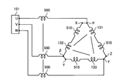
図1は実施の形態1に係る電動機の駆動装置の構成例を示す図である。電動機の駆動装置400は、交流電源20から供給される交流電力を、電動機130を駆動可能な周波数の交流電力に変換する電力変換装置である。電動機の駆動装置400は、インバータ基板100、ノイズ抑制部110、リレー基板200、第1の交流配線である交流配線140、第2の交流配線である交流配線150、及び第3の交流配線である交流配線160を備える。Embodiment 1
FIG. 1 is a view showing a configuration example of a drive device for an electric motor according to a first embodiment. Themotor drive device 400 is a power conversion device that converts AC power supplied from the AC power supply 20 into AC power of a frequency that can drive the motor 130. The motor drive device 400 includes an inverter board 100, a noise suppression unit 110, a relay board 200, an AC wiring 140 which is a first AC wiring, an AC wiring 150 which is a second AC wiring, and a third AC wiring. AC wiring 160 is provided.
図1は実施の形態1に係る電動機の駆動装置の構成例を示す図である。電動機の駆動装置400は、交流電源20から供給される交流電力を、電動機130を駆動可能な周波数の交流電力に変換する電力変換装置である。電動機の駆動装置400は、インバータ基板100、ノイズ抑制部110、リレー基板200、第1の交流配線である交流配線140、第2の交流配線である交流配線150、及び第3の交流配線である交流配線160を備える。
FIG. 1 is a view showing a configuration example of a drive device for an electric motor according to a first embodiment. The
第1の基板であるインバータ基板100は、交流配線2、リアクトル30、整流器40、平滑コンデンサ50、インバータ60、制御部70及び検出部81を備える。交流配線2、リアクトル30、整流器40、平滑コンデンサ50、インバータ60、制御部70及び検出部81は、インバータ基板100の実装面に設けられる。実装面は、インバータ基板100に設けられる複数の端面の内、部品が実装される面である。
The inverter substrate 100 which is a first substrate includes an AC wiring 2, a reactor 30, a rectifier 40, a smoothing capacitor 50, an inverter 60, a control unit 70, and a detection unit 81. AC wiring 2, reactor 30, rectifier 40, smoothing capacitor 50, inverter 60, control unit 70 and detection unit 81 are provided on the mounting surface of inverter board 100. The mounting surface is a surface on which components are mounted among the plurality of end surfaces provided on the inverter substrate 100.
インバータ基板100の交流入力端子1a及び交流入力端子1bには、交流電源20と、交流配線2の一端とが接続される。交流配線2は、交流電源20から整流器40へ交流電力を伝送するために、インバータ基板100の実装面に形成されるパターン配線である。交流配線2の他端は、整流器40に接続される。
An alternating current power supply 20 and one end of an alternating current wiring 2 are connected to the alternating current input terminal 1 a and the alternating current input terminal 1 b of the inverter substrate 100. The AC wiring 2 is a pattern wiring formed on the mounting surface of the inverter substrate 100 in order to transmit AC power from the AC power supply 20 to the rectifier 40. The other end of the AC wiring 2 is connected to the rectifier 40.
力率改善用のリアクトル30は、交流配線2に設けられる。リアクトル30の一端は、交流入力端子1aと電気的に接続される。リアクトル30の他端は、整流器40と電気的に接続される。
A reactor 30 for improving the power factor is provided in the AC wiring 2. One end of reactor 30 is electrically connected to AC input terminal 1a. The other end of reactor 30 is electrically connected to rectifier 40.
整流器40は、交流電源20から供給される交流電力を整流する。整流器40は、4つのダイオードを組み合わせて構成される全波整流回路である。整流器40は、ダイオード以外にも、MOSFET(Metal Oxide Semiconductor-Field Effect Transistor)を複数組み合わせて構成されたものでもよい。
The rectifier 40 rectifies AC power supplied from the AC power supply 20. The rectifier 40 is a full wave rectifier circuit configured by combining four diodes. The rectifier 40 may be configured by combining a plurality of MOSFETs (Metal Oxide Semiconductor-Field Effect Transistors) in addition to the diodes.
平滑コンデンサ50は、整流器40で整流された電力を平滑化する。平滑コンデンサ50の一端は、直流母線3aに接続される。直流母線3aは、整流器40とインバータ60との間に設けられる高電位側の配線である。直流母線3aの一端は整流器40の正側出力端子40aに接続される。直流母線3aの他端はインバータ60の正側入力端子60aに接続される。平滑コンデンサ50の他端は、直流母線3bに接続される。直流母線3bは、整流器40とインバータ60との間に設けられる低電位側の配線である。直流母線3bの一端は整流器40の負側出力端子40bに接続される。直流母線3bの他端はインバータ60の負側入力端子60bに接続される。
The smoothing capacitor 50 smoothes the power rectified by the rectifier 40. One end of the smoothing capacitor 50 is connected to the DC bus 3a. The DC bus 3 a is a high potential side wiring provided between the rectifier 40 and the inverter 60. One end of the DC bus 3 a is connected to the positive output terminal 40 a of the rectifier 40. The other end of the DC bus 3 a is connected to the positive input terminal 60 a of the inverter 60. The other end of the smoothing capacitor 50 is connected to the DC bus 3b. The DC bus 3 b is a low potential side wiring provided between the rectifier 40 and the inverter 60. One end of the DC bus 3 b is connected to the negative output terminal 40 b of the rectifier 40. The other end of DC bus 3 b is connected to negative input terminal 60 b of inverter 60.
インバータ60は、平滑コンデンサ50で平滑化された電力を交流電力に変換し、変換した交流電力を電動機130へ供給する電力変換器である。インバータ60は、複数のスイッチング素子611から616と、複数の還流ダイオード621から626とを備える。以下では、スイッチング素子611から616のそれぞれを区別せずに示す場合には、単にスイッチング素子と称する。また以下では、複数の還流ダイオード621から626のそれぞれを区別せずに示す場合には、単にダイオードと称する。
The inverter 60 is a power converter that converts the power smoothed by the smoothing capacitor 50 into AC power and supplies the converted AC power to the motor 130. The inverter 60 includes a plurality of switching elements 611 to 616 and a plurality of free wheeling diodes 621 to 626. Hereinafter, when the switching elements 611 to 616 are shown without distinction, they are simply referred to as switching elements. Also, in the following, when each of the plurality of free wheeling diodes 621 to 626 is shown without distinction, it is simply referred to as a diode.
スイッチング素子611は、制御部70から出力される駆動信号Xaによりスイッチング動作を行う素子である。スイッチング素子611は、制御部70から出力される駆動信号Xaによりスイッチング動作を行う素子であればよく、バイポーラトランジスタに限定されない。スイッチング素子612から616のそれぞれも同様である。スイッチング動作は、スイッチング素子611のオン状態とスイッチング素子611のオフ状態とを切替える動作である。オン状態とは、スイッチング素子611のコレクタとエミッタ間に電流が流れる状態であり、オフ状態とは、スイッチング素子611のコレクタとエミッタ間に電流が流れない状態である。スイッチング素子611のコレクタは、正側入力端子60aに接続される。スイッチング素子611のエミッタは、スイッチング素子612のコレクタに接続される。スイッチング素子611及びスイッチング素子612の接続点は、インバータ60の出力端子60cに接続される。
The switching element 611 is an element that performs a switching operation according to the drive signal Xa output from the control unit 70. The switching element 611 may be an element that performs a switching operation by the drive signal Xa output from the control unit 70, and is not limited to a bipolar transistor. The same applies to each of the switching elements 612 to 616. The switching operation is an operation of switching between the on state of the switching element 611 and the off state of the switching element 611. The on state is a state in which current flows between the collector and the emitter of the switching element 611, and the off state is a state in which current does not flow between the collector and the emitter of the switching element 611. The collector of the switching element 611 is connected to the positive side input terminal 60a. The emitter of switching element 611 is connected to the collector of switching element 612. The connection point of switching element 611 and switching element 612 is connected to output terminal 60 c of inverter 60.
出力端子60cには、U相の交流配線63の一端が接続される。交流配線63は、インバータ60から電動機130へ交流電力を伝送するために、インバータ基板100の実装面に形成されるパターン配線である。U相の交流配線63の他端は、U相の交流出力端子101に接続される。
One end of the U-phase AC wiring 63 is connected to the output terminal 60c. The AC wiring 63 is a pattern wiring formed on the mounting surface of the inverter substrate 100 in order to transmit AC power from the inverter 60 to the motor 130. The other end of the U-phase AC wiring 63 is connected to the U-phase AC output terminal 101.
交流出力端子101は、インバータ基板100の実装面に設けられる端子である。U相の交流出力端子101には、U相の交流配線140の一端が接続される。交流配線140は、インバータ60から電動機130へ交流電力を伝送するために、交流出力端子101と電動機130との間に設けられる配線である。U相の交流配線140の他端は、電動機130のU相巻線131の一端に接続される。
The AC output terminal 101 is a terminal provided on the mounting surface of the inverter board 100. One end of the U-phase AC wiring 140 is connected to the U-phase AC output terminal 101. The AC wiring 140 is a wiring provided between the AC output terminal 101 and the motor 130 in order to transmit AC power from the inverter 60 to the motor 130. The other end of the U-phase AC wiring 140 is connected to one end of the U-phase winding 131 of the motor 130.
スイッチング素子612は、制御部70から出力される駆動信号Xbによりスイッチング動作を行うスイッチング素子である。スイッチング素子612のエミッタは、負側入力端子60bに接続される。
The switching element 612 is a switching element that performs switching operation according to the drive signal Xb output from the control unit 70. The emitter of the switching element 612 is connected to the negative input terminal 60b.
スイッチング素子613は、制御部70から出力される駆動信号Yaによりスイッチング動作を行うスイッチング素子である。スイッチング素子613のコレクタは、正側入力端子60aに接続される。スイッチング素子613のエミッタは、スイッチング素子614のコレクタに接続される。スイッチング素子613及びスイッチング素子614の接続点は、インバータ60の出力端子60dに接続される。出力端子60dには、V相の交流配線63の一端が接続される。V相の交流配線63の他端は、V相の交流出力端子101に接続される。V相の交流出力端子101には、V相の交流配線140の一端が接続される。V相の交流配線140の他端は、電動機130のV相巻線132の一端に接続される。
The switching element 613 is a switching element that performs a switching operation according to the drive signal Ya output from the control unit 70. The collector of the switching element 613 is connected to the positive side input terminal 60a. The emitter of switching element 613 is connected to the collector of switching element 614. The connection point between switching element 613 and switching element 614 is connected to output terminal 60 d of inverter 60. One end of a V-phase AC wiring 63 is connected to the output terminal 60 d. The other end of the V-phase AC wiring 63 is connected to the V-phase AC output terminal 101. One end of a V-phase AC wiring 140 is connected to the V-phase AC output terminal 101. The other end of V-phase AC wiring 140 is connected to one end of V-phase winding 132 of motor 130.
スイッチング素子614は、制御部70から出力される駆動信号Ybによりスイッチング動作を行うスイッチング素子である。スイッチング素子614のエミッタは、負側入力端子60bに接続される。
The switching element 614 is a switching element that performs a switching operation according to the drive signal Yb output from the control unit 70. The emitter of the switching element 614 is connected to the negative input terminal 60b.
スイッチング素子615は、制御部70から出力される駆動信号Zaによりスイッチング動作を行うスイッチング素子である。スイッチング素子615のコレクタは、正側入力端子60aに接続される。スイッチング素子615のエミッタは、スイッチング素子616のコレクタに接続される。スイッチング素子615及びスイッチング素子616の接続点は、インバータ60の出力端子60eに接続される。出力端子60eには、W相の交流配線63の一端が接続される。W相の交流配線63の他端は、W相の交流出力端子101に接続される。W相の交流出力端子101には、W相の交流配線140の一端が接続される。W相の交流配線140の他端は、電動機130のW相巻線133の一端に接続される。
The switching element 615 is a switching element that performs a switching operation according to the drive signal Za output from the control unit 70. The collector of the switching element 615 is connected to the positive side input terminal 60a. The emitter of switching element 615 is connected to the collector of switching element 616. The connection point between switching element 615 and switching element 616 is connected to output terminal 60 e of inverter 60. One end of the W-phase AC wiring 63 is connected to the output terminal 60 e. The other end of the W-phase AC wiring 63 is connected to the W-phase AC output terminal 101. One end of the W-phase AC wiring 140 is connected to the W-phase AC output terminal 101. The other end of the W-phase AC wiring 140 is connected to one end of a W-phase winding 133 of the motor 130.
スイッチング素子616は、制御部70から出力される駆動信号Zbによりスイッチング動作を行うスイッチング素子である。スイッチング素子616のエミッタは、負側入力端子60bに接続される。
The switching element 616 is a switching element that performs a switching operation according to the drive signal Zb output from the control unit 70. The emitter of the switching element 616 is connected to the negative input terminal 60b.
以下では、複数の駆動信号XaからZbのそれぞれを区別せずに示す場合には、単に駆動信号と称する。
Hereinafter, in the case where each of the plurality of drive signals Xa to Zb is shown without distinction, it is simply referred to as a drive signal.
還流ダイオード621は、スイッチング素子611に逆並列に接続される。即ち、還流ダイオード621の陰極であるカソードはスイッチング素子611のコレクタに接続され、還流ダイオード621の陽極であるアノードはスイッチング素子611のエミッタに接続される。なお、還流ダイオード621は、整流作用を有する素子であればよく、ダイオードに限定されない。還流ダイオード622から626のそれぞれも同様である。
The free wheeling diode 621 is connected in antiparallel to the switching element 611. That is, the cathode which is the cathode of the reflux diode 621 is connected to the collector of the switching element 611, and the anode which is the anode of the reflux diode 621 is connected to the emitter of the switching element 611. The free wheeling diode 621 may be an element having a rectifying function, and is not limited to the diode. The same applies to each of the freewheeling diodes 622 to 626.
同様に、還流ダイオード622は、スイッチング素子612に逆並列に接続される。還流ダイオード623は、スイッチング素子613に逆並列に接続される。還流ダイオード624は、スイッチング素子614に逆並列に接続される。還流ダイオード625は、スイッチング素子615に逆並列に接続される。還流ダイオード626は、スイッチング素子616に逆並列に接続される。
Similarly, the free wheeling diode 622 is connected in antiparallel to the switching element 612. The free wheeling diode 623 is connected in antiparallel to the switching element 613. The free wheeling diode 624 is connected in antiparallel to the switching element 614. The free wheeling diode 625 is connected in antiparallel to the switching element 615. The free wheeling diode 626 is connected in antiparallel to the switching element 616.
制御部70は、検出部81の電圧検出部80で検出された検出値と、検出部81の電流検出部90で検出された検出値との少なくとも一方に基づき、駆動信号及び切替信号SWを生成する。電圧検出部80は、直流母線3a及び直流母線3bに印加される電圧を検出し、検出した電圧検出値を制御部70へ出力する。電流検出部90は、直流母線3bに流れる電流を検出し、検出した電流検出値を制御部70へ出力する。切替信号SWは、結線切替部120の動作を制御する信号である。切替信号SWが結線切替部120に入力されることにより、電動機130の巻線の結線状態がY結線又はΔ結線に切替えられる。
The control unit 70 generates the drive signal and the switching signal SW based on at least one of the detection value detected by the voltage detection unit 80 of the detection unit 81 and the detection value detected by the current detection unit 90 of the detection unit 81. Do. Voltage detection unit 80 detects the voltage applied to DC bus 3 a and DC bus 3 b, and outputs the detected voltage detection value to control unit 70. Current detection unit 90 detects the current flowing through DC bus 3b, and outputs the detected current detection value to control unit 70. The switching signal SW is a signal that controls the operation of the connection switching unit 120. By inputting the switching signal SW to the connection switching unit 120, the connection state of the winding of the motor 130 is switched to Y connection or Δ connection.
なお、電圧検出部80及び電流検出部90が設けられる位置は、制御部70が動作するために必要な情報を検出可能な位置であればよく、図1に示す位置に限定されない。具体的には、電圧検出部80は、平滑コンデンサ50と並列に設けられる抵抗によって分圧された電圧を検出可能な位置に設けてもよい。このように設けられた電圧検出部80は、平滑コンデンサ50の両端電圧、即ち、インバータ60の入力側電圧を、制御部70が検出可能な電圧に変換して出力する。電流検出部90は、交流配線63に流れる電流を検出可能な位置に設けてもよい。このように設けられた電流検出部90では、インバータ60から電動機130に流れる電流が検出される。
The position where the voltage detection unit 80 and the current detection unit 90 are provided may be any position that can detect information necessary for the operation of the control unit 70, and is not limited to the position shown in FIG. Specifically, the voltage detection unit 80 may be provided at a position where the voltage divided by the resistor provided in parallel with the smoothing capacitor 50 can be detected. The voltage detection unit 80 thus provided converts the voltage across the smoothing capacitor 50, that is, the input-side voltage of the inverter 60 into a voltage detectable by the control unit 70 and outputs the voltage. The current detection unit 90 may be provided at a position where the current flowing through the AC wiring 63 can be detected. In the current detection unit 90 provided in this manner, the current flowing from the inverter 60 to the motor 130 is detected.
結線切替部120は、第2の基板であるリレー基板200の実装面に設けられる。結線切替部120は、電動機130の巻線の結線状態を、Y結線からΔ結線に切替え、又はΔ結線からY結線に切替える切替器である。結線切替部120は、切替器121、切替器122及び切替器123を備える。切替器121、切替器122及び切替器123のそれぞれは、c接点型のリレーである。
The wire connection switching unit 120 is provided on the mounting surface of the relay substrate 200 which is the second substrate. The wire connection switching unit 120 is a switch that switches the wire connection state of the winding of the motor 130 from Y connection to Δ connection or from Δ connection to Y connection. The connection switching unit 120 includes a switch 121, a switch 122, and a switch 123. Each of the switch 121, the switch 122, and the switch 123 is a c-contact type relay.
切替器121は、接点a、接点b及び接点cを備える。接点cは、通電時に接点aと接続され、非通電時に接点bと接続される。
The switch 121 includes a contact a, a contact b, and a contact c. The contact c is connected to the contact a when energized and is connected to the contact b when deenergized.
切替器121の接点aは、交流配線150のW相の配線150bを介して、入力端子dに接続される。交流配線150は、交流配線140に結線切替部120を接続するための配線である。交流配線150は、配線150a及び配線150bを備える。配線150aは交流配線140とリレー基板200との間に設けられる配線である。配線150bはリレー基板200の実装面に形成されるパターン配線である。W相の配線150bの一端は、入力端子dに接続される。W相の配線150bの他端は、切替器121の接点aに接続される。入力端子dは、リレー基板200の実装面に設けられる端子である。W相の配線150aの一端は、入力端子dに接続される。W相の配線150aの他端は、W相の交流配線140に接続される。W相の配線150aの他端と、W相の交流配線140との接続点は、符号γで示される。接続点γの位置は、W相の交流配線140の内、ノイズ抑制部110と電動機130との間である。
The contact a of the switch 121 is connected to the input terminal d through the W-phase wiring 150 b of the AC wiring 150. The AC wire 150 is a wire for connecting the wire connection switching unit 120 to the AC wire 140. The AC wiring 150 includes a wiring 150 a and a wiring 150 b. The wiring 150 a is a wiring provided between the AC wiring 140 and the relay substrate 200. The wiring 150 b is a pattern wiring formed on the mounting surface of the relay substrate 200. One end of the W-phase wiring 150 b is connected to the input terminal d. The other end of the W-phase wiring 150 b is connected to the contact a of the switch 121. The input terminal d is a terminal provided on the mounting surface of the relay substrate 200. One end of the W-phase wiring 150a is connected to the input terminal d. The other end of the W-phase interconnection 150 a is connected to the W-phase AC interconnection 140. The connection point between the other end of the W-phase wire 150 a and the W-phase AC wire 140 is indicated by symbol γ. The position of the connection point γ is between the noise suppression unit 110 and the motor 130 in the W-phase AC wiring 140.
切替器121の接点bは、端子210と電気的に接続される。端子210はリレー基板200の実装面に設けられる端子であり、Δ結線時の中性点となる端子である。
The contact b of the switch 121 is electrically connected to the terminal 210. The terminal 210 is a terminal provided on the mounting surface of the relay substrate 200, and is a terminal serving as a neutral point in the Δ connection.
切替器121の接点cは、交流配線160のU相の配線160bを介して、入力端子Zに接続される。交流配線160は、電動機130に結線切替部120を接続するための配線である。交流配線160は、配線160a及び配線160bを備える。配線160aは電動機130とリレー基板200との間に設けられる配線である。配線160bはリレー基板200の実装面に形成されるパターン配線である。U相の配線160bの一端は、切替器121の接点cに接続される。U相の配線160bの他端は、入力端子Zに接続される。入力端子Zは、リレー基板200の実装面に設けられる端子である。U相の配線160aの一端は、入力端子Zに接続される。U相の配線160aの他端は、電動機130のU相巻線131の他端に接続される。
The contact c of the switching device 121 is connected to the input terminal Z via the U-phase wiring 160 b of the AC wiring 160. The AC wire 160 is a wire for connecting the wire connection switching unit 120 to the motor 130. The AC wiring 160 includes a wiring 160 a and a wiring 160 b. The wire 160 a is a wire provided between the motor 130 and the relay substrate 200. The wiring 160 b is a pattern wiring formed on the mounting surface of the relay substrate 200. One end of the U-phase wiring 160 b is connected to the contact c of the switch 121. The other end of the U-phase wiring 160 b is connected to the input terminal Z. The input terminal Z is a terminal provided on the mounting surface of the relay substrate 200. One end of the U-phase wiring 160 a is connected to the input terminal Z. The other end of the U-phase wire 160 a is connected to the other end of the U-phase winding 131 of the motor 130.
切替器121が接続状態Aのとき、U相巻線131の他端は、接続点γと電気的に接続される。接続状態Aは接点cが接点aと接続されている状態である。切替器121が接続状態Bのとき、U相巻線131の他端は、切替器122及び切替器123のそれぞれの接点bと電気的に接続される。接続状態Bは、接点cが接点bと接続されている状態である。
When the switch 121 is in the connection state A, the other end of the U-phase winding 131 is electrically connected to the connection point γ. The connection state A is a state in which the contact c is connected to the contact a. When the switch 121 is in the connection state B, the other end of the U-phase winding 131 is electrically connected to the contacts b of the switch 122 and the switch 123. The connection state B is a state in which the contact c is connected to the contact b.
切替器122の接点aは、U相の配線150bを介して、入力端子eに接続される。U相の配線150bの一端は、入力端子eに接続される。U相の配線150bの他端は、切替器122の接点aに接続される。入力端子eは、リレー基板200の実装面に設けられる端子である。U相の配線150aの一端は、入力端子eに接続される。U相の配線150aの他端は、U相の交流配線140に接続される。U相の配線150aの他端と、U相の交流配線140との接続点は、符号αで示される。接続点αの位置は、U相の交流配線140の内、ノイズ抑制部110と電動機130との間である。
The contact a of the switch 122 is connected to the input terminal e via the U-phase wire 150 b. One end of the U-phase wiring 150 b is connected to the input terminal e. The other end of the U-phase wiring 150 b is connected to the contact a of the switch 122. The input terminal e is a terminal provided on the mounting surface of the relay substrate 200. One end of the U-phase wiring 150 a is connected to the input terminal e. The other end of the U-phase interconnection 150 a is connected to the U-phase AC interconnection 140. A connection point between the other end of the U-phase wiring 150 a and the U-phase AC wiring 140 is indicated by a symbol α. The position of the connection point α is between the noise suppression unit 110 and the motor 130 in the U-phase AC wiring 140.
切替器122の接点bは、端子210と電気的に接続される。
The contact b of the switch 122 is electrically connected to the terminal 210.
切替器122の接点cは、交流配線160のV相の配線160bを介して、入力端子Xに接続される。V相の配線160bの一端は、切替器122の接点cに接続される。V相の配線160bの他端は、入力端子Xに接続される。入力端子Xは、リレー基板200の実装面に設けられる端子である。V相の配線160aの一端は、入力端子Xに接続される。V相の配線160aの他端は、電動機130のV相巻線132の他端に接続される。
The contact point c of the switch 122 is connected to the input terminal X via the V-phase wiring 160 b of the AC wiring 160. One end of the V-phase wiring 160 b is connected to the contact c of the switch 122. The other end of the V-phase wiring 160 b is connected to the input terminal X. The input terminal X is a terminal provided on the mounting surface of the relay substrate 200. One end of the V-phase wiring 160 a is connected to the input terminal X. The other end of the V-phase wiring 160 a is connected to the other end of the V-phase winding 132 of the motor 130.
切替器122が接続状態Aのとき、V相巻線132の他端は、接続点αと電気的に接続される。切替器122が接続状態Bのとき、V相巻線132の他端は、切替器121及び切替器123のそれぞれの接点bと電気的に接続される。
When the switch 122 is in the connection state A, the other end of the V-phase winding 132 is electrically connected to the connection point α. When the switch 122 is in the connection state B, the other end of the V-phase winding 132 is electrically connected to the contacts b of the switch 121 and the switch 123.
切替器123の接点aは、V相の配線150bを介して、入力端子fに接続される。V相の配線150bの一端は、入力端子fに接続される。V相の配線150bの他端は、切替器123の接点aに接続される。入力端子fは、リレー基板200の実装面に設けられる端子である。V相の配線150aの一端は、入力端子fに接続される。V相の配線150aの他端は、V相の交流配線140に接続される。V相の配線150aの他端と、V相の交流配線140との接続点は、符号βで示される。接続点βの位置は、V相の交流配線140の内、ノイズ抑制部110と電動機130との間である。
The contact a of the switch 123 is connected to the input terminal f via the V-phase wiring 150 b. One end of the V-phase wiring 150 b is connected to the input terminal f. The other end of the V-phase wiring 150 b is connected to the contact a of the switch 123. The input terminal f is a terminal provided on the mounting surface of the relay substrate 200. One end of the V-phase wiring 150 a is connected to the input terminal f. The other end of the V-phase interconnection 150 a is connected to the V-phase AC interconnection 140. A connection point between the other end of the V-phase wiring 150a and the V-phase AC wiring 140 is indicated by a symbol β. The position of the connection point β is between the noise suppression unit 110 and the motor 130 in the V-phase AC wiring 140.
切替器123の接点bは、端子210と電気的に接続される。
The contact b of the switch 123 is electrically connected to the terminal 210.
切替器123の接点cは、交流配線160のW相の配線160bを介して、入力端子Yに接続される。W相の配線160bの一端は、切替器123の接点cに接続される。W相の配線160bの他端は、入力端子Yに接続される。入力端子Yは、リレー基板200の実装面に設けられる端子である。入力端子Yには、W相の配線160aの一端が接続される。W相の配線160aの他端は、電動機130のW相巻線133の他端に接続される。
The contact c of the switch 123 is connected to the input terminal Y via the W-phase wiring 160 b of the AC wiring 160. One end of the W-phase wiring 160 b is connected to the contact c of the switch 123. The other end of the W-phase wiring 160 b is connected to the input terminal Y. The input terminal Y is a terminal provided on the mounting surface of the relay substrate 200. One end of a W-phase wire 160 a is connected to the input terminal Y. The other end of the W-phase wire 160 a is connected to the other end of the W-phase winding 133 of the motor 130.
切替器123が接続状態Aのとき、W相巻線133の他端は、接続点βと電気的に接続される。切替器123が接続状態Bのとき、W相巻線133の他端は、切替器121及び切替器122のそれぞれの接点bと電気的に接続される。
When the switch 123 is in the connection state A, the other end of the W-phase winding 133 is electrically connected to the connection point β. When the switch 123 is in the connection state B, the other end of the W-phase winding 133 is electrically connected to the contacts b of the switch 121 and the switch 122.
ノイズ抑制部110は、U相、V相及びW相の3つの交流配線140に設けられる。具体的には、ノイズ抑制部110は、交流出力端子101から電動機130まで伸びる交流配線140の内、交流出力端子101から接続点α,β,γまでの間の配線に設けられる。ノイズ抑制部110には、円筒状の磁性体、インダクタ又はバイパスコンデンサを例示できる。磁性体にはフェライトコアが用いられる。フェライトコアは、交流配線140に設けられてもよいし、交流配線140に隣接して設けられる電力信号線又はアース線に設けられてもよい。電力信号線は、交流出力端子101から電動機130まで伸びる信号伝送用配線である。信号伝送用配線は、モータの回転位置検出情報の伝送に利用される。アース線は、交流出力端子101から電動機130まで伸びる接地用配線である。インダクタにはフェライトビーズ、チョークコイル又はリアクトルが用いられる。バイパスコンデンサにはアクロスザラインコンデンサ又はラインバイパスコンデンサが用いられる。ノイズ抑制部110は、磁性体、インダクタ及びバイパスコンデンサの内の一つで構成したものでもよいし、磁性体、インダクタ及びバイパスコンデンサの内の複数のものを組み合わせて構成したものでもよい。
The noise suppression unit 110 is provided to the three AC wirings 140 of the U phase, the V phase, and the W phase. Specifically, the noise suppression unit 110 is provided in the wiring from the AC output terminal 101 to the connection points α, β, and γ among the AC wiring 140 extending from the AC output terminal 101 to the motor 130. The noise suppression unit 110 can be exemplified by a cylindrical magnetic body, an inductor, or a bypass capacitor. A ferrite core is used for the magnetic body. The ferrite core may be provided to the AC wiring 140 or may be provided to a power signal line or an earth wire provided adjacent to the AC wiring 140. The power signal line is a signal transmission wiring extending from the AC output terminal 101 to the motor 130. The signal transmission wiring is used to transmit rotational position detection information of the motor. The earth wire is a grounding wire extending from the AC output terminal 101 to the motor 130. A ferrite bead, a choke coil or a reactor is used for the inductor. As the bypass capacitor, an across-the-line capacitor or a line bypass capacitor is used. The noise suppression unit 110 may be configured by one of a magnetic body, an inductor and a bypass capacitor, or may be configured by combining a plurality of magnetic bodies, an inductor and a bypass capacitor.
電動機130は、U相巻線131、V相巻線132及びW相巻線133を備える。U相巻線131、V相巻線132及びW相巻線133は、切替器121から123の接続状態により、Y結線又はΔ結線に切替えが可能である。電動機130の巻線の結線状態が、Y結線又はΔ結線に切替えられることにより、電動機130の高出力駆動及び高効率駆動が可能である。以下では、U相巻線131、V相巻線132及びW相巻線133のそれぞれを区別せずに示す場合には、単に巻線と称する。
The motor 130 includes a U-phase winding 131, a V-phase winding 132 and a W-phase winding 133. U-phase winding 131, V-phase winding 132 and W-phase winding 133 can be switched to Y connection or Δ connection depending on the connection state of switches 121 to 123. By switching the wire connection state of the motor 130 to Y connection or Δ connection, high output drive and high efficiency drive of the motor 130 are possible. Hereinafter, the U-phase winding 131, the V-phase winding 132, and the W-phase winding 133 are simply referred to as windings when they are shown without distinction.
次に図2及び図3を参照して、電動機130の巻線の結線状態がY結線又はΔ結線に切替えられる理由を説明する。
Next, with reference to FIG. 2 and FIG. 3, the reason why the wire connection state of the winding of the motor 130 is switched to Y connection or Δ connection will be described.
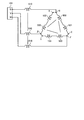
図2は実施の形態1に係る電動機の駆動装置によって結線状態がY結線となっている巻線を示す図である。切替器121から123のそれぞれが接続状態Bのとき、電動機130の巻線の結線状態は、図2に示すようにY結線となる。図2に示されるインダクタンス500は、図1のノイズ抑制部110が磁性体である場合に、Y結線時の交流配線140に形成されるインダクタンス成分である。
FIG. 2 is a view showing a winding whose connection state is Y connection by the drive device for an electric motor according to the first embodiment. When each of the switches 121 to 123 is in the connection state B, the wire connection state of the winding of the motor 130 is Y connection as shown in FIG. The inductance 500 shown in FIG. 2 is an inductance component formed in the AC wiring 140 at the time of Y connection when the noise suppression unit 110 of FIG. 1 is a magnetic body.
図3は実施の形態1に係る電動機の駆動装置によって結線状態がΔ結線となっている巻線を示す第1の図である。切替器121から123のそれぞれが接続状態Aのとき、電動機130の巻線の結線状態は、図3に示すようにΔ結線となる。図3に示されるインダクタンス500は、図1のノイズ抑制部110が磁性体である場合に、Δ結線時の交流配線140に形成されるインダクタンス成分である。
FIG. 3 is a first view showing a winding whose connection state is Δ connection by the motor drive device according to the first embodiment. When each of the switches 121 to 123 is in the connection state A, the wire connection state of the winding of the motor 130 is Δ connection as shown in FIG. The inductance 500 shown in FIG. 3 is an inductance component formed in the AC wiring 140 at the time of Δ connection when the noise suppression unit 110 in FIG. 1 is a magnetic body.
Y結線時の電動機130の線間電圧をVYとし、Y結線時に流れる電流をIYと定義する。またΔ結線時の電動機130の線間電圧をVΔとし、Δ結線時に流れる電流をIΔと定義する。このように定義した場合、線間電圧VYは、VY=√3×VΔで表すことができる。また電流IΔは、√3×IY=IΔで表すことができる。即ち、Δ結線時の電流は、Δ結線の電動機130と同一回転数でのY結線時の電流より大きくなるが、Δ結線時の電動機130の駆動に必要な電圧は、Δ結線の電動機130と同一回転数でのY結線時の電圧より低くできる。
The line voltage of the motor 130 in Y connection is VY, and the current flowing in Y connection is defined as IY. Further, the line voltage of the motor 130 at the time of Δ connection is VΔ, and the current flowing at the time of Δ connection is defined as IΔ. When defined in this manner, the line voltage VY can be expressed as VY = √3 × VΔ. The current IΔ can be expressed by √3 × IY = IΔ. That is, the current at the time of Δ connection is larger than the current at the same rotation speed as the motor 130 at Δ connection, but the voltage necessary for driving the motor 130 at the time of Δ connection is the motor 130 of Δ connection It can be lower than the voltage at Y connection at the same rotation speed.
近年の省エネルギー化のニーズの高まりにより、電動機130にはブラシレスDCモータが広く用いられている。ブラシレスDCモータの回転子には永久磁石が用いられる。電動機130にブラシレスDCモータを用いた場合、回転子の回転数が上昇する程、電動機130の逆起電圧が増加し、電動機130の駆動に必要な電圧値が増加する。逆起電圧は、電動機130の発電作用により、電動機130の駆動時に流れる電流の方向とは逆方向に、電流を流す起電圧である。
With the recent increase in needs for energy saving, a brushless DC motor is widely used as the motor 130. A permanent magnet is used for the rotor of the brushless DC motor. When a brushless DC motor is used as the motor 130, the back electromotive voltage of the motor 130 increases as the rotational speed of the rotor increases, and the voltage value necessary to drive the motor 130 increases. The back electromotive force is an electromotive voltage that causes a current to flow in the direction opposite to the direction of the current flowing when the motor 130 is driven by the power generation operation of the motor 130.
ここで、インバータ60によりY結線の電動機130を駆動する場合、Δ結線の電動機130を駆動するときに比べて、Δ結線の電動機130と同一回転数での電動機130の駆動に必要な電圧が増加する。そして、電動機130の駆動に必要な電圧が増加するに従い、逆起電圧も増加する。逆起電圧の増加を抑制するためには、永久磁石の磁力を低下させ、又は固定子の巻線を巻ほどくといった措置が必要になるが、この措置を施した場合、電動機130及びインバータ60に流れる電流が増加するため、効率の低下が避けられない。そこで、電動機130を特定の回転数より高い回転数で駆動する場合、Y結線からΔ結線に切替えることにより、電動機130の駆動に必要な電圧は、Y結線時の電圧の1/√3倍となる。そのため、上記の措置を施すことなく、電動機130の運転を継続できる。
Here, when the Y-connected motor 130 is driven by the inverter 60, the voltage required for driving the motor 130 at the same rotational speed as the Δ-connected motor 130 increases compared to when the Δ-connected motor 130 is driven. Do. Then, as the voltage required to drive the motor 130 increases, the back electromotive force also increases. In order to suppress the increase of the back electromotive force, it is necessary to reduce the magnetic force of the permanent magnet or to unroll the stator winding. When this measure is taken, the motor 130 and the inverter 60 are A decrease in efficiency is inevitable due to the increased current flow. Therefore, when the motor 130 is driven at a rotational speed higher than a specific rotational speed, the voltage necessary for driving the motor 130 is 1 / √3 times the voltage at the Y connection by switching from Y connection to Δ connection. Become. Therefore, the operation of the motor 130 can be continued without taking the above measures.
例えば、電動機130が空気調和機に用いられる場合、近年の空気調和機は、運転開始時の設定温度と室温との差が特定の値よりも大きいとき、設定温度に近づくまでは電動機130の回転数を上げることで、室温を設定温度に近づける。一方、設定温度と室温とが概ね一致しているとき、空気調和機は、電動機130の回転数を低下させる。概ね一致とは、設定温度と室温との温度差を例えば0.5℃以内とすることである。ここで、全体の運転時間に対して低速運転時間が占める割合は、全体の運転時間に対して高速運転時間が占める割合よりも大きい。低速運転時間は、特定の回転数よりも低い低回転数で電動機130が運転する時間である。高速運転時間は、特定の回転数よりも高い高回転数で電動機130が運転する時間である。そのため、電動機の駆動装置400は、低回転数で電動機130を駆動する場合には、駆動電圧が低いため、電流を低減することが可能なY結線とし、高回転数で電動機130を駆動する場合には、Δ結線とする。低回転数で電動機130を駆動する際にY結線にすることにより、Δ結線時に比べて、電動機130に流れる電流の値を1/√3倍にできるだけでなく、Y結線時の巻線の線径及び巻数を低回転数で最適となるように設定できる。そのため、Y結線で全回転数域を駆動することを前提に構成された電動機130に比べて、電動機130に流れる電流の値を低減できる。従って、インバータ60に電流が流れることで発生する損失を低減でき、インバータ60における電力変換効率が向上する。
For example, when the motor 130 is used for an air conditioner, the air conditioner in recent years rotates the motor 130 until the set temperature is approached when the difference between the set temperature at the start of operation and the room temperature is larger than a specific value. By raising the number, the room temperature approaches the set temperature. On the other hand, the air conditioner reduces the rotational speed of the motor 130 when the set temperature and the room temperature substantially match. The general agreement means that the temperature difference between the set temperature and the room temperature is, for example, within 0.5 ° C. Here, the ratio of the low speed operation time to the entire operation time is larger than the ratio of the high speed operation time to the entire operation time. The low speed operation time is a time during which the motor 130 operates at a low rotational speed lower than a specific rotational speed. The high speed operation time is a time during which the motor 130 is operated at a high rotational speed higher than a specific rotational speed. Therefore, in the case where the motor drive device 400 drives the motor 130 at a low rotation speed, the drive voltage is low, and thus the Y connection can be made to reduce the current, and the motor 130 is driven at a high rotation speed. Use the Δ connection. By using Y connection when driving motor 130 at a low rotational speed, the value of the current flowing through motor 130 can not only be 1 / √3 times that of Δ connection, but also the winding wire at Y connection The diameter and the number of turns can be set to be optimum at a low rotational speed. Therefore, the value of the current flowing through the motor 130 can be reduced compared to the motor 130 configured to drive the entire rotation speed range by Y connection. Therefore, the loss which generate | occur | produces because the electric current flows into the inverter 60 can be reduced, and the power conversion efficiency in the inverter 60 improves.
一方、高回転数で電動機130を駆動する場合、電動機の駆動装置400は、電動機130の巻線の結線状態をΔ結線とする。これにより、Y結線時の巻線の線径及び巻数を低回転数で最適となるように設定された電動機130に比べて、1/√3倍の電圧で電動機130を駆動できる。従って、巻線を巻ほどくこと無く全回転数領域で電動機130を駆動でき、また必要以上に電流値を増加させる弱め磁束制御を用いることなく、全回転数領域を駆動できる。
On the other hand, when the motor 130 is driven at a high rotational speed, the drive device 400 of the motor sets the wire connection state of the motor 130 to Δ connection. As a result, the motor 130 can be driven at a voltage 1 / 倍 3 times the voltage of the motor 130 set so as to optimize the wire diameter and the number of turns of the winding at the time of Y connection. Therefore, the motor 130 can be driven in the entire rotation number region without unwinding the winding, and the entire rotation number region can be driven without using flux-weakening control to increase the current value more than necessary.
但し、実施の形態1に係る電動機の駆動装置400は、巻線の結線状態をY結線又はΔ結線に切替える結線切替機構を備えるため、結線切替機構を備えない電動機の駆動装置に比べて、電動機の駆動装置400と電動機130との間の交流配線数が3倍になる。即ち、結線切替機構を備えない電動機の駆動装置では、1つの交流配線により、電動機の駆動装置と電動機とが接続されるのに対して、実施の形態1に係る電動機の駆動装置400では、交流配線140、交流配線150及び交流配線160が必要になる。交流配線の数が増加する程、EMI対策部品の取付箇所が増加する。従って、EMI対策構造が大型化かつ複雑化する。また空気調和機の室外機に、電動機の駆動装置400が設置される場合、EMI対策構造が大型化すると、室外機の筐体への、電動機の駆動装置400の取付け場所を確保できない可能性がある。そのため、室外機の筐体を大きくし、又は室外機内部の部品配置を見直すといった措置が必要になる。室外機の筐体は、室外機の内部に設けられる電気品箱、又は室外機の外郭を構成する筐体である。またEMI対策部品の取付箇所が増加することにより、EMI対策費用が増加し、さらにEMI対策部品による損失が増加することが懸念される。EMI対策部品による損失について説明すると、例えばEMI対策部品にフェライトコアが用いられている場合、高周波領域ではリアクタンスが抵抗成分として顕在化し、交流配線140に流れる電流が熱に変換される。この熱がEMI対策部品による損失に相当する。
However, since the motor drive device 400 according to the first embodiment includes the wire connection switching mechanism that switches the wire connection state to Y connection or Δ wire connection, the motor does not have the wire connection switching mechanism compared to the motor drive device. The number of AC wires between the drive device 400 and the motor 130 is tripled. That is, in the drive device for the motor not provided with the wire connection switching mechanism, the drive device for the motor and the motor are connected by one AC wiring, while in the drive device 400 for the motor according to the first embodiment, the AC Wiring 140, AC wiring 150 and AC wiring 160 are required. As the number of AC wiring increases, the number of mounting points of the EMI suppression component increases. Therefore, the EMI countermeasure structure becomes larger and more complicated. Further, when the motor drive device 400 is installed in the outdoor unit of the air conditioner, if the EMI countermeasure structure is enlarged, there is a possibility that the mounting place of the motor drive device 400 on the casing of the outdoor unit can not be secured. is there. Therefore, it is necessary to take measures such as enlarging the casing of the outdoor unit or reviewing the arrangement of components inside the outdoor unit. The casing of the outdoor unit is an electrical item box provided inside the outdoor unit, or a casing forming an outer shell of the outdoor unit. In addition, there is a concern that the increase in EMI countermeasure cost and the loss due to the EMI countermeasure part may increase due to the increase in the number of attachment points of the EMI countermeasure part. Describing the loss due to the EMI countermeasure component, for example, when a ferrite core is used for the EMI countermeasure component, reactance is manifested as a resistive component in a high frequency region, and the current flowing through the AC wiring 140 is converted to heat. This heat corresponds to the loss due to the EMI countermeasure component.
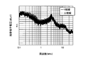
図4は図1に示すインバータと電動機との間にノイズ抑制部を設けていない場合における雑音端子電圧特性を示す図である。図4の縦軸は雑音端子電圧を表し、図4の横軸は周波数を表す。実線はY結線時の雑音端子電圧特性である。破線はΔ結線時の雑音端子電圧特性である。雑音端子電圧特性は、周波数特性又はノイズレベルを表す。電動機130の仕様と、電動機の駆動装置400の仕様とが変わることにより、雑音端子電圧特性も変化する。すなわち、インバータ60を構成するスイッチング素子と、インバータ60の出力電圧レベルと、スイッチング素子のスイッチング周波数と、電動機130の負荷要求と、電動機130の駆動周波数と、インバータ60と電動機130との間の配線の長さとが変わることによって、雑音端子電圧特性は変化する。実施の形態1に係る電動機の駆動装置400の構成例は、図示例に限定されないため、雑音端子電圧特性も図4に示されるものに限定されない。Δ結線時の雑音端子電圧特性では、インバータ60が駆動することで発生するスイッチングノイズに加えて、電動機130の三相巻線間に流れる循環電流に起因するノイズが発生する。電動機130の三相巻線間に流れる循環電流は、U相巻線131、V相巻線132及びW相巻線133の間に循環する電流である。
FIG. 4 is a diagram showing noise terminal voltage characteristics in the case where the noise suppression unit is not provided between the inverter and the motor shown in FIG. The vertical axis of FIG. 4 represents the noise terminal voltage, and the horizontal axis of FIG. 4 represents the frequency. The solid line is the noise terminal voltage characteristic at Y connection. The broken line is the noise terminal voltage characteristic at the time of Δ connection. The noise terminal voltage characteristics represent frequency characteristics or noise levels. By changing the specifications of the motor 130 and the specifications of the motor drive device 400, the noise terminal voltage characteristics also change. That is, the switching element constituting inverter 60, the output voltage level of inverter 60, the switching frequency of the switching element, the load requirement of motor 130, the driving frequency of motor 130, and the wiring between inverter 60 and motor 130 The noise terminal voltage characteristic is changed by changing the length of. The configuration example of the motor drive device 400 according to the first embodiment is not limited to the illustrated example, and therefore the noise terminal voltage characteristics are not limited to those shown in FIG. In addition to the switching noise generated when the inverter 60 is driven, noise due to circulating current flowing between the three-phase windings of the motor 130 is generated in the noise terminal voltage characteristic at the time of the Δ connection. The circulating current flowing between the three-phase windings of motor 130 is a current circulating between U-phase winding 131, V-phase winding 132 and W-phase winding 133.
そのため、Δ結線時の雑音端子電圧特性では、Y結線時の雑音端子電圧特性と比較して、ノイズ特性が200[kHz]から2[MHz]までの周波数帯域において、雑音端子電圧が増加する傾向にある。Y結線とΔ結線との結線切替機構を有する電動機の駆動装置400を構成する上では、Δ結線時の循環電流に起因するノイズ成分への対策手法の検討が必要不可欠である。
Therefore, in the noise terminal voltage characteristic at the time of Δ connection, the noise terminal voltage tends to increase in the frequency band from 200 [kHz] to 2 [MHz] compared to the noise terminal voltage characteristic at the Y connection. It is in. In configuring the motor drive device 400 having a connection switching mechanism of Y connection and Δ connection, it is essential to study measures against noise components caused by circulating current at Δ connection.
実施の形態1に係る電動機の駆動装置400は、このようなノイズ成分を低減するため、図1に示すように、接続点α,β,γと交流出力端子101との間にノイズ抑制部110が設けられる。接続点α,β,γと交流出力端子101との間にノイズ抑制部110を設けることにより、Δ結線及びY結線の何れの結線状態においても、インバータ60と電動機130との間に伝搬するEMIノイズが抑制される。
In order to reduce such noise components, motor drive device 400 according to the first embodiment reduces noise suppression unit 110 between connection points α, β, γ and AC output terminal 101 as shown in FIG. Is provided. By providing the noise suppression unit 110 between the connection points α, β, and γ and the AC output terminal 101, EMI propagated between the inverter 60 and the motor 130 in any connection state of Δ connection and Y connection. Noise is suppressed.
また、Δ結線及びY結線の何れの結線状態においても、インバータ60と電動機130との間では、インバータ60が駆動することで発生するスイッチングノイズが、EMIノイズの支配的要因となる。接続点α,β,γと交流出力端子101との間にノイズ抑制部110を設けることにより、インバータ60が駆動することで発生するスイッチングノイズを効果的に抑制できる。
In addition, in any of the connection states of the Δ connection and the Y connection, the switching noise generated by driving the inverter 60 between the inverter 60 and the motor 130 becomes a dominant factor of the EMI noise. By providing the noise suppression unit 110 between the connection points α, β, and γ and the AC output terminal 101, switching noise generated by driving the inverter 60 can be effectively suppressed.
また、実施の形態1に係る電動機の駆動装置400では、交流配線140にノイズ抑制部110が設けられる。従って、交流配線140、交流配線150及び交流配線160のそれぞれにEMI対策部品を取付ける場合に比べて、EMI対策部品の取付箇所が少なくて済む。そのため、EMI対策構造が簡素化され、電動機の駆動装置400の大型化と製造コストの増加とを抑制しながら、EMI対策構造を実現できる。またEMI対策部品の取付箇所が少なくて済むため、EMI対策部品の特性劣化及び故障発生の頻度が低減される。またEMI対策構造が簡素化されることにより、室外機の筐体への電動機の駆動装置400の取付け場所が確保し易くなり、室外機の筐体を大きくし、又は室外機内部の部品配置を見直すといった措置が不要になる。従って、室外機の大型化又は製造コストの上昇を抑制できる。また、EMI対策部品の取付箇所が少なくて済むため、前述したEMI対策部品による損失の増加が抑制され、電動機130を高効率かつ高出力に駆動可能である。またEMI対策部品の取付箇所が少なくて済むため、室外機の筐体へEMI対策部品を取付ける面積の増加が抑制される。さらに、EMI対策部品の取付箇所が少なくて済むため、EMI対策部品に巻かれる配線の長さを短くでき、配線長の増加を抑制できる。具体的には、フェライトコアをノイズ抑制部110として用いた場合、このフェライトコアには配線が複数回巻かれる。ノイズ抑制部110がフェライトコアである場合、当該配線は、交流配線140に相当する。EMI対策部品であるフェライトコアの数が少なくなることにより、フェライトコアに巻かれる配線長が短くなるため、配線の材料費と配線作業のコストとが低減される。またフェライトコアに巻かれる配線長が短くなるため、配線のインピーダンスが低減されて電動機130を高効率かつ高出力に駆動可能である。
In the motor drive device 400 according to the first embodiment, the AC wiring 140 is provided with the noise suppression unit 110. Therefore, compared with the case where the EMI suppression component is attached to each of the AC wiring 140, the AC wiring 150, and the AC wiring 160, the number of attachment places of the EMI suppression component can be reduced. Therefore, the EMI countermeasure structure is simplified, and the EMI countermeasure structure can be realized while suppressing an increase in size of the motor drive device 400 and an increase in manufacturing cost. In addition, since the number of attachment points of the EMI countermeasure components can be reduced, the frequency of the characteristic deterioration and failure occurrence of the EMI countermeasure components can be reduced. In addition, by simplifying the EMI countermeasure structure, it becomes easy to secure the mounting place of the drive device 400 of the motor to the casing of the outdoor unit, enlarge the casing of the outdoor unit, or arrange components inside the outdoor unit. It becomes unnecessary to take measures such as reviewing. Therefore, the enlargement of the outdoor unit or the increase in manufacturing cost can be suppressed. Further, since the number of attachment points of the EMI countermeasure components can be reduced, the increase in loss due to the EMI countermeasure components described above can be suppressed, and the motor 130 can be driven with high efficiency and high output. In addition, since the number of attachment points for the EMI countermeasure components can be reduced, an increase in the area for attaching the EMI countermeasure components to the casing of the outdoor unit is suppressed. Furthermore, since the number of attachment points of the EMI countermeasure components can be reduced, the length of the wiring wound on the EMI countermeasure components can be shortened, and an increase in the wiring length can be suppressed. Specifically, when a ferrite core is used as the noise suppression unit 110, a wire is wound multiple times on the ferrite core. When the noise suppression unit 110 is a ferrite core, the wiring corresponds to the AC wiring 140. By reducing the number of ferrite cores that are EMI suppression components, the length of wiring wound on the ferrite core becomes short, so that the material cost of the wiring and the cost of the wiring operation are reduced. Further, since the length of the wire wound around the ferrite core is shortened, the impedance of the wire is reduced, and the motor 130 can be driven with high efficiency and high output.
次に図5を参照して、Δ結線時の循環電流に起因するノイズの抑制方法について説明する。
Next, with reference to FIG. 5, a method of suppressing noise caused by circulating current at the time of Δ connection will be described.
図5は実施の形態1に係る電動機の駆動装置によって結線状態がΔ結線となっている巻線を示す第2の図である。図5には、磁性体で構成されるノイズ抑制部110によって、交流配線140に形成されるインダクタンス500と、インダクタンス510とが示される。インダクタンス510は、接続点α,β,γと接点aとの間の配線に、ノイズ抑制部110を追加で設けた場合に、追加されたノイズ抑制部110によって形成されるインダクタンスである。このようにノイズ抑制部110を追加で設けた場合、Δ結線時に、接続点α,β,γと電動機130の各巻線との間に、インダクタンス510が形成されるため、電動機130の三相巻線間に流れる循環電流に起因するノイズが抑制される。
FIG. 5 is a second view showing a winding whose connection state is Δ connection by the drive device for an electric motor according to the first embodiment. In FIG. 5, an inductance 500 and an inductance 510 which are formed on the AC wiring 140 by the noise suppression unit 110 made of a magnetic material are shown. The inductance 510 is an inductance formed by the added noise suppression unit 110 when the noise suppression unit 110 is additionally provided in the wiring between the connection points α, β, and γ and the contact point a. As described above, when the noise suppression unit 110 is additionally provided, an inductance 510 is formed between the connection points α, β, and γ and the windings of the motor 130 at the time of Δ connection. Noise due to circulating current flowing between the lines is suppressed.
なお実施の形態1では、リレー基板200の端子210から接点bまで伸びる配線に、ノイズ抑制部110を追加で設けてもよいし、接点cから入力端子X,Y,Zまで伸びる配線160bに、ノイズ抑制部110を追加で設けてもよい。このようにノイズ抑制部110を追加で設けることにより、Δ結線時には、配線160bに、追加されたノイズ抑制部によるインダクタンスが形成される。従って、三相巻線間に流れる循環電流に起因するノイズ成分が抑制される。一方、Y結線時には、交流配線140に図2に示すインダクタンス500が形成され、さらに端子210と入力端子X,Y,Zとの間の配線に、追加されたノイズ抑制部によるインダクタンスが形成される。従って、これらのインダクタンスを合算したインダクタンスにより、EMIノイズ抑制効果を高めることができる。
In the first embodiment, the noise suppression portion 110 may be additionally provided in the wiring extending from the terminal 210 of the relay substrate 200 to the contact b, or in the wiring 160b extending from the contact c to the input terminals X, Y, Z. The noise suppression unit 110 may be additionally provided. By additionally providing the noise suppressing portion 110 in this manner, an inductance by the added noise suppressing portion is formed in the wiring 160 b in the Δ connection. Therefore, the noise component resulting from the circulating current flowing between the three-phase windings is suppressed. On the other hand, at the time of Y connection, an inductance 500 shown in FIG. 2 is formed in AC wiring 140, and an inductance is formed by the added noise suppression portion in the wiring between terminal 210 and input terminals X, Y, Z. . Accordingly, the EMI noise suppression effect can be enhanced by the inductance obtained by adding these inductances.
なお、交流配線140は、インバータ基板100のパターン配線である交流配線63に直接接続してもよい。即ち、交流出力端子101を介さずに、交流配線63に交流配線140を接続してもよい。このように配線した場合でも、実施の形態1では、インバータ60から接続点α,β,γまでの間に一つのノイズ抑制部110が設けられているものとする。交流配線140にノイズ抑制部110を設けることにより、インバータ基板100上のパターン配線にEMI対策構造を設ける必要がなくなる。従って、パターン配線にEMI対策構造を設ける場合に比べて、パターン配線長を短くでき、またインバータ基板100上の配線構造が簡素化される。
Note that the AC wiring 140 may be directly connected to the AC wiring 63 which is a pattern wiring of the inverter substrate 100. That is, the AC wiring 140 may be connected to the AC wiring 63 without passing through the AC output terminal 101. Even in the case of such wiring, in the first embodiment, it is assumed that one noise suppression unit 110 is provided between the inverter 60 and the connection points α, β, and γ. By providing the noise suppressing portion 110 in the AC wiring 140, it is not necessary to provide the EMI countermeasure structure in the pattern wiring on the inverter substrate 100. Therefore, the pattern wiring length can be shortened and the wiring structure on the inverter substrate 100 can be simplified as compared with the case where the EMI countermeasure structure is provided in the pattern wiring.
なお、ノイズ抑制部110を交流配線140に設ける場合、ノイズ抑制部110は、インバータ基板100寄りに設けることが望ましい。即ち、交流配線140上におけるノイズ抑制部110から電動機130までの距離は、交流配線140上におけるノイズ抑制部110からインバータ60までの距離よりも長くすることが望ましい。これによりノイズ抑制部110を電動機130から遠ざけることができる。電動機130が駆動した際に発生する熱及び振動により、ノイズ抑制部110の特性劣化が進み、またノイズ抑制部110の故障発生の頻度が増加する恐れがある。ノイズ抑制部110を電動機130から遠ざけることにより、ノイズ抑制部110の特性劣化の進みを遅くでき、またノイズ抑制部110の故障発生の頻度を低減できる。
In addition, when providing the noise suppression part 110 in alternating current wiring 140, it is desirable to provide the noise suppression part 110 near the inverter board | substrate 100. FIG. That is, it is desirable that the distance from the noise suppression unit 110 to the motor 130 on the AC wiring 140 be longer than the distance from the noise suppression unit 110 to the inverter 60 on the AC wiring 140. Thereby, the noise suppression unit 110 can be kept away from the motor 130. Due to the heat and vibration generated when the motor 130 is driven, the characteristic deterioration of the noise suppression unit 110 may proceed, and the frequency of occurrence of failure of the noise suppression unit 110 may increase. By moving the noise suppression unit 110 away from the motor 130, the progress of the characteristic deterioration of the noise suppression unit 110 can be delayed, and the frequency of occurrence of failure of the noise suppression unit 110 can be reduced.
また実施の形態1に係る電動機の駆動装置400には、巻線をY結線からY結線に切替可能であり、また巻線をΔ結線からΔ結線に切替可能な機構を設けてもよい。具体的には、巻線の中間に切替スイッチを設け、要求負荷に応じて当該切替スイッチを動作させることにより三相巻線の巻数を調整する機構と、各相に巻線を二つ以上設け、要求負荷に応じて二つ以上の巻線のそれぞを連結させることにより三相巻線の巻数を調整する機構とが考えられる。但し、Y結線からY結線に切替る効果と、Δ結線からΔ結線に切替る効果とが得られれば、その構成は限定されない。
In the motor drive device 400 according to the first embodiment, the winding may be switched from Y connection to Y connection, and a mechanism capable of switching the winding from Δ connection to Δ connection may be provided. Specifically, a switch is provided in the middle of the winding, and a mechanism for adjusting the number of turns of the three-phase winding by operating the switch according to the required load, and providing two or more windings in each phase A mechanism is conceivable which adjusts the number of turns of the three-phase winding by connecting each of two or more windings in accordance with the required load. However, the configuration is not limited as long as the effect of switching from Y connection to Y connection and the effect of switching from Δ connection to Δ connection can be obtained.
実施の形態2.
図6は実施の形態2に係る電動機の駆動装置の構成例を示す図である。実施の形態2に係る電動機の駆動装置400-2は、リレー基板200の代わりにリレー基板200-2を備える。交流配線140は、交流配線140a、交流配線140b及び交流配線140cを備える。その他の構成については、実施の形態1の構成と同一又は同等であり、同一又は同等の構成部には同一の符号を付して、重複する説明は省略する。 Second Embodiment
FIG. 6 is a view showing a configuration example of a drive device for an electric motor according to a second embodiment. Drive device 400-2 of the motor according to the second embodiment includes relay substrate 200-2 instead ofrelay substrate 200. The AC wiring 140 includes an AC wiring 140a, an AC wiring 140b, and an AC wiring 140c. The other configuration is the same as or equivalent to the configuration of the first embodiment, and the same or equivalent components are denoted by the same reference numerals and redundant description will be omitted.
図6は実施の形態2に係る電動機の駆動装置の構成例を示す図である。実施の形態2に係る電動機の駆動装置400-2は、リレー基板200の代わりにリレー基板200-2を備える。交流配線140は、交流配線140a、交流配線140b及び交流配線140cを備える。その他の構成については、実施の形態1の構成と同一又は同等であり、同一又は同等の構成部には同一の符号を付して、重複する説明は省略する。 Second Embodiment
FIG. 6 is a view showing a configuration example of a drive device for an electric motor according to a second embodiment. Drive device 400-2 of the motor according to the second embodiment includes relay substrate 200-2 instead of
リレー基板200-2には、結線切替部120及び交流配線140bが設けられる。交流配線140bは、リレー基板200-2の実装面に形成されるパターン配線である。交流配線140bの一端は、交流配線140aの一端に接続される。交流配線140aは、インバータ基板100とリレー基板200-2との間に設けられる基板間配線である。U相の交流配線140bとU相の交流配線140aとの接続点は、接続点α’である。V相の交流配線140bとV相の交流配線140aとの接続点は、符号β’で示される。W相の交流配線140bとW相の交流配線140aとの接続点は、符号γ’で示される。U相の交流配線140aの他端は、U相の交流出力端子101に接続される。V相の交流配線140aの他端は、V相の交流出力端子101に接続される。W相の交流配線140aの他端は、W相の交流出力端子101に接続される。交流配線140aにはノイズ抑制部110が設けられる。
The connection switching unit 120 and the AC wiring 140b are provided on the relay substrate 200-2. The AC wiring 140b is a pattern wiring formed on the mounting surface of the relay substrate 200-2. One end of the AC wiring 140b is connected to one end of the AC wiring 140a. The AC wiring 140a is an inter-substrate wiring provided between the inverter substrate 100 and the relay substrate 200-2. A connection point between the U-phase AC wiring 140 b and the U-phase AC wiring 140 a is a connection point α ′. A connection point between the V-phase AC wiring 140 b and the V-phase AC wiring 140 a is indicated by a symbol β ′. A connection point between the W-phase AC wiring 140 b and the W-phase AC wiring 140 a is indicated by a symbol γ ′. The other end of the U-phase AC wiring 140 a is connected to the U-phase AC output terminal 101. The other end of the V-phase AC wiring 140 a is connected to the V-phase AC output terminal 101. The other end of the W-phase AC wiring 140 a is connected to the W-phase AC output terminal 101. The noise suppression unit 110 is provided in the AC wiring 140 a.
交流配線140bの他端は、交流配線140cの一端に接続される。交流配線140cは、リレー基板200-2と電動機130の巻線との間に設けられる電動機配線である。U相の交流配線140bとU相の交流配線140cとの接続点は、符号αで示される。V相の交流配線140bとV相の交流配線140cとの接続点は、符号βで示される。W相の交流配線140bとW相の交流配線140cとの接続点は、符号γで示される。U相の交流配線140cの他端は、U相巻線131の一端に接続される。V相の交流配線140cの他端は、V相巻線132の一端に接続される。W相の交流配線140cの他端は、W相巻線133の一端に接続される。
The other end of the AC wiring 140b is connected to one end of the AC wiring 140c. The AC wiring 140c is a motor wiring provided between the relay substrate 200-2 and the winding of the motor 130. A connection point between the U-phase AC wiring 140 b and the U-phase AC wiring 140 c is indicated by a symbol α. A connection point between the V-phase AC wiring 140 b and the V-phase AC wiring 140 c is indicated by a symbol β. A connection point between the W-phase AC wiring 140 b and the W-phase AC wiring 140 c is indicated by a symbol γ. The other end of the U-phase AC wiring 140 c is connected to one end of the U-phase winding 131. The other end of V-phase AC wiring 140 c is connected to one end of V-phase winding 132. The other end of the W-phase AC wiring 140 c is connected to one end of the W-phase winding 133.
交流配線150のW相の配線150bの一端は、W相の交流配線140bに接続される。W相の配線150bの他端は、切替器121の接点aに接続される。切替器121の接点aは、W相の配線150bを介して、W相の交流配線140bに接続される。交流配線150のU相の配線150bの一端は、U相の交流配線140bに接続される。U相の配線150bの他端は、切替器122の接点aに接続される。切替器122の接点aは、U相の配線150bを介して、U相の交流配線140bに接続される。交流配線150のV相の配線150bの一端は、V相の交流配線140bに接続される。V相の配線150bの他端は、切替器123の接点aに接続される。切替器123の接点aは、V相の配線150bを介して、V相の交流配線140bに接続される。
One end of the W-phase wiring 150 b of the AC wiring 150 is connected to the W-phase AC wiring 140 b. The other end of the W-phase wiring 150 b is connected to the contact a of the switch 121. The contact a of the switch 121 is connected to the W-phase AC wiring 140 b via the W-phase wiring 150 b. One end of the U-phase wiring 150 b of the AC wiring 150 is connected to the U-phase AC wiring 140 b. The other end of the U-phase wiring 150 b is connected to the contact a of the switch 122. The contact a of the switch 122 is connected to the U-phase AC wiring 140 b through the U-phase wiring 150 b. One end of the V-phase wiring 150 b of the AC wiring 150 is connected to the V-phase AC wiring 140 b. The other end of the V-phase wiring 150 b is connected to the contact a of the switch 123. The contact a of the switch 123 is connected to the V-phase AC wiring 140 b through the V-phase wiring 150 b.
実施の形態2では、電動機130がリレー基板200-2上の交流配線140bを介して、インバータ基板100に接続される。実施の形態1の交流配線140の長さは、実施の形態2の交流配線140cの長さよりも長いため、実施の形態1では、インバータ基板100の外側に交流配線140を中継するための端子台又はカシメが必要になる場合がある。端子台は、インバータ基板100から伸びる配線が接続される1次側端子と、電動機130から伸びる配線が接続される2次端子とを備えた端子台である。カシメは、インバータ基板100から伸びる配線の先端と、電動機130から伸びる配線の先端とを挿入する金属製のスリーブである。実施の形態2では、実施の形態1の交流配線140に比べて、交流配線140cの長さが短いため、端子台又はカシメを用いることなく、インバータ基板100と電動機130とを電気的に接続できる。従って、実施の形態2では、実施の形態1の効果に加えて、配線構造を簡素化できるという効果が得られる。また、実施の形態2では、交流配線140の配線長が実施の形態1よりも短くなるため、交流配線140の配線長が短くなる分、電動機の駆動装置400-2を軽量化できる。
In the second embodiment, motor 130 is connected to inverter board 100 via AC wiring 140b on relay board 200-2. Since the length of the AC wiring 140 of the first embodiment is longer than the length of the AC wiring 140c of the second embodiment, a terminal block for relaying the AC wiring 140 to the outside of the inverter substrate 100 in the first embodiment. Or caulking may be required. The terminal block is a terminal block including a primary side terminal to which a wire extending from the inverter substrate 100 is connected and a secondary terminal to which a wire extending from the motor 130 is connected. The caulking is a metal sleeve into which the end of the wire extending from the inverter substrate 100 and the end of the wire extending from the motor 130 are inserted. In the second embodiment, since the length of the AC wiring 140c is shorter than that of the AC wiring 140 of the first embodiment, the inverter substrate 100 and the motor 130 can be electrically connected without using a terminal block or caulking. . Therefore, in the second embodiment, in addition to the effects of the first embodiment, the effect that the wiring structure can be simplified can be obtained. Further, in the second embodiment, since the wiring length of the AC wiring 140 is shorter than that of the first embodiment, the motor driving device 400-2 can be reduced in weight by the reduction of the wiring length of the AC wiring 140.
なお、実施の形態2では、交流配線140aにノイズ抑制部110が設けられているため、実施の形態1と同様に、Δ結線及びY結線の何れの結線状態においても、インバータ60と電動機130との間に伝搬するEMIノイズが抑制される。また、交流配線140aにノイズ抑制部110を設けることにより、インバータ60が駆動することで発生するスイッチングノイズを効果的に抑制できる。また、交流配線140aにノイズ抑制部110を設けることにより、交流配線140及び交流配線160のそれぞれにEMI対策部品を取付ける場合に比べて、EMI対策部品の取付箇所が少なくて済む。そのため、EMI対策構造が簡素化され、電動機の駆動装置400-2の大型化と製造コストの増加とを抑制しながら、EMI対策構造を実現できる。
In the second embodiment, since the noise suppressing portion 110 is provided in the AC wiring 140a, the inverter 60 and the electric motor 130 are also connected in either the Δ connection or the Y connection as in the first embodiment. EMI noise that propagates between Further, by providing the noise suppressing portion 110 in the AC wiring 140a, it is possible to effectively suppress the switching noise generated by driving the inverter 60. Further, by providing the noise suppressing portion 110 in the AC wiring 140a, the number of attachment places of the EMI countermeasure components may be smaller than in the case where the EMI countermeasure components are attached to the AC wiring 140 and the AC wiring 160 respectively. Therefore, the EMI countermeasure structure is simplified, and the EMI countermeasure structure can be realized while suppressing the increase in size and manufacturing cost of the motor drive device 400-2.
なお、実施の形態2では、接続点α,β,γと接点aとの間の配線に、ノイズ抑制部110を追加で設けてもよい。接続点α,β,γと接点aとの間の配線は、交流配線140bでもよいし、配線150bでもよい。このように、ノイズ抑制部110を追加で設けることにより、Δ結線時には、交流配線140b及び配線150bの少なくとも一方に、追加されたノイズ抑制部によるインダクタンスが形成される。従って、三相巻線間に流れる循環電流に起因するノイズ成分が抑制される。
In the second embodiment, the noise suppression unit 110 may be additionally provided in the wiring between the connection points α, β, γ and the contact point a. Wiring between the connection points α, β, γ and the contact point a may be an AC wiring 140 b or a wiring 150 b. As described above, by additionally providing the noise suppressing portion 110, an inductance due to the noise suppressing portion added is formed in at least one of the AC wiring 140b and the wiring 150b in the Δ connection. Therefore, the noise component resulting from the circulating current flowing between the three-phase windings is suppressed.
なお、実施の形態2では、リレー基板200-2の端子210から接点bまで伸びる配線に、ノイズ抑制部110を追加で設けてもよいし、接点cから入力端子X,Y,Zまで伸びる配線160bに、ノイズ抑制部110を追加で設けてもよい。このように、ノイズ抑制部を追加で設けることにより、Δ結線時には、配線160bに、追加されたノイズ抑制部によるインダクタンスが形成される。従って、三相巻線間に流れる循環電流に起因するノイズ成分が抑制される。一方、Y結線時には、交流配線140aに図2に示すインダクタンス500が形成され、さらに端子210と入力端子X,Y,Zとの間の配線に、追加されたノイズ抑制部によるインダクタンスが形成される。その結果、これらのインダクタンスを合算したインダクタンスにより、EMIノイズ抑制効果を高めることができる。
In the second embodiment, the noise suppressing portion 110 may be additionally provided in the wiring extending from the terminal 210 to the contact b of the relay substrate 200-2, or the wiring extending from the contact c to the input terminals X, Y, Z The noise suppression unit 110 may be additionally provided at 160 b. As described above, by additionally providing the noise suppression portion, an inductance due to the added noise suppression portion is formed in the wiring 160 b in the Δ connection. Therefore, the noise component resulting from the circulating current flowing between the three-phase windings is suppressed. On the other hand, at the time of Y connection, the inductance 500 shown in FIG. 2 is formed in the AC wiring 140a, and the inductance by the added noise suppression portion is formed in the wiring between the terminal 210 and the input terminals X, Y, Z. . As a result, the EMI noise suppression effect can be enhanced by the inductance obtained by adding up these inductances.
なお、交流配線140aは、インバータ基板100のパターン配線である交流配線63に直接接続してもよい。即ち、交流出力端子101を介さずに、交流配線63に交流配線140aを接続してもよい。このように配線した場合でも、実施の形態2では、交流配線140aに一つのノイズ抑制部110が設けられているものとする。交流配線140aにノイズ抑制部110を設けることにより、インバータ基板100上のパターン配線にEMI対策構造を設ける必要がなくなる。従って、パターン配線にEMI対策構造を設ける場合に比べて、パターン配線長を短くでき、またインバータ基板100上の配線構造が簡素化される。
The AC wiring 140 a may be directly connected to the AC wiring 63 which is a pattern wiring of the inverter substrate 100. That is, the AC wiring 140 a may be connected to the AC wiring 63 without passing through the AC output terminal 101. Even in the case of such wiring, in the second embodiment, it is assumed that one noise suppressing portion 110 is provided in the AC wiring 140a. By providing the noise suppressing portion 110 in the AC wiring 140 a, it is not necessary to provide the EMI countermeasure structure in the pattern wiring on the inverter substrate 100. Therefore, the pattern wiring length can be shortened and the wiring structure on the inverter substrate 100 can be simplified as compared with the case where the EMI countermeasure structure is provided in the pattern wiring.
なお、ノイズ抑制部110を交流配線140aに設ける場合、ノイズ抑制部110は、インバータ基板100寄りに設けることが望ましい。即ち、交流配線140a上におけるノイズ抑制部110からリレー基板200-2までの距離は、交流配線140a上におけるノイズ抑制部110からインバータ60までの距離よりも長くすることが望ましい。これによりノイズ抑制部110を電動機130から遠ざけることができる。ノイズ抑制部110を電動機130から遠ざけることにより、ノイズ抑制部110の特性劣化の進みを遅くでき、またノイズ抑制部110の故障発生の頻度を低減できる。
In addition, when providing the noise suppression part 110 in alternating current wiring 140a, it is desirable to provide the noise suppression part 110 near the inverter board | substrate 100. FIG. That is, the distance from the noise suppression unit 110 to the relay substrate 200-2 on the AC wiring 140a is desirably longer than the distance from the noise suppression unit 110 to the inverter 60 on the AC wiring 140a. Thereby, the noise suppression unit 110 can be kept away from the motor 130. By moving the noise suppression unit 110 away from the motor 130, the progress of the characteristic deterioration of the noise suppression unit 110 can be delayed, and the frequency of occurrence of failure of the noise suppression unit 110 can be reduced.
また実施の形態2に係る電動機の駆動装置400-2には、実施の形態1と同様に、巻線をY結線からY結線に切替可能であり、また巻線をΔ結線からΔ結線に切替可能な機構を設けてもよい。
In the motor drive device 400-2 according to the second embodiment, the winding can be switched from Y connection to Y connection as in the first embodiment, and the winding can be switched from Δ connection to Δ connection. Possible mechanisms may be provided.
実施の形態3.
図7は実施の形態3に係る電動機の駆動装置の構成例を示す図である。実施の形態3に係る電動機の駆動装置400-3は、インバータ基板100及びリレー基板200の代わりに、第1の基板であるパワー基板300を備える。パワー基板300には、インバータ基板100に設けられる部品とリレー基板200に設けられる部品とが設けられる。交流配線140は、交流配線140d及び交流配線140eを備える。その他の構成については、実施の形態1の構成と同一又は同等であり、同一又は同等の構成部には同一の符号を付して、重複する説明は省略する。 Third Embodiment
FIG. 7 is a diagram showing a configuration example of a drive device for an electric motor according to a third embodiment. Drive device 400-3 of the motor according to the third embodiment includespower substrate 300 which is a first substrate, instead of inverter substrate 100 and relay substrate 200. The power substrate 300 is provided with components provided on the inverter substrate 100 and components provided on the relay substrate 200. The AC wiring 140 includes an AC wiring 140 d and an AC wiring 140 e. The other configuration is the same as or equivalent to the configuration of the first embodiment, and the same or equivalent components are denoted by the same reference numerals and redundant description will be omitted.
図7は実施の形態3に係る電動機の駆動装置の構成例を示す図である。実施の形態3に係る電動機の駆動装置400-3は、インバータ基板100及びリレー基板200の代わりに、第1の基板であるパワー基板300を備える。パワー基板300には、インバータ基板100に設けられる部品とリレー基板200に設けられる部品とが設けられる。交流配線140は、交流配線140d及び交流配線140eを備える。その他の構成については、実施の形態1の構成と同一又は同等であり、同一又は同等の構成部には同一の符号を付して、重複する説明は省略する。 Third Embodiment
FIG. 7 is a diagram showing a configuration example of a drive device for an electric motor according to a third embodiment. Drive device 400-3 of the motor according to the third embodiment includes
交流配線140dは、パワー基板300の実装面に形成されるパターン配線である。U相の交流配線140dの一端は、インバータ60の出力端子60cの一端に接続される。V相の交流配線140dの一端は、インバータ60の出力端子60dの一端に接続される。W相の交流配線140dの一端は、インバータ60の出力端子60eの一端に接続される。交流配線140dにはノイズ抑制部110が設けられる。
The AC wiring 140 d is a pattern wiring formed on the mounting surface of the power substrate 300. One end of the U-phase AC wiring 140 d is connected to one end of the output terminal 60 c of the inverter 60. One end of the V-phase AC wiring 140 d is connected to one end of the output terminal 60 d of the inverter 60. One end of the W-phase AC wiring 140 d is connected to one end of the output terminal 60 e of the inverter 60. The noise suppression unit 110 is provided in the AC wiring 140 d.
U相の交流配線140dの他端は、U相の交流出力端子101-3に接続される。交流出力端子101-3は、パワー基板300の実装面に設けられる端子である。V相の交流配線140dの他端は、V相の交流出力端子101-3に接続される。W相の交流配線140dの他端は、W相の交流出力端子101-3に接続される。
The other end of the U-phase AC wiring 140d is connected to the U-phase AC output terminal 101-3. The AC output terminal 101-3 is a terminal provided on the mounting surface of the power substrate 300. The other end of the V-phase AC wiring 140d is connected to the V-phase AC output terminal 101-3. The other end of the W-phase AC wiring 140d is connected to the W-phase AC output terminal 101-3.
交流出力端子101-3は、交流配線140eを介して、電動機130に接続される。交流配線140eは、パワー基板300と電動機130の巻線との間に設けられる配線である。U相の交流配線140eの一端は、U相の交流出力端子101-3に接続される。U相の交流配線140eの他端は、U相巻線131の一端に接続される。V相の交流配線140eの一端は、V相の交流出力端子101-3に接続される。V相の交流配線140eの他端は、V相巻線132の一端に接続される。W相の交流配線140eの一端は、W相の交流出力端子101-3に接続される。W相の交流配線140eの他端は、W相巻線133の一端に接続される。
The AC output terminal 101-3 is connected to the motor 130 via the AC wiring 140e. The AC wiring 140 e is a wiring provided between the power substrate 300 and the winding of the motor 130. One end of the U-phase AC wiring 140 e is connected to the U-phase AC output terminal 101-3. The other end of the U-phase AC wiring 140 e is connected to one end of the U-phase winding 131. One end of the V-phase AC wiring 140 e is connected to the V-phase AC output terminal 101-3. The other end of V-phase AC wiring 140 e is connected to one end of V-phase winding 132. One end of the W-phase AC wiring 140 e is connected to the W-phase AC output terminal 101-3. The other end of the W-phase AC wiring 140 e is connected to one end of the W-phase winding 133.
切替器121の接点aは、交流配線150のW相の配線150cを介して、W相の交流配線140dに接続される。配線150cは、配線150cはパワー基板300の実装面に形成されるパターン配線である。W相の配線150cの一端は、W相の交流配線140dに接続される。W相の配線150cの他端は、切替器121の接点aに接続される。W相の配線150cとW相の交流配線140dとの接続点は、符号γで示される。
The contact a of the switch 121 is connected to the W-phase AC wiring 140 d via the W-phase wiring 150 c of the AC wiring 150. The wiring 150 c is a pattern wiring formed on the mounting surface of the power substrate 300. One end of the W-phase interconnection 150c is connected to the W-phase AC interconnection 140d. The other end of the W-phase wiring 150 c is connected to the contact a of the switch 121. A connection point between the W-phase wiring 150c and the W-phase AC wiring 140d is indicated by a symbol γ.
切替器122の接点aは、U相の交流配線150の配線150cを介して、U相の交流配線140dに接続される。U相の配線150cの一端は、U相の交流配線140dに接続される。U相の配線150cの他端は、切替器122の接点aに接続される。U相の配線150cとU相の交流配線140dとの接続点は、符号αで示される。
The contact a of the switch 122 is connected to the U-phase AC wiring 140 d via the wiring 150 c of the U-phase AC wiring 150. One end of the U-phase interconnection 150c is connected to the U-phase AC interconnection 140d. The other end of the U-phase wiring 150 c is connected to the contact a of the switch 122. A connection point between the U-phase interconnection 150c and the U-phase AC interconnection 140d is indicated by a symbol α.
切替器123の接点aは、V相の配線150cを介して、V相の交流配線140dに接続される。V相の配線150cの一端は、V相の交流配線140dに接続される。V相の配線150cの他端は、切替器123の接点aに接続される。V相の配線150cとV相の交流配線140dとの接続点は、符号βで示される。
The contact a of the switch 123 is connected to the V-phase AC wiring 140 d via the V-phase wiring 150 c. One end of the V-phase interconnection 150c is connected to the V-phase AC interconnection 140d. The other end of the V-phase wiring 150 c is connected to the contact a of the switch 123. A connection point between the V-phase wiring 150c and the V-phase AC wiring 140d is indicated by a symbol β.
切替器121の接点bは端子211に接続される。端子211はパワー基板300に設けられる端子であり、Δ結線時の中性点となる端子である。切替器122の接点bは端子211に接続される。切替器123の接点bは端子211に接続される。
The contact b of the switch 121 is connected to the terminal 211. The terminal 211 is a terminal provided on the power substrate 300 and is a terminal serving as a neutral point in the Δ connection. The contact b of the switch 122 is connected to the terminal 211. The contact b of the switch 123 is connected to the terminal 211.
切替器121の接点cは、交流配線160のU相の配線160cを介して、入力端子Z’に接続される。交流配線160は、配線160a及び配線160cを備える。U相の配線160aの一端は、入力端子Z’に接続される。U相の配線160aの他端は、電動機130のU相巻線131の他端に接続される。配線160cはパワー基板300の実装面に形成されるパターン配線である。U相の配線160cの一端は、切替器121の接点cに接続される。U相の配線160cの他端は、入力端子Z’に接続される。入力端子Z’は、パワー基板300の実装面に設けられる端子である。
The contact c of the switch 121 is connected to the input terminal Z ′ via the U-phase wiring 160 c of the AC wiring 160. The AC wiring 160 includes a wiring 160 a and a wiring 160 c. One end of the U-phase wiring 160 a is connected to the input terminal Z ′. The other end of the U-phase wire 160 a is connected to the other end of the U-phase winding 131 of the motor 130. The wiring 160 c is a pattern wiring formed on the mounting surface of the power substrate 300. One end of the U-phase wiring 160 c is connected to the contact c of the switch 121. The other end of the U-phase wiring 160c is connected to the input terminal Z '. The input terminal Z ′ is a terminal provided on the mounting surface of the power substrate 300.
切替器122の接点cは、交流配線160のV相の配線160cを介して、入力端子X’に接続される。V相の配線160cの一端は、切替器122の接点cに接続される。V相の配線160cの他端は、入力端子X’に接続される。入力端子X’は、パワー基板300の実装面に設けられる端子である。V相の配線160aの一端は、入力端子X’に接続される。V相の配線160aの他端は、電動機130のV相巻線132の他端に接続される。
The contact c of the switch 122 is connected to the input terminal X ′ via the V-phase wiring 160 c of the AC wiring 160. One end of the V-phase wiring 160 c is connected to the contact c of the switch 122. The other end of the V phase wiring 160c is connected to the input terminal X '. The input terminal X ′ is a terminal provided on the mounting surface of the power substrate 300. One end of the V-phase wiring 160 a is connected to the input terminal X ′. The other end of the V-phase wiring 160 a is connected to the other end of the V-phase winding 132 of the motor 130.
切替器123の接点cは、交流配線160のW相の配線160cを介して、入力端子Y’に接続される。W相の配線160cの一端は、切替器123の接点cに接続される。W相の配線160cの他端は、入力端子Y’に接続される。入力端子Y’は、パワー基板300の実装面に設けられる端子である。W相の配線160aの一端は、入力端子Y’に接続される。W相の配線160aの他端は、電動機130のW相巻線133の他端に接続される。
The contact point c of the switch 123 is connected to the input terminal Y ′ via the W-phase wiring 160 c of the AC wiring 160. One end of the W-phase wiring 160 c is connected to the contact c of the switch 123. The other end of the W-phase interconnection 160c is connected to the input terminal Y '. The input terminal Y ′ is a terminal provided on the mounting surface of the power substrate 300. One end of the W-phase wiring 160 a is connected to the input terminal Y ′. The other end of the W-phase wire 160 a is connected to the other end of the W-phase winding 133 of the motor 130.
実施の形態3では、電動機130が、パワー基板300の交流配線140dと、交流配線140eと、交流配線160とを介して、インバータ60に接続される。実施の形態3では、パワー基板300を用いることにより、実施の形態1に比べて、使用される基板の枚数が低減される。また実施の形態3では、配線150aが不要なため、インバータ基板100とリレー基板200とを接続するための配線の数が低減される。
In the third embodiment, the motor 130 is connected to the inverter 60 via the AC wiring 140 d of the power substrate 300, the AC wiring 140 e, and the AC wiring 160. In the third embodiment, by using the power substrate 300, the number of substrates to be used can be reduced compared to the first embodiment. Further, in the third embodiment, since the wiring 150a is unnecessary, the number of wirings for connecting the inverter substrate 100 and the relay substrate 200 is reduced.
また実施の形態3では、実施の形態1の交流配線140に比べて、交流配線140eの長さが短いため、前述した端子台又はカシメを用いることなく、パワー基板300と電動機130とを電気的に接続できる。従って、実施の形態3では、実施の形態1の効果に加えて、配線構造を簡素化できるという効果が得られる。また交流配線140eの使用量が低減されるため、電動機の駆動装置400-3の製造コストを低減できる。また交流配線140eの配線長さが短くなるため、交流配線140eが有するインダクタンス成分が低減され、EMIノイズを低減できる。
Further, in the third embodiment, since the length of the AC wiring 140 e is shorter than that of the AC wiring 140 of the first embodiment, the power substrate 300 and the motor 130 can be electrically connected without using the above-described terminal block or caulking. Can connect to Therefore, in the third embodiment, in addition to the effects of the first embodiment, an effect that the wiring structure can be simplified can be obtained. Further, since the amount of use of the AC wiring 140e is reduced, the manufacturing cost of the motor driving device 400-3 can be reduced. Further, since the wiring length of the AC wiring 140 e is shortened, the inductance component of the AC wiring 140 e is reduced, and the EMI noise can be reduced.
なお、実施の形態3では、交流配線140dにノイズ抑制部110が設けられているため、実施の形態1と同様に、Δ結線及びY結線の何れの結線状態においても、インバータ60と電動機130との間に伝搬するEMIノイズが抑制される。また、交流配線140dにノイズ抑制部110を設けることにより、インバータ60が駆動することで発生するスイッチングノイズを効果的に抑制できる。また、交流配線140dにノイズ抑制部110を設けることにより、交流配線140d及び交流配線160のそれぞれにEMI対策部品を取付ける場合に比べて、EMI対策部品の取付箇所が少なくて済む。そのため、EMI対策構造が簡素化され、電動機の駆動装置400-3の大型化と製造コストの増加とを抑制しながら、EMI対策構造を実現できる。
In the third embodiment, since the noise suppressing portion 110 is provided in the AC wiring 140 d, the inverter 60 and the motor 130 are connected in either the Δ connection or the Y connection as in the first embodiment. EMI noise that propagates between Further, by providing the noise suppressing portion 110 in the AC wiring 140d, it is possible to effectively suppress the switching noise generated by driving the inverter 60. Further, by providing the noise suppressing portion 110 in the AC wiring 140d, the number of attachment places of the EMI countermeasure components can be reduced as compared with the case where the EMI countermeasure components are attached to each of the AC wiring 140d and the AC wiring 160. Therefore, the EMI countermeasure structure is simplified, and the EMI countermeasure structure can be realized while suppressing an increase in size and manufacturing cost of the motor drive device 400-3.
なお、実施の形態3では、接続点α,β,γと接点aとの間の配線150cに、ノイズ抑制部110を追加で設けてもよい。このように、ノイズ抑制部110を追加で設けることにより、Δ結線時には、配線150cに、追加されたノイズ抑制部によるインダクタンスが形成される。従って、三相巻線間に流れる循環電流に起因するノイズ成分が抑制される。
In the third embodiment, the noise suppression unit 110 may be additionally provided in the wiring 150 c between the connection points α, β, γ and the contact point a. As described above, by additionally providing the noise suppressing portion 110, an inductance by the added noise suppressing portion is formed in the wiring 150c in the Δ connection. Therefore, the noise component resulting from the circulating current flowing between the three-phase windings is suppressed.
なお、実施の形態3では、端子211から接点bまで伸びる配線に、ノイズ抑制部110を追加で設けてもよいし、接点cから入力端子X’,Y’,Z’まで伸びる配線160cに、ノイズ抑制部110を追加で設けてもよい。このように、ノイズ抑制部を追加で設けることにより、Δ結線時には、配線160cに、追加されたノイズ抑制部によるインダクタンスが形成される。従って、三相巻線間に流れる循環電流に起因するノイズ成分が抑制される。一方、Y結線時には、交流配線140dに図2に示すインダクタンス500が形成され、さらに端子211と入力端子X’,Y’,Z’との間の配線に、追加されたノイズ抑制部によるインダクタンスが形成される。その結果、これらのインダクタンスを合算したインダクタンスにより、EMIノイズ抑制効果を高めることができる。
In the third embodiment, the noise suppressing portion 110 may be additionally provided in the wiring extending from the terminal 211 to the contact b, or in the wiring 160c extending from the contact c to the input terminal X ′, Y ′, Z ′. The noise suppression unit 110 may be additionally provided. As described above, by additionally providing the noise suppression portion, an inductance due to the added noise suppression portion is formed in the wiring 160 c in the Δ connection. Therefore, the noise component resulting from the circulating current flowing between the three-phase windings is suppressed. On the other hand, at the time of Y connection, the inductance 500 shown in FIG. 2 is formed in the AC wiring 140d, and the inductance by the noise suppression portion added to the wiring between the terminal 211 and the input terminal X ', Y', Z ' It is formed. As a result, the EMI noise suppression effect can be enhanced by the inductance obtained by adding up these inductances.
なお、インバータ60の出力端子60cには、U相の交流配線140dの代わりに、U相の交流配線140eを接続してもよい。同様に、インバータ60の出力端子60dには、V相の交流配線140dの代わりに、V相の交流配線140eを接続してもよい。またインバータ60の出力端子60eには、W相の交流配線140dの代わりに、W相の交流配線140eを接続してもよい。このように配線した場合でも、実施の形態3では、交流配線140dに一つのノイズ抑制部110が設けられているものとする。交流配線140dにノイズ抑制部110を設けることにより、出力端子60c,60d,60eとインバータ60との間のパターン配線にEMI対策構造を設ける必要がなくなる。従って、パターン配線にEMI対策構造を設ける場合に比べて、パターン配線長を短くでき、またパワー基板300上の配線構造が簡素化される。
U-phase AC wiring 140e may be connected to output terminal 60c of inverter 60 instead of U-phase AC wiring 140d. Similarly, instead of the V-phase AC wiring 140d, the V-phase AC wiring 140e may be connected to the output terminal 60d of the inverter 60. Further, instead of the W-phase AC wiring 140d, the W-phase AC wiring 140e may be connected to the output terminal 60e of the inverter 60. Even in the case of such wiring, in the third embodiment, it is assumed that one noise suppressing portion 110 is provided in the AC wiring 140 d. By providing the noise suppressing portion 110 in the AC wiring 140d, it is not necessary to provide an EMI countermeasure structure in the pattern wiring between the output terminals 60c, 60d, 60e and the inverter 60. Therefore, the pattern wiring length can be shortened and the wiring structure on the power substrate 300 can be simplified as compared with the case where the EMI countermeasure structure is provided in the pattern wiring.
なお、ノイズ抑制部110を交流配線140dに設ける場合、ノイズ抑制部110は、インバータ60寄りに設けることが望ましい。即ち、交流配線140d上におけるノイズ抑制部110から交流出力端子101-3までの距離は、交流配線140d上におけるノイズ抑制部110からインバータ60までの距離よりも長くすることが望ましい。これによりノイズ抑制部110を電動機130から遠ざけることができる。ノイズ抑制部110を電動機130から遠ざけることにより、電動機130から伝達される熱及び振動が、ノイズ抑制部110に伝わり難くなる。そのため、ノイズ抑制部110の特性劣化の進みを遅くでき、またノイズ抑制部110の故障発生の頻度を低減できる。
In addition, when providing the noise suppression part 110 in 140 d of alternating current wiring, it is desirable to provide the noise suppression part 110 near the inverter 60. FIG. That is, the distance from the noise suppression unit 110 to the AC output terminal 101-3 on the AC wiring 140 d is desirably longer than the distance from the noise suppression unit 110 to the inverter 60 on the AC wiring 140 d. Thereby, the noise suppression unit 110 can be kept away from the motor 130. By moving the noise suppression unit 110 away from the motor 130, the heat and vibration transmitted from the motor 130 are less likely to be transmitted to the noise suppression unit 110. Therefore, the progress of the characteristic deterioration of the noise suppression unit 110 can be delayed, and the frequency of occurrence of failure of the noise suppression unit 110 can be reduced.
また実施の形態3に係る電動機の駆動装置400-3には、実施の形態1と同様に、巻線をY結線からY結線に切替可能であり、また巻線をΔ結線からΔ結線に切替可能な機構を設けてもよい。
In the motor driving device 400-3 according to the third embodiment, the winding can be switched from Y connection to Y connection as in the first embodiment, and the winding can be switched from Δ connection to Δ connection. Possible mechanisms may be provided.
実施の形態4.
図8は実施の形態4に係る電動機の駆動装置の構成例を示す図である。実施の形態4に係る電動機の駆動装置400-4では、交流出力端子101から電動機130まで伸びる交流配線140の内、接続点α,β,γから電動機130までの間の配線に、ノイズ抑制部110が設けられる。その他の構成については、実施の形態1の構成と同一又は同等であり、同一又は同等の構成部には同一の符号を付して、重複する説明は省略する。 Fourth Embodiment
FIG. 8 is a diagram showing an example of a configuration of a drive device for an electric motor according to a fourth embodiment. In the motor drive device 400-4 according to the fourth embodiment, of theAC wiring 140 extending from the AC output terminal 101 to the motor 130, the noise suppressing portion is connected to the wiring from the connection points α, β, γ to the motor 130. 110 are provided. The other configuration is the same as or equivalent to the configuration of the first embodiment, and the same or equivalent components are denoted by the same reference numerals and redundant description will be omitted.
図8は実施の形態4に係る電動機の駆動装置の構成例を示す図である。実施の形態4に係る電動機の駆動装置400-4では、交流出力端子101から電動機130まで伸びる交流配線140の内、接続点α,β,γから電動機130までの間の配線に、ノイズ抑制部110が設けられる。その他の構成については、実施の形態1の構成と同一又は同等であり、同一又は同等の構成部には同一の符号を付して、重複する説明は省略する。 Fourth Embodiment
FIG. 8 is a diagram showing an example of a configuration of a drive device for an electric motor according to a fourth embodiment. In the motor drive device 400-4 according to the fourth embodiment, of the
図9は実施の形態4に係る電動機の駆動装置によって結線状態がY結線となっている巻線を示す図である。図9に示されるインダクタンス500は、図8に示すノイズ抑制部110がEMIノイズを抑制する磁性体である場合に、Y結線時において、接続点α,β,γから電動機130までの間の交流配線140に形成されるインダクタンス成分である。インダクタンス500によって、Y結線時のインバータ60から電動機130までの間で発生するEMIノイズが抑制される。
FIG. 9 is a view showing a winding whose connection state is Y connection by the drive device for an electric motor according to the fourth embodiment. The inductance 500 shown in FIG. 9 is an alternating current from the connection points α, β, γ to the electric motor 130 in Y connection when the noise suppression unit 110 shown in FIG. 8 is a magnetic body that suppresses EMI noise. It is an inductance component formed in the wiring 140. The inductance 500 suppresses the EMI noise generated between the inverter 60 and the motor 130 during Y connection.
図10は実施の形態4に係る電動機の駆動装置によって結線状態がΔ結線となっている巻線を示す第1の図である。図10に示されるインダクタンス500は、図8に示すノイズ抑制部110がEMIノイズを抑制する磁性体である場合に、Δ結線時において、接続点α,β,γと各巻線との間に形成されるインダクタンス成分である。Δ結線時では、インダクタンス500によって、インバータ60から電動機130までの間で発生するEMIノイズが抑制され、さらに電動機130の三相巻線間に流れる循環電流に起因するノイズが抑制される。
FIG. 10 is a first diagram showing a winding whose connection state is Δ connection by the drive device for an electric motor according to the fourth embodiment. The inductance 500 shown in FIG. 10 is formed between the connection points α, β, and γ and each winding at the time of Δ connection when the noise suppression unit 110 shown in FIG. 8 is a magnetic body that suppresses EMI noise. Inductance component. At the time of Δ connection, the inductance 500 suppresses the EMI noise generated between the inverter 60 and the motor 130, and further suppresses the noise caused by the circulating current flowing between the three-phase windings of the motor 130.
このように実施の形態4では、Y結線時にはインバータ60と電動機130との間に伝搬するEMIノイズが抑制され、Δ結線時にはインバータ60と電動機130との間に伝搬するEMIノイズが抑制され、さらに循環電流に起因するノイズが抑制される。そのため実施の形態4では、実施の形態1から3よりもEMIノイズを抑制できる。
Thus, in the fourth embodiment, the EMI noise propagating between inverter 60 and motor 130 is suppressed in Y connection, and the EMI noise transmitted between inverter 60 and motor 130 is suppressed in Δ connection, and further. Noise due to circulating current is suppressed. Therefore, in the fourth embodiment, EMI noise can be suppressed more than in the first to third embodiments.
なお、図8に示す電動機の駆動装置400-4には、交流出力端子101から接続点α,β,γまでの交流配線140に、ノイズ抑制部110を追加で設けてもよい。このようにノイズ抑制部を追加することにより、Y結線時には、交流配線140bに、インダクタンス500と、追加されたノイズ抑制部によるインダクタンスとが形成される。その結果、インダクタンス500と、追加されたノイズ抑制部によるインダクタンスとを合算したインダクタンスによって、交流配線140にのみノイズ抑制部110を設けた場合に比べて、EMIノイズをより一層抑制できる。
In the motor driving device 400-4 shown in FIG. 8, the noise suppressing portion 110 may be additionally provided in the AC wiring 140 from the AC output terminal 101 to the connection points α, β, γ. By adding the noise suppression part as described above, in the Y connection, the inductance 500 and the inductance due to the added noise suppression part are formed in the AC wiring 140b. As a result, by adding the inductance 500 and the inductance of the added noise suppression unit, the EMI noise can be further suppressed compared to the case where the noise suppression unit 110 is provided only in the AC wiring 140.
図11は実施の形態4に係る電動機の駆動装置によって結線状態がΔ結線となっている巻線を示す第2の図である。図11には、インダクタンス500とインダクタンス510とが示される。インダクタンス500は、図10に示すインダクタンス500と同様のインダクタンスである。即ち、図8に示すノイズ抑制部110により、Δ結線時に接続点α,β,γと各巻線との間に形成されるインダクタンス成分である。インダクタンス510は、交流出力端子101から接続点α,β,γまでの配線に、ノイズ抑制部110を追加で設けた場合に、追加されたノイズ抑制部110によって形成されるインダクタンスである。このようにノイズ抑制部110を追加で設けた場合、Δ結線時に、接続点α,β,γと電動機130の各巻線との間に、インダクタンス500が形成され、さらに交流配線140にインダクタンス510が形成される。従って、インダクタンス500により、インバータ60と電動機130との間に伝搬するEMIノイズと、電動機130の三相巻線間の循環電流に起因するEMIノイズとが抑制される。さらに、インダクタンス510により、インバータ60と電動機130との間に伝搬するEMIノイズが抑制される。
FIG. 11 is a second view showing a winding whose connection state is Δ connection by the drive device for an electric motor according to the fourth embodiment. In FIG. 11, an inductance 500 and an inductance 510 are shown. The inductance 500 is the same as the inductance 500 shown in FIG. That is, it is an inductance component formed between the connection points α, β, γ and each winding at the time of Δ connection by the noise suppression unit 110 shown in FIG. The inductance 510 is an inductance formed by the added noise suppression unit 110 when the noise suppression unit 110 is additionally provided in the wiring from the AC output terminal 101 to the connection points α, β, and γ. Thus, when the noise suppression portion 110 is additionally provided, an inductance 500 is formed between the connection points α, β, γ and each winding of the motor 130 in the Δ connection, and an inductance 510 is further formed in the AC wiring 140. It is formed. Therefore, the inductance 500 suppresses the EMI noise propagating between the inverter 60 and the motor 130 and the EMI noise resulting from the circulating current between the three-phase windings of the motor 130. Furthermore, the inductance 510 suppresses EMI noise propagating between the inverter 60 and the motor 130.
なお、実施の形態4では、接続点α,β,γと接点aとの間の配線150aに、ノイズ抑制部110を追加で設けてもよい。このように、ノイズ抑制部110を追加で設けることにより、Δ結線時には、接続点α,β,γと電動機130の各巻線との間の配線に、前述したインダクタンス500と、追加されたノイズ抑制部によるインダクタンスとが形成される。従って、インバータ60と電動機130との間に伝搬するEMIノイズと、電動機130の三相巻線間の循環電流に起因するEMIノイズとが抑制される。
In the fourth embodiment, the noise suppression unit 110 may be additionally provided in the wiring 150 a between the connection points α, β, γ and the contact point a. As described above, by additionally providing the noise suppression unit 110, the inductance 500 described above and the noise suppression added to the wiring between the connection points α, β and γ and the windings of the motor 130 are added at the time of Δ connection. An inductance is formed by the part. Therefore, the EMI noise propagating between the inverter 60 and the motor 130 and the EMI noise resulting from the circulating current between the three phase windings of the motor 130 are suppressed.
なお、実施の形態4では、リレー基板200の端子210から接点bまで伸びる配線に、ノイズ抑制部110を追加で設けてもよいし、接点cから入力端子X,Y,Zまで伸びる配線160bに、ノイズ抑制部110を追加で設けてもよい。このように、ノイズ抑制部110を追加で設けることにより、Y結線時には、接続点α,β,γと電動機130の各巻線との間の配線に、インダクタンス500が形成され、さらに配線160bに、追加されたノイズ抑制部によるインダクタンスが形成される。従って、インダクタンス500と、追加されたノイズ抑制部110によるインダクタンスとを合算したインダクタンスが形成される。そのため、交流配線140にのみノイズ抑制部110を設けた場合に比べて、EMIノイズをより一層抑制できる。
In the fourth embodiment, the noise suppression portion 110 may be additionally provided in the wiring extending from the terminal 210 to the contact b of the relay substrate 200, or to the wiring 160b extending from the contact c to the input terminals X, Y, Z. The noise suppression unit 110 may be additionally provided. Thus, by additionally providing the noise suppression portion 110, in the case of Y connection, an inductance 500 is formed in the wiring between the connection points α, β, γ and each winding of the motor 130, and further in the wiring 160b. An inductance is formed by the added noise suppressor. Therefore, an inductance is formed by adding the inductance 500 and the inductance of the added noise suppression unit 110. Therefore, the EMI noise can be further suppressed as compared with the case where the noise suppression unit 110 is provided only in the AC wiring 140.
また、このようにノイズ抑制部110を追加で設けることにより、Δ結線時には、図11に示すように、接続点α,β,γと電動機130の各巻線との間の配線に、インダクタンス500及びインダクタンス510が形成される。従って、インバータ60と電動機130との間に伝搬するEMIノイズと、電動機130の三相巻線間の循環電流に起因するEMIノイズとが抑制される。
Further, by additionally providing the noise suppression portion 110 in this way, in the case of Δ connection, as shown in FIG. 11, the wiring between the connection points α, β, γ and each winding of the motor 130 is inductance 500 and An inductance 510 is formed. Therefore, the EMI noise propagating between the inverter 60 and the motor 130 and the EMI noise resulting from the circulating current between the three phase windings of the motor 130 are suppressed.
なお、交流配線140は、図8に示すインバータ基板100のパターン配線である交流配線63に直接接続してもよい。即ち、交流出力端子101を介さずに、交流配線63に交流配線140を接続してもよい。このように配線した場合でも、実施の形態4では、接続点α,β,γから電動機130までの配線の間に一つのノイズ抑制部110が設けられているものとする。交流配線140にノイズ抑制部110を設けることにより、インバータ基板100のパターン配線にEMI対策構造を設ける必要がなくなる。従って、パターン配線にEMI対策構造を設ける場合に比べて、パターン配線長を短くでき、またインバータ基板100上の配線構造が簡素化される。
The alternating current wiring 140 may be directly connected to an alternating current wiring 63 which is a pattern wiring of the inverter substrate 100 shown in FIG. That is, the AC wiring 140 may be connected to the AC wiring 63 without passing through the AC output terminal 101. Even in the case of such wiring, in the fourth embodiment, it is assumed that one noise suppression unit 110 is provided between the wiring from the connection points α, β, and γ to the motor 130. By providing the noise suppressing portion 110 in the AC wiring 140, it is not necessary to provide the EMI countermeasure structure in the pattern wiring of the inverter substrate 100. Therefore, the pattern wiring length can be shortened and the wiring structure on the inverter substrate 100 can be simplified as compared with the case where the EMI countermeasure structure is provided in the pattern wiring.
なお、ノイズ抑制部110を交流配線140に設ける場合、ノイズ抑制部110は、接続点α,β,γ寄りに設けることが望ましい。即ち、交流配線140上におけるノイズ抑制部110から電動機130までの距離は、交流配線140上におけるノイズ抑制部110から接続点α,β,γまでの距離よりも長くすることが望ましい。これによりノイズ抑制部110を電動機130から遠ざけることができる。ノイズ抑制部110を電動機130から遠ざけることにより、ノイズ抑制部110の特性劣化の進みを遅くでき、またノイズ抑制部110の故障発生の頻度を低減できる。
In addition, when providing the noise suppression part 110 in the alternating current wiring 140, it is desirable to provide the noise suppression part 110 near connection point (alpha), (beta), (gamma). That is, it is desirable that the distance from the noise suppression unit 110 to the motor 130 on the AC wiring 140 be longer than the distance from the noise suppression unit 110 on the AC wiring 140 to the connection points α, β, and γ. Thereby, the noise suppression unit 110 can be kept away from the motor 130. By moving the noise suppression unit 110 away from the motor 130, the progress of the characteristic deterioration of the noise suppression unit 110 can be delayed, and the frequency of occurrence of failure of the noise suppression unit 110 can be reduced.
なお、実施の形態4に係る電動機の駆動装置400-4には、実施の形態1と同様に、巻線をY結線からY結線に切替可能であり、また巻線をΔ結線からΔ結線に切替可能な機構を設けてもよい。
In the motor driving device 400-4 according to the fourth embodiment, as in the first embodiment, the winding can be switched from Y connection to Y connection, and from Δ connection to Δ connection. A switchable mechanism may be provided.
実施の形態5.
図12は実施の形態5に係る電動機の駆動装置の構成例を示す図である。実施の形態5に係る電動機の駆動装置400-5では、リレー基板200-2から電動機130まで伸びる交流配線140cに、ノイズ抑制部110が設けられる。その他の構成については、実施の形態2の構成と同一又は同等であり、同一又は同等の構成部には同一の符号を付して、重複する説明は省略する。 Embodiment 5
FIG. 12 is a diagram showing a configuration example of a drive device for an electric motor according to a fifth embodiment. In the motor drive device 400-5 according to the fifth embodiment, thenoise suppression unit 110 is provided in the AC wiring 140 c extending from the relay substrate 200-2 to the motor 130. The other configuration is the same as or equivalent to the configuration of the second embodiment, and the same or equivalent components are denoted by the same reference numerals and redundant description will be omitted.
図12は実施の形態5に係る電動機の駆動装置の構成例を示す図である。実施の形態5に係る電動機の駆動装置400-5では、リレー基板200-2から電動機130まで伸びる交流配線140cに、ノイズ抑制部110が設けられる。その他の構成については、実施の形態2の構成と同一又は同等であり、同一又は同等の構成部には同一の符号を付して、重複する説明は省略する。 Embodiment 5
FIG. 12 is a diagram showing a configuration example of a drive device for an electric motor according to a fifth embodiment. In the motor drive device 400-5 according to the fifth embodiment, the
実施の形態5では、実施の形態4の交流配線140に比べて、交流配線140cの長さが短いため、前述した端子台又はカシメを用いることなく、インバータ基板100と電動機130とを電気的に接続できる。従って、実施の形態5では実施の形態4の効果に加えて、配線構造を簡素化できるという効果が得られる。
In the fifth embodiment, since the length of the AC wiring 140c is shorter than that of the AC wiring 140 of the fourth embodiment, the inverter substrate 100 and the motor 130 can be electrically connected without using the above-described terminal block or caulking. It can connect. Therefore, in the fifth embodiment, in addition to the effects of the fourth embodiment, the effect that the wiring structure can be simplified can be obtained.
なお、実施の形態5では、交流配線140cにノイズ抑制部110が設けられているため、Y結線時には、接続点α,β,γと電動機130の各巻線との間に、ノイズ抑制部110によるインダクタンスが形成される。従って、接続点α,β,γと電動機130の各巻線との間に伝搬するEMIノイズが抑制される。一方、Δ結線時には、接続点α,β,γと電動機130の各巻線との間に、ノイズ抑制部110によるインダクタンスが形成される。この場合、当該インダクタンスによって、接続点α,β,γと電動機130との間に伝搬するEMIノイズが抑制され、さらに電動機130の三相巻線間の循環電流に起因するEMIノイズが抑制される。
In the fifth embodiment, since noise suppressing portion 110 is provided in AC wiring 140c, noise connecting portion 110 is connected between connection points α, β, γ and each winding of electric motor 130 in Y connection. An inductance is formed. Therefore, the EMI noise propagating between the connection points α, β, γ and the windings of the motor 130 is suppressed. On the other hand, at the time of Δ connection, an inductance by the noise suppression unit 110 is formed between the connection points α, β, γ and each winding of the motor 130. In this case, the inductance suppresses the EMI noise propagating between the connection points α, β, γ and the motor 130, and further suppresses the EMI noise caused by the circulating current between the three phase windings of the motor 130. .
また、Δ結線及びY結線の何れの結線状態においても、インバータ60と電動機130との間では、インバータ60が駆動することで発生するスイッチングノイズが、EMIノイズの支配的要因となる。接続点α,β,γと電動機130との間に、ノイズ抑制部110を設けることにより、インバータ60が駆動することで発生するEMIノイズを効果的に抑制できる。
In addition, in any of the connection states of the Δ connection and the Y connection, the switching noise generated by driving the inverter 60 between the inverter 60 and the motor 130 becomes a dominant factor of the EMI noise. By providing the noise suppression unit 110 between the connection points α, β, and γ and the motor 130, EMI noise generated by driving the inverter 60 can be effectively suppressed.
また、実施の形態5では、交流配線140cにノイズ抑制部110が設けられる。従って、交流配線140c及び交流配線160のそれぞれにEMI対策部品を取付ける場合に比べて、EMI対策部品の取付箇所が少なくて済む。そのため、EMI対策構造が簡素化され、電動機の駆動装置400-5の大型化と製造コストの増加とを抑制しながら、EMI対策構造を実現できる。またEMI対策部品の取付箇所が少なくて済むため、EMI対策部品の特性劣化及び故障発生の頻度が低減される。
Further, in the fifth embodiment, the noise suppressing portion 110 is provided in the AC wiring 140 c. Therefore, compared with the case where the EMI suppression component is attached to each of the AC wiring 140 c and the AC wiring 160, the number of attachment places of the EMI suppression component can be reduced. Therefore, the EMI countermeasure structure is simplified, and the EMI countermeasure structure can be realized while suppressing an increase in size and manufacturing cost of the motor drive device 400-5. In addition, since the number of attachment points of the EMI countermeasure components can be reduced, the frequency of the characteristic deterioration and failure occurrence of the EMI countermeasure components can be reduced.
また、EMI対策構造が簡素化されることにより、室外機の筐体への電動機の駆動装置400-5の取付け場所が確保し易くなり、室外機の筐体を大きくし、又は室外機内部の部品配置を見直すといった措置が不要になる、従って、室外機の大型化又は製造コストの上昇を抑制できる。また、EMI対策部品の取付箇所が少なくて済むため、EMI対策部品による損失の増加が抑制され、電動機130を高効率かつ高出力に駆動可能である。また、実施の形態5では交流配線140の配線長が実施の形態4よりも短くなるため、交流配線140の配線長が短くなる分、電動機の駆動装置400-5を軽量化できる。
In addition, by simplifying the EMI countermeasure structure, it becomes easy to secure the mounting place of the motor drive device 400-5 to the casing of the outdoor unit, and the casing of the outdoor unit is enlarged or the inside of the outdoor unit It becomes unnecessary to take measures such as reviewing the arrangement of parts, so it is possible to suppress an increase in size of the outdoor unit or an increase in manufacturing cost. In addition, since the number of attachment points of the EMI countermeasure components can be reduced, an increase in loss due to the EMI countermeasure components can be suppressed, and the motor 130 can be driven with high efficiency and high output. Further, in the fifth embodiment, since the wiring length of the AC wiring 140 is shorter than that of the fourth embodiment, it is possible to reduce the weight of the motor driving device 400-5 as the wiring length of the AC wiring 140 becomes shorter.
なお、実施の形態5では、交流配線140aに、ノイズ抑制部110を追加で設けてもよい。このように、ノイズ抑制部110を追加で設けることにより、Y結線時には、交流配線140cに、図9に示すインダクタンス500が形成される。さらに、追加されたノイズ抑制部によるインダクタンスが、交流配線140aに形成される。従って、インダクタンス500と、追加されたノイズ抑制部によるインダクタンスとを合算したインダクタンスによって、交流出力端子101と電動機130との間に伝搬するEMIノイズが抑制される。
In the fifth embodiment, the noise suppression unit 110 may be additionally provided to the AC wiring 140a. As described above, by additionally providing the noise suppression unit 110, an inductance 500 shown in FIG. 9 is formed in the AC wiring 140c at the time of Y connection. Furthermore, an inductance due to the added noise suppression unit is formed in the AC wiring 140a. Therefore, the EMI noise transmitted between the AC output terminal 101 and the motor 130 is suppressed by the inductance obtained by adding the inductance 500 and the inductance by the added noise suppression unit.
また、このようにノイズ抑制部110を追加で設けることにより、Δ結線時には、図11に示すように、接続点α,β,γと電動機130の各巻線との間の配線にインダクタンス500が形成され、交流出力端子101と電動機130との間の配線にインダクタンス510が形成される。そのため、インダクタンス500により、インバータ60と電動機130との間に伝搬するEMIノイズと、電動機130の三相巻線間の循環電流に起因するEMIノイズが抑制される。さらに、インダクタンス510により、インバータ60と電動機130との間に伝搬するEMIノイズが抑制される。
Further, by additionally providing the noise suppression portion 110 in this manner, an inductance 500 is formed in the wiring between the connection points α, β, γ and each winding of the motor 130 as shown in FIG. Thus, an inductance 510 is formed in the wiring between the AC output terminal 101 and the motor 130. Therefore, the inductance 500 suppresses the EMI noise propagating between the inverter 60 and the motor 130 and the EMI noise resulting from the circulating current between the three-phase windings of the motor 130. Furthermore, the inductance 510 suppresses EMI noise propagating between the inverter 60 and the motor 130.
なお、実施の形態5では、接続点α,β,γと接点aとの間の配線に、ノイズ抑制部110を追加で設けてもよい。接続点α,β,γと接点aとの間の配線は、交流配線140bでもよいし、配線150bでもよい。このように、ノイズ抑制部110を追加で設けることにより、Δ結線時には、前述したインダクタンス500が形成され、さらに交流配線140b及び配線150bの少なくとも一方に、追加されたノイズ抑制部によるインダクタンスが形成される。これらのインダクタンスを合算したインダクタンスにより、インバータ60と電動機130との間に伝搬するEMIノイズと、電動機130の三相巻線間の循環電流に起因するEMIノイズとが抑制される。
In the fifth embodiment, the noise suppression unit 110 may be additionally provided in the wiring between the connection points α, β, γ and the contact point a. Wiring between the connection points α, β, γ and the contact point a may be an AC wiring 140 b or a wiring 150 b. Thus, by additionally providing the noise suppression portion 110, the inductance 500 described above is formed at the time of Δ connection, and an inductance due to the added noise suppression portion is formed in at least one of the AC wiring 140b and the wiring 150b. Ru. The inductance which added these inductances suppresses the EMI noise propagated between the inverter 60 and the motor 130 and the EMI noise caused by the circulating current between the three-phase windings of the motor 130.
なお、実施の形態5では、リレー基板200-2の端子210から接点bまで伸びる配線に、ノイズ抑制部110を追加で設けてもよいし、接点cから入力端子X,Y,Zまで伸びる配線160bに、ノイズ抑制部110を追加で設けてもよい。このように、ノイズ抑制部を設けることにより、Δ結線時には、接続点α,β,γと電動機130の各巻線との間の配線にインダクタンス510が形成され、さらに配線160bに、追加されたノイズ抑制部によるインダクタンスが形成される。従って、インダクタンス510と、追加されたノイズ抑制部によるインダクタンスとを合算したインダクタンスにより、接続点α,β,γと電動機130の各巻線との間に伝搬するEMIノイズが抑制される。一方、Y結線時には、接続点α,β,γと電動機130の各巻線との間の配線に、図11に示すインダクタンス500が形成され、さらに端子210と入力端子X,Y,Zとの間の配線に、追加されたノイズ抑制部によるインダクタンスが接続点α,β,γと電動機130の各巻線との間の配線に形成される。従って、インダクタンス500と、追加されたノイズ抑制部によるインダクタンスとを合算したインダクタンスによって、インバータ60と電動機130との間に伝搬するEMIノイズが抑制され、さらに電動機130の三相巻線間に流れる循環電流に起因するノイズが抑制される。
In the fifth embodiment, the noise suppressing portion 110 may be additionally provided in the wiring extending from the terminal 210 to the contact b of the relay substrate 200-2, or the wiring extending from the contact c to the input terminals X, Y, Z The noise suppression unit 110 may be additionally provided at 160 b. Thus, by providing the noise suppressing portion, in the case of Δ connection, an inductance 510 is formed in the wiring between the connection points α, β, γ and each winding of the motor 130, and the noise added to the wiring 160b. An inductance is formed by the suppressor. Therefore, the EMI noise transmitted between the connection points α, β, γ and the windings of the motor 130 is suppressed by the inductance obtained by adding the inductance 510 and the inductance by the added noise suppression unit. On the other hand, in the case of Y connection, an inductance 500 shown in FIG. 11 is formed in the wiring between connection points α, β and γ and each winding of motor 130, and between terminal 210 and input terminals X, Y and Z. In the wiring of the above, an inductance due to the added noise suppression portion is formed in the wiring between the connection points α, β, γ and the windings of the motor 130. Therefore, the EMI noise transmitted between the inverter 60 and the motor 130 is suppressed by the inductance obtained by adding the inductance 500 and the inductance by the added noise suppression portion, and the circulation flowing between the three-phase windings of the motor 130 is further suppressed. Noise due to current is suppressed.
なお、交流配線140aは、インバータ基板100の交流配線63に直接接続してもよい。即ち、交流出力端子101を介さずに、交流配線63に交流配線140aを接続してもよい。このように配線した場合でも、実施の形態5では、交流配線140cに一つのノイズ抑制部110が設けられているものとする。交流配線140cにノイズ抑制部110を設けることにより、インバータ基板100上のパターン配線にEMI対策構造を設ける必要がなくなる。従って、パターン配線にEMI対策構造を設ける場合に比べて、パターン配線長を短くでき、またインバータ基板100上の配線構造が簡素化される。
The AC wiring 140 a may be directly connected to the AC wiring 63 of the inverter substrate 100. That is, the AC wiring 140 a may be connected to the AC wiring 63 without passing through the AC output terminal 101. Even in the case of such wiring, in the fifth embodiment, it is assumed that one noise suppressing portion 110 is provided in the AC wiring 140c. By providing the noise suppressing portion 110 in the AC wiring 140c, it is not necessary to provide the EMI countermeasure structure in the pattern wiring on the inverter substrate 100. Therefore, the pattern wiring length can be shortened and the wiring structure on the inverter substrate 100 can be simplified as compared with the case where the EMI countermeasure structure is provided in the pattern wiring.
なお、ノイズ抑制部110を交流配線140cに設ける場合、ノイズ抑制部110は、リレー基板200-2寄りに設けることが望ましい。即ち、交流配線140c上におけるノイズ抑制部110から電動機130までの距離は、交流配線140c上におけるノイズ抑制部110からリレー基板200-2までの距離よりも長くすることが望ましい。これによりノイズ抑制部110を電動機130から遠ざけることができる。ノイズ抑制部110を電動機130から遠ざけることにより、ノイズ抑制部110の特性劣化の進みを遅くでき、またノイズ抑制部110の故障発生の頻度を低減できる。
When the noise suppression unit 110 is provided in the AC wiring 140c, it is desirable that the noise suppression unit 110 be provided closer to the relay substrate 200-2. That is, it is desirable that the distance from the noise suppression unit 110 to the motor 130 on the AC wiring 140c be longer than the distance from the noise suppression unit 110 to the relay substrate 200-2 on the AC wiring 140c. Thereby, the noise suppression unit 110 can be kept away from the motor 130. By moving the noise suppression unit 110 away from the motor 130, the progress of the characteristic deterioration of the noise suppression unit 110 can be delayed, and the frequency of occurrence of failure of the noise suppression unit 110 can be reduced.
なお、実施の形態5に係る電動機の駆動装置400-5には、実施の形態1と同様に、巻線をY結線からY結線に切替可能であり、また巻線をΔ結線からΔ結線に切替可能な機構を設けてもよい。
In the motor driving device 400-5 according to the fifth embodiment, as in the first embodiment, the winding can be switched from Y connection to Y connection, and from Δ connection to Δ connection. A switchable mechanism may be provided.
実施の形態6.
図13は実施の形態6に係る電動機の駆動装置の構成例を示す図である。実施の形態6に係る電動機の駆動装置400-6では、パワー基板300から電動機130まで伸びる交流配線140eにノイズ抑制部110が設けられる。なお、実施の形態6では、交流配線140eにノイズ抑制部110が設けられているが、ノイズ抑制部110は、交流配線140eの代わりに交流配線160に設けてもよい。その他の構成については、実施の形態3の構成と同一又は同等であり、同一又は同等の構成部には同一の符号を付して、重複する説明は省略する。 Sixth Embodiment
FIG. 13 is a view showing an example of the configuration of a drive device for an electric motor according to a sixth embodiment. In motor drive device 400-6 according to the sixth embodiment,noise suppressor 110 is provided on AC wiring 140 e extending from power substrate 300 to motor 130. In the sixth embodiment, the noise suppressing portion 110 is provided in the AC wiring 140 e, but the noise suppressing portion 110 may be provided in the AC wiring 160 instead of the AC wiring 140 e. The other configuration is the same as or equivalent to the configuration of the third embodiment, and the same or equivalent components are denoted by the same reference numerals and redundant description will be omitted.
図13は実施の形態6に係る電動機の駆動装置の構成例を示す図である。実施の形態6に係る電動機の駆動装置400-6では、パワー基板300から電動機130まで伸びる交流配線140eにノイズ抑制部110が設けられる。なお、実施の形態6では、交流配線140eにノイズ抑制部110が設けられているが、ノイズ抑制部110は、交流配線140eの代わりに交流配線160に設けてもよい。その他の構成については、実施の形態3の構成と同一又は同等であり、同一又は同等の構成部には同一の符号を付して、重複する説明は省略する。 Sixth Embodiment
FIG. 13 is a view showing an example of the configuration of a drive device for an electric motor according to a sixth embodiment. In motor drive device 400-6 according to the sixth embodiment,
実施の形態6では、パワー基板300を用いることにより、実施の形態4に比べて、使用される基板の枚数が低減される。また、実施の形態6では配線150aが不要であるため、インバータ基板100とリレー基板200とを接続するための配線の数が低減される。また実施の形態6では、実施の形態4の交流配線140に比べて、交流配線140eの長さが短いため、前述した端子台又はカシメを用いることなく、パワー基板300と電動機130とを電気的に接続できる。従って、実施の形態6では、実施の形態4の効果に加えて、配線構造を簡素化できるという効果が得られる。また交流配線140eの使用量が低減されるため、電動機の駆動装置400-6の製造コストを低減できる。また交流配線140eの配線長さが短くなるため、交流配線140eが有するインダクタンス成分が低減され、EMIノイズを低減できる。
In the sixth embodiment, by using the power substrate 300, the number of substrates to be used can be reduced as compared with the fourth embodiment. Further, in the sixth embodiment, since the wiring 150a is unnecessary, the number of wirings for connecting the inverter substrate 100 and the relay substrate 200 is reduced. Further, in the sixth embodiment, since the length of the AC wiring 140 e is shorter than that of the AC wiring 140 of the fourth embodiment, the power substrate 300 and the motor 130 can be electrically connected without using the above-described terminal block or caulking. Can connect to Therefore, in the sixth embodiment, in addition to the effect of the fourth embodiment, an effect that the wiring structure can be simplified can be obtained. Further, since the amount of use of the AC wiring 140e is reduced, the manufacturing cost of the motor drive device 400-6 can be reduced. Further, since the wiring length of the AC wiring 140 e is shortened, the inductance component of the AC wiring 140 e is reduced, and the EMI noise can be reduced.
なお、実施の形態6では、交流配線140e又は交流配線160に、ノイズ抑制部110が設けられているため、Y結線時には、接続点α,β,γと電動機130の各巻線との間に、図9に示すインダクタンス500が形成される。従って、インバータ60と電動機130との間に伝搬するEMIノイズが抑制される。一方、Δ結線時には、インバータ60と電動機130の各巻線との間に、ノイズ抑制部110によるインダクタンスが形成される。そのため、インバータ60と電動機130との間に伝搬するEMIノイズが抑制され、さらに電動機130の三相巻線間に流れる循環電流に起因するEMIノイズが抑制される。
In the sixth embodiment, since noise suppressing portion 110 is provided in AC wiring 140 e or AC wiring 160, between the connection points α, β, γ and each winding of electric motor 130 in the Y connection, An inductance 500 shown in FIG. 9 is formed. Therefore, the EMI noise transmitted between the inverter 60 and the motor 130 is suppressed. On the other hand, at the time of Δ connection, an inductance is formed between the inverter 60 and each winding of the motor 130 by the noise suppression unit 110. Therefore, the EMI noise propagating between inverter 60 and motor 130 is suppressed, and the EMI noise resulting from the circulating current flowing between the three phase windings of motor 130 is further suppressed.
また、Δ結線及びY結線の何れの結線状態においても、インバータ60と電動機130との間では、インバータ60が駆動することで発生するスイッチングノイズがEMIノイズの支配的要因となる。交流配線140e又は交流配線160にノイズ抑制部110を設けることにより、インバータ60が駆動することで発生するEMIノイズを効果的に抑制できる。
Further, in any of the connection states of the Δ connection and the Y connection, the switching noise generated by driving the inverter 60 becomes a dominant factor of the EMI noise between the inverter 60 and the motor 130. By providing the noise suppression unit 110 in the AC wiring 140 e or the AC wiring 160, it is possible to effectively suppress the EMI noise generated by driving the inverter 60.
また、実施の形態6では、交流配線140e又は交流配線160にノイズ抑制部110が設けられるため、交流配線140e及び交流配線160のそれぞれにEMI対策部品を取付ける場合に比べて、EMI対策部品の取付箇所が少なくて済む。そのため、EMI対策構造が簡素化され、電動機の駆動装置400-6の大型化と製造コストの増加とを抑制しながら、EMI対策構造を実現できる。またEMI対策部品の取付箇所が少なくて済むため、EMI対策部品の特性劣化及び故障発生の頻度が低減される。またEMI対策構造が簡素化されることにより、室外機の筐体への電動機の駆動装置400-6の取付け場所が確保し易くなり、室外機の筐体を大きくし、又は室外機内部の部品配置を見直すといった措置が不要になる、従って、室外機の大型化又は製造コストの上昇を抑制できる。また、EMI対策部品の取付箇所が少なくて済むため、EMI対策部品による損失の増加が抑制され、電動機130を高効率かつ高出力に駆動可能である。
Further, in the sixth embodiment, since the noise suppressing portion 110 is provided in the AC wiring 140 e or the AC wiring 160, the EMI countermeasure mounting part is attached as compared to the case where the EMI countermeasure mounting part is attached to each of the AC wiring 140 e There are few places. Therefore, the EMI countermeasure structure is simplified, and the EMI countermeasure structure can be realized while suppressing the increase in size and manufacturing cost of the motor drive device 400-6. In addition, since the number of attachment points of the EMI countermeasure components can be reduced, the frequency of the characteristic deterioration and failure occurrence of the EMI countermeasure components can be reduced. In addition, by simplifying the EMI countermeasure structure, it becomes easy to secure the mounting place of the drive device 400-6 for the motor to the casing of the outdoor unit, enlarge the casing of the outdoor unit, or parts inside the outdoor unit It becomes unnecessary to take measures such as reviewing the arrangement, and therefore, it is possible to suppress an increase in size of the outdoor unit or an increase in manufacturing cost. In addition, since the number of attachment points of the EMI countermeasure components can be reduced, an increase in loss due to the EMI countermeasure components can be suppressed, and the motor 130 can be driven with high efficiency and high output.
なお、実施の形態6では、交流配線140dに、ノイズ抑制部110を追加で設けてもよい。このように、ノイズ抑制部110を追加で設けることにより、Y結線時には、交流出力端子101-3と電動機130との間の配線に、図9に示すインダクタンス500と、追加されたノイズ抑制部によるインダクタンスとが形成される。従って、インダクタンス500と、追加されたノイズ抑制部によるインダクタンスとを合算したインダクタンスにより、EMIノイズが抑制される。一方、Δ結線時には、接続点α,β,γと電動機130の各巻線との間に図11に示すインダクタンス500が形成され、交流配線140に図11に示すインダクタンス510が形成される。そのため、インダクタンス500により、インバータ60と電動機130との間に伝搬するEMIノイズと、電動機130の三相巻線間の循環電流に起因するEMIノイズとが抑制される。またインダクタンス510により、インバータ60と電動機130との間に伝搬するEMIノイズが抑制される。
In the sixth embodiment, the noise suppression unit 110 may be additionally provided to the AC wiring 140 d. Thus, by additionally providing the noise suppression unit 110, in the case of Y connection, in the wiring between the AC output terminal 101-3 and the motor 130, the inductance 500 shown in FIG. 9 and the noise suppression unit added thereto are provided. An inductance is formed. Therefore, the EMI noise is suppressed by the inductance obtained by adding the inductance 500 and the inductance of the added noise suppression unit. On the other hand, at the time of Δ connection, an inductance 500 shown in FIG. 11 is formed between connection points α, β and γ and the windings of motor 130, and an inductance 510 shown in FIG. Therefore, the inductance 500 suppresses the EMI noise propagating between the inverter 60 and the motor 130 and the EMI noise resulting from the circulating current between the three-phase windings of the motor 130. Further, the inductance 510 suppresses the EMI noise propagating between the inverter 60 and the motor 130.
なお、実施の形態6では、パワー基板300上の接続点α,β,γと接点aとの間の配線150cに、ノイズ抑制部110を追加で設けてもよい。このように、ノイズ抑制部110を追加で設けることにより、Δ結線時には、接続点α,β,γと電動機130の各巻線との間の配線に、図10に示すインダクタンス500が形成され、さらに追加されたノイズ抑制部によるインダクタンスが形成される。そのため、インダクタンス500と、追加されたノイズ抑制部によるインダクタンスとを合算したインダクタンスにより、インバータ60と電動機130との間に伝搬するEMIノイズと、三相巻線間に流れる循環電流に起因するノイズ成分とを抑制できる。
In the sixth embodiment, the noise suppression unit 110 may be additionally provided on the wiring 150c between the connection points α, β, and γ on the power substrate 300 and the contact a. Thus, by additionally providing the noise suppressing portion 110, an inductance 500 shown in FIG. 10 is formed in the wiring between the connection points α, β, γ and the windings of the motor 130 in the Δ connection, and further, An inductance is formed by the added noise suppressor. Therefore, the EMI component propagated between the inverter 60 and the motor 130 and the noise component caused by the circulating current flowing between the three-phase windings by the inductance obtained by adding the inductance 500 and the inductance by the added noise suppression unit. And can be suppressed.
なお、実施の形態6では、端子211から接点bまで伸びる配線に、ノイズ抑制部110を追加で設けてもよいし、接点cから入力端子X’,Y’,Z’まで伸びる配線160cに、ノイズ抑制部110を追加で設けてもよい。このように、ノイズ抑制部を追加で設けることにより、Y結線時には、インバータ60と電動機130の各巻線との間に、図9に示すインダクタンス500が形成され、さらに追加されたノイズ抑制部によるインダクタンスが形成される。そのため、インダクタンス500と、追加されたノイズ抑制部によるインダクタンスとを合算したインダクタンスにより、EMIノイズを抑制できる。Δ結線時には、接続点α,β,γと電動機130の各巻線との間の配線に、図10に示すインダクタンス500が形成され、さらに、追加されたノイズ抑制部によるインダクタンスが形成される。そのため、インダクタンス500と、追加されたノイズ抑制部によるインダクタンスとを合算したインダクタンスにより、インバータ60と電動機130との間に伝搬するEMIノイズと、三相巻線間に流れる循環電流に起因するEMIノイズとを抑制できる。
In the sixth embodiment, the noise suppression portion 110 may be additionally provided in the wiring extending from the terminal 211 to the contact b, or in the wiring 160c extending from the contact c to the input terminal X ′, Y ′, Z ′. The noise suppression unit 110 may be additionally provided. Thus, by additionally providing the noise suppression portion, an inductance 500 shown in FIG. 9 is formed between the inverter 60 and each winding of the motor 130 in Y connection, and an inductance by the noise suppression portion further added is provided. Is formed. Therefore, the EMI noise can be suppressed by the inductance obtained by adding the inductance 500 and the inductance of the added noise suppression unit. At the time of Δ connection, an inductance 500 shown in FIG. 10 is formed in the wiring between the connection points α, β, γ and the windings of the motor 130, and an inductance is formed by the added noise suppression portion. Therefore, the EMI noise propagated between the inverter 60 and the motor 130 and the EMI noise caused by the circulating current flowing between the three-phase windings by the inductance obtained by adding the inductance 500 and the inductance by the added noise suppression unit. And can be suppressed.
なお、出力端子60cには、U相の交流配線140dの代わりに、U相の交流配線140eを接続してもよい。同様に、出力端子60dには、V相の交流配線140dの代わりに、V相の交流配線140eを接続してもよい。また出力端子60eには、W相の交流配線140dの代わりに、W相の交流配線140eを接続してもよい。このように配線した場合でも、実施の形態6では、交流配線140eに一つのノイズ抑制部110が設けられているものとする。このように配線した上で交流配線140eにノイズ抑制部110を設けることにより、出力端子60c,60d,60eとインバータ60との間のパターン配線にEMI対策構造を設ける必要がなくなる。従って、パターン配線にEMI対策構造を設ける場合に比べて、パターン配線長を短くでき、またインバータ基板100上の配線構造が簡素化される。
Note that U-phase AC wiring 140 e may be connected to the output terminal 60 c instead of U-phase AC wiring 140 d. Similarly, in place of the V-phase AC wiring 140d, the V-phase AC wiring 140e may be connected to the output terminal 60d. Further, instead of the W-phase AC wiring 140d, the W-phase AC wiring 140e may be connected to the output terminal 60e. Even in the case of such wiring, in the sixth embodiment, it is assumed that one noise suppressing portion 110 is provided in the AC wiring 140 e. By providing the noise suppressing portion 110 in the AC wiring 140e after wiring in this manner, it is not necessary to provide an EMI countermeasure structure in the pattern wiring between the output terminals 60c, 60d, 60e and the inverter 60. Therefore, the pattern wiring length can be shortened and the wiring structure on the inverter substrate 100 can be simplified as compared with the case where the EMI countermeasure structure is provided in the pattern wiring.
なお、ノイズ抑制部110を交流配線140e又は交流配線160に設ける場合、ノイズ抑制部110は、インバータ60寄りに設けることが望ましい。具体的には、交流配線140eにノイズ抑制部110を設ける場合、交流配線140e上におけるノイズ抑制部110から電動機130までの距離は、交流配線140e上におけるノイズ抑制部110からパワー基板300までの距離よりも長くすることが望ましい。また、交流配線160にノイズ抑制部110を設ける場合、交流配線160上におけるノイズ抑制部110から電動機130までの距離は、交流配線160上におけるノイズ抑制部110からパワー基板300までの距離よりも長くすることが望ましい。これによりノイズ抑制部110を電動機130から遠ざけることができる。ノイズ抑制部110を電動機130から遠ざけることにより、電動機130から伝達される熱及び振動が、ノイズ抑制部110に伝わり難くなる。そのため、ノイズ抑制部110の特性劣化の進みを遅くでき、またノイズ抑制部110の故障発生の頻度を低減できる。
In addition, when providing the noise suppression part 110 in the alternating current wiring 140e or the alternating current wiring 160, it is desirable to provide the noise suppression part 110 near the inverter 60. Specifically, when the noise suppressing portion 110 is provided in the AC wiring 140 e, the distance from the noise suppressing portion 110 to the motor 130 on the AC wiring 140 e is the distance from the noise suppressing portion 110 to the power substrate 300 on the AC wiring 140 e. It is desirable to make it longer. When the noise suppression unit 110 is provided in the AC wiring 160, the distance from the noise suppression unit 110 to the motor 130 on the AC wiring 160 is longer than the distance from the noise suppression unit 110 on the AC wiring 160 to the power substrate 300. It is desirable to do. Thereby, the noise suppression unit 110 can be kept away from the motor 130. By moving the noise suppression unit 110 away from the motor 130, the heat and vibration transmitted from the motor 130 are less likely to be transmitted to the noise suppression unit 110. Therefore, the progress of the characteristic deterioration of the noise suppression unit 110 can be delayed, and the frequency of occurrence of failure of the noise suppression unit 110 can be reduced.
なお、実施の形態6に係る電動機の駆動装置400-6には、実施の形態1と同様に、巻線をY結線からY結線に切替可能であり、また巻線をΔ結線からΔ結線に切替可能な機構を設けてもよい。
In the motor driving device 400-6 according to the sixth embodiment, as in the first embodiment, the winding can be switched from Y connection to Y connection, and from Δ connection to Δ connection. A switchable mechanism may be provided.
実施の形態7.
図14は実施の形態7に係る空気調和機の構成例を示す図である。空気調和機700は、室内機701及び室外機702を備える。室外機702は、ケーシング702a、電動機130、送風ファン702d、機械室702f、仕切り板702g、圧縮機702c及び電気品箱800を備える。 Embodiment 7
FIG. 14 is a view showing a configuration example of an air conditioner according to a seventh embodiment. Theair conditioner 700 includes an indoor unit 701 and an outdoor unit 702. The outdoor unit 702 includes a casing 702a, a motor 130, a blower fan 702d, a machine room 702f, a partition plate 702g, a compressor 702c, and an electrical component box 800.
図14は実施の形態7に係る空気調和機の構成例を示す図である。空気調和機700は、室内機701及び室外機702を備える。室外機702は、ケーシング702a、電動機130、送風ファン702d、機械室702f、仕切り板702g、圧縮機702c及び電気品箱800を備える。 Embodiment 7
FIG. 14 is a view showing a configuration example of an air conditioner according to a seventh embodiment. The
ケーシング702aは、室外機702の外郭を構成する筐体である。送風室702eは、ケーシング702aの正面側の吹出口と、不図示の熱交換器との間に設けられる。熱交換器はケーシング702aの側面及び背面に設けられる。圧縮機702cは機械室702fの内部に配置される。機械室702fは、仕切り板702gによって送風室702eと隔てられた防雨構造である。圧縮機702cは、ロータリ圧縮機、スクロール圧縮機又は密閉型圧縮機を例示できる。圧縮機702cの内部には、不図示の冷媒圧縮部と、電動機130とが設けられる。電動機130の回転軸は冷媒圧縮部に接続される。電気品箱800は、機械室702f側に配置されると共に天面板702nと圧縮機702cとの間に配置される。電気品箱800は、不燃材の一例である金属を加工して形成された四角形状の筐体である。電気品箱800には実施の形態1に係る電動機の駆動装置400が設けられている。なお、電気品箱800には電動機の駆動装置400の代わりに実施の形態2から6の電動機の駆動装置400-2から400-6の何れかを設けてもよい。以下では電動機の駆動装置400から400-6のそれぞれを単に電動機の駆動装置と称する。電動機の駆動装置が電動機130を駆動することによって、電動機130の回転軸に接続された冷媒圧縮部では冷媒の圧縮が行われる。実施の形態7に係る空気調和機700は、電動機の駆動装置を備えることにより、Δ結線とY結線との切替えが可能なため、空気調和機700の高出力運転と高効率運転を両立できる。また、電動機の駆動装置を備えることにより、EMI対策構造又はEMI対策構造が簡素化されるため、電気品箱800を大型化しなくても、電気品箱800への電動機の駆動装置の取付け場所が確保し易くなる。従って、室外機702の大型化を抑制できる。
The casing 702 a is a casing that constitutes an outer shell of the outdoor unit 702. The air blowing chamber 702e is provided between the air outlet on the front side of the casing 702a and a heat exchanger (not shown). Heat exchangers are provided on the side and back of the casing 702a. The compressor 702c is disposed inside the machine room 702f. The machine room 702f is a rainproof structure separated from the air blowing room 702e by a partition plate 702g. The compressor 702c can be exemplified by a rotary compressor, a scroll compressor or a hermetic compressor. A refrigerant compressor (not shown) and an electric motor 130 are provided inside the compressor 702c. The rotating shaft of the motor 130 is connected to the refrigerant compressor. The electrical component box 800 is disposed on the machine room 702 f side and is disposed between the top plate 702 n and the compressor 702 c. The electrical component box 800 is a quadrangular housing formed by processing a metal which is an example of a noncombustible material. Electric appliance box 800 is provided with drive device 400 for the electric motor according to the first embodiment. Electric product box 800 may be provided with any of motor drive devices 400-2 to 400-6 of the second to sixth embodiments in place of motor drive device 400. Hereinafter, each of the drive devices 400 to 400-6 of the motor is simply referred to as a drive device of the motor. The drive device of the motor drives the motor 130, whereby the refrigerant is compressed in the refrigerant compression unit connected to the rotation shaft of the motor 130. The air conditioner 700 according to Embodiment 7 can switch between the Δ connection and the Y connection by providing a drive device for an electric motor, so that high power operation and high efficiency operation of the air conditioner 700 can be compatible. In addition, since the EMI countermeasure structure or the EMI countermeasure structure is simplified by providing the drive device of the motor, the place for attaching the drive device of the motor to the electrical item box 800 can be obtained without increasing the size of the electrical item box 800. It becomes easy to secure. Therefore, the enlargement of the outdoor unit 702 can be suppressed.
以上の実施の形態に示した構成は、本発明の内容の一例を示すものであり、別の公知の技術と組み合わせることも可能であるし、本発明の要旨を逸脱しない範囲で、構成の一部を省略、変更することも可能である。
The configuration shown in the above embodiment shows an example of the contents of the present invention, and can be combined with another known technique, and one of the configurations is possible within the scope of the present invention. Parts can be omitted or changed.
1a,1b 交流入力端子、2,63,140,140a,140b,140c,140d,140e,150,160 交流配線、3a,3b 直流母線、20 交流電源、30 リアクトル、40 整流器、40a 正側出力端子、40b 負側出力端子、50 平滑コンデンサ、60 インバータ、60a 正側入力端子、60b 負側入力端子、60c,60d,60e 出力端子、621,622,623,624,625,626 還流ダイオード、70 制御部、80 電圧検出部、81 検出部、90 電流検出部、100 インバータ基板、101,101-3 交流出力端子、110 ノイズ抑制部、120 結線切替部、121,122,123 切替器、130 電動機、131 U相巻線、132 V相巻線、133 W相巻線、150a,150b,150c,160a,160b,160c 配線、200,200-2 リレー基板、210,211 端子、300 パワー基板、400,400-2,400-3,400-4,400-5,400-6 電動機の駆動装置、500,510 インダクタンス、611,612,613,614,615,616 スイッチング素子、700 空気調和機、701 室内機、702 室外機、702a ケーシング、702c 圧縮機、702d 送風ファン、702e 送風室、702f 機械室、702g 仕切り板、702n 天面板、800 電気品箱。
1a, 1b AC input terminals 2, 63, 140, 140a, 140b, 140c, 140d, 150, 160 AC wiring, 3a, 3b DC buses, 20 AC power supplies, 30 reactors, 40 rectifiers, 40a positive side output terminals , 40b negative side output terminal, 50 smoothing capacitor, 60 inverter, 60a positive side input terminal, 60b negative side input terminal, 60c, 60d, 60e output terminal, 621, 622, 623, 624, 625, 626 return diode, 70 control Unit, 80 voltage detection unit, 81 detection unit, 90 current detection unit, 100 inverter board, 101, 101-3 AC output terminal, 110 noise suppression unit, 120 wire connection switching unit, 121, 122, 123 switch, 130 motor, 131 U phase winding, 132 V phase winding, 33 W-phase winding, 150a, 150b, 150c, 160a, 160c wiring, 200, 200-2 relay board, 210, 211 terminals, 300 power board, 400, 400-2, 400-3, 400-4, 400-5, 400-6 Motor Drive Device, 500, 510 Inductance, 611, 612, 613, 614, 615, 616 Switching Element, 700 Air Conditioner, 701 Indoor Unit, 702 Outdoor Unit, 702a Casing, 702c Compressor , 702d blower fan, 702e blower chamber, 702f machine chamber, 702g partition plate, 702n top plate, 800 electrical box.
Claims (8)
- 巻線を有する電動機に交流電力を供給するインバータと、
前記インバータが設けられる第1の基板と、
前記巻線の結線状態を、Y結線からΔ結線に切替え又はΔ結線からY結線に切替える結線切替部と、
前記インバータと前記結線切替部とを制御する制御部と、
一端が前記インバータと電気的に接続され、他端が前記巻線の一端と電気的に接続される第1の交流配線と、
一端が前記第1の交流配線と電気的に接続され、他端が前記結線切替部の一端と電気的に接続される第2の交流配線と、
一端が前記結線切替部の他端と電気的に接続され、他端が前記巻線の他端と電気的に接続される第3の交流配線と、
少なくとも前記第1の交流配線に設けられ、前記第1の交流配線で発生するノイズを抑制するノイズ抑制部と
を備えることを特徴とする電動機の駆動装置。 An inverter for supplying AC power to a motor having a winding,
A first substrate on which the inverter is provided;
A wire connection switching unit for switching the wire connection state of the winding from Y connection to Δ connection or from Δ connection to Y connection;
A control unit that controls the inverter and the wire connection switching unit;
A first alternating current wire having one end electrically connected to the inverter and the other end electrically connected to one end of the winding;
A second AC wiring whose one end is electrically connected to the first AC wiring and whose other end is electrically connected to one end of the connection switching unit;
A third AC wiring whose one end is electrically connected to the other end of the wire connection switching portion and whose other end is electrically connected to the other end of the winding;
And a noise suppression unit provided in at least the first alternating current wiring to suppress noise generated in the first alternating current wiring. - 前記結線切替部は、第2の基板に設けられ、
前記第1の交流配線は、
前記第2の基板に形成されるパターン配線と、
一端が前記インバータと電気的に接続され、他端が前記パターン配線の一端と電気的に接続される基板間配線と、
一端が前記パターン配線の他端と電気的に接続され、他端が前記巻線の一端と電気的に接続される電動機配線と
を備え、
前記第2の交流配線は、前記パターン配線と電気的に接続されることを特徴とする請求項1に記載の電動機の駆動装置。 The connection switching unit is provided on a second substrate,
The first alternating current wiring is
Pattern wiring formed on the second substrate;
An inter-substrate wiring in which one end is electrically connected to the inverter and the other end is electrically connected to one end of the pattern wiring;
And a motor wire having one end electrically connected to the other end of the pattern wiring and the other end electrically connected to one end of the winding.
The motor drive device according to claim 1, wherein the second AC wiring is electrically connected to the pattern wiring. - 前記第1の基板には、前記インバータと前記結線切替部とが設けられることを特徴とする請求項1に記載の電動機の駆動装置。 The drive device for an electric motor according to claim 1, wherein the inverter and the connection switching unit are provided on the first substrate.
- 前記ノイズ抑制部は、前記第1の交流配線と前記第2の交流配線との接続点から前記巻線までの間に設けられることを特徴とする請求項1から3の何れか一項に記載の電動機の駆動装置。 The said noise suppression part is provided between the connection point of the said 1st alternating current wiring and the said 2nd alternating current wiring to the said winding, The said noise suppression part is described in any one of the Claims 1 to 3 characterized by the above-mentioned. Motor drive device.
- 前記ノイズ抑制部は、前記第1の交流配線及び前記第2の交流配線に設けられることを特徴とする請求項1から4の何れか一項に記載の電動機の駆動装置。 The drive device for an electric motor according to any one of claims 1 to 4, wherein the noise suppression unit is provided in the first alternating current wiring and the second alternating current wiring.
- 前記ノイズ抑制部は、前記第1の交流配線及び前記第3の交流配線に設けられることを特徴とする請求項1から4の何れか一項に記載の電動機の駆動装置。 The drive device for an electric motor according to any one of claims 1 to 4, wherein the noise suppression unit is provided in the first alternating current wiring and the third alternating current wiring.
- 前記ノイズ抑制部は、前記第1の交流配線、前記第2の交流配線及び前記第3の交流配線に設けられることを特徴とする請求項1から4の何れか一項に記載の電動機の駆動装置。 The said noise suppression part is provided in the said 1st alternating current wiring, the said 2nd alternating current wiring, and the said 3rd alternating current wiring, The drive of the electric motor as described in any one of Claim 1 to 4 characterized by the above-mentioned. apparatus.
- 請求項1から7の何れか一項に記載の電動機の駆動装置を備えたことを特徴とする空気調和機。 An air conditioner comprising the motor drive device according to any one of claims 1 to 7.
Priority Applications (5)
| Application Number | Priority Date | Filing Date | Title |
|---|---|---|---|
| JP2019535486A JP6821031B2 (en) | 2017-08-08 | 2017-08-08 | Electric motor drive and air conditioner |
| CN201780093433.8A CN110945776B (en) | 2017-08-08 | 2017-08-08 | Motor drive device and air conditioner |
| PCT/JP2017/028828 WO2019030836A1 (en) | 2017-08-08 | 2017-08-08 | Electric motor drive device and air conditioner |
| EP17921011.7A EP3667897A4 (en) | 2017-08-08 | 2017-08-08 | Electric motor drive device and air conditioner |
| US16/614,234 US10978981B2 (en) | 2017-08-08 | 2017-08-08 | Drive apparatus for electric motor and air conditioner |
Applications Claiming Priority (1)
| Application Number | Priority Date | Filing Date | Title |
|---|---|---|---|
| PCT/JP2017/028828 WO2019030836A1 (en) | 2017-08-08 | 2017-08-08 | Electric motor drive device and air conditioner |
Publications (1)
| Publication Number | Publication Date |
|---|---|
| WO2019030836A1 true WO2019030836A1 (en) | 2019-02-14 |
Family
ID=65272093
Family Applications (1)
| Application Number | Title | Priority Date | Filing Date |
|---|---|---|---|
| PCT/JP2017/028828 WO2019030836A1 (en) | 2017-08-08 | 2017-08-08 | Electric motor drive device and air conditioner |
Country Status (5)
| Country | Link |
|---|---|
| US (1) | US10978981B2 (en) |
| EP (1) | EP3667897A4 (en) |
| JP (1) | JP6821031B2 (en) |
| CN (1) | CN110945776B (en) |
| WO (1) | WO2019030836A1 (en) |
Cited By (1)
| Publication number | Priority date | Publication date | Assignee | Title |
|---|---|---|---|---|
| JP2020156293A (en) * | 2019-03-22 | 2020-09-24 | 日本電産株式会社 | Motor and inverter device |
Families Citing this family (3)
| Publication number | Priority date | Publication date | Assignee | Title |
|---|---|---|---|---|
| DE112018007961T5 (en) * | 2018-09-07 | 2021-06-02 | Mitsubishi Electric Corporation | Electric motor control device and outdoor unit of an air conditioning system |
| JP7069400B2 (en) * | 2019-03-06 | 2022-05-17 | 三菱電機株式会社 | Motor drive and air conditioner |
| US20220214068A1 (en) * | 2019-06-24 | 2022-07-07 | Mitsubishi Electric Corporation | Air-conditioning device and air-conditioning system |
Citations (4)
| Publication number | Priority date | Publication date | Assignee | Title |
|---|---|---|---|---|
| JPH09191689A (en) | 1996-01-05 | 1997-07-22 | Fanuc Ltd | Method for inserting reactor in ac motor |
| JP2006246674A (en) | 2005-03-07 | 2006-09-14 | Mitsubishi Electric Corp | Apparatus and method for driving motor and compressor |
| JP2008228513A (en) * | 2007-03-15 | 2008-09-25 | Mitsubishi Electric Corp | Motor drive device and driving method, and refrigerating and air-conditioning device |
| JP2011199984A (en) * | 2010-03-18 | 2011-10-06 | Tokyo Institute Of Technology | Motor driving system |
Family Cites Families (16)
| Publication number | Priority date | Publication date | Assignee | Title |
|---|---|---|---|---|
| JPS6032596A (en) * | 1983-07-30 | 1985-02-19 | Mitsubishi Electric Corp | Control system of pole change motor |
| JP2932080B2 (en) * | 1990-03-13 | 1999-08-09 | 株式会社安川電機 | Inverter control method |
| IT1313385B1 (en) * | 1999-05-27 | 2002-07-23 | St Microelectronics Srl | METHOD AND DEVICE TO DRIVE WITH THE SAME INTEGRATED CIRCUIT BRUSHLESS MOTORS IN INDEPENDENT PHASES OR IN STAR-PRE-CONNECTED PHASES |
| EP1284045A1 (en) * | 2000-05-23 | 2003-02-19 | Vestas Wind System A/S | Variable speed wind turbine having a matrix converter |
| JP2005160263A (en) * | 2003-11-28 | 2005-06-16 | Nippon Reliance Kk | Ac variable-speed drive device |
| JP4515115B2 (en) * | 2004-03-01 | 2010-07-28 | 三菱電機株式会社 | Synchronous induction motor protection device, compressor, refrigeration cycle device |
| JP2005287157A (en) * | 2004-03-29 | 2005-10-13 | Mitsubishi Electric Corp | Noise filter and air conditioner |
| KR100688185B1 (en) * | 2004-05-28 | 2007-03-02 | 엘지전자 주식회사 | Speed changeable Motor |
| JP2008067534A (en) | 2006-09-08 | 2008-03-21 | Yaskawa Electric Corp | Filter and power converter |
| JP5213890B2 (en) * | 2010-02-23 | 2013-06-19 | 三菱電機株式会社 | Motor driving device, compressor, refrigeration cycle device, washing machine, washing dryer, and blower |
| JP5490249B2 (en) * | 2010-10-15 | 2014-05-14 | 三菱電機株式会社 | HEAT PUMP DEVICE, HEAT PUMP SYSTEM, AND INVERTER CONTROL METHOD |
| EP2884203B1 (en) * | 2012-06-29 | 2019-11-13 | Mitsubishi Electric Corporation | Heat pump device |
| JP2014045539A (en) * | 2012-08-24 | 2014-03-13 | Denso Corp | Noise suppressor for starter |
| US9344018B2 (en) * | 2013-08-23 | 2016-05-17 | Ld Design Electronics Ab | Method for making a motor quieter |
| JP6173231B2 (en) * | 2014-02-05 | 2017-08-02 | 三菱電機株式会社 | Power converter and air conditioner |
| US10320220B2 (en) * | 2017-08-23 | 2019-06-11 | Ford Global Technologies, Llc | Configurable hybrid drive systems |
-
2017
- 2017-08-08 JP JP2019535486A patent/JP6821031B2/en active Active
- 2017-08-08 CN CN201780093433.8A patent/CN110945776B/en active Active
- 2017-08-08 EP EP17921011.7A patent/EP3667897A4/en active Pending
- 2017-08-08 US US16/614,234 patent/US10978981B2/en active Active
- 2017-08-08 WO PCT/JP2017/028828 patent/WO2019030836A1/en unknown
Patent Citations (4)
| Publication number | Priority date | Publication date | Assignee | Title |
|---|---|---|---|---|
| JPH09191689A (en) | 1996-01-05 | 1997-07-22 | Fanuc Ltd | Method for inserting reactor in ac motor |
| JP2006246674A (en) | 2005-03-07 | 2006-09-14 | Mitsubishi Electric Corp | Apparatus and method for driving motor and compressor |
| JP2008228513A (en) * | 2007-03-15 | 2008-09-25 | Mitsubishi Electric Corp | Motor drive device and driving method, and refrigerating and air-conditioning device |
| JP2011199984A (en) * | 2010-03-18 | 2011-10-06 | Tokyo Institute Of Technology | Motor driving system |
Non-Patent Citations (1)
| Title |
|---|
| See also references of EP3667897A4 |
Cited By (2)
| Publication number | Priority date | Publication date | Assignee | Title |
|---|---|---|---|---|
| JP2020156293A (en) * | 2019-03-22 | 2020-09-24 | 日本電産株式会社 | Motor and inverter device |
| JP7078002B2 (en) | 2019-03-22 | 2022-05-31 | 日本電産株式会社 | Motors and inverters |
Also Published As
| Publication number | Publication date |
|---|---|
| US10978981B2 (en) | 2021-04-13 |
| EP3667897A1 (en) | 2020-06-17 |
| JPWO2019030836A1 (en) | 2019-12-12 |
| CN110945776B (en) | 2023-04-18 |
| CN110945776A (en) | 2020-03-31 |
| EP3667897A4 (en) | 2020-10-07 |
| JP6821031B2 (en) | 2021-01-27 |
| US20200186072A1 (en) | 2020-06-11 |
Similar Documents
| Publication | Publication Date | Title |
|---|---|---|
| JP6821031B2 (en) | Electric motor drive and air conditioner | |
| JPWO2004045055A1 (en) | Filter device | |
| JP2001238490A (en) | Control unit for a plurality of motors, power converter, inverter module and converter module | |
| EP3876401B1 (en) | Electronic control assembly and electric appliance | |
| JP5396920B2 (en) | Winding switching device for three-phase AC motor drive system | |
| JP4363497B1 (en) | Filter circuit mounting unit and power supply unit | |
| JP2017011993A (en) | Charger | |
| JP2000308385A (en) | Electric cleaner and inverter | |
| EP3852250A1 (en) | Electrical control assembly and electrical device | |
| US11965684B2 (en) | Inverter module and electric compressor comprising same | |
| EP3591829B1 (en) | Power conversion device | |
| JP2000324891A (en) | Inverter drive motor | |
| JP7176125B2 (en) | Electric circuit and refrigeration cycle device | |
| KR20200007417A (en) | Power converting apparatus and home appliance including the same | |
| WO2023228641A1 (en) | Inverter device and electric compressor comprising same | |
| JP2013178004A (en) | Air conditioner | |
| WO2019026257A1 (en) | Electric motor system and outdoor unit equipped with electric motor system | |
| JP2007228747A (en) | Inverter device | |
| WO2023021760A1 (en) | Induction electric device and air blower | |
| WO2013014769A1 (en) | Inverter and power supply | |
| JP2006262633A (en) | Converter | |
| JP6491761B2 (en) | Power conversion circuit | |
| JPH11146557A (en) | Leakage current suppress circuit | |
| CN110957947A (en) | Drive control circuit of motor, motor and household appliance | |
| JP2007064561A (en) | Air conditioner |
Legal Events
| Date | Code | Title | Description |
|---|---|---|---|
| 121 | Ep: the epo has been informed by wipo that ep was designated in this application |
Ref document number: 17921011 Country of ref document: EP Kind code of ref document: A1 |
|
| ENP | Entry into the national phase |
Ref document number: 2019535486 Country of ref document: JP Kind code of ref document: A |
|
| NENP | Non-entry into the national phase |
Ref country code: DE |
|
| ENP | Entry into the national phase |
Ref document number: 2017921011 Country of ref document: EP Effective date: 20200309 |