WO2019026366A1 - 使い捨て着用物品及びその製造方法 - Google Patents
使い捨て着用物品及びその製造方法 Download PDFInfo
- Publication number
- WO2019026366A1 WO2019026366A1 PCT/JP2018/017396 JP2018017396W WO2019026366A1 WO 2019026366 A1 WO2019026366 A1 WO 2019026366A1 JP 2018017396 W JP2018017396 W JP 2018017396W WO 2019026366 A1 WO2019026366 A1 WO 2019026366A1
- Authority
- WO
- WIPO (PCT)
- Prior art keywords
- sheet layer
- elastic film
- region
- sheet
- elastic
- Prior art date
- Legal status (The legal status is an assumption and is not a legal conclusion. Google has not performed a legal analysis and makes no representation as to the accuracy of the status listed.)
- Ceased
Links
Images










Classifications
-
- B—PERFORMING OPERATIONS; TRANSPORTING
- B29—WORKING OF PLASTICS; WORKING OF SUBSTANCES IN A PLASTIC STATE IN GENERAL
- B29C—SHAPING OR JOINING OF PLASTICS; SHAPING OF MATERIAL IN A PLASTIC STATE, NOT OTHERWISE PROVIDED FOR; AFTER-TREATMENT OF THE SHAPED PRODUCTS, e.g. REPAIRING
- B29C66/00—General aspects of processes or apparatus for joining preformed parts
- B29C66/01—General aspects dealing with the joint area or with the area to be joined
- B29C66/344—Stretching or tensioning the joint area during joining
-
- A—HUMAN NECESSITIES
- A61—MEDICAL OR VETERINARY SCIENCE; HYGIENE
- A61F—FILTERS IMPLANTABLE INTO BLOOD VESSELS; PROSTHESES; DEVICES PROVIDING PATENCY TO, OR PREVENTING COLLAPSING OF, TUBULAR STRUCTURES OF THE BODY, e.g. STENTS; ORTHOPAEDIC, NURSING OR CONTRACEPTIVE DEVICES; FOMENTATION; TREATMENT OR PROTECTION OF EYES OR EARS; BANDAGES, DRESSINGS OR ABSORBENT PADS; FIRST-AID KITS
- A61F13/00—Bandages or dressings; Absorbent pads
- A61F13/15—Absorbent pads, e.g. sanitary towels, swabs or tampons for external or internal application to the body; Supporting or fastening means therefor; Tampon applicators
-
- A—HUMAN NECESSITIES
- A61—MEDICAL OR VETERINARY SCIENCE; HYGIENE
- A61F—FILTERS IMPLANTABLE INTO BLOOD VESSELS; PROSTHESES; DEVICES PROVIDING PATENCY TO, OR PREVENTING COLLAPSING OF, TUBULAR STRUCTURES OF THE BODY, e.g. STENTS; ORTHOPAEDIC, NURSING OR CONTRACEPTIVE DEVICES; FOMENTATION; TREATMENT OR PROTECTION OF EYES OR EARS; BANDAGES, DRESSINGS OR ABSORBENT PADS; FIRST-AID KITS
- A61F13/00—Bandages or dressings; Absorbent pads
- A61F13/15—Absorbent pads, e.g. sanitary towels, swabs or tampons for external or internal application to the body; Supporting or fastening means therefor; Tampon applicators
- A61F13/45—Absorbent pads, e.g. sanitary towels, swabs or tampons for external or internal application to the body; Supporting or fastening means therefor; Tampon applicators characterised by the shape
- A61F13/49—Absorbent pads, e.g. sanitary towels, swabs or tampons for external or internal application to the body; Supporting or fastening means therefor; Tampon applicators characterised by the shape specially adapted to be worn around the waist, e.g. diapers or nappies
-
- A—HUMAN NECESSITIES
- A61—MEDICAL OR VETERINARY SCIENCE; HYGIENE
- A61F—FILTERS IMPLANTABLE INTO BLOOD VESSELS; PROSTHESES; DEVICES PROVIDING PATENCY TO, OR PREVENTING COLLAPSING OF, TUBULAR STRUCTURES OF THE BODY, e.g. STENTS; ORTHOPAEDIC, NURSING OR CONTRACEPTIVE DEVICES; FOMENTATION; TREATMENT OR PROTECTION OF EYES OR EARS; BANDAGES, DRESSINGS OR ABSORBENT PADS; FIRST-AID KITS
- A61F13/00—Bandages or dressings; Absorbent pads
- A61F13/15—Absorbent pads, e.g. sanitary towels, swabs or tampons for external or internal application to the body; Supporting or fastening means therefor; Tampon applicators
- A61F13/45—Absorbent pads, e.g. sanitary towels, swabs or tampons for external or internal application to the body; Supporting or fastening means therefor; Tampon applicators characterised by the shape
- A61F13/49—Absorbent pads, e.g. sanitary towels, swabs or tampons for external or internal application to the body; Supporting or fastening means therefor; Tampon applicators characterised by the shape specially adapted to be worn around the waist, e.g. diapers or nappies
- A61F13/496—Absorbent pads, e.g. sanitary towels, swabs or tampons for external or internal application to the body; Supporting or fastening means therefor; Tampon applicators characterised by the shape specially adapted to be worn around the waist, e.g. diapers or nappies in the form of pants or briefs
-
- A—HUMAN NECESSITIES
- A61—MEDICAL OR VETERINARY SCIENCE; HYGIENE
- A61F—FILTERS IMPLANTABLE INTO BLOOD VESSELS; PROSTHESES; DEVICES PROVIDING PATENCY TO, OR PREVENTING COLLAPSING OF, TUBULAR STRUCTURES OF THE BODY, e.g. STENTS; ORTHOPAEDIC, NURSING OR CONTRACEPTIVE DEVICES; FOMENTATION; TREATMENT OR PROTECTION OF EYES OR EARS; BANDAGES, DRESSINGS OR ABSORBENT PADS; FIRST-AID KITS
- A61F13/00—Bandages or dressings; Absorbent pads
- A61F13/15—Absorbent pads, e.g. sanitary towels, swabs or tampons for external or internal application to the body; Supporting or fastening means therefor; Tampon applicators
- A61F13/56—Supporting or fastening means
-
- B—PERFORMING OPERATIONS; TRANSPORTING
- B29—WORKING OF PLASTICS; WORKING OF SUBSTANCES IN A PLASTIC STATE IN GENERAL
- B29C—SHAPING OR JOINING OF PLASTICS; SHAPING OF MATERIAL IN A PLASTIC STATE, NOT OTHERWISE PROVIDED FOR; AFTER-TREATMENT OF THE SHAPED PRODUCTS, e.g. REPAIRING
- B29C65/00—Joining or sealing of preformed parts, e.g. welding of plastics materials; Apparatus therefor
- B29C65/02—Joining or sealing of preformed parts, e.g. welding of plastics materials; Apparatus therefor by heating, with or without pressure
- B29C65/08—Joining or sealing of preformed parts, e.g. welding of plastics materials; Apparatus therefor by heating, with or without pressure using ultrasonic vibrations
- B29C65/083—Joining or sealing of preformed parts, e.g. welding of plastics materials; Apparatus therefor by heating, with or without pressure using ultrasonic vibrations using a rotary sonotrode or a rotary anvil
- B29C65/086—Joining or sealing of preformed parts, e.g. welding of plastics materials; Apparatus therefor by heating, with or without pressure using ultrasonic vibrations using a rotary sonotrode or a rotary anvil using a rotary anvil
-
- B—PERFORMING OPERATIONS; TRANSPORTING
- B29—WORKING OF PLASTICS; WORKING OF SUBSTANCES IN A PLASTIC STATE IN GENERAL
- B29C—SHAPING OR JOINING OF PLASTICS; SHAPING OF MATERIAL IN A PLASTIC STATE, NOT OTHERWISE PROVIDED FOR; AFTER-TREATMENT OF THE SHAPED PRODUCTS, e.g. REPAIRING
- B29C66/00—General aspects of processes or apparatus for joining preformed parts
- B29C66/01—General aspects dealing with the joint area or with the area to be joined
- B29C66/05—Particular design of joint configurations
- B29C66/10—Particular design of joint configurations particular design of the joint cross-sections
- B29C66/11—Joint cross-sections comprising a single joint-segment, i.e. one of the parts to be joined comprising a single joint-segment in the joint cross-section
- B29C66/112—Single lapped joints
- B29C66/1122—Single lap to lap joints, i.e. overlap joints
-
- B—PERFORMING OPERATIONS; TRANSPORTING
- B29—WORKING OF PLASTICS; WORKING OF SUBSTANCES IN A PLASTIC STATE IN GENERAL
- B29C—SHAPING OR JOINING OF PLASTICS; SHAPING OF MATERIAL IN A PLASTIC STATE, NOT OTHERWISE PROVIDED FOR; AFTER-TREATMENT OF THE SHAPED PRODUCTS, e.g. REPAIRING
- B29C66/00—General aspects of processes or apparatus for joining preformed parts
- B29C66/01—General aspects dealing with the joint area or with the area to be joined
- B29C66/05—Particular design of joint configurations
- B29C66/20—Particular design of joint configurations particular design of the joint lines, e.g. of the weld lines
- B29C66/21—Particular design of joint configurations particular design of the joint lines, e.g. of the weld lines said joint lines being formed by a single dot or dash or by several dots or dashes, i.e. spot joining or spot welding
-
- B—PERFORMING OPERATIONS; TRANSPORTING
- B29—WORKING OF PLASTICS; WORKING OF SUBSTANCES IN A PLASTIC STATE IN GENERAL
- B29C—SHAPING OR JOINING OF PLASTICS; SHAPING OF MATERIAL IN A PLASTIC STATE, NOT OTHERWISE PROVIDED FOR; AFTER-TREATMENT OF THE SHAPED PRODUCTS, e.g. REPAIRING
- B29C66/00—General aspects of processes or apparatus for joining preformed parts
- B29C66/40—General aspects of joining substantially flat articles, e.g. plates, sheets or web-like materials; Making flat seams in tubular or hollow articles; Joining single elements to substantially flat surfaces
- B29C66/41—Joining substantially flat articles ; Making flat seams in tubular or hollow articles
-
- B—PERFORMING OPERATIONS; TRANSPORTING
- B29—WORKING OF PLASTICS; WORKING OF SUBSTANCES IN A PLASTIC STATE IN GENERAL
- B29C—SHAPING OR JOINING OF PLASTICS; SHAPING OF MATERIAL IN A PLASTIC STATE, NOT OTHERWISE PROVIDED FOR; AFTER-TREATMENT OF THE SHAPED PRODUCTS, e.g. REPAIRING
- B29C66/00—General aspects of processes or apparatus for joining preformed parts
- B29C66/40—General aspects of joining substantially flat articles, e.g. plates, sheets or web-like materials; Making flat seams in tubular or hollow articles; Joining single elements to substantially flat surfaces
- B29C66/41—Joining substantially flat articles ; Making flat seams in tubular or hollow articles
- B29C66/43—Joining a relatively small portion of the surface of said articles
- B29C66/433—Casing-in, i.e. enclosing an element between two sheets by an outlined seam
-
- B—PERFORMING OPERATIONS; TRANSPORTING
- B29—WORKING OF PLASTICS; WORKING OF SUBSTANCES IN A PLASTIC STATE IN GENERAL
- B29C—SHAPING OR JOINING OF PLASTICS; SHAPING OF MATERIAL IN A PLASTIC STATE, NOT OTHERWISE PROVIDED FOR; AFTER-TREATMENT OF THE SHAPED PRODUCTS, e.g. REPAIRING
- B29C66/00—General aspects of processes or apparatus for joining preformed parts
- B29C66/70—General aspects of processes or apparatus for joining preformed parts characterised by the composition, physical properties or the structure of the material of the parts to be joined; Joining with non-plastics material
- B29C66/72—General aspects of processes or apparatus for joining preformed parts characterised by the composition, physical properties or the structure of the material of the parts to be joined; Joining with non-plastics material characterised by the structure of the material of the parts to be joined
- B29C66/729—Textile or other fibrous material made from plastics
- B29C66/7294—Non woven mats, e.g. felt
-
- B—PERFORMING OPERATIONS; TRANSPORTING
- B29—WORKING OF PLASTICS; WORKING OF SUBSTANCES IN A PLASTIC STATE IN GENERAL
- B29C—SHAPING OR JOINING OF PLASTICS; SHAPING OF MATERIAL IN A PLASTIC STATE, NOT OTHERWISE PROVIDED FOR; AFTER-TREATMENT OF THE SHAPED PRODUCTS, e.g. REPAIRING
- B29C66/00—General aspects of processes or apparatus for joining preformed parts
- B29C66/80—General aspects of machine operations or constructions and parts thereof
- B29C66/81—General aspects of the pressing elements, i.e. the elements applying pressure on the parts to be joined in the area to be joined, e.g. the welding jaws or clamps
- B29C66/814—General aspects of the pressing elements, i.e. the elements applying pressure on the parts to be joined in the area to be joined, e.g. the welding jaws or clamps characterised by the design of the pressing elements, e.g. of the welding jaws or clamps
- B29C66/8141—General aspects of the pressing elements, i.e. the elements applying pressure on the parts to be joined in the area to be joined, e.g. the welding jaws or clamps characterised by the design of the pressing elements, e.g. of the welding jaws or clamps characterised by the surface geometry of the part of the pressing elements, e.g. welding jaws or clamps, coming into contact with the parts to be joined
- B29C66/81427—General aspects of the pressing elements, i.e. the elements applying pressure on the parts to be joined in the area to be joined, e.g. the welding jaws or clamps characterised by the design of the pressing elements, e.g. of the welding jaws or clamps characterised by the surface geometry of the part of the pressing elements, e.g. welding jaws or clamps, coming into contact with the parts to be joined comprising a single ridge, e.g. for making a weakening line; comprising a single tooth
- B29C66/81429—General aspects of the pressing elements, i.e. the elements applying pressure on the parts to be joined in the area to be joined, e.g. the welding jaws or clamps characterised by the design of the pressing elements, e.g. of the welding jaws or clamps characterised by the surface geometry of the part of the pressing elements, e.g. welding jaws or clamps, coming into contact with the parts to be joined comprising a single ridge, e.g. for making a weakening line; comprising a single tooth comprising a single tooth
-
- B—PERFORMING OPERATIONS; TRANSPORTING
- B29—WORKING OF PLASTICS; WORKING OF SUBSTANCES IN A PLASTIC STATE IN GENERAL
- B29C—SHAPING OR JOINING OF PLASTICS; SHAPING OF MATERIAL IN A PLASTIC STATE, NOT OTHERWISE PROVIDED FOR; AFTER-TREATMENT OF THE SHAPED PRODUCTS, e.g. REPAIRING
- B29C66/00—General aspects of processes or apparatus for joining preformed parts
- B29C66/80—General aspects of machine operations or constructions and parts thereof
- B29C66/81—General aspects of the pressing elements, i.e. the elements applying pressure on the parts to be joined in the area to be joined, e.g. the welding jaws or clamps
- B29C66/814—General aspects of the pressing elements, i.e. the elements applying pressure on the parts to be joined in the area to be joined, e.g. the welding jaws or clamps characterised by the design of the pressing elements, e.g. of the welding jaws or clamps
- B29C66/8141—General aspects of the pressing elements, i.e. the elements applying pressure on the parts to be joined in the area to be joined, e.g. the welding jaws or clamps characterised by the design of the pressing elements, e.g. of the welding jaws or clamps characterised by the surface geometry of the part of the pressing elements, e.g. welding jaws or clamps, coming into contact with the parts to be joined
- B29C66/81433—General aspects of the pressing elements, i.e. the elements applying pressure on the parts to be joined in the area to be joined, e.g. the welding jaws or clamps characterised by the design of the pressing elements, e.g. of the welding jaws or clamps characterised by the surface geometry of the part of the pressing elements, e.g. welding jaws or clamps, coming into contact with the parts to be joined being toothed, i.e. comprising several teeth or pins, or being patterned
-
- B—PERFORMING OPERATIONS; TRANSPORTING
- B29—WORKING OF PLASTICS; WORKING OF SUBSTANCES IN A PLASTIC STATE IN GENERAL
- B29C—SHAPING OR JOINING OF PLASTICS; SHAPING OF MATERIAL IN A PLASTIC STATE, NOT OTHERWISE PROVIDED FOR; AFTER-TREATMENT OF THE SHAPED PRODUCTS, e.g. REPAIRING
- B29C66/00—General aspects of processes or apparatus for joining preformed parts
- B29C66/80—General aspects of machine operations or constructions and parts thereof
- B29C66/83—General aspects of machine operations or constructions and parts thereof characterised by the movement of the joining or pressing tools
- B29C66/834—General aspects of machine operations or constructions and parts thereof characterised by the movement of the joining or pressing tools moving with the parts to be joined
- B29C66/8351—Jaws mounted on rollers, cylinders, drums, bands, belts or chains; Flying jaws
- B29C66/83511—Jaws mounted on rollers, cylinders, drums, bands, belts or chains; Flying jaws jaws mounted on rollers, cylinders or drums
-
- B—PERFORMING OPERATIONS; TRANSPORTING
- B29—WORKING OF PLASTICS; WORKING OF SUBSTANCES IN A PLASTIC STATE IN GENERAL
- B29C—SHAPING OR JOINING OF PLASTICS; SHAPING OF MATERIAL IN A PLASTIC STATE, NOT OTHERWISE PROVIDED FOR; AFTER-TREATMENT OF THE SHAPED PRODUCTS, e.g. REPAIRING
- B29C66/00—General aspects of processes or apparatus for joining preformed parts
- B29C66/80—General aspects of machine operations or constructions and parts thereof
- B29C66/83—General aspects of machine operations or constructions and parts thereof characterised by the movement of the joining or pressing tools
- B29C66/834—General aspects of machine operations or constructions and parts thereof characterised by the movement of the joining or pressing tools moving with the parts to be joined
- B29C66/8341—Roller, cylinder or drum types; Band or belt types; Ball types
- B29C66/83411—Roller, cylinder or drum types
- B29C66/83415—Roller, cylinder or drum types the contact angle between said rollers, cylinders or drums and said parts to be joined being a non-zero angle
-
- B—PERFORMING OPERATIONS; TRANSPORTING
- B29—WORKING OF PLASTICS; WORKING OF SUBSTANCES IN A PLASTIC STATE IN GENERAL
- B29L—INDEXING SCHEME ASSOCIATED WITH SUBCLASS B29C, RELATING TO PARTICULAR ARTICLES
- B29L2031/00—Other particular articles
- B29L2031/48—Wearing apparel
- B29L2031/4871—Underwear
- B29L2031/4878—Diapers, napkins
Definitions
- the present invention relates to a disposable wearing article provided with an elastic film stretch structure in which an elastic film is sandwiched between sheet layers.
- the elastic structure (hereinafter also referred to as elastic film elastic structure) in which the elastic film is sandwiched by sheet layers has an elastic film between a first sheet layer whose elastic region is made of nonwoven fabric etc. and a second sheet layer made of nonwoven fabric etc.
- the first sheet layer and the second sheet layer are arranged at intervals in the expansion and contraction direction and the direction orthogonal thereto, respectively. And are bonded through a through hole formed in the elastic film or through the elastic film.
- this elastic film stretch structure is linear only in the MD direction (machine direction) at the time of production and in the stretch direction, it can not exert a shrinking force in an oblique direction, for example, a direction along the base of the leg in a diaper. It was a thing.
- the present applicant has proposed a stretch structure that exerts a shrinking force in the oblique direction by extending the elastic film in the oblique direction and attaching it between the first sheet layer and the second sheet layer (patent document 4).
- a main object of the present invention is to provide a simple elastic film stretch structure having a plurality of non-parallel stretch directions.
- an elastic film is laminated between the first sheet layer and the second sheet layer, and the plurality of bonding portions in which the first sheet layer and the second sheet layer are arranged at intervals, through holes passing through the elastic film.
- an elastic film stretchable structure joined via the elastic film In the disposable wearing article, the region having the elastic film stretch structure has a stretch region that elastically stretches with the elastic film, The stretchable region has a single film portion that includes only one elastic film and does not have another elastic member, and the single film portion includes a first region that stretches in a first direction, and the first region with respect to the first region. A second region located in a direction orthogonal to the first direction, the second region extending and contracting in a second direction oblique to the first direction; Disposable wear article characterized in that.
- the stretchable region of the present embodiment is located in a single film portion including only one elastic film, a first region that stretches in the first direction, and a direction orthogonal to the first direction with respect to the first region, relative to the first direction Since it has the second region that expands and contracts in the second direction that is diagonally oriented, it has a plurality of non-parallel expansion and contraction directions while having a simple structure that does not use a plurality of elastic members. Therefore, an expansion-contraction direction can be made to differ according to the site
- a front and back separate or front and rear exterior body having a front body waist portion, a back body waist portion and an intermediate portion positioned therebetween; And an interior body attached to the exterior body, extending from the front to the back through the crotch.
- a pants-type disposable wear in which both sides of the exterior body in the front body and both sides of the exterior body in the back body are respectively joined to form a side seal portion, and a waist opening and a pair of left and right legs are formed.
- At least one of the exterior body of the front body and the exterior body of the rear body has the stretchable area at least on both sides in the width direction than the interior body, and the single film portion of the stretchable area is the middle part from the middle part It extends around the inside,
- the second region includes a portion along the base of the leg of the wearer, and the expansion and contraction direction is obliquely downward toward the center in the width direction, and the first region is the portion It is located closer to the waist opening than the second region, and is provided so that the expansion and contraction direction is the width direction,
- the disposable wearing article according to the first aspect.
- a tape type disposable wear having a front body and a back body, and connection tapes extending from both sides of the back body, the connection tape having a connection portion detachably connected to the front body. It is an article,
- the connection tape has the elastic region.
- the single film portion of the stretchable region has the first region above the middle in the vertical direction of the connection tape and the second region below it.
- the first area is provided so that the expansion and contraction direction is the width direction, and the second area is provided obliquely upward toward the leading end side of the connection tape.
- connection tape In the tape type disposable wearing article which mounts by connecting to the front body the connection tape extended from the both sides of the back body, providing an elastic region in the connection tape is performed.
- the lower side of the connecting tape is a leg opening, and expansion and contraction of the connecting tape enables deformation of the leg opening.
- the connection tape if the second region that extends and contracts obliquely upward toward the leading end side of the connection tape as in this embodiment is provided below the middle in the vertical direction of the connection tape, the connection tape has a direction around the legs. Since it can be extended and contracted in the near direction, the fit around the legs is excellent. In addition, the fit in the circumferential direction is also ensured by the first region having stretchability in the width direction.
- ⁇ Fourth aspect> In the manufacturing method of the disposable wearing article according to any one of the first to third aspects, In forming the elastic film stretch structure, Between the first sheet layer and the second sheet layer, in a state in which the elastic film is sandwiched and stretched in the first direction, the elastic film is penetrated or at many places spaced apart While joining the first sheet layer and the second sheet layer via an elastic film, Prior to bonding the first sheet layer and the second sheet layer, a slit or a hole having a dimension of 50 mm or more in the orthogonal direction is formed at the middle of the elastic film in the orthogonal direction orthogonal to the first direction.
- a slit or a hole having a length of 50 mm or more in the orthogonal direction is only formed in the middle of the elastic film in the orthogonal direction. It is possible to produce a simple elastic film stretch structure having a plurality of non-parallel stretch directions. That is, when the elastic film in which the slits or the holes are formed is stretched in the first direction, the slits or the holes are contracted in the orthogonal direction while expanding in the first direction.
- a portion of the continuous portion adjacent to the end of the slit or hole in the orthogonal direction is pulled toward the center of the slit or hole in the orthogonal direction, and the continuous portion is not affected by the tension in the first direction.
- a portion extended in the second direction and a portion in which the extension direction is changed in the second direction toward the end of the slit or the hole in the orthogonal direction are formed by the influence of the tension. Therefore, in this state, after joining the first sheet layer and the second sheet layer, when the extension force is released, the portion elongated in the first direction at the time of joining becomes a first region which expands and contracts in the first direction.
- a portion extended in two directions is a second region that expands and contracts in a second direction.
- ⁇ Fifth aspect> In the manufacturing method of the disposable wearing article according to any one of the first to third aspects, In forming the elastic film stretch structure, Between the first sheet layer and the second sheet layer, in a state in which the elastic film is sandwiched and stretched in the first direction, the elastic film is penetrated or at many places spaced apart While joining the first sheet layer and the second sheet layer via an elastic film, Prior to bonding the first sheet layer and the second sheet layer, the elastic film has a length in the orthogonal direction at an interval in the first direction and both directions in the middle of the orthogonal direction.
- a plurality of the slits or holes of 50 mm or more are arrayed, and a first continuous portion continuous in the first direction is left on both sides in the orthogonal direction with respect to the array region of the slits or holes; A second continuous portion continuous in the first direction is left in the orthogonally spaced portion of the slits or holes in the arrangement region, Bonding the first sheet layer and the second sheet layer in a state where the elastic film having the slits or the holes and the first continuous portion and the second continuous portion is stretched in the first direction,
- the manufacturing method of the disposable wearing article characterized by the above-mentioned.
- first continuous portion adjacent to the end of the slit or hole in the orthogonal direction is pulled toward the center of the slit or hole in the orthogonal direction, and the first continuous portion is affected by the tension.
- a portion extending in the first direction and a portion in which the extension direction is changed in an oblique direction (second direction) toward the end in the orthogonal direction of the slit or the hole are formed due to the influence of tension.
- second continuous portion a portion adjacent to the end of the slit or hole located on one side across the continuous portion and a portion adjacent to the end of the slit or hole located on the other side are separated from each other To be pulled in opposite directions in the orthogonal direction.
- the portion between the end of the slit or hole located on one side across the second continuous portion and the end of the slit or hole located on the other side is the second continuous portion. It extends in an oblique direction (second direction) connecting the end of the slit or hole located on one side across the portion and the end of the slit or hole located on the other side. Therefore, in this state, after joining the first sheet layer and the second sheet layer, when the extension force is released, the portion elongated in the first direction at the time of joining becomes a first region which expands and contracts in the first direction. A portion extended in two directions is a second region that expands and contracts in a second direction.
- the tensile force due to the deformation of the two slits or holes acts on the obliquely extending portion in the second continuous portion
- the tensile force due to the deformation of one slit or the hole acts The inclination in the extension direction is deeper than in the diagonal extension part in the first continuous part.
- a front and back separate or front and rear exterior body having a front body waist portion, a back body waist portion and an intermediate portion positioned therebetween; And an interior body attached to the exterior body, extending from the front to the back through the crotch.
- a pants-type disposable wear in which both sides of the exterior body in the front body and both sides of the exterior body in the back body are respectively joined to form a side seal portion, and a waist opening and a pair of left and right legs are formed.
- a method of manufacturing an article The elastic film is continuously supplied in the MD direction, and the first sheet layer and the second sheet layer are continuously supplied on the front and back sides respectively in the MD direction, and the elastic film is expanded in the MD direction In a state of being sandwiched between the first sheet layer and the second sheet layer, the elastic film is penetrated or through the elastic film at a number of places spaced apart, the first sheet layer and the second sheet layer
- the disposable wearing article of the third aspect can be manufactured.
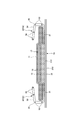
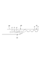
- FIG. 1 is a cross-sectional view taken along the line CC in FIG. 1;
- FIG. 2 is a cross-sectional view taken along line AA of FIG.
- FIG. 2 is a cross-sectional view taken along the line BB in FIG.
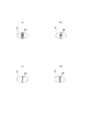
- (A) is a plan view of the main part of the stretchable area
- (b) is a cross-sectional view taken along the line DD of (a)
- (c) is a cross-sectional view in the mounted state
- (d) is a cross-sectional view in the natural length state. It is a trace figure of the microscope picture from the (a) plane direction of the expansion-contraction area
- (A) is a plan view of the main part of the stretchable area
- (b) is a cross-sectional view taken along the line DD of (a)
- (c) is a cross-sectional view in the mounted state
- (d) is a cross-sectional view in the natural length state. It is a trace figure of the microscope picture from the (a) plane direction of the expansion-contraction area
- FIG. 6 is a trace of a picture of the unstretched area of a sample. It is a principal part enlarged plan view of a non-stretching field. It is a top view which shows the example of various arrangement
- (A) is a cross-sectional view taken along the line CC in FIG. 15, (b) is a cross-sectional view taken along the line EE in FIG. It is sectional drawing which shows roughly the principal part cross section of the exterior body expanded to a certain extent. It is sectional drawing which shows roughly the principal part cross section of the exterior body expanded to a certain extent.
- (A) Trace figure of a top photograph of a sheet joined part formed in the 1st welding form (b) It is a trace figure of a top photograph of a sheet joined part formed in the 3rd welding form. It is the schematic of an ultrasonic sealing apparatus. It is a top view which shows the change of the elastic film at the time of manufacture.
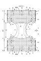
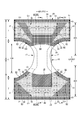
- FIG. 1 to 6 show a pants-type disposable diaper.
- This pants-type disposable diaper (hereinafter, also simply referred to as a diaper) has an exterior body 20 forming a front body F and a back body B, and an interior body 10 fixed and integrated to the exterior body 20.
- the inner body 10 is formed by interposing an absorber 13 between the liquid-permeable top sheet 11 and the liquid-impermeable sheet 12.
- the inner body 10 and the outer body 20 are front body F and back body B Are folded at the center in the front-rear direction LD (longitudinal direction), which is the boundary between the two, and both sides thereof are joined to each other by heat welding or a hot melt adhesive, etc. It becomes a pants type disposable diaper in which a pair of leg openings were formed.
- bonding means such as a hot melt adhesive
- the inner body 10 has a structure in which an absorber 13 is interposed between a top sheet 11 and a liquid impermeable sheet 12 made of polyethylene or the like, as shown in FIGS. It absorbs and holds the excretory fluid that has passed through the sheet 11.
- the planar shape of the inner body 10 is not particularly limited, but generally it is generally rectangular as shown in FIG.
- a non-woven or non-porous non-woven fabric, a porous plastic sheet, or the like is suitably used as the top sheet 11 that covers the front side (skin side) of the absorbent body 13.
- the material fibers constituting the non-woven fabric may be synthetic fibers of olefin type such as polyethylene or polypropylene, polyester type, polyamide type etc., regenerated fibers such as rayon or cupra, natural fibers such as cotton, etc.
- Spunlace method Nonwoven fabrics obtained by an appropriate processing method such as a spun bond method, a thermal bond method, a meltblown method, a needle punch method or the like can be used.
- the spunlace method is excellent in flexibility and drapability, and the thermal bonding method is excellent in bulk and softness.
- urine etc. will be absorbed quickly, and it will be excellent in dry touch property.
- the top sheet 11 extends around the side edge of the absorber 13 to the back side of the absorber 13.
- a liquid impermeable plastic sheet such as polyethylene or polypropylene is used, but in recent years, it has moisture permeability from the viewpoint of prevention of peeling. Is preferably used.
- This water-impervious and moisture-permeable sheet is a microporous sheet obtained by, for example, melt-kneading an inorganic filler in an olefin resin such as polyethylene or polypropylene to form a sheet, and then stretching in a uniaxial or biaxial direction. is there.
- the absorbent 13 is a known one, for example, a pile of pulp fibers, an aggregate of filaments such as cellulose acetate, or a non-woven fabric, and is formed by mixing and fixing a superabsorbent polymer as necessary. Can be used.
- the absorbent body 13 can be packaged by a packaging sheet 14 having liquid permeability and liquid holding property, such as crepe paper, as necessary, for shape and polymer holding.
- the shape of the absorber 13 is formed in a substantially hourglass shape having a narrow portion 13N at the crotch portion which is narrower than the front and rear sides.
- the dimension of the constricted portion 13N can be appropriately determined, but the longitudinal length of the constricted portion 13N can be about 20 to 50% of the total length of the diaper, and the width of the narrowest part is 40% of the total width of the absorbent 13 It can be about 60%.
- the absorber 13 is not included in the portion corresponding to the constricted portion 13N of the absorber 13 in the interior body 10.
- An absorber side 17 is formed.
- the liquid impermeable sheet 12 is folded back on the both sides in the width direction of the absorber 13 together with the top sheet 11.
- this liquid impermeable sheet 12 it is desirable to use an opaque sheet so as not to have brown color such as defecation and urine.
- a film formed by internally adding a pigment such as calcium carbonate, titanium oxide, zinc oxide, white carbon, clay, talc, barium sulfate or the like into a plastic and using it as a film is preferably used.
- the three-dimensional gather 90 includes a fixing portion 91 fixed to the side of the back surface of the inner body 10, and the fixing portion 91 passing through the side of the inner body 10.
- Each of these parts is formed of a gather sheet 95 formed by folding a sheet such as non-woven fabric into a double sheet.
- the gather sheet 95 is attached over the entire front-rear direction of the inner body 10, the falling portions 93 are provided on the front and back sides of the non-absorbent side 17 and the free portions 94 are on both sides of the non-absorbent side 17 It is extended. Further, between the double gather sheets 95, an elongated gather elastic member 96 is disposed at a tip end portion of the free part or the like. The gather elastic member 96 is for raising the free portion 94 by an elastic contraction force as shown in FIG. 5 in the product state.
- the solid gather 90 shown in FIGS. 5 and 6 has a configuration in which the main body 92 is not folded back, but the base side portion of the main body 92 is obliquely erected toward the center in the width direction, and the intermediate gathers Any known form can be adopted, such as a form in which the tip end side portion is obliquely erected outward in the width direction.
- the gather elastic member 96 materials such as styrene rubber, olefin rubber, urethane rubber, ester rubber, polyurethane, polyethylene, polystyrene, styrene butadiene, silicone, polyester and the like which are usually used can be used. Further, in order to make it difficult to see from the outside, it is preferable that the thickness be 925 dtex or less, the tension be 150 to 350%, and the interval be 7.0 mm or less. As the gather elastic member 96, in addition to a thread as shown in the illustrated embodiment, a tape-like member having a certain width can also be used.
- the material fibers constituting the above-mentioned gather sheet 95 are also synthetic fibers such as olefins such as polyethylene or polypropylene, polyesters and polyamides, as well as synthetic fibers such as rayon and cupra, natural fibers such as cotton, etc.
- non-woven fabrics obtained by an appropriate processing method such as a spun bond method, a thermal bond method, a meltblown method, a needle punch method or the like can be used as the fiber, in particular, the basis weight is It is preferable to use a non-woven fabric which is excellent in breathability by suppressing.
- silicone type, paraffin metal type, alkylchromic chloride type water repellent, etc. in order to prevent permeation of urine and the like, to prevent run-out and to improve the feel (dry feeling) to the skin. It is desirable to use a water repellent treated non-woven fabric coated with.
- the inner surface of the inner body 10 is joined to the inner surface of the outer body 20 by a hot melt adhesive or the like in the inner and outer fixing area 10B (hatched area).
- the inside and outside fixed area 10B can be appropriately determined, and can be substantially the entire width direction WD of the inner body 10. However, it is preferable that both widthwise side portions are not fixed to the outer body 20.
- the exterior body 20 extends laterally from the side edge of the absorber 13. As shown in the illustrated embodiment, the outer edge of the outer body 20 may be located at the center in the width direction of the inner edge of the inner body 10 in the crotch, as in the illustrated embodiment, or may be located at the outer side in the width direction. Further, the exterior body 20 is a range in the front-rear direction between the waist T, which is a range in the front-rear direction corresponding to the side seal portion 21, and the waist T of the front body F and the waist T of the rear body B. And an intermediate portion L.
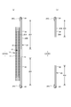
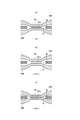
- FIG.2 and FIG.4-FIG. 6 shows, between the 1st sheet layer 20A and the 2nd sheet layer 20B.
- the elastic film 30 is laminated, as shown in FIG. 7, the first sheet layer 20A and the second sheet layer 20B penetrate the elastic film 30 at a large number of sheet bonding portions 40 arranged at intervals. It has an elastic film stretchable structure 20X joined through the through hole 31.
- the first sheet layer 20A and the second sheet layer 20B may be indirectly joined via the elastic film 30, not through the through holes 31 of the elastic film 30.
- the planar shape of the exterior body 20 is formed by concave line around the leg 29 so that the widthwise side edges of the middle portion L respectively form a leg opening, and has a shape resembling an hourglass as a whole.
- the exterior body 20 may be formed separately in the front body F and the back body B, and may be disposed so as to be separated in the front-rear direction LD at the crotch.
- FIG.1 and FIG.2 is a form by which elastic film elastic structure 20X is extended to the waist end area 23, when elastic film elastic structure 20X is used for the waist end area 23, a waist end If necessary, as shown in FIGS. 15 and 16, the waist end area 23 is not provided with the elastic film stretch structure 20X, as in the case where the tightening of the area 23 becomes insufficient.
- a telescopic structure by the member 24 can also be provided.
- an elongated elastic member extending along the leg opening is not provided at an edge portion of the leg opening in the exterior body 20.
- the waist elastic member 24 is an elongated elastic member such as a plurality of thread rubbers arranged at intervals in the front-rear direction LD, and gives an elastic force so as to tighten the circumference of the trunk of the body.
- the waist elastic members 24 are preferably arranged three to eight, preferably at a distance of about 3 to 8 mm so as to form a predetermined expansion / contraction zone, instead of being arranged substantially in a bundle with a close spacing. Five or more are arranged.
- the extension rate at the time of fixation of the waist portion elastic member 24 can be appropriately determined, it can be about 230 to 320% in the case of ordinary adults.
- a rubber thread is used as the waist portion elastic member 24 in the illustrated example
- another elongated elastic member such as a plain rubber may be used.
- it may be a general-purpose form in which only an elongated elastic member such as thread rubber or plain rubber is provided without providing the elastic film expansion and contraction structure 20X in the exterior body 20.
- the elastic film stretch structure 20X is not provided in the middle portion L between the waist T of the front body F and the waist T of the back body B, or the front body A telescopic structure 20X is continuously provided in the front-rear direction LD from the inside of the waist T of F to the middle of the waist T of the back body B through the middle portion L, or only one of the front body F and the back body B Appropriate modifications such as providing the elastic film stretchable structure 20X are also possible.
- the shapes of the individual sheet bonding portions 40 and the through holes 31 in the natural length state can be appropriately determined, but the shape is circular (see FIGS. 7 and 8), elliptical, triangular, rectangular (see FIGS. 9 to 12). ), Polygons such as rhombus (see FIG. 13 (b)) or convex lens (see FIG. 13 (a)), concave lens (see FIG. 13 (c)), stars, clouds, etc. be able to.
- the dimensions of individual sheet joints are not particularly limited, but the maximum length is preferably 0.5 to 3.0 mm, particularly preferably 0.7 to 1.1 mm, and the maximum width 40 x is 0.1 to 3.0 mm. In particular, in the case of a long shape in the orthogonal direction XD orthogonal to the expansion and contraction direction, it is preferable to set it to 0.1 to 1.1 mm.
- each sheet bonding portion 40 may be appropriately determined, but if the size is too large, the hardness of the sheet bonding portion 40 has a large influence on the feel, and if it is too small, the bonding area is small and the materials are sufficiently adhered.
- the area of each sheet bonding portion 40 is preferably about 0.14 to 3.5 mm 2 because it can not be done.
- the area of the openings of the individual through holes 31 is preferably 1 to 1.5 times the area of the sheet joint, although the area of the openings of the individual through holes 31 may be equal to or larger than the sheet joint because the sheet joint is formed through the through holes 31. Is preferred.
- the area of the opening of the through hole 31 is not the state of the elastic film 30 alone, but a value in the state of being integrated with the first sheet layer 20A and the second sheet layer 20B and in the state of natural length.
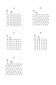
- planar arrangement of the sheet bonding portion 40 and the through holes 31 can be determined as appropriate, a planar arrangement which is regularly repeated is preferable, and an oblique lattice shape as shown in FIG. 14 (a) or FIG. 14 (b) Hexagonal grid as shown (these are also referred to as zigzag), square grid as shown in FIG. 14 (c), rectangular grid as shown in FIG. 14 (d), as shown in FIG.
- Parallel grid in the figure, two groups are provided so that a group of many parallel diagonal rows cross each other) or the like (they are inclined at an angle of less than 90 degrees with respect to the extension direction ED)
- a group of sheet junctions 40 (the arrangement of group units may be regular or irregular, and may be pattern or character) may be regularly repeated It can also be done.
- first sheet layer 20A and the second sheet layer 20B in the sheet bonding portion 40 are bonded through the through holes 31 formed in the elastic film 30, at least the first sheet layer 20A and the second sheet layer 20 in the sheet bonding portion 40. It is desirable that the first sheet layer 20A and the second sheet layer 20B are not joined to the elastic film 30 except between the sheet layers 20B.
- the means for bonding the first sheet layer 20A and the second sheet layer 20B in the sheet bonding portion 40 is not particularly limited.
- the first sheet layer 20A and the second sheet layer 20B in the sheet bonding portion 40 may be bonded by a hot melt adhesive or by bonding means such as heat sealing or ultrasonic sealing. .
- the form in which the sheet bonding portion 40 is formed by material welding is the first form in the sheet bonding portion 40.
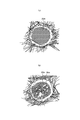
- a first welding mode in which the first sheet layer 20A and the second sheet layer 20B are joined only by the molten solidified material 20m of at least one of the one sheet layer 20A and the second sheet layer 20B (FIG. 17 (a 17)
- the second welding mode in which the first sheet layer 20A and the second sheet layer 20B are joined only by the whole or most or a part of the solidified portion 30m of the elastic film 30 in the sheet joining portion 40 see, and any of the third welding forms (see FIG.
- the second and third welding forms are Masui.
- the first sheet layer by 20 m of the solidified part of the first sheet layer 20 A and the second sheet layer 20 B and 30 m of the solidified part of all or most of the elastic film 30 in the sheet bonding portion 40. It is a form by which 20A and the 2nd sheet layer 20B are joined.
- the elastic film 30 is reflected in white between the melted and solidified materials 20m of the fibers of the first sheet layer 20A or the second sheet layer 20B appearing in black.
- the elastic film 30m of the elastic film of the elastic film of the first sheet layer 20A or the second sheet layer 20B is obtained. No solidified melt is observed (the white part is the boundary of 20 m of the solidified melt of fibers and the irregular reflection of 20 m of the solidified melt of fibers).
- the first sheet layer 20A and the second sheet layer 20A with the molten solidified material 20m of at least one of the first sheet layer 20A and the second sheet layer 20B as an adhesive When joining the sheet layer 20B, it is preferable not to melt part of the first sheet layer 20A and the second sheet layer 20B because the sheet bonding portion 40 is not hardened.
- the core of all the fibers of the sheet bonding portion 40 is that the first sheet layer 20A and the second sheet layer 20B are not partially melted.
- the composite fiber not only the core but also the central part of the monocomponent fiber remains, but its surrounding part (including not only the sheath of the composite fiber but also the part on the surface side of the monocomponent fiber)
- the fibers are not melted at all, but the remaining fibers are all melted or the core remains, but the surrounding portion includes a melted form.
- the peel strength is high.
- the first sheet layer 20A is formed under the condition that the melting point of at least one of the first sheet layer 20A and the second sheet layer 20B is higher than the melting point of the elastic film 30 and the heating temperature at the time of forming the sheet bonding portion 40.
- the elastic film 30 is sandwiched between the second sheet layer 20B, and a portion to be the sheet bonding portion 40 is pressurized and heated, and only the elastic film 30 is melted.
- the melting point of the elastic film 30 is preferably about 80 to 145 ° C.
- the melting points of the first sheet layer 20A and the second sheet layer 20 B are about 85 to 190 ° C., particularly about 150 to 190 ° C.
- the difference between the melting point of the first sheet layer 20A and the second sheet layer 20B and the melting point of the elastic film 30 is preferably about 60 to 90.degree.
- the heating temperature is preferably about 100 to 150 ° C.
- the melted and solidified material 30m of the elastic film 30 is a sheet bonding portion as shown in FIG. 40 may penetrate between the fibers all over the thickness direction of the first sheet layer 20A and the second sheet layer 20B in 40, but as shown in FIGS. 17 (b) and (c) and FIG.
- the flexibility of the sheet bonding portion 40 is higher in the mode in which the fibers are penetrated between the fibers or in the mode in which the fibers of the first sheet layer 20A and the second sheet layer 20B hardly penetrate as shown in FIG. It becomes a thing.
- FIG. 20 shows an example of an ultrasonic sealing device suitable for forming the second welding mode and the third welding mode.
- this ultrasonic sealing device when forming the sheet bonding portion 40, the first sheet layer 20A, between the anvil roll 60 having the projections 60a formed in the pattern of the sheet bonding portion 40 on the outer surface, and the ultrasonic horn 61, The elastic film 30 and the second sheet layer 20B are fed.
- the feed drive roll 63 and the nip roll 62 are set by making the feed transfer speed by the feed drive roll 63 and the nip roll 62 of the elastic film 30 on the upstream side slower than the transfer speeds of the anvil roll 60 and the ultrasonic horn 61 and thereafter.
- an elastic force is applied in the MD direction (machine direction, flow direction) to stretch the elastic film 30 as a whole to a predetermined elongation rate.
- the elongation rate of the elastic film 30 as a whole can be set by selecting the speed difference between the anvil roll 60 and the feed drive roll 63, and can be set to, for example, about 300% to 500%.
- 62 is a nip roll.
- the through hole 31 is formed is not necessarily clear, but it is considered that the portion of the elastic film 30 corresponding to the projection 60 a of the anvil roll 60 is melted and separated from the periphery to open the hole.
- the part between the through-holes 31 adjacent to the expansion-contraction direction ED in the elastic film 30 is expanded-contracted by the through-hole 31, as shown to FIG. 7 (a), FIG. 9 (a) and FIG. Since it is cut from the parts on both sides of the direction and loses the support on both sides in the contraction direction, the expansion and contraction direction is closer to the center of the orthogonal direction XD orthogonal to the expansion and contraction direction ED as long as continuity in the direction orthogonal to the contraction direction is maintained.
- the constituent materials of the first sheet layer 20A and the second sheet layer 20B can be used without particular limitation as long as they are sheet-like, but it is preferable to use a non-woven fabric from the viewpoint of air permeability and flexibility.
- the non-woven fabric is not particularly limited as to its raw material fiber.
- synthetic fibers such as olefins such as polyethylene and polypropylene, polyesters and polyamides, regenerated fibers such as rayon and cupra, natural fibers such as cotton, etc., mixed fibers of which two or more are used, composite fibers Etc.
- the non-woven fabric may be produced by any processing.
- the processing method examples include known methods such as spun lace method, spun bond method, thermal bond method, melt blown method, needle punch method, air through method, point bond method and the like.
- the basis weight is preferably about 12 to 20 g / m 2 .
- a part or all of the first sheet layer 20A and the second sheet layer 20B may be a pair of layers in which one sheet of material is folded back to be opposed.
- the component positioned on the outside is the second sheet layer 20B, and a folded portion 20C formed by being folded back to the inner surface at the waist opening edge is the first sheet layer 20A.
- the elastic film 30 is interposed between them, and in the other parts, the component positioned inside is the first sheet layer 20A, and the component positioned outside is the second sheet layer 20B, and the elastic film 30 is interposed therebetween. Can be intervened.
- the constituent of the first sheet layer 20A and the constituent of the second sheet layer 20B are individually provided over the entire longitudinal direction LD, and the constituent of the first sheet layer 20A and the second sheet are not folded.
- the elastic film 30 can also be interposed between the components of the layer 20B.
- the elastic film 30 is not particularly limited, and as long as it is a thermoplastic resin film having elasticity by itself, in addition to non-porous ones, those in which a large number of holes and slits are formed for ventilation can also be used.
- the tensile strength in the MD direction is 8 to 25 N / 35 mm
- the tensile strength in the CD direction is 5 to 20 N / 35 mm
- the tensile elongation in the MD direction is 450 to 1050%
- the tensile elongation in the CD direction is 450 to 1400%
- the elastic film 30 is The thickness of the elastic film 30 is not particularly limited, but is preferably about 20 to 40 ⁇ m.
- region which has the elastic film expansion-contraction structure 20X in the exterior body 20 has an expansion-contraction expansion-contraction area
- the elastic film 30 has a portion 32 which is linearly continuous along the stretch direction ED, and is contracted in the stretch direction ED by the contraction force of the elastic film 30, and in the stretch direction ED. It is extensible. More specifically, in a state in which elastic film 30 is expanded in expansion / contraction direction ED, the through holes of elastic film 30 are spaced at intervals in expansion / contraction direction ED and orthogonal direction XD (for example, width direction WD and longitudinal direction LD).
- the first sheet layer 20A and the second sheet layer 20B are joined via 31 to form a large number of sheet bonding portions 40, thereby forming an elastic film stretch structure 20X, and in the stretch area 80, the elastic film 30 is substantially formed.
- Such stretchability can be provided by arranging the through holes 31 so as to have a linearly continuous portion along the stretch direction ED.
- the elastic region 80 bulges in the direction in which the first sheet layer 20A and the second sheet layer 20B between the sheet bonding portions 40 are separated from each other. Then, the contraction weir 25 extending in the orthogonal direction XD is formed, and as shown in FIG. 7C and FIG. It is supposed to be. Further, as in the illustrated embodiment, the first sheet layer 20A and the second sheet layer 20B are not joined to the elastic film 30 except at least between the first sheet layer 20A and the second sheet layer 20B in the sheet joining portion 40. 7 (c) and 9 (c) assuming the mounted state, and FIGS. 7 (a) and (b) and FIGS.
- the elastic limit elongation in the expansion / contraction direction ED of the expansion / contraction area 80 be 200% or more (preferably 265 to 295%).
- the elastic limit elongation of the stretchable region 80 is substantially determined by the stretch rate of the elastic film 30 at the time of manufacture, it is reduced by a factor that inhibits the contraction of the stretch direction ED based on this.
- the main factor of such inhibition is the ratio of the length 40x of the sheet bonding portion 40 to the unit length in the expansion / contraction direction ED, and the elastic limit elongation decreases as the ratio increases.
- the elastic limit elongation of the stretchable region 80 can be adjusted by the area ratio of the sheet bonding portion 40.
- the extension stress of the stretchable region 80 can be adjusted mainly by the sum of the widths 32w of the portions 32 in which the elastic film 30 is linearly continuous along the stretch direction ED (for example, the width direction WD).
- the width 32w of the portion 32 in which the elastic film 30 is linearly continuous along the expansion / contraction direction ED is a distance 31d in the orthogonal direction XD (for example, the longitudinal direction LD) of the through holes 31 in contact with both side edges of the continuous portion 32
- the spacing 31d of the through holes 31 is equal to the length 31y of the through holes 31 in the orthogonal direction XD and the length 40y of the sheet bonding portion 40 in the orthogonal direction XD (the through holes 31 and the sheet bonding portion described above In the case where the simultaneous formation method of 40 is adopted, etc.)
- the expansion stress of the stretchable area 80 can be adjusted by the ratio of the length 40 y of the sheet bonding portion 40 per unit length in the orthogonal direction XD, and in the normal case, the sheet bonding portion 40 Since the length 40 y of the sheet bonding portion 40 is correlated with the area ratio of the sheet bonding portion 40, the length of the sheet bonding portion 40 can be adjusted by the area ratio of the sheet bonding portion 40.
- the extensional stress of the expansion and contraction region 80 can be set as a standard when it is extended to 50% of the elastic limit.
- the area ratio of the sheet bonding portion 40 in the stretchable region 80 and the area of each sheet bonding portion 40 can be determined as appropriate, but in the normal case, it is preferable to be in the following range.
- Area of sheet bonding portion 40 0.14 to 3.5 mm 2 (particularly, 0.14 to 1.0 mm 2 )
- Area ratio of sheet bonding portion 40 1.8 to 19.1% (particularly, 1.8 to 10.6%)
- the elastic limit elongation and the extension stress of the stretchable area 80 can be adjusted by the area of the sheet bonding portion 40, a plurality of areas in which the area ratio of the sheet bonding portion 40 in the stretchable area 80 is different as shown in FIG. Can be provided to change the fit according to the site.
- the area 81 extending obliquely along the base of the leg in the front body F and the edge area 82 of the leg opening have a high area ratio of the sheet bonding portion 40 compared with the other areas. Therefore, the tensile stress is weak, and it is a region that can be flexibly expanded and contracted.
- the iliac-facing region 83 in the back body B and the edge region 82 of the leg opening also have a high area ratio of the sheet bonding portion 40 compared to the other regions, and hence the region where the extension stress is weak and softly expands and contracts. It has become.
- the area 84 at the middle of the width direction WD of the portion overlapping the interior body 10 in the front body F has a higher area ratio of the sheet bonding portion 40 compared to the other areas, and the elongation stress is further weak.
- the elastic limit elongation is also a smaller area.
- each stretchable area 80 of the front body F and the back body B has a single film portion 85 which includes only one elastic film 30 and does not include other elastic members.
- the single film portion 85 covers the entire stretchable area 80, but may have a structure in which only a part of the stretchable area 80 has the elastic film 30 of one layer.
- each single film portion 85 extends from inside the middle portion L to the inside of the waist portion T and is located on the waist opening side, and the first region 51 in which the expansion and contraction direction ED is the first direction D1 (width direction WD) And second regions 52 and 53 which are located in a direction orthogonal to the first direction D1 with respect to the first region 51 and extend / contract in (second directions D2 and D3) oblique to the first direction D1. doing.
- each single film portion 85 of the example shown in FIG. 2 is adjacent to the first area 51 as a second area, and the expansion / contraction direction ED is the area 53 of the diagonal upward D3 toward the center in the width direction, And a region 52 including a portion along the base of the leg, in which the expansion / contraction direction ED is obliquely downward D2 toward the width direction center, and between these second regions 52, 53.
- the second region is only the region 52 including the portion along the base of the leg in which the expansion / contraction direction ED is obliquely downward D2 toward the center in the width direction.
- the single film portion 85 causes a contractile force to be developed obliquely downward D2 toward the center in the width direction in the portion along the base of the leg of the wearer, and the width at the waist opening side than that Since the part in which the contraction force is developed is provided in the direction WD, the fit to the base of the leg and the circumference of the trunk is improved.
- the difference between the example shown in FIG. 2 and the example shown in FIG. 15 is the difference in manufacturing method described later.
- the position of the first region 51 is not particularly limited, but preferably includes at least the end on the waist opening side in the single film portion 85 of the waist portion T in the front-rear direction LD, and the waist portion It is more preferable that the entire waist opening side is included from the center in the front-rear direction of T.
- the first region 51 may be provided only in a part of the width direction WD, but it is preferable that the first region 51 extends over the entire width direction of the waist portion T.
- the position of the second regions 52 and 53 can be appropriately determined as long as it includes the portion along the base of the leg of the wearer, but in the longitudinal direction LD, the leg opening side of the waist portion T of the single film portion 85 It is preferable to be provided in a portion from the end of the to the middle portion L. Further, in the width direction WD, it is preferable to be provided at least on both sides in the width direction than both side edges of the inner body 10, and can be provided over the entire width direction. A non-stretchable area 70 can also be provided.
- the elastic film stretchable structure 20X of the example shown in FIG. 15 can be manufactured, for example, by the method shown in FIG. 20 and FIG. That is, as in the example shown in FIG. 20, in the manufacturing process of the package 20, the elastic film 30 is continuously supplied in the MD direction, and the first sheet layer 20A and the second sheet layer 20B are respectively provided on the front and back sides.
- the elastic film 30 is By penetrating or bonding the first sheet layer 20A and the second sheet layer 20B via the elastic film 30, the portion to be the exterior body 20 of the front body F and the portion to be the exterior body 20 of the rear body B are integrated Form.
- a single elastic film extends from at least a portion to be the waist T of the front body F to a portion to be the waist T of the back B as the elastic film 30.
- the film 30 is supplied.
- the crotch portion of each of the pants-type disposable diapers in the middle region of the elastic film 30 in the CD direction prior to bonding the first sheet layer 20A and the second sheet layer 20B, as shown in FIG. 21, the crotch portion of each of the pants-type disposable diapers in the middle region of the elastic film 30 in the CD direction.
- the slit 35 having a size of 50 mm or more in the CD direction is sequentially formed in a portion including the portion where the continuous direction 36 continues in the MD direction on both sides of the slit 35 in the CD direction.
- the first sheet layer 20A and the second sheet layer 20B are joined in a state in which the elastic film 30 having the slits 35 and the continuous portion 36 is stretched in the MD direction.
- the slits 35 Prior to bonding the first sheet layer 20A and the second sheet layer 20B, the slits 35 having a length of 50 mm or more in the CD direction are formed in the middle of the CD direction of the elastic film 30.
- the slit 35 expands in the MD direction and shrinks in the CD direction, as shown by a white arrow in FIG.
- the part extended in the oblique direction at the time of joining includes a part along the base of the leg and in the width direction
- the second regions 52 and 53 expand and contract in the diagonally downward direction toward the center of the WD, and from the area on the waist opening side, the portion expanded in the MD direction at the time of bonding is the MD direction (that is, the width direction WD in the example shown in FIG. 15)
- the first region 51 expands and contracts in
- the process of a well-known manufacturing method can be employ
- the width direction WD of the disposable wearing article is in the MD direction
- the individual disposable wearing articles are continuous in the MD direction in the unfolded state by assembling the inner body 10 separately manufactured in the manufacturing process of the inner body 10 with intervals in the MD direction while conveying so as to Form the interior assembly (attachment process of the interior body 10).
- a portion 201 to be the exterior body 20 of the front body F and a portion 202 to be the exterior body 20 of the rear body B are Bonding to form the side seal portion 21 and cutting the portion to be the exterior body 20 of the front body F and the portion to be the exterior body 20 of the rear body B at the boundaries of the individual disposable wearing articles (side seal / separating process ), Individual pants-type disposable diapers can be manufactured.
- the elastic film stretchable structure 20X of the example shown in FIG. 2 can be manufactured, for example, by the method shown in FIG. 20 and FIG. That is, prior to bonding the first sheet layer 20A and the second sheet layer 20B in the manufacturing process of the exterior body 20, as shown in FIG. 23, of the intermediate region in the CD direction in the elastic film 30, the front body Slits 35 with a size of 50 mm or more in the CD direction in the first part P1 that will be the side edges of F and the side edges of the back body B and the second part P2 that includes the part that will be the crotch of each pant type disposable diaper Form each.
- a first continuous portion 36A continuous in the MD direction outside the first portion P1 in the CD direction is left, and a second continuous in the MD direction between the first portion P1 and the second portion in the CD direction Leave the continuous portion 36B. Then, the first sheet layer 20A and the second sheet layer 20B are joined in a state in which the elastic film 30 having the slits 35, the first continuous portion 36A and the second continuous portion 36B is stretched in the MD direction.
- the elastic film 30 in which the slits 35 are formed in the first portion P1 and the second portion P2 and the first continuous portion 36A and the second continuous portion 36B are extended in the MD direction, as shown in FIG.
- the slit 35 expands in the MD direction and shrinks in the CD direction. This point is the same as the example shown in FIG. 21 described above.
- the slits 35 are alternately arranged at intervals in the MD direction and the CD direction, and the first continuous portion 36A and the second continuous portion 36B are left.
- the portion of the first continuous portion 36A adjacent to the end of the slit 35 in the CD direction is the center side of the slit 35 in the CD direction.
- the first continuous portion 36A is not affected by the tension and extends in the MD direction (first direction D1), and the tension causes the extension direction to be inclined toward the end of the slit 35 in the CD direction.
- a portion changed in the direction (second direction D3) is formed.
- the second continuous portion 36B a portion adjacent to the end of the slit 35 located on one side across the second continuous portion 36B and a portion adjacent to the end of the slit 35 located on the other side are It is pulled in the opposite direction in the CD direction so as to be separated from each other.
- the portion between the end of the slit 35 located on one side across the second continuous portion 36B and the end of the slit 35 located on the other side is the second continuous portion It extends in an oblique direction (second direction D2) connecting the end of the slit 35 located on one side across the portion 36B and the end of the slit 35 located on the other side.
- the inclination in the extension direction is deeper than that in the oblique extension in.
- the longitudinal direction LD range corresponding to the slits 35 in the side edges of the body B is a weakly stretchable area 54 where the stretch force is very weak, and adjacent to the upper and lower sides of the weak stretchable area 54 respectively
- the second regions 52 and 53 expand and contract in an oblique direction, and a portion of the second regions 52 and 53 adjacent to the waist opening and extended in the MD direction during bonding becomes the first region 51 that expands and contracts in the MD direction.
- the second region 52 on the center side of the LD in the front-rear direction LD than the weakly stretchable region 54 includes a portion along the base of the leg, and the stretchable direction ED is obliquely downward toward the middle in the width direction WD.
- the expansion and contraction direction ED is obliquely upward toward the center of the width direction WD.
- the front-rear direction LD range corresponding to the slit 35 of the second portion P2 is cut to form a leg opening and hardly remains in the product, but if it remains, it becomes a weakly elastic region 54.
- the steps of a known manufacturing method for example, the steps of the example shown in FIG. 24 or 25 can be employed.
- the slit 35 means a cut which is hardly open with a natural length, but instead of the slit 35, the dimension in the MD direction is smaller than the dimension in the CD direction (for example, other than half)
- a hole may be provided.
- the dimension in the CD direction of the slit 35 or the hole can be appropriately determined as long as it is 50 mm or more, but in the normal case, it is preferably 50 to 400 mm, particularly 80 to 320 mm.
- the slits 35 be located in the region of the elastic film 30 to be the middle portion L of each of the pants-type disposable diapers, the region to be the waist portion T of the front body F and the rear body B It may extend in the CD direction to at least one of the regions to be the waist T.
- Non-stretchable area In the example shown in FIG. 2, the entire elastic film 30 stretchable structure 20X is used as the stretchable region 80 and there is no non-stretchable region, but in the region having the elastic film stretchable structure 20X, as shown in FIG. A stretchable area 70 can be provided. The arrangement of the stretchable region 80 and the non-stretchable region 70 can be determined as appropriate. In the case of the exterior body 20 of the underpants type disposable diaper as in the present embodiment, a portion overlapping with the absorber 13 is a region that does not require expansion and contraction, so a part or all of the portion overlapping with the absorber 13 as illustrated.
- the non-stretchable area 70 it is desirable to include substantially the entire inside and outside fixed area 10B.
- the non-stretchable region 70 can be provided from the region overlapping the absorber 13 to the region not overlapping the absorber 13 located in the width direction WD or the longitudinal direction LD, and the non-stretch region only in the region not overlapping the absorber 13 70 can also be provided.
- the non-stretchable region 70 can be a region which does not have a linearly continuous portion along the extension direction at the time of manufacture due to the presence of the through holes 31. Accordingly, even if the entire elastic film elastic structure 20X including both of the elastic region 80 and the non-elastic region 70 is formed in the same manner as the elastic region 80, as shown in FIG. Since it does not continue linearly along the extension direction (width direction WD in the example of FIG. 11) at the time of manufacture, the contraction force of the elastic film 30 hardly acts on the first sheet layer 20A and the second sheet layer 20B. Elasticity almost disappears and elastic limit elongation approaches 100%.
- the stretchable area 80 and the non-stretchable area 70 can be formed by the presence or absence of the portion where the elastic film 30 is not linearly continuous along the extension direction at the time of manufacture. Further, the continuity of the elastic film 30 remains even in the non-stretchable region 70, and as can be seen from FIG. 12, since the independent cut pieces of the elastic film 30 do not remain and no creases are formed, the appearance is extremely good.
- the elastic limit elongation in the stretch direction ED may be 120% or less, preferably 110% or less, and particularly preferably 100%.
- the arrangement pattern of the through holes 31 in the elastic film 30 in the non-stretchable region 70 can be appropriately determined, but as shown in FIG. 11, they are staggered and the center spacing 31e in the orthogonal direction XD of the through holes 31 is the through hole 31. If the pattern is shorter than the length 31y in the orthogonal direction XD, the continuity of the elastic film 30 can be almost completely eliminated while maintaining the continuity of the elastic film 30, and the appearance is also preferable as shown in FIG. Become. In this case, it is more preferable that the center interval 31 f of the through hole 31 in the expansion and contraction direction ED be shorter than the length 31 x of the through hole 31 in the expansion and contraction direction ED.
- the non-stretchable region 70 is stretched to the elastic limit in the expansion / contraction direction ED.
- the center spacing 31e in the orthogonal direction XD of the through hole 31 is 0.4 to 2.7 mm, and the length 31 y in the orthogonal direction X of the through hole 31 is 0.5 to 3.0 mm, in particular 0.7 to 1.1 mm It is preferable that The center spacing 31f of the through holes 31 in the expansion / contraction direction ED is preferably 0.5 to 2 times, particularly 1 to 1.2 times the length 31y of the through holes 31 in the orthogonal direction XD. It is preferable that the length 31x of the expansion / contraction direction ED is 1.1 to 1.8 times, particularly 1.1 to 1.4 times the center interval 31f of the through holes 31 in the expansion / contraction direction ED.
- the center of the through hole 31 in the stretch direction ED In the state in which the non-stretchable region 70 is stretched to the elastic limit in the stretch direction ED (in other words, the state in which the first sheet layer 20A and the second sheet layer 20B are completely developed), the center of the through hole 31 in the stretch direction ED.
- the spacing 31f is equal to the center spacing 40f in the expansion / contraction direction ED of the sheet bonding portion 40
- the center spacing 31e in the orthogonal direction XD of the through hole 31 is equal to the center spacing 40e in the orthogonal direction XD of the sheet bonding portion 40.
- the length 31y of the direction XD is equal to the length 40y of the orthogonal direction XD of the sheet bonding portion 40.
- the elastic film 30 is not joined to the first sheet layer 20A and the second sheet layer 20B except between the first sheet layer 20A and the second sheet layer 20B in the sheet bonding portion 40,
- the peripheral edge of the through hole 31 of the elastic film 30 and the sheet bonding portion 40 are separated at both sides in the expansion / contraction direction ED of the sheet bonding portion 40 in the state of natural length, Even if the material is a non-porous film or sheet, this gap is preferable because air permeability is always added.
- the above-described simultaneous formation method of the through hole 31 and the sheet bonding portion 40 is adopted, this state is naturally obtained regardless of the shape of the sheet bonding portion 40 or the like.
- the shapes of the individual sheet bonding portions 40 and the through holes 31 in the natural length state are not particularly limited, but it is desirable from the viewpoint of flexibility that the area be small, and linear continuity in the width direction WD of the elastic film 30 is eliminated.
- the elastic film 30 is easily broken if the corner is an acute angle like a rhombus.
- the convex lens shape is preferable because the welding of the sheet bonding portion 40 is stabilized, and the concave lens shape is preferable in that the area can be further reduced.
- the area ratio of the sheet bonding portion 40 and the area of the individual sheet bonding portions 40 in the non-stretchable region can be appropriately determined, in the normal case, the area of each sheet bonding portion 40 is small and the sheets Since the non-stretchable area
- Area of sheet bonding portion 40 0.10 to 0.75 mm 2 (particularly, 0.10 to 0.35 mm 2 )
- Area ratio of the sheet bonding portion 40 4 to 13% (particularly, 5 to 10%)
- the elastic limit elongation of the non-stretchable region 70 can be changed according to the arrangement pattern of the through holes 31 and the size and center distance of the individual through holes 31. Therefore, although not shown, they may be made different between a plurality of locations in the stretchable region 80 or a plurality of non-stretchable regions 70. For example, it is one preferable embodiment to make the elastic limit elongation in the non-stretchable area 70 of the front body F larger than the elastic limit stretch in the non-stretchable area 70 of the rear body B.
- the non-stretchable region 70 has a linearly continuous portion along the stretch direction ED as in the stretch region, the elastic limit elongation is extremely low because the area ratio of the sheet bonding portion is higher than that of the stretch region. It is also possible to adopt a form that kills other stretchability such as a form that is 130% or less, a form that cuts in one place or multiple places in the stretch direction ED like a stretch structure using a conventional thread rubber it can.
- the above-described stretchable structure 20X is not limited to pants-type disposable diapers, but it is possible to use tape-type disposable diapers around the waist and connecting tapes, solid gathers generally used for absorbent articles in general, flat gathers, etc. It can apply also to a manufacturing method.
- the positions of the first direction, the second direction, the positions of the first region and the second region, and the positions of the slits or holes can be appropriately determined in consideration of fit and the like.
- the tape-type disposable diaper has the connecting tape 100 extending from both sides of the back body B, and the connecting tape 100 is connected to the front body F in a detachable manner. It is what you have.
- an elastic region 80 having a single film portion 85 is provided at the middle in the width direction of the back body B, and the elastic direction ED has a width above the middle in the vertical direction in the single film portion 85
- a first area 51 in the direction WD can be provided, and a second area 52 can be provided below the first area 51 in which the expansion / contraction direction ED is obliquely upward toward both sides in the width direction WD.
- an expansion / contraction area 80 having a single film portion 85 is provided on the connection tape 100, and a first area 51 in which the expansion / contraction direction ED is the width direction WD is provided above the middle in the vertical direction of the connection tape 100.
- a second area 52 may be provided in which the expansion / contraction direction ED is obliquely upward toward the leading end side of the connection tape 100. Since the lower side of the connection tape 100 is a leg opening, and expansion and contraction of the connection tape 100 enables deformation of the leg opening, the connection tape 100 is connected by providing the first region 51 and the second region 52 as in the latter case. Since the tape 100 can be expanded and contracted in the direction closer to the direction around the leg, the fit around the leg is excellent.
- first region 51 having stretchability in the width direction WD also ensures fit in the circumferential direction. It is also preferable that the connecting tape 100 is vertically dividable (or cut in advance) by perforations 102 along the boundary between the first area and the second area as in the illustrated example.
- Front body and back body mean front and rear portions of the pants-type disposable diaper, respectively, bordering on the front-rear direction center.
- the crotch refers to a range in the front-rear direction including the center in the front-rear direction of the pants-type disposable diaper, and when the absorber has a constricted portion, it refers to the longitudinal range of the portion having the constricted portion.
- the MD direction of the non-woven fabric is the direction of fiber orientation of the non-woven fabric.
- the fiber orientation is the direction along which the fibers of the non-woven fabric are aligned.
- Elastic limit elongation means elongation at the elastic limit (in other words, the state in which the first sheet layer and the second sheet layer are fully developed) in the expansion / contraction direction ED, and the length at the elastic limit is a natural length Is expressed as a percentage based on 100%.
- the “area ratio” means the ratio of the target portion to the unit area, and the target portion (for example, the sheet bonding portion 40) in the target region (for example, the stretchable region 80, the non-stretchable region 70, the main stretchable portion, and the buffer stretchable portion)
- the total area of the opening of the through hole 31 and the vent hole is divided by the area of the target area and expressed as a percentage, and in particular, the "area ratio" in the area having the expansion and contraction structure is up to the elastic limit in the expansion and contraction direction ED. It means the area ratio in the stretched state.
- “Stretch rate” means the value when natural length is 100%.
- ⁇ "Age” is measured as follows. After the sample or test piece is predried, it is left in a test room or apparatus under standard conditions (test place: temperature 23 ⁇ 1 ° C., relative humidity 50 ⁇ 2%) to be in a constant weight state. Pre-drying refers to bringing a sample or test piece to a constant weight in an environment at a temperature of 100 ° C. In addition, it is not necessary to perform preliminary drying about the fiber whose official moisture percentage is 0.0%. From a test piece in a constant weight state, using a template for sampling (100 mm ⁇ 100 mm), cut out a sample of 100 mm ⁇ 100 mm in size.
- the weight of the sample is measured, multiplied by 100, the weight per square meter is calculated, and taken as the basis weight.
- the “thickness” of the absorber is the thickness measuring instrument of Ozaki Manufacturing Co., Ltd. (Pecock, Dial Thickness Gauge Large Type, Model J-B (measurement range 0 to 35 mm) or Model K-4 (measurement range 0 to 50 mm)) Measure with the sample and thickness gauge horizontal. - other than the above "thickness” is used automatic thickness measuring instrument (KES-G5 Handy Compression measurement program), load: 0.098 N / cm 2, and the pressure area: automatically measured under the conditions of 2 cm 2.
- ⁇ “Tensile strength” and “Tensile elongation (breaking elongation)” conform to JIS K 7127: 1999 “Plastic-Test method of tensile characteristics-” except that the test piece is made into a rectangular shape of 35 mm wide ⁇ 80 mm long. It means that the initial chuck distance (marked line distance) is 50 mm and the tensile speed is 300 mm / min.
- ⁇ “Tensile stress” is a tensile test based on JIS K 7127: 1999 “Plastic-Test method for tensile properties-” with an initial chuck spacing (distance between marked lines) of 50 mm and a tensile speed of 300 mm / min.
- N / 35 mm the tensile stress measured when stretching in the elastic region
- the degree of stretching can be appropriately determined depending on the test object.
- it is preferable to make a test piece into a rectangular shape with a width of 35 mm and a length of 80 mm or more when a test piece with a width of 35 mm can not be cut out, a test piece is made with a width that can be cut out and the measured value is 35 mm wide The value converted to
- at least comparison can be made as long as test pieces of the same size are used even if the small test pieces are appropriately compared if the magnitude of the extension stress is compared. .
- “Expanded state” means a flat state without contraction or slack. -Unless otherwise indicated, the dimension of each part means the dimension in the unfolded state, not the natural length state. ⁇ If there is no description about the environmental conditions in the test or measurement, the test or measurement shall be performed in the test room or equipment under the standard condition (test place: temperature 23 ⁇ 1 ° C, relative humidity 50 ⁇ 2%) Do.
- the present invention is applicable to general disposable wear articles provided with an elastic region such as various types of disposable diapers such as tape type and pad type, sanitary napkins, etc. other than the pants type disposable diaper as described above.
- SYMBOLS 10 Interior body, 10B ... Inside-and-outside fixed area
- region 11 ... Top sheet, 12 ... Liquid-impervious sheet, 13 ... Absorbent body, 13N ... Bump part, 14 ... Packaging sheet, 17 ... Non-absorber side part, 20 ...
- Exterior body 20A first sheet layer, 20B: second sheet layer, 20C: folded portion, 20X: elastic film stretch structure, 21: side seal portion, 23: waist end area, 24: waist elastic member, 25: shrinkage ⁇ , 29: leg around line, 30: elastic film, 31: through hole, 40: sheet joint, 70: non-stretching area, 80: stretching area, 90: solid gather, 93: lying part, 94: free part, 95: Gathered sheet, 96: Gathered elastic member, B: Rear body, ED: Stretching direction, XD: Orthogonal direction, F: Front body, L: Intermediate part, LD: Front and back direction, T: Waist part, WD: Width direction, 5: single film portion 51: first region 52, 53 second region 54: weakly stretchable region D1 first direction D2, D3 second direction 35: slit 36: continuous portion P1 ... 1st part, P2 ... 2nd part, 36A ... 1st continuation part, 36B ... 2nd continuation part, 100
Landscapes
- Engineering & Computer Science (AREA)
- Health & Medical Sciences (AREA)
- Mechanical Engineering (AREA)
- Heart & Thoracic Surgery (AREA)
- Epidemiology (AREA)
- Biomedical Technology (AREA)
- Vascular Medicine (AREA)
- Life Sciences & Earth Sciences (AREA)
- Animal Behavior & Ethology (AREA)
- General Health & Medical Sciences (AREA)
- Public Health (AREA)
- Veterinary Medicine (AREA)
- Textile Engineering (AREA)
- Absorbent Articles And Supports Therefor (AREA)
Abstract
非平行な複数の伸縮方向を有する簡素な弾性フィルム伸縮構造を提供する。 上記課題は、第1シート層(20A)及び第2シート層(20B)の間に弾性フィルム(30)が積層され、第1シート層及び第2シート層が、間隔を空けて配列された多数の接合部で接合された、弾性フィルム伸縮構造(20X)を備えており、弾性フィルム伸縮構造を有する領域は、弾性フィルムとともに弾性伸縮する伸縮領域(80)を有してり、伸縮領域は、弾性フィルムを一層のみ含みかつ他の弾性部材を有しない単フィルム部分(85)を有するとともに、この単フィルム部分に、第1方向(D1)に伸縮する第1領域(51)と、第1領域に対し第1方向と直交する方向に位置し、第1方向に対して斜め向きの第2方向(D2,D3)に伸縮する第2領域(52,53)とを有する、ことを特徴とする使い捨て着用物品により解決される。
Description
本発明は、弾性フィルムをシート層で挟んでなる弾性フィルム伸縮構造を備えた使い捨て着用物品に関するものである。
使い捨ておむつや生理用ナプキン等の使い捨て着用物品においては、身体表面へのフィット性を向上するために、脚周りや胴周り等の適所に伸縮性を付与することが一般的である。伸縮性を付与するための手法としては、従来、糸ゴム等の細長状の弾性部材を長手方向に伸長した状態で多数並べて固定する手法が広く採用されているが、面的なフィット性に優れるものとして、弾性フィルムを伸縮性の付与方向に伸長した状態で取り付ける手法も提案されている。(例えば特許文献1~3参照)。
この弾性フィルムをシート層で挟んだ伸縮構造(以下、弾性フィルム伸縮構造ともいう)は、伸縮領域が不織布等からなる第1シート層と、不織布等からなる第2シート層との間に弾性フィルムが積層されるとともに、弾性フィルムが伸縮方向に伸長された状態で、第1シート層及び第2シート層が、伸縮方向及びこれと直交する方向にそれぞれ間隔を空けて配列された多数の接合部で、弾性フィルムに形成された貫通孔を通じて又は弾性フィルムを介して接合されてなるものである。このような弾性フィルム伸縮構造を有する伸縮領域は、自然長状態では、接合部間において弾性フィルムが収縮するのに伴い、接合部の間隔が狭くなり、第1シート層及び第2シート層における接合部間に伸縮方向と交差する方向に延びる収縮皺が形成される。反対に伸長時には、接合部間において弾性フィルムが伸長するのに伴い、接合部の間隔及び第1シート層及び第2シート層における収縮皺が広がり、第1シート層及び第2シート層の完全展開状態まで弾性伸長が可能となる。この弾性フィルム伸縮構造は、面的なフィット性に優れるのはもちろん、弾性フィルムの貫通孔が通気性向上にも寄与するという利点がある。
しかしながら、この弾性フィルム伸縮構造は、伸縮方向が製造時のMD方向(機械方向)のみで、しかも直線的であるため、例えばおむつにおける脚の付け根に沿う方向等、斜め方向に収縮力を発揮できないものであった。
これに対し、本出願人は、弾性フィルムを斜め向きに伸長させて第1シート層及び第2シート層間に取り付けることにより、斜め向きの収縮力を発揮する伸縮構造を提案している(特許文献4参照)。
しかし、従来のものは、特許文献4記載のものを含め、弾性フィルムを一方向に伸長させて製造するため、弾性フィルムを一層のみ含む単フィルム部分では伸縮方向がほぼ平行(伸縮方向の位置が同じであれば、伸縮方向と直交する直交方向のどの位置でも伸縮方向が同じ)となっていた。このため、例えば、パンツタイプやテープタイプの使い捨て着用物品に弾性フィルム伸縮構造を適用する場合、胴周り部における幅方向の伸縮性を弾性フィルムにより付加し、脚の付け根に沿う部分には細長状の弾性部材を付加するといった解決策も提案されている(特許文献5参照)が、製造工程が複雑となり、製品構造も複雑となるという問題点がある。
そこで、本発明の主たる課題は、非平行な複数の伸縮方向を有する簡素な弾性フィルム伸縮構造を提供することにある。
上記課題を解決した各種態様は以下のとおりである。
<第1の態様>
第1シート層及び第2シート層の間に弾性フィルムが積層され、前記第1シート層及び第2シート層が、間隔を空けて配列された多数の接合部で、弾性フィルムを貫通する孔を通じて又は前記弾性フィルムを介して接合された、弾性フィルム伸縮構造を備えており、
前記弾性フィルム伸縮構造を有する領域は、前記弾性フィルムとともに弾性伸縮する伸縮領域を有している、使い捨て着用物品において、
前記伸縮領域は、弾性フィルムを一層のみ含みかつ他の弾性部材を有しない単フィルム部分を有するとともに、この単フィルム部分に、第1方向に伸縮する第1領域と、前記第1領域に対し前記第1方向と直交する方向に位置し、前記第1方向に対して斜め向きの第2方向に伸縮する第2領域とを有する、
ことを特徴とする使い捨て着用物品。
<第1の態様>
第1シート層及び第2シート層の間に弾性フィルムが積層され、前記第1シート層及び第2シート層が、間隔を空けて配列された多数の接合部で、弾性フィルムを貫通する孔を通じて又は前記弾性フィルムを介して接合された、弾性フィルム伸縮構造を備えており、
前記弾性フィルム伸縮構造を有する領域は、前記弾性フィルムとともに弾性伸縮する伸縮領域を有している、使い捨て着用物品において、
前記伸縮領域は、弾性フィルムを一層のみ含みかつ他の弾性部材を有しない単フィルム部分を有するとともに、この単フィルム部分に、第1方向に伸縮する第1領域と、前記第1領域に対し前記第1方向と直交する方向に位置し、前記第1方向に対して斜め向きの第2方向に伸縮する第2領域とを有する、
ことを特徴とする使い捨て着用物品。
(作用効果)
本態様の伸縮領域は、弾性フィルムを一層のみ含む単フィルム部分に、第1方向に伸縮する第1領域と、第1領域に対し第1方向と直交する方向に位置し、第1方向に対して斜め向きの第2方向に伸縮する第2領域とを有するため、複数の弾性部材を用いない簡素な構造でありながら、非平行な複数の伸縮方向を有するものとなる。よって、使い捨て着用物品の部位に応じて伸縮方向を異なるものとでき、より適切なフィット性の確保が可能となる。
本態様の伸縮領域は、弾性フィルムを一層のみ含む単フィルム部分に、第1方向に伸縮する第1領域と、第1領域に対し第1方向と直交する方向に位置し、第1方向に対して斜め向きの第2方向に伸縮する第2領域とを有するため、複数の弾性部材を用いない簡素な構造でありながら、非平行な複数の伸縮方向を有するものとなる。よって、使い捨て着用物品の部位に応じて伸縮方向を異なるものとでき、より適切なフィット性の確保が可能となる。
<第2の態様>
前身頃の胴周り部、後身頃の胴周り部及びそれの間に位置する中間部を有する、前後別々の又は前後一体の外装体と、
前記外装体に取り付けられ、前身頃から股間部を経て後身頃に至る内装体とを備え、
前身頃における外装体の両側部と後身頃における外装体の両側部とがそれぞれ接合されてサイドシール部が形成されるとともに、ウエスト開口及び左右一対の脚開口が形成された、パンツタイプの使い捨て着用物品であり、
前記前身頃の外装体及び前記後身頃の外装体の少なくとも一方は、少なくとも前記内装体よりも幅方向両側に前記伸縮領域を有するとともに、この伸縮領域の前記単フィルム部分は前記中間部内から前記胴周り部内にわたり延びており、
前記単フィルム部分では、前記第2領域は装着者の脚の付け根に沿う部分を含むとともに、伸縮方向が幅方向中央に向かって斜め下向きとなるように設けられており、前記第1領域は前記第2領域よりもウエスト開口側に位置し、伸縮方向が幅方向となるように設けられている、
第1の態様の使い捨て着用物品。
前身頃の胴周り部、後身頃の胴周り部及びそれの間に位置する中間部を有する、前後別々の又は前後一体の外装体と、
前記外装体に取り付けられ、前身頃から股間部を経て後身頃に至る内装体とを備え、
前身頃における外装体の両側部と後身頃における外装体の両側部とがそれぞれ接合されてサイドシール部が形成されるとともに、ウエスト開口及び左右一対の脚開口が形成された、パンツタイプの使い捨て着用物品であり、
前記前身頃の外装体及び前記後身頃の外装体の少なくとも一方は、少なくとも前記内装体よりも幅方向両側に前記伸縮領域を有するとともに、この伸縮領域の前記単フィルム部分は前記中間部内から前記胴周り部内にわたり延びており、
前記単フィルム部分では、前記第2領域は装着者の脚の付け根に沿う部分を含むとともに、伸縮方向が幅方向中央に向かって斜め下向きとなるように設けられており、前記第1領域は前記第2領域よりもウエスト開口側に位置し、伸縮方向が幅方向となるように設けられている、
第1の態様の使い捨て着用物品。
(作用効果)
本態様のパンツタイプの使い捨て着用物品では、単フィルム部分により、装着者の脚の付け根に沿う部分では幅方向中央に向かって斜め下向きに収縮力が発現し、それよりもウエスト開口側では幅方向に収縮力が発現するため、脚の付け根及び胴周りのそれぞれに対するフィット性が良好となる。
本態様のパンツタイプの使い捨て着用物品では、単フィルム部分により、装着者の脚の付け根に沿う部分では幅方向中央に向かって斜め下向きに収縮力が発現し、それよりもウエスト開口側では幅方向に収縮力が発現するため、脚の付け根及び胴周りのそれぞれに対するフィット性が良好となる。
<第3の態様>
前身頃及び後身頃と、後身頃の両側部から延び出た連結テープとを有し、前記連結テープは前記前身頃に着脱可能に連結される連結部を有している、テープタイプの使い捨て着用物品であり、
前記連結テープは、前記伸縮領域を有しており、
前記伸縮領域の前記単フィルム部分は、前記連結テープにおける上下方向中間より上側に前記第1領域を、及びそれより下側に前記第2領域をそれぞれ有しており、
前記第1領域は伸縮方向が幅方向となるように設けられており、前記第2領域は前記連結テープの先端側に向かって斜め上向きとなるように設けられている、
第1の態様の使い捨て着用物品。
前身頃及び後身頃と、後身頃の両側部から延び出た連結テープとを有し、前記連結テープは前記前身頃に着脱可能に連結される連結部を有している、テープタイプの使い捨て着用物品であり、
前記連結テープは、前記伸縮領域を有しており、
前記伸縮領域の前記単フィルム部分は、前記連結テープにおける上下方向中間より上側に前記第1領域を、及びそれより下側に前記第2領域をそれぞれ有しており、
前記第1領域は伸縮方向が幅方向となるように設けられており、前記第2領域は前記連結テープの先端側に向かって斜め上向きとなるように設けられている、
第1の態様の使い捨て着用物品。
(作用効果)
後身頃の両側部から延び出た連結テープを前身頃に連結することにより装着を行うテープタイプの使い捨て着用物品では、連結テープに伸縮領域を設けることが行われている。この場合、連結テープの下側は脚開口となり、連結テープの伸縮により脚開口の変形が可能となる。ここで、本態様のように連結テープの先端側に向かって斜め上向きに伸縮する第2領域を、連結テープの上下方向中間より下側に有していると、連結テープが脚周りの方向により近い方向に伸縮できるため、脚周りのフィット性に優れたものとなる。また、幅方向の伸縮性を有する第1領域により胴周り方向のフィット性も確保される。
後身頃の両側部から延び出た連結テープを前身頃に連結することにより装着を行うテープタイプの使い捨て着用物品では、連結テープに伸縮領域を設けることが行われている。この場合、連結テープの下側は脚開口となり、連結テープの伸縮により脚開口の変形が可能となる。ここで、本態様のように連結テープの先端側に向かって斜め上向きに伸縮する第2領域を、連結テープの上下方向中間より下側に有していると、連結テープが脚周りの方向により近い方向に伸縮できるため、脚周りのフィット性に優れたものとなる。また、幅方向の伸縮性を有する第1領域により胴周り方向のフィット性も確保される。
<第4の態様>
第1~3のいずれか一つの態様の使い捨て着用物品の製造方法において、
前記弾性フィルム伸縮構造を形成するにあたり、
前記第1シート層と前記第2シート層との間に、前記弾性フィルムを前記第1方向に伸長しつつ挟んだ状態で、間隔を空けた多数箇所で、前記弾性フィルムを貫通して又は前記弾性フィルムを介して前記第1シート層及び第2シート層を接合するとともに、
前記第1シート層及び第2シート層を接合するのに先立ち、前記弾性フィルムにおける前記第1方向と直交する直交方向の中間に、前記直交方向の寸法が50mm以上のスリット又は孔を形成するとともに、前記スリット又は孔よりも前記直交方向の両側に前記第1方向に連続する連続部分を残し、
このスリット又は孔と連続部分とを有する弾性フィルムを前記第1方向に伸長した状態で、前記第1シート層及び第2シート層の接合を行う、
ことを特徴とする使い捨て着用物品の製造方法。
第1~3のいずれか一つの態様の使い捨て着用物品の製造方法において、
前記弾性フィルム伸縮構造を形成するにあたり、
前記第1シート層と前記第2シート層との間に、前記弾性フィルムを前記第1方向に伸長しつつ挟んだ状態で、間隔を空けた多数箇所で、前記弾性フィルムを貫通して又は前記弾性フィルムを介して前記第1シート層及び第2シート層を接合するとともに、
前記第1シート層及び第2シート層を接合するのに先立ち、前記弾性フィルムにおける前記第1方向と直交する直交方向の中間に、前記直交方向の寸法が50mm以上のスリット又は孔を形成するとともに、前記スリット又は孔よりも前記直交方向の両側に前記第1方向に連続する連続部分を残し、
このスリット又は孔と連続部分とを有する弾性フィルムを前記第1方向に伸長した状態で、前記第1シート層及び第2シート層の接合を行う、
ことを特徴とする使い捨て着用物品の製造方法。
(作用効果)
このような方法により、第1シート層及び第2シート層を接合するのに先立ち、弾性フィルムにおける直交方向の中間に、直交方向の長さが50mm以上のスリット又は孔を形成しておくだけで、非平行な複数の伸縮方向を有する簡素な弾性フィルム伸縮構造を製造することができる。すなわち、スリット又は孔を形成した弾性フィルムを第1方向に伸長すると、スリット又は孔が第1方向に拡大しつつ直交方向に縮小する。これに伴い、連続部分のうちスリット又は孔の直交方向の端部に隣接する部分は、スリット又は孔の直交方向の中央側に引っ張られ、連続部分には、引っ張りの影響を受けず第1方向に伸長した部分と、引っ張りの影響により伸長方向がスリット又は孔の直交方向の端部に向かう第2方向に変化した部分とが形成される。よって、この状態で、第1シート層及び第2シート層を接合した後、伸長力を開放すると、接合時に第1方向に伸長した部分は第1方向に伸縮する第1領域となり、接合時に第2方向に伸長した部分は第2方向に伸縮する第2領域となる。
このような方法により、第1シート層及び第2シート層を接合するのに先立ち、弾性フィルムにおける直交方向の中間に、直交方向の長さが50mm以上のスリット又は孔を形成しておくだけで、非平行な複数の伸縮方向を有する簡素な弾性フィルム伸縮構造を製造することができる。すなわち、スリット又は孔を形成した弾性フィルムを第1方向に伸長すると、スリット又は孔が第1方向に拡大しつつ直交方向に縮小する。これに伴い、連続部分のうちスリット又は孔の直交方向の端部に隣接する部分は、スリット又は孔の直交方向の中央側に引っ張られ、連続部分には、引っ張りの影響を受けず第1方向に伸長した部分と、引っ張りの影響により伸長方向がスリット又は孔の直交方向の端部に向かう第2方向に変化した部分とが形成される。よって、この状態で、第1シート層及び第2シート層を接合した後、伸長力を開放すると、接合時に第1方向に伸長した部分は第1方向に伸縮する第1領域となり、接合時に第2方向に伸長した部分は第2方向に伸縮する第2領域となる。
<第5の態様>
第1~3のいずれか一つの態様の使い捨て着用物品の製造方法において、
前記弾性フィルム伸縮構造を形成するにあたり、
前記第1シート層と前記第2シート層との間に、前記弾性フィルムを前記第1方向に伸長しつつ挟んだ状態で、間隔を空けた多数箇所で、前記弾性フィルムを貫通して又は前記弾性フィルムを介して前記第1シート層及び第2シート層を接合するとともに、
前記第1シート層及び第2シート層を接合するのに先立ち、前記弾性フィルムにおける前記直交方向の中間に、前記第1方向及び前記直交方向の両方向に間隔を空けて、直交方向の長さが50mm以上の複数の前記スリット又は孔を配列するとともに、前記スリット又は孔の配列領域よりも前記直交方向の両側に、前記第1方向に連続する第1連続部分を残し、かつ前記スリット又は孔の配列領域内における前記スリット又は孔の前記直交方向の間隔部分に、前記第1方向に連続する第2連続部分を残し、
このスリット又は孔と第1連続部分及び第2連続部分とを有する弾性フィルムを、前記第1方向に伸長した状態で、前記第1シート層及び第2シート層の接合を行う、
ことを特徴とする使い捨て着用物品の製造方法。
第1~3のいずれか一つの態様の使い捨て着用物品の製造方法において、
前記弾性フィルム伸縮構造を形成するにあたり、
前記第1シート層と前記第2シート層との間に、前記弾性フィルムを前記第1方向に伸長しつつ挟んだ状態で、間隔を空けた多数箇所で、前記弾性フィルムを貫通して又は前記弾性フィルムを介して前記第1シート層及び第2シート層を接合するとともに、
前記第1シート層及び第2シート層を接合するのに先立ち、前記弾性フィルムにおける前記直交方向の中間に、前記第1方向及び前記直交方向の両方向に間隔を空けて、直交方向の長さが50mm以上の複数の前記スリット又は孔を配列するとともに、前記スリット又は孔の配列領域よりも前記直交方向の両側に、前記第1方向に連続する第1連続部分を残し、かつ前記スリット又は孔の配列領域内における前記スリット又は孔の前記直交方向の間隔部分に、前記第1方向に連続する第2連続部分を残し、
このスリット又は孔と第1連続部分及び第2連続部分とを有する弾性フィルムを、前記第1方向に伸長した状態で、前記第1シート層及び第2シート層の接合を行う、
ことを特徴とする使い捨て着用物品の製造方法。
(作用効果)
このような方法により、第1シート層及び第2シート層を接合するのに先立ち、弾性フィルムにおける直交方向の中間に、第1方向及び直交方向の両方向に間隔を空けて、直交方向の長さが50mm以上のスリット又は孔を形成しておくと、次のように非平行な複数の伸縮方向を有する簡素な弾性フィルム伸縮構造を製造することができる。すなわち、スリット又は孔を形成した弾性フィルムを第1方向に伸長すると、スリット又は孔が第1方向に拡大しつつ直交方向に縮小する。これに伴い、第1連続部分のうちスリット又は孔の直交方向の端部に隣接する部分は、スリット又は孔の直交方向の中央側に引っ張られ、第1連続部分には、引っ張りの影響を受けず第1方向に伸長した部分と、引っ張りの影響により伸長方向がスリット又は孔の直交方向の端部に向かう斜め方向(第2方向)に変化した部分とが形成される。
一方、第2連続部分では、連続部分を挟んで一方側に位置するスリット又は孔の端部に隣接する部分と、他方側に位置するスリット又は孔の端部に隣接する部分とが、互いに離間するように直交方向に反対向きに引っ張られる。この結果、第2連続部分のうち、第2連続部分を挟んで一方側に位置するスリット又は孔の端部と他方側に位置するスリット又は孔の端部との間の部分は、第2連続部分を挟んで一方側に位置するスリット又は孔の端部と他方側に位置するスリット又は孔の端部とを結ぶ斜め方向(第2方向)に伸長した状態となる。
よって、この状態で、第1シート層及び第2シート層を接合した後、伸長力を開放すると、接合時に第1方向に伸長した部分は第1方向に伸縮する第1領域となり、接合時に第2方向に伸長した部分は第2方向に伸縮する第2領域となる。特に、本態様では、第2連続部分における斜め方向の伸長部分には、二つのスリット又は孔の変形による反対向きの引張力が作用するため、一つのスリット又は孔の変形による引っ張り力が作用する第1連続部分における斜め方向の伸長部分よりも、伸長方向の傾斜が深くなる。
このような方法により、第1シート層及び第2シート層を接合するのに先立ち、弾性フィルムにおける直交方向の中間に、第1方向及び直交方向の両方向に間隔を空けて、直交方向の長さが50mm以上のスリット又は孔を形成しておくと、次のように非平行な複数の伸縮方向を有する簡素な弾性フィルム伸縮構造を製造することができる。すなわち、スリット又は孔を形成した弾性フィルムを第1方向に伸長すると、スリット又は孔が第1方向に拡大しつつ直交方向に縮小する。これに伴い、第1連続部分のうちスリット又は孔の直交方向の端部に隣接する部分は、スリット又は孔の直交方向の中央側に引っ張られ、第1連続部分には、引っ張りの影響を受けず第1方向に伸長した部分と、引っ張りの影響により伸長方向がスリット又は孔の直交方向の端部に向かう斜め方向(第2方向)に変化した部分とが形成される。
一方、第2連続部分では、連続部分を挟んで一方側に位置するスリット又は孔の端部に隣接する部分と、他方側に位置するスリット又は孔の端部に隣接する部分とが、互いに離間するように直交方向に反対向きに引っ張られる。この結果、第2連続部分のうち、第2連続部分を挟んで一方側に位置するスリット又は孔の端部と他方側に位置するスリット又は孔の端部との間の部分は、第2連続部分を挟んで一方側に位置するスリット又は孔の端部と他方側に位置するスリット又は孔の端部とを結ぶ斜め方向(第2方向)に伸長した状態となる。
よって、この状態で、第1シート層及び第2シート層を接合した後、伸長力を開放すると、接合時に第1方向に伸長した部分は第1方向に伸縮する第1領域となり、接合時に第2方向に伸長した部分は第2方向に伸縮する第2領域となる。特に、本態様では、第2連続部分における斜め方向の伸長部分には、二つのスリット又は孔の変形による反対向きの引張力が作用するため、一つのスリット又は孔の変形による引っ張り力が作用する第1連続部分における斜め方向の伸長部分よりも、伸長方向の傾斜が深くなる。
<第6の態様>
前身頃の胴周り部、後身頃の胴周り部及びそれの間に位置する中間部を有する、前後別々の又は前後一体の外装体と、
前記外装体に取り付けられ、前身頃から股間部を経て後身頃に至る内装体とを備え、
前身頃における外装体の両側部と後身頃における外装体の両側部とがそれぞれ接合されてサイドシール部が形成されるとともに、ウエスト開口及び左右一対の脚開口が形成された、パンツタイプの使い捨て着用物品の製造方法であって、
前記弾性フィルムをMD方向に連続的に供給するとともに、その表裏両側に前記第1シート層及び第2シート層をそれぞれMD方向に連続的に供給し、前記弾性フィルムをMD方向に伸長しつつ前記第1シート層及び第2シート層の間に挟んだ状態で、間隔を空けた多数箇所で、前記弾性フィルムを貫通して又は前記弾性フィルムを介して前記第1シート層及び第2シート層を接合することにより、前記前身頃の外装体となる部分及び前記後身頃の外装体となる部分を一体的に形成する外装体の製造工程と、
前記内装体の製造工程と、
前記外装体の製造工程により一体的に形成した、前身頃の外装体となる部分及び後身頃の外装体となる部分を、脚開口となる部分を切除した後又は前身頃の外装体となる部分及び後身頃の外装体となる部分に分割した後、前記使い捨て着用物品の展開状態と同様の配置で、かつ使い捨て着用物品の幅方向がMD方向となるように搬送しつつ、MD方向に間隔を空けて、前記内装体の製造工程で製造した前記内装体を組み付けることによって、個々の使い捨て着用物品となる部分が展開状態でMD方向に連続する内装組み付け体を形成する、内装体の取付工程と、
前記内装組み付け体をCD方向に二つ折りした後、個々の使い捨て着用物品の両側部となる部位で前記前身頃の外装体となる部分及び後身頃の外装体となる部分を接合して前記サイドシール部を形成するとともに、個々の使い捨て着用物品の境界において前記前身頃の外装体となる部分及び後身頃の外装体となる部分を切断し、個々の使い捨て着用物品を得る、サイドシール・切り離し工程と、を含み、
前記外装体の製造工程で、前記弾性フィルムとして、少なくとも前身頃の胴周り部となる部分内から後身頃の胴周り部となる部分内にわたる単一の弾性フィルムを供給し、
前記第1シート層及び第2シート層を接合するのに先立ち、前記弾性フィルムにおけるCD方向の中間の領域のうち、前記前身頃の両側縁及び前記後身頃の両側縁となる第1部位、及び前記個々の使い捨て着用物品の股間部となる部分を含む第2部位に、CD方向の寸法が50mm以上の前記スリット又は孔をそれぞれ形成し、
CD方向において前記第1部位よりも外側にMD方向に連続する前記第1連続部分を残し、かつCD方向において第1部位と第2部位との間にMD方向に連続する前記第2連続部分を残す、
第5の態様の使い捨て着用物品の製造方法。
前身頃の胴周り部、後身頃の胴周り部及びそれの間に位置する中間部を有する、前後別々の又は前後一体の外装体と、
前記外装体に取り付けられ、前身頃から股間部を経て後身頃に至る内装体とを備え、
前身頃における外装体の両側部と後身頃における外装体の両側部とがそれぞれ接合されてサイドシール部が形成されるとともに、ウエスト開口及び左右一対の脚開口が形成された、パンツタイプの使い捨て着用物品の製造方法であって、
前記弾性フィルムをMD方向に連続的に供給するとともに、その表裏両側に前記第1シート層及び第2シート層をそれぞれMD方向に連続的に供給し、前記弾性フィルムをMD方向に伸長しつつ前記第1シート層及び第2シート層の間に挟んだ状態で、間隔を空けた多数箇所で、前記弾性フィルムを貫通して又は前記弾性フィルムを介して前記第1シート層及び第2シート層を接合することにより、前記前身頃の外装体となる部分及び前記後身頃の外装体となる部分を一体的に形成する外装体の製造工程と、
前記内装体の製造工程と、
前記外装体の製造工程により一体的に形成した、前身頃の外装体となる部分及び後身頃の外装体となる部分を、脚開口となる部分を切除した後又は前身頃の外装体となる部分及び後身頃の外装体となる部分に分割した後、前記使い捨て着用物品の展開状態と同様の配置で、かつ使い捨て着用物品の幅方向がMD方向となるように搬送しつつ、MD方向に間隔を空けて、前記内装体の製造工程で製造した前記内装体を組み付けることによって、個々の使い捨て着用物品となる部分が展開状態でMD方向に連続する内装組み付け体を形成する、内装体の取付工程と、
前記内装組み付け体をCD方向に二つ折りした後、個々の使い捨て着用物品の両側部となる部位で前記前身頃の外装体となる部分及び後身頃の外装体となる部分を接合して前記サイドシール部を形成するとともに、個々の使い捨て着用物品の境界において前記前身頃の外装体となる部分及び後身頃の外装体となる部分を切断し、個々の使い捨て着用物品を得る、サイドシール・切り離し工程と、を含み、
前記外装体の製造工程で、前記弾性フィルムとして、少なくとも前身頃の胴周り部となる部分内から後身頃の胴周り部となる部分内にわたる単一の弾性フィルムを供給し、
前記第1シート層及び第2シート層を接合するのに先立ち、前記弾性フィルムにおけるCD方向の中間の領域のうち、前記前身頃の両側縁及び前記後身頃の両側縁となる第1部位、及び前記個々の使い捨て着用物品の股間部となる部分を含む第2部位に、CD方向の寸法が50mm以上の前記スリット又は孔をそれぞれ形成し、
CD方向において前記第1部位よりも外側にMD方向に連続する前記第1連続部分を残し、かつCD方向において第1部位と第2部位との間にMD方向に連続する前記第2連続部分を残す、
第5の態様の使い捨て着用物品の製造方法。
(作用効果)
本態様により、第3の態様の使い捨て着用物品を製造することができる。
本態様により、第3の態様の使い捨て着用物品を製造することができる。
以上のとおり、本発明によれば、非平行な伸縮性を有する弾性フィルム伸縮構造となる、等の利点がもたらされる。
以下、本発明の一実施形態について、添付図面を参照しつつ詳説する。なお、断面図中の点模様部分はホットメルト接着剤等の接合手段を示している。
図1~図6はパンツタイプ使い捨ておむつを示している。このパンツタイプ使い捨ておむつ(以下、単におむつともいう。)は、前身頃F及び後身頃Bをなす外装体20と、この外装体20に固定され一体化された内装体10とを有しており、内装体10は液透過性のトップシート11と液不透過性シート12との間に吸収体13が介在されてなるものである。製造に際しては、外装体20の内面(上面)に対して内装体10の裏面がホットメルト接着剤などの接合手段によって接合された後に、内装体10及び外装体20が前身頃F及び後身頃Bの境界である前後方向LD(縦方向)の中央で折り畳まれ、その両側部が相互に熱溶着又はホットメルト接着剤などによって接合されてサイドシール部21が形成されることによって、ウエスト開口及び左右一対の脚開口が形成されたパンツタイプ使い捨ておむつとなる。
図1~図6はパンツタイプ使い捨ておむつを示している。このパンツタイプ使い捨ておむつ(以下、単におむつともいう。)は、前身頃F及び後身頃Bをなす外装体20と、この外装体20に固定され一体化された内装体10とを有しており、内装体10は液透過性のトップシート11と液不透過性シート12との間に吸収体13が介在されてなるものである。製造に際しては、外装体20の内面(上面)に対して内装体10の裏面がホットメルト接着剤などの接合手段によって接合された後に、内装体10及び外装体20が前身頃F及び後身頃Bの境界である前後方向LD(縦方向)の中央で折り畳まれ、その両側部が相互に熱溶着又はホットメルト接着剤などによって接合されてサイドシール部21が形成されることによって、ウエスト開口及び左右一対の脚開口が形成されたパンツタイプ使い捨ておむつとなる。
(内装体の構造例)
内装体10は、図4~図6に示すように、トップシート11と、ポリエチレン等からなる液不透過性シート12との間に、吸収体13を介在させた構造を有しており、トップシート11を透過した排泄液を吸収保持するものである。内装体10の平面形状は特に限定されないが、図1に示されるようにほぼ長方形とすることが一般的である。
内装体10は、図4~図6に示すように、トップシート11と、ポリエチレン等からなる液不透過性シート12との間に、吸収体13を介在させた構造を有しており、トップシート11を透過した排泄液を吸収保持するものである。内装体10の平面形状は特に限定されないが、図1に示されるようにほぼ長方形とすることが一般的である。
吸収体13の表側(肌側)を覆うトップシート11としては、有孔又は無孔の不織布や多孔性プラスチックシートなどが好適に用いられる。不織布を構成する素材繊維は、ポリエチレン又はポリプロピレン等のオレフィン系、ポリエステル系、ポリアミド系等の合成繊維の他、レーヨンやキュプラ等の再生繊維、綿等の天然繊維とすることができ、スパンレース法、スパンボンド法、サーマルボンド法、メルトブローン法、ニードルパンチ法等の適宜の加工法によって得られた不織布を用いることができる。これらの加工法の内、スパンレース法は柔軟性、ドレープ性に富む点で優れ、サーマルボンド法は嵩高でソフトである点で優れている。トップシート11に多数の透孔を形成した場合には、尿などが速やかに吸収されるようになり、ドライタッチ性に優れたものとなる。トップシート11は、吸収体13の側縁部を巻き込んで吸収体13の裏側まで延在している。
吸収体13の裏側(非肌当接側)を覆う液不透過性シート12は、ポリエチレン又はポリプロピレンなどの液不透過性プラスチックシートが用いられるが、近年はムレ防止の点から透湿性を有するものが好適に用いられる。この遮水・透湿性シートは、例えばポリエチレンやポリプロピレン等のオレフィン樹脂中に無機充填材を溶融混練してシートを形成した後、一軸又は二軸方向に延伸することにより得られる微多孔性シートである。
吸収体13としては、公知のもの、例えばパルプ繊維の積繊体、セルロースアセテート等のフィラメントの集合体、あるいは不織布を基本とし、必要に応じて高吸収性ポリマーを混合、固着等してなるものを用いることができる。この吸収体13は、形状及びポリマー保持等のため、必要に応じてクレープ紙等の、液透過性及び液保持性を有する包装シート14によって包装することができる。
吸収体13の形状は、股間部に前後両側よりも幅の狭い括れ部分13Nを有するほぼ砂時計状に形成されている。括れ部分13Nの寸法は適宜定めることができるが、括れ部分13Nの前後方向長さはおむつ全長の20~50%程度とすることができ、その最も狭い部分の幅は吸収体13の全幅の40~60%程度とすることができる。このような括れ部分13Nを有する場合において、内装体10の平面形状がほぼ長方形とされていると、内装体10における吸収体13の括れ部分13Nと対応する部分に、吸収体13を有しない無吸収体側部17が形成される。
液不透過性シート12は、トップシート11とともに吸収体13の幅方向両側で裏側に折り返されている。この液不透過性シート12としては、排便や尿などの褐色が出ないように不透明のものを用いるのが望ましい。不透明化としては、プラスチック中に、炭酸カルシウム、酸化チタン、酸化亜鉛、ホワイトカーボン、クレイ、タルク、硫酸バリウムなどの顔料や充填材を内添してフィルム化したものが好適に使用される。
内装体10の両側部には脚周りにフィットする立体ギャザー90が形成されている。この立体ギャザー90は、図5及び図6に示されるように、内装体10の裏面の側部に固定された固定部91と、この固定部91から内装体10の側方を経て内装体10の表面の側部上まで延在する本体部92と、本体部92の前後端部が倒伏状態で内装体10の表面(図示形態ではトップシート11)の側部に固定されて形成された倒伏部分93と、この倒伏部分93間が非固定とされて形成された自由部分94とを有している。これらの各部は、不織布などのシートを折り返して二重シートとしたギャザーシート95により形成されている。ギャザーシート95は、内装体10の前後方向全体にわたり取り付けられており、倒伏部分93は無吸収体側部17よりも前側及び後側に設けられ、自由部分94は無吸収体側部17の前後両側に延在されている。また、二重のギャザーシート95間には、自由部分の先端部等に細長状のギャザー弾性部材96が配設されている。ギャザー弾性部材96は、製品状態において図5に示すように、弾性収縮力により自由部分94を立ち上げるためのものである。
図5及び図6に示される立体ギャザー90は、本体部92が折り返されていない形態であるが、本体部92における付け根側の部分が幅方向中央側に向かって斜めに起立し、中間部より先端側の部分が幅方向外側に向かって斜めに起立する形態とするなど、公知のあらゆる形態を採用することができる。
ギャザー弾性部材96としては、通常使用されるスチレン系ゴム、オレフィン系ゴム、ウレタン系ゴム、エステル系ゴム、ポリウレタン、ポリエチレン、ポリスチレン、スチレンブタジエン、シリコーン、ポリエステル等の素材を用いることができる。また、外側から見え難くするため、太さは925dtex以下、テンションは150~350%、間隔は7.0mm以下として配設するのがよい。なお、ギャザー弾性部材96としては、図示形態のような糸状の他、ある程度の幅を有するテープ状のものを用いることもできる。
前述のギャザーシート95を構成する素材繊維もトップシート11と同様に、ポリエチレン又はポリプロピレン等のオレフィン系、ポリエステル系、ポリアミド系等の合成繊維の他、レーヨンやキュプラ等の再生繊維、綿等の天然繊維とすることができ、スパンボンド法、サーマルボンド法、メルトブローン法、ニードルパンチ法等の適宜の加工方法に得られた不織布を用いることができるが、特にはムレを防止するために坪量を抑えて通気性に優れた不織布を用いるのがよい。さらにギャザーシート95については、尿などの透過を防止するとともに、カブレを防止しかつ肌への感触性(ドライ感)を高めるために、シリコーン系、パラフィン金属系、アルキルクロミッククロライド系撥水剤などをコーティングした撥水処理不織布を用いるのが望ましい。
図3~図6に示すように、内装体10はその裏面が、内外固定領域10B(斜線領域)において、外装体20の内面に対してホットメルト接着剤等により接合される。この内外固定領域10Bは、適宜定めることができ、内装体10の幅方向WDのほぼ全体とすることもできるが、幅方向両側部は外装体20に固定しないことが好ましい。
(外装体の構造例)
外装体20は吸収体13の側縁より側方まで延在されている。外装体20は図示形態のように股間部において外装体20の側縁が内装体10の側縁より幅方向中央側に位置していても、また幅方向外側に位置していても良い。また、外装体20は、サイドシール部21と対応する前後方向範囲である胴周り部Tと、前身頃Fの胴周り部T及び後身頃Bの胴周り部Tの間の前後方向範囲である中間部Lとを有する。そして、図示形態の外装体20では、その中間部Lの前後方向中間を除いて、図2及び図4~図6に示されるように、第1シート層20A及び第2シート層20Bの間に弾性フィルム30が積層されるとともに、図7に示されるように、第1シート層20A及び第2シート層20Bが、間隔を空けて配列された多数のシート接合部40で弾性フィルム30を貫通する貫通孔31を通じて接合された、弾性フィルム伸縮構造20Xを有している。第1シート層20A及び第2シート層20Bは、弾性フィルム30の貫通孔31を通じてではなく、弾性フィルム30を介して間接的に接合されていても良い。外装体20の平面形状は、中間部Lの幅方向両側縁がそれぞれ脚開口を形成するように凹状の脚周りライン29により形成されており、全体として砂時計に似た形状をなしている。外装体20は、前身頃F及び後身頃Bで個別に形成し、両者が股間部で前後方向LDに離間するように配置しても良い。
外装体20は吸収体13の側縁より側方まで延在されている。外装体20は図示形態のように股間部において外装体20の側縁が内装体10の側縁より幅方向中央側に位置していても、また幅方向外側に位置していても良い。また、外装体20は、サイドシール部21と対応する前後方向範囲である胴周り部Tと、前身頃Fの胴周り部T及び後身頃Bの胴周り部Tの間の前後方向範囲である中間部Lとを有する。そして、図示形態の外装体20では、その中間部Lの前後方向中間を除いて、図2及び図4~図6に示されるように、第1シート層20A及び第2シート層20Bの間に弾性フィルム30が積層されるとともに、図7に示されるように、第1シート層20A及び第2シート層20Bが、間隔を空けて配列された多数のシート接合部40で弾性フィルム30を貫通する貫通孔31を通じて接合された、弾性フィルム伸縮構造20Xを有している。第1シート層20A及び第2シート層20Bは、弾性フィルム30の貫通孔31を通じてではなく、弾性フィルム30を介して間接的に接合されていても良い。外装体20の平面形状は、中間部Lの幅方向両側縁がそれぞれ脚開口を形成するように凹状の脚周りライン29により形成されており、全体として砂時計に似た形状をなしている。外装体20は、前身頃F及び後身頃Bで個別に形成し、両者が股間部で前後方向LDに離間するように配置しても良い。
図1及び図2に示す形態は、弾性フィルム伸縮構造20Xがウエスト端部領域23まで延在されている形態であるが、ウエスト端部領域23に弾性フィルム伸縮構造20Xを用いると、ウエスト端部領域23の締め付けが不十分になる等、必要に応じて、図15及び図16に示すようにウエスト端部領域23には弾性フィルム伸縮構造20Xを設けずに、従来の細長状のウエスト部弾性部材24による伸縮構造を設けることもできる。ただし、外装体20における脚開口の縁部分には、脚開口に沿って延びる細長状の弾性部材は設けられない。ウエスト部弾性部材24は、前後方向LDに間隔をおいて配置された複数の糸ゴム等の細長状の弾性部材であり、身体の胴周りを締め付けるように伸縮力を与えるものである。ウエスト部弾性部材24は、間隔を密にして実質的に一束として配置されるのではなく、所定の伸縮ゾーンを形成するように3~8mm程度の間隔を空けて、3本以上、好ましくは5本以上配置される。ウエスト部弾性部材24の固定時の伸長率は適宜定めることができるが、通常の成人用の場合230~320%程度とすることができる。ウエスト部弾性部材24は、図示例では糸ゴムを用いたが、例えば平ゴム等、他の細長状の弾性部材を用いても良い。また、図示しないが、外装体20に弾性フィルム伸縮構造20Xを設けずに、糸ゴム、平ゴム等の細長状の弾性部材のみ設ける汎用形態としてもよい。
他の形態としては、図示しないが、前身頃Fの胴周り部Tと後身頃Bの胴周り部Tとの間の中間部Lには弾性フィルム伸縮構造20Xを設けない形態としたり、前身頃Fの胴周り部T内から中間部Lを経て後身頃Bの胴周り部T内まで前後方向LDに連続的に伸縮構造20Xを設けたり、前身頃F及び後身頃Bのいずれか一方にのみ弾性フィルム伸縮構造20Xを設けたりすること等、適宜の変形も可能である。
個々のシート接合部40及び貫通孔31の自然長状態での形状は、適宜定めることができるが、真円形(図7、図8参照)、楕円形、三角形、長方形(図9~図12参照)、ひし形(図13(b)参照)等の多角形、あるいは凸レンズ形(図13(a)参照)、凹レンズ形(図13(c)参照)、星形、雲形等、任意の形状とすることができる。個々のシート接合部の寸法は特に限定されないが、最大長さは0.5~3.0mm、特に0.7~1.1mmとするのが好ましく、最大幅40xは0.1~3.0mm、特に伸縮方向と直交する直交方向XDに長い形状の場合には0.1~1.1mmとするのが好ましい。
個々のシート接合部40の大きさは、適宜定めれば良いが、大きすぎるとシート接合部40の硬さが感触に及ぼす影響が大きくなり、小さすぎると接合面積が少なく資材同士が十分に接着できなくなるため、通常の場合、個々のシート接合部40の面積は0.14~3.5mm2程度とすることが好ましい。個々の貫通孔31の開口の面積は、貫通孔31を介してシート接合部が形成されるためシート接合部以上であれば良いが、シート接合部の面積の1~1.5倍程度とすることが好ましい。なお、貫通孔31の開口の面積は、弾性フィルム30単独の状態ではなく第1シート層20A及び第2シート層20Bと一体化した状態で、かつ自然長の状態における値を意味し、貫通孔31の開口の面積が、弾性フィルム30の表と裏で異なる等、厚み方向に均一でない場合には最小値を意味する。
シート接合部40及び貫通孔31の平面配列は適宜定めることができるが、規則的に繰り返される平面配列が好ましく、図14(a)に示すような斜方格子状や、図14(b)に示すような六角格子状(これらは千鳥状ともいわれる)、図14(c)に示すような正方格子状、図14(d)に示すような矩形格子状、図14(e)に示すような平行体格子(図示のように、多数の平行な斜め方向の列の群が互いに交差するように2群設けられる形態)状等(これらが伸縮方向EDに対して90度未満の角度で傾斜したものを含む)のように規則的に繰り返されるものの他、シート接合部40の群(群単位の配列は規則的でも不規則でも良く、模様や文字状等でも良い)が規則的に繰り返されるものとすることもできる。
シート接合部40における第1シート層20A及び第2シート層20Bの接合は、弾性フィルム30に形成された貫通孔31を通じて接合される場合、少なくともシート接合部40における第1シート層20A及び第2シート層20B間以外では、第1シート層20A及び第2シート層20Bは弾性フィルム30と接合されていないことが望ましい。
シート接合部40における第1シート層20A及び第2シート層20Bの接合手段は特に限定されない。例えば、シート接合部40における第1シート層20A及び第2シート層20Bの接合はホットメルト接着剤によりなされていても、ヒートシールや超音波シール等の素材溶着による接合手段によりなされていても良い。
シート接合部40において第1シート層20A及び第2シート層20Bが弾性フィルム30の貫通孔31を通じて接合される場合、シート接合部40が素材溶着により形成される形態は、シート接合部40における第1シート層20A及び第2シート層20Bの少なくとも一方の大部分又は一部の溶融固化物20mのみにより第1シート層20A及び第2シート層20Bが接合される第1溶着形態(図17(a)参照)、シート接合部40における弾性フィルム30の全部若しくは大部分又は一部の溶融固化物30mのみにより第1シート層20A及び第2シート層20Bが接合される第2溶着形態(図17(b)参照)、及びこれらの両者が組み合わさった第3溶着形態(図17(c)参照)のいずれでも良いが、第2、第3溶着形態が好ましい。特に好ましいのは、第1シート層20A及び第2シート層20Bの一部の溶融固化物20mと、シート接合部40における弾性フィルム30の全部若しくは大部分の溶融固化物30mとにより第1シート層20A及び第2シート層20Bが接合される形態である。なお、図19(b)に示される第3溶着形態では、黒色に写っている第1シート層20A又は第2シート層20Bの繊維の溶融固化物20m間に、白色に写っている弾性フィルム30の溶融固化物30mが見られるのに対して、図19(a)に示される第1溶着形態では、第1シート層20A又は第2シート層20Bの繊維の溶融固化物20m間に弾性フィルムの溶融固化物は見られない(白色部分は繊維の溶融固化物20mの境界と、繊維の溶融固化物20mの乱反射である)。
第1接着形態や第3接着形態のように、第1シート層20A及び第2シート層20Bの少なくとも一方の大部分又は一部の溶融固化物20mを接着剤として第1シート層20A及び第2シート層20Bを接合する場合、第1シート層20A及び第2シート層20Bの一部は溶融しない方がシート接合部40が硬質化しないため好ましい。なお、第1シート層20A及び第2シート層20Bが不織布であるときには、第1シート層20A及び第2シート層20Bの一部が溶融しないことには、シート接合部40の全繊維について芯(複合繊維における芯だけでなく単成分繊維の中心部分を含む)は残るがその周囲部分(複合繊維における鞘だけでなく単成分繊維の表層側の部分を含む)は溶融する形態や、一部の繊維は全く溶融しないが、残りの繊維は全部が溶融する又は芯は残るがその周囲部分は溶融する形態を含む。
第2溶着形態及び第3溶着形態のように、弾性フィルム30の溶融固化物30mを接着剤として第1シート層20A及び第2シート層20Bを接合すると、剥離強度が高いものとなる。第2溶着形態では、第1シート層20A及び第2シート層20Bの少なくとも一方の融点が弾性フィルム30の融点及びシート接合部40形成時の加熱温度よりも高い条件下で、第1シート層20A及び第2シート層20B間に弾性フィルム30を挟み、シート接合部40となる部位を加圧・加熱し、弾性フィルム30のみを溶融することにより製造することができる。一方、第3溶着形態では、第1シート層20A及び第2シート層20Bの少なくとも一方の融点が弾性フィルム30の融点よりも高い条件下で、第1シート層20A及び第2シート層20B間に弾性フィルム30を挟み、シート接合部40となる部位を加圧・加熱し、第1シート層20A及び第2シート層20Bの少なくとも一方と弾性フィルム30とを溶融することにより製造することができる。このような観点から、弾性フィルム30の融点は80~145℃程度のものが好ましく、第1シート層20A及び第2シート層20Bの融点は85~190℃程度、特に150~190℃程度のものが好ましく、第1シート層20A及び第2シート層20Bの融点と弾性フィルム30の融点との差は60~90℃程度であるのが好ましい。また、加熱温度は100~150℃程度とするのが好ましい。
第2溶着形態及び第3溶着形態では、第1シート層20A及び第2シート層20Bが不織布であるときには、弾性フィルム30の溶融固化物30mは、図18(c)に示すようにシート接合部40における第1シート層20A及び第2シート層20Bの厚み方向全体にわたり繊維間に浸透していても良いが、図17(b)(c)及び図18(a)に示すように厚み方向中間まで繊維間に浸透する形態、又は図18(b)に示すように第1シート層20A及び第2シート層20Bの繊維間にほとんど浸透しない形態の方が、シート接合部40の柔軟性が高いものとなる。
図20は、第2溶着形態及び第3溶着形態を形成するのに好適な超音波シール装置の例を示している。この超音波シール装置では、シート接合部40の形成に際して、外面にシート接合部40のパターンで形成した突起部60aを有するアンビルロール60と超音波ホーン61との間に、第1シート層20A、弾性フィルム30及び第2シート層20Bを送り込む。この際、例えば上流側の弾性フィルム30の送り込み駆動ロール63及びニップロール62による送り込み移送速度を、アンビルロール60及び超音波ホーン61以降の移送速度よりも遅くすることにより、送り込み駆動ロール63及びニップロール62によるニップ位置からアンビルロール60及び超音波ホーン61によるシール位置までの経路で、弾性フィルム30をMD方向(マシン方向、流れ方向)に伸長力を加え、全体として所定の伸長率まで伸長する。この弾性フィルム30の全体としての伸長率は、アンビルロール60及び送り込み駆動ロール63の速度差を選択することにより設定することができ、例えば300%~500%程度とすることができる。62はニップロールである。アンビルロール60と超音波ホーン61との間に送り込まれた、第1シート層20A、弾性フィルム30及び第2シート層20Bは、この順に積層した状態で、突起部60aと超音波ホーン61との間で加圧しつつ、超音波ホーン61の超音波振動エネルギーにより加熱し、弾性フィルム30のみを溶融するか、又は第1シート層20A及び第2シート層20Bの少なくとも一方と弾性フィルム30とを溶融することによって、弾性フィルム30に貫通孔31を形成するのと同時に、その貫通孔31を通じて第1シート層20A及び第2シート層20Bを接合する。したがって、この場合にはアンビルロール60の突起部60aの大きさ、形状、離間間隔、ロール長方向及びロール周方向の配置パターンなどを選定することにより、シート接合部40の面積率を選択することができる。
貫通孔31が形成される理由は必ずしも明確ではないが、弾性フィルム30におけるアンビルロール60の突起部60aと対応する部分が溶融して周囲から離脱することにより開孔するものと考えられる。この際、弾性フィルム30における、伸縮方向EDに隣接する貫通孔31の間の部分は、図7(a)、図9(a)及び図11(a)に示すように、貫通孔31により伸縮方向両側の部分から切断され、収縮方向両側の支えを失うことになるため、収縮方向と直交する方向の連続性を保ちうる範囲で、伸縮方向EDと直交する直交方向XDの中央側ほど伸縮方向中央側に釣り合うまで収縮し、貫通孔31が伸縮方向EDに拡大する。そして、後述する伸縮領域80のように弾性フィルム30が伸縮方向EDに沿って直線的に連続する部分が残るパターンでシート接合部40を形成すると、図7(d)及び図9(d)に示すように、個別の製品に切断すること等により自然長状態まで収縮するときに、貫通孔31の拡大部分の伸縮方向EDの長さは、貫通孔31とシート接合部40との間に隙間ができなくなるまで収縮することとなる。一方、後述する非伸縮領域70のように弾性フィルム30が伸縮方向EDに沿って直線的に連続する部分がないパターンでシート接合部40を形成すると、図11(d)に示すように、個別の製品に切断すること等により自然長状態まで収縮するときにほとんど収縮しないため、貫通孔31とシート接合部40との間に隙間が大きく残されることとなる。
第1シート層20A及び第2シート層20Bの構成材は、シート状のものであれば特に限定無く使用できるが、通気性及び柔軟性の観点から不織布を用いることが好ましい。不織布は、その原料繊維が何であるかは特に限定されない。例えば、ポリエチレンやポリプロピレン等のオレフィン系、ポリエステル系、ポリアミド系等の合成繊維、レーヨンやキュプラ等の再生繊維、綿等の天然繊維などや、これらから二種以上が使用された混合繊維、複合繊維などを例示することができる。さらに、不織布は、どのような加工によって製造されたものであってもよい。加工方法としては、公知の方法、例えば、スパンレース法、スパンボンド法、サーマルボンド法、メルトブローン法、ニードルパンチ法、エアスルー法、ポイントボンド法等を例示することができる。不織布を用いる場合、その目付けは12~20g/m2程度とするのが好ましい。また、第1シート層20A及び第2シート層20Bの一部又は全部は、一枚の資材を折り返して対向させた一対の層であっても良い。例えば、図示形態のように、ウエスト端部領域23では、外側に位置する構成材を第2シート層20Bとし、かつそのウエスト開口縁で内面側に折り返してなる折り返し部分20Cを第1シート層20Aとして、その間に弾性フィルム30を介在させるとともに、それ以外の部分では内側に位置する構成材を第1シート層20Aとし、外側に位置する構成材を第2シート層20Bとして、その間に弾性フィルム30を介在させることができる。もちろん、前後方向LDの全体にわたり第1シート層20Aの構成材及び第2シート層20Bの構成材を個別に設け、構成材を折り返しすることなく、第1シート層20Aの構成材及び第2シート層20Bの構成材間に弾性フィルム30を介在させることもできる。
弾性フィルム30は特に限定されるものではなく、それ自体弾性を有する熱可塑性樹脂フィルムであれば、無孔のものの他、通気のために多数の孔やスリットが形成されたものも用いることができる。特に、MD方向における引張強度が8~25N/35mm、CD方向における引張強度が5~20N/35mm、MD方向における引張伸度が450~1050%、及びCD方向における引張伸度が450~1400%の弾性フィルム30であると好ましい。弾性フィルム30の厚みは特に限定されないが、20~40μm程度であるのが好ましい。
(伸縮領域)
外装体20における弾性フィルム伸縮構造20Xを有する領域は、伸縮可能な伸縮領域を有している。伸縮領域80では、弾性フィルム30が伸縮方向EDに沿って直線的に連続する部分32を有しており、かつ弾性フィルム30の収縮力により伸縮方向EDに収縮しているとともに、伸縮方向EDに伸長可能となっている。より具体的には、弾性フィルム30を伸縮方向EDに伸長した状態で、伸縮方向ED及び直交方向XD((例えば幅方向WD及び前後方向LD)にそれぞれ間隔を空けて、弾性フィルム30の貫通孔31を介して第1シート層20A及び第2シート層20Bを接合し、多数のシート接合部40を形成することにより、弾性フィルム伸縮構造20Xを形成するとともに、伸縮領域80では弾性フィルム30がほぼ伸縮方向EDに沿って直線的に連続する部分を有するように貫通孔31を配置することによって、このような伸縮性を付与することができる。
外装体20における弾性フィルム伸縮構造20Xを有する領域は、伸縮可能な伸縮領域を有している。伸縮領域80では、弾性フィルム30が伸縮方向EDに沿って直線的に連続する部分32を有しており、かつ弾性フィルム30の収縮力により伸縮方向EDに収縮しているとともに、伸縮方向EDに伸長可能となっている。より具体的には、弾性フィルム30を伸縮方向EDに伸長した状態で、伸縮方向ED及び直交方向XD((例えば幅方向WD及び前後方向LD)にそれぞれ間隔を空けて、弾性フィルム30の貫通孔31を介して第1シート層20A及び第2シート層20Bを接合し、多数のシート接合部40を形成することにより、弾性フィルム伸縮構造20Xを形成するとともに、伸縮領域80では弾性フィルム30がほぼ伸縮方向EDに沿って直線的に連続する部分を有するように貫通孔31を配置することによって、このような伸縮性を付与することができる。
伸縮領域80は、自然長状態では、図7(d)及び図9(d)に示すように、シート接合部40間の第1シート層20A及び第2シート層20Bが互いに離間する方向に膨らんで、直交方向XDに延びる収縮皺25が形成され、図7(c)及び図9(c)に示すように、伸縮方向EDにある程度伸長した装着状態でも、収縮皺25は伸ばされるものの、残るようになっている。また、図示形態のように、第1シート層20A及び第2シート層20Bは、少なくともシート接合部40における第1シート層20A及び第2シート層20B間以外では弾性フィルム30と接合されていないと、装着状態を想定した図7(c)及び図9(c)及び第1シート層20A及び第2シート層20Bの展開状態を想定した図7(a)(b)及び図9(a)(b)からも分かるように、これらの状態では、弾性フィルム30における貫通孔31と、シート接合部40との間に隙間が形成され、弾性フィルム30の素材が無孔のフィルムやシートであっても、この隙間により通気性が付加される。また、図7(d)及び図9(d)に示す自然長状態では、弾性フィルム30の収縮により貫通孔31がすぼまり、貫通孔31とシート接合部40との間に隙間がほとんど形成されない。なお、装着状態及び自然長状態の収縮皺25の状態は、図8及び図10にも現れている。
伸縮領域80の伸縮方向EDの弾性限界伸びは200%以上(好ましくは265~295%)とすることが望ましい。伸縮領域80の弾性限界伸びは、製造時の弾性フィルム30の伸長率によってほぼ決まるがこれを基本として、伸縮方向EDの収縮を阻害する要因により低下する。このような阻害要因の主なものは、伸縮方向EDにおいて単位長さ当たりに占めるシート接合部40の長さ40xの割合であり、この割合が大きくなるほど弾性限界伸びが低下する。通常の場合、シート接合部40の長さ40xはシート接合部40の面積率と相関があるため、伸縮領域80の弾性限界伸びはシート接合部40の面積率により調整できる。
伸縮領域80の伸長応力は、主に弾性フィルム30が伸縮方向ED(例えば幅方向WD)に沿って直線的に連続する部分32の幅32wの総和により調整することができる。弾性フィルム30が伸縮方向EDに沿って直線的に連続する部分32の幅32wは、当該連続する部分32の両側縁に接する貫通孔31の、直交方向XD(例えば前後方向LD)の間隔31dに等しく、当該貫通孔31の間隔31dは、直交方向XDにおける貫通孔31の長さ31yと、直交方向XDにおけるシート接合部40の長さ40yとが等しいとき(前述の貫通孔31及びシート接合部40の同時形成手法を採用する場合等)には、当該連続する部分の両側縁に接するシート接合部40の、直交方向XDの間隔40dに等しい。よって、この場合には、直交方向XDにおいて単位長さ当たりに占めるシート接合部40の長さ40yの割合により、伸縮領域80の伸長応力を調整することができ、通常の場合、シート接合部40の長さ40yはシート接合部40の面積率と相関があるため、シート接合部40の長さはシート接合部40の面積率により調整できる。伸縮領域80の伸長応力は、弾性限界の50%まで伸長したときの伸長応力を目安とすることができる。
伸縮領域80におけるシート接合部40の面積率及び個々のシート接合部40の面積は適宜定めることができるが、通常の場合、次の範囲内とするのが好ましい。
シート接合部40の面積:0.14~3.5mm2(特に0.14~1.0mm2)
シート接合部40の面積率:1.8~19.1%(特に1.8~10.6%)
シート接合部40の面積:0.14~3.5mm2(特に0.14~1.0mm2)
シート接合部40の面積率:1.8~19.1%(特に1.8~10.6%)
このように、伸縮領域80の弾性限界伸び及び伸長応力はシート接合部40の面積により調整できるため、図15に示すように、伸縮領域80内にシート接合部40の面積率が異なる複数の領域を設け、部位に応じてフィット性を変化させることができる。図15に示す形態では、前身頃Fにおける脚の付け根に沿って斜め方向に延びる領域81、及び脚開口の縁部領域82は、それ以外の領域と比べてシート接合部40の面積率が高く、従って伸長応力が弱く、柔軟に伸縮する領域となっている。また、後身頃Bにおける腸骨対向領域83、及び脚開口の縁部領域82も、それ以外の領域と比べてシート接合部40の面積率が高く、したがって伸長応力が弱く、柔軟に伸縮する領域となっている。さらに、図示例では、前身頃Fにおける内装体10と重なる部分の幅方向WD中間の領域84は、それ以外の領域と比べてシート接合部40の面積率がさらに高く、伸長応力がさらに弱く、弾性限界伸びもさらに小さい領域となっている。
(伸縮方向)
図示例では、前身頃F及び後身頃Bの各伸縮領域80は、弾性フィルム30を一層のみ含みかつ他の弾性部材を含まない単フィルム部分85を有している。図示例では、単フィルム部分85は伸縮領域80の全体にわたっているが、伸縮領域80の一部のみ一層の弾性フィルム30を有する構造となっていてもよい。そして、各単フィルム部分85は中間部L内から胴周り部T内にわたり延びているとともに、ウエスト開口側に位置し、伸縮方向EDが第1方向D1(幅方向WD)となる第1領域51と、第1領域51に対し第1方向D1と直交する方向に位置し、第1方向D1に対して斜め向きの(第2方向D2,D3)に伸縮する第2領域52,53とを有している。
図示例では、前身頃F及び後身頃Bの各伸縮領域80は、弾性フィルム30を一層のみ含みかつ他の弾性部材を含まない単フィルム部分85を有している。図示例では、単フィルム部分85は伸縮領域80の全体にわたっているが、伸縮領域80の一部のみ一層の弾性フィルム30を有する構造となっていてもよい。そして、各単フィルム部分85は中間部L内から胴周り部T内にわたり延びているとともに、ウエスト開口側に位置し、伸縮方向EDが第1方向D1(幅方向WD)となる第1領域51と、第1領域51に対し第1方向D1と直交する方向に位置し、第1方向D1に対して斜め向きの(第2方向D2,D3)に伸縮する第2領域52,53とを有している。
また、図2に示す例の各単フィルム部分85は、第2領域として、第1領域51に隣接し、伸縮方向EDが幅方向中央に向かって斜め上向きD3の領域53と、それよりも前後方向中央側に位置し、伸縮方向EDが幅方向中央に向かって斜め下向きD2の、脚の付け根に沿う部分を含む領域52とを有しており、これらの第2領域52,53の間には、伸縮力が非常に弱い弱伸縮領域54が介在している。一方、図15に示す例では、第2領域は、伸縮方向EDが幅方向中央に向かって斜め下向きD2の、脚の付け根に沿う部分を含む領域52のみとなっている。いずれにせよ、これらの例では、単フィルム部分85により、装着者の脚の付け根に沿う部分では幅方向中央に向かって斜め下向きD2に収縮力が発現し、それよりもウエスト開口側には幅方向WDに収縮力が発現する部分を有するため、脚の付け根及び胴周りのそれぞれに対するフィット性が良好となる。なお、図2に示す例と図15に示す例との違いは、後述する製造方法の違いを想定したものである。
第1領域51の位置は特に限定されるものではないが、前後方向LDにおいて、胴周り部Tの単フィルム部分85における、少なくともウエスト開口側の端部を含んでいることが好ましく、胴周り部Tの前後方向中央よりウエスト開口側の全体を含んでいるとより好ましい。また、第1領域51は、幅方向WDの一部にのみ設けられていてもよいが、胴周り部Tの幅方向全体にわたり延びていると好ましい。
第2領域52,53の位置は、装着者の脚の付け根に沿う部分を含む限り適宜定めることができるが、前後方向LDにおいては、単フィルム部分85のうち、胴周り部Tの脚開口側の端部から中間部Lにかけての部分に設けられていることが好ましい。また、幅方向WDにおいては少なくとも内装体10の両側縁よりも幅方向両側の部分に設けられていることが好ましく、幅方向全体にわたり設けることもできるが、内装体10と重なる部分には後述する非伸縮領域70を設けることもできる。
図15に示す例の弾性フィルム伸縮構造20Xは、例えば図20及び図21に示す方法により製造することができる。すなわち、外装体20の製造工程で、図20に示す例のように、弾性フィルム30をMD方向に連続的に供給するとともに、その表裏両側に第1シート層20A及び第2シート層20BをそれぞれMD方向に連続的に供給し、弾性フィルム30をMD方向に伸長しつつ第1シート層20A及び第2シート層20Bの間に挟んだ状態で、間隔を空けた多数箇所で、弾性フィルム30を貫通して又は弾性フィルム30を介して第1シート層20A及び第2シート層20Bを接合することにより、前身頃Fの外装体20となる部分及び後身頃Bの外装体20となる部分を一体的に形成する。
特徴的には、この外装体20の製造工程で、弾性フィルム30として、少なくとも前身頃Fの胴周り部Tとなる部分内から後身頃Bの胴周り部Tとなる部分内にわたる単一の弾性フィルム30を供給する。また、第1シート層20A及び第2シート層20Bを接合するのに先立ち、図21に示すように、弾性フィルム30におけるCD方向の中間の領域のうち、個々のパンツタイプ使い捨ておむつの股間部となる部分を含む部位に、CD方向の寸法が50mm以上のスリット35を順次形成するとともに、このスリット35よりもCD方向の両側にMD方向に連続する連続部分36を残しておく。そして、このスリット35と連続部分36とを有する弾性フィルム30をMD方向に伸長した状態で、第1シート層20A及び第2シート層20Bの接合を行う。
第1シート層20A及び第2シート層20Bを接合するのに先立ち、弾性フィルム30におけるCD方向の中間に、CD方向の長さが50mm以上のスリット35を形成しておくと、スリット35を形成した弾性フィルム30をMD方向に伸長したとき、図22に白抜き矢印で示すように、スリット35がMD方向に拡大しつつCD方向に縮小する。これに伴い、連続部分36のうちスリット35のCD方向の端部に隣接する部分は、スリット35のCD方向の中央側に引っ張られ、連続部分36には、引っ張りの影響を受けずMD方向(第1方向D1)に伸長した部分と、引っ張りの影響により伸長方向がスリット35のCD方向の端部に向かう斜め方向(第2方向D2)に変化した部分とが形成される。よって、この状態で、第1シート層20A及び第2シート層20Bを接合した後、伸長力を開放すると、接合時に斜め方向に伸長した部分は、脚の付け根に沿う部分を含み、かつ幅方向WD中央に向かって斜め下向きの方向に伸縮する第2領域52,53となり、これよりもウエスト開口側は、接合時にMD方向に伸長した部分はMD方向(つまり図15に示す例の幅方向WD)に伸縮する第1領域51となる。
その他は、公知の製造方法の工程を採用できる。例えば、図24に示すように、外装体20の製造工程により一体的に形成した外装体20となる部分200を、脚開口LOとなる部分を切除した後、又は図25に示すように前身頃Fの外装体20となる部分201及び後身頃Bの外装体20となる部分202に分割した後、使い捨て着用物品の展開状態と同様の配置で、かつ使い捨て着用物品の幅方向WDがMD方向となるように搬送しつつ、MD方向に間隔を空けて、内装体10の製造工程で別途製造した内装体10を組み付けることによって、個々の使い捨て着用物品となる部分が展開状態でMD方向に連続する内装組み付け体を形成する(内装体10の取付工程)。その後、内装組み付け体をCD方向に二つ折りした後、個々の使い捨て着用物品の両側部となる部位で前身頃Fの外装体20となる部分201及び後身頃Bの外装体20となる部分202を接合してサイドシール部21を形成するとともに、個々の使い捨て着用物品の境界において前身頃Fの外装体20となる部分及び後身頃Bの外装体20となる部分を切断し(サイドシール・切り離し工程)、個々のパンツタイプ使い捨ておむつを製造することができる。
他方、図2に示す例の弾性フィルム伸縮構造20Xは、例えば図20及び図23に示す方法により製造することができる。すなわち、外装体20の製造工程で、第1シート層20A及び第2シート層20Bを接合するのに先立ち、図23に示すように、弾性フィルム30におけるCD方向の中間の領域のうち、前身頃Fの両側縁及び後身頃Bの両側縁となる第1部位P1、及び個々のパンツタイプ使い捨ておむつの股間部となる部分を含む第2部位P2に、CD方向の寸法が50mm以上のスリット35をそれぞれ形成する。この際、CD方向において第1部位P1よりも外側にMD方向に連続する第1連続部分36Aを残し、かつCD方向において第1部位P1と第2部位との間にMD方向に連続する第2連続部分36Bを残しておく。そして、このスリット35と第1連続部分36A及び第2連続部分36Bとを有する弾性フィルム30をMD方向に伸長した状態で、第1シート層20A及び第2シート層20Bの接合を行う。
このように第1部位P1及び第2部位P2にスリット35を形成し、第1連続部分36A及び第2連続部分36Bを残した弾性フィルム30をMD方向に伸長すると、図22に示すように、スリット35がMD方向に拡大しつつCD方向に縮小する。この点では前述の図21に示す例と同様である。ただし、図23に示す例では、スリット35がMD方向及びCD方向に間隔を空けて互い違いに配置されており、第1連続部分36A及び第2連続部分36Bが残されている。この結果、スリット35がMD方向に拡大しつつCD方向に縮小するのに伴い、第1連続部分36Aのうちスリット35のCD方向の端部に隣接する部分は、スリット35のCD方向の中央側に引っ張られ、第1連続部分36Aには、引っ張りの影響を受けずMD方向(第1方向D1)に伸長した部分と、引っ張りの影響により伸長方向がスリット35のCD方向の端部に向かう斜め方向(第2方向D3)に変化した部分とが形成される。
一方、第2連続部分36Bでは、第2連続部分36Bを挟んで一方側に位置するスリット35の端部に隣接する部分と、他方側に位置するスリット35の端部に隣接する部分とが、互いに離間するようにCD方向に反対向きに引っ張られる。この結果、第2連続部分36Bのうち、第2連続部分36Bを挟んで一方側に位置するスリット35の端部と他方側に位置するスリット35の端部との間の部分は、第2連続部分36Bを挟んで一方側に位置するスリット35の端部と他方側に位置するスリット35の端部とを結ぶ斜め方向(第2方向D2)に伸長した状態となる。つまり、第2連続部分36Bにおける斜め方向の伸長部分には、二つのスリット35の変形による反対向きの引張力が作用するため、一つのスリット35の変形による引張力が作用する第1連続部分36Aにおける斜め方向の伸長部分よりも、伸長方向の傾斜が深くなる。
そして、この状態で、第1シート層20A及び第2シート層20Bを接合した後、伸長力を開放すると、図2に示す例のように、第1部位P1(前身頃Fの両側縁及び後身頃Bの両側縁)のスリット35に対応する前後方向LD範囲は伸縮力が非常に弱い弱伸縮領域54となり、この弱伸縮領域54の上下両側にそれぞれ隣接する、接合時に斜め方向に伸長した部分は斜め方向に伸縮する第2領域52,53となり、第2領域52,53のウエスト開口側に隣接する、接合時にMD方向に伸長した部分はMD方向に伸縮する第1領域51となる。そして、弱伸縮領域54よりも前後方向LD中央側の第2領域52は脚の付け根に沿う部分を含み、伸縮方向EDが幅方向WD中央に向かって斜め下向きとなり、弱伸縮領域54よりもウエスト開口側の第2領域53は、伸縮方向EDが幅方向WD中央に向かって斜め上向きとなる。なお、第2部位P2のスリット35に対応する前後方向LD範囲は、図示例では脚開口を形成するために切断され、製品にはほとんど残らないが、残る場合には弱伸縮領域54となる。その他は、公知の製造方法の工程、例えば図24又は図25に示す例の工程を採用できる。
なお、これらの製造方法において、スリット35とは、自然長でほとんど開口しない切込みを意味するものであるが、スリット35に代えて、CD方向寸法よりもMD方向寸法が短い(例えば半分以外)の孔を設けてもよい。スリット35又は孔のCD方向寸法は50mm以上であれば適宜定めることができるが、通常の場合50~400mm、特に80~320mmであると好ましい。また、スリット35は、弾性フィルム30における個々のパンツタイプ使い捨ておむつの中間部Lとなる領域内に位置していることが好ましいが、前身頃Fの胴周り部Tとなる領域及び後身頃Bの胴周り部Tとなる領域の少なくとも一方までCD方向に延びていてもよい。
(非伸縮領域)
図2に示す例は、弾性フィルム30伸縮構造20Xの全体を伸縮領域80とし、非伸縮領域を有しないものであるが、弾性フィルム伸縮構造20Xを有する領域には、図15に示すように非伸縮領域70を設けることができる。伸縮領域80及び非伸縮領域70の配置は適宜定めることができる。本実施形態のようなパンツタイプ使い捨ておむつの外装体20の場合、吸収体13と重なる部分は伸縮が不要な領域であるため、図示形態のように、吸収体13と重なる部分の一部又は全部(内外固定領域10Bのほぼ全体を含むことが望ましい)を非伸縮領域70とするのは好ましい。もちろん、吸収体13と重なる領域からその幅方向WD又は前後方向LDに位置する吸収体13と重ならない領域にかけて非伸縮領域70を設けることもでき、吸収体13と重ならない領域にのみ非伸縮領域70を設けることもできる。
図2に示す例は、弾性フィルム30伸縮構造20Xの全体を伸縮領域80とし、非伸縮領域を有しないものであるが、弾性フィルム伸縮構造20Xを有する領域には、図15に示すように非伸縮領域70を設けることができる。伸縮領域80及び非伸縮領域70の配置は適宜定めることができる。本実施形態のようなパンツタイプ使い捨ておむつの外装体20の場合、吸収体13と重なる部分は伸縮が不要な領域であるため、図示形態のように、吸収体13と重なる部分の一部又は全部(内外固定領域10Bのほぼ全体を含むことが望ましい)を非伸縮領域70とするのは好ましい。もちろん、吸収体13と重なる領域からその幅方向WD又は前後方向LDに位置する吸収体13と重ならない領域にかけて非伸縮領域70を設けることもでき、吸収体13と重ならない領域にのみ非伸縮領域70を設けることもできる。
非伸縮領域70は、弾性フィルム30は連続するものの、貫通孔31の存在により製造時の伸長方向に沿って直線的に連続する部分を有しない領域とすることができる。したがって、伸縮領域80と同様にして、伸縮領域80及び非伸縮領域70の両者を含む弾性フィルム伸縮構造20X全体を形成するとしても、図11に示すように、非伸縮領域70では、弾性フィルム30が製造時の伸長方向(図11の例では幅方向WD)に沿って直線的に連続しないため、弾性フィルム30の収縮力が第1シート層20A及び第2シート層20Bにほとんど作用せず、伸縮性がほぼ消失し、弾性限界伸びは100%に近くなるのである。そしてこのような非伸縮領域70では、第1シート層20A及び第2シート層20Bが間隔を空けて配列された多数のシート接合部40で接合されており、シート接合部40が連続的とならないため、柔軟性の低下は防止される。換言すれば、弾性フィルム30が製造時の伸長方向に沿って直線的に連続しない部分の有無により伸縮領域80及び非伸縮領域70を形成することができる。また、非伸縮領域70でも弾性フィルム30の連続性が残っており、図12からも分かるように、弾性フィルム30の独立切断片が残ることもなく、また皺も形成されないため、極めて見栄えが良く、かつ貫通孔31による厚み方向の通気性が確保される。非伸縮領域70は、伸縮方向EDの弾性限界伸びが120%以下であればよいが、110%以下であることが好ましく、100%であると特に好ましい。
非伸縮領域70における弾性フィルム30における貫通孔31の配列パターンは適宜定めることができるが、図11に示すように千鳥状配置とし、貫通孔31の直交方向XDの中心間隔31eが貫通孔31の直交方向XDの長さ31yより短いパターンとすると、弾性フィルム30の連続性を維持しつつ伸縮方向EDの直線連続性をほぼ完全に無くすことができ、見栄えも図12に示すように好ましいものとなる。この場合、貫通孔31の伸縮方向EDの中心間隔31fが貫通孔31の伸縮方向EDの長さ31xより短いことがより好ましい。
通常の場合、中でも弾性フィルム30を伸縮方向EDに4倍に伸長したときの伸長応力が4~12N/35mmのものである場合、非伸縮領域70を伸縮方向EDに弾性限界まで伸ばした状態で、貫通孔31の直交方向XDの中心間隔31eが0.4~2.7mm、かつ貫通孔31の直交方向XDの長さ31yが0.5~3.0mm、特に0.7~1.1mmであると好ましい。また、貫通孔31の伸縮方向EDの中心間隔31fが、貫通孔31の直交方向XDの長さ31yの0.5~2倍、特に1~1.2倍であると好ましく、貫通孔31の伸縮方向EDの長さ31xが、貫通孔31の伸縮方向EDの中心間隔31fの1.1~1.8倍、特に1.1~1.4倍であると好ましい。なお、非伸縮領域70を伸縮方向EDに弾性限界まで伸ばした状態(換言すれば第1シート層20A及び第2シート層20Bが完全に展開した状態)では、貫通孔31の伸縮方向EDの中心間隔31fはシート接合部40の伸縮方向EDの中心間隔40fに等しく、貫通孔31の直交方向XDの中心間隔31eはシート接合部40の直交方向XDの中心間隔40eに等しく、貫通孔31の直交方向XDの長さ31yはシート接合部40の直交方向XDの長さ40yに等しい。
非伸縮領域70では、シート接合部40における第1シート層20A及び第2シート層20Bの間以外では、第1シート層20A及び第2シート層20Bと弾性フィルム30とが接合されておらず、かつ自然長の状態でシート接合部40の伸縮方向EDの両側に弾性フィルム30の貫通孔31の周縁及びシート接合部40が離間されて形成された隙間を有していると、弾性フィルム30の素材が無孔のフィルムやシートであっても、この隙間により常に通気性が付加されるため好ましい。前述の貫通孔31及びシート接合部40の同時形成手法を採用する場合には、シート接合部40の形状等に関係なく、自然にこの状態になる。
個々のシート接合部40及び貫通孔31の自然長状態での形状は、特に限定されないが、柔軟性の観点からは面積が小さいことが望ましく、弾性フィルム30の幅方向WDの直線連続性をなくすためには、前後方向LDに長い形状であることが望ましいため、前後方向LDに長い楕円形、長方形(図11、図13(d)参照)、ひし形(図13(b)参照)、凸レンズ形(図13(a)参照)、凹レンズ形(図13(c)参照)とすることが好ましい。ただし、ひし形のように角が鋭角であると、弾性フィルム30が破断しやすい。これに対して、凸レンズ形はシート接合部40の溶着が安定するため好ましく、凹レンズ形は面積をより小さくできる点で好ましい。
非伸縮領域におけるシート接合部40の面積率及び個々のシート接合部40の面積は適宜定めることができるが、通常の場合、次の範囲内とすると、各シート接合部40の面積が小さくかつシート接合部40の面積率が低いことにより非伸縮領域70が硬くならないため好ましい。
シート接合部40の面積:0.10~0.75mm2(特に0.10~0.35mm2)
シート接合部40の面積率:4~13%(特に5~10%)
シート接合部40の面積:0.10~0.75mm2(特に0.10~0.35mm2)
シート接合部40の面積率:4~13%(特に5~10%)
このように、非伸縮領域70の弾性限界伸びは、貫通孔31の配列パターンや、個々の貫通孔31の寸法及び中心間隔により変化させることができる。よって、図示しないが、これらを伸縮領域80内の複数個所、又は複数の非伸縮領域70間で異ならしめることもできる。例えば、前身頃Fの非伸縮領域70における弾性限界伸びを後身頃Bの非伸縮領域70における弾性限界伸びよりも大きくするのは一つの好ましい形態である。
非伸縮領域70は、伸縮領域と同様に伸縮方向EDに沿って直線的に連続する部分を有するものの、シート接合部の面積率が伸縮領域よりも高いことにより弾性限界伸びが著しく低く、具体的には130%以下とされている形態、従来の糸ゴムを用いる伸縮構造のように伸縮方向EDに一か所又は複数個所で切断する形態等、他の伸縮性を殺す形態を採用することもできる。
(その他)
上述の伸縮構造20Xは、パンツタイプ使い捨ておむつだけでなく、テープタイプ使い捨ておむつの胴周りや連結テープ、吸収性物品全般に汎用されている立体ギャザー、平面ギャザー等、他の伸縮部、及びそれらの製造方法にも適用することができる。この場合において、第1方向、第2方向、第1領域及び第2領域の位置、スリット又は孔の位置は、フィット性等を考慮して適宜定めることができる。
上述の伸縮構造20Xは、パンツタイプ使い捨ておむつだけでなく、テープタイプ使い捨ておむつの胴周りや連結テープ、吸収性物品全般に汎用されている立体ギャザー、平面ギャザー等、他の伸縮部、及びそれらの製造方法にも適用することができる。この場合において、第1方向、第2方向、第1領域及び第2領域の位置、スリット又は孔の位置は、フィット性等を考慮して適宜定めることができる。
例えば、テープタイプ使い捨ておむつは、図26に示すように、後身頃Bの両側部から延び出た連結テープ100を有し、連結テープ100は前身頃Fに着脱可能に連結される連結部101を有しているものである。このようなテープタイプ使い捨ておむつにおいては、例えば、後身頃Bの幅方向中間に単フィルム部分85を有する伸縮領域80を設け、この単フィルム部分85における上下方向中間より上側に、伸縮方向EDが幅方向WDとなる第1領域51を設け、それより下側に、伸縮方向EDが幅方向WD両側に向かって斜め上向きとなる第2領域52を設けることができる。
また、連結テープ100に単フィルム部分85を有する伸縮領域80を設け、連結テープ100における上下方向中間より上側に、伸縮方向EDが幅方向WDとなる第1領域51を設け、それより下側に、伸縮方向EDが連結テープ100の先端側に向かって斜め上向きとなる第2領域52を設けてもよい。連結テープ100の下側は脚開口となり、連結テープ100の伸縮により脚開口の変形が可能となるため、後者のように連結テープ100に第1領域51及び第2領域52を設けることにより、連結テープ100が脚周りの方向により近い方向に伸縮できるため、脚周りのフィット性に優れたものとなる。また、幅方向WDの伸縮性を有する第1領域51により胴周り方向のフィット性も確保される。図示例のように、第1領域及び第2領域の境界に沿うミシン目102により連結テープ100が上下に分割可能となっている(又は予め切断されている)のも好ましい。
<明細書中の用語の説明>
明細書中の以下の用語は、明細書中に特に記載が無い限り、以下の意味を有するものである。
・「前身頃」「後身頃」は、パンツタイプ使い捨ておむつの前後方向中央を境としてそれぞれ前側及び後側の部分を意味する。また、股間部は、パンツタイプ使い捨ておむつの前後方向中央を含む前後方向範囲を意味し、吸収体が括れ部を有する場合には当該括れ部を有する部分の前後方向範囲を意味する。
・「MD方向」及び「CD方向」とは、製造設備における流れ方向(MD方向)及びこれと直交する横方向(CD方向)を意味し、いずれか一方が製品の前後方向となるものであり、他方が製品の幅方向となるものである。不織布のMD方向は、不織布の繊維配向の方向である。繊維配向とは、不織布の繊維が沿う方向であり、例えば、TAPPI標準法T481の零距離引張強さによる繊維配向性試験法に準じた測定方法や、前後方向及び幅方向の引張強度比から繊維配向方向を決定する簡易的測定方法により判別することができる。
・「弾性限界伸び」とは、伸縮方向EDにおける弾性限界(換言すれば第1シート層及び第2シート層が完全に展開した状態)の伸びを意味し、弾性限界時の長さを自然長を100%としたときの百分率で表すものである。
・「面積率」とは単位面積に占める対象部分の割合を意味し、対象領域(例えば伸縮領域80、非伸縮領域70、主伸縮部分、緩衝伸縮部分)における対象部分(例えばシート接合部40、貫通孔31の開口、通気孔)の総和面積を当該対象領域の面積で除して百分率で表すものであり、特に伸縮構造を有する領域における「面積率」とは、伸縮方向EDに弾性限界まで伸ばした状態の面積率を意味するものである。対象部分が間隔を空けて多数設けられる形態では、対象部分が10個以上含まれるような大きさに対象領域を設定して、面積率を求めることが望ましい。
・「伸長率」は、自然長を100%としたときの値を意味する。
・「目付け」は次のようにして測定されるものである。試料又は試験片を予備乾燥した後、標準状態(試験場所は、温度23±1℃、相対湿度50±2%)の試験室又は装置内に放置し、恒量になった状態にする。予備乾燥は、試料又は試験片を温度100℃の環境で恒量にすることをいう。なお、公定水分率が0.0%の繊維については、予備乾燥を行わなくてもよい。恒量になった状態の試験片から、試料採取用の型板(100mm×100mm)を使用し、100mm×100mmの寸法の試料を切り取る。試料の重量を測定し、100倍して1平米あたりの重さを算出し、目付けとする。
・吸収体の「厚み」は、株式会社尾崎製作所の厚み測定器(ピーコック、ダイヤルシックネスゲージ大型タイプ、型式J-B(測定範囲0~35mm)又は型式K-4(測定範囲0~50mm))を用い、試料と厚み測定器を水平にして、測定する。
・上記以外の「厚み」は、自動厚み測定器(KES-G5 ハンディ圧縮計測プログラム)を用い、荷重:0.098N/cm2、及び加圧面積:2cm2の条件下で自動測定する。
・「引張強度」及び「引張伸度(破断伸び)」は、試験片を幅35mm×長さ80mmの長方形状とする以外は、JIS K7127:1999「プラスチック-引張特性の試験方法-」に準じて、初期チャック間隔(標線間距離)を50mmとし、引張速度を300mm/minとして測定される値を意味する。
・「伸長応力」とは、JIS K7127:1999「プラスチック-引張特性の試験方法-」に準じて、初期チャック間隔(標線間距離)を50mmとし、引張速度を300mm/minとする引張試験により、弾性領域内で伸長するときに測定される引張応力(N/35mm)を意味し、伸長の程度は試験対象により適宜決定することができる。試験片は幅35mm、長さ80mm以上の長方形状とすることが好ましいが、幅35mmの試験片を切り出すことができない場合には、切り出し可能な幅で試験片を作成し、測定値を幅35mmに換算した値とする。また、対象領域が小さく、十分な試験片を採取できない場合であっても、伸長応力の大小を比較するのであれば、適宜小さい試験片でも同寸法の試験片を用いる限り少なくとも比較は可能である。
・「展開状態」とは、収縮や弛み無く平坦に展開した状態を意味する。
・各部の寸法は、特に記載が無い限り、自然長状態ではなく展開状態における寸法を意味する。
・試験や測定における環境条件についての記載が無い場合、その試験や測定は、標準状態(試験場所は、温度23±1℃、相対湿度50±2%)の試験室又は装置内で行うものとする。
明細書中の以下の用語は、明細書中に特に記載が無い限り、以下の意味を有するものである。
・「前身頃」「後身頃」は、パンツタイプ使い捨ておむつの前後方向中央を境としてそれぞれ前側及び後側の部分を意味する。また、股間部は、パンツタイプ使い捨ておむつの前後方向中央を含む前後方向範囲を意味し、吸収体が括れ部を有する場合には当該括れ部を有する部分の前後方向範囲を意味する。
・「MD方向」及び「CD方向」とは、製造設備における流れ方向(MD方向)及びこれと直交する横方向(CD方向)を意味し、いずれか一方が製品の前後方向となるものであり、他方が製品の幅方向となるものである。不織布のMD方向は、不織布の繊維配向の方向である。繊維配向とは、不織布の繊維が沿う方向であり、例えば、TAPPI標準法T481の零距離引張強さによる繊維配向性試験法に準じた測定方法や、前後方向及び幅方向の引張強度比から繊維配向方向を決定する簡易的測定方法により判別することができる。
・「弾性限界伸び」とは、伸縮方向EDにおける弾性限界(換言すれば第1シート層及び第2シート層が完全に展開した状態)の伸びを意味し、弾性限界時の長さを自然長を100%としたときの百分率で表すものである。
・「面積率」とは単位面積に占める対象部分の割合を意味し、対象領域(例えば伸縮領域80、非伸縮領域70、主伸縮部分、緩衝伸縮部分)における対象部分(例えばシート接合部40、貫通孔31の開口、通気孔)の総和面積を当該対象領域の面積で除して百分率で表すものであり、特に伸縮構造を有する領域における「面積率」とは、伸縮方向EDに弾性限界まで伸ばした状態の面積率を意味するものである。対象部分が間隔を空けて多数設けられる形態では、対象部分が10個以上含まれるような大きさに対象領域を設定して、面積率を求めることが望ましい。
・「伸長率」は、自然長を100%としたときの値を意味する。
・「目付け」は次のようにして測定されるものである。試料又は試験片を予備乾燥した後、標準状態(試験場所は、温度23±1℃、相対湿度50±2%)の試験室又は装置内に放置し、恒量になった状態にする。予備乾燥は、試料又は試験片を温度100℃の環境で恒量にすることをいう。なお、公定水分率が0.0%の繊維については、予備乾燥を行わなくてもよい。恒量になった状態の試験片から、試料採取用の型板(100mm×100mm)を使用し、100mm×100mmの寸法の試料を切り取る。試料の重量を測定し、100倍して1平米あたりの重さを算出し、目付けとする。
・吸収体の「厚み」は、株式会社尾崎製作所の厚み測定器(ピーコック、ダイヤルシックネスゲージ大型タイプ、型式J-B(測定範囲0~35mm)又は型式K-4(測定範囲0~50mm))を用い、試料と厚み測定器を水平にして、測定する。
・上記以外の「厚み」は、自動厚み測定器(KES-G5 ハンディ圧縮計測プログラム)を用い、荷重:0.098N/cm2、及び加圧面積:2cm2の条件下で自動測定する。
・「引張強度」及び「引張伸度(破断伸び)」は、試験片を幅35mm×長さ80mmの長方形状とする以外は、JIS K7127:1999「プラスチック-引張特性の試験方法-」に準じて、初期チャック間隔(標線間距離)を50mmとし、引張速度を300mm/minとして測定される値を意味する。
・「伸長応力」とは、JIS K7127:1999「プラスチック-引張特性の試験方法-」に準じて、初期チャック間隔(標線間距離)を50mmとし、引張速度を300mm/minとする引張試験により、弾性領域内で伸長するときに測定される引張応力(N/35mm)を意味し、伸長の程度は試験対象により適宜決定することができる。試験片は幅35mm、長さ80mm以上の長方形状とすることが好ましいが、幅35mmの試験片を切り出すことができない場合には、切り出し可能な幅で試験片を作成し、測定値を幅35mmに換算した値とする。また、対象領域が小さく、十分な試験片を採取できない場合であっても、伸長応力の大小を比較するのであれば、適宜小さい試験片でも同寸法の試験片を用いる限り少なくとも比較は可能である。
・「展開状態」とは、収縮や弛み無く平坦に展開した状態を意味する。
・各部の寸法は、特に記載が無い限り、自然長状態ではなく展開状態における寸法を意味する。
・試験や測定における環境条件についての記載が無い場合、その試験や測定は、標準状態(試験場所は、温度23±1℃、相対湿度50±2%)の試験室又は装置内で行うものとする。
本発明は、上記例のようなパンツタイプ使い捨ておむつの他、テープタイプ、パッドタイプ等の各種使い捨ておむつ、生理用ナプキン等、伸縮領域を備える使い捨て着用物品全般に利用できるものである。
10…内装体、10B…内外固定領域、11…トップシート、12…液不透過性シート、13…吸収体、13N…括れ部分、14…包装シート、17…無吸収体側部、20…外装体、20A…第1シート層、20B…第2シート層、20C…折り返し部分、20X…弾性フィルム伸縮構造、21…サイドシール部、23…ウエスト端部領域、24…ウエスト部弾性部材、25…収縮皺、29…脚周りライン、30…弾性フィルム、31…貫通孔、40…シート接合部、70…非伸縮領域、80…伸縮領域、90…立体ギャザー、93…倒伏部分、94…自由部分、95…ギャザーシート、96…ギャザー弾性部材、B…後身頃、ED…伸縮方向、XD…直交方向、F…前身頃、L…中間部、LD…前後方向、T…胴周り部、WD…幅方向、85…単フィルム部分、51…第1領域、52,53…第2領域、54…弱伸縮領域、D1…第1方向、D2,D3…第2方向、35…スリット、36…連続部分、P1…第1部位、P2…第2部位、36A…第1連続部分、36B…第2連続部分、100…連結テープ。
Claims (6)
- 第1シート層及び第2シート層の間に弾性フィルムが積層され、前記第1シート層及び第2シート層が、間隔を空けて配列された多数の接合部で、弾性フィルムを貫通する孔を通じて又は前記弾性フィルムを介して接合された、弾性フィルム伸縮構造を備えており、
前記弾性フィルム伸縮構造を有する領域は、前記弾性フィルムとともに弾性伸縮する伸縮領域を有している、使い捨て着用物品において、
前記伸縮領域は、弾性フィルムを一層のみ含みかつ他の弾性部材を有しない単フィルム部分を有するとともに、この単フィルム部分に、第1方向に伸縮する第1領域と、前記第1領域に対し前記第1方向と直交する方向に位置し、前記第1方向に対して斜め向きの第2方向に伸縮する第2領域とを有する、
ことを特徴とする使い捨て着用物品。 - 前身頃の胴周り部、後身頃の胴周り部及びそれの間に位置する中間部を有する、前後別々の又は前後一体の外装体と、
前記外装体に取り付けられ、前身頃から股間部を経て後身頃に至る内装体とを備え、
前身頃における外装体の両側部と後身頃における外装体の両側部とがそれぞれ接合されてサイドシール部が形成されるとともに、ウエスト開口及び左右一対の脚開口が形成された、パンツタイプの使い捨て着用物品であり、
前記前身頃の外装体及び前記後身頃の外装体の少なくとも一方は、少なくとも前記内装体よりも幅方向両側に前記伸縮領域を有するとともに、この伸縮領域の前記単フィルム部分は前記中間部内から前記胴周り部内にわたり延びており、
前記単フィルム部分では、前記第2領域は装着者の脚の付け根に沿う部分を含むとともに、伸縮方向が幅方向中央に向かって斜め下向きとなるように設けられており、前記第1領域は前記第2領域よりもウエスト開口側に位置し、伸縮方向が幅方向となるように設けられている、
請求項1記載の使い捨て着用物品。 - 前身頃及び後身頃と、後身頃の両側部から延び出た連結テープとを有し、前記連結テープは前記前身頃に着脱可能に連結される連結部を有している、テープタイプの使い捨て着用物品であり、
前記連結テープは、前記伸縮領域を有しており、
前記伸縮領域の前記単フィルム部分は、前記連結テープにおける上下方向中間より上側に前記第1領域を、及びそれより下側に前記第2領域をそれぞれ有しており、
前記第1領域は伸縮方向が幅方向となるように設けられており、前記第2領域は前記連結テープの先端側に向かって斜め上向きとなるように設けられている、
請求項1記載の使い捨て着用物品。 - 請求項1~3のいずれか一項に記載の使い捨て着用物品の製造方法において、
前記弾性フィルム伸縮構造を形成するにあたり、
前記第1シート層と前記第2シート層との間に、前記弾性フィルムを前記第1方向に伸長しつつ挟んだ状態で、間隔を空けた多数箇所で、前記弾性フィルムを貫通して又は前記弾性フィルムを介して前記第1シート層及び第2シート層を接合するとともに、
前記第1シート層及び第2シート層を接合するのに先立ち、前記弾性フィルムにおける前記第1方向と直交する直交方向の中間に、前記直交方向の寸法が50mm以上のスリット又は孔を形成するとともに、前記スリット又は孔よりも前記直交方向の両側に前記第1方向に連続する連続部分を残し、
このスリット又は孔と連続部分とを有する弾性フィルムを前記第1方向に伸長した状態で、前記第1シート層及び第2シート層の接合を行う、
ことを特徴とする使い捨て着用物品の製造方法。 - 請求項1~3のいずれか一項に記載の使い捨て着用物品の製造方法において、
前記弾性フィルム伸縮構造を形成するにあたり、
前記第1シート層と前記第2シート層との間に、前記弾性フィルムを前記第1方向に伸長しつつ挟んだ状態で、間隔を空けた多数箇所で、前記弾性フィルムを貫通して又は前記弾性フィルムを介して前記第1シート層及び第2シート層を接合するとともに、
前記第1シート層及び第2シート層を接合するのに先立ち、前記弾性フィルムにおける前記直交方向の中間に、前記第1方向及び前記直交方向の両方向に間隔を空けて、直交方向の長さが50mm以上の複数の前記スリット又は孔を配列するとともに、前記スリット又は孔の配列領域よりも前記直交方向の両側に、前記第1方向に連続する第1連続部分を残し、かつ前記スリット又は孔の配列領域内における前記スリット又は孔の前記直交方向の間隔部分に、前記第1方向に連続する第2連続部分を残し、
このスリット又は孔と第1連続部分及び第2連続部分とを有する弾性フィルムを、前記第1方向に伸長した状態で、前記第1シート層及び第2シート層の接合を行う、
ことを特徴とする使い捨て着用物品の製造方法。 - 前身頃の胴周り部、後身頃の胴周り部及びそれの間に位置する中間部を有する、前後別々の又は前後一体の外装体と、
前記外装体に取り付けられ、前身頃から股間部を経て後身頃に至る内装体とを備え、
前身頃における外装体の両側部と後身頃における外装体の両側部とがそれぞれ接合されてサイドシール部が形成されるとともに、ウエスト開口及び左右一対の脚開口が形成された、パンツタイプの使い捨て着用物品の製造方法であって、
前記弾性フィルムをMD方向に連続的に供給するとともに、その表裏両側に前記第1シート層及び第2シート層をそれぞれMD方向に連続的に供給し、前記弾性フィルムをMD方向に伸長しつつ前記第1シート層及び第2シート層の間に挟んだ状態で、間隔を空けた多数箇所で、前記弾性フィルムを貫通して又は前記弾性フィルムを介して前記第1シート層及び第2シート層を接合することにより、前記前身頃の外装体となる部分及び前記後身頃の外装体となる部分を一体的に形成する外装体の製造工程と、
前記内装体の製造工程と、
前記外装体の製造工程により一体的に形成した、前身頃の外装体となる部分及び後身頃の外装体となる部分を、脚開口となる部分を切除した後又は前身頃の外装体となる部分及び後身頃の外装体となる部分に分割した後、前記使い捨て着用物品の展開状態と同様の配置で、かつ使い捨て着用物品の幅方向がMD方向となるように搬送しつつ、MD方向に間隔を空けて、前記内装体の製造工程で製造した前記内装体を組み付けることによって、個々の使い捨て着用物品となる部分が展開状態でMD方向に連続する内装組み付け体を形成する、内装体の取付工程と、
前記内装組み付け体をCD方向に二つ折りした後、個々の使い捨て着用物品の両側部となる部位で前記前身頃の外装体となる部分及び後身頃の外装体となる部分を接合して前記サイドシール部を形成するとともに、個々の使い捨て着用物品の境界において前記前身頃の外装体となる部分及び後身頃の外装体となる部分を切断し、個々の使い捨て着用物品を得る、サイドシール・切り離し工程と、を含み、
前記外装体の製造工程で、前記弾性フィルムとして、少なくとも前身頃の胴周り部となる部分内から後身頃の胴周り部となる部分内にわたる単一の弾性フィルムを供給し、
前記第1シート層及び第2シート層を接合するのに先立ち、前記弾性フィルムにおけるCD方向の中間の領域のうち、前記前身頃の両側縁及び前記後身頃の両側縁となる第1部位、及び前記個々の使い捨て着用物品の股間部となる部分を含む第2部位に、CD方向の寸法が50mm以上の前記スリット又は孔をそれぞれ形成し、
CD方向において前記第1部位よりも外側にMD方向に連続する前記第1連続部分を残し、かつCD方向において第1部位と第2部位との間にMD方向に連続する前記第2連続部分を残す、
請求項5記載の使い捨て着用物品の製造方法。
Applications Claiming Priority (2)
| Application Number | Priority Date | Filing Date | Title |
|---|---|---|---|
| JP2017150530A JP6360950B1 (ja) | 2017-08-03 | 2017-08-03 | 使い捨て着用物品及びその製造方法 |
| JP2017-150530 | 2017-08-03 |
Publications (1)
| Publication Number | Publication Date |
|---|---|
| WO2019026366A1 true WO2019026366A1 (ja) | 2019-02-07 |
Family
ID=62904932
Family Applications (1)
| Application Number | Title | Priority Date | Filing Date |
|---|---|---|---|
| PCT/JP2018/017396 Ceased WO2019026366A1 (ja) | 2017-08-03 | 2018-05-01 | 使い捨て着用物品及びその製造方法 |
Country Status (2)
| Country | Link |
|---|---|
| JP (1) | JP6360950B1 (ja) |
| WO (1) | WO2019026366A1 (ja) |
Families Citing this family (3)
| Publication number | Priority date | Publication date | Assignee | Title |
|---|---|---|---|---|
| BR112021002199A2 (pt) * | 2018-08-06 | 2021-05-04 | Essity Hygiene And Health Aktiebolag | conjunto de artigos e método para produzir |
| JP6800277B2 (ja) * | 2019-05-20 | 2020-12-16 | ユニ・チャーム株式会社 | パンツ型使い捨ておむつ、及び、パンツ型使い捨ておむつの製造方法 |
| JP2020073097A (ja) * | 2020-02-06 | 2020-05-14 | ユニ・チャーム株式会社 | 着用物品 |
Citations (5)
| Publication number | Priority date | Publication date | Assignee | Title |
|---|---|---|---|---|
| JPH10510199A (ja) * | 1995-05-12 | 1998-10-06 | ザ、プロクター、エンド、ギャンブル、カンパニー | 多方向伸長性サイドパネルを有する使い捨てプルオン式吸収性物品 |
| JP2004532758A (ja) * | 2001-06-21 | 2004-10-28 | ザ プロクター アンド ギャンブル カンパニー | 弾性のある積層ウェブ |
| JP2008260131A (ja) * | 2007-04-10 | 2008-10-30 | Zuiko Corp | 積層伸縮シートの製造方法 |
| JP2014520589A (ja) * | 2011-06-30 | 2014-08-25 | エスセーアー・ハイジーン・プロダクツ・アーベー | 弾性積層体を形成する方法 |
| JP2016185266A (ja) * | 2015-03-27 | 2016-10-27 | 大王製紙株式会社 | パンツタイプ使い捨ておむつ |
-
2017
- 2017-08-03 JP JP2017150530A patent/JP6360950B1/ja active Active
-
2018
- 2018-05-01 WO PCT/JP2018/017396 patent/WO2019026366A1/ja not_active Ceased
Patent Citations (5)
| Publication number | Priority date | Publication date | Assignee | Title |
|---|---|---|---|---|
| JPH10510199A (ja) * | 1995-05-12 | 1998-10-06 | ザ、プロクター、エンド、ギャンブル、カンパニー | 多方向伸長性サイドパネルを有する使い捨てプルオン式吸収性物品 |
| JP2004532758A (ja) * | 2001-06-21 | 2004-10-28 | ザ プロクター アンド ギャンブル カンパニー | 弾性のある積層ウェブ |
| JP2008260131A (ja) * | 2007-04-10 | 2008-10-30 | Zuiko Corp | 積層伸縮シートの製造方法 |
| JP2014520589A (ja) * | 2011-06-30 | 2014-08-25 | エスセーアー・ハイジーン・プロダクツ・アーベー | 弾性積層体を形成する方法 |
| JP2016185266A (ja) * | 2015-03-27 | 2016-10-27 | 大王製紙株式会社 | パンツタイプ使い捨ておむつ |
Also Published As
| Publication number | Publication date |
|---|---|
| JP6360950B1 (ja) | 2018-07-18 |
| JP2019025225A (ja) | 2019-02-21 |
Similar Documents
| Publication | Publication Date | Title |
|---|---|---|
| JP6240733B1 (ja) | 使い捨て着用物品及びその製造方法 | |
| JP6193429B1 (ja) | 弾性フィルム伸縮構造の形成方法及び吸収性物品 | |
| JP6049228B1 (ja) | 吸収性物品 | |
| JP6723087B2 (ja) | 使い捨て着用物品 | |
| JP6331199B2 (ja) | 吸収性物品 | |
| JP6546237B2 (ja) | 伸縮部材及びこの伸縮部材を有する使い捨て着用物品 | |
| JP2017225508A5 (ja) | ||
| JP2016193199A5 (ja) | ||
| WO2019065575A1 (ja) | 伸縮部材及びこの伸縮部材を有する使い捨て着用物品 | |
| JP2017064225A5 (ja) | ||
| JP6396549B1 (ja) | 使い捨て着用物品 | |
| JP6360950B1 (ja) | 使い捨て着用物品及びその製造方法 | |
| WO2019064667A1 (ja) | 使い捨て着用物品 | |
| JP6370965B1 (ja) | パンツタイプ使い捨ておむつ | |
| WO2019065572A1 (ja) | 伸縮部材及びこの伸縮部材を有する使い捨て着用物品 | |
| JP6137712B2 (ja) | パンツタイプ使い捨ておむつ | |
| WO2016121977A1 (ja) | パンツタイプ使い捨ておむつ | |
| JP6514744B2 (ja) | 吸収性物品及びその製造方法 | |
| JP6681866B2 (ja) | 伸縮部材及びこの伸縮部材を有するパンツタイプ使い捨て着用物品 | |
| WO2019065573A1 (ja) | 伸縮部材及びこの伸縮部材を有する使い捨て着用物品 | |
| WO2019065574A1 (ja) | 伸縮部材及びこの伸縮部材を有する使い捨て着用物品、並びに伸縮部材の製造方法 | |
| JP6492152B1 (ja) | 伸縮部材及びこの伸縮部材を有する使い捨て着用物品 | |
| JP6546251B2 (ja) | 伸縮部材及びこの伸縮部材を有する使い捨て着用物品、並びに伸縮部材の製造方法 | |
| JP6546310B1 (ja) | 伸縮部材及びこの伸縮部材を有する使い捨て着用物品 | |
| JP5980399B1 (ja) | パンツタイプ使い捨ておむつ |
Legal Events
| Date | Code | Title | Description |
|---|---|---|---|
| 121 | Ep: the epo has been informed by wipo that ep was designated in this application |
Ref document number: 18840144 Country of ref document: EP Kind code of ref document: A1 |
|
| NENP | Non-entry into the national phase |
Ref country code: DE |
|
| 122 | Ep: pct application non-entry in european phase |
Ref document number: 18840144 Country of ref document: EP Kind code of ref document: A1 |