WO2019021588A1 - 無線lan通信装置および無線lan通信方法 - Google Patents
無線lan通信装置および無線lan通信方法 Download PDFInfo
- Publication number
- WO2019021588A1 WO2019021588A1 PCT/JP2018/018836 JP2018018836W WO2019021588A1 WO 2019021588 A1 WO2019021588 A1 WO 2019021588A1 JP 2018018836 W JP2018018836 W JP 2018018836W WO 2019021588 A1 WO2019021588 A1 WO 2019021588A1
- Authority
- WO
- WIPO (PCT)
- Prior art keywords
- mpdu
- data
- wireless lan
- lan communication
- unit
- Prior art date
Links
- 238000004891 communication Methods 0.000 title claims abstract description 123
- 238000000034 method Methods 0.000 title claims description 111
- 238000012545 processing Methods 0.000 claims abstract description 190
- 230000008569 process Effects 0.000 claims description 98
- 230000004931 aggregating effect Effects 0.000 claims description 10
- 230000002776 aggregation Effects 0.000 claims description 4
- 238000004220 aggregation Methods 0.000 claims description 4
- 230000005540 biological transmission Effects 0.000 description 45
- 238000012937 correction Methods 0.000 description 28
- 230000006870 function Effects 0.000 description 22
- 238000005516 engineering process Methods 0.000 description 15
- 238000001514 detection method Methods 0.000 description 10
- 230000011664 signaling Effects 0.000 description 10
- 238000010586 diagram Methods 0.000 description 9
- 230000004044 response Effects 0.000 description 6
- 238000012549 training Methods 0.000 description 6
- 230000000694 effects Effects 0.000 description 5
- 239000000203 mixture Substances 0.000 description 5
- 239000000284 extract Substances 0.000 description 3
- 238000012986 modification Methods 0.000 description 3
- 230000004048 modification Effects 0.000 description 3
- 230000010267 cellular communication Effects 0.000 description 2
- 238000006243 chemical reaction Methods 0.000 description 2
- 238000011161 development Methods 0.000 description 2
- 230000001151 other effect Effects 0.000 description 2
- 239000004065 semiconductor Substances 0.000 description 2
- 230000005236 sound signal Effects 0.000 description 2
- 230000001133 acceleration Effects 0.000 description 1
- 230000004075 alteration Effects 0.000 description 1
- 238000013459 approach Methods 0.000 description 1
- 238000004364 calculation method Methods 0.000 description 1
- 230000000295 complement effect Effects 0.000 description 1
- 239000012634 fragment Substances 0.000 description 1
- 238000013467 fragmentation Methods 0.000 description 1
- 238000006062 fragmentation reaction Methods 0.000 description 1
- 238000003384 imaging method Methods 0.000 description 1
- 238000012905 input function Methods 0.000 description 1
- 239000004973 liquid crystal related substance Substances 0.000 description 1
- 229910044991 metal oxide Inorganic materials 0.000 description 1
- 150000004706 metal oxides Chemical class 0.000 description 1
- 238000012806 monitoring device Methods 0.000 description 1
- 238000000926 separation method Methods 0.000 description 1
Images


Classifications
-
- H—ELECTRICITY
- H04—ELECTRIC COMMUNICATION TECHNIQUE
- H04L—TRANSMISSION OF DIGITAL INFORMATION, e.g. TELEGRAPHIC COMMUNICATION
- H04L1/00—Arrangements for detecting or preventing errors in the information received
- H04L1/12—Arrangements for detecting or preventing errors in the information received by using return channel
- H04L1/16—Arrangements for detecting or preventing errors in the information received by using return channel in which the return channel carries supervisory signals, e.g. repetition request signals
- H04L1/18—Automatic repetition systems, e.g. Van Duuren systems
- H04L1/1867—Arrangements specially adapted for the transmitter end
- H04L1/189—Transmission or retransmission of more than one copy of a message
-
- H—ELECTRICITY
- H04—ELECTRIC COMMUNICATION TECHNIQUE
- H04L—TRANSMISSION OF DIGITAL INFORMATION, e.g. TELEGRAPHIC COMMUNICATION
- H04L1/00—Arrangements for detecting or preventing errors in the information received
- H04L1/12—Arrangements for detecting or preventing errors in the information received by using return channel
- H04L1/16—Arrangements for detecting or preventing errors in the information received by using return channel in which the return channel carries supervisory signals, e.g. repetition request signals
- H04L1/1607—Details of the supervisory signal
- H04L1/1628—List acknowledgements, i.e. the acknowledgement message consisting of a list of identifiers, e.g. of sequence numbers
-
- H—ELECTRICITY
- H04—ELECTRIC COMMUNICATION TECHNIQUE
- H04L—TRANSMISSION OF DIGITAL INFORMATION, e.g. TELEGRAPHIC COMMUNICATION
- H04L1/00—Arrangements for detecting or preventing errors in the information received
- H04L1/12—Arrangements for detecting or preventing errors in the information received by using return channel
- H04L1/16—Arrangements for detecting or preventing errors in the information received by using return channel in which the return channel carries supervisory signals, e.g. repetition request signals
- H04L1/18—Automatic repetition systems, e.g. Van Duuren systems
- H04L1/1812—Hybrid protocols; Hybrid automatic repeat request [HARQ]
- H04L1/1819—Hybrid protocols; Hybrid automatic repeat request [HARQ] with retransmission of additional or different redundancy
-
- H—ELECTRICITY
- H04—ELECTRIC COMMUNICATION TECHNIQUE
- H04L—TRANSMISSION OF DIGITAL INFORMATION, e.g. TELEGRAPHIC COMMUNICATION
- H04L1/00—Arrangements for detecting or preventing errors in the information received
- H04L1/004—Arrangements for detecting or preventing errors in the information received by using forward error control
- H04L1/0045—Arrangements at the receiver end
- H04L1/0047—Decoding adapted to other signal detection operation
-
- H—ELECTRICITY
- H04—ELECTRIC COMMUNICATION TECHNIQUE
- H04L—TRANSMISSION OF DIGITAL INFORMATION, e.g. TELEGRAPHIC COMMUNICATION
- H04L1/00—Arrangements for detecting or preventing errors in the information received
- H04L1/0078—Avoidance of errors by organising the transmitted data in a format specifically designed to deal with errors, e.g. location
- H04L1/0083—Formatting with frames or packets; Protocol or part of protocol for error control
-
- H—ELECTRICITY
- H04—ELECTRIC COMMUNICATION TECHNIQUE
- H04L—TRANSMISSION OF DIGITAL INFORMATION, e.g. TELEGRAPHIC COMMUNICATION
- H04L1/00—Arrangements for detecting or preventing errors in the information received
- H04L1/12—Arrangements for detecting or preventing errors in the information received by using return channel
- H04L1/16—Arrangements for detecting or preventing errors in the information received by using return channel in which the return channel carries supervisory signals, e.g. repetition request signals
- H04L1/1607—Details of the supervisory signal
- H04L1/1642—Formats specially adapted for sequence numbers
-
- H—ELECTRICITY
- H04—ELECTRIC COMMUNICATION TECHNIQUE
- H04L—TRANSMISSION OF DIGITAL INFORMATION, e.g. TELEGRAPHIC COMMUNICATION
- H04L69/00—Network arrangements, protocols or services independent of the application payload and not provided for in the other groups of this subclass
- H04L69/22—Parsing or analysis of headers
-
- H—ELECTRICITY
- H04—ELECTRIC COMMUNICATION TECHNIQUE
- H04L—TRANSMISSION OF DIGITAL INFORMATION, e.g. TELEGRAPHIC COMMUNICATION
- H04L69/00—Network arrangements, protocols or services independent of the application payload and not provided for in the other groups of this subclass
- H04L69/30—Definitions, standards or architectural aspects of layered protocol stacks
- H04L69/32—Architecture of open systems interconnection [OSI] 7-layer type protocol stacks, e.g. the interfaces between the data link level and the physical level
- H04L69/322—Intralayer communication protocols among peer entities or protocol data unit [PDU] definitions
-
- H—ELECTRICITY
- H04—ELECTRIC COMMUNICATION TECHNIQUE
- H04W—WIRELESS COMMUNICATION NETWORKS
- H04W28/00—Network traffic management; Network resource management
- H04W28/02—Traffic management, e.g. flow control or congestion control
- H04W28/04—Error control
-
- H—ELECTRICITY
- H04—ELECTRIC COMMUNICATION TECHNIQUE
- H04W—WIRELESS COMMUNICATION NETWORKS
- H04W80/00—Wireless network protocols or protocol adaptations to wireless operation
- H04W80/02—Data link layer protocols
-
- H—ELECTRICITY
- H04—ELECTRIC COMMUNICATION TECHNIQUE
- H04W—WIRELESS COMMUNICATION NETWORKS
- H04W84/00—Network topologies
- H04W84/02—Hierarchically pre-organised networks, e.g. paging networks, cellular networks, WLAN [Wireless Local Area Network] or WLL [Wireless Local Loop]
- H04W84/10—Small scale networks; Flat hierarchical networks
- H04W84/12—WLAN [Wireless Local Area Networks]
Definitions
- the present disclosure relates to a wireless LAN communication apparatus and a wireless LAN communication method.
- Hybrid ARQ Hybrid Automatic repeat-request
- Patent Document 1 discloses a technique for adding HARQ to a wireless LAN protocol using MAC-based feedback.
- Patent No. 5254369 gazette
- the present disclosure has been made in view of the above, and provides a new and improved wireless LAN communication apparatus and wireless LAN communication method capable of realizing more appropriate retransmission control in a wireless LAN system.
- a data unit in which encoding processing capable of determining the success or failure of decoding is performed, a generation unit generating a data frame in which a data unit in which retransmission processing is performed is different, and a transmission unit transmitting the data frame A wireless LAN communication device is provided.
- a computer-implemented wireless LAN communication method is provided.
- a wireless LAN communication apparatus comprising: a reception processing unit that performs reception processing.
- reception including a data frame in which a coding process capable of determining the success or failure of decoding is performed and a data frame in which a data unit in which retransmission processing is performed is different, and decoding of the data frame
- a computer implemented wireless LAN communication method comprising: performing processing.
- FIG. 1 is a diagram for describing an overview of coding processing when the present disclosure is applied to A-MSDU. It is a figure explaining the outline
- FIG. 7 is a diagram for describing a case where MPDUs configured by aggregating a plurality of MSDUs are further aggregated. It is a figure explaining the variation of the storage position of a physical layer header.
- HARQ a technology related to retransmission control
- an appropriate block length is defined according to the number of subcarriers in the physical layer, and retransmission control is performed in units of this block length.
- the block length which is a unit of retransmission control is a fixed length, retransmission control or sequence management is easy.
- the wireless LAN system it is required to realize more appropriate retransmission control. More specifically, since the data (eg, MPDU) communicated in the wireless LAN system has a variable length, fragmentation processing for predetermined access control is difficult, and the above HARQ is applied directly to the wireless LAN system. Was difficult. For example, when applying HARQ to a wireless LAN system, the separation positions of variable length data and HARQ blocks communicated in the wireless LAN system are different.
- retransmission control is performed in units of MPDUs, even if HARQ is used as processing of the lower layer of the MAC layer, retransmission control in units corresponding to HARQ is not performed. For example, even if one HARQ block has an error, the entire MPDU larger than the HARQ block is retransmitted, and the utilization efficiency of the transmission path is not improved.
- a plurality of data units can be aggregated by applying the frame aggregation technology, which can reduce the overhead of frame transmission and improve transmission efficiency.
- frame aggregation techniques a technique called A-MPDU (Aggregated MPDU), which aggregates a plurality of MPDUs as one physical layer frame, is considered to be particularly effective and has been widely used.
- the receiving apparatus can not perform simple combining processing of the retransmitted MPDU and the MPDU received in the past.
- delimiter information describing data length information of the MPDU is added to the head of the MPDU, and the receiving apparatus that has received the A-MPDU is based on the data length information. Recognize boundaries Therefore, if the data length information included in the delimiter information is incorrect, the receiving apparatus can not correctly recognize the boundary of each MPDU, so the reception processing of MPDUs after the portion where the boundary can not be correctly recognized fails. , Had dropped these MPDUs.
- the presenter of the present invention came to create the present case.
- the present disclosure can realize more appropriate retransmission control in a wireless LAN system.
- the present disclosure can make the MPDU reception process successful even when the data length information of the MPDU described in the delimiter information in the configuration of the A-MPDU is incorrect.
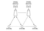
- a wireless LAN system according to an embodiment of the present disclosure will be described.
- an access point apparatus hereinafter referred to as “AP (Access Point)" 200 and a station apparatus (hereinafter referred to as “STA (Station)”) are referred to. And 100).
- AP Access Point
- STA Station
- BSS Basic Service Set
- the wireless LAN system according to the present embodiment can be installed at any place.
- the wireless LAN system according to the present embodiment can be installed in an office building, a house, a commercial facility, a public facility, or the like.
- the area of the BSS 10 may overlap with the area of another BSS 10 (hereinafter referred to as an “OBSS (Overlap Basic Service Set)”) in which the frequency channels used overlap.
- OBSS overlap Basic Service Set
- signals transmitted from STAs 100 located in the overlapping area may interfere with signals transmitted from the OBSS.
- the area of BSS10a overlaps with a part of area of BSS10b which is OBSS, and STA100b is located in the overlapping area.
- the signal transmitted from the STA 100b belonging to the BSS 10a may interfere with the signal transmitted from the AP 200b or STA 100c belonging to the BSS 10b.
- the communication base station and the communication terminal in another communication system other than the wireless LAN may cause interference by overlapping and existing in the BSS 10a.
- the AP 200 is a wireless LAN communication device that is connected to an external network and provides the STA 100 with communication with the external network.
- the AP 200 is connected to the Internet, and provides communication between the STA 100 and devices on the Internet or devices connected via the Internet.
- the STA 100 is a wireless LAN communication device that communicates with the AP 200.
- the STA 100 may be any communication device.
- the STA 100 may be a display having a display function, a memory having a storage function, a keyboard and a mouse having an input function, a speaker having a sound output function, and a smartphone having a function of executing advanced calculation processing.
- the functions of the present disclosure may be realized by any of the AP 200 and the STA 100. That is, the AP 200 and the STA 100 can have the same functional configuration. Therefore, in the following, one or both of the AP 200 and the STA 100 may be referred to as a “transmitting device” and a “receiving device”.
- communication of data frames in which the data unit in which the encoding process capable of determining the success or failure of the decoding is performed is different from the data unit in which the retransmission process is performed is performed.
- the transmitting apparatus generates an A-MPDU in which a plurality of MPDUs are aggregated, and adds an error correction code to the A-MPDU in predetermined block units.
- the receiving apparatus performs reception processing (including decoding processing) of the A-MPDU, and identifies a block for which reception processing has failed. After that, the MPDU can be restored by combining the error-free blocks in each of the MPDU for which the reception processing has failed and the retransmitted MPDU, and the reception processing can be made successful.
- the transmitting device includes a physical layer header (such as PLCP header) or information used for identifying aggregated MPDUs, or a physical layer trailer (such as PLCP trailer) including the same information as a data frame. It is good also as composition added at the end of.
- the information used to identify the MPDU is, for example, the data length and the sequence number of the MPDU.
- the wireless LAN system can identify each MPDU even if the data length information included in the delimiter information is erroneous.
- the wireless LAN system can successfully receive the physical layer trailer even if reception of the physical layer header fails. For example, each MPDU included in the A-MPDU can be identified.
- the wireless LAN system can store a plurality of identical retransmission MPDUs in A-MPDU, as long as there is room in the frame configuration of A-MPDU. By this, the wireless LAN system can increase the possibility that the combining process is successful.
- the data frame to be communicated is an A-MPDU is merely an example, and the present invention is not limited to this.
- the data frame to be communicated may be an A-MSDU or an unaggregated MPDU or MSDU.
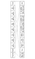
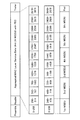
- the transmitting apparatus adds a physical layer header after a predetermined preamble (Preamble), or a plurality of aggregated MPDUs (in the figure, eight MPDUs (1st MPDU to 8th MPDU) To create a data frame in which a physical layer trailer is added after the
- Preamble a predetermined preamble
- a plurality of aggregated MPDUs in the figure, eight MPDUs (1st MPDU to 8th MPDU
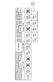
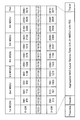
- the physical layer header and physical layer trailer are received address identification information (RXAID), transmission address identification information (TXAID), coding format information etc. (Type), and block length information (Block Size) for which coding processing is performed.
- MPDU sequence number information (Seq. No.) as information used for identification of each MPDU, data length information of the entire A-MPDU (Total Length), number information of aggregated MPDUs (MPDU Count), and information used for identification of each MPDU.
- MPDU data length information Leength
- CRC error detection code
- sequence number information (Seq. No.) of the MPDU in FIG. 2 indicates the start sequence number (Start Sequence) and the sequence number of the subsequent MPDU in a bit map format (Sequence Bitmap) And may be substituted.
- the transmitting apparatus does not have to add the sequence number information (Seq. No.) of the MPDU to each MPDU, so the amount of information of the A-MPDU can be reduced.
- the MPDU includes delimiter information (Delimiter), a predetermined MAC layer Protocol Data Unit (MAC Layer Protocol Data Unit), and an error detection code (CRC).
- the delimiter information includes MPDU data length information (MPDU Length), an error detection code (CRC), delimiter identification information (Delimiter Signature) used to identify the delimiter information, and a reserved field (Reserved).
- MPDU Length MPDU data length information
- CRC error detection code
- Delimiter Identification information delimiter Signature
- the transmitting apparatus aggregates the fourth MPDU (4th MPDU) from the first MPDU (1st MPDU), and sets data to which Padding (Pad) is added as appropriate as a target of encoding processing.
- the transmitter uses, for example, an RS (255, 239) code (code length 255 symbols, data length 239 symbols, parity length 16 symbols) which is a type of Reed-Solomon code, as processing of a predetermined coding unit.
- RS 255, 239 code
- the transmitting apparatus divides a data string configured as an A-MPDU into 239-byte units, generates 16-byte redundant codes (FEC1 to FEC12), and combines them into 1 block of 255 bytes of data.
- FEC1 to FEC12 16-byte redundant codes
- the transmitting apparatus generates a data frame in which a predetermined preamble (Preamble), a physical layer header (Header) and a physical layer trailer (Trailer) are added to the data generated above.
- Preamble a predetermined preamble
- Header a physical layer header
- Trailer a physical layer trailer
- FIG. 5 is merely an example, and any coding process may be employed as long as it is a coding process that can determine the success or failure of decoding.
- the receiving apparatus detects a predetermined preamble (Preamble), and the data frame received based on the information included in the subsequent physical layer header (Header) or physical layer trailer (Trailer) is a data frame according to the present disclosure.
- Preamble a predetermined preamble
- Header physical layer header
- Trailer physical layer trailer
- the receiving device acquires various parameters included in the physical layer header (Header) or the physical layer trailer (Trailer), and among them, the block length of the encoding process is calculated based on the type information etc. of the encoding (Type). To grasp. Then, the receiving apparatus performs error detection and error correction by extracting redundant information from the encoded information as processing of a predetermined encoding unit. That is, the receiving apparatus extracts information of 0 to 239 bytes from the information of 0 to 255 bytes and performs error detection and error correction. By this, as shown in FIG. 6, the receiving apparatus extracts 2880 bytes of data (0 to 2879) from the 3072 bytes of data (0 to 3071).
- the receiving device stores a block in which an error is detected and error correction has failed. More specifically, the receiving device has data length information (Length) of each MPDU contained in the physical layer header (Header) or physical layer trailer (Trailer) and sequence number information (Seq. No.) of each MPDU. And identify the MPDU for which the error correction has failed and the range in which the error correction has failed in the MPDU, and stores the information.
- Length data length information
- Header physical layer header
- Trailer physical layer trailer
- sequence number information Seq. No.
- the receiving device requests the transmitting device to retransmit the MPDU for which the error correction has failed, and combines the error-free blocks in each of the retransmitted MPDU and the MPDU transmitted in the past, so that there is no error.
- the MPDU can be recovered and the reception process can be successful.
- FIG. 7 An example of MPDU combining processing will be described with reference to FIGS. 7 to 11.
- FIG. 7 An example of MPDU combining processing will be described with reference to FIGS. 7 to 11.
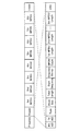
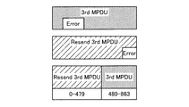
- the receiving apparatus receives an A-MPDU in which four MPDUs (1st MPDU to 4th MPDU) shown in FIG. 7 are aggregated, and performs reception processing including decoding processing on the A-MPDU.
- the receiving device detects an error in a part of blocks of the third MPDU (3rd MPDU) and fails in error correction. More specifically, the blocks from 1440th byte to 1679th byte (the block corresponding to the 96th byte to the 335rd byte in the third MPDU) before the encoding process is performed on the A-MPDU. Suppose that error correction fails. It is assumed that the reception process has succeeded for MPDUs other than the third MPDU.
- the receiving apparatus transmits a predetermined response signal to notify the transmitting apparatus that the reception process of MPDUs other than the third MPDU has succeeded.
- prescribed response signal may be block ACK (ACKnowledgement), for example, it is not limited to this.
- the transmitting device that has received the response signal recognizes that the reception processing of MPDUs other than the third MPDU is successful (in other words, there is a possibility that the reception processing of the third MPDU may have failed), and 3 Retransmit the second MPDU.
- the transmitting device aggregates a third MPDU for retransmission (Resend 3rd MPDU), a newly transmitted fifth MPDU (5th MPDU), and a sixth MPDU (6th MPDU).
- A-MPDU is sent to the receiver.
- the receiving device includes a block including the head portion of the fifth MPDU (5th MPDU) from the end of the third MPDU (Resend 3rd MPDU) retransmitted, and the fifth MPDU (5th MPDU).
- a block including the head portion of the fifth MPDU (5th MPDU) from the end of the third MPDU (Resend 3rd MPDU) retransmitted and the fifth MPDU (5th MPDU).
- an error is detected in a block included near the end of MPDU) and error correction fails.
- the blocks from the 720th byte to the 959th byte (the block corresponding to the 720th byte to the 863th byte in the third MPDU and the 5th byte before the A-MPDU is subjected to encoding processing
- the block corresponding to the 0th byte to the 95th byte in the second MPDU) and the block from the 1680th byte to the 1919th byte (the block corresponding to the 816th byte to the 1055th byte in the 5th MPDU)
- the correction failed a correction failed.
- the receiving apparatus performs a combining process using the third MPDU transmitted in the past and the retransmitted third MPDU. More specifically, the receiving device combines error-free portions of the third MPDU (3rd MPDU) transmitted in the past and the third MPDU (Resend 3rd MPDU) retransmitted. For example, as shown in FIG. 9, the receiving apparatus may use the 0th to 479th bytes of the third resent MPDU (Resend 3rd MPDU) and the 3rd MPDU (3rd MPDU) transmitted in the past. By combining the 480th byte to the 863th byte, the MPDU without error is restored. In addition, as long as there is no error, any portion may be used for the combining process.
- the reception apparatus Since the third MPDU has been restored by the combining process and the reception process has succeeded, the reception apparatus is notified of that by transmitting a predetermined response signal.
- the wireless LAN system can realize more appropriate retransmission control. More specifically, even if an error is included in a part of blocks of MPDU, the receiving apparatus can use the error-free part of MPDU instead of discarding the entire MPDU, which is higher. It is possible to recover an error-free MPDU with probability. Also, the receiving apparatus can perform combining processing without depending on the block length of the encoding processing by managing the error occurrence part of the MPDU in byte units.
- the A-MPDU may include a plurality of the same retransmission MPDU.
- the transmitter may store a plurality of identical retransmission MPDUs in the A-MPDU, as long as there is room for the frame configuration of the A-MPDU.
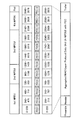
- FIG. 10 shows another A-MPDU transmitted after the A-MPDU shown in FIG.
- the transmitting device having received the predetermined response signal from the receiving device recognizes that there is a possibility that the reception processing of the fifth MPDU may have failed, and retransmits the fifth MPDU.
- the transmitting apparatus stores a fifth MPDU for retransmission (Resend 5th MPDU) and a newly transmitted seventh MPDU (7th MPDU). Then, if there is room for repeatedly storing the fifth MPDU for retransmission (Resend 5th MPDU) in the A-MPDU, the transmitting device repeats the fifth MPDU for retransmission (Repeat 5th MPDU).
- FIG. 10 shows the case where two identical retransmission MPDUs are stored, the number of stored MPDUs is not particularly limited.
- the transmitting device transmits an A-MPDU in which these MPDUs are aggregated to the receiving device.
- the receiving apparatus detects an error in some blocks included in a fifth MPDU for retransmission (Resend 5th MPDU) and a fifth MPDU repeatedly generated (Repeat 5th MPDU), and fails in error correction. . More specifically, the block from the 480th byte to the 959th byte, the block from the 1920th byte to the 2159th byte (the fifth to be repeatedly retransmitted before the A-MPDU is subjected to the encoding process) And the blocks corresponding to the 384th byte to the 623rd byte in MPDU (Repeat 5th MPDU), and the blocks from the 2640th byte to the 2879th byte (1104 in the 5th MPDU (Repeat 5th MPDU) that is repeatedly retransmitted) It is assumed that the error correction fails in the block corresponding to the 1152nd byte from the byte.
- the receiving device is configured to send the fifth MPDU (5th MPDU), the fifth MPDU for retransmission (Resend 5th MPDU), and the repeatedly resent fifth MPDU (Repeat 5th MPDU). Synthesize the missing part.
- the receiving apparatus may use the 0th to 479th bytes of the fifth MPDU for retransmission (Resend 5th MPDU) and the 5th MPDU (5th MPDU) transmitted in the past. Errors are generated by combining the 480th to 815th bytes and the 1056th to 1151st bytes with the 816th to 1055th bytes of the fifth MPDU (Repeat 5th MPDU) that has been repeatedly retransmitted. Restore the missing MPDU. Also in this example, as long as there is no error, any portion may be used for the combining process.
- the receiving apparatus can restore the fifth MPDU by the combining process and can successfully perform the receiving process, and thus notifies the transmitting apparatus of that by transmitting a predetermined response signal.
- the wireless LAN system can increase the possibility that the combining process will be successful, and can use the transmission path more effectively.
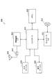
- the STA 100 and the AP 200 can have the same functional configuration. Therefore, hereinafter, the functional configuration of the STA 100 will be mainly described, and the functional configuration specific to the AP 200 will be specifically described. Also, the functional configurations described below are merely an example, and the functional configurations included in the STA 100 and the AP 200 are not particularly limited. For example, the functional configuration described below may be omitted as appropriate, or another functional configuration may be added.
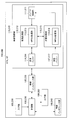
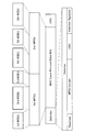
- the STA 100 includes a wireless communication unit 110, a wireless interface unit 120, a control unit 130, a wired interface unit 140, an input unit 150, and an output unit 160.
- the wireless communication unit 110 is a functional configuration that performs overall processing related to wireless communication. As illustrated in FIG. 12, the wireless communication unit 110 includes an antenna control unit 111, a reception processing unit 112, an MPDU processing unit 113, a reception buffer 114, a transmission processing unit 115, an MPDU processing unit 116, and a transmission buffer. And 117.
- the antenna control unit 111 is a functional configuration that transmits and receives a wireless signal by controlling at least one antenna. For example, by controlling an antenna, the antenna control unit 111 functions as a receiving unit that receives a wireless signal transmitted from another communication device, and converts it to a reception level at which a baseband signal can be extracted in the subsequent processing. The processed signal is provided to the reception processing unit 112.
- the antenna control unit 111 also functions as a transmission unit that controls transmission power as necessary so that the transmission signal reaches the destination device more reliably, and transmits the transmission signal generated by the transmission processing unit 115. Do.
- the reception processing unit 112 performs reception processing on the reception signal provided from the antenna control unit 111. For example, the reception processing unit 112 outputs a baseband signal by performing analog processing and down conversion on the reception signal obtained from the antenna. Then, the reception processing unit 112 extracts A-MPDU included in the baseband signal. Then, the reception processing unit 112 performs decoding processing in block units of coding processing, and performs error detection processing and error correction processing. The reception processing unit 112 provides the extracted A-MPDU or the like to the MPDU processing unit 113.
- the MPDU processing unit 113 performs processing related to MPDU in the reception process. For example, the MPDU processing unit 113 uses MPDU sequence number information (Seq. No.) and MPDU data length information (Length) acquired from the physical layer header or physical layer trailer to generate each MPDU from the A-MPDU. Separate. The MPDU processing unit 113 may separate each MPDU from the A-MPDU by using the data length information (MPDU Length) of the MPDU acquired from delimiter information (Delimiter) of each MPDU.
- MPDU sequence number information Seq. No.
- Length MPDU data length information acquired from the physical layer header or physical layer trailer
- the MPDU processing unit 113 performs processing on the MPDU for which the error correction has failed. More specifically, as a decoding process of a predetermined coding unit, the MPDU processing unit 113 identifies the MPDU for which the error correction has failed and the range for which the error correction has failed in the MPDU, and stores these information. Then, as a combining process, the MPDU processing unit 113 recovers an error-free MPDU by combining the error-free portions of the MPDU and the retransmitted MPDU (and the repeatedly retransmitted MPDU). Then, the MPDU processing unit 113 temporarily stores the MPDU in the reception buffer 114 when the MPDU without error can be restored.
- the MPDU processing unit 113 provides the MPDU (or data included in the MPDU) that has succeeded in the reception process including the decoding process and the combining process to an arbitrary application via the wireless interface unit 120 or the like.
- the reception buffer 114 is a functional configuration that temporarily stores the restored MPDU.
- the reception buffer 114 may temporarily store a portion of the MPDU for which the error correction has failed, in which there is no error in the decoding processing of the predetermined coding unit.
- the reception buffer 114 has a memory for storing such information.
- the transmission processing unit 115 performs transmission processing of the A-MPDU generated by the MPDU processing unit 116. More specifically, the transmission processing unit 115 performs an encoding process using an RS (255, 239) code or the like on the A-MPDU generated by the MPDU processing unit 116. That is, the transmission processing unit 115 divides data configured as an A-MPDU into block lengths as processing of a predetermined coding unit, and adds a redundant code (FEC or the like). Furthermore, the transmission processing unit 115 generates transmission data by adding a physical layer header, a physical layer trailer, and the like to the data to which the redundant code is added.
- RS 255, 239 code
- the transmission processing unit 115 generates a baseband signal by performing modulation processing on transmission data, and generates a transmission signal by performing up conversion on the baseband signal.
- the transmission processing unit 115 provides a transmission signal to the antenna control unit 111.
- the MPDU processing unit 116 performs processing relating to MPDU in transmission processing. For example, the MPDU processing unit 116 uses the information stored in the transmission buffer 117 to construct an MPDU to which a MAC header including destination information and the like is added. Then, the MPDU processing unit 116 sets sequence number information (Seq. No.) for each constructed MPDU, and manages MPDU data length information (Length).
- sequence number information Seq. No.
- the MPDU processing unit 116 also functions as a generation unit that generates an A-MPDU by aggregating MPDUs until a predetermined data length is reached or a predetermined number of blocks is reached. Further, as described above, the MPDU processing unit 116 may store a plurality of same MPDUs for retransmission in the A-MPDU as long as the frame configuration of the A-MPDU has a margin.
- the transmission buffer 117 is a functional configuration for temporarily storing information to be wirelessly transmitted provided from an arbitrary application via the wireless interface unit 120.
- the transmission buffer 117 includes a memory for storing the information.
- the wireless interface unit 120 is an interface to the wireless communication unit 110, and is a functional configuration that exchanges information between the wireless communication unit 110 and an arbitrary application.
- the control unit 130 is a functional configuration that centrally manages the overall processing performed by the STA 100.
- the control unit 130 may be, for example, a central processing unit (CPU) or a read only memory (ROM). Memory), RAM (Random Access Memory), and the like.
- the wired interface unit 140 is, for example, an interface to an arbitrary external device, and is a functional configuration that exchanges information between the STA 100 and the external device.
- the wired interface unit 240 is essential because it functions as an adapter for connecting to the Internet.
- the input unit 150 is a functional configuration that receives input of various information.
- the input unit 150 includes an input unit such as a touch panel, a button, a keyboard, or a microphone, and the user can input various information using the input unit.
- the input unit 150 may not exist or may have a simple configuration.
- the output unit 160 is a functional configuration that outputs various information.
- the output unit 160 includes a display unit such as a display or an audio output unit such as a speaker, and displays desired information on the display or the like based on a control signal from the control unit 130, or desired sound information. It is generated by a speaker or the like.
- the output unit 160 may not exist or may have a simple configuration.
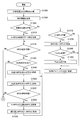
- step S1000 the transmission buffer 117 stores the information to be wirelessly transmitted, which is provided from an arbitrary application via the wireless interface unit 120.
- step S1004 the MPDU processing unit 116 acquires destination information of the transmission signal. Then, if the receiving apparatus serving as the destination corresponds to the technology of the present disclosure (step S1008 / Yes), the MPDU processing unit 116 sets data length information (Total Length) of the entire A-MPDU in step S1012. .
- the MPDU processing unit 116 determines whether or not the total value of the data lengths of the stored MPDUs has reached the data length of the entire A-MPDU set in the previous stage. If the total value of the data lengths of the stored MPDUs has not reached the data length of the entire A-MPDU and MPDUs can be added (Yes at Step S1016), and if there are MPDUs for retransmission (Steps S1016) In step S1040, the MPDU processing unit 116 stores the MPDU for retransmission in the A-MPDU, and the process returns to step S1016.
- Step S1016 / Yes When the total value of the data lengths of the stored MPDUs does not reach the data length of the entire A-MPDU set in the previous stage and MPDUs can be added (Step S1016 / Yes), and the MPDU for retransmission is If the MPDU does not exist (step S1020 / No), in step S1024, the MPDU processing unit 116 stores unsent MPDUs in the A-MPDU in order of sequence number.
- Step S1028 / Yes the MPDU processing unit 116 reacquires the MPDU stored at the beginning of the A-MPDU from the transmission buffer 117, and in step S1036, the MPDU is transferred to the A-MPDU.
- the MPDU is repeatedly stored, and the process returns to step S1016. That is, as long as there is room in the frame configuration of A-MPDU, MPDU processing section 116 repeatedly stores these MPDUs in A-MPDU in the order of priority of MPDUs for retransmission and MPDUs not transmitted.
- step S1016 and S1028 the total value of the data lengths of the stored MPDUs approaches the data length of the entire A-MPDU previously set in the previous stage, so that there is no room in the frame configuration, and addition of MPDUs is impossible If it is (step S1016 / No, step S1028 / No), the MPDU processing unit 116 determines the necessity of Padding in step S1044. If the MPDU processing unit 116 determines that Padding is necessary (Yes at Step S1044), the MPDU processing unit 116 adds Padding to the end of the A-MPDU at Step S1048.
- step S1052 the transmission processing unit 115 sets a block length in the encoding process using RS (255, 239) code or the like, and in step S1056, the data configured as an A-MPDU is the block Divide by length and add redundant code (FEC etc.).
- the transmission processing unit 115 acquires data length information (Length) of each MPDU in step S1060, and in step S1064, constructs a physical layer header and physical layer trailer including parameters of the encoding process, etc. Add to A-MPDU.
- the antenna control unit 111 transmits, as a physical layer frame, a signal to which the physical layer header and the physical layer trailer have been added, and the process ends.
- step S1008 when the receiving device to be the destination does not correspond to the technology of the present disclosure (step S1008 / No), in step S1072, whether or not the MPDU processing unit 116 can configure an existing A-MPDU. Determine about If the MPDU processing unit 116 determines that the existing A-MPDU can be configured (step S1072 / Yes), the MPDU processing unit 116 stores the MPDU in the A-MPDU in step S1076.
- step S1080 the MPDU processing unit 116 determines the need for Padding. If the MPDU processing unit 116 determines that Padding is necessary (Step S1080 / Yes), the MPDU processing unit 116 adds Padding to the end of the A-MPDU in Step S1084, and the process moves to Step S1068. Do. That is, the antenna control unit 111 transmits the generated signal as a physical layer frame, and the process ends. Note that the above flowchart is merely an example, and may be changed as appropriate.
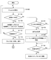
- step S1100 the reception processing unit 112 detects a predetermined preamble (Preamble) to detect a wireless signal.
- the reception processing unit 112 determines whether the detected wireless signal corresponds to the present disclosure based on all or part of the information included in the physical layer header or the arrangement of the physical headers. to decide. If the detected wireless signal corresponds to the present disclosure (step S1104 / Yes), the reception processing unit 112 is included in the physical layer trailer when the reception processing unit 112 can not correctly decode the physical layer header or the physical layer header in step S1108. Get the parameters to be
- step S1112 the reception processing unit 112 determines whether the wireless signal is addressed to the own apparatus based on the received address identification information (RXAID) of the acquired parameters. If the wireless signal is addressed to the own apparatus (step S1112 / Yes), in step S1116, the reception processing unit 112 divides the received data into block lengths of a predetermined encoding process, and divides the data in block units. Perform decryption processing.
- RXAID received address identification information
- MPDU processing unit 113 acquires MPDU in which error correction processing was successful in step S1124. , And stored in the reception buffer 114.
- step S1128 whether the MPDU for retransmission includes the MPDU for retransmission based on the MPDU sequence number information (Seq. No.) acquired from the physical layer header or the physical layer trailer? Decide whether or not. If the received A-MPDU includes the retransmission MPDU (Yes at Step S1128), at Step S1132, the MPDU processing unit 113 acquires an error-free part of the MPDUs received in the past.
- the MPDU processing unit 113 acquires an error-free part of the MPDUs received in the past.
- step S1136 the MPDU processing unit 113 determines whether or not the MPDU without error can be recovered by combining the error-free portion of each of the MPDU received in the past and the MPDU for retransmission. If the MPDU processing unit 113 determines that the MPDU having no error can be restored by combining (Yes at step S1136), the MPDU processing unit 113 performs an combining process at step S1140, and thus the MPDU having no error can be obtained. Restore. In step S1144, the MPDU processing unit 113 describes the sequence number information (Seq. No.) of the restored MPDU as ACK information.
- step S1148 the MPDU processing unit 113 determines MPDU data length information (Length).
- step S1152 the range of blocks having errors is specified and stored. Also, in step S1128, when the received A-MPDU does not include the MPDU for retransmission (step S1128 / No), the process moves to step S1156.
- step S1156 the MPDU processing unit 113 determines whether the processing up to the last MPDU included in the A-MPDU has been completed. If it is determined that the processing up to the last MPDU has not been completed (step S1156 / No), the processing moves to step S1116, and the above-described processing is repeated for each MPDU.
- the transmission processing unit 115 If it is determined that the processing up to the end MPDU has been completed (Yes at Step S1156), the transmission processing unit 115 reads out the information for ACK at Step S1160, and for example, it is received without error at Step S1164. Construct a block ACK frame including MPDU sequence number information (Seq. No.). In step S1168, the antenna control unit 111 transmits the constructed block ACK frame, and the process ends.
- step S1104 If the detected wireless signal does not correspond to the present disclosure in step S1104 (step S1104 / No), and if the data is normally received (step S1172 / Yes), in step S1176, The MPDU processing unit 113 acquires the MPDU successfully received and stores the MPDU in the reception buffer 114. In step S1180, the MPDU processing unit 113 describes, as ACK information, the sequence number information (Seq. No.) of the MPDU received normally. When the data is not normally received in step S1172 (step S1172 / No), the process moves to step S1184.
- step S1184 the MPDU processing unit 113 determines whether or not processing up to the last MPDU included in the A-MPDU has been completed. If it is determined that the processing up to the last MPDU has not been completed (step S1184 / No), the processing moves to step S1172, and the above-described processing is repeated for each MPDU.
- step S1184 If it is determined that the processing up to the last MPDU has been completed (step S1184 / Yes), the processing moves to step S1160. That is, by performing the process after step S1160, a block ACK frame is transmitted, and the process ends. Note that the above flowchart is merely an example, and may be changed as appropriate.
- the block length for which the encoding process is performed is smaller than the MPDU, which is a data unit for which the retransmission process is performed.
- the block length for which the encoding process is performed may be larger than the MPDU. Therefore, in the following, with reference to FIG. 15 and FIG. 16, the case where the block length for which the encoding process is performed is larger than MPDU will be described.
- the transmitting device aggregates the first MPDU (1st MPDU) to the seventh MPDU (7th MPDU).
- the transmitting apparatus adds Padding (Pad) as necessary to a portion less than the block length. For example, since the data length of 1st MPDU is less than the block length, the transmitting apparatus adds Padding (Pad). In addition, since the total value of the data lengths of the 3rd MPDU and the 4th MPDU is less than the block length, the transmitting apparatus adds Padding (Pad). On the other hand, since the data length of the 2nd MPDU is equal to the block length, the transmitter does not add Padding (Pad).
- the transmitting apparatus stores the plurality of MPDUs in one block without adding Padding (Pad). For example, since the total value of the data lengths of the 5th MPDU, 6th MPDU, and 7th MPDU is equal to the block length, the transmitting apparatus stores these MPDUs in one block.
- the transmitting apparatus performs encoding processing using, for example, an RS (255, 239) code.
- the transmitting apparatus generates a data frame in which a predetermined preamble (Preamble), a physical layer header (Header), and a physical layer trailer (Trailer) are added to the data subjected to the encoding process.
- a predetermined preamble Preamble
- a physical layer header Header
- a physical layer trailer Trailer
- the configurations of the physical layer header (Header) and the physical layer trailer (Trailer) are the same as the configurations described with reference to FIG. 2 and FIG.
- the contents of the decoding process shown in FIG. 16 are the same as the contents described with reference to FIG. That is, the receiving device acquires various parameters included in the physical layer header (Header) or the physical layer trailer (Trailer), and among them, the block length of the encoding process is calculated based on the type information of the encoding (Type) and the like. To grasp. Then, the receiving apparatus performs error detection and error correction by extracting redundant information from the encoded information.
- Header physical layer header
- Trailer physical layer trailer
- the block length of the encoding process is calculated based on the type information of the encoding (Type) and the like. To grasp. Then, the receiving apparatus performs error detection and error correction by extracting redundant information from the encoded information.
- the receiving apparatus stores blocks in which error correction has failed. Then, as in the above embodiment, the receiving device requests the transmitting device to retransmit the MPDU for which error correction has failed, and the error-free blocks of each of the retransmitted MPDU and the MPDU transmitted in the past. By combining, it is possible to recover an error-free MPDU and make the reception process successful.
- the present disclosure may be applied to the case where the block length for which the encoding process is performed is larger than the MPDU.
- the physical layer header (Header) and physical layer trailer (Trailer) of A-MSDU are reception address identification information (RXAID), transmission address identification information (TXAID), coding format information, etc. (Type), block length information (Block Size) on which the encoding process is performed, data length information of the entire A-MSDU (Total Length), number information of aggregated MSDU (MSDU Count), and each MSDU Information used for identification includes sequence number information (Seq. No.) of MSDU, data length information (Length) of MSDU, and an error detection code (CRC).
- RXAID reception address identification information
- TXAID transmission address identification information
- Type block length information on which the encoding process is performed
- Data length information of the entire A-MSDU Total Length
- number information of aggregated MSDU MSDU Count
- each MSDU Information used for identification includes sequence number information (Seq. No.) of MSDU, data length information (Length) of MSDU, and an error detection code (CRC).
- FIG. 17 is merely an example, and the configuration of the physical layer header (Header) and physical layer trailer (Trailer) of A-MSDU is not limited to this.
- information Sequence Bitmap
- the sequence number information (Seq. No.) of the MSDU indicates the start sequence number (Start Sequence) and the sequence number of the MSDU contained in the subsequent A-MSDU in a bitmap format. It may be replaced by
- the transmitting device aggregates the first MSDU (1st MSDU) to the sixth MSDU (6th MSDU), and sets data to which Padding (Pad) is appropriately added as a target of encoding processing.
- the transmitting apparatus performs encoding processing using, for example, an RS (255, 239) code.
- the transmitting apparatus generates a data frame in which a predetermined preamble (Preamble), a physical layer header (Header), and a physical layer trailer (Trailer) are added to the data subjected to the encoding process.
- Preamble a predetermined preamble
- Header a physical layer header
- Trailer a physical layer trailer
- the contents of the decoding process shown in FIG. 19 are the same as the contents described with reference to FIG. That is, the receiving device acquires various parameters included in the physical layer header (Header) or the physical layer trailer (Trailer), and among them, the block length of the encoding process is calculated based on the type information of the encoding (Type) and the like. To grasp. Then, the receiving apparatus performs error detection and error correction by extracting redundant information from the encoded information.
- Header physical layer header
- Trailer physical layer trailer
- the block length of the encoding process is calculated based on the type information of the encoding (Type) and the like. To grasp. Then, the receiving apparatus performs error detection and error correction by extracting redundant information from the encoded information.
- the receiving apparatus stores a block in which an error is detected and error correction has failed. More specifically, the receiving device has data length information (Length) of each MSDU and sequence number information (Seq. No.) of each MSDU included in the physical layer header (Header) or physical layer trailer (Trailer). And identify the MSDU that failed in error correction and the range in which the error correction failed in the MSDU, and store these pieces of information.
- Length data length information
- Seq. No. sequence number information
- the receiving device transmits a block ACK frame or the like to the transmitting device to request retransmission of the MSDU failed in error correction, and the error-free block of each of the retransmitted MSDU and the MSDU transmitted in the past.
- the error-free MSDU can be restored and the reception process can be successful by combining.
- the present disclosure can be applied to A-MSDU.
- the transmitting device may assemble six MSDU (1st MSDU to 6th MSDU) into one MPDU (1st MPDU) to construct a frame. Then, the transmitting apparatus adds delimiter information (Delimiter) and an error detection code (CRC) to the MPDU.
- delimiter delimiter information
- CRC error detection code
- MPDUs configured by aggregating a plurality of MSDUs may be not one but a plurality.
- the transmitting device aggregates 3 MSDUs (1st MSDU to 3rd MSDU) into one MPDU (1st MPDU), and another 3 MSDUs (4th MSDU to 6th MSDU). After aggregating into another MPDU (2nd MPDU), one frame may be constructed by further aggregating the two MPDUs.
- the receiving apparatus restores the error-free MSDU by combining the retransmitted MSDU and the error-free blocks of the MSDU transmitted in the past, and causes the reception process to succeed. be able to.
- the present disclosure can also be applied to the case where a plurality of MSDUs are aggregated to form an MPDU.
- the physical layer header (Header) is stored between a predetermined preamble (Preamble) and the first MPDU in the A-MPDU (note that the physical layer header (Header A physical layer trailer containing the same information as the header) was also added at the end).
- Preamble a predetermined preamble
- the storage position of the physical layer header (Header) is not limited to this.
- the physical layer header may be stored between the PLCP header and the first MPDU in the A-MPDU.
- a legacy short training field L-STF
- L-LTF legacy long training field
- L-SIG legacy signaling
- HE-SIG-A high efficiency short training field
- HE-STF high efficiency short training field
- HE-LTF predetermined number of high efficiency long training field
- HE- And SIG-B high efficiency signaling B
- the physical layer header (Header) is between the predetermined number of high efficiency long training fields (HE-LTF) and high efficiency signaling B (HE-SIG-B). May be stored in
- the physical layer header (Header) is stored between high efficiency signaling A (HE-SIG-A) and high efficiency short training field (HE-STF). May be referred in FIG. 25
- the physical layer header may be stored between legacy signaling (L-SIG) and high efficiency signaling A (HE-SIG-A).
- the physical layer header may be configured as part of high efficiency signaling A (HE-SIG-A).
- the physical layer header may be configured as part of high efficiency signaling B (HE-SIG-B).
- the physical layer header may be configured as part of newly defined high efficiency signaling C (HE-SIG-C).
- a physical layer trailer including the same information as the physical layer header (Header) may be added to the end of the frame, or the physical layer header (Header) may be added. ) May be omitted and only the physical layer trailer may be added to the end of the frame.
- the storage position of the physical layer header can take various variations.
- the STA 100 may be a smartphone, a tablet PC (Personal Computer), a notebook PC, a mobile terminal such as a portable game terminal or a digital camera, a television receiver, a printer, a fixed terminal such as a digital scanner or network storage, or a car navigation device Etc. may be realized as an on-vehicle terminal.
- the STA 100 is realized as a terminal (also referred to as a machine type communication (MTC) terminal) that performs machine-to-machine (M2M) communication, such as a smart meter, a vending machine, a remote monitoring device, or a POS (point of sale) terminal.
- MTC machine type communication
- M2M machine-to-machine
- the STA 100 may be a wireless communication module (for example, an integrated circuit module configured with one die) mounted on these terminals.
- the AP 200 may be realized as a wireless LAN access point (also referred to as a wireless base station) having a router function or not. Also, the AP 200 may be implemented as a mobile wireless LAN router. Furthermore, the AP 200 may be a wireless communication module (for example, an integrated circuit module configured with one die) mounted in these devices.
- a wireless LAN access point also referred to as a wireless base station
- the AP 200 may be implemented as a mobile wireless LAN router.
- the AP 200 may be a wireless communication module (for example, an integrated circuit module configured with one die) mounted in these devices.
- FIG. 30 is a block diagram showing an example of a schematic configuration of a smartphone 900 to which the technology according to the present disclosure can be applied.
- the smartphone 900 includes a processor 901, a memory 902, a storage 903, an external connection interface 904, a camera 906, a sensor 907, a microphone 908, an input device 909, a display device 910, a speaker 911, a wireless communication interface 913, an antenna switch 914, an antenna 915, A bus 917, a battery 918 and an auxiliary controller 919 are provided.
- the processor 901 may be, for example, a central processing unit (CPU) or a system on chip (SoC), and controls functions of an application layer and other layers of the smartphone 900.
- the memory 902 includes a random access memory (RAM) and a read only memory (ROM), and stores programs and data to be executed by the processor 901.
- the storage 903 may include a storage medium such as a semiconductor memory or a hard disk.
- the external connection interface 904 is an interface for connecting an external device such as a memory card or a USB (Universal Serial Bus) device to the smartphone 900.
- the camera 906 includes an imaging element such as, for example, a charge coupled device (CCD) or a complementary metal oxide semiconductor (CMOS), and generates a captured image.
- the sensor 907 may include, for example, a sensor group such as a positioning sensor, a gyro sensor, a geomagnetic sensor, and an acceleration sensor.
- the microphone 908 converts audio input to the smartphone 900 into an audio signal.
- the input device 909 includes, for example, a touch sensor that detects a touch on the screen of the display device 910, a keypad, a keyboard, a button, a switch, or the like, and receives an operation or information input from the user.
- the display device 910 has a screen such as a liquid crystal display (LCD) or an organic light emitting diode (OLED) display, and displays an output image of the smartphone 900.
- the speaker 911 converts an audio signal output from the smartphone 900 into an audio.
- the wireless communication interface 913 supports one or more of wireless LAN standards such as IEEE 802.11a, 11 b, 11 g, 11 n, 11 ac, and 11 ad to execute wireless communication.
- the wireless communication interface 913 may communicate with other devices via the wireless LAN access point in the infrastructure mode.
- the wireless communication interface 913 can directly communicate with another device in a direct communication mode such as an ad hoc mode or Wi-Fi Direct (registered trademark).
- Wi-Fi Direct one of two terminals operates as an access point unlike in the ad hoc mode, but communication is directly performed between the terminals.
- the wireless communication interface 913 may typically include a baseband processor, an RF (Radio Frequency) circuit, a power amplifier, and the like.
- the wireless communication interface 913 may be a memory that stores a communication control program, a processor that executes the program, and a one-chip module in which related circuits are integrated.
- the wireless communication interface 913 may support other types of wireless communication schemes such as a near field wireless communication scheme, a close proximity wireless communication scheme, or a cellular communication scheme in addition to the wireless LAN scheme.
- the antenna switch 914 switches the connection destination of the antenna 915 between a plurality of circuits (for example, circuits for different wireless communication schemes) included in the wireless communication interface 913.
- the antenna 915 has a single or a plurality of antenna elements (for example, a plurality of antenna elements constituting a MIMO antenna), and is used for transmission and reception of a wireless signal by the wireless communication interface 913.
- the smart phone 900 may be equipped with a some antenna (For example, the antenna for wireless LANs, the antenna for proximity wireless communication systems, etc.). In that case, the antenna switch 914 may be omitted from the configuration of the smartphone 900.
- the bus 917 connects the processor 901, the memory 902, the storage 903, the external connection interface 904, the camera 906, the sensor 907, the microphone 908, the input device 909, the display device 910, the speaker 911, the wireless communication interface 913 and the auxiliary controller 919 to one another.
- the battery 918 supplies power to each block of the smartphone 900 shown in FIG. 30 via a feed line partially shown by a broken line in the figure.
- the auxiliary controller 919 operates minimum necessary functions of the smartphone 900, for example, in the sleep mode.
- the smartphone 900 may operate as a wireless access point (software AP) by the processor 901 executing the access point function at the application level. Also, the wireless communication interface 913 may have a wireless access point function.
- FIG. 31 is a block diagram showing an example of a schematic configuration of a car navigation device 920 to which the technology according to the present disclosure can be applied.
- the car navigation device 920 includes a processor 921, a memory 922, a GPS (Global Positioning System) module 924, a sensor 925, a data interface 926, a content player 927, a storage medium interface 928, an input device 929, a display device 930, a speaker 931, wireless communication.
- An interface 933, an antenna switch 934, an antenna 935 and a battery 938 are provided.
- the processor 921 may be, for example, a CPU or an SoC, and controls the navigation function and other functions of the car navigation device 920.
- the memory 922 includes a RAM and a ROM, and stores programs and data to be executed by the processor 921.
- the GPS module 924 uses GPS signals received from GPS satellites to measure the location (eg, latitude, longitude and altitude) of the car navigation device 920.
- the sensor 925 may include, for example, a sensor group such as a gyro sensor, a geomagnetic sensor, and an air pressure sensor.
- the data interface 926 is connected to the on-vehicle network 941 via, for example, a terminal (not shown), and acquires data generated on the vehicle side, such as vehicle speed data.
- Content player 927 plays content stored on a storage medium (eg, CD or DVD) inserted into storage medium interface 928.
- the input device 929 includes, for example, a touch sensor, a button or a switch that detects a touch on the screen of the display device 930, and receives an operation or an information input from a user.
- the display device 930 has a screen such as an LCD or an OLED display, and displays an image of the navigation function or the content to be reproduced.
- the speaker 931 outputs the sound of the navigation function or the content to be reproduced.
- the wireless communication interface 933 supports one or more of wireless LAN standards such as IEEE 802.11a, 11 b, 11 g, 11 n, 11 ac, and 11 ad, and performs wireless communication.
- the wireless communication interface 933 may communicate with other devices via the wireless LAN access point in the infrastructure mode.
- the wireless communication interface 933 can directly communicate with another device in a direct communication mode such as an ad hoc mode or Wi-Fi Direct.
- the wireless communication interface 933 may typically include a baseband processor, an RF circuit, a power amplifier, and the like.
- the wireless communication interface 933 may be a one-chip module in which a memory for storing a communication control program, a processor for executing the program, and related circuits are integrated.
- the wireless communication interface 933 may support other types of wireless communication schemes, such as a short distance wireless communication scheme, a close proximity wireless communication scheme, or a cellular communication scheme, in addition to the wireless LAN scheme.
- the antenna switch 934 switches the connection destination of the antenna 935 among a plurality of circuits included in the wireless communication interface 933.
- the antenna 935 has a single or multiple antenna elements, and is used for transmission and reception of wireless signals by the wireless communication interface 933.
- Car navigation apparatus 920 may be provided with a plurality of antennas. In that case, the antenna switch 934 may be omitted from the configuration of the car navigation device 920.
- the battery 938 supplies power to each block of the car navigation device 920 shown in FIG. 31 via a feed line partially shown by a broken line in the figure.
- the battery 938 also stores power supplied from the vehicle side.
- the technology according to the present disclosure may be realized as an on-board system (or vehicle) 940 including one or more blocks of the car navigation device 920 described above, an on-board network 941, and a vehicle-side module 942.
- the vehicle-side module 942 generates vehicle-side data such as a vehicle speed, an engine speed, or failure information, and outputs the generated data to the in-vehicle network 941.
- FIG. 32 is a block diagram showing an example of a schematic configuration of a wireless access point 950 to which the technology according to the present disclosure can be applied.
- the wireless access point 950 includes a controller 951, a memory 952, an input device 954, a display device 955, a network interface 957, a wireless communication interface 963, an antenna switch 964 and an antenna 965.
- the controller 951 may be, for example, a CPU or a digital signal processor (DSP), and various functions (for example, access restriction, routing, encryption, firewall) of the Internet Protocol (IP) layer and higher layers of the wireless access point 950. And log management etc.).
- the memory 952 includes a RAM and a ROM, and stores programs executed by the controller 951 and various control data (for example, a terminal list, a routing table, an encryption key, security settings and logs, etc.).
- the input device 954 includes, for example, a button or a switch, and receives an operation from the user.
- the display device 955 includes an LED lamp and the like, and displays the operating status of the wireless access point 950.
- the network interface 957 is a wired communication interface for connecting the wireless access point 950 to the wired communication network 958.
- the network interface 957 may have a plurality of connection terminals.
- the wired communication network 958 may be a LAN such as Ethernet (registered trademark) or may be a Wide Area Network (WAN).
- the wireless communication interface 963 supports one or more of wireless LAN standards such as IEEE 802.11a, 11b, 11g, 11n, 11ac, and 11ad, and provides wireless connection as an access point to nearby terminals.
- the wireless communication interface 963 may typically include a baseband processor, an RF circuit, a power amplifier, and the like.
- the wireless communication interface 963 may be a memory that stores a communication control program, a processor that executes the program, and a one-chip module in which related circuits are integrated.
- the antenna switch 964 switches the connection destination of the antenna 965 between a plurality of circuits included in the wireless communication interface 963.
- the antenna 965 has a single or multiple antenna elements, and is used for transmission and reception of wireless signals by the wireless communication interface 963.
- the wireless LAN system restores the MPDU by combining the MPDU for which the reception processing has failed and the error-free blocks in each of the retransmitted MPDUs, and performs the reception processing. It can be successful.
- the wireless LAN system can realize more appropriate retransmission control. More specifically, even if an error is included in a part of blocks of MPDU, the receiving apparatus can use the error-free part of MPDU instead of discarding the entire MPDU, which is higher. It is possible to recover an error-free MPDU with probability. Also, the receiving apparatus can perform combining processing without depending on the block length of the encoding processing by managing the error occurrence part of the MPDU in byte units.
- the wireless LAN system includes, in the physical layer header, information used for identifying aggregated MPDUs, and adds a physical layer trailer including the same information to the end of the data frame.
- the wireless LAN system can identify each MPDU even if the data length information included in the delimiter information is erroneous.
- the possibility that the combining process will be successful can be increased by storing a plurality of same retransmission MPDUs in the A-MPDU.
- the data unit in which the encoding process is performed is smaller than the data unit in which the retransmission process is performed, The wireless LAN communication device according to (1).
- the data unit in which the encoding process is performed is larger than the data unit in which the retransmission process is performed, The wireless LAN communication device according to (1).
- the generation unit generates the data frame by aggregating data of data units in which the retransmission process is performed.
- the wireless LAN communication device according to any one of (1) to (3).
- the generation unit performs the aggregation until a predetermined data length is reached.
- the wireless LAN communication device according to (4).
- the data frame may be an A-MPDU in which MPDUs are aggregated, or an A-MSDU in which MSDUs are aggregated.
- the wireless LAN communication device according to (5).
- the generation unit includes a plurality of the same data for retransmission in the data frame, The wireless LAN communication device according to (5) or (6).
- the generation unit adds, to the data frame, information used to identify data to be subjected to the retransmission process.
- the wireless LAN communication device according to any one of (1) to (7).
- the information used to identify the data includes data length information and sequence number information of data to be subjected to the retransmission process.
- the generation unit includes information used to identify the data in a physical layer header or physical layer trailer added to the data frame.
- (11) Generating a data frame in which a data unit in which encoding processing capable of determining the success or failure of decoding is performed is different from a data unit in which retransmission processing is performed; Sending the data frame.
- the reception processing unit specifies a range of data for which the reception process has failed, and performs a combining process with a part of the retransmitted data.
- the data frame is generated by aggregating data in data units in which the retransmission process is performed.
- the data frame may be an A-MPDU in which MPDUs are aggregated, or an A-MSDU in which MSDUs are aggregated.
- the reception processing unit performs the reception process using the same data for retransmission included in a plurality of the data frames.
- the reception processing unit performs the reception process based on information added to the data frame and used for identification of data to be subjected to the retransmission process.
- the information used to identify the data includes data length information and sequence number information of data to be subjected to the retransmission process.
- the information used to identify the data is included in a physical layer header or physical layer trailer attached to the data frame, The wireless LAN communication device according to (17) or (18). (20) Receiving a data frame in which a data unit in which encoding processing capable of determining the success or failure of decoding is performed is different from a data unit in which retransmission processing is performed; Performing reception processing including decoding of the data frame; A wireless LAN communication method implemented by a computer.
Abstract
Description
1.背景
2.本開示の一実施形態に係る無線LANシステム
3.変形例
4.応用例
5.むすび
まず、本開示の背景について説明する。
上記では、本開示の背景について説明してきた。続いて、本開示の一実施形態に係る無線LANシステムについて説明する。
まず、図1を参照して、本実施形態に係る無線LANシステムの構成について説明する。
上記では、本実施形態に係る無線LANシステムの構成について説明した。続いて、本実施形態に係る無線LANシステムの機能概要について説明する。
上記では、本実施形態に係る無線LANシステムの機能概要について説明した。続いて、本実施形態に係る無線LANシステムの機能詳細(フレーム構成等を含む)について説明する。まず、図2を参照して、AーMPDUの物理層ヘッダおよび物理層トレーラについて説明する。
上記では、本実施形態に係る無線LANシステムの機能詳細について説明した。続いて、図12を参照して、AP200およびSTA100の機能構成について説明する。
無線通信部110は、無線通信に関する処理全般を行う機能構成である。図12に示すように、無線通信部110は、アンテナ制御部111と、受信処理部112と、MPDU処理部113と、受信バッファ114と、送信処理部115と、MPDU処理部116と、送信バッファ117と、を備える。
アンテナ制御部111は、少なくとも1つのアンテナを制御することで、無線信号の送受信を行う機能構成である。例えば、アンテナ制御部111は、アンテナを制御することで、他の通信装置から送信された無線信号を受信する受信部として機能し、後段の処理でベースバンド信号が抽出可能の受信レベルにまで変換処理を施した信号を受信処理部112に提供する。また、アンテナ制御部111は、宛先装置に送信信号がより確実に到達するように、必要に応じて送信電力を制御し、送信処理部115によって生成される送信信号を送信する送信部としても機能する。
受信処理部112は、アンテナ制御部111から提供される受信信号に対して受信処理を行う。例えば、受信処理部112は、アンテナから得られる受信信号について、アナログ処理およびダウンコンバージョンを施すことにより、ベースバンド信号を出力する。そして、受信処理部112は、ベースバンド信号に含まれるAーMPDUを抽出する。そして、受信処理部112は、符号化処理のブロック単位で復号処理を行い、誤り検出処理および誤り訂正処理を行う。受信処理部112は、抽出したAーMPDU等をMPDU処理部113に提供する。
MPDU処理部113は、受信処理においてMPDUに関する処理を行う。例えば、MPDU処理部113は、物理層ヘッダまたは物理層トレーラから取得された、MPDUのシーケンス番号情報(Seq.No.)およびMPDUのデータ長情報(Length)を用いて、AーMPDUから各MPDUを分離する。なお、MPDU処理部113は、各MPDUのデリミタ情報(Delimiter)から取得されたMPDUのデータ長情報(MPDU Length)を用いて、AーMPDUから各MPDUを分離してもよい。
受信バッファ114は、復元されたMPDUを一時的に格納する機能構成である。また、受信バッファ114は、誤り訂正に失敗したMPDUのうち、所定の符号化単位の復号処理の誤りが無い部分を一時的に格納してもよい。受信バッファ114は、これらの情報を記憶するメモリを備えている。
送信処理部115は、MPDU処理部116によって生成されるAーMPDUの送信処理を行う。より具体的に説明すると、送信処理部115は、MPDU処理部116において生成されたAーMPDUに対してRS(255,239)符号等を用いた符号化処理を行う。すなわち、送信処理部115は、AーMPDUとして構成されるデータを所定の符号化単位の処理としてブロック長に区切り、冗長符号(FEC等)を付加する。さらに、送信処理部115は、冗長符号を付加したデータに対して物理層ヘッダおよび物理層トレーラ等を付加することで送信データを生成する。
MPDU処理部116は、送信処理においてMPDUに関する処理を行う。例えば、MPDU処理部116は、送信バッファ117に格納されている情報を用いて、宛先情報等を含むMACヘッダを付加したMPDUを構築する。そして、MPDU処理部116は、構築したMPDU毎にシーケンス番号情報(Seq.No.)を設定し、MPDUのデータ長情報(Length)を管理する。
送信バッファ117は、無線インタフェース部120を介して任意のアプリケーションから提供された、無線送信される情報を一時的に格納する機能構成である。送信バッファ117は、当該情報を記憶するメモリを備えている。
無線インタフェース部120は、無線通信部110に対するインタフェースであり、無線通信部110と任意のアプリケーションとの情報の受け渡しを行う機能構成である。
制御部130は、STA100による処理全般を一元的に管理する機能構成である。制御部130は、例えば、CPU(Central Processing Unit)、ROM(Read Only
Memory)、RAM(Random Access Memory)等を備えた各種ICチップ等により実現される。
有線インタフェース部140は、例えば、任意の外部装置に対するインタフェースであり、STA100と当該外部装置との情報の受け渡しを行う機能構成である。なお、AP200においては、有線インタフェース部240は、インターネットに接続するアダプターとして機能するため、必須である。
入力部150は、各種情報の入力を受ける機能構成である。例えば、入力部150はタッチパネル、ボタン、キーボードまたはマイクロホン等の入力手段を備えており、ユーザがこれらの入力手段を用いて各種情報を入力することができる。なお、AP200においては、入力部150は、存在しなくてもよく、あるいは簡素な構成でもよい。
出力部160は、各種情報を出力する機能構成である。例えば、出力部160は、ディスプレイ等の表示手段またはスピーカ等の音声出力手段を備えており、制御部130からの制御信号に基づいて所望の情報をディスプレイ等に表示させたり、所望の音情報をスピーカ等によって発生させたりする。なお、AP200においては、出力部160は、存在しなくてもよく、あるいは簡素な構成でもよい。
上記では、AP200およびSTA100の機能構成について説明した。続いて、AP200およびSTA100の動作について説明する。なお、上記のとおり、本開示の機能は、STA100およびAP200のいずれによって実現されてもよいため、以下では、一例として、送信装置および受信装置として機能するSTA100の動作について説明する。
上記では、AP200およびSTA100の動作について説明した。続いて、本開示の変形例について説明する。
上記の実施形態においては、符号化処理が行われるブロック長は、再送処理が行われるデータ単位であるMPDUよりも小さかった。しかし、符号化処理が行われるブロック長は、MPDUよりも大きくてもよい。そこで、以下では、図15および図16を参照して、符号化処理が行われるブロック長がMPDUよりも大きい場合について説明する。
上記の実施形態においては、本開示がAーMPDUへ適用された場合について説明した。しかし、本開示は、AーMSDUへ適用されてもよい。そこで、以下では、図17~図19を参照して、本開示がAーMSDUへ適用された場合について説明する。
続いて、複数のMSDUを集約してMPDUを構成する場合の例について説明する。
続いて、図22~図29を参照して、物理層ヘッダ(Header)の格納位置のバリエーションについて説明する。
本開示に係る技術は、様々な製品へ応用可能である。例えば、STA100は、スマートフォン、タブレットPC(Personal Computer)、ノートPC、携帯型ゲーム端末若しくはデジタルカメラなどのモバイル端末、テレビジョン受像機、プリンタ、デジタルスキャナ若しくはネットワークストレージなどの固定端末、又はカーナビゲーション装置などの車載端末として実現されてもよい。また、STA100は、スマートメータ、自動販売機、遠隔監視装置又はPOS(Point Of Sale)端末などの、M2M(Machine To Machine)通信を行う端末(MTC(Machine Type Communication)端末ともいう)として実現されてもよい。さらに、STA100は、これら端末に搭載される無線通信モジュール(例えば、1つのダイで構成される集積回路モジュール)であってもよい。
図30は、本開示に係る技術が適用され得るスマートフォン900の概略的な構成の一例を示すブロック図である。スマートフォン900は、プロセッサ901、メモリ902、ストレージ903、外部接続インタフェース904、カメラ906、センサ907、マイクロフォン908、入力デバイス909、表示デバイス910、スピーカ911、無線通信インタフェース913、アンテナスイッチ914、アンテナ915、バス917、バッテリー918及び補助コントローラ919を備える。
図31は、本開示に係る技術が適用され得るカーナビゲーション装置920の概略的な構成の一例を示すブロック図である。カーナビゲーション装置920は、プロセッサ921、メモリ922、GPS(Global Positioning System)モジュール924、センサ925、データインタフェース926、コンテンツプレーヤ927、記憶媒体インタフェース928、入力デバイス929、表示デバイス930、スピーカ931、無線通信インタフェース933、アンテナスイッチ934、アンテナ935及びバッテリー938を備える。
図32は、本開示に係る技術が適用され得る無線アクセスポイント950の概略的な構成の一例を示すブロック図である。無線アクセスポイント950は、コントローラ951、メモリ952、入力デバイス954、表示デバイス955、ネットワークインタフェース957、無線通信インタフェース963、アンテナスイッチ964及びアンテナ965を備える。
以上で説明してきたように、本開示に係る無線LANシステムは、受信処理に失敗したMPDUと、再送されたMPDUそれぞれにおける誤りの無いブロックの合成処理を行うことでMPDUを復元し、受信処理を成功させることができる。
(1)
復号の成否を判定可能な符号化処理が行われるデータ単位と、再送処理が行われるデータ単位が異なるデータフレームを生成する生成部と、
前記データフレームを送信する送信部と、を備える、
無線LAN通信装置。
(2)
前記符号化処理が行われるデータ単位は、前記再送処理が行われるデータ単位よりも小さい、
前記(1)に記載の無線LAN通信装置。
(3)
前記符号化処理が行われるデータ単位は、前記再送処理が行われるデータ単位よりも大きい、
前記(1)に記載の無線LAN通信装置。
(4)
前記生成部は、前記再送処理が行われるデータ単位のデータの集約を行うことで、前記データフレームを生成する、
前記(1)から(3)のいずれか1項に記載の無線LAN通信装置。
(5)
前記生成部は、所定のデータ長になるまで前記集約を行う、
前記(4)に記載の無線LAN通信装置。
(6)
前記データフレームは、MPDUが集約されたAーMPDU、または、MSDUが集約されたAーMSDUである、
前記(5)に記載の無線LAN通信装置。
(7)
前記生成部は、前記データフレームに再送用の同一データを複数含める、
前記(5)または(6)に記載の無線LAN通信装置。
(8)
前記生成部は、前記再送処理が行われるデータの識別に用いられる情報を前記データフレームに付加する、
前記(1)から(7)のいずれか1項に記載の無線LAN通信装置。
(9)
前記データの識別に用いられる情報は、前記再送処理が行われるデータのデータ長情報およびシーケンス番号情報を含む、
前記(8)に記載の無線LAN通信装置。
(10)
前記生成部は、前記データの識別に用いられる情報を、前記データフレームに付加される物理層ヘッダまたは物理層トレーラに含める、
前記(8)または(9)に記載の無線LAN通信装置。
(11)
復号の成否を判定可能な符号化処理が行われるデータ単位と、再送処理が行われるデータ単位が異なるデータフレームを生成することと、
前記データフレームを送信することと、を有する、
コンピュータにより実行される無線LAN通信方法。
(12)
復号の成否を判定可能な符号化処理が行われるデータ単位と、再送処理が行われるデータ単位が異なるデータフレームを受信する受信部と、
前記データフレームの復号を含む受信処理を行う受信処理部と、を備える、
無線LAN通信装置。
(13)
前記受信処理部は、前記受信処理に失敗したデータの範囲を特定し、再送されたデータの一部との合成処理を行う、
前記(12)に記載の無線LAN通信装置。
(14)
前記データフレームは、前記再送処理が行われるデータ単位のデータの集約によって生成される、
前記(12)または(13)に記載の無線LAN通信装置。
(15)
前記データフレームは、MPDUが集約されたAーMPDU、または、MSDUが集約されたAーMSDUである、
前記(14)に記載の無線LAN通信装置。
(16)
前記受信処理部は、前記データフレームに複数含まれる再送用の同一データを用いて前記受信処理を行う、
前記(14)または(15)に記載の無線LAN通信装置。
(17)
前記受信処理部は、前記データフレームに付加される、前記再送処理が行われるデータの識別に用いられる情報に基づいて前記受信処理を行う、
前記(12)から(16)のいずれか1項に記載の無線LAN通信装置。
(18)
前記データの識別に用いられる情報は、前記再送処理が行われるデータのデータ長情報およびシーケンス番号情報を含む、
前記(17)に記載の無線LAN通信装置。
(19)
前記データの識別に用いられる情報は、前記データフレームに付加される物理層ヘッダまたは物理層トレーラに含まれる、
前記(17)または(18)に記載の無線LAN通信装置。
(20)
復号の成否を判定可能な符号化処理が行われるデータ単位と、再送処理が行われるデータ単位が異なるデータフレームを受信することと、
前記データフレームの復号を含む受信処理を行うことと、を有する、
コンピュータにより実行される無線LAN通信方法。
200 AP
110、210 無線通信部
111、211 アンテナ制御部
112、212 受信処理部
113、213 MPDU処理部
114、214 受信バッファ
115、215 送信処理部
116、216 MPDU処理部
117、217 送信バッファ
120、220 無線インタフェース部
130、230 制御部
140、240 有線インタフェース部
150、250 入力部
160、260 出力部
Claims (20)
- 復号の成否を判定可能な符号化処理が行われるデータ単位と、再送処理が行われるデータ単位が異なるデータフレームを生成する生成部と、
前記データフレームを送信する送信部と、を備える、
無線LAN通信装置。 - 前記符号化処理が行われるデータ単位は、前記再送処理が行われるデータ単位よりも小さい、
請求項1に記載の無線LAN通信装置。 - 前記符号化処理が行われるデータ単位は、前記再送処理が行われるデータ単位よりも大きい、
請求項1に記載の無線LAN通信装置。 - 前記生成部は、前記再送処理が行われるデータ単位のデータの集約を行うことで、前記データフレームを生成する、
請求項1に記載の無線LAN通信装置。 - 前記生成部は、所定のデータ長になるまで前記集約を行う、
請求項4に記載の無線LAN通信装置。 - 前記データフレームは、MPDUが集約されたAーMPDU、または、MSDUが集約されたAーMSDUである、
請求項5に記載の無線LAN通信装置。 - 前記生成部は、前記データフレームに再送用の同一データを複数含める、
請求項5に記載の無線LAN通信装置。 - 前記生成部は、前記再送処理が行われるデータの識別に用いられる情報を前記データフレームに付加する、
請求項1に記載の無線LAN通信装置。 - 前記データの識別に用いられる情報は、前記再送処理が行われるデータのデータ長情報およびシーケンス番号情報を含む、
請求項8に記載の無線LAN通信装置。 - 前記生成部は、前記データの識別に用いられる情報を、前記データフレームに付加される物理層ヘッダまたは物理層トレーラに含める、
請求項8に記載の無線LAN通信装置。 - 復号の成否を判定可能な符号化処理が行われるデータ単位と、再送処理が行われるデータ単位が異なるデータフレームを生成することと、
前記データフレームを送信することと、を有する、
コンピュータにより実行される無線LAN通信方法。 - 復号の成否を判定可能な符号化処理が行われるデータ単位と、再送処理が行われるデータ単位が異なるデータフレームを受信する受信部と、
前記データフレームの復号を含む受信処理を行う受信処理部と、を備える、
無線LAN通信装置。 - 前記受信処理部は、前記受信処理に失敗したデータの範囲を特定し、再送されたデータの一部との合成処理を行う、
請求項12に記載の無線LAN通信装置。 - 前記データフレームは、前記再送処理が行われるデータ単位のデータの集約によって生成される、
請求項12に記載の無線LAN通信装置。 - 前記データフレームは、MPDUが集約されたAーMPDU、または、MSDUが集約されたAーMSDUである、
請求項14に記載の無線LAN通信装置。 - 前記受信処理部は、前記データフレームに複数含まれる再送用の同一データを用いて前記受信処理を行う、
請求項14に記載の無線LAN通信装置。 - 前記受信処理部は、前記データフレームに付加される、前記再送処理が行われるデータの識別に用いられる情報に基づいて前記受信処理を行う、
請求項12に記載の無線LAN通信装置。 - 前記データの識別に用いられる情報は、前記再送処理が行われるデータのデータ長情報およびシーケンス番号情報を含む、
請求項17に記載の無線LAN通信装置。 - 前記データの識別に用いられる情報は、前記データフレームに付加される物理層ヘッダまたは物理層トレーラに含まれる、
請求項17に記載の無線LAN通信装置。 - 復号の成否を判定可能な符号化処理が行われるデータ単位と、再送処理が行われるデータ単位が異なるデータフレームを受信することと、
前記データフレームの復号を含む受信処理を行うことと、を有する、
コンピュータにより実行される無線LAN通信方法。
Priority Applications (7)
| Application Number | Priority Date | Filing Date | Title |
|---|---|---|---|
| CN201880048386.XA CN110945811B (zh) | 2017-07-27 | 2018-05-16 | 无线lan通信设备和无线lan通信方法 |
| US16/632,392 US11206110B2 (en) | 2017-07-27 | 2018-05-16 | Wireless LAN communication device and wireless LAN communication method |
| EP18837408.6A EP3661089A4 (en) | 2017-07-27 | 2018-05-16 | WLAN COMMUNICATION DEVICE AND WLAN COMMUNICATION METHOD |
| JP2019532394A JP7238775B2 (ja) | 2017-07-27 | 2018-05-16 | 無線lan通信装置および無線lan通信方法 |
| KR1020207001287A KR20200033845A (ko) | 2017-07-27 | 2018-05-16 | 무선 lan 통신 장치 및 무선 lan 통신 방법 |
| CA3070549A CA3070549A1 (en) | 2017-07-27 | 2018-05-16 | Wireless lan communication device and wireless lan communication method |
| US17/530,511 US20220077968A1 (en) | 2017-07-27 | 2021-11-19 | Wireless lan communication device and wireless lan communication method |
Applications Claiming Priority (2)
| Application Number | Priority Date | Filing Date | Title |
|---|---|---|---|
| JP2017145740 | 2017-07-27 | ||
| JP2017-145740 | 2017-07-27 |
Related Child Applications (2)
| Application Number | Title | Priority Date | Filing Date |
|---|---|---|---|
| US16/632,392 A-371-Of-International US11206110B2 (en) | 2017-07-27 | 2018-05-16 | Wireless LAN communication device and wireless LAN communication method |
| US17/530,511 Continuation US20220077968A1 (en) | 2017-07-27 | 2021-11-19 | Wireless lan communication device and wireless lan communication method |
Publications (1)
| Publication Number | Publication Date |
|---|---|
| WO2019021588A1 true WO2019021588A1 (ja) | 2019-01-31 |
Family
ID=65040150
Family Applications (1)
| Application Number | Title | Priority Date | Filing Date |
|---|---|---|---|
| PCT/JP2018/018836 WO2019021588A1 (ja) | 2017-07-27 | 2018-05-16 | 無線lan通信装置および無線lan通信方法 |
Country Status (8)
| Country | Link |
|---|---|
| US (2) | US11206110B2 (ja) |
| EP (1) | EP3661089A4 (ja) |
| JP (1) | JP7238775B2 (ja) |
| KR (1) | KR20200033845A (ja) |
| CN (1) | CN110945811B (ja) |
| CA (1) | CA3070549A1 (ja) |
| TW (1) | TWI757517B (ja) |
| WO (1) | WO2019021588A1 (ja) |
Cited By (2)
| Publication number | Priority date | Publication date | Assignee | Title |
|---|---|---|---|---|
| CN112821984A (zh) * | 2019-11-15 | 2021-05-18 | 华为技术有限公司 | 无线局域网数据处理方法、装置及设备 |
| AU2018326862B2 (en) * | 2017-08-31 | 2021-08-19 | Sony Corporation | Communication device and method |
Families Citing this family (3)
| Publication number | Priority date | Publication date | Assignee | Title |
|---|---|---|---|---|
| JP7290670B2 (ja) * | 2019-02-15 | 2023-06-13 | 株式会社Nttドコモ | 端末、無線通信方法、基地局及びシステム |
| US11496924B2 (en) * | 2019-07-02 | 2022-11-08 | Qualcomm Incorporated | Medium access control (MAC) protocol data unit (MPDU) and codeword alignment and validation |
| US11387935B2 (en) * | 2021-02-19 | 2022-07-12 | Ultralogic 6G, Llc | Error detection and correction by modulation quality in 5G/6G |
Citations (8)
| Publication number | Priority date | Publication date | Assignee | Title |
|---|---|---|---|---|
| JP2004260633A (ja) * | 2003-02-26 | 2004-09-16 | Sanyo Electric Co Ltd | データ送信装置、データ送信方法およびプログラム |
| JP2010050923A (ja) * | 2008-08-25 | 2010-03-04 | Sony Corp | 通信装置、通信方法、プログラム、および通信システム |
| US20120072520A1 (en) * | 2009-05-27 | 2012-03-22 | St-Ericsson Sa | System and Method for Establishing Reliable Communication in a Connection-Less Environment |
| US8386892B1 (en) * | 2007-11-05 | 2013-02-26 | Massachusetts Institute Of Technology | Partial packet recovery for wireless networks |
| JP5254369B2 (ja) | 2008-03-03 | 2013-08-07 | クゥアルコム・インコーポレイテッド | Macベースのフィードバックを用いてwlanプロトコルにハイブリッドarqを追加すること |
| JP2014522610A (ja) * | 2011-06-08 | 2014-09-04 | マーベル ワールド トレード リミテッド | 低データレートのwlanのための効率的な送信 |
| WO2015006640A1 (en) * | 2013-07-11 | 2015-01-15 | Interdigital Patent Holdings, Inc. | Systems and methods for smart harq for wifi |
| US20170126363A1 (en) * | 2014-03-17 | 2017-05-04 | Interdigital Patent Holdings, Inc. | Methods for reception failure identification and remediation for wifi |
Family Cites Families (22)
| Publication number | Priority date | Publication date | Assignee | Title |
|---|---|---|---|---|
| JPS5254369Y2 (ja) | 1971-02-22 | 1977-12-09 | ||
| KR100542090B1 (ko) * | 2002-12-16 | 2006-01-11 | 한국전자통신연구원 | 무선 통신 시스템에서의 오류 제어 방법, 매체 접속 제어프레임 설계 방법 및 단말기 등록 방법과 기록 매체 |
| JP4407126B2 (ja) * | 2003-01-09 | 2010-02-03 | ソニー株式会社 | 無線通信システム、無線通信装置及び無線通信方法、並びにコンピュータ・プログラム |
| KR100842586B1 (ko) * | 2006-01-03 | 2008-07-01 | 삼성전자주식회사 | 무선 근거리 네트워크 시스템에서 응집된 매체 액세스 제어프로토콜 데이터 유닛들의 전송 방법 및 그 시스템 |
| US7904777B2 (en) * | 2006-01-24 | 2011-03-08 | Samsung Electronics Co., Ltd. | Method and system for generating block acknowledgements in wireless communications |
| KR101099993B1 (ko) * | 2006-12-07 | 2011-12-28 | 미쓰비시덴키 가부시키가이샤 | 무선 통신 시스템, 무선 단말국, 무선 기지국 및 무선 통신 방법 |
| US20090031185A1 (en) * | 2007-07-23 | 2009-01-29 | Texas Instruments Incorporated | Hybrid arq systems and methods for packet-based networks |
| JP5091761B2 (ja) * | 2008-05-13 | 2012-12-05 | 株式会社東芝 | 無線通信装置 |
| JP5175633B2 (ja) * | 2008-06-19 | 2013-04-03 | 株式会社東芝 | 無線通信装置、無線通信の制御方法、および無線通信の制御プログラム |
| KR20100027935A (ko) * | 2008-09-03 | 2010-03-11 | 삼성전자주식회사 | 무선통신시스템에서 에러제어를 위한 데이터 생성 장치 및 방법 |
| US8041216B2 (en) * | 2009-06-10 | 2011-10-18 | Alcatel Lucent | System and method for channel-adaptive error-resilient burst mode transmission |
| KR101678487B1 (ko) * | 2009-09-18 | 2016-11-23 | 한국전자통신연구원 | 무선 통신 시스템을 위한 데이터 송수신 장치 및 방법 |
| US8473821B2 (en) * | 2010-11-09 | 2013-06-25 | Qualcomm, Incorporated | Packet-level erasure protection coding in aggregated packet transmissions |
| WO2012064502A1 (en) | 2010-11-12 | 2012-05-18 | Interdigital Patent Holdings, Inc. | Method and apparatus for performing channel aggregation and medium access control retransmission |
| US8971247B2 (en) * | 2012-05-25 | 2015-03-03 | Qualcomm Incorporated | Methods, devices, and systems for efficient retransmission communications |
| CN102984232B (zh) * | 2012-10-30 | 2016-06-08 | 西安电子科技大学 | 多跳网络中的实时流媒体传输方法 |
| MY157062A (en) * | 2012-10-30 | 2016-04-29 | Univ Putra Malaysia | A method for adjusting aggregation size based on acknowledgement (ack) bitmap |
| US9967061B2 (en) | 2014-03-10 | 2018-05-08 | Lg Electronics Inc. | Method and apparatus for retransmission in wireless LAN |
| US9565594B2 (en) * | 2014-03-28 | 2017-02-07 | Qualcomm Incorporated | Link aggregation in wireless local area networks |
| US10374776B2 (en) * | 2014-11-20 | 2019-08-06 | Industrial Technology Research Institute | Base station, user equipment for integrating multiple rats using carrier aggregation and methods thereof |
| WO2016111435A1 (ko) * | 2015-01-08 | 2016-07-14 | 엘지전자 주식회사 | 무선랜에서 헤더에 대한 에러 체크 비트를 포함하는 프레임을 전송하는 방법 및 장치 |
| US10153868B2 (en) * | 2015-06-12 | 2018-12-11 | Apple Inc. | Hybrid automatic repeat request (H-ARQ) for a wireless local area network |
-
2018
- 2018-05-16 US US16/632,392 patent/US11206110B2/en active Active
- 2018-05-16 CA CA3070549A patent/CA3070549A1/en active Pending
- 2018-05-16 EP EP18837408.6A patent/EP3661089A4/en active Pending
- 2018-05-16 KR KR1020207001287A patent/KR20200033845A/ko not_active Application Discontinuation
- 2018-05-16 WO PCT/JP2018/018836 patent/WO2019021588A1/ja active Application Filing
- 2018-05-16 JP JP2019532394A patent/JP7238775B2/ja active Active
- 2018-05-16 CN CN201880048386.XA patent/CN110945811B/zh active Active
- 2018-07-03 TW TW107122879A patent/TWI757517B/zh active
-
2021
- 2021-11-19 US US17/530,511 patent/US20220077968A1/en active Pending
Patent Citations (8)
| Publication number | Priority date | Publication date | Assignee | Title |
|---|---|---|---|---|
| JP2004260633A (ja) * | 2003-02-26 | 2004-09-16 | Sanyo Electric Co Ltd | データ送信装置、データ送信方法およびプログラム |
| US8386892B1 (en) * | 2007-11-05 | 2013-02-26 | Massachusetts Institute Of Technology | Partial packet recovery for wireless networks |
| JP5254369B2 (ja) | 2008-03-03 | 2013-08-07 | クゥアルコム・インコーポレイテッド | Macベースのフィードバックを用いてwlanプロトコルにハイブリッドarqを追加すること |
| JP2010050923A (ja) * | 2008-08-25 | 2010-03-04 | Sony Corp | 通信装置、通信方法、プログラム、および通信システム |
| US20120072520A1 (en) * | 2009-05-27 | 2012-03-22 | St-Ericsson Sa | System and Method for Establishing Reliable Communication in a Connection-Less Environment |
| JP2014522610A (ja) * | 2011-06-08 | 2014-09-04 | マーベル ワールド トレード リミテッド | 低データレートのwlanのための効率的な送信 |
| WO2015006640A1 (en) * | 2013-07-11 | 2015-01-15 | Interdigital Patent Holdings, Inc. | Systems and methods for smart harq for wifi |
| US20170126363A1 (en) * | 2014-03-17 | 2017-05-04 | Interdigital Patent Holdings, Inc. | Methods for reception failure identification and remediation for wifi |
Non-Patent Citations (3)
| Title |
|---|
| CHOI, SUNG-HYUN ET AL.: "IEEE 802.11 MAC-Level FEC scheme with retransmission combining", IEEE TRANSACTIONS ON WIRELESS COMMUNICATIONS, vol. 5, no. 1, 16 January 2006 (2006-01-16), pages 203 - 211, XP001545713, ISSN: 1536-1276, DOI: doi:10.1109/TWC.2006.01014 * |
| LIN, JIASHI ET AL.: "Novel Design and Analysis of Aggregtated ARQ Protocols for IEEE 802.11n Networks", IEEE TRANSACTIONS ON MOBILE COMPUTING, vol. 12, no. 3, 7 February 2012 (2012-02-07), pages 556 - 570, XP011494603, ISSN: 1536-1233 * |
| See also references of EP3661089A4 |
Cited By (5)
| Publication number | Priority date | Publication date | Assignee | Title |
|---|---|---|---|---|
| AU2018326862B2 (en) * | 2017-08-31 | 2021-08-19 | Sony Corporation | Communication device and method |
| US11343019B2 (en) | 2017-08-31 | 2022-05-24 | Sony Corporation | Communication apparatus and method |
| US11750327B2 (en) | 2017-08-31 | 2023-09-05 | Sony Group Corporation | Communication apparatus and method |
| CN112821984A (zh) * | 2019-11-15 | 2021-05-18 | 华为技术有限公司 | 无线局域网数据处理方法、装置及设备 |
| CN112821984B (zh) * | 2019-11-15 | 2022-07-22 | 华为技术有限公司 | 无线局域网数据处理方法、装置及设备 |
Also Published As
| Publication number | Publication date |
|---|---|
| JP7238775B2 (ja) | 2023-03-14 |
| US11206110B2 (en) | 2021-12-21 |
| TW201911842A (zh) | 2019-03-16 |
| EP3661089A4 (en) | 2020-07-29 |
| CA3070549A1 (en) | 2019-01-31 |
| KR20200033845A (ko) | 2020-03-30 |
| TWI757517B (zh) | 2022-03-11 |
| US20220077968A1 (en) | 2022-03-10 |
| CN110945811A (zh) | 2020-03-31 |
| JPWO2019021588A1 (ja) | 2020-05-28 |
| EP3661089A1 (en) | 2020-06-03 |
| US20200153558A1 (en) | 2020-05-14 |
| CN110945811B (zh) | 2023-07-04 |
Similar Documents
| Publication | Publication Date | Title |
|---|---|---|
| JP7238775B2 (ja) | 無線lan通信装置および無線lan通信方法 | |
| US10700814B2 (en) | Information processing apparatus, information processing method, and program | |
| US11563831B2 (en) | Communication device and communication method | |
| TWI768120B (zh) | 無線lan通訊裝置、無線lan通訊方法及電腦可讀取之記錄媒體 | |
| EP3790213B1 (en) | Mac-based hybrid automatic repeat request (harq) | |
| JP6962311B2 (ja) | 無線通信装置および無線通信方法 | |
| WO2021186587A1 (ja) | 送信局及び受信局 | |
| US10993145B2 (en) | Communication device, communication method, and program | |
| CN201248041Y (zh) | 指示字段被定址到的临时块流的设备和处理该字段的设备 | |
| JPWO2020116184A1 (ja) | 通信装置、及び通信方法 |
Legal Events
| Date | Code | Title | Description |
|---|---|---|---|
| 121 | Ep: the epo has been informed by wipo that ep was designated in this application |
Ref document number: 18837408 Country of ref document: EP Kind code of ref document: A1 |
|
| ENP | Entry into the national phase |
Ref document number: 2019532394 Country of ref document: JP Kind code of ref document: A |
|
| ENP | Entry into the national phase |
Ref document number: 3070549 Country of ref document: CA |
|
| NENP | Non-entry into the national phase |
Ref country code: DE |
|
| WWE | Wipo information: entry into national phase |
Ref document number: 2018837408 Country of ref document: EP |
|
| ENP | Entry into the national phase |
Ref document number: 2018837408 Country of ref document: EP Effective date: 20200227 |