EP3661089A1 - Wireless lan communication device and wireless lan communication method - Google Patents
Wireless lan communication device and wireless lan communication method Download PDFInfo
- Publication number
- EP3661089A1 EP3661089A1 EP18837408.6A EP18837408A EP3661089A1 EP 3661089 A1 EP3661089 A1 EP 3661089A1 EP 18837408 A EP18837408 A EP 18837408A EP 3661089 A1 EP3661089 A1 EP 3661089A1
- Authority
- EP
- European Patent Office
- Prior art keywords
- mpdu
- data
- wireless lan
- lan communication
- communication device
- Prior art date
- Legal status (The legal status is an assumption and is not a legal conclusion. Google has not performed a legal analysis and makes no representation as to the accuracy of the status listed.)
- Pending
Links
- 238000000034 method Methods 0.000 title claims abstract description 263
- 238000004891 communication Methods 0.000 title claims abstract description 127
- 230000008569 process Effects 0.000 claims abstract description 237
- 230000005540 biological transmission Effects 0.000 claims abstract description 45
- 230000004931 aggregating effect Effects 0.000 claims description 19
- 230000002776 aggregation Effects 0.000 claims description 10
- 238000004220 aggregation Methods 0.000 claims description 10
- 238000010586 diagram Methods 0.000 description 36
- 238000012937 correction Methods 0.000 description 27
- 230000006870 function Effects 0.000 description 18
- 230000008878 coupling Effects 0.000 description 11
- 238000010168 coupling process Methods 0.000 description 11
- 238000005859 coupling reaction Methods 0.000 description 11
- 238000001514 detection method Methods 0.000 description 10
- 230000011664 signaling Effects 0.000 description 10
- 230000000694 effects Effects 0.000 description 8
- 238000005516 engineering process Methods 0.000 description 8
- 238000012545 processing Methods 0.000 description 7
- 230000004044 response Effects 0.000 description 6
- 238000012549 training Methods 0.000 description 6
- 238000005192 partition Methods 0.000 description 5
- 230000004048 modification Effects 0.000 description 4
- 238000012986 modification Methods 0.000 description 4
- 238000006243 chemical reaction Methods 0.000 description 3
- 230000010267 cellular communication Effects 0.000 description 2
- 239000000284 extract Substances 0.000 description 2
- 239000012634 fragment Substances 0.000 description 2
- 230000001151 other effect Effects 0.000 description 2
- 239000004065 semiconductor Substances 0.000 description 2
- 230000005236 sound signal Effects 0.000 description 2
- 230000001133 acceleration Effects 0.000 description 1
- 230000004075 alteration Effects 0.000 description 1
- 238000004364 calculation method Methods 0.000 description 1
- 230000000295 complement effect Effects 0.000 description 1
- 238000000605 extraction Methods 0.000 description 1
- 238000003384 imaging method Methods 0.000 description 1
- 230000006872 improvement Effects 0.000 description 1
- 238000012905 input function Methods 0.000 description 1
- 239000004973 liquid crystal related substance Substances 0.000 description 1
- 229910044991 metal oxide Inorganic materials 0.000 description 1
- 150000004706 metal oxides Chemical class 0.000 description 1
- 238000012806 monitoring device Methods 0.000 description 1
Images


Classifications
-
- H—ELECTRICITY
- H04—ELECTRIC COMMUNICATION TECHNIQUE
- H04L—TRANSMISSION OF DIGITAL INFORMATION, e.g. TELEGRAPHIC COMMUNICATION
- H04L1/00—Arrangements for detecting or preventing errors in the information received
- H04L1/12—Arrangements for detecting or preventing errors in the information received by using return channel
- H04L1/16—Arrangements for detecting or preventing errors in the information received by using return channel in which the return channel carries supervisory signals, e.g. repetition request signals
- H04L1/18—Automatic repetition systems, e.g. Van Duuren systems
- H04L1/1867—Arrangements specially adapted for the transmitter end
- H04L1/189—Transmission or retransmission of more than one copy of a message
-
- H—ELECTRICITY
- H04—ELECTRIC COMMUNICATION TECHNIQUE
- H04L—TRANSMISSION OF DIGITAL INFORMATION, e.g. TELEGRAPHIC COMMUNICATION
- H04L1/00—Arrangements for detecting or preventing errors in the information received
- H04L1/12—Arrangements for detecting or preventing errors in the information received by using return channel
- H04L1/16—Arrangements for detecting or preventing errors in the information received by using return channel in which the return channel carries supervisory signals, e.g. repetition request signals
- H04L1/1607—Details of the supervisory signal
- H04L1/1628—List acknowledgements, i.e. the acknowledgement message consisting of a list of identifiers, e.g. of sequence numbers
-
- H—ELECTRICITY
- H04—ELECTRIC COMMUNICATION TECHNIQUE
- H04L—TRANSMISSION OF DIGITAL INFORMATION, e.g. TELEGRAPHIC COMMUNICATION
- H04L1/00—Arrangements for detecting or preventing errors in the information received
- H04L1/12—Arrangements for detecting or preventing errors in the information received by using return channel
- H04L1/16—Arrangements for detecting or preventing errors in the information received by using return channel in which the return channel carries supervisory signals, e.g. repetition request signals
- H04L1/18—Automatic repetition systems, e.g. Van Duuren systems
- H04L1/1812—Hybrid protocols; Hybrid automatic repeat request [HARQ]
- H04L1/1819—Hybrid protocols; Hybrid automatic repeat request [HARQ] with retransmission of additional or different redundancy
-
- H—ELECTRICITY
- H04—ELECTRIC COMMUNICATION TECHNIQUE
- H04L—TRANSMISSION OF DIGITAL INFORMATION, e.g. TELEGRAPHIC COMMUNICATION
- H04L1/00—Arrangements for detecting or preventing errors in the information received
- H04L1/004—Arrangements for detecting or preventing errors in the information received by using forward error control
- H04L1/0045—Arrangements at the receiver end
- H04L1/0047—Decoding adapted to other signal detection operation
-
- H—ELECTRICITY
- H04—ELECTRIC COMMUNICATION TECHNIQUE
- H04L—TRANSMISSION OF DIGITAL INFORMATION, e.g. TELEGRAPHIC COMMUNICATION
- H04L1/00—Arrangements for detecting or preventing errors in the information received
- H04L1/0078—Avoidance of errors by organising the transmitted data in a format specifically designed to deal with errors, e.g. location
- H04L1/0083—Formatting with frames or packets; Protocol or part of protocol for error control
-
- H—ELECTRICITY
- H04—ELECTRIC COMMUNICATION TECHNIQUE
- H04L—TRANSMISSION OF DIGITAL INFORMATION, e.g. TELEGRAPHIC COMMUNICATION
- H04L1/00—Arrangements for detecting or preventing errors in the information received
- H04L1/12—Arrangements for detecting or preventing errors in the information received by using return channel
- H04L1/16—Arrangements for detecting or preventing errors in the information received by using return channel in which the return channel carries supervisory signals, e.g. repetition request signals
- H04L1/1607—Details of the supervisory signal
- H04L1/1642—Formats specially adapted for sequence numbers
-
- H—ELECTRICITY
- H04—ELECTRIC COMMUNICATION TECHNIQUE
- H04L—TRANSMISSION OF DIGITAL INFORMATION, e.g. TELEGRAPHIC COMMUNICATION
- H04L69/00—Network arrangements, protocols or services independent of the application payload and not provided for in the other groups of this subclass
- H04L69/22—Parsing or analysis of headers
-
- H—ELECTRICITY
- H04—ELECTRIC COMMUNICATION TECHNIQUE
- H04L—TRANSMISSION OF DIGITAL INFORMATION, e.g. TELEGRAPHIC COMMUNICATION
- H04L69/00—Network arrangements, protocols or services independent of the application payload and not provided for in the other groups of this subclass
- H04L69/30—Definitions, standards or architectural aspects of layered protocol stacks
- H04L69/32—Architecture of open systems interconnection [OSI] 7-layer type protocol stacks, e.g. the interfaces between the data link level and the physical level
- H04L69/322—Intralayer communication protocols among peer entities or protocol data unit [PDU] definitions
-
- H—ELECTRICITY
- H04—ELECTRIC COMMUNICATION TECHNIQUE
- H04W—WIRELESS COMMUNICATION NETWORKS
- H04W28/00—Network traffic management; Network resource management
- H04W28/02—Traffic management, e.g. flow control or congestion control
- H04W28/04—Error control
-
- H—ELECTRICITY
- H04—ELECTRIC COMMUNICATION TECHNIQUE
- H04W—WIRELESS COMMUNICATION NETWORKS
- H04W80/00—Wireless network protocols or protocol adaptations to wireless operation
- H04W80/02—Data link layer protocols
-
- H—ELECTRICITY
- H04—ELECTRIC COMMUNICATION TECHNIQUE
- H04W—WIRELESS COMMUNICATION NETWORKS
- H04W84/00—Network topologies
- H04W84/02—Hierarchically pre-organised networks, e.g. paging networks, cellular networks, WLAN [Wireless Local Area Network] or WLL [Wireless Local Loop]
- H04W84/10—Small scale networks; Flat hierarchical networks
- H04W84/12—WLAN [Wireless Local Area Networks]
Definitions
- the present disclosure relates to a wireless LAN communication device and a wireless LAN communication method.
- Hybrid ARQ Hybrid Automatic repeat-request
- PTL 1 discloses a technique to add HARQ to a wireless LAN protocol with MAC-based feedback.
- data for example, MPDU (MAC layer Protocol Data Unit)
- MPDU MAC layer Protocol Data Unit
- the present disclosure has been devised in view of the above-described circumstances, and provides a novel and improved wireless LAN communication device and wireless LAN communication method that make it possible to achieve more appropriate retransmission control in a wireless LAN system.
- a wireless LAN communication device including: a generator that generates a data frame for which a data unit in which an encoding process is performed and a data unit in which a retransmission process is performed are different from each other; and a transmission section that transmits the data frame.
- the encoding process makes it possible to determine whether or not decoding is successful.
- a wireless LAN communication method that is executed by a computer.
- the wireless LAN communication method includes: generating a data frame for which a data unit in which an encoding process is performed and a data unit in which a retransmission process is performed are different from each other; and transmitting the data frame.
- the encoding process making it possible to determine whether or not decoding is successful.
- a wireless LAN communication device including: a reception section that receives a data frame for which a data unit in which an encoding process is performed and a data unit in which a retransmission process is performed are different from each other; and a reception process section that performs a reception process including decoding the data frame.
- the encoding process makes it possible to determine whether or not decoding is successful.
- a wireless LAN communication method that is executed by a computer.
- the wireless LAN communication method includes: receiving a data frame for which a data unit in which an encoding process is performed and a data unit in which a retransmission process is performed are different from each other; and performing a reception process including decoding the data frame.
- the encoding process makes it possible to determine whether or not decoding is successful.
- HARQ a technique related to retransmission control that is called HARQ.
- an appropriate block length is defined depending on the number of subcarriers in a physical layer, and retransmission control is performed with this block length used as a unit.
- the block length used as a unit for retransmission control is then a fixed length, and the retransmission control or sequence management is thus easy.
- data for example, MPDU
- fragment processing is difficult for predetermined access control, making it difficult to directly apply the above-described HARQ to the wireless LAN system.
- block partition positions in variable-length data that is communicated in the wireless LAN system are different from those of HARQ.
- the retransmission control is performed in the wireless LAN system with MPDU used as a unit. Accordingly, even if HARQ is used for processing in a lower layer than the MAC layer, the retransmission control is not performed in a unit corresponding to HARQ. For example, if there is an error in one HARQ block, whole MPDU that is larger than the HARQ block is retransmitted, preventing improvement in efficiency of transmission path usage.
- a frame aggregation technique is applied to the wireless LAN system to enable aggregation of a plurality of data units, and thus it is possible to reduce frame transmission overhead and improve transmission efficiency.
- frame aggregation techniques a technique called A-MPDU (aggregated MPDU) aggregation has been considered particularly effective and generally and widely used. This technique aggregates a plurality of MPDUs as one physical layer frame.
- delimiter information including data length information of the MPDU in an A-MPDU configuration is appended at the beginning the of MPDU.
- the receiver that receives the A-MPDU recognizes boundaries of the respective MPDUs on the basis of the data length information. If the data length information included in the delimiter information is incorrect, the receiver is thus unable to correctly recognize boundaries of the respective MPDUs. Consequently, the receiver fails in a reception process of MPDU located at or after the boundary that has not been correctly recognized, and discards such MPDU.
- the discloser of the present application has devised the present application in view of the circumstances described above.
- the present disclosure makes it possible to achieve more appropriate retransmission control in wireless LAN systems.
- the present disclosure also enables a reception process of MPDU to be successful even in a case where data length information of MPDU included in delimiter information in an A-MPDU configuration is incorrect.
- the following describes a wireless LAN system according to an embodiment of the present disclosure.
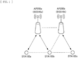
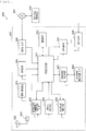
- the wireless LAN system includes access point devices (each referred to below as “AP (Access Point)”) 200 and station devices (each referred to below as “STA (Station)”) 100.
- AP Access Point
- STA Service Set
- One AP 200 and one or more STAs 100 then form a basic service set (referred to below as “BSS (Basic Service Set)") 10.
- BSS Basic Service Set
- the wireless LAN system according to the present embodiment may be installed in any places.
- the wireless LAN system according to the present embodiment may be installed in office buildings, residential houses, business or public establishments, and the like.
- an area of the BSS 10 may overlap with an area of another BSS 10 (referred to below as "OBSS (Overlap Basic Service Set)”) whose frequency channel overlaps with the frequency channel used by the BSS 10.
- OBSS overlap Basic Service Set
- a signal transmitted from the STA 100 located in the overlapping area may interfere with a signal transmitted from the OBSS.
- an area of BSS 10a overlaps with a portion of an area of BSS 10b that is OBSS, and STA 100b is located in the overlapping area.
- a signal transmitted from the STA 100b belonging to the BSS 10a may interfere with a signal transmitted from AP 200b or STA 100c belonging to the BSS 10b.
- FIG. 1 illustrates, as an example, a case where other wireless LAN systems cause interference therebetween, but this is not limitative.
- a communication base station and a communication terminal in another communication system other than wireless LAN may overlap with the BSS 10a to cause interference.
- Each of the APs 200 is a wireless LAN communication device that is coupled to an external network and provides the STA 100 with communication with the external network.
- the AP 200 is coupled to the Internet and provides communication between the STA 100 and a device on the Internet or a device to be coupled via the Internet.
- the STA 100 is a wireless LAN communication device that communicates with the AP 200.
- the STA 100 may be any communication device.
- the STA 100 may be a display having a display function, a memory having a storage function, a keyboard and a mouse each having an input function, a speaker having a sound output function, or a smartphone having an advanced calculation processing execution function.
- the functionality of the present disclosure may be achieved by either the AP 200 or the STA 100. That is, the AP 200 and the STA 100 may have the same functional components. Either or both of the AP 200 and the STA 100 may therefore be referred to below as “transmitter” or “receiver”.
- the configuration of the wireless LAN system according to the present embodiment has been described above. Next, the overview of the functionality of the wireless LAN system according to the present embodiment is described.
- a data frame is communicated in which a data unit in which an encoding process is performed and a data unit in which a retransmission process is performed are different from each other.
- the encoding process makes it possible to determine whether or not decoding is successful.
- the transmitter generates A-MPDU in which a plurality of MPDUs is aggregated, and appends an error correcting code to the A-MPDU in units of predetermined blocks.
- the receiver performs a reception process (including a decoding process) of the A-MPDU and specifies a block for which the reception process has been unsuccessful. Thereafter, the receiver performs a combining process of respective error-free blocks from MPDU for which the reception process has been unsuccessful and retransmitted MPDU to restore the MPDU, thereby succeeding in the reception process.
- the transmitter may include, in a physical layer header (such as a PLCP header), information for use in identification of the aggregated MPDU in the A-MPDU or append a physical layer trailer (such as a PLCP trailer) including the same information to the end of a data frame.
- a physical layer header such as a PLCP header
- the information for use in identification of MPDU for example, means the data length, the sequence number, and the like of the MPDU. This enables the wireless LAN system to identify each MPDU even if the data length information included in the delimiter information is incorrect.
- including the information not only in the physical layer header, but also in the physical layer trailer enables the wireless LAN system to identify each MPDU included in the A-MPDU as long as the physical layer trailer is successfully received even if the physical layer header is unsuccessfully received.
- the wireless LAN system is able to store a plurality of identical retransmission MPDUs in A-MPDU as long as a frame configuration of the A-MPDU has the capacity. This enables the wireless LAN system to increase the possibility of succeeding in the combining process.
- the data frame to be communicated is A-MPDU, but this is not limitative.
- the data frame to be communicated may be A-MSDU, non-aggregated MPDU, or non-aggregated MSDU.
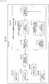
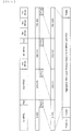
- the transmitter generates a data frame in which the physical layer header is appended after a predetermined preamble (Preamble) or the physical layer trailer is appended after a plurality of aggregated MPDUs (eight MPDUs (1st MPDU to 8th MPDU) are aggregated in the diagram).
- Preamble predetermined preamble
- MPDUs eight MPDUs (1st MPDU to 8th MPDU
- the physical layer header and the physical layer trailer include information such as recipient address identification information (RXAID), transmitter address identification information (TXAID), encoding format information (Type), encoding process block length information (Block Size), data length information (Total Length) of the entire A-MPDU, information (MPDU Count) of the number of MPDUs to be aggregated, sequence number information (Seq. No.) of the MPDUs and data length information (Length) of the MPDU as the information for use in identification of each MPDU, and an error detection code (CRC).
- RXAID recipient address identification information
- TXAID transmitter address identification information
- Type encoding format information
- Block Size encoding process block length information
- Data length information Total Length
- MPDU Count information of the number of MPDUs to be aggregated
- sequence number information Seq. No.
- Data length information Length
- CRC error detection code
- sequence number information (Seq. No.) of the MPDUs in FIG. 2 may be replaced with a starting sequence number (Start Sequence) and information (Sequence Bitmap) indicating the sequence number of the subsequent MPDU in a bitmap format. This eliminates the need to append the sequence number information (Seq. No.) of MPDU to each MPDU, and thus enables the transmitter to reduce the volume of A-MPDU information.
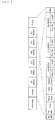
- the MPDU includes delimiter information (Delimiter), protocol data unit (MAC Layer Protocol Data Unit) of a predetermined MAC layer, and an error detection code (CRC).
- the delimiter information then includes data length information (MPDU Length) of MPDU, an error detection code (CRC), delimiter identification information (Delimiter Signature) for use in identification of the delimiter information, and a reserved field (Reserved).
- MPDU Length data length information
- CRC error detection code
- Delimiter Identification information Delimiter Signature
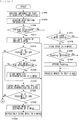
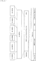
- the transmitter targets, for the encoding process, data obtained by aggregating first MPDU (1st MPDU) to fourth MPDU (4th MPDU) and appending Padding (Pad) thereto as appropriate.
- the transmitter then performs the encoding process using, for example, an RS (255, 239) code (code length: 255 symbols, data length: 239 symbols, parity length: 16 symbols), which is a kind of Reed-Solomon codes, as a process of a predetermined encoding unit.
- the transmitter partitions a data string configured as the A-MPDU on a 239-byte boundary, generates 16-byte redundancy codes (FEC 1 to FEC 12), and combines them to generate data having 255-byte blocks.
- FEC 1 to FEC 12 16-byte redundancy codes
- the transmitter then generates a data frame obtained by appending the predetermined preamble (Preamble), the physical layer header (Header), and the physical layer trailer (Trailer) to the data generated as described above.
- Preamble predetermined preamble
- Header physical layer header
- Trailer physical layer trailer
- FIG. 5 is merely an example, but any encoding process may be employed as long as the encoding process makes it possible to determine whether or not decoding is successful.
- the receiver detects the predetermined preamble (Preamble), recognizes that the received data frame is the data frame according to the present disclosure on the basis of the information included in the subsequent physical layer header (Header) or physical layer trailer (Trailer), and performs the decoding process according to the present disclosure.
- Preamble predetermined preamble
- Header physical layer header
- Trailer physical layer trailer
- the receiver acquires various parameters included in the physical layer header (Header) or the physical layer trailer (Trailer), and grasps the block length of the encoding process on the basis of the encoding format information (Type) or the like of the parameters.
- the receiver then performs error detection and error correction as a process of a predetermined encoding unit by extracting redundancy information from the encoded information. That is, the receiver performs the error detection and the error correction by extracting 0 to 239-byte information from 0 to 255-byte information.
- the receiver extracts the 2880-byte data (0 to 2879) from the 3072-byte data (0 to 3071) as illustrated in FIG. 6 .
- the receiver then stores a block for which an error has been detected and the error correction has been unsuccessful. More specifically, the receiver specifies MPDU for which the error correction has been unsuccessful and a range in the MPDU for which the error correction has been unsuccessful on the basis of the data length information (Length) of each MPDU and the sequence number information (Seq. No.) of each MPDU included in the physical layer header (Header) or the physical layer trailer (Trailer), and stores the information.
- Length data length information
- Seq. No. sequence number information
- the receiver requests the transmitter to retransmit the MPDU for which the error correction has been unsuccessful, and restores error-free MPDU by combining respective error-free blocks from the retransmitted MPDU and the MPDU transmitted in the past, thereby succeeding in the reception process.
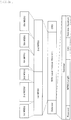
- the receiver receives A-MPDU obtained by aggregating four MPDUs (1st MPDU to 4th MPDU) illustrated in FIG. 7 and performs the reception process including the decoding process on the A-MPDU.
- the receiver detects an error in a block in the third MPDU (3rd MPDU) and fails in the error correction. More specifically, it is assumed that the receiver fails in the error correction of a block ranging from the 1440th byte to the 1679th byte before the encoding process is performed on the A-MPDU (a block corresponding to a range from the 96th byte to the 335th byte in the third MPDU). It should be noted that the reception process for the MPDUs other than the third MPDU is successful.
- the receiver notifies the transmitter of the successful reception process for the MPDUs other than the third MPDU by transmitting a predetermined response signal.
- the predetermined response signal may be, for example, block ACK (ACKnowledgement), but is not limited thereto.
- the transmitter that receives the response signal grasps that the reception process of the MPDUs other than the third MPDU has been successful (in other words, the reception process for the third MPDU may have been unsuccessful) and retransmits the third MPDU.
- the transmitter transmits, to the receiver, A-MPDU obtained by aggregating third MPDU (Resend 3rd MPDU) for retransmission, and the fifth MPDU (5th MPDU) and the sixth MPDU (6th MPDU) to be newly transmitted.
- A-MPDU obtained by aggregating third MPDU (Resend 3rd MPDU) for retransmission, and the fifth MPDU (5th MPDU) and the sixth MPDU (6th MPDU) to be newly transmitted.
- the receiver detects errors in a block including the end of the retransmitted third MPDU (Resend 3rd MPDU) and the beginning portion of the fifth MPDU (5th MPDU) and in a block included near the end of the fifth MPDU (5th MPDU), and fails in the error correction as illustrated in FIG. 8 .
- the receiver fails in the error correction for a block ranging from the 720th byte to the 959th byte before the encoding process is performed on the A-MPDU (a block corresponding to a range from the 720th byte to the 863rd byte in the third MPDU and a block corresponding to a range from the 0th byte to the 95th byte of the fifth MPDU) and a block ranging from the 1680th byte to the 1919th byte (a block corresponding to a range from the 816th byte to the 1055th byte of the fifth MPDU).
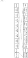
- the receiver then performs the combining process using the third MPDU transmitted in the past and the retransmitted third MPDU. More specifically, the receiver combines respective error-free portions of the third MPDU (3rd MPDU) transmitted in the past and the retransmitted third MPDU (Resend 3rd MPDU). For example, as illustrated in FIG. 9 , the receiver combines the 0th byte to the 479th byte of the retransmitted third MPDU (Resend 3rd MPDU) and the 480th byte to the 863rd byte of the third MPDU (3rd MPDU) transmitted in the past to restore error-free MPDU. It should be noted that any portions may be used for the combining process as long as the portions are error-free.
- the 0th byte to the 719th byte of the retransmitted third MPDU (Resend 3rd MPDU) and the 720th byte to the 863rd byte of the third MPDU (Resend 3rd MPDU) transmitted in the past may be used for the combining process.
- the receiver restores the third MPDU through the combining process and succeeds in the reception process. Accordingly, the receiver notifies the transmitter of that by transmitting a predetermined response signal.
- the above-described combining process enables the wireless LAN system to achieve more appropriate retransmission control. More specifically, even if a block in MPDU includes an error, the receiver is able to use error-free portions of the MPDU for the combining process instead of discarding the whole MPDU. It is therefore possible to restore error-free MPDU with a higher probability. Furthermore, the receiver is able to perform the combining process without depending on the block length of the encoding process by managing an error-containing portion of the MPDU in units of bytes.
- A-MPDU may include a plurality of identical MPDUs for retransmission.
- the transmitter may store a plurality of identical MPDUs for retransmission in A-MPDU as long as the frame configuration of the A-MPDU has the capacity.
- FIG. 10 illustrates another A-MPDU to be transmitted after the A-MPDU illustrated in FIG. 8 .
- the transmitter that receives a predetermined response signal from the receiver grasps that the reception process of the fifth MPDU may have been unsuccessful, and retransmits the fifth MPDU.
- the transmitter then stores a fifth MPDU (Resend 5th MPDU) for retransmission and the seventh MPDU (7th MPDU) to be newly transmitted as illustrated in FIG. 10 .
- the transmitter then repeatedly stores the fifth MPDU (Repeat 5th MPDU) for retransmission in the A-MPDU if the A-MPDU has the capacity to have the fifth MPDU (Resend 5th MPDU) for retransmission repeatedly stored therein.
- FIG. 10 illustrates a case where two identical MPDUs for retransmission are stored, but any number of identical MPDUs for retransmission may be stored.
- the transmitter transmits the A-MPDU obtained by aggregating these MPDUs to the receiver.
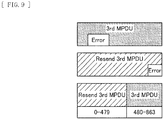
- the receiver detects errors in blocks included in the fifth MPDU (Resend 5th MPDU) for retransmission and the repeatedly retransmitted fifth MPDU (Repeat 5th MPDU), and fails in the error correction. More specifically, it is assumed the receiver fails in the error correction in a block ranging from the 480th byte to the 959th byte before the encoding process is performed on the A-MPDU, a block ranging from the 1920th byte to the 2159th byte before the encoding process is performed on the A-MPDU (a block corresponding to a range from the 384th byte to the 623rd byte in the repeatedly retransmitted fifth MPDU (Repeat 5th MPDU)), and a block ranging from the 2640th byte to the 2879th byte before the encoding process is performed on the A-MPDU (a block corresponding to a range from the 1104th byte to the 1152nd byte in the repeatedly retransmitted fifth MPDU (Repeat 5th MPDU)
- the receiver then combines respective error-free portions of the fifth MPDU (5th MPDU) transmitted in the past, the fifth MPDU (Resend 5th MPDU) for retransmission, and the repeatedly retransmitted fifth MPDU (Repeat 5th MPDU). For example, as illustrated in FIG.
- the receiver combines the 0th byte to the 479th byte of the fifth MPDU (Resend 5th MPDU) for retransmission, the 480th byte to the 815th byte and the 1056th byte to the 1151st byte of the fifth MPDU (5th MPDU) transmitted in the past, and the 816th byte to the 1055th byte of the repeatedly retransmitted fifth MPDU (Repeat 5th MPDU) to restore error-free MPDU.
- any portions may also be used for the combining process in this example as long as the portions are error-free.
- the receiver restores the fifth MPDU through the combining process and succeeds in the reception process. Accordingly, the receiver notifies the transmitter of that by transmitting a predetermined response signal.
- the STA 100 and the AP 200 may include the same functional components as described above. The following therefore mainly describes functional components of the STA 100 and additionally describes functional components specific to the AP 200. Furthermore, the functional components described below are merely an example, but the functional components of the STA 100 and the AP 200 are not particularly limited. For example, functional components described below may be omitted as appropriate, or other functional components may be added.
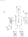
- the STA 100 includes a wireless communication unit 110, a wireless interface 120, a controller 130, a wired interface 140, an input unit 150, and an output unit 160.
- the wireless communication unit 110 has a functional component that performs all processes related to wireless communication. As illustrated in FIG. 12 , the wireless communication unit 110 includes an antenna controller 111, a reception process section 112, an MPDU processor 113, a reception buffer 114, a transmission process section 115, an MPDU processor 116, and a transmission buffer 117.
- the antenna controller 111 has a functional component that controls at least one antenna to transmit and receive wireless signals.
- the antenna controller 111 functions as a reception section that receives a wireless signal transmitted from another communication device by controlling the antenna and provides the reception process section 112 with a signal obtained by performing a conversion process on the wireless signal to a reception level that allows extraction of a baseband signal in a subsequent process.
- the antenna controller 111 functions as a transmission section that transmits a transmission signal generated by the transmission process section 115 by controlling transmission power as necessary to more reliably cause the transmission signal to reach a destination device.
- the reception process section 112 performs the reception process on a reception signal provided from the antenna controller 111. For example, the reception process section 112 outputs a baseband signal by performing analog processing and down-conversion on the reception signal obtained from the antenna. The reception process section 112 then extracts A-MPDU included in the baseband signal. The reception process section 112 then performs the decoding process in a block unit of the encoding process to perform the error detection and error correction process. The reception process section 112 provides the extracted A-MPDU or the like to the MPDU processor 113.
- the MPDU processor 113 performs an MPDU-related process in the reception process. For example, the MPDU processor 113 separates each MPDU from the A-MPDU by using the sequence number information (Seq. No.) of the MPDUs and the data length information (Length) of the MPDUs acquired from the physical layer header or the physical layer trailer. It should be noted that the MPDU processor 113 may separate each MPDU from the A-MPDU by using the data length information (MPDU Length) of the MPDUs acquired from the delimiter information (Delimiter) of each MPDU.
- sequence number information Seq. No.
- Length data length information
- the MPDU processor 113 may separate each MPDU from the A-MPDU by using the data length information (MPDU Length) of the MPDUs acquired from the delimiter information (Delimiter) of each MPDU.
- the MPDU processor 113 performs a process on MPDU for which the error correction has been unsuccessful. More specifically, as the decoding process of a predetermined encoding unit, the MPDU processor 113 specifies MPDU for which the error correction has been unsuccessful and a range in the MPDU for which the error correction has been unsuccessful, and stores the information. The MPDU processor 113 then restores error-free MPDU by combining respective error-free portions of the MPDU and retransmitted MPDU (and repeatedly retransmitted MPDU) as the combining process. In a case where successfully restoring the error-free MPDU, the MPDU processor 113 then temporarily stores the MPDU in the reception buffer 114.
- the MPDU processor 113 provides any application with the MPDU (or data included in the MPDU) for which the reception process including the decoding process and the combining process have been successful through the wireless interface 120 or the like.
- the reception buffer 114 has a functional component that temporality stores the restored MPDU. Furthermore, the reception buffer 114 may temporality store a portion, which is free from an error in the decoding process of a predetermined encoding unit, of the MPDU for which the error correction has been unsuccessful.
- the reception buffer 114 includes a memory that stores the information.
- the transmission process section 115 performs the transmission process of A-MPDU generated by the MPDU processor 116. More specifically, the transmission process section 115 performs the encoding process on the A-MPDU generated by the MPDU processor 116.
- the encoding process uses an RS (255, 239) code or the like. That is, as a process of a predetermined encoding unit, the transmission process section 115 partitions data configured as the A-MPDU on the basis of a block length and appends redundancy codes (such as FECs) thereto. Furthermore, the transmission process section 115 appends the physical layer header, the physical layer trailer, or the like to the data with the redundancy codes appended thereto, thereby generating transmission data.
- RS 255, 239 code
- the transmission process section 115 then generates a baseband signal by performing a modulation process on the transmission data and generates a transmission signal by performing up-conversion on the baseband signal.
- the transmission process section 115 provides the transmission signal to the antenna controller 111.
- the MPDU processor 116 performs an MPDU-related process in the transmission process. For example, the MPDU processor 116 uses information stored in the transmission buffer 117 to construct MPDU having a MAC header appended thereto. The MAC header includes destination information or the like. The MPDU processor 116 then sets the sequence number information (Seq. No.) for each constructed MPDU to manage the data length information (Length) of the MPDU.
- sequence number information Seq. No.
- the MPDU processor 116 also functions as a generator that generates A-MPDU by aggregating MPDUs until a predetermined data length is reached or a predetermined number of blocks is reached.
- the MPDU processor 116 may store a plurality of identical MPDUs for retransmission in A-MPDU as long as the frame configuration of the A-MPDU has the capacity.
- the transmission buffer 117 has a functional component that temporarily stores information that is wirelessly transmitted and provided from any application through the wireless interface 120.
- the transmission buffer 117 includes a memory that stores the information.
- the wireless interface 120 is an interface for the wireless communication unit 110 and is a functional component that allows information to be exchanged between the wireless communication unit 110 and any application.
- the controller 130 is a functional component that centrally manages all processes by the STA 100.
- the control unit 130 is achieved by various IC chips and the like each including CPU (Central Processing Unit), ROM (Read Only Memory), RAM (Random Access Memory), and the like for example.
- CPU Central Processing Unit
- ROM Read Only Memory
- RAM Random Access Memory
- the wired interface 140 is, for example, an interface for any external device, and is a functional component that allows information to be exchanged between the STA 100 and the external device. It should be noted that the wired interface 240 is indispensable for the AP 200 because the wired interface 240 functions as an adapter for coupling to the Internet.
- the input unit 150 is a functional component that receives input of various kinds of information.
- the input unit 150 includes an input means such as a touch panel, a button, a keyboard, or a microphone, and allows a user to input various kinds of information by using these input means.
- the AP 200 may omit the input unit 150 or the input unit 150 may have a simpler configuration.
- the output unit 160 is a functional component that outputs various kinds of information.
- the output unit 160 includes a display means such as a display or a sound output means such as a speaker, and causes the display or the like to display desired information or causes the speaker or the like to generate desired sound information on the basis of a control signal from the controller 130.
- the AP 200 may omit the output unit 160 or the output unit 160 may have a simpler configuration.
- the functional components of the AP 200 and the STA 100 have been described above. Next, operations of the AP 200 and the STA 100 are described. It should be noted that the functionality of the present disclosure may be achieved by either the STA 100 or the AP 200 as described above. The following therefore describes, as an example, the operation of the STA 100 functioning as a transmitter and a receiver.
- the transmission buffer 117 stores information that is wirelessly transmitted and provided from any application through the wireless interface 120.
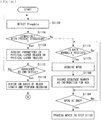
- the MPDU processor 116 acquires destination information of a transmission signal. In a case where a destination receiver is compatible with the technology of the present disclosure (step S1008/Yes), the MPDU processor 116 sets the data length information (Total Length) of the entire A-MPDU at step S1012.
- the MPDU processor 116 determines whether or not a total value of the data lengths of MPDUs to be stored reaches the data length of the entire A-MPDU set in the preceding step. In a case where the total value of the data lengths of the MPDUs to be stored does not reach the data length of the entire A-MPDU, but it is possible to add MPDU (step S1016/Yes), and in a case where there is MPDU for retransmission (step S1020/Yes), the MPDU processor 116 stores the MPDU for retransmission in the A-MPDU at step S1040. The process then returns to step S1016.
- the MPDU processor 116 stores the MPDU that have not yet been transmitted in the A-MPDU in order of sequence numbers at step S1024.
- the MPDU processor 116 acquires MPDU stored at the beginning of the A-MPDU again from the transmission buffer 117 at step S1032, and repeatedly stores the MPDU in the A-MPDU at step S1036. The process then returns to step S1016. That is, the MPDU processor 116 repeatedly stores a MPDU for retransmission and MPDU that has not yet been transmitted in the A-MPDU in this order of priority as long as the frame configuration of the A-MPDU has the capacity.
- the MPDU processor 116 determines the necessity of Padding at step S1044. In a case where the MPDU processor 116 determines that Padding is necessary (step S1044/Yes), the MPDU processor 116 appends Padding to the end of the A-MPDU at step S1048.
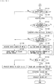
- the transmission process section 115 sets a block length for the encoding process using an RS(255,239) code or the like at step S1052, and partitions the data configured as the A-MPDU on the basis of the block length and appends redundancy codes (such as FECs) at step S1056.
- the transmission process section 115 acquires the data length information (Length) of each MPDU at step S1060, constructs a physical layer header and a physical layer trailer including encoding process parameters and the like, and appends the physical layer header and the physical layer trailer to the A-MPDU at step S1064.
- the antenna controller 111 transmits, as a physical layer frame, a signal having the physical layer header and the physical layer trailer appended thereto. The process then ends.
- the MPDU processor 116 determines whether or not it is possible to configure existing A-MPDU at step S1072. In a case where the MPDU processor 116 determines that it is possible to configure existing A-MPDU (step S1072/Yes), the MPDU processor 116 stores MPDU in the A-MPDU at step S1076.
- the MPDU processor 116 determines the necessity of Padding. In a case where the MPDU processor 116 determines that Padding is necessary (step S1080/Yes), the MPDU processor 116 appends Padding to the end of the A-MPDU at step S1048, and the process moves to step S1068. That is, the antenna controller 111 transmits the generated signal as a physical layer frame, and the process ends. It should be noted that the above-described flowchart is merely an example, and is modifiable as appropriate.
- the reception process section 112 detects a predetermined preamble (Preamble), thereby detecting a wireless signal.
- the reception process section 112 determines whether or not the detected wireless signal is compatible with the present disclosure on the basis of all or a portion of the information included in the physical layer header or the arrangement of the physical header. In a case where the detected wireless signal is compatible with the present disclosure (step S1104/Yes), the reception process section 112 acquires parameters included in the physical layer header at step S1108. In a case where the reception process section 112 fails to decode the physical layer header correctly, the reception process section 112 alternatively acquires parameters included in the physical layer trailer.
- the reception process section 112 determines whether or not the wireless signal is addressed to the own device on the basis of the recipient address identification information (RXAID) among the acquired parameters. In a case where the wireless signal is addressed to the own device (step S1112/Yes), the reception process section 112 divides the received data on the basis of a block length of a predetermined encoding process and performs the decoding process in units of divided blocks at step S1116.
- RXAID recipient address identification information
- the MPDU processor 113 acquires MPDU for which the error correction has been successful and stores the MPDU in the reception buffer 114 at step S1124.
- the MPDU processor 113 determines whether or not the received A-MPDU includes MPDU for retransmission on the basis of the sequence number information (Seq. No.) of the MPDUs acquired from the physical layer header or the physical layer trailer. In a case where the received A-MPDU includes MPDU for retransmission (step S1128/Yes), the MPDU processor 113 acquires an error-free portion of MPDU received in the past at step S1132.
- the MPDU processor 113 determines whether or not it is possible to restore error-free MPDU by combining respective error-free portions from the MPDU received in the past and the MPDU for retransmission. In a case where the MPDU processor 113 determines that it is possible to restore error-free MPDU by combining the error-free portions (step S1136/Yes), the MPDU processor 113 restores the error-free MPDU by performing the combining process at step S1140. At step S1144, the MPDU processor 113 records the sequence number information (Seq. No.) of the successfully restored MPDU as information for ACK.
- the MPDU processor 113 determines that it is not possible to restore error-free MPDU by combining the error-free portions at step S1136 (step S1136/No)
- the MPDU processor 113 acquires the data length information (Length) of the MPDUs at step S1148, and specifies and stores a range in a block having the error at step S1152. Furthermore, in a case where the received A-MPDU includes no MPDU for retransmission at step S1128 (step S1128/No), the process moves to step S1156.
- the MPDU processor 113 determines whether or not the process is complete to the MPDU at the end included in the A-MPDU. In a case where it is determined that the process is not complete to the MPDU at the end (step S1156/No), the process moves to step S1116 and the above-described process on each MPDU is repeated.
- the transmission process section 115 reads out the information for ACK at step S1160 and constructs, for example, a block ACK frame including the sequence number information (Seq. No.) of the MPDUs received with no error at step S1164.
- the antenna controller 111 transmits the constructed block ACK frame, and the process ends.
- the MPDU processor 113 acquires the normally received MPDUs and stores the acquired MPDUs in the reception buffer 114 at step S1176.
- the MPDU processor 113 records the sequence number information (Seq. No.) of the normally received MPDU as information for ACK.
- the process moves to step S1184.
- the MPDU processor 113 determines whether or not the process is complete to the MPDU at the end included in the A-MPDU. In a case where it is determined that the process is not complete to the MPDU at the end (step S1184/No), the process moves to step S1172 and the above-described process on each MPDU is repeated.
- step S1184/Yes the process moves to step S1160. That is, the processes at step S1160 and the following steps are performed, thereby transmitting a block ACK frame.
- the block length of the encoding process is shorter than that of the MPDU that is a data unit in which the retransmission process is performed.
- the block length of the encoding process may be greater than that of the MPDU. The following therefore describes a case where the block length of the encoding process is greater than that of the MPDU with reference to FIGs. 15 and 16 .
- the transmitter aggregates first MPDU (1st MPDU) to seventh MPDU (7th MPDU).
- the transmitter then appends Padding (Pad) to MPDU shorter than the block length as necessary.
- the data length of the 1st MPDU is shorter than the block length, and therefore the transmitter appends Padding (Pad) thereto.
- a total value of the respective data lengths of the 3rd MPDU and the 4th MPDU is also shorter than the block length, and therefore the transmitter appends Padding (Pad) thereto.
- the data length of the 2nd MPDU is equal to the block length, and therefore the transmitter does not append Padding (Pad) thereto.
- the transmitter stores the plurality of MPDUs in one block without appending Padding (Pad) thereto.
- a total value of the respective data lengths of the 5th MPDU, the 6th MPDU, and the 7th MPDU is equal to the block length, and therefore the transmitter stores these MPDUs in one block.
- the transmitter performs the encoding process by using, for example, an RS (255, 239) code.
- the transmitter then generates a data frame obtained by appending the predetermined preamble (Preamble), the physical layer header (Header), and the physical layer trailer (Trailer) to the data subjected to the encoding process.
- Preamble predetermined preamble
- Header physical layer header
- Trailer physical layer trailer
- the receiver acquires various parameters included in the physical layer header (Header) or the physical layer trailer (Trailer), and grasps the block length of the encoding process on the basis of the encoding format information (Type) or the like of the parameters. The receiver then performs error detection and error correction by extracting redundancy information from the encoded information.
- Header physical layer header
- Trailer physical layer trailer
- Type encoding format information
- the receiver stores a block for which the error correction has been unsuccessful. Similarly to the embodiment described above, the receiver then requests the transmitter to retransmit the MPDU for which the error correction has been unsuccessful, and restores error-free MPDU by combining respective error-free blocks from the retransmitted MPDU and the MPDU transmitted in the past, thereby succeeding in the reception process.
- the present disclosure is applicable to the case where the block length of the encoding process is greater than that of the MPDU.
- the physical layer header (Header) and the physical layer trailer (Trailer) of the A-MSDU include information such as recipient address identification information (RXAID), transmitter address identification information (TXAID), encoding format information (Type), encoding process block length information (Block Size), data length information (Total Length) of the entire A-MSDU, information (MSDU Count) of the number of MSDUs to be aggregated, sequence number information (Seq. No.) of the MSDUs and data length information (Length) of the MSDU as the information for use in identification of each MSDU, and an error detection code (CRC).
- RXAID recipient address identification information
- TXAID transmitter address identification information
- Type encoding format information
- Block Size encoding process block length information
- FIG. 17 is merely an example, but the configuration of the physical layer header (Header) and the physical layer trailer (Trailer) of the A-MSDU is not limited thereto.
- the sequence number information (Seq. No.) of the MSDUs may be replaced with a starting sequence number (Start Sequence) and information (Sequence Bitmap) indicating the sequence number of the MSDUs included in the subsequent A-MSDU in a bitmap format.
- the transmitter targets, for the encoding process, data obtained by aggregating first MSDU (1st MSDU) to sixth MSDU (6th MSDU) and appending Padding (Pad) thereto as appropriate.
- the transmitter performs the encoding process by using, for example, an RS (255, 239) code.
- the transmitter then generates a data frame obtained by appending the predetermined preamble (Preamble), the physical layer header (Header), and the physical layer trailer (Trailer) to the data subjected to the encoding process.
- Preamble predetermined preamble
- Header physical layer header
- Trailer physical layer trailer
- the receiver acquires various parameters included in the physical layer header (Header) or the physical layer trailer (Trailer), and grasps the block length of the encoding process on the basis of the encoding format information (Type) or the like of the parameters. The receiver then performs error detection and error correction by extracting redundancy information from the encoded information.
- Header physical layer header
- Trailer physical layer trailer
- Type encoding format information
- the receiver stores a block for which an error has been detected and the error correction has been unsuccessful. More specifically, the receiver specifies MSDU for which the error correction has been unsuccessful and a range in the MSDU for which the error correction has been unsuccessful on the basis of the data length information (Length) of each MSDU and the sequence number information (Seq. No.) of each MSDU included in the physical layer header (Header) or the physical layer trailer (Trailer), and stores the information.
- Length data length information
- Seq. No. sequence number information
- the receiver requests the transmitter to retransmit the MPDU for which the error correction has been unsuccessful, by transmitting a block ACK frame and the like to the transmitter, and restores error-free MSDU by combining respective error-free blocks from the retransmitted MSDU and the MSDU transmitted in the past, thereby succeeding in the reception process.
- the present disclosure is also applicable to A-MSDU.
- the transmitter may construct a frame by aggregating six MSDUs (1st MSDU to 6th MSDU) into one MPDU (1st MPDU).
- the transmitter then appends delimiter information (Delimiter) and an error detection code (CRC) to the MPDU.
- delimiter delimiter information
- CRC error detection code
- a plurality of MPDUs may be configured instead of one MPDU by aggregating a plurality of MSDUs.
- the transmitter may aggregate three MSDUs (1st MSDU to 3rd MSDU) into one MPDU (1st MPDU), aggregate other three MSDUs (4th MSDU to 6th MSDU) into another MPDU (2nd MPDU), and then further aggregate the two MPDUs to construct one frame.
- the receiver restores error-free MSDU by combining respective error-free blocks of retransmitted MSDU and MSDU transmitted in the past, thereby succeeding in the reception process.
- the present disclosure is also applicable to the case where MPDU is configured by aggregating a plurality of MSDUs.
- the physical layer header (Header) is stored between the predetermined preamble (Preamble) and the MPDU at the beginning of the A-MPDU as illustrated in FIG. 22 (it should be noted that the physical layer trailer (Trailer) including the same information as that of the physical layer header (Header) is also appended to the end).
- the storage position of the physical layer header (Header) is not limited thereto.
- the physical layer header may be stored between the PLCP header and the MPDU at the beginning of the A-MPDU.
- a legacy short training field L-STF
- L-LTF legacy long training field
- L-SIG legacy signaling
- HE-SIG-A high efficiency signaling A
- HE-STF high efficiency short training field
- HE-LTF high efficiency short training field
- HE-SIG-B high efficiency signaling B
- the physical layer header may be stored between a predetermined number of high efficiency short training fields (HE-LTF) and the high efficiency signaling B (HE-SIG-B).
- HE-LTF high efficiency short training fields
- HE-SIG-B high efficiency signaling B
- the physical layer header may be stored between the high efficiency signaling A (HE-SIG-A) and the high efficiency short training field (HE-STF).
- the physical layer header may be stored between the legacy signaling (L-SIG) and the high efficiency signaling A (HE-SIG-A).
- the physical layer header may be configured as a portion of the high efficiency signaling A (HE-SIG-A).
- the physical layer header may be configured as a portion of the high efficiency signaling B (HE-SIG-B).
- the physical layer header may be configured as a portion of newly defined high efficiency signaling C (HE-SIG-C).
- the physical layer trailer (Trailer) including the same information as that of the physical layer header (Header) may be appended to the end of the frame as in FIG. 22 , or only the physical layer trailer (Trailer) may be appended to the end of the frame with the physical layer header (Header) omitted.
- the storage position of the physical layer header may take various variations.
- the STA 100 may be achieved as a mobile terminal such as a smartphone, tablet PC (Personal Computer), notebook PC, a portable game terminal, or a digital camera; a fixed terminal such as a television receiver, a printer, a digital scanner, or a network storage; or an on-vehicle terminal such as a car navigation apparatus.
- the STA 100 may be achieved as a terminal (also referred to as MTC (Machine Type Communication) terminal) that performs M2M (Machine To Machine) communication such as a smart meter, a vending machine, a remote monitoring device, or a POS (Point Of Sale) terminal.
- the STA 100 may be a wireless communication module (for example, integrated circuit module including one die) mounted on these terminals.
- the AP 200 may be achieved as a wireless LAN access point (also referred to as wireless base station) with or without a router function.
- the AP 200 may be achieved as a mobile wireless LAN router.
- the AP 200 may be a wireless communication module (for example, integrated circuit module including one die) mounted on these devices.
- FIG. 30 is a block diagram illustrating an example of a schematic configuration of a smartphone 900 to which the technology according to the present disclosure may be applied.
- the smartphone 900 includes a processor 901, a memory 902, a storage 903, an external coupling interface 904, a camera 906, a sensor 907, a microphone 908, an input device 909, a display device 910, a speaker 911, a wireless communication interface 913, an antenna switch 914, an antenna 915, a bus 917, a battery 918, and an auxiliary controller 919.
- the processor 901 may be, for example, CPU (Central Processing Unit) or SoC (System on Chip), and controls the functions of an application layer and other layers of the smartphone 900.
- the memory 902 includes RAM (Random Access Memory) and ROM (Read Only Memory), and stores a program to be executed by the processor 901 and data.
- the storage 903 may include a storage medium such as a semiconductor memory or a hard disk.
- the external coupling interface 904 is an interface for coupling an externally attached device such as a memory card or a USB (Universal Serial Bus) device to the smartphone 900.
- the camera 906 includes, for example, an imaging element such as CCD (Charge Coupled Device) or CMOS (Complementary Metal Oxide Semiconductor), and generates a captured image.
- the sensor 907 may include a sensor group including, for example, a positioning sensor, a gyro sensor, a geomagnetic sensor, an acceleration sensor and the like.
- the microphone 908 converts a sound that is inputted into the smartphone 900 to a sound signal.
- the input device 909 includes, for example, a touch sensor that detects a touch onto a screen of the display device 910, a key pad, a keyboard, a button, a switch, or the like, and receives an operation or an information input from a user.
- the display device 910 includes a screen such as a liquid crystal display (LCD) or an organic light-emitting diode (OLED) display, and displays an output image of the smartphone 900.
- the speaker 911 converts the sound signal that is outputted from the smartphone 900 to a sound.
- the wireless communication interface 913 supports one or more of wireless LAN standards such as IEEE 802.11a, 11b, 11g, 11n, 11ac, and llad, and executes wireless communication.
- the wireless communication interface 913 may communicate with another device via a wireless LAN access point in an infrastructure mode.
- the wireless communication interface 913 may directly communicate with another device in an ad-hoc mode or a direct communication mode such as Wi-Fi Direct (registered trademark).
- Wi-Fi Direct registered trademark
- the wireless communication interface 913 may include a baseband processor, an RF (Radio Frequency) circuit, a power amplifier, and the like.
- the wireless communication interface 913 may be a one-chip module in which a memory that stores a communication control program, a processor that executes the program, and a related circuit are integrated.
- the wireless communication interface 913 may support another type of wireless communication scheme such as a short-range wireless communication scheme, a near field communication scheme, or a cellular communication scheme in addition to a wireless LAN scheme.
- the antenna switch 914 switches a coupling destination of the antenna 915 between a plurality of circuits (for example, circuits for different wireless communication schemes) included in the wireless communication interface 913.
- the antenna 915 includes one or more antenna elements (for example, a plurality of antenna elements included in a MIMO antenna), and is used for transmission and reception of the wireless signal by the wireless communication interface 913.
- the smartphone 900 is not limited to the example illustrated in FIG. 30 , but may include a plurality of antennas (for example, an antenna for wireless LAN and an antenna for a near field communication scheme). In that case, the antenna switch 914 may be omitted from the configuration of the smartphone 900.
- the bus 917 couples the processor 901, the memory 902, the storage 903, the external coupling interface 904, the camera 906, the sensor 907, the microphone 908, the input device 909, the display device 910, the speaker 911, the wireless communication interface 913, and the auxiliary controller 919 to each other.
- the battery 918 supplies electric power to each block of the smartphone 900 illustrated in FIG. 30 via a power supply line that is partially illustrated in the diagram as a dashed line.
- the auxiliary controller 919 for example, operates a minimally necessary function of the smartphone 900 in a sleep mode.
- the smartphone 900 may operate as a wireless access point (software AP) through the processor 901 executing an application-level access point function.
- the wireless communication interface 913 may have a wireless access point function.
- FIG. 31 is a block diagram illustrating an example of a schematic configuration of a car navigation apparatus 920 to which the technology according to the present disclosure may be applied.
- the car navigation apparatus 920 includes a processor 921, a memory 922, a GPS (Global Positioning System) module 924, a sensor 925, a data interface 926, a content player 927, a storage medium interface 928, an input device 929, a display device 930, a speaker 931, a wireless communication interface 933, an antenna switch 934, an antenna 935, and a battery 938.
- GPS Global Positioning System
- the processor 921 may be, for example, CPU or SoC, and controls the navigation function and the other functions of the car navigation apparatus 920.
- the memory 922 includes RAM and ROM, and stores a program to be executed by the processor 921 and data.
- the GPS module 924 uses a GPS signal received from a GPS satellite to measure the position (e.g., latitude, longitude, and altitude) of the car navigation apparatus 920.
- the sensor 925 may include a sensor group including, for example, a gyro sensor, a geomagnetic sensor, an atmospheric pressure sensor and the like.
- the data interface 926 is, for example, coupled to an in-vehicle network 941 via a terminal that is not illustrated, and acquires data such as vehicle speed data generated on the vehicle side.
- the content player 927 reproduces content stored in a storage medium (e.g., CD or DVD) to be inserted into the storage medium interface 928.
- the input device 929 includes, for example, a touch sensor that detects a touch onto a screen of the display device 930, a button, a switch, or the like, and receives an operation or an information input from a user.
- the display device 930 includes a screen such as LCD or an OLED display, and displays an image of the navigation function or the reproduced content.
- the speaker 931 outputs a sound of the navigation function or the reproduced content.
- the wireless communication interface 933 supports one or more of wireless LAN standards such as IEEE 802.11a, 11b, 11g, 11n, 11ac, and llad, and executes wireless communication.
- the wireless communication interface 933 may communicate with another device via a wireless LAN access point in an infrastructure mode. Furthermore, the wireless communication interface 933 may directly communicate with another device in an ad-hoc mode or a direct communication mode such as Wi-Fi Direct.
- the wireless communication interface 933 may include a baseband processor, an RF circuit, a power amplifier, and the like.
- the wireless communication interface 933 may be a one-chip module in which a memory that stores a communication control program, a processor that executes the program, and a related circuit are integrated.
- the wireless communication interface 933 may support another type of wireless communication scheme such as a short-range wireless communication scheme, a near field communication scheme, or a cellular communication scheme in addition to a wireless LAN scheme.
- the antenna switch 934 switches a coupling destination of the antenna 935 between a plurality of circuits included in the wireless communication interface 933.
- the antenna 935 includes one or more antenna elements, and is used for transmission and reception of the wireless signal by the wireless communication interface 933.
- the car navigation apparatus 920 is not limited to the example illustrated in FIG. 31 , but may include a plurality of antennas. In that case, the antenna switch 934 may be omitted from the configuration of the car navigation apparatus 920.
- the battery 938 supplies electric power to each block of the car navigation apparatus 920 illustrated in FIG. 31 via a power supply line that is partially illustrated in the diagram as a dashed line. In addition, the battery 938 accumulates the electric power supplied from the vehicle side.
- the technology according to the present disclosure may also be achieved as an in-vehicle system (or a vehicle) 940 including one or more blocks of the car navigation apparatus 920 described above, the in-vehicle network 941, and a vehicle module 942.
- the vehicle module 942 generates vehicle data such as vehicle speed, engine speed, and trouble information, and outputs the generated data to the in-vehicle network 941.
- FIG. 32 is a block diagram illustrating an example of a schematic configuration of a wireless access point 950 to which the technology according to the present disclosure may be applied.
- the wireless access point 950 includes a controller 951, a memory 952, an input device 954, a display device 955, a network interface 957, a wireless communication interface 963, an antenna switch 964, and an antenna 965.
- the controller 951 may be, for example, CPU or DSP (Digital Signal Processor), and causes various functions (for example, access restriction, routing, encryption, firewall, log management, and the like) in an IP (Internet Protocol) layer and higher layers of the wireless access point 950 to operate.
- the memory 952 includes RAM and ROM, and stores a program to be executed by the controller 951 and various kinds of control data (for example, terminal lists, routing tables, encryption keys, security settings, logs, and the like).
- the input device 954 includes, for example, a button, a switch, or the like, and receives an operation from a user.
- the display device 955 includes an LED lamp and the like, and displays an operation status of the wireless access point 950.
- the network interface 957 is a wired communication interface for coupling the wireless access point 950 to a wired communication network 958.
- the network interface 957 may include a plurality of coupling terminals.
- the wired communication network 958 may be LAN such as Ethernet (registered trademark) or may be WAN (Wide Area Network).
- the wireless communication interface 963 supports one or more of wireless LAN standards such as IEEE 802.11a, 11b, 11g, 11n, 11ac, and llad, and provides wireless coupling as an access point for a terminal in the vicinity.
- the wireless communication interface 963 may include a baseband processor, an RF circuit, a power amplifier, and the like.
- the wireless communication interface 963 may be a one-chip module in which a memory that stores a communication control program, a processor that executes the program, and a related circuit are integrated.
- the antenna switch 964 switches a coupling destination of the antenna 965 between a plurality of circuits included in the wireless communication interface 963.
- the antenna 965 includes one or more antenna elements, and is used for transmission and reception of the wireless signal by the wireless communication interface 963.
- the wireless LAN system performs a combining process of respective error-free blocks from MPDU for which the reception process has been unsuccessful and retransmitted MPDU to restore the MPDU, thereby succeeding in the reception process.
- the receiver is able to use error-free portions of the MPDU for the combining process instead of discarding the whole MPDU. It is therefore possible to restore error-free MPDU with a higher probability. Furthermore, the receiver is able to perform the combining process without depending on the block length of the encoding process by managing an error-containing portion of the MPDU in units of bytes.
- the wireless LAN system includes, in a physical layer header, information for use in identification of aggregated MPDUs in A-MPDU and appends a physical layer trailer including the same information to the end of a data frame. This enables the wireless LAN system to identify each MPDU even if the data length information included in the delimiter information is incorrect.
- the wireless LAN system is able to store a plurality of identical retransmission MPDUs in A-MPDU as long as a frame configuration of the A-MPDU has the capacity. This makes it possible to increase the possibility of succeeding in the combining process.
- the effects described herein are merely illustrative and exemplary, and not limitative. That is, the technology according to the present disclosure may exert other effects that are apparent to those skilled in the art from the description herein, in addition to the above-described effects or in place of the above-described effects.
Abstract
Description
- The present disclosure relates to a wireless LAN communication device and a wireless LAN communication method.
- In recent years, various retransmission schemes have been developed as communication techniques have been developed. For example, among wireless communication techniques, a technique related to retransmission control that is called Hybrid ARQ (Hybrid Automatic repeat-request, referred to below as "HARQ") has been developed.
- For example,
PTL 1 below discloses a technique to add HARQ to a wireless LAN protocol with MAC-based feedback. - PTL 1: Japanese Patent No.
5254369 - Here, it is requested to achieve more appropriate retransmission control in wireless LAN systems. More specifically, data (for example, MPDU (MAC layer Protocol Data Unit)) that is communicated in a wireless LAN system has a variable length, and therefore it is necessary to perform individual sequence management when fragment processing is performed for predetermined access control, making it difficult to perform control. It has therefore been difficult to directly apply the above-described HARQ to the wireless LAN system.
- The present disclosure has been devised in view of the above-described circumstances, and provides a novel and improved wireless LAN communication device and wireless LAN communication method that make it possible to achieve more appropriate retransmission control in a wireless LAN system.
- According to the present disclosure, there is provided a wireless LAN communication device including: a generator that generates a data frame for which a data unit in which an encoding process is performed and a data unit in which a retransmission process is performed are different from each other; and a transmission section that transmits the data frame. The encoding process makes it possible to determine whether or not decoding is successful.
- In addition, according to the present disclosure, there is provided a wireless LAN communication method that is executed by a computer. The wireless LAN communication method includes: generating a data frame for which a data unit in which an encoding process is performed and a data unit in which a retransmission process is performed are different from each other; and transmitting the data frame. The encoding process making it possible to determine whether or not decoding is successful.
- In addition, according to the present disclosure, there is provided a wireless LAN communication device including: a reception section that receives a data frame for which a data unit in which an encoding process is performed and a data unit in which a retransmission process is performed are different from each other; and a reception process section that performs a reception process including decoding the data frame. The encoding process makes it possible to determine whether or not decoding is successful.
- In addition, according to the present disclosure, there is provided a wireless LAN communication method that is executed by a computer. The wireless LAN communication method includes: receiving a data frame for which a data unit in which an encoding process is performed and a data unit in which a retransmission process is performed are different from each other; and performing a reception process including decoding the data frame. The encoding process makes it possible to determine whether or not decoding is successful.
- As described above, according to the present disclosure, it is possible to achieve more appropriate retransmission control in a wireless LAN system.
- It should be noted that the above-described effects are not necessarily limitative. Any of the effects indicated in this description or other effects that may be understood from this description may be exerted in addition to the above-described effects or in place of the above-described effects.
-
- [
FIG. 1] FIG. 1 is a diagram illustrating an example of a configuration of a wireless LAN system according to the present embodiment. - [
FIG. 2] FIG. 2 is a diagram illustrating an example of a configuration of a physical layer header and a physical layer trailer. - [
FIG. 3] FIG. 3 is a diagram illustrating an example of the configuration of the physical layer header and the physical layer trailer. - [
FIG. 4] FIG. 4 is a diagram illustrating an example of a configuration of MPDU. - [
FIG. 5] FIG. 5 is a diagram describing an overview of an encoding process. - [
FIG. 6] FIG. 6 is a diagram describing an overview of a decoding process. - [
FIG. 7] FIG. 7 is a diagram describing an example of a combining process using retransmitted MPDU. - [
FIG. 8] FIG. 8 is a diagram describing an example of the combining process using the retransmitted MPDU. - [
FIG. 9] FIG. 9 is a diagram describing an example of the combining process using the retransmitted MPDU. - [
FIG. 10] FIG. 10 is a diagram describing an example of a combining process using repeatedly retransmitted MPDU. - [
FIG. 11] FIG. 11 is a diagram describing an example of the combining process using the repeatedly retransmitted MPDU. - [
FIG. 12] FIG. 12 is a block diagram illustrating an example of a functional component of AP and STA. - [
FIG. 13A] FIG. 13A is a flowchart illustrating an example of a transmission operation. - [
FIG. 13B] FIG. 13B is a flowchart illustrating an example of the transmission operation. - [
FIG. 14A] FIG. 14A is a flowchart illustrating an example of a reception operation. - [
FIG. 14B] FIG. 14B is a flowchart illustrating an example of the reception operation. - [
FIG. 15] FIG. 15 is a diagram describing an overview of an encoding process in a case where a block length is greater than that of MPDU. - [
FIG. 16] FIG. 16 is a diagram describing an overview of a decoding process in a case where a block length is greater than that of MPDU. - [
FIG. 17] FIG. 17 is a diagram illustrating an example of a configuration of a physical layer header and a physical layer trailer in a case where the present disclosure is applied to A-MSDU. - [
FIG. 18] FIG. 18 is a diagram describing an overview of an encoding process in the case where the present disclosure is applied to the A-MSDU. - [
FIG. 19] FIG. 19 is a diagram describing an overview of a decoding process in the case where the present disclosure is applied to the A-MSDU. - [
FIG. 20] FIG. 20 is a diagram describing a case where one MPDU includes a plurality of aggregated MSDUs. - [
FIG. 21] FIG. 21 is a diagram describing a case where MPDUs including a plurality of aggregated MSDUs are further aggregated. - [
FIG. 22] FIG. 22 is a diagram describing a variation of a storage position of the physical layer header. - [
FIG. 23] FIG. 23 is a diagram describing a variation of the storage position of the physical layer header. - [
FIG. 24] FIG. 24 is a diagram describing a variation of the storage position of the physical layer header. - [
FIG. 25] FIG. 25 is a diagram describing a variation of the storage position of the physical layer header. - [
FIG. 26] FIG. 26 is a diagram describing a variation of the storage position of the physical layer header. - [
FIG. 27] FIG. 27 is a diagram describing a variation of the storage position of the physical layer header. - [
FIG. 28] FIG. 28 is a diagram describing a variation of the storage position of the physical layer header. - [
FIG. 29] FIG. 29 is a diagram describing a variation of the storage position of the physical layer header. - [
FIG. 30] FIG. 30 is a block diagram illustrating an example of a schematic configuration of a smartphone. - [
FIG. 31] FIG. 31 is a block diagram illustrating an example of a schematic configuration of a car navigation apparatus. - [
FIG. 32] FIG. 32 is a block diagram illustrating an example of a schematic configuration of a wireless access point. - The following describes a preferred embodiment of the present disclosure in detail with reference to the accompanying drawings. It should be noted that, in this description and the accompanying drawings, components that have substantially the same functional configuration are indicated by the same reference signs, and thus redundant description thereof is omitted.
- It should be noted that the description is given in the following order.
- 1. Background
- 2. Wireless LAN System according to Embodiment of Present Disclosure
- 3. Modification Examples
- 4. Application Examples
- 5. Conclusion
- First, the background of the present disclosure is described.
- As described above, in recent years, various retransmission schemes have been developed as communication techniques have been developed. For example, among wireless communication techniques, a technique related to retransmission control that is called HARQ has been developed. For example, in a public wireless communication system, an appropriate block length is defined depending on the number of subcarriers in a physical layer, and retransmission control is performed with this block length used as a unit. The block length used as a unit for retransmission control is then a fixed length, and the retransmission control or sequence management is thus easy.
- Here, it is requested to achieve more appropriate retransmission control in wireless LAN systems. More specifically, data (for example, MPDU) that is communicated in a wireless LAN system has a variable length, and therefore fragment processing is difficult for predetermined access control, making it difficult to directly apply the above-described HARQ to the wireless LAN system. For example, in a case where HARQ is applied to a wireless LAN system, block partition positions in variable-length data that is communicated in the wireless LAN system are different from those of HARQ.
- Furthermore, the retransmission control is performed in the wireless LAN system with MPDU used as a unit. Accordingly, even if HARQ is used for processing in a lower layer than the MAC layer, the retransmission control is not performed in a unit corresponding to HARQ. For example, if there is an error in one HARQ block, whole MPDU that is larger than the HARQ block is retransmitted, preventing improvement in efficiency of transmission path usage.
- Furthermore, a frame aggregation technique is applied to the wireless LAN system to enable aggregation of a plurality of data units, and thus it is possible to reduce frame transmission overhead and improve transmission efficiency. Among frame aggregation techniques, a technique called A-MPDU (aggregated MPDU) aggregation has been considered particularly effective and generally and widely used. This technique aggregates a plurality of MPDUs as one physical layer frame.
- In a case where HARQ is applied to an A-MPDU frame, block partition positions in each MPDU are different from those of HARQ, because the length of the MPDU is variable as described above. A receiver is therefore unable to perform a simple combining process of retransmitted MPDU and MPDU received in the past.
- Furthermore, delimiter information including data length information of the MPDU in an A-MPDU configuration is appended at the beginning the of MPDU. The receiver that receives the A-MPDU recognizes boundaries of the respective MPDUs on the basis of the data length information. If the data length information included in the delimiter information is incorrect, the receiver is thus unable to correctly recognize boundaries of the respective MPDUs. Consequently, the receiver fails in a reception process of MPDU located at or after the boundary that has not been correctly recognized, and discards such MPDU.
- The discloser of the present application has devised the present application in view of the circumstances described above. The present disclosure makes it possible to achieve more appropriate retransmission control in wireless LAN systems. The present disclosure also enables a reception process of MPDU to be successful even in a case where data length information of MPDU included in delimiter information in an A-MPDU configuration is incorrect. The following describes a wireless LAN system according to an embodiment of the present disclosure.
- The background of the present disclosure has been described above. Next, a wireless LAN system according to an embodiment of the present disclosure is described.
- First, the configuration of the wireless LAN system according to the present embodiment is described with reference to
FIG. 1 . - As illustrated in
FIG. 1 , the wireless LAN system according to the present embodiment includes access point devices (each referred to below as "AP (Access Point)") 200 and station devices (each referred to below as "STA (Station)") 100. One AP 200 and one or more STAs 100 then form a basic service set (referred to below as "BSS (Basic Service Set)") 10. - The wireless LAN system according to the present embodiment may be installed in any places. For example, the wireless LAN system according to the present embodiment may be installed in office buildings, residential houses, business or public establishments, and the like.
- In addition, an area of the BSS 10 according to the present embodiment may overlap with an area of another BSS 10 (referred to below as "OBSS (Overlap Basic Service Set)") whose frequency channel overlaps with the frequency channel used by the BSS 10. In that case, a signal transmitted from the STA 100 located in the overlapping area may interfere with a signal transmitted from the OBSS. Referring to an example illustrated in
FIG. 1 , an area of BSS 10a overlaps with a portion of an area of BSS 10b that is OBSS, and STA 100b is located in the overlapping area. In this case, a signal transmitted from the STA 100b belonging to the BSS 10a may interfere with a signal transmitted from AP 200b or STA 100c belonging to the BSS 10b. It should be noted thatFIG. 1 illustrates, as an example, a case where other wireless LAN systems cause interference therebetween, but this is not limitative. For example, a communication base station and a communication terminal in another communication system other than wireless LAN may overlap with the BSS 10a to cause interference. - Each of the APs 200 is a wireless LAN communication device that is coupled to an external network and provides the STA 100 with communication with the external network. For example, the AP 200 is coupled to the Internet and provides communication between the STA 100 and a device on the Internet or a device to be coupled via the Internet.
- The STA 100 is a wireless LAN communication device that communicates with the AP 200. The STA 100 may be any communication device. For example, the STA 100 may be a display having a display function, a memory having a storage function, a keyboard and a mouse each having an input function, a speaker having a sound output function, or a smartphone having an advanced calculation processing execution function.
- It should be noted that the functionality of the present disclosure may be achieved by either the AP 200 or the STA 100. That is, the AP 200 and the STA 100 may have the same functional components. Either or both of the AP 200 and the STA 100 may therefore be referred to below as "transmitter" or "receiver".
- The configuration of the wireless LAN system according to the present embodiment has been described above. Next, the overview of the functionality of the wireless LAN system according to the present embodiment is described.
- In the wireless LAN system according to the present embodiment, a data frame is communicated in which a data unit in which an encoding process is performed and a data unit in which a retransmission process is performed are different from each other. The encoding process makes it possible to determine whether or not decoding is successful.
- More specifically, the transmitter generates A-MPDU in which a plurality of MPDUs is aggregated, and appends an error correcting code to the A-MPDU in units of predetermined blocks. The receiver performs a reception process (including a decoding process) of the A-MPDU and specifies a block for which the reception process has been unsuccessful. Thereafter, the receiver performs a combining process of respective error-free blocks from MPDU for which the reception process has been unsuccessful and retransmitted MPDU to restore the MPDU, thereby succeeding in the reception process.
- Furthermore, the transmitter may include, in a physical layer header (such as a PLCP header), information for use in identification of the aggregated MPDU in the A-MPDU or append a physical layer trailer (such as a PLCP trailer) including the same information to the end of a data frame. Here, the information for use in identification of MPDU, for example, means the data length, the sequence number, and the like of the MPDU. This enables the wireless LAN system to identify each MPDU even if the data length information included in the delimiter information is incorrect. Furthermore, including the information not only in the physical layer header, but also in the physical layer trailer enables the wireless LAN system to identify each MPDU included in the A-MPDU as long as the physical layer trailer is successfully received even if the physical layer header is unsuccessfully received.
- Furthermore, the wireless LAN system is able to store a plurality of identical retransmission MPDUs in A-MPDU as long as a frame configuration of the A-MPDU has the capacity. This enables the wireless LAN system to increase the possibility of succeeding in the combining process.
- It should be noted that it is merely an example that the data frame to be communicated is A-MPDU, but this is not limitative. For example, the data frame to be communicated may be A-MSDU, non-aggregated MPDU, or non-aggregated MSDU.
- The overview of the functionality of the wireless LAN system according to the present embodiment has been described above. Next, the details (including a frame configuration and the like) of the functionality of the wireless LAN system according to the present embodiment are described. First, a physical layer header and a physical layer trailer of A-MPDU are described with reference to
FIG. 2 . - As illustrated in
FIG. 2 , the transmitter generates a data frame in which the physical layer header is appended after a predetermined preamble (Preamble) or the physical layer trailer is appended after a plurality of aggregated MPDUs (eight MPDUs (1st MPDU to 8th MPDU) are aggregated in the diagram). - The physical layer header and the physical layer trailer include information such as recipient address identification information (RXAID), transmitter address identification information (TXAID), encoding format information (Type), encoding process block length information (Block Size), data length information (Total Length) of the entire A-MPDU, information (MPDU Count) of the number of MPDUs to be aggregated, sequence number information (Seq. No.) of the MPDUs and data length information (Length) of the MPDU as the information for use in identification of each MPDU, and an error detection code (CRC). It should be noted that
FIG. 2 is merely an example, but the configuration of the physical layer header and the physical layer trailer of the A-MPDU is not limited thereto. - Next, variations of a physical layer header and a physical layer trailer of A-MPDU are described with reference to
FIG. 3 . As illustrated inFIG. 3 , the sequence number information (Seq. No.) of the MPDUs inFIG. 2 may be replaced with a starting sequence number (Start Sequence) and information (Sequence Bitmap) indicating the sequence number of the subsequent MPDU in a bitmap format. This eliminates the need to append the sequence number information (Seq. No.) of MPDU to each MPDU, and thus enables the transmitter to reduce the volume of A-MPDU information. - Next, the configuration of MPDU is described with reference to
FIG. 4 . As illustrated inFIG. 4 , the MPDU includes delimiter information (Delimiter), protocol data unit (MAC Layer Protocol Data Unit) of a predetermined MAC layer, and an error detection code (CRC). The delimiter information then includes data length information (MPDU Length) of MPDU, an error detection code (CRC), delimiter identification information (Delimiter Signature) for use in identification of the delimiter information, and a reserved field (Reserved). It should be noted thatFIG. 4 is merely an example, but the configuration of MPDU is not limited thereto. - Next, an overview of an encoding process is described with reference to
FIG. 5 . - In an example illustrated in
FIG. 5 , the transmitter targets, for the encoding process, data obtained by aggregating first MPDU (1st MPDU) to fourth MPDU (4th MPDU) and appending Padding (Pad) thereto as appropriate. - The transmitter then performs the encoding process using, for example, an RS (255, 239) code (code length: 255 symbols, data length: 239 symbols, parity length: 16 symbols), which is a kind of Reed-Solomon codes, as a process of a predetermined encoding unit. In this case, the transmitter partitions a data string configured as the A-MPDU on a 239-byte boundary, generates 16-byte redundancy codes (
FEC 1 to FEC 12), and combines them to generate data having 255-byte blocks. Thus, 2880-byte data (0 to 2879) is changed to 3072-byte data (0 to 3071) as illustrated inFIG. 5 . - The transmitter then generates a data frame obtained by appending the predetermined preamble (Preamble), the physical layer header (Header), and the physical layer trailer (Trailer) to the data generated as described above.
- It should be noted that
FIG. 5 is merely an example, but any encoding process may be employed as long as the encoding process makes it possible to determine whether or not decoding is successful. - Next, an overview of a decoding process is described with reference to
FIG. 6 . - The receiver detects the predetermined preamble (Preamble), recognizes that the received data frame is the data frame according to the present disclosure on the basis of the information included in the subsequent physical layer header (Header) or physical layer trailer (Trailer), and performs the decoding process according to the present disclosure.
- First, the receiver acquires various parameters included in the physical layer header (Header) or the physical layer trailer (Trailer), and grasps the block length of the encoding process on the basis of the encoding format information (Type) or the like of the parameters. The receiver then performs error detection and error correction as a process of a predetermined encoding unit by extracting redundancy information from the encoded information. That is, the receiver performs the error detection and the error correction by extracting 0 to 239-byte information from 0 to 255-byte information. Thus, the receiver extracts the 2880-byte data (0 to 2879) from the 3072-byte data (0 to 3071) as illustrated in
FIG. 6 . - The receiver then stores a block for which an error has been detected and the error correction has been unsuccessful. More specifically, the receiver specifies MPDU for which the error correction has been unsuccessful and a range in the MPDU for which the error correction has been unsuccessful on the basis of the data length information (Length) of each MPDU and the sequence number information (Seq. No.) of each MPDU included in the physical layer header (Header) or the physical layer trailer (Trailer), and stores the information.
- The receiver then requests the transmitter to retransmit the MPDU for which the error correction has been unsuccessful, and restores error-free MPDU by combining respective error-free blocks from the retransmitted MPDU and the MPDU transmitted in the past, thereby succeeding in the reception process.
- Next, an example of the combining process of MPDUs is described with reference to
FIGs. 7 to 11 . - First, the receiver receives A-MPDU obtained by aggregating four MPDUs (1st MPDU to 4th MPDU) illustrated in
FIG. 7 and performs the reception process including the decoding process on the A-MPDU. - It is then assumed that the receiver detects an error in a block in the third MPDU (3rd MPDU) and fails in the error correction. More specifically, it is assumed that the receiver fails in the error correction of a block ranging from the 1440th byte to the 1679th byte before the encoding process is performed on the A-MPDU (a block corresponding to a range from the 96th byte to the 335th byte in the third MPDU). It should be noted that the reception process for the MPDUs other than the third MPDU is successful.
- The receiver notifies the transmitter of the successful reception process for the MPDUs other than the third MPDU by transmitting a predetermined response signal. It should be noted that the predetermined response signal may be, for example, block ACK (ACKnowledgement), but is not limited thereto.
- The transmitter that receives the response signal grasps that the reception process of the MPDUs other than the third MPDU has been successful (in other words, the reception process for the third MPDU may have been unsuccessful) and retransmits the third MPDU.
- For example, as illustrated in
FIG. 8 , the transmitter transmits, to the receiver, A-MPDU obtained by aggregating third MPDU (Resend 3rd MPDU) for retransmission, and the fifth MPDU (5th MPDU) and the sixth MPDU (6th MPDU) to be newly transmitted. - It is assumed that the receiver detects errors in a block including the end of the retransmitted third MPDU (Resend 3rd MPDU) and the beginning portion of the fifth MPDU (5th MPDU) and in a block included near the end of the fifth MPDU (5th MPDU), and fails in the error correction as illustrated in
FIG. 8 . - More specifically, it is assumed that the receiver fails in the error correction for a block ranging from the 720th byte to the 959th byte before the encoding process is performed on the A-MPDU (a block corresponding to a range from the 720th byte to the 863rd byte in the third MPDU and a block corresponding to a range from the 0th byte to the 95th byte of the fifth MPDU) and a block ranging from the 1680th byte to the 1919th byte (a block corresponding to a range from the 816th byte to the 1055th byte of the fifth MPDU).
- The receiver then performs the combining process using the third MPDU transmitted in the past and the retransmitted third MPDU. More specifically, the receiver combines respective error-free portions of the third MPDU (3rd MPDU) transmitted in the past and the retransmitted third MPDU (Resend 3rd MPDU). For example, as illustrated in
FIG. 9 , the receiver combines the 0th byte to the 479th byte of the retransmitted third MPDU (Resend 3rd MPDU) and the 480th byte to the 863rd byte of the third MPDU (3rd MPDU) transmitted in the past to restore error-free MPDU. It should be noted that any portions may be used for the combining process as long as the portions are error-free. For example, the 0th byte to the 719th byte of the retransmitted third MPDU (Resend 3rd MPDU) and the 720th byte to the 863rd byte of the third MPDU (Resend 3rd MPDU) transmitted in the past may be used for the combining process. - The receiver restores the third MPDU through the combining process and succeeds in the reception process. Accordingly, the receiver notifies the transmitter of that by transmitting a predetermined response signal.
- The above-described combining process enables the wireless LAN system to achieve more appropriate retransmission control. More specifically, even if a block in MPDU includes an error, the receiver is able to use error-free portions of the MPDU for the combining process instead of discarding the whole MPDU. It is therefore possible to restore error-free MPDU with a higher probability. Furthermore, the receiver is able to perform the combining process without depending on the block length of the encoding process by managing an error-containing portion of the MPDU in units of bytes.
- Although an example of the case where A-MPDU includes one MPDU for retransmission has been described above, A-MPDU may include a plurality of identical MPDUs for retransmission. For example, the transmitter may store a plurality of identical MPDUs for retransmission in A-MPDU as long as the frame configuration of the A-MPDU has the capacity.
- Now, a case where A-MPDU includes a plurality of identical MPDUs for retransmission is described with reference to
FIG. 10. FIG. 10 illustrates another A-MPDU to be transmitted after the A-MPDU illustrated inFIG. 8 . - The transmitter that receives a predetermined response signal from the receiver grasps that the reception process of the fifth MPDU may have been unsuccessful, and retransmits the fifth MPDU. The transmitter then stores a fifth MPDU (Resend 5th MPDU) for retransmission and the seventh MPDU (7th MPDU) to be newly transmitted as illustrated in
FIG. 10 . The transmitter then repeatedly stores the fifth MPDU (Repeat 5th MPDU) for retransmission in the A-MPDU if the A-MPDU has the capacity to have the fifth MPDU (Resend 5th MPDU) for retransmission repeatedly stored therein. It should be noted thatFIG. 10 illustrates a case where two identical MPDUs for retransmission are stored, but any number of identical MPDUs for retransmission may be stored. The transmitter transmits the A-MPDU obtained by aggregating these MPDUs to the receiver. - It is assumed that the receiver detects errors in blocks included in the fifth MPDU (Resend 5th MPDU) for retransmission and the repeatedly retransmitted fifth MPDU (Repeat 5th MPDU), and fails in the error correction. More specifically, it is assumed the receiver fails in the error correction in a block ranging from the 480th byte to the 959th byte before the encoding process is performed on the A-MPDU, a block ranging from the 1920th byte to the 2159th byte before the encoding process is performed on the A-MPDU (a block corresponding to a range from the 384th byte to the 623rd byte in the repeatedly retransmitted fifth MPDU (Repeat 5th MPDU)), and a block ranging from the 2640th byte to the 2879th byte before the encoding process is performed on the A-MPDU (a block corresponding to a range from the 1104th byte to the 1152nd byte in the repeatedly retransmitted fifth MPDU (Repeat 5th MPDU)).
- The receiver then combines respective error-free portions of the fifth MPDU (5th MPDU) transmitted in the past, the fifth MPDU (Resend 5th MPDU) for retransmission, and the repeatedly retransmitted fifth MPDU (Repeat 5th MPDU). For example, as illustrated in
FIG. 11 , the receiver combines the 0th byte to the 479th byte of the fifth MPDU (Resend 5th MPDU) for retransmission, the 480th byte to the 815th byte and the 1056th byte to the 1151st byte of the fifth MPDU (5th MPDU) transmitted in the past, and the 816th byte to the 1055th byte of the repeatedly retransmitted fifth MPDU (Repeat 5th MPDU) to restore error-free MPDU. It should be noted that any portions may also be used for the combining process in this example as long as the portions are error-free. - The receiver restores the fifth MPDU through the combining process and succeeds in the reception process. Accordingly, the receiver notifies the transmitter of that by transmitting a predetermined response signal.
- Repeatedly storing the MPDU for retransmission enables the wireless LAN system to increase the possibility of succeeding in the combining process and more effectively use the transmission path.
- The details of the functionality of the wireless LAN system according to the present embodiment have been described above. Next, functional components of the AP 200 and the STA 100 are described with reference to
FIG. 12 . - It should be noted that the STA 100 and the AP 200 may include the same functional components as described above. The following therefore mainly describes functional components of the STA 100 and additionally describes functional components specific to the AP 200. Furthermore, the functional components described below are merely an example, but the functional components of the STA 100 and the AP 200 are not particularly limited. For example, functional components described below may be omitted as appropriate, or other functional components may be added.
- As illustrated in
FIG. 12 , the STA 100 includes a wireless communication unit 110, a wireless interface 120, a controller 130, a wired interface 140, an input unit 150, and an output unit 160. - The wireless communication unit 110 has a functional component that performs all processes related to wireless communication. As illustrated in
FIG. 12 , the wireless communication unit 110 includes an antenna controller 111, a reception process section 112, an MPDU processor 113, a reception buffer 114, a transmission process section 115, an MPDU processor 116, and a transmission buffer 117. - The antenna controller 111 has a functional component that controls at least one antenna to transmit and receive wireless signals. For example, the antenna controller 111 functions as a reception section that receives a wireless signal transmitted from another communication device by controlling the antenna and provides the reception process section 112 with a signal obtained by performing a conversion process on the wireless signal to a reception level that allows extraction of a baseband signal in a subsequent process. Furthermore, the antenna controller 111 functions as a transmission section that transmits a transmission signal generated by the transmission process section 115 by controlling transmission power as necessary to more reliably cause the transmission signal to reach a destination device.
- The reception process section 112 performs the reception process on a reception signal provided from the antenna controller 111. For example, the reception process section 112 outputs a baseband signal by performing analog processing and down-conversion on the reception signal obtained from the antenna. The reception process section 112 then extracts A-MPDU included in the baseband signal. The reception process section 112 then performs the decoding process in a block unit of the encoding process to perform the error detection and error correction process. The reception process section 112 provides the extracted A-MPDU or the like to the MPDU processor 113.
- The MPDU processor 113 performs an MPDU-related process in the reception process. For example, the MPDU processor 113 separates each MPDU from the A-MPDU by using the sequence number information (Seq. No.) of the MPDUs and the data length information (Length) of the MPDUs acquired from the physical layer header or the physical layer trailer. It should be noted that the MPDU processor 113 may separate each MPDU from the A-MPDU by using the data length information (MPDU Length) of the MPDUs acquired from the delimiter information (Delimiter) of each MPDU.
- Furthermore, the MPDU processor 113 performs a process on MPDU for which the error correction has been unsuccessful. More specifically, as the decoding process of a predetermined encoding unit, the MPDU processor 113 specifies MPDU for which the error correction has been unsuccessful and a range in the MPDU for which the error correction has been unsuccessful, and stores the information. The MPDU processor 113 then restores error-free MPDU by combining respective error-free portions of the MPDU and retransmitted MPDU (and repeatedly retransmitted MPDU) as the combining process. In a case where successfully restoring the error-free MPDU, the MPDU processor 113 then temporarily stores the MPDU in the reception buffer 114.
- Furthermore, the MPDU processor 113 provides any application with the MPDU (or data included in the MPDU) for which the reception process including the decoding process and the combining process have been successful through the wireless interface 120 or the like.
- The reception buffer 114 has a functional component that temporality stores the restored MPDU. Furthermore, the reception buffer 114 may temporality store a portion, which is free from an error in the decoding process of a predetermined encoding unit, of the MPDU for which the error correction has been unsuccessful. The reception buffer 114 includes a memory that stores the information.
- The transmission process section 115 performs the transmission process of A-MPDU generated by the MPDU processor 116. More specifically, the transmission process section 115 performs the encoding process on the A-MPDU generated by the MPDU processor 116. The encoding process uses an RS (255, 239) code or the like. That is, as a process of a predetermined encoding unit, the transmission process section 115 partitions data configured as the A-MPDU on the basis of a block length and appends redundancy codes (such as FECs) thereto. Furthermore, the transmission process section 115 appends the physical layer header, the physical layer trailer, or the like to the data with the redundancy codes appended thereto, thereby generating transmission data.
- The transmission process section 115 then generates a baseband signal by performing a modulation process on the transmission data and generates a transmission signal by performing up-conversion on the baseband signal. The transmission process section 115 provides the transmission signal to the antenna controller 111.
- The MPDU processor 116 performs an MPDU-related process in the transmission process. For example, the MPDU processor 116 uses information stored in the transmission buffer 117 to construct MPDU having a MAC header appended thereto. The MAC header includes destination information or the like. The MPDU processor 116 then sets the sequence number information (Seq. No.) for each constructed MPDU to manage the data length information (Length) of the MPDU.
- Further, the MPDU processor 116 also functions as a generator that generates A-MPDU by aggregating MPDUs until a predetermined data length is reached or a predetermined number of blocks is reached. In addition, as described above, the MPDU processor 116 may store a plurality of identical MPDUs for retransmission in A-MPDU as long as the frame configuration of the A-MPDU has the capacity.
- The transmission buffer 117 has a functional component that temporarily stores information that is wirelessly transmitted and provided from any application through the wireless interface 120. The transmission buffer 117 includes a memory that stores the information.
- The wireless interface 120 is an interface for the wireless communication unit 110 and is a functional component that allows information to be exchanged between the wireless communication unit 110 and any application.
- The controller 130 is a functional component that centrally manages all processes by the STA 100. The control unit 130 is achieved by various IC chips and the like each including CPU (Central Processing Unit), ROM (Read Only Memory), RAM (Random Access Memory), and the like for example.
- The wired interface 140 is, for example, an interface for any external device, and is a functional component that allows information to be exchanged between the STA 100 and the external device. It should be noted that the
wired interface 240 is indispensable for the AP 200 because thewired interface 240 functions as an adapter for coupling to the Internet. - The input unit 150 is a functional component that receives input of various kinds of information. For example, the input unit 150 includes an input means such as a touch panel, a button, a keyboard, or a microphone, and allows a user to input various kinds of information by using these input means. It should be noted that the AP 200 may omit the input unit 150 or the input unit 150 may have a simpler configuration.
- The output unit 160 is a functional component that outputs various kinds of information. For example, the output unit 160 includes a display means such as a display or a sound output means such as a speaker, and causes the display or the like to display desired information or causes the speaker or the like to generate desired sound information on the basis of a control signal from the controller 130. It should be noted that the AP 200 may omit the output unit 160 or the output unit 160 may have a simpler configuration.
- The functional components of the AP 200 and the STA 100 have been described above. Next, operations of the AP 200 and the STA 100 are described. It should be noted that the functionality of the present disclosure may be achieved by either the STA 100 or the AP 200 as described above. The following therefore describes, as an example, the operation of the STA 100 functioning as a transmitter and a receiver.
- First, the operation of the STA 100 functioning as the transmitter is described with reference to
FIGs. 13A and13B . - At step S1000, the transmission buffer 117 stores information that is wirelessly transmitted and provided from any application through the wireless interface 120. At step S1004, the MPDU processor 116 acquires destination information of a transmission signal. In a case where a destination receiver is compatible with the technology of the present disclosure (step S1008/Yes), the MPDU processor 116 sets the data length information (Total Length) of the entire A-MPDU at step S1012.
- The MPDU processor 116 then determines whether or not a total value of the data lengths of MPDUs to be stored reaches the data length of the entire A-MPDU set in the preceding step. In a case where the total value of the data lengths of the MPDUs to be stored does not reach the data length of the entire A-MPDU, but it is possible to add MPDU (step S1016/Yes), and in a case where there is MPDU for retransmission (step S1020/Yes), the MPDU processor 116 stores the MPDU for retransmission in the A-MPDU at step S1040. The process then returns to step S1016.
- In a case where the total value of the data lengths of the MPDUs to be stored does not reach the data length of the entire A-MPDU set in the preceding step, but it is possible to add MPDU (step S1016/Yes), and in a case where there is no MPDU for retransmission (step S1020/No), the MPDU processor 116 stores the MPDU that have not yet been transmitted in the A-MPDU in order of sequence numbers at step S1024.
- In a case where the total value of the data lengths of the MPDUs to be stored does not reach the data length of the entire A-MPDU set in the preceding step, but it is possible to add MPDU even after the MPDU that have not yet been transmitted are stored in the A-MPDU (step S1028/Yes), the MPDU processor 116 acquires MPDU stored at the beginning of the A-MPDU again from the transmission buffer 117 at step S1032, and repeatedly stores the MPDU in the A-MPDU at step S1036. The process then returns to step S1016. That is, the MPDU processor 116 repeatedly stores a MPDU for retransmission and MPDU that has not yet been transmitted in the A-MPDU in this order of priority as long as the frame configuration of the A-MPDU has the capacity.
- In a case where the frame configuration runs out of the capacity because the total value of the data lengths of the MPDUs to be stored comes close to the data length of the entire A-MPDU set in the preceding step, and it is no longer possible to add MPDU at step S1016 and step S1028 (step S1016/No and step S1028/No), the MPDU processor 116 determines the necessity of Padding at step S1044. In a case where the MPDU processor 116 determines that Padding is necessary (step S1044/Yes), the MPDU processor 116 appends Padding to the end of the A-MPDU at step S1048.
- Thereafter, the transmission process section 115 sets a block length for the encoding process using an RS(255,239) code or the like at step S1052, and partitions the data configured as the A-MPDU on the basis of the block length and appends redundancy codes (such as FECs) at step S1056.
- Thereafter, the transmission process section 115 acquires the data length information (Length) of each MPDU at step S1060, constructs a physical layer header and a physical layer trailer including encoding process parameters and the like, and appends the physical layer header and the physical layer trailer to the A-MPDU at step S1064. At step S1068, the antenna controller 111 transmits, as a physical layer frame, a signal having the physical layer header and the physical layer trailer appended thereto. The process then ends.
- It should be noted that, in a case where the destination receiver is not compatible with the technology of the present disclosure at step S1008 (step S1008/No), the MPDU processor 116 determines whether or not it is possible to configure existing A-MPDU at step S1072. In a case where the MPDU processor 116 determines that it is possible to configure existing A-MPDU (step S1072/Yes), the MPDU processor 116 stores MPDU in the A-MPDU at step S1076.
- At step S1080, the MPDU processor 116 determines the necessity of Padding. In a case where the MPDU processor 116 determines that Padding is necessary (step S1080/Yes), the MPDU processor 116 appends Padding to the end of the A-MPDU at step S1048, and the process moves to step S1068. That is, the antenna controller 111 transmits the generated signal as a physical layer frame, and the process ends. It should be noted that the above-described flowchart is merely an example, and is modifiable as appropriate.
- Next, the operation of the STA 100 functioning as the receiver is described with reference to
FIGs. 14A and14B . - At step S1100, the reception process section 112 detects a predetermined preamble (Preamble), thereby detecting a wireless signal. At
step S 1104, the reception process section 112 determines whether or not the detected wireless signal is compatible with the present disclosure on the basis of all or a portion of the information included in the physical layer header or the arrangement of the physical header. In a case where the detected wireless signal is compatible with the present disclosure (step S1104/Yes), the reception process section 112 acquires parameters included in the physical layer header at step S1108. In a case where the reception process section 112 fails to decode the physical layer header correctly, the reception process section 112 alternatively acquires parameters included in the physical layer trailer. - At step S1112, the reception process section 112 determines whether or not the wireless signal is addressed to the own device on the basis of the recipient address identification information (RXAID) among the acquired parameters. In a case where the wireless signal is addressed to the own device (step S1112/Yes), the reception process section 112 divides the received data on the basis of a block length of a predetermined encoding process and performs the decoding process in units of divided blocks at step S1116.
- In a case where an error is detected and the error correction is successful as a result of the decoding process at step S1120 (step S1120/Yes), the MPDU processor 113 acquires MPDU for which the error correction has been successful and stores the MPDU in the reception buffer 114 at step S1124.
- At step S1128, the MPDU processor 113 determines whether or not the received A-MPDU includes MPDU for retransmission on the basis of the sequence number information (Seq. No.) of the MPDUs acquired from the physical layer header or the physical layer trailer. In a case where the received A-MPDU includes MPDU for retransmission (step S1128/Yes), the MPDU processor 113 acquires an error-free portion of MPDU received in the past at step S1132.
- At step S1136, the MPDU processor 113 determines whether or not it is possible to restore error-free MPDU by combining respective error-free portions from the MPDU received in the past and the MPDU for retransmission. In a case where the MPDU processor 113 determines that it is possible to restore error-free MPDU by combining the error-free portions (step S1136/Yes), the MPDU processor 113 restores the error-free MPDU by performing the combining process at step S1140. At step S1144, the MPDU processor 113 records the sequence number information (Seq. No.) of the successfully restored MPDU as information for ACK.
- In a case where the MPDU processor 113 determines that it is not possible to restore error-free MPDU by combining the error-free portions at step S1136 (step S1136/No), the MPDU processor 113 acquires the data length information (Length) of the MPDUs at step S1148, and specifies and stores a range in a block having the error at step S1152. Furthermore, in a case where the received A-MPDU includes no MPDU for retransmission at step S1128 (step S1128/No), the process moves to step S1156.
- At step S1156, the MPDU processor 113 determines whether or not the process is complete to the MPDU at the end included in the A-MPDU. In a case where it is determined that the process is not complete to the MPDU at the end (step S1156/No), the process moves to step S1116 and the above-described process on each MPDU is repeated.
- In a case where it is determined that the process is complete to the MPDU at the end (step S1156/Yes), the transmission process section 115 reads out the information for ACK at step S1160 and constructs, for example, a block ACK frame including the sequence number information (Seq. No.) of the MPDUs received with no error at step S1164. At step S1168, the antenna controller 111 transmits the constructed block ACK frame, and the process ends.
- It should be noted that, in a case where the detected wireless signal is not compatible with the present disclosure at step S1104 (step S1104/No), and in a case where the data is normally received (step S1172/Yes), the MPDU processor 113 acquires the normally received MPDUs and stores the acquired MPDUs in the reception buffer 114 at step S1176. At step S1180, the MPDU processor 113 records the sequence number information (Seq. No.) of the normally received MPDU as information for ACK. In a case where the data is not normally received at step S1172 (step S1172/No), the process moves to step S1184.
- At step S1184, the MPDU processor 113 determines whether or not the process is complete to the MPDU at the end included in the A-MPDU. In a case where it is determined that the process is not complete to the MPDU at the end (step S1184/No), the process moves to step S1172 and the above-described process on each MPDU is repeated.
- In a case where it is determined that the process is complete to the MPDU at the end (step S1184/Yes), the process moves to step S1160. That is, the processes at step S1160 and the following steps are performed, thereby transmitting a block ACK frame. The process ends. It should be noted that the above-described flowchart is merely an example, and is modifiable as appropriate.
- The operations of the AP 200 and the STA 100 have been described above. Next, modification examples of the present disclosure are described.
- In the above-described embodiment, the block length of the encoding process is shorter than that of the MPDU that is a data unit in which the retransmission process is performed. However, the block length of the encoding process may be greater than that of the MPDU. The following therefore describes a case where the block length of the encoding process is greater than that of the MPDU with reference to
FIGs. 15 and16 . - In an example illustrated in
FIG. 15 , the transmitter aggregates first MPDU (1st MPDU) to seventh MPDU (7th MPDU). The transmitter then appends Padding (Pad) to MPDU shorter than the block length as necessary. For example, the data length of the 1st MPDU is shorter than the block length, and therefore the transmitter appends Padding (Pad) thereto. Furthermore, a total value of the respective data lengths of the 3rd MPDU and the 4th MPDU is also shorter than the block length, and therefore the transmitter appends Padding (Pad) thereto. By contrast, the data length of the 2nd MPDU is equal to the block length, and therefore the transmitter does not append Padding (Pad) thereto. - In addition, in a case where a total value of the respective data lengths of a plurality of MPDUs is equal to the block length, the transmitter stores the plurality of MPDUs in one block without appending Padding (Pad) thereto. For example, a total value of the respective data lengths of the 5th MPDU, the 6th MPDU, and the 7th MPDU is equal to the block length, and therefore the transmitter stores these MPDUs in one block.
- The contents of the encoding process illustrated in
FIG. 15 are similar to those have been described with reference toFIG. 5 . Accordingly, detailed description thereof is omitted. That is, the transmitter performs the encoding process by using, for example, an RS (255, 239) code. - The transmitter then generates a data frame obtained by appending the predetermined preamble (Preamble), the physical layer header (Header), and the physical layer trailer (Trailer) to the data subjected to the encoding process. The configuration of the physical layer header (Header) and the physical layer trailer (Trailer) is similar to the configuration described with reference to
FIGs. 2 and3 . Accordingly, description thereof is omitted. - In addition, the contents of the decoding process illustrated in
FIG. 16 are similar to those have been described with reference toFIG. 6 . Accordingly, detailed description thereof is omitted. That is, the receiver acquires various parameters included in the physical layer header (Header) or the physical layer trailer (Trailer), and grasps the block length of the encoding process on the basis of the encoding format information (Type) or the like of the parameters. The receiver then performs error detection and error correction by extracting redundancy information from the encoded information. - Here, the receiver stores a block for which the error correction has been unsuccessful. Similarly to the embodiment described above, the receiver then requests the transmitter to retransmit the MPDU for which the error correction has been unsuccessful, and restores error-free MPDU by combining respective error-free blocks from the retransmitted MPDU and the MPDU transmitted in the past, thereby succeeding in the reception process.
- As described above, the present disclosure is applicable to the case where the block length of the encoding process is greater than that of the MPDU.
- As for the above-described embodiment, a case where the present disclosure is applied to A-MPDU has been described. However, the present disclosure may be applied to A-MSDU. The following therefore describes a case where the present disclosure is applied to A-MSDU with reference to
FIGs. 17 to 19 . - First, a physical layer header (Header) and a physical layer trailer (Trailer) of the A-MSDU are described with reference to
FIG. 17 . As illustrated inFIG. 17 , the physical layer header (Header) and the physical layer trailer (Trailer) of the A-MSDU include information such as recipient address identification information (RXAID), transmitter address identification information (TXAID), encoding format information (Type), encoding process block length information (Block Size), data length information (Total Length) of the entire A-MSDU, information (MSDU Count) of the number of MSDUs to be aggregated, sequence number information (Seq. No.) of the MSDUs and data length information (Length) of the MSDU as the information for use in identification of each MSDU, and an error detection code (CRC). - It should be noted that
FIG. 17 is merely an example, but the configuration of the physical layer header (Header) and the physical layer trailer (Trailer) of the A-MSDU is not limited thereto. For example, the sequence number information (Seq. No.) of the MSDUs may be replaced with a starting sequence number (Start Sequence) and information (Sequence Bitmap) indicating the sequence number of the MSDUs included in the subsequent A-MSDU in a bitmap format. - Next, an overview of an encoding process is described with reference to
FIG. 18 . - In an example illustrated in
FIG. 18 , the transmitter targets, for the encoding process, data obtained by aggregating first MSDU (1st MSDU) to sixth MSDU (6th MSDU) and appending Padding (Pad) thereto as appropriate. - The contents of the encoding process illustrated in
FIG. 18 are similar to those have been described with reference toFIG. 5 . Accordingly, detailed description thereof is omitted. That is, the transmitter performs the encoding process by using, for example, an RS (255, 239) code. - The transmitter then generates a data frame obtained by appending the predetermined preamble (Preamble), the physical layer header (Header), and the physical layer trailer (Trailer) to the data subjected to the encoding process.
- In addition, the contents of the decoding process illustrated in
FIG. 19 are similar to those have been described with reference toFIG. 6 . Accordingly, detailed description thereof is omitted. That is, the receiver acquires various parameters included in the physical layer header (Header) or the physical layer trailer (Trailer), and grasps the block length of the encoding process on the basis of the encoding format information (Type) or the like of the parameters. The receiver then performs error detection and error correction by extracting redundancy information from the encoded information. - Here, the receiver stores a block for which an error has been detected and the error correction has been unsuccessful. More specifically, the receiver specifies MSDU for which the error correction has been unsuccessful and a range in the MSDU for which the error correction has been unsuccessful on the basis of the data length information (Length) of each MSDU and the sequence number information (Seq. No.) of each MSDU included in the physical layer header (Header) or the physical layer trailer (Trailer), and stores the information.
- The receiver then requests the transmitter to retransmit the MPDU for which the error correction has been unsuccessful, by transmitting a block ACK frame and the like to the transmitter, and restores error-free MSDU by combining respective error-free blocks from the retransmitted MSDU and the MSDU transmitted in the past, thereby succeeding in the reception process.
- As described above, the present disclosure is also applicable to A-MSDU.
- Next, a case where an MPDU is configured by aggregating a plurality of MSDUs is described.
- For example, as illustrated in
FIG. 20 , the transmitter may construct a frame by aggregating six MSDUs (1st MSDU to 6th MSDU) into one MPDU (1st MPDU). The transmitter then appends delimiter information (Delimiter) and an error detection code (CRC) to the MPDU. It should be noted that the contents of the delimiter information (Delimiter) are similar to the contents described with reference toFIG. 4 . Accordingly, description thereof is omitted. - In addition, a plurality of MPDUs may be configured instead of one MPDU by aggregating a plurality of MSDUs. For example, as illustrated in
FIG. 21 , the transmitter may aggregate three MSDUs (1st MSDU to 3rd MSDU) into one MPDU (1st MPDU), aggregate other three MSDUs (4th MSDU to 6th MSDU) into another MPDU (2nd MPDU), and then further aggregate the two MPDUs to construct one frame. - In this case, similarly to the above, the receiver restores error-free MSDU by combining respective error-free blocks of retransmitted MSDU and MSDU transmitted in the past, thereby succeeding in the reception process.
- As described above, the present disclosure is also applicable to the case where MPDU is configured by aggregating a plurality of MSDUs.
- Next, variations of the storage position of the physical layer header (Header) are described with reference to
FIGs. 22 to 29 . - In the above-described example, the physical layer header (Header) is stored between the predetermined preamble (Preamble) and the MPDU at the beginning of the A-MPDU as illustrated in
FIG. 22 (it should be noted that the physical layer trailer (Trailer) including the same information as that of the physical layer header (Header) is also appended to the end). However, the storage position of the physical layer header (Header) is not limited thereto. - For example, as illustrated in
FIG. 23 , the physical layer header (Header) may be stored between the PLCP header and the MPDU at the beginning of the A-MPDU. Here, inFIG. 23 , a legacy short training field (L-STF), a legacy long training field (L-LTF), legacy signaling (L-SIG), high efficiency signaling A (HE-SIG-A), a high efficiency short training field (HE-STF), a predetermined number of high efficiency short training fields (HE-LTF), and high efficiency signaling B (HE-SIG-B) are included as a traditional preamble. - In addition, as illustrated in
FIG. 24 , the physical layer header (Header) may be stored between a predetermined number of high efficiency short training fields (HE-LTF) and the high efficiency signaling B (HE-SIG-B). - In addition, as illustrated in
FIG. 25 , the physical layer header (Header) may be stored between the high efficiency signaling A (HE-SIG-A) and the high efficiency short training field (HE-STF). - In addition, as illustrated in
FIG. 26 , the physical layer header (Header) may be stored between the legacy signaling (L-SIG) and the high efficiency signaling A (HE-SIG-A). - In addition, as illustrated in
FIG. 27 , the physical layer header (Header) may be configured as a portion of the high efficiency signaling A (HE-SIG-A). - In addition, as illustrated in
FIG. 28 , the physical layer header (Header) may be configured as a portion of the high efficiency signaling B (HE-SIG-B). - In addition, as illustrated in
FIG. 29 , the physical layer header (Header) may be configured as a portion of newly defined high efficiency signaling C (HE-SIG-C). - It should be noted that, in
FIGs. 23 to 29 , the physical layer trailer (Trailer) including the same information as that of the physical layer header (Header) may be appended to the end of the frame as inFIG. 22 , or only the physical layer trailer (Trailer) may be appended to the end of the frame with the physical layer header (Header) omitted. - As described above, the storage position of the physical layer header (Header) may take various variations.
- The technology according to the present disclosure is applicable to various products. For example, the STA 100 may be achieved as a mobile terminal such as a smartphone, tablet PC (Personal Computer), notebook PC, a portable game terminal, or a digital camera; a fixed terminal such as a television receiver, a printer, a digital scanner, or a network storage; or an on-vehicle terminal such as a car navigation apparatus. In addition, the STA 100 may be achieved as a terminal (also referred to as MTC (Machine Type Communication) terminal) that performs M2M (Machine To Machine) communication such as a smart meter, a vending machine, a remote monitoring device, or a POS (Point Of Sale) terminal. Further, the STA 100 may be a wireless communication module (for example, integrated circuit module including one die) mounted on these terminals.
- By contrast, for example, the AP 200 may be achieved as a wireless LAN access point (also referred to as wireless base station) with or without a router function. In addition, the AP 200 may be achieved as a mobile wireless LAN router. Further, the AP 200 may be a wireless communication module (for example, integrated circuit module including one die) mounted on these devices.
-
FIG. 30 is a block diagram illustrating an example of a schematic configuration of asmartphone 900 to which the technology according to the present disclosure may be applied. Thesmartphone 900 includes aprocessor 901, amemory 902, astorage 903, anexternal coupling interface 904, acamera 906, asensor 907, amicrophone 908, aninput device 909, adisplay device 910, aspeaker 911, awireless communication interface 913, anantenna switch 914, anantenna 915, abus 917, abattery 918, and anauxiliary controller 919. - The
processor 901 may be, for example, CPU (Central Processing Unit) or SoC (System on Chip), and controls the functions of an application layer and other layers of thesmartphone 900. Thememory 902 includes RAM (Random Access Memory) and ROM (Read Only Memory), and stores a program to be executed by theprocessor 901 and data. Thestorage 903 may include a storage medium such as a semiconductor memory or a hard disk. Theexternal coupling interface 904 is an interface for coupling an externally attached device such as a memory card or a USB (Universal Serial Bus) device to thesmartphone 900. - The
camera 906 includes, for example, an imaging element such as CCD (Charge Coupled Device) or CMOS (Complementary Metal Oxide Semiconductor), and generates a captured image. Thesensor 907 may include a sensor group including, for example, a positioning sensor, a gyro sensor, a geomagnetic sensor, an acceleration sensor and the like. Themicrophone 908 converts a sound that is inputted into thesmartphone 900 to a sound signal. Theinput device 909 includes, for example, a touch sensor that detects a touch onto a screen of thedisplay device 910, a key pad, a keyboard, a button, a switch, or the like, and receives an operation or an information input from a user. Thedisplay device 910 includes a screen such as a liquid crystal display (LCD) or an organic light-emitting diode (OLED) display, and displays an output image of thesmartphone 900. Thespeaker 911 converts the sound signal that is outputted from thesmartphone 900 to a sound. - The
wireless communication interface 913 supports one or more of wireless LAN standards such as IEEE 802.11a, 11b, 11g, 11n, 11ac, and llad, and executes wireless communication. Thewireless communication interface 913 may communicate with another device via a wireless LAN access point in an infrastructure mode. Furthermore, thewireless communication interface 913 may directly communicate with another device in an ad-hoc mode or a direct communication mode such as Wi-Fi Direct (registered trademark). It should be noted that, in Wi-Fi Direct, unlike the ad-hoc mode, one of two terminals operates as an access point, but these terminals directly communicate with each other. Typically, thewireless communication interface 913 may include a baseband processor, an RF (Radio Frequency) circuit, a power amplifier, and the like. Thewireless communication interface 913 may be a one-chip module in which a memory that stores a communication control program, a processor that executes the program, and a related circuit are integrated. Thewireless communication interface 913 may support another type of wireless communication scheme such as a short-range wireless communication scheme, a near field communication scheme, or a cellular communication scheme in addition to a wireless LAN scheme. Theantenna switch 914 switches a coupling destination of theantenna 915 between a plurality of circuits (for example, circuits for different wireless communication schemes) included in thewireless communication interface 913. Theantenna 915 includes one or more antenna elements (for example, a plurality of antenna elements included in a MIMO antenna), and is used for transmission and reception of the wireless signal by thewireless communication interface 913. - It should be noted that the
smartphone 900 is not limited to the example illustrated inFIG. 30 , but may include a plurality of antennas (for example, an antenna for wireless LAN and an antenna for a near field communication scheme). In that case, theantenna switch 914 may be omitted from the configuration of thesmartphone 900. - The
bus 917 couples theprocessor 901, thememory 902, thestorage 903, theexternal coupling interface 904, thecamera 906, thesensor 907, themicrophone 908, theinput device 909, thedisplay device 910, thespeaker 911, thewireless communication interface 913, and theauxiliary controller 919 to each other. Thebattery 918 supplies electric power to each block of thesmartphone 900 illustrated inFIG. 30 via a power supply line that is partially illustrated in the diagram as a dashed line. Theauxiliary controller 919, for example, operates a minimally necessary function of thesmartphone 900 in a sleep mode. - It should be noted that the
smartphone 900 may operate as a wireless access point (software AP) through theprocessor 901 executing an application-level access point function. In addition, thewireless communication interface 913 may have a wireless access point function. -
FIG. 31 is a block diagram illustrating an example of a schematic configuration of acar navigation apparatus 920 to which the technology according to the present disclosure may be applied. Thecar navigation apparatus 920 includes aprocessor 921, amemory 922, a GPS (Global Positioning System)module 924, asensor 925, adata interface 926, acontent player 927, astorage medium interface 928, aninput device 929, adisplay device 930, aspeaker 931, awireless communication interface 933, anantenna switch 934, anantenna 935, and abattery 938. - The
processor 921 may be, for example, CPU or SoC, and controls the navigation function and the other functions of thecar navigation apparatus 920. Thememory 922 includes RAM and ROM, and stores a program to be executed by theprocessor 921 and data. - The
GPS module 924 uses a GPS signal received from a GPS satellite to measure the position (e.g., latitude, longitude, and altitude) of thecar navigation apparatus 920. Thesensor 925 may include a sensor group including, for example, a gyro sensor, a geomagnetic sensor, an atmospheric pressure sensor and the like. The data interface 926 is, for example, coupled to an in-vehicle network 941 via a terminal that is not illustrated, and acquires data such as vehicle speed data generated on the vehicle side. - The
content player 927 reproduces content stored in a storage medium (e.g., CD or DVD) to be inserted into thestorage medium interface 928. Theinput device 929 includes, for example, a touch sensor that detects a touch onto a screen of thedisplay device 930, a button, a switch, or the like, and receives an operation or an information input from a user. Thedisplay device 930 includes a screen such as LCD or an OLED display, and displays an image of the navigation function or the reproduced content. Thespeaker 931 outputs a sound of the navigation function or the reproduced content. - The
wireless communication interface 933 supports one or more of wireless LAN standards such as IEEE 802.11a, 11b, 11g, 11n, 11ac, and llad, and executes wireless communication. Thewireless communication interface 933 may communicate with another device via a wireless LAN access point in an infrastructure mode. Furthermore, thewireless communication interface 933 may directly communicate with another device in an ad-hoc mode or a direct communication mode such as Wi-Fi Direct. Typically, thewireless communication interface 933 may include a baseband processor, an RF circuit, a power amplifier, and the like. Thewireless communication interface 933 may be a one-chip module in which a memory that stores a communication control program, a processor that executes the program, and a related circuit are integrated. Thewireless communication interface 933 may support another type of wireless communication scheme such as a short-range wireless communication scheme, a near field communication scheme, or a cellular communication scheme in addition to a wireless LAN scheme. Theantenna switch 934 switches a coupling destination of theantenna 935 between a plurality of circuits included in thewireless communication interface 933. Theantenna 935 includes one or more antenna elements, and is used for transmission and reception of the wireless signal by thewireless communication interface 933. - It should be noted that the
car navigation apparatus 920 is not limited to the example illustrated inFIG. 31 , but may include a plurality of antennas. In that case, theantenna switch 934 may be omitted from the configuration of thecar navigation apparatus 920. - The
battery 938 supplies electric power to each block of thecar navigation apparatus 920 illustrated inFIG. 31 via a power supply line that is partially illustrated in the diagram as a dashed line. In addition, thebattery 938 accumulates the electric power supplied from the vehicle side. - In addition, the technology according to the present disclosure may also be achieved as an in-vehicle system (or a vehicle) 940 including one or more blocks of the
car navigation apparatus 920 described above, the in-vehicle network 941, and avehicle module 942. Thevehicle module 942 generates vehicle data such as vehicle speed, engine speed, and trouble information, and outputs the generated data to the in-vehicle network 941. -
FIG. 32 is a block diagram illustrating an example of a schematic configuration of awireless access point 950 to which the technology according to the present disclosure may be applied. Thewireless access point 950 includes acontroller 951, amemory 952, aninput device 954, adisplay device 955, anetwork interface 957, awireless communication interface 963, anantenna switch 964, and anantenna 965. - The
controller 951 may be, for example, CPU or DSP (Digital Signal Processor), and causes various functions (for example, access restriction, routing, encryption, firewall, log management, and the like) in an IP (Internet Protocol) layer and higher layers of thewireless access point 950 to operate. Thememory 952 includes RAM and ROM, and stores a program to be executed by thecontroller 951 and various kinds of control data (for example, terminal lists, routing tables, encryption keys, security settings, logs, and the like). - The
input device 954 includes, for example, a button, a switch, or the like, and receives an operation from a user. Thedisplay device 955 includes an LED lamp and the like, and displays an operation status of thewireless access point 950. - The
network interface 957 is a wired communication interface for coupling thewireless access point 950 to awired communication network 958. Thenetwork interface 957 may include a plurality of coupling terminals. Thewired communication network 958 may be LAN such as Ethernet (registered trademark) or may be WAN (Wide Area Network). - The
wireless communication interface 963 supports one or more of wireless LAN standards such as IEEE 802.11a, 11b, 11g, 11n, 11ac, and llad, and provides wireless coupling as an access point for a terminal in the vicinity. Typically, thewireless communication interface 963 may include a baseband processor, an RF circuit, a power amplifier, and the like. Thewireless communication interface 963 may be a one-chip module in which a memory that stores a communication control program, a processor that executes the program, and a related circuit are integrated. Theantenna switch 964 switches a coupling destination of theantenna 965 between a plurality of circuits included in thewireless communication interface 963. Theantenna 965 includes one or more antenna elements, and is used for transmission and reception of the wireless signal by thewireless communication interface 963. - As described above, the wireless LAN system according to the present disclosure performs a combining process of respective error-free blocks from MPDU for which the reception process has been unsuccessful and retransmitted MPDU to restore the MPDU, thereby succeeding in the reception process.
- This enables the wireless LAN system to achieve more appropriate retransmission control. More specifically, even if a block in MPDU includes an error, the receiver is able to use error-free portions of the MPDU for the combining process instead of discarding the whole MPDU. It is therefore possible to restore error-free MPDU with a higher probability. Furthermore, the receiver is able to perform the combining process without depending on the block length of the encoding process by managing an error-containing portion of the MPDU in units of bytes.
- Furthermore, the wireless LAN system includes, in a physical layer header, information for use in identification of aggregated MPDUs in A-MPDU and appends a physical layer trailer including the same information to the end of a data frame. This enables the wireless LAN system to identify each MPDU even if the data length information included in the delimiter information is incorrect.
- Furthermore, the wireless LAN system is able to store a plurality of identical retransmission MPDUs in A-MPDU as long as a frame configuration of the A-MPDU has the capacity. This makes it possible to increase the possibility of succeeding in the combining process.
- A preferred embodiment(s) of the present disclosure has/have been described above in detail with reference to the accompanying drawings, but the technical scope of the present disclosure is not limited to such an embodiment(s). A person skilled in the art may find various alterations and modifications within the scope of the appended claims, and it should be understood that theyl naturally come under the technical scope of the present disclosure.
- Further, the effects described herein are merely illustrative and exemplary, and not limitative. That is, the technology according to the present disclosure may exert other effects that are apparent to those skilled in the art from the description herein, in addition to the above-described effects or in place of the above-described effects.
- It should be noted that the following configurations also fall within the technical scope of the present disclosure.
- (1) A wireless LAN communication device including:
- a generator that generates a data frame for which a data unit in which an encoding process is performed and a data unit in which a retransmission process is performed are different from each other, the encoding process making it possible to determine whether or not decoding is successful; and
- a transmission section that transmits the data frame.
- (2) The wireless LAN communication device according to (1), in which the data unit in which the encoding process is performed is smaller than the data unit in which the retransmission process is performed.
- (3) The wireless LAN communication device according to (1), in which the data unit in which the encoding process is performed is larger than the data unit in which the retransmission process is performed.
- (4) The wireless LAN communication device according to any one of (1) to (3), in which the generator generates the data frame through aggregation of data in the data unit in which the retransmission process is performed.
- (5) The wireless LAN communication device according to (4), in which the generator performs the aggregation until a predetermined data length is reached.
- (6) The wireless LAN communication device according to (5), in which the data frame includes A-MPDU obtained by aggregating MPDUs or A-MSDU obtained by aggregating MSDUs.
- (7) The wireless LAN communication device according to (5) or (6), in which the generator includes a plurality of identical pieces of data for retransmission in the data frame.
- (8) The wireless LAN communication device according to any one of (1) to (7), in which the generator appends, to the data frame, information for use in identification of data to be subjected to the retransmission process.
- (9) The wireless LAN communication device according to (8), in which the information for use in identification of the data includes data length information and sequence number information of the data to be subjected to the retransmission process.
- (10) The wireless LAN communication device according to (8) or (9), in which the generator includes the information for use in identification of the data in a physical layer header or a physical layer trailer appended to the data frame.
- (11) A wireless LAN communication method that is executed by a computer, the wireless LAN communication method including:
- generating a data frame for which a data unit in which an encoding process is performed and a data unit in which a retransmission process is performed are different from each other, the encoding process making it possible to determine whether or not decoding is successful; and
- transmitting the data frame.
- (12) A wireless LAN communication device including:
- a reception section that receives a data frame for which a data unit in which an encoding process is performed and a data unit in which a retransmission process is performed are different from each other, the encoding process making it possible to determine whether or not decoding is successful; and
- a reception process section that performs a reception process including decoding the data frame.
- (13) The wireless LAN communication device according to (12), in which the reception process section specifies a range in data for which the reception process has been unsuccessful, and performs a combining process with a portion of retransmitted data.
- (14) The wireless LAN communication device according to (12) or (13), in which the data frame is generated through aggregation of data in the data unit in which the retransmission process is performed.
- (15) The wireless LAN communication device according to (14), in which the data frame includes A-MPDU obtained by aggregating MPDUs or A-MSDU obtained by aggregating MSDUs.
- (16) The wireless LAN communication device according to (14) or (15), in which the reception process section performs the reception process by using a plurality of identical pieces of data for retransmission included in the data frame.
- (17) The wireless LAN communication device according to any one of (12) to (16), in which the reception process section performs the reception process on a basis of information for use in identification of data to be subjected to the retransmission process, the information being appended to the data frame.
- (18) The wireless LAN communication device according to (17), in which the information for use in identification of the data includes data length information and sequence number information of the data to be subjected to the retransmission process.
- (19) The wireless LAN communication device according to (17) or (18), in which the information for use in identification of the data is included in a physical layer header or a physical layer trailer appended to the data frame.
- (20) A wireless LAN communication method that is executed by a computer, the wireless LAN communication method including:
- receiving a data frame for which a data unit in which an encoding process is performed and a data unit in which a retransmission process is performed are different from each other, the encoding process making it possible to determine whether or not decoding is successful; and
- performing a reception process including decoding the data frame.
-
- 100
- STA
- 200
- AP
- 110, 210
- Wireless communication unit
- 111, 211
- Antenna controller
- 112, 212
- Reception process section
- 113, 213
- MPDU processor
- 114, 214
- Reception buffer
- 115, 215
- Transmission process section
- 116, 216
- MPDU processor
- 117, 217
- Transmission buffer
- 120, 220
- Wireless interface
- 130, 230
- Controller
- 140, 240
- Wired interface
- 150, 250
- Input unit
- 160, 260
- Output unit
Claims (20)
- A wireless LAN communication device comprising:a generator that generates a data frame for which a data unit in which an encoding process is performed and a data unit in which a retransmission process is performed are different from each other, the encoding process making it possible to determine whether or not decoding is successful; anda transmission section that transmits the data frame.
- The wireless LAN communication device according to claim 1, wherein the data unit in which the encoding process is performed is smaller than the data unit in which the retransmission process is performed.
- The wireless LAN communication device according to claim 1, wherein the data unit in which the encoding process is performed is larger than the data unit in which the retransmission process is performed.
- The wireless LAN communication device according to claim 1, wherein the generator generates the data frame through aggregation of data in the data unit in which the retransmission process is performed.
- The wireless LAN communication device according to claim 4, wherein the generator performs the aggregation until a predetermined data length is reached.
- The wireless LAN communication device according to claim 5, wherein the data frame comprises A-MPDU obtained by aggregating MPDUs or A-MSDU obtained by aggregating MSDUs.
- The wireless LAN communication device according to claim 5, wherein the generator includes a plurality of identical pieces of data for retransmission in the data frame.
- The wireless LAN communication device according to claim 1, wherein the generator appends, to the data frame, information for use in identification of data to be subjected to the retransmission process.
- The wireless LAN communication device according to claim 8, wherein the information for use in identification of the data includes data length information and sequence number information of the data to be subjected to the retransmission process.
- The wireless LAN communication device according to claim 8, wherein the generator includes the information for use in identification of the data in a physical layer header or a physical layer trailer appended to the data frame.
- A wireless LAN communication method that is executed by a computer, the wireless LAN communication method comprising:generating a data frame for which a data unit in which an encoding process is performed and a data unit in which a retransmission process is performed are different from each other, the encoding process making it possible to determine whether or not decoding is successful; andtransmitting the data frame.
- A wireless LAN communication device comprising:a reception section that receives a data frame for which a data unit in which an encoding process is performed and a data unit in which a retransmission process is performed are different from each other, the encoding process making it possible to determine whether or not decoding is successful; anda reception process section that performs a reception process including decoding the data frame.
- The wireless LAN communication device according to claim 12, wherein the reception process section specifies a range in data for which the reception process has been unsuccessful, and performs a combining process with a portion of retransmitted data.
- The wireless LAN communication device according to claim 12, wherein the data frame is generated through aggregation of data in the data unit in which the retransmission process is performed.
- The wireless LAN communication device according to claim 14, wherein the data frame comprises A-MPDU obtained by aggregating MPDUs or A-MSDU obtained by aggregating MSDUs.
- The wireless LAN communication device according to claim 14, wherein the reception process section performs the reception process by using a plurality of identical pieces of data for retransmission included in the data frame.
- The wireless LAN communication device according to claim 12, wherein the reception process section performs the reception process on a basis of information for use in identification of data to be subjected to the retransmission process, the information being appended to the data frame.
- The wireless LAN communication device according to claim 17, wherein the information for use in identification of the data includes data length information and sequence number information of the data to be subjected to the retransmission process.
- The wireless LAN communication device according to claim 17, wherein the information for use in identification of the data is included in a physical layer header or a physical layer trailer appended to the data frame.
- A wireless LAN communication method that is executed by a computer, the wireless LAN communication method comprising:receiving a data frame for which a data unit in which an encoding process is performed and a data unit in which a retransmission process is performed are different from each other, the encoding process making it possible to determine whether or not decoding is successful; andperforming a reception process including decoding the data frame.
Applications Claiming Priority (2)
| Application Number | Priority Date | Filing Date | Title |
|---|---|---|---|
| JP2017145740 | 2017-07-27 | ||
| PCT/JP2018/018836 WO2019021588A1 (en) | 2017-07-27 | 2018-05-16 | Wireless lan communication device and wireless lan communication method |
Publications (2)
| Publication Number | Publication Date |
|---|---|
| EP3661089A1 true EP3661089A1 (en) | 2020-06-03 |
| EP3661089A4 EP3661089A4 (en) | 2020-07-29 |
Family
ID=65040150
Family Applications (1)
| Application Number | Title | Priority Date | Filing Date |
|---|---|---|---|
| EP18837408.6A Pending EP3661089A4 (en) | 2017-07-27 | 2018-05-16 | Wireless lan communication device and wireless lan communication method |
Country Status (8)
| Country | Link |
|---|---|
| US (2) | US11206110B2 (en) |
| EP (1) | EP3661089A4 (en) |
| JP (1) | JP7238775B2 (en) |
| KR (1) | KR20200033845A (en) |
| CN (1) | CN110945811B (en) |
| CA (1) | CA3070549A1 (en) |
| TW (1) | TWI757517B (en) |
| WO (1) | WO2019021588A1 (en) |
Families Citing this family (5)
| Publication number | Priority date | Publication date | Assignee | Title |
|---|---|---|---|---|
| KR20200045471A (en) | 2017-08-31 | 2020-05-04 | 소니 주식회사 | Communication device and method |
| JP7290670B2 (en) * | 2019-02-15 | 2023-06-13 | 株式会社Nttドコモ | Terminal, wireless communication method, base station and system |
| US11496924B2 (en) * | 2019-07-02 | 2022-11-08 | Qualcomm Incorporated | Medium access control (MAC) protocol data unit (MPDU) and codeword alignment and validation |
| CN112821984B (en) * | 2019-11-15 | 2022-07-22 | 华为技术有限公司 | Method, device and equipment for processing wireless local area network data |
| US11387935B2 (en) * | 2021-02-19 | 2022-07-12 | Ultralogic 6G, Llc | Error detection and correction by modulation quality in 5G/6G |
Family Cites Families (30)
| Publication number | Priority date | Publication date | Assignee | Title |
|---|---|---|---|---|
| JPS5254369Y2 (en) | 1971-02-22 | 1977-12-09 | ||
| KR100542090B1 (en) * | 2002-12-16 | 2006-01-11 | 한국전자통신연구원 | Method for controlling error, designing medium access control frame and registering terminal in wireless communication system and recording medium |
| JP4407126B2 (en) * | 2003-01-09 | 2010-02-03 | ソニー株式会社 | Wireless communication system, wireless communication apparatus, wireless communication method, and computer program |
| JP2004260633A (en) * | 2003-02-26 | 2004-09-16 | Sanyo Electric Co Ltd | Data transmitter, method for transmitting data, and program |
| KR100842586B1 (en) * | 2006-01-03 | 2008-07-01 | 삼성전자주식회사 | METHOD FOR TRANSMITTING OF AGGREGATED MAC MPDUs IN WIRELESS TELECOMMUNICATION SYSTEM AND THEREFOR SYSTEM |
| US7904777B2 (en) * | 2006-01-24 | 2011-03-08 | Samsung Electronics Co., Ltd. | Method and system for generating block acknowledgements in wireless communications |
| KR101099993B1 (en) * | 2006-12-07 | 2011-12-28 | 미쓰비시덴키 가부시키가이샤 | Radio communication system, radio terminal station, radio base station, and radio communication method |
| US20090031185A1 (en) * | 2007-07-23 | 2009-01-29 | Texas Instruments Incorporated | Hybrid arq systems and methods for packet-based networks |
| US8386892B1 (en) * | 2007-11-05 | 2013-02-26 | Massachusetts Institute Of Technology | Partial packet recovery for wireless networks |
| US8004992B2 (en) | 2008-03-03 | 2011-08-23 | Qualcomm Incorporated | Adding hybrid ARQ to WLAN protocols with MAC based feedback |
| JP5091761B2 (en) * | 2008-05-13 | 2012-12-05 | 株式会社東芝 | Wireless communication device |
| JP5175633B2 (en) * | 2008-06-19 | 2013-04-03 | 株式会社東芝 | Wireless communication apparatus, wireless communication control method, and wireless communication control program |
| JP2010050923A (en) * | 2008-08-25 | 2010-03-04 | Sony Corp | Communication device, communication method, program, and communication system |
| KR20100027935A (en) * | 2008-09-03 | 2010-03-11 | 삼성전자주식회사 | Apparatus and method for generating mac protocol data unit in wireless communication system |
| EP2257025A1 (en) * | 2009-05-27 | 2010-12-01 | ST-Ericsson SA | System and method for establishing reliable communication in a connection-less environment |
| US8041216B2 (en) * | 2009-06-10 | 2011-10-18 | Alcatel Lucent | System and method for channel-adaptive error-resilient burst mode transmission |
| KR101678487B1 (en) * | 2009-09-18 | 2016-11-23 | 한국전자통신연구원 | Data transmission/reception apparatus and method for wireless communication system |
| US8473821B2 (en) * | 2010-11-09 | 2013-06-25 | Qualcomm, Incorporated | Packet-level erasure protection coding in aggregated packet transmissions |
| WO2012064502A1 (en) | 2010-11-12 | 2012-05-18 | Interdigital Patent Holdings, Inc. | Method and apparatus for performing channel aggregation and medium access control retransmission |
| CN103718596B (en) * | 2011-06-08 | 2018-02-23 | 马维尔国际贸易有限公司 | High efficiency of transmission for low data rate WLAN |
| US8971247B2 (en) * | 2012-05-25 | 2015-03-03 | Qualcomm Incorporated | Methods, devices, and systems for efficient retransmission communications |
| CN102984232B (en) * | 2012-10-30 | 2016-06-08 | 西安电子科技大学 | Real-time flow-medium transmission method in multihop network |
| MY157062A (en) * | 2012-10-30 | 2016-04-29 | Univ Putra Malaysia | A method for adjusting aggregation size based on acknowledgement (ack) bitmap |
| TW201519596A (en) * | 2013-07-11 | 2015-05-16 | Interdigital Patent Holdings | Systems and methods for smart HARQ for WiFi |
| US9967061B2 (en) | 2014-03-10 | 2018-05-08 | Lg Electronics Inc. | Method and apparatus for retransmission in wireless LAN |
| CN106464434B (en) * | 2014-03-17 | 2020-03-27 | 交互数字专利控股公司 | IEEE802.11 station STA and method used therein |
| US9565594B2 (en) * | 2014-03-28 | 2017-02-07 | Qualcomm Incorporated | Link aggregation in wireless local area networks |
| US10374776B2 (en) * | 2014-11-20 | 2019-08-06 | Industrial Technology Research Institute | Base station, user equipment for integrating multiple rats using carrier aggregation and methods thereof |
| WO2016111435A1 (en) * | 2015-01-08 | 2016-07-14 | 엘지전자 주식회사 | Method and device for transmitting frame including error check bits for header in wireless lan |
| US10153868B2 (en) * | 2015-06-12 | 2018-12-11 | Apple Inc. | Hybrid automatic repeat request (H-ARQ) for a wireless local area network |
-
2018
- 2018-05-16 US US16/632,392 patent/US11206110B2/en active Active
- 2018-05-16 CA CA3070549A patent/CA3070549A1/en active Pending
- 2018-05-16 EP EP18837408.6A patent/EP3661089A4/en active Pending
- 2018-05-16 KR KR1020207001287A patent/KR20200033845A/en not_active Application Discontinuation
- 2018-05-16 WO PCT/JP2018/018836 patent/WO2019021588A1/en active Application Filing
- 2018-05-16 JP JP2019532394A patent/JP7238775B2/en active Active
- 2018-05-16 CN CN201880048386.XA patent/CN110945811B/en active Active
- 2018-07-03 TW TW107122879A patent/TWI757517B/en active
-
2021
- 2021-11-19 US US17/530,511 patent/US20220077968A1/en active Pending
Also Published As
| Publication number | Publication date |
|---|---|
| JP7238775B2 (en) | 2023-03-14 |
| US11206110B2 (en) | 2021-12-21 |
| TW201911842A (en) | 2019-03-16 |
| EP3661089A4 (en) | 2020-07-29 |
| CA3070549A1 (en) | 2019-01-31 |
| KR20200033845A (en) | 2020-03-30 |
| WO2019021588A1 (en) | 2019-01-31 |
| TWI757517B (en) | 2022-03-11 |
| US20220077968A1 (en) | 2022-03-10 |
| CN110945811A (en) | 2020-03-31 |
| JPWO2019021588A1 (en) | 2020-05-28 |
| US20200153558A1 (en) | 2020-05-14 |
| CN110945811B (en) | 2023-07-04 |
Similar Documents
| Publication | Publication Date | Title |
|---|---|---|
| US20220077968A1 (en) | Wireless lan communication device and wireless lan communication method | |
| US10700814B2 (en) | Information processing apparatus, information processing method, and program | |
| US11496271B2 (en) | Device that convey data for a block acknowledge (ACK) | |
| US20230208945A1 (en) | Communication device and communication method | |
| CN111010262A (en) | Radio link control transmission method and related product | |
| EP3691161A1 (en) | Wireless lan communication device, wireless lan communication method and wireless lan communication program | |
| EP3386236B1 (en) | Information processing device, communication system, information processing method and program | |
| EP3422761B1 (en) | Wireless communication device and wireless communication method | |
| US10993145B2 (en) | Communication device, communication method, and program |
Legal Events
| Date | Code | Title | Description |
|---|---|---|---|
| STAA | Information on the status of an ep patent application or granted ep patent |
Free format text: STATUS: THE INTERNATIONAL PUBLICATION HAS BEEN MADE |
|
| PUAI | Public reference made under article 153(3) epc to a published international application that has entered the european phase |
Free format text: ORIGINAL CODE: 0009012 |
|
| STAA | Information on the status of an ep patent application or granted ep patent |
Free format text: STATUS: REQUEST FOR EXAMINATION WAS MADE |
|
| 17P | Request for examination filed |
Effective date: 20200116 |
|
| AK | Designated contracting states |
Kind code of ref document: A1 Designated state(s): AL AT BE BG CH CY CZ DE DK EE ES FI FR GB GR HR HU IE IS IT LI LT LU LV MC MK MT NL NO PL PT RO RS SE SI SK SM TR |
|
| AX | Request for extension of the european patent |
Extension state: BA ME |
|
| A4 | Supplementary search report drawn up and despatched |
Effective date: 20200626 |
|
| RIC1 | Information provided on ipc code assigned before grant |
Ipc: H04W 28/04 20090101ALI20200623BHEP Ipc: H04L 1/16 20060101AFI20200623BHEP Ipc: H04L 29/08 20060101ALI20200623BHEP Ipc: H04W 84/12 20090101ALI20200623BHEP Ipc: H04L 1/18 20060101ALI20200623BHEP Ipc: H04L 29/06 20060101ALI20200623BHEP |
|
| DAV | Request for validation of the european patent (deleted) | ||
| DAX | Request for extension of the european patent (deleted) | ||
| RAP3 | Party data changed (applicant data changed or rights of an application transferred) |
Owner name: SONY GROUP CORPORATION |
|
| STAA | Information on the status of an ep patent application or granted ep patent |
Free format text: STATUS: EXAMINATION IS IN PROGRESS |
|
| 17Q | First examination report despatched |
Effective date: 20211126 |