WO2019017472A1 - Guide information display device, crane, and guide information generation method - Google Patents
Guide information display device, crane, and guide information generation method Download PDFInfo
- Publication number
- WO2019017472A1 WO2019017472A1 PCT/JP2018/027280 JP2018027280W WO2019017472A1 WO 2019017472 A1 WO2019017472 A1 WO 2019017472A1 JP 2018027280 W JP2018027280 W JP 2018027280W WO 2019017472 A1 WO2019017472 A1 WO 2019017472A1
- Authority
- WO
- WIPO (PCT)
- Prior art keywords
- data
- guide information
- camera
- data processing
- processing unit
- Prior art date
Links
Images


Classifications
-
- B—PERFORMING OPERATIONS; TRANSPORTING
- B66—HOISTING; LIFTING; HAULING
- B66C—CRANES; LOAD-ENGAGING ELEMENTS OR DEVICES FOR CRANES, CAPSTANS, WINCHES, OR TACKLES
- B66C13/00—Other constructional features or details
- B66C13/18—Control systems or devices
- B66C13/46—Position indicators for suspended loads or for crane elements
-
- B—PERFORMING OPERATIONS; TRANSPORTING
- B66—HOISTING; LIFTING; HAULING
- B66C—CRANES; LOAD-ENGAGING ELEMENTS OR DEVICES FOR CRANES, CAPSTANS, WINCHES, OR TACKLES
- B66C23/00—Cranes comprising essentially a beam, boom, or triangular structure acting as a cantilever and mounted for translatory of swinging movements in vertical or horizontal planes or a combination of such movements, e.g. jib-cranes, derricks, tower cranes
- B66C23/88—Safety gear
Definitions
- the present invention relates to a guide information display device for assisting a crane operation by an operator, a crane including the same, and a technique of generating guide information.
- Patent Document 1 an imaging unit attached near the tip of a boom, a display unit for displaying an image captured by the imaging unit, a crane controller for controlling the attitude of a mobile crane, and other mobile cranes are mutually used.
- a mobile crane including a communication unit for transmitting and receiving information to the imager, and an image controller for displaying information of other mobile cranes received from other mobile cranes superimposed on an image of the display unit
- An apparatus is disclosed.
- the image controller is configured to display, as information of another mobile crane, a movement limit line of a load of another mobile crane superimposed on the image of the display unit.
- the image controller calculates the maximum working radius centered on the turning center of the boom based on the load load and the outrigger overhang amount acquired by the crane controller.
- the image controller obtains coordinates of a range being imaged with the turning center as the origin based on the zoom magnification of the imaging unit (movie camera), the tilt angle, the pan angle, and the height position.
- the height of the imaging unit is calculated based on the boom length and the elevation angle acquired by the crane controller.
- the image controller converts the movement limit line, which is a curve indicating the area of the maximum work radius, into the absolute coordinate system to which the image captured by the imaging unit belongs, and superimposes the image on the image.
- the height of the imaging unit is determined by the crane length and the elevation angle acquired as crane information.
- the ground surface around the suspended load is
- the present invention has been made in view of such current problems, and has a guide information display device capable of displaying guide information that accurately represents the flow line of a suspended load, and a crane including the guide information display device It is an object of the present invention to provide a method of generating guide information capable of generating guide information that accurately represents the flow line of a suspended load.
- the guide information display device includes at least the suspended load and the ground surface from above the suspended load suspended by the wire suspended from the boom and moved according to the operation of the boom.
- a data acquisition unit including a camera for capturing an image of an area, a laser scanner for acquiring point cloud data from above the suspended load in the area, a data display unit for displaying an image of the camera, And a data processing unit that generates guide information to be displayed superimposed on the image of the camera based on point cloud data acquired by a laser scanner, the data processing unit including the point cloud data acquired by the laser scanner While estimating the reference height of the ground surface based on the above, calculating the imaging range of the camera based on the reference height of the ground surface, and based on the imaging range of the camera And generates the guide information representing a flow line of the suspended load.
- the guide information display device having such a configuration, it is possible to display guide information that accurately represents the flow line of the hanging load.
- the data processing unit moves the swing direction of the load based on the position of the swing center of the boom based on the imaging range of the camera as the guide information.
- Generating work radius line information representing the flow line of According to the guide information display device having such a configuration, it is possible to display work radius line information that accurately represents the flow line of the suspended load.
- the data processing unit may set the boom based on the turning center of the boom and the position of the data acquisition unit as the guide information based on the imaging range of the camera. It is characterized in that axis information representing a flow line of the hanging load in the axial direction of the boom is generated. According to the guide information display device having such a configuration, it is possible to display axis line information that accurately represents the flow line of the load.
- the data processing unit outputs the guide information by a broken line, and the length and interval of the broken line are calculated based on the reference height of the ground surface. It is characterized in that it is set according to the photographing range of According to the guide information display apparatus having such a configuration, the operator can easily grasp the sense of distance to the object to be measured.
- the data processing unit divides the area into a grid in plan view, and generates a plurality of small areas having the same shape and the same area, In the small area, point data having a maximum distance in the vertical direction from the laser center position of the laser scanner is extracted, and in the small area, the distances of the other point data from the point data having the maximum distance are separated While calculating the quantity, the point data whose distance separation distance is equal to or less than a predetermined threshold is extracted as point data constituting the ground surface, and the ground in the small area is based on the point data constituting the ground surface It is characterized in that the reference height of the surface is estimated. According to the guide information display device having such a configuration, it is possible to display guide information that accurately represents the flow line of the hanging load.
- a crane according to the present invention is characterized by including a guide information display device. According to the crane of such a configuration, it is possible to display guide information that accurately represents the flow line of the suspended load.
- the hanging load and the ground surface are suspended from above the hanging load which is suspended by the wire suspended from the boom by the camera and moved according to the operation of the boom.
- the lifting load based on the shooting range of the camera as the guide information is based on the position of the swing center of the boom. It is characterized in that work radius line information representing a flow line in the turning direction is generated. According to the method of generating guide information of such a configuration, it is possible to generate guide information that accurately represents the flow line of the load.
- a pivot center of the boom and a position of the camera are referenced. It is characterized in that axis information representing a flow line in the axial direction of the boom of the load is generated. According to the method of generating guide information of such a configuration, it is possible to generate guide information that accurately represents the flow line of the load.
- the data processing means outputs the guide information as a broken line, and the length and interval of the broken line are set according to the photographing range of the camera.
- An information display process is further provided. According to the method of generating guide information of such a configuration, the operator can easily grasp the sense of distance to the object to be measured.
- guide information display device the crane, and the method of generating guide information according to the present invention, guide information that accurately represents the flow line of the suspended load can be displayed.
- the schematic diagram which shows the whole structure of the crane which concerns on one Embodiment of this invention.
- BRIEF DESCRIPTION OF THE DRAWINGS The schematic diagram which shows the whole structure of the guide information display apparatus which concerns on one Embodiment of this invention.
- field angle of a camera (A) Z axial direction view schematic diagram, (B) X axial direction view schematic diagram.
- FIG. 7A is a schematic view showing a data acquisition unit;
- FIG. 7A is a view looking up in the Y-axis direction;
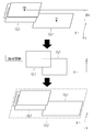
- FIG. 8A is a diagram showing a display state of guide information,
- FIG. 8A is a diagram showing a data display unit displaying an image M, and
- FIG. 8B is a diagram showing a data display unit showing an image M and guide information GD superimposed.
- a schematic diagram showing another configuration of the guide information display device (A) when the data processing unit, data display unit, and data input unit are constituted by a tablet PC, (B) data display unit, data input unit by touch panel display device If configured
- the schematic diagram which shows the relationship between a suspended load area
- FIG. 7 is a flowchart showing the flow of data processing by the data processing unit.
- the figure which shows the point-group data acquired by the data acquisition part (A) The figure which plotted the point-group data on a XYZ coordinate system, (B) The figure which divided the point-group data plotted on a XYZ coordinate system into several groups.
- Flow chart of the ground surface estimation method Explanatory drawing of the calculation method of the reference
- FIG. 7 is a flow diagram of a method of combining planes present in different groups.
- Explanatory drawing of the coupling method of the plane which exists in a different group Explanatory drawing of the clustering process of the same area
- another same area cluster including all planar clusters whose elevation value difference is equal to or greater than a threshold is set.
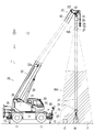
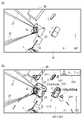
- the crane 1 is an example of a crane provided with a guide information display device according to an embodiment of the present invention, and is a mobile crane that can move to a desired location.
- the crane 1 includes a traveling vehicle 10 and a crane device 20.
- the traveling vehicle 10 transports the crane device 20, has a plurality of (four in the present embodiment) wheels 11, and travels using an engine (not shown) as a power source.
- An outrigger 12 is provided at each of four corners of the traveling vehicle 10.
- the outrigger 12 is composed of an overhang beam 12a that can be extended hydraulically on both sides in the width direction of the traveling vehicle 10, and a hydraulic jack cylinder 12b that can extend in a direction perpendicular to the ground.
- the traveling vehicle 10 can bring the crane 1 into a workable state by grounding the jack cylinder 12b, and by increasing the extension length of the overhang beam 12a, the workable range of the crane 1 (work Radius) can be extended.
- the crane device 20 lifts the load W by a wire rope, and the swivel base 21, the telescopic boom 22, the main hook block 23, the sub hook block 24, the relief cylinder 25, the main winch 26, the main wire rope 27, the sub winch A sub wire rope 29 and a cabin 30 are provided.
- the swivel base 21 is configured to be able to pivot the crane apparatus 20, and is provided on the frame of the traveling vehicle 10 via an annular bearing.
- the annular bearing is disposed such that the center of rotation thereof is perpendicular to the installation surface of the traveling vehicle 10.
- the swivel base 21 is configured to be rotatable in one direction and the other direction with the center of the annular bearing as a rotation center.
- the swivel base 21 is rotated by a hydraulic swivel motor (not shown).
- the telescopic boom 22 supports the wire rope in a state in which the load W can be lifted.
- the telescopic boom 22 includes a plurality of base boom members 22a, second boom members 22b, third boom members 22c, force boom members 22d, fifth boom members 22e, and top boom members 22f. Each boom member is inserted in the order of the size of the cross-sectional area in a nested manner.
- the telescopic boom 22 is configured to be telescopic in the axial direction by moving each boom member with a telescopic cylinder (not shown).
- the telescopic boom 22 is provided so that the base end of the base boom member 22 a can swing on the swivel base 21.
- the telescopic boom 22 is configured to be horizontally rotatable and swingable on the frame of the traveling vehicle 10.
- the main hook block 23 is for hooking and suspending the hanging load W, and a plurality of hook sheaves around which the main wire rope 27 is wound and a main hook 32 for hanging the hanging load W are provided.
- the crane apparatus 20 further includes a sub hook block 24 for hooking and suspending the suspended load W in addition to the main hook block 23, and the sub hook block 24 is provided with a sub hook 33 for suspending the suspended load W. It is done.
- the relief cylinder 25 raises and lowers the telescopic boom 22 and holds the telescopic boom 22 in a posture.
- the relief cylinder 25 is composed of a hydraulic cylinder consisting of a cylinder portion and a rod portion.
- the main winch 26 is for carrying in (rolling up) and unwinding (rolling down) the main wire rope 27, and in the present embodiment, is constituted by a hydraulic winch.
- the main winch 26 is configured such that the main drum on which the main wire rope 27 is wound is rotated by the main hydraulic motor.
- the main winch 26 feeds the main wire rope 27 wound around the main drum by supplying the hydraulic fluid so that the main hydraulic motor rotates in one direction, and the main hydraulic motor rotates in the other direction.
- the main wire rope 27 is wound around the main drum and fed in by supplying the hydraulic oil.
- sub winch 28 is for carrying in and delivering the sub wire rope 29, and in the present embodiment, is constituted by a hydraulic winch.
- the cabin 30 covers a driver's seat 31 on which the operator is seated, and is provided on the side of the telescopic boom 22 in the swivel base 21.
- the crane 1 configured as described above can move the crane device 20 to an arbitrary position by causing the traveling vehicle 10 to travel, and causes the telescopic boom 22 to rise to an arbitrary elevation angle by the elevation cylinder 25.
- the telescopic boom 22 can be extended to any telescopic boom length.
- the crane 1 also includes a controller 34 that controls the operation of the swivel base 21, the telescopic boom 22, the relief cylinder 25 and the like (that is, the operation of the crane 1).
- the controller 34 can externally output information concerning the operation state of the swivel base 21, the telescopic boom 22, the hoisting cylinder 25, etc., information concerning the performance unique to the crane 1, the weight of the suspended load W, etc. .
- an XYZ coordinate system as shown in FIG. 1 is defined with reference to the axial direction of the fulcrum of the telescopic boom 22 (the same applies to the following description).
- the X-axis direction (also referred to as a lateral direction) is a horizontal direction parallel to the axial direction of the fulcrum of the telescopic boom 22.
- the Y-axis direction (also referred to as the elevation direction) is the vertical direction.
- the Z-axis direction (also referred to as the depth direction) is a horizontal direction perpendicular to the axial direction of the fulcrum of the telescopic boom 22. That is, the XYZ coordinate system is defined as a local coordinate system based on the telescopic boom 22, as shown in FIG.
- the crane 1 is provided with a guide information display device 50 as shown in FIG.
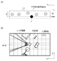
- the guide information display device 50 is an example of the guide information display device according to the present invention, and in order to enable the work by the crane 1 as shown in FIG. 1 to be performed efficiently and safely, the hanging load W It is a device for displaying information (hereinafter referred to as guide information) of an area including the following (hereinafter referred to as a hanging load area WA) as a video and presenting it to the operator.
- guide information information of an area including the following (hereinafter referred to as a hanging load area WA) as a video and presenting it to the operator.
- the “hanging load area WA” here is set as an area including the hanging load W in the Y-axis direction view in the working area SA of the crane 1, as shown in FIGS. 2 and 4. This is an area for which “guide information” is to be generated.
- the “suspended load area WA” is set as an area including immediately below the top boom member 22 f of the telescopic boom 22 in the crane 1, and the suspended load W, the ground surface F, and the feature C existing in the suspended load area WA are guides It becomes a measurement object by the information display device 50.
- the “suspended load area WA” is displaced in response to the turning operation, the raising and lowering operation, and the extension and contraction operation of the extension boom 22.
- the “guide information” referred to here is the operator about the quality of the telescopic boom 22 such as the length, the turning position, the ups and downs angle, the amount of unwinding of the wire rope when the operator transports the load W by the crane 1
- Image information of the suspended load area WA information pertaining to the shapes of the suspended load W and the feature C, height information of the suspended load W, height information of the feature C, and of the suspended load W It contains information related to flow lines.
- the guide information display device 50 is configured by a data acquisition unit 60, a data processing unit 70, a data display unit 80, and a data input unit 90.
- the data acquisition unit 60 is a part for acquiring data necessary for generating guide information in the suspended load area WA, and as shown in FIG. 3, the camera 61, the laser scanner 62, and the inertial measurement device (IMU) 63 Have.
- IMU inertial measurement device
- the data acquisition unit 60 is attached to the top boom member 22 f located at the tip of the telescopic boom 22 of the crane 1, and directly below the boom tip located directly above the load W It is placed in a state where it can catch the situation.
- “directly above” the suspended load W includes the position vertically above the suspended load W and the position of a certain range (for example, the range of the upper surface of the suspended load W) based on that position. It is a concept.
- the data acquisition unit 60 is attached to the top boom member 22f at the tip of the telescopic boom 22 via a gimbal 67 (see FIG. 1), and when the telescopic boom 22 performs a hoisting operation, a turning operation, and an telescopic operation.
- the attitude of the data acquisition unit 60 (the attitude in the Y-axis direction) can be maintained substantially constant.
- the camera 61 and the laser scanner 62 can always be directed to the load W.
- the data acquisition unit 60 can always acquire data from the suspended load W and the ground surface F (that is, the suspended load area WA) existing therebelow by the camera 61 and the laser scanner 62.
- the feature C exists in the suspended load area WA
- data of the feature C can be acquired by the camera 61 and the laser scanner 62.
- the camera 61 is a digital video camera for capturing an image of the suspended load area WA, and has a function of outputting the captured image to the outside in real time.
- the camera 61 has an angle of view (horizontal angle of view ⁇ h and vertical angle of view ⁇ v) as shown in FIGS. 5 (A) and 5 (B).
- the camera 61 has the number of pixels, the frame rate, and the image transmission rate in consideration of the amount of data necessary for generating appropriate guide information.
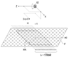
- the laser scanner 62 irradiates a laser to the object to be measured, and receives light reflected from the object to be measured by the laser, thereby acquiring information on the reflection point, and It is an apparatus for acquiring point cloud data.
- the objects to be measured by the laser scanner 62 are a load W, a feature C, and a ground surface F.
- a first GNSS receiver 65 for acquiring a measurement time is connected to the laser scanner 62.
- the laser scanner 62 acquires planar three-dimensional point cloud data in real time.
- the laser scanner 62 is provided with a total of 16 laser transmitting / receiving sensors, and it is possible to simultaneously irradiate 16 lasers to the measurement object to acquire point cloud data of the measurement object It is possible.
- the 16 laser transmitting / receiving sensors of the laser scanner 62 are disposed with different irradiation angles by 2 ° in the Z-axis direction, and irradiate the laser with a spread of 30 ° as a whole to the object to be measured. It is configured to be possible.
- each laser transmission / reception sensor of the laser scanner 62 is configured to be capable of rotating 360 degrees (all directions) around the Z axis.
- a locus drawn by a laser irradiated toward the suspended load area WA is referred to as a laser side line.
- the laser side line is parallel to the X-axis direction, and the laser scanner 62 simultaneously draws 16 laser side lines.
- the laser scanner 62 is disposed such that the laser side line is parallel to the X-axis direction. Further, in the laser scanner 62, a reference axis for changing the irradiation angle of the laser is parallel to the Z-axis direction.
- an inertial measurement unit (hereinafter referred to as IMU) 63 is a device for acquiring posture data of the camera 61 and the laser scanner 62 at the time of data acquisition.
- the IMU 63 can measure the attitude angle in real time, and has measurement accuracy that can be used to correct point cloud data acquired by the laser scanner 62.
- a second GNSS receiver 66 for obtaining measurement time is connected to the IMU 63.
- the data acquisition part 60 is a sensor unit which fixed the camera 61, the laser scanner 62, and inertial measurement device (IMU) 63 with respect to the frame body 64, and was comprised integrally.
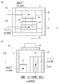
- the frame body 64 is a substantially rectangular parallelepiped object configured by combining five plate members.
- the frame body 64 constitutes a rectangular parallelepiped side surface portion of four plate members, and the remaining one plate member constitutes an upper surface portion of the rectangular parallelepiped member and has an opening at the lower side.
- the camera 61 and the laser scanner 62 are attached to the inner side of the side surface of the frame 64, and the IMU 63 is attached to the upper surface of the frame 64.
- the image pickup device center position of the camera 61 and the laser center position of the laser scanner 62 are separated by a distance ⁇ zh in the Z-axis direction when viewed in the Y-axis direction.
- the laser center position is the rotation center of the laser in the laser scanner 62 and is located on the Z axis.
- the image pickup device center position of the camera 61 and the laser center position of the laser scanner 62 are separated by a distance ⁇ yv in the Y axis direction when viewed in the X axis direction.
- one of a pair of facing side surfaces of the four side surfaces of the frame body 64 is perpendicular to the Z axis, and the other of the facing pair of side surfaces is perpendicular to the X axis Will be placed in
- the data acquisition unit 60 is disposed in a posture in which the upper surface portion of the frame body 64 is perpendicular to the Y axis.
- the guide information display device 50 converts coordinate values between the XYZ coordinate system and the camera space coordinate system in order to superimpose guide information GD to be described later on the image M captured by the camera 61 and display the guide information GD on the data display unit 80. Do the processing.
- a three-dimensional camera space coordinate system Xc ⁇ Yc ⁇ Zc is defined in the video space of the camera 61.
- the distance in the X-axis direction from the vertical line extended from the lens center of the camera 61 to the point (x, y) is dh, and the maximum screen width in the horizontal direction of the camera 61 is wh.
- the point (x, y) has a position in the X axis direction from the screen center as x.
- the Xc coordinates of the point (x, y) in the camera space are expressed by the following Equations (1) and (2).
- the horizontal difference between the position of the imaging device of the camera 61 and the center of the laser is ⁇ zh (see FIG.
- the horizontal width of the camera image is wh
- the horizontal angle of view of the camera 61 is ⁇ h
- the temporary variable is tmp1.
- tmp1 (y ⁇ zh) ⁇ tan ( ⁇ ⁇ ⁇ h / 360) (1)
- Xc wh / 2-wh ⁇ x / (2 ⁇ tmp 1) (2)
- the Zc coordinates of the point (y, z) in the XYZ coordinate system into Zc coordinates in the camera space coordinate system will be described.
- the distance in the Z-axis direction from the point (y, z) to the laser center is dv
- the maximum screen width in the horizontal direction of the camera 61 is wv.
- the point (y, z) has a position in the Z-axis direction from the screen center as z.
- the Zc coordinates of the point (y, z) in the camera space are expressed by the following equations (3) and (4).
- the difference in the vertical direction between the image pickup element of the camera 61 and the position of the laser center of the laser scanner 62 is ⁇ yv (see FIG. 7B)
- the vertical width of the camera image is wv
- the vertical image of the camera 61 The angle is ⁇ v
- the temporary variable is tmp2.
- tmp2 Y ⁇ tan ( ⁇ ⁇ ⁇ v / 360)
- Zc wv / 2 + wv ⁇ (Z ⁇ yv) / (2 ⁇ tmp 2) (4)
- the guide information display device 50 converts the coordinates of point group data acquired by the laser scanner 62 or the like in the XYZ coordinate system into the camera space coordinate system using the above equations (1) to (4).
- the guide information GD is aligned and displayed on the image M taken at step.
- an apparatus capable of measuring the three-dimensional shape of the object to be measured is selected from the maximum reach height (for example, about 100 m) in consideration of the maximum reach height of the telescopic boom 22.
- an apparatus having predetermined performance for each specification such as measurement speed, number of measurement points, measurement accuracy, etc. in consideration of data amount and data accuracy necessary to generate appropriate guide information select.
- the case of using the laser scanner 62 provided with a total of 16 laser transmitting and receiving sensors is illustrated, but in the guide information display apparatus according to the present invention, the number of laser transmitting and receiving sensors constituting the laser scanner is used. It is not limited by. That is, in the guide information display apparatus according to the present invention, a laser scanner having an optimum specification is appropriately selected according to the maximum reach height of the boom (jib) of the crane and the like.
- the data acquired by the data acquisition unit 60 in the hanging load area WA includes the hanging load W, the ground surface F below the hanging load W, and an image obtained by photographing the feature C existing around the hanging load W by the camera 61 Contains data. Further, the data acquired in the suspended load area WA by the data acquiring unit 60 includes the suspended load W, the ground surface F, and point cloud data acquired by scanning the feature C with the laser scanner 62.
- the ground surface F mentioned here widely includes the surfaces to be the transfer source and the transfer destination of the hanging load W, and includes not only the ground surface but also the floor surface and roof surface of the roof of the building.
- the data processing unit 70 is a part for processing the data acquired by the data acquisition unit 60 to generate guide information GD to be presented to the operator, and in the present embodiment, predetermined data It is configured by a general-purpose personal computer in which a processing program is installed. Further, the data processing unit 70 is electrically connected to the controller 34 of the crane 1, and “crane information” output from the controller 34 is input to the data processing unit 70.
- the data display unit 80 is a part for displaying guide information GD to be presented to the operator, and includes a display device connected to the data processing unit 70. As shown in FIG. 8A, the data display unit 80 displays the video M of the suspended load area WA taken by the camera 61 in real time.
- a guide frame GD1 representing the external shape of the hanging load W and the feature C in the Y-axis direction view
- height information GD2 of the lower surface of the hanging load W ground
- the height information GD3 of the upper surface of the object C, the work radius line information GD4 indicating the flow line of the hanging load W, and the axis information GD5 indicating the axial direction of the telescopic boom 22 are included.
- the guide information GD generated by the data processing unit 70 and the video M are superimposed and displayed.
- the data input unit 90 is a part for inputting setting values and the like to the data processing unit 70, and is configured by a touch panel, a mouse, a keyboard device, and the like.
- the data processing unit 70, the data display unit 80, and the data input unit 90 are implemented by a tablet-type general purpose personal computer (hereinafter also referred to as a tablet PC). It is preferable to construct integrally.
- the data display unit 80 and the data input unit 90 are integrated by a touch panel display device, and the touch panel display device performs data processing as a general purpose PC.
- the unit 70 may be connected.
- the data display unit 80 and the data input unit 90 are disposed in a position in front of the driver's seat 31 in the cabin 30 at a position where the operator can easily view.
- the data processing unit 70 is preferably arranged in the vicinity of the data acquisition unit 60.
- the data processing unit 70, the data display unit 80, and the data input unit 90 are integrally configured by a tablet PC, the data processing unit 70 may be disposed in the cabin 30. Transmission of data between the data acquisition unit 60 and the data processing unit 70 is preferably performed by a wired LAN.
- the data transmission between the data acquisition unit 60 and the data processing unit 70 may adopt a wireless LAN or may adopt power line communication.
- the data processing unit 70, the data display unit 80, and the data input unit 90 are implemented by a tablet-type general purpose personal computer (hereinafter also referred to as a tablet PC). It is preferable to construct integrally.
- the data display unit 80 and the data input unit 90 are integrated by a touch panel display device, and the touch panel display device performs data processing as a general purpose PC.
- the unit 70 may be connected.
- the camera 61 continuously shoots the suspended load area WA, and acquires the image M of the suspended load area WA.
- point cloud data P point cloud data acquired by the laser scanner 62
- the point cloud data P is a set of point data p
- the point data p represents a point located on the ground surface F, the suspended load W, and the upper surface of the feature C existing in the suspended load area WA.
- the distance a from the measurement object (for example, the ground object C) to the laser scanner 62 and the irradiation angle b of the laser scanner 62 when the point data p is acquired. Information is included.
- the first GNSS receiver 65 is connected to the laser scanner 62, and while acquiring point cloud data P, the first GNSS receiver 65 receives time information from a plurality of positioning satellites Do. Then, the data processing unit 70 adds information related to the acquisition time of the point data p to the point data p. That is, the information related to the point data p includes the acquisition time tp in addition to the distance a and the irradiation angle b.
- the point cloud data P is acquired by the laser scanner 62, and at the same time, the attitude data Q of the laser scanner 62 is acquired by the IMU 63 at a predetermined cycle.
- the posture data Q includes information on the angle and acceleration with respect to each axial direction of the X, Y, and Z axes of the laser scanner 62.
- the acquisition cycle of the posture data Q by the IMU 63 is shorter than the acquisition cycle of the point cloud data P by the laser scanner 62.
- the posture data Q is a set of individual posture data q measured for each measurement cycle.
- a second GNSS receiver 66 is connected to the IMU 63 to acquire attitude data Q, and at the same time, the second GNSS receiver 66 receives time information from a plurality of positioning satellites.
- the data processing unit 70 assigns an acquisition time tq to the individual posture data q as information related to the acquisition time of the individual posture data q. That is, the information concerning the individual posture data q includes the acquisition time tq.
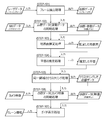
- the data processing unit 70 first, "frame extraction processing” is performed (STEP-101).
- the point cloud data P for one frame is cut out and output from the stream data of the point cloud data P.
- the point group data P for one frame is a set of point data p acquired while the irradiation direction of the laser by the laser scanner 62 makes one rotation around the Z axis.
- “synchronization processing of point cloud data and posture data” is performed (STEP-102).
- the data processing unit 70 synchronizes the point data p included in the point cloud data P for one frame with the attitude data Q acquired by the IMU 63. Specifically, in each point data p, the acquisition time tq of the individual posture data q closest to the acquisition time tp of the point data p is searched, and the individual posture data q at the acquisition time tq is Synchronize by matching to.
- the data processing unit 70 outputs point data p synchronized with the individual posture data q. Then, as shown in FIG. 11, the data processing unit 70 calculates the distance h from the laser center position of the laser scanner 62 to the point data p based on the distance a and the irradiation angle b.
- the “distance h” is the distance from the laser center position of the laser scanner 62 to the horizontal plane where the point data p exists, that is, the distance in the vertical direction from the laser center position of the laser scanner 62 to the point data p. is there.
- the data processing unit 70 performs correction using the individual posture data q corresponding to the point data p.
- the error caused by the attitude of the laser scanner 62 can be eliminated, and the distance h of the point data p can be calculated more accurately.
- the data acquisition unit 60 is provided with the IMU 63 for acquiring the attitude data Q of the laser scanner 62, and the data processing unit 70 is based on the attitude data Q of the laser scanner 62 acquired by the IMU 63.
- the point cloud data P is corrected.
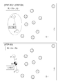
- FIG. 13A shows point cloud data P (a set of point data p) viewed from the Z-axis direction.
- ground surface estimation processing is performed next (STEP-103).
- the data processing unit 70 performs processing to estimate the reference height H0 of the ground surface F present in the suspended load area WA.
- the data processing unit 70 first acquires point cloud data P for one frame.
- the point cloud data P is acquired from above the suspended load W and the feature C which are measurement objects, in the suspended load area WA including the suspended load W and the feature C and the ground surface F.
- the data processing unit 70 divides the suspended load area WA into a plurality of small areas S in a grid shape in plan view (view in the Y-axis direction) (area division process : STEP-201).
- the data processing unit 70 divides the laser side line at equal intervals by a dividing line parallel to the Z-axis direction, and divides it into small regions S having the same shape and the same area based on the divided laser side line doing.
- the data processing unit 70 divides the laser side line into ten parts to divide them into 160 small areas S.
- the data processing unit 70 extracts point data p having the largest distance h (the distance h is the maximum distance hmax) in each small area S (maximum point data extraction step: STEP-202). Point data p which is the maximum distance hmax is estimated to be point data p existing at the lowest position. Then, as shown in FIG. 14 and FIG. 15 (A), the data processing unit 70 calculates the separation amount D of the distance h of the other point data to the point data p which is the maximum distance hmax (a separation amount calculation step: STEP-203).
- the data processing unit 70 configures the ground surface F with point data p having a separation amount D within a predetermined threshold r1 (in this embodiment, a separation amount D within 7 cm) based on the maximum distance hmax. It extracts as point data (ground surface point data extraction process: STEP-204).
- the data processing unit 70 estimates the reference height H0 of the ground surface F of each small area S based on the distance h of the extracted point data p in each small area S (small area ground surface estimation step: STEP -205).
- the data processing unit 70 sets the average value of the distances h of the extracted point data p as the reference height H0 of the ground surface F in the small area S. With such a configuration, the data processing unit 70 can estimate the reference height H0 of the ground surface F in any small region S.
- the data processing unit 70 estimates the reference height H0 of the ground surface F of the suspended load area WA based on the reference height H0 of the ground surface F in each small area S (area ground surface estimation step: STEP-206). In the present embodiment, the data processing unit 70 further averages the reference height H0 (average value of the distance h) of the ground surface F in each small region S in all the small regions S as the ground surface of the suspended load region WA. The reference height H0 of F is used. With such a configuration, the data processing unit 70 can estimate the reference height H0 of the ground surface F of the suspended load area WA. Then, the data processing unit 70 calculates the elevation value H of the point data p from the distance h and the reference height H0. As shown in FIG. 10, the altitude value H is the height from the reference height H0 of the point data p.
- the data processing unit 70 determines that the difference between the reference height H0 of the ground surface F in one small area S and the reference height H0 of the ground surface F in the suspended load area WA is larger than a predetermined threshold.
- the point data p which does not constitute the ground surface F is determined to be extracted, and instead of the reference height H0 of the ground surface F in one small area S, the difference among the small areas S adjacent to the one small area S
- the reference height H0 of the ground surface F in the suspended load area WA may be corrected using the reference height H0 of the ground surface F of the small area S where the value of L falls below a predetermined threshold.
- the data processing unit 70 when it is estimated that point data p which does not constitute the ground surface F is extracted by such a configuration, a small area adjacent to one small area S instead of one small area S
- the reference height H0 of the ground surface F of the suspended load area WA can be more accurately estimated by using the reference height H0 of the ground surface F of the small area S in which the difference is less than the predetermined threshold among the regions S. .
- the reference height H0 of the ground surface F in the suspended load area WA in (STEP-206) it is estimated that point data p that does not constitute the ground surface F is extracted from all the small areas S. You may exclude the small area
- the data processing unit 70 can exclude the small area S estimated to be incapable of extracting point data constituting the ground surface F. Therefore, the reference height H0 in the suspended load area WA can be accurately estimated.
- the separation amount calculating step of calculating the separation amount D of the distance h of the other point data p to the point data p having the largest distance h, and in the small area S, the distance D of the distance h is
- the reference height H0 of the ground surface F of the small area S is estimated based on the ground surface point data extraction process of extracting the point data p within the predetermined threshold value r1 and the point data p extracted in the ground surface point data extraction process.
- Small territory It includes a ground surface estimating step, and a region ground surface estimating step of estimating the reference high
- the guide information display device 50 is configured to generate the guide information GD based on the reference height H0 of the ground surface F acquired accurately by the above processing. For this reason, in the guide information display device 50, the height information of the suspended load W and the height information of the feature C can be accurately calculated based on the reference height H0 of the ground surface F.
- the data processing unit 70 may be configured to automatically determine and designate the specific position on the video.
- the ground surface F to be a reference can be determined by designating the position of the ground surface in the data display unit 80 and the data input unit 90.
- the operator designates a clear position on the image displayed on the data display unit 80 as the ground surface.
- the data processing unit 70 generates a reference circle of a predetermined radius centered on the designated position (point), as shown in FIG.
- the data processing unit 70 detects an overlap with the point data p on the laser side line, and selects a plurality of point data p included in the reference circle.
- the data processing unit 70 first extracts point data p having the largest distance h (the distance h is the maximum distance hmax) from the plurality of selected point data p. . Then, the data processing unit 70 calculates the separation amount D of the distance h of the other point data to the point data p which is the maximum distance hmax.
- the data processing unit 70 configures the ground surface F as point data p whose distance D is within the predetermined threshold r1 (in this embodiment, distance D is within 7 cm) with reference to the maximum distance hmax. Extract as data.
- the data processing unit 70 estimates the reference height H0 of the ground surface F based on the distance h of the extracted point data p. In the present embodiment, the data processing unit 70 adopts the average value of the distances h of the extracted point data p as the reference height H0 of the ground surface F.
- “Plane estimation processing” is performed (STEP-104).
- the data processing unit 70 estimates the upper surfaces of the suspended load W and the feature C, which are measurement objects, present in the suspended load area WA by the upper surface estimation method described below.
- the point cloud data P for one frame is plotted on the suspended load area WA indicated by the XYZ coordinate system, as shown in FIG. 13A.
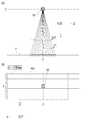
- the point cloud data P in such a suspended load area WA is schematically represented as shown in the upper diagram of FIG.
- the data processing unit 70 divides the point cloud data P acquired in the hanging load area WA as shown in the upper view of FIG. 17 into layers in the Y-axis direction with a predetermined thickness d as shown in the middle of FIG.
- the point cloud data P is distributed to a plurality of groups (see FIG. 13B).
- the data processing unit 70 assigns individual group IDs (here, IDs: 001 to 006) to the divided groups, and associates each point data p with the group ID.
- the data processing unit 70 estimates a plane by using a plurality of point data p included in the group.
- the “plane” referred to here is a plane which exists upward in the load W and the feature C, that is, the “upper surface” of the load W and the feature C.
- the data processing unit 70 selects two point data p ⁇ p from a plurality of point data p ⁇ p... Included in the same group, as shown in FIGS. (2 point selection process: STEP-301). Then, the data processing unit 70 calculates the distance L1 between two points of the selected two point data p ⁇ p as shown in FIG. 18 and the lower diagram of FIG. 19 (inter-point distance calculation step: STEP-302).
- the data processing unit 70 selects two points (two shown by dotted lines). One point data p ⁇ p) is considered to be on the same plane (two-point plane considering process: STEP-304). Then, the data processing unit 70 calculates the center of gravity G1 of each point (here, two selected points) considered to be on the same plane, as shown in FIGS. 18 and 20 (lower center calculation step: STEP-305). If it is determined as "no" in (STEP-303), the process returns to (STEP-301) to reselect two new points.
- the data processing unit 70 searches for point data p that is a nearby point with respect to the calculated center of gravity G1, as shown in FIG. 18 and the upper diagram in FIG. 21 (nearest point searching step: STEP-306).
- the “nearby point” referred to here is a point at which the distance between points with respect to the center of gravity G1 is equal to or less than the threshold value r2.
- the data processing unit 70 finds point data p that is a nearby point (STEP-307), the point data p that is the nearby point is the two points selected earlier. It is considered that it is on the same plane as the data p ⁇ p (near point plane considering step: STEP-308).
- the data processing unit 70 returns to (STEP-305) as shown in FIGS. 18 and 22 and the respective points regarded as being on the same plane (here, three points indicated by dotted lines).
- a new center of gravity G2 is calculated from the point data p ⁇ p ⁇ p).
- the data processing unit 70 proceeds to (STEP-306), and further searches for point data p which is a nearby point with respect to the gravity center G2. Then, as shown in FIG. 18 and the lower diagram of FIG. 22, if the data processing unit 70 further finds point data p that is a nearby point (STEP-307), the point data p that is a nearby point is also selected each point previously. And the point data p on the same plane as (step-308). Then, the data processing unit 70 searches for nearby points while calculating a new centroid, and repeats the processing from (STEP-305) to (STEP-308) in order until the point data p which is a nearby point is not detected. Do.
- the data processing unit 70 determines “no” in (STEP-307) and determines that the point is considered to be on the same plane if a new neighboring point is not found.
- Cluster a subset (cluster) of data p to estimate a plane (STEP-309).
- clustering divides point group data P, which is a set of point data p, into clusters so that point data p included in each cluster has a common feature of being on the same plane. It is a process.
- the data processing unit 70 divides the point cloud data P into point data p considered to be on the same plane, and sets a plane cluster CL1 (see the lower diagram in FIG. 17).
- each point data p belonging to the plane cluster CL1 it is possible to define a plane (that is, the “upper surface” of the hanging load W and the feature C).
- a plurality of plane clusters CL1 may exist in a group to which the same group ID is assigned.
- the data processing unit 70 estimates the "width" of the plane from the maximum value and the minimum value of the X coordinate of the point data p belonging to the plane cluster CL1, and the "depth” of the plane from the maximum value and the minimum value of the Z coordinate. Estimate The data processing unit 70 thus defines the plane formed by the plane cluster CL1.
- the plane defined here may be a polygon other than a rectangle.
- the top surfaces of the suspended load W and the ground object C can be estimated based on only the point cloud data P corresponding to the top surface acquired by the laser scanner 62. Therefore, in the upper surface estimation method described in the present embodiment, it is possible to estimate the upper surfaces of the hanging load W and the ground object C in a short time based on the point cloud data P acquired by the laser scanner 62. It is possible to estimate the upper surface of the load W and the feature C in real time.
- the top surfaces of the suspended load W and the feature C can be estimated without using a statistical method, and compared with the case where the statistical method is used, the suspended load W and the feature C It is possible to reduce the amount of calculation required to estimate the upper surface of. Therefore, in the upper surface estimation method described in the present embodiment, it is possible to estimate the upper surfaces of the suspended load W and the ground object C in a shorter time based on the point cloud data P acquired by the laser scanner 62.
- the data acquisition unit 60 is provided on the top boom member 22 f of the telescopic boom 22 in the crane 1, and the laser scanner 62 is used to Although the case of acquiring point cloud data P pertaining to the hanging load W, the ground object C, and the ground surface F from the vertically upper side is illustrated, the upper surface estimation method of the measurement object according to the present invention It is not limited as what is applied when making what exists around a suspended load into a measuring object.
- a laser scanner is provided at the boom tip portion or the drone of a work vehicle (for example, work vehicle etc.) provided with a boom, and exists vertically from below
- the present invention can be widely applied to the case of acquiring point cloud data of a measurement object and estimating the upper surface of the measurement object based on the acquired point cloud data.
- the data processing unit 70 combines the estimated planar clusters CL1 (upper surface).
- the data processing unit 70 selects two plane clusters CL1 and CL1 to which different group IDs are assigned among the estimated plane clusters CL1, as shown in FIGS.
- the difference dH of the altitude value H is calculated (STEP-401: altitude value difference calculating step).
- the data processing unit 70 searches for a combination in which the difference dH is within the threshold value r3 (STEP-402).
- the altitude value H of the plane cluster CL1 mentioned here is an average value of the altitude values H of the point data p belonging to the plane cluster CL1.
- the data processing unit 70 determines the combination of those planar clusters CL1 ⁇ .
- the overlap dW in the X-axis direction is detected for CL1 (STEP-403: overlap detection step).
- overlap refers to the overlap degree and separation degree in the X-axis direction of the plane defined by the plane cluster CL1, and as shown in FIGS. 24 and 25, the overlap amount dW1 of “width” is detected. In the case (dW1> 0) or when the separation amount dW2 is equal to or less than the predetermined threshold value r4 (0 ⁇ dW2 ⁇ r4), “overlap” is detected.
- the data processing unit 70 repeats the above processing until the combination of planar clusters CL1 and CL1 satisfying the condition disappears (STEP-406), and a plane existing across a plurality of groups is displayed. presume.
- the data processing unit 70 outputs the plane (that is, plane cluster CL1) coupled by the above coupling process.
- the plane defined by the plane cluster CL1 is a plane facing upward in the load W and the feature C, that is, the upper surface of the load W and the feature C.
- Such a plane estimation method can estimate a plane without using a normal vector of the point cloud data P. For this reason, there is a feature that the amount of calculation can be reduced compared to the case of estimating a plane using a normal vector of the point cloud data P.
- the hanging load W or the ground can be obtained without acquiring point data p of the side surface of the hanging load W or the feature C. The three-dimensional shape of the object C can be grasped.
- clustering processing of the same area is performed (STEP-105).
- clustering divides point cloud data P, which is a set of data, into clusters so that point data p included in each cluster has a common feature of being in the “same area”. It is a process.
- the generated plane cluster CL1 (plane) is clustered from different viewpoints of whether or not it exists in the “same area” regardless of whether or not it configures the same plane. It is a process.
- the data processing unit 70 includes a plane cluster CL1 including point data p whose elevation value H is the maximum value Hh, and a plane cluster not coupled to the plane cluster CL1. Extract CL1. Then, the data processing unit 70 calculates the difference ⁇ H of the altitude values H of the extracted planar clusters CL1, and if the difference ⁇ H is equal to or less than a predetermined threshold, the process proceeds to the next determination.
- the data processing unit 70 confirms overlap in the Y-axis direction for two plane clusters CL1 and CL1 whose difference ⁇ H is less than or equal to a predetermined threshold.
- the data processing unit 70 “same area” as shown in the lower diagram of FIG.
- These planar clusters CL1 and CL1 form the same area cluster CL2.
- the data processing unit 70 further searches the plane cluster CL1 including the point data p having the maximum value Hh of the elevation value H and the plane cluster CL1 not coupled to the plane cluster CL1, and the plane cluster CL1 is not coupled. If is extracted, the judgment based on the difference ⁇ H and the confirmation of the overlap in the Y-axis direction are performed, and if there is a plane cluster CL1 meeting the above condition, it is further added to the same area cluster CL2.
- the data processing unit 70 repeats such processing until the unjoined planar cluster CL1 is not found with respect to the planar cluster CL1 including the point data p having the maximum value Hh of the elevation value H.
- the data processing unit 70 forms the same area cluster CL2 by the above processing.
- the point data p belonging to the same area cluster CL2 formed in this way is treated as having one shape in shape in the display of the guide information GD described later, so as to surround the same area cluster CL2.
- the guide frame GD1 is displayed.
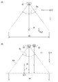
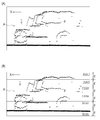
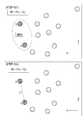
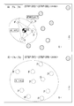
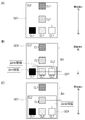
- Such “clustering process of the same area” is preferably hierarchical clustering using a tree structure based on elevation values as shown in FIGS. 27 (A) and 27 (B).
- the data processing unit 70 creates a tree structure using the elevation value H for each feature C in the “clustering process of the same area”.
- the hierarchical clustering using the tree structure is performed on the feature C of the first example shown in FIG. 27 (A)
- the feature C of the second example shown in FIG. 27 (B) An example of hierarchical clustering using a tree structure is illustrated.
- the data processing unit 70 sets a plane cluster CL1 having the smallest average value of the elevation values H as a "root”. In addition, if there is a plane cluster CL1 having an overlap in the Y-axis direction view with respect to the plane cluster CL1 configuring the “root”, the data processing unit 70 extends the “branch” from the “root” At the tip of the branch, a planar cluster CL1 having the overlap is added. Then, the data processing unit 70 sets the plane cluster CL1 having the largest average value of the elevation values H as a “child”.
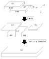
- the data processing unit 70 acquires the tree structure of the feature C created in the “clustering process of the same area”. Then, the data processing unit 70 acquires point data p included in each plane cluster CL1 configuring the tree structure. Next, as shown in the upper diagram of FIG. 28, the data processing unit 70 obtains point data p on the laser side line located farthest in the Z-axis direction from the point data p of the “child” plane cluster CL1. Do. Then, the data processing unit 70 creates a rectangle having a width in the X-axis direction which is separated in the Z-axis direction by a half of the distance to the adjacent laser side line and can surround each point data p. .
- the data processing unit 70 includes all point data p on the corresponding laser side line as shown in the lower part of FIG. Transform the rectangle to create an outline. Then, the data processing unit 70 searches for the point data p on the adjacent laser side line until the point data p on the target laser side line disappears, and repeats the above processing. Finally, the data processing unit 70 creates an outline that externally wraps all planar clusters CL1 included in the selected tree structure.
- the data processing unit 70 outputs only the outline that meets the conditions as the guide frame GD1 out of the generated outlines.
- the conditions to be output as the guide frame GD1 for example, as shown in FIG. 29A, it is possible to select the conditions for displaying only the outline of the feature C, which is a large frame. When this condition is selected, one guide frame GD1 surrounding the entire feature C is displayed for the feature C on the data display unit 80.
- the difference (difference .DELTA.H) of the elevation value H with respect to the "root" is Among the outlines (small frames) which are equal to or greater than the threshold value, it is possible to select a condition for displaying the outline relating to the plane cluster CL1 having the highest elevation value H in each branch.
- the data display unit 80 displays a first guide frame GD1 surrounding the entire feature C and a second guide frame included inside the first guide frame GD1.
- the guide frame GD1 is displayed, and more detailed guide information GD in which the three-dimensional shape of the feature C is considered is displayed.
- the difference (difference ⁇ H) of the elevation value H with respect to the “root” is It is possible to select a condition for displaying all the outlines (small frames) which are equal to or larger than the threshold. Even when this condition is selected, the data display unit 80 displays the first guide frame GD1 surrounding the entire feature C and the second guide frame GD1 included therein, and the ground More detailed guide information GD in which the three-dimensional shape of the object C is considered is displayed.
- Such display conditions can also be performed by adjusting the threshold value of the difference ⁇ H.
- the operator can appropriately select the display conditions of the guide frame GD1 so that the display of the guide information GD can be more easily viewed.
- the guide frame GD1 representing the feature C in more detail in consideration of the three-dimensional shape of the feature C is generated by generating the guide frame GD1 based on the same area cluster CL2. It is possible to generate. Further, in the guide information display device 50, it is possible to generate a guide frame GD1 which collectively encloses the planar cluster CL1 present in the same area. That is, according to the guide information display device 50, it is possible to present more detailed and easy-to-view guide information GD.
- synchronization processing of point cloud data and camera image is performed (STEP-106).
- the point cloud data P acquired in the XYZ coordinate system is converted into coordinate values in the camera space coordinate system and synchronized with the image M captured by the camera 61 ( Alignment) and output to the data display unit 80.
- “guide display processing” is performed next (STEP-107).
- the data processing unit 70 generates guide information GD based on the generated information of the same area cluster CL 2, and outputs the guide information GD to the data display unit 80.
- "crane information” output from the controller 34 of the crane 1 is used.
- the “crane information” used here includes information on the length of the telescopic boom 22, the elevation angle, the working radius of the crane 1, the weight of the hanging load W, and the like.
- the guide information GD can be generated by accurately grasping the three-dimensional shape of.
- Such a configuration is suitable for the purpose of grasping the shapes of the hanging load W and the ground object C in real time because the amount of data computation can be small, and the data processing unit 70 with a simple hardware configuration can be used .
- the data display unit 80 displays the guide information GD.
- the guide information GD displayed by the data display unit 80 includes information relating to the designated position of the ground surface F by the operator as shown in FIG. 8 (B).
- the hanging load W can be designated.
- the plane (upper surface) present at the designated position is set as representing the upper surface of the hanging load W.
- the guide frame GD1 according to the hanging load W and the guide frame GD1 according to the feature C be displayed by changing the line color, the line thickness, and the like.
- the information which concerns on the ground surface F and the designated position of the hanging load W is displayed by the marker represented with figures, such as a circle.
- the guide information GD displayed by the data display unit 80 includes the guide frame GD1 generated by the data processing unit 70.
- the data processing unit 70 outputs the guide frame GD1 based on the set same area cluster CL2.
- the data processing unit 70 can provide a margin for reliably avoiding a collision as the guide frame GD1 of the hanging load W, and a frame offset outward from the outline of the hanging load W by a predetermined distance.
- the line can be output as a guide frame GD1.
- Such a guide frame GD1 is a frame display in which the upper surface (planar cluster CL1) estimated in the hanging load W and the feature C is surrounded by line segments.
- the guide information GD displayed by the data display unit 80 includes height information GD2 from the reference height H0 to the lower surface of the hanging load W and height information GD3 from the reference height H0 to the upper surface of the feature C. include.
- the height information GD2 of the hanging load W be configured to be provided with an independent area at an easily viewable position on the screen of the data display unit 80 and to be displayed in the area.
- the height information GD2 of the hanging load W and the height information GD3 of the feature C are not mistaken.
- the data processing unit 70 calculates the height information GD2 by subtracting the height of the suspended load W from the upper surface height of the plane cluster CL1 estimated to be the upper surface of the suspended load W.
- the operator inputs information related to the suspended load W (hereinafter referred to as “suspended load information”) to the data processing unit 70 in advance.
- the operator inputs the "hanging load information” from the data input unit 90.
- the data processing part 70 acquires the height of the hanging load W using "hanging load information.”
- the height information GD3 of the feature C is displayed inside the guide frame GD1 surrounding the feature C.
- the guide frame GD1 is configured to be displayed so as to partially overlap the guide frame GD1.
- the correspondence between the feature C and the height information GD3 is clarified by such a configuration.
- the data processing unit 70 changes the line color of the guide frame GD1 in accordance with the elevation value H of the flat cluster CL1 corresponding to the guide frame GD1.
- the guide information display device 50 with such a configuration, when the operator looks at the guide frame GD1, the rough elevation value (height) of the hanging load W or the feature C can be perceived sensuously. For this reason, in the guide information display device 50, the heights of the hanging load W and the feature C can be more accurately presented.
- the data processing unit 70 changes the font color of the height information GD2 in accordance with the elevation value H of the plane cluster CL1 corresponding to the guide frame GD1.
- the operator can perceptually perceive rough elevation values (heights) of the suspended load W and the feature C by looking at the height information GD2. For this reason, in the guide information display device 50, the heights of the hanging load W and the feature C can be more accurately presented.
- the display of the guide information GD performed by the guide information display device 50 includes flow line information of the hanging load W.
- the movement line information of the hanging load W includes work radius line information GD4 of the crane 1 and axis information GD5 of the telescopic boom 22 of the crane 1.
- the "flow line information of the hanging load W" may be replaced with "flow line information of the main hook 32", and the work radius line information GD4 and the axis line information GD5 may be "flow line of the main hook 32". It can also be used as information.
- the work radius line information GD4 is an indicator of the flow line of the suspended load W when the telescopic boom 22 is turned, and the suspended load W moves along an arc shown as the work radius line information GD4.
- the axis information GD5 is an indicator of the flow line of the suspended load W when the telescopic boom 22 is moved up and down and extends and retracts, and the suspended load W moves along a straight line indicated as the axis information GD5.
- the working radius R of the crane 1 is the horizontal distance from the turning center of the telescopic boom 22 in the crane 1 to the vertical line passing through the center of the main hook 32 (in this embodiment, the lens center of the camera 61).
- an XYZ coordinate system as shown in FIG. 32 is defined with reference to the origin O1 of the camera coordinate system (the lens center of the camera 61).
- the X-axis direction is a horizontal direction parallel to the axial direction of the fulcrum of the telescopic boom 22.
- the Y-axis direction is the vertical direction.
- the Z-axis direction is a horizontal direction perpendicular to the axial direction of the fulcrum of the telescopic boom 22.
- the turning center of the telescopic boom 22 expressed with the origin O1 of the camera coordinate system as a reference is O2 (x1, y1, z1)
- the working radius R can be calculated by the following equations (5) and (6).
- the temporary variable is tmp3.
- the data processing unit 70 may use the working radius R input as “crane information” from the crane 1 in addition to the case where the working radius R is calculated based on the above formulas (5) and (6).
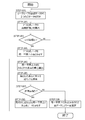
- the data processing unit 70 acquires an image M photographed by the camera 61 (photographing step: STEP-501).
- the image M of the camera 61 is suspended at least from the load W and the ground surface F from above the load W lifted by the crane 1 provided with the telescopic boom 22 capable of turning, raising and lowering and telescopic movement. It is acquired in the load area WA.
- the data processing unit 70 acquires point cloud data P for one frame (point cloud data acquisition step: STEP-502).
- the point cloud data P is acquired from above the suspended load W in the suspended load area WA including at least the suspended load W and the ground surface F.
- the data processing unit 70 performs an arbitrary small area S (for example, a predetermined small area S intersecting the perpendicular extending from the lens center of the camera 61) or the small area S by the ground surface estimation process described above (see FIGS. 14 to 16) or The reference height H0 of the ground surface F of the suspended load area WA is estimated (ground surface estimation step: STEP-503).
- an arbitrary small area S for example, a predetermined small area S intersecting the perpendicular extending from the lens center of the camera 61
- the reference height H0 of the ground surface F of the suspended load area WA is estimated (ground surface estimation step: STEP-503).
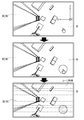
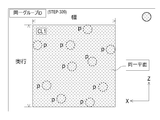
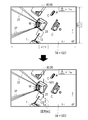
- the data processing unit 70 based on the reference height H0 of the ground surface F, as shown in the upper view of FIG. 30, the upper view of FIG. 31, and FIG. Calculate wv (shooting range calculation step: STEP-504).
- the data processing unit 70 calculates the turning center of the crane 1 with respect to the imaging range of the camera 61 from the origin O1 and the working radius R of the camera coordinate system as shown in the middle of FIG. Then, as shown in FIG. 30 lower view and FIG. 33, the data processing unit 70 generates work radius line information GD4 which is the guide information GD from the swing center point O2 of the crane 1 and the work radius R (flow line information generation process : STEP-505).
- the data processing unit 70 passes through the points O1 and O2 based on the origin O1 of the camera coordinate system and the turning center point O2 of the telescopic boom 22. From the above, the axial direction of the telescopic boom 22 is calculated to generate axis information GD5 which is guide information GD.
- axis information GD5 which is guide information GD.
- either of the work radius line information GD4 and the axis line information GD5 may be generated first by the data processing unit 70. Further, in (STEP-405), only one of the work radius line information GD4 and the axis line information GD5 may be generated.
- the data processing unit 70 outputs the work radius line information GD4 to the data display unit 80 as shown in FIG. 30B and FIG. 33, and the work radius line information GD4 is superimposed on the image M in the data display unit 80.
- display flow line information display process: STEP-506).
- the data processing unit 70 outputs the axis line information GD5 to the data display unit 80 as shown in FIG. 31 lower view and FIG. Is superimposed and displayed.
- the axial line information GD5 is displayed along the Z-axis direction.
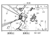
- the work radius line information GD4 and the axis line information GD5 may be simultaneously displayed on the data display unit 80 as shown in FIG.
- the data processing unit 70 outputs a line for displaying the work radius line information GD4 and the axis line information GD5 by a broken line as shown in the lower side of FIG. 30 and the lower side of FIG.
- the length and the interval are set according to the height (the imaging range) of the data acquisition unit 60 calculated based on the reference height H0 of the ground surface F.
- the length of a broken line and a length (hereinafter referred to as a reference length) as an indication of the interval are set.
- the work radius information GD4 and the axis line information GD5 are determined according to the height (the size of the imaging range) of the data acquisition unit 60 calculated based on the reference height H0 of the ground surface F.
- the length and interval of the broken line are changed, and on the scale at that time, it is displayed as the length and interval corresponding to 1 m on the ground surface F. That is, as the height of the data acquisition unit 60 increases, the length and interval of the broken line on the display shorten, and as the height of the data acquisition unit 60 decreases, the length and interval of the broken line on the display increase.
- the operator can display the ground surface F from the guide information GD by displaying the lengths and intervals of the broken lines of the work radius line information GD4 and the axis line information GD5 in the reference lengths.
- the sense of distance to the object to be measured can be easily grasped.
- the reference height H0 of the ground surface F around the suspended load W is calculated using the ground surface estimation processing, and the imaging range of the camera 61 is calculated based on the reference height H0 of the ground surface F.
- the method of calculating the imaging range is not limited to this.
- the imaging range of the camera 61 may be calculated based on the height of the camera 61 with respect to the installation surface of the crane 1 calculated from “crane information”. Further, as long as the camera 61 has a zoom function, the imaging range of the camera 61 may be calculated in consideration of the zoom magnification.
- the guide information display apparatus is suspended by the main wire rope 27 suspended from the telescopic boom 22 and is moved from above the suspended load W moved according to the operation of the telescopic boom 22
- the data acquisition unit 60 including the laser scanner 62 to acquire the data display unit 80 that displays the image M of the camera 61, and the point cloud data P acquired by the laser scanner 62
- the data processing unit 70 generates the guide information GD to be displayed in an overlapping manner, and the data processing unit 70 determines the reference height H of the ground surface F based on the point cloud data P acquired by the laser scanner 62.
- the display of the guide information GD performed by the guide information display device 50 includes an alarm display for preventing contact between the load W and the feature C.
- the horizontal distance when projecting the hanging load W and the feature C on a horizontal plane is equal to or less than a predetermined threshold (for example, 1 m), and the distance in the vertical direction is a predetermined threshold (for example, 1 m) If it is the following, it is determined that there is a risk of contact.
- the data processing unit 70 guides the guide frame GD1 of the feature C and the guide frame GD1 of the feature C in such a manner as to emphasize the guide frame GD1 and height information GD2 of the feature C which may come into contact with the load W. Output height information GD2.
- the data processing unit 70 outputs the guide frame GD1 of the feature C and the height information GD2 in a mode in which the guide frame GD1 and the height information GD2 of the feature C blink.
- the data processing unit 70 outputs the guide frame GD1 and the height information GD2 of the feature C as an alarm display, and displays them on the data display unit 80, whereby the operator's attention can be urged. .
- the exclusion area JA is set between the suspended load W and the top boom member 22f. Then, the data processing unit 70 is configured to exclude point data p acquired in the excluded area JA from the data processing target.
- the main wire rope 27 passes through the exclusion area JA.
- the guide information display device 50 is configured to present more accurate and easy-to-see guide information GD by not including the main wire rope 27 in the generation target (measurement object) of the guide information GD.
- the excluded area JA should be set at a position separated by a predetermined distance from the upper surface of the suspended load W in consideration of not affecting the generation of the guide frame GD1 of the suspended load W. Is preferred.
- a guide frame GD1 indicating the shape of the suspended load W and the feature C existing around the suspended load W and the height for the operator of the crane 1 is shown.
- the guide information GD including the height information GD2 and GD3 can be accurately presented.
- the operator can use the guide information GD presented by the guide information display device 50. Based on the work by the crane 1 can be performed efficiently and safely.
- the present invention is applicable to a guide information display device, a crane and a method of generating guide information.
Abstract
The present invention provides guide information which accurately represents the path of movement of a hoisting load. A guide information display device is equipped with: a data acquisition unit provided with a camera which captures an image of a region containing at least a hoisting load and the ground surface from above the hoisting load which moves according to the operation of a boom and is hanging from a wire hanging from the boom, and also provided with a laser scanner for acquiring a data point group from above the hoisting load in said region; a data display unit for displaying the camera image; and a data processing unit for generating guide information to be displayed in an overlapping manner on the camera image, on the basis of the data point group acquired by the laser scanner. Therein, the data processing unit estimates the standard height of the ground surface on the basis of the data point group acquired by the laser scanner, calculates the camera imaging range on the basis of the standard height of the ground surface, and generates guide information expressing the path of movement of the hoisting load on the basis of the camera imaging range.
Description
本発明は、オペレータによるクレーン作業を補助するガイド情報表示装置、これを備えたクレーン、およびガイド情報の生成方法の技術に関する。
The present invention relates to a guide information display device for assisting a crane operation by an operator, a crane including the same, and a technique of generating guide information.
特許文献1には、ブームの先端近傍に取り付けられる撮像部と、撮像部によって撮像された画像を表示する表示部と、移動式クレーンの姿勢を制御するクレーンコントローラと、他の移動式クレーンと相互に情報を送受信するための通信部と、他の移動式クレーンから受信した他の移動式クレーンの情報を、表示部の画像に重ねて表示するための画像コントローラと、を備える移動式クレーンの表示装置が開示されている。
In Patent Document 1, an imaging unit attached near the tip of a boom, a display unit for displaying an image captured by the imaging unit, a crane controller for controlling the attitude of a mobile crane, and other mobile cranes are mutually used. Of a mobile crane including a communication unit for transmitting and receiving information to the imager, and an image controller for displaying information of other mobile cranes received from other mobile cranes superimposed on an image of the display unit An apparatus is disclosed.
画像コントローラは、他の移動式クレーンの情報として、他の移動式クレーンの吊荷の移動限界線を、表示部の画像に重ねて表示するように構成される。画像コントローラは、クレーンコントローラが取得する吊荷荷重とアウトリガ張出量とに基づいて、ブームの旋回中心を中心とした最大作業半径を演算する。画像コントローラは、撮像部(ムービーカメラ)のズーム倍率、チルト角やパン角、高さ位置に基づいて、旋回中心を原点にして撮像されている範囲の座標を求める。撮像部の高さは、クレーンコントローラが取得するブーム長さおよび起伏角度に基づいて演算される。そして、画像コントローラは、最大作業半径の領域を示す曲線である移動限界線を、撮影部が撮像する画像が属する絶対座標系に変換して、画像に重ねて表示する。
The image controller is configured to display, as information of another mobile crane, a movement limit line of a load of another mobile crane superimposed on the image of the display unit. The image controller calculates the maximum working radius centered on the turning center of the boom based on the load load and the outrigger overhang amount acquired by the crane controller. The image controller obtains coordinates of a range being imaged with the turning center as the origin based on the zoom magnification of the imaging unit (movie camera), the tilt angle, the pan angle, and the height position. The height of the imaging unit is calculated based on the boom length and the elevation angle acquired by the crane controller. Then, the image controller converts the movement limit line, which is a curve indicating the area of the maximum work radius, into the absolute coordinate system to which the image captured by the imaging unit belongs, and superimposes the image on the image.
特許文献1に記載の移動式クレーンの表示装置では、撮像部の高さは、クレーン情報として取得されるクレーン長さおよび起伏角により求められているが、例えば、吊荷周辺の地表面が、ブームを有する作業機の設置面に比べて隆起又は沈下していると、撮像部から地表面までの距離を算定する際に、物体周辺の地表面の隆起量もしくは沈下量を考慮することができないため、撮像部の高さを正確に算定することができなかった。そのため、吊荷の動線情報(現在の作業半径での動線情報)を正確に表示することができない場合があった。
In the display device of the mobile crane described in Patent Document 1, the height of the imaging unit is determined by the crane length and the elevation angle acquired as crane information. For example, the ground surface around the suspended load is When calculating the distance from the imaging unit to the ground surface, it is not possible to consider the amount of elevation or settlement on the ground surface around the object if it is raised or lowered compared to the installation surface of the work machine having a boom Therefore, the height of the imaging unit could not be accurately calculated. Therefore, there were cases where it was not possible to correctly display the flow line information of the suspended load (flow line information at the current working radius).
本発明は、斯かる現状の課題に鑑みてなされたものであり、吊荷の動線を正確に表したガイド情報を表示することができるガイド情報表示装置およびガイド情報表示装置を備えたクレーンと、吊荷の動線を正確に表したガイド情報を生成することができるガイド情報の生成方法を提供することを目的とする。
The present invention has been made in view of such current problems, and has a guide information display device capable of displaying guide information that accurately represents the flow line of a suspended load, and a crane including the guide information display device It is an object of the present invention to provide a method of generating guide information capable of generating guide information that accurately represents the flow line of a suspended load.
本発明の解決しようとする課題は以上の如くであり、次にこの課題を解決するための手段を説明する。
The problem to be solved by the present invention is as described above, and next, means for solving the problem will be described.
即ち、本発明に係るガイド情報表示装置は、ブームから垂下されるワイヤによって吊り下げられ、前記ブームの動作に応じて移動される吊荷の上方から、前記吊荷と地表面と、を少なくとも含む領域の映像を撮影するカメラと、前記領域において、前記吊荷の上方から点群データを取得するレーザスキャナと、を備えたデータ取得部と、前記カメラの映像を表示するデータ表示部と、前記レーザスキャナで取得した点群データに基づいて、前記カメラの映像に重畳して表示するガイド情報を生成するデータ処理部と、を備え、前記データ処理部は、前記レーザスキャナで取得した点群データに基づいて前記地表面の基準高を推定するとともに、前記地表面の基準高に基づいて前記カメラの撮影範囲を算出し、前記カメラの撮影範囲に基づいて、前記吊荷の動線を表す前記ガイド情報を生成することを特徴とする。
このような構成のガイド情報表示装置によれば、吊荷の動線を正確に表したガイド情報を表示することができる。 That is, the guide information display device according to the present invention includes at least the suspended load and the ground surface from above the suspended load suspended by the wire suspended from the boom and moved according to the operation of the boom. A data acquisition unit including a camera for capturing an image of an area, a laser scanner for acquiring point cloud data from above the suspended load in the area, a data display unit for displaying an image of the camera, And a data processing unit that generates guide information to be displayed superimposed on the image of the camera based on point cloud data acquired by a laser scanner, the data processing unit including the point cloud data acquired by the laser scanner While estimating the reference height of the ground surface based on the above, calculating the imaging range of the camera based on the reference height of the ground surface, and based on the imaging range of the camera And generates the guide information representing a flow line of the suspended load.
According to the guide information display device having such a configuration, it is possible to display guide information that accurately represents the flow line of the hanging load.
また、本発明に係るガイド情報表示装置は、前記データ処理部は、前記ガイド情報として、前記カメラの撮影範囲に基づいて、前記ブームの旋回中心の位置を基準とした前記吊荷の旋回方向への動線を表す作業半径線情報を生成することを特徴とする。
このような構成のガイド情報表示装置によれば、吊荷の動線を正確に表した作業半径線情報を表示することができる。 Further, in the guide information display device according to the present invention, the data processing unit moves the swing direction of the load based on the position of the swing center of the boom based on the imaging range of the camera as the guide information. Generating work radius line information representing the flow line of
According to the guide information display device having such a configuration, it is possible to display work radius line information that accurately represents the flow line of the suspended load.
また、本発明に係るガイド情報表示装置は、前記データ処理部は、前記ガイド情報として、前記カメラの撮影範囲に基づいて、前記ブームの旋回中心と前記データ取得部の位置とを基準とした前記吊荷の前記ブームの軸線方向への動線を表す軸線情報を生成することを特徴とする。
このような構成のガイド情報表示装置によれば、吊荷の動線を正確に表した軸線情報を表示することができる。 Further, in the guide information display device according to the present invention, the data processing unit may set the boom based on the turning center of the boom and the position of the data acquisition unit as the guide information based on the imaging range of the camera. It is characterized in that axis information representing a flow line of the hanging load in the axial direction of the boom is generated.
According to the guide information display device having such a configuration, it is possible to display axis line information that accurately represents the flow line of the load.
また、本発明に係るガイド情報表示装置において、前記データ処理部は、前記ガイド情報を破線によって出力し、かつ、該破線の長さおよび間隔を前記地表面の基準高に基づいて算出した前記カメラの撮影範囲に応じて設定することを特徴とする。
このような構成のガイド情報表示装置によれば、オペレータは測定対象物に対する距離感を容易に把握することができる。 Further, in the guide information display device according to the present invention, the data processing unit outputs the guide information by a broken line, and the length and interval of the broken line are calculated based on the reference height of the ground surface. It is characterized in that it is set according to the photographing range of
According to the guide information display apparatus having such a configuration, the operator can easily grasp the sense of distance to the object to be measured.
また、本発明に係るガイド情報表示装置において、前記データ処理部は、前記領域を、平面視において格子状に分割し、同一形状で、かつ、同一面積を有する複数の小領域を生成し、前記小領域において、前記レーザスキャナのレーザ中心位置からの鉛直方向の距離が最大である点データを抽出し、前記小領域において、前記距離が最大である点データに対する他の点データの前記距離の離れ量を算出するとともに、前記距離の離れ量が所定の閾値以下である点データを、地表面を構成する点データとして抽出し、前記地表面を構成する点データに基づいて前記小領域における前記地表面の基準高を推定することを特徴とする。
このような構成のガイド情報表示装置によれば、吊荷の動線を正確に表したガイド情報を表示することができる。 Further, in the guide information display device according to the present invention, the data processing unit divides the area into a grid in plan view, and generates a plurality of small areas having the same shape and the same area, In the small area, point data having a maximum distance in the vertical direction from the laser center position of the laser scanner is extracted, and in the small area, the distances of the other point data from the point data having the maximum distance are separated While calculating the quantity, the point data whose distance separation distance is equal to or less than a predetermined threshold is extracted as point data constituting the ground surface, and the ground in the small area is based on the point data constituting the ground surface It is characterized in that the reference height of the surface is estimated.
According to the guide information display device having such a configuration, it is possible to display guide information that accurately represents the flow line of the hanging load.
また、本発明に係るクレーンは、ガイド情報表示装置を備えることを特徴とする。
このような構成のクレーンによれば、吊荷の動線を正確に表したガイド情報を表示することができる。 A crane according to the present invention is characterized by including a guide information display device.
According to the crane of such a configuration, it is possible to display guide information that accurately represents the flow line of the suspended load.
また、本発明に係るガイド情報の生成方法は、カメラによって、ブームから垂下されるワイヤによって吊り下げられ、前記ブームの動作に応じて移動される吊荷の上方から、前記吊荷と地表面と、を少なくとも含む領域を撮影する撮影工程と、レーザスキャナによって、前記吊荷の上方から、前記領域において点群データを取得する点群データ取得工程と、前記レーザスキャナで取得した点群データに基づいて、前記カメラの映像に重畳して表示するガイド情報を生成するデータ処理手段によって、前記点群データに基づいて前記地表面の基準高を推定する地表面推定工程と、前記地表面の基準高に基づいて前記カメラの撮影範囲を算出する撮影範囲算出工程と、前記カメラの撮影範囲に基づいて、前記吊荷の動線を表す前記ガイド情報を生成する動線情報生成工程と、を備えることを特徴とする。
このような構成のガイド情報の生成方法によれば、吊荷の動線を正確に表したガイド情報を生成することができる。 Further, according to the method of generating guide information according to the present invention, the hanging load and the ground surface are suspended from above the hanging load which is suspended by the wire suspended from the boom by the camera and moved according to the operation of the boom. And a point cloud data acquisition step of acquiring point cloud data in the area from above the suspended load by the laser scanner, and a point cloud data acquired by the laser scanner. A ground surface estimation step of estimating a reference height of the ground surface based on the point cloud data by data processing means for generating guide information to be displayed superimposed on the image of the camera; and a reference height of the ground surface A shooting range calculation step of calculating a shooting range of the camera based on the above, and the guide information representing the flow line of the hanging load based on the shooting range of the camera; A flow line information generating step of, characterized in that it comprises a.
According to the method of generating guide information of such a configuration, it is possible to generate guide information that accurately represents the flow line of the load.
また、本発明に係るガイド情報の生成方法は、前記動線情報生成工程において、前記ガイド情報として、前記カメラの撮影範囲に基づいて、前記ブームの旋回中心の位置を基準とした前記吊荷の旋回方向への動線を表す作業半径線情報を生成することを特徴とする。
このような構成のガイド情報の生成方法によれば、吊荷の動線を正確に表したガイド情報を生成することができる。 Further, in the method of generating guide information according to the present invention, in the flow line information generation step, the lifting load based on the shooting range of the camera as the guide information is based on the position of the swing center of the boom. It is characterized in that work radius line information representing a flow line in the turning direction is generated.
According to the method of generating guide information of such a configuration, it is possible to generate guide information that accurately represents the flow line of the load.
また、本発明に係るガイド情報の生成方法は、前記動線情報生成工程において、前記ガイド情報として、前記カメラの撮影範囲に基づいて、前記ブームの旋回中心と前記カメラの位置とを基準とした前記吊荷の前記ブームの軸線方向への動線を表す軸線情報を生成することを特徴とする。
このような構成のガイド情報の生成方法によれば、吊荷の動線を正確に表したガイド情報を生成することができる。 Further, in the method of generating guide information according to the present invention, in the flow line information generation step, based on a photographing range of the camera as the guide information, a pivot center of the boom and a position of the camera are referenced. It is characterized in that axis information representing a flow line in the axial direction of the boom of the load is generated.
According to the method of generating guide information of such a configuration, it is possible to generate guide information that accurately represents the flow line of the load.
また、本発明に係るガイド情報の生成方法は、前記データ処理手段によって、前記ガイド情報を破線によって出力し、かつ、該破線の長さおよび間隔を前記カメラの撮影範囲に応じて設定する動線情報表示工程を、さらに備えることを特徴とする。
このような構成のガイド情報の生成方法によれば、オペレータは測定対象物に対する距離感を容易に把握することができる。 Further, in the method of generating guide information according to the present invention, the data processing means outputs the guide information as a broken line, and the length and interval of the broken line are set according to the photographing range of the camera. An information display process is further provided.
According to the method of generating guide information of such a configuration, the operator can easily grasp the sense of distance to the object to be measured.
本発明の効果として、以下に示すような効果を奏する。
The effects of the present invention are as follows.
本発明に係るガイド情報表示装置、クレーンおよびガイド情報の生成方法によれば、吊荷の動線を正確に表したガイド情報を表示することができる。
According to the guide information display device, the crane, and the method of generating guide information according to the present invention, guide information that accurately represents the flow line of the suspended load can be displayed.
次に、発明の実施の形態を説明する。
図1に示す如く、クレーン1は、本発明の一実施形態に係るガイド情報表示装置を備えたクレーンの一例であり、所望の場所に移動可能な移動式クレーンである。
クレーン1は、走行車両10、クレーン装置20を備えている。 Next, an embodiment of the invention will be described.
As shown in FIG. 1, thecrane 1 is an example of a crane provided with a guide information display device according to an embodiment of the present invention, and is a mobile crane that can move to a desired location.
Thecrane 1 includes a traveling vehicle 10 and a crane device 20.
図1に示す如く、クレーン1は、本発明の一実施形態に係るガイド情報表示装置を備えたクレーンの一例であり、所望の場所に移動可能な移動式クレーンである。
クレーン1は、走行車両10、クレーン装置20を備えている。 Next, an embodiment of the invention will be described.
As shown in FIG. 1, the
The
走行車両10は、クレーン装置20を搬送するものであり、複数(本実施形態では4個)の車輪11を有し、エンジン(図示せず)を動力源として走行する。
走行車両10の四方角部には、アウトリガ12が設けられている。アウトリガ12は、走行車両10の幅方向両側に油圧によって延伸可能な張り出しビーム12aと地面に垂直な方向に延伸可能な油圧式のジャッキシリンダ12bとから構成されている。そして、走行車両10は、ジャッキシリンダ12bを接地させることにより、クレーン1を作業可能な状態とすることができ、張り出しビーム12aの延伸長さを大きくすることにより、クレーン1の作業可能範囲(作業半径)を広げることができる。 The travelingvehicle 10 transports the crane device 20, has a plurality of (four in the present embodiment) wheels 11, and travels using an engine (not shown) as a power source.
Anoutrigger 12 is provided at each of four corners of the traveling vehicle 10. The outrigger 12 is composed of an overhang beam 12a that can be extended hydraulically on both sides in the width direction of the traveling vehicle 10, and a hydraulic jack cylinder 12b that can extend in a direction perpendicular to the ground. The traveling vehicle 10 can bring the crane 1 into a workable state by grounding the jack cylinder 12b, and by increasing the extension length of the overhang beam 12a, the workable range of the crane 1 (work Radius) can be extended.
走行車両10の四方角部には、アウトリガ12が設けられている。アウトリガ12は、走行車両10の幅方向両側に油圧によって延伸可能な張り出しビーム12aと地面に垂直な方向に延伸可能な油圧式のジャッキシリンダ12bとから構成されている。そして、走行車両10は、ジャッキシリンダ12bを接地させることにより、クレーン1を作業可能な状態とすることができ、張り出しビーム12aの延伸長さを大きくすることにより、クレーン1の作業可能範囲(作業半径)を広げることができる。 The traveling
An
クレーン装置20は、吊荷Wをワイヤロープによって吊り上げるものであり、旋回台21、伸縮ブーム22、メインフックブロック23、サブフックブロック24、起伏シリンダ25、メインウインチ26、メインワイヤロープ27、サブウインチ28、サブワイヤロープ29、キャビン30を備えている。
The crane device 20 lifts the load W by a wire rope, and the swivel base 21, the telescopic boom 22, the main hook block 23, the sub hook block 24, the relief cylinder 25, the main winch 26, the main wire rope 27, the sub winch A sub wire rope 29 and a cabin 30 are provided.
旋回台21は、クレーン装置20を旋回可能に構成するものであり、円環状の軸受を介して走行車両10のフレーム上に設けられる。円環状の軸受は、その回転中心が走行車両10の設置面に対して垂直になるように配置されている。旋回台21は、円環状の軸受の中心を回転中心として一方向と他方向とに回転自在に構成されている。また、旋回台21は、油圧式の旋回モータ(図示せず)によって回転される。
The swivel base 21 is configured to be able to pivot the crane apparatus 20, and is provided on the frame of the traveling vehicle 10 via an annular bearing. The annular bearing is disposed such that the center of rotation thereof is perpendicular to the installation surface of the traveling vehicle 10. The swivel base 21 is configured to be rotatable in one direction and the other direction with the center of the annular bearing as a rotation center. In addition, the swivel base 21 is rotated by a hydraulic swivel motor (not shown).
伸縮ブーム22は、吊荷Wを吊り上げ可能な状態にワイヤロープを支持するものである。伸縮ブーム22は、複数のブーム部材であるベースブーム部材22a、セカンドブーム部材22b、サードブーム部材22c、フォースブーム部材22d、フィフスブーム部材22e、トップブーム部材22fから構成されている。各ブーム部材は、断面積の大きさの順に入れ子式に挿入されている。伸縮ブーム22は、各ブーム部材を図示しない伸縮シリンダで移動させることで軸方向に伸縮自在に構成されている。伸縮ブーム22は、ベースブーム部材22aの基端が旋回台21上に揺動可能に設けられている。これにより、伸縮ブーム22は、走行車両10のフレーム上で水平回転可能かつ揺動自在に構成されている。
The telescopic boom 22 supports the wire rope in a state in which the load W can be lifted. The telescopic boom 22 includes a plurality of base boom members 22a, second boom members 22b, third boom members 22c, force boom members 22d, fifth boom members 22e, and top boom members 22f. Each boom member is inserted in the order of the size of the cross-sectional area in a nested manner. The telescopic boom 22 is configured to be telescopic in the axial direction by moving each boom member with a telescopic cylinder (not shown). The telescopic boom 22 is provided so that the base end of the base boom member 22 a can swing on the swivel base 21. Thus, the telescopic boom 22 is configured to be horizontally rotatable and swingable on the frame of the traveling vehicle 10.
メインフックブロック23は、吊荷Wを引掛けて吊り下げるためのものであり、メインワイヤロープ27が巻き掛けられる複数のフックシーブと、吊荷Wを吊るメインフック32とが設けられている。
クレーン装置20は、メインフックブロック23の他に、吊荷Wを引掛けて吊り下げるためのサブフックブロック24をさらに備えており、サブフックブロック24には、吊荷Wを吊るサブフック33が設けられている。 Themain hook block 23 is for hooking and suspending the hanging load W, and a plurality of hook sheaves around which the main wire rope 27 is wound and a main hook 32 for hanging the hanging load W are provided.
Thecrane apparatus 20 further includes a sub hook block 24 for hooking and suspending the suspended load W in addition to the main hook block 23, and the sub hook block 24 is provided with a sub hook 33 for suspending the suspended load W. It is done.
クレーン装置20は、メインフックブロック23の他に、吊荷Wを引掛けて吊り下げるためのサブフックブロック24をさらに備えており、サブフックブロック24には、吊荷Wを吊るサブフック33が設けられている。 The
The
起伏シリンダ25は、伸縮ブーム22を起立および倒伏させ、伸縮ブーム22の姿勢を保持するものである。起伏シリンダ25はシリンダ部とロッド部とからなる油圧シリンダから構成されている。
The relief cylinder 25 raises and lowers the telescopic boom 22 and holds the telescopic boom 22 in a posture. The relief cylinder 25 is composed of a hydraulic cylinder consisting of a cylinder portion and a rod portion.
メインウインチ26は、メインワイヤロープ27の繰り入れ(巻き上げ)および繰り出し(巻き下げ)を行うものであり、本実施形態では油圧ウインチによって構成している。
メインウインチ26は、メインワイヤロープ27が巻きつけられるメインドラムがメイン用油圧モータによって回転されるように構成されている。メインウインチ26は、メイン用油圧モータが一方向へ回転するように作動油が供給されることでメインドラムに巻きつけられているメインワイヤロープ27を繰り出し、メイン用油圧モータが他方向へ回転するように作動油が供給されることでメインワイヤロープ27をメインドラムに巻きつけて繰り入れるように構成されている。 Themain winch 26 is for carrying in (rolling up) and unwinding (rolling down) the main wire rope 27, and in the present embodiment, is constituted by a hydraulic winch.
Themain winch 26 is configured such that the main drum on which the main wire rope 27 is wound is rotated by the main hydraulic motor. The main winch 26 feeds the main wire rope 27 wound around the main drum by supplying the hydraulic fluid so that the main hydraulic motor rotates in one direction, and the main hydraulic motor rotates in the other direction. As described above, the main wire rope 27 is wound around the main drum and fed in by supplying the hydraulic oil.
メインウインチ26は、メインワイヤロープ27が巻きつけられるメインドラムがメイン用油圧モータによって回転されるように構成されている。メインウインチ26は、メイン用油圧モータが一方向へ回転するように作動油が供給されることでメインドラムに巻きつけられているメインワイヤロープ27を繰り出し、メイン用油圧モータが他方向へ回転するように作動油が供給されることでメインワイヤロープ27をメインドラムに巻きつけて繰り入れるように構成されている。 The
The
また、サブウインチ28は、サブワイヤロープ29の繰り入れおよび繰り出しを行うものであり、本実施形態では、油圧ウインチによって構成している。
Further, the sub winch 28 is for carrying in and delivering the sub wire rope 29, and in the present embodiment, is constituted by a hydraulic winch.
キャビン30は、オペレータが着座する運転座席31を覆うものであり、旋回台21における伸縮ブーム22の側方に設けられている。
The cabin 30 covers a driver's seat 31 on which the operator is seated, and is provided on the side of the telescopic boom 22 in the swivel base 21.
このように構成されるクレーン1は、走行車両10を走行させることで、任意の位置にクレーン装置20を移動させることができ、また、起伏シリンダ25で伸縮ブーム22を任意の起伏角度に起立させることで、伸縮ブーム22を任意の伸縮ブーム長さに延伸させることができる。
The crane 1 configured as described above can move the crane device 20 to an arbitrary position by causing the traveling vehicle 10 to travel, and causes the telescopic boom 22 to rise to an arbitrary elevation angle by the elevation cylinder 25. Thus, the telescopic boom 22 can be extended to any telescopic boom length.
また、クレーン1は、旋回台21、伸縮ブーム22、起伏シリンダ25等の動作(即ち、クレーン1の動作)を制御するコントローラ34を備えている。コントローラ34は、旋回台21、伸縮ブーム22、起伏シリンダ25等の動作状態に係る情報や、クレーン1固有の性能に係る情報、および吊荷Wの重量等を外部に出力することが可能である。
The crane 1 also includes a controller 34 that controls the operation of the swivel base 21, the telescopic boom 22, the relief cylinder 25 and the like (that is, the operation of the crane 1). The controller 34 can externally output information concerning the operation state of the swivel base 21, the telescopic boom 22, the hoisting cylinder 25, etc., information concerning the performance unique to the crane 1, the weight of the suspended load W, etc. .
尚、本説明では、伸縮ブーム22の起伏支点の軸方向を基準として、図1に示すようなXYZ座標系を規定している(以下の説明においても同様)。
X軸方向(側線方向とも呼ぶ)は、伸縮ブーム22の起伏支点の軸方向に対して平行な水平方向である。また、Y軸方向(標高方向とも呼ぶ)は、鉛直方向である。さらに、Z軸方向(奥行方向とも呼ぶ)は、伸縮ブーム22の起伏支点の軸方向に対して垂直な水平方向である。即ち、XYZ座標系は、図2に示すように、伸縮ブーム22を基準としたローカル座標系として規定している。 In the present description, an XYZ coordinate system as shown in FIG. 1 is defined with reference to the axial direction of the fulcrum of the telescopic boom 22 (the same applies to the following description).
The X-axis direction (also referred to as a lateral direction) is a horizontal direction parallel to the axial direction of the fulcrum of thetelescopic boom 22. Also, the Y-axis direction (also referred to as the elevation direction) is the vertical direction. Furthermore, the Z-axis direction (also referred to as the depth direction) is a horizontal direction perpendicular to the axial direction of the fulcrum of the telescopic boom 22. That is, the XYZ coordinate system is defined as a local coordinate system based on the telescopic boom 22, as shown in FIG.
X軸方向(側線方向とも呼ぶ)は、伸縮ブーム22の起伏支点の軸方向に対して平行な水平方向である。また、Y軸方向(標高方向とも呼ぶ)は、鉛直方向である。さらに、Z軸方向(奥行方向とも呼ぶ)は、伸縮ブーム22の起伏支点の軸方向に対して垂直な水平方向である。即ち、XYZ座標系は、図2に示すように、伸縮ブーム22を基準としたローカル座標系として規定している。 In the present description, an XYZ coordinate system as shown in FIG. 1 is defined with reference to the axial direction of the fulcrum of the telescopic boom 22 (the same applies to the following description).
The X-axis direction (also referred to as a lateral direction) is a horizontal direction parallel to the axial direction of the fulcrum of the
次に、本発明の一実施形態に係るガイド情報表示装置について、説明する。
クレーン1は、図3に示すようなガイド情報表示装置50を備えている。
ガイド情報表示装置50は、本発明に係るガイド情報表示装置の一例であり、図1に示すようなクレーン1による作業を効率よく、かつ、安全に行うことを可能にするために、吊荷Wを含む領域(以下、吊荷領域WAと言う)の情報(以下、ガイド情報と言う)を映像で表示し、オペレータに提示するための装置である。 Next, a guide information display apparatus according to an embodiment of the present invention will be described.
Thecrane 1 is provided with a guide information display device 50 as shown in FIG.
The guideinformation display device 50 is an example of the guide information display device according to the present invention, and in order to enable the work by the crane 1 as shown in FIG. 1 to be performed efficiently and safely, the hanging load W It is a device for displaying information (hereinafter referred to as guide information) of an area including the following (hereinafter referred to as a hanging load area WA) as a video and presenting it to the operator.
クレーン1は、図3に示すようなガイド情報表示装置50を備えている。
ガイド情報表示装置50は、本発明に係るガイド情報表示装置の一例であり、図1に示すようなクレーン1による作業を効率よく、かつ、安全に行うことを可能にするために、吊荷Wを含む領域(以下、吊荷領域WAと言う)の情報(以下、ガイド情報と言う)を映像で表示し、オペレータに提示するための装置である。 Next, a guide information display apparatus according to an embodiment of the present invention will be described.
The
The guide
ここでいう「吊荷領域WA」とは、図2および図4に示すように、クレーン1の作業領域SA内で、Y軸方向視において吊荷Wを含む領域として設定されるものであり、「ガイド情報」を生成する対象となる領域である。
「吊荷領域WA」は、クレーン1における伸縮ブーム22のトップブーム部材22fの直下を含む領域として設定され、吊荷領域WA内に存在する吊荷W、地表面F、地物Cが、ガイド情報表示装置50による測定対象物となる。「吊荷領域WA」は、伸縮ブーム22の旋回動作、起伏動作、伸縮動作に応じて変位する。 The “hanging load area WA” here is set as an area including the hanging load W in the Y-axis direction view in the working area SA of thecrane 1, as shown in FIGS. 2 and 4. This is an area for which “guide information” is to be generated.
The “suspended load area WA” is set as an area including immediately below thetop boom member 22 f of the telescopic boom 22 in the crane 1, and the suspended load W, the ground surface F, and the feature C existing in the suspended load area WA are guides It becomes a measurement object by the information display device 50. The “suspended load area WA” is displaced in response to the turning operation, the raising and lowering operation, and the extension and contraction operation of the extension boom 22.
「吊荷領域WA」は、クレーン1における伸縮ブーム22のトップブーム部材22fの直下を含む領域として設定され、吊荷領域WA内に存在する吊荷W、地表面F、地物Cが、ガイド情報表示装置50による測定対象物となる。「吊荷領域WA」は、伸縮ブーム22の旋回動作、起伏動作、伸縮動作に応じて変位する。 The “hanging load area WA” here is set as an area including the hanging load W in the Y-axis direction view in the working area SA of the
The “suspended load area WA” is set as an area including immediately below the
また、ここで言う「ガイド情報」は、オペレータがクレーン1によって吊荷Wを搬送するときに、伸縮ブーム22の長さ・旋回位置・起伏角度、ワイヤロープの巻き出し量等の良否について、オペレータの判断を補助する情報であり、吊荷領域WAの映像情報、吊荷Wおよび地物Cの形状に係る情報、吊荷Wの高さ情報、地物Cの高さ情報、吊荷Wの動線に係る情報等が含まれる。
In addition, the “guide information” referred to here is the operator about the quality of the telescopic boom 22 such as the length, the turning position, the ups and downs angle, the amount of unwinding of the wire rope when the operator transports the load W by the crane 1 Image information of the suspended load area WA, information pertaining to the shapes of the suspended load W and the feature C, height information of the suspended load W, height information of the feature C, and of the suspended load W It contains information related to flow lines.
図3および図4に示す如く、ガイド情報表示装置50は、データ取得部60と、データ処理部70と、データ表示部80と、データ入力部90によって、構成されている。
As shown in FIGS. 3 and 4, the guide information display device 50 is configured by a data acquisition unit 60, a data processing unit 70, a data display unit 80, and a data input unit 90.
データ取得部60は、吊荷領域WAにおけるガイド情報を生成するために必要なデータを取得する部位であり、図3に示すように、カメラ61、レーザスキャナ62、慣性計測装置(IMU)63を備えている。
The data acquisition unit 60 is a part for acquiring data necessary for generating guide information in the suspended load area WA, and as shown in FIG. 3, the camera 61, the laser scanner 62, and the inertial measurement device (IMU) 63 Have.
図4に示すように、データ取得部60は、クレーン1の伸縮ブーム22の先端に位置しているトップブーム部材22fに付設されており、吊荷Wの真上に位置するブーム先端から真下の状況を捉えることができる状態で配置されている。尚、ここでいう吊荷Wの「真上」は、吊荷Wの鉛直上方の位置と、その位置を基準とした一定範囲(例えば、吊荷Wの上面の範囲)の位置と、を含む概念である。
As shown in FIG. 4, the data acquisition unit 60 is attached to the top boom member 22 f located at the tip of the telescopic boom 22 of the crane 1, and directly below the boom tip located directly above the load W It is placed in a state where it can catch the situation. Here, “directly above” the suspended load W includes the position vertically above the suspended load W and the position of a certain range (for example, the range of the upper surface of the suspended load W) based on that position. It is a concept.
データ取得部60は、伸縮ブーム22の先端部のトップブーム部材22fに対してジンバル67(図1参照)を介して付設されており、伸縮ブーム22が起伏動作、旋回動作、伸縮動作をしたときに、データ取得部60の姿勢(Y軸方向に向けた姿勢)を略一定に保持することができるように構成されている。これにより、カメラ61とレーザスキャナ62を常に吊荷Wに向けておくことができる。このため、データ取得部60は、カメラ61とレーザスキャナ62によって、吊荷Wとその下方に存在する地表面F(即ち、吊荷領域WA)から、常にデータを取得することができる。また、吊荷領域WAに地物Cが存在する場合には、カメラ61とレーザスキャナ62によって、地物Cのデータを取得することができる。
The data acquisition unit 60 is attached to the top boom member 22f at the tip of the telescopic boom 22 via a gimbal 67 (see FIG. 1), and when the telescopic boom 22 performs a hoisting operation, a turning operation, and an telescopic operation. In addition, the attitude of the data acquisition unit 60 (the attitude in the Y-axis direction) can be maintained substantially constant. Thus, the camera 61 and the laser scanner 62 can always be directed to the load W. For this reason, the data acquisition unit 60 can always acquire data from the suspended load W and the ground surface F (that is, the suspended load area WA) existing therebelow by the camera 61 and the laser scanner 62. Further, when the feature C exists in the suspended load area WA, data of the feature C can be acquired by the camera 61 and the laser scanner 62.
図5(A)(B)に示すように、カメラ61は、吊荷領域WAの映像を撮影するためのデジタルビデオカメラであり、撮影した映像をリアルタイムで外部に出力する機能を有している。カメラ61は、図5(A)(B)に示すような画角(水平画角θhおよび垂直画角θv)を有している。また、カメラ61は、適切なガイド情報の生成に必要なデータ量を考慮した画素数、フレームレート、画像伝送レートを有している。
As shown in FIGS. 5A and 5B, the camera 61 is a digital video camera for capturing an image of the suspended load area WA, and has a function of outputting the captured image to the outside in real time. . The camera 61 has an angle of view (horizontal angle of view θh and vertical angle of view θv) as shown in FIGS. 5 (A) and 5 (B). In addition, the camera 61 has the number of pixels, the frame rate, and the image transmission rate in consideration of the amount of data necessary for generating appropriate guide information.
図3に示すように、レーザスキャナ62は、測定対象物にレーザを照射し、そのレーザの測定対象物における反射光を受光することによって、その反射点に係る情報を取得し、測定対象物の点群データを取得する装置である。レーザスキャナ62の測定対象物は、吊荷W、地物C、地表面Fである。また、レーザスキャナ62には、測定時刻を取得するための第一GNSS受信機65が接続されている。
ガイド情報表示装置50では、レーザスキャナ62によって、リアルタイムに平面的な三次元点群データを取得する。 As shown in FIG. 3, thelaser scanner 62 irradiates a laser to the object to be measured, and receives light reflected from the object to be measured by the laser, thereby acquiring information on the reflection point, and It is an apparatus for acquiring point cloud data. The objects to be measured by the laser scanner 62 are a load W, a feature C, and a ground surface F. In addition, a first GNSS receiver 65 for acquiring a measurement time is connected to the laser scanner 62.
In the guideinformation display device 50, the laser scanner 62 acquires planar three-dimensional point cloud data in real time.
ガイド情報表示装置50では、レーザスキャナ62によって、リアルタイムに平面的な三次元点群データを取得する。 As shown in FIG. 3, the
In the guide
図6に示すように、レーザスキャナ62は、合計16個のレーザ送受信センサを備えており、同時に16本のレーザを測定対象物に照射して、測定対象物の点群データを取得することができるものである。レーザスキャナ62の16個の各レーザ送受信センサは、Z軸方向において2°ずつ照射角度を異ならせて配置されており、測定対象物に対して、全体で30°の拡がりを持ってレーザを照射可能に構成されている。また、レーザスキャナ62の各レーザ送受信センサは、Z軸回りに360°(全方位)回転可能に構成されている。尚、以下の説明では、吊荷領域WAに向けて照射されるレーザが描く軌跡をレーザ側線と呼ぶ。レーザ側線は、X軸方向に対して平行であり、レーザスキャナ62では、16本のレーザ側線が同時に描かれる。
As shown in FIG. 6, the laser scanner 62 is provided with a total of 16 laser transmitting / receiving sensors, and it is possible to simultaneously irradiate 16 lasers to the measurement object to acquire point cloud data of the measurement object It is possible. The 16 laser transmitting / receiving sensors of the laser scanner 62 are disposed with different irradiation angles by 2 ° in the Z-axis direction, and irradiate the laser with a spread of 30 ° as a whole to the object to be measured. It is configured to be possible. Further, each laser transmission / reception sensor of the laser scanner 62 is configured to be capable of rotating 360 degrees (all directions) around the Z axis. In the following description, a locus drawn by a laser irradiated toward the suspended load area WA is referred to as a laser side line. The laser side line is parallel to the X-axis direction, and the laser scanner 62 simultaneously draws 16 laser side lines.
そして、レーザスキャナ62は、レーザ側線がX軸方向に対して平行となるように配置されている。また、レーザスキャナ62は、レーザの照射角度を変更する基準軸が、Z軸方向に対して平行とされている。
The laser scanner 62 is disposed such that the laser side line is parallel to the X-axis direction. Further, in the laser scanner 62, a reference axis for changing the irradiation angle of the laser is parallel to the Z-axis direction.
図3に示すように、慣性計測装置(Inertial Measurement Unit、以下IMUと呼ぶ)63は、データ取得時におけるカメラ61とレーザスキャナ62の姿勢データを取得するための装置である。IMU63は、リアルタイムで姿勢角を測定することが可能であり、レーザスキャナ62によって取得した点群データの補正に利用可能な測定精度を有している。また、IMU63には、測定時刻を取得するための第二GNSS受信機66が接続されている。
As shown in FIG. 3, an inertial measurement unit (hereinafter referred to as IMU) 63 is a device for acquiring posture data of the camera 61 and the laser scanner 62 at the time of data acquisition. The IMU 63 can measure the attitude angle in real time, and has measurement accuracy that can be used to correct point cloud data acquired by the laser scanner 62. In addition, a second GNSS receiver 66 for obtaining measurement time is connected to the IMU 63.
図7(A)(B)に示すように、データ取得部60はカメラ61、レーザスキャナ62、慣性計測装置(IMU)63をフレーム体64に対して固定し、一体に構成したセンサユニットである。
フレーム体64は、5枚の板材を組み合わせて構成された略直方体状の物体である。フレーム体64は、4枚の板材で直方体の四方の側面部を構成するとともに、残り1枚の板材で、直方体の上面部を構成し、下方に開口部を有する形状に構成されている。データ取得部60では、カメラ61とレーザスキャナ62を、フレーム体64の側面部内側に付設し、IMU63を、フレーム体64の上面部に付設している。図7(A)に示すように、カメラ61の撮像素子中心位置とレーザスキャナ62のレーザ中心位置は、Y軸方向視において、Z軸方向に距離Δzhで離間している。尚、レーザ中心位置とは、レーザスキャナ62におけるレーザの回転中心であり、Z軸上に位置している。
また、図7(B)に示すように、カメラ61の撮像素子中心位置とレーザスキャナ62のレーザ中心位置は、X軸方向視において、Y軸方向に距離Δyvで離間している。
データ取得部60は、フレーム体64の四方の側面部のうち、対面する一対の側面部の一方がZ軸に対して垂直となり、対面する一対の側面部の他方がX軸に対して垂直となる姿勢で配置される。また、データ取得部60は、フレーム体64の上面部が、Y軸に対して垂直となる姿勢で配置される。 As shown to FIG. 7 (A) (B), thedata acquisition part 60 is a sensor unit which fixed the camera 61, the laser scanner 62, and inertial measurement device (IMU) 63 with respect to the frame body 64, and was comprised integrally. .
Theframe body 64 is a substantially rectangular parallelepiped object configured by combining five plate members. The frame body 64 constitutes a rectangular parallelepiped side surface portion of four plate members, and the remaining one plate member constitutes an upper surface portion of the rectangular parallelepiped member and has an opening at the lower side. In the data acquisition unit 60, the camera 61 and the laser scanner 62 are attached to the inner side of the side surface of the frame 64, and the IMU 63 is attached to the upper surface of the frame 64. As shown in FIG. 7A, the image pickup device center position of the camera 61 and the laser center position of the laser scanner 62 are separated by a distance Δzh in the Z-axis direction when viewed in the Y-axis direction. The laser center position is the rotation center of the laser in the laser scanner 62 and is located on the Z axis.
Further, as shown in FIG. 7B, the image pickup device center position of thecamera 61 and the laser center position of the laser scanner 62 are separated by a distance Δyv in the Y axis direction when viewed in the X axis direction.
In thedata acquisition unit 60, one of a pair of facing side surfaces of the four side surfaces of the frame body 64 is perpendicular to the Z axis, and the other of the facing pair of side surfaces is perpendicular to the X axis Will be placed in In addition, the data acquisition unit 60 is disposed in a posture in which the upper surface portion of the frame body 64 is perpendicular to the Y axis.
フレーム体64は、5枚の板材を組み合わせて構成された略直方体状の物体である。フレーム体64は、4枚の板材で直方体の四方の側面部を構成するとともに、残り1枚の板材で、直方体の上面部を構成し、下方に開口部を有する形状に構成されている。データ取得部60では、カメラ61とレーザスキャナ62を、フレーム体64の側面部内側に付設し、IMU63を、フレーム体64の上面部に付設している。図7(A)に示すように、カメラ61の撮像素子中心位置とレーザスキャナ62のレーザ中心位置は、Y軸方向視において、Z軸方向に距離Δzhで離間している。尚、レーザ中心位置とは、レーザスキャナ62におけるレーザの回転中心であり、Z軸上に位置している。
また、図7(B)に示すように、カメラ61の撮像素子中心位置とレーザスキャナ62のレーザ中心位置は、X軸方向視において、Y軸方向に距離Δyvで離間している。
データ取得部60は、フレーム体64の四方の側面部のうち、対面する一対の側面部の一方がZ軸に対して垂直となり、対面する一対の側面部の他方がX軸に対して垂直となる姿勢で配置される。また、データ取得部60は、フレーム体64の上面部が、Y軸に対して垂直となる姿勢で配置される。 As shown to FIG. 7 (A) (B), the
The
Further, as shown in FIG. 7B, the image pickup device center position of the
In the
次に、XYZ座標系における点(x,y)のX座標を、カメラ空間座標系におけるXc座標に変換する方法について、説明する。
Next, a method of converting the X coordinate of point (x, y) in the XYZ coordinate system into the Xc coordinate in the camera space coordinate system will be described.
ガイド情報表示装置50では、カメラ61で撮影した映像M上に後述するガイド情報GDを重畳してデータ表示部80に表示するために、XYZ座標系とカメラ空間座標系の間で座標値の変換処理を行う。ガイド情報表示装置50では、カメラ61の映像空間において、三次元のカメラ空間座標系Xc・Yc・Zcを規定している。
The guide information display device 50 converts coordinate values between the XYZ coordinate system and the camera space coordinate system in order to superimpose guide information GD to be described later on the image M captured by the camera 61 and display the guide information GD on the data display unit 80. Do the processing. In the guide information display device 50, a three-dimensional camera space coordinate system Xc · Yc · Zc is defined in the video space of the camera 61.
図5(A)に示すように、カメラ61のレンズ中心から延ばした垂線から点(x,y)までのX軸方向の距離をdh、カメラ61の水平方向の最大画面幅をwhとする。また、点(x,y)は、画面中心からX軸方向の位置をxとしている。このとき、カメラ空間における点(x,y)のXc座標は、以下の数式(1)(2)で表される。
尚、以下の数式では、カメラ61の撮像素子とレーザ中心の位置の水平方向の差分をΔzhとし(図7(A)参照)、カメラ画像の横幅をwh、カメラ61の水平画角をθh、一時変数をtmp1としている。
tmp1=(y-Δzh)×tan(π×θh/360)・・・(1)
Xc=wh/2-wh×x/(2×tmp1)・・・(2) As shown in FIG. 5A, the distance in the X-axis direction from the vertical line extended from the lens center of thecamera 61 to the point (x, y) is dh, and the maximum screen width in the horizontal direction of the camera 61 is wh. In addition, the point (x, y) has a position in the X axis direction from the screen center as x. At this time, the Xc coordinates of the point (x, y) in the camera space are expressed by the following Equations (1) and (2).
In the following equation, the horizontal difference between the position of the imaging device of thecamera 61 and the center of the laser is Δzh (see FIG. 7A), the horizontal width of the camera image is wh, and the horizontal angle of view of the camera 61 is θh, The temporary variable is tmp1.
tmp1 = (y−Δzh) × tan (π × θh / 360) (1)
Xc = wh / 2-wh × x / (2 × tmp 1) (2)
尚、以下の数式では、カメラ61の撮像素子とレーザ中心の位置の水平方向の差分をΔzhとし(図7(A)参照)、カメラ画像の横幅をwh、カメラ61の水平画角をθh、一時変数をtmp1としている。
tmp1=(y-Δzh)×tan(π×θh/360)・・・(1)
Xc=wh/2-wh×x/(2×tmp1)・・・(2) As shown in FIG. 5A, the distance in the X-axis direction from the vertical line extended from the lens center of the
In the following equation, the horizontal difference between the position of the imaging device of the
tmp1 = (y−Δzh) × tan (π × θh / 360) (1)
Xc = wh / 2-wh × x / (2 × tmp 1) (2)
次に、XYZ座標系における点(y,z)のZ座標を、カメラ空間座標系におけるZc座標に変換する方法について、説明する。
図5(B)に示すように、点(y,z)からレーザ中心までのZ軸方向の距離をdv、カメラ61の水平方向の最大画面幅をwvとしている。また、点(y,z)は、画面中心からZ軸方向の位置をzとしている。このとき、カメラ空間における点(y,z)のZc座標は、以下の数式(3)(4)で表される。
尚、以下の数式では、カメラ61の撮像素子とレーザスキャナ62のレーザ中心の位置の垂直方向の差分をΔyv(図7(B)参照)、カメラ画像の縦幅をwv、カメラ61の垂直画角をθv、一時変数をtmp2としている。
tmp2=Y×tan(π×θv/360)・・・(3)
Zc=wv/2+wv×(Z-Δyv)/(2×tmp2)・・・(4) Next, a method of converting the Z coordinates of the point (y, z) in the XYZ coordinate system into Zc coordinates in the camera space coordinate system will be described.
As shown in FIG. 5B, the distance in the Z-axis direction from the point (y, z) to the laser center is dv, and the maximum screen width in the horizontal direction of thecamera 61 is wv. In addition, the point (y, z) has a position in the Z-axis direction from the screen center as z. At this time, the Zc coordinates of the point (y, z) in the camera space are expressed by the following equations (3) and (4).
In the following formula, the difference in the vertical direction between the image pickup element of thecamera 61 and the position of the laser center of the laser scanner 62 is Δyv (see FIG. 7B), the vertical width of the camera image is wv, and the vertical image of the camera 61 The angle is θv, and the temporary variable is tmp2.
tmp2 = Y × tan (π × θv / 360) (3)
Zc = wv / 2 + wv × (Z−Δyv) / (2 × tmp 2) (4)
図5(B)に示すように、点(y,z)からレーザ中心までのZ軸方向の距離をdv、カメラ61の水平方向の最大画面幅をwvとしている。また、点(y,z)は、画面中心からZ軸方向の位置をzとしている。このとき、カメラ空間における点(y,z)のZc座標は、以下の数式(3)(4)で表される。
尚、以下の数式では、カメラ61の撮像素子とレーザスキャナ62のレーザ中心の位置の垂直方向の差分をΔyv(図7(B)参照)、カメラ画像の縦幅をwv、カメラ61の垂直画角をθv、一時変数をtmp2としている。
tmp2=Y×tan(π×θv/360)・・・(3)
Zc=wv/2+wv×(Z-Δyv)/(2×tmp2)・・・(4) Next, a method of converting the Z coordinates of the point (y, z) in the XYZ coordinate system into Zc coordinates in the camera space coordinate system will be described.
As shown in FIG. 5B, the distance in the Z-axis direction from the point (y, z) to the laser center is dv, and the maximum screen width in the horizontal direction of the
In the following formula, the difference in the vertical direction between the image pickup element of the
tmp2 = Y × tan (π × θv / 360) (3)
Zc = wv / 2 + wv × (Z−Δyv) / (2 × tmp 2) (4)
ガイド情報表示装置50では、上記数式(1)~(4)を用いて、XYZ座標系においてレーザスキャナ62等によって取得した点群データの座標を、カメラ空間座標系に変換することによって、カメラ61で撮影した映像M上にガイド情報GDを位置合わせして表示する。
The guide information display device 50 converts the coordinates of point group data acquired by the laser scanner 62 or the like in the XYZ coordinate system into the camera space coordinate system using the above equations (1) to (4). The guide information GD is aligned and displayed on the image M taken at step.
尚、レーザスキャナ62としては、伸縮ブーム22の最高到達高さを考慮して、その最高到達高さ(例えば、約100m)から測定対象物の三次元形状を測定可能な機器を選択する。また、レーザスキャナ62としては、適切なガイド情報を生成するために必要なデータ量およびデータ精度を考慮して、測定スピード、測定ポイント数、測定精度等の各仕様について所定の性能を有する機器を選択する。
As the laser scanner 62, an apparatus capable of measuring the three-dimensional shape of the object to be measured is selected from the maximum reach height (for example, about 100 m) in consideration of the maximum reach height of the telescopic boom 22. In addition, as the laser scanner 62, an apparatus having predetermined performance for each specification such as measurement speed, number of measurement points, measurement accuracy, etc. in consideration of data amount and data accuracy necessary to generate appropriate guide information select.
尚、本実施形態では、合計16個のレーザ送受信センサを備えたレーザスキャナ62を用いる場合を例示しているが、本発明に係るガイド情報表示装置は、レーザスキャナを構成するレーザ送受信センサの個数によっては限定されない。即ち、本発明に係るガイド情報表示装置では、クレーンのブーム(ジブ)の最高到達高さ等に応じて、最適な仕様のレーザスキャナを適宜選択する。
In the present embodiment, the case of using the laser scanner 62 provided with a total of 16 laser transmitting and receiving sensors is illustrated, but in the guide information display apparatus according to the present invention, the number of laser transmitting and receiving sensors constituting the laser scanner is used. It is not limited by. That is, in the guide information display apparatus according to the present invention, a laser scanner having an optimum specification is appropriately selected according to the maximum reach height of the boom (jib) of the crane and the like.
データ取得部60によって吊荷領域WAにおいて取得するデータには、吊荷Wと、吊荷Wの下方の地表面Fと、吊荷Wの周囲に存在する地物Cをカメラ61によって撮影した映像データが含まれる。また、データ取得部60によって吊荷領域WAにおいて取得するデータには、吊荷Wと、地表面Fと、地物Cをレーザスキャナ62によってスキャンして取得した点群データが含まれる。尚、ここでいう地表面Fには、吊荷Wの搬送元および搬送先となる面を広く含み、地上面のみならず、建物屋上の床面や屋根面等も含まれる。
The data acquired by the data acquisition unit 60 in the hanging load area WA includes the hanging load W, the ground surface F below the hanging load W, and an image obtained by photographing the feature C existing around the hanging load W by the camera 61 Contains data. Further, the data acquired in the suspended load area WA by the data acquiring unit 60 includes the suspended load W, the ground surface F, and point cloud data acquired by scanning the feature C with the laser scanner 62. The ground surface F mentioned here widely includes the surfaces to be the transfer source and the transfer destination of the hanging load W, and includes not only the ground surface but also the floor surface and roof surface of the roof of the building.
図3に示すように、データ処理部70は、データ取得部60で取得したデータを処理して、オペレータに提示するガイド情報GDを生成するための部位であり、本実施形態では、所定のデータ処理プログラムがインストールされた汎用のパーソナルコンピュータによって構成している。
また、データ処理部70は、クレーン1のコントローラ34と電気的に接続されており、コントローラ34から出力される「クレーン情報」が、データ処理部70に入力される。 As shown in FIG. 3, thedata processing unit 70 is a part for processing the data acquired by the data acquisition unit 60 to generate guide information GD to be presented to the operator, and in the present embodiment, predetermined data It is configured by a general-purpose personal computer in which a processing program is installed.
Further, thedata processing unit 70 is electrically connected to the controller 34 of the crane 1, and “crane information” output from the controller 34 is input to the data processing unit 70.
また、データ処理部70は、クレーン1のコントローラ34と電気的に接続されており、コントローラ34から出力される「クレーン情報」が、データ処理部70に入力される。 As shown in FIG. 3, the
Further, the
データ表示部80は、オペレータに提示するガイド情報GDを表示するための部位であり、データ処理部70に接続されたディスプレイ装置により構成される。
データ表示部80には、図8(A)に示すように、カメラ61によって撮影した吊荷領域WAの映像Mをリアルタイムに表示する。 Thedata display unit 80 is a part for displaying guide information GD to be presented to the operator, and includes a display device connected to the data processing unit 70.
As shown in FIG. 8A, thedata display unit 80 displays the video M of the suspended load area WA taken by the camera 61 in real time.
データ表示部80には、図8(A)に示すように、カメラ61によって撮影した吊荷領域WAの映像Mをリアルタイムに表示する。 The
As shown in FIG. 8A, the
ガイド情報GDには、図8(B)に示すように、吊荷W・地物CのY軸方向視における外形形状を表すガイド枠GD1や、吊荷Wの下面の高さ情報GD2、地物Cの上面の高さ情報GD3、吊荷Wの動線を示す作業半径線情報GD4、伸縮ブーム22の軸線方向を示す軸線情報GD5等が含まれる。
そして、データ表示部80には、データ処理部70で生成したガイド情報GDと映像Mが重畳して表示される。 In the guide information GD, as shown in FIG. 8B, a guide frame GD1 representing the external shape of the hanging load W and the feature C in the Y-axis direction view, height information GD2 of the lower surface of the hanging load W, ground The height information GD3 of the upper surface of the object C, the work radius line information GD4 indicating the flow line of the hanging load W, and the axis information GD5 indicating the axial direction of thetelescopic boom 22 are included.
Then, on thedata display unit 80, the guide information GD generated by the data processing unit 70 and the video M are superimposed and displayed.
そして、データ表示部80には、データ処理部70で生成したガイド情報GDと映像Mが重畳して表示される。 In the guide information GD, as shown in FIG. 8B, a guide frame GD1 representing the external shape of the hanging load W and the feature C in the Y-axis direction view, height information GD2 of the lower surface of the hanging load W, ground The height information GD3 of the upper surface of the object C, the work radius line information GD4 indicating the flow line of the hanging load W, and the axis information GD5 indicating the axial direction of the
Then, on the
図3に示す如く、データ入力部90は、データ処理部70に対して、設定値等を入力するための部位であり、タッチパネル、マウス、キーボード装置等により構成される。
As shown in FIG. 3, the data input unit 90 is a part for inputting setting values and the like to the data processing unit 70, and is configured by a touch panel, a mouse, a keyboard device, and the like.
尚、ガイド情報表示装置50は、図9(A)に示すように、データ処理部70とデータ表示部80とデータ入力部90をタブレット型の汎用パーソナルコンピュータ(以下、タブレットPCとも呼ぶ)によって、一体的に構成することが好ましい。また、ガイド情報表示装置50は、図9(B)に示すように、データ表示部80とデータ入力部90をタッチパネル式ディスプレイ装置によって一体で構成し、当該タッチパネル式ディスプレイ装置に汎用PCたるデータ処理部70を接続する構成としてもよい。
In the guide information display device 50, as shown in FIG. 9A, the data processing unit 70, the data display unit 80, and the data input unit 90 are implemented by a tablet-type general purpose personal computer (hereinafter also referred to as a tablet PC). It is preferable to construct integrally. Further, as shown in FIG. 9B, in the guide information display device 50, the data display unit 80 and the data input unit 90 are integrated by a touch panel display device, and the touch panel display device performs data processing as a general purpose PC. The unit 70 may be connected.
図4に示すように、データ表示部80とデータ入力部90は、キャビン30内の運転座席31の前方のオペレータが見やすい位置に配置する。データ処理部70は、データ取得部60の近傍に配置することが好ましい。尚、データ処理部70とデータ表示部80とデータ入力部90をタブレットPCによって一体的に構成した場合には、データ処理部70をキャビン30内に配置する構成としてもよい。
データ取得部60とデータ処理部70間のデータの伝送は、有線LANによることが好ましい。尚、データ取得部60とデータ処理部70間のデータの伝送は、無線LANを採用してもよく、あるいは、電力線通信を採用してもよい。 As shown in FIG. 4, thedata display unit 80 and the data input unit 90 are disposed in a position in front of the driver's seat 31 in the cabin 30 at a position where the operator can easily view. The data processing unit 70 is preferably arranged in the vicinity of the data acquisition unit 60. When the data processing unit 70, the data display unit 80, and the data input unit 90 are integrally configured by a tablet PC, the data processing unit 70 may be disposed in the cabin 30.
Transmission of data between thedata acquisition unit 60 and the data processing unit 70 is preferably performed by a wired LAN. The data transmission between the data acquisition unit 60 and the data processing unit 70 may adopt a wireless LAN or may adopt power line communication.
データ取得部60とデータ処理部70間のデータの伝送は、有線LANによることが好ましい。尚、データ取得部60とデータ処理部70間のデータの伝送は、無線LANを採用してもよく、あるいは、電力線通信を採用してもよい。 As shown in FIG. 4, the
Transmission of data between the
尚、ガイド情報表示装置50は、図9(A)に示すように、データ処理部70とデータ表示部80とデータ入力部90をタブレット型の汎用パーソナルコンピュータ(以下、タブレットPCとも呼ぶ)によって、一体的に構成することが好ましい。また、ガイド情報表示装置50は、図9(B)に示すように、データ表示部80とデータ入力部90をタッチパネル式ディスプレイ装置によって一体で構成し、当該タッチパネル式ディスプレイ装置に汎用PCたるデータ処理部70を接続する構成としてもよい。
In the guide information display device 50, as shown in FIG. 9A, the data processing unit 70, the data display unit 80, and the data input unit 90 are implemented by a tablet-type general purpose personal computer (hereinafter also referred to as a tablet PC). It is preferable to construct integrally. Further, as shown in FIG. 9B, in the guide information display device 50, the data display unit 80 and the data input unit 90 are integrated by a touch panel display device, and the touch panel display device performs data processing as a general purpose PC. The unit 70 may be connected.
ここで、データ取得部60によるデータの取得状況を説明する。
データ取得部60では、カメラ61によって、吊荷領域WAを連続的に撮影し、吊荷領域WAの映像Mを取得する。 Here, an acquisition situation of data by thedata acquisition unit 60 will be described.
In thedata acquisition unit 60, the camera 61 continuously shoots the suspended load area WA, and acquires the image M of the suspended load area WA.
データ取得部60では、カメラ61によって、吊荷領域WAを連続的に撮影し、吊荷領域WAの映像Mを取得する。 Here, an acquisition situation of data by the
In the
図10に示すように、データ取得部60では、レーザスキャナ62によって、吊荷領域WAを連続的にスキャンし、吊荷領域WAにおける測定対象物の点群データを取得する。以下では、レーザスキャナ62によって取得する点群データを、点群データPと呼ぶ。点群データPは、点データpの集合であり、点データpは、吊荷領域WAに存在する地表面F、吊荷W、地物Cの上面に位置する点を表している。そして、点データpには、図11に示すように、測定対象物(例えば地物C)からレーザスキャナ62までの距離aと、その点データpを取得したときのレーザスキャナ62の照射角度bの情報が含まれている。
As shown in FIG. 10, in the data acquisition unit 60, the hanging load area WA is continuously scanned by the laser scanner 62, and point cloud data of the measurement object in the hanging load area WA is acquired. Hereinafter, point cloud data acquired by the laser scanner 62 is referred to as point cloud data P. The point cloud data P is a set of point data p, and the point data p represents a point located on the ground surface F, the suspended load W, and the upper surface of the feature C existing in the suspended load area WA. Then, as shown in FIG. 11, in the point data p, the distance a from the measurement object (for example, the ground object C) to the laser scanner 62 and the irradiation angle b of the laser scanner 62 when the point data p is acquired. Information is included.
図3に示すように、レーザスキャナ62には、第一GNSS受信機65を接続しており、点群データPを取得すると同時に、第一GNSS受信機65によって複数の測位衛星から時間情報を受信する。そして、データ処理部70は、点データpに対して、該点データpの取得時間に係る情報を付与する。即ち、点データpに係る情報には、距離a、照射角度bの他、取得時間tpが含まれている。
As shown in FIG. 3, the first GNSS receiver 65 is connected to the laser scanner 62, and while acquiring point cloud data P, the first GNSS receiver 65 receives time information from a plurality of positioning satellites Do. Then, the data processing unit 70 adds information related to the acquisition time of the point data p to the point data p. That is, the information related to the point data p includes the acquisition time tp in addition to the distance a and the irradiation angle b.
また、データ取得部60では、レーザスキャナ62によって、点群データPを取得すると同時に、IMU63によって、所定の周期でレーザスキャナ62の姿勢データQを取得する。姿勢データQには、レーザスキャナ62のX・Y・Z軸の各軸方向に対する角度と加速度に係る情報が含まれる。尚、IMU63による姿勢データQの取得周期は、レーザスキャナ62による点群データPの取得周期よりも短くする。姿勢データQは、測定周期ごとに測定される個別姿勢データqの集合である。
Further, in the data acquisition unit 60, the point cloud data P is acquired by the laser scanner 62, and at the same time, the attitude data Q of the laser scanner 62 is acquired by the IMU 63 at a predetermined cycle. The posture data Q includes information on the angle and acceleration with respect to each axial direction of the X, Y, and Z axes of the laser scanner 62. The acquisition cycle of the posture data Q by the IMU 63 is shorter than the acquisition cycle of the point cloud data P by the laser scanner 62. The posture data Q is a set of individual posture data q measured for each measurement cycle.
IMU63には、第二GNSS受信機66を接続しており、姿勢データQを取得すると同時に、第二GNSS受信機66によって、複数の測位衛星から時間情報を受信する。データ処理部70は、個別姿勢データqに対して、該個別姿勢データqの取得時間に係る情報として取得時間tqを付与する。即ち、個別姿勢データqに係る情報には、取得時間tqが含まれている。
A second GNSS receiver 66 is connected to the IMU 63 to acquire attitude data Q, and at the same time, the second GNSS receiver 66 receives time information from a plurality of positioning satellites. The data processing unit 70 assigns an acquisition time tq to the individual posture data q as information related to the acquisition time of the individual posture data q. That is, the information concerning the individual posture data q includes the acquisition time tq.
次に、データ処理部70によるデータの処理状況を説明する。
Next, the processing status of data by the data processing unit 70 will be described.
図12に示す如く、データ処理部70によるデータ処理では、まず「フレーム抽出処理」を行う(STEP-101)。
データ処理部70による点群データPのデータ処理では、点群データPのストリームデータから、1フレーム分の点群データPを切り出して出力する。1フレーム分の点群データPは、レーザスキャナ62によるレーザの照射方向がZ軸回りに1周する間に取得する点データpの集合である。 As shown in FIG. 12, in the data processing by thedata processing unit 70, first, "frame extraction processing" is performed (STEP-101).
In the data processing of the point cloud data P by thedata processing unit 70, the point cloud data P for one frame is cut out and output from the stream data of the point cloud data P. The point group data P for one frame is a set of point data p acquired while the irradiation direction of the laser by the laser scanner 62 makes one rotation around the Z axis.
データ処理部70による点群データPのデータ処理では、点群データPのストリームデータから、1フレーム分の点群データPを切り出して出力する。1フレーム分の点群データPは、レーザスキャナ62によるレーザの照射方向がZ軸回りに1周する間に取得する点データpの集合である。 As shown in FIG. 12, in the data processing by the
In the data processing of the point cloud data P by the
図12に示す如く、データ処理部70によるデータ処理では、次に「点群データと姿勢データの同期処理」を行う(STEP-102)。
データ処理部70は、1フレーム分の点群データPに含まれる点データpを、IMU63によって取得した姿勢データQと同期させる。
具体的には、個々の点データpにおいて、その点データpの取得時間tpに最も近い個別姿勢データqの取得時間tqを探索し、該取得時間tqにおける個別姿勢データqを、その点データpに対応付けることで同期する。 As shown in FIG. 12, in the data processing by thedata processing unit 70, next, “synchronization processing of point cloud data and posture data” is performed (STEP-102).
Thedata processing unit 70 synchronizes the point data p included in the point cloud data P for one frame with the attitude data Q acquired by the IMU 63.
Specifically, in each point data p, the acquisition time tq of the individual posture data q closest to the acquisition time tp of the point data p is searched, and the individual posture data q at the acquisition time tq is Synchronize by matching to.
データ処理部70は、1フレーム分の点群データPに含まれる点データpを、IMU63によって取得した姿勢データQと同期させる。
具体的には、個々の点データpにおいて、その点データpの取得時間tpに最も近い個別姿勢データqの取得時間tqを探索し、該取得時間tqにおける個別姿勢データqを、その点データpに対応付けることで同期する。 As shown in FIG. 12, in the data processing by the
The
Specifically, in each point data p, the acquisition time tq of the individual posture data q closest to the acquisition time tp of the point data p is searched, and the individual posture data q at the acquisition time tq is Synchronize by matching to.
このようにしてデータ処理部70は、個別姿勢データqに同期された点データpを出力する。
そして、図11に示すように、データ処理部70は、距離aおよび照射角度bとに基づいて、レーザスキャナ62のレーザ中心位置から点データpまでの距離hを算出する。尚、ここで言う「距離h」は、レーザスキャナ62のレーザ中心位置から点データpが存在する水平面までの距離、つまり、レーザスキャナ62のレーザ中心位置から点データpまでの鉛直方向の距離である。 Thus, thedata processing unit 70 outputs point data p synchronized with the individual posture data q.
Then, as shown in FIG. 11, thedata processing unit 70 calculates the distance h from the laser center position of the laser scanner 62 to the point data p based on the distance a and the irradiation angle b. Here, the “distance h” is the distance from the laser center position of the laser scanner 62 to the horizontal plane where the point data p exists, that is, the distance in the vertical direction from the laser center position of the laser scanner 62 to the point data p. is there.
そして、図11に示すように、データ処理部70は、距離aおよび照射角度bとに基づいて、レーザスキャナ62のレーザ中心位置から点データpまでの距離hを算出する。尚、ここで言う「距離h」は、レーザスキャナ62のレーザ中心位置から点データpが存在する水平面までの距離、つまり、レーザスキャナ62のレーザ中心位置から点データpまでの鉛直方向の距離である。 Thus, the
Then, as shown in FIG. 11, the
また、データ処理部70では、点データpの距離hを算出する際に、その点データpに対応する個別姿勢データqを用いて補正を行う。これによって、レーザスキャナ62の姿勢に起因する誤差を解消し、より精度よく点データpの距離hを算出することができる。
Further, when calculating the distance h of the point data p, the data processing unit 70 performs correction using the individual posture data q corresponding to the point data p. Thus, the error caused by the attitude of the laser scanner 62 can be eliminated, and the distance h of the point data p can be calculated more accurately.
即ち、ガイド情報表示装置50において、データ取得部60は、レーザスキャナ62の姿勢データQを取得するIMU63を備え、データ処理部70は、IMU63で取得したレーザスキャナ62の姿勢データQに基づいて、点群データPを補正している。
ガイド情報表示装置50では、このような構成によって、オペレータに対して、より的確なガイド情報GDを提示することが可能になっている。 That is, in the guideinformation display device 50, the data acquisition unit 60 is provided with the IMU 63 for acquiring the attitude data Q of the laser scanner 62, and the data processing unit 70 is based on the attitude data Q of the laser scanner 62 acquired by the IMU 63. The point cloud data P is corrected.
In the guideinformation display device 50, with such a configuration, it is possible to present more accurate guide information GD to the operator.
ガイド情報表示装置50では、このような構成によって、オペレータに対して、より的確なガイド情報GDを提示することが可能になっている。 That is, in the guide
In the guide
1フレーム分の点群データPをXYZ座標系にプロットすると、図13(A)のように表される。図13(A)はZ軸方向から見た点群データP(点データpの集合)である。
When point cloud data P for one frame is plotted in the XYZ coordinate system, it is represented as shown in FIG. 13 (A). FIG. 13A shows point cloud data P (a set of point data p) viewed from the Z-axis direction.
図12に示す如く、データ処理部70によるデータ処理では、次に「地表面推定処理」を行う(STEP-103)。データ処理部70は、吊荷領域WAに存在する地表面Fの基準高H0を推定する処理を行う。
As shown in FIG. 12, in the data processing by the data processing unit 70, "ground surface estimation processing" is performed next (STEP-103). The data processing unit 70 performs processing to estimate the reference height H0 of the ground surface F present in the suspended load area WA.
ここでは、まず、地表面Fを自動的に推定する場合を説明する。
Here, first, the case of automatically estimating the ground surface F will be described.
(点群データ取得工程)
データ処理部70は、まず、1フレーム分の点群データPを取得する。点群データPは、測定対象物たる吊荷Wおよび地物Cの上方から、吊荷Wおよび地物Cおよび地表面Fを含む吊荷領域WAにおいて取得したものである。 (Point cloud data acquisition process)
Thedata processing unit 70 first acquires point cloud data P for one frame. The point cloud data P is acquired from above the suspended load W and the feature C which are measurement objects, in the suspended load area WA including the suspended load W and the feature C and the ground surface F.
データ処理部70は、まず、1フレーム分の点群データPを取得する。点群データPは、測定対象物たる吊荷Wおよび地物Cの上方から、吊荷Wおよび地物Cおよび地表面Fを含む吊荷領域WAにおいて取得したものである。 (Point cloud data acquisition process)
The
図14および図15(B)に示すように、データ処理部70は、吊荷領域WAを、平面視(Y軸方向視)において、格子状に複数の小領域Sに分割する(領域分割工程:STEP-201)。データ処理部70は、Z軸方向に対して平行な分割線によってレーザ側線を等間隔に分割し、分割されたレーザ側線を基準とする同一形状で、かつ、同一面積を有する小領域Sに分割している。本実施形態において、データ処理部70は、レーザ側線を10分割することで、160個の小領域Sに分割している。
As shown in FIGS. 14 and 15B, the data processing unit 70 divides the suspended load area WA into a plurality of small areas S in a grid shape in plan view (view in the Y-axis direction) (area division process : STEP-201). The data processing unit 70 divides the laser side line at equal intervals by a dividing line parallel to the Z-axis direction, and divides it into small regions S having the same shape and the same area based on the divided laser side line doing. In the present embodiment, the data processing unit 70 divides the laser side line into ten parts to divide them into 160 small areas S.
次に、データ処理部70は、各小領域Sにおいて、距離hが最も大きい(距離hが最大距離hmaxである)点データpを抽出する(最大点データ抽出工程:STEP-202)。最大距離hmaxである点データpは、最も低い位置に存在している点データpであると推測される。そして、図14および図15(A)に示すように、データ処理部70は、最大距離hmaxである点データpに対する他の点データの距離hの離れ量Dを算出する(離れ量算出工程:STEP-203)。データ処理部70は、最大距離hmaxを基準として、距離hの離れ量Dが所定の閾値r1以内(本実施形態では離れ量Dが7cm以内)にある点データpを、地表面Fを構成する点データとして抽出する(地表面点データ抽出工程:STEP-204)。
Next, the data processing unit 70 extracts point data p having the largest distance h (the distance h is the maximum distance hmax) in each small area S (maximum point data extraction step: STEP-202). Point data p which is the maximum distance hmax is estimated to be point data p existing at the lowest position. Then, as shown in FIG. 14 and FIG. 15 (A), the data processing unit 70 calculates the separation amount D of the distance h of the other point data to the point data p which is the maximum distance hmax (a separation amount calculation step: STEP-203). The data processing unit 70 configures the ground surface F with point data p having a separation amount D within a predetermined threshold r1 (in this embodiment, a separation amount D within 7 cm) based on the maximum distance hmax. It extracts as point data (ground surface point data extraction process: STEP-204).
次に、データ処理部70は、各小領域Sにおいて、抽出した点データpの距離hに基づいて各小領域Sの地表面Fの基準高H0を推定する(小領域地表面推定工程:STEP-205)。本実施形態では、データ処理部70は、抽出した点データpの距離hの平均値を、小領域Sにおける地表面Fの基準高H0としている。
データ処理部70では、このような構成によって、任意の小領域Sにおいて、地表面Fの基準高H0を推定することができる。 Next, thedata processing unit 70 estimates the reference height H0 of the ground surface F of each small area S based on the distance h of the extracted point data p in each small area S (small area ground surface estimation step: STEP -205). In the present embodiment, the data processing unit 70 sets the average value of the distances h of the extracted point data p as the reference height H0 of the ground surface F in the small area S.
With such a configuration, thedata processing unit 70 can estimate the reference height H0 of the ground surface F in any small region S.
データ処理部70では、このような構成によって、任意の小領域Sにおいて、地表面Fの基準高H0を推定することができる。 Next, the
With such a configuration, the
さらに、データ処理部70は、各小領域Sにおける地表面Fの基準高H0に基づいて吊荷領域WAの地表面Fの基準高H0を推定する(領域地表面推定工程:STEP-206)。本実施形態では、データ処理部70は、各小領域Sにおける地表面Fの基準高H0(距離hの平均値)をさらに全ての小領域Sで平均した値を、吊荷領域WAの地表面Fの基準高H0としている。
データ処理部70では、このような構成によって、吊荷領域WAの地表面Fの基準高H0を推定することができる。そして、データ処理部70は、距離hと基準高H0から、点データpの標高値Hを算出する。図10に示すように、標高値Hは、点データpの基準高H0からの高さである。 Furthermore, thedata processing unit 70 estimates the reference height H0 of the ground surface F of the suspended load area WA based on the reference height H0 of the ground surface F in each small area S (area ground surface estimation step: STEP-206). In the present embodiment, the data processing unit 70 further averages the reference height H0 (average value of the distance h) of the ground surface F in each small region S in all the small regions S as the ground surface of the suspended load region WA. The reference height H0 of F is used.
With such a configuration, thedata processing unit 70 can estimate the reference height H0 of the ground surface F of the suspended load area WA. Then, the data processing unit 70 calculates the elevation value H of the point data p from the distance h and the reference height H0. As shown in FIG. 10, the altitude value H is the height from the reference height H0 of the point data p.
データ処理部70では、このような構成によって、吊荷領域WAの地表面Fの基準高H0を推定することができる。そして、データ処理部70は、距離hと基準高H0から、点データpの標高値Hを算出する。図10に示すように、標高値Hは、点データpの基準高H0からの高さである。 Furthermore, the
With such a configuration, the
(STEP-206)において、データ処理部70は、吊荷領域WAにおける地表面Fの基準高H0に対する一の小領域Sにおける地表面Fの基準高H0の差異が所定の閾値よりも大きい場合に、地表面Fを構成しない点データpを抽出したものと判断し、一の小領域Sにおける地表面Fの基準高H0の代わりに、一の小領域Sに隣接する小領域Sのうち、差異が所定の閾値未満となる小領域Sの地表面Fの基準高H0を用いて、吊荷領域WAにおける地表面Fの基準高H0を補正してもよい。
データ処理部70では、このような構成によって、地表面Fを構成しない点データpを抽出したものと推定される場合に、一の小領域Sの代わりに、一の小領域Sに隣接する小領域Sのうち、差異が所定の閾値未満となる小領域Sの地表面Fの基準高H0を用いることで、吊荷領域WAの地表面Fの基準高H0をより正確に推定することができる。 In (STEP-206), thedata processing unit 70 determines that the difference between the reference height H0 of the ground surface F in one small area S and the reference height H0 of the ground surface F in the suspended load area WA is larger than a predetermined threshold. The point data p which does not constitute the ground surface F is determined to be extracted, and instead of the reference height H0 of the ground surface F in one small area S, the difference among the small areas S adjacent to the one small area S The reference height H0 of the ground surface F in the suspended load area WA may be corrected using the reference height H0 of the ground surface F of the small area S where the value of L falls below a predetermined threshold.
In thedata processing unit 70, when it is estimated that point data p which does not constitute the ground surface F is extracted by such a configuration, a small area adjacent to one small area S instead of one small area S The reference height H0 of the ground surface F of the suspended load area WA can be more accurately estimated by using the reference height H0 of the ground surface F of the small area S in which the difference is less than the predetermined threshold among the regions S. .
データ処理部70では、このような構成によって、地表面Fを構成しない点データpを抽出したものと推定される場合に、一の小領域Sの代わりに、一の小領域Sに隣接する小領域Sのうち、差異が所定の閾値未満となる小領域Sの地表面Fの基準高H0を用いることで、吊荷領域WAの地表面Fの基準高H0をより正確に推定することができる。 In (STEP-206), the
In the
また、(STEP-206)において、吊荷領域WAにおける地表面Fの基準高H0を推定する際に、全ての小領域Sのうち、地表面Fを構成しない点データpを抽出したものと推定される小領域Sを除外してもよい。例えば、各小領域Sにおいて算出される地表面Fの基準高H0のうち、最小である一の小領域Sにおける地表面Fの基準高H0を基準として、所定の閾値以内にある小領域Sの地表面Fの基準高H0のみを用いて平均値を算出してもよい。以上のように、吊荷領域WAにおける地表面Fの基準高H0を推定する際に、全ての小領域Sの基準高H0を用いる必要はなく、特定の小領域Sの基準高H0のみを用いてもよい。
データ処理部70では、このような構成によって、地表面Fを構成する点データを抽出できていないと推定される小領域Sを除外することができる。そのため、正確に吊荷領域WAにおける基準高H0の推定を行うことができる。 Also, when estimating the reference height H0 of the ground surface F in the suspended load area WA in (STEP-206), it is estimated that point data p that does not constitute the ground surface F is extracted from all the small areas S. You may exclude the small area | region S to be done. For example, among the reference heights H0 of the ground surface F calculated in each small region S, the small regions S within the predetermined threshold value with reference to the reference height H0 of the ground surface F in one small region S that is the smallest The average value may be calculated using only the reference height H0 of the ground surface F. As described above, when the reference height H0 of the ground surface F in the suspended load area WA is estimated, it is not necessary to use the reference height H0 of all the small areas S, and only the reference height H0 of the specific small area S is used. May be
With such a configuration, thedata processing unit 70 can exclude the small area S estimated to be incapable of extracting point data constituting the ground surface F. Therefore, the reference height H0 in the suspended load area WA can be accurately estimated.
データ処理部70では、このような構成によって、地表面Fを構成する点データを抽出できていないと推定される小領域Sを除外することができる。そのため、正確に吊荷領域WAにおける基準高H0の推定を行うことができる。 Also, when estimating the reference height H0 of the ground surface F in the suspended load area WA in (STEP-206), it is estimated that point data p that does not constitute the ground surface F is extracted from all the small areas S. You may exclude the small area | region S to be done. For example, among the reference heights H0 of the ground surface F calculated in each small region S, the small regions S within the predetermined threshold value with reference to the reference height H0 of the ground surface F in one small region S that is the smallest The average value may be calculated using only the reference height H0 of the ground surface F. As described above, when the reference height H0 of the ground surface F in the suspended load area WA is estimated, it is not necessary to use the reference height H0 of all the small areas S, and only the reference height H0 of the specific small area S is used. May be
With such a configuration, the
以上のように、地表面推定方法では、レーザスキャナ62によって、地表面Fを含む吊荷領域WAにおいて点群データPを取得する点群データ取得工程と、吊荷領域WAを、平面視において格子状に分割し、同一形状で、かつ、同一面積を有する複数の小領域Sを生成する領域分割工程と、小領域Sにおいて、距離hが最大である点データpを抽出する最大点データ抽出工程と、小領域Sにおいて、距離hが最大である点データpに対する他の点データpの距離hの離れ量Dを算出する離れ量算出工程と、小領域Sにおいて、距離hの離れ量Dが所定の閾値r1以内である点データpを抽出する地表面点データ抽出工程と、地表面点データ抽出工程において抽出される点データpに基づいて小領域Sの地表面Fの基準高H0を推定する小領域地表面推定工程と、各小領域Sの地表面Fの基準高H0に基づいて吊荷領域WAの地表面Fの基準高H0を推定する領域地表面推定工程と、を備えている。
As described above, in the ground surface estimation method, the point cloud data acquisition step of acquiring the point cloud data P in the suspended load area WA including the ground surface F by the laser scanner 62 and the suspended load area WA Region division step of dividing into a plurality of subregions to generate a plurality of small regions S having the same shape and the same area, and a maximum point data extraction step of extracting point data p having the largest distance h in the small regions S In the small area S, the separation amount calculating step of calculating the separation amount D of the distance h of the other point data p to the point data p having the largest distance h, and in the small area S, the distance D of the distance h is The reference height H0 of the ground surface F of the small area S is estimated based on the ground surface point data extraction process of extracting the point data p within the predetermined threshold value r1 and the point data p extracted in the ground surface point data extraction process. Small territory It includes a ground surface estimating step, and a region ground surface estimating step of estimating the reference high H0 of the ground surface F of the suspended load area WA on the basis of the reference high H0 of the ground surface F of each of the small areas S.
ガイド情報表示装置50では、上記処理によって精度よく取得した地表面Fの基準高H0に基づいて、ガイド情報GDを生成する構成としている。このため、ガイド情報表示装置50では、地表面Fの基準高H0に基づいて、吊荷Wの高さ情報、地物Cの高さ情報を、精度良く算出することができる。
The guide information display device 50 is configured to generate the guide information GD based on the reference height H0 of the ground surface F acquired accurately by the above processing. For this reason, in the guide information display device 50, the height information of the suspended load W and the height information of the feature C can be accurately calculated based on the reference height H0 of the ground surface F.
次に、映像上の特定の位置を基準として、地表面Fを推定する場合を説明する。尚、ここでは、映像上の特定の位置を、オペレータが手動で指定する場合を例示するが、データ処理部70が、映像上の特定の位置を自動的に決定し指定する構成としてもよい。
Next, the case where ground surface F is presumed on the basis of the specific position on a picture is explained. Here, although the case where the operator manually designates a specific position on the video is exemplified, the data processing unit 70 may be configured to automatically determine and designate the specific position on the video.
ガイド情報表示装置50では、データ表示部80およびデータ入力部90において地表面の位置を指定することで、基準となる地表面Fを決定することができる。
手動による場合、まず図16上図に示すように、オペレータがデータ表示部80に表示される映像上で、地表面であることが明らかな位置を指定する。すると、データ処理部70は、図16中図に示すように、その指定された位置(点)を中心とする所定半径の基準円を生成する。そして、データ処理部70は、図16下図に示すように、レーザ側線上にある点データpとの重なりを検出し、基準円内に含まれる複数の点データpを選択する。 In the guideinformation display device 50, the ground surface F to be a reference can be determined by designating the position of the ground surface in the data display unit 80 and the data input unit 90.
In the case of manual operation, first, as shown in the upper drawing of FIG. 16, the operator designates a clear position on the image displayed on thedata display unit 80 as the ground surface. Then, the data processing unit 70 generates a reference circle of a predetermined radius centered on the designated position (point), as shown in FIG. Then, as shown in the lower part of FIG. 16, the data processing unit 70 detects an overlap with the point data p on the laser side line, and selects a plurality of point data p included in the reference circle.
手動による場合、まず図16上図に示すように、オペレータがデータ表示部80に表示される映像上で、地表面であることが明らかな位置を指定する。すると、データ処理部70は、図16中図に示すように、その指定された位置(点)を中心とする所定半径の基準円を生成する。そして、データ処理部70は、図16下図に示すように、レーザ側線上にある点データpとの重なりを検出し、基準円内に含まれる複数の点データpを選択する。 In the guide
In the case of manual operation, first, as shown in the upper drawing of FIG. 16, the operator designates a clear position on the image displayed on the
そして、データ処理部70は、図15(A)に示すように、選択された複数の点データpからまず、距離hが最も大きい(距離hが最大距離hmaxである)点データpを抽出する。そして、データ処理部70は、最大距離hmaxである点データpに対する他の点データの距離hの離れ量Dを算出する。データ処理部70は、最大距離hmaxを基準として、距離hの離れ量Dが所定の閾値r1以内(本実施形態では離れ量Dが7cm以内)にある点データpを地表面Fを構成する点データとして抽出する。データ処理部70は、抽出した点データpの距離hに基づいて地表面Fの基準高H0を推定する。本実施形態では、データ処理部70は、抽出した点データpの距離hの平均値を地表面Fの基準高H0として採用する。
Then, as shown in FIG. 15A, the data processing unit 70 first extracts point data p having the largest distance h (the distance h is the maximum distance hmax) from the plurality of selected point data p. . Then, the data processing unit 70 calculates the separation amount D of the distance h of the other point data to the point data p which is the maximum distance hmax. The data processing unit 70 configures the ground surface F as point data p whose distance D is within the predetermined threshold r1 (in this embodiment, distance D is within 7 cm) with reference to the maximum distance hmax. Extract as data. The data processing unit 70 estimates the reference height H0 of the ground surface F based on the distance h of the extracted point data p. In the present embodiment, the data processing unit 70 adopts the average value of the distances h of the extracted point data p as the reference height H0 of the ground surface F.
図12に示す如く、データ処理部70によるデータ処理では、次に「平面の推定処理」を行う(STEP-104)。データ処理部70は、以下に示す上面推定方法によって、吊荷領域WAに存在する測定対象物たる吊荷Wと地物Cの上面を推定する。
As shown in FIG. 12, in the data processing by the data processing unit 70, next, “Plane estimation processing” is performed (STEP-104). The data processing unit 70 estimates the upper surfaces of the suspended load W and the feature C, which are measurement objects, present in the suspended load area WA by the upper surface estimation method described below.
1フレーム分の点群データPをXYZ座標系で示した吊荷領域WA上にプロットすると、図13(A)に示すように表される。そして、このような吊荷領域WAにある点群データPを模式的に表すと、図17上図のように表される。
The point cloud data P for one frame is plotted on the suspended load area WA indicated by the XYZ coordinate system, as shown in FIG. 13A. The point cloud data P in such a suspended load area WA is schematically represented as shown in the upper diagram of FIG.
データ処理部70は、図17上図に示すような吊荷領域WAにおいて取得した点群データPを、図17中図に示すように、Y軸方向に所定の厚みdで層状に分割し、点群データPを複数のグループに振り分ける(図13(B)参照)。
このときデータ処理部70は、分割した各グループに個別のグループID(ここでは、ID:001~006とする)を付与し、各点データpをグループIDに関連付ける。 Thedata processing unit 70 divides the point cloud data P acquired in the hanging load area WA as shown in the upper view of FIG. 17 into layers in the Y-axis direction with a predetermined thickness d as shown in the middle of FIG. The point cloud data P is distributed to a plurality of groups (see FIG. 13B).
At this time, thedata processing unit 70 assigns individual group IDs (here, IDs: 001 to 006) to the divided groups, and associates each point data p with the group ID.
このときデータ処理部70は、分割した各グループに個別のグループID(ここでは、ID:001~006とする)を付与し、各点データpをグループIDに関連付ける。 The
At this time, the
そして、データ処理部70は、各グループにおいて、そのグループに含まれる複数の点データpを用いて、平面を推定する。ここで言う「平面」は、吊荷Wおよび地物Cにおいて上向きに存在する平面であり、即ち、吊荷Wおよび地物Cの「上面」である。
Then, in each group, the data processing unit 70 estimates a plane by using a plurality of point data p included in the group. The “plane” referred to here is a plane which exists upward in the load W and the feature C, that is, the “upper surface” of the load W and the feature C.
具体的には、まず、データ処理部70は、図18および図19上図に示すように、同一グループに含まれる複数の点データp・p・・・から2つの点データp・pを選択する(2点選択工程:STEP-301)。
そして、データ処理部70は、図18および図19下図に示すように、選択した2つの点データp・pの2点間距離L1を算出する(点間距離算出工程:STEP-302)。 Specifically, first, thedata processing unit 70 selects two point data p · p from a plurality of point data p · p... Included in the same group, as shown in FIGS. (2 point selection process: STEP-301).
Then, thedata processing unit 70 calculates the distance L1 between two points of the selected two point data p · p as shown in FIG. 18 and the lower diagram of FIG. 19 (inter-point distance calculation step: STEP-302).
そして、データ処理部70は、図18および図19下図に示すように、選択した2つの点データp・pの2点間距離L1を算出する(点間距離算出工程:STEP-302)。 Specifically, first, the
Then, the
次に、データ処理部70は、図18および図20上図に示すように、2点間距離L1が所定の閾値r2以下であれば(STEP-303)、その2点(点線で示した2つの点データp・p)は同一平面上にあるものとみなす(2点平面みなし工程:STEP-304)。そして、データ処理部70は、図18および図20下図に示すように、同一平面上にあるとみなされた各点(ここでは、選択した2点)の重心G1を算出する(重心算出工程:STEP-305)。仮に、(STEP-303)において、「no」と判定された場合には、(STEP-301)に戻って、新たな2点を選択し直す。
Next, as shown in the upper part of FIGS. 18 and 20, if the distance L1 between two points is less than or equal to a predetermined threshold value r2 (STEP-303), the data processing unit 70 selects two points (two shown by dotted lines). One point data p · p) is considered to be on the same plane (two-point plane considering process: STEP-304). Then, the data processing unit 70 calculates the center of gravity G1 of each point (here, two selected points) considered to be on the same plane, as shown in FIGS. 18 and 20 (lower center calculation step: STEP-305). If it is determined as "no" in (STEP-303), the process returns to (STEP-301) to reselect two new points.
次に、データ処理部70は、図18および図21上図に示すように、算出した重心G1に対する近傍点となる点データpを探索する(近傍点探索工程:STEP-306)。ここで言う「近傍点」とは、重心G1に対する点間距離が閾値r2以下の点である。
そして、データ処理部70は、図18および図21下図に示すように、近傍点たる点データpが見つかれば(STEP-307)、その近傍点たる点データpも、先に選択した2つの点データp・pと同一平面上にあるものとみなす(近傍点平面みなし工程:STEP-308)。 Next, thedata processing unit 70 searches for point data p that is a nearby point with respect to the calculated center of gravity G1, as shown in FIG. 18 and the upper diagram in FIG. 21 (nearest point searching step: STEP-306). The “nearby point” referred to here is a point at which the distance between points with respect to the center of gravity G1 is equal to or less than the threshold value r2.
Then, as shown in FIG. 18 and the lower diagram of FIG. 21, when thedata processing unit 70 finds point data p that is a nearby point (STEP-307), the point data p that is the nearby point is the two points selected earlier. It is considered that it is on the same plane as the data p · p (near point plane considering step: STEP-308).
そして、データ処理部70は、図18および図21下図に示すように、近傍点たる点データpが見つかれば(STEP-307)、その近傍点たる点データpも、先に選択した2つの点データp・pと同一平面上にあるものとみなす(近傍点平面みなし工程:STEP-308)。 Next, the
Then, as shown in FIG. 18 and the lower diagram of FIG. 21, when the
そして、データ処理部70は、図18および図22上図に示すように、(STEP-305)に戻って、同一平面上にあるとみなされた各点(ここでは、点線で示した3つの点データp・p・p)から、新たな重心G2を算出する。
Then, the data processing unit 70 returns to (STEP-305) as shown in FIGS. 18 and 22 and the respective points regarded as being on the same plane (here, three points indicated by dotted lines). A new center of gravity G2 is calculated from the point data p · p · p).
データ処理部70は、(STEP-306)に移行して、重心G2に対する近傍点となる点データpをさらに探索する。そして、データ処理部70は、図18および図22下図に示すように、近傍点たる点データpがさらに見つかれば(STEP-307)、その近傍点たる点データpも、先に選択した各点と同一平面上にある点データpであるものとみなす(STEP-308)。
そして、データ処理部70は、新たな重心を算出しながら近傍点を探索し、近傍点たる点データpが検出されなくなるまで(STEP-305)から(STEP-308)までの処理を順に繰り返して行う。 Thedata processing unit 70 proceeds to (STEP-306), and further searches for point data p which is a nearby point with respect to the gravity center G2. Then, as shown in FIG. 18 and the lower diagram of FIG. 22, if the data processing unit 70 further finds point data p that is a nearby point (STEP-307), the point data p that is a nearby point is also selected each point previously. And the point data p on the same plane as (step-308).
Then, thedata processing unit 70 searches for nearby points while calculating a new centroid, and repeats the processing from (STEP-305) to (STEP-308) in order until the point data p which is a nearby point is not detected. Do.
そして、データ処理部70は、新たな重心を算出しながら近傍点を探索し、近傍点たる点データpが検出されなくなるまで(STEP-305)から(STEP-308)までの処理を順に繰り返して行う。 The
Then, the
そして、データ処理部70は、図18および図23に示すように、新たな近傍点が見つからなければ、(STEP-307)で「no」と判定し、同一平面上にあるとみなされた点データpの部分集合(クラスタ)をクラスタリングして、平面を推定する(STEP-309)。ここで言う「クラスタリング」とは、点データpの集合である点群データPをクラスタに切り分けて、各クラスタに含まれる点データpが、同一平面上にあるという共通の特徴を持つようにする処理である。
データ処理部70は、点群データPを、同一平面上にあるとみなされた点データpに切り分けて、平面クラスタCL1を設定する(図17下図参照)。平面クラスタCL1に属する各点データpによれば、平面(即ち、吊荷Wおよび地物Cの「上面」)を規定することができる。尚、同一のグループIDが付与されたグループ内には、複数の平面クラスタCL1が存在する場合もある。 Then, as shown in FIG. 18 and FIG. 23, thedata processing unit 70 determines “no” in (STEP-307) and determines that the point is considered to be on the same plane if a new neighboring point is not found. Cluster a subset (cluster) of data p to estimate a plane (STEP-309). Here, “clustering” divides point group data P, which is a set of point data p, into clusters so that point data p included in each cluster has a common feature of being on the same plane. It is a process.
Thedata processing unit 70 divides the point cloud data P into point data p considered to be on the same plane, and sets a plane cluster CL1 (see the lower diagram in FIG. 17). According to each point data p belonging to the plane cluster CL1, it is possible to define a plane (that is, the “upper surface” of the hanging load W and the feature C). A plurality of plane clusters CL1 may exist in a group to which the same group ID is assigned.
データ処理部70は、点群データPを、同一平面上にあるとみなされた点データpに切り分けて、平面クラスタCL1を設定する(図17下図参照)。平面クラスタCL1に属する各点データpによれば、平面(即ち、吊荷Wおよび地物Cの「上面」)を規定することができる。尚、同一のグループIDが付与されたグループ内には、複数の平面クラスタCL1が存在する場合もある。 Then, as shown in FIG. 18 and FIG. 23, the
The
そして、データ処理部70は、平面クラスタCL1に属する点データpの、X座標の最大値と最小値から平面の「幅」を推定し、Z座標の最大値と最小値から平面の「奥行」を推定する。データ処理部70は、このようにして、平面クラスタCL1が形成する平面を規定する。尚、ここで規定する平面は、矩形以外の多角形であってもよい。
Then, the data processing unit 70 estimates the "width" of the plane from the maximum value and the minimum value of the X coordinate of the point data p belonging to the plane cluster CL1, and the "depth" of the plane from the maximum value and the minimum value of the Z coordinate. Estimate The data processing unit 70 thus defines the plane formed by the plane cluster CL1. The plane defined here may be a polygon other than a rectangle.
このような上面推定方法では、レーザスキャナ62で取得した上面に対応する点群データPのみに基づいて吊荷Wおよび地物Cの上面を推定することができる。このため本実施形態で示した上面推定方法では、レーザスキャナ62で取得した点群データPに基づいて、短時間で吊荷Wおよび地物Cの上面を推定することが可能になり、ひいては、リアルタイムに吊荷Wおよび地物Cの上面を推定することが実現できる。
In such a top surface estimation method, the top surfaces of the suspended load W and the ground object C can be estimated based on only the point cloud data P corresponding to the top surface acquired by the laser scanner 62. Therefore, in the upper surface estimation method described in the present embodiment, it is possible to estimate the upper surfaces of the hanging load W and the ground object C in a short time based on the point cloud data P acquired by the laser scanner 62. It is possible to estimate the upper surface of the load W and the feature C in real time.
また、このような上面推定方法では、統計的手法を用いずに吊荷Wおよび地物Cの上面を推定することができ、統計的手法を用いる場合に比べて、吊荷Wおよび地物Cの上面の推定に要する計算量を低減することができる。このため本実施形態で示した上面推定方法では、レーザスキャナ62で取得した点群データPに基づいて、より短時間で吊荷Wおよび地物Cの上面を推定することが可能になる。
Moreover, in such a top surface estimation method, the top surfaces of the suspended load W and the feature C can be estimated without using a statistical method, and compared with the case where the statistical method is used, the suspended load W and the feature C It is possible to reduce the amount of calculation required to estimate the upper surface of. Therefore, in the upper surface estimation method described in the present embodiment, it is possible to estimate the upper surfaces of the suspended load W and the ground object C in a shorter time based on the point cloud data P acquired by the laser scanner 62.
尚、本実施形態で示した吊荷Wおよび地物Cの上面推定方法では、クレーン1において、伸縮ブーム22のトップブーム部材22fにデータ取得部60を設け、レーザスキャナ62によって、吊荷Wの鉛直上方から吊荷W、地物C、地表面Fに係る点群データPを取得する場合を例示しているが、本発明に係る測定対象物の上面推定方法は、クレーンの吊荷とその吊荷の周囲に存在するものを測定対象物とする場合に適用するものとして限定されるものではない。
即ち、本実施形態で示した上面推定方法は、例えば、ブームを備える作業車両(例えば、高所作業車等)のブーム先端部やドローン等にレーザスキャナを設けて、上空からその鉛直下方に存在する測定対象物の点群データを取得し、取得した点群データに基づいて測定対象物の上面を推定する場合に広く適用することができる。 In thecrane 1, the data acquisition unit 60 is provided on the top boom member 22 f of the telescopic boom 22 in the crane 1, and the laser scanner 62 is used to Although the case of acquiring point cloud data P pertaining to the hanging load W, the ground object C, and the ground surface F from the vertically upper side is illustrated, the upper surface estimation method of the measurement object according to the present invention It is not limited as what is applied when making what exists around a suspended load into a measuring object.
That is, in the upper surface estimation method shown in the present embodiment, for example, a laser scanner is provided at the boom tip portion or the drone of a work vehicle (for example, work vehicle etc.) provided with a boom, and exists vertically from below The present invention can be widely applied to the case of acquiring point cloud data of a measurement object and estimating the upper surface of the measurement object based on the acquired point cloud data.
即ち、本実施形態で示した上面推定方法は、例えば、ブームを備える作業車両(例えば、高所作業車等)のブーム先端部やドローン等にレーザスキャナを設けて、上空からその鉛直下方に存在する測定対象物の点群データを取得し、取得した点群データに基づいて測定対象物の上面を推定する場合に広く適用することができる。 In the
That is, in the upper surface estimation method shown in the present embodiment, for example, a laser scanner is provided at the boom tip portion or the drone of a work vehicle (for example, work vehicle etc.) provided with a boom, and exists vertically from below The present invention can be widely applied to the case of acquiring point cloud data of a measurement object and estimating the upper surface of the measurement object based on the acquired point cloud data.
次に、データ処理部70は、推定した各平面クラスタCL1(上面)を結合する。
データ処理部70は、図24および図25上図に示すように、推定された平面クラスタCL1のうち、異なるグループIDが付与された2つの平面クラスタCL1・CL1を選択し、各平面クラスタCL1の標高値Hの差異dHを算出する(STEP-401:標高値差異算出工程)。 Next, thedata processing unit 70 combines the estimated planar clusters CL1 (upper surface).
Thedata processing unit 70 selects two plane clusters CL1 and CL1 to which different group IDs are assigned among the estimated plane clusters CL1, as shown in FIGS. The difference dH of the altitude value H is calculated (STEP-401: altitude value difference calculating step).
データ処理部70は、図24および図25上図に示すように、推定された平面クラスタCL1のうち、異なるグループIDが付与された2つの平面クラスタCL1・CL1を選択し、各平面クラスタCL1の標高値Hの差異dHを算出する(STEP-401:標高値差異算出工程)。 Next, the
The
ここで、データ処理部70は、差異dHが閾値r3以内である組み合わせを探索する(STEP-402)。ここでいう平面クラスタCL1の標高値Hとは、平面クラスタCL1に属する各点データpの標高値Hの平均値である。
Here, the data processing unit 70 searches for a combination in which the difference dH is within the threshold value r3 (STEP-402). The altitude value H of the plane cluster CL1 mentioned here is an average value of the altitude values H of the point data p belonging to the plane cluster CL1.
次に、データ処理部70は、図24および図25中図に示すように、標高値Hの差異dHが閾値r3以内である平面クラスタCL1の組み合わせが検出されたときには、それらの平面クラスタCL1・CL1についてX軸方向における重なりdWを検出する(STEP-403:重なり検出工程)。ここでいう「重なり」とは、平面クラスタCL1によって規定される平面のX軸方向における重複度合および離間度合であり、図24および図25に示すように、「幅」の重複量dW1が検出された場合(dW1>0)か、もしくは、離間量dW2が所定の閾値r4以下である場合(0≦dW2≦r4)に、「重なり」を検出するものとする。
Next, as shown in FIGS. 24 and 25, when a combination of planar clusters CL1 having a difference dH of the elevation value H within the threshold value r3 is detected, the data processing unit 70 determines the combination of those planar clusters CL1 ···. The overlap dW in the X-axis direction is detected for CL1 (STEP-403: overlap detection step). Here, “overlap” refers to the overlap degree and separation degree in the X-axis direction of the plane defined by the plane cluster CL1, and as shown in FIGS. 24 and 25, the overlap amount dW1 of “width” is detected. In the case (dW1> 0) or when the separation amount dW2 is equal to or less than the predetermined threshold value r4 (0 ≦ dW2 ≦ r4), “overlap” is detected.
そして、データ処理部70は、図24および図25に示すように、「重なり」が検出された場合には(STEP-404)、それらの平面クラスタCL1・CL1に属する点データpが同一平面上に存在するものとみなし、二つの平面クラスタCL1・CL1を結合し、新たな平面クラスタCL1として更新する(STEP-405:平面結合工程)。また、このとき、新たな平面クラスタCL1に属する各点データpから、新たな標高値Hを算出する。
Then, as shown in FIG. 24 and FIG. 25, when “overlap” is detected (STEP-404), the data processing unit 70, on the same plane, point data p belonging to those plane clusters CL1 and CL1. The two planar clusters CL1 and CL1 are joined and updated as a new planar cluster CL1 (STEP-405: planar coupling process). At this time, a new altitude value H is calculated from each point data p belonging to the new plane cluster CL1.
データ処理部70は、図24に示すように、以上の処理を、条件を満たす平面クラスタCL1・CL1の組み合わせが無くなるまで繰り返して行い(STEP-406)、複数のグループに跨って存在する平面を推定する。
As shown in FIG. 24, the data processing unit 70 repeats the above processing until the combination of planar clusters CL1 and CL1 satisfying the condition disappears (STEP-406), and a plane existing across a plurality of groups is displayed. presume.
そして、データ処理部70は、以上の結合処理によって結合した平面(即ち、平面クラスタCL1)を出力する。
平面クラスタCL1によって規定される平面は、吊荷Wおよび地物Cにおいて上向きに存在する平面であり、即ち、吊荷Wおよび地物Cの上面である。 Then, thedata processing unit 70 outputs the plane (that is, plane cluster CL1) coupled by the above coupling process.
The plane defined by the plane cluster CL1 is a plane facing upward in the load W and the feature C, that is, the upper surface of the load W and the feature C.
平面クラスタCL1によって規定される平面は、吊荷Wおよび地物Cにおいて上向きに存在する平面であり、即ち、吊荷Wおよび地物Cの上面である。 Then, the
The plane defined by the plane cluster CL1 is a plane facing upward in the load W and the feature C, that is, the upper surface of the load W and the feature C.
このような平面の推定方法では、点群データPの法線ベクトルを用いずに平面を推定することができる。このため、点群データPの法線ベクトルを用いて平面を推定する場合に比べて、計算量が少なくて済むという特徴がある。
また、このような平面の推定方法では、吊荷Wや地物Cの上面を推定することによって、吊荷Wや地物Cの側面の点データpを取得せずに、吊荷Wや地物Cの立体的形状を把握することができる。 Such a plane estimation method can estimate a plane without using a normal vector of the point cloud data P. For this reason, there is a feature that the amount of calculation can be reduced compared to the case of estimating a plane using a normal vector of the point cloud data P.
In addition, in such a method of estimating a plane, by estimating the upper surface of the hanging load W or the feature C, the hanging load W or the ground can be obtained without acquiring point data p of the side surface of the hanging load W or the feature C. The three-dimensional shape of the object C can be grasped.
図12に示す如く、データ処理部70によるデータ処理では、次に「同一領域のクラスタリング処理」を行う(STEP-105)。ここで言う「クラスタリング」とは、データの集合である点群データPを、クラスタに切り分けて、各クラスタに含まれる点データpが、「同一領域」にあるという共通の特徴を持つようにする処理である。
As shown in FIG. 12, in the data processing by the data processing unit 70, next, “clustering processing of the same area” is performed (STEP-105). Here, “clustering” divides point cloud data P, which is a set of data, into clusters so that point data p included in each cluster has a common feature of being in the “same area”. It is a process.
ここで行う「同一領域のクラスタリング処理」は、生成した平面クラスタCL1(平面)を、同一平面を構成するか否かとは無関係に、「同一領域」に存在するか否かという異なる観点でクラスタリングする処理である。
In the “clustering process of the same area” performed here, the generated plane cluster CL1 (plane) is clustered from different viewpoints of whether or not it exists in the “same area” regardless of whether or not it configures the same plane. It is a process.
具体的には、図26上図に示すように、データ処理部70は、標高値Hが最大値Hhである点データpを含む平面クラスタCL1と、この平面クラスタCL1に未結合である平面クラスタCL1を抽出する。そして、データ処理部70は、抽出した各平面クラスタCL1の標高値Hの差分ΔHを算出し、差分ΔHが所定の閾値以下であれば、次の判定に移行する。
Specifically, as shown in the upper diagram of FIG. 26, the data processing unit 70 includes a plane cluster CL1 including point data p whose elevation value H is the maximum value Hh, and a plane cluster not coupled to the plane cluster CL1. Extract CL1. Then, the data processing unit 70 calculates the difference ΔH of the altitude values H of the extracted planar clusters CL1, and if the difference ΔH is equal to or less than a predetermined threshold, the process proceeds to the next determination.
次の判定に移行すると、データ処理部70は、図26中図に示すように、差分ΔHが所定の閾値以下の二つの平面クラスタCL1・CL1について、Y軸方向視における重なりを確認する。
ここで、二つの平面クラスタCL1・CL1が、Y軸方向視において重なっている場合には、データ処理部70は、図26下図に示すように、これらの平面クラスタCL1・CL1を「同一領域」にあるものとみなし、これらの平面クラスタCL1・CL1によって、同一領域クラスタCL2を形成する。 In the next determination, as shown in the middle of FIG. 26, thedata processing unit 70 confirms overlap in the Y-axis direction for two plane clusters CL1 and CL1 whose difference ΔH is less than or equal to a predetermined threshold.
Here, when the two plane clusters CL1 and CL1 overlap in the Y-axis direction view, thedata processing unit 70 “same area” as shown in the lower diagram of FIG. These planar clusters CL1 and CL1 form the same area cluster CL2.
ここで、二つの平面クラスタCL1・CL1が、Y軸方向視において重なっている場合には、データ処理部70は、図26下図に示すように、これらの平面クラスタCL1・CL1を「同一領域」にあるものとみなし、これらの平面クラスタCL1・CL1によって、同一領域クラスタCL2を形成する。 In the next determination, as shown in the middle of FIG. 26, the
Here, when the two plane clusters CL1 and CL1 overlap in the Y-axis direction view, the
そして、データ処理部70は、標高値Hの最大値Hhを有する点データpを含む平面クラスタCL1と、この平面クラスタCL1に未結合である平面クラスタCL1をさらに探索し、未結合の平面クラスタCL1が抽出されれば、差分ΔHによる判定と、Y軸方向視における重なりの確認を行い、上記条件に合致する平面クラスタCL1があれば、上記同一領域クラスタCL2にさらに追加する。
Then, the data processing unit 70 further searches the plane cluster CL1 including the point data p having the maximum value Hh of the elevation value H and the plane cluster CL1 not coupled to the plane cluster CL1, and the plane cluster CL1 is not coupled. If is extracted, the judgment based on the difference ΔH and the confirmation of the overlap in the Y-axis direction are performed, and if there is a plane cluster CL1 meeting the above condition, it is further added to the same area cluster CL2.
データ処理部70は、このような処理を、標高値Hの最大値Hhを有する点データpを含む平面クラスタCL1に対して未結合の平面クラスタCL1が見つからなくなるまで繰り返して行う。データ処理部70は、以上のような処理によって、同一領域クラスタCL2を形成する。
The data processing unit 70 repeats such processing until the unjoined planar cluster CL1 is not found with respect to the planar cluster CL1 including the point data p having the maximum value Hh of the elevation value H. The data processing unit 70 forms the same area cluster CL2 by the above processing.
そして、このようにして形成された同一領域クラスタCL2に属する点データpは、後述するガイド情報GDの表示において、形状的に一つのまとまりがあるものとして扱われ、同一領域クラスタCL2を囲むようにガイド枠GD1が表示される。
The point data p belonging to the same area cluster CL2 formed in this way is treated as having one shape in shape in the display of the guide information GD described later, so as to surround the same area cluster CL2. The guide frame GD1 is displayed.
尚、このような「同一領域のクラスタリング処理」は、図27(A)(B)に示すような、標高値に基づく木構造を用いた階層的クラスタリングとすることが好ましい。データ処理部70は、「同一領域のクラスタリング処理」において、地物Cごとに、標高値Hを用いて木構造を作成する。ここでは、図27(A)に示した第一の例の地物Cについて木構造を用いた階層的クラスタリングを行った場合と、図27(B)に示した第二の例の地物Cについて木構造を用いた階層的クラスタリングを行った場合を例示している。
Such “clustering process of the same area” is preferably hierarchical clustering using a tree structure based on elevation values as shown in FIGS. 27 (A) and 27 (B). The data processing unit 70 creates a tree structure using the elevation value H for each feature C in the “clustering process of the same area”. Here, when the hierarchical clustering using the tree structure is performed on the feature C of the first example shown in FIG. 27 (A), the feature C of the second example shown in FIG. 27 (B) An example of hierarchical clustering using a tree structure is illustrated.
標高値に基づく木構造を用いた階層的クラスタリングでは、データ処理部70は、標高値Hの平均値が最も小さい平面クラスタCL1を「根(ルート)」として設定する。また、データ処理部70は、「根」を構成する平面クラスタCL1に対して、Y軸方向視において重なりを持つ平面クラスタCL1があれば、「根」から「枝(ブランチ)」を伸ばし、「枝」の先に、その重なりを持つ平面クラスタCL1を追加する。そして、データ処理部70は、標高値Hの平均値が最も大きい平面クラスタCL1を「子」として設定する。
In hierarchical clustering using a tree structure based on elevation values, the data processing unit 70 sets a plane cluster CL1 having the smallest average value of the elevation values H as a "root". In addition, if there is a plane cluster CL1 having an overlap in the Y-axis direction view with respect to the plane cluster CL1 configuring the “root”, the data processing unit 70 extends the “branch” from the “root” At the tip of the branch, a planar cluster CL1 having the overlap is added. Then, the data processing unit 70 sets the plane cluster CL1 having the largest average value of the elevation values H as a “child”.
ここで、ガイド枠GD1の生成方法について、説明する。
データ処理部70は、「同一領域のクラスタリング処理」において作成した地物Cの木構造を取得する。そして、データ処理部70は、木構造を構成する各平面クラスタCL1に含まれる点データpを取得する。
次に、データ処理部70は、図28上図に示すように、「子」の平面クラスタCL1の点データpから、Z軸方向において最も奥に位置するレーザ側線上の各点データpを取得する。そして、データ処理部70は、隣り合うレーザ側線との距離の1/2だけZ軸方向に離れており、かつ、各点データpを囲むことができるX軸方向の幅を有する矩形を作成する。 Here, a method of generating the guide frame GD1 will be described.
Thedata processing unit 70 acquires the tree structure of the feature C created in the “clustering process of the same area”. Then, the data processing unit 70 acquires point data p included in each plane cluster CL1 configuring the tree structure.
Next, as shown in the upper diagram of FIG. 28, thedata processing unit 70 obtains point data p on the laser side line located farthest in the Z-axis direction from the point data p of the “child” plane cluster CL1. Do. Then, the data processing unit 70 creates a rectangle having a width in the X-axis direction which is separated in the Z-axis direction by a half of the distance to the adjacent laser side line and can surround each point data p. .
データ処理部70は、「同一領域のクラスタリング処理」において作成した地物Cの木構造を取得する。そして、データ処理部70は、木構造を構成する各平面クラスタCL1に含まれる点データpを取得する。
次に、データ処理部70は、図28上図に示すように、「子」の平面クラスタCL1の点データpから、Z軸方向において最も奥に位置するレーザ側線上の各点データpを取得する。そして、データ処理部70は、隣り合うレーザ側線との距離の1/2だけZ軸方向に離れており、かつ、各点データpを囲むことができるX軸方向の幅を有する矩形を作成する。 Here, a method of generating the guide frame GD1 will be described.
The
Next, as shown in the upper diagram of FIG. 28, the
次に、データ処理部70は、作成した矩形に隣接するレーザ側線上に点データpが存在する場合には、図28下図に示すように、該当するレーザ側線上の点データpを全て含むように矩形を変形させて、外形線を作成する。
そして、データ処理部70は、対象となるレーザ側線上の点データpが無くなるまで隣接するレーザ側線上に点データpを探索し、上記処理を繰り返す。
最後に、データ処理部70は、選択した木構造に含まれる全ての平面クラスタCL1を外包する外形線を作成する。 Next, when point data p exists on the laser side line adjacent to the created rectangle, thedata processing unit 70 includes all point data p on the corresponding laser side line as shown in the lower part of FIG. Transform the rectangle to create an outline.
Then, thedata processing unit 70 searches for the point data p on the adjacent laser side line until the point data p on the target laser side line disappears, and repeats the above processing.
Finally, thedata processing unit 70 creates an outline that externally wraps all planar clusters CL1 included in the selected tree structure.
そして、データ処理部70は、対象となるレーザ側線上の点データpが無くなるまで隣接するレーザ側線上に点データpを探索し、上記処理を繰り返す。
最後に、データ処理部70は、選択した木構造に含まれる全ての平面クラスタCL1を外包する外形線を作成する。 Next, when point data p exists on the laser side line adjacent to the created rectangle, the
Then, the
Finally, the
そして、データ処理部70は、作成した外形線の中から、条件に合う外形線のみをガイド枠GD1として出力する。
ガイド枠GD1として出力する条件は、例えば、図29(A)に示すように、地物Cの大枠たる外形線のみを表示する条件を選択することができる。この条件を選択した場合には、データ表示部80には、その地物Cに対して、地物Cの全体を囲む一つのガイド枠GD1が表示される。 Then, thedata processing unit 70 outputs only the outline that meets the conditions as the guide frame GD1 out of the generated outlines.
As the conditions to be output as the guide frame GD1, for example, as shown in FIG. 29A, it is possible to select the conditions for displaying only the outline of the feature C, which is a large frame. When this condition is selected, one guide frame GD1 surrounding the entire feature C is displayed for the feature C on thedata display unit 80.
ガイド枠GD1として出力する条件は、例えば、図29(A)に示すように、地物Cの大枠たる外形線のみを表示する条件を選択することができる。この条件を選択した場合には、データ表示部80には、その地物Cに対して、地物Cの全体を囲む一つのガイド枠GD1が表示される。 Then, the
As the conditions to be output as the guide frame GD1, for example, as shown in FIG. 29A, it is possible to select the conditions for displaying only the outline of the feature C, which is a large frame. When this condition is selected, one guide frame GD1 surrounding the entire feature C is displayed for the feature C on the
また、ガイド枠GD1として出力する条件としては、例えば、図29(B)に示すように、地物Cの大枠たる外形線に加えて、「根」に対する標高値Hの差(差分ΔH)が、閾値以上である外形線(小枠)のうち、各枝で標高値Hが最も高い平面クラスタCL1に係る外形線を表示する条件を選択することができる。この条件を選択した場合には、データ表示部80には、その地物Cの全体を囲む一つ目のガイド枠GD1と、一つ目のガイド枠GD1の内側に包含される二つ目のガイド枠GD1が表示され、地物Cの立体的形状が考慮されたより詳細なガイド情報GDが表示される。
Further, as a condition to be output as the guide frame GD1, for example, as shown in FIG. 29 (B), in addition to the outline that is the outline frame of the feature C, the difference (difference .DELTA.H) of the elevation value H with respect to the "root" is Among the outlines (small frames) which are equal to or greater than the threshold value, it is possible to select a condition for displaying the outline relating to the plane cluster CL1 having the highest elevation value H in each branch. When this condition is selected, the data display unit 80 displays a first guide frame GD1 surrounding the entire feature C and a second guide frame included inside the first guide frame GD1. The guide frame GD1 is displayed, and more detailed guide information GD in which the three-dimensional shape of the feature C is considered is displayed.
さらに、ガイド枠GD1として出力する条件としては、例えば、図29(C)に示すように、地物Cの大枠たる外形線に加えて、「根」に対する標高値Hの差(差分ΔH)が、閾値以上である外形線(小枠)を全て表示する条件を選択することができる。この条件を選択した場合にも、データ表示部80には、地物Cの全体を囲む一つ目のガイド枠GD1と、その内側に包含される二つ目のガイド枠GD1が表示され、地物Cの立体的形状が考慮されたより詳細なガイド情報GDが表示される。
Furthermore, as a condition to be output as the guide frame GD1, for example, as shown in FIG. 29C, in addition to the outline that is the outline of the feature C, the difference (difference ΔH) of the elevation value H with respect to the “root” is It is possible to select a condition for displaying all the outlines (small frames) which are equal to or larger than the threshold. Even when this condition is selected, the data display unit 80 displays the first guide frame GD1 surrounding the entire feature C and the second guide frame GD1 included therein, and the ground More detailed guide information GD in which the three-dimensional shape of the object C is considered is displayed.
このような表示条件は、差分ΔHの閾値を調整することによっても行うことができる。オペレータは、ガイド情報GDの表示がより見易くなるように、ガイド枠GD1の表示条件を適宜選択することができる。
Such display conditions can also be performed by adjusting the threshold value of the difference ΔH. The operator can appropriately select the display conditions of the guide frame GD1 so that the display of the guide information GD can be more easily viewed.
即ち、ガイド情報表示装置50では、同一領域クラスタCL2に基づいてガイド枠GD1を生成することによって、地物Cの立体的形状を考慮して、地物Cをより詳細に表現したガイド枠GD1を生成することが可能になる。また、ガイド情報表示装置50では、同一領域に存在する平面クラスタCL1をまとめて囲むガイド枠GD1を生成することが可能になる。即ち、ガイド情報表示装置50によれば、より詳細で見易いガイド情報GDを提示することができる。
That is, in the guide information display device 50, the guide frame GD1 representing the feature C in more detail in consideration of the three-dimensional shape of the feature C is generated by generating the guide frame GD1 based on the same area cluster CL2. It is possible to generate. Further, in the guide information display device 50, it is possible to generate a guide frame GD1 which collectively encloses the planar cluster CL1 present in the same area. That is, according to the guide information display device 50, it is possible to present more detailed and easy-to-view guide information GD.
図12に示す如く、データ処理部70によるデータ処理では、次に「点群データとカメラ映像の同期処理」を行う(STEP-106)。
ここでは、図5(A)(B)に示した通り、XYZ座標系で取得した点群データPをカメラ空間座標系の座標値に変換して、カメラ61によって撮影した映像M上に同期(位置合わせ)して、データ表示部80へと出力する。 As shown in FIG. 12, in the data processing by thedata processing unit 70, next, “synchronization processing of point cloud data and camera image” is performed (STEP-106).
Here, as shown in FIGS. 5A and 5B, the point cloud data P acquired in the XYZ coordinate system is converted into coordinate values in the camera space coordinate system and synchronized with the image M captured by the camera 61 ( Alignment) and output to thedata display unit 80.
ここでは、図5(A)(B)に示した通り、XYZ座標系で取得した点群データPをカメラ空間座標系の座標値に変換して、カメラ61によって撮影した映像M上に同期(位置合わせ)して、データ表示部80へと出力する。 As shown in FIG. 12, in the data processing by the
Here, as shown in FIGS. 5A and 5B, the point cloud data P acquired in the XYZ coordinate system is converted into coordinate values in the camera space coordinate system and synchronized with the image M captured by the camera 61 ( Alignment) and output to the
図12に示す如く、データ処理部70によるデータ処理では、次に「ガイド表示処理」を行う(STEP-107)。
データ処理部70は、生成した同一領域クラスタCL2の情報に基づいて、ガイド情報GDを生成し、データ表示部80に出力する。
尚、「ガイド表示処理」に際しては、クレーン1のコントローラ34から出力される「クレーン情報」を利用する。ここで利用する「クレーン情報」には、伸縮ブーム22の長さ、起伏角度、クレーン1の作業半径、吊荷Wの重量等に係る情報が含まれる。 As shown in FIG. 12, in the data processing by thedata processing unit 70, "guide display processing" is performed next (STEP-107).
Thedata processing unit 70 generates guide information GD based on the generated information of the same area cluster CL 2, and outputs the guide information GD to the data display unit 80.
In the "guide display processing", "crane information" output from thecontroller 34 of the crane 1 is used. The “crane information” used here includes information on the length of the telescopic boom 22, the elevation angle, the working radius of the crane 1, the weight of the hanging load W, and the like.
データ処理部70は、生成した同一領域クラスタCL2の情報に基づいて、ガイド情報GDを生成し、データ表示部80に出力する。
尚、「ガイド表示処理」に際しては、クレーン1のコントローラ34から出力される「クレーン情報」を利用する。ここで利用する「クレーン情報」には、伸縮ブーム22の長さ、起伏角度、クレーン1の作業半径、吊荷Wの重量等に係る情報が含まれる。 As shown in FIG. 12, in the data processing by the
The
In the "guide display processing", "crane information" output from the
データ処理部70によるデータ処理の一連の流れを説明したが、このような構成では、測定対象物の側面における点データpを取得する必要がなく、少ない演算量で、吊荷Wや地物Cの立体的形状を的確に把握して、ガイド情報GDを生成することができる。このような構成は、データ演算量が少なくて済むため、リアルタイムに吊荷Wや地物Cの形状を把握する用途に適しており、簡易なハードウェア構成のデータ処理部70を用いることができる。
Although a series of data processing by the data processing unit 70 has been described, in such a configuration, it is not necessary to acquire point data p on the side surface of the measurement object, and the load W or feature C can be reduced with a small amount of operation. The guide information GD can be generated by accurately grasping the three-dimensional shape of. Such a configuration is suitable for the purpose of grasping the shapes of the hanging load W and the ground object C in real time because the amount of data computation can be small, and the data processing unit 70 with a simple hardware configuration can be used .
次に、ガイド情報GDの内容について、説明する。
ガイド情報表示装置50では、データ表示部80によって、ガイド情報GDを表示する。データ表示部80によって表示するガイド情報GDには、図8(B)に示すような、オペレータによる地表面Fの指定位置に係る情報が含まれている。 Next, the contents of the guide information GD will be described.
In the guideinformation display device 50, the data display unit 80 displays the guide information GD. The guide information GD displayed by the data display unit 80 includes information relating to the designated position of the ground surface F by the operator as shown in FIG. 8 (B).
ガイド情報表示装置50では、データ表示部80によって、ガイド情報GDを表示する。データ表示部80によって表示するガイド情報GDには、図8(B)に示すような、オペレータによる地表面Fの指定位置に係る情報が含まれている。 Next, the contents of the guide information GD will be described.
In the guide
また、ガイド情報表示装置50では、吊荷Wを指定することができる。オペレータが地表面Fを指定する場合と同様に、画面上で吊荷Wを指示することで、その指定位置に存在する平面(上面)が吊荷Wの上面を表すものとして設定される。吊荷Wとして指定された後は、吊荷Wに係るガイド枠GD1と地物Cに係るガイド枠GD1は、線色や線太さ等を変えて区別して表示することが好ましい。
地表面Fと吊荷Wの指定位置に係る情報は、円等の図形で表したマーカーによって表示される。 Further, in the guideinformation display device 50, the hanging load W can be designated. As in the case where the operator designates the ground surface F, by specifying the hanging load W on the screen, the plane (upper surface) present at the designated position is set as representing the upper surface of the hanging load W. After being designated as the hanging load W, it is preferable that the guide frame GD1 according to the hanging load W and the guide frame GD1 according to the feature C be displayed by changing the line color, the line thickness, and the like.
The information which concerns on the ground surface F and the designated position of the hanging load W is displayed by the marker represented with figures, such as a circle.
地表面Fと吊荷Wの指定位置に係る情報は、円等の図形で表したマーカーによって表示される。 Further, in the guide
The information which concerns on the ground surface F and the designated position of the hanging load W is displayed by the marker represented with figures, such as a circle.
また、データ表示部80によって表示するガイド情報GDには、データ処理部70によって生成したガイド枠GD1が含まれている。
The guide information GD displayed by the data display unit 80 includes the guide frame GD1 generated by the data processing unit 70.
データ処理部70は、設定された同一領域クラスタCL2に基づいて、ガイド枠GD1を出力する。尚、データ処理部70は、吊荷Wのガイド枠GD1としては、衝突を確実に回避するための余裕を設けることができ、吊荷Wの外形線から所定の距離だけ外側にオフセットさせた枠線を、ガイド枠GD1として出力することができる。このようなガイド枠GD1は、吊荷Wおよび地物Cにおいて推定された上面(平面クラスタCL1)を線分で囲う枠表示となっている。
The data processing unit 70 outputs the guide frame GD1 based on the set same area cluster CL2. The data processing unit 70 can provide a margin for reliably avoiding a collision as the guide frame GD1 of the hanging load W, and a frame offset outward from the outline of the hanging load W by a predetermined distance. The line can be output as a guide frame GD1. Such a guide frame GD1 is a frame display in which the upper surface (planar cluster CL1) estimated in the hanging load W and the feature C is surrounded by line segments.
また、データ表示部80によって表示するガイド情報GDには、基準高H0から吊荷Wの下面までの高さ情報GD2と、基準高H0から地物Cの上面までの高さ情報GD3と、が含まれている。
The guide information GD displayed by the data display unit 80 includes height information GD2 from the reference height H0 to the lower surface of the hanging load W and height information GD3 from the reference height H0 to the upper surface of the feature C. include.
吊荷Wの高さ情報GD2は、データ表示部80の画面上の見やすい位置に独立したエリアを設けて、そのエリアに表示する構成とすることが好ましい。
ガイド情報表示装置50では、このような構成によって、吊荷Wの高さ情報GD2と地物Cの高さ情報GD3を見間違えることがないようにしている。 It is preferable that the height information GD2 of the hanging load W be configured to be provided with an independent area at an easily viewable position on the screen of thedata display unit 80 and to be displayed in the area.
In the guideinformation display device 50, with such a configuration, the height information GD2 of the hanging load W and the height information GD3 of the feature C are not mistaken.
ガイド情報表示装置50では、このような構成によって、吊荷Wの高さ情報GD2と地物Cの高さ情報GD3を見間違えることがないようにしている。 It is preferable that the height information GD2 of the hanging load W be configured to be provided with an independent area at an easily viewable position on the screen of the
In the guide
データ処理部70は、高さ情報GD2を、吊荷Wの上面であると推定した平面クラスタCL1の上面高さから吊荷Wの高さを引くことによって算出する。
ガイド情報表示装置50では、オペレータが、吊荷Wに係る情報(以下「吊荷情報」と呼ぶ)を、予めデータ処理部70に入力する。このオペレータによる「吊荷情報」の入力は、データ入力部90から行われる。そして、データ処理部70は、「吊荷情報」を利用して、吊荷Wの高さを取得する。 Thedata processing unit 70 calculates the height information GD2 by subtracting the height of the suspended load W from the upper surface height of the plane cluster CL1 estimated to be the upper surface of the suspended load W.
In the guideinformation display device 50, the operator inputs information related to the suspended load W (hereinafter referred to as “suspended load information”) to the data processing unit 70 in advance. The operator inputs the "hanging load information" from the data input unit 90. And the data processing part 70 acquires the height of the hanging load W using "hanging load information."
ガイド情報表示装置50では、オペレータが、吊荷Wに係る情報(以下「吊荷情報」と呼ぶ)を、予めデータ処理部70に入力する。このオペレータによる「吊荷情報」の入力は、データ入力部90から行われる。そして、データ処理部70は、「吊荷情報」を利用して、吊荷Wの高さを取得する。 The
In the guide
ガイド情報表示装置50では、地物Cの高さ情報GD3を、地物Cを囲むガイド枠GD1の内側に表示する構成としている。あるいは、ガイド情報表示装置50では、ガイド枠GD1が小さい場合には、ガイド枠GD1と一部が重なるように表示する構成としている。
ガイド情報表示装置50では、このような構成によって、地物Cと高さ情報GD3の対応関係を明確にしている。 In the guideinformation display device 50, the height information GD3 of the feature C is displayed inside the guide frame GD1 surrounding the feature C. Alternatively, in the guide information display device 50, when the guide frame GD1 is small, the guide frame GD1 is configured to be displayed so as to partially overlap the guide frame GD1.
In the guideinformation display device 50, the correspondence between the feature C and the height information GD3 is clarified by such a configuration.
ガイド情報表示装置50では、このような構成によって、地物Cと高さ情報GD3の対応関係を明確にしている。 In the guide
In the guide
また、ガイド情報表示装置50では、データ処理部70によって、そのガイド枠GD1に対応する平面クラスタCL1の標高値Hに応じて、ガイド枠GD1の線色を変える構成としている。
ガイド情報表示装置50では、このような構成によって、オペレータがガイド枠GD1を見ることで、吊荷Wや地物Cのおおまかな標高値(高さ)を感覚的に知覚することができる。このため、ガイド情報表示装置50では、吊荷Wと地物Cの高さをより的確に提示することができる。 In the guideinformation display device 50, the data processing unit 70 changes the line color of the guide frame GD1 in accordance with the elevation value H of the flat cluster CL1 corresponding to the guide frame GD1.
In the guideinformation display device 50, with such a configuration, when the operator looks at the guide frame GD1, the rough elevation value (height) of the hanging load W or the feature C can be perceived sensuously. For this reason, in the guide information display device 50, the heights of the hanging load W and the feature C can be more accurately presented.
ガイド情報表示装置50では、このような構成によって、オペレータがガイド枠GD1を見ることで、吊荷Wや地物Cのおおまかな標高値(高さ)を感覚的に知覚することができる。このため、ガイド情報表示装置50では、吊荷Wと地物Cの高さをより的確に提示することができる。 In the guide
In the guide
さらに、ガイド情報表示装置50では、データ処理部70によって、そのガイド枠GD1に対応する平面クラスタCL1の標高値Hに応じて、高さ情報GD2のフォント色を変える構成としている。
ガイド情報表示装置50では、このような構成によって、オペレータが高さ情報GD2を見ることで、吊荷Wや地物Cのおおまかな標高値(高さ)を感覚的に知覚できる。このため、ガイド情報表示装置50では、吊荷Wと地物Cの高さをより的確に提示することができる。 Furthermore, in the guideinformation display device 50, the data processing unit 70 changes the font color of the height information GD2 in accordance with the elevation value H of the plane cluster CL1 corresponding to the guide frame GD1.
In the guideinformation display device 50, with such a configuration, the operator can perceptually perceive rough elevation values (heights) of the suspended load W and the feature C by looking at the height information GD2. For this reason, in the guide information display device 50, the heights of the hanging load W and the feature C can be more accurately presented.
ガイド情報表示装置50では、このような構成によって、オペレータが高さ情報GD2を見ることで、吊荷Wや地物Cのおおまかな標高値(高さ)を感覚的に知覚できる。このため、ガイド情報表示装置50では、吊荷Wと地物Cの高さをより的確に提示することができる。 Furthermore, in the guide
In the guide
図30および図31に示すように、ガイド情報表示装置50によって行うガイド情報GDの表示には、吊荷Wの動線情報が含まれている。吊荷Wの動線情報には、クレーン1の作業半径線情報GD4と、クレーン1の伸縮ブーム22の軸線情報GD5が含まれる。尚、ここでいう「吊荷Wの動線情報」は、「メインフック32の動線情報」と換言してもよく、作業半径線情報GD4と軸線情報GD5は、「メインフック32の動線情報」としても利用することができる。
As shown in FIGS. 30 and 31, the display of the guide information GD performed by the guide information display device 50 includes flow line information of the hanging load W. The movement line information of the hanging load W includes work radius line information GD4 of the crane 1 and axis information GD5 of the telescopic boom 22 of the crane 1. The "flow line information of the hanging load W" may be replaced with "flow line information of the main hook 32", and the work radius line information GD4 and the axis line information GD5 may be "flow line of the main hook 32". It can also be used as information.
作業半径線情報GD4は、伸縮ブーム22を旋回動作させるときの吊荷Wの動線の目安となるものであり、吊荷Wは作業半径線情報GD4として示す円弧に沿って移動する。軸線情報GD5は、伸縮ブーム22を起伏動作および伸縮動作させるときの吊荷Wの動線の目安となるものであり、吊荷Wは軸線情報GD5として示す直線に沿って移動する。
The work radius line information GD4 is an indicator of the flow line of the suspended load W when the telescopic boom 22 is turned, and the suspended load W moves along an arc shown as the work radius line information GD4. The axis information GD5 is an indicator of the flow line of the suspended load W when the telescopic boom 22 is moved up and down and extends and retracts, and the suspended load W moves along a straight line indicated as the axis information GD5.
図32を用いて、作業半径線情報GD4の生成に用いるクレーン1の作業半径Rの算出方法について説明する。ここでいう、クレーン1の作業半径Rとは、クレーン1における伸縮ブーム22の旋回中心から、メインフック32の中心(本実施形態では、カメラ61のレンズ中心)を通る鉛直線までの水平距離を指す。
尚、本説明においてのみ、カメラ座標系の原点O1(カメラ61のレンズ中心)を基準として、図32に示すようなXYZ座標系を規定している。X軸方向は、伸縮ブーム22の起伏支点の軸方向に対して平行な水平方向である。また、Y軸方向は、鉛直方向である。さらに、Z軸方向は、伸縮ブーム22の起伏支点の軸方向に対して垂直な水平方向である。 The method of calculating the work radius R of thecrane 1 used to generate the work radius line information GD4 will be described with reference to FIG. Here, the working radius R of the crane 1 is the horizontal distance from the turning center of the telescopic boom 22 in the crane 1 to the vertical line passing through the center of the main hook 32 (in this embodiment, the lens center of the camera 61). Point to.
Incidentally, only in the present description, an XYZ coordinate system as shown in FIG. 32 is defined with reference to the origin O1 of the camera coordinate system (the lens center of the camera 61). The X-axis direction is a horizontal direction parallel to the axial direction of the fulcrum of thetelescopic boom 22. The Y-axis direction is the vertical direction. Furthermore, the Z-axis direction is a horizontal direction perpendicular to the axial direction of the fulcrum of the telescopic boom 22.
尚、本説明においてのみ、カメラ座標系の原点O1(カメラ61のレンズ中心)を基準として、図32に示すようなXYZ座標系を規定している。X軸方向は、伸縮ブーム22の起伏支点の軸方向に対して平行な水平方向である。また、Y軸方向は、鉛直方向である。さらに、Z軸方向は、伸縮ブーム22の起伏支点の軸方向に対して垂直な水平方向である。 The method of calculating the work radius R of the
Incidentally, only in the present description, an XYZ coordinate system as shown in FIG. 32 is defined with reference to the origin O1 of the camera coordinate system (the lens center of the camera 61). The X-axis direction is a horizontal direction parallel to the axial direction of the fulcrum of the
カメラ座標系の原点O1を基準として表される伸縮ブーム22の旋回中心をO2(x1,y1,z1)、カメラ座標系の原点O1を基準として表される伸縮ブーム22の起伏支点をO3(x2,y2,z2)、伸縮ブーム22のブーム長さをL、伸縮ブーム22の起伏角をθとしたとき、作業半径Rは、以下の数式(5)(6)で算出することができる。尚、以下の数式では、一時変数をtmp3としている。
tmp3={(x1-x2)2+(y1-y2)2}/1000・・・(5)
R=tmp3+L×cosθ・・・(6)
尚、データ処理部70は、上記数式(5)(6)に基づいて作業半径Rを算出する場合のほか、クレーン1から「クレーン情報」として入力される作業半径Rを用いてもよい。 The turning center of thetelescopic boom 22 expressed with the origin O1 of the camera coordinate system as a reference is O2 (x1, y1, z1), and the relief fulcrum of the telescopic boom 22 expressed with the origin O1 of the camera coordinate system as a reference O3 (x2 , Y2, z2), when the boom length of the telescopic boom 22 is L and the elevation angle of the telescopic boom 22 is θ, the working radius R can be calculated by the following equations (5) and (6). In the following formula, the temporary variable is tmp3.
tmp3 = {(x1-x2) 2+ (y1-y2) 2} / 1000 (5)
R =tmp 3 + L × cos θ (6)
Thedata processing unit 70 may use the working radius R input as “crane information” from the crane 1 in addition to the case where the working radius R is calculated based on the above formulas (5) and (6).
tmp3={(x1-x2)2+(y1-y2)2}/1000・・・(5)
R=tmp3+L×cosθ・・・(6)
尚、データ処理部70は、上記数式(5)(6)に基づいて作業半径Rを算出する場合のほか、クレーン1から「クレーン情報」として入力される作業半径Rを用いてもよい。 The turning center of the
tmp3 = {(x1-x2) 2+ (y1-y2) 2} / 1000 (5)
R =
The
ここで、動線情報たるガイド情報GDの生成方法について、説明する。
図33に示す如く、まず、データ処理部70は、カメラ61が撮影した映像Mを取得する(撮影工程:STEP-501)。カメラ61の映像Mは、旋回動作と起伏動作と伸縮動作とが可能な伸縮ブーム22を備えたクレーン1によって吊り上げた吊荷Wの上方から、吊荷Wと地表面Fと、を少なくとも含む吊荷領域WAにおいて取得したものである。 Here, a method of generating guide information GD which is flow line information will be described.
As shown in FIG. 33, first, thedata processing unit 70 acquires an image M photographed by the camera 61 (photographing step: STEP-501). The image M of the camera 61 is suspended at least from the load W and the ground surface F from above the load W lifted by the crane 1 provided with the telescopic boom 22 capable of turning, raising and lowering and telescopic movement. It is acquired in the load area WA.
図33に示す如く、まず、データ処理部70は、カメラ61が撮影した映像Mを取得する(撮影工程:STEP-501)。カメラ61の映像Mは、旋回動作と起伏動作と伸縮動作とが可能な伸縮ブーム22を備えたクレーン1によって吊り上げた吊荷Wの上方から、吊荷Wと地表面Fと、を少なくとも含む吊荷領域WAにおいて取得したものである。 Here, a method of generating guide information GD which is flow line information will be described.
As shown in FIG. 33, first, the
次に、データ処理部70は、1フレーム分の点群データPを取得する(点群データ取得工程:STEP-502)。点群データPは、吊荷Wの上方から、吊荷Wと地表面Fと、を少なくとも含む吊荷領域WAにおいて取得したものである。
Next, the data processing unit 70 acquires point cloud data P for one frame (point cloud data acquisition step: STEP-502). The point cloud data P is acquired from above the suspended load W in the suspended load area WA including at least the suspended load W and the ground surface F.
そして、データ処理部70は、前述した地表面推定処理(図14~図16参照)によって、任意の小領域S(例えば、カメラ61のレンズ中心から延ばした垂線と交わる所定の小領域S)又は吊荷領域WAの地表面Fの基準高H0を推定する(地表面推定工程:STEP-503)。
Then, the data processing unit 70 performs an arbitrary small area S (for example, a predetermined small area S intersecting the perpendicular extending from the lens center of the camera 61) or the small area S by the ground surface estimation process described above (see FIGS. 14 to 16) or The reference height H0 of the ground surface F of the suspended load area WA is estimated (ground surface estimation step: STEP-503).
データ処理部70は、地表面Fの基準高H0に基づいて、図30上図、図31上図および図33に示すように、実空間上におけるカメラ61の撮影範囲である横幅whおよび縦幅wvを算出する(撮影範囲算出工程:STEP-504)。
The data processing unit 70, based on the reference height H0 of the ground surface F, as shown in the upper view of FIG. 30, the upper view of FIG. 31, and FIG. Calculate wv (shooting range calculation step: STEP-504).
また、データ処理部70は、図30中図に示すように、カメラ座標系の原点O1および作業半径Rから、カメラ61の撮影範囲に対するクレーン1の旋回中心を算出する。そして、図30下図および図33に示すように、データ処理部70は、クレーン1の旋回中心点O2および作業半径Rからガイド情報GDである作業半径線情報GD4を生成する(動線情報生成工程:STEP-505)。
Further, the data processing unit 70 calculates the turning center of the crane 1 with respect to the imaging range of the camera 61 from the origin O1 and the working radius R of the camera coordinate system as shown in the middle of FIG. Then, as shown in FIG. 30 lower view and FIG. 33, the data processing unit 70 generates work radius line information GD4 which is the guide information GD from the swing center point O2 of the crane 1 and the work radius R (flow line information generation process : STEP-505).
さらに、(STEP-505)において、データ処理部70は、図31下図に示すように、カメラ座標系の原点O1および伸縮ブーム22の旋回中心点O2に基づいて、各点O1・O2を通る線分から伸縮ブーム22の軸線方向を算出してガイド情報GDである軸線情報GD5を生成する。
尚、(STEP-505)においては、データ処理部70によって、作業半径線情報GD4と軸線情報GD5のいずれを先に生成してもよい。また、(STEP-405)では、作業半径線情報GD4と軸線情報GD5のいずれか一方だけを生成する構成としてもよい。 Furthermore, in (STEP-505), as shown in the lower part of FIG. 31, thedata processing unit 70 passes through the points O1 and O2 based on the origin O1 of the camera coordinate system and the turning center point O2 of the telescopic boom 22. From the above, the axial direction of the telescopic boom 22 is calculated to generate axis information GD5 which is guide information GD.
In (STEP-505), either of the work radius line information GD4 and the axis line information GD5 may be generated first by thedata processing unit 70. Further, in (STEP-405), only one of the work radius line information GD4 and the axis line information GD5 may be generated.
尚、(STEP-505)においては、データ処理部70によって、作業半径線情報GD4と軸線情報GD5のいずれを先に生成してもよい。また、(STEP-405)では、作業半径線情報GD4と軸線情報GD5のいずれか一方だけを生成する構成としてもよい。 Furthermore, in (STEP-505), as shown in the lower part of FIG. 31, the
In (STEP-505), either of the work radius line information GD4 and the axis line information GD5 may be generated first by the
そして、データ処理部70は、図30下図および図33に示すように、データ表示部80に作業半径線情報GD4を出力し、データ表示部80において、映像Mに作業半径線情報GD4を重畳させて表示する(動線情報表示工程:STEP-506)。
Then, the data processing unit 70 outputs the work radius line information GD4 to the data display unit 80 as shown in FIG. 30B and FIG. 33, and the work radius line information GD4 is superimposed on the image M in the data display unit 80. And display (flow line information display process: STEP-506).
さらに、(STEP-506)において、データ処理部70は、図31下図および図33に示すように、軸線情報GD5をデータ表示部80に出力し、データ表示部80において、映像Mに軸線情報GD5を重畳させて表示する。本実施形態では、カメラ61の撮影範囲における縦方向および伸縮ブーム22の軸線方向は常に一致しているため、映像Mにおいて軸線情報GD5はZ軸方向に沿うように表示される。
尚、(STEP-506)において、作業半径線情報GD4と軸線情報GD5は、図34に示すように、データ表示部80において同時に表示してもよい。 Further, in (STEP-506), thedata processing unit 70 outputs the axis line information GD5 to the data display unit 80 as shown in FIG. 31 lower view and FIG. Is superimposed and displayed. In the present embodiment, since the longitudinal direction in the imaging range of the camera 61 and the axial direction of the telescopic boom 22 always coincide with each other, in the image M, the axial line information GD5 is displayed along the Z-axis direction.
In (STEP-506), the work radius line information GD4 and the axis line information GD5 may be simultaneously displayed on thedata display unit 80 as shown in FIG.
尚、(STEP-506)において、作業半径線情報GD4と軸線情報GD5は、図34に示すように、データ表示部80において同時に表示してもよい。 Further, in (STEP-506), the
In (STEP-506), the work radius line information GD4 and the axis line information GD5 may be simultaneously displayed on the
また、(STEP-506)において、データ処理部70は、図30下図、図31下図に示すように、作業半径線情報GD4および軸線情報GD5を表示する線を破線によって出力し、かつ、その破線の長さおよび間隔を、地表面Fの基準高H0に基づいて算出したデータ取得部60の高さ(撮影範囲)に応じて設定する。まず、破線の長さおよび間隔の目安となる長さ(以下、基準長さと呼ぶ)を設定する。例えば、基準長さを1mとした場合、作業半径情報GD4と軸線情報GD5は、地表面Fの基準高H0に基づいて算出したデータ取得部60の高さ(撮影範囲の大きさ)に応じて表示上では破線の長さおよび間隔を変更し、そのときのスケールにおいて、地表面Fで1mに相当する長さおよび間隔として表示される。つまり、データ取得部60の高さが高くなるほど、表示上での破線の長さおよび間隔が短くなり、データ取得部60の高さが低いほど、表示上での破線の長さおよび間隔が長くなるように設定される。
以上のように、ガイド情報表示装置50では、作業半径線情報GD4および軸線情報GD5の破線の長さおよび間隔が、基準長さで表示されることによって、オペレータはガイド情報GDから地表面Fを含む測定対象物に対する距離感を容易に把握することができる。 Further, in (STEP-506), thedata processing unit 70 outputs a line for displaying the work radius line information GD4 and the axis line information GD5 by a broken line as shown in the lower side of FIG. 30 and the lower side of FIG. The length and the interval are set according to the height (the imaging range) of the data acquisition unit 60 calculated based on the reference height H0 of the ground surface F. First, the length of a broken line and a length (hereinafter referred to as a reference length) as an indication of the interval are set. For example, when the reference length is 1 m, the work radius information GD4 and the axis line information GD5 are determined according to the height (the size of the imaging range) of the data acquisition unit 60 calculated based on the reference height H0 of the ground surface F. On the display, the length and interval of the broken line are changed, and on the scale at that time, it is displayed as the length and interval corresponding to 1 m on the ground surface F. That is, as the height of the data acquisition unit 60 increases, the length and interval of the broken line on the display shorten, and as the height of the data acquisition unit 60 decreases, the length and interval of the broken line on the display increase. Is set to be
As described above, in the guideinformation display device 50, the operator can display the ground surface F from the guide information GD by displaying the lengths and intervals of the broken lines of the work radius line information GD4 and the axis line information GD5 in the reference lengths. The sense of distance to the object to be measured can be easily grasped.
以上のように、ガイド情報表示装置50では、作業半径線情報GD4および軸線情報GD5の破線の長さおよび間隔が、基準長さで表示されることによって、オペレータはガイド情報GDから地表面Fを含む測定対象物に対する距離感を容易に把握することができる。 Further, in (STEP-506), the
As described above, in the guide
尚、本実施形態では、地表面推定処理を用いて、吊荷W周辺の地表面Fの基準高H0を算出し、該地表面Fの基準高H0に基づいて、カメラ61の撮影範囲を算出しているが、撮影範囲の算出方法はこれに限定されない。例えば、「クレーン情報」から算出されるクレーン1の設置面に対するカメラ61の高さに基づいて、カメラ61の撮影範囲を算出してもよい。また、カメラ61がズーム機能を有している場合であれば、ズーム倍率を考慮して、カメラ61の撮影範囲を算出してもよい。
In the present embodiment, the reference height H0 of the ground surface F around the suspended load W is calculated using the ground surface estimation processing, and the imaging range of the camera 61 is calculated based on the reference height H0 of the ground surface F. However, the method of calculating the imaging range is not limited to this. For example, the imaging range of the camera 61 may be calculated based on the height of the camera 61 with respect to the installation surface of the crane 1 calculated from “crane information”. Further, as long as the camera 61 has a zoom function, the imaging range of the camera 61 may be calculated in consideration of the zoom magnification.
即ち、本発明の一実施形態に係るガイド情報表示装置は、伸縮ブーム22から垂下されるメインワイヤロープ27によって吊り下げられ、伸縮ブーム22の動作に応じて移動される吊荷Wの上方から、吊荷Wと吊荷Wの下方に存在する地表面Fと、を少なくとも含む吊荷領域WAの映像を撮影するカメラ61と、吊荷領域WAにおいて、吊荷Wの上方から点群データPを取得するレーザスキャナ62と、を備えたデータ取得部60と、カメラ61の映像Mを表示するデータ表示部80と、レーザスキャナ62で取得した点群データPに基づいて、カメラ61の映像Mに重畳して表示するガイド情報GDを生成するデータ処理部70と、を備え、データ処理部70は、レーザスキャナ62で取得した点群データPに基づいて地表面Fの基準高H0を推定するとともに、地表面Fの基準高H0に基づいてカメラ61の撮影範囲(横幅whおよび縦幅wv)を算出し、カメラ61の撮影範囲に基づいて、吊荷Wの動線を表すガイド情報GDを生成する。
そして、このような構成のガイド情報表示装置では、吊荷Wの動線を正確に表したガイド情報GDである作業半径線情報GD4および軸線情報GD5を表示することができる。 That is, the guide information display apparatus according to the embodiment of the present invention is suspended by themain wire rope 27 suspended from the telescopic boom 22 and is moved from above the suspended load W moved according to the operation of the telescopic boom 22 The load load W and the ground surface F below the load load W, the camera 61 capturing an image of the load load area WA including at least the point load data P from above the load load W in the load load area WA Based on the data acquisition unit 60 including the laser scanner 62 to acquire, the data display unit 80 that displays the image M of the camera 61, and the point cloud data P acquired by the laser scanner 62, And the data processing unit 70 generates the guide information GD to be displayed in an overlapping manner, and the data processing unit 70 determines the reference height H of the ground surface F based on the point cloud data P acquired by the laser scanner 62. And calculate the shooting range (horizontal width wh and vertical width wv) of the camera 61 based on the reference height H0 of the ground surface F, and based on the shooting range of the camera 61, a guide that represents the flow line of the hanging load W Generate information GD.
Then, in the guide information display device having such a configuration, it is possible to display work radius line information GD4 and axis information GD5 which are guide information GD representing the flow line of the hanging load W accurately.
そして、このような構成のガイド情報表示装置では、吊荷Wの動線を正確に表したガイド情報GDである作業半径線情報GD4および軸線情報GD5を表示することができる。 That is, the guide information display apparatus according to the embodiment of the present invention is suspended by the
Then, in the guide information display device having such a configuration, it is possible to display work radius line information GD4 and axis information GD5 which are guide information GD representing the flow line of the hanging load W accurately.
さらに、ガイド情報表示装置50によって行うガイド情報GDの表示には、吊荷Wと地物Cの接触を防止するための警報表示が含まれている。
データ処理部70は、吊荷Wと地物Cを水平面に投影した際の水平距離が、所定の閾値(例えば、1m)以下であり、かつ、鉛直方向の距離が所定の閾値(例えば、1m)以下であった場合に、接触の恐れがあるものと判断する。 Furthermore, the display of the guide information GD performed by the guideinformation display device 50 includes an alarm display for preventing contact between the load W and the feature C.
In thedata processing unit 70, the horizontal distance when projecting the hanging load W and the feature C on a horizontal plane is equal to or less than a predetermined threshold (for example, 1 m), and the distance in the vertical direction is a predetermined threshold (for example, 1 m) If it is the following, it is determined that there is a risk of contact.
データ処理部70は、吊荷Wと地物Cを水平面に投影した際の水平距離が、所定の閾値(例えば、1m)以下であり、かつ、鉛直方向の距離が所定の閾値(例えば、1m)以下であった場合に、接触の恐れがあるものと判断する。 Furthermore, the display of the guide information GD performed by the guide
In the
このときデータ処理部70は、図34に示すように、吊荷Wと接触する恐れがある地物Cのガイド枠GD1および高さ情報GD2を強調させる態様で、地物Cのガイド枠GD1および高さ情報GD2を出力する。あるいは、データ処理部70は、地物Cのガイド枠GD1および高さ情報GD2を点滅させる態様で、地物Cのガイド枠GD1および高さ情報GD2を出力する。ガイド情報表示装置50では、データ処理部70によって、警報表示たる地物Cのガイド枠GD1および高さ情報GD2を出力し、データ表示部80に表示することで、オペレータの注意を促すことができる。
At this time, as shown in FIG. 34, the data processing unit 70 guides the guide frame GD1 of the feature C and the guide frame GD1 of the feature C in such a manner as to emphasize the guide frame GD1 and height information GD2 of the feature C which may come into contact with the load W. Output height information GD2. Alternatively, the data processing unit 70 outputs the guide frame GD1 of the feature C and the height information GD2 in a mode in which the guide frame GD1 and the height information GD2 of the feature C blink. In the guide information display device 50, the data processing unit 70 outputs the guide frame GD1 and the height information GD2 of the feature C as an alarm display, and displays them on the data display unit 80, whereby the operator's attention can be urged. .
また、ガイド情報表示装置50では、データ処理部70によってガイド情報GDを生成するにあたって、図35に示すように、吊荷Wとトップブーム部材22fの間に除外領域JAを設定する。そして、データ処理部70は、当該除外領域JA内で取得された点データpを、データ処理の対象から除外する構成としている。
Further, in the guide information display device 50, when generating the guide information GD by the data processing unit 70, as shown in FIG. 35, the exclusion area JA is set between the suspended load W and the top boom member 22f. Then, the data processing unit 70 is configured to exclude point data p acquired in the excluded area JA from the data processing target.
除外領域JAには、メインワイヤロープ27が通過している。ガイド情報表示装置50では、メインワイヤロープ27をガイド情報GDの生成対象(測定対象物)に含めないようにすることで、より正確で見やすいガイド情報GDを提示する構成としている。尚、除外領域JAは、吊荷Wのガイド枠GD1の生成に影響を及ぼさないように考慮して、その下端高さを、吊荷Wの上面から所定の距離だけ離れた位置に設定することが好ましい。
The main wire rope 27 passes through the exclusion area JA. The guide information display device 50 is configured to present more accurate and easy-to-see guide information GD by not including the main wire rope 27 in the generation target (measurement object) of the guide information GD. In addition, the excluded area JA should be set at a position separated by a predetermined distance from the upper surface of the suspended load W in consideration of not affecting the generation of the guide frame GD1 of the suspended load W. Is preferred.
このような構成のガイド情報表示装置50では、クレーン1のオペレータに対して、吊荷Wと吊荷Wの周辺に存在する地物Cについて、その形状を示すガイド枠GD1と、高さを示す高さ情報GD2・GD3を含むガイド情報GDを的確に提示することができる。そして、このような構成のガイド情報表示装置50を用いれば、例えば、オペレータが吊荷Wを直接視認することができない状況においても、オペレータは、ガイド情報表示装置50によって提示されるガイド情報GDに基づいて、効率よく、かつ、安全にクレーン1による作業を行うことができる。
In the guide information display device 50 having such a configuration, a guide frame GD1 indicating the shape of the suspended load W and the feature C existing around the suspended load W and the height for the operator of the crane 1 is shown. The guide information GD including the height information GD2 and GD3 can be accurately presented. When the guide information display device 50 having such a configuration is used, for example, even in a situation where the operator can not visually recognize the hanging load W directly, the operator can use the guide information GD presented by the guide information display device 50. Based on the work by the crane 1 can be performed efficiently and safely.
本発明は、ガイド情報表示装置、クレーンおよびガイド情報の生成方法に利用可能である。
The present invention is applicable to a guide information display device, a crane and a method of generating guide information.
1 クレーン
61 カメラ
62 レーザスキャナ
70 データ処理部
D 離れ量
F 地表面
P 点群データ
p 点データ
S 小領域
W 吊荷
C 地物
WA 吊荷領域
h 距離Reference Signs List 1 crane 61 camera 62 laser scanner 70 data processing unit D distance F ground surface P point group data p point data S small area W suspended load C feature WA suspended load area h distance
61 カメラ
62 レーザスキャナ
70 データ処理部
D 離れ量
F 地表面
P 点群データ
p 点データ
S 小領域
W 吊荷
C 地物
WA 吊荷領域
h 距離
Claims (10)
- ブームから垂下されるワイヤによって吊り下げられ、前記ブームの動作に応じて移動される吊荷の上方から、前記吊荷と地表面と、を少なくとも含む領域の映像を撮影するカメラと、
前記領域において、前記吊荷の上方から点群データを取得するレーザスキャナと、
を備えたデータ取得部と、
前記カメラの映像を表示するデータ表示部と、
前記レーザスキャナで取得した点群データに基づいて、前記カメラの映像に重畳して表示するガイド情報を生成するデータ処理部と、を備え、
前記データ処理部は、前記レーザスキャナで取得した点群データに基づいて前記地表面の基準高を推定するとともに、前記地表面の基準高に基づいて前記カメラの撮影範囲を算出し、前記カメラの撮影範囲に基づいて、前記吊荷の動線を表す前記ガイド情報を生成する、
ことを特徴とするガイド情報表示装置。 A camera for capturing an image of an area including at least the suspended load and the ground surface from above the suspended load suspended by a wire suspended from the boom and moved according to the operation of the boom;
A laser scanner for acquiring point cloud data from above the suspended load in the area;
A data acquisition unit equipped with
A data display unit for displaying an image of the camera;
A data processing unit configured to generate guide information to be superimposed and displayed on the image of the camera based on the point cloud data acquired by the laser scanner;
The data processing unit estimates a reference height of the ground surface based on point cloud data acquired by the laser scanner, and calculates an imaging range of the camera based on the reference height of the ground surface. Generating the guide information representing the flow line of the suspended load based on the imaging range;
A guide information display device characterized in that. - 前記データ処理部は、前記ガイド情報として、前記カメラの撮影範囲に基づいて、前記ブームの旋回中心の位置を基準とした前記吊荷の旋回方向への動線を表す作業半径線情報を生成する、
ことを特徴とする請求項1に記載のガイド情報表示装置。 The data processing unit generates, as the guide information, work radius line information representing a flow line in the turning direction of the hanging load based on the position of the turning center of the boom based on the imaging range of the camera. ,
The guide information display device according to claim 1, characterized in that: - 前記データ処理部は、前記ガイド情報として、前記カメラの撮影範囲に基づいて、前記ブームの旋回中心と前記データ取得部の位置とを基準とした前記吊荷の前記ブームの軸線方向への動線を表す軸線情報を生成する、
ことを特徴とする請求項1または請求項2に記載のガイド情報表示装置。 The data processing unit is a flow line in the axial direction of the boom of the lifting load based on the swing center of the boom and the position of the data acquisition unit as the guide information based on the imaging range of the camera. Generate axis information representing
The guide information display device according to claim 1 or 2, characterized in that: - 前記データ処理部は、
前記ガイド情報を破線によって出力し、かつ、該破線の長さおよび間隔を前記地表面の基準高に基づいて算出した前記カメラの撮影範囲に応じて設定する、
ことを特徴とする請求項1から請求項3の何れか一項に記載のガイド情報表示装置。 The data processing unit
Outputting the guide information by a broken line, and setting the length and interval of the broken line in accordance with the photographing range of the camera calculated based on the reference height of the ground surface;
The guide information display apparatus according to any one of claims 1 to 3, characterized in that: - 前記データ処理部は、
前記領域を、平面視において格子状に分割し、同一形状で、かつ、同一面積を有する複数の小領域を生成し、
前記小領域において、前記レーザスキャナのレーザ中心位置からの鉛直方向の距離が最大である点データを抽出し、
前記小領域において、前記距離が最大である点データに対する他の点データの前記距離の離れ量を算出するとともに、前記距離の離れ量が所定の閾値以下である点データを、地表面を構成する点データとして抽出し、
前記地表面を構成する点データに基づいて前記小領域における前記地表面の基準高を推定する、
ことを特徴とする請求項1から請求項4の何れか一項に記載のガイド情報表示装置。 The data processing unit
The area is divided into a grid in plan view to generate a plurality of small areas having the same shape and the same area;
Extracting point data in which the vertical distance from the laser center position of the laser scanner is maximum in the small area;
In the small area, the distance of the distance of the other point data to the point data having the maximum distance is calculated, and the point data of which the distance of the distance is equal to or less than a predetermined threshold is constructed on the ground surface. Extracted as point data,
Estimating a reference height of the ground surface in the small area based on point data constituting the ground surface;
The guide information display device according to any one of claims 1 to 4, characterized in that: - 請求項1から請求項5の何れか一項に記載のガイド情報表示装置を備える、
ことを特徴とするクレーン。 A guide information display apparatus according to any one of claims 1 to 5, comprising:
A crane characterized by - カメラによって、ブームから垂下されるワイヤによって吊り下げられ、前記ブームの動作に応じて移動される吊荷の上方から、前記吊荷と地表面と、を少なくとも含む領域を撮影する撮影工程と、
レーザスキャナによって、前記吊荷の上方から、前記領域において点群データを取得する点群データ取得工程と、
前記レーザスキャナで取得した点群データに基づいて、前記カメラの映像に重畳して表示するガイド情報を生成するデータ処理手段によって、
前記点群データに基づいて前記地表面の基準高を推定する地表面推定工程と、
前記地表面の基準高に基づいて前記カメラの撮影範囲を算出する撮影範囲算出工程と、
前記カメラの撮影範囲に基づいて、前記吊荷の動線を表す前記ガイド情報を生成する動線情報生成工程と、
を備える、
ことを特徴とするガイド情報の生成方法。 An imaging step of imaging an area including at least the suspended load and the ground surface from above the suspended load suspended by a wire suspended from the boom by a camera and moved according to the operation of the boom;
A point cloud data acquisition step of acquiring point cloud data in the area from above the suspended load by a laser scanner;
The data processing means generates guide information to be superimposed and displayed on the image of the camera based on the point cloud data acquired by the laser scanner.
A ground surface estimation step of estimating a reference height of the ground surface based on the point cloud data;
An imaging range calculation step of calculating an imaging range of the camera based on the reference height of the ground surface;
A flow line information generation step of generating the guide information representing the flow line of the suspended load based on the imaging range of the camera;
Equipped with
A method of generating guide information characterized in that. - 前記動線情報生成工程において、
前記ガイド情報として、前記カメラの撮影範囲に基づいて、前記ブームの旋回中心の位置を基準とした前記吊荷の旋回方向への動線を表す作業半径線情報を生成する、
ことを特徴とする請求項7に記載のガイド情報の生成方法。 In the flow line information generation step,
As the guide information, work radius line information representing a flow line in the turning direction of the hanging load with reference to the position of the turning center of the boom is generated based on the imaging range of the camera.
The method according to claim 7, wherein the guide information is generated. - 前記動線情報生成工程において、
前記ガイド情報として、前記カメラの撮影範囲に基づいて、前記ブームの旋回中心と前記カメラの位置とを基準とした前記吊荷の前記ブームの軸線方向への動線を表す軸線情報を生成する、
ことを特徴とする請求項7または請求項8に記載のガイド情報の生成方法。 In the flow line information generation step,
As the guide information, based on the imaging range of the camera, axis information representing a flow line of the hanging load in the axial direction of the boom based on the pivot center of the boom and the position of the camera is generated.
A method of generating guide information according to claim 7 or 8, characterized in that. - 前記データ処理手段によって、
前記ガイド情報を破線によって出力し、かつ、該破線の長さおよび間隔を前記カメラの撮影範囲に応じて設定する動線情報表示工程を、
さらに備える、
ことを特徴とする請求項7から請求項9の何れか一項に記載のガイド情報の生成方法。 By said data processing means
The flow line information display process of outputting the guide information by a broken line and setting the length and interval of the broken line according to the photographing range of the camera,
Furthermore,
The method of generating guide information according to any one of claims 7 to 9, characterized in that:
Applications Claiming Priority (2)
| Application Number | Priority Date | Filing Date | Title |
|---|---|---|---|
| JP2017142202A JP6832806B2 (en) | 2017-07-21 | 2017-07-21 | Guide information display device, crane and guide information generation method |
| JP2017-142202 | 2017-07-21 |
Publications (1)
| Publication Number | Publication Date |
|---|---|
| WO2019017472A1 true WO2019017472A1 (en) | 2019-01-24 |
Family
ID=65016596
Family Applications (1)
| Application Number | Title | Priority Date | Filing Date |
|---|---|---|---|
| PCT/JP2018/027280 WO2019017472A1 (en) | 2017-07-21 | 2018-07-20 | Guide information display device, crane, and guide information generation method |
Country Status (2)
| Country | Link |
|---|---|
| JP (1) | JP6832806B2 (en) |
| WO (1) | WO2019017472A1 (en) |
Families Citing this family (1)
| Publication number | Priority date | Publication date | Assignee | Title |
|---|---|---|---|---|
| JP7351231B2 (en) * | 2020-02-10 | 2023-09-27 | 株式会社タダノ | Hanging load monitoring device, crane, hanging load monitoring method and program |
Citations (3)
| Publication number | Priority date | Publication date | Assignee | Title |
|---|---|---|---|---|
| JP2013018580A (en) * | 2011-07-08 | 2013-01-31 | Tadano Ltd | Performance line display unit |
| JP2013120176A (en) * | 2011-12-09 | 2013-06-17 | Tadano Ltd | System for notifying height information of object around hoisting load |
| JP2016153335A (en) * | 2015-02-20 | 2016-08-25 | 株式会社タダノ | Suspended load monitoring equipment |
-
2017
- 2017-07-21 JP JP2017142202A patent/JP6832806B2/en active Active
-
2018
- 2018-07-20 WO PCT/JP2018/027280 patent/WO2019017472A1/en active Application Filing
Patent Citations (3)
| Publication number | Priority date | Publication date | Assignee | Title |
|---|---|---|---|---|
| JP2013018580A (en) * | 2011-07-08 | 2013-01-31 | Tadano Ltd | Performance line display unit |
| JP2013120176A (en) * | 2011-12-09 | 2013-06-17 | Tadano Ltd | System for notifying height information of object around hoisting load |
| JP2016153335A (en) * | 2015-02-20 | 2016-08-25 | 株式会社タダノ | Suspended load monitoring equipment |
Also Published As
| Publication number | Publication date |
|---|---|
| JP6832806B2 (en) | 2021-02-24 |
| JP2019023116A (en) | 2019-02-14 |
Similar Documents
| Publication | Publication Date | Title |
|---|---|---|
| WO2019017458A1 (en) | Guide information display device, crane equipped with same, and guide information display method | |
| JP7008851B2 (en) | Guide information display device, guide information display method, and work equipment | |
| WO2019017455A1 (en) | Guide information display device and crane | |
| JP6907061B2 (en) | Top surface estimation method for measurement object, guide information display device and crane | |
| WO2019017430A1 (en) | Measurement target top-surface estimation method, guide information display device, and crane | |
| JP6871097B2 (en) | Guide information display device, work equipment equipped with this, and guide information display method | |
| WO2019017469A1 (en) | Ground surface estimation method, guide information display device, and crane | |
| WO2019017472A1 (en) | Guide information display device, crane, and guide information generation method |
Legal Events
| Date | Code | Title | Description |
|---|---|---|---|
| 121 | Ep: the epo has been informed by wipo that ep was designated in this application |
Ref document number: 18834815 Country of ref document: EP Kind code of ref document: A1 |
|
| NENP | Non-entry into the national phase |
Ref country code: DE |
|
| 122 | Ep: pct application non-entry in european phase |
Ref document number: 18834815 Country of ref document: EP Kind code of ref document: A1 |