WO2019015330A1 - 用于控制立式空调风机转速的方法及装置、立式空调 - Google Patents
用于控制立式空调风机转速的方法及装置、立式空调 Download PDFInfo
- Publication number
- WO2019015330A1 WO2019015330A1 PCT/CN2018/077919 CN2018077919W WO2019015330A1 WO 2019015330 A1 WO2019015330 A1 WO 2019015330A1 CN 2018077919 W CN2018077919 W CN 2018077919W WO 2019015330 A1 WO2019015330 A1 WO 2019015330A1
- Authority
- WO
- WIPO (PCT)
- Prior art keywords
- air inlet
- fan speed
- compensation value
- purifying device
- fan
- Prior art date
- Legal status (The legal status is an assumption and is not a legal conclusion. Google has not performed a legal analysis and makes no representation as to the accuracy of the status listed.)
- Ceased
Links
Images

Classifications
-
- F—MECHANICAL ENGINEERING; LIGHTING; HEATING; WEAPONS; BLASTING
- F24—HEATING; RANGES; VENTILATING
- F24F—AIR-CONDITIONING; AIR-HUMIDIFICATION; VENTILATION; USE OF AIR CURRENTS FOR SCREENING
- F24F11/00—Control or safety arrangements
Definitions
- the invention relates to the technical field of air conditioners, in particular to a method and device for controlling the speed of a vertical air conditioner fan and a vertical air conditioner.
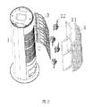
- the air conditioning filter structure comprises: a housing 1 having an air inlet 2 formed therein; and a first filter 4 movably disposed at the air inlet 2 corresponding position; the driving device 12 is connected with the first filter 4, the driving device 12 drives the first filter 4 to switch between an open position and a closed position, wherein the first filter 4 is allowed to open when in the open position
- the air inlet 2 passes through the first filter 4 when the air inlet 2 enters the air inlet 2 in the closed position.
- the first filter 4 is a high-efficiency filter for filtering fine particles in the air such as PM2.5.
- the first filter 4 is placed in the closed position by the driving device 12. At this time, the air is circulated through the first filter 4 to achieve the purpose of purifying the air.
- the first filter 4 in this patent application is a purification device for air purification.
- the purification device partially or completely covers the air inlet of the air conditioner, the amount of air intake at the air inlet of the air conditioner is lowered.
- the embodiment of the invention provides a method and a device for controlling the rotational speed of a vertical air conditioner fan, so as to solve the problem of reducing the air intake amount at the air inlet of the air conditioner when the first filter partially or completely covers the air inlet of the air conditioner.
- a method for controlling a rotational speed of a vertical air conditioner fan wherein an air inlet of the vertical air conditioner is provided with a variable position purifying device, and the purifying device is driven by a motor A position change occurs, the method comprising: calculating a fan speed compensation value according to the position of the purifying device; and adjusting the vertical air conditioner fan speed according to the fan speed compensation value.
- the calculating the fan speed compensation value according to the position of the purifying device comprises: determining a coverage area of the air inlet by the purifying device according to a position of the purifying device, and according to the purifying device The coverage area of the air inlet determines the fan speed compensation value; or, the fan speed compensation value is determined according to the relative position between the purification device and the air inlet.
- the motor is a stepping motor, and a coverage area S f of the purifying device to the air inlet is determined according to a running step of the stepping motor, a step size, and a height of the air inlet.
- the coverage area S f of the purifying device to the air inlet is determined according to a step direction of the stepping motor, a running step, a step, and a height of the air inlet.
- determining the fan speed compensation value according to the relative position between the purifying device and the air inlet comprising: determining a fan speed compensation value according to a distance between the purifying device and the air inlet; or And determining a fan speed compensation value according to an angle between the purifying device and the air inlet.
- a device for controlling a rotational speed of a vertical air conditioner fan wherein an air inlet of the vertical air conditioner is provided with a positionally variable purifying device, and the purifying device is driven by a motor
- the device includes: a calculating unit, configured to calculate a fan speed compensation value according to the position of the cleaning device; and an adjusting unit, configured to adjust the vertical air-conditioning fan speed according to the fan speed compensation value.
- the method further includes: a determining unit, configured to determine, according to a position of the purifying device, a coverage area of the air inlet; the calculating unit is further configured to: according to the purifying device The coverage area of the tuyere determines the fan speed compensation value; or, the fan speed compensation value is determined according to the relative position between the purification device and the air inlet.
- a determining unit configured to determine, according to a position of the purifying device, a coverage area of the air inlet
- the calculating unit is further configured to: according to the purifying device The coverage area of the tuyere determines the fan speed compensation value; or, the fan speed compensation value is determined according to the relative position between the purification device and the air inlet.
- the fan speed, the target speed is the speed that the fan needs to reach after the position of the purifying device is changed.
- the motor is a stepping motor
- the determining unit is further configured to determine, according to the running step of the stepping motor, the step distance, and the height of the air inlet, the purifying device to the air inlet Covering area S f .
- the coverage area S f of the purifying device to the air inlet is determined according to a step direction of the stepping motor, a running step, a step, and a height of the air inlet.
- the calculating unit is further configured to determine a fan speed compensation value according to a distance between the purifying device and the air inlet; or, according to an angle between the purifying device and the air inlet Fan speed compensation value.
- a vertical air conditioner includes a fan, an air inlet, a purifying device disposed at the air inlet, and a motor for driving a position change of the purifying device, the vertical air conditioner further A device for controlling the rotational speed of a vertical air conditioner fan according to any of the above embodiments.
- the wind speed compensation value can be calculated according to the position of the cleaning device, and according to the calculation, The fan speed compensation value adjusts the vertical air conditioner fan speed, so that the air inlet amount at the air inlet can be compensated by increasing the fan speed.
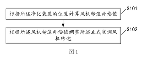
- FIG. 1 is a schematic flow chart of a method for controlling a rotational speed of a vertical air conditioner fan according to an exemplary embodiment
- FIG. 2 is a schematic structural view of an air conditioning filter structure disclosed in the prior art
- FIG. 3 is a block diagram of an apparatus for controlling the rotational speed of a vertical air conditioner fan, according to an exemplary embodiment
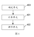
- FIG. 4 is a block diagram of an apparatus for controlling the rotational speed of a vertical air conditioner fan, according to an exemplary embodiment.
- FIG. 1 is a flow chart showing a method for controlling the rotational speed of a vertical air conditioner fan, according to an exemplary embodiment. As shown in Figure 1, it includes:
- Step S101 calculating a fan speed compensation value according to the position of the purification device.
- a control method is provided to compensate for a decrease in the amount of intake air at the air inlet of the air conditioner caused by partially or completely covering the air inlet of the air conditioner by increasing the speed of the fan.
- the purifying device is disposed at the air inlet position of the vertical air conditioner, and the purifying device is changed in position under the driving of the motor.
- the compensation value of the fan speed is calculated based on the position of the purification device.
- the initial fan speed is used as the reference value, and when the purifying device is in the closed position, the compensation value of the fan speed is positive; when the purifying device is in the open position, the compensation value of the fan speed is zero.
- the initial fan speed is determined by the air-conditioning wind speed set by the user. For example, when the user sets the air-conditioning wind speed to high speed, the fan speed is 1500r/min (rev/min); when the user sets the air-conditioning wind speed to low speed, the fan speed is 500r/min (rev / min).
- the fan speed before the change of the position of the purifying device is a reference value, and when the purifying device changes from the open position to the closed position, the compensation value of the fan speed is positive; When the device changes from the closed position to the open position, the compensation value of the fan speed is negative.
- Step S102 adjusting the rotation speed of the vertical air conditioner fan according to the fan speed compensation value.
- the fan speed compensation value is first calculated according to the position of the cleaning device, and the fan speed is adjusted according to the fan speed compensation value to maintain the cooling or heating efficiency.
- the fan speed compensation value is calculated according to the position of the purifying device, and the vertical air conditioner fan speed is adjusted according to the calculated fan speed compensation value, thereby being able to compensate for the partial or full coverage of the air conditioning air inlet by the purifying device.
- the air intake at the air inlet of the air conditioner is reduced.
- the purification device includes a sub-purification device at the upper portion and a sub-purification device at the lower portion, the drive device driving the two sub-purification devices to move in opposite directions in a vertical direction to switch between an open position and a closed position.
- the cleaning device rotates circumferentially along the vertical air conditioning housing during the switching of the cleaning device from the closed position to the open position.
- the purification device includes two sub-purification devices. During the switching of the purification device from the closed position to the open position, the two sub-purification devices rotate circumferentially in the direction away from each other along the vertical air conditioner.
- the purifying device completely covers the air inlet when in the closed position, and the purifying device can cover the air inlet to different degrees according to different air quality, for example, when the air quality is slightly better, the purifying device The device covers only one-half of the cross-sectional area of the air inlet; when the air quality is slightly worse, the purification device covers three-quarters of the cross-sectional area of the air inlet.
- the coverage area of the air inlet by the purification device is determined according to the position of the purification device, and the wind speed compensation value is determined according to the coverage area of the air inlet of the purification device or according to the relative relationship between the purification device and the air inlet.
- the position determines the fan speed compensation value.
- the fan speed compensation value is determined by formula (1):
- f' is the fan speed compensation value
- S f is the current coverage area of the air inlet of the purification device
- S is the area of the air inlet
- k is the compensation coefficient
- the target speed of the fan is determined by formula (2):
- f is the target speed of the fan
- f 0 is the initial fan speed
- the target speed is the speed that the fan must reach when part or all of the air inlet is covered after the position of the purification device changes.
- the stepping motor is started in accordance with the change in position from the open position purification apparatus reaches the operating position of the current number of steps, the step height from the inlet and the stepping motor is determined coverage area S f purifying apparatus of the air inlet .
- the coverage area of the purification device for the air inlet may vary from large to small or from small to large.
- the compensation value of the fan speed is calculated as the reference value when the position of the purification device changes, if the coverage area of the air inlet is increased from small to large, the air intake at the air inlet becomes smaller, which is compensation.
- the air volume needs to increase the fan speed.
- the compensation value of the fan speed is positive; if the coverage area of the air inlet is reduced from large to small, the air intake at the air inlet becomes larger, and the fan speed can be reduced.
- the compensation value of the fan speed is negative at this time.
- the fan speed compensation value is determined by formula (3):
- ⁇ S is a positive value.
- S is the area of the air inlet
- k is the compensation coefficient.
- the coverage area of the air inlet by the purifying device is determined according to the stepping direction of the stepping motor, the number of running steps, the stepping distance of the stepping motor, and the height of the air inlet.
- the step direction is positive, and finally the obtained f' is a positive value;
- the step when the stepping motor drives the purification device from the closed position to the open position The forward direction is negative, and the resulting f' is a negative value.
- f is the target rotational speed of the fan
- f 1 is the rotational speed of the fan before the position of the purification device changes
- the target rotational speed is the rotational speed of the fan after the position of the purification device is changed.
- the coverage area of the air inlet is different by the purification device, and the wind resistance at the air inlet is increased when part or all of the purification device covers the air inlet of the air conditioner, thereby causing the air intake at the air inlet of the air conditioner to decrease, according to the purification.
- the device determines the fan speed compensation value for the coverage area of the air inlet, or determines the fan speed compensation value according to the relative position between the purification device and the air inlet, and then adjusts the fan speed according to the fan speed compensation value, by increasing the fan speed
- the air intake at the air inlet is compensated, and the coverage area of the air inlet is reduced when the air inlet of the air purifying device is increased, and the fan speed is reduced to save energy.
- the purging device translates radially outward of the vertical air conditioning housing during the process of switching the cleaning device from the closed position to the open position.
- the purifying device when the purifying device is changed in position from the closed position, the purifying device does not cause coverage of the air inlet, but it still blocks the wind in the direction perpendicular to the direction of the air inlet, resulting in a decrease in the air volume of the air inlet.
- the greater the distance between the purification device and the air inlet the larger the air volume from the air inlet.
- the fan speed compensation value is determined according to the distance between the purification device and the air inlet. When the distance between the purifying device and the air inlet is larger, the fan speed compensation value is smaller; when the distance between the purifying device and the air inlet is smaller, the fan speed compensation value is larger.
- the purification device includes two sub-purification devices arranged side by side, one side of which is pivotally disposed relative to the vertical air conditioner.
- the drive device drives each of the sub-purification devices to rotate about a side of each of the sub-purification devices away from the vertical air conditioner.
- the adjacent sides of the two sub-purification devices are respectively provided with a rotating shaft, and the driving device can be rotated by the rotating shaft driving sub-purification device, so that the two sub-purifying devices are rotated, and when in the open position, the sub-purifying device and There is an angle between the air inlets. When the angle is larger, the air volume of the air inlet is larger.
- the fan speed compensation value is determined according to the distance between the purification device and the air inlet.
- the compensation value of the fan speed is smaller; when the angle between the purifying device and the air inlet is smaller, the compensation value of the fan speed is smaller.
- the distance or angle between the purifying device and the air inlet is different, and the air volume of the air inlet is different, and the wind speed compensation value is determined according to the distance between the purifying device and the air inlet, or according to the between the purifying device and the air inlet.
- the angle of the fan determines the compensation value of the fan speed, and then adjusts the fan speed according to the fan speed compensation value, and compensates the air intake at the air inlet by increasing the fan speed.
- FIG. 6 is a block diagram of an apparatus for controlling the rotational speed of a vertical air conditioner fan, according to an exemplary embodiment. As shown in FIG. 6, the calculation unit 401 and the adjustment unit 402 are included.
- a calculating unit 401 configured to calculate a fan speed compensation value according to the position of the purifying device
- the adjusting unit 402 is configured to adjust the vertical air-conditioning fan speed according to the fan speed compensation value.
- the calculating unit calculates the fan speed compensation value according to the position of the purifying device, and the adjusting unit adjusts the vertical air-conditioning fan speed according to the fan speed compensation value calculated by the calculating unit, and the purifying device partially or completely covers the air-conditioning air inlet.
- the resistance of the air inlet at the large air inlet causes the air intake at the air inlet of the air conditioner to decrease, and the air intake at the air inlet is compensated by increasing the speed of the fan.
- the method further includes: a determining unit 403, configured to determine a coverage area of the air purifying port of the purifying device according to a location of the purifying device.
- the calculating unit 401 is further configured to determine a fan speed compensation value according to the coverage area of the air inlet by the purifying device determined by the determining unit 403.
- the calculating unit 401 is further configured to determine a fan speed compensation value according to a relative position between the purifying device and the air inlet determined by the determining unit 403.
- the calculating unit 401 is further configured to determine the fan speed compensation value by using formula (1).
- the fan speed when the purifying device is in the open position is used as a reference value.
- the calculating unit 401 is further configured to determine the target rotational speed of the fan by using formula (2).
- the determining unit 403 is further configured to determine the purifying device according to the stepping motor, the number of running steps of the cleaning device starting from the open position and reaching the current position, the stepping distance of the stepping motor, and the height of the air inlet.
- the coverage area S f of the air inlet is further configured to determine the purifying device according to the stepping motor, the number of running steps of the cleaning device starting from the open position and reaching the current position, the stepping distance of the stepping motor, and the height of the air inlet.
- the coverage area of the air inlet corresponding to the purification device described in the foregoing method embodiment may be changed from large to small or from small to large.
- the calculating unit 401 determines the fan speed compensation value by the formula (3).
- the determining unit 403 determines the coverage area of the air inlet by the purifying device according to the stepping direction of the stepping motor, the number of running steps, the stepping distance of the stepping motor, and the height of the air inlet. For example, when the stepping motor drives the cleaning device from the open position to the closed position, the step direction is positive, and finally the obtained f' is a positive value; the step when the stepping motor drives the purification device from the closed position to the open position The forward direction is negative, and the resulting f" is a negative value.
- the target speed of the fan is determined by equation (4).
- the coverage area of the air inlet of the purification device is different, and when the purification device partially or completely covers the air inlet of the air conditioner, the resistance of the air inlet at the air inlet is increased, and the air intake at the air inlet of the air conditioner is reduced.
- the calculating unit determines the fan speed compensation value according to the coverage area of the air inlet of the purifying device, or determines the fan speed compensation value according to the relative position between the purifying device and the air inlet, and the adjusting unit adjusts the fan speed according to the fan speed compensation value. By increasing the fan speed, the amount of air entering the air inlet is compensated. When the coverage area of the air inlet is reduced, and the air volume at the air inlet is increased, the fan speed is reduced to save energy.
- the calculation unit 402 is further configured to determine the fan speed compensation according to the distance between the purification device and the air inlet, corresponding to the case where the distance or the angle of the cleaning device is different from the air inlet. Value, or determine the fan speed compensation value based on the angle between the purification device and the air inlet.
- the distance or angle between the purification device and the air inlet is different, and the air volume of the air inlet is different.
- the calculation unit determines the wind speed compensation value according to the distance between the purification device and the air inlet, or according to the cleaning device and the air inlet.
- the angle between the fans determines the fan speed compensation value, and the adjustment unit adjusts the fan speed according to the fan speed compensation value, and compensates the air inlet amount at the air inlet by increasing the fan speed.
- a vertical air conditioner including a fan, an air inlet, a purifying device disposed at the air inlet, and a motor for driving a position change of the purifying device, wherein the vertical air conditioner further includes the above Device for controlling the rotational speed of a vertical air conditioner fan according to an embodiment
Landscapes
- Engineering & Computer Science (AREA)
- Chemical & Material Sciences (AREA)
- Combustion & Propulsion (AREA)
- Mechanical Engineering (AREA)
- General Engineering & Computer Science (AREA)
- Air Conditioning Control Device (AREA)
Abstract
一种用于控制立式空调风机转速的方法,该立式空调的进风口设有位置可变的净化装置,该净化装置在电机驱动下发生位置变化,该用于控制立式空调风机转速的方法包括:根据该净化装置的位置计算风机转速补偿值(S101);根据该风机转速补偿值调整该立式空调风机转速(S102)。还公开了一种用于控制立式空调风机转速的装置和一种立式空调。
Description
本申请基于申请号为201710602571.6、申请日为2017年7月21日的中国专利申请提出,并要求该中国专利申请的优先权,该中国专利申请的全部内容在此引入本申请作为参考。
本发明涉及空调技术领域,特别涉及一种用于控制立式空调风机转速的方法及装置和一种立式空调。
当前,越来越多的空调具有空气净化功能。中国专利申请CN106594885A公开一种空调过滤结构,如图2所示,该空调过滤结构包括:壳体1,壳体1上形成有进风口2;第一过滤器4,活动地设置在与进风口2对应的位置处;驱动装置12,与第一过滤器4连接,驱动装置12驱动第一过滤器4在打开位置和关闭位置之间切换,其中,在打开位置时第一过滤器4让开进风口2,在关闭位置时进入进风口2的气流经过第一过滤器4。其中,第一过滤器4是高效过滤器,用于过滤空气中的细小颗粒,如PM2.5等。当用户环境较多灰尘时,通过驱动装置12使第一过滤器4处于关闭位置,此时,空气循环经第一过滤器4除尘,达到净化空气的目的。
可以看出,该专利申请中的第一过滤器4为一种用于空气净化的净化装置。但是,在该专利申请中当净化装置部分或全部覆盖空调进风口时,会降低空调进风口处的进风量。
发明内容
本发明实施例提供了一种用于控制立式空调风机转速的方法及装置,以解决现有技术中第一过滤器部分或全部覆盖空调进风口时降低空调进风口处的进风量的问题。为了对披露的实施例的一些方面有一个基本的理解,下面给出了简单的概括。该概括部分不是泛泛评述,也不是要确定关键/重要组成元素或描绘这些实施例的保护范围。其唯一目的是用简单的形式呈现一些概念,以此作为后面的详细说明的序言。
根据本发明实施例的第一方面,提供了一种用于控制立式空调风机转速的方法,所述立式空调的进风口设有位置可变的净化装置,所述净化装置在电机驱动下发生位置变化,所述方法包括:根据所述净化装置的位置计算风机转速补偿值;根据所述风机转速补偿值调整所述立式空调风机转速。
可选地,所述根据所述净化装置的位置计算风机转速补偿值,包括:根据所述净 化装置的位置确定所述净化装置对所述进风口的覆盖面积,并根据所述净化装置对所述进风口的覆盖面积确定风机转速补偿值;或者,根据所述净化装置与所述进风口之间的相对位置确定风机转速补偿值。
可选地,通过计算f’=k×S
f/S确定风机转速补偿值f’;其中,S
f为所述净化装置对所述进风口的当前覆盖面积,S为所述进风口的面积,k为补偿系数。
可选地,通过计算f=f
0+f’确定风机的目标转速;其中,f为风机的目标转速,f
0为初始风机转速,目标转速即所述净化装置位置改变后部分或全部覆盖所述进风口时风机所要达到的转速。
可选地,通过计算f’=k×(S
f-S
f’)/S确定风机转速补偿值f’;其中,S
f为所述净化装置对所述进风口的当前覆盖面积,S
f’为所述净化装置在位置变化前对所述进风口的覆盖面积,S为所述进风口的面积,k为补偿系数。
可选地,通过计算f=f
1+f’确定风机的目标转速;其中,f为风机的目标转速,f
1为在所述净化装置的位置发生变化前的风机转速,目标转速即所述净化装置位置改变后风机所要达到的转速。
可选地,所述电机为步进电机,根据所述步进电机的运行步数、步距和所述进风口的高度确定所述净化装置对所述进风口的覆盖面积S
f。
可选地,根据所述步进电机的步进方向、运行步数、步距和所述进风口的高度确定所述净化装置对所述进风口的覆盖面积S
f。
可选地,所述根据所述净化装置与所述进风口之间的相对位置确定风机转速补偿值,包括:根据所述净化装置与所述进风口之间的距离确定风机转速补偿值;或者,根据所述净化装置与所述进风口之间的夹角确定风机转速补偿值。
可选地,所述净化装置与所述进风口之间的距离越远,所述风机转速的补偿值越小;所述净化装置与所述进风口之间的夹角越大,所述风机转速的补偿值越小。
根据本发明实施例的第二方面,提供一种用于控制立式空调风机转速的装置,所述立式空调的进风口设有位置可变的净化装置,所述净化装置在电机驱动下发生位置变化,所述装置包括:计算单元,用于根据所述净化装置的位置计算风机转速补偿值;调节单元,用于根据所述风机转速补偿值调整所述立式空调风机转速。
可选地,还包括:确定单元,用于根据所述净化装置的位置确定所述净化装置对所述进风口的覆盖面积;所述计算单元,还用于根据所述净化装置对所述进风口的覆盖面积确定风机转速补偿值;或者,根据所述净化装置与所述进风口之间的相对位置确定风机转速补偿值。
可选地,所述计算单元,还用于通过计算f’=k×S
f/S确定风机转速补偿值f’;其中,S
f为所述净化装置对所述进风口的当前覆盖面积,S为所述进风口的面积,k为补偿系数。
可选地,所述计算单元,还用于通过计算f=f
0+f’确定风机的目标转速;其中, f为风机的目标转速,f
0为初始风机转速,目标转速即所述净化装置位置改变后部分或全部覆盖所述进风口时风机所要达到的转速。
可选地,所述计算单元,还用于通过计算f’=k×(S
f-S
f’)/S确定风机转速补偿值f’;其中,S
f为所述净化装置对所述进风口的当前覆盖面积,S
f’为所述净化装置在位置变化前对所述进风口的覆盖面积,S为所述进风口的面积,k为补偿系数。
可选地,所述计算单元,还用于通过计算f=f
1+f’确定风机的目标转速;其中,f为风机的目标转速,f
1为在所述净化装置的位置发生变化前的风机转速,目标转速即所述净化装置位置改变后风机所要达到的转速。
可选地,所述电机为步进电机,所述确定单元还用于根据所述步进电机的运行步数、步距和所述进风口的高度确定所述净化装置对所述进风口的覆盖面积S
f。
可选地,根据所述步进电机的步进方向、运行步数、步距和所述进风口的高度确定所述净化装置对所述进风口的覆盖面积S
f。
可选地,所述计算单元,还用于根据所述净化装置与所述进风口之间的距离确定风机转速补偿值;或者,根据所述净化装置与所述进风口之间的夹角确定风机转速补偿值。
可选地,所述净化装置与所述进风口之间的距离越远,所述风机转速的补偿值越小;所述净化装置与所述进风口之间的夹角越大,所述风机转速的补偿值越小。
根据本发明实施例的第三方面,提供一种立式空调,包括风机、进风口、设置在所述进风口的净化装置和驱动所述净化装置发生位置变化的电机,所述立式空调还包括上述任一项实施例所述的用于控制立式空调风机转速的装置。
本发明实施例提供的技术方案可以包括以下有益效果:
净化装置部分或全部覆盖空调进风口时会增大进风口处的风阻,造成空调进风口处的进风量降低,采用上述实施例可以根据净化装置的位置计算风机转速补偿值,并根据计算得出的风机转速补偿值调整立式空调风机转速,从而能够通过提高风机转速的方式来补偿进风口处的进风量。
应当理解的是,以上的一般描述和后文的细节描述仅是示例性和解释性的,并不能限制本发明。
此处的附图被并入说明书中并构成本说明书的一部分,示出了符合本发明的实施例,并与说明书一起用于解释本发明的原理。
图1是根据一示例性实施例示出的一种用于控制立式空调风机转速的方法的流程示意图;
图2是现有技术公开的一种空调过滤结构的结构示意图;
图3是根据一示例性实施例示出的一种用于控制立式空调风机转速的装置的框 图;
图4是根据一示例性实施例示出的一种用于控制立式空调风机转速的装置的框图。
以下描述和附图充分地示出本发明的具体实施方案,以使本领域的技术人员能够实践它们。实施例仅代表可能的变化。除非明确要求,否则单独的部件和功能是可选的,并且操作的顺序可以变化。一些实施方案的部分和特征可以被包括在或替换其他实施方案的部分和特征。本发明的实施方案的范围包括权利要求书的整个范围,以及权利要求书的所有可获得的等同物。在本文中,各实施方案可以被单独地或总地用术语“发明”来表示,这仅仅是为了方便,并且如果事实上公开了超过一个的发明,不是要自动地限制该应用的范围为任何单个发明或发明构思。本文中,诸如第一和第二等之类的关系术语仅仅用于将一个实体或者操作与另一个实体或操作区分开来,而不要求或者暗示这些实体或操作之间存在任何实际的关系或者顺序。而且,术语“包括”、“包含”或者其任何其他变体意在涵盖非排他性的包含,从而使得包括一系列要素的过程、方法或者设备不仅包括那些要素,而且还包括没有明确列出的其他要素本文中各个实施例采用递进的方式描述,每个实施例重点说明的都是与其他实施例的不同之处,各个实施例之间相同相似部分互相参见即可。对于实施例公开的结构、产品等而言,由于其与实施例公开的部分相对应,所以描述的比较简单,相关之处参见方法部分说明即可。
图1是根据一示例性实施例示出的一种用于控制立式空调风机转速的方法的流程图。如图1所示,包括:
步骤S101,根据所述净化装置的位置计算风机转速补偿值。
在本实施例中,提供了一种控制方法,通过提高风机转速的方式来补偿因净化装置部分或全部覆盖空调进风口时造成的空调进风口处的进风量降低。其中,净化装置设置在立式空调的进风口位置,净化装置在电机驱动下发生位置变化。
首先,根据净化装置的位置来计算风机转速的补偿值。风机转速的补偿值计算有多种方式。第一种可选地实施方式,以初始风机转速为基准值,则当净化装置处于关闭位置时,风机转速的补偿值为正值;当净化装置处于打开位置时,风机转速的补偿值为零。需要说明的是,初始风机转速由用户设置的空调风速决定,如:用户设定空调风速为高速时,风机转速为1500r/min(转/分钟);用户设定空调风速低速时,风机转速为500r/min(转/分钟)。
第二种可选地实施方式,以在净化装置的位置发生变化前的风机转速为基准值,则当净化装置由打开位置变化到关闭位置时,风机转速的补偿值为正值;则当净化装置由关闭位置变化到打开位置时,风机转速的补偿值为负值。
步骤S102,根据所述风机转速补偿值调整所述立式空调风机转速。
本实施例提供的空调制方法,在净化装置位置发生变化时,首先根据净化装置的位置计算风机转速补偿值,进而根据风机转速补偿值来调节风机的转速以保持制冷或制热效率。
在本实施例中,根据净化装置的位置计算风机转速补偿值,并根据计算得出的风机转速补偿值调整立式空调风机转速,从而能够补偿因净化装置部分或全部覆盖空调进风口所造成的空调进风口处的进风量降低。
现有技术中公开了多种过滤结构。在一些实施例中,净化装置包括位于上部的子净化装置和位于下部的子净化装置,驱动装置驱动两个子净化装置在竖直方向上沿相反方向运动以在打开位置和关闭位置之间切换。
在另一些实施例中,在净化装置由关闭位置切换至打开位置的过程中,净化装置沿着立式空调壳体周向转动。
在另一些实施例中,净化装置包括两个子净化装置。在净化装置由关闭位置切换至打开位置的过程中,两个子净化装置向相互远离的方向沿立式空调周向转动。
前述任一实施例所述的过滤结构中,净化装置在关闭位置时会完全覆盖进风口,根据空气质量不同,净化装置可以不同程度的覆盖进风口,例如:当空气质量稍好一些时,净化装置只覆盖进风口截面面积的二分之一;当空气质量稍差一些时,净化装置覆盖进风口截面面积的四分之三。
此时,确定风机转速补偿值时根据净化装置的位置确定净化装置对进风口的覆盖面积,并根据净化装置对进风口的覆盖面积确定风机转速补偿值或者根据净化装置与进风口之间的相对位置确定风机转速补偿值。具体的,通过公式(1)确定风机转速补偿值:
f’=k×S
f/S (1)
其中,f’为风机转速补偿值,S
f为净化装置对进风口的当前覆盖面积,S为进风口的面积,k为补偿系数。
当风机转速的补偿值计算以净化装置处于打开位置时的风机转速为基准值时,通过公式(2)确定风机的目标转速:
f=f
0+f’ (2)
其中,f为风机的目标转速,f
0为初始风机转速,目标转速即净化装置位置改变后部分或全部覆盖进风口时风机所要达到的转速。
在计算f’时,根据步进电机在净化装置由打开位置开始进行位置变化到达当前位置的运行步数、步进电机的步距和进风口的高度确定净化装置对进风口的覆盖面积S
f。
在一些实施例中,净化装置对进风口的覆盖面积会由大变小或者由小变大。当风机转速的补偿值计算以在净化装置的位置发生变化时的风机转速为基准值时,若净化 装置对进风口的覆盖面积由小变大,进风口处的进风量变小,为补偿进风量,需要增大风机转速,此时风机转速的补偿值为正值;若净化装置对进风口的覆盖面积由大变小,则进风口处的进风量变大,此时可减小风机转速以节省功耗,此时风机转速的补偿值为负值。具体的,通过公式(3)确定风机转速补偿值:
f’=k×△S/S (3)
其中,f’为风机转速补偿值,△S为净化装置对进风口的覆盖面积的变化值,其中,△S=S
f-S
f,S
f为净化装置对进风口的当前覆盖面积,S
f’为净化装置在位置变化前对进风口的覆盖面积。当覆盖面积由小变大时,△S为正值,当覆盖面积由大变小时,△S为负值,S为进风口的面积,k为补偿系数。
此时,根据步进电机的步进方向、运行步数、步进电机的步距和进风口的高度确定净化装置对进风口的覆盖面积。如:以步进电机带动净化装置由打开位置到关闭位置时的步进方向为正向,最终得出的f’为正值;以步进电机带动净化装置由关闭位置到打开位置时的步进方向为负向,最终得出的f’为负值。
通过公式(4)确定风机的目标转速:
f=f
1+f’ (4)
其中,f为风机的目标转速,f
1为在净化装置的位置发生变化前的风机转速,目标转速即净化装置位置改变后风机所要达到的转速。
在本实施中,根据空气质量的不同,净化装置对进风口的覆盖面积不同,净化装置部分或全部覆盖空调进风口时增大进风口处风阻,造成空调进风口处的进风量降低,根据净化装置对进风口的覆盖面积确定风机转速补偿值,或根据净化装置与进风口之间的相对位置确定风机转速补偿值,进而根据风机转速补偿值对风机转速进行调节,通过提高风机转速的方式来补偿进风口处的进风量,在净化装置对进风口的覆盖面积减小,空调进风口处的进风量增大时,降低风机转速以节省能耗。
现有技术中公开的多种过滤结构,在一些实施例中,在净化装置由关闭位置切换至打开位置的过程中,净化装置沿着立式空调壳体的径向向外平移。
显然,当净化装置由关闭位置发生位置改变时,则净化装置并不会对进风口造成覆盖,但其仍阻挡了与进风口方向垂直方向的风,导致进风口的风量减小。随着净化装置的平移,净化装置与进风口之间的距离越大,进风口出的风量越大。
此时,根据净化装置与进风口之间的距离确定风机转速补偿值。当净化装置与进风口之间的距离越大,风机转速补偿值越小;当净化装置与进风口之间的距离越小,风机转速补偿值越大。
在另一些实施例中,净化装置包括两个并排设置的子净化装置,两个子净化装置的一侧相对立式空调可枢转地设置。在净化装置由关闭位置切换至打开位置的过程中,驱动装置驱动每个子净化装置绕该每个子净化装置的一侧向远离立式空调的方向转动。
更优选地,两个子净化装置的相邻的一侧分别设置有一个转轴,驱动装置可通过转轴驱动子净化装置转动,从而使这两个子净化装置发生转动,处于打开位置时,子净化装置与进风口之间有一个夹角。当所述夹角越大,进风口的风量越大。
此时,根据净化装置与进风口之间的距离确定风机转速补偿值。当净化装置与进风口之间的夹角越大,所述风机转速的补偿值越小;当净化装置与进风口之间的夹角越小,所述风机转速的补偿值越小。
在本实施中,净化装置与进风口的距离或夹角不同,进风口的风量大小不同,根据净化装置与进风口之间的距离确定风机转速补偿值,或根据净化装置与进风口之间的夹角确定风机转速补偿值,进而根据风机转速补偿值对风机转速进行调节,通过提高风机转速的方式来补偿进风口处的进风量。
下述为本公开装置实施例,可以用于执行本公开方法实施例。
图6是根据一示例性实施例示出的一种用于控制立式空调风机转速的装置的框图。如图6所示,包括:计算单元401和调节单元402。
计算单元401,用于根据所述净化装置的位置计算风机转速补偿值;
调节单元402,用于根据所述风机转速补偿值调整所述立式空调风机转速。
在本实施例中,计算单元根据净化装置的位置计算风机转速补偿值,调整单元根据计算单元计算得出的风机转速补偿值调整立式空调风机转速,净化装置部分或全部覆盖空调进风口时增大进风口处进风的阻力,造成空调进风口处的进风量降低,通过提高风机转速的方式来补偿进风口处的进风量。
在一些实施例中,还包括:确定单元403,用于根据所述净化装置的位置确定所述净化装置对所述进风口的覆盖面积。
对应前述方法实施例所述的根据净化装置的位置的来计算风机转速的补偿值第一种可选地实施方式。计算单元401,还用于根据确定单元403确定的所述净化装置对所述进风口的覆盖面积确定风机转速补偿值。
对应前述方法实施例所述的根据净化装置的位置的来计算风机转速的补偿值第二种可选地实施方式。计算单元401,还用于根据确定单元403确定的所述净化装置与所述进风口之间的相对位置确定风机转速补偿值。
在前述任一实施例中,计算单元401,还用于通过公式(1)确定风机转速补偿值。
对应前述方法实施例所述的当风机转速的补偿值计算以净化装置处于打开位置时的风机转速为基准值时。计算单元401,还用于通过公式(2)确定风机的目标转速。
在计算f’时,确定单元403,还用于根据步进电机在净化装置由打开位置开始进行位置变化并到达当前位置的运行步数、步进电机的步距和进风口的高度确定净化装置对进风口的覆盖面积S
f。
对应前述方法实施例所述的净化装置对进风口的覆盖面积会由大变小或者由小变大。当风机转速的补偿值计算以在净化装置的位置发生变化时的风机转速为基准值 时,计算单元401,通过公式(3)确定风机转速补偿值。
此时,确定单元403,根据步进电机的步进方向、运行步数、步进电机的步距和进风口的高度确定净化装置对进风口的覆盖面积。如:以步进电机带动净化装置由打开位置到关闭位置时的步进方向为正向,最终得出的f’为正值;以步进电机带动净化装置由关闭位置到打开位置时的步进方向为负向,最终得出的f”为负值。
通过公式(4)确定风机的目标转速。
在本实施中,根据空气质量的不同,净化装置对进风口的覆盖面积不同,净化装置部分或全部覆盖空调进风口时增大进风口处进风的阻力,造成空调进风口处的进风量降低,计算单元根据净化装置对进风口的覆盖面积确定风机转速补偿值,或根据净化装置与进风口之间的相对位置确定风机转速补偿值,进而调节单元根据风机转速补偿值对风机转速进行调节,通过提高风机转速的方式来补偿进风口处的进风量,在净化装置对进风口的覆盖面积减小,空调进风口处的进风量增大时,降低风机转速以节省能耗。
在另一些实施例中,对应前述方法实施例所述的净化装置与进风口的距离或夹角不同的情况,计算单元402,还用于根据净化装置与进风口之间的距离确定风机转速补偿值,或根据净化装置与进风口之间的夹角确定风机转速补偿值。
净化装置与进风口之间的距离越远,风机转速的补偿值越小,净化装置与进风口之间的夹角越大,风机转速的补偿值越小。
在本实施中,净化装置与进风口的距离或夹角不同,进风口的风量大小不同,计算单元根据净化装置与进风口之间的距离确定风机转速补偿值,或根据净化装置与进风口之间的夹角确定风机转速补偿值,进而调节单元根据风机转速补偿值对风机转速进行调节,通过提高风机转速的方式来补偿进风口处的进风量。
在另一些实施例中,提供一种立式空调,包括风机、进风口、设置在所述进风口的净化装置和驱动所述净化装置发生位置变化的电机,所述立式空调还包括上述任一项实施例所述的用于控制立式空调风机转速的装置
应当理解的是,本发明并不局限于上面已经描述并在附图中示出的流程及结构,并且可以在不脱离其范围进行各种修改和改变。本发明的范围仅由所附的权利要求来限制。
Claims (11)
- 一种用于控制立式空调风机转速的方法,所述立式空调的进风口设有位置可变的净化装置,所述净化装置在电机驱动下发生位置变化,其特征在于,所述方法包括:根据所述净化装置的位置计算风机转速补偿值;根据所述风机转速补偿值调整所述立式空调风机转速。
- 如权利要求1所述的方法,其特征在于,所述根据所述净化装置的位置计算风机转速补偿值,包括:根据所述净化装置的位置确定所述净化装置对所述进风口的覆盖面积,并根据所述净化装置对所述进风口的覆盖面积确定风机转速补偿值;或者,根据所述净化装置与所述进风口之间的相对位置确定风机转速补偿值。
- 如权利要求2所述的方法,其特征在于,所述电机为步进电机,根据所述步进电机的运行步数、步距和所述进风口的高度确定所述净化装置对所述进风口的覆盖面积。
- 如权利要求2所述的方法,其特征在于,所述根据所述净化装置与所述进风口之间的相对位置确定风机转速补偿值,包括:根据所述净化装置与所述进风口之间的距离确定风机转速补偿值;或者,根据所述净化装置与所述进风口之间的夹角确定风机转速补偿值。
- 如权利要求4所述的方法,其特征在于,所述净化装置与所述进风口之间的距离越远,所述风机转速的补偿值越小;所述净化装置与所述进风口之间的夹角越大,所述风机转速的补偿值越小。
- 一种用于控制立式空调风机转速的装置,所述立式空调的进风口设有位置可变的净化装置,所述净化装置在电机驱动下发生位置变化,其特征在于,所述装置包括:计算单元,用于根据所述净化装置的位置计算风机转速补偿值;调节单元,用于根据所述风机转速补偿值调整所述立式空调风机转速。
- 如权利要求6所述的装置,其特征在于,还包括:确定单元,用于根据所述净化装置的位置确定所述净化装置对所述进风口的覆盖面积;所述计算单元,还用于根据所述净化装置对所述进风口的覆盖面积确定风机转速补偿值;或者,根据所述净化装置与所述进风口之间的相对位置确定风机转速补偿值。
- 如权利要求7所述的装置,其特征在于,所述电机为步进电机,所述确定单元还用于根据所述步进电机的运行步数、步距和所述进风口的高度确定所述净化装置对所述进风口的覆盖面积Sf。
- 如权利要求7所述的装置,其特征在于,所述计算单元,还用于根据所述净化装置与所述进风口之间的距离确定风机转速补偿值;或者,根据所述净化装置与所述进风口之间的夹角确定风机转速补偿值。
- 如权利要求9所述的装置,其特征在于,所述净化装置与所述进风口之间的距离越远,所述风机转速的补偿值越小;所述净化装置与所述进风口之间的夹角越大,所述风机转速的补偿值越小。
- 一种立式空调,包括风机、进风口、设置在所述进风口的净化装置和驱动所述净化装置发生位置变化的电机,其特征在于,还包括如权利要求6至10任一项所述的用于控制立式空调风机转速的装置。
Applications Claiming Priority (2)
| Application Number | Priority Date | Filing Date | Title |
|---|---|---|---|
| CN201710602571.6A CN107525214A (zh) | 2017-07-21 | 2017-07-21 | 用于控制立式空调风机转速的方法及装置、立式空调 |
| CN201710602571.6 | 2017-07-21 |
Publications (1)
| Publication Number | Publication Date |
|---|---|
| WO2019015330A1 true WO2019015330A1 (zh) | 2019-01-24 |
Family
ID=60680175
Family Applications (1)
| Application Number | Title | Priority Date | Filing Date |
|---|---|---|---|
| PCT/CN2018/077919 Ceased WO2019015330A1 (zh) | 2017-07-21 | 2018-03-02 | 用于控制立式空调风机转速的方法及装置、立式空调 |
Country Status (2)
| Country | Link |
|---|---|
| CN (1) | CN107525214A (zh) |
| WO (1) | WO2019015330A1 (zh) |
Families Citing this family (3)
| Publication number | Priority date | Publication date | Assignee | Title |
|---|---|---|---|---|
| CN107525214A (zh) * | 2017-07-21 | 2017-12-29 | 青岛海尔空调器有限总公司 | 用于控制立式空调风机转速的方法及装置、立式空调 |
| CN108800475A (zh) * | 2018-06-04 | 2018-11-13 | 珠海格力电器股份有限公司 | 风机转速控制方法、装置及送风设备 |
| CN111013264A (zh) * | 2018-10-09 | 2020-04-17 | 青岛海尔空调器有限总公司 | 净化装置及其控制方法 |
Citations (5)
| Publication number | Priority date | Publication date | Assignee | Title |
|---|---|---|---|---|
| CN203907777U (zh) * | 2014-05-23 | 2014-10-29 | 北京中标新亚节能工程股份有限公司 | Pm2.5空气净化设备 |
| US20150354874A1 (en) * | 2014-06-10 | 2015-12-10 | Whirlpool Corporation | Air conditioner with selective filtering for air purification |
| CN106568125A (zh) * | 2016-10-24 | 2017-04-19 | 青岛海尔空调器有限总公司 | 空调器及基于导风板和/或摆叶位置的风速控制方法 |
| CN106958908A (zh) * | 2017-02-24 | 2017-07-18 | 珀隆有限公司 | 新风系统及其风量控制方法及装置 |
| CN107525214A (zh) * | 2017-07-21 | 2017-12-29 | 青岛海尔空调器有限总公司 | 用于控制立式空调风机转速的方法及装置、立式空调 |
Family Cites Families (2)
| Publication number | Priority date | Publication date | Assignee | Title |
|---|---|---|---|---|
| CN104913387B (zh) * | 2015-05-29 | 2017-09-19 | 广东美的制冷设备有限公司 | 过滤组件和空调器 |
| CN106091291B (zh) * | 2016-07-21 | 2019-04-30 | 广东美的制冷设备有限公司 | 一种空调风量自补偿控制方法、控制系统和空调 |
-
2017
- 2017-07-21 CN CN201710602571.6A patent/CN107525214A/zh active Pending
-
2018
- 2018-03-02 WO PCT/CN2018/077919 patent/WO2019015330A1/zh not_active Ceased
Patent Citations (5)
| Publication number | Priority date | Publication date | Assignee | Title |
|---|---|---|---|---|
| CN203907777U (zh) * | 2014-05-23 | 2014-10-29 | 北京中标新亚节能工程股份有限公司 | Pm2.5空气净化设备 |
| US20150354874A1 (en) * | 2014-06-10 | 2015-12-10 | Whirlpool Corporation | Air conditioner with selective filtering for air purification |
| CN106568125A (zh) * | 2016-10-24 | 2017-04-19 | 青岛海尔空调器有限总公司 | 空调器及基于导风板和/或摆叶位置的风速控制方法 |
| CN106958908A (zh) * | 2017-02-24 | 2017-07-18 | 珀隆有限公司 | 新风系统及其风量控制方法及装置 |
| CN107525214A (zh) * | 2017-07-21 | 2017-12-29 | 青岛海尔空调器有限总公司 | 用于控制立式空调风机转速的方法及装置、立式空调 |
Also Published As
| Publication number | Publication date |
|---|---|
| CN107525214A (zh) | 2017-12-29 |
Similar Documents
| Publication | Publication Date | Title |
|---|---|---|
| CN108278662B (zh) | 空调器的控制方法和空调器 | |
| CN1110655C (zh) | 空调器的气流控制方法 | |
| CN104236011B (zh) | 恒风量的空调器及其控制方法 | |
| WO2019015330A1 (zh) | 用于控制立式空调风机转速的方法及装置、立式空调 | |
| CN103185384A (zh) | 空调器及用于空调器的湿度控制方法和装置 | |
| CN106482186A (zh) | 烟机空调及烟机空调的控制方法 | |
| CN104422023B (zh) | 空调器室内机及其控制方法 | |
| CN107525215B (zh) | 用于控制立式空调的方法及装置 | |
| CN106765890A (zh) | 用于空调控制的方法及空调 | |
| CN107514738B (zh) | 用于控制立式空调的方法及装置 | |
| CN1721776A (zh) | 空调器 | |
| WO2014042002A1 (ja) | 空調室内機 | |
| CN107621056A (zh) | 用于控制空调的方法及装置、空调 | |
| CN103047734B (zh) | 一种可线性调节室内风轮转速的空调器控制方法 | |
| CN1124460C (zh) | 空调机 | |
| CN111623493A (zh) | 空调室外机及出风控制方法 | |
| KR20080021999A (ko) | 조절가능한 여과능력을 갖는 폐열회수형 환기장치 | |
| CN206739580U (zh) | 一种可旋转的空调 | |
| CN1114801C (zh) | 空调器风向的控制方法 | |
| CN206160243U (zh) | 烟机空调 | |
| CN105953331B (zh) | 一种湿帘风机自动控制系统 | |
| CN110081567A (zh) | 空调器的扰流方法 | |
| CN205783368U (zh) | 一种空气净化装置 | |
| CN1181486A (zh) | 用于控制空调器中排放空气流量的装置及其方法 | |
| CN114636238B (zh) | 电机温升控制方法 |
Legal Events
| Date | Code | Title | Description |
|---|---|---|---|
| 121 | Ep: the epo has been informed by wipo that ep was designated in this application |
Ref document number: 18835026 Country of ref document: EP Kind code of ref document: A1 |
|
| NENP | Non-entry into the national phase |
Ref country code: DE |
|
| 122 | Ep: pct application non-entry in european phase |
Ref document number: 18835026 Country of ref document: EP Kind code of ref document: A1 |