WO2019012940A1 - Display device and display system - Google Patents
Display device and display system Download PDFInfo
- Publication number
- WO2019012940A1 WO2019012940A1 PCT/JP2018/023603 JP2018023603W WO2019012940A1 WO 2019012940 A1 WO2019012940 A1 WO 2019012940A1 JP 2018023603 W JP2018023603 W JP 2018023603W WO 2019012940 A1 WO2019012940 A1 WO 2019012940A1
- Authority
- WO
- WIPO (PCT)
- Prior art keywords
- image forming
- forming apparatus
- virtual image
- display
- state
- Prior art date
Links
Images


Classifications
-
- G—PHYSICS
- G06—COMPUTING; CALCULATING OR COUNTING
- G06F—ELECTRIC DIGITAL DATA PROCESSING
- G06F3/00—Input arrangements for transferring data to be processed into a form capable of being handled by the computer; Output arrangements for transferring data from processing unit to output unit, e.g. interface arrangements
- G06F3/01—Input arrangements or combined input and output arrangements for interaction between user and computer
- G06F3/011—Arrangements for interaction with the human body, e.g. for user immersion in virtual reality
-
- G—PHYSICS
- G06—COMPUTING; CALCULATING OR COUNTING
- G06F—ELECTRIC DIGITAL DATA PROCESSING
- G06F3/00—Input arrangements for transferring data to be processed into a form capable of being handled by the computer; Output arrangements for transferring data from processing unit to output unit, e.g. interface arrangements
- G06F3/01—Input arrangements or combined input and output arrangements for interaction between user and computer
- G06F3/017—Gesture based interaction, e.g. based on a set of recognized hand gestures
-
- G—PHYSICS
- G06—COMPUTING; CALCULATING OR COUNTING
- G06F—ELECTRIC DIGITAL DATA PROCESSING
- G06F3/00—Input arrangements for transferring data to be processed into a form capable of being handled by the computer; Output arrangements for transferring data from processing unit to output unit, e.g. interface arrangements
- G06F3/12—Digital output to print unit, e.g. line printer, chain printer
- G06F3/1201—Dedicated interfaces to print systems
- G06F3/1202—Dedicated interfaces to print systems specifically adapted to achieve a particular effect
- G06F3/1203—Improving or facilitating administration, e.g. print management
- G06F3/1207—Improving or facilitating administration, e.g. print management resulting in the user being informed about print result after a job submission
-
- G—PHYSICS
- G06—COMPUTING; CALCULATING OR COUNTING
- G06F—ELECTRIC DIGITAL DATA PROCESSING
- G06F3/00—Input arrangements for transferring data to be processed into a form capable of being handled by the computer; Output arrangements for transferring data from processing unit to output unit, e.g. interface arrangements
- G06F3/12—Digital output to print unit, e.g. line printer, chain printer
- G06F3/1201—Dedicated interfaces to print systems
- G06F3/1223—Dedicated interfaces to print systems specifically adapted to use a particular technique
- G06F3/1229—Printer resources management or printer maintenance, e.g. device status, power levels
-
- G—PHYSICS
- G06—COMPUTING; CALCULATING OR COUNTING
- G06F—ELECTRIC DIGITAL DATA PROCESSING
- G06F3/00—Input arrangements for transferring data to be processed into a form capable of being handled by the computer; Output arrangements for transferring data from processing unit to output unit, e.g. interface arrangements
- G06F3/12—Digital output to print unit, e.g. line printer, chain printer
- G06F3/1201—Dedicated interfaces to print systems
- G06F3/1223—Dedicated interfaces to print systems specifically adapted to use a particular technique
- G06F3/1237—Print job management
- G06F3/1259—Print job monitoring, e.g. job status
-
- G—PHYSICS
- G06—COMPUTING; CALCULATING OR COUNTING
- G06T—IMAGE DATA PROCESSING OR GENERATION, IN GENERAL
- G06T19/00—Manipulating 3D models or images for computer graphics
-
- G—PHYSICS
- G06—COMPUTING; CALCULATING OR COUNTING
- G06T—IMAGE DATA PROCESSING OR GENERATION, IN GENERAL
- G06T19/00—Manipulating 3D models or images for computer graphics
- G06T19/003—Navigation within 3D models or images
-
- G—PHYSICS
- G06—COMPUTING; CALCULATING OR COUNTING
- G06T—IMAGE DATA PROCESSING OR GENERATION, IN GENERAL
- G06T19/00—Manipulating 3D models or images for computer graphics
- G06T19/006—Mixed reality
-
- G—PHYSICS
- G06—COMPUTING; CALCULATING OR COUNTING
- G06T—IMAGE DATA PROCESSING OR GENERATION, IN GENERAL
- G06T7/00—Image analysis
- G06T7/70—Determining position or orientation of objects or cameras
- G06T7/73—Determining position or orientation of objects or cameras using feature-based methods
-
- G—PHYSICS
- G06—COMPUTING; CALCULATING OR COUNTING
- G06F—ELECTRIC DIGITAL DATA PROCESSING
- G06F3/00—Input arrangements for transferring data to be processed into a form capable of being handled by the computer; Output arrangements for transferring data from processing unit to output unit, e.g. interface arrangements
- G06F3/12—Digital output to print unit, e.g. line printer, chain printer
- G06F3/1201—Dedicated interfaces to print systems
- G06F3/1202—Dedicated interfaces to print systems specifically adapted to achieve a particular effect
- G06F3/121—Facilitating exception or error detection and recovery, e.g. fault, media or consumables depleted
Definitions
- the present invention relates to a display device and a display system.
- the display device of Patent Document 1 is communicably connected to the image forming apparatus, and when detecting an operation on the virtual operation panel, transmits operation information indicating the detected operation to the image forming apparatus.
- the image forming apparatus executes processing according to the operation indicated by the received operation information.
- the user in the case of describing the image forming apparatus with respect to the user of the image forming apparatus (including a purchaser of the image forming apparatus, etc.), it is preferable to have the user operate the actual apparatus. This is because by having the user operate the actual apparatus while explaining the image forming apparatus, it is possible to efficiently explain the image forming apparatus.
- Patent Document 1 the virtual operation panel is displayed on the display device, but even if the operation is performed on the virtual operation panel, the state of the actual machine is changed by the operation if the actual machine does not exist. The user can not know. Therefore, even if the display device of Patent Document 1 is used, there may be a disadvantage that the user can not fully understand the content described by the explainer.
- the present invention has been made to solve the above-mentioned problems, and it is an object of the present invention to provide a display device and a display system capable of efficiently explaining the image forming apparatus even if there is no actual machine. I assume.
- a display device controls a display unit for displaying a virtual image forming device in an overlay display on a physical space while allowing a user to visually recognize the physical space And a unit.
- the control unit receives an operation request for requesting an operation to the virtual image forming apparatus from the user, the control unit instructs the display unit to change the state of the virtual image forming apparatus to the state when the operation requested by the operation request is performed.
- a display system includes a plurality of the display devices described above, and when a display device receives an operation request, the plurality of display devices are requested for the state of the virtual image forming apparatus by the operation request. Change to the state when the operation was performed.
- the state of the virtual image forming apparatus is changed to the state when the operation requested by the operation request is performed. We can know what kind of state it will be. Therefore, when the image forming apparatus is described, the description of the image forming apparatus can be efficiently performed even if there is no actual machine.
- the description regarding the image forming apparatus can be efficiently performed.
- FIG. 1 shows the structure of the head mounted display by one Embodiment of this invention, and a display system provided with the same.
- FIG. 6 illustrates a display operation performed when the head mounted display according to an embodiment of the present invention selectively changes the state of any of a plurality of virtual image forming apparatuses.
- the HMD 1 includes a display unit 11, an imaging unit 12, an operation unit 13, an HMD control unit 14, an HMD storage unit 15, and an HMD communication unit 16. These units are mounted on a glasses-type frame.
- the display unit 11 performs display.
- the display unit 11 is disposed at a position facing the eye of the user wearing the HMD 1. Thereby, an image is displayed in front of the user's eyes.
- an optical transmission type (optical see-through type) display device that transmits external light is used as the display unit 11.
- the display unit 11 including an optical transmission type display device includes a half mirror, and reflects an image to be displayed toward the user's eye by the half mirror. At this time, external light passes through the half mirror and enters the user's eye. That is, the display unit 11 overlays and displays an image on the real space while making the user visually recognize the real space. From the user, it appears that the display image displayed by the display unit 11 is synthesized in the real space (the display image appears to overlap with the real space).
- the imaging unit 12 performs imaging.
- the imaging unit 12 includes a CCD camera and the like, and is disposed at a position where imaging in the direction of view of the user wearing the HMD 1 is possible. As a result, a landscape in front of the user's eye (an object existing in the real space that spreads in front of the user's eye) is photographed.
- a gesture operation such as moving a hand (finger) in front of the eye
- the imaging unit 12 outputs imaging data obtained by imaging.
- the operation unit 13 receives, from the user wearing the HMD 1, an operation for performing various settings regarding display and photographing by the HMD 1.
- a hardware key for receiving the operation is provided in the HMD 1.
- the portable information terminal can also function as the operation unit 13 by communicably connecting a portable information terminal owned by the user, such as a smartphone, a tablet computer, or a notebook personal computer, to the HMD 1.
- the HMD control unit 14 includes a CPU that operates based on control programs and data.
- the HMD control unit 14 executes various processes for controlling the HMD 1. For example, the HMD control unit 14 controls the display by the display unit 11 and the imaging by the imaging unit 12 respectively. Further, the HMD control unit 14 detects an operation accepted from the user by the operation unit 13 (or a portable information terminal connected to the HMD 1).
- the HMD storage unit 15 includes non-volatile memory (ROM) and volatile memory (RAM).
- the HMD storage unit 15 stores control programs and data for operating the HMD control unit 14 (CPU).
- the HMD storage unit 15 also stores data (for example, display data for displaying an image, etc.) received from the server 2 described later.
- the HMD communication unit 16 is a communication interface for communicably connecting the HMD 1 to an external device, and includes a communication circuit and the like.
- the HMD control unit 14 communicates with an external device using the HMD communication unit 16.
- the HMD 1 (HMD communication unit 16) is connected to a communication network NT such as the Internet or a LAN.
- a server 2 as an external device is connected to the communication network NT.
- the display system 100 is constructed by the HMD 1 and the server 2.
- the display system 100 may include a plurality of HMDs 1.
- the plurality of HMDs 1 are communicably connected to other HMDs 1 respectively. Communication between the HMDs 1 may be performed via the communication network NT, or communication between the HMDs 1 may be performed directly, not via the communication network NT.
- the number of HMDs 1 included in the display system 100 is not particularly limited, and may be one or more.
- the server 2 includes a server control unit 21, a server storage unit 22, and a server communication unit 23.
- the server 2 is managed by a maker or distributor of an image forming apparatus (such as a multifunction peripheral or a printer).
- a personal computer can be used as the server 2.
- the server control unit 21 includes a CPU that operates based on control programs and data.
- the server control unit 21 executes various processes for controlling the server 2.
- the server storage unit 22 includes non-volatile memory (ROM) and volatile memory (RAM).
- the server storage unit 22 stores control programs and data for operating the server control unit 21 (CPU).
- the server storage unit 22 also includes a large-capacity storage device such as an HDD.
- the server communication unit 23 is a communication interface for communicably connecting the server 2 to an external device, and includes a communication circuit and the like.
- the server control unit 21 accesses the communication network NT using the server communication unit 23, and communicates with the HMD 1 (transmits and receives data to and from the HMD 1).
- ⁇ AR display processing> (Overview) A maker or distributor of an image forming apparatus promotes sales and teaches how to use the image forming apparatus. That is, the image forming apparatus will be described.
- the HMD 1 is provided to the prospective purchaser and the learner (purchaser). Purchasers and trainees should wear the HMD1. In other words, the purchaser and the trainee become the users of the HMD 1.
- the sales promotion and training of the image forming apparatus are performed using AR (Augmented Reality) technology without using a real image forming apparatus (actual machine).
- Display data of a virtual image forming apparatus (AR image to be overlaid and displayed on the real space) is created in advance to perform sales promotion and training using AR technology.
- the device states of the actual device are classified into a plurality of pieces, and a plurality of display data respectively corresponding to the plurality of device states are included in the display data information DD.
- the plurality of display data is associated with any of a plurality of operation information to be described later.
- identification information indicating the model of the corresponding actual device is attached to the plurality of display data.
- Display data information DD including a plurality of display data for one model is stored in the database DB.
- the database DB is stored in the server storage unit 22.
- display data of the virtual image forming apparatus is created for each model. Then, a plurality of display data information DD respectively corresponding to a plurality of models is stored in the database DB. In the following description, it is assumed that there are a plurality of models that can be targets for sales promotion and training.
- an AR marker corresponds to a "reference marker".
- QR code registered trademark
- the AR marker may be printed on a recording medium (card or the like) and the recording medium may be arranged in the venue.
- the person who executes the sales promotion and the training instructs the user who wears the HMD 1 to direct the gaze toward the AR marker.
- the imaging unit 12 is photographing. Therefore, the AR marker is photographed by the imaging unit 12.
- the HMD control unit 14 When the imaging unit 12 captures an AR marker, the HMD control unit 14 performs processing related to sales promotion and training (processing to support sales promotion and training). In other words, the HMD control unit 14 performs AR display processing to display the virtual image forming apparatus using the AR technology.
- the imaging unit 12 captures an AR marker at the start of the flowchart shown in FIG. Then, when the HMD control unit 14 detects an AR marker from the imaging data captured by the imaging unit 12, the flowchart shown in FIG. 2 starts.
- step S1 the HMD control unit 14 recognizes various information embedded in the AR marker.
- identification information indicating a model corresponding to the virtual image forming apparatus to be displayed is embedded. That is, here, the HMD control unit 14 recognizes the identification information.
- step S2 the HMD control unit 14 transmits a transmission request to the server 2 using the HMD communication unit 16 in order to obtain display data of the virtual image forming apparatus.
- the transmission request to the server 2 includes the identification information recognized in the process of step S1.
- the server 2 having received the transmission request (including the identification information) extracts basic display data from the display data information DD (information including a plurality of display data for one model) corresponding to the model indicated by the received identification information. . Then, the server 2 transmits the basic display data to the HMD 1.
- a state in which a real machine is executing a job (a state in which a sheet is conveyed and discharged)
- Display data for displaying in a virtual manner a display for virtually displaying a state in which a sheet cassette (corresponding to a "movable member") installed in an actual machine is moved from an initial position (a state of being pulled out)
- Data and display data etc. for virtually displaying the state (opened state) in which the document conveyance unit (corresponding to the “movable member”) installed in the actual machine is moved from the initial position exist.
- display data for virtually displaying the actual machine in the basic state in which the actual machine is not executing a job and the movable member such as the document conveyance unit or the paper cassette is installed at the initial position. Is the basic display data.
- the HMD control unit 14 causes the display unit 11 to display a virtual image forming apparatus (AR image) based on the basic display data in step S3.
- the display unit 11 overlays and displays the virtual image forming apparatus on the real space while making the user visually recognize the real space (in the hall).
- the HMD control unit 14 recognizes the position (coordinates) of the AR marker in the display area of the display unit 11 based on the imaging data captured by the imaging unit 12. Then, the HMD control unit 14 controls the display unit 11 so that the virtual image forming apparatus is displayed at the recognized position.
- the HMD control unit 14 recognizes the direction of the AR marker in the display area of the display unit 11 based on the imaging data captured by the imaging unit 12. Then, the HMD control unit 14 controls the display of the virtual image forming apparatus by the display unit 11 so that the recognized direction matches the direction of the virtual image forming apparatus.
- the HMD control unit 14 recognizes the size of the AR marker in the display area of the display unit 11 based on the imaging data captured by the imaging unit 12. Then, based on the recognized size, the HMD control unit 14 controls the display of the virtual image forming apparatus by the display unit 11 so that the virtual image forming apparatus becomes full size when viewed from the user.
- the AR marker is a QR code (registered trademark)
- the HMD control unit 14 displays the display area of the display unit 11 based on the position, orientation, and size of symbols present at three corners in the AR marker. Recognize the position, orientation and size of the AR marker at In other words, the HMD control unit 14 sets the position, the direction, and the size of the virtual image forming apparatus displayed on the display unit 11 based on the positions, the directions, and the sizes of the symbols present at three corners in the AR marker.
- an AR marker is disposed in a predetermined area in the hall.
- the AR marker is denoted by reference numeral 30.
- the virtual image forming apparatus is displayed on the HMD 1.
- reference numeral 40 is attached to the virtual image forming apparatus.
- FIG. 3 illustrates, as an example, a case where a real machine that is a model of the virtual image forming apparatus 40 is a multifunction machine.
- a sheet cassette for storing sheets is detachably installed, and an original transport unit for transporting an original is installed openably and closably. Then, when the job is executed, the multifunction peripheral conveys and discharges a sheet (sheet or document).
- the HMD control unit 14 resets the orientation of the virtual image forming apparatus 40 so that the orientation of the AR marker 30 matches the orientation of the virtual image forming apparatus 40.
- the orientation of the virtual image forming apparatus 40 displayed on the HMD 1 is changed from the state shown in the upper view of FIG. 5 (corresponding to the lower view in FIG. 3) to the state shown in the lower view of FIG.
- the display position, display direction (display angle) and display size of the virtual image forming apparatus 40 may be arbitrarily changed.
- three gesture operations respectively corresponding to a position change operation for changing the display position, an orientation change operation for changing the display direction, and a size change operation for changing the display size are predetermined.
- the imaging unit 12 captures the gesture operation performed by the user.
- the HMD control unit 14 detects the gesture operation performed by the user based on the imaging data captured by the imaging unit 12 and determines which of the position change operation, the display orientation change operation, and the size change operation the user has performed.
- the display unit 11 displays a button image (virtual button) for receiving each change operation. Then, the HMD control unit 14 receives a gesture operation on the button image (for example, an operation that virtually hits the button image) as a change operation.
- a gesture operation on the button image for example, an operation that virtually hits the button image
- the HMD control unit 14 causes the display unit 11 to move the virtual image forming apparatus 40, as shown in FIG. If it is determined that the user has performed the direction change operation, the HMD control unit 14 causes the display unit 11 to perform a process of rotating the virtual image forming apparatus 40, as shown in FIG. If it is determined that the user has performed the size change operation, the HMD control unit 14 causes the display unit 11 to perform a process of enlarging (or reducing) the virtual image forming apparatus 40, as shown in FIG. For example, the HMD control unit 14 returns the virtual image forming apparatus 40 to the state before the change when a predetermined time passes after the change operation is received. Alternatively, upon detecting that a predetermined return operation (a gesture operation or an operation on the operation unit 13) is performed, the HMD control unit 14 returns the virtual image forming apparatus 40 to the state before the change.
- a predetermined return operation a gesture operation or an operation on the operation unit 13
- the HMD 1 displays a virtual image forming apparatus
- the user can virtually operate the virtual image forming apparatus.
- the user can make an operation request to request an operation on the virtual image forming apparatus.
- the state of the virtual image forming apparatus is changed as if the user request operation was performed on the virtual image forming apparatus.
- a predetermined gesture operation is associated with the operation request.
- Information indicating the correspondence between the gesture operation and the operation request is stored in the HMD storage unit 15.
- the HMD control unit 14 receives the detected gesture operation as the operation request. Then, the HMD control unit 14 changes the display on the virtual image forming apparatus in the state where the user request operation (the operation requested by the operation request received from the user) is performed from the virtual image forming apparatus currently displayed. It makes the display unit 11 do.
- the display unit 11 displays a virtual image forming apparatus based on basic display data. Thereafter, a user who wants to virtually operate the virtual image forming apparatus performs a gesture operation in front of his eyes. The gesture operation of the user at this time is photographed by the imaging unit 12, and the photographing data obtained by the photographing is output to the HMD control unit 14. The HMD control unit 14 determines whether the user has performed the gesture operation associated with the operation request based on the imaging data captured by the imaging unit 12. As a result, when the HMD control unit 14 determines that the user has performed the gesture operation associated with the operation request, the flowchart illustrated in FIG. 9 starts.
- step S11 the HMD control unit 14 recognizes an operation request corresponding to the gesture operation performed by the user. In other words, the HMD control unit 14 recognizes what kind of operation the user has virtually performed on the virtual image forming apparatus.
- the HMD control unit 14 includes, in the transmission request, operation information indicating the operation requested by the operation request recognized in the process of step S11 (the operation virtually performed by the user on the virtual image forming apparatus). .
- the transmission request also includes identification information indicating a model corresponding to the virtual image forming apparatus currently displayed (virtual image forming apparatus virtually operated by the user). Then, the HMD control unit 14 transmits a transmission request including the identification information and the operation information to the server 2 using the HMD communication unit 16.
- the server 2 having received the transmission request (including the identification information and the operation information) extracts the display data corresponding to the received operation information from the display data information DD corresponding to the received identification information. Then, the server 2 transmits the extracted display data to the HMD 1. At this time, the communication status between the HMD 1 and the server 2 may be confirmed based on the packet loss rate obtained from the response packet to the ping packet. If the communication status is bad, the display data is resent from the server 2 to the HMD 1.
- the HMD control unit 14 causes the display unit 11 to display a virtual image forming apparatus (AR image) based on the display data in step S ⁇ b> 13.
- the display unit 11 overlays the virtual image forming apparatus based on the display data on the physical space while making the user visually recognize the physical space (in the hall).
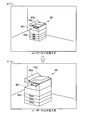
- the virtual image forming apparatus 40 shown in the lower part of FIG. 3 is displayed on the HMD 1, it is assumed that the user makes an operation request. Further, it is assumed that the operation requested by the operation request at this time (a virtual operation performed by the user on the virtual image forming apparatus 40) is a start operation instructing the execution of the job. In this case, the state of the virtual image forming apparatus 40 displayed on the HMD 1 is changed from the state shown in the upper drawing of FIG. 10 (corresponding to the lower drawing of FIG. 3) to the state shown in the lower drawing of FIG.
- the display data of the virtual image forming apparatus 40 in the job execution state where the job is being executed from the server 2 to the HMD 1 job execution Display data of the status is sent.
- the display data of the job execution state is display data including an AR image of a virtual sheet 40s imitating a sheet (for example, a printed sheet) discharged from the corresponding actual machine, and the state in which the virtual sheet 40s is conveyed and discharged.
- the HMD control unit 14 When the HMD communication unit 16 receives the display data of the job execution state, the HMD control unit 14 causes the display unit 11 to perform AR display based on the display data of the job execution state. As a result, the state of the virtual image forming apparatus 40 is changed to the state in which the virtual sheet 40s is conveyed and discharged. That is, the HMD control unit 14 instructs the display unit 11 to change the state of the virtual image forming apparatus 40 to the state when the operation requested by the operation request is performed.
- the display data of the job execution state is animation display data
- the HMD control unit 14 causes the display unit 11 to display an animation of a state in which the virtual image forming apparatus 40 transports and discharges the virtual sheet 40s.
- the HMD control unit 14 controls the display unit 11 so that the virtual image forming apparatus 40 transports and discharges the virtual sheet 40s at the same speed as the sheet transport speed of the corresponding model.
- the virtual sheet 40s is disposed on the virtual discharge tray 40t displayed as a part of the virtual image forming apparatus 40.
- the virtual sheets 40s on the virtual discharge tray 40t may blink at predetermined intervals.
- HMD control unit 14 performs a gesture operation (for example, a predetermined portion of virtual operation panel 40p) on a predetermined portion (for example, a portion corresponding to the start key) of virtual operation panel 40p displayed as a part of virtual image forming apparatus 40. Accept as an operation request). Then, the HMD control unit 14 recognizes that the operation corresponding to the received operation request is a start operation.
- a gesture operation for example, a predetermined portion of virtual operation panel 40p
- a predetermined portion for example, a portion corresponding to the start key
- the HMD control unit 14 causes the display unit 11 to display the virtual input device 50 separately from the virtual image forming apparatus 40.
- the virtual input device 50 is an AR image modeled after a notebook personal computer.
- the HMD control unit 14 receives, as an operation request, a gesture operation (for example, an operation for hitting a predetermined portion of the virtual input device 50) on a predetermined portion (for example, a portion corresponding to a keyboard) of the virtual input device 50.
- a gesture operation for example, an operation for hitting a predetermined portion of the virtual input device 50
- a predetermined portion for example, a portion corresponding to a keyboard
- the operation requested by the operation request from the user is the pull-out operation (corresponding to the “moving operation”) for pulling out the sheet cassette.
- the display data of the virtual image forming apparatus 40 in the cassette pulled out state in which the sheet cassette is pulled out is transmitted from the server 2 to the HMD 1.
- the state of the virtual image forming apparatus 40 displayed on the HMD 1 is shown in the lower view of FIG. 12 from the state shown in the upper view of FIG. It is changed to the state shown. That is, the virtual image forming apparatus 40 in the cassette pulled out state is displayed on the HMD 1.
- the HMD control unit 14 receives a gesture operation (for example, an operation of moving a hand back and forth) on the virtual sheet cassette 40c as an operation request. Then, the HMD control unit 14 recognizes that the operation corresponding to the received operation request is a withdrawal operation.
- a gesture operation for example, an operation of moving a hand back and forth
- the HMD control unit 14 recognizes that the operation corresponding to the received operation request is a withdrawal operation.
- the operation requested by the operation request from the user is an open operation (corresponding to a “moving operation”) for opening the document conveyance unit.
- display data (display data of the unit open state) of the unit open state virtual image forming apparatus 40 in which the document conveyance unit is opened is transmitted from the server 2 to the HMD 1.
- the state of the virtual image forming apparatus 40 displayed on the HMD 1 is shown in the lower view of FIG. 13 from the state shown in the upper view of FIG. It is changed to the state shown. That is, the virtual image forming apparatus 40 in the unit open state is displayed on the HMD 1.
- the HMD control unit 14 receives a gesture operation (for example, an operation of moving a hand up and down) on the virtual document conveyance unit 40d as an operation request. Then, the HMD control unit 14 recognizes that the operation corresponding to the received operation request is an open operation.
- a gesture operation for example, an operation of moving a hand up and down
- the HMD 1 controls the display unit 11 that displays the virtual image forming apparatus 40 in an overlay on the physical space while making the user visually recognize the physical space, and the HMD that controls the display unit 11 And a control unit 14 (control unit).
- the HMD control unit 14 receives an operation request for requesting an operation on the virtual image forming apparatus 40 from the user, the HMD control unit 14 instructs the display unit 11 and the operation requested for the state of the virtual image forming apparatus 40 is performed. Change to the state of the case.
- the state of the virtual image forming apparatus 40 is changed to the state when the operation requested by the operation request is performed. You can know if it will be like that. Therefore, when the image forming apparatus is described, the description of the image forming apparatus can be efficiently performed even if there is no actual machine.
- the HMD control unit 14 displays the state of the virtual image forming apparatus 40 as the virtual sheet 40 s. To transport and discharge. At this time, the HMD control unit 14 displays the display unit so that the virtual image forming apparatus 40 transports and discharges the virtual sheet 40s at the same speed as the sheet transport speed of the actual machine that has become a model of the virtual image forming apparatus 40. Control 11 In this configuration, the user can check the performance (print speed) of the actual machine. In other words, the user can check the productivity when installing (purchasing) a real machine.
- the HMD control unit 14 causes the display unit 11 to display the virtual operation panel 40p as a part of the virtual image forming apparatus 40, and virtuals based on the photographed data photographed by the imaging unit 12.
- the detected gesture operation is accepted as an operation request, and it is recognized that the operation requested by the received operation request is a start operation.
- the HMD control unit 14 causes the display unit 11 to display the virtual input device 50 separate from the virtual image forming apparatus 40, and a gesture operation is performed on the virtual input device 50 based on the imaging data captured by the imaging unit 12.
- the job is executed on the real machine by performing operations on the operation panel installed on the real machine and the input device connected to the real machine. Therefore, in this configuration, it is easy to understand what kind of operation should be performed when it is desired to change the state of the virtual image forming apparatus 40 to the job execution state.
- the HMD control unit 14 virtually converts the virtual sheet cassette 40c (virtual movable member) corresponding to the sheet cassette (movable member) of the actual machine that has become a model of the virtual image forming apparatus 40.
- the operation requested by the operation request is displayed as a part of the image forming apparatus 40 and the operation requested by the operation request is a pulling operation (moving operation)
- the state of the virtual image forming apparatus 40 is in the cassette pulling out state (virtual movable member To be moved).
- the HMD control unit 14 uses a virtual document conveyance unit 40 d (virtual movable member) corresponding to the document conveyance unit (movable member) of the actual machine that has become a model of the virtual image forming device 40 as a part of the virtual image formation device 40.
- the display unit 11 causes the display unit 11 to change the state of the virtual image forming apparatus 40 to the unit open state (the state where the virtual movable member is moved). .
- the user can know the state of the actual machine from which the sheet cassette has been pulled out and the state of the actual machine with the document conveyance unit opened.
- the HMD control unit 14 causes virtual image formation to be displayed on the display unit 11 based on the position, direction, and size of the AR marker 30 (reference marker) captured by the imaging unit 12 Set the position, orientation and size of the device 40.
- the HMD control unit 14 sets the size of the virtual image forming apparatus 40 so that the virtual image forming apparatus 40 becomes full size when viewed from the user.
- the size of the actual machine can be confirmed. For example, it is possible to confirm whether or not the actual machine can be installed at the installation location desired by the user, and to confirm the atmosphere when the actual machine is installed.
- the HMD control unit 14 causes the display unit 11 to display a plurality of virtual image forming apparatuses 40.
- Each model corresponding to each of the plurality of virtual image forming apparatuses 40 may be the same or different.
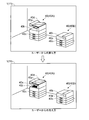
- the lower part of FIG. 14 illustrates the case where two virtual image forming apparatuses 40A and 40B having different corresponding models are displayed.
- a real machine corresponding to the virtual image forming apparatus 40A is a multifunction machine equipped with a scan function and a print function
- a real machine corresponding to the virtual image forming apparatus 40B is a printer without a scan function.
- the HMD control unit 14 determines that the operation request has been received from the user while the display unit 11 is displaying the plurality of virtual image forming apparatuses 40. In this case, the HMD control unit 14 instructs the display unit 11 to change each state of the plurality of virtual image forming apparatuses 40 to the state when the operation requested by the operation request is performed.
- an operation request is made in the state shown in the lower part of FIG. Further, it is assumed that the operation requested by the operation request is the start operation.
- the HMD control unit 14 requests the server 2 for operation information indicating the operation requested by the operation request, identification information of a model corresponding to the virtual image forming apparatus 40A (here, the symbol A is attached), A transmission request including the identification information of the model corresponding to the virtual image forming apparatus 40B (here, the symbol B is attached) is transmitted.
- the display data of the job execution state corresponding to the identification information A and the display data of the job execution state corresponding to the identification information B are transmitted from the server 2 to the HMD 1.
- the states of the virtual image forming apparatuses 40A and 40B displayed on the HMD 1 are changed from the state shown in the upper view of FIG. 15 (corresponding to the lower view in FIG. 14) to the state shown in the lower view of FIG. That is, the state of virtual image forming apparatus 40A is changed to the state of conveying and discharging virtual sheet 40s, and similarly, the state of virtual image forming apparatus 40B is changed to the state of conveying and discharging virtual sheet 40s. Ru.
- the HMD control unit 14 receives, from the user, the selection of the virtual image forming apparatus 40 to which the operation request is to be made among the plurality of virtual image forming apparatuses 40 before receiving the operation request. When the selection is received, the HMD control unit 14 instructs the display unit 11 to operate only the state of the virtual image forming apparatus 40 selected among the plurality of virtual image forming apparatuses 40 by the operation request. Make it change to the state it was in.
- the virtual image forming apparatus 40A is selected among the plurality of virtual image forming apparatuses 40 and an operation request is made. Further, it is assumed that the operation requested by the operation request is the start operation.
- the HMD control unit 14 transmits, to the server 2, a transmission request including operation information indicating the operation requested by the operation request, and identification information A of a model corresponding to the virtual image forming apparatus 40A.
- display data of the job execution state corresponding to the identification information A is transmitted from the server 2 to the HMD 1.
- the state of the virtual image forming apparatus 40A displayed on the HMD 1 is changed from the state shown in the upper view of FIG. 16 (corresponding to the lower view in FIG. 14) to the state shown in the lower view of FIG. That is, the state of the virtual image forming apparatus 40A is changed to the state in which the virtual sheet 40s is conveyed and discharged.
- the model (MFP) corresponding to the virtual image forming apparatus 40A has a scan function
- the model (printer) corresponding to the virtual image forming apparatus 40B has a scan function Not equipped.
- the status of the virtual image forming apparatus 40B is not changed even if an operation request related to the scan function (corresponding to “predetermined function” is made.
- the operation requested by the operation request is It will change to the state it was in.
- an operation request related to the scan function is made in the state shown in the lower part of FIG.
- the operation requested by the operation request relating to the scan function is an open operation (operation for opening the document conveyance unit).
- the HMD control unit 14 operates the operation information indicating the open operation which is the operation requested by the operation request, the identification information A of the model corresponding to the virtual image forming apparatus 40A, and the model corresponding to the virtual image forming apparatus 40B.
- display data display data in a unit open state
- the state of the virtual image forming apparatus 40A displayed on the HMD 1 is changed from the state shown in the upper view of FIG. 17 (corresponding to the lower view in FIG. 14) to the state shown in the lower view of FIG. That is, the virtual document conveyance unit 40d of the virtual image forming apparatus 40A is changed to the opened state. On the other hand, the state of the virtual image forming apparatus 40B is not changed.
- the plurality of training students wear the HMD 1 respectively. That is, there are a plurality of users of HMD1.
- the presenter also wears the HMD 1 (the presenter is also a user of the HMD 1).
- the state of the virtual image forming apparatus displayed on any of the HMDs 1 is changed, the state of the virtual image forming apparatus displayed on the other HMD 1 is also changed similarly can do.
- a virtual image forming apparatus 40 as shown in the upper part of FIG. 10 is displayed on the HMD 1 of each user. Then, in this state, it is assumed that a certain user makes an operation request. Further, it is assumed that the operation requested by the operation request from the user is the start operation.
- the HMD 1 receiving the operation request is referred to as a request receiving HMD 1.
- the HMD control unit 14 of the request acceptance HMD 1 transmits, to the server 2, a transmission request including operation information indicating the operation requested by the operation request and identification information of a model corresponding to the virtual image forming apparatus 40.
- the server 2 having received the transmission request recognizes the HMD 1 (referred to as a synchronization target HMD 1) currently displaying the same virtual image forming apparatus 40 as the request acceptance HMD 1 based on the received identification information.
- a synchronization target HMD 1 For example, each HMD 1 transmits to the server 2 identification information of a model corresponding to the virtual image forming apparatus 40 currently displayed. Therefore, the server 2 can recognize the synchronization target HMD 1 based on the identification information received from each HMD 1.
- the server 2 transmits display data corresponding to the received operation information to all of the request acceptance HMD 1 and the synchronization target HMD 1. Thereby, the state of the virtual image forming apparatus 40 displayed in the request acceptance HMD 1 is changed, and similarly, the state of the virtual image forming apparatus 40 displayed in the synchronization target HMD 1 is also changed. That is, the request acceptance HMD 1 and the synchronization target HMD 1 each display a virtual image forming apparatus 40 as shown in the lower part of FIG.
- the explainer when one explainer explains the image forming apparatus to a plurality of training students, the explainer performs the gesture operation (operation request) only once,
- the virtual image forming apparatus 40 displayed on all the HMDs 1 of the learner is changed to the state when the operation requested by the operation request is performed, so that the convenience is good.
- server 2 may be carried in HMD1, and server 2 may be omitted.
- the present invention can be realized only by the HMD 1 (communication between the HMD 1 and the server 2 becomes unnecessary). If the processing capacity of the server 2 is low, a plurality of servers 2 may be used.
- HMD1 can replace with HMD1 and can also use a smart phone and a tablet computer.
- a space recognition function may be used to arrange an object such as the virtual image forming apparatus 40.
Abstract
A display device (1) is provided with a display unit (11) for overlaying a virtual image forming device (40) on a real space while making the real space visible to a user, and a control unit (14) for controlling the display unit (11). When an operation request that requests operation on the virtual image forming device (40) is accepted from the user, the control unit (14) issues a command to the display unit (11) and causes the state of the virtual image forming device (40) to be changed to a state where the operation requested by the operation request is performed.
Description
本発明は、表示装置および表示システムに関する。
The present invention relates to a display device and a display system.
従来、画像形成装置の操作パネルを模した仮想操作パネルを表示する表示装置が知られている。このような表示装置は、たとえば、特許文献1に開示されている。
2. Description of the Related Art Conventionally, there has been known a display device that displays a virtual operation panel that simulates an operation panel of an image forming apparatus. Such a display device is disclosed, for example, in Patent Document 1.
特許文献1の表示装置は、画像形成装置に通信可能に接続され、仮想操作パネルに対する操作を検知すると、検知した操作を示す操作情報を画像形成装置に送信する。画像形成装置は、表示装置から操作情報を受信すると、受信した操作情報で示される操作に応じた処理を実行する。
The display device of Patent Document 1 is communicably connected to the image forming apparatus, and when detecting an operation on the virtual operation panel, transmits operation information indicating the detected operation to the image forming apparatus. When receiving the operation information from the display device, the image forming apparatus executes processing according to the operation indicated by the received operation information.
たとえば、画像形成装置のユーザー(画像形成装置の購入予定者なども含む)に対して画像形成装置に関する説明を行う場合には、ユーザーに実機を操作してもらうのが好ましい。なぜなら、画像形成装置に関する説明を行いつつ、ユーザーに実機を操作してもらうことにより、画像形成装置に関する説明を効率的に行うことができるためである。
For example, in the case of describing the image forming apparatus with respect to the user of the image forming apparatus (including a purchaser of the image forming apparatus, etc.), it is preferable to have the user operate the actual apparatus. This is because by having the user operate the actual apparatus while explaining the image forming apparatus, it is possible to efficiently explain the image forming apparatus.
しかし、説明を行うために準備した会場によっては、実機を会場内に搬入できない場合がある。この場合には、ユーザーに実機を操作してもらうことができないので、説明者が説明した内容をユーザーが十分に理解することができないという不都合が生じ得る。
However, depending on the venue prepared for the explanation, it may not be possible to carry the actual machine into the venue. In this case, since the user can not operate the actual machine, there may be a disadvantage that the user can not fully understand the content explained by the explainer.
ここで、特許文献1では、表示装置に仮想操作パネルを表示するが、仮想操作パネルに対して操作を行っても、実機が存在しなければ、当該操作によって実機の状態がどのように変化するかをユーザーは知ることができない。したがって、特許文献1の表示装置を用いても、説明者が説明した内容をユーザーが十分に理解することができないという不都合が生じ得る。
Here, in Patent Document 1, the virtual operation panel is displayed on the display device, but even if the operation is performed on the virtual operation panel, the state of the actual machine is changed by the operation if the actual machine does not exist. The user can not know. Therefore, even if the display device of Patent Document 1 is used, there may be a disadvantage that the user can not fully understand the content described by the explainer.
本発明は、上記課題を解決するためになされたものであり、実機が存在しなくても、画像形成装置に関する説明を効率的に行うことが可能な表示装置および表示システムを提供することを目的とする。
The present invention has been made to solve the above-mentioned problems, and it is an object of the present invention to provide a display device and a display system capable of efficiently explaining the image forming apparatus even if there is no actual machine. I assume.
上記目的を達成するため、本発明の第1の局面による表示装置は、ユーザーに現実空間を視認させつつ、現実空間上に仮想画像形成装置をオーバーレイ表示する表示部と、表示部を制御する制御部と、を備える。制御部は、仮想画像形成装置に対する操作を要求する操作要求をユーザーから受け付けると、表示部に指示し、仮想画像形成装置の状態を操作要求で要求された操作が行われた場合の状態に変更させる。
In order to achieve the above object, a display device according to a first aspect of the present invention controls a display unit for displaying a virtual image forming device in an overlay display on a physical space while allowing a user to visually recognize the physical space And a unit. When the control unit receives an operation request for requesting an operation to the virtual image forming apparatus from the user, the control unit instructs the display unit to change the state of the virtual image forming apparatus to the state when the operation requested by the operation request is performed. Let
本発明の第2の局面による表示システムは、上記表示装置を複数備え、複数の表示装置は、いずれかの表示装置が操作要求を受け付けると、仮想画像形成装置の状態を操作要求で要求された操作が行われた場合の状態に変更する。
A display system according to a second aspect of the present invention includes a plurality of the display devices described above, and when a display device receives an operation request, the plurality of display devices are requested for the state of the virtual image forming apparatus by the operation request. Change to the state when the operation was performed.
本発明の構成では、ユーザーが操作要求を行うと、仮想画像形成装置の状態が操作要求で要求した操作を行った場合の状態に変更されるので、ユーザーは操作要求で要求した操作によって実機がどのような状態になるかを知ることができる。したがって、画像形成装置に関する説明を行う場合に、実機が存在しなくても、画像形成装置に関する説明を効率的に行うことができる。
In the configuration of the present invention, when the user makes an operation request, the state of the virtual image forming apparatus is changed to the state when the operation requested by the operation request is performed. We can know what kind of state it will be. Therefore, when the image forming apparatus is described, the description of the image forming apparatus can be efficiently performed even if there is no actual machine.
本発明によれば、実機が存在しなくても、画像形成装置に関する説明を効率的に行うことができる。
According to the present invention, even if there is no actual machine, the description regarding the image forming apparatus can be efficiently performed.
<ヘッドマウントディスプレイの構成>
本実施形態のヘッドマウントディスプレイ1は、図1に示すような構成を有する。ヘッドマウントディスプレイ1は、眼鏡型であり、眼鏡のレンズに相当する部分に種々の画像を表示する。このため、ヘッドマウントディスプレイ1を装着した装着者(ユーザー)からは、眼前に画像が表示されたように見える。なお、ヘッドマウントディスプレイ1は「表示装置」に相当する。以下の説明では、ヘッドマウントディスプレイ(Head Mounted Display)をHMDと略称する。 <Configuration of head mounted display>
The head mounteddisplay 1 of the present embodiment has a configuration as shown in FIG. The head mounted display 1 is of the eyeglass type, and displays various images on a portion corresponding to the lens of the eyeglass. For this reason, from the wearer (user) wearing the head mounted display 1, it looks as if the image was displayed in front of the eye. The head mounted display 1 corresponds to a "display device". In the following description, a head mounted display is abbreviated as HMD.
本実施形態のヘッドマウントディスプレイ1は、図1に示すような構成を有する。ヘッドマウントディスプレイ1は、眼鏡型であり、眼鏡のレンズに相当する部分に種々の画像を表示する。このため、ヘッドマウントディスプレイ1を装着した装着者(ユーザー)からは、眼前に画像が表示されたように見える。なお、ヘッドマウントディスプレイ1は「表示装置」に相当する。以下の説明では、ヘッドマウントディスプレイ(Head Mounted Display)をHMDと略称する。 <Configuration of head mounted display>
The head mounted
HMD1は、表示部11、撮像部12、操作部13、HMD制御部14、HMD記憶部15およびHMD通信部16を備える。これら各部は眼鏡型のフレームに搭載される。
The HMD 1 includes a display unit 11, an imaging unit 12, an operation unit 13, an HMD control unit 14, an HMD storage unit 15, and an HMD communication unit 16. These units are mounted on a glasses-type frame.
表示部11は、表示を行う。表示部11は、HMD1を装着したユーザーの眼と対向する位置に配置さる。これにより、ユーザーの眼前に画像が表示される。たとえば、外光を透過させる光学透過型(光学シースルー型)のディスプレイ装置が表示部11として用いられる。光学透過型のディスプレイ装置からなる表示部11は、ハーフミラーを含み、表示すべき画像をハーフミラーによってユーザーの眼に向けて反射する。このとき、外光はハーフミラーを透過してユーザーの眼に入射する。すなわち、表示部11は、ユーザーに現実空間を視認させつつ、現実空間上に画像をオーバーレイ表示する。ユーザーからは、表示部11により表示された表示画像が現実空間に合成されたように見える(現実空間に表示画像が重なって見える)。
The display unit 11 performs display. The display unit 11 is disposed at a position facing the eye of the user wearing the HMD 1. Thereby, an image is displayed in front of the user's eyes. For example, an optical transmission type (optical see-through type) display device that transmits external light is used as the display unit 11. The display unit 11 including an optical transmission type display device includes a half mirror, and reflects an image to be displayed toward the user's eye by the half mirror. At this time, external light passes through the half mirror and enters the user's eye. That is, the display unit 11 overlays and displays an image on the real space while making the user visually recognize the real space. From the user, it appears that the display image displayed by the display unit 11 is synthesized in the real space (the display image appears to overlap with the real space).
撮像部12は、撮影を行う。撮像部12は、CCDカメラなどを含み、HMD1を装着したユーザーの視界方向の撮影が可能な位置に配置される。これにより、ユーザーの眼前の風景(ユーザーの眼前に広がる現実空間に存在するオブジェクト)が撮影される。ユーザーが眼前で手(指)を動かすなどのジェスチャー操作を行った場合には、ユーザーのジェスチャー操作が撮影される。撮像部12は、撮影で得られた撮影データを出力する。
The imaging unit 12 performs imaging. The imaging unit 12 includes a CCD camera and the like, and is disposed at a position where imaging in the direction of view of the user wearing the HMD 1 is possible. As a result, a landscape in front of the user's eye (an object existing in the real space that spreads in front of the user's eye) is photographed. When the user performs a gesture operation such as moving a hand (finger) in front of the eye, the gesture operation of the user is captured. The imaging unit 12 outputs imaging data obtained by imaging.
操作部13は、HMD1を装着したユーザーから、HMD1による表示や撮影に関する各種設定を行うための操作を受け付ける。たとえば、当該操作を受け付けるハードウェアキーがHMD1に設けられる。なお、スマートフォンやタブレットコンピューター、ノート型パーソナルコンピューターなど、ユーザー所有の携帯情報端末をHMD1に通信可能に接続することにより、当該携帯情報端末を操作部13として機能させることもできる。
The operation unit 13 receives, from the user wearing the HMD 1, an operation for performing various settings regarding display and photographing by the HMD 1. For example, a hardware key for receiving the operation is provided in the HMD 1. The portable information terminal can also function as the operation unit 13 by communicably connecting a portable information terminal owned by the user, such as a smartphone, a tablet computer, or a notebook personal computer, to the HMD 1.
HMD制御部14は、制御用のプログラムやデータに基づき動作するCPUを含む。HMD制御部14は、HMD1を制御するための各種処理を実行する。たとえば、HMD制御部14は、表示部11による表示および撮像部12による撮影をそれぞれ制御する。また、HMD制御部14は、操作部13(あるいは、HMD1に接続された携帯情報端末)がユーザーから受け付けた操作を検知する。
The HMD control unit 14 includes a CPU that operates based on control programs and data. The HMD control unit 14 executes various processes for controlling the HMD 1. For example, the HMD control unit 14 controls the display by the display unit 11 and the imaging by the imaging unit 12 respectively. Further, the HMD control unit 14 detects an operation accepted from the user by the operation unit 13 (or a portable information terminal connected to the HMD 1).
HMD記憶部15は、不揮発性メモリー(ROM)および揮発性メモリー(RAM)を含む。HMD記憶部15は、HMD制御部14(CPU)を動作させるための制御用のプログラムやデータを記憶する。また、HMD記憶部15は、後述するサーバー2から受信したデータ(たとえば、画像を表示するための表示データなど)を記憶する。
The HMD storage unit 15 includes non-volatile memory (ROM) and volatile memory (RAM). The HMD storage unit 15 stores control programs and data for operating the HMD control unit 14 (CPU). The HMD storage unit 15 also stores data (for example, display data for displaying an image, etc.) received from the server 2 described later.
HMD通信部16は、HMD1を外部機器に通信可能に接続するための通信インターフェースであり、通信回路などを含む。HMD制御部14は、HMD通信部16を用いて、外部機器と通信する。
The HMD communication unit 16 is a communication interface for communicably connecting the HMD 1 to an external device, and includes a communication circuit and the like. The HMD control unit 14 communicates with an external device using the HMD communication unit 16.
たとえば、HMD1(HMD通信部16)は、インターネットやLANなどの通信ネットワークNTに接続される。通信ネットワークNTには、外部機器としてのサーバー2が接続される。そして、HMD1とサーバー2とで表示システム100が構築される。
For example, the HMD 1 (HMD communication unit 16) is connected to a communication network NT such as the Internet or a LAN. A server 2 as an external device is connected to the communication network NT. Then, the display system 100 is constructed by the HMD 1 and the server 2.
なお、表示システム100が複数のHMD1を備えてもよい。この場合、複数のHMD1はそれぞれ他のHMD1と通信可能に接続される。HMD1間の通信は通信ネットワークNTを介して行われてもよいし、HMD1間の通信が通信ネットワークNTを介さず直接行われてもよい。表示システム100に含めるHMD1の台数は特に限定されず、1台でもよいし複数台でもよい。
Note that the display system 100 may include a plurality of HMDs 1. In this case, the plurality of HMDs 1 are communicably connected to other HMDs 1 respectively. Communication between the HMDs 1 may be performed via the communication network NT, or communication between the HMDs 1 may be performed directly, not via the communication network NT. The number of HMDs 1 included in the display system 100 is not particularly limited, and may be one or more.
サーバー2は、サーバー制御部21、サーバー記憶部22およびサーバー通信部23を備える。サーバー2は、画像形成装置(複合機やプリンターなど)のメーカーや販売業者が管理する。たとえば、パーソナルコンピューターなどをサーバー2として用いることができる。
The server 2 includes a server control unit 21, a server storage unit 22, and a server communication unit 23. The server 2 is managed by a maker or distributor of an image forming apparatus (such as a multifunction peripheral or a printer). For example, a personal computer can be used as the server 2.
サーバー制御部21は、制御用のプログラムやデータに基づき動作するCPUを含む。サーバー制御部21は、サーバー2を制御するための各種処理を実行する。
The server control unit 21 includes a CPU that operates based on control programs and data. The server control unit 21 executes various processes for controlling the server 2.
サーバー記憶部22は、不揮発性メモリー(ROM)および揮発性メモリー(RAM)を含む。サーバー記憶部22は、サーバー制御部21(CPU)を動作させるための制御用のプログラムやデータを記憶する。また、サーバー記憶部22は、HDDなどの大容量の記憶デバイスを含む。
The server storage unit 22 includes non-volatile memory (ROM) and volatile memory (RAM). The server storage unit 22 stores control programs and data for operating the server control unit 21 (CPU). The server storage unit 22 also includes a large-capacity storage device such as an HDD.
サーバー通信部23は、サーバー2を外部機器に通信可能に接続するための通信インターフェースであり、通信回路などを含む。サーバー制御部21は、サーバー通信部23を用いて通信ネットワークNTにアクセスし、HMD1と通信する(HMD1との間でデータを送受信する)。
The server communication unit 23 is a communication interface for communicably connecting the server 2 to an external device, and includes a communication circuit and the like. The server control unit 21 accesses the communication network NT using the server communication unit 23, and communicates with the HMD 1 (transmits and receives data to and from the HMD 1).
<AR表示処理>
(概要)
画像形成装置のメーカーや販売業者は、画像形成装置の購入予定者に対して、販売促進を行ったり、利用方法の教習を行ったりする。すなわち、画像形成装置に関する説明を行う。このときに、購入予定者や教習受講者(購入者)に対してHMD1が提供される。購入予定者や教習受講者はHMD1を装着する。すなわち、購入予定者や教習受講者がHMD1のユーザーとなる。 <AR display processing>
(Overview)
A maker or distributor of an image forming apparatus promotes sales and teaches how to use the image forming apparatus. That is, the image forming apparatus will be described. At this time, theHMD 1 is provided to the prospective purchaser and the learner (purchaser). Purchasers and trainees should wear the HMD1. In other words, the purchaser and the trainee become the users of the HMD 1.
(概要)
画像形成装置のメーカーや販売業者は、画像形成装置の購入予定者に対して、販売促進を行ったり、利用方法の教習を行ったりする。すなわち、画像形成装置に関する説明を行う。このときに、購入予定者や教習受講者(購入者)に対してHMD1が提供される。購入予定者や教習受講者はHMD1を装着する。すなわち、購入予定者や教習受講者がHMD1のユーザーとなる。 <AR display processing>
(Overview)
A maker or distributor of an image forming apparatus promotes sales and teaches how to use the image forming apparatus. That is, the image forming apparatus will be described. At this time, the
画像形成装置の販売促進や教習は、実物の画像形成装置(実機)を用いず、AR(Augmented Reality)技術を用いて行われる。AR技術を用いて販売促進や教習を行うため、仮想画像形成装置(現実空間上にオーバーレイ表示するAR画像)の表示データが予め作成される。たとえば、実機の装置状態が複数に分類され、複数の装置状態にそれぞれ対応する複数の表示データが表示データ情報DDに含められる。ここで、複数の表示データは、後述する複数の操作情報のいずれかに対応付けられる。また、複数の表示データには、対応する実機の機種を示す識別情報が付される。1機種分の複数の表示データを含む表示データ情報DDはデータベースDBに格納される。データベースDBはサーバー記憶部22に記憶される。
The sales promotion and training of the image forming apparatus are performed using AR (Augmented Reality) technology without using a real image forming apparatus (actual machine). Display data of a virtual image forming apparatus (AR image to be overlaid and displayed on the real space) is created in advance to perform sales promotion and training using AR technology. For example, the device states of the actual device are classified into a plurality of pieces, and a plurality of display data respectively corresponding to the plurality of device states are included in the display data information DD. Here, the plurality of display data is associated with any of a plurality of operation information to be described later. In addition, identification information indicating the model of the corresponding actual device is attached to the plurality of display data. Display data information DD including a plurality of display data for one model is stored in the database DB. The database DB is stored in the server storage unit 22.
販売促進や教習の対象となり得る機種が複数存在する場合には、機種ごとに仮想画像形成装置の表示データが作成される。そして、複数の機種にそれぞれ対応する複数の表示データ情報DDがデータベースDBに格納される。以下の説明では、販売促進や教習の対象となり得る機種が複数存在するとする。
When there are a plurality of models that can be targets for sales promotion or training, display data of the virtual image forming apparatus is created for each model. Then, a plurality of display data information DD respectively corresponding to a plurality of models is stored in the database DB. In the following description, it is assumed that there are a plurality of models that can be targets for sales promotion and training.
また、販売促進や教習を行う会場には、ARマーカーを配した領域が存在する。ARマーカーは「基準マーカー」に相当する。たとえば、QRコード(登録商標)がARマーカーとして用いられる。販売促進や教習で使用する会場にもよるが、ARマーカーを記録媒体(カードなど)に印刷し、当該記録媒体を会場内に配してもよい。
In addition, an area where AR markers are arranged exists in a place where sales promotion and teaching are performed. An AR marker corresponds to a "reference marker". For example, QR code (registered trademark) is used as an AR marker. Depending on the venue used for sales promotion and training, the AR marker may be printed on a recording medium (card or the like) and the recording medium may be arranged in the venue.
販売促進や教習の準備が整うと、販売促進や教習の実施者(画像形成装置に関する説明を行う説明者)はHMD1を装着したユーザーに対し、ARマーカーの方に視線を向けるよう指示する。このとき、撮像部12は撮影を行っている。したがって、撮像部12によりARマーカーが撮影される。
When the sales promotion and the training are ready, the person who executes the sales promotion and the training (explainer who explains the image forming apparatus) instructs the user who wears the HMD 1 to direct the gaze toward the AR marker. At this time, the imaging unit 12 is photographing. Therefore, the AR marker is photographed by the imaging unit 12.
HMD制御部14は、撮像部12がARマーカーを撮影すると、販売促進や教習に関する処理(販売促進や教習を支援する処理)を行う。言い換えると、HMD制御部14は、AR技術を用いて仮想画像形成装置を表示するAR表示処理を行う。
When the imaging unit 12 captures an AR marker, the HMD control unit 14 performs processing related to sales promotion and training (processing to support sales promotion and training). In other words, the HMD control unit 14 performs AR display processing to display the virtual image forming apparatus using the AR technology.
以下に、図2に示すフローチャートを参照し、HMD制御部14が最初に行うAR表示処理の流れを説明する。
The flow of AR display processing performed first by the HMD control unit 14 will be described below with reference to the flowchart shown in FIG.
図2に示すフローチャートのスタート時点では、撮像部12がARマーカーを撮影しているとする。そして、撮像部12が撮影した撮影データからHMD制御部14がARマーカーを検出すると、図2に示すフローチャートがスタートする。
It is assumed that the imaging unit 12 captures an AR marker at the start of the flowchart shown in FIG. Then, when the HMD control unit 14 detects an AR marker from the imaging data captured by the imaging unit 12, the flowchart shown in FIG. 2 starts.
ステップS1において、HMD制御部14は、ARマーカーに埋め込まれた各種情報を認識する。ARマーカーには、表示すべき仮想画像形成装置に対応する機種を示す識別情報が埋め込まれる。すなわち、ここでは、HMD制御部14によって識別情報が認識される。
In step S1, the HMD control unit 14 recognizes various information embedded in the AR marker. In the AR marker, identification information indicating a model corresponding to the virtual image forming apparatus to be displayed is embedded. That is, here, the HMD control unit 14 recognizes the identification information.
ステップS2において、HMD制御部14は、仮想画像形成装置の表示データを取得するため、HMD通信部16を用いて、サーバー2に送信要求を送信する。サーバー2への送信要求には、ステップS1の処理で認識した識別情報が含められる。
In step S2, the HMD control unit 14 transmits a transmission request to the server 2 using the HMD communication unit 16 in order to obtain display data of the virtual image forming apparatus. The transmission request to the server 2 includes the identification information recognized in the process of step S1.
送信要求(識別情報を含む)を受信したサーバー2は、受信した識別情報で示される機種に対応する表示データ情報DD(1機種分の複数の表示データを含む情報)から基本表示データを抽出する。そして、サーバー2は、基本表示データをHMD1に送信する。
The server 2 having received the transmission request (including the identification information) extracts basic display data from the display data information DD (information including a plurality of display data for one model) corresponding to the model indicated by the received identification information. . Then, the server 2 transmits the basic display data to the HMD 1.
たとえば、1機種分の複数の表示データ(複数の装置状態にそれぞれ対応する複数の表示データ)の中には、実機がジョブを実行している状態(シートを搬送し排出している状態)を仮想的に表示するための表示データ、実機に設置された用紙カセット(「可動部材」に相当)が初期位置から移動されている状態(引き出されている状態)を仮想的に表示するための表示データ、および、実機に設置された原稿搬送ユニット(「可動部材」に相当)が初期位置から移動されている状態(開けられている状態)を仮想的に表示するための表示データなどが存在する。このうち、実機がジョブを実行していない状態であって、原稿搬送ユニットや用紙カセットなどの可動部材が初期位置に設置された状態である基本状態の実機を仮想的に表示するための表示データが基本表示データとされる。
For example, among a plurality of display data for one model (a plurality of display data respectively corresponding to a plurality of device states), a state in which a real machine is executing a job (a state in which a sheet is conveyed and discharged) Display data for displaying in a virtual manner, a display for virtually displaying a state in which a sheet cassette (corresponding to a "movable member") installed in an actual machine is moved from an initial position (a state of being pulled out) Data and display data etc. for virtually displaying the state (opened state) in which the document conveyance unit (corresponding to the “movable member”) installed in the actual machine is moved from the initial position exist. . Among them, display data for virtually displaying the actual machine in the basic state in which the actual machine is not executing a job and the movable member such as the document conveyance unit or the paper cassette is installed at the initial position. Is the basic display data.
サーバー2から送信された基本表示データをHMD通信部16が受信すると、ステップS3において、HMD制御部14は、基本表示データに基づく仮想画像形成装置(AR画像)を表示部11に表示させる。表示部11は、ユーザーに現実空間(会場内)を視認させつつ、現実空間上に仮想画像形成装置をオーバーレイ表示する。
When the HMD communication unit 16 receives the basic display data transmitted from the server 2, the HMD control unit 14 causes the display unit 11 to display a virtual image forming apparatus (AR image) based on the basic display data in step S3. The display unit 11 overlays and displays the virtual image forming apparatus on the real space while making the user visually recognize the real space (in the hall).
このとき、HMD制御部14は、撮像部12が撮影した撮影データに基づき、表示部11の表示領域内でのARマーカーの位置(座標)を認識する。そして、HMD制御部14は、当該認識した位置に仮想画像形成装置が表示されるよう表示部11を制御する。
At this time, the HMD control unit 14 recognizes the position (coordinates) of the AR marker in the display area of the display unit 11 based on the imaging data captured by the imaging unit 12. Then, the HMD control unit 14 controls the display unit 11 so that the virtual image forming apparatus is displayed at the recognized position.
また、HMD制御部14は、撮像部12が撮影した撮影データに基づき、表示部11の表示領域内でのARマーカーの向きを認識する。そして、HMD制御部14は、当該認識した向きと仮想画像形成装置の向きとが一致するよう表示部11による仮想画像形成装置の表示を制御する。
Also, the HMD control unit 14 recognizes the direction of the AR marker in the display area of the display unit 11 based on the imaging data captured by the imaging unit 12. Then, the HMD control unit 14 controls the display of the virtual image forming apparatus by the display unit 11 so that the recognized direction matches the direction of the virtual image forming apparatus.
また、HMD制御部14は、撮像部12が撮影した撮影データに基づき、表示部11の表示領域内でのARマーカーの大きさを認識する。そして、HMD制御部14は、当該認識した大きさに基づき、ユーザーから見て仮想画像形成装置が実物大となるよう表示部11による仮想画像形成装置の表示を制御する。
Further, the HMD control unit 14 recognizes the size of the AR marker in the display area of the display unit 11 based on the imaging data captured by the imaging unit 12. Then, based on the recognized size, the HMD control unit 14 controls the display of the virtual image forming apparatus by the display unit 11 so that the virtual image forming apparatus becomes full size when viewed from the user.
特に限定されないが、ARマーカーはQRコード(登録商標)であり、HMD制御部14は、ARマーカー内の3隅に存在するシンボルの位置、向きおよび大きさに基づき、表示部11の表示領域内でのARマーカーの位置、向きおよび大きさを認識する。言い換えると、HMD制御部14は、ARマーカー内の3隅に存在するシンボルの位置、向きおよび大きさに基づき、表示部11に表示させる仮想画像形成装置の位置、向きおよび大きさを設定する。
Although not particularly limited, the AR marker is a QR code (registered trademark), and the HMD control unit 14 displays the display area of the display unit 11 based on the position, orientation, and size of symbols present at three corners in the AR marker. Recognize the position, orientation and size of the AR marker at In other words, the HMD control unit 14 sets the position, the direction, and the size of the virtual image forming apparatus displayed on the display unit 11 based on the positions, the directions, and the sizes of the symbols present at three corners in the AR marker.
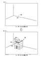
たとえば、図3上図に示すように、会場内の所定領域にARマーカーが配されているとする。図3上図では、ARマーカーに符号30を付す。HMD1がAR表示処理を行っていない状態では、ユーザーからは所定領域に実機が設置されていないように見える。
For example, as shown in the upper drawing of FIG. 3, it is assumed that an AR marker is disposed in a predetermined area in the hall. In the upper diagram of FIG. 3, the AR marker is denoted by reference numeral 30. When the HMD 1 is not performing AR display processing, it appears to the user that the actual device is not installed in the predetermined area.
そして、図3下図に示すように、HMD1によるAR表示処理が行われると、HMD1に仮想画像形成装置が表示される。図3下図では、仮想画像形成装置に符号40を付す。HMD1が仮想画像形成装置40を表示すると、実機は所定領域に設置されていないが、ユーザーからは所定領域に実機が設置されているように見える。
Then, as shown in the lower part of FIG. 3, when the AR display processing by the HMD 1 is performed, the virtual image forming apparatus is displayed on the HMD 1. In the lower part of FIG. 3, reference numeral 40 is attached to the virtual image forming apparatus. When the HMD 1 displays the virtual image forming apparatus 40, the real machine is not installed in the predetermined area, but it appears to the user that the real machine is installed in the predetermined area.
図3下図では、一例として、仮想画像形成装置40のモデルとなった実機が複合機である場合を図示する。当該複合機には、用紙を収容する用紙カセットが着脱可能に設置されるとともに、原稿を搬送する原稿搬送ユニットが開閉可能に設置される。そして、当該複合機は、ジョブの実行時に、シート(用紙あるいは原稿)を搬送し排出する。
The lower part of FIG. 3 illustrates, as an example, a case where a real machine that is a model of the virtual image forming apparatus 40 is a multifunction machine. In the multifunction machine, a sheet cassette for storing sheets is detachably installed, and an original transport unit for transporting an original is installed openably and closably. Then, when the job is executed, the multifunction peripheral conveys and discharges a sheet (sheet or document).
たとえば、図3下図に示した向きで仮想画像形成装置40が表示されているとき、図4に示す位置P1から位置P2にユーザーが移動したとする。すなわち、ユーザーが右手方向に移動したとする。なお、図4では、ユーザーの視線方向を破線矢印で示す。
For example, it is assumed that the user moves from position P1 to position P2 shown in FIG. 4 when the virtual image forming apparatus 40 is displayed in the orientation shown in the lower part of FIG. That is, it is assumed that the user moves in the right direction. In FIG. 4, the direction of the user's line of sight is indicated by a dashed arrow.
この場合、表示部11の表示領域内でのARマーカー30の向きが変わる。このため、HMD制御部14は、ARマーカー30の向きと仮想画像形成装置40の向きとが一致するよう仮想画像形成装置40の向きを再設定する。その結果、HMD1に表示される仮想画像形成装置40の向きは、図5上図(図3下図に相当)に示す状態から、図5下図に示す状態に変更される。
In this case, the direction of the AR marker 30 in the display area of the display unit 11 changes. Therefore, the HMD control unit 14 resets the orientation of the virtual image forming apparatus 40 so that the orientation of the AR marker 30 matches the orientation of the virtual image forming apparatus 40. As a result, the orientation of the virtual image forming apparatus 40 displayed on the HMD 1 is changed from the state shown in the upper view of FIG. 5 (corresponding to the lower view in FIG. 3) to the state shown in the lower view of FIG.
なお、仮想画像形成装置40の表示位置、表示向き(表示角度)および表示サイズの少なくとも1つを任意に変更することが可能であってもよい。たとえば、表示位置を変更する位置変更操作、表示向きを変更する向き変更操作、および、表示サイズを変更するサイズ変更操作にそれぞれ対応する3つのジェスチャー操作が予め定められる。各変更操作のいずれかに対応するジェスチャー操作をユーザーが眼前で行うと、ユーザーが行ったジェスチャー操作が撮像部12により撮影される。HMD制御部14は、撮像部12が撮影した撮影データに基づきユーザーが行ったジェスチャー操作を検知し、位置変更操作、表示向き変更操作およびサイズ変更操作のいずれをユーザーが行ったかを判断する。
Note that at least one of the display position, display direction (display angle) and display size of the virtual image forming apparatus 40 may be arbitrarily changed. For example, three gesture operations respectively corresponding to a position change operation for changing the display position, an orientation change operation for changing the display direction, and a size change operation for changing the display size are predetermined. When the user performs a gesture operation corresponding to any of the change operations in front of the eye, the imaging unit 12 captures the gesture operation performed by the user. The HMD control unit 14 detects the gesture operation performed by the user based on the imaging data captured by the imaging unit 12 and determines which of the position change operation, the display orientation change operation, and the size change operation the user has performed.
たとえば、表示部11は、各変更操作を受け付けるためのボタン画像(仮想ボタン)を表示する。そして、HMD制御部14は、当該ボタン画像に対するジェスチャー操作(たとえば、当該ボタン画像を仮想的に叩くような操作)を変更操作として受け付ける。
For example, the display unit 11 displays a button image (virtual button) for receiving each change operation. Then, the HMD control unit 14 receives a gesture operation on the button image (for example, an operation that virtually hits the button image) as a change operation.
ユーザーが位置変更操作を行ったと判断した場合、HMD制御部14は、図6に示すように、仮想画像形成装置40を移動させる処理を表示部11に行わせる。ユーザーが向き変更操作を行ったと判断した場合、HMD制御部14は、図7に示すように、仮想画像形成装置40を回転させる処理を表示部11に行わせる。ユーザーがサイズ変更操作を行ったと判断した場合、HMD制御部14は、図8に示すように、仮想画像形成装置40を拡大(縮小でもよい)する処理を表示部11に行わせる。たとえば、HMD制御部14は、変更操作の受け付け後、所定時間が経過すると、仮想画像形成装置40を変更前の状態に戻す。あるいは、HMD制御部14は、予め定められた復帰操作(ジェスチャー操作でもよいし操作部13に対する操作でもよい)が行われたことを検知すると、仮想画像形成装置40を変更前の状態に戻す。
If it is determined that the user has performed the position change operation, the HMD control unit 14 causes the display unit 11 to move the virtual image forming apparatus 40, as shown in FIG. If it is determined that the user has performed the direction change operation, the HMD control unit 14 causes the display unit 11 to perform a process of rotating the virtual image forming apparatus 40, as shown in FIG. If it is determined that the user has performed the size change operation, the HMD control unit 14 causes the display unit 11 to perform a process of enlarging (or reducing) the virtual image forming apparatus 40, as shown in FIG. For example, the HMD control unit 14 returns the virtual image forming apparatus 40 to the state before the change when a predetermined time passes after the change operation is received. Alternatively, upon detecting that a predetermined return operation (a gesture operation or an operation on the operation unit 13) is performed, the HMD control unit 14 returns the virtual image forming apparatus 40 to the state before the change.
(仮想画像形成装置に対する仮想的な操作)
HMD1が仮想画像形成装置を表示しているとき、ユーザーは仮想画像形成装置を仮想的に操作することができる。言い換えると、ユーザーは仮想画像形成装置に対する操作を要求する操作要求を行うことができる。ユーザーが操作要求を行うと、ユーザー要求の操作が仮想画像形成装置に対して行われたように仮想画像形成装置の状態が変更される。 (Virtual operation on virtual image forming apparatus)
When theHMD 1 displays a virtual image forming apparatus, the user can virtually operate the virtual image forming apparatus. In other words, the user can make an operation request to request an operation on the virtual image forming apparatus. When the user makes an operation request, the state of the virtual image forming apparatus is changed as if the user request operation was performed on the virtual image forming apparatus.
HMD1が仮想画像形成装置を表示しているとき、ユーザーは仮想画像形成装置を仮想的に操作することができる。言い換えると、ユーザーは仮想画像形成装置に対する操作を要求する操作要求を行うことができる。ユーザーが操作要求を行うと、ユーザー要求の操作が仮想画像形成装置に対して行われたように仮想画像形成装置の状態が変更される。 (Virtual operation on virtual image forming apparatus)
When the
たとえば、予め定められたジェスチャー操作が操作要求に対応付けられる。ジェスチャー操作と操作要求との対応関係を示す情報はHMD記憶部15に記憶される。HMD制御部14は、操作要求に対応付けられたジェスチャー操作をユーザーが行ったことを検知すると、当該検知したジェスチャー操作を操作要求として受け付ける。そして、HMD制御部14は、現在表示中の仮想画像形成装置から、ユーザー要求の操作(ユーザーから受け付けた操作要求で要求された操作)が行われた状態の仮想画像形成装置への表示変更を表示部11に行わせる。なお、仮想画像形成装置に対して仮想的に行うことが可能な操作(操作要求で要求可能な操作)は複数存在する。
For example, a predetermined gesture operation is associated with the operation request. Information indicating the correspondence between the gesture operation and the operation request is stored in the HMD storage unit 15. When detecting that the user has performed the gesture operation associated with the operation request, the HMD control unit 14 receives the detected gesture operation as the operation request. Then, the HMD control unit 14 changes the display on the virtual image forming apparatus in the state where the user request operation (the operation requested by the operation request received from the user) is performed from the virtual image forming apparatus currently displayed. It makes the display unit 11 do. There are a plurality of operations (operations that can be requested by an operation request) that can be virtually performed on the virtual image forming apparatus.
以下に、図9に示すフローチャートを参照し、表示部11が基本表示データに基づく仮想画像形成装置の表示を開始して以降にHMD制御部14が行うAR表示処理の流れを説明する。
The flow of AR display processing performed by the HMD control unit 14 after the display unit 11 starts the display of the virtual image forming apparatus based on the basic display data will be described below with reference to the flowchart shown in FIG.
図9に示すフローチャートのスタート時点では、表示部11が基本表示データに基づく仮想画像形成装置を表示しているとする。それ以降、仮想画像形成装置を仮想的に操作したいユーザーは眼前でジェスチャー操作を行う。このときのユーザーのジェスチャー操作は撮像部12により撮影され、当該撮影で得られた撮影データがHMD制御部14に出力される。HMD制御部14は、撮像部12が撮影した撮影データに基づき、操作要求に対応付けられたジェスチャー操作をユーザーが行ったか否かを判断する。その結果、操作要求に対応付けられたジェスチャー操作をユーザーが行ったとHMD制御部14が判断したとき、図9に示すフローチャートがスタートする。
At the start of the flowchart shown in FIG. 9, it is assumed that the display unit 11 displays a virtual image forming apparatus based on basic display data. Thereafter, a user who wants to virtually operate the virtual image forming apparatus performs a gesture operation in front of his eyes. The gesture operation of the user at this time is photographed by the imaging unit 12, and the photographing data obtained by the photographing is output to the HMD control unit 14. The HMD control unit 14 determines whether the user has performed the gesture operation associated with the operation request based on the imaging data captured by the imaging unit 12. As a result, when the HMD control unit 14 determines that the user has performed the gesture operation associated with the operation request, the flowchart illustrated in FIG. 9 starts.
ステップS11において、HMD制御部14は、ユーザーが行ったジェスチャー操作に対応する操作要求を認識する。言い換えると、HMD制御部14は、ユーザーが仮想画像形成装置に対してどのような操作を仮想的に行ったかを認識する。
In step S11, the HMD control unit 14 recognizes an operation request corresponding to the gesture operation performed by the user. In other words, the HMD control unit 14 recognizes what kind of operation the user has virtually performed on the virtual image forming apparatus.
ステップS12において、HMD制御部14は、ステップS11の処理で認識した操作要求で要求された操作(ユーザーが仮想画像形成装置に対して仮想的に行った操作)を示す操作情報を送信要求に含める。送信要求には、現在表示中の仮想画像形成装置(ユーザーが仮想的に操作した仮想画像形成装置)に対応する機種を示す識別情報も含められる。そして、HMD制御部14は、HMD通信部16を用いて、識別情報および操作情報を含む送信要求をサーバー2に送信する。
In step S12, the HMD control unit 14 includes, in the transmission request, operation information indicating the operation requested by the operation request recognized in the process of step S11 (the operation virtually performed by the user on the virtual image forming apparatus). . The transmission request also includes identification information indicating a model corresponding to the virtual image forming apparatus currently displayed (virtual image forming apparatus virtually operated by the user). Then, the HMD control unit 14 transmits a transmission request including the identification information and the operation information to the server 2 using the HMD communication unit 16.
送信要求(識別情報および操作情報を含む)を受信したサーバー2は、受信した識別情報に対応する表示データ情報DDから、受信した操作情報に対応する表示データを抽出する。そして、サーバー2は、抽出した表示データをHMD1に送信する。このときに、pingパケットに対する応答パケットから求められるパケットロス率に基づき、HMD1とサーバー2との間の通信状況の確認が行われてもよい。通信状況が悪い場合には、サーバー2からHMD1への表示データの再送が行われる。
The server 2 having received the transmission request (including the identification information and the operation information) extracts the display data corresponding to the received operation information from the display data information DD corresponding to the received identification information. Then, the server 2 transmits the extracted display data to the HMD 1. At this time, the communication status between the HMD 1 and the server 2 may be confirmed based on the packet loss rate obtained from the response packet to the ping packet. If the communication status is bad, the display data is resent from the server 2 to the HMD 1.
サーバー2から送信された表示データをHMD通信部16が受信すると、ステップS13において、HMD制御部14は、当該表示データに基づく仮想画像形成装置(AR画像)を表示部11に表示させる。表示部11は、ユーザーに現実空間(会場内)を視認させつつ、当該表示データに基づく仮想画像形成装置を現実空間上にオーバーレイ表示する。
When the HMD communication unit 16 receives the display data transmitted from the server 2, the HMD control unit 14 causes the display unit 11 to display a virtual image forming apparatus (AR image) based on the display data in step S <b> 13. The display unit 11 overlays the virtual image forming apparatus based on the display data on the physical space while making the user visually recognize the physical space (in the hall).
たとえば、図3下図に示した仮想画像形成装置40がHMD1に表示されているとき、ユーザーが操作要求を行ったとする。また、このときの操作要求で要求された操作(ユーザーが仮想画像形成装置40に対して行った仮想的な操作)がジョブの実行を指示するスタート操作であったとする。この場合、HMD1に表示される仮想画像形成装置40の状態は、図10上図(図3下図に相当)に示す状態から、図10下図に示す状態に変更される。
For example, when the virtual image forming apparatus 40 shown in the lower part of FIG. 3 is displayed on the HMD 1, it is assumed that the user makes an operation request. Further, it is assumed that the operation requested by the operation request at this time (a virtual operation performed by the user on the virtual image forming apparatus 40) is a start operation instructing the execution of the job. In this case, the state of the virtual image forming apparatus 40 displayed on the HMD 1 is changed from the state shown in the upper drawing of FIG. 10 (corresponding to the lower drawing of FIG. 3) to the state shown in the lower drawing of FIG.
具体的には、ユーザーからの操作要求で要求された操作がスタート操作であれば、サーバー2からHMD1に対し、ジョブを実行しているジョブ実行状態の仮想画像形成装置40の表示データ(ジョブ実行状態の表示データ)が送信される。ジョブ実行状態の表示データは、対応する実機から排出されるシート(たとえば、印刷済み用紙)を模した仮想シート40sのAR画像を含む表示データであり、仮想シート40sを搬送し排出している状態の仮想画像形成装置40を表示するための表示データである。
Specifically, if the operation requested by the operation request from the user is a start operation, the display data of the virtual image forming apparatus 40 in the job execution state where the job is being executed from the server 2 to the HMD 1 (job execution Display data of the status is sent. The display data of the job execution state is display data including an AR image of a virtual sheet 40s imitating a sheet (for example, a printed sheet) discharged from the corresponding actual machine, and the state in which the virtual sheet 40s is conveyed and discharged The display data for displaying the virtual image forming apparatus 40 of FIG.
HMD制御部14は、HMD通信部16がジョブ実行状態の表示データを受信すると、ジョブ実行状態の表示データに基づくAR表示を表示部11に行わせる。これにより、仮想画像形成装置40の状態が仮想シート40sを搬送し排出している状態に変更される。すなわち、HMD制御部14は、表示部11に指示し、仮想画像形成装置40の状態を操作要求で要求された操作が行われた場合の状態に変更させる。
When the HMD communication unit 16 receives the display data of the job execution state, the HMD control unit 14 causes the display unit 11 to perform AR display based on the display data of the job execution state. As a result, the state of the virtual image forming apparatus 40 is changed to the state in which the virtual sheet 40s is conveyed and discharged. That is, the HMD control unit 14 instructs the display unit 11 to change the state of the virtual image forming apparatus 40 to the state when the operation requested by the operation request is performed.
なお、ジョブ実行状態の表示データはアニメーションの表示データであり、HMD制御部14は、仮想画像形成装置40が仮想シート40sを搬送し排出している状態のアニメーションを表示部11に表示させる。このとき、HMD制御部14は、対応する機種のシート搬送速度と同じ速度で仮想画像形成装置40が仮想シート40sを搬送し排出している状態となるよう表示部11を制御する。特に限定されないが、仮想画像形成装置40が仮想シート40sを搬送し排出しているように表示するため、仮想画像形成装置40の一部として表示された仮想排出トレイ40t上に仮想シート40sを配し、仮想排出トレイ40t上の仮想シート40sを所定間隔で点滅させてもよい。
The display data of the job execution state is animation display data, and the HMD control unit 14 causes the display unit 11 to display an animation of a state in which the virtual image forming apparatus 40 transports and discharges the virtual sheet 40s. At this time, the HMD control unit 14 controls the display unit 11 so that the virtual image forming apparatus 40 transports and discharges the virtual sheet 40s at the same speed as the sheet transport speed of the corresponding model. Although not particularly limited, in order to display the virtual image forming apparatus 40 as conveying and discharging the virtual sheet 40s, the virtual sheet 40s is disposed on the virtual discharge tray 40t displayed as a part of the virtual image forming apparatus 40. Alternatively, the virtual sheets 40s on the virtual discharge tray 40t may blink at predetermined intervals.
たとえば、HMD制御部14は、仮想画像形成装置40の一部として表示された仮想操作パネル40pの所定箇所(たとえば、スタートキーに対応する箇所)に対するジェスチャー操作(たとえば、仮想操作パネル40pの所定箇所を叩くような操作)を操作要求として受け付ける。そして、HMD制御部14は、当該受け付けた操作要求に対応する操作がスタート操作であると認識する。
For example, HMD control unit 14 performs a gesture operation (for example, a predetermined portion of virtual operation panel 40p) on a predetermined portion (for example, a portion corresponding to the start key) of virtual operation panel 40p displayed as a part of virtual image forming apparatus 40. Accept as an operation request). Then, the HMD control unit 14 recognizes that the operation corresponding to the received operation request is a start operation.
あるいは、図11に示すように、HMD制御部14は、仮想画像形成装置40とは別に仮想入力装置50を表示部11に表示させる。たとえば、仮想入力装置50はノート型パーソナルコンピューターをモデルとしたAR画像である。そして、HMD制御部14は、仮想入力装置50の所定箇所(たとえば、キーボードに対応する箇所)に対するジェスチャー操作(たとえば、仮想入力装置50の所定箇所を叩くような操作)を操作要求として受け付ける。そして、HMD制御部14は、当該受け付けた操作要求に対応する操作がスタート操作であると認識する。
Alternatively, as shown in FIG. 11, the HMD control unit 14 causes the display unit 11 to display the virtual input device 50 separately from the virtual image forming apparatus 40. For example, the virtual input device 50 is an AR image modeled after a notebook personal computer. Then, the HMD control unit 14 receives, as an operation request, a gesture operation (for example, an operation for hitting a predetermined portion of the virtual input device 50) on a predetermined portion (for example, a portion corresponding to a keyboard) of the virtual input device 50. Then, the HMD control unit 14 recognizes that the operation corresponding to the received operation request is a start operation.
別の例として、ユーザーからの操作要求で要求された操作が用紙カセットを引き出す引出操作(「移動操作」に相当)であったとする。この場合、サーバー2からHMD1に対し、用紙カセットが引き出されているカセット引出状態の仮想画像形成装置40の表示データ(カセット引出状態の表示データ)が送信される。カセット引出状態の表示データに基づくAR表示が行われることによって、HMD1に表示される仮想画像形成装置40の状態は、図12上図(図3下図に相当)に示す状態から、図12下図に示す状態に変更される。すなわち、カセット引出状態の仮想画像形成装置40がHMD1に表示される。
As another example, it is assumed that the operation requested by the operation request from the user is the pull-out operation (corresponding to the “moving operation”) for pulling out the sheet cassette. In this case, the display data of the virtual image forming apparatus 40 in the cassette pulled out state in which the sheet cassette is pulled out (display data of the cassette pulled out state) is transmitted from the server 2 to the HMD 1. By performing AR display based on the display data of the cassette pulled out state, the state of the virtual image forming apparatus 40 displayed on the HMD 1 is shown in the lower view of FIG. 12 from the state shown in the upper view of FIG. It is changed to the state shown. That is, the virtual image forming apparatus 40 in the cassette pulled out state is displayed on the HMD 1.
たとえば、HMD制御部14は、仮想用紙カセット40cに対するジェスチャー操作(たとえば、手を前後に動かす操作)を操作要求として受け付ける。そして、HMD制御部14は、当該受け付けた操作要求に対応する操作が引出操作であると認識する。
For example, the HMD control unit 14 receives a gesture operation (for example, an operation of moving a hand back and forth) on the virtual sheet cassette 40c as an operation request. Then, the HMD control unit 14 recognizes that the operation corresponding to the received operation request is a withdrawal operation.
また、別の例として、ユーザーからの操作要求で要求された操作が原稿搬送ユニットを開ける開操作(「移動操作」に相当)であったとする。この場合、サーバー2からHMD1に対し、原稿搬送ユニットが開けられているユニット開状態の仮想画像形成装置40の表示データ(ユニット開状態の表示データ)が送信される。ユニット開状態の表示データに基づくAR表示が行われることによって、HMD1に表示される仮想画像形成装置40の状態は、図13上図(図3下図に相当)に示す状態から、図13下図に示す状態に変更される。すなわち、ユニット開状態の仮想画像形成装置40がHMD1に表示される。
Further, as another example, it is assumed that the operation requested by the operation request from the user is an open operation (corresponding to a “moving operation”) for opening the document conveyance unit. In this case, display data (display data of the unit open state) of the unit open state virtual image forming apparatus 40 in which the document conveyance unit is opened is transmitted from the server 2 to the HMD 1. By performing AR display based on display data of the unit open state, the state of the virtual image forming apparatus 40 displayed on the HMD 1 is shown in the lower view of FIG. 13 from the state shown in the upper view of FIG. It is changed to the state shown. That is, the virtual image forming apparatus 40 in the unit open state is displayed on the HMD 1.
たとえば、HMD制御部14は、仮想原稿搬送ユニット40dに対するジェスチャー操作(たとえば、手を上下に動かす操作)を操作要求として受け付ける。そして、HMD制御部14は、当該受け付けた操作要求に対応する操作が開操作であると認識する。
For example, the HMD control unit 14 receives a gesture operation (for example, an operation of moving a hand up and down) on the virtual document conveyance unit 40d as an operation request. Then, the HMD control unit 14 recognizes that the operation corresponding to the received operation request is an open operation.
本実施形態のHMD1(表示装置)は、上記のように、ユーザーに現実空間を視認させつつ、現実空間上に仮想画像形成装置40をオーバーレイ表示する表示部11と、表示部11を制御するHMD制御部14(制御部)と、を備える。HMD制御部14は、仮想画像形成装置40に対する操作を要求する操作要求をユーザーから受け付けると、表示部11に指示し、仮想画像形成装置40の状態を操作要求で要求された操作が行われた場合の状態に変更させる。
As described above, the HMD 1 (display device) according to the present embodiment controls the display unit 11 that displays the virtual image forming apparatus 40 in an overlay on the physical space while making the user visually recognize the physical space, and the HMD that controls the display unit 11 And a control unit 14 (control unit). When the HMD control unit 14 receives an operation request for requesting an operation on the virtual image forming apparatus 40 from the user, the HMD control unit 14 instructs the display unit 11 and the operation requested for the state of the virtual image forming apparatus 40 is performed. Change to the state of the case.
この構成では、ユーザーが操作要求を行うと、仮想画像形成装置40の状態が操作要求で要求した操作を行った場合の状態に変更されるので、ユーザーは操作要求で要求した操作によって実機がどのような状態になるかを知ることができる。したがって、画像形成装置に関する説明を行う場合に、実機が存在しなくても、画像形成装置に関する説明を効率的に行うことができる。
In this configuration, when the user makes an operation request, the state of the virtual image forming apparatus 40 is changed to the state when the operation requested by the operation request is performed. You can know if it will be like that. Therefore, when the image forming apparatus is described, the description of the image forming apparatus can be efficiently performed even if there is no actual machine.
また、本実施形態では、上記のように、HMD制御部14は、操作要求で要求された操作がスタート操作であった場合、仮想画像形成装置40の状態を仮想画像形成装置40が仮想シート40sを搬送し排出している状態に変更させる。このとき、HMD制御部14は、仮想画像形成装置40のモデルとなった実機のシート搬送速度と同じ速度で仮想画像形成装置40が仮想シート40sを搬送し排出している状態となるよう表示部11を制御する。この構成では、ユーザーは実機の性能(印刷速度)を確認することができる。言い換えると、ユーザーは実機を設置(購入)した場合の生産性を確認することができる。
Further, in the present embodiment, as described above, when the operation requested by the operation request is the start operation, the HMD control unit 14 displays the state of the virtual image forming apparatus 40 as the virtual sheet 40 s. To transport and discharge. At this time, the HMD control unit 14 displays the display unit so that the virtual image forming apparatus 40 transports and discharges the virtual sheet 40s at the same speed as the sheet transport speed of the actual machine that has become a model of the virtual image forming apparatus 40. Control 11 In this configuration, the user can check the performance (print speed) of the actual machine. In other words, the user can check the productivity when installing (purchasing) a real machine.
また、本実施形態では、上記のように、HMD制御部14は、仮想画像形成装置40の一部として仮想操作パネル40pを表示部11に表示させ、撮像部12が撮影した撮影データに基づき仮想操作パネル40pに対するジェスチャー操作が行われたことを検知すると当該検知したジェスチャー操作を操作要求として受け付けるとともに、当該受け付けた操作要求で要求された操作がスタート操作であると認識する。あるいは、HMD制御部14は、仮想画像形成装置40とは別体の仮想入力装置50を表示部11に表示させ、撮像部12が撮影した撮影データに基づき仮想入力装置50に対するジェスチャー操作が行われたことを検知すると当該検知したジェスチャー操作を操作要求として受け付けるとともに、当該受け付けた操作要求で要求された操作がスタート操作であると認識する。なお、通常では、実機に設置された操作パネルや実機に接続された入力装置に対して操作を行うことによって実機にてジョブが実行される。したがって、この構成では、仮想画像形成装置40の状態をジョブ実行状態に変更したい場合にどのような操作を行えばよいかが分かり易くなる。
Further, in the present embodiment, as described above, the HMD control unit 14 causes the display unit 11 to display the virtual operation panel 40p as a part of the virtual image forming apparatus 40, and virtuals based on the photographed data photographed by the imaging unit 12. When it is detected that a gesture operation has been performed on the operation panel 40p, the detected gesture operation is accepted as an operation request, and it is recognized that the operation requested by the received operation request is a start operation. Alternatively, the HMD control unit 14 causes the display unit 11 to display the virtual input device 50 separate from the virtual image forming apparatus 40, and a gesture operation is performed on the virtual input device 50 based on the imaging data captured by the imaging unit 12. When it detects the event, it accepts the detected gesture operation as an operation request, and recognizes that the operation requested by the received operation request is a start operation. Usually, the job is executed on the real machine by performing operations on the operation panel installed on the real machine and the input device connected to the real machine. Therefore, in this configuration, it is easy to understand what kind of operation should be performed when it is desired to change the state of the virtual image forming apparatus 40 to the job execution state.
また、本実施形態では、上記のように、HMD制御部14は、仮想画像形成装置40のモデルとなった実機の用紙カセット(可動部材)に対応する仮想用紙カセット40c(仮想可動部材)を仮想画像形成装置40の一部として表示部11に表示させ、操作要求で要求された操作が引出操作(移動操作)であった場合、仮想画像形成装置40の状態をカセット引出状態(仮想可動部材が移動された状態)に変更させる。また、HMD制御部14は、仮想画像形成装置40のモデルとなった実機の原稿搬送ユニット(可動部材)に対応する仮想原稿搬送ユニット40d(仮想可動部材)を仮想画像形成装置40の一部として表示部11に表示させ、操作要求で要求された操作が開操作(移動操作)であった場合、仮想画像形成装置40の状態をユニット開状態(仮想可動部材が移動された状態)に変更させる。この構成では、ユーザーは用紙カセットが引き出された実機の状態や原稿搬送ユニットが開けられた実機の状態を知ることができる。
Further, in the present embodiment, as described above, the HMD control unit 14 virtually converts the virtual sheet cassette 40c (virtual movable member) corresponding to the sheet cassette (movable member) of the actual machine that has become a model of the virtual image forming apparatus 40. When the operation requested by the operation request is displayed as a part of the image forming apparatus 40 and the operation requested by the operation request is a pulling operation (moving operation), the state of the virtual image forming apparatus 40 is in the cassette pulling out state (virtual movable member To be moved). Further, the HMD control unit 14 uses a virtual document conveyance unit 40 d (virtual movable member) corresponding to the document conveyance unit (movable member) of the actual machine that has become a model of the virtual image forming device 40 as a part of the virtual image formation device 40. When the operation requested by the operation request is an open operation (move operation), the display unit 11 causes the display unit 11 to change the state of the virtual image forming apparatus 40 to the unit open state (the state where the virtual movable member is moved). . In this configuration, the user can know the state of the actual machine from which the sheet cassette has been pulled out and the state of the actual machine with the document conveyance unit opened.
また、本実施形態では、上記のように、HMD制御部14は、撮像部12が撮影したARマーカー30(基準マーカー)の位置、向きおよび大きさに基づき、表示部11に表示させる仮想画像形成装置40の位置、向きおよび大きさを設定する。このとき、HMD制御部14は、ユーザーから見て仮想画像形成装置40が実物大となるよう仮想画像形成装置40の大きさを設定する。この構成では、実機のサイズを確認することができる。たとえば、ユーザー所望の設置場所に実機を設置できるか否かの確認や、実機を設置した場合の雰囲気を確認することができる。
Further, in the present embodiment, as described above, the HMD control unit 14 causes virtual image formation to be displayed on the display unit 11 based on the position, direction, and size of the AR marker 30 (reference marker) captured by the imaging unit 12 Set the position, orientation and size of the device 40. At this time, the HMD control unit 14 sets the size of the virtual image forming apparatus 40 so that the virtual image forming apparatus 40 becomes full size when viewed from the user. In this configuration, the size of the actual machine can be confirmed. For example, it is possible to confirm whether or not the actual machine can be installed at the installation location desired by the user, and to confirm the atmosphere when the actual machine is installed.
(複数の仮想画像形成装置を表示する場合の処理)
販売促進や教習を行う会場に配するARマーカーの個数は特に限定されない。一会場内に複数のARマーカー30が配される場合もある。 (Processing for displaying a plurality of virtual image forming apparatuses)
There are no particular limitations on the number of AR markers placed in the venue for sales promotion or teaching.Several AR markers 30 may be arranged in one venue.
販売促進や教習を行う会場に配するARマーカーの個数は特に限定されない。一会場内に複数のARマーカー30が配される場合もある。 (Processing for displaying a plurality of virtual image forming apparatuses)
There are no particular limitations on the number of AR markers placed in the venue for sales promotion or teaching.
たとえば、図14上図に示すように、複数のARマーカー30が配された会場内において、HMD1を装着したユーザーが複数のARマーカー30に視線を向けたことにより、撮像部12が複数のARマーカー30を撮影したとする。この場合、図14下図に示すように、HMD制御部14は、複数の仮想画像形成装置40を表示部11に表示させる。なお、複数の仮想画像形成装置40にそれぞれ対応する各機種が同じであってもよいし異なっていてもよい。図14下図では、対応する機種が互いに異なる2つの仮想画像形成装置40Aおよび40Bが表示されている場合を図示する。仮想画像形成装置40Aに対応する実機はスキャン機能およびプリント機能を搭載した複合機であり、仮想画像形成装置40Bに対応する実機はスキャン機能が非搭載のプリンターである。
For example, as shown in the upper diagram of FIG. 14, in the hall where the plurality of AR markers 30 are arranged, the user wearing the HMD 1 directs the line of sight to the plurality of AR markers 30, so that the imaging unit 12 has a plurality of ARs. Suppose that the marker 30 is photographed. In this case, as shown in the lower part of FIG. 14, the HMD control unit 14 causes the display unit 11 to display a plurality of virtual image forming apparatuses 40. Each model corresponding to each of the plurality of virtual image forming apparatuses 40 may be the same or different. The lower part of FIG. 14 illustrates the case where two virtual image forming apparatuses 40A and 40B having different corresponding models are displayed. A real machine corresponding to the virtual image forming apparatus 40A is a multifunction machine equipped with a scan function and a print function, and a real machine corresponding to the virtual image forming apparatus 40B is a printer without a scan function.
そして、表示部11が複数の仮想画像形成装置40を表示している状態で、ユーザーから操作要求を受け付けたとHMD制御部14が判断したとする。この場合、HMD制御部14は、表示部11に指示し、複数の仮想画像形成装置40の各状態を操作要求で要求された操作が行われた場合の状態に変更させる。
Then, it is assumed that the HMD control unit 14 determines that the operation request has been received from the user while the display unit 11 is displaying the plurality of virtual image forming apparatuses 40. In this case, the HMD control unit 14 instructs the display unit 11 to change each state of the plurality of virtual image forming apparatuses 40 to the state when the operation requested by the operation request is performed.
一例として、図14下図に示した状態において、操作要求が行われたとする。また、操作要求で要求された操作がスタート操作であったとする。
As an example, it is assumed that an operation request is made in the state shown in the lower part of FIG. Further, it is assumed that the operation requested by the operation request is the start operation.
この場合、HMD制御部14は、サーバー2に対し、操作要求で要求された操作を示す操作情報、仮想画像形成装置40Aに対応する機種の識別情報(ここでは、符号Aを付す)、および、仮想画像形成装置40Bに対応する機種の識別情報(ここでは、符号Bを付す)を含む送信要求を送信する。その結果、サーバー2からHMD1に対し、識別情報Aに対応するジョブ実行状態の表示データ、および、識別情報Bに対応するジョブ実行状態の表示データが送信される。
In this case, the HMD control unit 14 requests the server 2 for operation information indicating the operation requested by the operation request, identification information of a model corresponding to the virtual image forming apparatus 40A (here, the symbol A is attached), A transmission request including the identification information of the model corresponding to the virtual image forming apparatus 40B (here, the symbol B is attached) is transmitted. As a result, the display data of the job execution state corresponding to the identification information A and the display data of the job execution state corresponding to the identification information B are transmitted from the server 2 to the HMD 1.
これにより、HMD1に表示される仮想画像形成装置40Aおよび40Bの各状態は、図15上図(図14下図に相当)に示す状態から、図15下図に示す状態に変更される。すなわち、仮想画像形成装置40Aの状態が仮想シート40sを搬送し排出している状態に変更され、同様に、仮想画像形成装置40Bの状態も仮想シート40sを搬送し排出している状態に変更される。
Thus, the states of the virtual image forming apparatuses 40A and 40B displayed on the HMD 1 are changed from the state shown in the upper view of FIG. 15 (corresponding to the lower view in FIG. 14) to the state shown in the lower view of FIG. That is, the state of virtual image forming apparatus 40A is changed to the state of conveying and discharging virtual sheet 40s, and similarly, the state of virtual image forming apparatus 40B is changed to the state of conveying and discharging virtual sheet 40s. Ru.
この構成では、ジェスチャー操作(操作要求)を1回行うだけで、複数の仮想画像形成装置40の全ての状態を一括して変更させることができるので、ユーザーの利便性が向上する。
In this configuration, it is possible to collectively change all the states of the plurality of virtual image forming apparatuses 40 by performing the gesture operation (operation request) only once, thus improving the convenience of the user.
なお、HMD制御部14は、操作要求の受け付け前に、複数の仮想画像形成装置40のうち操作要求の対象とする仮想画像形成装置40の選択をユーザーから受け付ける。当該選択を受け付けた場合、HMD制御部14は、表示部11に指示し、複数の仮想画像形成装置40のうち選択された仮想画像形成装置40の状態だけを操作要求で要求された操作が行われた場合の状態に変更させる。
The HMD control unit 14 receives, from the user, the selection of the virtual image forming apparatus 40 to which the operation request is to be made among the plurality of virtual image forming apparatuses 40 before receiving the operation request. When the selection is received, the HMD control unit 14 instructs the display unit 11 to operate only the state of the virtual image forming apparatus 40 selected among the plurality of virtual image forming apparatuses 40 by the operation request. Make it change to the state it was in.
一例として、図14下図に示した状態において、複数の仮想画像形成装置40のうち仮想画像形成装置40Aが選択され、操作要求が行われたとする。また、操作要求で要求された操作がスタート操作であったとする。
As an example, in the state shown in the lower part of FIG. 14, it is assumed that the virtual image forming apparatus 40A is selected among the plurality of virtual image forming apparatuses 40 and an operation request is made. Further, it is assumed that the operation requested by the operation request is the start operation.
この場合、HMD制御部14は、サーバー2に対し、操作要求で要求された操作を示す操作情報、および、仮想画像形成装置40Aに対応する機種の識別情報Aを含む送信要求を送信する。その結果、サーバー2からHMD1に対し、識別情報Aに対応するジョブ実行状態の表示データが送信される。
In this case, the HMD control unit 14 transmits, to the server 2, a transmission request including operation information indicating the operation requested by the operation request, and identification information A of a model corresponding to the virtual image forming apparatus 40A. As a result, display data of the job execution state corresponding to the identification information A is transmitted from the server 2 to the HMD 1.
これにより、HMD1に表示される仮想画像形成装置40Aの状態は、図16上図(図14下図に相当)に示す状態から、図16下図に示す状態に変更される。すなわち、仮想画像形成装置40Aの状態が仮想シート40sを搬送し排出している状態に変更される。一方で、仮想シート40sを搬送し排出している状態の仮想画像形成装置40Bを表示するための表示データは存在しない。したがって、仮想画像形成装置40Bの状態は変更されない。
Thus, the state of the virtual image forming apparatus 40A displayed on the HMD 1 is changed from the state shown in the upper view of FIG. 16 (corresponding to the lower view in FIG. 14) to the state shown in the lower view of FIG. That is, the state of the virtual image forming apparatus 40A is changed to the state in which the virtual sheet 40s is conveyed and discharged. On the other hand, there is no display data for displaying the virtual image forming apparatus 40B in a state of transporting and discharging the virtual sheet 40s. Therefore, the state of the virtual image forming apparatus 40B is not changed.
この構成では、HMD1に複数の仮想画像形成装置40が表示されていても、いずれかの仮想画像形成装置40の状態だけを選択的に変更させることができるので、ユーザーの利便性が向上する。
In this configuration, even if a plurality of virtual image forming apparatuses 40 are displayed on the HMD 1, only the state of any of the virtual image forming apparatuses 40 can be selectively changed, so the convenience for the user is improved.
ここで、図14下図に示す例では、仮想画像形成装置40Aに対応する機種(複合機)はスキャン機能を搭載している一方で、仮想画像形成装置40Bに対応する機種(プリンター)はスキャン機能を搭載していない。この場合、スキャン機能(「所定機能に相当」に関する操作要求を行っても、仮想画像形成装置40Bの状態は変更されない。なお、仮想画像形成装置40Aの状態については、操作要求で要求した操作が行われた場合の状態に変更される。
Here, in the example shown in the lower part of FIG. 14, while the model (MFP) corresponding to the virtual image forming apparatus 40A has a scan function, the model (printer) corresponding to the virtual image forming apparatus 40B has a scan function Not equipped. In this case, the status of the virtual image forming apparatus 40B is not changed even if an operation request related to the scan function (corresponding to “predetermined function” is made. With regard to the status of the virtual image forming apparatus 40A, the operation requested by the operation request is It will change to the state it was in.
一例として、図14下図に示した状態において、スキャン機能に関する操作要求が行われたとする。たとえば、スキャン機能に関する操作要求で要求された操作は開操作(原稿搬送ユニットを開ける操作)である。
As an example, it is assumed that an operation request related to the scan function is made in the state shown in the lower part of FIG. For example, the operation requested by the operation request relating to the scan function is an open operation (operation for opening the document conveyance unit).
この場合、HMD制御部14は、操作要求で要求された操作である開操作を示す操作情報、仮想画像形成装置40Aに対応する機種の識別情報A、および、仮想画像形成装置40Bに対応する機種の識別情報Bを含む送信要求を送信する。ここで、識別情報Aに対応する複数の表示データの中には、開操作を示す操作情報に対応する表示データ(ユニット開状態の表示データ)が存在する。一方で、識別情報Bに対応する複数の表示データの中には、開操作を示す操作情報に対応する表示データが存在しない。したがって、サーバー2からHMD1に対しては、識別情報Aに対応するユニット開状態の表示データだけが送信される。
In this case, the HMD control unit 14 operates the operation information indicating the open operation which is the operation requested by the operation request, the identification information A of the model corresponding to the virtual image forming apparatus 40A, and the model corresponding to the virtual image forming apparatus 40B. The transmission request including the identification information B of Here, among the plurality of display data corresponding to the identification information A, display data (display data in a unit open state) corresponding to the operation information indicating the opening operation exists. On the other hand, among the plurality of display data corresponding to the identification information B, there is no display data corresponding to the operation information indicating the opening operation. Therefore, only the display data in the unit open state corresponding to the identification information A is transmitted from the server 2 to the HMD 1.
これにより、HMD1に表示される仮想画像形成装置40Aの状態は、図17上図(図14下図に相当)に示す状態から、図17下図に示す状態に変更される。すなわち、仮想画像形成装置40Aの仮想原稿搬送ユニット40dが開けられた状態に変更される。一方で、仮想画像形成装置40Bの状態は変更されない。
Thus, the state of the virtual image forming apparatus 40A displayed on the HMD 1 is changed from the state shown in the upper view of FIG. 17 (corresponding to the lower view in FIG. 14) to the state shown in the lower view of FIG. That is, the virtual document conveyance unit 40d of the virtual image forming apparatus 40A is changed to the opened state. On the other hand, the state of the virtual image forming apparatus 40B is not changed.
(複数のHMDを使用する場合の処理)
たとえば、複数人の教習受講者が存在する場合には、複数人の教習受講者がそれぞれHMD1を装着する。すなわち、HMD1のユーザーが複数となる。また、説明者もHMD1を装着する(当該説明者もHMD1のユーザーである)。このように複数のHMD1を使用する場合には、いずれかのHMD1に表示された仮想画像形成装置の状態を変更したとき、同様に、他のHMD1に表示された仮想画像形成装置の状態も変更することができる。 (Processing when using multiple HMDs)
For example, when there are a plurality of training students, the plurality of training students wear theHMD 1 respectively. That is, there are a plurality of users of HMD1. The presenter also wears the HMD 1 (the presenter is also a user of the HMD 1). When using a plurality of HMDs 1 in this way, when the state of the virtual image forming apparatus displayed on any of the HMDs 1 is changed, the state of the virtual image forming apparatus displayed on the other HMD 1 is also changed similarly can do.
たとえば、複数人の教習受講者が存在する場合には、複数人の教習受講者がそれぞれHMD1を装着する。すなわち、HMD1のユーザーが複数となる。また、説明者もHMD1を装着する(当該説明者もHMD1のユーザーである)。このように複数のHMD1を使用する場合には、いずれかのHMD1に表示された仮想画像形成装置の状態を変更したとき、同様に、他のHMD1に表示された仮想画像形成装置の状態も変更することができる。 (Processing when using multiple HMDs)
For example, when there are a plurality of training students, the plurality of training students wear the
たとえば、図10上図に示すような仮想画像形成装置40が各ユーザーのHMD1に表示されているとする。そして、この状態で、或るユーザーが操作要求を行ったとする。また、当該ユーザーからの操作要求で要求された操作がスタート操作であったとする。ここでは、操作要求を受け付けたHMD1を要求受付HMD1と称する。
For example, it is assumed that a virtual image forming apparatus 40 as shown in the upper part of FIG. 10 is displayed on the HMD 1 of each user. Then, in this state, it is assumed that a certain user makes an operation request. Further, it is assumed that the operation requested by the operation request from the user is the start operation. Here, the HMD 1 receiving the operation request is referred to as a request receiving HMD 1.
要求受付HMD1のHMD制御部14は、サーバー2に対し、操作要求で要求された操作を示す操作情報、および、仮想画像形成装置40に対応する機種の識別情報を含む送信要求を送信する。
The HMD control unit 14 of the request acceptance HMD 1 transmits, to the server 2, a transmission request including operation information indicating the operation requested by the operation request and identification information of a model corresponding to the virtual image forming apparatus 40.
送信要求を受けたサーバー2は、受信した識別情報に基づき、要求受付HMD1と同じ仮想画像形成装置40を現在表示しているHMD1(同期対象HMD1と称する)を認識する。たとえば、各HMD1は、現在表示中の仮想画像形成装置40に対応する機種の識別情報をサーバー2に送信する。したがって、サーバー2は、各HMD1から受信した識別情報に基づき、同期対象HMD1を認識することができる。
The server 2 having received the transmission request recognizes the HMD 1 (referred to as a synchronization target HMD 1) currently displaying the same virtual image forming apparatus 40 as the request acceptance HMD 1 based on the received identification information. For example, each HMD 1 transmits to the server 2 identification information of a model corresponding to the virtual image forming apparatus 40 currently displayed. Therefore, the server 2 can recognize the synchronization target HMD 1 based on the identification information received from each HMD 1.
サーバー2は、要求受付HMD1および同期対象HMD1の全てに対し、受信した操作情報に対応する表示データを送信する。これにより、要求受付HMD1に表示されている仮想画像形成装置40の状態が変更され、同様に、同期対象HMD1に表示されている仮想画像形成装置40の状態も変更される。すなわち、要求受付HMD1および同期対象HMD1は、それぞれ、図10下図に示すような仮想画像形成装置40を表示する。
The server 2 transmits display data corresponding to the received operation information to all of the request acceptance HMD 1 and the synchronization target HMD 1. Thereby, the state of the virtual image forming apparatus 40 displayed in the request acceptance HMD 1 is changed, and similarly, the state of the virtual image forming apparatus 40 displayed in the synchronization target HMD 1 is also changed. That is, the request acceptance HMD 1 and the synchronization target HMD 1 each display a virtual image forming apparatus 40 as shown in the lower part of FIG.
この構成では、たとえば、1人の説明者が複数人の教習受講者に対して画像形成装置に関する説明を行う場合、当該説明者がジェスチャー操作(操作要求)を1回行うだけで、複数人の教習受講者の全てのHMD1に表示された仮想画像形成装置40が操作要求で要求した操作を行った場合の状態に変更されるので、利便性が良い。
In this configuration, for example, when one explainer explains the image forming apparatus to a plurality of training students, the explainer performs the gesture operation (operation request) only once, The virtual image forming apparatus 40 displayed on all the HMDs 1 of the learner is changed to the state when the operation requested by the operation request is performed, so that the convenience is good.
今回開示された実施形態は、すべての点で例示であって、制限的なものではないと考えられるべきである。本発明の範囲は、上記実施形態の説明ではなく特許請求の範囲によって示され、さらに、特許請求の範囲と均等の意味および範囲内でのすべての変更が含まれる。
The embodiment disclosed this time should be considered as illustrative in all points and not restrictive. The scope of the present invention is indicated not by the description of the above embodiment but by the scope of claims, and further includes all modifications within the meaning and scope equivalent to the scope of claims.
たとえば、上記実施形態では、HMD1とサーバー2とを用いる場合について説明したが、サーバー2の機能をHMD1に搭載し、サーバー2を省略してもよい。この場合、HMD1だけで本発明を実現することができる(HMD1とサーバー2との間の通信が不要となる)。また、サーバー2の処理能力が低い場合には、複数のサーバー2を用いてもよい。
For example, although the case where HMD1 and server 2 were used was explained in the above-mentioned embodiment, the function of server 2 may be carried in HMD1, and server 2 may be omitted. In this case, the present invention can be realized only by the HMD 1 (communication between the HMD 1 and the server 2 becomes unnecessary). If the processing capacity of the server 2 is low, a plurality of servers 2 may be used.
また、上記実施形態では、HMD1を用いる例を示したが、HMD1に代えて、スマートフォンやタブレットコンピューターを用いることもできる。
Moreover, although the example using HMD1 was shown in the said embodiment, it can replace with HMD1 and can also use a smart phone and a tablet computer.
また、HMD1により空間認識が可能な場合には、ARマーカー30を利用するのではなく、空間認識機能を利用して、仮想画像形成装置40などのオブジェクトを配置する仕組みとしてもよい。
Further, when space recognition is possible by the HMD 1, instead of using the AR marker 30, a space recognition function may be used to arrange an object such as the virtual image forming apparatus 40.
Claims (13)
- ユーザーに現実空間を視認させつつ、前記現実空間上に仮想画像形成装置をオーバーレイ表示する表示部と、
前記表示部を制御する制御部と、を備え、
前記制御部は、前記仮想画像形成装置に対する操作を要求する操作要求をユーザーから受け付けると、前記表示部に指示し、前記仮想画像形成装置の状態を前記操作要求で要求された操作が行われた場合の状態に変更させることを特徴とする表示装置。 A display unit configured to overlay a virtual image forming apparatus on the physical space while making the user visually recognize the physical space;
A control unit that controls the display unit;
When the control unit receives an operation request for requesting an operation on the virtual image forming apparatus from the user, the control unit instructs the display unit, and the operation requested for the state of the virtual image forming apparatus is performed. A display device characterized in that it is changed to the state of the case. - 前記仮想画像形成装置は、ジョブの実行時にシートを搬送し排出する画像形成装置をモデルとしており、
前記制御部は、前記操作要求で要求された操作がスタート操作であった場合、前記仮想画像形成装置の状態を前記仮想画像形成装置が仮想シートを搬送し排出している状態に変更させることを特徴とする請求項1に記載の表示装置。 The virtual image forming apparatus is based on an image forming apparatus that conveys and discharges a sheet at the time of execution of a job.
When the operation requested by the operation request is a start operation, the control unit changes the state of the virtual image forming apparatus into a state in which the virtual image forming apparatus conveys and discharges the virtual sheet. The display device according to claim 1, characterized in that: - 前記制御部は、前記仮想画像形成装置のモデルとなった画像形成装置のシート搬送速度と同じ速度で前記仮想画像形成装置が前記仮想シートを搬送し排出している状態となるよう前記表示部を制御することを特徴とする請求項2に記載の表示装置。 The control unit causes the display unit to be in a state in which the virtual image forming apparatus is transporting and discharging the virtual sheet at the same speed as the sheet transporting speed of the image forming apparatus which has become a model of the virtual image forming apparatus. The display device according to claim 2, wherein control is performed.
- ユーザーのジェスチャー操作を撮影する撮像部を備え、
前記制御部は、前記仮想画像形成装置の一部として仮想操作パネルを前記表示部に表示させ、前記撮像部が撮影した撮影データに基づき前記仮想操作パネルに対するジェスチャー操作が行われたことを検知すると当該検知したジェスチャー操作を前記操作要求として受け付けるとともに、当該受け付けた前記操作要求で要求された操作が前記スタート操作であると認識することを特徴とする請求項2に記載の表示装置。 It has an imaging unit that captures the user's gesture operation,
The control unit causes the display unit to display a virtual operation panel as a part of the virtual image forming apparatus, and detects that a gesture operation has been performed on the virtual operation panel based on imaging data captured by the imaging unit. 3. The display device according to claim 2, wherein the detected gesture operation is accepted as the operation request, and the operation requested by the accepted operation request is recognized as the start operation. - ユーザーのジェスチャー操作を撮影する撮像部を備え、
前記制御部は、前記仮想画像形成装置とは別に仮想入力装置を前記表示部に表示させ、前記撮像部が撮影した撮影データに基づき前記仮想入力装置に対するジェスチャー操作が行われたことを検知すると当該検知したジェスチャー操作を前記操作要求として受け付けるとともに、当該受け付けた前記操作要求で要求された操作が前記スタート操作であると認識することを特徴とする請求項2に記載の表示装置。 It has an imaging unit that captures the user's gesture operation,
The control unit causes the display unit to display a virtual input device separately from the virtual image forming apparatus, and detects that a gesture operation has been performed on the virtual input device based on imaging data captured by the imaging unit. 3. The display device according to claim 2, wherein the detected gesture operation is accepted as the operation request, and the operation requested by the accepted operation request is recognized as the start operation. - 前記制御部は、前記仮想画像形成装置のモデルとなった画像形成装置の可動部材に対応する仮想可動部材を前記仮想画像形成装置の一部として前記表示部に表示させ、前記操作要求で要求された操作が移動操作であった場合、前記仮想画像形成装置の状態を前記仮想可動部材が移動された状態に変更させることを特徴とする請求項1に記載の表示装置。 The control unit causes a virtual movable member corresponding to a movable member of an image forming apparatus that has become a model of the virtual image forming apparatus to be displayed on the display unit as a part of the virtual image forming apparatus, and requested by the operation request The display device according to claim 1, wherein when the operation is a movement operation, the state of the virtual image forming apparatus is changed to a state in which the virtual movable member is moved.
- 前記現実空間に配された基準マーカーを撮影する撮像部を備え、
前記制御部は、前記撮像部が撮影した前記基準マーカーの位置、向きおよび大きさに基づき、前記表示部に表示させる前記仮想画像形成装置の位置、向きおよび大きさを設定することを特徴とする請求項1に記載の表示装置。 An imaging unit configured to image the reference marker disposed in the real space;
The control unit sets the position, orientation, and size of the virtual image forming apparatus to be displayed on the display unit, based on the position, orientation, and size of the reference marker captured by the imaging unit. The display device according to claim 1. - 前記制御部は、ユーザーから見て前記仮想画像形成装置が実物大となるよう前記仮想画像形成装置の大きさを設定することを特徴とする請求項7に記載の表示装置。 The display apparatus according to claim 7, wherein the control unit sets the size of the virtual image forming apparatus such that the virtual image forming apparatus has a full size when viewed from the user.
- 前記表示部は、複数の前記仮想画像形成装置を表示し、
前記制御部は、前記操作要求を受け付けると、前記表示部が表示している複数の前記仮想画像形成装置の各状態を前記操作要求で要求された操作が行われた場合の状態に変更させることを特徴とする請求項1に記載の表示装置。 The display unit displays a plurality of the virtual image forming apparatuses;
When the control unit receives the operation request, the control unit changes each state of the plurality of virtual image forming apparatuses displayed by the display unit to a state when the operation requested by the operation request is performed. The display device according to claim 1, characterized in that - 前記表示部は、複数の前記仮想画像形成装置を表示し、
前記制御部は、前記操作要求の受け付け前に、前記表示部が表示している複数の前記仮想画像形成装置のうち前記操作要求の対象とする前記仮想画像形成装置の選択をユーザーから受け付け、いずれかの前記仮想画像形成装置が選択された場合、選択された前記仮想画像形成装置の状態だけを前記操作要求で要求された操作が行われた場合の状態に変更させることを特徴とする請求項1に記載の表示装置。 The display unit displays a plurality of the virtual image forming apparatuses;
The control unit receives, from the user, the selection of the virtual image forming apparatus to be the target of the operation request among the plurality of virtual image forming apparatuses displayed by the display unit before receiving the operation request. When one of the virtual image forming apparatuses is selected, only the state of the selected virtual image forming apparatus is changed to the state when the operation requested by the operation request is performed. The display device according to 1. - 前記表示部は、所定機能が搭載された画像形成装置をモデルとした第1の前記仮想画像形成装置と、前記所定機能が搭載されていない画像形成装置をモデルとした第2の前記仮想画像形成装置とを表示し、
前記制御部は、前記操作要求で要求された操作が前記所定機能に関する操作であった場合、第1の前記仮想画像形成装置の状態を前記操作要求で要求された操作が行われた場合の状態に変更させる一方、第2の前記仮想画像形成装置の状態については変更させないことを特徴とする請求項1に記載の表示装置。 The display unit includes a first virtual image forming apparatus modeled after an image forming apparatus equipped with a predetermined function and a second virtual image forming modeled after an image forming apparatus not equipped with the predetermined function Display the device and
When the operation requested by the operation request is an operation relating to the predetermined function, the control unit is configured to perform a state when the operation requested by the operation request is performed. The display device according to claim 1, wherein the state of the second virtual image forming apparatus is not changed. - 請求項1に記載の表示装置を複数備え、
複数の前記表示装置は、いずれかの前記表示装置が前記操作要求を受け付けると、前記仮想画像形成装置の状態を前記操作要求で要求された操作が行われた場合の状態に変更することを特徴とする表示システム。 A plurality of display devices according to claim 1,
The plurality of display devices are characterized in that when any of the display devices receives the operation request, the state of the virtual image forming apparatus is changed to the state when the operation requested by the operation request is performed. And display system. - 複数の前記表示装置と通信可能に接続されるサーバーを備え、
前記サーバーは、複数の前記表示装置が行う表示動作を制御することを特徴とする請求項12に記載の表示システム。 A server communicably connected to the plurality of display devices;
The display system according to claim 12, wherein the server controls display operations performed by a plurality of the display devices.
Priority Applications (2)
| Application Number | Priority Date | Filing Date | Title |
|---|---|---|---|
| JP2019507876A JP6687157B2 (en) | 2017-07-14 | 2018-06-21 | Display device and display system |
| US16/325,511 US20190212962A1 (en) | 2017-07-14 | 2018-06-21 | Display device and display system |
Applications Claiming Priority (2)
| Application Number | Priority Date | Filing Date | Title |
|---|---|---|---|
| JP2017-138025 | 2017-07-14 | ||
| JP2017138025 | 2017-07-14 |
Publications (1)
| Publication Number | Publication Date |
|---|---|
| WO2019012940A1 true WO2019012940A1 (en) | 2019-01-17 |
Family
ID=65001305
Family Applications (1)
| Application Number | Title | Priority Date | Filing Date |
|---|---|---|---|
| PCT/JP2018/023603 WO2019012940A1 (en) | 2017-07-14 | 2018-06-21 | Display device and display system |
Country Status (3)
| Country | Link |
|---|---|
| US (1) | US20190212962A1 (en) |
| JP (1) | JP6687157B2 (en) |
| WO (1) | WO2019012940A1 (en) |
Cited By (2)
| Publication number | Priority date | Publication date | Assignee | Title |
|---|---|---|---|---|
| JP2020116057A (en) * | 2019-01-22 | 2020-08-06 | 株式会社バンダイ | Information processing system |
| JP2021081868A (en) * | 2019-11-15 | 2021-05-27 | 富士フイルムビジネスイノベーション株式会社 | Information processor, information processing system, information processing program |
Families Citing this family (3)
| Publication number | Priority date | Publication date | Assignee | Title |
|---|---|---|---|---|
| JP2018005091A (en) * | 2016-07-06 | 2018-01-11 | 富士通株式会社 | Display control program, display control method and display controller |
| JP2019149066A (en) * | 2018-02-28 | 2019-09-05 | 富士ゼロックス株式会社 | Information processing apparatus and program |
| JP7135444B2 (en) * | 2018-05-29 | 2022-09-13 | 富士フイルムビジネスイノベーション株式会社 | Information processing device and program |
Citations (5)
| Publication number | Priority date | Publication date | Assignee | Title |
|---|---|---|---|---|
| JP2005339266A (en) * | 2004-05-27 | 2005-12-08 | Canon Inc | Information processing method, information processor and imaging device |
| JP2012084155A (en) * | 2010-10-13 | 2012-04-26 | Toshiba Corp | Image processing system, image processing method and image processing program |
| JP2013105330A (en) * | 2011-11-14 | 2013-05-30 | Konica Minolta Business Technologies Inc | Control processing program, image display device and image display method |
| JP2016136376A (en) * | 2015-01-14 | 2016-07-28 | 株式会社リコー | Information processing apparatus, information processing method, and program |
| JP2016224810A (en) * | 2015-06-02 | 2016-12-28 | キヤノン株式会社 | System and method for controlling system |
Family Cites Families (3)
| Publication number | Priority date | Publication date | Assignee | Title |
|---|---|---|---|---|
| JP5796726B2 (en) * | 2013-03-29 | 2015-10-21 | コニカミノルタ株式会社 | Job information display device |
| EP3046080A3 (en) * | 2015-01-14 | 2016-11-30 | Ricoh Company, Ltd. | Information processing apparatus, information processing method, and computer-readable recording medium |
| JP6354653B2 (en) * | 2015-04-25 | 2018-07-11 | 京セラドキュメントソリューションズ株式会社 | Augmented reality operation system and augmented reality operation program |
-
2018
- 2018-06-21 JP JP2019507876A patent/JP6687157B2/en not_active Expired - Fee Related
- 2018-06-21 US US16/325,511 patent/US20190212962A1/en not_active Abandoned
- 2018-06-21 WO PCT/JP2018/023603 patent/WO2019012940A1/en active Application Filing
Patent Citations (5)
| Publication number | Priority date | Publication date | Assignee | Title |
|---|---|---|---|---|
| JP2005339266A (en) * | 2004-05-27 | 2005-12-08 | Canon Inc | Information processing method, information processor and imaging device |
| JP2012084155A (en) * | 2010-10-13 | 2012-04-26 | Toshiba Corp | Image processing system, image processing method and image processing program |
| JP2013105330A (en) * | 2011-11-14 | 2013-05-30 | Konica Minolta Business Technologies Inc | Control processing program, image display device and image display method |
| JP2016136376A (en) * | 2015-01-14 | 2016-07-28 | 株式会社リコー | Information processing apparatus, information processing method, and program |
| JP2016224810A (en) * | 2015-06-02 | 2016-12-28 | キヤノン株式会社 | System and method for controlling system |
Cited By (3)
| Publication number | Priority date | Publication date | Assignee | Title |
|---|---|---|---|---|
| JP2020116057A (en) * | 2019-01-22 | 2020-08-06 | 株式会社バンダイ | Information processing system |
| JP2021081868A (en) * | 2019-11-15 | 2021-05-27 | 富士フイルムビジネスイノベーション株式会社 | Information processor, information processing system, information processing program |
| JP7363399B2 (en) | 2019-11-15 | 2023-10-18 | 富士フイルムビジネスイノベーション株式会社 | Information processing device, information processing system, and information processing program |
Also Published As
| Publication number | Publication date |
|---|---|
| US20190212962A1 (en) | 2019-07-11 |
| JP6687157B2 (en) | 2020-04-22 |
| JPWO2019012940A1 (en) | 2019-11-07 |
Similar Documents
| Publication | Publication Date | Title |
|---|---|---|
| WO2019012940A1 (en) | Display device and display system | |
| JP5696908B2 (en) | Operation display system | |
| US8140970B2 (en) | System and method for semi-transparent display of hands over a keyboard in real-time | |
| JP7116206B2 (en) | mixed reality display system | |
| CN104079748B (en) | Job information display device | |
| US9905053B2 (en) | Information processing device, information processing method, and computer program product | |
| US20160165170A1 (en) | Augmented reality remote control | |
| JP4928592B2 (en) | Image processing apparatus and program | |
| JP2008059548A (en) | Lens order system, lens order method, lens order program, and recording medium for recording lens order program | |
| US20170083229A1 (en) | Magnifying display of touch input obtained from computerized devices with alternative touchpads | |
| CN109101208A (en) | Display methods, display device and the display system of interface | |
| CN102841738A (en) | Information processing apparatus communicating with external device via network, and control method thereof | |
| JP6662264B2 (en) | Display system | |
| US10530945B2 (en) | Display device and display system | |
| JP6255731B2 (en) | Display system, display method, and display terminal | |
| CN109582194A (en) | A kind of display control method and mobile terminal | |
| KR20160014759A (en) | Apparatus and method for controlling image screen using portable terminal | |
| JP2020154660A (en) | Display device and display method | |
| JP2019101886A (en) | Display device and program | |
| JP7403427B2 (en) | Transparent display device, work support system, display program | |
| JP7268449B2 (en) | Display control device, display control method, and display control program | |
| JP2006301915A (en) | Electronic data operating apparatus | |
| JP6551363B2 (en) | Information processing device | |
| JP2002366969A (en) | Device, method and program for presenting information, and computer readable recording medium with information presenting program recorded thereon | |
| CN115469736A (en) | Information processing apparatus, storage medium, information processing system, and information processing method |
Legal Events
| Date | Code | Title | Description |
|---|---|---|---|
| ENP | Entry into the national phase |
Ref document number: 2019507876 Country of ref document: JP Kind code of ref document: A |
|
| 121 | Ep: the epo has been informed by wipo that ep was designated in this application |
Ref document number: 18832591 Country of ref document: EP Kind code of ref document: A1 |
|
| NENP | Non-entry into the national phase |
Ref country code: DE |
|
| 122 | Ep: pct application non-entry in european phase |
Ref document number: 18832591 Country of ref document: EP Kind code of ref document: A1 |