WO2019012822A1 - High-frequency filter, multiplexer, high-frequency front end circuit, and communication device - Google Patents
High-frequency filter, multiplexer, high-frequency front end circuit, and communication device Download PDFInfo
- Publication number
- WO2019012822A1 WO2019012822A1 PCT/JP2018/020350 JP2018020350W WO2019012822A1 WO 2019012822 A1 WO2019012822 A1 WO 2019012822A1 JP 2018020350 W JP2018020350 W JP 2018020350W WO 2019012822 A1 WO2019012822 A1 WO 2019012822A1
- Authority
- WO
- WIPO (PCT)
- Prior art keywords
- switch
- circuit
- series arm
- switch element
- series
- Prior art date
Links
Images


Classifications
-
- H—ELECTRICITY
- H03—ELECTRONIC CIRCUITRY
- H03H—IMPEDANCE NETWORKS, e.g. RESONANT CIRCUITS; RESONATORS
- H03H9/00—Networks comprising electromechanical or electro-acoustic devices; Electromechanical resonators
- H03H9/46—Filters
- H03H9/54—Filters comprising resonators of piezo-electric or electrostrictive material
- H03H9/545—Filters comprising resonators of piezo-electric or electrostrictive material including active elements
-
- H—ELECTRICITY
- H03—ELECTRONIC CIRCUITRY
- H03F—AMPLIFIERS
- H03F1/00—Details of amplifiers with only discharge tubes, only semiconductor devices or only unspecified devices as amplifying elements
- H03F1/56—Modifications of input or output impedances, not otherwise provided for
-
- H—ELECTRICITY
- H03—ELECTRONIC CIRCUITRY
- H03F—AMPLIFIERS
- H03F3/00—Amplifiers with only discharge tubes or only semiconductor devices as amplifying elements
- H03F3/189—High frequency amplifiers, e.g. radio frequency amplifiers
- H03F3/19—High frequency amplifiers, e.g. radio frequency amplifiers with semiconductor devices only
-
- H—ELECTRICITY
- H03—ELECTRONIC CIRCUITRY
- H03H—IMPEDANCE NETWORKS, e.g. RESONANT CIRCUITS; RESONATORS
- H03H11/00—Networks using active elements
- H03H11/02—Multiple-port networks
- H03H11/04—Frequency selective two-port networks
-
- H—ELECTRICITY
- H03—ELECTRONIC CIRCUITRY
- H03H—IMPEDANCE NETWORKS, e.g. RESONANT CIRCUITS; RESONATORS
- H03H11/00—Networks using active elements
- H03H11/02—Multiple-port networks
- H03H11/34—Networks for connecting several sources or loads working on different frequencies or frequency bands, to a common load or source
-
- H—ELECTRICITY
- H03—ELECTRONIC CIRCUITRY
- H03H—IMPEDANCE NETWORKS, e.g. RESONANT CIRCUITS; RESONATORS
- H03H9/00—Networks comprising electromechanical or electro-acoustic devices; Electromechanical resonators
- H03H9/46—Filters
- H03H9/54—Filters comprising resonators of piezo-electric or electrostrictive material
- H03H9/542—Filters comprising resonators of piezo-electric or electrostrictive material including passive elements
-
- H—ELECTRICITY
- H03—ELECTRONIC CIRCUITRY
- H03H—IMPEDANCE NETWORKS, e.g. RESONANT CIRCUITS; RESONATORS
- H03H9/00—Networks comprising electromechanical or electro-acoustic devices; Electromechanical resonators
- H03H9/46—Filters
- H03H9/54—Filters comprising resonators of piezo-electric or electrostrictive material
- H03H9/56—Monolithic crystal filters
- H03H9/566—Electric coupling means therefor
- H03H9/568—Electric coupling means therefor consisting of a ladder configuration
-
- H—ELECTRICITY
- H03—ELECTRONIC CIRCUITRY
- H03H—IMPEDANCE NETWORKS, e.g. RESONANT CIRCUITS; RESONATORS
- H03H9/00—Networks comprising electromechanical or electro-acoustic devices; Electromechanical resonators
- H03H9/46—Filters
- H03H9/54—Filters comprising resonators of piezo-electric or electrostrictive material
- H03H9/58—Multiple crystal filters
- H03H9/60—Electric coupling means therefor
- H03H9/605—Electric coupling means therefor consisting of a ladder configuration
-
- H—ELECTRICITY
- H03—ELECTRONIC CIRCUITRY
- H03H—IMPEDANCE NETWORKS, e.g. RESONANT CIRCUITS; RESONATORS
- H03H9/00—Networks comprising electromechanical or electro-acoustic devices; Electromechanical resonators
- H03H9/46—Filters
- H03H9/64—Filters using surface acoustic waves
- H03H9/6403—Programmable filters
-
- H—ELECTRICITY
- H03—ELECTRONIC CIRCUITRY
- H03H—IMPEDANCE NETWORKS, e.g. RESONANT CIRCUITS; RESONATORS
- H03H9/00—Networks comprising electromechanical or electro-acoustic devices; Electromechanical resonators
- H03H9/46—Filters
- H03H9/64—Filters using surface acoustic waves
- H03H9/6423—Means for obtaining a particular transfer characteristic
- H03H9/6433—Coupled resonator filters
- H03H9/6483—Ladder SAW filters
-
- H—ELECTRICITY
- H04—ELECTRIC COMMUNICATION TECHNIQUE
- H04B—TRANSMISSION
- H04B1/00—Details of transmission systems, not covered by a single one of groups H04B3/00 - H04B13/00; Details of transmission systems not characterised by the medium used for transmission
- H04B1/38—Transceivers, i.e. devices in which transmitter and receiver form a structural unit and in which at least one part is used for functions of transmitting and receiving
- H04B1/40—Circuits
-
- H—ELECTRICITY
- H03—ELECTRONIC CIRCUITRY
- H03F—AMPLIFIERS
- H03F2200/00—Indexing scheme relating to amplifiers
- H03F2200/294—Indexing scheme relating to amplifiers the amplifier being a low noise amplifier [LNA]
-
- H—ELECTRICITY
- H03—ELECTRONIC CIRCUITRY
- H03F—AMPLIFIERS
- H03F2200/00—Indexing scheme relating to amplifiers
- H03F2200/451—Indexing scheme relating to amplifiers the amplifier being a radio frequency amplifier
-
- H—ELECTRICITY
- H03—ELECTRONIC CIRCUITRY
- H03H—IMPEDANCE NETWORKS, e.g. RESONANT CIRCUITS; RESONATORS
- H03H2210/00—Indexing scheme relating to details of tunable filters
- H03H2210/03—Type of tuning
- H03H2210/036—Stepwise
Definitions
- the present invention relates to a high frequency filter having a resonator, a multiplexer, a high frequency front end circuit, and a communication device.
- variable frequency high frequency filter (tunable filter) has been proposed.
- Such a variable-frequency high-frequency filter includes a series arm circuit, and as the series arm circuit, a configuration in which a circuit in which a capacitor and a switch element are connected in series and a series arm resonator are connected in parallel is known. (See, for example, Patent Document 1).
- the anti-resonance frequency which is a singular point at which the impedance of the series arm circuit is maximized, is switched by switching between conduction (on) and non-conduction (off) of the switch.
- the frequency of the attenuation pole being switched can be switched.
- the power resistance of the high frequency filter is required.
- An object of the present invention is to provide a high frequency filter, a multiplexer, a high frequency front end circuit, and a communication device in which power resistance is ensured while reducing and miniaturizing insertion loss in a pass band.
- a high frequency filter comprises: a first series arm circuit provided on a path connecting an input terminal and an output terminal; and the first series arm on the path Connected to a second series arm circuit provided closer to the output terminal than the circuit, a node on the path between the first series arm circuit and the second series arm circuit, and a ground
- a first parallel arm circuit the first series arm circuit having a first series arm resonator, a first capacitor, and a first switch element; the first capacitor and the first switch The element is connected in series, and the first series arm resonator and the circuit in which the first capacitor and the first switch element are connected in series are connected in parallel, and the second series arm circuit is a second series circuit.
- the first switch element and the second switch element are respectively connected by one semiconductor element or a plurality of semiconductor elements connected in series, which is the number of semiconductor elements constituting the first switch element.
- the number of stacks is larger than the number of second stacks, which is the number of semiconductor elements constituting the second switch element.
- the voltage applied to the switch element of the series arm circuit connected closer to the input terminal is higher when it is not conducting. Therefore, the first stack number of the first switch element in the first series arm circuit connected near the input terminal is the same as the second stack number of the second switch element in the second series arm circuit connected near the output terminal.
- the resistance (on-resistance) at the time of conduction of the second switch element can be reduced. Therefore, the insertion loss in the pass band of the high frequency filter when the second switch element is on can be reduced. That is, with regard to the high frequency filter having the frequency variable function, power resistance can be secured while achieving reduction and miniaturization of the insertion loss in the pass band.
- the anti-resonance frequency of the first series arm circuit is switched by switching conduction and non-conduction of the first switch element, and switching of conduction and non-conduction of the second switch element is performed.
- the anti-resonance frequency of the two series arm circuit may be switched.
- each of the semiconductor elements constituting the first switch element and each of the semiconductor elements constituting the second switch element are transistors, and the gate width of each of the transistors constituting the first switch element is The gate width of at least one of the transistors constituting the second switch element may be larger.
- the gate width of each of the transistors forming the first switch element connected near the input terminal is larger than the gate width of at least one of the transistors forming the second switch element connected near the output terminal.
- the insertion loss in the pass band of the high frequency filter can be reduced when the first switch element is on. That is, by increasing the gate width as well as increasing the number of stacks of the first switch elements compared to the second switch elements, in other words, reducing the number of stacks of the second switch elements compared to the first switch elements. Not only that, but also by reducing the gate width, it is possible to further secure the power resistance of the high frequency filter having the frequency variable function, while further reducing the insertion loss in the pass band and reducing the size.
- the antiresonance frequency of the first series arm resonator may be lower than the antiresonance frequency of the second series arm resonator.
- the sum of the voltages applied to the first switch element and the second switch element can be reduced, and the sum of the currents flowing to the first switch element and the second switch element can be reduced.
- the number of stacks of the two switch elements can be reduced and the gate width can be reduced. Therefore, it is possible to further reduce the insertion loss in the pass band and miniaturize the high frequency filter while securing the power durability.
- the high frequency filter further includes a third series arm circuit and a second parallel arm circuit, and the third series arm circuit is the first series arm circuit and the second series arm on the path.
- the first parallel arm circuit is connected to a node on the path between the first series arm circuit and the third series arm circuit, and to ground.
- the second parallel arm circuit is connected to a node on the path between the second series arm circuit and the third series arm circuit, and a ground, and the third series arm circuit is And a third series arm resonator, a third capacitor, and a third switch element, wherein the third capacitor and the third switch element are connected in series, and the third series arm resonator.
- a time in which the third capacitor and the third switch element are connected in series Are connected in parallel, and the third switch element is composed of one semiconductor element or a plurality of semiconductor elements connected in series, and the third stack number, which is the number of semiconductor elements constituting the third switch element, is The number may be smaller than the first stack number and larger than the second stack number.
- the frequency of the attenuation pole and the number of attenuation poles can be finely adjusted. Therefore, with regard to the high frequency filter capable of finely adjusting the frequency of the attenuation pole and the number of attenuation poles, it is possible to secure the power resistance while reducing the insertion loss in the passband and miniaturizing.
- Each of the semiconductor elements constituting the third switch element is a transistor, and the gate width of each of the transistors constituting the third switch element is at least one gate of the transistors constituting the first switch element. It may be smaller than the width and larger than the gate width of at least one of the transistors constituting the second switch element.
- the first parallel arm circuit may include a parallel arm resonator and a fourth switch element connected in series to the parallel arm resonator. Specifically, at least one of the resonant frequency and the antiresonant frequency of the first parallel arm circuit may be switched by switching conduction and non-conduction of the fourth switch element.
- the fourth switch element is configured of one semiconductor element or a plurality of semiconductor elements connected in series, and the first number of stacks or the second number of stacks is a semiconductor element constituting the fourth switch element. It may be smaller than the fourth stack number which is the number.
- the switch element in the parallel arm circuit is likely to be applied with a higher voltage than the switch element in the series arm circuit. Therefore, the fourth stack number of the fourth switch element in the first parallel arm circuit is made larger than the first stack number or the second stack number (in other words, the first stack number or the second stack number is greater than the fourth stack number) Also, by reducing the insertion loss in the pass band and reducing the size of the high frequency filter, it is possible to ensure the power resistance.
- Each of the semiconductor elements constituting the fourth switch element is a transistor, and the gate width of each of the transistors constituting the first switch element or the gate width of each of the transistors constituting the second switch element is The gate width of at least one of the transistors forming the fourth switch element may be smaller.
- the switch element in the parallel arm circuit tends to flow a larger current than the switch element in the series arm circuit. Therefore, the gate width of the fourth switch element in the parallel arm circuit is made larger than the gate width of the first switch element or the second switch element (in other words, the gate width of the first switch element or the second switch element is the fourth switch By making the width smaller than the gate width of the element), it is possible to secure the power resistance while reducing the insertion loss in the pass band and miniaturizing the high frequency filter.
- the plurality of switch elements included in the high frequency filter may be configured in one package.
- the high frequency filter can be miniaturized.
- the semiconductor element constituting each of the plurality of switch elements included in the high frequency filter may be a field effect transistor switch made of GaAs or a complementary metal oxide semiconductor (CMOS).
- CMOS complementary metal oxide semiconductor
- the field effect transistor has a planar structure and less interference with other elements, so it is easy to integrate, miniaturize the high frequency filter and reduce the insertion loss in the pass band.
- the plurality of resonators included in the high frequency filter may be resonators using SAW (Surface Acoustic Wave) or resonators using BAW (Bulk Acoustic Wave).
- SAW Surface Acoustic Wave
- BAW Bulk Acoustic Wave
- the SAW resonator and the BAW resonator are small and exhibit high Q characteristics, it is possible to reduce and miniaturize the insertion loss in the pass band of the high frequency filter.
- the steepness of the attenuation slope in the pass band can be increased, high-level selection of the high frequency filter becomes possible.
- a multiplexer includes a plurality of filters including the high frequency filter described above, and the input terminals or the output terminals of the plurality of filters are directly or indirectly connected to a common terminal.
- a high frequency front end circuit includes the above-described high frequency filter or the above multiplexer, and an amplification circuit directly or indirectly connected to the high frequency filter or the multiplexer.
- the amplifier circuit may be a power amplifier that amplifies a high frequency transmission signal, and the high frequency transmission signal amplified by the power amplifier may be input to the input terminals of the plurality of filters.
- the amplifier circuit may be a low noise amplifier that amplifies a high frequency reception signal, and the high frequency reception signal amplified by the low noise amplifier may be output from the output terminal of the plurality of filters.
- a communication apparatus includes: an RF signal processing circuit processing high frequency signals transmitted and received by an antenna element; and transmitting the high frequency signal between the antenna element and the RF signal processing circuit. And a high frequency front end circuit.
- the high frequency filter and the like According to the high frequency filter and the like according to the present invention, it is possible to secure the power withstanding characteristics while reducing and miniaturizing the insertion loss in the pass band.
- FIG. 1 is a circuit diagram of a filter according to the first embodiment.
- FIG. 2A is a schematic view showing the configuration of the switch.
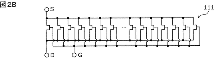
- FIG. 2B is a circuit configuration diagram of semiconductor elements constituting the switch.
- FIG. 3A is a graph showing the relationship between the number of stacks of switches and the switch characteristics.
- FIG. 3B is a graph showing the relationship between the gate width of the switch and the switch characteristic.
- FIG. 4 is a circuit diagram of filters according to Examples 1 to 3 and Comparative Example 1.
- FIG. 5 is a graph showing various characteristics of the filter according to Comparative Example 1.
- FIG. 6 is a graph showing various characteristics of the filter according to the first embodiment.
- FIG. 7 is a graph showing various characteristics of the filter according to the second embodiment.
- FIG. 8 is a graph showing various characteristics of the filter according to the third embodiment.
- FIG. 9 is a circuit diagram of filters according to Example 4 and Comparative Example 2.
- FIG. 10 is a graph showing various characteristics of the filter according to Comparative Example 2.
- FIG. 11 is a graph showing various characteristics of the filter according to the fourth embodiment.
- FIG. 12 is a circuit configuration diagram of a filter according to a modification of the first embodiment.
- FIG. 13 is an equivalent circuit diagram of a parallel arm circuit.
- FIG. 14 is a graph showing impedance characteristics, current characteristics, and voltage characteristics of the parallel arm circuit.
- FIG. 15A is a circuit configuration diagram of a parallel arm circuit.
- FIG. 15B is an equivalent circuit diagram of the parallel arm circuit when the switch is in the non-conductive state.
- FIG. 15A is a circuit configuration diagram of a parallel arm circuit.
- FIG. 15B is an equivalent circuit diagram of the parallel arm circuit when the switch is in the non-conductive state.
- FIG. 15C is an equivalent circuit diagram at a resonant frequency of a parallel arm circuit when the switch is in a non-conductive state.
- FIG. 15D is an equivalent circuit diagram at a resonant frequency of a parallel arm circuit when the switch is in a non-conductive state.
- FIG. 15E is a circuit configuration diagram of a parallel arm circuit.
- FIG. 15F is an equivalent circuit diagram at a resonant frequency of a parallel arm circuit when the switch is in a non-conductive state.
- FIG. 16 is a circuit configuration diagram showing another example of the filter according to the modification of the first embodiment.
- FIG. 17 is a circuit configuration diagram showing another example of the filter according to the modification of the first embodiment.
- FIG. 18 is a circuit configuration diagram showing another example of the filter according to the modification of the first embodiment.
- FIG. 19 is a circuit configuration diagram showing another example of the filter according to the modification of the first embodiment.
- FIG. 20 is a circuit diagram of a filter according to a fifth embodiment.
- FIG. 21A is a graph showing various characteristics of the filter according to the fifth embodiment when Band28a-Tx is used.
- FIG. 21B is a graph showing various characteristics of the filter according to the fifth embodiment when Band28b-Tx is used.
- FIG. 22 is a plan view illustrating the structure of the filter according to the fifth embodiment.
- FIG. 23 is a configuration diagram of the communication device and its peripheral circuit according to the second embodiment.
- passband lower end means “the lowest frequency in the passband”.
- pass band high end means “the highest frequency in the pass band”.
- low pass band side means “outside of pass band and lower frequency side than pass band”.
- high pass side of pass band means “outside of pass band and higher frequency side than pass band”.
- the “low frequency side” may be referred to as the “low frequency side”
- the “high frequency side” may be referred to as the “high frequency side”.
- the resonant frequency in the resonator or circuit is a resonant frequency for forming an attenuation pole in the pass band or near the pass band of the resonator or the filter including the circuit, and the resonator Alternatively, it is the frequency of the “resonance point” which is a singular point at which the impedance of the circuit becomes minimum (ideally, the point at which the impedance is 0).
- the antiresonance frequency in the resonator or the circuit is an antiresonance frequency for forming an attenuation pole in the pass band or near the pass band of the resonator or the filter including the circuit, unless otherwise specified. It is the frequency of the "anti-resonance point" which is a singular point at which the impedance of the resonator or the circuit concerned is maximal (ideally, the point at which the impedance is infinite).
- the series arm circuit and the parallel arm circuit are defined as follows.
- the parallel arm circuit is a circuit disposed between one node on the path connecting the input terminal and the output terminal and the ground.
- the series arm circuit is a circuit disposed between an input terminal or an output terminal and a node on the above path to which the parallel arm circuit is connected, or one of the above paths to which one parallel arm circuit is connected. , And another node on the path to which another parallel arm circuit is connected.
- FIG. 1 is a circuit configuration diagram of filter 10 according to the first embodiment.
- the filter (high frequency filter) 10 shown in the figure includes series arm circuits 11 and 12, a parallel arm circuit 21, and input / output terminals 101 and 102.
- the input / output terminal 101 is an input terminal to which a high frequency signal is input
- the input / output terminal 102 is an output terminal
- the input / output terminal 101 is an output terminal It becomes.
- the filter 10 When the filter 10 is used as, for example, a TDD (Time Division Duplex) filter, high frequency power may be applied to the output terminal. However, even in this case, when the high frequency power applied to the input terminal in one period is compared with the high frequency power applied to the output terminal in the other period, the former is larger than the latter. That is, in this case, the input terminal of the filter 10 is an input / output terminal to which higher frequency power is applied among the input / output terminals 101 and 102 to which high frequency power can be applied.
- TDD Time Division Duplex
- the filter 10 when used as, for example, a transmission filter of a multiplexer, received power may be applied to the output terminal. Since the transmission power is larger than the reception power, even in this case, the input terminal of the filter 10 is an input / output terminal to which a higher RF power is applied among the input / output terminals 101 and 102 to which the RF power can be applied. is there.
- the series arm circuit 11 is a series arm circuit provided on a path connecting the input / output terminal 101 and the input / output terminal 102.
- the series arm circuit 12 is a series arm circuit provided closer to the input / output terminal 102 than the series arm circuit 11 in the form of a path.
- the input / output terminal 101 is an input terminal to which a high frequency signal is input
- the input / output terminal 102 is an output terminal to which a high frequency signal is output. It is also called an arm circuit
- the series arm circuit 12 is also called a second series arm circuit.
- the input / output terminal 101 is an output terminal to which a high frequency signal is output
- the input / output terminal 102 is an input terminal to which a high frequency signal is input.
- It is also called a two series arm circuit
- the series arm circuit 12 is also called a first series arm circuit. That is, the series arm circuit near the input terminal is the first series arm circuit, and the series arm circuit near the output terminal is the second series arm circuit.
- the parallel arm circuit 21 is connected between the series arm circuit 11 and the series arm circuit 12 to the node x1 on the path connecting the input / output terminal 101 and the input / output terminal 102 and the ground. It is an arm circuit.
- the first parallel arm circuit may be constituted by, for example, a parallel arm resonator which is an elastic wave resonator, or may be a resonant circuit constituted by a plurality of resonators such as a longitudinally coupled resonator. Absent.
- the first parallel arm circuit may be, for example, a resonant circuit including an inductor and a capacitor.
- the parallel arm circuit is not limited to the resonant circuit, and may be an impedance element such as an inductor or a capacitor.
- the series arm circuit 11 includes a series arm resonator s1, a capacitor Cs1, and a switch SWs1.
- the switch SWs1 is a switch element connected in series to the capacitor Cs1 and configured of one semiconductor element or a plurality of semiconductor elements connected in series.
- the series arm circuit 12 includes a series arm resonator s2, a capacitor Cs2, and a switch SWs2.
- the switch SWs2 is a switch element connected in series with the capacitor Cs2 and configured of one semiconductor element or a plurality of semiconductor elements connected in series.
- Each of the semiconductor elements constituting the switch SWs1 and each of the semiconductor elements constituting the switch SWs2 are, for example, transistors.
- one semiconductor element (transistor) or a plurality of semiconductor elements (transistors) connected in series will also be referred to as at least one semiconductor element (transistor).
- the series arm resonator s1, the capacitor Cs1, and the switch SWs1 are respectively first series arm resonance.
- the series arm resonator s2, the capacitor Cs2, and the switch SWs2 are also referred to as a second series arm resonator, a second capacitor, and a second switch element, respectively.
- the series arm resonator s1, the capacitor Cs1, and the switch SWs1 are respectively second series
- the arm resonator, the second capacitor, and the second switch element are also referred to, and the series arm resonator s2, the capacitor Cs2, and the switch SWs2 are also referred to as a first series arm resonator, a first capacitor, and a first switch element, respectively.
- the series arm circuit 12 has the same configuration as that of the series arm circuit 11, except that the series arm circuit 12 is connected to the input / output terminal 102 and the circuit constant is different. Specifically, the series arm resonator s1, the capacitor Cs1, and the switch SWs1 in the series arm circuit 11 correspond to the series arm resonator s2, the capacitor Cs2, and the switch SWs2 in the series arm circuit 12, respectively. Therefore, in the following, the series arm circuit 11 will be described, and the series arm circuit 12 will be simplified and described.
- the series arm resonator s1 and the series arm resonator s2 may have different numbers of resonator divisions. Further, the series arm circuit 11 and the series arm circuit 12 may be configured to be different from each other as at least one of them has some element other than the circuit configuration described later. These matters are the same as in the following description of the circuit configuration.
- the series arm resonator s1 is an elastic wave resonator using an elastic wave, and for example, a resonator using SAW (Surface Acoustic Wave), a resonator using BAW (Bulk Acoustic Wave), or an FBAR (Film). Bulk Acoustic Resonator) etc.
- the SAW includes not only surface waves but also boundary waves.
- the series arm resonator s1 has a resonance frequency and a resonant frequency like a circuit in which an equivalent circuit of a resonator (a circuit in which an inductor and a capacitor are connected in series and a capacitor are connected in parallel) is an LC element. It may be a circuit having an antiresonant frequency.
- the resonance frequency of the series arm circuit 11 constitutes a pass band, and the antiresonance frequency of the series arm circuit 11 constitutes an attenuation pole.
- a circuit in which the capacitor Cs1 and the switch SWs1 are connected in series is connected in parallel to the series arm resonator s1.
- a control unit such as an RFIC (Radio Frequency Integrated Circuit)
- the impedance of the series arm circuit 11 is switched, that is, a series arm
- the antiresonant frequency of the circuit 11 is switched. Thereby, the frequency of the attenuation pole of the filter 10 is switched.
- the series arm circuit 11 is a circuit in which the capacitor Cs1 is connected in parallel to the series arm resonator s1 when the switch SWs1 is conductive, the antiresonance frequency of the series arm circuit 11 is the series arm resonator s1. Lower than the antiresonant frequency of
- the frequency variable width of the attenuation pole of the filter 10 depends on the element value of the capacitor Cs1.
- the capacitor Cs1 may be a variable capacitor such as a burr gap and a DTC (Digitally Tunable Capacitor).
- the switch SWs1 is a single pole single throw (SPST) type switch element including a transistor which is a semiconductor element.
- the switch SWs1 is formed of an FET (Field Effect Transistor), and is formed of, for example, GaAs or a Complementary Metal Oxide Semiconductor (CMOS). Since the switch using such a semiconductor is compact, the filter 10 can be miniaturized.
- FET Field Effect Transistor
- CMOS Complementary Metal Oxide Semiconductor
- the conduction and non-conduction of the switch SWs1 are switched, whereby the impedance of the series arm circuit 11 is switched, whereby the antiresonance frequency of the series arm circuit 11 is switched.
- the anti-resonance frequency is switched (changed) to the low band side or the high band side according to the conduction and non-conduction of the switch SWs1.
- the series circuit of the capacitor Cs1 and the switch SWs1 is connected in parallel to the series arm resonator s1, so that the switch SWs1 switches from conduction to non-conduction, whereby the series arm circuit 11 is formed.
- the anti-resonance frequency of is switched to the high frequency side. Since the frequency of the attenuation pole of the filter 10 is defined by the antiresonance frequency of the series arm circuits 11 and 12, switching the conduction and non-conduction of the switches SWs1 and SWs2 makes the frequency of the attenuation pole of the filter 10 variable. Become.
- FIG. 2A is a schematic view showing the configuration of the switch IC 50 according to the first embodiment.
- FIG. 2B is a circuit configuration diagram of the transistor 111 that constitutes the switch IC 50.
- (a) of FIG. 2A an implementation of a switch IC comprising four switches SWA to SWD is shown.
- the switches SWA to SWD are formed on the substrate 51.
- a power supply terminal P VCC On the back surface of the substrate 51, a power supply terminal P VCC , a control terminal P CTRL , a ground terminal P GND , and switch terminals P SWA , P SWB , P SWC , P SWD , P SWE, and P SWF are provided.
- the switch SWA is connected between the switch terminals P SWA and P SWF
- the switch SWB is connected between the switch terminals P SWB and P SWF
- the switch SWC is connected between the switch terminals P SWC and P SWE
- the switch SWD is connected between P SWD and P SWE .
- the switch SWs1 included in the filter 10 corresponds to the switch SWA
- the switch SWs2 corresponds to the switch SWC
- the switches SWB and SWD are not yet It becomes use.
- the switch IC 50 is not limited to the configuration shown in FIG. 2A, and may have only the switches SWA and SWC among the switches SWA to SWD shown in FIG. 2A.
- the input / output terminal 102 close to the switch SWC corresponding to the switch SWs2 is an input terminal to which a high frequency signal is input.
- the substrate 51 is operated by, for example, the power supply voltage VCC supplied from a power supply circuit such as a power management IC, and the switches SWs1 to SWs4 are individually made conductive according to the control signal input from the RFIC.
- a control circuit CTRL is provided which generates a plurality of switch drive voltages to be turned on.
- Each of switches SWA to SWD has a circuit configuration in which a plurality of transistors 111 are connected in series.
- Each of the switches SWA to SWD may be configured of one transistor 111.
- the transistor 111_1 configuring the switch SWA includes, for example, a source electrode including a plurality of source electrode fingers 111_1s, a drain electrode including a plurality of drain electrode fingers 111_1d, and a plurality of gate electrode fingers. It is an FET constituted by a gate electrode consisting of 111_1g.
- the transistor 111_2 configuring the switch SWC includes, for example, a source electrode including a plurality of source electrode fingers 111_2s, a drain electrode including a plurality of drain electrode fingers 111_2d, and a plurality of gates It is an FET constituted by a gate electrode consisting of electrode fingers 111_2g.
- a plurality of unit FETs configured such that the source electrode finger, the drain electrode finger, and the gate electrode finger face each other are arranged in parallel (comb like teeth) .
- the stack number Ns2 (here nine) of the transistors 111_2 configuring the switch SWC corresponding to the switch SWs2 is a transistor 111_1 configuring the switch SWA corresponding to the switch SWs1.
- Stack number Ns1 (here six) is greater than. That is, the stack number Ns2 (here, the first stack number) of the switches SWs2 (here, the first switch element) in the series arm circuit 12 (here, the first series arm circuit) is the series arm circuit 11 (here, the second series).
- the number of stacks Ns2 (here, second stack number) of the switches SWs1 (here, second switch elements) in the arm circuit) is larger.
- the gate width W2 of each of at least one (here, a plurality of) transistors 111_2 forming the switch SWC corresponding to the switch SWs2 is at least one (a plurality of here) of the switch SWA corresponding to the switch SWs1.
- At least one gate width W1 of the transistor 111_1 is larger. That is, the gate width W2 of each of at least one of the transistors constituting the switch SWs2 (here, the first switch element) in the series arm circuit 12 (here, the first series arm circuit) is the series arm circuit 11 (here, the second It is larger than at least one gate width W1 of each of at least one transistor constituting the switch SWs1 (here, the second switch element) in the parallel arm circuit).
- finger length L F2 switch SWC is the switch SWA finger Longer than L F1 .
- the switches SWs1 and SWs2 are designed as follows. That is, the stack number Ns2 of the switches SWs2 of the series arm circuit 12 connected near the input terminal is designed to be larger than the stack number Ns1 of the switches SWs1 in the series arm circuit 11. Further, the gate width W2 of the switch SWs2 is designed to be larger than the gate width W1 of the switch SWs1.
- the essential component of the invention is that the first stack of the first switch element of the first series arm circuit connected near the input terminal is the second switch element in the second series arm circuit. It is more than the second stack number.
- the gate width of each of the at least one transistor constituting the first switch element is larger than the gate width of at least one of the at least one transistor constituting the second switch element.
- the filter 10 can ensure power durability while reducing and miniaturizing the insertion loss in the pass band. This will be described using the relationship between the number of stacks Ns and the switch characteristics, and the relationship between the gate width W and the switch characteristics.
- FIG. 3A is a graph showing the relationship between the number of stacks Ns of the switches SWs1 and SWs2 and the switch characteristics. Specifically, FIG. 3A is a graph showing the relationship between the number of stacks Ns and the switch characteristic when the gate width W is fixed, for the switch formed of the transistor 111.
- FIG. 3B is a graph showing the relationship between the gate width W of the switches SWs1 and SWs2 and the switch characteristics according to the first embodiment. Specifically, FIG. 3A is a graph showing the relationship between the gate width W and the switch characteristic when the number of stacks Ns is fixed, for the switch formed of the transistor 111.
- the switch has resistance Ron when conducting and withstand voltage when nonconducting (maximum allowable voltage when nonconducting) Becomes higher.
- the withstand current at the time of conduction is constant regardless of the number of stacks Ns.
- the larger the number of stacks Ns the larger the size.
- the larger the gate width W the smaller the resistance Ron when conducting becomes.
- the withstand voltage at the time of non-conduction is constant regardless of the gate width W.
- the larger the gate width W the larger the withstand current at the time of conduction.
- the larger the gate width W the larger the size.
- the withstand voltage of one transistor 111 in which a plurality of unit FETs are connected in parallel is, for example, about 2.5 V
- the withstand current to the gate width is, for example, about 318 mA / mm
- the material of the gate electrode, and the source electrode It is defined by the gap between the finger 111 s and the drain electrode finger 111 d and the width of the electrode finger.
- the withstand voltage is improved as the stack number Ns of the transistors 111 is increased, but there is a trade-off relationship that the resistance at the time of conduction increases and the size increases. Further, the larger the gate width W of the transistor 111 is, the smaller the resistance at the time of conduction becomes, but there is a trade-off relationship that the size becomes larger.
- the first switch element of the first series arm circuit connected close to the input terminal has a higher voltage when it is not conducting as compared to the second switch element of the second series arm circuit connected close to the output terminal. Is applied. That is, in this case, the first switch element is required to have high voltage resistance, but the voltage resistance required for the second switch element is not high. Therefore, by making the number of the second stacks of the second switch elements smaller than the number of the first stacks of the first switch elements, it is possible to reduce the loss and reduce the size of the filter 10 while securing the voltage resistance. it can.
- the first switch element of the first series arm circuit connected near the input terminal has more current when conducting compared to the second switch element of the second series arm circuit connected near the output terminal. Flows. That is, although high resistance to current is required for the first switch element, the resistance to current required for the second switch element is not high. Therefore, by making the gate width of the first switch element larger than the gate width of the second switch element, the filter 10 can be miniaturized while securing current resistance. Furthermore, since the resistance at the time of conduction of the first switch element can be reduced, loss can be reduced when the first switch element is conductive.
- the second switch element has a smaller gate width than the first switch element, so that the resistance per conduction of the transistor 111 is large, but the number of stacks is small. This makes it possible to reduce the resistance during conduction of the entire second switch element represented by the product of the resistance during conduction per transistor 111 and the number of stacks. Therefore, loss can be reduced when the second switch element is conductive.
- the voltage applied to the switch may be referred to as “voltage across the switch” or “voltage across the switch element”.
- the magnitude of the voltage Vs1 across the switch SWs1 and the voltage Vs2 across the switch SWs2 is proportional to the magnitude of the high frequency power applied to the filter 10.
- the switches SWs1 and SWs2 are nonconductive, the impedances of the switches SWs1 and SWs2 are high, and the voltages Vs1 and Vs2 are high.
- a plurality of semiconductor elements are stacked (series connection) to divide a voltage applied to each semiconductor element.
- the number of stacks is increased, the size is increased and the resistance when the switch element is turned on is increased.
- the magnitude of the voltage Vs1 across the switch SWs1 is determined by which of the input / output terminals 101 and 102 the high frequency power is applied (the application direction of the high frequency power) and the magnitude of the applied power Depends on Further, the magnitude of the voltage Vs2 across the switch SWs2 also depends on the application direction of the high frequency power and the magnitude of the applied power. For example, when high frequency power is applied from the input / output terminal 102 side, the high frequency applied voltage accompanying the application of the high frequency power is higher as it is closer to the input / output terminal 102. That is, the high frequency applied voltage when the high frequency power is applied from the input / output terminal 102 is higher in the series arm circuit 12 than in the series arm circuit 11.
- the voltage Vs1 across the switch SWs1 is lower than the voltage Vs2 across the switch SWs2. It is less than Ns2.
- the switch SWs1 is compared to a configuration in which all the switch elements have the same configuration, that is, the same stack number, in order to ensure the withstand voltage of the switch elements with respect to high frequency input power.
- the number of stacks Ns1 of is smaller than the number of stacks Ns2 of switches SWs2. Therefore, the high frequency filter can be miniaturized as the number of stacks Ns1 is reduced, as compared with the variable frequency high frequency filter in which all the switch elements are in the same stack.
- the stack number Ns1 of the switch SWs1 is relatively reduced, the resistance at the time of conduction of the switch SWs1 can be reduced, so that the insertion loss in the pass band of the filter 10 at the time of conduction of the switch SWs1 can be reduced.
- the number Ns2 of stacks of the switches SWs2 having relatively high voltages at both ends is larger than the number Ns1 of stacks of the switches SWs1, the power durability of the filter 10 is secured. That is, it is possible to secure the power resistance characteristics while achieving low loss and downsizing when the switches in the series arm circuits 11 and 12 are conductive.
- FIG. 4 is a circuit diagram of the filter 10A according to the first to third embodiments and the first comparative example. As compared with the filter 10 according to the first embodiment, the filter 10A shown in the figure is different in the number of parallel arm circuits.
- the description of the same points as the filter 10 according to the first embodiment will be omitted, and the differences will be mainly described.
- the filter 10 ⁇ / b> A includes series arm circuits 11 and 12, parallel arm circuits 21, 22 and 23, and input / output terminals 101 and 102.
- the parallel arm circuits 21 to 23 are connected to the node on the path connecting the input / output terminal 101 and the input / output terminal 102 and the ground. Specifically, the parallel arm circuit 21 is connected to the node on the path between the input / output terminal 101 and the series arm circuit 11 and the ground. The parallel arm circuit 22 is connected to the node on the path between the series arm circuit 11 and the series arm circuit 12 and the ground. The parallel arm circuit 23 is connected to the node on the path between the input / output terminal 102 and the series arm circuit 12 and the ground.
- the parallel arm circuits 21, 22 and 23 are respectively constituted by parallel arm resonators p1, p2 and p3.
- the resonance frequency of the series arm circuits 11 and 12 constitutes a pass band
- the antiresonance frequency of the series arm circuits 11 and 12 constitutes an attenuation pole.
- a circuit in which the capacitor Cs1 and the switch SWs1 are connected in series is connected in parallel with the series arm resonator s1.
- a circuit in which the capacitor Cs2 and the switch SWs2 is connected in series is a series arm It is connected in parallel with the resonator s2.
- the series arm circuit 11 When the switches SWs1 and SWs2 are nonconductive, the circuit in which the capacitor Cs1 and the switch SWs1 are connected in series does not function, so that the series arm circuit 11 has almost the resonance characteristics of the series arm resonator s1, and the capacitor Cs2 and the switch SWs2 are connected in series Since the connected circuit does not function, the series arm circuit 12 has approximately the resonance characteristics of the series arm resonator s2.
- the series arm circuit 11 is a circuit in which the capacitor Cs1 is connected in parallel to the series arm resonator s1, so the antiresonance frequency of the series arm circuit 11 is the series arm resonance.
- the antiresonance frequency of the series arm circuit 12 is lower than that of the series arm resonator s2. It becomes lower than the antiresonance frequency.
- the filter 10A since the series arm resonators (s1, s2) are connected in parallel with the series circuit of the capacitors (Cs1, Cs2) and the switches (SWs1, SWs2), the switches SWs1 and SWs2 By switching from conduction to non-conduction, the antiresonance frequency of each series arm circuit (11, 12) is switched to the high frequency side (Faon ⁇ Faoff). Since the frequency of the attenuation pole of filter 10A is defined by the resonance frequency and antiresonance frequency of series arm circuits 11 and 12, and the resonance frequency and antiresonance frequency of parallel arm circuits 21-23, conduction of switches SWs1 and SWs2 is achieved. And the non-conduction can change the pass band and the attenuation band of the filter 10A.
- the Band 27-Tx (807 to 824 MHz) has a first pass band and a Band 27-Rx (852) by switching between conduction and non-conduction of the switches SWs1 and SWs2.
- a first filter characteristic with a first attenuation band of ⁇ 869 MHz, a second filter characteristic with a Band 26-Tx (814-849 MHz) as a second passband and a Band 26-Rx (859 to 894 MHz) as a second attenuation band Is a high frequency filter to be switched. That is, these filters are switched between the transmission filter corresponding to Band 27 and the transmission filter corresponding to Band 26 by switching between conduction and non-conduction of switches SWs 1 and SWs 2.
- Comparative Example 1 In Comparative Example 1, the number of stacks of the switches SWs1 and SWs2 is set to be the same in accordance with the maximum voltage of the switch to which the highest voltage of the switches SWs1 and SWs2 is applied. Further, the gate widths of the switches SWs1 and SWs2 are set to be the same in accordance with the maximum current of the switches through which the largest current flows among the switches SWs1 and SWs2. In the first comparative example, the input / output terminal 101 is an input terminal to which a high frequency signal is input.
- Table 1 shows the design parameters of the filter according to Comparative Example 1, the maximum current flowing through the switch (peak current: referred to as “switch current Is_max”) and the maximum voltage applied to the switch (peak voltage: referred to as “switch voltage Vs_max” ).
- the table also shows, as design parameters, the gate width W F and the stack number Ns of the switches in the series arm circuit, and the resonant frequency Fr and the antiresonant frequency Fa of the series arm circuit when the switch is conductive and nonconductive. ,It is shown.
- switch current Is_max the maximum current flowing to the switch when the switch in the series arm circuit is conductive and non-conductive
- Switch voltage Vs_max the maximum voltage (peak voltage) applied to the switch
- this table shows the largest current among the switch currents Is_max and the highest voltage among the switch voltages Vs_max when the switches in the series arm circuit are conductive and non-conductive, and the resistance Ron when conducting. ing.
- Table 2 also shows the allowable input current, the allowable input voltage and the size of each switch of the filter according to Comparative Example 1, and the total of these.
- Table 3 shows the insertion loss in the pass band of the filter according to Comparative Example 1.
- FIG. 5 is a graph which shows the various characteristics regarding the filter which concerns on the comparative example 1.
- the pass characteristic of the filter is shown in the first stage from the top (hereinafter referred to as “first stage”).
- impedance characteristics of the series arm circuits 11 and 12 are shown in the second stage from the top (hereinafter referred to as “second stage”).
- the third from the top hereinafter, referred to as “third stage”
- the characteristics of the current flowing through the switch are shown.
- switch voltage characteristic the characteristic of the voltage applied to the switch
- the number of stacks of semiconductor elements constituting the switches SWs1 and SWs2 is individually set in accordance with the voltage applied to the switches SWs1 and SWs2, and specifically, the following relationship is satisfied.
- the gate widths of the semiconductor elements constituting the switches SWs1 and SWs2 are set to be the same in accordance with the maximum current flowing through the switches SWs1 and SWs2.
- the input / output terminal 101 is an input terminal to which a high frequency signal is input. That is, the switch SWs1 connected near the input / output terminal 101 (input terminal) is a first switch element, and the switch SWs2 connected near the input / output terminal 102 (output terminal) is a second switch element.
- Table 4 shows design parameters and the like of the filter according to the first embodiment.
- Table 5 also shows the allowable input current, the allowable input voltage and the size of each switch of the filter according to the first embodiment, and the total thereof.
- Table 6 shows the insertion loss in the pass band of the filter according to the first embodiment.
- FIG. 6 is a graph showing various characteristics of the filter according to the first embodiment.
- the number of stacks of semiconductor elements constituting the switches SWs1 and SWs2 is individually set in accordance with the voltage applied to the switches SWs1 and SWs2. Furthermore, the gate widths of the semiconductor elements constituting the switches SWs1 and SWs2 are individually set in accordance with the current flowing through the switches SWs1 and SWs2, and specifically, the following relationship is satisfied.
- the input / output terminal 101 is an input terminal to which a high frequency signal is input. That is, the switch SWs1 connected near the input / output terminal 101 (input terminal) is a first switch element, and the switch SWs2 connected near the input / output terminal 102 (output terminal) is a second switch element.
- Table 7 shows design parameters and the like of the filter according to the second embodiment.
- Table 8 also shows the allowable input current, the allowable input voltage and the size of each switch of the filter according to the second embodiment, and the total thereof.
- Table 9 shows the insertion loss in the pass band of the filter according to the second embodiment.
- FIG. 7 is a graph showing various characteristics of the filter according to the second embodiment.
- the number of stacks of the semiconductor elements constituting the switches SWs1 and SWs2 is individually set in accordance with the voltage applied to the switches SWs1 and SWs2. Furthermore, the gate widths of the semiconductor elements constituting the switches SWs1 and SWs2 are individually set in accordance with the current flowing through the switches SWs1 and SWs2, and specifically, the following relationship is satisfied.
- the input / output terminal 102 is an input terminal to which a high frequency signal is input. That is, the switch SWs2 connected near the input / output terminal 102 (input terminal) is the first switch element, and the switch SWs1 connected near the input / output terminal 101 (output terminal) is the second switch element.
- Table 10 shows design parameters and the like of the filter according to the third embodiment. Further, Table 11 shows the allowable input current, the allowable input voltage and the size of each switch of the filter according to the third embodiment, and the total thereof. Further, Table 12 shows the insertion loss in the pass band of the filter according to the third embodiment.
- FIG. 8 is a graph showing various characteristics of the filter according to the third embodiment.
- series arm circuits 11 and 12 when switches SWs1 and SWs2 are nonconductive, the impedance of switches SWs1 and SWs2 is very high (ideally infinite), and series arm resonator s1 and The characteristics of s2 become dominant. Therefore, in this case, the characteristics of series arm circuits 11 and 12 shown in the right row and second stage of FIGS. 5 to 8 are substantially the same as the single characteristics of series arm resonators s1 and s2. That is, the antiresonance frequencies ("Fa off " in the figure) of the series arm resonators s1 and s2 in this case are substantially the same as the antiresonance frequencies of the series arm resonators s1 and s2, respectively.
- each of the series arm circuits 11 and 12 is a series arm resonator (s1, s2) And the capacitors (Cs1, Cs2) are connected in parallel. Therefore, in this case, as shown in the left row second stage in FIGS. 5 to 8, the antiresonance frequencies (“Fa on ” in the figure) of the series arm circuits (11, 12) are respectively series arm resonators. It is switched to the lower frequency side than the anti-resonance frequency of (s1, s2).
- Example 1 when Comparative Example 1 and Example 1 are compared, in Example 1, the number of stacks of the switch SWs2 (second switch element) (second stack number) is the number of stacks of the switch SWs1 (first switch element) The number of stacks is less than that).
- the total size of the switches SWs1 and SWs2 is made smaller than that of Comparative Example 1 (95400 ⁇ m 2 : Example 1 (see Table 5), 104400 ⁇ m 2 : Comparative Example 1 (Table 2) )
- insertion loss in the passband when switches SWs1 and SWs2 are conductive ie when Band27-Tx is used) (1.669 dB: Example 1 (see Table 6), 1.690 dB) Comparative Example 1 (see Table 3)).
- the number of stacks (second number of stacks) of the switch SWs2 is the number of stacks of the switch SWs1 (first switch element)
- the gate width of the switch SWs2 is smaller than the gate width of the switch SWs1.
- the number of stacks of the switch SWs1 (second switch element) is the number of stacks of the switch SWs2 (first switch element)
- the gate width of the switch SWs1 is smaller than the gate width of the switch SWs2.
- the anti-resonance frequency of the series arm resonator s2 (first series arm resonator) of the series arm circuit 12 (first series arm circuit) connected near the input / output terminal 102 (input terminal) The frequency is lower than the antiresonance frequency of the series arm resonator s1 (second series arm resonator) of the series arm circuit 11 (second series arm circuit) connected near the terminal 101 (output terminal).
- the switch SWs2 is also designed in accordance with the switch SWs1 in which the switch voltage is maximum and the switch current is also maximum. That is, for the switches SWs1 and SWs2, the number of stacks is large, and the gate width is designed to be large. Therefore, although the resistance at the time of conduction per semiconductor element constituting the switches SWs1 and SWs2 is small, the number of stacks is large, so the resistance Ron at the time of conduction of the switches SWs1 and SWs2 increases to 6.74 ⁇ . . Furthermore, in Comparative Example 1, the number of stacks is large and the gate width is large for the switches SWs1 and SWs2, so the total size of the switches SWs1 and SWs2 is also large.
- the number of stacks is large and the gate width is designed large, so the resistance Ron at conduction becomes as large as 6.74 ⁇ . It will However, the switch voltage of the switch SWs2 is lower than that of the switch SWs1. Therefore, the number of stacks of the switch SWs2 can be reduced compared to the switch SWs1.
- the resistance Ron at the time of conduction can be reduced to 5.58 ⁇ for the switch SWs2 as compared with the first comparative example. That is, it is possible to reduce the insertion loss in the passband when switches SWs1 and SWs2 are conductive (ie, when Band 27-Tx is used). In addition, since the number of stacks can be reduced for the switch SWs2, the total size of the switches SWs1 and SWs2 can be reduced.
- the gate width of the switch SWs2 is smaller than that in the first embodiment. Therefore, for the switch SWs2, although the resistance Ron in conduction is 6.70 ⁇ , which is not much different from that of the switch SWs1 (that is, the insertion loss in the over band does not change much), the total size of the switches SWs1 and SWs2 is It can be made smaller.
- the switch voltage of the switches SWs1 and SWs2 is generally lower and the switch current is also smaller overall, so the number of stacks of the switches SWs1 and SWs2 is reduced.
- the gate width can also be reduced. This is because the antiresonance frequency of the series arm resonator s2 (first series arm resonator) of the series arm circuit 12 (first series arm circuit) connected near the input / output terminal 102 (input terminal) is This is because the frequency is lower than the antiresonance frequency of the series arm resonator s1 (second series arm resonator) of the series arm circuit 11 (second series arm circuit) connected near the terminal 101 (output terminal). .
- the resistance Ron at the time of conduction can be reduced to 1.52 ⁇ for the switch SWs1 as compared with the second embodiment, and the resistance Ron at the time of conduction for the switch SWs2 can be reduced to 4.83 ⁇ . it can. That is, it is possible to further reduce the insertion loss in the pass band when switches SWs1 and SWs2 are conductive (ie, when Band27-Tx is used). Further, the number of stacks can be reduced for the switches SWs1 and SWs2, and the gate width can be reduced, so the total size of the switches SWs1 and SWs2 can be further reduced.
- the filter may have a ladder type filter structure including a first series arm circuit, a second series arm circuit, a third series arm circuit, a first parallel arm circuit, and a second parallel arm circuit.
- the third series arm circuit is provided between the first series arm circuit and the second series arm circuit on a path connecting the input terminal and the output terminal.
- the first parallel arm circuit is connected to a node on the path between the first series arm circuit and the third series arm circuit and to the ground.
- the second parallel arm circuit is connected to a node on the path between the second series arm circuit and the third series arm circuit and to the ground.
- the filter according to Comparative Example 2 is configured in the same manner as the filter according to Example 4 except that the design parameters are different.
- FIG. 9 is a circuit diagram of a filter 10B according to the fourth embodiment and the second comparative example. As compared with the filter 10A according to the first to third embodiments, the filter 10B shown in the figure is different in the number of series arm circuits and parallel arm circuits.
- the description of the same points as the filter 10 according to the first embodiment will be omitted, and the differences will be mainly described.
- the filter 10B includes series arm circuits 11, 12 and 13, parallel arm circuits 21 and 22, and input / output terminals 101 and 102.
- the series arm circuit 11 is a series arm circuit provided on a path connecting the input / output terminal 101 and the input / output terminal 102.
- the series arm circuit 13 is a series arm circuit provided closer to the input / output terminal 102 than the series arm circuit 11 in the path shape.
- the series arm circuit 12 is a third series arm circuit provided between the series arm circuit 11 and the series arm circuit 13 on the path.
- the parallel arm circuit 21 is a parallel arm circuit connected to a node on the path between the series arm circuit 11 and the series arm circuit 12 and the ground.
- the parallel arm circuit 22 is a parallel arm circuit connected to a node on the path between the series arm circuit 13 and the series arm circuit 12 and the ground.
- the parallel arm circuits 21 and 22 are respectively configured by parallel arm resonators p1 and p2.
- the input / output terminal 101 is an output terminal for outputting a high frequency signal
- the input / output terminal 102 is an input terminal for receiving a high frequency signal.
- the series arm circuit 11 is a second series arm circuit
- a series The arm circuit 13 is also referred to as a first series arm circuit
- the parallel arm circuit 21 as a second parallel arm circuit
- the parallel arm circuit 22 as a first parallel arm circuit.
- the series arm circuit 13 includes a series arm resonator s3, a capacitor Cs3, and a switch SWs3.
- the switch SWs3 is a switch element connected in series with the capacitor Cs3 and configured of one semiconductor element or a plurality of semiconductor elements connected in series.
- the input / output terminal 101 is an output terminal for outputting a high frequency signal
- the input / output terminal 102 is an input terminal for inputting a high frequency signal
- the series arm resonator s1, the capacitor Cs1, and the switch SWs1 are second ones.
- the series arm resonator, the second capacitor, and the second switch element are also referred to.
- the series arm resonator s3, the capacitor Cs3, and the switch SWs3 are also referred to as a first series arm resonator, a first capacitor, and a first switch element, respectively.
- the series arm resonator s2, the capacitor Cs2, and the switch SWs2 are also referred to as a third series arm resonator, a third capacitor, and a third switch element.
- the series arm circuit 13 has the same configuration as the series arm circuits 11 and 12 except that the circuit constant is different, and thus the detailed description will be omitted.
- the resonance frequency of the series arm circuits 11 to 13 constitutes a pass band
- the antiresonance frequency of the series arm circuits 11 to 13 constitutes an attenuation pole.
- a circuit in which the capacitor Cs1 and the switch SWs1 are connected in series is connected in parallel with the series arm resonator s1.
- a circuit in which the capacitor Cs2 and the switch SWs2 is connected in series is a series arm A circuit which is connected in parallel to the resonator s2 and in which the capacitor Cs3 and the switch SWs3 are connected in series in the series arm circuit 13 is connected in parallel to the series arm resonator s3.
- the impedance of the series arm circuits 11 to 13 is switched, that is, the series arm circuit 11
- the anti-resonance frequencies of ⁇ 13 are switched. Thereby, the frequency of the attenuation pole of the filter 10B is switched.
- the circuit in which the capacitor Cs1 and the switch SWs1 are connected in series does not function, so that the series arm circuit 11 has almost the resonance characteristics of the series arm resonator s1, and the capacitor Cs2 and the switch SWs2 are connected in series Since the connected circuit does not function, the series arm circuit 12 has almost the resonance characteristics of the series arm resonator s2, and the circuit in which the capacitor Cs3 and the switch SWs3 are connected in series does not function.
- the resonance characteristic of when the switches SWs1 to SWs3 are conductive, the series arm circuit 11 is a circuit in which the capacitor Cs1 is connected in parallel to the series arm resonator s1.
- the antiresonance frequency of the series arm circuit 12 is lower than that of the series arm resonator s2.
- the antiresonance frequency of the series arm circuit 13 is the antiresonance frequency of the series arm resonator s3. Lower than.
- the series arm resonators (s1 to s3) are connected in parallel with the series circuit of the capacitors (Cs1 to Cs3) and the switches (SWs1 to SWs3), the switches SWs1 to SWs3 By switching from conduction to non-conduction, the antiresonance frequency of each series arm circuit (11 to 13) is switched to the high frequency side (Faon ⁇ Faoff).
- the pass band and the attenuation band of filter 10B are defined by the resonant frequency and antiresonant frequency of series arm circuits 11 to 13 and the resonant frequency and antiresonant frequency of parallel arm circuits 21 and 22, switches SWs1 to SWs3 By switching between conduction and non-conduction, it is possible to change the pass band and the attenuation band of the filter 10B.
- the conduction and non-conduction of the switches SWs1 to SWs3 are switched to thereby set the Band 27-Tx as a first pass band and the Band 27-Rx as a first attenuation band.
- It is a high frequency filter in which the filter characteristic and the second filter characteristic having Band26-Tx as the second passband and Band26-Rx as the second attenuation band are switched. That is, these filters are switched between the transmission filter corresponding to Band 27 and the transmission filter corresponding to Band 26 by switching between conduction and non-conduction of switches SWs 1 and SWs 2.
- Example 4 and Comparative Example 2 when high frequency power of +36 dBm is applied to either of the input / output terminals 101 and 102, current resistance and voltage resistance necessary for the switches SWs1 to SWs3 are secured.
- the switches SWs1 to SWs3 are designed to do so.
- the design of the switches SWs1 to SWs3 in Example 4 and Comparative Example 2 will be specifically described below.
- the number of stacks of the switches SWs1 to SWs3 is set equal to the maximum voltage of the switch to which the highest voltage is applied among the switches SWs1 to SWs3. Further, the gate widths of the switches SWs1 to SWs3 are set to be equal to the maximum current of the switch through which the largest current flows among the switches SWs1 to SWs3.
- the input / output terminal 101 is an input terminal to which a high frequency signal is input.
- Table 13 shows the design parameters and the like of the filter according to Comparative Example 2. Further, Table 14 shows the allowable input current, the allowable input voltage and the size of each switch of the filter according to Comparative Example 2, and the total thereof. Further, Table 15 shows the insertion loss in the pass band of the filter according to Comparative Example 2.
- FIG. 10 is a graph showing various characteristics of the filter according to Comparative Example 2.
- the input / output terminal 102 is an input terminal to which a high frequency signal is input. That is, the switch SWs3 connected near the input / output terminal 102 (input terminal) is the first switch element, and the switch SWs1 connected near the input / output terminal 101 (output terminal) is the second switch element.
- Table 16 shows design parameters and the like of the filter according to the fourth embodiment.
- Table 17 also shows the allowable input current, the allowable input voltage and the size of each switch of the filter according to the fourth embodiment, and the total thereof.
- Table 18 shows the insertion loss in the pass band of the filter according to the fourth embodiment.
- FIG. 11 is a graph showing various characteristics of the filter according to the fourth embodiment.
- the characteristics of series arm circuits 11 to 13 shown in the right row and second stage of FIGS. 10 and 11 are substantially the same as the single characteristics of series arm resonators s1 to s3. That is, the antiresonance frequencies (“Fa off ” in the figure) of the series arm resonators s1 to s3 in this case are substantially the same as the antiresonance frequencies of the series arm resonators s1 to s3, respectively.
- the switches SWs1 to SWs3 are conductive, the impedances of the switches SWs1 to SWs3 are very low (ideally zero), and each of the series arm circuits 11 to 13 is a series arm resonator (s1 to s3) And the capacitors (Cs1 to Cs3) are connected in parallel. Therefore, in this case, as shown in the left row second stage of FIGS. 10 and 11, the anti-resonance frequency (“Fa on ” in the figure) of the series arm circuit (11 to 13) is a series arm resonator. It is switched to the lower frequency side than the antiresonant frequency of (s1 to s3).
- the stack number of the switch SWs2 (third switch element) (also referred to as the third stack number) is the stack of the switch SWs3 (first switch element).
- the number is smaller than the number (first stack number) and is larger than the stack number (second stack number) of the switch SWs1 (second switch element).
- the gate width of the switch SWs2 is smaller than the gate width of the switch SWs3 and larger than the gate width of the switch SWs1.
- the anti-resonance frequency of the series arm resonator s3 (first series arm resonator) of the series arm circuit 13 (first series arm circuit) connected near the input / output terminal 102 (input terminal) Is set lower than the antiresonance frequency of the series arm resonator s1 (second series arm resonator) of the series arm circuit 11 (second series arm circuit) connected near the input / output terminal 101 (output terminal) There is.
- the antiresonance frequency of the series arm resonator s1 of the series arm circuit 11 connected near the input / output terminal 101 (input terminal) is connected near the input / output terminal 102 (output terminal). It is higher than the antiresonance frequency of the series arm resonator s3 of the series arm circuit 13.
- the total size of the switches SWs1 to SWs3 is reduced as compared with the second comparative example (24100 ⁇ m 2 : fourth embodiment (see Table 17), 111150 ⁇ m 2 : the second comparative example (Table 14). Insertion loss in the pass band when switches SWs1 to SWs3 are conductive (ie when Band27-Tx is used) (1.421 dB: Example 4 (see Table 18), 1.543 dB). Comparative Example 2 (see Table 15)).
- the switches SWs2 and SWs3 also have the same design in accordance with the switch SWs1 in which the switch voltage is maximum and the switch current is also maximum. That is, for the switches SWs1 to SWs3, the number of stacks is large and the gate width is designed to be large. Therefore, although the resistance at the time of conduction per semiconductor element constituting the switches SWs1 to SWs3 is small, the number of stacks is large, so the resistance Ron at the time of conduction of the switches SWs1 to SWs3 increases to 17.18 ⁇ . . Further, in the comparative example 2, since the number of stacks is large and the gate width is large for all the switches SWs1 to SWs3, the total size of the switches SWs1 to SWs3 is also large.
- the switch voltage of the switches SWs1 to SWs3 is generally lower and the switch current is also generally smaller, so the number of stacks of the switches SWs1 to SWs3 is reduced.
- the gate width can also be reduced.
- the resistance Ron of the switch SWs1 when conducting 4.19 ⁇ , the resistance Ron of the switch SWs2 when conducting 9.21 ⁇ , and the switch SWs3 when the resistance Ron of 7 when conducting 7 It can be as small as .12 ⁇ . That is, it is possible to further reduce the insertion loss in the pass band when the switches SWs1 to SWs3 are conductive (ie, when Band27-Tx is used). Further, since the number of stacks can be reduced for the switches SWs1 to SWs3, the total size of the switches SWs1 to SWs3 can be reduced.
- the number of stacks of the second switch element (the switch SWs2 in Examples 1 and 2 and the switch SWs1 in Examples 3 and 4) in the second series arm circuit arranged near the output terminal is arranged near the input terminal
- the number of stacks of the third switch element (the switch SWs2 in the fourth embodiment) is smaller than the number of stacks of the first switch element and larger than the number of stacks of the second switch element, and the gate width of the third switch element is By making the width smaller than the gate width of the first switch element and larger than the gate width of the second switch element, the power resistance required for the filter can be secured, and further miniaturization and in the passband at the time of switch conduction Further reduction of the insertion loss of the
- the configuration of the parallel arm circuit is not limited to the configuration described in the first embodiment. Therefore, as a modified example of the first embodiment, a filter having a configuration of a parallel arm circuit different from that of the first embodiment will be described below.
- the parallel arm circuit is a circuit having only a parallel arm resonator.
- the parallel arm circuit has a switch circuit connected in series to the parallel arm resonator.
- FIG. 12 is a circuit configuration diagram of a filter 10C according to a modification of the first embodiment.
- the filter 10C shown in the figure is different from the filter 10 according to the first embodiment in the circuit configuration of the parallel arm circuit 21.
- the description of the same points as the filter 10 according to the first embodiment will be omitted, and differences will be mainly described.
- the parallel arm circuit 21 has a parallel arm resonator p1 and a switch circuit 31 described later connected in series to the parallel arm resonator p1.
- the parallel arm resonator p1 is an elastic wave resonator using an elastic wave, and is, for example, a resonator using SAW, a resonator using BAW, or an FBAR.
- the SAW includes not only surface waves but also boundary waves.
- the switch circuit 31 is connected in series to the parallel arm resonator p1, and in this modification, is connected in series to the parallel arm resonator p1 between the parallel arm resonator p1 and the ground.
- the switch circuit 31 may be connected in series with the parallel arm resonator p1 between the node x1 and the parallel arm resonator p1, but from the viewpoint of miniaturization, connection is performed in the connection order of this modification. Is preferred. This will be described in a fifth embodiment described later.
- the switch circuit 31 includes a capacitor Cp1 which is an example of an impedance element which is one of an inductor and a capacitor, and a switch SWp1 which is a fourth switch element formed of at least one semiconductor element.
- the switch circuit 31 switches between conduction and non-conduction of the switch SWp1 in accordance with a control signal from a control unit (not shown) such as RFIC. Then, by switching the switch SWp1, the impedance of the switch circuit 31 is switched, and the resonant frequency of the parallel arm circuit 21 is switched.
- the switch circuit 31 is a circuit in which the capacitor Cp1 and the switch SWp1 are connected in parallel.
- the resonance frequency of the parallel arm circuit 21 constitutes an attenuation pole on the lower side of the pass band of the filter 10C, and the frequency variable width of the attenuation pole of the filter 10C depends on the element value of the capacitor Cp1, for example, the element value of the capacitor Cp1 is The smaller the frequency, the wider the frequency variable range. Therefore, the element value of the capacitor Cp1 can be appropriately determined according to the frequency specification required for the filter 10C. Further, the capacitor Cp1 may be a variable capacitor such as a burr gap and a DTC.
- the switch SWp1 is an SPST switch element configured of a transistor which is a semiconductor element.
- the switch SWp1 is formed of an FET, and is made of, for example, GaAs or CMOS. Since the switch using such a semiconductor is compact, the filter 10C can be miniaturized.
- the switch SWp1 is configured of one semiconductor element or a plurality of semiconductor elements connected in series, as in the switch SWs1 and the like.
- the structure of the switch SWp1 included in the filter 10C is the same as that of the switch SWs1 or the like, and thus the description thereof is omitted.
- switching the conduction and non-conduction of the switch SWp1 switches the impedance of the switch circuit 31, thereby switching at least one of the resonant frequency and the antiresonant frequency of the parallel arm circuit 21.
- the parallel arm circuit 21 has a resonant frequency and an antiresonant frequency, and the resonant frequency is switched to the low band side or the high band side according to the conduction and non-conduction of the switch SWp1.
- switch circuit 31 is formed of a parallel circuit of capacitor Cp1 and switch SWp1, so that switch SWp1 switches from conduction to non-conduction, so that parallel arm circuit 21 is formed. Resonance frequency is switched to the high frequency side. Since the pass band and the attenuation band of filter 10C are defined by the resonance frequency and antiresonance frequency of series arm circuits 11 and 12, and the resonance frequency and antiresonance frequency of parallel arm circuit 21, switches SWs1 and SWs2 and switch SWp1 By switching between conduction and non-conduction, the frequencies of the pass band and the attenuation band of the filter 10C are switched (variable).
- another parallel arm circuit different from the parallel arm circuit 21 may be connected to a node different from the node x1.
- the magnitude of the voltage Vp1 across the switch SWp1 depends on which of the input / output terminals 101 and 102 the high frequency power is applied from (the application direction of the high frequency power) and the resonance frequency of the parallel arm resonator p1. Do. For example, when high frequency power is applied from the input / output terminal 102 side, the high frequency applied voltage accompanying the application of the high frequency power is so high that the switch SWp1 is connected near the input / output terminal 102.
- the high frequency voltage applied to the parallel arm circuit 21 is divided by the parallel arm resonator p1 and the switch circuit 31, but the division ratio depends on the impedance of the parallel arm resonator p1 and the switch circuit 31. .
- the impedance of the parallel arm resonator p1 largely changes depending on the resonance frequency and the antiresonance frequency. Therefore, among the high frequency voltages applied to the parallel arm circuit 21, the high frequency partial pressure applied to the switch circuit 31 is the parallel arm resonator It changes with the resonance characteristic of p1.
- FIG. 13 is an equivalent circuit diagram of the parallel arm circuit Px when the switch is nonconductive.
- FIG. 14 is a graph showing impedance characteristics, current characteristics, and voltage characteristics of the parallel arm circuit Px.
- the parallel arm circuit Px has a configuration in which a resonator reso and a capacitor Cx are connected in series.
- the capacitor Cx represents a non-conductive capacitance component of the switch.
- the resonant frequency of the resonant circuit Px is higher than the resonant frequency of the resonator reso. Further, as shown in the middle stage of FIG.
- the current I flowing through the parallel arm circuit Px (ie, the current I flowing through the capacitor Cx) is maximum at the resonance frequency of the parallel arm circuit Px. This is due to the fact that the impedance of the parallel arm circuit Px is minimized at the resonant frequency of the parallel arm circuit Px. Further, as shown in the lower part of FIG. 14, the voltage Vo applied to the parallel arm circuit Px is minimized at the resonant frequency of the parallel arm circuit Px, but the voltage Vc applied to the capacitor Cx (absolute value) The voltage Vr (absolute value) applied to the resonator reso is a maximum. Thus, at the resonance frequency of the parallel arm circuit Px, the voltage Vc and the current of the capacitor Cx become maximum. In other words, the voltage and current of the switch connected in series with the resonator reso can be maximum at the resonant frequency of the parallel arm circuit Px when the switch is not conducting.
- FIG. 15A is a circuit configuration diagram of the parallel arm circuit Py.
- FIG. 15B is an equivalent circuit diagram of the parallel arm circuit Py when the switch is in the non-conductive state.
- FIG. 15C is an equivalent circuit diagram at a resonant frequency of the parallel arm circuit Py when the switch is in the non-conductive state.
- the parallel arm circuit Py is a circuit in which a resonator reso and a switch SW are connected in series.
- the resonator reso is represented by a circuit in which a series circuit of an inductor L 1 , capacitors C 1 and R 1 , and a capacitance C 0 are connected in parallel.
- the switch SW is represented by a circuit in which a resistor R off and an off capacitance C off are connected in series.
- the equivalent circuit at the resonant frequency of the parallel arm circuit Py as shown in FIG. 15C, the inductor L 1 and a resistor R z and capacitor C z is represented by circuits connected in series.
- the resistance R z and the capacitance C z are represented by Expression 1 and Expression 2, respectively.
- the impedance Zp at the resonant frequency of the parallel arm circuit Py is expressed by Equation 3 from the equivalent circuit of FIG. 15C, and the current Ip flowing through the parallel arm circuit Py when the reference voltage Vp is applied to the parallel arm circuit Py is It becomes.
- Equation 5 holds at the resonance frequency of the parallel arm circuit Py.
- the voltage Vc applied to the capacitor Cz becomes Q times the reference voltage Vp of the parallel arm circuit Py, and a voltage exceeding the reference voltage Vp is applied to the switch SW in the parallel arm circuit Py when the switch SW is nonconductive. It takes.
- FIG. 15D is an equivalent circuit diagram at a resonant frequency of the parallel arm circuit Py when the switch SW is in a non-conductive state.
- the equivalent circuit shown in FIG. 15D is one in which the capacitor Cz is decomposed into the off capacitance C off of the switch SW.
- the voltage V Coff according to the OFF capacitance C off is represented by the formula 11, as the OFF capacitance C off of the switch SW is small, the voltage across the off capacitance C off of the switch SW is low. Also, as the Q value at the resonance frequency is lower, the voltage applied to the off capacitance C off of the switch SW is lower.
- FIG. 15E is a circuit configuration diagram of the parallel arm circuit Pz.
- FIG. 15F is an equivalent circuit diagram at a resonance frequency of the parallel arm circuit Pz when the switch SW is in the non-conductive state.
- Equation 12 the resonance frequency fr and the anti-resonance frequency fa of the resonator reso are expressed as shown in Equation 12 and Equation 13, respectively.
- Equation 14 the following can be found for the voltage V Coff of the off capacitance C off .
- the capacitance C 0 of the resonator reso increases, the voltage V Coff of the off capacitance C off of the switch SW decreases.
- the capacitor C p1 increases, the voltage V Coff of the off capacitance C off of the switch SW decreases.
- the frequency variable amount of parallel arm circuit Pz is small, the voltage V Coff off capacitance C off of the switch SW is lowered.
- the relative bandwidth (fa ⁇ fr) / fr of the resonator reso increases, the voltage V Coff of the off capacitance C off of the switch SW decreases.
- the magnitude of the voltage Vs across the switch SW depends on the high frequency power application direction and the resonant frequency of the parallel arm resonator.
- the magnitude of the voltage Vs across the switch SW is the capacitance of the parallel arm resonator, the equivalent capacitance C p1 of the switch SW, the frequency variable amount of the parallel arm circuit, and the parallel arm resonance It also depends on the fractional bandwidth of the child.
- the circuit configuration of the parallel arm circuit is not limited to that shown in FIG.
- the parallel arm circuit may have a circuit configuration shown in FIG. 16 to FIG.
- 16 to 19 are circuit configuration diagrams showing another example of the filter according to the modification of the first embodiment.
- the filter 10D shown in FIG. 16 is different from the filter 10C according to the modification of the first embodiment in the circuit configuration of the switch circuit 31.
- the switch circuit 31 includes an inductor Lp1 (impedance element), a switch SWp1 (fourth switch element), and a capacitor Cp1.
- the capacitor Cp1 is connected in series to the switch SWp1, and a circuit in which the capacitor Cp1 and the switch SW1a are connected in series is connected in parallel to the inductor Lp1.
- the switch circuit 31 is configured by a parallel circuit of the inductor Lp1 and the switch SWp1, switching the switch SWp1 from conduction to non-conduction causes the resonance frequency of the parallel arm circuit 21 to be lower. It is switched.
- the resonance frequency of the parallel arm circuit 21 when the switch SWp1 is in the conductive state is higher than the resonance frequency of the parallel arm resonator p1 by the capacitor Cp1 connected in series to the switch SWp1. It can be located on the frequency side. For this reason, by switching the conduction and non-conduction of the switch SWp1, the variable width of the frequency of the attenuation pole on the lower side of the pass band can be made larger than that of the filter 10C.
- the filter 10E shown in FIG. 17 is different from the filter 10C according to the modification of the first embodiment in the circuit configuration of the switch circuit 31.
- the switch circuit 31 includes a capacitor Cp1 (impedance element), a switch SWp1 (fourth switch element), and an inductor Lp1.
- the inductor Lp1 is connected in series to the switch SWp1, and a circuit in which the inductor Lp1 and the switch SW1a are connected in series is connected in parallel to the capacitor Cp1.
- the switch circuit 31 is configured by a parallel circuit of the capacitor Cp1 and the switch SWp1
- switching the switch SWp1 from conduction to non-conduction causes the resonance frequency of the parallel arm circuit 21 to the high frequency side. It is switched.
- the resonance frequency of the parallel arm circuit 21 when the switch SWp1 is in the conductive state is lower than the resonant frequency of the parallel arm resonator p1 by the inductor Lp1 connected in series to the switch SWp1. It can be located on the frequency side. For this reason, by switching the conduction and non-conduction of the switch SWp1, the variable width of the frequency of the attenuation pole on the lower side of the pass band can be made larger than that of the filter 10C.
- the filter 10F shown in FIG. 18 is different from the filter 10C according to the modification of the first embodiment in the circuit configuration of the parallel arm circuit 21.
- one parallel arm circuit includes two parallel arm resonators.
- the parallel arm circuit 21 includes parallel arm resonators p1a and p1b, and a switch circuit 31 connected in series to the parallel arm resonator p1a.
- the resonance frequency of the parallel arm resonator p1b is different from the resonance frequency of the parallel arm resonator p1a
- the antiresonance frequency of the parallel arm resonator p1b is different from the antiresonance frequency of the parallel arm resonator p1a.
- the switch SWp1 switches from conduction to non-conduction, so that the pass characteristic of the filter 10F has an attenuation slope on the low pass band side. It will switch to the high frequency side while maintaining the steepness.
- the filter can switch the frequency of the low pass end of the pass band and the frequency of the attenuation band to the high side while suppressing an increase in insertion loss at the low pass end of the pass band.
- the switch SWp1 switches from conduction to non-conduction, whereby the pass characteristic of the filter 10F is attenuated by the high pass band.
- the slope is switched to the high frequency side while maintaining the steepness.
- the filter can switch the frequency of the high pass end of the pass band and the frequency of the attenuation band to the high pass while suppressing the increase of the insertion loss of the high pass end of the pass band.
- a filter 10G shown in FIG. 19 is different from the filter 10C according to the modification of the first embodiment in the circuit configuration of the parallel arm circuit 21.
- one parallel arm circuit includes two parallel arm resonators and two switch circuits. More specifically, one parallel arm circuit has two sets of circuits in which parallel arm resonators and switch circuits are connected in series, and they are connected in parallel.
- the parallel arm circuit 21 includes parallel arm resonators p1a and p1b, a switch circuit 31a connected in series to the parallel arm resonator p1a, and a switch circuit 31b connected in series to the parallel arm resonator p1b. .
- the circuit in which the parallel arm resonator p1a and the switch circuit 31a are connected in series and the circuit in which the parallel arm resonator p1b and the switch circuit 31b are connected in series are connected in parallel between the node and the ground.
- the switch circuit 31a is a circuit including a capacitor Cp1a and a switch SWp1a. The switch SWp1a is connected in parallel to the capacitor Cp1a.
- the switch circuit 31b is a circuit including a capacitor Cp1b and a switch SWp1b.
- the switch SWp1 b is connected in parallel to the capacitor Cp1 b.
- the resonance frequency of the parallel arm resonator p1b is different from the resonance frequency of the parallel arm resonator p1a, and the antiresonance frequency of the parallel arm resonator p1b is different from the antiresonance frequency of the parallel arm resonator p1a.
- the pass characteristic of the filter 10G maintains the steepness of the attenuation slope on the low pass side of the pass band, and the pass band The passband can be switched to the high band side while maintaining the steepness of the attenuation slope on the high band side.
- the filter 10G by switching each switch from conduction to non-conduction, the attenuation pole on the low pass band side is shifted to the high band side, and the attenuation pole on the high band side of the pass band is high band
- the pass band can be shifted to the high band side while suppressing an increase in insertion loss at the low band end of the pass band while shifting to the low band.
- the passband lower band side attenuation pole is switched to the lower band side, and the passband high band side attenuation pole is switched to the low band side, the passband The passband can be switched to the low band side while suppressing an increase in the insertion loss at the high band end.
- each filter in this modification may be replaced with inductors. Even in this case, each filter in this modification has a frequency variable function.
- the switch circuit 31 includes the switch SWp1 and the capacitor or the inductor, it is sufficient that the switch circuit 31 includes at least the switch SWp1. That is, the parallel arm circuit 21 (first parallel arm circuit) may have the parallel arm resonator p1 and the switch SWp1 (fourth switch element) serially connected to the parallel arm resonator p1.
- Example 5 According to the present modification described above, with the filters 10C to 10G having a frequency variable function, it is possible to secure the power resistance while reducing the insertion loss in the passband and reducing the size. Hereinafter, this effect will be described using Example 5.
- FIG. 20 is a circuit diagram of the filter 10H according to the fifth embodiment.
- the filter 10H shown in the same figure differs in the number of series arm circuits and parallel arm circuits compared to the filter 10C.
- the filter 10H includes series arm circuits 11, 12, 13, 14, and 15, parallel arm circuits 21, 22, 23, and 24, and input / output terminals 101 and 102.
- the series arm circuit 11 is a series arm circuit provided on a path connecting the input / output terminal 101 and the input / output terminal 102.
- the series arm circuit 12 is a series arm circuit provided closer to the input / output terminal 102 than the series arm circuit 11 in the form of a path.
- the series arm circuit 13 is a series arm circuit provided closer to the input / output terminal 102 than the series arm circuit 12 in the form of the path.
- the series arm circuit 14 is a series arm circuit provided closer to the input / output terminal 102 than the series arm circuit 13 in the form of the path.
- the series arm circuit 15 is a series arm circuit provided closer to the input / output terminal 102 than the series arm circuit 14 in the form of the path.
- the series arm circuit 11 includes a series arm resonator s1, a capacitor Cs1, and a switch SWs1.
- the switch SWs1 is a switch element connected in series to the capacitor Cs1 and configured of one semiconductor element or a plurality of semiconductor elements connected in series.
- a circuit in which the capacitor Cs1 and the switch SWs1 are connected in series is connected in parallel to the series arm resonator s1.
- the series arm circuit 12 includes a series arm resonator s2, a capacitor Cs2, and a switch SWs2.
- the switch SWs2 is a switch element connected in series with the capacitor Cs2 and configured of one semiconductor element or a plurality of semiconductor elements connected in series.
- a circuit in which the capacitor Cs2 and the switch SWs2 are connected in series is connected in parallel to the series arm resonator s2.
- the series arm circuit 13 includes a series arm resonator s3, a capacitor Cs3, and a switch SWs3.
- the switch SWs3 is a switch element connected in series with the capacitor Cs3 and configured of one semiconductor element or a plurality of semiconductor elements connected in series.
- a circuit in which the capacitor Cs3 and the switch SWs3 are connected in series is connected in parallel to the series arm resonator s3.
- the series arm circuit 14 includes a series arm resonator s4, a capacitor Cs4, and a switch SWs4.
- the switch SWs4 is a switch element connected in series with the capacitor Cs4 and configured of one semiconductor element or a plurality of semiconductor elements connected in series.
- a circuit in which the capacitor Cs4 and the switch SWs4 are connected in series is connected in parallel to the series arm resonator s4.
- the series arm circuit 15 includes a series arm resonator s5, a capacitor Cs5, and a switch SWs5. It is a switch element connected in series with the switch SWs 25 and the capacitor Cs 5 and configured of one semiconductor element or a plurality of semiconductor elements connected in series. A circuit in which the capacitor Cs5 and the switch SWs5 are connected in series is connected in parallel to the series arm resonator s5.
- the parallel arm circuit 21 is connected to a node on the path between the series arm circuits 11 and 12 and to the ground.
- the parallel arm circuit 22 is connected to a node on the path between the series arm circuits 12 and 13 and to the ground.
- the parallel arm circuit 23 is connected to a node on the path between the series arm circuits 13 and 14 and to the ground.
- the parallel arm circuit 24 is connected to a node on the path between the series arm circuits 14 and 15 and to the ground.
- the parallel arm circuit 21 includes a parallel arm resonator p1 and a switch circuit 31 connected in series to the parallel arm resonator p1.
- the parallel arm circuit 22 includes a parallel arm resonator p2 and a switch circuit 32 connected in series to the parallel arm resonator p2.
- the parallel arm circuit 23 includes a parallel arm resonator p3 and a switch circuit 33 connected in series to the parallel arm resonator p3.
- the parallel arm circuit 24 includes a parallel arm resonator p4 and a switch circuit 34 connected in series to the parallel arm resonator p4.
- the switch circuit 31 has a capacitor Cp1 and a switch SWp1.
- the switch SWp1 is connected in parallel to the capacitor Cp1 and is configured of one semiconductor element or a plurality of semiconductor elements connected in series.
- the switch circuit 32 has a capacitor Cp2 and a switch SWp2.
- the switch SWp2 is connected in parallel to the capacitor Cp2 and is configured of one semiconductor element or a plurality of semiconductor elements connected in series.
- the switch circuit 33 has a capacitor Cp3 and a switch SWp3.
- the switch SWp3 is connected in parallel to the capacitor Cp3 and is configured of one semiconductor element or a plurality of semiconductor elements connected in series.
- the switch circuit 34 has a capacitor Cp4 and a switch SWp4.
- the switch SWp4 is connected in parallel to the capacitor Cp4 and is configured of one semiconductor element or a plurality of semiconductor elements connected in series.
- the resonance frequency of each series arm circuit constitutes a passband
- the antiresonance frequency of each series arm circuit constitutes an attenuation pole on the high side of the passband.
- the anti-resonance frequency of each parallel arm circuit constitutes a pass band
- the resonance frequency of each series arm circuit constitutes an attenuation pole on the low pass band side.
- each switch element By switching conduction and non-conduction of each switch element according to a control signal from a control unit (not shown) such as RFIC, impedance of each series arm circuit and each parallel arm circuit is switched, that is, each series The antiresonance frequency of the arm circuit and the resonance frequency of each parallel arm circuit are switched. Thereby, the frequency of the pass band of filter 10H and the attenuation pole is switched.
- a control unit not shown
- impedance of each series arm circuit and each parallel arm circuit is switched, that is, each series The antiresonance frequency of the arm circuit and the resonance frequency of each parallel arm circuit are switched. Thereby, the frequency of the pass band of filter 10H and the attenuation pole is switched.
- each parallel arm circuit is a circuit in which a capacitor is connected in series to the parallel arm resonator, so the resonant frequency of each parallel arm circuit is higher than the resonant frequency of each parallel arm resonator.
- each series arm circuit is a circuit in which a capacitor is connected in parallel to the series arm resonator, so the antiresonance frequency of each series arm circuit is equal to that of each series arm resonator.
- Each parallel arm circuit substantially has resonance characteristics of each parallel arm resonator because the capacitor in each parallel arm circuit does not function because the frequency is lower than the antiresonance frequency.
- each switch circuit (31 to 34) is formed of a parallel circuit of capacitors (Cp1 to Cp4) and switches (SWp1 to SWp4), switching of switches SWp1 to SWp4 from conduction to non-conduction
- the resonance frequency of each parallel arm circuit (21 to 24) is switched to the high frequency side (Frpon ⁇ Frpoff).
- the pass band and the attenuation band of filter 10H are defined by the resonant frequency and antiresonant frequency of series arm circuits 11 to 15 and the resonant frequency and antiresonant frequency of parallel arm circuits 21 to 24, switches SWs1 to SWs5 and By switching between conduction and non-conduction of the switches SWp1 to SWp4, it is possible to vary the frequency of the pass band and the frequency of the attenuation band of the filter 10H.
- Band 28a-Tx (703 to 733 MHz) when each switch element is conductive is switched to the first pass band and Band 28a-Rx (758) by switching between conduction and non-conduction of each switch element.
- the first filter characteristics with a first attenuation band of ⁇ 788 MHz, and the Band 28b-Tx (718-748 MHz) when each switch element is nonconductive is the second passband and the Band 28 b-Rx (773-803 MHz) is a second attenuation It is a high frequency filter in which the second filter characteristic to be a band is switched. That is, these filters are switched between the transmission filter corresponding to Band 28 a and the transmission filter corresponding to Band 28 b by switching conduction and non-conduction of each switch element, a high frequency filter having a frequency variable function (tunable filter ).
- the switches SWs1 to SWs5 and the switches SWp1 to SWp4 need to have the current resistance and the voltage resistance required. .About.SWs5 and switches SWp1 to SWp4 are designed. The design of the switches SWs1 to SWs5 and the switches SWp1 to SWp4 in the fifth embodiment will be specifically described below.
- the input / output terminal 102 is an input terminal to which a high frequency signal is input. That is, the switch SWs5 connected near the input / output terminal 102 (input terminal) is the first switch element, and the switch SWs1 connected near the input / output terminal 101 (output terminal) is the second switch element.
- the antiresonance frequency of the series arm resonator s5 (first series arm resonator) of the series arm circuit 15 (first series arm circuit) connected near the input / output terminal 102 (input terminal) is the input / output terminal.
- the antiresonance frequency of the series arm resonator s1 (second series arm resonator) of the series arm circuit 11 (second series arm circuit) connected close to 101 (output terminal) is made lower.
- the number of stacks and the gate width of the semiconductor elements constituting the switches SWs1 to SWs5 are individually set, and specifically, the following relationship is satisfied.
- switch SWs5 Number of stacks of switch SWs5> Number of stacks of switch SWs1 Gate width of switch SWs5> Gate width of switch SWs1 Number of stacks of switch SWs5> Number of stacks of at least one switch element of switches SWs2 to SWs4 Gate width of switch SWs5> Switch SWs2 to Gate width of at least one switch element of SWs4 Number of stacks of at least one switch element of switches SWs2 to SWs4> Stack number of switch SWs1: Gate width of at least one switch element of switches SWs2 to SWs4> Gate width of switch SWs1
- the number of stacks and the gate width of the semiconductor elements constituting the switches SWp1 to SWp4 are set individually, and specifically, the following relationship is satisfied.
- Table 19 shows design parameters and the like of the filter according to the fifth embodiment. Further, Table 20 shows the allowable input current, the allowable input voltage and the size of each switch of the filter according to the fifth embodiment, and the total thereof. Further, Table 21 shows the insertion loss in the pass band of the filter according to the fifth embodiment.
- FIG. 21A is a graph showing various characteristics of the filter 10H according to the fifth embodiment when the Bands 28a-Tx are used when the switches SWs1 to SWs5 and the switches SWp1 to SWp4 are conductive.
- FIG. 21B is a graph showing various characteristics of the filter 10H according to the fifth embodiment when the Bands 28b-Tx are used when the switches SWs1 to SWs5 and the switches SWp1 to SWp4 are nonconductive.
- the filter 10H according to the fifth embodiment as shown in the first stage of FIG. 21A, when the switches SWs1 to SWs5 and the switches SWp1 to SWp4 are conductive, the first filter characteristic is realized, and the filter 10H of FIG. As shown in one step, when the switches SWs1 to SWs5 and the switches SWp1 to SWp4 are in the non-conductive state, the second filter characteristic is realized.
- the passband is switched between the Band 28a-Tx and the Band 28b-Tx by switching the conduction and non-conduction of the switches SWs1 to SWs5 and the switches SWp1 to SWp4, and the attenuation band is Band28a-Rx and Band28b- It is a high frequency filter (tunable filter) having a frequency variable function, which is switched with Rx.
- the characteristics of the series arm circuits 11 to 15 shown in the left row and second stage of FIG. 21B are substantially the same as the single characteristics of the series arm resonators s1 to s5. That is, the antiresonance frequencies ("Fas off " in the figure) of the series arm resonators s1 to s5 in this case are substantially the same as the antiresonance frequencies of the series arm resonators s1 to s5, respectively.
- each of the series arm circuits 11 to 15 is a series arm resonator (s1 to s5) And the capacitors (Cs1 to Cs5) are connected in parallel. Therefore, in this case, as shown in the second row in the left column of FIG. 21A, the antiresonance frequencies (“Fas on ” in the figure) of the series arm circuits 11 to 15 are respectively non-conductive in the switches SWs1 to SWs5. Are switched to the lower frequency side than the antiresonance frequency of the series arm circuits 11-15.
- the characteristics of the parallel arm circuits 21 to 24 shown in the upper right column of FIG. 21A are substantially the same as the single characteristics of the parallel arm resonators p1 to p4. That is, the resonance frequencies (“Frp on ” in the figure) of the parallel arm circuits 21 to 24 in this case are substantially the same as the resonance frequencies of the parallel arm resonators p1 to p4, respectively.
- the switches SWp1 to SWp4 are nonconductive, the impedances of the switches SWp1 to SWp4 are very high (ideally infinite), and the parallel arm circuits 21 to 24 are parallel arm resonators (p1 to p4).
- the circuit is a circuit in which p4) and capacitors (Cp1 to Cp4) are connected in series. Therefore, in this case, as shown in the upper right column of FIG. 21B, the resonance frequencies (“Frp off ” in the figure) of the parallel arm circuits 21 to 24 are parallel arm circuits when the switches SWp1 to SWp4 are conductive. It is switched to the higher frequency side than the resonance frequency of 21-24.
- the frequency of the attenuation pole on the high band side in the pass band formed by the antiresonance frequency of the series arm circuits 11 to 15 and the parallel arms can be switched, and the first filter characteristic and the second filter characteristic can be switched.
- the number of stacks of the switch SWs3 (third switch element) (third stack number) is smaller than the number of stacks of the switch SWs5 (first switch element) (first stack number), and The number is larger than the number of stacks (second number of stacks) of the switch SWs1 (second switch element).
- the gate width of the switch SWs3 is smaller than the gate width of the switch SWs5 and larger than the gate width of the switch SWs1.
- the number of stacks of the switch SWp1 connected near the output terminal is smaller than the number of stacks of the switch SWp4 connected near the input terminal, and the gate width of the switch SWp1 is smaller than the gate width of the switch SWp4.
- the number of stacks (second stack number) of the switch SWs1 is smaller than the number of stacks of the switch SWp4 (fourth switch element) (also referred to as a fourth stack number). This is because the voltage applied to the switch SWp4 is higher than the voltage applied to the switch SWs1.
- the gate width of the switch SWs1 is smaller than the gate width of the switches SWp1 to SWp4. This is because the current flowing through the switch SWp4 is larger than the current flowing through the switch SWs1.
- the switches SWs1 to SWs5 and the switches SWp1 to SWp4 are conductive (that is, Insertion loss in the pass band in the case of using Band 28a-Tx can be reduced (2.071 dB: see Table 21, 1.543 dB: see Table 15).
- [11 configuration example] 22 is a plan view for explaining the structure of a filter 10H according to the fifth embodiment shown in FIG.
- the series arm resonators s1 to s5 and the parallel arm resonators p1 to p4 are surface acoustic wave resonators having IDT (InterDigital Transducer) electrodes formed on the substrate 41 having piezoelectricity, or formed on the substrate 41.
- Bulk acoustic wave resonator which is configured in one package.
- the switches SWs1 to SWs5 and the capacitors Cs1 to Cs5 are configured in a package 43 different from the series arm resonators s1 to s5 and the parallel arm resonators p1 to p4.
- the switches SWp1 to SWp4 and the capacitors Cp1 to Cp4 are formed in a package 42 different from the series arm resonators s1 to s5 and the parallel arm resonators p1 to p4. These three packages are mounted on the wiring substrate 44 and connected by the wiring formed on the wiring substrate 44.
- the capacitors Cs1 to Cs5 and the capacitors Cp1 to Cp4 are formed in the package on the switch side.
- the respective resonators are configured It may be configured on the substrate 41.
- the switch circuit configured by the capacitor and the switch is disposed on the ground side among the node side and the ground side on the path connecting the input / output terminals 101 and 102.
- the switch circuit when the switch circuit is disposed on the node side, the number of terminals needs to be increased in both the package including the resonator and the package including the switch, and the size becomes large. From this point of view, by arranging the switch circuit on the ground side of the node side and the ground side with respect to the parallel arm resonator, the filter 10H can be miniaturized.
- the number of stacks of the third switch element (the switch SWs3 in the fifth embodiment) is smaller than the number of stacks of the first switch element (the switch SWs5 in the fifth embodiment), and the second switch element (the switch SWs1 in the fifth embodiment) Power resistance required for the filter is ensured by increasing the number of stacks of the above three), making the gate width of the third switch element smaller than the gate width of the first switch element, and larger than the gate width of the second switch element. At the same time, miniaturization and further reduction of the insertion loss in the pass band when the switch is on can be achieved.
- the number of stacks of the first switch element or the second switch element (the switch SWs1 in the fifth embodiment) is smaller than the number of stacks of the fourth switch element (the switch SWp4 in the fifth embodiment). While ensuring power durability, further miniaturization and further reduction of insertion loss in the pass band when the switch is on can be achieved.
- the filter can be miniaturized.
- the filters described in the first embodiment and its examples can also be applied to multiplexers and high frequency front end circuits that support systems with a higher number of bands. Therefore, in the second embodiment, such a multiplexer, a high frequency front end circuit, and a communication apparatus will be described.
- FIG. 23 is a block diagram of the communication apparatus 5 according to the second embodiment.
- the communication apparatus 5 includes a switch group 310 formed of a plurality of switches, a filter group 320 formed of a plurality of filters, transmission side switches 331 and 332, and reception side switches 351 and 352, and 353, transmission amplification circuits 341 and 342, reception amplification circuits 361 and 362, an RF signal processing circuit (RFIC) 3, a baseband signal processing circuit (BBIC) 4, and an antenna element 2.
- RFIC RF signal processing circuit
- BBIC baseband signal processing circuit
- the switch group 310 connects the antenna element 2 and a signal path corresponding to a predetermined band in accordance with a control signal from a control unit (not shown), and is formed of, for example, a plurality of SPST type switches.
- the number of signal paths connected to the antenna element 2 is not limited to one, and may be plural. That is, the communication device 5 may support carrier aggregation.
- the filter group 320 is configured by, for example, a plurality of filters (including duplexers) having the next band in the pass band.
- the band is (i) transmission band of Band12, (ii) transmission band of Band13, (iii) transmission band of Band14, (iv) transmission band of Band27, (v) transmission band of Band26, vi) Band29 and Band14 or Band12, Band67 and Band13 reception band, (vii-Tx) Band68 or Band28a or Band28b transmission band, (vii-Rx) Band68 or Band28a or Band28b reception band, (viii-TxBand20 transmission band , (Viii-Rx) Band 20 reception band, (ix-Tx) Band 27 or Band 26 transmission band, (x-Tx) Band 8 transmission band, and (x-Rx) Band 8 reception band.
- the transmission side switch 331 is a switch circuit having a plurality of selection terminals connected to a plurality of transmission side signal paths on the low band side with low center frequency among the bands in the filter group 320 and a common terminal connected to the transmission amplification circuit 341 It is.
- the transmission side switch 332 is a switch having a plurality of selection terminals connected to a plurality of transmission side signal paths on the high band side having a high center frequency among bands in the filter group 320 and a common terminal connected to the transmission amplification circuit 342 It is a circuit.
- the transmission side switches 331 and 332 are switch circuits which are provided in the front stage of the filter group 320 (here, the front stage in the transmission side signal path) and switch the connection state according to the control signal from the control unit (not shown). .
- the high frequency signals here, high frequency transmission signals
- the transmission amplification circuits 341 and 342 are output to the antenna element 2 through the predetermined filters of the filter group 320.
- the reception side switch 351 is a switch circuit having a plurality of selection terminals connected to a plurality of reception side signal paths on the low band side having a low center frequency among the bands in the filter group 320 and a common terminal connected to the reception amplification circuit 361 It is.
- the receiving switch 352 has a common terminal connected to the receiving signal path of a predetermined band (here, Band 20), and two selection terminals connected to the common terminal of the receiving switch 351 and the common terminal of the receiving switch 352.
- the reception-side switch 353 is a switch having a plurality of selection terminals connected to a plurality of reception-side signal paths on the high band side with high center frequency among the bands in the filter group 320 and a common terminal connected to the reception amplification circuit 362 It is a circuit.
- the reception side switches 351 to 353 are provided at the subsequent stage of the filter group 320 (here, the subsequent stage in the reception side signal path), and the connection state is switched according to the control signal from the control unit (not shown).
- the high frequency signal (here, high frequency received signal) input to the antenna element 2 is amplified by the reception amplifier circuits 361 and 362 through the predetermined filters of the filter group 320, and the RF signal processing circuit (RFIC) Output to
- the RF signal processing circuit (RFIC) corresponding to the low band and the RF signal processing circuit (RFIC) corresponding to the high band may be provided separately.
- the transmission amplifier circuit 341 is a power amplifier that amplifies the power of a low band high frequency transmission signal
- the transmission amplifier circuit 342 is a power amplifier that amplifies the power of a high band high frequency transmission signal.
- the reception amplifier circuit 361 is a low noise amplifier that power-amplifies a low band high frequency reception signal
- the reception amplification circuit 362 is a low noise amplifier that powers a high band high frequency reception signal.
- the RF signal processing circuit (RFIC) 3 is a circuit that processes a high frequency signal transmitted and received by the antenna element 2. Specifically, the RF signal processing circuit (RFIC) 3 performs signal processing of a high frequency signal (here, a high frequency received signal) input from the antenna element 2 via the receiving signal path by down conversion or the like, and the signal The received signal generated by processing is output to the baseband signal processing circuit (BBIC) 4. Further, the RF signal processing circuit (RFIC) 3 performs signal processing on the transmission signal input from the baseband signal processing circuit (BBIC) 4 by up conversion and the like, and generates a high frequency signal (high frequency in this case) generated by the signal processing. The transmission signal is output to the transmission side signal path.
- a high frequency signal here, a high frequency received signal
- BBIC baseband signal processing circuit
- the communication device 5 configured in this way is (vi) a filter having the reception band of Band 29 and Band 14 or Band 12 or Band 67, Band 67 and Band 13 in the pass band, (vii-Tx) Band 68 or Band 28 a or Band 28 b transmission band as the pass band As at least one of the filters having the (vii-Rx) Band 68 or Band 28 a or Band 28 b reception band in the pass band, the (ix-Tx) Band 27 or Band 26 transmission band in the pass band, Embodiment 1 And a filter according to any of the embodiments. That is, the filter switches the frequency of the passband and the frequency of the attenuation band according to the control signal.
- the control unit constitutes the high frequency front end circuit 1.
- the switch group 310 and the filter group 320 constitute a multiplexer.
- the filter group 320 may be connected to the common terminal through the switch group 310 as in the second embodiment, and a plurality of filters according to the first embodiment may be It may be configured to be directly connected to the common terminal.
- control unit is not shown in FIG. 23, it may be included in the RF signal processing circuit (RFIC) 3, and constitutes a switch IC together with each switch controlled by the control unit. It is also good.
- RFIC RF signal processing circuit
- the high frequency front end circuit 1 and the communication device 5 configured as described above, by providing the filters according to the first embodiment and the example thereof, the required power resistance can be secured and the size can be reduced. And a high-performance high-frequency front end circuit and communication device capable of reducing the in-band insertion loss when each switch is on. In addition, since the number of filters can be reduced as compared to the case where filters are provided for each band, the size can be reduced.
- the transmission side switches 331 and 332 and the reception side switches 351 to 353 switch circuits provided at the front or rear of the filter group 320 (a plurality of high frequency filters) ).
- the transmission amplification circuits 341 and 242 or the reception amplification circuits 361 and 362 (amplification circuits) corresponding to a plurality of high frequency filters can be shared. Therefore, miniaturization and cost reduction of the high frequency front end circuit can be realized.
- the transmission switches 331 and 332 and the reception switches 351 to 353 may be provided.
- the number of transmission side switches 331 and 332 and the number of reception side switches 351 to 353 are not limited to the number described above, and, for example, one transmission side switch and one reception side switch are provided. I don't care.
- the number of selection terminals and the like of the transmission side switch and the reception side switch is not limited to that of the second embodiment, and may be two.
- the number of series arm circuits may be two or more, or five or more.
- each of the series arm resonator and the parallel arm resonator described above is not limited to one resonator, and may be configured by a plurality of divided resonators in which one resonator is divided.
- each switch element is composed of a plurality of transistors (specifically, FET) having the same configuration, for the sake of simplicity.
- FET field-effect transistor
- the configuration of each switch element is not limited to the above, and the configuration of at least one transistor may be different from the configuration of other transistors. That is, in each switch element, the gate widths of the plurality of transistors are not limited to the same but may be different.
- the current resistance of the switch element configured by connecting a plurality of transistors in series is limited by the current resistance of the transistor having the smallest gate width among the plurality of transistors (that is, the restriction is imposed) Will be Therefore, in order to satisfy the current resistance required for the switch element formed of a plurality of transistors, it is necessary to satisfy the current resistance for each of the plurality of transistors.
- a plurality of gate widths of the plurality of transistors constituting the first switch element may be used to constitute the second switch element.
- the gate width of at least one of the transistors of As a result, it is possible to secure current resistance that satisfies the power resistance required for a high frequency filter or the like while reducing the total size of the first switch element and the second switch element.
- a switch element configured by connecting a plurality of transistors in series, even if the gate widths of other transistors different from the transistor with the smallest gate width are increased, the current resistance of the entire switch element is improved. Not only that, it hinders miniaturization. Therefore, in order to miniaturize the switch element, it is necessary not to make the gate width too large for the other transistors.
- the gate width of each of the plurality of transistors constituting the second switch element is It may be smaller than any gate width of the transistor.
- the second switch element can be further miniaturized while securing the current resistance that satisfies the power resistance required for a high frequency filter or the like. That is, the high-frequency filter or the like including the second switch element can be further miniaturized while reducing the insertion loss in the passband and ensuring the power durability.
- each switch element was comprised by several transistors.
- the semiconductor element which comprises each switch element was a transistor, a diode switch etc. may be sufficient.
- control unit may be provided outside the RF signal processing circuit (RFIC) 3, and may be provided, for example, in the high frequency front end circuit 1.
- the high frequency front end circuit 1 is not limited to the above-described configuration, and may include a high frequency filter having a frequency variable circuit, and a control unit for controlling conduction and non-conduction of switch elements of the frequency variable circuit. Absent. According to the high frequency front end circuit 1 configured as described above, it is possible to switch the passband according to the required frequency specification while suppressing an increase in the insertion loss at the passband end.
- an inductor or a capacitor may be connected between each component.
- the inductor may include a wiring inductor formed by wiring connecting the components.
- the present invention is widely applicable to communication devices such as mobile phones as small filters, multiplexers, front end circuits and communication devices applicable to multi-band systems.
- RFIC radio frequency identification circuit
- BBIC Base band signal processing circuit
Abstract
This filter (10) is provided with a first serial arm circuit, a second serial arm circuit provided further toward the output terminal side than the first serial arm circuit, and a parallel arm circuit (21) connected to a node (x1) and a ground. Each serial arm circuit comprises a serial arm resonator, a capacitor, and a switch element. The capacitor and the switch element are connected in series, the serial arm resonator is connected in parallel with a circuit in which the capacitor and the switch element are connected in series, and a first stack number that is the number of semiconductor elements constituting a first switch element is greater than a second stack number that is the number of semiconductor elements constituting a second switch element.
Description
本発明は、共振子を有する高周波フィルタ、マルチプレクサ、高周波フロントエンド回路および通信装置に関する。
The present invention relates to a high frequency filter having a resonator, a multiplexer, a high frequency front end circuit, and a communication device.
従来、マルチバンド化に対応する高周波フィルタとして、周波数可変型の高周波フィルタ(チューナブルフィルタ)が提案されている。
Heretofore, as a high frequency filter compatible with multi-banding, a variable frequency high frequency filter (tunable filter) has been proposed.
このような周波数可変型の高周波フィルタは、直列腕回路を備え、当該直列腕回路としては、キャパシタおよびスイッチ素子が直列接続された回路と直列腕共振子とが並列接続された構成が知られている(例えば、特許文献1参照)。
Such a variable-frequency high-frequency filter includes a series arm circuit, and as the series arm circuit, a configuration in which a circuit in which a capacitor and a switch element are connected in series and a series arm resonator are connected in parallel is known. (See, for example, Patent Document 1).
上記従来の構成によれば、スイッチの導通(オン)および非導通(オフ)の切り替えにより、直列腕回路のインピーダンスが極大となる特異点である反共振周波数が切り替わるため、当該反共振周波数によって構成される減衰極の周波数を切り替えることができる。
According to the above-described conventional configuration, the anti-resonance frequency, which is a singular point at which the impedance of the series arm circuit is maximized, is switched by switching between conduction (on) and non-conduction (off) of the switch. The frequency of the attenuation pole being switched can be switched.
特許文献1に開示されたような高周波フィルタを、例えば、送信用フィルタとして適用する場合、当該高周波フィルタの耐電力性が要求される。高周波フィルタの耐電力性を向上させるには、直列腕回路の耐電力性について向上させる必要がある。直列腕回路の耐電力性を向上させるにあたり、直列腕共振子の耐電力性のみならず、直列腕回路を構成するスイッチについての耐電力性を向上させることが重要である。
When the high frequency filter as disclosed in Patent Document 1 is applied as, for example, a transmission filter, the power resistance of the high frequency filter is required. In order to improve the power durability of the high frequency filter, it is necessary to improve the power durability of the series arm circuit. In order to improve the power resistance of the series arm circuit, it is important not only to improve the power resistance of the series arm resonator but also to improve the power resistance of the switches constituting the series arm circuit.
しかしながら、従来では、上記高周波フィルタをマルチバンドのシステムに適用する場合に、上記スイッチの小型化および当該スイッチの導通時の低損失性を優先課題としており、上記スイッチの小型化および低損失性とトレードオフの関係にある耐電力性を向上させる構成については検討がなされていない。
However, conventionally, when the high frequency filter is applied to a multi-band system, the miniaturization of the switch and the low loss during conduction of the switch are given priority, and the miniaturization and low loss of the switch The configuration for improving the power durability which is in a trade-off relationship has not been studied.
そこで、本発明は、通過帯域内の挿入損失の低減および小型化を図りつつ、耐電力性が確保された高周波フィルタ、マルチプレクサ、高周波フロントエンド回路および通信装置を提供することを目的とする。
An object of the present invention is to provide a high frequency filter, a multiplexer, a high frequency front end circuit, and a communication device in which power resistance is ensured while reducing and miniaturizing insertion loss in a pass band.
上記目的を達成するために、本発明の一態様に係る高周波フィルタは、入力端子と出力端子とを結ぶ経路上に設けられた第1直列腕回路と、前記経路上における、前記第1直列腕回路よりも前記出力端子側に設けられた第2直列腕回路と、前記第1直列腕回路と前記第2直列腕回路との間にある前記経路上のノードと、グランドと、に接続された第1並列腕回路と、を備え、前記第1直列腕回路は、第1直列腕共振子と、第1キャパシタと、第1スイッチ素子と、を有し、前記第1キャパシタと前記第1スイッチ素子とは直列接続され、前記第1直列腕共振子と、前記第1キャパシタと前記第1スイッチ素子とが直列接続された回路とは並列接続され、前記第2直列腕回路は、第2直列腕共振子と、第2キャパシタと、第2スイッチ素子と、を有し、前記第2キャパシタと前記第2スイッチ素子とは直列接続され、前記第2直列腕共振子と、前記第2キャパシタと前記第2スイッチ素子とが直列接続された回路と、は並列接続され、前記第1スイッチ素子および前記第2スイッチ素子はそれぞれ、1つの半導体素子または直列接続された複数の半導体素子で構成され、前記第1スイッチ素子を構成する半導体素子の個数である第1スタック数は、前記第2スイッチ素子を構成する半導体素子の個数である第2スタック数よりも多い。
In order to achieve the above object, a high frequency filter according to one aspect of the present invention comprises: a first series arm circuit provided on a path connecting an input terminal and an output terminal; and the first series arm on the path Connected to a second series arm circuit provided closer to the output terminal than the circuit, a node on the path between the first series arm circuit and the second series arm circuit, and a ground A first parallel arm circuit, the first series arm circuit having a first series arm resonator, a first capacitor, and a first switch element; the first capacitor and the first switch The element is connected in series, and the first series arm resonator and the circuit in which the first capacitor and the first switch element are connected in series are connected in parallel, and the second series arm circuit is a second series circuit. Arm resonator, second capacitor, second switch element, And the second capacitor and the second switch element are connected in series, and the second series arm resonator and a circuit in which the second capacitor and the second switch element are connected in series are connected in parallel. The first switch element and the second switch element are respectively connected by one semiconductor element or a plurality of semiconductor elements connected in series, which is the number of semiconductor elements constituting the first switch element. The number of stacks is larger than the number of second stacks, which is the number of semiconductor elements constituting the second switch element.
このように構成された高周波フィルタは、入力端子の近くに接続された直列腕回路のスイッチ素子ほど、非導通時にかかる電圧が高い。そこで、入力端子の近くに接続された第1直列腕回路における第1スイッチ素子の第1スタック数を、出力端子の近くに接続された第2直列腕回路における第2スイッチ素子の第2スタック数よりも多くする(言い換えると、第2スタック数を第1スタック数より少なくする)ことにより、高周波フィルタのサイズを小さくしつつ、耐電圧性を確保することができる。また、第2スタック数が相対的に低減されたことにより、第2スイッチ素子の導通時の抵抗(オン抵抗)を小さくできる。よって、第2スイッチ素子の導通時における、高周波フィルタの通過帯域内の挿入損失を低減することができる。つまり、周波数可変機能を有する高周波フィルタについて、通過帯域内の挿入損失の低減および小型化を図りつつ、耐電力性を確保することができる。
In the high frequency filter configured as described above, the voltage applied to the switch element of the series arm circuit connected closer to the input terminal is higher when it is not conducting. Therefore, the first stack number of the first switch element in the first series arm circuit connected near the input terminal is the same as the second stack number of the second switch element in the second series arm circuit connected near the output terminal. By increasing the number more than that (in other words, making the second stack number smaller than the first stack number), it is possible to secure the voltage resistance while reducing the size of the high frequency filter. In addition, since the number of second stacks is relatively reduced, the resistance (on-resistance) at the time of conduction of the second switch element can be reduced. Therefore, the insertion loss in the pass band of the high frequency filter when the second switch element is on can be reduced. That is, with regard to the high frequency filter having the frequency variable function, power resistance can be secured while achieving reduction and miniaturization of the insertion loss in the pass band.
また、前記第1スイッチ素子の導通および非導通が切り替えられることにより、前記第1直列腕回路の反共振周波数が切り替えられ、前記第2スイッチ素子の導通および非導通が切り替えられることにより、前記第2直列腕回路の反共振周波数が切り替えられてもよい。
Further, the anti-resonance frequency of the first series arm circuit is switched by switching conduction and non-conduction of the first switch element, and switching of conduction and non-conduction of the second switch element is performed. The anti-resonance frequency of the two series arm circuit may be switched.
これによれば、第1直列腕回路および第2直列腕回路の反共振周波数が切り替えられることで、高周波フィルタの減衰極を切り替えることができる。
According to this, it is possible to switch the attenuation pole of the high frequency filter by switching the antiresonance frequency of the first series arm circuit and the second series arm circuit.
また、前記第1スイッチ素子を構成する半導体素子のそれぞれ、および、前記第2スイッチ素子を構成する半導体素子のそれぞれは、トランジスタであり、前記第1スイッチ素子を構成するトランジスタの各々のゲート幅は、前記第2スイッチ素子を構成するトランジスタの少なくとも1つのゲート幅より大きくてもよい。
Further, each of the semiconductor elements constituting the first switch element and each of the semiconductor elements constituting the second switch element are transistors, and the gate width of each of the transistors constituting the first switch element is The gate width of at least one of the transistors constituting the second switch element may be larger.
このように構成された高周波フィルタは、当該高周波フィルタに要求される耐電力性を満たすために、スイッチ素子の耐電流性を確保することが必要である。これに関し、入力端子の近くに接続された直列腕回路のスイッチ素子ほど、導通時に流れる電流が大きくなりやすい。そこで、入力端子の近くに接続された第1スイッチ素子を構成するトランジスタの各々のゲート幅を、出力端子の近くに接続された第2スイッチ素子を構成するトランジスタの少なくとも1つのゲート幅よりも大きくすることにより、高周波フィルタのサイズを小さくしつつ、高周波フィルタに要求される耐電力性を満たす耐電流性を確保することができる。また、第1スイッチ素子のゲート幅が相対的に大きいことにより、第1スイッチ素子の導通時の抵抗を小さくできる。よって、第1スイッチ素子の導通時に、高周波フィルタの通過帯域内の挿入損失を低減することができる。つまり、第2スイッチ素子と比べて第1スイッチ素子のスタック数を多くするだけでなく、ゲート幅も大きくすることで、言い換えると、第1スイッチ素子と比べて第2スイッチ素子のスタック数を少なくするだけでなく、ゲート幅も小さくすることで、周波数可変機能を有する高周波フィルタについて、通過帯域内の挿入損失の低減および小型化をより図りつつ、耐電力性をより確保することができる。
In the high frequency filter configured as described above, it is necessary to secure the current resistance of the switch element in order to satisfy the power resistance required of the high frequency filter. In this regard, as the switch element of the series arm circuit connected closer to the input terminal, the current flowing at the time of conduction tends to be larger. Therefore, the gate width of each of the transistors forming the first switch element connected near the input terminal is larger than the gate width of at least one of the transistors forming the second switch element connected near the output terminal. By doing this, it is possible to secure current resistance that satisfies the power resistance required for the high frequency filter while reducing the size of the high frequency filter. In addition, since the gate width of the first switch element is relatively large, it is possible to reduce the resistance when the first switch element is conducting. Therefore, the insertion loss in the pass band of the high frequency filter can be reduced when the first switch element is on. That is, by increasing the gate width as well as increasing the number of stacks of the first switch elements compared to the second switch elements, in other words, reducing the number of stacks of the second switch elements compared to the first switch elements. Not only that, but also by reducing the gate width, it is possible to further secure the power resistance of the high frequency filter having the frequency variable function, while further reducing the insertion loss in the pass band and reducing the size.
また、前記第1直列腕共振子の反共振周波数は、前記第2直列腕共振子の反共振周波数よりも低くてもよい。
The antiresonance frequency of the first series arm resonator may be lower than the antiresonance frequency of the second series arm resonator.
これによれば、第1スイッチ素子および第2スイッチ素子にかかる電圧の総和を低くでき、かつ、第1スイッチ素子および第2スイッチ素子に流れる電流の総和を小さくできるため、第1スイッチ素子および第2スイッチ素子のスタック数を減らせるとともに、ゲート幅を小さくできる。よって、耐電力性を確保しつつ、通過帯域内の挿入損失の低減および高周波フィルタの小型化をより図ることができる。
According to this, the sum of the voltages applied to the first switch element and the second switch element can be reduced, and the sum of the currents flowing to the first switch element and the second switch element can be reduced. The number of stacks of the two switch elements can be reduced and the gate width can be reduced. Therefore, it is possible to further reduce the insertion loss in the pass band and miniaturize the high frequency filter while securing the power durability.
また、前記高周波フィルタは、さらに、第3直列腕回路と、第2並列腕回路とを備え、前記第3直列腕回路は、前記経路上における、前記第1直列腕回路と前記第2直列腕回路との間に設けられており、前記第1並列腕回路は、前記第1直列腕回路と前記第3直列腕回路との間にある前記経路上のノードと、グランドとに接続されており、前記第2並列腕回路は、前記第2直列腕回路と前記第3直列腕回路との間にある前記経路上のノードと、グランドとに接続されており、前記第3直列腕回路は、さらに、第3直列腕共振子と、第3キャパシタと、第3スイッチ素子と、を有し、前記第3キャパシタと前記第3スイッチ素子とは直列接続され、前記第3直列腕共振子と、前記第3キャパシタと前記第3スイッチ素子とが直列接続された回路とは並列接続され、前記前記第3スイッチ素子は、1つの半導体素子または直列接続された複数の半導体素子で構成され、前記第3スイッチ素子を構成する半導体素子の個数である第3スタック数は、前記第1スタック数よりも少なく、かつ、前記第2スタック数よりも多くてもよい。
The high frequency filter further includes a third series arm circuit and a second parallel arm circuit, and the third series arm circuit is the first series arm circuit and the second series arm on the path. The first parallel arm circuit is connected to a node on the path between the first series arm circuit and the third series arm circuit, and to ground. The second parallel arm circuit is connected to a node on the path between the second series arm circuit and the third series arm circuit, and a ground, and the third series arm circuit is And a third series arm resonator, a third capacitor, and a third switch element, wherein the third capacitor and the third switch element are connected in series, and the third series arm resonator. A time in which the third capacitor and the third switch element are connected in series Are connected in parallel, and the third switch element is composed of one semiconductor element or a plurality of semiconductor elements connected in series, and the third stack number, which is the number of semiconductor elements constituting the third switch element, is The number may be smaller than the first stack number and larger than the second stack number.
これにより、3以上の直列腕回路を含む構成においても、高周波フィルタのサイズを小さくしつつ、耐電力性を確保することができる。また、3以上の直列腕回路の各々においてスイッチ素子の導通および非導通が適宜切り替えられることにより、減衰極の周波数および減衰極の数を細かく調整することができる。したがって、減衰極の周波数および減衰極の数を細かく調整することができる高周波フィルタについて、通過帯域内の挿入損失の低減および小型化を図りつつ、耐電力性を確保することができる。
As a result, even in a configuration including three or more series arm circuits, it is possible to ensure the power durability while reducing the size of the high frequency filter. Further, by appropriately switching conduction and non-conduction of the switch element in each of the three or more series arm circuits, the frequency of the attenuation pole and the number of attenuation poles can be finely adjusted. Therefore, with regard to the high frequency filter capable of finely adjusting the frequency of the attenuation pole and the number of attenuation poles, it is possible to secure the power resistance while reducing the insertion loss in the passband and miniaturizing.
また、前記第3スイッチ素子を構成する半導体素子のそれぞれは、トランジスタであり、前記第3スイッチ素子を構成するトランジスタの各々のゲート幅は、前記第1スイッチ素子を構成するトランジスタの少なくとも1つのゲート幅より小さく、かつ、前記第2スイッチ素子を構成するトランジスタの少なくとも1つのゲート幅よりも大きくてもよい。
Each of the semiconductor elements constituting the third switch element is a transistor, and the gate width of each of the transistors constituting the third switch element is at least one gate of the transistors constituting the first switch element. It may be smaller than the width and larger than the gate width of at least one of the transistors constituting the second switch element.
これにより、3以上の直列腕回路を含む構成においても、高周波フィルタのサイズを小さくしつつ、高周波フィルタに要求される耐電力性を満たす耐電流性を確保することができる。
As a result, even in the configuration including three or more series arm circuits, it is possible to reduce the size of the high frequency filter and to secure the current resistance that meets the power resistance required for the high frequency filter.
また、前記第1並列腕回路は、並列腕共振子と、当該並列腕共振子に直列接続された第4スイッチ素子と、を有してもよい。具体的には、前記第4スイッチ素子の導通および非導通が切り替えられることにより、前記第1並列腕回路の共振周波数または反共振周波数の少なくとも一方の周波数が切り替えられてもよい。
The first parallel arm circuit may include a parallel arm resonator and a fourth switch element connected in series to the parallel arm resonator. Specifically, at least one of the resonant frequency and the antiresonant frequency of the first parallel arm circuit may be switched by switching conduction and non-conduction of the fourth switch element.
これにより、第4スイッチ素子の導通および非導通の切り替えによって、通過帯域低域側および通過帯域高域側の減衰極の少なくとも一方の周波数を切り替える(可変する)こともできる。つまり、高周波フィルタの周波数の切り替えのバリエーションを増やすことができる。
Thus, it is possible to switch (change) the frequency of at least one of the passband lower band side and the passband upper band side attenuation pole by switching between conduction and non-conduction of the fourth switch element. That is, the variation of switching the frequency of the high frequency filter can be increased.
また、前記第4スイッチ素子は、1つの半導体素子または直列接続された複数の半導体素子で構成され、前記第1スタック数または前記第2スタック数は、前記第4スイッチ素子を構成する半導体素子の個数である第4スタック数よりも少なくてもよい。
In addition, the fourth switch element is configured of one semiconductor element or a plurality of semiconductor elements connected in series, and the first number of stacks or the second number of stacks is a semiconductor element constituting the fourth switch element. It may be smaller than the fourth stack number which is the number.
これによれば、並列腕回路におけるスイッチ素子の方が、直列腕回路におけるスイッチ素子よりも高い電圧が印加されやすい。そこで、第1並列腕回路における第4スイッチ素子の第4スタック数を第1スタック数または第2スタック数よりも多くする(言い換えると、第1スタック数または第2スタック数を第4スタック数よりも少なくする)ことにより、通過帯域内の挿入損失の低減および高周波フィルタの小型化を図りつつ、耐電力性を確保することができる。
According to this, the switch element in the parallel arm circuit is likely to be applied with a higher voltage than the switch element in the series arm circuit. Therefore, the fourth stack number of the fourth switch element in the first parallel arm circuit is made larger than the first stack number or the second stack number (in other words, the first stack number or the second stack number is greater than the fourth stack number) Also, by reducing the insertion loss in the pass band and reducing the size of the high frequency filter, it is possible to ensure the power resistance.
また、前記第4スイッチ素子を構成する半導体素子のそれぞれは、トランジスタであり、前記第1スイッチ素子を構成するトランジスタの各々のゲート幅または前記第2スイッチ素子を構成するトランジスタの各々のゲート幅は、前記第4スイッチ素子を構成するトランジスタの少なくとも1つのゲート幅より小さくてもよい。
Each of the semiconductor elements constituting the fourth switch element is a transistor, and the gate width of each of the transistors constituting the first switch element or the gate width of each of the transistors constituting the second switch element is The gate width of at least one of the transistors forming the fourth switch element may be smaller.
これによれば、並列腕回路におけるスイッチ素子の方が、直列腕回路におけるスイッチ素子よりも大きい電流が流れやすい。そこで、並列腕回路における第4スイッチ素子のゲート幅を第1スイッチ素子または第2スイッチ素子のゲート幅よりも大きくする(言い換えると、第1スイッチ素子または第2スイッチ素子のゲート幅を第4スイッチ素子のゲート幅よりも小さくする)ことにより、通通過帯域内の挿入損失の低減および高周波フィルタの小型化を図りつつ、耐電力性を確保することができる。
According to this, the switch element in the parallel arm circuit tends to flow a larger current than the switch element in the series arm circuit. Therefore, the gate width of the fourth switch element in the parallel arm circuit is made larger than the gate width of the first switch element or the second switch element (in other words, the gate width of the first switch element or the second switch element is the fourth switch By making the width smaller than the gate width of the element), it is possible to secure the power resistance while reducing the insertion loss in the pass band and miniaturizing the high frequency filter.
また、前記高周波フィルタが備える複数のスイッチ素子は、1つのパッケージ内に構成されていてもよい。
Further, the plurality of switch elements included in the high frequency filter may be configured in one package.
これにより、高周波フィルタを小型化できる。
Thereby, the high frequency filter can be miniaturized.
また、前記高周波フィルタが備える複数のスイッチ素子のそれぞれを構成する半導体素子は、GaAsもしくはCMOS(Complementary Metal Oxide Semiconductor)からなる電界効果型トランジスタスイッチであってもよい。
The semiconductor element constituting each of the plurality of switch elements included in the high frequency filter may be a field effect transistor switch made of GaAs or a complementary metal oxide semiconductor (CMOS).
これによれば、電界効果型トランジスタ(FET)は、平面的な構造であり、かつ、他の素子の干渉が少ないため、集積化しやすく、高周波フィルタの小型化および通過帯域内の挿入損失の低減を図ることができる。
According to this, the field effect transistor (FET) has a planar structure and less interference with other elements, so it is easy to integrate, miniaturize the high frequency filter and reduce the insertion loss in the pass band. Can be
また、前記高周波フィルタが備える複数の共振子は、SAW(Surface Acoustic Wave)を利用した共振子、または、BAW(Bulk Acoustic Wave)を利用した共振子であってもよい。
Further, the plurality of resonators included in the high frequency filter may be resonators using SAW (Surface Acoustic Wave) or resonators using BAW (Bulk Acoustic Wave).
これによれば、SAW共振子およびBAW共振子は、小型であり、かつ、高いQ特性を示すため、高周波フィルタについて、通過帯域内の挿入損失の低減および小型化を図ることができる。また、通過帯域の減衰スロープの急峻度を高くすることができるため、高周波フィルタの高度選択化が可能となる。
According to this, since the SAW resonator and the BAW resonator are small and exhibit high Q characteristics, it is possible to reduce and miniaturize the insertion loss in the pass band of the high frequency filter. In addition, since the steepness of the attenuation slope in the pass band can be increased, high-level selection of the high frequency filter becomes possible.
また、本発明の一態様に係るマルチプレクサは、上記の高周波フィルタを含む複数のフィルタを備え、前記複数のフィルタの入力端子または出力端子は、共通端子に直接的または間接的に接続されている。
A multiplexer according to an aspect of the present invention includes a plurality of filters including the high frequency filter described above, and the input terminals or the output terminals of the plurality of filters are directly or indirectly connected to a common terminal.
これにより、通過帯域内の挿入損失の低減および小型化を図りつつ、耐電力特性が確保されたマルチプレクサを提供できる。
As a result, it is possible to provide a multiplexer in which power resistance characteristics are secured while reducing and miniaturizing insertion loss in the pass band.
また、本発明の一態様に係る高周波フロントエンド回路は、上記の高周波フィルタまたは上記のマルチプレクサと、前記高周波フィルタまたは前記マルチプレクサに直接的または間接的に接続された増幅回路と、を備える。
A high frequency front end circuit according to an aspect of the present invention includes the above-described high frequency filter or the above multiplexer, and an amplification circuit directly or indirectly connected to the high frequency filter or the multiplexer.
これにより、通過帯域内の利得の向上および小型化を図りつつ、耐電力特性が確保された高周波フロントエンド回路を提供できる。
As a result, it is possible to provide a high frequency front end circuit in which power resistance characteristics are secured while achieving improvement and downsizing of the gain in the pass band.
また、前記増幅回路は、高周波送信信号を増幅するパワーアンプであり、前記複数のフィルタの前記入力端子には、前記パワーアンプで増幅された前記高周波送信信号が入力されてもよい。
The amplifier circuit may be a power amplifier that amplifies a high frequency transmission signal, and the high frequency transmission signal amplified by the power amplifier may be input to the input terminals of the plurality of filters.
これにより、通過帯域内の利得の向上および小型化を図りつつ、耐電力特性が確保された送信系の高周波フロントエンド回路を提供できる。
As a result, it is possible to provide a high frequency front end circuit of a transmission system in which power resistance characteristics are secured while achieving improvement and downsizing of the gain in the pass band.
また、前記増幅回路は、高周波受信信号を増幅するローノイズアンプであり、前記複数のフィルタの前記出力端子からは、前記ローノイズアンプで増幅される前記高周波受信信号が出力されてもよい。
The amplifier circuit may be a low noise amplifier that amplifies a high frequency reception signal, and the high frequency reception signal amplified by the low noise amplifier may be output from the output terminal of the plurality of filters.
これにより、通過帯域内の利得の向上および小型化を図りつつ、耐電力特性が確保された受信系の高周波フロントエンド回路を提供できる。
As a result, it is possible to provide a high frequency front end circuit of a receiving system in which power resistance characteristics are secured while achieving improvement and downsizing of the gain in the pass band.
また、本発明の一態様に係る通信装置は、アンテナ素子で送受信される高周波信号を処理するRF信号処理回路と、前記アンテナ素子と前記RF信号処理回路との間で前記高周波信号を伝達する上記の高周波フロントエンド回路と、を備える。
Further, a communication apparatus according to an aspect of the present invention includes: an RF signal processing circuit processing high frequency signals transmitted and received by an antenna element; and transmitting the high frequency signal between the antenna element and the RF signal processing circuit. And a high frequency front end circuit.
これにより、通過帯域内の利得の向上および小型化を図りつつ、耐電力特性が確保された通信装置を提供できる。
As a result, it is possible to provide a communication device in which power resistance characteristics are secured while achieving improvement and downsizing of the gain in the pass band.
本発明に係る高周波フィルタ等によれば、通過帯域内の挿入損失の低減および小型化を図りつつ、耐電力特性を確保することが可能となる。
According to the high frequency filter and the like according to the present invention, it is possible to secure the power withstanding characteristics while reducing and miniaturizing the insertion loss in the pass band.
以下、本発明の実施の形態について、実施例および図面を用いて詳細に説明する。なお、以下で説明する実施の形態は、いずれも包括的または具体的な例を示すものである。以下の実施の形態で示される数値、形状、材料、構成要素、構成要素の配置および接続形態などは、一例であり、本発明を限定する主旨ではない。以下の実施の形態における構成要素のうち、独立請求項に記載されていない構成要素については、任意の構成要素として説明される。また、図面に示される構成要素の大きさ、または大きさの比は、必ずしも厳密ではない。また、各図において、実質的に同一の構成に対しては同一の符号を付しており、重複する説明は省略または簡略化する場合がある。
Hereinafter, embodiments of the present invention will be described in detail using examples and drawings. The embodiments described below are all inclusive or specific examples. Numerical values, shapes, materials, components, arrangements of components, connection configurations and the like shown in the following embodiments are merely examples, and are not intended to limit the present invention. Among the components in the following embodiments, components not described in the independent claims are described as optional components. Also, the sizes or ratio of sizes of components shown in the drawings are not necessarily exact. Further, in the drawings, substantially the same configuration is given the same reference numeral, and overlapping description may be omitted or simplified.
また、以下において、「通過帯域低域端」は、「通過帯域内の最も低い周波数」を意味する。また、「通過帯域高域端」は、「通過帯域内の最も高い周波数」を意味する。また、以下において、「通過帯域低域側」は、「通過帯域外かつ通過帯域より低周波数側」を意味する。また「通過帯域高域側」は、「通過帯域外かつ通過帯域より高周波数側」を意味する。また、以下では、「低周波数側」を「低域側」と称し、「高周波数側」を「高域側」と称する場合がある。
Also, in the following, “passband lower end” means “the lowest frequency in the passband”. Also, “pass band high end” means “the highest frequency in the pass band”. Also, in the following, “low pass band side” means “outside of pass band and lower frequency side than pass band”. Also, "high pass side of pass band" means "outside of pass band and higher frequency side than pass band". Also, in the following, the “low frequency side” may be referred to as the “low frequency side”, and the “high frequency side” may be referred to as the “high frequency side”.
また、共振子または回路における共振周波数とは、特に断りの無い限り、当該共振子または当該回路を含むフィルタの通過帯域または通過帯域近傍の減衰極を形成するための共振周波数であり、当該共振子または当該回路のインピーダンスが極小となる特異点(理想的にはインピーダンスが0となる点)である「共振点」の周波数である。
Further, unless otherwise specified, the resonant frequency in the resonator or circuit is a resonant frequency for forming an attenuation pole in the pass band or near the pass band of the resonator or the filter including the circuit, and the resonator Alternatively, it is the frequency of the “resonance point” which is a singular point at which the impedance of the circuit becomes minimum (ideally, the point at which the impedance is 0).
また、共振子または回路における反共振周波数とは、特に断りの無い限り、当該共振子または当該回路を含むフィルタの通過帯域または通過帯域近傍の減衰極を形成するための反共振周波数であり、当該共振子または当該回路のインピーダンスが極大となる特異点(理想的にはインピーダンスが無限大となる点)である「反共振点」の周波数である。
Further, the antiresonance frequency in the resonator or the circuit is an antiresonance frequency for forming an attenuation pole in the pass band or near the pass band of the resonator or the filter including the circuit, unless otherwise specified. It is the frequency of the "anti-resonance point" which is a singular point at which the impedance of the resonator or the circuit concerned is maximal (ideally, the point at which the impedance is infinite).
なお、以下の実施の形態において、直列腕回路および並列腕回路は、以下のように定義される。
In the following embodiments, the series arm circuit and the parallel arm circuit are defined as follows.
並列腕回路は、入力端子および出力端子を結ぶ経路上の一のノードと、グランドと、の間に配置された回路である。
The parallel arm circuit is a circuit disposed between one node on the path connecting the input terminal and the output terminal and the ground.
直列腕回路は、入力端子もしくは出力端子と、並列腕回路が接続される上記経路上のノードと、の間に配置された回路、または、一の並列腕回路が接続される上記経路上の一のノードと、他の並列腕回路が接続される上記経路上の他のノードと、の間に配置された回路である。
The series arm circuit is a circuit disposed between an input terminal or an output terminal and a node on the above path to which the parallel arm circuit is connected, or one of the above paths to which one parallel arm circuit is connected. , And another node on the path to which another parallel arm circuit is connected.
(実施の形態1)
[1 高周波フィルタの基本構成]
図1は、実施の形態1に係るフィルタ10の回路構成図である。同図に示されたフィルタ(高周波フィルタ)10は、直列腕回路11および12と、並列腕回路21と、入出力端子101および102と、を備える。入出力端子101を高周波信号が入力される入力端子とした場合、入出力端子102は出力端子となり、入出力端子102を高周波信号が入力される入力端子とした場合、入出力端子101は出力端子となる。Embodiment 1
[1 Basic configuration of high frequency filter]
FIG. 1 is a circuit configuration diagram offilter 10 according to the first embodiment. The filter (high frequency filter) 10 shown in the figure includes series arm circuits 11 and 12, a parallel arm circuit 21, and input / output terminals 101 and 102. When the input / output terminal 101 is an input terminal to which a high frequency signal is input, the input / output terminal 102 is an output terminal, and when the input / output terminal 102 is an input terminal to which a high frequency signal is input, the input / output terminal 101 is an output terminal It becomes.
[1 高周波フィルタの基本構成]
図1は、実施の形態1に係るフィルタ10の回路構成図である。同図に示されたフィルタ(高周波フィルタ)10は、直列腕回路11および12と、並列腕回路21と、入出力端子101および102と、を備える。入出力端子101を高周波信号が入力される入力端子とした場合、入出力端子102は出力端子となり、入出力端子102を高周波信号が入力される入力端子とした場合、入出力端子101は出力端子となる。
[1 Basic configuration of high frequency filter]
FIG. 1 is a circuit configuration diagram of
なお、フィルタ10が例えばTDD(Time Division Duplex)フィルタとして用いられる場合には、出力端子に高周波電力が印加されることもある。ただし、この場合であっても、一の期間において入力端子に印加される高周波電力と他の一の期間において出力端子に印加される高周波電力とを比較すると、前者が後者よりも大きい。すなわち、この場合、フィルタ10の入力端子は、高周波電力が印加され得る入出力端子101および102のうち、より大きな高周波電力が印加される入出力端子である。
When the filter 10 is used as, for example, a TDD (Time Division Duplex) filter, high frequency power may be applied to the output terminal. However, even in this case, when the high frequency power applied to the input terminal in one period is compared with the high frequency power applied to the output terminal in the other period, the former is larger than the latter. That is, in this case, the input terminal of the filter 10 is an input / output terminal to which higher frequency power is applied among the input / output terminals 101 and 102 to which high frequency power can be applied.
また、フィルタ10が例えばマルチプレクサの送信フィルタとして用いられる場合には、出力端子に受信電力が印加されることもある。送信電力は受信電力より大きいため、この場合であっても、フィルタ10の入力端子は、高周波電力が印加され得る入出力端子101および102のうち、より大きな高周波電力が印加される入出力端子である。
Also, when the filter 10 is used as, for example, a transmission filter of a multiplexer, received power may be applied to the output terminal. Since the transmission power is larger than the reception power, even in this case, the input terminal of the filter 10 is an input / output terminal to which a higher RF power is applied among the input / output terminals 101 and 102 to which the RF power can be applied. is there.
直列腕回路11は、入出力端子101と入出力端子102とを結ぶ経路上に設けられた直列腕回路である。直列腕回路12は、当該経路状の直列腕回路11よりも入出力端子102側に設けられた直列腕回路である。後述する実施例1および2では、入出力端子101を高周波信号が入力される入力端子とし、入出力端子102を高周波信号が出力される出力端子とし、この場合、直列腕回路11を第1直列腕回路とも呼び、直列腕回路12を第2直列腕回路とも呼ぶ。また、後述する実施例3では、入出力端子101を高周波信号が出力される出力端子とし、入出力端子102を高周波信号が入力される入力端子とし、この場合には、直列腕回路11を第2直列腕回路とも呼び、直列腕回路12を第1直列腕回路とも呼ぶ。すなわち、入力端子に近い直列腕回路が第1直列腕回路であり、出力端子に近い直列腕回路が第2直列腕回路である。
The series arm circuit 11 is a series arm circuit provided on a path connecting the input / output terminal 101 and the input / output terminal 102. The series arm circuit 12 is a series arm circuit provided closer to the input / output terminal 102 than the series arm circuit 11 in the form of a path. In Examples 1 and 2 to be described later, the input / output terminal 101 is an input terminal to which a high frequency signal is input, and the input / output terminal 102 is an output terminal to which a high frequency signal is output. It is also called an arm circuit, and the series arm circuit 12 is also called a second series arm circuit. Further, in Example 3 described later, the input / output terminal 101 is an output terminal to which a high frequency signal is output, and the input / output terminal 102 is an input terminal to which a high frequency signal is input. It is also called a two series arm circuit, and the series arm circuit 12 is also called a first series arm circuit. That is, the series arm circuit near the input terminal is the first series arm circuit, and the series arm circuit near the output terminal is the second series arm circuit.
並列腕回路21は、直列腕回路11と直列腕回路12との間にある、入出力端子101と入出力端子102とを結ぶ経路上のノードx1と、グランドと、に接続された第1並列腕回路である。第1並列腕回路は、例えば、弾性波共振子である並列腕共振子で構成されていてもよく、あるいは、縦結合共振器等の複数の共振子で構成された共振回路であってもかまわない。また、第1並列腕回路は、例えば、インダクタおよびキャパシタによる共振回路であってもかまわない。さらには、並列腕回路は、共振回路に限らず、インダクタまたはキャパシタ等のインピーダンス素子であってもかまわない。
The parallel arm circuit 21 is connected between the series arm circuit 11 and the series arm circuit 12 to the node x1 on the path connecting the input / output terminal 101 and the input / output terminal 102 and the ground. It is an arm circuit. The first parallel arm circuit may be constituted by, for example, a parallel arm resonator which is an elastic wave resonator, or may be a resonant circuit constituted by a plurality of resonators such as a longitudinally coupled resonator. Absent. In addition, the first parallel arm circuit may be, for example, a resonant circuit including an inductor and a capacitor. Furthermore, the parallel arm circuit is not limited to the resonant circuit, and may be an impedance element such as an inductor or a capacitor.
直列腕回路11は、直列腕共振子s1と、キャパシタCs1と、スイッチSWs1と、を有している。スイッチSWs1は、キャパシタCs1と直列接続され、かつ、1つの半導体素子または直列接続された複数の半導体素子で構成されたスイッチ素子である。直列腕回路12は、直列腕共振子s2と、キャパシタCs2と、スイッチSWs2と、を有している。スイッチSWs2は、キャパシタCs2と直列接続され、かつ、1つの半導体素子または直列接続された複数の半導体素子で構成されたスイッチ素子である。スイッチSWs1を構成する半導体素子のそれぞれ、および、スイッチSWs2を構成する半導体素子のそれぞれは、例えば、トランジスタである。なお、以下では、1つの半導体素子(トランジスタ)または直列接続された複数の半導体素子(トランジスタ)を、少なくとも1つの半導体素子(トランジスタ)とも呼ぶ。
The series arm circuit 11 includes a series arm resonator s1, a capacitor Cs1, and a switch SWs1. The switch SWs1 is a switch element connected in series to the capacitor Cs1 and configured of one semiconductor element or a plurality of semiconductor elements connected in series. The series arm circuit 12 includes a series arm resonator s2, a capacitor Cs2, and a switch SWs2. The switch SWs2 is a switch element connected in series with the capacitor Cs2 and configured of one semiconductor element or a plurality of semiconductor elements connected in series. Each of the semiconductor elements constituting the switch SWs1 and each of the semiconductor elements constituting the switch SWs2 are, for example, transistors. Hereinafter, one semiconductor element (transistor) or a plurality of semiconductor elements (transistors) connected in series will also be referred to as at least one semiconductor element (transistor).
入出力端子101を高周波信号が入力される入力端子とし、入出力端子102を高周波信号が出力される出力端子とした場合、直列腕共振子s1、キャパシタCs1、スイッチSWs1をそれぞれ第1直列腕共振子、第1キャパシタ、第1スイッチ素子とも呼び、直列腕共振子s2、キャパシタCs2、スイッチSWs2をそれぞれ第2直列腕共振子、第2キャパシタ、第2スイッチ素子とも呼ぶ。一方、入出力端子101を高周波信号が出力される出力端子とし、入出力端子102を高周波信号が入力される入力端子とした場合、直列腕共振子s1、キャパシタCs1、スイッチSWs1をそれぞれ第2直列腕共振子、第2キャパシタ、第2スイッチ素子とも呼び、直列腕共振子s2、キャパシタCs2、スイッチSWs2をそれぞれ第1直列腕共振子、第1キャパシタ、第1スイッチ素子とも呼ぶ。
When the input / output terminal 101 is an input terminal to which a high frequency signal is input and the input / output terminal 102 is an output terminal to which a high frequency signal is output, the series arm resonator s1, the capacitor Cs1, and the switch SWs1 are respectively first series arm resonance. The series arm resonator s2, the capacitor Cs2, and the switch SWs2 are also referred to as a second series arm resonator, a second capacitor, and a second switch element, respectively. On the other hand, when the input / output terminal 101 is an output terminal to which a high frequency signal is output and the input / output terminal 102 is an input terminal to which a high frequency signal is input, the series arm resonator s1, the capacitor Cs1, and the switch SWs1 are respectively second series The arm resonator, the second capacitor, and the second switch element are also referred to, and the series arm resonator s2, the capacitor Cs2, and the switch SWs2 are also referred to as a first series arm resonator, a first capacitor, and a first switch element, respectively.
なお、直列腕回路12は、入出力端子102側に接続される点および回路定数が異なる点を除き、直列腕回路11と同様の構成を有する。具体的には、直列腕回路11における直列腕共振子s1、キャパシタCs1およびスイッチSWs1は、それぞれ、直列腕回路12における直列腕共振子s2、キャパシタCs2およびスイッチSWs2に相当する。このため、以下では、直列腕回路11について説明し、直列腕回路12については簡略化して説明する。
The series arm circuit 12 has the same configuration as that of the series arm circuit 11, except that the series arm circuit 12 is connected to the input / output terminal 102 and the circuit constant is different. Specifically, the series arm resonator s1, the capacitor Cs1, and the switch SWs1 in the series arm circuit 11 correspond to the series arm resonator s2, the capacitor Cs2, and the switch SWs2 in the series arm circuit 12, respectively. Therefore, in the following, the series arm circuit 11 will be described, and the series arm circuit 12 will be simplified and described.
なお、直列腕共振子s1と直列腕共振子s2とは、共振子の分割数が互いに異なっていてもかまわない。また、直列腕回路11と直列腕回路12とは、少なくとも一方が後述する回路構成以外の何らかの素子を有することにより、互いに異なる構成となっていてもかまわない。これらの事項は、以降の回路構成の説明においても、同様である。
The series arm resonator s1 and the series arm resonator s2 may have different numbers of resonator divisions. Further, the series arm circuit 11 and the series arm circuit 12 may be configured to be different from each other as at least one of them has some element other than the circuit configuration described later. These matters are the same as in the following description of the circuit configuration.
直列腕共振子s1は、弾性波を用いた弾性波共振子であり、例えば、SAW(Surface Acoustic Wave)を利用した共振子、BAW(Bulk Acoustic Wave)を利用した共振子、もしくは、FBAR(Film Bulk Acoustic Resonator)等である。なお、SAWには、表面波だけでなく境界波も含まれる。なお、直列腕共振子s1は、共振子の等価回路(インダクタとキャパシタとが直列接続された回路と、キャパシタとが並列接続された回路)をLC素子で構成した回路のように、共振周波数および反共振周波数を有する回路であってもよい。
The series arm resonator s1 is an elastic wave resonator using an elastic wave, and for example, a resonator using SAW (Surface Acoustic Wave), a resonator using BAW (Bulk Acoustic Wave), or an FBAR (Film). Bulk Acoustic Resonator) etc. The SAW includes not only surface waves but also boundary waves. The series arm resonator s1 has a resonance frequency and a resonant frequency like a circuit in which an equivalent circuit of a resonator (a circuit in which an inductor and a capacitor are connected in series and a capacitor are connected in parallel) is an LC element. It may be a circuit having an antiresonant frequency.
直列腕回路11の共振周波数によって通過帯域が構成され、直列腕回路11の反共振周波数によって減衰極が構成される。また、直列腕回路11において、キャパシタCs1およびスイッチSWs1を直列接続した回路は、直列腕共振子s1と並列接続されている。RFIC(Radio Frequency Integrated Circuit)等の制御部(図示せず)からの制御信号にしたがってスイッチSWs1の導通および非導通が切り替えられることで、直列腕回路11のインピーダンスが切り替えられ、つまりは、直列腕回路11の反共振周波数が切り替えられる。これにより、フィルタ10の減衰極の周波数が切り替えられる。スイッチSWs1が非導通の場合には、キャパシタCs1およびスイッチSWs1を直列接続した回路が機能しないため、直列腕回路11は概ね直列腕共振子s1の共振特性となる。一方で、スイッチSWs1が導通の場合には、直列腕回路11は直列腕共振子s1にキャパシタCs1が並列に接続された回路となるため、直列腕回路11の反共振周波数は直列腕共振子s1の反共振周波数よりも低くなる。
The resonance frequency of the series arm circuit 11 constitutes a pass band, and the antiresonance frequency of the series arm circuit 11 constitutes an attenuation pole. Further, in the series arm circuit 11, a circuit in which the capacitor Cs1 and the switch SWs1 are connected in series is connected in parallel to the series arm resonator s1. By switching between conduction and non-conduction of the switch SWs1 in accordance with a control signal from a control unit (not shown) such as an RFIC (Radio Frequency Integrated Circuit), the impedance of the series arm circuit 11 is switched, that is, a series arm The antiresonant frequency of the circuit 11 is switched. Thereby, the frequency of the attenuation pole of the filter 10 is switched. When the switch SWs1 is nonconductive, the circuit in which the capacitor Cs1 and the switch SWs1 are connected in series does not function, so the series arm circuit 11 has almost the resonance characteristics of the series arm resonator s1. On the other hand, since the series arm circuit 11 is a circuit in which the capacitor Cs1 is connected in parallel to the series arm resonator s1 when the switch SWs1 is conductive, the antiresonance frequency of the series arm circuit 11 is the series arm resonator s1. Lower than the antiresonant frequency of
フィルタ10の減衰極の周波数可変幅は、キャパシタCs1の素子値に依存し、例えばキャパシタCs1の素子値が大きいほど周波数可変幅が広くなる。このため、キャパシタCs1の素子値は、フィルタ10に要求される周波数仕様に応じて適宜決定され得る。また、キャパシタCs1は、バリギャップおよびDTC(Digitally Tunable Capacitor)等の可変キャパシタであってもかまわない。
The frequency variable width of the attenuation pole of the filter 10 depends on the element value of the capacitor Cs1. For example, the larger the element value of the capacitor Cs1, the wider the frequency variable width. Therefore, the element value of the capacitor Cs1 can be appropriately determined in accordance with the frequency specification required for the filter 10. Also, the capacitor Cs1 may be a variable capacitor such as a burr gap and a DTC (Digitally Tunable Capacitor).
スイッチSWs1は、半導体素子であるトランジスタで構成されたSPST(Single Pole Single Throw)型のスイッチ素子である。スイッチSWs1は、具体的にはFET(Field Effect Transistor:電界効果型トランジスタ)で構成されており、例えば、GaAsもしくはCMOS(Complementary Metal Oxide Semiconductor)からなる。このような半導体を用いたスイッチは小型であるため、フィルタ10を小型化することができる。
The switch SWs1 is a single pole single throw (SPST) type switch element including a transistor which is a semiconductor element. Specifically, the switch SWs1 is formed of an FET (Field Effect Transistor), and is formed of, for example, GaAs or a Complementary Metal Oxide Semiconductor (CMOS). Since the switch using such a semiconductor is compact, the filter 10 can be miniaturized.
上記回路構成により、スイッチSWs1の導通および非導通が切り替えられることにより、直列腕回路11のインピーダンスが切り替えられ、これにより、直列腕回路11の反共振周波数が切り替えられる。具体的には、スイッチSWs1の導通および非導通に応じて、反共振周波数が低域側または高域側に切り替わる(可変する)。
With the above-described circuit configuration, the conduction and non-conduction of the switch SWs1 are switched, whereby the impedance of the series arm circuit 11 is switched, whereby the antiresonance frequency of the series arm circuit 11 is switched. Specifically, the anti-resonance frequency is switched (changed) to the low band side or the high band side according to the conduction and non-conduction of the switch SWs1.
実施の形態1に係るフィルタ10では、キャパシタCs1とスイッチSWs1との直列回路が直列腕共振子s1に並列接続されているので、スイッチSWs1が導通から非導通へと切り替わることにより、直列腕回路11の反共振周波数が高域側へと切り替えられる。フィルタ10の減衰極の周波数は、直列腕回路11および12の反共振周波数により規定されるため、スイッチSWs1およびSWs2の導通と非導通とを切り替えることにより、フィルタ10の減衰極の周波数は可変となる。
In the filter 10 according to the first embodiment, the series circuit of the capacitor Cs1 and the switch SWs1 is connected in parallel to the series arm resonator s1, so that the switch SWs1 switches from conduction to non-conduction, whereby the series arm circuit 11 is formed. The anti-resonance frequency of is switched to the high frequency side. Since the frequency of the attenuation pole of the filter 10 is defined by the antiresonance frequency of the series arm circuits 11 and 12, switching the conduction and non-conduction of the switches SWs1 and SWs2 makes the frequency of the attenuation pole of the filter 10 variable. Become.
以下では、フィルタ10が有するスイッチSWs1およびSWs2の構造について、図2Aおよび図2Bを用いて詳細に説明する。
Hereinafter, the structures of the switches SWs1 and SWs2 of the filter 10 will be described in detail with reference to FIGS. 2A and 2B.
[2 スイッチ素子の構造および特性]
図2Aは、実施の形態1に係るスイッチIC50の構成を示す模式図である。また、図2Bは、スイッチIC50を構成するトランジスタ111の回路構成図である。図2Aの(a)では、4つのスイッチSWA~SWDを備えるスイッチICの実装形態が示されている。 [Structure and Characteristics of Two-Switch Element]
FIG. 2A is a schematic view showing the configuration of theswitch IC 50 according to the first embodiment. FIG. 2B is a circuit configuration diagram of the transistor 111 that constitutes the switch IC 50. In (a) of FIG. 2A, an implementation of a switch IC comprising four switches SWA to SWD is shown.
図2Aは、実施の形態1に係るスイッチIC50の構成を示す模式図である。また、図2Bは、スイッチIC50を構成するトランジスタ111の回路構成図である。図2Aの(a)では、4つのスイッチSWA~SWDを備えるスイッチICの実装形態が示されている。 [Structure and Characteristics of Two-Switch Element]
FIG. 2A is a schematic view showing the configuration of the
図2Aの(a)に示すように、スイッチSWA~SWDは、基板51に形成されている。基板51の裏面には、電源端子PVCC、制御端子PCTRL、グランド端子PGND、ならびに、スイッチ端子PSWA、PSWB、PSWC、PSWD、PSWEおよびPSWFが設けられている。スイッチ端子PSWAおよびPSWFの間にスイッチSWAが接続され、スイッチ端子PSWBおよびPSWFの間にスイッチSWBが接続され、スイッチ端子PSWCおよびPSWEの間にスイッチSWCが接続され、スイッチ端子PSWDおよびPSWEの間にスイッチSWDが接続されている。
As shown in (a) of FIG. 2A, the switches SWA to SWD are formed on the substrate 51. On the back surface of the substrate 51, a power supply terminal P VCC , a control terminal P CTRL , a ground terminal P GND , and switch terminals P SWA , P SWB , P SWC , P SWD , P SWE, and P SWF are provided. The switch SWA is connected between the switch terminals P SWA and P SWF , the switch SWB is connected between the switch terminals P SWB and P SWF , the switch SWC is connected between the switch terminals P SWC and P SWE , and the switch terminals The switch SWD is connected between P SWD and P SWE .
実施の形態1に係るフィルタ10を図2Aに示されるスイッチIC50により実現する場合、フィルタ10が有するスイッチSWs1はスイッチSWAに相当し、スイッチSWs2はスイッチSWCに相当し、スイッチSWBおよびスイッチSWDは未使用となる。なお、スイッチIC50は、図2Aに示された構成に限らず、図2Aに示されたスイッチSWA~SWDのうち、スイッチSWAおよびSWCのみを有する構成であってもかまわない。なお、図2Aおよび図2Bでの説明においては、スイッチSWs2に相当するスイッチSWCが近くに接続された入出力端子102を高周波信号が入力される入力端子としている。
When the filter 10 according to the first embodiment is realized by the switch IC 50 shown in FIG. 2A, the switch SWs1 included in the filter 10 corresponds to the switch SWA, the switch SWs2 corresponds to the switch SWC, and the switches SWB and SWD are not yet It becomes use. The switch IC 50 is not limited to the configuration shown in FIG. 2A, and may have only the switches SWA and SWC among the switches SWA to SWD shown in FIG. 2A. In the description of FIG. 2A and FIG. 2B, the input / output terminal 102 close to the switch SWC corresponding to the switch SWs2 is an input terminal to which a high frequency signal is input.
また、基板51には、例えば、パワーマネジメントIC等の電源回路から供給された電源電圧VCCによって動作し、RFICから入力された制御信号に応じて、スイッチSWs1~SWs4を個別に導通とするおよび非導通とする複数のスイッチ駆動電圧を生成する制御回路CTRLが設けられている。
Further, the substrate 51 is operated by, for example, the power supply voltage VCC supplied from a power supply circuit such as a power management IC, and the switches SWs1 to SWs4 are individually made conductive according to the control signal input from the RFIC. A control circuit CTRL is provided which generates a plurality of switch drive voltages to be turned on.
スイッチSWA~SWDの各々は、複数のトランジスタ111が直列接続された回路構成を有する。なお、スイッチSWA~SWDの各々は、1つのトランジスタ111で構成されていてもよい。図2Aの(b)に示すように、スイッチSWAを構成するトランジスタ111_1は、例えば、複数のソース電極指111_1sからなるソース電極、複数のドレイン電極指111_1dからなるドレイン電極、および複数のゲート電極指111_1gからなるゲート電極で構成されるFETである。また、図2Aの(c)に示すように、スイッチSWCを構成するトランジスタ111_2は、例えば、複数のソース電極指111_2sからなるソース電極、複数のドレイン電極指111_2dからなるドレイン電極、および複数のゲート電極指111_2gからなるゲート電極で構成されるFETである。言い換えると、トランジスタ111(111_1および111_2)は、ソース電極指、ドレイン電極指、およびゲート電極指が互いに向き合って構成される1組の単位FETが、複数並列(櫛歯状)に配置されている。
Each of switches SWA to SWD has a circuit configuration in which a plurality of transistors 111 are connected in series. Each of the switches SWA to SWD may be configured of one transistor 111. As shown in (b) of FIG. 2A, the transistor 111_1 configuring the switch SWA includes, for example, a source electrode including a plurality of source electrode fingers 111_1s, a drain electrode including a plurality of drain electrode fingers 111_1d, and a plurality of gate electrode fingers. It is an FET constituted by a gate electrode consisting of 111_1g. In addition, as illustrated in (c) of FIG. 2A, the transistor 111_2 configuring the switch SWC includes, for example, a source electrode including a plurality of source electrode fingers 111_2s, a drain electrode including a plurality of drain electrode fingers 111_2d, and a plurality of gates It is an FET constituted by a gate electrode consisting of electrode fingers 111_2g. In other words, in the transistor 111 (111_1 and 111_2), a plurality of unit FETs configured such that the source electrode finger, the drain electrode finger, and the gate electrode finger face each other are arranged in parallel (comb like teeth) .
このように構成されたスイッチSWA~SWDにおいて、1つのトランジスタ111を構成する電極指の重複する長さをフィンガー長LFと呼び、フィンガー長LFとフィンガー数NFとを乗算したものをゲート幅Wと呼ぶ。さらに、1つのスイッチを構成するトランジスタ111の個数を、スタック数Nsと呼ぶ。
In the thus configured switch SWA ~ SWD, called overlapping length of electrode fingers constituting one of the transistor 111 and the finger length L F, a material obtained by multiplying the finger length L F and the finger number N F gate Call it width W. Further, the number of transistors 111 forming one switch is called a stack number Ns.
ここで、図2Aの(a)に示すように、スイッチSWs2に相当するスイッチSWCを構成するトランジスタ111_2のスタック数Ns2(ここでは9個)は、スイッチSWs1に相当するスイッチSWAを構成するトランジスタ111_1のスタック数Ns1(ここでは6個)より多い。つまり、直列腕回路12(ここでは第1直列腕回路)におけるスイッチSWs2(ここでは第1スイッチ素子)のスタック数Ns2(ここでは第1スタック数)は、直列腕回路11(ここでは第2直列腕回路)におけるスイッチSWs1(ここでは第2スイッチ素子)のスタック数Ns2(ここでは第2スタック数)よりも多い。
Here, as shown in (a) of FIG. 2A, the stack number Ns2 (here nine) of the transistors 111_2 configuring the switch SWC corresponding to the switch SWs2 is a transistor 111_1 configuring the switch SWA corresponding to the switch SWs1. Stack number Ns1 (here six) is greater than. That is, the stack number Ns2 (here, the first stack number) of the switches SWs2 (here, the first switch element) in the series arm circuit 12 (here, the first series arm circuit) is the series arm circuit 11 (here, the second series). The number of stacks Ns2 (here, second stack number) of the switches SWs1 (here, second switch elements) in the arm circuit) is larger.
また、スイッチSWs2に相当するスイッチSWCを構成する少なくとも1つ(ここでは複数)のトランジスタ111_2の各々のゲート幅W2は、スイッチSWs1に相当するスイッチSWAを構成する少なくとも1つ(ここでは複数)のトランジスタ111_1の少なくとも1つのゲート幅W1より大きい。つまり、直列腕回路12(ここでは第1直列腕回路)におけるスイッチSWs2(ここでは第1スイッチ素子)を構成する少なくとも1つのトランジスタの各々のゲート幅W2は、直列腕回路11(ここでは第2並列腕回路)におけるスイッチSWs1(ここでは第2スイッチ素子)を構成する少なくとも1つのトランジスタの各々の少なくとも1つのゲート幅W1より大きい。
The gate width W2 of each of at least one (here, a plurality of) transistors 111_2 forming the switch SWC corresponding to the switch SWs2 is at least one (a plurality of here) of the switch SWA corresponding to the switch SWs1. At least one gate width W1 of the transistor 111_1 is larger. That is, the gate width W2 of each of at least one of the transistors constituting the switch SWs2 (here, the first switch element) in the series arm circuit 12 (here, the first series arm circuit) is the series arm circuit 11 (here, the second It is larger than at least one gate width W1 of each of at least one transistor constituting the switch SWs1 (here, the second switch element) in the parallel arm circuit).
例えば、図2Aの(b)および(c)に示すように、スイッチSWAのフィンガー数NF1とスイッチSWCのフィンガー数NF2とは同じであり、スイッチSWCのフィンガー長LF2はスイッチSWAのフィンガー長LF1より長い。
For example, as shown in (b) and (c) in FIG. 2A, it is the same as the number of fingers N F2 of the finger number N F1 and the switch SWC switches SWA, finger length L F2 switch SWC is the switch SWA finger Longer than L F1 .
このように、直列腕回路11のスイッチSWs1および直列腕回路12のスイッチSWs2により周波数可変機能が果たされるフィルタ10において、スイッチSWs1およびSWs2は、次のように設計されている。すなわち、入力端子の近くに接続された直列腕回路12のスイッチSWs2のスタック数Ns2は、直列腕回路11におけるスイッチSWs1のスタック数Ns1より多く設計されている。また、スイッチSWs2のゲート幅W2は、スイッチSWs1のゲート幅W1より大きく設計されている。
Thus, in the filter 10 in which the frequency variable function is performed by the switch SWs1 of the series arm circuit 11 and the switch SWs2 of the series arm circuit 12, the switches SWs1 and SWs2 are designed as follows. That is, the stack number Ns2 of the switches SWs2 of the series arm circuit 12 connected near the input terminal is designed to be larger than the stack number Ns1 of the switches SWs1 in the series arm circuit 11. Further, the gate width W2 of the switch SWs2 is designed to be larger than the gate width W1 of the switch SWs1.
なお、実施の形態1では、発明の必須構成要素は、入力端子の近くに接続された第1直列腕回路の第1スイッチ素子の第1スタックが、第2直列腕回路における第2スイッチ素子の第2スタック数より多いことである。一方で、第1スイッチ素子を構成する少なくとも1つのトランジスタの各々のゲート幅が、第2スイッチ素子を構成する少なくとも1つのトランジスタの少なくとも1つのゲート幅より大きいことは発明の必須構成要素ではない。
In the first embodiment, the essential component of the invention is that the first stack of the first switch element of the first series arm circuit connected near the input terminal is the second switch element in the second series arm circuit. It is more than the second stack number. On the other hand, it is not an essential component of the invention that the gate width of each of the at least one transistor constituting the first switch element is larger than the gate width of at least one of the at least one transistor constituting the second switch element.
これにより、フィルタ10は、通過帯域内の挿入損失の低減および小型化を図りつつ、耐電力性を確保することができる。これについて、スタック数Nsとスイッチ特性との関係、および、ゲート幅Wとスイッチ特性との関係を用いて説明する。
Thus, the filter 10 can ensure power durability while reducing and miniaturizing the insertion loss in the pass band. This will be described using the relationship between the number of stacks Ns and the switch characteristics, and the relationship between the gate width W and the switch characteristics.
図3Aは、スイッチSWs1およびSWs2のスタック数Nsとスイッチ特性との関係を表すグラフである。具体的には、図3Aは、トランジスタ111で構成されるスイッチについて、ゲート幅Wが固定の場合におけるスタック数Nsとスイッチ特性との関係を表すグラフである。また、図3Bは、実施の形態1に係るスイッチSWs1およびSWs2のゲート幅Wとスイッチ特性との関係を表すグラフである。具体的には、図3Aは、トランジスタ111で構成されるスイッチについて、スタック数Nsが固定の場合におけるゲート幅Wとスイッチ特性との関係を表すグラフである。
FIG. 3A is a graph showing the relationship between the number of stacks Ns of the switches SWs1 and SWs2 and the switch characteristics. Specifically, FIG. 3A is a graph showing the relationship between the number of stacks Ns and the switch characteristic when the gate width W is fixed, for the switch formed of the transistor 111. FIG. 3B is a graph showing the relationship between the gate width W of the switches SWs1 and SWs2 and the switch characteristics according to the first embodiment. Specifically, FIG. 3A is a graph showing the relationship between the gate width W and the switch characteristic when the number of stacks Ns is fixed, for the switch formed of the transistor 111.
図3Aの左側および中央に示すように、ゲート幅Wが固定の場合、スイッチは、スタック数Nsが多いほど、導通時の抵抗Ronおよび非導通時の耐電圧(非導通時の最大許容電圧)が高くなる。また、図3Aの右側に示すように、この場合、スタック数Nsに依存せず、導通時の耐電流(導通時の最大許容電流)は一定となる。さらに、図3Aの左側、中央、および右側に示すように、この場合、スタック数Nsが多いほど、サイズが大きくなる。
As shown in the left side and center of FIG. 3A, when the gate width W is fixed, as the number of stacks Ns is larger, the switch has resistance Ron when conducting and withstand voltage when nonconducting (maximum allowable voltage when nonconducting) Becomes higher. Further, as shown on the right side of FIG. 3A, in this case, the withstand current at the time of conduction (maximum allowable current at the time of conduction) is constant regardless of the number of stacks Ns. Furthermore, as shown on the left, center, and right of FIG. 3A, in this case, the larger the number of stacks Ns, the larger the size.
また、図3Bの左側に示すように、スタック数Nsが固定の場合、スイッチは、ゲート幅Wが大きいほど、導通時の抵抗Ronが小さくなる。また、図3Bの中央に示すように、この場合、ゲート幅Wに依存せず、非導通時の耐電圧は一定となる。また、図3Bの右側に示すように、この場合、ゲート幅Wが大きいほど、導通時の耐電流が大きくなる。さらに、図3Bの左側、中央、および右側に示すように、この場合、ゲート幅Wが大きいほど、サイズが大きくなる。
Further, as shown on the left side of FIG. 3B, when the number of stacks Ns is fixed, the larger the gate width W, the smaller the resistance Ron when conducting becomes. Further, as shown in the center of FIG. 3B, in this case, the withstand voltage at the time of non-conduction is constant regardless of the gate width W. Further, as shown on the right side of FIG. 3B, in this case, the larger the gate width W, the larger the withstand current at the time of conduction. Furthermore, as shown on the left, center and right of FIG. 3B, in this case, the larger the gate width W, the larger the size.
なお、複数の単位FETが並列接続された1つのトランジスタ111の耐電圧は例えば2.5V程度であり、ゲート幅に対する耐電流は例えば318mA/mm程度であり、ゲート電極の材質、および、ソース電極指111sとドレイン電極指111dの間のギャップおよび電極指の幅で規定される。
The withstand voltage of one transistor 111 in which a plurality of unit FETs are connected in parallel is, for example, about 2.5 V, the withstand current to the gate width is, for example, about 318 mA / mm, the material of the gate electrode, and the source electrode It is defined by the gap between the finger 111 s and the drain electrode finger 111 d and the width of the electrode finger.
スイッチSWs1~SWs4では、トランジスタ111のスタック数Nsを多くするほど耐電圧は向上するが、導通時の抵抗が大きくなるとともにサイズが大きくなるというトレードオフの関係がある。また、トランジスタ111のゲート幅Wを大きくするほど導通時の抵抗は小さくなるが、サイズが大きくなるというトレードオフの関係がある。
In the switches SWs1 to SWs4, the withstand voltage is improved as the stack number Ns of the transistors 111 is increased, but there is a trade-off relationship that the resistance at the time of conduction increases and the size increases. Further, the larger the gate width W of the transistor 111 is, the smaller the resistance at the time of conduction becomes, but there is a trade-off relationship that the size becomes larger.
なお、ゲート幅Wが同じであっても、フィンガー長LFが短いほど、かつ、フィンガー数Nfが多いほど、導通時の抵抗は小さくなる。これは、フィンガー長LFが短いほど電極指の長手方向の抵抗成分が小さくなることに起因するものである。したがって、ゲート幅Wが固定の場合、フィンガー長LFを短くしてフィンガー数を多くした構成は、フィンガー長LFを長くしてフィンガー数を減らした構成に比べて、導通時の抵抗を小さくできるとともに、耐電流性を向上することができる。なお、スイッチ素子を構成する少なくとも1つの半導体素子が複数の場合、複数の半導体素子のフィンガー長およびフィンガー数のそれぞれが互いに異なっていてもよい。
Even if the gate width W is the same, the shorter the finger length L F and the larger the number of fingers Nf, the smaller the resistance at the time of conduction. This is due to the fact that the shorter the finger length L F, the smaller the resistance component in the longitudinal direction of the electrode finger. Therefore, when the gate width W is fixed, the configuration in which the finger length L F is shortened to increase the number of fingers has a smaller resistance during conduction than the configuration in which the finger length L F is increased to reduce the number of fingers. While being able to do, it can improve current resistance. In addition, when the at least 1 semiconductor element which comprises a switch element is plural, each of the finger length of a some semiconductor element and the number of fingers may mutually differ.
これらの関係から、本願発明者は、直列腕回路11および12のスイッチSWs1およびSWs2によって周波数可変機能を有する高周波フィルタについて、次のような知見を得た。
From these relationships, the inventor of the present application has obtained the following knowledge about a high frequency filter having a frequency variable function by the switches SWs1 and SWs2 of the series arm circuits 11 and 12.
すなわち、入力端子の近くに接続された第1直列腕回路の第1スイッチ素子には、出力端子の近くに接続された第2直列腕回路の第2スイッチ素子に比べ、非導通時により高い電圧が印加される。つまり、この場合、第1スイッチ素子には高い耐電圧性が要求されるが、一方で、第2スイッチ素子に要求される耐電圧性は高くない。したがって、第2スイッチ素子の第2スタック数を第1スイッチ素子の第1スタック数より少なくすることにより、フィルタ10について、耐電圧性を確保しつつ、低損失化することおよび小型化することができる。
That is, the first switch element of the first series arm circuit connected close to the input terminal has a higher voltage when it is not conducting as compared to the second switch element of the second series arm circuit connected close to the output terminal. Is applied. That is, in this case, the first switch element is required to have high voltage resistance, but the voltage resistance required for the second switch element is not high. Therefore, by making the number of the second stacks of the second switch elements smaller than the number of the first stacks of the first switch elements, it is possible to reduce the loss and reduce the size of the filter 10 while securing the voltage resistance. it can.
また、入力端子の近くに接続された第1直列腕回路の第1スイッチ素子には、出力端子の近くに接続された第2直列腕回路の第2スイッチ素子に比べ、導通時により多くの電流が流れる。つまり、第1スイッチ素子には高い耐電流性が要求されるが、一方で、第2スイッチ素子に要求される耐電流性は高くない。したがって、第1スイッチ素子のゲート幅を第2スイッチ素子のゲート幅より大きくすることにより、フィルタ10について、耐電流性を確保しつつ小型化することができる。さらに、第1スイッチ素子の導通時の抵抗を低減できるため、第1スイッチ素子が導通の場合において低損失化が可能となる。
Also, the first switch element of the first series arm circuit connected near the input terminal has more current when conducting compared to the second switch element of the second series arm circuit connected near the output terminal. Flows. That is, although high resistance to current is required for the first switch element, the resistance to current required for the second switch element is not high. Therefore, by making the gate width of the first switch element larger than the gate width of the second switch element, the filter 10 can be miniaturized while securing current resistance. Furthermore, since the resistance at the time of conduction of the first switch element can be reduced, loss can be reduced when the first switch element is conductive.
また、第2スイッチ素子は、第1スイッチ素子に比べて、ゲート幅が小さいことによりトランジスタ111の1つ当たりの導通時の抵抗は大きいが、一方で、スタック数は少ない。これにより、トランジスタ111の1つ当たりの導通時の抵抗とスタック数との乗算値で表される第2スイッチ素子全体の導通時の抵抗を低減することができる。このため、第2スイッチ素子が導通の場合において低損失化することができる。
Further, the second switch element has a smaller gate width than the first switch element, so that the resistance per conduction of the transistor 111 is large, but the number of stacks is small. This makes it possible to reduce the resistance during conduction of the entire second switch element represented by the product of the resistance during conduction per transistor 111 and the number of stacks. Therefore, loss can be reduced when the second switch element is conductive.
なお、以降、スイッチに印加される電圧を、「スイッチの両端電圧」または「スイッチ素子の両端電圧」と称することがある。
Hereinafter, the voltage applied to the switch may be referred to as “voltage across the switch” or “voltage across the switch element”.
[3 スイッチ素子の両端電圧とスイッチ素子構造との関係]
スイッチSWs1の両端電圧Vs1およびスイッチSWs2の両端電圧Vs2の大きさは、フィルタ10に印加される高周波電力の大きさに比例する。特に、スイッチSWs1およびSWs2が非導通の場合において、スイッチSWs1およびSWs2のインピーダンスが高くなるため、両端電圧Vs1およびVs2は高くなる。 [Relationship between voltage across switch element and switch element structure]
The magnitude of the voltage Vs1 across the switch SWs1 and the voltage Vs2 across the switch SWs2 is proportional to the magnitude of the high frequency power applied to thefilter 10. In particular, when the switches SWs1 and SWs2 are nonconductive, the impedances of the switches SWs1 and SWs2 are high, and the voltages Vs1 and Vs2 are high.
スイッチSWs1の両端電圧Vs1およびスイッチSWs2の両端電圧Vs2の大きさは、フィルタ10に印加される高周波電力の大きさに比例する。特に、スイッチSWs1およびSWs2が非導通の場合において、スイッチSWs1およびSWs2のインピーダンスが高くなるため、両端電圧Vs1およびVs2は高くなる。 [Relationship between voltage across switch element and switch element structure]
The magnitude of the voltage Vs1 across the switch SWs1 and the voltage Vs2 across the switch SWs2 is proportional to the magnitude of the high frequency power applied to the
一般的なスイッチ素子では、複数の半導体素子をスタック(直列接続)して各半導体素子にかかる電圧を分割する。しかし、スタック数を増やすとサイズが大型化するとともに、スイッチ素子の導通時の抵抗が大きくなる。
In a general switch element, a plurality of semiconductor elements are stacked (series connection) to divide a voltage applied to each semiconductor element. However, when the number of stacks is increased, the size is increased and the resistance when the switch element is turned on is increased.
つまり、半導体素子のスタック数を増やすと、フィルタの耐電力性は向上するが、サイズが大型化するとともに導通時の抵抗が大きくなるため、スイッチ素子の導通時の通過帯域内の挿入損失が悪化する。一方、半導体素子のスタック数を減らすと、フィルタの耐電力性は悪化するが、小型化できるとともに導通時の抵抗を小さくできるため、スイッチ素子の導通時の通過帯域内の挿入損失が低減する。すなわち、スイッチ素子を構成する半導体素子のスタック数を調整することは、耐電力性と、サイズおよび通過帯域内の挿入損失との間でトレードオフの関係を有することとなる。
That is, when the number of stacks of semiconductor elements is increased, the power resistance of the filter is improved, but the size increases and the resistance at the time of conduction increases, so that the insertion loss in the passband at the time of conduction of the switch elements is deteriorated. Do. On the other hand, when the number of stacks of the semiconductor elements is reduced, the power resistance of the filter is degraded, but the size can be reduced and the resistance at the time of conduction can be reduced. That is, adjusting the number of stacks of semiconductor elements constituting the switch element has a trade-off relationship between power resistance and size and insertion loss in the pass band.
上記観点から、周波数可変型の高周波フィルタに必要とされる耐電力性を満たすために、各直列腕回路のスイッチ素子のスタック数を同じにすると、サイズおよび通過帯域内の挿入損失が悪化するという問題がある。
From the above point of view, if the number of stacks of switch elements in each series arm circuit is made the same in order to satisfy the power resistance required for the variable-frequency high frequency filter, the size and the insertion loss in the passband will be degraded. There's a problem.
実施の形態1に係るフィルタ10において、スイッチSWs1の両端電圧Vs1の大きさは、高周波電力が入出力端子101および102のいずれから印加されるか(高周波電力の印加方向)および印加電力の大きさに依存する。また、スイッチSWs2の両端電圧Vs2の大きさも同様に、上記高周波電力の印加方向および印加電力の大きさに依存する。例えば、高周波電力が入出力端子102側から印加された場合、当該高周波電力の印加に伴う高周波印加電圧は、入出力端子102に近いほど高い。つまり、高周波電力が入出力端子102側から印加された場合の高周波印加電圧は、直列腕回路12の方が直列腕回路11よりも高い。
In the filter 10 according to the first embodiment, the magnitude of the voltage Vs1 across the switch SWs1 is determined by which of the input / output terminals 101 and 102 the high frequency power is applied (the application direction of the high frequency power) and the magnitude of the applied power Depends on Further, the magnitude of the voltage Vs2 across the switch SWs2 also depends on the application direction of the high frequency power and the magnitude of the applied power. For example, when high frequency power is applied from the input / output terminal 102 side, the high frequency applied voltage accompanying the application of the high frequency power is higher as it is closer to the input / output terminal 102. That is, the high frequency applied voltage when the high frequency power is applied from the input / output terminal 102 is higher in the series arm circuit 12 than in the series arm circuit 11.
例えば、入出力端子102を高周波信号が入力される入力端子とする構成によれば、スイッチSWs1の両端電圧Vs1の方がスイッチSWs2の両端電圧Vs2よりも低くなるため、スタック数Ns1を、スタック数Ns2よりも少なくしている。
For example, according to the configuration in which the input / output terminal 102 is an input terminal to which a high frequency signal is input, the voltage Vs1 across the switch SWs1 is lower than the voltage Vs2 across the switch SWs2. It is less than Ns2.
これによれば、フィルタ10において、高周波入力電力に対するスイッチ素子の耐電圧を確保すべく、全てのスイッチ素子を同一の構成、つまり、同一のスタック数とした構成と比較して、例えば、スイッチSWs1のスタック数Ns1を、スイッチSWs2のスタック数Ns2よりも少なくしている。よって、全てのスイッチ素子を同一のスタックとした周波数可変型の高周波フィルタと比較して、スタック数Ns1の削減に伴い、高周波フィルタを小型化できる。また、スイッチSWs1のスタック数Ns1が相対的に削減されたことにより、スイッチSWs1の導通時の抵抗を小さくできるので、スイッチSWs1の導通時のフィルタ10の通過帯域内の挿入損失を低減できる。一方、両端電圧が相対的に高いスイッチSWs2のスタック数Ns2がスイッチSWs1のスタック数Ns1よりも多いことにより、フィルタ10の耐電力性が確保される。つまり、直列腕回路11および12のスイッチ導通時の低損失性および小型化を図りつつ、耐電力特性を確保することが可能となる。
According to this, in the filter 10, for example, the switch SWs1 is compared to a configuration in which all the switch elements have the same configuration, that is, the same stack number, in order to ensure the withstand voltage of the switch elements with respect to high frequency input power. The number of stacks Ns1 of is smaller than the number of stacks Ns2 of switches SWs2. Therefore, the high frequency filter can be miniaturized as the number of stacks Ns1 is reduced, as compared with the variable frequency high frequency filter in which all the switch elements are in the same stack. Further, since the stack number Ns1 of the switch SWs1 is relatively reduced, the resistance at the time of conduction of the switch SWs1 can be reduced, so that the insertion loss in the pass band of the filter 10 at the time of conduction of the switch SWs1 can be reduced. On the other hand, since the number Ns2 of stacks of the switches SWs2 having relatively high voltages at both ends is larger than the number Ns1 of stacks of the switches SWs1, the power durability of the filter 10 is secured. That is, it is possible to secure the power resistance characteristics while achieving low loss and downsizing when the switches in the series arm circuits 11 and 12 are conductive.
[4 実施例1~3および比較例1]
以上説明した実施の形態1によれば、周波数可変機能を有するフィルタ10について、通過帯域内の挿入損失の低減および小型化を図りつつ、耐電力性を確保することができる。以下、この効果について、実施例(実施例1~3)を用いて、その比較例(比較例1)と比較しながら説明する。なお、比較例1に係るフィルタは、設計パラメータが異なる点を除き、実施例1~3に係るフィルタと同様に構成されている。 [4 Examples 1 to 3 and Comparative Example 1]
According to the first embodiment described above, with thefilter 10 having the frequency variable function, it is possible to ensure the power durability while reducing the insertion loss in the passband and reducing the size. Hereinafter, this effect will be described using Examples (Examples 1 to 3) in comparison with Comparative Examples (Comparative Example 1). The filter according to Comparative Example 1 is configured in the same manner as the filters according to Examples 1 to 3 except that the design parameters are different.
以上説明した実施の形態1によれば、周波数可変機能を有するフィルタ10について、通過帯域内の挿入損失の低減および小型化を図りつつ、耐電力性を確保することができる。以下、この効果について、実施例(実施例1~3)を用いて、その比較例(比較例1)と比較しながら説明する。なお、比較例1に係るフィルタは、設計パラメータが異なる点を除き、実施例1~3に係るフィルタと同様に構成されている。 [4 Examples 1 to 3 and Comparative Example 1]
According to the first embodiment described above, with the
図4は、実施例1~3および比較例1に係るフィルタ10Aの回路構成図である。同図に示されたフィルタ10Aは、実施の形態1に係るフィルタ10と比較して、並列腕回路の数が異なる。以下、実施例1~3に係るフィルタ10Aについて、実施の形態1に係るフィルタ10と同じ点については説明を省略し、異なる点を中心に説明する。
FIG. 4 is a circuit diagram of the filter 10A according to the first to third embodiments and the first comparative example. As compared with the filter 10 according to the first embodiment, the filter 10A shown in the figure is different in the number of parallel arm circuits. Hereinafter, with respect to the filter 10A according to the first to third embodiments, the description of the same points as the filter 10 according to the first embodiment will be omitted, and the differences will be mainly described.
図4に示すように、フィルタ10Aは、直列腕回路11および12と、並列腕回路21、22および23と、入出力端子101および102と、を備える。
As shown in FIG. 4, the filter 10 </ b> A includes series arm circuits 11 and 12, parallel arm circuits 21, 22 and 23, and input / output terminals 101 and 102.
並列腕回路21~23は、入出力端子101と入出力端子102とを結ぶ経路上のノードとグランドとに接続されている。具体的には、並列腕回路21は、入出力端子101と直列腕回路11との間にある当該経路上のノードとグランドとに接続されている。並列腕回路22は、直列腕回路11と直列腕回路12との間にある当該経路上のノードとグランドとに接続されている。並列腕回路23は、入出力端子102と直列腕回路12との間にある当該経路上のノードとグランドとに接続されている。並列腕回路21、22および23は、それぞれ、並列腕共振子p1、p2およびp3で構成されている。
The parallel arm circuits 21 to 23 are connected to the node on the path connecting the input / output terminal 101 and the input / output terminal 102 and the ground. Specifically, the parallel arm circuit 21 is connected to the node on the path between the input / output terminal 101 and the series arm circuit 11 and the ground. The parallel arm circuit 22 is connected to the node on the path between the series arm circuit 11 and the series arm circuit 12 and the ground. The parallel arm circuit 23 is connected to the node on the path between the input / output terminal 102 and the series arm circuit 12 and the ground. The parallel arm circuits 21, 22 and 23 are respectively constituted by parallel arm resonators p1, p2 and p3.
フィルタ10Aでは、直列腕回路11および12の共振周波数によって通過帯域が構成され、直列腕回路11および12の反共振周波数によって減衰極が構成される。また、直列腕回路11において、キャパシタCs1およびスイッチSWs1を直列接続した回路は、直列腕共振子s1と並列接続され、直列腕回路12において、キャパシタCs2およびスイッチSWs2を直列接続した回路は、直列腕共振子s2と並列接続されている。RFIC等の制御部(図示せず)からの制御信号にしたがってスイッチSWs1およびSWs2の導通および非導通が切り替えられることで、直列腕回路11および12のインピーダンスが切り替えられ、つまりは、直列腕回路11および12の反共振周波数が切り替えられる。これにより、フィルタ10Aの減衰極の周波数が切り替えられる。スイッチSWs1およびSWs2が非導通の場合には、キャパシタCs1およびスイッチSWs1を直列接続した回路が機能しないため、直列腕回路11は概ね直列腕共振子s1の共振特性となり、キャパシタCs2およびスイッチSWs2を直列接続した回路が機能しないため、直列腕回路12は概ね直列腕共振子s2の共振特性となる。一方で、スイッチSWs1およびSWs2が導通の場合には、直列腕回路11は直列腕共振子s1にキャパシタCs1が並列に接続された回路となるため、直列腕回路11の反共振周波数は直列腕共振子s1の反共振周波数よりも低くなり、直列腕回路12は直列腕共振子s2にキャパシタCs2が並列に接続された回路となるため、直列腕回路12の反共振周波数は直列腕共振子s2の反共振周波数よりも低くなる。
In the filter 10A, the resonance frequency of the series arm circuits 11 and 12 constitutes a pass band, and the antiresonance frequency of the series arm circuits 11 and 12 constitutes an attenuation pole. Further, in the series arm circuit 11, a circuit in which the capacitor Cs1 and the switch SWs1 are connected in series is connected in parallel with the series arm resonator s1. In the series arm circuit 12, a circuit in which the capacitor Cs2 and the switch SWs2 is connected in series is a series arm It is connected in parallel with the resonator s2. By switching between conduction and non-conduction of switches SWs1 and SWs2 in accordance with a control signal from a control unit (not shown) such as RFIC, the impedance of series arm circuits 11 and 12 is switched, that is, series arm circuit 11 And 12 anti-resonance frequencies are switched. Thereby, the frequency of the attenuation pole of the filter 10A is switched. When the switches SWs1 and SWs2 are nonconductive, the circuit in which the capacitor Cs1 and the switch SWs1 are connected in series does not function, so that the series arm circuit 11 has almost the resonance characteristics of the series arm resonator s1, and the capacitor Cs2 and the switch SWs2 are connected in series Since the connected circuit does not function, the series arm circuit 12 has approximately the resonance characteristics of the series arm resonator s2. On the other hand, when the switches SWs1 and SWs2 are conductive, the series arm circuit 11 is a circuit in which the capacitor Cs1 is connected in parallel to the series arm resonator s1, so the antiresonance frequency of the series arm circuit 11 is the series arm resonance. Since the series arm circuit 12 becomes a circuit in which the capacitor Cs2 is connected in parallel to the series arm resonator s2, the antiresonance frequency of the series arm circuit 12 is lower than that of the series arm resonator s2. It becomes lower than the antiresonance frequency.
本実施例に係るフィルタ10Aでは、各直列腕共振子(s1、s2)がキャパシタ(Cs1、Cs2)とスイッチ(SWs1、SWs2)との直列回路と並列に接続されているので、スイッチSWs1およびSWs2が導通から非導通へと切り替わることにより、各直列腕回路(11、12)の反共振周波数が高域側へと切り替えられる(Faon→Faoff)。フィルタ10Aの減衰極の周波数は、直列腕回路11および12の共振周波数および反共振周波数、ならびに、並列腕回路21~23の共振周波数および反共振周波数により規定されるため、スイッチSWs1およびSWs2の導通と非導通とを切り替えることにより、フィルタ10Aの通過帯域および減衰帯域を可変させることが可能となる。
In the filter 10A according to the present embodiment, since the series arm resonators (s1, s2) are connected in parallel with the series circuit of the capacitors (Cs1, Cs2) and the switches (SWs1, SWs2), the switches SWs1 and SWs2 By switching from conduction to non-conduction, the antiresonance frequency of each series arm circuit (11, 12) is switched to the high frequency side (Faon → Faoff). Since the frequency of the attenuation pole of filter 10A is defined by the resonance frequency and antiresonance frequency of series arm circuits 11 and 12, and the resonance frequency and antiresonance frequency of parallel arm circuits 21-23, conduction of switches SWs1 and SWs2 is achieved. And the non-conduction can change the pass band and the attenuation band of the filter 10A.
また、実施例1~3および比較例1に係るフィルタは、スイッチSWs1およびSWs2の導通および非導通が切り替えられることにより、Band27-Tx(807~824MHz)を第1通過帯域かつBand27-Rx(852~869MHz)を第1減衰帯域とする第1フィルタ特性と、Band26-Tx(814~849MHz)を第2通過帯域かつBand26-Rx(859~894MHz)を第2減衰帯域とする第2フィルタ特性とが切り替えられる高周波フィルタである。つまり、これらのフィルタは、スイッチSWs1およびSWs2の導通および非導通が切り替えられることにより、Band27に対応した送信フィルタとBand26に対応した送信フィルタとに切り替えられる、周波数可変機能を有する高周波フィルタ(チューナブルフィルタ)である。
In the filters according to Examples 1 to 3 and Comparative Example 1, the Band 27-Tx (807 to 824 MHz) has a first pass band and a Band 27-Rx (852) by switching between conduction and non-conduction of the switches SWs1 and SWs2. A first filter characteristic with a first attenuation band of ~ 869 MHz, a second filter characteristic with a Band 26-Tx (814-849 MHz) as a second passband and a Band 26-Rx (859 to 894 MHz) as a second attenuation band Is a high frequency filter to be switched. That is, these filters are switched between the transmission filter corresponding to Band 27 and the transmission filter corresponding to Band 26 by switching between conduction and non-conduction of switches SWs 1 and SWs 2. A high frequency filter (tunable with frequency variable function) Filter).
ここで、実施例1~3および比較例1ではいずれも、入出力端子101または102のいずれかに+36dBmの高周波電力を印加した場合に、スイッチSWs1およびSWs2に必要な耐電流性および耐電圧性を確保するように、スイッチSWs1およびSWs2が設計されている。以下、実施例1~3および比較例1におけるスイッチSWs1およびSWs2の設計について、具体的に説明する。
Here, in any of Examples 1 to 3 and Comparative Example 1, the current resistance and voltage resistance required for the switches SWs1 and SWs2 when high frequency power of +36 dBm is applied to either the input / output terminal 101 or 102 The switches SWs1 and SWs2 are designed to ensure. The design of the switches SWs1 and SWs2 in Examples 1 to 3 and Comparative Example 1 will be specifically described below.
[4.1 比較例1]
比較例1では、スイッチSWs1およびSWs2のうち最も高い電圧が印加されるスイッチの最大電圧に合わせて、スイッチSWs1およびSWs2のスタック数が同一に設定されている。また、スイッチSWs1およびSWs2のうち最も大きな電流が流れるスイッチの最大電流に合わせて、スイッチSWs1およびSWs2のゲート幅が同一に設定されている。なお、比較例1では、入出力端子101を高周波信号が入力される入力端子としている。 [4.1 Comparative Example 1]
In Comparative Example 1, the number of stacks of the switches SWs1 and SWs2 is set to be the same in accordance with the maximum voltage of the switch to which the highest voltage of the switches SWs1 and SWs2 is applied. Further, the gate widths of the switches SWs1 and SWs2 are set to be the same in accordance with the maximum current of the switches through which the largest current flows among the switches SWs1 and SWs2. In the first comparative example, the input /output terminal 101 is an input terminal to which a high frequency signal is input.
比較例1では、スイッチSWs1およびSWs2のうち最も高い電圧が印加されるスイッチの最大電圧に合わせて、スイッチSWs1およびSWs2のスタック数が同一に設定されている。また、スイッチSWs1およびSWs2のうち最も大きな電流が流れるスイッチの最大電流に合わせて、スイッチSWs1およびSWs2のゲート幅が同一に設定されている。なお、比較例1では、入出力端子101を高周波信号が入力される入力端子としている。 [4.1 Comparative Example 1]
In Comparative Example 1, the number of stacks of the switches SWs1 and SWs2 is set to be the same in accordance with the maximum voltage of the switch to which the highest voltage of the switches SWs1 and SWs2 is applied. Further, the gate widths of the switches SWs1 and SWs2 are set to be the same in accordance with the maximum current of the switches through which the largest current flows among the switches SWs1 and SWs2. In the first comparative example, the input /
表1に、比較例1に係るフィルタの設計パラメータ、スイッチに流れる最大電流(ピーク電流:「スイッチ電流Is_max」と称する)およびスイッチに印加される最大電圧(ピーク電圧:「スイッチ電圧Vs_max」と称する)を示す。また、この表には、設計パラメータとして、直列腕回路におけるスイッチのゲート幅WFおよびスタック数Nsと、当該スイッチが導通および非導通の場合における直列腕回路の共振周波数Frおよび反共振周波数Faと、が示されている。また、この表には、直列腕回路におけるスイッチが導通および非導通の場合における当該スイッチに流れる最大電流(ピーク電流:「スイッチ電流Is_max」と称する)および当該スイッチに印加される最大電圧(ピーク電圧:「スイッチ電圧Vs_max」と称する)が示されている。さらに、この表には、直列腕回路におけるスイッチが導通および非導通の場合における各スイッチ電流Is_maxのうち最も大きい電流および各スイッチ電圧Vs_maxのうち最も高い電圧、ならびに、導通時の抵抗Ronが示されている。このことは、以降、同様の表においても同様である。また、表2に、比較例1に係るフィルタの各スイッチの許容入力電流、許容入力電圧およびサイズと、これらの合計と、を示す。また、表3に、比較例1に係るフィルタの通過帯域内の挿入損失を示す。
Table 1 shows the design parameters of the filter according to Comparative Example 1, the maximum current flowing through the switch (peak current: referred to as "switch current Is_max") and the maximum voltage applied to the switch (peak voltage: referred to as "switch voltage Vs_max" ). The table also shows, as design parameters, the gate width W F and the stack number Ns of the switches in the series arm circuit, and the resonant frequency Fr and the antiresonant frequency Fa of the series arm circuit when the switch is conductive and nonconductive. ,It is shown. Also, in this table, the maximum current (peak current: referred to as "switch current Is_max") flowing to the switch when the switch in the series arm circuit is conductive and non-conductive, and the maximum voltage (peak voltage) applied to the switch : “Switch voltage Vs_max” is shown. Furthermore, this table shows the largest current among the switch currents Is_max and the highest voltage among the switch voltages Vs_max when the switches in the series arm circuit are conductive and non-conductive, and the resistance Ron when conducting. ing. The same applies to the same tables thereafter. Table 2 also shows the allowable input current, the allowable input voltage and the size of each switch of the filter according to Comparative Example 1, and the total of these. Further, Table 3 shows the insertion loss in the pass band of the filter according to Comparative Example 1.
また、図5は、比較例1に係るフィルタに関する各種特性を示すグラフである。具体的には、同図において、上から一段目(以降、「第一段」と称する)には、フィルタの通過特性が示されている。また、上から二段目(以降、「第二段」と称する)には、直列腕回路11および12のインピーダンス特性が示されている。また、上から三段目(以降、「第三段」と称する)には、スイッチに流れる電流の特性(スイッチ電流特性)が示されている。また、上から四段目(以降、「第四段」と称する)には、スイッチに印加される電圧の特性(スイッチ電圧特性)が示されている。また、左列には、スイッチSWs1およびSWs2が導通時の、Band27-Txを第1通過帯域かつBand27-Rxを第1減衰帯域とする第1フィルタ特性のフィルタに関する各種特性が示されており、右列には、スイッチSWs1およびSws2が非導通時の、Band26-Txを第1通過帯域かつBand26-Rxを第1減衰帯域とする第2フィルタ特性のフィルタに関する各種特性が示されている。これらについては、以降のフィルタに関する各種特性を示すグラフについても同様である。
Moreover, FIG. 5 is a graph which shows the various characteristics regarding the filter which concerns on the comparative example 1. FIG. Specifically, in the same figure, the pass characteristic of the filter is shown in the first stage from the top (hereinafter referred to as "first stage"). Also, impedance characteristics of the series arm circuits 11 and 12 are shown in the second stage from the top (hereinafter referred to as “second stage”). In the third from the top (hereinafter, referred to as "third stage"), the characteristics of the current flowing through the switch (switch current characteristics) are shown. In the fourth from the top (hereinafter, referred to as "fourth stage"), the characteristic of the voltage applied to the switch (switch voltage characteristic) is shown. In the left column are shown various characteristics of the filter of the first filter characteristic in which Band 27-Tx is a first pass band and Band 27-Rx is a first attenuation band when the switches SWs 1 and SWs 2 are conducting, The right column shows various characteristics of the filter of the second filter characteristic in which Band26-Tx is a first pass band and Band26-Rx is a first attenuation band when the switches SWs1 and Sws2 are nonconductive. About these, it is the same also about the graph which shows the various characteristics regarding a subsequent filter.


[4.2 実施例1]
実施例1では、スイッチSWs1およびSWs2に印加される電圧に合わせて、スイッチSWs1およびSWs2を構成する半導体素子のスタック数が個別に設定されており、具体的には次の関係を満たす。なお、スイッチSWs1およびSWs2を構成する半導体素子のゲート幅は、SWs1およびSWs2に流れる最大電流に合わせて、同一に設定されている。 [4.2 Example 1]
In the first embodiment, the number of stacks of semiconductor elements constituting the switches SWs1 and SWs2 is individually set in accordance with the voltage applied to the switches SWs1 and SWs2, and specifically, the following relationship is satisfied. The gate widths of the semiconductor elements constituting the switches SWs1 and SWs2 are set to be the same in accordance with the maximum current flowing through the switches SWs1 and SWs2.
スイッチSWs1のスタック数 > スイッチSWs2のスタック数
スイッチSWs1のゲート幅 = スイッチSWs2のゲート幅 Number of stacks of switch SWs1> Number of stacks of switch SWs2 Gate width of switch SWs1 = gate width of switch SWs2
スイッチSWs1のゲート幅 = スイッチSWs2のゲート幅 Number of stacks of switch SWs1> Number of stacks of switch SWs2 Gate width of switch SWs1 = gate width of switch SWs2
なお、実施例1では、入出力端子101を高周波信号が入力される入力端子としている。つまり、入出力端子101(入力端子)の近くに接続されたスイッチSWs1が第1スイッチ素子となり、入出力端子102(出力端子)の近くに接続されたスイッチSWs2が第2スイッチ素子となる。
In the first embodiment, the input / output terminal 101 is an input terminal to which a high frequency signal is input. That is, the switch SWs1 connected near the input / output terminal 101 (input terminal) is a first switch element, and the switch SWs2 connected near the input / output terminal 102 (output terminal) is a second switch element.
表4に、実施例1に係るフィルタの設計パラメータ等を示す。また、表5に、実施例1に係るフィルタの各スイッチの許容入力電流、許容入力電圧およびサイズと、これらの合計と、を示す。また、表6に、実施例1に係るフィルタの通過帯域内の挿入損失を示す。
Table 4 shows design parameters and the like of the filter according to the first embodiment. Table 5 also shows the allowable input current, the allowable input voltage and the size of each switch of the filter according to the first embodiment, and the total thereof. Table 6 shows the insertion loss in the pass band of the filter according to the first embodiment.
また、図6は、実施例1に係るフィルタに関する各種特性を示すグラフである。
FIG. 6 is a graph showing various characteristics of the filter according to the first embodiment.


[4.3 実施例2]
実施例2では、スイッチSWs1およびSWs2に印加される電圧に合わせて、スイッチSWs1およびSWs2を構成する半導体素子のスタック数が個別に設定されている。さらに、スイッチSWs1およびSWs2に流れる電流に合わせて、スイッチSWs1およびSWs2を構成する半導体素子のゲート幅が個別に設定されており、具体的には次の関係を満たす。 [4.3 Example 2]
In the second embodiment, the number of stacks of semiconductor elements constituting the switches SWs1 and SWs2 is individually set in accordance with the voltage applied to the switches SWs1 and SWs2. Furthermore, the gate widths of the semiconductor elements constituting the switches SWs1 and SWs2 are individually set in accordance with the current flowing through the switches SWs1 and SWs2, and specifically, the following relationship is satisfied.
スイッチSWs1のスタック数 > スイッチSWs2のスタック数
スイッチSWs1のゲート幅 > スイッチSWs2のゲート幅 Number of stacks of switch SWs1> Number of stacks of switch SWs2 Gate width of switch SWs1> Gate width of switch SWs2
スイッチSWs1のゲート幅 > スイッチSWs2のゲート幅 Number of stacks of switch SWs1> Number of stacks of switch SWs2 Gate width of switch SWs1> Gate width of switch SWs2
なお、実施例2では、入出力端子101を高周波信号が入力される入力端子としている。つまり、入出力端子101(入力端子)の近くに接続されたスイッチSWs1が第1スイッチ素子となり、入出力端子102(出力端子)の近くに接続されたスイッチSWs2が第2スイッチ素子となる。
In the second embodiment, the input / output terminal 101 is an input terminal to which a high frequency signal is input. That is, the switch SWs1 connected near the input / output terminal 101 (input terminal) is a first switch element, and the switch SWs2 connected near the input / output terminal 102 (output terminal) is a second switch element.
表7に、実施例2に係るフィルタの設計パラメータ等を示す。また、表8に、実施例2に係るフィルタの各スイッチの許容入力電流、許容入力電圧およびサイズと、これらの合計と、を示す。また、表9に、実施例2に係るフィルタの通過帯域内の挿入損失を示す。
Table 7 shows design parameters and the like of the filter according to the second embodiment. Table 8 also shows the allowable input current, the allowable input voltage and the size of each switch of the filter according to the second embodiment, and the total thereof. Table 9 shows the insertion loss in the pass band of the filter according to the second embodiment.
また、図7は、実施例2に係るフィルタに関する各種特性を示すグラフである。
FIG. 7 is a graph showing various characteristics of the filter according to the second embodiment.


[4.4 実施例3]
実施例3では、スイッチSWs1およびSWs2に印加される電圧に合わせて、スイッチSWs1およびSWs2を構成する半導体素子のスタック数が個別に設定されている。さらに、スイッチSWs1およびSWs2に流れる電流に合わせて、スイッチSWs1およびSWs2を構成する半導体素子のゲート幅が個別に設定されており、具体的には次の関係を満たす。 [4.4 Example 3]
In the third embodiment, the number of stacks of the semiconductor elements constituting the switches SWs1 and SWs2 is individually set in accordance with the voltage applied to the switches SWs1 and SWs2. Furthermore, the gate widths of the semiconductor elements constituting the switches SWs1 and SWs2 are individually set in accordance with the current flowing through the switches SWs1 and SWs2, and specifically, the following relationship is satisfied.
スイッチSWs2のスタック数 > スイッチSWs1のスタック数
スイッチSWs2のゲート幅 > スイッチSWs1のゲート幅 Number of stacks of switch SWs2> Number of stacks of switch SWs1 Gate width of switch SWs2> Gate width of switch SWs1
スイッチSWs2のゲート幅 > スイッチSWs1のゲート幅 Number of stacks of switch SWs2> Number of stacks of switch SWs1 Gate width of switch SWs2> Gate width of switch SWs1
なお、実施例3では、入出力端子102を高周波信号が入力される入力端子としている。つまり、入出力端子102(入力端子)の近くに接続されたスイッチSWs2が第1スイッチ素子となり、入出力端子101(出力端子)の近くに接続されたスイッチSWs1が第2スイッチ素子となる。
In the third embodiment, the input / output terminal 102 is an input terminal to which a high frequency signal is input. That is, the switch SWs2 connected near the input / output terminal 102 (input terminal) is the first switch element, and the switch SWs1 connected near the input / output terminal 101 (output terminal) is the second switch element.
表10に、実施例3に係るフィルタの設計パラメータ等を示す。また、表11に、実施例3に係るフィルタの各スイッチの許容入力電流、許容入力電圧およびサイズと、これらの合計と、を示す。また、表12に、実施例3に係るフィルタの通過帯域内の挿入損失を示す。
Table 10 shows design parameters and the like of the filter according to the third embodiment. Further, Table 11 shows the allowable input current, the allowable input voltage and the size of each switch of the filter according to the third embodiment, and the total thereof. Further, Table 12 shows the insertion loss in the pass band of the filter according to the third embodiment.
また、図8は、実施例3に係るフィルタに関する各種特性を示すグラフである。
FIG. 8 is a graph showing various characteristics of the filter according to the third embodiment.


[4.5 比較例1と実施例1~3の比較]
図5~図8および表1、表4、表7、表10に示すように、比較例1および実施例1~3に係るフィルタにおいて、直列腕回路11および12の共振特性(共振周波数および反共振周波数)はほぼ同じである。これらのフィルタでは、図5~図8の第一段に示すように、Band27に対応した第1フィルタ特性とBand26に対応した第2フィルタ特性とに切り替えられる。 [4.5 Comparison of Comparative Example 1 and Examples 1 to 3]
As shown in FIGS. 5 to 8 and Table 1, Table 4, Table 7 and Table 10, in the filters according to Comparative Example 1 and Examples 1 to 3, the resonance characteristics (resonance frequency and anti The resonant frequencies are approximately the same. In these filters, as shown in the first stage of FIGS. 5 to 8, the first filter characteristic corresponding to Band 27 and the second filter characteristic corresponding to Band 26 are switched.
具体的には、直列腕回路11および12において、スイッチSWs1およびSWs2が非導通の場合には、スイッチSWs1およびSWs2のインピーダンスは非常に高く(理想的には無限大)、直列腕共振子s1およびs2の特性が支配的になる。よって、この場合、図5~図8の右列第二段に示す直列腕回路11および12の特性は、直列腕共振子s1およびs2の単体特性と概ね同じとなる。つまり、この場合の直列腕共振子s1およびs2の反共振周波数(図中の「Faoff」)は、それぞれ、直列腕共振子s1およびs2の反共振周波数と概ね同じとなる。
Specifically, in series arm circuits 11 and 12, when switches SWs1 and SWs2 are nonconductive, the impedance of switches SWs1 and SWs2 is very high (ideally infinite), and series arm resonator s1 and The characteristics of s2 become dominant. Therefore, in this case, the characteristics of series arm circuits 11 and 12 shown in the right row and second stage of FIGS. 5 to 8 are substantially the same as the single characteristics of series arm resonators s1 and s2. That is, the antiresonance frequencies ("Fa off " in the figure) of the series arm resonators s1 and s2 in this case are substantially the same as the antiresonance frequencies of the series arm resonators s1 and s2, respectively.
一方、スイッチSWs1およびSWs2が導通の場合には、スイッチSWs1およびSWs2のインピーダンスは非常に低く(理想的にはゼロ)、直列腕回路11および12のそれぞれは、直列腕共振子(s1、s2)とキャパシタ(Cs1、Cs2)とを並列に接続した回路となる。よって、この場合、図5~図8の左列第二段に示すように、直列腕回路(11、12)の反共振周波数(図中の「Faon」)は、それぞれ、直列腕共振子(s1、s2)の反共振周波数より低周波数側へ切り替えられる。
On the other hand, when the switches SWs1 and SWs2 are conductive, the impedance of the switches SWs1 and SWs2 is very low (ideally zero), and each of the series arm circuits 11 and 12 is a series arm resonator (s1, s2) And the capacitors (Cs1, Cs2) are connected in parallel. Therefore, in this case, as shown in the left row second stage in FIGS. 5 to 8, the antiresonance frequencies (“Fa on ” in the figure) of the series arm circuits (11, 12) are respectively series arm resonators. It is switched to the lower frequency side than the anti-resonance frequency of (s1, s2).
このため、スイッチSWs1およびSWs2の導通および非導通の切り替えにより、通過帯域高域側の減衰極の周波数を切り替えることができ、第1フィルタ特性と第2フィルタ特性とを切り替えることができる。
For this reason, by switching between conduction and non-conduction of the switches SWs1 and SWs2, it is possible to switch the frequency of the attenuation pole on the high pass band side of the pass band and to switch the first filter characteristic and the second filter characteristic.
ここで、比較例1と実施例1とを比べると、実施例1では、スイッチSWs2(第2スイッチ素子)のスタック数(第2スタック数)がスイッチSWs1(第1スイッチ素子)のスタック数(第1スタック数)より少なくされている。これにより、実施例1によれば、比較例1に比べて、スイッチSWs1およびSWs2の合計サイズを小さくしつつ(95400μm2:実施例1(表5参照)、104400μm2:比較例1(表2参照))、スイッチSWs1およびSWs2が導通の場合(すなわちBand27-Tx使用時)における通過帯域内の挿入損失を低減することができる(1.669dB:実施例1(表6参照)、1.690dB:比較例1(表3参照))。
Here, when Comparative Example 1 and Example 1 are compared, in Example 1, the number of stacks of the switch SWs2 (second switch element) (second stack number) is the number of stacks of the switch SWs1 (first switch element) The number of stacks is less than that). Thus, according to Example 1, the total size of the switches SWs1 and SWs2 is made smaller than that of Comparative Example 1 (95400 μm 2 : Example 1 (see Table 5), 104400 μm 2 : Comparative Example 1 (Table 2) ) And insertion loss in the passband when switches SWs1 and SWs2 are conductive (ie when Band27-Tx is used) (1.669 dB: Example 1 (see Table 6), 1.690 dB) Comparative Example 1 (see Table 3)).
また、比較例1と実施例2とを比べると、実施例2では、スイッチSWs2(第2スイッチ素子)のスタック数(第2スタック数)がスイッチSWs1(第1スイッチ素子)のスタック数(第1スタック数)より少なくされ、かつ、スイッチSWs2のゲート幅がスイッチSWs1のゲート幅より小さくされている。これにより、実施例2によれば、比較例1に比べて、スイッチSWs1およびSWs2の合計サイズを小さくしつつ(88200μm2:実施例2(表8参照)、104400μm2:比較例1(表2参照))、スイッチSWs1およびSWs2が導通の場合(すなわちBand27-Tx使用時)における通過帯域内の挿入損失を低減することができる(1.688dB:実施例2(表9参照)、1.690dB:比較例1(表3参照))。
Further, comparing the comparative example 1 with the example 2, in the example 2, the number of stacks (second number of stacks) of the switch SWs2 (second switch element) is the number of stacks of the switch SWs1 (first switch element) And the gate width of the switch SWs2 is smaller than the gate width of the switch SWs1. Thus, according to Example 2, the total size of the switches SWs1 and SWs2 is reduced compared to Comparative Example 1 (88200 μm 2 : Example 2 (see Table 8), 104400 μm 2 : Comparative Example 1 (Table 2). ) And insertion loss in the passband when switches SWs1 and SWs2 are conductive (ie when Band27-Tx is used) (1.688 dB: Example 2 (see Table 9), 1.690 dB) Comparative Example 1 (see Table 3)).
また、比較例1と実施例3とを比べると、実施例3では、スイッチSWs1(第2スイッチ素子)のスタック数(第2スタック数)がスイッチSWs2(第1スイッチ素子)のスタック数(第1スタック数)より少なくされ、かつ、スイッチSWs1のゲート幅がスイッチSWs2のゲート幅より小さくされている。さらには、入出力端子102(入力端子)の近くに接続された直列腕回路12(第1直列腕回路)の直列腕共振子s2(第1直列腕共振子)の反共振周波数は、入出力端子101(出力端子)の近くに接続された直列腕回路11(第2直列腕回路)の直列腕共振子s1(第2直列腕共振子)の反共振周波数よりも低くされている。なお、比較例1、実施例1および2では、入出力端子101(入力端子)の近くに接続された直列腕回路11(第1直列腕回路)の直列腕共振子s1(第1直列腕共振子)の反共振周波数は、入出力端子102(出力端子)の近くに接続された直列腕回路12(第2直列腕回路)の直列腕共振子s2(第2直列腕共振子)の反共振周波数よりも高くされている。これにより、実施例3によれば、比較例1に比べて、スイッチSWs1およびSWs2の合計サイズを小さくしつつ(23900μm2:実施例3(表11参照)、104400μm2:比較例1(表2参照))、スイッチSWs1およびSWs2が導通の場合(すなわちBand27-Tx使用時)における通過帯域内の挿入損失をさらに低減することができる(1.536dB:実施例3(表12参照)、1.690dB:比較例1(表3参照))。
Further, when comparing Comparative Example 1 and Example 3, in Example 3, the number of stacks of the switch SWs1 (second switch element) (second stack number) is the number of stacks of the switch SWs2 (first switch element) And the gate width of the switch SWs1 is smaller than the gate width of the switch SWs2. Furthermore, the anti-resonance frequency of the series arm resonator s2 (first series arm resonator) of the series arm circuit 12 (first series arm circuit) connected near the input / output terminal 102 (input terminal) The frequency is lower than the antiresonance frequency of the series arm resonator s1 (second series arm resonator) of the series arm circuit 11 (second series arm circuit) connected near the terminal 101 (output terminal). In Comparative Example 1 and Examples 1 and 2, the series arm resonator s1 (first series arm resonance) of the series arm circuit 11 (first series arm circuit) connected near the input / output terminal 101 (input terminal) Of the series arm resonator s2 (second series arm resonator) of the series arm circuit 12 (second series arm circuit) connected near the input / output terminal 102 (output terminal) It is higher than the frequency. Thus, according to Example 3, the total size of the switches SWs1 and SWs2 is reduced compared to Comparative Example 1 (23900 μm 2 : Example 3 (see Table 11), 104400 μm 2 : Comparative Example 1 (Table 2). Insertion loss in the passband when switches SWs1 and SWs2 are conductive (ie when Band27-Tx is used) (1.536 dB: Example 3 (see Table 12)); 690 dB: Comparative Example 1 (see Table 3)).
具体的には、比較例1では、スイッチ電圧が最大となりスイッチ電流も最大となるスイッチSWs1に合わせて、スイッチSWs2も設計されている。つまり、スイッチSWs1およびSWs2について、スタック数が多く、ゲート幅が大きく設計されている。そのため、スイッチSWs1およびSWs2を構成する半導体素子1つ当たりの導通時の抵抗は小さいが、スタック数が多いために、スイッチSWs1およびSWs2はそれぞれ導通時の抵抗Ronが6.74Ωと大きくなってしまう。さらに、比較例1では、スイッチSWs1およびSWs2についてスタック数が多くゲート幅が大きいため、スイッチSWs1およびSWs2の合計サイズも大きくなってしまう。
Specifically, in the comparative example 1, the switch SWs2 is also designed in accordance with the switch SWs1 in which the switch voltage is maximum and the switch current is also maximum. That is, for the switches SWs1 and SWs2, the number of stacks is large, and the gate width is designed to be large. Therefore, although the resistance at the time of conduction per semiconductor element constituting the switches SWs1 and SWs2 is small, the number of stacks is large, so the resistance Ron at the time of conduction of the switches SWs1 and SWs2 increases to 6.74 Ω. . Furthermore, in Comparative Example 1, the number of stacks is large and the gate width is large for the switches SWs1 and SWs2, so the total size of the switches SWs1 and SWs2 is also large.
一方、実施例1では、スイッチ電圧が最大となりスイッチ電流も最大となるスイッチSWs1については、スタック数が多く、ゲート幅が大きく設計されているため、導通時の抵抗Ronが6.74Ωと大きくなってしまう。しかし、スイッチSWs2については、スイッチSWs1に比べて、スイッチ電圧が低い。よって、スイッチSWs2については、スイッチSWs1に比べて、スタック数を減らすことができる。
On the other hand, in the first embodiment, for the switch SWs1 in which the switch voltage is maximum and the switch current is also maximum, the number of stacks is large and the gate width is designed large, so the resistance Ron at conduction becomes as large as 6.74Ω. It will However, the switch voltage of the switch SWs2 is lower than that of the switch SWs1. Therefore, the number of stacks of the switch SWs2 can be reduced compared to the switch SWs1.
よって、実施例1では、比較例1に比べて、スイッチSWs2について、導通時の抵抗Ronを5.58Ωと小さくすることができる。つまり、スイッチSWs1およびSWs2が導通の場合(すなわちBand27-Tx使用時)における通過帯域内の挿入損失を低減することができる。また、スイッチSWs2について、スタック数を減らすことができるため、スイッチSWs1およびSWs2の合計サイズを小さくすることができる。
Therefore, in the first embodiment, the resistance Ron at the time of conduction can be reduced to 5.58Ω for the switch SWs2 as compared with the first comparative example. That is, it is possible to reduce the insertion loss in the passband when switches SWs1 and SWs2 are conductive (ie, when Band 27-Tx is used). In addition, since the number of stacks can be reduced for the switch SWs2, the total size of the switches SWs1 and SWs2 can be reduced.
また、実施例2では、実施例1と比べて、スイッチSWs2のゲート幅を小さくしている。したがって、スイッチSWs2については、導通時の抵抗Ronは6.70ΩとスイッチSWs1に比べてあまり変わらない(つまり、過帯域内の挿入損失はあまり変わらない)が、スイッチSWs1およびSWs2の合計サイズをさらに小さくすることができる。
Further, in the second embodiment, the gate width of the switch SWs2 is smaller than that in the first embodiment. Therefore, for the switch SWs2, although the resistance Ron in conduction is 6.70Ω, which is not much different from that of the switch SWs1 (that is, the insertion loss in the over band does not change much), the total size of the switches SWs1 and SWs2 is It can be made smaller.
また、実施例3では、実施例2と比べて、スイッチSWs1およびSWs2のスイッチ電圧が全体的に低くなり、スイッチ電流も全体的に小さくなっているため、スイッチSWs1およびSWs2のスタック数を少なくし、ゲート幅も小さくすることを実現できている。これは、入出力端子102(入力端子)の近くに接続された直列腕回路12(第1直列腕回路)の直列腕共振子s2(第1直列腕共振子)の反共振周波数は、入出力端子101(出力端子)の近くに接続された直列腕回路11(第2直列腕回路)の直列腕共振子s1(第2直列腕共振子)の反共振周波数よりも低くされているためである。
Further, in the third embodiment, as compared with the second embodiment, the switch voltage of the switches SWs1 and SWs2 is generally lower and the switch current is also smaller overall, so the number of stacks of the switches SWs1 and SWs2 is reduced. The gate width can also be reduced. This is because the antiresonance frequency of the series arm resonator s2 (first series arm resonator) of the series arm circuit 12 (first series arm circuit) connected near the input / output terminal 102 (input terminal) is This is because the frequency is lower than the antiresonance frequency of the series arm resonator s1 (second series arm resonator) of the series arm circuit 11 (second series arm circuit) connected near the terminal 101 (output terminal). .
したがって、実施例3では、実施例2に比べて、スイッチSWs1について導通時の抵抗Ronを1.52Ωと小さくすることができ、スイッチSWs2について導通時の抵抗Ronを4.83Ωと小さくすることができる。つまり、スイッチSWs1およびSWs2が導通の場合(すなわちBand27-Tx使用時)における通過帯域内の挿入損失をさらに低減することができる。また、スイッチSWs1およびSWs2について、スタック数を減らすことができ、ゲート幅を小さくすることができるため、スイッチSWs1およびSWs2の合計サイズをさらに小さくすることができる。
Therefore, in the third embodiment, the resistance Ron at the time of conduction can be reduced to 1.52Ω for the switch SWs1 as compared with the second embodiment, and the resistance Ron at the time of conduction for the switch SWs2 can be reduced to 4.83Ω. it can. That is, it is possible to further reduce the insertion loss in the pass band when switches SWs1 and SWs2 are conductive (ie, when Band27-Tx is used). Further, the number of stacks can be reduced for the switches SWs1 and SWs2, and the gate width can be reduced, so the total size of the switches SWs1 and SWs2 can be further reduced.
[5 実施例4および比較例2]
なお、フィルタを構成する直列腕回路の数や並列腕回路の数は、図4に示すフィルタ10Aの構成に限らない。例えば、フィルタは、第1直列腕回路、第2直列腕回路、第3直列腕回路、第1並列腕回路および第2並列腕回路で構成されるラダー型のフィルタ構造を有していてもよい。第3直列腕回路は、入力端子と出力端子とを結ぶ経路上における、第1直列腕回路と第2直列腕回路との間に設けられる。第1並列腕回路は、第1直列腕回路と第3直列腕回路との間にある当該経路上のノードと、グランドとに接続される。第2並列腕回路は、第2直列腕回路と第3直列腕回路との間にある当該経路上のノードと、グランドとに接続される。以下では、フィルタ10Aと異なる構成のフィルタについて、実施例4を用いて、比較例2と比較しながら説明する。なお、比較例2に係るフィルタは、設計パラメータが異なる点を除き、実施例4に係るフィルタと同様に構成されている。 [5 Example 4 and Comparative Example 2]
The number of series arm circuits constituting the filter and the number of parallel arm circuits are not limited to the configuration of thefilter 10A shown in FIG. For example, the filter may have a ladder type filter structure including a first series arm circuit, a second series arm circuit, a third series arm circuit, a first parallel arm circuit, and a second parallel arm circuit. . The third series arm circuit is provided between the first series arm circuit and the second series arm circuit on a path connecting the input terminal and the output terminal. The first parallel arm circuit is connected to a node on the path between the first series arm circuit and the third series arm circuit and to the ground. The second parallel arm circuit is connected to a node on the path between the second series arm circuit and the third series arm circuit and to the ground. Hereinafter, a filter having a configuration different from that of the filter 10A will be described using the fourth embodiment in comparison with the second comparative example. The filter according to Comparative Example 2 is configured in the same manner as the filter according to Example 4 except that the design parameters are different.
なお、フィルタを構成する直列腕回路の数や並列腕回路の数は、図4に示すフィルタ10Aの構成に限らない。例えば、フィルタは、第1直列腕回路、第2直列腕回路、第3直列腕回路、第1並列腕回路および第2並列腕回路で構成されるラダー型のフィルタ構造を有していてもよい。第3直列腕回路は、入力端子と出力端子とを結ぶ経路上における、第1直列腕回路と第2直列腕回路との間に設けられる。第1並列腕回路は、第1直列腕回路と第3直列腕回路との間にある当該経路上のノードと、グランドとに接続される。第2並列腕回路は、第2直列腕回路と第3直列腕回路との間にある当該経路上のノードと、グランドとに接続される。以下では、フィルタ10Aと異なる構成のフィルタについて、実施例4を用いて、比較例2と比較しながら説明する。なお、比較例2に係るフィルタは、設計パラメータが異なる点を除き、実施例4に係るフィルタと同様に構成されている。 [5 Example 4 and Comparative Example 2]
The number of series arm circuits constituting the filter and the number of parallel arm circuits are not limited to the configuration of the
図9は、実施例4および比較例2に係るフィルタ10Bの回路構成図である。同図に示されたフィルタ10Bは、実施例1~3に係るフィルタ10Aと比較して、直列腕回路および並列腕回路の数が異なる。以下、実施例1に係るフィルタ10Aについて、実施の形態1に係るフィルタ10と同じ点については説明を省略し、異なる点を中心に説明する。
FIG. 9 is a circuit diagram of a filter 10B according to the fourth embodiment and the second comparative example. As compared with the filter 10A according to the first to third embodiments, the filter 10B shown in the figure is different in the number of series arm circuits and parallel arm circuits. Hereinafter, in the filter 10A according to the first embodiment, the description of the same points as the filter 10 according to the first embodiment will be omitted, and the differences will be mainly described.
図9に示すように、フィルタ10Bは、直列腕回路11、12および13と、並列腕回路21および22と、入出力端子101および102と、を備える。
As shown in FIG. 9, the filter 10B includes series arm circuits 11, 12 and 13, parallel arm circuits 21 and 22, and input / output terminals 101 and 102.
直列腕回路11は、入出力端子101と入出力端子102とを結ぶ経路上に設けられた直列腕回路である。直列腕回路13は、当該経路状の直列腕回路11よりも入出力端子102側に設けられた直列腕回路である。直列腕回路12は、当該経路上における、直列腕回路11と直列腕回路13との間に設けられた第3直列腕回路である。
The series arm circuit 11 is a series arm circuit provided on a path connecting the input / output terminal 101 and the input / output terminal 102. The series arm circuit 13 is a series arm circuit provided closer to the input / output terminal 102 than the series arm circuit 11 in the path shape. The series arm circuit 12 is a third series arm circuit provided between the series arm circuit 11 and the series arm circuit 13 on the path.
並列腕回路21は、直列腕回路11と直列腕回路12との間にある当該経路上のノードと、グランドとに接続された並列腕回路である。並列腕回路22は、直列腕回路13と直列腕回路12との間にある当該経路上のノードと、グランドとに接続された並列腕回路である。並列腕回路21および22は、それぞれ、並列腕共振子p1およびp2で構成されている。
The parallel arm circuit 21 is a parallel arm circuit connected to a node on the path between the series arm circuit 11 and the series arm circuit 12 and the ground. The parallel arm circuit 22 is a parallel arm circuit connected to a node on the path between the series arm circuit 13 and the series arm circuit 12 and the ground. The parallel arm circuits 21 and 22 are respectively configured by parallel arm resonators p1 and p2.
実施例4では、入出力端子101を高周波信号が出力される出力端子とし、入出力端子102を高周波信号が入力される入力端子とし、この場合、直列腕回路11を第2直列腕回路、直列腕回路13を第1直列腕回路、並列腕回路21を第2並列腕回路、並列腕回路22を第1並列腕回路とも呼ぶ。
In the fourth embodiment, the input / output terminal 101 is an output terminal for outputting a high frequency signal, and the input / output terminal 102 is an input terminal for receiving a high frequency signal. In this case, the series arm circuit 11 is a second series arm circuit, a series The arm circuit 13 is also referred to as a first series arm circuit, the parallel arm circuit 21 as a second parallel arm circuit, and the parallel arm circuit 22 as a first parallel arm circuit.
直列腕回路13は、直列腕共振子s3と、キャパシタCs3と、スイッチSWs3と、を有している。スイッチSWs3は、キャパシタCs3と直列接続され、かつ、1つの半導体素子または直列接続された複数の半導体素子で構成されたスイッチ素子である。実施例4では、入出力端子101を高周波信号が出力される出力端子とし、入出力端子102を高周波信号が入力される入力端子とし、直列腕共振子s1、キャパシタCs1、スイッチSWs1をそれぞれ第2直列腕共振子、第2キャパシタ、第2スイッチ素子とも呼び、直列腕共振子s3、キャパシタCs3、スイッチSWs3をそれぞれ第1直列腕共振子、第1キャパシタ、第1スイッチ素子とも呼ぶ。また、実施例4では、直列腕共振子s2、キャパシタCs2、スイッチSWs2を第3直列腕共振子、第3キャパシタ、第3スイッチ素子とも呼ぶ。
The series arm circuit 13 includes a series arm resonator s3, a capacitor Cs3, and a switch SWs3. The switch SWs3 is a switch element connected in series with the capacitor Cs3 and configured of one semiconductor element or a plurality of semiconductor elements connected in series. In the fourth embodiment, the input / output terminal 101 is an output terminal for outputting a high frequency signal, the input / output terminal 102 is an input terminal for inputting a high frequency signal, and the series arm resonator s1, the capacitor Cs1, and the switch SWs1 are second ones. The series arm resonator, the second capacitor, and the second switch element are also referred to. The series arm resonator s3, the capacitor Cs3, and the switch SWs3 are also referred to as a first series arm resonator, a first capacitor, and a first switch element, respectively. In the fourth embodiment, the series arm resonator s2, the capacitor Cs2, and the switch SWs2 are also referred to as a third series arm resonator, a third capacitor, and a third switch element.
なお、直列腕回路13は、回路定数が異なる点を除き、直列腕回路11および12と同様の構成を有するため、詳細な説明を省略する。
The series arm circuit 13 has the same configuration as the series arm circuits 11 and 12 except that the circuit constant is different, and thus the detailed description will be omitted.
フィルタ10Bでは、直列腕回路11~13の共振周波数によって通過帯域が構成され、直列腕回路11~13の反共振周波数によって減衰極が構成される。また、直列腕回路11において、キャパシタCs1およびスイッチSWs1を直列接続した回路は、直列腕共振子s1と並列接続され、直列腕回路12において、キャパシタCs2およびスイッチSWs2を直列接続した回路は、直列腕共振子s2と並列接続され、直列腕回路13において、キャパシタCs3およびスイッチSWs3を直列接続した回路は、直列腕共振子s3と並列接続されている。RFIC等の制御部(図示せず)からの制御信号にしたがってスイッチSWs1~SWs3の導通および非導通が切り替えられることで、直列腕回路11~13のインピーダンスが切り替えられ、つまりは、直列腕回路11~13の反共振周波数が切り替えられる。これにより、フィルタ10Bの減衰極の周波数が切り替えられる。スイッチSWs1~SWs3が非導通の場合には、キャパシタCs1およびスイッチSWs1を直列接続した回路が機能しないため、直列腕回路11は概ね直列腕共振子s1の共振特性となり、キャパシタCs2およびスイッチSWs2を直列接続した回路が機能しないため、直列腕回路12は概ね直列腕共振子s2の共振特性となり、キャパシタCs3およびスイッチSWs3を直列接続した回路が機能しないため、直列腕回路13は概ね直列腕共振子s3の共振特性となる。一方で、スイッチSWs1~SWs3が導通の場合には、直列腕回路11は直列腕共振子s1にキャパシタCs1が並列に接続された回路となるため、直列腕回路11の反共振周波数は直列腕共振子s1の反共振周波数よりも低くなり、直列腕回路12は直列腕共振子s2にキャパシタCs2が並列に接続された回路となるため、直列腕回路12の反共振周波数は直列腕共振子s2の反共振周波数よりも低くなり、直列腕回路13は直列腕共振子s3にキャパシタCs3が並列に接続された回路となるため、直列腕回路13の反共振周波数は直列腕共振子s3の反共振周波数よりも低くなる。
In the filter 10B, the resonance frequency of the series arm circuits 11 to 13 constitutes a pass band, and the antiresonance frequency of the series arm circuits 11 to 13 constitutes an attenuation pole. Further, in the series arm circuit 11, a circuit in which the capacitor Cs1 and the switch SWs1 are connected in series is connected in parallel with the series arm resonator s1. In the series arm circuit 12, a circuit in which the capacitor Cs2 and the switch SWs2 is connected in series is a series arm A circuit which is connected in parallel to the resonator s2 and in which the capacitor Cs3 and the switch SWs3 are connected in series in the series arm circuit 13 is connected in parallel to the series arm resonator s3. By switching between conduction and non-conduction of the switches SWs1 to SWs3 in accordance with a control signal from a control unit (not shown) such as RFIC, the impedance of the series arm circuits 11 to 13 is switched, that is, the series arm circuit 11 The anti-resonance frequencies of ̃13 are switched. Thereby, the frequency of the attenuation pole of the filter 10B is switched. When the switches SWs1 to SWs3 are nonconductive, the circuit in which the capacitor Cs1 and the switch SWs1 are connected in series does not function, so that the series arm circuit 11 has almost the resonance characteristics of the series arm resonator s1, and the capacitor Cs2 and the switch SWs2 are connected in series Since the connected circuit does not function, the series arm circuit 12 has almost the resonance characteristics of the series arm resonator s2, and the circuit in which the capacitor Cs3 and the switch SWs3 are connected in series does not function. The resonance characteristic of On the other hand, when the switches SWs1 to SWs3 are conductive, the series arm circuit 11 is a circuit in which the capacitor Cs1 is connected in parallel to the series arm resonator s1. Since the series arm circuit 12 becomes a circuit in which the capacitor Cs2 is connected in parallel to the series arm resonator s2, the antiresonance frequency of the series arm circuit 12 is lower than that of the series arm resonator s2. Since the series arm circuit 13 becomes a circuit in which the capacitor Cs3 is connected in parallel to the series arm resonator s3, the antiresonance frequency of the series arm circuit 13 is the antiresonance frequency of the series arm resonator s3. Lower than.
本実施例に係るフィルタ10Bでは、各直列腕共振子(s1~s3)がキャパシタ(Cs1~Cs3)とスイッチ(SWs1~SWs3)との直列回路と並列に接続されているので、スイッチSWs1~SWs3が導通から非導通へと切り替わることにより、各直列腕回路(11~13)の反共振周波数が高域側へと切り替えられる(Faon→Faoff)。フィルタ10Bの通過帯域および減衰帯域は、直列腕回路11~13の共振周波数および反共振周波数、ならびに、並列腕回路21および22の共振周波数および反共振周波数により規定されるため、スイッチSWs1~SWs3の導通と非導通とを切り替えることにより、フィルタ10Bの通過帯域および減衰帯域を可変させることが可能となる。
In the filter 10B according to the present embodiment, since the series arm resonators (s1 to s3) are connected in parallel with the series circuit of the capacitors (Cs1 to Cs3) and the switches (SWs1 to SWs3), the switches SWs1 to SWs3 By switching from conduction to non-conduction, the antiresonance frequency of each series arm circuit (11 to 13) is switched to the high frequency side (Faon → Faoff). Since the pass band and the attenuation band of filter 10B are defined by the resonant frequency and antiresonant frequency of series arm circuits 11 to 13 and the resonant frequency and antiresonant frequency of parallel arm circuits 21 and 22, switches SWs1 to SWs3 By switching between conduction and non-conduction, it is possible to change the pass band and the attenuation band of the filter 10B.
また、実施例4および比較例2に係るフィルタは、スイッチSWs1~SWs3の導通および非導通が切り替えられることにより、Band27-Txを第1通過帯域かつBand27-Rxを第1減衰帯域とする第1フィルタ特性と、Band26-Txを第2通過帯域かつBand26-Rxを第2減衰帯域とする第2フィルタ特性とが切り替えられる高周波フィルタである。つまり、これらのフィルタは、スイッチSWs1およびSWs2の導通および非導通が切り替えられることにより、Band27に対応した送信フィルタとBand26に対応した送信フィルタとに切り替えられる、周波数可変機能を有する高周波フィルタ(チューナブルフィルタ)である。
In the filters according to the fourth example and the second comparative example, the conduction and non-conduction of the switches SWs1 to SWs3 are switched to thereby set the Band 27-Tx as a first pass band and the Band 27-Rx as a first attenuation band. It is a high frequency filter in which the filter characteristic and the second filter characteristic having Band26-Tx as the second passband and Band26-Rx as the second attenuation band are switched. That is, these filters are switched between the transmission filter corresponding to Band 27 and the transmission filter corresponding to Band 26 by switching between conduction and non-conduction of switches SWs 1 and SWs 2. A high frequency filter (tunable with frequency variable function) Filter).
ここで、実施例4および比較例2ではいずれも、入出力端子101および102のいずれかに+36dBmの高周波電力を印加した場合に、スイッチSWs1~SWs3に必要な耐電流性および耐電圧性を確保するように、スイッチSWs1~SWs3が設計されている。以下、実施例4および比較例2におけるスイッチSWs1~SWs3の設計について、具体的に説明する。
Here, in Example 4 and Comparative Example 2, when high frequency power of +36 dBm is applied to either of the input / output terminals 101 and 102, current resistance and voltage resistance necessary for the switches SWs1 to SWs3 are secured. The switches SWs1 to SWs3 are designed to do so. The design of the switches SWs1 to SWs3 in Example 4 and Comparative Example 2 will be specifically described below.
[5.1 比較例2]
比較例2では、スイッチSWs1~SWs3のうち最も高い電圧が印加されるスイッチの最大電圧に合わせて、スイッチSWs1~SWs3のスタック数が同一に設定されている。また、スイッチSWs1~SWs3のうち最も大きな電流が流れるスイッチの最大電流に合わせて、スイッチSWs1~SWs3のゲート幅が同一に設定されている。なお、比較例2では、入出力端子101を高周波信号が入力される入力端子としている。 [5.1 Comparative Example 2]
In the second comparative example, the number of stacks of the switches SWs1 to SWs3 is set equal to the maximum voltage of the switch to which the highest voltage is applied among the switches SWs1 to SWs3. Further, the gate widths of the switches SWs1 to SWs3 are set to be equal to the maximum current of the switch through which the largest current flows among the switches SWs1 to SWs3. In Comparative Example 2, the input /output terminal 101 is an input terminal to which a high frequency signal is input.
比較例2では、スイッチSWs1~SWs3のうち最も高い電圧が印加されるスイッチの最大電圧に合わせて、スイッチSWs1~SWs3のスタック数が同一に設定されている。また、スイッチSWs1~SWs3のうち最も大きな電流が流れるスイッチの最大電流に合わせて、スイッチSWs1~SWs3のゲート幅が同一に設定されている。なお、比較例2では、入出力端子101を高周波信号が入力される入力端子としている。 [5.1 Comparative Example 2]
In the second comparative example, the number of stacks of the switches SWs1 to SWs3 is set equal to the maximum voltage of the switch to which the highest voltage is applied among the switches SWs1 to SWs3. Further, the gate widths of the switches SWs1 to SWs3 are set to be equal to the maximum current of the switch through which the largest current flows among the switches SWs1 to SWs3. In Comparative Example 2, the input /
表13に、比較例2に係るフィルタの設計パラメータ等を示す。また、表14に、比較例2に係るフィルタの各スイッチの許容入力電流、許容入力電圧およびサイズと、これらの合計と、を示す。また、表15に、比較例2に係るフィルタの通過帯域内の挿入損失を示す。
Table 13 shows the design parameters and the like of the filter according to Comparative Example 2. Further, Table 14 shows the allowable input current, the allowable input voltage and the size of each switch of the filter according to Comparative Example 2, and the total thereof. Further, Table 15 shows the insertion loss in the pass band of the filter according to Comparative Example 2.
また、図10は、比較例2に係るフィルタに関する各種特性を示すグラフである。
FIG. 10 is a graph showing various characteristics of the filter according to Comparative Example 2.


[5.2 実施例4]
実施例4では、スイッチSWs1~SWs3を構成する半導体素子のスタック数およびゲート幅が個別に設定されており、具体的には次の関係を満たす。 [5.2 Example 4]
In the fourth embodiment, the number of stacks and the gate width of the semiconductor elements constituting the switches SWs1 to SWs3 are individually set, and specifically, the following relationship is satisfied.
スイッチSWs3のスタック数 > スイッチSWs2のスタック数
スイッチSWs3のゲート幅 > スイッチSWs2のゲート幅
スイッチSWs2のスタック数 > スイッチSWs1のスタック数
スイッチSWs2のゲート幅 > スイッチSWs1のゲート幅 Number of stacks of switch SWs3> Number of stacks of switch SWs2 Gate width of switch SWs3> Gate width of switch SWs2 Number of stacks of switch SWs2> Number of stacks of switch SWs1 Gate width of switch SWs2> Gate width of switch SWs1
なお、実施例4では、入出力端子102を高周波信号が入力される入力端子としている。つまり、入出力端子102(入力端子)の近くに接続されたスイッチSWs3が第1スイッチ素子となり、入出力端子101(出力端子)の近くに接続されたスイッチSWs1が第2スイッチ素子となる。
In the fourth embodiment, the input / output terminal 102 is an input terminal to which a high frequency signal is input. That is, the switch SWs3 connected near the input / output terminal 102 (input terminal) is the first switch element, and the switch SWs1 connected near the input / output terminal 101 (output terminal) is the second switch element.
表16に、実施例4に係るフィルタの設計パラメータ等を示す。また、表17に、実施例4に係るフィルタの各スイッチの許容入力電流、許容入力電圧およびサイズと、これらの合計と、を示す。また、表18に、実施例4に係るフィルタの通過帯域内の挿入損失を示す。
Table 16 shows design parameters and the like of the filter according to the fourth embodiment. Table 17 also shows the allowable input current, the allowable input voltage and the size of each switch of the filter according to the fourth embodiment, and the total thereof. Further, Table 18 shows the insertion loss in the pass band of the filter according to the fourth embodiment.
また、図11は、実施例4に係るフィルタに関する各種特性を示すグラフである。
FIG. 11 is a graph showing various characteristics of the filter according to the fourth embodiment.


[5.3 比較例2と実施例4の比較]
図10、図11および表13、表16に示すように、比較例2および実施例4に係るフィルタにおいて、直列腕回路11~13の共振特性(共振周波数および反共振周波数)はほぼ同じである。これらのフィルタでは、図10および図11の第一段に示すように、Band27に対応した第1フィルタ特性とBand26に対応した第2フィルタ特性とに切り替えられる。 [5.3 Comparison of Comparative Example 2 and Example 4]
As shown in FIGS. 10, 11, 13 and 16, in the filters according to Comparative Example 2 and Example 4, the resonance characteristics (resonance frequency and antiresonance frequency) of theseries arm circuits 11 to 13 are substantially the same. . In these filters, as shown in the first stage of FIGS. 10 and 11, the first filter characteristic corresponding to Band 27 and the second filter characteristic corresponding to Band 26 are switched.
図10、図11および表13、表16に示すように、比較例2および実施例4に係るフィルタにおいて、直列腕回路11~13の共振特性(共振周波数および反共振周波数)はほぼ同じである。これらのフィルタでは、図10および図11の第一段に示すように、Band27に対応した第1フィルタ特性とBand26に対応した第2フィルタ特性とに切り替えられる。 [5.3 Comparison of Comparative Example 2 and Example 4]
As shown in FIGS. 10, 11, 13 and 16, in the filters according to Comparative Example 2 and Example 4, the resonance characteristics (resonance frequency and antiresonance frequency) of the
具体的には、直列腕回路11~13において、スイッチSWs1~SWs3が非導通の場合には、スイッチSWs1~SWs3のインピーダンスは非常に高く(理想的には無限大)、直列腕共振子s1~s3の特性が支配的になる。よって、この場合、図10および図11の右列第二段に示す直列腕回路11~13の特性は、直列腕共振子s1~s3の単体特性と概ね同じとなる。つまり、この場合の直列腕共振子s1~s3の反共振周波数(図中の「Faoff」)は、それぞれ、直列腕共振子s1~s3の反共振周波数と概ね同じとなる。
Specifically, in the series arm circuits 11 to 13, when the switches SWs1 to SWs3 are nonconductive, the impedances of the switches SWs1 to SWs3 are very high (ideally infinite), and the series arm resonators s1 to The characteristics of s3 become dominant. Therefore, in this case, the characteristics of series arm circuits 11 to 13 shown in the right row and second stage of FIGS. 10 and 11 are substantially the same as the single characteristics of series arm resonators s1 to s3. That is, the antiresonance frequencies (“Fa off ” in the figure) of the series arm resonators s1 to s3 in this case are substantially the same as the antiresonance frequencies of the series arm resonators s1 to s3, respectively.
一方、スイッチSWs1~SWs3が導通の場合には、スイッチSWs1~SWs3のインピーダンスは非常に低く(理想的にはゼロ)、直列腕回路11~13のそれぞれは、直列腕共振子(s1~s3)とキャパシタ(Cs1~Cs3)とを並列に接続した回路となる。よって、この場合、図10および図11の左列第二段に示すように、直列腕回路(11~13)の反共振周波数(図中の「Faon」)は、それぞれ、直列腕共振子(s1~s3)の反共振周波数より低周波数側へ切り替えられる。
On the other hand, when the switches SWs1 to SWs3 are conductive, the impedances of the switches SWs1 to SWs3 are very low (ideally zero), and each of the series arm circuits 11 to 13 is a series arm resonator (s1 to s3) And the capacitors (Cs1 to Cs3) are connected in parallel. Therefore, in this case, as shown in the left row second stage of FIGS. 10 and 11, the anti-resonance frequency (“Fa on ” in the figure) of the series arm circuit (11 to 13) is a series arm resonator. It is switched to the lower frequency side than the antiresonant frequency of (s1 to s3).
このため、スイッチSWs1~SWs3の導通および非導通の切り替えにより、通過帯域高域側の減衰極の周波数を切り替えることができ、第1フィルタ特性と第2フィルタ特性とを切り替えることができる。
Therefore, by switching between conduction and non-conduction of the switches SWs1 to SWs3, it is possible to switch the frequency of the attenuation pole on the high pass band side of the pass band, and to switch the first filter characteristic and the second filter characteristic.
ここで、比較例2と実施例4とを比べると、実施例4ではスイッチSWs2(第3スイッチ素子)のスタック数(第3スタック数とも呼ぶ)が、スイッチSWs3(第1スイッチ素子)のスタック数(第1スタック数)よりも少なく、かつ、スイッチSWs1(第2スイッチ素子)のスタック数(第2スタック数)より多くされている。さらに、スイッチSWs2のゲート幅が、スイッチSWs3のゲート幅よりも小さく、かつ、スイッチSWs1のゲート幅より大きくされている。
Here, when Comparative Example 2 and Example 4 are compared, in Example 4, the stack number of the switch SWs2 (third switch element) (also referred to as the third stack number) is the stack of the switch SWs3 (first switch element). The number is smaller than the number (first stack number) and is larger than the stack number (second stack number) of the switch SWs1 (second switch element). Furthermore, the gate width of the switch SWs2 is smaller than the gate width of the switch SWs3 and larger than the gate width of the switch SWs1.
また、実施例4では、入出力端子102(入力端子)の近くに接続された直列腕回路13(第1直列腕回路)の直列腕共振子s3(第1直列腕共振子)の反共振周波数は、入出力端子101(出力端子)の近くに接続された直列腕回路11(第2直列腕回路)の直列腕共振子s1(第2直列腕共振子)の反共振周波数よりも低くされている。なお、比較例2では、入出力端子101(入力端子)の近くに接続された直列腕回路11の直列腕共振子s1の反共振周波数は、入出力端子102(出力端子)の近くに接続された直列腕回路13の直列腕共振子s3の反共振周波数よりも高くされている。
In the fourth embodiment, the anti-resonance frequency of the series arm resonator s3 (first series arm resonator) of the series arm circuit 13 (first series arm circuit) connected near the input / output terminal 102 (input terminal) Is set lower than the antiresonance frequency of the series arm resonator s1 (second series arm resonator) of the series arm circuit 11 (second series arm circuit) connected near the input / output terminal 101 (output terminal) There is. In Comparative Example 2, the antiresonance frequency of the series arm resonator s1 of the series arm circuit 11 connected near the input / output terminal 101 (input terminal) is connected near the input / output terminal 102 (output terminal). It is higher than the antiresonance frequency of the series arm resonator s3 of the series arm circuit 13.
これにより、実施例4によれば、比較例2に比べて、スイッチSWs1~SWs3の合計サイズを小さくしつつ(24100μm2:実施例4(表17参照)、111150μm2:比較例2(表14参照))、スイッチSWs1~SWs3が導通の場合(すなわちBand27-Tx使用時)における通過帯域内の挿入損失を低減することができる(1.421dB:実施例4(表18参照)、1.543dB:比較例2(表15参照))。
Thus, according to the fourth embodiment, the total size of the switches SWs1 to SWs3 is reduced as compared with the second comparative example (24100 μm 2 : fourth embodiment (see Table 17), 111150 μm 2 : the second comparative example (Table 14). Insertion loss in the pass band when switches SWs1 to SWs3 are conductive (ie when Band27-Tx is used) (1.421 dB: Example 4 (see Table 18), 1.543 dB). Comparative Example 2 (see Table 15)).
具体的には、比較例2では、スイッチ電圧が最大となりスイッチ電流も最大となるスイッチSWs1に合わせて、スイッチSWs2およびSWs3も同じ設計としている。つまり、スイッチSWs1~SWs3について、スタック数が多く、ゲート幅が大きく設計されている。そのため、スイッチSWs1~SWs3を構成する半導体素子1つ当たりの導通時の抵抗は小さいが、スタック数が多いために、スイッチSWs1~SWs3はそれぞれ導通時の抵抗Ronが17.18Ωと大きくなってしまう。さらに、比較例2では、全てのスイッチSWs1~SWs3についてスタック数が多くゲート幅が大きいため、スイッチSWs1~SWs3の合計サイズも大きくなってしまう。
Specifically, in the second comparative example, the switches SWs2 and SWs3 also have the same design in accordance with the switch SWs1 in which the switch voltage is maximum and the switch current is also maximum. That is, for the switches SWs1 to SWs3, the number of stacks is large and the gate width is designed to be large. Therefore, although the resistance at the time of conduction per semiconductor element constituting the switches SWs1 to SWs3 is small, the number of stacks is large, so the resistance Ron at the time of conduction of the switches SWs1 to SWs3 increases to 17.18 Ω. . Further, in the comparative example 2, since the number of stacks is large and the gate width is large for all the switches SWs1 to SWs3, the total size of the switches SWs1 to SWs3 is also large.
一方、実施例4では、比較例2と比べて、スイッチSWs1~SWs3のスイッチ電圧が全体的に低くなりスイッチ電流も全体的に小さくなっているため、スイッチSWs1~SWs3のスタック数を少なくし、ゲート幅も小さくすることを実現できている。
On the other hand, in the fourth embodiment, as compared with the second comparative example, the switch voltage of the switches SWs1 to SWs3 is generally lower and the switch current is also generally smaller, so the number of stacks of the switches SWs1 to SWs3 is reduced. The gate width can also be reduced.
したがって、実施例4では、比較例2に比べて、スイッチSWs1について導通時の抵抗Ronを4.19Ω、スイッチSWs2について導通時の抵抗Ronを9.21Ω、スイッチSWs3について導通時の抵抗Ronを7.12Ωと小さくすることができる。つまり、スイッチSWs1~SWs3が導通の場合(すなわちBand27-Tx使用時)における通過帯域内の挿入損失をさらに低減することができる。また、スイッチSWs1~SWs3について、スタック数を減らすことができるため、スイッチSWs1~SWs3の合計サイズを小さくすることができる。
Therefore, in the fourth embodiment, compared with the second comparative example, the resistance Ron of the switch SWs1 when conducting 4.19Ω, the resistance Ron of the switch SWs2 when conducting 9.21Ω, and the switch SWs3 when the resistance Ron of 7 when conducting 7 It can be as small as .12Ω. That is, it is possible to further reduce the insertion loss in the pass band when the switches SWs1 to SWs3 are conductive (ie, when Band27-Tx is used). Further, since the number of stacks can be reduced for the switches SWs1 to SWs3, the total size of the switches SWs1 to SWs3 can be reduced.
[6 まとめ]
以上、実施例1~4を例に説明した実施の形態1に係るフィルタによれば、次の(1)~(4)の効果が奏される。 [6 Summary]
As described above, according to the filter of the first embodiment described in the first to fourth embodiments, the following effects (1) to (4) can be obtained.
以上、実施例1~4を例に説明した実施の形態1に係るフィルタによれば、次の(1)~(4)の効果が奏される。 [6 Summary]
As described above, according to the filter of the first embodiment described in the first to fourth embodiments, the following effects (1) to (4) can be obtained.
(1)出力端子の近くに配置された第2直列腕回路における第2スイッチ素子(実施例1および2ではスイッチSWs2、実施例3および4ではスイッチSWs1)のスタック数を入力端子の近くに配置された第1直列腕回路における第1スイッチ素子(実施例1および2ではスイッチSWs1、実施例3ではスイッチSWs2、実施例4ではスイッチSWs3)のスタック数よりも少なくすることで、フィルタに求められる耐電力性を確保するとともに、小型化、および、スイッチ導通時の通過帯域内の挿入損失を低減することができる。
(1) The number of stacks of the second switch element (the switch SWs2 in Examples 1 and 2 and the switch SWs1 in Examples 3 and 4) in the second series arm circuit arranged near the output terminal is arranged near the input terminal The number of stacks of the first switch elements (the switch SWs1 in the first and second embodiments, the switch SWs2 in the third embodiment, and the switch SWs3 in the fourth embodiment) in the first series arm circuit Power resistance can be ensured, and miniaturization and insertion loss in the pass band when the switch is on can be reduced.
(2)出力端子の近くに配置された第2直列腕回路における第2スイッチ素子のゲート幅を入力端子の近くに配置された第1直列腕回路における第1スイッチ素子のゲート幅よりも小さくすることで、フィルタに求められる耐電力性を確保するとともに、さらなる小型化、および、スイッチ導通時の通過帯域内の挿入損失のさらなる低減が図られる。
(2) Make the gate width of the second switch element in the second series arm circuit arranged near the output terminal smaller than the gate width of the first switch element in the first series arm circuit arranged near the input terminal Thus, the power resistance required for the filter can be secured, and further miniaturization and further reduction of the insertion loss in the pass band when the switch is on can be achieved.
(3)第3スイッチ素子(実施例4ではスイッチSWs2)のスタック数を第1スイッチ素子のスタック数より少なく、かつ、第2スイッチ素子のスタック数より多くし、第3スイッチ素子のゲート幅を第1スイッチ素子のゲート幅より小さく、かつ、第2スイッチ素子のゲート幅より大きくすることで、フィルタに求められる耐電力性を確保するとともに、さらなる小型化、および、スイッチ導通時の通過帯域内の挿入損失のさらなる低減が図られる。
(3) The number of stacks of the third switch element (the switch SWs2 in the fourth embodiment) is smaller than the number of stacks of the first switch element and larger than the number of stacks of the second switch element, and the gate width of the third switch element is By making the width smaller than the gate width of the first switch element and larger than the gate width of the second switch element, the power resistance required for the filter can be secured, and further miniaturization and in the passband at the time of switch conduction Further reduction of the insertion loss of the
(4)スイッチの導通および非導通の切り替えにより、通過帯域高域側の減衰極の周波数を切り替えることができる。
(4) By switching between conduction and non-conduction of the switch, it is possible to switch the frequency of the attenuation pole on the higher side of the pass band.
なお、並列腕回路の構成は、実施の形態1で説明した構成に限らない。そこで、以下、実施の形態1の変形例として、実施の形態1に比べて、並列腕回路の構成が異なるフィルタについて説明する。
The configuration of the parallel arm circuit is not limited to the configuration described in the first embodiment. Therefore, as a modified example of the first embodiment, a filter having a configuration of a parallel arm circuit different from that of the first embodiment will be described below.
(実施の形態1の変形例)
上記実施の形態1では、並列腕回路は並列腕共振子のみを有する回路であった。これに対し、本変形例では、並列腕回路は並列腕共振子に直列接続されたスイッチ回路を有する。 (Modification of Embodiment 1)
In the first embodiment, the parallel arm circuit is a circuit having only a parallel arm resonator. On the other hand, in this modification, the parallel arm circuit has a switch circuit connected in series to the parallel arm resonator.
[7 高周波フィルタの基本構成]
以下、実施の形態1の変形例に係るフィルタについて、図12を用いて、説明する。 [7 Basic configuration of high frequency filter]
The filter according to the modification of the first embodiment will be described below with reference to FIG.
以下、実施の形態1の変形例に係るフィルタについて、図12を用いて、説明する。 [7 Basic configuration of high frequency filter]
The filter according to the modification of the first embodiment will be described below with reference to FIG.
図12は、実施の形態1の変形例に係るフィルタ10Cの回路構成図である。同図に示されたフィルタ10Cは、実施の形態1に係るフィルタ10と比較して、並列腕回路21の回路構成が異なる。以下、本変形例に係るフィルタ10Cについて、実施の形態1に係るフィルタ10と同じ点については説明を省略し、異なる点を中心に説明する。
FIG. 12 is a circuit configuration diagram of a filter 10C according to a modification of the first embodiment. The filter 10C shown in the figure is different from the filter 10 according to the first embodiment in the circuit configuration of the parallel arm circuit 21. In the following, with regard to the filter 10C according to the present modification, the description of the same points as the filter 10 according to the first embodiment will be omitted, and differences will be mainly described.
並列腕回路21は、並列腕共振子p1と、並列腕共振子p1に直列接続された後述するスイッチ回路31と、を有する。
The parallel arm circuit 21 has a parallel arm resonator p1 and a switch circuit 31 described later connected in series to the parallel arm resonator p1.
並列腕共振子p1は、弾性波を用いた弾性波共振子であり、例えば、SAWを利用した共振子、BAWを利用した共振子、もしくは、FBAR等である。なお、SAWには、表面波だけでなく境界波も含まれる。
The parallel arm resonator p1 is an elastic wave resonator using an elastic wave, and is, for example, a resonator using SAW, a resonator using BAW, or an FBAR. The SAW includes not only surface waves but also boundary waves.
スイッチ回路31は、並列腕共振子p1と直列接続されており、本変形例では、並列腕共振子p1とグランドとの間で並列腕共振子p1と直列接続されている。なお、スイッチ回路31は、ノードx1と並列腕共振子p1との間で並列腕共振子p1と直列接続されていてもかまわないが、小型化の観点からは、本変形例の接続順序で接続されていることが好ましい。このことについては、後述する実施例5で説明する。
The switch circuit 31 is connected in series to the parallel arm resonator p1, and in this modification, is connected in series to the parallel arm resonator p1 between the parallel arm resonator p1 and the ground. The switch circuit 31 may be connected in series with the parallel arm resonator p1 between the node x1 and the parallel arm resonator p1, but from the viewpoint of miniaturization, connection is performed in the connection order of this modification. Is preferred. This will be described in a fifth embodiment described later.
スイッチ回路31は、具体的には、インダクタおよびキャパシタの一方であるインピーダンス素子の一例であるキャパシタCp1と、少なくとも1つの半導体素子で構成された第4スイッチ素子であるスイッチSWp1と、を有する。このスイッチ回路31は、RFIC等の制御部(図示せず)からの制御信号にしたがってスイッチSWp1の導通および非導通が切り替えられる。そしてスイッチSWp1を切り替えることによって、スイッチ回路31のインピーダンスが切り替えられるとともに、並列腕回路21の共振周波数が切り替えられる。本変形例では、スイッチ回路31は、キャパシタCp1とスイッチSWp1とが並列接続された回路である。
Specifically, the switch circuit 31 includes a capacitor Cp1 which is an example of an impedance element which is one of an inductor and a capacitor, and a switch SWp1 which is a fourth switch element formed of at least one semiconductor element. The switch circuit 31 switches between conduction and non-conduction of the switch SWp1 in accordance with a control signal from a control unit (not shown) such as RFIC. Then, by switching the switch SWp1, the impedance of the switch circuit 31 is switched, and the resonant frequency of the parallel arm circuit 21 is switched. In the present modification, the switch circuit 31 is a circuit in which the capacitor Cp1 and the switch SWp1 are connected in parallel.
並列腕回路21の共振周波数によってフィルタ10Cの通過帯域低域側の減衰極が構成され、フィルタ10Cの減衰極の周波数可変幅は、キャパシタCp1の素子値に依存し、例えばキャパシタCp1の素子値が小さいほど周波数可変幅が広くなる。このため、キャパシタCp1の素子値は、フィルタ10Cに要求される周波数仕様に応じて適宜決定され得る。また、キャパシタCp1は、バリギャップおよびDTC等の可変キャパシタであってもかまわない。
The resonance frequency of the parallel arm circuit 21 constitutes an attenuation pole on the lower side of the pass band of the filter 10C, and the frequency variable width of the attenuation pole of the filter 10C depends on the element value of the capacitor Cp1, for example, the element value of the capacitor Cp1 is The smaller the frequency, the wider the frequency variable range. Therefore, the element value of the capacitor Cp1 can be appropriately determined according to the frequency specification required for the filter 10C. Further, the capacitor Cp1 may be a variable capacitor such as a burr gap and a DTC.
スイッチSWp1は、半導体素子であるトランジスタで構成されたSPST型のスイッチ素子である。スイッチSWp1は、具体的にはFETで構成されており、例えば、GaAsもしくはCMOSからなる。このような半導体を用いたスイッチは小型であるため、フィルタ10Cを小型化することができる。
The switch SWp1 is an SPST switch element configured of a transistor which is a semiconductor element. Specifically, the switch SWp1 is formed of an FET, and is made of, for example, GaAs or CMOS. Since the switch using such a semiconductor is compact, the filter 10C can be miniaturized.
本変形例では、スイッチSWp1は、スイッチSWs1等と同じように、1つ半導体素子または直列接続された複数の半導体素子で構成されている。フィルタ10Cが有するスイッチSWp1の構造については、スイッチSWs1等と同じであるため説明を省略する。
In this modification, the switch SWp1 is configured of one semiconductor element or a plurality of semiconductor elements connected in series, as in the switch SWs1 and the like. The structure of the switch SWp1 included in the filter 10C is the same as that of the switch SWs1 or the like, and thus the description thereof is omitted.
上記回路構成により、スイッチSWp1の導通および非導通が切り替えられることにより、スイッチ回路31のインピーダンスが切り替えられ、これにより、並列腕回路21の共振周波数または反共振周波数の少なくとも一方の周波数が切り替えられる。なお、本変形例では、並列腕回路21の共振周波数のみが切り替えられる。具体的には、並列腕回路21は、共振周波数および反共振周波数を有し、スイッチSWp1の導通および非導通に応じて、当該共振周波数が、低域側または高域側に切り替えられる。
With the above-described circuit configuration, switching the conduction and non-conduction of the switch SWp1 switches the impedance of the switch circuit 31, thereby switching at least one of the resonant frequency and the antiresonant frequency of the parallel arm circuit 21. In the present modification, only the resonance frequency of the parallel arm circuit 21 is switched. Specifically, the parallel arm circuit 21 has a resonant frequency and an antiresonant frequency, and the resonant frequency is switched to the low band side or the high band side according to the conduction and non-conduction of the switch SWp1.
実施の形態1の変形例に係るフィルタ10Cでは、スイッチ回路31がキャパシタCp1とスイッチSWp1との並列回路で構成されているので、スイッチSWp1が導通から非導通へと切り替わることにより、並列腕回路21の共振周波数が高域側へと切り替えられる。フィルタ10Cの通過帯域および減衰帯域は、直列腕回路11および12の共振周波数および反共振周波数、ならびに、並列腕回路21の共振周波数および反共振周波数により規定されるため、スイッチSWs1およびSWs2ならびにスイッチSWp1の導通と非導通とを切り替えることにより、フィルタ10Cの通過帯域および減衰帯域の周波数が切り替わる(可変する)。
In filter 10C according to the modification of the first embodiment, switch circuit 31 is formed of a parallel circuit of capacitor Cp1 and switch SWp1, so that switch SWp1 switches from conduction to non-conduction, so that parallel arm circuit 21 is formed. Resonance frequency is switched to the high frequency side. Since the pass band and the attenuation band of filter 10C are defined by the resonance frequency and antiresonance frequency of series arm circuits 11 and 12, and the resonance frequency and antiresonance frequency of parallel arm circuit 21, switches SWs1 and SWs2 and switch SWp1 By switching between conduction and non-conduction, the frequencies of the pass band and the attenuation band of the filter 10C are switched (variable).
なお、並列腕回路21とは異なる他の並列腕回路がノードx1と異なるノードに接続されてもよい。この場合、スイッチSWp1の両端電圧Vp1の大きさは、高周波電力が入出力端子101および102のいずれから印加されるか(高周波電力の印加方向)、ならびに、並列腕共振子p1の共振周波数に依存する。例えば、高周波電力が入出力端子102側から印加された場合、当該高周波電力の印加に伴う高周波印加電圧は、スイッチSWp1が入出力端子102の近くに接続されるほど高い。また、並列腕回路21に印加された高周波電圧は、並列腕共振子p1とスイッチ回路31とで分圧されるが、分圧比率は、並列腕共振子p1およびスイッチ回路31のインピーダンスに依存する。並列腕共振子p1のインピーダンスは、共振周波数および反共振周波数により大きく変化するため、並列腕回路21に印加された高周波電圧のうち、スイッチ回路31に印加される高周波分圧は、並列腕共振子p1の共振特性により変化する。
Note that another parallel arm circuit different from the parallel arm circuit 21 may be connected to a node different from the node x1. In this case, the magnitude of the voltage Vp1 across the switch SWp1 depends on which of the input / output terminals 101 and 102 the high frequency power is applied from (the application direction of the high frequency power) and the resonance frequency of the parallel arm resonator p1. Do. For example, when high frequency power is applied from the input / output terminal 102 side, the high frequency applied voltage accompanying the application of the high frequency power is so high that the switch SWp1 is connected near the input / output terminal 102. The high frequency voltage applied to the parallel arm circuit 21 is divided by the parallel arm resonator p1 and the switch circuit 31, but the division ratio depends on the impedance of the parallel arm resonator p1 and the switch circuit 31. . The impedance of the parallel arm resonator p1 largely changes depending on the resonance frequency and the antiresonance frequency. Therefore, among the high frequency voltages applied to the parallel arm circuit 21, the high frequency partial pressure applied to the switch circuit 31 is the parallel arm resonator It changes with the resonance characteristic of p1.
[8 スイッチにかかる電圧の解析]
ここで、上記並列腕回路を構成するスイッチの両端電圧が、どのような回路パラメータに影響するかを解析した結果について、説明する。 [Analysis of voltage applied to 8 switches]
Here, the result of analysis of which circuit parameter the voltage across the switches constituting the parallel arm circuit affects will be described.
ここで、上記並列腕回路を構成するスイッチの両端電圧が、どのような回路パラメータに影響するかを解析した結果について、説明する。 [Analysis of voltage applied to 8 switches]
Here, the result of analysis of which circuit parameter the voltage across the switches constituting the parallel arm circuit affects will be described.
図13は、スイッチが非導通時の並列腕回路Pxの等価回路図である。また、図14は、並列腕回路Pxのインピーダンス特性、電流特性、および電圧特性を表すグラフである。図13において、並列腕回路Pxは、共振子resoとキャパシタCxとが直列接続された構成となっている。キャパシタCxは、スイッチの非導通状態の容量成分を表したものである。図14の上段に示すように、共振回路Pxの共振周波数は、共振子resoの共振周波数より高くなっている。また、図14の中段に示すように、並列腕回路Pxに流れる電流I(すなわちキャパシタCxに流れる電流I)は、並列腕回路Pxの共振周波数において最大となっている。これは、並列腕回路Pxの共振周波数において並列腕回路Pxのインピーダンスが極小となっていることに起因するものである。また、図14の下段に示すように、並列腕回路Pxにかかる電圧Voは、並列腕回路Pxの共振周波数において極小となっているが、キャパシタCxにかかる電圧Vc(の絶対値)、および、共振子resoにかかる電圧Vr(の絶対値)は、極大となっている。このように、並列腕回路Pxの共振周波数において、キャパシタCxの電圧Vcおよび電流が最大となる。言い換えると、共振子resoと直列接続されるスイッチの電圧および電流は、スイッチが非導通時の並列腕回路Pxの共振周波数において、最大となり得る。
FIG. 13 is an equivalent circuit diagram of the parallel arm circuit Px when the switch is nonconductive. FIG. 14 is a graph showing impedance characteristics, current characteristics, and voltage characteristics of the parallel arm circuit Px. In FIG. 13, the parallel arm circuit Px has a configuration in which a resonator reso and a capacitor Cx are connected in series. The capacitor Cx represents a non-conductive capacitance component of the switch. As shown in the upper part of FIG. 14, the resonant frequency of the resonant circuit Px is higher than the resonant frequency of the resonator reso. Further, as shown in the middle stage of FIG. 14, the current I flowing through the parallel arm circuit Px (ie, the current I flowing through the capacitor Cx) is maximum at the resonance frequency of the parallel arm circuit Px. This is due to the fact that the impedance of the parallel arm circuit Px is minimized at the resonant frequency of the parallel arm circuit Px. Further, as shown in the lower part of FIG. 14, the voltage Vo applied to the parallel arm circuit Px is minimized at the resonant frequency of the parallel arm circuit Px, but the voltage Vc applied to the capacitor Cx (absolute value) The voltage Vr (absolute value) applied to the resonator reso is a maximum. Thus, at the resonance frequency of the parallel arm circuit Px, the voltage Vc and the current of the capacitor Cx become maximum. In other words, the voltage and current of the switch connected in series with the resonator reso can be maximum at the resonant frequency of the parallel arm circuit Px when the switch is not conducting.
図15Aは、並列腕回路Pyの回路構成図である。また、図15Bは、スイッチが非導通状態である場合の並列腕回路Pyの等価回路図である。また、図15Cは、スイッチが非導通状態である場合の並列腕回路Pyの共振周波数における等価回路図である。
FIG. 15A is a circuit configuration diagram of the parallel arm circuit Py. FIG. 15B is an equivalent circuit diagram of the parallel arm circuit Py when the switch is in the non-conductive state. FIG. 15C is an equivalent circuit diagram at a resonant frequency of the parallel arm circuit Py when the switch is in the non-conductive state.
図15Aに示すように、並列腕回路Pyは、共振子resoとスイッチSWとが直列接続された回路である。図15Bに示すように、共振子resoは、インダクタL1、容量C1およびR1の直列回路と静電容量C0とが並列接続された回路で表される。また、スイッチSWは、抵抗Roffとオフ容量Coffとが直列接続された回路で表される。ここで、並列腕回路Pyの共振周波数における等価回路は、図15Cのように、インダクタL1と抵抗Rzと容量Czとが直列接続された回路で表される。ここで、抵抗Rzおよび容量Czは、それぞれ、式1および式2で表される。
As shown in FIG. 15A, the parallel arm circuit Py is a circuit in which a resonator reso and a switch SW are connected in series. As shown in FIG. 15B, the resonator reso is represented by a circuit in which a series circuit of an inductor L 1 , capacitors C 1 and R 1 , and a capacitance C 0 are connected in parallel. The switch SW is represented by a circuit in which a resistor R off and an off capacitance C off are connected in series. Here, the equivalent circuit at the resonant frequency of the parallel arm circuit Py, as shown in FIG. 15C, the inductor L 1 and a resistor R z and capacitor C z is represented by circuits connected in series. Here, the resistance R z and the capacitance C z are represented by Expression 1 and Expression 2, respectively.

また、並列腕回路Pyの共振周波数におけるインピーダンスZpは、図15Cの等価回路より、式3となり、並列腕回路Pyに基準電圧Vpをかけたときに並列腕回路Pyに流れる電流Ipは、式4となる。
Further, the impedance Zp at the resonant frequency of the parallel arm circuit Py is expressed by Equation 3 from the equivalent circuit of FIG. 15C, and the current Ip flowing through the parallel arm circuit Py when the reference voltage Vp is applied to the parallel arm circuit Py is It becomes.


ここで、並列腕回路Pyの共振周波数では、式5が成立する。
Here, the equation 5 holds at the resonance frequency of the parallel arm circuit Py.

これより、並列腕回路Pyの共振周波数において流れる電流Iprは、式6となる。
From this, the current Ipr flowing at the resonant frequency of the parallel arm circuit Py is expressed by Equation 6.

また、並列腕回路Pyの共振周波数におけるキャパシタCzにかかる電圧Vcは、式7となる。
Further, the voltage Vc applied to the capacitor Cz at the resonance frequency of the parallel arm circuit Py is expressed by Formula 7.

並列腕回路Pyの共振周波数において、ωr=1/√(L1CZ)であるため、これを式7に代入すると、電圧Vcは、式8となる。
Since ωr = 1 / √ (L 1 C Z ) at the resonance frequency of the parallel arm circuit Py, substituting this into the equation 7, the voltage Vc becomes the equation 8.

なお、共振の鋭さ(Q値)は、式9で表される。
The sharpness of resonance (Q value) is expressed by Equation 9.

式8および式9より、電圧Vcは、式10となる。
From Expression 8 and Expression 9, the voltage Vc is Expression 10.

よって、式10より、キャパシタCzにかかる電圧Vcは、並列腕回路Pyの基準電圧VpのQ倍となり、スイッチSWが非導通時の並列腕回路Pyにおいて、スイッチSWに基準電圧Vpを超える電圧がかかる。
Therefore, according to Equation 10, the voltage Vc applied to the capacitor Cz becomes Q times the reference voltage Vp of the parallel arm circuit Py, and a voltage exceeding the reference voltage Vp is applied to the switch SW in the parallel arm circuit Py when the switch SW is nonconductive. It takes.
図15Dは、スイッチSWが非導通状態である場合の並列腕回路Pyの共振周波数における等価回路図である。図15Dに示された等価回路は、キャパシタCzを、スイッチSWのオフ容量Coffに分解したものである。この場合、オフ容量Coffにかかる電圧VCoffは、式11で表され、スイッチSWのオフ容量Coffが小さいほど、スイッチSWのオフ容量Coffにかかる電圧は低くなる。また、共振周波数におけるQ値が低いほど、スイッチSWのオフ容量Coffにかかる電圧は低くなる。
FIG. 15D is an equivalent circuit diagram at a resonant frequency of the parallel arm circuit Py when the switch SW is in a non-conductive state. The equivalent circuit shown in FIG. 15D is one in which the capacitor Cz is decomposed into the off capacitance C off of the switch SW. In this case, the voltage V Coff according to the OFF capacitance C off is represented by the formula 11, as the OFF capacitance C off of the switch SW is small, the voltage across the off capacitance C off of the switch SW is low. Also, as the Q value at the resonance frequency is lower, the voltage applied to the off capacitance C off of the switch SW is lower.

ここで、並列腕回路Pyに対して、スイッチSWにキャパシタCp1を並列接続した回路を考える。
Here, with respect to the parallel arm circuit Py, consider a circuit in which the capacitor C p1 is connected in parallel to the switch SW.
図15Eは、並列腕回路Pzの回路構成図である。また、図15Fは、スイッチSWが非導通状態である場合の並列腕回路Pzの共振周波数における等価回路図である。
FIG. 15E is a circuit configuration diagram of the parallel arm circuit Pz. FIG. 15F is an equivalent circuit diagram at a resonance frequency of the parallel arm circuit Pz when the switch SW is in the non-conductive state.
共振子の等価回路モデルから、共振子resoの共振周波数frおよび反共振周波数faは、それぞれ、式12および式13のように表される。
From the equivalent circuit model of the resonator, the resonance frequency fr and the anti-resonance frequency fa of the resonator reso are expressed as shown in Equation 12 and Equation 13, respectively.


式11のCoffを(Coff+Cp1)に変更したもの、および式12、式13から、並列腕回路Pzにおけるオフ容量Coffにかかる電圧VCoffは、式14で表される。
A modification of the C off of formula 11 (C off + C p1), and Equation 12, from Equation 13, the voltage V Coff according to the OFF capacitance C off the parallel arm circuit Pz is expressed by equation 14.

式14より、オフ容量Coffの電圧VCoffについて、以下のことがわかる。
(1)共振子resoの静電容量C0が大きいほど、スイッチSWのオフ容量Coffの電圧VCoffが低くなる。
(2)キャパシタCp1が大きいほど、スイッチSWのオフ容量Coffの電圧VCoffが低くなる。
(3)並列腕回路Pzの周波数可変量が小さいほど、スイッチSWのオフ容量Coffの電圧VCoffが低くなる。
(4)共振子resoの比帯域幅(fa-fr)/frが大きいほど、スイッチSWのオフ容量Coffの電圧VCoffが低くなる。 FromEquation 14, the following can be found for the voltage V Coff of the off capacitance C off .
(1) As the capacitance C 0 of the resonator reso increases, the voltage V Coff of the off capacitance C off of the switch SW decreases.
(2) As the capacitor C p1 increases, the voltage V Coff of the off capacitance C off of the switch SW decreases.
(3) as the frequency variable amount of parallel arm circuit Pz is small, the voltage V Coff off capacitance C off of the switch SW is lowered.
(4) As the relative bandwidth (fa−fr) / fr of the resonator reso increases, the voltage V Coff of the off capacitance C off of the switch SW decreases.
(1)共振子resoの静電容量C0が大きいほど、スイッチSWのオフ容量Coffの電圧VCoffが低くなる。
(2)キャパシタCp1が大きいほど、スイッチSWのオフ容量Coffの電圧VCoffが低くなる。
(3)並列腕回路Pzの周波数可変量が小さいほど、スイッチSWのオフ容量Coffの電圧VCoffが低くなる。
(4)共振子resoの比帯域幅(fa-fr)/frが大きいほど、スイッチSWのオフ容量Coffの電圧VCoffが低くなる。 From
(1) As the capacitance C 0 of the resonator reso increases, the voltage V Coff of the off capacitance C off of the switch SW decreases.
(2) As the capacitor C p1 increases, the voltage V Coff of the off capacitance C off of the switch SW decreases.
(3) as the frequency variable amount of parallel arm circuit Pz is small, the voltage V Coff off capacitance C off of the switch SW is lowered.
(4) As the relative bandwidth (fa−fr) / fr of the resonator reso increases, the voltage V Coff of the off capacitance C off of the switch SW decreases.
本変形例では、スイッチSWの両端電圧Vsの大きさは、高周波電力印加方向、および、並列腕共振子の共振周波数に依存する。しかしながら、上記解析結果のように、スイッチSWの両端電圧Vsの大きさは、並列腕共振子の静電容量、スイッチSWの等価容量Cp1、並列腕回路の周波数可変量、および、並列腕共振子の比帯域幅にも依存する。
In the present modification, the magnitude of the voltage Vs across the switch SW depends on the high frequency power application direction and the resonant frequency of the parallel arm resonator. However, as in the above analysis result, the magnitude of the voltage Vs across the switch SW is the capacitance of the parallel arm resonator, the equivalent capacitance C p1 of the switch SW, the frequency variable amount of the parallel arm circuit, and the parallel arm resonance It also depends on the fractional bandwidth of the child.
[9 並列腕回路のバリエーション]
なお、並列腕回路の回路構成については、図12に示すものに限らない。例えば、並列腕回路は、図16から図19に示す回路構成であってもよい。 [9 Variations of parallel arm circuit]
The circuit configuration of the parallel arm circuit is not limited to that shown in FIG. For example, the parallel arm circuit may have a circuit configuration shown in FIG. 16 to FIG.
なお、並列腕回路の回路構成については、図12に示すものに限らない。例えば、並列腕回路は、図16から図19に示す回路構成であってもよい。 [9 Variations of parallel arm circuit]
The circuit configuration of the parallel arm circuit is not limited to that shown in FIG. For example, the parallel arm circuit may have a circuit configuration shown in FIG. 16 to FIG.
図16から図19は、実施の形態1の変形例に係るフィルタの他の一例を示す回路構成図である。
16 to 19 are circuit configuration diagrams showing another example of the filter according to the modification of the first embodiment.
図16に示されたフィルタ10Dは、実施の形態1の変形例に係るフィルタ10Cと比較して、スイッチ回路31の回路構成が異なる。スイッチ回路31は、インダクタLp1(インピーダンス素子)と、スイッチSWp1(第4スイッチ素子)と、キャパシタCp1と、を有する。キャパシタCp1はスイッチSWp1に直列接続され、キャパシタCp1とスイッチSW1aとが直列接続された回路は、インダクタLp1に並列接続されている。
The filter 10D shown in FIG. 16 is different from the filter 10C according to the modification of the first embodiment in the circuit configuration of the switch circuit 31. The switch circuit 31 includes an inductor Lp1 (impedance element), a switch SWp1 (fourth switch element), and a capacitor Cp1. The capacitor Cp1 is connected in series to the switch SWp1, and a circuit in which the capacitor Cp1 and the switch SW1a are connected in series is connected in parallel to the inductor Lp1.
フィルタ10Dでは、スイッチ回路31がインダクタLp1とスイッチSWp1との並列回路で構成されているので、スイッチSWp1が導通から非導通へと切り替わることにより、並列腕回路21の共振周波数が低域側へと切り替えられる。また、スイッチSWp1が導通状態の場合には、スイッチSWp1に直列接続されたキャパシタCp1により、スイッチSWp1が導通状態の場合の並列腕回路21の共振周波数を、並列腕共振子p1の共振周波数より高周波数側に位置させることができる。このため、スイッチSWp1の導通と非導通とを切り替えることにより、フィルタ10Cと比較して、通過帯域低域側の減衰極の周波数の可変幅を大きくすることができる。
In the filter 10D, since the switch circuit 31 is configured by a parallel circuit of the inductor Lp1 and the switch SWp1, switching the switch SWp1 from conduction to non-conduction causes the resonance frequency of the parallel arm circuit 21 to be lower. It is switched. When the switch SWp1 is in the conductive state, the resonance frequency of the parallel arm circuit 21 when the switch SWp1 is in the conductive state is higher than the resonance frequency of the parallel arm resonator p1 by the capacitor Cp1 connected in series to the switch SWp1. It can be located on the frequency side. For this reason, by switching the conduction and non-conduction of the switch SWp1, the variable width of the frequency of the attenuation pole on the lower side of the pass band can be made larger than that of the filter 10C.
図17に示されたフィルタ10Eは、実施の形態1の変形例に係るフィルタ10Cと比較して、スイッチ回路31の回路構成が異なる。スイッチ回路31は、キャパシタCp1(インピーダンス素子)と、スイッチSWp1(第4スイッチ素子)と、インダクタLp1と、を有する。インダクタLp1はスイッチSWp1に直列接続され、インダクタLp1とスイッチSW1aとが直列接続された回路は、キャパシタCp1に並列接続されている。
The filter 10E shown in FIG. 17 is different from the filter 10C according to the modification of the first embodiment in the circuit configuration of the switch circuit 31. The switch circuit 31 includes a capacitor Cp1 (impedance element), a switch SWp1 (fourth switch element), and an inductor Lp1. The inductor Lp1 is connected in series to the switch SWp1, and a circuit in which the inductor Lp1 and the switch SW1a are connected in series is connected in parallel to the capacitor Cp1.
フィルタ10Eでは、スイッチ回路31がキャパシタCp1とスイッチSWp1との並列回路で構成されているので、スイッチSWp1が導通から非導通へと切り替わることにより、並列腕回路21の共振周波数が高域側へと切り替えられる。また、スイッチSWp1が導通状態の場合には、スイッチSWp1に直列接続されたインダクタLp1により、スイッチSWp1が導通状態の場合の並列腕回路21の共振周波数を、並列腕共振子p1の共振周波数より低周波数側に位置させることができる。このため、スイッチSWp1の導通と非導通とを切り替えることにより、フィルタ10Cと比較して、通過帯域低域側の減衰極の周波数の可変幅を大きくすることができる。
In the filter 10E, since the switch circuit 31 is configured by a parallel circuit of the capacitor Cp1 and the switch SWp1, switching the switch SWp1 from conduction to non-conduction causes the resonance frequency of the parallel arm circuit 21 to the high frequency side. It is switched. Further, when the switch SWp1 is in the conductive state, the resonance frequency of the parallel arm circuit 21 when the switch SWp1 is in the conductive state is lower than the resonant frequency of the parallel arm resonator p1 by the inductor Lp1 connected in series to the switch SWp1. It can be located on the frequency side. For this reason, by switching the conduction and non-conduction of the switch SWp1, the variable width of the frequency of the attenuation pole on the lower side of the pass band can be made larger than that of the filter 10C.
図18に示されたフィルタ10Fは、実施の形態1の変形例に係るフィルタ10Cと比較して、並列腕回路21の回路構成が異なる。具体的には、1つの並列腕回路が2つの並列腕共振子を含んでいる。
The filter 10F shown in FIG. 18 is different from the filter 10C according to the modification of the first embodiment in the circuit configuration of the parallel arm circuit 21. Specifically, one parallel arm circuit includes two parallel arm resonators.
並列腕回路21は、並列腕共振子p1aおよびp1bと、並列腕共振子p1aに直列接続されたスイッチ回路31と、を有している。並列腕共振子p1aおよびスイッチ回路31が直列接続された回路と、並列腕共振子p1bとは、ノードとグランドとの間に並列接続されている。並列腕共振子p1bの共振周波数は、並列腕共振子p1aの共振周波数と異なり、並列腕共振子p1bの反共振周波数は、並列腕共振子p1aの反共振周波数と異なる。
The parallel arm circuit 21 includes parallel arm resonators p1a and p1b, and a switch circuit 31 connected in series to the parallel arm resonator p1a. The circuit in which the parallel arm resonator p1a and the switch circuit 31 are connected in series and the parallel arm resonator p1b are connected in parallel between the node and the ground. The resonance frequency of the parallel arm resonator p1b is different from the resonance frequency of the parallel arm resonator p1a, and the antiresonance frequency of the parallel arm resonator p1b is different from the antiresonance frequency of the parallel arm resonator p1a.
並列腕共振子p1aの共振周波数が並列腕共振子p1bの共振周波数よりも低い場合、スイッチSWp1が導通から非導通に切り替わることにより、フィルタ10Fの通過特性は、通過帯域低域側の減衰スロープが急峻度を維持しつつ高域側に切り替わることになる。言い換えると、当該フィルタは通過帯域低域端の挿入損失の増大を抑制しつつ、通過帯域低域端の周波数および減衰帯域の周波数を高域側に切り替えることができる。
When the resonance frequency of the parallel arm resonator p1a is lower than the resonance frequency of the parallel arm resonator p1b, the switch SWp1 switches from conduction to non-conduction, so that the pass characteristic of the filter 10F has an attenuation slope on the low pass band side. It will switch to the high frequency side while maintaining the steepness. In other words, the filter can switch the frequency of the low pass end of the pass band and the frequency of the attenuation band to the high side while suppressing an increase in insertion loss at the low pass end of the pass band.
また、並列腕共振子p1aの共振周波数が並列腕共振子p1bの共振周波数よりも高い場合、スイッチSWp1が導通から非導通に切り替わることにより、フィルタ10Fの通過特性は、通過帯域高域側の減衰スロープが急峻度を維持しつつ高域側に切り替わることになる。言い換えると、当該フィルタは通過帯域高域端の挿入損失の増大を抑制しつつ、通過帯域高域端の周波数および減衰帯域の周波数を高域側に切り替えることができる。
In addition, when the resonance frequency of the parallel arm resonator p1a is higher than the resonance frequency of the parallel arm resonator p1b, the switch SWp1 switches from conduction to non-conduction, whereby the pass characteristic of the filter 10F is attenuated by the high pass band. The slope is switched to the high frequency side while maintaining the steepness. In other words, the filter can switch the frequency of the high pass end of the pass band and the frequency of the attenuation band to the high pass while suppressing the increase of the insertion loss of the high pass end of the pass band.
図19に示されたフィルタ10Gは、実施の形態1の変形例に係るフィルタ10Cと比較して、並列腕回路21の回路構成が異なる。具体的には、1つの並列腕回路が2つの並列腕共振子および2つのスイッチ回路を含んでいる。より具体的には、1つの並列腕回路は、並列腕共振子とスイッチ回路とが直列された回路を2組有し、それらが並列接続されている。
A filter 10G shown in FIG. 19 is different from the filter 10C according to the modification of the first embodiment in the circuit configuration of the parallel arm circuit 21. Specifically, one parallel arm circuit includes two parallel arm resonators and two switch circuits. More specifically, one parallel arm circuit has two sets of circuits in which parallel arm resonators and switch circuits are connected in series, and they are connected in parallel.
並列腕回路21は、並列腕共振子p1aおよびp1bと、並列腕共振子p1aに直列接続されたスイッチ回路31aと、並列腕共振子p1bに直列接続されたスイッチ回路31bと、を有している。並列腕共振子p1aおよびスイッチ回路31aが直列接続された回路と、並列腕共振子p1bおよびスイッチ回路31bが直列接続された回路とは、ノードとグランドとの間に並列接続されている。スイッチ回路31aは、キャパシタCp1aと、スイッチSWp1aとを有する回路である。スイッチSWp1aは、キャパシタCp1aと並列接続されている。スイッチ回路31bは、キャパシタCp1bと、スイッチSWp1bとを有する回路である。スイッチSWp1bは、キャパシタCp1bと並列接続されている。並列腕共振子p1bの共振周波数は、並列腕共振子p1aの共振周波数と異なり、並列腕共振子p1bの反共振周波数は、並列腕共振子p1aの反共振周波数と異なる。
The parallel arm circuit 21 includes parallel arm resonators p1a and p1b, a switch circuit 31a connected in series to the parallel arm resonator p1a, and a switch circuit 31b connected in series to the parallel arm resonator p1b. . The circuit in which the parallel arm resonator p1a and the switch circuit 31a are connected in series and the circuit in which the parallel arm resonator p1b and the switch circuit 31b are connected in series are connected in parallel between the node and the ground. The switch circuit 31a is a circuit including a capacitor Cp1a and a switch SWp1a. The switch SWp1a is connected in parallel to the capacitor Cp1a. The switch circuit 31b is a circuit including a capacitor Cp1b and a switch SWp1b. The switch SWp1 b is connected in parallel to the capacitor Cp1 b. The resonance frequency of the parallel arm resonator p1b is different from the resonance frequency of the parallel arm resonator p1a, and the antiresonance frequency of the parallel arm resonator p1b is different from the antiresonance frequency of the parallel arm resonator p1a.
スイッチSWp1aが導通から非導通に切り替えられ、かつ、スイッチSWp1bが導通から非導通に切り替えられることにより、フィルタ10Gの通過特性は、通過帯域低域側の減衰スロープが急峻度を維持し、通過帯域高域側の減衰スロープが急峻度を維持しつつ、通過帯域を高域側に切り替えられることになる。言い換えると、フィルタ10Gにおいて、各スイッチが導通から非導通に切り替えられることにより、通過帯域低域側の減衰極を高域側にシフトさせ、かつ、通過帯域高域側の減衰極を高域側にシフトさせながら、通過帯域低域端の挿入損失の増大を抑制しつつ、通過帯域を高域側にシフトさせることができる。一方、各スイッチが非導通から導通に切り替えられることにより、通過帯域低域側の減衰極を低域側に切り替え、かつ、通過帯域高域側の減衰極を低域側に切り替えながら、通過帯域高域端の挿入損失の増大を抑制しつつ、通過帯域を低域側に切り替えることができる。
With the switch SWp1a switched from conduction to non-conduction, and the switch SWp1b switched from conduction to non-conduction, the pass characteristic of the filter 10G maintains the steepness of the attenuation slope on the low pass side of the pass band, and the pass band The passband can be switched to the high band side while maintaining the steepness of the attenuation slope on the high band side. In other words, in the filter 10G, by switching each switch from conduction to non-conduction, the attenuation pole on the low pass band side is shifted to the high band side, and the attenuation pole on the high band side of the pass band is high band The pass band can be shifted to the high band side while suppressing an increase in insertion loss at the low band end of the pass band while shifting to the low band. On the other hand, by switching each switch from non-conductive to conductive, the passband lower band side attenuation pole is switched to the lower band side, and the passband high band side attenuation pole is switched to the low band side, the passband The passband can be switched to the low band side while suppressing an increase in the insertion loss at the high band end.
なお、本変形例におけるキャパシタCp1、Cp1a、Cp1b(インピーダンス素子)はインダクタに置き換えてもよい。この場合でも本変形例における各フィルタは、周波数可変機能を有する。
The capacitors Cp1, Cp1a and Cp1b (impedance elements) in this modification may be replaced with inductors. Even in this case, each filter in this modification has a frequency variable function.
また、スイッチ回路31は、スイッチSWp1と、キャパシタまたはインダクタとを有していたが、少なくともスイッチSWp1を有していればよい。つまり、並列腕回路21(第1並列腕回路)は、並列腕共振子p1と、並列腕共振子p1に直列接続されたスイッチSWp1(第4スイッチ素子)とを有していればよい。
Further, although the switch circuit 31 includes the switch SWp1 and the capacitor or the inductor, it is sufficient that the switch circuit 31 includes at least the switch SWp1. That is, the parallel arm circuit 21 (first parallel arm circuit) may have the parallel arm resonator p1 and the switch SWp1 (fourth switch element) serially connected to the parallel arm resonator p1.
[10 実施例5]
以上説明した本変形例によれば、周波数可変機能を有するフィルタ10C~10Gについて、通過帯域内の挿入損失の低減および小型化を図りつつ、耐電力性を確保することができる。以下、この効果について、実施例5を用いて説明する。 [10 Example 5]
According to the present modification described above, with thefilters 10C to 10G having a frequency variable function, it is possible to secure the power resistance while reducing the insertion loss in the passband and reducing the size. Hereinafter, this effect will be described using Example 5.
以上説明した本変形例によれば、周波数可変機能を有するフィルタ10C~10Gについて、通過帯域内の挿入損失の低減および小型化を図りつつ、耐電力性を確保することができる。以下、この効果について、実施例5を用いて説明する。 [10 Example 5]
According to the present modification described above, with the
図20は、実施例5に係るフィルタ10Hの回路構成図である。同図に示されたフィルタ10Hは、フィルタ10Cと比較して、直列腕回路および並列腕回路の数が異なる。
FIG. 20 is a circuit diagram of the filter 10H according to the fifth embodiment. The filter 10H shown in the same figure differs in the number of series arm circuits and parallel arm circuits compared to the filter 10C.
図20に示すように、フィルタ10Hは、直列腕回路11、12、13、14、および15と、並列腕回路21、22、23、および24と、入出力端子101および102と、を備える。
As shown in FIG. 20, the filter 10H includes series arm circuits 11, 12, 13, 14, and 15, parallel arm circuits 21, 22, 23, and 24, and input / output terminals 101 and 102.
直列腕回路11は、入出力端子101と入出力端子102とを結ぶ経路上に設けられた直列腕回路である。直列腕回路12は、当該経路状の直列腕回路11よりも入出力端子102側に設けられた直列腕回路である。直列腕回路13は、当該経路状の直列腕回路12よりも入出力端子102側に設けられた直列腕回路である。直列腕回路14は、当該経路状の直列腕回路13よりも入出力端子102側に設けられた直列腕回路である。直列腕回路15は、当該経路状の直列腕回路14よりも入出力端子102側に設けられた直列腕回路である。
The series arm circuit 11 is a series arm circuit provided on a path connecting the input / output terminal 101 and the input / output terminal 102. The series arm circuit 12 is a series arm circuit provided closer to the input / output terminal 102 than the series arm circuit 11 in the form of a path. The series arm circuit 13 is a series arm circuit provided closer to the input / output terminal 102 than the series arm circuit 12 in the form of the path. The series arm circuit 14 is a series arm circuit provided closer to the input / output terminal 102 than the series arm circuit 13 in the form of the path. The series arm circuit 15 is a series arm circuit provided closer to the input / output terminal 102 than the series arm circuit 14 in the form of the path.
直列腕回路11は、直列腕共振子s1と、キャパシタCs1と、スイッチSWs1と、を有している。スイッチSWs1は、キャパシタCs1と直列接続され、かつ、1つの半導体素子または直列接続された複数の半導体素子で構成されたスイッチ素子である。キャパシタCs1とスイッチSWs1とが直列接続された回路は、直列腕共振子s1と並列接続されている。
The series arm circuit 11 includes a series arm resonator s1, a capacitor Cs1, and a switch SWs1. The switch SWs1 is a switch element connected in series to the capacitor Cs1 and configured of one semiconductor element or a plurality of semiconductor elements connected in series. A circuit in which the capacitor Cs1 and the switch SWs1 are connected in series is connected in parallel to the series arm resonator s1.
直列腕回路12は、直列腕共振子s2と、キャパシタCs2と、スイッチSWs2と、を有している。スイッチSWs2は、キャパシタCs2と直列接続され、かつ、1つの半導体素子または直列接続された複数の半導体素子で構成されたスイッチ素子である。キャパシタCs2とスイッチSWs2とが直列接続された回路は、直列腕共振子s2と並列接続されている。
The series arm circuit 12 includes a series arm resonator s2, a capacitor Cs2, and a switch SWs2. The switch SWs2 is a switch element connected in series with the capacitor Cs2 and configured of one semiconductor element or a plurality of semiconductor elements connected in series. A circuit in which the capacitor Cs2 and the switch SWs2 are connected in series is connected in parallel to the series arm resonator s2.
直列腕回路13は、直列腕共振子s3と、キャパシタCs3と、スイッチSWs3と、を有している。スイッチSWs3は、キャパシタCs3と直列接続され、かつ、1つの半導体素子または直列接続された複数の半導体素子で構成されたスイッチ素子である。キャパシタCs3とスイッチSWs3とが直列接続された回路は、直列腕共振子s3と並列接続されている。
The series arm circuit 13 includes a series arm resonator s3, a capacitor Cs3, and a switch SWs3. The switch SWs3 is a switch element connected in series with the capacitor Cs3 and configured of one semiconductor element or a plurality of semiconductor elements connected in series. A circuit in which the capacitor Cs3 and the switch SWs3 are connected in series is connected in parallel to the series arm resonator s3.
直列腕回路14は、直列腕共振子s4と、キャパシタCs4と、スイッチSWs4と、を有している。スイッチSWs4は、キャパシタCs4と直列接続され、かつ、1つの半導体素子または直列接続された複数の半導体素子で構成されたスイッチ素子である。キャパシタCs4とスイッチSWs4とが直列接続された回路は、直列腕共振子s4と並列接続されている。
The series arm circuit 14 includes a series arm resonator s4, a capacitor Cs4, and a switch SWs4. The switch SWs4 is a switch element connected in series with the capacitor Cs4 and configured of one semiconductor element or a plurality of semiconductor elements connected in series. A circuit in which the capacitor Cs4 and the switch SWs4 are connected in series is connected in parallel to the series arm resonator s4.
直列腕回路15は、直列腕共振子s5と、キャパシタCs5と、スイッチSWs5と、を有している。スイッチSWs25、キャパシタCs5と直列接続され、かつ、1つの半導体素子または直列接続された複数の半導体素子で構成されたスイッチ素子である。キャパシタCs5とスイッチSWs5とが直列接続された回路は、直列腕共振子s5と並列接続されている。
The series arm circuit 15 includes a series arm resonator s5, a capacitor Cs5, and a switch SWs5. It is a switch element connected in series with the switch SWs 25 and the capacitor Cs 5 and configured of one semiconductor element or a plurality of semiconductor elements connected in series. A circuit in which the capacitor Cs5 and the switch SWs5 are connected in series is connected in parallel to the series arm resonator s5.
並列腕回路21は、直列腕回路11および12の間の経路上のノード、および、グランドに接続されている。並列腕回路22は、直列腕回路12および13の間の経路上のノード、および、グランドに接続されている。並列腕回路23は、直列腕回路13および14の間の経路上のノード、および、グランドに接続されている。並列腕回路24は、直列腕回路14および15の間の経路上のノード、および、グランドに接続されている。
The parallel arm circuit 21 is connected to a node on the path between the series arm circuits 11 and 12 and to the ground. The parallel arm circuit 22 is connected to a node on the path between the series arm circuits 12 and 13 and to the ground. The parallel arm circuit 23 is connected to a node on the path between the series arm circuits 13 and 14 and to the ground. The parallel arm circuit 24 is connected to a node on the path between the series arm circuits 14 and 15 and to the ground.
並列腕回路21は、並列腕共振子p1と、並列腕共振子p1に直列接続されたスイッチ回路31と、を有している。並列腕回路22は、並列腕共振子p2と、並列腕共振子p2に直列接続されたスイッチ回路32と、を有している。並列腕回路23は、並列腕共振子p3と、並列腕共振子p3に直列接続されたスイッチ回路33と、を有している。並列腕回路24は、並列腕共振子p4と、並列腕共振子p4に直列接続されたスイッチ回路34と、を有している。
The parallel arm circuit 21 includes a parallel arm resonator p1 and a switch circuit 31 connected in series to the parallel arm resonator p1. The parallel arm circuit 22 includes a parallel arm resonator p2 and a switch circuit 32 connected in series to the parallel arm resonator p2. The parallel arm circuit 23 includes a parallel arm resonator p3 and a switch circuit 33 connected in series to the parallel arm resonator p3. The parallel arm circuit 24 includes a parallel arm resonator p4 and a switch circuit 34 connected in series to the parallel arm resonator p4.
スイッチ回路31は、キャパシタCp1と、スイッチSWp1とを有する。スイッチSWp1は、キャパシタCp1と並列接続され、かつ、1つの半導体素子または直列接続された複数の半導体素子で構成されている。スイッチ回路32は、キャパシタCp2と、スイッチSWp2とを有する。スイッチSWp2は、キャパシタCp2と並列接続され、かつ、1つの半導体素子または直列接続された複数の半導体素子で構成されている。スイッチ回路33は、キャパシタCp3と、スイッチSWp3とを有する。スイッチSWp3は、キャパシタCp3と並列接続され、かつ、1つの半導体素子または直列接続された複数の半導体素子で構成されている。スイッチ回路34は、キャパシタCp4と、スイッチSWp4とを有する。スイッチSWp4は、キャパシタCp4と並列接続され、かつ、1つの半導体素子または直列接続された複数の半導体素子で構成されている。
The switch circuit 31 has a capacitor Cp1 and a switch SWp1. The switch SWp1 is connected in parallel to the capacitor Cp1 and is configured of one semiconductor element or a plurality of semiconductor elements connected in series. The switch circuit 32 has a capacitor Cp2 and a switch SWp2. The switch SWp2 is connected in parallel to the capacitor Cp2 and is configured of one semiconductor element or a plurality of semiconductor elements connected in series. The switch circuit 33 has a capacitor Cp3 and a switch SWp3. The switch SWp3 is connected in parallel to the capacitor Cp3 and is configured of one semiconductor element or a plurality of semiconductor elements connected in series. The switch circuit 34 has a capacitor Cp4 and a switch SWp4. The switch SWp4 is connected in parallel to the capacitor Cp4 and is configured of one semiconductor element or a plurality of semiconductor elements connected in series.
フィルタ10Hでは、各直列腕回路の共振周波数によって通過帯域が構成され、各直列腕回路の反共振周波数によって通過帯域高域側の減衰極が構成される。また、各並列腕回路の反共振周波数によって通過帯域が構成され、各直列腕回路の共振周波数によって通過帯域低域側の減衰極が構成される。また、各直列腕回路において、キャパシタおよびスイッチ素子を直列接続した回路は、各直列腕共振子と並列接続され、各並列腕回路において、キャパシタおよびスイッチ素子を並列接続した回路は、各並列腕共振子と直列接続されている。RFIC等の制御部(図示せず)からの制御信号にしたがって各スイッチ素子の導通および非導通が切り替えられることで、各直列腕回路および各並列腕回路のインピーダンスが切り替えられ、つまりは、各直列腕回路の反共振周波数および各並列腕回路の共振周波数が切り替えられる。これにより、フィルタ10Hの通過帯域および減衰極の周波数が切り替えられる。各スイッチ素子が非導通の場合には、各直列腕回路におけるキャパシタおよびスイッチ素子を直列接続した回路が機能しないため、各直列腕回路は概ね各直列腕共振子の共振特性となり、各並列腕回路は並列腕共振子にキャパシタが直列に接続された回路となるため、各並列腕回路の共振周波数は各並列腕共振子の共振周波数よりも高くなる。一方で、各スイッチ素子が導通の場合には、各直列腕回路は直列腕共振子にキャパシタが並列に接続された回路となるため、各直列腕回路の反共振周波数は各直列腕共振子の反共振周波数よりも低くなり、各並列腕回路におけるキャパシタが機能しないため、各並列腕回路は概ね各並列腕共振子の共振特性となる。
In the filter 10H, the resonance frequency of each series arm circuit constitutes a passband, and the antiresonance frequency of each series arm circuit constitutes an attenuation pole on the high side of the passband. Further, the anti-resonance frequency of each parallel arm circuit constitutes a pass band, and the resonance frequency of each series arm circuit constitutes an attenuation pole on the low pass band side. In each series arm circuit, a circuit in which a capacitor and a switch element are connected in series is connected in parallel with each series arm resonator, and in each parallel arm circuit, a circuit in which a capacitor and a switch element is connected in parallel is each parallel arm resonance It is connected in series with the child. By switching conduction and non-conduction of each switch element according to a control signal from a control unit (not shown) such as RFIC, impedance of each series arm circuit and each parallel arm circuit is switched, that is, each series The antiresonance frequency of the arm circuit and the resonance frequency of each parallel arm circuit are switched. Thereby, the frequency of the pass band of filter 10H and the attenuation pole is switched. When each switch element is non-conductive, each series arm circuit has almost the resonance characteristic of each series arm resonator, since the circuit in which the capacitor and the switch element in each series arm circuit are connected in series does not function. Is a circuit in which a capacitor is connected in series to the parallel arm resonator, the resonant frequency of each parallel arm circuit is higher than the resonant frequency of each parallel arm resonator. On the other hand, when each switch element is conductive, each series arm circuit is a circuit in which a capacitor is connected in parallel to the series arm resonator, so the antiresonance frequency of each series arm circuit is equal to that of each series arm resonator. Each parallel arm circuit substantially has resonance characteristics of each parallel arm resonator because the capacitor in each parallel arm circuit does not function because the frequency is lower than the antiresonance frequency.
フィルタ10Hでは、各直列腕共振子(s1~s5)がキャパシタ(Cs1~Cs5)とスイッチ(SWs1~SWs5)との直列回路と並列に接続されているので、スイッチSWs1~SWs5が導通から非導通へと切り替わることにより、各直列腕回路(11~15)の反共振周波数が高域側へと切り替えられる(Fason→Fasoff)。また、各スイッチ回路(31~34)がキャパシタ(Cp1~Cp4)とスイッチ(SWp1~SWp4)との並列回路で構成されているので、スイッチSWp1~SWp4が導通から非導通へと切り替わることにより、各並列腕回路(21~24)の共振周波数が高域側へと切り替えられる(Frpon→Frpoff)。フィルタ10Hの通過帯域および減衰帯域は、直列腕回路11~15の共振周波数および反共振周波数、ならびに、並列腕回路21~24の共振周波数および反共振周波数により規定されるため、スイッチSWs1~SWs5およびスイッチSWp1~SWp4の導通と非導通とを切り替えることにより、フィルタ10Hの通過帯域の周波数および減衰帯域の周波数を可変させることが可能となる。
In the filter 10H, since the series arm resonators (s1 to s5) are connected in parallel with the series circuit of the capacitors (Cs1 to Cs5) and the switches (SWs1 to SWs5), the switches SWs1 to SWs5 are not conductive By switching to the side, the anti-resonance frequency of each series arm circuit (11 to 15) is switched to the high frequency side (Fason → Fasoff). In addition, since each switch circuit (31 to 34) is formed of a parallel circuit of capacitors (Cp1 to Cp4) and switches (SWp1 to SWp4), switching of switches SWp1 to SWp4 from conduction to non-conduction The resonance frequency of each parallel arm circuit (21 to 24) is switched to the high frequency side (Frpon → Frpoff). Since the pass band and the attenuation band of filter 10H are defined by the resonant frequency and antiresonant frequency of series arm circuits 11 to 15 and the resonant frequency and antiresonant frequency of parallel arm circuits 21 to 24, switches SWs1 to SWs5 and By switching between conduction and non-conduction of the switches SWp1 to SWp4, it is possible to vary the frequency of the pass band and the frequency of the attenuation band of the filter 10H.
また、実施例5に係るフィルタは、各スイッチ素子の導通および非導通が切り替えられることにより、各スイッチ素子が導通時のBand28a-Tx(703~733MHz)を第1通過帯域かつBand28a-Rx(758~788MHz)を第1減衰帯域とする第1フィルタ特性と、各スイッチ素子が非導通時のBand28b-Tx(718~748MHz)を第2通過帯域かつBand28b-Rx(773~803MHz)を第2減衰帯域とする第2フィルタ特性とが切り替えられる高周波フィルタである。つまり、これらのフィルタは、各スイッチ素子の導通および非導通が切り替えられることにより、Band28aに対応した送信フィルタとBand28bに対応した送信フィルタとに切り替えられる、周波数可変機能を有する高周波フィルタ(チューナブルフィルタ)である。
In the filter according to the fifth embodiment, Band 28a-Tx (703 to 733 MHz) when each switch element is conductive is switched to the first pass band and Band 28a-Rx (758) by switching between conduction and non-conduction of each switch element. The first filter characteristics with a first attenuation band of ~ 788 MHz, and the Band 28b-Tx (718-748 MHz) when each switch element is nonconductive is the second passband and the Band 28 b-Rx (773-803 MHz) is a second attenuation It is a high frequency filter in which the second filter characteristic to be a band is switched. That is, these filters are switched between the transmission filter corresponding to Band 28 a and the transmission filter corresponding to Band 28 b by switching conduction and non-conduction of each switch element, a high frequency filter having a frequency variable function (tunable filter ).
ここで、実施例5では、入出力端子102に+36dBmの高周波電力を印加した場合に、スイッチSWs1~SWs5およびスイッチSWp1~SWp4に必要な耐電流性および耐電圧性を確保するように、スイッチSWs1~SWs5およびスイッチSWp1~SWp4が設計されている。以下、実施例5におけるスイッチSWs1~SWs5およびスイッチSWp1~SWp4の設計について、具体的に説明する。
Here, in the fifth embodiment, when high frequency power of +36 dBm is applied to the input / output terminal 102, the switches SWs1 to SWs5 and the switches SWp1 to SWp4 need to have the current resistance and the voltage resistance required. .About.SWs5 and switches SWp1 to SWp4 are designed. The design of the switches SWs1 to SWs5 and the switches SWp1 to SWp4 in the fifth embodiment will be specifically described below.
なお、実施例5では、入出力端子102を高周波信号が入力される入力端子としている。つまり、入出力端子102(入力端子)の近くに接続されたスイッチSWs5が第1スイッチ素子となり、入出力端子101(出力端子)の近くに接続されたスイッチSWs1が第2スイッチ素子となる。
In the fifth embodiment, the input / output terminal 102 is an input terminal to which a high frequency signal is input. That is, the switch SWs5 connected near the input / output terminal 102 (input terminal) is the first switch element, and the switch SWs1 connected near the input / output terminal 101 (output terminal) is the second switch element.
また、入出力端子102(入力端子)の近くに接続された直列腕回路15(第1直列腕回路)の直列腕共振子s5(第1直列腕共振子)の反共振周波数は、入出力端子101(出力端子)の近くに接続された直列腕回路11(第2直列腕回路)の直列腕共振子s1(第2直列腕共振子)の反共振周波数よりも低くされている。
The antiresonance frequency of the series arm resonator s5 (first series arm resonator) of the series arm circuit 15 (first series arm circuit) connected near the input / output terminal 102 (input terminal) is the input / output terminal. The antiresonance frequency of the series arm resonator s1 (second series arm resonator) of the series arm circuit 11 (second series arm circuit) connected close to 101 (output terminal) is made lower.
実施例5では、スイッチSWs1~SWs5を構成する半導体素子のスタック数およびゲート幅が個別に設定されており、具体的には次の関係を満たす。
In the fifth embodiment, the number of stacks and the gate width of the semiconductor elements constituting the switches SWs1 to SWs5 are individually set, and specifically, the following relationship is satisfied.
スイッチSWs5のスタック数 > スイッチSWs1のスタック数
スイッチSWs5のゲート幅 > スイッチSWs1のゲート幅
スイッチSWs5のスタック数 > スイッチSWs2~SWs4の少なくとも1つのスイッチ素子のスタック数
スイッチSWs5のゲート幅 > スイッチSWs2~SWs4の少なくとも1つのスイッチ素子のゲート幅
スイッチSWs2~SWs4の少なくとも1つのスイッチ素子のスタック数 > スイッチSWs1のスタック数
スイッチSWs2~SWs4の少なくとも1つのスイッチ素子のゲート幅 > スイッチSWs1のゲート幅 Number of stacks of switch SWs5> Number of stacks of switch SWs1 Gate width of switch SWs5> Gate width of switch SWs1 Number of stacks of switch SWs5> Number of stacks of at least one switch element of switches SWs2 to SWs4 Gate width of switch SWs5> Switch SWs2 to Gate width of at least one switch element of SWs4 Number of stacks of at least one switch element of switches SWs2 to SWs4> Stack number of switch SWs1: Gate width of at least one switch element of switches SWs2 to SWs4> Gate width of switch SWs1
また、実施例5では、スイッチSWp1~SWp4を構成する半導体素子のスタック数およびゲート幅が個別に設定されており、具体的には次の関係を満たす。
In the fifth embodiment, the number of stacks and the gate width of the semiconductor elements constituting the switches SWp1 to SWp4 are set individually, and specifically, the following relationship is satisfied.
スイッチSWp4のスタック数 > スイッチSWp1のスタック数
スイッチSWp4のゲート幅 > スイッチSWp1のゲート幅 Number of stacks of switch SWp4> Number of stacks of switch SWp1 Gate width of switch SWp4> Gate width of switch SWp1
スイッチSWp4のゲート幅 > スイッチSWp1のゲート幅 Number of stacks of switch SWp4> Number of stacks of switch SWp1 Gate width of switch SWp4> Gate width of switch SWp1
また、直列腕回路のスイッチ素子と並列腕回路のスイッチ素子とで次の関係を満たす。
Further, the following relationship is satisfied between the switch elements of the series arm circuit and the switch elements of the parallel arm circuit.
スイッチSWs1またはSWs5のスタック数 <スイッチSWp1~SWp4の少なくとも1つのスイッチ素子のスタック数
スイッチSWs1またはSWs5のゲート幅 <スイッチSWp1~SWp4の少なくとも1つのスイッチ素子のゲート幅 Number of stacks of switches SWs1 or SWs5 <number of stacks of at least one switch element of switches SWp1 to SWp4 Gate width of switch SWs1 or SWs5 <gate width of at least one switch element of switches SWp1 to SWp4
スイッチSWs1またはSWs5のゲート幅 <スイッチSWp1~SWp4の少なくとも1つのスイッチ素子のゲート幅 Number of stacks of switches SWs1 or SWs5 <number of stacks of at least one switch element of switches SWp1 to SWp4 Gate width of switch SWs1 or SWs5 <gate width of at least one switch element of switches SWp1 to SWp4
表19に、実施例5に係るフィルタの設計パラメータ等を示す。また、表20に、実施例5に係るフィルタの各スイッチの許容入力電流、許容入力電圧およびサイズと、これらの合計と、を示す。また、表21に、実施例5に係るフィルタの通過帯域内の挿入損失を示す。
Table 19 shows design parameters and the like of the filter according to the fifth embodiment. Further, Table 20 shows the allowable input current, the allowable input voltage and the size of each switch of the filter according to the fifth embodiment, and the total thereof. Further, Table 21 shows the insertion loss in the pass band of the filter according to the fifth embodiment.
また、図21Aは、スイッチSWs1~SWs5およびスイッチSWp1~SWp4が導通時のBand28a-Tx使用時において、実施例5に係るフィルタ10Hに関する各種特性を示すグラフである。図21Bは、スイッチSWs1~SWs5およびスイッチSWp1~SWp4が非導通時のBand28b-Tx使用時において、実施例5に係るフィルタ10Hに関する各種特性を示すグラフである。
FIG. 21A is a graph showing various characteristics of the filter 10H according to the fifth embodiment when the Bands 28a-Tx are used when the switches SWs1 to SWs5 and the switches SWp1 to SWp4 are conductive. FIG. 21B is a graph showing various characteristics of the filter 10H according to the fifth embodiment when the Bands 28b-Tx are used when the switches SWs1 to SWs5 and the switches SWp1 to SWp4 are nonconductive.


実施例5に係るフィルタ10Hでは、図21Aの第一段に示すように、スイッチSWs1~SWs5およびスイッチSWp1~SWp4が導通状態である場合には、第1フィルタ特性が実現され、図21Bの第一段に示すように、スイッチSWs1~SWs5およびスイッチSWp1~SWp4が非導通状態である場合には、第2フィルタ特性が実現されている。つまり、フィルタ10Hは、スイッチSWs1~SWs5およびスイッチSWp1~SWp4の導通および非導通が切り替えられることにより、通過帯域がBand28a-TxとBand28b-Txとで切り替えられ、減衰帯域がBand28a-RxとBand28b-Rxとで切り替えられる、周波数可変機能を有する高周波フィルタ(チューナブルフィルタ)である。
In the filter 10H according to the fifth embodiment, as shown in the first stage of FIG. 21A, when the switches SWs1 to SWs5 and the switches SWp1 to SWp4 are conductive, the first filter characteristic is realized, and the filter 10H of FIG. As shown in one step, when the switches SWs1 to SWs5 and the switches SWp1 to SWp4 are in the non-conductive state, the second filter characteristic is realized. That is, in the filter 10H, the passband is switched between the Band 28a-Tx and the Band 28b-Tx by switching the conduction and non-conduction of the switches SWs1 to SWs5 and the switches SWp1 to SWp4, and the attenuation band is Band28a-Rx and Band28b- It is a high frequency filter (tunable filter) having a frequency variable function, which is switched with Rx.
具体的には、直列腕回路11~15において、スイッチSWs1~SWs5が非導通の場合には、スイッチSWs1~SWs5のインピーダンスは非常に高く(理想的には無限大)、直列腕共振子s1~s5の特性が支配的になる。よって、この場合、図21Bの左列第二段に示す直列腕回路11~15の特性は、直列腕共振子s1~s5の単体特性と概ね同じとなる。つまり、この場合の直列腕共振子s1~s5の反共振周波数(図中の「Fasoff」)は、それぞれ、直列腕共振子s1~s5の反共振周波数と概ね同じとなる。
Specifically, in the series arm circuits 11 to 15, when the switches SWs1 to SWs5 are nonconductive, the impedances of the switches SWs1 to SWs5 are very high (ideally infinite), and the series arm resonators s1 to The characteristics of s5 become dominant. Therefore, in this case, the characteristics of the series arm circuits 11 to 15 shown in the left row and second stage of FIG. 21B are substantially the same as the single characteristics of the series arm resonators s1 to s5. That is, the antiresonance frequencies ("Fas off " in the figure) of the series arm resonators s1 to s5 in this case are substantially the same as the antiresonance frequencies of the series arm resonators s1 to s5, respectively.
一方、スイッチSWs1~SWs5が導通の場合には、スイッチSWs1~SWs5のインピーダンスは非常に低く(理想的にはゼロ)、直列腕回路11~15のそれぞれは、直列腕共振子(s1~s5)とキャパシタ(Cs1~Cs5)とを並列に接続した回路となる。よって、この場合、図21Aの左列第二段に示すように、直列腕回路11~15の反共振周波数(図中の「Fason」)は、それぞれ、スイッチSWs1~SWs5が非導通の場合における直列腕回路11~15の反共振周波数より低周波数側へ切り替えられる。
On the other hand, when the switches SWs1 to SWs5 are conductive, the impedances of the switches SWs1 to SWs5 are very low (ideally zero), and each of the series arm circuits 11 to 15 is a series arm resonator (s1 to s5) And the capacitors (Cs1 to Cs5) are connected in parallel. Therefore, in this case, as shown in the second row in the left column of FIG. 21A, the antiresonance frequencies (“Fas on ” in the figure) of the series arm circuits 11 to 15 are respectively non-conductive in the switches SWs1 to SWs5. Are switched to the lower frequency side than the antiresonance frequency of the series arm circuits 11-15.
また、並列腕回路21~24において、スイッチSWp1~SWp4が導通の場合には、スイッチSWp1~SWp4のインピーダンスは非常に低く(理想的にはゼロ)、キャパシタCp1~Cp4が短絡され、並列腕共振子p1~p4の特性が支配的になる。よって、この場合、図21Aの右列上段に示す並列腕回路21~24の特性は、並列腕共振子p1~p4の単体特性と概ね同じとなる。つまり、この場合の並列腕回路21~24の共振周波数(図中の「Frpon」)は、それぞれ、並列腕共振子p1~p4の共振周波数と概ね同じとなる。
Further, in the parallel arm circuits 21 to 24, when the switches SWp1 to SWp4 are conductive, the impedance of the switches SWp1 to SWp4 is very low (ideally zero), and the capacitors Cp1 to Cp4 are short-circuited, and parallel arm resonance is generated. The characteristics of the children p1 to p4 become dominant. Therefore, in this case, the characteristics of the parallel arm circuits 21 to 24 shown in the upper right column of FIG. 21A are substantially the same as the single characteristics of the parallel arm resonators p1 to p4. That is, the resonance frequencies (“Frp on ” in the figure) of the parallel arm circuits 21 to 24 in this case are substantially the same as the resonance frequencies of the parallel arm resonators p1 to p4, respectively.
一方、スイッチSWp1~SWp4が非導通の場合には、スイッチSWp1~SWp4のインピーダンスは非常に高く(理想的には無限大)、並列腕回路21~24のそれぞれは、並列腕共振子(p1~p4)とキャパシタ(Cp1~Cp4)とを直列に接続した回路となる。よって、この場合、図21Bの右列上段に示すように、並列腕回路21~24の共振周波数(図中の「Frpoff」)は、それぞれ、スイッチSWp1~SWp4が導通の場合における並列腕回路21~24の共振周波数より高周波数側へ切り替えられる。
On the other hand, when the switches SWp1 to SWp4 are nonconductive, the impedances of the switches SWp1 to SWp4 are very high (ideally infinite), and the parallel arm circuits 21 to 24 are parallel arm resonators (p1 to p4). The circuit is a circuit in which p4) and capacitors (Cp1 to Cp4) are connected in series. Therefore, in this case, as shown in the upper right column of FIG. 21B, the resonance frequencies (“Frp off ” in the figure) of the parallel arm circuits 21 to 24 are parallel arm circuits when the switches SWp1 to SWp4 are conductive. It is switched to the higher frequency side than the resonance frequency of 21-24.
このため、スイッチSWs1~SWs5およびスイッチSWp1~SWp4の導通および非導通の切り替えにより、直列腕回路11~15の反共振周波数によって構成された通過帯域高域側の減衰極の周波数、および、並列腕回路21~24の共振周波数によって構成された通過帯域低域側の減衰極の周波数を切り替えることができ、第1フィルタ特性と第2フィルタ特性とを切り替えることができる。
Therefore, by switching between conduction and non-conduction of the switches SWs1 to SWs5 and the switches SWp1 to SWp4, the frequency of the attenuation pole on the high band side in the pass band formed by the antiresonance frequency of the series arm circuits 11 to 15 and the parallel arms The frequency of the attenuation pole on the lower side of the pass band configured by the resonant frequencies of the circuits 21 to 24 can be switched, and the first filter characteristic and the second filter characteristic can be switched.
ここで、実施例5では、スイッチSWs3(第3スイッチ素子)のスタック数(第3スタック数)が、スイッチSWs5(第1スイッチ素子)のスタック数(第1スタック数)よりも少なく、かつ、スイッチSWs1(第2スイッチ素子)のスタック数(第2スタック数)より多くされている。さらに、スイッチSWs3のゲート幅が、スイッチSWs5のゲート幅よりも小さく、かつ、スイッチSWs1のゲート幅より大きくされている。また、出力端子の近くに接続されたスイッチSWp1のスタック数が入力端子の近くに接続されたスイッチSWp4のスタック数より少なくされ、かつ、スイッチSWp1のゲート幅がスイッチSWp4のゲート幅より小さくされている。
Here, in the fifth embodiment, the number of stacks of the switch SWs3 (third switch element) (third stack number) is smaller than the number of stacks of the switch SWs5 (first switch element) (first stack number), and The number is larger than the number of stacks (second number of stacks) of the switch SWs1 (second switch element). Furthermore, the gate width of the switch SWs3 is smaller than the gate width of the switch SWs5 and larger than the gate width of the switch SWs1. Further, the number of stacks of the switch SWp1 connected near the output terminal is smaller than the number of stacks of the switch SWp4 connected near the input terminal, and the gate width of the switch SWp1 is smaller than the gate width of the switch SWp4. There is.
また、実施例5では、スイッチSWs1(第2スイッチ素子)のスタック数(第2スタック数)がスイッチSWp4(第4スイッチ素子)のスタック数(第4スタック数とも呼ぶ)よりも少ない。これは、スイッチSWp4に印加される電圧がスイッチSWs1に印加される電圧よりも高いためである。また、スイッチSWs1のゲート幅がスイッチSWp1~SWp4のゲート幅よりも小さい。これは、スイッチSWp4に流れる電流がスイッチSWs1に流れる電流よりも大きいためである。
Further, in the fifth embodiment, the number of stacks (second stack number) of the switch SWs1 (second switch element) is smaller than the number of stacks of the switch SWp4 (fourth switch element) (also referred to as a fourth stack number). This is because the voltage applied to the switch SWp4 is higher than the voltage applied to the switch SWs1. Further, the gate width of the switch SWs1 is smaller than the gate width of the switches SWp1 to SWp4. This is because the current flowing through the switch SWp4 is larger than the current flowing through the switch SWs1.
これにより、実施例5によれば、スイッチSWs1~SWs5およびスイッチSWp1~SWp4の合計サイズを小さくしつつ(25100μm2:表20参照)、スイッチSWs1~SWs5およびスイッチSWp1~SWp4が導通の場合(すなわちBand28a-Tx使用時)における通過帯域内の挿入損失を低減することができる(2.071dB:表21参照、1.543dB:表15参照)。
Thus, according to the fifth embodiment, while the total size of the switches SWs1 to SWs5 and the switches SWp1 to SWp4 is reduced (25100 μm 2 : see Table 20), the switches SWs1 to SWs5 and the switches SWp1 to SWp4 are conductive (that is, Insertion loss in the pass band in the case of using Band 28a-Tx can be reduced (2.071 dB: see Table 21, 1.543 dB: see Table 15).
[11 構成例]
図22は、図20に示す実施例5に係るフィルタ10Hの構造を説明する平面図である。直列腕共振子s1~s5および並列腕共振子p1~p4は、圧電性を有する基板41上に形成されたIDT(InterDigital Transducer)電極を有する弾性表面波共振子、または、基板41上に形成されたバルク弾性波共振子であり、1つのパッケージ内に構成されている。また、スイッチSWs1~SWs5およびキャパシタCs1~Cs5は、直列腕共振子s1~s5および並列腕共振子p1~p4とは別のパッケージ43内に構成されている。また、スイッチSWp1~SWp4およびキャパシタCp1~Cp4は、直列腕共振子s1~s5および並列腕共振子p1~p4とは別のパッケージ42内に構成されている。これら3つのパッケージは、配線基板44上に実装され、配線基板44に形成された配線により接続される。 [11 configuration example]
22 is a plan view for explaining the structure of afilter 10H according to the fifth embodiment shown in FIG. The series arm resonators s1 to s5 and the parallel arm resonators p1 to p4 are surface acoustic wave resonators having IDT (InterDigital Transducer) electrodes formed on the substrate 41 having piezoelectricity, or formed on the substrate 41. Bulk acoustic wave resonator, which is configured in one package. The switches SWs1 to SWs5 and the capacitors Cs1 to Cs5 are configured in a package 43 different from the series arm resonators s1 to s5 and the parallel arm resonators p1 to p4. The switches SWp1 to SWp4 and the capacitors Cp1 to Cp4 are formed in a package 42 different from the series arm resonators s1 to s5 and the parallel arm resonators p1 to p4. These three packages are mounted on the wiring substrate 44 and connected by the wiring formed on the wiring substrate 44.
図22は、図20に示す実施例5に係るフィルタ10Hの構造を説明する平面図である。直列腕共振子s1~s5および並列腕共振子p1~p4は、圧電性を有する基板41上に形成されたIDT(InterDigital Transducer)電極を有する弾性表面波共振子、または、基板41上に形成されたバルク弾性波共振子であり、1つのパッケージ内に構成されている。また、スイッチSWs1~SWs5およびキャパシタCs1~Cs5は、直列腕共振子s1~s5および並列腕共振子p1~p4とは別のパッケージ43内に構成されている。また、スイッチSWp1~SWp4およびキャパシタCp1~Cp4は、直列腕共振子s1~s5および並列腕共振子p1~p4とは別のパッケージ42内に構成されている。これら3つのパッケージは、配線基板44上に実装され、配線基板44に形成された配線により接続される。 [11 configuration example]
22 is a plan view for explaining the structure of a
本構成では、キャパシタCs1~Cs5およびキャパシタCp1~Cp4は、スイッチ側のパッケージ内に形成されているが、櫛歯容量電極やMIM容量電極を用いて形成される場合には、各共振子を構成する基板41上に構成してもよい。ただし、小型化の観点から、各キャパシタは、スイッチ側のパッケージ内に形成されることが望ましい。なぜなら、各キャパシタを、各共振子を含むパッケージに形成された場合、当該パッケージの端子数を増やす必要があり、サイズが大きくなってしまうからである。
In this configuration, the capacitors Cs1 to Cs5 and the capacitors Cp1 to Cp4 are formed in the package on the switch side. However, when formed using the comb-tooth capacitance electrode or the MIM capacitance electrode, the respective resonators are configured It may be configured on the substrate 41. However, from the viewpoint of miniaturization, it is desirable that each capacitor be formed in a package on the switch side. This is because, when each capacitor is formed in a package including each resonator, it is necessary to increase the number of terminals of the package, resulting in an increase in size.
また、本構成例では、キャパシタとスイッチとで構成されるスイッチ回路は、入出力端子101および102を結ぶ経路上のノード側およびグランド側のうちグランド側に配置されている。これに対して、スイッチ回路を上記ノード側に配置すると、共振子を含むパッケージおよびスイッチを含むパッケージの双方において、端子数を増やす必要があり、サイズが大きくなってしまう。この観点から、スイッチ回路が、並列腕共振子に対して、ノード側およびグランド側のうちグランド側に配置されることで、フィルタ10Hの小型化が可能となる。
Further, in this configuration example, the switch circuit configured by the capacitor and the switch is disposed on the ground side among the node side and the ground side on the path connecting the input / output terminals 101 and 102. On the other hand, when the switch circuit is disposed on the node side, the number of terminals needs to be increased in both the package including the resonator and the package including the switch, and the size becomes large. From this point of view, by arranging the switch circuit on the ground side of the node side and the ground side with respect to the parallel arm resonator, the filter 10H can be miniaturized.
[12 まとめ]
以上、実施例5を例に説明した実施の形態1の変形例に係るフィルタによれば、次の(1)~(5)の効果が奏される。 [12 Summary]
As described above, according to the filter of the modification of the first embodiment in which the fifth embodiment is described as an example, the following effects (1) to (5) can be obtained.
以上、実施例5を例に説明した実施の形態1の変形例に係るフィルタによれば、次の(1)~(5)の効果が奏される。 [12 Summary]
As described above, according to the filter of the modification of the first embodiment in which the fifth embodiment is described as an example, the following effects (1) to (5) can be obtained.
(1)第3スイッチ素子(実施例5ではスイッチSWs3)のスタック数を第1スイッチ素子(実施例5ではスイッチSWs5)のスタック数より少なく、かつ、第2スイッチ素子(実施例5ではスイッチSWs1)のスタック数より多くし、第3スイッチ素子のゲート幅を第1スイッチ素子のゲート幅より小さく、かつ、第2スイッチ素子のゲート幅より大きくすることで、フィルタに求められる耐電力性を確保するとともに、小型化、および、スイッチ導通時の通過帯域内の挿入損失のさらなる低減が図られる。
(1) The number of stacks of the third switch element (the switch SWs3 in the fifth embodiment) is smaller than the number of stacks of the first switch element (the switch SWs5 in the fifth embodiment), and the second switch element (the switch SWs1 in the fifth embodiment) Power resistance required for the filter is ensured by increasing the number of stacks of the above three), making the gate width of the third switch element smaller than the gate width of the first switch element, and larger than the gate width of the second switch element. At the same time, miniaturization and further reduction of the insertion loss in the pass band when the switch is on can be achieved.
(2)第1スイッチ素子または第2スイッチ素子(実施例5ではスイッチSWs1)のスタック数を第4スイッチ素子(実施例5ではスイッチSWp4)のスタック数よりも少なくすることで、フィルタに求められる耐電力性を確保するとともに、さらなる小型化、および、スイッチ導通時の通過帯域内の挿入損失のさらなる低減が図られる。
(2) The number of stacks of the first switch element or the second switch element (the switch SWs1 in the fifth embodiment) is smaller than the number of stacks of the fourth switch element (the switch SWp4 in the fifth embodiment). While ensuring power durability, further miniaturization and further reduction of insertion loss in the pass band when the switch is on can be achieved.
(3)第1スイッチ素子または第2スイッチ素子(実施例5ではスイッチSWs1)のゲート幅を第4スイッチ素子(実施例5ではスイッチSWp1~SWp4)のゲート幅よりも小さくすることで、フィルタに求められる耐電力性を確保するとともに、さらなる小型化、および、スイッチ導通時の通過帯域内の挿入損失のさらなる低減が図られる。
(3) By making the gate width of the first switch element or the second switch element (the switch SWs1 in the fifth embodiment) smaller than the gate width of the fourth switch element (the switches SWp1 to SWp4 in the fifth embodiment), While ensuring the required power resistance, further miniaturization and further reduction of the insertion loss in the pass band when the switch is on can be achieved.
(4)スイッチの導通および非導通の切り替えにより、通過帯域高域側および低域側の減衰極の周波数を切り替えることができる。
(4) By switching between conduction and non-conduction of the switch, it is possible to switch the frequency of the attenuation pole on the high band side and the low band side of the pass band.
(5)スイッチ回路を、並列腕共振子に対して、ノード側およびグランド側のうちグランド側に配置されることで、フィルタの小型化が可能となる。
(5) Since the switch circuit is disposed on the ground side of the node side and the ground side with respect to the parallel arm resonator, the filter can be miniaturized.
(実施の形態2)
実施の形態1およびその実施例で説明したフィルタは、使用バンド数がより多いシステムに対応するマルチプレクサおよび高周波フロントエンド回路に適用することもできる。そこで、実施の形態2では、このようなマルチプレクサ、高周波フロントエンド回路および通信装置について説明する。 Second Embodiment
The filters described in the first embodiment and its examples can also be applied to multiplexers and high frequency front end circuits that support systems with a higher number of bands. Therefore, in the second embodiment, such a multiplexer, a high frequency front end circuit, and a communication apparatus will be described.
図23は、実施の形態2に係る通信装置5の構成図である。
FIG. 23 is a block diagram of the communication apparatus 5 according to the second embodiment.
同図に示すように、通信装置5は、複数のスイッチにより構成されるスイッチ群310と、複数のフィルタにより構成されるフィルタ群320と、送信側スイッチ331、332ならびに受信側スイッチ351、352および353と、送信増幅回路341、342ならびに受信増幅回路361、362と、RF信号処理回路(RFIC)3と、ベースバンド信号処理回路(BBIC)4と、アンテナ素子2と、を備える。
As shown in the figure, the communication apparatus 5 includes a switch group 310 formed of a plurality of switches, a filter group 320 formed of a plurality of filters, transmission side switches 331 and 332, and reception side switches 351 and 352, and 353, transmission amplification circuits 341 and 342, reception amplification circuits 361 and 362, an RF signal processing circuit (RFIC) 3, a baseband signal processing circuit (BBIC) 4, and an antenna element 2.
スイッチ群310は、制御部(図示せず)からの制御信号にしたがって、アンテナ素子2と所定のバンドに対応する信号経路とを接続し、例えば、複数のSPST型のスイッチによって構成される。なお、アンテナ素子2と接続される信号経路は1つに限らず、複数であってもかまわない。つまり、通信装置5は、キャリアアグリゲーションに対応してもかまわない。
The switch group 310 connects the antenna element 2 and a signal path corresponding to a predetermined band in accordance with a control signal from a control unit (not shown), and is formed of, for example, a plurality of SPST type switches. The number of signal paths connected to the antenna element 2 is not limited to one, and may be plural. That is, the communication device 5 may support carrier aggregation.
フィルタ群320は、例えば次の帯域を通過帯域に有する複数のフィルタ(デュプレクサを含む)によって構成される。具体的には、当該帯域は、(i)Band12の送信帯域、(ii)Band13の送信帯域、(iii)Band14の送信帯域、(iv)Band27の送信帯域、(v)Band26の送信帯域、(vi)Band29およびBand14またはBand12、Band67およびBand13の受信帯域、(vii-Tx)Band68またはBand28aまたはBand28bの送信帯域、(vii-Rx)Band68またはBand28aまたはBand28bの受信帯域、(viii-TxBand20の送信帯域、(viii-Rx)Band20の受信帯域、(ix-Tx)Band27またはBand26の送信帯域、(x-Tx)Band8の送信帯域、ならびに、(x-Rx)Band8の受信帯域、である。
The filter group 320 is configured by, for example, a plurality of filters (including duplexers) having the next band in the pass band. Specifically, the band is (i) transmission band of Band12, (ii) transmission band of Band13, (iii) transmission band of Band14, (iv) transmission band of Band27, (v) transmission band of Band26, vi) Band29 and Band14 or Band12, Band67 and Band13 reception band, (vii-Tx) Band68 or Band28a or Band28b transmission band, (vii-Rx) Band68 or Band28a or Band28b reception band, (viii-TxBand20 transmission band , (Viii-Rx) Band 20 reception band, (ix-Tx) Band 27 or Band 26 transmission band, (x-Tx) Band 8 transmission band, and (x-Rx) Band 8 reception band.
送信側スイッチ331は、フィルタ群320におけるバンドのうち中心周波数が低いローバンド側の複数の送信側信号経路に接続された複数の選択端子と送信増幅回路341に接続された共通端子とを有するスイッチ回路である。送信側スイッチ332は、フィルタ群320におけるバンドのうち中心周波数が高いハイバンド側の複数の送信側信号経路に接続された複数の選択端子と送信増幅回路342に接続された共通端子とを有するスイッチ回路である。これら送信側スイッチ331、332は、フィルタ群320の前段(ここでは送信側信号経路における前段)に設けられ、制御部(図示せず)からの制御信号にしたがって接続状態が切り替えられるスイッチ回路である。これにより、送信増幅回路341、342で増幅された高周波信号(ここでは高周波送信信号)は、フィルタ群320の所定のフィルタを介してアンテナ素子2に出力される。
The transmission side switch 331 is a switch circuit having a plurality of selection terminals connected to a plurality of transmission side signal paths on the low band side with low center frequency among the bands in the filter group 320 and a common terminal connected to the transmission amplification circuit 341 It is. The transmission side switch 332 is a switch having a plurality of selection terminals connected to a plurality of transmission side signal paths on the high band side having a high center frequency among bands in the filter group 320 and a common terminal connected to the transmission amplification circuit 342 It is a circuit. The transmission side switches 331 and 332 are switch circuits which are provided in the front stage of the filter group 320 (here, the front stage in the transmission side signal path) and switch the connection state according to the control signal from the control unit (not shown). . Thus, the high frequency signals (here, high frequency transmission signals) amplified by the transmission amplification circuits 341 and 342 are output to the antenna element 2 through the predetermined filters of the filter group 320.
受信側スイッチ351は、フィルタ群320におけるバンドのうち中心周波数が低いローバンド側の複数の受信側信号経路に接続された複数の選択端子と受信増幅回路361に接続された共通端子とを有するスイッチ回路である。受信側スイッチ352は、所定のバンド(ここではBand20)の受信側信号経路に接続された共通端子と、受信側スイッチ351の共通端子および受信側スイッチ352の共通端子に接続された2つの選択端子とを有するスイッチ回路である。受信側スイッチ353は、フィルタ群320におけるバンドのうち中心周波数が高いハイバンド側の複数の受信側信号経路に接続された複数の選択端子と受信増幅回路362に接続された共通端子とを有するスイッチ回路である。これら受信側スイッチ351~353は、フィルタ群320の後段(ここでは受信側信号経路における後段)に設けられ、制御部(図示せず)からの制御信号にしたがって接続状態が切り替えられる。これにより、アンテナ素子2に入力された高周波信号(ここでは高周波受信信号)は、フィルタ群320の所定のフィルタを介して、受信増幅回路361、362で増幅されて、RF信号処理回路(RFIC)に出力される。なお、ローバンドに対応するRF信号処理回路(RFIC)とハイバンドに対応するRF信号処理回路(RFIC)とが個別に設けられていてもかまわない。
The reception side switch 351 is a switch circuit having a plurality of selection terminals connected to a plurality of reception side signal paths on the low band side having a low center frequency among the bands in the filter group 320 and a common terminal connected to the reception amplification circuit 361 It is. The receiving switch 352 has a common terminal connected to the receiving signal path of a predetermined band (here, Band 20), and two selection terminals connected to the common terminal of the receiving switch 351 and the common terminal of the receiving switch 352. And a switch circuit having The reception-side switch 353 is a switch having a plurality of selection terminals connected to a plurality of reception-side signal paths on the high band side with high center frequency among the bands in the filter group 320 and a common terminal connected to the reception amplification circuit 362 It is a circuit. The reception side switches 351 to 353 are provided at the subsequent stage of the filter group 320 (here, the subsequent stage in the reception side signal path), and the connection state is switched according to the control signal from the control unit (not shown). As a result, the high frequency signal (here, high frequency received signal) input to the antenna element 2 is amplified by the reception amplifier circuits 361 and 362 through the predetermined filters of the filter group 320, and the RF signal processing circuit (RFIC) Output to The RF signal processing circuit (RFIC) corresponding to the low band and the RF signal processing circuit (RFIC) corresponding to the high band may be provided separately.
送信増幅回路341は、ローバンドの高周波送信信号を電力増幅するパワーアンプであり、送信増幅回路342は、ハイバンドの高周波送信信号を電力増幅するパワーアンプである。
The transmission amplifier circuit 341 is a power amplifier that amplifies the power of a low band high frequency transmission signal, and the transmission amplifier circuit 342 is a power amplifier that amplifies the power of a high band high frequency transmission signal.
受信増幅回路361は、ローバンドの高周波受信信号を電力増幅するローノイズアンプであり、受信増幅回路362は、ハイバンドの高周波受信信号を電力増幅するローノイズアンプである。
The reception amplifier circuit 361 is a low noise amplifier that power-amplifies a low band high frequency reception signal, and the reception amplification circuit 362 is a low noise amplifier that powers a high band high frequency reception signal.
RF信号処理回路(RFIC)3は、アンテナ素子2で送受信される高周波信号を処理する回路である。具体的には、RF信号処理回路(RFIC)3は、アンテナ素子2から受信側信号経路を介して入力された高周波信号(ここでは高周波受信信号)を、ダウンコンバートなどにより信号処理し、当該信号処理して生成された受信信号をベースバンド信号処理回路(BBIC)4へ出力する。また、RF信号処理回路(RFIC)3は、ベースバンド信号処理回路(BBIC)4から入力された送信信号をアップコンバートなどにより信号処理し、当該信号処理して生成された高周波信号(ここでは高周波送信信号)を送信側信号経路に出力する。
The RF signal processing circuit (RFIC) 3 is a circuit that processes a high frequency signal transmitted and received by the antenna element 2. Specifically, the RF signal processing circuit (RFIC) 3 performs signal processing of a high frequency signal (here, a high frequency received signal) input from the antenna element 2 via the receiving signal path by down conversion or the like, and the signal The received signal generated by processing is output to the baseband signal processing circuit (BBIC) 4. Further, the RF signal processing circuit (RFIC) 3 performs signal processing on the transmission signal input from the baseband signal processing circuit (BBIC) 4 by up conversion and the like, and generates a high frequency signal (high frequency in this case) generated by the signal processing. The transmission signal is output to the transmission side signal path.
このように構成された通信装置5は、(vi)Band29およびBand14またはBand12、Band67およびBand13の受信帯域を通過帯域に有するフィルタ、(vii-Tx)Band68またはBand28aまたはBand28bの送信帯域を通過帯域に有するフィルタ、(vii-Rx)Band68またはBand28aまたはBand28bの受信帯域を通過帯域に有するフィルタ、(ix-Tx)Band27またはBand26の送信帯域を通過帯域に有するフィルタの少なくとも1つとして、実施の形態1およびその実施例のいずれかに係るフィルタを備える。つまり、当該フィルタは、制御信号にしたがって、通過帯域の周波数と減衰帯域の周波数とを切り替える。
The communication device 5 configured in this way is (vi) a filter having the reception band of Band 29 and Band 14 or Band 12 or Band 67, Band 67 and Band 13 in the pass band, (vii-Tx) Band 68 or Band 28 a or Band 28 b transmission band as the pass band As at least one of the filters having the (vii-Rx) Band 68 or Band 28 a or Band 28 b reception band in the pass band, the (ix-Tx) Band 27 or Band 26 transmission band in the pass band, Embodiment 1 And a filter according to any of the embodiments. That is, the filter switches the frequency of the passband and the frequency of the attenuation band according to the control signal.
なお、通信装置5のうち、スイッチ群310と、フィルタ群320と、送信側スイッチ331、332ならびに受信側スイッチ351、352、353と、送信増幅回路341、342ならびに受信増幅回路361、362と、上記制御部とは、高周波フロントエンド回路1を構成する。また、スイッチ群310とフィルタ群320とは、マルチプレクサを構成する。なお、本発明に係るマルチプレクサは、実施の形態2のように、フィルタ群320が、スイッチ群310を介して共通端子に接続されていてもよいし、実施の形態1に係る複数のフィルタが、共通端子に直接接続されている構成であってもよい。
Of the communication device 5, the switch group 310, the filter group 320, the transmission side switches 331 and 332, the reception side switches 351, 352 and 353, the transmission amplification circuits 341 and 342 and the reception amplification circuits 361 and 362, The control unit constitutes the high frequency front end circuit 1. The switch group 310 and the filter group 320 constitute a multiplexer. In the multiplexer according to the present invention, the filter group 320 may be connected to the common terminal through the switch group 310 as in the second embodiment, and a plurality of filters according to the first embodiment may be It may be configured to be directly connected to the common terminal.
ここで、上記制御部は、図23には図示していないが、RF信号処理回路(RFIC)3が有していてもよいし、制御部が制御する各スイッチとともにスイッチICを構成していてもよい。
Here, although the control unit is not shown in FIG. 23, it may be included in the RF signal processing circuit (RFIC) 3, and constitutes a switch IC together with each switch controlled by the control unit. It is also good.
以上のように構成された高周波フロントエンド回路1および通信装置5によれば、上記実施の形態1およびその実施例に係るフィルタを備えることにより、要求される耐電力性を確保するとともに、小型化、および、各スイッチの導通時の通過帯域内挿入損失を低減することができる高性能な高周波フロントエンド回路および通信装置を実現できる。また、バンドごとにフィルタを設ける場合に比べてフィルタの個数を削減できるため、小型化することができる。
According to the high frequency front end circuit 1 and the communication device 5 configured as described above, by providing the filters according to the first embodiment and the example thereof, the required power resistance can be secured and the size can be reduced. And a high-performance high-frequency front end circuit and communication device capable of reducing the in-band insertion loss when each switch is on. In addition, since the number of filters can be reduced as compared to the case where filters are provided for each band, the size can be reduced.
また、実施の形態2に係る高周波フロントエンド回路1によれば、フィルタ群320(複数の高周波フィルタ)の前段または後段に設けられた送信側スイッチ331、332ならびに受信側スイッチ351~353(スイッチ回路)を備える。これにより、高周波信号が伝達される信号経路の一部を共通化することができる。よって、例えば、複数の高周波フィルタに対応する送信増幅回路341、242あるいは受信増幅回路361、362(増幅回路)を共通化することができる。したがって、高周波フロントエンド回路の小型化および低コスト化が可能となる。
Further, according to the high frequency front end circuit 1 according to the second embodiment, the transmission side switches 331 and 332 and the reception side switches 351 to 353 (switch circuits provided at the front or rear of the filter group 320 (a plurality of high frequency filters) ). Thus, part of the signal path through which the high frequency signal is transmitted can be shared. Therefore, for example, the transmission amplification circuits 341 and 242 or the reception amplification circuits 361 and 362 (amplification circuits) corresponding to a plurality of high frequency filters can be shared. Therefore, miniaturization and cost reduction of the high frequency front end circuit can be realized.
なお、送信側スイッチ331、332ならびに受信側スイッチ351~353は、少なくとも1つが設けられていればよい。また、送信側スイッチ331、332の個数、ならびに、受信側スイッチ351~353の個数は、上記説明した個数に限らず、例えば、1つの送信側スイッチと1つの受信側スイッチとが設けられていてもかまわない。また、送信側スイッチおよび受信側スイッチの選択端子等の個数も、実施の形態2に限らず、それぞれ2つであってもかまわない。
Note that at least one of the transmission switches 331 and 332 and the reception switches 351 to 353 may be provided. Further, the number of transmission side switches 331 and 332 and the number of reception side switches 351 to 353 are not limited to the number described above, and, for example, one transmission side switch and one reception side switch are provided. I don't care. Further, the number of selection terminals and the like of the transmission side switch and the reception side switch is not limited to that of the second embodiment, and may be two.
(その他の実施の形態)
以上、本発明に係る高周波フィルタ、マルチプレクサ、高周波フロントエンド回路および通信装置について、実施の形態1および2を挙げて説明したが、本発明は、上記実施の形態に限定されるものではない。上記実施の形態における任意の構成要素を組み合わせて実現される別の実施の形態や、上記実施の形態に対して本発明の主旨を逸脱しない範囲で当業者が思いつく各種変形を施して得られる変形例や、本発明に係る高周波フィルタ、マルチプレクサ、高周波フロントエンド回路および通信装置を内蔵した各種機器も本発明に含まれる。 (Other embodiments)
The high frequency filter, the multiplexer, the high frequency front end circuit, and the communication apparatus according to the present invention have been described above with reference to the first and second embodiments, but the present invention is not limited to the above embodiments. Other embodiments realized by combining arbitrary components in the above embodiments, and modifications obtained by applying various modifications to the above embodiments without departing from the scope of the present invention will occur to those skilled in the art Examples of the present invention include various devices incorporating the high frequency filter, multiplexer, high frequency front end circuit, and communication device according to the present invention.
例えば、直列腕回路の個数は2以上あればよく、5以上であってもかまわない。
For example, the number of series arm circuits may be two or more, or five or more.
また、上記説明した直列腕共振子および並列腕共振子の各々は、1つの共振子に限らず、1つの共振子が分割された複数の分割共振子によって構成されていてもかまわない。
Further, each of the series arm resonator and the parallel arm resonator described above is not limited to one resonator, and may be configured by a plurality of divided resonators in which one resonator is divided.
また、上記説明では、簡明のために、各スイッチ素子が同一の構成からなる複数のトランジスタ(具体的にはFET)で構成されるとして、一のスイッチ素子と他のスイッチ素子とでゲート幅の大小を比較した。しかし、各スイッチ素子の構成は、上記に限らず、少なくとも1つのトランジスタの構成が他のトランジスタの構成と異なっていてもかまわない。すなわち、各スイッチ素子において、複数のトランジスタのゲート幅は、同一に限らず、異なっていてもかまわない。
Further, in the above description, it is assumed that each switch element is composed of a plurality of transistors (specifically, FET) having the same configuration, for the sake of simplicity. We compared the size. However, the configuration of each switch element is not limited to the above, and the configuration of at least one transistor may be different from the configuration of other transistors. That is, in each switch element, the gate widths of the plurality of transistors are not limited to the same but may be different.
このようなスイッチ素子を有する構成であっても、ゲート幅について上記説明した関係が成り立つことにより、上記説明と同様の効果が奏される。
Even in the configuration having such a switch element, the same effect as described above can be obtained by the above-described relationship regarding the gate width.
具体的には、複数のトランジスタが直列接続されることで構成されたスイッチ素子の耐電流性は、当該複数のトランジスタのうちゲート幅が最小のトランジスタの耐電流性によって律速される(すなわち、制約される)。そこで、複数のトランジスタで構成されたスイッチ素子に要求される耐電流性を満たすためには、当該複数のトランジスタの各々について当該耐電流性を満たすことが必要である。
Specifically, the current resistance of the switch element configured by connecting a plurality of transistors in series is limited by the current resistance of the transistor having the smallest gate width among the plurality of transistors (that is, the restriction is imposed) Will be Therefore, in order to satisfy the current resistance required for the switch element formed of a plurality of transistors, it is necessary to satisfy the current resistance for each of the plurality of transistors.
したがって、例えば、第2スイッチ素子よりも高い耐電流性が要求される第1スイッチ素子については、第1スイッチ素子を構成する複数のトランジスタの各々のゲート幅を、第2スイッチ素子を構成する複数のトランジスタの少なくとも1つのゲート幅より大きくする。これにより、第1スイッチ素子および第2スイッチ素子について、合計サイズを小さくしつつ、高周波フィルタ等に要求される耐電力性を満たす耐電流性を確保することができる。
Therefore, for example, with respect to the first switch element requiring higher current resistance than the second switch element, a plurality of gate widths of the plurality of transistors constituting the first switch element may be used to constitute the second switch element. The gate width of at least one of the transistors of As a result, it is possible to secure current resistance that satisfies the power resistance required for a high frequency filter or the like while reducing the total size of the first switch element and the second switch element.
また、複数のトランジスタが直列接続されることで構成されたスイッチ素子では、ゲート幅が最小のトランジスタと異なる他のトランジスタのゲート幅を大きくしても、スイッチ素子全体の耐電流性の向上に寄与しないばかりか、小型化の妨げとなる。そこで、スイッチ素子の小型化のためには、他のトランジスタについて、ゲート幅を大きくしすぎないことが必要である。
Further, in a switch element configured by connecting a plurality of transistors in series, even if the gate widths of other transistors different from the transistor with the smallest gate width are increased, the current resistance of the entire switch element is improved. Not only that, it hinders miniaturization. Therefore, in order to miniaturize the switch element, it is necessary not to make the gate width too large for the other transistors.
したがって、例えば、第1スイッチ素子ほどの高い耐電流性が要求されない第2スイッチ素子については、第2スイッチ素子を構成する複数のトランジスタの各々のゲート幅を、第1スイッチ素子を構成する複数のトランジスタのいずれのゲート幅より小さくしてもかまわない。これにより、第2スイッチ素子について、高周波フィルタ等に要求される耐電力性を満たす耐電流性を確保しつつ、さらに小型化することができる。つまり、第2スイッチ素子を備える高周波フィルタ等について、通過帯域内の挿入損失の低減および耐電力性の確保を図りつつ、さらに小型化することができる。
Therefore, for example, for the second switch element in which high current resistance as high as that of the first switch element is not required, the gate width of each of the plurality of transistors constituting the second switch element is It may be smaller than any gate width of the transistor. As a result, the second switch element can be further miniaturized while securing the current resistance that satisfies the power resistance required for a high frequency filter or the like. That is, the high-frequency filter or the like including the second switch element can be further miniaturized while reducing the insertion loss in the passband and ensuring the power durability.
また、各スイッチ素子について、上記説明では、複数のトランジスタで構成された場合を例に説明したが、1つのトランジスタで構成されていてもかまわない。
Moreover, although the case where each switch element was comprised by several transistors was demonstrated to the example in the said description, you may be comprised with one transistor.
また、上記実施の形態では、各スイッチ素子を構成する半導体素子は、トランジスタであったが、ダイオードスイッチ等であってもよい。
Moreover, in the said embodiment, although the semiconductor element which comprises each switch element was a transistor, a diode switch etc. may be sufficient.
また、例えば、制御部は、RF信号処理回路(RFIC)3の外部に設けられていてもよく、例えば、高周波フロントエンド回路1に設けられていてもかまわない。つまり、高周波フロントエンド回路1は、上記説明した構成に限らず、周波数可変回路を有する高周波フィルタと、当該周波数可変回路のスイッチ素子の導通および非導通を制御する制御部と、を備えてもかまわない。このように構成された高周波フロントエンド回路1によれば、通過帯域端の挿入損失の増大を抑制しつつ、要求される周波数仕様に応じて通過帯域を切り替えることができる。
Also, for example, the control unit may be provided outside the RF signal processing circuit (RFIC) 3, and may be provided, for example, in the high frequency front end circuit 1. That is, the high frequency front end circuit 1 is not limited to the above-described configuration, and may include a high frequency filter having a frequency variable circuit, and a control unit for controlling conduction and non-conduction of switch elements of the frequency variable circuit. Absent. According to the high frequency front end circuit 1 configured as described above, it is possible to switch the passband according to the required frequency specification while suppressing an increase in the insertion loss at the passband end.
また、例えば、高周波フロントエンド回路1または通信装置5において、各構成要素の間に、インダクタやキャパシタが接続されていてもかまわない。なお、インダクタには、各構成要素間を繋ぐ配線による配線インダクタが含まれてもよい。
Further, for example, in the high frequency front end circuit 1 or the communication device 5, an inductor or a capacitor may be connected between each component. Note that the inductor may include a wiring inductor formed by wiring connecting the components.
本発明は、マルチバンドシステムに適用できる小型のフィルタ、マルチプレクサ、フロントエンド回路および通信装置として、携帯電話などの通信機器に広く利用できる。
INDUSTRIAL APPLICABILITY The present invention is widely applicable to communication devices such as mobile phones as small filters, multiplexers, front end circuits and communication devices applicable to multi-band systems.
1 高周波フロントエンド回路
2 アンテナ素子
3 RF信号処理回路(RFIC)
4 ベースバンド信号処理回路(BBIC)
5 通信装置
10、10A、10B、10C、10D、10E、10F、10G、10H フィルタ
11、12、13、14、15 直列腕回路
21、22、23、24 並列腕回路
31、31a、31b、32、33、34 スイッチ回路
41 基板
42、43 パッケージ
44 配線基板
50 スイッチIC
51 基板
101、102 入出力端子
111、111_1、111_2 半導体素子
111_1d、111_2d ドレイン電極指
111_1g、111_2g ゲート電極指
111_1s、111_2s ソース電極指
310 スイッチ群
320 フィルタ群
331、332 送信側スイッチ
341、342 送信増幅回路
351、352、353 受信側スイッチ
361、362 受信増幅回路
Cs1、Cs2、Cs3、Cs4、Cs5、Cp1、Cp1a、Cp1b、Cp2、Cp3、Cp4 キャパシタ
Lp1 インダクタ
p1、p1a、p1b、p2、p3、p4 並列腕共振子
s1、s2、s3、s4、s5 直列腕共振子
SWs1、SWs2、SWs3、SWs4、SWs5、SWp1、SWp1a、SWp1b、SWp2、SWp3、SWp4、SWp5 スイッチ
x1 ノード 1 high frequencyfront end circuit 2 antenna element 3 RF signal processing circuit (RFIC)
4 Base band signal processing circuit (BBIC)
5 communication devices 10, 10A, 10B, 10C, 10D, 10E, 10F, 10H filters 11, 12, 13, 14, 15 series arm circuits 21, 22, 23, 24 parallel arm circuits 31, 31a, 31b, 32 33, 34 switch circuit 41 board 42, 43 package 44 wiring board 50 switch IC
51 substrate 101, 102 input / output terminal 111, 111_1, 111_2 semiconductor element 111_1d, 111_2d drain electrode finger 111_1g, 111_2g gate electrode finger 111_1s, 111_2s source electrode finger 310 switch group 320 filter group 331, 332 transmission side switch 341, 342 transmission amplification Circuits 351, 352, 353 Reception side switches 361, 362 Reception amplification circuits Cs1, Cs2, Cs3, Cs4, Cs5, Cs1, Cp1 Cp1a, Cp1 b, Cp2, Cp3, Cp4 Capacitors Lp1 Inductors p1, p1a, p1b, p2, p3, p4 Parallel arm resonators s1, s2, s3, s4 and s5 Series arm resonators SWs1, SWs2, SWs3, SWs4, SWs5, SWp1, SWp1a, SWp1a, SWp1b, SWp2 SWp3, SWp4, SWp5 switch x1 node
2 アンテナ素子
3 RF信号処理回路(RFIC)
4 ベースバンド信号処理回路(BBIC)
5 通信装置
10、10A、10B、10C、10D、10E、10F、10G、10H フィルタ
11、12、13、14、15 直列腕回路
21、22、23、24 並列腕回路
31、31a、31b、32、33、34 スイッチ回路
41 基板
42、43 パッケージ
44 配線基板
50 スイッチIC
51 基板
101、102 入出力端子
111、111_1、111_2 半導体素子
111_1d、111_2d ドレイン電極指
111_1g、111_2g ゲート電極指
111_1s、111_2s ソース電極指
310 スイッチ群
320 フィルタ群
331、332 送信側スイッチ
341、342 送信増幅回路
351、352、353 受信側スイッチ
361、362 受信増幅回路
Cs1、Cs2、Cs3、Cs4、Cs5、Cp1、Cp1a、Cp1b、Cp2、Cp3、Cp4 キャパシタ
Lp1 インダクタ
p1、p1a、p1b、p2、p3、p4 並列腕共振子
s1、s2、s3、s4、s5 直列腕共振子
SWs1、SWs2、SWs3、SWs4、SWs5、SWp1、SWp1a、SWp1b、SWp2、SWp3、SWp4、SWp5 スイッチ
x1 ノード 1 high frequency
4 Base band signal processing circuit (BBIC)
5
51
Claims (18)
- 入力端子と出力端子とを結ぶ経路上に設けられた第1直列腕回路と、
前記経路上における、前記第1直列腕回路よりも前記出力端子側に設けられた第2直列腕回路と、
前記第1直列腕回路と前記第2直列腕回路との間にある前記経路上のノードと、グランドと、に接続された第1並列腕回路と、を備え、
前記第1直列腕回路は、第1直列腕共振子と、第1キャパシタと、第1スイッチ素子と、を有し、
前記第1キャパシタと前記第1スイッチ素子とは直列接続され、
前記第1直列腕共振子と、前記第1キャパシタと前記第1スイッチ素子とが直列接続された回路とは並列接続され、
前記第2直列腕回路は、第2直列腕共振子と、第2キャパシタと、第2スイッチ素子と、を有し、
前記第2キャパシタと前記第2スイッチ素子とは直列接続され、
前記第2直列腕共振子と、前記第2キャパシタと前記第2スイッチ素子とが直列接続された回路と、は並列接続され、
前記第1スイッチ素子および前記第2スイッチ素子はそれぞれ、1つの半導体素子または直列接続された複数の半導体素子で構成され、
前記第1スイッチ素子を構成する半導体素子の個数である第1スタック数は、前記第2スイッチ素子を構成する半導体素子の個数である第2スタック数よりも多い、
高周波フィルタ。 A first series arm circuit provided on a path connecting an input terminal and an output terminal;
A second series arm circuit provided closer to the output terminal than the first series arm circuit on the path;
A node on the path between the first series arm circuit and the second series arm circuit, and a first parallel arm circuit connected to a ground,
The first series arm circuit includes a first series arm resonator, a first capacitor, and a first switch element.
The first capacitor and the first switch element are connected in series,
The first series arm resonator and a circuit in which the first capacitor and the first switch element are connected in series are connected in parallel,
The second series arm circuit includes a second series arm resonator, a second capacitor, and a second switch element,
The second capacitor and the second switch element are connected in series,
The second series arm resonator and a circuit in which the second capacitor and the second switch element are connected in series are connected in parallel,
Each of the first switch element and the second switch element is configured of one semiconductor element or a plurality of semiconductor elements connected in series.
The first number of stacks, which is the number of semiconductor elements that constitute the first switch element, is greater than the number of second stacks, which is the number of semiconductor elements that constitute the second switch element.
High frequency filter. - 前記第1スイッチ素子の導通および非導通が切り替えられることにより、前記第1直列腕回路の反共振周波数が切り替えられ、
前記第2スイッチ素子の導通および非導通が切り替えられることにより、前記第2直列腕回路の反共振周波数が切り替えられる、
請求項1に記載の高周波フィルタ。 By switching between conduction and non-conduction of the first switch element, the antiresonance frequency of the first series arm circuit is switched,
Switching the conduction and non-conduction of the second switch element switches the anti-resonance frequency of the second series arm circuit,
The high frequency filter according to claim 1. - 前記第1スイッチ素子を構成する半導体素子のそれぞれ、および、前記第2スイッチ素子を構成する半導体素子のそれぞれは、トランジスタであり、
前記第1スイッチ素子を構成するトランジスタの各々のゲート幅は、前記第2スイッチ素子を構成するトランジスタの少なくとも1つのゲート幅より大きい、
請求項1または2に記載の高周波フィルタ。 Each of the semiconductor elements constituting the first switch element and each of the semiconductor elements constituting the second switch element are transistors,
The gate width of each of the transistors constituting the first switch element is larger than the gate width of at least one of the transistors constituting the second switch element,
The high frequency filter according to claim 1 or 2. - 前記第1直列腕共振子の反共振周波数は、前記第2直列腕共振子の反共振周波数よりも低い、
請求項1~3のいずれか1項に記載の高周波フィルタ。 The antiresonance frequency of the first series arm resonator is lower than the antiresonance frequency of the second series arm resonator,
The high frequency filter according to any one of claims 1 to 3. - 前記高周波フィルタは、さらに、第3直列腕回路と、第2並列腕回路とを備え、
前記第3直列腕回路は、前記経路上における、前記第1直列腕回路と前記第2直列腕回路との間に設けられており、
前記第1並列腕回路は、前記第1直列腕回路と前記第3直列腕回路との間にある前記経路上のノードと、グランドとに接続されており、
前記第2並列腕回路は、前記第2直列腕回路と前記第3直列腕回路との間にある前記経路上のノードと、グランドとに接続されており、
前記第3直列腕回路は、さらに、第3直列腕共振子と、第3キャパシタと、第3スイッチ素子と、を有し、
前記第3キャパシタと前記第3スイッチ素子とは直列接続され、
前記第3直列腕共振子と、前記第3キャパシタと前記第3スイッチ素子とが直列接続された回路とは並列接続され、
前記前記第3スイッチ素子は、1つの半導体素子または直列接続された複数の半導体素子で構成され、
前記第3スイッチ素子を構成する半導体素子の個数である第3スタック数は、前記第1スタック数よりも少なく、かつ、前記第2スタック数よりも多い、
請求項1~4のいずれか1項に記載の高周波フィルタ。 The high frequency filter further includes a third series arm circuit and a second parallel arm circuit,
The third series arm circuit is provided on the path between the first series arm circuit and the second series arm circuit.
The first parallel arm circuit is connected to a node on the path between the first series arm circuit and the third series arm circuit, and a ground.
The second parallel arm circuit is connected to a node on the path between the second series arm circuit and the third series arm circuit, and a ground.
The third series arm circuit further includes a third series arm resonator, a third capacitor, and a third switch element,
The third capacitor and the third switch element are connected in series,
The third series arm resonator and a circuit in which the third capacitor and the third switch element are connected in series are connected in parallel,
The third switch element is composed of one semiconductor element or a plurality of semiconductor elements connected in series.
The third number of stacks, which is the number of semiconductor elements constituting the third switch element, is smaller than the first number of stacks and larger than the second number of stacks.
The high frequency filter according to any one of claims 1 to 4. - 前記第3スイッチ素子を構成する半導体素子のそれぞれは、トランジスタであり、
前記第3スイッチ素子を構成するトランジスタの各々のゲート幅は、前記第1スイッチ素子を構成するトランジスタの少なくとも1つのゲート幅より小さく、かつ、前記第2スイッチ素子を構成するトランジスタの少なくとも1つのゲート幅よりも大きい、
請求項5に記載の高周波フィルタ。 Each of the semiconductor elements constituting the third switch element is a transistor,
The gate width of each of the transistors constituting the third switch element is smaller than the gate width of at least one of the transistors constituting the first switch element, and at least one gate of the transistors constituting the second switch element Greater than width,
The high frequency filter according to claim 5. - 前記第1並列腕回路は、並列腕共振子と、当該並列腕共振子に直列接続された第4スイッチ素子と、を有する、
請求項1~6のいずれか1項に記載の高周波フィルタ。 The first parallel arm circuit includes a parallel arm resonator and a fourth switch element connected in series to the parallel arm resonator.
The high frequency filter according to any one of claims 1 to 6. - 前記第4スイッチ素子の導通および非導通が切り替えられることにより、前記第1並列腕回路の共振周波数または反共振周波数の少なくとも一方の周波数が切り替えられる、
請求項7に記載の高周波フィルタ。 By switching between conduction and non-conduction of the fourth switch element, at least one of the resonant frequency and the antiresonant frequency of the first parallel arm circuit is switched.
The high frequency filter according to claim 7. - 前記第4スイッチ素子は、1つの半導体素子または直列接続された複数の半導体素子で構成され、
前記第1スタック数または前記第2スタック数は、前記第4スイッチ素子を構成する半導体素子の個数である第4スタック数よりも少ない、
請求項7または8に記載の高周波フィルタ。 The fourth switch element includes one semiconductor element or a plurality of semiconductor elements connected in series.
The first number of stacks or the second number of stacks is smaller than a fourth number of stacks, which is the number of semiconductor elements constituting the fourth switch element.
A high frequency filter according to claim 7 or 8. - 前記第4スイッチ素子を構成する半導体素子のそれぞれは、トランジスタであり、
前記第1スイッチ素子を構成するトランジスタの各々のゲート幅または前記第2スイッチ素子を構成するトランジスタの各々のゲート幅は、前記第4スイッチ素子を構成するトランジスタの少なくとも1つのゲート幅より小さい、
請求項7~9のいずれか1項に記載の高周波フィルタ。 Each of the semiconductor elements constituting the fourth switch element is a transistor,
The gate width of each of the transistors constituting the first switch element or the gate width of each of the transistors constituting the second switch element is smaller than the gate width of at least one of the transistors constituting the fourth switch element
The high frequency filter according to any one of claims 7 to 9. - 前記高周波フィルタが備える複数のスイッチ素子は、1つのパッケージ内に構成されている、
請求項1~10のいずれか1項に記載の高周波フィルタ。 The plurality of switch elements included in the high frequency filter are configured in one package,
The high frequency filter according to any one of claims 1 to 10. - 前記高周波フィルタが備える複数のスイッチ素子のそれぞれを構成する半導体素子は、GaAsもしくはCMOS(Complementary Metal Oxide Semiconductor)からなる電界効果型トランジスタスイッチである、
請求項1~11のいずれか1項に記載の高周波フィルタ。 The semiconductor element constituting each of the plurality of switch elements included in the high frequency filter is a field effect transistor switch made of GaAs or a complementary metal oxide semiconductor (CMOS).
The high frequency filter according to any one of claims 1 to 11. - 前記高周波フィルタが備える複数の共振子は、SAW(Surface Acoustic Wave)を利用した共振子、または、BAW(Bulk Acoustic Wave)を利用した共振子である、
請求項1~12のいずれか1項に記載の高周波フィルタ。 The plurality of resonators included in the high frequency filter are resonators using surface acoustic wave (SAW) or resonators using bulk acoustic wave (BAW).
The high frequency filter according to any one of claims 1 to 12. - 請求項1~13のいずれか1項に記載の高周波フィルタを含む複数のフィルタを備え、
前記複数のフィルタの入力端子または出力端子は、共通端子に直接的または間接的に接続されている、
マルチプレクサ。 A plurality of filters including the high frequency filter according to any one of claims 1 to 13,
Input terminals or output terminals of the plurality of filters are connected directly or indirectly to a common terminal,
Multiplexer. - 請求項1~13のいずれか1項に記載の高周波フィルタまたは請求項14に記載のマルチプレクサと、
前記高周波フィルタまたは前記マルチプレクサに直接的または間接的に接続された増幅回路と、を備える、
高周波フロントエンド回路。 A high frequency filter according to any one of claims 1 to 13 or a multiplexer according to claim 14;
An amplification circuit directly or indirectly connected to the high frequency filter or the multiplexer;
High frequency front end circuit. - 前記増幅回路は、高周波送信信号を増幅するパワーアンプであり、
前記複数のフィルタの前記入力端子には、前記パワーアンプで増幅された前記高周波送信信号が入力される、
請求項15に記載の高周波フロントエンド回路。 The amplification circuit is a power amplifier for amplifying a high frequency transmission signal,
The high frequency transmission signal amplified by the power amplifier is input to the input terminal of the plurality of filters.
A high frequency front end circuit according to claim 15. - 前記増幅回路は、高周波受信信号を増幅するローノイズアンプであり、
前記複数のフィルタの前記出力端子からは、前記ローノイズアンプで増幅される前記高周波受信信号が出力される、
請求項15に記載の高周波フロントエンド回路。 The amplification circuit is a low noise amplifier that amplifies a high frequency reception signal,
The high frequency reception signal amplified by the low noise amplifier is output from the output terminal of the plurality of filters.
A high frequency front end circuit according to claim 15. - アンテナ素子で送受信される高周波信号を処理するRF信号処理回路と、
前記アンテナ素子と前記RF信号処理回路との間で前記高周波信号を伝達する請求項15~17のいずれか1項に記載の高周波フロントエンド回路と、を備える、
通信装置。 An RF signal processing circuit that processes a high frequency signal transmitted and received by the antenna element;
The high frequency front end circuit according to any one of claims 15 to 17, which transmits the high frequency signal between the antenna element and the RF signal processing circuit.
Communication device.
Priority Applications (1)
| Application Number | Priority Date | Filing Date | Title |
|---|---|---|---|
| US16/733,236 US10840886B2 (en) | 2017-07-10 | 2020-01-03 | Radio-frequency filter, multiplexer, radio-frequency front-end circuit, and communication device |
Applications Claiming Priority (2)
| Application Number | Priority Date | Filing Date | Title |
|---|---|---|---|
| JP2017-134980 | 2017-07-10 | ||
| JP2017134980 | 2017-07-10 |
Related Child Applications (1)
| Application Number | Title | Priority Date | Filing Date |
|---|---|---|---|
| US16/733,236 Continuation US10840886B2 (en) | 2017-07-10 | 2020-01-03 | Radio-frequency filter, multiplexer, radio-frequency front-end circuit, and communication device |
Publications (1)
| Publication Number | Publication Date |
|---|---|
| WO2019012822A1 true WO2019012822A1 (en) | 2019-01-17 |
Family
ID=65001665
Family Applications (1)
| Application Number | Title | Priority Date | Filing Date |
|---|---|---|---|
| PCT/JP2018/020350 WO2019012822A1 (en) | 2017-07-10 | 2018-05-28 | High-frequency filter, multiplexer, high-frequency front end circuit, and communication device |
Country Status (2)
| Country | Link |
|---|---|
| US (1) | US10840886B2 (en) |
| WO (1) | WO2019012822A1 (en) |
Families Citing this family (1)
| Publication number | Priority date | Publication date | Assignee | Title |
|---|---|---|---|---|
| CN111183585B (en) * | 2017-10-10 | 2023-09-15 | 株式会社村田制作所 | multiplexer |
Citations (5)
| Publication number | Priority date | Publication date | Assignee | Title |
|---|---|---|---|---|
| JP2000323961A (en) * | 1999-03-10 | 2000-11-24 | Matsushita Electric Ind Co Ltd | Band switching filter using surface acoustic wave resonator, and antenna duplexer using the filter |
| JP2011249466A (en) * | 2010-05-25 | 2011-12-08 | Renesas Electronics Corp | Semiconductor device |
| JP2012054635A (en) * | 2010-08-31 | 2012-03-15 | Hitachi Metals Ltd | High frequency circuit, high frequency component, and communication device |
| JP2014502803A (en) * | 2010-12-10 | 2014-02-03 | ペレグリン セミコンダクター コーポレイション | Resonator circuit and method, system, and apparatus for tuning a resonator |
| US20160094199A1 (en) * | 2014-09-29 | 2016-03-31 | Commissariat A L'energie Atomique Et Aux Energies Alternatives | Resonant circuit with variable frequency and impedance |
Family Cites Families (5)
| Publication number | Priority date | Publication date | Assignee | Title |
|---|---|---|---|---|
| JPH10336000A (en) | 1997-06-05 | 1998-12-18 | Nec Eng Ltd | High-frequency signal switch |
| US7443269B2 (en) | 2005-07-27 | 2008-10-28 | Avago Technologies General Ip (Singapore) Pte. Ltd. | Method and apparatus for selectively blocking radio frequency (RF) signals in a radio frequency (RF) switching circuit |
| WO2009025055A1 (en) * | 2007-08-23 | 2009-02-26 | Fujitsu Limited | Elastic wave filter, duplexer using the elastic wave filter, and communication equipment using the duplexer |
| US9287829B2 (en) * | 2012-12-28 | 2016-03-15 | Peregrine Semiconductor Corporation | Control systems and methods for power amplifiers operating in envelope tracking mode |
| JP6327258B2 (en) * | 2014-02-10 | 2018-05-23 | 株式会社村田製作所 | Filter circuit and wireless communication device |
-
2018
- 2018-05-28 WO PCT/JP2018/020350 patent/WO2019012822A1/en active Application Filing
-
2020
- 2020-01-03 US US16/733,236 patent/US10840886B2/en active Active
Patent Citations (5)
| Publication number | Priority date | Publication date | Assignee | Title |
|---|---|---|---|---|
| JP2000323961A (en) * | 1999-03-10 | 2000-11-24 | Matsushita Electric Ind Co Ltd | Band switching filter using surface acoustic wave resonator, and antenna duplexer using the filter |
| JP2011249466A (en) * | 2010-05-25 | 2011-12-08 | Renesas Electronics Corp | Semiconductor device |
| JP2012054635A (en) * | 2010-08-31 | 2012-03-15 | Hitachi Metals Ltd | High frequency circuit, high frequency component, and communication device |
| JP2014502803A (en) * | 2010-12-10 | 2014-02-03 | ペレグリン セミコンダクター コーポレイション | Resonator circuit and method, system, and apparatus for tuning a resonator |
| US20160094199A1 (en) * | 2014-09-29 | 2016-03-31 | Commissariat A L'energie Atomique Et Aux Energies Alternatives | Resonant circuit with variable frequency and impedance |
Also Published As
| Publication number | Publication date |
|---|---|
| US10840886B2 (en) | 2020-11-17 |
| US20200144991A1 (en) | 2020-05-07 |
Similar Documents
| Publication | Publication Date | Title |
|---|---|---|
| US10862456B2 (en) | Acoustic wave filter device, multiplexer, radio frequency front-end circuit, and communication device | |
| US10958247B2 (en) | Multiplexer, high-frequency front-end circuit, and communication device | |
| US10812048B2 (en) | Acoustic wave filter device, radio-frequency front-end circuit, and communication apparatus | |
| US11876506B2 (en) | Acoustic wave filter device | |
| US10720903B2 (en) | Acoustic wave filter device, radio-frequency front-end circuit, and communication apparatus | |
| US10911027B2 (en) | Radio-frequency filter, multiplexer, radio-frequency front-end circuit, and communication device | |
| US10944381B2 (en) | Acoustic wave filter device, multiplexer, radio-frequency front end circuit, and communication device | |
| WO2018051864A1 (en) | High-frequency front-end circuit and communication apparatus | |
| US10958242B2 (en) | Acoustic wave filter device, multiplexer, radio-frequency front end circuit, and communication device | |
| JPWO2017217197A1 (en) | Multiplexer, high frequency front end circuit and communication device | |
| CN109661777B (en) | Elastic wave filter device, high-frequency front-end circuit, and communication device | |
| US10742193B2 (en) | Acoustic wave filter device, RF front-end circuit, and communication apparatus | |
| US11476835B2 (en) | High-frequency filter circuit, high-frequency front end circuit, and communication device | |
| WO2019044656A1 (en) | Filter device, multiplexer, high frequency front end circuit, and communication device | |
| WO2018097203A1 (en) | Elastic wave filter device, multiplexer, high frequency front-end circuit, and communication device | |
| US11031921B2 (en) | Acoustic wave filter device, duplexer, radio frequency front end circuit and communication apparatus | |
| US10819310B2 (en) | Radio-frequency filter circuit, multiplexer, radio-frequency front-end circuit, and communication apparatus | |
| US11139798B2 (en) | Radio-frequency filter, multiplexer, radio-frequency front-end circuit, and communication device | |
| CN111201709B (en) | Elastic wave filter, multiplexer, high-frequency front-end circuit, and communication device | |
| WO2019065274A1 (en) | Filter device, multiplexer, high-frequency front-end circuit, and communication device | |
| US11489514B2 (en) | Radio-frequency filter, multiplexer, radio-frequency front-end circuit, and communication device | |
| US10727810B2 (en) | Radio-frequency filter, multiplexer, radio-frequency front-end circuit, and communication device | |
| US10840886B2 (en) | Radio-frequency filter, multiplexer, radio-frequency front-end circuit, and communication device |
Legal Events
| Date | Code | Title | Description |
|---|---|---|---|
| 121 | Ep: the epo has been informed by wipo that ep was designated in this application |
Ref document number: 18831869 Country of ref document: EP Kind code of ref document: A1 |
|
| NENP | Non-entry into the national phase |
Ref country code: DE |
|
| 122 | Ep: pct application non-entry in european phase |
Ref document number: 18831869 Country of ref document: EP Kind code of ref document: A1 |
|
| NENP | Non-entry into the national phase |
Ref country code: JP |