WO2019012755A1 - シート状構造体、形状推定方法、及び宇宙機 - Google Patents
シート状構造体、形状推定方法、及び宇宙機 Download PDFInfo
- Publication number
- WO2019012755A1 WO2019012755A1 PCT/JP2018/013902 JP2018013902W WO2019012755A1 WO 2019012755 A1 WO2019012755 A1 WO 2019012755A1 JP 2018013902 W JP2018013902 W JP 2018013902W WO 2019012755 A1 WO2019012755 A1 WO 2019012755A1
- Authority
- WO
- WIPO (PCT)
- Prior art keywords
- sheet
- sail
- shape
- incident
- sunlight
- Prior art date
- Legal status (The legal status is an assumption and is not a legal conclusion. Google has not performed a legal analysis and makes no representation as to the accuracy of the status listed.)
- Ceased
Links
Images




Classifications
-
- G—PHYSICS
- G01—MEASURING; TESTING
- G01B—MEASURING LENGTH, THICKNESS OR SIMILAR LINEAR DIMENSIONS; MEASURING ANGLES; MEASURING AREAS; MEASURING IRREGULARITIES OF SURFACES OR CONTOURS
- G01B11/00—Measuring arrangements characterised by the use of optical techniques
- G01B11/24—Measuring arrangements characterised by the use of optical techniques for measuring contours or curvatures
- G01B11/245—Measuring arrangements characterised by the use of optical techniques for measuring contours or curvatures using a plurality of fixed, simultaneously operating transducers
-
- B—PERFORMING OPERATIONS; TRANSPORTING
- B64—AIRCRAFT; AVIATION; COSMONAUTICS
- B64G—COSMONAUTICS; VEHICLES OR EQUIPMENT THEREFOR
- B64G1/00—Cosmonautic vehicles
- B64G1/22—Parts of, or equipment specially adapted for fitting in or to, cosmonautic vehicles
- B64G1/24—Guiding or controlling apparatus, e.g. for attitude control
- B64G1/244—Spacecraft control systems
-
- B—PERFORMING OPERATIONS; TRANSPORTING
- B64—AIRCRAFT; AVIATION; COSMONAUTICS
- B64G—COSMONAUTICS; VEHICLES OR EQUIPMENT THEREFOR
- B64G1/00—Cosmonautic vehicles
- B64G1/22—Parts of, or equipment specially adapted for fitting in or to, cosmonautic vehicles
- B64G1/24—Guiding or controlling apparatus, e.g. for attitude control
- B64G1/36—Guiding or controlling apparatus, e.g. for attitude control using sensors, e.g. sun-sensors, horizon sensors
- B64G1/363—Guiding or controlling apparatus, e.g. for attitude control using sensors, e.g. sun-sensors, horizon sensors using sun sensors
-
- B—PERFORMING OPERATIONS; TRANSPORTING
- B64—AIRCRAFT; AVIATION; COSMONAUTICS
- B64G—COSMONAUTICS; VEHICLES OR EQUIPMENT THEREFOR
- B64G1/00—Cosmonautic vehicles
- B64G1/22—Parts of, or equipment specially adapted for fitting in or to, cosmonautic vehicles
- B64G1/40—Arrangements or adaptations of propulsion systems
- B64G1/407—Solar sailing
-
- B—PERFORMING OPERATIONS; TRANSPORTING
- B64—AIRCRAFT; AVIATION; COSMONAUTICS
- B64G—COSMONAUTICS; VEHICLES OR EQUIPMENT THEREFOR
- B64G1/00—Cosmonautic vehicles
- B64G1/22—Parts of, or equipment specially adapted for fitting in or to, cosmonautic vehicles
- B64G1/42—Arrangements or adaptations of power supply systems
- B64G1/44—Arrangements or adaptations of power supply systems using radiation, e.g. deployable solar arrays
- B64G1/443—Photovoltaic cell arrays
-
- B—PERFORMING OPERATIONS; TRANSPORTING
- B64—AIRCRAFT; AVIATION; COSMONAUTICS
- B64G—COSMONAUTICS; VEHICLES OR EQUIPMENT THEREFOR
- B64G1/00—Cosmonautic vehicles
- B64G1/22—Parts of, or equipment specially adapted for fitting in or to, cosmonautic vehicles
- B64G1/66—Arrangements or adaptations of apparatus or instruments, not otherwise provided for
-
- H—ELECTRICITY
- H02—GENERATION; CONVERSION OR DISTRIBUTION OF ELECTRIC POWER
- H02S—GENERATION OF ELECTRIC POWER BY CONVERSION OF INFRARED RADIATION, VISIBLE LIGHT OR ULTRAVIOLET LIGHT, e.g. USING PHOTOVOLTAIC [PV] MODULES
- H02S10/00—PV power plants; Combinations of PV energy systems with other systems for the generation of electric power
- H02S10/40—Mobile PV generator systems
-
- H—ELECTRICITY
- H02—GENERATION; CONVERSION OR DISTRIBUTION OF ELECTRIC POWER
- H02S—GENERATION OF ELECTRIC POWER BY CONVERSION OF INFRARED RADIATION, VISIBLE LIGHT OR ULTRAVIOLET LIGHT, e.g. USING PHOTOVOLTAIC [PV] MODULES
- H02S30/00—Structural details of PV modules other than those related to light conversion
-
- H—ELECTRICITY
- H10—SEMICONDUCTOR DEVICES; ELECTRIC SOLID-STATE DEVICES NOT OTHERWISE PROVIDED FOR
- H10F—INORGANIC SEMICONDUCTOR DEVICES SENSITIVE TO INFRARED RADIATION, LIGHT, ELECTROMAGNETIC RADIATION OF SHORTER WAVELENGTH OR CORPUSCULAR RADIATION
- H10F19/00—Integrated devices, or assemblies of multiple devices, comprising at least one photovoltaic cell covered by group H10F10/00, e.g. photovoltaic modules
- H10F19/30—Integrated devices, or assemblies of multiple devices, comprising at least one photovoltaic cell covered by group H10F10/00, e.g. photovoltaic modules comprising thin-film photovoltaic cells
-
- B—PERFORMING OPERATIONS; TRANSPORTING
- B64—AIRCRAFT; AVIATION; COSMONAUTICS
- B64G—COSMONAUTICS; VEHICLES OR EQUIPMENT THEREFOR
- B64G1/00—Cosmonautic vehicles
- B64G1/22—Parts of, or equipment specially adapted for fitting in or to, cosmonautic vehicles
- B64G1/222—Parts of, or equipment specially adapted for fitting in or to, cosmonautic vehicles for deploying structures between a stowed and deployed state
-
- B—PERFORMING OPERATIONS; TRANSPORTING
- B64—AIRCRAFT; AVIATION; COSMONAUTICS
- B64G—COSMONAUTICS; VEHICLES OR EQUIPMENT THEREFOR
- B64G1/00—Cosmonautic vehicles
- B64G1/22—Parts of, or equipment specially adapted for fitting in or to, cosmonautic vehicles
- B64G1/222—Parts of, or equipment specially adapted for fitting in or to, cosmonautic vehicles for deploying structures between a stowed and deployed state
- B64G1/2229—Parts of, or equipment specially adapted for fitting in or to, cosmonautic vehicles for deploying structures between a stowed and deployed state characterised by the deployment actuating mechanism
-
- B—PERFORMING OPERATIONS; TRANSPORTING
- B64—AIRCRAFT; AVIATION; COSMONAUTICS
- B64G—COSMONAUTICS; VEHICLES OR EQUIPMENT THEREFOR
- B64G1/00—Cosmonautic vehicles
- B64G1/22—Parts of, or equipment specially adapted for fitting in or to, cosmonautic vehicles
- B64G1/24—Guiding or controlling apparatus, e.g. for attitude control
- B64G1/26—Guiding or controlling apparatus, e.g. for attitude control using jets
-
- B—PERFORMING OPERATIONS; TRANSPORTING
- B64—AIRCRAFT; AVIATION; COSMONAUTICS
- B64G—COSMONAUTICS; VEHICLES OR EQUIPMENT THEREFOR
- B64G1/00—Cosmonautic vehicles
- B64G1/22—Parts of, or equipment specially adapted for fitting in or to, cosmonautic vehicles
- B64G1/24—Guiding or controlling apparatus, e.g. for attitude control
- B64G1/28—Guiding or controlling apparatus, e.g. for attitude control using inertia or gyro effect
- B64G1/281—Spin-stabilised spacecraft
-
- Y—GENERAL TAGGING OF NEW TECHNOLOGICAL DEVELOPMENTS; GENERAL TAGGING OF CROSS-SECTIONAL TECHNOLOGIES SPANNING OVER SEVERAL SECTIONS OF THE IPC; TECHNICAL SUBJECTS COVERED BY FORMER USPC CROSS-REFERENCE ART COLLECTIONS [XRACs] AND DIGESTS
- Y02—TECHNOLOGIES OR APPLICATIONS FOR MITIGATION OR ADAPTATION AGAINST CLIMATE CHANGE
- Y02E—REDUCTION OF GREENHOUSE GAS [GHG] EMISSIONS, RELATED TO ENERGY GENERATION, TRANSMISSION OR DISTRIBUTION
- Y02E10/00—Energy generation through renewable energy sources
- Y02E10/50—Photovoltaic [PV] energy
Definitions
- the present invention relates to a sheet-like structure, a shape estimation method, and a spacecraft.
- Non-Patent Document 1 describes a solar sail "IKAROS".
- a solar sail is a space sailing ship having a sail that receives sunlight, and travels through space using the radiation pressure that the sail receives from sunlight as a driving force.
- This sail is constructed by expanding a sheet-like thin film in space.
- the expanded sail is a large-scale structure with an area of approximately 200 m 2 .
- the radiation pressure which acts on a solar sail increases, and the propulsion required for navigation is obtained.
- the sheet-like member has problems such as flexibility.
- a radiation pressure corresponding to the shape acts on the expanded sail.
- the radiation pressure may act in an unintended direction to shift the attitude or the like of the solar sail. For this reason, it is important to grasp the shape of the expanded sail.
- Non-Patent Document 1 describes a monitor camera installed in a spacecraft main body and a separation camera separated from the spacecraft main body.
- the deployment of the sail can be confirmed by capturing an image of the sail using a monitor camera or a separate camera.
- a monitor camera or a separate camera.
- there is a limit to the range that can be captured, etc. so it may be difficult to accurately grasp the shape such as the unevenness of the sail.
- an object of the present invention is to provide a sheet-like structure, a shape estimation method, and a spacecraft capable of estimating a sheet-like shape with high accuracy.
- a sheet-like structure includes a sheet-like member and a plurality of detection sensors.
- the sheet-like member extends in the in-plane direction orthogonal to the thickness direction, and light is incident.
- the plurality of detection sensors are disposed in the sheet-like member in a distributed manner along the in-plane direction, and are sensors for detecting an incident angle of the light to the sheet-like member at each arrangement position.
- a plurality of detection sensors are dispersedly arranged in the in-plane direction of the sheet-like member on the sheet-like member on which light is incident. From the detection results of each detection sensor, the incident angle of light on the sheet-like member at the arrangement position of each detection sensor is detected. This makes it possible to estimate the sheet-like shape with high accuracy.
- the light may include sunlight.
- the plurality of detection sensors may include thin film solar cells.
- the incident angle of sunlight can be easily detected, and the sheet-like shape can be easily estimated.
- the plurality of detection sensors may include a temperature sensor. For example, by using a temperature sensor, the incident angle of light can be easily detected, and the sheet-like shape can be easily estimated.
- a reference plane of a sheet-like structure on which light is incident is set. First information regarding an incident direction of the light with respect to the reference plane is obtained. In the two or more states in which the incident directions are different from each other, second information on an incident angle of the light to the sheet-like structure at a plurality of detection positions dispersed in the sheet-like structure is obtained. The shape of the sheet-like structure is estimated based on the first and second information in the two or more states.
- first information on the incident direction of the light to the reference surface of the sheet-like structure and second information on the incident angle of the light at the plurality of detection positions on the sheet-like structure are obtained.
- the sheet-like shape can be estimated with high accuracy.
- the shape of the sheet-like structure may be estimated by estimating the position in the orthogonal direction orthogonal to the reference plane. . This makes it possible to estimate the shape of the sheet-like structure from the component in the direction orthogonal to the reference plane. As a result, the amount of calculations required to estimate the shape is suppressed, and the calculation speed is improved.
- the shape of the sheet-like structure may be monitored. This makes it possible to monitor, for example, the shape of the sheet-like structure in real time.
- a spacecraft includes a sheet-like structure and a main body connected to the sheet-like structure.
- the sheet-like structure includes a sheet-like member and a plurality of detection sensors.
- the sheet-like member extends in the in-plane direction orthogonal to the thickness direction, and light is incident.
- the plurality of detection sensors are disposed in the sheet-like member in a distributed manner along the in-plane direction, and are sensors for detecting an incident angle of the light to the sheet-like member at each arrangement position.
- the light may include sunlight.
- the main body may have a sun sensor that detects the incident direction of the sunlight.
- the sheet-like structure which can estimate a sheet-like shape with high precision, the shape estimation method, and a spacecraft can be provided.
- FIG. 1 is a perspective view of a spacecraft provided with a sail according to an embodiment of the present invention. It is a schematic diagram which shows the structural example of a thin film solar cell. It is a graph which shows the relationship between the voltage output of a thin film solar cell, and the incident angle (beta). It is a schematic diagram which shows the sail extended on the plane. It is a schematic diagram which shows the structural example of a temperature sensor. It is a schematic diagram which shows the structural example of a gossamer structure. It is a schematic diagram which shows the structural example of a gossamer structure.
- FIG. 1 is a perspective view of a spacecraft 100 provided with a sail 10 according to an embodiment of the present invention.
- the spacecraft 100 has a sail 10 and a spacecraft main body 20.
- the spacecraft 100 is a solar sail that extends the sail 10 and navigates the outer space.
- the sail 10 corresponds to a sheet-like structure.
- the sail 10 has a sheet-like member 11 and a plurality of detection sensors 12.
- the sheet-like member 11 extends in an in-plane direction orthogonal to the thickness direction, and is in the form of a flexible sheet. Therefore, the sheet-like member 11 has a thin wide surface which can be easily bent.
- three-dimensional shapes such as deflection and unevenness of the sheet-like member 11 are schematically illustrated by dotted lines.
- the sheet-like member 11 has a front surface 13, a back surface 14, and an opening 15.
- the surface 13 is a surface that is directed to the sun and into which the sunlight 30 is incident.
- the sunlight 30 which injects into the surface 13 is typically illustrated by the arrow.
- the back surface 14 is a surface on the opposite side to the side where the sunlight 30 of the sheet-like member 11 is incident. Therefore, the thickness direction of the sheet-like member 11 is a direction orthogonal to the front surface 13 and the back surface 14, and the in-plane direction is a direction along the front surface 13 and the back surface 14.
- the opening 15 is disposed at the center of the sheet-like member 11.
- the spacecraft body 20 is installed in the opening 15.
- the planar shape of the sheet-like member 11 is substantially square (see FIG. 4).
- the length of one side of the square is set to, for example, about 14 m.
- the area of the square is about 200 m 2 .
- the thickness of the sheet-like member 11 is set to several micrometers. As a result, it is possible to realize a lightweight sail 10 with a large scale structure.
- the present invention is applicable regardless of the planar shape, size, thickness and the like of the sheet-like member 11.
- the sheet-like member 11 for example, a thin film of polyimide resin or the like which can be expanded in the space environment is used. Further, aluminum is vapor-deposited on the sheet-like member 11, and it is possible to reflect the sunlight 30. As a result, the sheet-like member 11 can be efficiently subjected to the radiation pressure by the sunlight 30, and a sufficient propulsive force can be generated.
- the specific configuration of the sheet-like member 11 is not limited, and any configuration capable of receiving a radiation pressure by the sunlight 30 may be used, for example.
- the plurality of detection sensors 12 are sensors for detecting an incident angle of the sunlight 30 to the sheet-like member 11.
- the plurality of detection sensors 12 are distributed on the surface 13 of the sheet-like member 11 along the surface 13.
- the plurality of detection sensors 12 are distributed at predetermined intervals so as not to bias the density of the sensors.
- the arrangement position and the like of each detection sensor 12 may be appropriately set according to the configuration and the like of the sheet-like member 11.
- a thin film solar cell is used as the detection sensor 12.
- the thin film solar cell is configured using, for example, an a-Si (amorphous silicon) cell having a thickness of several tens of micrometers.
- FIG. 2 is a schematic diagram which shows the structural example of the thin film solar cell 40.
- the thin film solar cell 40 detection sensor 12
- the thin film solar cell 40 has an incident surface 41 on which the sunlight 30 is incident, and a back surface 42 opposite to the incident surface 41.
- the thin film solar cell 40 is configured such that the incident surface 41 and the back surface 42 are substantially parallel to each other, and the back surface 42 is directed to the surface 13 of the sheet-like member 11 and disposed at the arrangement position P (black circle in FIG. .
- the direction orthogonal to the incident surface 41 of the thin film solar cell 40 and the direction orthogonal to the surface 13 of the sheet-like member 11 are substantially the same. That is, the normal direction at the incident surface 41 of the thin-film solar cell 40 is substantially parallel to the normal direction of the surface 13 of the sheet-like member 11 at the arrangement position P.
- the normal direction of the surface 13 of the sheet-like member 11 at the arrangement position P is shown using the local normal vector n.
- the incident angle of the sunlight 30 to the sheet-like member 11 at the arrangement position P is an angle formed by the local normal vector n at the arrangement position P and the sun vector S.
- the sun vector S is a unit vector representing the direction of the sun viewed from the arrangement position P.
- the sunlight 30 is incident along a direction parallel to the sun vector S.
- the sunlight 30 is incident on the incident surface 41 of the thin film solar cell 40 disposed at the disposition position P at an angle substantially equal to the incident angle of the sunlight 30 at the disposition position P with respect to the sheet-like member 11.
- the incident angle of the sunlight 30 which injects into the sheet-like member 11 and the thin film solar cell 40 is described as the incident angle (beta) using the same code
- FIG. 3 is a graph showing the relationship between the voltage output of the thin film solar cell 40 and the incident angle ⁇ .
- the horizontal axis in FIG. 3 is the incident angle ⁇ with respect to the incident surface 41 of the thin film solar cell 40.
- the vertical axis is the voltage V output from the thin film solar cell 40.
- the thin film solar cell 40 outputs a voltage V according to the incident angle ⁇ .
- the relationship between the voltage V output from the thin film solar cell 40 and the incident angle ⁇ is measured and stored in advance.
- the incident angle ⁇ of sunlight 30 incident on the thin film solar cell 40 is detected from the voltage V ( ⁇ cos ( ⁇ )) of the thin film solar cell 40 by referring to the relationship between the voltage V and the incident angle ⁇ It is possible. That is, it is possible to detect the incident angle ⁇ of the sunlight 30 at the arrangement position P with respect to the sheet-like member 11 from the voltage V of the thin-film solar cell 40.
- the spacecraft body 20 has a cylindrical shape extending along the central axis 21.
- the spacecraft body 20 is disposed at the opening 15 of the sail 10.
- the spacecraft body 20 and the sail 10 are mechanically and electrically connected via a tether and a harness (not shown).
- the spacecraft body 20 has a sun sensor, an attitude control mechanism, and a shape estimation processor (all are not shown).
- the sun sensor detects the incident direction of the sunlight 30. That is, the sun sensor detects the direction of the sun viewed from the spacecraft.
- the specific configuration or the like of the solar sensor is not limited, and any sensor capable of detecting the incident direction of the sunlight 30 may be used, for example.
- the attitude control mechanism is constituted by a thruster or the like for controlling the attitude of the spacecraft.
- the spacecraft main body 20 can perform rotational movement with reference to the central axis 21 using an attitude control mechanism.
- the large-sized sail 10 is deployed and expanded using the centrifugal force generated by this rotational movement. Therefore, the spacecraft 100 travels in the space while rotating on the basis of the central axis 21 with the sail 10 expanded.
- the shape estimation processing unit acquires the output from the plurality of detection sensors 12 and the sun sensor.
- the shape estimation processing unit can execute processing such as estimation of the shape of the sail 10 described later based on the acquired data.
- the shape estimation processing unit may communicate with a control system on the ground or the like via a communication antenna.
- a computer can be used as the shape estimation processing unit, and the operation of each unit of the spacecraft 100 may be appropriately controlled by the computer.
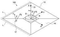
- FIG. 4 is a schematic view showing the sail 10 stretched on a plane.
- the sail 10 sheet-like member 11 expanded two-dimensionally along the plane orthogonal to the central axis 21 of the spacecraft main body 20 is illustrated.
- the plane including the two-dimensionally expanded sail 10 is set to the reference plane 16 of the sail 10.
- a plane in which the sail 10 is two-dimensionally expanded so as to be orthogonal to the central axis 21 of the spacecraft body 20 is set as the reference plane 16.
- the method of setting the reference surface 16 is not limited, and the reference surface 16 may be appropriately set according to the configuration of the sail 10 or the like.
- each axis is set such that the XY plane is the reference plane 16 and the direction parallel to the Z axis is the direction orthogonal to the reference plane 16.
- the method of setting the reference surface 16 and the origin O of the XYZ axes is not limited, and may be appropriately set according to the configuration of the sail 10, for example.
- the sun vector S can be represented by using an incident angle (reference incident angle ⁇ b) of the sunlight 30 with respect to the reference plane 16 and an azimuth angle ⁇ .
- the reference incident angle ⁇ b is an angle formed by a reference normal vector nb representing the normal direction of the reference surface 16 and the sun vector S.
- the azimuth angle ⁇ is an angle formed by a component parallel to the reference plane 16 of the sun vector S and the X axis, and is an angle representing the azimuth of the sun vector S in the XY plane.
- the sun sensor detects the sun vector S by detecting, for example, the reference incident angle ⁇ b and the azimuth angle ⁇ of the sunlight 30.
- the XYZ components of the sun vector S may be detected directly.
- any method capable of detecting the direction of incidence of the sunlight 30 on the reference surface 16 may be used.
- the reference incident angle ⁇ b and the azimuth angle ⁇ ⁇ are included in the first information on the incident direction of the sunlight 30 with respect to the reference plane.
- the distance between the sun and the spacecraft 100 is sufficiently large.
- the sunlight 30 which injects into the sail 10 can be regarded as substantially parallel light. Therefore, the sun vector S is constant regardless of the position of the sail 10.
- the shape of the sail 10 is a shape including three-dimensional unevenness such as deflection as shown in FIG. Therefore, the normal direction at each position on the sail 10 is oriented in accordance with the shape of the sail 10.
- FIG. 4 a partial area 17 when the sail 10 has a three-dimensional shape and a local normal vector n in the partial area 17 are schematically illustrated.
- the incident angle ⁇ of the sunlight 30 incident on the partial region 17 is the angle between the local normal vector n and the sun vector S. Therefore, the incident angle ⁇ in the partial area 17 is an angle according to the direction of the local normal vector n.
- the incident angle ⁇ of the sunlight 30 at each position on the sail 10 with respect to the sail 10 (sheet-like member 11) is an angle corresponding to the shape at each position.
- the incident angle ⁇ at each position is described as a local incident angle ⁇ .
- the local incident angle ⁇ at each arrangement position P is detected.
- the outputs from the plurality of detection sensors 12 are included in the second information on the incident angle of the sunlight on the sheet-like structure at the plurality of detection positions dispersedly disposed in the sheet-like structure.
- Shape Estimation of Sail 10 In the present embodiment, the shape of the sail 10 is represented using an XYZ coordinate system based on the reference surface 16 of the sail 10. In the following, it is assumed that in-plane deformation of the sail 10 is negligible. Therefore, the shape of the sail 10 can be estimated by estimating the deformation in the direction (Z-axis direction) orthogonal to the in-plane direction of the sail 10. Hereinafter, the length of one side of the square sail is described as L.
- ⁇ and ⁇ are parameters corresponding to the X component and the Y component of the point r.
- ⁇ and ⁇ are values normalized by the half length (L / 2) of one side L of the sail 10, and both values are set to values from -1 to 1.
- z which is the Z component of the point r is rewritten as z ( ⁇ ,)) as a function of ⁇ and ⁇ . Therefore, the point r on the sail 10 can be regarded as a function r ( ⁇ ,)) of ⁇ and ⁇ .
- Partial derivatives r ⁇ and r ⁇ for r represent vectors parallel to a plane (tangent plane) in contact with the sail 10 at the point r.
- the direction orthogonal to the tangent plane is the normal direction at the point r.
- Local normal vector n at the point r is expressed as follows.
- the local normal vector n is a unit vector normalized by the absolute value of the vector product
- Equation (4) represents a binomial coefficient, for example, a coefficient of a term of ⁇ 1 in the expansion of (1 + ⁇ ) k . It is possible to set the maximum value k max of the order expanded in the equation (4) and to discard the order larger than k max .
- the method of setting the maximum value k max is not limited, and may be set appropriately according to, for example, the required calculation accuracy. Rewriting the summation in equation (4) and defining the expansion coefficient again, the Z component z ( ⁇ ,)) of the sail 10 is expressed as follows.
- z ( ⁇ ,)) is the inner product h T ( ⁇ ,)) a of the vector h T ( ⁇ ,)) for ⁇ and ⁇ and the vector a for the expansion coefficient a k It becomes possible to express using.
- the vector h T ( ⁇ ,)) is specifically expressed by the following equation.
- equation (3) representing the local normal vector n can be represented by the partial derivatives of z ( ⁇ , ⁇ ) with respect to ⁇ and ⁇ .
- the local normal vector n is represented by partially differentiating z ( ⁇ ,)) shown in the equation (5).
- the partial derivatives of z ( ⁇ ,)) with respect to ⁇ and ⁇ can be expressed in a simple form as follows.
- h ⁇ T and h ⁇ T represent partial derivatives of h T ( ⁇ ,)) with respect to ⁇ and ⁇ .
- h ⁇ T and h ⁇ T are specifically represented by the following formulas.
- the local normal vector n in a form including the expansion coefficient a by substituting the partial derivatives of z ( ⁇ ,)) with respect to ⁇ and ⁇ shown in the equation (7) into the equation (3) Become. Further, by using the local normal vector n, it is possible to represent the local incident angle ⁇ to the sail 10 of the sunlight 30 incident on an arbitrary point on the sail 10.
- cos ( ⁇ ). Since the local normal vector n and the sun vector S are unit vectors, the magnitude of each vector is 1. Therefore, n ⁇ S cos ( ⁇ ).
- cos ( ⁇ ) is a function of the expansion coefficient a and the sun vector S. That is, the local incident angle ⁇ at each point on the sail 10 is expressed as a function including the expansion coefficient a.
- the position where the sunlight 30 is incident is represented by ⁇ and ⁇ .
- the sun vector S and the local incident angle ⁇ (cos ( ⁇ )) at the arrangement position of the plurality of detection sensors 12 are detected.
- the arrangement position where each detection sensor 12 is arranged is described as P i (x i , y i ).
- N is the total number of detection sensors 12 arranged in the sail 10.
- the incident angle of the sunlight 30 detected by the i-th detection sensor 12 is described as a local incident angle ⁇ i * using “*”.
- the least squares method is performed on cos ( ⁇ i ) and cos ( ⁇ i * ) at the arrangement position P i of each detection sensor. Specifically, processing for minimizing the equation shown below is performed.
- Equation (11) for the square of the difference between the cos (beta i *) is a detection value as a function of the expansion coefficients a cos .beta i (a), the formula for calculating the total sum for all detection sensor 12 is there.
- the expansion coefficient a is determined so as to minimize the sum.
- cos ⁇ i (a) is a non-linear function with respect to the expansion coefficient a. Therefore, the minimization process is a process that deals with the nonlinear least squares method.
- the specific method of the minimization process is not limited. For example, when the displacement (z ( ⁇ ,))) in the Z-axis direction of the sail 10 is sufficiently small and the area of the sail 10 is sufficiently large, cos ⁇ (a) is taken as a linear function with respect to the expansion coefficient a It is possible to approximate.
- the minimization process is a process that handles the linear least squares method.
- the expansion coefficient a can be analytically calculated, and the time required for the calculation process can be sufficiently shortened.
- any method capable of calculating the expansion coefficient a may be used as appropriate.
- the expansion coefficient a can be properly calculated by performing the minimization process using the sun vector S and the local incident angle ⁇ i * at each position in a state in which the sun vectors S are different from each other. is there.
- the solar light 30 is disposed at the arrangement position of the plurality of detection sensors 12 dispersedly disposed in the sail 10 in two or more states in which the solar vectors S with respect to the reference plane 16 of the sunlight 30 are different from each other.
- Information on the local incident angle ⁇ i * is obtained.
- the shape of the sail 10 is estimated based on the information on the sun vector S in two or more states and the information on the local incident angle ⁇ i * .
- the spacecraft 100 expands the sail 10 by rotational movement. Therefore, the direction of the sun viewed from the reference surface 16 of the sail 10, that is, the sun vector S in the XYZ coordinate system fixed to the spacecraft main body 20 changes with time.
- the sun vector S and the local incident angle ⁇ i * at each position are acquired at a predetermined sampling rate. That is, data sets including the sun vector S and the local incident angle ⁇ i * are sequentially acquired at mutually different timings. Note that changes in the shape of the sail 10 during acquisition of the data set at each timing can be ignored.
- the sun vector S acquired at different timings j and the local incident angle ⁇ i * are described as follows.
- the minimization process is executed based on the equation (11) using each data set acquired at different timings j.
- the equation to be minimized is expressed as follows.
- the data set is acquired at least twice. That is, the number M of times of acquiring the data set is appropriately set so that M ⁇ 2.
- M the number of times of acquiring the data set
- M the number of times of acquiring the data set
- the shape of the sail 10 does not change while acquiring the data set at each timing j. That is, the expansion coefficient a representing the shape of the sail 10 is constant regardless of the timing at which each data set is acquired.
- the minimization process for equation (12) is performed to calculate the expansion coefficient a.
- the calculated expansion coefficients a by substituting the equation (5), the position z (xi], eta) in the Z-axis direction of the sail 10 at position P i of the respective detection sensors 12 is calculated. From z ( ⁇ , ⁇ ) at each arrangement position P i , a three-dimensional shape including the unevenness and the like of the sail 10 is estimated. This makes it possible to estimate the sheet-like shape with high accuracy.
- the position z ( ⁇ , ⁇ ) in the orthogonal direction orthogonal to the reference plane 16 to estimate the shape of the sail 10 is estimated Ru.
- the maximum estimation error was about 0.1 m.
- the spacecraft 100 for example, information such as the sun vector S and the local incident angle ⁇ is acquired by a shape estimation processor (computer) mounted on the spacecraft main body 20.
- the shape estimation processing unit calculates the shape of the sail 10 at predetermined intervals, for example, based on the acquired information.
- the calculated data is transmitted to a ground control system or the like.
- the shape of the sail 10 is visualized and the shape of the sail 10 is monitored. This makes it possible to monitor the shape of the sail 10 in real time. As a result, for example, it is possible to make a flight plan based on information such as the shape of the sail 10 or the like.
- the shape estimation processing unit mounted on the spacecraft main body 20 is not limited to the case of executing the process of estimating the shape of the sail 10, and the shape of the sail 10 may be estimated by another system or the like.
- information such as the sun vector S and the local incident angle ⁇ may be transmitted to the ground by the spacecraft 100, and a process of estimating the shape of the sail 10 may be performed by the ground system. Thereby, it is possible to suppress the power consumption of the spacecraft 100 accompanying the estimation processing of the shape and the like.
- the method of acquiring the information regarding sun vector S is not necessarily limited to the method of using a solar sensor.
- the sun vector S may be calculated based on information such as the trajectory, attitude, and position of the spacecraft 100.
- information on the calculated sun vector S is appropriately transmitted to a computer or the like that performs shape estimation processing.
- the thin film solar cell 40 is used as the detection sensor 12 for detecting the local incident angle ⁇ of the sunlight 30.
- FIG. 5 is a schematic view showing a configuration example of the temperature sensor 50.
- the temperature sensor 50 (detection sensor 12) has a sensor plate 51, a temperature detection element 52, and a cover film 53.
- the sensor plate 51 has a flat plate shape and is disposed along the in-plane direction of the sail 10 (sheet-like member 11).
- As the sensor plate 51 for example, a member having a high thermal conductivity is used.
- the temperature detection element 52 is thermally connected to the sensor plate 51 to detect the temperature of the sensor plate 51.
- the temperature detection element 52 is embedded in the sensor plate 51.
- a resistor resistance thermometer
- thermocouple thermocouple thermometer
- any element capable of temperature measurement may be used as the temperature detection element.
- the cover film 53 is disposed so as to cover the sensor plate 51 installed on the sail 10, and fixes the sensor plate 51 and the temperature detection element 52 to the sail 10.
- a temperature sensor 50 a disposed on the front surface 13 of the sail 10 to which the sunlight 30 is incident and a temperature sensor 50 b disposed on the back surface 14 of the sail 10 are respectively illustrated.
- the temperature sensor 50 can be installed on both the front surface 13 and the back surface 14 of the sail 10.
- a plurality of temperature sensors 50 may be disposed on one of the front surface 13 and the back surface 14 of the sail 10 or may be disposed on both the front surface 13 and the back surface 14 of the sail 10.
- the temperature T sensor detected by the temperature sensor 50 has a value corresponding to the local incident angle ⁇ of the sunlight 30.
- the sunlight 30 enters the sensor plate 51
- a part of the sunlight 30 is absorbed, and the temperature of the sensor plate 51 rises.
- the amount of heat absorbed by the sensor plate 51 is proportional to cos ( ⁇ ).
- heat is emitted (radiated) from the sensor plate 51 to the space via the front surface 13 and the back surface 14 of the sail 10.
- the present invention is not limited to the case where one of the thin film solar cell 40 and the temperature sensor 50 is used as the detection sensor 12.
- both the thin film solar cell 40 and the temperature sensor 50 may be appropriately used as the detection sensor 12. In this case, the design freedom of the sail 10 can be improved.
- the plurality of detection sensors 12 are dispersedly disposed along the in-plane direction of the sheet-like member 11 on the sheet-like member 11 on which the sunlight 30 is incident.
- the local incident angle ⁇ of the sunlight 30 at the arrangement position of each detection sensor 12 with respect to the sheet-like member 11 is detected from the detection result of each detection sensor 12. This makes it possible to estimate the sheet-like shape with high accuracy.
- the detection sensor 12 arranged at each point on the sail 10 detects the local incident angle ⁇ of the sunlight 30 with respect to the sail 10 at each point. As described above, it is possible to easily obtain information necessary to estimate the shape of the sail 10 with desired accuracy by measuring the angles of the sunlight incident on each point in a distributed manner.
- the spacecraft 100 is a solar power sail configured to perform solar power generation
- a cell (thin film solar cell) or the like used for solar power generation is used as it is as the detection sensor 12 Is possible. Therefore, the shape of the sail 10 can be easily estimated without substantially increasing the weight and the like of the spacecraft body 20.
- information on the sun vector S and the local incident angle ⁇ is detected in two or more states where the sun vectors S are different from each other.
- the shape of the sail 10 is estimated by calculating components orthogonal to the reference surface 16 for each point. That is, the process of calculating the Z component among the three-dimensional components representing each point is executed. This makes it possible to perform shape estimation of the sail 10 at high speed. In addition, since the calculation load is small, it can be easily automated by mounting so that on-board processing is possible.
- the information on the sun vector S and the local incident angle ⁇ , the information on the shape of the sail 10, etc. have a sufficiently smaller capacity than, for example, image data. Therefore, these pieces of information can be easily transferred. As a result, it is possible to easily monitor the shape of the sail 10 in real time.
- the solar sail has been described as an example of a large-scale structure (sheet-like structure) having a sheet-like structure.
- flexibility is called a Gossamer structure (Gossamer Structure).
- Gossamer Structure Gossamer Structure
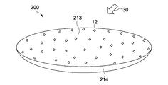
- FIG. 6A is a schematic view showing an example of the gossamer structure 200 in which the surface 213 on which the sunlight 30 is incident is concave.
- FIG. 6B is a schematic view showing an example of the gossamer structure 300 in which the surface 313 on which the sunlight 30 is incident is convex.
- the present invention is applicable regardless of the size, shape, and the like of the gossamer structures 200 and 300.
- a huge sheet-like structure (Gossamer structure 200) in which the surface 213 is concave, for example, it is possible to collect an electromagnetic wave or the like incident on the surface 213 at a predetermined point.
- a light collecting device for collecting the sunlight 30 is realized.
- a concave surface 213 so as to be able to reflect an electromagnetic wave of a predetermined frequency a huge antenna, a radio telescope, etc. are realized.
- the detection sensors 12 such as the thin film solar cell 40 and the temperature sensor 50
- the detection sensors 12 may be disposed on the back surface 214 opposite to the front surface 213.
- the shape or the like of the gossamer structure 200 can be adjusted, it is possible to perform the adjustment with high accuracy by estimating the shape.
- each structure may be arranged in space.
- the gossamer structures 200 and 300 function as an on-orbit plant for space solar power generation or a huge solar light shield.
- Each structure may be arranged on the ground as a huge structure. In any case, it is possible to easily estimate the shape of each structure by applying the present invention.
Landscapes
- Engineering & Computer Science (AREA)
- Remote Sensing (AREA)
- Aviation & Aerospace Engineering (AREA)
- Combustion & Propulsion (AREA)
- Chemical & Material Sciences (AREA)
- Life Sciences & Earth Sciences (AREA)
- Sustainable Development (AREA)
- Radar, Positioning & Navigation (AREA)
- Sustainable Energy (AREA)
- Physics & Mathematics (AREA)
- General Physics & Mathematics (AREA)
- Automation & Control Theory (AREA)
- Navigation (AREA)
- Photometry And Measurement Of Optical Pulse Characteristics (AREA)
- Photovoltaic Devices (AREA)
Abstract
【課題】シート状の形状を高精度に推定することが可能なシート状構造体を提供する。 【解決手段】シート状構造体は、シート状部材と、複数の検出センサと、を具備する。前記シート状部材は、厚さ方向に直交する面内方向に沿って延び、光が入射する。前記複数の検出センサは、前記シート状部材に前記面内方向に沿って分散して配置され、各配置位置における前記光の前記シート状部材に対する入射角を検出するためのセンサである。
Description
本発明は、シート状構造体、形状推定方法、及び宇宙機に関する。
シート状の部材は、様々な技術分野で多様な用途に用いられている。例えば、非特許文献1には、ソーラーセイル「IKAROS」について記載されている。ソーラーセイルは、太陽光を受けるセイルを有する宇宙帆船であり、セイルが太陽光から受ける輻射圧を推進力として宇宙空間を航行する。
このセイルは、シート状の薄膜を宇宙空間で展張することにより構成される。展張されたセイルは、面積がおよそ200m2の大規模な構造体となる。このように太陽光を受ける膜面の面積を広くすることで、ソーラーセイルに作用する輻射圧が増大し、航行に必要な推進力が得られる。
森治、川口淳一郎(他11名)著 「IKAROSの開発およびミッション概要」 日本航空宇宙学会誌 第60巻 第8号 283~289ページ (2012年8月)
しかしながら、シート状の部材はたわみやすいなどの問題がある。例えば、非特許文献1に記載のソーラーセイルでは、展張されたセイルに対して、その形状に応じた輻射圧が作用する。例えばセイルのたわみ等によりセイルの形状が想定した形状と異なっている状態では、意図しない方向に輻射圧が作用してソーラーセイルの姿勢等がずれるといった可能性が生じる。このため、展張されたセイルの形状を把握することが重要となる。
例えば非特許文献1には、宇宙機本体に設置されたモニタカメラや宇宙機本体から分離する分離カメラが記載されている。ソーラーセイルでは、モニタカメラや分離カメラを用いてセイルの画像を撮影することにより、セイルの展張状態を確認することができる。しかしながら、カメラを用いてセイルを撮影する方法では、撮影できる範囲等に制限があるため、セイルの凹凸等の形状を精度よく把握することが難しい場合があり得る。
上記の事情に鑑み、本発明の目的は、シート状の形状を高精度に推定することが可能なシート状構造体、形状推定方法、及び宇宙機を提供することにある。
上記目的を達成するため、本発明の一形態に係るシート状構造体は、シート状部材と、複数の検出センサと、を具備する。
前記シート状部材は、厚さ方向に直交する面内方向に沿って延び、光が入射する。
前記複数の検出センサは、前記シート状部材に前記面内方向に沿って分散して配置され、各配置位置における前記光の前記シート状部材に対する入射角を検出するためのセンサである。
前記シート状部材は、厚さ方向に直交する面内方向に沿って延び、光が入射する。
前記複数の検出センサは、前記シート状部材に前記面内方向に沿って分散して配置され、各配置位置における前記光の前記シート状部材に対する入射角を検出するためのセンサである。
このシート状構造体では、光が入射するシート状部材に、シート状部材の面内方向に沿って複数の検出センサが分散して配置される。各検出センサの検出結果から、各検出センサの配置位置におけるシート状部材に対する光の入射角が検出される。これにより、シート状の形状を高精度に推定することが可能となる。
前記光が太陽光を含んでもよい。この場合、前記複数の検出センサは、薄膜太陽電池を含んでもよい。
例えば薄膜太陽電池を用いることで、太陽光の入射角を容易に検出することが可能となり、シート状の形状を容易に推定することが可能となる。
例えば薄膜太陽電池を用いることで、太陽光の入射角を容易に検出することが可能となり、シート状の形状を容易に推定することが可能となる。
前記複数の検出センサは、温度センサを含んでもよい。
例えば温度センサを用いることで、光の入射角を容易に検出することが可能となり、シート状の形状を容易に推定することが可能となる。
例えば温度センサを用いることで、光の入射角を容易に検出することが可能となり、シート状の形状を容易に推定することが可能となる。
本発明の一形態に係る形状推定方法では、光が入射するシート状構造体の基準面を設定する。
前記光の前記基準面に対する入射方向に関する第1の情報が取得される。
前記入射方向が互いに異なる2以上の状態で、前記シート状構造体に分散して配置された複数の検出位置における前記光の前記シート状構造体に対する入射角に関する第2の情報が取得される。
前記2以上の状態における前記第1及び前記第2の情報に基づいて、前記シート状構造体の形状が推定される。
前記光の前記基準面に対する入射方向に関する第1の情報が取得される。
前記入射方向が互いに異なる2以上の状態で、前記シート状構造体に分散して配置された複数の検出位置における前記光の前記シート状構造体に対する入射角に関する第2の情報が取得される。
前記2以上の状態における前記第1及び前記第2の情報に基づいて、前記シート状構造体の形状が推定される。
この形状推定方法では、光のシート状構造体の基準面に対する入射方向に関する第1の情報と、複数の検出位置における光のシート状構造体に対する入射角に関する第2の情報とが取得される。基準面に対する入射方向が互いに異なる2以上の状態で取得された第1及び第2の情報を用いることで、シート状の形状を高精度に推定することが可能となる。
前記形状推定方法では、前記シート状構造体の前記複数の検出位置の各々について、前記基準面に直交する直交方向の位置を推定することで、前記シート状構造体の形状を推定してもよい。
これにより、シート状構造体の形状を基準面に直交する方向の成分から推定することが可能となる。この結果、形状の推定に要する演算量等が抑制され演算速度が向上する。
これにより、シート状構造体の形状を基準面に直交する方向の成分から推定することが可能となる。この結果、形状の推定に要する演算量等が抑制され演算速度が向上する。
前記形状推定方法では、前記シート状構造体の形状をモニタリングしてもよい。
これにより、例えばシート状構造体の形状をリアルタイムで監視することが可能となる。
これにより、例えばシート状構造体の形状をリアルタイムで監視することが可能となる。
本発明の一形態に係る宇宙機は、シート状構造体と、前記シート状構造体に接続される本体と、を具備する。
前記シート状構造体は、シート状部材と、複数の検出センサと、を具備する。
前記シート状部材は、厚さ方向に直交する面内方向に沿って延び、光が入射する。
前記複数の検出センサは、前記シート状部材に前記面内方向に沿って分散して配置され、各配置位置における前記光の前記シート状部材に対する入射角を検出するためのセンサである。
前記シート状構造体は、シート状部材と、複数の検出センサと、を具備する。
前記シート状部材は、厚さ方向に直交する面内方向に沿って延び、光が入射する。
前記複数の検出センサは、前記シート状部材に前記面内方向に沿って分散して配置され、各配置位置における前記光の前記シート状部材に対する入射角を検出するためのセンサである。
前記光が太陽光を含んでもよい。この場合、前記本体は、前記太陽光の入射方向を検出する太陽センサを有してもよい。
本発明によれば、シート状の形状を高精度に推定することが可能なシート状構造体、形状推定方法、及び宇宙機を提供することができる。
以下、図面を参照しながら、本発明の実施形態として、シート状構造体の一例であるソーラーセイルについて説明する。また、光は太陽光として説明する。なお、本発明は下記の実施形態によって限定的に解釈されるものではない。
1.セイルの構成
図1は、本発明の一実施形態に係るセイル10を備えた宇宙機100の斜視図である。図1に示すように、宇宙機100は、セイル10と、宇宙機本体20とを有する。宇宙機100は、セイル10を展張して宇宙空間を航行するソーラーセイルである。本実施形態では、セイル10は、シート状構造体に相当する。
図1は、本発明の一実施形態に係るセイル10を備えた宇宙機100の斜視図である。図1に示すように、宇宙機100は、セイル10と、宇宙機本体20とを有する。宇宙機100は、セイル10を展張して宇宙空間を航行するソーラーセイルである。本実施形態では、セイル10は、シート状構造体に相当する。
図1に示すように、セイル10は、シート状部材11と、複数の検出センサ12とを有する。シート状部材11は、厚さ方向に直交する面内方向に沿って延び、柔軟性を有するシート状である。従ってシート状部材11は、容易に曲げることが可能な薄く広い面を有する。図1では、シート状部材11のたわみや凹凸等の立体的な形状が点線により模式的に図示されている。
シート状部材11は、表面13と、裏面14と、開口部15とを有する。表面13は、太陽に向けられ、太陽光30が入射する面である。なお図1では、表面13に入射する太陽光30が矢印により模式的に図示されている。
裏面14は、シート状部材11の太陽光30が入射する側とは反対側の面である。従って、シート状部材11の厚さ方向は表面13及び裏面14に直交する方向であり、面内方向は表面13及び裏面14に沿った方向である。開口部15は、シート状部材11の中央に配置される。開口部15には、宇宙機本体20が設置される。
シート状部材11を平面上に展張した場合、シート状部材11の平面形状は、略正方形となる(図4参照)。正方形の一辺の長さは、例えば約14mとなるように設定される。この場合、正方形の面積は約200m2となる。またシート状部材11の厚さは、数マイクロメートルに設定される。これにより、大規模な構造でありながら軽量なセイル10を実現することが可能となる。シート状部材11の平面形状、サイズ、及び厚さ等に係らず本発明は適用可能である。
シート状部材11としては、例えば宇宙環境で展張可能なポリイミド樹脂等の薄膜が用いられる。またシート状部材11にはアルミニウムが蒸着されており、太陽光30を反射することが可能である。これにより、シート状部材11は太陽光30による輻射圧を効率的に受けることが可能となり、十分な推進力を生み出すことが可能となる。シート状部材11の具体的な構成は限定されず、例えば太陽光30による輻射圧を受けることが可能な任意の構成が用いられてよい。
複数の検出センサ12は、太陽光30のシート状部材11に対する入射角を検出するためのセンサである。複数の検出センサ12は、シート状部材11の表面13上に、表面13に沿って分散して配置される。例えば複数の検出センサ12は、センサの密度が偏らないように所定の間隔をあけて分散して配置される。もちろん、シート状部材11の構成等に応じて、各検出センサ12の配置位置等が適宜設定されてもよい。
本実施形態では、検出センサ12として、薄膜太陽電池が用いられる。薄膜太陽電池は、例えば厚さが数十マイクロメートルのa-Si(アモルファスシリコン)セル等を用いて構成される。このような薄い素子を用いることで、シート状部材11にかかる負荷等を十分に抑制することが可能となり、例えばシート状部材11を適正に展張することが可能となる。
図2は、薄膜太陽電池40の構成例を示す模式図である。薄膜太陽電池40(検出センサ12)は、太陽光30が入射する入射面41と、入射面41の反対側の背面42とを有する。薄膜太陽電池40は、入射面41と背面42とが互いに略平行となるように構成され、背面42をシート状部材11の表面13に向けて配置位置P(図中の黒丸)に配置される。
配置位置Pでは、薄膜太陽電池40の入射面41に直交する方向とシート状部材11の表面13に直交する方向とが略同じ方向となる。すなわち、薄膜太陽電池40の入射面41での法線方向が、その配置位置Pにおけるシート状部材11の表面13の法線方向と略平行となる。図2では、配置位置Pでのシート状部材11の表面13の法線方向が、局所法線ベクトルnを用いて示されている。
図2に示すように、配置位置Pにおける太陽光30のシート状部材11に対する入射角は、配置位置Pでの局所法線ベクトルnと太陽ベクトルSとが成す角度となる。ここで太陽ベクトルSとは、配置位置Pから見た太陽の方向を表す単位ベクトルである。従って太陽光30は太陽ベクトルSと平行な方向に沿って入射することになる。
配置位置Pに配置された薄膜太陽電池40の入射面41には、配置位置Pにおける太陽光30のシート状部材11に対する入射角と略等しい角度で太陽光30が入射する。以下では、シート状部材11及び薄膜太陽電池40に入射する太陽光30の入射角を、同じ符号βを用いて入射角βと記載する。
図3は、薄膜太陽電池40の電圧出力と入射角βとの関係を示すグラフである。図3の横軸は、薄膜太陽電池40の入射面41に対する入射角βである。また縦軸は、薄膜太陽電池40から出力される電圧Vである。
薄膜太陽電池40からは、入射角βに応じた電圧Vが出力される。具体的には、薄膜太陽電池40の電圧Vは、cos(β)に比例した値となる。従って図3に示すように、薄膜太陽電池40に直交する方向(β=0°)から太陽光30が入射した場合に、電圧Vは最大となる。また薄膜太陽電池40に平行な方向(β=90°)から太陽光30が入射した場合に、電圧Vはゼロとなる。
例えば、薄膜太陽電池40から出力される電圧Vと入射角βとの関係を予め測定して記憶しておく。この電圧Vと入射角βとの関係を参照することで、薄膜太陽電池40の電圧V(∝cos(β))から、当該薄膜太陽電池40に入射する太陽光30の入射角βを検出することが可能である。すなわち、薄膜太陽電池40の電圧Vから、その配置位置Pにおける太陽光30のシート状部材11に対する入射角βを検出することが可能である。
図1に示すように、宇宙機本体20は、中心軸21に沿って延びる円柱状である。宇宙機本体20は、セイル10の開口部15に配置される。宇宙機本体20とセイル10とは、図示しないテザー及びハーネスを介して機械的及び電気的に接続される。宇宙機本体20は、太陽センサ、姿勢制御機構、及び形状推定処理部を有する(いずれも図示省略)。
太陽センサ(光センサ)は、太陽光30の入射方向を検出する。すなわち太陽センサは、宇宙機から見た太陽の方向を検出する。太陽センサの具体的な構成等は限定されず、例えば太陽光30の入射方向を検出可能な任意のセンサが用いられてよい。
姿勢制御機構は、宇宙機の姿勢を制御するためのスラスタ等により構成される。宇宙機本体20は、姿勢制御機構を用いて中心軸21を基準に回転運動を行なうことが可能である。宇宙機100では、この回転運動により発生する遠心力を用いて大型のセイル10が展開・展張される。従って宇宙機100は、セイル10を展張した状態で中心軸21を基準に回転しながら宇宙空間を航行することになる。
形状推定処理部は、複数の検出センサ12や太陽センサからの出力を取得する。形状推定処理部は、取得したデータに基づいて、後述するセイル10の形状を推定する処理等を実行可能である。また形状推定処理部は、通信アンテナを介して地上の管制システム等との通信を行なってもよい。形状推定処理部としては例えばコンピュータを用いることができ、宇宙機100の各部の動作は当該コンピュータにより適宜制御されてもよい。
図4は、平面上に展張されたセイル10を示す模式図である。図4では、宇宙機本体20の中心軸21に直交する平面に沿って、2次元的に展張されたセイル10(シート状部材11)が図示されている。この2次元的に展張されたセイル10を含む面が、セイル10の基準面16に設定される。言い換えれば、宇宙機本体20の中心軸21に直交するように2次元的にセイル10を展張した面が基準面16として設定される。なお基準面16を設定する方法等は限定されず、セイル10の構成等に応じて適宜基準面16が設定されてよい。
宇宙機100では、宇宙機本体20の中心軸21と基準面16とが交わる点を原点Oとして、互いに直交するX軸、Y軸、及びZ軸が設定される。すなわち、XY平面が基準面16となり、Z軸と平行な方向が基準面16に直交する方向となるように各軸が設定される。なお、基準面16やXYZ軸の原点O等を設定する方法は限定されず、例えばセイル10の構成等に応じて適宜設定されてよい。
上記したように太陽センサにより、太陽光30の入射方向が検出される。本実施形態では、太陽センサにより、セイル10の基準面16に設定されたXYZ座標での太陽ベクトルS=(sx,sy,sz)Tが検出される。ここで上付きの添え字"T"はベクトルの転置を表す。
図4に示すように、太陽ベクトルSは、太陽光30の基準面16に対する入射角(基準入射角βb)と、方位角Φとを用いて表すことが可能である。基準入射角βbは、基準面16の法線方向を表す基準法線ベクトルnbと太陽ベクトルSとが成す角度である。また方位角Φは、太陽ベクトルSの基準面16に平行な成分とX軸とが成す角度であり、太陽ベクトルSのXY平面における方位を表す角度である。
太陽センサは、例えば太陽光30の基準入射角βb及び方位角Φを検出することで、太陽ベクトルSを検出する。もちろん太陽ベクトルSのXYZの各成分が直接検出されてもよい。この他、太陽光30の基準面16に対する入射方向を検出可能な任意の方法が用いられてよい。本実施系形態では、基準入射角βb及び方位角Φは、太陽光30の基準面に対する入射方向に関する第1の情報に含まれる。
一般に、太陽と宇宙機100との間の距離は十分に離れている。このため、セイル10に入射する太陽光30は略平行光と見做すことができる。従って、太陽ベクトルSは、セイル10の位置に係らず一定となる。
一方で実際の宇宙機100では、セイル10の形状は、図1に示すようにたわみ等の3次元的な凹凸を含む形状となる。従って、セイル10上の各位置における法線方向はセイル10の形状に応じた方向を向くことになる。
図4には、セイル10が3次元的な形状を有する場合の部分領域17と、当該部分領域17における局所法線ベクトルnとが模式的に図示されている。部分領域17に入射する太陽光30の入射角βは、局所法線ベクトルnと太陽ベクトルSとの成す角度である。従って部分領域17での入射角βは、局所法線ベクトルnの向きに応じた角度となる。
このようにセイル10上の各位置における太陽光30のセイル10(シート状部材11)に対する入射角βは、各位置での形状に応じた角度となる。以下では、各位置における入射角βを局所入射角βと記載する。
このように、セイル10上の各配置位置Pに配置された検出センサ12の出力(薄膜太陽電池40の電圧V)を取得することにより、各配置位置Pにおける局所入射角βが検出される。本実施形態では、複数の検出センサ12からの出力は、シート状構造体に分散して配置された複数の検出位置における太陽光のシート状構造体に対する入射角に関する第2の情報に含まれる。
2.セイル10の形状推定
本実施形態では、セイル10の基準面16を基準としたXYZ座標系を用いてセイル10の形状を表す。以下では、セイル10の面内方向の変形は無視できるものと仮定する。従ってセイル10の面内方向に直交する方向(Z軸方向)の変形を推定することにより、セイル10の形状が推定される。以下では、正方形状のセイルの一辺の長さをLと記載する。
本実施形態では、セイル10の基準面16を基準としたXYZ座標系を用いてセイル10の形状を表す。以下では、セイル10の面内方向の変形は無視できるものと仮定する。従ってセイル10の面内方向に直交する方向(Z軸方向)の変形を推定することにより、セイル10の形状が推定される。以下では、正方形状のセイルの一辺の長さをLと記載する。
セイル10(シート状部材11)の入射面41上の任意の点rはXYZ座標系を用いてr=(x,y,z)Tと表される。Monge形式のパッチを用いると、点rは以下のように書き換えられる。

ここで、ξ及びηは、点rのX成分及びY成分に対応するパラメータである。なおξ及びηは、セイル10の一辺Lの半分の長さ(L/2)により正規化された値であり、ともに-1から1までの値となるように設定される。Monge形式では、式(1)に示すように、点rのZ成分であるzがξ及びηの関数としてz(ξ,η)と書き換えられる。従って、セイル10上の点rは、ξ及びηの関数r(ξ,η)と見做すことが可能となる。
式(1)に示す書き換え、すなわちr(x,y,z)からr(ξ,η)へのパラメータ表示では、ξ及びηに関するrの偏微分が線形独立な関係となる。具体的には、各パラメータξ及びηによるrについての偏微分は以下のように表される。

rについての偏微分rξ及びrηは、点rでセイル10に接する面(接平面)に平行なベクトルを表す。この接平面に直交する方向が、点rでの法線方向となる。従って点rでの局所法線ベクトルnは、rについての偏微分rξ及びrηのベクトル積(rξ×rη)を用いて、以下のように表される。

式(3)に示すように、局所法線ベクトルnは、ベクトル積の絶対値||rξ×rη||により規格化された単位ベクトルとなる。また局所法線ベクトルnは、ξ及びηに関するz(ξ,η)の偏微分により表される。
セイル10のZ成分(z(ξ,η))について、ξ及びηに関するべき級数展開を考える。セイル10の中心r(0,0)を基準として、無限級数として展開すると、z(ξ,η)は、以下の式で表される。

なお式(4)の右辺における"()"は二項係数を表し、例えば(1+α)kの展開におけるαlの項の係数を表す。式(4)式において展開される次数の最大値kmaxを設定し、kmaxより大きい次数を切り捨てることが可能である。最大値kmaxを設定する方法等は限定されず、例えば要求される計算精度等に応じて適宜設定されてよい。式(4)における総和を書き直し、展開係数を改めて定義すると、セイル10のZ成分z(ξ,η)は以下のように表される。

式(5)に示すように、z(ξ,η)は、ξ及びηに関するベクトルhT(ξ,η)と、展開係数akに関するベクトルaとの内積hT(ξ,η)aを用いて表すことが可能となる。なお、ベクトルhT(ξ,η)は、具体的には以下の式で表される。

このように、式(5)を用いることで、セイル10の形状(点rのZ成分)を展開係数であるベクトルa=(a0,a1,a2,a3,…)Tにより表すことが可能である。言い換えれば、展開係数aを具体的に算出することで、セイル10の形状を推定することが可能となる。
上記したように、局所法線ベクトルnを表す式(3)は、ξ及びηに関するz(ξ,η)の偏微分により表すことが可能である。例えば式(5)に示すz(ξ,η)を偏微分することで、局所法線ベクトルnを表すとする。この場合、ξ及びηに関するz(ξ,η)の偏微分は、以下のようにシンプルな形式で表すことが可能である。

ここで、hξ
T及びhη
Tは、ξ及びηに関するhT(ξ,η)の偏微分を表す。hξ
T及びhη
Tは、具体的には以下の式で表される。


従って、式(7)に示すξ及びηに関するz(ξ,η)の偏微分を式(3)に代入することで、局所法線ベクトルnを展開係数aを含む形で表すことが可能となる。また局所法線ベクトルnを用いることで、セイル10上の任意の点に入射する太陽光30のセイル10に対する局所入射角βを表すことが可能である。
図4で説明したように、セイル10上の点r(x,y)=r(x(ξ),y(η))における、太陽光30の局所入射角βは、太陽ベクトルSと点rでの局所法線ベクトルnとの間の角度である。局所法線ベクトルnと太陽ベクトルSとの内積は、n・S=|n||S|cos(β)となる。局所法線ベクトルn及び太陽ベクトルSは単位ベクトルであるため、各ベクトルの大きさは1である。従って、n・S=cos(β)となる。
太陽光30の局所入射角βの余弦、すなわちcos(β)は、式(3)に示す局所法線ベクトルnと、太陽ベクトルS=(sx,sy,sz)Tとを用いて、以下の式で表される。

式(10)に示すように、cos(β)は、展開係数aと太陽ベクトルSとの関数となる。すなわち、セイル10上の各点での局所入射角βが、展開係数aを含む関数として表される。なお太陽光30が入射する位置はξ及びηにより表される。
上記したように、宇宙機100では、太陽ベクトルSと、複数の検出センサ12の配置位置での局所入射角β(cos(β))とが検出される。以下では、各検出センサ12が配置される配置位置をPi(xi,yi)と記載する。ここで下付の添え字iはi=1…Nとなる整数であり、各々の検出センサを示すインデックスである。Nはセイル10に配置される検出センサ12の総数である。また式(10)に示す局所入射角βと区別するために、i番目の検出センサ12により検出された太陽光30の入射角を"*"を用いて局所入射角βi
*と記載する。
展開係数aは、式(10)に示すcos(βi)と、実際に検出されたcos(βi
*)との差が最小となるように定められる。すなわち、検出値であるβi
*との誤差が最小となるβiが実現されるように、展開係数a=(a0,a1,a2,a3,…)Tが定められる。
本実施形態では展開係数aを求めるために、各検出センサの配置位置Piおける、cos(βi)及びcos(βi
*)に関する最小二乗法が実行される。具体的には、以下に示す式を最小化する処理が実行される。

式(11)は、展開係数aの関数であるcosβi(a)と検出値であるcos(βi
*)との差分の2乗について、すべての検出センサ12での総和を算出する式である。最小化処理では、この総和が最小となるように、展開係数aが定められる。なお、式(10)に示すように、cosβi(a)は、展開係数aに対して非線形な関数である。従って最小化処理は、非線形の最小二乗法を扱う処理となる。
最小化処理の具体的な方法等は限定されない。例えば、セイル10のZ軸方向の変位(z(ξ,η))が十分に小さく、セイル10の面積が十分に大きい場合には、cosβ(a)を展開係数aに対して線形な関数として近似することが可能である。この近似を用いることで、最小化処理は線形な最小二乗法を扱う処理となる。この結果、例えば展開係数aを解析的に計算することが可能となり、計算処理に要する時間を十分に短縮することが可能である。この他、展開係数aを算出可能な任意の方法が適宜用いられてよい。
異なる方向から太陽光30が入射した場合のデータを用いることで、展開係数aを解決することが可能である。すなわち、太陽ベクトルSが互いに異なる状態での、太陽ベクトルSと各位置での局所入射角βi
*とを用いて最小化処理を行なうことで、展開係数aを適正に算出することが可能である。
本実施形態では、太陽光30の基準面16に対する太陽ベクトルSが互いに異なる2以上の状態で、セイル10に分散して配置された複数の検出センサ12の配置位置における太陽光30のセイル10に対する局所入射角βi
*に関する情報が取得される。そして、2以上の状態における太陽ベクトルSに関する情報及び局所入射角βi
*に関する情報に基づいて、セイル10の形状が推定される。
例えば、宇宙機100は回転運動によりセイル10を展張している。このためセイル10の基準面16から見た太陽の方向、すなわち宇宙機本体20に固定されたXYZ座標系での太陽ベクトルSは、時間とともに変化する。
宇宙機100では、例えば所定のサンプリングレートで太陽ベクトルS及び各位置での局所入射角βi
*がそれぞれ取得される。つまり互いに異なるタイミングで、太陽ベクトルS及び局所入射角βi
*が含まれるデータセットが順次取得される。なお、各タイミングでデータセットが取得されている間のセイル10の形状の変化は無視できるものとする。
以下では、所定のサンプリレートで取得された各データセットを区別するためにインデックスj(j=1~M)を用いる。例えば、異なるタイミングjで取得された太陽ベクトルS及び局所入射角βi
*は以下のように記載される。

本実施系形態では、異なるタイミングjで取得された各データセットを用いて、式(11)をもとに最小化処理が実行される。具体的には、最小化の対象となる式は以下のように表される。

式(12)において、データセットは少なくとも2回取得される。すなわちデータセットを取得する回数MはM≧2となるように適宜設定される。回数Mを増やすことで、例えば展開係数aの算出精度を向上することが可能である。あるいは回数Mを減らすことで、最小化処理に要する時間や電力等を抑えることが可能である。
また上記したように、各タイミングjでデータセットを取得する間、セイル10の形状は変わらないものとする。すなわち、セイル10の形状を表す展開係数aは、各データセットが取得されたタイミングに係らず一定である。
式(12)についての最小化処理が実行され、展開係数aが算出される。算出された展開係数aを式(5)に代入することにより、各検出センサ12の配置位置Piでのセイル10のZ軸方向の位置z(ξ,η)が算出される。この各配置位置Piでのz(ξ,η)から、セイル10の凹凸等を含む3次元的な形状が推定される。これにより、シート状の形状を高精度に推定することが可能となる。
このように本実施形態では、セイル10の複数の配置位置Piの各々について、基準面16に直交する直交方向の位置z(ξ,η)を推定することで、セイル10の形状が推定される。これにより、例えばX軸方向やY軸方向の成分等を計算することなく、セイル10の形状を容易に推定することが可能である。この結果、形状の推定に要する演算量等が抑制され演算速度等を向上することが可能となる。
例えば、本発明に係る形状推定方法を用いて、50m×50mのサイズのセイル10についての形状推定のシミュレーションを行ったところ、最大推定誤差はおよそ0.1mであった。このように、大規模なシート状の構造体についても、十分に高い精度で形状を推定することが可能である。
宇宙機100では、例えば宇宙機本体20に搭載された形状推定処理部(コンピュータ)により、太陽ベクトルS及び局所入射角β等の情報が取得される。形状推定処理部は、取得した情報に基づいて、例えば所定の間隔でセイル10の形状を算出する。
算出されたデータは地上の管制システム等に送信される。管制システムでは、例えばセイル10の形状が可視化され、セイル10の形状がモニタリングされる。これにより、セイル10の形状をリアルタイムで監視することが可能となる。この結果、例えばセイル10の形状等の情報に基づいて、フライトプランを立てるといったことが可能となる。
なお宇宙機本体20に搭載された形状推定処理部により、セイル10の形状を推定する処理を実行する場合に限定されず、他のシステム等によりセイル10の形状が推定されてもよい。例えば、宇宙機100により太陽ベクトルS及び局所入射角β等の情報が地上に送信されて、地上のシステムによりセイル10の形状を推定する処理が実行されてもよい。これにより、形状の推定処理等に伴う宇宙機100の電力消費を抑えることが可能である。
また太陽ベクトルSに関する情報を取得する方法は、太陽センサを用いる方法に限定されるわけではない。例えば、宇宙機100の軌道、姿勢、及び位置等の情報に基づいて太陽ベクトルSが算出されてもよい。この場合、算出された太陽ベクトルSに関する情報が、形状の推定処理を行なうコンピュータ等に適宜送信される。これにより、例えば宇宙機本体20に太陽センサが搭載されていない場合であっても、セイル10の形状を容易に推定することが可能である。
上記では、太陽光30の局所入射角βを検出するための検出センサ12として、薄膜太陽電池40が用いられた。本発明では検出センサ12として、温度センサを用いることも可能である。
図5は、温度センサ50の構成例を示す模式図である。温度センサ50(検出センサ12)は、センサプレート51と、温度検出素子52と、カバーフィルム53とを有する。センサプレート51は、平板状の形状でありセイル10(シート状部材11)の面内方向に沿って配置される。センサプレート51としては、例えば熱伝導率の高い部材が用いられる。
温度検出素子52は、センサプレート51と熱的に接続され、センサプレート51の温度を検出する。例えば図5に示すように、温度検出素子52はセンサプレート51に埋め込まれる。温度検出素子52としては、例えば温度に応じて抵抗率が変化する抵抗体(抵抗温度計)や、熱起電力を用いて温度を測定する熱伝対(サーモカップル温度計)等が用いられる。この他、温度測定が可能な任意の素子が温度検出素子として用いられてよい。
カバーフィルム53は、セイル10に設置されたセンサプレート51を覆うように配置され、センサプレート51及び温度検出素子52をセイル10に固定する。
図5では、太陽光30が入射するセイル10の表面13に配置された温度センサ50aと、セイル10の裏面14に設置された温度センサ50bとが、それぞれ図示されている。このように、温度センサ50は、セイル10の表面13及び裏面14の両方に設置することが可能である。例えば複数の温度センサ50が、セイル10の表面13及び裏面14のどちらか一方に配置されてもよいし、セイル10の表面13及び裏面14の両方に設置されてもよい。
例えば温度センサ50を構成する部材(センサプレート51やカバーフィルム53)について、光の吸収率や光(赤外光)の放射率等の光学特性が定まっているとする。この場合、温度センサ50により検出される温度Tsensorは、太陽光30の局所入射角βに応じた値となる。
例えばセンサプレート51に太陽光30が入射すると、太陽光30の一部が吸収されセンサプレート51の温度が上昇する。この時、センサプレート51が吸収する熱量は、cos(β)に比例する。一方でセンサプレート51からは、セイル10の表面13及び裏面14を介して宇宙空間に熱量が放出(放射)される。こうしたセンサプレート51での熱量の収支を計算することにより、温度センサ50で検出される温度Tsensorから局所入射角βを求めることが可能である。
このように、温度センサ50を用いた場合であっても、セイル10に分散して配置された複数の温度センサ50の配置位置における太陽光30のセイル10に対する局所入射角βに関する情報を取得することが可能である。これにより、セイル10の形状を高精度に推定することが可能である。
なお本発明は、検出センサ12として、薄膜太陽電池40及び温度センサ50のどちらか一方を用いる場合に限定されるわけではない。例えば薄膜太陽電池40及び温度センサ50の両方が検出センサ12として適宜用いられてもよい。この場合、セイル10の設計自由度等を向上させることが可能となる。
以上、本実施形態に係るセイル10では、太陽光30が入射するシート状部材11に、シート状部材11の面内方向に沿って複数の検出センサ12が分散して配置される。各検出センサ12の検出結果から、各検出センサ12の配置位置における太陽光30のシート状部材11に対する局所入射角βが検出される。これにより、シート状の形状を高精度に推定することが可能となる。
本実施形態に係るセイル10では、セイル10上の各点に配置された検出センサ12により、各点でのセイル10に対する太陽光30の局所入射角βが検出される。このように各点に入射する太陽光の角度を分散して測定することにより、セイル10の形状を所望の精度で推定するために必要な情報を容易に取得することが可能である。
例えば、宇宙機100(セイル10)が太陽光発電を行なうように構成されたソーラー電力セイルである場合には、太陽光発電に用いられるセル(薄膜太陽電池)等をそのまま検出センサ12として用いることが可能である。このため宇宙機本体20の重量等を略増加させることなく、セイル10の形状を容易に推定することが可能となる。
また本実施系形態では、太陽ベクトルSが互いに異なる2以上の状態で太陽ベクトルS及び局所入射角βに関する情報が検出される。これらの情報を用いることで、セイル10の形状を推定する際の誤差等を十分に小さくすることが可能となる。この結果、セイル10の形状を十分高精度に推定することが可能となる。
セイル10の形状は、各点について、基準面16に直交する成分を算出することにより推定される。すなわち、各点を表す3次元の成分のうちZ成分を算出する処理が実行される。これにより、セイル10の形状推定を高速に実行することが可能となる。また計算負荷が小さいため、オンボードでの処理が可能なように実装することで、容易に自動化することが可能である。
なお、太陽ベクトルS及び局所入射角βに関する情報や、セイル10の形状に関する情報等は、例えば画像データ等に比べ十分に容量が小さい。従ってこれらの情報は、容易に転送することが可能である。この結果、リアルタイムでセイル10の形状を容易にモニタリングすることが可能となる。
このようにセイル10の形状を高精度に推定することで、セイル10が受ける輻射圧が宇宙機100の運動に及ぼす作用等を詳細に調べることが可能となる。例えば実際の測定結果に基づいて、セイル10の形状が宇宙機100(ソーラーセイル)の回転や姿勢に及ぼす影響等を調べることが可能である。またセイル10の形状を調整する調整機構等が搭載されている場合には、推定された形状データをフィードバックすることで、セイル10の形状を高精度に調整するといったことも可能である。
3.その他のシート状構造体
上記では、シート状の構造を有する大規模な構造体(シート状構造体)の一例としてソーラーセイルについて説明した。こうした柔軟性を有するシート状の部材(薄膜やメッシュ等)により構成される巨大な構造体は、ゴッサマー構造体(Gossamer Structure)と呼ばれる。以下ではセイル10とは別のゴッサマー構造体について説明する。
上記では、シート状の構造を有する大規模な構造体(シート状構造体)の一例としてソーラーセイルについて説明した。こうした柔軟性を有するシート状の部材(薄膜やメッシュ等)により構成される巨大な構造体は、ゴッサマー構造体(Gossamer Structure)と呼ばれる。以下ではセイル10とは別のゴッサマー構造体について説明する。
図6Aは、太陽光30が入射する表面213が凹面状となるゴッサマー構造体200の一例を示す模式図である。図6Bは、太陽光30が入射する表面313が凸面状となるゴッサマー構造体300の一例を示す模式図である。なお、ゴッサマー構造体200及び300のサイズや形状等に係らず、本発明は適用可能である。
図6Aに示すように、表面213が凹面状の巨大なシート状構造体(ゴッサマー構造体200)を構成することにより、例えば表面213に入射する電磁波等を所定のポイントに集めることが可能である。例えば、凹面状の表面213を太陽光30を反射可能に構成することで、太陽光30を集光する集光装置が実現される。また凹面状の表面213を所定の周波数の電磁波を反射可能に構成することで、巨大なアンテナや電波望遠鏡等が実現される。
このようなゴッサマー構造体200に、検出センサ12(薄膜太陽電池40や温度センサ50等)を分散して配置することにより、ゴッサマー構造体200の形状を容易に推定することが可能である。図6Aでは、表面213に分散して配置された検出センサ12が図示されている。なお検出センサ12が温度センサ50の場合には、表面213の反対側の裏面214に検出センサ12が配置されてもよい。
推定された形状を元に、例えば集光装置の集光効率やアンテナ(電波望遠鏡)の検出精度等を詳細に調べることが可能である。またゴッサマー構造体200の形状等を調整可能である場合には、形状を推定することで高精度な調整が可能となる。
図6Bに示すように、表面313が凸面状のゴッサマー構造体300を構成することにより、巨大なドームやテント等の構造を実現することが可能である。この場合もゴッサマー構造体300に検出センサ12を分散して配置することにより、形状を容易に推定することが可能である。
なおゴッサマー構造体200及び300が配置される環境等は限定されない。例えば各構造体が宇宙空間に配置されてもよい。この場合、例えばゴッサマー構造体200及び300は、宇宙太陽光発電のための軌道上プラントや、巨大な太陽光シールドとして機能する。また各構造体が巨大建造物として地上に配置されてもよい。いずれの場合であっても、本発明を適用することより、各構造体の形状を容易に推定することが可能である。
10…セイル
11…シート状部材
12…検出センサ
13…表面
14…裏面
16…基準面
20…宇宙機本体
30…太陽光
40…薄膜太陽電池
50、50a、50b…温度センサ
100…宇宙機
200、300…ゴッサマー構造体
β…局所入射角
n…局所法線ベクトル
P…配置位置
S…太陽ベクトル
11…シート状部材
12…検出センサ
13…表面
14…裏面
16…基準面
20…宇宙機本体
30…太陽光
40…薄膜太陽電池
50、50a、50b…温度センサ
100…宇宙機
200、300…ゴッサマー構造体
β…局所入射角
n…局所法線ベクトル
P…配置位置
S…太陽ベクトル
Claims (8)
- 厚さ方向に直交する面内方向に沿って延び、光が入射するシート状部材と、
前記シート状部材に前記面内方向に沿って分散して配置され、各配置位置における前記光の前記シート状部材に対する入射角を検出するための複数の検出センサと
を具備するシート状構造体。 - 請求項1に記載のシート状構造体であって、
前記光が太陽光を含み、
前記複数の検出センサは、薄膜太陽電池を含む
シート状構造体。 - 請求項1又は2に記載のシート状構造体であって、
前記複数の検出センサは、温度センサを含む
シート状構造体。 - 光が入射するシート状構造体の基準面を設定し、
前記光の前記基準面に対する入射方向に関する第1の情報を取得し、
前記入射方向が互いに異なる2以上の状態で、前記シート状構造体に分散して配置された複数の検出位置における前記光の前記シート状構造体に対する入射角に関する第2の情報を取得し、
前記2以上の状態における前記第1及び前記第2の情報に基づいて、前記シート状構造体の形状を推定する
形状推定方法。 - 請求項4に記載の形状推定方法であって、
前記シート状構造体の前記複数の検出位置の各々について、前記基準面に直交する直交方向の位置を推定することで、前記シート状構造体の形状を推定する
形状推定方法。 - 請求項4又は5に記載の形状推定方法であって、
前記シート状構造体の形状をモニタリングする
形状推定方法。 - シート状構造体と、前記シート状構造体に接続される本体と、を具備し、
前記シート状構造体は、
厚さ方向に直交する面内方向に沿って延び、光が入射するシート状部材と、
前記シート状部材に前記面内方向に沿って分散して配置され、各配置位置における前記光の前記シート状部材に対する入射角を検出するための複数の検出センサと、を有する
宇宙機。 - 請求項7に記載の宇宙機であって、
前記光が太陽光を含み、
前記本体は、前記太陽光の入射方向を検出する太陽センサを有する
宇宙機。
Priority Applications (2)
| Application Number | Priority Date | Filing Date | Title |
|---|---|---|---|
| US16/627,095 US11512944B2 (en) | 2017-07-11 | 2018-03-30 | Sheet-like structure, shape estimation method, and spacecraft |
| US18/050,660 US11768070B2 (en) | 2017-07-11 | 2022-10-28 | Sheet-like structure, shape estimation method, and spacecraft |
Applications Claiming Priority (2)
| Application Number | Priority Date | Filing Date | Title |
|---|---|---|---|
| JP2017-135449 | 2017-07-11 | ||
| JP2017135449A JP6842169B2 (ja) | 2017-07-11 | 2017-07-11 | シート状構造体、形状推定方法、及び宇宙機 |
Related Child Applications (2)
| Application Number | Title | Priority Date | Filing Date |
|---|---|---|---|
| US16/627,095 A-371-Of-International US11512944B2 (en) | 2017-07-11 | 2018-03-30 | Sheet-like structure, shape estimation method, and spacecraft |
| US18/050,660 Division US11768070B2 (en) | 2017-07-11 | 2022-10-28 | Sheet-like structure, shape estimation method, and spacecraft |
Publications (1)
| Publication Number | Publication Date |
|---|---|
| WO2019012755A1 true WO2019012755A1 (ja) | 2019-01-17 |
Family
ID=65002184
Family Applications (1)
| Application Number | Title | Priority Date | Filing Date |
|---|---|---|---|
| PCT/JP2018/013902 Ceased WO2019012755A1 (ja) | 2017-07-11 | 2018-03-30 | シート状構造体、形状推定方法、及び宇宙機 |
Country Status (3)
| Country | Link |
|---|---|
| US (2) | US11512944B2 (ja) |
| JP (1) | JP6842169B2 (ja) |
| WO (1) | WO2019012755A1 (ja) |
Families Citing this family (3)
| Publication number | Priority date | Publication date | Assignee | Title |
|---|---|---|---|---|
| KR102846619B1 (ko) * | 2022-09-29 | 2025-08-14 | 한국과학기술연구원 | 지정맥 특징과 손가락 형태를 이용하는 생체 인식 장치 |
| JP7819139B2 (ja) * | 2023-03-17 | 2026-02-24 | 株式会社日立製作所 | 宇宙構造物制御システムおよび宇宙構造物制御方法 |
| CN116902224B (zh) * | 2023-07-17 | 2026-03-24 | 北京航空航天大学 | 一种基于双层薄膜传感器的空间微小碎片监测微纳卫星 |
Citations (5)
| Publication number | Priority date | Publication date | Assignee | Title |
|---|---|---|---|---|
| US6019320A (en) * | 1998-09-15 | 2000-02-01 | Hughes Electronics Corporation | Spacecraft acquisition of sun pointing |
| US20140264700A1 (en) * | 2013-03-13 | 2014-09-18 | The Aerospace Corporation | Monolithic sun sensors, assemblies thereof, and methods of making and using same |
| JP2016030486A (ja) * | 2014-07-28 | 2016-03-07 | 日本電気株式会社 | ソーラセイル及びそれを用いたソーラセイル宇宙機 |
| US20160311558A1 (en) * | 2015-04-22 | 2016-10-27 | Composite Technology Development, Inc. | Multiple boom deployment |
| JP2017123921A (ja) * | 2016-01-12 | 2017-07-20 | 学校法人北里研究所 | 形状推定装置、スキャニング装置、動作検出装置、形状推定方法、スキャニング方法、動作検出方法、プログラム |
Family Cites Families (18)
| Publication number | Priority date | Publication date | Assignee | Title |
|---|---|---|---|---|
| JPH06117924A (ja) * | 1992-08-19 | 1994-04-28 | Nippondenso Co Ltd | 光位置検出装置 |
| JPH0669536A (ja) * | 1992-08-21 | 1994-03-11 | Nippondenso Co Ltd | 光位置検出装置の製造方法 |
| JPH06123654A (ja) * | 1992-08-25 | 1994-05-06 | Nippondenso Co Ltd | 日射センサ |
| DE69323618T3 (de) * | 1992-11-06 | 2005-02-03 | Denso Corp., Kariya | Pyrheliometrischer sensor |
| DE69617482T2 (de) * | 1995-01-25 | 2002-06-13 | Control Devices, Inc. | Photosensor zur Erkennung der Einfallsrichtung und Intensität von optischer Strahlung |
| US6653549B2 (en) * | 2000-07-10 | 2003-11-25 | Canon Kabushiki Kaisha | Photovoltaic power generation systems and methods of controlling photovoltaic power generation systems |
| US6921050B2 (en) * | 2003-01-17 | 2005-07-26 | Northrop Grumman Corporation | Solar torque control using thin film directionally reflective, emissive, absorptive and transmissive surfaces |
| KR100654975B1 (ko) * | 2005-07-27 | 2006-12-08 | 현대모비스 주식회사 | 차량용 일사량감지센서 |
| US20100000594A1 (en) * | 2008-07-03 | 2010-01-07 | Greenfield Solar Corp. | Solar concentrators with temperature regulation |
| US9013102B1 (en) * | 2009-05-23 | 2015-04-21 | Imaging Systems Technology, Inc. | Radiation detector with tiled substrates |
| US9169832B2 (en) * | 2010-09-13 | 2015-10-27 | Guangdong Fuxing Food Machinery Co., Ltd. | Ground high-temperature high-efficiency solar steam electricity-generating device |
| TWI444576B (zh) * | 2010-12-30 | 2014-07-11 | Nat Univ Tsing Hua | 利用感測器進行追日功能之裝置與方法 |
| US8358419B2 (en) * | 2011-04-05 | 2013-01-22 | Integrated Plasmonics Corporation | Integrated plasmonic sensing device and apparatus |
| US9310843B2 (en) * | 2013-01-02 | 2016-04-12 | Apple Inc. | Electronic devices with light sensors and displays |
| US9116046B2 (en) * | 2013-03-15 | 2015-08-25 | Infineon Technologies Austria Ag | Device and method for determining a direction from a surface of one or more photodetector elements of an integrated circuit to a source providing electromagnetic waves and method for manufacturing an device |
| DE102013006264A1 (de) * | 2013-04-11 | 2014-10-16 | Grenzebach Maschinenbau Gmbh | Vorrichtung und Verfahren zur optimalen Justierung der Linsenplatte in einem CPV-Modul |
| DE102013109506A1 (de) * | 2013-08-30 | 2015-03-05 | CiS Forschungsinstitut für Mikrosensorik und Photovoltaik GmbH | Richtungssensitiver Fotosensor zur Erfassung der Einfallsrichtung von Licht |
| US20150136944A1 (en) * | 2013-11-21 | 2015-05-21 | Avraham Segev | Sunlight tracking sensor and system |
-
2017
- 2017-07-11 JP JP2017135449A patent/JP6842169B2/ja active Active
-
2018
- 2018-03-30 WO PCT/JP2018/013902 patent/WO2019012755A1/ja not_active Ceased
- 2018-03-30 US US16/627,095 patent/US11512944B2/en active Active
-
2022
- 2022-10-28 US US18/050,660 patent/US11768070B2/en active Active
Patent Citations (5)
| Publication number | Priority date | Publication date | Assignee | Title |
|---|---|---|---|---|
| US6019320A (en) * | 1998-09-15 | 2000-02-01 | Hughes Electronics Corporation | Spacecraft acquisition of sun pointing |
| US20140264700A1 (en) * | 2013-03-13 | 2014-09-18 | The Aerospace Corporation | Monolithic sun sensors, assemblies thereof, and methods of making and using same |
| JP2016030486A (ja) * | 2014-07-28 | 2016-03-07 | 日本電気株式会社 | ソーラセイル及びそれを用いたソーラセイル宇宙機 |
| US20160311558A1 (en) * | 2015-04-22 | 2016-10-27 | Composite Technology Development, Inc. | Multiple boom deployment |
| JP2017123921A (ja) * | 2016-01-12 | 2017-07-20 | 学校法人北里研究所 | 形状推定装置、スキャニング装置、動作検出装置、形状推定方法、スキャニング方法、動作検出方法、プログラム |
Also Published As
| Publication number | Publication date |
|---|---|
| US20200165011A1 (en) | 2020-05-28 |
| JP6842169B2 (ja) | 2021-03-17 |
| US20230073182A1 (en) | 2023-03-09 |
| US11512944B2 (en) | 2022-11-29 |
| JP2019018588A (ja) | 2019-02-07 |
| US11768070B2 (en) | 2023-09-26 |
Similar Documents
| Publication | Publication Date | Title |
|---|---|---|
| US11768070B2 (en) | Sheet-like structure, shape estimation method, and spacecraft | |
| Banfield et al. | InSight auxiliary payload sensor suite (APSS) | |
| Fontanella et al. | MEMS gyros temperature calibration through artificial neural networks | |
| Shen et al. | Spatial gradients from irregular, multiple‐point spacecraft configurations | |
| Scheeres et al. | Effect of density inhomogeneity on YORP: The case of Itokawa | |
| CN102175241A (zh) | 一种火星探测器巡航段自主天文导航方法 | |
| Liu et al. | An improved quaternion Gauss–Newton algorithm for attitude determination using magnetometer and accelerometer | |
| CN109141472B (zh) | 用于评估星敏感器热稳定性的观星测试装置和方法 | |
| Gou et al. | INS/CNS navigation system based on multi-star pseudo measurements | |
| Kim et al. | A whisker-inspired fin sensor for multi-directional airflow sensing | |
| Inácio et al. | Analysis of star camera errors in GRACE data and their impact on monthly gravity field models | |
| CN119758229A (zh) | 电磁波处理系统 | |
| CN110146092A (zh) | 基于导航信息评价的双体小行星探测轨迹优化方法 | |
| CN102514734A (zh) | 基于日地系统Halo轨道探测器构型与姿态指向的姿态递推方法 | |
| Herceg et al. | Characterization and compensation of thermo-elastic instability of SWARM optical bench on Micro Advanced Stellar Compass attitude observations | |
| Talon et al. | Shape reconstruction of planar flexible spacecraft structures using distributed sun sensors | |
| De Filippis et al. | Characterization of the outgassing event during BepiColombo second Venus flyby using Italian Spring Accelerometer data | |
| Vertát et al. | Earth’s thermal radiation sensors for attitude determination systems of small satellites | |
| Cordeiro et al. | Kalman-based attitude estimation for an UAV via an antenna array | |
| Beierle et al. | Design and utilization of the Stanford vision-based navigation testbed for spacecraft rendezvous | |
| Shelekhov et al. | Opportunities to monitor the urban atmospheric turbulence using unmanned aerial system | |
| Wang et al. | Instrument description: The total solar irradiance monitor on the FY-3C satellite, an instrument with a pointing system | |
| Hadaegh et al. | Guidance and control of formation flying spacecraft | |
| Rife et al. | Combined effects of geometric rotation and antenna calibration patterns on GNSS phase windup | |
| JP2015075463A (ja) | 太陽センサ |
Legal Events
| Date | Code | Title | Description |
|---|---|---|---|
| 121 | Ep: the epo has been informed by wipo that ep was designated in this application |
Ref document number: 18832848 Country of ref document: EP Kind code of ref document: A1 |
|
| NENP | Non-entry into the national phase |
Ref country code: DE |
|
| 122 | Ep: pct application non-entry in european phase |
Ref document number: 18832848 Country of ref document: EP Kind code of ref document: A1 |