WO2019009622A1 - Intra-prediction mode-based image processing method and apparatus therefor - Google Patents
Intra-prediction mode-based image processing method and apparatus therefor Download PDFInfo
- Publication number
- WO2019009622A1 WO2019009622A1 PCT/KR2018/007590 KR2018007590W WO2019009622A1 WO 2019009622 A1 WO2019009622 A1 WO 2019009622A1 KR 2018007590 W KR2018007590 W KR 2018007590W WO 2019009622 A1 WO2019009622 A1 WO 2019009622A1
- Authority
- WO
- WIPO (PCT)
- Prior art keywords
- sample
- reference sample
- prediction
- current block
- samples
- Prior art date
Links
Images
Classifications
-
- H—ELECTRICITY
- H04—ELECTRIC COMMUNICATION TECHNIQUE
- H04N—PICTORIAL COMMUNICATION, e.g. TELEVISION
- H04N19/00—Methods or arrangements for coding, decoding, compressing or decompressing digital video signals
- H04N19/10—Methods or arrangements for coding, decoding, compressing or decompressing digital video signals using adaptive coding
- H04N19/102—Methods or arrangements for coding, decoding, compressing or decompressing digital video signals using adaptive coding characterised by the element, parameter or selection affected or controlled by the adaptive coding
- H04N19/103—Selection of coding mode or of prediction mode
- H04N19/11—Selection of coding mode or of prediction mode among a plurality of spatial predictive coding modes
-
- H—ELECTRICITY
- H04—ELECTRIC COMMUNICATION TECHNIQUE
- H04N—PICTORIAL COMMUNICATION, e.g. TELEVISION
- H04N19/00—Methods or arrangements for coding, decoding, compressing or decompressing digital video signals
- H04N19/10—Methods or arrangements for coding, decoding, compressing or decompressing digital video signals using adaptive coding
- H04N19/102—Methods or arrangements for coding, decoding, compressing or decompressing digital video signals using adaptive coding characterised by the element, parameter or selection affected or controlled by the adaptive coding
- H04N19/132—Sampling, masking or truncation of coding units, e.g. adaptive resampling, frame skipping, frame interpolation or high-frequency transform coefficient masking
-
- H—ELECTRICITY
- H04—ELECTRIC COMMUNICATION TECHNIQUE
- H04N—PICTORIAL COMMUNICATION, e.g. TELEVISION
- H04N19/00—Methods or arrangements for coding, decoding, compressing or decompressing digital video signals
- H04N19/10—Methods or arrangements for coding, decoding, compressing or decompressing digital video signals using adaptive coding
- H04N19/169—Methods or arrangements for coding, decoding, compressing or decompressing digital video signals using adaptive coding characterised by the coding unit, i.e. the structural portion or semantic portion of the video signal being the object or the subject of the adaptive coding
- H04N19/17—Methods or arrangements for coding, decoding, compressing or decompressing digital video signals using adaptive coding characterised by the coding unit, i.e. the structural portion or semantic portion of the video signal being the object or the subject of the adaptive coding the unit being an image region, e.g. an object
- H04N19/176—Methods or arrangements for coding, decoding, compressing or decompressing digital video signals using adaptive coding characterised by the coding unit, i.e. the structural portion or semantic portion of the video signal being the object or the subject of the adaptive coding the unit being an image region, e.g. an object the region being a block, e.g. a macroblock
-
- H—ELECTRICITY
- H04—ELECTRIC COMMUNICATION TECHNIQUE
- H04N—PICTORIAL COMMUNICATION, e.g. TELEVISION
- H04N19/00—Methods or arrangements for coding, decoding, compressing or decompressing digital video signals
- H04N19/50—Methods or arrangements for coding, decoding, compressing or decompressing digital video signals using predictive coding
- H04N19/593—Methods or arrangements for coding, decoding, compressing or decompressing digital video signals using predictive coding involving spatial prediction techniques
Definitions
- the present invention relates to a still image or moving image processing method, and more particularly, to a method of encoding / decoding a still image or moving image based on an intra prediction mode and an apparatus for supporting the same.
- Compressive encoding refers to a series of signal processing techniques for transmitting digitized information over a communication line or for storing it in a form suitable for a storage medium.
- Media such as video, image, and audio can be subject to compression coding.
- a technique for performing compression coding on an image is referred to as video image compression.
- Next-generation video content will feature high spatial resolution, high frame rate, and high dimensionality of scene representation. Processing such content will result in a tremendous increase in terms of memory storage, memory access rate, and processing power.
- An object of the present invention is to provide a linear interpolation intra prediction method of generating a weighted prediction sample based on a distance between a current sample and a reference sample.
- a method of processing an image based on an intra prediction mode comprising: generating a lower right reference sample adjacent to a lower right side of a current block; A left reference sample of the current block and a lower right reference sample are linearly interpolated by linearly interpolating the upper right reference sample and the lower right reference sample of the current block to linearly interpolate the lower left reference sample and the lower right reference sample, Generating a lower reference sample of the lower reference sample; And generating a prediction sample of the current block using a left reference sample, an upper reference sample, a right reference sample, and a lower reference sample of the current block.
- the step of generating a prediction sample of the current block further comprises generating a prediction sample of the current block by averaging the left reference sample, the upper reference sample, the right reference sample and the lower reference samples can do.
- the step of generating a prediction sample of the current block includes averaging the samples of the left reference sample, the upper reference sample, the right reference sample, and the lower reference sample to calculate a left average value, an upper average value, Deriving an average value; And generating a prediction sample of the current block by linearly interpolating the left mean value, the upper mean value, the right mean value, and the lower mean value.
- the generating of the prediction sample of the current block may include: calculating a weight according to a distance between a current pixel in the current block and a reference sample in each direction of the current block; And generating a prediction sample of the current pixel by applying the calculated weight to the left average value, the upper average value, the right average value, and the lower average value, respectively, to perform linear interpolation.
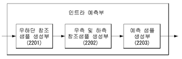
- an apparatus for processing an image based on an intra prediction mode comprising: a lower right reference sample generation unit for generating a lower right reference sample adjacent to a lower right side of a current block; A left reference sample of the current block and a lower right reference sample are linearly interpolated by linearly interpolating the upper right reference sample and the lower right reference sample of the current block to linearly interpolate the lower left reference sample and the lower right reference sample, A right and a lower reference sample generator for generating a lower reference sample of the reference sample; And a prediction sample generator for generating a prediction sample of the current block using a left reference sample, an upper reference sample, a right reference sample, and a lower reference sample of the current block.
- the prediction sample generator may generate a prediction sample of the current block by averaging the left reference sample, the upper reference sample, the right reference sample, and the lower reference sample.
- the prediction sample generator derives a left average value, an upper average value, a right average value, and a lower average value by averaging the samples of the left reference sample, the upper reference sample, the right reference sample, and the lower reference sample,
- the predicted sample of the current block may be generated by linearly interpolating the average value, the upper average value, the right mean value, and the lower mean value.
- the prediction sample generator calculates a weight according to a distance between a current pixel in the current block and a reference sample in each direction of the current block, and outputs the calculated weight to the left average value, the upper average value, And applying a linear interpolation to each of the lower average values to generate a prediction sample of the current pixel.
- the embodiment of the present invention it is possible to improve prediction accuracy by generating a plurality of prediction samples based on the intra prediction mode and linearly interpolating the generated prediction samples.
- prediction error can be reduced and compression performance can be improved by applying a weight according to the distance between the current sample and the reference sample in each direction.
- FIG. 1 is a schematic block diagram of an encoder in which still image or moving picture signal encoding is performed according to an embodiment of the present invention.
- FIG. 2 is a schematic block diagram of a decoder in which still image or moving picture signal encoding is performed according to an embodiment of the present invention.
- FIG. 3 is a diagram for explaining a division structure of a coding unit applicable to the present invention.
- FIG. 4 is a diagram for explaining a prediction unit that can be applied to the present invention.
- FIG. 5 is a diagram illustrating an intra prediction method according to an embodiment to which the present invention is applied.
- FIG. 6 illustrates a prediction direction according to an intra prediction mode.
- FIG. 7 is a diagram for explaining a linear interpolation prediction method, to which the present invention can be applied.
- FIG. 8 illustrates region division according to the direction and angle of the intra-prediction mode.
- FIG. 9 is a diagram illustrating a method for generating a bottom-right sample in accordance with one embodiment of the present invention.
- FIG. 10 is a diagram illustrating a method of generating a bottom-right sample according to an embodiment of the present invention.
- FIG. 11 is a diagram for explaining a linear interpolation predicting method to which the present invention is applied.
- FIG. 12 is a view for explaining a method of generating a lower end sample and a right end sample according to an embodiment of the present invention.
- FIG. 13 is a diagram for explaining a linear interpolation prediction method, to which the present invention is applied.
- FIG. 14 is a diagram for explaining a linear interpolation prediction method, to which the present invention is applied.
- 15 is a diagram for explaining a linear interpolation prediction method according to an embodiment of the present invention.
- 16 is a diagram illustrating an intra prediction method using a multi-reference sample line as an embodiment to which the present invention is applied.
- 17 and 18 are diagrams for explaining a linear interpolation prediction method according to an embodiment of the present invention.
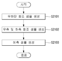
- 19 is a flowchart illustrating a linear interpolation prediction method according to an embodiment of the present invention.
- FIG. 20 is a flowchart for explaining a syntax parsing routine for linear interpolation prediction, to which the present invention is applied.
- 21 is a diagram illustrating an intra prediction mode based linear interpolation prediction method according to an embodiment of the present invention.
- 22 is a diagram specifically illustrating an intra predictor according to an embodiment of the present invention.
- FIG. 23 shows a structure of a content streaming system as an embodiment to which the present invention is applied.
- 'processing unit' means a unit in which processing of encoding / decoding such as prediction, conversion and / or quantization is performed.
- the processing unit may be referred to as a " processing block " or a " block "
- the processing unit may be interpreted to include a unit for the luma component and a unit for the chroma component.
- the processing unit may correspond to a coding tree unit (CTU), a coding unit (CU), a prediction unit (PU), or a transform unit (TU).
- CTU coding tree unit
- CU coding unit
- PU prediction unit
- TU transform unit
- the processing unit can be interpreted as a unit for a luminance (luma) component or as a unit for a chroma component.
- the processing unit may include a Coding Tree Block (CTB), a Coding Block (CB), a Prediction Block (PU), or a Transform Block (TB) ).
- CTB Coding Tree Block
- CB Coding Block
- PU Prediction Block
- TB Transform Block
- the processing unit may be interpreted to include a unit for the luma component and a unit for the chroma component.
- processing unit is not necessarily limited to a square block, but may be configured as a polygonal shape having three or more vertexes.
- a pixel, a pixel, or the like is collectively referred to as a sample.
- using a sample may mean using a pixel value, a pixel value, or the like.
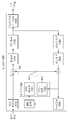
- FIG. 1 is a schematic block diagram of an encoder in which still image or moving picture signal encoding is performed according to an embodiment of the present invention.
- an encoder 100 includes an image divider 110, a subtractor 115, a transformer 120, a quantizer 130, an inverse quantizer 140, an inverse transformer 150, A decoding unit 160, a decoded picture buffer (DPB) 170, a predicting unit 180, and an entropy encoding unit 190.
- the prediction unit 180 may include an inter prediction unit 181 and an intra prediction unit 182.
- the image divider 110 divides an input video signal (or a picture, a frame) input to the encoder 100 into one or more processing units.
- the subtractor 115 subtracts a prediction signal (or a prediction block) output from the prediction unit 180 (i.e., the inter prediction unit 181 or the intra prediction unit 182) from the input video signal, And generates a residual signal (or difference block).
- the generated difference signal (or difference block) is transmitted to the conversion unit 120.
- the transforming unit 120 transforms a difference signal (or a difference block) by a transform technique (for example, DCT (Discrete Cosine Transform), DST (Discrete Sine Transform), GBT (Graph-Based Transform), KLT (Karhunen- Etc.) to generate a transform coefficient.
- a transform technique for example, DCT (Discrete Cosine Transform), DST (Discrete Sine Transform), GBT (Graph-Based Transform), KLT (Karhunen- Etc.
- the transform unit 120 may generate transform coefficients by performing transform using a transform technique determined according to a prediction mode applied to a difference block and a size of a difference block.
- the quantization unit 130 quantizes the transform coefficients and transmits the quantized transform coefficients to the entropy encoding unit 190.
- the entropy encoding unit 190 entropy-codes the quantized signals and outputs them as a bitstream.
- the quantized signal output from the quantization unit 130 may be used to generate a prediction signal.
- the quantized signal can be reconstructed by applying inverse quantization and inverse transformation through the inverse quantization unit 140 and the inverse transform unit 150 in the loop.
- a reconstructed signal can be generated by adding the reconstructed difference signal to a prediction signal output from the inter prediction unit 181 or the intra prediction unit 182.
- the filtering unit 160 applies filtering to the restored signal and outputs the restored signal to the playback apparatus or the decoded picture buffer 170.
- the filtered signal transmitted to the decoding picture buffer 170 may be used as a reference picture in the inter-prediction unit 181. [ As described above, not only the picture quality but also the coding efficiency can be improved by using the filtered picture as a reference picture in the inter picture prediction mode.
- the decoded picture buffer 170 may store the filtered picture for use as a reference picture in the inter-prediction unit 181.
- the inter-prediction unit 181 performs temporal prediction and / or spatial prediction to remove temporal redundancy and / or spatial redundancy with reference to a reconstructed picture.
- the reference picture used for prediction is a transformed signal obtained through quantization and inverse quantization in units of blocks at the time of encoding / decoding in the previous time, blocking artifacts or ringing artifacts may exist have.
- the inter-prediction unit 181 can interpolate signals between pixels by sub-pixel by applying a low-pass filter in order to solve the performance degradation due to discontinuity or quantization of such signals.
- a subpixel means a virtual pixel generated by applying an interpolation filter
- an integer pixel means an actual pixel existing in a reconstructed picture.
- the interpolation method linear interpolation, bi-linear interpolation, wiener filter and the like can be applied.
- the interpolation filter may be applied to a reconstructed picture to improve the accuracy of the prediction.
- the inter-prediction unit 181 generates an interpolation pixel by applying an interpolation filter to an integer pixel, and uses an interpolated block composed of interpolated pixels as a prediction block Prediction can be performed.
- the intra predictor 182 predicts a current block by referring to samples in the vicinity of a block to be currently encoded.
- the intraprediction unit 182 may perform the following procedure to perform intra prediction. First, a reference sample necessary for generating a prediction signal can be prepared. Then, a prediction signal can be generated using the prepared reference sample. Thereafter, the prediction mode is encoded. At this time, reference samples can be prepared through reference sample padding and / or reference sample filtering. Since the reference samples have undergone prediction and reconstruction processes, quantization errors may exist. Therefore, a reference sample filtering process can be performed for each prediction mode used for intraprediction to reduce such errors.
- the intra predictor 182 can perform intra prediction on a current block by linearly interpolating prediction sample values generated based on an intra prediction mode of the current block. A more detailed description of the intra predictor 182 will be described later.
- a prediction signal (or a prediction block) generated through the inter prediction unit 181 or the intra prediction unit 182 is used to generate a reconstruction signal (or reconstruction block) or a difference signal (or a difference block) / RTI >
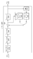
- FIG. 2 is a schematic block diagram of a decoder in which still image or moving picture signal encoding is performed according to an embodiment of the present invention.
- the decoder 200 includes an entropy decoding unit 210, an inverse quantization unit 220, an inverse transform unit 230, an adder 235, a filtering unit 240, a decoded picture buffer (DPB) A buffer unit 250, and a prediction unit 260.
- the prediction unit 260 may include an inter prediction unit 261 and an intra prediction unit 262.
- the reconstructed video signal output through the decoder 200 may be reproduced through a reproducing apparatus.
- the decoder 200 receives a signal (i.e., a bit stream) output from the encoder 100 of FIG. 1, and the received signal is entropy-decoded through the entropy decoding unit 210.
- a signal i.e., a bit stream
- the inverse quantization unit 220 obtains a transform coefficient from the entropy-decoded signal using the quantization step size information.
- the inverse transform unit 230 obtains a residual signal (or a difference block) by inverse transforming the transform coefficient by applying an inverse transform technique.
- the adder 235 adds the obtained difference signal (or difference block) to the prediction signal output from the prediction unit 260 (i.e., the inter prediction unit 261 or the intra prediction unit 262) ) To generate a reconstructed signal (or reconstruction block).
- the filtering unit 240 applies filtering to a reconstructed signal (or a reconstructed block) and outputs it to a reproducing apparatus or transmits the reconstructed signal to a decoding picture buffer unit 250.
- the filtered signal transmitted to the decoding picture buffer unit 250 may be used as a reference picture in the inter prediction unit 261.
- the embodiments described in the filtering unit 160, the inter-prediction unit 181 and the intra-prediction unit 182 of the encoder 100 respectively include the filtering unit 240 of the decoder, the inter-prediction unit 261, The same can be applied to the intra prediction unit 262.
- the intra-prediction unit 262 can perform intra-prediction on a current block by linearly interpolating prediction sample values generated based on an intra-prediction mode of the current block. A more detailed description of the intra prediction unit 262 will be described later.
- a block-based image compression method is used in a still image or moving image compression technique (for example, HEVC).
- HEVC still image or moving image compression technique
- a block-based image compression method is a method of dividing an image into a specific block unit, and can reduce memory usage and computation amount.
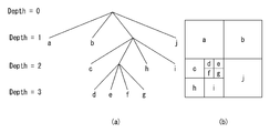
- FIG. 3 is a diagram for explaining a division structure of a coding unit applicable to the present invention.
- the encoder divides one image (or picture) into units of a rectangular shaped coding tree unit (CTU: Coding Tree Unit). Then, one CTU is sequentially encoded according to a raster scan order.
- CTU Coding Tree Unit
- the size of CTU can be set to 64 ⁇ 64, 32 ⁇ 32, or 16 ⁇ 16.
- the encoder can select the size of the CTU according to the resolution of the input image or characteristics of the input image.
- the CTU includes a coding tree block (CTB) for a luma component and a CTB for two chroma components corresponding thereto.
- CTB coding tree block
- One CTU can be partitioned into a quad-tree structure. That is, one CTU is divided into four units having a square shape and having a half horizontal size and a half vertical size to generate a coding unit (CU) have. This division of the quad-tree structure can be performed recursively. That is, the CU is hierarchically partitioned from one CTU to a quad-tree structure.
- CU coding unit
- the CU means a basic unit of coding in which processing of an input image, for example, intra / inter prediction is performed.
- the CU includes a coding block (CB) for the luma component and CB for the corresponding two chroma components.
- CB coding block
- the size of CU can be set to 64 ⁇ 64, 32 ⁇ 32, 16 ⁇ 16, or 8 ⁇ 8.
- the root node of the quad-tree is associated with the CTU.
- the quad-tree is divided until it reaches the leaf node, and the leaf node corresponds to the CU.
- the CTU may not be divided.
- the CTU corresponds to the CU.
- a node that is not further divided in the lower node having a depth of 1 corresponds to a CU.
- CU (a), CU (b), and CU (j) corresponding to nodes a, b, and j in FIG. 3B are divided once in the CTU and have a depth of one.
- a node that is not further divided in the lower node having a depth of 2 corresponds to a CU.
- CU (c), CU (h) and CU (i) corresponding to nodes c, h and i in FIG. 3B are divided twice in the CTU and have a depth of 2.
- a node that is not further divided in the lower node having a depth of 3 corresponds to a CU.
- the maximum size or the minimum size of the CU can be determined according to the characteristics of the video image (for example, resolution) or considering the efficiency of encoding. Information on this or information capable of deriving the information may be included in the bitstream.
- a CU having a maximum size is called a Largest Coding Unit (LCU), and a CU having a minimum size can be referred to as a Smallest Coding Unit (SCU).
- LCU Largest Coding Unit
- SCU Smallest Coding Unit
- a CU having a tree structure can be hierarchically divided with a predetermined maximum depth information (or maximum level information).
- Each divided CU can have depth information.
- the depth information indicates the number and / or degree of division of the CU, and therefore may include information on the size of the CU.
- the size of the SCU can be obtained by using the LCU size and the maximum depth information. Conversely, by using the size of the SCU and the maximum depth information of the tree, the size of the LCU can be obtained.
- information indicating whether the corresponding CU is divided may be transmitted to the decoder.
- This partitioning information is included in all CUs except SCU. For example, if the value of the flag indicating division is '1', the corresponding CU is again divided into four CUs. If the flag indicating the division is '0', the corresponding CU is not further divided, Can be performed.
- the CU is a basic unit of coding in which intra prediction or inter prediction is performed.
- the HEVC divides the CU into units of Prediction Unit (PU) in order to more effectively code the input image.
- PU Prediction Unit
- PU is a basic unit for generating prediction blocks, and it is possible to generate prediction blocks in units of PU different from each other in a single CU.
- PUs belonging to one CU are not mixed with intra prediction and inter prediction, and PUs belonging to one CU are coded by the same prediction method (i.e., intra prediction or inter prediction).
- the PU is not divided into a quad-tree structure, and is divided into a predetermined form in one CU. This will be described with reference to the following drawings.
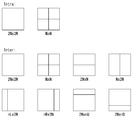
- FIG. 4 is a diagram for explaining a prediction unit that can be applied to the present invention.
- the PU is divided according to whether the intra prediction mode is used or the inter prediction mode is used in the coding mode of the CU to which the PU belongs.
- FIG. 4A illustrates a PU when an intra prediction mode is used
- FIG. 4B illustrates a PU when an inter prediction mode is used.
- one CU has two types (ie, 2N ⁇ 2N or N X N).
- one CU is divided into four PUs, and different prediction blocks are generated for each PU unit.
- the division of the PU can be performed only when the size of the CB with respect to the luminance component of the CU is the minimum size (i.e., when the CU is the SCU).
- one CU has eight PU types (ie, 2N ⁇ 2N , NN, 2NN, NNN, NLNN, NRNN, 2NNU, 2NND).
- N ⁇ N type PU segmentation can be performed only when the size of the CB for the luminance component of the CU is the minimum size (ie, when the CU is SCU).
- AMP Asymmetric Motion Partition
- 'n' means a 1/4 value of 2N.
- the AMP can not be used when the CU to which the PU belongs is the minimum size CU.
- the optimal division structure of the coding unit (CU), the prediction unit (PU), and the conversion unit (TU) for efficiently encoding an input image in one CTU is a rate-distortion- Value. ≪ / RTI > For example, if we look at the optimal CU partitioning process within a 64 ⁇ 64 CTU, the rate-distortion cost can be calculated by dividing from a 64 ⁇ 64 CU to an 8 ⁇ 8 CU.
- the concrete procedure is as follows.
- 32 ⁇ 32 CUs are subdivided into 4 16 ⁇ 16 CUs to determine the optimal PU and TU partition structure that yields the minimum rate-distortion value for each 16 ⁇ 16 CU.
- a prediction mode is selected in units of PU, and prediction and reconstruction are performed in units of actual TUs for the selected prediction mode.
- the TU means the basic unit on which the actual prediction and reconstruction are performed.
- the TU includes a transform block (TB) for the luma component and a TB for the two chroma components corresponding thereto.
- the TU is hierarchically divided into a quad-tree structure from one CU to be coded, as one CTU is divided into a quad-tree structure to generate a CU.
- the TUs segmented from the CUs can be further divided into smaller lower TUs.
- the size of the TU can be set to any one of 32 ⁇ 32, 16 ⁇ 16, 8 ⁇ 8, and 4 ⁇ 4.
- the root node of the quadtree is associated with a CU.
- the quad-tree is divided until it reaches a leaf node, and the leaf node corresponds to TU.
- the CU may not be divided.
- the CU corresponds to the TU.
- TU (a), TU (b), and TU (j) corresponding to nodes a, b, and j in FIG. 3B are once partitioned in the CU and have a depth of one.
- the node that is not further divided in the lower node having the depth of 2 corresponds to TU.
- TU (c), TU (h) and TU (i) corresponding to nodes c, h and i in FIG. 3B are divided twice in CU and have a depth of 2.
- a node that is not further divided in the lower node having a depth of 3 corresponds to a CU.
- TU (d), TU (e), TU (f), and TU (g) corresponding to nodes d, e, f and g in FIG. Depth.
- a TU having a tree structure can be hierarchically divided with predetermined maximum depth information (or maximum level information). Then, each divided TU can have depth information.
- the depth information indicates the number and / or degree of division of the TU, and therefore may include information on the size of the TU.
- information indicating whether the corresponding TU is divided may be communicated to the decoder.
- This partitioning information is included in all TUs except the minimum size TU. For example, if the value of the flag indicating whether or not to divide is '1', the corresponding TU is again divided into four TUs, and if the flag indicating the division is '0', the corresponding TU is no longer divided.
- And may use the decoded portion of the current picture or other pictures that contain the current processing unit to recover the current processing unit in which decoding is performed.
- a picture (slice) that uses only the current picture, that is, a picture (slice) that uses only the current picture, that is, a picture (slice) that performs only intra-picture prediction is referred to as an intra picture or an I picture
- a picture (slice) using a predictive picture or a P picture (slice), a maximum of two motion vectors and a reference index may be referred to as a bi-predictive picture or a B picture (slice).
- Intra prediction refers to a prediction method that derives the current processing block from a data element (e.g., a sample value, etc.) of the same decoded picture (or slice). That is, it means a method of predicting the pixel value of the current processing block by referring to the reconstructed areas in the current picture.
- a data element e.g., a sample value, etc.
- Inter prediction refers to a prediction method of deriving a current processing block based on a data element (e.g., a sample value or a motion vector) of a picture other than the current picture. That is, this means a method of predicting pixel values of a current processing block by referring to reconstructed areas in other reconstructed pictures other than the current picture.
- a data element e.g., a sample value or a motion vector
- intra prediction (or intra prediction) will be described in more detail.
- Intra prediction Intra prediction (or intra prediction)
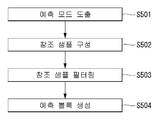
- FIG. 5 is a diagram illustrating an intra prediction method according to an embodiment to which the present invention is applied.
- the decoder derives an intra prediction mode of the current processing block (S501).
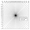
- intra prediction it is possible to have a prediction direction with respect to the position of a reference sample used for prediction according to the prediction mode.
- An intra prediction mode having a prediction direction is referred to as an intra prediction mode (Intra_Angular prediction mode).
- intra prediction mode Intra_Angular prediction mode
- intra-planar (INTRA_PLANAR) prediction mode there are an intra-planar (INTRA_PLANAR) prediction mode and an intra-DC (INTRA_DC) prediction mode as intra-prediction modes having no prediction direction.
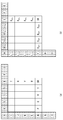
- Table 1 illustrates the intra-prediction mode and related names
- FIG. 6 illustrates the prediction direction according to the intra-prediction mode.
- intra prediction prediction is performed on the current processing block based on the derived prediction mode. Since the reference sample used in the prediction differs from the concrete prediction method used in the prediction mode according to the prediction mode, when the current block is encoded in the intra prediction mode, the decoder derives the prediction mode of the current block in order to perform prediction.
- the decoder checks whether neighboring samples of the current processing block can be used for prediction, and constructs reference samples to be used for prediction (S502).
- neighbor samples of the current processing block include a sample adjacent to the left boundary of the current processing block of size nS x nS and a total of 2 x nS samples neighboring the bottom-left, A sample adjacent to the top boundary and a total of 2 x n S samples neighboring the top-right side and one sample neighboring the top-left of the current processing block.
- the decoder may substitute samples that are not available with the available samples to construct reference samples for use in prediction.
- the decoder may perform filtering of the reference samples based on the intra prediction mode (S503).
- Whether or not the filtering of the reference sample is performed can be determined based on the size of the current processing block.
- the filtering method of the reference sample may be determined by a filtering flag transmitted from the encoder.
- the decoder generates a prediction block for the current processing block based on the intra prediction mode and the reference samples (S504). That is, the decoder determines the intra prediction mode derived in the intra prediction mode deriving step S501, the prediction for the current processing block based on the reference samples acquired in the reference sample building step S502 and the reference sample filtering step S503, (I.e., generates a prediction sample).
- the left boundary sample of the prediction block i.e., the sample in the prediction block adjacent to the left boundary
- samples in the prediction block adjacent to the upper boundary that is, samples in the prediction block adjacent to the upper boundary
- filtering may be applied to the left boundary sample or the upper boundary sample, similar to the INTRA_DC mode, for the vertical direction mode and the horizontal direction mode of the intra directional prediction modes.
- the value of a predicted sample can be derived based on a reference sample located in a prediction direction.
- the boundary sample which is not located in the prediction direction may be adjacent to the reference sample which is not used for prediction. That is, the distance from the reference sample that is not used for prediction may be much closer than the distance from the reference sample used for prediction.
- the decoder may adaptively apply filtering to the left boundary samples or the upper boundary samples according to whether the intra-prediction direction is vertical or horizontal. That is, when the intra prediction direction is vertical, filtering is applied to the left boundary samples, and filtering is applied to the upper boundary samples when the intra prediction direction is the horizontal direction.
- HEVC generates prediction blocks using 33 directional prediction methods, two non-directional prediction methods, and 35 prediction methods through intraprediction (or intra prediction).
- the conventional intra prediction method generates a prediction sample using a surrounding reference sample (assuming that it is encoded / decoded in a raster scan order, an upper reference sample or a left reference sample). Then, the generated prediction sample is copied to the prediction sample generated according to the direction of the intra prediction mode.
- the prediction accuracy decreases as the distance from the reference sample increases. That is, if the distance between the reference samples used for prediction and the prediction sample is close, the prediction accuracy is high. However, if the distance between the reference sample used for prediction and the prediction sample is far, the prediction accuracy is low.
- the present invention proposes a linear interpolation intra prediction method applying a weight according to a distance between a current sample and a reference sample.
- the encoder / decoder may derive a plurality of prediction samples using peripheral reference samples and linearly interpolate the derived prediction samples to produce a final prediction sample.
- the neighboring samples of the invention proposed herein may refer to samples available in intra prediction. In the description of the present invention, neighboring samples will be described below for convenience of explanation, but the present invention is not limited thereto.
- Neighboring samples include a sample adjacent to the left boundary of the current block of size nS ⁇ nS and a total of 2 ⁇ n Samples neighboring the bottom-left, a sample adjacent to the top boundary of the current block And a total of 2 x n S samples neighboring the top-right and one sample neighboring the top-left of the current block.
- a sample adjacent to the top-right and a sample adjacent to the bottom-left are described as follows, but the present invention is not limited thereto.
- the samples neighboring the top-right of the current block are [nS, -1] to [2 * nS-1], assuming that the horizontal and vertical coordinates of the upper left sample of the current block are [0,0] , -1], respectively.
- a sample neighboring the bottom-left of the current block may mean nS samples located at [-1, nS] - [-1, 2 * nS-1].
- the linear interpolation intra prediction method derives a first predicted sample value and a second predicted sample value using neighboring samples of a current block, linearly interpolates the derived first predicted sample value and second predicted sample value, Can be generated.
- one reference sample may be determined as a reference sample for linear interpolation on a block-by-block basis to derive a second predicted sample value, or a sample may be generated on the basis of the direction and angle of the intra-
- the second predicted sample value may be derived from one of the neighboring samples and the second predicted sample value may be derived from the linear interpolation between the two reference samples.
- the encoder / decoder may derive the first predicted sample value and the second predicted sample value, and linearly interpolate the derived first predicted sample value and the derived second predicted sample value to generate a predicted sample of the current block.
- the first predicted sample value may be derived by the method described in FIGS. 5 and 6.
- neighboring samples of the current block include samples adjacent to the left boundary of the current processing block of size nS ⁇ nS and neighboring samples at the bottom- 2 x n S samples, a sample adjacent to the top boundary of the current processing block, and a total of 2 x n S samples neighboring the top-right side and the top-left side of the current processing block It can mean one neighboring sample.
- the encoder / decoder may substitute samples that are not available with the available samples, And perform filtering of the reference samples based on the intra prediction mode.
- the encoder / decoder may derive the first predicted sample value using the intra prediction mode and the reference samples.
- the encoder / decoder may determine a reference sample for linear interpolation based on the direction and angle of the intra-prediction mode and determine a second predicted sample value with the determined reference sample value. A method of determining a reference sample for linear interpolation will be described below with reference to FIGS. 7 and 8. FIG.
- FIG. 7 is a diagram for explaining a linear interpolation prediction method, to which the present invention can be applied.
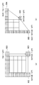
- the encoder / decoder can determine different reference samples as reference samples for linear interpolation depending on the direction and angle of the intra prediction mode. And the encoder / decoder may use the reference sample value for the determined linear interpolation as the second predicted sample value. In the case of Fig. 7 (a), the reference sample for linear interpolation may be determined as the upper-right sample 701 adjacent to the current block.
- the encoder / decoder can linearly interpolate the first predicted sample value and the value of the upper-right sample 701 adjacent to the current block to generate a predicted sample value of the current sample.
- the encoder / decoder can generate a prediction block of the current block by applying the same method to all samples in the current block.
- the reference sample for linear interpolation may be determined as the lower-right sample 702 adjacent to the current block.
- the encoder / decoder may linearly interpolate the first predicted sample value and the lower-right sample 702 value adjacent to the current block to generate a predicted sample value of the current sample.
- the encoder / decoder can generate a prediction block of the current block by applying the same method to all samples in the current block.
- the reference sample for linear interpolation can be determined as the lower left sample 703 adjacent to the current block.
- the encoder / decoder can linearly interpolate the first predicted sample value and the lower-left sample 703 value adjacent to the current block to produce a predicted sample value of the current sample.
- the encoder / decoder can generate a prediction block of the current block by applying the same method to all samples in the current block.
- a reference sample for linear interpolation according to the direction and angle of the intra-prediction mode may be determined as the upper-left sample 701, the lower-right sample 702, or the lower left sample 703 adjacent to the current block.
- the determined reference sample value may be derived as a second predicted sample value.
- the second predicted sample value may be derived using different reference samples depending on the direction and angle of the intra-prediction mode.
- the direction and angle will be described with reference to the following drawings.
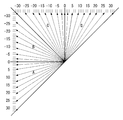
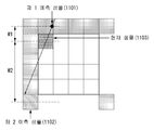
- FIG. 8 illustrates region division according to the direction and angle of the intra-prediction mode.
- regions having horizontal directionality can be divided into regions A and B, and regions having vertical directionality can be divided into regions C and D.
- positive angular regions can be divided into A and D regions
- negative angular regions can be divided into B and C regions based on angles.
- Table 2 summarizes the division of regions according to the direction and angle of the prediction mode.
- the area A is a case where the direction of the intra-prediction mode is the horizontal direction and belongs to the area of the positive angular direction.
- the B region is a case where the direction of the intra-prediction mode is the horizontal direction and belongs to the region of the negative angular direction.
- the C region is a case in which the direction of the intra-prediction mode is a vertical direction and belongs to a region in the negative angular direction.
- the D region is a case in which the direction of the intra-prediction mode is a vertical direction and belongs to a region in a positive angular direction.
- FIG. 7A shows the case where the direction of the intra-prediction mode belongs to the A region
- FIG. 7B shows the case of belonging to the B and C regions, .
- the second predicted sample value can be derived as the value of the upper-right sample 701 adjacent to the current block.
- the second predicted sample value is the lower- (702). ≪ / RTI >
- the second predicted sample value may be derived as the value of the lower left sample 703 adjacent to the current block.
- the value of the upper right sample 701 adjacent to the current block may be derived as the second predicted sample value, and the value of the lower right sample 702 adjacent to the current block may be calculated as the second predicted sample value .
- a linear interpolation value (or averaged value) of the upper-left sample 701 and the lower-right sample 702 may be derived as the second predicted sample value.
- the value of the lower left sample 703 adjacent to the current block may be derived as the second predicted sample value
- the value of the lower right sample 702 adjacent to the current block may be derived as the second predicted sample value
- a linear interpolation (or averaged value) of the lower-left sample 703 and the lower-right sample 702 may be derived as a second predicted sample value.
- the lower right sample value adjacent to the current block can be derived as the second predicted sample value.
- the encoder / decoder may generate the bottom right sample to derive the second predicted sample value.
- FIG. 9 is a diagram illustrating a method for generating a bottom-right sample in accordance with one embodiment of the present invention.
- a lower right sample 901 adjacent to a current block and a lower left sample 902 adjacent to a current block can be used to generate a lower right sample 903 adjacent to a current block.
- the lower-right sample 901 and the lower-left sample 902 may be generated as the average value of the upper-left sample 901 and the lower-left sample 902, respectively.
- a lower right sample 903 may be generated using Equation (1).
- a sample located at the rightmost side of a sample adjacent to the upper right end of the current block (hereinafter, referred to as an upper rightmost sample) (2 * nS-1, -1) samples (904) in a sample that is twice as long as the current block in the direction of the current block, i.e., in the nS x nS block, and a sample located at the lowermost (Hereinafter, referred to as an " most left bottom sample ") (e.g., a sample that is twice as long as the current block in the vertical direction on the basis of a sample adjacent to the upper left end of the current block, * nS-1] samples) 905 can be used to generate lower-right samples 906 adjacent to the current block.
- the value of the bottom right sample (906) can be generated by averaging the values of the right most upper left sample (904) and the most left lower right sample (905). At this time, the lower right sample 906 may be generated using Equation (2).
- FIG. 9 a method of generating lower-right samples using neighboring samples belonging to the reconstructed image by performing encoding / decoding has been described. A method of directly using a sample value of an original image will be described with reference to the following drawings.
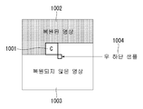
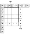
- FIG. 10 is a diagram illustrating a method of generating a bottom-right sample according to an embodiment of the present invention.
- encoding / decoding is performed based on the current block C 1001 and the reconstructed image part 1002 is still encoded / (Or a portion of the image not restored) 1003, as shown in FIG. That is, the non-reconstructed image portion 1003, which is the right side and the lower side of the current block C 1001, may correspond to a portion where encoding / decoding has not yet been performed.
- the decoder can not immediately use the lower-most sample 1004.
- the encoder transmits a sample value corresponding to the lower-right sample 1004 adjacent to the current block C 1001 in the original image to the decoder, and the decoder receives the sample value and outputs the lower- The value can be used as is.
- the encoder can perform encoding using the value of the lower right sample (1004) of the original image, and the decoder can perform decoding using the value of the lower right sample (1004) received as it is.
- the encoder / decoder uses the sampled values of the original image as it is, the prediction accuracy and compression performance can be improved.
- FIG. 11 is a diagram for explaining a linear interpolation predicting method to which the present invention is applied.
- the encoder / decoder can derive the intra prediction mode of the current block, verify that neighboring samples can be used, and construct reference samples used for prediction.
- the encoder / decoder may derive the first predicted sample 1101 value using the derived intra prediction mode and reference samples.
- the value of the second predicted sample 1102 may be determined as the lower left sample value adjacent to the current block.
- the encoder / decoder may linearly interpolate the value of the first predicted sample 1101 and the value of the second predicted sample 1102 to generate a predicted sample (or a final predicted sample) of the current sample 1103.
- the predicted sample value (or the final predicted sample) of the current sample 1103 can be calculated as shown in Equation (3).
- Equation (3) w1 is a vertical distance between the first predicted sample 1101 and the current sample 1103, and w2 is a vertical distance between the second predicted sample 1102 and the current sample 1103. [ That is, the encoder / decoder performs a linear interpolation by applying a weight according to the vertical distance ratio to the value of the first predicted sample 1101 and the value of the second predicted sample 1102, thereby generating a predicted sample of the current sample 1103 .
- the encoder / decoder can generate a prediction block of the current block by applying the same method to all samples in the current block.
- the predicted sample value of the current sample can be calculated using Equation (3).
- the encoder / decoder calculates the vertical distance between the first predicted sample and the current sample, the vertical distance between the second predicted sample and the current sample The weighting according to the vertical distance may be applied and linearly interpolated to generate a prediction sample of the current sample.
- the predicted sample value of the current sample can be calculated using Equation (3).
- the encoder / decoder can generate a prediction block of the current block by applying the same method to all samples in the current block.
- a linear interpolation intra prediction method in which a reference sample for linear interpolation is determined and a second predicted sample value is derived from the determined reference sample value has been described.
- a linear interpolation intra prediction method in which a second predicted sample value is derived from one reference sample value of neighboring samples according to a direction of an intra prediction mode or a second predicted sample value is derived by linearly interpolating two reference samples Will be described.
- the encoder / decoder may derive the first predicted sample value and the second predicted sample value, and linearly interpolate the derived first predicted sample value and the derived second predicted sample value to generate a predicted sample of the current block.
- the first predicted sample value may be derived by the method described in FIGS. 5 and 6.
- neighboring samples of the current block include samples adjacent to the left boundary of the current processing block of size nS ⁇ nS and neighboring samples at the bottom- 2 x n S samples, a sample adjacent to the top boundary of the current processing block, and a total of 2 x n S samples neighboring the top-right side and the top-left side of the current processing block It can mean one neighboring sample.
- the decoder may substitute samples that are not available with the available samples to construct reference samples to use for prediction And can perform filtering of the reference samples based on the intra prediction mode.
- the encoder / decoder may derive a first predicted sample value using the intra prediction mode and the reference samples.
- the second predicted sample value may be derived as one reference sample value of neighboring samples of the current block, or may be derived as a linear interpolation of two reference samples, based on the direction of the intra prediction mode.
- neighboring samples of the current block include a sample adjacent to the left boundary of the current block of size nS x nS and a total of 2 x nS samples neighboring the bottom- , A sample adjacent to the top boundary of the current block and a total of 2 x n S samples neighboring the top-right side and one sample neighboring the top-left of the current block, NS samples adjacent to the right boundary of the current block, nS samples adjacent to the bottom boundary of the current block, and / or one sample adjacent to the bottom-right of the current block .
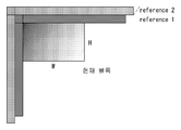
- FIG. 12 is a view for explaining a method of generating a lower end sample and a right end sample according to an embodiment of the present invention.
- the encoder / decoder may generate a lower-right sample 1203 adjacent to the current block.
- the lower-right sample 1203 adjacent to the current block can be generated by the method described in FIGS. 9 and 10.
- FIG. 9 is a diagrammatic representation of the lower-right sample 1203 adjacent to the current block.
- the lower sample neighboring to the lower end of the current block may be generated by linearly interpolating the lower left sample 1201 and the lower right sample 1203 adjacent to the current block and the right sample neighboring the right end of the current block may be generated by linearly interpolating Can be generated by linearly interpolating the upper-left sample 1202 and the lower-right sample 1203.
- the encoder / decoder can generate the first sample 1204 on the left side of the lower sample by linearly interpolating the samples on the lower left sample 1201 and the sample on the lower right 1203 using a weight according to the distance ratio. That is, the ratio between the weight applied to the lower left sample 1201 and the weight applied to the lower right sample 1203 is determined by the distance between the left first sample 1204 and the lower left sample 1201, Can be calculated as 4: 1 according to the distance between the left first sample 1204 and the right lower sample 1203. [
- the left third sample 1205 and the bottom left sample 1205 of the lower left sample and the lower left sample 1205 of the lower left sample may be determined to be 2: 3 according to the distance of the lower sample 1203.
- the encoder / decoder can generate the lower-end sample by linearly interpolating the weight according to the distance ratio between the lower-left sample 1201 and the lower-right sample 1203, And a weight according to the distance ratio with the lower-end sample 1203 may be applied and linear interpolation may be performed.
- the encoder / decoder may construct the lower and upper right samples without generating the lower right sample 1203 first, and may also be configured to select the average of the lower left sample 1201 and the lower right sample 1203,
- the lower and upper right samples may be composed of an average value of the lower right sample 1203.
- the encoder / decoder may generate a rightmost sample and a bottom sample of the current block, and derive a first predicted sample value and a second predicted sample value based on the intra prediction mode of the current block. Will be described with reference to the following drawings.
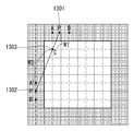
- 13 and 14 are diagrams for explaining a linear interpolation prediction method, to which the present invention is applied.
- the encoder / decoder may derive an intra prediction mode and generate a first prediction sample value P 1301 based on the derived intra prediction mode.
- the encoder / decoder determines A reference samples and B reference samples according to the direction and angle of the intra prediction mode of the current sample C 1303, and linearly interpolates A reference samples and B reference samples to generate a first predicted sample value P (1301 Can be derived.
- the first predicted sample value P (1301) may be derived from one reference sample value used for prediction or the first predicted sample value P (1301) may be derived by linearly interpolating two reference samples .
- the encoder / decoder may generate a second predicted sample value P '(1302) based on the derived intra prediction mode.
- the encoder / decoder determines the A 'reference sample and the B' reference sample according to the direction and angle of the intra prediction mode of the current block and linearly interpolates the A 'reference sample and the B' reference sample to obtain a second predicted sample value P ' 1302 can be derived.
- a second predicted sample value P '1302 is derived from one reference sample value used for prediction or a second predicted sample value P' 1302 is obtained by linearly interpolating two reference samples can do.
- the encoder / decoder can derive the first predicted sample value and the second predicted sample value in a direction other than the direction of the intra-prediction mode illustrated in FIG.
- a first predicted sample value P (1301) may be derived from one reference sample value used for prediction or a first predicted sample value P (1301) may be derived from a linear interpolation of two reference samples .
- a second predicted sample value P '(1302) is derived from one reference sample value used for prediction based on the intra prediction mode among the samples neighboring to the top of the current block or the rightmost reference sample, A second predicted sample value P '(1302) may be derived from the interpolated value.
- the first predicted sample value P (1301) is derived from one reference sample value used for prediction based on the intra prediction mode among the samples neighboring to the top, or the first predicted sample value P (1301) is obtained by linearly interpolating the two reference samples. (1301) can be derived.
- a second predicted sample value P '(1302) is derived from one reference sample value used for prediction based on the intra-prediction mode among the lower-right sample adjacent to the current block, the lower sample of the current block, or the right-
- a second predicted sample value P '1302 can be derived from the linear interpolation of the reference samples.
- the first predicted sample value P (1301) is derived from one reference sample value used for prediction based on the intra prediction mode among the samples neighboring to the top, or the first predicted sample value P (1301) is obtained by linearly interpolating the two reference samples. (1301) can be derived.
- a second predicted sample value P '(1302) is derived from one lower reference sample adjacent to the current block, one reference sample value used for prediction based on the intra prediction mode among the lower or right sample of the current block,
- a second predicted sample value P '1302 can be derived from the linear interpolation of the sample.
- first predicted sample value P 1301 and the second predicted sample value P '1302 are derived, the first predicted sample value P 1301 and the second predicted sample value P' 1302 are linearly interpolated, A predicted sample (or a final predicted sample) of C 1303 can be generated.
- the predicted sample value of the current sample C 1303 can be calculated as shown in Equation (4).
- W1 in Equation 4 can be calculated as the distance between the first predicted sample 1301 and the current sample C 1303 and w2 as the distance between the second predicted sample 1302 and the current sample C 1303.
- the encoder / decoder can generate a predicted sample of the current sample C 1303 by applying a linear weighted value to the value of the first predicted sample 1301 and the value of the second predicted sample 1302, and linearly interpolating the weighted value.
- the encoder / decoder can apply the same method to all prediction samples existing in the current block to generate a prediction block of the current block.
- the encoder / decoder can calculate the predicted sample value of the current sample using the equation (4) also for directions other than the directions of the intra-prediction mode illustrated in FIG.
- the encoder / decoder calculates the distance between the first predicted sample and the current sample in all intraprediction modes having directionality (for example, an intra prediction mode with 33 directions in HEVC), a distance between the second predicted sample and the current sample To generate a prediction sample of the current sample (or current block).
- the predicted sample value of the current sample can be calculated using Equation (4).
- the encoder / decoder When deriving the second predicted sample value, the encoder / decoder generates a reference sample array and generates one reference sample value that is used for prediction based on the intra prediction mode among the reference sample array To derive the second predicted sample value or to linearly interpolate the two reference samples to derive the second predicted sample value.
- a reference sample array may refer to an array composed of reference samples used for prediction according to the intra prediction mode of the current block among neighboring samples of the current block.
- the first reference sample sequence may refer to an arrangement consisting of reference samples used for prediction according to the intra prediction mode of the current block to generate a first prediction sample value.
- the second reference sample sequence may refer to an arrangement consisting of reference samples used for prediction according to the intra prediction mode of the current block to generate a second prediction sample value.
- the second reference sample array may include a right-top reference sample arrangement and / or a bottom reference sample arrangement as described below.
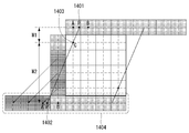
- the first predicted sample value P (1401) may be derived by the method described in FIG. That is, the encoder / decoder may derive an intra prediction mode and generate a first predicted sample value P (1401) based on the derived intra prediction mode.
- a reference sample and B reference sample are used in accordance with the direction and angle of the intra prediction mode of the current sample C 1403, and linear interpolation of the A reference sample and the B reference sample is performed so that the first predicted sample value P (1401) have.
- the first predicted sample value P (1401) may be derived from the reference sample value used for the prediction or the first predicted sample value P (1401) may be derived from the linear interpolation between the two reference samples.
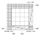
- the encoder / decoder may first generate a reference sample array 1404 to derive a second predicted sample value.
- a reference sample array 1404 For convenience of explanation, it is assumed that the horizontal and vertical coordinates of the current sample C 1303 are [0, 0].
- the encoder / decoder copies the sample neighboring the left side of the current block to the left side of the lower sample A lower reference sample array 1404 can be generated.
- the encoder / decoder determines that three samples are used for prediction among the samples adjacent to the left side of the current block according to the intra-prediction mode of the current block, and each of the horizontal and vertical coordinates is [ 1,1], [-1,2], [-1,3], the reference sample located at [-1,1] is copied to the location of [-4,4], and [-1,2 ] To the position of [-3,4] and copying the reference sample located at [-1,3] to the position of [-2,4] to create the lower sample buffer .
- the encoder / decoder may generate the bottom reference sample array 1404 using the generated bottom sample buffer and bottom samples.
- the encoder / decoder derives a second predicted sample value P '(1402) with one reference sample value of the lower reference sample array 1404 generated based on the intra prediction mode of the current block, or linearly interpolates two reference samples
- the second predicted sample value P '1402 can be derived.
- the encoder / decoder determines the reference sample A 'and the reference sample B' among the bottom reference sample array 1404 generated based on the intra prediction mode of the current block, and outputs the reference sample A 'and the reference sample B' To derive a second predicted sample value P '(1402).
- the encoder / decoder can derive the second predicted sample value using the above-described method even in a mode other than the prediction mode illustrated in FIG.
- the encoder / decoder derives the second predicted sample value from one of the right-hand reference sample sequences generated based on the intra-prediction mode of the current block or derives a second predicted sample value from the linear interpolated value of the two reference samples can do.
- the encoder / decoder copies the bottom sample to the bottom of the right- You can create an array.
- the encoder / decoder derives the second predicted sample value from one of the right-hand reference sample sequences generated based on the intra-prediction mode of the current block or derives a second predicted sample value from the linear interpolated value of the two reference samples can do.
- the encoder / decoder copies the rightmost sample to the right of the bottom sample, You can create an array.
- the encoder / decoder derives the second predicted sample value from one of the lower reference sample sequences generated based on the intra-prediction mode of the current block or the second predicted sample value from the linear interpolation of the two reference samples .
- the encoder / decoder may linearly interpolate the derived first predicted sample value and the second predicted sample value to produce a predicted sample (or a final predicted sample) of the current sample.
- the encoder / decoder can generate a prediction sample of the current sample using Equation (4) as in the method described in FIG. That is, the encoder / decoder may apply the weight values w1 and w2 to the first predicted sample value and the second predicted sample value and linearly interpolate to generate the predicted sample value of the current sample.
- the encoder / decoder can generate the right and left reference samples and / or the bottom reference sample and linearly interpolate the reference sample and the reference sample determined by the existing intra prediction method to generate a prediction block.
- the linear interpolation prediction method for generating and using the right / bottom reference samples is assumed to be performed in the raster scanning order, but the present invention is not limited thereto.
- the encoder / decoder can generate the neighbor reference samples of the unrecovered region using the neighbor reference samples of the reconstructed region, and perform linear interpolation prediction using the generated neighbor reference samples.
- the existing linear interpolation intra prediction method is applied only to the directional prediction mode, not all the prediction modes. Nevertheless, the prediction block generated through the planar mode during the non-directional mode exhibits a statistically similar characteristic to the prediction block generated through the existing linear interpolation intra prediction. In the planar mode, as well as the linear interpolation intra prediction mode, the predicted block is generated from the neighbor reference samples of the current block through linear interpolation. Therefore, in the existing linear interpolation intra prediction, only linear interpolation prediction is performed in consideration of the prediction direction, and planner prediction performs general linear interpolation prediction. In both cases, linear interpolation improves subjective image quality and compression performance Can be increased.
- the present invention proposes an intra-DC prediction method using linear interpolation.
- the encoder / decoder can perform prediction using more reference samples than the conventional DC mode.
- 15 is a diagram for explaining a linear interpolation prediction method according to an embodiment of the present invention.
- Each block shown in FIG. 15 may correspond to a pixel or may correspond to a subunit (or sub-block) of a specific size.
- the subunit may be 2x2, 4x4, 8x8 size.
- the current block 1501 may be a 4x4 block.
- the current block 1501 may be a 16x16 block Lt; / RTI >
- each block shown in FIG. 15 corresponds to a pixel and a size of a current block 1501 is 4x4.
- the encoder / decoder may generate right and bottom reference samples through linear interpolation and generate a prediction block with an average value of surrounding reference samples containing it.
- the prediction method according to the present embodiment can be referred to as a DC mode, a linear interpolation DC mode, and a linear interpolation intra DC mode.
- the encoder / decoder may generate neighboring reference samples in all directions of the current block 1501 prior to generating the prediction block of the current block 1501.
- the reference samples A to O in FIG. 15 correspond to the reference samples of the reconstructed region
- the encoder / decoder can generate reference samples of the reconstructed region of the current block 1501.
- the encoder / decoder can generate a BR reference sample 1502, which is a lower right reference sample.
- the BR reference sample 1502 can be generated by applying the method described above with reference to FIG. 9 or FIG.
- the encoder / decoder then linearly interpolates the generated BR reference samples 1502 and E reference samples to generate T, U, V, W right reference samples (or right reference samples) And M reference samples can be linearly interpolated to generate P, Q, R, S lower reference samples (or lower reference samples).
- the method described previously in Fig. 12 can be applied.
- the right reference samples can be collectively referred to as the right reference sample arrangement, the right reference sample arrangement, and the like
- the lower reference samples can be collectively referred to as a lower reference sample arrangement and a lower reference sample arrangement.
- the encoder / decoder can average the reference samples in all directions of the current block 1501 to generate a prediction block.
- the encoder / decoder may include an upper reference sample (A, B, C, D), a lower reference sample (P, Q, R, S), a left reference sample
- the predicted block of the current block 1501 can be generated as an average value of the pixel values (T, U, V, W).
- the encoder / decoder may perform intra prediction using more reference samples around the current block.
- the encoder / decoder may generate a prediction block using the average value of some direction reference samples among the upper, lower, left, and right reference samples. For example, the encoder / decoder may generate a DC prediction block using an average of the upper reference samples and the lower reference samples. Alternatively, the encoder / decoder may generate a DC prediction block using an average of the right reference samples and the left reference samples. Alternatively, the encoder / decoder may use the average of the reference samples in any direction among the neighbor reference samples of the current block to generate a prediction block.
- the encoder / decoder may determine a reference sample used for DC prediction block generation according to the size or shape of the intra prediction block. For example, if the current block is a non-square block, a prediction block can be generated by averaging the reference samples in a specific direction according to the width and height of the current block. The encoder / decoder may generate the DC prediction block using the average of the upper reference samples and the lower reference samples according to the ratio of the width and the height of the current block, and may generate DC prediction blocks using the average of the right reference samples and the left reference samples. A prediction block may be generated.
- the intra-DC mode in the conventional image compression coding technique and the linear interpolation intra-DC mode proposed in the present embodiment can be selectively applied according to the size of the current block.
- the encoder / decoder applies the proposed method when the size of the current block is less than or equal to a predetermined specific size (e.g., 8x8, 16x16, 32x32), and if the size exceeds the predetermined size, Prediction can be performed.
- a predetermined specific size e.g., 8x8, 16x16, 32x32
- each of the blocks shown in FIG. 15 may correspond to a subunit of a specific size.
- a multi-reference sample line can be used as the surrounding reference sample.
- 16 is a diagram illustrating an intra prediction method using a multi-reference sample line as an embodiment to which the present invention is applied.
- intraprediction is performed using two left and right reference sample lines of a current block.
- the present invention is not limited thereto, and the encoder / decoder can perform prediction using reference samples of three or more reference sample lines.
- each of the blocks shown in FIG. 15 described above may correspond to a 2x2 sub-unit, and the current block may be an 8x8 block.
- the prediction block can be generated by applying the method described previously in Fig. 15 in the same way.
- the subunit value may be an average value, a middle value, or the like of the pixels in the subunit.
- the encoder / decoder may use a plurality of reference sample lines as reference samples of the reconstructed area (i.e., left, upper left, upper) (I.e., lower, lower right, right) reference samples may use a single reference sample line.
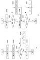
- 17 and 18 are diagrams for explaining a linear interpolation prediction method according to an embodiment of the present invention.
- the encoder / decoder can linearly interpolate the average value of the reference samples in the upper, left, right, and lower directions to generate a prediction block.
- the prediction method according to the present embodiment can be referred to as a DC mode, a linear interpolation DC mode, and a linear interpolation intra DC mode.
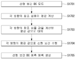
- the encoder / decoder checks whether the linear interpolation DC mode is applied to the current block (S1701).
- the encoder may signal the decoder to a syntax indicating that the linear interpolation DC mode is applied to the current block. This will be described in detail later.
- the encoder / decoder calculates an average value of the neighbor reference samples in each direction of the current block (S1702). That is, the encoder / decoder can average the reference samples in each direction by averaging the neighbor reference samples in the upper, lower, left, and right four directions of the current block.
- each of the illustrated blocks may correspond to a pixel or a sub-unit (or sub-block) of a specific size.
- the subunit may be 2x2, 4x4, 8x8 size.
- the current block may be a 4x4 block.
- the current block may be an 8x8 block.
- the current block may be a 16x16 block.
- each block shown in FIG. 18 corresponds to a pixel and the current block size is 4x4.
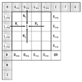
- the encoder / decoder generates an upper reference sample average value Uavg (or an upper average value) by averaging the upper reference samples A, B, C and D as shown in Equation 5 below, J, K, and L are averaged to generate a left reference sample average value Lavg (or a left average value Lavg) by averaging the left reference samples I, J, K, ), And the right reference sample average value Ravg (or the right average value) can be generated by averaging the right reference samples T, U, V, and W.
- the encoder / decoder replaces the surrounding reference sample values in each direction with the average value calculated in step S1702 (S1703).
- the encoder / decoder replaces the upper reference samples A, B, C, and D with the upper reference sample average value Uavg and the lower reference samples P, Q, R, U, V, W) is replaced with the left reference sample average value (Lavg) and the left reference sample (T, U, V, W) It can be replaced with the sample average value Ravg.
- the encoder / decoder performs linear interpolation (S1704) using the replaced reference sample value and the position of the current pixel (or the distance between the current pixel and the reference sample) in step S1703, and generates a linear interpolation DC prediction block S1705).
- the encoder / decoder may apply step S1704 for each pixel in the current block, or may apply step S1704 for each sub-block of a specific size in the current block.
- 19 is a flowchart illustrating a linear interpolation prediction method according to an embodiment of the present invention.
- each of the illustrated blocks may correspond to a pixel or a sub-unit (or sub-block) of a specific size.
- the subunit may be 2x2, 4x4, 8x8 size.
- the current block may be a 4x4 block.
- the current block may be an 8x8 block.
- the current block may be a 16x16 block.
- each block shown in FIG. 19 corresponds to a pixel and the current block size is 4x4.
- the encoder / decoder can perform linear interpolation based on the distance between each direction reference sample and the current pixel C. In this case, the encoder / decoder can generate the linearly interpolated intra-DC prediction samples of the current pixel C using Equation (6).
- the encoder / decoder can calculate the weight according to the distance between the current pixel and the reference sample in each direction, and apply the calculated weight to the average of the reference samples in each direction to generate a prediction sample of the current pixel have.
- each of the blocks shown in Figs. 18 and 19 may correspond to a sub-unit of a certain size, in which case the multi-reference sample line described in Fig. 16 may be used as a peripheral reference sample.
- each of the blocks shown in Figs. 18 and 19 described above may correspond to a 2x2 sub-unit, and the current block may be an 8x8 block.
- the prediction block can be generated by applying the method described in FIGS. 17 to 19 in the same manner.
- the subunit value may be an average value, a middle value, or the like of the pixels in the subunit.
- the encoder / decoder uses a plurality of reference sample lines for the reference samples of the reconstructed region (i.e., left, upper left, upper) (I.e., lower, lower right, right) reference samples may use a single reference sample line.
- the intra-DC mode in the conventional image compression coding technique and the linear interpolation intra-DC mode proposed in the present embodiment can be selectively applied according to the size of the current block.
- the encoder / decoder applies the proposed method when the size of the current block is less than or equal to a predetermined specific size (e.g., 8x8, 16x16, 32x32), and if the size exceeds the predetermined size, Prediction can be performed.
- a predetermined specific size e.g., 8x8, 16x16, 32x32
- FIG. 20 is a flowchart for explaining a syntax parsing routine for linear interpolation prediction, to which the present invention is applied.
- the decoder may parse the LIP flag (or syntax) indicating whether or not the linear interpolation prediction (LIP) is applied, and then parse the prediction mode of the current block, After parsing the prediction mode, the LIP flag may be parsed according to the derived prediction mode.
- LIP linear interpolation prediction
- the decoder parses the LIP flag (S2001). It is possible to determine whether or not the LIP is applied to the current block based on the LIP flag.
- the decoder derives the prediction mode of the current block. Specifically, the decoder parses the MPM flag (S2002), and checks whether the MPM mode is applied to the current block (S2003). If the MPM mode is applied to the current block, the decoder parses the MPM index (S2004). If the MPM mode is not applied to the current block, the residual mode index is parsed (S2005).
- the MPM index indicates a prediction mode used for intra prediction of the current block in the MPM candidate list
- the residual mode index indicates a prediction mode used for intra prediction of the current block among the prediction modes other than the MPM candidate, Lt; / RTI >
- the decoder may parse the prediction mode of the current block, and then adaptively parse the LIP flag according to the derived prediction mode.
- the decoder parses the MPM flag (S2006), and checks whether the MPM mode is applied to the current block (S2007). If the MPM mode is applied to the current block, the decoder parses the MPM index (S2008). If the MPM mode is not applied to the current block, the residual mode index is parsed (S2009).
- the decoder determines whether the prediction mode of the current block is the planar mode (S2010). As described above, linear interpolation prediction is not applied in the planar mode of the non-directional mode. On the other hand, according to the embodiment of the present invention described in FIGS. 15 to 19, linear interpolation prediction can be applied to the DC mode of the non-directional mode. That is, if the prediction mode of the current block is not the planar mode, the decoder can parse the LIP flag (S2011) and determine whether LIP is applied to the current block based on the LIP flag.
- S2010 planar mode
- the linear interpolation intra-DC prediction mode proposed in the present invention may be added to the intra prediction mode as an independent prediction mode regardless of whether the LIP is applied or not.
- 21 is a diagram illustrating an intra prediction mode based linear interpolation prediction method according to an embodiment of the present invention.
- the encoder / decoder generates a lower right reference sample adjacent to the lower right of the current block (S2101).
- the encoder / decoder can generate the lower right reference sample by applying the method described above with reference to FIG. 9 or FIG.
- the encoder / decoder linearly interpolates the upper right reference sample and the lower right reference sample of the current block to generate a right reference sample of the current block, linearly interpolates the lower left reference sample and the lower right reference sample of the current block, And generates a reference sample (S2102).
- the encoder / decoder can generate the right reference sample and the lower reference sample by applying the method described above with reference to FIG.
- the encoder / decoder weighted based on distance to generate samples (i.e., pixels) located between the upper-right reference sample and the lower right reference sample and weighted based on the distance to generate a lower left reference sample and a lower right reference sample Lt; / RTI > can be generated.
- the encoder / decoder generates a prediction sample of the current block using the left reference sample, the upper reference sample, the right reference sample, and the lower reference sample of the current block (S2103).
- the encoder / decoder can generate a prediction sample of the current block by averaging the left reference sample, the upper reference sample, the right reference sample, and the lower reference sample.
- the encoder / decoder averages the left average value, the upper average value, the right average value, and the lower average value by averaging the samples of the left reference sample, the upper reference sample, the right reference sample, .
- the predicted samples of the current block can be generated by linearly interpolating the derived left mean value, upper mean value, right mean value, and lower mean value.
- the encoder / decoder can calculate the weight according to the distance between the current pixel in the current block and the reference sample in each direction of the current block. Then, the predicted sample of the current pixel can be generated by applying the calculated weight to the left average value, the upper average value, the right average value, and the lower average value, respectively, to perform the linear interpolation. At this time, the above-described expression (6) can be used.
- 22 is a diagram specifically illustrating an intra predictor according to an embodiment of the present invention.
- the intra prediction unit is shown as one block in FIG. 22 for the sake of convenience, the intra prediction unit may be implemented in an encoder and / or a decoder.
- the intra prediction unit implements the functions, processes and / or methods proposed in FIGS. 7 to 21 above.
- the intra prediction unit may include a lower-right reference sample generation unit 2201, a right and lower reference sample generation unit 2202, and a prediction block generation unit 2203.
- the lower-right reference sample generation unit 2201 generates a lower-right reference sample adjacent to the lower-right side of the current block.
- the lower-right reference sample generation unit 2201 can generate the lower-right reference sample by applying the method described previously with reference to FIG. 9 or FIG.
- the right and lower reference sample generation unit 2202 linearly interpolates the upper right reference sample and the lower right reference sample of the current block to generate a right reference sample of the current block and outputs a lower left reference sample and a lower right reference sample And generates a lower reference sample of the current block by linear interpolation.
- the right and lower reference sample generation unit 2202 can generate the right reference sample and the lower reference sample by applying the method described above with reference to FIG.
- the right and lower reference sample generation unit 2202 generates samples (i.e., pixels) located between the upper right reference sample and the lower right reference sample by weighting based on the distance, You can create samples located between the reference and bottom right reference samples.
- the prediction block generation unit 2203 generates prediction samples of the current block using the left reference sample, the upper reference sample, the right reference sample, and the lower reference sample of the current block.
- the prediction block generator 2203 may generate a prediction sample of the current block by averaging the left reference sample, the upper reference sample, the right reference sample, and the lower reference sample.
- the prediction block generation unit 2203 averages the samples of the left reference sample, the upper reference sample, the right reference sample, and the lower reference sample to calculate a left average value, an upper average value, And the lower mean value can be derived.
- the predicted samples of the current block can be generated by linearly interpolating the derived left mean value, upper mean value, right mean value, and lower mean value.
- the prediction block generator 2203 can calculate a weight according to the distance between the current pixel in the current block and the reference sample in each direction of the current block. Then, the predicted sample of the current pixel can be generated by applying the calculated weight to the left average value, the upper average value, the right average value, and the lower average value, respectively, to perform the linear interpolation. At this time, the above-described expression (6) can be used.
- FIG. 23 shows a structure of a content streaming system as an embodiment to which the present invention is applied.
- the content streaming system to which the present invention is applied may include an encoding server, a streaming server, a web server, a media repository, a user device, and a multimedia input device.
- the encoding server compresses content input from multimedia input devices such as a smart phone, a camera, and a camcorder into digital data to generate a bit stream and transmit the bit stream to the streaming server.
- multimedia input devices such as a smart phone, a camera, a camcorder, or the like directly generates a bitstream
- the encoding server may be omitted.
- the bitstream may be generated by an encoding method or a bitstream generating method to which the present invention is applied, and the streaming server may temporarily store the bitstream in the process of transmitting or receiving the bitstream.
- the streaming server transmits multimedia data to a user device based on a user request through the web server, and the web server serves as a medium for informing the user of what services are available.
- the web server delivers it to the streaming server, and the streaming server transmits the multimedia data to the user.
- the content streaming system may include a separate control server. In this case, the control server controls commands / responses among the devices in the content streaming system.
- the streaming server may receive content from a media repository and / or an encoding server. For example, when receiving the content from the encoding server, the content can be received in real time. In this case, in order to provide a smooth streaming service, the streaming server can store the bit stream for a predetermined time.
- Examples of the user device include a mobile phone, a smart phone, a laptop computer, a digital broadcasting terminal, a personal digital assistant (PDA), a portable multimedia player (PMP), a navigation device, a slate PC, Such as tablet PCs, ultrabooks, wearable devices (e.g., smartwatches, smart glass, HMDs (head mounted displays)), digital TVs, desktops Computers, and digital signage.
- PDA personal digital assistant
- PMP portable multimedia player
- slate PC Such as tablet PCs, ultrabooks, wearable devices (e.g., smartwatches, smart glass, HMDs (head mounted displays)), digital TVs, desktops Computers, and digital signage.
- Each of the servers in the content streaming system can be operated as a distributed server. In this case, data received at each server can be distributed.
- the embodiments described in the present invention can be implemented and executed on a processor, a microprocessor, a controller, or a chip.
- the functional units depicted in the figures may be implemented and implemented on a computer, processor, microprocessor, controller, or chip.
- the decoder and encoder to which the present invention is applied can be applied to multimedia communication devices such as a multimedia broadcasting transmitting and receiving device, a mobile communication terminal, a home cinema video device, a digital cinema video device, a surveillance camera, a video chatting device, (3D) video devices, video telephony video devices, and medical video devices, and the like, which may be included in, for example, a storage medium, a camcorder, a video on demand (VoD) service provision device, an OTT video (Over the top video) And may be used to process video signals or data signals.
- the OTT video (Over the top video) device may include a game console, a Blu-ray player, an Internet access TV, a home theater system, a smart phone, a tablet PC, a DVR (Digital Video Recorder)
- the processing method to which the present invention is applied may be produced in the form of a computer-executed program, and may be stored in a computer-readable recording medium.
- the multimedia data having the data structure according to the present invention can also be stored in a computer-readable recording medium.
- the computer-readable recording medium includes all kinds of storage devices and distributed storage devices in which computer-readable data is stored.
- the computer-readable recording medium may be, for example, a Blu-ray Disc (BD), a Universal Serial Bus (USB), a ROM, a PROM, an EPROM, an EEPROM, a RAM, a CD- Data storage devices.
- the computer-readable recording medium includes media implemented in the form of a carrier wave (for example, transmission over the Internet).
- the bit stream generated by the encoding method can be stored in a computer-readable recording medium or transmitted over a wired or wireless communication network.
- an embodiment of the present invention may be embodied as a computer program product by program code, and the program code may be executed in a computer according to an embodiment of the present invention.
- the program code may be stored on a carrier readable by a computer.
- Embodiments in accordance with the present invention may be implemented by various means, for example, hardware, firmware, software, or a combination thereof.
- an embodiment of the present invention may include one or more application specific integrated circuits (ASICs), digital signal processors (DSPs), digital signal processing devices (DSPDs), programmable logic devices (PLDs) field programmable gate arrays, processors, controllers, microcontrollers, microprocessors, and the like.
- ASICs application specific integrated circuits
- DSPs digital signal processors
- DSPDs digital signal processing devices
- PLDs programmable logic devices
- an embodiment of the present invention may be implemented in the form of a module, a procedure, a function, or the like for performing the functions or operations described above.
- the software code can be stored in memory and driven by the processor.
- the memory is located inside or outside the processor and can exchange data with the processor by various means already known.
Abstract
Disclosed, in the present invention, are an intra-prediction mode-based image processing method and an apparatus therefor. Specifically, the intra-prediction mode-based image processing method may comprise the steps of: generating a bottom right reference sample adjacent to the bottom right side of a current block; generating a right reference sample of the current block by linearly interpolating a top right reference sample and the bottom right reference sample of the current block, and generating a bottom reference sample of the current block by linearly interpolating a bottom left reference sample and the bottom right reference sample of the current block; and generating a prediction sample of the current block by using a left reference sample, a top reference sample, a right reference sample, and a bottom reference sample of the current block.
Description
본 발명은 정지 영상 또는 동영상 처리 방법에 관한 것으로서, 보다 상세하게 인트라 예측 모드(intra prediction mode) 기반으로 정지 영상 또는 동영상을 인코딩/디코딩하는 방법 및 이를 지원하는 장치에 관한 것이다. BACKGROUND OF THE INVENTION 1. Field of the Invention The present invention relates to a still image or moving image processing method, and more particularly, to a method of encoding / decoding a still image or moving image based on an intra prediction mode and an apparatus for supporting the same.
압축 부호화란 디지털화한 정보를 통신 회선을 통해 전송하거나, 저장 매체에 적합한 형태로 저장하기 위한 일련의 신호 처리 기술을 의미한다. 영상, 이미지, 음성 등의 미디어가 압축 부호화의 대상이 될 수 있으며, 특히 영상을 대상으로 압축 부호화를 수행하는 기술을 비디오 영상 압축이라고 일컫는다. Compressive encoding refers to a series of signal processing techniques for transmitting digitized information over a communication line or for storing it in a form suitable for a storage medium. Media such as video, image, and audio can be subject to compression coding. In particular, a technique for performing compression coding on an image is referred to as video image compression.
차세대 비디오 컨텐츠는 고해상도(high spatial resolution), 고프레임율(high frame rate) 및 영상 표현의 고차원화(high dimensionality of scene representation)라는 특징을 갖게 될 것이다. 그러한 컨텐츠를 처리하기 위해서는 메모리 저장(memory storage), 메모리 액세스율(memory access rate) 및 처리 전력(processing power) 측면에서 엄청난 증가를 가져올 것이다.Next-generation video content will feature high spatial resolution, high frame rate, and high dimensionality of scene representation. Processing such content will result in a tremendous increase in terms of memory storage, memory access rate, and processing power.
따라서, 차세대 비디오 컨텐츠를 보다 효율적으로 처리하기 위한 코딩 툴을 디자인할 필요가 있다.Therefore, there is a need to design a coding tool for processing next generation video contents more efficiently.
본 발명의 목적은 현재 샘플과 참조 샘플간 거리를 기반으로 가중치가 적용된 예측 샘플을 생성하는 선형 보간 인트라 예측 방법을 제안한다.An object of the present invention is to provide a linear interpolation intra prediction method of generating a weighted prediction sample based on a distance between a current sample and a reference sample.
또한, 본 발명의 목적은 이전에 복원되지 않은 영역의 참조 샘플들을 포함한 현재 블록의 이웃하는 참조 샘플들을 이용하여 인트라 예측을 수행하는 방법을 제안한다.It is also an object of the present invention to provide a method of performing intra prediction using neighboring reference samples of a current block including reference samples of a previously unreversed region.
또한, 본 발명의 목적은 기존의 DC 모드 대비 더 많은 참조 샘플을 이용하는 선형 보간 인트라 DC 예측 방법을 제안한다.It is also an object of the present invention to provide a linear interpolation intra-DC prediction method using more reference samples than the conventional DC mode.
본 발명에서 이루고자 하는 기술적 과제들은 이상에서 언급한 기술적 과제들로 제한되지 않으며, 언급하지 않은 또 다른 기술적 과제들은 아래의 기재로부터 본 발명이 속하는 기술분야에서 통상의 지식을 가진 자에게 명확하게 이해될 수 있을 것이다.The technical objects to be achieved by the present invention are not limited to the above-mentioned technical problems, and other technical subjects which are not mentioned are described in the following description, which will be clearly understood by those skilled in the art to which the present invention belongs It will be possible.
본 발명의 일 양상은, 인트라 예측(intra prediction) 모드 기반으로 영상을 처리하는 방법에 있어서, 현재 블록의 우하측에 인접한 우하단 참조 샘플을 생성하는 단계; 상기 현재 블록의 우상측 참조 샘플 및 상기 우하단 참조 샘플을 선형 보간하여 상기 현재 블록의 우측 참조 샘플을 생성하고, 상기 현재 블록의 좌하측 참조 샘플 및 상기 우하단 참조 샘플을 선형 보간하여 상기 현재 블록의 하측 참조 샘플을 생성하는 단계; 및 상기 현재 블록의 좌측 참조 샘플, 상측 참조 샘플, 우측 참조 샘플 및 하측 참조 샘플을 이용하여 상기 현재 블록의 예측 샘플을 생성하는 단계를 포함할 수 있다.According to an aspect of the present invention, there is provided a method of processing an image based on an intra prediction mode, the method comprising: generating a lower right reference sample adjacent to a lower right side of a current block; A left reference sample of the current block and a lower right reference sample are linearly interpolated by linearly interpolating the upper right reference sample and the lower right reference sample of the current block to linearly interpolate the lower left reference sample and the lower right reference sample, Generating a lower reference sample of the lower reference sample; And generating a prediction sample of the current block using a left reference sample, an upper reference sample, a right reference sample, and a lower reference sample of the current block.
바람직하게, 상기 현재 블록의 예측 샘플을 생성하는 단계는, 상기 좌측 참조 샘플, 상기 상측 참조 샘플, 상기 우측 참조 샘플 및 상기 하측 참조 샘플들을 평균하여 상기 현재 블록의 예측 샘플을 생성하는 단계를 더 포함할 수 있다.Advantageously, the step of generating a prediction sample of the current block further comprises generating a prediction sample of the current block by averaging the left reference sample, the upper reference sample, the right reference sample and the lower reference samples can do.
바람직하게, 상기 현재 블록의 예측 샘플을 생성하는 단계는, 상기 좌측 참조 샘플, 상기 상측 참조 샘플, 상기 우측 참조 샘플 및 상기 하측 참조 샘플의 샘플들을 각각 평균하여 좌측 평균값, 상측 평균값, 우측 평균값 및 하측 평균값을 유도하는 단계; 및 상기 좌측 평균값, 상기 상측 평균값, 상기 우측 평균값 및 상기 하측 평균값을 선형 보간하여 상기 현재 블록의 예측 샘플을 생성하는 단계를 더 포함할 수 있다.Preferably, the step of generating a prediction sample of the current block includes averaging the samples of the left reference sample, the upper reference sample, the right reference sample, and the lower reference sample to calculate a left average value, an upper average value, Deriving an average value; And generating a prediction sample of the current block by linearly interpolating the left mean value, the upper mean value, the right mean value, and the lower mean value.
바람직하게, 상기 현재 블록의 예측 샘플을 생성하는 단계는, 상기 현재 블록 내 현재 픽셀과 상기 현재 블록의 각 방향의 참조 샘플간 거리에 따라 가중치를 계산하는 단계; 및 상기 계산된 가중치를 상기 좌측 평균값, 상기 상측 평균값, 상기 우측 평균값 및 상기 하측 평균값에 각각 적용하여 선형 보간을 수행함으로써 상기 현재 픽셀의 예측 샘플을 생성하는 단계를 포함할 수 있다.The generating of the prediction sample of the current block may include: calculating a weight according to a distance between a current pixel in the current block and a reference sample in each direction of the current block; And generating a prediction sample of the current pixel by applying the calculated weight to the left average value, the upper average value, the right average value, and the lower average value, respectively, to perform linear interpolation.
본 발명의 다른 일 양상은, 인트라 예측(intra prediction) 모드 기반으로 영상을 처리하는 장치에 있어서, 현재 블록의 우하측에 인접한 우하단 참조 샘플을 생성하는 우하단 참조 샘플 생성부; 상기 현재 블록의 우상측 참조 샘플 및 상기 우하단 참조 샘플을 선형 보간하여 상기 현재 블록의 우측 참조 샘플을 생성하고, 상기 현재 블록의 좌하측 참조 샘플 및 상기 우하단 참조 샘플을 선형 보간하여 상기 현재 블록의 하측 참조 샘플을 생성하는 우측 및 하측 참조 샘플 생성부; 및 상기 현재 블록의 좌측 참조 샘플, 상측 참조 샘플, 우측 참조 샘플 및 하측 참조 샘플을 이용하여 상기 현재 블록의 예측 샘플을 생성하는 예측 샘플 생성부를 포함할 수 있다.According to another aspect of the present invention, there is provided an apparatus for processing an image based on an intra prediction mode, the apparatus comprising: a lower right reference sample generation unit for generating a lower right reference sample adjacent to a lower right side of a current block; A left reference sample of the current block and a lower right reference sample are linearly interpolated by linearly interpolating the upper right reference sample and the lower right reference sample of the current block to linearly interpolate the lower left reference sample and the lower right reference sample, A right and a lower reference sample generator for generating a lower reference sample of the reference sample; And a prediction sample generator for generating a prediction sample of the current block using a left reference sample, an upper reference sample, a right reference sample, and a lower reference sample of the current block.
바람직하게, 상기 예측 샘플 생성부는 상기 좌측 참조 샘플, 상기 상측 참조 샘플, 상기 우측 참조 샘플 및 상기 하측 참조 샘플들을 평균하여 상기 현재 블록의 예측 샘플을 생성할 수 있다.The prediction sample generator may generate a prediction sample of the current block by averaging the left reference sample, the upper reference sample, the right reference sample, and the lower reference sample.
바람직하게, 상기 예측 샘플 생성부는 상기 좌측 참조 샘플, 상기 상측 참조 샘플, 상기 우측 참조 샘플 및 상기 하측 참조 샘플의 샘플들을 각각 평균하여 좌측 평균값, 상측 평균값, 우측 평균값 및 하측 평균값을 유도하고, 상기 좌측 평균값, 상기 상측 평균값, 상기 우측 평균값 및 상기 하측 평균값을 선형 보간하여 상기 현재 블록의 예측 샘플을 생성할 수 있다.Preferably, the prediction sample generator derives a left average value, an upper average value, a right average value, and a lower average value by averaging the samples of the left reference sample, the upper reference sample, the right reference sample, and the lower reference sample, The predicted sample of the current block may be generated by linearly interpolating the average value, the upper average value, the right mean value, and the lower mean value.
바람직하게, 상기 예측 샘플 생성부는 상기 현재 블록 내 현재 픽셀과 상기 현재 블록의 각 방향의 참조 샘플간 거리에 따라 가중치를 계산하고, 상기 계산된 가중치를 상기 좌측 평균값, 상기 상측 평균값, 상기 우측 평균값 및 상기 하측 평균값에 각각 적용하여 선형 보간을 수행함으로써 상기 현재 픽셀의 예측 샘플을 생성할 수 있다.Preferably, the prediction sample generator calculates a weight according to a distance between a current pixel in the current block and a reference sample in each direction of the current block, and outputs the calculated weight to the left average value, the upper average value, And applying a linear interpolation to each of the lower average values to generate a prediction sample of the current pixel.
본 발명의 실시예에 따르면, 인트라 예측 모드에 기반하여 복수의 예측 샘플들을 생성하고 생성된 예측 샘플들을 선형 보간함으로써 예측의 정확도를 향상시킬 수 있다.According to the embodiment of the present invention, it is possible to improve prediction accuracy by generating a plurality of prediction samples based on the intra prediction mode and linearly interpolating the generated prediction samples.
또한, 본 발명의 실시예에 따르면, 현재 샘플과 각 방향의 참조 샘플간의 거리에 따른 가중치를 적용함으로써 예측 에러를 줄이고 압축 성능을 향상 시킬 수 있다.In addition, according to the embodiment of the present invention, prediction error can be reduced and compression performance can be improved by applying a weight according to the distance between the current sample and the reference sample in each direction.
본 발명에서 얻을 수 있는 효과는 이상에서 언급한 효과로 제한되지 않으며, 언급하지 않은 또 다른 효과들은 아래의 기재로부터 본 발명이 속하는 기술분야에서 통상의 지식을 가진 자에게 명확하게 이해될 수 있을 것이다.The effects obtained in the present invention are not limited to the effects mentioned above, and other effects not mentioned can be clearly understood by those skilled in the art from the following description .
본 발명에 관한 이해를 돕기 위해 상세한 설명의 일부로 포함되는, 첨부 도면은 본 발명에 대한 실시예를 제공하고, 상세한 설명과 함께 본 발명의 기술적 특징을 설명한다.The accompanying drawings, which are included to provide a further understanding of the invention and are incorporated in and constitute a part of the specification, illustrate embodiments of the invention and, together with the description, serve to explain the technical features of the invention.
도 1은 본 발명이 적용되는 실시예로서, 정지 영상 또는 동영상 신호의 인코딩이 수행되는 인코더의 개략적인 블록도를 나타낸다.FIG. 1 is a schematic block diagram of an encoder in which still image or moving picture signal encoding is performed according to an embodiment of the present invention.
도 2는 본 발명이 적용되는 실시예로서, 정지 영상 또는 동영상 신호의 인코딩이 수행되는 디코더의 개략적인 블록도를 나타낸다.2 is a schematic block diagram of a decoder in which still image or moving picture signal encoding is performed according to an embodiment of the present invention.
도 3은 본 발명에 적용될 수 있는 코딩 유닛의 분할 구조를 설명하기 위한 도면이다.3 is a diagram for explaining a division structure of a coding unit applicable to the present invention.
도 4는 본 발명에 적용될 수 있는 예측 유닛을 설명하기 위한 도면이다. 4 is a diagram for explaining a prediction unit that can be applied to the present invention.
도 5는 본 발명이 적용되는 실시예로서, 인트라 예측 방법을 예시하는 도면이다. 5 is a diagram illustrating an intra prediction method according to an embodiment to which the present invention is applied.
도 6은 인트라 예측 모드에 따른 예측 방향을 예시한다. FIG. 6 illustrates a prediction direction according to an intra prediction mode.
도 7은 본 발명이 적용될 수 있는 실시예로서, 선형 보간 예측 방법을 설명하기 위한 도면이다.FIG. 7 is a diagram for explaining a linear interpolation prediction method, to which the present invention can be applied.
도 8은 인트라 예측 모드의 방향성과 각도에 따른 영역 구분을 예시한다.FIG. 8 illustrates region division according to the direction and angle of the intra-prediction mode.
도 9는 본 발명의 일 실시예에 따른 우하단 샘플을 생성하는 방법을 예시하는 도면이다.9 is a diagram illustrating a method for generating a bottom-right sample in accordance with one embodiment of the present invention.
도 10은 본 발명의 일 실시예에 따른 우하단 샘플을 생성하는 방법을 예시하는 도면이다.10 is a diagram illustrating a method of generating a bottom-right sample according to an embodiment of the present invention.
도 11은 본 발명이 적용되는 실시예로서, 선형 보간 예측 방법을 설명하기 위한 도면이다.11 is a diagram for explaining a linear interpolation predicting method to which the present invention is applied.
도 12는 본 발명의 일 실시예에 따른 하단 샘플과 우단 샘플을 생성하는 방법을 설명하기 위한 도면이다.12 is a view for explaining a method of generating a lower end sample and a right end sample according to an embodiment of the present invention.
도 13은 본 발명이 적용되는 실시예로서, 선형 보간 예측 방법을 설명하기 위한 도면이다.FIG. 13 is a diagram for explaining a linear interpolation prediction method, to which the present invention is applied.
도 14는 본 발명이 적용되는 실시예로서, 선형 보간 예측 방법을 설명하기 위한 도면이다.FIG. 14 is a diagram for explaining a linear interpolation prediction method, to which the present invention is applied.
도 15는 본 발명의 일 실시예에 따른 선형 보간 예측 방법을 설명하기 위한 도면이다.15 is a diagram for explaining a linear interpolation prediction method according to an embodiment of the present invention.
도 16은 본 발명이 적용되는 실시예로서, 멀티 참조 샘플 라인을 이용한 인트라 예측 방법을 예시하는 도면이다.16 is a diagram illustrating an intra prediction method using a multi-reference sample line as an embodiment to which the present invention is applied.
도 17 및 도 18은 본 발명의 일 실시예에 따른 선형 보간 예측 방법을 설명하기 위한 도면이다.17 and 18 are diagrams for explaining a linear interpolation prediction method according to an embodiment of the present invention.
도 19는 본 발명의 일 실시예에 따른 선형 보간 예측 방법을 설명하기 위한 흐름도이다.19 is a flowchart illustrating a linear interpolation prediction method according to an embodiment of the present invention.
도 20은 본 발명이 적용되는 실시예로서, 선형 보간 예측을 위한 신택스(syntax) 파싱 루틴을 설명하기 위한 흐름도이다.FIG. 20 is a flowchart for explaining a syntax parsing routine for linear interpolation prediction, to which the present invention is applied.
도 21은 본 발명의 일 실시예에 따른 인트라 예측 모드 기반 선형 보간 예측 방법을 예시하는 도면이다.21 is a diagram illustrating an intra prediction mode based linear interpolation prediction method according to an embodiment of the present invention.
도 22은 본 발명의 일 실시예에 따른 인트라 예측부를 보다 구체적으로 예시하는 도면이다.22 is a diagram specifically illustrating an intra predictor according to an embodiment of the present invention.
도 23은 본 발명이 적용되는 실시예로서, 컨텐츠 스트리밍 시스템 구조도를 나타낸다.FIG. 23 shows a structure of a content streaming system as an embodiment to which the present invention is applied.
이하, 본 발명에 따른 바람직한 실시 형태를 첨부된 도면을 참조하여 상세하게 설명한다. 첨부된 도면과 함께 이하에 개시될 상세한 설명은 본 발명의 예시적인 실시형태를 설명하고자 하는 것이며, 본 발명이 실시될 수 있는 유일한 실시형태를 나타내고자 하는 것이 아니다. 이하의 상세한 설명은 본 발명의 완전한 이해를 제공하기 위해서 구체적 세부사항을 포함한다. 그러나, 당업자는 본 발명이 이러한 구체적 세부사항 없이도 실시될 수 있음을 안다. Hereinafter, preferred embodiments according to the present invention will be described in detail with reference to the accompanying drawings. DETAILED DESCRIPTION OF THE PREFERRED EMBODIMENTS The following detailed description, together with the accompanying drawings, is intended to illustrate exemplary embodiments of the invention and is not intended to represent the only embodiments in which the invention may be practiced. The following detailed description includes specific details in order to provide a thorough understanding of the present invention. However, those skilled in the art will appreciate that the present invention may be practiced without these specific details.
몇몇 경우, 본 발명의 개념이 모호해지는 것을 피하기 위하여 공지의 구조 및 장치는 생략되거나, 각 구조 및 장치의 핵심기능을 중심으로 한 블록도 형식으로 도시될 수 있다. In some instances, well-known structures and devices may be omitted or may be shown in block diagram form, centering on the core functionality of each structure and device, to avoid obscuring the concepts of the present invention.
아울러, 본 발명에서 사용되는 용어는 가능한 한 현재 널리 사용되는 일반적인 용어를 선택하였으나, 특정한 경우는 출원인이 임의로 선정한 용어를 사용하여 설명한다. 그러한 경우에는 해당 부분의 상세 설명에서 그 의미를 명확히 기재하므로, 본 발명의 설명에서 사용된 용어의 명칭만으로 단순 해석되어서는 안 될 것이며 그 해당 용어의 의미까지 파악하여 해석되어야 함을 밝혀두고자 한다.In addition, although the term used in the present invention is selected as a general term that is widely used as far as possible, a specific term will be described using a term arbitrarily selected by the applicant. In such a case, the meaning is clearly stated in the detailed description of the relevant part, so it should be understood that the name of the term used in the description of the present invention should not be simply interpreted and that the meaning of the corresponding term should be understood and interpreted .
이하의 설명에서 사용되는 특정 용어들은 본 발명의 이해를 돕기 위해서 제공된 것이며, 이러한 특정 용어의 사용은 본 발명의 기술적 사상을 벗어나지 않는 범위에서 다른 형태로 변경될 수 있다. 예를 들어, 신호, 데이터, 샘플, 픽쳐, 프레임, 블록 등의 경우 각 코딩 과정에서 적절하게 대체되어 해석될 수 있을 것이다.The specific terminology used in the following description is provided to aid understanding of the present invention, and the use of such specific terminology may be changed into other forms without departing from the technical idea of the present invention. For example, signals, data, samples, pictures, frames, blocks, etc. may be appropriately replaced in each coding process.
이하 본 명세서에서 '처리 유닛'은 예측, 변환 및/또는 양자화 등과 같은 인코딩/디코딩의 처리 과정이 수행되는 단위를 의미한다. 이하, 설명의 편의를 위해 처리 유닛은 '처리 블록' 또는 '블록'으로 지칭될 수도 있다. Herein, 'processing unit' means a unit in which processing of encoding / decoding such as prediction, conversion and / or quantization is performed. Hereinafter, the processing unit may be referred to as a " processing block " or a " block "
처리 유닛은 휘도(luma) 성분에 대한 단위와 색차(chroma) 성분에 대한 단위를 포함하는 의미로 해석될 수 있다. 예를 들어, 처리 유닛은 코딩 트리 유닛(CTU: Coding Tree Unit), 코딩 유닛(CU: Coding Unit), 예측 유닛(PU: Prediction Unit) 또는 변환 유닛(TU: Transform Unit)에 해당될 수 있다. The processing unit may be interpreted to include a unit for the luma component and a unit for the chroma component. For example, the processing unit may correspond to a coding tree unit (CTU), a coding unit (CU), a prediction unit (PU), or a transform unit (TU).
또한, 처리 유닛은 휘도(luma) 성분에 대한 단위 또는 색차(chroma) 성분에 대한 단위로 해석될 수 있다. 예를 들어, 처리 유닛은 휘도(luma) 성분에 대한 코딩 트리 블록(CTB: Coding Tree Block), 코딩 블록(CB: Coding Block), 예측 블록(PU: Prediction Block) 또는 변환 블록(TB: Transform Block)에 해당될 수 있다. 또는, 색차(chroma) 성분에 대한 코딩 트리 블록(CTB), 코딩 블록(CB), 예측 블록(PU) 또는 변환 블록(TB)에 해당될 수 있다. 또한, 이에 한정되는 것은 아니며 처리 유닛은 휘도(luma) 성분에 대한 단위와 색차(chroma) 성분에 대한 단위를 포함하는 의미로 해석될 수도 있다. Further, the processing unit can be interpreted as a unit for a luminance (luma) component or as a unit for a chroma component. For example, the processing unit may include a Coding Tree Block (CTB), a Coding Block (CB), a Prediction Block (PU), or a Transform Block (TB) ). Or may correspond to a coding tree block (CTB), a coding block (CB), a prediction block (PU) or a transform block (TB) for a chroma component. Also, the present invention is not limited to this, and the processing unit may be interpreted to include a unit for the luma component and a unit for the chroma component.
또한, 처리 유닛은 반드시 정사각형의 블록으로 한정되는 것은 아니며, 3개 이상의 꼭지점을 가지는 다각형 형태로 구성될 수도 있다. Further, the processing unit is not necessarily limited to a square block, but may be configured as a polygonal shape having three or more vertexes.
또한, 이하 본 명세서에서 픽셀 또는 화소 등을 샘플로 통칭한다. 그리고, 샘플을 이용한다는 것은 픽셀 값 또는 화소 값 등을 이용한다는 것을 의미할 수 있다. In the following description, a pixel, a pixel, or the like is collectively referred to as a sample. And, using a sample may mean using a pixel value, a pixel value, or the like.
도 1은 본 발명이 적용되는 실시예로서, 정지 영상 또는 동영상 신호의 인코딩이 수행되는 인코더의 개략적인 블록도를 나타낸다.FIG. 1 is a schematic block diagram of an encoder in which still image or moving picture signal encoding is performed according to an embodiment of the present invention.
도 1을 참조하면, 인코더(100)는 영상 분할부(110), 감산기(115), 변환부(120), 양자화부(130), 역양자화부(140), 역변환부(150), 필터링부(160), 복호 픽쳐 버퍼(DPB: Decoded Picture Buffer)(170), 예측부(180) 및 엔트로피 인코딩부(190)를 포함하여 구성될 수 있다. 그리고, 예측부(180)는 인터 예측부(181), 인트라 예측부(182)을 포함하여 구성될 수 있다. 1, an encoder 100 includes an image divider 110, a subtractor 115, a transformer 120, a quantizer 130, an inverse quantizer 140, an inverse transformer 150, A decoding unit 160, a decoded picture buffer (DPB) 170, a predicting unit 180, and an entropy encoding unit 190. The prediction unit 180 may include an inter prediction unit 181 and an intra prediction unit 182.
영상 분할부(110)는 인코더(100)에 입력된 입력 영상 신호(Input video signal)(또는, 픽쳐, 프레임)를 하나 이상의 처리 유닛으로 분할한다. The image divider 110 divides an input video signal (or a picture, a frame) input to the encoder 100 into one or more processing units.
감산기(115)는 입력 영상 신호에서 예측부(180)로부터(즉, 인터 예측부(181) 또는 인트라 예측부(182))로부터 출력된 예측 신호(prediction signal)(또는 예측 블록)를 감산하여 차분 신호(residual signal)(또는 차분 블록)를 생성한다. 생성된 차분 신호(또는 차분 블록)는 변환부(120)로 전송된다. The subtractor 115 subtracts a prediction signal (or a prediction block) output from the prediction unit 180 (i.e., the inter prediction unit 181 or the intra prediction unit 182) from the input video signal, And generates a residual signal (or difference block). The generated difference signal (or difference block) is transmitted to the conversion unit 120.
변환부(120)는 차분 신호(또는 차분 블록)에 변환 기법(예를 들어, DCT(Discrete Cosine Transform), DST(Discrete Sine Transform), GBT(Graph-Based Transform), KLT(Karhunen-Loeve transform) 등)을 적용하여 변환 계수(transform coefficient)를 생성한다. 이때, 변환부(120)는 차분 블록에 적용된 예측 모드와 차분 블록의 크기에 따라서 결정된 변환 기법을 이용하여 변환을 수행함으로써 변환 계수들을 생성할 수 있다. The transforming unit 120 transforms a difference signal (or a difference block) by a transform technique (for example, DCT (Discrete Cosine Transform), DST (Discrete Sine Transform), GBT (Graph-Based Transform), KLT (Karhunen- Etc.) to generate a transform coefficient. At this time, the transform unit 120 may generate transform coefficients by performing transform using a transform technique determined according to a prediction mode applied to a difference block and a size of a difference block.
양자화부(130)는 변환 계수를 양자화하여 엔트로피 인코딩부(190)로 전송하고, 엔트로피 인코딩부(190)는 양자화된 신호(quantized signal)를 엔트로피 코딩하여 비트 스트림으로 출력한다.The quantization unit 130 quantizes the transform coefficients and transmits the quantized transform coefficients to the entropy encoding unit 190. The entropy encoding unit 190 entropy-codes the quantized signals and outputs them as a bitstream.
한편, 양자화부(130)로부터 출력된 양자화된 신호(quantized signal)는 예측 신호를 생성하기 위해 이용될 수 있다. 예를 들어, 양자화된 신호(quantized signal)는 루프 내의 역양자화부(140) 및 역변환부(150)를 통해 역양자화 및 역변환을 적용함으로써 차분 신호를 복원할 수 있다. 복원된 차분 신호를 인터 예측부(181) 또는 인트라 예측부(182)로부터 출력된 예측 신호(prediction signal)에 더함으로써 복원 신호(reconstructed signal)가 생성될 수 있다. Meanwhile, the quantized signal output from the quantization unit 130 may be used to generate a prediction signal. For example, the quantized signal can be reconstructed by applying inverse quantization and inverse transformation through the inverse quantization unit 140 and the inverse transform unit 150 in the loop. A reconstructed signal can be generated by adding the reconstructed difference signal to a prediction signal output from the inter prediction unit 181 or the intra prediction unit 182. [
한편, 위와 같은 압축 과정에서 인접한 블록들이 서로 다른 양자화 파라미터에 의해 양자화됨으로써 블록 경계가 보이는 열화가 발생될 수 있다. 이러한 현상을 블록킹 열화(blocking artifacts)라고 하며, 이는 화질을 평가하는 중요한 요소 중의 하나이다. 이러한 열화를 줄이기 위해 필터링 과정을 수행할 수 있다. 이러한 필터링 과정을 통해 블록킹 열화를 제거함과 동시에 현재 픽쳐에 대한 오차를 줄임으로써 화질을 향상시킬 수 있게 된다.On the other hand, in the compression process as described above, adjacent blocks are quantized by different quantization parameters, so that deterioration of the block boundary can be generated. This phenomenon is called blocking artifacts, and this is one of the important factors for evaluating image quality. A filtering process can be performed to reduce such deterioration. Through the filtering process, blocking deterioration is eliminated and the error of the current picture is reduced, thereby improving the image quality.
필터링부(160)는 복원 신호에 필터링을 적용하여 이를 재생 장치로 출력하거나 복호 픽쳐 버퍼(170)에 전송한다. 복호 픽쳐 버퍼(170)에 전송된 필터링된 신호는 인터 예측부(181)에서 참조 픽쳐로 사용될 수 있다. 이처럼, 필터링된 픽쳐를 화면간 예측 모드에서 참조 픽쳐로 이용함으로써 화질뿐만 아니라 부호화 효율도 향상시킬 수 있다. The filtering unit 160 applies filtering to the restored signal and outputs the restored signal to the playback apparatus or the decoded picture buffer 170. The filtered signal transmitted to the decoding picture buffer 170 may be used as a reference picture in the inter-prediction unit 181. [ As described above, not only the picture quality but also the coding efficiency can be improved by using the filtered picture as a reference picture in the inter picture prediction mode.
복호 픽쳐 버퍼(170)는 필터링된 픽쳐를 인터 예측부(181)에서의 참조 픽쳐으로 사용하기 위해 저장할 수 있다.The decoded picture buffer 170 may store the filtered picture for use as a reference picture in the inter-prediction unit 181. [
인터 예측부(181)는 복원 픽쳐(reconstructed picture)를 참조하여 시간적 중복성 및/또는 공간적 중복성을 제거하기 위해 시간적 예측 및/또는 공간적 예측을 수행한다. 여기서, 예측을 수행하기 위해 이용되는 참조 픽쳐는 이전 시간에 부호화/복호화 시 블록 단위로 양자화와 역양자화를 거친 변환된 신호이기 때문에, 블로킹 아티팩트(blocking artifact)나 링잉 아티팩트(ringing artifact)가 존재할 수 있다. The inter-prediction unit 181 performs temporal prediction and / or spatial prediction to remove temporal redundancy and / or spatial redundancy with reference to a reconstructed picture. Here, since the reference picture used for prediction is a transformed signal obtained through quantization and inverse quantization in units of blocks at the time of encoding / decoding in the previous time, blocking artifacts or ringing artifacts may exist have.
따라서, 인터 예측부(181)는 이러한 신호의 불연속이나 양자화로 인한 성능 저하를 해결하기 위해, 로우패스 필터(lowpass filter)를 적용함으로써 픽셀들 사이의 신호를 서브 픽셀 단위로 보간할 수 있다. 여기서, 서브 픽셀은 보간 필터를 적용하여 생성된 가상의 화소를 의미하고, 정수 픽셀은 복원된 픽쳐에 존재하는 실제 화소를 의미한다. 보간 방법으로는 선형 보간, 양선형 보간(bi-linear interpolation), 위너 필터(wiener filter) 등이 적용될 수 있다.Accordingly, the inter-prediction unit 181 can interpolate signals between pixels by sub-pixel by applying a low-pass filter in order to solve the performance degradation due to discontinuity or quantization of such signals. Here, a subpixel means a virtual pixel generated by applying an interpolation filter, and an integer pixel means an actual pixel existing in a reconstructed picture. As the interpolation method, linear interpolation, bi-linear interpolation, wiener filter and the like can be applied.
보간 필터는 복원 픽쳐(reconstructed picture)에 적용되어 예측의 정밀도를 향상시킬 수 있다. 예를 들어, 인터 예측부(181)는 정수 픽셀에 보간 필터를 적용하여 보간 픽셀을 생성하고, 보간 픽셀들(interpolated pixels)로 구성된 보간 블록(interpolated block)을 예측 블록(prediction block)으로 사용하여 예측을 수행할 수 있다. The interpolation filter may be applied to a reconstructed picture to improve the accuracy of the prediction. For example, the inter-prediction unit 181 generates an interpolation pixel by applying an interpolation filter to an integer pixel, and uses an interpolated block composed of interpolated pixels as a prediction block Prediction can be performed.
인트라 예측부(182)는 현재 부호화를 진행하려고 하는 블록의 주변에 있는 샘플들을 참조하여 현재 블록을 예측한다. 인트라 예측부(182)는, 인트라 예측을 수행하기 위해 다음과 같은 과정을 수행할 수 있다. 먼저, 예측 신호를 생성하기 위해 필요한 참조 샘플을 준비할 수 있다. 그리고, 준비된 참조 샘플을 이용하여 예측 신호를 생성할 수 있다. 이후, 예측 모드를 부호화하게 된다. 이때, 참조 샘플은 참조 샘플 패딩 및/또는 참조 샘플 필터링을 통해 준비될 수 있다. 참조 샘플은 예측 및 복원 과정을 거쳤기 때문에 양자화 에러가 존재할 수 있다. 따라서, 이러한 에러를 줄이기 위해 인트라 예측에 이용되는 각 예측 모드에 대해 참조 샘플 필터링 과정이 수행될 수 있다.The intra predictor 182 predicts a current block by referring to samples in the vicinity of a block to be currently encoded. The intraprediction unit 182 may perform the following procedure to perform intra prediction. First, a reference sample necessary for generating a prediction signal can be prepared. Then, a prediction signal can be generated using the prepared reference sample. Thereafter, the prediction mode is encoded. At this time, reference samples can be prepared through reference sample padding and / or reference sample filtering. Since the reference samples have undergone prediction and reconstruction processes, quantization errors may exist. Therefore, a reference sample filtering process can be performed for each prediction mode used for intraprediction to reduce such errors.
특히, 본 발명에 따른 인트라 예측부(182)는 현재 블록의 인트라 예측 모드에 기반하여 생성되는 예측 샘플 값들을 선형 보간하여 현재 블록에 대하여 인트라 예측을 수행할 수 있다. 인트라 예측부(182)에 대한 보다 상세한 설명은 후술한다.In particular, the intra predictor 182 according to the present invention can perform intra prediction on a current block by linearly interpolating prediction sample values generated based on an intra prediction mode of the current block. A more detailed description of the intra predictor 182 will be described later.
인터 예측부(181) 또는 상기 인트라 예측부(182)를 통해 생성된 예측 신호(prediction signal)(또는 예측 블록)는 복원 신호(또는 복원 블록)를 생성하기 위해 이용되거나 차분 신호(또는 차분 블록)를 생성하기 위해 이용될 수 있다. A prediction signal (or a prediction block) generated through the inter prediction unit 181 or the intra prediction unit 182 is used to generate a reconstruction signal (or reconstruction block) or a difference signal (or a difference block) / RTI >
도 2는 본 발명이 적용되는 실시예로서, 정지 영상 또는 동영상 신호의 인코딩이 수행되는 디코더의 개략적인 블록도를 나타낸다.2 is a schematic block diagram of a decoder in which still image or moving picture signal encoding is performed according to an embodiment of the present invention.
도 2를 참조하면, 디코더(200)는 엔트로피 디코딩부(210), 역양자화부(220), 역변환부(230), 가산기(235), 필터링부(240), 복호 픽쳐 버퍼(DPB: Decoded Picture Buffer Unit)(250), 예측부(260)를 포함하여 구성될 수 있다. 그리고, 예측부(260)는 인터 예측부(261) 및 인트라 예측부(262)를 포함하여 구성될 수 있다. 2, the decoder 200 includes an entropy decoding unit 210, an inverse quantization unit 220, an inverse transform unit 230, an adder 235, a filtering unit 240, a decoded picture buffer (DPB) A buffer unit 250, and a prediction unit 260. The prediction unit 260 may include an inter prediction unit 261 and an intra prediction unit 262.
그리고, 디코더(200)를 통해 출력된 복원 영상 신호(reconstructed video signal)는 재생 장치를 통해 재생될 수 있다.The reconstructed video signal output through the decoder 200 may be reproduced through a reproducing apparatus.
디코더(200)는 도 1의 인코더(100)로부터 출력된 신호(즉, 비트 스트림)을 수신하고, 수신된 신호는 엔트로피 디코딩부(210)를 통해 엔트로피 디코딩된다. The decoder 200 receives a signal (i.e., a bit stream) output from the encoder 100 of FIG. 1, and the received signal is entropy-decoded through the entropy decoding unit 210.
역양자화부(220)에서는 양자화 스텝 사이즈 정보를 이용하여 엔트로피 디코딩된 신호로부터 변환 계수(transform coefficient)를 획득한다. The inverse quantization unit 220 obtains a transform coefficient from the entropy-decoded signal using the quantization step size information.
역변환부(230)에서는 역변환 기법을 적용하여 변환 계수를 역변환하여 차분 신호(residual signal)(또는 차분 블록)를 획득하게 된다. The inverse transform unit 230 obtains a residual signal (or a difference block) by inverse transforming the transform coefficient by applying an inverse transform technique.
가산기(235)는 획득된 차분 신호(또는 차분 블록)를 예측부(260)(즉, 인터 예측부(261) 또는 인트라 예측부(262))로부터 출력된 예측 신호(prediction signal)(또는 예측 블록)에 더함으로써 복원 신호(reconstructed signal)(또는 복원 블록)가 생성된다.The adder 235 adds the obtained difference signal (or difference block) to the prediction signal output from the prediction unit 260 (i.e., the inter prediction unit 261 or the intra prediction unit 262) ) To generate a reconstructed signal (or reconstruction block).
필터링부(240)는 복원 신호(reconstructed signal)(또는 복원 블록)에 필터링을 적용하여 이를 재생 장치로 출력하거나 복호 픽쳐 버퍼부(250)에 전송한다. 복호 픽쳐 버퍼부(250)에 전송된 필터링된 신호는 인터 예측부(261)에서 참조 픽쳐로 사용될 수 있다. The filtering unit 240 applies filtering to a reconstructed signal (or a reconstructed block) and outputs it to a reproducing apparatus or transmits the reconstructed signal to a decoding picture buffer unit 250. The filtered signal transmitted to the decoding picture buffer unit 250 may be used as a reference picture in the inter prediction unit 261.
본 명세서에서, 인코더(100)의 필터링부(160), 인터 예측부(181) 및 인트라 예측부(182)에서 설명된 실시예들은 각각 디코더의 필터링부(240), 인터 예측부(261) 및 인트라 예측부(262)에도 동일하게 적용될 수 있다.The embodiments described in the filtering unit 160, the inter-prediction unit 181 and the intra-prediction unit 182 of the encoder 100 respectively include the filtering unit 240 of the decoder, the inter-prediction unit 261, The same can be applied to the intra prediction unit 262.
특히, 본 발명에 따른 인트라 예측부(262)는 현재 블록의 인트라 예측 모드에 기반하여 생성되는 예측 샘플 값들을 선형 보간하여 현재 블록에 대하여 인트라 예측을 수행할 수 있다. 인트라 예측부(262)에 대한 보다 상세한 설명은 후술한다.In particular, the intra-prediction unit 262 according to the present invention can perform intra-prediction on a current block by linearly interpolating prediction sample values generated based on an intra-prediction mode of the current block. A more detailed description of the intra prediction unit 262 will be described later.
일반적으로 정지 영상 또는 동영상 압축 기술(예를 들어, HEVC)에서는 블록 기반의 영상 압축 방법을 이용한다. 블록 기반의 영상 압축 방법은 영상을 특정 블록 단위로 나누어서 처리하는 방법으로서, 메모리 사용과 연산량을 감소시킬 수 있다. Generally, a block-based image compression method is used in a still image or moving image compression technique (for example, HEVC). A block-based image compression method is a method of dividing an image into a specific block unit, and can reduce memory usage and computation amount.
도 3은 본 발명에 적용될 수 있는 코딩 유닛의 분할 구조를 설명하기 위한 도면이다.3 is a diagram for explaining a division structure of a coding unit applicable to the present invention.
인코더는 하나의 영상(또는 픽쳐)을 사각형 형태의 코딩 트리 유닛(CTU: Coding Tree Unit) 단위로 분할한다. 그리고, 래스터 스캔 순서(raster scan order)에 따라 하나의 CTU 씩 순차적으로 인코딩한다.The encoder divides one image (or picture) into units of a rectangular shaped coding tree unit (CTU: Coding Tree Unit). Then, one CTU is sequentially encoded according to a raster scan order.
HEVC에서 CTU의 크기는 64×64, 32×32, 16×16 중 어느 하나로 정해질 수 있다. 인코더는 입력된 영상의 해상도 또는 입력된 영상의 특성 등에 따라 CTU의 크기를 선택하여 사용할 수 있다. CTU은 휘도(luma) 성분에 대한 코딩 트리 블록(CTB: Coding Tree Block)과 이에 대응하는 두 개의 색차(chroma) 성분에 대한 CTB를 포함한다. In HEVC, the size of CTU can be set to 64 × 64, 32 × 32, or 16 × 16. The encoder can select the size of the CTU according to the resolution of the input image or characteristics of the input image. The CTU includes a coding tree block (CTB) for a luma component and a CTB for two chroma components corresponding thereto.
하나의 CTU은 쿼드-트리(Quad-tree) 구조로 분할될 수 있다. 즉, 하나의 CTU은 정사각형 형태를 가지면서 절반의 수평 크기(half horizontal size) 및 절반의 수직 크기(half vertical size)를 가지는 4개의 유닛으로 분할되어 코딩 유닛(CU: Coding Unit)이 생성될 수 있다. 이러한 쿼드-트리 구조의 분할은 재귀적으로 수행될 수 있다. 즉, CU은 하나의 CTU로부터 쿼드-트리 구조로 계층적으로 분할된다.One CTU can be partitioned into a quad-tree structure. That is, one CTU is divided into four units having a square shape and having a half horizontal size and a half vertical size to generate a coding unit (CU) have. This division of the quad-tree structure can be performed recursively. That is, the CU is hierarchically partitioned from one CTU to a quad-tree structure.
CU은 입력 영상의 처리 과정, 예컨대 인트라(intra)/인터(inter) 예측이 수행되는 코딩의 기본 단위를 의미한다. CU은 휘도(luma) 성분에 대한 코딩 블록(CB: Coding Block)과 이에 대응하는 두 개의 색차(chroma) 성분에 대한 CB를 포함한다. HEVC에서 CU의 크기는 64×64, 32×32, 16×16, 8×8 중 어느 하나로 정해질 수 있다. The CU means a basic unit of coding in which processing of an input image, for example, intra / inter prediction is performed. The CU includes a coding block (CB) for the luma component and CB for the corresponding two chroma components. In HEVC, the size of CU can be set to 64 × 64, 32 × 32, 16 × 16, or 8 × 8.
도 3을 참조하면, 쿼드-트리의 루트 노드(root node)는 CTU와 관련된다. 쿼드-트리는 리프 노드(leaf node)에 도달할 때까지 분할되고, 리프 노드는 CU에 해당한다. Referring to FIG. 3, the root node of the quad-tree is associated with the CTU. The quad-tree is divided until it reaches the leaf node, and the leaf node corresponds to the CU.
보다 구체적으로 살펴보면, CTU는 루트 노드(root node)에 해당되고, 가장 작은 깊이(depth)(즉, depth=0) 값을 가진다. 입력 영상의 특성에 따라 CTU가 분할되지 않을 수도 있으며, 이 경우 CTU은 CU에 해당한다. More specifically, the CTU corresponds to a root node and has the smallest depth (i.e., depth = 0). Depending on the characteristics of the input image, the CTU may not be divided. In this case, the CTU corresponds to the CU.
CTU은 쿼드 트리 형태로 분할될 수 있으며, 그 결과 깊이 1(depth=1)인 하위 노드들이 생성된다. 그리고, 1의 깊이를 가지는 하위 노드에서 더 이상 분할되지 않은 노드(즉, 리프 노드)는 CU에 해당한다. 예를 들어, 도 3(b)에서 노드 a, b 및 j에 대응하는 CU(a), CU(b), CU(j)는 CTU에서 한 번 분할되었으며, 1의 깊이를 가진다.The CTU can be partitioned into a quad tree form, resulting in subnodes with depth 1 (depth = 1). A node that is not further divided in the lower node having a depth of 1 (i.e., leaf node) corresponds to a CU. For example, CU (a), CU (b), and CU (j) corresponding to nodes a, b, and j in FIG. 3B are divided once in the CTU and have a depth of one.
1의 깊이를 가지는 노드 중 적어도 어느 하나는 다시 퀴드 트리 형태로 분할될 수 있으며, 그 결과 깊이 1(즉, depth=2)인 하위 노드들이 생성된다. 그리고, 2의 깊이를 가지는 하위 노드에서 더 이상 분할되지 않은 노드(즉, 리프 노드)는 CU에 해당한다. 예를 들어, 도 3(b)에서 노드 c, h 및 i에 대응하는 CU(c), CU(h), CU(i)는 CTU에서 두 번 분할되었으며, 2의 깊이를 가진다. At least one of the nodes having a depth of 1 can be further divided into a quadtree form, so that the lower nodes having a depth 1 (i.e., depth = 2) are generated. A node that is not further divided in the lower node having a depth of 2 (i.e., a leaf node) corresponds to a CU. For example, CU (c), CU (h) and CU (i) corresponding to nodes c, h and i in FIG. 3B are divided twice in the CTU and have a depth of 2.
또한, 2의 깊이를 가지는 노드 중 적어도 어느 하나는 다시 쿼드 트리 형태로 분할될 수 있으며, 그 결과 깊이 3(즉, depth=3)인 하위 노드들이 생성된다. 그리고, 3의 깊이를 가지는 하위 노드에서 더 이상 분할되지 않은 노드(즉, 리프 노드)는 CU에 해당한다. 예를 들어, 도 3(b)에서 노드 d, e, f, g에 대응하는 CU(d), CU(e), CU(f), CU(g)는 CTU에서 3번 분할되었으며, 3의 깊이를 가진다.Also, at least one of the nodes having a depth of 2 can be further divided into a quad tree form, so that the lower nodes having a depth of 3 (i.e., depth = 3) are generated. A node that is not further divided in the lower node having a depth of 3 corresponds to a CU. For example, CU (d), CU (e), CU (f) and CU (g) corresponding to nodes d, e, f and g in FIG. Depth.
인코더에서는 비디오 영상의 특성(예를 들어, 해상도)에 따라서 혹은 부호화의 효율을 고려하여 CU의 최대 크기 또는 최소 크기를 결정할 수 있다. 그리고, 이에 대한 정보 또는 이를 유도할 수 있는 정보가 비트스트림에 포함될 수 있다. 최대 크기를 가지는 CU를 최대 코딩 유닛(LCU: Largest Coding Unit)이라고 지칭하며, 최소 크기를 가지는 CU를 최소 코딩 유닛(SCU: Smallest Coding Unit)이라고 지칭할 수 있다. In the encoder, the maximum size or the minimum size of the CU can be determined according to the characteristics of the video image (for example, resolution) or considering the efficiency of encoding. Information on this or information capable of deriving the information may be included in the bitstream. A CU having a maximum size is called a Largest Coding Unit (LCU), and a CU having a minimum size can be referred to as a Smallest Coding Unit (SCU).
또한, 트리 구조를 갖는 CU은 미리 정해진 최대 깊이 정보(또는, 최대 레벨 정보)를 가지고 계층적으로 분할될 수 있다. 그리고, 각각의 분할된 CU은 깊이 정보를 가질 수 있다. 깊이 정보는 CU의 분할된 횟수 및/또는 정도를 나타내므로, CU의 크기에 관한 정보를 포함할 수도 있다.Also, a CU having a tree structure can be hierarchically divided with a predetermined maximum depth information (or maximum level information). Each divided CU can have depth information. The depth information indicates the number and / or degree of division of the CU, and therefore may include information on the size of the CU.
LCU가 쿼드 트리 형태로 분할되므로, LCU의 크기 및 최대 깊이 정보를 이용하면 SCU의 크기를 구할 수 있다. 또는 역으로, SCU의 크기 및 트리의 최대 깊이 정보를 이용하면, LCU의 크기를 구할 수 있다.Since the LCU is divided into quad tree form, the size of the SCU can be obtained by using the LCU size and the maximum depth information. Conversely, by using the size of the SCU and the maximum depth information of the tree, the size of the LCU can be obtained.
하나의 CU에 대하여, 해당 CU이 분할 되는지 여부를 나타내는 정보(예를 들어, 분할 CU 플래그(split_cu_flag))가 디코더에 전달될 수 있다. 이 분할 정보는 SCU을 제외한 모든 CU에 포함되어 있다. 예를 들어, 분할 여부를 나타내는 플래그의 값이 '1'이면 해당 CU은 다시 4개의 CU으로 나누어지고, 분할 여부를 나타내는 플래그의 값이 '0'이면 해당 CU은 더 이상 나누어지지 않고 해당 CU에 대한 처리 과정이 수행될 수 있다.For one CU, information indicating whether the corresponding CU is divided (for example, a split CU flag (split_cu_flag)) may be transmitted to the decoder. This partitioning information is included in all CUs except SCU. For example, if the value of the flag indicating division is '1', the corresponding CU is again divided into four CUs. If the flag indicating the division is '0', the corresponding CU is not further divided, Can be performed.
상술한 바와 같이, CU는 인트라 예측 또는 인터 예측이 수행되는 코딩의 기본 단위이다. HEVC는 입력 영상을 보다 효과적으로 코딩하기 위하여 CU를 예측 유닛(PU: Prediction Unit) 단위로 분할한다. As described above, the CU is a basic unit of coding in which intra prediction or inter prediction is performed. The HEVC divides the CU into units of Prediction Unit (PU) in order to more effectively code the input image.
PU는 예측 블록을 생성하는 기본 단위로서, 하나의 CU 내에서도 PU 단위로 서로 다르게 예측 블록을 생성할 수 있다. 다만, 하나의 CU 내에 속한 PU들은 인트라 예측과 인터 예측이 혼합되어 사용되지 않으며, 하나의 CU 내에 속한 PU들은 동일한 예측 방법(즉, 인트라 예측 혹은 인터 예측)으로 코딩된다.PU is a basic unit for generating prediction blocks, and it is possible to generate prediction blocks in units of PU different from each other in a single CU. However, PUs belonging to one CU are not mixed with intra prediction and inter prediction, and PUs belonging to one CU are coded by the same prediction method (i.e., intra prediction or inter prediction).
PU는 쿼드-트리 구조로 분할되지 않으며, 하나의 CU에서 미리 정해진 형태로 한번 분할된다. 이에 대하여 아래 도면을 참조하여 설명한다.The PU is not divided into a quad-tree structure, and is divided into a predetermined form in one CU. This will be described with reference to the following drawings.
도 4는 본 발명에 적용될 수 있는 예측 유닛을 설명하기 위한 도면이다. 4 is a diagram for explaining a prediction unit that can be applied to the present invention.
PU는 PU가 속하는 CU의 코딩 모드로 인트라 예측 모드가 사용되는지 인터 예측 모드가 사용되는지에 따라 상이하게 분할된다.The PU is divided according to whether the intra prediction mode is used or the inter prediction mode is used in the coding mode of the CU to which the PU belongs.
도 4(a)는 인트라 예측 모드가 사용되는 경우의 PU를 예시하고, 도 4(b)는 인터 예측 모드가 사용되는 경우의 PU를 예시한다. FIG. 4A illustrates a PU when an intra prediction mode is used, and FIG. 4B illustrates a PU when an inter prediction mode is used.
도 4(a)를 참조하면, 하나의 CU의 크기가 2N×2N(N=4,8,16,32)인 경우를 가정하면, 하나의 CU는 2가지 타입(즉, 2N×2N 또는 N×N)으로 분할될 수 있다. Referring to FIG. 4A, assuming that the size of one CU is 2N × 2N (N = 4, 8, 16, and 32), one CU has two types (ie, 2N × 2N or N X N).
여기서, 2N×2N 형태의 PU로 분할되는 경우, 하나의 CU 내에 하나의 PU만이 존재하는 것을 의미한다. Here, when divided into 2N × 2N type PUs, it means that only one PU exists in one CU.
반면, N×N 형태의 PU로 분할되는 경우, 하나의 CU는 4개의 PU로 분할되고, 각 PU 단위 별로 서로 다른 예측 블록이 생성된다. 다만, 이러한 PU의 분할은 CU의 휘도 성분에 대한 CB의 크기가 최소 크기인 경우(즉, CU가 SCU인 경우)에만 수행될 수 있다. On the other hand, in case of dividing into N × N type PUs, one CU is divided into four PUs, and different prediction blocks are generated for each PU unit. However, the division of the PU can be performed only when the size of the CB with respect to the luminance component of the CU is the minimum size (i.e., when the CU is the SCU).
도 4(b)를 참조하면, 하나의 CU의 크기가 2N×2N(N=4,8,16,32)인 경우를 가정하면, 하나의 CU는 8가지의 PU 타입(즉, 2N×2N, N×N, 2N×N, N×2N, nL×2N, nR×2N, 2N×nU, 2N×nD)으로 분할될 수 있다.Referring to FIG. 4B, assuming that the size of one CU is 2N × 2N (N = 4, 8, 16, and 32), one CU has eight PU types (ie, 2N × 2N , NN, 2NN, NNN, NLNN, NRNN, 2NNU, 2NND).
인트라 예측과 유사하게, N×N 형태의 PU 분할은 CU의 휘도 성분에 대한 CB의 크기가 최소 크기인 경우(즉, CU가 SCU인 경우)에만 수행될 수 있다. Similar to intraprediction, N × N type PU segmentation can be performed only when the size of the CB for the luminance component of the CU is the minimum size (ie, when the CU is SCU).
인터 예측에서는 가로 방향으로 분할되는 2N×N 형태 및 세로 방향으로 분할되는 N×2N 형태의 PU 분할을 지원한다. In the inter prediction, 2N × N type division in the horizontal direction and N × 2N type PU division in the vertical direction are supported.
또한, 비대칭 움직임 분할(AMP: Asymmetric Motion Partition) 형태인 nL×2N, nR×2N, 2N×nU, 2N×nD 형태의 PU 분할을 지원한다. 여기서, 'n'은 2N의 1/4 값을 의미한다. 다만, AMP는 PU가 속한 CU가 최소 크기의 CU인 경우 사용될 수 없다. In addition, it supports PU segmentation of nL × 2N, nR × 2N, 2N × nU, and 2N × nD types in the form of Asymmetric Motion Partition (AMP). Here, 'n' means a 1/4 value of 2N. However, the AMP can not be used when the CU to which the PU belongs is the minimum size CU.
하나의 CTU 내의 입력 영상을 효율적으로 부호화하기 위해 코딩 유닛(CU), 예측 유닛(PU), 변환 유닛(TU)의 최적의 분할 구조는 아래와 같은 수행 과정을 거쳐 최소 율-왜곡(Rate-Distortion) 값을 기반으로 결정될 수 있다. 예를 들어, 64×64 CTU 내 최적의 CU 분할 과정을 살펴보면, 64×64 크기의 CU에서 8×8 크기의 CU까지의 분할 과정을 거치면서 율-왜곡 비용을 계산할 수 있다. 구체적인 과정은 다음과 같다.The optimal division structure of the coding unit (CU), the prediction unit (PU), and the conversion unit (TU) for efficiently encoding an input image in one CTU is a rate-distortion- Value. ≪ / RTI > For example, if we look at the optimal CU partitioning process within a 64 × 64 CTU, the rate-distortion cost can be calculated by dividing from a 64 × 64 CU to an 8 × 8 CU. The concrete procedure is as follows.
1) 64×64 크기의 CU에 대해 인터/인트라 예측, 변환/양자화, 역양자화/역변환 및 엔트로피 인코딩 수행을 통해 최소의 율-왜곡 값을 발생시키는 최적의 PU와 TU의 분할 구조를 결정한다.1) Determine the optimal PU and TU partition structure that generates the minimum rate-distortion value through inter / intra prediction, transform / quantization, dequantization / inverse transformation, and entropy encoding for 64 × 64 CUs.
2) 64×64 CU를 32×32 크기의 CU 4개로 분할하고 각 32×32 CU에 대해 최소의 율-왜곡 값을 발생시키는 최적의 PU와 TU의 분할 구조를 결정한다.2) Divide the 64 × 64 CU into 4 32 × 32 CUs and determine the partition structure of the optimal PU and TU to generate the minimum rate-distortion value for each 32 × 32 CU.
3) 32×32 CU를 16×16 크기의 CU 4개로 다시 분할하고, 각 16×16 CU에 대해 최소의 율-왜곡 값을 발생시키는 최적의 PU와 TU의 분할 구조를 결정한다.3) 32 × 32 CUs are subdivided into 4 16 × 16 CUs to determine the optimal PU and TU partition structure that yields the minimum rate-distortion value for each 16 × 16 CU.
4) 16×16 CU를 8×8 크기의 CU 4개로 다시 분할하고, 각 8×8 CU에 대해 최소의 율-왜곡 값을 발생시키는 최적의 PU와 TU의 분할 구조를 결정한다.4) Divide the 16 × 16 CU into 4 8 × 8 CUs and determine the optimal PU and TU partition structure that yields the minimum rate-distortion value for each 8 × 8 CU.
5) 위의 3)의 과정에서 산출한 16×16 CU의 율-왜곡 값과 위의 4)의 과정에서 산출한 4개 8×8 CU의 율-왜곡 값의 합을 비교하여 16×16 블록 내에서 최적의 CU의 분할 구조를 결정한다. 이 과정을 나머지 3개의 16×16 CU들에 대해서도 동일하게 수행한다.5) The sum of the 16 × 16 CU rate-distortion values calculated in the above procedure 3) and the sum of the 4 8 × 8 CU rate-distortion values calculated in the process 4) Lt; RTI ID = 0.0 > CU < / RTI > This process is also performed for the remaining three 16 × 16 CUs.
6) 위의 2)의 과정에서 계산된 32×32 CU의 율-왜곡 값과 위의 5)의 과정에서 획득한 4개 16×16 CU의 율-왜곡 값의 합을 비교하여 32×32 블록 내에서 최적의 CU의 분할 구조를 결정한다. 이 과정을 나머지 3개의 32×32 CU들에 대해서도 동일하게 수행한다.6) The sum of the 32 × 32 CU rate-distortion values calculated in the process 2) above and the sum of the 4 16 × 16 CU rate-distortion values obtained in the process 5) Lt; RTI ID = 0.0 > CU < / RTI > This process is also performed for the remaining three 32 × 32 CUs.
7) 마지막으로, 위의 1)의 과정에서 계산된 64×64 CU의 율-왜곡 값과 위의 6)의 과정에서 획득한 4개 32×32 CU의 율-왜곡 값의 합을 비교하여 64×64 블록 내에서 최적의 CU의 분할 구조를 결정한다.7) Finally, we compare the sum of the rate-distortion values of 64 × 64 CUs calculated in the process of the above 1) and the rate-distortion values of the four 32 × 32 CUs obtained in the process of the above 6) The optimal CU division structure is determined within the x 64 blocks.
인트라 예측 모드에서, PU 단위로 예측 모드가 선택되고, 선택된 예측 모드에 대해 실제 TU 단위로 예측과 재구성이 수행된다.In the intra prediction mode, a prediction mode is selected in units of PU, and prediction and reconstruction are performed in units of actual TUs for the selected prediction mode.
TU는 실제 예측과 재구성이 수행되는 기본 단위를 의미한다. TU는 휘도(luma) 성분에 대한 변환 블록(TB: Transform Block)과 이에 대응하는 두 개의 색차(chroma) 성분에 대한 TB를 포함한다. TU means the basic unit on which the actual prediction and reconstruction are performed. The TU includes a transform block (TB) for the luma component and a TB for the two chroma components corresponding thereto.
앞서 도 3의 예시에서 하나의 CTU가 쿼드-트리 구조로 분할되어 CU가 생성되는 것과 같이, TU는 코딩하려는 하나의 CU로부터 쿼드-트리 구조로 계층적으로 분할된다. In the example of FIG. 3, the TU is hierarchically divided into a quad-tree structure from one CU to be coded, as one CTU is divided into a quad-tree structure to generate a CU.
TU는 쿼드-트리 구조로 분할되므로 CU로부터 분할된 TU는 다시 더 작은 하위 TU로 분할될 수 있다. HEVC에서는 TU의 크기는 32×32, 16×16, 8×8, 4×4 중 어느 하나로 정해질 수 있다.Since the TU is divided into quad-tree structures, the TUs segmented from the CUs can be further divided into smaller lower TUs. In HEVC, the size of the TU can be set to any one of 32 × 32, 16 × 16, 8 × 8, and 4 × 4.
다시 도 3을 참조하면, 쿼드-트리의 루트 노드(root node)는 CU와 관련된다고 가정한다. 쿼드-트리는 리프 노드(leaf node)에 도달할 때까지 분할되고, 리프 노드는 TU에 해당한다. Referring again to FIG. 3, it is assumed that the root node of the quadtree is associated with a CU. The quad-tree is divided until it reaches a leaf node, and the leaf node corresponds to TU.
보다 구체적으로 살펴보면, CU는 루트 노드(root node)에 해당되고, 가장 작은 깊이(depth)(즉, depth=0) 값을 가진다. 입력 영상의 특성에 따라 CU가 분할되지 않을 수도 있으며, 이 경우 CU은 TU에 해당한다. More specifically, the CU corresponds to a root node and has the smallest depth (i.e., depth = 0). Depending on the characteristics of the input image, the CU may not be divided. In this case, the CU corresponds to the TU.
CU은 쿼드 트리 형태로 분할될 수 있으며, 그 결과 깊이 1(depth=1)인 하위 노드들이 생성된다. 그리고, 1의 깊이를 가지는 하위 노드에서 더 이상 분할되지 않은 노드(즉, 리프 노드)는 TU에 해당한다. 예를 들어, 도 3(b)에서 노드 a, b 및 j에 대응하는 TU(a), TU(b), TU(j)는 CU에서 한 번 분할되었으며, 1의 깊이를 가진다.The CU can be partitioned into a quadtree form, resulting in sub-nodes with depth 1 (depth = 1). Then, a node that is not further divided in the lower node having a depth of 1 (i.e., leaf node) corresponds to TU. For example, TU (a), TU (b), and TU (j) corresponding to nodes a, b, and j in FIG. 3B are once partitioned in the CU and have a depth of one.
1의 깊이를 가지는 노드 중 적어도 어느 하나는 다시 퀴드 트리 형태로 분할될 수 있으며, 그 결과 깊이 1(즉, depth=2)인 하위 노드들이 생성된다. 그리고, 2의 깊이를 가지는 하위 노드에서 더 이상 분할되지 않은 노드(즉, 리프 노드)는 TU에 해당한다. 예를 들어, 도 3(b)에서 노드 c, h 및 i에 대응하는 TU(c), TU(h), TU(i)는 CU에서 두 번 분할되었으며, 2의 깊이를 가진다. At least one of the nodes having a depth of 1 can be further divided into a quadtree form, so that the lower nodes having a depth 1 (i.e., depth = 2) are generated. And, the node that is not further divided in the lower node having the depth of 2 (ie leaf node) corresponds to TU. For example, TU (c), TU (h) and TU (i) corresponding to nodes c, h and i in FIG. 3B are divided twice in CU and have a depth of 2.
또한, 2의 깊이를 가지는 노드 중 적어도 어느 하나는 다시 쿼드 트리 형태로 분할될 수 있으며, 그 결과 깊이 3(즉, depth=3)인 하위 노드들이 생성된다. 그리고, 3의 깊이를 가지는 하위 노드에서 더 이상 분할되지 않은 노드(즉, 리프 노드)는 CU에 해당한다. 예를 들어, 도 3(b)에서 노드 d, e, f, g에 대응하는 TU(d), TU(e), TU(f), TU(g)는 CU에서 3번 분할되었으며, 3의 깊이를 가진다.Also, at least one of the nodes having a depth of 2 can be further divided into a quad tree form, so that the lower nodes having a depth of 3 (i.e., depth = 3) are generated. A node that is not further divided in the lower node having a depth of 3 corresponds to a CU. For example, TU (d), TU (e), TU (f), and TU (g) corresponding to nodes d, e, f and g in FIG. Depth.
트리 구조를 갖는 TU은 미리 정해진 최대 깊이 정보(또는, 최대 레벨 정보)를 가지고 계층적으로 분할될 수 있다. 그리고, 각각의 분할된 TU은 깊이 정보를 가질 수 있다. 깊이 정보는 TU의 분할된 횟수 및/또는 정도를 나타내므로, TU의 크기에 관한 정보를 포함할 수도 있다.A TU having a tree structure can be hierarchically divided with predetermined maximum depth information (or maximum level information). Then, each divided TU can have depth information. The depth information indicates the number and / or degree of division of the TU, and therefore may include information on the size of the TU.
하나의 TU에 대하여, 해당 TU이 분할 되는지 여부를 나타내는 정보(예를 들어, 분할 TU 플래그(split_transform_flag))가 디코더에 전달될 수 있다. 이 분할 정보는 최소 크기의 TU을 제외한 모든 TU에 포함되어 있다. 예를 들어, 분할 여부를 나타내는 플래그의 값이 '1'이면 해당 TU은 다시 4개의 TU으로 나누어지고, 분할 여부를 나타내는 플래그의 값이 '0'이면 해당 TU은 더 이상 나누어지지 않는다. For one TU, information indicating whether the corresponding TU is divided (e.g., a split TU flag (split_transform_flag)) may be communicated to the decoder. This partitioning information is included in all TUs except the minimum size TU. For example, if the value of the flag indicating whether or not to divide is '1', the corresponding TU is again divided into four TUs, and if the flag indicating the division is '0', the corresponding TU is no longer divided.
예측(prediction)Prediction
디코딩이 수행되는 현재 처리 유닛을 복원하기 위해서 현재 처리 유닛이 포함된 현재 픽쳐 또는 다른 픽쳐들의 디코딩된 부분을 이용할 수 있다. And may use the decoded portion of the current picture or other pictures that contain the current processing unit to recover the current processing unit in which decoding is performed.
복원에 현재 픽쳐만을 이용하는, 즉 화면내 예측만을 수행하는 픽쳐(슬라이스)를 인트라 픽쳐 또는 I 픽쳐(슬라이스), 각 유닛을 예측하기 위하여 최대 하나의 움직임 벡터 및 레퍼런스 인덱스를 이용하는 픽쳐(슬라이스)를 예측 픽쳐(predictive picture) 또는 P 픽쳐(슬라이스), 최대 두 개의 움직임 벡터 및 레퍼런스 인덱스를 이용하는 픽쳐(슬라이스)를 쌍예측 픽쳐(Bi-predictive picture) 또는 B 픽쳐(슬라이스)라고 지칭할 수 있다. A picture (slice) that uses only the current picture, that is, a picture (slice) that uses only the current picture, that is, a picture (slice) that performs only intra-picture prediction is referred to as an intra picture or an I picture A picture (slice) using a predictive picture or a P picture (slice), a maximum of two motion vectors and a reference index may be referred to as a bi-predictive picture or a B picture (slice).
인트라 예측은 동일한 디코딩된 픽쳐(또는 슬라이스)의 데이터 요소(예를 들어, 샘플 값 등)으로부터 현재 처리 블록을 도출하는 예측 방법을 의미한다. 즉, 현재 픽쳐 내의 복원된 영역들을 참조하여 현재 처리 블록의 픽셀값을 예측하는 방법을 의미한다. Intra prediction refers to a prediction method that derives the current processing block from a data element (e.g., a sample value, etc.) of the same decoded picture (or slice). That is, it means a method of predicting the pixel value of the current processing block by referring to the reconstructed areas in the current picture.
인터 예측은 현재 픽쳐 이외의 픽쳐의 데이터 요소(예를 들어, 샘플 값 또는 움직임 벡터 등)의 기반하여 현재 처리 블록을 도출하는 예측 방법을 의미한다. 즉, 현재 픽쳐 이외의 복원된 다른 픽쳐 내의 복원된 영역들을 참조하여 현재 처리 블록의 픽셀값을 예측하는 방법을 의미한다.Inter prediction refers to a prediction method of deriving a current processing block based on a data element (e.g., a sample value or a motion vector) of a picture other than the current picture. That is, this means a method of predicting pixel values of a current processing block by referring to reconstructed areas in other reconstructed pictures other than the current picture.
이하, 인트라 예측(또는 화면 내 예측)에 대하여 보다 상세히 살펴본다.Hereinafter, intra prediction (or intra prediction) will be described in more detail.
인트라Intra
예측( prediction(
IntraIntra
prediction)(또는 화면 내 예측) prediction (or intra prediction)
도 5는 본 발명이 적용되는 실시예로서, 인트라 예측 방법을 예시하는 도면이다. 5 is a diagram illustrating an intra prediction method according to an embodiment to which the present invention is applied.
도 5를 참조하면, 디코더는 현재 처리 블록의 인트라 예측 모드를 도출(derivation)한다(S501).Referring to FIG. 5, the decoder derives an intra prediction mode of the current processing block (S501).
인트라 예측에서는 예측 모드에 따라 예측에 사용되는 참조 샘플의 위치에 대한 예측 방향을 가질 수 있다. 예측 방향을 가지는 인트라 예측 모드를 인트라 방향성 예측 모드(Intra_Angular prediction mode)라고 지칭한다. 반면, 예측 방향을 가지지 않는 인트라 예측 모드로서, 인트라 플래너(INTRA_PLANAR) 예측 모드, 인트라 DC(INTRA_DC) 예측 모드가 있다. In intra prediction, it is possible to have a prediction direction with respect to the position of a reference sample used for prediction according to the prediction mode. An intra prediction mode having a prediction direction is referred to as an intra prediction mode (Intra_Angular prediction mode). On the other hand, there are an intra-planar (INTRA_PLANAR) prediction mode and an intra-DC (INTRA_DC) prediction mode as intra-prediction modes having no prediction direction.
표 1은 인트라 예측 모드와 관련 명칭에 대하여 예시하고, 도 6은 인트라 예측 모드에 따른 예측 방향을 예시한다. Table 1 illustrates the intra-prediction mode and related names, and FIG. 6 illustrates the prediction direction according to the intra-prediction mode.

인트라 예측에서는 도출되는 예측 모드에 기반하여 현재 처리 블록에 대한 예측을 수행한다. 예측 모드에 따라 예측에 사용되는 참조 샘풀과 구체적인 예측 방법이 달라지므로, 현재 블록이 인트라 예측 모드로 인코딩된 경우, 디코더는 예측을 수행하기 위해 현재 블록의 예측 모드를 도출한다. In intra prediction, prediction is performed on the current processing block based on the derived prediction mode. Since the reference sample used in the prediction differs from the concrete prediction method used in the prediction mode according to the prediction mode, when the current block is encoded in the intra prediction mode, the decoder derives the prediction mode of the current block in order to perform prediction.
디코더는 현재 처리 블록의 주변 샘플들(neighboring samples)이 예측에 사용될 수 있는지 확인하고, 예측에 사용할 참조 샘플들을 구성한다(S502).The decoder checks whether neighboring samples of the current processing block can be used for prediction, and constructs reference samples to be used for prediction (S502).
인트라 예측에서 현재 처리 블록의 주변 샘플들은 nS×nS 크기의 현재 처리 블록의 좌측(left) 경계에 인접한 샘플 및 좌하측(bottom-left)에 이웃하는 총 2×nS 개의 샘플들, 현재 처리 블록의 상측(top) 경계에 인접한 샘플 및 우상측(top-right)에 이웃하는 총 2×nS 개의 샘플들 및 현재 처리 블록의 좌상측(top-left)에 이웃하는 1개의 샘플을 의미한다. In the intra prediction, neighbor samples of the current processing block include a sample adjacent to the left boundary of the current processing block of size nS x nS and a total of 2 x nS samples neighboring the bottom-left, A sample adjacent to the top boundary and a total of 2 x n S samples neighboring the top-right side and one sample neighboring the top-left of the current processing block.
그러나, 현재 처리 블록의 주변 샘플들 중 일부는 아직 디코딩되지 않았거나, 이용 가능하지 않을 수 있다. 이 경우, 디코더는 이용 가능한 샘플들로 이용 가능하지 않은 샘플들을 대체(substitution)하여 예측에 사용할 참조 샘플들을 구성할 수 있다. However, some of the surrounding samples of the current processing block may not yet be decoded or may not be available. In this case, the decoder may substitute samples that are not available with the available samples to construct reference samples for use in prediction.
디코더는 인트라 예측 모드에 기반하여 참조 샘플의 필터링을 수행할 수 있(S503).The decoder may perform filtering of the reference samples based on the intra prediction mode (S503).
참조 샘플의 필터링 수행 여부는 현재 처리 블록의 크기에 기반하여 결정될 수 있다. 또한, 참조 샘플의 필터링 방법은 인코더로부터 전달되는 필터링 플래그에 의해 결정될 수 있다. Whether or not the filtering of the reference sample is performed can be determined based on the size of the current processing block. In addition, the filtering method of the reference sample may be determined by a filtering flag transmitted from the encoder.
디코더는 인트라 예측 모드와 참조 샘플들에 기반하여 현재 처리 블록에 대한 예측 블록을 생성한다(S504). 즉, 디코더는 인트라 예측 모드 도출 단계(S501)에서 도출된 인트라 예측 모드와 참조 샘플 구성 단계(S502)와 참조 샘플 필터링 단계(S503)를 통해 획득한 참조 샘플들에 기반하여 현재 처리 블록에 대한 예측 블록을 생성(즉, 예측 샘플 생성)한다. The decoder generates a prediction block for the current processing block based on the intra prediction mode and the reference samples (S504). That is, the decoder determines the intra prediction mode derived in the intra prediction mode deriving step S501, the prediction for the current processing block based on the reference samples acquired in the reference sample building step S502 and the reference sample filtering step S503, (I.e., generates a prediction sample).
현재 처리 블록이 INTRA_DC 모드로 인코딩된 경우 처리 블록 간의 경계의 불연속성(discontinuity)를 최소화하기 위해, S504 단계에서 예측 블록의 좌측(left) 경계 샘플(즉, 좌측 경계에 인접한 예측 블록 내 샘플)과 상측(top) 경계 샘플(즉, 상측 경계에 인접한 예측 블록 내 샘플)을 필터링할 수 있다. In order to minimize the discontinuity of the boundary between the processing blocks when the current processing block is encoded in the INTRA_DC mode, the left boundary sample of the prediction block (i.e., the sample in the prediction block adjacent to the left boundary) (that is, samples in the prediction block adjacent to the upper boundary).
또한, S504 단계에서 인트라 방향성 예측 모드들 중 수직 방향 모드(vertical mode) 및 수평 방향 모드(horizontal mode)에 대해서도 INTRA_DC 모드와 유사하게 좌측 경계 샘플 또는 상측 경계 샘플에 필터링을 적용할 수 있다. Also, in step S504, filtering may be applied to the left boundary sample or the upper boundary sample, similar to the INTRA_DC mode, for the vertical direction mode and the horizontal direction mode of the intra directional prediction modes.
보다 구체적으로 살펴보면, 현재 처리 블록이 수직 방향 모드(vertical mode) 또는 수평 방향 모드(horizontal mode)로 인코딩된 경우, 예측 방향에 위치하는 참조 샘플에 기반하여 예측 샘플의 값을 도출할 수 있다. 이때, 예측 블록의 좌측 경계 샘플 또는 상측 경계 샘플 중 예측 방향에 위치하지 않는 경계 샘플이 예측에 사용되지 않는 참조 샘플과 인접할 수 있다. 즉, 예측에 사용되는 참조 샘플과의 거리보다 예측에 사용되지 않는 참조 샘플과의 거리가 훨씬 가까울 수 있다.More specifically, when the current processing block is encoded in a vertical mode or a horizontal mode, the value of a predicted sample can be derived based on a reference sample located in a prediction direction. At this time, among the left boundary sample or the upper boundary sample of the prediction block, the boundary sample which is not located in the prediction direction may be adjacent to the reference sample which is not used for prediction. That is, the distance from the reference sample that is not used for prediction may be much closer than the distance from the reference sample used for prediction.
따라서, 디코더는 인트라 예측 방향이 수직 방향인지 수평 방향인지에 따라 적응적으로 좌측 경계 샘플들 또는 상측 경계 샘플들에 필터링을 적용할 수 있다. 즉, 인트라 예측 방향이 수직 방향인 경우, 좌측 경계 샘플들에 필터링을 적용하고, 인트라 예측 방향이 수평 방향인 경우, 상측 경계 샘플들에 필터링을 적용할 수 있다. Accordingly, the decoder may adaptively apply filtering to the left boundary samples or the upper boundary samples according to whether the intra-prediction direction is vertical or horizontal. That is, when the intra prediction direction is vertical, filtering is applied to the left boundary samples, and filtering is applied to the upper boundary samples when the intra prediction direction is the horizontal direction.
앞서 설명한 바와 같이, HEVC에서는 인트라 예측(또는 화면 내 예측)을 통해 33가지의 방향성 예측 방법과 두 가지의 무 방향성 예측 방법, 총 35가지 예측 방법을 이용하여 예측 블록을 생성한다. 기존의 인트라 예측 방법은 주변 참조 샘플(래스터 스캔 순서로 부호화/복호화되는 경우를 가정하면, 상측 참조 샘플 또는 좌측 참조 샘플)을 이용하여 예측 샘플을 생성한다. 그리고, 생성된 예측 샘플을 인트라 예측 모드의 방향성에 따라 생성된 예측 샘플을 복사한다.As described above, HEVC generates prediction blocks using 33 directional prediction methods, two non-directional prediction methods, and 35 prediction methods through intraprediction (or intra prediction). The conventional intra prediction method generates a prediction sample using a surrounding reference sample (assuming that it is encoded / decoded in a raster scan order, an upper reference sample or a left reference sample). Then, the generated prediction sample is copied to the prediction sample generated according to the direction of the intra prediction mode.
예측 샘플 값을 예측 방향에 따라 단순히 복사하기 때문에, 참조 샘플로부터 거리가 멀어짐에 따라 예측의 정확도가 떨어지는 문제가 발생한다. 즉, 예측에 이용되는 참조 샘플들과 예측 샘플의 거리가 가까운 경우에는 예측 정확도가 높지만, 예측에 이용되는 참조 샘플들과 예측 샘플의 거리가 먼 경우에는 예측 정확도가 낮다. Since the predicted sample value is simply copied in accordance with the prediction direction, there arises a problem that the accuracy of the prediction decreases as the distance from the reference sample increases. That is, if the distance between the reference samples used for prediction and the prediction sample is close, the prediction accuracy is high. However, if the distance between the reference sample used for prediction and the prediction sample is far, the prediction accuracy is low.
위와 같은 문제점을 개선하기 위하여, 본 발명에서는 현재 샘플과 참조 샘플간 거리에 따른 가중치를 적용하는 선형 보간 인트라 예측 방법을 제안한다. 본 발명의 실시예에서, 인코더/디코더는 주변 참조 샘플들을 이용하여 복수의 예측 샘플을 유도하고, 유도된 예측 샘플을 선형 보간하여 최종 예측 샘플을 생성할 수 있다. 이하, 본 명세서에서 제안하는 발명의 이웃하는 샘플들(neighboring samples)은 인트라 예측에서 이용가능한 샘플들을 의미할 수 있다. 또한, 본 발명의 설명에 있어서 설명의 편의를 위해 이웃하는 샘플을 다음과 같이 가정하여 설명하나, 이에 한정되는 것은 아니다. In order to solve the above problems, the present invention proposes a linear interpolation intra prediction method applying a weight according to a distance between a current sample and a reference sample. In an embodiment of the present invention, the encoder / decoder may derive a plurality of prediction samples using peripheral reference samples and linearly interpolate the derived prediction samples to produce a final prediction sample. Hereinafter, the neighboring samples of the invention proposed herein may refer to samples available in intra prediction. In the description of the present invention, neighboring samples will be described below for convenience of explanation, but the present invention is not limited thereto.
이웃하는 샘플은 nS×nS 크기의 현재 블록의 좌측(left) 경계에 인접한 샘플 및 좌하측(bottom-left)에 이웃하는 총 2×nS 개의 샘플들, 현재 블록의 상측(top) 경계에 인접한 샘플 및 우상측(top-right)에 이웃하는 총 2×nS 개의 샘플들 및 현재 블록의 좌상측(top-left)에 이웃하는 1개의 샘플을 의미할 수 있다. 또한, 이웃하는 샘플은 상기 샘플들에 추가적으로 현재 블록의 우측(right) 경계에 인접한 nS 개의 샘플들, 현재 블록의 하측(bottom) 경계에 인접한 nS 개의 샘플들 및 현재 블록의 우하단(bottom-right)에 인접한 1 개의 샘플을 더 포함하는 샘플들을 의미할 수도 있다.Neighboring samples include a sample adjacent to the left boundary of the current block of size nS 占 nS and a total of 2 占 n Samples neighboring the bottom-left, a sample adjacent to the top boundary of the current block And a total of 2 x n S samples neighboring the top-right and one sample neighboring the top-left of the current block. The neighboring samples may also include nS samples adjacent to the right boundary of the current block, nS samples adjacent to the bottom boundary of the current block, and bottom-right samples of the current block, Lt; RTI ID = 0.0 > 1). ≪ / RTI >
또한, 본 발명의 설명에 있어서 설명의 편의를 위해 우상단(top-right)에 이웃하는 샘플과 좌하단(bottom-left)에 이웃하는 샘플을 다음과 같이 가정하여 설명하나, 이에 한정되는 것은 아니다. 현재 블록의 좌상단 샘플의 수평 방향 및 수직 방향 좌표를 [0,0]으로 가정할 때, 현재 블록의 우상단(top-right)에 이웃하는 샘플은 [nS,-1]~[2*nS-1,-1] 에 위치하는 nS 개의 샘플들을 의미할 수 있다. 또한, 현재 블록의 좌하단(bottom-left)에 이웃하는 샘플은 [-1, nS]~[-1, 2*nS-1] 에 위치하는 nS 개의 샘플들을 의미할 수 있다. In the description of the present invention, for convenience of explanation, a sample adjacent to the top-right and a sample adjacent to the bottom-left are described as follows, but the present invention is not limited thereto. The samples neighboring the top-right of the current block are [nS, -1] to [2 * nS-1], assuming that the horizontal and vertical coordinates of the upper left sample of the current block are [0,0] , -1], respectively. Also, a sample neighboring the bottom-left of the current block may mean nS samples located at [-1, nS] - [-1, 2 * nS-1].
선형 보간 인트라 예측 방법은 현재 블록의 이웃하는 샘플을 이용하여 제 1 예측 샘플 값과 제 2 예측 샘플 값을 도출하고, 도출된 제 1 예측 샘플 값과 제 2 예측 샘플 값을 선형 보간하여 현재 블록에 대한 예측 샘플을 생성할 수 있다. 인트라 예측 모드를 영역 별로 구분한 후, 블록 단위로 하나의 참조 샘플이 선형 보간을 위한 참조 샘플로 결정되어 제 2 예측 샘플 값이 도출될 수도 있고, 인트라 예측 모드의 방향성 및 각도에 따라 샘플 단위로 이웃하는 샘플 중 1개의 참조 샘플 값으로 제 2 예측 샘플 값이 도출되거나 2개의 참조 샘플을 선형 보간한 값으로 제 2 예측 샘플 값이 도출될 수도 있다. The linear interpolation intra prediction method derives a first predicted sample value and a second predicted sample value using neighboring samples of a current block, linearly interpolates the derived first predicted sample value and second predicted sample value, Can be generated. After dividing the intra prediction mode into regions, one reference sample may be determined as a reference sample for linear interpolation on a block-by-block basis to derive a second predicted sample value, or a sample may be generated on the basis of the direction and angle of the intra- The second predicted sample value may be derived from one of the neighboring samples and the second predicted sample value may be derived from the linear interpolation between the two reference samples.
먼저, 인트라 예측 모드를 영역 별로 구분한 후, 블록 단위로 하나의 참조 샘플이 선형 보간을 위한 참조 샘플로 결정되고, 결정된 참조 샘플 값으로 제 2 예측 샘플 값이 도출되는 선형 보간 인트라 예측 방법을 설명한다. 인코더/디코더는 제 1 예측 샘플 값과 제 2 예측 샘플 값을 도출하고, 도출된 제 1 예측 샘플 값과 제 2 예측 샘플 값을 선형 보간하여 현재 블록의 예측 샘플을 생성할 수 있다.First, a description will be given of a linear interpolation intra prediction method in which a reference sample for linear interpolation is determined as a reference sample for each block, and the second predicted sample value is derived from the determined reference sample value, after dividing the intra prediction mode into regions do. The encoder / decoder may derive the first predicted sample value and the second predicted sample value, and linearly interpolate the derived first predicted sample value and the derived second predicted sample value to generate a predicted sample of the current block.
제 1 예측 샘플 값은 도 5 및 도 6에서 설명한 방법으로 도출될 수 있다. 즉, 인코더/디코더는 현재 블록의 인트라 예측 모드를 도출하고, 현재 블록의 이웃하는 샘플들(neighboring samples)이 예측에 사용될 수 있는지 확인하고, 예측에 이용되는 참조 샘플들을 구성할 수 있다. The first predicted sample value may be derived by the method described in FIGS. 5 and 6. FIG. That is, the encoder / decoder derives the intra prediction mode of the current block, verifies that neighboring samples of the current block can be used for prediction, and constructs reference samples used for prediction.
여기서, HEVC의 경우를 예로 들면, 현재 블록의 이웃하는 샘플들(neighboring samples)은 nS×nS 크기의 현재 처리 블록의 좌측(left) 경계에 인접한 샘플 및 좌하측(bottom-left)에 이웃하는 총 2×nS 개의 샘플들, 현재 처리 블록의 상측(top) 경계에 인접한 샘플 및 우상측(top-right)에 이웃하는 총 2×nS 개의 샘플들 및 현재 처리 블록의 좌상측(top-left)에 이웃하는 1개의 샘플을 의미할 수 있다.For example, in the case of the HEVC, neighboring samples of the current block include samples adjacent to the left boundary of the current processing block of size nS 占 nS and neighboring samples at the bottom- 2 x n S samples, a sample adjacent to the top boundary of the current processing block, and a total of 2 x n S samples neighboring the top-right side and the top-left side of the current processing block It can mean one neighboring sample.
현재 블록의 이웃하는 샘플들(neighboring samples) 중 일부가 아직 디코딩되지 않았거나 이용 가능하지 않을 경우, 인코더/디코더는 이용 가능한 샘플들로 이용 가능하지 않은 샘플들을 대체(substitution)하여 예측에 사용할 참조 샘플들을 구성할 수 있고, 인트라 예측 모드에 기반하여 참조 샘플의 필터링을 수행할 수 있다. 인코더/디코더는 인트라 예측 모드 및 참조 샘플들을 사용하여 제 1 예측 샘플 값을 도출할 수 있다. 인코더/디코더는 인트라 예측 모드의 방향성 및 각도에 기반하여 선형 보간을 위한 참조 샘플을 결정할 수 있고, 결정된 참조 샘플 값으로 제 2 예측 샘플 값을 결정할 수 있다. 선형 보간을 위한 참조 샘플을 결정하는 방법을 이하 도 7 및 도 8을 참조하여 설명한다.If some of the neighboring samples of the current block have not yet been decoded or are not available, the encoder / decoder may substitute samples that are not available with the available samples, And perform filtering of the reference samples based on the intra prediction mode. The encoder / decoder may derive the first predicted sample value using the intra prediction mode and the reference samples. The encoder / decoder may determine a reference sample for linear interpolation based on the direction and angle of the intra-prediction mode and determine a second predicted sample value with the determined reference sample value. A method of determining a reference sample for linear interpolation will be described below with reference to FIGS. 7 and 8. FIG.
도 7은 본 발명이 적용될 수 있는 실시예로서, 선형 보간 예측 방법을 설명하기 위한 도면이다.FIG. 7 is a diagram for explaining a linear interpolation prediction method, to which the present invention can be applied.
인코더/디코더는 인트라 예측 모드의 방향성과 각도에 따라 서로 다른 참조 샘플을 선형 보간을 위한 참조 샘플로 결정할 수 있다. 그리고 인코더/디코더는 결정된 선형 보간을 위한 참조 샘플 값을 제 2 예측 샘플 값으로 사용할 수 있다. 도 7(a)의 경우, 선형 보간을 위한 참조 샘플은 현재 블록에 인접한 우상단 샘플(701)로 결정될 수 있다. The encoder / decoder can determine different reference samples as reference samples for linear interpolation depending on the direction and angle of the intra prediction mode. And the encoder / decoder may use the reference sample value for the determined linear interpolation as the second predicted sample value. In the case of Fig. 7 (a), the reference sample for linear interpolation may be determined as the upper-right sample 701 adjacent to the current block.
즉, 도 7(a)의 경우 인코더/디코더는 제 1 예측 샘플 값과 현재 블록에 인접한 우상단 샘플(701) 값을 선형 보간하여 현재 샘플의 예측 샘플 값을 생성할 수 있다. 인코더/디코더는 현재 블록 내 모든 샘플 각각에 대하여 동일한 방법을 적용하여 현재 블록의 예측 블록을 생성할 수 있다.7A, the encoder / decoder can linearly interpolate the first predicted sample value and the value of the upper-right sample 701 adjacent to the current block to generate a predicted sample value of the current sample. The encoder / decoder can generate a prediction block of the current block by applying the same method to all samples in the current block.
도 7(b)의 경우 선형 보간을 위한 참조 샘플은 현재 블록에 인접한 우하단 샘플(702)로 결정될 수 있다. 이 경우, 인코더/디코더는 제 1 예측 샘플 값과 현재 블록에 인접한 우하단 샘플(702) 값을 선형 보간하여 현재 샘플의 예측 샘플 값을 생성할 수 있다. 인코더/디코더는 현재 블록 내 모든 샘플 각각에 대하여 동일한 방법을 적용하여 현재 블록의 예측 블록을 생성할 수 있다. In Fig. 7 (b), the reference sample for linear interpolation may be determined as the lower-right sample 702 adjacent to the current block. In this case, the encoder / decoder may linearly interpolate the first predicted sample value and the lower-right sample 702 value adjacent to the current block to generate a predicted sample value of the current sample. The encoder / decoder can generate a prediction block of the current block by applying the same method to all samples in the current block.
도 7(c)의 경우 선형 보간을 위한 참조 샘플은 현재 블록에 인접한 좌하단 샘플(703)로 결정될 수 있다. 이 경우, 인코더/디코더는 제 1 예측 샘플 값과 현재 블록에 인접한 좌하단 샘플(703) 값을 선형 보간하여 현재 샘플의 예측 샘플 값을 생성할 수 있다. 인코더/디코더는 현재 블록 내 모든 샘플 각각에 대하여 동일한 방법을 적용하여 현재 블록의 예측 블록을 생성할 수 있다.7 (c), the reference sample for linear interpolation can be determined as the lower left sample 703 adjacent to the current block. In this case, the encoder / decoder can linearly interpolate the first predicted sample value and the lower-left sample 703 value adjacent to the current block to produce a predicted sample value of the current sample. The encoder / decoder can generate a prediction block of the current block by applying the same method to all samples in the current block.
즉, 인트라 예측 모드의 방향성 및 각도에 따라 선형 보간을 위한 참조 샘플이 현재 블록에 인접한 우상단 샘플(701), 우하단 샘플(702) 또는 좌하단 샘플(703)로 결정될 수 있다. 결정된 참조 샘플 값이 제 2 예측 샘플 값으로 도출될 수 있다.That is, a reference sample for linear interpolation according to the direction and angle of the intra-prediction mode may be determined as the upper-left sample 701, the lower-right sample 702, or the lower left sample 703 adjacent to the current block. The determined reference sample value may be derived as a second predicted sample value.
위에서 설명한 바와 같이, 인트라 예측 모드의 방향성 및 각도에 따라 서로 다른 참조 샘플을 이용하여 제 2 예측 샘플 값이 도출될 수 있는데, 이하에서 아래 도면을 참조하여 방향성 및 각도의 구분에 대하여 설명한다.As described above, the second predicted sample value may be derived using different reference samples depending on the direction and angle of the intra-prediction mode. Hereinafter, the direction and angle will be described with reference to the following drawings.
도 8은 인트라 예측 모드의 방향성과 각도에 따른 영역 구분을 예시한다.FIG. 8 illustrates region division according to the direction and angle of the intra-prediction mode.
도 8을 참조하면, 수평 방향성을 갖는 영역은 A, B 영역으로, 수직 방향성을 갖는 영역은 C, D 영역으로 구분할 수 있다. 또한, 각도를 기준으로 양의 각도 영역을 A, D 영역으로, 그리고 음의 각도 영역을 B, C 영역으로 구분할 수 있다. 표 2는 예측 모드의 방향과 각도에 따른 영역 구분을 정리한 표이다.Referring to FIG. 8, regions having horizontal directionality can be divided into regions A and B, and regions having vertical directionality can be divided into regions C and D. In addition, positive angular regions can be divided into A and D regions, and negative angular regions can be divided into B and C regions based on angles. Table 2 summarizes the division of regions according to the direction and angle of the prediction mode.

즉, A 영역은 인트라 예측 모드의 방향이 수평 방향성이고 양의 각도 방향의 영역에 속하는 경우이다. B 영역은 인트라 예측 모드의 방향이 수평 방향성이고 음의 각도 방향의 영역에 속하는 경우이다. C 영역은 인트라 예측 모드의 방향이 수직 방향성이고 음의 각도 방향의 영역에 속하는 경우이다. D 영역은 인트라 예측 모드의 방향이 수직 방향성이고 양의 각도 방향의 영역에 속하는 경우이다.That is, the area A is a case where the direction of the intra-prediction mode is the horizontal direction and belongs to the area of the positive angular direction. The B region is a case where the direction of the intra-prediction mode is the horizontal direction and belongs to the region of the negative angular direction. The C region is a case in which the direction of the intra-prediction mode is a vertical direction and belongs to a region in the negative angular direction. The D region is a case in which the direction of the intra-prediction mode is a vertical direction and belongs to a region in a positive angular direction.
도 7을 참조하면, 도 7(a)는 인트라 예측 모드의 방향이 A 영역에 속하는 경우, 도 7(b)는 B, C 영역에 속하는 경우, 도 7(c)는 D 영역에 속하는 경우에 해당할 수 있다.Referring to FIG. 7, FIG. 7A shows the case where the direction of the intra-prediction mode belongs to the A region, FIG. 7B shows the case of belonging to the B and C regions, .
즉, 인트라 예측 모드의 방향이 A 영역(수평 방향성 및 양의 각도 방향의 영역)에 속하는 경우, 제 2 예측 샘플 값은 현재 블록에 인접한 우상단 샘플(701) 값으로 도출될 수 있다. That is, if the direction of the intra-prediction mode belongs to the A region (region in the horizontal direction and positive angular direction), the second predicted sample value can be derived as the value of the upper-right sample 701 adjacent to the current block.
인트라 예측 모드의 방향이 B 영역(수평 방향성 및 음의 각도 방향의 영역) 또는 C 영역(수직 방향성 및 음의 각도 방향의 영역)에 속하는 경우, 제 2 예측 샘플 값은 현재 블록에 인접한 우하단 샘플(702) 값으로 도출될 수 있다.When the direction of the intra prediction mode belongs to the B region (region in the horizontal direction and negative angular direction) or C region (region in the vertical direction and negative angular direction), the second predicted sample value is the lower- (702). ≪ / RTI >
인트라 예측 모드의 방향이 D 영역(수직 방향성 및 양의 각도 방향의 영역)에 속하는 경우, 제 2 예측 샘플 값은 현재 블록에 인접한 좌하단 샘플(703) 값으로 도출될 수 있다.If the direction of the intra prediction mode belongs to the D region (region of the vertical direction and positive angular direction), the second predicted sample value may be derived as the value of the lower left sample 703 adjacent to the current block.
수평 방향 모드(Horizontal mode)의 경우에는 현재 블록에 인접한 우상단 샘플(701) 값이 제 2 예측 샘플 값으로 도출될 수도 있고, 현재 블록에 인접한 우하단 샘플(702) 값이 제 2 예측 샘플 값으로 도출될 수도 있다. 또한, 우상단 샘플(701)과 우하단 샘플(702)을 선형 보간한 값(또는 평균한 값)이 제 2 예측 샘플 값으로 도출될 수도 있다.In the case of the horizontal mode, the value of the upper right sample 701 adjacent to the current block may be derived as the second predicted sample value, and the value of the lower right sample 702 adjacent to the current block may be calculated as the second predicted sample value . In addition, a linear interpolation value (or averaged value) of the upper-left sample 701 and the lower-right sample 702 may be derived as the second predicted sample value.
수직 방향 모드(Vertical mode)의 경우에는 현재 블록에 인접한 좌하단 샘플(703) 값이 제 2 예측 샘플 값으로 도출될 수도 있고, 현재 블록에 인접한 우하단 샘플(702) 값이 제 2 예측 샘플 값으로 도출될 수도 있다. 또한, 좌하단 샘플(703)과 우하단 샘플(702)을 선형 보간한 값(또는 평균한 값)이 제 2 예측 샘플 값으로 도출될 수도 있다.In the case of the vertical mode, the value of the lower left sample 703 adjacent to the current block may be derived as the second predicted sample value, and the value of the lower right sample 702 adjacent to the current block may be derived as the second predicted sample value . ≪ / RTI > In addition, a linear interpolation (or averaged value) of the lower-left sample 703 and the lower-right sample 702 may be derived as a second predicted sample value.
B, C 영역에 속하는 경우 현재 블록에 인접한 우하단 샘플 값이 제 2 예측 샘플 값으로 도출될 수 있다. 이때, 인코더/디코더는 제 2 예측 샘플 값을 도출하기 위해 우하단 샘플을 생성할 수 있다. 아래의 도면을 참조하여 우하단 샘플(또는 우하단 참조 샘플)을 생성하는 방법을 설명한다.B, and C, the lower right sample value adjacent to the current block can be derived as the second predicted sample value. At this time, the encoder / decoder may generate the bottom right sample to derive the second predicted sample value. A method of generating a lower-left sample (or a lower right-hand reference sample) with reference to the following drawings will be described.
도 9는 본 발명의 일 실시예에 따른 우하단 샘플을 생성하는 방법을 예시하는 도면이다.9 is a diagram illustrating a method for generating a bottom-right sample in accordance with one embodiment of the present invention.
도 9(a)를 참조하면, 현재 블록에 인접한 우상단 샘플(901)과 현재 블록에 인접한 좌하단 샘플(902)을 사용하여 현재 블록에 인접한 우하단 샘플(903)을 생성할 수 있다. Referring to FIG. 9A, a lower right sample 901 adjacent to a current block and a lower left sample 902 adjacent to a current block can be used to generate a lower right sample 903 adjacent to a current block.
예를 들어, 우상단 샘플(901) 값과 좌하단 샘플(902) 값의 평균값으로 우하단 샘플(903) 값을 생성할 수 있다. 이때, 수학식 1을 이용하여 우하단 샘플(903)을 생성할 수도 있다. For example, the lower-right sample 901 and the lower-left sample 902 may be generated as the average value of the upper-left sample 901 and the lower-left sample 902, respectively. At this time, a lower right sample 903 may be generated using Equation (1).
도 9(b)를 참조하면, 현재 블록의 우상단에 이웃하는 샘플 중 최우측에 위치하는 샘플(이하, most 우상단 샘플이라고 지칭함)(예를 들어, 현재 블록의 좌상단에 이웃하는 샘플을 기준으로 수평 방향으로 현재 블록의 2배 길이만큼 떨어진 샘플, 즉 nS×nS 블록에서 [2*nS-1,-1] 샘플)(904)과 현재 블록의 좌하단에 이웃하는 샘플 중 최하측에 위치하는 샘플(이하, most 좌하단 샘플이라고 지칭함)(예를 들어, 현재 블록의 좌상단에 이웃하는 샘플을 기준으로 수직 방향으로 현재 블록의 2배 길이만큼 떨어진 샘플, 즉 nS×nS 블록에서 [-1,2*nS-1] 샘플)(905)을 사용하여 현재 블록에 인접한 우하단 샘플(906)을 생성할 수 있다.Referring to FIG. 9 (b), a sample located at the rightmost side of a sample adjacent to the upper right end of the current block (hereinafter, referred to as an upper rightmost sample) (2 * nS-1, -1) samples (904) in a sample that is twice as long as the current block in the direction of the current block, i.e., in the nS x nS block, and a sample located at the lowermost (Hereinafter, referred to as an " most left bottom sample ") (e.g., a sample that is twice as long as the current block in the vertical direction on the basis of a sample adjacent to the upper left end of the current block, * nS-1] samples) 905 can be used to generate lower-right samples 906 adjacent to the current block.
예를 들어, most 우상단 샘플(904) 값과 most 좌하단 샘플(905) 값의 평균값으로 우하단 샘플(906) 값을 생성할 수 있다. 이때, 수학식 2를 이용하여 우하단 샘플(906)을 생성할 수도 있다.For example, the value of the bottom right sample (906) can be generated by averaging the values of the right most upper left sample (904) and the most left lower right sample (905). At this time, the lower right sample 906 may be generated using Equation (2).
도 9에서는 이미 부호화/복호화가 수행되어 복원된 영상에 속하는 이웃하는 샘플을 사용하여 우하단 샘플을 생성하는 방법을 살펴보았다. 아래의 도면을 참조하여 원 영상의 샘플 값을 바로 사용하는 방법을 설명한다.In FIG. 9, a method of generating lower-right samples using neighboring samples belonging to the reconstructed image by performing encoding / decoding has been described. A method of directly using a sample value of an original image will be described with reference to the following drawings.
도 10은 본 발명의 일 실시예에 따른 우하단 샘플을 생성하는 방법을 예시하는 도면이다.10 is a diagram illustrating a method of generating a bottom-right sample according to an embodiment of the present invention.
도 10을 참조하면, 예를 들어, 래스터 스캔 순서로 부호화/복호화가 이루어지는 경우, 현재 블록 C(1001)를 기준으로 부호화/복호화가 수행되어 복원된 영상 부분(1002)과 아직 부호화/복호화가 수행되지 않은 부분(또는 복원되지 않은 영상 부분)(1003)으로 나누어 질 수 있다. 즉, 현재 블록 C(1001)의 우측 및 하측 부분인 복원되지 않은 영상 부분(1003)은 아직 부호화/복호화가 수행되지 않은 부분에 해당할 수 있다.Referring to FIG. 10, for example, when encoding / decoding is performed in the raster scan order, encoding / decoding is performed based on the current block C 1001 and the reconstructed image part 1002 is still encoded / (Or a portion of the image not restored) 1003, as shown in FIG. That is, the non-reconstructed image portion 1003, which is the right side and the lower side of the current block C 1001, may correspond to a portion where encoding / decoding has not yet been performed.
현재 블록 C(1001)에 인접한 우하단 샘플(1004)은 아직 복원되지 않은 부분에 해당하기 때문에 디코더는 우하단 샘플(1004) 값을 바로 사용할 수 없다. Since the lower-right sample 1004 adjacent to the current block C 1001 corresponds to a portion that has not yet been reconstructed, the decoder can not immediately use the lower-most sample 1004.
이 경우, 인코더는 원 영상에서 현재 블록 C(1001)에 인접한 우하단 샘플(1004)에 대응되는 샘플 값을 디코더로 전송하고, 디코더는 샘플 값을 수신하여, 원 영상의 우하단 샘플(1004) 값을 그대로 사용할 수 있다.In this case, the encoder transmits a sample value corresponding to the lower-right sample 1004 adjacent to the current block C 1001 in the original image to the decoder, and the decoder receives the sample value and outputs the lower- The value can be used as is.
즉, 인코더는 원 영상의 우하단 샘플(1004) 값을 사용하여 부호화를 수행할 수 있고, 디코더는 수신한 우하단 샘플(1004) 값을 그대로 사용하여 복호화를 수행할 수 있다.That is, the encoder can perform encoding using the value of the lower right sample (1004) of the original image, and the decoder can perform decoding using the value of the lower right sample (1004) received as it is.
인코더/디코더가 원 영상의 샘플 값을 그대로 사용하기 때문에 예측의 정확도 및 압축 성능이 향상될 수 있다.Since the encoder / decoder uses the sampled values of the original image as it is, the prediction accuracy and compression performance can be improved.
이상에서 제 1 예측 샘플 값과 제 2 예측 샘플 값을 도출하는 방법 및 우하단 샘플을 생성하는 방법을 설명하였다. 이하에서 아래의 도면을 참조하여 제 1 예측 샘플 값과 제 2 예측 샘플 값을 선형 보간하여 현재 블록의 예측 샘플(또는 최종 예측 샘플) 값을 생성하는 방법을 설명한다.The method of deriving the first predicted sample value and the second predicted sample value and the method of generating the lower-order sample have been described above. Hereinafter, a method of generating a predicted sample (or a final predicted sample) value of a current block by linearly interpolating a first predicted sample value and a second predicted sample value will be described with reference to the following drawings.
도 11은 본 발명이 적용되는 실시예로서, 선형 보간 예측 방법을 설명하기 위한 도면이다.11 is a diagram for explaining a linear interpolation predicting method to which the present invention is applied.
도 11에서는 설명의 편의를 위해, 현재 블록의 인트라 예측 모드의 방향이 수직 방향성 및 양의 각도 방향의 영역에 속하는 경우(즉, 도 8에서 D영역)를 예로 들어 설명한다.In FIG. 11, for convenience of description, the case where the direction of the intra-prediction mode of the current block belongs to the area of the vertical direction and the positive angle direction (that is, the area D in FIG. 8) will be described as an example.
인코더/디코더는 현재 블록의 인트라 예측 모드를 도출하고, 이웃하는 샘플(neighboring samples)이 이용될 수 있는지 확인하고 예측에 이용되는 참조 샘플들을 구성할 수 있다. 인코더/디코더는 도출된 인트라 예측 모드 및 참조 샘플들을 사용하여 제 1 예측 샘플(1101) 값을 도출할 수 있다.The encoder / decoder can derive the intra prediction mode of the current block, verify that neighboring samples can be used, and construct reference samples used for prediction. The encoder / decoder may derive the first predicted sample 1101 value using the derived intra prediction mode and reference samples.
전술한 바와 같이, 현재 블록의 인트라 예측 모드의 방향이 수직 방향성이고 양의 각도 방향의 영역에 속하는 경우, 제 2 예측 샘플(1102) 값은 현재 블록에 인접한 좌하단 샘플 값으로 결정될 수 있다. As described above, when the direction of the intra-prediction mode of the current block is the vertical direction and belongs to the area in the positive angular direction, the value of the second predicted sample 1102 may be determined as the lower left sample value adjacent to the current block.
인코더/디코더는 제 1 예측 샘플(1101) 값과 제 2 예측 샘플(1102) 값을 선형 보간하여 현재 샘플(1103)의 예측 샘플(또는 최종 예측 샘플)을 생성할 수 있다. 이때, 현재 샘플(1103)의 예측 샘플 값(또는 최종 예측 샘플)은 수학식 3과 같이 계산될 수 있다.The encoder / decoder may linearly interpolate the value of the first predicted sample 1101 and the value of the second predicted sample 1102 to generate a predicted sample (or a final predicted sample) of the current sample 1103. At this time, the predicted sample value (or the final predicted sample) of the current sample 1103 can be calculated as shown in Equation (3).

수학식 3에서 w1은 제 1 예측 샘플(1101)과 현재 샘플(1103)간의 수직 거리, w2는 제 2 예측 샘플(1102)과 현재 샘플(1103)간의 수직 거리로 계산될 수 있다. 즉, 인코더/디코더는 제 1 예측 샘플(1101) 값과 제 2 예측 샘플(1102) 값에 수직 거리비에 따른 가중값을 적용하여 선형 보간을 수행함으로써, 현재 샘플(1103)의 예측 샘플을 생성할 수 있다. In Equation (3), w1 is a vertical distance between the first predicted sample 1101 and the current sample 1103, and w2 is a vertical distance between the second predicted sample 1102 and the current sample 1103. [ That is, the encoder / decoder performs a linear interpolation by applying a weight according to the vertical distance ratio to the value of the first predicted sample 1101 and the value of the second predicted sample 1102, thereby generating a predicted sample of the current sample 1103 .
인코더/디코더는 동일한 방법을 현재 블록 내 모든 샘플에 대하여 적용함으로써 현재 블록의 예측 블록을 생성할 수 있다. The encoder / decoder can generate a prediction block of the current block by applying the same method to all samples in the current block.
도 11에서 예시한 인트라 예측 모드의 방향 이외의 방향에 대해서도 수학식 3을 사용하여 현재 샘플의 예측 샘플 값이 계산될 수 있다. For a direction other than the direction of the intra prediction mode illustrated in FIG. 11, the predicted sample value of the current sample can be calculated using Equation (3).
즉, 방향성을 갖는 모든 인트라 예측 모드(예를 들어, HEVC에서 33가지의 방향성을 갖는 인트라 예측 모드)에서 인코더/디코더는 제 1 예측 샘플과 현재 샘플 간의 수직 거리, 제 2 예측 샘플과 현재 샘플 간의 수직 거리에 따른 가중값을 적용하고 선형 보간하여 현재 샘플의 예측 샘플을 생성할 수 있다. 이때, 수학식 3을 사용하여 현재 샘플의 예측 샘플 값이 계산될 수 있다. 인코더/디코더는 동일한 방법을 현재 블록 내 모든 샘플에 적용함으로써 현재 블록의 예측 블록을 생성할 수 있다. That is, in all intraprediction modes having directionality (for example, an intra prediction mode with 33 directions in HEVC), the encoder / decoder calculates the vertical distance between the first predicted sample and the current sample, the vertical distance between the second predicted sample and the current sample The weighting according to the vertical distance may be applied and linearly interpolated to generate a prediction sample of the current sample. At this time, the predicted sample value of the current sample can be calculated using Equation (3). The encoder / decoder can generate a prediction block of the current block by applying the same method to all samples in the current block.
이상에서, 선형 보간을 위한 참조 샘플이 결정되고, 결정된 참조 샘플 값으로 제 2 예측 샘플 값이 도출되는 선형 보간 인트라 예측 방법에 대하여 살펴보았다. 이하에서는 인트라 예측 모드의 방향에 따라 이웃하는 샘플 중 1개의 참조 샘플 값으로 제 2 예측 샘플 값이 도출되거나 2개의 참조 샘플을 선형 보간한 값으로 제 2 예측 샘플 값이 도출되는 선형 보간 인트라 예측 방법에 대하여 설명한다.In the above, a linear interpolation intra prediction method in which a reference sample for linear interpolation is determined and a second predicted sample value is derived from the determined reference sample value has been described. Hereinafter, a linear interpolation intra prediction method in which a second predicted sample value is derived from one reference sample value of neighboring samples according to a direction of an intra prediction mode or a second predicted sample value is derived by linearly interpolating two reference samples Will be described.
인코더/디코더는 제 1 예측 샘플 값과 제 2 예측 샘플 값을 도출하고, 도출된 제 1 예측 샘플 값과 제 2 예측 샘플 값을 선형 보간하여 현재 블록의 예측 샘플을 생성할 수 있다.The encoder / decoder may derive the first predicted sample value and the second predicted sample value, and linearly interpolate the derived first predicted sample value and the derived second predicted sample value to generate a predicted sample of the current block.
먼저, 제 1 예측 샘플 값은 도 5 및 도 6에서 설명한 방법으로 도출될 수 있다. 즉, 인코더/디코더는 현 재 블록의 인트라 예측 모드를 도출하고, 현재 블록의 이웃하는 샘플들(neighboring samples)이 예측에 사용될 수 있는지 확인하고, 예측에 사용할 참조 샘플들을 구성할 수 있다. First, the first predicted sample value may be derived by the method described in FIGS. 5 and 6. FIG. That is, the encoder / decoder can derive the intra prediction mode of the current block, determine whether neighboring samples of the current block can be used for prediction, and construct reference samples to use for prediction.
여기서, HEVC의 경우를 예로 들면, 현재 블록의 이웃하는 샘플들(neighboring samples)은 nS×nS 크기의 현재 처리 블록의 좌측(left) 경계에 인접한 샘플 및 좌하측(bottom-left)에 이웃하는 총 2×nS 개의 샘플들, 현재 처리 블록의 상측(top) 경계에 인접한 샘플 및 우상측(top-right)에 이웃하는 총 2×nS 개의 샘플들 및 현재 처리 블록의 좌상측(top-left)에 이웃하는 1개의 샘플을 의미할 수 있다.For example, in the case of the HEVC, neighboring samples of the current block include samples adjacent to the left boundary of the current processing block of size nS 占 nS and neighboring samples at the bottom- 2 x n S samples, a sample adjacent to the top boundary of the current processing block, and a total of 2 x n S samples neighboring the top-right side and the top-left side of the current processing block It can mean one neighboring sample.
현재 블록의 이웃하는 샘플들(neighboring samples) 중 일부가 아직 디코딩되지 않았거나 이용 가능하지 않을 경우, 디코더는 이용 가능한 샘플들로 이용 가능하지 않은 샘플들을 대체(substitution)하여 예측에 사용할 참조 샘플들을 구성할 수 있고, 인트라 예측 모드에 기반하여 참조 샘플의 필터링을 수행할 수 있다. If some of the neighboring samples of the current block have not yet been decoded or are not available, the decoder may substitute samples that are not available with the available samples to construct reference samples to use for prediction And can perform filtering of the reference samples based on the intra prediction mode.
인코더/디코더는 인트라 예측 모드와 참조 샘플들을 사용하여 제 1 예측 샘플 값을 도출할 수 있다.The encoder / decoder may derive a first predicted sample value using the intra prediction mode and the reference samples.
제 2 예측 샘플 값은 인트라 예측 모드의 방향에 기반하여, 현재 블록의 이웃하는 샘플 중 1개의 참조 샘플 값으로 도출되거나 2개의 참조 샘플을 선형 보간한 값으로 도출될 수 있다.The second predicted sample value may be derived as one reference sample value of neighboring samples of the current block, or may be derived as a linear interpolation of two reference samples, based on the direction of the intra prediction mode.
여기서, HEVC의 경우를 예로 들면, 현재 블록의 이웃하는 샘플은 nS×nS 크기의 현재 블록의 좌측(left) 경계에 인접한 샘플 및 좌하측(bottom-left)에 이웃하는 총 2×nS 개의 샘플들, 현재 블록의 상측(top) 경계에 인접한 샘플 및 우상측(top-right)에 이웃하는 총 2×nS 개의 샘플들 및 현재 블록의 좌상측(top-left)에 이웃하는 1개의 샘플, 현재 블록의 우측(right) 경계에 인접한 nS 개의 샘플들, 현재 블록의 하측(bottom) 경계에 인접한 nS 개의 샘플들 및/또는 현재 블록의 우하단(bottom-right)에 인접한 1 개의 샘플을 의미할 수도 있다.For example, in the case of the HEVC, neighboring samples of the current block include a sample adjacent to the left boundary of the current block of size nS x nS and a total of 2 x nS samples neighboring the bottom- , A sample adjacent to the top boundary of the current block and a total of 2 x n S samples neighboring the top-right side and one sample neighboring the top-left of the current block, NS samples adjacent to the right boundary of the current block, nS samples adjacent to the bottom boundary of the current block, and / or one sample adjacent to the bottom-right of the current block .
현재 블록의 우단에 이웃하는 우단 샘플(또는 우단 참조 샘플) 또는 현재 블록의 하단에 이웃하는 하단 샘플(또는 하단 참조 샘플)을 생성하는 방법을 아래의 도면을 참조하여 설명한다. A method of generating a rightmost sample (or a rightmost reference sample) adjacent to the right end of the current block or a lower sample (or a lower reference sample) adjacent to the lower end of the current block will be described with reference to the following drawings.
도 12는 본 발명의 일 실시예에 따른 하단 샘플과 우단 샘플을 생성하는 방법을 설명하기 위한 도면이다.12 is a view for explaining a method of generating a lower end sample and a right end sample according to an embodiment of the present invention.
도 12를 참조하면, 인코더/디코더는 현재 블록에 인접한 우하단 샘플(1203)을 생성할 수 있다. Referring to FIG. 12, the encoder / decoder may generate a lower-right sample 1203 adjacent to the current block.
현재 블록에 인접한 우하단 샘플(1203)은 도 9 및 도 10에서 설명한 방법으로 생성될 수 있다. The lower-right sample 1203 adjacent to the current block can be generated by the method described in FIGS. 9 and 10. FIG.
현재 블록의 하단에 이웃하는 하단 샘플은 현재 블록에 인접한 좌하단 샘플(1201)과 우하단 샘플(1203)을 선형 보간하여 생성될 수 있고, 현재 블록의 우단에 이웃하는 우단 샘플은 현재 블록에 인접한 우상단 샘플(1202)과 우하단 샘플(1203)을 선형 보간하여 생성될 수 있다.The lower sample neighboring to the lower end of the current block may be generated by linearly interpolating the lower left sample 1201 and the lower right sample 1203 adjacent to the current block and the right sample neighboring the right end of the current block may be generated by linearly interpolating Can be generated by linearly interpolating the upper-left sample 1202 and the lower-right sample 1203.
예를 들어, 인코더/디코더는 하단 샘플 중 좌측 첫 번째 샘플(1204)은 좌하단 샘플(1201)과 우하단 샘플(1203)을 거리비에 따른 가중치를 적용하여 선형 보간하여 생성할 수 있다. 즉, 좌하단 샘플(1201)에 적용되는 가중치와 우하단 샘플(1203)에 적용되는 가중치의 비율은, 하단 샘플 중 좌측 첫 번째 샘플(1204)과 좌하단 샘플(1201)의 거리와 하단 샘플 중 좌측 첫 번째 샘플(1204)과 우하단 샘플(1203)의 거리에 따라 4:1로 계산될 수 있다. For example, the encoder / decoder can generate the first sample 1204 on the left side of the lower sample by linearly interpolating the samples on the lower left sample 1201 and the sample on the lower right 1203 using a weight according to the distance ratio. That is, the ratio between the weight applied to the lower left sample 1201 and the weight applied to the lower right sample 1203 is determined by the distance between the left first sample 1204 and the lower left sample 1201, Can be calculated as 4: 1 according to the distance between the left first sample 1204 and the right lower sample 1203. [
또한, 하단 샘플 중 좌측 세 번째 샘플(1205)을 예로 들면, 하단 샘플 중 좌측 세 번째 샘플(1205)과 좌하단 샘플(1201)의 거리와 하단 샘플 중 좌측 세 번째 샘플(1205)과 우하단 샘플(1203)의 거리에 따라 좌하단 샘플(1201)에 적용되는 가중치와 우하단 샘플(1203)에 적용되는 가중치의 비율을 2:3으로 결정될 수 있다.For example, the left third sample 1205 and the bottom left sample 1205 of the lower left sample and the lower left sample 1205 of the lower left sample, The ratio between the weight applied to the lower left sample 1201 and the weight applied to the lower right sample 1203 may be determined to be 2: 3 according to the distance of the lower sample 1203.
즉, 인코더/디코더는 하단 샘플을 좌하단 샘플(1201) 및 우하단 샘플(1203)과의 거리비에 따른 가중치를 적용하고 선형 보간하여 생성할 수 있고, 우단 샘플을 우상단 샘플(1202) 및 우하단 샘플(1203)과의 거리비에 따른 가중치를 적용하고 선형 보간하여 생성할 수 있다.In other words, the encoder / decoder can generate the lower-end sample by linearly interpolating the weight according to the distance ratio between the lower-left sample 1201 and the lower-right sample 1203, And a weight according to the distance ratio with the lower-end sample 1203 may be applied and linear interpolation may be performed.
전술한 하단 샘플 및 우단 샘플의 생성 방법은 하나의 실시예로서 반드시 이에 한정되는 것은 아니다. 즉, 인코더/디코더는 우하단 샘플(1203)을 먼저 생성하지 않고 하단 샘플 및 우단 샘플을 구성할 수도 있고, 좌하단 샘플(1201) 및 우하단 샘플(1203)의 평균값 또는 우상단 샘플(1202) 및 우하단 샘플(1203)의 평균값으로 하단 샘플 및 우단 샘플을 구성할 수도 있다.The above-described method of generating the lower-end sample and the right-end sample is not necessarily limited to this example. That is, the encoder / decoder may construct the lower and upper right samples without generating the lower right sample 1203 first, and may also be configured to select the average of the lower left sample 1201 and the lower right sample 1203, The lower and upper right samples may be composed of an average value of the lower right sample 1203.
인코더/디코더는 현재 블록의 우단 샘플 및 하단 샘플 생성하고, 현재 블록의 인트라 예측 모드에 기반하여 제 1 예측 샘플 값 및 제 2 예측 샘플 값을 도출할 수 있다. 아래의 도면을 참조하여 설명한다.The encoder / decoder may generate a rightmost sample and a bottom sample of the current block, and derive a first predicted sample value and a second predicted sample value based on the intra prediction mode of the current block. Will be described with reference to the following drawings.
도 13 및 도 14는 본 발명이 적용되는 실시예로서, 선형 보간 예측 방법을 설명하기 위한 도면이다.13 and 14 are diagrams for explaining a linear interpolation prediction method, to which the present invention is applied.
도 13 및 도 14에서는 설명의 편의를 위해, 현재 블록의 인트라 예측 모드의 방향이 수직 방향성 및 양의 각도 방향의 영역에 속하는 경우(즉, 도 8에서 D영역)를 예로 들어 설명한다.In Figs. 13 and 14, for convenience of explanation, the case where the direction of the intra-prediction mode of the current block belongs to the area of the vertical direction and the positive angular direction (that is, the area D in Fig. 8) will be described as an example.
도 13을 참조하면, 인코더/디코더는 인트라 예측 모드를 도출하고 도출된 인트라 예측 모드에 기반하여 제 1 예측 샘플 값 P(1301)를 생성할 수 있다. 인코더/디코더는 현재 샘플 C(1303)의 인트라 예측 모드의 방향 및 각도에 따라 A 참조 샘플과 B 참조 샘플을 결정하고, A 참조 샘플과 B 참조 샘플을 선형 보간하여 제 1 예측 샘플 값 P(1301)을 도출할 수 있다.Referring to FIG. 13, the encoder / decoder may derive an intra prediction mode and generate a first prediction sample value P 1301 based on the derived intra prediction mode. The encoder / decoder determines A reference samples and B reference samples according to the direction and angle of the intra prediction mode of the current sample C 1303, and linearly interpolates A reference samples and B reference samples to generate a first predicted sample value P (1301 Can be derived.
즉, 인코더/디코더는 현재 블록의 인트라 예측 모드의 방향이 수직 방향성 및 양의 각도 방향의 영역에 속하는 경우(즉, 도 8에서 D영역), 현재 블록의 상단 또는 우상단에 이웃하는 샘플 중 인트라 예측 모드에 기반하여 예측에 이용되는 1개의 참조 샘플 값으로 제 1 예측 샘플 값 P(1301) 을 도출하거나 2개의 참조 샘플을 선형 보간한 값으로 제 1 예측 샘플 값 P(1301)를 도출할 수 있다.That is, when the direction of the intra-prediction mode of the current block belongs to the area of the vertical direction and the positive angular direction (i.e., area D in FIG. 8), the encoder / The first predicted sample value P (1301) may be derived from one reference sample value used for prediction or the first predicted sample value P (1301) may be derived by linearly interpolating two reference samples .
또한, 인코더/디코더는 도출된 인트라 예측 모드에 기반하여 제 2 예측 샘플 값 P’(1302)를 생성할 수 있다. 인코더/디코더는 현재 블록의 인트라 예측 모드의 방향 및 각도에 따라 A’참조 샘플과 B’참조 샘플을 결정하고, A’참조 샘플과 B’참조 샘플을 선형 보간하여 제 2 예측 샘플 값 P’(1302)를 도출할 수 있다. In addition, the encoder / decoder may generate a second predicted sample value P '(1302) based on the derived intra prediction mode. The encoder / decoder determines the A 'reference sample and the B' reference sample according to the direction and angle of the intra prediction mode of the current block and linearly interpolates the A 'reference sample and the B' reference sample to obtain a second predicted sample value P ' 1302 can be derived.
즉, 인코더/디코더는 현재 블록의 인트라 예측 모드의 방향이 수직 방향성 및 양의 각도 방향의 영역에 속하는 경우(즉, 도 8에서 D영역), 현재 블록의 좌측에 이웃하는 샘플 또는 하단 샘플 중 인트라 예측 모드에 기반하여 예측에 이용되는 1개의 참조 샘플 값으로 제 2 예측 샘플 값 P’(1302)를 도출하거나 2개의 참조 샘플을 선형 보간한 값으로 제 2 예측 샘플 값 P’(1302)를 도출할 수 있다.That is, when the direction of the intra-prediction mode of the current block belongs to the area of the vertical direction and the positive angular direction (i.e., area D in FIG. 8), the encoder / Based on the prediction mode, a second predicted sample value P '1302 is derived from one reference sample value used for prediction or a second predicted sample value P' 1302 is obtained by linearly interpolating two reference samples can do.
도 13에서 예시한 인트라 예측 모드의 방향 이외의 방향에 대해서도 인코더/디코더는 동일한 방법으로 제 1 예측 샘플 값과 제 2 예측 샘플 값이 도출할 수 있다.The encoder / decoder can derive the first predicted sample value and the second predicted sample value in a direction other than the direction of the intra-prediction mode illustrated in FIG.
예를 들어, 현재 블록의 인트라 예측 모드의 방향이 수평 방향성 및 양의 각도 방향의 영역에 속하는 경우(즉, 도 8에서 A영역)에도, 현재 블록의 좌측 또는 좌하단에 이웃하는 샘플 중 인트라 예측 모드에 기반하여 예측에 이용되는 1개의 참조 샘플 값으로 제 1 예측 샘플 값 P(1301)가 도출되거나 2개의 참조 샘플을 선형 보간한 값으로 제 1 예측 샘플 값 P(1301)가 도출될 수 있다. 또한, 현재 블록의 상단에 이웃하는 샘플 또는 우단 참조 샘플 중 인트라 예측 모드에 기반하여 예측에 이용되는 1개의 참조 샘플 값으로 제 2 예측 샘플 값 P’(1302)가 도출되거나 2개의 참조 샘플을 선형 보간한 값으로 제 2 예측 샘플 값 P’(1302)가 도출될 수 있다.For example, even when the direction of the intra-prediction mode of the current block belongs to the area of the horizontal direction and the positive angular direction (i.e., the area A in FIG. 8) A first predicted sample value P (1301) may be derived from one reference sample value used for prediction or a first predicted sample value P (1301) may be derived from a linear interpolation of two reference samples . Further, a second predicted sample value P '(1302) is derived from one reference sample value used for prediction based on the intra prediction mode among the samples neighboring to the top of the current block or the rightmost reference sample, A second predicted sample value P '(1302) may be derived from the interpolated value.
또한, 예를 들어, 현재 블록의 인트라 예측 모드의 방향이 수평 방향성 및 음의 각도 방향의 영역에 속하는 경우(즉, 도 8에서 B영역), 현재 블록에 인접한 좌상단 참조 샘플, 현재 블록의 좌측 또는 상단에 이웃하는 샘플 중 인트라 예측 모드에 기반하여 예측에 이용되는 1개의 참조 샘플 값으로 제 1 예측 샘플 값 P(1301) 가 도출되거나 2개의 참조 샘플을 선형 보간한 값으로 제 1 예측 샘플 값 P(1301)가 도출될 수 있다. 또한, 현재 블록에 인접한 우하단 샘플, 현재 블록의 하단 샘플 또는 우단 샘플 중 인트라 예측 모드에 기반하여 예측에 이용되는 1개의 참조 샘플 값으로 제 2 예측 샘플 값 P’(1302)가 도출되거나 2개의 참조 샘플을 선형 보간한 값으로 제 2 예측 샘플 값 P’(1302)가 도출될 수 있다.Also, for example, when the direction of the intra-prediction mode of the current block belongs to the area of the horizontal direction and the negative angular direction (that is, the area B in FIG. 8), the upper left reference sample adjacent to the current block, The first predicted sample value P (1301) is derived from one reference sample value used for prediction based on the intra prediction mode among the samples neighboring to the top, or the first predicted sample value P (1301) is obtained by linearly interpolating the two reference samples. (1301) can be derived. Also, a second predicted sample value P '(1302) is derived from one reference sample value used for prediction based on the intra-prediction mode among the lower-right sample adjacent to the current block, the lower sample of the current block, or the right- A second predicted sample value P '1302 can be derived from the linear interpolation of the reference samples.
또한, 예를 들어, 현재 블록의 인트라 예측 모드의 방향이 수직 방향성 및 음의 각도 방향의 영역에 속하는 경우(즉, 도 8에서 C영역), 현재 블록에 인접한 좌상단 참조 샘플, 현재 블록의 좌측 또는 상단에 이웃하는 샘플 중 인트라 예측 모드에 기반하여 예측에 이용되는 1개의 참조 샘플 값으로 제 1 예측 샘플 값 P(1301)가 도출되거나 2개의 참조 샘플을 선형 보간한 값으로 제 1 예측 샘플 값 P(1301)가 도출될 수 있다. 또한, 현재 블록에 인접한 우하단 샘플, 현재 블록의 하단 또는 우단 샘플 중 인트라 예측 모드에 기반하여 예측에 이용되는 1개의 참조 샘플 값으로 제 2 예측 샘플 값 P’(1302)가 도출되거나 2개의 참조 샘플을 선형 보간한 값으로 제 2 예측 샘플 값 P’(1302)가 도출될 수 있다.Also, for example, if the direction of the intra-prediction mode of the current block belongs to the region of the vertical direction and the negative angular direction (that is, the region C in FIG. 8), the upper left reference sample adjacent to the current block, The first predicted sample value P (1301) is derived from one reference sample value used for prediction based on the intra prediction mode among the samples neighboring to the top, or the first predicted sample value P (1301) is obtained by linearly interpolating the two reference samples. (1301) can be derived. Also, a second predicted sample value P '(1302) is derived from one lower reference sample adjacent to the current block, one reference sample value used for prediction based on the intra prediction mode among the lower or right sample of the current block, A second predicted sample value P '1302 can be derived from the linear interpolation of the sample.
제 1 예측 샘플 값 P(1301)와 제 2 예측 샘플 값 P’(1302)가 도출되면, 제 1 예측 샘플 값 P(1301)와 제 2 예측 샘플 값 P’(1302)을 선형 보간하여 현재 샘플 C(1303)의 예측 샘플(또는 최종 예측 샘플)이 생성될 수 있다.When the first predicted sample value P 1301 and the second predicted sample value P '1302 are derived, the first predicted sample value P 1301 and the second predicted sample value P' 1302 are linearly interpolated, A predicted sample (or a final predicted sample) of C 1303 can be generated.
이때, 현재 샘플 C(1303)의 예측 샘플 값은 수학식 4와 같이 계산될 수 있다.At this time, the predicted sample value of the current sample C 1303 can be calculated as shown in Equation (4).
수학식 4에서 w1은 제 1 예측 샘플(1301)과 현재 샘플 C(1303)간의 거리, w2는 제 2 예측 샘플(1302)과 현재 샘플 C(1303)간의 거리로 계산될 수 있다. 즉, 인코더/디코더는 제 1 예측 샘플(1301) 값과 제 2 예측 샘플(1302) 값에 거리비에 따른 가중값을 적용하고 선형 보간하여 현재 샘플 C(1303)의 예측 샘플을 생성할 수 있다. 인코더/디코더는 동일한 방법을 현재 블록 내에 존재하는 모든 예측 샘플에 적용하여 현재 블록의 예측 블록을 생성할 수 있다.W1 in Equation 4 can be calculated as the distance between the first predicted sample 1301 and the current sample C 1303 and w2 as the distance between the second predicted sample 1302 and the current sample C 1303. [ That is, the encoder / decoder can generate a predicted sample of the current sample C 1303 by applying a linear weighted value to the value of the first predicted sample 1301 and the value of the second predicted sample 1302, and linearly interpolating the weighted value. The encoder / decoder can apply the same method to all prediction samples existing in the current block to generate a prediction block of the current block.
도 13에서 예시한 인트라 예측 모드의 방향 이외의 방향에 대해서도 인코더/디코더는 수학식 4를 사용하여 현재 샘플의 예측 샘플 값을 계산할 수 있다. The encoder / decoder can calculate the predicted sample value of the current sample using the equation (4) also for directions other than the directions of the intra-prediction mode illustrated in FIG.
즉, 인코더/디코더는 방향성을 갖는 모든 인트라 예측 모드(예를 들어, HEVC에서 33가지의 방향성을 갖는 인트라 예측 모드)에서 제 1 예측 샘플과 현재 샘플 간의 거리, 제 2 예측 샘플과 현재 샘플 간의 거리에 따른 가중값을 적용하고 결합하여 현재 샘플(또는 현재 블록)의 예측 샘플을 생성할 수 있다. 이 경우, 수학식 4를 사용하여 현재 샘플의 예측 샘플 값이 계산될 수 있다.That is, the encoder / decoder calculates the distance between the first predicted sample and the current sample in all intraprediction modes having directionality (for example, an intra prediction mode with 33 directions in HEVC), a distance between the second predicted sample and the current sample To generate a prediction sample of the current sample (or current block). In this case, the predicted sample value of the current sample can be calculated using Equation (4).
인코더/디코더는 제 2 예측 샘플 값을 도출할 때, 참조 샘플 배열(reference sample array)를 생성하고, 참조 샘플 배열(reference sample array) 중 인트라 예측 모드에 기반하여 예측에 이용되는 1개의 참조 샘플 값으로 제 2 예측 샘플 값을 도출하거나 2개의 참조 샘플을 선형 보간한 값으로 제 2 예측 샘플 값을 도출할 수 있다.When deriving the second predicted sample value, the encoder / decoder generates a reference sample array and generates one reference sample value that is used for prediction based on the intra prediction mode among the reference sample array To derive the second predicted sample value or to linearly interpolate the two reference samples to derive the second predicted sample value.
참조 샘플 배열(reference sample array)은 현재 블록의 이웃하는 샘플 중에서 현재 블록의 인트라 예측 모드에 따라 예측에 이용되는 참조 샘플들로 구성되는 배열을 의미할 수 있다. A reference sample array may refer to an array composed of reference samples used for prediction according to the intra prediction mode of the current block among neighboring samples of the current block.
제 1 참조 샘플 배열은 제 1 예측 샘플 값을 생성하기 위해 현재 블록의 인트라 예측 모드에 따라 예측에 이용되는 참조 샘플들로 구성되는 배열을 의미할 수 있다.The first reference sample sequence may refer to an arrangement consisting of reference samples used for prediction according to the intra prediction mode of the current block to generate a first prediction sample value.
제 2 참조 샘플 배열은 제 2 예측 샘플 값을 생성하기 위해 현재 블록의 인트라 예측 모드에 따라 예측에 이용되는 참조 샘플들로 구성되는 배열을 의미할 수 있다. 제 2 참조 샘플 배열은 후술하는 우단 참조 샘플 배열 및/또는 하단 참조 샘플 배열을 포함할 수 있다.And the second reference sample sequence may refer to an arrangement consisting of reference samples used for prediction according to the intra prediction mode of the current block to generate a second prediction sample value. The second reference sample array may include a right-top reference sample arrangement and / or a bottom reference sample arrangement as described below.
도 14를 참조하면, 제 1 예측 샘플 값 P(1401)는 도 13에서 설명한 방법으로 도출될 수 있다. 즉, 인코더/디코더는 인트라 예측 모드를 도출하고, 도출된 인트라 예측 모드에 기반하여 제 1 예측 샘플 값 P(1401)를 생성할 수 있다. 현재 샘플 C(1403)의 인트라 예측 모드의 방향 및 각도에 따라 A 참조 샘플과 B 참조 샘플이 사용되고, A 참조 샘플과 B 참조 샘플을 선형 보간하여 제 1 예측 샘플 값 P(1401)가 도출될 수 있다.Referring to FIG. 14, the first predicted sample value P (1401) may be derived by the method described in FIG. That is, the encoder / decoder may derive an intra prediction mode and generate a first predicted sample value P (1401) based on the derived intra prediction mode. A reference sample and B reference sample are used in accordance with the direction and angle of the intra prediction mode of the current sample C 1403, and linear interpolation of the A reference sample and the B reference sample is performed so that the first predicted sample value P (1401) have.
즉, 현재 블록의 인트라 예측 모드의 방향이 수직 방향성 및 양의 각도 방향의 영역에 속하는 경우(즉, 도 8에서 D영역), 인코더/디코더는 현재 블록의 상단 또는 우상단 참조 샘플 중 인트라 예측 모드에 기반하여 예측에 이용되는 참조 샘플 값으로 제 1 예측 샘플 값 P(1401)를 도출하거나 2개의 참조 샘플을 선형 보간한 값으로 제 1 예측 샘플 값 P(1401)를 도출할 수 있다.That is, when the direction of the intra-prediction mode of the current block belongs to the area of the vertical direction and the positive angular direction (i.e., the area D in FIG. 8), the encoder / decoder sets the intra- The first predicted sample value P (1401) may be derived from the reference sample value used for the prediction or the first predicted sample value P (1401) may be derived from the linear interpolation between the two reference samples.
인코더/디코더는 제 2 예측 샘플 값을 도출하기 위해 먼저 참조 샘플 배열(reference sample array)(1404)을 생성할 수 있다. 설명의 편의를 위해, 현재 샘플 C(1303)의 수평 방향 및 수직 방향 좌표를 [0,0]이라고 가정한다.The encoder / decoder may first generate a reference sample array 1404 to derive a second predicted sample value. For convenience of explanation, it is assumed that the horizontal and vertical coordinates of the current sample C 1303 are [0, 0].
현재 블록의 인트라 예측 모드의 방향이 수직 방향성 및 양의 각도 방향의 영역에 속하는 경우(즉, 도 8에서 D영역), 인코더/디코더는 현재 블록의 좌측에 이웃하는 샘플을 하단 샘플의 좌측에 복사하여 하단 참조 샘플 배열(1404)을 생성할 수 있다.If the direction of the intra prediction mode of the current block belongs to the area of the vertical direction and the positive angular direction (i.e., the area D in FIG. 8), the encoder / decoder copies the sample neighboring the left side of the current block to the left side of the lower sample A lower reference sample array 1404 can be generated.
도 14를 참조하면, 예를 들어, 인코더/디코더는 현재 블록의 인트라 예측 모드에 따라 현재 블록의 좌측에 이웃하는 샘플 중 예측에 이용되는 샘플이 3개이고 각각의 수평 방향 및 수직 방향 좌표가 [-1,1], [-1,2], [-1,3] 인 경우, [-1, 1]에 위치하는 참조 샘플을 [-4,4]의 위치로 복사하고, [-1,2]에 위치하는 참조 샘플을 [-3,4]의 위치로 복사하고, [-1,3]에 위치하는 참조 샘플을 [-2,4]의 위치로 복사하여 하단 샘플 버퍼를 생성할 수 있다.Referring to FIG. 14, for example, the encoder / decoder determines that three samples are used for prediction among the samples adjacent to the left side of the current block according to the intra-prediction mode of the current block, and each of the horizontal and vertical coordinates is [ 1,1], [-1,2], [-1,3], the reference sample located at [-1,1] is copied to the location of [-4,4], and [-1,2 ] To the position of [-3,4] and copying the reference sample located at [-1,3] to the position of [-2,4] to create the lower sample buffer .
인코더/디코더는 생성된 하단 샘플 버퍼와 하단 샘플을 이용하여 하단 참조 샘플 배열(1404)을 생성할 수 있다. 인코더/디코더는 현재 블록의 인트라 예측 모드에 기반하여 생성된 하단 참조 샘플 배열(1404) 중 1개의 참조 샘플 값으로 제 2 예측 샘플 값 P’(1402)를 도출하거나 2개의 참조 샘플을 선형 보간한 값으로 제 2 예측 샘플 값 P’(1402)를 도출할 수 있다.The encoder / decoder may generate the bottom reference sample array 1404 using the generated bottom sample buffer and bottom samples. The encoder / decoder derives a second predicted sample value P '(1402) with one reference sample value of the lower reference sample array 1404 generated based on the intra prediction mode of the current block, or linearly interpolates two reference samples The second predicted sample value P '1402 can be derived.
즉, 인코더/디코더는 현재 블록의 인트라 예측 모드에 기반하여 생성된 하단 참조 샘플 배열(1404) 중 참조 샘플 A’와 참조 샘플 B’를 결정하고, 참조 샘플 A’와 참조 샘플 B’를 선형 보간하여 제 2 예측 샘플 값 P’(1402)를 도출할 수 있다.That is, the encoder / decoder determines the reference sample A 'and the reference sample B' among the bottom reference sample array 1404 generated based on the intra prediction mode of the current block, and outputs the reference sample A 'and the reference sample B' To derive a second predicted sample value P '(1402).
인코더/디코더는 도 14에서 예시하고 있는 예측 모드 이외의 모드에서도 위와 같은 방법을 이용하여 제 2 예측 샘플 값을 도출할 수 있다.The encoder / decoder can derive the second predicted sample value using the above-described method even in a mode other than the prediction mode illustrated in FIG.
예를 들어, 현재 블록의 인트라 예측 모드의 방향이 수평 방향성 및 양의 각도 방향의 영역에 속하는 경우(즉, 도 8에서 A영역), 인코더/디코더는 현재 블록의 상단에 이웃하는 샘플을 우단 샘플의 상단에 복사하여 우단 참조 샘플 배열을 생성할 수 있다. 인코더/디코더는 현재 블록의 인트라 예측 모드에 기반하여 생성된 우단 참조 샘플 배열 중 1개의 참조 샘플으로 제 2 예측 샘플 값을 도출하거나 2개의 참조 샘플을 선형 보간한 값으로부터 제 2 예측 샘플 값을 도출할 수 있다. For example, if the direction of the intra-prediction mode of the current block belongs to a region of horizontal direction and positive angular direction (i.e., region A in FIG. 8), the encoder / To create a right-hand reference sample array. The encoder / decoder derives the second predicted sample value from one of the right-hand reference sample sequences generated based on the intra-prediction mode of the current block or derives a second predicted sample value from the linear interpolated value of the two reference samples can do.
또한, 현재 블록의 인트라 예측 모드의 방향이 수평 방향성 및 음의 각도 방향의 영역에 속하는 경우(즉, 도 8에서 B영역), 인코더/디코더는 하단 샘플을 우단 샘플의 하단에 복사하여 우단 참조 샘플 배열을 생성할 수 있다. 인코더/디코더는 현재 블록의 인트라 예측 모드에 기반하여 생성된 우단 참조 샘플 배열 중 1개의 참조 샘플으로 제 2 예측 샘플 값을 도출하거나 2개의 참조 샘플을 선형 보간한 값으로부터 제 2 예측 샘플 값을 도출할 수 있다. In addition, if the direction of the intra-prediction mode of the current block belongs to a region of horizontal direction and negative angular direction (i.e., region B in Fig. 8), the encoder / decoder copies the bottom sample to the bottom of the right- You can create an array. The encoder / decoder derives the second predicted sample value from one of the right-hand reference sample sequences generated based on the intra-prediction mode of the current block or derives a second predicted sample value from the linear interpolated value of the two reference samples can do.
또한, 현재 블록의 인트라 예측 모드의 방향이 수직 방향성 및 음의 각도 방향의 영역에 속하는 경우(즉, 도 8에서 C영역), 인코더/디코더는 우단 샘플을 하단 샘플의 우측에 복사하여 하단 참조 샘플 배열을 생성할 수 있다. 인코더/디코더는 현재 블록의 인트라 예측 모드에 기반하여 생성된 하단 참조 샘플 배열 중 1개의 참조 샘플 값으로 제 2 예측 샘플 값을 도출하거나 2개의 참조 샘플을 선형 보간한 값으로부터 제 2 예측 샘플 값을 도출할 수 있다. Further, if the direction of the intra-prediction mode of the current block belongs to the region of the vertical direction and the negative angular direction (i.e., the region C in Fig. 8), the encoder / decoder copies the rightmost sample to the right of the bottom sample, You can create an array. The encoder / decoder derives the second predicted sample value from one of the lower reference sample sequences generated based on the intra-prediction mode of the current block or the second predicted sample value from the linear interpolation of the two reference samples .
인코더/디코더는 도출된 제 1 예측 샘플 값과 제 2 예측 샘플 값을 선형 보간하여 현재 샘플의 예측 샘플(또는 최종 예측 샘플)을 생성할 수 있다. 이때, 인코더/디코더는 도 13에서 설명한 방법과 동일하게 수학식 4를 이용하여 현재 샘플의 예측 샘플을 생성할 수 있다. 즉, 인코더/디코더는 제 1 예측 샘플 값과 제 2 예측 샘플 값에 가중값 w1 및 w2를 적용하고 선형 보간하여 현재 샘플의 예측 샘플 값을 생성할 수 있다.The encoder / decoder may linearly interpolate the derived first predicted sample value and the second predicted sample value to produce a predicted sample (or a final predicted sample) of the current sample. At this time, the encoder / decoder can generate a prediction sample of the current sample using Equation (4) as in the method described in FIG. That is, the encoder / decoder may apply the weight values w1 and w2 to the first predicted sample value and the second predicted sample value and linearly interpolate to generate the predicted sample value of the current sample.
이상에서 설명한 바와 같이, 인코더/디코더는 우단 참조 샘플 및/또는 하단 참조 샘플을 생성하고, 이를 기존의 인트라 예측 방법으로 결정되는 참조 샘플과 선형 보간하여 예측 블록을 생성할 수 있다. 본 발명에서는 래스터 스캔 순서로 부호화/복호화를 수행하는 것으로 가정하여 우단/하단 참조 샘플을 생성 및 이용하는 선형 보간 예측 방법을 위주로 설명하나, 이에 한정되는 것은 아니다. 부호화/복호화 순서에 관계없이 인코더/디코더는 복원된 영역의 주변 참조 샘플을 이용하여 복원되지 않은 영역의 주변 참조 샘플들을 생성하고, 이를 이용하여 선형 보간 예측을 수행할 수 있다.As described above, the encoder / decoder can generate the right and left reference samples and / or the bottom reference sample and linearly interpolate the reference sample and the reference sample determined by the existing intra prediction method to generate a prediction block. The linear interpolation prediction method for generating and using the right / bottom reference samples is assumed to be performed in the raster scanning order, but the present invention is not limited thereto. Regardless of the encoding / decoding order, the encoder / decoder can generate the neighbor reference samples of the unrecovered region using the neighbor reference samples of the reconstructed region, and perform linear interpolation prediction using the generated neighbor reference samples.
기존의 선형 보간 인트라 예측 방법은 모든 예측 모드가 아닌 방향성 예측 모드에 대해서만 적용된다. 그럼에도, 비방향성 모드 중 플래너 모드를 통해 생성된 예측 블록은 기존의 선형 보간 인트라 예측을 통해 생성된 예측 블록과 통계적으로 유사한 특성을 보인다. 플래너 모드의 경우에도 선형 보간 인트라 예측 모드와 마찬가지로 선형 보간을 통해 현재 블록의 주변 참조 샘플로부터 예측된 블록을 생성하기 때문이다. 따라서, 기존의 선형 보간 인트라 예측은 예측 방향을 고려하여 선형 보간 예측을 수행하고 플래너 예측은 일반적인 선형 보간 예측을 수행한다는 차이점만 존재할 뿐, 2가지 경우 모두 선형 보간을 통해 주관적 화질을 향상시키고 압축 성능을 높일 수 있다는 공통적인 특징을 가진다. The existing linear interpolation intra prediction method is applied only to the directional prediction mode, not all the prediction modes. Nevertheless, the prediction block generated through the planar mode during the non-directional mode exhibits a statistically similar characteristic to the prediction block generated through the existing linear interpolation intra prediction. In the planar mode, as well as the linear interpolation intra prediction mode, the predicted block is generated from the neighbor reference samples of the current block through linear interpolation. Therefore, in the existing linear interpolation intra prediction, only linear interpolation prediction is performed in consideration of the prediction direction, and planner prediction performs general linear interpolation prediction. In both cases, linear interpolation improves subjective image quality and compression performance Can be increased.
반면에, 선형 보간 인트라 예측이 적용되지 않는 비방향성 모드 중 DC 모드의 경우에는 상측 참조 샘플들과 좌측 참조 샘플들의 평균값으로 예측 블록을 생성하기 때문에, 기존의 선형 보간 인트라 예측 또는 플래너 예측 모드 대비 예측 블록 생성 방법에 큰 차이점이 존재한다. 이를 고려하여, 본 발명에서는 선형 보간을 이용한 인트라 DC 예측 방법을 제안한다. 본 발명의 실시예에서, 인코더/디코더는 기존의 DC 모드 대비 더 많은 참조 샘플을 이용하여 예측을 수행할 수 있다.On the other hand, in the case of the DC mode in the non-directional mode in which the linear interpolation intra prediction is not applied, since the prediction block is generated by the average value of the upper reference samples and the left reference samples, the conventional linear interpolation intra- There is a big difference in the block generation method. In consideration of this, the present invention proposes an intra-DC prediction method using linear interpolation. In an embodiment of the present invention, the encoder / decoder can perform prediction using more reference samples than the conventional DC mode.
도 15는 본 발명의 일 실시예에 따른 선형 보간 예측 방법을 설명하기 위한 도면이다.15 is a diagram for explaining a linear interpolation prediction method according to an embodiment of the present invention.
도 15에 도시된 각각의 블록들은 픽셀에 대응될 수도 있고, 특정 크기의 서브 유닛(또는 서브 블록)에 대응될 수도 있다. 예를 들어, 서브 유닛은 2x2, 4x4, 8x8 크기일 수 있다. 도 15에 도시된 블록들이 픽셀에 대응되는 경우를 가정하면, 현재 블록(1501)은 4x4 크기의 블록일 수 있다. 마찬가지로, 2x2 크기의 서브 유닛에 대응되는 경우를 가정하면 현재 블록(1501)은 8x8 크기의 블록일 수 있고, 4x4 크기의 서브 유닛에 대응되는 경우를 가정하면 현재 블록(1501)은 16x16 크기의 블록일 수 있다. 이하에서는 설명의 편의를 위해 도 15에 도시된 각각의 블록들이 픽셀에 대응되고 현재 블록(1501)의 크기가 4x4인 경우를 가정하여 설명하도록 한다.Each block shown in FIG. 15 may correspond to a pixel or may correspond to a subunit (or sub-block) of a specific size. For example, the subunit may be 2x2, 4x4, 8x8 size. Assuming that the blocks shown in FIG. 15 correspond to pixels, the current block 1501 may be a 4x4 block. Similarly, assuming that the current block 1501 corresponds to a 2x2 sub-unit, assuming that the current block 1501 may be an 8x8 block and corresponds to a 4x4 sub-unit, the current block 1501 may be a 16x16 block Lt; / RTI > Hereinafter, for convenience of explanation, it is assumed that each block shown in FIG. 15 corresponds to a pixel and a size of a current block 1501 is 4x4.
본 발명의 일 실시예에서, 인코더/디코더는 선형 보간을 통해 우단 및 하단 참조 샘플을 생성하고, 이를 포함한 주변 참조 샘플들의 평균값으로 예측 블록을 생성할 수 있다. 본 실시예에 따른 예측 방법은 DC 모드, 선형 보간 DC 모드, 선형 보간 인트라 DC 모드로 지칭될 수 있다. In one embodiment of the present invention, the encoder / decoder may generate right and bottom reference samples through linear interpolation and generate a prediction block with an average value of surrounding reference samples containing it. The prediction method according to the present embodiment can be referred to as a DC mode, a linear interpolation DC mode, and a linear interpolation intra DC mode.
구체적으로, 인코더/디코더는 현재 블록(1501)의 예측 블록을 생성하기에 앞서 현재 블록(1501)의 모든 방향의 이웃하는 참조 샘플들을 생성할 수 있다. 이때, 도 15에서 A 부터 O까지의 참조 샘플들은 복원된 영역의 참조 샘플에 해당하며, 인코더/디코더는 현재 블록(1501)의 복원되지 않은 영역의 참조 샘플을 생성할 수 있다. 먼저, 인코더/디코더는 우하단 참조 샘플인 BR 참조 샘플(1502)을 생성할 수 있다. 이 경우, BR 참조 샘플(1502)은 앞서 도 9 또는 도 10에서 설명한 방법을 적용하여 생성될 수 있다.Specifically, the encoder / decoder may generate neighboring reference samples in all directions of the current block 1501 prior to generating the prediction block of the current block 1501. [ In this case, the reference samples A to O in FIG. 15 correspond to the reference samples of the reconstructed region, and the encoder / decoder can generate reference samples of the reconstructed region of the current block 1501. First, the encoder / decoder can generate a BR reference sample 1502, which is a lower right reference sample. In this case, the BR reference sample 1502 can be generated by applying the method described above with reference to FIG. 9 or FIG.
이후, 인코더/디코더는 생성된 BR 참조 샘플(1502)과 E 참조 샘플을 선형 보간하여 T, U, V, W 우측 참조 샘플(또는 우단 참조 샘플)들을 생성하고, 생성된 BR 참조 샘플(1502)과 M 참조 샘플을 선형 보간하여 P, Q, R, S 하측 참조 샘플(또는 하단 참조 샘플)들을 생성할 수 있다. 이 경우, 앞서 도 12에서 설명한 방법이 적용될 수 있다. 본 발명에서, 우측 참조 샘플들은 우측 참조 샘플 배열, 우단 참조 샘플 배열 등으로 통칭할 수 있고, 하측 참조 샘플들은 하측 참조 샘플 배열, 하단 참조 샘플 배열 등으로 통칭할 수 있다.The encoder / decoder then linearly interpolates the generated BR reference samples 1502 and E reference samples to generate T, U, V, W right reference samples (or right reference samples) And M reference samples can be linearly interpolated to generate P, Q, R, S lower reference samples (or lower reference samples). In this case, the method described previously in Fig. 12 can be applied. In the present invention, the right reference samples can be collectively referred to as the right reference sample arrangement, the right reference sample arrangement, and the like, and the lower reference samples can be collectively referred to as a lower reference sample arrangement and a lower reference sample arrangement.
그리고, 인코더/디코더는 현재 블록(1501)의 모든 방향의 참조 샘플들을 평균하여 예측 블록을 생성할 수 있다. 예를 들어, 인코더/디코더는 상측 참조 샘플(A, B, C, D), 하측 참조 샘플(P, Q, R, S), 좌측 참조 샘플(I, J, K, L) 및 우측 참조 샘플(T, U, V, W)의 평균값으로 현재 블록(1501)의 예측 블록을 생성할 수 있다.Then, the encoder / decoder can average the reference samples in all directions of the current block 1501 to generate a prediction block. For example, the encoder / decoder may include an upper reference sample (A, B, C, D), a lower reference sample (P, Q, R, S), a left reference sample The predicted block of the current block 1501 can be generated as an average value of the pixel values (T, U, V, W).
상단 참조 샘플들(A, B, C, D)과 좌단 참조 샘플들(I, J, K, L)의 평균하여 예측 블록을 생성하는 종래의 영상 압축 기술에서의 인트라 DC 모드와 달리, 본 발명의 일 실시예에 따르면, 인코더/디코더는 현재 블록 주변의 더 많은 참조 샘플들을 이용하여 인트라 예측을 수행할 수 있다.Unlike the intra-DC mode in the conventional image compression technique for generating prediction blocks by averaging the upper reference samples A, B, C, and D and the left-most reference samples I, J, K, and L, According to one embodiment of the encoder / decoder, the encoder / decoder may perform intra prediction using more reference samples around the current block.
일 실시예에서, 인코더/디코더는 상측, 하측, 좌측, 우측의 참조 샘플들 중에서 일부 방향 참조 샘플들의 평균값을 이용하여 예측 블록을 생성할 수 있다. 예를 들어, 인코더/디코더는 상측 참조 샘플들과 하측 참조 샘플들의 평균을 이용하여 DC 예측 블록을 생성할 수 있다. 또는, 인코더/디코더는 우측 참조 샘플들과 좌측 참조 샘플들의 평균을 이용하여 DC 예측 블록을 생성할 수도 있다. 또는, 인코더/디코더는 현재 블록의 주변 참조 샘플들 중에서 임의의 방향의 참조 샘플들의 평균을 이용하여 예측 블록을 생성할 수 있다.In one embodiment, the encoder / decoder may generate a prediction block using the average value of some direction reference samples among the upper, lower, left, and right reference samples. For example, the encoder / decoder may generate a DC prediction block using an average of the upper reference samples and the lower reference samples. Alternatively, the encoder / decoder may generate a DC prediction block using an average of the right reference samples and the left reference samples. Alternatively, the encoder / decoder may use the average of the reference samples in any direction among the neighbor reference samples of the current block to generate a prediction block.
또한, 일 실시예에서, 인코더/디코더는 인트라 예측 블록의 크기 또는 모양에 따라 DC 예측 블록 생성에 이용되는 참조 샘플을 결정할 수 있다. 예를 들어, 현재 블록이 비정방형 블록인 경우, 현재 블록의 너비와 높이에 따라 특정 방향의 참조 샘플들을 평균하여 예측 블록을 생성할 수 있다. 인코더/디코더는 현재 블록의 너비와 높이의 비율에 따라 상측 참조 샘플들과 하측 참조 샘플들의 평균을 이용하여 DC 예측 블록을 생성할 수도 있고, 우측 참조 샘플들과 좌측 참조 샘플들의 평균을 이용하여 DC 예측 블록을 생성할 수도 있다.Also, in one embodiment, the encoder / decoder may determine a reference sample used for DC prediction block generation according to the size or shape of the intra prediction block. For example, if the current block is a non-square block, a prediction block can be generated by averaging the reference samples in a specific direction according to the width and height of the current block. The encoder / decoder may generate the DC prediction block using the average of the upper reference samples and the lower reference samples according to the ratio of the width and the height of the current block, and may generate DC prediction blocks using the average of the right reference samples and the left reference samples. A prediction block may be generated.
또한, 일 실시예에서, 종래의 영상 압축 부호화 기술에서의 인트라 DC 모드와 본 실시예에서 제안하는 선형 보간 인트라 DC 모드는 현재 블록의 크기에 따라 선택적으로 적용될 수 있다. 예를 들어, 인코더/디코더는 현재 블록의 크기가 미리 정해진 특정 크기(예컨대, 8x8, 16x16, 32x32) 이하인 경우에 제안하는 방법을 적용하고, 상기 미리 정해진 특정 크기를 초과하는 경우에는 종래의 인트라 DC 예측을 수행할 수 있다.Also, in one embodiment, the intra-DC mode in the conventional image compression coding technique and the linear interpolation intra-DC mode proposed in the present embodiment can be selectively applied according to the size of the current block. For example, the encoder / decoder applies the proposed method when the size of the current block is less than or equal to a predetermined specific size (e.g., 8x8, 16x16, 32x32), and if the size exceeds the predetermined size, Prediction can be performed.
또한, 전술한 바와 같이, 도 15에 도시된 각각의 블록들은 특정 크기의 서브 유닛에 대응될 수도 있다. 이 경우, 멀티 참조 샘플 라인이 주변 참조 샘플로 이용될 수 있다. 아래의 도면을 참조하여 설명한다.Further, as described above, each of the blocks shown in FIG. 15 may correspond to a subunit of a specific size. In this case, a multi-reference sample line can be used as the surrounding reference sample. Will be described with reference to the following drawings.
도 16은 본 발명이 적용되는 실시예로서, 멀티 참조 샘플 라인을 이용한 인트라 예측 방법을 예시하는 도면이다.16 is a diagram illustrating an intra prediction method using a multi-reference sample line as an embodiment to which the present invention is applied.
도 16을 참조하면, 현재 블록의 좌측, 상측 2개의 참조 샘플 라인을 이용하여 인트라 예측을 수행하는 경우를 가정한다. 다만, 본 발명이 이에 한정되는 것은 아니며, 인코더/디코더는 3개 이상의 참조 샘플 라인의 참조 샘플을 이용하여 예측을 수행할 수 있다.Referring to FIG. 16, it is assumed that intraprediction is performed using two left and right reference sample lines of a current block. However, the present invention is not limited thereto, and the encoder / decoder can perform prediction using reference samples of three or more reference sample lines.
도 16에 도시된 바와 같이 2개의 참조 샘플 라인을 사용하는 경우, 앞서 설명한 도 15에 도시된 각각의 블록들은 2x2 크기의 서브 유닛에 대응될 수 있고, 현재 블록은 8x8 크기 블록일 수 있다. 멀티 참조 샘플 라인을 이용하는 경우에도 앞서 도 15에서 설명한 방법을 동일하게 적용하여 예측 블록을 생성할 수 있다. 이때, 서브 유닛 값은 해당 서브 유닛 내 픽셀들의 평균값, 중간값 등일 수 있다.When two reference sample lines are used as shown in FIG. 16, each of the blocks shown in FIG. 15 described above may correspond to a 2x2 sub-unit, and the current block may be an 8x8 block. Even in the case of using the multi-reference sample line, the prediction block can be generated by applying the method described previously in Fig. 15 in the same way. At this time, the subunit value may be an average value, a middle value, or the like of the pixels in the subunit.
또한, 일 예로, 인코더/디코더는 선형 보간 인트라 DC 예측 블록을 생성함에 있어서, 복원된 영역(즉, 좌측, 좌상측, 상측)의 참조 샘플은 복수의 참조 샘플 라인을 이용하고, 복원되지 않은 영역(즉, 하측, 우하측, 우측)의 참조 샘플은 단일 참조 샘플 라인을 이용할 수도 있다.In addition, for example, in generating the linear interpolated intra-DC prediction block, the encoder / decoder may use a plurality of reference sample lines as reference samples of the reconstructed area (i.e., left, upper left, upper) (I.e., lower, lower right, right) reference samples may use a single reference sample line.
도 17 및 도 18은 본 발명의 일 실시예에 따른 선형 보간 예측 방법을 설명하기 위한 도면이다.17 and 18 are diagrams for explaining a linear interpolation prediction method according to an embodiment of the present invention.
본 발명의 일 실시예에서, 인코더/디코더는 상측, 좌측, 우측, 하측의 각 방향의 참조 샘플들의 평균값을 선형 보간하여 예측 블록을 생성할 수 있다. 본 실시예에 따른 예측 방법은 DC 모드, 선형 보간 DC 모드, 선형 보간 인트라 DC 모드로 지칭될 수 있다.In an embodiment of the present invention, the encoder / decoder can linearly interpolate the average value of the reference samples in the upper, left, right, and lower directions to generate a prediction block. The prediction method according to the present embodiment can be referred to as a DC mode, a linear interpolation DC mode, and a linear interpolation intra DC mode.
구체적으로, 인코더/디코더는 현재 블록에 선형 보간 DC 모드가 적용되는지 여부를 확인한다(S1701). 인코더는 현재 블록에 선형 보간 DC 모드가 적용됨을 나타내는 신택스(syntax)를 디코더로 시그널링할 수 있다. 이에 대해서는 자세히 후술한다.Specifically, the encoder / decoder checks whether the linear interpolation DC mode is applied to the current block (S1701). The encoder may signal the decoder to a syntax indicating that the linear interpolation DC mode is applied to the current block. This will be described in detail later.
인코더/디코더는 현재 블록의 각 방향의 주변 참조 샘플들의 평균값을 계산한다(S1702). 즉, 인코더/디코더는 현재 블록의 상측, 하측, 좌측, 우측 네 방향의 주변 참조 샘플들을 각각 평균하여 각 방향의 참조 샘플 평균값을 계산할 수 있다.The encoder / decoder calculates an average value of the neighbor reference samples in each direction of the current block (S1702). That is, the encoder / decoder can average the reference samples in each direction by averaging the neighbor reference samples in the upper, lower, left, and right four directions of the current block.
도 18을 참조하면, 도시된 각각의 블록들은 픽셀에 대응될 수도 있고, 특정 크기의 서브 유닛(또는 서브 블록)에 대응될 수도 있다. 예를 들어, 서브 유닛은 2x2, 4x4, 8x8 크기일 수 있다. 도 18에 도시된 블록들이 픽셀에 대응되는 경우를 가정하면, 현재 블록은 4x4 크기의 블록일 수 있다. 마찬가지로, 2x2 크기의 서브 유닛에 대응되는 경우를 가정하면 현재 블록은 8x8 크기의 블록일 수 있고, 4x4 크기의 서브 유닛에 대응되는 경우를 가정하면 현재 블록은 16x16 크기의 블록일 수 있다. 이하에서는 설명의 편의를 위해 도 18에 도시된 각각의 블록들이 픽셀에 대응되고 현재 블록의 크기가 4x4인 경우를 가정하여 설명하도록 한다.Referring to FIG. 18, each of the illustrated blocks may correspond to a pixel or a sub-unit (or sub-block) of a specific size. For example, the subunit may be 2x2, 4x4, 8x8 size. Assuming that the blocks shown in FIG. 18 correspond to pixels, the current block may be a 4x4 block. Similarly, assuming that the current block corresponds to a 2x2 sub-unit, the current block may be an 8x8 block. Assuming that the current block corresponds to a 4x4 sub-unit, the current block may be a 16x16 block. Hereinafter, for convenience of explanation, it is assumed that each block shown in FIG. 18 corresponds to a pixel and the current block size is 4x4.
인코더/디코더는 아래의 수학식 5와 같이, 상측 참조 샘플(A, B, C, D)을 평균하여 상측 참조 샘플 평균값(Uavg)(또는 상측 평균값)을 생성하고, 하측 참조 샘플(P, Q, R, S)을 평균하여 하측 참조 샘플 평균값(Davg)(또는 하측 평균값)을 생성하고, 좌측 참조 샘플(I, J, K, L)을 평균하여 좌측 참조 샘플 평균값(Lavg)(또는 좌측 평균값)을 생성하고, 우측 참조 샘플(T, U, V, W)을 평균하여 우측 참조 샘플 평균값(Ravg)(또는 우측 평균값)을 생성할 수 있다.The encoder / decoder generates an upper reference sample average value Uavg (or an upper average value) by averaging the upper reference samples A, B, C and D as shown in Equation 5 below, J, K, and L are averaged to generate a left reference sample average value Lavg (or a left average value Lavg) by averaging the left reference samples I, J, K, ), And the right reference sample average value Ravg (or the right average value) can be generated by averaging the right reference samples T, U, V, and W. [

인코더/디코더는 각 방향의 주변 참조 샘플 값을 S1702 단계에서 계산된 평균값으로 대체한다(S1703). 도 18(b)를 참조하면, 인코더/디코더는 상측 참조 샘플(A, B, C, D)을 상측 참조 샘플 평균값(Uavg)으로 대체하고, 하측 참조 샘플(P, Q, R, S)을 하측 참조 샘플 평균값(Davg)으로 대체하고, 좌측 참조 샘플(I, J, K, L)을 좌측 참조 샘플 평균값(Lavg)으로 대체하고, 우측 참조 샘플(T, U, V, W)을 우측 참조 샘플 평균값(Ravg)으로 대체할 수 있다.The encoder / decoder replaces the surrounding reference sample values in each direction with the average value calculated in step S1702 (S1703). 18 (b), the encoder / decoder replaces the upper reference samples A, B, C, and D with the upper reference sample average value Uavg and the lower reference samples P, Q, R, U, V, W) is replaced with the left reference sample average value (Lavg) and the left reference sample (T, U, V, W) It can be replaced with the sample average value Ravg.
그리고, 인코더/디코더는 S1703 단계에서 대체된 참조 샘플 값 및 현재 픽셀의 위치(또는 현재 픽셀과 참조 샘플간 거리)를 이용하여 선형 보간을 수행하고(S1704), 선형 보간 DC 예측 블록을 생성한다(S1705). 이때, 인코더/디코더는 현재 블록 내 각 픽셀 단위로 S1704 단계를 적용할 수도 있고, 현재 블록 내 특정 크기의 서브 블록 단위로 S1704 단계를 적용할 수도 있다. 각 방향의 참조 샘플 평균값을 이용하여 선형 보간을 수행하는 방법을 아래의 도면을 참조하여 설명한다.The encoder / decoder performs linear interpolation (S1704) using the replaced reference sample value and the position of the current pixel (or the distance between the current pixel and the reference sample) in step S1703, and generates a linear interpolation DC prediction block S1705). At this time, the encoder / decoder may apply step S1704 for each pixel in the current block, or may apply step S1704 for each sub-block of a specific size in the current block. A method of performing linear interpolation using the average value of reference samples in each direction will be described with reference to the following drawings.
도 19는 본 발명의 일 실시예에 따른 선형 보간 예측 방법을 설명하기 위한 흐름도이다.19 is a flowchart illustrating a linear interpolation prediction method according to an embodiment of the present invention.
도 19를 참조하면, 도시된 각각의 블록들은 픽셀에 대응될 수도 있고, 특정 크기의 서브 유닛(또는 서브 블록)에 대응될 수도 있다. 예를 들어, 서브 유닛은 2x2, 4x4, 8x8 크기일 수 있다. 도 19에 도시된 블록들이 픽셀에 대응되는 경우를 가정하면, 현재 블록은 4x4 크기의 블록일 수 있다. 마찬가지로, 2x2 크기의 서브 유닛에 대응되는 경우를 가정하면 현재 블록은 8x8 크기의 블록일 수 있고, 4x4 크기의 서브 유닛에 대응되는 경우를 가정하면 현재 블록은 16x16 크기의 블록일 수 있다. 이하에서는 설명의 편의를 위해 도 19에 도시된 각각의 블록들이 픽셀에 대응되고 현재 블록의 크기가 4x4인 경우를 가정하여 설명하도록 한다.Referring to FIG. 19, each of the illustrated blocks may correspond to a pixel or a sub-unit (or sub-block) of a specific size. For example, the subunit may be 2x2, 4x4, 8x8 size. Assuming that the blocks shown in FIG. 19 correspond to pixels, the current block may be a 4x4 block. Similarly, assuming that the current block corresponds to a 2x2 sub-unit, the current block may be an 8x8 block. Assuming that the current block corresponds to a 4x4 sub-unit, the current block may be a 16x16 block. Hereinafter, for convenience of description, it is assumed that each block shown in FIG. 19 corresponds to a pixel and the current block size is 4x4.
인코더/디코더는 각 방향 참조 샘플과 현재 픽셀 C간의 거리를 기반으로 선형 보간을 수행할 수 있다. 이 경우, 인코더/디코더는 다음의 수학식 6을 이용하여 현재 픽셀 C의 선형 보간 인트라 DC 예측 샘플을 생성할 수 있다.The encoder / decoder can perform linear interpolation based on the distance between each direction reference sample and the current pixel C. In this case, the encoder / decoder can generate the linearly interpolated intra-DC prediction samples of the current pixel C using Equation (6).
수학식 6을 참조하면, 인코더/디코더는 현재 픽셀과 각 방향의 참조 샘플간 거리에 따라 가중치를 계산하고, 각 방향의 참조 샘플 평균값에 계산된 가중치를 적용하여 현재 픽셀의 예측 샘플을 생성할 수 있다.Referring to equation (6), the encoder / decoder can calculate the weight according to the distance between the current pixel and the reference sample in each direction, and apply the calculated weight to the average of the reference samples in each direction to generate a prediction sample of the current pixel have.
전술한 바와 같이, 도 18 및 도 19에 도시된 각각의 블록들은 특정 크기의 서브 유닛에 대응될 수도 있고, 이 경우 앞서 도 16에서 설명한 멀티 참조 샘플 라인이 주변 참조 샘플로 이용될 수 있다.As described above, each of the blocks shown in Figs. 18 and 19 may correspond to a sub-unit of a certain size, in which case the multi-reference sample line described in Fig. 16 may be used as a peripheral reference sample.
만약, 2개의 참조 샘플 라인을 사용하는 경우, 앞서 설명한 도 18 및 도 19에 도시된 각각의 블록들은 2x2 크기의 서브 유닛에 대응될 수 있고, 현재 블록은 8x8 크기 블록일 수 있다. 멀티 참조 샘플 라인을 이용하는 경우에도 앞서 도 17 내지 도 19에서 설명한 방법을 동일하게 적용하여 예측 블록을 생성할 수 있다. 이때, 서브 유닛 값은 해당 서브 유닛 내 픽셀들의 평균값, 중간값 등일 수 있다.If two reference sample lines are used, each of the blocks shown in Figs. 18 and 19 described above may correspond to a 2x2 sub-unit, and the current block may be an 8x8 block. Even in the case of using the multi-reference sample line, the prediction block can be generated by applying the method described in FIGS. 17 to 19 in the same manner. At this time, the subunit value may be an average value, a middle value, or the like of the pixels in the subunit.
일 실시예에서, 인코더/디코더는 선형 보간 인트라 DC 예측 블록을 생성함에 있어서, 복원된 영역(즉, 좌측, 좌상측, 상측)의 참조 샘플은 복수의 참조 샘플 라인을 이용하고, 복원되지 않은 영역(즉, 하측, 우하측, 우측)의 참조 샘플은 단일 참조 샘플 라인을 이용할 수도 있다.In one embodiment, in generating the linear interpolated intra-DC prediction block, the encoder / decoder uses a plurality of reference sample lines for the reference samples of the reconstructed region (i.e., left, upper left, upper) (I.e., lower, lower right, right) reference samples may use a single reference sample line.
또한, 일 실시예에서, 종래의 영상 압축 부호화 기술에서의 인트라 DC 모드와 본 실시예에서 제안하는 선형 보간 인트라 DC 모드는 현재 블록의 크기에 따라 선택적으로 적용될 수 있다. 예를 들어, 인코더/디코더는 현재 블록의 크기가 미리 정해진 특정 크기(예컨대, 8x8, 16x16, 32x32) 이하인 경우에 제안하는 방법을 적용하고, 상기 미리 정해진 특정 크기를 초과하는 경우에는 종래의 인트라 DC 예측을 수행할 수 있다. Also, in one embodiment, the intra-DC mode in the conventional image compression coding technique and the linear interpolation intra-DC mode proposed in the present embodiment can be selectively applied according to the size of the current block. For example, the encoder / decoder applies the proposed method when the size of the current block is less than or equal to a predetermined specific size (e.g., 8x8, 16x16, 32x32), and if the size exceeds the predetermined size, Prediction can be performed.
도 20은 본 발명이 적용되는 실시예로서, 선형 보간 예측을 위한 신택스(syntax) 파싱 루틴을 설명하기 위한 흐름도이다.FIG. 20 is a flowchart for explaining a syntax parsing routine for linear interpolation prediction, to which the present invention is applied.
본 발명의 일 실시예에서, 디코더는 선형 보간 예측(LIP: Linear Interpolation Prediction)의 적용 여부를 나타내는 LIP 플래그(또는 신택스)를 파싱한 후, 현재 블록의 예측 모드를 파싱할 수도 있고, 현재 블록의 예측 모드를 파싱한 후, 도출된 예측 모드에 따라 LIP 플래그를 파싱할 수도 있다.In one embodiment of the present invention, the decoder may parse the LIP flag (or syntax) indicating whether or not the linear interpolation prediction (LIP) is applied, and then parse the prediction mode of the current block, After parsing the prediction mode, the LIP flag may be parsed according to the derived prediction mode.
도 20(a)를 참조하면, 디코더는 LIP 플래그를 파싱한다(S2001). LIP 플래그를 기반으로 현재 블록에 LIP가 적용되는지 여부를 결정할 수 있다.Referring to FIG. 20 (a), the decoder parses the LIP flag (S2001). It is possible to determine whether or not the LIP is applied to the current block based on the LIP flag.
그리고, 디코더는 현재 블록의 예측 모드를 도출한다. 구체적으로, 디코더는 MPM 플래그를 파싱하고(S2002), 현재 블록에 MPM 모드가 적용되는지 여부를 확인한다(S2003). 현재 블록에 MPM 모드가 적용되는 경우, 디코더는 MPM 인덱스를 파싱하고(S2004), 현재 블록에 MPM 모드가 적용되지 않는 경우, 잔여 모드 인덱스를 파싱한다(S2005). 여기서, MPM 인덱스는 MPM 후보 리스트 중에서 현재 블록의 인트라 예측에 이용되는 예측 모드를 지시하는 신택스이고, 잔여 모드 인덱스는 MPM 후보를 제외한 나머지 예측 모드들 중에서 현재 블록의 인트라 예측에 이용되는 예측 모드를 지시하는 신택스이다.Then, the decoder derives the prediction mode of the current block. Specifically, the decoder parses the MPM flag (S2002), and checks whether the MPM mode is applied to the current block (S2003). If the MPM mode is applied to the current block, the decoder parses the MPM index (S2004). If the MPM mode is not applied to the current block, the residual mode index is parsed (S2005). Herein, the MPM index indicates a prediction mode used for intra prediction of the current block in the MPM candidate list, and the residual mode index indicates a prediction mode used for intra prediction of the current block among the prediction modes other than the MPM candidate, Lt; / RTI >
전술한 바와 같이, 디코더는 현재 블록의 예측 모드를 파싱한 후, 도출된 예측 모드에 따라 적응적으로 LIP 플래그를 파싱할 수도 있다.As described above, the decoder may parse the prediction mode of the current block, and then adaptively parse the LIP flag according to the derived prediction mode.
도 20(b)를 참조하면, 디코더는 MPM 플래그를 파싱하고(S2006), 현재 블록에 MPM 모드가 적용되는지 여부를 확인한다(S2007). 현재 블록에 MPM 모드가 적용되는 경우, 디코더는 MPM 인덱스를 파싱하고(S2008), 현재 블록에 MPM 모드가 적용되지 않는 경우, 잔여 모드 인덱스를 파싱한다(S2009).Referring to FIG. 20B, the decoder parses the MPM flag (S2006), and checks whether the MPM mode is applied to the current block (S2007). If the MPM mode is applied to the current block, the decoder parses the MPM index (S2008). If the MPM mode is not applied to the current block, the residual mode index is parsed (S2009).
디코더는 현재 블록의 예측 모드가 플래너 모드인지 여부를 판단한다(S2010). 전술한 바와 같이, 비방향성 모드 중 플래너 모드의 경우에는 선형 보간 예측이 적용되지 않는다. 반면에, 앞서 도 15 내지 도 19에서 설명한 본 발명의 실시예에 따르면, 비방향성 모드 중 DC 모드에 선형 보간 예측을 적용할 수 있다. 즉, 현재 블록의 예측 모드가 플래너 모드가 아닌 경우, 디코더는 LIP 플래그를 파싱하여(S2011), LIP 플래그를 기반으로 현재 블록에 LIP가 적용되는지 여부를 결정할 수 있다.The decoder determines whether the prediction mode of the current block is the planar mode (S2010). As described above, linear interpolation prediction is not applied in the planar mode of the non-directional mode. On the other hand, according to the embodiment of the present invention described in FIGS. 15 to 19, linear interpolation prediction can be applied to the DC mode of the non-directional mode. That is, if the prediction mode of the current block is not the planar mode, the decoder can parse the LIP flag (S2011) and determine whether LIP is applied to the current block based on the LIP flag.
한편, 일 실시예에서, 본 발명에서 제안하는 선형 보간 인트라 DC 예측 모드는 LIP 적용 여부와 관계 없이 독립적인 예측 모드로서 인트라 예측 모드에 추가될 수도 있다.Meanwhile, in one embodiment, the linear interpolation intra-DC prediction mode proposed in the present invention may be added to the intra prediction mode as an independent prediction mode regardless of whether the LIP is applied or not.
도 21은 본 발명의 일 실시예에 따른 인트라 예측 모드 기반 선형 보간 예측 방법을 예시하는 도면이다.21 is a diagram illustrating an intra prediction mode based linear interpolation prediction method according to an embodiment of the present invention.
도 21을 참조하면, 인코더/디코더는 현재 블록의 우하측에 인접한 우하단 참조 샘플을 생성한다(S2101). 이 경우, 인코더/디코더는 앞서 도 9 또는 도 10에서 설명한 방법을 적용하여 우하단 참조 샘플을 생성할 수 있다.Referring to FIG. 21, the encoder / decoder generates a lower right reference sample adjacent to the lower right of the current block (S2101). In this case, the encoder / decoder can generate the lower right reference sample by applying the method described above with reference to FIG. 9 or FIG.
인코더/디코더는 현재 블록의 우상측 참조 샘플 및 우하단 참조 샘플을 선형 보간하여 현재 블록의 우측 참조 샘플을 생성하고, 현재 블록의 좌하측 참조 샘플 및 우하단 참조 샘플을 선형 보간하여 현재 블록의 하측 참조 샘플을 생성한다(S2102). 이 경우, 인코더/디코더는 앞서 도 12에서 설명한 방법을 적용하여 우측 참조 샘플 및 하측 참조 샘플을 생성할 수 있다. 다시 말해, 인코더/디코더는 거리를 기반으로 가중합하여 우상측 참조 샘플과 우하단 참조 샘플 사이에 위치한 샘플(즉, 픽셀)들을 생성하고, 거리를 기반으로 가중합하여 좌하측 참조 샘플과 우하단 참조 샘플 사이에 위치한 샘플들을 생성할 수 있다.The encoder / decoder linearly interpolates the upper right reference sample and the lower right reference sample of the current block to generate a right reference sample of the current block, linearly interpolates the lower left reference sample and the lower right reference sample of the current block, And generates a reference sample (S2102). In this case, the encoder / decoder can generate the right reference sample and the lower reference sample by applying the method described above with reference to FIG. In other words, the encoder / decoder weighted based on distance to generate samples (i.e., pixels) located between the upper-right reference sample and the lower right reference sample and weighted based on the distance to generate a lower left reference sample and a lower right reference sample Lt; / RTI > can be generated.
인코더/디코더는 현재 블록의 좌측 참조 샘플, 상측 참조 샘플, 우측 참조 샘플 및 하측 참조 샘플을 이용하여 현재 블록의 예측 샘플을 생성한다(S2103).The encoder / decoder generates a prediction sample of the current block using the left reference sample, the upper reference sample, the right reference sample, and the lower reference sample of the current block (S2103).
앞서 도 15에서 설명한 바와 같이, 인코더/디코더는 좌측 참조 샘플, 상측 참조 샘플, 우측 참조 샘플 및 하측 참조 샘플들을 평균하여 현재 블록의 예측 샘플을 생성할 수 있다.As described above with reference to FIG. 15, the encoder / decoder can generate a prediction sample of the current block by averaging the left reference sample, the upper reference sample, the right reference sample, and the lower reference sample.
또한, 앞서 도 17 내지 도 19에서 설명한 바와 같이, 인코더/디코더는 좌측 참조 샘플, 상측 참조 샘플, 우측 참조 샘플 및 하측 참조 샘플의 샘플들을 각각 평균하여 좌측 평균값, 상측 평균값, 우측 평균값 및 하측 평균값을 유도할 수 있다. 그리고, 유도된 좌측 평균값, 상측 평균값, 우측 평균값 및 하측 평균값을 선형 보간하여 상기 현재 블록의 예측 샘플을 생성할 수 있다.As described above with reference to FIGS. 17 to 19, the encoder / decoder averages the left average value, the upper average value, the right average value, and the lower average value by averaging the samples of the left reference sample, the upper reference sample, the right reference sample, . The predicted samples of the current block can be generated by linearly interpolating the derived left mean value, upper mean value, right mean value, and lower mean value.
구체적으로, 인코더/디코더는 현재 블록 내 현재 픽셀과 현재 블록의 각 방향의 참조 샘플간 거리에 따라 가중치를 계산할 수 있다. 그리고, 계산된 가중치를 좌측 평균값, 상측 평균값, 우측 평균값 및 하측 평균값에 각각 적용하여 선형 보간을 수행함으로써 상기 현재 픽셀의 예측 샘플을 생성할 수 있다. 이때, 앞서 설명한 수학식 6이 이용될 수 있다.Specifically, the encoder / decoder can calculate the weight according to the distance between the current pixel in the current block and the reference sample in each direction of the current block. Then, the predicted sample of the current pixel can be generated by applying the calculated weight to the left average value, the upper average value, the right average value, and the lower average value, respectively, to perform the linear interpolation. At this time, the above-described expression (6) can be used.
도 22는 본 발명의 일 실시예에 따른 인트라 예측부를 보다 구체적으로 예시하는 도면이다.22 is a diagram specifically illustrating an intra predictor according to an embodiment of the present invention.
도 22에서는 설명의 편의를 위해 인트라 예측부를 하나의 블록으로 도시하였으나, 인트라 예측부는 인코더 및/또는 디코더에 포함되는 구성으로 구현될 수 있다.Although the intra prediction unit is shown as one block in FIG. 22 for the sake of convenience, the intra prediction unit may be implemented in an encoder and / or a decoder.
도 22를 참조하면, 인트라 예측부는 앞서 도 7내지 도 21에서 제안된 기능, 과정 및/또는 방법을 구현한다. 구체적으로, 인트라 예측부는 우하단 참조 샘플 생성부(2201), 우측 및 하측 참조 샘플 생성부(2202) 및 예측 블록 생성부(2203)를 포함하여 구성될 수 있다.Referring to FIG. 22, the intra prediction unit implements the functions, processes and / or methods proposed in FIGS. 7 to 21 above. Specifically, the intra prediction unit may include a lower-right reference sample generation unit 2201, a right and lower reference sample generation unit 2202, and a prediction block generation unit 2203.
도 22를 참조하면, 우하단 참조 샘플 생성부(2201)는 현재 블록의 우하측에 인접한 우하단 참조 샘플을 생성한다. 이 경우, 우하단 참조 샘플 생성부(2201)는 앞서 도 9 또는 도 10에서 설명한 방법을 적용하여 우하단 참조 샘플을 생성할 수 있다.22, the lower-right reference sample generation unit 2201 generates a lower-right reference sample adjacent to the lower-right side of the current block. In this case, the lower-right reference sample generation unit 2201 can generate the lower-right reference sample by applying the method described previously with reference to FIG. 9 or FIG.
우측 및 하측 참조 샘플 생성부(2202)는 현재 블록의 우상측 참조 샘플 및 우하단 참조 샘플을 선형 보간하여 현재 블록의 우측 참조 샘플을 생성하고, 현재 블록의 좌하측 참조 샘플 및 우하단 참조 샘플을 선형 보간하여 현재 블록의 하측 참조 샘플을 생성한다. 이 경우, 우측 및 하측 참조 샘플 생성부(2202)는 앞서 도 12에서 설명한 방법을 적용하여 우측 참조 샘플 및 하측 참조 샘플을 생성할 수 있다. 다시 말해, 우측 및 하측 참조 샘플 생성부(2202)는 거리를 기반으로 가중합하여 우상측 참조 샘플과 우하단 참조 샘플 사이에 위치한 샘플(즉, 픽셀)들을 생성하고, 거리를 기반으로 가중합하여 좌하측 참조 샘플과 우하단 참조 샘플 사이에 위치한 샘플들을 생성할 수 있다.The right and lower reference sample generation unit 2202 linearly interpolates the upper right reference sample and the lower right reference sample of the current block to generate a right reference sample of the current block and outputs a lower left reference sample and a lower right reference sample And generates a lower reference sample of the current block by linear interpolation. In this case, the right and lower reference sample generation unit 2202 can generate the right reference sample and the lower reference sample by applying the method described above with reference to FIG. In other words, the right and lower reference sample generation unit 2202 generates samples (i.e., pixels) located between the upper right reference sample and the lower right reference sample by weighting based on the distance, You can create samples located between the reference and bottom right reference samples.
예측 블록 생성부(2203)는 현재 블록의 좌측 참조 샘플, 상측 참조 샘플, 우측 참조 샘플 및 하측 참조 샘플을 이용하여 현재 블록의 예측 샘플을 생성한다.The prediction block generation unit 2203 generates prediction samples of the current block using the left reference sample, the upper reference sample, the right reference sample, and the lower reference sample of the current block.
앞서 도 15에서 설명한 바와 같이, 예측 블록 생성부(2203)는 좌측 참조 샘플, 상측 참조 샘플, 우측 참조 샘플 및 하측 참조 샘플들을 평균하여 현재 블록의 예측 샘플을 생성할 수 있다.As described above with reference to FIG. 15, the prediction block generator 2203 may generate a prediction sample of the current block by averaging the left reference sample, the upper reference sample, the right reference sample, and the lower reference sample.
또한, 앞서 도 17 내지 도 19에서 설명한 바와 같이, 예측 블록 생성부(2203)는 좌측 참조 샘플, 상측 참조 샘플, 우측 참조 샘플 및 하측 참조 샘플의 샘플들을 각각 평균하여 좌측 평균값, 상측 평균값, 우측 평균값 및 하측 평균값을 유도할 수 있다. 그리고, 유도된 좌측 평균값, 상측 평균값, 우측 평균값 및 하측 평균값을 선형 보간하여 상기 현재 블록의 예측 샘플을 생성할 수 있다.17 to 19, the prediction block generation unit 2203 averages the samples of the left reference sample, the upper reference sample, the right reference sample, and the lower reference sample to calculate a left average value, an upper average value, And the lower mean value can be derived. The predicted samples of the current block can be generated by linearly interpolating the derived left mean value, upper mean value, right mean value, and lower mean value.
구체적으로, 예측 블록 생성부(2203)는 현재 블록 내 현재 픽셀과 현재 블록의 각 방향의 참조 샘플간 거리에 따라 가중치를 계산할 수 있다. 그리고, 계산된 가중치를 좌측 평균값, 상측 평균값, 우측 평균값 및 하측 평균값에 각각 적용하여 선형 보간을 수행함으로써 상기 현재 픽셀의 예측 샘플을 생성할 수 있다. 이때, 앞서 설명한 수학식 6이 이용될 수 있다. Specifically, the prediction block generator 2203 can calculate a weight according to the distance between the current pixel in the current block and the reference sample in each direction of the current block. Then, the predicted sample of the current pixel can be generated by applying the calculated weight to the left average value, the upper average value, the right average value, and the lower average value, respectively, to perform the linear interpolation. At this time, the above-described expression (6) can be used.
도 23은 본 발명이 적용되는 실시예로서, 컨텐츠 스트리밍 시스템 구조도를 나타낸다.FIG. 23 shows a structure of a content streaming system as an embodiment to which the present invention is applied.
도 23을 살펴보면, 본 발명이 적용되는 컨텐츠 스트리밍 시스템은 크게 인코딩 서버, 스트리밍 서버, 웹 서버, 미디어 저장소, 사용자 장치 및 멀티미디어 입력 장치를 포함할 수 있다.Referring to FIG. 23, the content streaming system to which the present invention is applied may include an encoding server, a streaming server, a web server, a media repository, a user device, and a multimedia input device.
상기 인코딩 서버는 스마트폰, 카메라, 캠코더 등과 같은 멀티미디어 입력 장치들로부터 입력된 컨텐츠를 디지털 데이터로 압축하여 비트스트림을 생성하고 이를 상기 스트리밍 서버로 전송하는 역할을 한다. 다른 예로, 스마트폰, 카메라, 캠코더 등과 같은 멀티미디어 입력 장치들이 비트스트림을 직접 생성하는 경우, 상기 인코딩 서버는 생략될 수 있다.The encoding server compresses content input from multimedia input devices such as a smart phone, a camera, and a camcorder into digital data to generate a bit stream and transmit the bit stream to the streaming server. As another example, when a multimedia input device such as a smart phone, a camera, a camcorder, or the like directly generates a bitstream, the encoding server may be omitted.
상기 비트스트림은 본 발명이 적용되는 인코딩 방법 또는 비트스트림 생성 방법에 의해 생성될 수 있고, 상기 스트리밍 서버는 상기 비트스트림을 전송 또는 수신하는 과정에서 일시적으로 상기 비트스트림을 저장할 수 있다.The bitstream may be generated by an encoding method or a bitstream generating method to which the present invention is applied, and the streaming server may temporarily store the bitstream in the process of transmitting or receiving the bitstream.
상기 스트리밍 서버는 웹 서버를 통한 사용자 요청에 기초하여 멀티미디어 데이터를 사용자 장치에 전송하고, 상기 웹 서버는 사용자에게 어떠한 서비스가 있는지를 알려주는 매개체 역할을 한다. 사용자가 상기 웹 서버에 원하는 서비스를 요청하면, 상기 웹 서버는 이를 스트리밍 서버에 전달하고, 상기 스트리밍 서버는 사용자에게 멀티미디어 데이터를 전송한다. 이때, 상기 컨텐츠 스트리밍 시스템은 별도의 제어 서버를 포함할 수 있고, 이 경우 상기 제어 서버는 상기 컨텐츠 스트리밍 시스템 내 각 장치 간 명령/응답을 제어하는 역할을 한다.The streaming server transmits multimedia data to a user device based on a user request through the web server, and the web server serves as a medium for informing the user of what services are available. When a user requests a desired service to the web server, the web server delivers it to the streaming server, and the streaming server transmits the multimedia data to the user. At this time, the content streaming system may include a separate control server. In this case, the control server controls commands / responses among the devices in the content streaming system.
상기 스트리밍 서버는 미디어 저장소 및/또는 인코딩 서버로부터 컨텐츠를 수신할 수 있다. 예를 들어, 상기 인코딩 서버로부터 컨텐츠를 수신하게 되는 경우, 상기 컨텐츠를 실시간으로 수신할 수 있다. 이 경우, 원활한 스트리밍 서비스를 제공하기 위하여 상기 스트리밍 서버는 상기 비트스트림을 일정 시간동안 저장할 수 있다.The streaming server may receive content from a media repository and / or an encoding server. For example, when receiving the content from the encoding server, the content can be received in real time. In this case, in order to provide a smooth streaming service, the streaming server can store the bit stream for a predetermined time.
상기 사용자 장치의 예로는, 휴대폰, 스마트 폰(smart phone), 노트북 컴퓨터(laptop computer), 디지털방송용 단말기, PDA(personal digital assistants), PMP(portable multimedia player), 네비게이션, 슬레이트 PC(slate PC), 태블릿 PC(tablet PC), 울트라북(ultrabook), 웨어러블 디바이스(wearable device, 예를 들어, 워치형 단말기 (smartwatch), 글래스형 단말기 (smart glass), HMD(head mounted display)), 디지털 TV, 데스크탑 컴퓨터, 디지털 사이니지 등이 있을 수 있다.Examples of the user device include a mobile phone, a smart phone, a laptop computer, a digital broadcasting terminal, a personal digital assistant (PDA), a portable multimedia player (PMP), a navigation device, a slate PC, Such as tablet PCs, ultrabooks, wearable devices (e.g., smartwatches, smart glass, HMDs (head mounted displays)), digital TVs, desktops Computers, and digital signage.
상기 컨텐츠 스트리밍 시스템 내 각 서버들은 분산 서버로 운영될 수 있으며, 이 경우 각 서버에서 수신하는 데이터는 분산 처리될 수 있다.Each of the servers in the content streaming system can be operated as a distributed server. In this case, data received at each server can be distributed.
상기 기술된 것과 같이, 본 발명에서 설명한 실시예들은 프로세서, 마이크로 프로세서, 컨트롤러 또는 칩 상에서 구현되어 수행될 수 있다. 예를 들어, 각 도면에서 도시한 기능 유닛들은 컴퓨터, 프로세서, 마이크로 프로세서, 컨트롤러 또는 칩 상에서 구현되어 수행될 수 있다.As described above, the embodiments described in the present invention can be implemented and executed on a processor, a microprocessor, a controller, or a chip. For example, the functional units depicted in the figures may be implemented and implemented on a computer, processor, microprocessor, controller, or chip.
또한, 본 발명이 적용되는 디코더 및 인코더는 멀티미디어 방송 송수신 장치, 모바일 통신 단말, 홈 시네마 비디오 장치, 디지털 시네마 비디오 장치, 감시용 카메라, 비디오 대화 장치, 비디오 통신과 같은 실시간 통신 장치, 모바일 스트리밍 장치, 저장 매체, 캠코더, 주문형 비디오(VoD) 서비스 제공 장치, OTT 비디오(Over the top video) 장치, 인터넷 스트리밍 서비스 제공 장치, 3차원(3D) 비디오 장치, 화상 전화 비디오 장치, 및 의료용 비디오 장치 등에 포함될 수 있으며, 비디오 신호 또는 데이터 신호를 처리하기 위해 사용될 수 있다. 예를 들어, OTT 비디오(Over the top video) 장치로는 게임 콘솔, 블루레이 플레이어, 인터넷 접속 TV, 홈시어터 시스템, 스마트폰, 태블릿 PC, DVR(Digital Video Recoder) 등을 포함할 수 있다.In addition, the decoder and encoder to which the present invention is applied can be applied to multimedia communication devices such as a multimedia broadcasting transmitting and receiving device, a mobile communication terminal, a home cinema video device, a digital cinema video device, a surveillance camera, a video chatting device, (3D) video devices, video telephony video devices, and medical video devices, and the like, which may be included in, for example, a storage medium, a camcorder, a video on demand (VoD) service provision device, an OTT video (Over the top video) And may be used to process video signals or data signals. For example, the OTT video (Over the top video) device may include a game console, a Blu-ray player, an Internet access TV, a home theater system, a smart phone, a tablet PC, a DVR (Digital Video Recorder)
또한, 본 발명이 적용되는 처리 방법은 컴퓨터로 실행되는 프로그램의 형태로 생산될 수 있으며, 컴퓨터가 판독할 수 있는 기록 매체에 저장될 수 있다. 본 발명에 따른 데이터 구조를 가지는 멀티미디어 데이터도 또한 컴퓨터가 판독할 수 있는 기록 매체에 저장될 수 있다. 상기 컴퓨터가 판독할 수 있는 기록 매체는 컴퓨터로 읽을 수 있는 데이터가 저장되는 모든 종류의 저장 장치 및 분산 저장 장치를 포함한다. 상기 컴퓨터가 판독할 수 있는 기록 매체는, 예를 들어, 블루레이 디스크(BD), 범용 직렬 버스(USB), ROM, PROM, EPROM, EEPROM, RAM, CD-ROM, 자기 테이프, 플로피 디스크 및 광학적 데이터 저장 장치를 포함할 수 있다. 또한, 상기 컴퓨터가 판독할 수 있는 기록 매체는 반송파(예를 들어, 인터넷을 통한 전송)의 형태로 구현된 미디어를 포함한다. 또한, 인코딩 방법으로 생성된 비트스트림이 컴퓨터가 판독할 수 있는 기록 매체에 저장되거나 유무선 통신 네트워크를 통해 전송될 수 있다.Further, the processing method to which the present invention is applied may be produced in the form of a computer-executed program, and may be stored in a computer-readable recording medium. The multimedia data having the data structure according to the present invention can also be stored in a computer-readable recording medium. The computer-readable recording medium includes all kinds of storage devices and distributed storage devices in which computer-readable data is stored. The computer-readable recording medium may be, for example, a Blu-ray Disc (BD), a Universal Serial Bus (USB), a ROM, a PROM, an EPROM, an EEPROM, a RAM, a CD- Data storage devices. In addition, the computer-readable recording medium includes media implemented in the form of a carrier wave (for example, transmission over the Internet). In addition, the bit stream generated by the encoding method can be stored in a computer-readable recording medium or transmitted over a wired or wireless communication network.
또한, 본 발명의 실시예는 프로그램 코드에 의한 컴퓨터 프로그램 제품으로 구현될 수 있고, 상기 프로그램 코드는 본 발명의 실시예에 의해 컴퓨터에서 수행될 수 있다. 상기 프로그램 코드는 컴퓨터에 의해 판독가능한 캐리어 상에 저장될 수 있다.Further, an embodiment of the present invention may be embodied as a computer program product by program code, and the program code may be executed in a computer according to an embodiment of the present invention. The program code may be stored on a carrier readable by a computer.
이상에서 설명된 실시예들은 본 발명의 구성요소들과 특징들이 소정 형태로 결합된 것들이다. 각 구성요소 또는 특징은 별도의 명시적 언급이 없는 한 선택적인 것으로 고려되어야 한다. 각 구성요소 또는 특징은 다른 구성요소나 특징과 결합되지 않은 형태로 실시될 수 있다. 또한, 일부 구성요소들 및/또는 특징들을 결합하여 본 발명의 실시예를 구성하는 것도 가능하다. 본 발명의 실시예들에서 설명되는 동작들의 순서는 변경될 수 있다. 어느 실시예의 일부 구성이나 특징은 다른 실시예에 포함될 수 있고, 또는 다른 실시예의 대응하는 구성 또는 특징과 교체될 수 있다. 특허청구범위에서 명시적인 인용 관계가 있지 않은 청구항들을 결합하여 실시예를 구성하거나 출원 후의 보정에 의해 새로운 청구항으로 포함시킬 수 있음은 자명하다.The embodiments described above are those in which the elements and features of the present invention are combined in a predetermined form. Each component or feature shall be considered optional unless otherwise expressly stated. Each component or feature may be implemented in a form that is not combined with other components or features. It is also possible to construct embodiments of the present invention by combining some of the elements and / or features. The order of the operations described in the embodiments of the present invention may be changed. Some configurations or features of certain embodiments may be included in other embodiments, or may be replaced with corresponding configurations or features of other embodiments. It is clear that the claims that are not expressly cited in the claims may be combined to form an embodiment or be included in a new claim by an amendment after the application.
본 발명에 따른 실시예는 다양한 수단, 예를 들어, 하드웨어, 펌웨어(firmware), 소프트웨어 또는 그것들의 결합 등에 의해 구현될 수 있다. 하드웨어에 의한 구현의 경우, 본 발명의 일 실시예는 하나 또는 그 이상의 ASICs(application specific integrated circuits), DSPs(digital signal processors), DSPDs(digital signal processing devices), PLDs(programmable logic devices), FPGAs(field programmable gate arrays), 프로세서, 콘트롤러, 마이크로 콘트롤러, 마이크로 프로세서 등에 의해 구현될 수 있다.Embodiments in accordance with the present invention may be implemented by various means, for example, hardware, firmware, software, or a combination thereof. In the case of hardware implementation, an embodiment of the present invention may include one or more application specific integrated circuits (ASICs), digital signal processors (DSPs), digital signal processing devices (DSPDs), programmable logic devices (PLDs) field programmable gate arrays, processors, controllers, microcontrollers, microprocessors, and the like.
펌웨어나 소프트웨어에 의한 구현의 경우, 본 발명의 일 실시예는 이상에서 설명된 기능 또는 동작들을 수행하는 모듈, 절차, 함수 등의 형태로 구현될 수 있다. 소프트웨어 코드는 메모리에 저장되어 프로세서에 의해 구동될 수 있다. 상기 메모리는 상기 프로세서 내부 또는 외부에 위치하여, 이미 공지된 다양한 수단에 의해 상기 프로세서와 데이터를 주고 받을 수 있다.In the case of an implementation by firmware or software, an embodiment of the present invention may be implemented in the form of a module, a procedure, a function, or the like for performing the functions or operations described above. The software code can be stored in memory and driven by the processor. The memory is located inside or outside the processor and can exchange data with the processor by various means already known.
본 발명은 본 발명의 필수적 특징을 벗어나지 않는 범위에서 다른 특정한 형태로 구체화될 수 있음은 당업자에게 자명하다. 따라서, 상술한 상세한 설명은 모든 면에서 제한적으로 해석되어서는 아니 되고 예시적인 것으로 고려되어야 한다. 본 발명의 범위는 첨부된 청구항의 합리적 해석에 의해 결정되어야 하고, 본 발명의 등가적 범위 내에서의 모든 변경은 본 발명의 범위에 포함된다.It will be apparent to those skilled in the art that the present invention may be embodied in other specific forms without departing from the essential characteristics thereof. Accordingly, the foregoing detailed description is to be considered in all respects illustrative and not restrictive. The scope of the present invention should be determined by rational interpretation of the appended claims, and all changes within the scope of equivalents of the present invention are included in the scope of the present invention.
이상, 전술한 본 발명의 바람직한 실시예는, 예시의 목적을 위해 개시된 것으로, 당업자라면 이하 첨부된 특허청구범위에 개시된 본 발명의 기술적 사상과 그 기술적 범위 내에서, 다양한 다른 실시예들을 개량, 변경, 대체 또는 부가 등이 가능할 것이다.It will be apparent to those skilled in the art that various modifications and variations can be made in the present invention without departing from the spirit or scope of the invention as defined by the appended claims. , Substitution or addition, or the like.
Claims (8)
- 인트라 예측(intra prediction) 모드 기반으로 영상을 처리하는 방법에 있어서,1. A method for processing an image based on an intra prediction mode,현재 블록의 우하측에 인접한 우하단 참조 샘플을 생성하는 단계;Generating a lower right reference sample adjacent to the lower right side of the current block;상기 현재 블록의 우상측 참조 샘플 및 상기 우하단 참조 샘플을 선형 보간하여 상기 현재 블록의 우측 참조 샘플을 생성하고, 상기 현재 블록의 좌하측 참조 샘플 및 상기 우하단 참조 샘플을 선형 보간하여 상기 현재 블록의 하측 참조 샘플을 생성하는 단계; 및A left reference sample of the current block and a lower right reference sample are linearly interpolated by linearly interpolating the upper right reference sample and the lower right reference sample of the current block to linearly interpolate the lower left reference sample and the lower right reference sample, Generating a lower reference sample of the lower reference sample; And상기 현재 블록의 좌측 참조 샘플, 상측 참조 샘플, 우측 참조 샘플 및 하측 참조 샘플을 이용하여 상기 현재 블록의 예측 샘플을 생성하는 단계를 포함하는 방법.Generating a prediction sample of the current block using a left reference sample, an upper reference sample, a right reference sample, and a lower reference sample of the current block.
- 제1 항에 있어서,The method according to claim 1,상기 현재 블록의 예측 샘플을 생성하는 단계는,Wherein the step of generating a prediction sample of the current block comprises:상기 좌측 참조 샘플, 상기 상측 참조 샘플, 상기 우측 참조 샘플 및 상기 하측 참조 샘플들을 평균하여 상기 현재 블록의 예측 샘플을 생성하는 단계를 더 포함하는 방법.Further comprising generating a prediction sample of the current block by averaging the left reference sample, the upper reference sample, the right reference sample, and the lower reference samples.
- 제1 항에 있어서,The method according to claim 1,상기 현재 블록의 예측 샘플을 생성하는 단계는,Wherein the step of generating a prediction sample of the current block comprises:상기 좌측 참조 샘플, 상기 상측 참조 샘플, 상기 우측 참조 샘플 및 상기 하측 참조 샘플의 샘플들을 각각 평균하여 좌측 평균값, 상측 평균값, 우측 평균값 및 하측 평균값을 유도하는 단계; 및Deriving a left mean value, an upper mean value, a right mean value, and a lower mean value by averaging each of the samples of the left reference sample, the upper reference sample, the right reference sample, and the lower reference sample; And상기 좌측 평균값, 상기 상측 평균값, 상기 우측 평균값 및 상기 하측 평균값을 선형 보간하여 상기 현재 블록의 예측 샘플을 생성하는 단계를 더 포함하는 방법.Further comprising: linearly interpolating the left mean value, the upper mean value, the right mean value, and the lower mean value to generate a prediction sample of the current block.
- 제3 항에 있어서,The method of claim 3,상기 현재 블록의 예측 샘플을 생성하는 단계는,Wherein the step of generating a prediction sample of the current block comprises:상기 현재 블록 내 현재 픽셀과 상기 현재 블록의 각 방향의 참조 샘플간 거리에 따라 가중치를 계산하는 단계; 및Calculating a weight according to a distance between a current pixel in the current block and a reference sample in each direction of the current block; And상기 계산된 가중치를 상기 좌측 평균값, 상기 상측 평균값, 상기 우측 평균값 및 상기 하측 평균값에 각각 적용하여 선형 보간을 수행함으로써 상기 현재 픽셀의 예측 샘플을 생성하는 단계를 포함하는 방법.Generating a prediction sample of the current pixel by applying the calculated weight to the left mean value, the upper mean value, the right mean value, and the lower mean value, respectively, to perform a linear interpolation.
- 인트라 예측(intra prediction) 모드 기반으로 영상을 처리하는 장치에 있어서,An apparatus for processing an image based on an intra prediction mode, the apparatus comprising:현재 블록의 우하측에 인접한 우하단 참조 샘플을 생성하는 우하단 참조 샘플 생성부;A lower right reference sample generating unit for generating a lower right reference sample adjacent to the lower right side of the current block;상기 현재 블록의 우상측 참조 샘플 및 상기 우하단 참조 샘플을 선형 보간하여 상기 현재 블록의 우측 참조 샘플을 생성하고, 상기 현재 블록의 좌하측 참조 샘플 및 상기 우하단 참조 샘플을 선형 보간하여 상기 현재 블록의 하측 참조 샘플을 생성하는 우측 및 하측 참조 샘플 생성부; 및A left reference sample of the current block and a lower right reference sample are linearly interpolated by linearly interpolating the upper right reference sample and the lower right reference sample of the current block to linearly interpolate the lower left reference sample and the lower right reference sample, A right and a lower reference sample generator for generating a lower reference sample of the reference sample; And상기 현재 블록의 좌측 참조 샘플, 상측 참조 샘플, 우측 참조 샘플 및 하측 참조 샘플을 이용하여 상기 현재 블록의 예측 샘플을 생성하는 예측 샘플 생성부를 포함하는 장치.And a prediction sample generator for generating a prediction sample of the current block using the left reference sample, the upper reference sample, the right reference sample, and the lower reference sample of the current block.
- 제5 항에 있어서,6. The method of claim 5,상기 예측 샘플 생성부는 상기 좌측 참조 샘플, 상기 상측 참조 샘플, 상기 우측 참조 샘플 및 상기 하측 참조 샘플들을 평균하여 상기 현재 블록의 예측 샘플을 생성하는 장치.Wherein the prediction sample generator averages the left reference sample, the upper reference sample, the right reference sample, and the lower reference samples to generate a prediction sample of the current block.
- 제5 항에 있어서,6. The method of claim 5,상기 예측 샘플 생성부는 상기 좌측 참조 샘플, 상기 상측 참조 샘플, 상기 우측 참조 샘플 및 상기 하측 참조 샘플의 샘플들을 각각 평균하여 좌측 평균값, 상측 평균값, 우측 평균값 및 하측 평균값을 유도하고,Wherein the prediction sample generator averages the samples of the left reference sample, the upper reference sample, the right reference sample, and the lower reference sample to derive a left mean value, an upper mean value, a right mean value, and a lower mean value,상기 좌측 평균값, 상기 상측 평균값, 상기 우측 평균값 및 상기 하측 평균값을 선형 보간하여 상기 현재 블록의 예측 샘플을 생성하는 장치.And linearly interpolates the left mean value, the upper mean value, the right mean value, and the lower mean value to generate a predicted sample of the current block.
- 제7 항에 있어서,8. The method of claim 7,상기 예측 샘플 생성부는 상기 현재 블록 내 현재 픽셀과 상기 현재 블록의 각 방향의 참조 샘플간 거리에 따라 가중치를 계산하고,Wherein the prediction sample generator calculates a weight according to a distance between a current pixel in the current block and a reference sample in each direction of the current block,상기 계산된 가중치를 상기 좌측 평균값, 상기 상측 평균값, 상기 우측 평균값 및 상기 하측 평균값에 각각 적용하여 선형 보간을 수행함으로써 상기 현재 픽셀의 예측 샘플을 생성하는 장치.And applying the calculated weight to the left mean value, the upper mean value, the right mean value, and the lower mean value, respectively, to perform a linear interpolation to generate a predicted sample of the current pixel.
Applications Claiming Priority (2)
| Application Number | Priority Date | Filing Date | Title |
|---|---|---|---|
| US201762528445P | 2017-07-04 | 2017-07-04 | |
| US62/528,445 | 2017-07-04 |
Publications (1)
| Publication Number | Publication Date |
|---|---|
| WO2019009622A1 true WO2019009622A1 (en) | 2019-01-10 |
Family
ID=64950197
Family Applications (1)
| Application Number | Title | Priority Date | Filing Date |
|---|---|---|---|
| PCT/KR2018/007590 WO2019009622A1 (en) | 2017-07-04 | 2018-07-04 | Intra-prediction mode-based image processing method and apparatus therefor |
Country Status (1)
| Country | Link |
|---|---|
| WO (1) | WO2019009622A1 (en) |
Citations (5)
| Publication number | Priority date | Publication date | Assignee | Title |
|---|---|---|---|---|
| WO2014010943A1 (en) * | 2012-07-10 | 2014-01-16 | 한국전자통신연구원 | Method and device for encoding/decoding image |
| KR20150000908A (en) * | 2013-06-24 | 2015-01-06 | 한양대학교 산학협력단 | Method and apparatus for video coding/decoding using intra prediction |
| WO2015009039A1 (en) * | 2013-07-15 | 2015-01-22 | 삼성전자 주식회사 | Method for improving intra-prediction of diagonal mode in video coding |
| KR20150059145A (en) * | 2011-06-28 | 2015-05-29 | 삼성전자주식회사 | Method and apparatus for video intra prediction encoding, and method and apparatus for video intra prediction decoding |
| WO2017018664A1 (en) * | 2015-07-28 | 2017-02-02 | 엘지전자(주) | Intra prediction mode-based image processing method and apparatus therefor |
-
2018
- 2018-07-04 WO PCT/KR2018/007590 patent/WO2019009622A1/en active Application Filing
Patent Citations (5)
| Publication number | Priority date | Publication date | Assignee | Title |
|---|---|---|---|---|
| KR20150059145A (en) * | 2011-06-28 | 2015-05-29 | 삼성전자주식회사 | Method and apparatus for video intra prediction encoding, and method and apparatus for video intra prediction decoding |
| WO2014010943A1 (en) * | 2012-07-10 | 2014-01-16 | 한국전자통신연구원 | Method and device for encoding/decoding image |
| KR20150000908A (en) * | 2013-06-24 | 2015-01-06 | 한양대학교 산학협력단 | Method and apparatus for video coding/decoding using intra prediction |
| WO2015009039A1 (en) * | 2013-07-15 | 2015-01-22 | 삼성전자 주식회사 | Method for improving intra-prediction of diagonal mode in video coding |
| WO2017018664A1 (en) * | 2015-07-28 | 2017-02-02 | 엘지전자(주) | Intra prediction mode-based image processing method and apparatus therefor |
Similar Documents
| Publication | Publication Date | Title |
|---|---|---|
| WO2018030599A1 (en) | Intra-prediction mode-based image processing method and device therefor | |
| WO2020226424A1 (en) | Image encoding/decoding method and device for performing mip and lfnst, and method for transmitting bitstream | |
| WO2017018664A1 (en) | Intra prediction mode-based image processing method and apparatus therefor | |
| WO2019017694A1 (en) | Intra-prediction mode-based image processing method and apparatus for same | |
| WO2018047995A1 (en) | Intra-prediction mode-based image processing method and apparatus therefor | |
| WO2018124333A1 (en) | Intra prediction mode-based image processing method, and apparatus therefor | |
| WO2020004990A1 (en) | Method for processing image on basis of inter-prediction mode and device therefor | |
| WO2021054676A1 (en) | Image encoding/decoding method and device for performing prof, and method for transmitting bitstream | |
| WO2018105759A1 (en) | Image encoding/decoding method and apparatus therefor | |
| WO2020180119A1 (en) | Image decoding method based on cclm prediction, and device therefor | |
| WO2019194514A1 (en) | Image processing method based on inter prediction mode, and device therefor | |
| WO2021060847A1 (en) | Image encoding/decoding method and device for determining division mode on basis of color format, and method for transmitting bitstream | |
| WO2020246803A1 (en) | Matrix-based intra prediction device and method | |
| WO2018174457A1 (en) | Image processing method and device therefor | |
| WO2020036390A1 (en) | Method and apparatus for processing image signal | |
| WO2019216714A1 (en) | Method for processing image on basis of inter-prediction mode and apparatus therefor | |
| WO2019027145A1 (en) | Method and device for inter-prediction mode-based image processing | |
| WO2020013569A1 (en) | Image decoding method and apparatus based on affine motion prediction in image coding system | |
| WO2019194463A1 (en) | Method for processing image and apparatus therefor | |
| WO2021101205A1 (en) | Image coding device and method | |
| WO2021101201A1 (en) | Image coding device and method, for controlling loop filtering | |
| WO2018034374A1 (en) | Method and apparatus for encoding and decoding video signal using intra-prediction filtering | |
| WO2020256482A1 (en) | Transform-based image coding method and device therefor | |
| WO2020242183A1 (en) | Image coding method and device on basis of wide-angle intra prediction and transform | |
| WO2019009620A1 (en) | Image processing method on basis of intra prediction mode and apparatus therefor |
Legal Events
| Date | Code | Title | Description |
|---|---|---|---|
| 121 | Ep: the epo has been informed by wipo that ep was designated in this application |
Ref document number: 18828689 Country of ref document: EP Kind code of ref document: A1 |
|
| NENP | Non-entry into the national phase |
Ref country code: DE |
|
| 122 | Ep: pct application non-entry in european phase |
Ref document number: 18828689 Country of ref document: EP Kind code of ref document: A1 |