WO2018235666A1 - Mélange adaptatif au niveau du pixel pour conversion descendante de fréquence de trame - Google Patents
Mélange adaptatif au niveau du pixel pour conversion descendante de fréquence de trame Download PDFInfo
- Publication number
- WO2018235666A1 WO2018235666A1 PCT/JP2018/022288 JP2018022288W WO2018235666A1 WO 2018235666 A1 WO2018235666 A1 WO 2018235666A1 JP 2018022288 W JP2018022288 W JP 2018022288W WO 2018235666 A1 WO2018235666 A1 WO 2018235666A1
- Authority
- WO
- WIPO (PCT)
- Prior art keywords
- video data
- mixing
- frame
- rate
- pixel
- Prior art date
Links
Images


Classifications
-
- H—ELECTRICITY
- H04—ELECTRIC COMMUNICATION TECHNIQUE
- H04N—PICTORIAL COMMUNICATION, e.g. TELEVISION
- H04N19/00—Methods or arrangements for coding, decoding, compressing or decompressing digital video signals
- H04N19/10—Methods or arrangements for coding, decoding, compressing or decompressing digital video signals using adaptive coding
- H04N19/102—Methods or arrangements for coding, decoding, compressing or decompressing digital video signals using adaptive coding characterised by the element, parameter or selection affected or controlled by the adaptive coding
- H04N19/117—Filters, e.g. for pre-processing or post-processing
-
- H—ELECTRICITY
- H04—ELECTRIC COMMUNICATION TECHNIQUE
- H04N—PICTORIAL COMMUNICATION, e.g. TELEVISION
- H04N19/00—Methods or arrangements for coding, decoding, compressing or decompressing digital video signals
- H04N19/10—Methods or arrangements for coding, decoding, compressing or decompressing digital video signals using adaptive coding
- H04N19/102—Methods or arrangements for coding, decoding, compressing or decompressing digital video signals using adaptive coding characterised by the element, parameter or selection affected or controlled by the adaptive coding
- H04N19/132—Sampling, masking or truncation of coding units, e.g. adaptive resampling, frame skipping, frame interpolation or high-frequency transform coefficient masking
-
- H—ELECTRICITY
- H04—ELECTRIC COMMUNICATION TECHNIQUE
- H04N—PICTORIAL COMMUNICATION, e.g. TELEVISION
- H04N19/00—Methods or arrangements for coding, decoding, compressing or decompressing digital video signals
- H04N19/10—Methods or arrangements for coding, decoding, compressing or decompressing digital video signals using adaptive coding
- H04N19/134—Methods or arrangements for coding, decoding, compressing or decompressing digital video signals using adaptive coding characterised by the element, parameter or criterion affecting or controlling the adaptive coding
- H04N19/136—Incoming video signal characteristics or properties
-
- H—ELECTRICITY
- H04—ELECTRIC COMMUNICATION TECHNIQUE
- H04N—PICTORIAL COMMUNICATION, e.g. TELEVISION
- H04N19/00—Methods or arrangements for coding, decoding, compressing or decompressing digital video signals
- H04N19/10—Methods or arrangements for coding, decoding, compressing or decompressing digital video signals using adaptive coding
- H04N19/169—Methods or arrangements for coding, decoding, compressing or decompressing digital video signals using adaptive coding characterised by the coding unit, i.e. the structural portion or semantic portion of the video signal being the object or the subject of the adaptive coding
- H04N19/17—Methods or arrangements for coding, decoding, compressing or decompressing digital video signals using adaptive coding characterised by the coding unit, i.e. the structural portion or semantic portion of the video signal being the object or the subject of the adaptive coding the unit being an image region, e.g. an object
- H04N19/172—Methods or arrangements for coding, decoding, compressing or decompressing digital video signals using adaptive coding characterised by the coding unit, i.e. the structural portion or semantic portion of the video signal being the object or the subject of the adaptive coding the unit being an image region, e.g. an object the region being a picture, frame or field
-
- H—ELECTRICITY
- H04—ELECTRIC COMMUNICATION TECHNIQUE
- H04N—PICTORIAL COMMUNICATION, e.g. TELEVISION
- H04N19/00—Methods or arrangements for coding, decoding, compressing or decompressing digital video signals
- H04N19/10—Methods or arrangements for coding, decoding, compressing or decompressing digital video signals using adaptive coding
- H04N19/169—Methods or arrangements for coding, decoding, compressing or decompressing digital video signals using adaptive coding characterised by the coding unit, i.e. the structural portion or semantic portion of the video signal being the object or the subject of the adaptive coding
- H04N19/182—Methods or arrangements for coding, decoding, compressing or decompressing digital video signals using adaptive coding characterised by the coding unit, i.e. the structural portion or semantic portion of the video signal being the object or the subject of the adaptive coding the unit being a pixel
-
- H—ELECTRICITY
- H04—ELECTRIC COMMUNICATION TECHNIQUE
- H04N—PICTORIAL COMMUNICATION, e.g. TELEVISION
- H04N19/00—Methods or arrangements for coding, decoding, compressing or decompressing digital video signals
- H04N19/30—Methods or arrangements for coding, decoding, compressing or decompressing digital video signals using hierarchical techniques, e.g. scalability
- H04N19/31—Methods or arrangements for coding, decoding, compressing or decompressing digital video signals using hierarchical techniques, e.g. scalability in the temporal domain
-
- H—ELECTRICITY
- H04—ELECTRIC COMMUNICATION TECHNIQUE
- H04N—PICTORIAL COMMUNICATION, e.g. TELEVISION
- H04N19/00—Methods or arrangements for coding, decoding, compressing or decompressing digital video signals
- H04N19/44—Decoders specially adapted therefor, e.g. video decoders which are asymmetric with respect to the encoder
-
- H—ELECTRICITY
- H04—ELECTRIC COMMUNICATION TECHNIQUE
- H04N—PICTORIAL COMMUNICATION, e.g. TELEVISION
- H04N19/00—Methods or arrangements for coding, decoding, compressing or decompressing digital video signals
- H04N19/46—Embedding additional information in the video signal during the compression process
-
- H—ELECTRICITY
- H04—ELECTRIC COMMUNICATION TECHNIQUE
- H04N—PICTORIAL COMMUNICATION, e.g. TELEVISION
- H04N19/00—Methods or arrangements for coding, decoding, compressing or decompressing digital video signals
- H04N19/70—Methods or arrangements for coding, decoding, compressing or decompressing digital video signals characterised by syntax aspects related to video coding, e.g. related to compression standards
-
- H—ELECTRICITY
- H04—ELECTRIC COMMUNICATION TECHNIQUE
- H04N—PICTORIAL COMMUNICATION, e.g. TELEVISION
- H04N19/00—Methods or arrangements for coding, decoding, compressing or decompressing digital video signals
- H04N19/80—Details of filtering operations specially adapted for video compression, e.g. for pixel interpolation
Definitions
- the present technology relates to a transmitting apparatus, a transmitting method, a receiving apparatus, and a receiving method.
- the present technology relates to, for example, a transmitting apparatus that transmits moving-image data items at a high frame rate.
- the high frame rate is, for example, several times, several tens of times, or even several hundreds of times as high as a normal frame rate of, for example, 60 Hz or 50 Hz.
- Frame interpolation with the images with the high degree of sharpness which are captured with the high-speed frame shutter, causes a larger difference between a case where motion vector search is applicable and otherwise. Thus, the difference therebetween is displayed as noticeable image degradation.
- High-load calculation is frequently used to increase accuracy of the motion vector search at the time of the frame interpolation. However, the high-load calculation adversely affects cost of the receiver.
- Patent Literature 1 The applicant of the present application has previously proposed a technology for converting the original data items of the images captured with the high-speed frame shutter and displaying these images with quality at a certain level or higher on a related-art receiver that decodes the data items at the normal frame rate (refer to Patent Literature 1).
- a concept of the present technology lies in a transmitting apparatus including circuitry configured to perform processing of mixing, at a mixing rate, pixels of each frame of first video data with pixels of one or more peripheral frames of the first video data and obtain second video data at a first frame rate, wherein the mixing rate for each pixel of the respective frame of the first video data is based on a luminance value of the respective pixel.
- the second video data includes frames corresponding to a second frame rate that is lower than the first frame rate, the frames corresponding to the second frame rate being mixed with the peripheral frames.
- the circuitry is further configured to encode the frames corresponding to the second frame rate to obtain a basic stream and encode remaining frames of the second video data to obtain an extended stream.
- the circuitry inserts information about the mixing rate for each pixel of the respective frame of the first video data into the basic stream and the extended stream in association with the respective frame and transmits the basic stream and the extended stream into which the information about the mixing rate has been inserted.
- the information about the mixing rate for each pixel of the respective frame of the first video data includes plural mixing rates and a corresponding luminance range for at least one of the mixing rates.
- the basic stream and the extended stream have a Network Abstraction Layer (NAL) unit structure, and the circuitry is configured to insert a Supplemental Enhancement Information (SEI) NAL unit with the information about the mixing rate into the basic stream and the extended stream.
- NAL Network Abstraction Layer
- SEI Supplemental Enhancement Information
- the circuitry is configured to determine, when performing the processing of mixing the pixels of each frame of the first video data with the pixels of the one or more peripheral frames of the first video data, the mixing rate for each pixel of the respective frame of the first video data based on a luminance value of the respective pixel.
- the circuitry is configured to determine, when performing the processing of mixing the pixels of each frame of the first video data with the pixels of the one or more peripheral frames of the first video data, the mixing rate for each pixel of the respective frame of the first video data based on a luminance value of the respective pixel, and based on the luminance values of the pixels of the one or more peripheral frames.
- the information about the mixing rate for each pixel of the respective frame of the first video data includes a first luminance threshold and a second luminance threshold, the first luminance threshold and the second luminance threshold defining the corresponding luminance range for at least one of the mixing rates.
- the first frame rate is 120 Hz or 240 Hz
- the second frame rate is 60 Hz.
- Another concept of the present technology lies in a transmission method comprising performing, by circuitry, processing of mixing, at a mixing rate, pixels of each frame of first video data with pixels of one or more peripheral frames of the first video data and obtaining second video data at a first frame rate.
- the mixing rate for each pixel of the respective frame of the first video data is based on a luminance value of the respective pixel.
- the second video data includes frames corresponding to a second frame rate that is lower than the first frame rate and the frames corresponding to the second frame rate are mixed with the peripheral frames.
- the transmission method further includes encoding, by the circuitry, the frames corresponding to the second frame rate to obtain a basic stream and encoding remaining frames of the second video data to obtain an extended stream.
- the method further includes inserting, by the circuitry, information about the mixing rate for each pixel of the respective frame of the first video data into the basic stream and the extended stream in association with the respective frame and transmitting, by the circuitry, the basic stream and the extended stream into which the information about the mixing rate has been inserted.
- a reception apparatus comprising circuitry configured to receive a basic stream and an extended stream, which are obtained by performing processing of mixing, at a mixing rate, pixels of each frame of first video data with pixels of one or more peripheral frames of the first video data and obtaining second video data at a first frame rate.
- the mixing rate for each pixel of the respective frame of the first video data is based on a luminance value of the respective pixel
- the second video data include frames corresponding to a second frame rate that is lower than the first frame rate
- the frames corresponding to the second frame rate are mixed with the peripheral frames.
- the basic stream and the extended stream are obtained by then encoding the frames corresponding to the second frame rate to obtain the basic stream, and encoding remaining frames of the second video data to obtain the extended stream, information about the mixing rate for each pixel of the respective frame of the first video data being included in the basic stream and the extended stream in association with the respective frame.
- the reception apparatus further includes circuitry configured to, based on a frame rate capability of a display connected to the reception apparatus, decode the basic stream to obtain frames at the second frame rate or decode the basic stream and the extended stream to obtain the second video data, and obtain mixing-released video data at the first frame rate by performing back mixing processing on the second video data on a basis of the information about the mixing rate.
- the information about the mixing rate for each pixel of the respective frame of the first video data includes plural mixing rates and a corresponding luminance range for at least one of the mixing rates.
- the circuitry is configured to perform back mixing processing based on the plural mixing rates and the corresponding luminance range for at least one of the mixing rates.
- Another concept of the present technology lies in a reception method comprising receiving, by circuitry, a basic stream and an extended stream, which are obtained by performing processing of mixing, at a mixing rate, pixels of each frame of first video data with pixels of one or more peripheral frames of the first video data and obtaining second video data at a first frame rate.
- the mixing rate for each pixel of the respective frame of the first video data is based on a luminance value of the respective pixel.
- the second video data including frames corresponding to a second frame rate that is lower than the first frame rate, and the frames corresponding to the second frame rate are mixed with the peripheral frames.
- the basic stream and the extended stream are obtained by encoding the frames corresponding to the second frame rate to obtain the basic stream, and encoding remaining frames of the second video data to obtain the extended stream.
- Information about the mixing rate for each pixel of the respective frame of the first video data is included in the basic stream and the extended stream in association with the respective frame.
- the reception method further includes, based on a frame rate capability of a display connected to the reception apparatus, decoding, by the circuitry, the basic stream to obtain frames at the second frame rate, or decoding the basic stream and the extended stream to obtain the second video data, and obtaining mixing-released video data at the first frame rate by performing back mixing processing on the second video data on a basis of the information about the mixing rate.
- a reception apparatus comprising circuitry configured to acquire second video data obtained by performing processing of mixing, at a mixing rate, pixels of each frame of first video data with pixels of one or more peripheral frames of the first video data.
- the mixing rate for each pixel of the respective frame of the first video data is based on a luminance value of the respective pixel.
- the circuitry is configured to transmit the second video data and information about the mixing rate for each pixel of the respective frame of the first video data to an external device via a transfer path, the information about the mixing rate for each pixel of the respective frame of the first video data includes plural mixing rates and a corresponding luminance range for at least one of the mixing rates.
- the circuitry is configured to respectively insert the information about the mixing rate for each pixel of the respective frame into a blanking period of the respective frame of the second video data and transmit the second video data.
- the circuitry is further configured to perform back mixing processing on each frame of the second video data on a basis of the information about the mixing rate to obtain third video data.
- the circuitry is configured to transmit the third video data instead of the second video data when the external device does not have a function of the back mixing processing.
- the second video data has a first frame rate
- the second video data includes frames corresponding to a second frame rate that is lower than the first frame rate
- the frames corresponding to the second frame rate are mixed with the peripheral frames.
- the circuitry is further configured to transmit fourth video data that includes the frames corresponding to the second frame rate instead of the second video data when a frame rate at which display is able to be performed by the external device is the second frame rate.
- Another concept of the present technology lies in a reception method comprising acquiring, by circuitry, second video data obtained by performing processing of mixing, at a mixing rate, pixels of each frame of first video data with pixels of one or more peripheral frames of the first video data.
- the mixing rate for each pixel of the respective frame of the first video data is based on a luminance value of the respective pixel.
- the reception method further includes transmitting, by the circuitry, the second video data and information about the mixing rate for each pixel of the respective frame of the first video data to an external device via a transfer path, the information about the mixing rate for each pixel of the respective frame of the first video data includes plural mixing rates and a corresponding luminance range for at least one of the mixing rates.
- a reception apparatus comprising circuitry configured to receive second video data obtained by performing processing of mixing, at a mixing rate, pixels of each frame of first video data with pixels of one or more peripheral frames of the first video data.
- Information about a mixing rate for each pixel of the respective frame of the first video data is received from an external device via a transfer path.
- the mixing rate for each pixel of the respective frame of the first video data is based on a luminance value of the respective pixel.
- the circuitry is further configured to obtain mixing-released video data by performing back mixing processing on each frame of the second video data on a basis of the information about the mixing rate, the information about the mixing rate for each pixel of the respective frame of the first video data includes plural mixing rates and a corresponding luminance range for at least one of the mixing rates.
- Another concept of the present technology lies in a reception method comprising receiving, by circuitry, second video data obtained by performing processing of mixing, at a mixing rate, pixels of each frame of first video data with pixels of one or more peripheral frames of the first video data.
- Information about a mixing rate for each pixel of the respective frame of the first video data is received from an external device via a transfer path, wherein the mixing rate for each pixel of the respective frame of the first video data is based on a luminance value of the respective pixel.
- the reception method includes obtaining, by the circuitry, mixing-released video data by performing back mixing processing on each frame of the second video data on a basis of the information about the mixing rate, the information about the mixing rate for each pixel of the respective frame of the first video data includes plural mixing rates and a corresponding luminance range for at least one of the mixing rates.
- the receiving unit receives the container containing the video stream obtained by encoding the first moving-image data item at the first frame rate.
- the control unit controls the decoding process and the rate-conversion process.
- the decoding process includes decoding the video stream such that the first moving-image data item at the first frame rate is obtained.
- the rate-conversion process includes executing the process of blending the image data items of the peripheral frames of the first moving-image data item with the image data items of the processing-target frames of the first moving-image data item, the processing-target frames corresponding to the second frame rate that is lower than the first frame rate, such that the second moving-image data item at the second frame rate is obtained.
- pixels of frames at the second frame rate are mixed with pixels of the peripheral frames, that is, under the state of the high shutter-opening rate.
- images of this moving image can be smoothly displayed in such a manner that the stroboscopic effect is reduced.
- the image-quality problem as a result of the frame interpolation process including the low-load calculation in the display process can be avoided.
- a receiving apparatus comprises a receiver configured to receive a video stream obtained by encoding second video data at a first frame rate.
- the receiving apparatus also includes circuitry configured to control decoding the video stream such that the second video data at the first frame rate is obtained.
- the circuitry is further configured to control mixing, at a mixing rate, pixels of each frame of first video data with pixels of one or more peripheral frames of the first video data.
- the second video data includes frames corresponding to a second frame rate that is lower than the first frame rate, the frames corresponding to the second frame rate being mixed with the peripheral frames, such that a basic stream at the second frame rate is obtained.
- the mixing rate for each pixel of the respective frame of the first video data is based on a luminance value of the respective pixel.
- moving-image data items at a normal frame rate and a high frame rate can be satisfactorily transmitted.
- the advantages disclosed herein are not necessarily limited to those described hereinabove, and all of the advantages disclosed herein can be obtained.
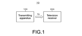
- Fig. 1 is a block diagram showing a configuration example of a transmitting-and-receiving system according to a first embodiment.
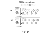
- Fig. 2 is illustrations of an example of a base stream at 60 Hz and an enhanced stream at +60 Hz, which are obtained by a blending process on a moving-image data item at 120 Hz.
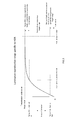
- Fig. 3 is a graph showing an example of HDR photoelectric conversion characteristics.
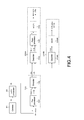
- Fig. 4 is a schematic diagram showing processes in a transmitting apparatus and television receivers.
- Fig. 5 is a schematic illustration of an example of blending on a transmitting side and unblending (reverse blending) on a receiving side.
- Fig. 1 is a block diagram showing a configuration example of a transmitting-and-receiving system according to a first embodiment.
- Fig. 2 is illustrations of an example of a base stream at 60 Hz and an enhanced stream at +60 Hz, which are obtained by a blending process on a moving-image data item at 120
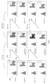
- FIG. 6 is schematic illustrations of processes by a pre-processor and a post-processor in a case where a related-art method is employed as a method of determining blending rates.
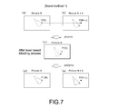
- Fig. 7 is schematic illustrations of processes by the pre-processor and the post-processor in a case where a novel method 1 is employed as the method of determining the blending rates.
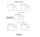
- Fig. 8 shows a determination logic of a blending process in the pre-processor and in an unblending process (reverse blending process) in the post-processor in the case where the novel method 1 is employed as the method of determining the blending rates.
- Fig. 7 is schematic illustrations of processes by the pre-processor and the post-processor in a case where a novel method 1 is employed as the method of determining the blending rates.
- Fig. 8 shows a determination logic of a blending process in the pre-processor and in an unblending process (reverse blending process) in the post-processor in the case where the novel method 1 is employed as
- FIG. 9 is schematic illustrations of processes by the pre-processor and the post-processor in a case where a novel method 2 is employed as the method of determining the blending rates.
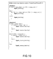
- Fig. 10 shows another determination logic of the blending process in the pre-processor and in the unblending process (reverse blending process) in the post-processor in the case where the novel method 2 is employed as the method of determining the blending rates.
- Fig. 11 is a block diagram showing a configuration example of the transmitting apparatus.
- Fig. 12 is a block diagram showing a configuration example of the pre-processor in the case where the novel method 1 is employed as the method of determining the blending rates.
- Fig. 13 shows an example of an upper-limit-value table that is used in a pixel processing unit.
- Fig. 10 shows another determination logic of the blending process in the pre-processor and in the unblending process (reverse blending process) in the post-processor in the case where the novel method 2 is employed as the method of determining the
- Fig. 14 shows an example of a lower-limit-value table that is used in the pixel processing unit.
- Fig. 15 is a flowchart showing an example of a procedure for generating selection signals on a pixel-by-pixel basis in a control unit.
- Fig. 16 is a block diagram showing another configuration example of the pre-processor in the case where the novel method 2 is employed as the method of determining the blending rates.
- Fig. 17 is a flowchart showing another example of the procedure for generating the selection signals on the pixel-by-pixel basis in the control unit.
- Fig. 18 is a table showing a structural example of "Blend_and_range_information SEI message.” Fig.
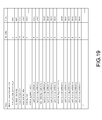
- FIG. 19 is a table showing a structural example of "Blend_and_range_information().”
- Fig. 20 shows contents of main information items in the structural example of "Blend_and_range_information().”
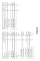
- Fig. 21 is a table showing a structural example of "HFR_descriptor.”
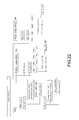
- Fig. 22 shows a structural example of a transport stream TS.
- Fig. 23 is a block diagram showing a configuration example of a television receiver having a decoding capability to process a moving-image data item at a high frame rate (120 Hz).
- Fig. 24 is a block diagram showing a configuration example of the post-processor in the case where the novel method 1 is employed as the method of determining the blending rates.
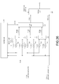
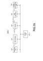
- FIG. 25 is a flowchart showing an example of a procedure for generating selection signals on the pixel-by-pixel basis in another control unit.
- Fig. 26 is a block diagram showing another configuration example of the post-processor in the case where the novel method 2 is employed as the method of determining the blending rates.
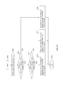
- Fig. 27 is a flowchart showing another example of the procedure for generating the selection signals on the pixel-by-pixel basis in the other control unit.
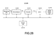
- Fig. 28 is a block diagram showing a configuration example of a television receiver having a decoding capability to process a moving-image data item at a normal frame rate (60 Hz).
- Fig. 29 is a block diagram showing a configuration example of a transmitting-and-receiving system according to a second embodiment.
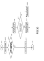
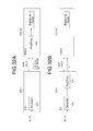
- FIG. 30 is a flowchart showing an example of a control procedure in a control unit (CPU) of a set-top box.
- Fig. 31 is a schematic diagram showing processes by the transmitting apparatus, the set-top box, and displays.
- Fig. 32A and Fig. 32B are diagrams showing a comparison between a case where the display has a function of the reverse blending process (unblending process) and otherwise.
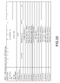
- Fig. 33 is a table showing a structural example of "HFR Blending InfoFrame.”
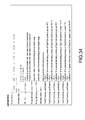
- Fig. 34 shows contents of main information items in the structural example of "HFR Blending InfoFrame.”
- Fig. 35 is a block diagram shows a configuration example of the set-top box.
- Fig. 35 is a block diagram shows a configuration example of the set-top box.
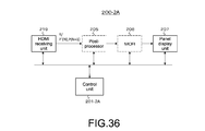
- FIG. 36 is a block diagram showing a configuration example of the display compatible with the moving-image data item at the high frame rate.
- Fig. 37 is a block diagram showing a configuration example of the display compatible with the moving-image data item at the normal frame rate.
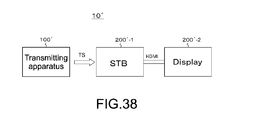
- Fig. 38 is a block diagram showing a configuration example of a transmitting-and-receiving system according to a third embodiment.
- Fig. 39 is a schematic diagram showing processes by a transmitting apparatus, a set-top box, and displays.
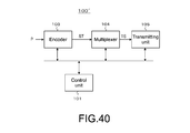
- Fig. 40 is a block diagram showing a configuration example of the transmitting apparatus.
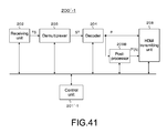
- Fig. 41 is a block diagram showing a configuration example of the set-top box.
- Fig. 42 is a block diagram showing a configuration example of another post-processor in the case where the novel method 1 is employed as the method of determining the blending rates.
- Fig. 43 is a block diagram showing another configuration example of the other post-processor in the case where the novel method 2 is employed as the method of determining the blending rates.
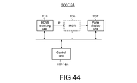
- Fig. 44 is a block diagram showing a configuration example of the display compatible with the moving-image data item at the high frame rate.
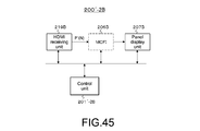
- Fig. 45 is a block diagram showing a configuration example of the display compatible with the moving-image data item at the normal frame rate.
- Fig. 46 is a schematic illustration of an example of the blending on the transmitting side and the unblending on the receiving side in a general pattern of the blending process.
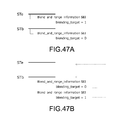
- Fig. 48 is a table showing a structural example of "Blend_and_range_information SEI message" in the general pattern of the blending process.
- Fig. 49 is a table showing a structural example of "HFR Blending InfoFrame" in the general pattern of the blending process.
- FIG. 1 shows a configuration example of a transmitting-and-receiving system 10 according to the first embodiment.
- This transmitting-and-receiving system 10 includes a transmitting apparatus 100 and a television receiver 200.
- the transmitting apparatus 100 transmits a transport stream TS as a container via a broadcast wave.
- This transport stream TS contains a base stream (base video stream) and an enhanced stream (enhanced video stream) that are obtained by processing a moving-image data item at a high frame rate of, for example, 120 Hz or 240 Hz, more specifically, at 120 Hz in this embodiment.
- the base stream and the enhanced stream each have a NAL unit structure.
- the base stream is obtained as follows. Specifically, a moving-image data item after a blending process is obtained by executing a process of blending, at per-frame blending rates based on data levels, image data items of peripheral frames of a high-frame-rate moving-image data item before the blending with image data items of processing-target frames of the high-frame-rate moving-image data item before the blending.
- image data items of frames of the moving-image data item after the blending process at least image data items of frames corresponding to a normal frame rate, specifically, corresponding to 60 Hz in this embodiment are blended with image data items of peripheral frames.
- the base stream is obtained by encoding the image data items of the frames corresponding to the normal frame rate (base frames).
- the enhanced stream is obtained by encoding image data items of the rest of the frames (enhanced frames).
- the base stream contains, as access units, the encoded image data items of the frames corresponding to the normal frame rate. Further, the enhanced stream contains, as access units, the encoded image data items of the enhanced frames corresponding to the high frame rate.
- Fig. 2 illustrates an example of a base stream at 60 Hz, which is obtained by execution of the blending process on the moving-image data item at 120 Hz, and an enhanced stream at +60 Hz.
- Frame pairs are each formed of two frames, one of which constitutes the base stream and another one of which is subsequent thereto and constitutes an enhanced stream.
- an image data item of a first frame specifically, an image data item of a frame of the base stream is blended with an image data item of the enhanced frame (blended state), and this image data item of this frame subsequent thereto of the enhanced stream is not blended with the image data item of the base frame (unblended state).
- the image data item of the first frame specifically, the image data item of the frame of the base stream is blended with the image data item of the enhanced frame (blended state)
- this image data item of the frame subsequent thereto of the enhanced stream is also blended with the image data item of the base frame (blended state).
- Information items of the blending rates and a range information item of each of the image data items are inserted into a layer of a video (video stream) and/or a layer of a container.
- the information items of the blending rates contain coefficient sets as many as the number of taps of a filter to be used in the blending process. For example, when "m"-tap filter by which "m" frames can be blended is used, "m" coefficients are contained in the coefficient set of each of the frames.
- the range information item of each of the image data items contains information items of a first threshold and a second threshold smaller than the first threshold. Further, in this embodiment, the above-mentioned moving-image data item at 120 Hz is an HDR moving-image data item.
- Fig. 3 shows an example of HDR photoelectric conversion characteristics.
- the abscissa axis represents luminance
- the ordinate axis represents transmission code values.
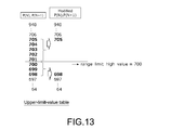
- the first threshold is a level value "Range_limit_high_value” equivalent to a luminance (100 cd/m 2 ) corresponding to a standard dynamic range (SDR), which is set such that whether or not levels of the image data items are within a range of brightness reproduction levels as a special-blending-process target range is determined.
- SDR standard dynamic range
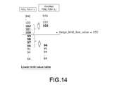
- the second threshold is a level value "Range_limit_low_value,” which is set such that whether or not the levels of the image data items are within a range of dark-part reproduction levels as another special-blending-process target range.
- the image data items of the peripheral frames of the moving-image data item at the high frame rate are blended with the image data items of the processing-target frames of the moving-image data item at the high frame rate.
- the blending rates are determined by using the above-mentioned level values "Range_limit_high_value” and "Range_limit_low_value” on a pixel-by-pixel basis.
- the determination of the blending rates is performed by a novel method 1 or a novel method 2.
- the blending rates are each determined based on the image data item of the processing-target frame.
- the blending rates are each determined based not only on the image data item of the processing-target frame but also on the image data item of the peripheral frame.
- SEINAL units each containing the information item of the blending rate (coefficient set) and the range information item of the image data item are inserted into the base stream or the enhanced stream.
- SEINAL units each containing the information item of the blending rate (coefficient set) and the range information item of the image data item are inserted into the base stream or the enhanced stream.
- the television receiver 200 receives the above-mentioned transport stream TS that is transmitted via the broadcast wave from the transmitting apparatus 100.
- the television receiver 200 has a decoding capability to process a moving-image data item at the normal frame rate (60 Hz)
- the television receiver 200 processes only the base stream contained in the transport stream TS so as to generate the moving-image data item at the normal frame rate, and reproduces its images.
- the television receiver 200 when the television receiver 200 has a decoding capability to process the moving-image data item at the high frame rate (120 Hz), the television receiver 200 processes both the base stream and the enhanced stream contained in the transport stream TS so as to generate the moving-image data item at the high frame rate, and reproduces its images.
- the television receiver 200 acquires the information items of the blending rates and the range information item of each of the image data items, which are inserted into the layer of the video (video stream) and/or the layer of the container, and executes an unblending process (reverse blending process) with use of these information items.
- the television receiver 200 executes a decoding process on the base stream so as to generate the image data items of the frames corresponding to the normal frame rate, and executes a decoding process on the enhanced stream so as to generate the image data items of the enhanced frames corresponding to the high frame rate. Then, the television receiver 200 executes the unblending process (reverse blending process) based on the information items of the blending rates (coefficient sets) with use of the image data items of the frames corresponding to the normal frame rate and use of the image data items of the enhanced frames corresponding to the high frame rate. In this way, a moving-image data item at a frame rate as high as that before the blending process is obtained.
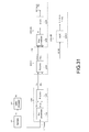
- FIG. 4 schematically shows processes by the transmitting apparatus 100 and the television receivers 200 (200A and 200B).
- image sequences P'(N) and P(N+1) of output from a pre-processor 102 of the transmitting apparatus 100 and image sequences P'(N) and P(N+1) of output from decoders 204 and 204B of the television receivers 200A and 200B, which are the same as each other in time series, may be different from each other in image quality due to processes based on codecs.
- a moving-image data item Va at a higher frame rate, which is output from a camera (imaging apparatus) 81, is transmitted to an HFR processor 82. With this, a moving-image data item Vb at the high frame rate (120 Hz) is obtained. This moving-image data item Vb is input as a moving-image data item P to the transmitting apparatus 100.
- the pre-processor 102 executes the blending process on image data items of frames of the moving-image data item P. With this, image data items P'(N) of the frames corresponding to the normal frame rate, and image data items P(N+1) of the enhanced frames corresponding to the high frame rate are obtained. Note that, in this embodiment, the image data items P(N+1) are not subjected to the blending with image data items of peripheral frames.
- an encoder 103 executes the encoding process on the image data items P'(N) and P(N+1). With this, a base stream STb and an enhanced stream STe are obtained. These streams STb and STe are transmitted from the transmitting apparatus 100 to the television receiver 200. Note that the information items of the blending rates of the frames and the range information items of the image data items of the frames are associated respectively with the image data items of the frames, and are inserted into these streams STb and STe.
- the decoder 204 executes the decoding process on the two streams STb and STe. With this, the image data items P'(N) of the frames corresponding to the normal frame rate, and the image data items P(N+1) of the enhanced frames corresponding to the high frame rate are obtained.
- a post-processor 205 executes the unblending process (reverse blending process) on the image information items P'(N) and P(N+1) on the basis of the information items of the blending rates of the frames and the range information item of each of the image data items.
- a moving-image data item R at the high frame rate (120 Hz) as high as that of the moving-image data item P on a transmitting side.
- This moving-image data item R is used as it is as a displaying moving-image data item, or converted to the same by being increased in frame rate through frame interpolation in a motion-compensated frame interpolation (MCFI) unit 206.
- MCFI motion-compensated frame interpolation
- the decoder 204B executes the decoding process on the stream STb. With this, the image data items P'(N) of the frames corresponding to the normal frame rate are obtained. Then, in the television receiver 200B, a moving-image data item including the image data items P'(N) of the frames corresponding to the normal frame rate is used as it is as a displaying moving-image data item, or converted to the same by being increased in frame rate through frame interpolation in a motion-compensated frame interpolation (MCFI) unit 206B.
- MCFI motion-compensated frame interpolation
- Fig. 5 schematically illustrates an example of the blending on the transmitting side and the unblending on the receiving side.
- This example corresponds to the example in (a) of Fig. 2, specifically, a picture "N" and a picture "N+1" form a frame pair, and a picture "N+2" and a picture “N+3" form another frame pair.
- objects Oa and Ob are static objects
- an object Oc is a moving object.
- an image data item of a first frame specifically, an image data item of a frame of the base stream is blended with an image data item of the enhanced frame (blended state), and this image data item of this frame subsequent thereto of the enhanced stream is not blended with the image data item of the base frame (unblended state). Further, the blended state is canceled by the unblending process (reverse blending process) on the receiving side.
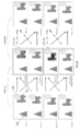
- Fig. 6 schematically illustrates processes by the pre-processor 102 and the post-processor 205 in a case where a related-art method is employed as the method of determining the blending rates.
- A of Fig. 6 illustrates an image of the picture "N" before the blending process in the pre-processor 102.
- B of Fig. 6 illustrates an image of the picture "N+1" before the blending process in the pre-processor 102.
- C of Fig. 6 illustrates an image of the picture "N” after the blending process in the pre-processor 102.
- FIG. 6 illustrates an image of the picture "N" after the unblending process is executed in the post-processor 205
- (e) of Fig. 6 illustrates an image of the picture "N+1" that is used in the post-processor 205.
- the post-processor 205 executes the following unblending process of Type0. With this, a value of P''(N) is obtained. In this way, in the television receiver 200A compatible with the high frame rate, the brightness quality is restored by the unblending process.
- the point P(N) in the image of the picture "N” is subjected to the following blending process of Type1 (special blending process) so as to be blended with the point P(N+1) at the same position coordinates in the picture "N+1.”
- the value of P'(N) is obtained by the calculation of the arithmetic mean (weight is ignored) between P(N) and P(N+1).
- FIG. 7 illustrates an image of the picture "N" after the unblending process in the post-processor 205
- (e) of Fig. 7 illustrates an image of the picture "N+1" that is used in the post-processor 205.
- Fig. 9 schematically illustrates processes by the pre-processor 102 and the post-processor 205 in a case where the novel method 2 is employed as the method of determining the blending rates.
- A) of Fig. 9 illustrates an image of the picture "N" before the blending process in the pre-processor 102.
- B) of Fig. 9 illustrates an image of the picture "N+1" before the blending process in the pre-processor 102.
- C of Fig. 9 illustrates an image of the picture "N” after the blending process in the pre-processor 102.
- a point P(N)b in the image of the picture "N” is subjected to the following blending process of Type2 (special blending process) so as to be blended with a point P(N+1)b at the same position coordinates in the picture "N+1.”
- the value of P'(N) is obtained by the calculation of the arithmetic mean (weight is ignored) between P(N)b and P(N+1)b.
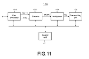
- FIG. 11 shows a configuration example of the transmitting apparatus 100.
- This transmitting apparatus 100 includes a control unit 101, the pre-processor 102, the encoder 103, a multiplexer 104, and a transmitting unit 105.
- the control unit 101 controls operations of the units in the transmitting apparatus 100.
- the pre-processor 102 receives the moving-image data item P at the high frame rate (120 Hz), and outputs the image data items P'(N) of the frames corresponding to the normal frame rate (60 Hz), and the image data items P(N+1) of the enhanced frames corresponding to the high frame rate.
- the pre-processor 102 generates the moving-image data item after the blending process by executing the process of blending, at the per-frame blending rates based on data levels, the image data items of the peripheral frames of the high-frame-rate moving-image data item P before the blending process with the image data items of the processing-target frames of the high-frame-rate moving-image data item P before the blending process.
- the image data items P'(N) correspond to the image data items of the frames corresponding to the normal frame rate (60 Hz)
- the image data items P(N+1) correspond to the image data items of the rest of the frames.
- at least the image data items P'(N) are blended with the image data items of the peripheral frames.
- Fig. 12 shows a configuration example of the pre-processor 102.
- This example is a configuration example in the case where the novel method 1 is employed as the method of determining the blending rates.
- This pre-processor 102 includes a pixel processing unit 120, a frame delay unit 121, coefficient multipliers 122, 123, 125, and 126, adding units 124 and 127, a switching unit 128, and an output unit 129.
- Fig. 13 shows an example of an upper-limit-value table that is used in the pixel processing unit 120.
- Fig. 14 shows an example of a lower-limit-value table that is used in the pixel processing unit 120.
- the pre-processor 102 executes the "Type1 blending process."
- the upper-limit-value table and the lower-limit-value table which are set separately from each other in the above description, may be set as a single table.
- the coefficient multiplier 122 has a coefficient (a/k) set by the control unit 101, and the image data item P(N) is multiplied by this coefficient. Further, the coefficient multiplier 123 has a coefficient (b/k) set by the control unit 101, and the image data item P(N+1) is multiplied by this coefficient. Output values from the coefficient multipliers 122 and 123 are added to each other by the adding unit 124. Note that the coefficient multipliers 122 and 123 and the adding unit 124 serve as a filter that executes the "Type0 blending process," and the image data item P'(N) generated by the "Type0 blending process" is obtained from the adding unit 124.
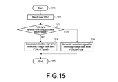
- Fig. 15 is a flowchart showing an example of a procedure for generating the selection signals on the pixel-by-pixel basis in the control unit 101.
- Step ST1 the control unit 101 starts the procedure.
- Step ST2 the control unit 101 reads a pixel P(N).
- Step ST3 the control unit 101 determines whether or not the pixel P(N) is within the special-blending-process target range "(P(N)>range_high) or (P(N) ⁇ range_low)."
- Step ST4 When the control unit 101 determines that the pixel P(N) is out of either one of the special-blending-process target ranges and within the normal-blending-process target range, in Step ST4, the control unit 101 generates a selection signal for selecting the image data item P'(N) obtained by the "Type0 blending process.” Then, in Step ST5, the control unit 101 terminates the procedure. Meanwhile, when the control unit 101 determines that the pixel P(N) is within one of the special-blending-process target ranges, in Step ST6, the control unit 101 generates a selection signal for selecting the image data item P'(N) obtained by the "Type1 blending process.” Then, in Step ST5, the control unit 101 terminates the procedure.
- the image data item P'(N) obtained in the switching unit 128 and the image data item P(N+1) obtained in the pixel processing unit 120 are input to the output unit 129.
- a frame synchronization signal at 60 Hz is supplied to this output unit 129.
- the output unit 129 outputs the image data item P'(N) of each of the frames corresponding to the normal frame rate, and the image data item P(N+1) of each of the enhanced frames corresponding to the high frame rate.
- Fig. 16 shows another configuration example of the pre-processor 102.
- This example is a configuration example in the case where the novel method 2 is employed as the method of determining the blending rates.
- the parts corresponding to those in Fig. 12 are denoted by the same reference symbols, and detailed description thereof is omitted as appropriate.
- This pre-processor 102 includes the pixel processing unit 120, the frame delay unit 121, the coefficient multipliers 122, 123, 125, and 126, coefficient multipliers 130 and 131, the adding units 124 and 127, an adding unit 132, a switching unit 133, and the output unit 129.
- the image data item P(N) that is obtained from the frame delay unit 121 is input to the coefficient multiplier 122, the coefficient multiplier 125, and the coefficient multiplier 130. Further, the image data item P(N+1) that is obtained from the pixel processing unit 120 is input to the coefficient multiplier 123, the coefficient multiplier 126, and the coefficient multiplier 131.
- the coefficient multiplier 122 has the coefficient (a/k) set by the control unit 101, and the image data item P(N) is multiplied by this coefficient. Further, the coefficient multiplier 123 has the coefficient (b/k) set by the control unit 101, and the image data item P(N+1) is multiplied by this coefficient.
- the output values from the coefficient multipliers 122 and 123 are added to each other by the adding unit 124. Note that the coefficient multipliers 122 and 123 and the adding unit 124 serve as the filter that executes the "Type0 blending process," and the image data item P'(N) generated by the "Type0 blending process" is obtained from the adding unit 124.
- the coefficient multiplier 125 has the coefficient (c/m) set by the control unit 101, and the image data item P(N) is multiplied by this coefficient. Still further, the coefficient multiplier 126 has the coefficient (d/m) set by the control unit 101, and the image data item P(N+1) is multiplied by this coefficient.
- the output values from the coefficient multipliers 125 and 126 are added to each other by the adding unit 127. Note that the coefficient multipliers 125 and 126 and the adding unit 127 serve as the filter that executes the "Type1 blending process," and the image data item P'(N) generated by the "Type1 blending process" is obtained from the adding unit 127.
- the coefficient multiplier 130 has a coefficient (e/s) set by the control unit 101, and the image data item P(N) is multiplied by this coefficient.
- the coefficient multiplier 131 has a coefficient (f/s) set by the control unit 101, and the image data item P(N+1) is multiplied by this coefficient.
- Output values from the coefficient multipliers 130 and 131 are added to each other by the adding unit 132.
- the coefficient multipliers 130 and 131 and the adding unit 132 serve as a filter that executes the "Type2 blending process," and the image data item P'(N) generated by the "Type2 blending process" is obtained from the adding unit 132.
- the control unit 101 Based on the image data item P(N) obtained from the frame delay unit 121, the image data item P(N+1) obtained from the pixel processing unit 120, and the preset level values "range_limit_high_value” and “range_limit_low_value,” the control unit 101 generates the selection signals on the pixel-by-pixel basis, and transmits these signals to the switching unit 133.
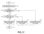
- Fig. 17 is a flowchart showing another example of the procedure for generating the selection signals on the pixel-by-pixel basis in the control unit 101.
- the control unit 101 starts the procedure.
- the control unit 101 reads the pixel P(N) and a pixel P(N+1).
- the control unit 101 determines whether or not the pixel P(N) is within the special-blending-process target range "(P(N)>range_high) or (P(N) ⁇ range_low)."
- Step ST14 the control unit 101 determines whether or not the pixel P(N+1) is within the special-blending-process target range "(P(N+1)>range_high) or (P(N+1) ⁇ range_low)."
- Step ST15 the control unit 101 determines that the pixel P(N+1) is out of either one of the special-blending-process target ranges and within the normal-blending-process target range.
- Step ST16 the control unit 101 generates the selection signal for selecting the image data item P'(N) obtained by the "Type0 blending process.”
- Step ST16 the control unit 101 terminates the procedure.
- Step ST17 the control unit 101 generates a selection signal for selecting the image data item P'(N) obtained by the "Type2 blending process.”
- Step ST16 the control unit 101 terminates the procedure.
- Step ST13 when the control unit 101 determines that the pixel P(N) is within one of the special-blending-process target ranges, in Step ST18, the control unit 101 generates the selection signal for selecting the image data item P'(N) obtained by the "Type0 blending process.” Then, in Step ST16, the control unit 101 terminates the procedure.
- the image data item P'(N) obtained in the switching unit 133 and the image data item P(N+1) obtained in the pixel processing unit 120 are input to the output unit 129.
- the frame synchronization signal at 60 Hz is supplied to this output unit 129.
- the output unit 129 outputs the image data item P'(N) of each of the frames corresponding to the normal frame rate, and the image data item P(N+1) of each of the enhanced frames corresponding to the high frame rate.
- the encoder 103 executes the encoding process on the image data items P'(N) and P(N+1) obtained from the pre-processor 102 so as to generate the base stream STb and the enhanced stream STe.
- predictive encoding processes such as H.264/AVC and H.265/HEVC are executed on the image data items P'(N) and P(N+1).
- Fig. 18 shows a structural example (syntax) of the "Blend_and_range_information SEI message.”
- "uuid_iso_iec_11578” has an UUID value specified in "ISO/IEC 11578:1996 AnnexA.”
- "Blend_and_range_information()" is inserted into a field of "user_data_payload_bytes.”
- a sixteenth-bit field of "range_limit_high_value” indicates the level value of the upper limit of the normal-blending-process target range.
- a sixteen-bit field of "range_limit_low_value” indicates the level value of the lower limit of the normal-blending-process target range.
- blending_mode indicates modes of the blending processes.
- "0x0” indicates a mode0, that is, a mode of executing only the normal blending process in related art.
- "0x1" indicates a mode1, that is, a mode of executing the blending processes including the special blending process based on the determination of the pixels in the picture "N.”
- "0x2" indicates a mode2, that is, a mode of executing the blending processes including the special blending process based on the determination of the pixels in each of the pictures "N" and "N+1.”
- the eight-bit field of "type0_blending_coefficient_a” indicates the coefficient "a” (coefficient for base-layer pixels) in the "Type0 blending process” being the normal blending process.
- the eight-bit field of "type0_blending_coefficient_b” indicates the coefficient "b” (coefficient for enhanced pixels) in the "Type0 blending process” being the normal blending process.
- the eight-bit field of "type1_blending_coefficient_c” indicates the coefficient "c” (coefficient for the base-layer pixels) in the "Type1 blending process” being the special blending process.
- the eight-bit field of "type1_blending_coefficient_d” indicates the coefficient "d” (coefficient for the enhanced pixels) the "Type1 blending process” being the special blending process.
- the eight-bit field of "type2_blending_coefficient_e” indicates the coefficient "e” (coefficient for the base-layer pixels) in the "Type2 blending process” being the other special blending process.
- the eight-bit field of "type2_blending_coefficient_f” indicates the coefficient "f” (coefficient for the enhanced pixels) in the "Type2 blending process” being the other special blending process.
- the above-mentioned coefficients correspond to the information items of the blending rates relating to the blending processes.
- the multiplexer 104 packetizes the base stream STb and the enhanced stream STe generated by the encoder 103 into packetized elementary stream (PES) packets, and packetizes these packets further into transport packets to be multiplexed. In this way, the transport stream TS as a multiplexed stream is obtained.
- PES packetized elementary stream
- the multiplexer 104 inserts the information items of the blending rates and the range information item of each of the image data items into the layer of the transport stream TS as the container.
- newly defined "HFR_descriptors” are inserted into video elementary stream loops arranged correspondingly to the base stream and the enhanced stream under a program map table. Note that, in the case where the information items of the blending rates and the range information item of each of the image data items are arranged in the SEI as described above, the information items can be switched on a picture-by-picture basis or a scene-by-scene basis.
- the information items of the blending rates and the range information item of each of the image data items are arranged in the descriptors of the container, the information items can be switched in units of longer periods, specifically, on a program-by-program basis or in units of divided programs
- Fig. 21 shows a structural example (Syntax) of the "HFR_descriptor.”
- this "HFR_descriptor” contains information items similar to those of the above-described “Blend_and_range_information SEI message” (refer to Fig. 19).
- Arrangement of the "HFR_descriptor” is advantageous in that, before the receiver starts the decoding process, types of processes necessary for HFR picture data items can be understood, and preparation for subsequent post-processes can be completed.
- Fig. 22 shows a configuration example of the transport stream TS.
- This transport stream TS contains the two video streams, that is, the base stream STb and the enhanced stream STe.
- the base stream STb contains the two video streams, that is, the base stream STb and the enhanced stream STe.
- the "Blend_and_range_information SEI message” (refer to Fig. 19) is inserted into each of the encoded image data items of the pictures, which are contained in the PES packet "video PES1" and the PES packet "video PES2.” Note that this example is corresponds to the example in which the information items of the blending rates and the range information item of each of the image data items are inserted into each of the base stream STb and the enhanced stream STe.
- the transport stream TS contains, as one of program specific information (PSI) items, the program map table (PMT).
- PSIs refer to information items of to which program the elementary streams contained in the transport stream TS belong.
- video ES2 loop not only the information items of, for example, the stream type and the packet identifier (PID) corresponding to the enhanced stream (video PES2), but also the descriptors that describe the information items relating to this video stream, such as "hevc_descriptor” and the above-mentioned “HFR_descriptor” (refer to Fig. 21), are also arranged.
- a type of this stream is represented by "0x25" corresponding to the enhanced stream.
- the transmitting unit 105 modulates the transport stream TS, for example, in accordance with a modulation scheme suited to broadcasting, such as QPSK and OFDM, and transmits an RF signal via a transmitting antenna.
- a modulation scheme suited to broadcasting such as QPSK and OFDM
- the novel method 1 in accordance with the data levels of the image data items P(N), the "Type0 blending process” being the normal blending process or the "Type1 blending process” being the special blending process is used.
- the novel method 2 in accordance with the data levels of the image data items P(N) and P(N+1), the "Type0 blending process” being the normal blending process, the "Type1 blending process” being the special blending process, or the "Type2 blending process” being the other special blending process is used.
- the transport stream TS generated in the multiplexer 104 is transmitted to the transmitting unit 105.
- this transport stream TS is modulated, for example, in accordance with the modulation scheme suited to the broadcasting, such as QPSK and OFDM, and the RF signal is transmitted via the transmitting antenna.
- FIG. 23 is a configuration example of the television receiver 200A having the decoding capability to process the moving-image data item at the high frame rate (120 Hz).
- This television receiver 200A includes a control unit 201, a receiving unit 202, a demultiplexer 203, the decoder 204, the post-processor 205, the motion-compensated frame interpolation (MCFI) unit 206, and a panel display unit 207. Further, the demultiplexer 203 extracts section information items contained in the layer of the transport stream TS, and transmits these information items to the control unit 201. In this case, the "HFR_descriptors" (refer to Fig. 21) each containing the information items of the blending rates and the range information item of each of the image data items are also extracted.
- the decoder 204 executes the decoding process on the base stream STb so as to generate the image data item P'(N) of each of the frames corresponding to the normal frame rate, and executes the decoding process on the enhanced stream STe so as to generate the image data item P(N+1) of each of the enhanced frames corresponding to the high frame rate.
- the control unit 201 On the basis of the information items of the blending rates and the range information item of each of the image data items, when the unblending process (reverse blending process) is executed, the control unit 201 is allowed to appropriately determine which type of the unblending processes (reverse blending processes) to apply on the pixel-by-pixel basis, and is allowed to appropriately set filtering coefficients in accordance with the types the unblending processes (reverse blending processes). In this way, the post-processor 205 is allowed to appropriately perform control described below of the post-processor 205.
- the post-processor 205 executes the unblending processes (reverse blending processes) based on the image data items P'(N) and P(N+1) obtained in the decoder 204. With this, the unblended moving-image data item R at the high frame rate is obtained.
- the coefficient multiplier 220 has a coefficient (k/a) set by the control unit 201, and the image data item P'(N) is multiplied by this coefficient. Further, the coefficient multiplier 221 has a coefficient (-b/a) set by the control unit 201, and the image data item P(N+1) is multiplied by this coefficient. Output values from the coefficient multipliers 220 and 221 are added to each other by the adding unit 222. Note that the coefficient multipliers 220 and 221 and the adding unit 222 serve as a filter that executes the "Type0 unblending process" (reverse blending process), and an image data item P''(N) generated by the "Type0 unblending process” is obtained from the adding unit 222.
- control unit 201 On the basis of the image data items P'(N) and P(N+1) and the level values "range_limit_high_value” and “range_limit_low_value” as the range information item of each of the image data items, the control unit 201 generates the selection signals on the pixel-by-pixel basis, and transmits these signals to the switching unit 226.
- Step ST24 the control unit 201 generates the selection signal for selecting the image data item P''(N) obtained by the "Type0 unblending process.” Then, in Step ST25, the control unit 201 terminates the procedure. Meanwhile, when the control unit 201 determines that the pixel P'(N) is within one of the special-blending-process target ranges, the control unit 201 advances the procedure to the process of Step ST26.
- Step ST26 the control unit 201 determines whether or not the pixel P(N+1) is within the special-blending-process target range "(P(N+1)>range_high) or (P(N+1) ⁇ range_low)."
- the control unit 201 determines that the pixel P(N+1) is out of either one of the special-blending-process target ranges and within the normal-blending-process target range.
- Step ST27 the control unit 201 generates the selection signal for selecting the image data item P''(N) obtained by the "Type1 unblending process.” Then, in Step ST25, the control unit 201 terminates the procedure.
- Step ST24 the control unit 201 generates the selection signal for selecting the image data item P''(N) obtained by the "Type0 unblending process.” Then, in Step ST25, the control unit 201 terminates the procedure.
- the image data item P''(N) obtained in the switching unit 226 and the image data item P(N+1) are input to the switching unit 227.
- a frame synchronization signal at 120 Hz is supplied to this switching unit 227.
- the switching unit 227 extracts the unblended image data item P''(N) and the image data item P(N+1) alternately to each other, and outputs the moving-image data item R at the high frame rate (120 Hz).
- the image data item P'(N) of the picture "N” is input to the coefficient multiplier 200, the coefficient multiplier 223, and the coefficient multiplier 230. Further, the image data item P(N+1) of the picture "N+1” is input to the coefficient multiplier 221, the coefficient multiplier 224, and the coefficient multiplier 231.
- the coefficient multiplier 223 has the coefficient (m/c) set by the control unit 201, and the image data item P'(N) is multiplied by this coefficient. Further, the coefficient multiplier 224 has the coefficient (-d/c) set by the control unit 201, and the image data item P(N+1) is multiplied by this coefficient.
- the output values from the coefficient multipliers 223 and 224 are added to each other by the adding unit 225. Note that the coefficient multipliers 223 and 224 and the adding unit 225 serve as the filter that executes the "Type1 unblending process" (reverse blending process), and the image data item P''(N) generated by the "Type1 unblending process” is obtained from the adding unit 225.
- the image data items P''(N) obtained in the adding units 222, 225, and 232 are input to the switching unit 233.
- the switching unit 233 selectively outputs the image data item P''(N) obtained by the "Type0 unblending process" from the adding unit 222, the image data item P''(N) obtained by the "Type1 unblending process” from the adding unit 225, or the image data item P''(N) obtained by the "Type2 unblending process” from the adding unit 232.
- control unit 201 On the basis of the image data items P'(N) and P(N+1) and the level values "range_limit_high_value” and “range_limit_low_value” as the range information item of each of the image data items, the control unit 201 generates the selection signals on the pixel-by-pixel basis, and transmits these signals to the switching unit 233.
- Fig. 27 is a flowchart showing another example of the procedure for generating the selection signals on the pixel-by-pixel basis in the control unit 201.
- the control unit 201 starts the procedure.
- the control unit 201 reads the pixels P'(N) and P(N+1).
- Step ST33 the control unit 201 determines whether or not the pixel P'(N) is within the special-blending-process target range "(P'(N)>range_high) or (P'(N) ⁇ range_low)."
- Step ST34 the control unit 201 determines that the pixel P'(N) is out of either one of the special-blending-process target ranges and within the normal-blending-process target range.
- Step ST35 the control unit 201 terminates the procedure.
- Step ST33 when the control unit 201 determines that the pixel P'(N) is within one of the special-blending-process target ranges, in Step ST36, the control unit 201 determines whether or not the pixel P(N+1) is within the special-blending-process target range "(P(N+1)>range_high) or (P(N+1) ⁇ range_low)."
- Step ST37 the control unit 201 generates the selection signal for selecting the image data item P''(N) obtained by the "Type1 unblending process.” Then, in Step ST35, the control unit 201 terminates the procedure.
- Step ST36 when the control unit 201 determines that the pixel P(N+1) is within one of the special-blending-process target ranges, in Step ST38, the control unit 201 generates the selection signal for selecting the image data item P''(N) obtained by the "Type2 unblending process.” Then, in Step ST35, the control unit 201 terminates the procedure.
- the MCFI unit 206 executes a motion-compensated frame interpolation process on the moving-image data item R at the high frame rate, which is obtained in the post-processor 205. With this, a moving-image data item at a much higher rate is obtained. Note that this MCFI unit 206 may be omitted.
- the panel display unit 207 displays images of the moving-image data item R at the high frame rate, which is obtained in the post-processor 205, or images of the moving-image data item increased in frame rate in the MCFI unit 206.
- the transport stream TS is acquired by demodulating the RF-modulated signal received via the receiving antenna.
- This transport stream TS is transmitted to the demultiplexer 203.
- the base stream STb and the enhanced stream STe are extracted from the transport stream TS by filtering the PIDs, and are supplied to the decoder 204.
- the decoding process is executed on the base stream STb such that the image data item P'(N) of each of the frames corresponding to the normal frame rate is obtained, and the decoding process is executed on the enhanced stream STe such that the image data item P(N+1) of each of the enhanced frames corresponding to the high frame rate is obtained.
- These image data items P'(N) and P(N+1) are supplied to the post-processor 205.
- the parameter set and the SEI that are inserted into each of the access units of each of the base stream STb and the enhanced stream STe are extracted and transmitted to the control unit 201.
- the "Blend_and_range_information SEI messages" each containing the information item of the blending rate and the range information item of the image data item are also extracted.
- control unit 201 on the basis of the information items of the blending rates and the range information item of each of the image data items, when executing the unblending process (reverse blending process), which type of the unblending processes (reverse blending processes) to apply on the pixel-by-pixel basis is allowed to be appropriately determined.
- filtering coefficients in accordance with the types the unblending processes (reverse blending processes) are allowed to be appropriately set.
- the unblending processes (reverse blending processes) are executed on the basis of the image data items P'(N) and P(N+1) obtained in the decoder 204. With this, the unblended moving-image data item R at the high frame rate is obtained.
- the novel method 1 in accordance with the data levels of the image data item P'(N), the "Type0 unblending process” being the normal unblending process or the "Type1 unblending process” being the special unblending process is used.
- the novel method 2 in accordance with the data levels of the image data items P'(N) and P(N+1), the "Type0 unblending process” being the normal unblending process, the "Type1 unblending process” being the special unblending process, or the "Type2 unblending process” being the other special unblending process is used.
- the moving-image data item R at the high frame rate, which is obtained in the post-processor 205, or the moving-image data item increased in frame rate in the MCFI unit 206 is supplied to the panel display unit 207.
- the images of these moving-image data items are displayed on the panel display unit 207.
- Fig. 28 is a configuration example of the television receiver 200B having the decoding capability to process the moving-image data item at the normal frame rate (60 Hz).
- This television receiver 200B includes a control unit 201B, a receiving unit 202B, a demultiplexer 203B, the decoder 204B, the MCFI unit 206B, and a panel display unit 207B.
- the control unit 201B controls operations of the units in the television receiver 200B.
- the receiving unit 202B acquires the transport stream TS by demodulating the RF-modulated signal received via the receiving antenna.
- the demultiplexer 203B extracts the base stream STb from the transport stream TS by filtering the PIDs, and supplies this stream to the decoder 204B.
- the decoder 204B executes the decoding process on the base stream STb so as to generate the image data item P'(N) of each of the frames corresponding to the normal frame rate.
- the MCFI unit 206B executes the motion-compensated frame interpolation process on these image data items P'(N) so as to generate a moving-image data item at a much higher rate. Note that this MCFI unit 206B may be omitted.
- the panel display unit 207B displays images of the moving-image data item at the normal frame rate (image data items P'(N)), which is obtained in the decoder 204B, or of the moving-image data item increased in frame rate in the MCFI unit 206B.
- the transport stream TS is acquired by demodulating the RF-modulated signal received via the receiving antenna.
- This transport stream TS is transmitted to the demultiplexer 203B.
- the base stream STb is extracted from the transport stream TS by filtering the PIDs, and is supplied to the decoder 204B.
- the decoding process is executed on the base stream STb such that the image data item P'(N) of each of the frames corresponding to the normal frame rate is obtained.
- the moving-image data item at the normal frame rate, which is obtained in the decoder 204B, or the moving-image data item increased in frame rate in the MCFI unit 206B is supplied to the panel display unit 207B.
- the images of these moving-image data items are displayed on the panel display unit 207B.
- the transmitting-and-receiving system 10 shown in Fig. 1 among the image data items of the frames of the moving-image data item at the high frame rate, at least the image data items of the frames corresponding to the normal frame rate are blended with the image data items of the peripheral frames, that is, under a state of a high shutter-opening rate.
- the base stream STb to be transmitted is obtained by encoding these image data items of the frames corresponding to the normal frame rate.
- the moving-image data item at the normal frame rate is obtained by processing the base stream STb, and images of the moving image can be smoothly displayed.
- an image-quality problem as a result of the frame interpolation process including low-load calculation in the display process can be avoided.
- the image data item of each of the frames is blended with the image data item of corresponding one of the peripheral frames at the blending rate in accordance with the data level.
- the original texture of the images such as a high dynamic range (HDR) effect, can be prevented from being impaired by the blending processes.
- the enhanced stream STe is obtained by encoding the image data items of the rest of the frames.
- the base stream STb and the enhanced stream STe are transmitted with the information items of the blending rates (coefficient sets) of the frames and the range information item of each of the image data items, which are associated respectively with the image data items of the frames, being inserted into these streams.
- the unblended moving-image data item can be easily and appropriately obtained by executing the unblending processes (reverse blending processes) on the moving-image data item obtained by decoding the base stream and the enhanced stream.
- the present technology is not limited to the above-described example of the transmitting-and-receiving system 10 shown in Fig. 1, in which the base stream STb and the enhanced stream STe are transmitted to the receiving side with the information items of the blending rates of the frames and the range information item of each of the image data items being inserted therein.
- the information items of the blending rates of the frames and the range information item of each of the image data items may be provided with other units to the receiving side.
- the transmitting-and-receiving system 10 includes the transmitting apparatus 100 and the television receiver 200.
- the present technology is applicable is applicable to other configurations of the transmitting-and-receiving system.
- the television receiver 200 may be replaced with a set-top box and a display that are connected to each other via digital interfaces (multimedia interfaces) such as a high-definition multimedia interface (HDMI).
- HDMI high-definition multimedia interface
- Fig. 29 shows a configuration example of a transmitting-and-receiving system 10A.
- This transmitting-and-receiving system 10A includes the transmitting apparatus 100, a set-top box (STB) 200-1, and a display 200-2.
- the set-top box (STB) 200-1 and the display 200-2 are connected to each other via the HDMI.
- the transmitting apparatus 100 is the same as the transmitting apparatus 100 in the transmitting-and-receiving system 10 shown in Fig. 1, and hence description thereof is omitted.
- the set-top box 200-1 receives the transport stream TS that is transmitted via the broadcast wave from the transmitting apparatus 100.
- the set-top box 200-1 processes both the base stream STb and the enhanced stream STe contained in the transport stream TS. With this, the image data items P'(N) and P(N+1) are obtained.
- the set-top box 200-1 transmits, to the display 200-2 via the HDMI transmission path, the image data items P'(N) and P(N+1) of each of the frames, which have been subjected to the blending process, the information items of the blending rates (coefficient sets), and the range information item of each of the image data items.
- the set-top box 200-1 executes, on the basis of the information items of the blending rates (coefficient sets), the unblending process (reverse blending process) on the image data items P'(N) and P(N+1) that have been subjected to the blending process. With this, the unblended moving-image data item R at the high frame rate is obtained. Then, the set-top box 200-1 transmits this moving-image data item R at the high frame rate to the display 200-2 via the HDMI transmission path.
- the set-top box 200-1 processes only the base stream STb contained in the transport stream TS. With this, the image data item P'(N) of each of the frames corresponding to the normal frame rate is obtained. Then, the set-top box 200-1 transmits these image data items P'(N) to the display 200-2 via the HDMI transmission path.
- the set-top box 200-1 being a source apparatus acquires EDID from the display 200-2 being a sink apparatus, and determines whether or not the display 200-2 is compatible with the moving-image data item at the high frame rate (120 Hz), and determines whether or not the display 200-2 has the function of the unblending process (reverse blending process).
- Fig. 30 is a flowchart showing an example of a control procedure in a control unit (CPU) of the set-top box 200-1.
- the control unit starts the control procedure.
- the control unit checks the EDID read out from the display 200-2.
- Step ST43 the control unit determines whether or not the display 200-2 is compatible with the moving-image data item at the high frame rate (120 Hz).
- Step ST44 the control unit decodes only the base stream STb, and transmits the image data item P(N) of each of the frames corresponding to the normal frame rate (60 Hz) to the display 200-2. After the process of this Step ST44, in Step ST45, the control unit terminates the control procedure.
- Step ST43 when the control unit determines that the display 200-2 is compatible with the moving-image data item at the high frame rate, in Step ST46, the control unit decodes both the base stream STb and the enhanced stream STe.
- Step ST47 the control unit determines whether or not the display 200-2 has the function of the unblending process (reverse blending process).
- Step ST48 the control unit determines execution of the unblending process on the set-top box 200-1 side, and transmits the unblended moving-image data item R at the high frame rate to the display 200-2.
- Step ST45 the control unit terminates the control procedure.
- Step ST47 when the control unit determines that the display 200-2 has the function of the unblending process, in Step ST49, the control unit determines execution of the unblending process on the display 200-2 side, and transmits, to the display 200-2 via the HDMI transmission path, the image data items P'(N) and P(N+1) that have been subjected to the blending process, the information items of the blending rates (coefficient sets), and the range information item of each of the image data items.
- Step ST45 the control unit terminates the control procedure.
- Fig. 31 schematically shows processes by the transmitting apparatus 100, the set-top box 200-1, and the display 200-2.
- the image sequences P'(N) and P(N+1) of the output from the pre-processor 102 of the transmitting apparatus 100, and the image sequences P'(N) and P(N+1) of the output from the decoder 204 of the set-top box 200-1, which are the same as each other in time series, may be different from each other in image quality due to the processes based on the codecs.
- the transmitting apparatus 100 is the same as that described with reference to Fig. 4, and hence description thereof is omitted.
- the decoder 204 executes the decoding process on the two streams STb and STe. With this, the image data item P'(N) of each of the frames corresponding to the normal frame rate, and the image data items P(N+1) of each of the enhanced frames corresponding to the high frame rate are obtained.
- the display 200-2A has the function of the unblending process (reverse blending process), from the set-top box 200-1, the image data items P'(N) and P(N+1), the information items of the blending rates (coefficient sets), and the range information item of each of the image data items are transmitted to the display 200-2A via the HDMI transmission path.
- the display 200-2A includes the post-processor 205, and the display 200-2A has the function of the unblending process (reverse blending process). Further, Fig. 32A shows a state in this case.
- the post-processor 205 therein executes the unblending process (reverse blending process) on the image data items P'(N) and P(N+1). With this, the unblended moving-image data item R at the high frame rate is obtained. Then, from the set-top box 200-1, this moving-image data item R is transmitted to the display 200-2A via the HDMI transmission path.
- Fig. 32B shows a state in this case.
- the decoder 204 executes the decoding process on the stream STb. With this, the image data item P'(N) of each of the frames corresponding to the normal frame rate is obtained. In addition, from the set-top box 200-1, these image data items P'(N) are transmitted to the display 200-2B via the HDMI transmission path.
- the image data items P'(N) and P(N+1) that have been subjected to the blending process, the information items of the blending rates (coefficient sets) of the frames, and the range information item of each of the image data items are transmitted, via the HDMI transmission path, to the display 200-2A compatible with the moving-image data item at the high frame rate (120 Hz) and has the function of the unblending process (reverse blending process).
- the information items of the blending rates (coefficient sets) and the range information item are transmitted, for example, under a state of being inserted into blanking periods of the image data items P'(N) and P(N+1).
- newly defined "HFR Blending InfoFrames" are used.
- Fig. 33 shows a structural example (syntax) of the "HFR Blending InfoFrame," and Fig. 34 shows contents of main information items (semantics) in this structural example.
- First three bytes of this Infoframe correspond to a header part in which information items of "InfoFrame Type,” "Version Number,” and byte lengths of "Data Bytes” are arranged.
- a three-bit information item of "Frame Rate” is arranged from a seventh bit to a fifth bit of "Data Byte 1.”
- This three-bit information item indicates a frame rate. For example, “3” indicates 120 Hz.
- a one-bit information item of "Blending_flag” is arranged in a fourth bit of "Data Byte 1.”
- This information item indicates whether or not the process of blending with an peripheral image data item is applied. For example, “0” indicates “Not Applied,” and "1" indicates "Applied.”
- a one-bit information item of "Synchronized Frame (SF)" is arranged in a zeroth bit of "Data Byte 1.”
- This information item indicates whether nor not a process of synchronization with a next video frame is essential. For example, “0” indicates that the process of synchronization with the next video frame is inessential, and “1" indicates that the process of synchronization with the next video frame is essential.
- an eight-bit information item of "bit_depth_information” is arranged in Data Byte 2.
- This information item indicates a bit width of an encoded pixel. For example, “0” indicates 8 bits, “1” indicates 10 bits, “2" indicates 12 bits, and “3" indicates 16 bits.
- the sixteen-bit information items "Range_limit_high_value” are arranged in “Data Byte 3" and “Data Byte 4.” These information items indicate the level value of the upper limit of the normal-blending-process target range. Yet further, the sixteen-bit information items “Range_limit_low_value” are arranged in “Data Byte 5" and “Data Byte 6.” These information items indicate the level value of the lower limit of the normal-blending-process target range.
- the eight-bit information item of "Blending_mode” is arranged in "Data Byte 7.”
- This information item indicates the modes of the blending processes.
- "0x0” indicates the mode0, that is, the mode of executing only the normal blending process in related art.
- "0x1” indicates the mode1, that is, the mode of executing the blending processes including the special blending process based on the determination of the pixels in the picture "N.”
- “0x2” indicates the mode2, that is, the mode of executing the blending processes including the special blending process based on the determination of the pixels in each of the pictures "N" and "N+1.”
- the eight-bit information item of "Type0_blending_coefficient_a” is arranged in “Data Byte 8.” This information item indicates the coefficient "a” (coefficient for the base-layer pixels) in the "Type0 blending process” being the normal blending process. Yet further, the eight-bit information item of "Type0_blending_coefficient_b” is arranged in “Data Byte 9.” This information item indicates the coefficient "b” (coefficient for the enhanced pixels) in the "Type0 blending process” being the normal blending process.
- the eight-bit information item of "Type1_blending_coefficient_c” is arranged in “Data Byte 10.” This information item indicates the coefficient "c” (coefficient for the base-layer pixels) in the "Type1 blending process” being the special blending process. Yet further, the eight-bit information item of "Type1_blending_coefficient_d” is arranged in “Data Byte 11.” This information item indicates the coefficient "d” (coefficient for the enhanced pixels) in the "Type1 blending process” being the special blending process.
- the eight-bit information item of "Type2_blending_coefficient_e” is arranged in "Data Byte 12.” This information item indicates the coefficient “e” (coefficient for the base-layer pixels) in the "Type2 blending process” being the special blending process. Yet further, the eight-bit information item of "Type2_blending_coefficient_f” is arranged in “Data Byte 13.” This information item indicates the coefficient "f” (coefficient for the enhanced pixels) in the "Type2 blending process” being the special blending process.
- Fig. 35 shows a configuration example of the set-top box 200-1.
- This set-top box 200-1 includes a control unit 201-1, the receiving unit 202, the demultiplexer 203, the decoder 204, the post-processor 205, and an HDMI transmitting unit 208.
- the control unit 201-1 controls operations of the units in the set-top box 200-1.
- the receiving unit 202 acquires the transport stream TS by demodulating the RF-modulated signal received via the receiving antenna, and transmits the transport stream TS to the demultiplexer 203.
- the demultiplexer 203 extracts, by filtering the PIDs, both the base stream STb and the enhanced stream STe, or only the base stream STb.
- the decoder 204 executes the decoding process on the base stream STb so as to generate the image data item P'(N) of each of the frames corresponding to the normal frame rate, and executes the decoding process on the enhanced stream STe so as to generate the image data item P(N+1) of each of the enhanced frames corresponding to the high frame rate.
- the decoder 204 extracts the parameter set and the SEI that are inserted into each of the access units of each of the base stream STb and the enhanced stream STe, and transmits these information items to the control unit 201-1.
- the "Blend_and_range_information SEI messages" (refer to Fig. 19) each containing the information item of the blending rate (coefficient set) of each of the frames, and the range information item of the image data item are also extracted.
- control unit 201-1 is allowed to recognize the information items of the blending rates (coefficient sets) of each of the frames and the range information item of each of the image data items, and hence is allowed to appropriately determine which type of the unblending processes (reverse blending processes) to apply on the pixel-by-pixel basis when the unblending process (reverse blending process) is executed in the post-processor 205.
- control unit 201-1 is allowed to appropriately set the filtering coefficients in accordance with the types the unblending processes.
- control unit 201-1 is allowed to obtain, from the "Blend_and_range_information SEI message," various information items that are arranged in the "HFR Blending InfoFrame" at the time of transmitting the "HFR Blending InfoFrame” to the display 200-2.
- the decoder 204 executes the decoding process on this base stream STb. With this, the image data item P'(N) of each of the frames corresponding to the normal frame rate is obtained.
- the post-processor 205 executes the unblending processes on the image data items P'(N) and P(N+1) obtained in the decoder 204. With this, the unblended moving-image data item R at the high frame rate is obtained.
- the HDMI transmitting unit 208 transmits, by communication using HDMI, an uncompressed moving-image data item to the display 200-2 via the HDMI transmission path. Note that, in the case where the display 200-2 is compatible with the moving-image data item at the high frame rate, and does not have the function of the unblending process, the moving-image data item R unblended in the post-processor 205 is transmitted to the display 200-2 via the HDMI transmission path.
- the image data items P'(N) and P(N+1) obtained in the decoder 204 are transmitted to the display 200-2 via the HDMI transmission path.
- the unblending process is executed on the display 200-2 side, and hence the "HFR Blending InfoFrames" containing the information items of the blending rates (refer to Fig. 33) are transmitted under the state of being inserted into the blanking periods of the image data items of the frames of the image data items P'(N) and P(N+1).
- the image data item P'(N) of each of the frames corresponding to the normal frame rate which is obtained in the decoder 204, is transmitted to the display 200-2 via the HDMI transmission path.
- Fig. 36 shows a configuration example of the display 200-2A compatible with the moving-image data item at the high frame rate.
- This display 200-2A includes a control unit 201-2A, an HDMI receiving unit 219, the post-processor 205, the MCFI unit 206, and the panel display unit 207. Note that the post-processor 205 may be omitted.
- the control unit 201-2A controls operations of the units in the display 200-2A.
- the HDMI receiving unit 219 receives, by the communication using HDMI, the uncompressed moving-image data item at the high frame rate from the set-top box 200-1 via the HDMI transmission path. Note that, in the case where the post-processor 205 is omitted, the unblended moving-image data item R is received.
- the post-processor 205 the image data items P'(N) and P(N+1) that have been subjected to the blending process are received.
- the "HFR Blending InfoFrame" inserted into the blanking period of each of the image data items P'(N) and P(N+1) (refer to Fig. 33) is extracted and transmitted to the control unit 201-2A.
- control unit 201-1A is allowed to recognize the information items of the blending rates (coefficient sets) of each of the frames and the range information item of each of the image data items, and hence is allowed to appropriately determine which type of the unblending processes (reverse blending processes) to apply on the pixel-by-pixel basis when the unblending process (reverse blending process) is executed in the post-processor 205.
- control unit 201-1A is allowed to appropriately set the filtering coefficients in accordance with the types the unblending processes.
- the post-processor 205 executes the unblending processes (reverse blending processes) on the image data items P'(N) and P(N+1) received by the HDMI receiving unit 219. With this, the unblended moving-image data item R at the high frame rate is obtained.
- the MCFI unit 206 executes the motion-compensated frame interpolation process on the moving-image data item R at the high frame rate, which is received by the HDMI receiving unit 219 or obtained in the post-processor 205. With this, a moving-image data item at a much higher rate is obtained. Note that this MCFI unit 206 may be omitted.
- the panel display unit 207 displays images of the moving-image data item R at the high frame rate, which is received by the HDMI receiving unit 219 or obtained in the post-processor 205, or images of the moving-image data item increased in frame rate in the MCFI unit 206.
- Fig. 37 shows a configuration example of the display 200-2B compatible with the moving-image data item at the normal frame rate.
- This display 200-2B includes a control unit 201-2B, an HDMI receiving unit 219B, the MCFI unit 206B, and the panel display unit 207B.
- the control unit 201-2B controls operations of the units in the display 200-2B.
- the HDMI receiving unit 219B receives, by the communication using HDMI, an uncompressed moving-image data item P'(N) at the normal frame rate from the set-top box 200-1 via the HDMI transmission path.
- the MCFI unit 206B executes the motion-compensated frame interpolation process on the moving-image data item P'(N) at the normal frame rate, which are received by the HDMI receiving unit 219B. With this, a moving-image data item at a higher rate is obtained. Note that this MCFI unit 206B may be omitted.
- the panel display unit 207B displays images of the moving-image data item at the normal frame rate, which is received by the HDMI receiving unit 219B, or images of the moving-image data item increased in frame rate in the MCFI unit 206B.
- the "HFR Blending InfoFrames" containing the information items of the blending rates of the frames are transmitted together.
- the unblending process is executed on the image data items P'(N) and P(N+1) on the basis of the information items of the blending rates of the frames and the range information item of each of the image data items.
- Fig. 38 shows a configuration example of a transmitting-and-receiving system 10'.
- This transmitting-and-receiving system 10' includes a transmitting apparatus 100', a set-top box (STB) 200'-1, and a display 200'-2.
- the set-top box (STB) 200'-1 and the display 200'-2 are connected to each other via the HDMI.
- the transmitting apparatus 100' transmits the transport stream TS as a container via a broadcast wave.
- This transport stream TS contains a video stream that is obtained by encoding a moving-image data item at the high frame rate of, for example, 120 Hz or 240 Hz, more specifically, at 120 Hz in this embodiment.
- the set-top box 200'-1 receives the above-mentioned transport stream TS that is transmitted via the broadcast wave from the transmitting apparatus 100'.
- the set-top box 200'-1 decodes the video stream contained in the transport stream TS. With this, the moving-image data item at the high frame rate is obtained and transmitted to the display 200'-2.
- the set-top box 200'-1 decodes the video stream contained in the transport stream TS.
- the moving-image data item at the high frame rate (120 Hz) obtained in this way is subjected to rate conversion. With this, the moving-image data item at the normal frame rate is obtained and transmitted to the display 200'-2.
- the process of blending the image data items of peripheral frames is executed such that a stroboscopic effect and the like are restrained.
- Fig. 39 schematically shows processes by the transmitting apparatus 100', the set-top box 200'-1, and the displays 200'-2 (200'-2A and 200'-2B).
- This moving-image data item Vb is input as the moving-image data item P to the transmitting apparatus 100'.
- the encoder 103 executes the encoding process on the moving-image data item P. With this, a video stream ST is obtained.
- This video stream ST is transmitted from the transmitting apparatus 100' to the set-top box 200'-1.
- the decoder 204 executes the decoding process on the video stream ST. With this, the moving-image data item P at the high frame rate is obtained. In the set-top box 200'-1, this moving-image data item P is transmitted as it is, via the HDMI transmission path, to the display 200'-2A compatible with the moving-image data item at the high frame rate (120 Hz).
- a post-processor 209B executes the blending process on, among the image data items of the frames of the moving-image data item P, the image data item of each of the frames corresponding to the normal frame rate. With this, the image data item P'(N) of each of the frames corresponding to the normal frame rate is obtained.
- these image data items P'(N) are transmitted, via the HDMI transmission path, the display 200'-2B compatible with the moving-image data item at the normal frame rate (60 Hz).
- the moving-image data item P is used as it is as a displaying moving-image data item, or converted to the same by being increased in frame rate through the frame interpolation in the motion-compensated frame interpolation (MCFI) unit 206.
- the moving-image data item including the image data items P'(N) is used as it is as a displaying moving-image data item, or converted to the same by being increased in frame rate through the frame interpolation in the motion-compensated frame interpolation (MCFI) unit 206B.
- Fig. 40 shows a configuration example of the transmitting apparatus 100'.
- This transmitting apparatus 100' includes the control unit 101, the encoder 103, the multiplexer 104, and the transmitting unit 105.
- the control unit 101 controls operations of the units in the transmitting apparatus 100'.
- the encoding process is executed on the moving-image data item P at the high frame rate. With this, the video stream ST is generated.
- the predictive encoding processes such as H.264/AVC and H.265/HEVC are executed on the moving-image data item P.
- the video stream ST generated in the encoder 103 is packetized into the packetized elementary stream (PES) packets, and further into the transport packets to be multiplexed. In this way, the video stream ST as a multiplexed stream is obtained.
- this transport stream TS is modulated, for example, in accordance with the modulation scheme suited to the broadcasting, such as QPSK and OFDM, and the RF signal is transmitted via the transmitting antenna.
- Fig. 41 shows a configuration example of the set-top box 200'-1.
- This set-top box 200'-1 includes a control unit 201'-1, the receiving unit 202, the demultiplexer 203, the decoder 204, the post-processor 209B, and the HDMI transmitting unit 208.
- the control unit 201'-1 controls operations of the units in the set-top box 200'-1.
- the transport stream TS is acquired by demodulating the RF-modulated signal received via the receiving antenna.
- the video stream ST is extracted from the transport stream TS by filtering the PIDs, and then supplied to the decoder 204.
- the decoding process is executed on the video stream ST. With this, the moving-image data item P at the high frame rate is obtained. Further, in the post-processor 209B, among the image data items of the frames of the moving-image data item P, the image data item of each of the frames corresponding to the normal frame rate is subjected to the blending process. With this, the image data item P'(N) of each of the frames corresponding to the normal frame rate is obtained.
- the uncompressed moving-image data items are transmitted to the displays 200'-2A and 200'-2B via the HDMI transmission path.
- the moving-image data item P obtained in the decoder 204 is transmitted, via the HDMI transmission path, to the display 200'-2A compatible with the moving-image data item at the high frame rate (120 Hz).
- the image data items P'(N) obtained in the post-processor 209B are transmitted, via the HDMI transmission path, to the display 200'-2B compatible with the moving-image data item at the normal frame rate (60 Hz).
- Fig. 42 shows a configuration example of the post-processor 209B.
- this post-processor 209B has the same configuration and performs the same operations as those of the pre-processor 102 shown in Fig. 12 except that the output system for the image data items P(N+1) is omitted. With this, the image data items P'(N) are obtained.
- this post-processor 209B is different from the pre-processor 102 of Fig. 12 also in that the pixel processing unit 120 may be bypassed in a case where it is unnecessary to take into consideration the determination based on the image data items P'(N) as to whether or not the pixel values are within one of the special-blending-process target ranges.
- Fig. 43 shows another configuration example of the post-processor 209B.
- this post-processor 209B has the same configuration and performs the same operations as those of the pre-processor 102 shown in Fig. 16 except that the output system for the image data items P(N+1) is omitted. With this, the image data items P'(N) are obtained.
- this post-processor 209B is different from the pre-processor 106 of Fig. 12 also in that the pixel processing unit 120 may be bypassed in the case where it is unnecessary to take into consideration the determination based on the image data items P'(N) as to whether or not the pixel values are within one of the special-blending-process target ranges.
- the information item of "Blend_and_range_information SEI message" need not be added to the output of the post-processor 209B.
- Fig. 44 shows a configuration example of the display 200'-2A compatible with the moving-image data item at the high frame rate (120 Hz).
- This display 200'-2A includes a control unit 201'-2A, the HDMI receiving unit 219, the MCFI unit 206, and the panel display unit 207.
- the control unit 201'-2A controls operations of the units in the display 200'-2A.
- the HDMI receiving unit 219 receives, by the communication using HDMI, an uncompressed moving-image data item P at the high frame rate from the set-top box 200'-1 via the HDMI transmission path.
- the motion-compensated frame interpolation process is executed on the moving-image data item P at the high frame rate, which is received by the HDMI receiving unit 219. With this, a moving-image data item at a higher rate is obtained. Note that this MCFI unit 206 may be omitted.
- the panel display unit 207 images of the moving-image data item P at the high frame rate, which is received by the HDMI receiving unit 219, or images of the moving-image data item increased in frame rate in the MCFI unit 206 are displayed.
- Fig. 45 shows a configuration example of the display 200'-2B compatible with the moving-image data item at the normal frame rate (60 Hz).
- This display 200'-2B includes a control unit 201'-2B, the HDMI receiving unit 219B, the MCFI unit 206B, and the panel display unit 207B.
- This display 200'-2B has the same configuration as that of the display 200-2B described above with reference to Fig. 37, and hence description thereof is omitted.
- the image data item of each of the frames corresponding to the normal frame rate is subjected to the blending process by the post-processor 209B. With this, the image data item P'(N) of each of the frames corresponding to the normal frame rate is obtained. With this, the display 200'-2B, which is compatible with the moving-image data item at the normal frame rate (60 Hz) and to which these image data items P'(N) are supplied, is allowed to smoothly display the images of the moving image. Further, the image-quality problem as a result of the frame interpolation process including the low-load calculation in the display process can be avoided.
- the image data item P(N) of each of the frames corresponding to the normal frame rate is obtained.
- the original texture of the images such as the high dynamic range (HDR) effect, can be prevented from being impaired by the blending processes.
- the blending process need not necessarily be executed only on the picture P(N) of the pictures P(N) and P(N+1), and may be executed on the picture P(N+1).
- the blending rates in the blending of the image data item P(N) and blending rates in the blending of the image data item P(N+1) may be set independently of each other.
- the image data items P'(N) and P'(N+1) are expressed as follows.
- A is "blending_coef_a” for the image data item P(N) in the case where the image data item P(N) is a blending target
- B is “blending_coef_b” for the image data item P(N+1) in the same case
- a is “blending_coef_a” for the image data item P(N) in the case where the image data item P(N+1) is a blending target
- "b” is "blending_coef_b” for the image data item P(N+1) in the same case.
- an image data item of a first frame specifically, an image data item of a frame of the base stream
- an image data item of an enhanced frame is blended at a predetermined blending rate with an image data item of an enhanced frame (blended state).
- an image data item of a frame subsequent thereto specifically, the image data item of the frame subsequent thereto of the enhanced stream is blended at a predetermined blending rate with the image data item of the base frame (blended state).
- Fig. 47A and Fig. 47B each show a method of arranging SEIs in the general pattern of the blending process.
- Fig. 47A shows a first method. This first method is a method of arranging an SEI of a group (base sublayer) in which P(N) is a blending target, and an SEI of a group (enhanced sublayer) in which P(N+1) is a blending target respectively into these sublayers.
- Fig. 48 shows a structural example of "Blend_and_range_information SEI message" in the general pattern of the blending process.
- This structural example is the same as the structural example shown in Fig. 19 except that the element "blending_target” is newly defined.
- “0" indicates the base sublayer
- "1" indicates a first enhanced sublayer.
- Fig. 49 shows a structural example of "HFR Blending InfoFrame” in the general pattern of the blending process.
- This structural example is the same as the structural example shown in Fig. 33 except that the element "blending_target" is newly defined.
- the combinations of the frame rates are not limited to those of the examples in the embodiments described hereinabove, that is, not limited to the high frame rate of 120 Hz or 240 Hz and the normal frame rate of 60 Hz.
- description of the embodiments, which is made hereinabove with a focus on the luminance may be made with a focus on colors. In that case, the similar processes are executed in an RGB domain.
- the configuration of the transmitting-and-receiving system to which the present technology is applicable is not limited to those of the systems in the embodiments described hereinabove, that is, not limited to the transmitting-and-receiving system 10 including the transmitting apparatus 100 and the television receiver 200, or to the transmitting-and-receiving system 10A including the transmitting apparatus 100, the set-top box 200-1, and the display 200-2.
- the container is the transport stream (MPEG-2 TS).
- MPEG-2 TS transport stream
- MMT MPEG Media Transport
- ISOBMFF ISOBMFF
- a transmission apparatus comprising: circuitry configured to perform processing of mixing, at a mixing rate, pixels of each frame of first video data with pixels of one or more peripheral frames of the first video data and obtain second video data at a first frame rate, wherein the mixing rate for each pixel of the respective frame of the first video data is based on a luminance value of the respective pixel, the second video data including frames corresponding to a second frame rate that is lower than the first frame rate, the frames corresponding to the second frame rate being mixed with the peripheral frames, and the circuitry is further configured to encode the frames corresponding to the second frame rate to obtain a basic stream and encode remaining frames of the second video data to obtain an extended stream, insert information about the mixing rate for each pixel of the respective frame of the first video data into the basic stream and the extended stream in association with the respective frame, and transmit the basic stream and the extended stream into which the information about the mixing rate has been inserted.
- the transmission apparatus wherein the information about the mixing rate for each pixel of the respective frame of the first video data includes plural mixing rates and a corresponding luminance range for at least one of the mixing rates.
- the basic stream and the extended stream have a Network Abstraction Layer (NAL) unit structure, and the circuitry is configured to insert a Supplemental Enhancement Information (SEI) NAL unit with the information about the mixing rate into the basic stream and the extended stream.
- NAL Network Abstraction Layer
- SEI Supplemental Enhancement Information
- the transmission apparatus wherein the circuitry is configured to determine, when performing the processing of mixing the pixels of each frame of the first video data with the pixels of the one or more peripheral frames of the first video data, the mixing rate for each pixel of the respective frame of the first video data based on a luminance value of the respective pixel.
- the circuitry is configured to determine, when performing the processing of mixing the pixels of each frame of the first video data with the pixels of the one or more peripheral frames of the first video data, the mixing rate for each pixel of the respective frame of the first video data based on a luminance value of the respective pixel, and based on the luminance values of the pixels of the one or more peripheral frames.
- the transmission apparatus according to Item (2), wherein the information about the mixing rate for each pixel of the respective frame of the first video data includes a first luminance threshold and a second luminance threshold, the first luminance threshold and the second luminance threshold defining the corresponding luminance range for at least one of the mixing rates.
- the first frame rate is 120 Hz or 240 Hz
- the second frame rate is 60 Hz.
- a transmission method comprising: performing, by circuitry, processing of mixing, at a mixing rate, pixels of each frame of first video data with pixels of one or more peripheral frames of the first video data and obtaining second video data at a first frame rate, wherein the mixing rate for each pixel of the respective frame of the first video data is based on a luminance value of the respective pixel, the second video data including frames corresponding to a second frame rate that is lower than the first frame rate, the frames corresponding to the second frame rate being mixed with the peripheral frames, and the transmission method further includes encoding, by the circuitry, the frames corresponding to the second frame rate to obtain a basic stream and encoding remaining frames of the second video data to obtain an extended stream, inserting, by the circuitry, information about the mixing rate for each pixel of the respective frame of the first video data into the basic stream and the extended stream in association with the respective frame, and transmitting, by the circuitry, the basic stream and the extended stream into which the information about the mixing rate has been inserted.
- a reception apparatus comprising: circuitry configured to receive a basic stream and an extended stream, which are obtained by performing processing of mixing, at a mixing rate, pixels of each frame of first video data with pixels of one or more peripheral frames of the first video data and obtaining second video data at a first frame rate, wherein the mixing rate for each pixel of the respective frame of the first video data is based on a luminance value of the respective pixel, and the second video data including frames corresponding to a second frame rate that is lower than the first frame rate, the frames corresponding to the second frame rate are mixed with the peripheral frames, encoding the frames corresponding to the second frame rate to obtain the basic stream, and encoding remaining frames of the second video data to obtain the extended stream, information about the mixing rate for each pixel of the respective frame of the first video data is included in the basic stream and the extended stream in association with the respective frame, and the reception apparatus further includes circuitry configured to, based on a frame rate capability of a display connected to the reception apparatus, decode the basic stream to obtain frames at the second frame
- a reception method comprising: receiving, by circuitry, a basic stream and an extended stream, which are obtained by performing processing of mixing, at a mixing rate, pixels of each frame of first video data with pixels of one or more peripheral frames of the first video data and obtaining second video data at a first frame rate, wherein the mixing rate for each pixel of the respective frame of the first video data is based on a luminance value of the respective pixel, the second video data including frames corresponding to a second frame rate that is lower than the first frame rate, the frames corresponding to the second frame rate are mixed with the peripheral frames, encoding the frames corresponding to the second frame rate to obtain the basic stream, and encoding remaining frames of the second video data to obtain the extended stream, information about the mixing rate for each pixel of the respective frame of the first video data is included in the basic stream and the extended stream in association with the respective frame, and the reception method further includes, based on a frame rate capability of a display connected to the reception apparatus, decoding, by the circuitry, the basic stream to obtain frames at the first
- a reception apparatus comprising: circuitry configured to acquire second video data obtained by performing processing of mixing, at a mixing rate, pixels of each frame of first video data with pixels of one or more peripheral frames of the first video data, wherein the mixing rate for each pixel of the respective frame of the first video data is based on a luminance value of the respective pixel; and transmit the second video data and information about the mixing rate for each pixel of the respective frame of the first video data to an external device via a transfer path, the information about the mixing rate for each pixel of the respective frame of the first video data includes plural mixing rates and a corresponding luminance range for at least one of the mixing rates.
- the reception apparatus wherein the circuitry is configured to respectively insert the information about the mixing rate for each pixel of the respective frame into a blanking period of the respective frame of the second video data and transmit the second video data.
- the circuitry is further configured to perform back mixing processing on each frame of the second video data on a basis of the information about the mixing rate to obtain third video data, wherein the circuitry is configured to transmit the third video data instead of the second video data when the external device does not have a function of the back mixing processing.
- the reception apparatus wherein the second video data has a first frame rate, the second video data including frames corresponding to a second frame rate that is lower than the first frame rate, the frames corresponding to the second frame rate are mixed with the peripheral frames, and the circuitry is further configured to transmit fourth video data that includes the frames corresponding to the second frame rate instead of the second video data when a frame rate at which display is able to be performed by the external device is the second frame rate.
- a reception method comprising: acquiring, by circuitry, second video data obtained by performing processing of mixing, at a mixing rate, pixels of each frame of first video data with pixels of one or more peripheral frames of the first video data, wherein the mixing rate for each pixel of the respective frame of the first video data is based on a luminance value of the respective pixel; and transmitting, by the circuitry, the second video data and information about the mixing rate for each pixel of the respective frame of the first video data to an external device via a transfer path, the information about the mixing rate for each pixel of the respective frame of the first video data includes plural mixing rates and a corresponding luminance range for at least one of the mixing rates.
- a reception apparatus comprising: circuitry configured to receive second video data obtained by performing processing of mixing, at a mixing rate, pixels of each frame of first video data with pixels of one or more peripheral frames of the first video data, and information about a mixing rate for each pixel of the respective frame of the first video data from an external device via a transfer path, wherein the mixing rate for each pixel of the respective frame of the first video data is based on a luminance value of the respective pixel; and obtain mixing-released video data by performing back mixing processing on each frame of the second video data on a basis of the information about the mixing rate, the information about the mixing rate for each pixel of the respective frame of the first video data includes plural mixing rates and a corresponding luminance range for at least one of the mixing rates.
- a reception method comprising: receiving, by circuitry, second video data obtained by performing processing of mixing, at a mixing rate, pixels of each frame of first video data with pixels of one or more peripheral frames of the first video data, and information about a mixing rate for each pixel of the respective frame of the first video data from an external device via a transfer path, wherein the mixing rate for each pixel of the respective frame of the first video data is based on a luminance value of the respective pixel; and obtaining, by the circuitry, mixing-released video data by performing back mixing processing on each frame of the second video data on a basis of the information about the mixing rate, the information about the mixing rate for each pixel of the respective frame of the first video data includes plural mixing rates and a corresponding luminance range for at least one of the mixing rates.
- a receiving apparatus comprising: a receiver configured to receive a video stream obtained by encoding second video data at a first frame rate; and circuitry configured to control decoding the video stream such that the second video data at the first frame rate is obtained, and mixing, at a mixing rate, pixels of each frame of first video data with pixels of one or more peripheral frames of the first video data, the second video data including frames corresponding to a second frame rate that is lower than the first frame rate, the frames corresponding to the second frame rate are mixed with the peripheral frames, such that a basic stream at the second frame rate is obtained.
- the mixing rate for each pixel of the respective frame of the first video data is based on a luminance value of the respective pixel.
- a main feature of the embodiments of the present technology lies in that, by blending, among the image data items of the frames of the moving-image data item at the high frame rate, at least the image data items of the frames corresponding to the normal frame rate with the image data items of the peripheral frames, and by transmitting the image data items of the frames corresponding to the normal frame rate under this state, that is, under the state of the higher shutter-opening rate, the receiver having the decoding capability to process the moving-image data item at the normal frame rate is allowed to smoothly display the images of this moving image in such a manner that a stroboscopic effect is reduced (refer to Fig. 5).
- Another main feature lies in that, when executing the blending processes, blending is performed at the blending rate in accordance with the data levels and on the pixel-by-pixel basis, whereby the original texture of the images, such as the HDR effect, can be prevented from being impaired by the blending processes (refer to Fig. 12 and Fig. 16).
Landscapes
- Engineering & Computer Science (AREA)
- Multimedia (AREA)
- Signal Processing (AREA)
- Two-Way Televisions, Distribution Of Moving Picture Or The Like (AREA)
- Television Systems (AREA)
- Compression Or Coding Systems Of Tv Signals (AREA)
Abstract
L'invention concerne un appareil de transmission configuré pour mélanger, à une fréquence de mélange, des pixels de premières données de vidéo avec des pixels de trames périphériques des premières données de vidéo et obtenir des deuxièmes données de vidéo à une première fréquence de trame. La fréquence de mélange pour chaque pixel d'une trame des premières données de vidéo est basée sur une valeur de luminance du pixel. Les deuxièmes données de vidéo contiennent des trames ayant une deuxième fréquence de trame inférieure à la première fréquence de trame. L'appareil encode les trames ayant la deuxième fréquence de trame pour obtenir un flux de base et encode les trames restantes des deuxièmes données de vidéo pour obtenir un flux étendu, insère des informations concernant la fréquence de mélange dans le flux de base et le flux étendu en association avec chaque trame, et transmet le flux de base et le flux étendu dans lequel les informations concernant la fréquence de mélange ont été insérées.
Priority Applications (3)
| Application Number | Priority Date | Filing Date | Title |
|---|---|---|---|
| EP18734646.5A EP3643071A1 (fr) | 2017-06-19 | 2018-06-11 | Mélange adaptatif au niveau du pixel pour conversion descendante de fréquence de trame |
| US16/621,437 US11350115B2 (en) | 2017-06-19 | 2018-06-11 | Transmitting apparatus, transmitting method, receiving apparatus, and receiving method |
| US17/729,095 US11895309B2 (en) | 2017-06-19 | 2022-04-26 | Transmitting apparatus, transmitting method, receiving apparatus, and receiving method |
Applications Claiming Priority (2)
| Application Number | Priority Date | Filing Date | Title |
|---|---|---|---|
| JP2017-120026 | 2017-06-19 | ||
| JP2017120026A JP6982990B2 (ja) | 2017-06-19 | 2017-06-19 | 送信装置、送信方法、受信装置および受信方法 |
Related Child Applications (2)
| Application Number | Title | Priority Date | Filing Date |
|---|---|---|---|
| US16/621,437 A-371-Of-International US11350115B2 (en) | 2017-06-19 | 2018-06-11 | Transmitting apparatus, transmitting method, receiving apparatus, and receiving method |
| US17/729,095 Continuation US11895309B2 (en) | 2017-06-19 | 2022-04-26 | Transmitting apparatus, transmitting method, receiving apparatus, and receiving method |
Publications (1)
| Publication Number | Publication Date |
|---|---|
| WO2018235666A1 true WO2018235666A1 (fr) | 2018-12-27 |
Family
ID=62751499
Family Applications (1)
| Application Number | Title | Priority Date | Filing Date |
|---|---|---|---|
| PCT/JP2018/022288 WO2018235666A1 (fr) | 2017-06-19 | 2018-06-11 | Mélange adaptatif au niveau du pixel pour conversion descendante de fréquence de trame |
Country Status (4)
| Country | Link |
|---|---|
| US (2) | US11350115B2 (fr) |
| EP (1) | EP3643071A1 (fr) |
| JP (1) | JP6982990B2 (fr) |
| WO (1) | WO2018235666A1 (fr) |
Cited By (2)
| Publication number | Priority date | Publication date | Assignee | Title |
|---|---|---|---|---|
| WO2019230432A1 (fr) * | 2018-05-30 | 2019-12-05 | ソニー株式会社 | Dispositif de réception, procédé de réception, dispositif d'émission, et procédé d'émission |
| CN113273218A (zh) * | 2018-12-28 | 2021-08-17 | 索尼集团公司 | 发送装置、发送方法、编码装置、编码方法、接收装置和接收方法 |
Families Citing this family (1)
| Publication number | Priority date | Publication date | Assignee | Title |
|---|---|---|---|---|
| US11265580B2 (en) * | 2019-03-22 | 2022-03-01 | Tencent America LLC | Supplemental enhancement information messages for neural network based video post processing |
Citations (6)
| Publication number | Priority date | Publication date | Assignee | Title |
|---|---|---|---|---|
| US20050036704A1 (en) * | 2003-08-13 | 2005-02-17 | Adriana Dumitras | Pre-processing method and system for data reduction of video sequences and bit rate reduction of compressed video sequences using spatial filtering |
| WO2012166512A2 (fr) * | 2011-05-31 | 2012-12-06 | Dolby Laboratories Licensing Corporation | Compression vidéo réalisant des compromis et une optimisation de résolution |
| EP2688304A1 (fr) * | 2012-03-01 | 2014-01-22 | Sony Corporation | Émetteur, procédé d'émission et récepteur |
| EP2731337A1 (fr) * | 2012-10-17 | 2014-05-14 | Dolby Laboratories Licensing Corporation | Système et procédé de transmissions de trames de vidéo |
| WO2015076277A1 (fr) | 2013-11-22 | 2015-05-28 | ソニー株式会社 | Dispositif d'émission, procédé d'émission, dispositif de réception et procédé de réception |
| WO2017038800A1 (fr) * | 2015-09-01 | 2017-03-09 | ソニー株式会社 | Dispositif de transmission, procédé de transmission, dispositif de réception et procédé de réception |
Family Cites Families (28)
| Publication number | Priority date | Publication date | Assignee | Title |
|---|---|---|---|---|
| US5797041A (en) | 1992-06-30 | 1998-08-18 | Hitachi, Ltd. | Communication control system utilizing a shared buffer composed of first and second descriptors which are managed by high and low level protocols |
| US6198505B1 (en) | 1999-07-19 | 2001-03-06 | Lockheed Martin Corp. | High resolution, high speed digital camera |
| JP4187425B2 (ja) | 2000-09-11 | 2008-11-26 | 富士フイルム株式会社 | 画像制御装置およびディジタルカメラ |
| US20040240543A1 (en) | 2001-09-04 | 2004-12-02 | Faroudja Yves C. | Low bandwidth video compression |
| JP4334533B2 (ja) * | 2005-11-24 | 2009-09-30 | 株式会社東芝 | 動画像符号化/復号化方法および装置 |
| JP2008164758A (ja) | 2006-12-27 | 2008-07-17 | Eastman Kodak Co | 画像復元装置 |
| WO2008140656A2 (fr) | 2007-04-03 | 2008-11-20 | Gary Demos | Compensation de mouvement de champ d'écoulement pour compression vidéo |
| US8045836B2 (en) * | 2008-01-11 | 2011-10-25 | Texas Instruments Incorporated | System and method for recording high frame rate video, replaying slow-motion and replaying normal speed with audio-video synchronization |
| GB2459684A (en) | 2008-04-30 | 2009-11-04 | British Broadcasting Corp | Television Signal having high frame rate |
| JP2010226258A (ja) | 2009-03-19 | 2010-10-07 | Fujitsu Ltd | 情報取得システム、送信装置、データ捕捉装置、送信方法及びデータ捕捉方法 |
| JP2010268441A (ja) | 2009-04-16 | 2010-11-25 | Sanyo Electric Co Ltd | 画像処理装置、撮像装置及び画像再生装置 |
| KR101682147B1 (ko) | 2010-04-05 | 2016-12-05 | 삼성전자주식회사 | 변환 및 역변환에 기초한 보간 방법 및 장치 |
| US20120030682A1 (en) | 2010-07-28 | 2012-02-02 | Cisco Technology, Inc. | Dynamic Priority Assessment of Multimedia for Allocation of Recording and Delivery Resources |
| KR20130037194A (ko) * | 2011-10-05 | 2013-04-15 | 한국전자통신연구원 | 비디오 부호화/복호화 방법 및 그 장치 |
| US20130187962A1 (en) | 2012-01-23 | 2013-07-25 | Pixel Qi Corporation | Mixed Transmissive-Reflective-Transflective Liquid Crystal Display |
| KR20150059722A (ko) | 2012-08-10 | 2015-06-02 | 엘지전자 주식회사 | 신호 송수신 장치 및 신호 송수신 방법 |
| US9479782B2 (en) | 2012-09-28 | 2016-10-25 | Qualcomm Incorporated | Supplemental enhancement information message coding |
| JP6605789B2 (ja) | 2013-06-18 | 2019-11-13 | パナソニック インテレクチュアル プロパティ コーポレーション オブ アメリカ | 送信方法、受信方法、送信装置、および、受信装置 |
| EP3070934A4 (fr) | 2013-11-13 | 2017-03-29 | LG Electronics Inc. | Procédé et appareil de transmission de signaux de diffusion permettant de fournir un service de diffusion hdr |
| US9915939B2 (en) | 2013-12-13 | 2018-03-13 | General Electric Company | Systems and methods for providing multiple frame rates on a common physical network |
| US9414100B2 (en) | 2014-03-31 | 2016-08-09 | Arris Enterprises, Inc. | Adaptive streaming transcoder synchronization |
| CN113613009A (zh) * | 2015-02-27 | 2021-11-05 | 索尼公司 | 发送装置、发送方法、接收装置和接收方法 |
| US9955191B2 (en) | 2015-07-01 | 2018-04-24 | At&T Intellectual Property I, L.P. | Method and apparatus for managing bandwidth in providing communication services |
| US10834444B2 (en) * | 2015-08-25 | 2020-11-10 | Sony Corporation | Transmitting apparatus, transmission method, receiving apparatus, and reception method |
| AU2016320946B2 (en) | 2015-09-10 | 2020-07-02 | Sony Corporation | Transmission device, transmission method, reception device, and reception method |
| JP5961317B2 (ja) | 2015-11-30 | 2016-08-02 | ソニー株式会社 | 送信装置、送信方法、受信装置および受信方法 |
| US9639935B1 (en) | 2016-05-25 | 2017-05-02 | Gopro, Inc. | Apparatus and methods for camera alignment model calibration |
| US10341658B2 (en) * | 2017-01-30 | 2019-07-02 | Intel Corporation | Motion, coding, and application aware temporal and spatial filtering for video pre-processing |
-
2017
- 2017-06-19 JP JP2017120026A patent/JP6982990B2/ja active Active
-
2018
- 2018-06-11 US US16/621,437 patent/US11350115B2/en active Active
- 2018-06-11 EP EP18734646.5A patent/EP3643071A1/fr active Pending
- 2018-06-11 WO PCT/JP2018/022288 patent/WO2018235666A1/fr unknown
-
2022
- 2022-04-26 US US17/729,095 patent/US11895309B2/en active Active
Patent Citations (7)
| Publication number | Priority date | Publication date | Assignee | Title |
|---|---|---|---|---|
| US20050036704A1 (en) * | 2003-08-13 | 2005-02-17 | Adriana Dumitras | Pre-processing method and system for data reduction of video sequences and bit rate reduction of compressed video sequences using spatial filtering |
| WO2012166512A2 (fr) * | 2011-05-31 | 2012-12-06 | Dolby Laboratories Licensing Corporation | Compression vidéo réalisant des compromis et une optimisation de résolution |
| EP2688304A1 (fr) * | 2012-03-01 | 2014-01-22 | Sony Corporation | Émetteur, procédé d'émission et récepteur |
| EP2731337A1 (fr) * | 2012-10-17 | 2014-05-14 | Dolby Laboratories Licensing Corporation | Système et procédé de transmissions de trames de vidéo |
| WO2015076277A1 (fr) | 2013-11-22 | 2015-05-28 | ソニー株式会社 | Dispositif d'émission, procédé d'émission, dispositif de réception et procédé de réception |
| WO2017038800A1 (fr) * | 2015-09-01 | 2017-03-09 | ソニー株式会社 | Dispositif de transmission, procédé de transmission, dispositif de réception et procédé de réception |
| EP3346710A1 (fr) * | 2015-09-01 | 2018-07-11 | Sony Corporation | Dispositif de transmission, procédé de transmission, dispositif de réception et procédé de réception |
Cited By (5)
| Publication number | Priority date | Publication date | Assignee | Title |
|---|---|---|---|---|
| WO2019230432A1 (fr) * | 2018-05-30 | 2019-12-05 | ソニー株式会社 | Dispositif de réception, procédé de réception, dispositif d'émission, et procédé d'émission |
| US11418838B2 (en) | 2018-05-30 | 2022-08-16 | Saturn Licensing Llc | Reception device, reception method, transmission device, and transmission method |
| US11956496B2 (en) | 2018-05-30 | 2024-04-09 | Saturn Licensing Llc | Reception device, reception method, transmission device, and transmission method |
| CN113273218A (zh) * | 2018-12-28 | 2021-08-17 | 索尼集团公司 | 发送装置、发送方法、编码装置、编码方法、接收装置和接收方法 |
| US11843822B2 (en) | 2018-12-28 | 2023-12-12 | Sony Group Corporation | Transmission apparatus, transmission method, encoding apparatus, encoding method, reception apparatus, and reception method |
Also Published As
| Publication number | Publication date |
|---|---|
| EP3643071A1 (fr) | 2020-04-29 |
| JP2019004430A (ja) | 2019-01-10 |
| US20220385930A1 (en) | 2022-12-01 |
| JP6982990B2 (ja) | 2021-12-17 |
| US11895309B2 (en) | 2024-02-06 |
| US20200195943A1 (en) | 2020-06-18 |
| US11350115B2 (en) | 2022-05-31 |
Similar Documents
| Publication | Publication Date | Title |
|---|---|---|
| US11711569B2 (en) | Method and device for adapting the video content decoded from elementary streams to the characteristics of a display | |
| US11895309B2 (en) | Transmitting apparatus, transmitting method, receiving apparatus, and receiving method | |
| US11627367B2 (en) | Transmitting device, transmitting method, receiving device, and receiving method | |
| US11082710B2 (en) | Embedding video watermarks without visible impairments | |
| US10432957B2 (en) | Transmission device, transmitting method, reception device, and receiving method | |
| US20220167019A1 (en) | Method and device for reconstructing image data from decoded image data | |
| US11722636B2 (en) | Transmission device, transmission method, reception device, and reception method | |
| KR102561506B1 (ko) | 송신 장치, 송신 방법, 수신 장치 및 수신 방법 | |
| EP3367685B1 (fr) | Procédé et dispositif pour reconstruire des données d'image à partir des données d'image décodées | |
| KR102567633B1 (ko) | 오버레이 지시를 사용하는 적응적 하이 다이나믹 레인지 톤 매핑 | |
| CN112400324A (zh) | 用于处理视频信号的方法和装置 | |
| EP3718305A1 (fr) | Commande de saturation pour reconstruction de plage dynamique élevée | |
| CN112154664B (zh) | 接收装置、接收方法、发送装置和发送方法 |
Legal Events
| Date | Code | Title | Description |
|---|---|---|---|
| 121 | Ep: the epo has been informed by wipo that ep was designated in this application |
Ref document number: 18734646 Country of ref document: EP Kind code of ref document: A1 |
|
| NENP | Non-entry into the national phase |
Ref country code: DE |
|
| ENP | Entry into the national phase |
Ref document number: 2018734646 Country of ref document: EP Effective date: 20200120 |