WO2018235325A1 - 電池管理装置、電池管理方法、電力貯蔵システム - Google Patents
電池管理装置、電池管理方法、電力貯蔵システム Download PDFInfo
- Publication number
- WO2018235325A1 WO2018235325A1 PCT/JP2018/003184 JP2018003184W WO2018235325A1 WO 2018235325 A1 WO2018235325 A1 WO 2018235325A1 JP 2018003184 W JP2018003184 W JP 2018003184W WO 2018235325 A1 WO2018235325 A1 WO 2018235325A1
- Authority
- WO
- WIPO (PCT)
- Prior art keywords
- battery
- temperature
- battery management
- temperature parameter
- management device
- Prior art date
- Legal status (The legal status is an assumption and is not a legal conclusion. Google has not performed a legal analysis and makes no representation as to the accuracy of the status listed.)
- Ceased
Links
Images
Classifications
-
- H—ELECTRICITY
- H01—ELECTRIC ELEMENTS
- H01M—PROCESSES OR MEANS, e.g. BATTERIES, FOR THE DIRECT CONVERSION OF CHEMICAL ENERGY INTO ELECTRICAL ENERGY
- H01M10/00—Secondary cells; Manufacture thereof
- H01M10/42—Methods or arrangements for servicing or maintenance of secondary cells or secondary half-cells
- H01M10/48—Accumulators combined with arrangements for measuring, testing or indicating the condition of cells, e.g. the level or density of the electrolyte
-
- G—PHYSICS
- G01—MEASURING; TESTING
- G01R—MEASURING ELECTRIC VARIABLES; MEASURING MAGNETIC VARIABLES
- G01R31/00—Arrangements for testing electric properties; Arrangements for locating electric faults; Arrangements for electrical testing characterised by what is being tested not provided for elsewhere
- G01R31/36—Arrangements for testing, measuring or monitoring the electrical condition of accumulators or electric batteries, e.g. capacity or state of charge [SoC]
-
- H—ELECTRICITY
- H01—ELECTRIC ELEMENTS
- H01M—PROCESSES OR MEANS, e.g. BATTERIES, FOR THE DIRECT CONVERSION OF CHEMICAL ENERGY INTO ELECTRICAL ENERGY
- H01M10/00—Secondary cells; Manufacture thereof
- H01M10/42—Methods or arrangements for servicing or maintenance of secondary cells or secondary half-cells
- H01M10/44—Methods for charging or discharging
-
- H—ELECTRICITY
- H01—ELECTRIC ELEMENTS
- H01M—PROCESSES OR MEANS, e.g. BATTERIES, FOR THE DIRECT CONVERSION OF CHEMICAL ENERGY INTO ELECTRICAL ENERGY
- H01M10/00—Secondary cells; Manufacture thereof
- H01M10/60—Heating or cooling; Temperature control
- H01M10/61—Types of temperature control
- H01M10/613—Cooling or keeping cold
-
- H—ELECTRICITY
- H01—ELECTRIC ELEMENTS
- H01M—PROCESSES OR MEANS, e.g. BATTERIES, FOR THE DIRECT CONVERSION OF CHEMICAL ENERGY INTO ELECTRICAL ENERGY
- H01M10/00—Secondary cells; Manufacture thereof
- H01M10/60—Heating or cooling; Temperature control
- H01M10/62—Heating or cooling; Temperature control specially adapted for specific applications
- H01M10/625—Vehicles
-
- H—ELECTRICITY
- H01—ELECTRIC ELEMENTS
- H01M—PROCESSES OR MEANS, e.g. BATTERIES, FOR THE DIRECT CONVERSION OF CHEMICAL ENERGY INTO ELECTRICAL ENERGY
- H01M10/00—Secondary cells; Manufacture thereof
- H01M10/60—Heating or cooling; Temperature control
- H01M10/63—Control systems
- H01M10/633—Control systems characterised by algorithms, flow charts, software details or the like
-
- H—ELECTRICITY
- H01—ELECTRIC ELEMENTS
- H01M—PROCESSES OR MEANS, e.g. BATTERIES, FOR THE DIRECT CONVERSION OF CHEMICAL ENERGY INTO ELECTRICAL ENERGY
- H01M10/00—Secondary cells; Manufacture thereof
- H01M10/60—Heating or cooling; Temperature control
- H01M10/63—Control systems
- H01M10/637—Control systems characterised by the use of reversible temperature-sensitive devices, e.g. NTC, PTC or bimetal devices; characterised by control of the internal current flowing through the cells, e.g. by switching
-
- H—ELECTRICITY
- H01—ELECTRIC ELEMENTS
- H01M—PROCESSES OR MEANS, e.g. BATTERIES, FOR THE DIRECT CONVERSION OF CHEMICAL ENERGY INTO ELECTRICAL ENERGY
- H01M10/00—Secondary cells; Manufacture thereof
- H01M10/60—Heating or cooling; Temperature control
- H01M10/65—Means for temperature control structurally associated with the cells
- H01M10/655—Solid structures for heat exchange or heat conduction
- H01M10/6551—Surfaces specially adapted for heat dissipation or radiation, e.g. fins or coatings
-
- H—ELECTRICITY
- H01—ELECTRIC ELEMENTS
- H01M—PROCESSES OR MEANS, e.g. BATTERIES, FOR THE DIRECT CONVERSION OF CHEMICAL ENERGY INTO ELECTRICAL ENERGY
- H01M10/00—Secondary cells; Manufacture thereof
- H01M10/60—Heating or cooling; Temperature control
- H01M10/65—Means for temperature control structurally associated with the cells
- H01M10/656—Means for temperature control structurally associated with the cells characterised by the type of heat-exchange fluid
- H01M10/6561—Gases
- H01M10/6563—Gases with forced flow, e.g. by blowers
-
- H—ELECTRICITY
- H02—GENERATION; CONVERSION OR DISTRIBUTION OF ELECTRIC POWER
- H02J—ELECTRIC POWER NETWORKS; CIRCUIT ARRANGEMENTS OR SYSTEMS FOR SUPPLYING OR DISTRIBUTING ELECTRIC POWER; SYSTEMS FOR STORING ELECTRIC ENERGY
- H02J7/00—Circuit arrangements for charging or discharging batteries or for supplying loads from batteries
- H02J7/02—Circuit arrangements for charging or discharging batteries or for supplying loads from batteries for charging batteries from AC mains by converters
- H02J7/04—Regulation of charging current or voltage
-
- Y—GENERAL TAGGING OF NEW TECHNOLOGICAL DEVELOPMENTS; GENERAL TAGGING OF CROSS-SECTIONAL TECHNOLOGIES SPANNING OVER SEVERAL SECTIONS OF THE IPC; TECHNICAL SUBJECTS COVERED BY FORMER USPC CROSS-REFERENCE ART COLLECTIONS [XRACs] AND DIGESTS
- Y02—TECHNOLOGIES OR APPLICATIONS FOR MITIGATION OR ADAPTATION AGAINST CLIMATE CHANGE
- Y02E—REDUCTION OF GREENHOUSE GAS [GHG] EMISSIONS, RELATED TO ENERGY GENERATION, TRANSMISSION OR DISTRIBUTION
- Y02E60/00—Enabling technologies; Technologies with a potential or indirect contribution to GHG emissions mitigation
- Y02E60/10—Energy storage using batteries
Definitions
- the present invention relates to a battery management device, a battery management method, and a power storage system.
- a battery In a conventional general power storage system, a battery combining a plurality of battery cells, a cooling system that cools the battery and performs temperature control, and a battery that performs charge / discharge control of the battery to maintain the system in a safe state And a management device.
- a cooling system is used to forcibly cool the battery so that the battery temperature is less than or equal to a preset maximum temperature.
- a power storage system using a natural cooling type battery without a cooling system is also used.
- the battery temperature may exceed the allowable value depending on the operating conditions and the surrounding environment. In that case, charging and discharging must be stopped until the battery temperature falls below the allowable value, during which the power storage system becomes inoperative. That is, in the natural cooling type power storage system, the operating conditions should be set lower than in the forced cooling type power storage system provided with the cooling system. Therefore, when operating the natural cooling type power storage system, in consideration of the ambient environment of the battery, while limiting the battery temperature within the allowable value, set the operation condition that minimizes the period of non-operation state There is a need.
- Patent Document 1 discloses a water-cooled battery pack based on cooling water temperature detected by a cooling water temperature sensor, battery temperature detected by a battery temperature sensor, and environmental temperature detected by an environmental temperature sensor.
- a charge control device is disclosed that controls charging.
- charge and discharge control of the battery can not be appropriately performed unless the temperature of the cooling water or the environmental temperature is measured.
- a battery management apparatus is an apparatus for managing a chargeable / dischargeable battery, comprising: a temperature parameter adjustment unit for adjusting a temperature parameter used for estimating the temperature of the battery, wherein the temperature parameter adjustment unit The temperature parameter is adjusted when the temperature of the battery is rising.
- the battery management method is a method for managing a chargeable / dischargeable battery, wherein, when the temperature of the battery is rising, the computer adjusts the temperature parameter used to estimate the temperature of the battery. I do.
- the battery management device, the chargeable / dischargeable battery, and the allowable value of the charge / discharge current of the battery determined based on the temperature parameter after adjustment by the temperature parameter adjustment unit. And a charge and discharge device for charging and discharging the battery.
- charge and discharge control of the battery can be appropriately performed without measuring the cooling water temperature or the environmental temperature.
- FIG. 1 It is a schematic block diagram of the electric power storage system concerning one embodiment of the present invention. It is a figure which shows the functional block of the battery management apparatus regarding allowable electric current calculation processing. It is a figure which shows the functional block of a battery state calculation part. It is a figure which shows the example of the equivalent circuit of the battery cell in a battery model. It is a figure which shows the functional block of a temperature parameter adjustment part. It is a figure which shows the example of a temperature change of the assembled battery for demonstrating the application condition of temperature parameter adjustment by one Embodiment of this invention. It is a figure which shows the example of a temperature change of the assembled battery for demonstrating the application of the temperature parameter adjustment by the modification 1. FIG.
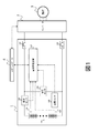
- FIG. 1 is a schematic configuration diagram of a power storage system according to an embodiment of the present invention.
- a power storage system (BESS) 1 shown in FIG. 1 includes a battery assembly 101, a battery management device 102, a current sensor 103, a cell controller 104, a voltage sensor 105, a temperature sensor 106, and a relay 107.
- the power storage system 1 is connected to a load 3 such as an AC motor via an inverter 2.
- the power storage system 1 and the inverter 2 are connected to the host controller 4 via a communication line (not shown).
- the assembled battery 101 is configured by connecting a plurality of chargeable / dischargeable battery cells in series and in parallel.
- the DC power discharged from the assembled battery 101 is converted into AC power by the inverter 2 and supplied to the load 3. Further, when the load 3 is in a regenerative operation, AC power output from the load 3 is converted into DC power by the inverter 2, and the assembled battery 101 is charged. Charge and discharge of the battery assembly 101 are performed by the operation of the inverter 2. The operation of the inverter 2 is controlled by the host controller 4.
- the current sensor 103 detects the current flowing in the battery pack 101, and outputs the detection result to the battery management device 102.
- the cell controller 104 detects the voltage of each battery cell of the assembled battery 101, and outputs the detection result to the battery management device 102.
- Voltage sensor 105 detects the voltage (total voltage) of battery assembly 101 and outputs the detection result to battery management device 102.
- the temperature sensor 106 detects the temperature of the battery pack 101, and outputs the detection result to the battery management device 102.
- the relay 107 switches the connection state between the power storage system 1 and the inverter 2 according to the control of the host controller 4.
- the battery management device 102 performs charge / discharge control of the assembled battery 101 based on the detection results of the current sensor 103, the cell controller 104, the voltage sensor 105, and the temperature sensor 106.
- charge / discharge control of the assembled battery 101 performed by the battery management apparatus 102, for example, allowable current calculation processing for determining an allowable value (upper limit value) of charge / discharge current of the assembled battery 101, balancing control for adjusting the charge state of each battery cell And so on.
- the battery management device 102 performs information communication necessary for charge / discharge control of the assembled battery 101 with the host controller 4.
- the power storage system 1 is a natural cooling system that does not have a cooling device such as a cooling fan or a water-cooled heat sink.
- a cooling device such as a cooling fan or a water-cooled heat sink.
- the amount of temperature change at this time largely depends on the charge and discharge current. Therefore, in the power storage system 1, the allowable value of the charge / discharge current is determined by the allowable current calculation process of the battery management device 102, and the charge / discharge current is limited according to this allowable value. Thereby, the rapid temperature rise during charge and discharge can be suppressed, and the temperature of the assembled battery 101 can be maintained within a predetermined range.
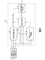
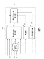
- FIG. 2 is a diagram showing functional blocks of the battery management device 102 regarding the allowable current calculation process.
- the battery management apparatus 102 includes functional blocks of a battery state calculation unit 501, a temperature parameter adjustment unit 502, a temperature prediction unit 503, and a current limit value calculation unit 504. These functional blocks are realized, for example, by executing a predetermined program on a computer.
- Battery state calculating unit 501 a current sensor 103, from the voltage sensor 105 and temperature sensor 106, obtains the detected current I when in the assembled battery 101 is charged and discharged, closed circuit voltage CCV and a battery temperature T cell, respectively. Then, based on these pieces of information, state values of an open circuit voltage OCV representing the current state of the assembled battery 101, a state of charge SOC, a polarization voltage Vp, a charge capacity decrease amount SOHQ and an internal resistance increase amount SOHQ are calculated. The details of the method of calculating these state values by the battery state calculation unit 501 will be described later with reference to FIG.
- Temperature parameter adjustment unit 502 a current sensor 103, from the voltage sensor 105 and temperature sensor 106, obtains the detected current I when in the assembled battery 101 is charged and discharged, closed circuit voltage CCV and a battery temperature T cell, respectively. Further, among the state values of the battery pack 101 calculated by the battery state calculation unit 501, the open circuit voltage OCV, the charge state SOC, and the polarization voltage Vp are acquired. Then, based on these pieces of information, the temperature parameter used to estimate the temperature of the battery assembly 101 is adjusted, and the adjusted temperature parameter is output.
- the temperature parameter adjusted by the temperature parameter adjustment unit 502 As an example of the temperature parameter adjusted by the temperature parameter adjustment unit 502, the case of adjusting the heat capacity c of the battery assembly 101 will be described.
- the value of the heat capacity c at the current time t adjusted by the temperature parameter adjustment unit 502 is represented as c (t).
- the details of the method of calculating the heat capacity c (t) by the temperature parameter adjustment unit 502 will be described later with reference to FIG.
- each state value of the battery pack 101 calculated by the battery state calculation unit 501 is acquired.
- the heat capacity c (t) calculated by the temperature parameter adjustment unit 502 is acquired. Then, based on these pieces of information, the temperature of the battery pack 101 in the future is predicted, and a temperature predicted value Tpredicted representing the prediction result is calculated.
- the temperature prediction unit 503 for example, as a charge / discharge scenario of the battery assembly 101, a plurality of combinations of future charge / discharge conditions of the battery assembly 101, for example, a combination of current value, current waveform, and energization time, are stored. .
- a temperature prediction model according to the value of the heat capacity c (t) is set in advance for each charge and discharge scenario.
- the temperature prediction unit 503 calculates the current I obtained from the current sensor 103, the voltage sensor 105, and the temperature sensor 106, the closed circuit voltage CCV, and the battery temperature T cell, and each state of the assembled battery 101 calculated by the battery state calculation unit 501.
- One of a plurality of charge / discharge scenarios set in advance is selected based on the value.
- the temperature predicted value T predicted is calculated.
- the method of calculating the temperature predicted value T predicted in the temperature prediction unit 503 is not limited to the above.
- the current limit value calculation unit 504 acquires each state value of the battery pack 101 calculated by the battery state calculation unit 501. Further, the temperature predicted value T predicted calculated by the temperature prediction unit 503 is acquired. Then, based on these pieces of information, current limit value I limit representing the allowable value (upper limit value) of the charge / discharge current of assembled battery 101 is calculated.
- the current limit value I limit calculated by the current limit value calculation unit 504 is transmitted from the battery management device 102 to the host controller 4 and used for control of the inverter 2 or the like. As a result, charge and discharge control of the battery assembly 101 is performed in the power storage system 1 so that the temperature of the battery assembly 101 does not exceed the upper limit value T limit . At this time, the inverter 2 charges and discharges the assembled battery 101 according to the current limit value I limit .
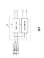
- FIG. 3 is a diagram showing a functional block of the battery state calculation unit 501.
- the battery state calculation unit 501 includes a battery model unit 601 and a deterioration state detection unit 602.
- the battery model unit 601 stores a battery model obtained by modeling the battery assembly 101, and uses this battery model to determine the open circuit voltage OCV, the state of charge SOC, and the polarization voltage Vp.
- the battery model in the battery model unit 601 is set, for example, according to the number of series connection and parallel connection of battery cells in the actual assembled battery 101, and the equivalent circuit of each battery cell.
- the battery model unit 601 applies the current I obtained from the current sensor 103, the voltage sensor 105, and the temperature sensor 106, the closed circuit voltage CCV, and the battery temperature T cell to the battery model to obtain the state of the battery pack 101.
- the open circuit voltage OCV, the state of charge SOC, and the polarization voltage Vp can be obtained in accordance with.
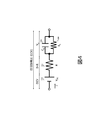
- FIG. 4 is a diagram showing an example of an equivalent circuit of a battery cell in a battery model set in the battery model unit 601.
- the equivalent circuit of the battery cell shown in FIG. 4 includes an open circuit voltage source 603 having a voltage value Voc, an internal resistance 604 having a resistance value R, a polarization capacitance 605 having a capacitance value Cp, and a polarization resistance 606 having a resistance value Rp.
- the polarization models which are parallel circuits, are connected in series with each other.
- the voltage across open circuit voltage source 603, that is, voltage value Voc corresponds to open circuit voltage OCV
- the voltage across the parallel circuit of polarization capacity 605 and polarization resistor 606 corresponds to polarization voltage Vp.
- the value obtained by adding the application voltage I ⁇ R of the internal resistor 604 and the polarization voltage Vp to the open circuit voltage OCV when the current I flows in this equivalent circuit corresponds to the closed circuit voltage CCV.
- the value of each circuit constant in the equivalent circuit of FIG. 4 is determined in accordance with the battery temperature T cell .
- battery model portion 601 obtains open circuit voltage OCV and polarization voltage Vp in the entire assembled battery 101 from current I, closed circuit voltage CCV and battery temperature T cell based on these relationships, and further open circuit voltage OCV.
- the charge state SOC can be obtained from the calculation result of
- the deterioration state detection unit 602 detects the deterioration state of the assembled battery 101 and obtains the charge capacity decrease amount SOHQ and the internal resistance increase amount SOHQ according to the deterioration state. Deterioration of each battery cell of the assembled battery 101 proceeds by repeating charging and discharging, and a decrease in charge capacity and an increase in internal resistance occur according to the deterioration state.
- the deterioration state detection unit 602 stores in advance information representing the relationship between the current and voltage of the assembled battery 101 and the temperature and the deterioration state, and using the information, the current sensor 103, the voltage sensor 105, and the temperature The deterioration state of the assembled battery 101 is detected based on the current I, the closed circuit voltage CCV and the battery temperature T cell acquired from the sensor 106 respectively. Then, based on the relationship between the deterioration state and the charge capacity decrease amount SOHQ and the internal resistance increase amount SOHQ stored in advance, the charge capacity decrease amount SOHQ and the internal resistance increase amount SOHQ corresponding to the detection result of the deterioration state of the assembled battery 101 It can be asked.
- FIG. 5 is a diagram showing a functional block of the temperature parameter adjustment unit 502.
- the temperature parameter adjustment unit 502 includes a DCR map 607, a thermal energy calculation unit 608, a determination unit 609, an increase temperature calculation unit 610, and a temperature parameter calculation unit 611.
- the DCR map 607 obtains the internal resistance value R of the assembled battery 101 based on the battery temperature T cell acquired from the temperature sensor 106 and the charge state SOC calculated by the battery state calculation unit 501.
- the DCR map 607 is, for example, a two-dimensional look-up table in which the internal resistance value R is set using the temperature and charge state of the assembled battery 101 as a search key, and from the input battery temperature T cell and charge state SOC, The internal resistance value R can be determined.
- the thermal energy calculation unit 608 acquires the current I of the assembled battery 101 and the battery temperature T cell from the current sensor 103 and the temperature sensor 106. Further, the open circuit voltage OCV and the polarization voltage Vp are acquired from the battery state calculation unit 501. Further, the internal resistance value R of the assembled battery 101 is acquired from the DCR map 607. Based on these acquired values, the thermal energy calculation unit 608 calculates thermal energy E (t) generated by the battery assembly 101 by the current time t.
- Equation (1) P represents the calorific value of the battery pack 101
- h represents the heat transfer coefficient of the battery pack 101
- A represents the surface area of the battery pack 101
- T ambient represents the ambient temperature
- the heat generation amount P of the above equation (1) is generally expressed by the following equation (2) as a function of the internal resistance value R, current I, polarization voltage Vp, battery temperature T cell and open circuit voltage OCV It can be expressed as However, the calculation formula of the calorific value P is not limited to Formula (2).
- the amount of heat released from the battery assembly 101 to the environment is proportional to the difference between the battery temperature T cell and the ambient temperature T ambient .
- the power storage system 1 of the present embodiment does not include a sensor that detects the ambient temperature T ambient, and therefore, the formula (1) can not be applied. Therefore, the heat energy calculation unit 608 integrates the heat generation amount P calculated by the above equation (2) from the initial time t initial to the current time t to obtain the heat energy E (t) as an integrated value of the heat generation amount P. calculate.
- Rising temperature calculation unit 610 calculates value T cell (t) of battery temperature T cell at current time t and value T of battery temperature T cell at initial time t initial based on battery temperature T cell obtained from temperature sensor 106. Calculate the difference with cell (t initial ). Then, the calculation result is output as the temperature increase ⁇ T (t) of the battery pack 101 at the current time t.
- the temperature parameter calculation unit 611 calculates the thermal energy E (t) calculated by the thermal energy calculation unit 608, the determination value D (t) determined by the determination unit 609, and the rising temperature calculated by the rising temperature calculation unit 610. Obtain ⁇ T (t). Then, the heat capacity c (t) of the assembled battery 101 at the current time t is calculated based on the acquired values.
- the temperature parameter calculation unit 611 sets an initial value c initial of the heat capacity of the battery assembly 101 at an initial time t initial .
- the heat capacity c (t) of the assembled battery 101 at the current time t is calculated by the following equation (3) or (4).
- the initial value c initial of the heat capacity may be a value set in advance, or may be a value obtained by averaging the history of the heat capacity c (t).
- the heat capacity c (t) represented by the formulas (3) and (4) corresponds to the heat capacity c in the above-mentioned formula (1), and the unit thereof is Joule / ° C. (J ⁇ ° C. ⁇ 1 ) is there.
- the heat capacity c (t) which is one of the temperature parameters of the assembled battery 101, is determined in consideration of the change in the charge / discharge current and temperature of the assembled battery 101 in the past by the method described above. calculate. Therefore, information on heat dissipation from the battery pack 101 to the surroundings can be taken into consideration to some extent.
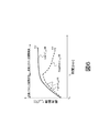
- a curve 612 shows an example of a temperature change of the battery assembly 101, in which the temperature rises sharply between time t0 and time t1 and rises slowly after time t1.
- a curve 613 indicated by a broken line shows an example of a temperature change of the battery assembly 101 in which the temperature rises sharply between time t0 and time t1 and decreases after time t1.
- the change rate dT cell / dt of the battery temperature T cell obtained from the temperature sensor 106 satisfies the condition of the following equation (5).
- the adjustment of the heat capacity c (t) which is a temperature parameter of the assembled battery 101 is effective.
- Slope min is a positive constant value.
- the adjustment of the heat capacity c (t) becomes effective, for example, in the period from time t0 to time t1 in the cases shown in curves 612 and 613 in FIG.
- adjustment of the heat capacity c (t) is performed according to the above-mentioned equation (4).
- the temperature parameter adjustment unit 502 adjusts the temperature parameters used to estimate the temperature of the battery assembly 101 according to the temperature rise. Can.
- the temperature prediction unit 503 calculates the temperature predicted value T predicted (t + ⁇ t) at time t + ⁇ t ahead of the current time t. For example, it calculates according to the following formula (6).
- T model is a function including c (t) and I virtual as arguments.
- I virtual represents a virtual current value at time t + ⁇ t in the charge and discharge scenario selected by the temperature prediction unit 503.
- arguments other than the thermal capacity c (t) and the virtual current value I virtual in the function T model are omitted, but any other argument can be used besides these.
- the battery management device 102 is a device that manages the chargeable / dischargeable battery assembly 101, and includes a temperature parameter adjustment unit 502 that adjusts the temperature parameter used to estimate the temperature of the battery assembly 101.
- the temperature parameter adjustment unit 502 adjusts the temperature parameter when the temperature of the assembled battery 101 is rising. Since it did in this way, charge / discharge control of the assembled battery 101 can be performed appropriately, without measuring a cooling water temperature or environmental temperature.
- the temperature parameter that the temperature parameter adjustment unit 502 performs adjustment includes the heat capacity c (t) of the assembled battery 101. Since this is done, it is possible to adjust the temperature parameter necessary for estimating the temperature of the battery assembly 101.
- the temperature parameter adjustment unit 502 determines the calorific value P of the assembled battery 101 represented by the equation (2). Adjust the temperature parameter based on the integrated value. Specifically, the thermal energy E (t) is calculated based on the integrated value of the calorific value P, and the heat capacity c (t) at the current time t is calculated by the equation (4) using the thermal energy E (t). calculate.
- the temperature parameter is adjusted by calculating the same value as the previous calculation result as the heat capacity c (t) at the current time t by equation (3). Not performed. As described above, when it is not necessary to adjust the temperature parameter by the temperature parameter adjustment unit 502, this is not performed, so that the processing load on the battery management apparatus 102 can be reduced.
- the battery management apparatus 102 acquires the current I of the battery pack 101, the closed circuit voltage CCV and the battery temperature T cell , and represents the state value representing the state of the battery pack 101, that is, the open circuit voltage OCV, the charge state SOC,
- the battery state calculation unit 501 further calculates a polarization voltage Vp, a charge capacity decrease amount SOHQ, and an internal resistance increase amount SOHQ.
- the temperature parameter adjustment unit 502 is based on, for example, the equation (2) based on at least one of the current I of the assembled battery 101 and the battery temperature T cell and the state value calculated by the battery state calculation unit 501.
- the calorific value P is calculated. Since it did in this way, calorific value P according to the state of assembled battery 101 can be computed.
- the battery management device 102 further includes a temperature prediction unit 503 that predicts the future temperature of the battery assembly 101 based on the temperature parameter adjusted by the temperature parameter adjustment unit 502. Since this is done, it is possible to predict the future temperature of the battery assembly 101 without measuring the cooling water temperature or the environmental temperature.
- the temperature prediction unit 503 stores in advance a plurality of charge / discharge scenarios respectively representing the future charge / discharge status of the assembled battery 101, and any one of the plurality of charge / discharge scenarios is used for the future assembled battery Predict the temperature of 101. Since this is done, the future temperature of the battery pack 101 can be easily and accurately predicted.
- Battery management device 102 sets current limit value I representing an allowable value of charge / discharge current of assembled battery 101 based on temperature predicted value T predicted representing the temperature of assembled battery 101 in the future predicted by temperature prediction unit 503. It further includes a current limit value calculation unit 504 that calculates limit. Since this is done, charge and discharge control of the assembled battery 101 can be performed so that the temperature of the assembled battery 101 does not exceed the upper limit value T limit without measuring the cooling water temperature or the environmental temperature.
- Modification 1 Although the above embodiment has described an application example of a natural cooling type power storage system, the present invention is also applicable to a forced cooling type power storage system in which the battery assembly 101 is cooled using a cooling device such as a cooling fan or a water cooling heat sink. Is equally applicable.
- a cooling device such as a cooling fan or a water cooling heat sink.
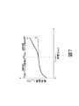
- a curve 614 indicated by a broken line shows an example of a temperature change of the battery assembly 101 when the forced cooling by the cooling device is continued.
- a curve 615 shows an example of temperature change of the battery assembly 101 when forced cooling by the cooling device is stopped after time t COOLING OFF .
- the battery temperature T cell is rising.
- a temperature prediction model in such a case is not usually set, and an appropriate temperature predicted value Tpredicted can not be calculated.
- the temperature predicted value T predicted can be obtained by adjusting the temperature parameter, and charge / discharge control of the assembled battery 101 can be performed.
- the determination unit 609 determines whether to adjust the temperature parameter by comparing the change in temperature of the battery pack 101 at the current time t with a predetermined determination reference value.
- a predetermined determination reference value For example, the determination reference value for the deterioration state of the assembled battery 101 is defined, and the determination value is obtained by comparing the charge capacity decrease amount SOHQ and the internal resistance increase amount SOHQ calculated by the battery state calculation unit 501 with the determination reference value. D (t) may be determined.
- a plurality of types of determination reference values such as a determination reference value for temperature change of the battery assembly 101 and a determination reference value for the deterioration state may be used.
Landscapes
- Engineering & Computer Science (AREA)
- Manufacturing & Machinery (AREA)
- Chemical & Material Sciences (AREA)
- Chemical Kinetics & Catalysis (AREA)
- Electrochemistry (AREA)
- General Chemical & Material Sciences (AREA)
- Power Engineering (AREA)
- Automation & Control Theory (AREA)
- Secondary Cells (AREA)
- General Physics & Mathematics (AREA)
- Physics & Mathematics (AREA)
- Charge And Discharge Circuits For Batteries Or The Like (AREA)
- Tests Of Electric Status Of Batteries (AREA)
Abstract
冷却水温度や環境温度を測定することなく、電池の充放電制御を適切に行う。 電池管理装置102は、充放電可能な電池を管理する装置であって、電池の温度推定に用いられる温度パラメータの調整を行う温度パラメータ調整部502を備える。温度パラメータ調整部502は、電池の温度が上昇しているときに温度パラメータの調整を行う。また、電池管理装置102は、温度パラメータ調整部502による調整後の温度パラメータに基づいて将来の電池温度を予測する温度予測部503と、温度予測部503により予測された将来の電池温度に基づいて電池の充放電電流の許容値を算出する電流制限値算出部504とをさらに備える。
Description
本発明は、電池管理装置、電池管理方法および電力貯蔵システムに関する。
近年、地球温暖化問題の観点から、太陽光や風力などの再生可能エネルギーを利用して発電を行い、電力貯蔵システム(Battery Energy Storage System:BESS)を用いて出力の安定化を図った発送電システムの利用が拡大している。また、自動車等の移動交通システムにおいても、排ガス規制の観点から、こうした電力貯蔵システムが広く用いられている。
従来の一般的な電力貯蔵システムは、複数の電池セルを組み合わせた電池と、電池を冷却して温度調節を行う冷却システムと、電池の充放電制御を行ってシステムを安全な状態に維持する電池管理装置とを備えて構成される。こうした従来の電力貯蔵システムでは、冷却システムを用いて、電池温度が予め設定された最大温度以下となるように電池を強制的に冷却している。
一方、電力貯蔵システムの用途によっては、大きさや重さの低減が重要な場合がある。そのため、冷却システムを設けない自然冷却方式の電池を用いた電力貯蔵システムも利用されている。こうした自然冷却方式の電力貯蔵システムでは、運用状況や周囲環境によっては、電池温度が許容値を超えてしまう場合がある。その場合、電池温度が許容値未満となるまでは充放電を停止しなければならず、その間は電力貯蔵システムが非稼働状態となる。すなわち、自然冷却方式の電力貯蔵システムでは、冷却システムを備えた強制冷却方式の電力貯蔵システムと比べて、運用条件を低く設定しなれればならない。したがって、自然冷却方式の電力貯蔵システムを運用する際には、電池の周囲環境を考慮して、電池温度を許容値以内に制限しつつ、非稼働状態の期間を最小化する運用条件を設定する必要がある。
電池の周囲環境を考慮した充電制御に関して、特許文献1に記載の技術が知られている。特許文献1には、冷却水温度センサにより検出された冷却水温度と、電池温度センサにより検出された電池温度と、環境温度センサにより検出された環境温度とに基づいて、水冷構造の組電池の充電を制御する充電制御装置が開示されている。
特許文献1の充電制御装置では、冷却水温度や環境温度を測定しなければ、電池の充放電制御を適切に行うことができない。
本発明による電池管理装置は、充放電可能な電池を管理する装置であって、前記電池の温度推定に用いられる温度パラメータの調整を行う温度パラメータ調整部を備え、前記温度パラメータ調整部は、前記電池の温度が上昇しているときに前記温度パラメータの調整を行う。
本発明による電池管理方法は、充放電可能な電池を管理するための方法であって、コンピュータにより、前記電池の温度が上昇しているときに、前記電池の温度推定に用いられる温度パラメータの調整を行う。
本発明による電力貯蔵システムは、電池管理装置と、充放電可能な電池と、前記温度パラメータ調整部による調整後の前記温度パラメータに基づいて決定された前記電池の充放電電流の許容値に従って、前記電池の充放電を行う充放電装置と、を備える。
本発明による電池管理方法は、充放電可能な電池を管理するための方法であって、コンピュータにより、前記電池の温度が上昇しているときに、前記電池の温度推定に用いられる温度パラメータの調整を行う。
本発明による電力貯蔵システムは、電池管理装置と、充放電可能な電池と、前記温度パラメータ調整部による調整後の前記温度パラメータに基づいて決定された前記電池の充放電電流の許容値に従って、前記電池の充放電を行う充放電装置と、を備える。
本発明によれば、冷却水温度や環境温度を測定することなく、電池の充放電制御を適切に行うことができる。
以下では、本発明の実施形態について説明する。
図1は、本発明の一実施形態に係る電力貯蔵システムの概略構成図である。図1に示す電力貯蔵システム(BESS)1は、組電池101、電池管理装置102、電流センサ103、セルコントローラ104、電圧センサ105、温度センサ106、およびリレー107を備える。電力貯蔵システム1は、インバータ2を介して、交流モータ等の負荷3に接続されている。電力貯蔵システム1およびインバータ2は、不図示の通信回線を介して上位コントローラ4に接続されている。
組電池101は、充放電可能な複数の電池セルを直並列に接続して構成されている。負荷3を力行運転する際には、組電池101から放電された直流電力がインバータ2により交流電力に変換され、負荷3に供給される。また、負荷3を回生運転する際には、負荷3から出力された交流電力がインバータ2により直流電力に変換され、組電池101に充電される。こうしたインバータ2の動作により、組電池101の充放電が行われる。インバータ2の動作は、上位コントローラ4により制御される。
電流センサ103は、組電池101に流れる電流を検出し、その検出結果を電池管理装置102に出力する。セルコントローラ104は、組電池101の各電池セルの電圧を検出し、その検出結果を電池管理装置102に出力する。電圧センサ105は、組電池101の電圧(総電圧)を検出し、その検出結果を電池管理装置102に出力する。温度センサ106は、組電池101の温度を検出し、その検出結果を電池管理装置102に出力する。リレー107は、上位コントローラ4の制御に応じて、電力貯蔵システム1とインバータ2の間の接続状態を切り替える。
電池管理装置102は、電流センサ103、セルコントローラ104、電圧センサ105および温度センサ106の各検出結果に基づき、組電池101の充放電制御を行う。電池管理装置102が行う組電池101の充放電制御には、例えば、組電池101の充放電電流の許容値(上限値)を定める許容電流算出処理、各電池セルの充電状態を調整するバランシング制御などが含まれる。電池管理装置102は、上位コントローラ4との間で、組電池101の充放電制御に必要な情報通信を行う。
電力貯蔵システム1は、冷却ファンや水冷ヒートシンク等の冷却装置を持たない自然冷却方式のシステムである。組電池101の充放電中には、各電池セルにおける電気化学反応や相転移、ジュール発熱、周囲環境等によって組電池101の温度が変化する。このときの温度変化量は、充放電電流に大きく依存する。そのため、電力貯蔵システム1では、電池管理装置102の許容電流算出処理により充放電電流の許容値を定め、この許容値に従って充放電電流を制限する。これにより、充放電中の急激な温度上昇を抑制し、組電池101の温度を所定の範囲内に維持することができる。
図2は、許容電流算出処理に関する電池管理装置102の機能ブロックを示す図である。電池管理装置102は、電池状態算出部501、温度パラメータ調整部502、温度予測部503および電流制限値算出部504の各機能ブロックを有する。これらの機能ブロックは、たとえば所定のプログラムをコンピュータで実行することにより実現される。
電池状態算出部501は、電流センサ103、電圧センサ105および温度センサ106から、組電池101が充放電中のときに検出された電流I、閉回路電圧CCVおよび電池温度Tcellをそれぞれ取得する。そして、これらの情報に基づき、組電池101の現在の状態を表す開回路電圧OCV、充電状態SOC、分極電圧Vp、充電容量減少量SOHQおよび内部抵抗増加量SOHQの各状態値を算出する。なお、電池状態算出部501によるこれらの状態値の算出方法の詳細については、後で図3を参照して説明する。
温度パラメータ調整部502は、電流センサ103、電圧センサ105および温度センサ106から、組電池101が充放電中のときに検出された電流I、閉回路電圧CCVおよび電池温度Tcellをそれぞれ取得する。また、電池状態算出部501で算出された組電池101の状態値のうち、開回路電圧OCV、充電状態SOC、および分極電圧Vpを取得する。そして、これらの情報に基づき、組電池101の温度推定に用いられる温度パラメータの調整を行い、調整後の温度パラメータを出力する。
本実施形態では、温度パラメータ調整部502が調整する温度パラメータの例として、組電池101の熱容量cを調整する場合を説明する。以下では、温度パラメータ調整部502により調整された現在時刻tにおける熱容量cの値をc(t)と表す。なお、温度パラメータ調整部502による熱容量c(t)の算出方法の詳細については、後で図5を参照して説明する。
温度予測部503は、電流センサ103、電圧センサ105および温度センサ106から、組電池101が充放電中のときに検出された電流I、閉回路電圧CCVおよび電池温度Tcellをそれぞれ取得する。また、電池状態算出部501で算出された組電池101の各状
態値を取得する。さらに、温度パラメータ調整部502で算出された熱容量c(t)を取得する。そして、これらの情報に基づいて将来の組電池101の温度を予測し、その予測結果を表す温度予測値Tpredictedを算出する。
態値を取得する。さらに、温度パラメータ調整部502で算出された熱容量c(t)を取得する。そして、これらの情報に基づいて将来の組電池101の温度を予測し、その予測結果を表す温度予測値Tpredictedを算出する。
温度予測部503には、例えば、組電池101の充放電シナリオとして、組電池101における将来の充放電状況、たとえば電流値、電流波形、通電時間などを組み合わせたものが、複数組記憶されている。また、充放電シナリオごとに、熱容量c(t)の値に応じた温度予測モデルが予め設定されている。温度予測部503は、電流センサ103、電圧センサ105および温度センサ106からそれぞれ取得した電流I、閉回路電圧CCVおよび電池温度Tcellと、電池状態算出部501で算出された組電池101の各状態値とに基づき、予め設定された複数の充放電シナリオの中でいずれかを選択する。そして、選択した充放電シナリオと、温度パラメータ調整部502から取得した熱容量c(t)とに基づき、温度予測値Tpredictedを算出する。このとき、複数の充放電シナリオを選択することで、充放電シナリオごとに異なる複数の温度予測値Tpredictedを算出してもよい。なお、熱容量c(t)の値から組電池101の状態に応じた適切な温度予測値Tpredictedを算出できれば、温度予測部503における温度予測値Tpredictedの算出方法は上記のものに限定されない。
電流制限値算出部504は、電池状態算出部501で算出された組電池101の各状態値を取得する。また、温度予測部503で算出された温度予測値Tpredictedを取得する。
そして、これらの情報に基づき、組電池101の充放電電流の許容値(上限値)を表す電流制限値Ilimitを算出する。電流制限値算出部504により算出された電流制限値Ilimitは、電池管理装置102から上位コントローラ4に送信され、インバータ2の制御等に利用される。これにより、組電池101の温度が上限値Tlimitを超えないように、電力貯蔵システム1において組電池101の充放電制御が行われる。このときインバータ2は、電流制限値Ilimitに従って組電池101の充放電を行う。
そして、これらの情報に基づき、組電池101の充放電電流の許容値(上限値)を表す電流制限値Ilimitを算出する。電流制限値算出部504により算出された電流制限値Ilimitは、電池管理装置102から上位コントローラ4に送信され、インバータ2の制御等に利用される。これにより、組電池101の温度が上限値Tlimitを超えないように、電力貯蔵システム1において組電池101の充放電制御が行われる。このときインバータ2は、電流制限値Ilimitに従って組電池101の充放電を行う。
図3は、電池状態算出部501の機能ブロックを示す図である。電池状態算出部501は、電池モデル部601および劣化状態検出部602を備える。
電池モデル部601は、組電池101をモデル化した電池モデルを記憶しており、この電池モデルを用いて、開回路電圧OCV、充電状態SOCおよび分極電圧Vpを求める。電池モデル部601における電池モデルは、例えば、実際の組電池101における電池セルの直列接続数および並列接続数や、各電池セルの等価回路に応じて設定されている。電池モデル部601は、電流センサ103、電圧センサ105および温度センサ106からそれぞれ取得した電流I、閉回路電圧CCVおよび電池温度Tcellをこの電池モデルに対して適用することで、組電池101の状態に応じた開回路電圧OCV、充電状態SOCおよび分極電圧Vpを求めることができる。
図4は、電池モデル部601に設定される電池モデルにおける電池セルの等価回路の例を示す図である。図4に示す電池セルの等価回路は、電圧値Vocを有する開放電圧源603と、抵抗値Rを有する内部抵抗604と、容量値Cpを有する分極容量605と抵抗値Rpを有する分極抵抗606の並列回路である分極モデルとが、互いに直列接続されて構成されている。この等価回路において、開放電圧源603の両端電圧、すなわち電圧値Vocは開回路電圧OCVに相当し、分極容量605と分極抵抗606の並列回路の両端電圧は分極電圧Vpに相当する。また、この等価回路に電流Iが流れたときの内部抵抗604の印加電圧I×Rおよび分極電圧Vpを開回路電圧OCVに加えた値は、閉回路電圧CCVに相当する。さらに、図4の等価回路における各回路定数の値は、電池温度Tcellに応じて定まる。したがって、電池モデル部601では、これらの関係に基づき、電流I、閉回路電圧CCVおよび電池温度Tcellから、組電池101全体での開回路電圧OCVおよび分極電圧Vpを求め、さらに開回路電圧OCVの算出結果から充電状態SOCを求めることができる。
図3の説明に戻ると、劣化状態検出部602は、組電池101の劣化状態を検出し、その劣化状態に応じた充電容量減少量SOHQおよび内部抵抗増加量SOHQを求める。組電池101の各電池セルは、充放電を繰り返すことで劣化が進行し、その劣化状態に応じて充電容量の減少および内部抵抗の増加が生じる。劣化状態検出部602は、例えば、組電池101の電流、電圧および温度と劣化状態との関係を表す情報を予め記憶しており、この情報を用いることで、電流センサ103、電圧センサ105および温度センサ106からそれぞれ取得した電流I、閉回路電圧CCVおよび電池温度Tcellに基づいて、組電池101の劣化状態を検出する。そして、予め記憶された劣化状態と充電容量減少量SOHQおよび内部抵抗増加量SOHQとの関係に基づき、組電池101の劣化状態の検出結果に対応する充電容量減少量SOHQおよび内部抵抗増加量SOHQを求めることができる。
図5は、温度パラメータ調整部502の機能ブロックを示す図である。温度パラメータ調整部502は、DCRマップ607、熱エネルギー算出部608、判定部609、上昇温度算出部610、および温度パラメータ算出部611を備える。
DCRマップ607は、温度センサ106から取得した電池温度Tcellと、電池状態算出部501で算出された充電状態SOCとに基づいて、組電池101の内部抵抗値Rを求める。DCRマップ607は、例えば、組電池101の温度と充電状態を検索キーとして内部抵抗値Rが設定された二次元ルックアップテーブルであり、入力された電池温度Tcellおよび充電状態SOCの値から、内部抵抗値Rを求めることができる。
熱エネルギー算出部608は、電流センサ103および温度センサ106から、組電池101の電流Iおよび電池温度Tcellを取得する。また、電池状態算出部501から、開回路電圧OCVおよび分極電圧Vpを取得する。さらに、DCRマップ607から、組電池101の内部抵抗値Rを取得する。取得したこれらの値に基づいて、熱エネルギー算出部608は、組電池101が現在時刻tまでに発生した熱エネルギーE(t)を算出する。
ここで、熱エネルギー算出部608による熱エネルギーE(t)の算出方法の詳細について説明する。一般に、組電池101における温度変化と、発熱量および周囲への放熱量との関係は、前述の熱容量cおよび電池温度Tcellを用いて、以下の式(1)のような熱エネルギー平衡式で表される。式(1)において、Pは組電池101の発熱量、hは組電池101の熱伝達係数、Aは組電池101の表面積、Tambientは周囲環境温度をそれぞれ表している。

ここで、上記式(1)の発熱量Pは一般に、組電池101の内部抵抗値R、電流I、分極電圧Vp、電池温度Tcellおよび開回路電圧OCVの関数として、以下の式(2)のように表すことができる。ただし、発熱量Pの算出式は式(2)に限定されない。

また、上記式(1)により、組電池101から周囲への放熱量は、電池温度Tcellと周囲環境温度Tambientの差分に比例することが分かる。
本実施形態の電力貯蔵システム1は、周囲環境温度Tambientを検出するセンサを備えていないため、式(1)を適用することができない。そこで、熱エネルギー算出部608は、上記式(2)で算出される発熱量Pを初期時刻tinitialから現在時刻tまで積算することにより、発熱量Pの積算値として熱エネルギーE(t)を算出する。
判定部609は、温度センサ106から取得した電池温度Tcellに基づいて、現在時刻tにおける組電池101の温度変化に対する判定値D(t)を出力する。判定部609は、例えば、現在時刻tにおける電池温度Tcellの変化が所定の判定基準値を満たす場合は、D(t)=1を出力し、満たさない場合はD(t)=0を出力する。なお、判定部609における判定基準値は複数存在してもよい。その場合、複数の判定基準値のうち少なくとも一つを満たした場合にD(t)=1を出力してもよいし、全ての判定基準値を満たした場合にD(t)=1を出力してもよい。
上昇温度算出部610は、温度センサ106から取得した電池温度Tcellに基づいて、現在時刻tにおける電池温度Tcellの値Tcell(t)と、初期時刻tinitialにおける電池温度Tcellの値Tcell(tinitial)との差分を算出する。そして、その算出結果を現在時刻tにおける組電池101の上昇温度ΔT(t)として出力する。
温度パラメータ算出部611は、熱エネルギー算出部608で算出された熱エネルギーE(t)と、判定部609で求められた判定値D(t)と、上昇温度算出部610で算出された上昇温度ΔT(t)とを取得する。そして、取得したこれらの値に基づいて、現在時刻tにおける組電池101の熱容量c(t)を算出する。
例えば、温度パラメータ算出部611では、初期時刻tinitialにおいて、組電池101の熱容量の初期値cinitialを設定する。この熱容量の初期値cinitialを出発点として、下記の式(3)または式(4)により、現在時刻tにおける組電池101の熱容量c(t)を算出する。なお、熱容量の初期値cinitialは、予め設定された値でもよいし、熱容量c(t)の履歴を平均化した値としてもよい。
D(t)=0の場合は、以下の式(3)により、現在時刻tにおける組電池101の熱容量c (t)を算出する。すなわち、前回の算出結果と同じ値を、現在時刻tにおける熱容量c(t)として算出する。
c(t)=c(t-1) ・・・(3)
c(t)=c(t-1) ・・・(3)
一方、D(t)=1の場合は、以下の式(4)により、現在時刻tにおける組電池101の熱容量c(t)を算出する。
c(t)=E(t)/ΔT(t) ・・・(4)
c(t)=E(t)/ΔT(t) ・・・(4)
なお、式(3)、(4)で表される熱容量c(t)は、前述の式(1)における熱容量cに対応しており、その単位はジュール/℃(J・℃-1)である。
温度パラメータ調整部502では、以上説明したような方法により、過去の組電池101の充放電電流および温度の変化を考慮して、組電池101の温度パラメータの一つである熱容量c(t)を算出する。そのため、組電池101から周囲への放熱に関する情報についても、ある程度は考慮に入れることができる。
次に、図6のグラフに示す組電池101の温度変化例を参照して、本実施形態による温度パラメータ調整の適用条件について説明する。図6において、曲線612は、時刻t0から時刻t1の間に温度が急激に上昇し、時刻t1以降ではゆっくりと上昇する組電池101の温度変化例を示している。一方、破線で示した曲線613は、時刻t0から時刻t1の間に温度が急激に上昇し、時刻t1以降では低下する組電池101の温度変化例を示している。
ここで、判定部609の判定において用いられる前述の判定基準値をSlopeminと表すと、温度センサ106から取得した電池温度Tcellの変化速度dTcell/dtが以下の式(5)の条件を満たすときに、組電池101の温度パラメータである熱容量c(t)の調整が有効となる。なお、式(5)において、Slopeminは正の一定値である。

上記式(5)の条件により、図6において曲線612、613にそれぞれ示した場合では、例えば時刻t0から時刻t1の期間に熱容量c(t)の調整が有効となり、時刻t1以降の期間に熱容量c(t)の調整が無効となる。すなわち、時刻t0から時刻t1の期間では、曲線612、613いずれの場合でも組電池101の温度上昇速度が判定基準値Slopeminよりも高いため、電池温度Tcellの変化速度dTcell/dtが式(5)の条件を満たしてD(t)=1となる。
その結果、前述の式(4)に従って熱容量c(t)の調整が行われる。一方、時刻t1以降の期間では、曲線612の場合は組電池101の温度上昇速度が判定基準値Slopeminよりも低く、また曲線613の場合は組電池101の温度が低下しているため、いずれの場合も電池温度Tcellの変化速度dTcell/dtが式(5)の条件を満たさずにD(t)=0となる。その結果、熱容量c(t)の調整が行われない。
その結果、前述の式(4)に従って熱容量c(t)の調整が行われる。一方、時刻t1以降の期間では、曲線612の場合は組電池101の温度上昇速度が判定基準値Slopeminよりも低く、また曲線613の場合は組電池101の温度が低下しているため、いずれの場合も電池温度Tcellの変化速度dTcell/dtが式(5)の条件を満たさずにD(t)=0となる。その結果、熱容量c(t)の調整が行われない。
温度パラメータ調整部502では、以上説明したようにして、組電池101の温度が上昇しているときに、その温度上昇に応じて、組電池101の温度推定に用いられる温度パラメータの調整を行うことができる。
温度予測部503では、温度パラメータ調整部502で算出された現在時刻tにおける組電池101の熱容量c(t)に基づいて、現在時刻tより先の時刻t+Δtにおける温度予測値Tpredicted(t+Δt)を、例えば以下の式(6)に従って算出する。式(6)において、Tmodelは、c(t)およびIvirtualを引数に含む関数である。なお、Ivirtualは、温度予測部503で選択した充放電シナリオにおける時刻t+Δtでの仮想電流値を表している。また、式(6)では、関数Tmodelにおける熱容量c(t)と仮想電流値Ivirtual以外の引数を省略しているが、これら以外にも任意の引数を用いることが可能である。

以上説明した本発明の一実施形態によれば、以下の作用効果を奏する。
(1)電池管理装置102は、充放電可能な組電池101を管理する装置であって、組電池101の温度推定に用いられる温度パラメータの調整を行う温度パラメータ調整部502を備える。温度パラメータ調整部502は、組電池101の温度が上昇しているときに温度パラメータの調整を行う。このようにしたので、冷却水温度や環境温度を測定することなく、組電池101の充放電制御を適切に行うことができる。
(2)温度パラメータ調整部502が調整を行う温度パラメータは、組電池101の熱容量c(t)を含む。このようにしたので、組電池101の温度推定に必要な温度パラメータの調整を行うことができる。
(3)温度パラメータ調整部502は、組電池101の温度変化が所定の判定基準値、例えば式(5)の条件を満たす場合、式(2)で表される組電池101の発熱量Pの積算値に基づいて温度パラメータの調整を行う。具体的には、発熱量Pの積算値に基づいて熱エネルギーE(t)を算出し、この熱エネルギーE(t)を用いた式(4)により、現在時刻tにおける熱容量c(t)を算出する。一方、組電池101の温度変化が判定基準値を満たさない場合、式(3)により前回の算出結果と同じ値を現在時刻tにおける熱容量c(t)として算出することで、温度パラメータの調整を行わない。このようにして、温度パラメータ調整部502による温度パラメータの調整が必要ない場合はこれを行わないこととしたので、電池管理装置102における処理負荷の軽減を図ることができる。
(4)電池管理装置102は、組電池101の電流I、閉回路電圧CCVおよび電池温度Tcellを取得して、組電池101の状態を表す状態値、すなわち開回路電圧OCV、充電状態SOC、分極電圧Vp、充電容量減少量SOHQおよび内部抵抗増加量SOHQを算出する電池状態算出部501をさらに備える。温度パラメータ調整部502は、組電池101の電流Iおよび電池温度Tcellの少なくとも一方と、電池状態算出部501により算出された状態値とに基づいて、例えば式(2)により、組電池101の発熱量Pを算出する。このようにしたので、組電池101の状態に応じた発熱量Pを算出することができる。
(5)電池管理装置102は、温度パラメータ調整部502による調整後の温度パラメータに基づいて将来の組電池101の温度を予測する温度予測部503をさらに備える。このようにしたので、冷却水温度や環境温度を測定することなく、組電池101の将来の温度を予測することが可能である。
(6)温度予測部503は、組電池101の将来の充放電状況をそれぞれ表す複数の充放電シナリオを予め記憶しており、これら複数の充放電シナリオのうちいずれかを用いて将来の組電池101の温度を予測する。このようにしたので、組電池101の将来の温度を容易にかつ正確に予測することができる。
(7)電池管理装置102は、温度予測部503により予測された将来の組電池101の温度を表す温度予測値Tpredictedに基づいて組電池101の充放電電流の許容値を表す電流制限値Ilimitを算出する電流制限値算出部504をさらに備える。このようにしたので、冷却水温度や環境温度を測定することなく、組電池101の温度が上限値Tlimitを超えないように、組電池101の充放電制御を行うことができる。
なお、以上説明した本発明の一実施形態は、次のように変形してもよい。
(変形例1)
上記実施形態では、自然冷却方式の電力貯蔵システムにおける適用例を説明したが、冷却ファンや水冷ヒートシンク等の冷却装置を用いて組電池101を冷却する強制冷却方式の電力貯蔵システムにおいても、本発明を同様に適用可能である。
上記実施形態では、自然冷却方式の電力貯蔵システムにおける適用例を説明したが、冷却ファンや水冷ヒートシンク等の冷却装置を用いて組電池101を冷却する強制冷却方式の電力貯蔵システムにおいても、本発明を同様に適用可能である。
図7のグラフに示す組電池101の温度変化例を参照して、本変形例による温度パラメータ調整の適用について説明する。図7において、破線で示した曲線614は、冷却装置による強制冷却を続けた場合の組電池101の温度変化例を示している。一方、曲線615は、時刻tCOOLING OFF以降では冷却装置による強制冷却を停止した場合の組電池101の温度変化例を示している。
曲線615において、時刻tCOOLING OFF以降では強制冷却が停止されているため、電池温度Tcellが上昇している。しかし、強制冷却方式の電力貯蔵システムでは、通常はこのような場合の温度予測モデルが設定されておらず、適切な温度予測値Tpredictedを算出することができない。本変形例によれば、こうした場合にも、温度パラメータの調整を行うことで適切な温度予測値Tpredictedを求め、組電池101の充放電制御を行うことができる。
(変形例2)
上記実施形態では、温度パラメータ調整部502において、組電池101の温度パラメータのうち、式(1)における熱容量cを調整する例を説明したが、他の温度パラメータ、例えば式(1)における熱伝達係数hを調整してもよい。また、複数の温度パラメータを調整してもよい。すなわち、温度パラメータ調整部502が調整を行う温度パラメータは、組電池101の熱容量cおよび熱伝達係数hのいずれか少なくとも一つを含むことができる。
上記実施形態では、温度パラメータ調整部502において、組電池101の温度パラメータのうち、式(1)における熱容量cを調整する例を説明したが、他の温度パラメータ、例えば式(1)における熱伝達係数hを調整してもよい。また、複数の温度パラメータを調整してもよい。すなわち、温度パラメータ調整部502が調整を行う温度パラメータは、組電池101の熱容量cおよび熱伝達係数hのいずれか少なくとも一つを含むことができる。
(変形例3)
上記実施形態では、判定部609において、現在時刻tにおける組電池101の温度変化と所定の判定基準値とを比較することで、温度パラメータの調整を行うか否かを定める判定値D(t)を決定する例を説明したが、他の判定基準値を用いてもよい。例えば、組電池101の劣化状態に対する判定基準値を定めておき、電池状態算出部501により算出された充電容量減少量SOHQや内部抵抗増加量SOHQをこの判定基準値と比較することで、判定値D(t)を決定してもよい。さらに、例えば組電池101の温度変化に対する判定基準値と劣化状態に対する判定基準値など、複数種類の判定基準値を用いてもよい。
上記実施形態では、判定部609において、現在時刻tにおける組電池101の温度変化と所定の判定基準値とを比較することで、温度パラメータの調整を行うか否かを定める判定値D(t)を決定する例を説明したが、他の判定基準値を用いてもよい。例えば、組電池101の劣化状態に対する判定基準値を定めておき、電池状態算出部501により算出された充電容量減少量SOHQや内部抵抗増加量SOHQをこの判定基準値と比較することで、判定値D(t)を決定してもよい。さらに、例えば組電池101の温度変化に対する判定基準値と劣化状態に対する判定基準値など、複数種類の判定基準値を用いてもよい。
以上説明した実施形態や各種の変化例はあくまで一例であり、発明の特徴が損なわれない限り、本発明はこれらの内容に限定されない。本発明は上述した実施形態や変形例に限定されるものではなく、本発明の趣旨を逸脱しない範囲で種々の変更が可能である。
1 電力貯蔵システム(BESS)
2 インバータ
3 負荷
4 上位コントローラ
101 組電池
102 電池管理装置
103 電流センサ
104 セルコントローラ
105 電圧センサ
106 温度センサ
107 リレー
501 電池状態算出部
502 温度パラメータ調整部
503 温度予測部
504 電流制限値算出部
601 電池モデル部
602 劣化状態検出部
603 開放電圧源
604 内部抵抗
605 分極容量
606 分極抵抗
607 DCRマップ
608 熱エネルギー算出部
609 判定部
610 上昇温度算出部
611 温度パラメータ算出部
2 インバータ
3 負荷
4 上位コントローラ
101 組電池
102 電池管理装置
103 電流センサ
104 セルコントローラ
105 電圧センサ
106 温度センサ
107 リレー
501 電池状態算出部
502 温度パラメータ調整部
503 温度予測部
504 電流制限値算出部
601 電池モデル部
602 劣化状態検出部
603 開放電圧源
604 内部抵抗
605 分極容量
606 分極抵抗
607 DCRマップ
608 熱エネルギー算出部
609 判定部
610 上昇温度算出部
611 温度パラメータ算出部
Claims (9)
- 充放電可能な電池を管理する装置であって、
前記電池の温度推定に用いられる温度パラメータの調整を行う温度パラメータ調整部を備え、
前記温度パラメータ調整部は、前記電池の温度が上昇しているときに前記温度パラメータの調整を行う電池管理装置。 - 請求項1に記載の電池管理装置において、
前記温度パラメータは、前記電池の熱容量および前記電池の熱伝達係数のいずれか少なくとも一つを含む電池管理装置。 - 請求項1または請求項2に記載の電池管理装置において、
前記温度パラメータ調整部は、前記電池の温度変化が所定の判定基準値を満たす場合、前記電池の発熱量の積算値に基づいて前記温度パラメータの調整を行い、前記判定基準値を満たさない場合、前記温度パラメータの調整を行わない電池管理装置。 - 請求項3に記載の電池管理装置において、
前記電池の電流、電圧および温度を取得して、前記電池の状態を表す状態値を算出する電池状態算出部をさらに備え、
前記温度パラメータ調整部は、前記電池の電流および温度の少なくとも一方と、前記電池状態算出部により算出された前記状態値とに基づいて、前記電池の発熱量を算出する電池管理装置。 - 請求項1から請求項4までのいずれか一項に記載の電池管理装置において、
前記温度パラメータ調整部による調整後の前記温度パラメータに基づいて将来の前記電池の温度を予測する温度予測部をさらに備える電池管理装置。 - 請求項5に記載の電池管理装置において、
前記温度予測部は、前記電池の将来の充放電状況をそれぞれ表す複数の充放電シナリオを予め記憶しており、前記複数の充放電シナリオのうちいずれかを用いて将来の前記電池の温度を予測する電池管理装置。 - 請求項5または請求項6に記載の電池管理装置において、
前記温度予測部により予測された将来の前記電池の温度に基づいて前記電池の充放電電流の許容値を算出する電流制限値算出部をさらに備える電池管理装置。 - 充放電可能な電池を管理するための方法であって、
コンピュータにより、前記電池の温度が上昇しているときに、前記電池の温度推定に用いられる温度パラメータの調整を行う電池管理方法。 - 請求項1から請求項7までのいずれか一項に記載の電池管理装置と、
充放電可能な電池と、
前記温度パラメータ調整部による調整後の前記温度パラメータに基づいて決定された前記電池の充放電電流の許容値に従って、前記電池の充放電を行う充放電装置と、を備える電力貯蔵システム。
Applications Claiming Priority (2)
| Application Number | Priority Date | Filing Date | Title |
|---|---|---|---|
| JP2017121379A JP6996878B2 (ja) | 2017-06-21 | 2017-06-21 | 電池管理装置、電池管理方法、電力貯蔵システム |
| JP2017-121379 | 2017-06-21 |
Publications (1)
| Publication Number | Publication Date |
|---|---|
| WO2018235325A1 true WO2018235325A1 (ja) | 2018-12-27 |
Family
ID=64736019
Family Applications (1)
| Application Number | Title | Priority Date | Filing Date |
|---|---|---|---|
| PCT/JP2018/003184 Ceased WO2018235325A1 (ja) | 2017-06-21 | 2018-01-31 | 電池管理装置、電池管理方法、電力貯蔵システム |
Country Status (2)
| Country | Link |
|---|---|
| JP (1) | JP6996878B2 (ja) |
| WO (1) | WO2018235325A1 (ja) |
Cited By (7)
| Publication number | Priority date | Publication date | Assignee | Title |
|---|---|---|---|---|
| CN116127772A (zh) * | 2023-02-22 | 2023-05-16 | 江苏正力新能电池技术有限公司 | 一种动力电池的热仿真方法和热仿真装置 |
| CN116500481A (zh) * | 2023-05-23 | 2023-07-28 | 东风商用车有限公司 | 整车直流充电过程检测电池系统健康度的方法 |
| US11916473B2 (en) * | 2018-09-28 | 2024-02-27 | Omron Corporation | Power supply device and power supply system |
| WO2024090160A1 (ja) * | 2022-10-28 | 2024-05-02 | 日立建機株式会社 | 電動式作業機械 |
| US12015290B2 (en) | 2020-10-30 | 2024-06-18 | Techtronic Cordless Gp | Battery pack with temperature limited current |
| EP4354689A4 (en) * | 2021-06-09 | 2025-06-25 | Hitachi, Ltd. | CHARGE CONTROL SYSTEM, CHARGE CONTROL PROCEDURE AND PROGRAM |
| CN120908247A (zh) * | 2025-10-09 | 2025-11-07 | 江苏迪昊特电子科技有限公司 | 储能电池箱体散热性能的多参数联合测试方法 |
Families Citing this family (2)
| Publication number | Priority date | Publication date | Assignee | Title |
|---|---|---|---|---|
| CN110427305B (zh) * | 2019-08-06 | 2023-04-11 | Oppo广东移动通信有限公司 | 电池漏气处理方法和装置、电子设备、可读存储介质 |
| JP2024083789A (ja) * | 2022-12-12 | 2024-06-24 | いすゞ自動車株式会社 | 劣化推定装置 |
Citations (5)
| Publication number | Priority date | Publication date | Assignee | Title |
|---|---|---|---|---|
| JP2006101674A (ja) * | 2004-09-30 | 2006-04-13 | Toyota Motor Corp | 二次電池の充放電制御装置 |
| JP2006304572A (ja) * | 2005-04-25 | 2006-11-02 | Matsushita Electric Works Ltd | 充電装置 |
| JP2009081958A (ja) * | 2007-09-26 | 2009-04-16 | Hitachi Vehicle Energy Ltd | 充放電制御装置 |
| JP2015133290A (ja) * | 2014-01-15 | 2015-07-23 | 三菱重工業株式会社 | 冷却システム及びその制御装置並びに制御方法 |
| JP2017073845A (ja) * | 2015-10-05 | 2017-04-13 | トヨタ自動車株式会社 | バッテリ装置 |
Family Cites Families (3)
| Publication number | Priority date | Publication date | Assignee | Title |
|---|---|---|---|---|
| JP2011217549A (ja) * | 2010-04-01 | 2011-10-27 | Hitachi Automotive Systems Ltd | バッテリ充電制御装置 |
| US9059595B2 (en) * | 2010-04-28 | 2015-06-16 | Toyota Jidosha Kabushiki Kaisha | Charging control method for secondary battery and control device |
| JP2016005304A (ja) * | 2014-06-13 | 2016-01-12 | トヨタ自動車株式会社 | 車両 |
-
2017
- 2017-06-21 JP JP2017121379A patent/JP6996878B2/ja active Active
-
2018
- 2018-01-31 WO PCT/JP2018/003184 patent/WO2018235325A1/ja not_active Ceased
Patent Citations (5)
| Publication number | Priority date | Publication date | Assignee | Title |
|---|---|---|---|---|
| JP2006101674A (ja) * | 2004-09-30 | 2006-04-13 | Toyota Motor Corp | 二次電池の充放電制御装置 |
| JP2006304572A (ja) * | 2005-04-25 | 2006-11-02 | Matsushita Electric Works Ltd | 充電装置 |
| JP2009081958A (ja) * | 2007-09-26 | 2009-04-16 | Hitachi Vehicle Energy Ltd | 充放電制御装置 |
| JP2015133290A (ja) * | 2014-01-15 | 2015-07-23 | 三菱重工業株式会社 | 冷却システム及びその制御装置並びに制御方法 |
| JP2017073845A (ja) * | 2015-10-05 | 2017-04-13 | トヨタ自動車株式会社 | バッテリ装置 |
Cited By (9)
| Publication number | Priority date | Publication date | Assignee | Title |
|---|---|---|---|---|
| US11916473B2 (en) * | 2018-09-28 | 2024-02-27 | Omron Corporation | Power supply device and power supply system |
| US12015290B2 (en) | 2020-10-30 | 2024-06-18 | Techtronic Cordless Gp | Battery pack with temperature limited current |
| EP4354689A4 (en) * | 2021-06-09 | 2025-06-25 | Hitachi, Ltd. | CHARGE CONTROL SYSTEM, CHARGE CONTROL PROCEDURE AND PROGRAM |
| WO2024090160A1 (ja) * | 2022-10-28 | 2024-05-02 | 日立建機株式会社 | 電動式作業機械 |
| JP2024064485A (ja) * | 2022-10-28 | 2024-05-14 | 日立建機株式会社 | 電動式作業機械 |
| CN116127772A (zh) * | 2023-02-22 | 2023-05-16 | 江苏正力新能电池技术有限公司 | 一种动力电池的热仿真方法和热仿真装置 |
| CN116500481A (zh) * | 2023-05-23 | 2023-07-28 | 东风商用车有限公司 | 整车直流充电过程检测电池系统健康度的方法 |
| CN116500481B (zh) * | 2023-05-23 | 2026-02-27 | 东风商用车有限公司 | 整车直流充电过程检测电池系统健康度的方法 |
| CN120908247A (zh) * | 2025-10-09 | 2025-11-07 | 江苏迪昊特电子科技有限公司 | 储能电池箱体散热性能的多参数联合测试方法 |
Also Published As
| Publication number | Publication date |
|---|---|
| JP2019008907A (ja) | 2019-01-17 |
| JP6996878B2 (ja) | 2022-01-17 |
Similar Documents
| Publication | Publication Date | Title |
|---|---|---|
| JP6996878B2 (ja) | 電池管理装置、電池管理方法、電力貯蔵システム | |
| CN107408827B (zh) | 用于调整二次电池的充电条件的设备和方法 | |
| JP6664013B2 (ja) | バッテリー管理装置及び方法 | |
| JP2022036156A (ja) | 電池管理装置、電池管理方法、電力貯蔵システム | |
| KR101685130B1 (ko) | 이차전지의 전력 제어 장치 및 방법 | |
| JP5019010B2 (ja) | 二次電池の充電制御方法及び制御装置 | |
| JP6787660B2 (ja) | 電池制御装置、動力システム | |
| KR102574083B1 (ko) | 배터리 관리 장치 및 방법 | |
| JP7185437B2 (ja) | 電池管理装置、電池管理方法、電力貯蔵システム | |
| US20190207406A1 (en) | Battery Energy Storage System, Battery Management System, and Control Method | |
| JP7389258B2 (ja) | 電池管理装置、電池管理方法、電力貯蔵システム | |
| CN111953032A (zh) | 电池管理系统装置及其控制方法 | |
| WO2020246558A1 (ja) | 電池制御装置 | |
| WO2021157120A1 (ja) | 電池管理装置、電池管理方法、電力貯蔵システム | |
| JP2012216423A (ja) | 温度ムラを考慮した熱入出量制御システム | |
| Vatanparvar et al. | OTEM: Optimized thermal and energy management for hybrid electrical energy storage in electric vehicles | |
| JP6158107B2 (ja) | エネルギーマネジメントシステム | |
| CN117621911A (zh) | 电池功率控制方法、装置、设备、存储介质和程序产品 | |
| KR101539810B1 (ko) | 배터리 팩 제어방법 및 제어장치 | |
| JPWO2013128727A1 (ja) | 調整機器制御システム、調整機器制御方法、蓄電池システムおよびプログラム | |
| Khanna et al. | Battery Optimization of Electric Vehicles Using Battery Management System | |
| JP2023152422A (ja) | 電池システム | |
| Mousa | Optimising Electric Vehicles Battery Management: Cell Balancing, Thermal Management, and State of Charge Estimation | |
| CN117767480A (zh) | 虚拟划分电池包组的充电方法及相关产品 |
Legal Events
| Date | Code | Title | Description |
|---|---|---|---|
| 121 | Ep: the epo has been informed by wipo that ep was designated in this application |
Ref document number: 18821335 Country of ref document: EP Kind code of ref document: A1 |
|
| NENP | Non-entry into the national phase |
Ref country code: DE |
|
| 122 | Ep: pct application non-entry in european phase |
Ref document number: 18821335 Country of ref document: EP Kind code of ref document: A1 |