WO2018235259A1 - 画像伝送システム、撮像端末、表示端末、調整方法、調整補助方法、調整プログラム、および調整補助プログラム - Google Patents
画像伝送システム、撮像端末、表示端末、調整方法、調整補助方法、調整プログラム、および調整補助プログラム Download PDFInfo
- Publication number
- WO2018235259A1 WO2018235259A1 PCT/JP2017/023176 JP2017023176W WO2018235259A1 WO 2018235259 A1 WO2018235259 A1 WO 2018235259A1 JP 2017023176 W JP2017023176 W JP 2017023176W WO 2018235259 A1 WO2018235259 A1 WO 2018235259A1
- Authority
- WO
- WIPO (PCT)
- Prior art keywords
- imaging
- terminal
- time
- display
- adjustment
- Prior art date
- Legal status (The legal status is an assumption and is not a legal conclusion. Google has not performed a legal analysis and makes no representation as to the accuracy of the status listed.)
- Ceased
Links
Images













Classifications
-
- H—ELECTRICITY
- H04—ELECTRIC COMMUNICATION TECHNIQUE
- H04N—PICTORIAL COMMUNICATION, e.g. TELEVISION
- H04N1/00—Scanning, transmission or reproduction of documents or the like, e.g. facsimile transmission; Details thereof
- H04N1/00095—Systems or arrangements for the transmission of the picture signal
- H04N1/00103—Systems or arrangements for the transmission of the picture signal specially adapted for radio transmission, e.g. via satellites
-
- H—ELECTRICITY
- H04—ELECTRIC COMMUNICATION TECHNIQUE
- H04L—TRANSMISSION OF DIGITAL INFORMATION, e.g. TELEGRAPHIC COMMUNICATION
- H04L7/00—Arrangements for synchronising receiver with transmitter
- H04L7/04—Speed or phase control by synchronisation signals
-
- H—ELECTRICITY
- H04—ELECTRIC COMMUNICATION TECHNIQUE
- H04N—PICTORIAL COMMUNICATION, e.g. TELEVISION
- H04N1/00—Scanning, transmission or reproduction of documents or the like, e.g. facsimile transmission; Details thereof
- H04N1/00127—Connection or combination of a still picture apparatus with another apparatus, e.g. for storage, processing or transmission of still picture signals or of information associated with a still picture
- H04N1/00129—Connection or combination of a still picture apparatus with another apparatus, e.g. for storage, processing or transmission of still picture signals or of information associated with a still picture with a display device, e.g. CRT or LCD monitor
-
- H—ELECTRICITY
- H04—ELECTRIC COMMUNICATION TECHNIQUE
- H04N—PICTORIAL COMMUNICATION, e.g. TELEVISION
- H04N23/00—Cameras or camera modules comprising electronic image sensors; Control thereof
- H04N23/60—Control of cameras or camera modules
-
- H—ELECTRICITY
- H04—ELECTRIC COMMUNICATION TECHNIQUE
- H04N—PICTORIAL COMMUNICATION, e.g. TELEVISION
- H04N2201/00—Indexing scheme relating to scanning, transmission or reproduction of documents or the like, and to details thereof
- H04N2201/0008—Connection or combination of a still picture apparatus with another apparatus
- H04N2201/0034—Details of the connection, e.g. connector, interface
- H04N2201/0048—Type of connection
- H04N2201/0055—By radio
-
- H—ELECTRICITY
- H04—ELECTRIC COMMUNICATION TECHNIQUE
- H04N—PICTORIAL COMMUNICATION, e.g. TELEVISION
- H04N2201/00—Indexing scheme relating to scanning, transmission or reproduction of documents or the like, and to details thereof
- H04N2201/0077—Types of the still picture apparatus
- H04N2201/0084—Digital still camera
-
- H—ELECTRICITY
- H04—ELECTRIC COMMUNICATION TECHNIQUE
- H04N—PICTORIAL COMMUNICATION, e.g. TELEVISION
- H04N23/00—Cameras or camera modules comprising electronic image sensors; Control thereof
- H04N23/60—Control of cameras or camera modules
- H04N23/61—Control of cameras or camera modules based on recognised objects
-
- H—ELECTRICITY
- H04—ELECTRIC COMMUNICATION TECHNIQUE
- H04N—PICTORIAL COMMUNICATION, e.g. TELEVISION
- H04N23/00—Cameras or camera modules comprising electronic image sensors; Control thereof
- H04N23/60—Control of cameras or camera modules
- H04N23/617—Upgrading or updating of programs or applications for camera control
-
- H—ELECTRICITY
- H04—ELECTRIC COMMUNICATION TECHNIQUE
- H04N—PICTORIAL COMMUNICATION, e.g. TELEVISION
- H04N23/00—Cameras or camera modules comprising electronic image sensors; Control thereof
- H04N23/60—Control of cameras or camera modules
- H04N23/62—Control of parameters via user interfaces
-
- H—ELECTRICITY
- H04—ELECTRIC COMMUNICATION TECHNIQUE
- H04N—PICTORIAL COMMUNICATION, e.g. TELEVISION
- H04N23/00—Cameras or camera modules comprising electronic image sensors; Control thereof
- H04N23/60—Control of cameras or camera modules
- H04N23/66—Remote control of cameras or camera parts, e.g. by remote control devices
-
- H—ELECTRICITY
- H04—ELECTRIC COMMUNICATION TECHNIQUE
- H04N—PICTORIAL COMMUNICATION, e.g. TELEVISION
- H04N23/00—Cameras or camera modules comprising electronic image sensors; Control thereof
- H04N23/60—Control of cameras or camera modules
- H04N23/66—Remote control of cameras or camera parts, e.g. by remote control devices
- H04N23/661—Transmitting camera control signals through networks, e.g. control via the Internet
Definitions
- the present invention relates to an image transmission system, an imaging terminal, a display terminal, an adjustment method, an adjustment assistance method, an adjustment program, and an adjustment assistance program.
- the imaging terminal transmits captured image data captured by the imaging unit provided in the imaging terminal to the display terminal.
- the display terminal causes the display unit provided in the display terminal to display an image according to the captured image data transmitted from the imaging terminal.
- synchronization signals such as a vertical synchronization signal and a horizontal synchronization signal based on a reference clock signal generated by a crystal oscillation IC or the like are generated in each of the imaging terminal and the display terminal.
- each of an imaging terminal and a display terminal operate
- the synchronization signal generated by the imaging terminal A deviation may occur in the synchronization signal generated by the display terminal. That is, a phase or period shift may occur between the clock signal generated by the crystal oscillation IC mounted on the imaging terminal and the clock signal generated by the crystal oscillation IC mounted on the display terminal.
- the effective period of the image in the captured image data transmitted from the imaging terminal may not fall within the synchronization signal generated by the display terminal. That is, the start timing or the end timing of the effective period of the image in the captured image data transmitted from the imaging terminal deviates from the start timing or the end timing of the effective period of the image based on the synchronization signal generated by the display terminal. There is also.
- the display terminal is transmitted from the imaging terminal when the effective period of the image in the captured image data transmitted from the imaging terminal deviates from the effective period of the image based on the synchronization signal generated by the display terminal. It will not be possible to correctly display an image according to captured image data.
- Patent Document 1 a technology of a communication apparatus for synchronizing communication timings of two communication means has been proposed.
- at least one of the communication means is controlled such that beacons transmitted by two communication means communicating independently on different frequencies synchronize with each other.
- each communication unit transmits a beacon at a predetermined time interval and then issues a predetermined signal after a predetermined time has elapsed.
- two communication means are provided based on the time difference between the timing at which each communication means has received a signal issued from each communication means in response to transmission of a beacon signal. Communication timing is synchronized.
- the delay of wireless transmission between communication devices may fluctuate due to interference of wireless signals and the like.
- the control of synchronization in the communication device technology disclosed in Patent Document 1 no consideration is given to the delay of wireless transmission. Therefore, when the technology of the communication apparatus disclosed in Patent Document 1 is applied to each of the imaging terminal and the display terminal in the image transmission apparatus, for example, due to a temporary delay of wireless transmission, it is necessary if it is essential It is possible to control the phase shift without
- the present invention is made based on the above problem recognition, and in an image transmission system for wirelessly transmitting captured image data between an imaging terminal and a display terminal, timing signals of the imaging terminal and timing signals of the display terminal It is an object of the present invention to provide an image transmission system, an imaging terminal, a display terminal, an adjustment method, an adjustment assistance method, an adjustment program, and an adjustment assistance program capable of determining whether or not adjustment of phase shift between them is necessary.
- an image transmission system includes an imaging terminal transmitting imaging image data at an imaging cycle, and a display terminal receiving the imaging image data and displaying the display image at a display cycle. And one of the imaging terminal and the display terminal is provided, and generates a first measurement signal in synchronization with the imaging cycle and transmits the signal to the other terminal; A second measurement signal according to the first measurement signal transmitted from the terminal of the mobile station, the transmission timing of the first measurement signal, the reception timing of the second measurement signal, and Elapsed time data indicating an elapsed time from a reception timing of the first measurement signal in the other terminal to a transmission timing of the second measurement signal, which is included in the second measurement signal.
- a communication delay time calculation function for calculating a delay time receives the first measurement signal, generate the second measurement signal including the elapsed time data, and A communication delay time calculation assisting function to be transmitted to one of the terminals, and any one of the imaging terminal and the display terminal is equipped with the imaging terminal based on the communication delay time and a predetermined threshold time.
- the phase adjustment function is based on the communication delay time when it is determined that the adjustment of the phase shift is necessary.
- the phase of the imaging timing or the display timing may be adjusted.
- the adjustment necessity determination function adjusts the phase shift when the communication delay time is equal to or less than the threshold time. You may decide that it is necessary.
- the adjustment necessity determination function currently determines the threshold time when it is determined that the adjustment of the phase shift is necessary. It may be updated to a time shorter than the time that has been set.
- the adjustment necessity determination function finally adjusts the phase shift when the communication delay time exceeds the threshold time.
- the threshold time may be updated based on the communication delay time when the estimated accumulated time exceeds a predetermined ratio of the threshold time.
- the imaging terminal and the display terminal include a clock generator having the same specification, and the phase shift accumulated time estimation function
- the cumulative time may be estimated based on information indicating accuracy specifications of the clock generator stored in advance and the unadjusted elapsed time.
- any one of the imaging terminal and the display terminal is provided, and the imaging is performed each time a predetermined time elapses.
- the apparatus may further include a cycle adjustment necessity determination function of determining whether or not adjustment of a cycle shift between the cycle and the display cycle is necessary.
- the phase shift accumulated time estimation function includes information indicating an adjustment amount of the cycle shift by the cycle adjustment necessity determination function;
- the accumulated time may be estimated based on the unadjusted elapsed time.
- an imaging terminal includes an imaging terminal transmitting imaging image data in an imaging cycle, and a display terminal receiving the imaging image data and displaying in a display cycle.
- a first measurement signal is generated in synchronization with the imaging cycle, transmitted to the display terminal, and a second signal corresponding to the first measurement signal transmitted from the display terminal.
- the second display terminal receives the second measurement signal, the transmission timing of the first measurement signal, the reception timing of the second measurement signal, and the second measurement signal.
- a display terminal includes an imaging terminal transmitting imaging image data at an imaging cycle, and a display terminal receiving the imaging image data and displaying the display image at a display cycle.
- the display terminal which receives the first measurement signal transmitted from the imaging terminal in synchronization with the imaging cycle, and receives the first measurement signal from the reception timing of the first measurement signal.
- a communication delay time calculation auxiliary function of generating the second measurement signal including elapsed time data indicating the elapse of time until the transmission timing of the second measurement signal according to the second measurement signal, and transmitting the second measurement signal to the imaging terminal; Prepare.
- an image transmission system comprising: an imaging terminal transmitting imaging image data at an imaging cycle; and a display terminal receiving the imaging image data and displaying the display image at a display cycle
- a process of generating a first measurement signal in synchronization with the other terminal and transmitting it to the other terminal, a process of receiving the first measurement signal by the other terminal, and The second measurement signal including elapsed time data indicating the passage of time from the reception timing of the first measurement signal to the transmission timing of the second measurement signal according to the first measurement signal is generated Processing to transmit to the one terminal, and the second terminal receives the second measurement signal, the transmission timing of the first measurement signal, and the reception timing of the second measurement signal And a process of calculating a communication delay time based on the elapsed time data, and at any one of the imaging terminal and the display terminal, based on the communication delay time and a predetermined threshold time.
- an adjustment method includes an imaging terminal transmitting imaging image data in an imaging cycle and a display terminal receiving the imaging image data and displaying the display image in a display cycle
- the process of transmitting to the display terminal, and the time from the reception timing of the first measurement signal transmitted from the display terminal to the transmission timing of the second measurement signal according to the first measurement signal Processing for receiving the second measurement signal including elapsed time data indicating the lapse of time, transmission timing of the first measurement signal, reception timing of the second measurement signal, and A phase between an imaging timing of the imaging terminal and a display timing of the display terminal based on elapsed time data, processing of calculating a communication delay time, and the communication delay time and a predetermined threshold time.
- an adjustment assisting method comprises: an imaging terminal transmitting imaging image data at an imaging cycle; and a display terminal receiving the imaging image data and displaying the display image at a display cycle
- An elapsed time indicating the passage of time from the reception timing of the first measurement signal to the transmission timing of the second measurement signal according to the first measurement signal after receiving the received first measurement signal Generating the second measurement signal including time data and transmitting the second measurement signal to the imaging terminal.
- an adjustment program includes an imaging terminal transmitting imaging image data in an imaging cycle, and a display terminal receiving the imaging image data and displaying in a display cycle.
- An adjustment program that causes a computer to execute an adjustment method for adjusting a phase shift between an imaging timing of the imaging terminal and a display timing of the display terminal in the imaging terminal, the first adjustment program being synchronized with the imaging cycle.
- a process for generating a measurement signal and transmitting it to the display terminal, and a second measurement according to the first measurement signal from the reception timing of the first measurement signal transmitted from the display terminal A process of receiving the second measurement signal including elapsed time data indicating an elapse of time until the transmission timing of the signal, and a transmission timing of the first measurement signal And a process of calculating a communication delay time based on the reception timing of the second measurement signal and the elapsed time data, and the imaging terminal based on the communication delay time and a predetermined threshold time.
- a process of determining whether or not it is necessary to adjust the phase shift between the imaging timing and the display timing of the display terminal; and a process of adjusting the phase of the imaging timing when it is determined that the phase shift needs adjustment. Is an adjustment program that causes a computer to execute.
- an adjustment auxiliary program comprises: an imaging terminal transmitting imaging image data at an imaging cycle; and a display terminal receiving the imaging image data and displaying the display image at a display cycle
- An adjustment assisting program for causing a computer to execute an adjustment assisting method for assisting adjustment of a phase shift between an imaging timing of the imaging terminal and a display timing of the display terminal in the display terminal; And the first measurement signal transmitted from the imaging terminal is received, and the transmission timing of the second measurement signal according to the first measurement signal from the reception timing of the first measurement signal Processing of generating the second measurement signal including elapsed time data indicating an elapse of time to and transmitting the signal to the imaging terminal Is an integer auxiliary program.
- the image transmission system for wirelessly transmitting captured image data between the imaging terminal and the display terminal, it is necessary to adjust the phase shift between the timing signal of the imaging terminal and the timing signal of the display terminal.
- the image transmission system that can be determined, the imaging terminal, the display terminal, the adjustment method, the adjustment assistance method, the adjustment program, and the adjustment assistance program can be provided.
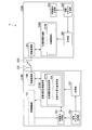
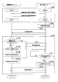
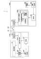
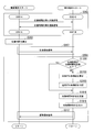
- FIG. 1 is a block diagram showing a schematic configuration of an image transmission system according to a first embodiment of the present invention. It is the flowchart which showed the processing procedure of the image transmission system in the 1st Embodiment of this invention. It is the flowchart which showed the process procedure of transmission / reception with the outward path
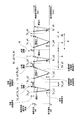
- FIG. 6 is a diagram showing an example of timing for transmitting and receiving an outward path signal for reciprocating time measurement and a backward path signal for reciprocating time measurement in the image transmission system according to the first embodiment of the present invention.
- FIG. 7 is a diagram showing an example of another timing of transmitting and receiving an outward path signal for round trip time measurement and a backward path signal for round trip time measurement in the image transmission system according to the first embodiment of the present invention.
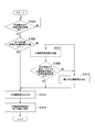
- the imaging terminal which comprises the image transmission system in the 1st Embodiment of this invention calculates the round trip time of wireless transmission. It is the flowchart which showed the process procedure of the update process of the determination value of the round trip time by the imaging terminal which comprises the image transmission system in the 1st Embodiment of this invention. It is the flowchart which showed an example of the process sequence which calculates
- FIG. 5 is a timing chart showing an example of transmission and reception of captured image data to be wirelessly transmitted in the image transmission system according to the first embodiment of the present invention.
- FIG. 6 is a diagram showing an example of a relationship between synchronization signals and time when wirelessly transmitting captured image data in the image transmission system according to the first embodiment of the present invention. It is the flowchart which showed the process procedure of the processing of the phase adjustment of the imaging synchronous signal by the imaging terminal which comprises the image transmission system in the 2nd Embodiment of this invention. It is the flowchart which showed the process procedure of the phase adjustment pre-processing of the imaging synchronous signal by the imaging terminal which comprises the image transmission system in the 2nd Embodiment of this invention.
- the imaging terminal wirelessly transmits (transmits) captured image data of an image captured by the imaging unit to the display terminal using a wireless communication technology
- the display terminal receives the image from the imaging terminal
- each of the imaging terminal and the display terminal when the imaging terminal and the display terminal are activated, each of the imaging terminal and the display terminal generates a reference clock signal and starts operation. More specifically, the imaging terminal generates a reference clock signal (hereinafter referred to as “imaging reference clock signal”) in the imaging terminal, and starts operation according to the timing of the generated imaging reference clock signal. In addition, the display terminal generates a reference clock signal (hereinafter, referred to as “display reference clock signal”) in the display terminal, and starts operation according to the timing of the generated display reference clock signal. Then, in the image transmission system, an operation of establishing a wireless connection is performed between the imaging terminal and the display terminal.
- imaging reference clock signal hereinafter referred to as “imaging reference clock signal”
- display reference clock signal a reference clock signal
- the imaging terminal transmits a connection request to the display terminal until the wireless connection with the display terminal is established.
- the connection request is transmitted from the imaging terminal until the wireless connection with the imaging terminal is established
- the display terminal transmits a response signal corresponding to the connection request to the imaging terminal.
- the wireless connection is established between the imaging terminal and the display terminal by the transmission of the connection request by the imaging terminal and the transmission of the response signal according to the connection request by the display terminal.
- each of the imaging terminal and the display terminal monitors the quality of wireless communication by monitoring the interference of another wireless communication device or the like with the channel of wireless communication currently being used. Then, each of the imaging terminal and the display terminal operates to always select or switch a channel of wireless communication so that wireless transmission can be performed using a channel with good communication quality.
- the monitoring of the quality of wireless communication between the imaging terminal and the display terminal and the method of wireless transmission using a channel with good communication quality can be easily considered based on the existing wireless communication technology. Therefore, the detailed description about the method of the wireless transmission in an imaging terminal and a display terminal is also omitted.
- the imaging terminal After the wireless connection is established between the imaging terminal and the display terminal, the imaging terminal generates a synchronization signal (hereinafter referred to as “vertical synchronization signal” or “horizontal synchronization signal” generated based on the imaging reference clock signal).
- Image pickup image data of an image picked up by the image pickup unit is transmitted to the display terminal in accordance with the timing of “image pickup synchronization signal”.
- the display terminal receives received image data from the imaging terminal according to the timing of a synchronization signal (hereinafter referred to as "display synchronization signal”) such as a vertical synchronization signal or a horizontal synchronization signal generated based on the display reference clock signal. Display the corresponding image on the display unit.
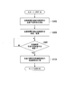
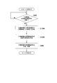
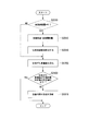
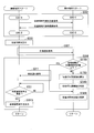
- FIG. 1 is a flow chart showing a schematic processing procedure of processing in an image transmission system according to an embodiment of the present invention.
- the outward travel signal for reciprocating time measurement and the backward travel signal for backward time measurement are transmitted and received between the imaging terminal and the display terminal (step S302). More specifically, in the process of step S302, an outward travel time signal for calculating a round trip time required for transmission / reception when any one of the imaging terminal and the display terminal performs wireless transmission Send to the other terminal. Then, the other terminal that has received the forward travel time measurement signal transmits the return travel time measurement forward signal according to the received forward travel time measurement forward pass signal to the other terminal that has sent the forward travel time measurement forward pass signal. Do.
- one of the terminals that receives the return path measurement signal for round trip time calculates the round trip time required for transmission and reception in wireless transmission between the imaging terminal and the display terminal (step S303). More specifically, in the process of step S303, either one of the imaging terminal and the display terminal is used to measure the transmission time of the forward pass signal for round trip time measurement and the round trip time sent from the other terminal. Based on the reception time of the return signal and the information included in the return time measurement return signal, the return time of the signal that reciprocates by wireless transmission is calculated.
- the round trip time is a required time (delay time) of wireless communication in radio transmission of a return time signal for round trip time transmission from one terminal to the other terminal, and a round trip time transmitted from the other terminal to the one terminal It is a time obtained by totaling the time required for wireless communication (delay time) in the wireless transmission of the forward measurement signal.
- one of the terminals receiving the return path measurement signal for the round trip time operates based on the round trip time required for transmission and reception in the wireless transmission between the imaging terminal and the display terminal.
- the phase of the timing signal being used is adjusted (step S304). More specifically, when one of the terminals is an imaging terminal, the imaging terminal performs timing of imaging by the imaging unit or transmission of imaged image data of a captured image to the display terminal based on the imaging reference clock signal.
- the phase of the imaging synchronization signal is adjusted by regenerating the imaging synchronization signal which is a signal.
- the display terminal is a display that is a timing signal for causing the display unit to display an image according to captured image data received from the imaging terminal based on the display reference clock signal.
- the phase of the display synchronization signal is adjusted by regenerating the synchronization signal. As a result, in the image transmission system, adjustment is performed so that the phases of the imaging synchronization signal and the display synchronization signal do not shift between the imaging terminal and the display terminal.
- the processing up to here is processing of phase adjustment of timing signals performed between the imaging terminal and the display terminal in the image transmission system.
- the process returns to step S302, and the process of adjusting the phase of step S302 to step S304 is repeated.
- the imaging synchronization signal and the display synchronization signal are adjusted so that the phases of the imaging synchronization signal and the display synchronization signal do not shift as time passes.
- the period adjustment of the timing signal may be performed based on the information used in the process of adjusting the phase. That is, in the image transmission system, the period of the imaging synchronization signal and that of the display synchronization signal may be adjusted so as not to shift with the lapse of time.
- the outline flowchart of the process of phase adjustment by the image transmission system shown in FIG. 1 shows the case where the period adjustment of the timing signal is performed in step S310, following the process of phase adjustment of the timing signal in step S304.
- the imaging terminal When the wireless connection with the display terminal is established, the imaging terminal generates the time of the imaging terminal itself based on the imaging reference clock signal. For example, the imaging terminal uses the time when wireless connection with the display terminal is established as the reference time (for example, time 0), and based on the imaging reference clock signal, represents the time elapsed thereafter (hereinafter referred to as “imaging terminal time Start the generation of Then, in step S302, the imaging terminal determines a time (imaging terminal time) to be sent to the display terminal for the forward pass signal for round trip time measurement, and generates a forward pass signal for round trip time measurement by the determined transmission scheduled time. .
- the reference time for example, time 0
- imaging reference clock signal represents the time elapsed thereafter
- the imaging terminal includes the information of the packet identification number in the outward trip signal for round trip time measurement and transmits it to the display terminal. After that, the imaging terminal stands by for the return time signal for round trip time measurement according to the transmitted round trip time measurement forward path signal to be transmitted from the display terminal.
- the display terminal when the wireless connection with the imaging terminal is established, the display terminal generates the time of the display terminal itself based on the display reference clock signal. For example, the display terminal sets a time when wireless connection with the imaging terminal is established as a reference time (for example, time 0), and based on the display reference clock signal, represents a time elapsed thereafter (hereinafter referred to as “display terminal time Start the generation of Then, the display terminal stands by for the forward travel time measuring signal to be transmitted from the imaging terminal. Thereafter, when the display terminal receives the outward trip signal for round trip time transmission transmitted from the imaging terminal, in step S302, the display terminal extracts the information of the packet identification number included in the received outward trip round trip signal.
- a reference time for example, time 0
- the display terminal stands by for the forward travel time measuring signal to be transmitted from the imaging terminal.
- the display terminal counts display terminal time that represents the time when the forward / return time measurement forward path signal is received. Then, the display terminal determines a time (display terminal time) to be sent to the imaging terminal for a return time measurement return signal according to the received return time measurement forward path signal, and the round trip time is determined by the determined transmission scheduled time. Generate a return signal for measurement. At this time, the display terminal calculates, as the receiver elapsed time, the difference between the reception time of the outward trip signal for round trip time measurement and the transmission scheduled time of the home return signal for round trip time determination.
- the display terminal receives the information on the calculated receiver elapsed time, the information on the scheduled transmission time of the return path signal for round trip time measurement, and the information on the packet identification number extracted from the forward path signal for round trip time measurement. And send to the imaging terminal.
- the imaging terminal when receiving the return time signal for round trip time measurement transmitted from the display terminal, the imaging terminal counts an imaging terminal time indicating the time when the return time signal for round trip time measurement is received. The imaging terminal also extracts information on the elapsed time of the receiver included in the received return time signal for return time measurement, information on the scheduled transmission time of the return time signal for return time measurement, and information on the packet identification number. Then, in step S303, the imaging terminal calculates the difference between the scheduled transmission time of the forward / return time measurement signal determined in step S302 and the reception time of the backward travel time measurement return signal. Then, the imaging terminal calculates the round trip time required for transmission and reception when performing wireless transmission with the display terminal by subtracting the extracted receiver elapsed time from the calculated difference time. That is, the imaging terminal calculates the delay time of the signal that reciprocates only in the wireless transmission between the imaging terminal and the display terminal.
- the imaging terminal performs the process of adjusting the phase of the timing signal in step S304.
- the process of adjusting the phase of the timing signal by the imaging terminal it is used when imaging is performed by the imaging unit according to the reciprocation time calculated based on the information of the reciprocation time measurement backward signal corresponding to the transmitted reciprocation time measurement forward signal.
- the imaging synchronization signal timing signal
- the phase is adjusted without changing the period of the imaging synchronization signal.
- the imaging terminal performs imaging synchronization when the round trip time calculated in step S303 is equal to or less than a determination value that is a threshold for determining a predetermined round trip time (hereinafter referred to as "round trip time determination value").
- a signal (timing signal) is regenerated to adjust the phase of the imaging synchronization signal.
- the imaging terminal keeps the current generation timing without regenerating the imaging synchronization signal (timing signal), that is, The process of adjusting the phase of the timing signal in step S304 ends without adjusting the phase of the imaging synchronization signal.
- the imaging terminal repeats the process of adjusting the phase of the timing signal in steps S302 to S304.
- the imaging terminal when performing the period adjustment of the timing signal, the imaging terminal continues the process of the phase adjustment of the timing signal in step S304.
- a process of adjusting the cycle of the timing signal in S310 is performed.
- the process of adjusting the cycle of the timing signal in step S310 may be performed each time the process of adjusting the phase of the timing signal is performed a predetermined number of times, that is, each time a predetermined time has elapsed.
- either one of the imaging terminal and the display terminal uses the outward signal for round trip time measurement as the other terminal.
- the process of adjusting the phase of the timing signal is started.
- the image transmission system based on the information on the forward travel time measuring forward signal transmitted by any one of the terminals and the information included in the round trip time measuring return inbound signal according to the transmitted forward travel time measuring forward pass signal.
- the phase adjustment of the timing signal is performed based on the calculated round trip time of only transmission and reception of wireless transmission between the imaging terminal and the display terminal.
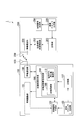
- FIG. 2 is a block diagram showing a schematic configuration of an image transmission system according to the first embodiment of the present invention.
- the image transmission system 1 includes an imaging terminal 100 and a display terminal 200.
- the imaging terminal 100 starts operation according to the timing of the imaging reference clock signal generated in the imaging terminal 100.
- the imaging terminal 100 transmits captured image data of an image captured by the imaging unit to the display terminal 200 in accordance with the timing of the imaging synchronization signal which is a timing signal generated based on the imaging reference clock signal.
- display terminal 200 starts operation according to the timing of the display reference clock signal generated in display terminal 200.
- the display terminal 200 causes the display unit to display an image according to the received captured image data from the imaging terminal 100 in accordance with the timing of the display synchronization signal which is a timing signal generated based on the display reference clock signal.
- the imaging terminal 100 transmits the forward pass signal for round trip time measurement to the display terminal 200, and the information is displayed according to the information regarding the forward pass signal for round trip time sent and the sent forward pass signal for round trip time measurement.
- the image transmission system is configured to adjust the phase of a timing signal (imaging synchronization signal) generated by the imaging terminal 100 based on the information included in the return path measurement signal sent from the terminal 200.
- the imaging terminal 100 includes a synchronization signal generation unit 102, a cycle adjustment unit 101, a source oscillation clock generation unit 103, a wireless communication unit 108, a round trip time measurement unit 106, a clocking unit 107, a phase adjustment unit 109, A phase adjustment execution determination unit 110, a phase shift accumulated value estimation unit 111, and an antenna 120 are provided.
- the display terminal 200 further includes a synchronization signal generation unit 204, a source oscillation clock generation unit 205, a wireless communication unit 201, a round trip time measurement assistance unit 202, a clock unit 203, and an antenna 220.
- imaging is performed that includes the phase adjustment execution determination unit 110 in the reciprocation time measurement unit 106, and includes the phase adjustment unit 109 and the phase shift accumulated value estimation unit 111 in the phase adjustment execution determination unit 110.
- the configuration of the terminal 100 is shown. Further, FIG. 2 shows a configuration in which the imaging terminal 100 includes the period adjustment unit 101.
- the imaging terminal 100 may be configured to perform at least phase adjustment of the timing signal (imaging synchronization signal). Therefore, in the image transmission system 1, the imaging terminal 100 may be configured not to include one or both of the period adjustment unit 101 and the phase shift accumulated value estimation unit 111 illustrated in FIG.
- the source oscillation clock generation unit 103 generates a source oscillation clock signal as a source of an imaging reference clock signal at which the imaging terminal 100 operates.
- the source oscillation clock generation unit 103 is, for example, a so-called clock generator configured to include a crystal oscillation IC or the like.
- the source oscillation clock generation unit 103 generates a source oscillation clock signal when the imaging terminal 100 is activated.
- the imaging reference clock signal is generated based on the source oscillation clock signal generated by the source oscillation clock generation unit 103. In the following description, in order to facilitate the description, it is assumed that the source oscillation clock generation unit 103 generates an imaging reference clock signal.
- the clock unit 107 clocks the time (imaging terminal time) in the imaging terminal 100 based on the imaging reference clock signal generated by the source oscillation clock generation unit 103.
- the clock unit 107 outputs information on the clocked imaging terminal time to the round trip time measurement unit 106 (including the phase adjustment execution determination unit 110, the phase adjustment unit 109, and the phase shift accumulated value estimation unit 111).
- the clock unit 107 may also output information on the clocked imaging terminal time to the wireless communication unit 108.
- the synchronization signal generation unit 102 starts the effective period of captured image data captured and output by an imaging unit (not shown) provided in the imaging terminal 100 based on the imaging reference clock signal generated by the source oscillation clock generation unit 103.
- a synchronization signal (imaging synchronization signal) such as a vertical synchronization signal or a horizontal synchronization signal indicating the end is generated.
- the synchronization signal generation unit 102 generates the imaging synchronization signal generated by the imaging unit (not shown) and the round trip time measurement unit 106 (including the phase adjustment execution determination unit 110, the phase adjustment unit 109, and the phase shift accumulated value estimation unit 111). Output to each of.
- the synchronization signal generation unit 102 When the synchronization signal generation unit 102 receives an instruction to adjust the phase of the imaging synchronization signal from the phase adjustment unit 109 included in the phase adjustment execution determination unit 110 in the reciprocation time measurement unit 106, the adjustment instruction on the input phase is input. According to the above, the imaging synchronization signal is regenerated (that is, the phase of the imaging synchronization signal to be generated is adjusted). In addition, when an instruction to adjust the cycle of the imaging synchronization signal is input from the cycle adjustment unit 101, the synchronization signal generation unit 102 regenerates (that is, generates an image to generate) the imaging synchronization signal according to the adjustment instruction of the input cycle. Adjust the period of the sync signal). Then, the synchronization signal generation unit 102 outputs the regenerated imaging synchronization signal to each of the imaging unit (not shown) and the round trip time measurement unit 106.
- the round trip time measurement unit 106 measures (calculates) the round trip time required for transmission and reception when wirelessly transmitting between the imaging terminal 100 and the display terminal 200 based on the information of the imaging terminal time output from the clock unit 107. .
- the round trip time measuring unit 106 is an imaging terminal time to which an outward travel time signal for calculating the round trip time in wireless transmission is to be transmitted to the display terminal 200 first. Determine the scheduled transmission time. Then, the round trip time measurement unit 106 generates a round trip time measurement forward path signal by the determined scheduled transmission time, and outputs the generated round trip time measurement forward path signal to the wireless communication unit 108 for transmission to the display terminal 200.
- the round trip time measurement unit 106 temporarily stores information of the determined scheduled transmission time.
- the information on the scheduled transmission time that the round trip time measurement unit 106 temporarily stores may be the scheduled transmission time that the round trip time measurement unit 106 has determined.
- the information on the scheduled transmission time temporarily stored in the reciprocation time measurement unit 106 may be information on the actual transmission time at which the wireless communication unit 108 transmitted the outward travel signal for reciprocation time measurement to the display terminal 200.
- the scheduled transmission time determined by the round trip time measurement unit 106 is the same as the actual transmission time at which the wireless communication unit 108 transmitted the forward trip signal for round trip time measurement to the display terminal 200. This will be described as "scheduled transmission time".
- the return time signal for return time measurement transmitted from display terminal 200 is output from wireless communication section 108, return time measurement section 106 scheduled transmission time of the return time signal for return time measurement once stored.
- the reciprocation time of the signal that reciprocates by wireless transmission with the display terminal 200 is calculated based on the above information and the information of the return time measurement return signal output from the wireless communication unit 108.
- the information on the return time signal for return time measurement includes information on the elapsed time of the receiver included in the return time signal for return time measurement, information on the scheduled transmission time of the return time signal for return time signal, and information on the packet identification number.
- the round trip time measurement unit 106 temporarily stores information on the round trip time measurement return path signal, including information on the reception time at which the round trip time measurement return path signal was received.
- the information on the reception time temporarily stored in the round trip time measurement unit 106 may be an input time at which the return time signal for round trip time measurement is input from the wireless communication unit 108 to the round trip time measurement unit 106.
- the information on the reception time that the round trip time measurement unit 106 temporarily stores is the information on the reception time at which the radio communication unit 108 actually received the return time signal for round trip time measurement transmitted from the display terminal 200. Good.
- the input time when the return time signal for reciprocation time measurement is input from the wireless communication unit 108 and the reception time when the wireless communication unit 108 actually receives the return time signal for reciprocation time are the same time And will be described as "reception time".
- the round trip time measurement unit 106 outputs the calculated round trip time information to the phase adjustment execution determination unit 110.
- the phase adjustment execution determination unit 110 determines whether to perform the phase adjustment of the imaging synchronization signal based on the information on the round trip time output from the round trip time measurement unit 106. More specifically, the phase adjustment execution determination unit 110 compares the reciprocation time output from the reciprocation time measurement unit 106 with the reciprocation time determination value which is determined and stored in advance. That is, the phase adjustment execution determination unit 110 compares the delay time of the signal delayed only by wireless transmission and reception between the imaging terminal 100 and the display terminal 200 with the delay time represented by the predetermined round trip time determination value. Then, when the round trip time output from the round trip time measurement unit 106 is equal to or less than a predetermined round trip time determination value, the phase adjustment execution determination unit 110 determines to perform the phase adjustment of the imaging synchronization signal. On the other hand, when the round trip time output from the round trip time measurement unit 106 is larger than the predetermined round trip time determination value, the phase adjustment execution determination unit 110 determines that the phase adjustment of the imaging synchronization signal is not performed.
- the phase adjustment execution determination unit 110 sends information representing the result of determining the execution of the phase adjustment of the imaging synchronization signal (hereinafter referred to as “phase adjustment execution determination result”) to the phase adjustment unit 109 and the phase shift accumulated value estimation unit 111. Output. At this time, the phase adjustment execution determination unit 110 performs phase adjustment on the information on the round trip time output from the round trip time measurement unit 106 together with the phase adjustment execution determination result on which it is determined whether to perform the phase adjustment of the imaging synchronization signal. Output to the unit 109.
- phase adjustment unit 109 When the phase adjustment execution determination result output from the phase adjustment execution determination unit 110 indicates that the phase adjustment of the imaging synchronization signal is to be performed, the phase adjustment unit 109 performs the phase adjustment execution determination together with the phase adjustment execution determination result.
- An instruction for adjusting the phase of the imaging synchronization signal is output to the synchronization signal generation unit 102 based on the information of the round trip time output from 110.
- the phase adjustment unit 109 causes the synchronization signal generation unit 102 to adjust the phase of the imaging synchronization signal by outputting an instruction to regenerate the generation of the imaging synchronization signal.
- phase adjustment unit 109 causes the synchronization signal generation unit 102 to temporarily stop the generation of the imaging synchronization signal, and resume generation of the imaging synchronization signal after waiting for the time represented by the information on the round trip time.
- the phase of the imaging synchronization signal is adjusted by instructing.
- a series of instructions for adjusting the phase of the imaging synchronization signal output from the phase adjustment unit 109 to the synchronization signal generation unit 102 will be referred to as “phase adjustment instruction”.
- the phase adjustment unit 109 sends the synchronization signal generation unit 102 Do not output phase adjustment instruction. That is, when the phase adjustment unit 109 does not perform the phase adjustment of the imaging synchronization signal, the phase adjustment unit 109 does not instruct the synchronization signal generation unit 102 to adjust the phase of the imaging synchronization signal, and the synchronization signal generation unit 102 generates the imaging synchronization signal. To continue.
- the phase shift accumulated value estimation unit 111 synchronizes the display synchronization with the imaging synchronization signal based on a period in which the phase adjustment execution determination result output from the phase adjustment execution determination unit 110 indicates that the phase adjustment of the imaging synchronization signal is not performed. Estimate the amount of phase shift with the signal. Then, based on the result of estimation of the phase shift amount between the imaging synchronization signal and the display synchronization signal, the phase shift accumulated value estimation unit 111 outputs the phase adjustment execution determination result output from the phase adjustment execution determination unit 110 as imaging synchronization. Even in the case where it is indicated that the phase adjustment of the signal is not performed, the phase adjustment unit 109 causes the phase adjustment of the imaging synchronization signal to be performed.
- phase shift accumulated value estimation unit 111 outputs the phase adjustment execution determination result indicating that the phase adjustment of the imaging synchronization signal is performed from the phase adjustment execution determination unit 110, and then the phase of the imaging synchronization signal The time when the phase adjustment execution determination result indicating that the adjustment is not performed is continuously output from the phase adjustment execution determination unit 110 is timed.
- phase unadjusted Time (accumulated) an elapsed time during which the phase adjustment of the imaging synchronization signal is not performed.
- the phase shift accumulated value estimation unit 111 determines the phase shift amount between the imaging synchronization signal and the display synchronization signal based on the phase unadjusted time in the state where the phase adjustment of the measured imaging synchronization signal is not performed (hereinafter referred to as “ The phase shift accumulation value is calculated. Then, the phase shift accumulated value estimation unit 111 estimates the phase shift amount between the imaging synchronization signal and the display synchronization signal by comparing the calculated phase shift accumulated value with a predetermined round trip time determination value.
- the phase shift accumulated value estimation unit 111 determines that the phase shift amount between the imaging synchronization signal and the display synchronization signal is large when the phase shift accumulated value exceeds a predetermined ratio of the predetermined round trip time determination value.
- the phase shift accumulated value estimation unit 111 reduces the reciprocation time determination value, which is determined in advance to determine whether the phase adjustment execution determination unit 110 performs the phase adjustment of the imaging synchronization signal, in a short time. Update.
- the imaging synchronization signal generated by the synchronization signal generation unit 102 is increased by the phase adjustment unit 109 when the phase adjustment execution determination unit 110 next determines whether to perform the phase adjustment of the imaging synchronization signal.
- the phase adjustment of will be instructed.
- the phase shift accumulated value estimation unit 111 estimates that the amount of phase shift between the imaging synchronization signal and the display synchronization signal is large
- the phase adjustment unit 109 instructs the phase adjustment of the imaging synchronization signal to be performed. It may be.
- the phase shift accumulated value estimating unit 111 determines that the phase shift amount between the imaging synchronization signal and the display synchronization signal is small. presume. In this case, the phase shift accumulated value estimation unit 111 continues to accumulate the round trip time.
- the imaging terminal 100 may not include the phase shift accumulated value estimation unit 111.
- the wireless communication unit 108 is a communication unit that transmits and receives signals and data by wireless transmission established with the display terminal 200 by wireless connection.
- the wireless communication unit 108 transmits captured image data captured and output by an imaging unit (not shown) included in the imaging terminal 100 to the display terminal 200 via the antenna 120 for wireless communication.
- the wireless communication unit 108 transmits the outward trip signal for round trip time measurement output from the round trip time measurement unit 106 to the display terminal 200 via the antenna 120.
- the wireless communication unit 108 receives, via the antenna 120, the return time signal for round trip time transmitted from the display terminal 200 in accordance with the transmitted round trip time measurement forward path signal.
- the wireless communication unit 108 outputs the received return time signal for round trip time measurement to the round trip time measurement unit 106.
- the antenna 120 is an antenna for wireless communication for the imaging terminal 100 to wirelessly communicate with the display terminal 200.
- the antenna 120 transmits, to the display terminal 200, a wireless signal corresponding to the captured image data output from the wireless communication unit 108 and the forward path measuring time signal.
- the antenna 120 receives a wireless signal according to the return path measurement signal for round trip time transmitted from the display terminal 200. Then, the antenna 120 outputs the received return time signal for return time measurement to the wireless communication unit 108.
- the cycle adjustment unit 101 determines whether or not to adjust the cycle of the imaging synchronization signal generated by the synchronization signal generation unit 102 each time a predetermined time elapses. Then, when it is determined that the period adjustment unit 101 is to adjust the period of the imaging synchronization signal, an instruction for adjusting the period of the imaging synchronization signal (hereinafter referred to as “period adjustment instruction”) is sent to the synchronization signal generation unit 102. Output.
- the imaging terminal 100 may not include the cycle adjustment unit 101.
- the imaging terminal 100 captures an image by the imaging unit (not shown), or an imaging synchronization signal (timing used when transmitting captured image data of an image captured by the imaging unit (not shown) to the display terminal 200 Adjust the phase and period (at least phase) of the signal). That is, the imaging terminal 100 generates imaging synchronization generated by itself so that the phase and period (at least phase) of the imaging synchronization signal and the display synchronization signal do not shift between the display terminal 200 and the image transmission system 1 together. The phase and period (at least phase) of the signal are adjusted to match the phase and period (at least phase) of the display synchronization signal generated by the display terminal 200.
- each component for adjusting the phase and period (at least phase) of the imaging synchronization signal provided in the imaging terminal 100 may be realized by processorizing a part or all of the functions.
- all the above-described functions in the imaging terminal 100 may be realized by one processor.
- it may be configured to be realized by an individual processor corresponding to each function described above in the imaging terminal 100, that is, a plurality of processors.
- the processor described above can be realized, for example, by a general-purpose CPU (Central Processing Unit) and a program recorded in the memory.
- a part or all of the above-described respective functions in the imaging terminal 100 may be realized by an integrated circuit such as a dedicated large scale integration (LSI), a so-called application specific integrated circuit (ASIC).
- LSI dedicated large scale integration
- ASIC application specific integrated circuit
- the source oscillation clock generation unit 205 generates a source oscillation clock signal which is a source of a display reference clock signal at which the display terminal 200 operates.
- the source oscillation clock generation unit 205 is, for example, a so-called clock generator configured to include a crystal oscillation IC or the like.
- the source oscillation clock generation unit 205 generates a source oscillation clock signal when the display terminal 200 is activated.
- the display reference clock signal is generated based on the source oscillation clock signal generated by the source oscillation clock generator 205. In the following description, in order to facilitate the description, it is assumed that the source oscillation clock generation unit 205 generates a display reference clock signal.
- the clock unit 203 clocks the time (display terminal time) on the display terminal 200 based on the display reference clock signal generated by the source oscillation clock generation unit 205.
- the timer unit 203 outputs information on the counted display terminal time to the round trip time measurement assisting unit 202.
- the clock unit 203 may also output information on the counted display terminal time to the wireless communication unit 201.
- the synchronization signal generation unit 204 causes captured image data transmitted from the imaging terminal 100 to be displayed on a display unit (not shown) provided in the display terminal 200 based on the display reference clock signal generated by the source oscillation clock generation unit 205. And a synchronization signal (display synchronization signal) such as a vertical synchronization signal or a horizontal synchronization signal indicating the start or end of the effective period of the image according to.
- the synchronization signal generation unit 204 generates an image according to the captured image data transmitted from the imaging terminal 100, and generates a display device such as a liquid crystal display (LCD).
- a display image processing unit (not shown) that performs processing to be displayed on a display unit (not shown) configured to be included is output to a display unit (not shown) or the like.
- the round trip time measurement auxiliary unit 202 generates a round trip time measurement return path signal according to the round trip time measurement forward path signal transmitted from the imaging terminal 100 based on the display terminal time information output from the clock unit 203. . Then, the round trip time measurement auxiliary unit 202 outputs the generated return time signal for round trip time measurement to the wireless communication unit 201 and causes the imaging terminal 100 to transmit it. Thereby, the round trip time measurement assisting unit 202 assists the measurement (calculation) of the round trip time required for transmission and reception when performing wireless transmission between the imaging terminal 100 and the display terminal 200, which is performed in the imaging terminal 100.
- the roundtrip time measurement auxiliary unit 202 When generating the roundtrip time measurement return path signal, the roundtrip time measurement auxiliary unit 202 first transmits a return time signal for roundtrip time measurement to the display terminal 200 according to the received roundtrip time measurement forward path signal. The scheduled transmission time, which is the time, is determined. In addition, the round trip time measurement auxiliary unit 202 calculates a difference between the determined transmission scheduled time of the return time signal for round trip time measurement and the reception time of the forward time signal for round trip time measurement as a receiver elapsed time.
- the round trip time measurement assisting unit 202 temporarily stores information on the reception time of the round trip time measurement forward path signal used when calculating the receiver elapsed time.
- the information on the reception time temporarily stored in the reciprocation time measurement auxiliary unit 202 may be an input time when the reciprocation time measurement forward path signal is input from the wireless communication unit 201 to the reciprocation time measurement auxiliary unit 202.
- the wireless communication unit 201 actually received the outward travel time measuring signal from the imaging terminal 100, which is output from the wireless communication unit 201, of the reception time information temporarily stored in the round trip time measurement auxiliary unit 202. It may be information on reception time.
- the input time when the forward / return time measurement forward path signal is input from the wireless communication unit 201 and the reception time when the wireless communication unit 201 actually receives the forward / backward time measurement signal are the same time In order to distinguish it from the reception time used in the round trip time measurement unit 106, it will be described as "input time”.
- the round trip time measurement auxiliary unit 202 extracts information of the receiver elapsed time calculated until the determined transmission scheduled time, the transmission scheduled time of the return path signal for round trip time determination, and the forward path signal for round trip time measurement.
- a return time signal for round-trip time measurement including the information of the packet identification number is generated, and the generated return time signal for round-trip time measurement is output to the wireless communication unit 201 and transmitted to the imaging terminal 100.
- the wireless communication unit 201 is a communication unit that transmits and receives signals and data by wireless transmission established by wireless connection with the imaging terminal 100.
- the wireless communication unit 201 receives the captured image data and the round trip time measuring outward signal transmitted from the imaging terminal 100 via the antenna 220 for wireless communication.
- the wireless communication unit 201 outputs the received captured image data to a display image processing unit (not shown). Further, the wireless communication unit 201 outputs the received reciprocation time measurement forward path signal to the reciprocation time measurement assisting unit 202.
- the wireless communication unit 201 receives, via the antenna 220, the return time signal for reciprocation time measurement output from the reciprocation time measurement auxiliary unit 202 according to the reciprocation time measurement forward path signal transmitted from the imaging terminal 100 via the antenna 220. Send to 100
- the antenna 220 is an antenna for wireless communication for the display terminal 200 to wirelessly communicate with the imaging terminal 100.
- the antenna 220 receives a radio signal according to captured image data transmitted from the imaging terminal 100 and a forward travel time measuring signal. Then, the antenna 220 outputs the received captured image data and the forward path signal for round trip time measurement to the wireless communication unit 201. In addition, the antenna 220 transmits, to the imaging terminal 100, a wireless signal corresponding to the return time signal for round trip time output from the wireless communication unit 201.
- the display terminal 200 captures an image by an imaging unit (not shown) provided in the imaging terminal 100 or transmits captured image data of an image captured by the imaging unit (not shown) to the display terminal 200. It helps to adjust the phase and period (at least phase) of the imaging synchronization signal (timing signal) to be used. That is, the display terminal 200 generates so that the imaging terminal 100 and the display terminal 200 do not shift the phase or the period (at least the phase) of the display synchronization signal with the display terminal 200. The processing of adjusting the phase and period (at least phase) of the imaging synchronization signal to match the phase and period (at least phase) of the display synchronization signal generated by itself is assisted.
- each component for example, the function of the reciprocation time measurement assisting unit 202, and the function of each component for assisting the adjustment of the phase and period (at least phase) of the imaging synchronization signal by the imaging terminal 100
- It may be processor-implemented.
- all the above-described functions of the display terminal 200 may be realized by one processor. Further, the configuration may be realized by individual processors corresponding to the above-described respective functions in the display terminal 200, that is, a plurality of processors.
- the processor described above can be realized, for example, by a general-purpose CPU and a program stored in a memory.
- a part or all of the above-described respective functions in the display terminal 200 may be realized by an integrated circuit such as a dedicated LSI (so-called ASIC).
- the imaging terminal 100 captures an image based on the forward travel time measuring signal transmitted to the display terminal 200 and the backward travel time measuring signal transmitted from the display terminal 200.
- the phase and period (at least phase) of the imaging synchronization signal generated based on the imaging reference clock signal generated by the source oscillation clock generation unit 103 included in the terminal 100 are adjusted. That is, in the image transmission system 1, when the display terminal 200 transmits the captured image data of the image captured by the imaging unit (not illustrated) to the display terminal 200 by radio, the captured image data is displayed on the display unit (not illustrated) Match the timing to display the image according to. Thereby, in the image transmission system 1, the display terminal 200 can stably display an image according to the captured image data wirelessly transmitted from the imaging terminal 100 on a display unit (not shown).
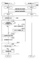
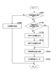
- FIG. 3 is a flow chart showing the processing procedure of the image transmission system 1 in the first embodiment of the present invention.
- step S302 the imaging terminal 100 transmits an outward trip signal for round trip time measurement to the display terminal 200, and the display terminal 200 responds to the outward trip signal for round trip time
- the round trip time measurement return path signal is transmitted to the imaging terminal 100.
- the round trip time measurement unit 106 uses the wireless communication unit 108 and the antenna 120 for the outward trip signal for round trip time measurement in the processing of step S302-A to step S302-B in step S302.
- the signal is transmitted to the display terminal 200 via the communication terminal 200, and the return time signal for return time measurement transmitted from the display terminal 200 is received.
- the round trip time transmitted from the imaging terminal 100 in the process of step S302-C to step S302-D in step S302 is the round trip time measurement assisting unit 202.
- a forward pass signal for measurement is received via the antenna 220 and the wireless communication unit 201, and a return pass signal for round trip time measurement corresponding to the received forward pass time measurement signal is transmitted to the imaging terminal 100.
- the imaging terminal 100 calculates the round trip time required for transmission and reception in wireless transmission between the imaging terminal 100 and the display terminal 200 in step S303. More specifically, the imaging terminal 100 is based on the information on the outbound signal for reciprocating time measurement transmitted by the reciprocating time measurement unit 106 and the information included in the inbound signal for reciprocating time measurement transmitted from the display terminal 200. The round trip time required for transmission and reception in the wireless transmission between the terminal and the display terminal 200 is calculated.
- step S304 based on the round trip time required for transmission and reception in the wireless transmission between the imaging terminal 100 and the display terminal 200 calculated in step S303, the phase of the imaging synchronization signal. Adjust the More specifically, in step S304, the phase adjustment execution determination unit 110 determines whether the reciprocation time calculated by the reciprocation time measurement unit 106 is equal to or less than a predetermined reciprocation time determination value (step S1709). .
- the phase adjustment execution determination unit 110 determines that the phase adjustment is to be performed when the calculated round trip time is equal to or less than the predetermined round trip time determination value as a result of the determination in step S1709 (“YES” in step S1709). Then, the phase adjustment implementation determination unit 110 outputs, to the phase adjustment unit 109, the phase adjustment implementation determination result representing the determination result and the information on the round trip time. Thereby, the phase adjustment unit 109 generates, as a synchronization signal, a phase adjustment instruction for adjusting the phase of the imaging synchronization signal based on the phase adjustment execution determination result output from the phase adjustment execution determination unit 110 and the information on the round trip time. It is output to the part 102 (step S1915). Thereby, the synchronization signal generation unit 102 adjusts the phase of the imaging synchronization signal to be generated in accordance with the phase adjustment instruction output from the phase adjustment unit 109.
- step S1709 determines that the phase adjustment execution determination unit 110 determines that the calculated round trip time is not less than the predetermined round trip time determination value as a result of the determination in step S1709, that is, the calculated round trip time is greater than the predetermined round trip time determination value. It is determined that the phase adjustment is not performed at (“NO” in step S1709), and the process of step S304 ends.
- the phase adjustment execution determination unit 110 does not perform the process in step S1915.
- the process of step S304 may be ended. That is, when the phase adjustment execution determination unit 110 determines that the phase adjustment is not performed, the phase adjustment unit 109 may not output the phase adjustment instruction.
- the imaging terminal 100 adjusts the phases of the imaging synchronization signal and the display synchronization signal so that they do not shift with the passage of time.
- the configuration of the image transmission system 1 shown in FIG. 2 shows a configuration in which the imaging terminal 100 is provided with the phase shift accumulated value estimation unit 111 and the period adjustment unit 101. Therefore, in the flowchart of the processing procedure of the image transmission system 1 shown in FIG. 3, when it is determined in step S304 that the reciprocation time calculated in step S303 is not equal to or less than a predetermined reciprocation time determination value (“NO” in step S1709 The case where the phase shift accumulated value estimation unit 111 performs processing for updating the round trip time determination value used by the phase adjustment execution determination unit 110 in step S1709 is shown in “)”.
- the phase shift accumulated value estimation unit 111 outputs the phase adjustment execution determination result indicating that the phase adjustment execution determination unit 110 does not perform the phase adjustment of the imaging synchronization signal in step S1709.
- the unadjusted time is accumulated to calculate the phase shift accumulated value (step S1703).
- the phase shift cumulative value estimation unit 111 determines the calculated phase shift cumulative value based on a predetermined round trip time determination value (step S2103).
- the phase shift accumulated value estimation unit 111 updates the round trip time determination value to a short time (small value) when the phase shift accumulated value exceeds a predetermined ratio of the predetermined round trip time determination value (step S 1916). .
- step S1709 the phase adjustment execution determination unit 110 determines that the round trip time calculated by the round trip time measurement unit 106 is less than or equal to the predetermined round trip time determination value.
- the process may also be performed in the case (“YES” in step S1709). That is, the phase adjustment execution determination unit 110 determines the round trip time of a small value determined to be equal to or less than the predetermined round trip time determination value, and then determines the round trip time calculated by the round trip time measurement unit 106 next time. It may be a value.
- step S310 the imaging terminal 100 reciprocates for transmission and reception in wireless transmission between the imaging terminal 100 and the display terminal 200 calculated in step S303.
- the case where the period of an imaging synchronous signal is adjusted based on time is shown. More specifically, the cycle adjustment unit 101 determines whether a predetermined time set in advance has elapsed since the cycle of the imaging synchronization signal was adjusted last time (step S305).
- the cycle adjustment unit 101 determines that the cycle adjustment is to be performed when a predetermined time set in advance has elapsed since the cycle of the imaging synchronization signal was adjusted last time (“YES” in step S305), and the cycle of the imaging synchronization signal
- the adjustment processing is instructed to the synchronization signal generation unit 102.
- the synchronization signal generation unit 102 performs a period adjustment process of the imaging synchronization signal to be generated (step S2117).
- the imaging terminal 100 only needs to be configured to perform at least phase adjustment of the timing signal (imaging synchronization signal), and the imaging terminal 100 includes the phase shift accumulated value estimation unit 111 and The configuration may not include one or both of the cycle adjustment unit 101.
- the image transmission system 1 does not execute the processing corresponding to the components not provided in the imaging terminal 100.
- FIG. 4 is a flow chart showing a processing procedure of transmission and reception between the outward trip signal for round trip time measurement and the backward trip signal for round trip time measurement by the imaging terminal 100 constituting the image transmission system 1 according to the first embodiment of the present invention. Further, FIG.
- FIG. 5 is a flowchart showing a process procedure of transmission and reception of a forward pass signal for reciprocating time measurement and a backward pass signal for reciprocating time measurement by the display terminal 200 constituting the image transmission system 1 according to the first embodiment of the present invention. is there.
- the round trip time measurement unit 106 determines a scheduled transmission time for transmitting the forward path measuring signal for the round trip time to the display terminal 200 (step S105). Then, the round trip time measurement unit 106 generates a round trip time measurement forward path signal by the determined scheduled transmission time, and outputs the generated round trip time measurement forward path signal to the wireless communication unit 108 to be transmitted to the display terminal 200 ( Step S508).
- the round trip time measurement unit 106 confirms whether the wireless communication unit 108 receives the return time signal for round trip time transmission transmitted from the display terminal 200 according to the transmitted round trip time measurement forward path signal (step S501). ). It should be noted that the check as to whether or not the wireless communication unit 108 has received the return time signal for reciprocating time measurement transmitted from the display terminal 200 performed by the reciprocating time measuring unit 106 in step S501 is This can be performed depending on whether or not the return signal for home use is output from the wireless communication unit 108.
- step S501 As a result of the confirmation in step S501, when the wireless communication unit 108 has not received the return time signal for round trip time transmitted from the display terminal 200 (“NO” in step S501), the round trip time measurement unit 106 performs the step S501 is repeated to wait for the return time signal for return time measurement to be transmitted from the display terminal 200.
- step S501 when the wireless communication unit 108 receives the return time signal for return time measurement transmitted from the display terminal 200 (“YES” in step S501), the return time time measurement unit 106 performs wireless communication The reception time of the return time measuring signal is measured based on the return time measuring signal output from the communication unit 108 (step S104).
- the roundtrip time measurement assisting unit 202 confirms whether the wireless communication unit 201 has received the roundtrip time measurement forward path signal transmitted from the imaging terminal 100 (step S602). ).
- the confirmation as to whether or not the wireless communication unit 201 has received the forward travel time measuring forward path signal transmitted from the imaging terminal 100 performed by the round trip time measurement assisting unit 202 in step S602 is the round trip time transmitted from the imaging terminal 100 This can be performed depending on whether the forward measurement signal for measurement is output from the wireless communication unit 201 or not.
- step S602 if the wireless communication unit 201 has not received the forward travel time measuring forward signal transmitted from the imaging terminal 100 (“NO” in step S602), the round trip time measurement assisting unit 202 Step S602 is repeated to wait for the forward travel time measuring signal to be transmitted from the imaging terminal 100.
- the round trip time assistance unit 202 Based on the outward travel signal for reciprocation time output from the wireless communication unit 201, the input time that is the reception time of the outward travel signal for reciprocation time measurement is measured (step S1104).
- the round-trip time measurement auxiliary unit 202 determines a transmission scheduled time to be sent to the imaging terminal 100 for the round-trip time measurement return path according to the round-trip time measurement forward path signal transmitted from the imaging terminal 100 (step S1106). Then, the round trip time measurement auxiliary unit 202 generates a return time signal for round trip time measurement by the determined scheduled transmission time, and outputs the generated round trip time measurement return path signal to the wireless communication unit 201 to transmit it to the imaging terminal 100. (Step S605).
- the round trip time measurement unit 106 transmits the forward path signal for round trip time measurement to the display terminal 200, and the display terminal according to the transmitted round trip time measurement forward path signal.
- the reception time of the return path signal for round trip time transmitted from 200 is clocked.
- the round-trip time measurement auxiliary unit 202 counts the input time of the round-trip time measurement forward path signal transmitted from the imaging terminal 100 and responds to the round-trip time measurement forward path signal.
- the round trip time measurement return path signal is transmitted to the imaging terminal 100. That is, in the image transmission system 1, the display terminal 200 returns the return time signal for return time measurement in accordance with the return time signal for return time measurement transmitted from the imaging terminal 100.
- captured image data is wirelessly transmitted from the imaging terminal 100 to the display terminal 200.
- transmission and reception of the forward travel time measuring forward pass signal and the backward travel time measuring backward pass signal between the round trip time measuring unit 106 and the round trip time measurement assisting unit 202 are performed in a period in which the captured image data is not wirelessly transmitted.
- the reciprocation time measurement is performed at timing when the reciprocation time measurement unit 106 and the reciprocation time measurement auxiliary unit 202 do not interfere with wireless transmission of captured image data from the imaging terminal 100 to the display terminal 200.
- Transmission and reception of a forward pass signal and a return pass signal for round trip time measurement are performed.
- an example of timing for transmitting and receiving a forward travel time measuring signal and a backward travel time measuring return signal between the round trip time measuring unit 106 and the round trip time measurement assisting unit 202 will be described.
- FIG. 6 is a diagram showing an example of timing for transmitting and receiving an outward path signal for reciprocating time measurement and a backward path signal for reciprocating time measurement in the image transmission system 1 according to the first embodiment of the present invention.
- FIG. 6 shows the relationship between the reciprocation time measurement unit 106 and the reciprocation time measurement assistance unit 202 at predetermined timings in each frame of an image for wirelessly transmitting captured image data from the imaging terminal 100 to the display terminal 200. It is an example in the case of transmitting / receiving the return pass signal for round trip time measurement, and the return pass signal for round trip time measurement.
- the reciprocation time measurement unit 106 and the reciprocation time measurement assisting unit 202 are for measuring the reciprocation time during a period in which a packet of captured image data (hereinafter referred to as "effective packet") of the effective period in an image of one frame Send and receive forward and backward signals and return time measuring signals.
- effective packet a packet of captured image data
- the valid packet is wirelessly transmitted triggered by the timing of the imaging synchronization signal indicating the start of the valid period of the image.
- a case is shown in which the round trip time measuring forward path signal and the round trip time measuring return path signal are transmitted and received during the time period until the signal is sent.
- a period until the period of the effective packet starts here, “blanking period” is used.
- the reciprocation time measurement unit 106 transmits the reciprocation time measurement forward path signal to the reciprocation time measurement auxiliary unit 202, and the reciprocation time measurement auxiliary unit 202 reciprocates the reciprocation time measurement return path signal according to the reciprocation time measurement forward path signal. It is transmitted (returned) to the time measurement unit 106.
- the timing at which the round trip time measurement unit 106 and the round trip time measurement auxiliary unit 202 transmit and receive the round trip time measurement forward pass signal and the round trip time measurement return path signal is blanking.
- the timing may be radio transmission of a header packet including information such as the size of the image represented by the captured image data, which is considered to be transmitted during the period.
- the next frame is triggered by the timing of the imaging synchronization signal indicating the end of the effective period of the image.
- the timing of the imaging synchronization signal indicating the end of the effective period of the image.
- the case of transmitting and receiving the forward pass signal for round trip time measurement and the backward pass signal for round trip time measurement is shown.
- the period of the effective packet in the wireless transmission of the next frame after the period of the effective packet ends.
- the reciprocation time measurement unit 106 transmits a reciprocation time measurement forward path signal to the reciprocation time measurement assistance unit 202, and the reciprocation time measurement assistance unit 202 reciprocates A return path signal for time measurement is transmitted (returned) to the round trip time measurement unit 106.
- the timing at which the reciprocation time measurement unit 106 and the reciprocation time measurement auxiliary unit 202 transmit and receive the reciprocation time measurement forward path signal and the reciprocation time measurement backward path signal is blanking. It may be timing to wirelessly transmit a header packet regarding captured image data, which is transmitted during a period.
- one predetermined time is indicated from the timing of the imaging synchronization signal indicating the start of the effective period of the image.
- the figure shows a case in which the outward trip signal for round trip time measurement and the backward trip signal for round trip time measurement are transmitted and received during a period in which the effective packet is wirelessly transmitted, triggered by the timing of the imaging synchronization signal. More specifically, in the example shown in (c) of FIG. 6, in wireless transmission of captured image data of each frame, it is indicated that a predetermined delay period D has elapsed since the period of the effective packet has started.
- the reciprocation time measurement unit 106 transmits the reciprocation time measurement forward path signal to the reciprocation time measurement auxiliary unit 202, and the reciprocation time measurement auxiliary unit 202 reciprocates the reciprocation time measurement return signal Have been sent (returned) to
- the round trip time measurement unit 106 and the round trip time measurement auxiliary unit 202 do not interfere with wireless transmission of valid captured image data in an image of one frame. There is no difference in transmitting and receiving the forward pass signal for measurement and the backward pass signal for round trip time measurement. Therefore, in the example shown in (c) of FIG. 6 as well, either the round trip time measurement unit 106 or the round trip time measurement assisting unit 202 divides the captured image data into a plurality of pieces and wirelessly transmits them during the effective packet period. During a period between two valid packets, a forward / return signal for round-trip time measurement and a return path signal for round-trip time measurement are transmitted / received. For this reason, in the example shown in FIG.
- the imaging synchronization signal indicating one predetermined time is determined between any two effective packets after the delay period D has elapsed since the effective packet period has started. This is an imaging synchronization signal indicating one time point.
- the imaging synchronization signal indicating one predetermined point in time may be a synchronization packet indicating one point in time between any two effective packets after the delay period D has elapsed since the period of the effective packet started.
- the timing at which the round trip time measurement unit 106 and the round trip time measurement auxiliary unit 202 transmit and receive the round trip time measurement forward path signal and the round trip time measurement return path signal is shown in (a) to (c) of FIG. It is not limited to the timing shown. That is, the reciprocation time measurement unit 106 and the reciprocation time measurement assisting unit 202 reciprocate with the outward time signal for reciprocation time at any timing as long as it does not interfere with the wireless transmission of valid captured image data in an image of one frame. It may be transmitted and received with the time measurement return signal.
- FIG. 7 is a diagram showing an example of another timing at which transmission and reception of the outward trip signal for reciprocating time measurement and the backward trip signal for reciprocating time measurement are performed in the image transmission system 1 according to the first embodiment of the present invention.
- FIG. 7 shows an acknowledge (ACK) signal or a negative acknowledgment indicating the state of wireless transmission of an effective packet when imaging image data of an image of one frame is divided into a plurality of parts and wirelessly transmitted from the imaging terminal 100 to the display terminal 200.
- ACK acknowledge
- NAK This is an example in the case of transmitting and receiving the forward pass signal for round trip time measurement and the return pass signal for round trip time measurement, included in the packet of the (NAK) signal.
- the round trip time measuring unit 106 and the round trip time measurement assisting unit 202 use a packet of an acknowledge (ACK) signal or a negative acknowledge (NAK) signal in any valid packet (hereinafter referred to as “ACK / NAK packet”).
- ACK acknowledge
- NAK negative acknowledge
- the first effective packet wirelessly transmitted after the imaging synchronization signal indicating the start of the effective period of the image It shows the case of transmitting and receiving the forward pass signal for round trip time measurement and the return path signal for round trip time measurement in the corresponding ACK / NAK packet. More specifically, in the example shown in FIG. 7, a round trip is performed after the period until the period of the effective packet starts in the wireless transmission of one frame of captured image data (again, this is referred to as the “blanking period”).
- the time measurement unit 106 transmits an outward path signal for reciprocation time measurement to the reciprocation time measurement auxiliary unit 202 by including an ACK / NAK packet representing a state in which the first effective packet has been wirelessly transmitted to the reciprocation time measurement auxiliary unit 202.
- the return time signal for return time measurement is transmitted (returned) to the return time measurement unit 106.
- the example shown in FIG. 7 shows the case where the forward / backward signal for roundtrip time measurement and the backward path signal for roundtrip time measurement are transmitted / received in the ACK / NAK packet corresponding to the first effective packet.
- the ACK / NAK packet that transmits / receives the outward signal for measurement and the return signal for reciprocation time is an ACK corresponding to a valid packet (for example, the fifth valid packet etc.) in a specific order counted after the blanking period. / NAK packet may be used.
- the forward pass signal for round trip time measurement and the backward pass signal for round trip time measurement are transmitted and received in the ACK / NAK packet corresponding to the same valid packet.
- the ACK / NAK packet for transmitting the forward signal and the ACK / NAK packet for transmitting the return signal for round trip time measurement may be an ACK / NAK packet corresponding to a specific valid packet in a different order.
- the configuration is not limited to the configuration in which the outward trip signal for round trip time measurement and the backward trip signal for round trip time measurement are included in a packet related to wireless transmission of captured image data to perform transmission and reception.
- the configuration may be such that transmission and reception between the outward trip signal for round trip time measurement and the backward trip signal for round trip time measurement are included in another packet wirelessly transmitted between the imaging terminal 100 and the display terminal 200.
- a configuration may be used in which a dedicated packet representing each of the outward travel signal for round trip time measurement and the return backward signal for round trip time measurement is wirelessly transmitted between the imaging terminal 100 and the display terminal 200.
- each time which transmitted / received the going-around time measurement forward pass signal and the going-around time measuring return way signal is measured.
- the round trip time required for transmission and reception when performing wireless transmission between the imaging terminal 100 and the display terminal 200 is calculated based on the information of the counted time.
- the round trip time required for transmission and reception when wirelessly transmitting between the imaging terminal 100 and the display terminal 200 is calculated by the processing of step S303.
- the reciprocation time measurement unit 106 first receives the scheduled transmission time of the reciprocation time measurement forward path signal determined in step S105 and the reciprocation time measurement repatriation signal counted in step S104. Calculate the difference with the time. Then, the round trip time measurement unit 106 performs wireless transmission between the imaging terminal 100 and the display terminal 200 by subtracting the receiver elapsed time extracted from the received return time measuring signal from the time of the calculated difference. Calculate the reciprocation time of the signal that reciprocates only at.
- the round trip time measurement unit 106 calculates, as the round trip time in the wireless transmission, the time required for the transmission of the round trip time measurement forward path signal and the reception of the round trip time measurement return path signal. .
- FIG. 8 is a diagram for explaining an example of a method in which the imaging terminal 100 configuring the image transmission system 1 according to the first embodiment of the present invention calculates the round trip time of wireless transmission.
- FIG. 8 shows a temporal relationship between a forward travel time measuring forward signal transmitted by the imaging terminal 100 to the display terminal 200 and a backward traveling time return signal transmitted by the display terminal 200 to the imaging terminal 100.
- the imaging terminal 100 can receive the return path signal for round trip time measurement.
- the round trip time measurement unit 106 calculates the round trip time of only the wireless transmission between the imaging terminal 100 and the display terminal 200 in consideration of the state of the wireless transmission illustrated in FIG. 8.
- the time from the scheduled transmission time Tsa to the input time Tra0 is taken as the transmission time Td_a_ideal
- the time from the scheduled transmission time Trb to the reception time Tsb0 is taken as the reception time Td_b_ideal.
- the time from the scheduled transmission time Tsa to the input time Tra is taken as the transmission time Td_a_all
- the time from the scheduled transmission time Trb to the reception time Tsb is taken as the reception time Td_b_all.
- the transmission time Td_a_all and the reception time Td_b_all are calculated by the round trip time measurement unit 106 as a component of the antenna passing time Td_all when the round trip time> 0.
- imaging terminal 100 returns for reciprocating time measurement
- the time up to the reception time Tsb at which the signal is received is taken as the total required time ⁇ Tsend.
- the display backward travel time signal for return Is the receiver elapsed time, that is, the receiver elapsed time, as the receiver elapsed time ⁇ Trev.
- the receiver elapsed time ⁇ Trev is calculated by the round trip time measurement assisting unit 202. More specifically, the round trip time measurement assisting unit 202 calculates the receiver elapsed time ⁇ Trev by the following equation (1) in the state of wireless transmission shown in FIG.
- the round trip time measurement unit 106 sets the imaging terminal 100 and the display terminal 200 on the basis of the following formulas (2) to (6) established by the state of wireless transmission shown in FIG. 8 and the above definition.
- the round trip time Td of only wireless transmission between the two is calculated.
- the round trip time measurement unit 106 outputs information on the calculated round trip time Td to the phase adjustment execution determination unit 110. Thereby, in the image transmission system 1, the phase of the imaging synchronization signal generated by the synchronization signal generation unit 102 is adjusted based on the determination result of the reciprocation time Td calculated by the reciprocation time measurement unit 106 in the process of step S304.
- step S304 if the phase adjustment execution determination unit 110 determines in step S1709 that the reciprocation time calculated by the reciprocation time measurement unit 106 is equal to or less than a predetermined reciprocation time determination value ("YES" in step S1709). ), It is determined that the phase adjustment of the imaging synchronization signal generated by the synchronization signal generation unit 102 is to be performed. For example, when the predetermined round trip time determination value is used as the round trip time determination value Td_th, the phase adjustment execution determination unit 110 compares the round trip time Td calculated by the round trip time measurement unit 106 in step S303.
- phase adjustment execution determination unit 110 determines to perform the phase adjustment of the imaging synchronization signal generated by the synchronization signal generation unit 102 when the compared round trip time Td is equal to or less than the round trip time determination value Td_th.
- step S 1916 phase adjustment implementation determination unit 110 adds a new round trip time Td that is equal to or less than the round trip time determination value Td_th, that is, a new round trip time Td that is shorter (smaller) than the round trip time determination value Td_th. It may be updated as a round trip time judgment value Td_th.
- the new round trip time determination value Td_th updated in step S1916 may be, for example, the average value of the current round trip time Td used in the determination and the current round trip time determination value Td_th. Also, the new round trip time determination value Td_th updated in step S1916 is, for example, a statistical calculation such as the mode of the current round trip time Td used for the determination and the multiple round trip times Td determined in the past. It may be a value obtained by Further, the new round trip time determination value Td_th updated in step S1916 may not be a value obtained using the round trip time Td, but may be a predetermined fixed value.
- the phase adjustment execution determination unit 110 outputs the phase adjustment execution determination result representing the execution of the phase adjustment of the imaging synchronization signal determined in step S1709 and the round trip time Td to the phase adjustment unit 109.
- step S 1915 the phase adjustment unit 109 outputs, to the synchronization signal generation unit 102, a phase adjustment instruction for adjusting the phase of the imaging synchronization signal. More specifically, the phase adjustment unit 109 synchronizes the generation of the imaging synchronization signal with the phase adjustment instruction to be regenerated after waiting for the round trip time Td calculated by the round trip time measurement unit 106 in step S303 Output to Thereby, the synchronization signal generation unit 102 adjusts the phase of the imaging synchronization signal to be generated in accordance with the phase adjustment instruction output from the phase adjustment unit 109.
- the phase adjustment execution determination unit 110 included in the imaging terminal 100 includes the phase shift accumulated value estimation unit 111 in addition to the phase adjustment unit 109.
- the phase shift accumulated value estimation unit 111 calculates the phase shift accumulated value when the phase adjustment execution determination unit 110 determines that the phase adjustment of the imaging synchronization signal is not performed in step S1709 (“NO” in step S1709).
- the amount of phase shift between the imaging synchronization signal and the display synchronization signal is estimated.
- the phase deviation cumulative value estimation unit 111 determines whether the phase adjustment execution determination unit 110 performs the phase adjustment of the imaging synchronization signal.
- the predetermined round-trip time determination value used in determining whether or not is updated.
- the process (steps S1703 to S1916) in which the phase shift accumulated value estimation unit 111 estimates the phase shift amount between the imaging synchronization signal and the display synchronization signal and updates the round trip time determination value .
- FIG. 9 is a flowchart showing the procedure of the process of updating the determination value of the reciprocation time (reciprocal time determination value) by the imaging terminal 100 configuring the image transmission system 1 according to the first embodiment of the present invention. Note that, in the image transmission system 1, since the imaging terminal 100 includes the period adjustment unit 101, in FIG. 9, the period of the imaging synchronization signal generated in accordance with the period adjustment instruction output from the period adjustment unit 101 is adjusted. 7 shows the processing procedure in the case of the synchronization signal generation unit 102 having the configuration described below.
- the synchronization signal generation unit 102 adjusts the cycle of the imaging synchronization signal according to the cycle adjustment instruction output from the cycle adjustment unit 101.
- the information of the period adjustment amount at the time of the phase shift accumulated value estimation unit 111 determines whether the acquired period adjustment amount is other than “0” (period adjustment amount ⁇ 0) (step S2019). That is, in step S2019, the phase shift accumulated value estimation unit 111 determines whether or not the synchronization signal generation unit 102 has performed the period adjustment of the imaging synchronization signal.
- the phase shift accumulated value estimation unit 111 steps the process when the cycle adjustment amount is not other than "0", that is, the cycle adjustment amount is "0" ("NO” in step S2019). Proceed to S1703.
- the phase shift accumulated value estimation unit 111 replaces the period adjustment amount as a period error (step S2012).
- the periodic error is defined as a predetermined value based on the output error in the source oscillation clock signal that the source oscillation clock generation unit 103 that generates the source oscillation clock signal has.
- the periodic error is an error generated in 100 ppm units due to temperature characteristics, for example, depending on the accuracy of the clock generator. is there. Therefore, the periodic error may be set based on the information of the specification representing the accuracy of the clock generator instead of replacing the periodic adjustment amount.
- phase shift accumulated value estimation unit 111 finally performs the phase adjustment of the imaging synchronization signal, the elapsed time of the state where the phase adjustment of the imaging synchronization signal is not performed, that is, imaging from the phase adjustment execution determination unit 110
- the time (phase unadjusted time) during which the phase adjustment execution determination result indicating that the phase adjustment of the synchronization signal is not performed is continuously output is timed (step S2018).
- the phase shift accumulated value estimation unit 111 calculates the phase shift accumulated value based on the periodic error and the counted phase unadjusted time (step S1703). For example, assuming that the period adjustment amount acquired from the synchronization signal generation unit 102 in step S2019 is a period adjustment amount E, and this period adjustment amount E is other than “0”, it is replaced with a period error E ′ in step S2012. Do. Then, the phase shift accumulated value estimation unit 111 considers the case where the phase unadjusted time T 'is clocked in step S2018. In this case, the phase shift accumulated value estimation unit 111 calculates the phase shift accumulated value V by multiplying the phase unadjusted time T ′ and the periodic error E ′ as in the following formula (7).
- the phase shift accumulated value estimation unit 111 determines whether the calculated phase shift accumulated value is equal to or less than a predetermined ratio of a predetermined round trip time determination value (step S2103).
- the phase shift accumulated value estimation unit 111 determines the round trip time when the calculated phase shift accumulated value is equal to or less than a predetermined ratio of the predetermined round trip time determination value as a result of the determination in step S2103 (“YES” in step S2103) It is determined that the value is not updated, and the process of updating the round trip time determination value is ended.
- the phase shift cumulative value estimation unit 111 determines that the calculated phase shift cumulative value is not equal to or less than a predetermined ratio of the predetermined round trip time determination value, that is, the calculated phase shift cumulative value is predetermined.
- a predetermined ratio of the predetermined round trip time determination value is exceeded ("NO" in step S2103), it is determined to update the round trip time determination value.
- the phase shift accumulated value estimation unit 111 updates the round trip time determination value to a short time (small value) (step S1916).
- the phase shift accumulated value estimating unit 111 multiplies the current round trip time determination value Td_th by a predetermined constant ⁇ ( ⁇ is a real number of 1 ⁇ ) as shown in the following equation (8) to shorten a short time (
- the round-trip time determination value Td_newth which has been set to a small value), is updated as a new determination value Td_th.
- the new round trip time determination value updated by the phase shift accumulated value estimation unit 111 in step S1916 is obtained based on the same idea as when the phase adjustment execution determination unit 110 updates the round trip time determination value in step S1916. It may be a value. That is, the phase shift accumulated value estimation unit 111 determines, in step S1916, an average value of the current round trip time Td and the current round trip time determination value Td_th that the phase adjustment execution determination section 110 used in the determination in step S1709. A value obtained by performing a statistical operation such as a mode value of the round trip time Td, a predetermined fixed value, or the like may be updated as a new round trip time determination value Td_th.
- step S310 by providing the cycle adjustment unit 101 in the imaging terminal 100, following the phase adjustment of the imaging synchronization signal, in step S310, the period adjustment of the imaging synchronization signal is performed each time a predetermined time elapses. Is going.
- step S310 an example of the process of step S310 for obtaining the period adjustment amount when the period adjustment unit 101 performs the period adjustment of the imaging synchronization signal will be described.
- FIG. 10 is a flowchart showing an example of a processing procedure for obtaining a period adjustment amount of an imaging synchronization signal by the imaging terminal 100 configuring the image transmission system 1 according to the first embodiment of the present invention. If it is determined in step S305 in step S310 that the predetermined time set in advance has elapsed (“YES” in step S305), the cycle adjustment unit 101 determines that the cycle adjustment of the imaging synchronization signal is to be performed, the cycle adjustment in step S2117 In the process, the period adjustment amount when performing the period adjustment of the imaging synchronization signal is determined by the processing procedure shown in FIG.
- the cycle adjustment unit 101 starts the process of obtaining the cycle adjustment amount of the imaging synchronization signal, first, after performing the phase adjustment of the imaging synchronization signal lastly from the round trip time measurement unit 106, it is determined that the phase adjustment is not performed A plurality of reciprocation time determination values used by the phase adjustment execution determination unit 110 to determine the reciprocation time within a period, estimated transmission times of corresponding reciprocation time measurement forward path signals transmitted to calculate respective reciprocation times, And the combination of the transmission scheduled time of the return path signal for each corresponding round trip time measurement is acquired (step S802).
- the cycle adjustment unit 101 extracts the smallest round trip time determination value from among the acquired multiple round trip time determination values (step S803). Thereafter, based on the information on the extracted round trip time determination value, the cycle adjustment unit 101 temporarily adjusts the period by causing the generation of the imaging synchronization signal to stand by for the time represented by the minimum round trip time determination value An estimated value of the accuracy of the imaging synchronization signal (hereinafter, referred to as “period-adjusted accuracy estimated value”) is calculated (step S806). Then, the cycle adjustment unit 101 determines whether or not the calculated cycle adjustment precision estimation value represents a value that the cycle precision of the imaging synchronization signal is improved (step S1004).
- step S1004 determines that the accuracy of the cycle of the imaging synchronization signal does not improve as a result of the determination in step S1004 ("NO" in step S1004), the process of obtaining the cycle adjustment amount ends. That is, the cycle adjustment unit 101 adjusts the cycle of the imaging synchronization signal based on the combination of the acquired round trip time determination value, the scheduled transmission time of the forward pass signal for round trip time measurement, and the scheduled transmission time of the home pass signal for round trip time measurement. Do not do.
- the cycle adjustment unit 101 calculates the estimated cycle accuracy after adjustment and the acquired round trip A period adjustment amount for performing period adjustment of the imaging synchronization signal is calculated based on a combination of the time determination value, the scheduled transmission time of the outward travel signal for round trip time measurement, and the scheduled transmission time of the backward travel time signal return path signal. Then, the cycle adjustment unit 101 outputs the calculated cycle adjustment amount to the synchronization signal generation unit 102 together with the cycle adjustment instruction (step S1206).
- step S2117 the synchronization signal generation unit 102 adjusts the period of the imaging synchronization signal to be generated according to the period adjustment amount in accordance with the period adjustment instruction output from the period adjustment unit 101.
- FIG. 11 is a flowchart showing a processing procedure of adjustment processing of an imaging synchronization signal by the imaging terminal 100 configuring the image transmission system 1 according to the first embodiment of the present invention.
- the synchronization signal generation unit 102 starts an operation of generating an imaging synchronization signal. Then, the synchronization signal generation unit 102 confirms whether or not the period adjustment instruction is output from the period adjustment unit 101 (step S203).
- step S203 As a result of confirmation in step S203, when the period adjustment instruction is not output from the period adjustment unit 101 ("NO" in step S203), the synchronization signal generation unit 102 proceeds the process to step S208.
- the cycle adjustment instruction is output from the cycle adjustment unit 101 as a result of confirmation in step S203 (“YES” in step S203)
- the synchronization signal generation unit 102 is output from the cycle adjustment unit 101 together with the cycle adjustment instruction.
- the cycle adjustment of the imaging synchronization signal is performed according to the cycle adjustment amount (step S204).
- the synchronization signal generation unit 102 determines in step S204 The cycle adjustment is performed by calculating the cycle A ′ of the imaging synchronization signal subjected to the cycle adjustment in 9).
- the synchronization signal generation unit 102 has been described as performing period adjustment of the imaging synchronization signal in accordance with the period adjustment amount output from the period adjustment unit 101 in step S204.
- the method for the synchronization signal generation unit 102 to adjust the period of the imaging synchronization signal is not limited to the method according to the amount of period adjustment, and the period of the imaging synchronization signal is calculated based on the existing period adjustment technology. You may adjust.
- the synchronization signal generation unit 102 checks whether the phase adjustment instruction is output from the phase adjustment unit 109 (step S208). As a result of the confirmation in step S208, when the phase adjustment instruction is not output from the phase adjustment unit 109 (“NO” in step S208), the synchronization signal generation unit 102 proceeds the process to step S207. On the other hand, as a result of confirmation in step S208, when the phase adjustment instruction is output from the phase adjustment unit 109 ("YES" in step S208), the synchronization signal generation unit 102 generates an imaging synchronization signal according to the phase adjustment instruction. Stop once.
- step S206 the synchronization signal generation unit 102 stands by until the time represented by the reciprocation time output from the phase adjustment unit 109 together with the phase adjustment instruction elapses. Thereafter, the synchronization signal generation unit 102 proceeds with the process to step S207.
- the synchronization signal generation unit 102 generates an imaging synchronization signal, and outputs the generated imaging synchronization signal to each component (an imaging unit or a reciprocation time measurement unit 106, not shown) included in the imaging terminal 100 ( Step S207).
- step S203 the cycle adjustment instruction is output from the cycle adjustment unit 101 to the synchronization signal generation unit 102 (“YES” in step S203), and the cycle adjustment amount output from the cycle adjustment unit 101 together with the cycle adjustment instruction in step S204.
- step S205 the synchronization signal generation unit 102 shifts the phase in the phase adjustment execution determination unit 110 provided in the round trip time measurement unit 106 with the information on the period adjustment amount output together with the period adjustment instruction from the period adjustment unit 101. It is output to the cumulative value estimation unit 111.
- the synchronization signal generation unit 102 adjusts the imaging synchronization signal whose phase or period is adjusted according to the phase adjustment instruction output from the phase adjustment unit 109 or the period adjustment instruction output from the period adjustment unit 101. Generate and output. Thereby, in the image transmission system 1, the phase and period (at least phase) of the imaging synchronization signal generated in the imaging terminal 100 are adjusted to match the phase and period (at least phase) of the display synchronization signal generated by the display terminal 200. can do.
- FIG. 12 is a timing chart showing an example of transmission and reception of captured image data wirelessly transmitted in the image transmission system 1 according to the first embodiment of the present invention.
- FIG. 13 shows synchronization signals (imaging synchronization signal and display synchronization signal) and time (imaging terminal time and display terminal time) when wirelessly transmitting captured image data in the image transmission system 1 according to the first embodiment of the present invention. ) And an example of the relationship between
- FIG. 12 illustrates an example of timing when the synchronization signal generation unit 102 generates an imaging synchronization signal on the time axis of imaging terminal time in the imaging terminal 100. Further, FIG. 12 illustrates an example of timing when the synchronization signal generation unit 204 generates a display synchronization signal on the time axis of the display terminal time in the display terminal 200. Further, FIG. 12 shows an example of the timing of a forward / return time measuring signal and a returning time signal for reciprocating time measurement wirelessly transmitted between the imaging terminal 100 and the display terminal 200. Further, in FIG.
- the phase or period of the imaging synchronization signal and the phase of the display synchronization signal change with time.
- an example of the relationship with the period. 12 and 13 show the phase and period of the imaging synchronization signal generated by the synchronization signal generation unit 102 based on the round trip time calculated in the imaging terminal 100, the phase of the display synchronization signal generated by the synchronization signal generation unit 204, and The case where it adjusted so that a period may be adjusted is shown typically.
- the receiver progressing from the input time at which the display terminal 200 received the forward travel time measurement signal to the scheduled transmission time at which the backward travel time transmission forward signal is transmitted
- the first return time measurement return path signal transmitted from the display terminal 200 (reciprocal time measurement assisting unit 202) when the display terminal time Tr_y1 is received.
- the round trip time measurement unit 106 calculates a first round trip time Td_y1 based on the first round trip time measurement forward path signal transmitted first and the first round trip time measurement return path signal received first.
- Td_y1 a first round trip time Td_y1 based on the first round trip time measurement forward path signal transmitted first and the first round trip time measurement return path signal received first.
- the first round trip time Td_y1 calculated by the round trip time measurement unit 106 is a round trip time that is smaller than the round trip time determination value Td_th (Td_y1 ⁇ Td_th). Therefore, the phase adjustment execution determination unit 110 determines that the phase adjustment of the imaging synchronization signal is to be performed, and outputs the phase adjustment execution determination result representing the result determined here to the phase adjustment unit 109. Then, according to the phase adjustment execution determination result output from the phase adjustment execution determination unit 110, the phase adjustment unit 109 waits for generation of the imaging synchronization signal until the time represented by the first round trip time Td_y1 elapses.
- a phase adjustment instruction representing that the phase of the imaging synchronization signal is adjusted is output to the synchronization signal generation unit 102.
- the synchronization signal generation unit 102 adjusts the phase of the generated imaging synchronization signal by regenerating the imaging synchronization signal after waiting for the first round trip time Td_y1 instructed from the phase adjustment unit 109. .
- the phase of the imaging synchronization signal generated by the synchronization signal generation unit 102 approaches the phase of the display synchronization signal generated by the synchronization signal generation unit 204 as in the example shown in FIG.
- the imaging terminal 100 repeats the phase adjustment of the imaging synchronization signal.
- the round trip time measurement unit 106 calculates a second round trip time Td_y2 based on the second round trip time measurement forward path signal transmitted secondly and the second round trip time measurement return path signal received secondly.
- Td_y2 a second round trip time measurement forward path signal transmitted secondly and the second round trip time measurement return path signal received secondly.
- the second round trip time Td_y2 calculated by the round trip time measurement unit 106 is also a round trip time that is smaller than the round trip time determination value Td_th (Td_y2 ⁇ Td_th). Therefore, the phase adjustment execution determination unit 110 determines that the phase adjustment of the imaging synchronization signal is to be performed. Then, the phase adjustment unit 109 synchronizes the phase adjustment instruction representing the adjustment of the phase of the imaging synchronization signal by waiting for the generation of the imaging synchronization signal to elapse until the time represented by the second round trip time Td_y2 elapses. It is output to the generation unit 102.
- the synchronization signal generation unit 102 generates an imaging synchronization signal by regenerating after waiting for generation of the imaging synchronization signal for a time represented by the second round-trip time Td_y2 instructed from the phase adjustment unit 109. Adjust the phase of As a result, the phase of the imaging synchronization signal generated by the synchronization signal generation unit 102 approaches the phase of the display synchronization signal generated by the synchronization signal generation unit 204 as in the example shown in FIG.
- the third round trip time measurement return path signal transmitted from (the round trip time measurement assisting unit 202) when the display terminal time Tr_y3 is received.
- the third round trip time Td_y3 calculated by the round trip time measurement unit 106 is a round trip time that is larger than the round trip time determination value Td_th (Td_y3> Td_th). Therefore, the phase adjustment execution determination unit 110 determines that the phase adjustment of the imaging synchronization signal is not to be performed.
- the phase adjustment unit 109 does not output a phase adjustment instruction to the synchronization signal generation unit 102. That is, the phase adjustment unit 109 causes the synchronization signal generation unit 102 to continue generating the imaging synchronization signal without performing the phase adjustment of the imaging synchronization signal. Thereby, the synchronization signal generation unit 102 continues generation of the imaging synchronization signal at the phase adjusted in accordance with the second round trip time Td_y2, that is, at the previously adjusted timing.
- the third round trip time transmitted from the display terminal 200 (round trip time measurement assisting unit 202) when the display terminal time Tr_y3 is the imaging terminal 100 (round trip time measurement unit 106).
- the cycle adjustment unit 101 After receiving the measurement return path signal, a predetermined time required to determine whether or not to perform the periodic adjustment has elapsed.
- the cycle adjustment unit 101 outputs the cycle adjustment amount E to the synchronization signal generation unit 102 together with the cycle adjustment instruction.
- the synchronization signal generation unit 102 adjusts the period of the imaging synchronization signal to be generated according to the period adjustment amount E output from the period adjustment unit 101.
- the cycle of the imaging synchronization signal generated by the synchronization signal generation unit 102 is the same as the cycle of the display synchronization signal generated by the synchronization signal generation unit 204, as in the example shown in FIG.
- the imaging terminal 100 adjusts the phase and period of the imaging synchronization signal to be generated.
- a display generated by the display terminal 200 (more specifically, the synchronization signal generation unit 204) generates a phase and a period (at least a phase) of the imaging synchronization signal generated by the synchronization signal generation unit 102.
- the round trip time measuring unit 106 and the display terminal 200 provided in the imaging terminal 100.
- the reciprocation time measurement forward path signal and the reciprocation time measurement backward path signal are transmitted / received to / from the reciprocation time measurement assisting unit 202 provided in Then, in the image transmission system 1 according to the first embodiment, the round trip time measurement unit 106 is configured to transmit the forward time signal for round trip time transmission and the forward time signal for round trip time transmitted from the round trip time measurement assisting unit 202.
- the reciprocation time required for transmission and reception in the wireless transmission between the imaging terminal 100 and the display terminal 200 is calculated based on the reception time of the reciprocation time measurement return signal according to the above. Then, in the image transmission system 1 of the first embodiment, the synchronization signal provided to the imaging terminal 100 by the phase adjustment execution determination unit 110 provided to the imaging terminal 100 based on the round trip time calculated by the round trip time measuring unit 106. It is determined whether the phase adjustment of the imaging synchronization signal generated by the generation unit 102 is to be performed. Then, in the image transmission system 1 of the first embodiment, when the phase adjustment execution determination unit 110 determines that the phase adjustment of the imaging synchronization signal is to be performed, the phase adjustment unit 109 included in the imaging terminal 100 determines the imaging synchronization signal.
- a phase adjustment instruction for adjusting the phase of the signal is output to the synchronization signal generation unit 102.
- the synchronization signal generation unit 102 adjusts the phase of the imaging synchronization signal to be generated in accordance with the phase adjustment instruction output from the phase adjustment unit 109. That is, in the image transmission system 1 of the first embodiment, the imaging terminal 100 adjusts the phase of the imaging synchronization signal generated so as to match the phase of the display synchronization signal generated by the display terminal 200.
- phase shift accumulated value estimation unit 111 provided in the imaging terminal 100 determines that the phase adjustment execution determination unit 110 does not perform the phase adjustment of the imaging synchronization signal An amount of phase shift between the imaging synchronization signal and the display synchronization signal is estimated. Then, the phase shift accumulated value estimation unit 111 causes the phase adjustment unit 109 to perform phase adjustment of the imaging synchronization signal based on the estimated phase shift amount.
- the imaging reference clock signal generated by the source oscillation clock generation unit 103 provided in the imaging terminal 100 and the source oscillation clock generation unit 205 provided in the display terminal 200 are generated. Even when the phases of the imaging synchronization signal and the display synchronization signal shift with the lapse of time due to an error in the phase or period between the display reference clock signal to be displayed, the display synchronization of the phase of the imaging synchronization signal It can be synchronized with the phase of the signal. As a result, in the image transmission system 1 according to the first embodiment, the communication quality of the wireless transmission between the imaging terminal 100 and the display terminal 200 suddenly deteriorates due to frequent retransmission of transmission and reception of packets and a decrease in communication rate.
- the captured image data can be wirelessly transmitted from the imaging terminal 100 to the display terminal 200 without exceeding the effective period of the display image.
- a display image according to captured image data transmitted from the imaging terminal 100 can be stably displayed.
- the cycle of the imaging synchronization signal can also be adjusted.
- the display terminal 200 can display the display image according to the captured image data transmitted from the imaging terminal 100 more stably.
- step S304 in the process of adjusting the phase of the imaging synchronization signal in step S304 illustrated in FIG. 3, the phase of the imaging synchronization signal is calculated each time the reciprocation time measurement unit 106 calculates the reciprocation time.
- the processing procedure for adjusting has been described.
- the process of adjusting the phase of the imaging synchronization signal in step S304 is not limited to the process procedure shown in FIG.
- step S304 when the round trip time calculated by the round trip time measurement unit 106 is affected by a significant delay that occurs suddenly in wireless transmission
- the phase adjustment unit 109 may output to the synchronization signal generation unit 102 a phase adjustment instruction to adjust the phase of the imaging synchronization signal to a larger value. Therefore, in step S304 of the flowchart of the processing procedure of the image transmission system 1 shown in FIG. 3, the phase adjustment unit 109 performs a phase adjustment instruction to greatly adjust the phase of the imaging synchronization signal from the first stage.
- the phase adjustment amount for adjusting the phase may be divided in stages so as not to be output to the phase adjustment processing of outputting a phase adjustment instruction to the synchronization signal generation unit 102.
- an image transmission system according to a second embodiment of the present invention will be described.
- the configurations of the imaging terminal and the display terminal in the image transmission system of the second embodiment are the same as the configuration of the image transmission system 1 of the first embodiment shown in FIG. Therefore, detailed description of the configuration of the image transmission system of the second embodiment is omitted, and the image transmission system 1 of the first embodiment is described as performing the operation of the image transmission system of the second embodiment. .
- the image transmission system of the second embodiment is referred to as an “image transmission system 2”.
- the entire operation of the image transmission system 2 is the same as that of the image transmission system 1 of the first embodiment. That is, in the image transmission system 2 as well, between the roundtrip time measurement unit 106 included in the imaging terminal 100 and the roundtrip time measurement auxiliary unit 202 included in the display terminal 200, a forward path signal for roundtrip time measurement and a backward path signal for roundtrip time measurement Transmission and reception with each other (step S302). Also in the image transmission system 2, the reciprocation time measurement unit 106 measures the reciprocation time according to the transmission time of the reciprocation time measurement forward path signal and the reciprocation time measurement forward path signal transmitted from the reciprocation time measurement assisting unit 202.
- the reciprocation time required for transmission and reception in the wireless transmission between the imaging terminal 100 and the display terminal 200 is calculated (step S303).
- the phase adjustment execution determination unit 110 included in the imaging terminal 100 performs phase adjustment of the imaging synchronization signal generated by the synchronization signal generation unit 102 included in the imaging terminal 100 based on the round trip time. It is determined whether or not.
- the phase adjustment unit 109 included in the imaging terminal 100 outputs a phase adjustment instruction, and the synchronization signal generation unit 102
- the phase of the imaging synchronization signal is adjusted (step S304).
- step S304 is different from that of the image transmission system 1 of the first embodiment.
- the process of step S304 is different from that of the image transmission system 1 of the first embodiment.
- a more detailed operation will be described with respect to the phase adjustment process (step S304) different from that of the image transmission system 1 of the first embodiment.
- the cycle adjustment unit 101 provided in the imaging terminal 100 continues the phase, following the process of adjusting the phase of the imaging synchronization signal in step S304.
- the period adjustment instruction may be output based on the information used in the adjustment process, and the synchronization signal generation unit 102 may perform the process of step S310 in which the period adjustment of the imaging synchronization signal is performed.
- FIG. 14 is a flow chart showing a processing procedure of phase adjustment processing of an imaging synchronization signal by the imaging terminal 100 configuring the image transmission system 2 according to the second embodiment of the present invention.
- the phase adjustment execution determination unit 110 first determines whether the phase adjustment pre-processing is completed (step S1602). More specifically, in step S1602, the phase adjustment execution determination unit 110 determines that the phase adjustment pre-processing is completed, for example, by confirming the phase adjustment pre-processing completion signal that is set to ON when the phase adjustment pre-processing is completed. Is determined whether or not.
- step S1602 If it is determined in step S1602 that the phase adjustment pre-processing complete signal is OFF, for example, the phase adjustment pre-processing is not completed (“NO” in step S1602). It is determined that the phase adjustment pre-processing is to be performed. Then, the phase adjustment execution determination unit 110 performs phase adjustment pre-processing (step S1604).
- the phase adjustment pre-processing performed by the phase adjustment execution determination unit 110 in step S1604 is a plurality of calculations calculated by the reciprocation time measurement unit 106 so as not to perform the phase adjustment for largely adjusting the phase of the imaging synchronization signal
- the phase adjustment unit 109 is a process for causing the phase adjustment to be performed stepwise based on the information on the round trip time. A detailed description of the processing procedure of phase adjustment pre-processing performed by the phase adjustment implementation determination unit 110 in step S1604 will be described later.
- the phase adjustment execution determination unit 110 determines that the phase adjustment pre-processing is completed, for example, the phase adjustment pre-processing completion signal is ON ("YES" in step S1602). It is determined that the phase adjustment pre-processing is not performed. In this case, the phase adjustment execution determination unit 110 performs the process of step S304 in the image transmission system 1 of the first embodiment. More specifically, when the phase adjustment execution determination unit 110 determines that the phase adjustment pre-processing is not performed, it is determined whether the reciprocation time is equal to or less than a predetermined reciprocation time determination value (step S1709). I do.
- the phase adjustment unit 109 performs a phase adjustment instruction to adjust the phase of the imaging synchronization signal based on the phase adjustment execution determination result and the information of the reciprocation time.
- the synchronization signal generation unit 102 adjusts the phase of the imaging synchronization signal to be generated in accordance with the phase adjustment instruction output from the phase adjustment unit 109.
- the process is the same as the process in step S304 in the image transmission system 1 of the first embodiment.
- the phase shift accumulated value estimation unit 111 may perform the process (steps S1703, S2103, and S1916) of updating the round trip time determination value used by the phase adjustment execution determination unit 110 in step S1709.
- the phase adjustment execution determination unit 110 determines whether the reciprocation time is less than or equal to the reciprocation time determination value determined in step S1709. You may carry out similarly to the process of step S304 in the image transmission system 1 of embodiment.
- FIG. 15 is a flowchart showing a processing procedure of phase adjustment pre-processing of an imaging synchronization signal by the imaging terminal 100 configuring the image transmission system 2 according to the second embodiment of the present invention. If it is determined in step S1602 that the phase adjustment pre-processing has not been completed (“NO” in step S1602), the phase adjustment execution determination unit 110 continues to perform phase adjustment pre-processing.
- the phase adjustment execution determination unit 110 calculates the number of reciprocation times as many as a predetermined number of times (for example, ⁇ times (a natural number of 2 or more, a positive integer)) from the reciprocation time measurement unit 106. It is checked whether information has been input (acquired) (step S1810). As a result of confirmation in step S1810, when the information on the reciprocation time for the predetermined number of times is not acquired from the reciprocation time measurement unit 106 ("NO" in step S1810), the phase adjustment execution determination unit 110 returns to step S1810. Step S1810 is repeated until the information on the reciprocation time for a predetermined number of times is acquired from the reciprocation time measurement unit 106.
- a predetermined number of times for example, ⁇ times (a natural number of 2 or more, a positive integer
- step S1810 when the information on the reciprocation time for the predetermined number of times is acquired from the reciprocation time measurement unit 106 (“YES” in step S1810), the phase adjustment execution determination unit 110 acquires the acquired predetermined number of times It is determined whether or not all round-trip times of minutes (for example, ⁇ times) are equal to or less than a predetermined round-trip time determination value (step S1809).
- step S1809 As a result of the determination in step S1809, when all the round trip times for the predetermined number of times acquired from the round trip time measurement unit 106 are less than or equal to the predetermined round trip time determination value (“YES” in step S1809), the phase adjustment execution determination unit 110 determines that the phase adjustment is to be performed, and outputs the phase adjustment execution determination result and the information on the round trip time to the phase adjustment unit 109.
- the phase adjustment implementation determination unit 110 determines the predetermined reciprocation time determination value used for the determination as the reciprocation time calculated by the reciprocation time measurement unit 106. The result is output to the phase adjustment unit 109 together with the phase adjustment execution determination result.
- the phase adjustment execution determination unit 110 outputs the round trip time determination value Td_th as the round trip time Td to the phase adjustment unit 109.
- the phase adjustment unit 109 instructs the synchronization signal generation unit 102 to adjust the phase of the imaging synchronization signal based on the phase adjustment execution determination result output from the phase adjustment execution determination unit 110 and the information on the reciprocation time (phase The adjustment instruction is output) (step S1915).
- the synchronization signal generation unit 102 adjusts the phase of the imaging synchronization signal to be generated in accordance with the phase adjustment instruction output from the phase adjustment unit 109.
- step S1809 if any of the predetermined number of reciprocation times obtained from reciprocation time measurement unit 106 is not equal to or less than the predetermined reciprocation time determination value (“NO” in step S1809), phase adjustment is performed
- the determination unit 110 extracts the minimum round trip time from among the acquired predetermined number of round trip times (step S 1813).
- the round trip time extracted by the phase adjustment execution determination unit 110 is not limited to the minimum round trip time among the obtained predetermined number of round trip times.
- the phase adjustment execution determination unit 110 may extract any one of the reciprocation times below the predetermined reciprocation time determination value from among the acquired predetermined number of reciprocation times.
- the phase adjustment execution determination unit 110 may output the extracted minimum round trip time as the round trip time calculated by the round trip time measurement unit 106 to the phase adjustment unit 109 together with the phase adjustment execution determination result.
- the phase adjustment unit 109 synchronizes the phase adjustment instruction to adjust the phase of the imaging synchronization signal based on the phase adjustment execution determination result output from the phase adjustment implementation determination unit 110 and the information on the reciprocation time It is output to the signal generation unit 102.
- the synchronization signal generation unit 102 adjusts the phase of the imaging synchronization signal to be generated in accordance with the phase adjustment instruction output from the phase adjustment unit 109.
- the phase adjustment execution determination unit 110 indicates whether the phase adjustment pre-processing is completed or not, assuming that the phase adjustment pre-processing is completed.
- the information is set to a state indicating that the phase adjustment pre-processing has been completed (step S1816).
- the phase adjustment pre-processing completion signal indicating whether the phase adjustment pre-processing is completed is set to the ON state indicating that the phase adjustment pre-processing is completed.
- the phase adjustment process of the imaging synchronization signal in step S304 is performed so that the phase of the imaging synchronization signal generated by the synchronization signal generation unit 102 is not largely adjusted from the first stage. And performs phase adjustment pre-processing to cause the phase adjustment unit 109 to perform phase adjustment in stages.
- the number of times of phase adjustment of the imaging synchronization signal in the phase adjustment preprocessing may be changed as appropriate. That is, in the above description, the process of step S1809 for determining whether or not all of the obtained predetermined number of reciprocation times (for example, ⁇ times) is less than or equal to a predetermined reciprocation time determination value is performed once.
- step S1809 In the flowchart of the processing procedure of the phase adjustment pre-processing in the image transmission system 2 shown in FIG. 15, as a result of the determination in step S1809, one of the predetermined number of reciprocation times obtained from the reciprocation time measurement unit 106 is predetermined reciprocation When it is not below the time judgment value (“NO” in step S1809), processing similar to the processing in step S1809 is further performed to divide the phase adjustment of the imaging synchronization signal into three stages.
- step S1809 if any of the predetermined number of reciprocation times obtained from reciprocation time measurement unit 106 is not equal to or less than the predetermined reciprocation time determination value (“NO” in step S1809)
- the phase adjustment execution determination unit 110 updates the round trip time determination value to a time (small value) shorter than the current round trip time determination value (step S1812). For example, when the current cycle of the imaging synchronization signal is cycle A, the phase adjustment execution determination unit 110 calculates and updates the round trip time determination value Td_th according to the following equation (10).
- the initial value of the reciprocation time determination value Td_th is, for example, a value calculated in advance by multiplying the cycle A which is the cycle of the imaging synchronization signal by a positive real number as a coefficient as shown in the following equation (11) May be
- the phase adjustment execution determination unit 110 further acquires, from the round trip time measurement unit 106, information on the round trip time for a predetermined number of times (for example, ⁇ times). Then, the phase adjustment execution determination unit 110 determines whether all the round trip times obtained for the predetermined number of times (for example, ⁇ times) are equal to or less than the updated round trip time determination value (step S1806).
- step S1806 when all the round trip times for the predetermined number of times further acquired from the round trip time measurement unit 106 are less than or equal to the updated round trip time determination value (“YES” in step S1806), the phase adjustment execution determination unit 110 determines that the phase adjustment is to be performed, and outputs the phase adjustment execution determination result and the information on the round trip time to the phase adjustment unit 109.
- the phase adjustment implementation determination unit 110 uses the same updating as in the case where it is determined to perform the phase adjustment according to the result of the determination in step S1809.
- the reciprocation time determination value is output as the reciprocation time calculated by the reciprocation time measurement unit 106 to the phase adjustment unit 109 together with the phase adjustment execution determination result.
- the phase adjustment unit 109 generates a phase adjustment instruction based on the phase adjustment execution determination result output from the phase adjustment execution determination unit 110 and the information on the round trip time (the updated round trip time determination value) as the synchronization signal generation unit It outputs to 102 (step S1915).
- the synchronization signal generation unit 102 adjusts the phase of the imaging synchronization signal to be generated in accordance with the phase adjustment instruction output from the phase adjustment unit 109.
- step S1806 determines whether any of the predetermined number of reciprocation times obtained from reciprocation time measurement unit 106 is not less than the updated reciprocation time determination value (“NO” in step S1806).
- step S 1813 the determination unit 110 extracts the minimum round trip time from among the acquired round trip times.
- the phase adjustment execution determination unit 110 acquires two round trips (for example, 2 ⁇ ⁇ times) for the predetermined number of times in the processing up to this point. For this reason, the phase adjustment execution determination unit 110 extracts the minimum round trip time from all the acquired round trip times in the process of step S1813 performed according to the result of the determination of step S1806.
- step S 1813 the phase adjustment execution determination unit 110 determines, out of all acquired round trip times (for example, 2 ⁇ ⁇ times), either a predetermined round trip time determination value or less than the updated round trip time determination value.
- the round trip time of may be extracted.
- the phase adjustment execution determination unit 110 outputs the extracted minimum round trip time as the round trip time calculated by the round trip time measurement unit 106 to the phase adjustment unit 109 together with the phase adjustment execution determination result.
- step S 1915 the phase adjustment unit 109 adjusts the phase of the imaging synchronization signal based on the phase adjustment execution determination result output from the phase adjustment execution determination unit 110 and the information on the round trip time (extracted round trip time).
- the synchronization signal generation unit 102 adjusts the phase of the imaging synchronization signal to be generated in accordance with the phase adjustment instruction output from the phase adjustment unit 109.
- the phase adjustment process of the imaging synchronization signal in step S304 is performed so that the phase of the imaging synchronization signal generated by the synchronization signal generation unit 102 is not largely adjusted from the first stage. And performing phase adjustment pre-processing to divide phase adjustment in stages.
- FIG. 15 shows the case where the phase adjustment of the imaging synchronization signal is performed in three stages, based on the same concept, By changing the processing procedure, the phase adjustment of the imaging synchronization signal may be divided into more stages.
- the round trip is performed.
- the phase and period of the imaging synchronization signal generated by the imaging terminal 100 are adjusted to the phase and period of the display synchronization signal generated by the display terminal 200 Adjust to Moreover, in the image transmission system 2 of the second embodiment, information on the round trip time for a predetermined number of times output from the round trip time measuring unit 106 so that the phase of the imaging synchronization signal is not largely adjusted from the first stage.
- the phase adjustment amount of the imaging synchronization signal is divided in stages and the phase adjustment processing is performed.
- a sudden interference occurs in wireless transmission due to a sudden interference or the like that occurs from the beginning until a predetermined time for acquiring information on a predetermined number of reciprocation times elapses. Even when a significant delay occurs, the phase of an imaging synchronization signal to be generated can be adjusted without being affected by the significant delay.
- the imaged image data from the imaging terminal 100 to the display terminal 200 without exceeding the effective period of the display image Can be wirelessly transmitted, and the display terminal 200 can stably display a display image according to the captured image data transmitted from the imaging terminal 100.
- the round trip time measurement unit 106 which is a component for adjusting the phase of the imaging synchronization signal generated by the imaging terminal 100.
- the configuration has been described in which the phase adjustment execution determination unit 110, the phase adjustment unit 109, and the phase shift accumulated value estimation unit 111 are provided in the imaging terminal 100, and the round trip time measurement assistance unit 202 is provided in the display terminal 200.
- the imaging terminal 100 transmits the forward travel time measuring signal to the display terminal 200 and transmits it from the display terminal 200.
- the configuration for calculating the round trip time by receiving the returned round trip time measuring signal has been described.
- the display terminal transmits a forward path measuring signal for round trip time to the imaging terminal and transmits from the imaging terminal Even if the reciprocation time is calculated by receiving the reciprocation time measurement return path signal, it is possible to realize the function of adjusting the phase of the imaging synchronization signal generated by the imaging terminal.
- FIG. 16 is a block diagram showing a schematic configuration of an image transmission system in the third embodiment of the present invention.
- the image transmission system 3 includes an imaging terminal 1100 and a display terminal 1200.
- the imaging terminal 1100 includes a synchronization signal generation unit 102, a cycle adjustment unit 101, a source oscillation clock generation unit 103, a wireless communication unit 108, a round trip time measurement assistance unit 1106, a timing unit 107, a phase adjustment unit 109, and A phase adjustment execution determination unit 110, a phase shift accumulated value estimation unit 111, and an antenna 120 are provided.
- the display terminal 1200 includes a synchronization signal generation unit 204, a source oscillation clock generation unit 205, a wireless communication unit 201, a round trip time measurement unit 1202, a clock unit 203, and an antenna 220.
- the components of the image transmission system 3 have the same configuration as the components of the image transmission system 1 of the first embodiment shown in FIG. 2 and the image transmission system 2 of the second embodiment shown in FIG. Elements are given the same reference numerals.
- the image transmission system 3 also uses an outward signal for reciprocating time measurement and reciprocation between the imaging terminal 1100 and the display terminal 1200.
- the phase and period (at least phase) of the imaging synchronization signal generated by the imaging terminal 1100 are transmitted and received with the backward path signal for time measurement, and the phase and period (at least phase) of the display synchronization signal generated by the display terminal 1200 It is an image transmission system configured to be adjusted to match.
- the arrangement of some components provided in the imaging terminal 100 or the display terminal 200 in the image transmission system 1 of the first embodiment and the image transmission system 2 of the second embodiment is interchanged. ing. More specifically, in the image transmission system 3, a round trip time replacing the round trip time measuring unit 106 provided in the imaging terminal 100 in the image transmission system 1 of the first embodiment and the image transmission system 2 of the second embodiment. The measurement unit 1202 is provided in the display terminal 1200. Further, in the image transmission system 3, a reciprocation time measurement assistance unit replacing the reciprocation time measurement assistance unit 202 provided in the display terminal 200 in the image transmission system 1 of the first embodiment and the image transmission system 2 of the second embodiment The imaging terminal 1100 is equipped with 1106.
- the display terminal 1200 transmits a forward travel time measuring signal to the imaging terminal 1100, and the imaging terminal 1100 reciprocates according to the forward travel time measuring signal transmitted from the display terminal 1200.
- a return signal for time measurement is transmitted to display terminal 1200.
- the display terminal 1200 receives the transmission time of the outward travel time signal for reciprocation time, and the reception time of the return backward time measurement signal according to the outward travel time signal for outward travel.
- the round trip time required for transmission and reception in wireless transmission between the imaging terminal 1100 and the display terminal 1200 is calculated based on the above.
- the function and operation of each component are the same as the image transmission system 1 of the first embodiment.
- the functions and operations of corresponding components in the image transmission system 2 of the second embodiment are imaged in the image transmission system 1 of the first embodiment and the image transmission system 2 of the second embodiment. This can be easily understood from the above description given for each component provided in the terminal 100 and the display terminal 200. Therefore, the detailed description regarding each component provided in the image transmission system 3 is omitted.
- FIG. 17 is a flow chart showing the processing procedure of the image transmission system 3 in the third embodiment of the present invention.
- step S302 the display terminal 1200 transmits an outward trip signal for round trip time measurement to the imaging terminal 1100, and the imaging terminal 1100 responds to the outward trip signal for round trip time
- the return path signal for round trip time measurement is transmitted to the display terminal 1200.
- the round trip time measurement unit 1202 performs the process of step S302-A to step S302-B in step S302 by using the wireless communication unit 201 and the antenna 220 for the forward pass time measurement signal.
- the signal is transmitted to the imaging terminal 1100 via the communication terminal, and the return time signal for round trip time transmission transmitted from the imaging terminal 1100 is received.
- the round trip time transmitted from the display terminal 1200 in the process of step S302-C to step S302-D in step S302 is the round trip time measurement assisting unit 1106.
- a forward pass signal for measurement is received via the antenna 120 and the wireless communication unit 108, and a return pass signal for round trip time measurement according to the received forward pass signal for round trip time measurement is transmitted to the display terminal 1200.
- step S302 for transmitting and receiving an outward trip signal for reciprocating time measurement and a backward trip signal for reciprocating time measurement between the imaging terminal 1100 and the display terminal 1200 corresponds to the image transmission of the first embodiment.
- This can be easily understood by considering the imaging terminal 100 and the display terminal 200 performing the process of step S302 in the system 1 and the image transmission system 2 of the second embodiment in reverse. More specifically, the process of transmitting and receiving the forward pass signal for round trip time measurement and the backward pass signal for round trip time measurement by the imaging terminal 100 of the image transmission system 1 of the first embodiment shown in FIG.
- step S302-C processing of transmission and reception between the forward pass signal for round trip time measurement and the backward pass signal for round trip time measurement by the display terminal 200 of the image transmission system 1 of the first embodiment shown in FIG. 5 (step S302-C to step).
- step S302-D processing of transmission and reception between the forward pass signal for round trip time measurement and the backward pass signal for round trip time measurement by the display terminal 200 of the image transmission system 1 of the first embodiment shown in FIG. 5
- the display terminal 1200 calculates the round trip time required for transmission and reception in wireless transmission between the imaging terminal 1100 and the display terminal 1200 in step S303. More specifically, based on the information related to the forward travel time measuring forward signal transmitted by the round trip time measurement unit 1202 and the information included in the backward traveling time return signal transmitted from the imaging terminal 1100, the imaging terminal 1100 The round trip time required for transmission and reception in wireless transmission between the terminal and the display terminal 1200 is calculated.
- the display terminal 1200 After that, in the image transmission system 3, in step S307, the display terminal 1200 generates a measurement notification signal including information on the calculated round trip time, and transmits the generated measurement notification signal to the imaging terminal 1100. More specifically, the information of the reciprocation time calculated by the reciprocation time measurement unit 1202, the information of the transmission scheduled time of the outward travel signal for reciprocation time measurement, and the transmission scheduled time included in the received return time signal for reciprocation time measurement Generating a measurement notification signal including information; Then, the round trip time measurement unit 1202 outputs the generated measurement notification signal to the wireless communication unit 201, and causes the imaging terminal 1100 to transmit the generated measurement notification signal via the wireless communication unit 201 and the antenna 220.
- the imaging terminal 1100 acquires the information on the round trip time from the display terminal 1200. More specifically, the wireless communication unit 108 receives the measurement notification signal transmitted from the display terminal 1200 via the antenna 120. Then, the wireless communication unit 108 receives the information on the round trip time included in the received measurement notification signal, the information on the transmission scheduled time of the forward path measuring signal, and the information on the transmission scheduled time included in the round trip time returning signal. And is output to the round trip time measurement auxiliary unit 1106.
- step S304 the imaging terminal 1100 is transmitted from the display terminal 1200, that is, the wireless communication between the imaging terminal 1100 and the display terminal 1200 calculated by the display terminal 1200 in step S303.
- the phase of the imaging synchronization signal is adjusted based on the round trip time required for transmission and reception in transmission.
- the process of adjusting the phase of the imaging synchronization signal in step S304 is the same as the process of step S304 in the image transmission system 1 of the first embodiment and the image transmission system 2 of the second embodiment. Therefore, the detailed description about the process of step S304 in the image transmission system 3 is omitted.
- the display terminal 1200 performs transmission of the forward travel time measuring signal and calculation of the round trip time in wireless transmission between the imaging terminal 1100 and the display terminal 1200, and the imaging terminal 1100
- the adjustment is made so that the phases of the imaging synchronization signal and the display synchronization signal do not shift with the passage of time.
- step S310 follows the process of adjusting the phase of the imaging synchronization signal in step S304. Processing may be performed. That is, the cycle adjustment unit 101 included in the imaging terminal 1100 outputs a cycle adjustment instruction based on the information used in the phase adjustment process, and the synchronization signal generation unit 102 outputs the cycle adjustment instruction output from the cycle adjustment unit 101. The period adjustment of the imaging synchronization signal may be performed according to.
- the process of step S310 in this case is the same as the process of step S310 in the image transmission system 1 of the first embodiment and the image transmission system 2 of the second embodiment. In the flowchart of the processing procedure of the image transmission system 3 shown in FIG. 17, the illustration of the processing of step S310 performed subsequently to the processing of step S304 is omitted.
- the display terminal 1200 measures the round trip time in wireless transmission between the imaging terminal 1100 and the display terminal 1200 by transmitting the outward path signal for round trip time measurement. (Calculation)
- the imaging terminal 1100 adjusts the phase and period (at least phase) of the imaging synchronization signal to be generated based on the round trip time measured (calculated) by the display terminal 1200.
- the imaging terminal 1100 (more specifically, the synchronization signal generation unit 102) Is adjusted so as to match the phase and period (at least phase) of the display synchronization signal generated by the display terminal 1200.
- the display terminal 1200 is a captured image wirelessly transmitted from the imaging terminal 1100. An image corresponding to the data can be stably displayed on a display unit (not shown).
- the round trip time measuring unit 1202 and the imaging terminal 1100 provided in the display terminal 1200 The transmission / reception of the forward / return time measuring signal and the returning time of the reciprocating time measurement is performed with the reciprocation time measurement auxiliary unit 1106 provided in FIG. Then, in the image transmission system 3 of the third embodiment, the round trip time measurement unit 1202 uses the transmission time of the round trip time measurement forward path signal and the round trip time measurement forward path transmitted from the round trip time measurement assisting unit 1106.
- the reciprocation time required for transmission and reception in the wireless transmission between the imaging terminal 1100 and the display terminal 1200 is calculated based on the reception time of the corresponding return time measurement return path signal, and is transmitted to the imaging terminal 1100. Then, in the image transmission system 3 of the third embodiment, the synchronization signal provided to the imaging terminal 1100 by the phase adjustment execution determination unit 110 provided to the imaging terminal 1100 is based on the round trip time calculated by the round trip time measuring unit 1202. It is determined whether the phase adjustment of the imaging synchronization signal generated by the generation unit 102 is to be performed.
- the phase adjustment unit 109 provided in the imaging terminal 1100 determines the imaging synchronization signal.
- a phase adjustment instruction for adjusting the phase of the signal is output to the synchronization signal generation unit 102.
- the synchronization signal generation unit 102 adjusts the phase of the imaging synchronization signal to be generated in accordance with the phase adjustment instruction output from the phase adjustment unit 109.
- the phase and period of the imaging synchronization signal (at least the phase Can be aligned with the phase and period (at least phase) of the display synchronization signal. That is, even in the image transmission system 3 of the third embodiment, the respective phases of the imaging synchronization signal and the display synchronization signal are elapsed with time due to the error of the phase and the period between the imaging reference clock signal and the display reference clock signal. Even in the case of shifting simultaneously, the phase and period (at least phase) of the imaging synchronization signal can be matched with the phase and period (at least phase) of the display synchronization signal.
- the display image is displayed on the display terminal 1200 from the imaging terminal 1100.
- the captured image data can be wirelessly transmitted without exceeding the effective period of the above, and a display image according to the captured image data transmitted from the imaging terminal 1100 can be stably displayed on the display terminal 1200.
- the display terminal 1200 calculates the round trip time required for transmission and reception in wireless transmission between the imaging terminal 1100 and the display terminal 1200. Therefore, in the image transmission system 3 of the third embodiment, it is not necessary to calculate the round trip time in the imaging terminal 1100, and the processing load performed in the imaging terminal 1100 can be reduced.
- each component of the imaging terminal or the display terminal is provided with each component for adjusting the phase of the imaging synchronization signal generated by the imaging terminal. Even with the configuration, it is possible to realize the function of adjusting the phase of the imaging synchronization signal generated by the imaging terminal.
- FIG. 18 is a block diagram showing a schematic configuration of an image transmission system according to a fourth embodiment of the present invention.
- the image transmission system 4 includes an imaging terminal 2100 and a display terminal 2200.
- the imaging terminal 2100 includes a synchronization signal generation unit 102, a cycle adjustment unit 101, a source oscillation clock generation unit 103, a wireless communication unit 108, a round trip time measurement assistance unit 2106, a time measurement unit 107, and a phase adjustment execution determination unit
- a phase shift accumulated value estimation unit 111 and an antenna 120 are provided.
- the display terminal 2200 includes a synchronization signal generation unit 204, a source oscillation clock generation unit 205, a wireless communication unit 201, a reciprocation time measurement unit 2202, a clock unit 203, a phase adjustment unit 2109, and an antenna 220.
- a synchronization signal generation unit 204 a source oscillation clock generation unit 205
- a wireless communication unit 201 a wireless communication unit 201
- a reciprocation time measurement unit 2202 a clock unit 203
- a phase adjustment unit 2109 a phase adjustment unit 2109
- the components of the image transmission system 4 are the same as the components of the image transmission system 1 of the first embodiment shown in FIG. 2 and the image transmission system 2 of the second embodiment shown in FIG. Elements are given the same reference numerals.
- the image transmission system 4 also uses an outward signal for reciprocating time measurement and reciprocation between the imaging terminal 2100 and the display terminal 2200.
- the phase and period (at least phase) of the imaging synchronization signal generated by the imaging terminal 2100 are transmitted and received with the backward signal for time measurement, and the phase and period (at least phase) of the display synchronization signal generated by the display terminal 2200 It is an image transmission system configured to be adjusted to match.
- the display terminal 2200 transmits an outward trip signal for round trip time measurement to the imaging terminal 2100 so that the imaging terminal 2100 and the display terminal 2200 can be used.
- the image transmission system calculates the round trip time in the wireless transmission between them, and adjusts the phase and period (at least the phase) of the imaging synchronization signal generated by the imaging terminal 2100.
- the display terminal 2200 is provided with a phase adjustment unit 2109 that replaces the phase adjustment unit 109 provided in the imaging terminal 1100 in the image transmission system 3 of the third embodiment. More specifically, in the image transmission system 4, the phase adjustment unit 2109 is provided in the round trip time measurement unit 2202 provided in the display terminal 2200.
- the display terminal 2200 transmits, to the imaging terminal 2100, a phase adjustment instruction for adjusting the phase of the imaging synchronization signal generated by the synchronization signal generation unit 102 included in the imaging terminal 2100. Then, in the image transmission system 4, the imaging terminal 2100 adjusts the phase of the imaging synchronization signal generated according to the phase adjustment instruction transmitted from the display terminal 2200.
- the image transmission system 4 also has a process of exchanging signals by wireless transmission along with the change of the arrangement of the components, the function and operation of each component are the same as the image transmission system 1 of the first embodiment. And the functions and operations of corresponding components in the image transmission system 2 of the second embodiment. That is, the functions and operations of the respective components provided in the imaging terminal 2100 and the display terminal 2200 in the image transmission system 4 are imaged in the image transmission system 1 of the first embodiment and the image transmission system 2 of the second embodiment This can be easily understood from the above description given for each component provided in the terminal 100 and the display terminal 200. Therefore, the detailed description about each component with which the image transmission system 4 was equipped is abbreviate
- the image transmission system 4 adds the information on the result of the phase adjustment execution determination as a result of the phase adjustment unit 2109 being provided in the display terminal 2200 A process of transmitting to the display terminal 2200 and a process of transmitting information of a phase adjustment instruction to the imaging terminal 2100 are added.
- the outline of the overall operation in the image transmission system 4 is the same as that of the image transmission system 1 of the first embodiment and the image transmission system 2 of the second embodiment.
- FIG. 19 is a flow chart showing the processing procedure of the image transmission system 4 in the fourth embodiment of the present invention.
- step S302 the display terminal 2200 transmits a forward travel time measuring signal to the imaging terminal 2100, and the imaging terminal 2100 responds to the forward travel time measuring The return path signal for round trip time measurement is transmitted to the display terminal 2200.
- the process of step S302 in the image transmission system 4 is the same as the process of step S302 in the image transmission system 3 of the third embodiment.
- step S303 the display terminal 2200 calculates the round trip time required for transmission and reception in wireless transmission between the imaging terminal 2100 and the display terminal 2200.
- the process of step S303 in the image transmission system 4 is also similar to the process of step S303 in the image transmission system 3 of the third embodiment.
- step S307 the display terminal 2200 generates a measurement notification signal including information on the calculated round trip time, and transmits the generated measurement notification signal to the imaging terminal 2100. Thereby, the imaging terminal 2100 acquires information on the round trip time from the display terminal 2200.
- the process of step S307 in the image transmission system 4 is also similar to the process of step S307 in the image transmission system 3 of the third embodiment.
- step S304 the image transmission system 4 adjusts the phase of the imaging synchronization signal based on the information on the round trip time transmitted from the display terminal 2200.
- the display terminal 2200 outputs a phase adjustment instruction to the synchronization signal generation unit 102 provided in the imaging terminal 2100.
- phase adjustment implementation determination unit 2110 determines whether or not the round trip time transmitted from display terminal 2200 is equal to or less than a predetermined round trip time determination value (step S1709). .
- step S1709 the phase adjustment execution determination unit 2110 determines that the round trip time transmitted from the display terminal 2200 is not equal to or less than the predetermined round trip time determination value, that is, If the calculated round trip time is larger than the predetermined round trip time determination value (“NO” in step S1709), it is determined that the phase adjustment is not performed, and the process of step S304 ends.
- the phase shift accumulated value estimation unit 111 estimates the phase shift amount between the imaging synchronization signal and the display synchronization signal, and based on the estimation result, the phase adjustment execution determination unit
- the predetermined round trip time determination value used when determining whether or not 2110 performs phase adjustment of the imaging synchronization signal may be updated.
- the process of estimating the phase shift amount between the imaging synchronization signal and the display synchronization signal in the image transmission system 4 and updating the round trip time determination value corresponds to the image transmission system of the first embodiment. As it is similar to the image transmission system 3 of the first to third embodiments, the detailed description is omitted.
- phase adjustment execution determination unit 2110 determines that the round trip time transmitted from the display terminal 2200 is less than or equal to the predetermined round trip time determination value as a result of the determination in step S1709 (“YES” in step S1709), the phase adjustment is performed. Is determined to be implemented. In this case, the phase adjustment implementation determination unit 2110 generates a determination notification signal including the phase adjustment implementation determination result representing the determined result, and transmits the generated determination notification signal to the display terminal 2200 (step S311). More specifically, phase adjustment implementation determination unit 2110 generates a determination notification signal including the information on the phase adjustment implementation determination result and the information on the round trip time transmitted from display terminal 2200. Then, the phase adjustment execution determination unit 2110 outputs the generated determination notification signal to the wireless communication unit 108 and causes the phase adjustment unit 2109 to transmit the generated determination notification signal via the wireless communication unit 108 and the antenna 120.
- step S1916 may be performed to update as a time determination value.
- the process of step S1916 in the image transmission system 4 is also the same as the process of step S1916 in the image transmission system 1 of the first embodiment to the image transmission system 3 of the third embodiment, and thus the detailed description is omitted. Do.
- step S321 the display terminal 2200 checks whether or not the determination notification signal transmitted from the imaging terminal 2100 has been received. More specifically, the phase adjustment unit 2109 confirms whether or not the phase adjustment execution determination result determined by the phase adjustment execution determination unit 2110 and the information on the round trip time have been acquired. If the phase adjustment unit 2109 does not acquire the phase adjustment execution determination result determined by the phase adjustment execution determination unit 2110 and the information on the reciprocation time as a result of confirmation in step S 321 (“NO” in step S 321), Returning to step S321, step S321 is repeated until the phase adjustment execution determination result and the information on the round trip time are acquired from the phase adjustment implementation determination unit 2110.
- phase adjustment section 2109 acquires the result of the phase adjustment execution determination determined by phase adjustment implementation determination section 2110 and the information on the reciprocation time as a result of the determination in step S 321 (“YES” in step S 321)
- An adjustment notification signal including a phase adjustment instruction to adjust the phase of the imaging synchronization signal is generated based on the acquired phase adjustment execution determination result and the information on the round trip time (step S 1915).
- the phase adjustment unit 2109 transmits the generated adjustment notification signal to the imaging terminal 2100 (step S312). More specifically, the phase adjustment unit 2109 generates an adjustment notification signal including a phase adjustment instruction indicating that the phase of the imaging synchronization signal is adjusted for the time represented in the information of the round trip time. Then, the phase adjustment unit 2109 outputs the generated adjustment notification signal to the wireless communication unit 201, and causes the imaging terminal 2100 to transmit the generated adjustment notification signal via the wireless communication unit 201 and the antenna 220. Thereby, the imaging terminal 2100 acquires the phase adjustment instruction generated by the phase adjustment unit 2109 provided in the display terminal 2200. More specifically, the wireless communication unit 108 receives the adjustment notification signal transmitted from the display terminal 2200 via the antenna 120.
- the wireless communication unit 108 outputs the information on the phase adjustment instruction included in the received adjustment notification signal to the phase adjustment execution determination unit 2110.
- the phase adjustment execution determination unit 2110 outputs the phase adjustment instruction output from the wireless communication unit 108 to the synchronization signal generation unit 102.
- the synchronization signal generation unit 102 generates an imaging synchronization according to the phase adjustment instruction output from the phase adjustment execution determination unit 2110, that is, the phase adjustment instruction transmitted from the phase adjustment unit 2109 provided in the display terminal 2200. Perform phase adjustment of the signal.
- the display terminal 2200 performs transmission of the forward travel time measuring signal and calculation of the round trip time in wireless transmission between the imaging terminal 2100 and the display terminal 2200. Further, in the image transmission system 4, the imaging terminal 2100 transmits to the display terminal 2200 the result of the phase adjustment execution determination that determines whether to perform the phase adjustment of the imaging synchronization signal, and the display terminal 2200 transmits the phase adjustment instruction. Transmit to imaging terminal 2100. Thereby, in the image transmission system 4, the imaging terminal 2100 adjusts the phase of the imaging synchronization signal and the display synchronization signal so that they do not shift with the passage of time according to the phase adjustment instruction transmitted from the display terminal 2200.
- step S304 the process of adjusting the phase of the imaging synchronization signal in step S304 is continued to step S310.
- the process of adjusting the period of the imaging synchronization signal in the above may be performed.
- the process of step S310 in this case is the same as the process of step S310 in the image transmission system 1 of the first embodiment to the image transmission system 3 of the third embodiment.
- the illustration of the processing of step S310 performed subsequently to the processing of step S304 is omitted.
- the display terminal 2200 measures the round trip time in wireless transmission between the imaging terminal 2100 and the display terminal 2200 by transmitting the forward path measurement signal for round trip time. (calculate. Then, in the image transmission system 4, the imaging terminal 2100 determines whether to adjust the phase of the imaging synchronization signal based on the round trip time measured (calculated) by the display terminal 1200. Then, in the image transmission system 4, the display terminal 2200 outputs a phase adjustment instruction for adjusting the phase of the imaging synchronization signal. Then, in the image transmission system 4, the imaging terminal 1100 adjusts the phase of the imaging synchronization signal to be generated.
- the imaging terminal 2100 (more specifically, the synchronization signal generation unit 102)
- the phase and period (at least phase) of the imaging synchronization signal generated by are adjusted to match the phase and period (at least phase) of the display synchronization signal generated by the display terminal 2200. That is, in the image transmission system 4 as well as the image transmission system 1 of the first embodiment to the image transmission system 3 of the third embodiment, the picked up image of the image picked up by the image pickup unit (not shown)
- the timing at which the data is wirelessly transmitted to the display terminal 2200 is matched with the timing at which the display terminal 2200 displays an image according to the captured image data on a display unit (not shown).
- the display terminal 2200 is a captured image wirelessly transmitted from the imaging terminal 2100 An image corresponding to the data can be stably displayed on a display unit (not shown).
- the round trip time measuring unit 2202 uses the transmission time of the round trip time measurement forward path signal and the round trip time measurement forward path transmitted from the round trip time measurement auxiliary unit 2106.
- the reciprocation time required for transmission and reception in the wireless transmission between the imaging terminal 2100 and the display terminal 2200 is calculated based on the reception time of the corresponding return time measurement return path signal, and transmitted to the imaging terminal 2100. Then, in the image transmission system 4 of the fourth embodiment, the synchronization signal provided to the imaging terminal 2100 based on the reciprocation time calculated by the reciprocation time measuring unit 2202 by the phase adjustment execution determination unit 2110 provided to the imaging terminal 2100. It is determined whether or not the phase adjustment of the imaging synchronization signal generated by the generation unit 102 is to be performed, and the phase adjustment implementation determination result as the determined result is transmitted to the display terminal 2200.
- the phase adjustment unit 2109 provided in the display terminal 2200 is an imaging synchronization signal.
- a phase adjustment instruction for adjusting the phase of the image is generated and transmitted to the imaging terminal 2100.
- the synchronization signal generation unit 102 provided in the imaging terminal 2100 adjusts the phase of the imaging synchronization signal to be generated according to the phase adjustment instruction transmitted from the phase adjustment unit 2109 Do.
- the phase and period of the imaging synchronization signal can be aligned with the phase and period (at least phase) of the display synchronization signal. That is, even in the image transmission system 4 of the fourth embodiment, the respective phases of the imaging synchronization signal and the display synchronization signal are elapsed with time due to the error of the phase and the period between the imaging reference clock signal and the display reference clock signal. Even in the case of shifting simultaneously, the phase and period (at least phase) of the imaging synchronization signal can be matched with the phase and period (at least phase) of the display synchronization signal.
- the same effect as the image transmission system 1 of the first embodiment to the image transmission system 3 of the third embodiment can be obtained. That is, in the image transmission system 4 of the fourth embodiment, as in the image transmission system 1 of the first embodiment to the image transmission system 3 of the third embodiment, the display image is displayed on the display terminal 2200 from the imaging terminal 2100.
- the captured image data can be wirelessly transmitted without exceeding the effective period of the above, and a display image according to the captured image data transmitted from the imaging terminal 2100 can be stably displayed on the display terminal 2200.
- the display terminal 2200 performs calculation of the round trip time required for transmission and reception in wireless transmission between the imaging terminal 2100 and the display terminal 2200. Further, in the image transmission system 4 of the fourth embodiment, the display terminal 2200 generates a phase adjustment instruction for adjusting the phase of the imaging synchronization signal. As a result, in the image transmission system 4 of the fourth embodiment, it is not necessary to calculate the round trip time and generate a phase adjustment instruction in the imaging terminal 2100, and the processing load in the imaging terminal 2100 can be reduced. .
- FIG. 20 is a block diagram showing a schematic configuration of an image transmission system according to a fifth embodiment of the present invention.
- the image transmission system 5 includes an imaging terminal 3100 and a display terminal 3200.
- the imaging terminal 3100 includes a synchronization signal generation unit 102, a cycle adjustment unit 101, a source oscillation clock generation unit 103, a wireless communication unit 108, a round trip time measurement assistance unit 3106, a time measurement unit 107, and a phase adjustment unit 109. , And an antenna 120.
- the display terminal 3200 includes a synchronization signal generation unit 204, a source oscillation clock generation unit 205, a wireless communication unit 201, a round trip time measurement unit 3202, a clock unit 203, a phase adjustment execution determination unit 3110, and a phase shift.
- a cumulative value estimation unit 3111 and an antenna 220 are provided.
- the components of the image transmission system 5 are the same as the components of the image transmission system 1 of the first embodiment shown in FIG. 2 and the image transmission system 2 of the second embodiment shown in FIG. Elements are given the same reference numerals.
- the image transmission system 5 also uses an outward signal for reciprocating time measurement and reciprocation between the imaging terminal 3100 and the display terminal 3200.
- the phase and period (at least phase) of the imaging synchronization signal generated by the imaging terminal 3100 are transmitted and received with the backward signal for time measurement, and the phase and period (at least phase) of the display synchronization signal generated by the display terminal 3200 It is an image transmission system configured to be adjusted to match.
- the display terminal 3200 transmits an outward trip signal for round trip time measurement to the imaging terminal 3100 so that the imaging terminal 3100 and the display terminal 3200 can be used.
- the round trip time in the wireless transmission between is calculated, and the imaging terminal 3100 adjusts the phase and period (at least the phase) of the imaging synchronization signal to be generated.
- the image transmission system 5 some components provided in the imaging terminal 1100 in the image transmission system 3 of the third embodiment are moved to the display terminal 3200. More specifically, in the image transmission system 5, a phase adjustment execution determination unit 3110 replacing the phase adjustment execution determination unit 110 provided in the imaging terminal 1100 in the image transmission system 3 of the third embodiment; The display terminal 3200 is provided with each of the phase shift accumulated value estimation unit 3111 that replaces the estimation unit 111. More specifically, the image transmission system 5 includes the phase adjustment execution determination unit 3110 including the phase shift accumulated value estimation unit 3111 in the round trip time measurement unit 3202 included in the display terminal 3200.
- the synchronization signal is a phase adjustment instruction that causes the imaging terminal 3100 to adjust the phase of the imaging synchronization signal based on the phase adjustment execution determination result transmitted from the display terminal 3200 and the information on the reciprocation time. It is output to the generation unit 102 to adjust the phase of the imaging synchronization signal to be generated.
- the image transmission system 5 also has a process of exchanging signals by wireless transmission along with the change of the arrangement of the components, the function and operation of each component are the same as the image transmission system 1 of the first embodiment. And the functions and operations of corresponding components in the image transmission system 2 of the second embodiment. That is, the functions and operations of the respective components provided in the imaging terminal 3100 and the display terminal 3200 in the image transmission system 5 are imaged in the image transmission system 1 of the first embodiment and the image transmission system 2 of the second embodiment. This can be easily understood from the above description given for each component provided in the terminal 100 and the display terminal 200. Therefore, the detailed description about each component with which the image transmission system 5 was equipped is abbreviate
- FIG. 21 is a flow chart showing the processing procedure of the image transmission system 5 in the fifth embodiment of the present invention.
- step S302 in the image transmission system 5 is the same as the process of step S302 in the image transmission system 3 of the third embodiment.
- step S303 the display terminal 3200 calculates the round trip time required for transmission and reception in wireless transmission between the imaging terminal 3100 and the display terminal 3200.
- the process of step S303 in the image transmission system 5 is also the same as the process of step S303 in the image transmission system 3 of the third embodiment.
- step S304 the image transmission system 5 adjusts the phase of the imaging synchronization signal based on the information on the round trip time calculated by the display terminal 3200 in step S303. More specifically, in step S304, the phase adjustment execution determination unit 3110 determines whether the reciprocation time calculated by the reciprocation time measurement unit 3202 is equal to or less than a predetermined reciprocation time determination value (step S1709). .
- step S1709 the phase adjustment execution determination unit 3110 determines that the round trip time is not equal to or less than the predetermined round trip time determination value, that is, the round trip time calculated by the round trip time measurement unit 3202 included in the display terminal 3200 is predetermined.
- the round trip time determination value (“NO” in step S1709)
- the phase shift accumulated value estimation unit 3111 estimates the phase shift amount between the imaging synchronization signal and the display synchronization signal, and based on the estimation result, the phase adjustment execution determination unit
- the predetermined round trip time determination value used when determining whether the 3110 performs the phase adjustment of the imaging synchronization signal may be updated.
- the process of estimating the phase shift amount between the imaging synchronization signal and the display synchronization signal in the image transmission system 5 and updating the round trip time determination value corresponds to the image transmission system of the first embodiment. As it is similar to the image transmission system 4 of the first to fourth embodiments, the detailed description is omitted.
- phase adjustment implementation determination unit 3110 determines that phase adjustment is to be performed if the round trip time is less than or equal to the predetermined round trip time determination value (“YES” in step S1709). In this case, the phase adjustment implementation determination unit 3110 generates a determination notification signal including the phase adjustment implementation determination result representing the determination result, and transmits the generated determination notification signal to the display terminal 3200 (step S311). More specifically, the phase adjustment execution determination unit 3110 generates a determination notification signal including the information on the phase adjustment execution determination result and the information on the round trip time calculated by the round trip time measurement unit 3202. Then, the phase adjustment execution determination unit 3110 outputs the generated determination notification signal to the wireless communication unit 201 and causes the phase adjustment unit 109 to transmit the generated determination notification signal via the wireless communication unit 201 and the antenna 220.
- step S1916 may be performed to update as a time determination value.
- the process of step S1916 in the image transmission system 5 is also the same as the process of step S1916 in the image transmission system 1 of the first embodiment to the image transmission system 4 of the fourth embodiment, the detailed description is omitted. Do.
- the imaging terminal 3100 checks whether or not the determination notification signal transmitted from the display terminal 3200 has been received (step S321). More specifically, the phase adjustment unit 109 checks whether or not the phase adjustment execution determination result determined by the phase adjustment implementation determination unit 3110 and the information on the round trip time have been acquired. If the phase adjustment unit 109 has not acquired the phase adjustment execution determination result determined by the phase adjustment implementation determination unit 3110 and the information on the reciprocation time as a result of confirmation in step S 321 (“NO” in step S 321), Returning to step S321, step S321 is repeated until the phase adjustment execution determination result and the information on the round trip time are acquired from the phase adjustment implementation determination unit 3110.
- phase adjustment section 109 acquires the result of the phase adjustment execution determination determined by phase adjustment implementation determination section 3110 and the information on the reciprocation time as a result of the determination in step S 321 (“YES” in step S 321)
- a phase adjustment instruction to adjust the phase of the imaging synchronization signal is output to the synchronization signal generation unit 102 based on the acquired phase adjustment execution determination result and the information on the round trip time (step S 1915).
- the synchronization signal generation unit 102 adjusts the phase of the imaging synchronization signal to be generated in accordance with the phase adjustment instruction output from the phase adjustment unit 109.
- the display terminal 3200 transmits the forward travel time measuring signal, calculates the round trip time in wireless transmission between the imaging terminal 3100 and the display terminal 3200, and the phase of the imaging synchronization signal The transmission of the phase adjustment execution determination result, which is determined whether to perform the adjustment, is performed. Further, in the image transmission system 5, the imaging terminal 3100 generates a phase adjustment instruction. Thus, in the image transmission system 5, the imaging terminal 3100 adjusts the phases of the imaging synchronization signal and the display synchronization signal so that they do not shift with the lapse of time.
- step S304 the process of adjusting the phase of the imaging synchronization signal in step S304 is continued to step S310.
- the process of adjusting the period of the imaging synchronization signal in the above may be performed.
- the process of step S310 in this case is the same as the process of step S310 in the image transmission system 1 of the first embodiment to the image transmission system 4 of the fourth embodiment.
- the illustration of the process of step S310 performed subsequently to the process of step S304 is omitted.
- the display terminal 3200 measures the round trip time in wireless transmission between the imaging terminal 3100 and the display terminal 3200 by transmitting the forward path measurement signal for round trip time. (calculate. Furthermore, in the image transmission system 5, it is determined whether the display terminal 3200 adjusts the phase of the imaging synchronization signal based on the measured (calculated) round trip time, and the phase adjustment execution determination result of the determined result is output. Do. Then, in the image transmission system 5, a phase adjustment instruction for the imaging terminal 3100 to adjust the phase of the imaging synchronization signal based on the information of the round trip time measured (calculated) by the display terminal 3200 and the phase adjustment execution determination result. And adjust the phase of the generated imaging synchronization signal.
- the imaging terminal 3100 (more specifically, the synchronization signal generation unit 102)
- the phase and period (at least phase) of the imaging synchronization signal generated by are adjusted to match the phase and period (at least phase) of the display synchronization signal generated by the display terminal 3200.
- the display terminal 3200 is a captured image wirelessly transmitted from the imaging terminal 3100 An image corresponding to the data can be stably displayed on a display unit (not shown).
- the round trip time measuring unit 3202 and the imaging terminal 3100 provided in the display terminal 3200 are transmitted / received to / from the reciprocation time measurement assisting unit 3106 included in the above. Then, in the image transmission system 5 of the fifth embodiment, the round trip time measurement unit 3202 uses the transmission time of the round trip time measurement forward path signal and the round trip time measurement forward path transmitted from the round trip time measurement auxiliary unit 3106.
- the round trip time required for transmission and reception in wireless transmission between the imaging terminal 3100 and the display terminal 3200 is calculated on the basis of the reception time of the corresponding return time measurement return path signal. Then, in the image transmission system 5 of the fifth embodiment, the synchronization signal provided to the imaging terminal 3100 based on the round trip time calculated by the round trip time measuring unit 3202 by the phase adjustment execution determination unit 3110 included in the display terminal 3200. It is determined whether or not the phase adjustment of the imaging synchronization signal generated by the generation unit 102 is to be performed, and the result of the phase adjustment execution determination result as the determined result is transmitted to the imaging terminal 3100.
- the phase adjustment unit 109 provided in the imaging terminal 3100 adjusts the phase of the imaging synchronization signal based on the phase adjustment execution determination result transmitted from the display terminal 3200.
- the synchronization signal generation unit 102 provided in the imaging terminal 3100 adjusts the phase of the imaging synchronization signal generated according to the phase adjustment instruction output from the phase adjustment unit 109.
- the phase or period of the imaging synchronization signal can be aligned with the phase and period (at least phase) of the display synchronization signal. That is, even in the image transmission system 5 of the fifth embodiment, the respective phases of the imaging synchronization signal and the display synchronization signal are elapsed with time due to the error of the phase and the period between the imaging reference clock signal and the display reference clock signal. Even in the case of shifting simultaneously, the phase and period (at least phase) of the imaging synchronization signal can be matched with the phase and period (at least phase) of the display synchronization signal.
- the same effect as the image transmission system 1 of the first embodiment to the image transmission system 4 of the fourth embodiment can be obtained. That is, in the image transmission system 5 of the fifth embodiment, as in the image transmission system 1 of the first embodiment to the image transmission system 4 of the fourth embodiment, the display image is displayed on the display terminal 3200 from the imaging terminal 3100.
- the captured image data can be wirelessly transmitted without exceeding the effective period of the above, and the display terminal 3200 can stably display the display image according to the captured image data transmitted from the imaging terminal 3100.
- the image transmission system 5 of the fifth embodiment it is determined whether to calculate the round trip time required for transmission and reception in wireless transmission between the imaging terminal 3100 and the display terminal 3200 and to adjust the phase of the generated imaging synchronization signal.
- the display terminal 3200 makes this determination. Thereby, in the image transmission system 5 of the fifth embodiment, it is not necessary to calculate the round trip time and to determine whether or not to perform the phase adjustment in the imaging terminal 3100, and the processing load in the imaging terminal 3100 is reduced. can do.
- FIG. 22 is a block diagram showing a schematic configuration of an image transmission system according to a sixth embodiment of the present invention.
- the image transmission system 6 includes an imaging terminal 4100 and a display terminal 4200.
- the imaging terminal 4100 includes a synchronization signal generation unit 102, a cycle adjustment unit 101, a source oscillation clock generation unit 103, a wireless communication unit 108, a reciprocation time measurement assistance unit 4106, a timing unit 107, and an antenna 120. ing.
- the display terminal 4200 includes the synchronization signal generation unit 204, the source oscillation clock generation unit 205, the wireless communication unit 201, the round trip time measurement unit 4202, the clock unit 203, the phase adjustment unit 4109, and the phase adjustment execution determination A unit 4110, a phase shift accumulated value estimation unit 4111, and an antenna 220 are provided.
- the components of the image transmission system 6 are the same as the components of the image transmission system 1 of the first embodiment shown in FIG. 2 and the image transmission system 2 of the second embodiment shown in FIG. Elements are given the same reference numerals.
- the image transmission system 6 also uses an outward signal for reciprocating time measurement and reciprocation between the imaging terminal 4100 and the display terminal 4200.
- the phase and period (at least phase) of the imaging synchronization signal generated by the imaging terminal 4100 are transmitted and received with the backward path signal for time measurement, and the phase and period (at least phase) of the display synchronization signal generated by the display terminal 4200 It is an image transmission system configured to be adjusted to match.
- the display terminal 4200 transmits an outward trip signal for round trip time measurement to the imaging terminal 4100 so that the imaging terminal 4100 and the display terminal 4200 can be used.
- the round trip time in the wireless transmission between is calculated, and the imaging terminal 4100 adjusts the phase and period (at least phase) of the imaging synchronization signal to be generated.
- the image transmission system 6 some components provided in the imaging terminal 1100 in the image transmission system 3 of the third embodiment are moved to the display terminal 4200. More specifically, in the image transmission system 6, a phase adjustment execution determination unit 4110 replacing the phase adjustment execution determination unit 110 provided in the imaging terminal 1100 in the image transmission system 3 of the third embodiment, a phase adjustment unit 109 The display terminal 4200 is provided with a phase adjustment unit 4109 replacing the above and a phase shift accumulated value estimating unit 4111 replacing the phase shift accumulated value estimating unit 111. More specifically, the image transmission system 6 includes the phase adjustment execution determination unit 4110 including the phase adjustment unit 4109 and the phase shift accumulated value estimation unit 4111 in the round trip time measurement unit 4202 included in the display terminal 4200. ing.
- the configuration of the image transmission system 6 is the phase adjustment execution determination unit 110, the phase adjustment unit 109, and the phase shift in the round trip time measurement auxiliary unit 1106 provided in the imaging terminal 1100 in the image transmission system 3 of the third embodiment. This corresponds to a configuration in which each component of the cumulative value estimation unit 111 is provided in the display terminal 4200. Further, the configuration of the image transmission system 6 is the reciprocation time measurement unit 106 and the phase adjustment unit 109 provided in the imaging terminal 100 in the image transmission system 1 of the first embodiment and the image transmission system 2 of the second embodiment. The configuration corresponds to a configuration in which each component of the phase adjustment execution determination unit 110 and the phase shift accumulated value estimation unit 111 is provided in the display terminal 4200.
- a phase adjustment instruction for adjusting the phase of the imaging synchronization signal from the calculation of the round trip time required for transmission and reception of wireless transmission between the imaging terminal 4100 and the display terminal 4200. are transmitted to the imaging terminal 4100, and the imaging terminal 4100 adjusts the phase of the imaging synchronization signal to be generated according to the phase adjustment instruction transmitted from the display terminal 4200.
- the image transmission system 6 also has a process of exchanging signals by wireless transmission along with the change of the arrangement of the components, the function and operation of each component are the image transmission system of the first embodiment.
- the functions and operations of corresponding components in the image transmission system 2 of the first and second embodiments are the same. That is, the functions and operations of the respective components provided in the imaging terminal 4100 and the display terminal 4200 in the image transmission system 6 are imaged in the image transmission system 1 of the first embodiment and the image transmission system 2 of the second embodiment.
- This can be easily understood from the above description given for each component provided in the terminal 100 and the display terminal 200. Therefore, the detailed description about each component with which the image transmission system 6 was equipped is abbreviate
- the imaging terminal 4100 is provided with the information on the round trip time along with the configuration in which the phase adjustment unit 4109, the phase adjustment execution determination unit 4110, and the phase shift accumulated value estimation unit 4111 are provided in the display terminal 4200. There is no processing of transmitting the information of the phase adjustment execution determination result, and processing of transmitting the information of the phase adjustment instruction to the imaging terminal 4100 is added.
- the outline of the overall operation in the image transmission system 6 is similar to that of the image transmission system 1 of the first embodiment and the image transmission system 2 of the second embodiment.
- FIG. 23 is a flow chart showing the processing procedure of the image transmission system 6 in the sixth embodiment of the present invention.
- step S302 in the image transmission system 6 is the same as the process of step S302 in the image transmission system 3 of the third embodiment.
- step S303 the display terminal 4200 calculates the round trip time required for transmission and reception in wireless transmission between the imaging terminal 4100 and the display terminal 4200.
- the process of step S303 in the image transmission system 6 is also similar to the process of step S303 in the image transmission system 3 of the third embodiment.
- step S304 the image transmission system 6 adjusts the phase of the imaging synchronization signal based on the information on the round trip time calculated by the display terminal 4200 in step S303.
- the display terminal 4200 outputs a phase adjustment instruction to the synchronization signal generation unit 102 provided in the imaging terminal 4100.
- step S304 the phase adjustment execution determination unit 4110 determines whether the reciprocation time calculated by the reciprocation time measurement unit 4202 is less than or equal to a predetermined reciprocation time determination value (step S1709). .
- the phase adjustment execution determination unit 4110 determines that the round trip time is not equal to or less than the predetermined round trip time determination value, that is, the round trip time calculated by the round trip time measurement unit 4202 included in the display terminal 4200 is predetermined.
- the process of step S304 is ended.
- the phase adjustment execution determination unit 4110 does not perform the process in step S1915.
- the process of step S304 may be ended. That is, when the phase adjustment execution determination unit 4110 determines that the phase adjustment is not performed, the phase adjustment unit 4109 may not output the phase adjustment instruction.
- the phase shift accumulated value estimation unit 4111 estimates the phase shift amount between the imaging synchronization signal and the display synchronization signal, and based on the estimation result, the phase adjustment execution determination unit The predetermined round trip time determination value used when determining whether the 4110 performs the phase adjustment of the imaging synchronization signal may be updated.
- the process of estimating the phase shift amount between the imaging synchronization signal and the display synchronization signal in the image transmission system 6 and updating the round trip time determination value corresponds to the image transmission system of the first embodiment. As it is similar to the image transmission system 5 of the first to fifth embodiments, the detailed description is omitted.
- phase adjustment implementation determination unit 4110 determines that the phase adjustment is to be performed if the round trip time is equal to or less than the predetermined round trip time determination value (“YES” in step S1709). In this case, the phase adjustment execution determination unit 4110 outputs, to the phase adjustment unit 4109, the phase adjustment execution determination result representing the determined result and the information on the round trip time.
- the round trip time of the small value determined to be equal to or less than the predetermined round trip time determination value is determined as the next round trip time for the next round trip time.
- the process of step S1916 may be performed to update as a time determination value.
- the process of step S1916 in the image transmission system 6 is also the same as the process of step S1916 in the image transmission system 1 of the first embodiment to the image transmission system 5 of the fifth embodiment, the detailed description is omitted. Do.
- the phase adjustment unit 4109 adjusts the adjustment notification signal including the phase adjustment instruction for adjusting the phase of the imaging synchronization signal based on the phase adjustment execution determination result output from the phase adjustment execution determination unit 4110 and the information on the reciprocation time. It generates (step S1915).
- the phase adjustment unit 4109 transmits the generated adjustment notification signal to the imaging terminal 4100 (step S312).
- the imaging terminal 4100 acquires a phase adjustment instruction generated by the phase adjustment unit 4109 provided in the display terminal 4200.
- the wireless communication unit 108 receives the adjustment notification signal transmitted from the display terminal 4200 via the antenna 120.
- the wireless communication unit 108 outputs the information on the phase adjustment instruction included in the received adjustment notification signal to the round trip time measurement assisting unit 4106.
- the round trip time measurement auxiliary unit 4106 outputs the phase adjustment instruction output from the wireless communication unit 108 to the synchronization signal generation unit 102.
- the synchronization signal generation unit 102 generates an imaging synchronization according to the phase adjustment instruction output from the reciprocation time measurement auxiliary unit 4106, that is, the phase adjustment instruction transmitted from the phase adjustment unit 4109 provided in the display terminal 4200. Perform phase adjustment of the signal.
- the display terminal 4200 transmits the forward travel time measuring signal, calculates the round trip time in wireless transmission between the imaging terminal 4100 and the display terminal 4200, and the phase of the imaging synchronization signal A phase adjustment instruction is generated and transmitted based on the result of determining whether to perform the adjustment.
- the imaging terminal 4100 adjusts the phase of the imaging synchronization signal and the display synchronization signal so as not to shift with the passage of time according to the phase adjustment instruction transmitted from the display terminal 4200.
- step S310 follows the process of adjusting the phase of the imaging synchronization signal in step S304.
- the process of adjusting the period of the imaging synchronization signal in the above may be performed.
- the process of step S310 in this case is the same as the process of step S310 in the image transmission system 1 of the first embodiment to the image transmission system 5 of the fifth embodiment.
- the processing of step S310 performed subsequently to the processing of step S304 is not shown.
- the display terminal 4200 measures the reciprocation time in wireless transmission between the imaging terminal 4100 and the display terminal 4200 by transmitting the outward path signal for reciprocation time measurement. (calculate. Further, in the image transmission system 6, the display terminal 4200 determines whether to adjust the phase of the imaging synchronization signal based on the measured (calculated) round trip time. Then, in the image transmission system 6, a phase adjustment instruction for adjusting the phase of the imaging synchronization signal is sent to the imaging terminal 4100 based on the phase adjustment execution determination result of the determination result and the information of the measured (calculated) round trip time. Send. Then, in the image transmission system 6, the imaging terminal 4100 adjusts the phase of the imaging synchronization signal generated.
- the imaging terminal 4100 (more specifically, the synchronization signal generation unit 102)
- the phase and period (at least phase) of the imaging synchronization signal generated by are adjusted to match the phase and period (at least phase) of the display synchronization signal generated by the display terminal 4200.
- the display terminal 4200 is a captured image wirelessly transmitted from the imaging terminal 4100 An image corresponding to the data can be stably displayed on a display unit (not shown).
- the round trip time measuring unit 4202 and the imaging terminal 4100 provided in the display terminal 4200.
- the transmission / reception of the forward / return time measuring signal and the returning time of the reciprocating time measurement is performed with the round-trip time measurement auxiliary unit 4106 provided in the image transmission system 6 of the sixth embodiment.
- the round trip time measurement unit 4202 uses the transmission time of the round trip time measurement forward path signal and the round trip time measurement forward path transmitted from the round trip time measurement auxiliary unit 4106.
- the round trip time required for transmission and reception in wireless transmission between the imaging terminal 4100 and the display terminal 4200 is calculated based on the reception time of the corresponding return time measurement return path signal. Then, in the image transmission system 6 of the sixth embodiment, the synchronization signal provided to the imaging terminal 4100 based on the round trip time calculated by the round trip time measuring unit 4202 by the phase adjustment execution determination unit 4110 included in the display terminal 4200. It is determined whether or not the phase adjustment of the imaging synchronization signal generated by the generation unit 102 is to be performed, and the phase adjustment implementation determination result as the determined result is output to the phase adjustment unit 4109.
- the phase adjustment unit 4109 provided in the display terminal 4200 is an imaging synchronization signal.
- a phase adjustment instruction for adjusting the phase of the image is generated and transmitted to the imaging terminal 4100.
- the synchronization signal generation unit 102 provided in the imaging terminal 4100 adjusts the phase of the imaging synchronization signal to be generated according to the phase adjustment instruction transmitted from the phase adjustment unit 4109 Do.
- the phase and period of the imaging synchronization signal (at least the phase Can be aligned with the phase and period (at least phase) of the display synchronization signal. That is, even in the image transmission system 6 of the sixth embodiment, the respective phases of the imaging synchronization signal and the display synchronization signal are elapsed with time due to the error of the phase and the period between the imaging reference clock signal and the display reference clock signal. Even in the case of shifting simultaneously, the phase and period (at least phase) of the imaging synchronization signal can be matched with the phase and period (at least phase) of the display synchronization signal.
- the same effects as those of the image transmission system 1 of the first embodiment to the image transmission system 5 of the fifth embodiment can be obtained. That is, in the image transmission system 6 of the sixth embodiment, as in the image transmission system 1 of the first embodiment to the image transmission system 5 of the fifth embodiment, the display image is displayed on the display terminal 4200 from the imaging terminal 4100.
- the captured image data can be wirelessly transmitted without exceeding the effective period of the above, and a display image according to the captured image data transmitted from the imaging terminal 4100 can be stably displayed on the display terminal 4200.
- the display terminal 4200 adjusts the phase of the imaging synchronization signal from the calculation of the round trip time required for transmission and reception of wireless transmission between the imaging terminal 4100 and the display terminal 4200.
- a phase adjustment instruction is transmitted to the imaging terminal 4100 until the generation of a phase adjustment instruction for the purpose.
- the imaging terminal 100 transmits a forward travel time measuring signal to the display terminal 200 and transmits it from the display terminal 200.
- the configuration for calculating the round trip time by receiving the returned round trip time measuring signal has been described.
- the image transmission system 3 of the third embodiment to the image transmission system 6 of the sixth embodiment the image transmission system 1 of the first embodiment and the image transmission system 2 of the second embodiment are reverse to each other.
- the display terminal transmits the forward / return time measurement forward pass signal to the imaging terminal and receives the round trip time measurement return pass signal transmitted from the imaging terminal, part of the components are configured to calculate the round trip time.
- An example of moving to another terminal has been described.
- each component for adjusting the phase of the imaging synchronization signal generated by the imaging terminal is provided in any terminal of the imaging terminal or the display terminal. Even with the configuration, it is possible to realize the function of adjusting the phase of the imaging synchronization signal generated by the imaging terminal. That is, as in the case of the image transmission system 1 of the first embodiment and the image transmission system 2 of the second embodiment, the imaging terminal transmits the forward path signal for round trip time measurement to the display terminal, and is transmitted from the display terminal. In the configuration in which the reciprocation time is calculated by receiving the reciprocation time measurement return path signal, imaging synchronization generated by the imaging terminal similarly even when some components are moved to another terminal The function of adjusting the phase of the signal can be realized.
- FIG. 24 is a block diagram showing a schematic configuration of an image transmission system according to a seventh embodiment of the present invention.
- the image transmission system 7 includes an imaging terminal 5100 and a display terminal 5200.
- the imaging terminal 5100 includes a synchronization signal generation unit 102, a period adjustment unit 101, a source oscillation clock generation unit 103, a wireless communication unit 108, a round trip time measurement unit 5106, a clocking unit 107, and an antenna 120. There is.
- the display terminal 5200 performs the phase adjustment execution of the synchronization signal generation unit 204, the source oscillation clock generation unit 205, the wireless communication unit 201, the reciprocation time measurement auxiliary unit 5202, the timing unit 203, and the phase adjustment unit 5109.
- a determination unit 5110, a phase shift accumulated value estimation unit 5111, and an antenna 220 are provided.
- the components of the image transmission system 7 are the same as the components of the image transmission system 1 of the first embodiment shown in FIG. 2 and the image transmission system 2 of the second embodiment shown in FIG. Elements are given the same reference numerals.
- the image transmission system 7 also uses an outward signal for reciprocating time measurement and reciprocation between the imaging terminal 5100 and the display terminal 5200.
- the phase and period (at least phase) of the imaging synchronization signal generated by the imaging terminal 5100 are transmitted and received with the backward signal for time measurement, and the phase and period (at least phase) of the display synchronization signal generated by the display terminal 5200.
- the imaging terminal 5100 transmits a forward travel time measuring signal to the display terminal 5200, as in the image transmission system 1 of the first embodiment and the image transmission system 2 of the second embodiment.
- the round trip time in wireless transmission between the imaging terminal 5100 and the display terminal 5200 is calculated, and the imaging terminal 5100 adjusts the phase and period (at least phase) of the imaging synchronization signal generated.
- the phase is replaced with the phase adjustment execution determination unit 110 provided in the imaging terminal 100 in the image transmission system 1 of the first embodiment and the image transmission system 2 of the second embodiment.
- the display terminal 5200 is provided with the adjustment execution determination unit 5110, the phase adjustment unit 5109 replacing the phase adjustment unit 109, and the phase shift accumulated value estimation unit 5111 replacing the phase shift accumulated value estimation unit 111.
- the phase adjustment execution determination unit 5110 including the phase adjustment unit 5109 and the phase shift accumulated value estimation unit 5111 is included in the round trip time measurement auxiliary unit 5202 included in the display terminal 5200. Have.
- the imaging terminal 5100 transmits a forward travel time measuring signal to the display terminal 5200, and the display terminal 5200 reciprocates according to the forward traveling time signal transmitted from the imaging terminal 5100.
- a return path signal for time measurement is transmitted to the imaging terminal 5100.
- the imaging terminal 5100 receives the transmission time of the outward travel time signal for reciprocation time, and the reception time of the return backward time measurement signal according to the outward travel time signal for sending back from the display terminal 5200.
- the round trip time required for transmission and reception in wireless transmission between the imaging terminal 5100 and the display terminal 5200 is calculated based on the above, and information on the calculated round trip time is transmitted to the display terminal 5200.
- the display terminal 5200 determines whether to perform the phase adjustment of the imaging synchronization signal based on the information of the round trip time transmitted from the imaging terminal 5100, and performs the phase adjustment of the determined result.
- a phase adjustment instruction based on the implementation determination result is transmitted to the imaging terminal 5100.
- the imaging terminal 5100 adjusts the phase of the imaging synchronization signal to be generated in accordance with the phase adjustment instruction transmitted from the display terminal 5200.
- the image transmission system 7 also has a process of exchanging signals by wireless transmission along with the change of the arrangement of the components, the function and operation of each component are the same as the image transmission system 1 of the first embodiment. And the functions and operations of corresponding components in the image transmission system 2 of the second embodiment. That is, the functions and operations of the respective components provided in the imaging terminal 5100 and the display terminal 5200 in the image transmission system 7 are imaged in the image transmission system 1 of the first embodiment and the image transmission system 2 of the second embodiment. This can be easily understood from the above description given for each component provided in the terminal 100 and the display terminal 200. Therefore, the detailed description about each component with which the image transmission system 7 was equipped is abbreviate
- FIG. 25 is a flowchart showing the processing procedure of the image transmission system 7 in the seventh embodiment of the present invention.
- step S302 the imaging terminal 5100 transmits a forward travel time measuring signal to the display terminal 5200, and the display terminal 5200 responds to the forward travel time measuring The return path signal for round trip time measurement is transmitted to the imaging terminal 5100.
- the process of step S302 in the image transmission system 7 is the same as the process of step S302 in the image transmission system 1 of the first embodiment and the image transmission system 2 of the second embodiment.
- step S303 the imaging terminal 5100 calculates the round trip time required for transmission and reception in wireless transmission between the imaging terminal 5100 and the display terminal 5200.
- the process of step S303 in the image transmission system 7 is also similar to the process of step S303 in the image transmission system 1 of the first embodiment and the image transmission system 2 of the second embodiment.
- the imaging terminal 5100 generates a measurement notification signal including information on the calculated round trip time, and transmits the generated measurement notification signal to the display terminal 5200. More specifically, the information of the reciprocation time calculated by the reciprocation time measurement unit 5106, the information of the transmission scheduled time of the outward travel signal for reciprocation time measurement, and the transmission scheduled time included in the received return time signal for reciprocation time measurement Generating a measurement notification signal including information; Then, the round trip time measurement unit 5106 outputs the generated measurement notification signal to the wireless communication unit 108 and causes the display terminal 5200 to transmit the generated measurement notification signal via the wireless communication unit 108 and the antenna 120. Thus, the display terminal 5200 acquires information on the round trip time from the imaging terminal 5100.
- the wireless communication unit 201 receives the measurement notification signal transmitted from the imaging terminal 5100 via the antenna 220. Then, the wireless communication unit 201 receives information on the reciprocation time included in the received measurement notification signal, information on the transmission scheduled time of the outward travel signal for reciprocation time, and information on the transmission scheduled time included in the return time signal for reciprocation time And each of them is output to the round trip time measurement auxiliary unit 5202.
- step S304 the display terminal 5200 is transmitted from the imaging terminal 5100, that is, the wireless between the imaging terminal 5100 and the display terminal 5200 calculated in step S303 by the imaging terminal 5100.
- the phase of the imaging synchronization signal is adjusted based on the round trip time required for transmission and reception in transmission.
- the display terminal 5200 outputs a phase adjustment instruction to the synchronization signal generation unit 102 provided in the imaging terminal 5100.
- phase adjustment implementation determination unit 5110 determines whether the round trip time transmitted from imaging terminal 5100 is less than or equal to a predetermined round trip time determination value (step S1709). .
- the phase adjustment execution determination unit 5110 determines that the round trip time transmitted from the imaging terminal 5100 is not less than or equal to the predetermined round trip time determination value, that is, the round trip time measurement unit 5106 included in the imaging terminal 5100 is If the calculated round trip time is larger than the predetermined round trip time determination value (“NO” in step S1709), it is determined that the phase adjustment is not performed, and the process of step S304 ends.
- the phase adjustment execution determination unit 5110 determines that the reciprocation time is "NO" in step S1709.
- the process of step S304 may be ended without performing the process of That is, when the phase adjustment execution determination unit 5110 determines that the phase adjustment is not performed, the phase adjustment unit 5109 may not output the phase adjustment instruction.
- the phase shift accumulated value estimating unit 5111 estimates the phase shift amount between the imaging synchronization signal and the display synchronization signal, and based on the estimation result, the phase adjustment execution determination unit The predetermined round trip time determination value used when determining whether or not 5110 performs the phase adjustment of the imaging synchronization signal may be updated.
- the process (steps S1703 to S1916) of estimating the phase shift amount between the imaging synchronization signal and the display synchronization signal in the image transmission system 7 and updating the round trip time determination value is the image transmission system of the first embodiment. As it is similar to the image transmission system 6 of the first to sixth embodiments, the detailed description is omitted.
- phase adjustment execution determination unit 5110 determines that the round trip time transmitted from the imaging terminal 5100 is less than or equal to the predetermined round trip time determination value as a result of the determination in step S1709 (“YES” in step S1709), the phase adjustment is performed. Is determined to be implemented. In this case, the phase adjustment implementation determination unit 5110 outputs, to the phase adjustment unit 5109, the phase adjustment implementation determination result representing the determination result and the information on the round trip time.
- step S1916 may be performed to update as a time determination value. Since the process of step S1916 in the image transmission system 7 is also the same as the process of step S1916 in the image transmission system 1 of the first embodiment to the image transmission system 6 of the sixth embodiment, the detailed description will be omitted. Do.
- the phase adjustment unit 5109 adjusts the adjustment notification signal including the phase adjustment instruction for adjusting the phase of the imaging synchronization signal based on the phase adjustment execution determination result output from the phase adjustment execution determination unit 5110 and the information on the reciprocation time. It generates (step S1915).
- the phase adjustment unit 5109 transmits the generated adjustment notification signal to the imaging terminal 5100 (step S312). More specifically, the phase adjustment unit 5109 generates an adjustment notification signal including a phase adjustment instruction indicating that the phase of the imaging synchronization signal is adjusted for the time represented in the information of the round trip time. Then, the phase adjustment unit 5109 outputs the generated adjustment notification signal to the wireless communication unit 201, and causes the imaging terminal 5100 to transmit the generated adjustment notification signal via the wireless communication unit 201 and the antenna 220. Thereby, the imaging terminal 5100 acquires the phase adjustment instruction generated by the phase adjustment unit 5109 provided in the display terminal 5200. More specifically, the wireless communication unit 108 receives the adjustment notification signal transmitted from the display terminal 5200 via the antenna 120.
- the wireless communication unit 108 outputs the information on the phase adjustment instruction included in the received adjustment notification signal to the round trip time measurement unit 5106.
- the round trip time measurement unit 5106 outputs the phase adjustment instruction output from the wireless communication unit 108 to the synchronization signal generation unit 102.
- the synchronization signal generation unit 102 generates an imaging synchronization signal according to the phase adjustment instruction output from the round trip time measurement unit 5106, that is, the phase adjustment instruction transmitted from the phase adjustment unit 5109 provided in the display terminal 5200. Perform the phase adjustment of
- the imaging terminal 5100 performs transmission of the forward travel time measuring signal and calculation of the round trip time in wireless transmission between the imaging terminal 5100 and the display terminal 5200. Further, in the image transmission system 7, the display terminal 5200 generates and transmits a phase adjustment instruction based on the result of determining whether to perform the phase adjustment of the imaging synchronization signal. Thereby, in the image transmission system 7, the imaging terminal 5100 adjusts the phases of the imaging synchronization signal and the display synchronization signal so that they do not shift with the passage of time according to the phase adjustment instruction transmitted from the display terminal 5200.
- step S310 follows the process of adjusting the phase of the imaging synchronization signal in step S304.
- the process of adjusting the period of the imaging synchronization signal in the above may be performed.
- the process of step S310 in this case is the same as the process of step S310 in the image transmission system 1 of the first embodiment to the image transmission system 6 of the sixth embodiment.
- the processing of step S310 performed subsequently to the processing of step S304 is not shown.
- the imaging terminal 5100 measures the reciprocation time in wireless transmission between the imaging terminal 5100 and the display terminal 5200 by transmitting the outward path signal for reciprocating time measurement. (calculate. Then, in the image transmission system 7, the display terminal 5200 determines whether to adjust the phase of the imaging synchronization signal based on the round trip time measured (calculated) by the imaging terminal 5100. Then, in the image transmission system 7, a phase adjustment instruction for adjusting the phase of the imaging synchronization signal based on the result of the phase adjustment execution determination result determined by the display terminal 5200 and the information of the measured (calculated) round trip time. Are transmitted to the imaging terminal 5100.
- the imaging terminal 5100 adjusts the phase of the imaging synchronization signal to be generated in accordance with the phase adjustment instruction transmitted from the display terminal 5200.
- the imaging terminal 5100 (more specifically, the synchronization signal generation unit 102) It adjusts so that the phase and period (at least phase) of the imaging synchronization signal which H. generates may be matched with the phase and period (at least phase) of the display synchronization signal which the display terminal 5200 generate
- the display terminal 5200 is a captured image wirelessly transmitted from the imaging terminal 5100 An image corresponding to the data can be stably displayed on a display unit (not shown).
- the round trip time measuring unit 5106 and the display terminal 5200 provided in the imaging terminal 5100.
- the transmission / reception of the forward / return time measuring signal and the returning time of the reciprocating time measurement is carried out with the reciprocation time measurement auxiliary unit 5202 provided in FIG.
- the round trip time measurement unit 5106 uses the transmission time of the round trip time measurement forward path signal and the round trip time measurement forward path transmitted from the round trip time measurement auxiliary unit 5202.
- the round trip time required for transmission and reception in wireless transmission between the imaging terminal 5100 and the display terminal 5200 is calculated based on the reception time of the corresponding return time measurement return path signal. Then, in the image transmission system 7 of the seventh embodiment, the synchronization signal provided to the imaging terminal 5100 based on the round trip time calculated by the round trip time measuring unit 5106 by the phase adjustment execution determination unit 5110 included in the display terminal 5200. It is determined whether or not the phase adjustment of the imaging synchronization signal generated by the generation unit 102 is to be performed, and the phase adjustment execution determination result as the determined result is output to the phase adjustment unit 5109.
- the phase adjustment unit 5109 provided in the display terminal 5200 is an imaging synchronization signal.
- a phase adjustment instruction for adjusting the phase of the image is generated and transmitted to the imaging terminal 5100.
- the synchronization signal generation unit 102 provided in the imaging terminal 5100 adjusts the phase of the imaging synchronization signal to be generated according to the phase adjustment instruction transmitted from the phase adjustment unit 5109. Do.
- the phase or period of the imaging synchronization signal (at least the phase Can be aligned with the phase and period (at least phase) of the display synchronization signal. That is, also in the image transmission system 7 of the seventh embodiment, the respective phases of the imaging synchronization signal and the display synchronization signal are elapsed with time due to the error of the phase and the period between the imaging reference clock signal and the display reference clock signal. Even in the case of shifting simultaneously, the phase and period (at least phase) of the imaging synchronization signal can be matched with the phase and period (at least phase) of the display synchronization signal.
- the same effect as the image transmission system 1 of the first embodiment to the image transmission system 6 of the sixth embodiment can be obtained. That is, in the image transmission system 7 of the seventh embodiment, as in the image transmission system 1 of the first embodiment to the image transmission system 6 of the sixth embodiment, the display image is displayed on the display terminal 5200 from the imaging terminal 5100.
- the captured image data can be wirelessly transmitted without exceeding the effective period of the above, and a display image according to the captured image data transmitted from the imaging terminal 5100 can be stably displayed on the display terminal 5200.
- the imaging terminal 5100 only needs to calculate the round trip time required for transmission and reception of wireless transmission between the imaging terminal 5100 and the display terminal 5200. That is, in the image transmission system 7 of the seventh embodiment, it is not necessary to determine whether or not to perform phase adjustment in the imaging terminal 5100 and to generate a phase adjustment instruction, and the processing load on the imaging terminal 5100 is reduced. can do.
- FIG. 26 is a block diagram showing a schematic configuration of an image transmission system according to the eighth embodiment of the present invention.
- the image transmission system 8 includes an imaging terminal 6100 and a display terminal 6200.
- the imaging terminal 6100 includes a synchronization signal generation unit 102, a cycle adjustment unit 101, a source oscillation clock generation unit 103, a wireless communication unit 108, a round trip time measurement unit 6106, a timing unit 107, and a phase adjustment unit 109.
- An antenna 120 is provided.
- the display terminal 6200 includes a synchronization signal generation unit 204, a source oscillation clock generation unit 205, a wireless communication unit 201, a reciprocation time measurement assistance unit 6202, a clock unit 203, a phase adjustment execution determination unit 6110, and a phase.
- a deviation cumulative value estimation unit 6111 and an antenna 220 are provided.
- the components of the image transmission system 8 have the same configuration as the components of the image transmission system 1 of the first embodiment shown in FIG. 2 and the image transmission system 2 of the second embodiment shown in FIG. Elements are given the same reference numerals.
- the image transmission system 8 also uses an outward signal for reciprocating time measurement and reciprocation between the imaging terminal 6100 and the display terminal 6200.
- the phase and period (at least phase) of the imaging synchronization signal generated by the imaging terminal 6100 are transmitted and received with the backward signal for time measurement, and the phase and period (at least phase) of the display synchronization signal generated by the display terminal 6200.
- the imaging terminal 6100 transmits a forward travel time measuring signal to the display terminal 6200 as in the image transmission system 1 of the first embodiment and the image transmission system 2 of the second embodiment.
- the round trip time in wireless transmission between the imaging terminal 6100 and the display terminal 6200 is calculated, and the imaging terminal 6100 adjusts the phase and period (at least phase) of the imaging synchronization signal generated.
- the image transmission system 8 some components of the imaging terminal 100 included in the image transmission system 1 of the first embodiment and the image transmission system 2 of the second embodiment are moved to the display terminal 6200. ing. More specifically, in the image transmission system 8, a phase instead of the phase adjustment execution determination unit 110 provided in the imaging terminal 100 in the image transmission system 1 of the first embodiment and the image transmission system 2 of the second embodiment. Each of the adjustment execution determination unit 6110 and the phase shift cumulative value estimation unit 6111 replacing the phase shift cumulative value estimation unit 111 is provided in the display terminal 6200. More specifically, the image transmission system 8 includes the phase adjustment execution determination unit 6110 including the phase shift accumulated value estimation unit 6111 in the round trip time measurement auxiliary unit 6202 included in the display terminal 6200. The configuration of the image transmission system 8 corresponds to the configuration in which the phase adjustment unit 5109 provided in the display terminal 5200 in the image transmission system 7 of the seventh embodiment returns to the imaging terminal 5100.
- the imaging terminal 6100 transmits an outward trip signal for round trip time measurement to the display terminal 6200, and the display terminal 6200 reciprocates according to the outward trip signal for round trip time transmitted from the imaging terminal 6100.
- a return path signal for time measurement is transmitted to the imaging terminal 6100.
- the imaging terminal 6100 receives the transmission time of the outward trip signal for round trip time measurement, and the reception time of the backward trip time measurement signal according to the outward trip signal for round trip time measurement transmitted from the display terminal 6200.
- the reciprocation time required for transmission and reception in wireless transmission between the imaging terminal 6100 and the display terminal 6200 is calculated based on the above, and information on the calculated reciprocation time is transmitted to the display terminal 6200.
- the display terminal 6200 determines whether to perform the phase adjustment of the imaging synchronization signal based on the information of the round trip time transmitted from the imaging terminal 6100, and performs the phase adjustment of the determined result.
- the implementation determination result is transmitted to the imaging terminal 6100.
- the synchronization signal is a phase adjustment instruction for adjusting the phase of the imaging synchronization signal based on the phase adjustment execution determination result transmitted from the display terminal 6200 and the information on the reciprocation time of the imaging terminal 6100. It is output to the generation unit 102 to adjust the phase of the imaging synchronization signal to be generated.
- the image transmission system 8 also has a process of exchanging signals by wireless transmission along with the change of the arrangement of the components, the functions and operations of the respective components are the same as the image transmission system 1 of the first embodiment. And the functions and operations of corresponding components in the image transmission system 2 of the second embodiment. That is, the functions and operations of the respective components provided in the imaging terminal 6100 and the display terminal 6200 in the image transmission system 8 are imaged in the image transmission system 1 of the first embodiment and the image transmission system 2 of the second embodiment. This can be easily understood from the above description given for each component provided in the terminal 100 and the display terminal 200. Therefore, the detailed description about each component with which the image transmission system 8 was equipped is abbreviate
- the image transmission system 8 transmits the information on the round trip time to the display terminal 6200 as the phase adjustment implementation determination unit 6110 and the phase shift accumulated value estimation unit 6111 are provided to the display terminal 6200. A process of transmitting information on the phase adjustment implementation determination result to the imaging terminal 6100 is added.
- the outline of the overall operation in the image transmission system 8 is the same as that of the image transmission system 1 of the first embodiment and the image transmission system 2 of the second embodiment. Therefore, also in the image transmission system 8, the description of the outline of the overall operation is omitted, and a more specific operation of adjusting the phase of the imaging synchronization signal in the image transmission system 8 will be described.
- FIG. 27 is a flow chart showing the processing procedure of the image transmission system 8 in the eighth embodiment of the present invention.
- step S302 the imaging terminal 6100 transmits a forward travel time measuring signal to the display terminal 6200, and the display terminal 6200 responds to the forward travel time measuring The return path signal for round trip time measurement is transmitted to the imaging terminal 6100.
- the process of step S302 in the image transmission system 8 is the same as the process of step S302 in the image transmission system 1 of the first embodiment and the image transmission system 2 of the second embodiment.
- the imaging terminal 6100 calculates the round trip time required for transmission and reception in wireless transmission between the imaging terminal 6100 and the display terminal 6200 in step S303.
- the process of step S303 in the image transmission system 8 is also similar to the process of step S303 in the image transmission system 1 of the first embodiment and the image transmission system 2 of the second embodiment.
- step S307 the imaging terminal 6100 generates a measurement notification signal including information on the calculated round trip time, and transmits the generated measurement notification signal to the display terminal 6200.
- the display terminal 6200 acquires information on the round trip time from the imaging terminal 6100.
- the process of step S307 in the image transmission system 8 is the same as the process of step S307 in the image transmission system 7 of the seventh embodiment.
- step S304 the display terminal 6200 is transmitted from the imaging terminal 6100, that is, the wireless between the imaging terminal 6100 and the display terminal 6200 calculated in step S303 by the imaging terminal 6100.
- the phase of the imaging synchronization signal is adjusted based on the round trip time required for transmission and reception in transmission.
- the display terminal 6200 transmits a phase adjustment execution determination result indicating whether or not to perform phase adjustment to the imaging terminal 6100, and the imaging terminal 6100 transmits the phase transmitted from the display terminal 6200.
- a phase adjustment instruction is output to the synchronization signal generation unit 102 based on the adjustment execution determination result.
- phase adjustment implementation determination unit 6110 determines whether or not the round trip time transmitted from imaging terminal 6100 is less than or equal to a predetermined round trip time determination value (step S1709). .
- step S1709 the phase adjustment execution determination unit 6110 determines that the round trip time transmitted from the imaging terminal 6100 is not equal to or less than the predetermined round trip time determination value, that is, the round trip time measurement unit 6106 included in the imaging terminal 6100 is If the calculated round trip time is larger than the predetermined round trip time determination value (“NO” in step S1709), it is determined that the phase adjustment is not performed, and the process of step S304 ends.
- the phase shift accumulated value estimating unit 6111 estimates the phase shift amount between the imaging synchronization signal and the display synchronization signal, and based on the estimation result, the phase adjustment execution determination unit The predetermined round trip time determination value used when determining whether the 6110 performs the phase adjustment of the imaging synchronization signal may be updated.
- the process (steps S1703 to S1916) of estimating the phase shift amount between the imaging synchronization signal and the display synchronization signal in the image transmission system 8 and updating the round trip time determination value is the image transmission system of the first embodiment. As it is the same as the image transmission system 7 of the first to seventh embodiments, the detailed description is omitted.
- the phase adjustment execution determination unit 6110 determines that the round trip time transmitted from the imaging terminal 6100 is less than or equal to the predetermined round trip time determination value as a result of the determination in step S1709 (“YES” in step S1709) Is determined to be implemented. In this case, the phase adjustment implementation determination unit 6110 generates a determination notification signal including the phase adjustment implementation determination result representing the determination result, and transmits the generated determination notification signal to the imaging terminal 6100 (step S311). More specifically, the phase adjustment execution determination unit 6110 generates a determination notification signal including the information on the phase adjustment execution determination result and the information on the round trip time transmitted from the imaging terminal 6100. Then, the phase adjustment execution determination unit 6110 outputs the generated determination notification signal to the wireless communication unit 201, and causes the phase adjustment unit 109 to transmit the generated determination notification signal via the wireless communication unit 201 and the antenna 220.
- the round trip time of the small value determined to be equal to or less than the predetermined round trip time determination value is determined by the phase adjustment execution determination unit 6110, and the round trip time is determined next.
- the process of step S1916 may be performed to update as a time determination value.
- the process of step S1916 in the image transmission system 8 is also the same as the process of step S1916 in the image transmission system 1 of the first embodiment to the image transmission system 7 of the seventh embodiment, and thus the detailed description is omitted. Do.
- the imaging terminal 6100 confirms whether or not the determination notification signal transmitted from the display terminal 6200 has been received (step S321). More specifically, the phase adjustment unit 109 confirms whether the phase adjustment execution determination result determined by the phase adjustment implementation determination unit 6110 and the information on the round trip time have been acquired. If the phase adjustment unit 109 has not acquired the phase adjustment implementation determination result determined by the phase adjustment implementation determination unit 6110 and the information on the reciprocation time as a result of the confirmation in step S 321 (“NO” in step S 321), Returning to step S321, step S321 is repeated until the phase adjustment execution determination result and the information on the round trip time are acquired from the phase adjustment implementation determination unit 6110.
- phase adjustment section 109 acquires the result of the phase adjustment execution determination determined by phase adjustment implementation determination section 6110 and the information on the reciprocation time as a result of the determination in step S 321 (“YES” in step S 321)
- a phase adjustment instruction to adjust the phase of the imaging synchronization signal is output to the synchronization signal generation unit 102 based on the acquired phase adjustment execution determination result and the information on the round trip time (step S 1915).
- the synchronization signal generation unit 102 adjusts the phase of the imaging synchronization signal to be generated in accordance with the phase adjustment instruction output from the phase adjustment unit 109.
- the imaging terminal 6100 performs transmission of the forward travel time measuring signal and calculation of the round trip time in wireless transmission between the imaging terminal 6100 and the display terminal 6200. Further, in the image transmission system 8, the display terminal 6200 transmits the phase adjustment execution determination result that is determined whether to perform the phase adjustment of the imaging synchronization signal. Thereby, in the image transmission system 8, the imaging terminal 6100 generates a phase adjustment instruction based on the phase adjustment execution determination result transmitted from the display terminal 6200, and the display synchronization with the imaging synchronization signal according to the generated phase adjustment instruction Adjust so that the phase with the signal does not shift with the passage of time.
- step S310 the process of adjusting the phase of the imaging synchronization signal in step S304 is continued to step S310.
- the process of adjusting the cycle of the imaging synchronization signal in The process of step S310 in this case is the same as the process of step S310 in the image transmission system 1 of the first embodiment to the image transmission system 7 of the seventh embodiment.
- the illustration of the processing of step S310 performed subsequently to the processing of step S304 is omitted.
- the imaging terminal 6100 measures the round trip time in wireless transmission between the imaging terminal 6100 and the display terminal 6200 by transmitting the outward path signal for round trip time measurement. (calculate. Then, in the image transmission system 8, the display terminal 6200 determines whether to adjust the phase of the imaging synchronization signal based on the reciprocation time measured (calculated) by the imaging terminal 6100, and performs the phase adjustment of the determined result. Output the judgment result. Then, in the image transmission system 8, the imaging terminal 6100 adjusts the phase of the imaging synchronization signal based on the phase adjustment implementation determination result as a result determined by the display terminal 6200 and the information of the measured (calculated) round trip time.
- the phase adjustment instruction of is generated, and the phase of the generated imaging synchronization signal is adjusted.
- the imaging terminal 6100 (more specifically, the synchronization signal generation unit 102)
- the phase and period (at least phase) of the imaging synchronization signal generated by are adjusted to match the phase and period (at least phase) of the display synchronization signal generated by the display terminal 6200.
- the imaged image of the image imaged by the imaging unit (not shown) by the imaging terminal 6100 The timing at which the data is wirelessly transmitted to the display terminal 6200 is matched with the timing at which the display terminal 6200 displays an image according to the captured image data on a display unit (not shown).
- the display terminal 6200 is a captured image wirelessly transmitted from the imaging terminal 6100 An image corresponding to the data can be stably displayed on a display unit (not shown).
- the round trip time measurement unit 6106 and the display terminal 6200 provided in the imaging terminal 6100.
- the reciprocation time measurement forward path signal and the reciprocation time measurement backward path signal are transmitted / received to / from the reciprocation time measurement assisting unit 6202 provided in Then, in the image transmission system 8 of the eighth embodiment, the round trip time measurement unit 6106 uses the transmission time of the round trip time measurement forward path signal and the round trip time measurement forward path transmitted from the round trip time measurement assisting unit 6202.
- the round trip time required for transmission and reception in wireless transmission between the imaging terminal 6100 and the display terminal 6200 is calculated based on the reception time of the corresponding return time measurement return path signal. Then, in the image transmission system 8 according to the eighth embodiment, the synchronization signal provided to the imaging terminal 6100 based on the round trip time calculated by the round trip time measuring unit 6106 by the phase adjustment execution determination unit 6110 included in the display terminal 6200. It is determined whether or not the phase adjustment of the imaging synchronization signal generated by the generation unit 102 is to be performed, and the result of the phase adjustment implementation determination result as the determined result is transmitted to the imaging terminal 6100.
- the phase adjustment unit 109 provided in the imaging terminal 6100 adjusts the phase of the imaging synchronization signal based on the phase adjustment execution determination result transmitted from the display terminal 6200.
- the synchronization signal generation unit 102 provided in the imaging terminal 6100 adjusts the phase of the imaging synchronization signal to be generated in accordance with the phase adjustment instruction output from the phase adjustment unit 109.
- the phase or period of the imaging synchronization signal (at least the phase Can be aligned with the phase and period (at least phase) of the display synchronization signal. That is, even in the image transmission system 8 of the eighth embodiment, the respective phases of the imaging synchronization signal and the display synchronization signal are elapsed with time due to the error of the phase and the period between the imaging reference clock signal and the display reference clock signal. Even in the case of shifting simultaneously, the phase and period (at least phase) of the imaging synchronization signal can be matched with the phase and period (at least phase) of the display synchronization signal.
- the same effect as the image transmission system 1 of the first embodiment to the image transmission system 7 of the seventh embodiment can be obtained. That is, also in the image transmission system 8 of the eighth embodiment, as in the image transmission system 1 of the first embodiment to the image transmission system 7 of the seventh embodiment, the display image is displayed on the display terminal 6200 to the display terminal 6200.
- the captured image data can be wirelessly transmitted without exceeding the effective period of the above, and a display image according to the captured image data transmitted from the imaging terminal 6100 can be stably displayed on the display terminal 6200.
- the display terminal 6200 determines whether to perform phase adjustment of the imaging synchronization signal to be generated, and transmits the phase adjustment execution determination result to the imaging terminal 6100. .
- FIG. 28 is a block diagram showing a schematic configuration of an image transmission system according to a ninth embodiment of the present invention.
- the image transmission system 9 includes an imaging terminal 7100 and a display terminal 7200.
- the imaging terminal 7100 includes a synchronization signal generation unit 102, a cycle adjustment unit 101, a source oscillation clock generation unit 103, a wireless communication unit 108, a round trip time measurement unit 7106, a time measurement unit 107, and a phase adjustment execution determination unit 7110. , The phase shift accumulated value estimation unit 111, and the antenna 120.
- the display terminal 7200 includes a synchronization signal generation unit 204, a source oscillation clock generation unit 205, a wireless communication unit 201, a round trip time measurement assistance unit 7202, a clock unit 203, a phase adjustment unit 7109, and an antenna 220. Is equipped.
- the components of the image transmission system 9 are the same as the components of the image transmission system 1 of the first embodiment shown in FIG. 2 and the image transmission system 2 of the second embodiment shown in FIG. Elements are given the same reference numerals.
- the image transmission system 9 also uses an outward signal for reciprocating time measurement and reciprocation between the imaging terminal 7100 and the display terminal 7200.
- the phase and period (at least phase) of the imaging synchronization signal generated by the imaging terminal 7100 are transmitted and received with the backward signal for time measurement, and the phase and period (at least phase) of the display synchronization signal generated by the display terminal 7200.
- the imaging terminal 7100 transmits a forward path signal for round trip time measurement to the display terminal 7200.
- the round trip time in wireless transmission between the imaging terminal 7100 and the display terminal 7200 is calculated, and the imaging terminal 7100 adjusts the phase and period (at least the phase) of the imaging synchronization signal generated.
- the image transmission system 9 some components of the imaging terminal 100 included in the image transmission system 1 of the first embodiment and the image transmission system 2 of the second embodiment are moved to the display terminal 7200. ing. More specifically, in the image transmission system 9, a phase adjustment unit that replaces the phase adjustment unit 109 provided in the imaging terminal 100 in the image transmission system 1 of the first embodiment and the image transmission system 2 of the second embodiment.
- the display terminal 7200 is provided with 7109. More specifically, in the image transmission system 9, the phase adjustment unit 7109 is provided in the round trip time measurement assisting unit 7202 provided in the display terminal 7200.
- the configuration of the image transmission system 9 is such that the phase adjustment execution determination unit 5110 and the phase shift accumulated value estimation unit 5111 included in the display terminal 5200 in the image transmission system 7 of the seventh embodiment are returned to the imaging terminal 7100 It corresponds to the configuration.
- the image transmission system 9 includes the phase adjustment execution determination unit 7110 including the phase shift accumulated value estimation unit 111 in the round trip time measurement unit 7106 included in the imaging terminal 7100.
- the imaging terminal 7100 transmits a forward travel time measuring signal to the display terminal 7200, and the display terminal 7200 reciprocates according to the forward traveling time signal transmitted from the imaging terminal 7100.
- a return path signal for time measurement is transmitted to the imaging terminal 7100.
- the imaging terminal 7100 receives the transmission time of the outward trip signal for round trip time measurement and the reception time of the backward trip time measurement signal according to the outward trip signal for round trip time measurement transmitted from the display terminal 7200. And calculates the round trip time required for transmission and reception in wireless transmission between the imaging terminal 7100 and the display terminal 7200.
- the imaging terminal 7100 performs the phase adjustment of the imaging synchronization signal based on the information of the calculated round trip time, and the phase adjustment execution determination result of the determined result is displayed Send to 7200.
- the synchronization signal generation unit 102 included in the imaging terminal 7100 generates the display terminal 7200 based on the phase adjustment execution determination result transmitted from the imaging terminal 7100 and the information on the round trip time.
- a phase adjustment instruction for adjusting the phase of the imaging synchronization signal is generated and transmitted to the imaging terminal 2100.
- the imaging terminal 7100 adjusts the phase of the imaging synchronization signal generated in accordance with the phase adjustment instruction transmitted from the display terminal 7200.
- the image transmission system 9 also has a process of exchanging signals by wireless transmission along with the change of the arrangement of the components, the function and operation of each component are the same as the image transmission system 1 of the first embodiment. And the functions and operations of corresponding components in the image transmission system 2 of the second embodiment. That is, the functions and operations of the components provided in the imaging terminal 7100 and the display terminal 7200 in the image transmission system 9 are imaged in the image transmission system 1 of the first embodiment and the image transmission system 2 of the second embodiment. This can be easily understood from the above description given for each component provided in the terminal 100 and the display terminal 200. Therefore, the detailed description about each component with which the image transmission system 9 was equipped is abbreviate
- FIG. 29 is a flow chart showing the processing procedure of the image transmission system 9 in the ninth embodiment of the present invention.
- step S302 the imaging terminal 7100 transmits an outward trip signal for round trip time measurement to the display terminal 7200, and the display terminal 7200 responds to the outward trip signal for round trip time
- the return path signal for round trip time measurement is transmitted to the imaging terminal 7100.
- the process of step S302 in the image transmission system 9 is the same as the process of step S302 in the image transmission system 1 of the first embodiment and the image transmission system 2 of the second embodiment.
- step S303 the imaging terminal 7100 calculates a round trip time required for transmission and reception in wireless transmission between the imaging terminal 7100 and the display terminal 7200.
- the process of step S303 in the image transmission system 9 is also similar to the process of step S303 in the image transmission system 1 of the first embodiment and the image transmission system 2 of the second embodiment.
- step S304 the image transmission system 9 adjusts the phase of the imaging synchronization signal based on the round trip time calculated in step S303.
- the display terminal 7200 outputs a phase adjustment instruction to the synchronization signal generation unit 102 provided in the imaging terminal 7100.
- step S304 the phase adjustment execution determination unit 7110 determines whether the reciprocation time calculated by the reciprocation time measurement unit 7106 is equal to or less than a predetermined reciprocation time determination value (step S1709). .
- step S1709 the phase adjustment execution determination unit 7110 determines that the round trip time is not equal to or less than the predetermined round trip time determination value, that is, the round trip time calculated by the round trip time measurement unit 7106 included in the imaging terminal 7100 is predetermined.
- the round trip time determination value (“NO” in step S1709)
- the phase shift accumulated value estimating unit 111 estimates the phase shift amount between the imaging synchronization signal and the display synchronization signal, and based on the estimation result, the phase adjustment execution determination unit The predetermined round trip time determination value used when determining whether or not 7110 performs the phase adjustment of the imaging synchronization signal may be updated.
- the process (steps S1703 to S1916) of estimating the phase shift amount between the imaging synchronization signal and the display synchronization signal in the image transmission system 9 and updating the round trip time determination value is the image transmission system of the first embodiment. As it is similar to the image transmission system 8 of the first to eighth embodiments, the detailed description is omitted.
- phase adjustment implementation determination unit 7110 determines that phase adjustment is to be performed if the round trip time is equal to or less than the predetermined round trip time determination value (“YES” in step S1709). In this case, the phase adjustment implementation determination unit 7110 generates a determination notification signal including the phase adjustment implementation determination result indicating the determination result, and transmits the generated determination notification signal to the display terminal 7200 (step S311). More specifically, the phase adjustment implementation determination unit 7110 generates a determination notification signal including information on the phase adjustment implementation determination result and information on the round trip time calculated by the round trip time measurement unit 7106. Then, the phase adjustment execution determination unit 7110 outputs the generated determination notification signal to the wireless communication unit 108 and causes the phase adjustment unit 7109 to transmit the generated determination notification signal via the wireless communication unit 108 and the antenna 120.
- the round trip time of the small value determined to be equal to or less than the predetermined round trip time determination value is determined by the phase adjustment execution determination unit 7110, and the round trip time is determined next.
- the process of step S1916 may be performed to update as a time determination value.
- the process of step S1916 in the image transmission system 9 is also the same as the process of step S1916 in the image transmission system 1 of the first embodiment to the image transmission system 8 of the eighth embodiment, and thus the detailed description is omitted. Do.
- step S321 the display terminal 7200 confirms whether the determination notification signal transmitted from the imaging terminal 7100 has been received. More specifically, the phase adjustment unit 7109 confirms whether or not the phase adjustment execution determination result determined by the phase adjustment execution determination unit 7110 and the information on the round trip time have been acquired. If the phase adjustment unit 7109 has not acquired the phase adjustment execution determination result determined by the phase adjustment execution determination unit 7110 and the information on the reciprocation time as a result of the confirmation in step S 321 (“NO” in step S 321), Returning to step S321, step S321 is repeated until the phase adjustment execution determination result and the information on the round trip time are acquired from the phase adjustment implementation determination unit 7110.
- phase adjustment section 7109 acquires the result of the phase adjustment execution determination determined by phase adjustment implementation determination section 7110 and the information on the reciprocation time as a result of the determination in step S 321 (“YES” in step S 321)
- An adjustment notification signal including a phase adjustment instruction to adjust the phase of the imaging synchronization signal is generated based on the acquired phase adjustment execution determination result and the information on the round trip time (step S 1915).
- the phase adjustment unit 7109 transmits the generated adjustment notification signal to the imaging terminal 7100 (step S312).
- the imaging terminal 7100 acquires the phase adjustment instruction generated by the phase adjustment unit 7109 provided in the display terminal 7200.
- the wireless communication unit 108 receives the adjustment notification signal transmitted from the display terminal 7200 via the antenna 120.
- the wireless communication unit 108 outputs the information on the phase adjustment instruction included in the received adjustment notification signal to the phase adjustment execution determination unit 7110.
- the phase adjustment execution determination unit 7110 outputs the phase adjustment instruction output from the wireless communication unit 108 to the synchronization signal generation unit 102.
- the synchronization signal generation unit 102 generates an imaging synchronization according to the phase adjustment instruction output from the phase adjustment execution determination unit 7110, that is, the phase adjustment instruction transmitted from the phase adjustment unit 7109 provided in the display terminal 7200 Perform phase adjustment of the signal.
- the imaging terminal 7100 performs transmission of the forward travel time measuring signal and calculation of the round trip time in wireless transmission between the imaging terminal 7100 and the display terminal 7200. Further, in the image transmission system 9, the imaging terminal 7100 transmits to the display terminal 7200 a phase adjustment execution determination result that determines whether or not to perform the phase adjustment of the imaging synchronization signal, and the display terminal 7200 transmits the imaging terminal 7200 from the imaging terminal 7100. A phase adjustment instruction is generated based on the transmitted phase adjustment execution determination result, and the generated phase adjustment instruction is transmitted to the imaging terminal 7100. Thereby, in the image transmission system 9, the imaging terminal 7100 adjusts the phase of the imaging synchronization signal and the display synchronization signal so as not to shift with the passage of time according to the phase adjustment instruction transmitted from the display terminal 7200.
- step S310 the process of adjusting the phase of the imaging synchronization signal in step S304 is continued to step S310.
- the process of adjusting the cycle of the imaging synchronization signal in The process of step S310 in this case is the same as the process of step S310 in the image transmission system 1 of the first embodiment to the image transmission system 8 of the eighth embodiment.
- the illustration of the processing of step S310 performed subsequently to the processing of step S304 is omitted.
- the imaging terminal 7100 measures the reciprocation time in wireless transmission between the imaging terminal 7100 and the display terminal 7200 by transmitting the outward path signal for reciprocating time measurement. (calculate. Furthermore, in the image transmission system 9, it is determined whether the imaging terminal 7100 adjusts the phase of the imaging synchronization signal based on the measured (calculated) round-trip time, and the phase adjustment execution determination result of the determined result is displayed Transmit to terminal 7200. Then, in the image transmission system 9, the display terminal 7200 performs a phase adjustment instruction for adjusting the phase of the imaging synchronization signal based on the phase adjustment execution determination result transmitted from the imaging terminal 7100 and the information on the reciprocation time. It transmits to the imaging terminal 7100.
- the imaging terminal 7100 adjusts the phase of the imaging synchronization signal generated in accordance with the phase adjustment instruction transmitted from the display terminal 7200.
- the imaging terminal 7100 (more specifically, the synchronization signal generation unit 102) It adjusts so that the phase and period (at least phase) of the imaging synchronization signal which H. generates may be matched with the phase and period (at least phase) of the display synchronization signal which display terminal 7200 generates.
- the display terminal 7200 is a captured image wirelessly transmitted from the imaging terminal 7100. An image corresponding to the data can be stably displayed on a display unit (not shown).
- the round trip time measurement unit 7106 and the display terminal 7200 provided in the imaging terminal 7100.
- the reciprocation time measurement forward path signal and the reciprocation time measurement backward path signal are transmitted / received to / from the reciprocation time measurement assisting unit 7202 provided in Then, in the image transmission system 9 of the ninth embodiment, the round trip time measurement unit 7106 uses the transmission time of the round trip time measurement forward path signal and the round trip time measurement forward path transmitted from the round trip time measurement assisting unit 7202
- the round trip time required for transmission and reception in wireless transmission between the imaging terminal 7100 and the display terminal 7200 is calculated based on the reception time of the corresponding return time measurement return path signal.
- the phase or period of the imaging synchronization signal (at least the phase Can be aligned with the phase and period (at least phase) of the display synchronization signal. That is, also in the image transmission system 9 of the ninth embodiment, the respective phases of the imaging synchronization signal and the display synchronization signal are elapsed with time due to the error of the phase and the period between the imaging reference clock signal and the display reference clock signal. Even in the case of shifting simultaneously, the phase and period (at least phase) of the imaging synchronization signal can be matched with the phase and period (at least phase) of the display synchronization signal.
- the display image is displayed on the display terminal 7200 from the imaging terminal 7100.
- the captured image data can be wirelessly transmitted without exceeding the effective period of the above, and the display terminal 7200 can stably display the display image according to the captured image data transmitted from the imaging terminal 7100.
- the display terminal 7200 generates a phase adjustment instruction for adjusting the phase of the generated imaging synchronization signal, and transmits the phase adjustment instruction to the imaging terminal 7100. .
- an imaging terminal for example, imaging terminal 100 transmitting imaging image data in an imaging cycle (timing signal, for example, imaging synchronization signal), and imaging image data are received, and a display cycle (for An image transmission system (e.g., image transmission system 1) having a display terminal (e.g., display terminal 200) displayed by a timing signal (e.g., display synchronization signal), which is one of an imaging terminal and a display terminal
- the first terminal is provided in one terminal, generates a first measurement signal (forward trip signal for reciprocation time measurement) in synchronization with a timing signal (for example, an imaging synchronization signal), transmits it to the other terminal, and transmits it from the other terminal
- the second measurement signal return signal for reciprocation time measurement according to the reciprocation time measurement forward signal for reception is received, and the transmission timing of the reciprocation time measurement forward signal and reciprocation time measurement are received.
- a communication delay time calculation function (for example, the function of the round trip time measurement unit 106) that calculates the communication delay time (round trip time) based on (receiver elapsed time), and the other terminal are provided for round trip time measurement
- a communication delay time calculation assist function (for example, the function of the round trip time measurement assist unit 202) that receives a forward path signal, generates a return time signal for round trip time measurement including the elapsed time of the receiver, and transmits it to one terminal
- the imaging timing (for example, the imaging terminal) of one of the terminal and the display terminal, based on the round trip time and a predetermined threshold time (round trip time determination value)
- Adjustment necessity determination function (for example, phase adjustment execution determination) that determines (determines) whether or not adjustment (phase adjustment) of phase shift between
- the imaging timing (for example, imaging) is determined based on the round trip time.
- An image transmission system (for example, the image transmission system 1) is configured to adjust the phase of the synchronization signal) or the display timing (for example, the display synchronization signal).
- the adjustment necessity determination function determines that the phase adjustment is to be performed when the round trip time is equal to or less than the round trip time determination value (for example, the image transmission system 1) ) Is configured.
- the adjustment necessity determination function updates the round trip time determination value to a time shorter than the currently determined time when it is determined that the phase adjustment is to be performed.
- a transmission system for example, an image transmission system 1 is configured.
- the adjustment necessity determination function determines that the reciprocation time exceeds the reciprocation time determination value (the reciprocation time is greater than the reciprocation time determination value) (does not perform the phase adjustment).
- the accumulated time (phase deviation accumulated value) of phase deviation is estimated (calculated
- the phase shift accumulated time estimation function for example, the function of the phase shift accumulated value estimation unit 111
- the phase shift accumulated time estimation function determines that the estimated (calculated) phase shift accumulated value is the round trip time judgment value.
- the image transmission system for example, the image transmission system 1 is configured to update the round trip time determination value based on the round trip time.
- the imaging terminal and the display terminal are provided with clock generators (for example, the source oscillation clock generation unit 103 and the source oscillation clock generation unit 205) of the same specifications.
- An image transmission system (for example, an image transmission system) which estimates (calculates) a phase shift accumulated value based on information indicating the accuracy specification of a clock generator stored in advance and the phase unadjusted time. 1) is configured.
- one of the imaging terminal and the display terminal is provided with a timing signal (for example, an imaging synchronization signal) and a timing signal (for example, an imaging synchronization signal) each time a predetermined time elapses.
- An image transmission system e.g., a function of the cycle adjustment unit 101 that further determines whether it is necessary to adjust the cycle shift with the display synchronization signal (cycle adjustment) (e.g., the function of the cycle adjustment unit 101).
- An image transmission system 1 is configured.
- the phase shift accumulated time estimation function is based on the information indicating the adjustment amount (period adjustment amount) of the period shift by the period adjustment necessity determination function and the phase unadjusted time.
- An image transmission system (for example, the image transmission system 1) configured to estimate (calculate) the phase shift accumulated value is configured.
- an imaging terminal for example, imaging terminal 100 transmitting imaging image data in an imaging cycle (timing signal, for example, imaging synchronization signal), and imaging image data are received and displayed.
- An imaging terminal in an image transmission system (for example, the image transmission system 1) having a display terminal (for example, the display terminal 200) displaying in a cycle (for example, a display synchronization signal), the timing signal (for example, imaging)
- the first measurement signal is generated in synchronization with the synchronization signal) and transmitted to the display terminal, and the second measurement signal (forward signal for reciprocation time measurement) transmitted from the display terminal is generated.
- a measurement signal (return signal for reciprocation time measurement), transmitting timing of a reciprocation time measurement forward signal, reception timing of a reciprocation time return signal, reciprocation time return Based on elapsed time data (receiver elapsed time) indicating the passage of time from the reception timing of the forward travel time measurement forward signal at the display terminal to the transmission timing of the backward travel time return backward signal, which is included in the signal,
- the imaging timing of the imaging terminal based on the communication delay time calculation function (for example, the function of the round trip time measurement unit 106) that calculates the time (round trip time), the round trip time, and a predetermined threshold time (round trip time determination value).
- Adjustment necessity determination function for example, phase
- determining necessity of adjustment (phase adjustment) of phase shift between (for example, imaging synchronization signal) and display timing (for example, display synchronization signal) of display terminal Function of the adjustment execution determination unit 110) and when it is determined (determined) that phase adjustment is necessary (phase adjustment is performed), the phase of the imaging timing (for example, imaging synchronization signal)
- Phase adjusting function of integer e.g., function of the phase adjustment unit 109
- an imaging terminal e.g., the imaging terminal 100
- an imaging terminal for example, imaging terminal 100 transmitting imaging image data in an imaging cycle (timing signal, for example, imaging synchronization signal), and imaging image data are received and displayed.
- a display terminal in an image transmission system having a display terminal (for example, the display terminal 200) displaying with a cycle (for example, a display synchronization signal)
- the first measurement signal (outbound signal for reciprocation time measurement) transmitted from the imaging terminal in synchronization with the synchronization signal) is received, and from the reception timing of the outward signal for reciprocation time measurement according to the outward signal for reciprocation time Contains elapsed time data (receiver elapsed time) indicating the passage of time until the transmission timing of the second measurement signal (return signal for reciprocation time measurement)
- Communication delay time calculating auxiliary function to be sent to the imaging device to generate a time backward signal for measurement (for example, the function of round trip time measurement auxiliary unit 202), the display terminal comprising a (
- an imaging terminal for example, imaging terminal 100 transmitting imaging image data in an imaging cycle (timing signal, for example, imaging synchronization signal), and imaging image data are received and displayed.
- an image transmission system for example, the image transmission system 1 having a display terminal (for example, the display terminal 200) displaying with a cycle (for example, a display synchronization signal), imaging timing (for example, an imaging synchronization signal) of the imaging terminal Adjustment method (phase adjustment) between the display timing (for example, display synchronization signal) of the display terminal (for example, display synchronization signal), which is a timing from any one of the imaging terminal and the display terminal
- the imaging timing for example, the imaging terminal
- the imaging terminal Processing, and at any one of the imaging terminal and the display terminal, the imaging timing (for example, the imaging terminal) of the imaging terminal based on the round trip time and the predetermined threshold time (round trip time determination value)
- a process of determining (determining) whether or not the phase adjustment between the image synchronization signal) and the display timing of the display terminal (for example, the display synchronization signal) needs to be performed (phase adjustment is performed) is determined (determined) And adjusting the phase of imaging timing (for example, imaging synchronization signal) or display timing (for example, display synchronization signal) at any one of the imaging terminal and the display terminal.
- the method is structured.
- an imaging terminal for example, imaging terminal 100 transmitting imaging image data in an imaging cycle (timing signal, for example, imaging synchronization signal), and imaging image data are received and displayed.
- an imaging terminal of an image transmission system having a display terminal (for example, the display terminal 200) displaying with a cycle (for example, a display synchronization signal), imaging timing (for example, imaging terminal) of the imaging terminal
- a cycle for example, a display synchronization signal
- the round trip time and the predetermined threshold time (round trip time determination value)
- Adjustment method comprising a process of adjusting the phase, the No.
- an imaging terminal for example, imaging terminal 100 transmitting imaging image data in an imaging cycle (timing signal, for example, imaging synchronization signal), and imaging image data are received and displayed.
- a display terminal of an image transmission system having a display terminal (for example, the display terminal 200) displaying with a cycle (for example, a display synchronization signal), imaging timing (for example, imaging terminal) of the imaging terminal
- For measuring the round trip time including elapsed time data (receiver elapsed time) indicating the passage of time from the time
- an imaging terminal for example, imaging terminal 100 transmitting imaging image data in an imaging cycle (timing signal, for example, imaging synchronization signal), and imaging image data are received and displayed.
- an imaging terminal of an image transmission system having a display terminal (for example, the display terminal 200) displaying with a cycle (for example, a display synchronization signal), imaging timing (for example, imaging terminal) of the imaging terminal
- An adjustment program that causes a computer to execute an adjustment method of adjusting (phase adjustment) a phase shift between an imaging synchronization signal) and a display timing (for example, a display synchronization signal) of a display terminal, which is a timing signal (for example, imaging synchronization)
- a process of generating a first measurement signal (a forward pass signal for reciprocating time measurement) in synchronization with the signal The elapsed time indicating the passage of time from the reception timing of the forward / return time measurement forward pass signal transmitted from the transmission timing to the transmission timing of the second measurement
- an imaging terminal for example, imaging terminal 100 transmitting imaging image data in an imaging cycle (timing signal, for example, imaging synchronization signal), and imaging image data are received and displayed.
- a display terminal of an image transmission system for example, the image transmission system 1 having a display terminal (for example, the display terminal 200) displaying with a cycle (for example, a display synchronization signal), imaging timing (for example, imaging terminal) of the imaging terminal
- An adjustment assisting program which causes a computer to execute an adjustment assisting method for assisting adjustment (phase adjustment) of a phase shift between an imaging synchronization signal) and a display timing (for example, a display synchronization signal) of a display terminal.
- the first measurement signal (forward signal for reciprocation time measurement) transmitted from the imaging terminal in synchronization with the imaging synchronization signal Elapsed time data indicating the passage of time from the reception timing of the forward / return time measurement forward pass signal to the transmission timing of the second measurement signal (round-trip time return inbound signal) according to the forward / return time forward trip signal
- An adjustment assisting program is configured to cause the computer to execute a process of generating a return path signal for round trip time measurement including a receiver elapsed time) and transmitting the return path signal to the imaging terminal.
- round-trip time measurement between the imaging terminal and the display terminal Transmission and reception of a forward pass signal and a return pass signal for round trip time measurement are performed. Then, in each embodiment of the present invention, one of the imaging terminal and the display terminal that transmits the forward path measurement signal for the round trip time and receives the return path signal for the round trip time is one of the forward path measurement forward path signals. Based on the transmission time and the reception time of the return time measurement return signal according to the sent return time measurement forward path signal, the round trip time required to transmit and receive the signal in wireless transmission between the imaging terminal and the display terminal is calculated Do.
- each embodiment of the present invention it is determined whether or not to perform phase adjustment of the timing signal (in each embodiment, an imaging synchronization signal) generated by the imaging terminal based on the calculated round trip time.
- the phase of the timing signal is adjusted.
- the timing signal generated by the imaging terminal and the timing signal generated by the display terminal errors in each of the imaging terminals and the display terminals
- the phase of the timing signal generated by the imaging terminal may be adjusted to the phase of the timing signal generated by the display terminal. it can.
- each embodiment of the present invention in wireless transmission between the imaging terminal and the display terminal, even if variations in transmission time or a sudden large delay occur, the predetermined range is exceeded. Wireless transmission can be performed in the state where the delay of wireless transmission is removed. Thereby, in each embodiment of the present invention, it is possible to wirelessly transmit captured image data from the imaging terminal to the display terminal without exceeding the effective period of the display image, and in the display terminal, the imaging transmitted from the imaging terminal A display image according to the image data can be stably displayed.
- the image transmission system has been described in which the phase of the imaging synchronization signal generated by the imaging terminal is adjusted to match the phase of the display synchronization signal generated by the display terminal. That is, in each embodiment of the present invention, the case where the timing signal to be adjusted in phase is the imaging synchronization signal generated by the imaging terminal has been described.
- the timing signal whose phase is to be adjusted is not limited to the timing signal generated by the imaging terminal shown in each embodiment of the present invention.
- the timing signal whose phase is to be adjusted may be a timing signal generated by the display terminal.
- the image transmission system may be configured to adjust the phase of the display synchronization signal generated by the display terminal so as to match the phase of the imaging synchronization signal generated by the imaging terminal. Even in this case, by applying the concept of the present invention, it is possible to easily configure the image transmission system configured to adjust the phase as the target timing signal generated by the display terminal.
- the image transmission system 1 illustrated in FIG. 2 or a part thereof for example, the round trip time measurement unit 106 provided in the imaging terminal 100, the phase adjustment execution determination unit 110, the phase adjustment unit 109, phase shift accumulated value estimation
- the program for realizing the processing by the round-trip time measurement assisting unit 202 provided in the display terminal 200 is recorded in a computer readable recording medium, and the computer system reads the program recorded in the recording medium.
- the round-trip time measurement unit 106, the phase adjustment execution determination unit 110, the phase adjustment unit 109, the phase shift accumulated value estimation unit 111, and the display of the image transmission system 1 of this embodiment and the imaging terminal 100 are displayed.
- the “computer system” referred to here may include an OS and hardware such as peripheral devices.
- the “computer system” also includes a homepage providing environment (or display environment) if the WWW system is used.
- “computer readable recording medium” means flexible disk, magneto-optical disk, ROM, writable nonvolatile memory such as flash memory, portable medium such as CD-ROM, hard disk incorporated in computer system, etc. Storage devices.
- “computer readable recording medium” refers to volatile memory (for example, DRAM (Dynamic Memory) inside a computer system serving as a server or client when a program is transmitted via a network such as the Internet or a communication line such as a telephone line).
- DRAM Dynamic Memory
- the program which holds the program for a fixed time is included.
- the program may be transmitted from a computer system in which the program is stored in a storage device or the like to another computer system via a transmission medium or by transmission waves in the transmission medium.
- the “transmission medium” for transmitting the program is a medium having a function of transmitting information, such as a network (communication network) such as the Internet or a communication line (communication line) such as a telephone line.
- the program may be for realizing a part of the functions described above.
- it may be a so-called difference file (difference program) that realizes the above-described functions in combination with a program already recorded in the computer system.
- Image transmission system image transmission system 100, 1100, 2100, 3100, 4100, 5100, 6100, 7100 Imaging terminal (image transmission system, imaging terminal) 101 Period adjustment unit (period adjustment necessity determination function) 102 Synchronization signal generation unit 103 Source oscillation clock generation unit 106, 1202, 2202, 3202, 4202, 5106, 6106, 7106 Round trip time measurement unit (communication delay time calculation function) 107 Timekeeping unit 108 Wireless communication unit 109, 2109, 4109, 5109, 7109 Phase adjustment unit (phase adjustment function) 110, 2110, 3110, 4110, 5110, 6110, 7110 phase adjustment execution determination unit (adjustment necessity determination function) 1111, 3111, 4111, 5111, 6111 Phase shift cumulative value estimation unit (phase shift cumulative time estimation function) 120 Antenna 200, 1200, 2200, 3200, 4200, 5200, 6200, 7200 Display Terminal (Image Transmission System, Display Terminal) 201 Wireless communication unit 202, 1106, 2
Landscapes
- Engineering & Computer Science (AREA)
- Signal Processing (AREA)
- Multimedia (AREA)
- Physics & Mathematics (AREA)
- Astronomy & Astrophysics (AREA)
- General Physics & Mathematics (AREA)
- Computer Networks & Wireless Communication (AREA)
- Studio Devices (AREA)
Abstract
撮像周期で撮像画像データを送信する撮像端末と、撮像画像データを受信し、表示周期で表示する表示端末とを有する画像伝送システムであって、一方の端末に備えられ、撮像周期で第1の計測用信号を他方の端末に送信し、第1の計測用信号に応じた経過時間データを含む第2の計測用信号を他方の端末から受信し、第1の計測用信号の送信タイミングと、第2の計測用信号の受信タイミングと、経過時間とに基づいて、通信遅延時間を算出する通信遅延時間算出機能と、他方の端末に備えられ、該第2の計測用信号を生成する通信遅延時間算出補助機能と、いずれかの端末に備えられ、通信遅延時間と予め定めた閾値時間とに基づいて、撮像端末の撮像タイミングと表示端末の表示タイミングとの間の位相ずれの調整の要否を決定する調整要否決定機能と、位相ずれの調整が必要と決定された場合に、撮像タイミングまたは表示タイミングの位相を調整する位相調整機能と、を備える。
Description
本発明は、画像伝送システム、撮像端末、表示端末、調整方法、調整補助方法、調整プログラム、および調整補助プログラムに関する。
従来から、例えば、IEEE(Institute of Electrical and Electronics Engineers)802.11などの無線通信規格、いわゆる、WiFi(登録商標)に代表される高速の無線通信技術を用いて、撮像端末と表示端末との間で撮像画像データを無線伝送する画像伝送システムが実用化されている。画像伝送システムでは、撮像端末が、撮像端末に備えた撮像部によって撮影した撮像画像データを表示端末に送信する。そして、画像伝送システムでは、表示端末が、撮像端末から送信されてきた撮像画像データに応じた画像を、表示端末に備えた表示部に表示させる。
このような画像伝送システムでは、例えば、水晶発振ICなどが発生する基準のクロック信号に基づいた垂直同期信号や水平同期信号などの同期信号を、撮像端末と表示端末とのそれぞれで生成する。そして、撮像端末と表示端末とのそれぞれは、生成した同期信号のタイミングに従って動作する。つまり、撮像端末では、撮像端末内で生成した同期信号のタイミングに従って、撮像部による画像の撮像を行い、撮影した撮像画像データを表示端末に送信する。また、表示端末では、表示端末内で生成した同期信号のタイミングに従って、撮像端末から送信されてきた撮像画像データに応じた画像を表示部に表示させる。
ところで、画像伝送システムにおいては、撮像端末と表示端末とのそれぞれに搭載した水晶発振ICが同じ位相や周期のクロック信号を発生する水晶発振ICであった場合でも、撮像端末が生成する同期信号と表示端末が生成する同期信号とにずれが生じることがある。つまり、撮像端末に搭載された水晶発振ICが発生するクロック信号と、表示端末に搭載された水晶発振ICが発生するクロック信号との間に、位相や周期のずれが生じることがある。これは、それぞれの水晶発振ICに備えた水晶振動子が持っている出力信号の位相や周期の誤差(例えば、温度特性による100ppm単位の誤差)や、撮像端末と表示端末とのそれぞれの電源を投入するタイミングのバラツキなどに起因するものである。そして、撮像端末と表示端末とのそれぞれが生成する同期信号のずれ量は、時間の経過に比例して大きくなる。このため、仮に、撮像端末と表示端末とのそれぞれが同期信号を生成するタイミングを一致させる処理を、電源を投入した後に有限の回数(例えば、1回や2回など)だけ施したとしても、撮像端末が生成する同期信号と表示端末が生成する同期信号とは、時間の経過と共にずれてきてしまう。
そして、撮像端末と表示端末とにおいて同期信号がずれると、撮像端末から送信されてきた撮像画像データにおける画像の有効期間が、表示端末が生成する同期信号の中に収まらなくなってしまうこともある。つまり、撮像端末から送信されてきた撮像画像データにおける画像の有効期間の開始タイミングまたは終了タイミングが、表示端末が生成する同期信号に基づいた画像の有効期間の開始タイミングまたは終了タイミングから外れてしまうこともある。そして、撮像端末から送信されてきた撮像画像データにおける画像の有効期間が、表示端末が生成する同期信号に基づいた画像の有効期間から外れてしまうと、表示端末が、撮像端末から送信されてきた撮像画像データに応じた画像を正しく表示させることができなくなってしまう。
そこで、例えば、特許文献1のように、2つの通信手段の通信タイミングを同期させる通信装置の技術が提案されている。特許文献1に開示された技術では、異なる周波数で独立して通信を行う2つの通信手段がそれぞれ送信するビーコンが同期するように、少なくともいずれかの通信手段を制御する。このとき、特許文献1に開示された技術では、それぞれの通信手段が、所定の時間間隔でビーコンを送信した後、所定の時間が経過した後に所定の信号を発行する。そして、特許文献1に開示された技術では、それぞれの通信手段がビーコン信号を送信したことに応じてそれぞれの通信手段から発行される信号を受け取ったタイミングの時間差に基づいて、2つの通信手段の通信タイミングを同期させている。
ところで、無線通信では、例えば、無線信号の混信などによって通信装置間における無線伝送の遅延が変動することがある。しかしながら、特許文献1に開示された通信装置の技術における同期の制御では、無線伝送の遅延についての考慮がされていない。このため、特許文献1に開示された通信装置の技術を画像伝送装置における撮像端末と表示端末とのそれぞれに適用した場合、例えば、一時的な無線伝送の遅延が原因で、本来であれば必要のない位相ずれの制御を行ってしまうことがあり得る。
本発明は、上記の課題認識に基づいてなされたものであり、撮像端末と表示端末との間で撮像画像データを無線伝送する画像伝送システムにおいて、撮像端末のタイミング信号と表示端末のタイミング信号との間の位相ずれの調整要否を決定することができる画像伝送システム、撮像端末、表示端末、調整方法、調整補助方法、調整プログラム、および調整補助プログラムを提供することを目的としている。
本発明の第1の態様によれば、画像伝送システムは、撮像周期で撮像画像データを送信する撮像端末と、前記撮像画像データを受信し、表示周期で表示する表示端末とを有する画像伝送システムであって、前記撮像端末と前記表示端末との内、いずれか一方の端末に備えられ、前記撮像周期に同期して第1の計測用信号を生成して他方の端末に送信し、前記他方の端末から送信されてきた前記第1の計測用信号に応じた第2の計測用信号を受信し、前記第1の計測用信号の送信タイミングと、前記第2の計測用信号の受信タイミングと、前記第2の計測用信号に含まれる、前記他方の端末における前記第1の計測用信号の受信タイミングから前記第2の計測用信号の送信タイミングまでの時間の経過を示す経過時間データとに基づいて、通信遅延時間を算出する通信遅延時間算出機能と、前記他方の端末に備えられ、前記第1の計測用信号を受信し、前記経過時間データを含んだ前記第2の計測用信号を生成して前記一方の端末に送信する通信遅延時間算出補助機能と、前記撮像端末と前記表示端末とのうちいずれかの端末に備えられ、前記通信遅延時間と予め定めた閾値時間とに基づいて、前記撮像端末の撮像タイミングと前記表示端末の表示タイミングとの間の位相ずれの調整の要否を決定する調整要否決定機能と、前記撮像端末と前記表示端末とのうちいずれかの端末に備えられ、前記位相ずれの調整が必要と決定された場合に、前記撮像タイミングまたは前記表示タイミングの位相を調整する位相調整機能と、を備える。
本発明の第2の態様によれば、上記第1の態様の画像伝送システムにおいて、前記位相調整機能は、前記位相ずれの調整が必要と決定された場合に、前記通信遅延時間に基づいて、前記撮像タイミングまたは前記表示タイミングの位相を調整してもよい。
本発明の第3の態様によれば、上記第2の態様の画像伝送システムにおいて、前記調整要否決定機能は、前記通信遅延時間が前記閾値時間以下である場合に、前記位相ずれの調整が必要と決定してもよい。
本発明の第4の態様によれば、上記第3の態様の画像伝送システムにおいて、前記調整要否決定機能は、前記位相ずれの調整が必要と決定した場合に、前記閾値時間を、現在定められている時間よりも短い時間に更新してもよい。
本発明の第5の態様によれば、上記第3の態様の画像伝送システムにおいて、前記調整要否決定機能は、前記通信遅延時間が前記閾値時間を上回る場合に、最後に前記位相ずれの調整が必要と決定したときからの時間の経過を示す未調整経過時間に基づいて、前記位相ずれの累積時間を推定する位相ずれ累積時間推定機能、を有し、前記位相ずれ累積時間推定機能は、推定した前記累積時間が、前記閾値時間の所定割合を越える場合に、前記通信遅延時間に基づいて、前記閾値時間を更新してもよい。
本発明の第6の態様によれば、上記第5の態様の画像伝送システムにおいて、前記撮像端末と前記表示端末とは、同じ仕様のクロックジェネレータを具備しており、前記位相ずれ累積時間推定機能は、予め記憶されている前記クロックジェネレータの精度仕様を示す情報と、前記未調整経過時間とに基づいて、前記累積時間を推定してもよい。
本発明の第7の態様によれば、上記第5の態様の画像伝送システムにおいて、前記撮像端末と前記表示端末とのうちいずれかの端末に備えられ、所定時間が経過するごとに、前記撮像周期と前記表示周期との間の周期ずれの調整の要否を判定する周期調整要否判定機能、をさらに備えてもよい。
本発明の第8の態様によれば、上記第7の態様の画像伝送システムにおいて、前記位相ずれ累積時間推定機能は、前記周期調整要否判定機能による前記周期ずれの調整量を示す情報と、前記未調整経過時間とに基づいて、前記累積時間を推定してもよい。
本発明の第9の態様によれば、撮像端末は、撮像周期で撮像画像データを送信する撮像端末と、前記撮像画像データを受信し、表示周期で表示する表示端末とを有する画像伝送システムにおける前記撮像端末であって、前記撮像周期に同期して第1の計測用信号を生成して前記表示端末に送信し、前記表示端末から送信されてきた前記第1の計測用信号に応じた第2の計測用信号を受信し、前記第1の計測用信号の送信タイミングと、前記第2の計測用信号の受信タイミングと、前記第2の計測用信号に含まれる、前記表示端末における前記第1の計測用信号の受信タイミングから前記第2の計測用信号の送信タイミングまでの時間の経過を示す経過時間データとに基づいて、通信遅延時間を算出する通信遅延時間算出機能と、前記通信遅延時間と予め定めた閾値時間とに基づいて、前記撮像端末の撮像タイミングと前記表示端末の表示タイミングとの間の位相ずれの調整の要否を決定する調整要否決定機能と、前記位相ずれの調整が必要と決定された場合に、前記撮像タイミングの位相を調整する位相調整機能と、を備える。
本発明の第10の態様によれば、表示端末は、撮像周期で撮像画像データを送信する撮像端末と、前記撮像画像データを受信し、表示周期で表示する表示端末とを有する画像伝送システムにおける前記表示端末であって、前記撮像周期に同期して前記撮像端末から送信されてきた第1の計測用信号を受信し、前記第1の計測用信号の受信タイミングから前記第1の計測用信号に応じた第2の計測用信号の送信タイミングまでの時間の経過を示す経過時間データを含んだ前記第2の計測用信号を生成して前記撮像端末に送信する通信遅延時間算出補助機能、を備える。
本発明の第11の態様によれば、調整方法は、撮像周期で撮像画像データを送信する撮像端末と、前記撮像画像データを受信し、表示周期で表示する表示端末とを有する画像伝送システムにおいて、前記撮像端末の撮像タイミングと前記表示端末の表示タイミングとの間の位相ずれを調整する調整方法であって、前記撮像端末と前記表示端末との内、いずれか一方の端末から、前記撮像周期に同期して第1の計測用信号を生成して他方の端末に送信する処理と、前記他方の端末で、前記第1の計測用信号を受信する処理と、前記他方の端末において、前記第1の計測用信号の受信タイミングから前記第1の計測用信号に応じた第2の計測用信号の送信タイミングまでの時間の経過を示す経過時間データを含んだ前記第2の計測用信号を生成して前記一方の端末に送信する処理と、前記一方の端末で、前記第2の計測用信号を受信し、前記第1の計測用信号の送信タイミングと、前記第2の計測用信号の受信タイミングと、前記経過時間データとに基づいて、通信遅延時間を算出する処理と、前記撮像端末と前記表示端末とのうちいずれかの端末において、前記通信遅延時間と予め定めた閾値時間とに基づいて、前記撮像端末の撮像タイミングと前記表示端末の表示タイミングとの間の位相ずれの調整の要否を決定する処理と、前記位相ずれの調整が必要と決定された場合に、前記撮像端末と前記表示端末とのうちいずれかの端末において、前記撮像タイミングまたは前記表示タイミングの位相を調整する処理と、を含む。
本発明の第12の態様によれば、調整方法は、撮像周期で撮像画像データを送信する撮像端末と、前記撮像画像データを受信し、表示周期で表示する表示端末とを有する画像伝送システムの前記撮像端末において、前記撮像端末の撮像タイミングと前記表示端末の表示タイミングとの間の位相ずれを調整する調整方法であって、前記撮像周期に同期して第1の計測用信号を生成して前記表示端末に送信する処理と、前記表示端末から送信された、前記第1の計測用信号の受信タイミングから前記第1の計測用信号に応じた第2の計測用信号の送信タイミングまでの時間の経過を示す経過時間データを含んだ前記第2の計測用信号を受信する処理と、前記第1の計測用信号の送信タイミングと、前記第2の計測用信号の受信タイミングと、前記経過時間データとに基づいて、通信遅延時間を算出する処理と、前記通信遅延時間と予め定めた閾値時間とに基づいて、前記撮像端末の撮像タイミングと前記表示端末の表示タイミングとの間の位相ずれの調整の要否を決定する処理と、前記位相ずれの調整が必要と決定された場合に、前記撮像タイミングの位相を調整する処理と、を含む。
本発明の第13の態様によれば、調整補助方法は、撮像周期で撮像画像データを送信する撮像端末と、前記撮像画像データを受信し、表示周期で表示する表示端末とを有する画像伝送システムの前記表示端末において、前記撮像端末の撮像タイミングと前記表示端末の表示タイミングとの間の位相ずれの調整を補助する調整補助方法であって、前記撮像周期に同期して前記撮像端末から送信されてきた第1の計測用信号を受信し、前記第1の計測用信号の受信タイミングから前記第1の計測用信号に応じた第2の計測用信号の送信タイミングまでの時間の経過を示す経過時間データを含んだ前記第2の計測用信号を生成して前記撮像端末に送信する処理、を含む。
本発明の第14の態様によれば、調整プログラムは、撮像周期で撮像画像データを送信する撮像端末と、前記撮像画像データを受信し、表示周期で表示する表示端末とを有する画像伝送システムの前記撮像端末において、前記撮像端末の撮像タイミングと前記表示端末の表示タイミングとの間の位相ずれを調整する調整方法をコンピュータに実行させる調整プログラムであって、前記撮像周期に同期して第1の計測用信号を生成して前記表示端末に送信する処理と、前記表示端末から送信された、前記第1の計測用信号の受信タイミングから前記第1の計測用信号に応じた第2の計測用信号の送信タイミングまでの時間の経過を示す経過時間データを含んだ前記第2の計測用信号を受信する処理と、前記第1の計測用信号の送信タイミングと、前記第2の計測用信号の受信タイミングと、前記経過時間データとに基づいて、通信遅延時間を算出する処理と、前記通信遅延時間と予め定めた閾値時間とに基づいて、前記撮像端末の撮像タイミングと前記表示端末の表示タイミングとの間の位相ずれの調整の要否を決定する処理と、前記位相ずれの調整が必要と決定された場合に、前記撮像タイミングの位相を調整する処理と、をコンピュータに実行させる調整プログラムである。
本発明の第15の態様によれば、調整補助プログラムは、撮像周期で撮像画像データを送信する撮像端末と、前記撮像画像データを受信し、表示周期で表示する表示端末とを有する画像伝送システムの前記表示端末において、前記撮像端末の撮像タイミングと前記表示端末の表示タイミングとの間の位相ずれの調整を補助する調整補助方法をコンピュータに実行させる調整補助プログラムであって、前記撮像周期に同期して前記撮像端末から送信されてきた第1の計測用信号を受信し、前記第1の計測用信号の受信タイミングから前記第1の計測用信号に応じた第2の計測用信号の送信タイミングまでの時間の経過を示す経過時間データを含んだ前記第2の計測用信号を生成して前記撮像端末に送信する処理、をコンピュータに実行させる調整補助プログラムである。
上記各態様によれば、撮像端末と表示端末との間で撮像画像データを無線伝送する画像伝送システムにおいて、撮像端末のタイミング信号と表示端末のタイミング信号との間の位相ずれの調整要否を決定することができる画像伝送システム、撮像端末、表示端末、調整方法、調整補助方法、調整プログラム、および調整補助プログラムを提供することができるという効果が得られる。
以下、本発明の実施形態について、図面を参照して説明する。本発明の実施形態の画像伝送システムは、撮像端末が、撮像部によって撮像した画像の撮像画像データを、無線通信技術を用いて表示端末に無線伝送(送信)し、表示端末が、撮像端末から無線伝送(送信)されてきた撮像画像データに応じた画像(表示画像)を表示部に表示させる画像表示システムである。まず、画像伝送システムにおける全体の動作の概要について説明する。
画像伝送システムでは、撮像端末と表示端末とが起動すると、撮像端末と表示端末とのそれぞれは、基準のクロック信号を発生して動作を開始する。より具体的には、撮像端末は、撮像端末内で基準のクロック信号(以下、「撮像基準クロック信号」という)を発生し、発生した撮像基準クロック信号のタイミングに従って動作を開始する。また、表示端末は、表示端末内で基準のクロック信号(以下、「表示基準クロック信号」という)を発生し、発生した表示基準クロック信号のタイミングに従って動作を開始する。そして、画像伝送システムでは、撮像端末と表示端末との間で、無線接続を確立する動作を行う。
例えば、撮像端末は、表示端末との間の無線接続が確立するまでの間、表示端末に接続要求を送信する。表示端末は、撮像端末との間の無線接続が確立するまでの間、撮像端末から接続要求が送信されてくると、その接続要求に応じた応答信号を、撮像端末に送信する。このような撮像端末による接続要求の送信と、表示端末による接続要求に応じた応答信号の送信とによって、撮像端末と表示端末との間で無線接続を確立する。
なお、撮像端末と表示端末との間で無線接続を確立するために行う処理は、既存の無線通信技術に基づいて容易に考えることができる。従って、撮像端末と表示端末との間で無線接続を確立するために行う処理に関する詳細な説明は省略する。また、撮像端末と表示端末とのそれぞれは、無線接続が確立した後、現在使用している無線通信のチャンネルに対する他の無線通信装置などによる干渉を監視することによって無線通信の品質を監視する。そして、撮像端末と表示端末とのそれぞれは、通信品質の良いチャンネルを使用して無線伝送が行えるように、常に無線通信のチャンネルの選択や切り替えを行うように動作する。この撮像端末と表示端末とにおける無線通信の品質の監視や、通信品質の良いチャンネルを使用した無線伝送の方法も、既存の無線通信技術に基づいて容易に考えることができる。従って、撮像端末と表示端末とにおける無線伝送の方法に関する詳細な説明も省略する。
その後、画像伝送システムでは、撮像端末と表示端末との間で無線接続が確立した後、撮像端末は、撮像基準クロック信号に基づいて生成した垂直同期信号や水平同期信号などの同期信号(以下「撮像同期信号」という)のタイミングに従って、撮像部によって撮像した画像の撮像画像データを表示端末に送信する。一方、表示端末は、表示基準クロック信号に基づいて生成した垂直同期信号や水平同期信号などの同期信号(以下、「表示同期信号」という)のタイミングに従って、受信した撮像端末からの撮像画像データに応じた画像を表示部に表示させる。
また、画像伝送システムでは、撮像端末と表示端末との無線接続が確立すると、撮像端末と表示端末との間で位相調整の処理を開始する。ここで、撮像端末と表示端末との無線接続が確立した後に行われる位相調整の処理の概略の処理手順に付いて説明する。図1は、本発明の実施形態による画像伝送システムにおける処理の概略の処理手順を示したフローチャートである。
画像伝送システムでは、位相調整の処理を開始すると、まず、撮像端末と表示端末との間で、往復時間計測用往路信号と往復時間計測用復路信号との送受信を行う(ステップS302)。より具体的には、ステップS302の処理において、撮像端末と表示端末との内、いずれか一方の端末が、無線伝送する際の送受信に要する往復時間を算出するための往復時間計測用往路信号を他方の端末に送信する。そして、往復時間計測用往路信号を受信した他方の端末は、受信した往復時間計測用往路信号に応じた往復時間計測用復路信号を、往復時間計測用往路信号を送信してきた一方の端末に送信する。
続いて、画像伝送システムでは、往復時間計測用復路信号を受信した一方の端末が、撮像端末と表示端末との間における無線伝送において送受信に要する往復時間を算出する(ステップS303)。より具体的には、ステップS303の処理において、撮像端末と表示端末との内、いずれか一方の端末は、往復時間計測用往路信号の送信時刻と、他方の端末から送信された往復時間計測用復路信号の受信時刻および往復時間計測用復路信号に含まれる情報とに基づいて、無線伝送で往復する信号の往復時間を算出する。ここで、往復時間は、一方の端末から他方の端末に送信する往復時間計測用復路信号の無線伝送における無線通信の所要時間(遅延時間)と、他方の端末から一方の端末に送信する往復時間計測用往路信号の無線伝送における無線通信の所要時間(遅延時間)とを合計した時間である。
続いて、画像伝送システムでは、往復時間計測用復路信号を受信した一方の端末が、算出した撮像端末と表示端末との間における無線伝送において送受信に要する往復時間に基づいて、自身が動作をする際に用いているタイミング信号の位相を調整する(ステップS304)。より具体的には、一方の端末が撮像端末である場合、撮像端末は、撮像基準クロック信号に基づいて、撮像部による撮像や、撮像した画像の撮像画像データを表示端末に送信する際のタイミング信号である撮像同期信号を生成し直すことによって、撮像同期信号の位相を調整する。また、一方の端末が表示端末である場合、表示端末は、表示基準クロック信号に基づいて、受信した撮像端末からの撮像画像データに応じた画像を表示部に表示させる際のタイミング信号である表示同期信号を生成し直すことによって、表示同期信号の位相を調整する。これにより、画像伝送システムでは、撮像端末と表示端末との間で、撮像同期信号と表示同期信号との位相がずれないように調整される。
ここでまでの処理が、画像伝送システムにおいて撮像端末と表示端末との間で行うタイミング信号の位相調整の処理である。画像伝送システムでは、ステップS304におけるタイミング信号の位相調整の処理を終了した後、ステップS302に戻って、ステップS302~ステップS304の位相調整の処理を繰り返す。このような位相調整の処理によって、画像伝送システムでは、撮像端末と表示端末との間で、撮像同期信号と表示同期信号との位相が時間の経過と共にずれないように調整される。
なお、画像伝送システムでは、ステップS304におけるタイミング信号の位相調整の処理に引き続き、位相調整の処理において用いた情報に基づいて、タイミング信号の周期調整を行うようにしてもよい。つまり、画像伝送システムでは、さらに、撮像同期信号と表示同期信号との周期が時間の経過と共にずれないように調整してもよい。図1に示した画像伝送システムによる位相調整の処理の概略のフローチャートには、ステップS304におけるタイミング信号の位相調整の処理に引き続き、ステップS310において、タイミング信号の周期調整を行う場合を示している。
ここで、画像伝送システムを構成する撮像端末を一方の端末とし、表示端末を他方の端末とした場合を一例として、画像伝送システムにおいて行うタイミング信号の位相調整の処理のより詳細な動作を説明する。なお、画像伝送システムを構成する表示端末を一方の端末とし、撮像端末を他方の端末とした場合における動作は、以下の説明における撮像端末と表示端末とを逆に考えることによって容易に理解することができる。
撮像端末は、表示端末との無線接続が確立すると、撮像基準クロック信号に基づいて撮像端末自身の時刻を生成する。例えば、撮像端末は、表示端末との無線接続が確立したときを基準の時刻(例えば、時刻0)とし、撮像基準クロック信号に基づいて、その後の経過時間を表す時刻(以下、「撮像端末時刻」という)の生成を開始する。そして、撮像端末は、ステップS302において、往復時間計測用往路信号を表示端末に送信する予定の時刻(撮像端末時刻)を決定し、決定した送信予定時刻までに往復時間計測用往路信号を生成する。そして、撮像端末は、パケット識別番号の情報を往復時間計測用往路信号に含めて、表示端末に送信する。その後、撮像端末は、送信した往復時間計測用往路信号に応じた往復時間計測用復路信号が表示端末から送信されてくるのを待機する。
一方、表示端末は、撮像端末との無線接続が確立すると、表示基準クロック信号に基づいて表示端末自身の時刻を生成する。例えば、表示端末は、撮像端末との無線接続が確立したときを基準の時刻(例えば、時刻0)とし、表示基準クロック信号に基づいて、その後の経過時間を表す時刻(以下、「表示端末時刻」という)の生成を開始する。そして、表示端末は、撮像端末から往復時間計測用往路信号が送信されてくるのを待機する。その後、表示端末は、撮像端末から送信された往復時間計測用往路信号を受信すると、ステップS302において、受信した往復時間計測用往路信号に含まれるパケット識別番号の情報を抽出する。また、表示端末は、往復時間計測用往路信号を受信した時刻を表す表示端末時刻を計時する。そして、表示端末は、受信した往復時間計測用往路信号に応じた往復時間計測用復路信号を撮像端末に送信する予定の時刻(表示端末時刻)を決定し、決定した送信予定時刻までに往復時間計測用復路信号を生成する。このとき、表示端末は、往復時間計測用往路信号の受信時刻と、決定した往復時間計測用復路信号の送信予定時刻との差分を、受信機経過時間として算出する。そして、表示端末は、算出した受信機経過時間の情報、往復時間計測用復路信号の送信予定時刻の情報、および往復時間計測用往路信号から抽出したパケット識別番号の情報を往復時間計測用復路信号に含めて、撮像端末に送信する。
その後、撮像端末は、表示端末から送信された往復時間計測用復路信号を受信すると、往復時間計測用復路信号を受信した時刻を表す撮像端末時刻を計時する。また、撮像端末は、受信した往復時間計測用復路信号に含まれる受信機経過時間の情報、往復時間計測用復路信号の送信予定時刻の情報、およびパケット識別番号の情報を抽出する。そして、撮像端末は、ステップS303において、ステップS302において決定した往復時間計測用往路信号の送信予定時刻と、往復時間計測用復路信号の受信時刻との差分を算出する。そして、撮像端末は、算出した差分の時刻から、抽出した受信機経過時間を差し引くことによって、表示端末との間で無線伝送する際の送受信に要する往復時間を算出する。つまり、撮像端末は、撮像端末と表示端末との間での無線伝送のみにおいて往復する信号の遅延時間を算出する。
このようにして画像伝送システムでは、撮像端末と表示端末との内、いずれか一方の端末が往復時間計測用往路信号を送信した時刻の情報と、他方の端末から送信されてきた往復時間計測用復路信号を受信した時刻の情報と、他方の端末が往復時間計測用往路信号を受信してから往復時間計測用復路信号を送信するまでの時刻の情報とに基づいて、無線伝送のみにおいて往復する信号の遅延時間を、往復時間として算出する。
その後、画像伝送システムでは、撮像端末が、ステップS304におけるタイミング信号の位相調整の処理を行う。撮像端末によるタイミング信号の位相調整の処理では、送信した往復時間計測用往路信号に対応する往復時間計測用復路信号の情報に基づいて算出した往復時間に応じて、撮像部で撮像する際に用いる撮像同期信号(タイミング信号)を再生成することによって、撮像同期信号の周期を変えずに、位相を調整する。ここで、撮像端末は、ステップS303において算出した往復時間が、予め定めた往復時間を判定するための閾値である判定値(以下、「往復時間判定値」という)以下であるときに、撮像同期信号(タイミング信号)を再生成して、撮像同期信号の位相を調整する。一方、撮像端末は、ステップS303において算出した往復時間が、予め定めた往復時間判定値よりも大きい場合には、撮像同期信号(タイミング信号)を再生成せずに現在の生成タイミングのままとして、つまり、撮像同期信号の位相を調整せずに、ステップS304におけるタイミング信号の位相調整の処理を終了する。
以降、画像伝送システムでは、撮像端末が、ステップS302~ステップS304のタイミング信号の位相調整の処理を繰り返す。
なお、図1に示した画像伝送システムによる位相調整の処理の概略のフローチャートのように、タイミング信号の周期調整を行う場合、撮像端末は、ステップS304におけるタイミング信号の位相調整の処理に引き続き、ステップS310におけるタイミング信号の周期調整の処理を行う。なお、ステップS310におけるタイミング信号の周期調整の処理は、タイミング信号の位相調整の処理を予め定めた回数行うごとに、つまり、予め定めた時間が経過するごとに行うようにしてもよい。
上述したように、画像伝送システムでは、撮像端末と表示端末との無線接続が確立した後、撮像端末と表示端末との内、いずれか一方の端末が往復時間計測用往路信号を他方の端末に送信することによって、タイミング信号の位相調整の処理を開始する。そして、画像伝送システムでは、いずれか一方の端末が送信した往復時間計測用往路信号に関する情報と、送信した往復時間計測用往路信号に応じた往復時間計測用復路信号に含まれる情報とに基づいて算出した、撮像端末と表示端末との間での無線伝送の送受信のみの往復時間に基づいて、タイミング信号の位相調整を行う。
(第1の実施形態)
次に、画像伝送システムにおいてタイミング信号の位相調整を行う具体的な構成および動作について説明する。図2は、本発明の第1の実施形態における画像伝送システムの概略構成を示したブロック図である。画像伝送システム1は、撮像端末100と表示端末200と、を備えている。なお、撮像端末100は、撮像端末100内で発生した撮像基準クロック信号のタイミングに従って動作を開始する。そして、撮像端末100は、撮像基準クロック信号に基づいて生成したタイミング信号である撮像同期信号のタイミングに従って、撮像部によって撮像した画像の撮像画像データを表示端末200に送信する。また、表示端末200は、表示端末200内で発生した表示基準クロック信号のタイミングに従って動作を開始する。そして、表示端末200は、表示基準クロック信号に基づいて生成したタイミング信号である表示同期信号のタイミングに従って、受信した撮像端末100からの撮像画像データに応じた画像を表示部に表示させる。
次に、画像伝送システムにおいてタイミング信号の位相調整を行う具体的な構成および動作について説明する。図2は、本発明の第1の実施形態における画像伝送システムの概略構成を示したブロック図である。画像伝送システム1は、撮像端末100と表示端末200と、を備えている。なお、撮像端末100は、撮像端末100内で発生した撮像基準クロック信号のタイミングに従って動作を開始する。そして、撮像端末100は、撮像基準クロック信号に基づいて生成したタイミング信号である撮像同期信号のタイミングに従って、撮像部によって撮像した画像の撮像画像データを表示端末200に送信する。また、表示端末200は、表示端末200内で発生した表示基準クロック信号のタイミングに従って動作を開始する。そして、表示端末200は、表示基準クロック信号に基づいて生成したタイミング信号である表示同期信号のタイミングに従って、受信した撮像端末100からの撮像画像データに応じた画像を表示部に表示させる。
また、画像伝送システム1は、撮像端末100が往復時間計測用往路信号を表示端末200に送信し、送信した往復時間計測用往路信号に関する情報と、送信した往復時間計測用往路信号に応じて表示端末200から送信されてきた往復時間計測用復路信号に含まれる情報とに基づいて、撮像端末100が生成するタイミング信号(撮像同期信号)の位相調整を行う構成の画像伝送システムである。
撮像端末100は、同期信号生成部102と、周期調整部101と、源振クロック生成部103と、無線通信部108と、往復時間計測部106と、計時部107と、位相調整部109と、位相調整実施判定部110と、位相ずれ累積値推定部111と、アンテナ120とを備えている。また、表示端末200は、同期信号生成部204と、源振クロック生成部205と、無線通信部201と、往復時間計測補助部202と、計時部203と、アンテナ220とを備えている。
なお、図2においては、往復時間計測部106内に位相調整実施判定部110を備え、この位相調整実施判定部110内に位相調整部109と位相ずれ累積値推定部111とを備えている撮像端末100の構成を示している。また、図2においては、撮像端末100に、周期調整部101を備えた構成を示している。しかし、画像伝送システム1では、撮像端末100が、少なくともタイミング信号(撮像同期信号)の位相調整を行う構成であればよい。このため、画像伝送システム1では、撮像端末100に、図2に示した周期調整部101および位相ずれ累積値推定部111のいずれか一方または両方を備えていない構成であってもよい。
まず、撮像端末100に備えたそれぞれの構成要素について説明する。
源振クロック生成部103は、撮像端末100が動作する撮像基準クロック信号の元となる源振クロック信号を発生する。源振クロック生成部103は、例えば、水晶発振ICなどを含んで構成される、いわゆる、クロックジェネレータである。源振クロック生成部103は、撮像端末100が起動すると、源振クロック信号を発生する。撮像基準クロック信号は、源振クロック生成部103が発生する源振クロック信号に基づいて生成される。なお、以下の説明においては、説明を容易にするため、源振クロック生成部103が撮像基準クロック信号を発生するものとして説明する。
計時部107は、源振クロック生成部103が発生した撮像基準クロック信号に基づいて、撮像端末100における時刻(撮像端末時刻)を計時する。計時部107は、計時した撮像端末時刻の情報を、往復時間計測部106(位相調整実施判定部110、位相調整部109、および位相ずれ累積値推定部111を含む)に出力する。なお、計時部107は、計時した撮像端末時刻の情報を無線通信部108にも出力してもよい。
同期信号生成部102は、源振クロック生成部103が発生する撮像基準クロック信号に基づいて、撮像端末100に備えた不図示の撮像部が撮像して出力する撮像画像データの有効期間の開始または終了を示す垂直同期信号や水平同期信号などの同期信号(撮像同期信号)を生成する。同期信号生成部102は、生成した撮像同期信号を、不図示の撮像部と往復時間計測部106(位相調整実施判定部110、位相調整部109、および位相ずれ累積値推定部111を含む)とのそれぞれに出力する。
同期信号生成部102は、往復時間計測部106内の位相調整実施判定部110に備えた位相調整部109から撮像同期信号の位相を調整する指示が入力された場合、入力された位相の調整指示に従って、撮像同期信号を再生成(つまり、生成する撮像同期信号の位相を調整)する。また、同期信号生成部102は、周期調整部101から撮像同期信号の周期を調整する指示が入力された場合、入力された周期の調整指示に従って、撮像同期信号を再生成(つまり、生成する撮像同期信号の周期を調整)する。そして、同期信号生成部102は、再生成した撮像同期信号を、不図示の撮像部と往復時間計測部106とのそれぞれに出力する。
往復時間計測部106は、計時部107から出力された撮像端末時刻の情報に基づいて、撮像端末100と表示端末200との間で無線伝送する際の送受信に要する往復時間を計測(算出)する。往復時間計測部106は、無線伝送における往復時間を計測する際に、まず、無線伝送における往復時間を算出するための往復時間計測用往路信号を表示端末200に送信する予定の撮像端末時刻である送信予定時刻を決定する。そして、往復時間計測部106は、決定した送信予定時刻までに往復時間計測用往路信号を生成し、生成した往復時間計測用往路信号を無線通信部108に出力して表示端末200に送信させる。
なお、往復時間計測部106は、決定した送信予定時刻の情報を、一旦記憶しておく。ここで、往復時間計測部106が一旦記憶しておく送信予定時刻の情報は、往復時間計測部106が決定した送信予定時刻であってもよい。また、往復時間計測部106が一旦記憶しておく送信予定時刻の情報は、無線通信部108が往復時間計測用往路信号を表示端末200に送信した実際の送信時刻の情報であってもよい。以下の説明においては、往復時間計測部106が決定した送信予定時刻と、無線通信部108が往復時間計測用往路信号を表示端末200に送信した実際の送信時刻とが同じ時刻であるものとし、「送信予定時刻」として説明する。
その後、往復時間計測部106は、表示端末200から送信されてきた往復時間計測用復路信号が無線通信部108から出力されると、一旦記憶しておいた往復時間計測用往路信号の送信予定時刻の情報と、無線通信部108から出力された往復時間計測用復路信号の情報とに基づいて、表示端末200との間の無線伝送で往復する信号の往復時間を算出する。ここで、往復時間計測用復路信号の情報には、往復時間計測用復路信号に含まれる受信機経過時間の情報、往復時間計測用復路信号の送信予定時刻の情報、およびパケット識別番号の情報に加えて、往復時間計測用往路信号を受信した受信時刻の情報がある。
なお、往復時間計測部106は、往復時間計測用復路信号を受信した受信時刻の情報を含めて、往復時間計測用復路信号の情報を、一旦記憶しておく。ここで、往復時間計測部106が一旦記憶しておく受信時刻の情報は、無線通信部108から往復時間計測部106に往復時間計測用復路信号が入力された入力時刻であってもよい。また、往復時間計測部106が一旦記憶しておく受信時刻の情報は、表示端末200から送信された往復時間計測用復路信号を無線通信部108が実際に受信した受信時刻の情報であってもよい。以下の説明においては、無線通信部108から往復時間計測用復路信号が入力された入力時刻と、無線通信部108が往復時間計測用復路信号を実際に受信した受信時刻とが同じ時刻であるものとし、「受信時刻」として説明する。
往復時間計測部106は、算出した往復時間の情報を、位相調整実施判定部110に出力する。
位相調整実施判定部110は、往復時間計測部106から出力された往復時間の情報に基づいて、撮像同期信号の位相調整を実施するか否かを判定する。より具体的には、位相調整実施判定部110は、往復時間計測部106から出力された往復時間と、予め定めて記憶されている往復時間判定値とを比較する。つまり、位相調整実施判定部110は、撮像端末100と表示端末200との間の無線の送受信のみで遅延する信号の遅延時間と、予め定めた往復時間判定値が表す遅延時間とを比較する。そして、位相調整実施判定部110は、往復時間計測部106から出力された往復時間が、予め定めた往復時間判定値以下である場合に、撮像同期信号の位相調整を実施すると判定する。一方、位相調整実施判定部110は、往復時間計測部106から出力された往復時間が、予め定めた往復時間判定値よりも大きい場合には、撮像同期信号の位相調整を実施しないと判定する。
位相調整実施判定部110は、撮像同期信号の位相調整の実施を判定した結果を表す情報(以下、「位相調整実施判定結果」という)を、位相調整部109および位相ずれ累積値推定部111に出力する。このとき、位相調整実施判定部110は、撮像同期信号の位相調整を実施するか否かを判定した位相調整実施判定結果と共に、往復時間計測部106から出力された往復時間の情報を、位相調整部109に出力する。
位相調整部109は、位相調整実施判定部110から出力された位相調整実施判定結果が撮像同期信号の位相調整を実施することを表している場合に、位相調整実施判定結果と共に位相調整実施判定部110から出力された往復時間の情報とに基づいて、撮像同期信号の位相を調整させるための指示を同期信号生成部102に出力する。位相調整部109は、同期信号生成部102に、撮像同期信号の生成を再生成させる指示を出力することによって、撮像同期信号の位相を調整させる。より具体的には、位相調整部109は、同期信号生成部102に、撮像同期信号の生成を一旦停止させ、往復時間の情報に表された時間だけ待った後に撮像同期信号の生成を再開させるように指示することによって、撮像同期信号の位相を調整させる。以下の説明においては、位相調整部109が同期信号生成部102に出力する撮像同期信号の位相を調整させるための一連の指示を、「位相調整指示」という。
なお、位相調整部109は、位相調整実施判定部110から出力された位相調整実施判定結果が撮像同期信号の位相調整を実施しないことを表している場合には、同期信号生成部102に対して位相調整指示を出力しない。つまり、位相調整部109は、撮像同期信号の位相調整を実施しない場合には、同期信号生成部102に撮像同期信号の位相調整を指示せずに、同期信号生成部102による撮像同期信号の生成を継続させる。
位相ずれ累積値推定部111は、位相調整実施判定部110から出力された位相調整実施判定結果が撮像同期信号の位相調整を実施しないことを表している期間に基づいて、撮像同期信号と表示同期信号との位相のずれ量を推定する。そして、位相ずれ累積値推定部111は、撮像同期信号と表示同期信号との位相のずれ量を推定した結果に基づいて、位相調整実施判定部110から出力された位相調整実施判定結果が撮像同期信号の位相調整を実施しないことを表している場合でも、位相調整部109が撮像同期信号の位相調整を実施するようにさせる。
より具体的には、位相ずれ累積値推定部111は、撮像同期信号の位相調整を実施することを表す位相調整実施判定結果が位相調整実施判定部110から出力された後、撮像同期信号の位相調整を実施しないことを表している位相調整実施判定結果が位相調整実施判定部110から継続して出力されている時間を計時する。これにより、位相ずれ累積値推定部111は、最後に撮像同期信号の位相調整を実施したときから、撮像同期信号の位相調整を行っていない状態となっている経過時間(以下、「位相未調整時間」という)を計時(累積)する。
そして、位相ずれ累積値推定部111は、計時した撮像同期信号の位相調整を行っていない状態の位相未調整時間に基づいて、撮像同期信号と表示同期信号との位相のずれ量(以下、「位相ずれ累積値」という)を算出する。そして、位相ずれ累積値推定部111は、算出した位相ずれ累積値と、予め定めた往復時間判定値とを比較することによって、撮像同期信号と表示同期信号との位相のずれ量を推定する。このとき、位相ずれ累積値推定部111は、位相ずれ累積値が、予め定めた往復時間判定値の所定の割合を上回る場合に、撮像同期信号と表示同期信号との位相のずれ量が大きいと推定する。この場合、位相ずれ累積値推定部111は、位相調整実施判定部110が撮像同期信号の位相調整を実施するか否かを判定するために予め定められている往復時間判定値を、短い時間に更新する。これにより、同期信号生成部102が生成する撮像同期信号は、次に位相調整実施判定部110が撮像同期信号の位相調整を実施するか否かを判定したときに、位相調整部109によってより多くの位相調整が指示されるようになる。なお、位相ずれ累積値推定部111は、撮像同期信号と表示同期信号との位相のずれ量が大きいと推定した場合、位相調整部109に、撮像同期信号の位相調整の実施を指示させる構成であってもよい。
一方、位相ずれ累積値推定部111は、位相ずれ累積値が、予め定めた往復時間判定値の所定の割合以下である場合に、撮像同期信号と表示同期信号との位相のずれ量は少ないと推定する。この場合、位相ずれ累積値推定部111は、往復時間の累積を継続する。なお、位相ずれ累積値推定部111は、位相調整実施判定部110から出力された位相調整実施判定結果が撮像同期信号の位相調整を実施することを表している場合には、位相ずれ累積値を初期化、つまり、位相未調整時間を、位相未調整時間=0にする。これにより、位相ずれ累積値推定部111は、再度、最後に撮像同期信号の位相調整を実施したときから、撮像同期信号の位相調整を行っていない状態となっている位相未調整時間を計時(累積)することになる。
なお、画像伝送システム1では、少なくとも、位相調整実施判定部110から出力された位相調整実施判定結果が撮像同期信号の位相調整を実施することを表している場合に、位相調整部109によって撮像同期信号の位相が調整されればよい。このため、上述したように、撮像端末100は、位相ずれ累積値推定部111を備えていない構成であってもよい。
無線通信部108は、表示端末200との間で確立した無線接続による無線伝送によって、信号やデータを送受信する通信部である。無線通信部108は、撮像端末100に備えた不図示の撮像部が撮像して出力した撮像画像データを、無線通信用のアンテナ120を介して表示端末200に送信する。また、無線通信部108は、往復時間計測部106から出力された往復時間計測用往路信号を、アンテナ120を介して表示端末200に送信する。
また、無線通信部108は、送信した往復時間計測用往路信号に応じて表示端末200から送信されてきた往復時間計測用復路信号を、アンテナ120を介して受信する。無線通信部108は、受信した往復時間計測用復路信号を、往復時間計測部106に出力する。
アンテナ120は、撮像端末100が表示端末200との間で無線通信を行うための無線通信用のアンテナである。アンテナ120は、無線通信部108から出力された撮像画像データや往復時間計測用往路信号に応じた無線信号を表示端末200に送信する。また、アンテナ120は、表示端末200から送信されてきた往復時間計測用復路信号に応じた無線信号を受信する。そして、アンテナ120は、受信した往復時間計測用復路信号を無線通信部108に出力する。
周期調整部101は、予め定めた時間が経過するごとに、同期信号生成部102が生成する撮像同期信号の周期の調整を実施するか否かを判定する。そして、周期調整部101は、撮像同期信号の周期の調整を実施すると判定した場合、撮像同期信号の周期を調整させるための指示(以下、「周期調整指示」という)を同期信号生成部102に出力する。
なお、画像伝送システム1では、少なくとも、位相調整実施判定部110から出力された位相調整実施判定結果が撮像同期信号の位相調整を実施することを表している場合に、位相調整部109によって撮像同期信号の位相が調整されればよい。このため、上述したように、撮像端末100は、周期調整部101を備えていない構成であってもよい。
このような構成によって、撮像端末100は、不図示の撮像部による画像の撮像や、不図示の撮像部によって撮像した画像の撮像画像データを表示端末200に送信する際に用いる撮像同期信号(タイミング信号)の位相や周期(少なくとも位相)を調整する。つまり、撮像端末100は、共に画像伝送システム1を構成する表示端末200との間で撮像同期信号と表示同期信号との位相や周期(少なくとも位相)がずれないように、自身が生成する撮像同期信号の位相や周期(少なくとも位相)を、表示端末200が生成する表示同期信号の位相や周期(少なくとも位相)と合わせるように調整する。
なお、撮像端末100に備えた、撮像同期信号の位相や周期(少なくとも位相)を調整するためのそれぞれの構成要素の機能(例えば、往復時間計測部106、位相調整実施判定部110、および位相調整部109の機能、さらには、位相ずれ累積値推定部111や周期調整部101を含めた機能)は、その一部または全部をプロセッサ化して実現する構成にしてもよい。このとき、撮像端末100における上述した全部の機能を1つのプロセッサによって実現する構成にしてもよい。また、撮像端末100における上述したそれぞれの機能に対応した個別のプロセッサ、つまり、複数のプロセッサによって実現する構成にしてもよい。なお、上述したプロセッサは、例えば、汎用的なCPU(Central Processing Unit)とメモリに記録したプログラムとによって実現することができる。また、撮像端末100における上述したそれぞれの機能の一部または全部を、専用のLSI(Large Scale Integration)、いわゆる、ASIC(Application Specific Integrated Circuit)などの集積回路で実現する構成にしてもよい。
続いて、表示端末200に備えたそれぞれの構成要素について説明する。
源振クロック生成部205は、表示端末200が動作する表示基準クロック信号の元となる源振クロック信号を発生する。源振クロック生成部205は、例えば、水晶発振ICなどを含んで構成される、いわゆる、クロックジェネレータである。源振クロック生成部205は、表示端末200が起動すると、源振クロック信号を発生する。表示基準クロック信号は、源振クロック生成部205が発生する源振クロック信号に基づいて生成される。なお、以下の説明においては、説明を容易にするため、源振クロック生成部205が表示基準クロック信号を発生するものとして説明する。
計時部203は、源振クロック生成部205が発生した表示基準クロック信号に基づいて、表示端末200における時刻(表示端末時刻)を計時する。計時部203は、計時した表示端末時刻の情報を、往復時間計測補助部202に出力する。なお、計時部203は、計時した表示端末時刻の情報を無線通信部201にも出力してもよい。
同期信号生成部204は、源振クロック生成部205が発生する表示基準クロック信号に基づいて、表示端末200に備えた不図示の表示部に表示させる、撮像端末100から送信されてきた撮像画像データに応じた画像の有効期間の開始または終了を示す垂直同期信号や水平同期信号などの同期信号(表示同期信号)を生成する。同期信号生成部204は、生成した表示同期信号を、撮像端末100から送信されてきた撮像画像データに応じた画像を生成して、例えば、液晶ディスプレイ(LCD:Liquid Crystal Display)などの表示装置を含んで構成される不図示の表示部に表示させる処理を行う不図示の表示画像処理部や、不図示の表示部などに出力する。
往復時間計測補助部202は、計時部203から出力された表示端末時刻の情報に基づいて、撮像端末100から送信されてきた往復時間計測用往路信号に応じた往復時間計測用復路信号を生成する。そして、往復時間計測補助部202は、生成した往復時間計測用復路信号を無線通信部201に出力して撮像端末100に送信させる。これにより、往復時間計測補助部202は、撮像端末100において行う、撮像端末100と表示端末200との間で無線伝送する際の送受信に要する往復時間の計測(算出)を補助する。
往復時間計測補助部202は、往復時間計測用復路信号を生成する際に、まず、受信した往復時間計測用往路信号に応じた往復時間計測用復路信号を表示端末200に送信する予定の表示端末時刻である送信予定時刻を決定する。また、往復時間計測補助部202は、決定した往復時間計測用復路信号の送信予定時刻と、往復時間計測用往路信号の受信時刻との差分を、受信機経過時間として算出する。
なお、往復時間計測補助部202は、受信機経過時間を算出する際に用いる往復時間計測用往路信号の受信時刻の情報を、一旦記憶しておく。ここで、往復時間計測補助部202が一旦記憶しておく受信時刻の情報は、無線通信部201から往復時間計測補助部202に往復時間計測用往路信号が入力された入力時刻であってもよい。また、往復時間計測補助部202が一旦記憶しておく受信時刻の情報は、無線通信部201から出力された、撮像端末100からの往復時間計測用往路信号を無線通信部201が実際に受信した受信時刻の情報であってもよい。以下の説明においては、無線通信部201から往復時間計測用往路信号が入力された入力時刻と、無線通信部201が往復時間計測用往路信号を実際に受信した受信時刻とが同じ時刻であるものとし、往復時間計測部106において用いる受信時刻と区別するため、「入力時刻」として説明する。
そして、往復時間計測補助部202は、決定した送信予定時刻までに、算出した受信機経過時間と、決定した往復時間計測用復路信号の送信予定時刻の情報と、往復時間計測用往路信号から抽出したパケット識別番号の情報とを含んだ往復時間計測用復路信号を生成し、生成した往復時間計測用復路信号を無線通信部201に出力して撮像端末100に送信させる。
無線通信部201は、撮像端末100との間で確立した無線接続による無線伝送によって、信号やデータを送受信する通信部である。無線通信部201は、撮像端末100から送信されてきた撮像画像データや往復時間計測用往路信号を、無線通信用のアンテナ220を介して受信する。無線通信部201は、受信した撮像画像データを、不図示の表示画像処理部に出力する。また、無線通信部201は、受信した往復時間計測用往路信号を、往復時間計測補助部202に出力する。
また、無線通信部201は、撮像端末100から送信されてきた往復時間計測用往路信号に応じて往復時間計測補助部202から出力された往復時間計測用復路信号を、アンテナ220を介して撮像端末100に送信する。
アンテナ220は、表示端末200が撮像端末100との間で無線通信を行うための無線通信用のアンテナである。アンテナ220は、撮像端末100から送信されてきた撮像画像データや往復時間計測用往路信号に応じた無線信号を受信する。そして、アンテナ220は、受信した撮像画像データや往復時間計測用往路信号を無線通信部201に出力する。また、アンテナ220は、無線通信部201から出力された往復時間計測用復路信号に応じた無線信号を撮像端末100に送信する。
このような構成によって、表示端末200は、撮像端末100に備えた不図示の撮像部による画像の撮像や、不図示の撮像部によって撮像した画像の撮像画像データを表示端末200に送信する際に用いる撮像同期信号(タイミング信号)の位相や周期(少なくとも位相)の調整を補助する。つまり、表示端末200は、共に画像伝送システム1を構成する撮像端末100が、表示端末200との間で撮像同期信号と表示同期信号との位相や周期(少なくとも位相)がずれないように生成する撮像同期信号の位相や周期(少なくとも位相)を、自身が生成する表示同期信号の位相や周期(少なくとも位相)と合わせるように調整する処理を補助する。
なお、表示端末200に備えた、撮像端末100による撮像同期信号の位相や周期(少なくとも位相)の調整を補助するためのそれぞれの構成要素の機能(例えば、往復時間計測補助部202の機能、さらには、撮像端末100から送信されてきた撮像画像データに応じた画像を生成して不図示の表示部に表示させる処理を行う不図示の表示画像処理部の機能)は、その一部または全部をプロセッサ化して実現する構成にしてもよい。このとき、表示端末200における上述した全部の機能を1つのプロセッサによって実現する構成にしてもよい。また、表示端末200における上述したそれぞれの機能に対応した個別のプロセッサ、つまり、複数のプロセッサによって実現する構成にしてもよい。なお、上述したプロセッサは、例えば、汎用的なCPUとメモリに記録したプログラムとによって実現することができる。また、表示端末200における上述したそれぞれの機能の一部または全部を、専用のLSI(いわゆる、ASIC)などの集積回路で実現する構成にしてもよい。
このような構成によって、画像伝送システム1では、撮像端末100が、表示端末200に送信した往復時間計測用往路信号と、表示端末200から送信されてきた往復時間計測用復路信号に基づいて、撮像端末100に備えた源振クロック生成部103が発生する撮像基準クロック信号に基づいて生成する撮像同期信号の位相や周期(少なくとも位相)を調整する。つまり、画像伝送システム1では、撮像端末100が、不図示の撮像部によって撮像した画像の撮像画像データを表示端末200に無線伝送するタイミングを、表示端末200が不図示の表示部に撮像画像データに応じた画像を表示するタイミングと合わせる。これにより、画像伝送システム1では、表示端末200が、撮像端末100から無線伝送されてきた撮像画像データに応じた画像を、不図示の表示部に安定して表示させることができる。
次に、画像伝送システム1においてタイミング信号の位相調整を行うより具体的な動作について説明する。図3は、本発明の第1の実施形態における画像伝送システム1の処理手順を示したフローチャートである。
画像伝送システム1では、位相調整の処理を開始すると、ステップS302において、撮像端末100が、往復時間計測用往路信号を表示端末200に送信し、表示端末200が、往復時間計測用往路信号に応じた往復時間計測用復路信号を撮像端末100に送信する。より具体的には、撮像端末100では、往復時間計測部106が、ステップS302内のステップS302-A~ステップS302-Bの処理において、往復時間計測用往路信号を無線通信部108およびアンテナ120を介して表示端末200に送信し、表示端末200から送信されてきた往復時間計測用復路信号を受信する。一方、表示端末200では、位相調整の処理を開始すると、往復時間計測補助部202が、ステップS302内のステップS302-C~ステップS302-Dの処理において、撮像端末100から送信されてきた往復時間計測用往路信号をアンテナ220および無線通信部201を介して受信し、受信した往復時間計測用往路信号に応じた往復時間計測用復路信号を撮像端末100に送信する。
その後、画像伝送システム1では、ステップS303において、撮像端末100が、撮像端末100と表示端末200との間の無線伝送において送受信に要する往復時間を算出する。より具体的には、往復時間計測部106が、送信した往復時間計測用往路信号に関する情報と表示端末200から送信されてきた往復時間計測用復路信号に含まれる情報とに基づいて、撮像端末100と表示端末200との間の無線伝送において送受信に要する往復時間を算出する。
その後、画像伝送システム1では、ステップS304において、撮像端末100が、ステップS303において算出した撮像端末100と表示端末200との間の無線伝送において送受信に要する往復時間に基づいて、撮像同期信号の位相を調整する。より具体的には、ステップS304において、位相調整実施判定部110は、往復時間計測部106が算出した往復時間が、予め定めた往復時間判定値以下であるか否かを判定する(ステップS1709)。
位相調整実施判定部110は、ステップS1709の判定の結果、算出した往復時間が予め定めた往復時間判定値以下である場合(ステップS1709の“YES”)に位相調整を実施すると判定する。そして、位相調整実施判定部110は、判定した結果を表す位相調整実施判定結果と往復時間の情報とを位相調整部109に出力する。これにより、位相調整部109は、位相調整実施判定部110から出力された位相調整実施判定結果と往復時間の情報とに基づいて、撮像同期信号の位相を調整させる位相調整指示を、同期信号生成部102に出力する(ステップS1915)。これにより、同期信号生成部102は、位相調整部109から出力された位相調整指示に従って、生成する撮像同期信号の位相調整を実施する。
一方、位相調整実施判定部110は、ステップS1709の判定の結果、算出した往復時間が予め定めた往復時間判定値以下でない、つまり、算出した往復時間が予め定めた往復時間判定値よりも大きい場合(ステップS1709の“NO”)に位相調整を実施しないと判定し、ステップS304の処理を終了する。なお、位相調整実施判定部110は、ステップS1709の判定の結果が、算出した往復時間が予め定めた往復時間判定値以下でない(ステップS1709の“NO”)場合、ステップS1915の処理を行わずに、ステップS304の処理を終了してもよい。つまり、位相調整実施判定部110は、位相調整を実施しないと判定した場合には、位相調整部109に位相調整指示を出力させなくてもよい。
このようにして、画像伝送システム1では、撮像端末100が、撮像同期信号と表示同期信号との位相が時間の経過と共にずれないように調整する。
なお、図2に示した画像伝送システム1の構成では、撮像端末100に、位相ずれ累積値推定部111および周期調整部101を備えている構成を示している。このため、図3に示した画像伝送システム1の処理手順のフローチャートでは、ステップS304において、ステップS303において算出した往復時間が予め定めた往復時間判定値以下でないと判定した場合(ステップS1709の“NO”)に、位相ずれ累積値推定部111が、ステップS1709において位相調整実施判定部110が用いる往復時間判定値を更新する処理を行う場合を示している。
より具体的には、位相ずれ累積値推定部111は、ステップS1709において位相調整実施判定部110から撮像同期信号の位相調整を実施しないことを表している位相調整実施判定結果が出力されている位相未調整時間を累積して、位相ずれ累積値を算出する(ステップS1703)。そして、位相ずれ累積値推定部111は、算出した位相ずれ累積値を、予め定めた往復時間判定値に基づいて判定する(ステップS2103)。その後、位相ずれ累積値推定部111は、位相ずれ累積値が予め定めた往復時間判定値の所定の割合を上回る場合に、往復時間判定値を短い時間(小さい値)に更新する(ステップS1916)。
なお、ステップS1916における往復時間判定値を更新する処理は、ステップS1709において位相調整実施判定部110が、往復時間計測部106が算出した往復時間が予め定めた往復時間判定値以下であると判定した場合(ステップS1709の“YES”)にも行ってもよい。つまり、位相調整実施判定部110は、予め定めた往復時間判定値以下であると判定した小さな値の往復時間を、次に往復時間計測部106が算出した往復時間を判定する際の往復時間判定値としてもよい。
また、図3に示した画像伝送システム1の処理手順のフローチャートでは、ステップS310において、撮像端末100が、ステップS303において算出した撮像端末100と表示端末200との間の無線伝送において送受信に要する往復時間に基づいて撮像同期信号の周期を調整する場合を示している。より具体的には、周期調整部101が、前回撮像同期信号の周期を調整してから予め定めた所定時間が経過したか否かを判定する(ステップS305)。そして、周期調整部101は、前回撮像同期信号の周期を調整してから予め定めた所定時間が経過した場合(ステップS305の“YES”)に周期調整を実施すると判定し、撮像同期信号の周期調整処理を同期信号生成部102に指示する。これにより、同期信号生成部102は、生成する撮像同期信号の周期調整処理を実施する(ステップS2117)。
なお、上述したように、画像伝送システム1では、撮像端末100が、少なくともタイミング信号(撮像同期信号)の位相調整を行う構成であればよく、撮像端末100に、位相ずれ累積値推定部111および周期調整部101のいずれか一方または両方を備えていない構成であってもよい。この場合、画像伝送システム1では、図3に示した画像伝送システム1の処理手順のフローチャートにおいて、撮像端末100に備えていない構成要素に対応する処理を実施しない処理手順となる。
以下、画像伝送システム1におけるそれぞれの処理について、より詳細に説明する。まず、画像伝送システム1における往復時間計測用往路信号と往復時間計測用復路信号との送受信の処理(ステップS302)について、より詳細に説明する。図4は、本発明の第1の実施形態における画像伝送システム1を構成する撮像端末100による往復時間計測用往路信号と往復時間計測用復路信号との送受信の処理手順を示したフローチャートである。また、図5は、本発明の第1の実施形態における画像伝送システム1を構成する表示端末200による往復時間計測用往路信号と往復時間計測用復路信号との送受信の処理手順を示したフローチャートである。
最初に、図4を参照して、撮像端末100による往復時間計測用往路信号と往復時間計測用復路信号との送受信の処理手順を説明する。撮像端末100において位相調整の処理を開始すると、往復時間計測部106は、往復時間計測用往路信号を表示端末200に送信する予定の送信予定時刻を決定する(ステップS105)。そして、往復時間計測部106は、決定した送信予定時刻までに往復時間計測用往路信号を生成し、生成した往復時間計測用往路信号を無線通信部108に出力して表示端末200に送信させる(ステップS508)。
その後、往復時間計測部106は、送信した往復時間計測用往路信号に応じて表示端末200から送信された往復時間計測用復路信号を無線通信部108が受信したか否かを確認する(ステップS501)。なお、往復時間計測部106がステップS501において行う表示端末200から送信された往復時間計測用復路信号を無線通信部108が受信したか否かの確認は、表示端末200から送信された往復時間計測用復路信号が無線通信部108から出力されたか否かによって行うことができる。
ステップS501の確認の結果、表示端末200から送信された往復時間計測用復路信号を無線通信部108が受信していない場合(ステップS501の“NO”)には、往復時間計測部106は、ステップS501を繰り返して、往復時間計測用復路信号が表示端末200から送信されてくるのを待機する。一方、ステップS501の確認の結果、表示端末200から送信された往復時間計測用復路信号を無線通信部108が受信した場合(ステップS501の“YES”)には、往復時間計測部106は、無線通信部108から出力された往復時間計測用復路信号に基づいて、往復時間計測用復路信号の受信時刻を計時する(ステップS104)。
続いて、図5を参照して、表示端末200による往復時間計測用往路信号と往復時間計測用復路信号との送受信の処理手順を説明する。表示端末200において位相調整の処理を開始すると、往復時間計測補助部202は、撮像端末100から送信された往復時間計測用往路信号を無線通信部201が受信したか否かを確認する(ステップS602)。なお、往復時間計測補助部202がステップS602において行う撮像端末100から送信された往復時間計測用往路信号を無線通信部201が受信したか否かの確認は、撮像端末100から送信された往復時間計測用往路信号が無線通信部201から出力されたか否かによって行うことができる。
ステップS602の確認の結果、撮像端末100から送信された往復時間計測用往路信号を無線通信部201が受信していない場合(ステップS602の“NO”)には、往復時間計測補助部202は、ステップS602を繰り返して、往復時間計測用往路信号が撮像端末100から送信されてくるのを待機する。一方、ステップS602の確認の結果、撮像端末100から送信された往復時間計測用往路信号を無線通信部201が受信した場合(ステップS602の“YES”)には、往復時間計測補助部202は、無線通信部201から出力された往復時間計測用往路信号に基づいて、往復時間計測用往路信号の受信時刻である入力時刻を計時する(ステップS1104)。
その後、往復時間計測補助部202は、撮像端末100から送信されてきた往復時間計測用往路信号に応じた往復時間計測用復路信号を撮像端末100に送信する予定の送信予定時刻を決定する(ステップS1106)。そして、往復時間計測補助部202は、決定した送信予定時刻までに往復時間計測用復路信号を生成し、生成した往復時間計測用復路信号を無線通信部201に出力して撮像端末100に送信させる(ステップS605)。
このようにして、画像伝送システム1では、撮像端末100において、往復時間計測部106が、往復時間計測用往路信号を表示端末200に送信し、送信した往復時間計測用往路信号に応じて表示端末200から送信された往復時間計測用復路信号の受信時刻を計時する。また、画像伝送システム1では、表示端末200において、往復時間計測補助部202が、撮像端末100から送信されてきた往復時間計測用往路信号の入力時刻を計時し、往復時間計測用往路信号に応じた往復時間計測用復路信号を撮像端末100に送信する。つまり、画像伝送システム1では、表示端末200が、撮像端末100から送信されてきた往復時間計測用往路信号に応じて、往復時間計測用復路信号を返送する。
なお、画像伝送システム1では、撮像端末100から表示端末200に、撮像画像データを無線伝送している。このため、往復時間計測部106と往復時間計測補助部202との間の往復時間計測用往路信号と往復時間計測用復路信号との送受信は、撮像画像データを無線伝送していない期間において行われる。つまり、画像伝送システム1では、往復時間計測部106と往復時間計測補助部202とのそれぞれが、撮像端末100から表示端末200への撮像画像データの無線伝送に妨げとならないタイミングで、往復時間計測用往路信号と往復時間計測用復路信号との送受信を行う。ここで、往復時間計測部106と往復時間計測補助部202との間で往復時間計測用往路信号と往復時間計測用復路信号とを送受信するタイミングの一例について説明する。
図6は、本発明の第1の実施形態における画像伝送システム1において往復時間計測用往路信号と往復時間計測用復路信号との送受信を行うタイミングの一例を示した図である。図6は、撮像端末100から表示端末200に撮像画像データを無線伝送する画像のそれぞれのフレームにおいて、予め定めたタイミングのときに、往復時間計測部106と往復時間計測補助部202との間で往復時間計測用往路信号と往復時間計測用復路信号とを送受信する場合の一例である。往復時間計測部106と往復時間計測補助部202とは、1フレームの画像における有効期間の撮像画像データのパケット(以下、「有効パケット」という)を無線伝送していない期間に、往復時間計測用往路信号と往復時間計測用復路信号とを送受信する。
図6の(a)に示した一例では、撮像端末100から表示端末200に無線伝送するそれぞれのフレームにおいて、画像の有効期間の開始を示す撮像同期信号のタイミングを契機として、有効パケットが無線伝送されるまでの間の期間に、往復時間計測用往路信号と往復時間計測用復路信号とを送受信する場合を示している。より具体的には、図6の(a)に示した一例では、それぞれのフレームの撮像画像データの無線伝送において、有効パケットの期間が始まるまでの期間(ここでは、「ブランキング期間」としている)に、往復時間計測部106が往復時間計測用往路信号を往復時間計測補助部202に送信し、往復時間計測補助部202が往復時間計測用往路信号に応じた往復時間計測用復路信号を往復時間計測部106に送信(返送)している。
なお、図6の(a)に示した一例において、往復時間計測部106と往復時間計測補助部202とが往復時間計測用往路信号と往復時間計測用復路信号とを送受信するタイミングは、ブランキング期間中に伝送されると考えられる、撮像画像データが表す画像の大きさなどの情報が含まれたヘッダパケットを無線伝送するタイミングであってもよい。
また、図6の(b)に示した一例では、撮像端末100から表示端末200に無線伝送するそれぞれのフレームにおいて、画像の有効期間の終了を示す撮像同期信号のタイミングを契機として、次のフレームの無線伝送が開始されるまでの間の期間に、往復時間計測用往路信号と往復時間計測用復路信号とを送受信する場合を示している。より具体的には、図6の(b)に示した一例では、それぞれのフレームの撮像画像データの無線伝送において、有効パケットの期間が終了してから次のフレームの無線伝送において有効パケットの期間が始まるまでの期間(ここでも、「ブランキング期間」としている)に、往復時間計測部106が往復時間計測用往路信号を往復時間計測補助部202に送信し、往復時間計測補助部202が往復時間計測用復路信号を往復時間計測部106に送信(返送)している。
なお、図6の(b)に示した一例において、往復時間計測部106と往復時間計測補助部202とが往復時間計測用往路信号と往復時間計測用復路信号とを送受信するタイミングは、ブランキング期間中に伝送される、撮像画像データに関するヘッダパケットを無線伝送するタイミングであってもよい。
図6の(c)に示した一例では、撮像端末100から表示端末200に無線伝送するそれぞれのフレームにおいて、画像の有効期間の開始を示す撮像同期信号のタイミングから、予め定めた1時点を示す撮像同期信号のタイミングを契機として、有効パケットが無線伝送されている期間中に、往復時間計測用往路信号と往復時間計測用復路信号とを送受信する場合を示している。より具体的には、図6の(c)に示した一例では、それぞれのフレームの撮像画像データの無線伝送において、有効パケットの期間が始まってから予め定めた遅延期間Dが経過したことを示す撮像同期信号のタイミングで、往復時間計測部106が往復時間計測用往路信号を往復時間計測補助部202に送信して、往復時間計測補助部202が往復時間計測用復路信号を往復時間計測部106に送信(返送)している。
なお、図6の(c)に示した一例でも、往復時間計測部106と往復時間計測補助部202とは、1フレームの画像における有効な撮像画像データの無線伝送の妨げとならないように往復時間計測用往路信号と往復時間計測用復路信号とを送受信することには変わりはない。従って、図6の(c)に示した一例でも、往復時間計測部106と往復時間計測補助部202とは、有効パケットの期間中において、撮像画像データを複数に分割して無線伝送するいずれか2つの有効パケット間の期間に、往復時間計測用往路信号と往復時間計測用復路信号とを送受信している。このため、図6の(c)に示した一例において予め定めた1時点を示す撮像同期信号は、有効パケットの期間が始まってから遅延期間Dが経過した後のいずれか2つの有効パケット間の1時点を示す撮像同期信号である。なお、予め定めた1時点を示す撮像同期信号は、有効パケットの期間が始まってから遅延期間Dが経過した後のいずれか2つの有効パケット間の1時点を示す同期パケットであってもよい。
なお、往復時間計測部106と往復時間計測補助部202とが往復時間計測用往路信号と往復時間計測用復路信号とを送受信するタイミングは、図6の(a)~図6の(c)に示したタイミングに限定されるものではない。つまり、往復時間計測部106と往復時間計測補助部202とは、1フレームの画像における有効な撮像画像データの無線伝送の妨げとならないタイミングであれば、いかなるタイミングで往復時間計測用往路信号と往復時間計測用復路信号とを送受信してもよい。
ここで、往復時間計測部106と往復時間計測補助部202との間で往復時間計測用往路信号と往復時間計測用復路信号とを送受信する別のタイミングの一例について説明する。図7は、本発明の第1の実施形態における画像伝送システム1において往復時間計測用往路信号と往復時間計測用復路信号との送受信を行う別のタイミングの一例を示した図である。図7は、撮像端末100から表示端末200に1つのフレームの画像の撮像画像データを複数に分割して無線伝送する際に、有効パケットの無線伝送の状態を表すアクノリッジ(ACK)信号やネガティブアクノリッジ(NAK)信号のパケットに含めて、往復時間計測用往路信号と往復時間計測用復路信号とを送受信する場合の一例である。往復時間計測部106と往復時間計測補助部202とは、いずれかの有効パケットにおけるアクノリッジ(ACK)信号やネガティブアクノリッジ(NAK)信号のパケット(以下、「ACK/NAKパケット」という)によって、往復時間計測用往路信号と往復時間計測用復路信号とを送受信する。
図7に示した一例では、撮像端末100から表示端末200に無線伝送する1フレームの分の有効パケットの内、画像の有効期間の開始を示す撮像同期信号の後に無線伝送する最初の有効パケットに対応するACK/NAKパケットに含めて、往復時間計測用往路信号と往復時間計測用復路信号とを送受信する場合を示している。より具体的には、図7に示した一例では、1フレームの撮像画像データの無線伝送において有効パケットの期間が始まるまでの期間(ここでも、「ブランキング期間」としている)の後で、往復時間計測部106が、最初の有効パケットを無線伝送した状態を表すACK/NAKパケットに含めて、往復時間計測用往路信号を往復時間計測補助部202に送信し、往復時間計測補助部202が、往復時間計測用復路信号を往復時間計測部106に送信(返送)している。
なお、図7に示した一例においては、最初の有効パケットに対応するACK/NAKパケットに含めて往復時間計測用往路信号と往復時間計測用復路信号とを送受信する場合を示したが、往復時間計測用往路信号と往復時間計測用復路信号とを送受信するACK/NAKパケットは、ブランキング期間の後から数えた特定の順番の有効パケット(例えば、5個目の有効パケットなど)に対応するACK/NAKパケットであってもよい。また、図7に示した一例においては、同じ有効パケットに対応するACK/NAKパケットに含めて往復時間計測用往路信号と往復時間計測用復路信号とを送受信する場合を示したが、往復時間計測用往路信号を送信するACK/NAKパケットと、往復時間計測用復路信号を送信するACK/NAKパケットとは、順番の異なる特定の有効パケットに対応するACK/NAKパケットであってもよい。
このようにして、画像伝送システム1では、往復時間計測部106と往復時間計測補助部202とのそれぞれが、撮像端末100から表示端末200への撮像画像データの無線伝送に妨げとならないタイミングで、往復時間計測用往路信号と往復時間計測用復路信号との送受信を行う。なお、図6および図7に示した往復時間計測用往路信号と往復時間計測用復路信号との送受信のタイミングの一例では、撮像画像データを無線伝送する際のいずれかのパケットに含めて、往復時間計測用往路信号と往復時間計測用復路信号との送受信を行う場合の一例を説明した。しかし、往復時間計測用往路信号と往復時間計測用復路信号とは、撮像画像データの無線伝送に関わるパケットに含めて送受信を行う構成に限定されるものではない。例えば、往復時間計測用往路信号と往復時間計測用復路信号との送受信を、撮像端末100と表示端末200との間で無線伝送する別のパケットに含めて行う構成であってもよい。また、例えば、往復時間計測用往路信号と往復時間計測用復路信号とのそれぞれを表す専用のパケットを撮像端末100と表示端末200との間で無線伝送する構成であってもよい。
その後、画像伝送システム1では、往復時間計測用往路信号と往復時間計測用復路信号との送受信したそれぞれの時刻を計時する。そして、画像伝送システム1では、計時した時刻の情報に基づいて、撮像端末100と表示端末200との間で無線伝送する際の送受信に要する往復時間を算出する。
画像伝送システム1では、ステップS303の処理によって、撮像端末100が、撮像端末100と表示端末200との間で無線伝送する際の送受信に要する往復時間を算出する。このステップS303における往復時間の算出処理では、往復時間計測部106が、まず、ステップS105において決定した往復時間計測用往路信号の送信予定時刻と、ステップS104において計時した往復時間計測用復路信号の受信時刻との差分を算出する。そして、往復時間計測部106は、算出した差分の時刻から、受信した往復時間計測用復路信号から抽出した受信機経過時間を差し引くことによって、撮像端末100と表示端末200との間での無線伝送のみにおいて往復する信号の往復時間を算出する。つまり、往復時間計測部106は、ステップS303における往復時間の算出処理において、往復時間計測用往路信号の送信と往復時間計測用復路信号の受信とに要する時間を、無線伝送における往復時間として算出する。
ここで、ステップS303において往復時間計測部106が行う往復時間の算出方法の一例について説明する。図8は、本発明の第1の実施形態における画像伝送システム1を構成する撮像端末100が無線伝送の往復時間を算出する方法の一例を説明する図である。図8には、撮像端末100が表示端末200に送信する往復時間計測用往路信号と、表示端末200が撮像端末100に送信する往復時間計測用復路信号との時間的な関係を示している。
撮像端末100が、撮像端末時刻=時刻Tsa(送信予定時刻Tsa)のときに往復時間計測用往路信号を表示端末200に送信すると、無線伝送における遅延時間が少ない理想的な状態では、表示端末時刻=時刻Tra0(入力時刻Tra0)のときに、表示端末200が往復時間計測用往路信号を受信することができる。しかし、無線伝送の遅延によって、送信予定時刻Tsaのときに撮像端末100が送信した往復時間計測用往路信号は、表示端末時刻=時刻Tra(入力時刻Tra)のときに表示端末200が受信することになる。一方、表示端末200が、表示端末時刻=時刻Trb(送信予定時刻Trb)のときに往復時間計測用往路信号に応じた往復時間計測用復路信号を撮像端末100に送信すると、無線伝送における遅延時間が少ない理想的な状態では、撮像端末時刻=時刻Tsb0(受信時刻Tsb0)のときに、撮像端末100が往復時間計測用復路信号を受信することができる。しかし、無線伝送の遅延によって、送信予定時刻Trbのときに表示端末200が送信した往復時間計測用復路信号は、撮像端末時刻=時刻Tsb(受信時刻Tsb)のときに撮像端末100が受信することになる。そして、往復時間計測部106は、図8に示した無線伝送の状態を考慮して、撮像端末100と表示端末200との間での無線伝送のみの往復時間を算出する。
ここで、図8を参照して、送信予定時刻Tsaから入力時刻Tra0までの時間を送信時間Td_a_idealとし、送信予定時刻Trbから受信時刻Tsb0までの時間を受信時間Td_b_idealとする。この送信時間Td_a_idealと受信時間Td_b_idealとは、往復時間=0とした場合の空中線経由時間Td_idealの成分として、往復時間計測部106に予め記憶されている。また、図8を参照して、送信予定時刻Tsaから入力時刻Traまでの時間を送信時間Td_a_allとし、送信予定時刻Trbから受信時刻Tsbまでの時間を受信時間Td_b_allとする。この送信時間Td_a_allと受信時間Td_b_allとは、往復時間>0とした場合の空中線経由時間Td_allの成分として、往復時間計測部106が算出する。
また、図8を参照して、撮像端末100が撮像端末時刻Tsに基づいて計時することができる、往復時間計測用往路信号を送信した送信予定時刻Tsaから、撮像端末100が往復時間計測用復路信号を受信した受信時刻Tsbまでの時間を、総所要時間ΔTsendとする。また、図8を参照して、表示端末200が表示端末時刻Trに基づいて計時することができる、往復時間計測用往路信号を受信した入力時刻Traから、表示端末200が往復時間計測用復路信号を送信した送信予定時刻Trbまでの時間、つまり、受信機経過時間を、受信機経過時間ΔTrevとする。この受信機経過時間ΔTrevは、往復時間計測補助部202が算出する。より具体的には、往復時間計測補助部202は、図8に示した無線伝送の状態において、下式(1)によって、受信機経過時間ΔTrevを算出する。

そして、往復時間計測部106は、図8に示した無線伝送の状態と上記の定義とによって成立する下式(2)~下式(6)に基づいて、撮像端末100と表示端末200との間での無線伝送のみの往復時間Tdを算出する。





なお、往復時間計測部106は、往復時間=0とした場合の空中線経由時間Td_idealおよびその成分(送信時間Td_a_ideal、受信時間Td_b_ideal)を用いずに、往復時間Tdを算出してもよい。つまり、往復時間計測部106は、空中線経由時間Td_ideal、送信時間Td_a_ideal、および受信時間Td_b_idealのそれぞれを“0”として、往復時間Tdを算出してもよい。この場合の往復時間Tdは、上式(3)に基づいて算出することができる。つまり、往復時間>0とした場合の空中線経由時間Td_allと同じ時間(Td=Td_all)となる。
往復時間計測部106は、算出した往復時間Tdの情報を、位相調整実施判定部110に出力する。これにより、画像伝送システム1では、ステップS304の処理によって、往復時間計測部106が算出した往復時間Tdの判定結果に基づいて、同期信号生成部102が生成する撮像同期信号の位相を調整する。
ステップS304の処理では、ステップS1709において、位相調整実施判定部110が、往復時間計測部106が算出した往復時間が予め定めた往復時間判定値以下であると判定した場合(ステップS1709の“YES”)に、同期信号生成部102が生成する撮像同期信号の位相調整を実施すると判定する。例えば、予め定めた往復時間判定値を、往復時間判定値Td_thとした場合、位相調整実施判定部110は、ステップS303において往復時間計測部106が算出した往復時間Tdと比較する。そして、位相調整実施判定部110は、比較した往復時間Tdが往復時間判定値Td_th以下である場合に、同期信号生成部102が生成する撮像同期信号の位相調整を実施すると判定する。この場合、位相調整実施判定部110は、ステップS1916において、往復時間判定値Td_th以下である往復時間Td、つまり、往復時間判定値Td_thよりも短い時間(小さな値)である往復時間Tdを、新たな往復時間判定値Td_thとして更新してもよい。
なお、ステップS1916において更新する新たな往復時間判定値Td_thは、例えば、判定に用いた現在の往復時間Tdと現在の往復時間判定値Td_thとの平均値であってもよい。また、ステップS1916において更新する新たな往復時間判定値Td_thは、例えば、判定に用いた現在の往復時間Tdと過去に判定を行った複数の往復時間Tdとの最頻値など、統計的な演算を行った値であってもよい。また、ステップS1916において更新する新たな往復時間判定値Td_thは、往復時間Tdを用いて求めた値ではなく、予め定めた固定値であってもよい。
位相調整実施判定部110は、ステップS1709において判定した、撮像同期信号の位相調整を実施することを表している位相調整実施判定結果と、往復時間Tdとを、位相調整部109に出力する。
そして、ステップS1915において、位相調整部109は、撮像同期信号の位相を調整するための位相調整指示を、同期信号生成部102に出力する。より具体的には、位相調整部109は、撮像同期信号の生成を、ステップS303において往復時間計測部106が算出した往復時間Tdだけ待機した後に再生成させる位相調整指示を、同期信号生成部102に出力する。これにより、同期信号生成部102は、位相調整部109から出力された位相調整指示に従って、生成する撮像同期信号の位相調整を実施する。
なお、画像伝送システム1では、撮像端末100に備えた位相調整実施判定部110に、位相調整部109に加えて、位相ずれ累積値推定部111を備えている。位相ずれ累積値推定部111は、位相調整実施判定部110が、ステップS1709において撮像同期信号の位相調整を実施しないと判定(ステップS1709の“NO”)した場合に、位相ずれ累積値を算出することによって、撮像同期信号と表示同期信号との位相のずれ量を推定する。そして、位相ずれ累積値推定部111は、撮像同期信号と表示同期信号との位相のずれ量を推定した結果に基づいて、位相調整実施判定部110が撮像同期信号の位相調整を実施するか否かを判定する際に用いる予め定めた往復時間判定値を更新する。ここで、位相ずれ累積値推定部111が撮像同期信号と表示同期信号との位相のずれ量を推定して往復時間判定値を更新する処理(ステップS1703~ステップS1916)について、より詳細に説明する。
図9は、本発明の第1の実施形態における画像伝送システム1を構成する撮像端末100による往復時間の判定値(往復時間判定値)の更新処理の処理手順を示したフローチャートである。なお、画像伝送システム1では、撮像端末100に周期調整部101を備えているため、図9には、周期調整部101から出力された周期調整指示に応じて生成する撮像同期信号の周期を調整する構成の同期信号生成部102である場合の処理手順を示している。
位相ずれ累積値推定部111が往復時間判定値を更新する処理を開始すると、まず、同期信号生成部102から、周期調整部101から出力された周期調整指示に応じて撮像同期信号の周期を調整したときの周期調整量の情報を取得する。そして、位相ずれ累積値推定部111は、取得した周期調整量が“0”以外(周期調整量≠0)であるか否かを判定する(ステップS2019)。つまり、位相ずれ累積値推定部111は、ステップS2019において、同期信号生成部102が撮像同期信号の周期調整を行ったか否かを判定する。
位相ずれ累積値推定部111は、ステップS2019の判定の結果、周期調整量が“0”以外でない、つまり、周期調整量が“0”である場合(ステップS2019の“NO”)、処理をステップS1703に進める。一方、位相ずれ累積値推定部111は、ステップS2019の判定の結果、周期調整量が“0”以外である場合(ステップS2019の“YES”)、周期調整量を周期誤差として置き換える(ステップS2012)。ここで、周期誤差は、源振クロック信号を発生する源振クロック生成部103が持っている、源振クロック信号における出力誤差に基づいた所定値として定義している。なお、周期誤差は、源振クロック生成部103と源振クロック生成部205とが同じ仕様のクロックジェネレータであった場合でも、クロックジェネレータの精度によって、例えば、温度特性による100ppm単位で発生する誤差である。このため、周期誤差は、周期調整量を置き換える代わりに、クロックジェネレータの精度を表す仕様の情報に基づいて設定されてもよい。
その後、位相ずれ累積値推定部111は、最後に撮像同期信号の位相調整を実施したときから、撮像同期信号の位相調整を行っていない状態の経過時間、つまり、位相調整実施判定部110から撮像同期信号の位相調整を実施しないことを表している位相調整実施判定結果が継続して出力されている時間(位相未調整時間)を計時する(ステップS2018)。
そして、位相ずれ累積値推定部111は、周期誤差と、計時した位相未調整時間とに基づいて、位相ずれ累積値を算出する(ステップS1703)。例えば、ステップS2019において同期信号生成部102から取得した周期調整量を周期調整量Eとし、この周期調整量Eが“0”以外である場合に、ステップS2012において周期誤差E’とし置き換えたものとする。そして、位相ずれ累積値推定部111は、ステップS2018において、位相未調整時間T’を計時した場合について考える。この場合、位相ずれ累積値推定部111は、下式(7)のように、位相未調整時間T’と周期誤差E’とを乗算して、位相ずれ累積値Vを算出する。

なお、位相ずれ累積値推定部111は、ステップS2019の判定の結果、周期調整量Eが“0”以外でない、つまり、周期調整量E=0である場合(ステップS2019の“NO”)には、周期調整量E=周期誤差E’=0であると考え、位相ずれ累積値Vを、位相ずれ累積値V=0として算出する。
続いて、位相ずれ累積値推定部111は、算出した位相ずれ累積値が、予め定めた往復時間判定値の所定の割合以下であるか否かを判定する(ステップS2103)。位相ずれ累積値推定部111は、ステップS2103の判定の結果、算出した位相ずれ累積値が予め定めた往復時間判定値の所定の割合以下である場合(ステップS2103の“YES”)に往復時間判定値を更新しないと判定し、往復時間判定値の更新処理を終了する。
一方、位相ずれ累積値推定部111は、ステップS2103の判定の結果、算出した位相ずれ累積値が予め定めた往復時間判定値の所定の割合以下でない、つまり、算出した位相ずれ累積値が予め定めた往復時間判定値の所定の割合を上回る場合(ステップS2103の“NO”)に往復時間判定値を更新すると判定する。そして、位相ずれ累積値推定部111は、往復時間判定値を短い時間(小さい値)に更新する(ステップS1916)。例えば、位相ずれ累積値推定部111は、下式(8)のように、現在の往復時間判定値Td_thに予め定めた定数ε(εは、1<εの実数)を乗算して短い時間(小さい値)にした往復時間判定値Td_newthを、新たな判定値Td_thとして更新する。

なお、位相ずれ累積値推定部111がステップS1916において更新する新たな往復時間判定値は、位相調整実施判定部110がステップS1916において往復時間判定値を更新する際の考え方と同様の考えで求めた値であってもよい。つまり、位相ずれ累積値推定部111は、ステップS1916において、位相調整実施判定部110がステップS1709において判定に用いた現在の往復時間Tdと現在の往復時間判定値Td_thとの平均値や、複数の往復時間Tdの最頻値などの統計的な演算を行った値、予め定めた固定値などを、新たな往復時間判定値Td_thとして更新してもよい。
なお、画像伝送システム1では、撮像端末100に周期調整部101を備えることによって、撮像同期信号の位相調整に引き続き、ステップS310において、予め定めた時間が経過するごとに撮像同期信号の周期調整を行っている。ここで、周期調整部101が撮像同期信号の周期調整を行う際の周期調整量を求めるステップS310の処理の一例について説明する。
図10は、本発明の第1の実施形態における画像伝送システム1を構成する撮像端末100による撮像同期信号の周期調整量を求める処理手順の一例を示したフローチャートである。周期調整部101は、ステップS310内のステップS305において、予め定めた所定時間が経過した(ステップS305の“YES”)ことにより、撮像同期信号の周期調整を実施すると判定すると、ステップS2117の周期調整処理において、図10に示した処理手順によって、撮像同期信号の周期調整を行う際の周期調整量を求める。
周期調整部101は、撮像同期信号の周期調整量を求める処理を開始すると、まず、往復時間計測部106から、最後に撮像同期信号の位相調整を実施した後、位相調整を行わないと判定した期間内に位相調整実施判定部110が往復時間の判定に用いた複数の往復時間判定値、それぞれの往復時間を算出するために送信した対応するそれぞれの往復時間計測用往路信号の送信予定時刻、および対応するそれぞれの往復時間計測用復路信号の送信予定時刻の組み合わせを取得する(ステップS802)。
続いて、周期調整部101は、取得した複数の往復時間判定値の中から、最も小さい往復時間判定値を抽出する(ステップS803)。その後、周期調整部101は、抽出した往復時間判定値の情報に基づいて、仮に最小の往復時間判定値に表された時間だけ撮像同期信号の生成を待機させることによって周期調整を行った場合における撮像同期信号の精度の推定値(以下、「周期調整後精度推定値」という)を算出する(ステップS806)。そして、周期調整部101は、算出した周期調整後精度推定値が、撮像同期信号の周期の精度が改善することを表している値であるか否かを判定する(ステップS1004)。
周期調整部101は、ステップS1004の判定の結果、撮像同期信号の周期の精度が改善しないと判定した場合(ステップS1004の“NO”)、周期調整量を求める処理を終了する。つまり、周期調整部101は、取得した往復時間判定値と、往復時間計測用往路信号の送信予定時刻と、往復時間計測用復路信号の送信予定時刻との組み合わせに基づいた撮像同期信号の周期調整を行わない。一方、周期調整部101は、ステップS1004の判定の結果、撮像同期信号の周期の精度が改善すると判定した場合(ステップS1004の“YES”)、算出した周期調整後精度推定値と、取得した往復時間判定値、往復時間計測用往路信号の送信予定時刻、および往復時間計測用復路信号の送信予定時刻の組み合わせに基づいて、撮像同期信号の周期調整を行うための周期調整量を算出する。そして、周期調整部101は、周期調整指示と共に、算出した周期調整量を、同期信号生成部102に出力する(ステップS1206)。
これにより、ステップS2117において、同期信号生成部102は、周期調整部101から出力された周期調整指示に応じて、生成する撮像同期信号の周期を周期調整量に従った分だけ調整する周期調整処理を実施する。
ここで、同期信号生成部102が、生成する撮像同期信号の位相および周期を調整する処理の一例について説明する。図11は、本発明の第1の実施形態における画像伝送システム1を構成する撮像端末100による撮像同期信号の調整処理の処理手順を示したフローチャートである。
同期信号生成部102は、撮像端末100が起動し、源振クロック生成部103から撮像基準クロック信号が入力されると、撮像同期信号を生成する動作を開始する。そして、同期信号生成部102は、周期調整部101から周期調整指示が出力されているか否かを確認する(ステップS203)。
同期信号生成部102は、ステップS203の確認の結果、周期調整部101から周期調整指示が出力されていない場合(ステップS203の“NO”)、処理をステップS208に進める。一方、同期信号生成部102は、ステップS203の確認の結果、周期調整部101から周期調整指示が出力されている場合(ステップS203の“YES”)、周期調整指示と共に周期調整部101から出力された周期調整量に従って、撮像同期信号の周期調整を実施する(ステップS204)。
例えば、周期調整を行う前の撮像同期信号の周期を周期Aとし、周期調整部101から出力された周期調整量を周期調整量Eとすると、ステップS204において同期信号生成部102は、下式(9)によって周期調整を行った撮像同期信号の周期A’を算出して周期調整を行う。

なお、画像伝送システム1では、図10を用いて、周期調整部101が撮像同期信号の周期調整を行う際の周期調整量を求める処理の一例について説明した。このため、同期信号生成部102は、ステップS204において、周期調整部101から出力された周期調整量に従って撮像同期信号の周期調整を実施するものとして説明した。しかし、同期信号生成部102が撮像同期信号の周期を調整する方法は、周期調整量に従った方法に限定されるものではなく、既存の周期調整の技術に基づいて、撮像同期信号の周期を調整してもよい。
続いて、同期信号生成部102は、位相調整部109から位相調整指示が出力されているか否かを確認する(ステップS208)。同期信号生成部102は、ステップS208の確認の結果、位相調整部109から位相調整指示が出力されていない場合(ステップS208の“NO”)、処理をステップS207に進める。一方、同期信号生成部102は、ステップS208の確認の結果、位相調整部109から位相調整指示が出力されている場合(ステップS208の“YES”)、位相調整指示に応じて撮像同期信号の生成を一旦停止する。そして、同期信号生成部102は、位相調整指示と共に位相調整部109から出力された往復時間に表された時間が経過するまで待機する(ステップS206)。その後、同期信号生成部102は、処理をステップS207に進める。
そして、同期信号生成部102は、撮像同期信号を生成し、生成した撮像同期信号を、撮像端末100に備えたそれぞれの構成要素(不図示の撮像部や往復時間計測部106)に出力する(ステップS207)。
その後、同期信号生成部102は、周期調整部101から周期調整指示が出力されており(ステップS203の“YES”)、ステップS204において、周期調整指示と共に周期調整部101から出力された周期調整量に従った撮像同期信号の周期調整を実施した場合には、実施した周期調整において調整した撮像同期信号の周期調整量の情報を、往復時間計測部106に出力する(ステップS205)。つまり、同期信号生成部102は、ステップS205において、周期調整部101から周期調整指示と共に出力された周期調整量の情報を、往復時間計測部106に備えた位相調整実施判定部110内の位相ずれ累積値推定部111に出力する。
このような処理手順によって、同期信号生成部102は、位相調整部109が出力した位相調整指示や、周期調整部101が出力した周期調整指示に応じて、位相や周期を調整した撮像同期信号を生成して出力する。これにより、画像伝送システム1では、撮像端末100において生成する撮像同期信号の位相や周期(少なくとも位相)を、表示端末200が生成する表示同期信号の位相や周期(少なくとも位相)と合わせるように調整することができる。
ここで、画像伝送システム1において撮像同期信号の位相や周期を調整する場合の一例について説明する。図12は、本発明の第1の実施形態における画像伝送システム1において無線伝送する撮像画像データの送受信の一例を示したタイミングチャートである。また、図13は、本発明の第1の実施形態における画像伝送システム1において撮像画像データを無線伝送する際の同期信号(撮像同期信号および表示同期信号)と時刻(撮像端末時刻および表示端末時刻)との関係の一例を示した図である。
図12には、撮像端末100における撮像端末時刻の時間軸上に、同期信号生成部102が撮像同期信号を生成するタイミングの一例を示している。また、図12には、表示端末200における表示端末時刻の時間軸上に、同期信号生成部204が表示同期信号を生成するタイミングの一例を示している。また、図12には、撮像端末100と表示端末200との間で無線伝送する往復時間計測用往路信号および往復時間計測用復路信号のタイミングの一例を示している。また、図13には、撮像端末100における撮像端末時刻をX軸とし、表示端末200における表示端末時刻をY軸として、時間の経過と共に変化する撮像同期信号の位相や周期と表示同期信号の位相や周期との関係の一例を示している。図12および図13は、撮像端末100において算出した往復時間に基づいて、同期信号生成部102が生成する撮像同期信号の位相や周期を、同期信号生成部204が生成する表示同期信号の位相や周期に合わせるように調整した場合を模式的に示している。
画像伝送システム1において、撮像端末100は、上述したように、無線接続が確立した時点を基準の撮像端末時刻=0として、撮像同期信号の生成を開始すると共に、往復時間計測用往路信号を送信予定時刻ごとに表示端末200に送信する。また、画像伝送システム1において、表示端末200は、上述したように、無線接続が確立した時点を基準の表示端末時刻=0として、表示同期信号の生成を開始すると共に、撮像端末100から往復時間計測用往路信号が送信されてくるのを待機する。そして、表示端末200は、撮像端末100から送信されてきた往復時間計測用往路信号を受信すると、受信した往復時間計測用往路信号に応じた往復時間計測用復路信号を、送信予定時刻ごとに撮像端末100に送信する。これにより、撮像端末100は、送信した往復時間計測用往路信号と受信した往復時間計測用復路信号とに基づいて、撮像同期信号の位相や周期を調整する。
図12に示した一例では、撮像端末100(より具体的には、往復時間計測部106)が、撮像端末時刻=Ts_y1~Ts_y5のそれぞれの時刻を送信予定時刻とし、それぞれの送信予定時刻において往復時間計測用往路信号を表示端末200に送信している状態を示している。また、図12に示した一例では、表示端末200(より具体的には、往復時間計測補助部202)が、撮像端末100から送信されてきた往復時間計測用往路信号を受信した後の表示端末時刻=Tr_y1~Tr_y5のそれぞれの時刻を送信予定時刻とし、それぞれの送信予定時刻において受信した往復時間計測用往路信号に応じた往復時間計測用復路信号を撮像端末100に送信している状態を示している。なお、図12に示した一例では、説明を容易にするため、表示端末200が往復時間計測用往路信号を受信した入力時刻から往復時間計測用復路信号を送信する送信予定時刻までの受信機経過時間を、受信機経過時間ΔTrev=0として示している。また、図13に示した撮像端末時刻=Ts_y1~Ts_y5と、表示端末時刻=Tr_y1~Tr_y5とのそれぞれの時刻は、図12に示した一例におけるそれぞれの時刻に対応している。
より具体的には、図12に示した一例では、撮像端末100(往復時間計測部106)が、撮像端末時刻=Ts_y1のときに1番目の往復時間計測用往路信号を表示端末200に送信し、表示端末200(往復時間計測補助部202)から表示端末時刻=Tr_y1のときに送信された1番目の往復時間計測用復路信号を受信している。これにより、往復時間計測部106は、1番目に送信した往復時間計測用往路信号と1番目に受信した往復時間計測用復路信号とに基づいて、1番目の往復時間Td_y1を算出する。図12に示した一例では、往復時間計測部106が算出した1番目の往復時間Td_y1が、往復時間判定値Td_thよりも小さい(Td_y1<Td_th)往復時間である。このため、位相調整実施判定部110は、撮像同期信号の位相調整を実施すると判定し、ここで判定した結果を表す位相調整実施判定結果を位相調整部109に出力する。そして、位相調整部109は、位相調整実施判定部110から出力された位相調整実施判定結果に応じて、撮像同期信号の生成を1番目の往復時間Td_y1に表された時間が経過するまで待機することによって撮像同期信号の位相を調整することを表す位相調整指示を同期信号生成部102に出力する。これにより、同期信号生成部102は、撮像同期信号の生成を位相調整部109から指示された1番目の往復時間Td_y1だけ待機した後に再生成することによって、生成する撮像同期信号の位相を調整する。その結果、同期信号生成部102が生成する撮像同期信号の位相が、図13に示した一例のように、同期信号生成部204が生成する表示同期信号の位相に近づく。
以降、同様に、撮像端末100(往復時間計測部106)は、撮像同期信号の位相調整を繰り返す。図12に示した一例では、撮像端末100(往復時間計測部106)が、撮像端末時刻=Ts_y2のときに2番目の往復時間計測用往路信号を表示端末200に送信し、表示端末200(往復時間計測補助部202)から表示端末時刻=Tr_y2のときに送信された2番目の往復時間計測用復路信号を受信している。これにより、往復時間計測部106は、2番目に送信した往復時間計測用往路信号と2番目に受信した往復時間計測用復路信号とに基づいて、2番目の往復時間Td_y2を算出する。図12に示した一例では、往復時間計測部106が算出した2番目の往復時間Td_y2も、往復時間判定値Td_thよりも小さい(Td_y2<Td_th)往復時間である。このため、位相調整実施判定部110は、撮像同期信号の位相調整を実施すると判定する。そして、位相調整部109は、撮像同期信号の生成を2番目の往復時間Td_y2に表された時間が経過するまで待機することによって撮像同期信号の位相を調整することを表す位相調整指示を同期信号生成部102に出力する。これにより、同期信号生成部102は、位相調整部109から指示された2番目の往復時間Td_y2に表された時間だけ撮像同期信号の生成を待機した後に再生成することによって、生成する撮像同期信号の位相を調整する。その結果、同期信号生成部102が生成する撮像同期信号の位相が、図13に示した一例のように、同期信号生成部204が生成する表示同期信号の位相に近づく。
なお、図12に示した一例では、撮像端末100(往復時間計測部106)が、撮像端末時刻=Ts_y3のときに3番目の往復時間計測用往路信号を表示端末200に送信し、表示端末200(往復時間計測補助部202)から表示端末時刻=Tr_y3のときに送信された3番目の往復時間計測用復路信号を受信している。このとき往復時間計測部106が算出した3番目の往復時間Td_y3は、往復時間判定値Td_thよりも大きい(Td_y3>Td_th)往復時間である。このため、位相調整実施判定部110は、撮像同期信号の位相調整を実施しないと判定する。この場合、位相調整部109は、位相調整指示を同期信号生成部102に出力しない。つまり、位相調整部109は、撮像同期信号の位相調整を実施せずに、同期信号生成部102に撮像同期信号の生成を継続させる。これにより、同期信号生成部102は、2番目の往復時間Td_y2に従って調整された位相、つまり、前回調整されたタイミングでの撮像同期信号の生成を継続する。
また、図12に示した一例では、撮像端末100(往復時間計測部106)が、表示端末時刻=Tr_y3のときに表示端末200(往復時間計測補助部202)から送信された3番目の往復時間計測用復路信号を受信した後に、周期調整を実施するか否か判定するのに必要な、予め定めた時間が経過している。そして、図12に示した一例では、周期調整部101が、周期調整指示と共に、周期調整量Eを同期信号生成部102に出力している。これにより、同期信号生成部102は、周期調整部101から出力された周期調整量Eに従って、生成する撮像同期信号の周期を調整する。図12に示した一例では、周期調整を行う前の撮像同期信号の周期Aを、周期調整量Eに従った調整量AEだけ大きくした周期A’に周期調整された状態を示している。その結果、同期信号生成部102が生成する撮像同期信号の周期が、図13に示した一例のように、同期信号生成部204が生成する表示同期信号の周期と同様になる。
このようにして、画像伝送システム1では、撮像端末100(より具体的には、同期信号生成部102)が、生成する撮像同期信号の位相や周期を調整する。これにより、画像伝送システム1では、同期信号生成部102が生成する撮像同期信号の位相や周期(少なくとも位相)を、表示端末200(より具体的には、同期信号生成部204)が生成する表示同期信号の位相や周期(少なくとも位相)と合わせるように調整する。つまり、画像伝送システム1では、源振クロック生成部103が発生する撮像基準クロック信号と、源振クロック生成部205が発生する表示基準クロック信号との間の位相や周期の誤差によって、撮像同期信号と表示同期信号とのそれぞれの位相や周期が時間の経過と共にずれていくような場合でも、撮像端末100において撮像同期信号の位相や周期(少なくとも位相)を、表示同期信号の位相や周期(少なくとも位相)と合わせるように調整する。
上述したように、第1の実施形態の画像伝送システム1では、撮像端末100と表示端末200との間の無線接続が確立した後、撮像端末100に備えた往復時間計測部106と表示端末200に備えた往復時間計測補助部202との間で往復時間計測用往路信号と往復時間計測用復路信号との送受信を行う。そして、第1の実施形態の画像伝送システム1では、往復時間計測部106が、往復時間計測用往路信号の送信予定時刻と、往復時間計測補助部202から送信されてきた往復時間計測用往路信号に応じた往復時間計測用復路信号の受信時刻とに基づいて、撮像端末100と表示端末200との間の無線伝送において送受信に要する往復時間を算出する。そして、第1の実施形態の画像伝送システム1では、撮像端末100に備えた位相調整実施判定部110が、往復時間計測部106が算出した往復時間に基づいて、撮像端末100に備えた同期信号生成部102が生成する撮像同期信号の位相調整を行うか否かを判定する。そして、第1の実施形態の画像伝送システム1では、位相調整実施判定部110が、撮像同期信号の位相調整を行うと判定した場合、撮像端末100に備えた位相調整部109が、撮像同期信号の位相を調整するための位相調整指示を同期信号生成部102に出力する。これにより、第1の実施形態の画像伝送システム1では、同期信号生成部102が、位相調整部109から出力された位相調整指示に従って、生成する撮像同期信号の位相を調整する。つまり、第1の実施形態の画像伝送システム1では、撮像端末100が、生成する撮像同期信号の位相を、表示端末200が生成する表示同期信号の位相に合わせるように調整する。
また、第1の実施形態の画像伝送システム1では、撮像端末100に備えた位相ずれ累積値推定部111が、位相調整実施判定部110が撮像同期信号の位相調整を行わない判定した場合でも、撮像同期信号と表示同期信号との位相のずれ量を推定する。そして、位相ずれ累積値推定部111は、推定した位相のずれ量に基づいて、位相調整部109に撮像同期信号の位相調整を実施するようにさせる。
これにより、第1の実施形態の画像伝送システム1では、撮像端末100に備えた源振クロック生成部103が発生する撮像基準クロック信号と、表示端末200に備えた源振クロック生成部205が発生する表示基準クロック信号との間の位相や周期の誤差によって、撮像同期信号と表示同期信号とのそれぞれの位相が時間の経過と共にずれていくような場合でも、撮像同期信号の位相を、表示同期信号の位相と合わせることができる。このことにより、第1の実施形態の画像伝送システム1では、撮像端末100と表示端末200との間の無線伝送が、パケットの送受信の再送が頻発や通信レートの低下などによって通信品質が突如悪化するような不安定な通信状況になり、所定の範囲を超えるようなバラツキがある無線伝送の遅れが発生した場合でも、所定の範囲を超えるような無線伝送の遅れを除いた状態で無線伝送を行うことができる。このことにより、第1の実施形態の画像伝送システム1では、撮像端末100から表示端末200に、表示画像の有効期間を超えることなく撮像画像データを無線伝送することができ、表示端末200において、撮像端末100から送信されてきた撮像画像データに応じた表示画像を安定して表示させることができる。
また、第1の実施形態の画像伝送システム1では、撮像同期信号の位相に加えて、撮像同期信号の周期も調整することができる。これにより、第1の実施形態の画像伝送システム1では、表示端末200において、撮像端末100から送信されてきた撮像画像データに応じた表示画像をさらに安定して表示させることができる。
なお、第1の実施形態の画像伝送システム1では、図3に示したステップS304における撮像同期信号の位相調整の処理において、往復時間計測部106が往復時間を算出するごとに撮像同期信号の位相調整を行う処理手順について説明した。しかし、ステップS304における撮像同期信号の位相調整の処理は、図3に示した処理手順に限定されるものではない。例えば、図3に示した画像伝送システム1の処理手順のフローチャートのステップS303において、往復時間計測部106が算出する往復時間が、無線伝送において突発的に発生した大幅な遅延に影響された場合、位相調整部109は、ステップS304において、撮像同期信号の位相をより大きく調整する位相調整指示を、同期信号生成部102に出力してしまうことが考えられる。このため、図3に示した画像伝送システム1の処理手順のフローチャートのステップS304において、位相調整部109が、最初の段階から撮像同期信号の位相を大きく調整する位相調整指示を同期信号生成部102に出力しないように、位相を調整する位相調整量を段階的に分けて、同期信号生成部102に位相調整指示を出力する位相調整の処理にしてもよい。
(第2の実施形態)
以下、本発明の第2の実施形態の画像伝送システムについて説明する。なお、第2の実施形態の画像伝送システムにおける撮像端末および表示端末の構成は、図2に示した第1の実施形態の画像伝送システム1の構成と同様である。従って、第2の実施形態の画像伝送システムの構成に関する詳細な説明は省略し、第1の実施形態の画像伝送システム1が、第2の実施形態の画像伝送システムの動作を行うものとして説明する。ただし、第1の実施形態の画像伝送システム1と第2の実施形態の画像伝送システムとを区別するため、第2の実施形態の画像伝送システムを、「画像伝送システム2」という。
以下、本発明の第2の実施形態の画像伝送システムについて説明する。なお、第2の実施形態の画像伝送システムにおける撮像端末および表示端末の構成は、図2に示した第1の実施形態の画像伝送システム1の構成と同様である。従って、第2の実施形態の画像伝送システムの構成に関する詳細な説明は省略し、第1の実施形態の画像伝送システム1が、第2の実施形態の画像伝送システムの動作を行うものとして説明する。ただし、第1の実施形態の画像伝送システム1と第2の実施形態の画像伝送システムとを区別するため、第2の実施形態の画像伝送システムを、「画像伝送システム2」という。
次に、画像伝送システム2においてタイミング信号の位相調整を行う具体的な動作について説明する。なお、画像伝送システム2における全体の動作は、第1の実施形態の画像伝送システム1と同様である。つまり、画像伝送システム2においても、撮像端末100に備えた往復時間計測部106と表示端末200に備えた往復時間計測補助部202との間で往復時間計測用往路信号と往復時間計測用復路信号との送受信する(ステップS302)。そして、画像伝送システム2においても、往復時間計測部106が、往復時間計測用往路信号の送信時刻と、往復時間計測補助部202から送信されてきた往復時間計測用往路信号に応じた往復時間計測用復路信号の受信時刻とに基づいて、撮像端末100と表示端末200との間の無線伝送において送受信に要する往復時間を算出する(ステップS303)。その後、画像伝送システム2においても、撮像端末100に備えた位相調整実施判定部110が、往復時間に基づいて撮像端末100に備えた同期信号生成部102が生成する撮像同期信号の位相調整を行うか否かを判定する。そして、画像伝送システム2においても、撮像同期信号の位相調整を行うと判定した場合に、撮像端末100に備えた位相調整部109が、位相調整指示を出力して、同期信号生成部102が、撮像同期信号の位相を調整する(ステップS304)。ただし、画像伝送システム2では、ステップS304の処理が、第1の実施形態の画像伝送システム1と異なる。以下の説明においては、第1の実施形態の画像伝送システム1と異なる位相調整の処理(ステップS304)について、より詳細な動作を説明する。
なお、画像伝送システム2においても、第1の実施形態の画像伝送システム1と同様に、ステップS304における撮像同期信号の位相調整の処理に引き続き、撮像端末100に備えた周期調整部101が、位相調整の処理において用いた情報に基づいて周期調整指示を出力して、同期信号生成部102が、撮像同期信号の周期調整を行うステップS310の処理を行ってもよい。
図14は、本発明の第2の実施形態における画像伝送システム2を構成する撮像端末100による撮像同期信号の位相調整の処理の処理手順を示したフローチャートである。位相調整実施判定部110は、往復時間計測部106から往復時間の情報が入力されると、位相調整の処理(ステップS304)を開始する。
位相調整の処理を開始すると、位相調整実施判定部110は、まず、位相調整前処理が完了しているか否かを判定する(ステップS1602)。より具体的には、ステップS1602において位相調整実施判定部110は、例えば、位相調整前処理が完了した場合にON状態に設定される位相調整前処理完了信号を確認することによって、位相調整前処理が完了しているか否かを判定する。
位相調整実施判定部110は、ステップS1602の判定の結果、例えば、位相調整前処理完了信号がOFF状態であるなど、位相調整前処理が完了していない場合(ステップS1602の“NO”)には、位相調整前処理を実施すると判定する。そして、位相調整実施判定部110は、位相調整前処理を実施する(ステップS1604)。なお、ステップS1604において位相調整実施判定部110が行う位相調整前処理は、最初の段階から撮像同期信号の位相を大きく調整する位相調整を行わないように、往復時間計測部106が算出した複数回分の往復時間の情報に基づいて、位相調整部109に、位相調整を段階的に行わせるための処理である。なお、位相調整実施判定部110がステップS1604において行う位相調整前処理の処理手順に関する詳細な説明は後述する。
一方、位相調整実施判定部110は、ステップS1602の判定の結果、例えば、位相調整前処理完了信号がON状態であるなど、位相調整前処理が完了している場合(ステップS1602の“YES”)には、位相調整前処理を実施しないと判定する。この場合、位相調整実施判定部110は、第1の実施形態の画像伝送システム1におけるステップS304の処理を行う。より具体的には、位相調整実施判定部110は、位相調整前処理を実施しないと判定した場合、引き続き、往復時間が予め定めた往復時間判定値以下であるか否かの判定(ステップS1709)を行う。そして、位相調整部109は、位相調整実施判定部110が位相調整を実施すると判定した場合に、位相調整実施判定結果と往復時間の情報とに基づいて撮像同期信号の位相を調整する位相調整指示を同期信号生成部102に出力する(ステップS1915)。これにより、同期信号生成部102は、位相調整部109から出力された位相調整指示に従って、生成する撮像同期信号の位相調整を実施する。
なお、画像伝送システム2においても、ステップS1709の判定の結果、往復時間が予め定めた往復時間判定値以下でない場合には、第1の実施形態の画像伝送システム1におけるステップS304の処理と同様に、位相ずれ累積値推定部111が、ステップS1709において位相調整実施判定部110が用いる往復時間判定値を更新する処理(ステップS1703、ステップS2103、およびステップS1916)を行ってもよい。また、ステップS1916における往復時間判定値を更新する処理は、ステップS1709の判定の結果、往復時間が予め定めた往復時間判定値以下である場合にも、位相調整実施判定部110が、第1の実施形態の画像伝送システム1におけるステップS304の処理と同様に行ってもよい。
続いて、ステップS1604において位相調整実施判定部110が行う位相調整前処理について説明する。図15は、本発明の第2の実施形態における画像伝送システム2を構成する撮像端末100による撮像同期信号の位相調整前処理の処理手順を示したフローチャートである。位相調整実施判定部110は、ステップS1602において、位相調整前処理が完了していないと判定した場合(ステップS1602の“NO”)に、引き続き、位相調整前処理を実施する。
位相調整前処理では、まず、位相調整実施判定部110は、往復時間計測部106から予め定めた回数分(例えば、α回(α=2以上の自然数、正の整数)分)の往復時間の情報が入力されたか(取得したか)否かを確認する(ステップS1810)。ステップS1810の確認の結果、往復時間計測部106から所定回数分の往復時間の情報を取得していない場合(ステップS1810の“NO”)には、位相調整実施判定部110は、ステップS1810に戻って、往復時間計測部106から所定回数分の往復時間の情報を取得するまで、ステップS1810を繰り返す。一方、ステップS1810の確認の結果、往復時間計測部106から所定回数分の往復時間の情報を取得した場合(ステップS1810の“YES”)には、位相調整実施判定部110は、取得した所定回数分(例えば、α回分)の往復時間の全てが、予め定めた往復時間判定値以下であるか否かを判定する(ステップS1809)。
ステップS1809の判定の結果、往復時間計測部106から取得した所定回数分の往復時間の全てが、予め定めた往復時間判定値以下である場合(ステップS1809の“YES”)、位相調整実施判定部110は、位相調整を実施すると判定し、位相調整実施判定結果と往復時間の情報とを位相調整部109に出力する。なお、ステップS1809の判定の結果によって位相調整を実施すると判定した場合、位相調整実施判定部110は、判定に用いた予め定めた往復時間判定値を往復時間計測部106が算出した往復時間として、位相調整実施判定結果と共に位相調整部109に出力する。例えば、予め定めた往復時間判定値を、往復時間判定値Td_thとした場合、位相調整実施判定部110は、往復時間判定値Td_thを往復時間Tdとして、位相調整部109に出力する。これにより、位相調整部109は、位相調整実施判定部110から出力された位相調整実施判定結果と往復時間の情報とに基づいて、撮像同期信号の位相調整を同期信号生成部102に指示(位相調整指示を出力)する(ステップS1915)。これにより、同期信号生成部102は、位相調整部109から出力された位相調整指示に従って、生成する撮像同期信号の位相調整を実施する。
一方、ステップS1809の判定の結果、往復時間計測部106から取得した所定回数分の往復時間のいずれかでも、予め定めた往復時間判定値以下でない場合(ステップS1809の“NO”)、位相調整実施判定部110は、取得した所定回数分の往復時間の中から最小の往復時間を抽出する(ステップS1813)。なお、ステップS1813において、位相調整実施判定部110が抽出する往復時間は、取得した所定回数分の往復時間の中の最小の往復時間に限定されるものではない。例えば、位相調整実施判定部110は、取得した所定回数分の往復時間の中から、予め定めた往復時間判定値を下回るいずれかの往復時間を抽出してもよい。そして、位相調整実施判定部110は、抽出した最小の往復時間を往復時間計測部106が算出した往復時間として、位相調整実施判定結果と共に位相調整部109に出力してもよい。これにより、ステップS1915において、位相調整部109は、位相調整実施判定部110から出力された位相調整実施判定結果と往復時間の情報とに基づいて撮像同期信号の位相を調整する位相調整指示を同期信号生成部102に出力する。これにより、同期信号生成部102は、位相調整部109から出力された位相調整指示に従って、生成する撮像同期信号の位相調整を実施する。
その後、同期信号生成部102による撮像同期信号の位相調整が完了した後、位相調整実施判定部110は、位相調整前処理が完了したものとして、位相調整前処理が完了しているか否かを表す情報を、位相調整前処理が完了したことを表す状態に設定する(ステップS1816)。例えば、位相調整前処理が完了しているか否かを表す位相調整前処理完了信号を、位相調整前処理が完了したことを表すON状態に設定する。
このようにして、画像伝送システム2では、同期信号生成部102が生成する撮像同期信号の位相を最初の段階から大きく調整することがないように、ステップS304における撮像同期信号の位相調整の処理において、位相調整部109に位相調整を段階的に分けて行わせるための位相調整前処理を行う。なお、位相調整前処理において撮像同期信号の位相調整を段階的に分ける回数は、適宜変更してもよい。つまり、上述した説明では、取得した所定回数分(例えば、α回分)の往復時間の全てが予め定めた往復時間判定値以下であるか否かを判定するステップS1809の処理を1回行うことによって、2段階に位相調整を分ける場合の処理手順を説明したが、さらにステップS1809の処理と同様の処理を行うことによって、撮像同期信号の位相調整をさらに多くの段階に分けることができる。
図15に示した画像伝送システム2における位相調整前処理の処理手順のフローチャートでは、ステップS1809の判定の結果、往復時間計測部106から取得した所定回数分の往復時間のいずれかが予め定めた往復時間判定値以下でない場合(ステップS1809の“NO”)に、さらにステップS1809の処理と同様の処理を行って、撮像同期信号の位相調整を3段階に分ける場合を示している。
より具体的には、ステップS1809の判定の結果、往復時間計測部106から取得した所定回数分の往復時間のいずれかが予め定めた往復時間判定値以下でない場合(ステップS1809の“NO”)、位相調整実施判定部110は、往復時間判定値を、現在の往復時間判定値よりも短い時間(小さい値)に更新する(ステップS1812)。例えば、撮像同期信号の現在の周期が周期Aである場合、位相調整実施判定部110は、下式(10)によって往復時間判定値Td_thを算出して更新する。

なお、往復時間判定値Td_thの初期値は、例えば、下式(11)のように、撮像同期信号の周期である周期Aに正の実数を係数として乗算することによって予め算出された値であってもよい。

その後、位相調整実施判定部110は、往復時間計測部106から予め定めた回数分(例えば、α回分)の往復時間の情報をさらに取得する。そして、位相調整実施判定部110は、さらに取得した所定回数分(例えば、α回分)の往復時間の全てが、更新した往復時間判定値以下であるか否かを判定する(ステップS1806)。
ステップS1806の判定の結果、往復時間計測部106からさらに取得した所定回数分の往復時間の全てが、更新した往復時間判定値以下である場合(ステップS1806の“YES”)、位相調整実施判定部110は、位相調整を実施すると判定し、位相調整実施判定結果と往復時間の情報とを位相調整部109に出力する。なお、ステップS1806の判定の結果によって位相調整を実施すると判定した場合、位相調整実施判定部110は、ステップS1809の判定の結果によって位相調整を実施すると判定した場合と同様に、判定に用いた更新した往復時間判定値を往復時間計測部106が算出した往復時間として、位相調整実施判定結果と共に位相調整部109に出力する。これにより、位相調整部109は、位相調整実施判定部110から出力された位相調整実施判定結果と往復時間の情報(更新した往復時間判定値)とに基づいた位相調整指示を、同期信号生成部102に出力する(ステップS1915)。これにより、同期信号生成部102は、位相調整部109から出力された位相調整指示に従って、生成する撮像同期信号の位相調整を実施する。
一方、ステップS1806の判定の結果、往復時間計測部106からさらに取得した所定回数分の往復時間のいずれかでも、更新した往復時間判定値以下でない場合(ステップS1806の“NO”)、位相調整実施判定部110は、ステップS1813において、取得した往復時間の中から最小の往復時間を抽出する。なお、位相調整実施判定部110は、ここまでの処理において、所定回数分の往復時間を2回分(例えば、2×α回分)取得している。このため、位相調整実施判定部110は、ステップS1806の判定の結果に応じて行うステップS1813の処理において、取得した全ての往復時間の中から最小の往復時間を抽出する。なお、ステップS1813において位相調整実施判定部110は、取得した全て(例えば、2×α回分)の往復時間の中から、予め定めた往復時間判定値、または更新した往復時間判定値を下回るいずれかの往復時間を抽出してもよい。そして、位相調整実施判定部110は、抽出した最小の往復時間を往復時間計測部106が算出した往復時間として、位相調整実施判定結果と共に位相調整部109に出力する。これにより、ステップS1915において、位相調整部109は、位相調整実施判定部110から出力された位相調整実施判定結果と往復時間の情報(抽出した往復時間)とに基づいて、撮像同期信号の位相調整を同期信号生成部102に指示する。これにより、同期信号生成部102は、位相調整部109から出力された位相調整指示に従って、生成する撮像同期信号の位相調整を実施する。
このようにして、画像伝送システム2では、同期信号生成部102が生成する撮像同期信号の位相を最初の段階から大きく調整することがないように、ステップS304における撮像同期信号の位相調整の処理において、位相調整を段階的に分けて行わせるための位相調整前処理を行う。なお、図15に示した画像伝送システム2における位相調整前処理の処理手順のフローチャートでは、撮像同期信号の位相調整を3段階に分けて行わせる場合を示したが、同様の考え方に基づいて、処理手順を変更することによって、撮像同期信号の位相調整をさらに多くの段階に分けてもよい。
上述したように、第2の実施形態の画像伝送システム2でも、第1の実施形態の画像伝送システム1と同様に、撮像端末100と表示端末200との間の無線接続が確立した後、往復時間計測用往路信号と往復時間計測用復路信号との送受信を行って、撮像端末100が生成する撮像同期信号の位相や周期を、表示端末200が生成する表示同期信号の位相や周期に合わせるように調整する。しかも、第2の実施形態の画像伝送システム2では、最初の段階から撮像同期信号の位相を大きく調整することがないように、往復時間計測部106から出力された所定回数分の往復時間の情報に基づいて、撮像同期信号の位相調整量を段階的に分けて位相調整の処理を行う。これにより、第2の実施形態の画像伝送システム2では、最初から所定回数分の往復時間の情報を取得する所定時間が経過するまでの間に発生した突発的な混信などによって、無線伝送に突発的に大幅な遅延が発生した場合でも、この大幅な遅延に影響されることなく、生成する撮像同期信号の位相を調整することができる。
これにより、第2の実施形態の画像伝送システム2でも、第1の実施形態の画像伝送システム1と同様に、撮像端末100から表示端末200に、表示画像の有効期間を超えることなく撮像画像データを無線伝送することができ、表示端末200において、撮像端末100から送信されてきた撮像画像データに応じた表示画像を安定して表示させることができる。
なお、第1の実施形態の画像伝送システム1および第2の実施形態の画像伝送システム2では、撮像端末100が生成する撮像同期信号の位相を調整するための構成要素である往復時間計測部106、位相調整実施判定部110、位相調整部109、および位相ずれ累積値推定部111を撮像端末100に備え、往復時間計測補助部202を表示端末200に備える構成について説明した。言い換えれば、第1の実施形態の画像伝送システム1および第2の実施形態の画像伝送システム2では、撮像端末100が往復時間計測用往路信号を表示端末200に送信して、表示端末200から送信されてきた往復時間計測用復路信号を受信することによって往復時間を算出する構成について説明した。しかし、本発明の画像伝送システムにおいては、撮像端末が生成する撮像同期信号の位相を調整するためのそれぞれの構成要素を、撮像端末または表示端末のいずれの端末に備えている構成であっても同様に、撮像端末が生成する撮像同期信号の位相を調整する機能を実現することができる。例えば、第1の実施形態の画像伝送システム1および第2の実施形態の画像伝送システム2とは逆に、表示端末が往復時間計測用往路信号を撮像端末に送信して、撮像端末から送信されてきた往復時間計測用復路信号を受信することによって往復時間を算出する構成であっても、同様に、撮像端末が生成する撮像同期信号の位相を調整する機能を実現することができる。
(第3の実施形態)
以下、本発明の第3の実施形態の画像伝送システムについて説明する。図16は、本発明の第3の実施形態における画像伝送システムの概略構成を示したブロック図である。画像伝送システム3は、撮像端末1100と表示端末1200と、を備えている。撮像端末1100は、同期信号生成部102と、周期調整部101と、源振クロック生成部103と、無線通信部108と、往復時間計測補助部1106と、計時部107と、位相調整部109と、位相調整実施判定部110と、位相ずれ累積値推定部111と、アンテナ120とを備えている。また、表示端末1200は、同期信号生成部204と、源振クロック生成部205と、無線通信部201と、往復時間計測部1202と、計時部203と、アンテナ220とを備えている。
以下、本発明の第3の実施形態の画像伝送システムについて説明する。図16は、本発明の第3の実施形態における画像伝送システムの概略構成を示したブロック図である。画像伝送システム3は、撮像端末1100と表示端末1200と、を備えている。撮像端末1100は、同期信号生成部102と、周期調整部101と、源振クロック生成部103と、無線通信部108と、往復時間計測補助部1106と、計時部107と、位相調整部109と、位相調整実施判定部110と、位相ずれ累積値推定部111と、アンテナ120とを備えている。また、表示端末1200は、同期信号生成部204と、源振クロック生成部205と、無線通信部201と、往復時間計測部1202と、計時部203と、アンテナ220とを備えている。
なお、図16では、画像伝送システム3の構成要素において、図2に示した第1の実施形態の画像伝送システム1および第2の実施形態の画像伝送システム2に備えた構成要素と同様の構成要素には、同一の符号を付与している。
画像伝送システム3も、第1の実施形態の画像伝送システム1および第2の実施形態の画像伝送システム2と同様に、撮像端末1100と表示端末1200との間で往復時間計測用往路信号と往復時間計測用復路信号との送受信を行って、撮像端末1100が、生成する撮像同期信号の位相や周期(少なくとも位相)を、表示端末1200が生成する表示同期信号の位相や周期(少なくとも位相)と合わせるように調整する構成の画像伝送システムである。
ただし、画像伝送システム3では、第1の実施形態の画像伝送システム1および第2の実施形態の画像伝送システム2において撮像端末100または表示端末200に備えていた一部の構成要素の配置が入れ替わっている。より具体的には、画像伝送システム3では、第1の実施形態の画像伝送システム1および第2の実施形態の画像伝送システム2において撮像端末100に備えていた往復時間計測部106に代わる往復時間計測部1202を、表示端末1200に備えている。また、画像伝送システム3では、第1の実施形態の画像伝送システム1および第2の実施形態の画像伝送システム2において表示端末200に備えていた往復時間計測補助部202に代わる往復時間計測補助部1106を、撮像端末1100に備えている。
このため、画像伝送システム3では、表示端末1200が往復時間計測用往路信号を撮像端末1100に送信し、撮像端末1100が、表示端末1200から送信されてきた往復時間計測用往路信号に応じた往復時間計測用復路信号を表示端末1200に送信する。そして、画像伝送システム3では、表示端末1200が、往復時間計測用往路信号の送信時刻と、撮像端末1100から送信されてきた往復時間計測用往路信号に応じた往復時間計測用復路信号の受信時刻とに基づいて、撮像端末1100と表示端末1200との間の無線伝送において送受信に要する往復時間を算出する。
しかし、画像伝送システム3では、構成要素の配置の変更に伴って無線伝送によって信号のやり取りをする処理があるものの、それぞれの構成要素の機能や動作は、第1の実施形態の画像伝送システム1および第2の実施形態の画像伝送システム2において対応する構成要素の機能や動作と同様である。つまり、画像伝送システム3において撮像端末1100および表示端末1200に備えたそれぞれの構成要素の機能や動作は、第1の実施形態の画像伝送システム1および第2の実施形態の画像伝送システム2において撮像端末100および表示端末200に備えたそれぞれの構成要素に対して行った上述した説明から容易に理解することができる。従って、画像伝送システム3に備えたそれぞれの構成要素に関する詳細な説明は省略する。
次に、画像伝送システム3における処理の動作について説明する。なお、画像伝送システム3では、表示端末1200が往復時間計測用往路信号を送信する構成への変更に伴って、往復時間の情報を撮像端末1100に送信する処理が追加となっている。しかし、画像伝送システム3における全体的な動作の概要は、第1の実施形態の画像伝送システム1および第2の実施形態の画像伝送システム2と同様である。従って、画像伝送システム3においては、全体的な動作の概要の説明は省略し、画像伝送システム3において撮像同期信号の位相調整を行うより具体的な動作について説明する。図17は、本発明の第3の実施形態における画像伝送システム3の処理手順を示したフローチャートである。
画像伝送システム3では、位相調整の処理を開始すると、ステップS302において、表示端末1200が、往復時間計測用往路信号を撮像端末1100に送信し、撮像端末1100が、往復時間計測用往路信号に応じた往復時間計測用復路信号を表示端末1200に送信する。より具体的には、表示端末1200では、往復時間計測部1202が、ステップS302内のステップS302-A~ステップS302-Bの処理において、往復時間計測用往路信号を無線通信部201およびアンテナ220を介して撮像端末1100に送信し、撮像端末1100から送信されてきた往復時間計測用復路信号を受信する。一方、撮像端末1100では、位相調整の処理を開始すると、往復時間計測補助部1106が、ステップS302内のステップS302-C~ステップS302-Dの処理において、表示端末1200から送信されてきた往復時間計測用往路信号をアンテナ120および無線通信部108を介して受信し、受信した往復時間計測用往路信号に応じた往復時間計測用復路信号を表示端末1200に送信する。
なお、画像伝送システム3において、撮像端末1100と表示端末1200との間で往復時間計測用往路信号と往復時間計測用復路信号とを送受信するステップS302の処理は、第1の実施形態の画像伝送システム1および第2の実施形態の画像伝送システム2においてステップS302の処理を行う撮像端末100と表示端末200とを逆に考えることによって容易に理解することができる。より具体的には、図4に示した、第1の実施形態の画像伝送システム1を構成する撮像端末100による往復時間計測用往路信号と往復時間計測用復路信号との送受信の処理(ステップS302-A~ステップS302-Bの処理)を、表示端末1200(より具体的には、往復時間計測部1202)が行うものとして考えることによって容易に理解することができる。また、図5に示した、第1の実施形態の画像伝送システム1を構成する表示端末200による往復時間計測用往路信号と往復時間計測用復路信号との送受信の処理(ステップS302-C~ステップS302-Dの処理)を、撮像端末1100(より具体的には、往復時間計測補助部1106)が行うものとして考えることによって容易に理解することができる。従って、画像伝送システム3におけるステップS302の処理に関する詳細な説明は省略する。
その後、画像伝送システム3では、ステップS303において、表示端末1200が、撮像端末1100と表示端末1200との間の無線伝送において送受信に要する往復時間を算出する。より具体的には、往復時間計測部1202が、送信した往復時間計測用往路信号に関する情報と撮像端末1100から送信されてきた往復時間計測用復路信号に含まれる情報とに基づいて、撮像端末1100と表示端末1200との間の無線伝送において送受信に要する往復時間を算出する。
その後、画像伝送システム3では、ステップS307において、表示端末1200が、算出した往復時間の情報を含む計測通知信号を生成し、生成した計測通知信号を撮像端末1100に送信する。より具体的には、往復時間計測部1202が、算出した往復時間の情報と、往復時間計測用往路信号の送信予定時刻の情報と、受信した往復時間計測用復路信号に含まれる送信予定時刻の情報とを含んだ計測通知信号を生成する。そして、往復時間計測部1202は、生成した計測通知信号を無線通信部201に出力して、無線通信部201およびアンテナ220を介して撮像端末1100に送信させる。これにより、撮像端末1100は、表示端末1200から往復時間の情報を取得する。より具体的には、無線通信部108が、表示端末1200から送信されてきた計測通知信号を、アンテナ120を介して受信する。そして、無線通信部108は、受信した計測通知信号に含まれる往復時間の情報と、往復時間計測用往路信号の送信予定時刻の情報と、往復時間計測用復路信号に含まれる送信予定時刻の情報とのそれぞれを、往復時間計測補助部1106に出力する。
その後、画像伝送システム3では、ステップS304において、撮像端末1100が、表示端末1200から送信されてきた、つまり、表示端末1200がステップS303において算出した、撮像端末1100と表示端末1200との間の無線伝送において送受信に要する往復時間に基づいて、撮像同期信号の位相を調整する。なお、ステップS304において撮像同期信号の位相を調整する処理は、第1の実施形態の画像伝送システム1および第2の実施形態の画像伝送システム2におけるステップS304の処理と同様である。従って、画像伝送システム3におけるステップS304の処理に関する詳細な説明は省略する。
このようにして、画像伝送システム3では、表示端末1200が往復時間計測用往路信号の送信と、撮像端末1100と表示端末1200との間の無線伝送における往復時間の算出とを行い、撮像端末1100が、撮像同期信号と表示同期信号との位相が時間の経過と共にずれないように調整する。
なお、画像伝送システム3においても、第1の実施形態の画像伝送システム1および第2の実施形態の画像伝送システム2と同様に、ステップS304における撮像同期信号の位相調整の処理に引き続き、ステップS310の処理を行ってもよい。つまり、撮像端末1100に備えた周期調整部101が、位相調整の処理において用いた情報に基づいて周期調整指示を出力し、同期信号生成部102が、周期調整部101から出力された周期調整指示に応じて撮像同期信号の周期調整を行ってもよい。この場合のステップS310の処理は、第1の実施形態の画像伝送システム1および第2の実施形態の画像伝送システム2におけるステップS310の処理と同様である。なお、図17に示した画像伝送システム3の処理手順のフローチャートでは、ステップS304の処理の後に引き続いて行うステップS310の処理の図示を省略している。
このような構成および処理手順によって、画像伝送システム3では、表示端末1200が、往復時間計測用往路信号を送信することによって、撮像端末1100と表示端末1200との間の無線伝送における往復時間を計測(算出)し、撮像端末1100が、表示端末1200が計測(算出)した往復時間に基づいて、生成する撮像同期信号の位相や周期(少なくとも位相)を調整する。これにより、画像伝送システム3でも、第1の実施形態の画像伝送システム1および第2の実施形態の画像伝送システム2と同様に、撮像端末1100(より具体的には、同期信号生成部102)が生成する撮像同期信号の位相や周期(少なくとも位相)を、表示端末1200が生成する表示同期信号の位相や周期(少なくとも位相)と合わせるように調整する。つまり、画像伝送システム3でも、第1の実施形態の画像伝送システム1および第2の実施形態の画像伝送システム2と同様に、撮像端末1100が、不図示の撮像部によって撮像した画像の撮像画像データを表示端末1200に無線伝送するタイミングを、表示端末1200が不図示の表示部に撮像画像データに応じた画像を表示するタイミングと合わせる。これにより、画像伝送システム3でも、第1の実施形態の画像伝送システム1および第2の実施形態の画像伝送システム2と同様に、表示端末1200が、撮像端末1100から無線伝送されてきた撮像画像データに応じた画像を、不図示の表示部に安定して表示させることができる。
上述したように、第3の実施形態の画像伝送システム3は、撮像端末1100と表示端末1200との間の無線接続が確立した後、表示端末1200に備えた往復時間計測部1202と撮像端末1100に備えた往復時間計測補助部1106との間で往復時間計測用往路信号と往復時間計測用復路信号との送受信を行う。そして、第3の実施形態の画像伝送システム3では、往復時間計測部1202が、往復時間計測用往路信号の送信時刻と、往復時間計測補助部1106から送信されてきた往復時間計測用往路信号に応じた往復時間計測用復路信号の受信時刻とに基づいて、撮像端末1100と表示端末1200との間の無線伝送において送受信に要する往復時間を算出し、撮像端末1100に送信する。そして、第3の実施形態の画像伝送システム3では、撮像端末1100に備えた位相調整実施判定部110が、往復時間計測部1202が算出した往復時間に基づいて、撮像端末1100に備えた同期信号生成部102が生成する撮像同期信号の位相調整を行うか否かを判定する。そして、第3の実施形態の画像伝送システム3では、位相調整実施判定部110が、撮像同期信号の位相調整を行うと判定した場合、撮像端末1100に備えた位相調整部109が、撮像同期信号の位相を調整するための位相調整指示を同期信号生成部102に出力する。これにより、第3の実施形態の画像伝送システム3では、同期信号生成部102が、位相調整部109から出力された位相調整指示に従って、生成する撮像同期信号の位相を調整する。
これにより、第3の実施形態の画像伝送システム3でも、第1の実施形態の画像伝送システム1および第2の実施形態の画像伝送システム2と同様に、撮像同期信号の位相や周期(少なくとも位相)を、表示同期信号の位相や周期(少なくとも位相)と合わせることができる。つまり、第3の実施形態の画像伝送システム3でも、撮像基準クロック信号と表示基準クロック信号との間の位相や周期の誤差によって、撮像同期信号と表示同期信号とのそれぞれの位相が時間の経過と共にずれていくような場合でも、撮像同期信号の位相や周期(少なくとも位相)を、表示同期信号の位相や周期(少なくとも位相)と合わせることができる。このことにより、第3の実施形態の画像伝送システム3でも、第1の実施形態の画像伝送システム1および第2の実施形態の画像伝送システム2と同様の効果を得ることができる。つまり、第3の実施形態の画像伝送システム3でも、第1の実施形態の画像伝送システム1および第2の実施形態の画像伝送システム2と同様に、撮像端末1100から表示端末1200に、表示画像の有効期間を超えることなく撮像画像データを無線伝送することができ、表示端末1200において、撮像端末1100から送信されてきた撮像画像データに応じた表示画像を安定して表示させることができる。
しかも、第3の実施形態の画像伝送システム3では、撮像端末1100と表示端末1200との間の無線伝送において送受信に要する往復時間の算出を、表示端末1200が行う。これにより、第3の実施形態の画像伝送システム3では、撮像端末1100において往復時間の算出を行う必要がなく、撮像端末1100において行う処理の負荷を軽減することができる。
なお、上述したように、本発明の画像伝送システムにおいては、撮像端末が生成する撮像同期信号の位相を調整するためのそれぞれの構成要素を、撮像端末または表示端末のいずれの端末に備えている構成であっても同様に、撮像端末が生成する撮像同期信号の位相を調整する機能を実現することができる。
(第4の実施形態)
以下、本発明の第4の実施形態の画像伝送システムについて説明する。図18は、本発明の第4の実施形態における画像伝送システムの概略構成を示したブロック図である。画像伝送システム4は、撮像端末2100と表示端末2200と、を備えている。撮像端末2100は、同期信号生成部102と、周期調整部101と、源振クロック生成部103と、無線通信部108と、往復時間計測補助部2106と、計時部107と、位相調整実施判定部2110と、位相ずれ累積値推定部111と、アンテナ120とを備えている。また、表示端末2200は、同期信号生成部204と、源振クロック生成部205と、無線通信部201と、往復時間計測部2202と、計時部203と、位相調整部2109と、アンテナ220とを備えている。
以下、本発明の第4の実施形態の画像伝送システムについて説明する。図18は、本発明の第4の実施形態における画像伝送システムの概略構成を示したブロック図である。画像伝送システム4は、撮像端末2100と表示端末2200と、を備えている。撮像端末2100は、同期信号生成部102と、周期調整部101と、源振クロック生成部103と、無線通信部108と、往復時間計測補助部2106と、計時部107と、位相調整実施判定部2110と、位相ずれ累積値推定部111と、アンテナ120とを備えている。また、表示端末2200は、同期信号生成部204と、源振クロック生成部205と、無線通信部201と、往復時間計測部2202と、計時部203と、位相調整部2109と、アンテナ220とを備えている。
なお、図18でも、画像伝送システム4の構成要素において、図2に示した第1の実施形態の画像伝送システム1および第2の実施形態の画像伝送システム2に備えた構成要素と同様の構成要素には、同一の符号を付与している。
画像伝送システム4も、第1の実施形態の画像伝送システム1~第3の実施形態の画像伝送システム3と同様に、撮像端末2100と表示端末2200との間で往復時間計測用往路信号と往復時間計測用復路信号との送受信を行って、撮像端末2100が、生成する撮像同期信号の位相や周期(少なくとも位相)を、表示端末2200が生成する表示同期信号の位相や周期(少なくとも位相)と合わせるように調整する構成の画像伝送システムである。なお、画像伝送システム4は、第3の実施形態の画像伝送システム3と同様に、表示端末2200が往復時間計測用往路信号を撮像端末2100に送信することによって撮像端末2100と表示端末2200との間の無線伝送における往復時間を算出し、撮像端末2100が、生成する撮像同期信号の位相や周期(少なくとも位相)を調整する画像伝送システムである。
ただし、画像伝送システム4では、第3の実施形態の画像伝送システム3において撮像端末1100に備えていた一部の構成要素を、表示端末2200に移動している。より具体的には、画像伝送システム4では、第3の実施形態の画像伝送システム3において撮像端末1100に備えていた位相調整部109に代わる位相調整部2109を、表示端末2200に備えている。さらに具体的には、画像伝送システム4では、位相調整部2109を、表示端末2200に備えた往復時間計測部2202内に備えている。
このため、画像伝送システム4では、表示端末2200が、撮像端末2100に備えた同期信号生成部102が生成する撮像同期信号の位相を調整するための位相調整指示を撮像端末2100に送信する。そして、画像伝送システム4では、撮像端末2100が、表示端末2200から送信されてきた位相調整指示に従って、生成する撮像同期信号の位相を調整する。
しかし、画像伝送システム4でも、構成要素の配置の変更に伴って無線伝送によって信号のやり取りをする処理があるものの、それぞれの構成要素の機能や動作は、第1の実施形態の画像伝送システム1および第2の実施形態の画像伝送システム2において対応する構成要素の機能や動作と同様である。つまり、画像伝送システム4において撮像端末2100および表示端末2200に備えたそれぞれの構成要素の機能や動作は、第1の実施形態の画像伝送システム1および第2の実施形態の画像伝送システム2において撮像端末100および表示端末200に備えたそれぞれの構成要素に対して行った上述した説明から容易に理解することができる。従って、画像伝送システム4に備えたそれぞれの構成要素に関する詳細な説明は省略する。
次に、画像伝送システム4における処理の動作について説明する。なお、画像伝送システム4では、位相調整部2109を表示端末2200に備える構成への変更に伴って、往復時間の情報を撮像端末2100に送信する処理に加えて、位相調整実施判定結果の情報を表示端末2200に送信する処理と、位相調整指示の情報を撮像端末2100に送信する処理とが追加となっている。しかし、画像伝送システム4における全体的な動作の概要は、第1の実施形態の画像伝送システム1および第2の実施形態の画像伝送システム2と同様である。従って、画像伝送システム4においても、全体的な動作の概要の説明は省略し、画像伝送システム4において撮像同期信号の位相調整を行うより具体的な動作について説明する。図19は、本発明の第4の実施形態における画像伝送システム4の処理手順を示したフローチャートである。
画像伝送システム4でも、位相調整の処理を開始すると、ステップS302において、表示端末2200が、往復時間計測用往路信号を撮像端末2100に送信し、撮像端末2100が、往復時間計測用往路信号に応じた往復時間計測用復路信号を表示端末2200に送信する。なお、画像伝送システム4におけるステップS302の処理は、第3の実施形態の画像伝送システム3におけるステップS302の処理と同様である。
その後、画像伝送システム4では、ステップS303において、表示端末2200が、撮像端末2100と表示端末2200との間の無線伝送において送受信に要する往復時間を算出する。なお、画像伝送システム4におけるステップS303の処理も、第3の実施形態の画像伝送システム3におけるステップS303の処理と同様である。
その後、画像伝送システム4では、ステップS307において、表示端末2200が、算出した往復時間の情報を含む計測通知信号を生成し、生成した計測通知信号を撮像端末2100に送信する。これにより、撮像端末2100は、表示端末2200から往復時間の情報を取得する。なお、画像伝送システム4におけるステップS307の処理も、第3の実施形態の画像伝送システム3におけるステップS307の処理と同様である。
その後、画像伝送システム4では、ステップS304において、表示端末2200から送信されてきた往復時間の情報に基づいて、撮像同期信号の位相を調整する。ただし、画像伝送システム4では、表示端末2200が、撮像端末2100に備えた同期信号生成部102に、位相調整指示を出力する。
より具体的には、ステップS304において、位相調整実施判定部2110は、表示端末2200から送信されてきた往復時間が、予め定めた往復時間判定値以下であるか否かを判定する(ステップS1709)。
位相調整実施判定部2110は、ステップS1709の判定の結果、表示端末2200から送信されてきた往復時間が予め定めた往復時間判定値以下でない、つまり、表示端末2200に備えた往復時間計測部2202が算出した往復時間が予め定めた往復時間判定値よりも大きい場合(ステップS1709の“NO”)、位相調整を実施しないと判定し、ステップS304の処理を終了する。
なお、この場合、画像伝送システム4においても、位相ずれ累積値推定部111が、撮像同期信号と表示同期信号との位相のずれ量を推定し、推定した結果に基づいて、位相調整実施判定部2110が撮像同期信号の位相調整を実施するか否かを判定する際に用いる予め定めた往復時間判定値を更新してもよい。なお、画像伝送システム4において撮像同期信号と表示同期信号との位相のずれ量を推定して往復時間判定値を更新する処理(ステップS1703~ステップS1916)は、第1の実施形態の画像伝送システム1~第3の実施形態の画像伝送システム3と同様であるため、詳細な説明は省略する。
一方、位相調整実施判定部2110は、ステップS1709の判定の結果、表示端末2200から送信されてきた往復時間が予め定めた往復時間判定値以下である場合(ステップS1709の“YES”)、位相調整を実施すると判定する。この場合、位相調整実施判定部2110は、判定した結果を表す位相調整実施判定結果を含む判定通知信号を生成し、生成した判定通知信号を表示端末2200に送信する(ステップS311)。より具体的には、位相調整実施判定部2110は、位相調整実施判定結果の情報と、表示端末2200から送信されてきた往復時間の情報とを含んだ判定通知信号を生成する。そして、位相調整実施判定部2110は、生成した判定通知信号を無線通信部108に出力して、無線通信部108およびアンテナ120を介して位相調整部2109に送信させる。
なお、この場合、画像伝送システム4においても、位相調整実施判定部2110が、予め定めた往復時間判定値以下であると判定した小さな値の往復時間を、次に往復時間を判定する際の往復時間判定値として更新するステップS1916の処理を行ってもよい。なお、画像伝送システム4におけるステップS1916の処理も、第1の実施形態の画像伝送システム1~第3の実施形態の画像伝送システム3におけるステップS1916の処理と同様であるため、詳細な説明は省略する。
そして、表示端末2200は、撮像端末2100から送信されてきた判定通知信号を受信したか否かを確認する(ステップS321)。より具体的には、位相調整部2109は、位相調整実施判定部2110が判定した位相調整実施判定結果と往復時間の情報とを取得したか否かを確認する。位相調整部2109は、ステップS321の確認の結果、位相調整実施判定部2110が判定した位相調整実施判定結果と往復時間の情報とを取得していない場合(ステップS321の“NO”)には、ステップS321に戻って、位相調整実施判定部2110から位相調整実施判定結果と往復時間の情報とを取得するまで、ステップS321を繰り返す。一方、位相調整部2109は、ステップS321の判定の結果、位相調整実施判定部2110が判定した位相調整実施判定結果と往復時間の情報とを取得した場合(ステップS321の“YES”)には、取得した位相調整実施判定結果と往復時間の情報とに基づいて、撮像同期信号の位相を調整させる位相調整指示を含む調整通知信号を生成する(ステップS1915)。
そして、位相調整部2109は、生成した調整通知信号を撮像端末2100に送信する(ステップS312)。より具体的には、位相調整部2109は、往復時間の情報に表された時間だけ撮像同期信号の位相を調整することを表す位相調整指示を含んだ調整通知信号を生成する。そして、位相調整部2109は、生成した調整通知信号を無線通信部201に出力して、無線通信部201およびアンテナ220を介して撮像端末2100に送信させる。これにより、撮像端末2100は、表示端末2200に備えた位相調整部2109が生成した位相調整指示を取得する。より具体的には、無線通信部108が、表示端末2200から送信されてきた調整通知信号を、アンテナ120を介して受信する。そして、無線通信部108は、受信した調整通知信号に含まれる位相調整指示の情報を、位相調整実施判定部2110に出力する。位相調整実施判定部2110は、無線通信部108から出力された位相調整指示を、同期信号生成部102に出力する。これにより、同期信号生成部102は、位相調整実施判定部2110から出力された位相調整指示、つまり、表示端末2200に備えた位相調整部2109から送信されてきた位相調整指示に従って、生成する撮像同期信号の位相調整を実施する。
このようにして、画像伝送システム4では、表示端末2200が往復時間計測用往路信号の送信と、撮像端末2100と表示端末2200との間の無線伝送における往復時間の算出とを行う。また、画像伝送システム4では、撮像端末2100が、撮像同期信号の位相調整を実施するか否かを判定した位相調整実施判定結果を表示端末2200に送信し、表示端末2200が、位相調整指示を撮像端末2100に送信する。これにより、画像伝送システム4では、撮像端末2100が、表示端末2200から送信されてきた位相調整指示に従って、撮像同期信号と表示同期信号との位相が時間の経過と共にずれないように調整する。
なお、画像伝送システム4においても、第1の実施形態の画像伝送システム1~第3の実施形態の画像伝送システム3と同様に、ステップS304における撮像同期信号の位相調整の処理に引き続き、ステップS310における撮像同期信号の周期調整の処理を行ってもよい。この場合のステップS310の処理は、第1の実施形態の画像伝送システム1~第3の実施形態の画像伝送システム3におけるステップS310の処理と同様である。なお、図19に示した画像伝送システム4の処理手順のフローチャートでは、ステップS304の処理の後に引き続いて行うステップS310の処理の図示を省略している。
このような構成および処理手順によって、画像伝送システム4では、表示端末2200が、往復時間計測用往路信号を送信することによって、撮像端末2100と表示端末2200との間の無線伝送における往復時間を計測(算出)する。そして、画像伝送システム4では、撮像端末2100が、表示端末1200が計測(算出)した往復時間に基づいて、撮像同期信号の位相を調整するか否かを判定する。そして、画像伝送システム4では、表示端末2200が、撮像同期信号の位相を調整するための位相調整指示を出力する。そして、画像伝送システム4では、撮像端末1100が、生成する撮像同期信号の位相を調整する。これにより、画像伝送システム4でも、第1の実施形態の画像伝送システム1~第3の実施形態の画像伝送システム3と同様に、撮像端末2100(より具体的には、同期信号生成部102)が生成する撮像同期信号の位相や周期(少なくとも位相)を、表示端末2200が生成する表示同期信号の位相や周期(少なくとも位相)と合わせるように調整する。つまり、画像伝送システム4でも、第1の実施形態の画像伝送システム1~第3の実施形態の画像伝送システム3と同様に、撮像端末2100が、不図示の撮像部によって撮像した画像の撮像画像データを表示端末2200に無線伝送するタイミングを、表示端末2200が不図示の表示部に撮像画像データに応じた画像を表示するタイミングと合わせる。これにより、画像伝送システム4でも、第1の実施形態の画像伝送システム1~第3の実施形態の画像伝送システム3と同様に、表示端末2200が、撮像端末2100から無線伝送されてきた撮像画像データに応じた画像を、不図示の表示部に安定して表示させることができる。
上述したように、第4の実施形態の画像伝送システム4は、撮像端末2100と表示端末2200との間の無線接続が確立した後、表示端末2200に備えた往復時間計測部2202と撮像端末2100に備えた往復時間計測補助部2106との間で往復時間計測用往路信号と往復時間計測用復路信号との送受信を行う。そして、第4の実施形態の画像伝送システム4では、往復時間計測部2202が、往復時間計測用往路信号の送信時刻と、往復時間計測補助部2106から送信されてきた往復時間計測用往路信号に応じた往復時間計測用復路信号の受信時刻とに基づいて、撮像端末2100と表示端末2200との間の無線伝送において送受信に要する往復時間を算出し、撮像端末2100に送信する。そして、第4の実施形態の画像伝送システム4では、撮像端末2100に備えた位相調整実施判定部2110が、往復時間計測部2202が算出した往復時間に基づいて、撮像端末2100に備えた同期信号生成部102が生成する撮像同期信号の位相調整を行うか否かを判定し、判定した結果の位相調整実施判定結果を表示端末2200に送信する。そして、第4の実施形態の画像伝送システム4では、位相調整実施判定部2110が、撮像同期信号の位相調整を行うと判定した場合、表示端末2200に備えた位相調整部2109が、撮像同期信号の位相を調整するための位相調整指示を生成し、撮像端末2100に送信する。これにより、第4の実施形態の画像伝送システム4では、撮像端末2100に備えた同期信号生成部102が、位相調整部2109から送信された位相調整指示に従って、生成する撮像同期信号の位相を調整する。
これにより、第4の実施形態の画像伝送システム4でも、第1の実施形態の画像伝送システム1~第3の実施形態の画像伝送システム3と同様に、撮像同期信号の位相や周期(少なくとも位相)を、表示同期信号の位相や周期(少なくとも位相)と合わせることができる。つまり、第4の実施形態の画像伝送システム4でも、撮像基準クロック信号と表示基準クロック信号との間の位相や周期の誤差によって、撮像同期信号と表示同期信号とのそれぞれの位相が時間の経過と共にずれていくような場合でも、撮像同期信号の位相や周期(少なくとも位相)を、表示同期信号の位相や周期(少なくとも位相)と合わせることができる。このことにより、第4の実施形態の画像伝送システム4でも、第1の実施形態の画像伝送システム1~第3の実施形態の画像伝送システム3と同様の効果を得ることができる。つまり、第4の実施形態の画像伝送システム4でも、第1の実施形態の画像伝送システム1~第3の実施形態の画像伝送システム3と同様に、撮像端末2100から表示端末2200に、表示画像の有効期間を超えることなく撮像画像データを無線伝送することができ、表示端末2200において、撮像端末2100から送信されてきた撮像画像データに応じた表示画像を安定して表示させることができる。
しかも、第4の実施形態の画像伝送システム4では、撮像端末2100と表示端末2200との間の無線伝送において送受信に要する往復時間の算出を、表示端末2200が行う。また、第4の実施形態の画像伝送システム4では、撮像同期信号の位相を調整するための位相調整指示を、表示端末2200が生成する。これにより、第4の実施形態の画像伝送システム4では、撮像端末2100において往復時間の算出と位相調整指示の生成とを行う必要がなく、撮像端末2100において行う処理の負荷を軽減することができる。
(第5の実施形態)
以下、本発明の第5の実施形態の画像伝送システムについて説明する。図20は、本発明の第5の実施形態における画像伝送システムの概略構成を示したブロック図である。画像伝送システム5は、撮像端末3100と表示端末3200と、を備えている。撮像端末3100は、同期信号生成部102と、周期調整部101と、源振クロック生成部103と、無線通信部108と、往復時間計測補助部3106と、計時部107と、位相調整部109と、アンテナ120とを備えている。また、表示端末3200は、同期信号生成部204と、源振クロック生成部205と、無線通信部201と、往復時間計測部3202と、計時部203と、位相調整実施判定部3110と、位相ずれ累積値推定部3111と、アンテナ220とを備えている。
以下、本発明の第5の実施形態の画像伝送システムについて説明する。図20は、本発明の第5の実施形態における画像伝送システムの概略構成を示したブロック図である。画像伝送システム5は、撮像端末3100と表示端末3200と、を備えている。撮像端末3100は、同期信号生成部102と、周期調整部101と、源振クロック生成部103と、無線通信部108と、往復時間計測補助部3106と、計時部107と、位相調整部109と、アンテナ120とを備えている。また、表示端末3200は、同期信号生成部204と、源振クロック生成部205と、無線通信部201と、往復時間計測部3202と、計時部203と、位相調整実施判定部3110と、位相ずれ累積値推定部3111と、アンテナ220とを備えている。
なお、図20でも、画像伝送システム5の構成要素において、図2に示した第1の実施形態の画像伝送システム1および第2の実施形態の画像伝送システム2に備えた構成要素と同様の構成要素には、同一の符号を付与している。
画像伝送システム5も、第1の実施形態の画像伝送システム1~第4の実施形態の画像伝送システム4と同様に、撮像端末3100と表示端末3200との間で往復時間計測用往路信号と往復時間計測用復路信号との送受信を行って、撮像端末3100が、生成する撮像同期信号の位相や周期(少なくとも位相)を、表示端末3200が生成する表示同期信号の位相や周期(少なくとも位相)と合わせるように調整する構成の画像伝送システムである。なお、画像伝送システム5は、第3の実施形態の画像伝送システム3と同様に、表示端末3200が往復時間計測用往路信号を撮像端末3100に送信することによって撮像端末3100と表示端末3200との間の無線伝送における往復時間を算出し、撮像端末3100が、生成する撮像同期信号の位相や周期(少なくとも位相)を調整する画像伝送システムである。
ただし、画像伝送システム5では、第3の実施形態の画像伝送システム3において撮像端末1100に備えていた一部の構成要素を、表示端末3200に移動している。より具体的には、画像伝送システム5では、第3の実施形態の画像伝送システム3において撮像端末1100に備えていた位相調整実施判定部110に代わる位相調整実施判定部3110と、位相ずれ累積値推定部111に代わる位相ずれ累積値推定部3111とのそれぞれを、表示端末3200に備えている。さらに具体的には、画像伝送システム5では、位相ずれ累積値推定部3111を備えた位相調整実施判定部3110を、表示端末3200に備えた往復時間計測部3202内に備えている。
このため、画像伝送システム5では、表示端末3200が、撮像端末3100に備えた同期信号生成部102が生成する撮像同期信号の位相を調整するか否かを判定した位相調整実施判定結果を撮像端末3100に送信する。そして、画像伝送システム5では、撮像端末3100が、表示端末3200から送信されてきた位相調整実施判定結果と往復時間の情報とに基づいて、撮像同期信号の位相を調整させる位相調整指示を同期信号生成部102に出力して、生成する撮像同期信号の位相を調整する。
しかし、画像伝送システム5でも、構成要素の配置の変更に伴って無線伝送によって信号のやり取りをする処理があるものの、それぞれの構成要素の機能や動作は、第1の実施形態の画像伝送システム1および第2の実施形態の画像伝送システム2において対応する構成要素の機能や動作と同様である。つまり、画像伝送システム5において撮像端末3100および表示端末3200に備えたそれぞれの構成要素の機能や動作は、第1の実施形態の画像伝送システム1および第2の実施形態の画像伝送システム2において撮像端末100および表示端末200に備えたそれぞれの構成要素に対して行った上述した説明から容易に理解することができる。従って、画像伝送システム5に備えたそれぞれの構成要素に関する詳細な説明は省略する。
次に、画像伝送システム5における処理の動作について説明する。なお、画像伝送システム5では、位相調整実施判定部3110および位相ずれ累積値推定部3111を表示端末3200に備える構成への変更に伴って、往復時間の情報を撮像端末3100に送信する処理がなくなり、位相調整実施判定結果の情報を撮像端末3100に送信する処理が追加となっている。しかし、画像伝送システム5における全体的な動作の概要は、第1の実施形態の画像伝送システム1および第2の実施形態の画像伝送システム2と同様である。従って、画像伝送システム5においても、全体的な動作の概要の説明は省略し、画像伝送システム5において撮像同期信号の位相調整を行うより具体的な動作について説明する。図21は、本発明の第5の実施形態における画像伝送システム5の処理手順を示したフローチャートである。
画像伝送システム5でも、位相調整の処理を開始すると、ステップS302において、表示端末3200が、往復時間計測用往路信号を撮像端末3100に送信し、撮像端末3100が、往復時間計測用往路信号に応じた往復時間計測用復路信号を表示端末3200に送信する。なお、画像伝送システム5におけるステップS302の処理は、第3の実施形態の画像伝送システム3におけるステップS302の処理と同様である。
その後、画像伝送システム5では、ステップS303において、表示端末3200が、撮像端末3100と表示端末3200との間の無線伝送において送受信に要する往復時間を算出する。なお、画像伝送システム5におけるステップS303の処理も、第3の実施形態の画像伝送システム3におけるステップS303の処理と同様である。
その後、画像伝送システム5では、ステップS304において、表示端末3200がステップS303において算出した往復時間の情報に基づいて、撮像同期信号の位相を調整する。より具体的には、ステップS304において、位相調整実施判定部3110は、往復時間計測部3202が算出した往復時間が、予め定めた往復時間判定値以下であるか否かを判定する(ステップS1709)。
位相調整実施判定部3110は、ステップS1709の判定の結果、往復時間が予め定めた往復時間判定値以下でない、つまり、表示端末3200に備えた往復時間計測部3202が算出した往復時間が予め定めた往復時間判定値よりも大きい場合(ステップS1709の“NO”)、位相調整を実施しないと判定し、ステップS304の処理を終了する。
なお、この場合、画像伝送システム5においても、位相ずれ累積値推定部3111が、撮像同期信号と表示同期信号との位相のずれ量を推定し、推定した結果に基づいて、位相調整実施判定部3110が撮像同期信号の位相調整を実施するか否かを判定する際に用いる予め定めた往復時間判定値を更新してもよい。なお、画像伝送システム5において撮像同期信号と表示同期信号との位相のずれ量を推定して往復時間判定値を更新する処理(ステップS1703~ステップS1916)は、第1の実施形態の画像伝送システム1~第4の実施形態の画像伝送システム4と同様であるため、詳細な説明は省略する。
一方、位相調整実施判定部3110は、ステップS1709の判定の結果、往復時間が予め定めた往復時間判定値以下である場合(ステップS1709の“YES”)、位相調整を実施すると判定する。この場合、位相調整実施判定部3110は、判定した結果を表す位相調整実施判定結果を含む判定通知信号を生成し、生成した判定通知信号を表示端末3200に送信する(ステップS311)。より具体的には、位相調整実施判定部3110は、位相調整実施判定結果の情報と、往復時間計測部3202が算出した往復時間の情報とを含んだ判定通知信号を生成する。そして、位相調整実施判定部3110は、生成した判定通知信号を無線通信部201に出力して、無線通信部201およびアンテナ220を介して位相調整部109に送信させる。
なお、この場合、画像伝送システム5においても、位相調整実施判定部3110が、予め定めた往復時間判定値以下であると判定した小さな値の往復時間を、次に往復時間を判定する際の往復時間判定値として更新するステップS1916の処理を行ってもよい。なお、画像伝送システム5におけるステップS1916の処理も、第1の実施形態の画像伝送システム1~第4の実施形態の画像伝送システム4におけるステップS1916の処理と同様であるため、詳細な説明は省略する。
そして、撮像端末3100は、表示端末3200から送信されてきた判定通知信号を受信したか否かを確認する(ステップS321)。より具体的には、位相調整部109は、位相調整実施判定部3110が判定した位相調整実施判定結果と往復時間の情報とを取得したか否かを確認する。位相調整部109は、ステップS321の確認の結果、位相調整実施判定部3110が判定した位相調整実施判定結果と往復時間の情報とを取得していない場合(ステップS321の“NO”)には、ステップS321に戻って、位相調整実施判定部3110から位相調整実施判定結果と往復時間の情報とを取得するまで、ステップS321を繰り返す。一方、位相調整部109は、ステップS321の判定の結果、位相調整実施判定部3110が判定した位相調整実施判定結果と往復時間の情報とを取得した場合(ステップS321の“YES”)には、取得した位相調整実施判定結果と往復時間の情報とに基づいて、撮像同期信号の位相を調整させる位相調整指示を、同期信号生成部102に出力する(ステップS1915)。これにより、同期信号生成部102は、位相調整部109から出力された位相調整指示に従って、生成する撮像同期信号の位相調整を実施する。
このようにして、画像伝送システム5では、表示端末3200が往復時間計測用往路信号の送信と、撮像端末3100と表示端末3200との間の無線伝送における往復時間の算出と、撮像同期信号の位相調整を実施するか否かを判定した位相調整実施判定結果の送信とを行う。また、画像伝送システム5では、撮像端末3100が、位相調整指示を生成する。これにより、画像伝送システム5では、撮像端末3100が、撮像同期信号と表示同期信号との位相が時間の経過と共にずれないように調整する。
なお、画像伝送システム5においても、第1の実施形態の画像伝送システム1~第4の実施形態の画像伝送システム4と同様に、ステップS304における撮像同期信号の位相調整の処理に引き続き、ステップS310における撮像同期信号の周期調整の処理を行ってもよい。この場合のステップS310の処理は、第1の実施形態の画像伝送システム1~第4の実施形態の画像伝送システム4におけるステップS310の処理と同様である。なお、図21に示した画像伝送システム5の処理手順のフローチャートでも、ステップS304の処理の後に引き続いて行うステップS310の処理の図示を省略している。
このような構成および処理手順によって、画像伝送システム5では、表示端末3200が、往復時間計測用往路信号を送信することによって、撮像端末3100と表示端末3200との間の無線伝送における往復時間を計測(算出)する。さらに、画像伝送システム5では、表示端末3200が、計測(算出)した往復時間に基づいて、撮像同期信号の位相を調整するか否かを判定し、判定した結果の位相調整実施判定結果を出力する。そして、画像伝送システム5では、撮像端末3100が、表示端末3200が計測(算出)した往復時間の情報と位相調整実施判定結果とに基づいて、撮像同期信号の位相を調整するための位相調整指示を生成し、生成する撮像同期信号の位相を調整する。これにより、画像伝送システム5でも、第1の実施形態の画像伝送システム1~第4の実施形態の画像伝送システム4と同様に、撮像端末3100(より具体的には、同期信号生成部102)が生成する撮像同期信号の位相や周期(少なくとも位相)を、表示端末3200が生成する表示同期信号の位相や周期(少なくとも位相)と合わせるように調整する。つまり、画像伝送システム5でも、第1の実施形態の画像伝送システム1~第4の実施形態の画像伝送システム4と同様に、撮像端末3100が、不図示の撮像部によって撮像した画像の撮像画像データを表示端末3200に無線伝送するタイミングを、表示端末3200が不図示の表示部に撮像画像データに応じた画像を表示するタイミングと合わせる。これにより、画像伝送システム5でも、第1の実施形態の画像伝送システム1~第4の実施形態の画像伝送システム4と同様に、表示端末3200が、撮像端末3100から無線伝送されてきた撮像画像データに応じた画像を、不図示の表示部に安定して表示させることができる。
上述したように、第5の実施形態の画像伝送システム5は、撮像端末3100と表示端末3200との間の無線接続が確立した後、表示端末3200に備えた往復時間計測部3202と撮像端末3100に備えた往復時間計測補助部3106との間で往復時間計測用往路信号と往復時間計測用復路信号との送受信を行う。そして、第5の実施形態の画像伝送システム5では、往復時間計測部3202が、往復時間計測用往路信号の送信時刻と、往復時間計測補助部3106から送信されてきた往復時間計測用往路信号に応じた往復時間計測用復路信号の受信時刻とに基づいて、撮像端末3100と表示端末3200との間の無線伝送において送受信に要する往復時間を算出する。そして、第5の実施形態の画像伝送システム5では、表示端末3200に備えた位相調整実施判定部3110が、往復時間計測部3202が算出した往復時間に基づいて、撮像端末3100に備えた同期信号生成部102が生成する撮像同期信号の位相調整を行うか否かを判定し、判定した結果の位相調整実施判定結果を撮像端末3100に送信する。そして、第5の実施形態の画像伝送システム5では、撮像端末3100に備えた位相調整部109が、表示端末3200から送信されてきた位相調整実施判定結果に基づいて、撮像同期信号の位相を調整するための位相調整指示を生成して出力する。これにより、第5の実施形態の画像伝送システム5では、撮像端末3100に備えた同期信号生成部102が、位相調整部109から出力された位相調整指示に従って、生成する撮像同期信号の位相を調整する。
これにより、第5の実施形態の画像伝送システム5でも、第1の実施形態の画像伝送システム1~第4の実施形態の画像伝送システム4と同様に、撮像同期信号の位相や周期(少なくとも位相)を、表示同期信号の位相や周期(少なくとも位相)と合わせることができる。つまり、第5の実施形態の画像伝送システム5でも、撮像基準クロック信号と表示基準クロック信号との間の位相や周期の誤差によって、撮像同期信号と表示同期信号とのそれぞれの位相が時間の経過と共にずれていくような場合でも、撮像同期信号の位相や周期(少なくとも位相)を、表示同期信号の位相や周期(少なくとも位相)と合わせることができる。このことにより、第5の実施形態の画像伝送システム5でも、第1の実施形態の画像伝送システム1~第4の実施形態の画像伝送システム4と同様の効果を得ることができる。つまり、第5の実施形態の画像伝送システム5でも、第1の実施形態の画像伝送システム1~第4の実施形態の画像伝送システム4と同様に、撮像端末3100から表示端末3200に、表示画像の有効期間を超えることなく撮像画像データを無線伝送することができ、表示端末3200において、撮像端末3100から送信されてきた撮像画像データに応じた表示画像を安定して表示させることができる。
しかも、第5の実施形態の画像伝送システム5では、撮像端末3100と表示端末3200との間の無線伝送において送受信に要する往復時間の算出と、生成する撮像同期信号の位相調整を行うか否かの判定を、表示端末3200が行う。これにより、第5の実施形態の画像伝送システム5では、撮像端末3100において往復時間の算出と位相調整を行うか否かの判定とを行う必要がなく、撮像端末3100において行う処理の負荷を軽減することができる。
(第6の実施形態)
以下、本発明の第6の実施形態の画像伝送システムについて説明する。図22は、本発明の第6の実施形態における画像伝送システムの概略構成を示したブロック図である。画像伝送システム6は、撮像端末4100と表示端末4200と、を備えている。撮像端末4100は、同期信号生成部102と、周期調整部101と、源振クロック生成部103と、無線通信部108と、往復時間計測補助部4106と、計時部107と、アンテナ120とを備えている。また、表示端末4200は、同期信号生成部204と、源振クロック生成部205と、無線通信部201と、往復時間計測部4202と、計時部203と、位相調整部4109と、位相調整実施判定部4110と、位相ずれ累積値推定部4111と、アンテナ220とを備えている。
以下、本発明の第6の実施形態の画像伝送システムについて説明する。図22は、本発明の第6の実施形態における画像伝送システムの概略構成を示したブロック図である。画像伝送システム6は、撮像端末4100と表示端末4200と、を備えている。撮像端末4100は、同期信号生成部102と、周期調整部101と、源振クロック生成部103と、無線通信部108と、往復時間計測補助部4106と、計時部107と、アンテナ120とを備えている。また、表示端末4200は、同期信号生成部204と、源振クロック生成部205と、無線通信部201と、往復時間計測部4202と、計時部203と、位相調整部4109と、位相調整実施判定部4110と、位相ずれ累積値推定部4111と、アンテナ220とを備えている。
なお、図22でも、画像伝送システム6の構成要素において、図2に示した第1の実施形態の画像伝送システム1および第2の実施形態の画像伝送システム2に備えた構成要素と同様の構成要素には、同一の符号を付与している。
画像伝送システム6も、第1の実施形態の画像伝送システム1~第5の実施形態の画像伝送システム5と同様に、撮像端末4100と表示端末4200との間で往復時間計測用往路信号と往復時間計測用復路信号との送受信を行って、撮像端末4100が、生成する撮像同期信号の位相や周期(少なくとも位相)を、表示端末4200が生成する表示同期信号の位相や周期(少なくとも位相)と合わせるように調整する構成の画像伝送システムである。なお、画像伝送システム6は、第3の実施形態の画像伝送システム3と同様に、表示端末4200が往復時間計測用往路信号を撮像端末4100に送信することによって撮像端末4100と表示端末4200との間の無線伝送における往復時間を算出し、撮像端末4100が、生成する撮像同期信号の位相や周期(少なくとも位相)を調整する画像伝送システムである。
ただし、画像伝送システム6では、第3の実施形態の画像伝送システム3において撮像端末1100に備えていた一部の構成要素を、表示端末4200に移動している。より具体的には、画像伝送システム6では、第3の実施形態の画像伝送システム3において撮像端末1100に備えていた位相調整実施判定部110に代わる位相調整実施判定部4110と、位相調整部109に代わる位相調整部4109と、位相ずれ累積値推定部111に代わる位相ずれ累積値推定部4111とのそれぞれを、表示端末4200に備えている。さらに具体的には、画像伝送システム6では、位相調整部4109と位相ずれ累積値推定部4111とを備えた位相調整実施判定部4110を、表示端末4200に備えた往復時間計測部4202内に備えている。
この画像伝送システム6の構成は、第3の実施形態の画像伝送システム3において撮像端末1100に備えていた往復時間計測補助部1106内の位相調整実施判定部110、位相調整部109、および位相ずれ累積値推定部111のそれぞれの構成要素を表示端末4200に備える構成に相当する。また、画像伝送システム6の構成は、第1の実施形態の画像伝送システム1および第2の実施形態の画像伝送システム2において撮像端末100に備えていた、往復時間計測部106、位相調整部109、位相調整実施判定部110、位相ずれ累積値推定部111のそれぞれの構成要素を表示端末4200に備える構成に相当する。言い換えれば、画像伝送システム6は、表示端末4200が、撮像端末4100と表示端末4200との間の無線伝送の送受信に要する往復時間の算出から、撮像同期信号の位相を調整するための位相調整指示の生成までを行って、位相調整指示を撮像端末4100に送信し、撮像端末4100が、表示端末4200から送信されてきた位相調整指示に従って、生成する撮像同期信号の位相を調整する構成である。
このため、画像伝送システム6でも、構成要素の配置の変更に伴って無線伝送によって信号のやり取りをする処理があるものの、それぞれの構成要素の機能や動作は、第1の実施形態の画像伝送システム1および第2の実施形態の画像伝送システム2において対応する構成要素の機能や動作と同様である。つまり、画像伝送システム6において撮像端末4100および表示端末4200に備えたそれぞれの構成要素の機能や動作は、第1の実施形態の画像伝送システム1および第2の実施形態の画像伝送システム2において撮像端末100および表示端末200に備えたそれぞれの構成要素に対して行った上述した説明から容易に理解することができる。従って、画像伝送システム6に備えたそれぞれの構成要素に関する詳細な説明は省略する。
次に、画像伝送システム6における処理の動作について説明する。なお、画像伝送システム6では、位相調整部4109、位相調整実施判定部4110、および位相ずれ累積値推定部4111を表示端末4200に備える構成への変更に伴って、往復時間の情報を撮像端末4100に送信する処理、位相調整実施判定結果の情報を送信する処理がなくなり、位相調整指示の情報を撮像端末4100に送信する処理が追加となっている。しかし、画像伝送システム6における全体的な動作の概要は、第1の実施形態の画像伝送システム1および第2の実施形態の画像伝送システム2と同様である。従って、画像伝送システム6においても、全体的な動作の概要の説明は省略し、画像伝送システム6において撮像同期信号の位相調整を行うより具体的な動作について説明する。図23は、本発明の第6の実施形態における画像伝送システム6の処理手順を示したフローチャートである。
画像伝送システム6でも、位相調整の処理を開始すると、ステップS302において、表示端末4200が、往復時間計測用往路信号を撮像端末4100に送信し、撮像端末4100が、往復時間計測用往路信号に応じた往復時間計測用復路信号を表示端末4200に送信する。なお、画像伝送システム6におけるステップS302の処理は、第3の実施形態の画像伝送システム3におけるステップS302の処理と同様である。
その後、画像伝送システム6では、ステップS303において、表示端末4200が、撮像端末4100と表示端末4200との間の無線伝送において送受信に要する往復時間を算出する。なお、画像伝送システム6におけるステップS303の処理も、第3の実施形態の画像伝送システム3におけるステップS303の処理と同様である。
その後、画像伝送システム6では、ステップS304において、表示端末4200がステップS303において算出した往復時間の情報に基づいて、撮像同期信号の位相を調整する。ただし、画像伝送システム6では、表示端末4200が、撮像端末4100に備えた同期信号生成部102に、位相調整指示を出力する。
より具体的には、ステップS304において、位相調整実施判定部4110は、往復時間計測部4202が算出した往復時間が、予め定めた往復時間判定値以下であるか否かを判定する(ステップS1709)。
位相調整実施判定部4110は、ステップS1709の判定の結果、往復時間が予め定めた往復時間判定値以下でない、つまり、表示端末4200に備えた往復時間計測部4202が算出した往復時間が予め定めた往復時間判定値よりも大きい場合(ステップS1709の“NO”)、位相調整を実施しないと判定し、ステップS304の処理を終了する。なお、位相調整実施判定部4110は、ステップS1709の判定の結果が、算出した往復時間が予め定めた往復時間判定値以下でない(ステップS1709の“NO”)場合、ステップS1915の処理を行わずに、ステップS304の処理を終了してもよい。つまり、位相調整実施判定部4110は、位相調整を実施しないと判定した場合には、位相調整部4109に位相調整指示を出力させなくてもよい。
なお、この場合、画像伝送システム6においても、位相ずれ累積値推定部4111が、撮像同期信号と表示同期信号との位相のずれ量を推定し、推定した結果に基づいて、位相調整実施判定部4110が撮像同期信号の位相調整を実施するか否かを判定する際に用いる予め定めた往復時間判定値を更新してもよい。なお、画像伝送システム6において撮像同期信号と表示同期信号との位相のずれ量を推定して往復時間判定値を更新する処理(ステップS1703~ステップS1916)は、第1の実施形態の画像伝送システム1~第5の実施形態の画像伝送システム5と同様であるため、詳細な説明は省略する。
一方、位相調整実施判定部4110は、ステップS1709の判定の結果、往復時間が予め定めた往復時間判定値以下である場合(ステップS1709の“YES”)、位相調整を実施すると判定する。この場合、位相調整実施判定部4110は、判定した結果を表す位相調整実施判定結果と往復時間の情報とを位相調整部4109に出力する。
なお、この場合、画像伝送システム6においても、位相調整実施判定部4110が、予め定めた往復時間判定値以下であると判定した小さな値の往復時間を、次に往復時間を判定する際の往復時間判定値として更新するステップS1916の処理を行ってもよい。なお、画像伝送システム6におけるステップS1916の処理も、第1の実施形態の画像伝送システム1~第5の実施形態の画像伝送システム5におけるステップS1916の処理と同様であるため、詳細な説明は省略する。
そして、位相調整部4109は、位相調整実施判定部4110から出力された位相調整実施判定結果と往復時間の情報とに基づいて、撮像同期信号の位相を調整させる位相調整指示を含む調整通知信号を生成する(ステップS1915)。
そして、位相調整部4109は、生成した調整通知信号を撮像端末4100に送信する(ステップS312)。これにより、撮像端末4100は、表示端末4200に備えた位相調整部4109が生成した位相調整指示を取得する。より具体的には、無線通信部108が、表示端末4200から送信されてきた調整通知信号を、アンテナ120を介して受信する。そして、無線通信部108は、受信した調整通知信号に含まれる位相調整指示の情報を、往復時間計測補助部4106に出力する。往復時間計測補助部4106は、無線通信部108から出力された位相調整指示を、同期信号生成部102に出力する。これにより、同期信号生成部102は、往復時間計測補助部4106から出力された位相調整指示、つまり、表示端末4200に備えた位相調整部4109から送信されてきた位相調整指示に従って、生成する撮像同期信号の位相調整を実施する。
このようにして、画像伝送システム6では、表示端末4200が往復時間計測用往路信号の送信と、撮像端末4100と表示端末4200との間の無線伝送における往復時間の算出と、撮像同期信号の位相調整を実施するか否かを判定した結果に基づいた位相調整指示の生成および送信とを行う。これにより、画像伝送システム6では、撮像端末4100が、表示端末4200から送信されてきた位相調整指示に従って、撮像同期信号と表示同期信号との位相が時間の経過と共にずれないように調整する。
なお、画像伝送システム6においても、第1の実施形態の画像伝送システム1~第5の実施形態の画像伝送システム5と同様に、ステップS304における撮像同期信号の位相調整の処理に引き続き、ステップS310における撮像同期信号の周期調整の処理を行ってもよい。この場合のステップS310の処理は、第1の実施形態の画像伝送システム1~第5の実施形態の画像伝送システム5におけるステップS310の処理と同様である。なお、図23に示した画像伝送システム6の処理手順のフローチャートでも、ステップS304の処理の後に引き続いて行うステップS310の処理の図示を省略している。
このような構成および処理手順によって、画像伝送システム6では、表示端末4200が、往復時間計測用往路信号を送信することによって、撮像端末4100と表示端末4200との間の無線伝送における往復時間を計測(算出)する。さらに、画像伝送システム6では、表示端末4200が、計測(算出)した往復時間に基づいて、撮像同期信号の位相を調整するか否かを判定する。そして、画像伝送システム6では、判定した結果の位相調整実施判定結果と計測(算出)した往復時間の情報とに基づいて、撮像同期信号の位相を調整するための位相調整指示を撮像端末4100に送信する。そして、画像伝送システム6では、撮像端末4100が、生成する撮像同期信号の位相を調整する。これにより、画像伝送システム6でも、第1の実施形態の画像伝送システム1~第5の実施形態の画像伝送システム5と同様に、撮像端末4100(より具体的には、同期信号生成部102)が生成する撮像同期信号の位相や周期(少なくとも位相)を、表示端末4200が生成する表示同期信号の位相や周期(少なくとも位相)と合わせるように調整する。つまり、画像伝送システム6でも、第1の実施形態の画像伝送システム1~第5の実施形態の画像伝送システム5と同様に、撮像端末4100が、不図示の撮像部によって撮像した画像の撮像画像データを表示端末4200に無線伝送するタイミングを、表示端末4200が不図示の表示部に撮像画像データに応じた画像を表示するタイミングと合わせる。これにより、画像伝送システム6でも、第1の実施形態の画像伝送システム1~第5の実施形態の画像伝送システム5と同様に、表示端末4200が、撮像端末4100から無線伝送されてきた撮像画像データに応じた画像を、不図示の表示部に安定して表示させることができる。
上述したように、第6の実施形態の画像伝送システム6は、撮像端末4100と表示端末4200との間の無線接続が確立した後、表示端末4200に備えた往復時間計測部4202と撮像端末4100に備えた往復時間計測補助部4106との間で往復時間計測用往路信号と往復時間計測用復路信号との送受信を行う。そして、第6の実施形態の画像伝送システム6では、往復時間計測部4202が、往復時間計測用往路信号の送信時刻と、往復時間計測補助部4106から送信されてきた往復時間計測用往路信号に応じた往復時間計測用復路信号の受信時刻とに基づいて、撮像端末4100と表示端末4200との間の無線伝送において送受信に要する往復時間を算出する。そして、第6の実施形態の画像伝送システム6では、表示端末4200に備えた位相調整実施判定部4110が、往復時間計測部4202が算出した往復時間に基づいて、撮像端末4100に備えた同期信号生成部102が生成する撮像同期信号の位相調整を行うか否かを判定し、判定した結果の位相調整実施判定結果を位相調整部4109に出力する。そして、第6の実施形態の画像伝送システム6では、位相調整実施判定部4110が、撮像同期信号の位相調整を行うと判定した場合、表示端末4200に備えた位相調整部4109が、撮像同期信号の位相を調整するための位相調整指示を生成し、撮像端末4100に送信する。これにより、第6の実施形態の画像伝送システム6では、撮像端末4100に備えた同期信号生成部102が、位相調整部4109から送信された位相調整指示に従って、生成する撮像同期信号の位相を調整する。
これにより、第6の実施形態の画像伝送システム6でも、第1の実施形態の画像伝送システム1~第5の実施形態の画像伝送システム5と同様に、撮像同期信号の位相や周期(少なくとも位相)を、表示同期信号の位相や周期(少なくとも位相)と合わせることができる。つまり、第6の実施形態の画像伝送システム6でも、撮像基準クロック信号と表示基準クロック信号との間の位相や周期の誤差によって、撮像同期信号と表示同期信号とのそれぞれの位相が時間の経過と共にずれていくような場合でも、撮像同期信号の位相や周期(少なくとも位相)を、表示同期信号の位相や周期(少なくとも位相)と合わせることができる。このことにより、第6の実施形態の画像伝送システム6でも、第1の実施形態の画像伝送システム1~第5の実施形態の画像伝送システム5と同様の効果を得ることができる。つまり、第6の実施形態の画像伝送システム6でも、第1の実施形態の画像伝送システム1~第5の実施形態の画像伝送システム5と同様に、撮像端末4100から表示端末4200に、表示画像の有効期間を超えることなく撮像画像データを無線伝送することができ、表示端末4200において、撮像端末4100から送信されてきた撮像画像データに応じた表示画像を安定して表示させることができる。
しかも、第6の実施形態の画像伝送システム6では、表示端末4200が、撮像端末4100と表示端末4200との間の無線伝送の送受信に要する往復時間の算出から、撮像同期信号の位相を調整するための位相調整指示の生成までを行って、位相調整指示を撮像端末4100に送信する。これにより、第6の実施形態の画像伝送システム6では、撮像端末4100において往復時間の算出、位相調整を行うか否かの判定、および位相調整指示の生成を行う必要がなく、撮像端末4100において行う処理の負荷を軽減することができる。
なお、第1の実施形態の画像伝送システム1および第2の実施形態の画像伝送システム2では、撮像端末100が往復時間計測用往路信号を表示端末200に送信して、表示端末200から送信されてきた往復時間計測用復路信号を受信することによって往復時間を算出する構成について説明した。そして、第3の実施形態の画像伝送システム3~第6の実施形態の画像伝送システム6では、第1の実施形態の画像伝送システム1および第2の実施形態の画像伝送システム2とは逆に、表示端末が往復時間計測用往路信号を撮像端末に送信して、撮像端末から送信されてきた往復時間計測用復路信号を受信することによって往復時間を算出する構成において、一部の構成要素が他の端末に移動している場合の一例について説明した。しかし、上述したように、本発明の画像伝送システムにおいては、撮像端末が生成する撮像同期信号の位相を調整するためのそれぞれの構成要素を、撮像端末または表示端末のいずれの端末に備えている構成であっても同様に、撮像端末が生成する撮像同期信号の位相を調整する機能を実現することができる。つまり、第1の実施形態の画像伝送システム1および第2の実施形態の画像伝送システム2と同様に、撮像端末が往復時間計測用往路信号を表示端末に送信して、表示端末から送信されてきた往復時間計測用復路信号を受信することによって往復時間を算出する構成において、一部の構成要素が他の端末に移動している場合であっても、同様に、撮像端末が生成する撮像同期信号の位相を調整する機能を実現することができる。
(第7の実施形態)
以下、本発明の第7の実施形態の画像伝送システムについて説明する。図24は、本発明の第7の実施形態における画像伝送システムの概略構成を示したブロック図である。画像伝送システム7は、撮像端末5100と表示端末5200と、を備えている。撮像端末5100は、同期信号生成部102と、周期調整部101と、源振クロック生成部103と、無線通信部108と、往復時間計測部5106と、計時部107と、アンテナ120とを備えている。また、表示端末5200は、同期信号生成部204と、源振クロック生成部205と、無線通信部201と、往復時間計測補助部5202と、計時部203と、位相調整部5109と、位相調整実施判定部5110と、位相ずれ累積値推定部5111と、アンテナ220とを備えている。
以下、本発明の第7の実施形態の画像伝送システムについて説明する。図24は、本発明の第7の実施形態における画像伝送システムの概略構成を示したブロック図である。画像伝送システム7は、撮像端末5100と表示端末5200と、を備えている。撮像端末5100は、同期信号生成部102と、周期調整部101と、源振クロック生成部103と、無線通信部108と、往復時間計測部5106と、計時部107と、アンテナ120とを備えている。また、表示端末5200は、同期信号生成部204と、源振クロック生成部205と、無線通信部201と、往復時間計測補助部5202と、計時部203と、位相調整部5109と、位相調整実施判定部5110と、位相ずれ累積値推定部5111と、アンテナ220とを備えている。
なお、図24でも、画像伝送システム7の構成要素において、図2に示した第1の実施形態の画像伝送システム1および第2の実施形態の画像伝送システム2に備えた構成要素と同様の構成要素には、同一の符号を付与している。
画像伝送システム7も、第1の実施形態の画像伝送システム1~第6の実施形態の画像伝送システム6と同様に、撮像端末5100と表示端末5200との間で往復時間計測用往路信号と往復時間計測用復路信号との送受信を行って、撮像端末5100が、生成する撮像同期信号の位相や周期(少なくとも位相)を、表示端末5200が生成する表示同期信号の位相や周期(少なくとも位相)と合わせるように調整する構成の画像伝送システムである。なお、画像伝送システム7は、第1の実施形態の画像伝送システム1および第2の実施形態の画像伝送システム2と同様に、撮像端末5100が往復時間計測用往路信号を表示端末5200に送信することによって撮像端末5100と表示端末5200との間の無線伝送における往復時間を算出し、撮像端末5100が、生成する撮像同期信号の位相や周期(少なくとも位相)を調整する画像伝送システムである。
ただし、画像伝送システム7では、第1の実施形態の画像伝送システム1および第2の実施形態の画像伝送システム2において撮像端末100に備えていた一部の構成要素を、表示端末5200に移動している。より具体的には、画像伝送システム7では、第1の実施形態の画像伝送システム1および第2の実施形態の画像伝送システム2において撮像端末100に備えていた位相調整実施判定部110に代わる位相調整実施判定部5110と、位相調整部109に代わる位相調整部5109と、位相ずれ累積値推定部111に代わる位相ずれ累積値推定部5111とのそれぞれを、表示端末5200に備えている。さらに具体的には、画像伝送システム7では、位相調整部5109と位相ずれ累積値推定部5111とを備えた位相調整実施判定部5110を、表示端末5200に備えた往復時間計測補助部5202内に備えている。
このため、画像伝送システム7では、撮像端末5100が往復時間計測用往路信号を表示端末5200に送信し、表示端末5200が、撮像端末5100から送信されてきた往復時間計測用往路信号に応じた往復時間計測用復路信号を撮像端末5100に送信する。そして、画像伝送システム7では、撮像端末5100が、往復時間計測用往路信号の送信時刻と、表示端末5200から送信されてきた往復時間計測用往路信号に応じた往復時間計測用復路信号の受信時刻とに基づいて、撮像端末5100と表示端末5200との間の無線伝送において送受信に要する往復時間を算出し、算出した往復時間の情報を、表示端末5200に送信する。そして、画像伝送システム7では、表示端末5200が、撮像端末5100から送信されてきた往復時間の情報に基づいて、撮像同期信号の位相調整を行うか否かを判定し、判定した結果の位相調整実施判定結果に基づいた位相調整指示を撮像端末5100に送信する。そして、画像伝送システム7では、撮像端末5100が、表示端末5200から送信されてきた位相調整指示に従って、生成する撮像同期信号の位相を調整する。
しかし、画像伝送システム7でも、構成要素の配置の変更に伴って無線伝送によって信号のやり取りをする処理があるものの、それぞれの構成要素の機能や動作は、第1の実施形態の画像伝送システム1および第2の実施形態の画像伝送システム2において対応する構成要素の機能や動作と同様である。つまり、画像伝送システム7において撮像端末5100および表示端末5200に備えたそれぞれの構成要素の機能や動作は、第1の実施形態の画像伝送システム1および第2の実施形態の画像伝送システム2において撮像端末100および表示端末200に備えたそれぞれの構成要素に対して行った上述した説明から容易に理解することができる。従って、画像伝送システム7に備えたそれぞれの構成要素に関する詳細な説明は省略する。
次に、画像伝送システム7における処理の動作について説明する。なお、画像伝送システム7では、位相調整部5109、位相調整実施判定部5110、および位相ずれ累積値推定部5111を表示端末5200に備える構成への変更に伴って、往復時間の情報を表示端末5200に送信する処理と、位相調整指示の情報を撮像端末5100に送信する処理とが追加となっている。しかし、画像伝送システム7における全体的な動作の概要は、第1の実施形態の画像伝送システム1および第2の実施形態の画像伝送システム2と同様である。従って、画像伝送システム7においても、全体的な動作の概要の説明は省略し、画像伝送システム7において撮像同期信号の位相調整を行うより具体的な動作について説明する。図25は、本発明の第7の実施形態における画像伝送システム7の処理手順を示したフローチャートである。
画像伝送システム7では、位相調整の処理を開始すると、ステップS302において、撮像端末5100が、往復時間計測用往路信号を表示端末5200に送信し、表示端末5200が、往復時間計測用往路信号に応じた往復時間計測用復路信号を撮像端末5100に送信する。なお、画像伝送システム7におけるステップS302の処理は、第1の実施形態の画像伝送システム1および第2の実施形態の画像伝送システム2におけるステップS302の処理と同様である。
その後、画像伝送システム7では、ステップS303において、撮像端末5100が、撮像端末5100と表示端末5200との間の無線伝送において送受信に要する往復時間を算出する。なお、画像伝送システム7におけるステップS303の処理も、第1の実施形態の画像伝送システム1および第2の実施形態の画像伝送システム2におけるステップS303の処理と同様である。
その後、画像伝送システム7では、ステップS307において、撮像端末5100が、算出した往復時間の情報を含む計測通知信号を生成し、生成した計測通知信号を表示端末5200に送信する。より具体的には、往復時間計測部5106が、算出した往復時間の情報と、往復時間計測用往路信号の送信予定時刻の情報と、受信した往復時間計測用復路信号に含まれる送信予定時刻の情報とを含んだ計測通知信号を生成する。そして、往復時間計測部5106は、生成した計測通知信号を無線通信部108に出力して、無線通信部108およびアンテナ120を介して表示端末5200に送信させる。これにより、表示端末5200は、撮像端末5100から往復時間の情報を取得する。より具体的には、無線通信部201が、撮像端末5100から送信されてきた計測通知信号を、アンテナ220を介して受信する。そして、無線通信部201は、受信した計測通知信号に含まれる往復時間の情報と、往復時間計測用往路信号の送信予定時刻の情報と、往復時間計測用復路信号に含まれる送信予定時刻の情報とのそれぞれを、往復時間計測補助部5202に出力する。
その後、画像伝送システム7では、ステップS304において、表示端末5200が、撮像端末5100から送信されてきた、つまり、撮像端末5100がステップS303において算出した、撮像端末5100と表示端末5200との間の無線伝送において送受信に要する往復時間に基づいて、撮像同期信号の位相を調整する。ただし、画像伝送システム7では、表示端末5200が、撮像端末5100に備えた同期信号生成部102に、位相調整指示を出力する。
より具体的には、ステップS304において、位相調整実施判定部5110は、撮像端末5100から送信されてきた往復時間が、予め定めた往復時間判定値以下であるか否かを判定する(ステップS1709)。
位相調整実施判定部5110は、ステップS1709の判定の結果、撮像端末5100から送信されてきた往復時間が予め定めた往復時間判定値以下でない、つまり、撮像端末5100に備えた往復時間計測部5106が算出した往復時間が予め定めた往復時間判定値よりも大きい場合(ステップS1709の“NO”)、位相調整を実施しないと判定し、ステップS304の処理を終了する。なお、位相調整実施判定部5110は、ステップS1709の判定の結果が、撮像端末5100から送信されてきた往復時間が予め定めた往復時間判定値以下でない(ステップS1709の“NO”)場合、ステップS1915の処理を行わずに、ステップS304の処理を終了してもよい。つまり、位相調整実施判定部5110は、位相調整を実施しないと判定した場合には、位相調整部5109に位相調整指示を出力させなくてもよい。
なお、この場合、画像伝送システム7においても、位相ずれ累積値推定部5111が、撮像同期信号と表示同期信号との位相のずれ量を推定し、推定した結果に基づいて、位相調整実施判定部5110が撮像同期信号の位相調整を実施するか否かを判定する際に用いる予め定めた往復時間判定値を更新してもよい。なお、画像伝送システム7において撮像同期信号と表示同期信号との位相のずれ量を推定して往復時間判定値を更新する処理(ステップS1703~ステップS1916)は、第1の実施形態の画像伝送システム1~第6の実施形態の画像伝送システム6と同様であるため、詳細な説明は省略する。
一方、位相調整実施判定部5110は、ステップS1709の判定の結果、撮像端末5100から送信されてきた往復時間が予め定めた往復時間判定値以下である場合(ステップS1709の“YES”)、位相調整を実施すると判定する。この場合、位相調整実施判定部5110は、判定した結果を表す位相調整実施判定結果と往復時間の情報とを位相調整部5109に出力する。
なお、この場合、画像伝送システム7においても、位相調整実施判定部5110が、予め定めた往復時間判定値以下であると判定した小さな値の往復時間を、次に往復時間を判定する際の往復時間判定値として更新するステップS1916の処理を行ってもよい。なお、画像伝送システム7におけるステップS1916の処理も、第1の実施形態の画像伝送システム1~第6の実施形態の画像伝送システム6におけるステップS1916の処理と同様であるため、詳細な説明は省略する。
そして、位相調整部5109は、位相調整実施判定部5110から出力された位相調整実施判定結果と往復時間の情報とに基づいて、撮像同期信号の位相を調整させる位相調整指示を含む調整通知信号を生成する(ステップS1915)。
そして、位相調整部5109は、生成した調整通知信号を撮像端末5100に送信する(ステップS312)。より具体的には、位相調整部5109は、往復時間の情報に表された時間だけ撮像同期信号の位相を調整することを表す位相調整指示を含んだ調整通知信号を生成する。そして、位相調整部5109は、生成した調整通知信号を無線通信部201に出力して、無線通信部201およびアンテナ220を介して撮像端末5100に送信させる。これにより、撮像端末5100は、表示端末5200に備えた位相調整部5109が生成した位相調整指示を取得する。より具体的には、無線通信部108が、表示端末5200から送信されてきた調整通知信号を、アンテナ120を介して受信する。そして、無線通信部108は、受信した調整通知信号に含まれる位相調整指示の情報を、往復時間計測部5106に出力する。往復時間計測部5106は、無線通信部108から出力された位相調整指示を、同期信号生成部102に出力する。これにより、同期信号生成部102は、往復時間計測部5106から出力された位相調整指示、つまり、表示端末5200に備えた位相調整部5109から送信されてきた位相調整指示に従って、生成する撮像同期信号の位相調整を実施する。
このようにして、画像伝送システム7では、撮像端末5100が往復時間計測用往路信号の送信と、撮像端末5100と表示端末5200との間の無線伝送における往復時間の算出とを行う。また、画像伝送システム7では、表示端末5200が、撮像同期信号の位相調整を実施するか否かを判定した結果に基づいた位相調整指示の生成および送信を行う。これにより、画像伝送システム7では、撮像端末5100が、表示端末5200から送信されてきた位相調整指示に従って、撮像同期信号と表示同期信号との位相が時間の経過と共にずれないように調整する。
なお、画像伝送システム7においても、第1の実施形態の画像伝送システム1~第6の実施形態の画像伝送システム6と同様に、ステップS304における撮像同期信号の位相調整の処理に引き続き、ステップS310における撮像同期信号の周期調整の処理を行ってもよい。この場合のステップS310の処理は、第1の実施形態の画像伝送システム1~第6の実施形態の画像伝送システム6におけるステップS310の処理と同様である。なお、図25に示した画像伝送システム7の処理手順のフローチャートでも、ステップS304の処理の後に引き続いて行うステップS310の処理の図示を省略している。
このような構成および処理手順によって、画像伝送システム7では、撮像端末5100が、往復時間計測用往路信号を送信することによって、撮像端末5100と表示端末5200との間の無線伝送における往復時間を計測(算出)する。そして、画像伝送システム7では、表示端末5200が、撮像端末5100が計測(算出)した往復時間に基づいて、撮像同期信号の位相を調整するか否かを判定する。そして、画像伝送システム7では、表示端末5200が、判定した結果の位相調整実施判定結果と計測(算出)した往復時間の情報とに基づいて、撮像同期信号の位相を調整するための位相調整指示を撮像端末5100に送信する。そして、画像伝送システム7では、撮像端末5100が、表示端末5200から送信されてきた位相調整指示に従って、生成する撮像同期信号の位相を調整する。これにより、画像伝送システム7でも、第1の実施形態の画像伝送システム1~第6の実施形態の画像伝送システム6と同様に、撮像端末5100(より具体的には、同期信号生成部102)が生成する撮像同期信号の位相や周期(少なくとも位相)を、表示端末5200が生成する表示同期信号の位相や周期(少なくとも位相)と合わせるように調整する。つまり、画像伝送システム7でも、第1の実施形態の画像伝送システム1~第6の実施形態の画像伝送システム6と同様に、撮像端末5100が、不図示の撮像部によって撮像した画像の撮像画像データを表示端末5200に無線伝送するタイミングを、表示端末5200が不図示の表示部に撮像画像データに応じた画像を表示するタイミングと合わせる。これにより、画像伝送システム7でも、第1の実施形態の画像伝送システム1~第6の実施形態の画像伝送システム6と同様に、表示端末5200が、撮像端末5100から無線伝送されてきた撮像画像データに応じた画像を、不図示の表示部に安定して表示させることができる。
上述したように、第7の実施形態の画像伝送システム7は、撮像端末5100と表示端末5200との間の無線接続が確立した後、撮像端末5100に備えた往復時間計測部5106と表示端末5200に備えた往復時間計測補助部5202との間で往復時間計測用往路信号と往復時間計測用復路信号との送受信を行う。そして、第7の実施形態の画像伝送システム7では、往復時間計測部5106が、往復時間計測用往路信号の送信時刻と、往復時間計測補助部5202から送信されてきた往復時間計測用往路信号に応じた往復時間計測用復路信号の受信時刻とに基づいて、撮像端末5100と表示端末5200との間の無線伝送において送受信に要する往復時間を算出する。そして、第7の実施形態の画像伝送システム7では、表示端末5200に備えた位相調整実施判定部5110が、往復時間計測部5106が算出した往復時間に基づいて、撮像端末5100に備えた同期信号生成部102が生成する撮像同期信号の位相調整を行うか否かを判定し、判定した結果の位相調整実施判定結果を位相調整部5109に出力する。そして、第7の実施形態の画像伝送システム7では、位相調整実施判定部5110が、撮像同期信号の位相調整を行うと判定した場合、表示端末5200に備えた位相調整部5109が、撮像同期信号の位相を調整するための位相調整指示を生成し、撮像端末5100に送信する。これにより、第7の実施形態の画像伝送システム7では、撮像端末5100に備えた同期信号生成部102が、位相調整部5109から送信された位相調整指示に従って、生成する撮像同期信号の位相を調整する。
これにより、第7の実施形態の画像伝送システム7でも、第1の実施形態の画像伝送システム1~第6の実施形態の画像伝送システム6と同様に、撮像同期信号の位相や周期(少なくとも位相)を、表示同期信号の位相や周期(少なくとも位相)と合わせることができる。つまり、第7の実施形態の画像伝送システム7でも、撮像基準クロック信号と表示基準クロック信号との間の位相や周期の誤差によって、撮像同期信号と表示同期信号とのそれぞれの位相が時間の経過と共にずれていくような場合でも、撮像同期信号の位相や周期(少なくとも位相)を、表示同期信号の位相や周期(少なくとも位相)と合わせることができる。このことにより、第7の実施形態の画像伝送システム7でも、第1の実施形態の画像伝送システム1~第6の実施形態の画像伝送システム6と同様の効果を得ることができる。つまり、第7の実施形態の画像伝送システム7でも、第1の実施形態の画像伝送システム1~第6の実施形態の画像伝送システム6と同様に、撮像端末5100から表示端末5200に、表示画像の有効期間を超えることなく撮像画像データを無線伝送することができ、表示端末5200において、撮像端末5100から送信されてきた撮像画像データに応じた表示画像を安定して表示させることができる。
しかも、第7の実施形態の画像伝送システム7では、表示端末5200が、生成する撮像同期信号の位相調整を行うか否かの判定と、撮像同期信号の位相を調整するための位相調整指示の生成とを行って、位相調整指示を撮像端末5100に送信する。これにより、第7の実施形態の画像伝送システム7では、撮像端末5100が、撮像端末5100と表示端末5200との間の無線伝送の送受信に要する往復時間の算出を行うのみでよくなる。つまり、第7の実施形態の画像伝送システム7では、撮像端末5100において位相調整を行うか否かの判定と位相調整指示の生成とを行う必要がなく、撮像端末5100において行う処理の負荷を軽減することができる。
(第8の実施形態)
以下、本発明の第8の実施形態の画像伝送システムについて説明する。図26は、本発明の第8の実施形態における画像伝送システムの概略構成を示したブロック図である。画像伝送システム8は、撮像端末6100と表示端末6200と、を備えている。撮像端末6100は、同期信号生成部102と、周期調整部101と、源振クロック生成部103と、無線通信部108と、往復時間計測部6106と、計時部107と、位相調整部109と、アンテナ120とを備えている。また、表示端末6200は、同期信号生成部204と、源振クロック生成部205と、無線通信部201と、往復時間計測補助部6202と、計時部203と、位相調整実施判定部6110と、位相ずれ累積値推定部6111と、アンテナ220とを備えている。
以下、本発明の第8の実施形態の画像伝送システムについて説明する。図26は、本発明の第8の実施形態における画像伝送システムの概略構成を示したブロック図である。画像伝送システム8は、撮像端末6100と表示端末6200と、を備えている。撮像端末6100は、同期信号生成部102と、周期調整部101と、源振クロック生成部103と、無線通信部108と、往復時間計測部6106と、計時部107と、位相調整部109と、アンテナ120とを備えている。また、表示端末6200は、同期信号生成部204と、源振クロック生成部205と、無線通信部201と、往復時間計測補助部6202と、計時部203と、位相調整実施判定部6110と、位相ずれ累積値推定部6111と、アンテナ220とを備えている。
なお、図26でも、画像伝送システム8の構成要素において、図2に示した第1の実施形態の画像伝送システム1および第2の実施形態の画像伝送システム2に備えた構成要素と同様の構成要素には、同一の符号を付与している。
画像伝送システム8も、第1の実施形態の画像伝送システム1~第7の実施形態の画像伝送システム7と同様に、撮像端末6100と表示端末6200との間で往復時間計測用往路信号と往復時間計測用復路信号との送受信を行って、撮像端末6100が、生成する撮像同期信号の位相や周期(少なくとも位相)を、表示端末6200が生成する表示同期信号の位相や周期(少なくとも位相)と合わせるように調整する構成の画像伝送システムである。なお、画像伝送システム8は、第1の実施形態の画像伝送システム1および第2の実施形態の画像伝送システム2と同様に、撮像端末6100が往復時間計測用往路信号を表示端末6200に送信することによって撮像端末6100と表示端末6200との間の無線伝送における往復時間を算出し、撮像端末6100が、生成する撮像同期信号の位相や周期(少なくとも位相)を調整する画像伝送システムである。
ただし、画像伝送システム8では、第1の実施形態の画像伝送システム1および第2の実施形態の画像伝送システム2において撮像端末100に備えていた一部の構成要素を、表示端末6200に移動している。より具体的には、画像伝送システム8では、第1の実施形態の画像伝送システム1および第2の実施形態の画像伝送システム2において撮像端末100に備えていた位相調整実施判定部110に代わる位相調整実施判定部6110と、位相ずれ累積値推定部111に代わる位相ずれ累積値推定部6111とのそれぞれを、表示端末6200に備えている。さらに具体的には、画像伝送システム8では、位相ずれ累積値推定部6111を備えた位相調整実施判定部6110を、表示端末6200に備えた往復時間計測補助部6202内に備えている。なお、画像伝送システム8の構成は、第7の実施形態の画像伝送システム7において表示端末5200に備えていた位相調整部5109が、撮像端末5100に戻った構成に相当する。
このため、画像伝送システム8では、撮像端末6100が往復時間計測用往路信号を表示端末6200に送信し、表示端末6200が、撮像端末6100から送信されてきた往復時間計測用往路信号に応じた往復時間計測用復路信号を撮像端末6100に送信する。そして、画像伝送システム8では、撮像端末6100が、往復時間計測用往路信号の送信時刻と、表示端末6200から送信されてきた往復時間計測用往路信号に応じた往復時間計測用復路信号の受信時刻とに基づいて、撮像端末6100と表示端末6200との間の無線伝送において送受信に要する往復時間を算出し、算出した往復時間の情報を、表示端末6200に送信する。そして、画像伝送システム8では、表示端末6200が、撮像端末6100から送信されてきた往復時間の情報に基づいて、撮像同期信号の位相調整を行うか否かを判定し、判定した結果の位相調整実施判定結果を撮像端末6100に送信する。そして、画像伝送システム8では、撮像端末6100が、表示端末6200から送信されてきた位相調整実施判定結果と往復時間の情報とに基づいて、撮像同期信号の位相を調整させる位相調整指示を同期信号生成部102に出力して、生成する撮像同期信号の位相を調整する。
しかし、画像伝送システム8でも、構成要素の配置の変更に伴って無線伝送によって信号のやり取りをする処理があるものの、それぞれの構成要素の機能や動作は、第1の実施形態の画像伝送システム1および第2の実施形態の画像伝送システム2において対応する構成要素の機能や動作と同様である。つまり、画像伝送システム8において撮像端末6100および表示端末6200に備えたそれぞれの構成要素の機能や動作は、第1の実施形態の画像伝送システム1および第2の実施形態の画像伝送システム2において撮像端末100および表示端末200に備えたそれぞれの構成要素に対して行った上述した説明から容易に理解することができる。従って、画像伝送システム8に備えたそれぞれの構成要素に関する詳細な説明は省略する。
次に、画像伝送システム8における処理の動作について説明する。なお、画像伝送システム8では、位相調整実施判定部6110および位相ずれ累積値推定部6111を表示端末6200に備える構成への変更に伴って、往復時間の情報を表示端末6200に送信する処理と、位相調整実施判定結果の情報を撮像端末6100に送信する処理とが追加となっている。しかし、画像伝送システム8における全体的な動作の概要は、第1の実施形態の画像伝送システム1および第2の実施形態の画像伝送システム2と同様である。従って、画像伝送システム8においても、全体的な動作の概要の説明は省略し、画像伝送システム8において撮像同期信号の位相調整を行うより具体的な動作について説明する。図27は、本発明の第8の実施形態における画像伝送システム8の処理手順を示したフローチャートである。
画像伝送システム8でも、位相調整の処理を開始すると、ステップS302において、撮像端末6100が、往復時間計測用往路信号を表示端末6200に送信し、表示端末6200が、往復時間計測用往路信号に応じた往復時間計測用復路信号を撮像端末6100に送信する。なお、画像伝送システム8におけるステップS302の処理は、第1の実施形態の画像伝送システム1および第2の実施形態の画像伝送システム2におけるステップS302の処理と同様である。
その後、画像伝送システム8では、ステップS303において、撮像端末6100が、撮像端末6100と表示端末6200との間の無線伝送において送受信に要する往復時間を算出する。なお、画像伝送システム8におけるステップS303の処理も、第1の実施形態の画像伝送システム1および第2の実施形態の画像伝送システム2におけるステップS303の処理と同様である。
その後、画像伝送システム8では、ステップS307において、撮像端末6100が、算出した往復時間の情報を含む計測通知信号を生成し、生成した計測通知信号を表示端末6200に送信する。これにより、表示端末6200は、撮像端末6100から往復時間の情報を取得する。なお、画像伝送システム8におけるステップS307の処理は、第7の実施形態の画像伝送システム7におけるステップS307の処理と同様である。
その後、画像伝送システム8では、ステップS304において、表示端末6200が、撮像端末6100から送信されてきた、つまり、撮像端末6100がステップS303において算出した、撮像端末6100と表示端末6200との間の無線伝送において送受信に要する往復時間に基づいて、撮像同期信号の位相を調整する。ただし、画像伝送システム8では、表示端末6200が、位相調整を実施するか否かを表す位相調整実施判定結果を撮像端末6100に送信し、撮像端末6100が、表示端末6200から送信されてきた位相調整実施判定結果に基づいて、同期信号生成部102に位相調整指示を出力する。
より具体的には、ステップS304において、位相調整実施判定部6110は、撮像端末6100から送信されてきた往復時間が、予め定めた往復時間判定値以下であるか否かを判定する(ステップS1709)。
位相調整実施判定部6110は、ステップS1709の判定の結果、撮像端末6100から送信されてきた往復時間が予め定めた往復時間判定値以下でない、つまり、撮像端末6100に備えた往復時間計測部6106が算出した往復時間が予め定めた往復時間判定値よりも大きい場合(ステップS1709の“NO”)、位相調整を実施しないと判定し、ステップS304の処理を終了する。
なお、この場合、画像伝送システム8においても、位相ずれ累積値推定部6111が、撮像同期信号と表示同期信号との位相のずれ量を推定し、推定した結果に基づいて、位相調整実施判定部6110が撮像同期信号の位相調整を実施するか否かを判定する際に用いる予め定めた往復時間判定値を更新してもよい。なお、画像伝送システム8において撮像同期信号と表示同期信号との位相のずれ量を推定して往復時間判定値を更新する処理(ステップS1703~ステップS1916)は、第1の実施形態の画像伝送システム1~第7の実施形態の画像伝送システム7と同様であるため、詳細な説明は省略する。
一方、位相調整実施判定部6110は、ステップS1709の判定の結果、撮像端末6100から送信されてきた往復時間が予め定めた往復時間判定値以下である場合(ステップS1709の“YES”)、位相調整を実施すると判定する。この場合、位相調整実施判定部6110は、判定した結果を表す位相調整実施判定結果を含む判定通知信号を生成し、生成した判定通知信号を撮像端末6100に送信する(ステップS311)。より具体的には、位相調整実施判定部6110は、位相調整実施判定結果の情報と、撮像端末6100から送信されてきた往復時間の情報とを含んだ判定通知信号を生成する。そして、位相調整実施判定部6110は、生成した判定通知信号を無線通信部201に出力して、無線通信部201およびアンテナ220を介して位相調整部109に送信させる。
なお、この場合、画像伝送システム8においても、位相調整実施判定部6110が、予め定めた往復時間判定値以下であると判定した小さな値の往復時間を、次に往復時間を判定する際の往復時間判定値として更新するステップS1916の処理を行ってもよい。なお、画像伝送システム8におけるステップS1916の処理も、第1の実施形態の画像伝送システム1~第7の実施形態の画像伝送システム7におけるステップS1916の処理と同様であるため、詳細な説明は省略する。
そして、撮像端末6100は、表示端末6200から送信されてきた判定通知信号を受信したか否かを確認する(ステップS321)。より具体的には、位相調整部109は、位相調整実施判定部6110が判定した位相調整実施判定結果と往復時間の情報とを取得したか否かを確認する。位相調整部109は、ステップS321の確認の結果、位相調整実施判定部6110が判定した位相調整実施判定結果と往復時間の情報とを取得していない場合(ステップS321の“NO”)には、ステップS321に戻って、位相調整実施判定部6110から位相調整実施判定結果と往復時間の情報とを取得するまで、ステップS321を繰り返す。一方、位相調整部109は、ステップS321の判定の結果、位相調整実施判定部6110が判定した位相調整実施判定結果と往復時間の情報とを取得した場合(ステップS321の“YES”)には、取得した位相調整実施判定結果と往復時間の情報とに基づいて、撮像同期信号の位相を調整させる位相調整指示を、同期信号生成部102に出力する(ステップS1915)。これにより、同期信号生成部102は、位相調整部109から出力された位相調整指示に従って、生成する撮像同期信号の位相調整を実施する。
このようにして、画像伝送システム8では、撮像端末6100が往復時間計測用往路信号の送信と、撮像端末6100と表示端末6200との間の無線伝送における往復時間の算出とを行う。また、画像伝送システム8では、表示端末6200が、撮像同期信号の位相調整を実施するか否かを判定した位相調整実施判定結果の送信を行う。これにより、画像伝送システム8では、撮像端末6100が、表示端末6200から送信されてきた位相調整実施判定結果に基づいて位相調整指示を生成し、生成した位相調整指示に従って、撮像同期信号と表示同期信号との位相が時間の経過と共にずれないように調整する。
なお、画像伝送システム8においても、第1の実施形態の画像伝送システム1~第7の実施形態の画像伝送システム7と同様に、ステップS304における撮像同期信号の位相調整の処理に引き続き、ステップS310における撮像同期信号の周期調整の処理を行ってもよい。この場合のステップS310の処理は、第1の実施形態の画像伝送システム1~第7の実施形態の画像伝送システム7におけるステップS310の処理と同様である。なお、図27に示した画像伝送システム8の処理手順のフローチャートでも、ステップS304の処理の後に引き続いて行うステップS310の処理の図示を省略している。
このような構成および処理手順によって、画像伝送システム8では、撮像端末6100が、往復時間計測用往路信号を送信することによって、撮像端末6100と表示端末6200との間の無線伝送における往復時間を計測(算出)する。そして、画像伝送システム8では、表示端末6200が、撮像端末6100が計測(算出)した往復時間に基づいて、撮像同期信号の位相を調整するか否かを判定し、判定した結果の位相調整実施判定結果を出力する。そして、画像伝送システム8では、撮像端末6100が、表示端末6200が判定した結果の位相調整実施判定結果と計測(算出)した往復時間の情報とに基づいて、撮像同期信号の位相を調整するための位相調整指示を生成し、生成する撮像同期信号の位相を調整する。これにより、画像伝送システム8でも、第1の実施形態の画像伝送システム1~第7の実施形態の画像伝送システム7と同様に、撮像端末6100(より具体的には、同期信号生成部102)が生成する撮像同期信号の位相や周期(少なくとも位相)を、表示端末6200が生成する表示同期信号の位相や周期(少なくとも位相)と合わせるように調整する。つまり、画像伝送システム8でも、第1の実施形態の画像伝送システム1~第7の実施形態の画像伝送システム7と同様に、撮像端末6100が、不図示の撮像部によって撮像した画像の撮像画像データを表示端末6200に無線伝送するタイミングを、表示端末6200が不図示の表示部に撮像画像データに応じた画像を表示するタイミングと合わせる。これにより、画像伝送システム8でも、第1の実施形態の画像伝送システム1~第7の実施形態の画像伝送システム7と同様に、表示端末6200が、撮像端末6100から無線伝送されてきた撮像画像データに応じた画像を、不図示の表示部に安定して表示させることができる。
上述したように、第8の実施形態の画像伝送システム8は、撮像端末6100と表示端末6200との間の無線接続が確立した後、撮像端末6100に備えた往復時間計測部6106と表示端末6200に備えた往復時間計測補助部6202との間で往復時間計測用往路信号と往復時間計測用復路信号との送受信を行う。そして、第8の実施形態の画像伝送システム8では、往復時間計測部6106が、往復時間計測用往路信号の送信時刻と、往復時間計測補助部6202から送信されてきた往復時間計測用往路信号に応じた往復時間計測用復路信号の受信時刻とに基づいて、撮像端末6100と表示端末6200との間の無線伝送において送受信に要する往復時間を算出する。そして、第8の実施形態の画像伝送システム8では、表示端末6200に備えた位相調整実施判定部6110が、往復時間計測部6106が算出した往復時間に基づいて、撮像端末6100に備えた同期信号生成部102が生成する撮像同期信号の位相調整を行うか否かを判定し、判定した結果の位相調整実施判定結果を撮像端末6100に送信する。そして、第8の実施形態の画像伝送システム8では、撮像端末6100に備えた位相調整部109が、表示端末6200から送信されてきた位相調整実施判定結果に基づいて、撮像同期信号の位相を調整するための位相調整指示を生成して出力する。これにより、第8の実施形態の画像伝送システム8では、撮像端末6100に備えた同期信号生成部102が、位相調整部109から出力された位相調整指示に従って、生成する撮像同期信号の位相を調整する。
これにより、第8の実施形態の画像伝送システム8でも、第1の実施形態の画像伝送システム1~第7の実施形態の画像伝送システム7と同様に、撮像同期信号の位相や周期(少なくとも位相)を、表示同期信号の位相や周期(少なくとも位相)と合わせることができる。つまり、第8の実施形態の画像伝送システム8でも、撮像基準クロック信号と表示基準クロック信号との間の位相や周期の誤差によって、撮像同期信号と表示同期信号とのそれぞれの位相が時間の経過と共にずれていくような場合でも、撮像同期信号の位相や周期(少なくとも位相)を、表示同期信号の位相や周期(少なくとも位相)と合わせることができる。このことにより、第8の実施形態の画像伝送システム8でも、第1の実施形態の画像伝送システム1~第7の実施形態の画像伝送システム7と同様の効果を得ることができる。つまり、第8の実施形態の画像伝送システム8でも、第1の実施形態の画像伝送システム1~第7の実施形態の画像伝送システム7と同様に、撮像端末6100から表示端末6200に、表示画像の有効期間を超えることなく撮像画像データを無線伝送することができ、表示端末6200において、撮像端末6100から送信されてきた撮像画像データに応じた表示画像を安定して表示させることができる。
しかも、第8の実施形態の画像伝送システム8では、表示端末6200が、生成する撮像同期信号の位相調整を行うか否かの判定を行って、位相調整実施判定結果を撮像端末6100に送信する。これにより、第8の実施形態の画像伝送システム8では、撮像端末6100において位相調整を行うか否かの判定を行う必要がなく、撮像端末6100において行う処理の負荷を軽減することができる。
(第9の実施形態)
以下、本発明の第9の実施形態の画像伝送システムについて説明する。図28は、本発明の第9の実施形態における画像伝送システムの概略構成を示したブロック図である。画像伝送システム9は、撮像端末7100と表示端末7200と、を備えている。撮像端末7100は、同期信号生成部102と、周期調整部101と、源振クロック生成部103と、無線通信部108と、往復時間計測部7106と、計時部107と、位相調整実施判定部7110と、位相ずれ累積値推定部111と、アンテナ120とを備えている。また、表示端末7200は、同期信号生成部204と、源振クロック生成部205と、無線通信部201と、往復時間計測補助部7202と、計時部203と、位相調整部7109と、アンテナ220とを備えている。
以下、本発明の第9の実施形態の画像伝送システムについて説明する。図28は、本発明の第9の実施形態における画像伝送システムの概略構成を示したブロック図である。画像伝送システム9は、撮像端末7100と表示端末7200と、を備えている。撮像端末7100は、同期信号生成部102と、周期調整部101と、源振クロック生成部103と、無線通信部108と、往復時間計測部7106と、計時部107と、位相調整実施判定部7110と、位相ずれ累積値推定部111と、アンテナ120とを備えている。また、表示端末7200は、同期信号生成部204と、源振クロック生成部205と、無線通信部201と、往復時間計測補助部7202と、計時部203と、位相調整部7109と、アンテナ220とを備えている。
なお、図28でも、画像伝送システム9の構成要素において、図2に示した第1の実施形態の画像伝送システム1および第2の実施形態の画像伝送システム2に備えた構成要素と同様の構成要素には、同一の符号を付与している。
画像伝送システム9も、第1の実施形態の画像伝送システム1~第8の実施形態の画像伝送システム8と同様に、撮像端末7100と表示端末7200との間で往復時間計測用往路信号と往復時間計測用復路信号との送受信を行って、撮像端末7100が、生成する撮像同期信号の位相や周期(少なくとも位相)を、表示端末7200が生成する表示同期信号の位相や周期(少なくとも位相)と合わせるように調整する構成の画像伝送システムである。なお、画像伝送システム9は、第1の実施形態の画像伝送システム1および第2の実施形態の画像伝送システム2と同様に、撮像端末7100が往復時間計測用往路信号を表示端末7200に送信することによって撮像端末7100と表示端末7200との間の無線伝送における往復時間を算出し、撮像端末7100が、生成する撮像同期信号の位相や周期(少なくとも位相)を調整する画像伝送システムである。
ただし、画像伝送システム9では、第1の実施形態の画像伝送システム1および第2の実施形態の画像伝送システム2において撮像端末100に備えていた一部の構成要素を、表示端末7200に移動している。より具体的には、画像伝送システム9では、第1の実施形態の画像伝送システム1および第2の実施形態の画像伝送システム2において撮像端末100に備えていた位相調整部109に代わる位相調整部7109を、表示端末7200に備えている。さらに具体的には、画像伝送システム9では、位相調整部7109を、表示端末7200に備えた往復時間計測補助部7202内に備えている。なお、画像伝送システム9の構成は、第7の実施形態の画像伝送システム7において表示端末5200に備えていた位相調整実施判定部5110と位相ずれ累積値推定部5111とが撮像端末7100に戻った構成に相当する。画像伝送システム9では、位相ずれ累積値推定部111を備えた位相調整実施判定部7110を、撮像端末7100に備えた往復時間計測部7106内に備えている。
このため、画像伝送システム9では、撮像端末7100が往復時間計測用往路信号を表示端末7200に送信し、表示端末7200が、撮像端末7100から送信されてきた往復時間計測用往路信号に応じた往復時間計測用復路信号を撮像端末7100に送信する。そして、画像伝送システム9では、撮像端末7100が、往復時間計測用往路信号の送信時刻と、表示端末7200から送信されてきた往復時間計測用往路信号に応じた往復時間計測用復路信号の受信時刻とに基づいて、撮像端末7100と表示端末7200との間の無線伝送において送受信に要する往復時間を算出する。そして、画像伝送システム9では、撮像端末7100が、算出した往復時間の情報に基づいて、撮像同期信号の位相調整を行うか否かを判定し、判定した結果の位相調整実施判定結果を表示端末7200に送信する。そして、画像伝送システム9では、表示端末7200が、撮像端末7100から送信されてきた位相調整実施判定結果と往復時間の情報とに基づいて、撮像端末7100に備えた同期信号生成部102が生成する撮像同期信号の位相を調整させるための位相調整指示を生成して、撮像端末2100に送信する。そして、画像伝送システム9では、撮像端末7100が、表示端末7200から送信されてきた位相調整指示に従って、生成する撮像同期信号の位相を調整する。
しかし、画像伝送システム9でも、構成要素の配置の変更に伴って無線伝送によって信号のやり取りをする処理があるものの、それぞれの構成要素の機能や動作は、第1の実施形態の画像伝送システム1および第2の実施形態の画像伝送システム2において対応する構成要素の機能や動作と同様である。つまり、画像伝送システム9において撮像端末7100および表示端末7200に備えたそれぞれの構成要素の機能や動作は、第1の実施形態の画像伝送システム1および第2の実施形態の画像伝送システム2において撮像端末100および表示端末200に備えたそれぞれの構成要素に対して行った上述した説明から容易に理解することができる。従って、画像伝送システム9に備えたそれぞれの構成要素に関する詳細な説明は省略する。
次に、画像伝送システム9における処理の動作について説明する。なお、画像伝送システム9では、位相調整部7109を表示端末7200に備える構成への変更に伴って、位相調整実施判定結果の情報を表示端末7200に送信する処理と、位相調整指示の情報を撮像端末7100に送信する処理とが追加となっている。しかし、画像伝送システム9における全体的な動作の概要は、第1の実施形態の画像伝送システム1および第2の実施形態の画像伝送システム2と同様である。従って、画像伝送システム9においても、全体的な動作の概要の説明は省略し、画像伝送システム9において撮像同期信号の位相調整を行うより具体的な動作について説明する。図29は、本発明の第9の実施形態における画像伝送システム9の処理手順を示したフローチャートである。
画像伝送システム9でも、位相調整の処理を開始すると、ステップS302において、撮像端末7100が、往復時間計測用往路信号を表示端末7200に送信し、表示端末7200が、往復時間計測用往路信号に応じた往復時間計測用復路信号を撮像端末7100に送信する。なお、画像伝送システム9におけるステップS302の処理は、第1の実施形態の画像伝送システム1および第2の実施形態の画像伝送システム2におけるステップS302の処理と同様である。
その後、画像伝送システム9では、ステップS303において、撮像端末7100が、撮像端末7100と表示端末7200との間の無線伝送において送受信に要する往復時間を算出する。なお、画像伝送システム9におけるステップS303の処理も、第1の実施形態の画像伝送システム1および第2の実施形態の画像伝送システム2におけるステップS303の処理と同様である。
その後、画像伝送システム9では、ステップS304において、ステップS303において算出した往復時間に基づいて、撮像同期信号の位相を調整する。ただし、画像伝送システム9では、表示端末7200が、撮像端末7100に備えた同期信号生成部102に、位相調整指示を出力する。
より具体的には、ステップS304において、位相調整実施判定部7110は、往復時間計測部7106が算出した往復時間が、予め定めた往復時間判定値以下であるか否かを判定する(ステップS1709)。
位相調整実施判定部7110は、ステップS1709の判定の結果、往復時間が予め定めた往復時間判定値以下でない、つまり、撮像端末7100に備えた往復時間計測部7106が算出した往復時間が予め定めた往復時間判定値よりも大きい場合(ステップS1709の“NO”)、位相調整を実施しないと判定し、ステップS304の処理を終了する。
なお、この場合、画像伝送システム9においても、位相ずれ累積値推定部111が、撮像同期信号と表示同期信号との位相のずれ量を推定し、推定した結果に基づいて、位相調整実施判定部7110が撮像同期信号の位相調整を実施するか否かを判定する際に用いる予め定めた往復時間判定値を更新してもよい。なお、画像伝送システム9において撮像同期信号と表示同期信号との位相のずれ量を推定して往復時間判定値を更新する処理(ステップS1703~ステップS1916)は、第1の実施形態の画像伝送システム1~第8の実施形態の画像伝送システム8と同様であるため、詳細な説明は省略する。
一方、位相調整実施判定部7110は、ステップS1709の判定の結果、往復時間が予め定めた往復時間判定値以下である場合(ステップS1709の“YES”)、位相調整を実施すると判定する。この場合、位相調整実施判定部7110は、判定した結果を表す位相調整実施判定結果を含む判定通知信号を生成し、生成した判定通知信号を表示端末7200に送信する(ステップS311)。より具体的には、位相調整実施判定部7110は、位相調整実施判定結果の情報と、往復時間計測部7106が算出した往復時間の情報とを含んだ判定通知信号を生成する。そして、位相調整実施判定部7110は、生成した判定通知信号を無線通信部108に出力して、無線通信部108およびアンテナ120を介して位相調整部7109に送信させる。
なお、この場合、画像伝送システム9においても、位相調整実施判定部7110が、予め定めた往復時間判定値以下であると判定した小さな値の往復時間を、次に往復時間を判定する際の往復時間判定値として更新するステップS1916の処理を行ってもよい。なお、画像伝送システム9におけるステップS1916の処理も、第1の実施形態の画像伝送システム1~第8の実施形態の画像伝送システム8におけるステップS1916の処理と同様であるため、詳細な説明は省略する。
そして、表示端末7200は、撮像端末7100から送信されてきた判定通知信号を受信したか否かを確認する(ステップS321)。より具体的には、位相調整部7109は、位相調整実施判定部7110が判定した位相調整実施判定結果と往復時間の情報とを取得したか否かを確認する。位相調整部7109は、ステップS321の確認の結果、位相調整実施判定部7110が判定した位相調整実施判定結果と往復時間の情報とを取得していない場合(ステップS321の“NO”)には、ステップS321に戻って、位相調整実施判定部7110から位相調整実施判定結果と往復時間の情報とを取得するまで、ステップS321を繰り返す。一方、位相調整部7109は、ステップS321の判定の結果、位相調整実施判定部7110が判定した位相調整実施判定結果と往復時間の情報とを取得した場合(ステップS321の“YES”)には、取得した位相調整実施判定結果と往復時間の情報とに基づいて、撮像同期信号の位相を調整させる位相調整指示を含む調整通知信号を生成する(ステップS1915)。
そして、位相調整部7109は、生成した調整通知信号を撮像端末7100に送信する(ステップS312)。これにより、撮像端末7100は、表示端末7200に備えた位相調整部7109が生成した位相調整指示を取得する。より具体的には、無線通信部108が、表示端末7200から送信されてきた調整通知信号を、アンテナ120を介して受信する。そして、無線通信部108は、受信した調整通知信号に含まれる位相調整指示の情報を、位相調整実施判定部7110に出力する。位相調整実施判定部7110は、無線通信部108から出力された位相調整指示を、同期信号生成部102に出力する。これにより、同期信号生成部102は、位相調整実施判定部7110から出力された位相調整指示、つまり、表示端末7200に備えた位相調整部7109から送信されてきた位相調整指示に従って、生成する撮像同期信号の位相調整を実施する。
このようにして、画像伝送システム9では、撮像端末7100が往復時間計測用往路信号の送信と、撮像端末7100と表示端末7200との間の無線伝送における往復時間の算出とを行う。また、画像伝送システム9では、撮像端末7100が、撮像同期信号の位相調整を実施するか否かを判定した位相調整実施判定結果を表示端末7200に送信し、表示端末7200が、撮像端末7100から送信されてきた位相調整実施判定結果に基づいて位相調整指示を生成し、生成した位相調整指示を撮像端末7100に送信する。これにより、画像伝送システム9では、撮像端末7100が、表示端末7200から送信されてきた位相調整指示に従って、撮像同期信号と表示同期信号との位相が時間の経過と共にずれないように調整する。
なお、画像伝送システム9においても、第1の実施形態の画像伝送システム1~第8の実施形態の画像伝送システム8と同様に、ステップS304における撮像同期信号の位相調整の処理に引き続き、ステップS310における撮像同期信号の周期調整の処理を行ってもよい。この場合のステップS310の処理は、第1の実施形態の画像伝送システム1~第8の実施形態の画像伝送システム8におけるステップS310の処理と同様である。なお、図29に示した画像伝送システム9の処理手順のフローチャートでも、ステップS304の処理の後に引き続いて行うステップS310の処理の図示を省略している。
このような構成および処理手順によって、画像伝送システム9では、撮像端末7100が、往復時間計測用往路信号を送信することによって、撮像端末7100と表示端末7200との間の無線伝送における往復時間を計測(算出)する。さらに、画像伝送システム9では、撮像端末7100が、計測(算出)した往復時間に基づいて、撮像同期信号の位相を調整するか否かを判定し、判定した結果の位相調整実施判定結果を表示端末7200に送信する。そして、画像伝送システム9では、表示端末7200が、撮像端末7100から送信されてきた位相調整実施判定結果と往復時間の情報とに基づいて、撮像同期信号の位相を調整するための位相調整指示を撮像端末7100に送信する。そして、画像伝送システム9では、撮像端末7100が、表示端末7200から送信されてきた位相調整指示に従って、生成する撮像同期信号の位相を調整する。これにより、画像伝送システム9でも、第1の実施形態の画像伝送システム1~第8の実施形態の画像伝送システム8と同様に、撮像端末7100(より具体的には、同期信号生成部102)が生成する撮像同期信号の位相や周期(少なくとも位相)を、表示端末7200が生成する表示同期信号の位相や周期(少なくとも位相)と合わせるように調整する。つまり、画像伝送システム9でも、第1の実施形態の画像伝送システム1~第8の実施形態の画像伝送システム8と同様に、撮像端末7100が、不図示の撮像部によって撮像した画像の撮像画像データを表示端末7200に無線伝送するタイミングを、表示端末7200が不図示の表示部に撮像画像データに応じた画像を表示するタイミングと合わせる。これにより、画像伝送システム9でも、第1の実施形態の画像伝送システム1~第8の実施形態の画像伝送システム8と同様に、表示端末7200が、撮像端末7100から無線伝送されてきた撮像画像データに応じた画像を、不図示の表示部に安定して表示させることができる。
上述したように、第9の実施形態の画像伝送システム9は、撮像端末7100と表示端末7200との間の無線接続が確立した後、撮像端末7100に備えた往復時間計測部7106と表示端末7200に備えた往復時間計測補助部7202との間で往復時間計測用往路信号と往復時間計測用復路信号との送受信を行う。そして、第9の実施形態の画像伝送システム9では、往復時間計測部7106が、往復時間計測用往路信号の送信時刻と、往復時間計測補助部7202から送信されてきた往復時間計測用往路信号に応じた往復時間計測用復路信号の受信時刻とに基づいて、撮像端末7100と表示端末7200との間の無線伝送において送受信に要する往復時間を算出する。そして、第9の実施形態の画像伝送システム9では、撮像端末7100に備えた位相調整実施判定部7110が、往復時間計測部7106が算出した往復時間に基づいて、撮像端末7100に備えた同期信号生成部102が生成する撮像同期信号の位相調整を行うか否かを判定し、判定した結果の位相調整実施判定結果を表示端末7200に送信する。そして、第9の実施形態の画像伝送システム9では、表示端末7200に備えた位相調整部7109が、撮像端末7100から送信されてきた位相調整実施判定結果に基づいて、撮像同期信号の位相を調整するための位相調整指示を生成し、撮像端末7100に送信する。これにより、第9の実施形態の画像伝送システム9では、撮像端末7100に備えた同期信号生成部102が、位相調整部7109から送信された位相調整指示に従って、生成する撮像同期信号の位相を調整する。
これにより、第9の実施形態の画像伝送システム9でも、第1の実施形態の画像伝送システム1~第8の実施形態の画像伝送システム8と同様に、撮像同期信号の位相や周期(少なくとも位相)を、表示同期信号の位相や周期(少なくとも位相)と合わせることができる。つまり、第9の実施形態の画像伝送システム9でも、撮像基準クロック信号と表示基準クロック信号との間の位相や周期の誤差によって、撮像同期信号と表示同期信号とのそれぞれの位相が時間の経過と共にずれていくような場合でも、撮像同期信号の位相や周期(少なくとも位相)を、表示同期信号の位相や周期(少なくとも位相)と合わせることができる。このことにより、第9の実施形態の画像伝送システム9でも、第1の実施形態の画像伝送システム1~第8の実施形態の画像伝送システム8と同様の効果を得ることができる。つまり、第9の実施形態の画像伝送システム9でも、第1の実施形態の画像伝送システム1~第8の実施形態の画像伝送システム8と同様に、撮像端末7100から表示端末7200に、表示画像の有効期間を超えることなく撮像画像データを無線伝送することができ、表示端末7200において、撮像端末7100から送信されてきた撮像画像データに応じた表示画像を安定して表示させることができる。
しかも、第9の実施形態の画像伝送システム9では、表示端末7200が、生成する撮像同期信号の位相を調整するための位相調整指示の生成を行って、位相調整指示を撮像端末7100に送信する。これにより、第9の実施形態の画像伝送システム9では、撮像端末7100において位相調整指示の生成を行う必要がなく、撮像端末7100において行う処理の負荷を軽減することができる。
本発明の各実施形態によれば、撮像周期(タイミング信号、例えば、撮像同期信号)で撮像画像データを送信する撮像端末(例えば、撮像端末100)と、撮像画像データを受信し、表示周期(タイミング信号、例えば、表示同期信号)で表示する表示端末(例えば、表示端末200)とを有する画像伝送システム(例えば、画像伝送システム1)であって、撮像端末と表示端末との内、いずれか一方の端末に備えられ、タイミング信号(例えば、撮像同期信号)に同期して第1の計測用信号(往復時間計測用往路信号)を生成して他方の端末に送信し、他方の端末から送信されてきた往復時間計測用往路信号に応じた第2の計測用信号(往復時間計測用復路信号)を受信し、往復時間計測用往路信号の送信タイミングと、往復時間計測用復路信号の受信タイミングと、往復時間計測用復路信号に含まれる、他方の端末における往復時間計測用往路信号の受信タイミングから往復時間計測用復路信号の送信タイミングまでの時間の経過を示す経過時間データ(受信機経過時間)とに基づいて、通信遅延時間(往復時間)を算出する通信遅延時間算出機能(例えば、往復時間計測部106の機能)と、他方の端末に備えられ、往復時間計測用往路信号を受信し、受信機経過時間を含んだ往復時間計測用復路信号を生成して一方の端末に送信する通信遅延時間算出補助機能(例えば、往復時間計測補助部202の機能)と、撮像端末と表示端末とのうちいずれかの端末に備えられ、往復時間と予め定めた閾値時間(往復時間判定値)とに基づいて、撮像端末の撮像タイミング(例えば、撮像同期信号)と表示端末の表示タイミング(例えば、表示同期信号)との間の位相ずれの調整(位相調整)の要否を決定(判定)する調整要否決定機能(例えば、位相調整実施判定部110の機能)と、撮像端末と表示端末とのうちいずれかの端末に備えられ、位相調整が必要(位相調整を実施する)と決定(判定)された場合に、撮像タイミング(例えば、撮像同期信号)または表示タイミング(例えば、表示同期信号)の位相を調整する位相調整機能(例えば、位相調整部109の機能)と、を備える画像伝送システム(例えば、画像伝送システム1)が構成される。
また、本発明の各実施形態によれば、位相調整機能は、位相調整が必要(位相調整を実施する)と決定(判定)された場合に、往復時間に基づいて、撮像タイミング(例えば、撮像同期信号)または表示タイミング(例えば、表示同期信号)の位相を調整する、画像伝送システム(例えば、画像伝送システム1)が構成される。
また、本発明の各実施形態によれば、調整要否決定機能は、往復時間が往復時間判定値以下である場合に、位相調整を実施すると判定する、画像伝送システム(例えば、画像伝送システム1)が構成される。
また、本発明の各実施形態によれば、調整要否決定機能は、位相調整を実施すると判定した場合に、往復時間判定値を、現在定められている時間よりも短い時間に更新する、画像伝送システム(例えば、画像伝送システム1)が構成される。
また、本発明の各実施形態によれば、調整要否決定機能は、往復時間が往復時間判定値を上回る(往復時間が往復時間判定値よりも大きい)場合(位相調整を実施しないと判定した場合)に、最後に位相調整を実施すると判定したときからの時間の経過を示す未調整経過時間(位相未調整時間)に基づいて、位相ずれの累積時間(位相ずれ累積値)を推定(算出)する位相ずれ累積時間推定機能(例えば、位相ずれ累積値推定部111の機能)、を有し、位相ずれ累積時間推定機能は、推定(算出)した位相ずれ累積値が、往復時間判定値の所定割合を越える場合に、往復時間に基づいて、往復時間判定値を更新する、画像伝送システム(例えば、画像伝送システム1)が構成される。
また、本発明の各実施形態によれば、撮像端末と表示端末とは、同じ仕様のクロックジェネレータ(例えば、源振クロック生成部103や源振クロック生成部205)を具備しており、位相ずれ累積時間推定機能は、予め記憶されているクロックジェネレータの精度仕様を示す情報と、位相未調整時間とに基づいて、位相ずれ累積値を推定(算出)する、画像伝送システム(例えば、画像伝送システム1)が構成される。
また、本発明の各実施形態によれば、撮像端末と表示端末とのうちいずれかの端末に備えられ、所定時間が経過するごとに、タイミング信号(例えば、撮像同期信号)とタイミング信号(例えば、表示同期信号)との間の周期ずれの調整(周期調整)の要否を判定する周期調整要否判定機能(例えば、周期調整部101の機能)、をさらに備える、画像伝送システム(例えば、画像伝送システム1)が構成される。
また、本発明の各実施形態によれば、位相ずれ累積時間推定機能は、周期調整要否判定機能による周期ずれの調整量(周期調整量)を示す情報と、位相未調整時間とに基づいて、位相ずれ累積値を推定(算出)する、画像伝送システム(例えば、画像伝送システム1)が構成される。
また、本発明の各実施形態によれば、撮像周期(タイミング信号、例えば、撮像同期信号)で撮像画像データを送信する撮像端末(例えば、撮像端末100)と、撮像画像データを受信し、表示周期(タイミング信号、例えば、表示同期信号)で表示する表示端末(例えば、表示端末200)とを有する画像伝送システム(例えば、画像伝送システム1)における撮像端末であって、タイミング信号(例えば、撮像同期信号)に同期して第1の計測用信号を生成して表示端末に送信し、表示端末から送信されてきた第1の計測用信号(往復時間計測用往路信号)に応じた第2の計測用信号(往復時間計測用復路信号)を受信し、往復時間計測用往路信号の送信タイミングと、往復時間計測用復路信号の受信タイミングと、往復時間計測用復路信号に含まれる、表示端末における往復時間計測用往路信号の受信タイミングから往復時間計測用復路信号の送信タイミングまでの時間の経過を示す経過時間データ(受信機経過時間)とに基づいて、通信遅延時間(往復時間)を算出する通信遅延時間算出機能(例えば、往復時間計測部106の機能)と、往復時間と予め定めた閾値時間(往復時間判定値)とに基づいて、撮像端末の撮像タイミング(例えば、撮像同期信号)と表示端末の表示タイミング(例えば、表示同期信号)との間の位相ずれの調整(位相調整)の要否を決定(判定)する調整要否決定機能(例えば、位相調整実施判定部110の機能)と、位相調整が必要(位相調整を実施する)と決定(判定)された場合に、撮像タイミング(例えば、撮像同期信号)の位相を調整する位相調整機能(例えば、位相調整部109の機能)と、を備える撮像端末(例えば、撮像端末100)が構成される。
また、本発明の各実施形態によれば、撮像周期(タイミング信号、例えば、撮像同期信号)で撮像画像データを送信する撮像端末(例えば、撮像端末100)と、撮像画像データを受信し、表示周期(タイミング信号、例えば、表示同期信号)で表示する表示端末(例えば、表示端末200)とを有する画像伝送システム(例えば、画像伝送システム1)における表示端末であって、タイミング信号(例えば、撮像同期信号)に同期して撮像端末から送信されてきた第1の計測用信号(往復時間計測用往路信号)を受信し、往復時間計測用往路信号の受信タイミングから往復時間計測用往路信号に応じた第2の計測用信号(往復時間計測用復路信号)の送信タイミングまでの時間の経過を示す経過時間データ(受信機経過時間)を含んだ往復時間計測用復路信号を生成して撮像端末に送信する通信遅延時間算出補助機能(例えば、往復時間計測補助部202の機能)、を備える表示端末(例えば、表示端末200)が構成される。
また、本発明の各実施形態によれば、撮像周期(タイミング信号、例えば、撮像同期信号)で撮像画像データを送信する撮像端末(例えば、撮像端末100)と、撮像画像データを受信し、表示周期(タイミング信号、例えば、表示同期信号)で表示する表示端末(例えば、表示端末200)とを有する画像伝送システム(例えば、画像伝送システム1)において、撮像端末の撮像タイミング(例えば、撮像同期信号)と表示端末の表示タイミング(例えば、表示同期信号)との間の位相ずれを調整(位相調整)する調整方法であって、撮像端末と表示端末との内、いずれか一方の端末から、タイミング信号(例えば、撮像同期信号)に同期して第1の計測用信号(往復時間計測用往路信号)を生成して他方の端末に送信する処理と、他方の端末で、往復時間計測用往路信号を受信する処理と、他方の端末において、往復時間計測用往路信号の受信タイミングから往復時間計測用往路信号に応じた第2の計測用信号(往復時間計測用復路信号)の送信タイミングまでの時間の経過を示す経過時間データ(受信機経過時間)を含んだ往復時間計測用復路信号を生成して一方の端末に送信する処理と、一方の端末で、往復時間計測用復路信号を受信し、往復時間計測用往路信号の送信タイミングと、往復時間計測用復路信号の受信タイミングと、受信機経過時間とに基づいて、通信遅延時間(往復時間)を算出する処理と、撮像端末と表示端末とのうちいずれかの端末において、往復時間と予め定めた閾値時間(往復時間判定値)とに基づいて、撮像端末の撮像タイミング(例えば、撮像同期信号)と表示端末の表示タイミング(例えば、表示同期信号)との間の位相調整の要否を決定(判定)する処理と、位相調整が必要(位相調整を実施する)と決定(判定)された場合に、撮像端末と表示端末とのうちいずれかの端末において、撮像タイミング(例えば、撮像同期信号)または表示タイミング(例えば、表示同期信号)の位相を調整する処理と、を含む調整方法が構成される。
また、本発明の各実施形態によれば、撮像周期(タイミング信号、例えば、撮像同期信号)で撮像画像データを送信する撮像端末(例えば、撮像端末100)と、撮像画像データを受信し、表示周期(タイミング信号、例えば、表示同期信号)で表示する表示端末(例えば、表示端末200)とを有する画像伝送システム(例えば、画像伝送システム1)の撮像端末において、撮像端末の撮像タイミング(例えば、撮像同期信号)と表示端末の表示タイミング(例えば、表示同期信号)との間の位相ずれを調整(位相調整)する調整方法であって、タイミング信号(例えば、撮像同期信号)に同期して第1の計測用信号(往復時間計測用往路信号)を生成して表示端末に送信する処理と、表示端末から送信された、往復時間計測用往路信号の受信タイミングから往復時間計測用往路信号に応じた第2の計測用信号(往復時間計測用復路信号)の送信タイミングまでの時間の経過を示す経過時間データ(受信機経過時間)を含んだ往復時間計測用復路信号を受信する処理と、往復時間計測用往路信号の送信タイミングと、往復時間計測用復路信号の受信タイミングと、受信機経過時間とに基づいて、通信遅延時間(往復時間)を算出する処理と、往復時間と予め定めた閾値時間(往復時間判定値)とに基づいて、撮像端末の撮像タイミング(例えば、撮像同期信号)と表示端末の表示タイミング(例えば、表示同期信号)との間の位相調整の要否を決定(判定)する処理と、位相調整が必要(位相調整を実施する)と決定(判定)された場合に、撮像タイミング(例えば、撮像同期信号)の位相を調整する処理と、を含む調整方法が構成される。
また、本発明の各実施形態によれば、撮像周期(タイミング信号、例えば、撮像同期信号)で撮像画像データを送信する撮像端末(例えば、撮像端末100)と、撮像画像データを受信し、表示周期(タイミング信号、例えば、表示同期信号)で表示する表示端末(例えば、表示端末200)とを有する画像伝送システム(例えば、画像伝送システム1)の表示端末において、撮像端末の撮像タイミング(例えば、撮像同期信号)と表示端末の表示タイミング(例えば、表示同期信号)との間の位相ずれの調整(位相調整)を補助する調整補助方法であって、タイミング信号(例えば、撮像同期信号)に同期して撮像端末から送信されてきた第1の計測用信号(往復時間計測用往路信号)を受信し、往復時間計測用往路信号の受信タイミングから往復時間計測用往路信号に応じた第2の計測用信号(往復時間計測用復路信号)の送信タイミングまでの時間の経過を示す経過時間データ(受信機経過時間)を含んだ往復時間計測用復路信号を生成して撮像端末に送信する処理、を含む調整補助方法が構成される。
また、本発明の各実施形態によれば、撮像周期(タイミング信号、例えば、撮像同期信号)で撮像画像データを送信する撮像端末(例えば、撮像端末100)と、撮像画像データを受信し、表示周期(タイミング信号、例えば、表示同期信号)で表示する表示端末(例えば、表示端末200)とを有する画像伝送システム(例えば、画像伝送システム1)の撮像端末において、撮像端末の撮像タイミング(例えば、撮像同期信号)と表示端末の表示タイミング(例えば、表示同期信号)との間の位相ずれを調整(位相調整)する調整方法をコンピュータに実行させる調整プログラムであって、タイミング信号(例えば、撮像同期信号)に同期して第1の計測用信号(往復時間計測用往路信号)を生成して表示端末に送信する処理と、表示端末から送信された、往復時間計測用往路信号の受信タイミングから往復時間計測用往路信号に応じた第2の計測用信号(往復時間計測用復路信号)の送信タイミングまでの時間の経過を示す経過時間データ(受信機経過時間)を含んだ往復時間計測用復路信号を受信する処理と、往復時間計測用往路信号の送信タイミングと、往復時間計測用復路信号の受信タイミングと、受信機経過時間とに基づいて、通信遅延時間(往復時間)を算出する処理と、往復時間と予め定めた閾値時間(往復時間判定値)とに基づいて、撮像端末の撮像タイミング(例えば、撮像同期信号)と表示端末の表示タイミング(例えば、表示同期信号)との間の位相調整の要否を決定(判定)する処理と、位相調整が必要(位相調整を実施する)と決定(判定)された場合に、撮像タイミング(例えば、撮像同期信号)の位相を調整する処理と、をコンピュータに実行させる調整プログラムが構成される。
また、本発明の各実施形態によれば、撮像周期(タイミング信号、例えば、撮像同期信号)で撮像画像データを送信する撮像端末(例えば、撮像端末100)と、撮像画像データを受信し、表示周期(タイミング信号、例えば、表示同期信号)で表示する表示端末(例えば、表示端末200)とを有する画像伝送システム(例えば、画像伝送システム1)の表示端末において、撮像端末の撮像タイミング(例えば、撮像同期信号)と表示端末の表示タイミング(例えば、表示同期信号)との間の位相ずれの調整(位相調整)を補助する調整補助方法をコンピュータに実行させる調整補助プログラムであって、タイミング信号(例えば、撮像同期信号)に同期して撮像端末から送信されてきた第1の計測用信号(往復時間計測用往路信号)を受信し、往復時間計測用往路信号の受信タイミングから往復時間計測用往路信号に応じた第2の計測用信号(往復時間計測用復路信号)の送信タイミングまでの時間の経過を示す経過時間データ(受信機経過時間)を含んだ往復時間計測用復路信号を生成して撮像端末に送信する処理、をコンピュータに実行させる調整補助プログラムが構成される。
上記に述べたように、本発明の各実施形態によれば、撮像端末と表示端末との間で撮像画像データを無線伝送する画像伝送システムにおいて、撮像端末と表示端末との間で往復時間計測用往路信号と往復時間計測用復路信号との送受信を行う。そして、本発明の各実施形態では、撮像端末と表示端末との内、往復時間計測用往路信号を送信し、往復時間計測用復路信号を受信した一方の端末が、往復時間計測用往路信号の送信時刻と、送信した往復時間計測用往路信号に応じた往復時間計測用復路信号の受信時刻とに基づいて、撮像端末と表示端末との間の無線伝送において信号の送受信に要する往復時間を算出する。その後、本発明の各実施形態では、算出した往復時間に基づいて、撮像端末が生成するタイミング信号(各実施形態においては、撮像同期信号)の位相調整を実施するか否かを判定し、位相調整を実施すると判定した場合に、タイミング信号の位相を調整する。これにより、本発明の各実施形態では、撮像端末と表示端末とのそれぞれの基準クロック信号における位相や周期の誤差によって、撮像端末が生成するタイミング信号と、表示端末が生成するタイミング信号(各実施形態においては、表示同期信号)とのそれぞれの位相が時間の経過と共にずれていくような場合でも、撮像端末が生成するタイミング信号の位相を、表示端末が生成するタイミング信号の位相に合わせることができる。このことにより、本発明の各実施形態では、撮像端末と表示端末との間で無線伝送において、伝送時間のバラツキや、突発的に大幅な遅延が発生した場合でも、所定の範囲を超えるような無線伝送の遅れを除いた状態で無線伝送を行うことができる。これにより、本発明の各実施形態では、撮像端末から表示端末に、表示画像の有効期間を超えることなく撮像画像データを無線伝送することができ、表示端末において、撮像端末から送信されてきた撮像画像データに応じた表示画像を安定して表示させることができる。
なお、本発明の各実施形態では、撮像端末が生成する撮像同期信号の位相を、表示端末が生成する表示同期信号の位相と合わせるように調整する構成の画像伝送システムについて説明した。つまり、本発明の各実施形態では、位相を調整する対象のタイミング信号が、撮像端末が生成する撮像同期信号である場合について説明した。しかし、位相を調整する対象のタイミング信号は、本発明の各実施形態で示した撮像端末が生成するタイミング信号に限定されるものではない。例えば、位相を調整する対象のタイミング信号は、表示端末が生成するタイミング信号であってもよい。つまり、表示端末が生成する表示同期信号の位相を、撮像端末が生成する撮像同期信号の位相と合わせるように調整する構成の画像伝送システムとしてもよい。この場合であっても、本発明の考え方を適用することによって、表示端末が生成するタイミング信号を対象のタイミング信号として位相を調整する構成の画像伝送システムを、容易に構成することができる。
なお、例えば、図2に示した画像伝送システム1やその一部、例えば、撮像端末100に備えた往復時間計測部106や、位相調整実施判定部110、位相調整部109、位相ずれ累積値推定部111、表示端末200に備えた往復時間計測補助部202による処理を実現するためのプログラムを、コンピュータ読み取り可能な記録媒体に記録して、当該記録媒体に記録されたプログラムをコンピュータシステムに読み込ませ、実行することにより、本実施形態の画像伝送システム1や、撮像端末100に備えた往復時間計測部106や、位相調整実施判定部110、位相調整部109、位相ずれ累積値推定部111、表示端末200に備えた往復時間計測補助部202に係る上述した種々の処理を行ってもよい。なお、ここでいう「コンピュータシステム」とは、OSや周辺機器などのハードウェアを含むものであってもよい。また、「コンピュータシステム」は、WWWシステムを利用している場合であれば、ホームページ提供環境(あるいは表示環境)も含むものとする。また、「コンピュータ読み取り可能な記録媒体」とは、フレキシブルディスク、光磁気ディスク、ROM、フラッシュメモリなどの書き込み可能な不揮発性メモリ、CD-ROMなどの可搬媒体、コンピュータシステムに内蔵されるハードディスクなどの記憶装置のことをいう。
さらに「コンピュータ読み取り可能な記録媒体」とは、インターネットなどのネットワークや電話回線などの通信回線を介してプログラムが送信された場合のサーバやクライアントとなるコンピュータシステム内部の揮発性メモリ(例えばDRAM(Dynamic Random Access Memory))のように、一定時間プログラムを保持しているものも含むものとする。また、上記プログラムは、このプログラムを記憶装置などに格納したコンピュータシステムから、伝送媒体を介して、あるいは、伝送媒体中の伝送波により他のコンピュータシステムに伝送されてもよい。ここで、プログラムを伝送する「伝送媒体」は、インターネットなどのネットワーク(通信網)や電話回線などの通信回線(通信線)のように情報を伝送する機能を有する媒体のことをいう。また、上記プログラムは、前述した機能の一部を実現するためのものであってもよい。さらに、前述した機能をコンピュータシステムにすでに記録されているプログラムとの組み合わせで実現するもの、いわゆる差分ファイル(差分プログラム)であってもよい。
以上、本発明の好ましい実施形態を説明したが、本発明はこれら実施形態およびその変形例に限定されることはない。本発明の趣旨を逸脱しない範囲で、構成の付加、省略、置換、およびその他の変更が可能である。
また、本発明は前述した説明によって限定されることはなく、添付のクレームの範囲によってのみ限定される。
また、本発明は前述した説明によって限定されることはなく、添付のクレームの範囲によってのみ限定される。
上記各実施形態によれば、撮像端末と表示端末との間で撮像画像データを無線伝送する画像伝送システムにおいて、撮像端末のタイミング信号と表示端末のタイミング信号との間の位相ずれの調整要否を決定することができる。
1,2,3,4,5,6,7,8,9 画像伝送システム(画像伝送システム)
100,1100,2100,3100,4100,5100,6100,7100 撮像端末(画像伝送システム,撮像端末)
101 周期調整部(周期調整要否判定機能)
102 同期信号生成部
103 源振クロック生成部
106,1202,2202,3202,4202,5106,6106,7106 往復時間計測部(通信遅延時間算出機能)
107 計時部
108 無線通信部
109,2109,4109,5109,7109 位相調整部(位相調整機能)
110,2110,3110,4110,5110,6110,7110 位相調整実施判定部(調整要否決定機能)
111,3111,4111,5111,6111 位相ずれ累積値推定部(位相ずれ累積時間推定機能)
120 アンテナ
200,1200,2200,3200,4200,5200,6200,7200 表示端末(画像伝送システム,表示端末)
201 無線通信部
202,1106,2106,3106,4106,5202,6202,7202 往復時間計測補助部(通信遅延時間算出補助機能)
203 計時部
204 同期信号生成部
205 源振クロック生成部
220 アンテナ
100,1100,2100,3100,4100,5100,6100,7100 撮像端末(画像伝送システム,撮像端末)
101 周期調整部(周期調整要否判定機能)
102 同期信号生成部
103 源振クロック生成部
106,1202,2202,3202,4202,5106,6106,7106 往復時間計測部(通信遅延時間算出機能)
107 計時部
108 無線通信部
109,2109,4109,5109,7109 位相調整部(位相調整機能)
110,2110,3110,4110,5110,6110,7110 位相調整実施判定部(調整要否決定機能)
111,3111,4111,5111,6111 位相ずれ累積値推定部(位相ずれ累積時間推定機能)
120 アンテナ
200,1200,2200,3200,4200,5200,6200,7200 表示端末(画像伝送システム,表示端末)
201 無線通信部
202,1106,2106,3106,4106,5202,6202,7202 往復時間計測補助部(通信遅延時間算出補助機能)
203 計時部
204 同期信号生成部
205 源振クロック生成部
220 アンテナ
Claims (15)
- 撮像周期で撮像画像データを送信する撮像端末と、前記撮像画像データを受信し、表示周期で表示する表示端末とを有する画像伝送システムであって、
前記撮像端末と前記表示端末との内、いずれか一方の端末に備えられ、前記撮像周期に同期して第1の計測用信号を生成して他方の端末に送信し、前記他方の端末から送信されてきた前記第1の計測用信号に応じた第2の計測用信号を受信し、前記第1の計測用信号の送信タイミングと、前記第2の計測用信号の受信タイミングと、前記第2の計測用信号に含まれる、前記他方の端末における前記第1の計測用信号の受信タイミングから前記第2の計測用信号の送信タイミングまでの時間の経過を示す経過時間データとに基づいて、通信遅延時間を算出する通信遅延時間算出機能と、
前記他方の端末に備えられ、前記第1の計測用信号を受信し、前記経過時間データを含んだ前記第2の計測用信号を生成して前記一方の端末に送信する通信遅延時間算出補助機能と、
前記撮像端末と前記表示端末とのうちいずれかの端末に備えられ、前記通信遅延時間と予め定めた閾値時間とに基づいて、前記撮像端末の撮像タイミングと前記表示端末の表示タイミングとの間の位相ずれの調整の要否を決定する調整要否決定機能と、
前記撮像端末と前記表示端末とのうちいずれかの端末に備えられ、前記位相ずれの調整が必要と決定された場合に、前記撮像タイミングまたは前記表示タイミングの位相を調整する位相調整機能と、
を備える画像伝送システム。 - 前記位相調整機能は、
前記位相ずれの調整が必要と決定された場合に、前記通信遅延時間に基づいて、前記撮像タイミングまたは前記表示タイミングの位相を調整する、
請求項1に記載の画像伝送システム。 - 前記調整要否決定機能は、
前記通信遅延時間が前記閾値時間以下である場合に、前記位相ずれの調整が必要と決定する、
請求項2に記載の画像伝送システム。 - 前記調整要否決定機能は、
前記位相ずれの調整が必要と決定した場合に、前記閾値時間を、現在定められている時間よりも短い時間に更新する、
請求項3に記載の画像伝送システム。 - 前記調整要否決定機能は、
前記通信遅延時間が前記閾値時間を上回る場合に、最後に前記位相ずれの調整が必要と決定したときからの時間の経過を示す未調整経過時間に基づいて、前記位相ずれの累積時間を推定する位相ずれ累積時間推定機能、
を有し、
前記位相ずれ累積時間推定機能は、
推定した前記累積時間が、前記閾値時間の所定割合を越える場合に、前記通信遅延時間に基づいて、前記閾値時間を更新する、
請求項3に記載の画像伝送システム。 - 前記撮像端末と前記表示端末とは、
同じ仕様のクロックジェネレータを具備しており、
前記位相ずれ累積時間推定機能は、
予め記憶されている前記クロックジェネレータの精度仕様を示す情報と、前記未調整経過時間とに基づいて、前記累積時間を推定する、
請求項5に記載の画像伝送システム。 - 前記撮像端末と前記表示端末とのうちいずれかの端末に備えられ、所定時間が経過するごとに、前記撮像周期と前記表示周期との間の周期ずれの調整の要否を判定する周期調整要否判定機能、
をさらに備える、
請求項5に記載の画像伝送システム。 - 前記位相ずれ累積時間推定機能は、
前記周期調整要否判定機能による前記周期ずれの調整量を示す情報と、前記未調整経過時間とに基づいて、前記累積時間を推定する、
請求項7に記載の画像伝送システム。 - 撮像周期で撮像画像データを送信する撮像端末と、前記撮像画像データを受信し、表示周期で表示する表示端末とを有する画像伝送システムにおける前記撮像端末であって、
前記撮像周期に同期して第1の計測用信号を生成して前記表示端末に送信し、前記表示端末から送信されてきた前記第1の計測用信号に応じた第2の計測用信号を受信し、前記第1の計測用信号の送信タイミングと、前記第2の計測用信号の受信タイミングと、前記第2の計測用信号に含まれる、前記表示端末における前記第1の計測用信号の受信タイミングから前記第2の計測用信号の送信タイミングまでの時間の経過を示す経過時間データとに基づいて、通信遅延時間を算出する通信遅延時間算出機能と、
前記通信遅延時間と予め定めた閾値時間とに基づいて、前記撮像端末の撮像タイミングと前記表示端末の表示タイミングとの間の位相ずれの調整の要否を決定する調整要否決定機能と、
前記位相ずれの調整が必要と決定された場合に、前記撮像タイミングの位相を調整する位相調整機能と、
を備える撮像端末。 - 撮像周期で撮像画像データを送信する撮像端末と、前記撮像画像データを受信し、表示周期で表示する表示端末とを有する画像伝送システムにおける前記表示端末であって、
前記撮像周期に同期して前記撮像端末から送信されてきた第1の計測用信号を受信し、前記第1の計測用信号の受信タイミングから前記第1の計測用信号に応じた第2の計測用信号の送信タイミングまでの時間の経過を示す経過時間データを含んだ前記第2の計測用信号を生成して前記撮像端末に送信する通信遅延時間算出補助機能、
を備える表示端末。 - 撮像周期で撮像画像データを送信する撮像端末と、前記撮像画像データを受信し、表示周期で表示する表示端末とを有する画像伝送システムにおいて、前記撮像端末の撮像タイミングと前記表示端末の表示タイミングとの間の位相ずれを調整する調整方法であって、
前記撮像端末と前記表示端末との内、いずれか一方の端末から、前記撮像周期に同期して第1の計測用信号を生成して他方の端末に送信する処理と、
前記他方の端末で、前記第1の計測用信号を受信する処理と、
前記他方の端末において、前記第1の計測用信号の受信タイミングから前記第1の計測用信号に応じた第2の計測用信号の送信タイミングまでの時間の経過を示す経過時間データを含んだ前記第2の計測用信号を生成して前記一方の端末に送信する処理と、
前記一方の端末で、前記第2の計測用信号を受信し、前記第1の計測用信号の送信タイミングと、前記第2の計測用信号の受信タイミングと、前記経過時間データとに基づいて、通信遅延時間を算出する処理と、
前記撮像端末と前記表示端末とのうちいずれかの端末において、前記通信遅延時間と予め定めた閾値時間とに基づいて、前記撮像端末の撮像タイミングと前記表示端末の表示タイミングとの間の位相ずれの調整の要否を決定する処理と、
前記位相ずれの調整が必要と決定された場合に、前記撮像端末と前記表示端末とのうちいずれかの端末において、前記撮像タイミングまたは前記表示タイミングの位相を調整する処理と、
を含む調整方法。 - 撮像周期で撮像画像データを送信する撮像端末と、前記撮像画像データを受信し、表示周期で表示する表示端末とを有する画像伝送システムの前記撮像端末において、前記撮像端末の撮像タイミングと前記表示端末の表示タイミングとの間の位相ずれを調整する調整方法であって、
前記撮像周期に同期して第1の計測用信号を生成して前記表示端末に送信する処理と、
前記表示端末から送信された、前記第1の計測用信号の受信タイミングから前記第1の計測用信号に応じた第2の計測用信号の送信タイミングまでの時間の経過を示す経過時間データを含んだ前記第2の計測用信号を受信する処理と、
前記第1の計測用信号の送信タイミングと、前記第2の計測用信号の受信タイミングと、前記経過時間データとに基づいて、通信遅延時間を算出する処理と、
前記通信遅延時間と予め定めた閾値時間とに基づいて、前記撮像端末の撮像タイミングと前記表示端末の表示タイミングとの間の位相ずれの調整の要否を決定する処理と、
前記位相ずれの調整が必要と決定された場合に、前記撮像タイミングの位相を調整する処理と、
を含む調整方法。 - 撮像周期で撮像画像データを送信する撮像端末と、前記撮像画像データを受信し、表示周期で表示する表示端末とを有する画像伝送システムの前記表示端末において、前記撮像端末の撮像タイミングと前記表示端末の表示タイミングとの間の位相ずれの調整を補助する調整補助方法であって、
前記撮像周期に同期して前記撮像端末から送信されてきた第1の計測用信号を受信し、前記第1の計測用信号の受信タイミングから前記第1の計測用信号に応じた第2の計測用信号の送信タイミングまでの時間の経過を示す経過時間データを含んだ前記第2の計測用信号を生成して前記撮像端末に送信する処理、
を含む調整補助方法。 - 撮像周期で撮像画像データを送信する撮像端末と、前記撮像画像データを受信し、表示周期で表示する表示端末とを有する画像伝送システムの前記撮像端末において、前記撮像端末の撮像タイミングと前記表示端末の表示タイミングとの間の位相ずれを調整する調整方法をコンピュータに実行させる調整プログラムであって、
前記撮像周期に同期して第1の計測用信号を生成して前記表示端末に送信する処理と、
前記表示端末から送信された、前記第1の計測用信号の受信タイミングから前記第1の計測用信号に応じた第2の計測用信号の送信タイミングまでの時間の経過を示す経過時間データを含んだ前記第2の計測用信号を受信する処理と、
前記第1の計測用信号の送信タイミングと、前記第2の計測用信号の受信タイミングと、前記経過時間データとに基づいて、通信遅延時間を算出する処理と、
前記通信遅延時間と予め定めた閾値時間とに基づいて、前記撮像端末の撮像タイミングと前記表示端末の表示タイミングとの間の位相ずれの調整の要否を決定する処理と、
前記位相ずれの調整が必要と決定された場合に、前記撮像タイミングの位相を調整する処理と、
をコンピュータに実行させる調整プログラム。 - 撮像周期で撮像画像データを送信する撮像端末と、前記撮像画像データを受信し、表示周期で表示する表示端末とを有する画像伝送システムの前記表示端末において、前記撮像端末の撮像タイミングと前記表示端末の表示タイミングとの間の位相ずれの調整を補助する調整補助方法をコンピュータに実行させる調整補助プログラムであって、
前記撮像周期に同期して前記撮像端末から送信されてきた第1の計測用信号を受信し、前記第1の計測用信号の受信タイミングから前記第1の計測用信号に応じた第2の計測用信号の送信タイミングまでの時間の経過を示す経過時間データを含んだ前記第2の計測用信号を生成して前記撮像端末に送信する処理、
をコンピュータに実行させる調整補助プログラム。
Priority Applications (2)
| Application Number | Priority Date | Filing Date | Title |
|---|---|---|---|
| PCT/JP2017/023176 WO2018235259A1 (ja) | 2017-06-23 | 2017-06-23 | 画像伝送システム、撮像端末、表示端末、調整方法、調整補助方法、調整プログラム、および調整補助プログラム |
| US16/718,527 US11089169B2 (en) | 2017-06-23 | 2019-12-18 | Image transfer system, imaging terminal, display terminal, and adjustment method |
Applications Claiming Priority (1)
| Application Number | Priority Date | Filing Date | Title |
|---|---|---|---|
| PCT/JP2017/023176 WO2018235259A1 (ja) | 2017-06-23 | 2017-06-23 | 画像伝送システム、撮像端末、表示端末、調整方法、調整補助方法、調整プログラム、および調整補助プログラム |
Related Child Applications (1)
| Application Number | Title | Priority Date | Filing Date |
|---|---|---|---|
| US16/718,527 Continuation US11089169B2 (en) | 2017-06-23 | 2019-12-18 | Image transfer system, imaging terminal, display terminal, and adjustment method |
Publications (1)
| Publication Number | Publication Date |
|---|---|
| WO2018235259A1 true WO2018235259A1 (ja) | 2018-12-27 |
Family
ID=64737791
Family Applications (1)
| Application Number | Title | Priority Date | Filing Date |
|---|---|---|---|
| PCT/JP2017/023176 Ceased WO2018235259A1 (ja) | 2017-06-23 | 2017-06-23 | 画像伝送システム、撮像端末、表示端末、調整方法、調整補助方法、調整プログラム、および調整補助プログラム |
Country Status (2)
| Country | Link |
|---|---|
| US (1) | US11089169B2 (ja) |
| WO (1) | WO2018235259A1 (ja) |
Families Citing this family (2)
| Publication number | Priority date | Publication date | Assignee | Title |
|---|---|---|---|---|
| WO2018235258A1 (ja) * | 2017-06-23 | 2018-12-27 | オリンパス株式会社 | 画像伝送システム、撮像端末、表示端末、調整方法、調整補助方法、調整プログラム、および調整補助プログラム |
| CN116389945A (zh) * | 2023-03-13 | 2023-07-04 | 黑芝麻科技公司 | 多传感器系统的同步 |
Citations (3)
| Publication number | Priority date | Publication date | Assignee | Title |
|---|---|---|---|---|
| JP2007049681A (ja) * | 2005-07-11 | 2007-02-22 | Canon Inc | ネットワークカメラ装置およびネットワークカメラ装置の映像フレームの送信方法 |
| JP2013121014A (ja) * | 2011-12-06 | 2013-06-17 | Nippon Telegr & Teleph Corp <Ntt> | 時刻同期装置及び方法 |
| JP2016046767A (ja) * | 2014-08-26 | 2016-04-04 | 株式会社東芝 | 通信装置及び通信システム |
Family Cites Families (2)
| Publication number | Priority date | Publication date | Assignee | Title |
|---|---|---|---|---|
| US7877777B2 (en) * | 2006-06-23 | 2011-01-25 | Canon Kabushiki Kaisha | Network camera apparatus and distributing method of video frames |
| JP2016005204A (ja) | 2014-06-18 | 2016-01-12 | キヤノン株式会社 | 通信装置、制御方法、及びプログラム |
-
2017
- 2017-06-23 WO PCT/JP2017/023176 patent/WO2018235259A1/ja not_active Ceased
-
2019
- 2019-12-18 US US16/718,527 patent/US11089169B2/en active Active
Patent Citations (3)
| Publication number | Priority date | Publication date | Assignee | Title |
|---|---|---|---|---|
| JP2007049681A (ja) * | 2005-07-11 | 2007-02-22 | Canon Inc | ネットワークカメラ装置およびネットワークカメラ装置の映像フレームの送信方法 |
| JP2013121014A (ja) * | 2011-12-06 | 2013-06-17 | Nippon Telegr & Teleph Corp <Ntt> | 時刻同期装置及び方法 |
| JP2016046767A (ja) * | 2014-08-26 | 2016-04-04 | 株式会社東芝 | 通信装置及び通信システム |
Also Published As
| Publication number | Publication date |
|---|---|
| US11089169B2 (en) | 2021-08-10 |
| US20200128140A1 (en) | 2020-04-23 |
Similar Documents
| Publication | Publication Date | Title |
|---|---|---|
| US11050548B2 (en) | Image transmission system, imaging terminal, display terminal, adjustment method, adjustment assistance method, and non-transitory computer-readable recording medium storing program | |
| TWI537747B (zh) | 動作啟始之時間同步技術 | |
| CN105743597B (zh) | 半导体装置、电子装置模块和网络系统 | |
| US9374214B2 (en) | Communication apparatus, communication system, and communication method | |
| CN105610652B (zh) | 数据传输延时的获取方法和装置 | |
| WO2017078810A1 (en) | Synchronization image data captured from a camera array with non-image data | |
| CN107251622A (zh) | 用于使装置同步的方法和系统 | |
| CN109891960B (zh) | 无线设备、无线设备处理方法和存储器 | |
| KR20140001740A (ko) | 촬상 장치, 촬상 시스템, 촬상 방법, 및 컴퓨터 판독 가능한 기록 매체 | |
| US20190014237A1 (en) | Image transfer system, image receiver, image transmitter, image transfer method, image reception method, image transmission method, and program | |
| TW201633836A (zh) | 範圍協定之方法及系統 | |
| JP5930685B2 (ja) | 時刻同期装置、無線端末および時刻同期システム | |
| CN106210689A (zh) | 一种图像同步采集系统和方法 | |
| WO2018227329A1 (zh) | 一种同步曝光的方法、装置及终端设备 | |
| JP2017069669A (ja) | 時刻同期装置、基地局装置、及び、時刻同期方法 | |
| WO2018235259A1 (ja) | 画像伝送システム、撮像端末、表示端末、調整方法、調整補助方法、調整プログラム、および調整補助プログラム | |
| JP2016025474A (ja) | 遅延測定方法、遅延測定装置、及びプログラム | |
| JP2014165809A (ja) | 帯域測定装置及びプログラム | |
| JP2013168811A (ja) | ネットワークシステム及び時刻同期方法 | |
| JP2017044599A (ja) | 制御システム | |
| CN108040193A (zh) | 协作图像控制 | |
| CN103857029B (zh) | 一种确定上行链路和下行链路的延时差的方法、装置和设备 | |
| CN111102689A (zh) | 时钟同步的调整方法及装置 | |
| JP6376911B2 (ja) | 時計の時刻比較方法および時計の時刻補正方法 | |
| JP2016005204A (ja) | 通信装置、制御方法、及びプログラム |
Legal Events
| Date | Code | Title | Description |
|---|---|---|---|
| 121 | Ep: the epo has been informed by wipo that ep was designated in this application |
Ref document number: 17914901 Country of ref document: EP Kind code of ref document: A1 |
|
| NENP | Non-entry into the national phase |
Ref country code: DE |
|
| 122 | Ep: pct application non-entry in european phase |
Ref document number: 17914901 Country of ref document: EP Kind code of ref document: A1 |
|
| NENP | Non-entry into the national phase |
Ref country code: JP |