WO2018230667A1 - 端末装置、基地局装置、通信方法、および、集積回路 - Google Patents
端末装置、基地局装置、通信方法、および、集積回路 Download PDFInfo
- Publication number
- WO2018230667A1 WO2018230667A1 PCT/JP2018/022800 JP2018022800W WO2018230667A1 WO 2018230667 A1 WO2018230667 A1 WO 2018230667A1 JP 2018022800 W JP2018022800 W JP 2018022800W WO 2018230667 A1 WO2018230667 A1 WO 2018230667A1
- Authority
- WO
- WIPO (PCT)
- Prior art keywords
- random access
- information
- base station
- preamble
- terminal device
- Prior art date
Links
Images


Classifications
-
- H—ELECTRICITY
- H04—ELECTRIC COMMUNICATION TECHNIQUE
- H04W—WIRELESS COMMUNICATION NETWORKS
- H04W72/00—Local resource management
- H04W72/50—Allocation or scheduling criteria for wireless resources
- H04W72/54—Allocation or scheduling criteria for wireless resources based on quality criteria
- H04W72/541—Allocation or scheduling criteria for wireless resources based on quality criteria using the level of interference
-
- H—ELECTRICITY
- H04—ELECTRIC COMMUNICATION TECHNIQUE
- H04L—TRANSMISSION OF DIGITAL INFORMATION, e.g. TELEGRAPHIC COMMUNICATION
- H04L5/00—Arrangements affording multiple use of the transmission path
- H04L5/003—Arrangements for allocating sub-channels of the transmission path
- H04L5/0053—Allocation of signaling, i.e. of overhead other than pilot signals
-
- H—ELECTRICITY
- H04—ELECTRIC COMMUNICATION TECHNIQUE
- H04W—WIRELESS COMMUNICATION NETWORKS
- H04W74/00—Wireless channel access, e.g. scheduled or random access
- H04W74/08—Non-scheduled or contention based access, e.g. random access, ALOHA, CSMA [Carrier Sense Multiple Access]
- H04W74/0833—Non-scheduled or contention based access, e.g. random access, ALOHA, CSMA [Carrier Sense Multiple Access] using a random access procedure
-
- H—ELECTRICITY
- H04—ELECTRIC COMMUNICATION TECHNIQUE
- H04L—TRANSMISSION OF DIGITAL INFORMATION, e.g. TELEGRAPHIC COMMUNICATION
- H04L5/00—Arrangements affording multiple use of the transmission path
- H04L5/003—Arrangements for allocating sub-channels of the transmission path
- H04L5/0048—Allocation of pilot signals, i.e. of signals known to the receiver
- H04L5/005—Allocation of pilot signals, i.e. of signals known to the receiver of common pilots, i.e. pilots destined for multiple users or terminals
-
- H—ELECTRICITY
- H04—ELECTRIC COMMUNICATION TECHNIQUE
- H04W—WIRELESS COMMUNICATION NETWORKS
- H04W72/00—Local resource management
- H04W72/04—Wireless resource allocation
-
- H—ELECTRICITY
- H04—ELECTRIC COMMUNICATION TECHNIQUE
- H04W—WIRELESS COMMUNICATION NETWORKS
- H04W72/00—Local resource management
- H04W72/04—Wireless resource allocation
- H04W72/044—Wireless resource allocation based on the type of the allocated resource
- H04W72/0446—Resources in time domain, e.g. slots or frames
-
- H—ELECTRICITY
- H04—ELECTRIC COMMUNICATION TECHNIQUE
- H04W—WIRELESS COMMUNICATION NETWORKS
- H04W72/00—Local resource management
- H04W72/30—Resource management for broadcast services
-
- H—ELECTRICITY
- H04—ELECTRIC COMMUNICATION TECHNIQUE
- H04W—WIRELESS COMMUNICATION NETWORKS
- H04W74/00—Wireless channel access, e.g. scheduled or random access
- H04W74/002—Transmission of channel access control information
- H04W74/004—Transmission of channel access control information in the uplink, i.e. towards network
-
- H—ELECTRICITY
- H04—ELECTRIC COMMUNICATION TECHNIQUE
- H04W—WIRELESS COMMUNICATION NETWORKS
- H04W74/00—Wireless channel access, e.g. scheduled or random access
- H04W74/002—Transmission of channel access control information
- H04W74/006—Transmission of channel access control information in the downlink, i.e. towards the terminal
-
- H—ELECTRICITY
- H04—ELECTRIC COMMUNICATION TECHNIQUE
- H04W—WIRELESS COMMUNICATION NETWORKS
- H04W74/00—Wireless channel access, e.g. scheduled or random access
- H04W74/08—Non-scheduled or contention based access, e.g. random access, ALOHA, CSMA [Carrier Sense Multiple Access]
-
- H—ELECTRICITY
- H04—ELECTRIC COMMUNICATION TECHNIQUE
- H04L—TRANSMISSION OF DIGITAL INFORMATION, e.g. TELEGRAPHIC COMMUNICATION
- H04L5/00—Arrangements affording multiple use of the transmission path
- H04L5/003—Arrangements for allocating sub-channels of the transmission path
- H04L5/0048—Allocation of pilot signals, i.e. of signals known to the receiver
- H04L5/0051—Allocation of pilot signals, i.e. of signals known to the receiver of dedicated pilots, i.e. pilots destined for a single user or terminal
-
- H—ELECTRICITY
- H04—ELECTRIC COMMUNICATION TECHNIQUE
- H04L—TRANSMISSION OF DIGITAL INFORMATION, e.g. TELEGRAPHIC COMMUNICATION
- H04L5/00—Arrangements affording multiple use of the transmission path
- H04L5/003—Arrangements for allocating sub-channels of the transmission path
- H04L5/0053—Allocation of signaling, i.e. of overhead other than pilot signals
- H04L5/0055—Physical resource allocation for ACK/NACK
Definitions
- One embodiment of the present invention relates to a terminal device, a base station device, a communication method, and an integrated circuit.
- Non-Patent Document 1 As a wireless access method and wireless network technology for the 5th generation cellular system, in the 3rd generation partnership project (3GPP: "The Third Generation Generation Partnership Project"), LTE (Long Term Generation Evolution)-Advanced Pro and NR (New Radio) technology) and standards are being developed (Non-Patent Document 1).
- 3GPP 3rd generation partnership project
- LTE Long Term Generation Evolution
- NR New Radio
- eMBB enhanced Mobile Broadband
- URLLC Ultra-Reliable and Low Latency Communication
- IoT Internet of Things
- mMTC massive-Machine-Type-Communication
- Non-patent Document 2 a massive MIMO (Multiple-Input Multiple-Output) technique for securing coverage by beam forming gain using a large number of antenna elements at high frequencies is being studied (Non-patent Document 2, Non-patent Document 3, Non-patent document 4).
- Non-patent Document 3 a massive MIMO (Multiple-Input Multiple-Output) technique for securing coverage by beam forming gain using a large number of antenna elements at high frequencies is being studied.
- the present invention provides a terminal apparatus capable of efficiently communicating with a base station apparatus, a base station apparatus communicating with the terminal apparatus, a communication method used for the terminal apparatus, and a communication method used for the base station apparatus.
- the communication method used for the terminal apparatus and the base station apparatus is an uplink transmission for efficient communication, reduction of complexity, inter-cell and / or interference between terminal apparatuses. Methods, modulation methods, and / or encoding methods may be included.
- the first aspect of the present invention is a terminal apparatus, wherein when receiving a preamble index information on a physical downlink control channel and the preamble index information has a predetermined value, one or Select one from a plurality of blocks, transmit a random access preamble based on the selected block, and correspond to the preamble index indicated in the preamble index information when the preamble index information is other than the predetermined value
- a transmission unit that transmits a random access preamble, and the block is configured with 4 OFDM symbols in which at least a synchronization signal and a physical broadcast channel are arranged.
- a second aspect of the present invention is a base station apparatus, in which a transmission unit that transmits preamble index information on a physical downlink control channel and a terminal when the preamble index information is a predetermined value
- a transmission unit that transmits preamble index information on a physical downlink control channel and a terminal when the preamble index information is a predetermined value
- a device receives a random access preamble based on a block selected from one or a plurality of blocks, and the preamble index information is other than the predetermined value, it corresponds to the preamble index indicated in the preamble index information
- a receiving unit that receives a random access preamble, and the block includes at least 4 OFDM symbols in which a synchronization signal and a physical broadcast channel are arranged.
- a third aspect of the present invention is a communication method used for a terminal apparatus, wherein when preamble index information is received on a physical downlink control channel and the preamble index information is a predetermined value, When one is selected from one or a plurality of blocks, a random access preamble based on the selected block is transmitted, and the preamble index information is other than the predetermined value, the preamble indicated in the preamble index information A random access preamble corresponding to the index is transmitted, and the block includes at least 4 OFDM symbols in which a synchronization signal and a physical broadcast channel are arranged.
- a fourth aspect of the present invention is a communication method used in a base station apparatus, wherein preamble index information is transmitted on a physical downlink control channel, and the preamble index information is a predetermined value.
- the terminal device receives a random access preamble based on a block selected from one or a plurality of blocks, and the preamble index information is other than the predetermined value, the preamble index indicated in the preamble index information A corresponding random access preamble is received, and the block is composed of at least 4 OFDM symbols in which a synchronization signal and a physical broadcast channel are arranged.
- a fifth aspect of the present invention is an integrated circuit mounted on a terminal device, and has a function of receiving preamble index information on a physical downlink control channel and the preamble index information has a predetermined value.
- one of one or a plurality of blocks is selected, a random access preamble based on the selected block is transmitted, and the preamble index information is indicated in the preamble index information when the preamble index information is other than the predetermined value.
- a function of transmitting a random access preamble corresponding to the determined preamble index is composed of 4 OFDM symbols in which at least a synchronization signal and a physical broadcast channel are arranged.
- An integrated circuit mounted on a base station apparatus, and a function of transmitting preamble index information on a physical downlink control channel and one terminal apparatus when the preamble index information has a predetermined value.
- a random access preamble based on a block selected from a plurality of blocks is received and the preamble index information is other than the predetermined value, a random access preamble corresponding to the preamble index indicated in the preamble index information is received.
- the base station apparatus exhibits the function of receiving, and the block is composed of at least 4 OFDM symbols in which a synchronization signal and a physical broadcast channel are arranged.
- the terminal device and the base station device can efficiently communicate with each other and / or reduce complexity.
- FIG. 1 is a conceptual diagram of a wireless communication system according to an embodiment of the present invention. It is a figure which shows an example of schematic structure of the downlink slot which concerns on embodiment of this invention. It is a figure which shows the relationship in the time domain of the sub-frame which concerns on embodiment of this invention, a slot, and a minislot. It is a figure which shows an example of the slot or sub-frame which concerns on embodiment of this invention. It is a figure which shows an example of the beam forming which concerns on embodiment of this invention. It is a figure which shows the concept by which the some reference signal to which the transmission beam was applied is transmitted in the 1 or several cell which concerns on embodiment of this invention.
- LTE and LTE-Advanced Pro
- NR may be defined as different RAT (Radio Access Technology).
- NR may be defined as a technology included in LTE. This embodiment may be applied to NR, LTE and other RATs. In the following description, terms related to LTE will be used for explanation, but the present invention may be applied to other technologies using other terms.
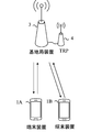
- FIG. 1 is a conceptual diagram of a wireless communication system according to an embodiment of the present invention.
- the wireless communication system includes a terminal device 1A, a terminal device 1B, and a base station device 3.
- the terminal device 1A and the terminal device 1B are also referred to as the terminal device 1.
- the terminal device 1 may also be referred to as a mobile station device, a user terminal (UE: User User Equipment), a communication terminal, a mobile device, a terminal, an MS (Mobile Station), or the like.
- the base station device 3 includes a radio base station device, a base station, a radio base station, a fixed station, an NB (Node B), an eNB (evolved Node B), an NRNB (NR Node B), a gNB (next generation Node B), It may be called an access point, BTS (Base Transceiver Station), BS (Base Station), or the like.
- the base station device 3 may include a core network device.
- the base station apparatus 3 may include one or a plurality of transmission / reception points 4 (transmission reception points: TRP). At least a part of the functions / processes of the base station apparatus 3 described below may be functions / processes at the respective transmission / reception points 4 included in the base station apparatus 3.
- the base station apparatus 3 may serve the terminal apparatus 1 by setting the communicable range (communication area) controlled by the base station apparatus 3 as one or a plurality of cells.
- the base station apparatus 3 may serve the terminal apparatus 1 by setting the communicable range (communication area) controlled by one or a plurality of transmission / reception points 4 as one or a plurality of cells.
- one cell may be divided into a plurality of partial areas (Beamed areas), and the terminal device 1 may be served in each partial area.
- the partial region may be identified based on a beam index or a precoding index used in beamforming.
- the communication area covered by the base station device 3 may have a different size and a different shape for each frequency. Moreover, the area to cover may differ for every frequency.
- a wireless network in which cells having different types of base station apparatuses 3 and different cell radii are mixed at the same frequency or different frequencies to form one communication system is referred to as a heterogeneous network.
- a wireless communication link from the base station device 3 to the terminal device 1 is referred to as a downlink.
- a wireless communication link from the terminal device 1 to the base station device 3 is referred to as an uplink.
- a wireless communication link from the terminal device 1 to another terminal device 1 is referred to as a side link.
- orthogonal frequency division including a cyclic prefix including a cyclic prefix (CP: Cyclic Prefix).
- Multiplexing OFDM: Orthogonal Frequency Division Multiplexing
- SC-FDM Single Carrier Frequency Division, Multiplexing
- Discrete Fourier Transform Spread OFDM DFT-S-OFDM: Discrete Fourier Transform Spread
- MC-CDM Multicarrier Code Division Multiplexing
- a universal filter multicarrier (UFMC: Universal-Filtered Multi- Carrier), filter OFDM (F-OFDM: Filtered OFDM), OFDM multiplied by a window (Windowed OFDM), and filter bank multicarrier (FBMC: Filter-Bank Multi-Carrier) may be used.
- UMC Universal-Filtered Multi- Carrier
- F-OFDM Filtered OFDM
- FBMC Filter-Bank Multi-Carrier
- OFDM is described as an OFDM transmission system, but the case of using the above-mentioned other transmission systems is also included in the present invention.
- the OFDM symbol in this embodiment may be an SC-FDM symbol (sometimes referred to as an SC-FDMA (Single-Carrier Frequency Division Multiple Access) symbol).
- CP is not used or zero padding is used instead of CP.
- the above-described transmission method may be used.
- CP and zero padding may be added to both the front and rear.
- the plurality of set serving cells include one primary cell (also referred to as Primary Cell, PCell) and one or more secondary cells (also referred to as Secondary Cell, SCell).
- the primary cell is a serving cell in which an initial connection establishment (initial connection establishment) procedure has been performed, a serving cell that has started a connection re-establishment procedure, or a cell designated as a primary cell in a handover procedure.
- One or a plurality of secondary cells may be set at the time when an RRC (Radio Resource Control) connection is established or later.
- the plurality of configured serving cells may include one primary secondary cell (also referred to as Primary SCell or PSCell).
- the primary secondary cell may be a secondary cell capable of transmitting control information in the uplink among one or a plurality of secondary cells in which the terminal device 1 is set. Even if a subset of two types of serving cells, a master cell group (also referred to as Master Cell Group, MCG) and a secondary cell group (also referred to as Secondary Cell Group, SCG), is set for the terminal device 1. Good.
- MCG Master Cell Group
- SCG Secondary Cell Group
- the master cell group is composed of one primary cell and zero or more secondary cells.
- the secondary cell group is composed of one primary secondary cell and zero or more secondary cells.
- TDD Time Division Duplex
- FDD Frequency Division Duplex
- a TDD (Time Division Division Duplex) method or an FDD (Frequency Division Duplex) method may be applied to all of a plurality of cells.
- cells to which the TDD scheme is applied and cells to which the FDD scheme is applied may be aggregated.
- a carrier corresponding to a serving cell is referred to as a downlink component carrier (or downlink carrier).
- a carrier corresponding to a serving cell is referred to as an uplink component carrier (or uplink carrier).
- a carrier corresponding to the serving cell is referred to as a side link component carrier (or side link carrier).
- a downlink component carrier, an uplink component carrier, and / or a side link component carrier are collectively referred to as a component carrier (or carrier).
- the physical channel and physical signal of this embodiment will be described.
- the downlink physical channel and / or the downlink physical signal may be collectively referred to as a downlink signal.
- Uplink physical channels and / or uplink physical signals may be collectively referred to as uplink signals.
- the downlink physical channel and / or the uplink physical channel may be collectively referred to as a physical channel.
- the downlink physical signal and / or the uplink physical signal may be collectively referred to as a physical signal.
- the following downlink physical channels are used in downlink wireless communication between the terminal device 1 and the base station device 3.
- the downlink physical channel is used for transmitting information output from an upper layer.
- ⁇ NR-PBCH New Radio Physical Broadcast CHannel
- NR-PDCCH New Radio Physical Downlink Control CHannel
- NR-PDSCH New Radio Physical Downlink Shared CHannel
- MIB Master Information Block
- important system information Essential information
- one or more important information blocks may be transmitted as an important information message.
- the important information block may include information indicating a part or all of a frame number (SFN: System Frame Number) (for example, information on a position in a super frame composed of a plurality of frames).
- SFN System Frame Number
- a radio frame (10 ms) is composed of 10 subframes of 1 ms, and the radio frame is identified by a frame number. The frame number returns to 0 at 1024 (Wrap around).
- information that can identify the region for example, identifier information of a downlink transmission beam constituting the region
- the downlink transmission beam identifier information may be indicated using an index of the downlink transmission beam (precoding).
- the time position in the frame (for example, the subframe number including the important information block (important information message)) is identified.
- Possible information may be included. That is, information for determining each of the subframe numbers in which transmission of important information blocks (important information messages) using different downlink transmission beam indexes may be included.
- the important information may include information necessary for connection to the cell and mobility.
- NR-PDCCH is used for transmitting downlink control information (Downlink Control Information: DCI) in downlink wireless communication (wireless communication from base station apparatus 3 to terminal apparatus 1).
- DCI Downlink Control Information
- one or a plurality of DCIs (which may be referred to as DCI formats) are defined for transmission of downlink control information. That is, the field for downlink control information is defined as DCI and mapped to information bits.
- DCI including information indicating the timing for transmitting HARQ-ACK for the scheduled NR-PDSCH (for example, the number of symbols from the last symbol included in NR-PDSCH to HARQ-ACK transmission) is defined. Also good.
- DCI used for scheduling of one downlink radio communication NR-PDSCH (transmission of one downlink transport block) in one cell may be defined.
- DCI used for scheduling of one uplink radio communication NR-PUSCH (transmission of one uplink transport block) in one cell may be defined as DCI.
- DCI includes information related to scheduling of NR-PDSCH or NR-PUSCH.
- the DCI for the downlink is also referred to as a downlink grant (downlink grant) or a downlink assignment (downlink assignment).
- the DCI for the uplink is also called an uplink grant (uplink grant) or an uplink assignment (Uplink assignment).
- NR-PDSCH is used for transmission of downlink data (DL-SCH: Downlink Shared Channel) from mediated access (MAC: Medium Access Control). It is also used to transmit system information (SI: System Information) and random access response (RAR: System Random Access Response).
- SI System Information
- RAR System Random Access Response
- the base station device 3 and the terminal device 1 exchange (transmit / receive) signals in a higher layer.
- the base station apparatus 3 and the terminal apparatus 1 transmit and receive RRC signaling (RRC message: Radio Resource Control message, RRC information: also called Radio Resource Control information) in the radio resource control (RRC: Radio Resource Control) layer. May be.
- RRC Radio Resource Control
- the base station device 3 and the terminal device 1 may transmit and receive a MAC control element in a MAC (Medium Access Control) layer.
- MAC Medium Access Control
- the RRC signaling and / or the MAC control element is also referred to as a higher layer signal.
- the upper layer means an upper layer viewed from the physical layer, and may include one or more of a MAC layer, an RRC layer, an RLC layer, a PDCP layer, a NAS layer, and the like.
- the upper layer may include one or a plurality of RRC layers, RLC layers, PDCP layers, NAS layers, and the like.
- NR-PDSCH may be used to transmit RRC signaling and a MAC control element (MAC CE: Medium Access Control Control Element).
- MAC CE Medium Access Control Control Element
- the RRC signaling transmitted from the base station apparatus 3 may be common signaling for a plurality of terminal apparatuses 1 in the cell.
- the RRC signaling transmitted from the base station device 3 may be signaling dedicated to a certain terminal device 1 (also referred to as dedicated signaling). That is, information specific to a terminal device (UE specific) may be transmitted to a certain terminal device 1 using dedicated signaling.
- the following downlink physical signals are used in downlink wireless communication.
- the downlink physical signal is not used for transmitting information output from the upper layer, but is used by the physical layer.
- ⁇ Synchronization signal (SS) ⁇ Reference signal (RS)
- the synchronization signal is used for the terminal device 1 to synchronize the downlink frequency domain and time domain.
- the synchronization signal may include a primary synchronization signal (PSS) and a secondary synchronization signal (SSS). Further, the synchronization signal may be used for the terminal device 1 to specify a cell identifier (cell ID).
- PSS primary synchronization signal
- SSS secondary synchronization signal
- cell ID cell identifier
- the synchronization signal may be used for selection / identification / determination of a downlink transmission beam used by the base station apparatus 3 and / or a downlink reception beam used by the terminal apparatus 1 in downlink beamforming. That is, the synchronization signal may be used for the terminal apparatus 1 to select / identify / determine the index of the downlink transmission beam applied to the downlink signal by the base station apparatus 3.
- the synchronization signal, primary synchronization signal, and secondary synchronization signal used in NR may be referred to as NR-SS, NR-PSS, and NR-SSS, respectively.
- the downlink reference signal (hereinafter, also simply referred to as a reference signal in the present embodiment) may be classified into a plurality of reference signals based on the usage or the like. For example, one or more of the following reference signals may be used as the reference signal.
- DMRS Demodulation Reference Signal
- CSI-RS Channel State Information Reference Signal
- PTRS Phase Tracking Reference Signal
- MRS Mobility Reference Signal
- the DMRS may be used for propagation path compensation when demodulating the received modulated signal.
- DMRSs may be collectively referred to as DMRSs for NR-PDSCH demodulation, NR-PDCCH demodulation, and / or NR-PBCH demodulation, or may be individually defined.
- CSI-RS may be used for channel state measurement.
- PTRS may be used to track the phase, such as by movement of the terminal.
- MRS may be used to measure reception quality from multiple base station devices for handover.
- a reference signal for compensating for phase noise may be defined in the reference signal.
- the plurality of reference signals may have the function of other reference signals.
- At least one of the plurality of reference signals, or other reference signal is a cell-specific reference signal (CRS), a base station apparatus 3 or a transmission / reception point 4 individually set for a cell.
- CRS cell-specific reference signal
- BRS beam-specific reference signal
- UE-specific reference signal UE-specific reference signal
- At least one of the reference signals may be used for fine synchronization such as numerology such as radio parameters and subcarrier intervals, FFT window synchronization, and the like.
- At least one of the reference signals may be used for radio resource measurement (RRM: Radio Resource Measurement).
- RRM Radio Resource Measurement
- at least one of the reference signals may be used for beam management.
- a synchronization signal may be used as at least one of the reference signals.
- the following uplink physical channels are used in uplink wireless communication between the terminal device 1 and the base station device 3 (wireless communication from the terminal device 1 to the base station device 3).
- the uplink physical channel is used for transmitting information output from an upper layer.
- ⁇ NR-PUCCH New Radio Physical Uplink Control CHannel
- NR-PUSCH New Radio Physical Uplink Shared CHannel
- NR-PRACH New Radio Physical Random Access CHannel
- the NR-PUCCH is used for transmitting uplink control information (UPCI).
- the uplink control information may include channel state information (CSI: Channel State Information) used to indicate the state of the downlink channel.
- CSI Channel State Information
- the uplink control information may include a scheduling request (SR: Scheduling Request) used for requesting UL-SCH resources.
- SR Scheduling Request
- the uplink control information may include HARQ-ACK (Hybrid Automatic Repeat request ACKnowledgement).
- HARQ-ACK may indicate HARQ-ACK for downlink data (Transport block, Medium Access Control Protocol Data Unit: MAC PDU, Downlink-Shared Channel: DL-SCH).
- NR-PUSCH is used to transmit uplink data (UL-SCH: Uplink Shared CHannel) from mediated access (MAC: Medium Access Control). Further, it may be used for transmitting HARQ-ACK and / or CSI together with uplink data. Further, it may be used to transmit only CSI or only HARQ-ACK and CSI. That is, it may be used to transmit only UCI.
- UL-SCH Uplink Shared CHannel
- MAC Medium Access Control
- NR-PUSCH may be used to transmit RRC signaling and MAC control elements.
- NR-PUSCH may be used for transmission of UE capability (UE Capability) in the uplink.
- the same name for example, NR-PCCH
- NR-PDCCH NR-PDCCH
- NR-PUCCH NR-PUCCH
- NR-PSCH NR-PDSCH and NR-PUSCH.
- the following uplink physical signals are used in uplink wireless communication.
- the uplink physical signal is not used for transmitting information output from the higher layer, but is used by the physical layer.
- UL RS Uplink Reference Signal
- DMRS Demodulation Reference Signal
- SRS Sounding Reference Signal
- the base station apparatus 3 uses DMRS to perform channel correction of NR-PUSCH or NR-PUCCH.
- transmitting both NR-PUSCH and DMRS is simply referred to as transmitting NR-PUSCH.
- transmitting both NR-PUCCH and DMRS is simply referred to as transmitting NR-PUCCH.
- the base station apparatus 3 uses SRS to measure the uplink channel state.
- the NR-PRACH may be used for transmitting a random access preamble.
- the NR-PRACH includes initial connection establishment procedure, handover procedure, connection re-establishment procedure, synchronization (timing adjustment) for uplink transmission, and NR-PUSCH (UL-SCH) resource. It may be used to indicate a request.
- subframes will be described. Although referred to as a subframe in this embodiment, it may be referred to as a resource unit, a radio frame, a time interval, a time interval, or the like.
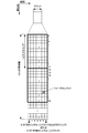
- FIG. 2 is a diagram illustrating an example of a schematic configuration of a downlink slot according to the embodiment of the present invention.
- Each radio frame is 10 ms long.
- Each radio frame is composed of 10 subframes and X slots. That is, the length of one subframe is 1 ms.
- the uplink slot is defined in the same manner, and the downlink slot and the uplink slot may be defined separately.
- the signal or physical channel transmitted in each of the slots may be represented by a resource grid.
- the resource grid is defined by a plurality of subcarriers and a plurality of OFDM symbols.
- the number of subcarriers constituting one slot depends on the downlink and uplink bandwidths of the cell.
- Each element in the resource grid is referred to as a resource element.
- Resource elements may be identified using subcarrier numbers and OFDM symbol numbers.
- the resource block is used to express a mapping of resource elements of a certain physical downlink channel (PDSCH or the like) or uplink channel (PUSCH or the like).
- resource blocks virtual resource blocks and physical resource blocks are defined.
- a physical uplink channel is first mapped to a virtual resource block. Thereafter, the virtual resource block is mapped to the physical resource block.
- one physical resource block is defined by 7 consecutive OFDM symbols in the time domain and 12 consecutive subcarriers in the frequency domain. The That is, one physical resource block is composed of (7 ⁇ 12) resource elements.
- one physical resource block is defined by, for example, 6 consecutive OFDM symbols in the time domain and 12 consecutive subcarriers in the frequency domain. That is, one physical resource block is composed of (6 ⁇ 12) resource elements. At this time, one physical resource block corresponds to one slot in the time domain and corresponds to 180 kHz in the frequency domain. Physical resource blocks are numbered from 0 in the frequency domain.
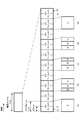
- FIG. 3 is a diagram illustrating the relationship in the time domain between subframes, slots, and minislots.
- the subframe is 1 ms regardless of the subcarrier interval, the number of OFDM symbols included in the slot is 7 or 14, and the slot length varies depending on the subcarrier interval.
- the slot length may be defined as 0.5 / ( ⁇ f / 15) ms when the number of OFDM symbols constituting one slot is 7, where the subcarrier interval is ⁇ f (kHz).
- ⁇ f may be defined by a subcarrier interval (kHz).
- the slot length may be defined as 1 / ( ⁇ f / 15) ms.
- ⁇ f may be defined by a subcarrier interval (kHz).
- the slot length may be defined as X / 14 / ( ⁇ f / 15) ms.
- a mini-slot (may be referred to as a sub-slot) is a time unit configured with fewer OFDM symbols than the number of OFDM symbols included in the slot. This figure shows an example in which a minislot is composed of 2 OFDM symbols. The OFDM symbols in the minislot may coincide with the OFDM symbol timing that constitutes the slot.
- the minimum scheduling unit may be a slot or a minislot.
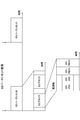
- FIG. 4 shows an example of a slot or a subframe.
- a case where the slot length is 0.5 ms at a subcarrier interval of 15 kHz is shown as an example.
- D indicates the downlink and U indicates the uplink.
- ⁇ Downlink part (duration) ⁇ Gap ⁇ Uplink part (duration) One or more of them.
- FIG. 4A may be referred to as a certain time interval (for example, a minimum unit of time resources that can be allocated to one UE, or a time unit, etc. In addition, a plurality of minimum units of time resources are bundled to be referred to as a time unit. 4) is an example used for all downlink transmission, and FIG. 4 (b) performs uplink scheduling via the NR-PDCCH, for example, with the first time resource, and the NR-PDCCH An uplink signal is transmitted through a processing delay, a switching time from downlink to uplink, and a gap for generating a transmission signal.
- FIG. 4 (b) performs uplink scheduling via the NR-PDCCH, for example, with the first time resource, and the NR-PDCCH
- FIG. 4 (c) is used for transmission of the downlink NR-PDCCH and / or downlink NR-PDSCH in the first time resource, for processing delay, downlink to uplink switching time, and transmission signal generation. Used for transmission of NR-PUSCH or NR-PUCCH through a gap.
- the uplink signal may be used for transmission of HARQ-ACK and / or CSI, that is, UCI.
- FIG. 4 (d) is used for transmission of NR-PDCCH and / or NR-PDSCH in the first time resource, and the NR ⁇ through the processing delay, downlink to uplink switching time, and gap for transmission signal generation. Used for transmission of PUSCH and / or NR-PUCCH.
- the uplink signal may be used for transmission of uplink data, that is, UL-SCH.
- FIG. 4 (e) is an example in which all are used for uplink transmission (NR-PUSCH or NR-PUCCH).
- the above-described downlink part and uplink part may be composed of a plurality of OFDM symbols as in LTE.
- Beam forming on the transmission side controls the amplitude and phase in analog or digital for each of the plurality of transmission antenna elements. This is a method of transmitting a signal with a high transmission antenna gain in an arbitrary direction, and the field pattern is referred to as a transmission beam.
- beam forming on the receiving side controls the amplitude and phase in an analog or digital manner for each of a plurality of receiving antenna elements. This is a method of receiving a signal with a high receiving antenna gain in an arbitrary direction, and the field pattern is referred to as a receiving beam.
- the beam management may be an operation of the base station apparatus 3 and / or the terminal apparatus 1 for obtaining directivity alignment and beam gain of the transmission beam and / or the reception beam.
- Fig. 5 shows an example of beamforming.
- a plurality of antenna elements are connected to a single transmission unit (TXRU: “Transceiver” unit) 50, the phase is controlled by a phase shifter 51 for each antenna element, and transmitted from the antenna element 52 in any direction with respect to the transmission signal.
- the beam can be directed.
- the TXRU 50 may be defined as an antenna port, and in the terminal device 1, only the antenna port may be defined. Since the directivity can be directed in an arbitrary direction by controlling the phase shifter 51, the base station apparatus 3 can communicate with the terminal apparatus 1 using a beam having a high gain.
- Beam forming may be referred to as virtualization, precoding, weight multiplication, and the like. Further, the signal itself transmitted simply using beam forming may be called a transmission beam.
- the transmission beam used by the terminal device 1 in uplink transmission beamforming is referred to as an uplink transmission beam (UL Tx beam), and the reception beam used by the base station device 3 in uplink reception beamforming.
- This is called an uplink receive beam (UL (Rx beam).
- the uplink transmission beam may be referred to as a transmission spatial filter setting in the terminal apparatus 1
- the uplink reception beam may be referred to as a reception spatial filter setting in the base station apparatus 3.
- a transmission beam used by the base station apparatus 3 in downlink transmission beamforming is referred to as a downlink transmission beam (DL (Tx beam), and a reception beam used by the terminal device 1 in downlink reception beamforming is downlink received. This is called a beam (DL Rx beam).
- the downlink transmission beam may be referred to as a transmission spatial filter setting in the base station apparatus 3, and the downlink reception beam may be referred to as a reception spatial filter setting in the terminal apparatus 1.
- the uplink transmission beam and the uplink reception beam may be collectively referred to as an uplink beam, and the downlink transmission beam and the downlink reception beam may be collectively referred to as a downlink beam.
- the processing performed by the terminal device 1 for uplink beamforming is referred to as uplink transmission beam processing or uplink precoding
- the processing performed by the base station device 3 for uplink beamforming is uplink reception beam processing. May be referred to.
- the processing performed by the terminal apparatus 1 for downlink beamforming is referred to as downlink reception beam processing
- the processing performed by the base station apparatus 3 for downlink beamforming is referred to as downlink transmission beam processing or downlink precoding. You may call it.
- the base station apparatus 3 may transmit a signal using a plurality of downlink transmission beams in one OFDM symbol.
- the antenna element of the base station apparatus 3 may be divided into subarrays, and different downlink beamforming may be performed in each subarray. Different downlink beamforming may be performed for each polarization using a polarization antenna.
- the terminal apparatus 1 may transmit a signal using a plurality of uplink transmission beams with one OFDM symbol.
- the base station apparatus 3 switches and uses a plurality of downlink transmission beams in a cell formed by the base station apparatus 3 and / or the transmission / reception point 4.
- An individual cell may be configured for each.
- the beam management according to the present embodiment may include the following operations. ⁇ Beam selection ⁇ Beam refinement ⁇ Beam recovery
- the beam selection may be an operation of selecting a beam in communication between the base station device 3 and the terminal device 1.
- the beam improvement may be an operation of changing the beam between the base station apparatus 3 and the terminal apparatus 1 that is optimal by selecting a beam having a higher gain or moving the terminal apparatus 1.
- the beam recovery may be an operation of reselecting a beam when the quality of the communication link is deteriorated due to a blockage caused by passage of an obstacle or a person in communication between the base station device 3 and the terminal device 1.
- the above operation is not limited to the above purpose. Since the base station apparatus 3 performs beam management in various situations, the effect can be achieved without limiting the purpose.
- a reference signal for example, CSI-RS
- QCL pseudo-co-location
- Two antenna ports are said to be QCL if the long term property of a channel carrying a symbol at one antenna port can be inferred from the channel carrying a symbol at the other antenna port.
- the long-term characteristics of the channel include one or more of delay spread, Doppler spread, Doppler shift, average gain, and average delay. For example, when antenna port 1 and antenna port 2 are QCL with respect to average delay, this means that the reception timing of antenna port 2 can be inferred from the reception timing of antenna port 1.
- This QCL can also be extended to beam management. Therefore, a QCL extended to a space may be newly defined.
- a QCL extended to a space may be newly defined.
- one or more of the following may be further included as the long term property of the channel in the spatial QCL assumption.
- Angle of arrival AoA (Angle of Arrival), ZoA (Zenithangle of Arrival), etc.
- Angle Spread eg ASA (Angle Spread of Arrival) or ZSA (Zenith angle Spread of Arrival) in a radio link or channel )
- -Transmission angle AoD, ZoD, etc.
- Angle Spread eg ASD (Angle Spread of Departure) or ZSS (Zenith angle Spread of Departure)
- the operations of the base station device 3 and the terminal device 1 equivalent to the beam management may be defined as the beam management by the QCL assumption of the space and the
- an antenna port may be assigned to each of precoding or transmission beams.
- a signal transmitted using different precoding or a signal transmitted using different transmission beams according to the present embodiment may be defined as a signal transmitted through different one or a plurality of antenna ports.
- an antenna port is defined as a channel through which a symbol that is a certain antenna port is transmitted can be estimated from a channel through which another symbol is transmitted through the same antenna port.
- the same antenna port may mean that the antenna port number (number for identifying the antenna port) is the same.
- An antenna port set may be configured by a plurality of antenna ports.
- the same antenna port set may be that the antenna port set number (the number for identifying the antenna port set) is the same.
- Transmitting a signal by applying different uplink transmission beams may be transmitting a signal using different antenna port sets or different antenna port sets including a plurality of antenna ports.
- Each beam index may be an OFDM symbol number, an antenna port number, or an antenna port set number.
- Transform precoding In the transform precoding, complex modulation symbols for one or a plurality of layers generated by layer mapping are input.
- Transform precoding may be a process of dividing a block of complex symbols into sets for each layer corresponding to one OFDM symbol. If OFDM is used, DFT (Discrete Fourier Transform) processing in transform precoding may not be necessary.
- Precoding may be to generate a vector block that maps to a resource element using the resulting vector block from the transform precoder as input. In the case of spatial multiplexing, one of the precoding matrices may be applied when generating a vector block that maps to resource elements. This processing may be called digital beam forming.
- Precoding may be defined including analog beam forming and digital beam forming, or may be defined as digital beam forming.
- Beamforming may be applied to a precoded signal, or precoding may be applied to a signal to which beamforming is applied.
- Beam forming may include analog beam forming and not include digital beam forming, or may include both digital beam forming and analog beam forming.
- a beamformed signal, a precoded signal, or a beamformed and precoded signal may be referred to as a beam.
- the beam index may be a precoding matrix index.
- the index of the beam and the index of the precoding matrix may be defined independently.
- a signal may be generated by applying the precoding matrix indicated by the index of the precoding matrix to the beam indicated by the index of the beam.
- the signal may be generated by applying the beamforming indicated by the beam index to the signal to which the precoding matrix indicated by the index of the precoding matrix is applied.
- Digital beamforming may apply different precoding matrices to resources in the frequency direction (eg, a set of subcarriers).
- a radio link configured using a predetermined transmission beam and / or a predetermined reception beam may be referred to as a beam pair link.
- beam pair links configured using different downlink transmission beams and / or different downlink reception beams may be different downlink beam pair links.
- beam pair links configured using different uplink transmission beams and / or different uplink reception beams may be different uplink beam pair links.
- a state in which a terminal device 1 can receive a downlink signal using a plurality of downlink transmission beams and / or a plurality of downlink reception beams in a cell is referred to as a state having a plurality of downlink beam pair links. Also good.
- the state in which the terminal apparatus 1 can transmit an uplink signal using a plurality of uplink transmission beams and / or a plurality of uplink reception beams in a cell is referred to as a state having a plurality of uplink beam pair links. Also good.
- FIG. 6 shows a case where the terminal apparatus 1 and the base station apparatus 3 configure a plurality of downlink beam pair links in the cell 100.
- the terminal apparatus 1 receives a downlink signal transmitted from the base station apparatus 3 using the downlink transmission beam t1 using the downlink reception beam r1.
- the terminal apparatus 1 receives a downlink signal transmitted from the base station apparatus 3 using the downlink transmission beam t2 using the downlink reception beam r2.
- the terminal apparatus 1 receives a downlink signal transmitted from the base station apparatus 3 using the downlink transmission beam t3, using the downlink reception beam r3.
- three downlink beam pair links are configured between the terminal apparatus 1 and the base station apparatus 3, and downlink transmission / reception is performed on all or part of the three downlink beam pair links.
- the terminal device 1 measures the reception power and / or reception quality based on the reference signal in each downlink beam pair link.
- a plurality of downlink beam pair links may be configured using a plurality of downlink reception beams for one downlink transmission beam.
- a plurality of downlink beam pair links may be configured using a plurality of downlink transmission beams for one downlink reception beam.
- one downlink beam pair link may be associated with one downlink transmission beam regardless of the downlink reception beam used.
- one uplink beam pair link may be associated with one uplink reception beam regardless of the uplink transmission beam used.
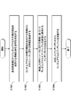
- FIG. 7 is a diagram illustrating an example of a synchronization signal block (also referred to as an SS (Synchronization Signal) block) and a synchronization signal burst set (also referred to as an SS burst set) according to the present embodiment.
- FIG. 7 shows an example in which two synchronization signal blocks are included in a synchronization signal burst set transmitted periodically, and the synchronization signal block is composed of 4 OFDM symbols.
- one or more synchronization signal blocks may constitute a synchronization signal burst (referred to as SS burst), and one or more synchronization signal bursts may constitute a synchronization signal burst set.
- SS burst synchronization signal burst
- synchronization signal burst set a synchronization signal burst set
- the synchronization signal block is a unit block composed of a synchronization signal (for example, NR-PSS, NR-SSS) and / or NR-PBCH.
- a synchronization signal for example, NR-PSS, NR-SSS
- NR-PBCH a synchronization signal
- the base station apparatus 3 uses an independent downlink transmission beam for each synchronization signal block. Also good.
- NR-PSS, NR-SSS, and NR-PBCH are time-multiplexed in one synchronization signal block, and NR ⁇ transmitted with a bandwidth wider than the bandwidth of NR-PSS and / or NR-SSS.
- An example is shown in which PBCH is time-multiplexed by two symbols.
- the order in which NR-PSS, NR-SSS, and / or NR-PBCH are multiplexed in the time domain may be different from the example shown in FIG. For example, when NR-PBCH is transmitted with two symbols, there may be an OFDM symbol that transmits NR-SSS between two NR-PBCH symbols.
- the synchronization signal burst set may be transmitted periodically.
- a cycle used for initial access and a cycle set for a connected terminal device (Connected or RRC_Connected) may be defined.
- the period set for the connected terminal device (Connected or RRC_Connected) may be set in the RRC layer.
- the period set for the connected (Connected or RRC_Connected) terminal is a period of radio resources in the time domain that can potentially be transmitted, and is the base station apparatus 3 actually transmitting? You may decide.
- the cycle used for the initial access may be defined in advance in a specification or the like.
- the synchronization signal burst set may be determined based on a system frame number (SFN). Also, the start position (boundary) of the synchronization signal burst set may be determined based on the SFN and the period.
- SFN system frame number
- the start position (boundary) of the synchronization signal burst set may be determined based on the SFN and the period.
- the same downlink transmission beam is applied to synchronization signal blocks having the same relative time in each synchronization signal burst set in a plurality of synchronization signal burst sets.
- the antenna port in the synchronization signal block having the same relative time in each synchronization signal burst set in the plurality of synchronization signal burst sets may be assumed to be QCL with respect to average delay, Doppler shift, and spatial correlation.
- the number of synchronization signal blocks may be defined as the number (number) of synchronization signal blocks in a synchronization signal burst, a synchronization signal burst set, or a period of the synchronization signal block, for example. Further, the number of synchronization signal blocks may indicate the number of beam groups for cell selection in a synchronization signal burst, a synchronization signal burst set, or a period of the synchronization signal block.
- a beam group may be defined as the number of synchronization signal blocks or different beams included in a synchronization signal burst, or in a synchronization signal burst set, or in the period of a synchronization signal block.
- the base station apparatus 3 notifies the terminal apparatus 1 of one or more of the resources that have transmitted the SRS by transmitting an SRS resource indicator (SRI).
- SRI SRS resource indicator
- the one or more SRS resources are associated with at least one antenna port and / or one uplink transmission beam (which may be a transmission spatial filter setting or a precoder of the terminal device 1).
- the terminal device 1 that has received the SRI information may determine an antenna port and / or an uplink transmission beam used for uplink transmission based on the SRI.
- the random access procedure (Random Access procedure) of this embodiment will be described.
- Random access procedures are classified into two procedures: contention based and non-contention based.
- the terminal device 1 is in an initial access from a state where it is not connected (communication) with the base station device 3 and / or uplink data or transmission that can be transmitted to the terminal device 1 while being connected to the base station device 3
- a contention-based random access procedure is performed at the time of scheduling request when possible side link data is generated.
- the use of random access is not limited to these.
- the occurrence of uplink data that can be transmitted to the terminal device 1 may include that a buffer status report corresponding to the uplink data that can be transmitted is triggered.
- the occurrence of uplink data that can be transmitted to the terminal device 1 may include that a scheduling request triggered based on the occurrence of uplink data that can be transmitted is pending.
- the occurrence of side link data that can be transmitted to the terminal device 1 may include that a buffer status report corresponding to the side link data that can be transmitted is triggered.
- the occurrence of side link data that can be transmitted to the terminal device 1 may include that a scheduling request triggered based on the occurrence of the transmittable side link data is pending.
- the terminal device 1 receives the NR-PDCCH from the base station device 3 and performs the non-contention based random access procedure when the NR-PDCCH includes information instructing the start of the random access procedure. Good.
- the information for instructing the start of the random access procedure includes NR-PDCCH order, PDCCH order, message 0, Msg. It may be referred to as 0 or the like.
- the non-contention based random access procedure is a procedure for performing random access using a preamble corresponding to the random access preamble index indicated by the NR-PDCCH order from the base station device 3, and the base station device 3 and the terminal device 1 Are used to quickly establish uplink synchronization between the terminal apparatus 1 and the base station apparatus 3 when the handover timing is not effective and the transmission timing of the mobile station apparatus is not effective.
- the use of random access is not limited to these.
- the terminal device 1 selects one of the preamble sets that can be used by the terminal device 1 at random.
- a contention-based random access procedure may be performed.
- the terminal device 1 of this embodiment receives random access setting information via an upper layer before starting a random access procedure (initiate).
- the random access setting information may include the following information or information for determining / setting the following information.
- a set of one or more time / frequency resources available for transmission of a random access preamble (sometimes referred to as PRACH resources) (eg, a set of available PRACH resources)
- PRACH resources sometimes referred to as PRACH resources
- random access setting information is associated with one synchronization signal block in the synchron
- the terminal apparatus 1 receives one or a plurality of random access setting information by a downlink signal, and each of the one or a plurality of random access setting information is a synchronization signal block (CSI-RS or downlink transmission beam). May be associated).
- the terminal device 1 selects one of the received one or more synchronization signal blocks (which may be CSI-RS or a downlink transmission beam), and performs random access associated with the selected synchronization signal block A random access procedure may be performed using the setting information.
- FIG. 8 is a diagram showing an example of the configuration of random access setting information according to the present embodiment.
- the terminal device 1 receives random access setting information corresponding to the first synchronization signal block and random access setting information corresponding to the second synchronization signal block.
- Each of random access setting information corresponding to the first synchronization signal block and random access setting information corresponding to the second synchronization signal block can be used for random access, a preamble group, a set of frequency / time resources, and other Contains information.
- FIG. 8 shows a case where the terminal device 1 has received two pieces of random access setting information corresponding to two synchronization signal blocks, the terminal device 1 corresponds to three or more synchronization signal blocks. Three or more pieces of random access setting information may be received.
- FIG. 8 shows a case where each piece of information included in the random access setting information exists for each synchronization signal block, but some of the information included in the random access setting information is a plurality of synchronization signal blocks. It may be set in common. For example, a part of the random access setting information may be information set for each synchronization signal block, CSI-RS or downlink transmission beam (transmission filter setting of the base station apparatus 3), and others may be set for each cell. Information to be set may be used.
- the set of one or more time / frequency resources that can be used for transmission of the random access preamble included in the random access setting information is set for each synchronization signal block, CSI-RS, and / or downlink transmission beam. May be.
- the terminal apparatus 1 may select one or more sets of time / frequency resources that can be used for transmission of the random access preamble based on the received synchronization signal block, CSI-RS, and / or downlink transmission beam. Good.
- each of the one or more random access preamble groups included in the random access setting information may be associated with each synchronization signal block, CSI-RS, and / or downlink transmission beam.
- the terminal device 1 may select a random access preamble group based on the received synchronization signal block, CSI-RS, and / or downlink transmission beam.
- the example of FIG. 8 shows a case where one random access setting information is associated with one synchronization signal block
- the one random access setting information has one index (for example, a synchronization signal block). Index, CSI-RS index, downlink transmission beam index, etc.).
- each terminal device 1 receives one or a plurality of downlink signals transmitted using one downlink transmission beam, and receives random access setting information associated with one of the downlink signals. Then, a random access procedure may be performed based on the received random access setting information.
- the terminal device 1 receives one or more synchronization signal blocks in the synchronization signal burst set, receives random access setting information associated with one of the synchronization signal blocks, and receives the received random access setting information.
- a random access procedure may be performed based on The terminal device 1 receives one or a plurality of CSI-RSs, receives random access setting information associated with one of the CSI-RSs, and performs a random access procedure based on the received random access setting information. May be performed.
- the one or more random access setting information may be configured with one random access channel setting (RACH-Config) and / or one physical random access channel setting (PRACH-Config).
- RACH-Config random access channel setting
- PRACH-Config physical random access channel setting
- the parameter related to random access for each downlink transmission beam may be included in the random access channel setting.
- Parameters related to the physical random access channel for each downlink transmission beam are included in the physical random access channel setting. Good.
- One random access setting information indicates a parameter related to random access corresponding to one downlink transmission beam, and a plurality of random access setting information indicates parameters related to a plurality of random access corresponding to a plurality of downlink transmission beams. Also good.
- One random access setting information may indicate a parameter related to physical random access corresponding to one downlink transmission beam, and may indicate a parameter related to a plurality of random access corresponding to a plurality of downlink transmission beams.
- random access setting information (random access channel setting corresponding to the beam, physical random access channel setting corresponding to the beam) corresponding to the beam may be selected.
- the terminal device 1 receives one or a plurality of random access setting information from the base station device 3 and / or the transmission / reception point 4 different from the base station device 3 and / or the transmission / reception point 4 that transmits the random access preamble. Also good.
- the terminal device 1 may transmit a random access preamble to the second base station device 3 based on at least one of the random access setting information received from the first base station device 3.
- the base station apparatus 3 may determine a downlink transmission beam to be applied when transmitting a downlink signal to the terminal apparatus 1 by receiving the random access preamble transmitted by the terminal apparatus 1.
- the terminal device 1 may transmit the random access preamble using the time / frequency resource indicated in the random access setting information associated with a certain downlink transmission beam.
- the base station device 3 is applied when transmitting a downlink signal to the terminal device 1 based on the random access preamble received from the terminal device 1 and / or the time / frequency resource at which the random access preamble is received.
- the power downlink transmission beam may be determined.
- a selection rule when the terminal device 1 according to the present embodiment receives a plurality of random access setting information and selects one random access setting information used for a random access procedure from the plurality of random access setting information will be described. .
- the terminal device 1 may select the random access setting information used for the random access procedure based on the propagation path characteristics with the base station device 3.
- the terminal device 1 may select the random access setting information used for the random access procedure based on the channel characteristics measured by the synchronization signal block or the downlink reference signal received from the base station device 3.
- the terminal device 1 may randomly select one random access setting information from a plurality of received random access setting information.
- the terminal device 1 may select one piece of random access setting information from a plurality of received random access setting information based on the downlink signal received from the base station device 3.
- the downlink signal may be received from the base station apparatus 3 that is the transmission destination of the random access preamble, or may be received from a different base station apparatus 3.
- the random access procedure with the second base station apparatus 3 that forms the second cell is the random access setting information selected based on the downlink signal from the first base station apparatus 3 that forms the first cell. You may use for.
- a subcarrier index, a resource block index, a subframe number, a system frame number, a symbol number, and / or a random access preamble can be transmitted.
- a preamble format may be set.
- the random access procedure when the terminal device 1 receives the NR-PDCCH order from the base station device 3 is realized by transmitting and receiving a plurality of messages between the terminal device 1 and the base station device 3, as shown in FIG.
- the base station apparatus 3 transmits an NR-PDCCH order on the NR-PDCCH to the terminal apparatus 1 and instructs it to perform a random access procedure.
- the information indicated by the NR-PDCCH order includes preamble index information, mask index information, SRI (SRS Resource Indicator) information, synchronization signal block reselection indication information (SS block Re-selection Indicator), random access setting reselection indication information ( Random Access Configuration Re-selection Indicator) and / or CSI-RS selection instruction information may be included.
- SRI SRS Resource Indicator
- SS block Re-selection Indicator synchronization signal block reselection indication information
- random access setting reselection indication information Random Access Configuration Re-selection Indicator
- CSI-RS selection instruction information may be included.
- Preamble index information is information indicating one or a plurality of preamble indexes among the preamble indexes of available random access preambles indicated in the random access setting information. However, when the preamble index information has a predetermined value, the terminal device 1 may randomly select one from one or a plurality of available random access preambles.
- the mask index information is information indicating an index of a PRACH resource that can be used for transmission of a random access preamble in the time domain and / or the frequency domain.
- the time resource and / or frequency resource indicated by the mask index information may be one specific resource, may indicate a plurality of selectable resources, or a different index may be one specific resource. Each of a resource and a plurality of selectable resources may be indicated.
- preamble index information and mask index information may be indicated by one index information.
- all or a part of a preamble (which may be referred to as a sequence or a code), a time resource, and a frequency resource that can be used by the terminal device 1 for transmission of a random access preamble may be indicated by one index.
- the preamble index information and / or mask index information may be set to different values for each synchronization signal block.
- the terminal apparatus 1 selects one of the received one or more synchronization signal blocks, and uses the preamble index information and / or the mask index information associated with the selected synchronization signal block, and the random access preamble. May be sent.
- the preamble index information and / or mask index information may be set to a common value in a plurality of synchronization signal blocks.
- the terminal device 1 selects one of the received one or more synchronization signal blocks, selects a random access setting associated with the selected synchronization signal block, and can use an available preamble and / or time.
- a random access preamble corresponding to the received preamble index information and / or mask index information may be transmitted.
- the SRI information is information that notifies at least a part of one or a plurality of SRS transmission resource indexes set by the base station apparatus 3.
- the SRI information may be bitmap information corresponding to one or a plurality of SRS transmission resources set by the base station device 3.
- the terminal device 1 may determine an antenna port for transmitting a random access preamble based on the received SRI information. However, when there are a plurality of SRS transmission resources indicated by the SRI information, the terminal device 1 may transmit a random access preamble on each of the plurality of antenna ports based on the plurality of SRS transmission resources. However, the terminal device 1 may use the antenna port associated with the SRS transmission resource indicated by the SRI information as an antenna port that can be used for transmission and retransmission of the random access preamble. The terminal device 1 may transmit the random access preamble using an uplink transmission beam (transmission spatial filter setting) associated with the SRS transmission resource indicated by the SRI information. However, the antenna port used for transmitting the random access preamble by the terminal device 1 that has received the SRI information in the NR-PDCCH order may be the antenna port and the QCL associated with the SRS transmission resource indicated by the SRI information.
- the synchronization signal block reselection instruction information is information that instructs the terminal apparatus 1 that has received the NR-PDCCH order whether or not to reselect a synchronization signal block to be used for performing a random access procedure.
- the terminal apparatus 1 monitors one or more synchronization signal blocks in the synchronization signal burst set and associates them with the selected one synchronization signal block.
- the random access preamble may be transmitted using the determined random access setting.
- the information indicated by the synchronization signal block reselection instruction information may be indicated by other information indicated by the NR-PDCCH order.
- information indicated by the synchronization signal block reselection instruction information may be included in the preamble index information.
- the terminal device 1 may reselect the synchronization signal block when the preamble index indicated by the NR-PDCCH order is a predetermined value.
- the random access setting reselection instruction information is information that instructs the terminal device 1 that has received the NR-PDCCH order whether or not to reselect the random access setting information used for performing the random access procedure.
- the terminal device 1 that has received the random access setting reselection instruction information in the NR-PDCCH order selects one of one or a plurality of random access setting information received by the downlink signal, and selects the selected random access setting information.
- the random access preamble may be transmitted based on
- the information indicated by the random access setting reselection instruction information may be indicated by other information indicated by the NR-PDCCH order.
- information indicated by the random access setting reselection instruction information may be included in the preamble index information.
- the terminal device 1 may reselect the random access setting information when the preamble index indicated by the NR-PDCCH order is a predetermined value.
- the CSI-RS selection instruction information is used to select one of a set one or a plurality of CSI-RSs used for performing a random access procedure for the terminal device 1 that has received the NR-PDCCH order. Is information for instructing.
- the CSI-RS selection instruction information may be information specifying at least a part of one or a plurality of CSI-RSs set by the base station device 3 for the terminal device 1.
- the terminal device 1 monitors one or more set CSI-RSs, and randomly associates with the selected one CSI-RS.
- the random access preamble may be transmitted using the access setting.
- the information indicated by the CSI-RS selection instruction information may be indicated by other information indicated by the NR-PDCCH order.
- information indicated by CSI-RS selection instruction information may be included in the preamble index information.
- the terminal device 1 monitors one or a plurality of CSI-RSs set when the preamble index indicated by the NR-PDCCH order is a predetermined value, and randomly associates with the selected one CSI-RS.
- the random access preamble may be transmitted using the access setting.
- one common index information may be used for preamble index information, SRI information, synchronization signal block reselection instruction information, random access setting reselection instruction information, and / or CSI-RS selection instruction information.
- the common index information is the first value
- the random access setting information is reselected
- one or more CSI-RSs are monitored. May be.
- the terminal device 1 that has received the NR-PDCCH order transmits a preamble for random access to the base station device 3 using a physical random access channel (PRACH).
- This transmitted preamble may be referred to as a random access preamble, message 1 or Msg1.
- the random access preamble is configured to notify the base station apparatus 3 of information by a plurality of sequences. For example, when 64 types of sequences are prepared, 6-bit information can be indicated to the base station apparatus 3. This information is indicated as a random access preamble identifier.
- the preamble sequence is selected from a preamble sequence set that uses a preamble index.
- the terminal device 1 transmits the random access preamble indicated when the preamble index indicating one random access preamble is indicated by the NR-PDCCH order.
- the terminal device 1 may randomly select one random access preamble from the available random access preambles when a preamble index indicating a predetermined value is indicated by the NR-PDCCH order.
- the terminal device 1 transmits the random access preamble using the frequency resource and / or the time resource corresponding to the indicated mask index.
- the terminal device 1 transmits the antenna port and / or uplink transmission corresponding to one or more SRS transmission resources indicated in the SRI setting information.
- One or more random access preambles are transmitted using the beam.
- the base station apparatus 3 that has received the random access preamble generates a random access response including an uplink grant for instructing the terminal apparatus 1 to transmit, and transmits the generated random access response to the terminal apparatus 1 using the downlink PSCH. To do.
- the random access response may be referred to as message 2 or Msg2.
- the base station apparatus 3 calculates a transmission timing shift between the terminal apparatus 1 and the base station apparatus 3 from the received random access preamble, and transmission timing adjustment information (Timing Advance Command) for adjusting the shift In message 2. Further, the base station device 3 includes a random access preamble identifier corresponding to the received random access preamble in the message 2.
- the base station apparatus 3 transmits a RA-RNTI (Random Access-Radio Network Temporary Identity) for indicating a random access response addressed to the terminal apparatus 1 that has transmitted the random access preamble, to the downlink PCCH.
- RA-RNTI Random Access-Radio Network Temporary Identity
- the RA-RNTI is determined according to frequency and time position information of the physical random access channel that has transmitted the random access preamble.
- the message 2 (downlink PSCH) may include an index of the uplink transmission beam used for transmission of the random access preamble.
- information for determining an uplink transmission beam used for transmission of message 3 may be transmitted using downlink PCCH and / or message 2 (downlink PSCH).
- the information for determining the uplink transmission beam used for transmission of message 3 includes information indicating a difference (adjustment, correction) from the precoding index used for transmission of the random access preamble. May be.
- ⁇ Message 3 (S804)>
- the terminal apparatus 1 that has transmitted the random access preamble detects the corresponding RA-RNTI
- the terminal apparatus 1 decodes the random access response arranged in the downlink PSCH.
- the terminal device 1 that has successfully decoded the random access response checks whether or not the random access response includes a random access preamble identifier corresponding to the transmitted random access preamble.
- the terminal device 1 transmits the data stored in the buffer to the base station device 3 using the uplink grant included in the received random access response.
- Data transmitted using the uplink grant at this time is referred to as message 3 or Msg3.
- the terminal device 1 receives information (C ⁇ ) for identifying the terminal device 1 in the message 3 to be transmitted when the random access response that has been successfully decoded has been successfully received for the first time in a series of random access procedures. RNTI) is transmitted to the base station apparatus 3.
- the terminal device 1 that has transmitted the message 3 starts a contention resolution timer that defines a period for monitoring the message 4 from the base station device 3, and receives the downlink PCCH transmitted from the base station within the timer. Try.
- the terminal device 1 that transmitted the C-RNTI MAC CE in message 3 received the PCCH addressed to the transmitted C-RNTI from the base station device 3, and the PCCH included an uplink grant for new transmission. In this case, it is considered that the contention resolution with the other terminal device 1 is successful, the contention resolution timer is stopped, and the random access procedure is terminated.
- the terminal device 1 again determines the random access preamble. Send and continue the random access procedure. However, if transmission of the random access preamble is repeated a predetermined number of times and if the contention resolution is not successful, it is determined that there is a problem with random access, and the random access problem is instructed to the upper layer. For example, the upper layer may reset the MAC entity based on a random access problem. When the reset of the MAC entity is requested by the upper layer, the terminal device 1 stops the random access procedure.
- the terminal device 1 can synchronize with the base station device 3 and perform uplink data transmission to the base station device 3.
- FIG. 10 is a flowchart showing an example of random access preamble transmission processing of the terminal device 1 according to the present embodiment.
- the terminal device 1 receives a signal including information (NR-PDCCH order) instructing the start of the random access procedure from the base station device 3 (S1001).
- the terminal device 1 detects information (for example, SRI information) related to the SRS resource from the received information instructing the start of the random access procedure (S1002).
- the terminal device 1 determines an antenna port to be used for transmission of the random access preamble based on the detected information regarding the SRS resource (S1003).
- the terminal device 1 transmits a random access preamble from the determined antenna port (S1004).
- FIG. 11 is a flowchart showing an example of reception processing of the random access preamble of the base station apparatus 3 according to this embodiment.
- the base station apparatus 3 generates information (NR-PDCCH order) instructing the start of a random access procedure including information on SRS resources (which may be SRI information, for example) (S2001).
- the base station apparatus 3 transmits a signal including information instructing the start of the generated random access procedure to the terminal apparatus 1 (S2002).
- the base station device 3 monitors the random access preamble based on the transmitted information regarding the SRS resource (S2003).
- FIG. 12 is a flowchart showing another example of the random access preamble transmission process of the terminal device 1 according to the present embodiment.
- the terminal apparatus 1 receives a signal including instruction information (NR-PDCCH order) instructing the start of the random access procedure from the base station apparatus 3 (S3001).
- the terminal device 1 determines whether to reselect one or more random access setting information based on the received instruction information (S3002).
- the terminal device 1 selects one of the received random access setting information or a plurality of random access setting information (S3004), and proceeds to step S3005. If the random access setting information is not selected again (S3003-NO), the terminal device 1 proceeds to step S3005 using the already selected random access setting information.
- the terminal device 1 transmits a random access preamble based on the selected random access setting information (S3005).
- FIG. 13 is a flowchart showing another example of the random access preamble reception process of the base station apparatus 3 according to the present embodiment.
- the base station apparatus 3 sends information (NR-PDCCH order) instructing the terminal apparatus 1 to start a random access procedure including information instructing whether or not to reselect one of a plurality of random access setting information. Generate (S4001).
- the base station device 3 transmits a signal including information instructing the start of the generated random access procedure to the terminal device 1 (S4002).
- the base station device 3 monitors the random access preamble associated with each of the plurality of random access setting information (S4003).
- FIG. 14 is a schematic block diagram showing the configuration of the terminal device 1 of the present embodiment.
- the terminal device 1 includes a wireless transmission / reception unit 10 and an upper layer processing unit 14.
- the wireless transmission / reception unit 10 includes an antenna unit 11, an RF (Radio Frequency) unit 12, and a baseband unit 13.
- the upper layer processing unit 14 includes a medium access control layer processing unit 15 and a radio resource control layer processing unit 16.
- the wireless transmission / reception unit 10 is also referred to as a transmission unit, a reception unit, a monitor unit, or a physical layer processing unit.
- the upper layer processing unit 14 is also referred to as a measurement unit or a control unit.
- the upper layer processing unit 14 outputs uplink data (which may be referred to as a transport block) generated by a user operation or the like to the radio transmission / reception unit 10.
- the upper layer processing unit 14 includes a medium access control (MAC: Medium Access Control) layer, a packet data integration protocol (Packet Data Convergence Protocol: PDCP) layer, a radio link control (Radio Link Control: RLC) layer, a radio resource control (Radio). (Resource Control: RRC) part or all of the processing.
- the upper layer processing unit 14 may have a function of determining whether or not to reselect one of one or a plurality of synchronization signal blocks based on the received information instructing the start of the random access procedure. .
- the upper layer processing unit 14 has a function of determining whether to reselect one or more random access setting information based on the received information instructing the start of the random access procedure. Good.
- the medium access control layer processing unit 15 included in the upper layer processing unit 14 performs processing of the MAC layer (medium access control layer).
- the medium access control layer processing unit 15 controls transmission of the scheduling request based on various setting information / parameters managed by the radio resource control layer processing unit 16.
- the radio resource control layer processing unit 16 included in the upper layer processing unit 14 performs processing of the RRC layer (radio resource control layer).
- the radio resource control layer processing unit 16 manages various setting information / parameters of the own device.
- the radio resource control layer processing unit 16 sets various setting information / parameters based on the upper layer signal received from the base station apparatus 3. That is, the radio resource control layer processing unit 16 sets various setting information / parameters based on information indicating various setting information / parameters received from the base station apparatus 3.
- the wireless transmission / reception unit 10 performs physical layer processing such as modulation, demodulation, encoding, and decoding.
- the radio transmission / reception unit 10 separates, demodulates, and decodes the signal received from the base station apparatus 3 and outputs the decoded information to the upper layer processing unit 14.
- the radio transmission / reception unit 10 generates a transmission signal by modulating and encoding data, and transmits the transmission signal to the base station apparatus 3.
- the radio transmission / reception unit 10 may have a function of receiving one or a plurality of synchronization signal blocks in a certain cell.
- the radio transmission / reception unit 10 may have a function of receiving a signal including instruction information for instructing the start of the random access procedure from the base station apparatus 3.
- the wireless transmission / reception unit 10 may have a function of receiving a plurality of reference signals.
- the radio transmission / reception unit 10 may have a function of determining an antenna port to be used for transmission of a random access preamble based on information regarding the SRS resource received from the base station device 3.
- the RF unit 12 converts the signal received via the antenna unit 11 into a baseband signal by orthogonal demodulation (down-conversion: down covert), and removes unnecessary frequency components.
- the RF unit 12 outputs the processed analog signal to the baseband unit.
- the baseband unit 13 converts the analog signal input from the RF unit 12 into a digital signal.
- the baseband unit 13 removes a portion corresponding to CP (CyclicPrefix) from the converted digital signal, and performs fast Fourier transform (FFT) on the signal from which CP is removed to extract a frequency domain signal. To do.
- CP CyclicPrefix
- FFT fast Fourier transform
- the baseband unit 13 performs inverse fast Fourier transform (Inverse Fourier Transform: IFFT) on the data to generate an OFDM symbol, adds a CP to the generated OFDM symbol, generates a baseband digital signal, and generates a baseband signal. Convert band digital signal to analog signal.
- the baseband unit 13 outputs the converted analog signal to the RF unit 12.
- IFFT inverse fast Fourier transform
- the RF unit 12 removes an extra frequency component from the analog signal input from the baseband unit 13 using a low-pass filter, up-converts the analog signal to a carrier frequency, and transmits the signal via the antenna unit 11. To do.
- the RF unit 12 amplifies power.
- the RF unit 12 may have a function of determining uplink signal and / or uplink channel transmission power to be transmitted in the serving cell.
- the RF unit 12 is also referred to as a transmission power control unit.
- FIG. 15 is a schematic block diagram showing the configuration of the base station apparatus 3 of the present embodiment.
- the base station apparatus 3 includes a radio transmission / reception unit 30 and an upper layer processing unit 34.
- the wireless transmission / reception unit 30 includes an antenna unit 31, an RF unit 32, and a baseband unit 33.
- the upper layer processing unit 34 includes a medium access control layer processing unit 35 and a radio resource control layer processing unit 36.
- the wireless transmission / reception unit 30 is also referred to as a transmission unit, a reception unit, or a physical layer processing unit. Moreover, you may provide the control part which controls the operation
- the upper layer processing unit 34 is also referred to as a terminal control unit.
- the upper layer processing unit 34 includes a medium access control (MAC: Medium Access Control) layer, a packet data integration protocol (Packet Data Convergence Protocol: PDCP) layer, a radio link control (Radio Link Control: RLC) layer, a radio resource control (Radio). (Resource Control: RRC) part or all of the processing.
- the upper layer processing unit 34 may have a function of generating information that instructs the terminal device 1 to start a random access procedure.
- the medium access control layer processing unit 35 included in the upper layer processing unit 34 performs processing of the MAC layer.
- the medium access control layer processing unit 35 performs processing related to the scheduling request based on various setting information / parameters managed by the radio resource control layer processing unit 36.
- the radio resource control layer processing unit 36 included in the higher layer processing unit 34 performs processing of the RRC layer.
- the radio resource control layer processing unit 36 generates downlink data (transport block), system information, RRC message, MAC CE (Control IV Element), etc. arranged in the physical downlink shared channel, or obtains it from the upper node. , Output to the wireless transceiver 30.
- the radio resource control layer processing unit 36 manages various setting information / parameters of each terminal device 1.
- the radio resource control layer processing unit 36 may set various setting information / parameters for each terminal device 1 via an upper layer signal. That is, the radio resource control layer processing unit 36 transmits / notifies information indicating various setting information / parameters.
- the radio resource control layer processing unit 36 may transmit / broadcast information for specifying settings of a plurality of reference signals in a certain cell.
- the wireless transmission / reception unit 30 has a function of transmitting a plurality of reference signals.
- the terminal device 1 may have a function of receiving a scheduling request transmitted using any one of a plurality of scheduling request resources set by the higher layer processing unit 34. Further, the wireless transmission / reception unit 30 may have a function of transmitting one or a plurality of synchronization signal blocks.
- the wireless transmission / reception unit 30 may have a function of transmitting a signal including information instructing the terminal device 1 to start a random access procedure.
- the wireless transmission / reception unit 30 may have a function of receiving / monitoring a random access preamble transmitted from the terminal device 1.
- wireless transmission / reception unit 30 some functions of the wireless transmission / reception unit 30 are the same as those of the wireless transmission / reception unit 10, and thus description thereof is omitted.
- the base station apparatus 3 is connected to one or more transmission / reception points 4, some or all of the functions of the wireless transmission / reception unit 30 may be included in each transmission / reception point 4.
- the upper layer processing unit 34 transmits (transfers) a control message or user data between the base station apparatuses 3 or between the upper network apparatus (MME, S-GW (Serving-GW)) and the base station apparatus 3. ) Or receive.
- MME upper network apparatus
- S-GW Serving-GW
- the upper layer processing unit 34 includes a radio resource management (Radio Resource Management) layer processing unit and an application layer processing unit.
- the upper layer processing unit 34 may have a function of setting a plurality of scheduling request resources corresponding to the plurality of reference signals transmitted from the wireless transmission / reception unit 30.
- part in the figure is an element that realizes the functions and procedures of the terminal device 1 and the base station device 3, which are also expressed by terms such as section, circuit, component device, device, and unit.
- Each of the units denoted by reference numerals 10 to 16 included in the terminal device 1 may be configured as a circuit.
- Each of the parts denoted by reference numerals 30 to 36 included in the base station device 3 may be configured as a circuit.
- a first aspect of the present invention is a terminal apparatus 1 that receives a signal including instruction information (may be NR-PDCCH order) instructing the start of a random access procedure from the base station apparatus 3 Receiving section 10 and a transmitting section 10 that transmits the one or more random access preambles based on the instruction information, wherein the transmitting section 10 is information related to the SRS resource included in the instruction information An antenna port used for transmission of the random access preamble is determined based on (may be SRI information).
- a second aspect of the present invention is a terminal device 1 that includes a receiving unit 10 that receives one or more random access setting information, and one of the one or more random access setting information.
- a control unit 14 to select, and a transmission unit 10 that transmits a random access preamble based on any one of the one or more random access setting information, and the reception unit 10 starts a random access procedure.
- the control unit 14 receives a signal including instruction information (which may be an NR-PDCCH order) to instruct, and the control unit 14 determines the random access preamble from the one or more random access setting information based on the instruction information. It is determined whether to reselect one to be used for transmission.
- the third aspect of the present invention is the base station apparatus 3, which is instruction information (NR-PDCCH order) for instructing the start of a random access procedure including information on SRS resources (which may be SRI information).
- the transmission unit 30 that transmits a signal including the instruction information to the terminal device 1, and the reception unit 30 that monitors a random access preamble based on information on the SRS resource. And comprising.
- the fourth aspect of the present invention is the base station apparatus 3, which instructs the terminal apparatus 1 whether to reselect one of the plurality of random access setting information (random access setting)
- the program that operates on the apparatus related to the present invention may be a program that controls the central processing unit (CPU) or the like to function the computer so as to realize the functions of the embodiments related to the present invention.
- the program or information handled by the program is temporarily stored in a volatile memory such as a Random Access Memory (RAM), a non-volatile memory such as a flash memory, a Hard Disk Drive (HDD), or other storage system.
- RAM Random Access Memory
- HDD Hard Disk Drive
- a program for realizing the functions of the embodiments according to the present invention may be recorded on a computer-readable recording medium.
- the “computer system” here is a computer system built in the apparatus, and includes hardware such as an operating system and peripheral devices.
- the “computer-readable recording medium” refers to a semiconductor recording medium, an optical recording medium, a magnetic recording medium, a medium that dynamically holds a program for a short time, or other recording medium that can be read by a computer. Also good.
- each functional block or various features of the apparatus used in the above-described embodiments can be implemented or executed by an electric circuit, for example, an integrated circuit or a plurality of integrated circuits.
- Electrical circuits designed to perform the functions described herein can be general purpose processors, digital signal processors (DSPs), application specific integrated circuits (ASICs), field programmable gate arrays (FPGAs), or others Programmable logic devices, discrete gate or transistor logic, discrete hardware components, or a combination thereof.
- a general purpose processor may be a microprocessor or a conventional processor, controller, microcontroller, or state machine.
- the electric circuit described above may be configured by a digital circuit or an analog circuit.
- one or more aspects of the present invention can use a new integrated circuit based on the technology.
- the present invention is not limited to the above-described embodiment.
- an example of the apparatus has been described.
- the present invention is not limited to this, and a stationary or non-movable electronic device installed indoors or outdoors, such as an AV device, a kitchen device, It can be applied to terminal devices or communication devices such as cleaning / washing equipment, air conditioning equipment, office equipment, vending machines, and other daily life equipment.
- Terminal equipment 1 (1A, 1B) Terminal equipment 3 Base station equipment 4 Transmission / reception point (TRP) 10 Wireless transceiver (transmitter, receiver, monitor, physical layer processor) DESCRIPTION OF SYMBOLS 11 Antenna part 12 RF part 13 Baseband part 14 Upper layer process part 15 Medium access control layer process part 16 Radio
Landscapes
- Engineering & Computer Science (AREA)
- Signal Processing (AREA)
- Computer Networks & Wireless Communication (AREA)
- Quality & Reliability (AREA)
- Mobile Radio Communication Systems (AREA)
Abstract
Description
・NR-PBCH(New Radio Physical Broadcast CHannel)
・NR-PDCCH(New Radio Physical Downlink Control CHannel)
・NR-PDSCH(New Radio Physical Downlink Shared CHannel)
NR-PBCHは、端末装置1が必要とする重要なシステム情報(Essential information)を含む重要情報ブロック(MIB:Master Information Block、EIB:Essential Information Block)を基地局装置3が報知するために用いられる。ここで、1つまたは複数の重要情報ブロックは、重要情報メッセージとして送信されてもよい。例えば、重要情報ブロックにはフレーム番号(SFN:System Frame Number)の一部あるいは全部を示す情報(例えば、複数のフレームで構成されるスーパーフレーム内における位置に関する情報)が含まれてもよい。例えば、無線フレーム(10ms)は、1msのサブフレームの10個で構成され、無線フレームは、フレーム番号で識別される。フレーム番号は、1024で0に戻る(Wrap around)。また、セル内の領域ごとに異なる重要情報ブロックが送信される場合には領域を識別できる情報(例えば、領域を構成する下りリンク送信ビームの識別子情報)が含まれてもよい。ここで、下りリンク送信ビームの識別子情報は、下りリンク送信ビーム(プリコーディング)のインデックスを用いて示されてもよい。また、セル内の領域ごとに異なる重要情報ブロック(重要情報メッセージ)が送信される場合にはフレーム内の時間位置(例えば、当該重要情報ブロック(重要情報メッセージ)が含まれるサブフレーム番号)を識別できる情報が含まれてもよい。すなわち、異なる下りリンク送信ビームのインデックスが用いられた重要情報ブロック(重要情報メッセージ)の送信のそれぞれが行われるサブフレーム番号のそれぞれを決定するための情報が含まれてもよい。例えば、重要情報には、セルへの接続やモビリティのために必要な情報が含まれてもよい。
・同期信号(Synchronization signal: SS)
・参照信号(Reference Signal: RS)
同期信号は、端末装置1が下りリンクの周波数領域および時間領域の同期をとるために用いられる。同期信号は、プライマリ同期信号(PSS:Primary Synchronization Signal)およびセカンダリ同期信号(SSS)を含んでよい。また、同期信号は、端末装置1がセル識別子(セルID:Cell Identifier)を特定するために用いられてもよい。また、同期信号は、下りリンクビームフォーミングにおいて基地局装置3が用いる下りリンク送信ビームおよび/または端末装置1が用いる下りリンク受信ビームの選択/識別/決定に用いられて良い。すなわち、同期信号は、基地局装置3によって下りリンク信号に対して適用された下りリンク送信ビームのインデックスを、端末装置1が選択/識別/決定するために用いられてもよい。ただし、NRにおいて用いられる同期信号、プライマリ同期信号およびセカンダリ同期信号をそれぞれNR-SS、NR-PSS、NR-SSSと称してもよい。
・CSI-RS(Channel State Information Reference Signal)
・PTRS(Phase Tracking Reference Signal)
・MRS(Mobility Reference Signal)
DMRSは、受信した変調信号の復調時の伝搬路補償に用いられてよい。DMRSは、NR-PDSCHの復調用、NR-PDCCHの復調用、および/またはNR-PBCHの復調用のDMRSを総じてDMRSと称してもよいし、それぞれ個別に定義されてもよい。
・NR-PUCCH(New Radio Physical Uplink Control CHannel)
・NR-PUSCH(New Radio Physical Uplink Shared CHannel)
・NR-PRACH(New Radio Physical Random Access CHannel)
NR-PUCCHは、上りリンク制御情報(Uplink Control Information: UCI)を送信するために用いられる。ここで、上りリンク制御情報には、下りリンクのチャネルの状態を示すために用いられるチャネル状態情報(CSI: Channel State Information)が含まれてもよい。また、上りリンク制御情報には、UL-SCHリソースを要求するために用いられるスケジューリング要求(SR: Scheduling Request)が含まれてもよい。また、上りリンク制御情報には、HARQ-ACK(Hybrid Automatic Repeat request ACKnowledgement)が含まれてもよい。HARQ-ACKは、下りリンクデータ(Transport block, Medium Access Control Protocol Data Unit: MAC PDU, Downlink-Shared Channel: DL-SCH)に対するHARQ-ACKを示してもよい。
・上りリンク参照信号(Uplink Reference Signal: UL RS)
本実施形態において、以下の2つのタイプの上りリンク参照信号が用いられる。
・DMRS(Demodulation Reference Signal)
・SRS(Sounding Reference Signal)
基地局装置3は、NR-PUSCHまたはNR-PUCCHの伝搬路補正を行なうためにDMRSを使用する。以下、NR-PUSCHとDMRSを共に送信することを、単にNR-PUSCHを送信すると称する。以下、NR-PUCCHとDMRSを共に送信することを、単にNR-PUCCHを送信すると称する。
NR-PRACHは、ランダムアクセスプリアンブルを送信するために用いられてもよい。NR-PRACHは、初期コネクション確立(initial connection establishment)プロシージャ、ハンドオーバプロシージャ、コネクション再確立(connection re-establishment)プロシージャ、上りリンク送信に対する同期(タイミング調整)、およびNR-PUSCH(UL-SCH)リソースの要求を示すために用いられてもよい。
・下りリンクパート(デュレーション)
・ギャップ
・上りリンクパート(デュレーション)
のうち1つまたは複数を含んでよい。
・ビーム選択(Beam selection)
・ビーム改善(Beam refinement)
・ビームリカバリ(Beam recovery)
例えば、ビーム選択は、基地局装置3と端末装置1の間の通信においてビームを選択する動作であってよい。また、ビーム改善は、さらに利得の高いビームの選択、あるいは端末装置1の移動によって最適な基地局装置3と端末装置1の間のビームの変更をする動作であってよい。ビームリカバリは、基地局装置3と端末装置1の間の通信において遮蔽物や人の通過などにより生じるブロッケージにより通信リンクの品質が低下した際にビームを再選択する動作であってよい。上記の動作は、上記の目的に限定されない。基地局装置3は、さまざまな状況でビームマネジメントを行うため、目的を限定しなくても、効果を発揮しうる。
・無線リンクあるいはチャネルにおける到来角(AoA(Angle of Arrival), ZoA(Zenithangle of Arrival)など)および/またはその角度広がり(Angle Spread、例えばASA(Angle Spread of Arrival)やZSA(Zenith angle Spread of Arrival))
・無線リンクあるいはチャネルにおける送出角(AoD, ZoDなど)および/またはその角度広がり(Angle Spread、例えばASD(Angle Spread of Departure)やZSS(Zenith angle Spread of Departure))
・空間相関(Spatial Correlation)
この方法により、ビームマネジメントとして、空間のQCL想定と無線リソース(時間および/または周波数)によりビームマネジメントと等価な基地局装置3、端末装置1の動作が定義されてもよい。
・ランダムアクセスプリアンブルの送信に利用可能な1つまたは複数の時間/周波数リソースのセット(PRACHリソースと称される場合もある)(例えば、利用可能なPRACHリソースのセット)
・1つまたは複数のランダムアクセスプリアンブルグループ
・利用可能な1つまたは複数のランダムアクセスプリアンブルあるいは前記複数のランダムアクセスプリアンブルグループにおいて利用可能な1つまたは複数のランダムアクセスプリアンブル
・ランダムアクセス応答のウィンドウサイズおよび衝突解消(コンテンションレゾリューション:Contention Resolution)タイマー(mac-ContentionResolutionTimer)
・パワーランピングステップ
・プリアンブル送信の最大送信回数
・プリアンブルの初期送信電力
・プリアンブルフォーマットに基づく電力オフセット
・パワーランピングの最大回数
ただし、ランダムアクセス設定情報は同期信号バーストセット内の1つの同期信号ブロックに関連付けられていてもよい。ただし、ランダムアクセス設定情報は設定された1つまたは複数のCSI-RSのうちの1つに関連付けられてもよい。ただし、ランダムアクセス設定情報は1つの下りリンク送信ビーム(あるいはビームインデックス)に関連付けられていてもよい。
基地局装置3は、端末装置1に対してNR-PDCCHでNR-PDCCHオーダーを送信し、ランダムアクセス手順を行なうように指示する。
NR-PDCCHオーダーを受信した端末装置1は、基地局装置3に対して、物理ランダムアクセスチャネル(PRACH; Physical Random Access Channel)でランダムアクセスのためのプリアンブルを送信する。この送信されるプリアンブルをランダムアクセスプリアンブル、メッセージ1またはMsg1と称してもよい。ランダムアクセスプリアンブルは、複数のシーケンスによって基地局装置3へ情報を通知するように構成される。例えば、64種類のシーケンスが用意されている場合、6ビットの情報を基地局装置3へ示すことができる。この情報は、ランダムアクセスプリアンブル識別子(Random Access preamble Identifier)として示される。プリアンブルシーケンスは、プリアンブルインデックスを用いるプリアンブルシーケンスセットの中から選択される。
ランダムアクセスプリアンブルを受信した基地局装置3は、端末装置1に送信を指示するための上りリンクグラントを含むランダムアクセス応答を生成し、生成したランダムアクセス応答を下りリンクのPSCHで端末装置1へ送信する。ランダムアクセス応答を、メッセージ2またはMsg2と称してもよい。また、基地局装置3は、受信したランダムアクセスプリアンブルから端末装置1と基地局装置3との間の送信タイミングのずれを算出し、該ずれを調整するための送信タイミング調整情報(Timing Advance Command)をメッセージ2に含める。また、基地局装置3は、受信したランダムアクセスプリアンブルに対応したランダムアクセスプリアンブル識別子をメッセージ2に含める。また、基地局装置3は、ランダムアクセスプリアンブルを送信した端末装置1宛てのランダムアクセス応答を示すためのRA-RNTI(ランダムアクセス応答識別情報:Random Access-Radio Network Temporary Identity)を、下りリンクのPCCHで送信する。RA-RNTIは、ランダムアクセスプリアンブルを送信した物理ランダムアクセスチャネルの周波数および時間の位置情報に応じて決定される。ここで、メッセージ2(下りリンクのPSCH)には、ランダムアクセスプリアンブルの送信に使用された上りリンク送信ビームのインデックスが含まれてもよい。また、下りリンクのPCCHおよび/またはメッセージ2(下りリンクのPSCH)を用いてメッセージ3の送信に使用される上りリンク送信ビームを決定するための情報が送信されてもよい。ここで、メッセージ3の送信に使用される上りリンク送信ビームを決定するための情報には、ランダムアクセスプリアンブルの送信に使用されたプリコーディングのインデックスからの差分(調整、補正)を示す情報が含まれてもよい。
ランダムアクセスプリアンブルを送信した端末装置1は、該ランダムアクセスプリアンブル送信後の複数のサブフレーム期間(RA応答ウィンドウと称される)内で、RA-RNTIによって識別されるランダムアクセス応答に対する下りリンクのPCCHのモニタリングを行う。ランダムアクセスプリアンブルを送信した端末装置1は、該当するRA-RNTIを検出した場合に、下りリンクのPSCHに配置されたランダムアクセス応答の復号を行う。ランダムアクセス応答の復号に成功した端末装置1は、該ランダムアクセス応答に、送信したランダムアクセスプリアンブルに対応したランダムアクセスプリアンブル識別子が含まれるか否か確認する。ランダムアクセスプリアンブル識別子が含まれる場合、ランダムアクセス応答に示される送信タイミング調整情報を用いて同期のずれを補正する。また、端末装置1は受信したランダムアクセス応答に含まれる上りリンクグラントを用いて、バッファに保管されているデータを基地局装置3へ送信する。この時上りリンクグラントを用いて送信されるデータをメッセージ3またはMsg3と称する。
基地局装置3は、ランダムアクセス応答で端末装置1のメッセージ3に対して割り当てたリソースで上りリンク送信を受信すると、受信したメッセージ3に含まれるC-RNTI MAC CEを検出する。そして、該端末装置1と接続を確立する場合、基地局装置3は検出したC-RNTI宛てにPCCHを送信する。基地局装置3は、検出したC-RNTI宛てにPCCHを送信する場合、該PCCHに上りリンクグラントを含める。基地局装置3が送信するこれらのPCCHはメッセージ4、Msg4あるいはコンテンションレゾリューションメッセージと称される。
〔関連出願の相互参照〕
本出願は、2017年6月15日に出願された出願番号2017-117490号の出願に関するものであって上記出願を基礎として優先権を主張するものである。上記出願の内容は、参照により本明細書に含まれる。
3 基地局装置
4 送受信点(TRP)
10 無線送受信部(送信部、受信部、モニタ部、物理層処理部)
11 アンテナ部
12 RF部
13 ベースバンド部
14 上位層処理部
15 媒体アクセス制御層処理部
16 無線リソース制御層処理部
30 無線送受信部(送信部、受信部、物理層処理部)
31 アンテナ部
32 RF部
33 ベースバンド部
34 上位層処理部
35 媒体アクセス制御層処理部
36 無線リソース制御層処理部
50 送信ユニット(TXRU)
51 位相シフタ
52 アンテナエレメント
Claims (6)
- 端末装置であって、
物理下りリンク制御チャネルでプリアンブルインデックス情報を受信する受信部と、
前記プリアンブルインデックス情報が所定の値であった場合に、一つまたは複数のブロックから1つを選択し、選択したブロックに基づくランダムアクセスプリアンブルを送信し、
前記プリアンブルインデックス情報が前記所定の値以外であった場合に、前記プリアンブルインデックス情報に示されたプリアンブルインデックスに対応するランダムアクセスプリアンブルを送信する送信部と、を備え、
前記ブロックは少なくとも同期信号と物理ブロードキャストチャネルが配置される4OFDMシンボルで構成される端末装置。 - 基地局装置であって、
物理下りリンク制御チャネルでプリアンブルインデックス情報を送信する送信部と、
前記プリアンブルインデックス情報が所定の値であった場合に、端末装置が一つまたは複数のブロックから選択したブロックに基づくランダムアクセスプリアンブルを受信し、
前記プリアンブルインデックス情報が前記所定の値以外であった場合に、前記プリアンブルインデックス情報に示されたプリアンブルインデックスに対応するランダムアクセスプリアンブルを受信する受信部と、を備え、
前記ブロックは少なくとも同期信号と物理ブロードキャストチャネルが配置される4OFDMシンボルで構成される基地局装置。 - 端末装置に用いられる通信方法であって、
物理下りリンク制御チャネルでプリアンブルインデックス情報を受信し、
前記プリアンブルインデックス情報が所定の値であった場合に、一つまたは複数のブロックから1つを選択し、選択したブロックに基づくランダムアクセスプリアンブルを送信し、
前記プリアンブルインデックス情報が前記所定の値以外であった場合に、前記プリアンブルインデックス情報に示されたプリアンブルインデックスに対応するランダムアクセスプリアンブルを送信し
前記ブロックは少なくとも同期信号と物理ブロードキャストチャネルが配置される4OFDMシンボルで構成される通信方法。 - 基地局装置に用いられる通信方法であって、
物理下りリンク制御チャネルでプリアンブルインデックス情報を送信し、
前記プリアンブルインデックス情報が所定の値であった場合に、端末装置が一つまたは複数のブロックから選択したブロックに基づくランダムアクセスプリアンブルを受信し、
前記プリアンブルインデックス情報が前記所定の値以外であった場合に、前記プリアンブルインデックス情報に示されたプリアンブルインデックスに対応するランダムアクセスプリアンブルを受信し、
前記ブロックは少なくとも同期信号と物理ブロードキャストチャネルが配置される4OFDMシンボルで構成される通信方法。 - 端末装置に実装される集積回路であって、
物理下りリンク制御チャネルでプリアンブルインデックス情報を受信する機能と、
前記プリアンブルインデックス情報が所定の値であった場合に、一つまたは複数のブロックから1つを選択し、選択したブロックに基づくランダムアクセスプリアンブルを送信し、
前記プリアンブルインデックス情報が前記所定の値以外であった場合に、前記プリアンブルインデックス情報に示されたプリアンブルインデックスに対応するランダムアクセスプリアンブルを送信する機能と、を前記端末装置に発揮させ、
前記ブロックは少なくとも同期信号と物理ブロードキャストチャネルが配置される4OFDMシンボルで構成される集積回路。 - 基地局装置に実装される集積回路であって、
物理下りリンク制御チャネルでプリアンブルインデックス情報を送信する機能と、
前記プリアンブルインデックス情報が所定の値であった場合に、端末装置が一つまたは複数のブロックから選択したブロックに基づくランダムアクセスプリアンブルを受信し、
前記プリアンブルインデックス情報が前記所定の値以外であった場合に、前記プリアンブルインデックス情報に示されたプリアンブルインデックスに対応するランダムアクセスプリアンブルを受信する機能と、を前記基地局装置に発揮させ、
前記ブロックは少なくとも同期信号と物理ブロードキャストチャネルが配置される4OFDMシンボルで構成される集積回路。
Priority Applications (6)
| Application Number | Priority Date | Filing Date | Title |
|---|---|---|---|
| PL18818639T PL3641474T3 (pl) | 2017-06-15 | 2018-06-14 | Urządzenie końcowe, urządzenie stacji bazowej, sposób komunikacji i układ scalony |
| CN201880038828.2A CN110741716B (zh) | 2017-06-15 | 2018-06-14 | 终端装置、基站装置、通信方法以及集成电路 |
| US16/620,632 US11184899B2 (en) | 2017-06-15 | 2018-06-14 | Terminal apparatus, base station apparatus, communication method, and integrated circuit |
| CA3066997A CA3066997A1 (en) | 2017-06-15 | 2018-06-14 | Terminal device, base station device, communication method, and integrated circuit |
| KR1020197038374A KR102569774B1 (ko) | 2017-06-15 | 2018-06-14 | 단말 장치, 기지국 장치, 통신 방법, 및 집적 회로 |
| EP18818639.9A EP3641474B1 (en) | 2017-06-15 | 2018-06-14 | Terminal device, base station device, communication method, and integrated circuit |
Applications Claiming Priority (2)
| Application Number | Priority Date | Filing Date | Title |
|---|---|---|---|
| JP2017-117490 | 2017-06-15 | ||
| JP2017117490A JP6960251B2 (ja) | 2017-06-15 | 2017-06-15 | 端末装置、基地局装置、通信方法、および、集積回路 |
Publications (1)
| Publication Number | Publication Date |
|---|---|
| WO2018230667A1 true WO2018230667A1 (ja) | 2018-12-20 |
Family
ID=64658642
Family Applications (1)
| Application Number | Title | Priority Date | Filing Date |
|---|---|---|---|
| PCT/JP2018/022800 WO2018230667A1 (ja) | 2017-06-15 | 2018-06-14 | 端末装置、基地局装置、通信方法、および、集積回路 |
Country Status (8)
| Country | Link |
|---|---|
| US (1) | US11184899B2 (ja) |
| EP (1) | EP3641474B1 (ja) |
| JP (1) | JP6960251B2 (ja) |
| KR (1) | KR102569774B1 (ja) |
| CN (1) | CN110741716B (ja) |
| CA (1) | CA3066997A1 (ja) |
| PL (1) | PL3641474T3 (ja) |
| WO (1) | WO2018230667A1 (ja) |
Families Citing this family (10)
| Publication number | Priority date | Publication date | Assignee | Title |
|---|---|---|---|---|
| US11419144B2 (en) * | 2017-09-29 | 2022-08-16 | Ntt Docomo, Inc. | User apparatus and base station apparatus |
| CN110099021B (zh) * | 2018-01-30 | 2021-10-26 | 成都华为技术有限公司 | 一种同步信号配置方法及装置 |
| CN110691421B (zh) * | 2018-07-06 | 2023-09-12 | 华为技术有限公司 | 数据传输方法及装置 |
| KR20200087465A (ko) * | 2019-01-11 | 2020-07-21 | 삼성전자주식회사 | 무선 통신 시스템에서 피드백 송수신 방법 및 장치 |
| US20220183075A1 (en) * | 2019-01-31 | 2022-06-09 | Beijing Xiaomi Mobile Software Co., Ltd. | Method and apparatus for receiving target downlink signal, and device and system |
| US11856616B2 (en) | 2019-02-13 | 2023-12-26 | Ntt Docomo, Inc. | User equipment |
| US11178628B2 (en) * | 2019-10-31 | 2021-11-16 | National Instruments Corporation | Efficient beam sweeping at a mobile device receiver |
| US11617203B2 (en) * | 2021-01-25 | 2023-03-28 | Qualcomm Incorporated | Sounding reference signals triggered by random access message 2 for random access message 4 quasi co-location |
| CN115915475A (zh) * | 2021-09-30 | 2023-04-04 | 展讯通信(上海)有限公司 | 通信方法、装置及设备 |
| WO2024069909A1 (ja) * | 2022-09-29 | 2024-04-04 | 株式会社Nttドコモ | 端末、基地局、及び通信方法 |
Citations (2)
| Publication number | Priority date | Publication date | Assignee | Title |
|---|---|---|---|---|
| WO2016025899A1 (en) * | 2014-08-15 | 2016-02-18 | Interdigital Patent Holding, Inc. | Supporting random access and paging procedures for reduced capability wtrus in an lte system |
| WO2016161408A1 (en) * | 2015-04-03 | 2016-10-06 | Qualcomm Incorporated | Random access procedures under coverage limitations |
Family Cites Families (4)
| Publication number | Priority date | Publication date | Assignee | Title |
|---|---|---|---|---|
| JP2013074447A (ja) * | 2011-09-28 | 2013-04-22 | Sharp Corp | 無線通信システム、移動局装置、基地局装置、無線通信方法及び集積回路 |
| EP2848073B1 (en) * | 2012-05-09 | 2018-07-11 | Telefonaktiebolaget LM Ericsson (publ) | Network node, user equipment and methods therein for random access handling |
| KR20170084026A (ko) * | 2014-11-06 | 2017-07-19 | 가부시키가이샤 엔티티 도코모 | 유저단말, 무선기지국 및 무선통신방법 |
| CN105992347B (zh) * | 2015-01-29 | 2021-11-12 | 北京三星通信技术研究有限公司 | 一种上行信号的发送方法、用户设备和基站 |
-
2017
- 2017-06-15 JP JP2017117490A patent/JP6960251B2/ja active Active
-
2018
- 2018-06-14 US US16/620,632 patent/US11184899B2/en active Active
- 2018-06-14 WO PCT/JP2018/022800 patent/WO2018230667A1/ja unknown
- 2018-06-14 CA CA3066997A patent/CA3066997A1/en active Pending
- 2018-06-14 CN CN201880038828.2A patent/CN110741716B/zh active Active
- 2018-06-14 EP EP18818639.9A patent/EP3641474B1/en active Active
- 2018-06-14 PL PL18818639T patent/PL3641474T3/pl unknown
- 2018-06-14 KR KR1020197038374A patent/KR102569774B1/ko active IP Right Grant
Patent Citations (2)
| Publication number | Priority date | Publication date | Assignee | Title |
|---|---|---|---|---|
| WO2016025899A1 (en) * | 2014-08-15 | 2016-02-18 | Interdigital Patent Holding, Inc. | Supporting random access and paging procedures for reduced capability wtrus in an lte system |
| WO2016161408A1 (en) * | 2015-04-03 | 2016-10-06 | Qualcomm Incorporated | Random access procedures under coverage limitations |
Non-Patent Citations (4)
| Title |
|---|
| "R1-162380", April 2016, INTEL CORPORATION, article "Overview of antenna technology for new radio interface" |
| ERICSSON: "Overview of NR", R1-163215, April 2016 (2016-04-01) |
| NOKIAALCATEL-LUCENT SHANGHAI BELL: "Basic Principles for the 5G New Radio Access technology", R1-162883, April 2016 (2016-04-01) |
| NTT DOCOMO: "Revision of SI: Study on New Radio Access Technology", RP-161214, June 2016 (2016-06-01) |
Also Published As
| Publication number | Publication date |
|---|---|
| PL3641474T3 (pl) | 2022-02-07 |
| CA3066997A1 (en) | 2018-12-20 |
| JP6960251B2 (ja) | 2021-11-05 |
| KR20200016284A (ko) | 2020-02-14 |
| EP3641474B1 (en) | 2021-09-08 |
| EP3641474A1 (en) | 2020-04-22 |
| CN110741716A (zh) | 2020-01-31 |
| KR102569774B1 (ko) | 2023-08-23 |
| JP2019004316A (ja) | 2019-01-10 |
| EP3641474A4 (en) | 2020-08-19 |
| US11184899B2 (en) | 2021-11-23 |
| CN110741716B (zh) | 2024-03-19 |
| US20210144723A1 (en) | 2021-05-13 |
Similar Documents
| Publication | Publication Date | Title |
|---|---|---|
| JP7039258B2 (ja) | 端末装置、基地局装置、通信方法、および、集積回路 | |
| WO2018174257A1 (ja) | 端末装置、通信方法、および、集積回路 | |
| KR102569774B1 (ko) | 단말 장치, 기지국 장치, 통신 방법, 및 집적 회로 | |
| WO2018174271A1 (ja) | 端末装置、基地局装置、通信方法、および、集積回路 | |
| WO2019216341A1 (ja) | 基地局装置、端末装置、通信方法、および、集積回路 | |
| WO2019139047A1 (ja) | 端末装置、基地局装置、通信方法、および、集積回路 | |
| JP7391124B2 (ja) | 端末装置、基地局装置、通信方法、および、集積回路 | |
| WO2020129783A1 (ja) | 基地局装置、端末装置、通信方法、および、集積回路 | |
| KR102368384B1 (ko) | 단말 장치, 기지국 장치, 통신 방법, 및, 집적 회로 | |
| WO2020129784A1 (ja) | 基地局装置、端末装置、通信方法、および、集積回路 | |
| WO2019139046A1 (ja) | 端末装置、基地局装置、通信方法、および、集積回路 |
Legal Events
| Date | Code | Title | Description |
|---|---|---|---|
| 121 | Ep: the epo has been informed by wipo that ep was designated in this application |
Ref document number: 18818639 Country of ref document: EP Kind code of ref document: A1 |
|
| ENP | Entry into the national phase |
Ref document number: 3066997 Country of ref document: CA |
|
| NENP | Non-entry into the national phase |
Ref country code: DE |
|
| ENP | Entry into the national phase |
Ref document number: 20197038374 Country of ref document: KR Kind code of ref document: A |
|
| ENP | Entry into the national phase |
Ref document number: 2018818639 Country of ref document: EP Effective date: 20200115 |