WO2018230237A1 - 調節弁の開度異常検出装置、開度異常検出方法 - Google Patents
調節弁の開度異常検出装置、開度異常検出方法 Download PDFInfo
- Publication number
- WO2018230237A1 WO2018230237A1 PCT/JP2018/018971 JP2018018971W WO2018230237A1 WO 2018230237 A1 WO2018230237 A1 WO 2018230237A1 JP 2018018971 W JP2018018971 W JP 2018018971W WO 2018230237 A1 WO2018230237 A1 WO 2018230237A1
- Authority
- WO
- WIPO (PCT)
- Prior art keywords
- control valve
- opening
- theoretical
- value
- opening degree
- Prior art date
- Legal status (The legal status is an assumption and is not a legal conclusion. Google has not performed a legal analysis and makes no representation as to the accuracy of the status listed.)
- Ceased
Links
Images



Classifications
-
- G—PHYSICS
- G05—CONTROLLING; REGULATING
- G05B—CONTROL OR REGULATING SYSTEMS IN GENERAL; FUNCTIONAL ELEMENTS OF SUCH SYSTEMS; MONITORING OR TESTING ARRANGEMENTS FOR SUCH SYSTEMS OR ELEMENTS
- G05B23/00—Testing or monitoring of control systems or parts thereof
- G05B23/02—Electric testing or monitoring
-
- G—PHYSICS
- G05—CONTROLLING; REGULATING
- G05D—SYSTEMS FOR CONTROLLING OR REGULATING NON-ELECTRIC VARIABLES
- G05D16/00—Control of fluid pressure
-
- G—PHYSICS
- G05—CONTROLLING; REGULATING
- G05D—SYSTEMS FOR CONTROLLING OR REGULATING NON-ELECTRIC VARIABLES
- G05D7/00—Control of flow
- G05D7/06—Control of flow characterised by the use of electric means
Definitions
- the present invention relates to an opening degree abnormality detecting device and an opening degree abnormality detecting method for a regulating valve such as a flow rate regulating valve or a pressure regulating valve in a liquid or gas process line.
- a positioner is used, and the positioner is attached to a control valve, thereby enabling control of the valve.
- the opening signal (actual opening%) output from the positioner of the control valve is analyzed as a deviation from the commanded opening from the controller.
- it is performed by obtaining an opening degree abnormality signal from the positioner.
- the output of the command opening, the opening signal input, and the like are managed by a general instrumentation control system.
- control valve positioners do not have an opening signal output, so they can be replaced with optional positioners or connected to an instrumentation control system, such as wiring work or modification of related software. Is required, and it is necessary to spend time for cost increase and construction.
- Patent Document 1 discloses an abnormality diagnosing means for diagnosing whether or not there is an abnormality in the flow rate adjusting means for the flow rate of cooling water flowing by bypassing a radiator.
- the cooling system abnormality diagnosis is performed from the amount of change in cooling water temperature, which is indirect data, there is a problem that the accuracy of abnormality diagnosis of the flow rate adjusting means is low.
- the present invention has been proposed in view of such circumstances, and it is highly accurate to detect abnormal opening of a control valve such as a flow control valve or a pressure control valve without requiring installation or construction of new instrumentation equipment. It is an object of the present invention to provide an opening degree abnormality detection device and method that can be detected by the above method.
- the present inventor has intensively studied to solve the above-described problems. As a result, by comparing the theoretical value based on the theoretical opening derived from the command opening for the control valve and the characteristics of the liquid or gas flowing in the line, and the actual value of the flow rate of the liquid or the pressure of the gas, The present inventors have found that an abnormal opening of the control valve can be detected with high accuracy, and have completed the present invention.
- a first invention of the present invention is an opening degree abnormality detecting device for detecting an opening degree abnormality of a control valve for adjusting a flow rate provided in a liquid process line, the command opening degree for the control valve being Data of a theoretical approximation formula derived from the flow rate of the liquid flowing through the liquid process line with respect to the command opening is stored in advance, and a theoretical flow rate value (theoretical value at a predetermined command opening obtained based on the theory approximation formula is stored. Value) and an actual measurement value of the flow rate of the liquid, the opening degree abnormality detecting device for the regulating valve includes an opening degree abnormality detecting unit that detects an opening degree abnormality of the regulating valve.
- a second invention of the present invention is an abnormal opening detection device for detecting an abnormal opening of a control valve for adjusting a pressure provided in a gas process line, wherein the reaction is connected to the control valve.
- Preliminary data of a theoretical approximation derived from the average value of the indicated value of the operating load in one cycle of pressure change of the vessel and the pressure change cycle time is stored in advance, and a predetermined operating load determined based on the theoretical approximation is stored.
- a control valve comprising an opening degree abnormality detection unit that detects an opening degree abnormality of the control valve by comparing the theoretical cycle time (theoretical value) at the indicated value with the actually measured actual period time (actual value). It is an opening abnormality detection apparatus.
- the third invention of the present invention is that, in the first or second invention, when the difference between the theoretical value and the actually measured value exceeds a predetermined threshold range, the opening degree of the control valve is increased. It is an opening degree abnormality detection device for a control valve that determines that an abnormality has occurred.
- an abnormality alarm unit that issues an alarm for recognizing the abnormality of the opening when the abnormality of the opening of the control valve is detected. Furthermore, it is an opening degree abnormality detection device of the control valve.
- a fifth aspect of the present invention is a method for detecting an abnormal opening of a control valve for adjusting an opening of a control valve for adjusting a flow rate provided in a liquid process line.
- Data of a theoretical approximation formula derived from the flow rate of the liquid flowing through the liquid process line with respect to the command opening is created in advance, and a theoretical flow rate value (theoretical value at a predetermined command opening calculated based on the theory approximation formula is obtained. Value) and an actual measurement value of the flow rate of the liquid, thereby detecting an abnormal opening of the control valve.
- a sixth invention of the present invention is an abnormal opening detection method for detecting an abnormal opening of a control valve for adjusting a pressure provided in a gas process line, wherein the reaction is connected to the control valve.
- the data of the theoretical approximate expression derived from the average value of the operation load indicating value in one cycle of the pressure change period of the vessel and the pressure change cycle time is created in advance, and the predetermined operational load obtained based on the theoretical approximate expression is determined.
- a control valve opening abnormality detection method that detects an abnormal opening of the control valve by comparing the theoretical cycle time (theoretical value) at the indicated value with the actual cycle time (actual value) measured. is there.
- a control valve such as a flow control valve or a pressure control valve with high accuracy without requiring installation or construction of new instrumentation equipment.
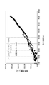
- FIG. 1 It is a figure which shows an example of a structure of the control equipment in process sites, such as a factory plant containing an opening abnormality detection apparatus. It is a graph of the correlation curve which showed the relationship of the flow volume [L / hr] of the liquid which flows through a process line with respect to instruction
- FIG. It is a flowchart which shows the flow of the detection process of the opening degree abnormality in an opening degree abnormality detection part.
- the control valve opening degree abnormality detecting device (hereinafter simply referred to as “opening degree abnormality detecting device”) according to the present invention is an abnormality (opening degree abnormality) of an opening degree (valve opening degree) of a flow control valve provided in a liquid process line. ).
- this opening abnormality detection device data of a theoretical approximation formula derived in advance by a command opening for a flow rate control valve provided in the process line and a flow rate of the liquid flowing through the process line for the command opening is stored in advance.
- the theoretical flow rate value theoretical value
- It is characterized by comprising an opening degree abnormality detecting unit for detecting.
- the “command opening” means an opening based on a control command notified to the flow control valve, and is an opening controlled and instructed according to the amount and speed of the liquid flowing through the process line.
- the command opening is expressed in “%” as a unit, and is defined as a ratio to the maximum opening when the maximum opening of the flow control valve is 100%.
- FIG. 1 is a diagram illustrating an example of a configuration of control equipment in a process site such as a factory plant including an opening abnormality detection device.
- the opening abnormality detection device 10 is provided in the control facility 1 and is electrically connected to a process line 20 through which a liquid flows.
- FIG. 1 shows an example in which the opening degree abnormality detection device 10 is configured as a part of a line control unit 30 that commands the opening degree with respect to a flow rate adjustment valve 21 provided in the process line 20.
- the opening abnormality detection device 10 includes an opening abnormality detection unit 11.
- the opening abnormality detection unit 11 samples and accumulates the command opening degree (%) for the flow rate control valve 21 emitted from the line control unit 30 and the flow rate data of the liquid flowing through the process line 20 with respect to the command opening degree, A theoretical approximation formula derived from the data is created in advance.
- the “theoretical approximate expression” refers to an approximate expression derived from a correlation curve obtained by accumulating data on the command opening for the flow rate control valve 21 and the flow rate of the liquid at that time. Is defined by a quadratic or cubic polynomial or linear approximation. Thus, the theoretical approximation formula can be defined because the flow rate characteristic has a high correlation with the valve opening degree of the flow rate control valve 21.
- this theoretical approximate expression can be calculated based on actual measurement values acquired by a conventional general-purpose data monitoring system used in a factory plant, and such actual measurement data is used as a command to the flow control valve 21.
- the flow rate characteristic of the liquid in the process line 20 with respect to the opening degree is obtained.
- the theoretical approximation formula can be easily constructed with general-purpose software for a personal computer, so that it is not necessary to prepare a special application.
- the opening degree abnormality detection unit 11 acquires the actual measurement value of the flow rate by the liquid flow meter 22 provided on the line of the process line 20.
- the opening degree abnormality detection unit 11 obtains a theoretical flow rate value (theoretical value) at a predetermined command opening degree obtained based on a theoretical approximation formula prepared and held in advance and actually measured at that time.
- the opening degree abnormality of the flow rate adjusting valve 21 is detected by comparing the measured value of the flow rate of the liquid to be measured. More specifically, the absolute value of the difference (theoretical value ⁇ actual value) calculated from the theoretical value and the actual value or the error rate (theoretical value ⁇ actual value / theoretical value ⁇ 100) is a predetermined threshold value. When the range is exceeded, it is determined that the opening degree abnormality has occurred in the flow rate control valve 21 and detected.
- an opening degree abnormality detecting device 10 data of actual measurement values with respect to the command opening degree is sampled during a normal process in which no opening degree abnormality has occurred, and a theoretical approximate expression is derived based on the accumulated sampling data. It is important to keep it. Since the theoretical value derived from the theoretical approximation formula derived in advance is compared with the actually measured value at a specific time point, the opening degree abnormality is generated in the flow rate control valve 21 at the site where the data is sampled. For example, based on a theoretical approximation formula created in advance, even a minute abnormality can be grasped more precisely, and an opening degree abnormality can be detected with high accuracy.
- a warning system (abnormality alarm unit) can be connected and provided.
- the warning system is a system for notifying the abnormality when it is determined that the opening degree abnormality has occurred in the flow control valve 21.
- the alarm system is not particularly limited.
- the alarm system can be configured by a personal PC connected to a general-purpose data monitoring system via a LAN network, and can generate an alarm sound or display an alarm screen on the PC screen. The alarm can be issued by various methods.
- the flow of abnormality detection will be described with respect to a device that detects an abnormality in the opening degree of the flow control valve 21 provided in the process line through which methanol as a liquid flows.
- circulates the process line to which the opening degree abnormality detection apparatus 10 is applied not only methanol but liquids, such as another compound solution, pure water, and process condensed water, may be sufficient.
- FIG. 1 An example of the configuration of the control equipment at the site such as a factory plant including the opening degree abnormality detection device 10 of the flow control valve 21 is as shown in FIG.
- the opening degree abnormality detection device 10 is configured as a part of a line control unit 30 that commands an opening degree to a flow rate adjustment valve 21 provided in the process line 20.
- the process line 20 is provided with a flow rate adjusting valve 21 that adjusts the flow rate of methanol flowing through the pipe (line), and a flow meter 22 that measures the flow rate of methanol flowing through the pipe.
- the opening abnormality detection device 10 includes an opening abnormality detection unit 11.
- FIG. 4 is a flowchart showing the flow of the abnormal opening detection process in the abnormal opening detection unit 11.
- Step S1 As shown in the flow chart of FIG. 4, first, as step S1, data relating to the flow rate of methanol flowing through the process line 20 with respect to the command opening is collected for a predetermined period.
- a flow rate measurement value [L / min] of the methanol flowing in the pipe is measured by a flow meter 22 provided on the pipe of the process line 20.
- an electric signal (s1) related to the measured flow rate is sent to the line control unit 30.
- the line control unit 30 generates a command opening [%] to the flow rate control valve 21 corresponding to the received flow rate measurement value, that is, an electrical signal (s2) of information relating to the theoretical opening corresponding to the flow rate measurement value, as general-purpose data. Transmit to the monitoring system 40.
- the data monitoring system 40 collects the acquired information and transmits an electrical signal (s3) of the information to the worker's personal PC 41.
- the information collection sampling time in the data monitoring system 40 is about 1 minute, and the sampling time interval in the personal PC 41 may be executed every several minutes.
- the line control unit 30 adjusts the flow rate based on the received flow rate measurement value so that the opening degree of the flow rate adjustment valve 21 provided on the pipe becomes the opening degree corresponding to the flow rate measurement value.
- An electric signal (s4) relating to the command opening is transmitted to the valve 21.
- Step S2 Next, as step S2, a theoretical approximate expression is derived based on the sampled information, and the theoretical approximate expression is held in advance so that a theoretical flow rate value (theoretical value) for a specific command opening can be calculated.
- methanol flow rate flow rate measurement value
- FIG. 2 a correlation curve is created and tabulated when the horizontal axis is the command opening [%] and the vertical axis is the liquid flow rate [L / hr].
- a theoretical approximate expression can be derived as a quadratic polynomial.
- the approximate expression can be adopted as the theoretical approximate expression.
- it can also be a polygonal line approximation, for example, a command (opening degree) can be segmented into a maximum of 12 segments (line segments).
- Step S3 Next, as step S3, the theoretical flow rate value (theoretical value) at a predetermined command opening obtained based on a theoretical approximation formula prepared and held in advance is compared with the actual measured value of the methanol flow rate at that time. To do.
- a theoretical flow rate value for a predetermined command opening is obtained based on the theoretical approximate expression obtained in step S2, and the theoretical flow rate value and the flowmeter 22 at that time are actually measured. Comparison with the measured value of methanol flow rate. Based on the comparison, the presence / absence of an abnormal opening of the flow control valve 21 is detected.
- the theoretical flow rate value for the opening command and the actual value measured by the flow meter 22 are compared. It is determined whether or not the “difference” in the flow rate exceeds the preset threshold range.
- the difference between the theoretical flow rate value and the actual measurement value may be an absolute value of the difference, or an error rate between the theoretical flow rate value and the actual measurement value (ratio of the absolute value of the difference to the theoretical flow rate value). There may be.
- Step S4 when the difference between the theoretical flow rate value and the actual measurement value exceeds a predetermined threshold value (in the case of “YES”), it is determined that the opening degree abnormality has occurred in the flow rate control valve 21.
- the theoretical flow rate value is compared with the actual measurement value, whether or not the absolute value of the difference is within a range of ⁇ 5 L / min as a threshold value, or the difference is a ratio with respect to the theoretical flow rate value as the threshold value. It is judged whether it is in the range of ⁇ 5%. If the difference is within a preset threshold range, it is determined that the opening degree abnormality has not occurred in the flow rate control valve 21, and if the difference exceeds the threshold range, the opening degree abnormality has occurred in the flow rate control valve 21. Is determined to have occurred.
- the threshold value is not limited to the exemplified values, and an arbitrary value can be set.
- step S3 If the difference between the theoretical flow rate value and the actual measurement value is within a predetermined threshold range (in the case of “NO”), it is determined that no opening abnormality has occurred, and the process returns to step S3 and is repeated.
- Step S5 As Step S5, when it is determined in Step S4 that the opening degree abnormality has occurred, an alarm is issued to recognize the opening degree abnormality of the flow rate control valve 21.
- the detected opening degree of the flow rate control valve 21 from the alarm system connected to the opening degree abnormality detection device 10 (opening degree abnormality detection unit 11).
- An alarm for recognizing an abnormality can be issued.
- the alarm may be a siren for notifying the worker in the control facility 1 or displaying a warning message (warning screen) on the worker's PC 41 connected to the opening abnormality detection device 10. It may be.
- the opening abnormality detection device 10 includes the opening abnormality detection unit 11 and is derived from the command opening for the flow rate control valve 21 and the flow rate of methanol flowing through the liquid process line for the command opening.
- the approximate flow rate data (theoretical value) at a predetermined command opening calculated based on the theoretical approximate equation and the actual measured value of the methanol flow rate at that time are obtained.
- the opening degree abnormality of the flow control valve 21 is detected.
- the opening degree abnormality of the flow control valve 21 can be detected with high accuracy without requiring installation or construction of new instrumentation equipment.
- Pressure control valve opening abnormality detection device a device for detecting an abnormality in the opening degree of a pressure control valve provided in a gas process line will be described.
- the opening abnormality detection device provided in the hydrogen production facility will be described as a specific example, but the gas flowing through the process line is not limited to hydrogen.
- FIG. 5 is a diagram showing a schematic configuration of the hydrogen production facility.
- a plurality of hydrogen refining vessels (hereinafter also simply referred to as “vessels”) 52 are arranged in parallel, and from the crude hydrogen gas line 53 through which crude hydrogen gas flows, to each vessel 52.
- a pressure control valve 54 is provided in the pipe into which the crude hydrogen gas flows.
- each vessel 52 is provided with a pressure transmitter 55 for monitoring the pressure in the vessel on the discharge side of the purified hydrogen gas, and on the piping for transferring the discharged purified hydrogen gas to the purified hydrogen gas line 57. Is provided with an automatic valve 56.
- an opening degree abnormality detection device 50 is provided, and is connected to each pressure control valve 54 that adjusts the pressure of the crude hydrogen gas flowing into each vessel 52.
- the opening abnormality detecting device 50 includes an opening abnormality detecting unit 51 that detects an opening abnormality of the pressure control valve 54.
- an operation load [%] that is an operation load instruction value for the vessel 52 constituting the hydrogen production facility 5 based on the condition of the amount of hydrogen gas consumed in the facility to which the purified hydrogen gas is supplied.
- the amount of purified hydrogen gas discharged from the vessel 52 is adjusted by an element called “.”
- the opening degree of the pressure control valve 54 for adjusting the pressure of the crude hydrogen gas flowing into the vessel 52 is determined. Yes.
- the operation load is an element that determines the production amount of hydrogen, which is the final product produced in the vessel, constituting the hydrogen production facility, and is the production load on the vessel. Also called load factor.
- the operation load is an instruction value of the operation load, and is an element controlled based on the amount of gas supplied with hydrogen gas produced by the vessel. For example, the maximum supply amount of hydrogen gas is 100%. Defined as a percentage of its maximum supply.
- each vessel 52 constituting the hydrogen production facility 5 crude hydrogen gas flows from the crude hydrogen gas line 53 in accordance with the operation load, and the crude hydrogen gas is refined into purified hydrogen gas, and the purified hydrogen gas is purified. Is discharged toward the purified hydrogen gas line 57. Therefore, in the vessel 52, the pressure changes periodically at a predetermined time interval. This period is called “pressure change period”. The time required for one cycle is referred to as “pressure change cycle time”.
- the opening degree abnormality detecting device 50 uses a pressure change cycle expressed by a relationship between an instruction value (operation load) related to the operation load on the vessel 52 and a pressure in the vessel at that time, and a correlation between them. Is obtained as an approximate expression (theoretical approximate expression). Then, the opening degree abnormality of the pressure control valve 54 is detected by comparing the theoretical cycle time based on the obtained theoretical approximation formula with the actually measured actual cycle time. Thus, in the opening degree abnormality detection device 50, the pressure change cycle that is an element related to the valve opening degree of the pressure control valve 54 is used.
- the opening degree abnormality detection device 50 is derived from the average value of the operation load instruction value and the pressure change cycle time in one pressure change cycle of the vessel 52 to which the pressure control valve 54 is connected. Approximate formula data is created and held in advance, the theoretical cycle time (theoretical value) at the indicated value for the predetermined operating load obtained based on the theoretical approximate formula, and the actual cycle time (actual measured value) measured Is detected, an abnormal opening of the pressure control valve 54 is detected.
- FIG. 6 is a graph showing a pressure change at a predetermined operation load for a certain period with respect to the vessel 52.
- an approximate expression is derived from an instruction value related to an operation load and a pressure change cycle time using a pressure change cycle as shown in FIG.
- the opening abnormality detection device 50 measures the pressure value in the vessel 52 and the instruction value related to the operation load from the monitoring start time, and serves as a reference pressure value (0.3 MPa in the example of FIG. 6).
- the time (Ti) of the minimum pressure value is obtained while comparing and calculating less than data.
- FIG. 7 is a graph showing the relationship between the average value of the instruction values related to the operational load and the pressure change cycle time created by the above procedures (1) to (5).
- the sampling time is 1 minute. Can be every.
- a threshold value for determining an abnormal opening of the pressure control valve is determined.
- This threshold value is prepared for the time difference between the theoretical cycle time (Tth_1) obtained by the produced approximate expression and the measured actual cycle time (Tcy_1), or the time difference error rate (%). , “Tsh_er%”.
- the time difference error rate (%) is defined by abs (Tcy_1 ⁇ Tth_1) / Tth_1 ⁇ 100.
- the theoretical cycle time (Tth_1) of the average value of the instruction values related to the operational load is obtained from the approximate expression, and the time difference (abs (Tcy_1 ⁇ Tth_1)) from the measured actual cycle time (Tcy_1) is determined in advance. It is determined whether or not it falls within the range of the threshold (Tsh), and when the threshold is exceeded, it is determined that the opening degree abnormality has occurred in the pressure control valve 54.
- the error rate of the time difference is It is determined whether or not it falls within the range of the threshold value (Tsh_er), and when the threshold value is exceeded, it is determined that an opening degree abnormality has occurred in the pressure control valve 54.
- an alarm for recognizing the opening degree abnormality of the pressure control valve 54 is generated.
- the opening abnormality detection device 50 can be provided with an alarm system (abnormal alarm unit) connected thereto.
- the warning system is a system for notifying the abnormality when it is determined that the opening degree abnormality has occurred in the pressure control valve 54.
- the alarm may be a siren for notifying the worker in the hydrogen production facility 5, and a warning message (warning screen) is displayed on the worker's PC connected to the opening abnormality detection device 50. It may be a thing.
- the opening degree abnormality detection device 50 includes the opening degree abnormality detection unit 51, and the opening degree abnormality detection unit 51 averages the operation load instruction values in one cycle of the pressure change period of the vessel 52.
- the data of the theoretical approximate expression derived by the value and the pressure change cycle time is created and held in advance.
- the flow rate control valve 21 is compared by comparing the theoretical cycle time (theoretical value) at the indicated value of the predetermined operating load obtained based on the theoretical approximation formula with the actually measured actual cycle time (actual value). An abnormality in the opening is detected.
- the opening degree abnormality detecting device 50 during normal operation, the data of the average value of the operation load indication value in the pressure change cycle 1 cycle in the vessel 52 and the pressure change cycle time is sampled in advance. It is important to derive an approximate expression. Since the theoretical value derived from the theoretical approximation formula derived in advance is compared with the actual cycle time at a specific time point, the opening degree abnormality is detected in the pressure control valve 54 at the site where the data is sampled. If it occurs, the change can be grasped more precisely even if it is a fine abnormality based on a theoretical approximation formula created in advance, and the opening degree abnormality can be detected with high accuracy.
Landscapes
- Physics & Mathematics (AREA)
- General Physics & Mathematics (AREA)
- Engineering & Computer Science (AREA)
- Automation & Control Theory (AREA)
- Fluid Mechanics (AREA)
- Testing And Monitoring For Control Systems (AREA)
- Flow Control (AREA)
- Control Of Fluid Pressure (AREA)
- Testing Of Devices, Machine Parts, Or Other Structures Thereof (AREA)
- Indication Of The Valve Opening Or Closing Status (AREA)
Abstract
新たな計装機器の設置や工事を要することなく、流量調節弁や圧力調節弁等の調節弁の開度異常を高い精度で検出できるようにする。 本発明は、液体プロセスライン上の流量調節弁の開度異常を検出する方法においては、調節弁に対する指令開度とその指令開度に対する液体の流量とにより導出される理論近似式のデータを予め作成し、理論近似式から求められる所定の指令開度での理論流量値とその液体の流量の実測値とを比較することで、調節弁の開度異常を検出する。また、気体プロセスライン上の圧力調節弁の開度異常を検出する方法においては、調節弁が接続された反応容器の圧力変化周期1サイクルにおける操業負荷の指示値の平均値と圧力変化周期時間とにより導出される理論近似式のデータを予め作成し、理論近似式から求められる所定の操業負荷の指示値での理論周期時間と実周期時間とを比較することで、調節弁の開度異常を検出する。
Description
本発明は、液体や気体のプロセスラインにおける流量調節弁や圧力調節弁等の調節弁の開度異常検出装置、及び開度異常検出方法に関する。
従来、バルブ駆動制御やプロセスオートメーション、その他の一般産業用機器の駆動制御においては、ポジショナーを用い、そのポジショナーを調節弁に取り付けることによって、弁の制御を可能にしている。
例えば、調節弁の開度異常を検知する方法として、一般的には、調節弁のポジショナーから出力される開度信号(実開度%)を調節計からの指令開度に対する偏差として解析するか、あるいはポジショナーから開度異常信号を取得することによって行われる。これらの指令開度の出力や開度信号入力等は、一般的な計装制御システムにより管理される。
しかしながら、調節弁のポジショナーには、開度信号出力の無い仕様も多く、そのオプション付きのポジショナーへの交換や計装制御システムとの接続を行うために、配線工事や、関係するソフトウェアの改造等が必要となり、コストアップやその構築に時間を費やすことが余儀なくされる。
例えば特許文献1には、ラジエータをバイパスして流れる冷却水の流量の流量調整手段の異常の有無を診断する異常診断手段について開示されている。しかしながら、間接データである冷却水温の変化量から冷却系の異常診断を行っているため、流量調整手段の異常診断の精度が低いという問題がある。
本発明は、このような実情に鑑みて提案されたものであり、新たな計装機器の設置や工事を要することなく、流量調節弁や圧力調節弁等の調節弁の開度異常を高い精度で検出することができる開度異常検出装置及び方法を提供することを目的とする。
本発明者は、上述した課題を解決するために鋭意検討を重ねた。その結果、調節弁に対する指令開度とラインを流れる液体や気体の特性とにより導出される理論近似値に基づく理論値と、その液体の流量又は気体の圧力の実測値とを比較することにより、調節弁の開度異常を高い精度で検出できることを見出し、本発明を完成するに至った。
[1]本発明の第1の発明は、液体プロセスラインに設けられる流量を調節するための調節弁の開度異常を検出する開度異常検出装置であって、前記調節弁に対する指令開度と該指令開度に対する前記液体プロセスラインを流れる液体の流量とにより導出される理論近似式のデータを予め保有し、該理論近似式に基づいて求められる所定の指令開度での理論流量値(理論値)と、該液体の流量の実測値とを比較することにより、該調節弁の開度異常を検出する開度異常検出部を備える、調節弁の開度異常検出装置である。
[2]本発明の第2の発明は、気体プロセスラインに設けられる圧力を調節するための調節弁の開度異常を検出する開度異常検出装置であって、前記調節弁が接続された反応容器の圧力変化周期1サイクルにおける操業負荷の指示値の平均値と圧力変化周期時間とにより導出される理論近似式のデータを予め保有し、該理論近似式に基づいて求められる所定の操業負荷の指示値での理論周期時間(理論値)と、実測された実周期時間(実測値)とを比較することにより、該調節弁の開度異常を検出する開度異常検出部を備える、調節弁の開度異常検出装置である。
[3]本発明の第3の発明は、第1又は第2の発明において、前記理論値と前記実測値との差が、所定の閾値の範囲を超えた場合に、前記調節弁に開度異常が発生していると判断する、調節弁の開度異常検出装置である。
[4]本発明の第4の発明は、第1乃至第3のいずれかの発明において、前記調節弁の開度異常を検出したとき、該開度異常を認知させる警報を発する異常警報部をさらに備える、調節弁の開度異常検出装置である。
[5]本発明の第5の発明は、液体プロセスラインに設けられる流量を調節するための調節弁の開度異常を検出する開度異常検出方法であって、前記調節弁に対する指令開度と該指令開度に対する前記液体プロセスラインを流れる液体の流量とにより導出される理論近似式のデータを予め作成し、前記理論近似式に基づいて求められる所定の指令開度での理論流量値(理論値)と、該液体の流量の実測値とを比較することにより、該調節弁の開度異常を検出する、調節弁の開度異常検出方法である。
[6]本発明の第6の発明は、気体プロセスラインに設けられる圧力を調節するための調節弁の開度異常を検出する開度異常検出方法であって、前記調節弁が接続された反応容器の圧力変化周期1サイクルにおける操業負荷の指示値の平均値と圧力変化周期時間とにより導出される理論近似式のデータを予め作成し、前記理論近似式に基づいて求められる所定の操業負荷の指示値での理論周期時間(理論値)と、実測された実周期時間(実測値)とを比較することにより、該調節弁の開度異常を検出する、調節弁の開度異常検出方法である。
本発明によれば、新たな計装機器の設置や工事を要することなく、流量調節弁や圧力調節弁等の調節弁の開度異常を高い精度で検出することができる。
以下、本発明の具体的な実施形態について詳細に説明する。なお、本発明は、以下の実施形態に限定されず、本発明の要旨を変更しない範囲で種々の変更が可能である。
≪1.流量調節弁の開度異常検出装置≫
本発明に係る調節弁の開度異常検出装置(以下、単に「開度異常検出装置」という)は、液体プロセスラインに設けられる流量調節弁の開度(弁開度)の異常(開度異常)を検出する装置である。
本発明に係る調節弁の開度異常検出装置(以下、単に「開度異常検出装置」という)は、液体プロセスラインに設けられる流量調節弁の開度(弁開度)の異常(開度異常)を検出する装置である。
この開度異常検出装置においては、プロセスラインに設けられる流量調節弁に対する指令開度とその指令開度に対するプロセスラインを流通する液体の流量とにより導出される理論近似式のデータを予め保有しており、その理論近似式に基づいて求められる所定の指令開度での理論流量値(理論値)と、そのときの液体の流量の実測値とを比較することにより、調節弁の開度異常を検出する開度異常検出部を備えることを特徴としている。
「指令開度」とは、流量調節弁に通知される制御指令に基づく開度をいい、プロセスラインを流れる液体の量や速度等に応じて制御され、指示される開度である。また、この指令開度は、単位として「%」で表されるものであり、流量調節弁の最大の開度を100%としたとき、その最大開度に対する割合として定義される。
図1は、開度異常検出装置を含む工場プラント等のプロセス現場における制御設備の構成の一例を示す図である。図1に示すように、開度異常検出装置10は、制御設備1内に設けられており、液体が流れるプロセスライン20と電気的に接続されている。なお、図1では、開度異常検出装置10が、プロセスライン20に設けられる流量調節弁21に対して開度を指令するライン制御部30の一部として構成されている例を示している。
具体的に、開度異常検出装置10は、開度異常検出部11を備えている。
開度異常検出部11は、ライン制御部30から発せられた流量調節弁21に対する指令開度(%)とその指令開度に対するプロセスライン20を流れる液体の流量のデータをサンプリングして蓄積し、そのデータから導出される理論近似式を予め作成している。
「理論近似式」とは、上述したように、流量調節弁21に対する指令開度とそのときの液体の流量とのデータを蓄積させて得られる相関曲線から導かれる近似式をいい、指令開度を定義域とした関数であって、2次又は3次の多項式、もしくは直線近似で表わされる。このように、理論近似式は、流量調節弁21の弁開度に対する流量特性の相関性が高いことから定義することができるものである。
例えば、この理論近似式は、工場プラントで使用される従来汎用のデータ監視システムにより取得した実測値をもとに算出することができ、そのような実測値データが、流量調節弁21への指令開度に対するそのプロセスライン20の液体の流量特性となる。なお、理論近似式は、パーソナルコンピュータの汎用ソフトで容易に構築ができるため、特別なアプリケーションを特段用意する必要はない。
一方で、開度異常検出部11は、プロセスライン20のライン上に設けられている液体の流量計22により流量の実測値を取得する。
そして、開度異常検出部11では、予め作成し保有していた理論近似式に基づいて求められる所定の指令開度での理論流量値(理論値)と、そのときの実際に計測して得られる液体の流量の実測値とを比較することによって、その流量調節弁21の開度異常を検出する。より具体的には、理論値と実測値とにより算出される差分(理論値-実測値)の絶対値、又は、その誤差率(理論値-実測値/理論値×100)が、所定の閾値の範囲を超えた場合に、その流量調節弁21に開度異常が発生していると判断して検知する。
このような開度異常検出装置10においては、開度異常が生じていない正常なプロセス時において指令開度に対する実計測値のデータをサンプリングし、蓄積されたサンプリングデータに基づいて理論近似式を導出しておくことが重要となる。そして、その予め導出しておいた理論近似式による理論値と、特定の時点における実測値を比較するようにしているため、データをサンプリングしたその現場の流量調節弁21に開度異常が生じれば、予め作成した理論近似式に基づいて、細かな異常であってもより緻密に変化を把握することができ、高い精度で開度異常を検出することができる。
また、新たな計装機器の設置や工事等を要することなく、効率的に流量調節弁21の開度異常を検出することができる。
なお、開度異常検出装置10においては、発警報システム(異常警報部)を接続して設けることができる。発警報システムは、流量調節弁21に開度異常が発生していると判断される場合に、その異常を知らせるシステムである。発警報システムとしては、特に限定されず、例えば汎用のデータ監視システムとLANネットワークで接続された作業者個人のPCにより構成でき、アラーム音を発する態様や、PC画面上に警報画面を表示させる態様等、種々の方法により発警報することができる。
より具体的に、液体としてのメタノールが流通するプロセスラインに設けられる流量調節弁21の開度異常を検出する装置に関して、その異常検出の流れを説明する。なお、開度異常検出装置10が適用されるプロセスラインを流通する液体としては、メタノールに限られず、その他の化合物溶液や、純水、プロセス凝集水等の液体であってもよい。
流量調節弁21の開度異常検出装置10を含む工場プラント等の現場における制御設備の構成の一例は、図1に示した通りである。図1に示すように、開度異常検出装置10は、プロセスライン20に設けられる流量調節弁21に対して開度を指令するライン制御部30の一部として構成されている。なお、プロセスライン20においては、配管(ライン)を流れるメタノールの流量を調整する流量調節弁21と、その配管を流れるメタノールの流量を測定する流量計22とが設けられている。
本発明に係る開度異常検出装置10は、開度異常検出部11を備えている。図4は、開度異常検出部11における、開度異常の検出処理の流れを示すフロー図である。
(ステップS1)
図4のフロー図に示すように、先ず、ステップS1として、所定の期間において指令開度に対するプロセスライン20を流れるメタノールの流量に関するデータを収集する。
図4のフロー図に示すように、先ず、ステップS1として、所定の期間において指令開度に対するプロセスライン20を流れるメタノールの流量に関するデータを収集する。
図1に示すように、プロセスライン20にメタノールが流通している所定の期間において、プロセスライン20の配管上に設けられた流量計22により、配管内を流れるメタノールの流量計測値[L/min]が測定され、その流量計測値に関する電気信号(s1)がライン制御部30に送られる。ライン制御部30は、受信した流量計測値に対応する流量調節弁21への指令開度[%]、すなわち流量計測値に対応する理論開度に関する情報の電気信号(s2)を、汎用のデータ監視システム40に送信する。データ監視システム40は、取得した情報を収集するとともに、その情報の電気信号(s3)を作業者の個人PC41に送信する。なお、データ監視システム40における情報収集のサンプリング時間はおよそ1分程度であり、個人PC41におけるサンプリング時間間隔は数分間おきに実行すればよい。
一方、ライン制御部30においては、受信した流量計測値に基づいて、その配管上に設けられた流量調節弁21の開度がその流量計測値に対応する開度となるように、その流量調節弁21に対して指令開度に関する電気信号(s4)を送信する。
(ステップS2)
次に、ステップS2として、サンプリングした情報に基づいて理論近似式を導出し、その理論近似式を予め保有して、特定の指令開度に対する理論流量値(理論値)を算出可能とする。
次に、ステップS2として、サンプリングした情報に基づいて理論近似式を導出し、その理論近似式を予め保有して、特定の指令開度に対する理論流量値(理論値)を算出可能とする。
具体的に、データ監視システム40においては、サンプリングした情報に基づいて、指令開度に対するメタノールの流量(流量計測値)の関係のデータをテーブル化する。例えば、図2に示すように、横軸を指令開度[%]とし、縦軸を液体流量[L/hr]としたときの相関曲線を作成してテーブル化する。この図2に示すような相関曲線によれば、2次の多項式として理論近似式を導出することができる。
なお、相関係数が高ければ(例えば0.9以上)、その近似式を理論近似式として採用することができる。また、図3に示すように、折れ線近似とすることもでき、例えば指令開度を最大12個までに区切ってセグメント(線分)を作成することもできる。
(ステップS3)
次に、ステップS3として、予め作成し保有している理論近似式に基づいて求められる所定の指令開度での理論流量値(理論値)と、そのときのメタノールの流量の実測値とを比較する。
次に、ステップS3として、予め作成し保有している理論近似式に基づいて求められる所定の指令開度での理論流量値(理論値)と、そのときのメタノールの流量の実測値とを比較する。
開度異常検出部11においては、ステップS2にて得られた理論近似式に基づいて所定の指令開度に対する理論流量値を求め、その理論流量値と、そのときに流量計22により実際に計測されるメタノールの流量の実測値との比較を行う。そして、その比較に基づいて流量調節弁21の開度異常の有無を検出する。
開度異常検出部11における開度異常の判定方法としては、例えば図2や図3のように得られた、開度指令に対する理論流量値と、流量計22により計測される実測値とを比較したときの流量の「差」が、予め設定した閾値の範囲を超えているか否かを判断する。ここで、理論流量値と実測値との差とは、差分の絶対値であってもよく、あるいはその理論流量値と実測値との誤差率(理論流量値に対する差分の絶対値の割合)であってもよい。
(ステップS4)
そして、ステップS4として、理論流量値と実測値との差が所定の閾値を超えた場合(「YES」の場合)に、流量調節弁21に開度異常が発生していると判定する。
そして、ステップS4として、理論流量値と実測値との差が所定の閾値を超えた場合(「YES」の場合)に、流量調節弁21に開度異常が発生していると判定する。
例えば、理論流量値と実測値とを比較したときに、その差の絶対値が閾値としての±5L/minの範囲内であるか否か、あるいは、その差が理論流量値に対する割合で閾値としての±5%の範囲内である否かを判断する。そして、その差が、予め設定した閾値の範囲内であれば流量調節弁21に開度異常は発生していないと判定し、その閾値の範囲を超える場合には流量調節弁21に開度異常が発生していると判定する。なお、閾値は、例示した値に限定されず、任意の値を設定することができる。
なお、理論流量値と実測値との差が所定の閾値の範囲内であれば(「NO」の場合)、開度異常の発生していないと判定され、ステップS3に戻り繰り返される。
(ステップS5)
ステップS5として、ステップS4にて開度異常が発生していると判定されたときに、流量調節弁21の開度異常を認知させる警報を発する。
ステップS5として、ステップS4にて開度異常が発生していると判定されたときに、流量調節弁21の開度異常を認知させる警報を発する。
例えば、開度異常が発生していると判定されたときには、開度異常検出装置10(開度異常検出部11)に接続された発警報システムから、その検出された流量調節弁21の開度異常を認知される警報を発するようにすることができる。警報としては、制御設備1内にいる作業員に知らせるためのサイレンであってもよく、また、開度異常検出装置10に接続された作業者のPC41に警告メッセージ(警告画面)を表示させるものであってもよい。
このように、本発明に係る開度異常検出装置10は、開度異常検出部11を備え、流量調節弁21に対する指令開度とその指令開度に対する液体プロセスラインを流れるメタノールの流量とにより導出される近似式のデータを予め作成して保有し、その理論近似式に基づいて求められる所定の指令開度での理論流量値(理論値)と、そのときのメタノールの流量の実測値とを比較することで流量調節弁21の開度異常を検出するようにしている。このことにより、新たな計装機器の設置や工事を要することなく、流量調節弁21の開度異常を高い精度で検出することができる。
≪2.圧力調節弁の開度異常検出装置≫
次に、本発明に係る開度異常検出装置として、気体プロセスラインに設けられる圧力調節弁の弁開度の異常を検出する装置について説明する。以下では、水素製造設備に設けられる開度異常検出装置を具体例として挙げて説明するが、プロセスラインを流通する気体としては、水素に限られない。
次に、本発明に係る開度異常検出装置として、気体プロセスラインに設けられる圧力調節弁の弁開度の異常を検出する装置について説明する。以下では、水素製造設備に設けられる開度異常検出装置を具体例として挙げて説明するが、プロセスラインを流通する気体としては、水素に限られない。
図5は、水素製造設備の概略構成を示す図である。図5に示すように、水素製造設備5においては、複数の水素精製ベッセル(以下、単に「ベッセル」ともいう)52が並列し、粗水素ガスが流通する粗水素ガスライン53から各ベッセル52に粗水素ガスが流入する配管に圧力調節弁54が設けられている。また、各ベッセル52には、精製水素ガスの吐出側に、ベッセル内圧力監視用の圧力伝送器55がそれぞれ設けられており、その吐出した精製水素ガスを精製水素ガスライン57へ移送する配管上には自動弁56が設けられている。
水素製造設備5においては、開度異常検出装置50が設けられており、各ベッセル52に流入する粗水素ガスの圧力を調節する各圧力調節弁54に接続されている。そして、その開度異常検出装置50においては、圧力調節弁54の開度異常を検出する開度異常検出部51を備えている。
水素製造設備5においては、精製水素ガスの供給先の設備で消費される水素ガス量の条件に基づき、当該水素製造設備5を構成するベッセル52に対する操業負荷の指示値であるオペレーションロード[%]と呼ばれる要素により、ベッセル52からの精製水素ガスの吐出量が調整されている。水素製造設備5においては、そのオペレーションロードの指令に基づいてベッセル52内の圧力をコントロールするために、ベッセル52に流入させる粗水素ガスの圧力を調整する圧力調節弁54の開度を決定している。
ここで、操業負荷とは、水素製造設備を構成するベッセルに対して、そのベッセルにて製造する最終生産物である水素の製造量を決定する要素であって、ベッセルに対する製造負荷であり、操業負荷率とも称される。また、オペレーションロードとは、その操業負荷の指示値であって、ベッセルにて製造した水素ガスを供給するガス量に基づいて制御される要素であり、例えば水素ガスの最大供給量を100%としたときのその最大供給量に対する割合として定義される。
水素製造設備5を構成する各ベッセル52においては、操業負荷に応じて、粗水素ガスライン53から粗水素ガスが流入し、内部で粗水素ガスを精製して精製水素ガスとし、その精製水素ガスを精製水素ガスライン57に向けて吐出する。そのため、ベッセル52内では、所定の時間間隔において周期的に圧力が変化する。なお、この周期を「圧力変化周期」という。また、周期1サイクルの所要時間を「圧力変化周期時間」という。
本発明者の検証により、ベッセル52内の圧力変化に着目したとき、圧力変化周期1サイクルにおいて、各オペレーションロードの平均値(%)に対する圧力変化周期時間の関係に高い相関性を有することが見出された。そこで、開度異常検出装置50においては、ベッセル52に対する操業負荷に関する指示値(オペレーションロード)と、そのときのベッセル内の圧力との関係で表される圧力変化周期を利用し、それらの相関関係を近似式(理論近似式)として求める。そして、求められた理論近似式に基づく理論周期時間と、実測された実周期時間とを比較することによって、圧力調節弁54の開度異常を検出する。このように、開度異常検出装置50においては、圧力調節弁54の弁開度に関係する要素である圧力変化周期を利用する。
より具体的には、開度異常検出装置50は、圧力調節弁54が接続されたベッセル52の圧力変化周期1サイクルにおける操業負荷の指示値の平均値と圧力変化周期時間とにより導出される理論近似式のデータを予め作成して保有し、その理論近似式に基づいて求められる所定の操業負荷に関する指示値での理論周期時間(理論値)と、実測された実周期時間(実測値)とを比較することにより、圧力調節弁54の開度異常を検出する。
例えば、図6は、ベッセル52に対する一定期間における所定の操業負荷での圧力変化を示すグラフ図である。開度異常検出装置50においては、先ず、図6に示すような圧力変化周期を利用して、操業負荷に関する指示値と、圧力変化周期時間とにより近似式を導出する。
(1)先ず、開度異常検出装置50は、モニタリング開始時刻から、ベッセル52内の圧力値と操業負荷に関する指示値とを計測し、目安とした圧力値(図6の例では0.3MPa)未満のデータを比較演算しながら、最小圧力値の時刻(Ti)を求める。
(2)(1)の手順と同様に、次に現れる最小圧力値の時刻(Ti+1)を求める。
(3)そして、求められた最小圧力値の時刻から、[Ti+1]-[Ti]=Tcy_1を算出し、これを圧力変化周期時間(以下、単に「周期時間」ともいう)と定義する。
(4)次に、時刻「Ti」~「Ti+1」の区間(圧力変化周期の1サイクル)における操業負荷に関する指示値の平均値を算出する。
(5)そして、(4)の手順で算出した、圧力変化周期1サイクルにおける操業負荷に関する指示値の平均値に対する周期時間(Tcy_1)の近似式を作成し、そこから理論周期時間(Tth_1)を求める。
図7は、上記の(1)~(5)の手順により作成される、操業負荷に関する指示値の平均値と圧力変化の周期時間との関係を示すグラフ図であり、例えばサンプリング時間は1分毎とすることができる。
(6)次に、圧力調節弁の開度異常を判定するための閾値を決定する。この閾値は、作製した近似式で得られた理論周期時間(Tth_1)と、計測された実周期時間(Tcy_1)との時間差、もしくは時間差誤差率(%)に対して用意し、それぞれ「Tsh」、「Tsh_er%」とする。なお、時間差誤差率(%)は、abs(Tcy_1-Tth_1)/Tth_1×100で定義されるものである。
(7)続いて、操業負荷に関する指示値の平均値の理論周期時間(Tth_1)を近似式より求め、計測した実周期時間(Tcy_1)との時間差(abs(Tcy_1-Tth_1)が、予め決定した閾値(Tsh)の範囲に入るか否かを判断し、その閾値を超えた場合には、圧力調節弁54に開度異常が発生していると判定する。あるいは、その時間差の誤差率が、閾値(Tsh_er)の範囲に入るか否かを判断し、その閾値を超えた場合には、圧力調節弁54に開度異常が発生していると判定する。
(8)開度異常が発生していると判定されると、圧力調節弁54の開度異常を認知させる警報を発生する。なお、警報を発するため、開度異常検出装置50においては発警報システム(異常警報部)を接続して設けることができる。発警報システムは、圧力調節弁54に開度異常が発生していると判断される場合に、その異常を知らせるシステムである。警報としては、水素製造設備5内にいる作業員に知らせるためのサイレンであってもよく、また、開度異常検出装置50に接続された作業者のPCに警告メッセージ(警告画面)を表示させるものであってもよい。
(9)なお、圧力調節弁54や、ベッセル52の吐出側の自動弁56に不具合が生じた場合には、図6中の破線(パターン1,2,3)で示すような圧力変化も考えられる。その場合も、警報を発するようにするとよい。
このように、本発明に係る開度異常検出装置50は、開度異常検出部51を備え、その開度異常検出部51は、ベッセル52の圧力変化周期1サイクルにおける操業負荷の指示値の平均値と、圧力変化周期時間とにより導出される理論近似式のデータを予め作成し保有している。そして、その理論近似式に基づいて求められる所定の操業負荷の指示値での理論周期時間(理論値)と、実測された実周期時間(実測値)とを比較することで、流量調節弁21の開度異常を検出するようにしている。
このような開度異常検出装置50においては、正常なオペレーション時に予め、ベッセル52内の圧力変化周期1サイクルにおける操業負荷の指示値の平均値とその圧力変化周期時間とのデータをサンプリングして理論近似式を導出することが重要となる。そして、その予め導出しておいた理論近似式による理論値と、特定の時点における実周期時間とを比較するようにしているため、データをサンプリングしたその現場の圧力調節弁54に開度異常が生じれば、予め作成した理論近似式に基づいて、細かな異常であってもより精密に変化を把握することができ、高い精度で開度異常を検出することができる。
また、新たな計装機器の設置や工事等を要することなく、効率的に圧力調節弁54の開度異常を検出することができる。
1 制御設備
5 水素製造設備
10 開度異常検出装置
11 開度異常検出部
20 プロセスライン
21 流量調節弁
22 流量計
30 ライン制御部
40 データ監視システム
50 開度異常検出装置
51 開度異常検出部
52 ベッセル
53 粗水素ガスライン
54 圧力調節弁
55 圧力伝送器
56 自動弁
57 精製水素ガスライン
5 水素製造設備
10 開度異常検出装置
11 開度異常検出部
20 プロセスライン
21 流量調節弁
22 流量計
30 ライン制御部
40 データ監視システム
50 開度異常検出装置
51 開度異常検出部
52 ベッセル
53 粗水素ガスライン
54 圧力調節弁
55 圧力伝送器
56 自動弁
57 精製水素ガスライン
Claims (6)
- 液体プロセスラインに設けられる流量を調節するための調節弁の開度異常を検出する開度異常検出装置であって、
前記調節弁に対する指令開度と該指令開度に対する前記液体プロセスラインを流れる液体の流量とにより導出される理論近似式のデータを予め保有し、該理論近似式に基づいて求められる所定の指令開度での理論流量値(理論値)と、該液体の流量の実測値とを比較することにより、該調節弁の開度異常を検出する開度異常検出部を備える
調節弁の開度異常検出装置。 - 気体プロセスラインに設けられる圧力を調節するための調節弁の開度異常を検出する開度異常検出装置であって、
前記調節弁が接続された反応容器の圧力変化周期1サイクルにおける操業負荷の指示値の平均値と圧力変化周期時間とにより導出される理論近似式のデータを予め保有し、該理論近似式に基づいて求められる所定の操業負荷の指示値での理論周期時間(理論値)と、実測された実周期時間(実測値)とを比較することにより、該調節弁の開度異常を検出する開度異常検出部を備える
調節弁の開度異常検出装置。 - 前記理論値と前記実測値との差が、所定の閾値の範囲を超えた場合に、前記調節弁に開度異常が発生していると判断する
請求項1又は2に記載の調節弁の開度異常検出装置。 - 前記調節弁の開度異常を検出したとき、該開度異常を認知させる警報を発する異常警報部をさらに備える
請求項1乃至3のいずれかに記載の調節弁の開度異常検出装置。 - 液体プロセスラインに設けられる流量を調節するための調節弁の開度異常を検出する開度異常検出方法であって、
前記調節弁に対する指令開度と該指令開度に対する前記液体プロセスラインを流れる液体の流量とにより導出される理論近似式のデータを予め作成し、
前記理論近似式に基づいて求められる所定の指令開度での理論流量値(理論値)と、該液体の流量の実測値とを比較することにより、該調節弁の開度異常を検出する
調節弁の開度異常検出方法。 - 気体プロセスラインに設けられる圧力を調節するための調節弁の開度異常を検出する開度異常検出方法であって、
前記調節弁が接続された反応容器の圧力変化周期1サイクルにおける操業負荷の指示値の平均値と圧力変化周期時間とにより導出される理論近似式のデータを予め作成し、
前記理論近似式に基づいて求められる所定の操業負荷の指示値での理論周期時間(理論値)と、実測された実周期時間(実測値)とを比較することにより、該調節弁の開度異常を検出する
調節弁の開度異常検出方法。
Priority Applications (1)
| Application Number | Priority Date | Filing Date | Title |
|---|---|---|---|
| PH12019502768A PH12019502768A1 (en) | 2017-06-12 | 2019-12-06 | Abnormal opening degree detection device and abnormal opening degree detection method for control valve |
Applications Claiming Priority (2)
| Application Number | Priority Date | Filing Date | Title |
|---|---|---|---|
| JP2017115111A JP6660029B2 (ja) | 2017-06-12 | 2017-06-12 | 調節弁の開度異常検出装置、開度異常検出方法 |
| JP2017-115111 | 2017-06-12 |
Publications (1)
| Publication Number | Publication Date |
|---|---|
| WO2018230237A1 true WO2018230237A1 (ja) | 2018-12-20 |
Family
ID=64659723
Family Applications (1)
| Application Number | Title | Priority Date | Filing Date |
|---|---|---|---|
| PCT/JP2018/018971 Ceased WO2018230237A1 (ja) | 2017-06-12 | 2018-05-16 | 調節弁の開度異常検出装置、開度異常検出方法 |
Country Status (3)
| Country | Link |
|---|---|
| JP (1) | JP6660029B2 (ja) |
| PH (1) | PH12019502768A1 (ja) |
| WO (1) | WO2018230237A1 (ja) |
Families Citing this family (1)
| Publication number | Priority date | Publication date | Assignee | Title |
|---|---|---|---|---|
| CN113325824B (zh) * | 2021-06-02 | 2022-10-25 | 三门核电有限公司 | 一种基于阈值监测的调节阀异常识别方法及系统 |
Citations (2)
| Publication number | Priority date | Publication date | Assignee | Title |
|---|---|---|---|---|
| JP2005267572A (ja) * | 2004-03-22 | 2005-09-29 | Jfe Steel Kk | 流量制御の異常判定方法及び装置 |
| JP2013088946A (ja) * | 2011-10-14 | 2013-05-13 | Horiba Stec Co Ltd | 流量制御装置、流量制御装置に用いられる診断装置及び診断用プログラム |
-
2017
- 2017-06-12 JP JP2017115111A patent/JP6660029B2/ja active Active
-
2018
- 2018-05-16 WO PCT/JP2018/018971 patent/WO2018230237A1/ja not_active Ceased
-
2019
- 2019-12-06 PH PH12019502768A patent/PH12019502768A1/en unknown
Patent Citations (2)
| Publication number | Priority date | Publication date | Assignee | Title |
|---|---|---|---|---|
| JP2005267572A (ja) * | 2004-03-22 | 2005-09-29 | Jfe Steel Kk | 流量制御の異常判定方法及び装置 |
| JP2013088946A (ja) * | 2011-10-14 | 2013-05-13 | Horiba Stec Co Ltd | 流量制御装置、流量制御装置に用いられる診断装置及び診断用プログラム |
Also Published As
| Publication number | Publication date |
|---|---|
| PH12019502768A1 (en) | 2020-11-09 |
| JP2019003260A (ja) | 2019-01-10 |
| JP6660029B2 (ja) | 2020-03-04 |
Similar Documents
| Publication | Publication Date | Title |
|---|---|---|
| JP6820364B2 (ja) | 動作プロセスを監視するシステム、方法、およびコンピュータ可読記憶媒体 | |
| EP2216700B1 (en) | Flow rate controller | |
| GB2506730B (en) | Systems and methods to monitor an asset in an operating process unit | |
| JP5975883B2 (ja) | 故障している計器を検出する方法及び装置 | |
| JP5958456B2 (ja) | プラント制御システム、制御装置、管理装置、及びプラント情報処理方法 | |
| US7778797B2 (en) | Method and system for detecting abnormal operation in a stirred vessel | |
| EP1792241B1 (en) | System and method for detecting an abnormal situation associated with a reactor | |
| JP5991329B2 (ja) | 制御装置、管理装置、プラント制御システム、及びデータ処理方法 | |
| EP2027513B1 (en) | Diagnostics in process control and monitoring systems | |
| JP4021634B2 (ja) | 故障予測支援装置 | |
| CN116954176B (zh) | 一种工业生产流程动态控制方法及系统 | |
| CN112561283B (zh) | 一种水电站调速器比例阀健康状态诊断方法和控制系统 | |
| JP6710939B2 (ja) | フィールド機器 | |
| CN116608135B (zh) | 一种供水泵状态检测装置及方法 | |
| WO2018230237A1 (ja) | 調節弁の開度異常検出装置、開度異常検出方法 | |
| JP2010276339A (ja) | センサ診断方法およびセンサ診断装置 | |
| US20200204887A1 (en) | Method of determining the time interval until a service action is required | |
| CN116880417A (zh) | 生产线智能点检系统 | |
| CN116447119A (zh) | 一种水泵无水保护的控制系统 | |
| JP7232028B2 (ja) | 運転監視装置および方法 | |
| CN119960535A (zh) | 一种消毒液配制系统智能操作方法及装置 | |
| JP2015225517A (ja) | 制御系異常判定装置および制御系異常判定方法 | |
| JP2024016374A (ja) | 監視システム、監視方法及びプログラム | |
| US20160202169A1 (en) | Method of operating a particle sensor and evaluation of the results thereof |
Legal Events
| Date | Code | Title | Description |
|---|---|---|---|
| 121 | Ep: the epo has been informed by wipo that ep was designated in this application |
Ref document number: 18818302 Country of ref document: EP Kind code of ref document: A1 |
|
| NENP | Non-entry into the national phase |
Ref country code: DE |
|
| 122 | Ep: pct application non-entry in european phase |
Ref document number: 18818302 Country of ref document: EP Kind code of ref document: A1 |