WO2018224262A1 - An electric motor ball bearing lubricating apparatus - Google Patents
An electric motor ball bearing lubricating apparatus Download PDFInfo
- Publication number
- WO2018224262A1 WO2018224262A1 PCT/EP2018/062728 EP2018062728W WO2018224262A1 WO 2018224262 A1 WO2018224262 A1 WO 2018224262A1 EP 2018062728 W EP2018062728 W EP 2018062728W WO 2018224262 A1 WO2018224262 A1 WO 2018224262A1
- Authority
- WO
- WIPO (PCT)
- Prior art keywords
- lubrication
- electric motor
- lubrication apparatus
- shield
- ball bearing
- Prior art date
- Legal status (The legal status is an assumption and is not a legal conclusion. Google has not performed a legal analysis and makes no representation as to the accuracy of the status listed.)
- Ceased
Links
Images


Classifications
-
- F—MECHANICAL ENGINEERING; LIGHTING; HEATING; WEAPONS; BLASTING
- F16—ENGINEERING ELEMENTS AND UNITS; GENERAL MEASURES FOR PRODUCING AND MAINTAINING EFFECTIVE FUNCTIONING OF MACHINES OR INSTALLATIONS; THERMAL INSULATION IN GENERAL
- F16C—SHAFTS; FLEXIBLE SHAFTS; ELEMENTS OR CRANKSHAFT MECHANISMS; ROTARY BODIES OTHER THAN GEARING ELEMENTS; BEARINGS
- F16C33/00—Parts of bearings; Special methods for making bearings or parts thereof
- F16C33/30—Parts of ball or roller bearings
- F16C33/66—Special parts or details in view of lubrication
- F16C33/6603—Special parts or details in view of lubrication with grease as lubricant
- F16C33/6622—Details of supply and/or removal of the grease, e.g. purging grease
- F16C33/6625—Controlling or conditioning the grease supply
-
- F—MECHANICAL ENGINEERING; LIGHTING; HEATING; WEAPONS; BLASTING
- F16—ENGINEERING ELEMENTS AND UNITS; GENERAL MEASURES FOR PRODUCING AND MAINTAINING EFFECTIVE FUNCTIONING OF MACHINES OR INSTALLATIONS; THERMAL INSULATION IN GENERAL
- F16C—SHAFTS; FLEXIBLE SHAFTS; ELEMENTS OR CRANKSHAFT MECHANISMS; ROTARY BODIES OTHER THAN GEARING ELEMENTS; BEARINGS
- F16C33/00—Parts of bearings; Special methods for making bearings or parts thereof
- F16C33/30—Parts of ball or roller bearings
- F16C33/66—Special parts or details in view of lubrication
- F16C33/6603—Special parts or details in view of lubrication with grease as lubricant
- F16C33/6607—Retaining the grease in or near the bearing
-
- F—MECHANICAL ENGINEERING; LIGHTING; HEATING; WEAPONS; BLASTING
- F16—ENGINEERING ELEMENTS AND UNITS; GENERAL MEASURES FOR PRODUCING AND MAINTAINING EFFECTIVE FUNCTIONING OF MACHINES OR INSTALLATIONS; THERMAL INSULATION IN GENERAL
- F16C—SHAFTS; FLEXIBLE SHAFTS; ELEMENTS OR CRANKSHAFT MECHANISMS; ROTARY BODIES OTHER THAN GEARING ELEMENTS; BEARINGS
- F16C33/00—Parts of bearings; Special methods for making bearings or parts thereof
- F16C33/30—Parts of ball or roller bearings
- F16C33/66—Special parts or details in view of lubrication
- F16C33/6637—Special parts or details in view of lubrication with liquid lubricant
- F16C33/664—Retaining the liquid in or near the bearing
-
- F—MECHANICAL ENGINEERING; LIGHTING; HEATING; WEAPONS; BLASTING
- F16—ENGINEERING ELEMENTS AND UNITS; GENERAL MEASURES FOR PRODUCING AND MAINTAINING EFFECTIVE FUNCTIONING OF MACHINES OR INSTALLATIONS; THERMAL INSULATION IN GENERAL
- F16C—SHAFTS; FLEXIBLE SHAFTS; ELEMENTS OR CRANKSHAFT MECHANISMS; ROTARY BODIES OTHER THAN GEARING ELEMENTS; BEARINGS
- F16C33/00—Parts of bearings; Special methods for making bearings or parts thereof
- F16C33/30—Parts of ball or roller bearings
- F16C33/66—Special parts or details in view of lubrication
- F16C33/6637—Special parts or details in view of lubrication with liquid lubricant
- F16C33/6659—Details of supply of the liquid to the bearing, e.g. passages or nozzles
-
- F—MECHANICAL ENGINEERING; LIGHTING; HEATING; WEAPONS; BLASTING
- F16—ENGINEERING ELEMENTS AND UNITS; GENERAL MEASURES FOR PRODUCING AND MAINTAINING EFFECTIVE FUNCTIONING OF MACHINES OR INSTALLATIONS; THERMAL INSULATION IN GENERAL
- F16C—SHAFTS; FLEXIBLE SHAFTS; ELEMENTS OR CRANKSHAFT MECHANISMS; ROTARY BODIES OTHER THAN GEARING ELEMENTS; BEARINGS
- F16C33/00—Parts of bearings; Special methods for making bearings or parts thereof
- F16C33/30—Parts of ball or roller bearings
- F16C33/66—Special parts or details in view of lubrication
- F16C33/6637—Special parts or details in view of lubrication with liquid lubricant
- F16C33/6659—Details of supply of the liquid to the bearing, e.g. passages or nozzles
- F16C33/6674—Details of supply of the liquid to the bearing, e.g. passages or nozzles related to the amount supplied, e.g. gaps to restrict flow of the liquid
-
- F—MECHANICAL ENGINEERING; LIGHTING; HEATING; WEAPONS; BLASTING
- F16—ENGINEERING ELEMENTS AND UNITS; GENERAL MEASURES FOR PRODUCING AND MAINTAINING EFFECTIVE FUNCTIONING OF MACHINES OR INSTALLATIONS; THERMAL INSULATION IN GENERAL
- F16C—SHAFTS; FLEXIBLE SHAFTS; ELEMENTS OR CRANKSHAFT MECHANISMS; ROTARY BODIES OTHER THAN GEARING ELEMENTS; BEARINGS
- F16C35/00—Rigid support of bearing units; Housings, e.g. caps, covers
- F16C35/04—Rigid support of bearing units; Housings, e.g. caps, covers in the case of ball or roller bearings
- F16C35/042—Housings for rolling element bearings for rotary movement
-
- F—MECHANICAL ENGINEERING; LIGHTING; HEATING; WEAPONS; BLASTING
- F16—ENGINEERING ELEMENTS AND UNITS; GENERAL MEASURES FOR PRODUCING AND MAINTAINING EFFECTIVE FUNCTIONING OF MACHINES OR INSTALLATIONS; THERMAL INSULATION IN GENERAL
- F16K—VALVES; TAPS; COCKS; ACTUATING-FLOATS; DEVICES FOR VENTING OR AERATING
- F16K5/00—Plug valves; Taps or cocks comprising only cut-off apparatus having at least one of the sealing faces shaped as a more or less complete surface of a solid of revolution, the opening and closing movement being predominantly rotary
- F16K5/04—Plug valves; Taps or cocks comprising only cut-off apparatus having at least one of the sealing faces shaped as a more or less complete surface of a solid of revolution, the opening and closing movement being predominantly rotary with plugs having cylindrical surfaces; Packings therefor
- F16K5/0414—Plug channel at 90 degrees to the inlet
-
- F—MECHANICAL ENGINEERING; LIGHTING; HEATING; WEAPONS; BLASTING
- F16—ENGINEERING ELEMENTS AND UNITS; GENERAL MEASURES FOR PRODUCING AND MAINTAINING EFFECTIVE FUNCTIONING OF MACHINES OR INSTALLATIONS; THERMAL INSULATION IN GENERAL
- F16K—VALVES; TAPS; COCKS; ACTUATING-FLOATS; DEVICES FOR VENTING OR AERATING
- F16K5/00—Plug valves; Taps or cocks comprising only cut-off apparatus having at least one of the sealing faces shaped as a more or less complete surface of a solid of revolution, the opening and closing movement being predominantly rotary
- F16K5/08—Details
- F16K5/22—Features relating to lubrication
- F16K5/225—Features relating to lubrication for plugs with cylindrical surfaces
-
- H—ELECTRICITY
- H02—GENERATION; CONVERSION OR DISTRIBUTION OF ELECTRIC POWER
- H02K—DYNAMO-ELECTRIC MACHINES
- H02K5/00—Casings; Enclosures; Supports
- H02K5/04—Casings or enclosures characterised by the shape, form or construction thereof
- H02K5/15—Mounting arrangements for bearing-shields or end plates
-
- H—ELECTRICITY
- H02—GENERATION; CONVERSION OR DISTRIBUTION OF ELECTRIC POWER
- H02K—DYNAMO-ELECTRIC MACHINES
- H02K5/00—Casings; Enclosures; Supports
- H02K5/04—Casings or enclosures characterised by the shape, form or construction thereof
- H02K5/16—Means for supporting bearings, e.g. insulating supports or means for fitting bearings in the bearing-shields
- H02K5/173—Means for supporting bearings, e.g. insulating supports or means for fitting bearings in the bearing-shields using bearings with rolling contact, e.g. ball bearings
- H02K5/1732—Means for supporting bearings, e.g. insulating supports or means for fitting bearings in the bearing-shields using bearings with rolling contact, e.g. ball bearings radially supporting the rotary shaft at both ends of the rotor
-
- F—MECHANICAL ENGINEERING; LIGHTING; HEATING; WEAPONS; BLASTING
- F16—ENGINEERING ELEMENTS AND UNITS; GENERAL MEASURES FOR PRODUCING AND MAINTAINING EFFECTIVE FUNCTIONING OF MACHINES OR INSTALLATIONS; THERMAL INSULATION IN GENERAL
- F16C—SHAFTS; FLEXIBLE SHAFTS; ELEMENTS OR CRANKSHAFT MECHANISMS; ROTARY BODIES OTHER THAN GEARING ELEMENTS; BEARINGS
- F16C19/00—Bearings with rolling contact, for exclusively rotary movement
- F16C19/02—Bearings with rolling contact, for exclusively rotary movement with bearing balls essentially of the same size in one or more circular rows
- F16C19/04—Bearings with rolling contact, for exclusively rotary movement with bearing balls essentially of the same size in one or more circular rows for radial load mainly
- F16C19/06—Bearings with rolling contact, for exclusively rotary movement with bearing balls essentially of the same size in one or more circular rows for radial load mainly with a single row or balls
-
- F—MECHANICAL ENGINEERING; LIGHTING; HEATING; WEAPONS; BLASTING
- F16—ENGINEERING ELEMENTS AND UNITS; GENERAL MEASURES FOR PRODUCING AND MAINTAINING EFFECTIVE FUNCTIONING OF MACHINES OR INSTALLATIONS; THERMAL INSULATION IN GENERAL
- F16C—SHAFTS; FLEXIBLE SHAFTS; ELEMENTS OR CRANKSHAFT MECHANISMS; ROTARY BODIES OTHER THAN GEARING ELEMENTS; BEARINGS
- F16C19/00—Bearings with rolling contact, for exclusively rotary movement
- F16C19/54—Systems consisting of a plurality of bearings with rolling friction
-
- F—MECHANICAL ENGINEERING; LIGHTING; HEATING; WEAPONS; BLASTING
- F16—ENGINEERING ELEMENTS AND UNITS; GENERAL MEASURES FOR PRODUCING AND MAINTAINING EFFECTIVE FUNCTIONING OF MACHINES OR INSTALLATIONS; THERMAL INSULATION IN GENERAL
- F16C—SHAFTS; FLEXIBLE SHAFTS; ELEMENTS OR CRANKSHAFT MECHANISMS; ROTARY BODIES OTHER THAN GEARING ELEMENTS; BEARINGS
- F16C2380/00—Electrical apparatus
- F16C2380/26—Dynamo-electric machines or combinations therewith, e.g. electro-motors and generators
Definitions
- the present invention relates to an electric motor comprising lubricating apparatuses that provide the lubrication of the ball bearings supporting the rotor.
- the electric motors (1') used in industrial applications comprise a stator (2') and a rotor (3') that moves in the stator (2'), and the shaft (4') that is snap-fitted to the center of the rotor (3') is supported from the two ends thereof by the ball bearings (5') placed into the hubs (7') at the center of the end-shields (6') arranged at the front and back of the stator (2').
- ball bearings (5') that do not have end-shields and that are lubricated from outside are used.
- lubrication channels (8') used for changing the lubricant are provided in the end-shields (6') of the electric motor (1').
- the lubrication channel (8') bored in the end-shield (6') extends up to the seating surface of the ball bearing (5').
- the clean lubricant that is introduced by means of pressure through the lubrication channel (8') bored on the upper side of the end-shield (6') reaches the seating surface of the ball bearing (5') and the ball bearing (5') is lubricated.
- the lubricant is pumped into the lubrication channel (8') until the dirty lubricant in the ball bearing (5') is completely discharged through the other end of the lubrication channel (8'). Since the lubrication channel (8') bored in the end-shield (6') is excessively long, the production process causes problems. Since the inlet of the lubrication channel (8') is away from the ball bearing (5'), the duration of the lubrication of the ball bearing (5') extends and discharging the dirty lubricant becomes more difficult. Some of the lubricant that is aimed to be discharged from the long lubrication channel (8') remains and solidifies in the end-shield (6'), clogs the lubrication channel (8') and the lubrication becomes more difficult.
- the aim of the present invention is the realization of an electric motor wherein the duration of the ball bearing lubrication process is reduced.
- the electric motor realized in order to attain the aim of the present invention comprises at least one screw-shaped lubrication apparatus that is attached to the end-shield from the front surface thereof.
- An L-shaped inner groove that extends in the axial direction is provided in the lubrication apparatus.
- the lubrication apparatus provides fluid communication between the inner groove and the lubrication channel in the end-shield at a predetermined angular position to which the lubrication apparatus is rotated around its own axis.
- the lubricant pumped through the Allen wrench socket in the screw head of the lubrication apparatus moves in the inner grove so as to be transferred to the lubrication channel and provides the lubrication of the ball bearing.
- Figure 1 – is the schematic view of an electric motor in the prior art.
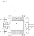
- Figure 2 – is the schematic view of the electric motor of the present invention.
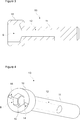
- Figure 3 – is the cross-sectional view of a lubrication apparatus.
- Figure 4 – is the perspective view of a lubrication apparatus.
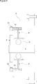
- Figure 5 - is the schematic view of the motor end-shield during the lubrication of the ball bearing.
- Figure 6 - is the schematic view of the motor end-shield when the lubrication process is not being carried out.
- the electric motor (1) comprises a stator (2) that is fixed into the outer casing; a rotor (3) that moves in the stator (2); a shaft (4) that is snap-fitted into the center of the rotor (3) and that rotates together with the rotor (3); two ball bearings (5) that are snap-fitted to both ends of the shaft (4) and that enable the rotor (3) to be supported; two end-shields (6) that are mounted to the front and back of the stator (2); a cylindrical hub (7) that is arranged at the center of each end-shield (6), that enables the rotor (3) to be supported between the end-shields (6) and wherein the ball bearings (5) are placed, and at least one lubrication channel (8) that is bored in the radial direction in the hub (7) and that transfers the pumped lubricant to the seating surface of the ball bearing (5), thus enabling the ball bearing (5) to be lubricated from outside.
- the electric motor (1) of the present invention comprises at least one screw-shaped lubrication apparatus (13) that is mounted to the end-shield (6) from the front surface thereof
- the lubrication apparatus (13) used in the electric motor (1) of the present invention is screwed into the hole bored in the front surface of the end-shield (6).
- the lubricant pumped into the socket (9) from the screw head (10) of the lubrication apparatus (13) moves along the inner grove (12) and flows into the lubrication channel (8) to which the inner groove (12) connects in the lubrication position.
- the lubricant transferred through the lubrication channel (8) reaches the seating surface of the ball bearing (5) in the hub (7) and enables the ball bearing (5) to be lubricated.
- the inner groove (12) is L-shaped and extends in the axial direction from the screw head (10) into the shank (11) and turns 90 degrees upon reaching the lubrication channel (8) so as to open to the outer surface of the shank (11).
- the lubrication apparatus (13) is moved (rotated) to a predetermined angular lubrication position (open position) by being rotated around its own axis
- the outlet of the L-shaped inner groove (12) that opens to the outer surface of the shank (11) connects to the lubrication channel (8) and enables the lubricant to be transferred to the ball bearing (5) through the lubrication channel (8).
- the electric motor (1) comprises at least one indicator (14) that is arranged on the screw head (10) of the lubrication apparatus (13) and/or on the end-shield (6) and that indicates the open position (lubrication position) wherein the inner groove (12) is connected to the lubrication channel (8) and the closed position wherein the inner groove (12) is disconnected from the lubrication channel (8).
- the electric motor (1) comprises two indicators (14) that are arranged on the screw head (10) of the lubrication apparatus (13) at both sides of the hexagonal socket (9).
- the lubrication apparatus (13) switches to the open position and allows lubrication when the lubrication apparatus (13) is rotated and the indicators (14) are one above the other (in the vertical position).
- the lubrication apparatus (13) switches to the closed position and does not allow lubrication when the lubrication apparatus (13) is rotated and the indicators (14) are side by side (in the horizontal position).
- the electric motor (1) comprises a lubrication apparatus (13) that is mounted to the upper part of the front surface of each end-shield (6) and that enables the lubricant to be pumped to the ball bearing (5) and a second lubrication apparatus (13) that is mounted to the lower part of the front surface of the end-shield (6) and that enables the residual lubricant leaving the ball bearing (5) during the lubrication process to be collected.
- the lubrication apparatus (13) comprises a stopple (15) that is inserted into the socket (9) in the screw head (10) and that prevents dust, etc. from entering the inner groove (12) when the lubrication apparatus (13) is not in use.
- the length of the lubrication channel (8) is reduced and the processing cost and the labor time of the end-shield (6) are decreased.
- the duration of the ball bearing (5) lubrication process is reduced and the clogging that is caused by the drying of the lubricant in the lubrication channel (8) is eliminated.
Landscapes
- Engineering & Computer Science (AREA)
- General Engineering & Computer Science (AREA)
- Mechanical Engineering (AREA)
- Power Engineering (AREA)
- Motor Or Generator Frames (AREA)
- Rolling Contact Bearings (AREA)
Abstract
The present invention relates to an electric motor (1) comprising a stator (2); a rotor (3) that moves in the stator (2); a shaft (4) that is snap-fitted into the center of the rotor (3) and that rotates together with the rotor (3); two ball bearings (5) that are snap-fitted to both ends of the shaft (4) and that enable the rotor (3) to be supported; two end-shields (6) that are mounted to the front and back of the stator (2); a hub (7) that is arranged at the center of each end-shield (6), that enables the rotor (3) to be supported between the end-shields (6) and wherein the ball bearings (5) are placed, and at least one lubrication channel (8) that is bored in the radial direction in the hub (7) and that transfers the pumped lubricant to the seating surface of the ball bearing (5), thus enabling the ball bearing (5) to be lubricated.
Description
The present invention relates to an electric motor comprising lubricating apparatuses that provide the lubrication of the ball bearings supporting the rotor. In the state of the art, the electric motors (1') used in industrial applications comprise a stator (2') and a rotor (3') that moves in the stator (2'), and the shaft (4') that is snap-fitted to the center of the rotor (3') is supported from the two ends thereof by the ball bearings (5') placed into the hubs (7') at the center of the end-shields (6') arranged at the front and back of the stator (2'). In some electric motors (1') ball bearings (5') that do not have end-shields and that are lubricated from outside are used. In such electric motors (1'), changing the ball bearing (5') is not preferable due to the weight of the end-shield (6'). In such cases, lubrication channels (8') used for changing the lubricant are provided in the end-shields (6') of the electric motor (1'). The lubrication channel (8') bored in the end-shield (6') extends up to the seating surface of the ball bearing (5'). The clean lubricant that is introduced by means of pressure through the lubrication channel (8') bored on the upper side of the end-shield (6') reaches the seating surface of the ball bearing (5') and the ball bearing (5') is lubricated. The lubricant is pumped into the lubrication channel (8') until the dirty lubricant in the ball bearing (5') is completely discharged through the other end of the lubrication channel (8'). Since the lubrication channel (8') bored in the end-shield (6') is excessively long, the production process causes problems. Since the inlet of the lubrication channel (8') is away from the ball bearing (5'), the duration of the lubrication of the ball bearing (5') extends and discharging the dirty lubricant becomes more difficult. Some of the lubricant that is aimed to be discharged from the long lubrication channel (8') remains and solidifies in the end-shield (6'), clogs the lubrication channel (8') and the lubrication becomes more difficult.
In the Patent Application No. WO2015185484, the lubrication of the ball bearing by means of an oil pan formed in the end-shield of an electric motor is disclosed.
In the Patent Application No. JP2013165542, the lubrication of the ball bearing by means of a channel bored on an electric motor shaft is disclosed.
The aim of the present invention is the realization of an electric motor wherein the duration of the ball bearing lubrication process is reduced.
The electric motor realized in order to attain the aim of the present invention comprises at least one screw-shaped lubrication apparatus that is attached to the end-shield from the front surface thereof. An L-shaped inner groove that extends in the axial direction is provided in the lubrication apparatus. The lubrication apparatus provides fluid communication between the inner groove and the lubrication channel in the end-shield at a predetermined angular position to which the lubrication apparatus is rotated around its own axis. The lubricant pumped through the Allen wrench socket in the screw head of the lubrication apparatus moves in the inner grove so as to be transferred to the lubrication channel and provides the lubrication of the ball bearing.
The electric motor realized in order to attain the aim of the present invention is illustrated in the attached figures, where:
Figure 1 – is the schematic view of an electric motor in the prior art.
Figure 2 – is the schematic view of the electric motor of the present invention.
Figure 3 – is the cross-sectional view of a lubrication apparatus.
Figure 4 – is the perspective view of a lubrication apparatus.
Figure 5 - is the schematic view of the motor end-shield during the lubrication of the ball bearing.
Figure 6 - is the schematic view of the motor end-shield when the lubrication process is not being carried out.
The elements in the figures are numbered as follows:
- Electric motor
- Stator
- Rotor
- Shaft
- Ball bearing
- End-shield
- Hub
- Lubrication channel
- Socket
- Screw head
- Shank
- Inner groove
- Lubrication apparatus
- Indication
- Stopple
The electric motor (1) comprises a stator (2) that is fixed into the outer casing; a rotor (3) that moves in the stator (2); a shaft (4) that is snap-fitted into the center of the rotor (3) and that rotates together with the rotor (3); two ball bearings (5) that are snap-fitted to both ends of the shaft (4) and that enable the rotor (3) to be supported; two end-shields (6) that are mounted to the front and back of the stator (2); a cylindrical hub (7) that is arranged at the center of each end-shield (6), that enables the rotor (3) to be supported between the end-shields (6) and wherein the ball bearings (5) are placed, and at least one lubrication channel (8) that is bored in the radial direction in the hub (7) and that transfers the pumped lubricant to the seating surface of the ball bearing (5), thus enabling the ball bearing (5) to be lubricated from outside.
The electric motor (1) of the present invention comprises at least one screw-shaped lubrication apparatus (13) that is mounted to the end-shield (6) from the front surface thereof
- comprising a screw head (10) having a hexagonal socket (9) that enables the lubrication apparatus (13) to be screwed to the end-shield (6) by being rotated with a tool such as an Allen wrench and a shank (11),
- having an inner groove (12) that extends in the axial direction from the socket (9) in the screw head (10) into the shank (11) and that provides fluid communication with the lubrication channel (8) at a predetermined angular position to which the lubrication apparatus (13) is rotated around its own axis so as to transfer the lubricant pumped through the screw head (10) to the lubrication channel (8) and enable the ball bearing (5) to be lubricated.
The lubrication apparatus (13) used in the electric motor (1) of the present invention is screwed into the hole bored in the front surface of the end-shield (6). The lubricant pumped into the socket (9) from the screw head (10) of the lubrication apparatus (13) moves along the inner grove (12) and flows into the lubrication channel (8) to which the inner groove (12) connects in the lubrication position. The lubricant transferred through the lubrication channel (8) reaches the seating surface of the ball bearing (5) in the hub (7) and enables the ball bearing (5) to be lubricated.
In an embodiment of the present invention, the inner groove (12) is L-shaped and extends in the axial direction from the screw head (10) into the shank (11) and turns 90 degrees upon reaching the lubrication channel (8) so as to open to the outer surface of the shank (11). When the lubrication apparatus (13) is moved (rotated) to a predetermined angular lubrication position (open position) by being rotated around its own axis, the outlet of the L-shaped inner groove (12) that opens to the outer surface of the shank (11) connects to the lubrication channel (8) and enables the lubricant to be transferred to the ball bearing (5) through the lubrication channel (8). When the lubrication apparatus (13) is moved (rotated) to a position (closed position) other than the predetermined angular lubrication position, the outlet of the inner groove (12) is disconnected from the lubrication channel (8) and thus, the fluid communication between the inner groove (12) and the lubrication channel is interrupted and the ball bearing (5) lubrication process is stopped.
In an embodiment of the present invention, the electric motor (1) comprises at least one indicator (14) that is arranged on the screw head (10) of the lubrication apparatus (13) and/or on the end-shield (6) and that indicates the open position (lubrication position) wherein the inner groove (12) is connected to the lubrication channel (8) and the closed position wherein the inner groove (12) is disconnected from the lubrication channel (8).
In an embodiment of the present invention, the electric motor (1) comprises two indicators (14) that are arranged on the screw head (10) of the lubrication apparatus (13) at both sides of the hexagonal socket (9). In this embodiment, the lubrication apparatus (13) switches to the open position and allows lubrication when the lubrication apparatus (13) is rotated and the indicators (14) are one above the other (in the vertical position). The lubrication apparatus (13) switches to the closed position and does not allow lubrication when the lubrication apparatus (13) is rotated and the indicators (14) are side by side (in the horizontal position).
In an embodiment of the present invention, the electric motor (1) comprises a lubrication apparatus (13) that is mounted to the upper part of the front surface of each end-shield (6) and that enables the lubricant to be pumped to the ball bearing (5) and a second lubrication apparatus (13) that is mounted to the lower part of the front surface of the end-shield (6) and that enables the residual lubricant leaving the ball bearing (5) during the lubrication process to be collected.
In an embodiment of the present invention, the lubrication apparatus (13) comprises a stopple (15) that is inserted into the socket (9) in the screw head (10) and that prevents dust, etc. from entering the inner groove (12) when the lubrication apparatus (13) is not in use.
In the electric motor (1) of the present invention, the length of the lubrication channel (8) is reduced and the processing cost and the labor time of the end-shield (6) are decreased. The duration of the ball bearing (5) lubrication process is reduced and the clogging that is caused by the drying of the lubricant in the lubrication channel (8) is eliminated.
Claims (10)
- An electric motor (1) comprising a stator (2) that is fixed into an outer casing; a rotor (3) that moves in the stator (2); a shaft (4) that is snap-fitted into the center of the rotor (3); two ball bearings (5) that are snap-fitted to both ends of the shaft (4); two end-shields (6) that are mounted to the front and back of the stator (2); a cylindrical hub (7) that is arranged at the center of each end-shield (6) and wherein the ball bearings (5) are placed, and at least one lubrication channel (8) that is bored in the radial direction in the hub (7) and that transfers the pumped lubricant to the seating surface of the ball bearing (5), thus enabling the ball bearing (5) to be lubricated, characterized by at least one lubrication apparatus (13) mounted to the end-shield (6) at its front surface, comprising a screw head (10) having a socket (9) that enables the lubrication apparatus (13) to be screwed to the end-shield (6) by being rotated and a shank (11), the lubrication apparatus (13) having an inner groove (12) that extends in the axial direction from the socket (9) in the screw head (10) into the shank (11) and that provides fluid communication with the lubrication channel (8) at a predetermined angular position to which the lubrication apparatus (13) is rotated around its own axis so as to transfer the lubricant pumped through the screw head (10) to the lubrication channel (8).
- An electric motor (1) as in Claim 1, characterized by the lubrication apparatus (13) having the inner groove (12) that is L-shaped and that extends in the axial direction from the screw head (10) into the shank (11) and turns 90 degrees at the level of the lubrication channel (8) so as to open to the outer surface of the shank (11).
- An electric motor (1) as in Claim 1 or 2, characterized by the lubrication apparatus (13) wherein when the lubrication apparatus (13) is moved to a predetermined angular lubrication position (open position) by being rotated around its own axis, the outlet of the L-shaped inner groove (12) that opens to the outer surface of the shank (11) connects to the lubrication channel (8).
- An electric motor (1) as in Claim 3, characterized by the lubrication apparatus (13) wherein the fluid connection between the inner groove (12) and the lubrication channel (8) is interrupted when the lubrication apparatus (13) is rotated to a position (closed position) other than the predetermined angular lubrication position.
- An electric motor (1) as in Claim 1 or 2, characterized by at least one indicator (14) that is arranged on the screw head (10) of the lubrication apparatus (13) and/or on the end-shield (6) and that indicates the open position wherein the inner groove (12) is connected to the lubrication channel (8) and the closed position wherein the inner groove (12) is disconnected from the lubrication channel (8).
- An electric motor (1) as in Claim 5, characterized by two indicators (14) arranged on the screw head (10) of the lubrication apparatus (13) at both sides of the socket (9).
- An electric motor (1) as in Claim 6, characterized by the lubrication apparatus (13) that switches to the open position and allows lubrication when the indicators (14) are one above the other (in the vertical position).
- An electric motor (1) as in Claim 6, characterized by the lubrication apparatus (13) that switches to the closed position and does not allow lubrication when the indicators (14) are side by side (in the horizontal position).
- An electric motor (1) as in Claim 1 or 2, characterized by a lubrication apparatus (13) that is mounted to the upper part of the front surface of each end-shield (6) and that enables the lubricant to be pumped to the ball bearing (5) and a second lubrication apparatus (13) that is mounted to the lower part of the front surface of the end-shield (6) and that enables the residual lubricant leaving the ball bearing (5) during the lubrication process to be collected.
- An electric motor (1) as in Claim 1 or 2, characterized by the lubrication apparatus (13) comprising a stopple (15) that is inserted into the socket (9) in the screw head (10) and that prevents dust, etc. from entering into the inner groove (12) when the lubrication apparatus (13) is not in use.
Applications Claiming Priority (2)
| Application Number | Priority Date | Filing Date | Title |
|---|---|---|---|
| TR201708312 | 2017-06-06 | ||
| TRA2017/08312 | 2017-06-06 |
Publications (1)
| Publication Number | Publication Date |
|---|---|
| WO2018224262A1 true WO2018224262A1 (en) | 2018-12-13 |
Family
ID=62200442
Family Applications (1)
| Application Number | Title | Priority Date | Filing Date |
|---|---|---|---|
| PCT/EP2018/062728 Ceased WO2018224262A1 (en) | 2017-06-06 | 2018-05-16 | An electric motor ball bearing lubricating apparatus |
Country Status (1)
| Country | Link |
|---|---|
| WO (1) | WO2018224262A1 (en) |
Cited By (1)
| Publication number | Priority date | Publication date | Assignee | Title |
|---|---|---|---|---|
| CN119412518A (en) * | 2025-01-08 | 2025-02-11 | 山西长河液压设备有限公司 | A ball valve for preventing valve handle from getting stuck |
Citations (7)
| Publication number | Priority date | Publication date | Assignee | Title |
|---|---|---|---|---|
| DE1526439A1 (en) * | 1966-03-03 | 1970-02-12 | Kuehnle Kopp Kausch Ag | Exhaust gas turbocharger with turbine and fan impellers arranged overhung on both sides of the shaft |
| JPS5340147A (en) * | 1976-09-24 | 1978-04-12 | Shin Meiwa Ind Co Ltd | Greasing system for bearing section of rotary machines |
| US20050286819A1 (en) * | 2004-06-28 | 2005-12-29 | Peter Mavrosakis | Multi-thickness film layer bearing cartridge and housing |
| JP2013165542A (en) | 2012-02-09 | 2013-08-22 | Toyota Motor Corp | Lubrication structure for rotating electric machine |
| DE102012206257A1 (en) * | 2012-04-17 | 2013-10-17 | Schaeffler Technologies AG & Co. KG | Arrangement for fastening roll e.g. cam roller, in retainer of terminal construction in e.g. guide track, has pin and fastening element axially clamped at clamping connection and expandable in clamping connection for bracing in retainer |
| US20150123502A1 (en) * | 2013-11-05 | 2015-05-07 | Hyundai Mobis Co., Ltd. | Cooling structure of oil cooling motor |
| WO2015185484A1 (en) | 2014-06-06 | 2015-12-10 | Siemens Aktiengesellschaft | Device for lubricating an antifriction bearing of an electric motor |
-
2018
- 2018-05-16 WO PCT/EP2018/062728 patent/WO2018224262A1/en not_active Ceased
Patent Citations (7)
| Publication number | Priority date | Publication date | Assignee | Title |
|---|---|---|---|---|
| DE1526439A1 (en) * | 1966-03-03 | 1970-02-12 | Kuehnle Kopp Kausch Ag | Exhaust gas turbocharger with turbine and fan impellers arranged overhung on both sides of the shaft |
| JPS5340147A (en) * | 1976-09-24 | 1978-04-12 | Shin Meiwa Ind Co Ltd | Greasing system for bearing section of rotary machines |
| US20050286819A1 (en) * | 2004-06-28 | 2005-12-29 | Peter Mavrosakis | Multi-thickness film layer bearing cartridge and housing |
| JP2013165542A (en) | 2012-02-09 | 2013-08-22 | Toyota Motor Corp | Lubrication structure for rotating electric machine |
| DE102012206257A1 (en) * | 2012-04-17 | 2013-10-17 | Schaeffler Technologies AG & Co. KG | Arrangement for fastening roll e.g. cam roller, in retainer of terminal construction in e.g. guide track, has pin and fastening element axially clamped at clamping connection and expandable in clamping connection for bracing in retainer |
| US20150123502A1 (en) * | 2013-11-05 | 2015-05-07 | Hyundai Mobis Co., Ltd. | Cooling structure of oil cooling motor |
| WO2015185484A1 (en) | 2014-06-06 | 2015-12-10 | Siemens Aktiengesellschaft | Device for lubricating an antifriction bearing of an electric motor |
Cited By (1)
| Publication number | Priority date | Publication date | Assignee | Title |
|---|---|---|---|---|
| CN119412518A (en) * | 2025-01-08 | 2025-02-11 | 山西长河液压设备有限公司 | A ball valve for preventing valve handle from getting stuck |
Similar Documents
| Publication | Publication Date | Title |
|---|---|---|
| US9520756B2 (en) | Linear electromechanical actuator | |
| RU2659420C2 (en) | Refrigerant compressor | |
| EP2071203B1 (en) | Rolling bearing and rolling bearing assembly | |
| CN101600895B (en) | Transmission with lube oil pump | |
| US20150285367A1 (en) | Adapter module | |
| US10639648B2 (en) | Rolling bearing cooling arrangement using lubricant and cooling air for centrifuges | |
| US20190240795A1 (en) | Turbine driven power unit for a cutting tool | |
| SE537741C2 (en) | Gearbox | |
| WO2012112484A1 (en) | Electric motor having an end frame | |
| US20090148088A1 (en) | Lubricator for Rolling Bearings | |
| WO2018224262A1 (en) | An electric motor ball bearing lubricating apparatus | |
| US11826795B2 (en) | Method for cleaning rolling bearing and rolling bearing cleaning device | |
| US10605083B2 (en) | Scroll-type fluid machine and maintenance method for same | |
| CN107503943B (en) | Oil pump structure of compressor and compressor with same | |
| CN101301780B (en) | Injection molding machine | |
| CN108757446B (en) | Scroll compressor and vehicle with same | |
| CA2842200C (en) | In situ gearbox greasing system | |
| KR101858571B1 (en) | Hydrostatic spindle device for a roll grinder | |
| KR20160006707A (en) | Pump arrangement | |
| CN203628214U (en) | Bearing lubrication cooling device | |
| KR20180051930A (en) | Journal Bearing having Wear Monitoring Function | |
| CN102345622A (en) | Heavy-duty high-speed cantilever type fan transmission system | |
| CN110637185B (en) | Bearing device and method for replacing grease | |
| CN202914701U (en) | Mechanical lubricating structure | |
| CN104632863A (en) | Bevel gear shaft for vehicles |
Legal Events
| Date | Code | Title | Description |
|---|---|---|---|
| 121 | Ep: the epo has been informed by wipo that ep was designated in this application |
Ref document number: 18725816 Country of ref document: EP Kind code of ref document: A1 |
|
| NENP | Non-entry into the national phase |
Ref country code: DE |
|
| 122 | Ep: pct application non-entry in european phase |
Ref document number: 18725816 Country of ref document: EP Kind code of ref document: A1 |