WO2018216498A1 - 画像処理装置、画像処理方法、および投影装置 - Google Patents
画像処理装置、画像処理方法、および投影装置 Download PDFInfo
- Publication number
- WO2018216498A1 WO2018216498A1 PCT/JP2018/018233 JP2018018233W WO2018216498A1 WO 2018216498 A1 WO2018216498 A1 WO 2018216498A1 JP 2018018233 W JP2018018233 W JP 2018018233W WO 2018216498 A1 WO2018216498 A1 WO 2018216498A1
- Authority
- WO
- WIPO (PCT)
- Prior art keywords
- image
- enhancement
- processing unit
- signal
- saturation
- Prior art date
- Legal status (The legal status is an assumption and is not a legal conclusion. Google has not performed a legal analysis and makes no representation as to the accuracy of the status listed.)
- Ceased
Links
Images






Classifications
-
- H—ELECTRICITY
- H04—ELECTRIC COMMUNICATION TECHNIQUE
- H04N—PICTORIAL COMMUNICATION, e.g. TELEVISION
- H04N9/00—Details of colour television systems
- H04N9/12—Picture reproducers
- H04N9/31—Projection devices for colour picture display, e.g. using electronic spatial light modulators [ESLM]
- H04N9/3129—Projection devices for colour picture display, e.g. using electronic spatial light modulators [ESLM] scanning a light beam on the display screen
-
- G—PHYSICS
- G02—OPTICS
- G02B—OPTICAL ELEMENTS, SYSTEMS OR APPARATUS
- G02B26/00—Optical devices or arrangements for the control of light using movable or deformable optical elements
- G02B26/08—Optical devices or arrangements for the control of light using movable or deformable optical elements for controlling the direction of light
- G02B26/10—Scanning systems
- G02B26/101—Scanning systems with both horizontal and vertical deflecting means, e.g. raster or XY scanners
-
- G—PHYSICS
- G02—OPTICS
- G02B—OPTICAL ELEMENTS, SYSTEMS OR APPARATUS
- G02B27/00—Optical systems or apparatus not provided for by any of the groups G02B1/00 - G02B26/00, G02B30/00
- G02B27/10—Beam splitting or combining systems
- G02B27/1006—Beam splitting or combining systems for splitting or combining different wavelengths
- G02B27/102—Beam splitting or combining systems for splitting or combining different wavelengths for generating a colour image from monochromatic image signal sources
-
- G—PHYSICS
- G02—OPTICS
- G02B—OPTICAL ELEMENTS, SYSTEMS OR APPARATUS
- G02B27/00—Optical systems or apparatus not provided for by any of the groups G02B1/00 - G02B26/00, G02B30/00
- G02B27/10—Beam splitting or combining systems
- G02B27/14—Beam splitting or combining systems operating by reflection only
- G02B27/145—Beam splitting or combining systems operating by reflection only having sequential partially reflecting surfaces
-
- G—PHYSICS
- G03—PHOTOGRAPHY; CINEMATOGRAPHY; ANALOGOUS TECHNIQUES USING WAVES OTHER THAN OPTICAL WAVES; ELECTROGRAPHY; HOLOGRAPHY
- G03B—APPARATUS OR ARRANGEMENTS FOR TAKING PHOTOGRAPHS OR FOR PROJECTING OR VIEWING THEM; APPARATUS OR ARRANGEMENTS EMPLOYING ANALOGOUS TECHNIQUES USING WAVES OTHER THAN OPTICAL WAVES; ACCESSORIES THEREFOR
- G03B21/00—Projectors or projection-type viewers; Accessories therefor
- G03B21/14—Details
- G03B21/20—Lamp housings
- G03B21/2006—Lamp housings characterised by the light source
- G03B21/2013—Plural light sources
-
- G—PHYSICS
- G03—PHOTOGRAPHY; CINEMATOGRAPHY; ANALOGOUS TECHNIQUES USING WAVES OTHER THAN OPTICAL WAVES; ELECTROGRAPHY; HOLOGRAPHY
- G03B—APPARATUS OR ARRANGEMENTS FOR TAKING PHOTOGRAPHS OR FOR PROJECTING OR VIEWING THEM; APPARATUS OR ARRANGEMENTS EMPLOYING ANALOGOUS TECHNIQUES USING WAVES OTHER THAN OPTICAL WAVES; ACCESSORIES THEREFOR
- G03B21/00—Projectors or projection-type viewers; Accessories therefor
- G03B21/14—Details
- G03B21/20—Lamp housings
- G03B21/2006—Lamp housings characterised by the light source
- G03B21/2033—LED or laser light sources
-
- G—PHYSICS
- G03—PHOTOGRAPHY; CINEMATOGRAPHY; ANALOGOUS TECHNIQUES USING WAVES OTHER THAN OPTICAL WAVES; ELECTROGRAPHY; HOLOGRAPHY
- G03B—APPARATUS OR ARRANGEMENTS FOR TAKING PHOTOGRAPHS OR FOR PROJECTING OR VIEWING THEM; APPARATUS OR ARRANGEMENTS EMPLOYING ANALOGOUS TECHNIQUES USING WAVES OTHER THAN OPTICAL WAVES; ACCESSORIES THEREFOR
- G03B21/00—Projectors or projection-type viewers; Accessories therefor
- G03B21/14—Details
- G03B21/20—Lamp housings
- G03B21/2066—Reflectors in illumination beam
-
- G—PHYSICS
- G09—EDUCATION; CRYPTOGRAPHY; DISPLAY; ADVERTISING; SEALS
- G09G—ARRANGEMENTS OR CIRCUITS FOR CONTROL OF INDICATING DEVICES USING STATIC MEANS TO PRESENT VARIABLE INFORMATION
- G09G3/00—Control arrangements or circuits, of interest only in connection with visual indicators other than cathode-ray tubes
- G09G3/02—Control arrangements or circuits, of interest only in connection with visual indicators other than cathode-ray tubes by tracing or scanning a light beam on a screen
-
- G—PHYSICS
- G09—EDUCATION; CRYPTOGRAPHY; DISPLAY; ADVERTISING; SEALS
- G09G—ARRANGEMENTS OR CIRCUITS FOR CONTROL OF INDICATING DEVICES USING STATIC MEANS TO PRESENT VARIABLE INFORMATION
- G09G5/00—Control arrangements or circuits for visual indicators common to cathode-ray tube indicators and other visual indicators
-
- G—PHYSICS
- G09—EDUCATION; CRYPTOGRAPHY; DISPLAY; ADVERTISING; SEALS
- G09G—ARRANGEMENTS OR CIRCUITS FOR CONTROL OF INDICATING DEVICES USING STATIC MEANS TO PRESENT VARIABLE INFORMATION
- G09G5/00—Control arrangements or circuits for visual indicators common to cathode-ray tube indicators and other visual indicators
- G09G5/02—Control arrangements or circuits for visual indicators common to cathode-ray tube indicators and other visual indicators characterised by the way in which colour is displayed
-
- G—PHYSICS
- G09—EDUCATION; CRYPTOGRAPHY; DISPLAY; ADVERTISING; SEALS
- G09G—ARRANGEMENTS OR CIRCUITS FOR CONTROL OF INDICATING DEVICES USING STATIC MEANS TO PRESENT VARIABLE INFORMATION
- G09G5/00—Control arrangements or circuits for visual indicators common to cathode-ray tube indicators and other visual indicators
- G09G5/10—Intensity circuits
-
- G—PHYSICS
- G09—EDUCATION; CRYPTOGRAPHY; DISPLAY; ADVERTISING; SEALS
- G09G—ARRANGEMENTS OR CIRCUITS FOR CONTROL OF INDICATING DEVICES USING STATIC MEANS TO PRESENT VARIABLE INFORMATION
- G09G5/00—Control arrangements or circuits for visual indicators common to cathode-ray tube indicators and other visual indicators
- G09G5/36—Control arrangements or circuits for visual indicators common to cathode-ray tube indicators and other visual indicators characterised by the display of a graphic pattern, e.g. using an all-points-addressable [APA] memory
-
- H—ELECTRICITY
- H04—ELECTRIC COMMUNICATION TECHNIQUE
- H04N—PICTORIAL COMMUNICATION, e.g. TELEVISION
- H04N9/00—Details of colour television systems
- H04N9/12—Picture reproducers
- H04N9/31—Projection devices for colour picture display, e.g. using electronic spatial light modulators [ESLM]
- H04N9/3179—Video signal processing therefor
- H04N9/3182—Colour adjustment, e.g. white balance, shading or gamut
-
- H—ELECTRICITY
- H04—ELECTRIC COMMUNICATION TECHNIQUE
- H04N—PICTORIAL COMMUNICATION, e.g. TELEVISION
- H04N9/00—Details of colour television systems
- H04N9/64—Circuits for processing colour signals
- H04N9/68—Circuits for processing colour signals for controlling the amplitude of colour signals, e.g. automatic chroma control circuits
-
- H—ELECTRICITY
- H04—ELECTRIC COMMUNICATION TECHNIQUE
- H04N—PICTORIAL COMMUNICATION, e.g. TELEVISION
- H04N9/00—Details of colour television systems
- H04N9/77—Circuits for processing the brightness signal and the chrominance signal relative to each other, e.g. adjusting the phase of the brightness signal relative to the colour signal, correcting differential gain or differential phase
Definitions
- the present technology relates to an image processing device, an image processing method, and a projection device, and in particular, an image processing device and an image that can improve the brightness of a projected image while satisfying safety standards as a laser product.
- the present invention relates to a processing method and a projection apparatus.
- the drive mirror that reflects the laser beam is scanned by the resonance operation, and the laser beam reflected by the drive mirror is irradiated to each position on the screen.
- spot light which is spot-like light is projected to each position on the screen by irradiation of the laser beam. That is, an image having a plurality of spot lights as pixels is projected on the screen.
- Such projectors that scan with laser beams are subject to laser power limitations in order to meet safety standards for laser products. Due to the limitation of the laser power, the brightness of the projected image is also limited.
- the present technology has been made in view of such a situation, and makes it possible to improve the brightness of a projected image while satisfying safety standards as a laser product.
- the image processing apparatus determines a first enhancement coefficient that enhances luminance of the image according to saturation of the image, and the image based on the determined first enhancement coefficient
- a saturation enhancement processing unit for converting the luminance signal A saturation enhancement processing unit for converting the luminance signal.
- the image processing apparatus determines an enhancement coefficient that enhances the luminance of the image according to the saturation of the image, and based on the determined enhancement coefficient, the image processing method. Convert luminance signal.
- the projection device determines an enhancement coefficient for enhancing the luminance of the image according to the saturation of the input image, and outputs the luminance signal of the image based on the determined enhancement coefficient.
- a saturation enhancement processing unit for conversion, a laser light source unit for outputting a laser beam corresponding to the pixel signal of the image obtained by converting the luminance signal, and scanning in the horizontal and vertical directions while reflecting the laser beam A scanning unit.
- a first enhancement coefficient that enhances the luminance of the image is determined according to the saturation of the image, and the luminance signal of the image is determined based on the determined first enhancement coefficient. Is converted.
- the image processing apparatus can be realized by causing a computer to execute a program.
- a program to be executed by a computer can be provided by being transmitted via a transmission medium or by being recorded on a recording medium.
- the image processing apparatus may be an independent apparatus or an internal block constituting one apparatus.
- the brightness of the projected image can be improved while satisfying the safety standard as a laser product.
- FIG. 6 is a diagram for explaining a correspondence relationship between a margin Mg and an enhancement coefficient Coeff1. It is a figure explaining the process of a saturation emphasis processing part. It is a figure explaining the relationship between the area
- FIG. 18 is a block diagram illustrating a configuration example of a computer to which the present technology is applied. It is a block diagram which shows the structural example of the electronic device to which this technique is applied.
- FIG. 1 is a block diagram illustrating a configuration example of a projection apparatus to which the present technology is applied.
- the projection apparatus 1 is a laser beam scanning type projection apparatus (projector) that projects a projection image 2a onto a screen 2 by scanning a laser beam as a light source.
- the projection destination of the projection image 2a is not limited to the screen 2, and may be a wall surface, a plane of a predetermined object, or the like.
- the projection apparatus 1 includes a controller 21, a laser driver 22, a mirror driver 23, laser light source units 24R, 24G, and 24B, a mirror 25, dichroic mirrors 26-1 and 26-2, a drive mirror 27, and an optical lens 28. Is done.
- the controller 21 is supplied with an image signal of a projection image 2a projected on the screen 2 as an input image signal from another device such as a personal computer.
- the controller 21 generates pixel data for each color (red, green, and blue) of each pixel constituting the projection image 2 a based on an input image signal supplied from another device, and obtains it from the mirror driver 23.
- the laser driver 22 is supplied in synchronization with the mirror synchronization signal.
- the mirror synchronization signal is a signal for driving the mirror driver 23 in synchronization with the input image signal.
- the laser driver 22 generates a drive signal corresponding to the pixel value for each pixel of the projection image 2a based on the pixel data for each color supplied from the controller 21, and supplies the drive signal to the laser light source units 24R, 24G, and 24B. Specifically, the laser driver 22 supplies a drive signal corresponding to the red pixel data to the laser light source unit 24R, and supplies a drive signal corresponding to the green pixel data to the laser light source unit 24G. A drive signal corresponding to the above is supplied to the laser light source unit 24B.
- the mirror driver 23 scans the laser beam in the horizontal direction (left and right direction in the figure) and the vertical direction (up and down direction in the figure) of the screen 2, and the horizontal scan signal and the vertical scan signal based on the resonance frequency of the drive mirror 27. Is supplied to the drive mirror 27. Further, the mirror driver 23 has a light receiving portion (not shown) that detects a part of the laser beam reflected by the drive mirror 27. Then, the mirror driver 23 adjusts the horizontal scan signal and the vertical scan signal based on the detection result of the light receiving unit, and feeds back the detection signal according to the detection result of the light receiving unit to the controller 21.
- the laser light source units 24R, 24G, and 24B each output a laser beam of a corresponding color (wavelength light) according to a drive signal supplied from the laser driver 22. Specifically, the laser light source unit 24R outputs a red laser beam with power according to the red pixel data.
- the laser light source unit 24G outputs a green laser beam with a power corresponding to the green pixel data, and the laser light source unit 24B outputs a blue laser beam with a power corresponding to the blue pixel data.
- the laser light source units 24R, 24G, and 24B are also simply referred to as the laser light source unit 24.
- the mirror 25 reflects the red laser beam output from the laser light source unit 24R.
- the dichroic mirror 26-1 reflects the green laser beam output from the laser light source unit 24G and transmits the red laser beam reflected by the mirror 25.
- the dichroic mirror 26-2 reflects the blue laser beam output from the laser light source unit 24B, the red laser beam reflected by the mirror 25, and the green laser beam reflected by the dichroic mirror 26-1. Permeate.
- the mirror 25 and the dichroic mirrors 26-1 and 26-2 are arranged in combination so that the optical axes of the laser beams output from the laser light source units 24R, 24G, and 24B are coaxial.
- the drive mirror 27 is a minute mirror formed by, for example, MEMS (Micro Electro Mechanical Systems), and is driven according to a horizontal scan signal and a vertical scan signal supplied from the mirror driver 23. That is, for example, the drive mirror 27 scans in the horizontal direction and the vertical direction of the screen 2 while reflecting the laser beam output from each of the laser light source units 24R, 24G, and 24B.
- MEMS Micro Electro Mechanical Systems
- the optical lens 28 is disposed on the optical path of the laser beam from the drive mirror 27 toward the screen 2 and corrects the optical path of the laser beam.
- the projector 1 can employ a configuration in which the laser driver 22 and the mirror driver 23 are integrated into the controller 21. Further, the projection apparatus 1 may be configured such that the optical lens 28 is not disposed on the optical path of the laser beam.
- FIG. 2 is a diagram showing the configuration of the laser light source units 24R, 24G, and 24B in more detail.
- the laser light source units 24R, 24G, and 24B include laser beam generation units 24Ra, 24Ga, and 24Ba of respective wavelengths of R (red), G (green), and B (blue), and collimator lenses 24Rb, 24Gb, and 24Bb, respectively. I have. That is, in the laser light source units 24R, 24G, and 24B, the laser beam generation units 24Ra, 24Ga, and 24Ba generate laser beams having wavelengths that are specific to the respective colors, and the collimator lenses 24Rb, 24Gb, and 24Bb are lasers having the respective wavelengths. Collimate the beam and output it.
- the laser beam generators 24Ra, 24Ga, and 24Ba and the collimator lenses 24Rb, 24Gb, and 24Bb are simply the laser beam generators 24a and the collimator lenses when it is not necessary to distinguish colors (wavelengths). 24b.
- the laser beam generator 24Ra emits a red laser beam based on a drive signal (Video Data Current Red) corresponding to red pixel data.
- the red laser beam emitted from the laser beam generator 24Ra is reflected by the mirror 25 and incident on the dichroic mirror 26-1 after the emission direction is appropriately adjusted by the collimator lens 24Rb.
- the laser beam generator 24Ga emits a green laser beam based on a drive signal (Video Data Current Green) corresponding to green pixel data.
- the green laser beam emitted from the laser beam generator 24Ga is appropriately adjusted by the collimator lens 24Gb, then reflected by the dichroic mirror 26-1, and incident on the dichroic mirror 26-2.
- the dichroic mirror 26-1 transmits the red laser beam incident from the mirror 25 and causes the red laser beam to enter the dichroic mirror 26-2.
- the laser beam generator 24Ba emits a blue laser beam based on a drive signal (Video Data Current Blue) corresponding to blue pixel data.
- the blue laser beam emitted from the laser beam generator 24Ba is reflected by the dichroic mirror 26-2 after entering the emission direction appropriately by the collimator lens 24Bb, and enters the drive mirror 27.
- the dichroic mirror 26-2 transmits the red and green laser beams incident from the dichroic mirror 26-1 and causes the laser beam to enter the drive mirror 27.
- red, green, and blue (RGB) laser beams are incident on the drive mirror 27 from the dichroic mirror 26-2 in a combined state.
- the projection apparatus 1 projects a two-dimensional projection image 2a on the screen 2 by driving the drive mirror 27 and scanning the red, green, and blue laser beams.
- a laser beam scanning method by the drive mirror 27 for example, there are a raster scanning method and a Lissajous scanning method.
- a raster scan is adopted.
- FIG. 3 the scanning trajectory of the laser beam by raster scanning is shown on the projection image 2a, the horizontal scan signal H-Scan is shown below the projection image 2a, and on the left side of the projection image 2a, A vertical scan signal V-Scan is shown.
- the horizontal scan signal H-Scan is, for example, a signal having a sinusoidal waveform oscillating at about 20 kHz according to the resonance frequency of the drive mirror 27.
- the frequency of the horizontal scan signal H-Scan is the horizontal synchronization of the projection image 2a. It becomes 1/2 of the frequency.
- the vertical scan signal V-Scan is, for example, a signal having a sawtooth waveform that vibrates at 60 Hz, which is a frequency corresponding to the frame period of the projection image 2a.
- the laser beam is not emitted in the scanning locus in the vicinity of both ends of the horizontal scanning signal H-Scan, and the folded portion of the scanning locus can be prevented from being used to project the projection image 2a.
- a section in which the vertical scan signal V-Scan has a waveform that rises substantially vertically, that is, the scanning locus of the laser beam is from the lower end (position at the end of scanning) to the upper end (position at the start of the next scanning).
- the laser beam is not emitted in the blanking interval, which is an interval that changes sharply.
- the drive mirror 27 is driven according to such a horizontal scan signal H-Scan and a vertical scan signal V-Scan, so that the laser beam is scanned with a scanning locus as shown on the projection image 2a. As shown, the laser beam is scanned in both directions. Since the scanning direction of the laser beam is reversed for each line of the scanning line directed in the horizontal direction, the process of rearranging the input image signal is performed for each line of the scanning line, or the data access direction for the input image signal is changed. There is a need to.
- the horizontal scanning speed of the laser beam increases at the center of the projection image 2a and decreases near the end of the projection image 2a.
- the scanning speed of the laser beam in the vertical direction is constant regardless of the position of the projection image 2a.
- the entire projection image 2a may be referred to as a screen.
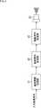
- FIG. 4 is a block diagram showing a general signal processing flow until an input image signal is converted into a drive signal input to the laser light source unit 24.
- An input image signal supplied from another device is converted into a drive signal by performing predetermined processing in each of the image quality adjustment processing unit 41, the pixel signal conversion unit 42, and the drive signal conversion unit 43,
- the laser light source 24 is supplied.
- the image quality adjustment processing unit 41 performs general image quality adjustment processing such as contrast adjustment and sharpness adjustment on the input image signal, and supplies the processed image signal to the pixel signal conversion unit 42.
- the input image signal is supplied as a YUV format image signal, for example.
- the YUV format is a signal expressed by a luminance signal Y and two color difference signals (Cb signal and Cr signal) of a Cb (U) component and a Cr (V) component.
- the luminance signal Y takes a value in the range of 0 to 1
- the Cb signal and Cr signal take a value in the range of -0.5 to +0.5.
- the Cb signal and Cr signal are also referred to as U signal and V signal for convenience.
- the pixel signal conversion unit 42 converts the image signal supplied from the image quality adjustment processing unit 41 into a pixel unit pixel signal constituting the screen in accordance with the scanning trajectory of the raster scan. More specifically, the pixel signal conversion unit 42 converts the YUV format image signal supplied from the image quality adjustment processing unit 41 into an RGB format image signal, and configures the screen according to the scanning trajectory of the raster scan. It is converted into pixel signals (pixel data) for each of R, G, and B in pixel units.
- the drive signal conversion unit 43 converts the pixel signal supplied from the pixel signal conversion unit 42 into a drive signal for each of R, G, and B, and supplies the drive signal to the laser light source unit 24.
- the laser power is also adjusted according to the scanning speed.
- the scanning speed of the laser beam in the horizontal direction increases at the center of the screen and decreases near the edge of the screen. Due to the difference, the integrated power varies depending on the screen position. In other words, when the horizontal scanning is performed with the same power, the time of incidence on the human eye becomes longer near the edge of the screen where the scanning speed is low, so that the laser power incident on the eye increases.
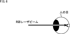
- the laser safety standard is the integrated power that enters the human eye unit time so that the collimated and highly condensing laser beam can be kept safe even if it enters the human eye. Restrictions are imposed on several conditions such as instantaneous power.
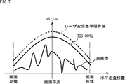
- the image with the maximum laser power is an image in which R, G, and B each emit light at 100%, that is, a white image. Therefore, as shown in the graph on the right side of FIG. 5, even when the laser light source unit 24 emits white light with RGB of 100%, the laser power is controlled so as not to exceed the laser safety standard limit value indicated by the broken line.
- the difference between the laser safety standard limit value and the power when light is emitted with RGB of 100% corresponds to the margin set by the projector 1.
- the laser safety standard restricts the power of a laser light source that can be output as a projection device, and is a limitation for projecting a bright image.
- an actual image displayed by the projection apparatus is configured by an image signal (pixel signal) having a brightness of about 30%, as shown by a curve shown as an actual image in FIG. In many cases, it is operating at a power sufficiently smaller than the laser safety standard limit value.
- the projection apparatus 1 analyzes the image configuration, specifically, the hue of the image such as a single color or a pure color, and the laser power within a range that does not exceed the laser safety standard limit value according to the hue of the analyzed image. By improving the brightness of the projected image.
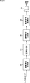
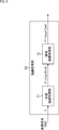
- FIG. 8 is a block diagram illustrating a flow of signal processing in the projection apparatus 1 until an input image signal is converted into a drive signal.
- the enhancement processing unit 61 is located between the image quality adjustment processing unit 41 and the pixel signal conversion unit 42. Newly provided.
- the processing of the image quality adjustment processing unit 41, the pixel signal conversion unit 42, and the drive signal conversion unit 43 is the same as the processing described in FIG.
- the enhancement processing unit 61 analyzes the image signal supplied from the image quality adjustment processing unit 41 from the image configuration, specifically, the hue of the image such as a single color or a pure color, and the image signal according to the analyzed hue of the image. Execute emphasis processing that emphasizes.
- the enhancement processing unit 61 supplies the image signal after the enhancement processing to the pixel signal conversion unit 42.
- the image quality adjustment processing unit 41, the pixel signal conversion unit 42, and the enhancement processing unit 61 in FIG. 8 correspond to processing blocks executed by the controller 21 in FIG. 1, and the drive signal conversion unit 43 in FIG. This corresponds to a processing block executed by the laser driver 22.
- FIG. 9 shows a detailed configuration of the enhancement processing unit 61.
- the enhancement processing unit 61 includes a saturation enhancement processing unit 71 and a region enhancement processing unit 72.
- the saturation enhancement processing unit 71 is supplied with the processed image signal in the YUV format after the image quality adjustment processing unit 41 performs general image quality adjustment processing such as contrast adjustment and sharpness adjustment.
- Coeff1 first enhancement coefficient Coeff1
- the region enhancement processing unit 72 divides the image supplied from the saturation enhancement processing unit 71 into a plurality of regions, and determines an enhancement coefficient Coeff2 (second enhancement coefficient Coeff2) for enhancing the luminance of the image for each region. To do. Then, the region enhancement processing unit 72 enhances (converts) the luminance signal Y ′ based on the determined enhancement coefficient Coeff2. Specifically, the region enhancement processing unit 72 uses the determined enhancement coefficient Coeff2 for the luminance signal Y ′ of the image signal in the YUV format supplied from the saturation enhancement processing unit 71, and uses the luminance signal Y ′′.
- Coeff2 * Y ′ is calculated, and the enhanced luminance signal Y ′′ is calculated and output to the pixel signal conversion unit 42.
- the luminance signal Y ′′ in which the luminance signal Y is enhanced by the saturation enhancement processing unit 71 and the region enhancement processing unit 72 and the two color difference signals (Cb signal and Cr signal) are R, G, B Is converted into a pixel signal.
- the saturation enhancement processing unit 71 analyzes the saturation of the image signal supplied from the image quality adjustment processing unit 41 for each pixel, and enhances the luminance signal Y of the pixel with high saturation using a predetermined enhancement coefficient Coeff1. .
- a pixel with high saturation means a pixel whose color is not white but a single color such as red, green, or blue, or a color close to a pure color.
- the hue becomes higher in saturation.
- red, green, and blue (RGB) lasers do not emit near 100%, and at least one of the red, green, and blue lasers operates at low power. Become.
- the red and green (RG) lasers when the red and green (RG) lasers emit 100%, the blue laser emits 0%, and the output laser power of RG 100% is emitted. Since the power at the time is sufficiently lower than the power at the time of light emission of 100% RGB, there is room for the red and green (RG) lasers to emit light at 100% or more as much as the blue laser is not emitted.
- the saturation enhancement processing unit 71 analyzes the saturation of the image signal for each pixel, and the luminance signal in which the luminance signal Y is enhanced for pixels of a single color such as red, green, and blue, or a hue close to pure color. Convert to Y '.
- the saturation enhancement processing unit 71 detects the absolute values of the U signal and the V signal, which are the color difference components of the target pixel, with each pixel constituting the screen as the target pixel, One having a larger absolute value is determined as a variable ⁇ UV for calculating the enhancement coefficient Coeff1.
- the saturation enhancement processing unit 71 substitutes the determined variable ⁇ UV for the function f ( ⁇ UV) that defines the correspondence between the variable ⁇ UV and the enhancement coefficient Coeff1, thereby enhancing the enhancement coefficient according to the saturation of the target pixel. Determine (calculate) Coeff1. Then, the saturation enhancement processing unit 71 multiplies the luminance signal Y of the target pixel by the determined enhancement coefficient Coeff1 to calculate the luminance signal Y ′ after the enhancement processing.
- FIG. 12A shows an example of a function f ( ⁇ UV) that defines the correspondence between the variable ⁇ UV and the enhancement coefficient Coeff1.
- the absolute value of the U signal and V signal is in the range of 0 to 0.5.
- the enhancement coefficient Coeff1 increases as the variable ⁇ UV approaches 0.5.
- the enhancement coefficient Coeff1 is 2.0.
- the enhancement coefficient Coeff1 equivalent to the power at the time of light emission of RGB 100% is, for example, 3.0. Since the function f ( ⁇ UV) is specified so that the enhancement coefficient Coeff1 is set in a range up to 2.0, which is smaller than that, the luminance signal Y is emphasized in a range not exceeding the laser safety standard limit value. Yes.
- FIG. 12B is a diagram showing the concept of the enhancement coefficient Coeff1 according to the variable ⁇ UV, and shows that the enhancement coefficient Coeff1 is set larger as the distance from the origin (center) increases in the U-V color space.
- the emphasis coefficient Coeff1 can be set to a larger value as it is closer to a single color. Therefore, the saturation enhancement processing unit 71 can also adopt a method of analyzing red, green, and blue (RGB) colors in more detail and determining the enhancement coefficient Coeff1 based on the RGB value of the image.
- RGB red, green, and blue
- the saturation enhancement processing unit 71 converts an image signal in YUV format into an image signal in RGB format (hereinafter also referred to as RGB signal).
- RGB signal an image signal in YUV format
- an image signal in YUV format can be converted into an image signal in RGB format by the following conversion formula.
- R Y + 1.402 * Cr
- G Y-0.344136 * Cb-0.714136 * Cr
- B Y + 1.772 * Cb
- the saturation enhancement processing unit 71 normalizes the RGB format image signal with the maximum value maxRGB that the RGB signal can take. That is, the saturation enhancement processing unit 71 uses each pixel constituting the screen as a target pixel, and standardizes the R signal, B signal, Rnrm, Gnrm, and Bnrm, which are G signals, are calculated.
- Rnrm R / maxRGB
- Gnrm G / maxRGB
- Bnrm B / maxRGB
- the maximum value maxRGB that the RGB signal can take 255.
- the saturation enhancement processing unit 71 performs R, B, and G signals Rnrm, Gnrm, and Bnrm of the pixel of interest for each RGB.
- the margin Mg is determined (calculated) by multiplying the power coefficients Cr, Cg, and Cb and subtracting from 1.
- the power coefficients Cr, Cg, and Cb correspond to power ratios of the laser light source units 24R, 24G, and 24B when the laser light source unit 24 displays white as an image.
- Mg 1- (Rnrm * Cr + Gnrm * Cg + Bnrm * Cb)
- the saturation enhancement processing unit 71 assigns the determined margin Mg to a function f (Mg) that defines the correspondence relationship between the margin Mg and the enhancement coefficient Coeff1, thereby enhancing the saturation according to the saturation of the target pixel.
- the coefficient Coeff1 is determined (calculated). Then, the saturation enhancement processing unit 71 multiplies the luminance signal Y of the target pixel by the determined enhancement coefficient Coeff1 to calculate the luminance signal Y ′ after the enhancement processing.
- FIG. 13A shows an example of a function f (Mg) that defines the correspondence between the margin Mg and the enhancement coefficient Coeff1.
- the function f (Mg) is a function in which the enhancement coefficient Coeff1 increases as the margin Mg, which is an operation value using Rnrm, Gnrm, and Bnrm, and the power coefficients Cr, Cg, and Cb, increases.
- the enhancement coefficient Coeff1 equivalent to the power at the time of light emission of 100% RGB is, for example, 3.0.
- the function f (Mg) is specified so that the enhancement coefficient Coeff1 is set in the range up to 2.0, which is smaller than that, so the luminance signal Y is emphasized in the range not exceeding the laser safety standard limit value. Yes.
- FIG. 13B is a diagram showing the concept of the enhancement coefficient Coeff1 according to the margin Mg, and shows that the enhancement coefficient Coeff1 is set larger as the distance from the origin (center) increases in the U-V color space.
- the saturation enhancement processing unit 71 determines the enhancement coefficient Coeff1 according to the variable ⁇ UV and calculates the luminance signal Y ′, depending on the enhancement processing based on the UV value or the margin Mg calculated from the RGB value.
- One of the enhancement processes based on the RGB values which is a process of determining the enhancement coefficient Coeff1 and calculating the luminance signal Y ′, is executed, and the calculated luminance signal Y ′ is output.
- the saturation enhancement processing unit 71 by analyzing the color difference of the input image signal for each pixel, as shown in FIG. Light emission exceeding 100% of the hour becomes possible. Thereby, the brightness of the projected image can be improved while satisfying the safety standard as a laser product.
- Projection image 2a projected onto screen 2 by projection apparatus 1 may be an image with a small area that emits light.
- An image that is bright and has a small area to emit light is, for example, an image of the universe or the starry sky.
- the area where each of R, G, and B emits light at 100% is an extremely narrow area, and when the laser safety standard is limited by the total sum of human eyes, the laser safety standard is exceeded. Is a sufficiently low integrated total value, and there is room for increasing the light emission power.
- the region enhancement processing unit 72 divides the screen into a plurality of regions, determines the enhancement coefficient Coeff2 of each region in consideration of the power integrated value to the human eye, and uses the determined enhancement coefficient Coeff2,
- the luminance signal Y ′ is converted into a luminance signal Y ′′.
- the division number of the screen is set so that the size of the subsequent one area is smaller than the pupil size of the human eye.
- the number of screen divisions can be determined by the user himself / herself on the setting screen or the like.
- the aspect ratio of the projection image 2a is 16: 9
- the distance from the projection apparatus 1 to the screen 2 is 100 mm
- the angle of view of the projected image 2a is 100 mm ⁇ 56.3 mm
- a human eye having a diameter of about 7 mm has a size of 7% of the horizontal angle of view and 12 of the vertical angle of view.
- the 3 ⁇ 3 9 regions 1 to 9 are larger than the pupil size of the human eye. Large area size.
- the area enhancement processing unit 72 When determining the enhancement coefficient Coeff2 of a predetermined attention area among the plurality of divided areas, the area enhancement processing unit 72 combines the attention area and the surrounding area, and is an area larger than the pupil size of the human eye Based on the size, the laser power total value Area avgTTL is calculated.
- the region enhancement processing unit 72 calculates the total laser power of the entire 3 ⁇ 3 9 regions centering on the region 5 by the following equation (1). Calculate the value Area avgTTL .
- the laser power total value of the entire 9 (integrated value sum) Area AvgTTL is obtained by adding the laser mean power Area avg1 to Area Avg9 region 1 to region 9.
- Equation (2) is obtained by dividing the sum of the RGB signals of all pixels in the region by the RGB power coefficients Cr, Cg, and Cb, respectively, by the number of pixels in the region Area ttl_pixel. Represents being done.
- the region for calculating the power integrated value is determined in relation to the pupil size (diameter of about 7 mm) of the human eye.
- the region enhancement processing unit 72 determines that the laser power total value Area avgTTL of the 3 ⁇ 3 peripheral region centered on the region of interest (region 5) calculated by Expression (1) is greater than the threshold value Th determined based on the laser safety standard. Determine if it is small.
- the region enhancement processing unit 72 When it is determined that the laser power total value Area avgTTL of the 3 ⁇ 3 peripheral region centered on the region of interest is smaller than the threshold Th, the region enhancement processing unit 72 performs the laser power total value Area avgTTL as shown in FIG. By substituting the calculated laser power total value Area avgTTL into the function g (Area avgTTL ) that defines the correspondence between the correlation coefficient and the enhancement coefficient Coeff2, the enhancement coefficient Coeff2 corresponding to the power integrated value of the region of interest is determined. Then, the area enhancement processing unit 72 multiplies the luminance signal Y ′ of each pixel in the attention area by the determined enhancement coefficient Coeff2, and calculates the luminance signal Y ′′ after the enhancement processing of each pixel in the attention area.
- a function g max (Area avgTTL ) indicated by a broken line represents an upper limit value of the enhancement coefficient Coeff2 that does not exceed the laser safety standard. Therefore, the function g (Area avgTTL ) that defines the correspondence between the laser power total value Area avgTTL and the enhancement coefficient Coeff2 is set so that the luminance signal Y ′ is emphasized within a range that does not exceed the laser safety standard limit value. ing.
- the processing of the region enhancement processing unit 72 by calculating the laser power integrated value corresponding to the input image signal in units of regions of a predetermined size, as shown in FIG. In the color unit B, light emission exceeding 100% of the normal time is possible. Thereby, the brightness of the projected image can be improved while satisfying the safety standard as a laser product.
- step S1 the saturation enhancement processing unit 71 executes saturation enhancement processing for enhancing the luminance signal Y using the enhancement coefficient Coeff1 according to the saturation of the image supplied from the image quality adjustment processing unit 41.
- FIG. 19 is a flowchart for explaining the details of the saturation enhancement process in step S1, and is a flowchart of the saturation enhancement process when the enhancement coefficient Coeff1 is calculated based on the UV value of the pixel.
- step S21 the saturation enhancement processing unit 71 sets a predetermined pixel of the image supplied from the image quality adjustment processing unit 41 as a target pixel.
- step S22 the saturation enhancement processing unit 71 detects the absolute values of the U signal and the V signal of the target pixel, and calculates the enhancement coefficient Coeff1 for the larger absolute value of the U signal and the V signal. To decide.
- step S23 the saturation enhancement processing unit 71 substitutes the determined variable ⁇ UV for the function f ( ⁇ UV) that defines the correspondence between the variable ⁇ UV and the enhancement coefficient Coeff1, thereby depending on the saturation of the target pixel.
- the enhancement coefficient Coeff1 is calculated (determined).
- step S24 the saturation enhancement processing unit 71 multiplies the luminance signal Y of the target pixel by the calculated enhancement coefficient Coeff1 to calculate the luminance signal Y ′ after the enhancement processing.
- the calculated luminance signal Y ′ is supplied to the region enhancement processing unit 72 together with the U signal and the V signal.
- step S25 the saturation enhancement processing unit 71 determines whether all the pixels of the image supplied from the image quality adjustment processing unit 41 have been set as the target pixel.
- step S25 when the saturation enhancement processing unit 71 determines that all the pixels are not set as the target pixel, the process returns to step S21. Thereby, the process of step S21 thru
- step S25 if it is determined in step S25 that all the pixels have been set as the target pixel, the saturation enhancement processing in FIG. 19 ends.
- FIG. 20 is a flowchart for explaining the details of the saturation enhancement processing in step S1, and is a flowchart of the saturation enhancement processing when the enhancement coefficient Coeff1 is calculated based on the RGB values of the pixels.
- step S41 the saturation enhancement processing unit 71 sets a predetermined pixel of the image supplied from the image quality adjustment processing unit 41 as a target pixel.
- step S42 the saturation enhancement processing unit 71 converts the YUV format image signal of the target pixel into an RGB format image signal (RGB signal).
- step S43 the saturation enhancement processing unit 71 calculates Rnrm, Gnrm, and Bnrm by normalizing the RGB signal of the pixel of interest with the maximum value maxRGB that the RGB signal can take.
- step S44 the saturation enhancement processing unit 71 calculates a margin Mg using the normalized R signal, B signal, and G signals Rnrm, Gnrm, and Bnrm of the target pixel. That is, the saturation enhancement processing unit 71 calculates the margin Mg by multiplying Rnrm, Gnrm, and Bnrm by RGB power coefficients Cr, Cg, and Cb and subtracting them from 1.
- step S45 the saturation enhancement processing unit 71 substitutes the calculated margin Mg into the function f (Mg) that defines the correspondence between the margin Mg and the enhancement coefficient Coeff1, thereby depending on the saturation of the target pixel.
- the enhancement coefficient Coeff1 is calculated (determined).
- the saturation enhancement processing unit 71 multiplies the calculated enhancement coefficient Coeff1 by the luminance signal Y of the pixel of interest to calculate a luminance signal Y ′ after enhancement processing.
- the calculated luminance signal Y ′ is supplied to the region enhancement processing unit 72 together with the U signal and the V signal.
- step S46 the saturation enhancement processing unit 71 determines whether all the pixels of the image supplied from the image quality adjustment processing unit 41 have been set as the target pixel.
- step S46 when the saturation enhancement processing unit 71 determines that all the pixels are not set as the target pixel, the process returns to step S41. Thereby, the process of step S41 thru
- step S46 if it is determined in step S46 that all the pixels have been set as the target pixel, the saturation enhancement processing in FIG. 20 ends.
- step S1 either the enhancement process based on the UV value described with reference to FIG. 19 or the enhancement process based on the RGB value described with reference to FIG. Can be arbitrarily selected according to setting information or the like.
- FIG. 21 is a flowchart for explaining the details of the region enhancement processing in step S2.
- step S61 the region enhancement processing unit 72 divides the image supplied from the image quality adjustment processing unit 41 into a plurality of regions.
- the number of areas to be divided is determined in advance by setting information or the like.
- step S62 the region enhancement processing unit 72 sets a predetermined region among the plurality of divided regions as a region of interest.
- step S ⁇ b> 63 the region enhancement processing unit 72 calculates a laser power total value Area avgTTL of a 3 ⁇ 3 peripheral region (hereinafter, appropriately referred to as the peripheral region of interest) centered on the set attention region.
- the area for calculating the total laser power value Area avgTTL is determined by the relationship with the pupil size of the human eye, and thus is not limited to 9 areas of 3 ⁇ 3.
- step S64 the region enhancement processing unit 72 determines whether the laser power total value Area avgTTL around the region of interest is smaller than a threshold value Th determined based on the laser safety standard.
- step S64 If it is determined in step S64 that the total laser power area Area avgTTL around the region of interest is smaller than the threshold value Th, the process proceeds to step S65, and the region enhancement processing unit 72 performs the laser power as shown in FIG.
- the region enhancement processing unit 72 performs the laser power as shown in FIG.
- step S66 the region emphasis processing unit 72 multiplies the luminance signal Y ′ of each pixel in the region of interest by the calculated enhancement coefficient Coeff2 to calculate the luminance signal Y ′′ after the enhancement processing of each pixel in the region of interest.
- the calculated luminance signal Y ′′ is supplied to the pixel signal converter 42 together with the U signal and the V signal.
- step S64 determines whether the total laser power value Area avgTTL around the region of interest is equal to or greater than the threshold value Th. If it is determined in step S64 that the total laser power value Area avgTTL around the region of interest is equal to or greater than the threshold value Th, the process proceeds to step S67, and the region enhancement processing unit 72 does not perform the enhancement process, The luminance signal Y ′ of each pixel is directly output as the luminance signal Y ′′ to the pixel signal converter 42 together with the U signal and the V signal.
- step S68 the region emphasis processing unit 72 determines whether all the regions among the plurality of divided regions have been set as the attention region.
- step S68 if the region emphasis processing unit 72 determines that all the regions are not set as the attention region, the process returns to step S62. Thereby, the process of step S62 thru
- step S68 if it is determined in step S68 that all of the divided areas have been set as the attention area, the area enhancement processing in FIG. 21 ends.
- the enhancement processing unit 61 enhances the luminance signal Y of the image supplied from the image quality adjustment processing unit 41 using the enhancement coefficient Coeff1 according to the saturation of the image, and further The emphasis coefficient Coeff2 is used for emphasis according to the laser power integrated value for each region. Thereby, the brightness of the projected image can be improved while satisfying the safety standard as a laser product.
- the human eye has a characteristic called the Helmholtz-Cole-Rush effect, which is perceived as bright when viewing images with high saturation.
- the laser light source has a wide color reproducibility due to its characteristics, and has an effect of perceiving a brighter image than a normal light source. Furthermore, by performing luminance enhancement in accordance with the saturation by the saturation enhancement processing of the saturation enhancement processing unit 71, a brighter and more vivid image can be expressed.
- the enhancement processing unit 61 is configured to include both the saturation enhancement processing unit 71 and the region enhancement processing unit 72, but may be configured to include only one of them. Even when the enhancement processing of any one of the saturation enhancement processing unit 71 and the region enhancement processing unit 72 is performed, the brightness of the projected image is improved.
- the enhancement processing is performed as part of the processing executed by the controller 21. However, even if the processing of the enhancement processing unit 61 is executed by an image processing apparatus provided separately from the controller 21. Good.
- an ISP (Image Signal Processor) 90 may be provided separately from the controller 21, and the ISP 90 as an image processing device may perform the enhancement processing of the enhancement processing unit 61.
- the processing of the enhancement processing unit 61 can be executed by a general-purpose computer as an image processing apparatus.
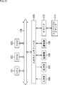
- FIG. 23 shows a configuration example of a computer when the processing of the enhancement processing unit 61 is executed by a general-purpose computer or the like as an image processing apparatus.
- This computer has a CPU (Central Processing Unit) 101 built-in.
- An input / output interface 105 is connected to the CPU 101 via the bus 104.
- a ROM (Read Only Memory) 102 and a RAM (Random Access Memory) 103 are connected to the bus 104.
- the input / output interface 105 includes an input unit 106 including input devices such as a keyboard, mouse, microphone, touch panel, and input terminal, an output unit 107 including a display, a speaker, and an output terminal, and a hard disk for storing programs and various data.
- a storage unit 108 including a RAM disk, a non-volatile memory, and the like, and a LAN (Local Area Network) adapter are connected to a communication unit 109 that executes communication processing via a network represented by the Internet.
- a drive 110 for reading / writing data from / to a removable medium 111 such as a magnetic disk, an optical disk, a magneto-optical disk, or a semiconductor memory is connected.
- the CPU 101 executes various processes according to the program loaded from the storage unit 108 to the RAM 103.
- the RAM 103 also appropriately stores data necessary for the CPU 101 to execute various processes.
- the CPU 101 loads, for example, the program stored in the storage unit 108 to the RAM 103 via the input / output interface 105 and the bus 104 and executes the program. Is performed.
- the program executed by the computer (CPU 101) can be provided by being recorded in the removable medium 111 as a package medium, for example.
- the program can be provided via a wired or wireless transmission medium such as a local area network, the Internet, or digital satellite broadcasting.
- the program can be installed in the storage unit 108 via the input / output interface 105 by attaching the removable medium 111 to the drive 110. Further, the program can be received by the communication unit 109 via a wired or wireless transmission medium and installed in the storage unit 108. In addition, the program can be installed in the ROM 102 or the storage unit 108 in advance.
- the program executed by the computer may be a program that is processed in time series in the order described in this specification, or in parallel or at a necessary timing such as when a call is made. It may be a program for processing.
- the projection module 1 having a configuration of about one chip, a mobile phone, a smartphone, a mobile terminal, a digital still camera, and the like.
- an image stored in each electronic device or an image received by communication may be projected.
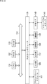
- FIG. 24 shows a configuration example of an electronic apparatus including a projection module 151 in which the function as the projection apparatus 1 of FIG. 1 is modularized into one chip.
- the functions and configurations of the CPU 131 to the removable medium 141 are substantially the same as those of the CPU 101 to the removable medium 111, and thus description thereof is omitted.
- the CPU 131 to the removable medium 141 of the electronic device in FIG. 24 are generally miniaturized with better portability than the CPU 101 to the removable medium 111.
- the projection module 151 has the same function as that of the projection apparatus 1 shown in FIG.
- Embodiments of the present technology are not limited to the above-described embodiments, and various modifications can be made without departing from the gist of the present technology.
- the enhancement coefficient Coeff1 and the enhancement coefficient Coeff2 are calculated by substituting predetermined values into the function f ( ⁇ UV), the function f (Mg), and the function g (Area avgTTL ).
- the emphasis coefficient Coeff1 and the emphasis coefficient Coeff2 may be determined (calculated) by holding a table storing the same correspondence as the function f () and the function g () and referring to the table.
- the present technology can take a cloud computing configuration in which one function is shared by a plurality of devices via a network and is jointly processed.
- each step described in the above flowchart can be executed by one device or can be shared by a plurality of devices.
- the plurality of processes included in the one step can be executed by being shared by a plurality of apparatuses in addition to being executed by one apparatus.
- a saturation enhancement processing unit that determines a first enhancement coefficient for enhancing the luminance of the image according to the saturation of the image, and converts the luminance signal of the image based on the determined first enhancement coefficient.
- An image processing apparatus comprising: (2) The image processing apparatus according to (1), wherein the saturation enhancement processing unit determines the first enhancement coefficient according to an absolute value of a color difference component of each pixel of the image. (3) The saturation enhancement processing unit determines the first enhancement coefficient by substituting one of the Cr component and Cb component having a larger absolute value of each pixel into the first function.
- the image processing apparatus (4) The image processing apparatus according to (3), wherein the first function is a function in which the first enhancement coefficient increases as the substituted value is closer to 0.5.
- the saturation enhancement processing unit determines the first enhancement coefficient according to an RGB value of each pixel of the image.
- the saturation enhancement processing unit normalizes the RGB value of each pixel of the image, and calculates the first enhancement coefficient based on the result of multiplying the normalized RGB value by the ratio of R, G, B.
- the image processing apparatus according to (5).
- the saturation enhancement processing unit substitutes an arithmetic value using a result obtained by multiplying the normalized RGB value by a ratio of each of R, G, and B into a first function, thereby obtaining the first enhancement coefficient.
- the image processing apparatus according to (6).
- (8) The image processing apparatus according to (7), wherein the first function is a function that increases the first enhancement coefficient as the calculated value increases.
- (9) For each of the regions obtained by dividing the image into a plurality of regions, a second enhancement coefficient for enhancing the luminance of the image is determined, and the luminance signal of the image is converted based on the determined second enhancement coefficient.
- the image processing apparatus according to any one of (1) to (8), further including a region enhancement processing unit that performs the processing.
- the region enhancement processing unit when determining the second enhancement coefficient of a region of interest that is a region of interest among the plurality of regions, calculates a power total value of the region of interest and its surrounding region,
- the image processing apparatus according to (9), wherein when the power total value is smaller than a predetermined threshold, the second enhancement coefficient is determined by substituting the power total value into a second function.
- the size of the region is smaller than the pupil size of the human eye, The size of the region for calculating the total power value, and the combined size of the region of interest and its peripheral region is a size larger than the pupil size of the human eye.
- (9) or (10) Image processing device when determining the second enhancement coefficient of a region of interest that is a region of interest among the plurality of regions, calculates a power total value of the region of interest and its surrounding region.
- the image processing device An image processing method for determining an enhancement coefficient for enhancing the luminance of the image according to the saturation of the image, and converting the luminance signal of the image based on the determined enhancement coefficient.
- a saturation enhancement processing unit that determines an enhancement coefficient for enhancing the luminance of the image according to the saturation of the input image, and converts the luminance signal of the image based on the determined enhancement coefficient;
- a laser light source unit that outputs a laser beam according to a pixel signal of the image into which the luminance signal is converted; And a scanning unit that scans in the horizontal direction and the vertical direction while reflecting the laser beam.
- 1 projection device 2a projection image, 21 controller, 22 laser driver, 23 mirror driver, 24R, 24G, 24B laser light source unit, 27 drive mirror, 61 enhancement processing unit, 71 saturation enhancement processing unit, 72 region enhancement processing unit, 90 ISP, 101 CPU, 102 ROM, 103 RAM, 106 input unit, 107 output unit, 108 storage unit, 109 communication unit, 110 drive, 151 projection module
Landscapes
- Physics & Mathematics (AREA)
- Engineering & Computer Science (AREA)
- General Physics & Mathematics (AREA)
- Optics & Photonics (AREA)
- Multimedia (AREA)
- Signal Processing (AREA)
- Computer Hardware Design (AREA)
- Theoretical Computer Science (AREA)
- Mechanical Optical Scanning Systems (AREA)
- Control Of Indicators Other Than Cathode Ray Tubes (AREA)
- Transforming Electric Information Into Light Information (AREA)
Abstract
本技術は、レーザ製品としての安全基準を満たしつつ、投影された画像の明るさを向上させることができるようにする画像処理装置、画像処理方法、および投影装置に関する。 彩度強調処理部は、画像の彩度に応じて、画像の輝度を強調する第1の強調係数を決定し、決定された第1の強調係数に基づいて、画像の輝度信号を変換する。本技術は、例えば、光源としてのレーザビームを走査するレーザビーム走査方式の投影装置等に適用できる。
Description
本技術は、画像処理装置、画像処理方法、および投影装置に関し、特に、レーザ製品としての安全基準を満たしつつ、投影された画像の明るさを向上させることができるようにした画像処理装置、画像処理方法、および投影装置に関する。
従来、例えば、スクリーンを対象として、正弦波状にレーザビームを往復走査させるタイプのプロジェクタが存在する(例えば、特許文献1参照)。
このプロジェクタによれば、レーザビームを反射する駆動ミラーが共振動作により走査され、駆動ミラーで反射されたレーザビームが、スクリーン上の各位置に照射される。
これにより、スクリーン上の各位置には、レーザビームの照射により、スポット状の光であるスポット光が投影される。すなわち、スクリーン上には、複数のスポット光をそれぞれ画素とする画像が投影される。
このようなレーザビームを走査させるプロジェクタは、レーザ製品としての安全基準を満たすため、レーザパワーの制限を受ける。レーザパワーの制限によって、投影される画像の明るさも制限される。
本技術は、このような状況に鑑みてなされたものであり、レーザ製品としての安全基準を満たしつつ、投影された画像の明るさを向上させることができるようにするものである。
本技術の一側面の画像処理装置は、画像の彩度に応じて、前記画像の輝度を強調する第1の強調係数を決定し、決定された前記第1の強調係数に基づいて、前記画像の輝度信号を変換する彩度強調処理部を備える。
本技術の一側面の画像処理方法は、画像処理装置が、画像の彩度に応じて、前記画像の輝度を強調する強調係数を決定し、決定された前記強調係数に基づいて、前記画像の輝度信号を変換する。
本技術の一側面の投影装置は、入力された画像の彩度に応じて、前記画像の輝度を強調する強調係数を決定し、決定された前記強調係数に基づいて、前記画像の輝度信号を変換する彩度強調処理部と、前記輝度信号が変換された前記画像の画素信号に応じたレーザビームを出力するレーザ光源部と、前記レーザビームを反射しつつ、水平方向および垂直方向に走査する走査部とを備える。
本技術の一側面においては、画像の彩度に応じて、前記画像の輝度を強調する第1の強調係数が決定され、決定された前記第1の強調係数に基づいて、前記画像の輝度信号が変換される。
なお、本技術の一側面の画像処理装置は、コンピュータにプログラムを実行させることにより実現することができる。
また、本技術の一側面の画像処理装置を実現するために、コンピュータに実行させるプログラムは、伝送媒体を介して伝送することにより、又は、記録媒体に記録して、提供することができる。
画像処理装置は、独立した装置であっても良いし、1つの装置を構成している内部ブロックであっても良い。
本技術の一側面によれば、レーザ製品としての安全基準を満たしつつ、投影された画像の明るさを向上させることができる。
なお、ここに記載された効果は必ずしも限定されるものではなく、本開示中に記載されたいずれかの効果であってもよい。
以下、本技術を実施するための形態(以下、実施の形態という)について説明する。なお、説明は以下の順序で行う。
1.投影装置の構成例
2.ラスタスキャンについて
3.一般的な信号処理の流れ
4.投影装置1における信号処理の流れ
5.強調処理部61の詳細構成
6.彩度強調処理部71の詳細
7.領域強調処理部72の詳細
8.フローチャート
9.投影装置のその他の構成例
10.コンピュータの構成例
11.プロジェクションモジュールとして電子機器に適用する例
1.投影装置の構成例
2.ラスタスキャンについて
3.一般的な信号処理の流れ
4.投影装置1における信号処理の流れ
5.強調処理部61の詳細構成
6.彩度強調処理部71の詳細
7.領域強調処理部72の詳細
8.フローチャート
9.投影装置のその他の構成例
10.コンピュータの構成例
11.プロジェクションモジュールとして電子機器に適用する例
<1.投影装置の構成例>
図1は、本技術を適用した投影装置の構成例を示すブロック図である。
図1は、本技術を適用した投影装置の構成例を示すブロック図である。
この投影装置1は、光源としてのレーザビームを走査することにより、投影画像2aをスクリーン2に投影するレーザビーム走査方式の投影装置(プロジェクタ)である。なお、投影画像2aの投影先は、スクリーン2に限らず、壁面や所定の物体の平面等でもよい。
投影装置1は、コントローラ21、レーザドライバ22、ミラードライバ23、レーザ光源部24R,24G、及び24B、ミラー25、ダイクロイックミラー26-1及び26-2、駆動ミラー27、並びに、光学レンズ28から構成される。
コントローラ21には、例えばパーソナルコンピュータなどの他の装置から、入力画像信号として、スクリーン2上に投影される投影画像2aの画像信号が供給される。
コントローラ21は、他の装置から供給される入力画像信号に基づいて、投影画像2aを構成する各画素の、色(赤、緑、及び青)ごとの画素データを生成し、ミラードライバ23から取得したミラー同期信号に同期してレーザドライバ22に供給する。なお、ミラー同期信号とは、入力画像信号に同期してミラードライバ23を駆動させるための信号をいう。
レーザドライバ22は、コントローラ21から供給される、色毎の画素データに基づき、投影画像2aの画素ごとの画素値に応じた駆動信号を生成し、レーザ光源部24R,24G、及び24Bに供給する。具体的には、レーザドライバ22は、赤の画素データに応じた駆動信号をレーザ光源部24Rに供給し、緑の画素データに応じた駆動信号をレーザ光源部24Gに供給し、青の画素データに応じた駆動信号をレーザ光源部24Bに供給する。
ミラードライバ23は、スクリーン2の水平方向(図中左右方向)および垂直方向(図中上下方向)にレーザビームをスキャンさせるために、駆動ミラー27の共振周波数に基づいた水平スキャン信号および垂直スキャン信号を生成して、駆動ミラー27に供給する。また、ミラードライバ23は、駆動ミラー27により反射されたレーザビームの一部を検出する受光部(図示せず)を有している。そして、ミラードライバ23は、受光部の検出結果に基づいて水平スキャン信号及び垂直スキャン信号を調整したり、受光部の検出結果に従った検出信号をコントローラ21にフィードバックしたりする。
レーザ光源部24R,24G、及び24Bは、レーザドライバ22から供給される駆動信号に従って、それぞれ対応する(波長の光の)色のレーザビームを出力する。具体的には、レーザ光源部24Rは、赤の画素データに応じたパワーで赤のレーザビームを出力する。レーザ光源部24Gは、緑の画素データに応じたパワーで緑のレーザビームを出力し、レーザ光源部24Bは、青の画素データに応じたパワーで青のレーザビームを出力する。
なお、以下では、レーザ光源部24R,24G、及び24Bを、それぞれ区別する必要がない場合、それらを単にレーザ光源部24ともいう。
ミラー25は、レーザ光源部24Rから出力される赤のレーザビームを反射する。ダイクロイックミラー26-1は、レーザ光源部24Gから出力される緑のレーザビームを反射するとともに、ミラー25により反射された赤のレーザビームを透過させる。ダイクロイックミラー26-2は、レーザ光源部24Bから出力される青のレーザビームを反射するとともに、ミラー25により反射された赤のレーザビーム、及び、ダイクロイックミラー26-1により反射された緑のレーザビームを透過させる。なお、ミラー25、並びに、ダイクロイックミラー26-1及び26-2は、レーザ光源部24R,24G、及び24Bから出力されたレーザビームの光軸が同軸となるように組み合わされて配置されている。
駆動ミラー27は、例えば、MEMS(Micro Electro Mechanical Systems)により形成された微小なミラーであり、ミラードライバ23から供給される水平スキャン信号及び垂直スキャン信号に従って駆動する。すなわち、例えば、駆動ミラー27は、レーザ光源部24R,24G、及び24Bのそれぞれから出力されたレーザビームを反射しつつ、スクリーン2の水平方向および垂直方向に走査(スキャン)する。
光学レンズ28は、駆動ミラー27からスクリーン2に向かうレーザビームの光学経路上に配置されており、レーザビームの光路を補正する。
なお、投影装置1は、レーザドライバ22及びミラードライバ23がコントローラ21に統合される構成を採用することができる。また、投影装置1は、レーザビームの光学経路上に光学レンズ28が配置されない構成としてもよい。
図2は、レーザ光源部24R,24G、及び24Bの構成をより詳細に示した図である。
レーザ光源部24R,24G、及び24Bは、それぞれ、R(赤),G(緑),B(青)の各波長のレーザビーム発生部24Ra,24Ga,24Ba、およびコリメータレンズ24Rb,24Gb,24Bbを備えている。すなわち、レーザ光源部24R,24G,24Bでは、それぞれレーザビーム発生部24Ra,24Ga,24Baが、各色に特有の波長のレーザビームを発生し、コリメータレンズ24Rb,24Gb,24Bbは、それぞれの波長のレーザビームをコリメートして出力する。尚、レーザビーム発生部24Ra,24Ga,24Ba、並びに、コリメータレンズ24Rb,24Gb,24Bbについては、それぞれ色(波長)を特に区別する必要が無い場合、単に、レーザビーム発生部24a、並びに、コリメータレンズ24bと称する。
レーザビーム発生部24Raは、赤の画素データに応じた駆動信号(Video Data Current Red)に基づいて、赤のレーザビームを出射する。レーザビーム発生部24Raから出射された赤のレーザビームが、コリメータレンズ24Rbにより出射方向が適切に調整された後、ミラー25により反射され、ダイクロイックミラー26-1に入射する。
レーザビーム発生部24Gaは、緑の画素データに応じた駆動信号(Video Data Current Green)に基づいて、緑のレーザビームを出射する。レーザビーム発生部24Gaから出射された緑のレーザビームが、コリメータレンズ24Gbにより出射方向が適切に調整された後、ダイクロイックミラー26-1により反射され、ダイクロイックミラー26-2に入射する。また、ダイクロイックミラー26-1は、ミラー25から入射される赤のレーザビームを透過させ、ダイクロイックミラー26-2に入射させる。
レーザビーム発生部24Baは、青の画素データに応じた駆動信号(Video Data Current Blue)に基づいて、青のレーザビームを出射する。レーザビーム発生部24Baから出射された青のレーザビームが、コリメータレンズ24Bbにより出射方向が適切に調整された後、ダイクロイックミラー26-2により反射され、駆動ミラー27に入射する。また、ダイクロイックミラー26-2は、ダイクロイックミラー26-1から入射される赤および緑のレーザビームを透過させ、駆動ミラー27に入射させる。結果として、赤、緑、および青(RGB)のレーザビームが、合波された状態で、ダイクロイックミラー26-2から駆動ミラー27に入射される。
投影装置1は、駆動ミラー27を駆動して、赤、緑、および青のレーザビームをスキャン(走査)することにより、スクリーン2上に二次元の投影画像2aを投影する。この駆動ミラー27によるレーザビームのスキャン方法としては、例えば、ラスタスキャンという方法と、リサージュスキャンという方法があるが、投影装置1では、例えばラスタスキャンが採用される。
<2.ラスタスキャンについて>
図3を参照して、ラスタスキャンについて説明する。
図3を参照して、ラスタスキャンについて説明する。
図3では、投影画像2a上にラスタスキャンによるレーザビームの走査軌跡が示されており、投影画像2aの下方に、水平スキャン信号H-Scanが示されており、投影画像2aの左方に、垂直スキャン信号V-Scanが示されている。
水平スキャン信号H-Scanは、例えば、駆動ミラー27の共振周波数に従った約20kHzで振動する正弦波の波形をした信号であり、水平スキャン信号H-Scanの周波数は、投影画像2aの水平同期周波数の1/2となる。垂直スキャン信号V-Scanは、例えば、投影画像2aのフレーム周期に応じた周波数である60Hzで振動する鋸波の波形をした信号である。
なお、水平スキャン信号H-Scanの両端近傍における走査軌跡において、レーザビームは非発光とされ、走査軌跡の折り返し部分は、投影画像2aを投影するのには使用されないようにすることができる。また、垂直スキャン信号V-Scanが略垂直に立ち上がる波形となっている区間、即ち、レーザビームの走査軌跡が下端(走査終了時の位置)から上端(次の走査開始時の位置)に向かって急峻に変化する区間である帰線区間において、レーザビームは非発光とされる。
このような水平スキャン信号H-Scan及び垂直スキャン信号V-Scanに従って駆動ミラー27が駆動することにより、投影画像2a上に示すような走査軌跡でレーザビームが走査される。図示されているように、レーザビームは双方向に走査される。水平方向に向かう走査線の一行ごとにレーザビームの走査方向が逆方向となるので、走査線の1行ごとに入力画像信号を並べ替える処理を行ったり、入力画像信号に対するデータのアクセス方向を変更する必要がある。
また、図3における水平スキャン信号H-Scanの下方に示されるように、レーザビームの水平方向の走査速度は、投影画像2aの中央において大きくなり、投影画像2aの端近傍において小さくなる。レーザビームの垂直方向の走査速度は、投影画像2aの位置によらず一定である。なお、以下では、簡単のため、投影画像2a全体を、画面と称して説明する場合がある。
<3.一般的な信号処理の流れ>
図4は、入力画像信号がレーザ光源部24に入力される駆動信号に変換されるまでの一般的な信号処理の流れを示すブロック図である。
図4は、入力画像信号がレーザ光源部24に入力される駆動信号に変換されるまでの一般的な信号処理の流れを示すブロック図である。
他の装置から供給された入力画像信号は、画質調整処理部41、画素信号変換部42、及び、駆動信号変換部43のそれぞれで所定の処理が実行されることにより駆動信号に変換されて、レーザ光源部24に供給される。
画質調整処理部41は、入力画像信号に対して、コントラスト調整やシャープネス調整などの一般的な画質調整処理を実行し、処理後の画像信号を画素信号変換部42に供給する。
入力画像信号は、例えば、YUVフォーマットの画像信号で供給される。YUVフォーマットは、輝度信号Yと、Cb(U)成分及びCr(V)成分の2つの色差信号(Cb信号及びCr信号)で表現される信号である。輝度信号Yは、0から1の範囲の値をとり、Cb信号及びCr信号は、-0.5から+0.5の範囲の値をとる。Cb信号及びCr信号は、便宜的に、U信号及びV信号とも称する。
画素信号変換部42は、画質調整処理部41から供給される画像信号を、ラスタスキャンの走査軌道に合わせて、画面を構成する画素単位の画素信号に変換する。より具体的には、画素信号変換部42は、画質調整処理部41から供給されるYUVフォーマットの画像信号を、RGBフォーマットの画像信号に変換し、ラスタスキャンの走査軌道に合わせて、画面を構成する画素単位のR,G,Bごとの画素信号(画素データ)に変換する。
駆動信号変換部43は、画素信号変換部42から供給される画素信号を、R,G,Bごとに、駆動信号に変換し、レーザ光源部24に供給する。
画素信号変換部42が、ラスタスキャンの走査軌道に合わせて、画像信号をR,G,Bごとの画素信号に変換する際、走査速度に応じたレーザパワーの調整も行う。
即ち、図5左側のグラフに示されるように、レーザビームの水平方向の走査速度は、画面中央において大きくなり、画面の端近傍において小さくなるので、同じパワーで水平方向に走査すると、走査速度の違いにより、積算パワーが画面位置に応じて異なることになる。換言すれば、同じパワーで水平走査すると、走査速度の小さい画面端近傍では、人の目に入射する時間が長くなるため、目に入射されるレーザパワーが大きくなる。
そこで、レーザ安全基準を満たすためには、図5右側のグラフに示されるように、走査速度の小さい画面端近傍では、レーザパワーを下げて、安全を確保する必要がある。
レーザ安全基準は、図6に示されるように、コリメートされた集光性の高いレーザビームが人の目に入射しても安全性が保てるように、人の目に単位時間に入る積算パワー、瞬間的なパワーなど、いくつかの条件で制約を課している。
レーザパワーが最大となる画像は、R,G,Bそれぞれが100%で発光する画像、即ち、白の画像である。したがって、図5右側のグラフのように、レーザ光源部24がRGB100%で白色光を発光した場合であっても、破線で示されるレーザ安全基準限界値を超えないように、レーザパワーが制御される。レーザ安全基準限界値と、RGB100%で発光したときのパワーとの差分は、投影装置1で設定されたマージンに相当する。レーザ安全基準は、投影装置として出力可能なレーザ光源のパワーを制約し、明るい画像を投影するための制限となっている。
一方で、一般的に、投影装置が表示させる実際の画像は、図7において、実画像として示される曲線のように、30%程度の明るさとなるような画像信号(画素信号)で構成されている場合が多く、レーザ安全基準限界値よりも十分小さいパワーで動作している。
そこで、投影装置1では、画像の構成、具体的には、単色や純色などの画像の色合いを解析し、解析した画像の色合いに応じて、レーザ安全基準限界値を超えない範囲で、レーザパワーを上げることにより、投影する画像の明るさを向上させる。
<4.投影装置1における信号処理の流れ>
図8は、投影装置1における、入力画像信号が駆動信号に変換されるまでの信号処理の流れを示すブロック図である。
図8は、投影装置1における、入力画像信号が駆動信号に変換されるまでの信号処理の流れを示すブロック図である。
図8に示される投影装置1の処理の流れを、図4で示した一般的な処理の流れと比較すると、画質調整処理部41と画素信号変換部42との間に、強調処理部61が新たに設けられている。画質調整処理部41、画素信号変換部42、及び、駆動信号変換部43の処理については、図4で説明した処理と同様であるため、その説明は省略する。
強調処理部61は、画質調整処理部41から供給される画像信号を、画像の構成、具体的には、単色や純色などの画像の色合いを解析し、解析した画像の色合いに応じて画像信号を強調する強調処理を実行する。強調処理部61は、強調処理後の画像信号を、画素信号変換部42に供給する。
図8の画質調整処理部41、画素信号変換部42、及び、強調処理部61は、図1のコントローラ21が実行する処理ブロックに対応し、図8の駆動信号変換部43は、図1のレーザドライバ22が実行する処理ブロックに対応する。
<5.強調処理部61の詳細構成>
図9は、強調処理部61の詳細構成を示している。
図9は、強調処理部61の詳細構成を示している。
強調処理部61は、彩度強調処理部71と、領域強調処理部72とを備える。
彩度強調処理部71には、画質調整処理部41において、コントラスト調整やシャープネス調整などの一般的な画質調整処理が行われた処理後の画像信号が、YUVフォーマットで供給される。
彩度強調処理部71は、画質調整処理部41から供給される画像の彩度に応じて、画像の輝度を強調する強調係数Coeff1(第1の強調係数Coeff1)を決定する。そして、彩度強調処理部71は、決定された強調係数Coeff1に基づいて、画像の輝度信号Yを強調(変換)する。具体的には、彩度強調処理部71は、画質調整処理部41から供給されるYUVフォーマットの画像信号の輝度信号Yに対して、決定された強調係数Coeff1を用いて、輝度信号Y’=Coeff1*Yを演算し、強調後の輝度信号Y’を算出して、領域強調処理部72に出力する。
領域強調処理部72は、彩度強調処理部71から供給される画像を複数の領域に分割して、領域ごとに、画像の輝度を強調する強調係数Coeff2(第2の強調係数Coeff2)を決定する。そして、領域強調処理部72は、決定された強調係数Coeff2に基づいて、輝度信号Y’を強調(変換)する。具体的には、領域強調処理部72は、彩度強調処理部71から供給されるYUVフォーマットの画像信号の輝度信号Y’に対して、決定された強調係数Coeff2を用いて、輝度信号Y”=Coeff2*Y’を演算し、強調後の輝度信号Y”を算出して、画素信号変換部42に出力する。
画素信号変換部42では、彩度強調処理部71及び領域強調処理部72によって輝度信号Yが強調された輝度信号Y”と2つの色差信号(Cb信号及びCr信号)が、R,G,Bの画素信号に変換される。
彩度強調処理部71及び領域強調処理部72が行う処理の詳細について、以下でさらに説明する。
<6.彩度強調処理部71の詳細>
初めに、彩度強調処理部71の処理の詳細について説明する。
初めに、彩度強調処理部71の処理の詳細について説明する。
彩度強調処理部71は、画質調整処理部41から供給される画像信号の彩度を画素ごとに解析し、彩度が高い画素の輝度信号Yを、所定の強調係数Coeff1を用いて強調する。
ここで、彩度が高い画素とは、画素の色合いが、白ではなく、赤や緑、青などの単色、純色に近い色合いの画素を意味する。U-V色空間において、図10に示されるように、U信号及びV信号の値がゼロから離れるほど、彩度の高い色合いとなる。
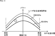
彩度が高い画素では、赤、緑、青(RGB)全てのレーザが100%近くで発光することはなく、赤、緑、青のうちの少なくとも1色のレーザは、低いパワーでの動作となる。
例えば、図11に示されるように、赤、緑(RG)のレーザが100%の発光であっても、青のレーザは0%の発光となる場合、出力レーザのパワーであるRG100%の発光時のパワーは、RGB100%の発光時のパワーよりも十分低くなるため、青のレーザを発光しない分だけ、赤、緑(RG)のレーザを100%以上のパワーで発光させる余地がある。
このように、彩度強調処理部71は、画像信号の彩度を画素ごとに解析し、赤や緑、青などの単色、純色に近い色合いの画素については、輝度信号Yを強調した輝度信号Y’に変換する。
より具体的には、彩度強調処理部71は、画面を構成する各画素を注目画素として、注目画素の色差成分であるU信号及びV信号の絶対値を検出し、U信号及びV信号の絶対値の大きい一方を、強調係数Coeff1を算出するための変数ΔUVに決定する。
そして、彩度強調処理部71は、変数ΔUVと強調係数Coeff1との対応関係を規定した関数f(ΔUV)に、決定した変数ΔUVを代入することにより、注目画素の彩度に応じた強調係数Coeff1を決定(算出)する。そして、彩度強調処理部71は、注目画素の輝度信号Yに、決定された強調係数Coeff1を乗算して、強調処理後の輝度信号Y’を算出する。
図12のAは、変数ΔUVと強調係数Coeff1との対応関係を規定した関数f(ΔUV)の例を示している。
U信号及びV信号は、いずれも-0.5から+0.5の範囲の値をとるので、U信号及びV信号の絶対値は、0から0.5の範囲となる。関数f(ΔUV)は、変数ΔUVが0.5に近づくほど、強調係数Coeff1が大きくなり、変数ΔUVが0.5のとき、強調係数Coeff1は2.0となっている。図12のAにおいて、RGB100%の発光時のパワーと同等の強調係数Coeff1は、例えば、3.0である。関数f(ΔUV)は、それよりも小さい2.0までの範囲で、強調係数Coeff1が設定されるように規定されているので、レーザ安全基準限界値を超えない範囲で、輝度信号Yが強調されている。
図12のBは、変数ΔUVに応じた強調係数Coeff1の概念を示した図であり、U-V色空間において、原点(中心)から離れるほど、強調係数Coeff1が大きく設定されることを表している。
なお、図10や図11からもわかるように、強調係数Coeff1は、単色に近いほど大きな値に設定可能である。そこで、彩度強調処理部71は、赤、緑、青(RGB)の色をより詳細に解析し、画像のRGB値に基づいて強調係数Coeff1を決定する方法も採用可能である。
具体的には、最初に、彩度強調処理部71は、YUVフォーマットの画像信号を、RGBフォーマットの画像信号(以下、RGB信号とも称する。)に変換する。例えば、ITU-R BT.601/ITU-R BT.709の規格によれば、以下の変換式により、YUVフォーマットの画像信号を、RGBフォーマットの画像信号に変換することができる。
R = Y + 1.402 * Cr
G = Y - 0.344136 * Cb - 0.714136 * Cr
B = Y + 1.772 * Cb
R = Y + 1.402 * Cr
G = Y - 0.344136 * Cb - 0.714136 * Cr
B = Y + 1.772 * Cb
次に、彩度強調処理部71は、RGBフォーマットの画像信号を、RGB信号がとり得る値の最大値maxRGBで規格化する。すなわち、彩度強調処理部71は、画面を構成する各画素を注目画素として、注目画素のR信号、B信号、G信号に対して、以下の式により、規格化したR信号、B信号、G信号であるRnrm、Gnrm、及び、Bnrmを計算する。
Rnrm=R/maxRGB
Gnrm=G/maxRGB
Bnrm=B/maxRGB
ここで、例えば、RGBフォーマットの画像信号が、8ビットで表現された信号である場合、RGB信号がとり得る値の最大値maxRGBは、255である。
Rnrm=R/maxRGB
Gnrm=G/maxRGB
Bnrm=B/maxRGB
ここで、例えば、RGBフォーマットの画像信号が、8ビットで表現された信号である場合、RGB信号がとり得る値の最大値maxRGBは、255である。
そして、彩度強調処理部71は、以下の式で表されるように、注目画素の規格化されたR信号、B信号、G信号であるRnrm、Gnrm、及び、Bnrmに対して、RGB毎のパワー係数Cr,Cg,Cbを掛けて、1から減算することにより、マージンMgを決定(算出)する。パワー係数Cr,Cg,Cbは、レーザ光源部24が画像として白を表示するときのレーザ光源部24R,24G、及び24Bそれぞれのパワーの比率に相当する。
Mg=1-(Rnrm*Cr + Gnrm*Cg + Bnrm*Cb)
Mg=1-(Rnrm*Cr + Gnrm*Cg + Bnrm*Cb)
最後に、彩度強調処理部71は、マージンMgと強調係数Coeff1との対応関係を規定した関数f(Mg)に、決定したマージンMgを代入することにより、注目画素の彩度に応じた強調係数Coeff1を決定(算出)する。そして、彩度強調処理部71は、注目画素の輝度信号Yに、決定された強調係数Coeff1を乗算して、強調処理後の輝度信号Y’を算出する。
図13のAは、マージンMgと強調係数Coeff1との対応関係を規定した関数f(Mg)の例を示している。
関数f(Mg)は、Rnrm、Gnrm、及び、Bnrmとパワー係数Cr,Cg,Cbとを用いた演算値であるマージンMgが大きくなるほど、強調係数Coeff1が大きくなる関数である。RGB100%の発光時のパワーと同等の強調係数Coeff1は、例えば、3.0である。関数f(Mg)は、それよりも小さい2.0までの範囲で、強調係数Coeff1が設定されるように規定されているので、レーザ安全基準限界値を超えない範囲で、輝度信号Yが強調されている。
図13のBは、マージンMgに応じた強調係数Coeff1の概念を示した図であり、U-V色空間において、原点(中心)から離れるほど、強調係数Coeff1が大きく設定されることを表している。
彩度強調処理部71は、変数ΔUVに応じた強調係数Coeff1を決定して輝度信号Y’を算出する処理である、UV値に基づく強調処理か、または、RGB値から演算したマージンMgに応じた強調係数Coeff1を決定して輝度信号Y’を算出する処理である、RGB値に基づく強調処理のいずれか一方を実行し、算出した輝度信号Y’を出力する。
なお、UV値に基づく強調処理か、または、RGB値に基づく強調処理のどちらを実行するかは、例えば、設定画面等によって、入力画像信号が供給される前に決定することができる。
以上のように、彩度強調処理部71の処理によれば、入力画像信号の色差を画素ごとに解析することにより、図14に示されるように、R,G,Bの色単位では、通常時の100%を超える発光が可能となる。これにより、レーザ製品としての安全基準を満たしつつ、投影された画像の明るさを向上することができる。
<7.領域強調処理部72の詳細>
次に、領域強調処理部72の処理の詳細について説明する。
次に、領域強調処理部72の処理の詳細について説明する。
投影装置1がスクリーン2に投影する投影画像2aが、明るく発光させる領域が少ない画像である場合がある。明るく発光させる領域が少ない画像とは、例えば、宇宙や星空の画像などである。このような画像においては、R,G,Bそれぞれが100%で発光する領域は極めて狭い領域であり、レーザ安全基準が人の目への積算合計値で制限されている場合、レーザ安全基準よりも十分に低い積算合計値となっており、発光パワーをアップさせる余地がある。
そこで、領域強調処理部72は、画面を複数の領域に分割し、人の目へのパワー積算値を考慮して各領域の強調係数Coeff2を決定し、決定された強調係数Coeff2を用いて、輝度信号Y’を輝度信号Y”に変換する。
画面を複数の領域に分割する際の分割数に制限はなく、任意の数に分割することができるが、投影領域に目がランダムに配置されることを考慮して、複数の領域に分割した後の1つの領域のサイズが、人の目の瞳孔サイズよりも小さなサイズとなるように、画面の分割数が設定される。画面の分割数は、設定画面等によって、ユーザ自身が決定することができる。
例えば、図15のAに示されるように、投影画像2aのアスペクト比が16:9、投影装置1からスクリーン2までの距離が100mm、投影距離と水平画角との比であるスローレシオ(=投影距離/水平画角)が1.0である場合、投影画像2aの画角は、100mmx56.3mmとなり、直径約7mmの人の目は、水平画角の7%の大きさ、垂直画角の12.4%の大きさに相当する。
そして、分割された単位領域のサイズと人の目の瞳孔サイズが、図15のBに示されるような関係にある場合、領域1ないし9の3x3の9領域で人の目の瞳孔サイズよりも大きな領域サイズとなる。
領域強調処理部72は、分割した複数の領域のうちの所定の注目領域の強調係数Coeff2を決定する場合、注目領域と、その周辺の領域を合わせて、人の目の瞳孔サイズよりも大きな領域サイズで、レーザパワー合計値AreaavgTTLを算出する。
例えば、領域5を注目領域として、領域5の強調係数Coeff2を決定する場合、領域強調処理部72は、以下の式(1)により、領域5を中心とする3x3の9領域全体のレーザパワー合計値AreaavgTTLを算出する。

式(1)によれば、9領域全体のレーザパワー合計値(積算合計値)AreaavgTTLは、領域1乃至領域9のレーザパワー平均値Areaavg1乃至Areaavg9を加算することにより得られる。
式(1)における領域1乃至領域9のレーザパワー平均値Areaavg1乃至Areaavg9それぞれは、式(2)で計算される。式(2)は、領域内の全画素のRGB毎の信号の和に、それぞれ、RGB毎のパワー係数Cr,Cg,Cbを掛けた総和を、領域内の画素数Areattl_pixelで除算して求められることを表す。
以上のように、パワー積算値を計算する際の領域は、人間の目の瞳孔サイズ(直径約7mm)との関係で決定される。
領域強調処理部72は、式(1)で算出した注目領域(領域5)を中心とする3x3の周辺領域のレーザパワー合計値AreaavgTTLが、レーザ安全基準を基に決定された閾値Thよりも小さいかを判定する。
注目領域を中心とする3x3の周辺領域のレーザパワー合計値AreaavgTTLが閾値Thよりも小さいと判定された場合、領域強調処理部72は、図16に示されるような、レーザパワー合計値AreaavgTTLと強調係数Coeff2との対応関係を規定した関数g(AreaavgTTL)に、算出したレーザパワー合計値AreaavgTTLを代入することにより、注目領域のパワー積算値に応じた強調係数Coeff2を決定する。そして、領域強調処理部72は、注目領域の各画素の輝度信号Y’に、決定された強調係数Coeff2を乗算して、注目領域の各画素の強調処理後の輝度信号Y”を算出する。
図16において、破線で示される関数gmax(AreaavgTTL)は、レーザ安全基準を超えない強調係数Coeff2の上限値を表す。したがって、レーザパワー合計値AreaavgTTLと強調係数Coeff2との対応関係を規定した関数g(AreaavgTTL)は、レーザ安全基準限界値を超えない範囲で、輝度信号Y’が強調されるように設定されている。
以上のように、領域強調処理部72の処理によれば、入力画像信号に対応するレーザパワー積算値を所定サイズの領域単位で算出することにより、図17に示されるように、R,G,Bの色単位では、通常時の100%を超える発光が可能となる。これにより、レーザ製品としての安全基準を満たしつつ、投影された画像の明るさを向上することができる。
<8.フローチャート>
次に、図18のフローチャートを参照して、投影装置1の強調処理部61によって実行される強調処理について説明する。この処理は、例えば、強調処理部61(の彩度強調処理部71)に、YUVフォーマットの画像信号が供給されたとき開始される。
次に、図18のフローチャートを参照して、投影装置1の強調処理部61によって実行される強調処理について説明する。この処理は、例えば、強調処理部61(の彩度強調処理部71)に、YUVフォーマットの画像信号が供給されたとき開始される。
初めに、ステップS1において、彩度強調処理部71は、画質調整処理部41から供給された画像の彩度に応じて、強調係数Coeff1を用いて輝度信号Yを強調する彩度強調処理を実行する。彩度強調処理の詳細は、図19及び図20を参照して後述する。彩度強調処理により、画質調整処理部41から供給された画像の各画素の輝度信号Yが輝度信号Y’=Coeff1*Yに変換され、領域強調処理部72に出力される。
ステップS2において、領域強調処理部72は、彩度強調処理部71から供給される画像を複数の領域に分割して、領域単位に強調係数Coeff2を用いて輝度信号Y’を強調する領域強調処理を実行する。領域強調処理の詳細は、図21を参照して後述する。領域強調処理により、彩度強調処理部71から供給された画像の各画素の輝度信号Y’が輝度信号Y”=Coeff2*Y’に変換され、画素信号変換部42に出力される。
図19は、ステップS1の彩度強調処理の詳細を説明するフローチャートであり、画素のUV値に基づいて強調係数Coeff1を算出する場合の彩度強調処理のフローチャートである。
図19のフローチャートでは、最初に、ステップS21において、彩度強調処理部71は、画質調整処理部41から供給された画像の所定の画素を注目画素に設定する。
ステップS22において、彩度強調処理部71は、注目画素のU信号及びV信号の絶対値を検出し、U信号及びV信号の絶対値の大きい方を、強調係数Coeff1を算出するための変数ΔUVに決定する。
ステップS23において、彩度強調処理部71は、変数ΔUVと強調係数Coeff1との対応関係を規定した関数f(ΔUV)に、決定した変数ΔUVを代入することにより、注目画素の彩度に応じた強調係数Coeff1を算出(決定)する。
ステップS24において、彩度強調処理部71は、注目画素の輝度信号Yに、算出した強調係数Coeff1を乗算して、強調処理後の輝度信号Y’を算出する。算出された輝度信号Y’は、U信号及びV信号とともに、領域強調処理部72に供給される。
ステップS25において、彩度強調処理部71は、画質調整処理部41から供給された画像の全ての画素を注目画素に設定したかを判定する。
ステップS25で、彩度強調処理部71は、全ての画素を注目画素に設定していないと判定した場合、処理をステップS21に戻す。これにより、上述したステップS21乃至S25の処理が繰り返される。すなわち、まだ注目画素に設定されていない所定の画素が注目画素に設定され、注目画素の彩度に応じた強調係数Coeff1が算出され、強調係数Coeff1により強調された輝度信号Y’が算出される。
一方、ステップS25で、全ての画素が注目画素に設定されたと判定された場合、図19の彩度強調処理は終了する。
図20は、ステップS1の彩度強調処理の詳細を説明するフローチャートであり、画素のRGB値に基づいて強調係数Coeff1を算出する場合の彩度強調処理のフローチャートである。
図20のフローチャートでは、最初に、ステップS41において、彩度強調処理部71は、画質調整処理部41から供給された画像の所定の画素を注目画素に設定する。
ステップS42において、彩度強調処理部71は、注目画素のYUVフォーマットの画像信号を、RGBフォーマットの画像信号(RGB信号)に変換する。
ステップS43において、彩度強調処理部71は、注目画素のRGB信号を、RGB信号がとり得る値の最大値maxRGBで規格化することにより、Rnrm、Gnrm、及び、Bnrmを算出する。
ステップS44において、彩度強調処理部71は、注目画素の規格化されたR信号、B信号、G信号であるRnrm、Gnrm、及び、Bnrmを用いて、マージンMgを算出する。すなわち、彩度強調処理部71は、Rnrm、Gnrm、及び、Bnrmに対して、RGB毎のパワー係数Cr,Cg,Cbを掛けて、1から減算することにより、マージンMgを算出する。
ステップS45において、彩度強調処理部71は、マージンMgと強調係数Coeff1との対応関係を規定した関数f(Mg)に、算出したマージンMgを代入することにより、注目画素の彩度に応じた強調係数Coeff1を算出(決定)する。そして、彩度強調処理部71は、注目画素の輝度信号Yに、算出した強調係数Coeff1を乗算して、強調処理後の輝度信号Y’を算出する。算出された輝度信号Y’は、U信号及びV信号とともに、領域強調処理部72に供給される。
ステップS46において、彩度強調処理部71は、画質調整処理部41から供給された画像の全ての画素を注目画素に設定したかを判定する。
ステップS46で、彩度強調処理部71は、全ての画素を注目画素に設定していないと判定した場合、処理をステップS41に戻す。これにより、上述したステップS41乃至S46の処理が繰り返される。すなわち、まだ注目画素に設定されていない所定の画素が注目画素に設定され、注目画素の彩度に応じた強調係数Coeff1が算出され、強調係数Coeff1により強調された輝度信号Y’が算出される。
一方、ステップS46で、全ての画素が注目画素に設定されたと判定された場合、図20の彩度強調処理は終了する。
なお、上述したように、ステップS1の彩度強調処理として、図19を参照して説明したUV値に基づく強調処理か、または、図20を参照して説明したRGB値に基づく強調処理のどちらを実行するかは、設定情報等によって任意に選択することができる。
図21は、ステップS2の領域強調処理の詳細を説明するフローチャートである。
図21のフローチャートでは、最初に、ステップS61において、領域強調処理部72は、画質調整処理部41から供給された画像を、複数の領域に分割する。分割する領域の数(分割数)は、設定情報等で予め決定される。
ステップS62において、領域強調処理部72は、分割した複数の領域のうちの所定の領域を、注目領域に設定する。
ステップS63において、領域強調処理部72は、設定した注目領域を中心とする3x3の周辺領域(以下、適宜、注目領域周辺と称する。)のレーザパワー合計値AreaavgTTLを算出する。なお、上述したように、レーザパワー合計値AreaavgTTLを計算する領域は、人の目の瞳孔サイズとの関係で決定されるため、3x3の9領域に限定されるものではない。
ステップS64において、領域強調処理部72は、注目領域周辺のレーザパワー合計値AreaavgTTLが、レーザ安全基準を基に決定された閾値Thよりも小さいかを判定する。
ステップS64で、注目領域周辺のレーザパワー合計値AreaavgTTLが閾値Thよりも小さいと判定された場合、処理はステップS65に進み、領域強調処理部72は、図16に示したような、レーザパワー合計値AreaavgTTLと強調係数Coeff2との対応関係を規定した関数g(AreaavgTTL)に、算出したレーザパワー合計値AreaavgTTLを代入することにより、注目領域周辺のパワー積算値に応じた強調係数Coeff2を算出(決定)する。
ステップS66において、領域強調処理部72は、注目領域の各画素の輝度信号Y’に、算出した強調係数Coeff2を乗算して、注目領域の各画素の強調処理後の輝度信号Y”を算出する。算出された輝度信号Y”は、U信号及びV信号とともに、画素信号変換部42に供給される。
一方、ステップS64で、注目領域周辺のレーザパワー合計値AreaavgTTLが閾値Th以上であると判定された場合、処理はステップS67に進み、領域強調処理部72は、強調処理を行わず、注目領域の各画素の輝度信号Y’を、そのまま輝度信号Y”として、U信号及びV信号とともに、画素信号変換部42に出力する。
ステップS66またはS67の後、ステップS68において、領域強調処理部72は、分割した複数の領域のうちの全ての領域を注目領域に設定したかを判定する。
ステップS68で、領域強調処理部72は、全ての領域を注目領域に設定していないと判定した場合、処理をステップS62に戻す。これにより、上述したステップS62乃至S68の処理が繰り返される。すなわち、まだ注目領域に設定されていない所定の領域が注目領域に設定され、注目領域のレーザパワー合計値AreaavgTTLに応じた強調係数Coeff2が算出され、強調係数Coeff2により強調された輝度信号Y”が算出される。
一方、ステップS68で、分割した複数の領域のうちの全ての領域を注目領域に設定したと判定された場合、図21の領域強調処理は終了する。
以上のように、投影装置1においては、強調処理部61が、画質調整処理部41から供給された画像の輝度信号Yを、画像の彩度に応じて強調係数Coeff1を用いて強調し、さらに、領域単位のレーザパワー積算値に応じて強調係数Coeff2を用いて強調する。これにより、レーザ製品としての安全基準を満たしつつ、投影された画像の明るさを向上させることができる。
人間の目は、ヘルムホルツコールラウシュ効果と呼ばれる、彩度が高い映像を見ると明るいと知覚する特性がある。レーザ光源は、特性上広い色再現性が可能であり、通常の光源に比べて彩度の高い映像を明るく知覚する効果がある。さらに、彩度強調処理部71の彩度強調処理によって彩度に応じた輝度の強調を行うことにより、より明るく鮮やかな映像表現が可能となる。
また、領域強調処理部72の領域強調処理によって、映像の明るさを解析し、映像の部分(領域)ごとに発光パワーの強調を行うことで、パワー積算値の低い暗い映像でも、より明るい映像表現が可能となる。
なお、強調処理部61は、彩度強調処理部71と領域強調処理部72の両方を備える構成としたが、いずれか一方のみを備える構成とすることも可能である。彩度強調処理部71と領域強調処理部72のうちのいずれか一方の強調処理を行う場合でも、投影された画像の明るさを向上させる効果を奏する。
<9.投影装置のその他の構成例>
上述した実施の形態では、コントローラ21が実行する処理の一部として、強調処理を行うようにしたが、コントローラ21とは別に設けた画像処理装置に、強調処理部61の処理を実行させてもよい。
上述した実施の形態では、コントローラ21が実行する処理の一部として、強調処理を行うようにしたが、コントローラ21とは別に設けた画像処理装置に、強調処理部61の処理を実行させてもよい。
例えば、図22に示されるように、コントローラ21とは別にISP(Image Signal Processor)90を設け、画像処理装置としてのISP90が、強調処理部61の強調処理を行う構成としてもよい。
<10.コンピュータの構成例>
あるいはまた、強調処理部61の処理を、画像処理装置としての汎用のコンピュータ等で実行させることも可能である。
あるいはまた、強調処理部61の処理を、画像処理装置としての汎用のコンピュータ等で実行させることも可能である。
図23は、強調処理部61の処理を、画像処理装置としての汎用のコンピュータ等で実行させる場合の、コンピュータの構成例を示している。
このコンピュータは、CPU(Central Processing Unit)101を内蔵している。CPU101にはバス104を介して、入出力インタ-フェイス105が接続されている。バス104には、ROM(Read Only Memory)102およびRAM(Random Access Memory)103が接続されている。
入出力インタ-フェイス105には、キーボード、マウス、マイクロホン、タッチパネル、入力端子などの入力デバイスよりなる入力部106、ディスプレイ、スピーカ、出力端子などよりなる出力部107、プログラムや各種データを格納するハードディスク、RAMディスク、不揮発性のメモリなどよりなる記憶部108、LAN(Local Area Network)アダプタなどよりなり、インターネットに代表されるネットワークを介した通信処理を実行する通信部109が接続されている。また、磁気ディスク、光ディスク、光磁気ディスク、或いは半導体メモリなどのリムーバブルメディア111に対してデータを読み書きするドライブ110が接続されている。
CPU101は、記憶部108からRAM103にロードされたプログラムに従って各種の処理を実行する。RAM103にはまた、CPU101が各種の処理を実行する上において必要なデータなども適宜記憶される。
以上のように構成されるコンピュータでは、CPU101が、例えば、記憶部108に記憶されているプログラムを、入出力インタフェース105及びバス104を介して、RAM103にロードして実行することにより、上述した一連の処理が行われる。
コンピュータ(CPU101)が実行するプログラムは、例えば、パッケージメディア等としてのリムーバブルメディア111に記録して提供することができる。また、プログラムは、ローカルエリアネットワーク、インターネット、デジタル衛星放送といった、有線または無線の伝送媒体を介して提供することができる。
コンピュータでは、プログラムは、リムーバブルメディア111をドライブ110に装着することにより、入出力インタフェース105を介して、記憶部108にインストールすることができる。また、プログラムは、有線または無線の伝送媒体を介して、通信部109で受信し、記憶部108にインストールすることができる。その他、プログラムは、ROM102や記憶部108に、あらかじめインストールしておくことができる。
なお、コンピュータが実行するプログラムは、本明細書で説明する順序に沿って時系列に処理が行われるプログラムであっても良いし、並列に、あるいは呼び出しが行われたとき等の必要なタイミングで処理が行われるプログラムであっても良い。
<11.プロジェクションモジュールとして電子機器に適用する例>
さらに、以上においては、投影装置1が単独で構成される例について説明してきたが、例えば、投影装置1を1チップ程度の構成からなるプロジェクションモジュールとして、携帯電話機、スマートフォン、携帯端末、デジタルスチルカメラやビデオカメラ等の撮像装置などの電子機器に組み込むようにし、例えば、それぞれの電子機器に記憶されている画像や通信により受信される画像を投影するようにしてもよい。
さらに、以上においては、投影装置1が単独で構成される例について説明してきたが、例えば、投影装置1を1チップ程度の構成からなるプロジェクションモジュールとして、携帯電話機、スマートフォン、携帯端末、デジタルスチルカメラやビデオカメラ等の撮像装置などの電子機器に組み込むようにし、例えば、それぞれの電子機器に記憶されている画像や通信により受信される画像を投影するようにしてもよい。
図24は、図1の投影装置1としての機能が1チップにモジュール化されたプロジェクションモジュール151を含む電子機器の構成例を示している。ここで、CPU131乃至リムーバブルメディア141の機能および構成は、CPU101乃至リムーバブルメディア111と略同機能であるので、その説明は省略する。ただし、図24における電子機器のCPU131乃至リムーバブルメディア141は、CPU101乃至リムーバブルメディア111より携帯性に優れた小型化されたものとされるのが一般的である。尚、プロジェクションモジュール151については、図1の投影装置1と同一の機能であるので、その説明は省略する。
本技術の実施の形態は、上述した実施の形態に限定されるものではなく、本技術の要旨を逸脱しない範囲において種々の変更が可能である。
上述した実施の形態においては、関数f(ΔUV)、関数f(Mg)、関数g(AreaavgTTL)に所定の値を代入することで、強調係数Coeff1や強調係数Coeff2を算出する構成を採用したが、関数f()や関数g()と同様の対応関係を格納するテーブルを保持し、そのテーブルを参照することで、強調係数Coeff1や強調係数Coeff2を決定(算出)してもよい。
例えば、本技術は、1つの機能をネットワークを介して複数の装置で分担、共同して処理するクラウドコンピューティングの構成をとることができる。
また、上述のフローチャートで説明した各ステップは、1つの装置で実行する他、複数の装置で分担して実行することができる。
さらに、1つのステップに複数の処理が含まれる場合には、その1つのステップに含まれる複数の処理は、1つの装置で実行する他、複数の装置で分担して実行することができる。
なお、本明細書に記載された効果はあくまで例示であって限定されるものではなく、本明細書に記載されたもの以外の効果があってもよい。
なお、本技術は以下のような構成も取ることができる。
(1)
画像の彩度に応じて、前記画像の輝度を強調する第1の強調係数を決定し、決定された前記第1の強調係数に基づいて、前記画像の輝度信号を変換する彩度強調処理部
を備える画像処理装置。
(2)
前記彩度強調処理部は、前記画像の各画素の色差成分の絶対値に応じて、前記第1の強調係数を決定する
前記(1)に記載の画像処理装置。
(3)
前記彩度強調処理部は、各画素のCr成分およびCb成分の絶対値の大きい一方を第1の関数に代入することにより、前記第1の強調係数を決定する
前記(2)に記載の画像処理装置。
(4)
前記第1の関数は、代入される値が0.5に近いほど、前記第1の強調係数が大きくなる関数である
前記(3)に記載の画像処理装置。
(5)
前記彩度強調処理部は、前記画像の各画素のRGB値に応じて、前記第1の強調係数を決定する
前記(1)に記載の画像処理装置。
(6)
前記彩度強調処理部は、前記画像の各画素のRGB値を規格化し、規格化されたRGB値にR,G,Bそれぞれの比率を乗算した結果に基づいて、前記第1の強調係数を決定する
前記(5)に記載の画像処理装置。
(7)
前記彩度強調処理部は、前記規格化されたRGB値にR,G,Bそれぞれの比率を乗算した結果を用いた演算値を第1の関数に代入することにより、前記第1の強調係数を決定する
前記(6)に記載の画像処理装置。
(8)
前記第1の関数は、前記演算値が大きくなるほど、前記第1の強調係数が大きくなる関数である
前記(7)に記載の画像処理装置。
(9)
前記画像を複数の領域に分割した前記領域ごとに、前記画像の輝度を強調する第2の強調係数を決定し、決定された前記第2の強調係数に基づいて、前記画像の輝度信号を変換する領域強調処理部をさらに備える
前記(1)乃至(8)のいずれかに記載の画像処理装置。
(10)
前記領域強調処理部は、前記複数の領域のうちの注目する領域である注目領域の前記第2の強調係数を決定する場合、前記注目領域と、その周辺領域のパワー合計値を算出し、前記パワー合計値が所定の閾値より小さい場合に、前記パワー合計値を第2の関数に代入することにより、前記第2の強調係数を決定する
前記(9)に記載の画像処理装置。
(11)
前記領域のサイズは、人の目の瞳孔サイズよりも小さなサイズであり、
前記パワー合計値を算出する領域のサイズである、前記注目領域と、その周辺領域を合わせたサイズは、人の目の瞳孔サイズよりも大きなサイズである
前記(9)または(10)に記載の画像処理装置。
(12)
画像処理装置が、
画像の彩度に応じて、前記画像の輝度を強調する強調係数を決定し、決定された前記強調係数に基づいて、前記画像の輝度信号を変換する
画像処理方法。
(13)
入力された画像の彩度に応じて、前記画像の輝度を強調する強調係数を決定し、決定された前記強調係数に基づいて、前記画像の輝度信号を変換する彩度強調処理部と、
前記輝度信号が変換された前記画像の画素信号に応じたレーザビームを出力するレーザ光源部と、
前記レーザビームを反射しつつ、水平方向および垂直方向に走査する走査部と
を備える投影装置。
(1)
画像の彩度に応じて、前記画像の輝度を強調する第1の強調係数を決定し、決定された前記第1の強調係数に基づいて、前記画像の輝度信号を変換する彩度強調処理部
を備える画像処理装置。
(2)
前記彩度強調処理部は、前記画像の各画素の色差成分の絶対値に応じて、前記第1の強調係数を決定する
前記(1)に記載の画像処理装置。
(3)
前記彩度強調処理部は、各画素のCr成分およびCb成分の絶対値の大きい一方を第1の関数に代入することにより、前記第1の強調係数を決定する
前記(2)に記載の画像処理装置。
(4)
前記第1の関数は、代入される値が0.5に近いほど、前記第1の強調係数が大きくなる関数である
前記(3)に記載の画像処理装置。
(5)
前記彩度強調処理部は、前記画像の各画素のRGB値に応じて、前記第1の強調係数を決定する
前記(1)に記載の画像処理装置。
(6)
前記彩度強調処理部は、前記画像の各画素のRGB値を規格化し、規格化されたRGB値にR,G,Bそれぞれの比率を乗算した結果に基づいて、前記第1の強調係数を決定する
前記(5)に記載の画像処理装置。
(7)
前記彩度強調処理部は、前記規格化されたRGB値にR,G,Bそれぞれの比率を乗算した結果を用いた演算値を第1の関数に代入することにより、前記第1の強調係数を決定する
前記(6)に記載の画像処理装置。
(8)
前記第1の関数は、前記演算値が大きくなるほど、前記第1の強調係数が大きくなる関数である
前記(7)に記載の画像処理装置。
(9)
前記画像を複数の領域に分割した前記領域ごとに、前記画像の輝度を強調する第2の強調係数を決定し、決定された前記第2の強調係数に基づいて、前記画像の輝度信号を変換する領域強調処理部をさらに備える
前記(1)乃至(8)のいずれかに記載の画像処理装置。
(10)
前記領域強調処理部は、前記複数の領域のうちの注目する領域である注目領域の前記第2の強調係数を決定する場合、前記注目領域と、その周辺領域のパワー合計値を算出し、前記パワー合計値が所定の閾値より小さい場合に、前記パワー合計値を第2の関数に代入することにより、前記第2の強調係数を決定する
前記(9)に記載の画像処理装置。
(11)
前記領域のサイズは、人の目の瞳孔サイズよりも小さなサイズであり、
前記パワー合計値を算出する領域のサイズである、前記注目領域と、その周辺領域を合わせたサイズは、人の目の瞳孔サイズよりも大きなサイズである
前記(9)または(10)に記載の画像処理装置。
(12)
画像処理装置が、
画像の彩度に応じて、前記画像の輝度を強調する強調係数を決定し、決定された前記強調係数に基づいて、前記画像の輝度信号を変換する
画像処理方法。
(13)
入力された画像の彩度に応じて、前記画像の輝度を強調する強調係数を決定し、決定された前記強調係数に基づいて、前記画像の輝度信号を変換する彩度強調処理部と、
前記輝度信号が変換された前記画像の画素信号に応じたレーザビームを出力するレーザ光源部と、
前記レーザビームを反射しつつ、水平方向および垂直方向に走査する走査部と
を備える投影装置。
1 投影装置, 2a 投影画像, 21 コントローラ, 22 レーザドライバ, 23 ミラードライバ, 24R,24G,24B レーザ光源部, 27 駆動ミラー, 61 強調処理部, 71 彩度強調処理部, 72 領域強調処理部, 90 ISP, 101 CPU, 102 ROM, 103 RAM, 106 入力部, 107 出力部, 108 記憶部, 109 通信部, 110 ドライブ, 151 プロジェクションモジュール
Claims (13)
- 画像の彩度に応じて、前記画像の輝度を強調する第1の強調係数を決定し、決定された前記第1の強調係数に基づいて、前記画像の輝度信号を変換する彩度強調処理部
を備える画像処理装置。 - 前記彩度強調処理部は、前記画像の各画素の色差成分の絶対値に応じて、前記第1の強調係数を決定する
請求項1に記載の画像処理装置。 - 前記彩度強調処理部は、各画素のCr成分およびCb成分の絶対値の大きい一方を第1の関数に代入することにより、前記第1の強調係数を決定する
請求項2に記載の画像処理装置。 - 前記第1の関数は、代入される値が0.5に近いほど、前記第1の強調係数が大きくなる関数である
請求項3に記載の画像処理装置。 - 前記彩度強調処理部は、前記画像の各画素のRGB値に応じて、前記第1の強調係数を決定する
請求項1に記載の画像処理装置。 - 前記彩度強調処理部は、前記画像の各画素のRGB値を規格化し、規格化されたRGB値にR,G,Bそれぞれの比率を乗算した結果に基づいて、前記第1の強調係数を決定する
請求項5に記載の画像処理装置。 - 前記彩度強調処理部は、前記規格化されたRGB値にR,G,Bそれぞれの比率を乗算した結果を用いた演算値を第1の関数に代入することにより、前記第1の強調係数を決定する
請求項6に記載の画像処理装置。 - 前記第1の関数は、前記演算値が大きくなるほど、前記第1の強調係数が大きくなる関数である
請求項7に記載の画像処理装置。 - 前記画像を複数の領域に分割した前記領域ごとに、前記画像の輝度を強調する第2の強調係数を決定し、決定された前記第2の強調係数に基づいて、前記画像の輝度信号を変換する領域強調処理部をさらに備える
請求項1に記載の画像処理装置。 - 前記領域強調処理部は、前記複数の領域のうちの注目する領域である注目領域の前記第2の強調係数を決定する場合、前記注目領域と、その周辺領域のパワー合計値を算出し、前記パワー合計値が所定の閾値より小さい場合に、前記パワー合計値を第2の関数に代入することにより、前記第2の強調係数を決定する
請求項9に記載の画像処理装置。 - 前記領域のサイズは、人の目の瞳孔サイズよりも小さなサイズであり、
前記パワー合計値を算出する領域のサイズである、前記注目領域と、その周辺領域を合わせたサイズは、人の目の瞳孔サイズよりも大きなサイズである
請求項9に記載の画像処理装置。 - 画像処理装置が、
画像の彩度に応じて、前記画像の輝度を強調する強調係数を決定し、決定された前記強調係数に基づいて、前記画像の輝度信号を変換する
画像処理方法。 - 入力された画像の彩度に応じて、前記画像の輝度を強調する強調係数を決定し、決定された前記強調係数に基づいて、前記画像の輝度信号を変換する彩度強調処理部と、
前記輝度信号が変換された前記画像の画素信号に応じたレーザビームを出力するレーザ光源部と、
前記レーザビームを反射しつつ、水平方向および垂直方向に走査する走査部と
を備える投影装置。
Priority Applications (1)
| Application Number | Priority Date | Filing Date | Title |
|---|---|---|---|
| US16/613,922 US11846769B2 (en) | 2017-05-25 | 2018-05-11 | Image processing apparatus, image processing method, and projection apparatus |
Applications Claiming Priority (2)
| Application Number | Priority Date | Filing Date | Title |
|---|---|---|---|
| JP2017-103293 | 2017-05-25 | ||
| JP2017103293 | 2017-05-25 |
Publications (1)
| Publication Number | Publication Date |
|---|---|
| WO2018216498A1 true WO2018216498A1 (ja) | 2018-11-29 |
Family
ID=64395683
Family Applications (1)
| Application Number | Title | Priority Date | Filing Date |
|---|---|---|---|
| PCT/JP2018/018233 Ceased WO2018216498A1 (ja) | 2017-05-25 | 2018-05-11 | 画像処理装置、画像処理方法、および投影装置 |
Country Status (2)
| Country | Link |
|---|---|
| US (1) | US11846769B2 (ja) |
| WO (1) | WO2018216498A1 (ja) |
Citations (4)
| Publication number | Priority date | Publication date | Assignee | Title |
|---|---|---|---|---|
| JP2007248936A (ja) * | 2006-03-17 | 2007-09-27 | Matsushita Electric Ind Co Ltd | 画像処理装置およびその方法、プログラム、記録媒体、集積回路 |
| JP2009210619A (ja) * | 2008-02-29 | 2009-09-17 | Toshiba Corp | 投射型表示装置及びその制御方法 |
| JP2013257477A (ja) * | 2012-06-14 | 2013-12-26 | Sony Corp | 表示装置、画像処理装置、および表示方法 |
| US20160366377A1 (en) * | 2015-06-11 | 2016-12-15 | Lg Electronics Inc. | Scanning projector and method for operating a scanning projector |
Family Cites Families (5)
| Publication number | Priority date | Publication date | Assignee | Title |
|---|---|---|---|---|
| JP2003021800A (ja) | 2001-07-10 | 2003-01-24 | Canon Inc | 投射型表示装置 |
| TWI280794B (en) * | 2004-09-06 | 2007-05-01 | Mstar Semiconductor Inc | Brightness adjustment method and device |
| JP2013200478A (ja) * | 2012-03-26 | 2013-10-03 | Citizen Holdings Co Ltd | 走査型画像投影装置及び走査型画像投影装置の駆動方法 |
| US10070016B2 (en) * | 2016-02-16 | 2018-09-04 | Microvision, Inc. | Multi-stripes lasers for laser based projector displays |
| JP6190482B1 (ja) * | 2016-03-18 | 2017-08-30 | シャープ株式会社 | 表示制御装置、表示装置、テレビジョン受像機、表示制御装置の制御方法、制御プログラム、及び記録媒体 |
-
2018
- 2018-05-11 US US16/613,922 patent/US11846769B2/en active Active
- 2018-05-11 WO PCT/JP2018/018233 patent/WO2018216498A1/ja not_active Ceased
Patent Citations (4)
| Publication number | Priority date | Publication date | Assignee | Title |
|---|---|---|---|---|
| JP2007248936A (ja) * | 2006-03-17 | 2007-09-27 | Matsushita Electric Ind Co Ltd | 画像処理装置およびその方法、プログラム、記録媒体、集積回路 |
| JP2009210619A (ja) * | 2008-02-29 | 2009-09-17 | Toshiba Corp | 投射型表示装置及びその制御方法 |
| JP2013257477A (ja) * | 2012-06-14 | 2013-12-26 | Sony Corp | 表示装置、画像処理装置、および表示方法 |
| US20160366377A1 (en) * | 2015-06-11 | 2016-12-15 | Lg Electronics Inc. | Scanning projector and method for operating a scanning projector |
Also Published As
| Publication number | Publication date |
|---|---|
| US20210333541A1 (en) | 2021-10-28 |
| US11846769B2 (en) | 2023-12-19 |
Similar Documents
| Publication | Publication Date | Title |
|---|---|---|
| US8274531B2 (en) | Display apparatus for projecting overlapping windows with light modulation valves | |
| US9826205B2 (en) | Display and portable projector | |
| CN103403617B (zh) | 图像投影装置和控制光源的方法 | |
| US9583068B2 (en) | Image display apparatus and method of controlling image display apparatus | |
| KR101209100B1 (ko) | 투영장치 | |
| EP3496087B1 (en) | Information processing device, information processing method, and program | |
| WO2016124096A1 (zh) | 投影系统及其控制方法 | |
| US10121271B2 (en) | Image processing apparatus and image processing method | |
| JP6794983B2 (ja) | 情報処理装置、情報処理方法、プログラム、及び画像表示装置 | |
| JP5534638B2 (ja) | 投射面条件を考慮する映像投射装置および方法 | |
| CN112147834B (zh) | 一种光源、投影显示装置及光源调制方法 | |
| US10271027B2 (en) | Method and device for projecting an image with improved safety | |
| US20200389631A1 (en) | Image processing apparatus and method | |
| JP7509686B2 (ja) | 広い色域画像のレンダリング | |
| WO2018216498A1 (ja) | 画像処理装置、画像処理方法、および投影装置 | |
| JPWO2017033369A1 (ja) | 画像表示装置、画像表示方法、及びプログラム | |
| US11448948B2 (en) | Processing method of image data, projection apparatus, processing apparatus of image data | |
| US11778150B2 (en) | Image supply device, display system, and method for direct display of second image | |
| CN110710201A (zh) | 用于激光投影单元的运行方法和控制单元以及激光投影单元 | |
| JP2010211149A (ja) | 画像表示装置 | |
| US20160212391A1 (en) | Method and device for projecting content | |
| JP5854120B2 (ja) | 表示装置 | |
| JP2014127884A (ja) | 色域変換装置、色域変換方法及び画像表示装置 | |
| JP2020144195A (ja) | 画像生成装置、画像投影装置、及び、画像生成方法 | |
| JP2013062744A (ja) | 画像処理装置、投影装置及びプログラム |
Legal Events
| Date | Code | Title | Description |
|---|---|---|---|
| 121 | Ep: the epo has been informed by wipo that ep was designated in this application |
Ref document number: 18805438 Country of ref document: EP Kind code of ref document: A1 |
|
| NENP | Non-entry into the national phase |
Ref country code: DE |
|
| 122 | Ep: pct application non-entry in european phase |
Ref document number: 18805438 Country of ref document: EP Kind code of ref document: A1 |
|
| NENP | Non-entry into the national phase |
Ref country code: JP |