WO2018211368A1 - Dispositif à semi-conducteur et son procédé de fabrication - Google Patents
Dispositif à semi-conducteur et son procédé de fabrication Download PDFInfo
- Publication number
- WO2018211368A1 WO2018211368A1 PCT/IB2018/053239 IB2018053239W WO2018211368A1 WO 2018211368 A1 WO2018211368 A1 WO 2018211368A1 IB 2018053239 W IB2018053239 W IB 2018053239W WO 2018211368 A1 WO2018211368 A1 WO 2018211368A1
- Authority
- WO
- WIPO (PCT)
- Prior art keywords
- insulator
- oxide
- region
- conductor
- film
- Prior art date
- Legal status (The legal status is an assumption and is not a legal conclusion. Google has not performed a legal analysis and makes no representation as to the accuracy of the status listed.)
- Ceased
Links
Images


























































Classifications
-
- H—ELECTRICITY
- H10—SEMICONDUCTOR DEVICES; ELECTRIC SOLID-STATE DEVICES NOT OTHERWISE PROVIDED FOR
- H10D—INORGANIC ELECTRIC SEMICONDUCTOR DEVICES
- H10D64/00—Electrodes of devices having potential barriers
- H10D64/20—Electrodes characterised by their shapes, relative sizes or dispositions
- H10D64/23—Electrodes carrying the current to be rectified, amplified, oscillated or switched, e.g. sources, drains, anodes or cathodes
-
- H—ELECTRICITY
- H10—SEMICONDUCTOR DEVICES; ELECTRIC SOLID-STATE DEVICES NOT OTHERWISE PROVIDED FOR
- H10B—ELECTRONIC MEMORY DEVICES
- H10B12/00—Dynamic random access memory [DRAM] devices
-
- H—ELECTRICITY
- H10—SEMICONDUCTOR DEVICES; ELECTRIC SOLID-STATE DEVICES NOT OTHERWISE PROVIDED FOR
- H10D—INORGANIC ELECTRIC SEMICONDUCTOR DEVICES
- H10D30/00—Field-effect transistors [FET]
- H10D30/60—Insulated-gate field-effect transistors [IGFET]
- H10D30/67—Thin-film transistors [TFT]
-
- H—ELECTRICITY
- H10—SEMICONDUCTOR DEVICES; ELECTRIC SOLID-STATE DEVICES NOT OTHERWISE PROVIDED FOR
- H10D—INORGANIC ELECTRIC SEMICONDUCTOR DEVICES
- H10D64/00—Electrodes of devices having potential barriers
- H10D64/01—Manufacture or treatment
- H10D64/011—Manufacture or treatment of electrodes ohmically coupled to a semiconductor
Definitions
- One embodiment of the present invention relates to a semiconductor device and a method for manufacturing the semiconductor device.
- One embodiment of the present invention relates to a semiconductor wafer, a module, and an electronic device.
- a semiconductor device refers to all devices that can function by utilizing semiconductor characteristics.
- a semiconductor element such as a transistor, a semiconductor circuit, an arithmetic device, and a memory device are one embodiment of the semiconductor device.
- a display device (a liquid crystal display device, a light-emitting display device, or the like), a projection device, a lighting device, an electro-optical device, a power storage device, a memory device, a semiconductor circuit, an imaging device, an electronic device, or the like may include a semiconductor device.
- one embodiment of the present invention is not limited to the above technical field.
- One embodiment of the invention disclosed in this specification and the like relates to an object, a method, or a manufacturing method.
- one embodiment of the present invention relates to a process, a machine, a manufacture, or a composition (composition of matter).
- the CPU is an aggregate of semiconductor elements having a semiconductor integrated circuit (at least a transistor and a memory) separated from a semiconductor wafer and formed with electrodes serving as connection terminals.
- a semiconductor circuit such as an LSI, a CPU, or a memory is mounted on a circuit board, for example, a printed wiring board, and is used as one of various electronic device components.
- a technique for forming a transistor using a semiconductor thin film formed over a substrate having an insulating surface has been attracting attention.
- the transistor is widely applied to electronic devices such as an integrated circuit (IC) and an image display device (also simply referred to as a display device).
- IC integrated circuit
- image display device also simply referred to as a display device.
- a silicon-based semiconductor material is widely known as a semiconductor thin film applicable to a transistor, but an oxide semiconductor has attracted attention as another material.
- a transistor using an oxide semiconductor has extremely small leakage current in a non-conduction state.
- a low power consumption CPU using a characteristic that a transistor including an oxide semiconductor has low leakage current is disclosed (see Patent Document 1).
- a self-aligned transistor As the self-aligned transistor, a metal film is formed over the source region and the drain region, and heat treatment is performed on the metal film, thereby increasing the resistance of the metal film and reducing the resistance of the source region and the drain region. Is disclosed (see Patent Document 2).
- a metal film is formed over the source region and the drain region, heat treatment is performed, and then a dopant is introduced through the metal film, so that the source region and the drain region are introduced.
- a method for reducing the resistance of the drain region is disclosed (see Patent Document 3).
- Patent Document 2 when the resistance of the source region and the drain region is lowered, a metal film is formed on the source region and the drain region, and the metal film is heat-treated in an oxygen atmosphere.
- the constituent element of the metal film enters the source region and the drain region of the oxide semiconductor film as a dopant to reduce the resistance.
- heat treatment is performed in an oxygen atmosphere to oxidize the conductive film and increase the resistance of the conductive film.
- the metal film since heat treatment is performed in an oxygen atmosphere, the metal film has a low effect of extracting oxygen from the oxide semiconductor film.
- one embodiment of the present invention provides a semiconductor device having favorable electrical characteristics by stably reducing resistance of a source region and a drain region of a transistor and highly purifying a channel formation region.
- One of the issues is to do.
- Another object of one embodiment of the present invention is to provide a semiconductor device that can be miniaturized or highly integrated.
- An object of one embodiment of the present invention is to provide a semiconductor device having favorable electrical characteristics.
- An object of one embodiment of the present invention is to provide a semiconductor device with high productivity.
- An object of one embodiment of the present invention is to provide a semiconductor device capable of retaining data for a long period of time.
- An object of one embodiment of the present invention is to provide a semiconductor device with high information writing speed.
- An object of one embodiment of the present invention is to provide a semiconductor device with high design freedom.
- An object of one embodiment of the present invention is to provide a semiconductor device capable of suppressing power consumption.
- An object of one embodiment of the present invention is to provide a novel semiconductor device.
- One embodiment of the present invention is a semiconductor device including a transistor, the transistor including an oxide, a first insulator over the oxide, a conductor over the first insulator, and a first insulator. And a second insulator disposed on the side surface of the conductor, and an oxide, a second insulator, and a layer having a metal atom disposed on the conductor. 1 region, a second region, and a third region located between the first region and the second region, wherein the first region overlaps with the first insulator, The second region overlaps with the layer having a metal atom and has a metal compound, the third region has a region overlapping with the second insulator, and the second region is the first region. The region where the oxygen concentration is lower than those of the first region and the third region, and the third region has an oxygen concentration between the oxygen concentration of the first region and the oxygen concentration of the second region.
- Another embodiment of the present invention is a semiconductor device including a transistor, the transistor including an oxide, a first insulator over the oxide, a conductor over the first insulator, A side surface of the insulator, and a second insulator disposed on the side surface of the conductor, and the oxide is formed of the first region, the second region, the first region, and the second region.
- a first region overlapping with the first insulator, a second region having a metal compound, and a third region having a second region The second region has a lower oxygen concentration than the first region and the third region, the third region has an oxygen concentration in the first region, and the second region has a region overlapping with the insulator.
- the semiconductor device includes a portion having an oxygen concentration between the region and the oxygen concentration.
- Another embodiment of the present invention is a semiconductor device including a transistor, the transistor including an oxide, a first insulator over the oxide, a conductor over the first insulator, On the side surface of the insulator, the second insulator disposed on the side surface of the conductor, the oxide, the second insulator, the layer having metal atoms disposed on the conductor, and the layer having metal atoms A third insulator disposed on the third insulator and a fourth insulator disposed on the third insulator, wherein the fourth insulator has less carbon than the second insulator, and the third insulator
- the insulator has an excess oxygen region, and the oxide has a first region, a second region, and a third region located between the first region and the second region.
- the first region overlaps with the first insulator, the second region overlaps with the layer having a metal atom, and has a metal compound, and the third region is
- the second region has a region overlapping with the second insulator, the second region has a lower resistance than the first region and the third region, and the first region has a higher resistance than the third region. is there.
- Another embodiment of the present invention is a semiconductor device including a transistor, the transistor including an oxide, a first insulator over the oxide, a conductor over the first insulator, On the side surface of the insulator, the second insulator disposed on the side surface of the conductor, the oxide, the second insulator, the third insulator disposed on the conductor, and the third insulator A fourth insulator, wherein the fourth insulator has less carbon than the second insulator, the third insulator has an excess oxygen region, and the oxide is: A first region; a second region; and a third region located between the first region and the second region, wherein the first region overlaps with the first insulator.
- the second region includes a metal compound
- the third region includes a region overlapping with the second insulator, and the second region is lower than the first region and the third region. resistance There, the first region is a high-resistance than the third region.
- the oxide includes In, an element M (M is Al, Ga, Y, or Sn), and Zn.
- the value of In in the oxide is larger in In value than in the element M in the atomic ratio.
- the metal compound has at least one of aluminum, ruthenium, titanium, tantalum, chromium, and tungsten.
- the second region has nitrogen.
- the first region has a lower hydrogen concentration than the second region.
- the first region has a lower hydrogen concentration than the second region and the third region.
- the transistor is a normally-off type.
- the metal compound has a portion mixed with the second region.
- the metal compound has at least one of aluminum, ruthenium, titanium, tantalum, chromium, and tungsten.
- the metal compound has aluminum and titanium.
- the metal compound has nitrogen.
- the metal compound has one or both of nitrogen and oxygen.
- the metal compound is 0.5 nm or more and less than 5 nm.
- the carbon included in the second insulator and the carbon included in the fourth insulator are measured by X-ray photoelectron spectroscopy.
- Another embodiment of the present invention is a semiconductor device including a transistor, the transistor including a first insulator, an oxide over the first insulator, a second insulator over the oxide, and a first insulator.
- 3 insulator, a conductor on the second insulator, a fourth insulator on the third insulator, a second insulator, a conductor, a third insulator, and a fourth insulator A fifth insulator provided on the oxide and a sixth insulator provided on the fifth insulator with the insulator interposed between the first region and the fifth insulator;
- a second region and a third region located between the first region and the second region, the first region having a region overlapping with the second insulator,
- the third region has a region overlapping with the third insulator and the fourth insulator, and the second region has a lower oxygen concentration than the first region and the third region, and the third region Area A region having an oxygen concentration between the oxygen concentration of the second region and the oxygen concentration of
- Another embodiment of the present invention is a semiconductor device including a transistor, the transistor including a first insulator, an oxide over the first insulator, and a second insulator over the oxide. , First film and third insulator, conductor on the second insulator, fourth insulator on the third insulator, second insulator, conductor, third And a fifth insulator provided on the oxide via a fourth insulator, and a sixth insulator provided on the fifth insulator, and oxidized.
- the object has a first region, a second region, and a third region located between the first region and the second region, wherein the first region is a second insulator.
- the third region has a region overlapping with the third insulator and the fourth insulator, and the second region is more than the first region and the third region.
- Low oxygen concentration The third region has a portion having an oxygen concentration between the oxygen concentration of the first region and the oxygen concentration of the second region, and the first film is provided in contact with the second region.
- the third insulator has a region in contact with the second insulator and a side surface of the conductor, and the fourth insulator is connected to the second insulator and the conductor through the third insulator.
- a semiconductor device having a region facing a side surface of a body.
- the third insulator may have a region in contact with the upper surface of the first insulator.
- the oxide may include In, an element M (M is Al, Ga, Y, or Sn), and Zn.
- the value of In in the oxide may be larger than the value of the element M in the atomic ratio.
- the second region may include at least one of aluminum, ruthenium, titanium, tantalum, chromium, and tungsten.
- the second region may further contain nitrogen.
- the first region may have a lower hydrogen concentration than the second region.
- the first region may have a lower hydrogen concentration than the second region and the third region.
- the transistor may be a normally-off transistor.
- the first film may have a portion mixed with the second region.
- the first film may have at least one of aluminum, ruthenium, titanium, tantalum, chromium, and tungsten.
- the first film may have aluminum and titanium.
- the first film may further include one or both of nitrogen and oxygen.
- the first film may be 0.5 nm or more and less than 5 nm.
- Another embodiment of the present invention is a method for manufacturing a semiconductor device including a transistor, in which the transistor is located between the first region, the second region, and the first region and the second region.
- An oxide including a third region, a first insulator and a second insulator over the oxide, a conductor over the first insulator, and a second region overlapping with the second region
- a third insulator provided on the insulator and in contact with side surfaces of the first insulator and the conductor; an oxide; a first insulator; a conductor; a second insulator; and a third insulator
- a first film containing a metal is formed so as to cover the insulator and to be in contact with the second region, and at least nitrogen is applied to the oxide and the first film.
- the first film may be formed by a sputtering method using any one or a plurality of gases selected from argon, nitrogen, and nitrogen.
- the first film may be removed after the first heat treatment.
- a second heat treatment may be further performed after the first heat treatment.
- the fourth insulator and the fifth insulator may be formed after the removal of the first film.
- Another embodiment of the present invention is a semiconductor device including an oxide in a channel formation region, the semiconductor device including a transistor and a wiring, and the transistor includes an oxide over a first insulator and an oxide.
- the second region overlaps with the fourth insulator, and the third region is in contact with the second region, and the third region has an oxygen concentration higher than that of the first region and the second region.
- a semiconductor device in which the second region has a lower oxygen concentration than the first region, and the wiring is in contact with the fifth insulator and is electrically connected to the third region A.
- Another embodiment of the present invention is a semiconductor device including an oxide in a channel formation region, the semiconductor device including a transistor and a wiring, the transistor including an oxide over the first insulator, A second insulator and a first film on the oxide; a first conductor on the second insulator; a third insulator on the first conductor; a second insulator; A first insulator and a fourth insulator in contact with the third insulator; and a fifth insulator in contact with the fourth insulator; and the oxide is the second insulator.
- the third region has a lower oxygen concentration than the first region and the second region
- the second region has a lower oxygen concentration than the first region
- the wiring has a fifth Edge member and the contact is and connected to the third region and electrically, is a semiconductor device according to claim.
- the oxide is a semiconductor device containing In, an element M (M is Al, Ga, Y, or Sn), and Zn.
- the oxide is a semiconductor device in which the value of In is larger than the value of the element M in the atomic ratio.
- the third region is a semiconductor device in which the carrier density is higher than that of the second region, and the second region is higher in carrier density than the first region.
- the third region is a semiconductor device including at least one of aluminum, ruthenium, titanium, tantalum, chromium, and tungsten.
- the third region is a semiconductor device further containing nitrogen.
- the first region is a semiconductor device having a lower hydrogen concentration than the second region.
- the first region is a semiconductor device having a lower hydrogen concentration than the second region and the third region.
- the fifth insulator is a semiconductor device including a metal oxide.
- the transistor is preferably a normally-off transistor.
- the first film has a portion mixed with the third region.
- the first film has at least one of aluminum, ruthenium, titanium, tantalum, chromium, and tungsten.
- the first film may include aluminum and titanium.
- the first film further includes one or both of nitrogen and oxygen.
- the first film is preferably 0.5 nm or more and less than 5 nm.
- a first insulator is formed over a substrate, an oxide layer is formed over the first insulator, and the first insulating layer is formed over the oxide layer.
- the film, the first conductive film, and the second insulating film are sequentially formed, and the first insulating film, the first conductive film, and the second insulating film are processed to form the second insulator, the first insulating film, Forming a conductor, a third insulator, covering the first insulator, the oxide layer, the second insulator, the first conductor, and the third insulator;
- the fourth insulating film is sequentially formed, and the third insulating film and the fourth insulating film are processed, so that the fourth insulating film is in contact with the second insulator, the first conductor, and the third insulator.
- the first film is preferably formed by a sputtering method using any one or a plurality of gases selected from argon, nitrogen, and oxygen.
- oxygen contained in the region is extracted by the first film in the region where the oxide layer of the oxide layer and the first film are in contact with each other by performing heat treatment.
- a second film covering at least the oxide, the first insulator, the third insulator, the fourth insulator, and the fifth insulator may be formed.
- the opening is preferably formed so that at least a part of the fifth insulator, the upper surface of the oxide layer, and the side surface of the oxide layer are exposed.
- the third insulating film and the fourth insulating film are preferably processed by anisotropic etching using a dry etching method.
- a semiconductor device having favorable electrical characteristics can be provided.
- a semiconductor device that can be miniaturized or highly integrated can be provided.
- a highly productive semiconductor device can be provided.
- a semiconductor device capable of retaining data for a long time can be provided.
- a semiconductor device with high information writing speed can be provided.
- a semiconductor device with a high degree of design freedom can be provided.
- a semiconductor device that can reduce power consumption can be provided.
- a novel semiconductor device can be provided.
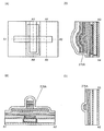
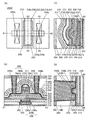
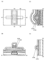
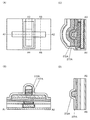
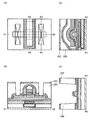
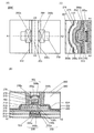
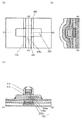
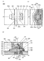
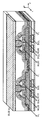
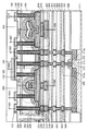
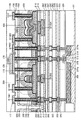
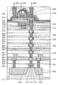
- 4A and 4B are a top view and cross-sectional views illustrating a semiconductor device according to one embodiment of the present invention.
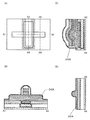
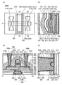
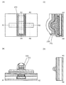
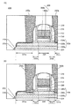
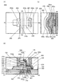
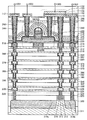
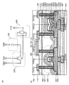
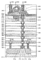
- 6A and 6B are cross-sectional views illustrating a semiconductor device according to one embodiment of the present invention.
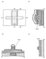
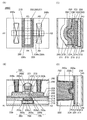
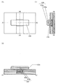
- 4A to 4C are a top view and cross-sectional views illustrating a method for manufacturing a semiconductor device according to one embodiment of the present invention.
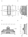
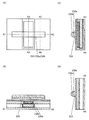
- 4A to 4C are a top view and cross-sectional views illustrating a method for manufacturing a semiconductor device according to one embodiment of the present invention.
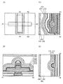
- 4A to 4C are a top view and cross-sectional views illustrating a method for manufacturing a semiconductor device according to one embodiment of the present invention.
- 4A to 4C are a top view and cross-sectional views illustrating a method for manufacturing a semiconductor device according to one embodiment of the present invention.
- 4A to 4C are a top view and cross-sectional views illustrating a method for manufacturing a semiconductor device according to one embodiment of the present invention.
- 4A to 4C are a top view and cross-sectional views illustrating a method for manufacturing a semiconductor device according to one embodiment of the present invention.
- 4A to 4C are a top view and cross-sectional views illustrating a method for manufacturing a semiconductor device according to one embodiment of the present invention.
- 4A to 4C are a top view and cross-sectional views illustrating a method for manufacturing a semiconductor device according to one embodiment of the present invention.
- 4A to 4C are a top view and cross-sectional views illustrating a method for manufacturing a semiconductor device according to one embodiment of the present invention.
- 4A to 4C are a top view and cross-sectional views illustrating a method for manufacturing a semiconductor device according to one embodiment of the present invention.
- 4A to 4C are a top view and cross-sectional views illustrating a method for manufacturing a semiconductor device according to one embodiment of the present invention.
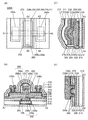
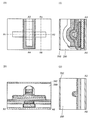
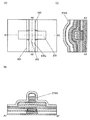
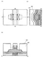
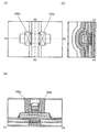
- 4A and 4B are a top view and cross-sectional views illustrating a semiconductor device according to one embodiment of the present invention.
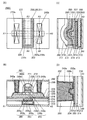
- 4A and 4B are a top view and cross-sectional views illustrating a semiconductor device according to one embodiment of the present invention.
- 4A and 4B are a top view and cross-sectional views illustrating a semiconductor device according to one embodiment of the present invention.
- 4A and 4B are a top view and cross-sectional views illustrating a semiconductor device according to one embodiment of the present invention.
- 4A and 4B are a top view and cross-sectional views illustrating a semiconductor device according to one embodiment of the present invention.
- 6A and 6B are cross-sectional views illustrating a semiconductor device according to one embodiment of the present invention.
- 4A to 4C are a top view and cross-sectional views illustrating a method for manufacturing a semiconductor device according to one embodiment of the present invention.
- 4A to 4C are a top view and cross-sectional views illustrating a method for manufacturing a semiconductor device according to one embodiment of the present invention.
- 4A to 4C are a top view and cross-sectional views illustrating a method for manufacturing a semiconductor device according to one embodiment of the present invention.
- 4A to 4C are a top view and cross-sectional views illustrating a method for manufacturing a semiconductor device according to one embodiment of the present invention.
- 4A to 4C are a top view and cross-sectional views illustrating a method for manufacturing a semiconductor device according to one embodiment of the present invention.
- 4A to 4C are a top view and cross-sectional views illustrating a method for manufacturing a semiconductor device according to one embodiment of the present invention.
- 4A and 4B are a top view and cross-sectional views illustrating a semiconductor device according to one embodiment of the present invention.
- 4A and 4B are a top view and cross-sectional views illustrating a semiconductor device according to one embodiment of the present invention.
- 4A and 4B are a top view and cross-sectional views illustrating a semiconductor device according to one embodiment of the present invention.
- 4A and 4B are a top view and a cross-sectional views illustrating a semiconductor device according to one embodiment of the present invention.
- FIG. 6 is a cross-sectional view of a semiconductor device according to one embodiment of the present invention.
- 4A to 4C are a top view and cross-sectional views illustrating a method for manufacturing a semiconductor device according to one embodiment of the present invention.
- 4A to 4C are a top view and cross-sectional views illustrating a method for manufacturing a semiconductor device according to one embodiment of the present invention.
- 4A to 4C are a top view and cross-sectional views illustrating a method for manufacturing a semiconductor device according to one embodiment of the present invention.
- 4A to 4C are a top view and cross-sectional views illustrating a method for manufacturing a semiconductor device according to one embodiment of the present invention.
- 4A to 4C are a top view and cross-sectional views illustrating a method for manufacturing a semiconductor device according to one embodiment of the present invention.
- 4A to 4C are a top view and cross-sectional views illustrating a method for manufacturing a semiconductor device according to one embodiment of the present invention.
- 4A to 4C are a top view and cross-sectional views illustrating a method for manufacturing a semiconductor device according to one embodiment of the present invention.
- 4A to 4C are a top view and cross-sectional views illustrating a method for manufacturing a semiconductor device according to one embodiment of the present invention.
- 4A to 4C are a top view and cross-sectional views illustrating a method for manufacturing a semiconductor device according to one embodiment of the present invention.
- 4A to 4C are a top view and cross-sectional views illustrating a method for manufacturing a semiconductor device according to one embodiment of the present invention.
- 4A and 4B are a top view and a cross-sectional view of a semiconductor device according to one embodiment of the present invention.
- 4A and 4B are a top view and a cross-sectional view of a semiconductor device according to one embodiment of the present invention.
- FIG. 6 is a cross-sectional view of a semiconductor device according to one embodiment of the present invention.
- 4A to 4C are a top view and cross-sectional views illustrating a method for manufacturing a semiconductor device according to one embodiment of the present invention.
- 4A to 4C are a top view and cross-sectional views illustrating a method for manufacturing a semiconductor device according to one embodiment of the present invention.
- 4A to 4C are a top view and cross-sectional views illustrating a method for manufacturing a semiconductor device according to one embodiment of the present invention.
- 4A to 4C are a top view and cross-sectional views illustrating a method for manufacturing a semiconductor device according to one embodiment of the present invention.
- 4A to 4C are a top view and cross-sectional views illustrating a method for manufacturing a semiconductor device according to one embodiment of the present invention.
- 4A to 4C are a top view and cross-sectional views illustrating a method for manufacturing a semiconductor device according to one embodiment of the present invention.
- 4A and 4B are a top view and a cross-sectional view of a semiconductor device according to one embodiment of the present invention.
- 4A and 4B are a top view and a cross-sectional view of a semiconductor device according to one embodiment of the present invention.
- 4A and 4B are a top view and a cross-sectional view of a semiconductor device according to one embodiment of the present invention.
- 4A and 4B are a top view and a cross-sectional view of a semiconductor device according to one embodiment of the present invention.
- 4A and 4B are a top view and a cross-sectional view of a semiconductor device according to one embodiment of the present invention.
- 4A and 4B are a top view and a cross-sectional view of a semiconductor device according to one embodiment of the present invention.
- 4A and 4B are a top view and a cross-sectional view of a semiconductor device according to one embodiment of the present invention.
- 4A and 4B are a top view and a cross-sectional view of a semiconductor device according to one embodiment of the present invention.
- FIG. 6 is a cross-sectional view of a semiconductor device according to one embodiment of the present invention.
- FIG. 6 is a cross-sectional view of a semiconductor device according to one embodiment of the present invention.
- 4A to 4C are a top view and cross-sectional views illustrating a method for manufacturing a semiconductor device according to one embodiment of the present invention.
- 4A to 4C are a top view and cross-sectional views illustrating a method for manufacturing a semiconductor device according to one embodiment of the present invention.
- 4A to 4C are a top view and cross-sectional views illustrating a method for manufacturing a semiconductor device according to one embodiment of the present invention.
- 4A to 4C are a top view and cross-sectional views illustrating a method for manufacturing a semiconductor device according to one embodiment of the present invention.
- 4A to 4C are a top view and cross-sectional views illustrating a method for manufacturing a semiconductor device according to one embodiment of the present invention.
- 4A to 4C are a top view and cross-sectional views illustrating a method for manufacturing a semiconductor device according to one embodiment of the present invention.
- 4A to 4C are a top view and cross-sectional views illustrating a method for manufacturing a semiconductor device according to one embodiment of the present invention.
- 4A to 4C are a top view and cross-sectional views illustrating a method for manufacturing a semiconductor device according to one embodiment of the present invention.
- 4A to 4C are a top view and cross-sectional views illustrating a method for manufacturing a semiconductor device according to one embodiment of the present invention.
- 4A to 4C are a top view and cross-sectional views illustrating a method for manufacturing a semiconductor device according to one embodiment of the present invention.
- 4A to 4C are a top view and cross-sectional views illustrating a method for manufacturing a semiconductor device according to one embodiment of the present invention.
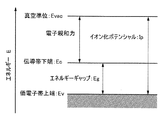
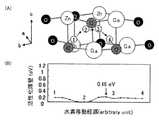
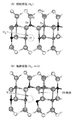
- 6A and 6B illustrate an energy band structure of an oxide semiconductor. Schematic diagram illustrating an area division of InGaZnO 4 in the crystal. InO 2 surface and (Ga, Zn) and the moving path of hydrogen atoms in the region between the O surface diagram illustrating the activation barrier on the path.
- 4A and 4B are a top view and a cross-sectional view of a semiconductor device according to one embodiment of the present invention.
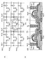
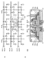
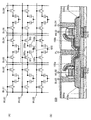
- 4A and 4B are a circuit diagram and a cross-sectional view of a semiconductor device according to one embodiment of the present invention.
- 4A and 4B are a circuit diagram and a cross-sectional view of a semiconductor device according to one embodiment of the present invention.
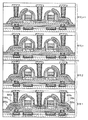
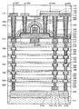
- FIG. 10 is a cross-sectional view illustrating a structure of a memory device according to one embodiment of the present invention.
- 4A and 4B are a top view and a cross-sectional view of a semiconductor device according to one embodiment of the present invention.
- 4A and 4B are a circuit diagram and a cross-sectional view of a semiconductor device according to one embodiment of the present invention.
- 4A and 4B are a circuit diagram and a cross-sectional view of a semiconductor device according to one embodiment of the present invention.
- FIG. 10 is a cross-sectional view illustrating a structure of a memory device according to one embodiment of the present invention.
- 4A and 4B are a top view and a cross-sectional view of a semiconductor device according to one embodiment of the present invention.
- 4A and 4B are a top view and a cross-sectional view of a semiconductor device according to one embodiment of the present invention.
- 4A and 4B are a circuit diagram and a cross-sectional view of a semiconductor device according to one embodiment of the present invention.
- FIG. 6 is a cross-sectional view of a semiconductor device according to one embodiment of the present invention.
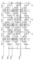
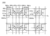
- FIG. 10 is a circuit diagram of a semiconductor device according to one embodiment of the present invention.
- FIG. 10 is a cross-sectional view illustrating a structure example of a semiconductor device.
- 4A and 4B are a circuit diagram and a cross-sectional view of a semiconductor device according to one embodiment of the present invention.
- FIG. 10 is a cross-sectional view illustrating a structure of a memory device according to one embodiment of the present invention.
- FIG. 10 is a cross-sectional view illustrating a structure of a memory device according to one embodiment of the present invention.
- FIG. 10 is a cross-sectional view illustrating a structure of a memory device according to one embodiment of the present invention.
- 4A and 4B are a circuit diagram and a cross-sectional view of a memory device according to one embodiment of the present invention.
- FIG. 10 is a cross-sectional view illustrating a structure of a memory device according to one embodiment of the present invention.
- FIG. 10 is a cross-sectional view illustrating a structure of a memory device according to one embodiment of the present invention.
- FIG. 10 is a cross-sectional view illustrating a structure of a memory device according to one embodiment of the present invention.
- 4A and 4B are a circuit diagram and a cross-sectional view of a memory device according to one embodiment of the present invention.
- FIG. 10 is a cross-sectional view illustrating a structure of a memory device according to one embodiment of the present invention.
- FIG. 10 is a cross-sectional view illustrating a structure of a memory device according to one embodiment of the present invention.
- FIG. 10 is a cross-sectional view illustrating a structure of a memory device according to one embodiment of the present invention.
- FIG. 10 is a cross-sectional view illustrating a structure of a memory device according to one embodiment of the present invention.
- FIG. 10 is a cross-sectional view illustrating a structure of a memory device according to one embodiment of the present invention.
- 4A and 4B are a circuit diagram and a cross-sectional view of a memory device according to one embodiment of the present invention.
- FIG. 10 is a cross-sectional view illustrating a structure of a memory device according to one embodiment of the present invention.
- FIG. 10 is a cross-sectional view illustrating a structure of a memory device according to one embodiment of the present invention.
- FIG. 10 is a cross-sectional view illustrating a structure of a memory device according to one embodiment of the present invention.
- FIG. 10 is a cross-sectional view illustrating a structure of a memory device according to one embodiment of the present invention.
- FIG. 10 is a cross-sectional view illustrating a structure of a memory device according to one embodiment of the present
- FIG. 10 is a cross-sectional view illustrating a structure of a memory device according to one embodiment of the present invention.
- 4A and 4B are a circuit diagram and a cross-sectional view of a memory device according to one embodiment of the present invention.
- FIG. 10 is a cross-sectional view illustrating a structure of a memory device according to one embodiment of the present invention.
- FIG. 10 is a cross-sectional view illustrating a structure of a memory device according to one embodiment of the present invention.
- FIG. 10 is a cross-sectional view illustrating a structure of a memory device according to one embodiment of the present invention.
- FIG. 10 is a cross-sectional view illustrating a structure of a memory device according to one embodiment of the present invention.
- FIG. 10 is a cross-sectional view illustrating a structure of a memory device according to one embodiment of the present invention.
- FIG. 10 is a cross-sectional view illustrating a structure of a memory device according to one embodiment of the present invention.
- the circuit diagram which shows the structural example of an inverter circuit, and the timing chart which shows the operation example.
- FIG. 10 is a block diagram illustrating a structure example of a memory device according to one embodiment of the present invention.
- FIG. 10 is a circuit diagram illustrating a structural example of a memory device according to one embodiment of the present invention.
- FIG. 10 is a circuit diagram illustrating a structural example of a memory device according to one embodiment of the present invention.
- FIG. 10 is a block diagram illustrating a structure example of a memory device according to one embodiment of the present invention.
- 4A and 4B are a block diagram and a circuit diagram illustrating a structure example of a memory device according to one embodiment of the present invention.
- FIG. 10 is a block diagram illustrating a structure example of a semiconductor device according to one embodiment of the present invention.
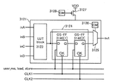
- 10A and 10B are a block diagram illustrating a structure example of a semiconductor device according to one embodiment of the present invention, a circuit diagram, and a timing chart illustrating an operation example of the semiconductor device.
- FIG. 10 is a circuit diagram illustrating a structural example of a memory device according to one embodiment of the present invention.
- FIG. 10 is a block diagram illustrating a structure example of a memory device according to one embodiment of the present invention.
- 4A and 4B are a block diagram and a circuit diagram
- FIG. 10 is a block diagram illustrating a structure example of a semiconductor device according to one embodiment of the present invention.
- 4A and 4B are a circuit diagram illustrating a structure example of a semiconductor device according to one embodiment of the present invention, and a timing chart illustrating an operation example of the semiconductor device.
- 1 is a block diagram illustrating a configuration example of an AI system according to one embodiment of the present invention.
- FIG. 10 is a block diagram illustrating an application example of an AI system according to one embodiment of the present invention.
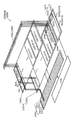
- FIG. 10 is a schematic perspective view illustrating a configuration example of an IC incorporating an AI system according to one embodiment of the present invention.
- FIG. 14 illustrates an electronic device according to one embodiment of the present invention.
- FIG. 14 illustrates an electronic device according to one embodiment of the present invention.
- FIG. 14 illustrates an electronic device according to one embodiment of the present invention.
- FIG. 14 illustrates an electronic device according to one embodiment of the present invention.
- FIG. 14 illustrates an electronic device according to one
- FIG. 14 illustrates an electronic device according to one embodiment of the present invention.
- FIG. 14 illustrates an electronic device according to one embodiment of the present invention.
- FIG. 14 illustrates an electronic device according to one embodiment of the present invention.
- a top view also referred to as a “plan view”
- a perspective view a perspective view, and the like
- some components may be omitted in order to facilitate understanding of the invention.
- description of some hidden lines may be omitted.
- the ordinal numbers attached as the first, second, etc. are used for convenience and do not indicate the order of steps or the order of lamination. Therefore, for example, the description can be made by appropriately replacing “first” with “second” or “third”.
- the ordinal numbers described in this specification and the like may not match the ordinal numbers used to specify one embodiment of the present invention.
- X and Y are assumed to be objects (for example, devices, elements, circuits, wirings, electrodes, terminals, conductive films, layers, etc.).
- an element that enables electrical connection between X and Y for example, a switch, a transistor, a capacitor, an inductor, a resistor, a diode, a display, etc.
- Element, light emitting element, load, etc. are not connected between X and Y
- elements for example, switches, transistors, capacitive elements, inductors
- resistor element for example, a diode, a display element, a light emitting element, a load, or the like.
- an element for example, a switch, a transistor, a capacitive element, an inductor, a resistance element, a diode, a display, etc.
- the switch has a function of controlling on / off. That is, the switch is in a conductive state (on state) or a non-conductive state (off state), and has a function of controlling whether or not to pass a current. Alternatively, the switch has a function of selecting and switching a path through which a current flows.
- the case where X and Y are electrically connected includes the case where X and Y are directly connected.
- a circuit for example, a logic circuit (an inverter, a NAND circuit, a NOR circuit, etc.) that enables a functional connection between X and Y, signal conversion, etc.
- Circuit (DA conversion circuit, AD conversion circuit, gamma correction circuit, etc.), potential level conversion circuit (power supply circuit (boost circuit, step-down circuit, etc.), level shifter circuit that changes signal potential level, etc.), voltage source, current source, switching Circuit, amplifier circuit (circuit that can increase signal amplitude or current amount, operational amplifier, differential amplifier circuit, source follower circuit, buffer circuit, etc.), signal generation circuit, memory circuit, control circuit, etc.)
- a circuit for example, a logic circuit (an inverter, a NAND circuit, a NOR circuit, etc.) that enables a functional connection between X and Y, signal conversion, etc.
- Circuit (DA conversion circuit, AD conversion circuit, gamma correction circuit, etc.), potential level conversion circuit (power supply circuit (boost circuit, step-down
- X and Y are functionally connected.
- the case where X and Y are functionally connected includes the case where X and Y are directly connected and the case where X and Y are electrically connected.
- a transistor is an element having at least three terminals including a gate, a drain, and a source. And it has a region where a channel is formed between the drain (drain terminal, drain region or drain electrode) and the source (source terminal, source region or source electrode), and through the region where the channel is formed, A current can flow between the source and the drain.
- a region where a channel is formed refers to a region where current mainly flows.
- the functions of the source and drain may be switched when transistors with different polarities are used or when the direction of current changes during circuit operation. Therefore, in this specification and the like, the terms “source” and “drain” may be used interchangeably.
- the channel length refers to, for example, a region where a semiconductor (or a portion where current flows in the semiconductor when the transistor is on) and a gate electrode overlap with each other in a top view of the transistor, or a region where a channel is formed
- the channel length is not necessarily the same in all regions. That is, the channel length of one transistor may not be fixed to one value. Therefore, in this specification, the channel length is any one of values, the maximum value, the minimum value, or the average value in a region where a channel is formed.
- the channel width is, for example, in a top view of a transistor in a region where a semiconductor (or a portion where a current flows in the semiconductor when the transistor is on) and a gate electrode overlap with each other, or in a region where a channel is formed. This is the length of a region where a vertical channel is formed with reference to the channel length direction. Note that in one transistor, the channel width is not necessarily the same in all regions. That is, the channel width of one transistor may not be fixed to one value. Therefore, in this specification, the channel width is any one of values, the maximum value, the minimum value, or the average value in a region where a channel is formed.
- the channel width in a region where a channel is actually formed (hereinafter also referred to as “effective channel width”) and the channel width (hereinafter, “apparently” shown in the top view of the transistor).
- channel width Sometimes referred to as “channel width”).
- the effective channel width may be larger than the apparent channel width, and the influence may not be negligible.
- the ratio of a channel formation region formed on the side surface of the semiconductor may increase. In that case, the effective channel width is larger than the apparent channel width.
- the apparent channel width may be referred to as “surrounded channel width (SCW)”.
- SCW surrounded channel width
- channel width in the case where the term “channel width” is simply used, it may denote an enclosed channel width or an apparent channel width.
- channel width in the case where the term “channel width” is simply used, it may denote an effective channel width. Note that the channel length, channel width, effective channel width, apparent channel width, enclosed channel width, and the like can be determined by analyzing a cross-sectional TEM image or the like.
- the impurity of a semiconductor means the thing other than the main component which comprises a semiconductor, for example.
- an element having a concentration of less than 0.1 atomic% can be said to be an impurity.
- the impurities are included, for example, DOS (Density of States) of the semiconductor may increase or crystallinity may decrease.
- examples of the impurity that changes the characteristics of the semiconductor include a Group 1 element, a Group 2 element, a Group 13 element, a Group 14 element, a Group 15 element, and an oxide semiconductor.
- water may also function as an impurity.
- oxygen vacancies may be formed, for example, by mixing impurities.
- impurities that change the characteristics of the semiconductor include group 1 elements, group 2 elements, group 13 elements, and group 15 elements excluding oxygen and hydrogen.
- a silicon oxynitride film has a higher oxygen content than nitrogen as its composition.
- oxygen is 55 atomic% to 65 atomic%
- nitrogen is 1 atomic% to 20 atomic%
- silicon is 25 atomic% to 35 atomic%
- hydrogen is 0.1 atomic% to 10 atomic%. It is included in the concentration range.
- the silicon nitride oxide film has a nitrogen content higher than that of oxygen.
- nitrogen is 55 atomic% to 65 atomic%
- oxygen is 1 atomic% to 20 atomic%
- silicon is 25 atomic% to 35 atomic%
- hydrogen is 0.1 atomic% to 10 atomic%. It is included in the concentration range.
- film and “layer” can be interchanged.
- conductive layer may be changed to the term “conductive film”.
- insulating film may be changed to the term “insulating layer” in some cases.
- the term “insulator” can be referred to as an insulating film or an insulating layer.
- the term “conductor” can be restated as a conductive film or a conductive layer.
- the term “semiconductor” can be restated as a semiconductor film or a semiconductor layer.
- the transistors described in this specification and the like are field-effect transistors unless otherwise specified.
- the transistors described in this specification and the like are n-channel transistors unless otherwise specified. Therefore, the threshold voltage (also referred to as “Vth”) is assumed to be greater than 0 V unless otherwise specified.
- parallel means a state in which two straight lines are arranged at an angle of ⁇ 10 ° to 10 °. Therefore, the case of ⁇ 5 ° to 5 ° is also included.
- substantially parallel means a state in which two straight lines are arranged at an angle of ⁇ 30 ° to 30 °.
- Vertical refers to a state in which two straight lines are arranged at an angle of 80 ° to 100 °. Therefore, the case of 85 ° to 95 ° is also included.
- substantially vertical means a state in which two straight lines are arranged at an angle of 60 ° to 120 °.
- a barrier film is a film having a function of suppressing permeation of impurities such as hydrogen and oxygen, and when the barrier film has conductivity, the barrier film is referred to as a conductive barrier film. There is.
- a metal oxide is a metal oxide in a broad expression.
- Metal oxides are classified into oxide insulators, oxide conductors (including transparent oxide conductors), oxide semiconductors (also referred to as oxide semiconductors or simply OS), and the like.
- oxide semiconductors also referred to as oxide semiconductors or simply OS
- the metal oxide may be referred to as an oxide semiconductor. That is, in the case of describing an OS FET or an OS transistor, it can be said to be a transistor including an oxide or an oxide semiconductor.
- normally-off means that when a voltage is not applied to the gate or a ground potential is applied to the gate, a current per channel width of 1 ⁇ m flowing through the transistor is 1 ⁇ 10 ⁇ 20 at room temperature. A or lower, 1 ⁇ 10 ⁇ 18 A or lower at 85 ° C., or 1 ⁇ 10 ⁇ 16 A or lower at 125 ° C.
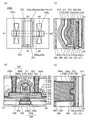
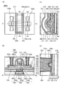
- ⁇ Configuration example of semiconductor device> 1A, 1B, 1C, and 1D are a top view and a cross-sectional view of the transistor 200A according to one embodiment of the present invention and the periphery of the transistor 200A.
- FIG. 1A is a top view of a semiconductor device having a transistor 200A.
- 1B, 1C, and 1D are cross-sectional views of the semiconductor device.
- FIG. 1B is a cross-sectional view taken along the dashed-dotted line A1-A2 in FIG. 1A and also a cross-sectional view in the channel length direction of the transistor 200A.
- FIG. 1C is a cross-sectional view taken along the dashed-dotted line A3-A4 in FIG. 1A and is a cross-sectional view in the channel width direction of the transistor 200A.
- FIG. 1D is a cross-sectional view taken along the dashed-dotted line A5-A6 in FIG. 1A and is a cross-sectional view of the source region or the drain region of the transistor 200A. Note that in the top view of FIG. 1A, some elements are omitted for clarity.
- the semiconductor device of one embodiment of the present invention includes the transistor 200A, the insulator 210 functioning as an interlayer film, the insulator 212, the insulator 280, the insulator 282, and the insulator 284.
- a conductor 203 that is electrically connected to the transistor 200A and functions as a wiring, and a conductor 240 (a conductor 240a and a conductor 240b) that function as a plug are included.
- the conductor 203 is in contact with the inner wall of the opening of the insulator 212, the first conductor of the conductor 203 is formed, and the second conductor of the conductor 203 is further formed inside.
- the height of the upper surface of the conductor 203 and the height of the upper surface of the insulator 212 can be approximately the same.
- the conductor 203 may be provided as a single layer or a stacked structure including three or more layers.
- an ordinal number may be given in the order of formation to be distinguished.
- the conductor 240 is formed in contact with the inner walls of the openings of the insulator 273, the insulator 274, the insulator 280, the insulator 282, and the insulator 284.
- the height of the upper surface of the conductor 240 and the height of the upper surface of the insulator 284 can be approximately the same.
- the conductor 240 may be a single layer or a stacked structure of three or more layers.
- the transistor 200 ⁇ / b> A includes an insulator 214 and an insulator 216 disposed over a substrate (not shown), and a conductor disposed to be embedded in the insulator 214 and the insulator 216.
- Oxide 230 (oxide 230a, oxide 230b, and oxide 230c) disposed on body 224, insulator 250 disposed on oxide 230, and metal disposed on insulator 250
- An insulator 271 disposed on the side surface of at least the oxide 230c, the insulator 250, the metal oxide 252, and the conductor 260, the oxide 230, and the insulator 275.
- the insulator 273 disposed on the layer 242 and the insulator 274 disposed on the insulator 273.
- the transistor 200A shows a structure in which three layers of the oxide 230a, the oxide 230b, and the oxide 230c are stacked
- the present invention is not limited to this.
- a structure in which a single layer of the oxide 230b, a two-layer structure of the oxide 230b and the oxide 230a, a two-layer structure of the oxide 230b and the oxide 230c, or a stacked structure of four or more layers may be employed.
- the structure in which the conductors 260a and 260b are stacked is described; however, the present invention is not limited to this.
- the transistor 200A includes a metal functioning as an oxide semiconductor in the oxide 230 (the oxide 230a, the oxide 230b, and the oxide 230c) including a region where a channel is formed (hereinafter also referred to as a channel formation region). It is preferable to use an oxide (hereinafter also referred to as an oxide semiconductor).
- An oxide semiconductor can be formed by a sputtering method or the like, and thus can be used for the transistor 200A included in a highly integrated semiconductor device.
- the oxide 230 includes an In-M-Zn oxide (the element M is aluminum, gallium, yttrium, copper, vanadium, beryllium, boron, titanium, iron, nickel, germanium, zirconium, molybdenum, lanthanum, cerium, neodymium) It is preferable to use a metal oxide such as one or a plurality selected from hafnium, tantalum, tungsten, or magnesium. Further, as the oxide 230, an In—Ga oxide or an In—Zn oxide may be used as the oxide 230.
- an oxide semiconductor forms a metal compound by adding a metal element such as aluminum, ruthenium, titanium, tantalum, chromium, or tungsten in addition to the elements included in the oxide semiconductor, and has low resistance.
- a metal element such as aluminum, ruthenium, titanium, tantalum, chromium, or tungsten
- aluminum, titanium, tantalum, tungsten, or the like is preferably used.
- a metal film containing the metal element, a nitride film containing the metal element, or an oxide film containing the metal element is preferably provided over the oxide semiconductor.
- a metal film containing the metal element, a nitride film containing the metal element, or an oxide film containing the metal element is preferably provided over the oxide semiconductor.
- part of oxygen in the oxide semiconductor located at or near the interface between the film and the oxide semiconductor is absorbed by the film, and oxygen vacancies are formed. The vicinity of the interface may be reduced in resistance.
- heat treatment may be performed in an atmosphere containing nitrogen.
- a metal element which is a component of the film is converted into an oxide semiconductor or a component of an oxide semiconductor from a metal film, a nitride film containing a metal element, or an oxide film containing a metal element.
- a certain metal element diffuses into the film, and the oxide semiconductor and the film form a metal compound, so that resistance can be reduced.
- the metal element added to the oxide semiconductor is in a relatively stable state by forming a metal compound with the oxide semiconductor, the metal element, and thus a highly reliable semiconductor device can be provided.
- a compound layer (hereinafter also referred to as a different layer) may be formed at the interface between the metal film, the nitride film containing a metal element, or the oxide film containing a metal element and the oxide semiconductor.
- a compound layer is a layer having a metal compound including a metal film, a nitride film containing a metal element, or a component of an oxide film containing a metal element and a component of an oxide semiconductor.
- a layer in which a metal element of an oxide semiconductor and an added metal element are alloyed may be formed as the compound layer. The alloyed layer is in a relatively stable state, and a highly reliable semiconductor device can be provided.
- the carrier density increases when an impurity element such as hydrogen or nitrogen is present.
- hydrogen in the oxide semiconductor reacts with oxygen bonded to a metal atom to be water, thereby forming oxygen vacancies.
- oxygen vacancy When hydrogen enters the oxygen vacancy, the carrier density increases.
- a part of hydrogen may be combined with oxygen bonded to a metal atom to generate electrons as carriers. That is, the resistance of an oxide semiconductor containing nitrogen or hydrogen is reduced.
- the oxide 230 processed into an island shape has a low resistance that functions as a region having a low carrier density and functioning as a source region or a drain region. A region can be provided.
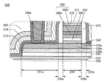
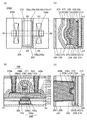
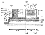
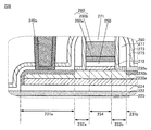
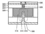
- FIG. 2 shows an enlarged view of a region 239 including the oxide 230b which is selectively reduced in resistance and is surrounded by a broken line in FIG.
- the oxide 230 includes a region 234 that functions as a channel formation region of a transistor, a region 231 (a region 231 a and a region 231 b) that functions as a source region or a drain region, a region 234, and a region 231. And a region 232 (region 232a and region 232b) provided between the two.
- the region 231 functioning as a source region or a drain region is a region having a low oxygen concentration and a low resistance.
- the region 234 functioning as a channel formation region is a high-resistance region having a higher oxygen concentration and a lower carrier density than the region 231 functioning as a source region or a drain region.
- the region 232 has a higher oxygen concentration and a lower carrier density than the region 231 that functions as a source region or a drain region, and a lower oxygen concentration and a carrier density than the region 234 that functions as a channel formation region. It is a high area.
- the region 231 preferably has a higher concentration of at least one of the metal element and the impurity element such as hydrogen and nitrogen than the region 232 and the region 234.
- the region 231 preferably includes one or more metal elements selected from metal elements such as aluminum, ruthenium, titanium, tantalum, tungsten, and chromium in addition to the oxide 230.
- the layer 242 may be provided as a film containing a metal element in contact with the region 231 of the oxide 230.
- a metal film, a nitride film containing a metal element, or an oxide film containing a metal element can be used as the layer 242.
- a compound layer may be formed at the interface between the layer 242 and the oxide 230.
- the compound layer is a layer having a metal compound including the component of the layer 242 and the component of the oxide 230.
- a layer in which the metal element in the oxide 230 and the added metal element are alloyed may be formed as the compound layer.
- a metal compound is formed in the oxide 230, and the resistance of the region 231 can be reduced.
- the metal compound is not necessarily formed in the oxide 230.
- a metal compound may be formed in the layer 242.
- the oxide layer may be provided on the surface of the oxide 230, the surface of the layer 242, or the compound layer formed at the interface between the layer 242 and the oxide 230.
- the region 231 may include a low-resistance region of the layer 242 or a low-resistance region of a compound layer formed between the layer 242 and the oxide 230. That is, in this specification, a region functioning as a source region or a drain region is a region 231.
- the region 232 has a region overlapping with the insulator 275.
- the region 232 preferably has a higher concentration of at least one of a metal element such as aluminum, ruthenium, titanium, tantalum, tungsten, or chromium and an impurity element such as hydrogen or nitrogen than the region 234.
- the layer 242 that is a metal film, a nitride film containing a metal element, or an oxide film containing a metal element is provided in contact with the region 231 of the oxide 230, whereby the components in the layer 242 and the oxide semiconductor component May form a metal compound.
- the metal compound may attract hydrogen contained in the oxide 230 in some cases. Therefore, the concentration of hydrogen in the region 232 in the vicinity of the region 231 may increase.
- one or both of the region 232 a and the region 232 b may have a region overlapping with the conductor 260.
- the conductor 260 can overlap the region 232a and the region 232b.
- the region 234, the region 231, and the region 232 are formed in the oxide 230 b, but are not limited thereto.
- these regions may be formed in the layer 242, the compound layer formed between the layer 242 and the oxide 230, the oxide 230a, and the oxide 230c.
- the boundaries of the regions are displayed substantially perpendicular to the upper surface of the oxide 230, but this embodiment is not limited to this.
- the region 232 may protrude to the conductor 260 side in the vicinity of the surface of the oxide 230b and recede to the conductor 240a side or the conductor 240b side in the vicinity of the lower surface of the oxide 230a.
- concentrations of metal elements and impurity elements such as hydrogen and nitrogen detected in each region are not limited to stepwise changes between the regions, but also continuously change (also referred to as gradation) within each region. Also good. That is, the closer to the channel formation region, the lower the concentration of the metal element and impurity elements such as hydrogen and nitrogen.
- a metal element that increases conductivity such as aluminum, ruthenium, titanium, tantalum, tungsten, and chromium, and an impurity is added to a desired region. That's fine.
- an impurity an element that forms oxygen vacancies, an element that is captured by oxygen vacancies, or the like may be used.
- the element include hydrogen, boron, carbon, nitrogen, fluorine, phosphorus, sulfur, chlorine, and a rare gas.
- rare gas elements include helium, neon, argon, krypton, and xenon.
- the region 231 can have high carrier density and low resistance by increasing the content of the above-described metal element that increases conductivity, an element that forms oxygen vacancies, or an element that is trapped by oxygen vacancies. it can.
- the layer 242 may be formed in contact with the region 231 of the oxide 230.
- a metal film, a nitride film containing a metal element, an oxide film containing a metal element, or the like can be used.
- the layer 242 is preferably provided over the oxide 230 with at least the insulator 250, the metal oxide 252, the conductor 260, the insulator 270, the insulator 271, and the insulator 275 interposed therebetween.
- the component of the layer 242 and the component of the oxide 230 form a metal compound, which becomes a region 231 and has a low resistance.
- part of oxygen in the oxide 230 located in the vicinity of the interface between the oxide 230 and the layer 242 or in the vicinity of the interface is absorbed by the layer 242, and oxygen vacancies are formed in the oxide 230. 231 may be formed.
- heat treatment may be performed in an atmosphere containing nitrogen while the oxide 230 and the layer 242 are in contact with each other.
- the metal element which is a component of the layer 242 is diffused from the layer 242 to the oxide 230 or the metal element which is a component of the oxide 230 is diffused to the layer 242, so that the oxide 230 and the layer 242 are formed.
- a metal compound is formed to reduce resistance.
- the metal element of the oxide 230 and the metal element of the layer 242 may be alloyed.
- the metal element of the oxide 230 and the metal element of the layer 242 are alloyed, the metal element is in a relatively stable state; thus, a highly reliable semiconductor device can be provided.
- the layer 242 absorbs oxygen in the region 231 of the oxide 230 and the region 232 adjacent to the region 231, oxygen vacancies may be generated in the region 231 and the region 232.
- the carrier density in the region 231 and the region 232 increases. Accordingly, the resistance of the region 231 and the region 232 of the oxide 230 is reduced.
- the layer 242 has a characteristic of absorbing hydrogen
- hydrogen in the oxide 230 is absorbed into the film. Therefore, hydrogen which is an impurity in the oxide 230 can be reduced. Further, the layer 242 may be removed together with hydrogen absorbed from the oxide 230 in a later step.
- the layer 242 is not necessarily removed.
- the layer 242 may be oxidized by oxygen absorbed from the oxide 230 to be an insulator and have high resistance. In that case, the layer 242 may function as an interlayer film.
- a conductive region in the case where a conductive region remains in the layer 242, it is oxidized by heat treatment to become an insulator, and the resistance is increased.
- the heat treatment is preferably performed in an oxidizing atmosphere, for example.
- the layer 242 may react with oxygen included in the structure and be oxidized by heat treatment.
- the layer 242 By leaving the layer 242 as an insulator, it can function as an interlayer film.
- the layer 242 is provided with a thickness that can be insulated in a later step.
- the layer 242 may be provided with a thickness of 0.5 nm to 5 nm, preferably 1 nm to 2 nm. Note that in the case where the heat treatment is performed in the above oxidizing atmosphere, it is preferable that the heat treatment is performed once in the atmosphere containing nitrogen while the oxide 230 and the layer 242 are in contact with each other. By performing heat treatment once in an atmosphere containing nitrogen, oxygen in the oxide 230 can easily diffuse into the layer 242.
- a transistor including an oxide semiconductor if an impurity and an oxygen vacancy exist in a region where a channel is formed in the oxide semiconductor, electric characteristics may be easily changed and reliability may be deteriorated.
- an oxygen vacancy is included in a region where a channel is formed in an oxide semiconductor, the transistor is likely to be normally on. Therefore, oxygen vacancies in the region 234 where a channel is formed are preferably reduced as much as possible.
- the insulating layer 250, the region 232 of the oxide 230b, and the oxide 230c are in contact with each other and contain more oxygen (also referred to as excess oxygen) than oxygen that satisfies the stoichiometric composition.
- An insulator 275 is preferably provided. That is, excess oxygen in the insulator 275 is diffused into the region 234 of the oxide 230, whereby oxygen vacancies in the region 234 of the oxide 230 can be reduced.
- an oxide film may be formed as the insulator 273 adjacent to the insulator 275 by a sputtering method.
- a sputtering method for forming an oxide an insulator with few impurities such as water or hydrogen can be formed.
- VDSP Vinyl Deposition SP
- ions and sputtered particles exist between the target and the substrate.
- the target is connected to a power source and is supplied with the potential E0.
- the substrate is given a potential E1 such as a ground potential.
- the substrate may be electrically floating.
- the ions in the plasma are accelerated by the potential difference E2-E0 and collide with the target, so that the sputtered particles are ejected from the target.
- the sputtered particles adhere to and deposit on the film formation surface to form a film.
- Some ions recoil by the target pass through a film formed as recoil ions, and may be taken into the insulator 275 in contact with the deposition surface.
- ions in the plasma are accelerated by the potential difference E2-E1, and impact the film formation surface. At this time, some ions reach the inside of the insulator 275.
- a region into which the ions are taken is formed in the insulator 275. That is, when the ions are oxygen-containing ions, an excess oxygen region is formed in the insulator 275.
- an excess oxygen region can be formed in the insulator 275. Excess oxygen in the insulator 275 can be supplied to the region 234 of the oxide 230 to compensate for oxygen vacancies in the oxide 230.
- the insulator 275 is preferably formed using silicon oxide, silicon oxynitride, silicon nitride oxide, or silicon oxide having holes. Materials such as silicon oxynitride tend to form excess oxygen regions. On the other hand, compared to the above-described materials such as silicon oxynitride, the oxide 230 tends to hardly form an excess oxygen region even if an oxide film formed by a sputtering method is formed over the oxide 230. Therefore, by providing the insulator 275 having an excess oxygen region around the region 234 of the oxide 230, the excess oxygen of the insulator 275 can be effectively supplied to the region 234 of the oxide 230.
- the insulator 273 is preferably made of aluminum oxide.
- Aluminum oxide may extract hydrogen in the oxide 230 by performing heat treatment in the state of being close to the oxide 230. Note that in the case where the layer 242 is provided between the oxide 230 and aluminum oxide, the hydrogen in the layer 242 is absorbed by the aluminum oxide, and the layer 242 in which hydrogen is reduced reduces the hydrogen in the oxide 230. May absorb. Therefore, the hydrogen concentration in the oxide 230 can be reduced.
- oxygen may be supplied from the insulator 273 to the oxide 230, the insulator 224, or the insulator 222 by performing heat treatment in a state where the insulator 273 and the oxide 230 are in proximity to each other.
- the oxide 230 can be selectively reduced in resistance by combining the above structure or the above steps.
- the resistance of the oxide 230 is reduced in a self-aligning manner by using the conductor 260 functioning as a gate electrode and the insulator 275 as a mask. Therefore, when the plurality of transistors 200A are formed at the same time, variation in electrical characteristics between the transistors can be reduced. Further, the channel length of the transistor 200A is determined by the width of the conductor 260 and the film thickness of the insulator 275, and the transistor 200A can be miniaturized by setting the width of the conductor 260 to the minimum processing dimension. Become.
- an oxide semiconductor can be formed by a sputtering method or the like, it can be used for a transistor included in a highly integrated semiconductor device.
- a transistor using an oxide semiconductor in a channel formation region has extremely small leakage current (off-state current) in a non-conduction state, a semiconductor device with low power consumption can be provided.
- a semiconductor device including a transistor with high on-state current can be provided.
- a semiconductor device including a transistor with low off-state current can be provided.
- the conductor 203 is extended in the channel width direction and functions as a wiring for applying a potential to the conductor 205.
- the conductor 203 is preferably provided so as to be embedded in the insulator 212.
- the conductor 205 is disposed so as to overlap with the oxide 230 and the conductor 260.
- the conductor 205 is preferably provided in contact with the conductor 203.
- the conductor 205 is preferably provided so as to be embedded in the insulator 214 and the insulator 216.
- the conductor 260 may function as a first gate (also referred to as a top gate) electrode.
- the conductor 205 may function as a second gate (also referred to as a bottom gate) electrode.
- the threshold voltage of the transistor 200A can be controlled by changing the potential applied to the conductor 205 independently of the potential applied to the conductor 260 without being linked.
- the threshold voltage of the transistor 200A can be higher than 0 V and the off-state current can be reduced. Therefore, when a negative potential is applied to the conductor 205, the drain current when the potential applied to the conductor 260 is 0 V can be made smaller than when a negative potential is not applied.
- the conductor 205 over the conductor 203, the distance between the conductor 203 having the function of the first gate electrode and the wiring and the conductor 203 can be appropriately designed. That is, by providing the insulator 214, the insulator 216, and the like between the conductor 203 and the conductor 260, parasitic capacitance between the conductor 203 and the conductor 260 can be reduced, and the conductor 203 and the conductor 260 can be reduced. The insulation breakdown voltage can be increased.
- the switching speed of the transistor 200A can be improved and a transistor having high frequency characteristics can be obtained.
- the reliability of the transistor 200A can be improved. Therefore, it is preferable to increase the thickness of the insulator 214 and the insulator 216. Note that the extending direction of the conductor 203 is not limited thereto, and may be extended in the channel length direction of the transistor 200A, for example.
- the conductor 205 is provided so as to overlap with the oxide 230 and the conductor 260 as illustrated in FIG.
- the conductor 205 is preferably provided larger than the region 234 in the oxide 230.
- the conductor 205 is preferably extended also in a region outside the end portion that intersects the channel width direction of the region 234 of the oxide 230. That is, it is preferable that the conductor 205 and the conductor 260 overlap with each other through the insulator on the side surface of the oxide 230 in the channel width direction.
- the electric field generated from the conductor 260 and the electric field generated from the conductor 205 are connected to form a channel formed in the oxide 230.
- the area can be covered.
- the channel formation region in the region 234 can be electrically surrounded by the electric field of the conductor 260 functioning as the first gate electrode and the electric field of the conductor 205 functioning as the second gate electrode.
- a transistor structure that electrically surrounds a channel formation region by an electric field of the first gate electrode and the second gate electrode is referred to as a surrounded channel (S-channel) structure.
- the conductor 205 is formed with a first conductor in contact with the inner walls of the openings of the insulator 214 and the insulator 216, and further a second conductor is formed inside.
- the height of the upper surface of the first conductor of the conductor 205 and the second conductor of the conductor 205 and the height of the upper surface of the insulator 216 can be approximately the same.
- the transistor 200A illustrates a structure in which the first conductor of the conductor 205 and the second conductor of the conductor 205 are stacked, the present invention is not limited to this.
- the conductor 205 may be provided as a single layer or a stacked structure including three or more layers.
- the first conductor of the conductor 205 or the conductor 203 includes a hydrogen atom, a hydrogen molecule, a water molecule, a nitrogen atom, a nitrogen molecule, a nitrogen oxide molecule (N 2 O, NO, NO 2, etc.), copper It is preferable to use a conductive material having a function of suppressing diffusion of impurities such as atoms (the impurities are difficult to permeate). Alternatively, it is preferable to use a conductive material having a function of suppressing diffusion of oxygen (for example, at least one of oxygen atoms and oxygen molecules) (the oxygen hardly transmits). Note that in this specification, the function of suppressing diffusion of impurities or oxygen is a function of suppressing diffusion of any one or all of the impurities and oxygen.
- the conductor 205 or the first conductor of the conductor 203 has a function of suppressing diffusion of oxygen
- the conductor 205 or the second conductor of the conductor 203 is oxidized to reduce conductivity. This can be suppressed.
- a conductive material having a function of suppressing oxygen diffusion for example, tantalum, tantalum nitride, ruthenium, ruthenium oxide, or the like is preferably used. Therefore, the conductive material may be a single layer or a stacked layer as the first conductor of the conductor 205 or the conductor 203.
- impurities such as hydrogen and water can be prevented from diffusing from the substrate side (below the insulator 210) to the transistor 200A side through the conductor 203 and the conductor 205.
- the second conductor of the conductor 205 is preferably formed using a conductive material containing tungsten, copper, or aluminum as a main component. Note that although the second conductor of the conductor 205 is illustrated as a single layer, it may have a stacked structure, for example, a stack of titanium or titanium nitride and the above conductive material.
- the second conductor of the conductor 203 functions as a wiring
- a conductor having higher conductivity than the second conductor of the conductor 205 is preferably used.
- a conductive material mainly containing copper or aluminum can be used.
- the second conductor of the conductor 203 may have a stacked structure, for example, a stack of titanium or titanium nitride and the above conductive material.
- copper for the conductor 203. Since copper has low resistance, it is preferably used for wiring and the like. On the other hand, since copper easily diffuses, the electrical characteristics of the transistor 200 ⁇ / b> A may be deteriorated by diffusing into the oxide 230. Therefore, for example, by using a material such as aluminum oxide or hafnium oxide having low copper permeability for the insulator 214, copper diffusion can be suppressed.
- the conductor 205, the insulator 214, and the insulator 216 are not necessarily provided. In that case, part of the conductor 203 can function as the second gate electrode.
- the insulator 210, the insulator 214, and the insulator 282 preferably function as barrier insulating films that prevent impurities such as water or hydrogen from entering the transistor 200A from the substrate side or the insulator 284 side. Therefore, the insulator 210, the insulator 214, and the insulator 282 include a hydrogen atom, a hydrogen molecule, a water molecule, a nitrogen atom, a nitrogen molecule, a nitric oxide molecule (N 2 O, NO, NO 2, and the like), a copper atom, and the like. It is preferable to use an insulating material having a function of suppressing diffusion of impurities (the above impurities are difficult to transmit). Alternatively, it is preferable to use an insulating material having a function of suppressing diffusion of oxygen (for example, at least one of an oxygen atom and an oxygen molecule) (the oxygen hardly transmits).
- the insulator 210 and the insulator 282 aluminum oxide or the like is preferably used as the insulator 210 and the insulator 282, and silicon nitride or the like is preferably used as the insulator 214.
- impurities such as hydrogen and water can be prevented from diffusing from the substrate side to the transistor 200A side with respect to the insulator 210 and the insulator 214.
- diffusion of oxygen contained in the insulator 224 and the like to the substrate side with respect to the insulator 210 and the insulator 214 can be suppressed.
- diffusion of impurities such as hydrogen and water from the insulator 284 side to the transistor 200A side rather than the insulator 282 can be suppressed.
- the insulator 214 can be provided between the conductor 203 and the conductor 205.
- the metal that easily diffuses such as copper
- the metal diffuses into a layer above the insulator 214. Can be suppressed.
- the insulator 212, the insulator 216, the insulator 280, and the insulator 284 that function as interlayer films preferably have a lower dielectric constant than the insulator 210 or the insulator 214.
- parasitic capacitance generated between the wirings can be reduced.
- An insulator such as strontium titanate (SrTiO 3 ) or (Ba, Sr) TiO 3 (BST) can be used in a single layer or a stacked layer.
- aluminum oxide, bismuth oxide, germanium oxide, niobium oxide, silicon oxide, titanium oxide, tungsten oxide, yttrium oxide, or zirconium oxide may be added to these insulators.
- these insulators may be nitrided. Silicon insulator, silicon oxynitride, or silicon nitride may be stacked over the above insulator.
- the insulator 220, the insulator 222, and the insulator 224 have a function as a gate insulator.
- the insulator 224 in contact with the oxide 230 is preferably an insulator containing more oxygen than oxygen that satisfies the stoichiometric composition. That is, it is preferable that an excess oxygen region be formed in the insulator 224.
- an insulator containing excess oxygen in contact with the oxide 230 oxygen vacancies in the oxide 230 can be reduced and the reliability of the transistor 200A can be improved.
- an oxide material from which part of oxygen is released by heating is preferably used as the insulator having an excess oxygen region.
- the oxide that desorbs oxygen by heating means that the amount of desorbed oxygen in terms of oxygen atom is 1.0 ⁇ 10 18 atoms in a thermal desorption gas spectroscopy (TDS) analysis. / Cm 3 or more, preferably 1.0 ⁇ 10 19 atoms / cm 3 or more, more preferably 2.0 ⁇ 10 19 atoms / cm 3 , or 3.0 ⁇ 10 20 atoms / cm 3 or more It is.
- the surface temperature of the film at the time of TDS analysis is preferably in the range of 100 ° C. to 700 ° C., or 100 ° C. to 400 ° C.
- the insulator 222 has a function of suppressing diffusion of oxygen (for example, at least one of an oxygen atom and an oxygen molecule) (the oxygen is difficult to transmit). It is preferable.
- the insulator 222 has a function of suppressing oxygen diffusion, oxygen in the excess oxygen region included in the insulator 224 can be efficiently supplied to the oxide 230 without diffusing to the insulator 220 side. .
- the conductor 205 can be prevented from reacting with oxygen in the excess oxygen region of the insulator 224.
- Examples of the insulator 222 include so-called aluminum oxide, hafnium oxide, tantalum oxide, zirconium oxide, lead zirconate titanate (PZT), strontium titanate (SrTiO 3 ), or (Ba, Sr) TiO 3 (BST).
- An insulator including a high-k material is preferably used as a single layer or a stacked layer. As transistor miniaturization and higher integration progress, problems such as leakage current may occur due to thinning of the gate insulator. By using a high-k material for the insulator functioning as a gate insulator, the gate potential during transistor operation can be reduced while maintaining the physical film thickness.
- an insulator including one or both of oxides of aluminum and hafnium which is an insulating material having a function of suppressing diffusion of impurities and oxygen (the oxygen is difficult to permeate) may be used.
- the insulator containing one or both of aluminum and hafnium aluminum oxide, hafnium oxide, an oxide containing aluminum and hafnium (hafnium aluminate), or the like is preferably used.
- the insulator 222 is formed using such a material, the insulator 222 suppresses release of oxygen from the oxide 230 and entry of impurities such as hydrogen into the oxide 230 from the periphery of the transistor 200A. Acts as a layer.
- aluminum oxide, bismuth oxide, germanium oxide, niobium oxide, silicon oxide, titanium oxide, tungsten oxide, yttrium oxide, or zirconium oxide may be added to these insulators.
- these insulators may be nitrided. Silicon insulator, silicon oxynitride, or silicon nitride may be stacked over the above insulator.
- the insulator 220 or the insulator 224 is preferably thermally stable.
- a gate insulator is formed to have a stacked structure that is thermally stable and has a high relative dielectric constant when combined with an insulator of a high-k material. Can do.
- the insulator 220, the insulator 222, and the insulator 224 may have a stacked structure of two or more layers. In that case, it is not limited to the laminated structure which consists of the same material, The laminated structure which consists of a different material may be sufficient.
- the oxide 230 includes an oxide 230a, an oxide 230b on the oxide 230a, and an oxide 230c on the oxide 230b.
- the oxide 230a under the oxide 230b, diffusion of impurities from the structure formed below the oxide 230a to the oxide 230b can be suppressed.
- the oxide 230c over the oxide 230b, diffusion of impurities from the structure formed above the oxide 230c to the oxide 230b can be suppressed.
- the oxide 230 preferably has a stacked structure of oxides having different atomic ratios of metal atoms. Specifically, in the metal oxide used for the oxide 230a, the atomic ratio of the element M in the constituent element is larger than the atomic ratio of the element M in the constituent element in the metal oxide used for the oxide 230b. It is preferable. In the metal oxide used for the oxide 230a, the atomic ratio of the element M to In is preferably larger than the atomic ratio of the element M to In in the metal oxide used for the oxide 230b. In the metal oxide used for the oxide 230b, the atomic ratio of In to the element M is preferably larger than the atomic ratio of In to the element M in the metal oxide used for the oxide 230a. As the oxide 230c, a metal oxide that can be used for the oxide 230a or the oxide 230b can be used.
- the energy level at the lower end of the conduction band of the oxide 230a and the oxide 230c is higher than the energy level at the lower end of the conduction band of the oxide 230b.
- the electron affinity of the oxide 230a and the oxide 230c is preferably smaller than the electron affinity of the oxide 230b.
- the energy level at the lower end of the conduction band changes gently.
- the energy level at the lower end of the conduction band at the junction of the oxide 230a, the oxide 230b, and the oxide 230c is continuously changed or continuously joined.
- the defect state density of the mixed layer formed at the interface between the oxide 230a and the oxide 230b and the interface between the oxide 230b and the oxide 230c is preferably low.
- the oxide 230a and the oxide 230b, and the oxide 230b and the oxide 230c have a common element (main component) in addition to oxygen, so that a mixed layer with a low density of defect states is formed. can do.
- the oxide 230b is an In—Ga—Zn oxide
- an In—Ga—Zn oxide, a Ga—Zn oxide, a gallium oxide, or the like may be used as the oxide 230a and the oxide 230c.
- the main path of the carrier is the oxide 230b.
- the oxide 230a and the oxide 230c have the above structure, the density of defect states at the interface between the oxide 230a and the oxide 230b and the interface between the oxide 230b and the oxide 230c can be reduced. Therefore, the influence on the carrier conduction due to the interface scattering is reduced, and the transistor 200A can obtain a high on-state current.
- the oxide 230 includes a region 231, a region 232, and a region 234. Note that at least part of the region 231 has a region in proximity to the insulator 273. The region 232 has at least a region overlapping with the insulator 275.
- the region 231a or the region 231b functions as a source region or a drain region.
- at least part of the region 234 functions as a region where a channel is formed.
- the region 232 when the region 232 is provided, a high resistance region is not formed between the region 231 functioning as a source region and a drain region and the region 234 where a channel is formed; thus, on-state current and mobility of the transistor Can be increased.
- the region 232 since the region 232 includes the source region, the drain region, and the first gate electrode (conductor 260) in the channel length direction, unnecessary capacitance is formed between the two. Can be suppressed.
- leakage current at the time of non-conduction can be reduced.
- a metal oxide functioning as an oxide semiconductor (hereinafter also referred to as an oxide semiconductor) is preferably used.
- a metal oxide having a band gap of 2 eV or more, preferably 2.5 eV or more is preferably used. In this manner, off-state current of a transistor can be reduced by using a metal oxide having a large band gap.
- An oxide semiconductor can be formed by a sputtering method or the like, and thus can be used for a transistor included in a highly integrated semiconductor device.
- the insulator 250 functions as a gate insulator.
- the insulator 250 is preferably provided in contact with the upper surface of the oxide 230c.
- the insulator 250 is preferably formed using an insulator from which oxygen is released by heating.
- the amount of released oxygen in terms of oxygen molecules is 1.0 ⁇ 10 18 molecules / cm 3 or more, preferably 1.0 ⁇ 10 19 molecules / cm 3 or more, more preferably 2
- the oxide film is 0.0 ⁇ 10 19 molecules / cm 3 or 3.0 ⁇ 10 20 molecules / cm 3 .
- the surface temperature of the film during the TDS analysis is preferably in the range of 100 ° C. or more and 700 ° C. or less.
- silicon oxide having excess oxygen silicon oxynitride, silicon nitride oxide, silicon nitride, silicon oxide to which fluorine is added, silicon oxide to which carbon is added, silicon oxide to which carbon and nitrogen are added, and voids Silicon oxide can be used.
- silicon oxide and silicon oxynitride are preferable because they are stable against heat.
- An insulator from which oxygen is released by heating is provided as the insulator 250 in contact with the top surface of the oxide 230c, whereby oxygen can be effectively supplied from the insulator 250 to the region 234 of the oxide 230b. .
- the concentration of impurities such as water or hydrogen in the insulator 250 is preferably reduced.
- the thickness of the insulator 250 is preferably greater than or equal to 1 nm and less than or equal to 20 nm.
- a metal oxide 252 may be provided in order to efficiently supply excess oxygen included in the insulator 250 to the oxide 230. Therefore, the metal oxide 252 preferably suppresses oxygen diffusion from the insulator 250. By providing the metal oxide 252 that suppresses oxygen diffusion, diffusion of excess oxygen from the insulator 250 to the conductor 260 is suppressed. That is, a decrease in the amount of excess oxygen supplied to the oxide 230 can be suppressed. In addition, oxidation of the conductor 260 due to excess oxygen can be suppressed.
- the metal oxide 252 may have a function as a part of the first gate electrode.
- an oxide semiconductor that can be used as the oxide 230 can be used as the metal oxide 252.
- the conductor 260 by forming the conductor 260 by a sputtering method, the electric resistance value of the metal oxide 252 can be reduced, whereby the conductor can be obtained.
- This can be called an OC (Oxide Conductor) electrode.
- the metal oxide 252 may function as a part of the gate insulator. Therefore, in the case where silicon oxide, silicon oxynitride, or the like is used for the insulator 250, the metal oxide 252 is preferably a metal oxide that is a high-k material with a high relative dielectric constant. By setting it as the said laminated structure, it can be set as the laminated structure stable with respect to a heat
- EOT equivalent oxide thickness
- the metal oxide 252 is shown as a single layer; however, a stacked structure including two or more layers may be used. For example, a metal oxide that functions as part of the first gate electrode and a metal oxide that functions as part of the gate insulator may be stacked.
- the on-state current of the transistor 200A can be improved without weakening the influence of the electric field from the conductor 260.
- the distance between the conductor 260 and the oxide 230 is maintained by the physical thickness of the insulator 250 and the metal oxide 252, so that the conductor 260 Leakage current between the oxide 230 can be suppressed. Therefore, by providing a stacked structure of the insulator 250 and the metal oxide 252, the physical distance between the conductor 260 and the oxide 230 and the electric field strength applied from the conductor 260 to the oxide 230 are It can be easily adjusted as appropriate.
- the metal oxide 252 can be used as the metal oxide 252.
- a metal oxide containing one kind or two or more kinds selected from hafnium, aluminum, gallium, yttrium, zirconium, tungsten, titanium, tantalum, nickel, germanium, magnesium, and the like can be used.
- hafnium oxide an oxide containing aluminum and hafnium (hafnium aluminate), which is an insulator containing one or both of aluminum and hafnium.
- hafnium aluminate has higher heat resistance than a hafnium oxide film. Therefore, it is preferable because it is difficult to crystallize in a heat history in a later process.
- the metal oxide 252 is not an essential component. What is necessary is just to design suitably according to the transistor characteristic to request
- the conductor 260 functioning as the first gate electrode includes a conductor 260a and a conductor 260b over the conductor 260a.
- the conductor 260a is a hydrogen atom, a hydrogen molecule, a water molecule, a nitrogen atom, a nitrogen molecule, a nitrogen oxide molecule (N 2 O, NO, NO 2, etc.), a copper atom
- a conductive material having a function of suppressing diffusion of impurities such as.
- the conductor 260a has a function of suppressing oxygen diffusion, it is possible to suppress the conductivity from being lowered due to oxidation of the conductor 260b due to excess oxygen included in the insulator 250 and the metal oxide 252.
- a conductive material having a function of suppressing oxygen diffusion for example, tantalum, tantalum nitride, ruthenium, or ruthenium oxide is preferably used.
- the conductor 260 functions as a wiring, it is preferable to use a conductor having high conductivity.
- the conductor 260b can be formed using a conductive material containing tungsten, copper, or aluminum as a main component.
- the conductor 260b may have a stacked structure, for example, a stack of titanium, titanium nitride, and the above conductive material.
- the conductor 260 it is preferable to overlap with the insulator 250. That is, it is preferable that the conductor 205, the insulator 250, and the conductor 260 form a stacked structure outside the side surface of the oxide 230.
- the electric field generated from the conductor 260 and the electric field generated from the conductor 205 are connected to form a channel formed in the oxide 230.
- the area can be covered.
- the channel formation region in the region 234 can be electrically surrounded by the electric field of the conductor 260 functioning as the first gate electrode and the electric field of the conductor 205 functioning as the second gate electrode. .
- an insulator 270 that functions as a barrier film may be provided over the conductor 260b.
- an insulating material having a function of suppressing permeation of impurities such as water or hydrogen and oxygen is preferably used.
- aluminum oxide or hafnium oxide is preferably used. Accordingly, it is possible to suppress the conductor 260 from being oxidized by oxygen from above the insulator 270. Further, impurities such as water or hydrogen from above the insulator 270 can be prevented from entering the oxide 230 through the conductor 260 and the insulator 250.
- an insulator 271 functioning as a hard mask over the insulator 270.
- the side surface of the conductor 260 is substantially vertical, specifically, the angle formed between the side surface of the conductor 260 and the substrate surface is 75 ° to 100 °, Preferably, it can be 80 ° or more and 95 ° or less.
- the insulator 275 to be formed next can be formed into a desired shape.
- the insulator 271 may also function as a barrier film by using an insulating material having a function of suppressing permeation of impurities such as water or hydrogen and oxygen. In that case, the insulator 270 is not necessarily provided.
- the insulator 275 functioning as a buffer layer is provided in contact with the side surface of the oxide 230 c, the side surface of the insulator 250, the side surface of the metal oxide 252, the side surface of the conductor 260, and the side surface of the insulator 270.
- silicon oxide and silicon oxynitride are preferable because they are thermally stable.
- silicon oxide and silicon oxide having holes are preferable because an excess oxygen region can be easily formed in a later step.
- the insulator 275 preferably has an excess oxygen region. By providing an insulator from which oxygen is released by heating as the insulator 275 in contact with the oxide 230c and the insulator 250, oxygen is effectively supplied from the insulator 250 to the region 234 of the oxide 230b. be able to. In addition, the concentration of impurities such as water or hydrogen in the insulator 275 is preferably reduced.
- the insulator 273 is provided over at least the region 231 of the oxide 230 and the insulator 275.
- an excess oxygen region can be provided in the insulator 275.
- oxygen can be supplied into the oxide 230 from the excess oxygen region.
- hydrogen in the oxide 230 can be extracted to the insulator 273.
- a metal oxide containing one or more selected from hafnium, aluminum, gallium, yttrium, zirconium, tungsten, titanium, tantalum, nickel, germanium, magnesium, or the like is used. be able to.
- aluminum oxide has a high barrier property and can suppress diffusion of hydrogen and nitrogen even in a thin film of 0.5 nm to 3.0 nm.
- an insulator 274 is provided over the insulator 273.
- the insulator 274 is preferably formed using a film having barrier properties and a reduced hydrogen concentration.
- silicon nitride oxide, silicon nitride, silicon oxide to which fluorine is added, or the like may be used as the insulator 274.
- an insulator 280 that functions as an interlayer film is preferably provided over the insulator 274.
- the insulator 280 preferably has a reduced concentration of impurities such as water or hydrogen in the film.
- an insulator 282 similar to the insulator 210 may be provided over the insulator 280.
- impurities in the insulator 280 can be reduced.
- the insulator 284 similar to the insulator 280 may be provided over the insulator 282.
- the conductor 240a and the conductor 240b are disposed in openings formed in the insulator 284, the insulator 282, the insulator 280, the insulator 274, and the insulator 273.
- the conductor 240a and the conductor 240b are provided to face each other with the conductor 260 interposed therebetween. Note that the top surfaces of the conductors 240a and 240b may be flush with the top surface of the insulator 284.
- the conductor 240a is in contact with the region 231a that functions as one of the source region and the drain region of the transistor 200A, and the conductor 240b is in contact with the region 231b that functions as the other of the source region and the drain region of the transistor 200. Therefore, the conductor 240a can function as one of the source electrode and the drain electrode, and the conductor 240b can function as the other of the source electrode and the drain electrode.
- a conductor 240a is formed in contact with the inner walls of the openings of the insulator 284, the insulator 282, the insulator 280, the insulator 274, and the insulator 273.
- a region 231a of the oxide 230 is located at least at a part of the bottom of the opening, and the conductor 240a is in contact with the region 231a.
- a conductor 240b is formed in contact with the inner walls of the openings of the insulator 284, the insulator 282, the insulator 280, the insulator 274, and the insulator 273.
- a region 231b of the oxide 230 is located at least at a part of the bottom of the opening, and the conductor 240b is in contact with the region 231b.
- the conductor 240a and the conductor 240b preferably overlap with the side surface of the oxide 230.
- the conductor 240a and the conductor 240b preferably overlap with both or one of the side surface on the A5 side and the side surface on the A6 side on the side surface intersecting the channel width direction of the oxide 230.
- the conductor 240a and the conductor 240b may overlap with the side surface on the A1 side (A2 side) on the side surface intersecting the channel length direction of the oxide 230.
- the conductor 240a and the conductor 240b overlap with the side surface of the oxide 230 (particularly, the region 231 serving as a source region or a drain region), whereby the conductor 240a and the conductor 240b
- the contact area of the contact portion can be increased, and the contact resistance between the conductor 240a and the conductor 240b and the transistor 200A can be reduced.
- the on-current can be increased while miniaturizing the source electrode and the drain electrode of the transistor.
- the conductive material 240a and the conductive material 240b are preferably formed using a conductive material containing tungsten, copper, or aluminum as a main component.
- the conductor 240a and the conductor 240b may have a stacked structure.
- the region where the resistance of the region 231 is reduced in the oxide 230 is removed,
- the oxide 230 that has not been reduced in resistance may be exposed.
- a metal film, a nitride film containing a metal element, or a metal element is used as a conductor used for a conductor in contact with the oxide 230 of the conductor 240 (hereinafter also referred to as a first conductor of the conductor 240). It is preferable to use an oxide film having the same.
- the first conductor of the conductor 240 preferably includes a metal element such as aluminum, ruthenium, titanium, tantalum, or tungsten.
- the insulator 284, the insulator 282, the insulator 280, the insulator 274, and the conductor in contact with the insulator 273 include the first conductor of the conductor 205, and the like.
- a conductive material having a function of suppressing permeation of impurities such as water or hydrogen is preferably used.
- tantalum, tantalum nitride, titanium, titanium nitride, ruthenium, or ruthenium oxide is preferably used.
- the conductive material having a function of suppressing permeation of impurities such as water or hydrogen may be used in a single layer or a stacked layer.
- a conductor functioning as a wiring may be disposed in contact with the upper surface of the conductor 240a and the upper surface of the conductor 240b.
- a conductive material containing tungsten, copper, or aluminum as a main component is preferably used.
- the conductor may have a stacked structure, for example, a stack of titanium, titanium nitride, and the conductive material. Note that like the conductor 203 and the like, the conductor may be formed so as to be embedded in an opening provided in the insulator.
- an insulator substrate, a semiconductor substrate, or a conductor substrate may be used as the substrate over which the transistor according to one embodiment of the present invention is formed.
- the insulator substrate include a glass substrate, a quartz substrate, a sapphire substrate, a stabilized zirconia substrate (such as a yttria stabilized zirconia substrate), and a resin substrate.
- the semiconductor substrate include a semiconductor substrate made of silicon or germanium, or a compound semiconductor substrate made of silicon carbide, silicon germanium, gallium arsenide, indium phosphide, zinc oxide, or gallium oxide.
- a semiconductor substrate having an insulator region inside the semiconductor substrate for example, an SOI (Silicon On Insulator) substrate.
- the conductor substrate include a graphite substrate, a metal substrate, an alloy substrate, and a conductive resin substrate.
- a substrate having a metal nitride a substrate having a metal oxide, and the like.
- a substrate in which a conductor or a semiconductor is provided on an insulator substrate a substrate in which a conductor or an insulator is provided on a semiconductor substrate, a substrate in which a semiconductor or an insulator is provided on a conductor substrate, and the like.
- a substrate in which an element is provided may be used. Examples of the element provided on the substrate include a capacitor element, a resistor element, a switch element, a light emitting element, and a memory element.
- a flexible substrate may be used as the substrate.
- a method for providing a transistor over a flexible substrate there is a method in which a transistor is manufactured over a non-flexible substrate, and then the transistor is peeled and transferred to a flexible substrate.
- a separation layer is preferably provided between the non-flexible substrate and the transistor.
- the substrate may have elasticity.
- the substrate may have a property of returning to the original shape when bending or pulling is stopped. Or you may have a property which does not return to an original shape.
- the substrate has a region having a thickness of, for example, 5 ⁇ m to 700 ⁇ m, preferably 10 ⁇ m to 500 ⁇ m, more preferably 15 ⁇ m to 300 ⁇ m.
- a semiconductor device including a transistor can be reduced in weight. Further, by making the substrate thin, it may have elasticity even when glass or the like is used, or may have a property of returning to its original shape when bending or pulling is stopped. Therefore, an impact applied to the semiconductor device on the substrate due to dropping or the like can be reduced. That is, a durable semiconductor device can be provided.
- the substrate which is a flexible substrate for example, metal, alloy, resin or glass, or fiber thereof can be used. Further, as the substrate, a sheet woven with fibers, a film, a foil, or the like may be used.
- a substrate that is a flexible substrate is preferably as the linear expansion coefficient is low because deformation due to the environment is suppressed.
- the substrate that is a flexible substrate for example, a material having a linear expansion coefficient of 1 ⁇ 10 ⁇ 3 / K or less, 5 ⁇ 10 ⁇ 5 / K or less, or 1 ⁇ 10 ⁇ 5 / K or less may be used.
- the resin include polyester, polyolefin, polyamide (such as nylon and aramid), polyimide, polycarbonate, and acrylic. In particular, since aramid has a low coefficient of linear expansion, it is suitable as a substrate that is a flexible substrate.
- Insulator examples include an insulating oxide, nitride, oxynitride, nitride oxide, metal oxide, metal oxynitride, and metal nitride oxide.
- the transistor when the transistor is miniaturized and highly integrated, problems such as leakage current may occur due to thinning of the gate insulator.
- a high-k material for the insulator functioning as a gate insulator the voltage during transistor operation can be reduced while maintaining the physical film thickness.
- a parasitic capacitance generated between wirings can be reduced by using a material having a low relative dielectric constant for the insulator functioning as an interlayer film. Therefore, the material may be selected according to the function of the insulator.
- Insulators having a high relative dielectric constant include gallium oxide, hafnium oxide, zirconium oxide, oxides containing aluminum and hafnium, oxynitrides containing aluminum and hafnium, oxides containing silicon and hafnium, silicon and hafnium. There are oxynitrides having silicon and nitrides having silicon and hafnium.
- Insulators having a low dielectric constant include silicon oxide, silicon oxynitride, silicon nitride oxide, silicon nitride, silicon oxide to which fluorine is added, silicon oxide to which carbon is added, silicon oxide to which carbon and nitrogen are added, Examples include silicon oxide or resin having holes.
- silicon oxide and silicon oxynitride are thermally stable. Therefore, for example, by combining with a resin, a laminated structure having a thermally stable and low relative dielectric constant can be obtained.
- the resin include polyester, polyolefin, polyamide (such as nylon and aramid), polyimide, polycarbonate, and acrylic.
- silicon oxide and silicon oxynitride can be combined with an insulator having a high relative dielectric constant to provide a thermally stable and high stacked dielectric structure.
- a transistor including an oxide semiconductor can be stabilized in electrical characteristics of the transistor by being surrounded by an insulator having a function of suppressing permeation of impurities such as hydrogen and oxygen.
- Examples of the insulator having a function of suppressing permeation of impurities such as hydrogen and oxygen include boron, carbon, nitrogen, oxygen, fluorine, magnesium, aluminum, silicon, phosphorus, chlorine, argon, gallium, germanium, yttrium, and zirconium.
- An insulator containing lanthanum, neodymium, hafnium, or tantalum may be used as a single layer or a stacked layer.
- an insulator having a function of suppressing permeation of impurities such as hydrogen and oxygen
- a metal oxide such as tantalum oxide, silicon nitride oxide, silicon nitride, or the like can be used.
- aluminum oxide has a high barrier property and can suppress diffusion of hydrogen and nitrogen even in a thin film of 0.5 nm to 3.0 nm.
- Hafnium oxide has a lower barrier property than aluminum oxide, but the barrier property can be increased by increasing the film thickness. Therefore, by adjusting the film thickness of hafnium oxide, appropriate addition amounts of hydrogen and nitrogen can be adjusted.
- the insulator 224 and the insulator 250 that function as part of the gate insulator are preferably insulators having an excess oxygen region.
- insulators having an excess oxygen region For example, by using a structure in which silicon oxide or silicon oxynitride having an excess oxygen region is in contact with the oxide 230, oxygen vacancies in the oxide 230 can be compensated.
- an insulator including one or more oxides of aluminum, hafnium, and gallium can be used.
- the insulator including one or both of aluminum and hafnium it is preferable to use aluminum oxide, hafnium oxide, an oxide containing aluminum and hafnium (hafnium aluminate), or the like.
- the gate insulator 220 it is preferable to use silicon oxide or silicon oxynitride which is stable against heat.
- the gate insulator has a laminated structure of a heat stable film and a film having a high relative dielectric constant, so that a thin film having an equivalent oxide thickness (EOT) of the gate insulator is maintained while maintaining a physical film thickness. Can be realized.
- EOT equivalent oxide thickness
- the on-current can be improved without weakening the influence of the electric field from the gate electrode.
- the leakage current between the gate electrode and the channel formation region can be suppressed by maintaining the distance between the gate electrode and the region where the channel is formed depending on the physical thickness of the gate insulator. .
- the insulator 212, the insulator 216, the insulator 271, the insulator 275, the insulator 280, and the insulator 284 preferably have an insulator with a low relative dielectric constant.
- the insulator 212, the insulator 216, the insulator 271, the insulator 275, the insulator 280, and the insulator 284 are formed using silicon oxide, silicon oxynitride, silicon nitride oxide, silicon nitride, silicon oxide to which fluorine is added, or carbon. It is preferable to include added silicon oxide, silicon oxide to which carbon and nitrogen are added, silicon oxide having holes, or a resin.
- the insulator 212, the insulator 216, the insulator 271, the insulator 275, the insulator 280, and the insulator 284 are formed using silicon oxide, silicon oxynitride, silicon nitride oxide, silicon nitride, silicon oxide to which fluorine is added, or carbon. It is preferable to have a stacked structure of added silicon oxide, silicon oxide to which carbon and nitrogen are added, or silicon oxide having holes and a resin. Since silicon oxide and silicon oxynitride are thermally stable, a laminated structure having a low thermal stability and a low relative dielectric constant can be obtained by combining with silicon. Examples of the resin include polyester, polyolefin, polyamide (such as nylon and aramid), polyimide, polycarbonate, and acrylic.
- an insulator having a function of suppressing permeation of impurities such as hydrogen and oxygen may be used.
- Examples of the insulator 210, the insulator 214, the insulator 270, the insulator 273, the insulator 284, and the insulator 282 include aluminum oxide, hafnium oxide, magnesium oxide, gallium oxide, germanium oxide, yttrium oxide, zirconium oxide, A metal oxide such as lanthanum oxide, neodymium oxide, or tantalum oxide, silicon nitride oxide, silicon nitride, or the like may be used.
- Conductor a metal selected from aluminum, chromium, copper, silver, gold, platinum, tantalum, nickel, titanium, molybdenum, tungsten, hafnium, vanadium, niobium, manganese, magnesium, zirconium, beryllium, indium, ruthenium, etc.
- a material containing one or more elements can be used.
- a semiconductor with high electrical conductivity typified by polycrystalline silicon containing an impurity element such as phosphorus, or silicide such as nickel silicide may be used.
- a plurality of conductive layers formed of the above materials may be stacked.
- a stacked structure in which the above-described material containing a metal element and a conductive material containing oxygen may be combined.
- a stacked structure in which the above-described material containing a metal element and a conductive material containing nitrogen are combined may be employed.
- a stacked structure of a combination of the above-described material containing a metal element, a conductive material containing oxygen, and a conductive material containing nitrogen may be employed.
- the conductor functioning as the gate electrode has a stacked structure in which the above-described material containing a metal element and the conductive material containing oxygen are combined. Is preferred.
- a conductive material containing oxygen is preferably provided on the channel formation region side.
- a conductive material containing oxygen and a metal element contained in a metal oxide in which a channel is formed as a conductor functioning as a gate electrode it is preferable to use a conductive material containing oxygen and a metal element contained in a metal oxide in which a channel is formed as a conductor functioning as a gate electrode.
- the above-described conductive material containing a metal element and nitrogen may be used.
- a conductive material containing nitrogen such as titanium nitride or tantalum nitride may be used.
- Indium tin oxide may be used.
- indium gallium zinc oxide containing nitrogen may be used.
- the conductor 260, the conductor 203, the conductor 205, and the conductor 240 aluminum, chromium, copper, silver, gold, platinum, tantalum, nickel, titanium, molybdenum, tungsten, hafnium, vanadium, niobium, manganese, magnesium
- a material containing one or more metal elements selected from zirconium, beryllium, indium, ruthenium, and the like can be used.
- a semiconductor with high electrical conductivity typified by polycrystalline silicon containing an impurity element such as phosphorus, or silicide such as nickel silicide may be used.
- a metal oxide functioning as an oxide semiconductor (hereinafter also referred to as an oxide semiconductor) is preferably used.
- an oxide semiconductor a metal oxide functioning as an oxide semiconductor
- the metal oxide applicable to the oxide 230 which concerns on this invention is demonstrated.
- the metal oxide preferably contains at least indium or zinc. In particular, it is preferable to contain indium and zinc. In addition to these, it is preferable that aluminum, gallium, yttrium, tin, or the like is contained. One or more kinds selected from boron, titanium, iron, nickel, germanium, zirconium, molybdenum, lanthanum, cerium, neodymium, hafnium, tantalum, tungsten, magnesium, or the like may be included.
- the metal oxide is an In-M-Zn oxide containing indium, the element M, and zinc is considered.
- the element M is aluminum, gallium, yttrium, tin, or the like.
- Other elements applicable to the element M include boron, titanium, iron, nickel, germanium, zirconium, molybdenum, lanthanum, cerium, neodymium, hafnium, tantalum, tungsten, and magnesium.
- the element M may be a combination of a plurality of the aforementioned elements.
- metal oxides containing nitrogen may be collectively referred to as metal oxides.
- a metal oxide containing nitrogen may be referred to as a metal oxynitride.
- composition of metal oxide A structure of a CAC (Cloud-Aligned Composite) -OS that can be used for the transistor disclosed in one embodiment of the present invention is described below.
- CAAC c-axis aligned crystal
- CAC Cloud-Aligned Composite
- CAC-OS or CAC-metal oxide has a conductive function in a part of the material and an insulating function in a part of the material, and the whole material has a function as a semiconductor.
- the conductive function is a function of flowing electrons (or holes) serving as carriers
- the insulating function is a carrier. This function prevents electrons from flowing.
- a function of switching (a function of turning on / off) can be imparted to CAC-OS or CAC-metal oxide by causing the conductive function and the insulating function to act complementarily. In CAC-OS or CAC-metal oxide, by separating each function, both functions can be maximized.
- CAC-OS or CAC-metal oxide has a conductive region and an insulating region.
- the conductive region has the above-described conductive function
- the insulating region has the above-described insulating function.
- the conductive region and the insulating region may be separated at the nanoparticle level.
- the conductive region and the insulating region may be unevenly distributed in the material, respectively.
- the conductive region may be observed with the periphery blurred and connected in a cloud shape.
- the conductive region and the insulating region are dispersed in the material with a size of 0.5 nm to 10 nm, preferably 0.5 nm to 3 nm, respectively. There is.
- CAC-OS or CAC-metal oxide is composed of components having different band gaps.
- CAC-OS or CAC-metal oxide includes a component having a wide gap caused by an insulating region and a component having a narrow gap caused by a conductive region.
- the carrier when the carrier flows, the carrier mainly flows in the component having the narrow gap.
- the component having a narrow gap acts in a complementary manner to the component having a wide gap, and the carrier flows through the component having the wide gap in conjunction with the component having the narrow gap. Therefore, when the CAC-OS or the CAC-metal oxide is used for a channel formation region of a transistor, high current driving force, that is, high on-state current and high field-effect mobility can be obtained in the on-state of the transistor.
- CAC-OS or CAC-metal oxide can also be called a matrix composite material (metal matrix composite) or a metal matrix composite material (metal matrix composite).
- An oxide semiconductor (metal oxide) is classified into a single crystal oxide semiconductor and a non-single crystal oxide semiconductor.
- the non-single-crystal oxide semiconductor include a CAAC-OS (c-axis aligned crystal oxide semiconductor), a polycrystalline oxide semiconductor, an nc-OS (nanocrystalline oxide semiconductor), and a pseudo-amorphous oxide semiconductor (a-like oxide semiconductor).
- OS amorphous-like oxide semiconductor) and amorphous oxide semiconductor.
- the CAAC-OS has a c-axis orientation and a crystal structure in which a plurality of nanocrystals are connected in the ab plane direction and has a strain.
- the strain refers to a portion where the orientation of the lattice arrangement changes between a region where the lattice arrangement is aligned and a region where another lattice arrangement is aligned in a region where a plurality of nanocrystals are connected.
- Nanocrystals are based on hexagons, but are not limited to regular hexagons and may be non-regular hexagons.
- a lattice arrangement such as a pentagon and a heptagon in the distortion.
- it is difficult to check a clear crystal grain boundary also referred to as a grain boundary
- the formation of crystal grain boundaries is suppressed by the distortion of the lattice arrangement. This is because the CAAC-OS can tolerate distortion due to the fact that the arrangement of oxygen atoms is not dense in the ab plane direction and the bond distance between atoms changes due to substitution of metal elements. Because.
- the CAAC-OS includes a layered crystal in which a layer containing indium and oxygen (hereinafter referred to as In layer) and a layer including elements M, zinc, and oxygen (hereinafter referred to as (M, Zn) layers) are stacked.
- In layer a layer containing indium and oxygen
- M, Zn elements M, zinc, and oxygen
- indium and the element M can be replaced with each other, and when the element M in the (M, Zn) layer is replaced with indium, it can also be expressed as an (In, M, Zn) layer. Further, when indium in the In layer is replaced with the element M, it can also be expressed as an (In, M) layer.
- CAAC-OS is a highly crystalline metal oxide.
- the CAAC-OS since it is difficult to confirm a clear crystal grain boundary in the CAAC-OS, it can be said that a decrease in electron mobility due to the crystal grain boundary hardly occurs.
- the CAAC-OS since the crystallinity of the metal oxide may be reduced due to entry of impurities, generation of defects, or the like, the CAAC-OS can be said to be a metal oxide with few impurities and defects (such as oxygen vacancies). Therefore, the physical properties of the metal oxide including a CAAC-OS are stable. Therefore, a metal oxide including a CAAC-OS is resistant to heat and has high reliability.
- Nc-OS has periodicity in atomic arrangement in a minute region (for example, a region of 1 nm to 10 nm, particularly a region of 1 nm to 3 nm).
- the nc-OS has no regularity in crystal orientation between different nanocrystals. Therefore, orientation is not seen in the whole film. Therefore, the nc-OS may not be distinguished from an a-like OS or an amorphous oxide semiconductor depending on an analysis method.
- A-like OS is a metal oxide having a structure between nc-OS and an amorphous oxide semiconductor.
- the a-like OS has a void or a low density region. That is, the a-like OS has lower crystallinity than the nc-OS and the CAAC-OS.
- Oxide semiconductors have various structures and have different characteristics.
- the oxide semiconductor of one embodiment of the present invention may include two or more of an amorphous oxide semiconductor, a polycrystalline oxide semiconductor, an a-like OS, an nc-OS, and a CAAC-OS.
- a transistor with high field-effect mobility can be realized by using the metal oxide for a channel formation region of the transistor.
- a highly reliable transistor can be realized.
- a metal oxide with low carrier density is preferably used.
- the impurity concentration in the metal oxide film may be lowered and the defect level density may be lowered.
- a low impurity concentration and a low density of defect states are referred to as high purity intrinsic or substantially high purity intrinsic.
- the metal oxide has a carrier density of less than 8 ⁇ 10 11 / cm 3 , preferably less than 1 ⁇ 10 11 / cm 3 , more preferably less than 1 ⁇ 10 10 / cm 3 , and 1 ⁇ 10 ⁇ 9 / What is necessary is just to be cm 3 or more.
- the trap level density may also be low.
- the charge trapped in the trap level of the metal oxide takes a long time to disappear, and may behave as if it were a fixed charge. Therefore, a transistor including a metal oxide with a high trap state density in a channel formation region may have unstable electrical characteristics.
- Impurities include hydrogen, nitrogen, alkali metal, alkaline earth metal, iron, nickel, silicon, and the like.
- the concentration of silicon and carbon in the metal oxide and the concentration of silicon and carbon in the vicinity of the interface with the metal oxide are 2 ⁇ 10 18 atoms / cm 3 or less, preferably 2 ⁇ 10 17 atoms / cm 3 or less.
- the metal oxide contains an alkali metal or an alkaline earth metal
- a defect level is formed and carriers may be generated. Therefore, a transistor in which a metal oxide containing an alkali metal or an alkaline earth metal is used for a channel formation region is likely to be normally on. Therefore, it is preferable to reduce the concentration of alkali metal or alkaline earth metal in the metal oxide.
- the concentration of the alkali metal or alkaline earth metal in the metal oxide obtained by SIMS is set to 1 ⁇ 10 18 atoms / cm 3 or less, preferably 2 ⁇ 10 16 atoms / cm 3 or less.
- the nitrogen in the channel formation region is preferably reduced as much as possible.
- the nitrogen concentration in the metal oxide is less than 5 ⁇ 10 19 atoms / cm 3 , preferably 5 ⁇ 10 18 atoms / cm 3 or less, more preferably 1 ⁇ 10 18 atoms / cm 3 or less in SIMS, Preferably, it is 5 ⁇ 10 17 atoms / cm 3 or less.
- hydrogen contained in the metal oxide reacts with oxygen bonded to the metal atom to become water, so that oxygen vacancies may be formed.
- oxygen vacancies When hydrogen enters the oxygen vacancies, electrons serving as carriers may be generated.
- a part of hydrogen may be combined with oxygen bonded to a metal atom to generate electrons as carriers. Therefore, a transistor in which a metal oxide containing hydrogen is used for a channel formation region is likely to be normally on. For this reason, it is preferable that hydrogen in the metal oxide is reduced as much as possible.
- the hydrogen concentration obtained by SIMS is less than 1 ⁇ 10 20 atoms / cm 3 , preferably less than 1 ⁇ 10 19 atoms / cm 3 , more preferably 5 ⁇ 10 18 atoms / cm 3. Less than 3 , more preferably less than 1 ⁇ 10 18 atoms / cm 3 .
- Stable electrical characteristics can be imparted by using a metal oxide in which impurities are sufficiently reduced for a channel formation region of a transistor.
- FIGS. 3 to 13 a manufacturing method of a semiconductor device including the transistor 200A according to the present invention will be described with reference to FIGS. 3 to 13, (A) in each drawing shows a top view. Moreover, (B) of each figure is sectional drawing corresponding to the site
- a substrate (not shown) is prepared, and an insulator 210 is formed on the substrate.
- the insulator 210 is formed by a sputtering method, a chemical vapor deposition (CVD) method, a molecular beam epitaxy (MBE) method, a pulsed laser deposition (PLD: Pulsed Laser Deposition) method, or an atom. It can be performed using a layer deposition (ALD: Atomic Layer Deposition) method or the like.
- the CVD method can be classified into a plasma CVD (PECVD: Plasma Enhanced CVD) method using plasma, a thermal CVD (TCVD: Thermal CVD) method using heat, a photo CVD (Photo CVD) method using light, and the like.
- PECVD Plasma Enhanced CVD
- TCVD Thermal CVD
- Photo CVD Photo CVD
- MCVD Metal CVD
- MOCVD Metal Organic CVD
- the plasma CVD method can obtain a high-quality film at a relatively low temperature.
- the thermal CVD method is a film formation method that can reduce plasma damage to an object to be processed because plasma is not used.
- a wiring, an electrode, an element (a transistor, a capacitor, or the like) included in the semiconductor device may be charged up by receiving electric charge from plasma.
- a wiring, an electrode, an element, or the like included in the semiconductor device may be destroyed by the accumulated charge.
- plasma damage during film formation does not occur, so that a film with few defects can be obtained.
- the ALD method is also a film forming method that can reduce plasma damage to the object to be processed.
- ALD does not cause plasma damage during film formation, a film with few defects can be obtained.
- some precursors used in the ALD method include impurities such as carbon. Therefore, a film provided by the ALD method may contain a larger amount of impurities such as carbon than a film provided by another film formation method.
- the quantification of impurities can be performed using X-ray photoelectron spectroscopy (XPS: X-ray Photoelectron Spectroscopy).
- the CVD method and the ALD method are film forming methods in which a film is formed by a reaction on the surface of an object to be processed, unlike a film forming method in which particles emitted from a target or the like are deposited. Therefore, it is a film forming method that is not easily affected by the shape of the object to be processed and has good step coverage.
- the ALD method has excellent step coverage and excellent thickness uniformity, and thus is suitable for covering the surface of an opening having a high aspect ratio.
- the ALD method since the ALD method has a relatively low film formation rate, it may be preferable to use it in combination with another film formation method such as a CVD method with a high film formation rate.
- the composition of the obtained film can be controlled by the flow rate ratio of the source gases.
- a film having an arbitrary composition can be formed depending on the flow rate ratio of the source gases.
- a film whose composition is continuously changed can be formed by changing the flow rate ratio of the source gas while forming the film.
- an aluminum oxide film is formed as the insulator 210 by a sputtering method.
- the insulator 210 may have a multilayer structure.
- an aluminum oxide film may be formed by a sputtering method, and the aluminum oxide film may be formed on the aluminum oxide by an ALD method.
- an aluminum oxide film may be formed by an ALD method, and an aluminum oxide film may be formed on the aluminum oxide by a sputtering method.
- an insulator 212 is formed on the insulator 210.
- the insulator 212 can be formed by a sputtering method, a CVD method, an MBE method, a PLD method, an ALD method, or the like.
- silicon oxide is formed as the insulator 212 by a CVD method.
- an opening reaching the insulator 210 is formed in the insulator 212.
- the opening includes, for example, a groove and a slit. In some cases, the opening is pointed to a region where the opening is formed.
- a wet etching method may be used for forming the opening, but a dry etching method is preferable for fine processing.
- the insulator 210 is preferably selected from an insulator that functions as an etching stopper film when the opening is formed by etching the insulator 212.
- the insulator 210 may be a silicon nitride film, an aluminum oxide film, or a hafnium oxide film as an insulating film that functions as an etching stopper film.
- a conductive film to be a first conductor of the conductor 203 is formed.
- the conductive film preferably includes a conductor having a function of suppressing permeation of oxygen.
- tantalum nitride, tungsten nitride, titanium nitride, or the like can be used.
- a stacked film of tantalum, tungsten, titanium, molybdenum, aluminum, copper, or molybdenum tungsten alloy can be used.
- the conductive film to be the first conductor of the conductor 203 can be formed by a sputtering method, a CVD method, an MBE method, a PLD method, an ALD method, or the like.
- the conductive film to be the first conductor of the conductor 203 tantalum nitride or a film in which titanium nitride is stacked over tantalum nitride is formed by a sputtering method.
- a metal nitride as the first conductor of the conductor 203, even if a metal that is easily diffused, such as copper, is used in the second conductor of the conductor 203, which will be described later, the metal is the conductor 203. It is possible to suppress the diffusion from the first conductor.
- a conductive film to be the second conductor of the conductor 203 is formed over the conductive film to be the first conductor of the conductor 203.
- the conductive film can be formed by a sputtering method, a CVD method, an MBE method, a PLD method, an ALD method, or the like.
- a low-resistance conductive material such as copper is formed as the conductive film to be the second conductor of the conductor 203.
- the conductive film to be the first conductor of the conductor 203 and a part of the conductive film to be the second conductor of the conductor 203 are removed.
- the insulator 212 is exposed.
- the conductive film that becomes the first conductor of the conductor 203 and the conductive film that becomes the second conductor of the conductor 203 remain only in the opening.
- the conductor 203 including the first conductor of the conductor 203 and the second conductor of the conductor 203 having a flat upper surface can be formed (see FIG. 3).
- part of the insulator 212 may be removed by the CMP treatment.
- an insulator 214 is formed over the insulator 212 and the conductor 203.
- the insulator 214 can be formed by a sputtering method, a CVD method, an MBE method, a PLD method, an ALD method, or the like.
- silicon nitride is formed as the insulator 214 by a CVD method. In this manner, by using an insulator that hardly transmits copper, such as silicon nitride, as the insulator 214, even if a metal that easily diffuses such as copper is used for the second conductor of the conductor 203, the metal is insulated. Diffusion to a layer above the body 214 can be suppressed.
- an insulator 216 is formed over the insulator 214.
- the insulator 216 can be formed by a sputtering method, a CVD method, an MBE method, a PLD method, an ALD method, or the like.
- silicon oxide is formed as the insulator 216 by a CVD method.
- an opening reaching the conductor 203 is formed in the insulator 214 and the insulator 216.
- a wet etching method may be used for forming the opening, but a dry etching method is preferable for fine processing.
- a conductive film to be a first conductor of the conductor 205 is formed.
- the conductive film to be the first conductor of the conductor 205 preferably includes a conductive material having a function of suppressing permeation of oxygen.
- a conductive material having a function of suppressing permeation of oxygen for example, tantalum nitride, tungsten nitride, titanium nitride, or the like can be used.
- a stacked film of tantalum, tungsten, titanium, molybdenum, aluminum, copper, or molybdenum tungsten alloy can be used.
- the conductive film to be the first conductor of the conductor 205 can be formed by a sputtering method, a CVD method, an MBE method, a PLD method, an ALD method, or the like.
- tantalum nitride is formed by a sputtering method as the conductive film to be the first conductor of the conductor 205.
- a conductive film to be the second conductor of the conductor 205 is formed over the conductive film to be the first conductor of the conductor 205.
- the conductive film can be formed by a sputtering method, a CVD method, an MBE method, a PLD method, an ALD method, or the like.
- titanium nitride is formed by a CVD method, and tungsten is formed over the titanium nitride by a CVD method.
- the conductive film to be the first conductor of the conductor 205 and a part of the conductive film to be the second conductor of the conductor 205 are removed, and the insulator 216 is exposed. To do. As a result, the conductive film to be the first conductor of the conductor 205 and the conductive film to be the second conductor of the conductor 205 remain only in the opening. Thus, the conductor 205 including the first conductor of the conductor 205 and the second conductor of the conductor 205 having a flat upper surface can be formed (see FIG. 3). Note that part of the insulator 216 may be removed by the CMP treatment.
- the insulator 220 is formed over the insulator 216 and the conductor 205.
- the insulator 220 can be formed by a sputtering method, a CVD method, an MBE method, a PLD method, an ALD method, or the like.
- a silicon oxide film is formed as the insulator 220 by a CVD method.
- an insulator 222 is formed on the insulator 220.
- an insulator including one or both of aluminum and hafnium may be formed.
- the insulator including one or both of aluminum and hafnium aluminum oxide, hafnium oxide, an oxide containing aluminum and hafnium (hafnium aluminate), or the like is preferably used.
- An insulator including one or both of aluminum and hafnium has a barrier property against oxygen, hydrogen, and water.
- the insulator 222 has a barrier property against hydrogen and water, diffusion of hydrogen and water included in the structure provided around the transistor 200A to the inside of the transistor 200A through the insulator 222 is suppressed. In addition, generation of oxygen vacancies in the oxide 230 can be suppressed.
- the insulator 222 can be formed by a sputtering method, a CVD method, an MBE method, a PLD method, an ALD method, or the like.
- an insulator 224 is formed over the insulator 222.
- the insulator 224 can be formed by a sputtering method, a CVD method, an MBE method, a PLD method, an ALD method, or the like (see FIG. 3).
- silicon oxide is formed as the insulator 224 by a CVD method.
- heat treatment is preferably performed.
- the heat treatment may be performed at 250 ° C to 650 ° C, preferably 300 ° C to 500 ° C, more preferably 320 ° C to 450 ° C.
- the heat treatment is performed in an atmosphere of nitrogen gas or an inert gas, or an atmosphere containing an oxidizing gas of 10 ppm or more, 1% or more, or 10% or more.
- the heat treatment may be performed in a reduced pressure state.
- the heat treatment is performed in an atmosphere containing an oxidizing gas of 10 ppm or more, 1% or more, or 10% or more in order to supplement the desorbed oxygen after the heat treatment in an atmosphere of nitrogen gas or inert gas. May be.
- the heat treatment treatment is performed at a temperature of 400 ° C. for one hour in a nitrogen atmosphere after the insulator 224 is formed.
- impurities such as hydrogen and water contained in the insulator 224 can be removed.
- the heat treatment can also be performed at the timing after the insulator 220 is formed and after the insulator 222 is formed.
- the heat treatment conditions described above can be used for the heat treatment, the heat treatment after the formation of the insulator 220 is preferably performed in an atmosphere containing nitrogen.
- plasma treatment including oxygen may be performed in a reduced pressure state.
- an apparatus having a power source that generates high-density plasma using microwaves for example.
- a power source for applying RF Radio Frequency
- high-density plasma high-density oxygen radicals can be generated.
- RF Radio Frequency
- plasma treatment containing oxygen may be performed to supplement oxygen that has been desorbed after performing plasma treatment containing an inert gas using this apparatus. Note that impurities such as hydrogen and water contained in the insulator 224 can be removed by appropriately selecting the conditions for the plasma treatment. In that case, heat treatment may not be performed.
- an oxide film 230A to be the oxide 230a and an oxide film 230B to be the oxide 230b are sequentially formed over the insulator 224 (see FIG. 4).
- the oxide film is preferably formed continuously without being exposed to the atmospheric environment. By forming the film without opening to the atmosphere, impurities or moisture from the atmospheric environment can be prevented from adhering to the oxide film 230A and the oxide film 230B, and the vicinity of the interface between the oxide film 230A and the oxide film 230B can be prevented. Can be kept clean.
- the oxide film 230A and the oxide film 230B can be formed by a sputtering method, a CVD method, an MBE method, a PLD method, an ALD method, or the like.
- the oxide film 230A and the oxide film 230B are formed by a sputtering method
- oxygen or a mixed gas of oxygen and a rare gas is used as a sputtering gas.
- excess oxygen in the oxide film to be formed can be increased.
- the oxide film is formed by a sputtering method
- the In-M-Zn oxide target can be used.
- part of oxygen contained in the sputtering gas may be supplied to the insulator 224 when the oxide film 230A is formed. Therefore, the proportion of oxygen contained in the sputtering gas for the oxide film 230A may be 70% or more, preferably 80% or more, more preferably 100%.
- an oxygen-deficient oxide semiconductor is formed when the proportion of oxygen contained in the sputtering gas is 1% to 30%, preferably 5% to 20%. It is formed.
- a transistor using an oxygen-deficient oxide semiconductor for a channel formation region can have a relatively high field-effect mobility.
- heat treatment may be performed.
- the heat treatment conditions described above can be used for the heat treatment.
- impurities such as hydrogen and water in the oxide film 230A and the oxide film 230B can be removed.
- the processing is continuously performed for one hour at a temperature of 400 ° C. in an oxygen atmosphere.
- the oxide film 230A and the oxide film 230B are processed into island shapes to form the oxide 230a and the oxide 230b (see FIG. 5).
- the oxide 230 a and the oxide 230 b are formed so that at least a part thereof overlaps with the conductor 205.
- the side surfaces of the oxide 230 a and the oxide 230 b are preferably substantially perpendicular to the upper surface of the insulator 222. Since the side surfaces of the oxide 230a and the oxide 230b are substantially perpendicular to the upper surface of the insulator 222, when the plurality of transistors 200A are provided, the area can be reduced and the density can be increased.
- the angle formed between the side surfaces of the oxides 230a and 230b and the top surface of the insulator 222 may be an acute angle. In that case, the angle between the side surfaces of the oxides 230a and 230b and the top surface of the insulator 222 is preferably as large as possible.
- a curved surface is provided between the side surfaces of the oxides 230a and 230b and the upper surface of the oxide 230b. That is, it is preferable that the end of the side surface and the end of the upper surface are curved (hereinafter also referred to as a round shape).
- the curved surface has a radius of curvature of 3 nm to 10 nm, preferably 5 nm to 6 nm, at the end of the oxide 230b.
- the oxide film may be processed using a lithography method.
- a dry etching method or a wet etching method can be used. Processing by the dry etching method is suitable for fine processing.
- a resist is exposed through a mask.
- a resist mask is formed by removing or leaving the exposed region using a developer.
- a conductor, a semiconductor, an insulator, or the like can be processed into a desired shape by etching through the resist mask.
- the resist mask may be formed by exposing the resist using KrF excimer laser light, ArF excimer laser light, EUV (Extreme Ultraviolet) light, or the like.
- an immersion technique may be used in which exposure is performed by filling a liquid (for example, water) between the substrate and the projection lens.
- an electron beam or an ion beam may be used.
- the resist mask can be removed by performing a dry etching process such as ashing, performing a wet etching process, performing a wet etching process after the dry etching process, or performing a dry etching process after the wet etching process. .
- a hard mask made of an insulator or a conductor may be used instead of the resist mask.
- an insulating film or a conductive film to be a hard mask material is formed over the oxide film 230B, a resist mask is formed thereon, and a hard mask having a desired shape is formed by etching the hard mask material. can do.
- the etching of the oxide film 230A and the oxide film 230B may be performed after the resist mask is removed, or may be performed while leaving the resist mask. In the latter case, the resist mask may disappear during etching.
- the hard mask may be removed by etching after the oxide film is etched.
- the material of the hard mask does not affect the subsequent process or can be used in the subsequent process, it is not always necessary to remove the hard mask.
- a capacitively coupled plasma (CCP) etching apparatus having parallel plate electrodes can be used as the dry etching apparatus.
- the capacitively coupled plasma etching apparatus having parallel plate electrodes may be configured to apply a high frequency power source to one of the parallel plate electrodes.
- a configuration in which a plurality of different high-frequency power sources are applied to one electrode of the parallel plate electrode may be employed.
- mold electrode may be sufficient.
- mold electrode may be sufficient.
- a dry etching apparatus having a high-density plasma source can be used.
- an inductively coupled plasma (ICP) etching apparatus can be used as the dry etching apparatus having a high-density plasma source.
- impurities due to an etching gas or the like may adhere to or diffuse on the surface or inside of the oxide 230a and the oxide 230b.
- impurities include fluorine and chlorine.
- ⁇ Clean to remove the above impurities.
- the cleaning method include wet cleaning using a cleaning liquid, plasma processing using plasma, cleaning by heat treatment, and the like, and the above cleanings may be combined as appropriate.
- cleaning may be performed using an aqueous solution obtained by diluting oxalic acid, phosphoric acid, hydrofluoric acid or the like with carbonated water or pure water.
- aqueous solution obtained by diluting oxalic acid, phosphoric acid, hydrofluoric acid or the like with carbonated water or pure water.
- ultrasonic cleaning using pure water or carbonated water may be performed.
- ultrasonic cleaning using pure water or carbonated water is performed.
- heat treatment may be performed.
- the heat treatment conditions the above-described heat treatment conditions can be used.
- an oxide film 230C to be the oxide 230c is formed over the insulator 224, the oxide 230a, and the oxide 230b (see FIG. 6).
- the oxide film 230C can be formed by a sputtering method, a CVD method, an MBE method, a PLD method, an ALD method, or the like.
- the oxide film 230C may be formed using a film formation method similar to that of the oxide film 230A or the oxide film 230B in accordance with characteristics required for the oxide 230c.
- an insulating film 250A, a metal oxide film 252A, a conductive film 260A, a conductive film 260B, an insulating film 270A, and an insulating film 271A are sequentially formed over the oxide film 230C (see FIG. 6).
- an insulating film 250A is formed.
- the insulating film 250A can be formed by a sputtering method, a CVD method, an MBE method, a PLD method, an ALD method, or the like.
- silicon oxynitride is preferably formed by a CVD method.
- the deposition temperature at the time of forming the insulating film 250A is preferably 350 ° C. or higher and lower than 450 ° C., particularly preferably around 400 ° C.
- oxygen can be introduced into the insulating film 250A by exciting oxygen with a microwave to generate high-density oxygen plasma and exposing the insulating film 250A to the oxygen plasma.
- heat treatment may be performed.
- the heat treatment conditions described above can be used for the heat treatment. Through the heat treatment, the moisture concentration and the hydrogen concentration of the insulating film 250A can be reduced.
- a metal oxide film 252A, a conductive film 260A, and a conductive film 260B are formed.
- an In—Ga—Zn oxide is formed by a sputtering method.
- a sputtering method is preferably used in an atmosphere containing oxygen gas.
- the insulating film 250A and the insulator 224 are formed while forming the metal oxide film 252A by forming the film in an oxygen gas atmosphere using a sputtering apparatus. Oxygen can be introduced into the. Further, by using one or both of aluminum and hafnium having barrier properties for the metal oxide film 252A, excess oxygen introduced into the insulating film 250A can be effectively contained.
- the conductive film 260A and the conductive film 260B can be formed by a sputtering method, a CVD method, an MBE method, a PLD method, an ALD method, or the like.
- a sputtering method a CVD method, an MBE method, a PLD method, an ALD method, or the like.
- titanium nitride may be formed as the conductive film 260A
- tungsten may be formed as the conductive film 260B.
- a metal nitride may be formed as the conductive film 260A by a sputtering method.
- the carrier density of the metal oxide film 252A is increased when nitrogen or hydrogen is supplied. That is, it functions as an oxide conductor (OC: Oxide Conductor). Therefore, by forming a metal nitride as the conductive film 260A by a sputtering method, a constituent element (particularly nitrogen) in the metal nitride diffuses into the metal oxide film 252A, and the resistance of the metal oxide film 252A is reduced.
- the resistance of the metal oxide film 252A is reduced due to damage (for example, sputtering damage) when the conductive film 260A is formed. Accordingly, the carrier density of the metal oxide film 252A is increased, and the conductivity of the metal oxide film 252A is increased.
- a transistor with a low driving voltage can be provided.
- heat treatment can be performed.
- the heat treatment conditions described above can be used for the heat treatment. Note that heat treatment may not be performed. Through this heat treatment, excess oxygen is added from the metal oxide film 252A to the insulating film 250A, and an excess oxygen region can be easily formed in the insulating film 250A.
- the insulating film 270A can be formed by a sputtering method, a CVD method, an MBE method, a PLD method, an ALD method, or the like. Since the insulating film 270A functions as a barrier film, an insulating material having a function of suppressing permeation of impurities such as water or hydrogen and oxygen is used. For example, aluminum oxide or hafnium oxide is preferably used. Thereby, the oxidation of the conductor 260 can be suppressed. Further, entry of impurities such as water or hydrogen into the oxide 230 through the conductor 260 and the insulator 250 can be suppressed. In this embodiment, aluminum oxide is formed as the insulating film 270A by an ALD method.
- the insulating film 271A can be formed by a sputtering method, a CVD method, an MBE method, a PLD method, an ALD method, or the like.
- the thickness of the insulating film 271A is preferably larger than the thickness of the insulating film 275A to be formed in a later step.
- silicon oxide is formed by a CVD method as the insulating film 271A.
- the insulating film 271A is etched to form an insulator 271.
- the insulator 271 functions as a hard mask.
- the side surface of the insulator 250, the side surface of the metal oxide 252, the side surface of the conductor 260a, the side surface of the conductor 260b, and the side surface of the insulator 270 are substantially perpendicular to the top surface of the substrate. Can be formed.
- the oxide film 230C, the insulating film 250A, the metal oxide film 252A, the conductive film 260A, the conductive film 260B, and the insulating film 270A are etched to form the oxide 230c, the insulator 250, and the metal oxide
- the object 252, the conductor 260 (the conductor 260 a and the conductor 260 b), and the insulator 270 are formed (see FIG. 7).
- the oxide 230c, the insulator 250, the metal oxide 252, the conductor 260, the insulator 270, and the insulator 271 are formed so that at least a part thereof overlaps with the conductor 205 and the oxide 230.
- the side surface of the oxide 230c, the side surface of the insulator 250, the side surface of the metal oxide 252, the side surface of the conductor 260, and the side surface of the insulator 270 are preferably in the same plane.
- the same surface shared by the side surface of the oxide 230c, the side surface of the insulator 250, the side surface of the metal oxide 252, the side surface of the conductor 260, and the side surface of the insulator 270 is substantially perpendicular to the upper surface of the substrate. It is preferable. That is, in the cross-sectional shape, the angle between the side surface of the oxide 230c, the insulator 250, the metal oxide 252, the conductor 260, and the insulator 270 and the top surface of the oxide 230 is preferably as large as possible.
- a cross-sectional shape of the oxide 230c, the insulator 250, the metal oxide 252, the conductor 260, and the insulator 270, and the top surface of the oxide 230 may be formed at an acute angle.
- the angle formed by the side surfaces of the oxide 230c, the insulator 250, the metal oxide 252, the conductor 260, and the insulator 270 and the top surface of the oxide 230 is preferably as large as possible.
- a post-process may be performed without removing the hard mask (insulator 271).
- an insulating film 275A is formed to cover the oxide 230, the insulator 250, the metal oxide 252, the conductor 260, the insulator 270, and the insulator 271 (see FIG. 8).
- the insulating film 275A preferably includes an insulator having a low relative dielectric constant.
- silicon oxide, silicon oxynitride, silicon nitride oxide, silicon nitride, silicon oxide added with fluorine, silicon oxide added with carbon, silicon oxide added with carbon and nitrogen, silicon oxide with holes, or resin It is preferable to have.
- silicon oxide, silicon oxynitride, silicon nitride oxide, or silicon oxide having holes for the insulating film 275A because an excess oxygen region can be easily formed in the insulator 275 in a later step.
- Silicon oxide and silicon oxynitride are preferable because they are thermally stable.
- anisotropic etching is performed on the insulating film 275A to form the insulator 275 on side surfaces of the oxide 230c, the insulator 250, the metal oxide 252, the conductor 260, and the insulator 270 (FIG. 9). reference.).
- the insulator 224 may be processed into an island shape. In that case, the insulator 222 can be used as an etching stopper film.
- the insulator 275 may also remain on the side surface of the insulator 224. In that case, the film property of an interlayer film formed in a later process can be improved. In addition, since the structure in which the insulator 275 remains is formed in contact with the side surface of the insulator 224, the insulator 224 can be provided with an excess oxygen region.
- a film 242A is formed over the insulator 224 and the oxide 230 through the oxide 230c, the insulator 250, the metal oxide 252, the conductor 260, the insulator 270, and the insulator 275 (FIG. 10).
- the film 242A has a thickness of 0.5 nm to 5 nm, preferably, 1 nm to 3 nm.
- a metal film, a nitride film containing a metal element, or an oxide film containing a metal element is used as the film 242A.
- the film 242A is a film containing a metal element such as aluminum, ruthenium, titanium, tantalum, tungsten, or chromium.
- the film 242A can be formed by a sputtering method, a CVD method, an MBE method, a PLD method, an ALD method, or the like.
- heat treatment is performed (see FIG. 11).
- the metal element which is a component of the film 242A is diffused from the film 242A to the oxide 230, or the metal element which is a component of the oxide 230 is diffused to the film 242A.
- the film 242A can form a metal compound, and the resistance can be reduced. Since the oxide 230 and the film 242A form a metal compound to be in a relatively stable state, a highly reliable semiconductor device can be provided.
- a metal compound is formed using the metal element of the film 242A and the metal element of the oxide 230, whereby the layer 242 is obtained.
- a compound layer may be formed at the interface between the film 242A and the oxide 230.
- the compound layer is a layer having a metal compound including the component of the film 242A and the component of the oxide 230.
- the layer 242 may include a compound layer.
- a layer in which the metal element of the oxide 230 and the metal element of the film 242A are alloyed may be formed. By alloying, the metal element is in a relatively stable state, and a highly reliable semiconductor device can be provided.
- the heat treatment may be performed at 250 ° C to 650 ° C, preferably 300 ° C to 500 ° C, more preferably 320 ° C to 450 ° C. Note that the heat treatment is performed in a nitrogen or inert gas atmosphere. Further, the heat treatment may be performed in a reduced pressure state.
- oxygen near the interface between the oxide 230 and the layer 242 may be absorbed by the layer 242. As a result, the resistance in the vicinity of the interface between the oxide 230 and the layer 242 is reduced (see FIG. 11).
- the layer 242 may be oxidized by oxygen absorbed from the oxide 230 to be an insulator, which may increase resistance.
- a part of the oxide 230 and the metal element described above may be alloyed.
- the metal element added to the oxide 230 is in a relatively stable state; thus, a highly reliable semiconductor device can be provided.
- the layer 242 with increased resistance may be used as an interlayer film.
- heat treatment may be performed in an atmosphere containing an oxidizing gas of 10 ppm or more, 1% or more, or 10% or more.
- the heat treatment may be performed at 250 ° C to 650 ° C, preferably 300 ° C to 500 ° C, more preferably 320 ° C to 450 ° C.
- a conductive region remains in the layer 242, it is oxidized by performing heat treatment in an oxidizing atmosphere to be an insulator and have high resistance.
- the layer 242 By leaving the layer 242 as an insulator, the layer 242 can function as an interlayer film.
- oxygen in the region 231 of the oxide 230 and the region 232 in the vicinity of the region 231 is absorbed by the layer 242, so that oxygen vacancies are generated in the region 231 and the region 232. May occur.
- the carrier density in the region 231 and the region 232 increases. Accordingly, the region 231 and the region 232 of the oxide 230 are n-type and have low resistance.
- the layer 242 may be removed.
- a dry etching method or a wet etching method can be used as a removal method.
- hydrogen in the oxide 230 absorbed by the layer 242 can be removed at the same time. Accordingly, hydrogen which is an impurity in the transistor 200A can be reduced.
- an insulator 273 is formed over the insulator 275 and the oxide 230 (see FIG. 12).
- the insulator 273 is preferably formed by a sputtering method.
- a sputtering method an insulator with few impurities such as water or hydrogen can be formed.
- aluminum oxide may be used as the insulator 273.
- oxygen can be introduced into the insulator 275 while the insulator 273 is formed.
- silicon oxide, silicon oxynitride, silicon nitride oxide, or silicon oxide having holes is used as the insulator 275, an excess oxygen region tends to be easily formed in the insulator 275.
- the oxide 230 tends to hardly form an excess oxygen region.
- an oxide film formed by a sputtering method may extract hydrogen from a deposition target structure.
- an excess oxygen region can be selectively formed in the insulator 275.
- the resistance reduction region in the oxide 230 can be prevented from increasing in resistance.
- the hydrogen concentration in the oxide 230 and the insulator 275 can be reduced.
- the insulator 275 in which the excess oxygen region is formed as described above can effectively supply oxygen from the excess oxygen region to the region 234 of the oxide 230.
- each region of the oxide 230 can be formed in a self-aligning manner. Therefore, a miniaturized or highly integrated semiconductor device can also be manufactured with high yield.
- heat treatment can be performed.
- the heat treatment conditions described above can be used for the heat treatment.
- hydrogen trapped in oxygen vacancies formed in the region 231 of the oxide 230 is absorbed by the insulator 273, so that hydrogen in the oxide 230 can be reduced.
- the insulator 274 is formed over the insulator 273 (see FIG. 12).
- the insulator 274 can be formed by a sputtering method, a CVD method, an MBE method, a PLD method, an ALD method, or the like.
- the insulator 274 preferably does not use hydrogen gas as a deposition gas. By not using hydrogen gas, an insulating film with reduced hydrogen concentration can be formed.
- silicon nitride may be formed by a CVD method using silane (SiH 4 ) and nitrogen (N 2 ) gas.
- the insulator 280 is formed by a sputtering method, a CVD method, an MBE method, a PLD method, an ALD method, or the like. Alternatively, a spin coating method, a dip method, a droplet discharge method (such as an ink jet method), a printing method (such as screen printing or offset printing), a doctor knife method, a roll coater method, or a curtain coater method can be used. . For example, silicon oxynitride may be used as the insulator 280.
- the insulator 280 is preferably formed so that the upper surface has flatness.
- the insulator 280 may have a flat upper surface immediately after film formation.
- the insulator 280 may have flatness by removing the insulator and the like from the upper surface so as to be parallel to a reference surface such as the back surface of the substrate after film formation. Such a process is called a flattening process.
- the planarization process include a CMP process and a dry etching process. In this embodiment, a CMP process is used as the planarization process. Note that the top surface of the insulator 280 is not necessarily flat.
- an insulator 282 is formed on the insulator 280.
- the insulator 282 is preferably formed with a sputtering apparatus. With such a structure, hydrogen can be prevented from entering the structure below the insulator 282. Further, since hydrogen or water in the insulator 280 is absorbed by the insulator 282, the impurity concentration in the insulator 280 can be reduced.
- an insulator 284 is formed over the insulator 282 (see FIG. 12).
- an insulator containing oxygen such as a silicon oxide film or a silicon oxynitride film is formed by a CVD method.
- the insulator 284 preferably has a lower dielectric constant than the insulator 282.
- an opening reaching the oxide 230 is formed in the insulator 284, the insulator 282, the insulator 280, the insulator 274, and the insulator 273.
- the opening may be formed using a lithography method. Note that the opening is formed so that the side surface of the oxide 230 is exposed in the opening reaching the oxide 230 so that the conductor 240a and the conductor 240b are provided in contact with the side surface of the oxide 230.
- a conductive film to be a first conductor of the conductor 240 and a conductive film to be a second conductor of the conductor 240 are formed.
- the conductive film can be formed by a sputtering method, a CVD method, an MBE method, a PLD method, an ALD method, or the like.
- the region having reduced resistance in the region 231 may be removed.
- a metal film, a nitride film containing a metal element, or an oxide film containing a metal element is preferably used as the first conductor of the conductor 240. That is, since the oxide 230 and the first conductor of the conductor 240 are in contact with each other, a metal compound or oxygen deficiency is formed in the contact region, and the resistance of the contact region between the oxide 230 and the conductor 240 is reduced. be able to.
- the first conductor of the conductor 240 preferably contains a metal element such as aluminum, ruthenium, titanium, tantalum, tungsten, or chromium.
- the conductor 240a and the conductor 240b having a flat upper surface can be formed by leaving the conductive film only in the opening (see FIG. 13).
- a semiconductor device including the transistor 200A can be manufactured. As illustrated in FIGS. 3 to 13, the transistor 200A can be manufactured using the method for manufacturing the semiconductor device described in this embodiment.
- a semiconductor device having favorable electrical characteristics can be provided.
- a semiconductor device with low off-state current can be provided.
- a semiconductor device with high on-state current can be provided.
- a highly reliable semiconductor device can be provided.
- a semiconductor device that can be miniaturized or highly integrated can be provided.
- a semiconductor device with reduced power consumption can be provided.
- a highly productive semiconductor device can be provided.
- (A) in each figure shows a top view.
- (B) of each figure is sectional drawing corresponding to the site
- (C) of each figure is sectional drawing corresponding to the site
- (D) of each figure is sectional drawing corresponding to the site
- some elements are omitted for clarity.
- the side surface of the oxide 230 and a surface parallel to the substrate have a taper angle.
- the taper angle ( ⁇ ) may be 45 ° or more and 80 ° or less, and preferably 50 ° or more and 70 ° or less.
- the side surface of the oxide 230 can be exposed when anisotropic etching is performed on the insulator 275.
- the side surface of the oxide 230 is also in contact with the film 242A, a metal compound is formed, and the resistance can be reduced. That is, the region 231 can also be formed on the side surface of the oxide 230.
- the oxide 230 has a tapered structure, the film property of a structure formed in an upper layer than the oxide 230 can be improved.
- the semiconductor device illustrated in FIG. 15 is different from the semiconductor device illustrated in ⁇ Structure example of semiconductor device> in that the insulated region of the layer 242 is removed. Specifically, as shown in FIG. 15, the layer 242 may remain only on the oxide 230. Alternatively, in the case where a metal compound is formed in the oxide 230, the layer 242 may be removed. Therefore, the region 231 may be formed only in the oxide 230.
- the layer 242 has a characteristic of absorbing hydrogen
- hydrogen in the oxide 230 is absorbed into the layer 242.
- hydrogen absorbed from the oxide 230 can also be removed. Therefore, hydrogen which is an impurity in the oxide 230 can be reduced.
- the semiconductor device illustrated in FIG. 16 is different from the semiconductor device illustrated in ⁇ Structure example of semiconductor device> in the shape of the conductor 240. That is, the semiconductor device described in ⁇ Structure Example of Semiconductor Device> has a structure in which the conductor 240 is provided in contact with the insulator 280, the insulator 282, and the insulator 284 which function as interlayer films.
- the semiconductor device illustrated in FIG. 16 openings are formed in the insulator 273 and the insulator 274 to form the conductor 240. That is, the conductor 240 has a structure that does not contact the interlayer film. Accordingly, the impurity of the insulator functioning as an interlayer film can be prevented from diffusing into the transistor 200A through the conductor 240. Therefore, an insulator having a barrier property is preferably provided over the conductor 240.
- the semiconductor device illustrated in FIG. 17 is different from the semiconductor device illustrated in ⁇ Structure Example of Semiconductor Device> between the conductor 240 and the insulator 280, the insulator 282, and the insulator 284 that function as an interlayer film.
- the difference is that an insulator 276 (insulator 276a and insulator 276b) which functions as a layer is provided.
- the insulator 276 and the insulator 282 preferably have barrier properties against oxygen, hydrogen, and water.
- an insulator 276 may be provided between the conductor 240, the insulator 280, and the insulator 282 having a barrier property.
- the insulator 276 is preferably provided in contact with the insulator 282 having a barrier property.
- the insulator 276 extends to the insulator 284, so that diffusion of oxygen and impurities can be further suppressed.
- impurities included in the insulator 280 can be prevented from diffusing into the transistor 200A through the conductor 240, thereby reducing the reliability of the semiconductor device.
- the provision of the insulator 276 can increase the range of materials for conductors used for plugs and wirings.
- a metal oxide can be used for the insulator 276, for example.
- an insulating film having a barrier property against oxygen and hydrogen such as aluminum oxide, hafnium oxide, and gallium oxide, is preferably used.
- silicon nitride formed by a CVD method may be used.
- Embodiment 2 An example of a semiconductor device including the transistor 200B according to one embodiment of the present invention, which is different from the semiconductor device including the transistor 200A described in Embodiment 1, will be described below.
- the structure having the same function as the structure of the semiconductor device described in the above embodiment is denoted by the same reference numeral. Therefore, a description is mainly given of differences from the semiconductor device described in the above embodiment, and a repetitive description is omitted. Furthermore, in the case where there is no particular description of a material, a function, a manufacturing method, or the like of a structure denoted by the same reference numeral, the contents described in the above embodiments are referred to for the material, function, a manufacturing method, and the like of the structure. be able to.
- ⁇ Configuration example of semiconductor device> 18A, 18B, 18C, and 18D are a top view and a cross-sectional view of the transistor 200B according to one embodiment of the present invention and the periphery of the transistor 200B.
- FIG. 18A is a top view of a semiconductor device including a transistor 200B.
- 18B, 18C, and 18D are cross-sectional views of the semiconductor device.
- FIG. 18B is a cross-sectional view taken along dashed-dotted line A1-A2 in FIG. 18A and also a cross-sectional view in the channel length direction of the transistor 200B.
- FIG. 18C is a cross-sectional view taken along dashed-dotted line A3-A4 in FIG. 18A and also a cross-sectional view in the channel width direction of the transistor 200B.
- FIG. 18D is a cross-sectional view taken along dashed-dotted line A5-A6 in FIG. 18A and is a cross-sectional view of the source region or the drain region of the transistor 200B. Note that in the top view of FIG. 18A, some elements are omitted for clarity.
- the semiconductor device of one embodiment of the present invention includes the transistor 200B, the insulator 210 functioning as an interlayer film, the insulator 212, the insulator 280, the insulator 282, and the insulator 284.
- a conductor 203 which is electrically connected to the transistor 200B and functions as a wiring and a conductor 240 (a conductor 240a and a conductor 240b) which function as a plug are included.
- the conductor 240 is formed in contact with the inner wall of the opening of the insulator 275, the insulator 273, the insulator 274, the insulator 280, the insulator 282, and the insulator 284.
- the height of the upper surface of the conductor 240 and the height of the upper surface of the insulator 284 can be approximately the same.
- the conductor 240 may be a single layer or a stacked structure of three or more layers.
- a transistor 200B illustrated in FIG. 18 includes at least an oxide 230c, an insulator 250, a metal oxide 252, and an insulator 272 disposed in contact with a side surface of the conductor 260, the oxide 230, and the insulator 272.
- a layer 242 disposed; an insulator 275 disposed on the layer 242; an insulator 273 disposed on the insulator 275; and an insulator 274 disposed on the insulator 273. This is different from the transistor 200A described in Embodiment 1.
- an oxide semiconductor is preferably used for the oxide 230 (the oxide 230a, the oxide 230b, and the oxide 230c) including the channel formation region.
- An oxide semiconductor can be formed by a sputtering method or the like, and thus can be used for the transistor 200B included in a highly integrated semiconductor device.
- an oxide semiconductor forms a metal compound by adding a metal element such as aluminum, ruthenium, titanium, tantalum, chromium, or tungsten in addition to the elements included in the oxide semiconductor, and has low resistance.
- a metal element such as aluminum, ruthenium, titanium, tantalum, chromium, or tungsten
- aluminum, titanium, tantalum, tungsten, or the like is preferably used.
- a metal film containing the metal element, a nitride film containing the metal element, or an oxide film containing the metal element is preferably provided over the oxide semiconductor.
- a metal film containing the metal element, a nitride film containing the metal element, or an oxide film containing the metal element is preferably provided over the oxide semiconductor.
- part of oxygen in the oxide semiconductor located at or near the interface between the film and the oxide semiconductor is absorbed by the film, and oxygen vacancies are formed. The vicinity of the interface may be reduced in resistance.
- heat treatment may be performed in an atmosphere containing nitrogen.
- a metal element which is a component of the film is converted into an oxide semiconductor or a component of an oxide semiconductor from a metal film, a nitride film containing a metal element, or an oxide film containing a metal element.
- a certain metal element diffuses into the film, and the oxide semiconductor and the film form a metal compound, so that resistance can be reduced.
- the metal element added to the oxide semiconductor is in a relatively stable state by forming a metal compound with the oxide semiconductor, the metal element, and thus a highly reliable semiconductor device can be provided.
- a compound layer may be formed at the interface between the metal film, the nitride film containing the metal element, or the oxide film containing the metal element and the oxide semiconductor.
- a compound layer is a layer having a metal compound including a metal film, a nitride film containing a metal element, or a component of an oxide film containing a metal element and a component of an oxide semiconductor.
- a layer in which a metal element of an oxide semiconductor and an added metal element are alloyed may be formed as the compound layer. The alloyed layer is in a relatively stable state, and a highly reliable semiconductor device can be provided.
- the carrier density increases when an impurity element such as hydrogen or nitrogen is present.
- hydrogen in the oxide semiconductor reacts with oxygen bonded to a metal atom to be water, thereby forming oxygen vacancies.
- oxygen vacancy When hydrogen enters the oxygen vacancy, the carrier density increases.
- a part of hydrogen may be combined with oxygen bonded to a metal atom to generate electrons as carriers. That is, the resistance of an oxide semiconductor containing nitrogen or hydrogen is reduced.
- the oxide 230 processed into an island shape has a low resistance that functions as a region having a low carrier density and functioning as a source region or a drain region. A region can be provided.
- FIG. 19 shows an enlarged view of a region 239 including the oxide 230b selectively reduced in resistance, which is surrounded by a broken line in FIG. 18B.
- the oxide 230 includes a region 234 that functions as a channel formation region of a transistor, a region 231 (a region 231 a and a region 231 b) that functions as a source region or a drain region, a region 234, and a region 231. And a region 232 (region 232a and region 232b) provided between the two.
- the region 232 has a region overlapping with the insulator 272.
- the layer 242 may be formed in contact with the region 231 of the oxide 230.
- a metal film, a nitride film containing a metal element, an oxide film containing a metal element, or the like can be used as the layer 242 as the layer 242.
- the layer 242 is preferably provided over the oxide 230 with at least the insulator 250, the metal oxide 252, the conductor 260, the insulator 270, the insulator 271, and the insulator 272 interposed therebetween.
- the component of the layer 242 and the component of the oxide 230 form a metal compound, which becomes a region 231 and has a low resistance.
- part of oxygen in the oxide 230 located in the vicinity of the interface between the oxide 230 and the layer 242 or in the vicinity of the interface is absorbed by the layer 242, and oxygen vacancies are formed in the oxide 230. 231 may be formed.
- heat treatment may be performed in an atmosphere containing nitrogen while the oxide 230 and the layer 242 are in contact with each other.
- the metal element which is a component of the layer 242 is diffused from the layer 242 to the oxide 230 or the metal element which is a component of the oxide 230 is diffused to the layer 242, so that the oxide 230 and the layer 242 are formed.
- a metal compound is formed to reduce resistance.
- the metal element of the oxide 230 and the metal element of the layer 242 may be alloyed.
- the metal element of the oxide 230 and the metal element of the layer 242 are alloyed, the metal element is in a relatively stable state; thus, a highly reliable semiconductor device can be provided.
- the layer 242 absorbs oxygen in the region 231 of the oxide 230 and the region 232 adjacent to the region 231, oxygen vacancies may be generated in the region 231 and the region 232.
- the carrier density in the region 231 and the region 232 increases. Accordingly, the resistance of the region 231 and the region 232 of the oxide 230 is reduced.
- the layer 242 has a characteristic of absorbing hydrogen
- hydrogen in the oxide 230 is absorbed into the film. Therefore, hydrogen which is an impurity in the oxide 230 can be reduced. Further, the layer 242 may be removed together with hydrogen absorbed from the oxide 230 in a later step.
- the layer 242 is not necessarily removed.
- the layer 242 may be oxidized by oxygen absorbed from the oxide 230 to be an insulator and have high resistance. In that case, the layer 242 may function as an interlayer film.
- a conductive region in the case where a conductive region remains in the layer 242, it is oxidized by heat treatment to become an insulator, and the resistance is increased.
- the heat treatment is preferably performed in an oxidizing atmosphere, for example.
- the layer 242 may react with oxygen included in the structure and be oxidized by heat treatment.
- the layer 242 By leaving the layer 242 as an insulator, it can function as an interlayer film.
- the layer 242 is provided with a thickness that can be insulated in a later step.
- the layer 242 may be provided with a thickness of 0.5 nm to 5 nm, preferably 1 nm to 2 nm. Note that in the case where the heat treatment is performed in the above oxidizing atmosphere, it is preferable that the heat treatment is performed once in the atmosphere containing nitrogen while the oxide 230 and the layer 242 are in contact with each other. By performing heat treatment once in an atmosphere containing nitrogen, oxygen in the oxide 230 can easily diffuse into the layer 242.
- a transistor including an oxide semiconductor if an impurity and an oxygen vacancy exist in a region where a channel is formed in the oxide semiconductor, electric characteristics may be easily changed and reliability may be deteriorated.
- an oxygen vacancy is included in a region where a channel is formed in an oxide semiconductor, the transistor is likely to be normally on. Therefore, oxygen vacancies in the region 234 where a channel is formed are preferably reduced as much as possible.
- an insulator 275 that contains more oxygen (also referred to as excess oxygen) than oxygen that satisfies the stoichiometric composition in the vicinity of the oxide 230.
- the excess oxygen included in the insulator 275 passes through the layer 242 and diffuses into the oxide 230, so that oxygen vacancies in the oxide 230 can be reduced.
- an oxide film may be formed as the insulator 273 in contact with the insulator 275 by a sputtering method.
- a sputtering method for forming an oxide an insulator with few impurities such as water or hydrogen can be formed.
- an excess oxygen region can be formed in the insulator 275. Excess oxygen in the insulator 275 is supplied to the oxide 230 so that oxygen vacancies in the oxide 230 can be compensated.
- the insulator 273 is preferably made of aluminum oxide.
- Aluminum oxide may extract hydrogen in the oxide 230 by performing heat treatment in the state of being close to the oxide 230. Note that in the case where the layer 242 and the insulator 275 are provided between the oxide 230 and aluminum oxide, the hydrogen in the layer 242 and the insulator 275 is absorbed by the aluminum oxide, and the hydrogen is reduced. 242 may absorb hydrogen in the oxide 230. Therefore, the hydrogen concentration in the oxide 230 can be reduced.
- oxygen may be supplied from the insulator 273 to the oxide 230, the insulator 224, or the insulator 222 by performing heat treatment in a state where the insulator 273 and the oxide 230 are in proximity to each other.
- the oxide 230 can be selectively reduced in resistance by combining the above structure or the above steps.
- the resistance of the oxide 230 is reduced in a self-aligning manner by using the conductor 260 functioning as a gate electrode and the insulator 272 as a mask. Therefore, when the plurality of transistors 200B are formed at the same time, variation in electrical characteristics between the transistors can be reduced. Further, the channel length of the transistor 200B is determined by the width of the conductor 260 and the film thickness of the insulator 272. By setting the width of the conductor 260 to the minimum processing dimension, the transistor 200B can be miniaturized.
- an oxide semiconductor can be formed by a sputtering method or the like, it can be used for a transistor included in a highly integrated semiconductor device.
- a transistor using an oxide semiconductor in a channel formation region has extremely small leakage current (off-state current) in a non-conduction state, a semiconductor device with low power consumption can be provided.
- a semiconductor device including a transistor with high on-state current can be provided.
- a semiconductor device including a transistor with low off-state current can be provided.
- the region 232 has at least a region overlapping with the insulator 272.
- an insulator 271 functioning as a hard mask over the insulator 270.
- the side surface of the conductor 260 is substantially vertical, specifically, the angle formed between the side surface of the conductor 260 and the substrate surface is 75 ° to 100 °, Preferably, it can be 80 ° or more and 95 ° or less.
- the insulator 272 to be formed next can be formed into a desired shape.
- the insulator 272 functioning as a buffer layer is provided in contact with the side surface of the oxide 230 c, the side surface of the insulator 250, the side surface of the metal oxide 252, the side surface of the conductor 260, and the side surface of the insulator 270.
- the insulator 272 may be formed using an insulating material having a function of suppressing permeation of impurities such as water or hydrogen and oxygen. In that case, the insulator 272 also has a function as a barrier layer.
- the insulator 272 is preferably formed using an ALD method.
- ALD method a dense thin film can be formed.
- the insulator 272 for example, aluminum oxide, hafnium oxide, or the like is preferably used.
- the thickness of the insulator 272 is preferably greater than or equal to 0.5 nm and less than or equal to 3.0 nm.
- the insulator 272 By providing the insulator 272, side surfaces of the insulator 250, the metal oxide 252, and the conductor 260 can be covered with an insulator having a function of suppressing permeation of impurities such as water or hydrogen and oxygen. Therefore, entry of impurities such as hydrogen and water into the oxide 230 from the insulator 250, the end portions of the metal oxide 252, and the like can be suppressed. Therefore, formation of oxygen vacancies at the interface between the oxide 230 and the insulator 250 is suppressed, and the reliability of the transistor 200B can be improved. That is, the insulator 272 functions as a side barrier that protects the side surfaces of the gate electrode and the gate insulator.
- An insulator 275 is provided over the oxide 230, the insulator 272, and the insulator 271.
- the insulator 275 having an excess oxygen region is provided in the vicinity of the oxide 230.
- silicon oxide and silicon oxynitride are preferable because they are thermally stable.
- silicon oxide and silicon oxide having holes are preferable because an excess oxygen region can be easily formed in a later step.
- the insulator 275 preferably has an excess oxygen region. By providing an insulator from which oxygen is released by heating as the insulator 275 in contact with the oxide 230c and the insulator 250, oxygen is effectively supplied from the insulator 250 to the region 234 of the oxide 230b. be able to. In addition, the concentration of impurities such as water or hydrogen in the insulator 275 is preferably reduced.
- excess oxygen included in the insulator 275 can be supplied to the oxide 230 while suppressing oxidation of the conductor 260.
- excess oxygen in the insulator 275 diffuses into the region 234 of the oxide 230, so that oxygen vacancies in the region 234 of the oxide 230 are reduced, so that the region 234 of the oxide 230 has higher resistance.
- oxygen vacancies formed in the region 231 of the oxide 230 are similarly compensated by oxygen supplied from the insulator 275.
- the low resistance region formed in the oxide 230 and the layer 242 is stable because a metal compound is formed. Therefore, lower resistance can be maintained than in the region 234 where the metal compound is not formed.
- the insulator 273 is provided over at least the region 231 of the oxide 230 and the insulator 275.
- an excess oxygen region can be provided in the insulator 275.
- oxygen can be supplied into the oxide 230 from the excess oxygen region.
- hydrogen in the oxide 230 can be extracted to the insulator 273.
- a metal oxide containing one or more selected from hafnium, aluminum, gallium, yttrium, zirconium, tungsten, titanium, tantalum, nickel, germanium, magnesium, or the like is used. be able to.
- aluminum oxide has a high barrier property and can suppress diffusion of hydrogen and nitrogen even in a thin film of 0.5 nm to 3.0 nm.
- the conductor 240a and the conductor 240b are disposed in openings formed in the insulator 284, the insulator 282, the insulator 280, the insulator 274, the insulator 273, and the insulator 275.
- a conductor 240a is formed in contact with the inner wall of the opening of the insulator 284, the insulator 282, the insulator 280, the insulator 274, the insulator 273, and the insulator 275.
- a region 231a of the oxide 230 is located at least at a part of the bottom of the opening, and the conductor 240a is in contact with the region 231a.
- the insulator 240, the insulator 282, the insulator 280, the insulator 274, the insulator 273, and the conductor 240b are formed in contact with the inner walls of the openings of the insulator 275.
- a region 231b of the oxide 230 is located at least at a part of the bottom of the opening, and the conductor 240b is in contact with the region 231b.
- the region in which the resistance of the region 231 is reduced in the oxide 230 May be removed, and the oxide 230 that is not reduced in resistance may be exposed.
- a metal film, a nitride film containing a metal element, or a metal element is used as a conductor used for a conductor in contact with the oxide 230 of the conductor 240 (hereinafter also referred to as a first conductor of the conductor 240). It is preferable to use an oxide film having the same.
- the first conductor of the conductor 240 preferably includes a metal element such as aluminum, ruthenium, titanium, tantalum, or tungsten.
- the insulator 284, the insulator 282, the insulator 280, the insulator 274, the insulator 273, and the conductor in contact with the insulator 275 include the first of the conductor 205.
- a conductive material having a function of suppressing permeation of impurities such as water or hydrogen.
- tantalum, tantalum nitride, titanium, titanium nitride, ruthenium, or ruthenium oxide is preferably used.
- the conductive material having a function of suppressing permeation of impurities such as water or hydrogen may be used in a single layer or a stacked layer.
- FIGS. 20 to 25 a method for manufacturing a semiconductor device including the transistor 200B according to the present invention will be described with reference to FIGS. 20 to 25,
- (B) of each figure is sectional drawing corresponding to the site
- (C) of each figure is sectional drawing corresponding to the site
- (D) of each figure is sectional drawing corresponding to the site
- the manufacturing method of the semiconductor device illustrated in FIG. 18 is similar to the manufacturing method of the semiconductor device illustrated in FIG. 1 until the insulator 271 is formed. Therefore, the method for manufacturing the semiconductor device according to FIGS. 3 to 7 can be referred to.
- the thickness of the insulating film 271A is preferably larger than the thickness of the insulating film 272A formed in a later step. Accordingly, when the insulator 272 is formed in a later step, the insulator 271 can be easily left on the conductor 260.
- silicon oxide is formed by a CVD method as the insulating film 271A.
- an insulating film 272A is formed to cover the oxide 230, the insulator 250, the metal oxide 252, the conductor 260, the insulator 270, and the insulator 271 (see FIG. 20). .
- the insulating film 272A can be formed by a sputtering method, a CVD method, an MBE method, a PLD method, an ALD method, or the like.
- the insulating film 272A is preferably formed by an ALD method having excellent coverage.
- ALD method even in a step portion formed by the conductor 260 or the like, an insulation having a uniform thickness with respect to the side surfaces of the insulator 250, the metal oxide 252, the conductor 260, and the insulator 270.
- a film 272A can be formed.
- a dense thin film can be formed by using the ALD method.
- aluminum oxide having a barrier property or the like may be provided as the insulating film 272A.
- an insulator having a barrier property can be used to suppress the conductor 260 from being oxidized by oxygen from above the insulating film 272A. Thereby, it can suppress that the resistance value of the conductor 260 goes up.
- the thickness of the insulating film 272A is preferably 0.5 nm to 3.0 nm.
- anisotropic etching is performed on the insulating film 272A to form the insulator 272 on side surfaces of the oxide 230c, the insulator 250, the metal oxide 252, the conductor 260, and the insulator 270 (FIG. 21). reference).
- the anisotropic etching process it is preferable to perform a dry etching process.
- the insulator 272 can be formed in a self-aligned manner by removing the insulating film formed on the surface substantially parallel to the substrate surface.
- the insulator 224 may be processed into an island shape.
- the insulator 222 can be used as an etching stopper film.
- a film 242A is formed over the insulator 224 and the oxide 230 through the oxide 230c, the insulator 250, the metal oxide 252, the conductor 260, the insulator 270, and the insulator 272 (FIG. 22).
- the film 242A in Embodiment 1 can be referred to.
- heat treatment is performed (see FIG. 23).
- the metal element which is a component of the film 242A is diffused from the film 242A to the oxide 230, or the metal element which is a component of the oxide 230 is diffused to the film 242A.
- the film 242A can form a metal compound, and the resistance can be reduced. Since the oxide 230 and the film 242A form a metal compound to be in a relatively stable state, a highly reliable semiconductor device can be provided.
- a metal compound is formed using the metal element of the film 242A and the metal element of the oxide 230, whereby the layer 242 is obtained.
- a compound layer may be formed at the interface between the film 242A and the oxide 230.
- the compound layer is a layer having a metal compound including the component of the film 242A and the component of the oxide 230.
- the layer 242 may include a compound layer.
- a layer in which the metal element of the oxide 230 and the metal element of the film 242A are alloyed may be formed. By alloying, the metal element is in a relatively stable state, and a highly reliable semiconductor device can be provided.
- the heat treatment may be performed at 250 ° C to 650 ° C, preferably 300 ° C to 500 ° C, more preferably 320 ° C to 450 ° C. Note that the heat treatment is performed in a nitrogen or inert gas atmosphere. Further, the heat treatment may be performed in a reduced pressure state.
- oxygen near the interface between the oxide 230 and the layer 242 may be absorbed by the layer 242. As a result, the resistance in the vicinity of the interface between the oxide 230 and the layer 242 is reduced (see FIG. 23).
- the layer 242 may be oxidized by oxygen absorbed from the oxide 230 to be an insulator, which may increase resistance.
- a part of the oxide 230 and the metal element described above may be alloyed.
- the metal element added to the oxide 230 is in a relatively stable state; thus, a highly reliable semiconductor device can be provided.
- the layer 242 with increased resistance may be used as an interlayer film.
- heat treatment may be performed in an atmosphere containing an oxidizing gas of 10 ppm or more, 1% or more, or 10% or more.
- the heat treatment may be performed at 250 ° C to 650 ° C, preferably 300 ° C to 500 ° C, more preferably 320 ° C to 450 ° C.
- a conductive region remains in the layer 242, it is oxidized by performing heat treatment in an oxidizing atmosphere to be an insulator and have high resistance.
- the layer 242 By leaving the layer 242 as an insulator, the layer 242 can function as an interlayer film.
- oxygen in the region 231 of the oxide 230 and the region 232 in the vicinity of the region 231 is absorbed by the layer 242, so that oxygen vacancies are generated in the region 231 and the region 232. May occur.
- the carrier density in the region 231 and the region 232 increases. Accordingly, the region 231 and the region 232 of the oxide 230 are n-type and have low resistance.
- the layer 242 may be removed.
- a dry etching method or a wet etching method can be used as a removal method.
- hydrogen in the oxide 230 absorbed by the layer 242 can be removed at the same time. Accordingly, hydrogen which is an impurity in the transistor 200B can be reduced.
- an insulator 275 is formed over the layer 242 (see FIG. 24).
- the insulating film 275A in Embodiment 1 can be referred to.
- the insulator 275 may also remain on the side surface of the insulator 224. In that case, the film property of an interlayer film formed in a later process can be improved. In addition, since the structure in which the insulator 275 remains is formed in contact with the side surface of the insulator 224, the insulator 224 can be provided with an excess oxygen region.
- an insulator 273 is formed over the insulator 275 (see FIG. 24).
- the insulator 273 in Embodiment 1 can be referred to for the material of the insulator 273, the deposition method, and the like.
- oxygen can be introduced into the insulator 275 while the insulator 273 is formed.
- silicon oxide, silicon oxynitride, silicon nitride oxide, or silicon oxide having holes is used as the insulator 275, an excess oxygen region tends to be easily formed in the insulator 275.
- an oxide film formed by a sputtering method may extract hydrogen from a deposition target structure. Therefore, for example, when an oxide film using a sputtering method is formed as the insulator 273, an excess oxygen region can be selectively formed in the insulator 275.
- the hydrogen concentration of the insulator 275 can be reduced.
- the insulator 275 in which the excess oxygen region is formed as described above can effectively supply oxygen from the excess oxygen region to the oxide 230.
- excess oxygen in the insulator 275 diffuses into the region 234 of the oxide 230, so that oxygen vacancies in the region 234 of the oxide 230 are reduced, so that the region 234 of the oxide 230 has higher resistance.
- oxygen vacancies formed in the region 231 of the oxide 230 are similarly compensated by oxygen supplied from the insulator 275.
- the low resistance region formed in the oxide 230 and the layer 242 is stable because a metal compound is formed. Therefore, lower resistance can be maintained than in the region 234 where the metal compound is not formed.
- each region of the oxide 230 can be formed in a self-aligning manner. Therefore, a miniaturized or highly integrated semiconductor device can also be manufactured with high yield.
- heat treatment can be performed.
- the heat treatment conditions described above can be used for the heat treatment.
- hydrogen trapped in oxygen vacancies formed in the region 231 of the oxide 230 is absorbed by the insulator 273, so that hydrogen in the oxide 230 can be reduced.
- the insulator 274, the insulator 280, the insulator 282, and the insulator 284 are sequentially formed over the insulator 273 (see FIG. 24). Note that the materials and formation methods of the insulator 274, the insulator 280, the insulator 282, and the insulator 284 are the same as those of the insulator 274, the insulator 280, the insulator 282, and the insulator 284 of Embodiment 1, respectively. You can visit.
- an opening reaching the oxide 230 is formed in the insulator 284, the insulator 282, the insulator 280, the insulator 274, the insulator 273, and the insulator 275.
- the opening may be formed using a lithography method. Note that the opening is formed so that the side surface of the oxide 230 is exposed in the opening reaching the oxide 230 so that the conductor 240a and the conductor 240b are provided in contact with the side surface of the oxide 230.
- a conductive film to be a first conductor of the conductor 240 and a conductive film to be a second conductor of the conductor 240 are formed.
- the conductive film can be formed by a sputtering method, a CVD method, an MBE method, a PLD method, an ALD method, or the like.
- the region where the resistance is reduced in the region 231 may be removed.
- a metal film, a nitride film containing a metal element, or an oxide film containing a metal element is preferably used as the first conductor of the conductor 240. That is, since the oxide 230 and the first conductor of the conductor 240 are in contact with each other, a metal compound or oxygen deficiency is formed in the contact region, and the resistance of the contact region between the oxide 230 and the conductor 240 is reduced. be able to.
- the first conductor of the conductor 240 preferably contains a metal element such as aluminum, ruthenium, titanium, tantalum, tungsten, or chromium.
- a semiconductor device including the transistor 200B can be manufactured. As illustrated in FIGS. 20 to 25, the transistor 200B can be manufactured using the method for manufacturing the semiconductor device described in this embodiment.
- a semiconductor device having favorable electrical characteristics can be provided.
- a semiconductor device with low off-state current can be provided.
- a semiconductor device with high on-state current can be provided.
- a highly reliable semiconductor device can be provided.
- a semiconductor device that can be miniaturized or highly integrated can be provided.
- a semiconductor device with reduced power consumption can be provided.
- a highly productive semiconductor device can be provided.
- (A) in each figure shows a top view.
- (B) of each figure is sectional drawing corresponding to the site
- (C) of each figure is sectional drawing corresponding to the site
- (D) of each figure is sectional drawing corresponding to the site
- some elements are omitted for clarity.
- the side surface of the oxide 230 and a surface parallel to the substrate have a taper angle.
- the taper angle ( ⁇ ) may be 45 ° to 80 °, preferably 50 ° to 70 °.
- the side surface of the oxide 230 can be exposed when anisotropic etching is performed on the insulator 272.
- the side surface of the oxide 230 is also in contact with the film 242A, a metal compound is formed, and the resistance can be reduced. That is, the region 231 can also be formed on the side surface of the oxide 230.
- the oxide 230 has a tapered structure, the film property of a structure formed in an upper layer than the oxide 230 can be improved.
- the semiconductor device illustrated in FIG. 27 is different from the semiconductor device illustrated in ⁇ Structure example of semiconductor device> in that the insulated region of the layer 242 is removed. Specifically, as shown in FIG. 27, the layer 242 may remain only on the oxide 230. Alternatively, in the case where a metal compound is formed in the oxide 230, the layer 242 may be removed. Therefore, the region 231 may be formed only in the oxide 230.
- the layer 242 has a characteristic of absorbing hydrogen
- hydrogen in the oxide 230 is absorbed into the layer 242.
- hydrogen absorbed from the oxide 230 can also be removed. Therefore, hydrogen which is an impurity in the oxide 230 can be reduced.
- the semiconductor device illustrated in FIG. 28 is different from the semiconductor device illustrated in ⁇ Structure example of semiconductor device> in the shape of the conductor 240. That is, the semiconductor device described in ⁇ Structure Example of Semiconductor Device> has a structure in which the conductor 240 is provided in contact with the insulator 280, the insulator 282, and the insulator 284 which function as interlayer films.
- the semiconductor device illustrated in FIG. 28 openings are formed in the insulator 275, the insulator 273, and the insulator 274 to form the conductor 240. That is, the conductor 240 has a structure that does not contact the interlayer film. Therefore, the impurity of the insulator functioning as an interlayer film can be prevented from diffusing into the transistor 200B through the conductor 240. Therefore, an insulator having a barrier property is preferably provided over the conductor 240.
- the semiconductor device illustrated in FIG. 29 is different from the semiconductor device illustrated in ⁇ Structure Example of Semiconductor Device> between the conductor 240 and the insulator 280, the insulator 282, and the insulator 284 functioning as an interlayer film.
- the difference is that an insulator 276 (insulator 276a and insulator 276b) which functions as a layer is provided.
- the insulator 276 and the insulator 282 preferably have barrier properties against oxygen, hydrogen, and water.
- an insulator 276 may be provided between the conductor 240, the insulator 280, and the insulator 282 having a barrier property.
- the insulator 276 is preferably provided in contact with the insulator 282 having a barrier property.
- the insulator 276 extends to the insulator 284, so that diffusion of oxygen and impurities can be further suppressed.
- impurities included in the insulator 280 can be prevented from diffusing into the transistor 200B through the conductor 240, thereby reducing the reliability of the semiconductor device.
- the provision of the insulator 276 can increase the range of materials for conductors used for plugs and wirings.
- a metal oxide can be used for the insulator 276, for example.
- an insulating film having a barrier property against oxygen and hydrogen such as aluminum oxide, hafnium oxide, and gallium oxide, is preferably used.
- silicon nitride formed by a CVD method may be used.
- the structure having the same function as the structure of the semiconductor device described in the above embodiment is denoted by the same reference numeral. Therefore, a description is mainly given of differences from the semiconductor device described in the above embodiment, and a repetitive description is omitted. Further, in the case where there is no particular description of a material, a manufacturing method, or the like having a structure with the same symbol, the contents described in the above embodiment modes can be referred to for the material, the manufacturing method, and the like of the structure.
- ⁇ Configuration example of semiconductor device> 30A to 30D are a top view and a cross-sectional view of the transistor 200C according to one embodiment of the present invention and the periphery of the transistor 200C.
- FIG. 30A is a top view of a semiconductor device having a transistor 200C.
- FIGS. 30B, 30C, and 30D are cross-sectional views of the semiconductor device.
- FIG. 30B is a cross-sectional view taken along dashed-dotted line A1-A2 in FIG. 30A and also a cross-sectional view in the channel length direction of the transistor 200C.
- FIG. 30C is a cross-sectional view taken along dashed-dotted line A3-A4 in FIG. 30A and also a cross-sectional view in the channel width direction of the transistor 200C.
- FIG. 30D is a cross-sectional view taken along dashed-dotted line A5-A6 in FIG. 30A and also a cross-sectional view of the source region or the drain region of the transistor 200C. Note that for simplification of the drawing, some components are not illustrated in the top view in FIG.
- the semiconductor device of one embodiment of the present invention includes the transistor 200C, the insulator 210 functioning as an interlayer film, the insulator 212, the insulator 280, and the insulator 282.
- a conductor 203 which is electrically connected to the transistor 200C and functions as a wiring, and a conductor 240 which functions as a plug are included.
- the first conductor 203a of the conductor 203 is formed in contact with the inner wall of the opening of the insulator 212, and the second conductor 203b of the conductor 203 is further formed inside.
- the height of the upper surface of the conductor 203 and the height of the upper surface of the insulator 212 can be approximately the same.
- the transistor 200C illustrates a structure in which the first conductor 203a of the conductor 203 and the second conductor 203b of the conductor 203 are stacked, the present invention is not limited to this.
- the conductor 203 may be provided as a single layer or a stacked structure including three or more layers. When a structure has a laminated structure, an ordinal number may be given in the order of formation to be distinguished.
- the conductor 240 is in contact with the inner walls of the openings of the insulator 280 and the insulator 282 to form the first conductor of the conductor 240, and further, the second conductor of the conductor 240 is formed inside. ing.
- the height of the upper surface of the conductor 240 and the height of the upper surface of the insulator 282 can be approximately the same.
- the transistor 200C illustrates a structure in which the first conductor of the conductor 240 and the second conductor of the conductor 240 are stacked, the present invention is not limited to this.
- the conductor 240 may be provided as a single layer or a stacked structure of three or more layers. When a structure has a laminated structure, an ordinal number may be given in the order of formation to be distinguished.
- the transistor 200C includes an insulator 214 and an insulator 216 which are disposed over a substrate (not illustrated), and a conductor 205 which is disposed so as to be embedded in the insulator 214 and the insulator 216.
- an oxide semiconductor is preferably used for the oxide 230 (the oxide 230a, the oxide 230b, and the oxide 230c) including the channel formation region.
- An oxide semiconductor can be formed by a sputtering method or the like, and thus can be used for the transistor 200C included in a highly integrated semiconductor device.
- an oxide semiconductor forms a metal compound by adding a metal element such as aluminum, ruthenium, titanium, tantalum, chromium, or tungsten in addition to the elements included in the oxide semiconductor, and has low resistance.
- a metal element such as aluminum, ruthenium, titanium, tantalum, chromium, or tungsten in addition to the elements included in the oxide semiconductor, and has low resistance.
- aluminum, titanium, tantalum, tungsten, or the like is preferably used.
- a metal film containing the metal element, a nitride film containing the metal element, or an oxide film containing the metal element is preferably provided over the oxide semiconductor.
- part of oxygen in the oxide semiconductor located at or near the interface between the film and the oxide semiconductor is absorbed by the film and the like, thereby forming oxygen vacancies and oxidation.
- the vicinity of the interface of the physical semiconductor may have a low resistance.
- heat treatment may be performed in an atmosphere containing nitrogen.
- the metal element diffuses from the metal film into the oxide semiconductor, and the metal element can be added to the oxide semiconductor.
- the oxide semiconductor and the metal element may be alloyed.
- the metal element added to the oxide semiconductor is in a relatively stable state; thus, a highly reliable semiconductor device can be provided.
- the carrier density increases when an impurity element such as hydrogen or nitrogen is present.
- hydrogen in the oxide semiconductor reacts with oxygen bonded to a metal atom to be water, thereby forming oxygen vacancies.
- the carrier density increases.
- a part of hydrogen may be combined with oxygen bonded to a metal atom to generate electrons as carriers. That is, the resistance of an oxide semiconductor containing nitrogen or hydrogen is reduced.
- a high resistance region and a low resistance region can be provided in the oxide semiconductor by selectively adding a metal element and an impurity element such as hydrogen and nitrogen to the oxide semiconductor. That is, by selectively reducing the resistance of the oxide 230, the oxide 230 processed into an island shape has a low resistance that functions as a region having a low carrier density and functioning as a source region or a drain region. A region can be provided.
- FIG. 31 shows an enlarged view of a region 239 including the oxide 230b which is selectively reduced in resistance and is surrounded by a broken line in FIG.
- the oxide 230 includes a region 234 functioning as a channel formation region of the transistor 200C, a region 231 (region 231a and region 231b) functioning as a source region or a drain region, a region 234, and a region 231. And a region 232 (region 232a and region 232b) provided between the first and second regions.
- the region 231 preferably includes one or more metal elements selected from metal elements such as aluminum, ruthenium, titanium, tantalum, tungsten, and chromium in addition to the oxide 230.
- metal elements such as aluminum, ruthenium, titanium, tantalum, tungsten, and chromium
- the resistance of the region 231 can be reduced.
- the region 231 may include a region in which the metal element in the oxide 230 and the added metal element are alloyed.
- the region 232 has a region overlapping with the insulator 272.
- the region 232 preferably has a higher concentration of at least one of a metal element such as aluminum, ruthenium, titanium, tantalum, tungsten, and chromium and an impurity element such as hydrogen and nitrogen than the region 234.
- a metal film, a nitride film containing a metal element, or an oxide film containing a metal element may be provided in contact with the region 231 of the oxide 230. Accordingly, the metal element in the film is added to the oxide semiconductor, and a metal compound may be formed in the oxide semiconductor. The metal compound may attract hydrogen contained in the oxide 230 in some cases. Thereby, the hydrogen concentration in the region 232 in the vicinity of the region 231 may increase.
- one or both of the region 232 a and the region 232 b may have a region overlapping with the conductor 260.
- the conductor 260 can overlap the region 232a and the region 232b.
- the region 234, the region 231 and the region 232 are formed in the oxide 230b, but the present invention is not limited to this.
- these regions may be formed in the oxide 230a or the oxide 230c.
- the boundary between the regions is displayed substantially perpendicular to the top surface of the oxide 230, but this embodiment is not limited to this.
- the region 232 may protrude toward the conductor 260 near the surface of the oxide 230b and recede toward the conductor 240a or the conductor 240b near the lower surface of the oxide 230b.
- concentrations of metal elements detected in each region and impurity elements such as hydrogen and nitrogen are not limited to stepwise changes between the regions, but also continuously change (also referred to as gradation) within each region. May be. That is, the closer to the channel formation region, the lower the concentration of the metal element and impurity elements such as hydrogen and nitrogen.
- a metal element that increases conductivity such as aluminum, ruthenium, titanium, tantalum, tungsten, and chromium
- an impurity may be added to a desired region.
- the impurity an element that forms oxygen vacancies, an element that is captured by oxygen vacancies, or the like may be used.
- the element include hydrogen, boron, carbon, nitrogen, fluorine, phosphorus, sulfur, chlorine, titanium, and a rare gas.
- rare gas elements include helium, neon, argon, krypton, and xenon.
- the region 231 has a high carrier density and a low resistance by increasing the content of the above-described metal element that increases conductivity, an element that forms oxygen vacancies, or an element that is trapped by oxygen vacancies. be able to.
- a metal film, a nitride film containing a metal element, an oxide film containing a metal element, or the like may be formed in contact with the region 231 of the oxide 230.
- a metal film, a nitride film containing a metal element, or an oxide film containing a metal element is oxidized through at least the oxide 230c, the insulator 250, the conductor 260, the insulator 271, the insulator 272, and the insulator 273. It is preferable to provide on the object 230b.
- the metal element diffuses from the film into the region 231 of the oxide 230.
- a metal compound is formed at 231 to reduce resistance.
- part of oxygen in the oxide 230 located in the vicinity of the interface between the region 231 and the metal film, the nitride film containing the metal element, or the oxide film containing the metal element or in the vicinity of the interface is absorbed by the film, In some cases, oxygen vacancies are formed in the region 231 to reduce resistance.
- a region where the resistance of the oxide 230 is reduced is represented by oblique lines as an example.
- the range represented by the oblique lines is not limited to the range shown in FIG.
- the low resistance region is formed in a region near the interface between the oxide 230 and the conductor 240 or a region in the region 231 from the upper surface of the oxide 230 to the lower surface of the oxide 230.
- heat treatment may be performed in an atmosphere containing nitrogen in a state where the region 231 is in contact with a metal film, a nitride film containing a metal element, or an oxide film containing a metal element.
- the metal element is diffused from the metal film to the region 231 of the oxide 230, and the metal element can be added to the region 231.
- the region 231 of the oxide 230 and the metal element may be alloyed.
- the metal element added to the oxide semiconductor is in a relatively stable state; thus, a highly reliable semiconductor device can be provided.
- the region 231 of the oxide 230 and the region 232 adjacent to the region 231 are absorbed by the metal film, the nitride film containing the metal element, or the oxide film containing the metal element, whereby the region 231 and the region Oxygen deficiency may occur in 232.
- the carrier density in the region 231 and the region 232 increases. Accordingly, the resistance of the region 231 and the region 232 of the oxide 230 is reduced.
- a metal film, a nitride film containing a metal element, or an oxide film containing a metal element has a characteristic of absorbing hydrogen
- hydrogen in the oxide 230 is absorbed into the film. Therefore, hydrogen which is an impurity in the oxide 230 can be reduced.
- the metal film, the nitride film containing a metal element, or the oxide film containing a metal element may be removed together with hydrogen absorbed from the oxide 230 in a later step.
- the metal film, the nitride film containing a metal element, or the oxide film containing a metal element is not necessarily removed.
- a metal film, a nitride film containing a metal element, or an oxide film containing a metal element is oxidized by oxygen absorbed from the oxide 230 to become an insulator and have a high resistance, it may be left. . In that case, it may function as an interlayer film.
- the metal film when a conductive region remains in a metal film, a nitride film containing a metal element, or an oxide film containing a metal element, the metal film can be oxidized by performing heat treatment in an oxidizing atmosphere. It becomes an insulator and increases resistance. By leaving the metal film, the nitride film containing a metal element, or the oxide film containing a metal element as an insulator, it can function as an interlayer film.
- the metal film, the nitride film containing a metal element, or the oxide film containing a metal element is preferably provided with a thickness of 0.5 nm to 5 nm, preferably 1 nm to 2 nm.
- a thickness of 0.5 nm to 5 nm preferably 1 nm to 2 nm.
- aluminum oxide of 0.7 nm to 8 nm may be formed.
- a transistor including an oxide semiconductor if impurities and oxygen vacancies exist in a region where a channel is formed in the oxide semiconductor, electric characteristics are likely to fluctuate and reliability may be deteriorated.
- an oxygen vacancy is included in a region where a channel is formed in an oxide semiconductor, the transistor is likely to be normally on. Therefore, oxygen vacancies in the region 234 where a channel is formed are preferably reduced as much as possible.
- an insulator 273 containing more oxygen (also referred to as excess oxygen) than oxygen that satisfies the stoichiometric composition is provided over the region 231 of the oxide 230.
- excess oxygen included in the insulator 273 diffuses through the insulator 272, the insulator 280, and the regions 231 and 232 of the oxide 230 into the region 234 of the oxide 230, whereby the region of the oxide 230 Oxygen deficiency at 234 can be reduced.
- the insulator 272 provided under the insulator 273 is preferably formed using silicon oxide, silicon oxynitride, silicon nitride oxide, or silicon oxide having holes. Materials such as silicon oxynitride tend to form excess oxygen regions. Therefore, for example, oxygen supplied from the insulator 273 may form an excess oxygen region in the insulator 272. As shown in FIGS. 30 and 31, the insulator 272 having the excess oxygen region is provided around the region 234 of the oxide 230, so that the excess oxygen of the insulator 272 has an effect on the region 234 of the oxide 230. Can be supplied automatically.
- the insulator 273 serving as an oxygen supply source is preferably an oxide formed by a sputtering method.
- An oxide film formed by a sputtering method can contain an oxygen-rich insulator with little impurity such as water or hydrogen.
- As the oxide it is particularly preferable to use aluminum oxide.
- the film In the case of using a sputtering method for forming an oxide, it is preferable to form the film using, for example, a facing target type sputtering apparatus.
- the facing target type sputtering apparatus can form a film without exposing the film forming surface to a high electric field region between the facing targets, so that the film forming surface is not easily damaged by plasma. Therefore, film formation damage to the insulator 272 and the oxide 230 can be reduced during the formation of the insulator to be the insulator 273, which is preferable.
- ions and sputtered particles exist between the target and the substrate.
- the target is connected to a power source and is supplied with the potential E0.
- the substrate is given a potential E1 such as a ground potential.
- the substrate may be electrically floating.
- the ions in the plasma are accelerated by the potential difference E2-E0 and collide with the target, so that the sputtered particles are ejected from the target.
- the sputtered particles adhere to and deposit on the film formation surface to form a film.
- some ions recoil by the target pass through a film formed as recoil ions, and may be taken into the insulator 272 in contact with the deposition surface.
- ions in the plasma are accelerated by the potential difference E2-E1, and impact the film formation surface. At this time, some ions reach the inside of the insulator 272.
- a region into which the ions are taken is formed in the insulator 272. That is, when the ions are oxygen-containing ions, an excess oxygen region is formed in the insulator 272.
- An excess oxygen region can be formed in the insulator 272 by introducing excess oxygen into the insulator 272. Excess oxygen in the insulator 272 is supplied to the oxide 230 in contact with the insulator 272. By supplying the oxygen to the region 234 of the oxide 230, oxygen vacancies in the oxide 230 can be compensated.
- the oxide 230 can be selectively reduced in resistance by combining the above structure or the above steps.
- the resistance of the oxide 230 is reduced in a self-aligning manner by using the conductor 260, the insulator 272, or the insulator 273 functioning as a gate electrode as a mask. To do. Therefore, when the plurality of transistors 200C are formed at the same time, variation in electrical characteristics between the transistors can be reduced. Further, the channel length of the transistor 200C is determined by the width of the conductor 260 and the film thickness of the insulator 272. By setting the width of the conductor 260 to the minimum processing dimension, the transistor 200C can be miniaturized. Become.
- an oxide semiconductor can be formed by a sputtering method or the like, it can be used for a transistor included in a highly integrated semiconductor device.
- a transistor using an oxide semiconductor in a channel formation region has extremely small leakage current (off-state current) in a non-conduction state, a semiconductor device with low power consumption can be provided.
- a semiconductor device including a transistor with high on-state current can be provided.
- a semiconductor device including a transistor with low off-state current can be provided.
- a first conductor 205a is formed in contact with the inner walls of the openings of the insulator 214 and the insulator 216, and a second conductor 205b is formed further inside.
- the heights of the upper surfaces of the first conductor 205a and the second conductor 205b and the height of the upper surface of the insulator 216 can be approximately the same.
- the conductor 205 may be provided as a single layer or a stacked structure including three or more layers. When a structure has a laminated structure, an ordinal number may be given in the order of formation to be distinguished.
- the first conductor of the conductor 205 or the conductor 203 is a hydrogen atom, a hydrogen molecule, a water molecule, a nitrogen atom, a nitrogen molecule, or a nitrogen oxide molecule (N 2 O)
- a conductive material that has a function of suppressing diffusion of impurities such as NO and NO 2 and copper atoms (the impurities are difficult to permeate).
- a conductive material having a function of suppressing diffusion of oxygen for example, at least one of oxygen atoms and oxygen molecules
- the oxygen hardly transmits.
- the function of suppressing diffusion of impurities or oxygen is a function of suppressing diffusion of any one or all of the impurities and oxygen.
- the conductor 205 or the first conductor of the conductor 203 has a function of suppressing diffusion of oxygen, whereby the conductor 205 or the second conductor of the conductor 203 (conductivity). It is possible to prevent the conductivity from decreasing due to oxidation of the body 205b or the conductor 203b).
- a conductive material having a function of suppressing oxygen diffusion for example, tantalum, tantalum nitride, ruthenium, or ruthenium oxide is preferably used. Therefore, the conductive material may be a single layer or a stacked layer as the first conductor of the conductor 205 or the conductor 203 (the conductor 205a or the conductor 203a). Accordingly, impurities such as hydrogen and water can be prevented from diffusing from the substrate side (below the insulator 210) to the transistor 200C side through the conductor 203 and the conductor 205.
- the second conductor 205b of the conductor 205 is preferably formed using a conductive material containing tungsten, copper, or aluminum as a main component.
- the second conductor 205b of the conductor 205 is illustrated as a single layer, but may have a stacked structure, for example, a stack of titanium, titanium nitride, and the above conductive material.
- the second conductor 203b of the conductor 203 functions as a wiring
- a conductor having higher conductivity than the second conductor 205b of the conductor 205 is preferably used.
- a conductive material mainly containing copper or aluminum can be used.
- the second conductor 203b of the conductor 203 may have a stacked structure, for example, a stack of titanium, titanium nitride, and the above conductive material.
- the conductor 203 it is preferable to use copper for the conductor 203. Since copper has low resistance, it is preferably used for wiring and the like. On the other hand, since copper easily diffuses, the electrical characteristics of the transistor 200C may be deteriorated by diffusing into the oxide 230.
- the insulator 214 can be made of copper diffusion by using a material such as aluminum oxide or hafnium oxide having low copper permeability.
- the conductor 205, the insulator 214, and the insulator 216 are not necessarily provided. In that case, part of the conductor 203 can function as the second gate electrode.
- the insulator 220, the insulator 222, and the insulator 224 have a function as a gate insulator.
- the insulator 224 in contact with the oxide 230 is preferably an oxide insulator containing oxygen in excess of the stoichiometric composition. That is, it is preferable that an excess oxygen region be formed in the insulator 224.
- an insulator containing excess oxygen in contact with the oxide 230 oxygen vacancies in the oxide 230 can be reduced and the reliability of the transistor 200C can be improved.
- the oxide 230 includes a region 231, a region 232, and a region 234.
- the region 232 includes at least a region overlapping with the insulator 272.
- the insulator 250 functions as a gate insulator.
- the insulator 250 is preferably provided in contact with the upper surface of the oxide 230c.
- the insulator 250 is preferably formed using an insulator from which oxygen is released by heating.
- the amount of released oxygen in terms of oxygen molecules is 1.0 ⁇ 10 18 molecules / cm 3 or more, preferably 1.0 ⁇ 10 19 molecules / cm 3 or more, more preferably 2
- the oxide film is 0.0 ⁇ 10 19 molecules / cm 3 or 3.0 ⁇ 10 20 molecules / cm 3 .
- the surface temperature of the film during the TDS analysis is preferably in the range of 100 ° C. or more and 700 ° C. or less.
- silicon oxide having excess oxygen silicon oxynitride, silicon nitride oxide, silicon nitride, silicon oxide to which fluorine is added, silicon oxide to which carbon is added, silicon oxide to which carbon and nitrogen are added, and voids Silicon oxide can be used.
- silicon oxide and silicon oxynitride are preferable because they are stable against heat.
- An insulator from which oxygen is released by heating is provided as the insulator 250 so as to be in contact with the upper surface of the oxide 230c, whereby oxygen can be effectively supplied from the insulator 250 to the region 234 of the oxide 230b through the oxide 230c. Can be supplied.
- the concentration of impurities such as water or hydrogen in the insulator 250 is preferably reduced.
- the thickness of the insulator 250 is preferably greater than or equal to 1 nm and less than or equal to 20 nm.
- a metal oxide may be provided between the insulator 250 and the conductor 260 in order to supply the excess oxygen of the insulator 250 to the oxide 230 efficiently.
- the metal oxide preferably suppresses oxygen diffusion from the insulator 250.
- diffusion of excess oxygen from the insulator 250 to the conductor 260 is suppressed. That is, a decrease in the amount of excess oxygen supplied to the oxide 230 can be suppressed.
- oxidation of the conductor 260 due to excess oxygen can be suppressed.
- the metal oxide may function as a part of the gate insulator. Therefore, when silicon oxide, silicon oxynitride, or the like is used for the insulator 250, the metal oxide is preferably a metal oxide that is a high-k material with a high relative dielectric constant. By setting it as the said laminated structure, it can be set as the laminated structure stable with respect to a heat
- EOT equivalent oxide thickness
- the metal oxide may have a function as a part of the first gate.
- an oxide semiconductor that can be used as the oxide 230 can be used as the metal oxide.
- the electric resistance value of the metal oxide can be reduced to obtain a conductor (OC electrode).
- the on-current of the transistor 200C can be improved without weakening the influence of the electric field from the conductor 260.
- the leakage current between the conductor 260 and the oxide 230 is maintained by maintaining the distance between the conductor 260 and the oxide 230 depending on the physical thickness of the insulator 250 and the metal oxide. Can be suppressed.
- the physical distance between the conductor 260 and the oxide 230 and the electric field strength applied from the conductor 260 to the oxide 230 can be reduced. It can be easily adjusted as appropriate.
- the metal oxide a metal containing one or more selected from hafnium, aluminum, gallium, yttrium, zirconium, tungsten, titanium, tantalum, nickel, germanium, or magnesium An oxide can be used. Further, by reducing the resistance of an oxide semiconductor that can be used for the oxide 230, the metal oxide can be used.
- hafnium oxide an oxide containing aluminum and hafnium (hafnium aluminate), which is an insulator containing one or both of aluminum and hafnium.
- hafnium aluminate has higher heat resistance than a hafnium oxide film. Therefore, it is preferable because it is difficult to crystallize in a heat history in a later process.
- the conductor 260 functioning as the first gate electrode includes a conductor 260a and a conductor 260b over the conductor 260a.
- the conductor 260a is a hydrogen atom, a hydrogen molecule, a water molecule, a nitrogen atom, a nitrogen molecule, a nitrogen oxide molecule (N 2 O, NO, NO 2, etc.), a copper atom
- a conductive material having a function of suppressing diffusion of impurities such as.
- the conductor 260a has a function of suppressing the diffusion of oxygen, it is possible to suppress the conductivity from being lowered due to oxidation of the conductor 260b due to excess oxygen of the insulator 250.
- tantalum, tantalum nitride, ruthenium, or ruthenium oxide is preferably used as the conductive material having a function of suppressing oxygen diffusion.
- an insulator that functions as a barrier film may be disposed over the conductor 260b.
- an insulating material having a function of suppressing permeation of impurities such as water or hydrogen and oxygen is preferably used.
- aluminum oxide or hafnium oxide is preferably used.
- impurities such as water or hydrogen from above the insulator can be prevented from entering the oxide 230 through the conductor 260 and the insulator 250.
- an insulator 271 that functions as a hard mask over the insulator.
- the side surface of the conductor 260 is substantially vertical, specifically, the angle formed between the side surface of the conductor 260 and the substrate surface is 75 ° to 100 °, Preferably, it can be 80 ° or more and 95 ° or less.
- the insulator 272 to be formed next can be formed into a desired shape.
- the insulator 271 may also function as a barrier film by using an insulating material having a function of suppressing permeation of impurities such as water or hydrogen and oxygen. In that case, an insulator having a function as the above-described barrier film is not necessarily provided over the conductor 260b.
- the insulator 272 functioning as a barrier film and a buffer layer includes a portion of the top surface of the oxide 230b (a portion overlapping with the region 232) in the channel length direction of the transistor 200C. It is provided in contact with the side surface of the object 230 c, the side surface of the insulator 250, and the side surface of the conductor 260. In addition, as illustrated in FIG. 30C, the transistor 200C is provided in contact with part of the top surface of the insulator 222 in the channel width direction of the transistor 200C.
- the insulator 272 is preferably formed using an ALD method.
- ALD method a dense thin film can be formed.
- silicon oxide, silicon oxynitride, silicon nitride oxide, silicon nitride, silicon oxide to which fluorine is added, silicon oxide to which carbon is added, silicon oxide to which carbon and nitrogen are added, silicon oxide or resin having holes Etc. are preferable.
- silicon oxide and silicon oxynitride are preferable because they are thermally stable.
- silicon oxide and silicon oxide having holes are preferable because an excess oxygen region can be easily formed in a later step.
- the insulator 272 may be formed using an insulating material having a function of suppressing permeation of impurities such as water or hydrogen and oxygen.
- an insulating material having a function of suppressing permeation of impurities such as water or hydrogen and oxygen For example, aluminum oxide or hafnium oxide is preferably used.
- oxygen in the insulator 250 can be prevented from diffusing to the outside.
- entry of impurities such as hydrogen and water into the oxide 230 from an end portion of the insulator 250 or the like can be suppressed. Therefore, formation of oxygen vacancies at the interface between the oxide 230 and the insulator 250 is suppressed, and the reliability of the transistor 200C can be improved.
- the insulator 272 by providing the insulator 272, side surfaces of the oxide 230c, the insulator 250, and the conductor 260 can be covered with an insulator having a function of suppressing permeation of impurities such as water or hydrogen and oxygen. .
- impurities such as water or hydrogen from above the transistor 200C can be prevented from entering the region 234 of the oxide 230 through the oxide 230c, the insulator 250, and the conductor 260. Therefore, the insulator 272 functions as a side barrier that protects the side surfaces of the gate electrode and the gate insulator.
- the insulator 272 preferably includes an insulator having a low relative dielectric constant.
- the insulator 272 includes silicon oxide, silicon oxynitride, silicon nitride oxide, silicon nitride, silicon oxide to which fluorine is added, silicon oxide to which carbon is added, silicon oxide to which carbon and nitrogen are added, and silicon oxide having a hole Or a resin or the like.
- the insulator 272 includes silicon oxide, silicon oxynitride, silicon nitride oxide, silicon nitride, silicon oxide to which fluorine is added, silicon oxide to which carbon is added, silicon oxide to which carbon and nitrogen are added, or silicon oxide having a hole And a laminated structure of resin.
- silicon oxide and silicon oxynitride are thermally stable, a laminated structure having a low thermal stability and a low relative dielectric constant can be obtained by combining with silicon.
- the resin include polyester, polyolefin, polyamide (such as nylon and aramid), polyimide, polycarbonate, and acrylic.
- the thickness of the insulator 272 is preferably 0.5 nm to 3.0 nm.
- An insulator 273 is provided on part of the top surface of the oxide 230b (a portion overlapping with the region 232), the side surface of the oxide 230c, the side surface of the insulator 250, and the side surface of the conductor 260 with the insulator 272 interposed therebetween. .
- the insulator 273 serving as an oxygen supply source to the oxide 230 is not in direct contact with the conductor 260. Therefore, oxidation of the conductor 260 functioning as the gate electrode due to oxygen from the insulator 273 can be suppressed.
- the insulator 273 is provided over the insulator 272 so as to have a region overlapping with the region 232 of the oxide 230.
- an excess oxygen region can be provided in the insulator 272. Thereby, oxygen can be supplied into the oxide 230 from the excess oxygen region.
- a metal oxide containing one or more kinds selected from hafnium, aluminum, gallium, yttrium, zirconium, tungsten, titanium, tantalum, nickel, germanium, magnesium, or the like is used as the insulator 273. Can do.
- aluminum oxide has a high barrier property and can suppress diffusion of hydrogen and nitrogen even in a thin film of 0.5 nm to 3.0 nm. Therefore, aluminum oxide formed by a sputtering method can serve as an oxygen supply source and function as a barrier film for impurities such as hydrogen. For example, by using aluminum oxide formed by a sputtering method for the insulator 273, the insulator 273 supplies oxygen to the insulator 272, and impurities such as hydrogen from above the insulator 273 are exposed to the insulator 272. It can suppress mixing in the side.
- an insulator 280 that functions as an interlayer film is preferably provided over the insulator 273.
- the insulator 280 preferably has a reduced concentration of impurities such as water or hydrogen in the film.
- an insulator 282 made of the same material as the insulator 273 on the insulator 280 is preferable to provide an insulator 282 made of the same material as the insulator 273 on the insulator 280.
- impurities such as hydrogen from above the insulator 282 can be prevented from entering the transistor 200C side.
- hydrogen contained in the insulator 280 can be extracted to the insulator 282.
- an insulator similar to the insulator 210 may be provided over the insulator 282.
- the conductor 240a and the conductor 240b are disposed in the openings formed in the insulator 282 and the insulator 280.
- the conductor 240a and the conductor 240b are provided to face each other with the conductor 260 interposed therebetween. Note that the top surfaces of the conductors 240a and 240b may be flush with the top surface of the insulator 282.
- the first conductor of the conductor 240a is formed in contact with the inner walls of the openings of the insulator 282 and the insulator 280.
- a region 231a of the oxide 230 is located at least at a part of the bottom of the opening, and the conductor 240a is in contact with the region 231a.
- the first conductor of the conductor 240b is formed in contact with the inner walls of the openings of the insulator 282 and the insulator 280.
- a region 231b of the oxide 230 is located at least at a part of the bottom of the opening, and the conductor 240b is in contact with the region 231b.
- the region of the oxide 230 in which the resistance is reduced may be removed.
- a metal film, a nitride film containing a metal element, or an oxide film containing a metal element may be used as the conductor used for the first conductor of the conductor 240.
- a metal compound or an oxygen vacancy is formed, and the resistance of the region 231 of the oxide 230 is reduced.
- the contact resistance between the oxide 230 and the conductor 240 can be reduced by reducing the resistance of the oxide 230 in contact with the first conductor of the conductor 240.
- the first conductor of the conductor 240 preferably contains a metal element such as aluminum, ruthenium, titanium, tantalum, or tungsten.
- the conductor in contact with the insulator 280 and the insulator 282 transmits impurities such as water or hydrogen, like the first conductor 205a of the conductor 205.
- a conductive material having a suppressing function For example, tantalum, tantalum nitride, titanium, titanium nitride, ruthenium, or ruthenium oxide is preferably used.
- the conductive material having a function of suppressing permeation of impurities such as water or hydrogen may be used in a single layer or a stacked layer.
- a conductor functioning as a wiring may be disposed in contact with the upper surface of the conductor 240a and the upper surface of the conductor 240b.
- a conductive material containing tungsten, copper, or aluminum as a main component is preferably used.
- the conductor may have a stacked structure, for example, a stack of titanium, titanium nitride, and the conductive material. Note that like the conductor 203 and the like, the conductor may be formed so as to be embedded in an opening provided in the insulator.
- FIGS. 32 to 41 a method for manufacturing a semiconductor device including the transistor 200C according to the present invention will be described with reference to FIGS. Further, in FIGS. 32 to 41, (A) in each figure shows a top view. Further, (B) in each drawing is a cross-sectional view corresponding to the portion indicated by the one-dot chain line in A1-A2 in (A), and is also a cross-sectional view in the channel length direction of the transistor 200C. Further, (C) in each drawing is a cross-sectional view corresponding to the portion indicated by the one-dot chain line of A3-A4 in (A), and is also a cross-sectional view in the channel width direction of the transistor 200C.
- (D) in each drawing is a cross-sectional view of a portion indicated by a dashed line A5-A6 in (A) of each drawing, and is also a cross-sectional view of a source region or a drain region of the transistor 200C. Note that in the top view of each figure (A), some elements are omitted for the sake of clarity.
- a substrate (not shown) is prepared, and the insulator 210, the insulator 212, the conductor 203, the insulator 214, the insulator 216, the conductor 205, the insulator 220, and the insulator 222 are sequentially formed over the substrate. (See FIG. 32). Note that the materials, formation methods, and the like of the insulator 210, the insulator 212, the conductor 203, the insulator 214, the insulator 216, the conductor 205, the insulator 220, and the insulator 222 are the same as those in Embodiment 1.
- the body 210, the insulator 212, the conductor 203, the insulator 214, the insulator 216, the conductor 205, the insulator 220, and the insulator 222 can be referred to.
- an insulating film 224A is formed over the insulator 222.
- the insulating film 224A can be formed by a sputtering method, a CVD method, an MBE method, a PLD method, an ALD method, or the like (see FIG. 32).
- silicon oxide is formed by a CVD method as the insulating film 224A.
- heat treatment is preferably performed.
- the heat treatment may be performed at 250 ° C to 650 ° C, preferably 300 ° C to 500 ° C, more preferably 320 ° C to 450 ° C.
- the heat treatment is performed in an atmosphere of nitrogen gas or an inert gas, or an atmosphere containing an oxidizing gas of 10 ppm or more, 1% or more, or 10% or more.
- the heat treatment may be performed in a reduced pressure state.
- the heat treatment is performed in an atmosphere containing an oxidizing gas of 10 ppm or more, 1% or more, or 10% or more in order to supplement the desorbed oxygen after the heat treatment in an atmosphere of nitrogen gas or inert gas. May be.
- the heat treatment treatment is performed at a temperature of 400 ° C. for 1 hour in a nitrogen atmosphere after the insulating film 224A is formed.
- impurities such as hydrogen and water contained in the insulating film 224A can be removed.
- the heat treatment can also be performed at the timing after the insulator 220 is formed and after the insulator 222 is formed.
- the heat treatment conditions described above can be used for the heat treatment, the heat treatment after the formation of the insulator 220 is preferably performed in an atmosphere containing nitrogen.
- plasma treatment including oxygen may be performed in a reduced pressure state.
- an apparatus having a power source that generates high-density plasma using microwaves for example.
- a power source for applying RF Radio Frequency
- high-density plasma high-density oxygen radicals can be generated, and by applying RF to the substrate side, oxygen radicals generated by the high-density plasma can be efficiently guided into the insulating film 224A. it can.
- plasma treatment containing oxygen may be performed to supplement the desorbed oxygen. Note that by appropriately selecting the conditions for the plasma treatment, impurities such as hydrogen and water contained in the insulating film 224A can be removed. In that case, heat treatment may not be performed.
- an oxide film 230A to be the oxide 230a and an oxide film 230B to be the oxide 230b are sequentially formed over the insulating film 224A (see FIG. 32).
- the oxide film 230A and the oxide film 230B in Embodiment 1 can be referred to for materials, formation methods, and the like of the oxide film 230A and the oxide film 230B, respectively.
- the insulating film 224A, the oxide film 230A, and the oxide film 230B are processed into island shapes to form the insulator 224, the oxide 230a, and the oxide 230b (see FIG. 33).
- the insulator 224, the oxide 230a, and the oxide 230b are formed so that at least a part thereof overlaps with the conductor 205.
- the side surfaces of the insulator 224, the oxide 230a, and the oxide 230b are preferably substantially perpendicular to the upper surface of the insulator 222. Since the side surfaces of the insulator 224, the oxide 230a, and the oxide 230b are substantially perpendicular to the upper surface of the insulator 222, when the plurality of transistors 200C are provided, the area can be reduced and the density can be increased. Become.
- an angle formed by the side surfaces of the insulator 224, the oxide 230a, and the oxide 230b and the upper surface of the insulator 222 may be an acute angle.
- the angle formed between the side surfaces of the insulator 224, the oxide 230a, and the oxide 230b and the upper surface of the insulator 222 is preferably as large as possible.
- a curved surface is provided between the side surfaces of the oxides 230a and 230b and the upper surface of the oxide 230b. That is, it is preferable that the end of the side surface and the end of the upper surface are curved (hereinafter also referred to as a round shape).
- the curved surface has a radius of curvature of 3 nm to 10 nm, preferably 5 nm to 6 nm, at the end of the oxide 230b.
- the oxide film may be processed using a lithography method.
- a dry etching method or a wet etching method can be used. Processing by the dry etching method is suitable for fine processing.
- a hard mask made of an insulator or a conductor may be used instead of the resist mask.
- an insulating film or a conductive film to be a hard mask material is formed over the oxide film 230B, a resist mask is formed thereon, and a hard mask having a desired shape is formed by etching the hard mask material. can do.
- the etching of the insulating film 224A, the oxide film 230A, and the oxide film 230B may be performed after removing the resist mask, or may be performed while leaving the resist mask. In the latter case, the resist mask may disappear during etching.
- the hard mask may be removed by etching after the oxide film is etched.
- the material of the hard mask does not affect the subsequent process or can be used in the subsequent process, it is not always necessary to remove the hard mask.
- impurities due to an etching gas or the like may adhere or diffuse on the surface or inside of the insulator 224, the oxide 230a, the oxide 230b, and the like.
- impurities include fluorine and chlorine.
- ⁇ Clean to remove the above impurities.
- the cleaning method include wet cleaning using a cleaning liquid, plasma processing using plasma, cleaning by heat treatment, and the like, and the above cleanings may be combined as appropriate.
- cleaning may be performed using an aqueous solution obtained by diluting oxalic acid, phosphoric acid, hydrofluoric acid or the like with carbonated water or pure water.
- aqueous solution obtained by diluting oxalic acid, phosphoric acid, hydrofluoric acid or the like with carbonated water or pure water.
- ultrasonic cleaning using pure water or carbonated water may be performed.
- ultrasonic cleaning using pure water or carbonated water is performed.
- heat treatment may be performed.
- the heat treatment conditions the above-described heat treatment conditions can be used.
- an oxide film to be the oxide film 230C is formed over the insulator 222, the insulator 224, the oxide 230a, and the oxide 230b.
- the oxide film to be the oxide film 230C can be formed by a sputtering method, a CVD method, an MBE method, a PLD method, an ALD method, or the like.
- An oxide film to be the oxide film 230C may be formed using a film formation method similar to that for the oxide film 230A or the oxide film 230B in accordance with characteristics required for the oxide 230c.
- the oxide film to be the oxide film 230C is etched to form the oxide film 230C (see FIG. 34).
- an insulating film 250A, a conductive film 260A, a conductive film 260B, and an insulating film 271A are sequentially formed over the oxide film 230C (see FIG. 34).
- materials, formation methods, and the like of the insulating film 250A, the conductive film 260A, the conductive film 260B, and the insulating film 271A are the same as the insulating film 250A, the conductive film 260A, the conductive film 260B, and the insulating film 271A of Embodiment 1, respectively. You can visit.
- a metal oxide film may be separately formed before the conductive film 260A is formed.
- an In—Ga—Zn oxide is formed by a sputtering method, for example.
- a sputtering method is preferably used in an atmosphere containing oxygen gas.
- an excess oxygen region can be formed in the insulating film 250A.
- the excess oxygen added to the insulating film 250 ⁇ / b> A can compensate oxygen vacancies in the oxide 230 by supplying oxygen to the oxide 230.
- the insulating film 250A and the insulating film 224A are formed while forming the metal oxide film by forming a film in an oxygen gas atmosphere using a sputtering apparatus. Oxygen can be introduced into the. In addition, by using one or both of aluminum and hafnium having barrier properties for the metal oxide film, excess oxygen introduced into the insulating film 250A can be effectively contained.
- a metal nitride may be formed as the conductive film 260A by a sputtering method.
- an oxide semiconductor typified by an In—Ga—Zn oxide is formed as the above-described metal oxide film over the insulating film 250A
- nitrogen or hydrogen is supplied to the metal oxide film.
- Carrier density increases. That is, the metal oxide film functions as an oxide conductor (OC). Therefore, by forming a metal nitride as the conductive film 260A by a sputtering method, a constituent element (particularly nitrogen) in the metal nitride is diffused into the metal oxide film, and the resistance of the metal oxide film is reduced. Further, the resistance of the metal oxide film is reduced due to damage (for example, sputtering damage) when the conductive film 260A is formed. Therefore, the carrier density of the metal oxide film is increased, and the conductivity of the metal oxide film is increased.
- heat treatment can be performed.
- the heat treatment conditions described above can be used for the heat treatment. Note that heat treatment may not be performed. Through this heat treatment, excess oxygen is added to the insulating film 250A from the above-described metal oxide film, and an excess oxygen region can be easily formed in the insulating film 250A.
- the film thickness of the insulating film 271A is preferably larger than the film thickness of the insulating film 272A to be formed in a later step. Accordingly, when the insulator 272 is formed in a later step, the insulator 271 can be easily left on the conductor 260.
- an insulating film having a function as a barrier film may be separately formed before the insulating film 271A is formed.
- the insulating film can be formed by a sputtering method, a CVD method, an MBE method, a PLD method, an ALD method, or the like. Since the insulating film functions as a barrier film, an insulating material having a function of suppressing permeation of impurities such as water or hydrogen and oxygen is used. For example, aluminum oxide or hafnium oxide is preferably used. Thereby, the oxidation of the conductor 260 can be suppressed. Further, entry of impurities such as water or hydrogen into the oxide 230 through the conductor 260 and the insulator 250 can be suppressed.
- the insulating film 271A is etched to form an insulator 271.
- the insulator 271 functions as a hard mask.
- the side surface of the oxide 230c, the side surface of the insulator 250, the side surface of the conductor 260a, and the side surface of the conductor 260b can be formed substantially perpendicular to the top surface of the substrate.
- the oxide film 230C, the insulating film 250A, the conductive film 260A, and the conductive film 260B are etched, and the oxide 230c, the insulator 250, and the conductor 260 (the conductor 260a and the conductor 260) are etched. 260b) (see FIG. 35).
- part of the insulator 222 may be removed in a region where the insulator 222 and the insulator 250 do not overlap with each other by the etching.
- the thickness of the region of the insulator 222 that overlaps with the insulator 250 may be greater than the thickness of the region that does not overlap with the insulator 250.
- the oxide 230c, the insulator 250, the conductor 260, and the insulator 271 are formed so that at least a part thereof overlaps with the conductor 205 and the oxide 230.
- the side surface of the oxide 230c, the side surface of the insulator 250, and the side surface of the conductor 260 are preferably in the same plane.
- the same surface shared by the side surface of the oxide 230c, the side surface of the insulator 250, and the side surface of the conductor 260 is preferably substantially perpendicular to the upper surface of the substrate. That is, in the cross-sectional shape, it is preferable that the angle formed by the side surfaces of the oxide 230c, the insulator 250, and the conductor 260 and the top surface of the oxide 230 be an acute angle and large. Note that in the cross-sectional shape, an angle formed by the side surfaces of the oxide 230c, the insulator 250, and the conductor 260 and the upper surface of the oxide 230 may be an acute angle. In that case, the angle formed by the side surfaces of the oxide 230c, the insulator 250, and the conductor 260 and the top surface of the oxide 230 is preferably as large as possible.
- a post-process may be performed without removing the hard mask (insulator 271).
- an insulating film 272A is formed to cover the oxide 230, the insulator 250, the conductor 260, and the insulator 271 (see FIG. 36).
- the insulating film 272A can be formed by a sputtering method, a CVD method, an MBE method, a PLD method, an ALD method, or the like.
- the insulating film 272A is preferably formed by an ALD method having excellent coverage.
- the insulating film 272A having a uniform thickness is formed on the side surfaces of the oxide 230c, the insulator 250, and the conductor 260 even in the step portion formed by the conductor 260 and the like. be able to.
- a dense thin film can be formed by using the ALD method.
- silicon oxide and silicon oxynitride are preferable because they are thermally stable.
- silicon oxide and silicon oxide having holes are preferable because an excess oxygen region can be easily formed in a later step.
- aluminum oxide having a barrier property or the like may be provided as the insulating film 272A.
- an insulator having a barrier property can be used to suppress the conductor 260 from being oxidized by oxygen from above the insulating film 272A. Thereby, it can suppress that the resistance value of the conductor 260 goes up.
- the thickness of the insulating film 272A is preferably 0.5 nm to 3.0 nm.
- an insulating film 273A is provided over the insulating film 272A (see FIG. 36).
- the insulating film 273A aluminum oxide formed by a sputtering method is preferably used. By using a sputtering method, an aluminum oxide film containing a large amount of oxygen and containing a small amount of impurities such as water or hydrogen can be formed.
- oxygen can be introduced into the insulating film 272A while forming the insulating film 273A. Accordingly, oxygen in the insulating film 273A is supplied to the insulating film 272A using the insulating film 273A as an oxygen supply source, and an excess oxygen region can be formed in the insulating film 272A. Oxygen in the excess oxygen region is supplied to the oxide 230 by a subsequent heat treatment or the like, so that oxygen vacancies in the region 234 of the oxide 230 can be compensated.
- anisotropic etching is performed on the insulating film 272A and the insulating film 273A to form the insulator 272 and the insulator 273 on the side surfaces of the oxide 230c, the insulator 250, and the conductor 260 (see FIG. 37). .
- the anisotropic etching process it is preferable to perform a dry etching process.
- the insulator 272 and the insulator 273 can be formed in a self-aligning manner by removing the insulating film formed on the surface substantially parallel to the substrate surface.
- the insulator 222 can be used as an etching stopper film in the treatment.
- a film 242A is formed (see FIG. 38). Note that the film 242A has a thickness of 0.5 nm to 5 nm, preferably, 1 nm to 3 nm.
- a metal film, a nitride film containing a metal element, or an oxide film containing a metal element is used as the film 242A.
- the film 242A is a film containing a metal element such as aluminum, ruthenium, titanium, tantalum, tungsten, or chromium. Note that the film 242A can be formed by a sputtering method, a CVD method, an MBE method, a PLD method, an ALD method, or the like.
- the heat treatment may be performed at 250 ° C to 650 ° C, preferably 300 ° C to 500 ° C, more preferably 320 ° C to 450 ° C.
- the heat treatment is performed in a nitrogen or inert gas atmosphere.
- the heat treatment may be performed in a reduced pressure state. For example, as the heat treatment, treatment is performed for 1 hour at a temperature of 400 ° C. in a nitrogen atmosphere after the film 242A is formed.
- the above-described metal element diffuses from the film 242A to the oxide 230, and the metal element can be added to the oxide 230.
- oxygen in the vicinity of the interface between the oxide 230 and the film 242A may be absorbed by the film 242A.
- the vicinity of the interface of the oxide 230 with the film 242A becomes a metal compound, and the resistance is reduced.
- part of the oxide 230 and the metal element described above may be alloyed.
- the metal element added to the oxide 230 is in a relatively stable state; thus, a highly reliable semiconductor device can be provided.
- heat treatment may be performed in an atmosphere containing an oxidizing gas of 10 ppm or more, 1% or more, or 10% or more.
- the heat treatment may be performed at 250 ° C to 650 ° C, preferably 300 ° C to 500 ° C, more preferably 320 ° C to 450 ° C.
- the film 242A is oxidized by performing heat treatment in an oxidizing atmosphere, so that it becomes an insulator and has high resistance.
- the film 242A can function as an interlayer film.
- oxygen in the region 231 and the region 232 is absorbed by the film 242A because oxygen in the region 231 of the oxide 230 and the region 232 adjacent to the region 231 are absorbed. May occur.
- hydrogen in the oxide 230 enters the oxygen vacancies, the carrier density in the region 231 and the region 232 increases. Therefore, the region 231 and the region 232 of the oxide 230 are n-type and have low resistance.
- the film 242A is removed (see FIG. 39).
- the region where the resistance of the oxide 230 is reduced by the above-described treatment is indicated by hatching.
- the metal film, the nitride film containing a metal element, or the oxide film containing a metal element is not necessarily removed.
- a metal film, a nitride film containing a metal element, or an oxide film containing a metal element is oxidized by oxygen absorbed from the oxide 230 to become an insulator and have a high resistance, it may be left. . In that case, it may function as an interlayer film.
- a dry etching method or a wet etching method can be used.
- heat treatment can be performed.
- the heat treatment conditions described above can be used for the heat treatment.
- hydrogen trapped in oxygen vacancies formed in the region 231 of the oxide 230 is absorbed into the insulator 273 through the insulator 272 or the insulator 280, so that hydrogen in the oxide 230 is reduced. be able to.
- an insulator 280 is formed on the insulator 273.
- the insulator 280 of Embodiment 1 can be referred to for a material, a formation method, and the like of the insulator 280.
- an insulator 282 is formed over the insulator 280 (see FIG. 40).
- the insulator 282 is preferably provided with an insulator 282 made of the same material as the insulator 273. With this structure, impurities such as hydrogen and water from above the insulator 282 can be prevented from entering the transistor 200C side. In some cases, hydrogen contained in the insulator 280 can be extracted to the insulator 282.
- an opening reaching the oxide 230 is formed in the insulator 282 and the insulator 280 (see FIG. 41).
- the opening may be formed using a lithography method. Note that the opening is formed so that the side surface of the oxide 230 is exposed in the opening reaching the oxide 230 so that the conductor 240a and the conductor 240b are provided in contact with the side surface of the oxide 230.
- a conductive film to be a first conductor of the conductor 240 and a second conductor of the conductor 240 are formed.
- the conductive film can be formed by a sputtering method, a CVD method, an MBE method, a PLD method, an ALD method, or the like.
- the region of the oxide 230 in which the resistance is reduced may be removed.
- a metal film, a nitride film containing a metal element, or an oxide film containing a metal element may be used as the first conductor of the conductor 240. Accordingly, since the oxide 230 and the first conductor of the conductor 240 are in contact with each other, a metal compound or an oxygen vacancy is formed in the region, and the contact region between the oxide 230 and the conductor 240 is reduced in resistance.
- the first conductor of the conductor 240 preferably contains a metal element such as aluminum, ruthenium, titanium, tantalum, tungsten, or chromium.
- the conductor 240a and the conductor 240b having a flat upper surface can be formed by leaving the conductive film only in the openings (see FIG. 30).
- a semiconductor device including the transistor 200C can be manufactured. As illustrated in FIGS. 32 to 41, the transistor 200C can be manufactured by using the method for manufacturing the semiconductor device described in this embodiment.
- a semiconductor device having favorable electrical characteristics can be provided.
- a semiconductor device with low off-state current can be provided.
- a semiconductor device with high on-state current can be provided.
- a highly reliable semiconductor device can be provided.
- a semiconductor device that can be miniaturized or highly integrated can be provided.
- a semiconductor device with reduced power consumption can be provided.
- a highly productive semiconductor device can be provided.
- FIG. 42A is a top view of a semiconductor device having a transistor 200C.
- FIG. 42B, FIG. 42C, and FIG. 42D are cross-sectional views of the semiconductor device.
- FIG. 42B is a cross-sectional view taken along dashed-dotted line A1-A2 in FIG. 42A and also a cross-sectional view in the channel length direction of the transistor 200C.
- FIG. 42C is a cross-sectional view taken along dashed-dotted line A3-A4 in FIG. 42A and is a cross-sectional view in the channel width direction of the transistor 200C.
- FIG. 42D is a cross-sectional view taken along the dashed-dotted line A5-A6 in FIG. 42A and is a cross-sectional view of the source region or the drain region of the transistor 200C. Note that for simplification of the drawing, some components are not illustrated in the top view in FIG.
- the structure of the transistor 200C will be described with reference to FIG. Note that also in this item, the material described in detail in the above embodiment and ⁇ Structure Example of Semiconductor Device> can be used as a material of the transistor 200C.
- the side surfaces of the insulator 224, the oxide 230a, and the oxide 230b and a surface parallel to the substrate surface have a taper angle.
- the taper angle may be 45 ° to 80 °, preferably 50 ° to 70 °.
- the side surface of the oxide 230a and the oxide 230b is also in contact with the film 242A (see FIG. 38). Become. Accordingly, the metal compound is reliably formed on the side surfaces of the oxide 230a and the oxide 230b, and the resistance can be reduced. That is, the region 231 can be reliably formed also on the side surface of the oxide 230. In addition, since the oxide 230a and the oxide 230b have a tapered structure, the coatability of the structure formed in an upper layer than the oxide 230a and the oxide 230b can be improved.
- the structure having the same function as the structure of the semiconductor device described in the above embodiment is denoted by the same reference numeral. Therefore, a description is mainly given of differences from the semiconductor device described in the above embodiment, and a repetitive description is omitted. Further, in the case where there is no particular description of a material, a manufacturing method, or the like having a structure with the same symbol, the contents described in the above embodiment modes can be referred to for the material, the manufacturing method, and the like of the structure.
- ⁇ Configuration example of semiconductor device> 43A to 43D are a top view and a cross-sectional view of the transistor 200D according to one embodiment of the present invention and the periphery of the transistor 200D.
- FIG. 43A is a top view of a semiconductor device having a transistor 200D.
- FIGS. 43B, 43C, and 43D are cross-sectional views of the semiconductor device.
- FIG. 43B is a cross-sectional view taken along dashed-dotted line A1-A2 in FIG. 43A and also a cross-sectional view in the channel length direction of the transistor 200D.
- FIG. 43C is a cross-sectional view taken along dashed-dotted line A3-A4 in FIG. 43A and is a cross-sectional view in the channel width direction of the transistor 200D.
- FIG. 43D is a cross-sectional view taken along dashed-dotted line A5-A6 in FIG. 43A and is a cross-sectional view of the source region or the drain region of the transistor 200D. Note that in the top view of FIG. 1A, some elements are omitted for clarity.
- the semiconductor device of one embodiment of the present invention includes the transistor 200D, the insulator 210 functioning as an interlayer film, the insulator 212, the insulator 280, and the insulator 282.
- a conductor 203 which is electrically connected to the transistor 200D and functions as a wiring, and a conductor 240 which functions as a plug are included.
- the conductor 240 is in contact with the inner walls of the openings of the insulator 275, the insulator 273, the insulator 280, and the insulator 282, and the first conductor of the conductor 240 is formed.
- a second conductor is formed.
- the height of the upper surface of the conductor 240 and the height of the upper surface of the insulator 282 can be approximately the same.
- the transistor 200D illustrates a structure in which the first conductor of the conductor 240 and the second conductor of the conductor 240 are stacked, the present invention is not limited to this.
- the conductor 240 may be provided as a single layer or a stacked structure of three or more layers. When a structure has a laminated structure, an ordinal number may be given in the order of formation to be distinguished.
- a transistor 200D illustrated in FIG. 43 includes an insulator 277 disposed on a side surface of the conductor 260 with the insulator 272 interposed therebetween, an insulator 275 disposed on the side surface of the insulator 277 and the oxide 230, and an insulator And the transistor 273 which is provided over the H.275, is different from the transistor 200C described in Embodiment 3.
- an oxide semiconductor is preferably used for the oxide 230 (the oxide 230a, the oxide 230b, and the oxide 230c) including the channel formation region.
- An oxide semiconductor can be formed by a sputtering method or the like, and thus can be used for the transistor 200D included in a highly integrated semiconductor device.
- an oxide semiconductor forms a metal compound by adding a metal element such as aluminum, ruthenium, titanium, tantalum, chromium, or tungsten in addition to the elements included in the oxide semiconductor, and has low resistance.
- a metal element such as aluminum, ruthenium, titanium, tantalum, chromium, or tungsten in addition to the elements included in the oxide semiconductor, and has low resistance.
- aluminum, titanium, tantalum, tungsten, or the like is preferably used.
- a metal film containing the metal element, a nitride film containing the metal element, or an oxide film containing the metal element is preferably provided over the oxide semiconductor.
- part of oxygen in the oxide semiconductor located at or near the interface between the film and the oxide semiconductor is absorbed by the film and the like, thereby forming oxygen vacancies and oxidation.
- the vicinity of the interface of the physical semiconductor may have a low resistance.
- heat treatment may be performed in an atmosphere containing nitrogen.
- the metal element diffuses from the metal film into the oxide semiconductor, and the metal element can be added to the oxide semiconductor.
- the oxide semiconductor and the metal element may be alloyed.
- the metal element added to the oxide semiconductor is in a relatively stable state; thus, a highly reliable semiconductor device can be provided.
- the carrier density increases when an impurity element such as hydrogen or nitrogen is present.
- hydrogen in the oxide semiconductor reacts with oxygen bonded to a metal atom to be water, thereby forming oxygen vacancies.
- the carrier density increases.
- a part of hydrogen may be combined with oxygen bonded to a metal atom to generate electrons as carriers. That is, the resistance of an oxide semiconductor containing nitrogen or hydrogen is reduced.
- a high resistance region and a low resistance region can be provided in the oxide semiconductor by selectively adding a metal element and an impurity element such as hydrogen and nitrogen to the oxide semiconductor. That is, by selectively reducing the resistance of the oxide 230, the oxide 230 processed into an island shape has a low resistance that functions as a region having a low carrier density and functioning as a source region or a drain region. A region can be provided.
- FIG. 44 shows an enlarged view of the region 239 including the oxide 230b which is selectively reduced in resistance and is surrounded by a broken line in FIG.
- the oxide 230 includes a region 234 functioning as a channel formation region of the transistor 200D, a region 231 (region 231a and region 231b) functioning as a source region or a drain region, a region 234, and a region 231. And a region 232 (region 232a and region 232b) provided between the first and second regions.
- a metal film, a nitride film containing a metal element, an oxide film containing a metal element, or the like may be formed in contact with the region 231 of the oxide 230.
- a metal film, a nitride film containing a metal element, or an oxide film containing a metal element is oxidized through at least the oxide 230c, the insulator 250, the conductor 260, the insulator 271, the insulator 272, and the insulator 277. It is preferable to provide on the object 230b.
- the metal element diffuses from the film into the region 231 of the oxide 230.
- a metal compound is formed at 231 to reduce resistance.
- part of oxygen in the oxide 230 located in the vicinity of the interface between the region 231 and the metal film, the nitride film containing the metal element, or the oxide film containing the metal element or in the vicinity of the interface is absorbed by the film, In some cases, oxygen vacancies are formed in the region 231 to reduce resistance. Note that in FIG. 2, a region where the resistance of the oxide 230 is reduced is represented by hatching as an example.
- the range represented by the oblique lines is not limited to the range of FIG.
- the low resistance region (or range) is formed in a region near the interface between the oxide 230 and the conductor 240 or a region in the region 231 from the upper surface of the oxide 230 to the lower surface of the oxide 230.
- heat treatment may be performed in an atmosphere containing nitrogen in a state where the region 231 is in contact with a metal film, a nitride film containing a metal element, or an oxide film containing a metal element.
- the metal element is diffused from the metal film to the region 231 of the oxide 230, and the metal element can be added to the region 231.
- the region 231 of the oxide 230 and the metal element may be alloyed.
- the metal element added to the oxide semiconductor is in a relatively stable state; thus, a highly reliable semiconductor device can be provided.
- the region 231 of the oxide 230 and the region 232 adjacent to the region 231 are absorbed by the metal film, the nitride film containing the metal element, or the oxide film containing the metal element, whereby the region 231 and the region Oxygen deficiency may occur in 232.
- the carrier density in the region 231 and the region 232 increases. Accordingly, the resistance of the region 231 and the region 232 of the oxide 230 is reduced.
- a metal film, a nitride film containing a metal element, or an oxide film containing a metal element has a characteristic of absorbing hydrogen
- hydrogen in the oxide 230 is absorbed into the film. Therefore, hydrogen which is an impurity in the oxide 230 can be reduced.
- the metal film, the nitride film containing a metal element, or the oxide film containing a metal element may be removed together with hydrogen absorbed from the oxide 230 in a later step.
- the metal film, the nitride film containing a metal element, or the oxide film containing a metal element is not necessarily removed.
- a metal film, a nitride film containing a metal element, or an oxide film containing a metal element is oxidized by oxygen absorbed from the oxide 230 to become an insulator and have a high resistance, it may be left. . In that case, it may function as an interlayer film.
- the metal film when a conductive region remains in a metal film, a nitride film containing a metal element, or an oxide film containing a metal element, the metal film can be oxidized by performing heat treatment in an oxidizing atmosphere. It becomes an insulator and increases resistance. By leaving the metal film, the nitride film containing a metal element, or the oxide film containing a metal element as an insulator, it can function as an interlayer film.
- the metal film, the nitride film containing a metal element, or the oxide film containing a metal element is preferably provided with a thickness of 0.5 nm to 5 nm, preferably 1 nm to 2 nm.
- a thickness of 0.5 nm to 5 nm preferably 1 nm to 2 nm.
- aluminum oxide of 0.7 nm to 8 nm may be formed.
- a transistor including an oxide semiconductor if impurities and oxygen vacancies exist in a region where a channel is formed in the oxide semiconductor, electric characteristics are likely to fluctuate and reliability may be deteriorated.
- an oxygen vacancy is included in a region where a channel is formed in an oxide semiconductor, the transistor is likely to be normally on. Therefore, oxygen vacancies in the region 234 where a channel is formed are preferably reduced as much as possible.
- an insulator 275 including more oxygen (also referred to as excess oxygen) than oxygen that satisfies the stoichiometric composition is preferably provided in contact with the oxide 230b. That is, excess oxygen in the insulator 275 is diffused into the region 234 of the oxide 230, whereby oxygen vacancies in the region 234 of the oxide 230 can be reduced.
- the insulator 275 is preferably formed using silicon oxide, silicon oxynitride, silicon nitride oxide, or silicon oxide having holes. Materials such as silicon oxynitride tend to form excess oxygen regions. On the other hand, compared to the above-described materials such as silicon oxynitride, the oxide 230 tends to hardly form an excess oxygen region. Therefore, by providing the insulator 275 having an excess oxygen region around the region 234 of the oxide 230, the excess oxygen of the insulator 275 can be effectively supplied to the region 234 of the oxide 230.
- an oxide film may be formed as the insulator 273 in contact with the insulator 275 by a sputtering method.
- a sputtering method for forming an oxide By using a sputtering method for forming an oxide, an insulator containing a large amount of oxygen and containing few impurities such as water or hydrogen can be formed.
- a sputtering method for example, it is preferable to form a film using a facing target type sputtering apparatus.
- the facing target type sputtering apparatus can form a film without exposing the film forming surface to a high electric field region between the facing targets, so that the film forming surface is not easily damaged by plasma. Therefore, film formation damage to the insulator 275 and the oxide 230 can be reduced during the formation of the insulator to be the insulator 273, which is preferable.
- ions and sputtered particles exist between the target and the substrate.
- the target is connected to a power source and is supplied with the potential E0.
- the substrate is given a potential E1 such as a ground potential.
- the substrate may be electrically floating.
- the ions in the plasma are accelerated by the potential difference E2-E0 and collide with the target, so that the sputtered particles are ejected from the target.
- the sputtered particles adhere to and deposit on the film formation surface to form a film.
- Some ions recoil by the target pass through a film formed as recoil ions, and may be taken into the insulator 275 in contact with the deposition surface.
- ions in the plasma are accelerated by the potential difference E2-E1, and impact the film formation surface. At this time, some ions reach the inside of the insulator 275.
- a region into which the ions are taken is formed in the insulator 275. That is, when the ions are oxygen-containing ions, an excess oxygen region is formed in the insulator 275.
- an excess oxygen region can be formed in the insulator 275.
- Excess oxygen in the insulator 275 is supplied to the oxide 230 in contact with the insulator 275.
- oxygen vacancies in the oxide 230 can be compensated.
- the insulator 273 is preferably made of aluminum oxide.
- the insulator 273 containing a large amount of oxygen can be formed.
- the insulator 273 serves as an oxygen supply source, and oxygen can be supplied to the insulator 275 and the region 230 of the oxide 230 as described above.
- the insulator 275 and the conductor 260 are physically separated by the insulator 271, the insulator 272, and the insulator 277.
- the conductor 260 functioning as a gate electrode can be prevented from being oxidized by oxygen from the insulator 275.
- the oxide 230 can be selectively reduced in resistance by combining the above structure or the above steps.
- the resistance of the oxide 230 is reduced in a self-aligning manner by using the conductor 260, the insulator 272, or the insulator 277 functioning as a gate electrode as a mask. To do. Therefore, when a plurality of transistors 200D are formed at the same time, variation in electrical characteristics between transistors can be reduced. Further, the channel length of the transistor 200D is determined by the width of the conductor 260 and the film thickness of the insulator 272. By setting the width of the conductor 260 to the minimum processing dimension, the transistor 200D can be miniaturized. Become.
- an oxide semiconductor can be formed by a sputtering method or the like, it can be used for a transistor included in a highly integrated semiconductor device.
- a transistor using an oxide semiconductor in a channel formation region has extremely small leakage current (off-state current) in a non-conduction state, a semiconductor device with low power consumption can be provided.
- a semiconductor device including a transistor with high on-state current can be provided.
- a semiconductor device including a transistor with low off-state current can be provided.
- a structure of a semiconductor device including the transistor 200D according to one embodiment of the present invention is different from the semiconductor device including the transistor 200A described in Embodiment 1 and the semiconductor device including the transistor 200C described in Embodiment 3. The point will be described.
- the oxide 230 includes a region 231, a region 232, and a region 234. Note that at least part of the region 231 includes a region in contact with the insulator 275.
- the region 232 includes at least a region overlapping with the insulator 272.
- An insulator 277 is provided on part of the top surface of the oxide 230b (a portion overlapping with the region 232), the side surface of the oxide 230c, the side surface of the insulator 250, and the side surface of the conductor 260 with the insulator 272 interposed therebetween. .
- the insulator 275 having the excess oxygen region and the conductor 260 can be reliably isolated by the insulator 272 and the insulator 277. Therefore, oxidation of the conductor 260 functioning as the gate electrode due to oxygen from the insulator 275 can be suppressed.
- the insulator 277 preferably includes an insulator having a low relative dielectric constant.
- the insulator 277 includes silicon oxide, silicon oxynitride, silicon nitride oxide, silicon nitride, silicon oxide to which fluorine is added, silicon oxide to which carbon is added, silicon oxide to which carbon and nitrogen are added, and silicon oxide having a hole Or a resin or the like.
- the insulator 277 is formed using silicon oxide, silicon oxynitride, silicon nitride oxide, silicon nitride, silicon oxide to which fluorine is added, silicon oxide to which carbon is added, silicon oxide to which carbon and nitrogen are added, or silicon oxide having a hole And a laminated structure of resin.
- silicon oxide and silicon oxynitride are thermally stable, a laminated structure having a low thermal stability and a low relative dielectric constant can be obtained by combining with silicon.
- the resin include polyester, polyolefin, polyamide (such as nylon and aramid), polyimide, polycarbonate, and acrylic.
- the insulator 275 is provided so as to have at least a region in contact with the region 231 of the oxide 230.
- the insulator 275 preferably has an excess oxygen region.
- silicon oxide, silicon oxynitride, silicon nitride oxide, or silicon oxide having vacancies is used as the insulator 275, an excess oxygen region is easily formed in the insulator 275 due to subsequent formation of the insulator 273. .
- oxygen included in the region can be efficiently supplied to the oxide 230.
- the insulator 273 is provided on the insulator 275.
- an excess oxygen region can be provided in the insulator 275. Thereby, oxygen can be supplied into the oxide 230 from the excess oxygen region.
- a metal oxide containing one or more kinds selected from hafnium, aluminum, gallium, yttrium, zirconium, tungsten, titanium, tantalum, nickel, germanium, magnesium, or the like is used as the insulator 273. Can do.
- aluminum oxide has a high barrier property and can suppress diffusion of hydrogen and nitrogen even in a thin film of 0.5 nm to 3.0 nm. Therefore, aluminum oxide formed by a sputtering method can serve as an oxygen supply source and function as a barrier film for impurities such as hydrogen.
- the insulator 273 supplies oxygen to the insulator 275, and impurities such as hydrogen from above the insulator 273 are exposed to the insulator 275. It can suppress mixing in the side.
- the conductor 240a and the conductor 240b are disposed in openings formed in the insulator 282, the insulator 280, the insulator 273, and the insulator 275.
- the conductor 240a and the conductor 240b are provided to face each other with the conductor 260 interposed therebetween. Note that the top surfaces of the conductors 240a and 240b may be flush with the top surface of the insulator 282.
- the first conductor of the conductor 240a is formed in contact with the inner walls of the openings of the insulator 282, the insulator 280, the insulator 273, and the insulator 275.
- a region 231a of the oxide 230 is located at least at a part of the bottom of the opening, and the conductor 240a is in contact with the region 231a.
- the first conductor of the conductor 240b is formed in contact with the inner walls of the openings of the insulator 282, the insulator 280, the insulator 273, and the insulator 275.
- a region 231b of the oxide 230 is located at least at a part of the bottom of the opening, and the conductor 240b is in contact with the region 231b.
- the region of the oxide 230 in which the resistance is reduced may be removed.
- a metal film, a nitride film containing a metal element, or an oxide film containing a metal element may be used as the conductor used for the first conductor of the conductor 240.
- a metal compound or an oxygen vacancy is formed, and the resistance of the region 231 of the oxide 230 is reduced.
- the contact resistance between the oxide 230 and the conductor 240 can be reduced by reducing the resistance of the oxide 230 in contact with the first conductor of the conductor 240.
- the first conductor of the conductor 240 preferably contains a metal element such as aluminum, ruthenium, titanium, tantalum, or tungsten.
- the conductor in contact with the insulator 275, the insulator 273, the insulator 280, and the insulator 282 is similar to the first conductor 205a of the conductor 205 and the like.
- a conductive material having a function of suppressing permeation of impurities such as water or hydrogen.
- tantalum, tantalum nitride, titanium, titanium nitride, ruthenium, or ruthenium oxide is preferably used.
- the conductive material having a function of suppressing permeation of impurities such as water or hydrogen may be used in a single layer or a stacked layer.
- FIGS. 45 to 50 a method for manufacturing a semiconductor device including the transistor 200D according to the present invention will be described with reference to FIGS.
- (A) in each drawing shows a top view.
- (B) in each drawing is a cross-sectional view corresponding to a portion indicated by a one-dot chain line in A1-A2 in (A), and is also a cross-sectional view in the channel length direction of the transistor 200D.
- (C) in each drawing is a cross-sectional view corresponding to the portion indicated by the one-dot chain line of A3-A4 in (A), and is also a cross-sectional view in the channel width direction of the transistor 200D.
- (D) in each drawing is a cross-sectional view taken along a dashed line A5-A6 in (A) in each drawing, and is also a cross-sectional view of a source region or a drain region of the transistor 200D. Note that in the top view of each figure (A), some elements are omitted for the sake of clarity.
- an insulating film 272A is formed to cover the oxide 230, the insulator 250, the conductor 260, and the insulator 271 (see FIG. 45). Note that the insulating film 272A in Embodiment 3 can be referred to for the material, the deposition method, and the like of the insulating film 272A.
- the thickness of the insulating film 272A is preferably 0.5 nm to 3.0 nm.
- the insulating film 277A preferably includes an insulator having a low relative dielectric constant.
- silicon oxide, silicon oxynitride, silicon nitride oxide, silicon nitride, silicon oxide added with fluorine, silicon oxide added with carbon, silicon oxide added with carbon and nitrogen, silicon oxide with holes, or resin It is preferable to have.
- silicon oxide, silicon oxynitride, silicon nitride oxide, or silicon oxide having a hole for the insulating film 277A because an excess oxygen region can be easily formed in the insulating film 277 in a later step. Silicon oxide and silicon oxynitride are preferable because they are thermally stable.
- anisotropic etching is performed on the insulating film 272A and the insulating film 277A to form the insulator 272 and the insulator 277 on side surfaces of the oxide 230c, the insulator 250, and the conductor 260 (see FIG. 46). .
- the anisotropic etching process it is preferable to perform a dry etching process.
- the insulator 272 and the insulator 277 can be formed in a self-aligned manner by removing the insulating film formed on the surface substantially parallel to the substrate surface.
- the insulator 222 can be used as an etching stopper film in the treatment.
- a film 242A is formed (see FIG. 47). Note that the film 242A has a thickness of 0.5 nm to 5 nm, preferably, 1 nm to 3 nm.
- a metal film, a nitride film containing a metal element, or an oxide film containing a metal element is used as the film 242A.
- the film 242A is a film containing a metal element such as aluminum, ruthenium, titanium, tantalum, tungsten, or chromium. Note that the film 242A can be formed by a sputtering method, a CVD method, an MBE method, a PLD method, an ALD method, or the like.
- the heat treatment may be performed at 250 ° C to 650 ° C, preferably 300 ° C to 500 ° C, more preferably 320 ° C to 450 ° C.
- the heat treatment is performed in a nitrogen or inert gas atmosphere.
- the heat treatment may be performed in a reduced pressure state. For example, as the heat treatment, treatment is performed for 1 hour at a temperature of 400 ° C. in a nitrogen atmosphere after the film 242A is formed.
- the above-described metal element diffuses from the film 242A to the oxide 230, and the metal element can be added to the oxide 230.
- oxygen in the vicinity of the interface between the oxide 230 and the film 242A may be absorbed by the film 242A.
- the vicinity of the interface of the oxide 230 with the film 242A becomes a metal compound, and the resistance is reduced.
- part of the oxide 230 and the metal element described above may be alloyed.
- the metal element added to the oxide 230 is in a relatively stable state; thus, a highly reliable semiconductor device can be provided.
- heat treatment may be performed in an atmosphere containing an oxidizing gas of 10 ppm or more, 1% or more, or 10% or more.
- the heat treatment may be performed at 250 ° C to 650 ° C, preferably 300 ° C to 500 ° C, more preferably 320 ° C to 450 ° C.
- the film 242A is oxidized by performing heat treatment in an oxidizing atmosphere, so that it becomes an insulator and has high resistance.
- the film 242A can function as an interlayer film.
- oxygen in the region 231 and the region 232 is absorbed by the film 242A because oxygen in the region 231 of the oxide 230 and the region 232 adjacent to the region 231 are absorbed. May occur.
- hydrogen in the oxide 230 enters the oxygen vacancies, the carrier density in the region 231 and the region 232 increases. Therefore, the region 231 and the region 232 of the oxide 230 are n-type and have low resistance.
- the film 242A is removed (see FIG. 48).
- the region where the resistance of the oxide 230 is reduced by the above-described treatment is indicated by hatching.
- the metal film, the nitride film containing a metal element, or the oxide film containing a metal element is not necessarily removed.
- a metal film, a nitride film containing a metal element, or an oxide film containing a metal element is oxidized by oxygen absorbed from the oxide 230 to become an insulator and have a high resistance, it may be left. . In that case, it may function as an interlayer film.
- a dry etching method or a wet etching method can be used.
- the insulator 275 preferably includes an insulator having a low relative dielectric constant.
- silicon oxide, silicon oxynitride, silicon nitride oxide, silicon nitride, silicon oxide added with fluorine, silicon oxide added with carbon, silicon oxide added with carbon and nitrogen, silicon oxide with holes, or resin It is preferable to have.
- silicon oxide, silicon oxynitride, silicon nitride oxide, or silicon oxide having holes for the insulator 275 because an excess oxygen region can be easily formed in the insulator 275 in a later step.
- Silicon oxide and silicon oxynitride are preferable because they are thermally stable.
- the insulator 273 is formed over the insulator 275 (see FIG. 49).
- the insulator 273 is preferably formed using aluminum oxide by a sputtering method. By using a sputtering method, an aluminum oxide film containing a large amount of oxygen and containing a small amount of impurities such as water or hydrogen can be formed.
- oxygen can be introduced into the insulator 275 while the insulator 273 is formed. Accordingly, the oxygen in the insulator 273 is supplied to the insulator 275 using the insulator 273 as an oxygen supply source, and an excess oxygen region can be formed in the insulator 275.
- the oxide 230 tends to hardly form an excess oxygen region even when an oxide film formed by a sputtering method is formed over the oxide 230. Therefore, for example, in the case where the oxide film using a sputtering method is formed as the insulator 275, an excess oxygen region can be selectively formed in the insulator 277. At this time, since an excess oxygen region is hardly formed in the oxide 230, the resistance reduction region in the oxide 230 can be prevented from increasing in resistance.
- the insulator 275 in which the excess oxygen region is formed as described above can effectively supply oxygen from the excess oxygen region to the region 234 of the oxide 230.
- each region of the oxide 230 can be formed in a self-aligning manner. Therefore, a miniaturized or highly integrated semiconductor device can also be manufactured with high yield.
- heat treatment can be performed.
- the heat treatment conditions described above can be used for the heat treatment.
- hydrogen trapped in oxygen vacancies formed in the region 231 of the oxide 230 is absorbed by the insulator 273 through the insulator 275, so that hydrogen in the oxide 230 can be reduced.
- the insulator 280 and the insulator 282 are sequentially formed on the insulator 273.
- the insulator 280 in Embodiment 1 and the insulator 282 in Embodiment 3 can be referred to for materials, formation methods, and the like of the insulator 280 and the insulator 282, respectively.
- an opening reaching the oxide 230 is formed in the insulator 282, the insulator 280, the insulator 273, and the insulator 275 (see FIG. 50).
- the opening may be formed using a lithography method. Note that the opening is formed so that the side surface of the oxide 230 is exposed in the opening reaching the oxide 230 so that the conductor 240a and the conductor 240b are provided in contact with the side surface of the oxide 230.
- a conductive film to be a first conductor of the conductor 240 and a second conductor of the conductor 240 are formed.
- the conductive film can be formed by a sputtering method, a CVD method, an MBE method, a PLD method, an ALD method, or the like.
- the region of the oxide 230 in which the resistance is reduced may be removed.
- a metal film, a nitride film containing a metal element, or an oxide film containing a metal element may be used as the first conductor of the conductor 240. Accordingly, since the oxide 230 and the first conductor of the conductor 240 are in contact with each other, a metal compound or an oxygen vacancy is formed in the region, and the contact region between the oxide 230 and the conductor 240 is reduced in resistance.
- the first conductor of the conductor 240 preferably contains a metal element such as aluminum, ruthenium, titanium, tantalum, tungsten, or chromium.
- the conductive film 240a and the conductive body 240b having a flat upper surface can be formed by leaving the conductive film only in the openings (see FIG. 43).
- a semiconductor device including the transistor 200D can be manufactured. As illustrated in FIGS. 45 to 50, the transistor 200D can be manufactured using the method for manufacturing the semiconductor device described in this embodiment.
- a semiconductor device having favorable electrical characteristics can be provided.
- a semiconductor device with low off-state current can be provided.
- a semiconductor device with high on-state current can be provided.
- a highly reliable semiconductor device can be provided.
- a semiconductor device that can be miniaturized or highly integrated can be provided.
- a semiconductor device with reduced power consumption can be provided.
- a highly productive semiconductor device can be provided.
- FIG. 51A is a top view of a semiconductor device having a transistor 200D.
- FIG. 51B, FIG. 51C, and FIG. 51D are cross-sectional views of the semiconductor device.
- FIG. 51B is a cross-sectional view taken along dashed-dotted line A1-A2 in FIG. 51A and also a cross-sectional view in the channel length direction of the transistor 200D.
- FIG. 51C is a cross-sectional view taken along dashed-dotted line A3-A4 in FIG. 51A and is a cross-sectional view in the channel width direction of the transistor 200D.
- FIG. 51D is a cross-sectional view taken along dashed-dotted line A5-A6 in FIG. 51A and is a cross-sectional view of the source region or the drain region of the transistor 200D. Note that for simplification of the drawing, some components are not illustrated in the top view in FIG.
- the structure of the transistor 200D will be described with reference to FIG. Note that also in this item, the material described in detail in the above embodiment and ⁇ Structure Example of Semiconductor Device> can be used as a material of the transistor 200D.
- the side surfaces of the insulator 224, the oxide 230a, and the oxide 230b and a surface parallel to the substrate surface have a taper angle.
- the taper angle may be 45 ° to 80 °, preferably 50 ° to 70 °.
- the side surface of the oxide 230a and the oxide 230b also reliably contacts the film 242A (see FIG. 47). Become. Accordingly, the metal compound is reliably formed on the side surfaces of the oxide 230a and the oxide 230b, and the resistance can be reduced. That is, the region 231 can be reliably formed also on the side surface of the oxide 230.
- the oxide 230a and the oxide 230b have a tapered structure, the coatability of the structure formed in an upper layer than the oxide 230a and the oxide 230b can be improved.
- the structure having the same function as the structure of the semiconductor device described in any of the above embodiments may be denoted with the same reference sign. Therefore, a description is mainly given of differences from the semiconductor device described in the above embodiment, and a repetitive description is omitted. Further, in the case where there is no particular description of a material, a manufacturing method, or the like having a structure with the same symbol, the contents described in the above embodiment modes can be referred to for the material, the manufacturing method, and the like of the structure.
- FIG. 52 is a top view and a cross-sectional view of the transistor 200E and the periphery of the transistor 200E according to one embodiment of the present invention.
- FIG. 52A is a top view of a semiconductor device including a transistor 200E.
- FIGS. 52B and 52C are cross-sectional views of the semiconductor device.
- FIG. 52B is a cross-sectional view taken along dashed-dotted line A1-A2 in FIG. 52A and also a cross-sectional view in the channel length direction of the transistor 200E.
- FIG. 52C is a cross-sectional view taken along dashed-dotted line A3-A4 in FIG. 52A and is a cross-sectional view in the channel width direction of the transistor 200E. Note that for simplification of the drawing, some components are not illustrated in the top view in FIG.
- the semiconductor device of one embodiment of the present invention includes the transistor 200E, the insulator 210 functioning as an interlayer film, the insulator 212, the insulator 280, and the insulator 282.
- a conductor 203 that is electrically connected to the transistor 200E and functions as a wiring, and a conductor 240 that functions as a plug are included.
- the conductor 203 is formed so as to be embedded in the insulator 212.
- the height of the upper surface of the conductor 203 and the height of the upper surface of the insulator 212 can be approximately the same.
- the conductor 203 has a single layer structure, the present invention is not limited to this.
- the conductor 203 may have a multilayer film structure of two or more layers.
- an ordinal number may be given in the order of formation to be distinguished.
- the conductor 240 is formed in contact with the inner walls of the openings of the insulator 280 and the insulator 282.
- the height of the upper surface of the conductor 240 and the height of the upper surface of the insulator 282 can be approximately the same.
- the transistor 200E shows a structure in which the conductor 240 is a single layer, the present invention is not limited to this.
- the conductor 240 may have a stacked structure of two or more layers. Details of the opening and the conductor 240 will be described later.
- a transistor 200E illustrated in FIG. 52 includes an insulator 270 disposed over the conductor 260, at least the oxide 230c, the insulator 250, the insulator 272 disposed in contact with the side surface of the conductor 260, and the insulator.
- the transistor 200C described in Embodiment 3 is different from the transistor 200C in Embodiment 3 in that the insulator 275 is provided on the side surface of the conductor 260 through the H.272.
- an oxide semiconductor is preferably used for the oxide 230 (the oxide 230a, the oxide 230b, and the oxide 230c) including the channel formation region.
- An oxide semiconductor can be formed by a sputtering method or the like, and thus can be used for the transistor 200E included in a highly integrated semiconductor device.
- the oxide semiconductor forms a metal compound by adding a metal element such as aluminum, ruthenium, titanium, tantalum, chromium, tungsten, etc. in addition to the elements constituting the oxide semiconductor, thereby reducing the resistance.
- a metal element such as aluminum, ruthenium, titanium, tantalum, chromium, tungsten, etc.
- aluminum, titanium, tantalum, tungsten, or the like is preferably used.
- a metal film containing the metal element, a nitride film containing the metal element, or an oxide film containing the metal element is preferably provided over the oxide semiconductor.
- part of oxygen in the oxide semiconductor located at or near the interface between the film and the oxide semiconductor is absorbed by the film and the like, thereby forming oxygen vacancies and oxidation.
- the vicinity of the interface of the physical semiconductor may have a low resistance.
- the periphery of the oxygen deficiency formed in the vicinity of the interface has distortion.
- the rare gas may be mixed into the oxide semiconductor during the film formation.
- distortion or structural disorder occurs in the vicinity of the interface and around the rare gas.
- the rare gas include He and Ar.
- Ar is more preferable than He because of its larger atomic radius.
- distortion or structural disorder is preferably generated. In the region where these strains or structures are disordered, it is considered that the number of metal atoms with a small number of bonded oxygen increases. The increase in the number of metal atoms with a small number of bonded oxygen may reduce the resistance in the vicinity of the interface and around the rare gas.
- the crystallinity is broken in the region where the strain or the structure is disordered, and it may be observed as amorphous.
- heat treatment may be performed in an atmosphere containing nitrogen.
- the metal element diffuses from the metal film into the oxide semiconductor, and the metal element can be added to the oxide semiconductor.
- the carrier density increases when an impurity element such as hydrogen or nitrogen is present.
- hydrogen in the oxide semiconductor reacts with oxygen bonded to a metal atom to be water, thereby forming oxygen vacancies.
- the carrier density increases.
- a part of hydrogen may be combined with oxygen bonded to a metal atom to generate electrons as carriers. That is, the resistance of an oxide semiconductor containing nitrogen or hydrogen is reduced.
- a high resistance region and a low resistance region can be provided in the oxide semiconductor by selectively adding a metal element and an impurity element such as hydrogen and nitrogen to the oxide semiconductor. That is, by selectively reducing the resistance of the oxide 230, the oxide 230 processed into an island shape has a low resistance that functions as a region having a low carrier density and functioning as a source region or a drain region. A region can be provided.
- FIG. 60 shows an enlarged view of a region 239 including the oxide 230b which is selectively reduced in resistance and is surrounded by a broken line in FIG.
- the oxide 230 includes a region 234 functioning as a channel formation region of the transistor 200E, a region 231 (region 231a and region 231b) functioning as a source region or a drain region, and a region 234. And a region 232 (region 232a and region 232b) provided between the region 231 and the region 231.
- the region 234, the region 231 and the region 232 are formed in the oxide 230b.
- the present invention is not limited to this.
- these regions may also be formed in the oxide 230a and the oxide 230c.
- the boundary of each region is displayed substantially perpendicular to the upper surface of the oxide 230, but this embodiment is not limited to this.
- the region 232 may protrude toward the conductor 260 near the surface of the oxide 230b and recede toward the conductor 240a or the conductor 240b near the lower surface of the oxide 230b.
- a metal element that increases conductivity such as aluminum, ruthenium, titanium, tantalum, tungsten, chromium, and indium
- an impurity is added to a desired region.
- the impurity an element that forms oxygen vacancies, an element that is captured by oxygen vacancies, or the like may be used.
- the element include hydrogen, boron, carbon, nitrogen, fluorine, phosphorus, sulfur, chlorine, titanium, and a rare gas.
- rare gas elements include helium, neon, argon, krypton, and xenon.
- the region 231 has a high carrier density and a low resistance by increasing the content of the metal element that increases conductivity, the element that forms oxygen vacancies, or the element that is trapped by oxygen vacancies. be able to.
- a metal film, a nitride film containing a metal element, an oxide film containing a metal element, or the like may be formed in contact with the region 231 of the oxide 230.
- a metal film, a nitride film containing a metal element, or an oxide film containing a metal element is formed over the oxide 230 through at least the insulator 250, the conductor 260, the insulator 270, the insulator 272, and the insulator 275. It is preferable to provide it.
- the metal element diffuses from the film into the region 231 of the oxide 230.
- a metal compound is formed at 231 to reduce resistance.
- part of oxygen in the oxide 230 located near the interface between the region 231 and the metal film, the nitride film containing the metal element, or the oxide film containing the metal element or in the vicinity of the interface is absorbed by the film, In some cases, oxygen vacancies are formed in the region 231 to reduce resistance. Note that in FIG. 60, a region where the resistance of the oxide 230 is reduced is represented by oblique lines as an example.
- the range represented by the oblique lines is not limited to the range in FIG.
- the low resistance region (or range) is formed in a region near the interface between the oxide 230 and the conductor 240 or a region in the region 231 from the upper surface of the oxide 230 to the lower surface of the oxide 230.
- heat treatment may be performed in an atmosphere containing nitrogen in a state where the region 231 is in contact with a metal film, a nitride film containing a metal element, or an oxide film containing a metal element.
- the metal element is diffused from the metal film to the region 231 of the oxide 230, and the metal element can be added to the region 231.
- the region 231 of the oxide 230 and the metal element may be alloyed.
- the metal element added to the oxide semiconductor is in a relatively stable state; thus, a highly reliable semiconductor device can be provided.
- the region 231 of the oxide 230 and the region 232 adjacent to the region 231 are absorbed by the metal film, the nitride film containing the metal element, or the oxide film containing the metal element, whereby the region 231 and the region Oxygen deficiency may occur in 232.
- the carrier density in the region 231 and the region 232 increases. Accordingly, the resistance of the region 231 and the region 232 of the oxide 230 is reduced.
- a metal film, a nitride film containing a metal element, or an oxide film containing a metal element has a characteristic of absorbing hydrogen
- hydrogen in the oxide 230 is absorbed into the film. Therefore, hydrogen which is an impurity in the oxide 230 can be reduced.
- the metal film, the nitride film containing a metal element, or the oxide film containing a metal element may be removed together with hydrogen absorbed from the oxide 230 in a later step.
- the metal film, the nitride film containing a metal element, or the oxide film containing a metal element is not necessarily removed.
- a metal film, a nitride film containing a metal element, or an oxide film containing a metal element is oxidized by oxygen absorbed from the oxide 230 to become an insulator and have a high resistance, it may be left. . In that case, it may function as an interlayer film.
- the metal film when a conductive region remains in a metal film, a nitride film containing a metal element, or an oxide film containing a metal element, the metal film can be oxidized by performing heat treatment in an oxidizing atmosphere. It becomes an insulator and increases resistance. By leaving the metal film, the nitride film containing a metal element, or the oxide film containing a metal element as an insulator, it can function as an interlayer film.
- the metal film, the nitride film containing a metal element, or the oxide film containing a metal element is preferably provided with a thickness of 0.5 nm to 5 nm, preferably 1 nm to 2 nm.
- a thickness of 0.5 nm to 5 nm preferably 1 nm to 2 nm.
- aluminum oxide of 0.7 nm to 8 nm may be formed.
- a transistor including an oxide semiconductor if an impurity and an oxygen vacancy exist in a region where a channel is formed in the oxide semiconductor, electric characteristics may be easily changed and reliability may be deteriorated.
- an oxygen vacancy is included in a region where a channel is formed in an oxide semiconductor, the transistor is likely to be normally on. Therefore, oxygen vacancies in the region 234 where a channel is formed are preferably reduced as much as possible.
- An oxide film may be formed as the insulator 275 by a sputtering method.
- a sputtering method for forming an oxide an insulator with few impurities such as water or hydrogen can be formed.
- ions and sputtered particles exist between the target and the substrate.
- the target is connected to a power source and is supplied with the potential E0.
- the substrate is given a potential E1 such as a ground potential.
- the substrate may be electrically floating.
- the ions in the plasma are accelerated by the potential difference E2-E0 and collide with the target, so that the sputtered particles are ejected from the target.
- the sputtered particles adhere to and deposit on the film formation surface to form a film.
- some ions recoil by the target pass through a film formed as recoil ions, and may be taken into the insulator 272 in contact with the deposition surface.
- ions in the plasma are accelerated by the potential difference E2-E1, and impact the film formation surface. At this time, some ions reach the inside of the insulator 272.
- the insulator 275 is preferably formed using aluminum oxide formed by a sputtering method.
- the insulator 275 is in contact with the insulator 272, and the insulator 272 has a region in contact with the insulator 224 and the oxide 230c.
- the insulator 272 including more oxygen (also referred to as excess oxygen) than oxygen that satisfies the stoichiometric composition can be provided. That is, excess oxygen in the insulator 272 diffuses into the region 234 of the oxide 230, whereby oxygen vacancies in the region 234 of the oxide 230 can be reduced.
- aluminum oxide may extract hydrogen in the oxide 230 by performing heat treatment in contact with the oxide 230. Therefore, the hydrogen concentration in the oxide 230 can be reduced.
- the oxide 230 can be selectively reduced in resistance by combining the above structure or the above steps.
- the channel length of the transistor 200E is determined by the width of the conductor 260 and the film thickness of the insulator 272.
- an oxide semiconductor can be formed by a sputtering method or the like, it can be used for a transistor included in a highly integrated semiconductor device.
- a transistor using an oxide semiconductor in a channel formation region has extremely small leakage current (off-state current) in a non-conduction state, a semiconductor device with low power consumption can be provided.
- a semiconductor device including a transistor with high on-state current can be provided.
- a semiconductor device including a transistor with low off-state current can be provided.
- the structure of a semiconductor device including the transistor 200E according to one embodiment of the present invention is different from the semiconductor device including the transistor 200A described in Embodiment 1 and the semiconductor device including the transistor 200C described in Embodiment 3. The point will be described.
- the electron affinity or the energy level Ec at the bottom of the conduction band is obtained from the ionization potential Ip, which is the difference between the vacuum level Evac and the energy level Ev at the top of the valence band, and the band gap Eg. Can do.
- the ionization potential Ip can be measured using, for example, an ultraviolet photoelectron spectroscopy (UPS) apparatus.
- the energy gap Eg can be measured using, for example, a spectroscopic ellipsometer.
- the oxide 230 includes a region 231, a region 232, and a region 234. Note that at least part of the region 231 includes a region in contact with the insulator 273.
- the region 232 includes at least a region overlapping with the insulator 272.
- An insulator from which oxygen is released by heating is provided as the insulator 250 in contact with the top surface of the oxide 230c, whereby oxygen can be effectively supplied from the insulator 250 to the region 234 of the oxide 230b. .
- the concentration of impurities such as water or hydrogen in the insulator 250 is preferably reduced.
- the thickness of the insulator 250 is preferably greater than or equal to 1 nm and less than or equal to 20 nm.
- a metal oxide may be provided on the insulator 250 in order to efficiently supply the excess oxygen of the insulator 250 to the oxide 230. Therefore, it is preferable that the metal oxide suppress oxygen diffusion from the insulator 250. By providing the metal oxide that suppresses diffusion of oxygen, diffusion of excess oxygen from the insulator 250 to the conductor 260 is suppressed. That is, a decrease in the amount of excess oxygen supplied to the oxide 230 can be suppressed. In addition, oxidation of the conductor 260 due to excess oxygen can be suppressed.
- an insulator 270 that functions as a barrier film may be provided over the conductor 260b.
- an insulating material having a function of suppressing permeation of impurities such as water or hydrogen and oxygen is preferably used.
- aluminum oxide or hafnium oxide is preferably used. Accordingly, it is possible to suppress the conductor 260 from being oxidized by oxygen from above the insulator 270. Further, impurities such as water or hydrogen from above the insulator 270 can be prevented from entering the oxide 230 through the conductor 260 and the insulator 250.
- the insulator 270 preferably has a function as a hard mask.
- the side surface of the conductor 260 is substantially vertical.
- the angle formed between the side surface of the conductor 260 and the substrate surface is 75 ° or more and 100.
- the angle may be not more than °, preferably not less than 80 ° and not more than 95 °.
- the insulator 272 functioning as a barrier film and a buffer layer is provided in contact with the side surface of the oxide 230 c, the side surface of the insulator 250, the side surface of the conductor 260, and the side surface of the insulator 270.
- the insulator 272 is preferably formed using an ALD method.
- ALD method a dense thin film can be formed.
- silicon oxide, silicon oxynitride, silicon nitride oxide, silicon nitride, silicon oxide to which fluorine is added, silicon oxide to which carbon is added, silicon oxide to which carbon and nitrogen are added, silicon oxide or resin having holes Etc. are preferable.
- silicon oxide and silicon oxynitride are preferable because they are thermally stable.
- silicon oxide and silicon oxide having holes are preferable because an excess oxygen region can be easily formed in a later step.
- an excess oxygen region is easily formed in the insulating film to be the insulator 272 by forming an insulating film to be the insulator 272 after the formation of the insulating film to be the insulator 272 by depositing aluminum oxide by a sputtering method. be able to.
- the insulator 272 may be formed using an insulating material having a function of suppressing permeation of impurities such as water or hydrogen and oxygen.
- an insulating material having a function of suppressing permeation of impurities such as water or hydrogen and oxygen For example, aluminum oxide or hafnium oxide is preferably used.
- oxygen in the insulator 250 can be prevented from diffusing to the outside.
- entry of impurities such as hydrogen and water into the oxide 230 from an end portion of the insulator 250 or the like can be suppressed. Accordingly, formation of oxygen vacancies at the interface between the oxide 230 and the insulator 250 is suppressed, and the reliability of the transistor 200E can be improved.
- the insulator 250 and the conductor 260 can be covered with an insulator having a function of suppressing permeation of impurities such as water or hydrogen and oxygen. Accordingly, impurities such as water or hydrogen from above the transistor 200E can be prevented from entering the oxide 230 through the insulator 250 and the conductor 260. Therefore, the insulator 272 functions as a side barrier that protects the side surfaces of the gate electrode and the gate insulator.
- the thickness of the insulator 272 is preferably 0.5 nm to 3.0 nm.
- an insulator 275 is provided on the side surfaces of the oxide 230c, the insulator 250, and the conductor 260 with the insulator 272 interposed therebetween.
- the insulator 272 preferably has an excess oxygen region by the formation of the insulator to be the insulator 275.
- a structure in which the insulator 224 and the insulator 272 are in contact with each other outside the insulator 224 may be employed. With this structure, excess oxygen in the insulator 272 can be supplied to the oxide 230 through the insulator 224.
- an insulator 280 that functions as an interlayer film is preferably provided so as to cover the oxide 230, the insulator 275, and the insulator 270.
- the insulator 280 preferably has a reduced concentration of impurities such as water or hydrogen in the film.
- the insulator 282 may be provided over the insulator 280.
- the insulator 282 is preferably an insulator similar to the insulator 210.
- the openings of the insulator 282 and the insulator 280 are formed so that the inner wall of the insulator 280 is in contact with the side surface of the insulator 275.
- the etching rate of the insulator 275 be significantly lower than that of the insulator 280 when the insulator 282 and the insulator 280 are opened.
- the etching rate of the insulator 275 is 1, the etching rate of the insulator 280 is preferably 5 or more, more preferably 10 or more.
- FIG. 53B illustrates an example in which the position of the opening is shifted to the A2 side from the designed position.
- the opening position can be changed even when the opening position is shifted in this way.
- the electrical connection between the embedded conductor 240a and the region 231a and the electrical connection between the conductor 240b embedded in the opening and the region 231b are performed in a self-aligned manner, which is favorable.
- FIG. 53B illustrates an example in which the opening is shifted to the A2 side, but the present invention is not limited to this. For example, the opening may be shifted to the A1 side.
- the conductor 240a and the conductor 240b are disposed in the openings formed in the insulator 282 and the insulator 280.
- the conductor 240a and the conductor 240b are provided to face each other with the conductor 260 interposed therebetween. Note that the top surfaces of the conductors 240a and 240b may be flush with the top surface of the insulator 282.
- the conductor 240a is in contact with the region 231a that functions as one of the source region and the drain region of the transistor 200E, and the conductor 240b is in contact with the region 231b that functions as the other of the source region and the drain region of the transistor 200E. Therefore, the conductor 240a can function as one of the source electrode and the drain electrode, and the conductor 240b can function as the other of the source electrode and the drain electrode.
- a conductor 240a is formed in contact with the inner walls of the openings of the insulator 282 and the insulator 280.
- a region 231a of the oxide 230 is located at least at a part of the bottom of the opening, and the conductor 240a is in contact with the region 231a.
- a conductor 240b is formed in contact with the inner walls of the openings of the insulator 282 and the insulator 280.
- a region 231b of the oxide 230 is located at least at a part of the bottom of the opening, and the conductor 240b is in contact with the region 231b.
- FIG. 59 is a cross-sectional view taken along the dashed-dotted line A5-A6 in FIG. 52A, and is a cross-sectional view of a region where the conductor 240a in the channel width direction of the transistor 200E and the oxide 230 are in contact with each other. It is. Note that the region where the conductor 240b and the oxide 230 are in contact has the same structure.
- the conductor 240a and the conductor 240b are preferably in contact with at least the top surface of the oxide 230 and further in contact with the side surface of the oxide 230.
- the conductor 240a and the conductor 240b are preferably in contact with both or one of the side surface on the A5 side and the side surface on the A6 side on the side surface intersecting the channel width direction of the oxide 230. That is, a region where the conductors 240a and 240b are in contact with the oxide 230 has a cross-sectional shape like a ridge (can be referred to as a ridge contact).
- the conductor 240a and the conductor 240b may be in contact with the side surface on the A1 side (A2 side) on the side surface intersecting the channel length direction of the oxide 230.
- the region where the conductors 240a and 240b are in contact with the oxide 230 is not limited to the example in FIG. 59A.
- the conductor 240a and the conductor 240 b may have a region in contact with the top surface of the oxide 230 and the side surface of the oxide 230.
- the conductor 240a and the conductor 240b may be in contact with the side surface on the A1 side (A2 side) on the side surface intersecting the channel length direction of the oxide 230.
- the body 240b may have a region in contact with the side surface on the A6 side of the oxide 230.
- the conductor 240a and the conductor 240b, the oxide 230 are preferably formed using a conductive material containing tungsten, copper, or aluminum as a main component.
- the conductor 240a and the conductor 240b may have a stacked structure.
- a parasitic capacitance is formed between the conductor 260 and the conductor 240a.
- a parasitic capacitance is formed between the conductor 260 and the conductor 240b. The parasitic capacitance is reduced by increasing the film thickness in the channel length direction of the insulator disposed between the conductor 260 and the conductor 240a (conductor 240b).
- the total film thickness (EOT: Equivalent Oxide Thickness) of the insulator 275 and the insulator 272 in the channel length direction is 10 nm to 50 nm, preferably 15 nm to 30 nm.
- the insulator 275 for example, aluminum oxide, silicon oxide, silicon oxynitride, silicon nitride oxide, or silicon nitride can be used.
- the low-resistance region of the region 231 in the oxide 230 may be removed.
- a metal film, a nitride film containing a metal element, or an oxide film containing a metal element is preferably used as the conductor used for the conductor 240. That is, when the oxide 230 and the conductor 240 are in contact with each other, a new low resistance region is formed in the oxide 230. By forming the low resistance region, the contact resistance between the oxide 230 and the conductor 240 can be reduced.
- the conductor 240 preferably contains a metal element such as aluminum, ruthenium, titanium, tantalum, or tungsten.
- FIG. 60B shows the vicinity of a newly reduced resistance region surrounded by a dashed-dotted frame.
- the insulator 280 and the conductor in contact with the insulator 282 transmit impurities such as water or hydrogen to the conductor in the same manner as the first conductor of the conductor 205.
- a conductive material having a suppressing function For example, tantalum, tantalum nitride, titanium, titanium nitride, ruthenium, or ruthenium oxide is preferably used.
- the conductive material having a function of suppressing permeation of impurities such as water or hydrogen may be used in a single layer or a stacked layer.
- 54A and 54B are a top view and a cross-sectional view of the transistor 200F and the periphery of the transistor 200F according to one embodiment of the present invention.
- FIG. 54A is a top view of a semiconductor device including a transistor 200F.
- 54B and 54C are cross-sectional views of the semiconductor device.
- FIG. 54B is a cross-sectional view taken along dashed-dotted line A1-A2 in FIG. 54A and also a cross-sectional view in the channel length direction of the transistor 200F.
- FIG. 54C is a cross-sectional view taken along dashed-dotted line A3-A4 in FIG. 54A and is a cross-sectional view in the channel width direction of the transistor 200F. Note that in the top view of FIG. 54A, some elements are omitted for clarity.
- the transistor 200F includes an insulator 214 and an insulator 216 which are disposed over a substrate (not shown), and a conductor which is disposed so as to be embedded in the insulator 214 and the insulator 216.
- An oxide 230 oxide 230a, oxide 230b, and oxide 230c
- the body 224 an insulator 250 disposed over the oxide 230
- a conductor disposed over the insulator 250 disposed over the insulator 250.
- Body 260 (conductor 260a and conductor 260b), insulator 270 disposed on conductor 260, and at least oxide 230c, insulator 250, and conductor 260 side
- An insulator 272 disposed in contact with the insulator 272, an insulator 275 disposed on a side surface of the conductor 260 via the insulator 272, a side surface of the insulator 275, and an insulator 273 disposed on the oxide 230 , And an insulator 276 disposed on the insulator 273.
- the side surface of the insulator 275 and the insulator 273 disposed on the oxide 230 and the insulator 276 disposed on the insulator 273 are different from the transistor 200E described above. Hereinafter, differences from the transistor 200E will be described.
- an insulator 273 is in contact with part of the top surface and part of the side surface of the oxide 230.
- An insulator 276 is provided in contact with the insulator 273. That is, with such a structure over the region 231, for example, a silicon oxide film is used as the insulator 273, and an aluminum oxide film is formed as the insulator 276 by a sputtering method, whereby hydrogen contained in the insulator 280 is formed. May be prevented from diffusing into the oxide 230.
- the description of the transistor 200E can be referred to for other structures, effects, and the like.
- FIG. 55 is a top view and a cross-sectional view of the transistor 200G according to one embodiment of the present invention and the periphery of the transistor 200G.
- FIG. 55A is a top view of a semiconductor device having a transistor 200G.
- FIGS. 55B and 54C are cross-sectional views of the semiconductor device.
- FIG. 55B is a cross-sectional view taken along dashed-dotted line A1-A2 in FIG. 55A and also a cross-sectional view in the channel length direction of the transistor 200G.
- FIG. 55C is a cross-sectional view taken along dashed-dotted line A3-A4 in FIG. 55A and also a cross-sectional view in the channel width direction of the transistor 200G. Note that for simplification of the drawing, some components are not illustrated in the top view in FIG.
- the transistor 200G includes an insulator 214 and an insulator 216 which are disposed over a substrate (not illustrated), and a conductor which is disposed so as to be embedded in the insulator 214 and the insulator 216.
- An oxide 230 oxide 230a, oxide 230b, and oxide 230c
- insulator 250 disposed over the oxide 230
- a conductor disposed over the insulator 250 disposed over the insulator 250.
- Body 260 (conductor 260a and conductor 260b), insulator 270 disposed on conductor 260, and at least oxide 230c, insulator 250, and conductor 260 side ,
- the insulator 272 disposed on the side surface of the conductor 260 via the insulator 272, the side surface of the insulator 275, and the insulator 274 disposed on the side surface of the oxide 230c. And having.
- the transistor 200E differs from the transistor 200E described above in that the insulator 274 is provided on the side surface of the insulator 275 and the side surface of the oxide 230c. Hereinafter, differences from the transistor 200E will be described.
- the openings of the insulator 282 and the insulator 280 are formed so that the inner wall of the insulator 280 is in contact with the side surface of the insulator 274.
- the etching rate of the insulator 274 is significantly lower than that of the insulator 280 when the insulator 282 and the insulator 280 are opened.
- the etching rate of the insulator 274 is 1, the etching rate of the insulator 280 is preferably 5 or more, more preferably 10 or more.
- the structure of the transistor 200G allows the electric field between the conductor 240a embedded in the opening and the region 231a. Since the electrical connection between the electrical connection 240b and the region 231b embedded in the opening and the region 231b is performed in a self-aligned manner, the electrical connection is improved.
- the conductor 240a and the conductor 240b are disposed in the openings formed in the insulator 282 and the insulator 280.
- the conductor 240a and the conductor 240b are provided to face each other with the conductor 260 interposed therebetween. Note that the top surfaces of the conductors 240a and 240b may be flush with the top surface of the insulator 282.
- the conductor 240a is in contact with the region 231a that functions as one of the source region and the drain region of the transistor 200G, and the conductor 240b is in contact with the region 231b that functions as the other of the source region and the drain region of the transistor 200G. Therefore, the conductor 240a can function as one of the source electrode and the drain electrode, and the conductor 240b can function as the other of the source electrode and the drain electrode.
- a conductor 240a is formed in contact with the inner walls of the openings of the insulator 282 and the insulator 280.
- a region 231a of the oxide 230 is located at least at a part of the bottom of the opening, and the conductor 240a is in contact with the region 231a.
- a conductor 240b is formed in contact with the inner walls of the openings of the insulator 282 and the insulator 280.
- a region 231b of the oxide 230 is located at least at a part of the bottom of the opening, and the conductor 240b is in contact with the region 231b.
- a parasitic capacitance is formed between the conductor 260 and the conductor 240a.
- a parasitic capacitance is formed between the conductor 260 and the conductor 240b. The parasitic capacitance is reduced by increasing the film thickness in the channel length direction of the insulator disposed between the conductor 260 and the conductor 240a (conductor 240b).
- the parasitic capacitance can be reduced by providing the transistor 200G with the insulator 274 in addition to the insulator 272 and the insulator 275.
- the film thickness in the channel length direction of the insulator disposed between the conductor 260 and the conductor 240a (conductor 240b) is the same as the channel length direction of the insulator 275 and the channel length direction of the insulator 272.
- the total value of the thickness of the insulator 274 in the channel length direction is obtained, so that the parasitic capacitance can be further reduced.
- the film thickness (EOT: Equivalent Oxide Thickness) of all of these insulators in the channel length direction is 10 nm to 50 nm, preferably 15 nm to 30 nm.
- the insulator 274 for example, aluminum oxide, silicon oxide, silicon oxynitride, silicon nitride oxide, or silicon nitride can be used.
- the transistor 200G can be operated at high speed.
- the description of the transistor 200E can be referred to for other structures, effects, and the like.
- FIG. 56 is a top view and a cross-sectional view of the transistor 200H and the periphery of the transistor 200H according to one embodiment of the present invention.
- FIG. 56A is a top view of a semiconductor device including a transistor 200H.
- FIGS. 56B and 56C are cross-sectional views of the semiconductor device.
- FIG. 56B is a cross-sectional view taken along dashed-dotted line A1-A2 in FIG. 56A and also a cross-sectional view in the channel length direction of the transistor 200H.
- FIG. 56C is a cross-sectional view taken along dashed-dotted line A3-A4 in FIG. 56A and is a cross-sectional view in the channel width direction of the transistor 200H. Note that for simplification of the drawing, some components are not illustrated in the top view in FIG.
- the transistor 200H includes an insulator 214 and an insulator 216 which are disposed over a substrate (not shown), and a conductor which is disposed so as to be embedded in the insulator 214 and the insulator 216.
- An oxide 230 oxide 230a, oxide 230b, and oxide 230c
- insulator 250 disposed over the oxide 230
- a conductor disposed over the insulator 250 disposed over the insulator 250.
- Body 260 (conductor 260a and conductor 260b), insulator 270 disposed on conductor 260, and at least oxide 230c, insulator 250, and conductor 260 side
- An insulator 272 disposed in contact with the insulator 272, an insulator 275 disposed on a side surface of the conductor 260 via the insulator 272, a side surface of the insulator 275, and an insulator 273 disposed on the oxide 230
- an insulator 276 disposed on the insulator 273 and an insulator 274 disposed on a side surface of the insulator 275 with the insulator 273 and the insulator 276 interposed therebetween.
- the transistor 200F differs from the transistor 200F described above in that the insulator 274 is provided on the side surface of the insulator 275 with the insulator 273 and the insulator 276 interposed therebetween.
- differences from the transistor 200F will be described.
- the openings of the insulator 282, the insulator 280, the insulator 276, and the insulator 273 are formed so that the inner wall of the insulator 280 is in contact with the side surface of the insulator 274.
- the opening rate of the insulator 274 when the insulator 282 and the insulator 280 are opened should be significantly lower than the etching rate of the insulator 280, the insulator 276, and the insulator 273. Is preferred.
- the etching rate of the insulator 274 is 1, the etching rates of the insulator 280, the insulator 276, and the insulator 273 are preferably 5 or more, and more preferably 10 or more.
- the conductor 240a and the conductor 240b are arranged in openings formed in the insulator 282, the insulator 280, the insulator 276, and the insulator 273.
- the conductor 240a and the conductor 240b are provided to face each other with the conductor 260 interposed therebetween. Note that the top surfaces of the conductors 240a and 240b may be flush with the top surface of the insulator 282.
- the conductor 240a is in contact with the region 231a that functions as one of the source region and the drain region of the transistor 200H, and the conductor 240b is in contact with the region 231b that functions as the other of the source region and the drain region of the transistor 200H. Therefore, the conductor 240a can function as one of the source electrode and the drain electrode, and the conductor 240c can function as the other of the source electrode and the drain electrode.
- a conductor 240a is formed in contact with the inner walls of the openings of the insulator 282, the insulator 280, the insulator 276, and the insulator 273.
- a region 231a of the oxide 230 is located at least at a part of the bottom of the opening, and the conductor 240a is in contact with the region 231a.
- a conductor 240b is formed in contact with the inner walls of the openings of the insulator 282, the insulator 280, the insulator 276, and the insulator 273.
- a region 231b of the oxide 230 is located at least at a part of the bottom of the opening, and the conductor 240b is in contact with the region 231b.
- a parasitic capacitance is formed between the conductor 260 and the conductor 240a.
- a parasitic capacitance is formed between the conductor 260 and the conductor 240b. The parasitic capacitance is reduced by increasing the film thickness in the channel length direction of the insulator disposed between the conductor 260 and the conductor 240a (conductor 240b).
- the parasitic capacitance can be reduced by providing the transistor 200H with the insulator 273, the insulator 276, and the insulator 274 in addition to the insulator 272 and the insulator 275.
- the film thickness in the channel length direction of the insulator disposed between the conductor 260 and the conductor 240a (conductor 240b) is the same as the channel length direction of the insulator 275 and the channel length direction of the insulator 272.
- the total value of the film thicknesses of the insulator 273, the insulator 276, and the insulator 274 in the channel length direction can be further reduced.
- the film thickness (EOT: Equivalent Oxide Thickness) of all of these insulators in the channel length direction is 10 nm to 50 nm, preferably 15 nm to 30 nm.
- the insulator 274 for example, aluminum oxide, silicon oxide, silicon oxynitride, silicon nitride oxide, or silicon nitride can be used.
- the transistor 200H can be operated at high speed.
- the description of the transistor 200F can be referred to for other structures and effects.
- Insulator examples include an insulating oxide, nitride, oxynitride, nitride oxide, metal oxide, metal oxynitride, and metal nitride oxide.
- a metal containing one or more selected from hafnium, aluminum, gallium, yttrium, zirconium, tungsten, titanium, tantalum, nickel, germanium, or magnesium An oxide can be used as the insulator 275 and the insulator 276, a metal containing one or more selected from hafnium, aluminum, gallium, yttrium, zirconium, tungsten, titanium, tantalum, nickel, germanium, or magnesium An oxide can be used.
- aluminum oxide has a high barrier property and can suppress diffusion of hydrogen and nitrogen even in a thin film of 0.5 nm to 3.0 nm.
- Hafnium oxide has a lower barrier property than aluminum oxide, but the barrier property can be increased by increasing the film thickness. Therefore, by adjusting the film thickness of hafnium oxide, appropriate addition amounts of hydrogen and nitrogen can be adjusted.
- the insulator 272, the insulator 273, and the insulator 274 preferably have an insulator with a low relative dielectric constant.
- the insulator 272, the insulator 273, and the insulator 274 were added with silicon oxide, silicon oxynitride, silicon nitride oxide, silicon nitride, silicon oxide added with fluorine, silicon oxide added with carbon, carbon, and nitrogen. It is preferable to include silicon oxide, silicon oxide having holes, resin, or the like.
- the insulator 272, the insulator 273, and the insulator 274 are added with silicon oxide, silicon oxynitride, silicon nitride oxide, silicon nitride, silicon oxide with fluorine added, silicon oxide with carbon added, carbon, and nitrogen added. It is preferable to have a stacked structure of silicon oxide or silicon oxide having holes and a resin. Since silicon oxide and silicon oxynitride are thermally stable, a laminated structure having a low thermal stability and a low relative dielectric constant can be obtained by combining with silicon. Examples of the resin include polyester, polyolefin, polyamide (such as nylon and aramid), polyimide, polycarbonate, and acrylic.
- FIGS. 61 to 71 a method for manufacturing a semiconductor device including the transistor 200E according to the present invention will be described with reference to FIGS.
- (A) in each drawing shows a top view.
- (B) in each drawing is a cross-sectional view corresponding to the portion indicated by the one-dot chain line in A1-A2 in (A), and is also a cross-sectional view in the channel length direction of the transistor 200E.
- (C) in each drawing is a cross-sectional view corresponding to the portion indicated by the one-dot chain line of A3-A4 in (A), and is also a cross-sectional view in the channel width direction of the transistor 200E. Note that in the top view of each figure (A), some elements are omitted for the sake of clarity.
- a substrate (not shown) is prepared, and an insulator 210 is formed on the substrate.
- the insulator 210 in Embodiment 1 can be referred to for the material, the deposition method, and the like of the insulator 210.
- a conductive film to be the conductor 203 is formed over the insulator 210.
- the conductive film to be the conductor 203 can be formed by a sputtering method, a CVD method, an MBE method, a PLD method, an ALD method, or the like.
- the conductive film to be the conductor 203 can be a multilayer film. In this embodiment, tungsten is formed as the conductive film to be the conductor 203.
- the conductive film to be the conductor 203 is processed using a lithography method, and the conductor 203 is formed.
- a hard mask made of an insulator or a conductor may be used instead of the resist mask.
- an insulating film or a conductive film to be a hard mask material is formed over the conductive film to be the conductor 203, a resist mask is formed thereover, and the hard mask material is etched to have a desired shape.
- a hard mask can be formed. Etching of the conductive film to be the conductor 203 may be performed after removing the resist mask, or may be performed with the resist mask remaining. In the latter case, the resist mask may disappear during etching. The hard mask may be removed by etching after the conductive film to be the conductor 203 is etched. On the other hand, when the material of the hard mask does not affect the subsequent process or can be used in the subsequent process, it is not always necessary to remove the hard mask.
- an insulating film to be the insulator 212 is formed over the insulator 210 and the conductor 203.
- the insulating film to be the insulator 212 can be formed by a sputtering method, a CVD method, an MBE method, a PLD method, an ALD method, or the like.
- silicon oxide is formed by a CVD method as the insulating film to be the insulator 212.
- the thickness of the insulating film to be the insulator 212 is preferably greater than or equal to the thickness of the conductor 203.
- the thickness of the conductor 203 is 1, the thickness of the insulating film to be the insulator 212 is 1 or more and 3 or less.
- the thickness of the conductor 203 is 150 nm, and the thickness of the insulating film to be the insulator 212 is 350 nm.
- An insulator 212 is formed on the insulator 210.
- the insulator 212 can be formed by a sputtering method, a CVD method, an MBE method, a PLD method, an ALD method, or the like.
- an opening reaching the insulator 210 is formed in the insulator 212.
- the opening includes, for example, a groove and a slit. In some cases, the opening is pointed to a region where the opening is formed.
- a wet etching method may be used for forming the opening, but a dry etching method is preferable for fine processing.
- the insulator 210 is preferably selected from an insulator that functions as an etching stopper film when the insulator 212 is etched to form a groove. For example, in the case where a silicon oxide film is used for the insulator 212 for forming the groove, a silicon nitride film, an aluminum oxide film, or a hafnium oxide film is preferably used as the insulator 210.
- the conductive film preferably includes a conductor having a function of suppressing permeation of oxygen.
- a conductor having a function of suppressing permeation of oxygen For example, tantalum nitride, tungsten nitride, titanium nitride, or the like can be used. Alternatively, a stacked film of tantalum, tungsten, titanium, molybdenum, aluminum, copper, or molybdenum tungsten alloy can be used.
- the conductive film to be the conductor 203 can be formed by a sputtering method, a CVD method, an MBE method, a PLD method, an ALD method, or the like.
- the conductive film to be the conductor 203 has a multilayer structure.
- tantalum nitride or a film in which titanium nitride is stacked over tantalum nitride is formed by a sputtering method.
- an upper conductive film is formed as the conductive film 203.
- the conductive film can be formed by a plating method, a sputtering method, a CVD method, an MBE method, a PLD method, an ALD method, or the like.
- a low-resistance conductive material such as copper is formed as the upper conductive film of the conductive film to be the conductor 203.
- the upper layer of the conductive film to be the conductor 203 and a part of the lower layer of the conductive film to be the conductor 203 are removed, and the insulator 212 is exposed.
- the conductive film to be the conductor 203 remains only in the opening. Accordingly, the conductor 203 having a flat upper surface can be formed.
- part of the insulator 212 may be removed by the CMP treatment. The above is a different method for forming the conductor 203.
- the insulator 214 and the insulator 216 are sequentially formed over the insulator 212 and the conductor 203.
- the insulator 214 and the insulator 216 in Embodiment 1 can be referred to for the material and the deposition method of the insulator 214 and the insulator 216, respectively.
- an opening reaching the conductor 203 is formed in the insulator 214 and the insulator 216.
- a wet etching method may be used for forming the opening, but a dry etching method is preferable for fine processing.
- the conductive film to be the conductor 205a preferably includes a conductive material having a function of suppressing permeation of oxygen.
- a conductive material having a function of suppressing permeation of oxygen for example, tantalum nitride, tungsten nitride, titanium nitride, or the like can be used.
- a stacked film of tantalum, tungsten, titanium, molybdenum, aluminum, copper, or molybdenum tungsten alloy can be used.
- the conductive film to be the conductor 205a can be formed by a sputtering method, a CVD method, an MBE method, a PLD method, an ALD method, or the like.
- tantalum nitride is formed by a sputtering method as the conductive film to be the conductor 205a.
- a conductive film to be the conductor 205b is formed over the conductive film to be the conductor 205a.
- the conductive film can be formed by a sputtering method, a CVD method, an MBE method, a PLD method, an ALD method, or the like.
- titanium nitride is formed by a CVD method as a conductive film to be the conductor 205b, and tungsten is formed by a CVD method on the titanium nitride.
- the conductive film to be the conductor 205a and the conductive film to be the conductor 205b are partially removed, and the insulator 216 is exposed.
- the conductive film to be the conductor 205a and the conductive film to be the conductor 205b remain only in the opening. Accordingly, the conductor 205 including the conductor 205a and the conductor 205b with a flat upper surface can be formed (see FIG. 61). Note that part of the insulator 216 may be removed by the CMP treatment.
- the insulator 220, the insulator 222, the insulating film 224A, the oxide film 230A to be the oxide 230a, and the oxide film 230B to be the oxide 230b are sequentially formed over the insulator 216 and the conductor 205 (see FIG. 61).
- the material and the film formation method of the insulator 220 and the insulator 222 can refer to the insulator 220 and the insulator 222 in Embodiment 1, respectively, and the material and the film formation method of the insulating film 224A can be referred to.
- the oxide film 230A and the oxide film 230B are processed into an island shape to form an oxide 230a and an oxide 230b.
- the insulating film 224A may be processed into an island shape (insulator 224).
- the insulator 222 can be used as an etching stopper film (see FIG. 62).
- the oxide 230 a and the oxide 230 b are formed so that at least a part thereof overlaps with the conductor 205.
- the side surfaces of the oxide 230 a and the oxide 230 b are preferably substantially perpendicular to the upper surface of the insulator 222. Since the side surfaces of the oxide 230a and the oxide 230b are substantially perpendicular to the upper surface of the insulator 222, when the plurality of transistors 200E are provided, the area can be reduced and the density can be increased.
- the angle formed by the side surfaces of the oxides 230a and 230b and the upper surface of the insulator 222 may be a small angle.
- the angle formed between the side surfaces of the oxides 230a and 230b and the upper surface of the insulator 222 is preferably greater than or equal to 60 ° and less than 70 °. With such a shape, the insulator 272 and the insulator 275 can be prevented from being formed on the side surfaces of the oxide 230a and the oxide 230b in a later process.
- a curved surface is provided between the side surfaces of the oxides 230a and 230b and the upper surface of the oxide 230b. That is, it is preferable that the end of the side surface and the end of the upper surface are curved (hereinafter also referred to as a round shape).
- the curved surface has a radius of curvature of 3 nm to 10 nm, preferably 5 nm to 6 nm, at the end of the oxide 230b.
- the oxide film may be processed using a lithography method.
- a dry etching method or a wet etching method can be used. Processing by the dry etching method is suitable for fine processing.
- impurities due to an etching gas or the like may adhere to or diffuse on the surface or inside of the oxide 230a and the oxide 230b.
- impurities include fluorine and chlorine.
- ⁇ Clean to remove the above impurities.
- the cleaning method include wet cleaning using a cleaning liquid, plasma processing using plasma, cleaning by heat treatment, and the like, and the above cleanings may be combined as appropriate.
- cleaning may be performed using an aqueous solution obtained by diluting oxalic acid, phosphoric acid, hydrofluoric acid or the like with carbonated water or pure water.
- aqueous solution obtained by diluting oxalic acid, phosphoric acid, hydrofluoric acid or the like with carbonated water or pure water.
- ultrasonic cleaning using pure water or carbonated water may be performed.
- ultrasonic cleaning using pure water or carbonated water is performed.
- heat treatment may be performed.
- the heat treatment conditions the above-described heat treatment conditions can be used.
- an oxide film 230C is formed over the insulating film 224A, the oxide 230a, and the oxide 230b (see FIG. 63). Note that the oxide film 230C of Embodiment 1 can be referred to for the material, the deposition method, and the like of the oxide film 230C.
- an insulating film 250A, a conductive film 260A, a conductive film 260B, and an insulating film 270A are sequentially formed over the oxide film 230C (see FIG. 63).
- an insulating film 250A is formed.
- the insulating film 250A in Embodiment 1 can be referred to for a material, a formation method, and the like of the insulating film 250A.
- a metal oxide film may be formed on the insulating film 250A.
- an In—Ga—Zn oxide is formed by a sputtering method.
- a sputtering method is preferably used in an atmosphere containing oxygen gas.
- an excess oxygen region can be formed in the insulating film 250A.
- the excess oxygen added to the insulating film 250 ⁇ / b> A can compensate oxygen vacancies in the oxide 230 by supplying oxygen to the oxide 230.
- the insulating film 250A and the insulating film 224A are formed while forming the metal oxide film by forming a film in an oxygen gas atmosphere using a sputtering apparatus. Oxygen can be introduced into the. In addition, by using one or both of aluminum and hafnium having barrier properties for the metal oxide film, excess oxygen introduced into the insulating film 250A can be effectively contained.
- a conductive film 260A and a conductive film 260B are formed.
- the conductive film 260A and the conductive film 260B in Embodiment 1 can be referred to for the materials, formation methods, and the like of the conductive film 260A and the conductive film 260B, respectively.
- a metal nitride may be formed as the conductive film 260A by a sputtering method.
- the metal oxide film has a high carrier density by being supplied with nitrogen or hydrogen. That is, it functions as an oxide conductor (OC). Therefore, by forming a metal nitride as the conductive film 260A by a sputtering method, a constituent element (particularly nitrogen) in the metal nitride is diffused into the metal oxide film previously formed, and the metal oxide film has a low thickness. Make resistance. Further, the resistance of the metal oxide film is reduced due to damage (for example, sputtering damage) during the formation of the conductive film 260A. Therefore, the carrier density of the metal oxide film is increased, and the conductivity of the metal oxide film is increased.
- heat treatment can be performed.
- the heat treatment conditions described above can be used for the heat treatment. Note that heat treatment may not be performed.
- heat treatment excess oxygen is added from the metal oxide film to the insulating film 250A, and an excess oxygen region can be easily formed in the insulating film 250A.
- the insulating film 270A can be formed by a sputtering method, a CVD method, an MBE method, a PLD method, an ALD method, or the like. Since the insulating film 270A functions as a barrier film, an insulating material having a function of suppressing permeation of impurities such as water or hydrogen and oxygen is used. For example, aluminum oxide or hafnium oxide is preferably used. Thereby, the oxidation of the conductor 260 can be suppressed. Further, entry of impurities such as water or hydrogen into the oxide 230 through the conductor 260 and the insulator 250 can be suppressed. In this embodiment mode, the insulating film 270A has a two-layer structure, aluminum oxide is formed by an ALD method, and then silicon oxide is formed by a CVD method.
- the insulating film 270A is etched to form the insulator 270.
- the insulator 270 functions as a hard mask.
- the oxide film 230C, the insulating film 250A, the conductive film 260A, and the conductive film 260B are etched to form the oxide 230c, the insulator 250, and the conductor 260 (the conductor 260a and the conductor 260b). ) (See FIG. 64).
- the oxide 230c, the insulator 250, the conductor 260, and the insulator 270 are formed so that at least a part thereof overlaps with the conductor 205 and the oxide 230.
- the side surface of the oxide 230c, the side surface of the insulator 250, and the side surface of the conductor 260 are preferably in the same plane.
- the same surface shared by the side surface of the oxide 230c, the side surface of the insulator 250, and the side surface of the conductor 260 is preferably substantially perpendicular to the upper surface of the substrate. That is, in the cross-sectional shape, it is preferable that the angle formed by the side surfaces of the oxide 230c, the insulator 250, and the conductor 260 and the top surface of the oxide 230 be an acute angle and large. Note that in the cross-sectional shape, an angle formed by the side surfaces of the oxide 230c, the insulator 250, and the conductor 260 and the upper surface of the oxide 230 may be an acute angle. In that case, the angle formed by the side surfaces of the oxide 230c, the insulator 250, and the conductor 260 and the top surface of the oxide 230 is preferably as large as possible.
- an insulating film 272A is formed to cover the oxide 230, the insulator 250, the conductor 260, and the insulator 270 (see FIG. 65).
- the insulating film 272A can be formed by a sputtering method, a CVD method, an MBE method, a PLD method, an ALD method, or the like.
- the insulating film 272A is preferably formed by an ALD method having excellent coverage.
- the insulating film 272 ⁇ / b> A having a uniform thickness is formed on the side surfaces of the insulator 250, the conductor 260, and the insulator 270 even in the step portion formed by the conductor 260 and the like. be able to.
- a dense thin film can be formed by using the ALD method.
- silicon oxide and silicon oxynitride are preferable because they are thermally stable.
- silicon oxide and silicon oxide having holes are preferable because an excess oxygen region can be easily formed in a later step.
- aluminum oxide having a barrier property or the like may be provided as the insulating film 272A.
- an insulator having a barrier property can be used to suppress the conductor 260 from being oxidized by oxygen from above the insulating film 272A. Thereby, it can suppress that the resistance value of the conductor 260 goes up.
- the thickness of the insulating film 272A is preferably 0.5 nm to 3.0 nm.
- an insulating film 275A is formed.
- the insulating film 275A can be formed by a sputtering method, a CVD method, an MBE method, a PLD method, an ALD method, or the like.
- aluminum oxide is formed as the insulating film 275A by a sputtering method.
- oxygen can be added to the insulating film 272A.
- the oxygen is added to the oxide 230 through the insulating film 272A, so that defects in the oxide 230 can be repaired (see FIG. 66).
- anisotropic etching is performed on the insulating film 272A and the insulating film 275A to form the insulator 272 and the insulator 275 (see FIG. 67).
- the anisotropic etching process it is preferable to perform a dry etching process. Accordingly, the insulator 272 and the insulator 275 can be formed in a self-aligning manner by removing the insulating film formed on the surface substantially parallel to the substrate surface.
- a film 242A is formed over the insulator 222, the insulator 224, and the oxide 230 through the oxide 230c, the insulator 250, the conductor 260, the insulator 270, the insulator 272, and the insulator 275. (See FIG. 68). Note that the film 242A has a thickness of 0.5 nm to 5 nm, preferably, 1 nm to 3 nm. As the film 242A, a metal film, a nitride film containing a metal element, or an oxide film containing a metal element is used.
- the film 242A is a film containing a metal element such as aluminum, ruthenium, titanium, tantalum, tungsten, or chromium. Note that the film 242A can be formed by a sputtering method, a CVD method, an MBE method, a PLD method, an ALD method, or the like.
- the heat treatment may be performed at 250 ° C to 650 ° C, preferably 300 ° C to 500 ° C, more preferably 320 ° C to 450 ° C.
- the heat treatment is performed in a nitrogen or inert gas atmosphere.
- the heat treatment may be performed in a reduced pressure state. For example, as the heat treatment, treatment is performed for 1 hour at a temperature of 400 ° C. in a nitrogen atmosphere after the film 242A is formed.
- the above-described metal element diffuses from the film 242A to the oxide 230, and the metal element can be added to the oxide 230.
- oxygen in the vicinity of the interface between the oxide 230 and the film 242A may be absorbed by the film 242A.
- the vicinity of the interface of the oxide 230 with the film 242A becomes a metal compound, and the resistance is reduced.
- part of the oxide 230 and the metal element described above may be alloyed.
- the metal element added to the oxide 230 is in a relatively stable state; thus, a highly reliable semiconductor device can be provided.
- heat treatment may be performed in an atmosphere containing an oxidizing gas of 10 ppm or more, 1% or more, or 10% or more.
- the heat treatment may be performed at 250 ° C to 650 ° C, preferably 300 ° C to 500 ° C, more preferably 320 ° C to 450 ° C.
- the film 242A is oxidized by performing heat treatment in an oxidizing atmosphere, so that it becomes an insulator and has high resistance.
- the film 242A can function as an interlayer film.
- oxygen in the region 231 and the region 232 is absorbed by the film 242A because oxygen in the region 231 of the oxide 230 and the region 232 adjacent to the region 231 are absorbed. May occur.
- hydrogen in the oxide 230 enters the oxygen vacancies, the carrier density in the region 231 and the region 232 increases. Accordingly, the region 231 and the region 232 of the oxide 230 are n-type and have low resistance.
- the film 242A is removed.
- the metal film, the nitride film containing a metal element, or the oxide film containing a metal element is not necessarily removed.
- a metal film, a nitride film containing a metal element, or an oxide film containing a metal element is oxidized by oxygen absorbed from the oxide 230 to become an insulator and have a high resistance, it may be left. . In that case, it may function as an interlayer film.
- a dry etching method or a wet etching method can be used.
- an insulator 280 is formed. Note that the insulator 280 of Embodiment 1 can be referred to for a material, a formation method, and the like of the insulator 280.
- an insulating film to be the insulator 282 may be formed over the insulator 280.
- the insulating film to be the insulator 282 can be formed by a sputtering method, a CVD method, an MBE method, a PLD method, an ALD method, or the like.
- an aluminum oxide film is preferably formed by a sputtering method, for example.
- An aluminum oxide film formed by a sputtering method may extract hydrogen from a deposition target structure. Therefore, in some cases, the diffusion of hydrogen included in the insulator 280 to the oxide 230 can be suppressed by forming an aluminum oxide film by a sputtering method.
- an opening reaching the region 231 of the oxide 230 is formed in the insulator 280 and the insulator 282 (see FIG. 70).
- the opening may be formed using a lithography method.
- the opening is formed so that the conductor 240 is provided in contact with the side surface of the insulator 275.
- the etching rate of the insulator 280 be higher than the etching rate of the insulator 275, that is, the etching rate of the insulator 275.
- the etching rate of the insulator 280 is preferably 5 or more, more preferably 10 or more.
- the opening can be disposed in the region 231 in a self-aligned manner, so that a fine transistor can be manufactured. Further, in the lithography process, an allowable range for the positional deviation between the conductor 260 and the opening is increased, so that an improvement in yield can be expected.
- the electrical connection between the conductor 240a embedded in the opening and the region 231a in a later process and the conductor 240b embedded in the opening And the region 231b are electrically connected to each other in a self-aligned manner.
- the conductive film to be the conductor 240a and the conductor 240b preferably has a stacked structure including a conductor having a function of suppressing transmission of impurities such as water or hydrogen.
- a stack of tantalum nitride, titanium nitride, or the like and tungsten, molybdenum, copper, or the like can be used.
- the conductive film to be the conductor 240 can be formed by a sputtering method, a CVD method, an MBE method, a PLD method, an ALD method, or the like.
- the region of the oxide 230 in which the resistance is reduced may be removed.
- a conductive film to be the conductor 240a and the conductor 240b is formed in the opening, since the oxide 230 and the conductive film to be the conductor 240a and the conductor 240b are in contact with each other, a metal compound or Oxygen vacancies are formed, and the resistance of the contact region between the oxide 230 and the conductive film to be the conductor 240a and the conductor 240b can be reduced.
- the conductive film to be the conductor 240a and the conductor 240b preferably contains a metal element such as aluminum, ruthenium, titanium, tantalum, tungsten, or chromium.
- the conductor 240a and the conductor 240b may be formed after aluminum oxide is formed on the side wall of the opening.
- aluminum oxide By forming aluminum oxide on the side wall portion of the opening, permeation of oxygen from the outside can be suppressed and oxidation of the conductors 240a and 240b can be prevented. Further, impurities such as water and hydrogen can be prevented from diffusing outside from the conductor 240a and the conductor 240b.
- the aluminum oxide can be formed by forming an aluminum oxide film in the opening using an ALD method or the like and performing anisotropic etching.
- a semiconductor device including the transistor 200E can be manufactured. As illustrated in FIGS. 61 to 71, the transistor 200E can be manufactured using the method for manufacturing the semiconductor device described in this embodiment.
- FIG. 57 illustrates a structural example in which the angle formed between the side surfaces of the oxides 230a and 230b and the top surface of the insulator 222 is small.
- the region 231 which is a low resistance region of the oxide 230 is formed on the side surface of the oxide 230a. Can also be formed.
- FIG. 58 shows an example of a structure in which the film 242A remains.
- the region other than the region in contact with the oxide 230 of the film 242A is increased in resistance and left as the insulator 242B, so that the film can function as an interlayer film.
- a semiconductor device having favorable electrical characteristics can be provided.
- a semiconductor device with low off-state current can be provided.
- a semiconductor device with high on-state current can be provided.
- a highly reliable semiconductor device can be provided.
- a semiconductor device that can be miniaturized or highly integrated can be provided.
- a semiconductor device with reduced power consumption can be provided.
- a highly productive semiconductor device can be provided.
- FIG. 73 shows a schematic diagram of a region division in the InGaZnO 4 crystal in which the migration path of hydrogen atoms was examined.
- the traversing path (c-axis direction) was examined.
- the evaluation of the activation barrier was performed using the first-principles electronic state / molecular dynamics calculation package VASP (Vienna ab initio simulation package), and the NEB (Nudged Elastic Band) method, which is a chemical reaction path search method, was used.
- the NEB method is a technique for finding a state where the required energy is the lowest among the states connecting the two states from the initial state and the final state.
- the activation barrier was the difference between the maximum energy in the pathway and the energy of the most stable structure on the pathway.
Landscapes
- Semiconductor Memories (AREA)
- Thin Film Transistor (AREA)
- Metal-Oxide And Bipolar Metal-Oxide Semiconductor Integrated Circuits (AREA)
- Design And Manufacture Of Integrated Circuits (AREA)
- Non-Volatile Memory (AREA)
- Electrodes Of Semiconductors (AREA)
Abstract
La présente invention concerne un dispositif à semi-conducteur capable d'obtenir de bonnes propriétés électriques et une intégration élevée. Ce dispositif à semi-conducteur a un oxyde dans une région de formation de canal, et comprend un transistor et un câblage, le transistor ayant : un oxyde sur un premier isolant; un second isolant sur l'oxyde; un premier conducteur sur le second isolant; un troisième isolant sur le premier conducteur; un quatrième isolant en contact avec le second isolant, le premier conducteur et le troisième isolant; et un cinquième isolant en contact avec le quatrième isolant. L'oxyde comprend : une première région chevauchant le second isolant; une seconde région chevauchant le quatrième isolant; et une troisième région en contact avec la seconde région, la troisième région ayant une concentration en oxygène qui est inférieure à celle de la première région et de la seconde région, et la seconde région a une concentration en oxygène qui est inférieure à celle de la première région. Le câblage est en contact avec le cinquième isolant, et électroconnecté à la troisième région.
Priority Applications (1)
| Application Number | Priority Date | Filing Date | Title |
|---|---|---|---|
| JP2019518595A JP7237822B2 (ja) | 2017-05-19 | 2018-05-10 | 半導体装置 |
Applications Claiming Priority (12)
| Application Number | Priority Date | Filing Date | Title |
|---|---|---|---|
| JP2017099939 | 2017-05-19 | ||
| JP2017-099937 | 2017-05-19 | ||
| JP2017100211 | 2017-05-19 | ||
| JP2017100210 | 2017-05-19 | ||
| JP2017099690 | 2017-05-19 | ||
| JP2017-100211 | 2017-05-19 | ||
| JP2017-099939 | 2017-05-19 | ||
| JP2017-100210 | 2017-05-19 | ||
| JP2017-099690 | 2017-05-19 | ||
| JP2017099937 | 2017-05-19 | ||
| JP2017-123184 | 2017-06-23 | ||
| JP2017123184 | 2017-06-23 |
Publications (1)
| Publication Number | Publication Date |
|---|---|
| WO2018211368A1 true WO2018211368A1 (fr) | 2018-11-22 |
Family
ID=64274311
Family Applications (1)
| Application Number | Title | Priority Date | Filing Date |
|---|---|---|---|
| PCT/IB2018/053239 Ceased WO2018211368A1 (fr) | 2017-05-19 | 2018-05-10 | Dispositif à semi-conducteur et son procédé de fabrication |
Country Status (2)
| Country | Link |
|---|---|
| JP (1) | JP7237822B2 (fr) |
| WO (1) | WO2018211368A1 (fr) |
Cited By (1)
| Publication number | Priority date | Publication date | Assignee | Title |
|---|---|---|---|---|
| WO2021090115A1 (fr) * | 2019-11-08 | 2021-05-14 | 株式会社半導体エネルギー研究所 | Dispositif à semi-conducteur |
Citations (4)
| Publication number | Priority date | Publication date | Assignee | Title |
|---|---|---|---|---|
| JP2013175711A (ja) * | 2012-01-26 | 2013-09-05 | Semiconductor Energy Lab Co Ltd | 半導体装置及び半導体装置の作製方法 |
| JP2013175710A (ja) * | 2012-01-23 | 2013-09-05 | Semiconductor Energy Lab Co Ltd | 半導体装置、及び半導体装置の作製方法 |
| JP2013175717A (ja) * | 2012-01-23 | 2013-09-05 | Semiconductor Energy Lab Co Ltd | 半導体装置の作製方法 |
| JP2014192418A (ja) * | 2013-03-28 | 2014-10-06 | Sony Corp | 半導体装置、表示装置および電子機器 |
-
2018
- 2018-05-10 WO PCT/IB2018/053239 patent/WO2018211368A1/fr not_active Ceased
- 2018-05-10 JP JP2019518595A patent/JP7237822B2/ja active Active
Patent Citations (4)
| Publication number | Priority date | Publication date | Assignee | Title |
|---|---|---|---|---|
| JP2013175710A (ja) * | 2012-01-23 | 2013-09-05 | Semiconductor Energy Lab Co Ltd | 半導体装置、及び半導体装置の作製方法 |
| JP2013175717A (ja) * | 2012-01-23 | 2013-09-05 | Semiconductor Energy Lab Co Ltd | 半導体装置の作製方法 |
| JP2013175711A (ja) * | 2012-01-26 | 2013-09-05 | Semiconductor Energy Lab Co Ltd | 半導体装置及び半導体装置の作製方法 |
| JP2014192418A (ja) * | 2013-03-28 | 2014-10-06 | Sony Corp | 半導体装置、表示装置および電子機器 |
Cited By (4)
| Publication number | Priority date | Publication date | Assignee | Title |
|---|---|---|---|---|
| WO2021090115A1 (fr) * | 2019-11-08 | 2021-05-14 | 株式会社半導体エネルギー研究所 | Dispositif à semi-conducteur |
| JPWO2021090115A1 (fr) * | 2019-11-08 | 2021-05-14 | ||
| JP7679305B2 (ja) | 2019-11-08 | 2025-05-19 | 株式会社半導体エネルギー研究所 | 半導体装置 |
| US12317469B2 (en) | 2019-11-08 | 2025-05-27 | Semiconductor Energy Laboratory Co., Ltd. | Semiconductor device |
Also Published As
| Publication number | Publication date |
|---|---|
| JP7237822B2 (ja) | 2023-03-13 |
| JPWO2018211368A1 (ja) | 2020-04-02 |
Similar Documents
| Publication | Publication Date | Title |
|---|---|---|
| JP7573570B2 (ja) | 半導体装置 | |
| JP7549688B2 (ja) | 半導体装置 | |
| KR102621455B1 (ko) | 반도체 장치 및 반도체 장치의 제작 방법 | |
| JP7679530B2 (ja) | 半導体装置 | |
| JP2018195814A (ja) | 半導体装置、および半導体装置の作製方法 | |
| JP2018201011A (ja) | 半導体装置、および半導体装置の作製方法 | |
| WO2018215878A1 (fr) | Dispositif à semi-conducteur et son procédé de production | |
| US11935964B2 (en) | Semiconductor device and method for manufacturing semiconductor device | |
| JP2018206841A (ja) | 半導体装置、および半導体装置の作製方法 | |
| JP2018206828A (ja) | 半導体装置、および半導体装置の作製方法 | |
| JP7258754B2 (ja) | 半導体装置、および半導体装置の作製方法 | |
| JP7237822B2 (ja) | 半導体装置 |
Legal Events
| Date | Code | Title | Description |
|---|---|---|---|
| 121 | Ep: the epo has been informed by wipo that ep was designated in this application |
Ref document number: 18801358 Country of ref document: EP Kind code of ref document: A1 |
|
| ENP | Entry into the national phase |
Ref document number: 2019518595 Country of ref document: JP Kind code of ref document: A |
|
| NENP | Non-entry into the national phase |
Ref country code: DE |
|
| 122 | Ep: pct application non-entry in european phase |
Ref document number: 18801358 Country of ref document: EP Kind code of ref document: A1 |