WO2018209886A1 - 改进的面向3d打印自定义模型立体二维码生成方法及系统 - Google Patents
改进的面向3d打印自定义模型立体二维码生成方法及系统 Download PDFInfo
- Publication number
- WO2018209886A1 WO2018209886A1 PCT/CN2017/106086 CN2017106086W WO2018209886A1 WO 2018209886 A1 WO2018209886 A1 WO 2018209886A1 CN 2017106086 W CN2017106086 W CN 2017106086W WO 2018209886 A1 WO2018209886 A1 WO 2018209886A1
- Authority
- WO
- WIPO (PCT)
- Prior art keywords
- model
- dimensional code
- stereoscopic
- module
- custom
- Prior art date
- Legal status (The legal status is an assumption and is not a legal conclusion. Google has not performed a legal analysis and makes no representation as to the accuracy of the status listed.)
- Ceased
Links
Images


Classifications
-
- G—PHYSICS
- G06—COMPUTING OR CALCULATING; COUNTING
- G06K—GRAPHICAL DATA READING; PRESENTATION OF DATA; RECORD CARRIERS; HANDLING RECORD CARRIERS
- G06K19/00—Record carriers for use with machines and with at least a part designed to carry digital markings
- G06K19/06—Record carriers for use with machines and with at least a part designed to carry digital markings characterised by the kind of the digital marking, e.g. shape, nature, code
- G06K19/06009—Record carriers for use with machines and with at least a part designed to carry digital markings characterised by the kind of the digital marking, e.g. shape, nature, code with optically detectable marking
- G06K19/06046—Constructional details
- G06K19/06159—Constructional details the marking being relief type, e.g. three-dimensional bar codes engraved in a support
Definitions
- the present invention relates to the field of 3D printing, and in particular, to an improved method and system for generating a stereoscopic two-dimensional code for a 3D printed custom model.
- Two-dimensional code also known as Quick Response Code
- QR code uses a black and white square module to encode a large amount of information, and the device scan can quickly convey the information it contains.
- QR code has become the most widely used automatic identification technology in the information age, and is widely used in product traceability, attraction tickets, Transportation management and conference services.
- the existing two-dimensional code generation technology is mostly oriented to digital images.
- 3D Printing also known as Additive Manufacturing (AM)
- AM additive Manufacturing
- Material manufacturing mode which constructs objects by layer-by-layer printing. Due to its innovation in manufacturing processes, it is considered to be “an important production tool for the third industrial revolution”.
- mainstream consumer-grade 3D printers can only print materials of a single attribute, that is, only a single color can be provided. It does not satisfy the characteristics of high-contrast foreground and background colors that require high-resolution decoding.
- the stereoscopic two-dimensional code that is expressed on any surface due to spatial distortion has a low recognition rate. Therefore, 3D using a single attribute molding material
- the technology of printers to create stereoscopic two-dimensional codes on any three-dimensional model is not mature enough.
- the application is suitable for printing a stereoscopic two-dimensional code by performing geometric and structural analysis on a custom three-dimensional model.
- the target area performs a dent operation according to the result of the perspective projection transformation to generate a stereoscopic two-dimensional code made by a 3D printer of a single attribute molding material.
- the target region used to generate the stereoscopic two-dimensional code is given by geometric and structural analysis, not completely specified by the user, and these target regions are often regions with relatively small curvature changes.
- the stereoscopic two-dimensional code generated by the method is not easily decoded by the decoder due to insufficient color contrast between the black and white modules.
- the present invention provides an improved 3D printing custom model stereoscopic two-dimensional code generation method, which firstly uses a perspective projection transformation to map a two-dimensional code to a target area of a custom 3D model. And performing a unified depth depression operation according to the transformation result, and then calculating the visibility of each point of the stereoscopic two-dimensional code, and according to the physics
- the relationship between the visibility and the gray value obtained by the experiment simulates the real two-dimensional code image, and then adjusts the depth of each black module of the stereoscopic two-dimensional code according to the result of the simulation, so that the contrast between the foreground color and the background color of the two-dimensional code Enhancement, thereby increasing the decoding success rate, and finally generating a three-dimensional model including a stereoscopic two-dimensional code that can be manufactured by a 3D printer of a single attribute molding material.
- An improved 3D printing custom model stereoscopic two-dimensional code generating method of the invention comprises:
- the two-dimensional code is mapped to the target area of the custom 3D model by using a perspective projection transformation method
- the physical experiment simulates the real two-dimensional code image, and calculates the overall contrast of the stereoscopic two-dimensional code and the contrast of each black module;
- the generated 3D model containing the stereoscopic two-dimensional code is input to a 3D printer, and printed by a single material, and finally a 3D object with a stereoscopic two-dimensional code is output.
- the method further includes:
- the mesh of the target area of the custom 3D model is re-triangulated such that the two-dimensional code grid mapped to the target area of the 3D model is merged with the given 3D model mesh of the user.
- the Lloyd relaxation-based resampling algorithm is used to obtain discrete sampling points on the surface of the custom 3D model, and the 3D Delaunay triangulation method is used to mesh the input custom 3D model.
- the data of the custom 3D model after meshing is linearly transformed, and the three-dimensional coordinate components of each point on the triangular mesh of the 3D model are mapped to [0-1].
- the specific process of mapping the two-dimensional code to the target area of the customized 3D model by using the perspective projection transformation method includes:
- the minimum area of the target area is obtained
- the triangular patches that intersect the target area and the ray are all deleted to obtain a three-dimensional model with holes, and then the boundary of the hole is obtained.
- the part between the boundary of the hole and the boundary of the triangular mesh of the two-dimensional code is subjected to 2D Delaunay triangulation. Perform a re-triangulation.
- the method further includes calculating the visibility of each point of the stereoscopic two-dimensional code, and the specific process is:
- the 3D model is sliced to obtain a visible polygon at each layer contour of each point on the solid two-dimensional code along the perspective projection direction;
- the ratio of the area of the integrating sphere visible at any point to the overall area of the integrating sphere gives the visibility of the current point.
- the invention simulates a real two-dimensional code image according to the relationship between the visibility and the gray value obtained by the physical experiment, and then adjusts the depth of each black module of the stereoscopic two-dimensional code according to the result of the simulation, so that the two-dimensional code foreground color and The contrast of the background color is enhanced, thereby increasing the decoding success rate.
- the invention also provides an improved 3D printing custom model stereoscopic two-dimensional code generation system.
- An improved 3D printing customized model stereoscopic two-dimensional code generating system of the present invention comprises:
- a meshing and normalization processing module for meshing and normalizing a custom 3D model
- mapping module configured to map a two-dimensional code to a target area of a custom 3D model by using a perspective projection transformation method
- a recessed module for performing a recess operation according to the mapping result, and generating a stereoscopic two-dimensional code having the same recess depth on the surface of the custom 3D model;
- An optimization module configured to optimize a depth of the stereoscopic two-dimensional black module according to the simulation result, and generate a stereoscopic two-dimensional code on the surface of the custom 3D model;
- a printing module for inputting the generated 3D model containing the stereoscopic two-dimensional code to the 3D printer, printing with a single material, and finally outputting the 3D object with the stereoscopic two-dimensional code.
- system further includes:
- a re-triangulation module for re-triangulating the mesh of the target area of the custom 3D model before performing the sag operation according to the mapping result, so that the two-dimensional code grid and the user mapped to the target area of the 3D model
- the fixed 3D model meshes are merged together.
- the meshing and normalization processing module includes:
- a meshing module for obtaining discrete sampling points on a surface of a custom 3D model using a Lloyd relaxation-based resampling algorithm, and meshing the input custom 3D model by a 3D Delaunay triangulation method;
- a linear transformation module for linearly transforming data of a customized three-dimensional model after meshing using a dispersion normalization method, and mapping three-dimensional coordinate components of each point on the triangular mesh of the 3D model to [0-1] between.
- mapping module includes:
- a minimum area calculation module of the target area which is used to obtain a minimum area of the target area according to the printing accuracy of the 3D printer;
- a viewpoint and a view plane position determining module configured to determine a relationship of the perspective projection transformation, thereby obtaining a position of the viewpoint and the view plane;
- a two-dimensional code triangular mesh marking module for placing a two-dimensional code on a viewing plane, and meshing each square module thereon into two triangles, emitting a series of rays from the viewpoint, and the rays pass through two
- the vertices of the dimension grid are projected to the three-dimensional model to generate a two-dimensional code triangle mesh in the target region of the surface of the 3D model, and the two-dimensional code triangle mesh corresponding to the surface of the 3D model of the two-dimensional code black module is marked as black. Representing these triangular meshes requires a sag operation.
- the system further includes: a visibility calculation module for assuming that only ambient light is equivalent to placing the stereoscopic two-dimensional code in the integrating sphere; and the 3D model is sliced to obtain each point on the stereoscopic two-dimensional code.
- the visible polygon at each layer contour is intersected on each layer along the perspective projection direction; the area of the spherical polygon visible at each point on the stereoscopic QR code is obtained according to the Girard theory; the sphere sphere and the integrating sphere visible at any point The ratio of the overall area gives the visibility of the current point.
- simulation module includes:
- a model surface hole acquisition module is configured to divide a binary image of a preset pixel value into a plurality of regions, and map the binary image to a surface of the model through a perspective projection transformation, and then recess the corresponding depth to obtain an equal number of the divided regions.
- the size is not Same hole
- a visibility and gray value relationship calculation module is used to obtain the visibility of the center point of each hole and obtain the average gray value of the corresponding position from the physical model photo as the gray value of the center point, by comparing the visibility with The gray value fitting curve obtains the relationship between them;
- a gray value calculation module for mapping the visibility of each point of the stereoscopic two-dimensional code to the gray value at the point of the stereoscopic two-dimensional code by the relationship between the visibility and the gray value, and finally obtaining the simulation
- the true two-dimensional code image is the gray value of each pixel.
- the present invention can specify an arbitrary target area by the user, and can still form sufficient contrast in the target area with a relatively large curvature change, and improve the decoding success rate of the stereoscopic two-dimensional code generated on any three-dimensional model, and finally generate.
- the stereoscopic two-dimensional code is obviously superior to the two-dimensional code printed by the existing 3D technology.
- the present invention firstly uses a perspective projection transformation to map a two-dimensional code to a target area of a custom 3D model, and performs a uniform depth depression operation according to the transformation result, and then calculates the visibility of each point of the stereoscopic two-dimensional code, and according to the physics.
- the relationship between the visibility and the gray value obtained by the experiment simulates the real two-dimensional code image, and then adjusts the depth of each black module of the stereoscopic two-dimensional code according to the result of the simulation, so that the contrast between the foreground color and the background color of the two-dimensional code Enhancement, thereby increasing the decoding success rate, and finally generating a three-dimensional model including a stereoscopic two-dimensional code that can be manufactured by a 3D printer of a single attribute molding material.
- the stereoscopic two-dimensional code generated by the present invention can be optimized in the depth of the recess of each black module, which greatly reduces the support structure required in the 3D printing process.
- the present invention generates a stereoscopic two-dimensional code by using a different recess depth in a target area of an arbitrary three-dimensional model specified by the user, so that the two-dimensional code can be easily manufactured by a 3D printer of a single attribute molding material, and the attraction thereof is generated. Can bring some commercial value.
- FIG. 1 is a flow chart of a method for generating a stereoscopic two-dimensional code for a 3D printed custom model of the present invention
- 2 is a result diagram of mapping a common two-dimensional code to a target region of a three-dimensional model bunny by perspective projection transformation
- 3 is a result diagram of re-triangulating the target area mesh such that the two-dimensional code grid mapped to the target area of the three-dimensional model and the user-given three-dimensional model mesh are merged;
- FIG. 4 is a schematic diagram of a stereoscopic two-dimensional code for generating a uniform depth of a depression in a target region by perspective projection transformation
- FIG. 5 is a schematic diagram of solving a visible polygon on each layer after a three-dimensional model slice including a stereoscopic two-dimensional code
- Figure 6 (a) is a visible spherical polygon of each slice layer latitude and longitude coordinates of a point p' on the stereoscopic two-dimensional code
- Figure 6 (b) is the final visible spherical polygon of the point obtained by intersecting the visible spherical polygons at the latitude and longitude coordinates of the respective slice layers at the point p';
- Figure 7 is a diagram showing the effect of a physical experiment model obtained by a printer using a white PLA material
- Figure 8 is a graph of visibility and gray value scatter plots and fitting curve results
- FIG. 9 is a schematic structural diagram of an improved stereoscopic two-dimensional code generating system for a 3D printing custom model according to the present invention.
- FIG. 10 is a schematic structural diagram of a meshing and normalization processing module
- mapping module 11 is a schematic structural diagram of a mapping module
- Figure 12 is a schematic structural view of an analog module.
- the triangular dough piece is a basic unit of a triangular mesh obtained by meshing processing by triangulation, and is formed by sequentially connecting three non-collinear vertices in the space, which can be understood as a triangle, an inner region of the triangle. It is a triangular patch.
- FIG. 1 is a flow chart of a method for generating a stereoscopic two-dimensional code for a 3D printed custom model of the present invention.
- the improved 3D printing customized model stereoscopic two-dimensional code generating method of the present invention includes at least:
- Step (1) Grid and normalize the custom 3D model.
- Step (1-1) using the Lloyd relaxation-based resampling algorithm to obtain discrete sampling points on the surface of the custom 3D model, and meshing the input custom 3D model by the 3D Delaunay triangulation method;
- Step (2) The two-dimensional code is mapped to the target area of the custom 3D model by using a perspective projection transformation method.
- the specific process of mapping a two-dimensional code to a target area of a custom 3D model by using a perspective projection transformation method includes:
- V is the version number of the input two-dimensional code
- the two-dimensional code has 40 versions.
- Version 1 is a matrix composed of 21*21 black or white square modules. After each increment of the version number, each of the two-dimensional codes Add 4 square modules to each column. The user specifies a region larger than A min on the surface of the custom 3D model as the target region.
- the step (2-2) specifically includes the following steps:
- the specific method of the step (2-2-2) is: experiments show that when the scanning distance and the common two-dimensional code size ratio is 10:1, most decoders can successfully decode, due to the use of a single material 3D printing of two
- the dimension code is affected by the illumination, foreground background color contrast, etc.
- the initial value of the ratio R can be set to 8:1, and the user can adjust accordingly according to the actual situation to calculate the distance between the target area and the view plane:
- the specific method of the step (2-2-3) is: setting the size of the view plane to the size of the decoder identification frame, and the initial value is 4 cm*4 cm, and the user can adjust accordingly according to the actual situation, and the view plane is perpendicular to the target.
- the normal direction of the area and the midpoint of the view plane are in the normal direction of the target area.
- Step (2-3) placing the two-dimensional code on the viewing plane, and meshing each square module on it into two triangles, emitting a series of rays from the viewpoint, and the rays passing through the two-dimensional code grid
- the vertex is projected onto the three-dimensional model to generate a two-dimensional code triangle mesh of the surface of the three-dimensional model in the target area, and the two-dimensional code triangle mesh corresponding to the surface of the three-dimensional model of the two-dimensional code black module is marked as black, representing the triangular mesh
- FIG. 2 is a result diagram of mapping a common two-dimensional code to a target region of a three-dimensional model bunny by perspective projection transformation. As shown in FIG. 4, the vertices of the two-dimensional code triangle mesh of the surface of the three-dimensional model can be obtained by intersecting the radii of the two-dimensional code with the vertices of the triangle mesh of the target area. Solve The process is as follows:
- c is the viewpoint position, which is the starting point coordinate of the ray
- s is the coordinate of the vertices of the square module on the two-dimensional code image
- t is the parameter in the ray equation
- V 0 , V 1 , v 2 is the three vertices of the triangle of the target area
- u and v are the texture coordinate values of the intersection.
- Step (3) performing a recess operation according to the mapping result, and generating a stereoscopic two-dimensional code having the same recess depth on the surface of the custom 3D model.
- the method before performing the recessing operation according to the mapping result, the method further includes:
- the mesh of the target area of the custom 3D model is re-triangulated such that the two-dimensional code grid mapped to the target area of the 3D model is merged with the given 3D model mesh of the user.
- the specific process of re-triangulating the mesh of the target area of the custom 3D model is:
- the triangular patches that intersect the target area and the ray are all deleted to obtain a three-dimensional model with holes, and then the boundary of the hole is obtained.
- the part between the boundary of the hole and the boundary of the triangular mesh of the two-dimensional code is subjected to 2D Delaunay triangulation. Perform a re-triangulation.
- Figure 3 is a result of re-triangulating the target area mesh so that the two-dimensional code mesh mapped to the target area of the three-dimensional model and the user-given three-dimensional model mesh are merged, wherein the triangular mesh of the red area is The part between the target area and the ray intersecting the triangle is deleted, and the part between the boundary of the hole and the boundary of the triangle of the two-dimensional code is re-triangulated by the 2D Delaunay triangulation method.
- Step (4) The physical experiment simulates the real two-dimensional code image, and calculates the overall contrast of the stereoscopic two-dimensional code and the contrast of each black module.
- the method before the physical experiment simulates the real two-dimensional code image, the method further includes calculating the visibility of each point of the stereoscopic two-dimensional code, and the specific process is:
- the integrating sphere is one inside
- the wall is coated with a white sphere of diffuse reflective material.
- the inner wall of the ball is coated with an ideal diffuse reflection material, that is, a material with a diffuse reflection coefficient close to 1.
- the light entering the integrating sphere through the window hole in the wall of the ball is coated through the inner wall.
- the layer is reflected multiple times and a uniform illumination is formed on the inner wall.
- Polygon P' As shown in FIG. 5, the blue circle is the intersection q of each point on the stereoscopic two-dimensional code along the perspective projection direction, and the color polygon contour is the contour of the layer after the slice processing, and the black polygon is the layer.
- Visible polygon P' The visible polygon P' satisfies each point r inside it, and the edge qr does not intersect any contour.
- the visible polygon P' is projected onto the spherical surface to obtain a three-dimensional rectangular coordinate of each vertex on the visible spherical polygon.
- the three-dimensional rectangular coordinates of each vertex of the spherical polygon are converted into latitude and longitude coordinates, and the intersection of these spherical polygons is calculated to obtain the visible spherical polygon P of the final point.
- the visible spherical polygon of each slice layer in the latitude and longitude coordinates of the point p′ on the stereoscopic two-dimensional code; as shown in FIG. 6( b ) is the latitude and longitude coordinates of each slice layer at the point p′ It can be seen that the spherical visible polygon P is the final visible spherical polygon P obtained by the spherical polygon.
- R is the radius of the integrating sphere
- ⁇ 1, ⁇ 2, ... , ⁇ n is a spherical polygon value A 1 A 2 ... A n corresponding to the interior angle.
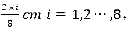
- Step (4-2-a): Design a binary image of size 200 ⁇ 200 pixels and divide it into 8 ⁇ 8 regions, each region containing 25 ⁇ 25 pixels, each column from left to right. Place a black pixel block of size (2i+1) ⁇ (2i+1)i 1, 2...,8, and then create a cube of 8cm ⁇ 8cm ⁇ 2cm, and set each line from top to bottom. Regional depth The binary map is mapped to the surface of the model through the perspective projection transformation, and then the corresponding depth is recessed to obtain 64 holes of different sizes.
- Figure 7 is a rendering of a physical experiment model obtained by a printer using white PLA material;
- Figure 8 is a plot of visibility and gray value scatter plots and fitting curve results.
- the invention simulates a real two-dimensional code image according to the relationship between the visibility and the gray value obtained by the physical experiment, and then adjusts the depth of each black module of the stereoscopic two-dimensional code according to the result of the simulation, so that the two-dimensional code foreground color and The contrast of the background color is enhanced, thereby increasing the decoding success rate.
- j is a pixel of the black module B i or the white module W i
- w j is the weight value at the pixel j obtained by the Gaussian kernel
- g j is the gray value at the pixel j.
- G W is the average gray value of all white modules:
- G B is the average gray value of all black modules:
- n are the number of all white and black modules in the stereoscopic two-dimensional code, respectively.
- D is the set of all white modules in the neighborhood where the black module B i 8 is connected
- k is the number of elements in the set D.
- Step (5) Optimize the depth of the stereoscopic two-dimensional black module according to the simulation result, and generate a stereoscopic two-dimensional code on the surface of the custom 3D model.
- setting the contrast threshold to 0.3 reduces the depth of the black module in the stereoscopic two-dimensional code until the contrast of all the black modules is just 0.3.
- Step (6) input the generated 3D model containing the stereoscopic two-dimensional code to the 3D printer, and print with a single material, and finally output the 3D object with the stereoscopic two-dimensional code.
- the generated model containing the stereoscopic two-dimensional code is exported to the stl format, and input into a 3D printer for print production.
- the invention can specify an arbitrary target area by the user, and can still form sufficient contrast in the target area with relatively large curvature change, and improve the decoding success rate of the stereoscopic two-dimensional code generated on any three-dimensional model, and finally generate the stereoscopic two.
- the dimensional code is significantly better than the two-dimensional code printed by the existing 3D technology.
- the invention firstly uses a perspective projection transformation to map a two-dimensional code to a target area of a custom 3D model, and performs a uniform depth depression operation according to the transformation result, and then calculates the visibility of each point of the stereoscopic two-dimensional code, and obtains according to a physical experiment.
- the relationship between the visibility and the gray value simulates the real two-dimensional code image, and then adjusts the depth of each black module of the stereoscopic two-dimensional code according to the result of the simulation, so that the contrast between the foreground color and the background color of the two-dimensional code is enhanced, thereby The decoding success rate is improved, and finally a three-dimensional model including a stereoscopic two-dimensional code which can be manufactured by a 3D printer of a single attribute molding material is generated.
- the stereoscopic two-dimensional code generated by the invention can achieve optimal depth in each black module, which greatly reduces the support structure required in the 3D printing process.
- the invention generates a stereoscopic two-dimensional code by using different recess depths in a target area of any three-dimensional model specified by the user, so that the two-dimensional code can be easily manufactured by a 3D printer of a single attribute molding material, and the attractiveness generated can bring Certain business value.
- FIG. 9 is a schematic structural view of an improved stereoscopic two-dimensional code generating system for a 3D printing custom model of the present invention.
- an improved 3D printing customized model stereoscopic two-dimensional code generating system of the present invention includes at least:
- a meshing and normalization processing module for meshing and normalizing a custom 3D model.
- the meshing and normalization processing module as shown in FIG. 10, further includes:
- Meshing module for finding discrete sampling points on the surface of a custom 3D model using Lloyd relaxation-based resampling algorithm, and implementing a custom 3D model network for input by 3D Delaunay triangulation method Grid
- (1-2) a linear transformation module for linearly transforming data of a customized three-dimensional model after meshing using a dispersion normalization method, and mapping three-dimensional coordinate components of each point on the triangular mesh of the 3D model to Between [0-1].
- a mapping module for mapping a two-dimensional code to a target area of a custom 3D model using a perspective projection transformation method.
- the mapping module of the present invention includes:
- a two-dimensional code triangular mesh marking module for placing a two-dimensional code on a viewing plane, and meshing each square module thereon into two triangles, emitting a series of rays from the viewpoint The ray is projected through the vertices of the two-dimensional code grid to the three-dimensional model, thereby generating a two-dimensional code triangle mesh in the target region of the surface of the 3D model, and the two-dimensional code triangulation corresponding to the surface of the 3D model of the two-dimensional code black module The cells are marked in black, which means that these triangular meshes need to be recessed.
- a recessed module for performing a recess operation according to the mapping result, and generating a stereoscopic two-dimensional code having the same recessed depth on the surface of the custom 3D model.
- the simulation module includes:
- Model surface hole acquisition module which is used to divide a binary map of a preset pixel value into a plurality of regions, and map the binary map to a surface of the model through a perspective projection transformation, and then recess the corresponding depth to obtain a hole of a different size than the number of divided areas;
- (4-2) a visibility and gray value relationship calculation module for obtaining the visibility of the center point of each hole and obtaining the average gray value of the corresponding position from the physical model photograph as the gray value of the center point, Obtaining the relationship between them by fitting the curve to the visibility and gray value;
- a gray value calculation module for mapping the visibility of each point of the stereoscopic two-dimensional code by the relationship between the visibility and the gray value to the gray value at the point of the stereoscopic two-dimensional code, and finally The gray value of each pixel of the simulated real two-dimensional code image can be obtained.
- an optimization module for optimizing the depth of the stereoscopic two-dimensional black module according to the simulation result, and generating a stereoscopic two-dimensional code on the surface of the custom 3D model
- a printing module for inputting the generated 3D model containing the stereoscopic two-dimensional code to the 3D printer, printing with a single material, and finally outputting the 3D object with the stereoscopic two-dimensional code.
- system further includes:
- a re-triangulation module for re-triangulating the mesh of the target area of the custom 3D model before performing the sag operation according to the mapping result, so that the two-dimensional code grid and the user mapped to the target area of the 3D model
- the fixed 3D model meshes are merged together.
- the system further includes: a visibility calculation module for assuming that only ambient light is equivalent to placing the stereoscopic two-dimensional code in the integrating sphere; and the 3D model is sliced to obtain a stereoscopic two-dimensional code.
- a visibility calculation module for assuming that only ambient light is equivalent to placing the stereoscopic two-dimensional code in the integrating sphere; and the 3D model is sliced to obtain a stereoscopic two-dimensional code.
- Each point intersects the visible polygon of each layer contour on each layer along the perspective projection direction; according to the inference of Girard theory, the area of the spherical polygon visible at each point on the stereoscopic two-dimensional code; the area of the integrating sphere visible at any point and The ratio of the overall area of the integrating sphere gives the visibility of the current point.
Landscapes
- Physics & Mathematics (AREA)
- General Physics & Mathematics (AREA)
- Engineering & Computer Science (AREA)
- Theoretical Computer Science (AREA)
- Processing Or Creating Images (AREA)
- Image Generation (AREA)
Abstract
Description




Claims (10)
- 一种改进的面向3D打印自定义模型立体二维码生成方法,其特征在于,包括:对自定义3D模型进行网格化和归一化处理;采用透视投影变换方法将二维码映射到自定义3D模型的目标区域;根据映射结果进行凹陷操作,在自定义3D模型表面生成具有相同凹陷深度的立体二维码;物理实验模拟真实的二维码图像,计算出立体二维码的整体对比度和每个黑色模块的对比度;根据模拟结果优化立体二维码黑色模块的深度,在自定义3D模型表面生成立体二维码;将生成的含有立体二维码的3D模型输入至3D打印机,并利用单一材料进行打印,最后输出带有立体二维码的3D实物。
- 如权利要求1所述的一种改进的面向3D打印自定义模型立体二维码生成方法,其特征在于,在根据映射结果进行凹陷操作之前,还包括:对自定义3D模型的目标区域的网格进行重新三角化,使得映射到3D模型的目标区域的二维码网格和用户给定的3D模型网格融合在一起。
- 如权利要求1所述的一种改进的面向3D打印自定义模型立体二维码生成方法,其特征在于,对自定义3D模型进行网格化和归一化处理的具体过程包括:使用基于Lloyd松弛的重采样算法在自定义3D模型表面求得离散采样点,通过3D Delaunay三角剖分方法实现对输入的自定义3D模型的网格化;使用离差标准化方法,对网格化后自定义三维模型的数据进行线性变换,将3D模型三角网格上每个点的三维坐标分量均映射到[0-1]之间。
- 如权利要求1所述的一种改进的面向3D打印自定义模型立体二维码生成方法,其特征在于,采用透视投影变换方法将二维码映射到自定义3D模型的目标区域的具体过程包括:根据3D打印机的打印精度,得到目标区域的最小面积;确定透视投影变换的关系,进而获得视点和视平面所在位置;将二维码放置在视平面上,并把其上的每个正方形模块网格化为两个三角形,从视点发出一系列射线,射线穿过二维码网格的顶点投射到三维模型,从而在3D模型表面的目标区域生成二维码三角网格,将对应于二维码黑色模块的3D模型表面的二维码三角网格标记为黑色,代表这些三角网格需要进行凹陷操作。
- 如权利要求2所述的一种改进的面向3D打印自定义模型立体二维码生成方法,其特征在于,对自定义3D模型的目标区域的网格进行重新三角化的具体过程为:将目标区域与射线相交的三角面片全部删除获得一个带洞的三维模型,然后获得洞的边界,将洞的边界与二维码三角网格的边界之间的部分采用2D Delaunay三角剖分方法进行重新三角化。
- 如权利要求1所述的一种改进的面向3D打印自定义模型立体二维码生成方法,其特征在于,物理实验模拟真实的二维码图像之前,还包括计算立体二维码的每一点的可见性,其具体过程为:假设只有环境光,相当于将立体二维码放置在积分球内;将3D模型进行切片处理,求得立体二维码上每一点沿着透视投影方向在每一层上交点在每一层轮廓的可见多边形;根据Girard理论的推论求得立体二维码上每一点可见球面多边形的面积;任一点可见的积分球面积与积分球整体面积之比,得到当前点的可见性。
- 如权利要求1所述的一种改进的面向3D打印自定义模型立体二维码生成方法,其特征在于,物理实验模拟真实的二维码图像的具体过程为:将一个预设像素值的二值图划分成若干个区域,将该二值图通过透视投影变换映射到模型表面,再凹陷相应的深度得到与划分区域数量相等的大小不同的洞;求得每个洞中心点的可见性并从物理模型照片中获得相应位置的平均灰度值作为中心点的灰度值,通过对可见性与灰度值拟合曲线获得它们之间的关系;将立体二维码每一点的可见性通过可见性和灰度值之间的关系映射为立体二维码该点处的灰度值,最终即可获得模拟出的真实二维码图像每个像素的灰度值。
- 一种改进的面向3D打印自定义模型立体二维码生成系统,其特征在于,包括:网格化和归一化处理模块,其用于对自定义3D模型进行网格化和归一化处理;映射模块,其用于采用透视投影变换方法将二维码映射到自定义3D模型的目标区域;凹陷模块,其用于根据映射结果进行凹陷操作,在自定义3D模型表面生成具有相同凹陷深度的立体二维码;模拟模块,其用于物理实验模拟真实的二维码图像,计算出立体二维码的整体对比度和每个黑色模块的对比度;优化模块,其用于根据模拟结果优化立体二维码黑色模块的深度,在自定义3D模型表面生成立体二维码;打印模块,其用于将生成的含有立体二维码的3D模型输入至3D打印机,并利用单一材料进行打印,最后输出带有立体二维码的3D实物。
- 如权利要求8所述的一种改进的面向3D打印自定义模型立体二维码生成系统,其特征在于,该系统还包括:重新三角化模块,其用于在根据映射结果进行凹陷操作之前,对自定义3D模型的目标区域的网格进行重新三角化,使得映射到3D模型的目标区域的二维码网格和用户给定的3D模型网格融合在一起。
- 如权利要求8所述的一种改进的面向3D打印自定义模型立体二维码生成系统,其特征在于,所述网格化和归一化处理模块包括:网格化模块,其用于使用基于Lloyd松弛的重采样算法在自定义3D模型表面求得离散采样点,通过3D Delaunay三角剖分方法实现对输入的自定义3D模型的网格化;线性变换模块,其用于使用离差标准化方法,对网格化后自定义三维模型的数据进行线性变换,将3D模型三角网格上每个点的三维坐标分量均映射到[0-1]之间;和/或,所述映射模块包括:目标区域的最小面积计算模块,其用于根据3D打印机的打印精度,得到目标区域的最小面积;视点和视平面位置确定模块,其用于确定透视投影变换的关系,进而获得视点和视平面所在位置;二维码三角网格标记模块,其用于将二维码放置在视平面上,并把其上的每个正方形模块网格化为两个三角形,从视点发出一系列射线,射线穿过二维码网格的顶点投射到三维模型,从而在3D模型表面的目标区域生成二维码三角网格,将对应于二维码黑色模块的3D模型表面的二维码三角网格标记为黑色,代表这些三角网格需要进行凹陷操作;和/或,该系统还包括:可见性计算模块,其用于假设只有环境光,相当于将立体二维码放置在积分球内;将3D模型进行切片处理,求得立体二维码上每一点沿着透视投影方向在每一层上交点在每一层轮廓的可见多边形;根据Girard理论的推论求得立体二维码上每一点可见球面多边形的面积;任一点可见的积分球面积与积分球整体面积之比,得到当前点的可见性;和/或,所述模拟模块包括:模型表面洞获取模块,其用于将一个预设像素值的二值图划分成若干个区域,将该二值图通过透视投影变换映射到模型表面,再凹陷相应的深度得到与划分区域数量相等的大小不同的洞;可见性与灰度值关系计算模块,其用于求得每个洞中心点的可见性并从物理模型照片中 获得相应位置的平均灰度值作为中心点的灰度值,通过对可见性与灰度值拟合曲线获得它们之间的关系;灰度值计算模块,其用于将立体二维码每一点的可见性通过可见性和灰度值之间的关系映射为立体二维码该点处的灰度值,最终即可获得模拟出的真实二维码图像每个像素的灰度值。
Applications Claiming Priority (2)
| Application Number | Priority Date | Filing Date | Title |
|---|---|---|---|
| CN201710343611.XA CN107145928B (zh) | 2017-05-16 | 2017-05-16 | 改进的面向3d打印自定义模型立体二维码生成方法及系统 |
| CN201710343611.X | 2017-05-16 |
Publications (1)
| Publication Number | Publication Date |
|---|---|
| WO2018209886A1 true WO2018209886A1 (zh) | 2018-11-22 |
Family
ID=59778326
Family Applications (1)
| Application Number | Title | Priority Date | Filing Date |
|---|---|---|---|
| PCT/CN2017/106086 Ceased WO2018209886A1 (zh) | 2017-05-16 | 2017-10-13 | 改进的面向3d打印自定义模型立体二维码生成方法及系统 |
Country Status (2)
| Country | Link |
|---|---|
| CN (1) | CN107145928B (zh) |
| WO (1) | WO2018209886A1 (zh) |
Cited By (3)
| Publication number | Priority date | Publication date | Assignee | Title |
|---|---|---|---|---|
| EP3667623A1 (en) * | 2018-12-12 | 2020-06-17 | Twikit NV | A system for optimizing a 3d mesh |
| WO2020131077A1 (en) | 2018-12-20 | 2020-06-25 | Hewlett-Packard Development Company, L.P. | Read curved visual marks |
| US20220067225A1 (en) * | 2019-04-30 | 2022-03-03 | Hewlett-Packard Development Company, L.P. | Dimensions in Additive Manufacturing |
Families Citing this family (10)
| Publication number | Priority date | Publication date | Assignee | Title |
|---|---|---|---|---|
| CN107145928B (zh) * | 2017-05-16 | 2020-05-22 | 山东大学 | 改进的面向3d打印自定义模型立体二维码生成方法及系统 |
| CN108062579B (zh) * | 2018-02-08 | 2024-07-05 | 科大讯飞股份有限公司 | 二维码模块及带有二维码的设备 |
| CN109087385A (zh) * | 2018-06-27 | 2018-12-25 | 山东大学 | 一种基于3d打印的岸滩生态环境模拟方法与系统 |
| CN109447208A (zh) * | 2018-08-31 | 2019-03-08 | 北京目瞳科技有限公司 | 一种3d码及3d码的识别方法 |
| US10974458B2 (en) | 2019-01-11 | 2021-04-13 | Hewlett-Packard Development Company, L.P. | Dimensional compensations for additive manufacturing |
| CN110008779B (zh) * | 2019-03-05 | 2022-04-15 | 北京印刷学院 | 一种立体二维码处理方法及装置 |
| CN112132970B (zh) * | 2020-08-26 | 2023-08-08 | 山东大学 | 一种面向3d打印的自然纹理合成系统及方法 |
| CN112233080B (zh) * | 2020-10-13 | 2024-05-24 | 深圳市纵维立方科技有限公司 | 三维模型重建方法和装置、电子设备及存储介质 |
| CN115952675B (zh) * | 2022-12-30 | 2026-01-02 | 基准方中建筑设计股份有限公司 | 一种立面设计方法、装置及存储介质 |
| CN116976380A (zh) * | 2023-07-31 | 2023-10-31 | 北京风知力品牌管理顾问有限公司 | 基于3d物品定制化的条形码生成方法及相关装置 |
Citations (4)
| Publication number | Priority date | Publication date | Assignee | Title |
|---|---|---|---|---|
| CN104866885A (zh) * | 2015-06-04 | 2015-08-26 | 杭州甘侑科技有限公司 | 一种防伪性高的二维码个性化定制系统及其工艺品 |
| CN105138726A (zh) * | 2015-07-23 | 2015-12-09 | 上海正雅齿科科技有限公司 | 可编码工件的制造方法及其识别方法 |
| US20170046548A1 (en) * | 2015-08-13 | 2017-02-16 | International Business Machines Corporation | Printing and extraction of 2d barcode on 3d objects |
| CN107145928A (zh) * | 2017-05-16 | 2017-09-08 | 山东大学 | 改进的面向3d打印自定义模型立体二维码生成方法及系统 |
Family Cites Families (4)
| Publication number | Priority date | Publication date | Assignee | Title |
|---|---|---|---|---|
| CN103354616A (zh) * | 2013-07-05 | 2013-10-16 | 南京大学 | 在平面显示器上实现立体显示的方法和系统 |
| CN204706050U (zh) * | 2015-02-11 | 2015-10-14 | 高磊 | 一种带有突出字体的二维码名片 |
| CN204856553U (zh) * | 2015-07-23 | 2015-12-09 | 上海正雅齿科科技有限公司 | 用于工件的立体二维码 |
| CN105183405B (zh) * | 2015-10-12 | 2017-12-05 | 山东大学 | 一种自定义模型表面镂空的3d打印方法 |
-
2017
- 2017-05-16 CN CN201710343611.XA patent/CN107145928B/zh active Active
- 2017-10-13 WO PCT/CN2017/106086 patent/WO2018209886A1/zh not_active Ceased
Patent Citations (4)
| Publication number | Priority date | Publication date | Assignee | Title |
|---|---|---|---|---|
| CN104866885A (zh) * | 2015-06-04 | 2015-08-26 | 杭州甘侑科技有限公司 | 一种防伪性高的二维码个性化定制系统及其工艺品 |
| CN105138726A (zh) * | 2015-07-23 | 2015-12-09 | 上海正雅齿科科技有限公司 | 可编码工件的制造方法及其识别方法 |
| US20170046548A1 (en) * | 2015-08-13 | 2017-02-16 | International Business Machines Corporation | Printing and extraction of 2d barcode on 3d objects |
| CN107145928A (zh) * | 2017-05-16 | 2017-09-08 | 山东大学 | 改进的面向3d打印自定义模型立体二维码生成方法及系统 |
Cited By (8)
| Publication number | Priority date | Publication date | Assignee | Title |
|---|---|---|---|---|
| EP3667623A1 (en) * | 2018-12-12 | 2020-06-17 | Twikit NV | A system for optimizing a 3d mesh |
| WO2020120698A1 (en) | 2018-12-12 | 2020-06-18 | Twikit Nv | A system for optimizing a 3d mesh |
| US11605200B2 (en) | 2018-12-12 | 2023-03-14 | Twikit Nv | System for optimizing a 3D mesh |
| WO2020131077A1 (en) | 2018-12-20 | 2020-06-25 | Hewlett-Packard Development Company, L.P. | Read curved visual marks |
| EP3899793A4 (en) * | 2018-12-20 | 2022-08-10 | Hewlett-Packard Development Company, L.P. | READABLE CURVED VISUAL MARKS |
| US11790204B2 (en) | 2018-12-20 | 2023-10-17 | Hewlett-Packard Development Company, L.P. | Read curved visual marks |
| US20220067225A1 (en) * | 2019-04-30 | 2022-03-03 | Hewlett-Packard Development Company, L.P. | Dimensions in Additive Manufacturing |
| US12079546B2 (en) | 2019-04-30 | 2024-09-03 | Hewlett-Packard Development Company, L.P. | Dimensions in additive manufacturing |
Also Published As
| Publication number | Publication date |
|---|---|
| CN107145928B (zh) | 2020-05-22 |
| CN107145928A (zh) | 2017-09-08 |
Similar Documents
| Publication | Publication Date | Title |
|---|---|---|
| WO2018209886A1 (zh) | 改进的面向3d打印自定义模型立体二维码生成方法及系统 | |
| CN101404091B (zh) | 基于两步形状建模的三维人脸重建方法和系统 | |
| CN108537864B (zh) | 利用具有网络渲染层的神经网络编辑数字图像 | |
| CN114902289A (zh) | 使用源自立体图像对的点云对结构建模的系统和方法 | |
| CN109712223B (zh) | 一种基于纹理合成的三维模型自动上色方法 | |
| CN109035388A (zh) | 三维人脸模型重建方法及装置 | |
| CN108510573A (zh) | 一种基于深度学习的多视点人脸三维模型重建的方法 | |
| US10837621B2 (en) | Methods and systems for freeform irradiance tailoring for light fields | |
| CN103761397A (zh) | 用于面曝光增材成型的3d模型切片及投影面生成方法 | |
| CN105184857A (zh) | 基于点结构光测距的单目视觉重建中尺度因子确定方法 | |
| US9202310B2 (en) | Physical reproduction of reflectance fields | |
| CN103093498A (zh) | 一种基于平面三角网格模板的三维人脸自动标准化方法 | |
| CN116385619B (zh) | 对象模型渲染方法、装置、计算机设备和存储介质 | |
| CN106874982A (zh) | 面向3d打印的自定义模型立体二维码生成方法及系统 | |
| Wu et al. | Survey on computational 3D visual optical art design | |
| CN119494906B (zh) | 积木模型的自动化渲染方法、装置、设备及存储介质 | |
| US11823328B2 (en) | Three-dimensional (3D) model generation from computer-aided design (CAD) data | |
| CN120823304A (zh) | 三维模型的阴影生成方法、装置、设备、介质和程序产品 | |
| CN118587266A (zh) | 一种基于林区图片生成含有林业基础数据的方法 | |
| US11562504B1 (en) | System, apparatus and method for predicting lens attribute | |
| CN117272491A (zh) | 一种基于ai绘图模型的快速建模方法、设备及介质 | |
| Hu et al. | Large-scale 3d semantic reconstruction for automated driving vehicles with adaptive truncated signed distance function | |
| CN121414992B (zh) | 基于零样本语义分割与物理属性估计的三维结构建模方法 | |
| CN121259011B (zh) | 三维点云分割方法、装置、设备及存储介质 | |
| Abbas et al. | Gaussian radial basis function for efficient computation of forest indirect illumination |
Legal Events
| Date | Code | Title | Description |
|---|---|---|---|
| 121 | Ep: the epo has been informed by wipo that ep was designated in this application |
Ref document number: 17909785 Country of ref document: EP Kind code of ref document: A1 |
|
| NENP | Non-entry into the national phase |
Ref country code: DE |
|
| 122 | Ep: pct application non-entry in european phase |
Ref document number: 17909785 Country of ref document: EP Kind code of ref document: A1 |
|
| 32PN | Ep: public notification in the ep bulletin as address of the adressee cannot be established |
Free format text: NOTING OF LOSS OF RIGHTS PURSUANT TO RULE 112(1) EPC (EPO FORM 1205A DATED 20/10/2020) |
|
| 122 | Ep: pct application non-entry in european phase |
Ref document number: 17909785 Country of ref document: EP Kind code of ref document: A1 |