WO2018207303A1 - On-board monitoring camera device - Google Patents
On-board monitoring camera device Download PDFInfo
- Publication number
- WO2018207303A1 WO2018207303A1 PCT/JP2017/017826 JP2017017826W WO2018207303A1 WO 2018207303 A1 WO2018207303 A1 WO 2018207303A1 JP 2017017826 W JP2017017826 W JP 2017017826W WO 2018207303 A1 WO2018207303 A1 WO 2018207303A1
- Authority
- WO
- WIPO (PCT)
- Prior art keywords
- obstacle
- image
- vehicle
- display
- obstacles
- Prior art date
Links
- 238000012544 monitoring process Methods 0.000 title abstract description 36
- 230000000007 visual effect Effects 0.000 claims abstract description 31
- 238000001514 detection method Methods 0.000 claims description 21
- 238000003384 imaging method Methods 0.000 claims description 14
- 238000012937 correction Methods 0.000 claims description 13
- 239000000284 extract Substances 0.000 claims description 4
- 238000000034 method Methods 0.000 description 23
- 238000012545 processing Methods 0.000 description 6
- 238000010586 diagram Methods 0.000 description 4
- 238000013459 approach Methods 0.000 description 2
- 238000003702 image correction Methods 0.000 description 2
- 230000000737 periodic effect Effects 0.000 description 2
- 230000000694 effects Effects 0.000 description 1
- 230000003068 static effect Effects 0.000 description 1
Images

Classifications
-
- B—PERFORMING OPERATIONS; TRANSPORTING
- B60—VEHICLES IN GENERAL
- B60W—CONJOINT CONTROL OF VEHICLE SUB-UNITS OF DIFFERENT TYPE OR DIFFERENT FUNCTION; CONTROL SYSTEMS SPECIALLY ADAPTED FOR HYBRID VEHICLES; ROAD VEHICLE DRIVE CONTROL SYSTEMS FOR PURPOSES NOT RELATED TO THE CONTROL OF A PARTICULAR SUB-UNIT
- B60W30/00—Purposes of road vehicle drive control systems not related to the control of a particular sub-unit, e.g. of systems using conjoint control of vehicle sub-units, or advanced driver assistance systems for ensuring comfort, stability and safety or drive control systems for propelling or retarding the vehicle
- B60W30/08—Active safety systems predicting or avoiding probable or impending collision or attempting to minimise its consequences
- B60W30/095—Predicting travel path or likelihood of collision
- B60W30/0956—Predicting travel path or likelihood of collision the prediction being responsive to traffic or environmental parameters
-
- B—PERFORMING OPERATIONS; TRANSPORTING
- B60—VEHICLES IN GENERAL
- B60K—ARRANGEMENT OR MOUNTING OF PROPULSION UNITS OR OF TRANSMISSIONS IN VEHICLES; ARRANGEMENT OR MOUNTING OF PLURAL DIVERSE PRIME-MOVERS IN VEHICLES; AUXILIARY DRIVES FOR VEHICLES; INSTRUMENTATION OR DASHBOARDS FOR VEHICLES; ARRANGEMENTS IN CONNECTION WITH COOLING, AIR INTAKE, GAS EXHAUST OR FUEL SUPPLY OF PROPULSION UNITS IN VEHICLES
- B60K35/00—Arrangement of adaptations of instruments
-
- B60K35/22—
-
- B60K35/28—
-
- B60K35/90—
-
- B—PERFORMING OPERATIONS; TRANSPORTING
- B60—VEHICLES IN GENERAL
- B60W—CONJOINT CONTROL OF VEHICLE SUB-UNITS OF DIFFERENT TYPE OR DIFFERENT FUNCTION; CONTROL SYSTEMS SPECIALLY ADAPTED FOR HYBRID VEHICLES; ROAD VEHICLE DRIVE CONTROL SYSTEMS FOR PURPOSES NOT RELATED TO THE CONTROL OF A PARTICULAR SUB-UNIT
- B60W30/00—Purposes of road vehicle drive control systems not related to the control of a particular sub-unit, e.g. of systems using conjoint control of vehicle sub-units, or advanced driver assistance systems for ensuring comfort, stability and safety or drive control systems for propelling or retarding the vehicle
- B60W30/08—Active safety systems predicting or avoiding probable or impending collision or attempting to minimise its consequences
- B60W30/095—Predicting travel path or likelihood of collision
-
- G—PHYSICS
- G06—COMPUTING; CALCULATING OR COUNTING
- G06T—IMAGE DATA PROCESSING OR GENERATION, IN GENERAL
- G06T1/00—General purpose image data processing
-
- G—PHYSICS
- G06—COMPUTING; CALCULATING OR COUNTING
- G06V—IMAGE OR VIDEO RECOGNITION OR UNDERSTANDING
- G06V40/00—Recognition of biometric, human-related or animal-related patterns in image or video data
- G06V40/10—Human or animal bodies, e.g. vehicle occupants or pedestrians; Body parts, e.g. hands
- G06V40/103—Static body considered as a whole, e.g. static pedestrian or occupant recognition
-
- G—PHYSICS
- G08—SIGNALLING
- G08G—TRAFFIC CONTROL SYSTEMS
- G08G1/00—Traffic control systems for road vehicles
- G08G1/16—Anti-collision systems
- G08G1/166—Anti-collision systems for active traffic, e.g. moving vehicles, pedestrians, bikes
-
- H—ELECTRICITY
- H04—ELECTRIC COMMUNICATION TECHNIQUE
- H04N—PICTORIAL COMMUNICATION, e.g. TELEVISION
- H04N7/00—Television systems
- H04N7/18—Closed-circuit television [CCTV] systems, i.e. systems in which the video signal is not broadcast
-
- B60K2360/173—
-
- B60K2360/176—
-
- B60K2360/178—
-
- B60K2360/179—
-
- B60K2360/21—
-
- B—PERFORMING OPERATIONS; TRANSPORTING
- B60—VEHICLES IN GENERAL
- B60R—VEHICLES, VEHICLE FITTINGS, OR VEHICLE PARTS, NOT OTHERWISE PROVIDED FOR
- B60R11/00—Arrangements for holding or mounting articles, not otherwise provided for
- B60R11/04—Mounting of cameras operative during drive; Arrangement of controls thereof relative to the vehicle
-
- B—PERFORMING OPERATIONS; TRANSPORTING
- B60—VEHICLES IN GENERAL
- B60R—VEHICLES, VEHICLE FITTINGS, OR VEHICLE PARTS, NOT OTHERWISE PROVIDED FOR
- B60R2300/00—Details of viewing arrangements using cameras and displays, specially adapted for use in a vehicle
- B60R2300/30—Details of viewing arrangements using cameras and displays, specially adapted for use in a vehicle characterised by the type of image processing
- B60R2300/301—Details of viewing arrangements using cameras and displays, specially adapted for use in a vehicle characterised by the type of image processing combining image information with other obstacle sensor information, e.g. using RADAR/LIDAR/SONAR sensors for estimating risk of collision
-
- B—PERFORMING OPERATIONS; TRANSPORTING
- B60—VEHICLES IN GENERAL
- B60R—VEHICLES, VEHICLE FITTINGS, OR VEHICLE PARTS, NOT OTHERWISE PROVIDED FOR
- B60R2300/00—Details of viewing arrangements using cameras and displays, specially adapted for use in a vehicle
- B60R2300/30—Details of viewing arrangements using cameras and displays, specially adapted for use in a vehicle characterised by the type of image processing
- B60R2300/307—Details of viewing arrangements using cameras and displays, specially adapted for use in a vehicle characterised by the type of image processing virtually distinguishing relevant parts of a scene from the background of the scene
-
- B—PERFORMING OPERATIONS; TRANSPORTING
- B60—VEHICLES IN GENERAL
- B60R—VEHICLES, VEHICLE FITTINGS, OR VEHICLE PARTS, NOT OTHERWISE PROVIDED FOR
- B60R2300/00—Details of viewing arrangements using cameras and displays, specially adapted for use in a vehicle
- B60R2300/80—Details of viewing arrangements using cameras and displays, specially adapted for use in a vehicle characterised by the intended use of the viewing arrangement
- B60R2300/8093—Details of viewing arrangements using cameras and displays, specially adapted for use in a vehicle characterised by the intended use of the viewing arrangement for obstacle warning
-
- B—PERFORMING OPERATIONS; TRANSPORTING
- B60—VEHICLES IN GENERAL
- B60W—CONJOINT CONTROL OF VEHICLE SUB-UNITS OF DIFFERENT TYPE OR DIFFERENT FUNCTION; CONTROL SYSTEMS SPECIALLY ADAPTED FOR HYBRID VEHICLES; ROAD VEHICLE DRIVE CONTROL SYSTEMS FOR PURPOSES NOT RELATED TO THE CONTROL OF A PARTICULAR SUB-UNIT
- B60W50/00—Details of control systems for road vehicle drive control not related to the control of a particular sub-unit, e.g. process diagnostic or vehicle driver interfaces
- B60W50/08—Interaction between the driver and the control system
- B60W50/14—Means for informing the driver, warning the driver or prompting a driver intervention
- B60W2050/143—Alarm means
-
- B—PERFORMING OPERATIONS; TRANSPORTING
- B60—VEHICLES IN GENERAL
- B60W—CONJOINT CONTROL OF VEHICLE SUB-UNITS OF DIFFERENT TYPE OR DIFFERENT FUNCTION; CONTROL SYSTEMS SPECIALLY ADAPTED FOR HYBRID VEHICLES; ROAD VEHICLE DRIVE CONTROL SYSTEMS FOR PURPOSES NOT RELATED TO THE CONTROL OF A PARTICULAR SUB-UNIT
- B60W50/00—Details of control systems for road vehicle drive control not related to the control of a particular sub-unit, e.g. process diagnostic or vehicle driver interfaces
- B60W50/08—Interaction between the driver and the control system
- B60W50/14—Means for informing the driver, warning the driver or prompting a driver intervention
- B60W2050/146—Display means
-
- B—PERFORMING OPERATIONS; TRANSPORTING
- B60—VEHICLES IN GENERAL
- B60W—CONJOINT CONTROL OF VEHICLE SUB-UNITS OF DIFFERENT TYPE OR DIFFERENT FUNCTION; CONTROL SYSTEMS SPECIALLY ADAPTED FOR HYBRID VEHICLES; ROAD VEHICLE DRIVE CONTROL SYSTEMS FOR PURPOSES NOT RELATED TO THE CONTROL OF A PARTICULAR SUB-UNIT
- B60W2420/00—Indexing codes relating to the type of sensors based on the principle of their operation
- B60W2420/40—Photo or light sensitive means, e.g. infrared sensors
- B60W2420/403—Image sensing, e.g. optical camera
-
- B60W2420/408—
-
- B—PERFORMING OPERATIONS; TRANSPORTING
- B60—VEHICLES IN GENERAL
- B60W—CONJOINT CONTROL OF VEHICLE SUB-UNITS OF DIFFERENT TYPE OR DIFFERENT FUNCTION; CONTROL SYSTEMS SPECIALLY ADAPTED FOR HYBRID VEHICLES; ROAD VEHICLE DRIVE CONTROL SYSTEMS FOR PURPOSES NOT RELATED TO THE CONTROL OF A PARTICULAR SUB-UNIT
- B60W50/00—Details of control systems for road vehicle drive control not related to the control of a particular sub-unit, e.g. process diagnostic or vehicle driver interfaces
- B60W50/08—Interaction between the driver and the control system
- B60W50/14—Means for informing the driver, warning the driver or prompting a driver intervention
-
- B—PERFORMING OPERATIONS; TRANSPORTING
- B60—VEHICLES IN GENERAL
- B60Y—INDEXING SCHEME RELATING TO ASPECTS CROSS-CUTTING VEHICLE TECHNOLOGY
- B60Y2300/00—Purposes or special features of road vehicle drive control systems
- B60Y2300/08—Predicting or avoiding probable or impending collision
-
- G—PHYSICS
- G06—COMPUTING; CALCULATING OR COUNTING
- G06V—IMAGE OR VIDEO RECOGNITION OR UNDERSTANDING
- G06V20/00—Scenes; Scene-specific elements
- G06V20/50—Context or environment of the image
- G06V20/56—Context or environment of the image exterior to a vehicle by using sensors mounted on the vehicle
- G06V20/58—Recognition of moving objects or obstacles, e.g. vehicles or pedestrians; Recognition of traffic objects, e.g. traffic signs, traffic lights or roads
Definitions
- the present invention relates to a vehicle-mounted monitoring camera device, and more particularly to a vehicle-mounted monitoring camera device that monitors the surroundings of a vehicle with a camera and transmits an obstacle that may cause a collision to a driver.
- such a surveillance camera may be equipped with a radar for monitoring an obstacle or approaching object behind.
- the radar is configured to search over a wide range of obstacles that may collide with the host vehicle when the host vehicle moves backward. For this reason, since the detection range of the radar is wider than the visual field range of the surveillance camera, the object detected by the radar may be outside the visual field range of the surveillance camera and cannot be confirmed from the video of the surveillance camera.
- a technique for removing distortion caused by a wide-angle lens by image processing is used.
- a specific position that is a reference for image correction processing is set in the video imaged by the imaging unit, and the video portion in the horizontal direction is shifted in the vertical direction with respect to the specific position, The distortion in the image with respect to the width direction of the vehicle is corrected linearly.
- the present invention has been made in order to solve such a problem, and a vehicle-mounted surveillance camera in which a driver can quickly grasp the direction of a detected obstacle without requiring a large display device.
- the object is to obtain a device.
- the present invention provides an obstacle detection unit that detects, as a first obstacle, an obstacle that may collide with the host vehicle among obstacles detected by a radar or a camera, the first obstacle, Photographed by a collision risk determination unit that detects the time until the host vehicle contacts or the distance between the first obstacle and the host vehicle, and a wide-angle lens having a wider imaging range than a standard lens.
- the first image is input, the distortion correction unit that corrects the distortion of the first image to generate the second image, and the shortest of the time or the distance detected by the collision risk determination unit
- the first obstacle having the time or the shortest distance is extracted as a second obstacle, and a certain range of image is extracted from the second image so that the second obstacle is located in the center in the lateral direction.
- a camera viewpoint display control unit and a first display device for displaying the third image wherein the camera viewpoint display control unit displays an image indicating a field range of the third image or a center direction of the field of view. It is a vehicle-mounted surveillance camera device that is superimposed on a third image.
- the in-vehicle monitoring camera device cuts out an image of an obstacle from an image taken with a wide-angle lens, and with respect to the cut out image, an image showing a visual field range of the image or a central direction of the visual field of the image is displayed. Since the display is superimposed, the driver can quickly grasp the direction of the obstacle without requiring a large display device.
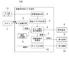
- FIG. 1 is a block diagram showing a configuration of an in-vehicle surveillance camera apparatus according to Embodiment 1 of the present invention.
- the in-vehicle monitoring camera device 100 is mounted on a vehicle.
- a vehicle on which the in-vehicle monitoring camera device 100 is mounted is referred to as “own vehicle”, and another vehicle is referred to as “other vehicle”.
- the camera 1 is connected to the in-vehicle monitoring camera device 100.
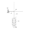
- the camera 1 is provided in the rear part of the own vehicle 101 as shown in FIG.
- the camera 1 is equipped with a wide-angle lens having a wider imaging range than the standard lens.
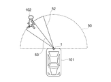
- the wide-angle lens can expand the imaging range up to 180 °. Therefore, the camera 1 can acquire an image of an imaging range with a wide viewing angle, for example, 180 degrees centered on the lens position of the camera 1, as in the imaging range 50 shown in FIG.
- the camera 1 captures the rear of the host vehicle 101 and outputs an image 1.
- the in-vehicle monitoring camera device 100 includes a distortion correction unit 2 as a means for acquiring an image.
- the distortion correction unit 2 receives the image 1 from the camera 1 and obtains the image 2 by removing the distortion of the image 1 caused by the wide-angle lens.
- Various methods have been proposed for removing image distortion caused by a wide-angle lens by image processing, as described in Patent Document 1, for example. Therefore, the distortion correction unit 2 may be configured to remove the distortion of the image 1 using, for example, one of such existing techniques.
- the method of removing the distortion of the image 1 is as follows. There is no particular limitation.
- a millimeter wave radar 11 is connected to the in-vehicle monitoring camera device 100.
- the millimeter wave radar 11 is provided, for example, at the rear part of the host vehicle 101.
- the millimeter wave radar 11 radiates a millimeter wave band and receives a reflected wave reflected by the surface of the obstacle.
- the millimeter wave radar 11 outputs the coordinates of the reflection point as sensing information regarding the obstacle using the reflected wave.
- the in-vehicle monitoring camera device 100 includes an obstacle detection unit 3 and a collision risk determination unit 4 as means for acquiring information on the obstacle.
- the obstacle detection unit 3 receives the sensing information from the millimeter wave radar 11 at a preset period, and specifies a set of coordinates of the reflection point as an obstacle based on the coordinates of the reflection point included in the sensing information. At the same time, the position, path, and speed of the obstacle are detected based on the time-series movement of the set. Further, the obstacle detection unit 3 detects an obstacle that may come into contact with the host vehicle 101 based on the position, route, and speed of the obstacle and the position, route, and speed of the host vehicle 101. Hereinafter, this obstacle is referred to as a “first obstacle”.
- the collision risk determination unit 4 detects the time until the host vehicle 101 comes into contact with the first obstacle detected by the obstacle detection unit 3 and the distance between the first obstacle and the host vehicle.
- the collision risk determination unit 4 determines the course of the host vehicle 101 and the course of the first obstacle 102 based on the position, course, and speed of the first obstacle 102 and the position, course, and speed of the host vehicle 101. Find the intersection point 40 at which. Next, the collision risk determination unit 4 obtains the arrival time A (see reference numeral 41) of the first obstacle 102 to the intersection 40 and the arrival time B (see reference numeral 42) of the host vehicle 101 to the intersection 40. . The collision risk determination unit 4 obtains the smaller one of the arrival time A and the arrival time B as “time until contact”.
- the collision risk determination unit 4 determines the distance between the first obstacle 102 and the own vehicle 101 based on the position of the first obstacle 102 and the position of the own vehicle 101 as “the obstacle and the own vehicle 101”. Calculated as “distance from vehicle”.
- the obstacle 102 is a pedestrian.
- the obstacle 102 is not limited to this, and the obstacle 102 includes a dynamic obstacle such as an animal, a tricycle, a bicycle, a single vehicle, and other vehicles, And static obstacles such as guardrails and utility poles.
- the vehicle-mounted monitoring camera device 100 includes a camera viewpoint display control unit 5 and an obstacle display superimposing unit 7 as means for performing display.
- a viewpoint storage unit 6 is connected to the camera viewpoint display control unit 5.
- the viewpoint storage unit 6 includes a memory.
- the viewpoint storage unit 6 stores obstacle information.
- the obstacle information is, for example, an obstacle ID.
- the camera viewpoint display control unit 5 performs the following three operations (1) to (3).
- the camera viewpoint display control unit 5 determines whether or not the obstacle information is recorded in the viewpoint storage unit 6. If the information is not recorded, the camera viewpoint display control unit 5 detects “contact” detected by the collision risk determination unit 4. The first obstacle having the shortest time is extracted as the second obstacle, and the viewpoint storage unit 6 stores information on the second obstacle.
- the viewpoint display control unit 5 determines whether or not the obstacle information is recorded in the viewpoint storage unit 6. If the information is not recorded, the camera viewpoint display control unit 5 detects “contact” detected by the collision risk determination unit 4. The first obstacle having the shortest time is extracted as the second obstacle, and the viewpoint storage unit 6 stores information on the second obstacle.
- the camera viewpoint display control unit 5 reads the information on the second obstacle from the viewpoint storage unit 6, cuts out the image of the second obstacle from the image 2, and generates the image 3.
- a predetermined fixed range is cut out from the image 2 so that the second obstacle is located at the center in the horizontal direction of the image.
- the certain range is, for example, a preset pixel range.
- the fixed range is a fixed value regardless of the distance to the second obstacle.
- the vertical center of the image is constant regardless of the position of the obstacle. Thereby, as the distance from the host vehicle 101 increases, the position of the obstacle in the image approaches the horizon. In this way, by making the vertical center of the image constant, the driver can easily grasp the distance to the obstacle.
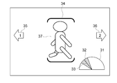
- the camera viewpoint display control unit 5 shows a radar chart 31 indicating the visual field range of the image 3 and the central direction of the visual field so that the driver can grasp the direction of the second obstacle. Is superimposed on the image 3.
- FIG. 4A shows an example of the radar chart 31.
- the radar chart 31 has a semicircular shape centered on the host vehicle 101.
- the radar chart 31 displays a visual field range 32 of the image 3 and a central direction 33 of the visual field.
- the colored area indicates the visual field range 32
- the solid line indicates the central direction 33 of the visual field.
- the radar chart 31 displays both the visual field range 32 of the image 3 and the central direction 33 of the visual field, but only one of them may be displayed.
- FIG. 4A is compared with FIG.
- reference numeral 50 indicates an imaging range of the camera 1.
- Reference numeral 52 denotes a range displayed as the image 3.
- the range is referred to as a display range or a visual field range of the image 3.
- Reference numeral 53 indicates the direction of the obstacle 102.
- the direction of the obstacle 102 indicates the center direction of the visual field of the image 3.
- the imaging range 50 in FIG. 5 corresponds to the semicircle of the radar chart 31 in FIG. 4A.
- the display range 52 in FIG. 5 corresponds to the visual field range 32 in FIG. 4A.
- the direction 53 in FIG. 5 corresponds to the central direction 33 of the visual field in FIG. 4A.
- the obstacle display superimposing unit 7 sets the time until the second obstacle displayed in the image 3 is contacted with the second obstacle detected by the collision risk determination unit 4 or the second obstacle.
- the image 4 is generated by superimposing the mark whose shape and color can be switched in accordance with the distance up to and output the image 4 to the display device 9.
- a display device 9 and a display device 10 are connected to the in-vehicle monitoring camera device 100.
- the mark is an emphasis display for alerting the driver to the second obstacle displayed in the image 3. Since the mark is changed in shape and color depending on the time or distance until contact, the driver determines the priority of the second obstacle, that is, the urgency level according to the shape and color of the mark. Can be recognized.
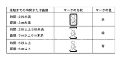
- FIG. 4A shows an example of the mark 34 superimposed on the image 4 (reference numeral 30).
- FIG. 4B shows an example of a data table in which the shape and color of the mark 34 are defined for each time or distance until contact. As shown in FIG. 4B, when the time to contact is within 2 seconds or the distance to contact is less than 3 m, the mark has a rectangular shape and the color of the mark so as to indicate that the priority is high. Is set to red. In addition, when the time to contact is 2 seconds or more and less than 5 seconds or the distance to contact is 3 m or more and less than 6 m, the mark shape is in parentheses to indicate that the priority is medium, and The color of the mark is set to green.
- the in-vehicle monitoring camera device 100 includes a camera output unit 12.
- the camera output unit 12 outputs the image 1 acquired from the camera 1 to the display device 10 as it is in order to display the entire image 1 acquired from the camera 1.
- the driver views the image 4 on the display device 9 and the image 1 on the display device 10 at the same time, so that the image 1 can roughly grasp the entire rear state of the host vehicle 101 with a wide viewing angle of 180 °. 4 makes it possible to accurately grasp the positional relationship of the obstacles.
- the camera viewpoint display control unit 5 further performs the following operation (4).
- an operation device 8 can be connected to the camera viewpoint display control unit 5.
- the camera viewpoint display control unit 5 receives a signal from the operation device 8, and in order of time until the host vehicle 101 contacts the obstacle, in order of distance from the obstacle, or viewpoint to the obstacle A mechanism is provided for changing the obstacle ID stored in the viewpoint storage unit 6 in accordance with any one of the order of the directions. Thereby, when the obstacle currently displayed on the display device 9 is switched to the next obstacle, the driver can specify in what order the next obstacle is selected. Details will be described later.
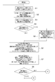
- the distortion correction unit 2 removes distortion due to the wide-angle lens from the image 1 acquired from the camera 1, and generates an image 2 (step S1).
- the obstacle detection unit 3 identifies one or more obstacles based on the set of reflection points from the millimeter wave radar 11 and its time-series movement, and the position and path of those obstacles. Based on the position of the obstacle, the course, the speed and the position, the course, and the speed of the host vehicle, the obstacle that may come into contact with the host vehicle is selected from the obstacles. Are extracted as obstacles (step S2).
- the collision risk determination unit 4 detects the time of contact with the first obstacle by the method shown in FIG. 3, and also detects the distance between the first obstacle and the host vehicle (step S3). At this time, a newly detected obstacle is assigned a new ID, and the previously detected obstacle is assigned the same ID as the previous one.
- the camera viewpoint display control unit 5 reads the obstacle ID stored in the viewpoint storage unit 6 in order to select an obstacle to be displayed on the display device 9, and the obstacle exists in the image 2. (Step S4).
- step S5 If it does not exist, it is assumed that there is no obstacle, and the ID of the obstacle with the shortest time to contact among the detected first obstacles is stored in the viewpoint storage unit 6 (step S5). On the other hand, when it exists, it progresses to step S6 as it is.
- the camera viewpoint display control unit 5 reads the obstacle ID stored in the viewpoint storage unit 6 and sets a preset pixel range so that the corresponding obstacle is in the horizontal center of the image.
- the image 3 is generated by cutting out from the image 2.
- the center in the vertical direction of the image is constant regardless of the position of the obstacle so that the distance to the obstacle can be grasped, and the farther obstacle can be seen to approach the horizon.
- the obstacle display superimposing unit 7 superimposes the semicircular radar chart 31 centering on the own vehicle 101 on the image 3 (step S6).
- the obstacle display superimposing unit 7 changes the mark and the color defined in the table of FIG. 4B so as to change the shape and color of the image 3 according to the time until the collision, as shown in FIG. 4A. 34 is superimposed.
- the mark 34 is superimposed on the pixel range 37 corresponding to the obstacle 102 in the image 3.
- the obstacle display superimposing unit 7 displays left obstacle information and right obstacle information indicating the presence of other obstacles not displayed in the image 3, respectively, as shown in FIG. 4A. Indicated by arrows 35 and 36. Further, numbers indicating the number of obstacles are displayed in the arrows 35 and 36. Thereby, the image 4 shown to FIG. 4A is produced
- an operation device 8 can be connected to the in-vehicle monitoring camera device 100.
- the operation by the driver's operation on the operating device 8 when the operating device 8 is connected to the in-vehicle monitoring camera device 100 will be described after step S8.
- the operation device 8 transmits a signal indicating that there is an operation input to the camera viewpoint display control unit 5 when an operation input for viewpoint switching is made by the driver. For this reason, the camera viewpoint display control unit 5 confirms whether or not there has been a viewpoint switching operation input based on the presence or absence of the signal from the operation device 8 (step S8). If there is an operation input, the process proceeds to step S9 in FIG. 2B. On the other hand, if there is no operation input, the process returns to step S1.
- the camera viewpoint display control unit 5 determines which is the switching order input to the operation device 8 (step S9). For example, there are three switching orders: “order in time until contact”, “order in viewpoint direction”, and “order in distance to an obstacle”.
- step S9 If it is determined in step S9 that the switching order is “time order until contact”, the camera viewpoint display control unit 5 detects the obstacle stored in the viewpoint storage unit 6 among the obstacles detected in step S2. The ID of the obstacle with the shortest time to contact next to the object is stored in the viewpoint storage unit 6 as a display target. However, if there is no corresponding obstacle, the ID of the obstacle with the shortest time to contact is stored in the viewpoint storage unit 6 as a display target (step S10).
- the camera viewpoint display control unit 5 is an obstacle detected in step S2 and is stored in the viewpoint storage unit 6.
- the ID of the obstacle having the closest viewpoint direction is stored in the viewpoint storage unit 6 as a display target.
- the ID of the obstacle on the leftmost side in the viewpoint direction is stored in the viewpoint storage unit 6 (step S11).
- step S9 If it is determined in step S9 that the switching order is “order of distance from an obstacle”, the camera viewpoint display control unit 5 is stored in the viewpoint storage unit 6 among the obstacles detected in step S2.
- the ID of the obstacle having the shortest distance from the host vehicle 101 next to the obstacle is stored in the viewpoint storage unit 6 as a display target.
- the ID of the obstacle with the shortest distance to the host vehicle 101 is stored in the viewpoint storage unit 6 as a display target (step S12).
- step S1 to step S12 is a periodic loop process. After the process is completed up to step S12, the process waits until the timing at which the image 1 of the camera 1 is input, and then the process from step S1 to step S12. The process starts again.
- the obstacle that may collide with the host vehicle 101 is designated as the first obstacle.
- An obstacle detection unit 3 that detects the obstacle
- a collision risk determination unit 4 that detects a time until the first obstacle and the host vehicle 101 come into contact with each other, or a distance between the first obstacle and the host vehicle.
- the first image captured by the wide-angle lens is input, the distortion correction unit 2 that corrects the distortion of the first image to generate the second image, and the time or distance detected by the collision risk determination unit 4 Among them, the first obstacle having the shortest time or the shortest distance is extracted as the second obstacle, and an image in a certain range is displayed so that the second obstacle is located in the center in the horizontal direction.
- a camera that cuts out from an image and generates a third image It includes a point display control unit 5, and a first display device 9 for displaying the third image.
- the camera viewpoint display control unit 5 superimposes the radar chart 31 as an image indicating the visual field range of the third image or the central direction of the visual field of the third image on the third image, so that the second image is displayed. Display the direction of the obstacle. Accordingly, the driver can quickly grasp the detected distance and direction to the obstacle without requiring a display device larger than the standard size display device.
- the radar chart 31 is merely an example, and any radar chart 31 may be used as long as it is an image showing the visual field range of the third image or the central direction of the visual field of the third image.
- the shape of the image is not a semicircular shape as shown in FIG. 4A but may be a circular shape or a rectangular shape.
- the display form and display method of the visual field range 32 and the central direction 33 of the visual field may be other display forms and display methods, for example, the central direction 33 of the visual field is indicated by an arrow.
- the mark 34 as an emphasis display for emphasizing the second obstacle displayed in the third image is applied to the second obstacle in the third image.
- An obstacle display superimposing unit 7 for superimposing is provided. As a result, the driver can instantly grasp the degree of obstacle collision risk.
- the operation device 8 to which a switching instruction for switching the second obstacle displayed in the third image to another one of the first obstacles is input is used. It may be. In this case, the second obstacle displayed in the third image can be switched to another one according to the driver switching instruction.
- the obstacle display superimposing unit 7 indicates the information indicating the presence of the other first obstacle not displayed in the third image by the arrows 35 and 36. May be. In that case, when the driver touches the arrows 35 and 36 with a finger, other obstacles not displayed on the screen can be displayed.
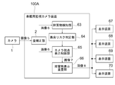
- FIG. FIG. 6 is a block diagram showing a configuration of an in-vehicle monitoring camera device 100A according to Embodiment 2 of the present invention.
- the in-vehicle monitoring camera device 100A is mounted on the host vehicle 101.
- the camera 1 is connected to the in-vehicle monitoring camera device 100A, as in the first embodiment. Similar to the first embodiment, the camera 1 is provided at the rear of the host vehicle 101 as shown in FIG. The camera 1 is equipped with a wide angle lens. Therefore, the camera 1 can acquire an image in an imaging range with a wide viewing angle, for example, 180 ° centered on the camera 1, as in the imaging range 50 illustrated in FIG. 5. The camera 1 captures the rear of the host vehicle 101 and outputs an image 5.
- the in-vehicle monitoring camera device 100A includes a distortion correction unit 2 as the first embodiment as means for acquiring an image to be displayed.
- the distortion correction unit 2 receives the image 5 from the camera 1 and obtains the image 6 by removing the distortion of the image 5 caused by the wide-angle lens in the same manner as in the first embodiment.
- the in-vehicle monitoring camera device 100A includes an obstacle detection unit 63 and a collision risk determination unit 64.
- the obstacle detection unit 3 shown in the first embodiment uses the sensing information of the millimeter wave radar 11.
- the obstacle detection unit 63 in the second embodiment passes through the distortion correction unit 2.
- An image 6 obtained from the camera 1 is used.
- the obstacle detection unit 63 performs image recognition processing on the image 6 to detect the presence of the obstacle, and reverse-projection transforms the pixel coordinates where the obstacle is detected to detect the position of the obstacle. Further, the obstacle detection unit 63 detects the position, course, and speed of the obstacle based on the time-series change in the position of the obstacle included in the image 6 obtained by the past image processing.
- the collision risk determination unit 64 Based on the position, path, and speed of the obstacle and the position, path, and speed of the host vehicle 101, an obstacle that may come into contact with the host vehicle 101 is detected as the first obstacle.
- the collision risk determination unit 64 detects “time until contact” and “distance between the obstacle and the host vehicle” by the same detection method as the collision risk determination unit 4 described in the first embodiment.
- the in-vehicle monitoring camera device 100A includes a camera viewpoint display control unit 65 and an obstacle display superimposing unit 66 as means for performing display.
- the camera viewpoint display control unit 65 performs the following three operations (1) to (3).
- the camera viewpoint display control unit 65 extracts a maximum of four obstacles in order from the shortest distance among the obstacles detected by the obstacle detection unit 63.
- the camera viewpoint display control unit 65 generates an image 7 for each extracted obstacle by cutting out a certain range from the image 6 so that the obstacle is positioned at the center in the horizontal direction of the image. To do. Since the image 7 is generated for each obstacle, the number of the images 7 is a maximum of four.
- the certain range is, for example, a preset pixel range. The vertical center of the image is constant regardless of the position of the obstacle so that the distance to the obstacle can be grasped, as in the first embodiment.
- the camera viewpoint display control unit 65 superimposes the radar chart 31 as an image indicating the visual field range of the image 7 or the central direction of the visual field on the image 7. Since the radar chart 31 is the same as the radar chart 31 described in the first embodiment, the description thereof is omitted here.
- the obstacle display superimposing unit 66 generates an image 8 in which the mark 34 whose shape and color change is superimposed on the obstacle of the image 7 according to the distance between the obstacle and the host vehicle, and generates four display devices. 67, 68, 69 and 70, respectively.
- the shape and color of the mark are defined in advance in the data table of FIG. 4B, for example.
- the example of the image 8 may be the same as the image 4 (reference numeral 30) illustrated in FIG. 4A, for example.
- the distortion correction unit 2 removes image distortion caused by the wide-angle lens from the image 5 acquired from the camera 1, and generates an image 6 (step S21).
- the obstacle detection unit 63 uses the image 6 to detect the presence and position of the first obstacle by image recognition processing (step S22).
- the collision risk determination unit 64 detects the distance between the first obstacle and the host vehicle 101 (step S23). .
- the camera viewpoint display control unit 65 extracts a maximum of four obstacles as second obstacles in the order of short time or distance until contact with the host vehicle 101 in the first obstacle. (Step S24).
- the number of first obstacles is four or less
- the number of second obstacles to be extracted is the same as the number of first obstacles.
- the camera viewpoint display control unit 65 displays an image in a certain range so that the second obstacle is the center in the horizontal direction of the image. 7 is cut out (step S25).
- the number of images 7 is the same as the number of second obstacles.
- the fixed range is, for example, a preset pixel range as in the first embodiment.
- the camera viewpoint display control unit 65 superimposes the radar chart 31 indicating the field-of-view range or the center direction of the field of view on each image 7 (step S26).
- the number of images 8 is the same as the number of second obstacles.
- the obstacle display superimposing unit 66 outputs each image 8 to the external display devices 67, 68, 69, 70 (step S28).
- step S21 to step S28 is a periodic loop process starting from the input of the image 5 from the camera 1. After the process is completed up to step S28, the image 5 from the camera 1 is input. The process from step S21 to step S28 is started again after waiting for the timing.
- the camera output unit 12 and the display device 10 shown in FIG. 1 are not provided, but the camera output unit 12 and the display device 10 shown in FIG. Thus, the image 5 may be displayed.
- the operating device 8 shown in FIG. 1 is not provided, but in the second embodiment as well, the operating device 8 shown in FIG. 1 is provided and obstructions are made according to the switching order designated by the driver. May be switched.
- the obstacle detection unit 63 that detects an obstacle that may collide with the host vehicle as the first obstacle
- a collision risk determination unit 64 that detects a time until the first obstacle comes into contact with the host vehicle 101 or a distance between the first obstacle and the host vehicle, and a first image taken by a wide-angle lens.
- the distortion correction unit 2 that corrects the distortion of the first image to generate the second image
- a first obstacle is extracted as a second obstacle, an image of a certain range is cut out from the second image so that the second obstacle is located in the center in the horizontal direction, and a third image is obtained.
- the camera viewpoint display control unit 65 to be generated and the third image are displayed. And a first display device 67-70 to.
- the camera viewpoint display control unit 5 converts the radar chart 31 as an image indicating the visual field range of the third image with respect to the imaging range of the first image or the center direction of the visual field of the third image into the third image. By superimposing, the direction of the second obstacle is displayed. Thereby, the effect similar to Embodiment 1 can be acquired.
- the camera viewpoint display control unit 5 extracts a plurality of first obstacles as the second obstacle, and generates a third image for each first obstacle. To do. Further, a plurality of display devices 67 to 70 are provided as display devices, and the third images generated for the respective first obstacles are displayed on the screens of the display devices 67 to 70, respectively. Accordingly, the driver can display a plurality of obstacles on the display device without switching the screen.
Abstract
An on-board monitoring camera device 100 includes: an obstacle detecting unit 3 that detects, as first obstacles, obstacles detected by a millimeter-wave radar 11 which might collide with the host vehicle; a collision-risk determining unit 4 that detects the time beforel the respective first obstacles and the vehicle come into contact with each other; a distortion correcting unit 2 that generates image 2 by correcting distortion in image 1 captured using a wide-angle lens; and a camera-viewpoint display control unit 5 that generates image 3 by cutting out, from image 2, an image of the first obstacle having the shortest time to collision. Therein, a radar chart 31 indicating the visual field range or the center direction of the visual field of image 3 is superimposed on image 3.
Description
この発明は車載用監視カメラ装置に関し、特に、車両の周囲をカメラで監視し、衝突の危険がある障害物をドライバーに伝える車両車載用監視カメラ装置に関するものである。
The present invention relates to a vehicle-mounted monitoring camera device, and more particularly to a vehicle-mounted monitoring camera device that monitors the surroundings of a vehicle with a camera and transmits an obstacle that may cause a collision to a driver.
広く普及している車載用監視カメラとして、車両が後退する際に、車両の後方の障害物をドライバーが確認できるようにするための車両後方監視カメラがある。
As a widely used in-vehicle monitoring camera, there is a vehicle rear monitoring camera that allows a driver to check an obstacle behind the vehicle when the vehicle moves backward.
また、そのような監視カメラに、後方の障害物または接近物を監視するためのレーダーが備えられている場合もある。当該レーダーは、自車両が後退する時に、自車両に衝突する可能性のある障害物を広範囲に探す構成となっている。そのため、レーダーの検知範囲は、監視カメラの視野範囲よりも広いため、レーダーで検知された物体が、監視カメラの視野範囲外にあって、監視カメラの映像からは確認できない場合がある。
Also, such a surveillance camera may be equipped with a radar for monitoring an obstacle or approaching object behind. The radar is configured to search over a wide range of obstacles that may collide with the host vehicle when the host vehicle moves backward. For this reason, since the detection range of the radar is wider than the visual field range of the surveillance camera, the object detected by the radar may be outside the visual field range of the surveillance camera and cannot be confirmed from the video of the surveillance camera.
これに対し、撮像範囲を180°近くまで広げることが可能な広角レンズを用いることで、大幅に視野範囲を広げた後方監視カメラが用いられている場合がある。しかしながら、その場合には、広角レンズにより画像に歪を生じているため、ドライバーが対象物の位置関係を把握するのが困難となる欠点がある。
On the other hand, there is a case where a rear-viewing camera that uses a wide-angle lens that can widen the imaging range up to nearly 180 ° and has a wide field of view is used. However, in this case, since the image is distorted by the wide-angle lens, there is a drawback that it is difficult for the driver to grasp the positional relationship of the object.
この欠点を克服するため、例えば特許文献1に記載の車両用映像補正装置では、広角レンズによる歪を画像処理により取り除く技術が用いられている。特許文献1に記載の装置では、撮像部で撮像された映像内に画像補正処理の基準となる特定位置を設定し、当該特定位置に対して左右方向の映像部分を上下方向にシフトさせて、車両の幅方向に対する映像内の歪曲を直線状に補正する。
In order to overcome this drawback, for example, in the vehicle image correction apparatus described in Patent Document 1, a technique for removing distortion caused by a wide-angle lens by image processing is used. In the apparatus described in Patent Document 1, a specific position that is a reference for image correction processing is set in the video imaged by the imaging unit, and the video portion in the horizontal direction is shifted in the vertical direction with respect to the specific position, The distortion in the image with respect to the width direction of the vehicle is corrected linearly.
しかしながら、特許文献1に記載のような技術を用いることで、例えば180°にわたるような視野角の広い映像を取得したとしても、それを歪なく表示するためには、大きな表示装置が必要となる。そのため、そのような大きな表示装置を、車両内の狭い運転席に設置することは困難であるという課題があった。
However, by using the technique as described in Patent Document 1, even if an image with a wide viewing angle such as 180 ° is acquired, a large display device is required to display it without distortion. . Therefore, there is a problem that it is difficult to install such a large display device in a narrow driver seat in the vehicle.
この発明は、かかる課題を解決するためになされたものであり、大きな表示装置を必要とせずに、ドライバーが、検知された障害物の方向を迅速に把握することが可能な、車載用監視カメラ装置を得ることを目的とする。
The present invention has been made in order to solve such a problem, and a vehicle-mounted surveillance camera in which a driver can quickly grasp the direction of a detected obstacle without requiring a large display device. The object is to obtain a device.
この発明は、レーダーまたはカメラで検知した障害物のうち、自車両に衝突する可能性のある障害物を、第1の障害物として検知する障害物検知部と、前記第1の障害物と前記自車両とが接触するまでの時間、または、前記第1の障害物と前記自車両との間の距離を検出する衝突リスク判定部と、標準レンズよりも広い撮像範囲を有する広角レンズにより撮影された第1の画像が入力され、前記第1の画像の歪を補正して第2の画像を生成する歪補正部と、前記衝突リスク判定部が検出した前記時間または前記距離のうち、最も短い時間または最も短い距離を有する前記第1の障害物を第2の障害物として抽出し、当該第2の障害物が横方向の中央に位置するように一定範囲の画像を前記第2の画像から切り出して、第3の画像を生成するカメラ視点表示制御部と、前記第3の画像を表示する第1の表示装置とを備え、前記カメラ視点表示制御部は、前記第3の画像の視野範囲または視野の中心方向を示す画像を前記第3の画像に重畳させる、車載用監視カメラ装置である。
The present invention provides an obstacle detection unit that detects, as a first obstacle, an obstacle that may collide with the host vehicle among obstacles detected by a radar or a camera, the first obstacle, Photographed by a collision risk determination unit that detects the time until the host vehicle contacts or the distance between the first obstacle and the host vehicle, and a wide-angle lens having a wider imaging range than a standard lens. The first image is input, the distortion correction unit that corrects the distortion of the first image to generate the second image, and the shortest of the time or the distance detected by the collision risk determination unit The first obstacle having the time or the shortest distance is extracted as a second obstacle, and a certain range of image is extracted from the second image so that the second obstacle is located in the center in the lateral direction. Cut out and generate a third image A camera viewpoint display control unit and a first display device for displaying the third image, wherein the camera viewpoint display control unit displays an image indicating a field range of the third image or a center direction of the field of view. It is a vehicle-mounted surveillance camera device that is superimposed on a third image.
この発明に係る車載用監視カメラ装置は、広角レンズで撮影した画像から障害物の画像を切り取り、切り取った当該画像に対して、当該画像の視野範囲または当該画像の視野の中心方向を示す画像を重畳して表示するようにしたので、大きな表示装置を必要とせずに、ドライバーが、障害物の方向を迅速に把握することができる。
The in-vehicle monitoring camera device according to the present invention cuts out an image of an obstacle from an image taken with a wide-angle lens, and with respect to the cut out image, an image showing a visual field range of the image or a central direction of the visual field of the image is displayed. Since the display is superimposed, the driver can quickly grasp the direction of the obstacle without requiring a large display device.
以下、図面に基づいて、この発明の実施の形態に係る車載用監視カメラ装置について説明する。
Hereinafter, a vehicle-mounted surveillance camera device according to an embodiment of the present invention will be described with reference to the drawings.
実施の形態1.
図1は、この発明の実施の形態1に係る車載用監視カメラ装置の構成を示すブロック図である。車載用監視カメラ装置100は車両に搭載されている。以下では、車載用監視カメラ装置100が搭載されている車両を「自車両」と呼び、他の車両を「他車両」と呼ぶこととする。Embodiment 1 FIG.
1 is a block diagram showing a configuration of an in-vehicle surveillance camera apparatus according toEmbodiment 1 of the present invention. The in-vehicle monitoring camera device 100 is mounted on a vehicle. Hereinafter, a vehicle on which the in-vehicle monitoring camera device 100 is mounted is referred to as “own vehicle”, and another vehicle is referred to as “other vehicle”.
図1は、この発明の実施の形態1に係る車載用監視カメラ装置の構成を示すブロック図である。車載用監視カメラ装置100は車両に搭載されている。以下では、車載用監視カメラ装置100が搭載されている車両を「自車両」と呼び、他の車両を「他車両」と呼ぶこととする。
1 is a block diagram showing a configuration of an in-vehicle surveillance camera apparatus according to
まず、図1に示すように、車載用監視カメラ装置100には、カメラ1が接続されている。カメラ1は、図5に示すように、自車両101の後部に設けられている。カメラ1は、標準レンズよりも広い撮像範囲を有する広角レンズを装備している。広角レンズは、撮像範囲を180°まで広げることができる。そのため、カメラ1は、図5に示す撮像範囲50のように、カメラ1のレンズ位置を中心とする、例えば180°にわたる広い視野角の撮像範囲の画像を取得することができる。カメラ1は、自車両101の後方を撮像し、画像1を出力する。
First, as shown in FIG. 1, the camera 1 is connected to the in-vehicle monitoring camera device 100. The camera 1 is provided in the rear part of the own vehicle 101 as shown in FIG. The camera 1 is equipped with a wide-angle lens having a wider imaging range than the standard lens. The wide-angle lens can expand the imaging range up to 180 °. Therefore, the camera 1 can acquire an image of an imaging range with a wide viewing angle, for example, 180 degrees centered on the lens position of the camera 1, as in the imaging range 50 shown in FIG. The camera 1 captures the rear of the host vehicle 101 and outputs an image 1.
車載用監視カメラ装置100は、画像を取得する手段として、歪補正部2を備える。歪補正部2は、カメラ1から画像1を受信し、広角レンズによる画像1の歪を取り除いて画像2を得る。広角レンズによる画像の歪を画像処理により取り除く方法は、例えば特許文献1にも記載されているように、種々提案されている。そのため、歪補正部2は、例えば、そのような既存の技術のうちの1つを用いて、画像1の歪を取り除くようにすればよく、ここでは、画像1の歪を取り除く方法については、特に限定しない。
The in-vehicle monitoring camera device 100 includes a distortion correction unit 2 as a means for acquiring an image. The distortion correction unit 2 receives the image 1 from the camera 1 and obtains the image 2 by removing the distortion of the image 1 caused by the wide-angle lens. Various methods have been proposed for removing image distortion caused by a wide-angle lens by image processing, as described in Patent Document 1, for example. Therefore, the distortion correction unit 2 may be configured to remove the distortion of the image 1 using, for example, one of such existing techniques. Here, the method of removing the distortion of the image 1 is as follows. There is no particular limitation.
さらに、図1に示すように、車載用監視カメラ装置100には、ミリ波レーダー11が接続されている。ミリ波レーダー11は、例えば、自車両101の後部に設けられている。ミリ波レーダー11は、ミリ波帯の電波を放射し、当該電波が障害物の表面で反射した反射波を受信する。ミリ波レーダー11は、当該反射波を用いて、反射点の座標を、障害物に関する感知情報として出力する。
Furthermore, as shown in FIG. 1, a millimeter wave radar 11 is connected to the in-vehicle monitoring camera device 100. The millimeter wave radar 11 is provided, for example, at the rear part of the host vehicle 101. The millimeter wave radar 11 radiates a millimeter wave band and receives a reflected wave reflected by the surface of the obstacle. The millimeter wave radar 11 outputs the coordinates of the reflection point as sensing information regarding the obstacle using the reflected wave.
車載用監視カメラ装置100は、障害物の情報を取得する手段として、障害物検知部3と衝突リスク判定部4とを備えている。
The in-vehicle monitoring camera device 100 includes an obstacle detection unit 3 and a collision risk determination unit 4 as means for acquiring information on the obstacle.
障害物検知部3は、ミリ波レーダー11から感知情報を予め設定された周期で受信し、当該感知情報に含まれる反射点の座標に基づいて、当該反射点の座標の集合を障害物として特定するとともに、当該集合の時系列的な動きに基づいて、障害物の位置、進路、速度を検知する。さらに、障害物検知部3は、障害物の位置、進路、速度と、自車両101の位置、進路、速度とに基づいて、自車両101に接触する可能性のある障害物を検知する。以下では、この障害物を「第1の障害物」と呼ぶこととする。
The obstacle detection unit 3 receives the sensing information from the millimeter wave radar 11 at a preset period, and specifies a set of coordinates of the reflection point as an obstacle based on the coordinates of the reflection point included in the sensing information. At the same time, the position, path, and speed of the obstacle are detected based on the time-series movement of the set. Further, the obstacle detection unit 3 detects an obstacle that may come into contact with the host vehicle 101 based on the position, route, and speed of the obstacle and the position, route, and speed of the host vehicle 101. Hereinafter, this obstacle is referred to as a “first obstacle”.
衝突リスク判定部4は、障害物検知部3によって検知された第1の障害物に自車両101が接触するまで時間と、第1の障害物と自車両との間の距離を検出する。
The collision risk determination unit 4 detects the time until the host vehicle 101 comes into contact with the first obstacle detected by the obstacle detection unit 3 and the distance between the first obstacle and the host vehicle.
図3を用いて、衝突リスク判定部4における「接触するまでの時間」の検出方法について説明する。衝突リスク判定部4は、第1の障害物102の位置、進路、速度と、自車両101の位置、進路、速度とに基づいて、自車両101の進路と第1の障害物102の進路とが交差する交点40を求める。次に、衝突リスク判定部4は、第1の障害物102の交点40までの到達時間A(符号41参照)と、自車両101の交点40までの到達時間B(符号42参照)とを求める。衝突リスク判定部4は、到達時間Aと到達時間Bとのうちのいずれか一方の小さい方の到達時間を「接触するまでの時間」として求める。また、衝突リスク判定部4は、第1の障害物102の位置と自車両101の位置とに基づいて、第1の障害物102と自車両101との間の距離を、「障害物と自車両との距離」として求める。なお、図3の例においては、障害物102を歩行者としているが、これに限定されずに、障害物102には、動物、三輪車、自転車、単車、他の車両などの動的障害物、および、ガードレール、電柱などの静的障害物が含まれる。
The detection method of “time until contact” in the collision risk determination unit 4 will be described with reference to FIG. The collision risk determination unit 4 determines the course of the host vehicle 101 and the course of the first obstacle 102 based on the position, course, and speed of the first obstacle 102 and the position, course, and speed of the host vehicle 101. Find the intersection point 40 at which. Next, the collision risk determination unit 4 obtains the arrival time A (see reference numeral 41) of the first obstacle 102 to the intersection 40 and the arrival time B (see reference numeral 42) of the host vehicle 101 to the intersection 40. . The collision risk determination unit 4 obtains the smaller one of the arrival time A and the arrival time B as “time until contact”. Further, the collision risk determination unit 4 determines the distance between the first obstacle 102 and the own vehicle 101 based on the position of the first obstacle 102 and the position of the own vehicle 101 as “the obstacle and the own vehicle 101”. Calculated as “distance from vehicle”. In the example of FIG. 3, the obstacle 102 is a pedestrian. However, the obstacle 102 is not limited to this, and the obstacle 102 includes a dynamic obstacle such as an animal, a tricycle, a bicycle, a single vehicle, and other vehicles, And static obstacles such as guardrails and utility poles.
また、車載用監視カメラ装置100は、表示を行う手段として、カメラ視点表示制御部5と障害物表示重畳部7とを備える。カメラ視点表示制御部5には、視点記憶部6が接続されている。視点記憶部6はメモリから構成されている。視点記憶部6は、障害物の情報を保存している。障害物の情報とは、例えば、障害物のIDとする。
Moreover, the vehicle-mounted monitoring camera device 100 includes a camera viewpoint display control unit 5 and an obstacle display superimposing unit 7 as means for performing display. A viewpoint storage unit 6 is connected to the camera viewpoint display control unit 5. The viewpoint storage unit 6 includes a memory. The viewpoint storage unit 6 stores obstacle information. The obstacle information is, for example, an obstacle ID.
カメラ視点表示制御部5は、次の3つの動作(1)~(3)を行う。
The camera viewpoint display control unit 5 performs the following three operations (1) to (3).
(1)カメラ視点表示制御部5は、視点記憶部6に障害物の情報が記録されているか否かを判定し、記録されていない場合に、衝突リスク判定部4で検出された「接触するまでの時間」のうち、最も短い時間を有する第1の障害物を抽出し、抽出した第1の障害物を、第2の障害物として、当該第2の障害物の情報を視点記憶部6に記憶させる。
(1) The camera viewpoint display control unit 5 determines whether or not the obstacle information is recorded in the viewpoint storage unit 6. If the information is not recorded, the camera viewpoint display control unit 5 detects “contact” detected by the collision risk determination unit 4. The first obstacle having the shortest time is extracted as the second obstacle, and the viewpoint storage unit 6 stores information on the second obstacle. Remember me.
(2)カメラ視点表示制御部5は、視点記憶部6から第2の障害物の情報を読込み、第2の障害物の画像を画像2から切り出して、画像3を生成する。第2の障害物の画像を切り出す際には、当該第2の障害物が画像の横方向の中心に位置するように、予め設定された一定の範囲を、画像2から切り出す。一定の範囲とは、例えば、予め設定された画素範囲とする。一定の範囲は、第2の障害物までの距離に依らずに、固定値とする。また、このとき、画像の縦方向の中心については、障害物の位置に依らずに一定とする。それにより、自車両101からの距離が遠いほど、その障害物の画像内の位置は水平線に近づくことになる。このように、画像の縦方向の中心を一定とすることで、ドライバーが障害物までの距離を把握しやすくなる。
(2) The camera viewpoint display control unit 5 reads the information on the second obstacle from the viewpoint storage unit 6, cuts out the image of the second obstacle from the image 2, and generates the image 3. When the image of the second obstacle is cut out, a predetermined fixed range is cut out from the image 2 so that the second obstacle is located at the center in the horizontal direction of the image. The certain range is, for example, a preset pixel range. The fixed range is a fixed value regardless of the distance to the second obstacle. At this time, the vertical center of the image is constant regardless of the position of the obstacle. Thereby, as the distance from the host vehicle 101 increases, the position of the obstacle in the image approaches the horizon. In this way, by making the vertical center of the image constant, the driver can easily grasp the distance to the obstacle.
(3)カメラ視点表示制御部5は、ドライバーが第2の障害物の方向を把握できるように、例えば図4Aに示すように、画像3の視野範囲と視野の中心方向とを示すレーダーチャート31を画像3に重畳する。図4Aは、レーダーチャート31の一例を示す。図4Aに示すように、レーダーチャート31は、自車両101を中心とした半円形を有している。レーダーチャート31には、画像3の視野範囲32と視野の中心方向33とが表示されている。図4Aにおいては、色付けされたエリアが視野範囲32を示し、実線が視野の中心方向33を示す。ここでは、レーダーチャート31が、画像3の視野範囲32と視野の中心方向33との両方を表示しているが、いずれか一方だけを表示するようにしてもよい。
(3) As shown in FIG. 4A, for example, as shown in FIG. 4A, the camera viewpoint display control unit 5 shows a radar chart 31 indicating the visual field range of the image 3 and the central direction of the visual field so that the driver can grasp the direction of the second obstacle. Is superimposed on the image 3. FIG. 4A shows an example of the radar chart 31. As shown in FIG. 4A, the radar chart 31 has a semicircular shape centered on the host vehicle 101. The radar chart 31 displays a visual field range 32 of the image 3 and a central direction 33 of the visual field. In FIG. 4A, the colored area indicates the visual field range 32, and the solid line indicates the central direction 33 of the visual field. Here, the radar chart 31 displays both the visual field range 32 of the image 3 and the central direction 33 of the visual field, but only one of them may be displayed.
なお、レーダーチャート31について、さらに詳しく説明する。図4Aと図5とを比較する。図5において、符号50は、カメラ1の撮像範囲を示す。また、符号52は、画像3として表示されている範囲を示す。以下では、当該範囲を、画像3の表示範囲または視野範囲と呼ぶ。また、符号53は、障害物102の方向を示す。なお、障害物102の方向は、画像3の視野の中心方向を示す。このとき、図5の撮像範囲50と、図4Aのレーダーチャート31の半円とが対応する。同様に、図5の表示範囲52と、図4Aの視野範囲32とが対応する。さらに、図5の方向53と、図4Aの視野の中心方向33とが対応する。
The radar chart 31 will be described in more detail. FIG. 4A is compared with FIG. In FIG. 5, reference numeral 50 indicates an imaging range of the camera 1. Reference numeral 52 denotes a range displayed as the image 3. Hereinafter, the range is referred to as a display range or a visual field range of the image 3. Reference numeral 53 indicates the direction of the obstacle 102. The direction of the obstacle 102 indicates the center direction of the visual field of the image 3. At this time, the imaging range 50 in FIG. 5 corresponds to the semicircle of the radar chart 31 in FIG. 4A. Similarly, the display range 52 in FIG. 5 corresponds to the visual field range 32 in FIG. 4A. Further, the direction 53 in FIG. 5 corresponds to the central direction 33 of the visual field in FIG. 4A.
障害物表示重畳部7は、画像3に表示された第2の障害物に対して、衝突リスク判定部4で検出された当該第2の障害物の接触までの時間または当該第2の障害物までの距離に応じて、形状と色とが切り替えられるマークを重畳した画像4を生成し、表示装置9に画像4を出力する。なお、図1に示すように、車載用監視カメラ装置100には、表示装置9と表示装置10とが接続されている。当該マークは、画像3に表示された第2の障害物に対して、ドライバーの注意を喚起するための強調表示である。当該マークは、接触までに時間または距離に応じて、形状と色とを変えるようにしたので、当該マークの形状と色とにより、ドライバーは、第2の障害物の優先度、すなわち、緊急度を認識することができる。
The obstacle display superimposing unit 7 sets the time until the second obstacle displayed in the image 3 is contacted with the second obstacle detected by the collision risk determination unit 4 or the second obstacle. The image 4 is generated by superimposing the mark whose shape and color can be switched in accordance with the distance up to and output the image 4 to the display device 9. As shown in FIG. 1, a display device 9 and a display device 10 are connected to the in-vehicle monitoring camera device 100. The mark is an emphasis display for alerting the driver to the second obstacle displayed in the image 3. Since the mark is changed in shape and color depending on the time or distance until contact, the driver determines the priority of the second obstacle, that is, the urgency level according to the shape and color of the mark. Can be recognized.
図4Aに、画像4(符号30)に重畳されるマーク34の一例を示す。また、図4Bに、接触までの時間または距離ごとに、マーク34の形状と色とを定義したデータテーブルの一例を示す。図4Bに示すように、接触までの時間が2秒以内または接触までの距離が3m未満の場合、優先度が高いことを示すように、マークの形状は、矩形形状で、かつ、マークの色は赤に設定されている。また、接触までの時間が2秒以上5秒未満または接触までの距離が3m以上6m未満の場合、優先度が中程度であることを示すように、マークの形状は、丸括弧で、かつ、マークの色は緑に設定されている。一方、接触までの時間が5秒以上または接触までの距離が6m以上の場合、優先度が低いことを示すように、マークの形状は、閉じ括弧のみが表示され、かつ、マークの色は青に設定されている。このように、画像4にマーク34とレーダーチャート31とを表示することで、ドライバーに対して、障害物の方向と優先度とを同時に提示することができる。なお、マークの形状および色は、単なる一例であり、これらに限定されない。
FIG. 4A shows an example of the mark 34 superimposed on the image 4 (reference numeral 30). FIG. 4B shows an example of a data table in which the shape and color of the mark 34 are defined for each time or distance until contact. As shown in FIG. 4B, when the time to contact is within 2 seconds or the distance to contact is less than 3 m, the mark has a rectangular shape and the color of the mark so as to indicate that the priority is high. Is set to red. In addition, when the time to contact is 2 seconds or more and less than 5 seconds or the distance to contact is 3 m or more and less than 6 m, the mark shape is in parentheses to indicate that the priority is medium, and The color of the mark is set to green. On the other hand, when the time to contact is 5 seconds or longer or the distance to contact is 6 meters or longer, only the closing parenthesis is displayed and the mark color is blue to indicate that the priority is low. Is set to Thus, by displaying the mark 34 and the radar chart 31 on the image 4, the direction and priority of the obstacle can be simultaneously presented to the driver. Note that the shape and color of the mark are merely examples, and the present invention is not limited to these.
さらに、車載用監視カメラ装置100は、カメラ出力部12を備えている。カメラ出力部12は、カメラ1から取得した画像1の全体を表示するために、カメラ1から取得した画像1を表示装置10にそのまま出力する。ドライバーが、表示装置9の画像4と表示装置10の画像1とを同時に見ることで、画像1により、自車両101の後方全体の状態を180°の広い視野角で大まかに把握しながら、画像4により、障害物の位置関係を正確に把握することができる。
Furthermore, the in-vehicle monitoring camera device 100 includes a camera output unit 12. The camera output unit 12 outputs the image 1 acquired from the camera 1 to the display device 10 as it is in order to display the entire image 1 acquired from the camera 1. The driver views the image 4 on the display device 9 and the image 1 on the display device 10 at the same time, so that the image 1 can roughly grasp the entire rear state of the host vehicle 101 with a wide viewing angle of 180 °. 4 makes it possible to accurately grasp the positional relationship of the obstacles.
なお、カメラ視点表示制御部5は、上記動作(1)~(3)に加えて、下記の動作(4)をさらに行う。カメラ視点表示制御部5には、図1に示すように、操作装置8を接続することができる。
In addition to the above operations (1) to (3), the camera viewpoint display control unit 5 further performs the following operation (4). As shown in FIG. 1, an operation device 8 can be connected to the camera viewpoint display control unit 5.
(4)カメラ視点表示制御部5は、操作装置8からの信号を受信し、障害物に自車両101が接触するまで時間の順、障害物との距離の順、または、障害物への視点の方向の順のいずれかの順序に従って、視点記憶部6に記憶されている障害物IDを変更する仕組みを備える。これにより、現在、表示装置9に表示されている障害物を、次の障害物に切り替えるときに、どの順序に従って、次の障害物を選択するかを、ドライバーが指定することができる。詳細については後述する。
(4) The camera viewpoint display control unit 5 receives a signal from the operation device 8, and in order of time until the host vehicle 101 contacts the obstacle, in order of distance from the obstacle, or viewpoint to the obstacle A mechanism is provided for changing the obstacle ID stored in the viewpoint storage unit 6 in accordance with any one of the order of the directions. Thereby, when the obstacle currently displayed on the display device 9 is switched to the next obstacle, the driver can specify in what order the next obstacle is selected. Details will be described later.
次に、図2Aおよび図2Bのフローチャートに基づいて、実施の形態1に係る車載用監視カメラ装置100の動作について説明する。
Next, the operation of the in-vehicle surveillance camera device 100 according to Embodiment 1 will be described based on the flowcharts of FIGS. 2A and 2B.
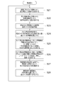
図2Aに示すように、まず、歪補正部2が、カメラ1から取得した画像1から、広角レンズによる歪を除去し、画像2を生成する(ステップS1)。
As shown in FIG. 2A, first, the distortion correction unit 2 removes distortion due to the wide-angle lens from the image 1 acquired from the camera 1, and generates an image 2 (step S1).
次に、障害物検知部3は、ミリ波レーダー11からの反射点の集合と、その時系列的な動きとに基づいて、1以上の障害物を特定し、それらの障害物の位置と進路と速度とを検知し、障害物の位置、進路、速度と自車両の位置、進路、速度とに基づいて、それらの障害物の中から自車両に接触する可能性のある障害物を、第1の障害物として抽出する(ステップS2)。
Next, the obstacle detection unit 3 identifies one or more obstacles based on the set of reflection points from the millimeter wave radar 11 and its time-series movement, and the position and path of those obstacles. Based on the position of the obstacle, the course, the speed and the position, the course, and the speed of the host vehicle, the obstacle that may come into contact with the host vehicle is selected from the obstacles. Are extracted as obstacles (step S2).
次に、衝突リスク判定部4が、第1の障害物へ接触する時間を図3に示した方法で検知すると共に、第1の障害物と自車両との距離を検知する(ステップS3)。この時、新たに検知された障害物には新しいIDを付し、前回検知された障害物には前回と同じIDを付す。
Next, the collision risk determination unit 4 detects the time of contact with the first obstacle by the method shown in FIG. 3, and also detects the distance between the first obstacle and the host vehicle (step S3). At this time, a newly detected obstacle is assigned a new ID, and the previously detected obstacle is assigned the same ID as the previous one.
次に、カメラ視点表示制御部5は、表示装置9に表示させる障害物を選択するため、視点記憶部6が記憶している障害物のIDを読込み、その障害物が画像2内に存在しているか判定する(ステップS4)。
Next, the camera viewpoint display control unit 5 reads the obstacle ID stored in the viewpoint storage unit 6 in order to select an obstacle to be displayed on the display device 9, and the obstacle exists in the image 2. (Step S4).
存在しない場合は、障害物がいなくなったものとし、検知された第1の障害物の中で接触までの時間が最も短い障害物のIDを、視点記憶部6に記憶させる(ステップS5)。一方、存在する場合は、そのまま、ステップS6に進む。
If it does not exist, it is assumed that there is no obstacle, and the ID of the obstacle with the shortest time to contact among the detected first obstacles is stored in the viewpoint storage unit 6 (step S5). On the other hand, when it exists, it progresses to step S6 as it is.
次に、カメラ視点表示制御部5が、視点記憶部6に記憶されている障害物のIDを読込み、該当する障害物が画像の横方向の中央となるように、予め設定された画素範囲を、画像2から切り出して、画像3を生成する。この時、画像の縦方向の中心については、障害物までの距離が把握できるよう障害物の位置に依らず一定とし、遠い障害物ほど、水平線に近づく様子がわかるようにする。さらに、障害物表示重畳部7が、画像3に対して、自車両101を中心とした半円のレーダーチャート31を重畳する(ステップS6)。
Next, the camera viewpoint display control unit 5 reads the obstacle ID stored in the viewpoint storage unit 6 and sets a preset pixel range so that the corresponding obstacle is in the horizontal center of the image. The image 3 is generated by cutting out from the image 2. At this time, the center in the vertical direction of the image is constant regardless of the position of the obstacle so that the distance to the obstacle can be grasped, and the farther obstacle can be seen to approach the horizon. Further, the obstacle display superimposing unit 7 superimposes the semicircular radar chart 31 centering on the own vehicle 101 on the image 3 (step S6).
その後、障害物表示重畳部7は、画像3に対して、図4Aに示すように、衝突までの時間に応じて、形状と色とを変化させるように、図4Bのテーブルで定義されたマーク34を重畳する。重畳方法は、画像3内の障害物102に対応する画素範囲37に対して、マーク34を重畳させる。さらに、障害物表示重畳部7は、画像3において、図4Aに示すように、画像3内に表示されていないその他の障害物の存在を示す左側障害物情報および右側障害物情報を、それぞれ、矢印35,36で示す。また、矢印35,36内には、障害物の数を示す数字を表示させる。これにより、図4Aに示す画像4が生成される(ステップS7)。
Thereafter, the obstacle display superimposing unit 7 changes the mark and the color defined in the table of FIG. 4B so as to change the shape and color of the image 3 according to the time until the collision, as shown in FIG. 4A. 34 is superimposed. In the superimposing method, the mark 34 is superimposed on the pixel range 37 corresponding to the obstacle 102 in the image 3. Further, as shown in FIG. 4A, the obstacle display superimposing unit 7 displays left obstacle information and right obstacle information indicating the presence of other obstacles not displayed in the image 3, respectively, as shown in FIG. 4A. Indicated by arrows 35 and 36. Further, numbers indicating the number of obstacles are displayed in the arrows 35 and 36. Thereby, the image 4 shown to FIG. 4A is produced | generated (step S7).
車載用監視カメラ装置100には、図1に示すように、操作装置8を接続することができる。操作装置8を車載用監視カメラ装置100に接続した場合の操作装置8へのドライバーの操作による動作をステップS8以降に記載する。
As shown in FIG. 1, an operation device 8 can be connected to the in-vehicle monitoring camera device 100. The operation by the driver's operation on the operating device 8 when the operating device 8 is connected to the in-vehicle monitoring camera device 100 will be described after step S8.
操作装置8は、ドライバーによって視点切替の操作入力がなされた場合に、カメラ視点表示制御部5に対して、操作入力があったことを示す信号を送信する。そのため、カメラ視点表示制御部5は、操作装置8からの当該信号の有無に基づいて、視点切替の操作入力があったかどうかを確認する(ステップS8)。操作入力があった場合、図2BのステップS9に進む。一方、操作入力が無かった場合、ステップS1の処理に戻る。
The operation device 8 transmits a signal indicating that there is an operation input to the camera viewpoint display control unit 5 when an operation input for viewpoint switching is made by the driver. For this reason, the camera viewpoint display control unit 5 confirms whether or not there has been a viewpoint switching operation input based on the presence or absence of the signal from the operation device 8 (step S8). If there is an operation input, the process proceeds to step S9 in FIG. 2B. On the other hand, if there is no operation input, the process returns to step S1.
操作入力があった場合、カメラ視点表示制御部5は、操作装置8に入力された切替順序がいずれであるかについて判断する(ステップS9)。切替順序は、例えば、「接触までの時間順」、「視点の方向順」、「障害物との距離順」の3通りとする。
When there is an operation input, the camera viewpoint display control unit 5 determines which is the switching order input to the operation device 8 (step S9). For example, there are three switching orders: “order in time until contact”, “order in viewpoint direction”, and “order in distance to an obstacle”.
ステップS9の判定で、切替順序が「接触までの時間順」である場合は、カメラ視点表示制御部5は、ステップS2で検出された障害物のうち、視点記憶部6に記憶されている障害物の次に接触までの時間が短い障害物のIDを、表示対象として視点記憶部6に記憶する。ただし、該当する障害物が無い場合には、最も接触までの時間が短い障害物のIDを、表示対象として視点記憶部6に記憶する(ステップS10)。
If it is determined in step S9 that the switching order is “time order until contact”, the camera viewpoint display control unit 5 detects the obstacle stored in the viewpoint storage unit 6 among the obstacles detected in step S2. The ID of the obstacle with the shortest time to contact next to the object is stored in the viewpoint storage unit 6 as a display target. However, if there is no corresponding obstacle, the ID of the obstacle with the shortest time to contact is stored in the viewpoint storage unit 6 as a display target (step S10).
ステップS9の判定で、切替順序が「視点の方向順」である場合は、カメラ視点表示制御部5は、ステップS2で検出された障害物であって、且つ、視点記憶部6に記憶されている障害物の右側にある障害物のうち、視点方向が一番近い障害物のIDを、表示対象として視点記憶部6に記憶させる。ただし、障害物の右側には、対象となる障害物が存在しない場合は、視点方向の一番左側にある障害物のIDを視点記憶部6に記憶させる(ステップS11)。
If it is determined in step S9 that the switching order is “viewpoint direction order”, the camera viewpoint display control unit 5 is an obstacle detected in step S2 and is stored in the viewpoint storage unit 6. Among the obstacles on the right side of the obstacle that is present, the ID of the obstacle having the closest viewpoint direction is stored in the viewpoint storage unit 6 as a display target. However, if there is no target obstacle on the right side of the obstacle, the ID of the obstacle on the leftmost side in the viewpoint direction is stored in the viewpoint storage unit 6 (step S11).
ステップS9の判定で、切替順序が「障害物との距離順」である場合は、カメラ視点表示制御部5は、ステップS2で検出された障害物のうち、視点記憶部6に記憶されている障害物の次に自車両101との距離が短い障害物のIDを、表示対象として視点記憶部6に記憶する。ただし、該当する障害物が無い場合には、最も自車両101との距離が短い障害物のIDを、表示対象として視点記憶部6に記憶する(ステップS12)。
If it is determined in step S9 that the switching order is “order of distance from an obstacle”, the camera viewpoint display control unit 5 is stored in the viewpoint storage unit 6 among the obstacles detected in step S2. The ID of the obstacle having the shortest distance from the host vehicle 101 next to the obstacle is stored in the viewpoint storage unit 6 as a display target. However, if there is no corresponding obstacle, the ID of the obstacle with the shortest distance to the host vehicle 101 is stored in the viewpoint storage unit 6 as a display target (step S12).
ステップS1からステップS12までの処理は、周期的なループ処理になっており、ステップS12まで処理が完了した後、カメラ1の画像1が入力されるタイミングまで待って、ステップS1からステップS12までの処理が再度開始される。
The process from step S1 to step S12 is a periodic loop process. After the process is completed up to step S12, the process waits until the timing at which the image 1 of the camera 1 is input, and then the process from step S1 to step S12. The process starts again.
尚、図2A及び図2Bにおいては、カメラ出力部12の動作についての記載を省略しているが、カメラ出力部12は、常に、カメラ1が出力する画像1を、表示装置10に出力して、カメラ1全体の画像がドライバーに見えるようにしている。
In FIG. 2A and FIG. 2B, description of the operation of the camera output unit 12 is omitted, but the camera output unit 12 always outputs the image 1 output by the camera 1 to the display device 10. The image of the entire camera 1 is visible to the driver.
このようなシステム構成と動作で実施することにより、自車両101の後退時に、車両周囲180°にわたる広い範囲を、大きな表示装置を用いなくとも、衝突リスクのある障害物の存在と位置の把握を、ドライバーが迅速に行うことが可能になる。
By implementing such a system configuration and operation, when the host vehicle 101 moves backward, the presence and position of an obstacle with a collision risk can be grasped over a wide range of 180 ° around the vehicle without using a large display device. , Allowing the driver to do quickly.
以上のように、実施の形態1においては、車載用監視カメラ装置100が、ミリ波レーダー11で検知した障害物のうち、自車両101に衝突する可能性のある障害物を、第1の障害物として検知する障害物検知部3と、第1の障害物と自車両101とが接触するまでの時間または第1の障害物と自車両との間の距離を検出する衝突リスク判定部4と、広角レンズにより撮影された第1の画像が入力され、第1の画像の歪を補正して第2の画像を生成する歪補正部2と、衝突リスク判定部4が検出した時間または距離のうち、最も短い時間または最も短い距離を有する第1の障害物を第2の障害物として抽出し、当該第2の障害物が横方向の中央に位置するように一定範囲の画像を第2の画像から切り出して、第3の画像を生成するカメラ視点表示制御部5と、第3の画像を表示する第1の表示装置9とを備えている。また、カメラ視点表示制御部5は、第3の画像の視野範囲または第3の画像の視野の中心方向を示す画像としてのレーダーチャート31を、第3の画像に重畳させることで、第2の障害物の方向を表示する。これにより、標準サイズの表示装置よりも大きな表示装置を必要とせずに、ドライバーが、検知された障害物までの距離および方向を迅速に把握することができる。なお、レーダーチャート31は単なる一例であり、第3の画像の視野範囲または第3の画像の視野の中心方向を示す画像であれば、いずれのものでもよい。例えば、当該画像の形状は、図4Aに示したような半円形ではなく、円形であってもよく、矩形であってもよい。また、画像の視野範囲32および視野の中心方向33の表示形態および表示方法も、例えば、視野の中心方向33を矢印で示すなど、他の表示形態及び表示方法であってもよい。
As described above, in the first embodiment, among the obstacles detected by the in-vehicle monitoring camera apparatus 100 using the millimeter wave radar 11, the obstacle that may collide with the host vehicle 101 is designated as the first obstacle. An obstacle detection unit 3 that detects the obstacle, a collision risk determination unit 4 that detects a time until the first obstacle and the host vehicle 101 come into contact with each other, or a distance between the first obstacle and the host vehicle, The first image captured by the wide-angle lens is input, the distortion correction unit 2 that corrects the distortion of the first image to generate the second image, and the time or distance detected by the collision risk determination unit 4 Among them, the first obstacle having the shortest time or the shortest distance is extracted as the second obstacle, and an image in a certain range is displayed so that the second obstacle is located in the center in the horizontal direction. A camera that cuts out from an image and generates a third image It includes a point display control unit 5, and a first display device 9 for displaying the third image. In addition, the camera viewpoint display control unit 5 superimposes the radar chart 31 as an image indicating the visual field range of the third image or the central direction of the visual field of the third image on the third image, so that the second image is displayed. Display the direction of the obstacle. Accordingly, the driver can quickly grasp the detected distance and direction to the obstacle without requiring a display device larger than the standard size display device. Note that the radar chart 31 is merely an example, and any radar chart 31 may be used as long as it is an image showing the visual field range of the third image or the central direction of the visual field of the third image. For example, the shape of the image is not a semicircular shape as shown in FIG. 4A but may be a circular shape or a rectangular shape. In addition, the display form and display method of the visual field range 32 and the central direction 33 of the visual field may be other display forms and display methods, for example, the central direction 33 of the visual field is indicated by an arrow.
また、実施の形態1においては、第3の画像内に表示されている第2の障害物を強調するための強調表示としてのマーク34を、第3の画像における第2の障害物に対して重畳する障害物表示重畳部7を備えている。これにより、ドライバーは、障害物の衝突リスクの程度を瞬時に把握することができる。
In the first embodiment, the mark 34 as an emphasis display for emphasizing the second obstacle displayed in the third image is applied to the second obstacle in the third image. An obstacle display superimposing unit 7 for superimposing is provided. As a result, the driver can instantly grasp the degree of obstacle collision risk.
また、実施の形態1においては、第3の画像内に表示する第2の障害物を、第1の障害物のうちの他の1つに切り替える切替指示が入力される操作装置8を用いるようにしてもよい。その場合には、ドライバーの切替指示に従って、第3の画像内に表示する第2の障害物を、他の1つに切り替えることができる。
In the first embodiment, the operation device 8 to which a switching instruction for switching the second obstacle displayed in the third image to another one of the first obstacles is input is used. It may be. In this case, the second obstacle displayed in the third image can be switched to another one according to the driver switching instruction.
また、実施の形態1においては、障害物表示重畳部7が、第3の画像内に表示されていない他の前記第1の障害物の存在を示す情報を、矢印35,36で示すようにしてもよい。その場合には、ドライバーが矢印35,36に指で触れることにより、画面に表示されていない他の障害物を表示することができる。
In the first embodiment, the obstacle display superimposing unit 7 indicates the information indicating the presence of the other first obstacle not displayed in the third image by the arrows 35 and 36. May be. In that case, when the driver touches the arrows 35 and 36 with a finger, other obstacles not displayed on the screen can be displayed.
実施の形態2.
図6は、この発明の実施の形態2に係る車載用監視カメラ装置100Aの構成を示すブロック図である。車載用監視カメラ装置100Aは自車両101に搭載されている。Embodiment 2. FIG.
FIG. 6 is a block diagram showing a configuration of an in-vehiclemonitoring camera device 100A according to Embodiment 2 of the present invention. The in-vehicle monitoring camera device 100A is mounted on the host vehicle 101.
図6は、この発明の実施の形態2に係る車載用監視カメラ装置100Aの構成を示すブロック図である。車載用監視カメラ装置100Aは自車両101に搭載されている。
FIG. 6 is a block diagram showing a configuration of an in-vehicle
まず、図6に示すように、車載用監視カメラ装置100Aには、実施の形態1と同様に、カメラ1が接続されている。実施の形態1と同様に、カメラ1は、図5に示すように、自車両101の後部に設けられている。カメラ1は、広角レンズを装備している。そのため、カメラ1は、図5に示す撮像範囲50のように、カメラ1を中心とする、例えば180°にわたる広い視野角の撮像範囲の画像を取得することができる。カメラ1は、自車両101の後方を撮像し、画像5を出力する。
First, as shown in FIG. 6, the camera 1 is connected to the in-vehicle monitoring camera device 100A, as in the first embodiment. Similar to the first embodiment, the camera 1 is provided at the rear of the host vehicle 101 as shown in FIG. The camera 1 is equipped with a wide angle lens. Therefore, the camera 1 can acquire an image in an imaging range with a wide viewing angle, for example, 180 ° centered on the camera 1, as in the imaging range 50 illustrated in FIG. 5. The camera 1 captures the rear of the host vehicle 101 and outputs an image 5.
車載用監視カメラ装置100Aは、表示する画像を取得する手段として、実施の形態1と同様に、歪補正部2を備える。歪補正部2は、カメラ1から画像5を受信し、実施の形態1と同様の方法で、広角レンズによる画像5の歪を取り除いて画像6を得る。
The in-vehicle monitoring camera device 100A includes a distortion correction unit 2 as the first embodiment as means for acquiring an image to be displayed. The distortion correction unit 2 receives the image 5 from the camera 1 and obtains the image 6 by removing the distortion of the image 5 caused by the wide-angle lens in the same manner as in the first embodiment.
さらに、車載用監視カメラ装置100Aは、障害物検知部63と衝突リスク判定部64とを備えている。
Furthermore, the in-vehicle monitoring camera device 100A includes an obstacle detection unit 63 and a collision risk determination unit 64.
上記の実施の形態1で示した障害物検知部3は、ミリ波レーダー11の感知情報を用いていたが、一方、実施の形態2における障害物検知部63は、歪補正部2を介してカメラ1から得られる画像6を用いる。障害物検知部63は、画像6に画像認識処理を行って、障害物の存在を検知するとともに、障害物が検知された画素座標を逆射影変換し、障害物の位置を検知する。さらに、障害物検知部63は、過去の画像処理で得られた画像6に含まれる障害物の位置の時系列的な変化をもとに、その障害物の位置、進路、速度を検知するとともに、その障害物の位置、進路、速度と、自車両101の位置、進路、速度とに基づいて、自車両101に接触する可能性のある障害物を第一の障害物として検知する。
衝突リスク判定部64は、上記実施の形態1で示した衝突リスク判定部4と同一の検出方法にて、「接触するまでの時間」および「障害物と自車両との距離」を検出する。 Theobstacle detection unit 3 shown in the first embodiment uses the sensing information of the millimeter wave radar 11. On the other hand, the obstacle detection unit 63 in the second embodiment passes through the distortion correction unit 2. An image 6 obtained from the camera 1 is used. The obstacle detection unit 63 performs image recognition processing on the image 6 to detect the presence of the obstacle, and reverse-projection transforms the pixel coordinates where the obstacle is detected to detect the position of the obstacle. Further, the obstacle detection unit 63 detects the position, course, and speed of the obstacle based on the time-series change in the position of the obstacle included in the image 6 obtained by the past image processing. Based on the position, path, and speed of the obstacle and the position, path, and speed of the host vehicle 101, an obstacle that may come into contact with the host vehicle 101 is detected as the first obstacle.
The collisionrisk determination unit 64 detects “time until contact” and “distance between the obstacle and the host vehicle” by the same detection method as the collision risk determination unit 4 described in the first embodiment.
衝突リスク判定部64は、上記実施の形態1で示した衝突リスク判定部4と同一の検出方法にて、「接触するまでの時間」および「障害物と自車両との距離」を検出する。 The
The collision
さらに、車載用監視カメラ装置100Aは、表示を行う手段として、カメラ視点表示制御部65と障害物表示重畳部66とを備える。
Furthermore, the in-vehicle monitoring camera device 100A includes a camera viewpoint display control unit 65 and an obstacle display superimposing unit 66 as means for performing display.
カメラ視点表示制御部65は、次の3つの動作(1)~(3)を行う。
The camera viewpoint display control unit 65 performs the following three operations (1) to (3).
(1)カメラ視点表示制御部65は、障害物検知部63によって検知された障害物のうち、距離が短い順に、最大4つの障害物を抽出する。
(1) The camera viewpoint display control unit 65 extracts a maximum of four obstacles in order from the shortest distance among the obstacles detected by the obstacle detection unit 63.
(2)カメラ視点表示制御部65は、抽出したそれぞれの障害物ごとに、画像6から、障害物が画像の横方向の中心に位置するように、一定の範囲を切り出して、画像7を生成する。画像7は、障害物ごとに生成されるので、画像7の個数は最大4つである。ここで、一定の範囲とは、例えば、予め設定された画素範囲である。また、画像の縦方向の中心は、実施の形態1と同様に、障害物までの距離が把握できるように、障害物の位置に依らずに一定とする。
(2) The camera viewpoint display control unit 65 generates an image 7 for each extracted obstacle by cutting out a certain range from the image 6 so that the obstacle is positioned at the center in the horizontal direction of the image. To do. Since the image 7 is generated for each obstacle, the number of the images 7 is a maximum of four. Here, the certain range is, for example, a preset pixel range. The vertical center of the image is constant regardless of the position of the obstacle so that the distance to the obstacle can be grasped, as in the first embodiment.
(3)カメラ視点表示制御部65は、画像7に対して、画像7の視野範囲または視野の中心方向を示す画像としてのレーダーチャート31を重畳する。レーダーチャート31は、上記の実施の形態1で説明したレーダーチャート31と同じであるため、ここでは、その説明を省略する。
(3) The camera viewpoint display control unit 65 superimposes the radar chart 31 as an image indicating the visual field range of the image 7 or the central direction of the visual field on the image 7. Since the radar chart 31 is the same as the radar chart 31 described in the first embodiment, the description thereof is omitted here.
障害物表示重畳部66は、画像7の障害物に対して、障害物と自車両との距離に応じて、形状と色の変化するマーク34を重畳した画像8を生成し、4つの表示装置67,68,69,70に、それぞれ、表示する。なお、マークの形状と色については、例えば、図4Bのデータテーブルで予め定義しておく。なお、画像8の例は、例えば、図4Aに示す画像4(符号30)と同じでよい。
The obstacle display superimposing unit 66 generates an image 8 in which the mark 34 whose shape and color change is superimposed on the obstacle of the image 7 according to the distance between the obstacle and the host vehicle, and generates four display devices. 67, 68, 69 and 70, respectively. Note that the shape and color of the mark are defined in advance in the data table of FIG. 4B, for example. The example of the image 8 may be the same as the image 4 (reference numeral 30) illustrated in FIG. 4A, for example.
次に、図7のフローチャートに基づいて、実施の形態2に係る車載用監視カメラ装置100Aの動作について説明する。
Next, the operation of the in-vehicle monitoring camera device 100A according to Embodiment 2 will be described based on the flowchart of FIG.
まず、歪補正部2が、カメラ1から取得した画像5から、広角レンズによる画像の歪を除去し、画像6を生成する(ステップS21)。
First, the distortion correction unit 2 removes image distortion caused by the wide-angle lens from the image 5 acquired from the camera 1, and generates an image 6 (step S21).
次に、障害物検知部63は、画像6を用いて、画像認識処理により、第1の障害物の存在、および、その位置を検知する(ステップS22)。
Next, the obstacle detection unit 63 uses the image 6 to detect the presence and position of the first obstacle by image recognition processing (step S22).
次に、検知された第1の障害物の位置と自車両101の位置とに基づいて、衝突リスク判定部64が、第1の障害物と自車両101との距離を検知する(ステップS23)。
Next, based on the detected position of the first obstacle and the position of the host vehicle 101, the collision risk determination unit 64 detects the distance between the first obstacle and the host vehicle 101 (step S23). .
次に、カメラ視点表示制御部65が、第1の障害物の中で、自車両101と接触するまでの時間、または距離が短い順に、最大4つの障害物を、第2の障害物として抽出する(ステップS24)。尚、第1の障害物が4つ以内の場合は、抽出される第2の障害物の数は、第1の障害物の数と同一になる。
Next, the camera viewpoint display control unit 65 extracts a maximum of four obstacles as second obstacles in the order of short time or distance until contact with the host vehicle 101 in the first obstacle. (Step S24). When the number of first obstacles is four or less, the number of second obstacles to be extracted is the same as the number of first obstacles.
次に、カメラ視点表示制御部65は、画像6から、これらの第2の障害物ごとに、当該第2の障害物が画像の横方向の中心となるように一定の範囲の画像を、画像7として切り出す(ステップS25)。画像7の個数は、第2の障害物の個数と同じである。また、一定の範囲とは、実施の形態1と同様に、例えば、予め設定された画素範囲とする。
Next, for each of these second obstacles, the camera viewpoint display control unit 65 displays an image in a certain range so that the second obstacle is the center in the horizontal direction of the image. 7 is cut out (step S25). The number of images 7 is the same as the number of second obstacles. Also, the fixed range is, for example, a preset pixel range as in the first embodiment.
さらに、カメラ視点表示制御部65は、各画像7に対し、切り出した画像の視野範囲または視野の中心方向を示すレーダーチャート31を重畳する(ステップS26)。
Furthermore, the camera viewpoint display control unit 65 superimposes the radar chart 31 indicating the field-of-view range or the center direction of the field of view on each image 7 (step S26).
最後に、障害物表示重畳部66が、図4Bのデータテーブルに従って、自車両101と障害物との距離に応じて、形状と色とを変えたマークを各画像7に対して重畳した画像8を生成する(ステップS27)。画像8の個数は、第2の障害物の個数と同じである。
Finally, the image 8 in which the obstacle display superimposing unit 66 superimposes a mark whose shape and color are changed on each image 7 according to the distance between the host vehicle 101 and the obstacle according to the data table of FIG. 4B. Is generated (step S27). The number of images 8 is the same as the number of second obstacles.
次に、障害物表示重畳部66が、外部の表示装置67,68,69,70に対して、各画像8を出力する(ステップS28)。
Next, the obstacle display superimposing unit 66 outputs each image 8 to the external display devices 67, 68, 69, 70 (step S28).
ステップS21からステップS28までの動作は、カメラ1からの画像5の入力を起点とした、周期的なループ処理になっており、ステップS28まで処理が完了した後、カメラ1からの画像5が入力されるタイミングまで待って、ステップS21からステップS28までの処理が再度開始される。
The operation from step S21 to step S28 is a periodic loop process starting from the input of the image 5 from the camera 1. After the process is completed up to step S28, the image 5 from the camera 1 is input. The process from step S21 to step S28 is started again after waiting for the timing.
実施の形態2においては、このようなシステム構成と動作で実施することにより、自車両101の後退時に、車両周囲180°にわたる広い範囲を、大きな表示装置を用いなくとも、複数存在する衝突リスクのある障害物の存在と位置の把握をドライバーが迅速に行うことが可能となる。
In the second embodiment, by implementing such a system configuration and operation, when the host vehicle 101 moves backward, a plurality of collision risks that exist over a wide range of 180 ° around the vehicle can be obtained without using a large display device. The driver can quickly grasp the presence and position of an obstacle.
なお、実施の形態2では、図1に示すカメラ出力部12と表示装置10とが設けられていないが、実施の形態2においても、図1に示すカメラ出力部12と表示装置10とを設けて、画像5を表示するようにしてもよい。
In the second embodiment, the camera output unit 12 and the display device 10 shown in FIG. 1 are not provided, but the camera output unit 12 and the display device 10 shown in FIG. Thus, the image 5 may be displayed.
なお、実施の形態2では、図1に示す操作装置8が設けられていないが、実施の形態2においても、図1に示す操作装置8を設けて、ドライバーが指定する切替順序に従って、障害物の切り替えが行えるようにしてもよい。
In the second embodiment, the operating device 8 shown in FIG. 1 is not provided, but in the second embodiment as well, the operating device 8 shown in FIG. 1 is provided and obstructions are made according to the switching order designated by the driver. May be switched.
以上のように、実施の形態2においては、カメラ1で検知した障害物のうち、自車両に衝突する可能性のある障害物を、第1の障害物として検知する障害物検知部63と、第1の障害物と自車両101とが接触するまでの時間または第1の障害物と自車両との間の距離を検出する衝突リスク判定部64と、広角レンズにより撮影された第1の画像が入力され、第1の画像の歪を補正して第2の画像を生成する歪補正部2と、衝突リスク判定部64が検出した時間または距離のうち、最も短い時間または最も短い距離を有する第1の障害物を第2の障害物として抽出し、当該第2の障害物が横方向の中央に位置するように一定範囲の画像を前記第2の画像から切り出して、第3の画像を生成するカメラ視点表示制御部65と、第3の画像を表示する第1の表示装置67~70とを備えている。また、カメラ視点表示制御部5は、第1の画像の撮像範囲に対する第3の画像の視野範囲または第3の画像の視野の中心方向を示す画像としてのレーダーチャート31を、第3の画像に重畳させることで、第2の障害物の方向を表示する。これにより、実施の形態1と同様の効果を得ることができる。
As described above, in the second embodiment, among the obstacles detected by the camera 1, the obstacle detection unit 63 that detects an obstacle that may collide with the host vehicle as the first obstacle, A collision risk determination unit 64 that detects a time until the first obstacle comes into contact with the host vehicle 101 or a distance between the first obstacle and the host vehicle, and a first image taken by a wide-angle lens. Is input, the distortion correction unit 2 that corrects the distortion of the first image to generate the second image, and the shortest time or the shortest distance among the time or distance detected by the collision risk determination unit 64 A first obstacle is extracted as a second obstacle, an image of a certain range is cut out from the second image so that the second obstacle is located in the center in the horizontal direction, and a third image is obtained. The camera viewpoint display control unit 65 to be generated and the third image are displayed. And a first display device 67-70 to. In addition, the camera viewpoint display control unit 5 converts the radar chart 31 as an image indicating the visual field range of the third image with respect to the imaging range of the first image or the center direction of the visual field of the third image into the third image. By superimposing, the direction of the second obstacle is displayed. Thereby, the effect similar to Embodiment 1 can be acquired.
さらに、実施の形態2においては、カメラ視点表示制御部5は、第2の障害物として、複数の第1の障害物を抽出して、各第1の障害物ごとに第3の画像を生成する。まら、表示装置として、複数の表示装置67~70が設けられ、各表示装置67~70の画面において、各第1の障害物ごとに生成された各第3の画像をそれぞれ表示させる。これにより、ドライバーは、画面を切り替えることなく、複数の障害物を表示装置で表示することができる。
Furthermore, in the second embodiment, the camera viewpoint display control unit 5 extracts a plurality of first obstacles as the second obstacle, and generates a third image for each first obstacle. To do. Further, a plurality of display devices 67 to 70 are provided as display devices, and the third images generated for the respective first obstacles are displayed on the screens of the display devices 67 to 70, respectively. Accordingly, the driver can display a plurality of obstacles on the display device without switching the screen.
1 カメラ、2 歪補正部、3,63 障害物検知部、4,64 衝突リスク判定部、5,65 カメラ視点表示制御部、6 視点記憶部、7,66 障害物表示重畳部、8 操作装置、9,10,67,68,69,70 表示装置、11 ミリ波レーダー、12 カメラ出力部、100,100A 車載用監視カメラ装置、101 自車両、102 障害物。
1 camera, 2 distortion correction unit, 3,63 obstacle detection unit, 4,64 collision risk determination unit, 5,65 camera viewpoint display control unit, 6 viewpoint storage unit, 7,66 obstacle display superimposition unit, 8 operation device 9, 10, 67, 68, 69, 70 display device, 11 millimeter wave radar, 12 camera output unit, 100, 100A onboard surveillance camera device, 101 own vehicle, 102 obstacle.
Claims (10)
- レーダーまたはカメラで検知した障害物のうち、自車両に衝突する可能性のある障害物を、第1の障害物として検知する障害物検知部と、
前記第1の障害物と前記自車両とが接触するまでの時間、または、前記第1の障害物と前記自車両との間の距離を検出する衝突リスク判定部と、
標準レンズよりも広い撮像範囲を有する広角レンズにより撮影された第1の画像が入力され、前記第1の画像の歪を補正して第2の画像を生成する歪補正部と、
前記衝突リスク判定部が検出した前記時間または前記距離のうち、最も短い時間または最も短い距離を有する前記第1の障害物を第2の障害物として抽出し、当該第2の障害物が横方向の中央に位置するように一定範囲の画像を前記第2の画像から切り出して、第3の画像を生成するカメラ視点表示制御部と、
前記第3の画像を表示する第1の表示装置と
を備え、
前記カメラ視点表示制御部は、前記第3の画像の視野範囲または視野の中心方向を示す画像を前記第3の画像に重畳させる、
車載用監視カメラ装置。 An obstacle detection unit that detects an obstacle that may collide with the host vehicle as a first obstacle among obstacles detected by a radar or a camera;
A collision risk determination unit that detects a time until the first obstacle comes into contact with the host vehicle or a distance between the first obstacle and the host vehicle;
A distortion correction unit that receives a first image captured by a wide-angle lens having an imaging range wider than that of a standard lens, corrects distortion of the first image, and generates a second image;
Of the time or the distance detected by the collision risk determination unit, the first obstacle having the shortest time or the shortest distance is extracted as a second obstacle, and the second obstacle is in the lateral direction. A camera viewpoint display control unit that cuts out an image of a certain range so as to be located in the center of the second image and generates a third image;
A first display device for displaying the third image,
The camera viewpoint display control unit superimposes an image indicating a visual field range of the third image or a central direction of the visual field on the third image;
In-vehicle surveillance camera device. - 前記第3の画像内に表示されている前記第2の障害物を強調するための強調表示を、前記第3の画像における前記第2の障害物に対して重畳する障害物表示重畳部を備えた、
請求項1に記載の車載用監視カメラ装置。 An obstacle display superimposing unit that superimposes an emphasis display for emphasizing the second obstacle displayed in the third image on the second obstacle in the third image. The
The in-vehicle surveillance camera device according to claim 1. - 前記障害物表示重畳部は、前記強調表示の色を、前記衝突リスク判定部が検出した前記時間または前記距離に応じて切り替える、
請求項2に記載の車載用監視カメラ装置。 The obstacle display superimposing unit switches the highlight color according to the time or the distance detected by the collision risk determination unit.
The in-vehicle surveillance camera device according to claim 2. - 前記障害物表示重畳部は、前記強調表示の形状を、前記衝突リスク判定部が検出した前記時間または前記距離に応じて切り替える、
請求項2に記載の車載用監視カメラ装置。 The obstacle display superimposing unit switches the shape of the highlighted display according to the time or the distance detected by the collision risk determination unit,
The in-vehicle surveillance camera device according to claim 2. - 前記障害物表示重畳部は、前記第3の画像内に表示されていない他の前記第1の障害物の存在を示す情報を、前記第3の画像に重畳する、
請求項2から4までのいずれか1項に記載の車載用監視カメラ装置。 The obstacle display superimposing unit superimposes information indicating the presence of the other first obstacle not displayed in the third image on the third image;
The in-vehicle surveillance camera device according to any one of claims 2 to 4. - 前記第3の画像内に表示する前記第2の障害物を、前記第1の障害物のうちの他の1つに切り替える切替指示が入力される操作装置
を備えた、
請求項1から5までのいずれか1項に記載の車載用監視カメラ装置。 An operating device to which a switching instruction for switching the second obstacle to be displayed in the third image to another one of the first obstacles is input;
The in-vehicle surveillance camera device according to any one of claims 1 to 5. - 前記操作装置に入力される前記切替指示による切替順序は、前記衝突リスク判定部が検出した前記時間または前記距離に基づく、
請求項6に記載の車載用監視カメラ装置。 The switching order by the switching instruction input to the operating device is based on the time or the distance detected by the collision risk determination unit.
The in-vehicle surveillance camera device according to claim 6. - 前記操作装置に入力される前記切替指示による切替順序は、前記第1の障害物が存在する方向に基づく、
請求項6に記載の車載用監視カメラ装置。 The switching order by the switching instruction input to the operating device is based on the direction in which the first obstacle exists.
The in-vehicle surveillance camera device according to claim 6. - 前記第1の画像を表示する第2の表示装置を備えた、
請求項1から8までのいずれか1項に記載の車載用監視カメラ装置。 A second display device for displaying the first image;
The in-vehicle surveillance camera device according to any one of claims 1 to 8. - 前記カメラ視点表示制御部は、前記第2の障害物として、複数の前記第1の障害物を抽出して、各前記第1の障害物ごとに前記第3の画像を生成し、
前記第1の表示装置は、複数の画面を有し、各画面において、各前記第1の障害物ごとに生成された各前記第3の画像をそれぞれ表示させる、
請求項1から9までのいずれか1項に記載の車載用監視カメラ装置。 The camera viewpoint display control unit extracts a plurality of the first obstacles as the second obstacle, and generates the third image for each of the first obstacles,
The first display device has a plurality of screens, and displays each of the third images generated for each of the first obstacles on each screen,
The vehicle-mounted surveillance camera apparatus of any one of Claim 1-9.
Priority Applications (5)
| Application Number | Priority Date | Filing Date | Title |
|---|---|---|---|
| PCT/JP2017/017826 WO2018207303A1 (en) | 2017-05-11 | 2017-05-11 | On-board monitoring camera device |
| US16/603,962 US11214248B2 (en) | 2017-05-11 | 2017-05-11 | In-vehicle monitoring camera device |
| DE112017007528.9T DE112017007528T5 (en) | 2017-05-11 | 2017-05-11 | Vehicle monitoring camera device |
| JP2019516811A JP6785953B2 (en) | 2017-05-11 | 2017-05-11 | In-vehicle surveillance camera device |
| CN201780090475.6A CN110612562B (en) | 2017-05-11 | 2017-05-11 | Vehicle-mounted monitoring camera device |
Applications Claiming Priority (1)
| Application Number | Priority Date | Filing Date | Title |
|---|---|---|---|
| PCT/JP2017/017826 WO2018207303A1 (en) | 2017-05-11 | 2017-05-11 | On-board monitoring camera device |
Publications (1)
| Publication Number | Publication Date |
|---|---|
| WO2018207303A1 true WO2018207303A1 (en) | 2018-11-15 |
Family
ID=64105305
Family Applications (1)
| Application Number | Title | Priority Date | Filing Date |
|---|---|---|---|
| PCT/JP2017/017826 WO2018207303A1 (en) | 2017-05-11 | 2017-05-11 | On-board monitoring camera device |
Country Status (5)
| Country | Link |
|---|---|
| US (1) | US11214248B2 (en) |
| JP (1) | JP6785953B2 (en) |
| CN (1) | CN110612562B (en) |
| DE (1) | DE112017007528T5 (en) |
| WO (1) | WO2018207303A1 (en) |
Cited By (2)
| Publication number | Priority date | Publication date | Assignee | Title |
|---|---|---|---|---|
| CN111506052A (en) * | 2019-01-14 | 2020-08-07 | 上海博泰悦臻网络技术服务有限公司 | Obstacle monitoring method and system, computer storage medium and vehicle-mounted terminal |
| WO2020261823A1 (en) * | 2019-06-27 | 2020-12-30 | 株式会社クボタ | Obstacle detection system, agricultural work vehicle, obstacle detection program, recording medium on which obstacle detection program is recorded, and obstacle detection method |
Families Citing this family (12)
| Publication number | Priority date | Publication date | Assignee | Title |
|---|---|---|---|---|
| KR102449834B1 (en) * | 2017-02-17 | 2022-09-29 | 스미도모쥬기가이고교 가부시키가이샤 | Perimeter monitoring system for working machines |
| DE112018007484T5 (en) * | 2018-04-16 | 2021-02-25 | Mitsubishi Electric Corporation | Obstacle detection device, automatic braking device using an obstacle detection device, obstacle detection method, and automatic braking method using an obstacle detection method |
| WO2020206380A1 (en) * | 2019-04-05 | 2020-10-08 | FLIR Belgium BVBA | Passage planning and navigation systems and methods |
| JP7308089B2 (en) * | 2019-07-18 | 2023-07-13 | 株式会社小松製作所 | WORK VEHICLE DISPLAY SYSTEM AND WORK VEHICLE DISPLAY METHOD |
| DE102019213423A1 (en) * | 2019-09-04 | 2021-03-04 | Robert Bosch Gmbh | Method and device for operating an automated vehicle |
| KR20210054107A (en) * | 2019-11-04 | 2021-05-13 | 현대자동차주식회사 | Display Apparatus and Method for Vehicle |
| US11615542B2 (en) * | 2019-11-14 | 2023-03-28 | Panasonic Avionics Corporation | Automatic perspective correction for in-flight entertainment (IFE) monitors |
| US11594144B2 (en) * | 2020-01-31 | 2023-02-28 | Honeywell International Inc. | Collision awareness using cameras mounted on a vehicle |
| US11733369B2 (en) * | 2021-02-11 | 2023-08-22 | Waymo Llc | Methods and systems for three dimensional object detection and localization |
| CN113184704A (en) * | 2021-04-28 | 2021-07-30 | 徐州重型机械有限公司 | Safety control system, method, control device and crane |
| JP2022186190A (en) * | 2021-06-04 | 2022-12-15 | トヨタ自動車株式会社 | Display device for vehicle, display system for vehicle, display method for vehicle, and program |
| KR102615479B1 (en) * | 2021-11-24 | 2023-12-19 | 현대모비스 주식회사 | Lamp and operating method of the same, vehicle |
Citations (5)
| Publication number | Priority date | Publication date | Assignee | Title |
|---|---|---|---|---|
| JP2006054662A (en) * | 2004-08-11 | 2006-02-23 | Mitsubishi Electric Corp | Drive support device |
| JP2008230476A (en) * | 2007-03-22 | 2008-10-02 | Denso Corp | Vehicle outside image taking display system and image display control device |
| JP2009023565A (en) * | 2007-07-20 | 2009-02-05 | Denso It Laboratory Inc | Drive assisting device and drive assisting method |
| JP2009067292A (en) * | 2007-09-14 | 2009-04-02 | Hitachi Ltd | In-vehicle camera system |
| JP2012227699A (en) * | 2011-04-19 | 2012-11-15 | Toyota Motor Corp | Image display device and image display method |
Family Cites Families (9)
| Publication number | Priority date | Publication date | Assignee | Title |
|---|---|---|---|---|
| JP2006178667A (en) | 2004-12-21 | 2006-07-06 | Nissan Motor Co Ltd | Video correcting apparatus and method for vehicle |
| KR100724134B1 (en) * | 2006-01-09 | 2007-06-04 | 삼성전자주식회사 | Method and apparatus for providing panoramic view with high speed image matching and mild mixed color blending |
| US8633810B2 (en) * | 2009-11-19 | 2014-01-21 | Robert Bosch Gmbh | Rear-view multi-functional camera system |
| JP5414714B2 (en) * | 2011-03-04 | 2014-02-12 | 日立オートモティブシステムズ株式会社 | Car camera and in-vehicle camera system |
| EP2723069B1 (en) * | 2011-06-16 | 2017-10-18 | Aisin Seiki Kabushiki Kaisha | Vehicle periphery monitoring device |
| JP2015022340A (en) * | 2013-07-16 | 2015-02-02 | スズキ株式会社 | Driving support device |
| US20150109444A1 (en) * | 2013-10-22 | 2015-04-23 | GM Global Technology Operations LLC | Vision-based object sensing and highlighting in vehicle image display systems |
| JP2016075818A (en) * | 2014-10-07 | 2016-05-12 | 株式会社デンソー | Information display device and information display method |
| JP6752024B2 (en) * | 2016-02-12 | 2020-09-09 | 日立オートモティブシステムズ株式会社 | Image processing device |
-
2017
- 2017-05-11 CN CN201780090475.6A patent/CN110612562B/en active Active
- 2017-05-11 JP JP2019516811A patent/JP6785953B2/en active Active
- 2017-05-11 US US16/603,962 patent/US11214248B2/en active Active
- 2017-05-11 WO PCT/JP2017/017826 patent/WO2018207303A1/en active Application Filing
- 2017-05-11 DE DE112017007528.9T patent/DE112017007528T5/en active Pending
Patent Citations (5)
| Publication number | Priority date | Publication date | Assignee | Title |
|---|---|---|---|---|
| JP2006054662A (en) * | 2004-08-11 | 2006-02-23 | Mitsubishi Electric Corp | Drive support device |
| JP2008230476A (en) * | 2007-03-22 | 2008-10-02 | Denso Corp | Vehicle outside image taking display system and image display control device |
| JP2009023565A (en) * | 2007-07-20 | 2009-02-05 | Denso It Laboratory Inc | Drive assisting device and drive assisting method |
| JP2009067292A (en) * | 2007-09-14 | 2009-04-02 | Hitachi Ltd | In-vehicle camera system |
| JP2012227699A (en) * | 2011-04-19 | 2012-11-15 | Toyota Motor Corp | Image display device and image display method |
Cited By (3)
| Publication number | Priority date | Publication date | Assignee | Title |
|---|---|---|---|---|
| CN111506052A (en) * | 2019-01-14 | 2020-08-07 | 上海博泰悦臻网络技术服务有限公司 | Obstacle monitoring method and system, computer storage medium and vehicle-mounted terminal |
| WO2020261823A1 (en) * | 2019-06-27 | 2020-12-30 | 株式会社クボタ | Obstacle detection system, agricultural work vehicle, obstacle detection program, recording medium on which obstacle detection program is recorded, and obstacle detection method |
| JP2021006011A (en) * | 2019-06-27 | 2021-01-21 | 株式会社クボタ | Obstacle detection system for farm working vehicle |
Also Published As
| Publication number | Publication date |
|---|---|
| JP6785953B2 (en) | 2020-11-18 |
| CN110612562A (en) | 2019-12-24 |
| CN110612562B (en) | 2022-02-25 |
| DE112017007528T5 (en) | 2020-01-23 |
| US20200148203A1 (en) | 2020-05-14 |
| JPWO2018207303A1 (en) | 2019-11-07 |
| US11214248B2 (en) | 2022-01-04 |
Similar Documents
| Publication | Publication Date | Title |
|---|---|---|
| WO2018207303A1 (en) | On-board monitoring camera device | |
| US8461976B2 (en) | On-vehicle device and recognition support system | |
| US8330816B2 (en) | Image processing device | |
| JP6307895B2 (en) | Vehicle periphery monitoring device | |
| JP4434224B2 (en) | In-vehicle device for driving support | |
| JP5347257B2 (en) | Vehicle periphery monitoring device and video display method | |
| JP6252316B2 (en) | Display control device for vehicle | |
| US20110228980A1 (en) | Control apparatus and vehicle surrounding monitoring apparatus | |
| JP4985250B2 (en) | Parking assistance device | |
| JP2018022234A (en) | Image processing device and environment recognition device | |
| JP6744236B2 (en) | Image display | |
| JP5691814B2 (en) | Driving assistance device | |
| JP2009231938A (en) | Surrounding monitoring device for vehicle | |
| JP2012227699A (en) | Image display device and image display method | |
| US10579884B2 (en) | Image processing device and image processing method | |
| KR20190047279A (en) | Method and apparatus for compositing a vehicle periphery images using cameras provided in vehicle | |
| JP2020091663A (en) | Display controller for vehicles | |
| TW201904282A (en) | Camera device, camera module and control method of camera device | |
| WO2017182193A1 (en) | Trailer angle detection using rear camera | |
| JP4848644B2 (en) | Obstacle recognition system | |
| JP2008059178A (en) | Operation support device and program | |
| JP2013161440A (en) | Vehicle surroundings monitoring device | |
| US20180186287A1 (en) | Image processing device and image processing method | |
| JP2016143308A (en) | Notification device, control method, program, and storage medium | |
| JP2013257151A (en) | Parallax value calculation device and parallax value calculation system including the same, moving surface area recognition system, parallax value calculation method, and program for parallax value calculation |
Legal Events
| Date | Code | Title | Description |
|---|---|---|---|
| 121 | Ep: the epo has been informed by wipo that ep was designated in this application |
Ref document number: 17908834 Country of ref document: EP Kind code of ref document: A1 |
|
| ENP | Entry into the national phase |
Ref document number: 2019516811 Country of ref document: JP Kind code of ref document: A |
|
| 122 | Ep: pct application non-entry in european phase |
Ref document number: 17908834 Country of ref document: EP Kind code of ref document: A1 |