WO2018199625A1 - Method and apparatus for csi reporting using multiple antenna panels in advanced wireless communication systems - Google Patents
Method and apparatus for csi reporting using multiple antenna panels in advanced wireless communication systems Download PDFInfo
- Publication number
- WO2018199625A1 WO2018199625A1 PCT/KR2018/004796 KR2018004796W WO2018199625A1 WO 2018199625 A1 WO2018199625 A1 WO 2018199625A1 KR 2018004796 W KR2018004796 W KR 2018004796W WO 2018199625 A1 WO2018199625 A1 WO 2018199625A1
- Authority
- WO
- WIPO (PCT)
- Prior art keywords
- codebook
- csi feedback
- mode
- phase
- panel
- Prior art date
Links
Classifications
-
- H—ELECTRICITY
- H04—ELECTRIC COMMUNICATION TECHNIQUE
- H04B—TRANSMISSION
- H04B7/00—Radio transmission systems, i.e. using radiation field
- H04B7/02—Diversity systems; Multi-antenna system, i.e. transmission or reception using multiple antennas
- H04B7/04—Diversity systems; Multi-antenna system, i.e. transmission or reception using multiple antennas using two or more spaced independent antennas
- H04B7/0413—MIMO systems
- H04B7/0417—Feedback systems
-
- H—ELECTRICITY
- H04—ELECTRIC COMMUNICATION TECHNIQUE
- H04B—TRANSMISSION
- H04B7/00—Radio transmission systems, i.e. using radiation field
- H04B7/02—Diversity systems; Multi-antenna system, i.e. transmission or reception using multiple antennas
- H04B7/04—Diversity systems; Multi-antenna system, i.e. transmission or reception using multiple antennas using two or more spaced independent antennas
- H04B7/06—Diversity systems; Multi-antenna system, i.e. transmission or reception using multiple antennas using two or more spaced independent antennas at the transmitting station
- H04B7/0613—Diversity systems; Multi-antenna system, i.e. transmission or reception using multiple antennas using two or more spaced independent antennas at the transmitting station using simultaneous transmission
- H04B7/0615—Diversity systems; Multi-antenna system, i.e. transmission or reception using multiple antennas using two or more spaced independent antennas at the transmitting station using simultaneous transmission of weighted versions of same signal
- H04B7/0619—Diversity systems; Multi-antenna system, i.e. transmission or reception using multiple antennas using two or more spaced independent antennas at the transmitting station using simultaneous transmission of weighted versions of same signal using feedback from receiving side
- H04B7/0621—Feedback content
- H04B7/0626—Channel coefficients, e.g. channel state information [CSI]
-
- H—ELECTRICITY
- H04—ELECTRIC COMMUNICATION TECHNIQUE
- H04B—TRANSMISSION
- H04B7/00—Radio transmission systems, i.e. using radiation field
- H04B7/02—Diversity systems; Multi-antenna system, i.e. transmission or reception using multiple antennas
- H04B7/04—Diversity systems; Multi-antenna system, i.e. transmission or reception using multiple antennas using two or more spaced independent antennas
- H04B7/0413—MIMO systems
- H04B7/0456—Selection of precoding matrices or codebooks, e.g. using matrices antenna weighting
- H04B7/046—Selection of precoding matrices or codebooks, e.g. using matrices antenna weighting taking physical layer constraints into account
- H04B7/0469—Selection of precoding matrices or codebooks, e.g. using matrices antenna weighting taking physical layer constraints into account taking special antenna structures, e.g. cross polarized antennas into account
-
- H—ELECTRICITY
- H04—ELECTRIC COMMUNICATION TECHNIQUE
- H04B—TRANSMISSION
- H04B7/00—Radio transmission systems, i.e. using radiation field
- H04B7/02—Diversity systems; Multi-antenna system, i.e. transmission or reception using multiple antennas
- H04B7/04—Diversity systems; Multi-antenna system, i.e. transmission or reception using multiple antennas using two or more spaced independent antennas
- H04B7/0413—MIMO systems
- H04B7/0456—Selection of precoding matrices or codebooks, e.g. using matrices antenna weighting
- H04B7/0478—Special codebook structures directed to feedback optimisation
-
- H—ELECTRICITY
- H04—ELECTRIC COMMUNICATION TECHNIQUE
- H04B—TRANSMISSION
- H04B7/00—Radio transmission systems, i.e. using radiation field
- H04B7/02—Diversity systems; Multi-antenna system, i.e. transmission or reception using multiple antennas
- H04B7/04—Diversity systems; Multi-antenna system, i.e. transmission or reception using multiple antennas using two or more spaced independent antennas
- H04B7/0413—MIMO systems
- H04B7/0456—Selection of precoding matrices or codebooks, e.g. using matrices antenna weighting
- H04B7/0482—Adaptive codebooks
-
- H—ELECTRICITY
- H04—ELECTRIC COMMUNICATION TECHNIQUE
- H04B—TRANSMISSION
- H04B7/00—Radio transmission systems, i.e. using radiation field
- H04B7/02—Diversity systems; Multi-antenna system, i.e. transmission or reception using multiple antennas
- H04B7/04—Diversity systems; Multi-antenna system, i.e. transmission or reception using multiple antennas using two or more spaced independent antennas
- H04B7/06—Diversity systems; Multi-antenna system, i.e. transmission or reception using multiple antennas using two or more spaced independent antennas at the transmitting station
- H04B7/0613—Diversity systems; Multi-antenna system, i.e. transmission or reception using multiple antennas using two or more spaced independent antennas at the transmitting station using simultaneous transmission
- H04B7/0615—Diversity systems; Multi-antenna system, i.e. transmission or reception using multiple antennas using two or more spaced independent antennas at the transmitting station using simultaneous transmission of weighted versions of same signal
- H04B7/0617—Diversity systems; Multi-antenna system, i.e. transmission or reception using multiple antennas using two or more spaced independent antennas at the transmitting station using simultaneous transmission of weighted versions of same signal for beam forming
-
- H—ELECTRICITY
- H04—ELECTRIC COMMUNICATION TECHNIQUE
- H04B—TRANSMISSION
- H04B7/00—Radio transmission systems, i.e. using radiation field
- H04B7/02—Diversity systems; Multi-antenna system, i.e. transmission or reception using multiple antennas
- H04B7/04—Diversity systems; Multi-antenna system, i.e. transmission or reception using multiple antennas using two or more spaced independent antennas
- H04B7/06—Diversity systems; Multi-antenna system, i.e. transmission or reception using multiple antennas using two or more spaced independent antennas at the transmitting station
- H04B7/0613—Diversity systems; Multi-antenna system, i.e. transmission or reception using multiple antennas using two or more spaced independent antennas at the transmitting station using simultaneous transmission
- H04B7/0615—Diversity systems; Multi-antenna system, i.e. transmission or reception using multiple antennas using two or more spaced independent antennas at the transmitting station using simultaneous transmission of weighted versions of same signal
- H04B7/0619—Diversity systems; Multi-antenna system, i.e. transmission or reception using multiple antennas using two or more spaced independent antennas at the transmitting station using simultaneous transmission of weighted versions of same signal using feedback from receiving side
- H04B7/0621—Feedback content
- H04B7/063—Parameters other than those covered in groups H04B7/0623 - H04B7/0634, e.g. channel matrix rank or transmit mode selection
-
- H—ELECTRICITY
- H04—ELECTRIC COMMUNICATION TECHNIQUE
- H04B—TRANSMISSION
- H04B7/00—Radio transmission systems, i.e. using radiation field
- H04B7/02—Diversity systems; Multi-antenna system, i.e. transmission or reception using multiple antennas
- H04B7/04—Diversity systems; Multi-antenna system, i.e. transmission or reception using multiple antennas using two or more spaced independent antennas
- H04B7/06—Diversity systems; Multi-antenna system, i.e. transmission or reception using multiple antennas using two or more spaced independent antennas at the transmitting station
- H04B7/0613—Diversity systems; Multi-antenna system, i.e. transmission or reception using multiple antennas using two or more spaced independent antennas at the transmitting station using simultaneous transmission
- H04B7/0615—Diversity systems; Multi-antenna system, i.e. transmission or reception using multiple antennas using two or more spaced independent antennas at the transmitting station using simultaneous transmission of weighted versions of same signal
- H04B7/0619—Diversity systems; Multi-antenna system, i.e. transmission or reception using multiple antennas using two or more spaced independent antennas at the transmitting station using simultaneous transmission of weighted versions of same signal using feedback from receiving side
- H04B7/0636—Feedback format
- H04B7/0639—Using selective indices, e.g. of a codebook, e.g. pre-distortion matrix index [PMI] or for beam selection
-
- H—ELECTRICITY
- H04—ELECTRIC COMMUNICATION TECHNIQUE
- H04B—TRANSMISSION
- H04B7/00—Radio transmission systems, i.e. using radiation field
- H04B7/02—Diversity systems; Multi-antenna system, i.e. transmission or reception using multiple antennas
- H04B7/04—Diversity systems; Multi-antenna system, i.e. transmission or reception using multiple antennas using two or more spaced independent antennas
- H04B7/06—Diversity systems; Multi-antenna system, i.e. transmission or reception using multiple antennas using two or more spaced independent antennas at the transmitting station
- H04B7/0686—Hybrid systems, i.e. switching and simultaneous transmission
- H04B7/0695—Hybrid systems, i.e. switching and simultaneous transmission using beam selection
Definitions
- the present disclosure relates generally to channel state information (CSI) reporting schemes for multiple antenna panels in advanced wireless communication systems.
- CSI channel state information
- the 5G or pre ⁇ 5G communicat ion system is also cal led a 'Beyond 4G Network' or a 'Post LTE System' .
- the 5G communication system is considered to be implemented in higher frequency (mmWave) bands, e.g., 60GHz bands, so as to accomplish higher data rates.
- the beamforming, massive multiple-input multiple-output (MIM0), Full Dimensional MIM0 (FD-MIM0) , array antenna, an analog beam forming, large scale antenna techniques are discussed in 5G communication systems.
- MIM0 massive multiple-input multiple-output
- FD-MIM0 Full Dimensional MIM0
- array antenna an analog beam forming, large scale antenna techniques.
- system network improvement is under way based on advanced small cells, cloud Radio Access Networks (RANs), ultra-dense networks, device-to-device (D2D) communication, wireless backhaul , moving network, cooperative communication, Coordinated Multi-Points (CoMP), reception-end interference cancellation and the like.
- RANs cloud Radio Access Networks
- D2D device-to-device
- wireless backhaul moving network
- cooperative communication Coordinated Multi-Points (CoMP), reception-end interference cancellation and the like.
- CoMP Coordinated Multi-Points
- FQAM Hybrid FSK and QAM Modulation
- SWSC sliding window superposition coding
- ACM advanced coding modulation
- FBMC filter bank multi carrier
- NOMA non-orthogonal multiple access
- SCMA sparse code multiple access
- IoT Information Technology
- a sensor network As technology elements, such as “sensing technology” , “wired/wireless communication and network infrastructure” , “service interface technology” , and “Security technology” have been demanded for IoT implementation, a sensor network, a Machine-to-Machine (M2M) communication, Machine Type Communication (MTC) , and so forth have been recently researched.
- M2M Machine-to-Machine
- MTC Machine Type Communication
- IoT environment may provide intelligent Internet technology services that create a new value to human life by collecting and analyzing data generated among connected things. IoT may be applied to a variety of fields including smart home, smart building, smart city, smart car or connected cars, smart grid, health care, smart appliances and advanced medical services through convergence and combination between existing Information Technology (IT) and various industrial applications.
- IT Information Technology
- the UE may report (e.g., feedback) information about channel measurement, e.g. , CSI , to the eNB.
- CSI channel measurement
- the eNB is able to select appropriate communication parameters to efficiently and effectively perform wireless data communication with the UE.
- Embodiments of the present disclosure provide methods and apparatuses for CSI reporting in an advanced wireless communication system.
- a user equipment (UE) for CSI feedback is provided.
- the UE comprises a transceiver configured to receive, from a base station (BS), configuration information for the CSI feedback, the configuration information indicating a number of antenna panels (N g ) at the BS and a codebook mode, wherein N g > 1 and each of the antenna panels comprises antenna ports with a first polarization (P ) and antenna ports with a second polarization (P2).
- the UE further comprises a processor operably connected to the transceiver.
- the processor is configured to identify the number of antenna panels (N g ) at the BS, identify a codebook for the CSI feedback based on the codebook mode configured between a first codebook mode and a second codebook mode, and generate the CSI feedback using the identified codebook.
- the transceiver is further configured to transmit the generated CSI feedback to the BS.
- the codebook corresponding to the first codebook mode is used to generate the CSI feedback based on a wideband inter-paftel co-phase that is common for a plurality of subbands configured for the CSI feedback.
- the codebook corresponding to the second codebook mode is used to generate the CSI feedback based on at least one of (i) a wideband inter-panel co-phase that is common for the plurality of subbands, and (ii) a subband inter-panel co-phase for each of the plurality of subbands.
- a BS comprises a processor configured to generate configuration information for CSI feedback, the configuration information indicating a number of antenna panels (N g ) at the BS and a codebook mode, the codebook mode indicating a codebook for the CSI feedback and configured between a first codebook mode and a second codebook mode, wherein N g > 1 and each of the antenna panels comprises antenna ports with a first polarization (Pi) and antenna ports with a second polarization (P2).
- the BS further comprises a transceiver operably connected to the processor. The transceiver is configured to transmit, to a UE, the configuration information and receive the CSI feedback from the UE generated in accordance with the indicated codebook.
- the codebook corresponding to the first codebook mode is used to generate the CSI feedback based on a wideband inter-panel co-phase that is common for a plurality of subbands configured for the CSI feedback.
- the codebook corresponding to the second codebook mode is used to generate the CSI feedback based on at least one of (i) a wideband inter-panel co-phase that is common for the plurality of subbands, and (ii) a subband inter-panel co-phase for each of the plurality of subbands.
- a method for CSI feedback by a UE is provided.
- the method comprises receiving, from a BS, configuration information for the CSI feedback, the configuration information i ndi cat ing a number of antenna panels (N g ) at the BS and a codebook mode , wherein N g > 1 and each of the antenna panels comprises antenna ports with a first polarization (Pi) and antenna ports with a second polarization (P 2 ), identifying the number of antenna panels (N g ) at the BS, identifying a codebook for the CSI feedback based on the codebook mode configured between a first codebook mode and a second codebook mode, generating the CSI feedback using the ident i f ied codebook, and transmi tt ing the generated CSI feedback to the BS.
- the codebook corresponding to the first codebook mode is used to generate the CSI feedback based on a wideband inter-panel co-phase that is common for a plurality of subbands configured for the CSI feedback.
- the codebook corresponding to the second codebook mode is used to generate the CSI feedback based on at least one of (i) a wideband inter-panel co-phase that is common for the plurality of subbands, and (ii) a subband inter-panel co-phase for each of the plurality of subbands .
- CSI reporting procedures can be efficiently performed and thereby signaling overhead can be reduced and efficiency of data rate can be achieved in advanced wireless communication system.
- FIGURE 1 illustrates an example wireless network according to embodiments of the present disclosure
- FIGURE 2 illustrates an example eNB according to embodiments of the present disclosure
- FIGURE 3 illustrates an example UE according to embodiments of the present disclosure
- FIGURE 4A illustrates a high-level diagram of an orthogonal frequency division multiple access transmit path according to embodiments of the present disclosure
- FIGURE 4B illustrates a high-level diagram of an orthogonal frequency division multiple access receive path according to embodiments of the present disclosure
- FIGURE 5 illustrates a transmitter block diagram for a PDSCH in a subframe according to embodiments of the present disclosure
- FIGURE 6 i 1 lustrates a receiver block diagram for a PDSCH in a subframe according to embodiments of the present disclosure
- FIGURE 7 illustrates a transmitter block diagram for a PUSCH in a subframe according to embodiments of the present disclosure
- FIGURE 8 i 1 lustrates a receiver block diagram for a PUSCH in a subframe according to embodiments of the present disclosure
- FIGURE 9 illustrates an example multiplexing of two slices according to embodiments of the present disclosure.
- FIGURE 10 illustrates an example antenna blocks according to embodiments of the present disclosure
- FIGURE 11 illustrates an example network configuration according to embodiments of the present disclosure
- FIGURE 12 i 1 lustrates an example mult iple antenna panels according to embodiments of the present disclosure
- FIGURE 13 i 1 lustrates an example mult iple antenna panels wi th 2 ports per panel according to embodiments of the present disclosure.
- FIGURE 14 illustrates a flowchart of a method for CSI feedback according to embodiments of the present disclosure.
- Couple and its derivatives refer to any direct or indirect communication between two or more elements, whether or not those elements are in physical contact with one another.
- the term “or” is inclusive, meaning and/or .
- controller means any device, system or part thereof that controls at least one operation. Such a controller may be implemented in hardware or a combination of hardware and software and/or firmware. The functionality associated with any particular controller may be centralized or distributed, whether locally or remotely.
- phrases "at least one of,” when used with a list of items, means that different combinations of one or more of the listed items may be used, and only one item in the list may be needed.
- “at least one of - A, B, and C” includes any of the following combinations: A, B, C, A and B, A and C, B and C, and A and B and C.
- various functions described below can be implemented or supported by one or more computer programs, each of which is formed from computer readable program code and embodied in a computer readable medium.
- application and “program” refer to one or more computer programs, software components, sets of instructions, procedures, functions, objects, classes, instances, related data, or a portion thereof adapted for implementation in a suitable computer readable program code.
- computer readable program code includes any type of computer code, including source code, object code, and executable code.
- computer readable medium includes any type of medium capable of being accessed by a computer, such as read only memory (ROM), random access memory (RAM) , a hard disk drive, a compact disc (CD) , a digital video disc (DVD), or any other type of memory.
- ROM read only memory
- RAM random access memory
- CD compact disc
- DVD digital video disc
- a "non-transitory” computer readable medium excludes wired, wireless, optical, or other communication links that transport transitory electrical or other signals.
- a non-transitory computer readable medium includes media where data can be permanent ly stored and media where data can be stored and later overwritten, such as a rewritable optical disc or an erasable memory device.
- FIGURES 1 through FIGURE 14, discussed below, and the various embodiments used to descr ibe the principles of the present disclosure in this patent document are by way of illustration only and should not be construed in any way to 1 imit the scope of the disclosure. Those ski 1 led in the art wi 11 understand that the principles of the present disclosure may be implemented in any suitably arranged system or device.
- RRC Radio Resource Control
- both FDD and TDD are considered as the duplex method for both DL and UL signaling.
- orthogonal frequency division multiplexing OFDM
- orthogonal frequency division multiple access 0FDMA
- this disclosure can be extended to other OFDM-based transmission waveforms or multiple access schemes such as filtered OFDM (F-OFDM).
- F-OFDM filtered OFDM
- the 5G or pre-5G communication system is also called a "beyond 4G network" or a "post LTE system.”
- the 5G communication system is considered to be implemented in higher frequency (mmWave) bands, e.g. , 60GHz bands, so as to accompl ish higher data rates.
- mmWave e.g. , 60GHz bands
- MIM0 massive multiple-input multiple-output
- FD-MIM0 full dimensional MIM0
- array antenna an analog beam forming, large scale antenna techniques and the like are discussed in 5G communication systems.
- FQAM frequency shift keying and quadrature amplitude modulation
- SWSC sliding window superposition coding
- AMC adaptive modulation and coding
- FBMC filter bank multi carrier
- NOMA non-orthogonal multiple access
- SCMA sparse code multiple access
- FIGURES 1-4B describe various embodiments implemented in wireless communications systems and with the use of orthogonal frequency division multiplexing (OFDM) or orthogonal frequency division multiple access (0FDMA) communication techniques.
- OFDM orthogonal frequency division multiplexing
- FDMA orthogonal frequency division multiple access
- FIGURE 1 illustrates an example wireless network according to embodiments of the present disclosure.
- the embodiment of the wireless network shown in FIGURE 1 is for illustration only. Other embodiments of the wireless network 100 could be used without departing from the scope of this disclosure.
- the wireless network includes an eNB 101, an eNB
- the eNB 101 communicates with the eNB 102 and the eNB 103.
- the eNB 101 also communicates with at least one network 130, such as the Internet, a proprietary Internet Protocol (IP) network, or other data network.
- IP Internet Protocol
- the eNB 102 provides wireless broadband access to the network 130 for a first plurality of user equipments (UEs) within a coverage area 120 of the eNB 102.
- the first plural ity of UEs includes a UE 111, which may be located in a smal 1 business (SB); a UE 112, which may be located in an enterprise (E); a UE 113, which may be located in a WiFi hotspot (HS); a UE 114, which may be located in a first residence (R), ' a UE 115, which may be located in a second residence (R) ; and a UE 116, which may be a mobile device (M), such as a cell phone, a wireless laptop, a wireless PDA, or the like.
- M mobile device
- the eNB 103 provides wireless broadband access to the network 130 for a second plurality of UEs within a coverage area 125 of the eNB 103.
- the second plurality of UEs includes the UE 115 and the UE 116.
- one or more of the eNBs 101-103 may communicate with each other and with the UEs 111-116 using 5G, LTE, LTE-A, WiMAX, WiFi , or other wireless communication techniques.
- the term “base station” or “BS” can refer to any component (or col lection of components) configured to provide wireless access to a network, such as transmit point (TP), transmit-receive point (TRP), an enhanced base station (eNodeB or eNB), a 5G base station (gNB) , a macrocell, a femtocell, a WiFi access point (AP) , or other wirelessly enabled devices.
- Base stations may provide wireless access in accordance with one or more wireless communication protocols, e.g., 5G 3GPP new radio interface/access (NR), long term evolution (LTE), LTE advanced (LTE-A), high speed packet access (HSPA), Wi-Fi 802.
- 5G 3GPP new radio interface/access NR
- LTE long term evolution
- LTE-A LTE advanced
- HSPA high speed packet access
- the terms “BS” and “TRP” are used interchangeably in this patent document to refer to network infrastructure components that provide wireless access to remote terminals.
- the term “user equipment” or “UE” can refer to any component such as “mobile station,” “subscriber station,” “remote terminal,” “wireless terminal,” “receive point,” or “user device.”
- the terms “user equipment” and “UE” are used in this patent document to refer to remote wireless equipment that wirelessly accesses a BS, whether the UE is a mobile device (such as a mobile telephone or smart hone) or is normally considered a stationary device (such as a desktop computer or vending machine).
- Dotted lines show the approximate extents of the coverage areas 120 and 125, which are shown as approximately circular for the purposes of illustration and explanation only. It should be clearly understood that the coverage areas associated with eNBs, such as the coverage areas 120 and 125, may have other shapes, including irregular shapes, depending upon the configuration of the eNBs and variations in the radio environment associated with natural and man-made obstructions.
- one or more of the UEs 111-116 include circuitry, programing, or a combination thereof, for efficient CSI reporting in an advanced wireless communication system.
- one or more of the eNBs 101-103 includes circuitry, programing, or a combinat ion thereof, for receiving efficient CSI reporting in an advanced wireless communication system.
- FIGURE 1 illustrates one example of a wireless network
- the wireless network could include any number of eNBs and any number of UEs in any suitable arrangement .
- the eNB 101 could communicate directly with any number of UEs and provide those UEs with wireless broadband access to the network 130.
- each eNB 102-103 could communicate direct ly wi th the network 130 and provide UEs with direct wireless broadband access to the network 130.
- the eNBs 101, 102, and/or 103 could provide access to other or additional external networks, such as external telephone networks or other types of data networks.
- FIGURE 2 illustrates an example eNB 102 according to embodiments of the present disclosure.
- the embodiment of the eNB 102 illustrated in FIGURE 2 is for illustration only, and the eNBs 101 and 103 of FIGURE 1 could have the same or similar configuration.
- eNBs come in a wide variety of configurations, and FIGURE 2 does not limit the scope of this disclosure to any particular implementation of an eNB.
- the eNB 102 includes mult iple antennas 205a-205n, multiple RF transceivers 210a-210n, transmit (TX) processing circuitry 215, and receive (RX) processing circuitry 220.
- the eNB 102 also includes a controller/processor 225, a memory 230, and a backhaul or network interface 235.
- the RF transceivers 210a ⁇ 210n receive, from the antennas 205a-205n, incoming RF signals, such as signals transmitted by UEs in the network 100.
- the RF transceivers 210a-210n down-convert the incoming RF signals to generate IF or baseband signals.
- the IF or baseband signals are sent to the RX processing circuitry 220, which generates processed baseband signals by filtering, decoding, and/or digitizing the baseband or IF signals.
- the RX processing circuitry 220 transmits the processed baseband signals to the controller/processor 225 for further processing.
- the TX processing circuitry 215 receives analog or digital data (such as voice data, web data, e-mail, or interactive video game data) from the controller/processor 225.
- the TX processing circuitry 215 encodes, multiplexes, and/or digitizes the outgoing baseband data to generate processed baseband or IF signals.
- the RF transceivers 210a-210n receive the outgoing processed baseband or IF signals from the TX processing circuitry 215 and up-converts the baseband or IF signals to RF signals that are transmitted via the antennas 205a ⁇ 205n.
- the controller/processor 225 can include one or more processors or other processing devices that control the overall operation of the eNB 102.
- the controller/processor 225 could control the reception of forward channel signals and the transmission of reverse channel signals by the RF transceivers 210a-210n, the RX processing circuitry 220, and the TX processing circuitry 215 in accordance with well-known principles.
- the controller/processor 225 could support additional functions as well, such as more advanced wireless communication functions.
- F° r instance the controller/processor 225 could support beam forming or directional routing operations in which outgoing signals from multiple antennas 205a ⁇ 205n are weighted differently to effectively steer the outgoing signals i a desired direction. Any of a wide variety of other functions could be supported in the eNB 102 by the controller/processor 225.
- the control ler/processor 225 is also capable of execut ing programs and other processes resident in the memory 230, such as an OS.
- the control ler/processor 225 can move data into or out of the memory 230 as required by an executing process.
- the control ler/processor 225 is also coupled to the backhaul or network interface 235.
- the backhaul or network interface 235 allows the eNB 102 to communicate with other devices or systems over a backhaul connection or over a network.
- the interface 235 could support communications over any suitable wired or wireless connect ion(s) .
- the interface 235 could allow the eNB 102 to communicate with other eNBs over a wired or wireless backhaul connection.
- the interface 235 could allow the eNB 102 to communicate over a wired or wireless local area network or over a wired or wireless connect ion to a larger network (such as the Internet).
- the interface 235 includes any suitable structure supporting communications over a wired or wireless connection, such as an Ethernet or RF transceiver.
- the memory 230 is coupled to the controller/processor 225. Part of the memory 230 could include a RAM, and another part of the memory 230 could include a Flash memory or other ROM.
- FIGURE 2 illustrates one example of eNB 102
- the eNB 102 could include any number of each component shown in FIGURE 2.
- an access point could include a number of interfaces 235, and the controller/processor 225 could support routing functions to route data between different network addresses.
- the eNB 102 could include multiple instances of each (such as one per RF transceiver).
- various components in FIGURE 2 could be combined, further subdivided, or omitted and additional components could be added according to particular needs.
- FIGURE 3 illustrates an example UE 116 according to embodiments of the present disclosure.
- the embodiment of the UE 116 illustrated in FIGURE 3 is for illustration only, and the UEs 111-115 of FIGURE 1 could have the same or similar configuration.
- UEs come in a wide variety of configurations, and FIGURE 3 does not limit the scope of this disclosure to any particular implementation of a UE.
- the UE 116 includes an antenna 305, a radio frequency (RF) transceiver 310, TX processing circuitry 315, amicrophone 320, and receive (RX) processing circuitry 325.
- the UE 116 also includes a speaker 330, a processor 340, an input/output (1/0) interface (IF) 345, a touchscreen 350, a display 355, and a memory 360.
- the memory 360 includes an operating system (OS) 361 and one or more applications 362.
- the RF transceiver 310 receives, from the antenna 305, an incoming RF signal transmitted by an eNB of the network 100.
- the RF transceiver 310 down-converts the incoming RF signal to generate an intermediate frequency (IF) ' or baseband signal .
- the IF or baseband signal is sent to the RX processing circuitry 325, which generates a processed baseband signal by filtering, decoding, and/or digitizing the baseband or IF signal.
- the RX processing circuitry 325 transmits the processed baseband signal to the speaker 330 (such as for voice data) or to the processor 340 for further processing (such as for web browsing data).
- the TX processing circuitry 315 receives analog or digital voice data from the microphone 320 or other outgoing baseband data (such as web data, e-mai 1 , or interact ive video game data) from the processor 340.
- the TX processing circuitry 315 encodes, multiplexes, and/or digitizes the outgoing baseband data to generate a processed baseband or IF signal.
- the RF transceiver 310 receives the outgoing processed baseband or IF signal from the TX processing circui try 315 and up-converts the baseband or IF signal to an RF signal that is transmitted via the antenna 305.
- the processor 340 can include one or more processors or other processing devices and execute the OS 361 stored in the memory 360 in order to control the overall operation of the UE 116.
- the processor 340 could control the reception of forward channel signals and the transmission of reverse channel signals by the RF transceiver 310, the RX processing circuitry 325, and the TX processing circuitry 315 in accordance with wel 1 -known principles.
- the processor 340 includes at least one microprocessor or microcontroller.
- the processor 340 is also capable of executing other processes and programs resident in the memory 360, such as processes for CSI reporting on PUCCH.
- the processor 340 can move data into or out of the memory 360 as required by an execut ing process.
- the processor 340 is configured to execute the applications 362 based on the OS 361 or in response to signals received from eNBs or an operator.
- the processor 340 is also coupled to the 1/0 interface 345, which provides the UE 116 with the ability to connect to other devices, such as laptop computers and handheld computers .
- the 1/0 interface 345 is the communicat ion path between these accessories and the processor 340.
- the processor 340 is also coupled to the touchscreen 350 and the display
- the operator of the UE 116 can use the touchscreen 350 to enter data into the UE 116.
- the display 355 may be a 1 i quid crystal display, 1 ight emi tt ing diode dis lay, or other display capable of rendering text and/or at least limited graphics, such as from web sites.
- the memory 360 is coupled to the processor 340. Part of the memory 360 could include a random access memory (RAM), and another part of the memory 360 could include a Flash memory or other read-only memory (ROM).
- FIGURE 3 illustrates one example of UE 116
- various changes may be made to FIGURE 3.
- various components in FIGURE 3 could be combined, further subdivided, or omitted and additional components could be added according to particular needs.
- the processor 340 could be divided into multiple processors, such as one or more central processing units (CPUs) and one or more graphics processing units (GPUs).
- FIGURE 3 illustrates the UE 116 configured as a mobile telephone or smartphone, UEs could be configured to operate as other types of mobile or stationary devices.
- FIGURE 4A is a high-level diagram of transmit path circuitry.
- the transmit path circuitry may be used for an orthogonal frequency division mult iple access (OFDMA) communication.
- FIGURE 4B is a high-level diagram of receive path circui try.
- the receive path circuitry may be used for an orthogonal frequency division mult iple access (OFDMA) communication.
- the transmit path circuitry may be implemented in a base station (eNB) 102 or a relay station, and the receive path circuitry may be implemented in a user equipment (e.g. User equipment 116 of FIGURE 1).
- eNB base station
- the receive path circuitry may be implemented in a user equipment (e.g. User equipment 116 of FIGURE 1).
- the receive path circuitry 450 may be implemented in a base stat ion (e.g. eNB 102 of FIGURE 1) or a relay station, and the transmit path circuitry may be implemented in a user equipment (e.g. user equipment 116 of FIGURE 1).
- a base stat ion e.g. eNB 102 of FIGURE 1
- the transmit path circuitry may be implemented in a user equipment (e.g. user equipment 116 of FIGURE 1).
- Transmit path circuitry comprises channel coding and modulat ion block
- Receive path circuitry 450 comprises down-converter (DC) 455, remove cyclic prefix block 460, serial-to-parallel (S-to-P) block 465, Size N Fast Fourier Transform (FFT) block 470, parallel-to-serial (P-to-S) block 475, and channel decoding and demodulation block 480.
- DC down-converter
- FFT Fast Fourier Transform
- FIGURES 4A 400 and 4B 450 may be implemented in software, while other components may be implemented by configurable hardware or a mixture of software and configurable hardware.
- the FFT blocks and the IFFT blocks described in this disclosure document may be implemented as configurable software algorithms, where the value of Size N may be modified according to the implementation.
- the value of the N variable may be any integer number (i.e., 1, 4, 3, 4, etc.), while for FFT and IFFT functions, the value of the N variable may be any integer number that is a power of two (i.e., 1, 2, 4, 8, 16, etc.).
- Serial-to-parallel block 410 converts (i.e., de-multiplexes) the serial modulated symbols to paral lei data to produce N paral lei symbol streams where N is the IFFT/FFT size used in BS 102 and UE 116. Size N IFFT block 415 then performs an IFFT operation on the N parallel symbol streams to produce time-domain output signals.
- coding e.g., LDPC coding
- modulates e.g., quadrature phase shift keying (QPSK) or quadrature amplitude modulation (QAM)
- QPSK quadrature phase shift keying
- QAM quadrature amplitude modulation
- Parallel-to-serial block 420 converts (i.e., multiplexes) the parallel time-domain output symbols from Size N IFFT block 415 to produce a serial time-domain signal.
- Add cyclic prefix block 425 then inserts a cyclic prefix to the time-domain signal.
- up-converter 430 modulates (i.e., up-converts) the output of add cyclic prefix block 425 to RF frequency for transmission via a wireless channel.
- the signal may also be filtered at baseband before conversion to RF frequency.
- the transmitted RF signal arrives at UE 116 after passing through the wireless channel, and reverse operations to those at eNB 102 are performed.
- Down-converter 455 down-converts the received signal to baseband frequency
- remove cyclic prefix block 460 removes the cyclic prefix to produce the serial t ime-domain baseband signal .
- Ser ial-to-paral lei block 465 converts the time-domain baseband signal to parallel time-domain signals.
- Size N FFT block 470 then performs an FFT algorithm to produce N parallel frequency-domain signals.
- Parallel-to-serial block 475 converts the parallel frequency-domain signals to a sequence of modulated data symbols.
- Channel decoding and demodulation block 480 demodulates and then decodes the modulated symbols to recover the original input data stream.
- Each of eNBs 101-103 may implement a transmit path that is analogous to transmitting in the downlink to user equipment 111-116 and may implement a receive path that is analogous to receiving in the uplink from user equipment 111-116.
- each one of user equipment 111-116 may implement a transmit path corresponding to the architecture for transmitting in the uplink to eNBs 101-103 and may implement a receive path corresponding to the architecture for receiving in the downlink from eNBs 101-103.
- enhanced mobile broadband eMBB
- ultra reliable and low latency URLL
- massive machine type communication mMTC is determined that a number of devices can be as many as 100,000 to 1 million per km2, but the reliability/throughput/latency requirement could be less stringent. This scenario may also involve power efficiency requirement as well, in that the battery consumption may be minimized as possible.
- a communication system includes a downlink (DL) that conveys signals from transmission points such as base stations (BSs) or NodeBs to user equipments (UEs) and an Uplink (UL) that conveys signals from UEs to reception points such as NodeBs.
- DL downlink
- UE user equipment
- UL Uplink
- a IE also commonly referred to as a terminal or a mobile station, may be fixed or mobile and may be a cellular phone, a personal computer device, or an automated device.
- An eNodeB which is generally a fixed station, may also be referred to as an access point or other equivalent terminology. For LTE systems, a NodeB is often referred as an eNodeB.
- DL signals can include data signals conveying information content, control signals conveying DL control informat ion (DCI) , and reference signals (RS) that are also known as pi lot signals.
- DCI DL control informat ion
- RS reference signals
- An eNodeB transmits data information through a physical DL shared channel (PDSCH).
- An eNodeB transmits DCI through a physical DL control channel (PDCCH) or an Enhanced PDCCH (EPDCCH).
- PDSCH physical DL shared channel
- EPCCH Enhanced PDCCH
- An eNodeB transmits acknowledgement information in response to data transport block (TB) transmission from a UE in a physical hybrid ARQ indicator channel (PHICH).
- An eNodeB transmits one or more of multiple types of RS including a UE-common RS (CRS) , a channel state information RS (CSI-RS) , or a demodulation RS (DMRS).
- CRS is transmitted over a DL system bandwidth (BW) and can be used by UEs to obtain a channel estimate to demodulate data or control information or to perform measurements.
- BW DL system bandwidth
- an eNodeB may transmit a CSI-RS with a smaller density in the time and/or frequency domain than a CRS.
- DMRS can be transmitted only in the BW of a respective PDSCH or EPDCCH and a UE can use the DMRS to demodulate data or control information inaPDSCHor anEPDCCH, respectively.
- a transmission time interval for DL channels is referred to as a subframe and can have, for example, duration of 1 millisecond.
- DL signals also include transmission of a logical channel that carries system control information.
- ABCCH is mapped to either a transport channel referred to as a broadcast channel (BCH) when the DL signals convey a master information block (MIB) or to a DL shared channel (DL-SCH) when the DL signals convey a System Information Block (SIB) .
- MIB master information block
- DL-SCH DL shared channel
- SIB System Information Block
- Most system information is included in different SIBs that are transmitted using DL-SCH.
- a presence of system information on a DL-SCH in a subframe can be indicated by a transmission of a corresponding PDCCH conveying a codeword with a cyclic redundancy check (CRC) scrambled with system information RNTI (SI-RNTI).
- SI-RNTI system information RNTI
- SIB— 1 scheduling information for the first SIB (SIB— 1) can be provided by the MIB.
- DL resource allocation is performed in a unit of subframe and a group of physical resource blocks (PRBs).
- a transmission BW includes frequency resource units referred to as resource blocks (RBs).
- Each RB includes NTM sub-carriers, or resource elements (REs), such as 12 REs.
- a unit of one RB over one subframe is referred to as a PRB.
- a UE can be allocated M PDSCH RBs for a total of
- UL signals can include data signals conveying data information, control signals conveying UL control information (UCI), and UL RS.
- UL RS includes DMRS and Sounding RS (SRS) .
- a UE transmits DMRS only in a BW of a respective PUSCH or PUCCH.
- An eNodeB can use a DMRS to demodulate data signals or UCI signals.
- a UE transmits SRS to provide an eNodeB with an UL CSI .
- a UE transmits data informat ion or UCI through a respective physical UL shared channel (PUSCH) or a Physical UL control channel (PUCCH).
- PUSCH physical UL shared channel
- PUCCH Physical UL control channel
- UCI includes Hybrid Automat ic Repeat request acknowledgement (HARQ-ACK) information, indicating correct (ACK) or incorrect (NACK) detect ion for a data TB in a PDSCH or absence of a PDCCH detect ion (DTX), schedul ing request (SR) indicating whether a UE has data in the UE' s buffer, rank indicator (RI), and channel state information (CSI) enabling an eNodeB to perform link adaptation for PDSCH transmissions to a UE.
- HARQ-ACK information is also transmitted by a UE in response to a detection of a PDCCH/EPDCCH indicating a release of semi-persistent ly scheduled PDSCH.
- An UL subframe includes two slots. Each slot includes N ⁇ b symbols for transmitting data information, UCI, DMRS, or SRS.
- a frequency resource unit of an UL system BW is a RB.
- a UE is allocated N RB RBs for a total of N m -NTM REs for a transmission BW.
- a last subframe symbol can be used to multiplex SRS transmissions from one or more UEs.
- FIGURE 5 illustrates a transmitter block diagram 500 for a PDSCH in a subframe according to embodiments of the present disclosure.
- the embodiment of the transmitter block diagram 500 i 1 lustrated in FIGURE 5 is for i 1 lustration only.
- FIGURE 5 does not limit the scope of this disclosure to any particular implementation of the transmitter block diagram 500.
- information bits 510 are encoded by encoder 520, such as a turbo encoder, and modulated by modulator 530, for example using quadrature phase shift keying (QPSK) modulation.
- a serial to parallel (S/P) converter 540 generates M modulation symbols that are subsequently provided to a mapper 550 to be mapped to REs selected by a transmission BW selection unit 555 for an assigned PDSCH transmission BW, unit 560 applies an Inverse fast Fourier transform (IFFT), the output is then serialized by a parallel to serial (P/S) converter 570 to create a time domain signal, filtering is applied by filter 580, and a signal transmitted 590.
- Additional functionalities such as data scrambling, cyclic prefix insertion, time windowing, interleaving, and others are well known in the art and are not shown for brevity.
- FIGURE 6 illustrates a receiver block diagram 600 for a PDSCH in a subframe according to embodiments of the present disclosure.
- the embodiment of the diagram 600 illustrated in FIGURE 6 is for illustration only.
- FIGURE 6 does not 1 imit the scope of this disclosure to any particular implementation of the diagram 600.
- a received signal 610 is f i ltered by f i Iter 620,
- REs 630 for an assigned reception BW are selected by BW selector 635, unit 640 applies a fast Fourier transform (FFT), and an output is serialized by a parallel-to-serial converter 650.
- a demodulator 660 coherently demodulates data symbols ' by applying a channel estimate obtained from a DMRS or a CRS (not shown), and a decoder 670, such as a turbo decoder, decodes the demodulated data to provide an estimate of the informat ion data bits 680.
- Addit ional functionalities such as time-windowing, cyclic prefix removal, de-scrambling, channel estimation, and de-interleaving are not shown for brevity.
- FIGURE 7 illustrates a transmitter block diagram 700 for a PUSCH in a subframe according to embodiments of the present disclosure.
- the embodiment of the block diagram 700 illustrated in FIGURE 7 is for i 1 lustration only.
- FIGURE 7 does not limit the scope of this disclosure to any particular implementation of the block diagram 700.
- information data bits 710 are encoded by encoder
- a discrete Fourier transform (DFT) unit 740 applies a DFT on the modulated data bits, REs 750 corresponding to an assigned PUSCH transmission BW are selected by transmission BW select ion unit 755, unit 760 appl ies an IFFT and, after a cycl ic prefix insert ion (not shown), filtering is applied by filter 770 and a signal transmitted 780.
- DFT discrete Fourier transform
- FIGURE 8 illustrates a receiver block diagram 800 for a PUSCH in a subframe according to embodiments of the present disclosure.
- the embodiment of the block diagram 800 i 1 lustrated in FIGURE 8 is for i 1 lustration only.
- FIGURE 8 does not limit the scope of this disclosure to any part icular implement at ion of the block diagram 800.
- a received signal 810 is filtered by filter 820.
- unit 830 applies a FFT
- REs 840 corresponding to an assigned PUSCH reception BW are selected by a reception BW selector 845
- unit 850 applies an inverse DFT (IDFT)
- IDFT inverse DFT
- a demodulator 860 coherently demodulates data symbols by applying a channel estimate obtained from a DMRS (not shown)
- a decoder 870 such as a turbo decoder, decodes the demodulated data to provide an estimate of the information data bits 880.
- next generation cellular systems various use cases are envisioned beyond the capabilities of LTE system.
- 5G or the fifth generation cellular system a system capable of operating at sub-6GHz and above-6 GHz (for example, in mmWave regime) becomes one of the requirements.
- 3GPP TR 22.891 745G use cases has been identified and described; those use cases can be roughly categorized into three different groups.
- a first group is termed 'enhanced mobi le broadband' (eMBB), targeted to high data rate services with less stringent latency and rel iabi 1 i ty requirements .
- eMBB 'enhanced mobi le broadband'
- a second group is termed “ultra-rel iable and low latency (URLL)” targeted for appl ications with less stringent data rate requirements, but less tolerant to latency.
- a third group is termed “massive MTC (mMTC)” targeted for large number of low-power device connections such as 1 million per km 2 with less stringent the reliability, data rate, and latency requirements.
- FIGURE 9 illustrates an example multiplexing of two slices 900 according to embodiments of the present disclosure.
- the embodiment of the multiplexing of two slices 900 illustrated in FIGURE 9 is for illustration only.
- FIGURE 9 does not limit the scope of this disclosure to any particular implementation of the multiplexing of two slices 900.
- a slice can be composed of one or two transmission instances where one transmission instance includes a control (CTRL) component (e.g., 920a, 960a, 960b, 920b, or 960c) and a data component (e.g., 930a, 970a, 970b, 930b, or 970c).
- CTRL control
- the two slices are multiplexed in frequency domain whereas in embodiment 950, the two slices are multiplexed in time domain.
- LTE specification supports up to 32 CSI-RS antenna ports which enable an eNB to be equipped with a large number of antenna elements (such as 64 or 128). In this case, a plurality of antenna elements is mapped onto one CSI-RS port. For next generation cellular systems such as 5G, the maximum number of CSI-RS ports can either remain the same or increase.
- FIGURE 10 illustrates an example antenna blocks 1000 according to embodiments of the present disclosure.
- the embodiment of the antenna blocks 1000 illustrated in FIGURE 10 is for illustration only.
- FIGURE 10 does not limit the scope of this disclosure to any particular implementation of the antenna blocks 1000.
- the number of antenna elements can be larger for a given form factor, the number of CSI-RS ports -which can correspond to the number of digital ly precoded ports - tends to be 1 imited due to hardware constraints (such as the feasibility to install a large number of ADCs/DACs at mmWave frequencies) as illustrated in FIGURE 10.
- one CSI-RS port is mapped onto a large number of antenna elements which can be controlled by a bank of analog phase shifters.
- One CSI-RS port can then correspond to one sub-array which produces a narrow analog beam through analog beamforming.
- This analog beam can be configured to sweep across a wider range of angles by varying the phase shifter bank across symbols or subframes.
- the number of sub-arrays (equal to the number of RF chains) is the same as the number of CSI-RS ports NCSI-PORT-
- a digital beamforming unit performs a linear combination across NCSI-PORT analog beams to further increase precoding gain. While analog beams are wideband (hence not frequency-selective), digital precoding can be varied across frequency sub-bands or resource blocks.
- FIGURE 11 illustrates an example network configuration 1100 according to embodiments of the present disclosure.
- the embodiment of the network configuration 1100 illustrated in FIGURE 11 is for illustration only.
- FIGURE 11 does not limit the scope of this disclosure to any particular implementation of the configuration 1100.
- An operator' s network 1110 includes a number of radio access network(s) 1120 (RAN(s)) that are associated with network devices such as eNBs 1130a and 1130b, small cell base stations (femto/pico eNBs or Wi-Fi access points) 1135a and 1135b.
- the network 1110 can support various services, each represented as a slice.
- an URLL slice 1140a serves UEs requiring URLL services such as cars 1145b, trucks 1145c, smart watches 1145a, and smart glasses 1145d.
- Two mMTC si ices 1150a and 550b serve UEs requiring mMTC services such as power meters 555b, and temperature control box 1155b.
- One eMBB slice 1160a serves UEs requiring eMBB services such as eel Is phones 1165a, laptops 1165b, and tablets 1165c.
- a device configured with two slices can also be envisioned.
- MIM0 has been identified as an essential feature in order to achieve high system throughput requirements and MIM0 may continue to be the same in NR.
- One of the key components of a MIM0 transmission scheme is the accurate CSI acquisition at the eNB (or TRP).
- TRP the eNB
- the availability of accurate CSI is necessary in order to guarantee high MU performance.
- the CSI can be acquired using the SRS transmission relying on the channel reciprocity.
- the CSI feedback framework is "implicit" in the form of CQI/PMI/RI derived from a codebook assuming SU transmission from eNB. Because of the inherent SU assumption whi le deriving CSI , this implicit CSI feedback is inadequate for MU transmission. Since future (e.g. NR) systems are likely to be more MU-centric, this SU-MU CSI mismatch may be a bott leneck in achieving high MU performance gains. Another issue with implicit feedback is the scalability with larger number of antenna ports at eNB.
- LTE specif icat ion which, at the very least, can serve as a good starting point to design advanced CSI scheme in NR MIMO.
- the CSI acquisition for NR MIMO may consider the following additional differentiating factors.
- CSI reporting in NR may be fle ible to support users with different CSI reporting capabilities. For example, some users may only be capable of reporting implicit CSI in the form of PMI/CQI/RI as in LTE and some other users may be capable of reporting both implicit as well as explicit channel reporting.
- UE motilities in NR can range from 0 kmph to 500 kmph. So, CSI report ing framework may be able to support such diverse use cases and UE capabilities.
- the number of antenna elements at the eNB can be up to 256, which means that the total number of antenna ports can be more than 32, which is the maximum number of antenna ports supported in LTE eFD-MIMO.
- this can be accommodated with partial-port CSI-RS mapping where each subset consists of at most 32 ports, the total number of ports across time can be extended to a much larger number. As the number of ports increases, meaningful system gain can only be obtained in a MU-centric system.
- the system throughput requirements (e.g. for eMBB in NR) is several times more than that for LTE eFD-MIMO.
- Such high throughput requirements can only met with a mechanism to provide very accurate CSI to the eNB.
- NR MIMO system may be beam-formed either cell-specifically or UE-specif ical ly, where the beams can either be of analog (RF) or digital or hybrid type.
- RF analog
- a mechanism is needed to obtain accurate beam-forming information at the eNB.
- both FDD and TDD are considered as the duplex method for both DL and UL signaling.
- OFDM orthogonal frequency division mult iplexing
- OFDMA orthogonal frequency division mult iple access
- the present disclosure can be extended to other OFDM-based transmission waveforms or multiple access schemes such as filtered OFDM (F-OFDM).
- the term “base station” or “BS” can refer to any component (or col lection of components) conf igured to provide wireless access to a network, such as transmit point (TP), transmit-receive point (TRP) , an enhanced base station (eNodeB or eNB) , gNB, a macrocell, a femtocell, a WiFi access point (AP) , or other wirelessly enabled devices.
- TP transmit point
- TRP transmit-receive point
- eNodeB or eNB enhanced base station
- gNB gNodeB
- AP WiFi access point
- Base stations may provide wireless access in accordance with one or more wireless communication protocols, e.g., 5G 3GPP new radio interface/access (NR), long term evolution (LTE) , LTE advanced (LTE-A) , high speed packet access (HSPA), Wi-Fi 802.11a/b/g/n/ac, etc.
- wireless communication protocols e.g., 5G 3GPP new radio interface/access (NR), long term evolution (LTE) , LTE advanced (LTE-A) , high speed packet access (HSPA), Wi-Fi 802.11a/b/g/n/ac, etc.
- NR 5G 3GPP new radio interface/access
- LTE long term evolution
- LTE-A LTE advanced
- HSPA high speed packet access
- Wi-Fi 802.11a/b/g/n/ac Wi-Fi 802.11a/b/g/n/ac
- FIGURE 12 illustrates an example multiple antenna panels 1200 according to embodiments of the present disclosure.
- the embodiment of the multiple antenna panels 1200 illustrated in FIGURE 12 is for illustration only. FIGURE 12 does not limit the scope of this disclosure to any particular implementation.
- J1 ⁇ 2 are the number of antenna ports with the same polarization in the first and second dimensions, respectively.
- each panel is a dual -polar ized antenna ports with ⁇ and U ⁇ ports in two dimensions.
- An illustration is shown in FIGURE 12 in which there are M- 1, 2, 4 antenna panels.
- the antenna pot layout, i.e., ( ⁇ , ⁇ ) value, for each antenna panel is identical.
- a UE is configured with Wi codebook for multiple antenna panels as shown in FIGURE 12 with M ⁇ 1 panels, which has a block diagonal structure with 2 blocks, where the first 2 consecut ive blocks are associated with the two polarizations of the 1 st antenna panel, the next 2 consecutive blocks are associated with the two polarizations of the 2 nd antenna panel, and so on.
- the Wi codebook structure is according to at least one of the following two alternatives. B 0 0
- Alt 1-1) is supported in the specification, for example, Alt 1-0.
- one of the two structures is configured to the UE via 1-bit higher layer (RRC) or MAC CE based or DCI based signaling.
- the UE reports a preferred a Wi codebook structure as a 1-bit WB CSI report either joint ly with other WB CSI reports or separately as a separate WB report.
- only of the two structures is supported for each antenna port layouts and/or lvalues.
- Alt lA-0 only one of the two alternatives (Alt lA-0, Alt l.A— 1) is supported in the specification, for example, Alt lA-0.
- one of the two alternatives is configured to the UE via 1-bit higher layer (RRC) or MAC CE based or DCI based signaling.
- the UE reports a preferred L value as a 1-bit WB CSI report either joint ly with other WB CSI reports or separately as a separate WB report.
- only of the two alternatives is supported for each antenna port layouts and/or lvalues.
- L 2
- at least one of the following is supported for the beam group structure or patterns comprising two beams.
- only one beam pattern is supported regardless of the antenna pot layout or (Mi, Mi) values.
- only one beam pattern is supported for 2D antenna port layouts, i.e. , (Mi, A3 ⁇ 4) with N ⁇ > 1 and Mi > 1, and only one beam pattern is supported for ID antenna port layouts, i.e., (Mi, i) with > 1 and Mi - 1.
- two beam patterns are supported regardless of the antenna pot layout or (Mi, Mi values.
- two beam patterns are supported for 2D antenna port layouts, i.e., .
- Mi, Mi with M > 1 and ⁇ 2 > 1
- one beam pattern is supported for ID antenna port layouts, i.e., (Mi, ⁇ 2 ) with N ⁇ > 1 and Mi - 1.
- two beam patterns are supported for 2D antenna port layouts, i.e. , (Mi, Mi) with N ⁇ > 1 and Mi > 1
- only one of the two alternatives (Alt lB-0, Alt lB-l) is supported in the specification, for example, Alt lB-0.
- one of the two alternatives is configured to the UE via 1-bit higher layer (RRC) or MAC CE based or DCI based signaling.
- the UE reports a preferred L value as a 1-bit WB CSl report either joint ly with other WB CSl reports or separately as a separate WB report.
- only of the two alternatives is supported for each antenna port layouts and/or lvalues.
- L 4
- at least one of the following is supported for the beam group structure or patterns comprising four beams.
- only one beam pattern is supported regardless of the antenna pot layout or (N, N) values.
- two beam patterns are supported regardless of the antenna pot layout or (Ni, ⁇ 0 values.
- two beam patterns are supported for 2D antenna port layouts, i.e.
- N, N with N > 1 and N2 > 1
- two beam patterns are supported for 2D antenna port layouts, i.e. , (N, N 2 ) with N > 1 and N 2 > 1
- two beam patterns are supported for ID antenna port layouts, i.e., (Ni, N) with Ni > 1 and N ⁇ - 1.
- the ⁇ beam groups (Bo, ⁇ , ⁇ ) comprises of over samp led 2D DFT beams.
- the DFT beam v lm can be expressed as follows:
- a UE is configured with W2 codebook for M > 1 antenna panels according to at least one of the following alternatives.
- W 2 c®d
- W 2 d®c
- W 2 [c 0 q c 0 d ! c 0 d 2 qd 2 c 0 d 3 qd 3 ] r .
- W 2 [1 q c 2 c 3 - C 2LM-I] T , where ⁇ q ⁇ are independent phase for panels and 2 polarizations.
- the codebook to report the W2 phase is at least one of BPSK ⁇ 1,-1 ⁇ or
- the codebook alter nat ives for inter-panel phase reporting is according to at least one of the following.
- a separate codebook e.g. W3
- W3 is used to report the inter-panel phase regardless of whether the inter-panel phase is reported in a WB or SB manner.
- This alternative is applicable to the case in which the inter-panel phase can be decoupled from the intra-panel phase.
- An example of which is Alt 2-0.
- Alt 2-2A if the inter-panel phase is reported in a SB manner, then the inter-panel phase is reported jointly with the second PMI ( 12) indicat ing co-phasing for two polar izat ions (and beam select ion of L > 1) using the W2 codebook.
- Alt 2-3A if the inter-panel phase is reported differentially with both WB and SB components, then the WB component of the inter-panel phase is reported joint ly with the first PMI ( indicat ing beam group using the Hi codebook, and the SB component of the inter-panel phase is reported jointly with the second PMI (12) indicat ing co-phasing for two polarizations (and beam selection of L > 1) using the W2 codebook.
- One of these alternatives is either fixed in the specification or configured via higher layer RRC or dynamic DCI signaling.
- the amplitude is also reported in addition to inter-panel phase according to at least one of the following alternatives.
- the amplitude is reported independently for each panel and common for the two polarizations in each panel.
- M ⁇ 1 amplitude needs to be reported since the amplitude for the first panel can be assumed to be 1 without loss of generality.
- the amplitude is reported independent ly for each panel and for each polar izat ion.
- 2M ⁇ l ampl itude needs to be reported since the amplitude for the first polarization of the first panel can be assumed to be 1 without loss of generality.
- the amplitude reporting can either be in a WB manner or in a SB manner or in a differential manner with both WB and SB components.
- One of these three reporting can either be fixed (e.g. WB reporting) or configurable via higher layer RRC or dynamic DCI signaling.
- the amplitude reporting can be turned ON or OFF using RRC or dynamic DCI signaling whereas the phase reporting is always ON.
- the ampl itude quant izat ion codebook (WB and/orSB) is according to at least one of the fol lowing alternat ives.
- M - 2 for rank 1:
- W 2 performs QPSK co-phasing between panels and polar izat ions .
- the UE is configured with higher-layer parameters (e.g., RRC) mult ipanel-Conf ig-M, codebook-Conf ig-Nl, and codebook-Conf ig ⁇ N2, to configure the codebook parameters M, and N2, respectively.
- RRC higher-layer parameters
- UE is further configured with higher-layer parameters codebook-Over Samp 1 i ng-Ra t eConfig-01 and codebook-Over Samp 1 i ng-Ra t eConfig-02, to configure 0i and (3 ⁇ 4, respectively.
- the codebook.detai Is for rank 1 and rank 2 CSI reporting are as fol lows.
- b kik2 is an oversampled 2D DFT beam; and
- c p i i is the co-phase value for panel p, polarization r and layer /.
- c 000 l, c o,i,o e ⁇ I .-l ' -; ' ⁇ . c i,o,o e ⁇ 1,7,-1,-7 ⁇ and c 1 0 E ⁇ !,; ' , -1, -; ' ⁇ , where the calculation and reporting of c 010 , c 1>0 , 0 and c 1>lj0 can be SB (which requires 6 bits/SB).
- c 110 c 010 x c 10fi , where the calculation and reporting of c 010 , c 10, o and c 110 can be SB (which requires 4 bits/SB).
- a B ⁇ e ⁇ *,e* ⁇ (1-bit SB phase) ;
- a WB ⁇ e * ,e * ,e ⁇ ⁇ ,e ⁇ * ⁇ ⁇ (2 bit WB phase) and jn jn jn j3n jSn j7n
- c 110 c 010 x c 10i o» where the calculation and reporting of c 10Q is WB (which requires 2 bits), and that of c o o can be WB or SB (which requires 2 bits/SB).
- At least one of the following embodiments may be used to support at least one of the above alternat ives .
- only one of the alternatives is fixed in the specification (e.g. Alt 4-2A) .
- two of these alternatives are supported in the specification (e.g. Alt 4-6A, Alt 4-2A) and one of the two is configured to the UE (RRC).
- one of the alternatives is either configured (via higher layer RRC signaling or dynamic DCI signaling) or UE reports a preferred alternative.
- Ci,o,o ⁇ , ⁇ , ⁇ , ⁇ , ⁇ .
- c i,i,o ⁇ ⁇ , ⁇ , ⁇ 3 ⁇ 4 ⁇ , ⁇ , ⁇
- a i,r,o ⁇ e ⁇ ,e ⁇ ,e ⁇ ,e ⁇ ⁇ and _ ⁇ ⁇
- a SB ⁇ e ⁇ * , e ⁇ * ⁇ (1-bit SB phase)
- a WB ⁇ e ⁇ *,e ⁇ ,e ⁇ ,e ⁇ ⁇ (2 bit WB phase)
- aSB ⁇ e ⁇ *,e ⁇ * ⁇ (1-bit SB phase);
- a WB ⁇ e ⁇ *, e ⁇ ,e e * ⁇ (2 bit WB phase)
- WB which requires 2 bits
- SB which requires 1 bi ts/SB
- Alt 4-2B Alt 4-2B
- two of these alternatives are supported in the specification (e.g. Alt 4-6B, Alt 4-2B) and one of the two is configured to the UE (RRC).
- one of the alternatives is either configured (via higher layer RRC signaling or dynamic DCI signaling) or UE reports a preferred alternative.
- Alt 4-6B is supported for both M- 2 and 4
- the reporting of c vx is according to the codebook in at least one of Alt 4-OA through Alt 4-5A or/and Alt 4-OB through Alt 4-5B.
- Alt 4B-0 in which UE reports a preferred orthogonal beam group using a 2-bit CSI reporting which is reported in a WB manner.
- This reporting can be separate or joint with other WB CSI reports such as (PMI .
- the reporting can be restricted to 1 bit.
- the UE is configured with the CQI reporting, in addition to RI /PMI , according to at least one of the following alternatives.
- Alt 5-0 a joint CQI common for all panels is reported.
- An example use case of this alternative is when all layers are transmitted from all panels.
- Alt 5-1 per panel CQI is reported, i.e. CQIs are reported in total.
- An example use case of this alternative is when different layers are transmitted from different panels. For example, layer 0 is transmitted from panel 0, layer 1 is transmitted from panel 1, and so on.
- the UE is configured with the RI reporting, in addition to CQI /PMI , according to at least one of the following alternatives.
- RI is fixed, and hence no RI is reported.
- a joint RI common for all panels is reported.
- An example use case of this alternative is when all layers are transmitted from all panels.
- RIs are reported in total.
- An example use case of this alternat ive is when di f ferent layers are transmitted from different panels. For example, at least one of layer 0 and 1 is transmitted from panel 0, at least one of layer 2 and 3 is transmitted from panel 1, and so on. In this case, each reported RI can be 1 bit.
- the UE is conf igured with the CRI report ing either alone or together with CSI reports CQI/PMI/RI.
- the UE is configured the CSI reporting for hybrid beamforming architecture comprising of both radio frequency (RF) or analog beams (precoding) in addit ion to the digital or baseband precoding.
- RF radio frequency
- precoding analog beams
- the beams in the Wl codebook is used to report analog beam and W2 is used to report inter-panel or/and intra-panel phase where the W2 codebook is according to some embodiment of the present disclosure.
- the UE is configured with the SB sizes and K2 respectively for inter-panel co-phasing and intra-panel (inter-polarization) co-phasing.
- K2 K2 r x where r is an integer, for example belonging to ⁇ 1, 2, 3, 4 ⁇ .
- a single (Ai, K 2 ) according to one of Alt 9-0 to Alt 9-3 is configured either higher layer RRC or dynamic MAC CE based or DCI signaling.
- the Rvalue is configured via higher layer RRC or dynamic MAC CE based or DCI signaling and the Rvalue is fixed, either BW-dependent or BW- independent .
- the Rvalue is configured via higher layer RRC or dynamic MAC CE based or DCI signaling and the value is fixed, either BW-dependent or BW- independent .
- Alt 9-6 the Rvalue is configured via higher layer RRC or dynamic MAC CE based or DCI signaling and the value is fixed, either BW-dependent or BW- independent .
- only one of the alternatives is fixed in the specification.
- one of the alternat ives is either configured
- a UE is configured with a PMI codebook for CSI feedback according to at least one of the following alternatives.
- Alt 10-0 panel selection
- 2 out of 4 panels are selected, and then the PMI codebook for 2 panels is used to report PMI for the selected two panels.
- panel selection is reported using CRI (CSI-RS resource indicator) .
- Alt 10-1 panel/polar izat ion combination select ion
- W 2 [ c o,o,o c o,i,o c i,o,o c i,i,o c 2,o,o c 2,i,o c 3,o,o c 3,i,o] T .
- W 2 [ 0,0,0 C 0,l,0 C l,0,0 C 1,1,0 C 2,0,0 C 2,l,0 C 3,0,0 c 3,i,o] T
- a p r 0 £ ⁇ e ⁇ *, e ⁇ ⁇ , e ⁇ * ⁇ , e ⁇ * ⁇ ) is reported WB and b VXiQ £ ⁇ e +,e ⁇ is reported SB (hence, requires 6 WB bits and 3 SB bit) . In total, this alternative requires, 6 WB bits to report WB part of the phase and 5 SB bits to report SB part of the phase.
- A; codebook; where ⁇ k l ' t , k 2 ' l ) (0,0) for rank 1 and 2, is according to Embodiment 4A and 4B for rank 3-8, and c prl is co-phasing coefficient between panels and polarizations.
- the inter-panel co-phasing payload is conf igurable via RRC.
- this mode can be supported with maximum 4 bits/subband according to at least one alternative in the aforementioned embodiment 10.
- c pr0 is given as follows. In one example of Mode 1,
- the calculation and reporting of c 0 ,i j0 can be subband (requires 2 bits/subband).
- the calculation and reporting of c p0Q is wideband (requires 2 x ⁇ N g - i) bits).
- the calculation and reporting of c 01i0 and b px0 can be subband (2 + 2x Ng— l) bits/subband) .
- the calculation and reporting of a prQ is wideband (4 x ⁇ N g - ⁇ ) bits) .
- each PMI value corresponds to four codebook indices »u - .2 > HA ⁇ an d wnen the number of layers ⁇ ⁇ 2,3,4 ⁇
- each PMI value corresponds to five codebook indices i u , ; 1 2 , J ' 13 , i 14 , i 2 ⁇
- the codebooks for 1-4 layers are given respectively in TABLES 8-11.
- the mapping from / 13 to k x and k 2 for 2-layer reporting is given in TABLE 6.
- the mapping from ; l3 to and k j for 3-layer and 4-layer reporting is given inTABLE 7.
- the quantities ⁇ p n , a p , b p , u m , and v, m are
- N g , ⁇ ⁇ , and N 2 are conf igured with the higher-layer parameters CodebookConf ig ⁇ Ng, CodebookConf ig-Nl and CodebookConf ig-N2, respectively.
- CSI-RS ports and the corresponding values of (o,,o 2 ) are given in TABLE -4.
- the number of CSI-RS ports, ⁇ CSI-RS » is 2N G N N 2 .
- CodebookConf ig ⁇ N2 is set to 1. [0205] [Table 6]
- Codebook-Config 1, 7V g e ⁇ 2,4 ⁇
- Codebook-Conf ig - I, N G 2 fu h o,i,-,NA-i 0,l,...,N 2 O 2 -l 0 ,2,3 0,1 w ⁇ 3)
- V CSI-RS a n v lm a p b n v,, m , apb, h v i,m -a p b n v r do,_
- the pre-coding vector/matrix for 1 - 4 layer CSI reporting is given by one of the following alt native equations.
- equation 1 l.m.p.n [ ⁇
- the five codebook indices 3 ⁇ 4, ,/ 12 , i 13 , and 2 for 2, 3, or 4-layer CSI reporting are reported as two PMIs: the first PMI i comprising four components, i.e., the second PMI 2 .
- the codebook index ; 14 is reported as a separate
- the inter-panel co-phase has two components : [ ⁇ ⁇ , ⁇ ⁇ ⁇ reported in WB manner and (iller ; , perhapsJ reported in a SB manner.
- the WB and SB components are reported according to at least one of the following alternatives.
- the third PMI / 3 indicates the WB component ⁇ ⁇ , ⁇ ⁇ ⁇ , and the SB component [ ⁇ , ⁇ is reported using the second PMI i 2 .
- the third PMI i 3 indicates the WB component [ ⁇ ⁇ , ⁇ ⁇ ⁇ , and the SB component [ ⁇ ⁇ , ⁇ ⁇ ⁇ is reported using a separate fourth PMI i 4 .
- the third PMI i 3 indicates the WB component ( ⁇ ⁇ , ⁇ ⁇ , and the SB component ( ⁇ ⁇ , ⁇ ⁇ ⁇ is reported using the second component ; 22 of the second PMI
- the 2-layer codebook table is given by TABLE 40.
- each PMI value corresponds to the codebook indices i x and i 2 , where i x is the vector given by: 3 ⁇ 4 and ⁇ is the associated RI value.
- N g , N, , and N 2 are configured with the higher-layer parameters CodebookConf ig-Ng, CodebookConf ig-Nl and CodebookConf ig-N2, respectively.
- CSI-RS ports and the corresponding values of (0,,o 2 ) are given in Table41.
- the number of CSI-RS ports, -Rs > is N g N l N 2 .
- n [n 0 «, « 2 n ⁇ n n 5 n 6 ]
- N g , N, , and N 2 are configured with the higher-layer parameters CodebookConf ig-Ng, CodebookConf ig-Nl and CodebookConf ig-N2, respectively.
- the supported configurations of (N g ,N,,N 2 ) f° r a given number of CSI-RS ports and the corresponding values of (o,,o 2 ) are given in Table 41.
- FIGURE 13 i 1 lustrates an example mult iple antenna panels wi th 2 ports per panel 1300 according to embodiments of the present disclosure.
- the embodiment of the multiple antenna panels with 2 ports per panel illustrated in FIGURE 13 is for illustration only. FIGURE 13 does not limit the scope of this disclosure to any particular implementation.
- a UE is configured with the PMI codebook with pre-coder fPior 1,1) ⁇ antenna panels according to at least one
- W c®d or d ⁇ 8>c
- c is an intra-panel phase vector (size 2 X 1), common for all panels
- d is an inter-panel phase vector (size N g x 1)
- W d®c
- W [d 0 c x d 0 d x c x d x ] T .
- W [c 0 c x c 0 d x c x d ] T .
- Alt Al-1 per panel phase:
- WSP l vector/matrix M ⁇ P as follows.
- N 2 : Rank 1: W MP P) ⁇ [0316]
- a UE is configured with a PMI codebook for
- Each PMI value corresponds to the codebook indices i x and i 2 , where the vector given by and ⁇ is the associated RI
- n [n 0 n n 2 ]
- n [n 0 n, n 2 n 3 n 4 « 5 n 6 ]
- the pre-coding matrix expression in the 3 layer codebook TABLE 56 is replaced with of following
- the codebook table for (N g ,N,,N 2 )£ ⁇ (2, 1,1), (4,1,1) ⁇ is as shown in TABLES 58-61, respectively, for 1 - 4 layer CSI reporting, where the PMI indices and i 2 are defined as in embodiment
- n [n 0 n, n 2 ]
- CSI-RS n [n 0 n, n 2 n 3 n 4 n 5 n 6 ]
- the pre-coding matrix expression in the 3 layer codebook 60 is replaced with one of following: w ⁇ 3) for
- the pre-coding matrix expression in the 5 layer codebook TABLE 62 is replaced with one of following: Configl ' - w 1 ,,N,,l w c 3 ,N t , w c N t , ⁇ ⁇
- the codebook table for (N g ,N,,N,) (1,1,1) , i.e., single panel with 2 ports, is defined by PMI indices i l4 and i 2 , and quantities ⁇ resort, a p , andb grind as defined in embodiment A3/A4/A5.
- 1-2 layer CSI reporting is according to one of the following alternatives.
- One of these alternatives is either fixed in the standard specification or is configured via higher layer signaling.
- the pre-coder. vector/matrix can be either according to Alt A6-0 or Alt A6-2 for all 1-2 layers.
- the pre-coding vector for 1-layer CSI reporting is given by , where 1
- the pre-coding vector/matrix can be either according to Alt A6-0 or Alt A6-2 for all 1-2 layers.
- the pre-coding vector for 1-layer CSI reporting is given by , where 1
- the pre-coder vector/matrix can be either according to Alt A6-1 or Alt A6-2 for all 1-2 layers.
- the pre-coder vector/matrix is according to Alt A6 ⁇ x for 1- layer CSI reporting and according to Alt A6-y for 2-layer CSI reporting where x ⁇ y.
- At least one of the proposed 2 port codebook in embodiment A6 is also used for TPMI indication (in UL-related DCI signaling) for codebook-based UL transmission.
- TPMI indication in UL-related DCI signaling
- Two alternatives in this case are as follows.
- the codebook is used regardless of 2 ports being either on a single panel with 2 dual -polarized antenna ports at the UE or two panels each with a single antenna port at the UE.
- Alt A6A-2 the codebook is only used for the case of two panels each with a single antenna port at the UE.
- 1-4 layer CSI reporting is according to one of the following alternatives.
- One of these alternatives is either fixed in the specification or is configured via higher layer signaling.
- Alt A7-0 if the UE is configured with CodebookMode
- the pre-coding vector for 1- layer CSI reporting is given by > where the range of values for i
- the pre-coding matrix for 3-layer CSI reporting is given by w 3 l
- A4 (or/and their components) are defined as in embodiment A4 (or A4A or A4B or A4C or A4D or their combination) for 3-layer CSI reporting.
Landscapes
- Engineering & Computer Science (AREA)
- Computer Networks & Wireless Communication (AREA)
- Signal Processing (AREA)
- Physics & Mathematics (AREA)
- Mathematical Physics (AREA)
- Mobile Radio Communication Systems (AREA)
- Radio Transmission System (AREA)
Abstract
The present disclosure relates to a communication method and system for converging a 5th-Generation (5G) communication system for supporting higher data rates beyond a 4th-Generation (4G) system with a technology for Internet of Things (IoT). The present disclosure may be applied to intelligent services based on the 5G communication technology and the IoT-related technology, such as smart home, smart building, smart city, smart car, connected car, health care, digital education, smart retail, security and safety services. A user equipment for CSI feedback and comprising a transceiver configured to receive, from a base station, configuration information for the CSI feedback, the configuration information indicating a number of antenna panels (N g ) at the BS and a codebook mode, wherein N g > 1 and each of the antenna panels comprises antenna ports with a first polarization (P1) and antenna ports with a second polarization (P2) is provided.
Description
[DESCRIPTION]
[Invention Title]
METHOD AND APPARATUS FOR CSI REPORTING USING MULTIPLE ANTENNA PANELS IN ADVANCED WIRELESS COMMUNICATION SYSTEMS
[Technical Field]
[0001] The present disclosure relates generally to channel state information (CSI) reporting schemes for multiple antenna panels in advanced wireless communication systems.
[Background Art]
[0002] To meet the demand for wireless data traffic having increased since deployment of 4G communication systems, efforts have been made to develop an improved 5G or pre-5G communication system. Therefore, the 5G or pre~5G communicat ion system is also cal led a 'Beyond 4G Network' or a 'Post LTE System' . The 5G communication system is considered to be implemented in higher frequency (mmWave) bands, e.g., 60GHz bands, so as to accomplish higher data rates. To decrease propagation loss of the radio waves and increase the transmission distance, the beamforming, massive multiple-input multiple-output (MIM0), Full Dimensional MIM0 (FD-MIM0) , array antenna, an analog beam forming, large scale antenna techniques are discussed in 5G communication systems. In addition, in 5G communication systems, development for system network improvement is under way based on advanced small cells, cloud Radio Access Networks (RANs), ultra-dense networks, device-to-device (D2D) communication, wireless backhaul , moving network, cooperative communication, Coordinated Multi-Points (CoMP), reception-end interference cancellation and the like. In the 5G system, Hybrid FSK and QAM Modulation (FQAM) and sliding window superposition coding (SWSC) as an advanced coding modulation (ACM), and filter bank multi carrier (FBMC), non-orthogonal multiple access(NOMA) , and sparse code multiple access (SCMA) as an advanced access technology have been developed.
[0003] The Internet, which is a human centered connect ivity network where humans generate and consume information, is now evolving to the Internet of Things (IoT) where distributed entities, such as things, exchange and process information without human intervention. The Internet of Everything (IoE), which is a combination of the IoT technology and the Big Data processing technology through connection with a cloud server, has emerged. As technology elements, such as "sensing technology" , "wired/wireless communication and network infrastructure" , "service interface technology" , and "Security technology" have been demanded for IoT implementation, a sensor network, a Machine-to-Machine (M2M) communication, Machine Type Communication (MTC) , and so forth have been recently researched. Such an IoT environment may provide intelligent Internet technology services that create a new value to human life by collecting and analyzing data generated among connected things. IoT may be applied to a variety of fields including smart home, smart building, smart city, smart car or connected cars, smart grid, health care, smart appliances and advanced medical services through convergence and combination between existing Information Technology (IT) and various industrial applications.
[0004] In line with this, various attempts have been made to apply 5G communication systems to IoT networks. For example, technologies such as a sensor network, Machine Type Communication (MTC), and Machine-to-Machine (M2M) communication may be implemented by beamforming, MIM0, and array antennas. Application of a cloud Radio Access Network (RAN) as the above-described Big Data processing technology may also be considered to be as an example of convergence between the 5G technology and the IoT technology.
[0005] Understanding and correctly estimating the channel in an advance wireless communication system between a user equipment (UE) and an eNode B (eNB) is important for efficient and effective wireless communication. In order to correctly estimate the channel conditions, the UE may report (e.g., feedback)
information about channel measurement, e.g. , CSI , to the eNB. With this information about the channel, the eNB is able to select appropriate communication parameters to efficiently and effectively perform wireless data communication with the UE.
[Disclosure]
[Technical Problem]
[0006] However, with increase in the numbers of antennas and channel paths of wireless communication devices, so too has the amount of feedback increased that may be needed to ideally estimate the channel. Thus, reducing channel feedback overheads is required for the advanced wireless communication system.
[Technical Solution]
[0007] Embodiments of the present disclosure provide methods and apparatuses for CSI reporting in an advanced wireless communication system.
[0008] In one embodiment, a user equipment (UE) for CSI feedback is provided.
The UE comprises a transceiver configured to receive, from a base station (BS), configuration information for the CSI feedback, the configuration information indicating a number of antenna panels (Ng) at the BS and a codebook mode, wherein Ng > 1 and each of the antenna panels comprises antenna ports with a first polarization (P ) and antenna ports with a second polarization (P2). The UE further comprises a processor operably connected to the transceiver. The processor is configured to identify the number of antenna panels (Ng) at the BS, identify a codebook for the CSI feedback based on the codebook mode configured between a first codebook mode and a second codebook mode, and generate the CSI feedback using the identified codebook. The transceiver is further configured to transmit the generated CSI feedback to the BS. The codebook corresponding to the first codebook mode is used to generate the CSI feedback based on a wideband inter-paftel co-phase that is common for a plurality of subbands configured for the CSI feedback. The codebook corresponding to the second codebook mode is used to generate the CSI feedback based on at least one of (i) a wideband inter-panel co-phase that is common
for the plurality of subbands, and (ii) a subband inter-panel co-phase for each of the plurality of subbands.
[0009] In another embodiment, a BS is provided. The BS comprises a processor configured to generate configuration information for CSI feedback, the configuration information indicating a number of antenna panels (Ng) at the BS and a codebook mode, the codebook mode indicating a codebook for the CSI feedback and configured between a first codebook mode and a second codebook mode, wherein Ng > 1 and each of the antenna panels comprises antenna ports with a first polarization (Pi) and antenna ports with a second polarization (P2). The BS further comprises a transceiver operably connected to the processor. The transceiver is configured to transmit, to a UE, the configuration information and receive the CSI feedback from the UE generated in accordance with the indicated codebook. The codebook corresponding to the first codebook mode is used to generate the CSI feedback based on a wideband inter-panel co-phase that is common for a plurality of subbands configured for the CSI feedback. The codebook corresponding to the second codebook mode is used to generate the CSI feedback based on at least one of (i) a wideband inter-panel co-phase that is common for the plurality of subbands, and (ii) a subband inter-panel co-phase for each of the plurality of subbands.
[0010] In yet another embodiment, a method for CSI feedback by a UE is provided.
The method comprises receiving, from a BS, configuration information for the CSI feedback, the configuration information i ndi cat ing a number of antenna panels (Ng) at the BS and a codebook mode , wherein Ng> 1 and each of the antenna panels comprises antenna ports with a first polarization (Pi) and antenna ports with a second polarization (P2), identifying the number of antenna panels (Ng) at the BS, identifying a codebook for the CSI feedback based on the codebook mode configured between a first codebook mode and a second codebook mode, generating the CSI feedback using the ident i f ied codebook, and transmi tt ing the generated CSI feedback to the BS. The codebook corresponding to the first codebook mode is used to generate
the CSI feedback based on a wideband inter-panel co-phase that is common for a plurality of subbands configured for the CSI feedback. The codebook corresponding to the second codebook mode is used to generate the CSI feedback based on at least one of (i) a wideband inter-panel co-phase that is common for the plurality of subbands, and (ii) a subband inter-panel co-phase for each of the plurality of subbands .
[0011] Other technical features may be readi ly apparent to one skilled in the art from the following figures, descriptions, and claims.
[Advantageous Effects]
[0012] According to embodiments of the invention, CSI reporting procedures can be efficiently performed and thereby signaling overhead can be reduced and efficiency of data rate can be achieved in advanced wireless communication system.
[Description of Drawings]
[0013] For a more complete understanding of the present disclosure and its advantages, reference is now made to the following description taken in conjunct ion with the accompanying drawings, in which like reference numerals represent like parts:
[0014] FIGURE 1 illustrates an example wireless network according to embodiments of the present disclosure!
[0015] FIGURE 2 illustrates an example eNB according to embodiments of the present disclosure;
[0016] FIGURE 3 illustrates an example UE according to embodiments of the present disclosure;
[0017] FIGURE 4A illustrates a high-level diagram of an orthogonal frequency division multiple access transmit path according to embodiments of the present disclosure;
[0018] FIGURE 4B illustrates a high-level diagram of an orthogonal frequency division multiple access receive path according to embodiments of the present disclosure;
[0019] FIGURE 5 illustrates a transmitter block diagram for a PDSCH in a subframe according to embodiments of the present disclosure;
[0020] FIGURE 6 i 1 lustrates a receiver block diagram for a PDSCH in a subframe according to embodiments of the present disclosure;
[0021] FIGURE 7 illustrates a transmitter block diagram for a PUSCH in a subframe according to embodiments of the present disclosure;
[0022] FIGURE 8 i 1 lustrates a receiver block diagram for a PUSCH in a subframe according to embodiments of the present disclosure;
[0023] FIGURE 9 illustrates an example multiplexing of two slices according to embodiments of the present disclosure!
[0024] FIGURE 10 illustrates an example antenna blocks according to embodiments of the present disclosure;
[0025] FIGURE 11 illustrates an example network configuration according to embodiments of the present disclosure;
[0026] FIGURE 12 i 1 lustrates an example mult iple antenna panels according to embodiments of the present disclosure;
[0027] FIGURE 13 i 1 lustrates an example mult iple antenna panels wi th 2 ports per panel according to embodiments of the present disclosure; and
[0028] FIGURE 14 illustrates a flowchart of a method for CSI feedback according to embodiments of the present disclosure.
[Mode for Invention]
[0029] Before undertaking the DETAILED DESCRIPTION below, it may be advantageous to set forth definitions of certain words and phrases used throughout this patent document. The term "couple" and its derivatives refer to any direct or indirect communication between two or more elements, whether or not those
elements are in physical contact with one another. The terms "transmit," "receive," and "communicate," as well as derivatives thereof, encompass both direct and indirect communicat ion. The terms "include" and "comprise," as well as derivatives thereof, mean inclusion without limitation. The term "or" is inclusive, meaning and/or . The phrase "associated with, " as well as derivatives thereof, means to include, be included within, interconnect with, contain, be contained within, connect to or with, couple to or with, be communicable with, cooperate with, interleave, juxtapose, be proximate to, be bound to or with, have, have a property of, have a relationship to or with, or the like. The term "controller" means any device, system or part thereof that controls at least one operation. Such a controller may be implemented in hardware or a combination of hardware and software and/or firmware. The functionality associated with any particular controller may be centralized or distributed, whether locally or remotely. The phrase "at least one of," when used with a list of items, means that different combinations of one or more of the listed items may be used, and only one item in the list may be needed. For example, "at least one of - A, B, and C" includes any of the following combinations: A, B, C, A and B, A and C, B and C, and A and B and C.
[0030] Moreover, various functions described below can be implemented or supported by one or more computer programs, each of which is formed from computer readable program code and embodied in a computer readable medium. The terms "application" and "program" refer to one or more computer programs, software components, sets of instructions, procedures, functions, objects, classes, instances, related data, or a portion thereof adapted for implementation in a suitable computer readable program code. The phrase "computer readable program code" includes any type of computer code, including source code, object code, and executable code. The phrase "computer readable medium" includes any type of medium capable of being accessed by a computer, such as read only memory (ROM),
random access memory (RAM) , a hard disk drive, a compact disc (CD) , a digital video disc (DVD), or any other type of memory. A "non-transitory" computer readable medium excludes wired, wireless, optical, or other communication links that transport transitory electrical or other signals. A non-transitory computer readable medium includes media where data can be permanent ly stored and media where data can be stored and later overwritten, such as a rewritable optical disc or an erasable memory device.
[0031] Definitions for other certain words and phrases are provided throughout this patent document. Those of ordinary skill in the art should understand that in many if not most instances, such definitions apply to prior as well as future uses of such defined words and phrases.
[0032] FIGURES 1 through FIGURE 14, discussed below, and the various embodiments used to descr ibe the principles of the present disclosure in this patent document are by way of illustration only and should not be construed in any way to 1 imit the scope of the disclosure. Those ski 1 led in the art wi 11 understand that the principles of the present disclosure may be implemented in any suitably arranged system or device.
[0033] The following documents and standards descriptions are hereby incorporated by reference into the present disclosure as if fully set forth herein: 3GPP TS 36.211 vl4.2.0, "E-UTRA , Physical channels and modulation;" 3GPP TS 36.212 vl4.2.0, "E-UTRA , Multiplexing and Channel coding;" 3GPP TS 36.213 vl4.2.0, "E-UTRA, Physical Layer Procedures;" 3GPP TS 36.321 vl4.2.0, "E-UTRA, Medium Access Control (MAC) protocol specification;" and3GPPTS36.331vl4.2.0, "E-UTRA , Radio Resource Control (RRC) protocol specification;" 3GPP TR 22.891 vl.2.0.
[0034] Aspects, features, and advantages of the disclosure are readily apparent from the following detailed description, simply by illustrating a number of particular embodiments and implementations, including the best mode contemplated for carrying out the disclosure. The disclosure is also capable of
other and different embodiments, and its several detai Is can be modified in various obvious respects, al 1 without departing from the spirit and scope of the disclosure. Accordingly, the drawings and description are to be regarded as illustrative in nature, and not as restrictive. The disclosure is illustrated by way of example, and not by way of limitation, in the figures of the accompanying drawings.
[0035] In the following, for brevity, both FDD and TDD are considered as the duplex method for both DL and UL signaling.
[0036] Although exemplary descriptions and embodiments to follow assume orthogonal frequency division multiplexing (OFDM) or orthogonal frequency division multiple access (0FDMA) , this disclosure can be extended to other OFDM-based transmission waveforms or multiple access schemes such as filtered OFDM (F-OFDM).
[0037] The present disclosure covers several components which can be used in conjunction or in combination with one another, or can operate as standalone schemes.
[0038] To meet the demand for wireless data traffic having increased since deployment of 4G communication systems, efforts have been made to develop an improved 5G or pre-5G communication system. Therefore, the 5G or pre-5G communication system is also called a "beyond 4G network" or a "post LTE system."
[0039] The 5G communication system is considered to be implemented in higher frequency (mmWave) bands, e.g. , 60GHz bands, so as to accompl ish higher data rates. To decrease propagation loss of the radio waves and increase the transmission coverage, the beamforming, massive multiple-input multiple-output (MIM0), full dimensional MIM0 (FD-MIM0), array antenna, an analog beam forming, large scale antenna techniques and the like are discussed in 5G communication systems.
[0040] In addition, in 5G communication systems, development for system network improvement is under way based on advanced small cells, cloud radio access networks (RANs), ultra-dense networks, device-to-device (D2D) communication,
wireless backhaul communication, moving network, cooperative communication, coordinated multi-points (CoMP) transmission and reception, interference mitigation and cancellation and the like.
[0041] In the 5G system, hybrid frequency shift keying and quadrature amplitude modulation (FQAM) and sliding window superposition coding (SWSC) as an adaptive modulation and coding (AMC) technique, and filter bank multi carrier (FBMC), non-orthogonal multiple access (NOMA), and sparse code multiple access (SCMA) as an advanced access technology have been developed.
[0042] FIGURES 1-4B below describe various embodiments implemented in wireless communications systems and with the use of orthogonal frequency division multiplexing (OFDM) or orthogonal frequency division multiple access (0FDMA) communication techniques. The descriptions of FIGURES 1-3 are not meant to imply physical or architectural limitations to the manner in which di fferent embodiments may be implemented. Different embodiments of the present disclosure may be implemented in any suitably-arranged communications system.
[0043] FIGURE 1 illustrates an example wireless network according to embodiments of the present disclosure. The embodiment of the wireless network shown in FIGURE 1 is for illustration only. Other embodiments of the wireless network 100 could be used without departing from the scope of this disclosure.
[0044] As shown in FIGURE 1, the wireless network includes an eNB 101, an eNB
102, and an eNB 103. The eNB 101 communicates with the eNB 102 and the eNB 103. The eNB 101 also communicates with at least one network 130, such as the Internet, a proprietary Internet Protocol (IP) network, or other data network.
[0045] The eNB 102 provides wireless broadband access to the network 130 for a first plurality of user equipments (UEs) within a coverage area 120 of the eNB 102. The first plural ity of UEs includes a UE 111, which may be located in a smal 1 business (SB); a UE 112, which may be located in an enterprise (E); a UE 113, which may be located in a WiFi hotspot (HS); a UE 114, which may be located in a first
residence (R), ' a UE 115, which may be located in a second residence (R) ; and a UE 116, which may be a mobile device (M), such as a cell phone, a wireless laptop, a wireless PDA, or the like. The eNB 103 provides wireless broadband access to the network 130 for a second plurality of UEs within a coverage area 125 of the eNB 103. The second plurality of UEs includes the UE 115 and the UE 116. In some embodiments, one or more of the eNBs 101-103 may communicate with each other and with the UEs 111-116 using 5G, LTE, LTE-A, WiMAX, WiFi , or other wireless communication techniques.
(0046] Depending on the network type, the term "base station" or "BS" can refer to any component (or col lection of components) configured to provide wireless access to a network, such as transmit point (TP), transmit-receive point (TRP), an enhanced base station (eNodeB or eNB), a 5G base station (gNB) , a macrocell, a femtocell, a WiFi access point (AP) , or other wirelessly enabled devices. Base stations may provide wireless access in accordance with one or more wireless communication protocols, e.g., 5G 3GPP new radio interface/access (NR), long term evolution (LTE), LTE advanced (LTE-A), high speed packet access (HSPA), Wi-Fi 802. lla/b/g/n/ac, etc. For the sake of convenience, the terms "BS" and "TRP" are used interchangeably in this patent document to refer to network infrastructure components that provide wireless access to remote terminals. Also, depending on the network type, the term "user equipment" or "UE" can refer to any component such as "mobile station," "subscriber station," "remote terminal," "wireless terminal," "receive point," or "user device." For the sake of convenience, the terms "user equipment" and "UE" are used in this patent document to refer to remote wireless equipment that wirelessly accesses a BS, whether the UE is a mobile device (such as a mobile telephone or smart hone) or is normally considered a stationary device (such as a desktop computer or vending machine).
[0047] Dotted lines show the approximate extents of the coverage areas 120 and 125, which are shown as approximately circular for the purposes of illustration and explanation only. It should be clearly understood that the coverage areas associated with eNBs, such as the coverage areas 120 and 125, may have other shapes, including irregular shapes, depending upon the configuration of the eNBs and variations in the radio environment associated with natural and man-made obstructions.
[0048] As described in more detail below, one or more of the UEs 111-116 include circuitry, programing, or a combination thereof, for efficient CSI reporting in an advanced wireless communication system. In certain embodiments, and one or more of the eNBs 101-103 includes circuitry, programing, or a combinat ion thereof, for receiving efficient CSI reporting in an advanced wireless communication system.
[0049] Although FIGURE 1 illustrates one example of a wireless network, various changes may be made to FIGURE 1. For example, the wireless network could include any number of eNBs and any number of UEs in any suitable arrangement . Also, the eNB 101 could communicate directly with any number of UEs and provide those UEs with wireless broadband access to the network 130. Similarly, each eNB 102-103 could communicate direct ly wi th the network 130 and provide UEs with direct wireless broadband access to the network 130. Further, the eNBs 101, 102, and/or 103 could provide access to other or additional external networks, such as external telephone networks or other types of data networks.
[0050] FIGURE 2 illustrates an example eNB 102 according to embodiments of the present disclosure. The embodiment of the eNB 102 illustrated in FIGURE 2 is for illustration only, and the eNBs 101 and 103 of FIGURE 1 could have the same or similar configuration. However, eNBs come in a wide variety of configurations, and FIGURE 2 does not limit the scope of this disclosure to any particular implementation of an eNB.
[0051] As shown in FIGURE 2, the eNB 102 includes mult iple antennas 205a-205n, multiple RF transceivers 210a-210n, transmit (TX) processing circuitry 215, and receive (RX) processing circuitry 220. The eNB 102 also includes a controller/processor 225, a memory 230, and a backhaul or network interface 235.
[0052] The RF transceivers 210a~210n receive, from the antennas 205a-205n, incoming RF signals, such as signals transmitted by UEs in the network 100. The RF transceivers 210a-210n down-convert the incoming RF signals to generate IF or baseband signals. The IF or baseband signals are sent to the RX processing circuitry 220, which generates processed baseband signals by filtering, decoding, and/or digitizing the baseband or IF signals. The RX processing circuitry 220 transmits the processed baseband signals to the controller/processor 225 for further processing.
[0053] The TX processing circuitry 215 receives analog or digital data (such as voice data, web data, e-mail, or interactive video game data) from the controller/processor 225. The TX processing circuitry 215 encodes, multiplexes, and/or digitizes the outgoing baseband data to generate processed baseband or IF signals. The RF transceivers 210a-210n receive the outgoing processed baseband or IF signals from the TX processing circuitry 215 and up-converts the baseband or IF signals to RF signals that are transmitted via the antennas 205a~205n.
[0054] The controller/processor 225 can include one or more processors or other processing devices that control the overall operation of the eNB 102. For example, the controller/processor 225 could control the reception of forward channel signals and the transmission of reverse channel signals by the RF transceivers 210a-210n, the RX processing circuitry 220, and the TX processing circuitry 215 in accordance with well-known principles. The controller/processor 225 could support additional functions as well, such as more advanced wireless communication functions.
[0055] F°r instance, the controller/processor 225 could support beam forming or directional routing operations in which outgoing signals from multiple antennas 205a~205n are weighted differently to effectively steer the outgoing signals i a desired direction. Any of a wide variety of other functions could be supported in the eNB 102 by the controller/processor 225.
[0056] The control ler/processor 225 is also capable of execut ing programs and other processes resident in the memory 230, such as an OS. The control ler/processor 225 can move data into or out of the memory 230 as required by an executing process.
[0057] The control ler/processor 225 is also coupled to the backhaul or network interface 235. The backhaul or network interface 235 allows the eNB 102 to communicate with other devices or systems over a backhaul connection or over a network. The interface 235 could support communications over any suitable wired or wireless connect ion(s) . For example, when the eNB 102 is implemented as part of a cellular communication system (such as one supporting 5G, LTE, or LTE-A), the interface 235 could allow the eNB 102 to communicate with other eNBs over a wired or wireless backhaul connection. When the eNB 102 is implemented as an access point, the interface 235 could allow the eNB 102 to communicate over a wired or wireless local area network or over a wired or wireless connect ion to a larger network (such as the Internet). The interface 235 includes any suitable structure supporting communications over a wired or wireless connection, such as an Ethernet or RF transceiver.
[0058] The memory 230 is coupled to the controller/processor 225. Part of the memory 230 could include a RAM, and another part of the memory 230 could include a Flash memory or other ROM.
[0059] Although FIGURE 2 illustrates one example of eNB 102, various changes may be made to FIGURE 2. For example, the eNB 102 could include any number of each component shown in FIGURE 2. As a particular example, an access point could include a number of interfaces 235, and the controller/processor 225 could support routing
functions to route data between different network addresses. As another particular example, whi le shown as including a single instance of TX processing circuitry 215 and a single instance of RX processing circuitry 220, the eNB 102 could include multiple instances of each (such as one per RF transceiver). Also, various components in FIGURE 2 could be combined, further subdivided, or omitted and additional components could be added according to particular needs.
[0060] FIGURE 3 illustrates an example UE 116 according to embodiments of the present disclosure. The embodiment of the UE 116 illustrated in FIGURE 3 is for illustration only, and the UEs 111-115 of FIGURE 1 could have the same or similar configuration. However, UEs come in a wide variety of configurations, and FIGURE 3 does not limit the scope of this disclosure to any particular implementation of a UE.
[0061] As shown in FIGURE 3, the UE 116 includes an antenna 305, a radio frequency (RF) transceiver 310, TX processing circuitry 315, amicrophone 320, and receive (RX) processing circuitry 325. The UE 116 also includes a speaker 330, a processor 340, an input/output (1/0) interface (IF) 345, a touchscreen 350, a display 355, and a memory 360. The memory 360 includes an operating system (OS) 361 and one or more applications 362.
[0062] The RF transceiver 310 receives, from the antenna 305, an incoming RF signal transmitted by an eNB of the network 100. The RF transceiver 310 down-converts the incoming RF signal to generate an intermediate frequency (IF)' or baseband signal . The IF or baseband signal is sent to the RX processing circuitry 325, which generates a processed baseband signal by filtering, decoding, and/or digitizing the baseband or IF signal. The RX processing circuitry 325 transmits the processed baseband signal to the speaker 330 (such as for voice data) or to the processor 340 for further processing (such as for web browsing data).
[0063] The TX processing circuitry 315 receives analog or digital voice data from the microphone 320 or other outgoing baseband data (such as web data, e-mai 1 ,
or interact ive video game data) from the processor 340. The TX processing circuitry 315 encodes, multiplexes, and/or digitizes the outgoing baseband data to generate a processed baseband or IF signal. The RF transceiver 310 receives the outgoing processed baseband or IF signal from the TX processing circui try 315 and up-converts the baseband or IF signal to an RF signal that is transmitted via the antenna 305.
[0064] The processor 340 can include one or more processors or other processing devices and execute the OS 361 stored in the memory 360 in order to control the overall operation of the UE 116. For example, the processor 340 could control the reception of forward channel signals and the transmission of reverse channel signals by the RF transceiver 310, the RX processing circuitry 325, and the TX processing circuitry 315 in accordance with wel 1 -known principles. In some embodiments, the processor 340 includes at least one microprocessor or microcontroller.
[0065] The processor 340 is also capable of executing other processes and programs resident in the memory 360, such as processes for CSI reporting on PUCCH. The processor 340 can move data into or out of the memory 360 as required by an execut ing process. In some embodiments, the processor 340 is configured to execute the applications 362 based on the OS 361 or in response to signals received from eNBs or an operator. The processor 340 is also coupled to the 1/0 interface 345, which provides the UE 116 with the ability to connect to other devices, such as laptop computers and handheld computers . The 1/0 interface 345 is the communicat ion path between these accessories and the processor 340.
[0066] The processor 340 is also coupled to the touchscreen 350 and the display
355. The operator of the UE 116 can use the touchscreen 350 to enter data into the UE 116. The display 355 may be a 1 i quid crystal display, 1 ight emi tt ing diode dis lay, or other display capable of rendering text and/or at least limited graphics, such as from web sites.
[0067] The memory 360 is coupled to the processor 340. Part of the memory 360 could include a random access memory (RAM), and another part of the memory 360 could include a Flash memory or other read-only memory (ROM).
[0068] Although FIGURE 3 illustrates one example of UE 116, various changes may be made to FIGURE 3. For example, various components in FIGURE 3 could be combined, further subdivided, or omitted and additional components could be added according to particular needs. As a particular example, the processor 340 could be divided into multiple processors, such as one or more central processing units (CPUs) and one or more graphics processing units (GPUs). Also, while FIGURE 3 illustrates the UE 116 configured as a mobile telephone or smartphone, UEs could be configured to operate as other types of mobile or stationary devices.
[0069] FIGURE 4A is a high-level diagram of transmit path circuitry. For example, the transmit path circuitry may be used for an orthogonal frequency division mult iple access (OFDMA) communication. FIGURE 4B is a high-level diagram of receive path circui try. For example, the receive path circuitry may be used for an orthogonal frequency division mult iple access (OFDMA) communication. In FIGURES 4A and 4B, for downlink communication, the transmit path circuitry may be implemented in a base station (eNB) 102 or a relay station, and the receive path circuitry may be implemented in a user equipment (e.g. User equipment 116 of FIGURE 1). In other examples, for uplink communication, the receive path circuitry 450 may be implemented in a base stat ion (e.g. eNB 102 of FIGURE 1) or a relay station, and the transmit path circuitry may be implemented in a user equipment (e.g. user equipment 116 of FIGURE 1).
[0070] Transmit path circuitry comprises channel coding and modulat ion block
405, serial-to-parallel (S~to-P) block 410, Size N Inverse Fast Fourier Transform (IFFT) block 415, parallel-to-serial (P-to~S) block 420, add cyclic prefix block 425, and up-converter (UC) 430. Receive path circuitry 450 comprises down-converter (DC) 455, remove cyclic prefix block 460, serial-to-parallel (S-to-P) block 465,
Size N Fast Fourier Transform (FFT) block 470, parallel-to-serial (P-to-S) block 475, and channel decoding and demodulation block 480.
[0071] At least some of the components in FIGURES 4A 400 and 4B 450 may be implemented in software, while other components may be implemented by configurable hardware or a mixture of software and configurable hardware. In particular, it is noted that the FFT blocks and the IFFT blocks described in this disclosure document may be implemented as configurable software algorithms, where the value of Size N may be modified according to the implementation.
[0072] Furthermore, although this disclosure is directed to an embodiment that implements the Fast Fourier Transform and the Inverse Fast Fourier Transform, this is by way of illustration only and may not be construed to limit the scope of the disclosure. It may be appreciated that in an alternate embodiment of the present disclosure, the Fast Fourier Transform functions and the Inverse Fast Fourier Transform functions may easily be replaced by discrete Fourier transform (DFT) functions and inverse discrete Fourier transform (IDFT) functions, respectively. It may be appreciated that for DFT and IDFT functions, the value of the N variable may be any integer number (i.e., 1, 4, 3, 4, etc.), while for FFT and IFFT functions, the value of the N variable may be any integer number that is a power of two (i.e., 1, 2, 4, 8, 16, etc.).
[0073] In transmit path circuitry 400, channel coding and modulation block
405 receives a set of information bits, applies coding (e.g., LDPC coding) and modulates (e.g., quadrature phase shift keying (QPSK) or quadrature amplitude modulation (QAM)) the input bits to produce a sequence of frequency-domain modulation symbols. Serial-to-parallel block 410 converts (i.e., de-multiplexes) the serial modulated symbols to paral lei data to produce N paral lei symbol streams where N is the IFFT/FFT size used in BS 102 and UE 116. Size N IFFT block 415 then performs an IFFT operation on the N parallel symbol streams to produce time-domain output signals. Parallel-to-serial block 420 converts (i.e., multiplexes) the
parallel time-domain output symbols from Size N IFFT block 415 to produce a serial time-domain signal. Add cyclic prefix block 425 then inserts a cyclic prefix to the time-domain signal. Finally, up-converter 430 modulates (i.e., up-converts) the output of add cyclic prefix block 425 to RF frequency for transmission via a wireless channel. The signal may also be filtered at baseband before conversion to RF frequency.
[0074] The transmitted RF signal arrives at UE 116 after passing through the wireless channel, and reverse operations to those at eNB 102 are performed. Down-converter 455 down-converts the received signal to baseband frequency, and remove cyclic prefix block 460 removes the cyclic prefix to produce the serial t ime-domain baseband signal . Ser ial-to-paral lei block 465 converts the time-domain baseband signal to parallel time-domain signals. Size N FFT block 470 then performs an FFT algorithm to produce N parallel frequency-domain signals. Parallel-to-serial block 475 converts the parallel frequency-domain signals to a sequence of modulated data symbols. Channel decoding and demodulation block 480 demodulates and then decodes the modulated symbols to recover the original input data stream.
[0075] Each of eNBs 101-103 may implement a transmit path that is analogous to transmitting in the downlink to user equipment 111-116 and may implement a receive path that is analogous to receiving in the uplink from user equipment 111-116. Similarly, each one of user equipment 111-116 may implement a transmit path corresponding to the architecture for transmitting in the uplink to eNBs 101-103 and may implement a receive path corresponding to the architecture for receiving in the downlink from eNBs 101-103.
[0076] 5G communication system use cases have been identified and described.
Those use cases can be roughly categorized into three different groups. In one example, enhanced mobile broadband (eMBB) is determined to do with high bits/sec requirement, with less stringent latency and rel iabi 1 ity requirements. In another
example, ultra reliable and low latency (URLL) is determined with less stringent bits/sec requirement. In yet another example, massive machine type communication (mMTC) is determined that a number of devices can be as many as 100,000 to 1 million per km2, but the reliability/throughput/latency requirement could be less stringent. This scenario may also involve power efficiency requirement as well, in that the battery consumption may be minimized as possible.
[0077] A communication system includes a downlink (DL) that conveys signals from transmission points such as base stations (BSs) or NodeBs to user equipments (UEs) and an Uplink (UL) that conveys signals from UEs to reception points such as NodeBs. A IE, also commonly referred to as a terminal or a mobile station, may be fixed or mobile and may be a cellular phone, a personal computer device, or an automated device. An eNodeB, which is generally a fixed station, may also be referred to as an access point or other equivalent terminology. For LTE systems, a NodeB is often referred as an eNodeB.
[0078] In a communication system, such as LTE system, DL signals can include data signals conveying information content, control signals conveying DL control informat ion (DCI) , and reference signals (RS) that are also known as pi lot signals. An eNodeB transmits data information through a physical DL shared channel (PDSCH). An eNodeB transmits DCI through a physical DL control channel (PDCCH) or an Enhanced PDCCH (EPDCCH).
[0079] An eNodeB transmits acknowledgement information in response to data transport block (TB) transmission from a UE in a physical hybrid ARQ indicator channel (PHICH). An eNodeB transmits one or more of multiple types of RS including a UE-common RS (CRS) , a channel state information RS (CSI-RS) , or a demodulation RS (DMRS). A CRS is transmitted over a DL system bandwidth (BW) and can be used by UEs to obtain a channel estimate to demodulate data or control information or to perform measurements. To reduce CRS overhead, an eNodeB may transmit a CSI-RS with a smaller density in the time and/or frequency domain than a CRS. DMRS can
be transmitted only in the BW of a respective PDSCH or EPDCCH and a UE can use the DMRS to demodulate data or control information inaPDSCHor anEPDCCH, respectively. A transmission time interval for DL channels is referred to as a subframe and can have, for example, duration of 1 millisecond.
[0080] DL signals also include transmission of a logical channel that carries system control information. ABCCH is mapped to either a transport channel referred to as a broadcast channel (BCH) when the DL signals convey a master information block (MIB) or to a DL shared channel (DL-SCH) when the DL signals convey a System Information Block (SIB) . Most system information is included in different SIBs that are transmitted using DL-SCH. A presence of system information on a DL-SCH in a subframe can be indicated by a transmission of a corresponding PDCCH conveying a codeword with a cyclic redundancy check (CRC) scrambled with system information RNTI (SI-RNTI). Alternatively, scheduling information for a SIB transmission can be provided in an earlier SIB and scheduling information for the first SIB (SIB— 1) can be provided by the MIB.
[0081] DL resource allocation is performed in a unit of subframe and a group of physical resource blocks (PRBs). A transmission BW includes frequency resource units referred to as resource blocks (RBs). Each RB includes N™ sub-carriers, or resource elements (REs), such as 12 REs. A unit of one RB over one subframe is referred to as a PRB. A UE can be allocated MPDSCH RBs for a total of
REs for the pDSCH transmission BW.
[0082] UL signals can include data signals conveying data information, control signals conveying UL control information (UCI), and UL RS. UL RS includes DMRS and Sounding RS (SRS) . A UE transmits DMRS only in a BW of a respective PUSCH or PUCCH. An eNodeB can use a DMRS to demodulate data signals or UCI signals. A UE transmits SRS to provide an eNodeB with an UL CSI . A UE transmits data informat ion or UCI through a respective physical UL shared channel (PUSCH) or a Physical UL
control channel (PUCCH). If a UE needs to transmit data information and UCI in a same UL subframe, the UE may mult iplex both in a PUSCH. UCI includes Hybrid Automat ic Repeat request acknowledgement (HARQ-ACK) information, indicating correct (ACK) or incorrect (NACK) detect ion for a data TB in a PDSCH or absence of a PDCCH detect ion (DTX), schedul ing request (SR) indicating whether a UE has data in the UE' s buffer, rank indicator (RI), and channel state information (CSI) enabling an eNodeB to perform link adaptation for PDSCH transmissions to a UE. HARQ-ACK information is also transmitted by a UE in response to a detection of a PDCCH/EPDCCH indicating a release of semi-persistent ly scheduled PDSCH.
[0083] An UL subframe includes two slots. Each slot includes N^b symbols for transmitting data information, UCI, DMRS, or SRS. A frequency resource unit of an UL system BW is a RB. A UE is allocated NRB RBs for a total of Nm-N™ REs for a transmission BW. For a PUCCH,
 A last subframe symbol can be used to multiplex SRS transmissions from one or more UEs. A number of subframe symbols that are available for data/UCI/DMRS transmission is Nsymb = 2-(Ns^b-l)-NSRS , where
NSRS=1 if a last subframe symbol is used to transmit SRS and NSRS=0 otherwise.
[0084j FIGURE 5 illustrates a transmitter block diagram 500 for a PDSCH in a subframe according to embodiments of the present disclosure. The embodiment of the transmitter block diagram 500 i 1 lustrated in FIGURE 5 is for i 1 lustration only. FIGURE 5 does not limit the scope of this disclosure to any particular implementation of the transmitter block diagram 500.
[0085] As shown in FIGURE 5, information bits 510 are encoded by encoder 520, such as a turbo encoder, and modulated by modulator 530, for example using quadrature phase shift keying (QPSK) modulation. A serial to parallel (S/P) converter 540 generates M modulation symbols that are subsequently provided to a mapper 550 to be mapped to REs selected by a transmission BW selection unit 555 for an assigned PDSCH transmission BW, unit 560 applies an Inverse fast Fourier
transform (IFFT), the output is then serialized by a parallel to serial (P/S) converter 570 to create a time domain signal, filtering is applied by filter 580, and a signal transmitted 590. Additional functionalities, such as data scrambling, cyclic prefix insertion, time windowing, interleaving, and others are well known in the art and are not shown for brevity.
[0086] FIGURE 6 illustrates a receiver block diagram 600 for a PDSCH in a subframe according to embodiments of the present disclosure. The embodiment of the diagram 600 illustrated in FIGURE 6 is for illustration only. FIGURE 6 does not 1 imit the scope of this disclosure to any particular implementation of the diagram 600.
[0087] As shown in FIGURE 6, a received signal 610 is f i ltered by f i Iter 620,
REs 630 for an assigned reception BW are selected by BW selector 635, unit 640 applies a fast Fourier transform (FFT), and an output is serialized by a parallel-to-serial converter 650. Subsequently, a demodulator 660 coherently demodulates data symbols' by applying a channel estimate obtained from a DMRS or a CRS (not shown), and a decoder 670, such as a turbo decoder, decodes the demodulated data to provide an estimate of the informat ion data bits 680. Addit ional functionalities such as time-windowing, cyclic prefix removal, de-scrambling, channel estimation, and de-interleaving are not shown for brevity.
[0088] FIGURE 7 illustrates a transmitter block diagram 700 for a PUSCH in a subframe according to embodiments of the present disclosure. The embodiment of the block diagram 700 illustrated in FIGURE 7 is for i 1 lustration only. FIGURE 7 does not limit the scope of this disclosure to any particular implementation of the block diagram 700.
[0089] As shown in FIGURE 7, information data bits 710 are encoded by encoder
720, such as a turbo encoder, and modulated by modulator 730. A discrete Fourier transform (DFT) unit 740 applies a DFT on the modulated data bits, REs 750 corresponding to an assigned PUSCH transmission BW are selected by transmission
BW select ion unit 755, unit 760 appl ies an IFFT and, after a cycl ic prefix insert ion (not shown), filtering is applied by filter 770 and a signal transmitted 780.
[0090] FIGURE 8 illustrates a receiver block diagram 800 for a PUSCH in a subframe according to embodiments of the present disclosure. The embodiment of the block diagram 800 i 1 lustrated in FIGURE 8 is for i 1 lustration only. FIGURE 8 does not limit the scope of this disclosure to any part icular implement at ion of the block diagram 800.
[0091] As shown in FIGURE 8, a received signal 810 is filtered by filter 820.
Subsequently, after a cycl ic prefix is removed (not shown), unit 830 applies a FFT, REs 840 corresponding to an assigned PUSCH reception BW are selected by a reception BW selector 845, unit 850 applies an inverse DFT (IDFT), a demodulator 860 coherently demodulates data symbols by applying a channel estimate obtained from a DMRS (not shown), a decoder 870, such as a turbo decoder, decodes the demodulated data to provide an estimate of the information data bits 880.
[0092] In next generation cellular systems, various use cases are envisioned beyond the capabilities of LTE system. Termed 5G or the fifth generation cellular system, a system capable of operating at sub-6GHz and above-6 GHz (for example, in mmWave regime) becomes one of the requirements. In 3GPP TR 22.891, 745G use cases has been identified and described; those use cases can be roughly categorized into three different groups. A first group is termed 'enhanced mobi le broadband' (eMBB), targeted to high data rate services with less stringent latency and rel iabi 1 i ty requirements . A second group is termed "ultra-rel iable and low latency (URLL)" targeted for appl ications with less stringent data rate requirements, but less tolerant to latency. A third group is termed "massive MTC (mMTC)" targeted for large number of low-power device connections such as 1 million per km2 with less stringent the reliability, data rate, and latency requirements.
[0093] In order for the 5G network to support such diverse services with different quality of services (QoS), one method has been identified in LTE
specification, called network slicing. To utilize PHY resources efficiently and multiplex various slices (with di f ferent resource allocation schemes, numerologies, and scheduling strategies) in DL-SCH, a flexible and self-contained frame or subframe design is utilized.
[0094] FIGURE 9 illustrates an example multiplexing of two slices 900 according to embodiments of the present disclosure. The embodiment of the multiplexing of two slices 900 illustrated in FIGURE 9 is for illustration only. FIGURE 9 does not limit the scope of this disclosure to any particular implementation of the multiplexing of two slices 900.
[0095] Two exemplary instances of multiplexing two slices within a common subframe or frame are depicted in FIGURE 9. In these exem lary embodiments, a slice can be composed of one or two transmission instances where one transmission instance includes a control (CTRL) component (e.g., 920a, 960a, 960b, 920b, or 960c) and a data component (e.g., 930a, 970a, 970b, 930b, or 970c). In embodiment 910, the two slices are multiplexed in frequency domain whereas in embodiment 950, the two slices are multiplexed in time domain. These two slices can be transmitted with different sets of numerology.
[0096] LTE specification supports up to 32 CSI-RS antenna ports which enable an eNB to be equipped with a large number of antenna elements (such as 64 or 128). In this case, a plurality of antenna elements is mapped onto one CSI-RS port. For next generation cellular systems such as 5G, the maximum number of CSI-RS ports can either remain the same or increase.
[0097] FIGURE 10 illustrates an example antenna blocks 1000 according to embodiments of the present disclosure. The embodiment of the antenna blocks 1000 illustrated in FIGURE 10 is for illustration only. FIGURE 10 does not limit the scope of this disclosure to any particular implementation of the antenna blocks 1000.
[0098] For mmWave bands, although the number of antenna elements can be larger for a given form factor, the number of CSI-RS ports -which can correspond to the number of digital ly precoded ports - tends to be 1 imited due to hardware constraints (such as the feasibility to install a large number of ADCs/DACs at mmWave frequencies) as illustrated in FIGURE 10. In this case, one CSI-RS port is mapped onto a large number of antenna elements which can be controlled by a bank of analog phase shifters. One CSI-RS port can then correspond to one sub-array which produces a narrow analog beam through analog beamforming. This analog beam can be configured to sweep across a wider range of angles by varying the phase shifter bank across symbols or subframes. The number of sub-arrays (equal to the number of RF chains) is the same as the number of CSI-RS ports NCSI-PORT- A digital beamforming unit performs a linear combination across NCSI-PORT analog beams to further increase precoding gain. While analog beams are wideband (hence not frequency-selective), digital precoding can be varied across frequency sub-bands or resource blocks.
[0099] FIGURE 11 illustrates an example network configuration 1100 according to embodiments of the present disclosure. The embodiment of the network configuration 1100 illustrated in FIGURE 11 is for illustration only. FIGURE 11 does not limit the scope of this disclosure to any particular implementation of the configuration 1100.
[0100] In order for the 5G network to support such diverse services with different quality of services (QoS), one scheme has been identified in LTE specification, called network slicing.
[0101] As shown in FIGURE 11, An operator' s network 1110 includes a number of radio access network(s) 1120 (RAN(s)) that are associated with network devices such as eNBs 1130a and 1130b, small cell base stations (femto/pico eNBs or Wi-Fi access points) 1135a and 1135b. The network 1110 can support various services, each represented as a slice.
[0102] In the example, an URLL slice 1140a serves UEs requiring URLL services such as cars 1145b, trucks 1145c, smart watches 1145a, and smart glasses 1145d. Two mMTC si ices 1150a and 550b serve UEs requiring mMTC services such as power meters 555b, and temperature control box 1155b. One eMBB slice 1160a serves UEs requiring eMBB services such as eel Is phones 1165a, laptops 1165b, and tablets 1165c. A device configured with two slices can also be envisioned.
[0103] From LTE specification, MIM0 has been identified as an essential feature in order to achieve high system throughput requirements and MIM0 may continue to be the same in NR. One of the key components of a MIM0 transmission scheme is the accurate CSI acquisition at the eNB (or TRP). For MU-MIMO, in particular, the availability of accurate CSI is necessary in order to guarantee high MU performance. For TDD systems, the CSI can be acquired using the SRS transmission relying on the channel reciprocity.
[0104] For FDD systems, on the other hand, it can be acquired using the CSI-RS transmission from eNB, and CSI acquisition and feedback from UE. In FDD systems, the CSI feedback framework is "implicit" in the form of CQI/PMI/RI derived from a codebook assuming SU transmission from eNB. Because of the inherent SU assumption whi le deriving CSI , this implicit CSI feedback is inadequate for MU transmission. Since future (e.g. NR) systems are likely to be more MU-centric, this SU-MU CSI mismatch may be a bott leneck in achieving high MU performance gains. Another issue with implicit feedback is the scalability with larger number of antenna ports at eNB.
[0105] For large number of antenna ports, the codebook design for implicit feedback is quite complicated (for example, in LTE specification, the total number of Class A codebooks = 44), and the designed codebook is not guaranteed to bring justifiable performance benefits in practical deployment scenarios (for example, only a small percentage gain can be shown at the most). Realizing aforementioned issues, it has agreed to provide specification support to advanced CSI reporting
in LTE specif icat ion, which, at the very least, can serve as a good starting point to design advanced CSI scheme in NR MIMO. Compared to LTE specification, the CSI acquisition for NR MIMO may consider the following additional differentiating factors.
[0106] In one example of f lexibi 1 ity CSI reporting framework, CSI reporting in NR may be fle ible to support users with different CSI reporting capabilities. For example, some users may only be capable of reporting implicit CSI in the form of PMI/CQI/RI as in LTE and some other users may be capable of reporting both implicit as well as explicit channel reporting. In addition, UE motilities in NR can range from 0 kmph to 500 kmph. So, CSI report ing framework may be able to support such diverse use cases and UE capabilities.
[0107] In one example of increased number of antenna ports, in NR MIMO, the number of antenna elements at the eNB can be up to 256, which means that the total number of antenna ports can be more than 32, which is the maximum number of antenna ports supported in LTE eFD-MIMO. Although this can be accommodated with partial-port CSI-RS mapping where each subset consists of at most 32 ports, the total number of ports across time can be extended to a much larger number. As the number of ports increases, meaningful system gain can only be obtained in a MU-centric system.
[0108] In one example of increased throughput requirement, the system throughput requirements (e.g. for eMBB in NR) is several times more than that for LTE eFD-MIMO. Such high throughput requirements can only met with a mechanism to provide very accurate CSI to the eNB.
[0109] In one example of beamforming, following the trend established in
FD-MIM0, NR MIMO system may be beam-formed either cell-specifically or UE-specif ical ly, where the beams can either be of analog (RF) or digital or hybrid type. For such a beam-formed system, a mechanism is needed to obtain accurate beam-forming information at the eNB.
[0110] In one example of unified design, since NR includes both above and below
6 GHz frequency bands, a unified MIMO framework working for both frequency regimes may be preferable.
[0111] In the following, for brevity, both FDD and TDD are considered as the duplex method for both DL and UL signaling. Although exemplary descriptions and embodiments to follow assume orthogonal frequency division mult iplexing (OFDM) or orthogonal frequency division mult iple access (OFDMA), the present disclosure can be extended to other OFDM-based transmission waveforms or multiple access schemes such as filtered OFDM (F-OFDM).
[0112] Depending on the network type, the term "base station" or "BS" can refer to any component (or col lection of components) conf igured to provide wireless access to a network, such as transmit point (TP), transmit-receive point (TRP) , an enhanced base station (eNodeB or eNB) , gNB, a macrocell, a femtocell, a WiFi access point (AP) , or other wirelessly enabled devices. Base stations may provide wireless access in accordance with one or more wireless communication protocols, e.g., 5G 3GPP new radio interface/access (NR), long term evolution (LTE) , LTE advanced (LTE-A) , high speed packet access (HSPA), Wi-Fi 802.11a/b/g/n/ac, etc. For the sake of convenience, the terms "BS" and "TRP" are used interchangeably in this patent document to refer to network infrastructure components that provide wireless access to remote terminals.
[0113] Also, depending on the network type, the term "user equipment" or
"UE" can refer to any component such as "mobi le stat ion, " "subscriber station, " "remote terminal , " "wireless terminal , " "receive point , " or "user device. " For the sake of convenience, the terms "user equipment" and "UE" are used in this patent document to refer to remote wireless equipment that wirelessly accesses a BS, whether the UE is a mobi le device (such as a mobi le telephone or smartphone) or is normal ly considered a stat ionary device (such as a desktop computer or vending machine).
[0114] FIGURE 12 illustrates an example multiple antenna panels 1200 according to embodiments of the present disclosure. The embodiment of the multiple antenna panels 1200 illustrated in FIGURE 12 is for illustration only. FIGURE 12 does not limit the scope of this disclosure to any particular implementation.
[0115] In the fol lowing, it is assumed that
 and J½ are the number of antenna ports with the same polarization in the first and second dimensions, respectively. For 2D antenna port layouts, it may be > 1, /½> 1, and for ID antenna port layouts > 1 and J½ = 1. So, for a dual-polar ized antenna port layout, the total number of antenna ports is 2Λι/½>·
[0116] The focus of the present disclosure is on the CSI acquisition for the antenna structure to which multiple antenna panels are applied where each panel is a dual -polar ized antenna ports with Νχ and U∑ ports in two dimensions. An illustration is shown in FIGURE 12 in which there are M- 1, 2, 4 antenna panels. Furthermore, the antenna pot layout, i.e., (Λί, Λ^) value, for each antenna panel is identical.
[0117] In one embodiment, a dual-stage codebook: W = W1W2 has been proposed for the multiple antenna panels in which the first stage Wi codebook is used to report a beam group comprising L beams, and the second stage W2 codebook is used to report a single beam selection (per layer) from the reported beam group which is common for two polarizations, and a co-phase value selection for the two polarizations, where L beam selection is WB, the single beam selection and co-phase selection is SB.
[0118] In one embodiment 1, a UE is configured with Wi codebook for multiple antenna panels as shown in FIGURE 12 with M≥ 1 panels, which has a block diagonal structure with 2 blocks, where the first 2 consecut ive blocks are associated with the two polarizations of the 1st antenna panel, the next 2 consecutive blocks are associated with the two polarizations of the 2nd antenna panel, and so on. The Wi codebook structure is according to at least one of the following two alternatives.
B0 0
[0119] In one example of Alt 1-0 (common Wi), W1 for M - 1 panel
0 B0 and

bi-i] is a common beam group for all panels comprising L beams. [0120] In one example of Alt 1-1 (per panel ffi), W1 = for M= 1 panel ,

are beam groups for panels 0, 1, 2, and 3, respectively, each comprising L beams.
[0121] In one example, only one of the two Wi codebook structures (Alt 1-0,
Alt 1-1) is supported in the specification, for example, Alt 1-0. In another example, one of the two structures is configured to the UE via 1-bit higher layer (RRC) or MAC CE based or DCI based signaling. In yet another example, the UE reports a preferred a Wi codebook structure as a 1-bit WB CSI report either joint ly with other
WB CSI reports or separately as a separate WB report. In yet another example, only of the two structures is supported for each antenna port layouts and/or lvalues.
[0122] In one embodiment 1A, a UE is configured with Wi codebook'(cf . Alt 1-0 or Alt 1-1), where the number of beams (L value) in the beam group for each panel is the same and is according to at least one of the two alternatives: Alt lA-0: L = l; and Alt lA-1: L = 2.
[0123] In one example, only one of the two alternatives (Alt lA-0, Alt l.A— 1) is supported in the specification, for example, Alt lA-0. In another example, one of the two alternatives is configured to the UE via 1-bit higher layer (RRC) or MAC CE based or DCI based signaling. In yet another example, the UE reports a preferred L value as a 1-bit WB CSI report either joint ly with other WB CSI reports or separately as a separate WB report. In yet another example, only of the two alternatives is supported for each antenna port layouts and/or lvalues.
[0124] For L = 2, at least one of the following is supported for the beam group structure or patterns comprising two beams. In one example, only one beam pattern is supported regardless of the antenna pot layout or (Mi, Mi) values. In one example, only one beam pattern is supported for 2D antenna port layouts, i.e. , (Mi, A¾) with N\ > 1 and Mi > 1, and only one beam pattern is supported for ID antenna port layouts, i.e., (Mi, i) with > 1 and Mi - 1. In one example, two beam patterns are supported regardless of the antenna pot layout or (Mi, Mi values. In one example, two beam patterns are supported for 2D antenna port layouts, i.e., . Mi, Mi) with M > 1 and Λ2 > 1, and one beam pattern is supported for ID antenna port layouts, i.e., (Mi, Λ2) with N\ > 1 and Mi - 1. In one example, two beam patterns are supported for 2D antenna port layouts, i.e. , (Mi, Mi) with N\ > 1 and Mi > 1, and two beam patterns are supported for ID antenna port layouts, i.e., (Mi,■ Mi) with Mi > 1 and A£ = 1.
[0125] In one embodiment IB, a UE is configured with Wi codebook (cf . Alt 1-0 or Alt 1-1), where the number of beams (L value) in the beam group for each panel
is the same and is according to at least one of the two alternatives: Alt lB-0: L = l; and Alt lB-l: L = 4.
[0126] In one example, only one of the two alternatives (Alt lB-0, Alt lB-l) is supported in the specification, for example, Alt lB-0. In another example, one of the two alternatives is configured to the UE via 1-bit higher layer (RRC) or MAC CE based or DCI based signaling. In yet another example, the UE reports a preferred L value as a 1-bit WB CSl report either joint ly with other WB CSl reports or separately as a separate WB report. In yet another example, only of the two alternatives is supported for each antenna port layouts and/or lvalues.
[0127] For L = 4, at least one of the following is supported for the beam group structure or patterns comprising four beams. In one example, only one beam pattern is supported regardless of the antenna pot layout or (N, N) values. In one example, only one beam pattern is supported for 2D antenna port layouts, i.e. , (N, N) with Ni> 1 and 7½ > 1, and only one beam pattern is supported for ID antenna port layouts, i.e., (Ni, N) with
 > 1 and N% = 1. In one example, two beam patterns are supported regardless of the antenna pot layout or (Ni, Λ0 values. In one example, two beam patterns are supported for 2D antenna port layouts, i.e. , (N, N) with N > 1 and N2 > 1, and one beam pattern is supported for ID antenna port layouts, i.e., (N, Λ2) with N > 1 and N = 1. In one example, two beam patterns are supported for 2D antenna port layouts, i.e. , (N, N2) with N > 1 and N2 > 1, and two beam patterns are supported for ID antenna port layouts, i.e., (Ni, N) with Ni > 1 and N∑ - 1.
[0128] In one embodiment 1C, the ίι beam groups (Bo, Βι,···) comprises of over samp led 2D DFT beams. For a given antenna port layout (Nl, N2) and over samp 1 ing
factors (01, 02) for two dimensions, the DFT beam vlm can be expressed as follows: where

[0129] In one embodiment 2, a UE is configured with W2 codebook for M > 1 antenna panels according to at least one of the following alternatives. In one example of Alt 2-0 (common intra-panel W2) , W2 = c®d or d(g>c where c is an intra-panel W2 vector (size2£ x 1), common for ll panels, and d is an inter-panel phase vector (size M x 1), where c®d denotes the Kronecker product of candd which is defined as c®d=[c0d cld ... c2i_,c/]r where d = [d0 d ... dM_ ].
[0130] If W2 = c®d, then for M= 2: W2 = [c0d0 cxd0 cxd ]T . If one of o and do is fixed to 1, one of the two alternate forms for W2 is considered: W2 = [d0 οίχ Cido xdi]7; and W2 = [c0 cx c d . If both <¾ and do are fixed to 1, then W2 = [1 dx c
 .
.
[0131] If W2 =c®d , then for M = 4:
W2 = [c0dQ odi c0d2 c0d3 d0 c1d1 cxd2 c1d3]r; since one of c¾ and αΌ can be fixed to 1, one of the two alternate forms for W2 is considered: W2 = [d0 di d2 d3 cxd0 cxdx cxd c1d3]7' ; and
W2 = [c0 c0dx c0d2 c0d3 Cx c d cxd2 c1d3]r.If both o and do are fixed to 1, then W2 = [1 d d2 d3 cx cxdx cxd2 cxd3]T .
[0132] If W2 = d®c, then for M- 2: W2 = [c0d0 cxd0 c0dx cxdx]T ; since one of Co and do can be fixed to 1, one of the two alternate forms for W2 is considered:^ = [d0 cxd0 dx cxdx]T; and W2 = [c0 c c0dx cxdx]T . For M= 4: W2 = [co 0 cxd0 cQd cxdx c0d2 cxd2 c0d3 cxd3]T', since one of o and do can be fixed to 1, one of the two alternate forms for W2 is considered: W2 =
[d0 qd0 dx c1d1 d2 qd2 d3 qd3]T ', and
W2 = [c0 q c0d! c0d2 qd2 c0d3 qd3]r.
[0133] In one example of Alt 2-1 (per panel Wz) ,
W2 = [1 q c2 c3 - C2LM-I]T, where {q} are independent phase for panels and 2 polarizations. For = 2: W2 = [1 q q c3]T. For = 4: W2 = [1 q c2 c3 c4 c5 c6 c7]T .
[0134] The codebook to report the W2 phase is at least one of BPSK {1,-1} or
QPSK {1,7,-1, - } or two stage aWBbWB where aWB and aSB codebooks are according to at least one of the following: aWB = {!,),— (2 bit WB phase) and aSB = {l,j} (1-bit SB phase); aWB = {l,j,-l,-j} (2 bit WB phase) and aSB = {1,-j} (1-bit SB phase); aWB ={1,7,-1,-;} (2 bit WB phase) and aSB = {e *,e*} (1-bit SB. phase);
jn )3π )5π ]Ίπ jn jn
awB = {e~*,e~i~, e * ,e 4 } (2 bit WB phase) and aSB = {e *,e*} (1-bit SB phase);
jn ]3π jSn j7n
awB = {e ,e~~,e 4 ,e * } (2 bit WB phase) and aSB = (1-bit SB phase); and
jn j3n ]5π j7n
awB = {e 4 ,e 4 , e 4 ,e * } (2 bit WB phase) and aSB = {l,j} (1-bit SB phase).
[0135] The codebook alter nat ives for inter-panel phase reporting is according to at least one of the following. In one example of Alt 2-OA, a separate codebook (e.g. W3) is used to report the inter-panel phase regardless of whether the inter-panel phase is reported in a WB or SB manner. This alternative is applicable to the case in which the inter-panel phase can be decoupled from the intra-panel phase. An example of which is Alt 2-0.
[0136] In one example of Alt 2-1A, if the inter-panel phase is reported in a WB manner, then the inter-panel phase is reported joint ly with the first PMI indicating beam group using the Wi codebook.
[0137] In one example of Alt 2-2A, if the inter-panel phase is reported in a SB manner, then the inter-panel phase is reported jointly with the second PMI ( 12) indicat ing co-phasing for two polar izat ions (and beam select ion of L > 1) using the W2 codebook.
[0138] In one example of Alt 2-3A, if the inter-panel phase is reported differentially with both WB and SB components, then the WB component of the inter-panel phase is reported joint ly with the first PMI (
 indicat ing beam group using the Hi codebook, and the SB component of the inter-panel phase is reported jointly with the second PMI (12) indicat ing co-phasing for two polarizations (and beam selection of L > 1) using the W2 codebook.
[0139] One of these alternatives is either fixed in the specification or configured via higher layer RRC or dynamic DCI signaling.
[0140] In one embodiment 2A, the amplitude is also reported in addition to inter-panel phase according to at least one of the following alternatives. In one example of Alt 2A-0, the amplitude is reported independently for each panel and common for the two polarizations in each panel. For M panels, M~ 1 amplitude needs to be reported since the amplitude for the first panel can be assumed to be 1 without loss of generality. In one example of Alt 2A-1, the amplitude is reported independent ly for each panel and for each polar izat ion. For panels, 2M~l ampl itude needs to be reported since the amplitude for the first polarization of the first panel can be assumed to be 1 without loss of generality.
[0141] The amplitude reporting can either be in a WB manner or in a SB manner or in a differential manner with both WB and SB components. One of these three reporting can either be fixed (e.g. WB reporting) or configurable via higher layer RRC or dynamic DCI signaling. For example, the amplitude reporting can be turned ON or OFF using RRC or dynamic DCI signaling whereas the phase reporting is always ON.
[0142] For yV-bit am l itude report ing, the ampl itude quant izat ion codebook (WB and/orSB) is according to at least one of the fol lowing alternat ives. In one example, if N = 1, then the amplitude codebook is one of the following: C0 = {l, o } ; = {1,0}; and C2 = {Vl.4125, VO.7079}. In one example, if N = 2, then the amplitude
codebook is one of the following: C0 = {l, o , V0.25,V0.125} ; and C1 = {l,VO5,VO25,0}. In one example, if N = 3, then the amplitude codebook is one of the following: C0 = {l,V05, VoT25, V0.125, V0.0625,VO.0313,VO.0156, V0.0078} ; Cx = {l, V05, V025;Vol25, V0.0625,VO.0313,VO.0156, 0} ; and
C2 = {l, V0.6683,VO.4467,VO.2985,VO.1995 ,VO.1334,VO.0891, 0} .
[0143] In one embodiment 3, the multi-panel codebook using a modular approach where the mult i -panel pre-coder vector/matrix WMP is built from the single-panel pre-coder vector/matrix W as follows. In one example of M - 2, for rank 1:
1:


selection of WSP is limited to be the same for all panels; and the inter-panel phase e'ai (i = 1 or 1-3) can be reported either WB or SB or both WB and SB; and the co-phase is reported SB.
[0144] In one embodiment 4, the UE is configured with a PMI codebook (via higher layer RC signaling) for CSI reporting for P- 2N1N2≥ CSI-RS antenna ports in #=2 panels as follows: the PMI codebook assumes W = WXW2 pre-coder structure
for rank 1 to 8 (1 layer to 8 layers) , where for each layer Wx =

is an oversampled 2D DFT beam; and W2 performs QPSK co-phasing between panels and polar izat ions .
[0145] The supported combinations of (M,
 /½, ft, (¾) are tabulated in TABLE
1. The UE is configured with higher-layer parameters (e.g., RRC) mult ipanel-Conf ig-M, codebook-Conf ig-Nl, and codebook-Conf ig~N2, to configure the codebook parameters M,
 and N2, respectively. Note that there is no need to signal (configure) {o,02) since only one (0,,<¾) is supported for each (NX,N2) . Other alternate tables are shown in TABLES 2-5. Note that in TABLE 5, (M,N1,N2) = (2, 1, 1) and (4, 1, 1) are also considered. Since for these two port configurations Nl = N2 = 1, the Wl codebook structure reduces to an M x M identity matrix, there is no Wi feedback needed, i.e., the WB reporting of is needed (bt = 1). Only one of these (M, , N2,
 0z) combination tables (or their any combinations) is supported in the specification.
[0146] [Table 1]
Number of
CSI-RS
ports
8 (2,2,1) (4,-)
12 (2,3,1) (4,-)
(2,2,2) (4,4)
16
(2,4,1) (4,-)
24 (2,3,2), (2,2,3) (4,4)
(2,6,1) (4,-)
(2,4,2), (2,2,4) (4,4)
32
(2,8,1) (4,-) Table 2]
Number of
CSI-RS (M,N1,N2)
ports
8 (2,2,1) (4,-)
12 (2,3,1) (4,-)
(2,2,2) (4,4)
16
(2,4,1) (4,-)
(2,3,2) (4,4)
24
(2,6,1) (4,-)
(2,4,2) (4,4)
32
(2,8,1) (4,-)
[Table 3]
Number of
CSI-RS (M,V1(N2) (Oi,02) ports
8 (2,2,1) (4,-)
16 (2,2,2) (4,4)
(2,4,1), (4,2,1) (4,-)
(2,3,2) (4,4)
24
(2,6,1) (4,-)
(2,4,2), (4,2,2) (4,4)
32
(2,8,1), (4,4,1) (4,-)
[0149] [Table 4]

[0150] [Table 5]
Number of
CSI-RS (M,N1,N2) (Oi,02) ports
4 (2,1,1) (-,-)
(4,1,1) (-,-)
8
(2,2,1) (4,-)
(2,2,2) (4,4)
(2,4,1), (4,2,1) (4,-)
(2,4,2), (4,2,2) (4,4)
32
(2,8,1), (4,4,1) (4,-)
[0151] If multiple (ox,02) pairs are supported for any {N N2) pair, then the
UE is further configured with higher-layer parameters codebook-Over Samp 1 i ng-Ra t eConfig-01 and codebook-Over Samp 1 i ng-Ra t eConfig-02, to configure 0i and (¾, respectively.
[0152] The codebook.detai Is for rank 1 and rank 2 CSI reporting are as fol lows.
2D DFT beam index
 ki) may be defined, where k = ia , fc2 = ili2 - The leading beam index (ι'ι,ι,-ι^) is reported wideband, where . = 0, 1, ...N101— 1 and i1<2 = 0,1, ...N202 - 1 , hence it requires nog2QViOiN202)l bits.
[0153] For 1 layer CSI reporting (rank 1), the pre-coding vector is given byW =
is giv
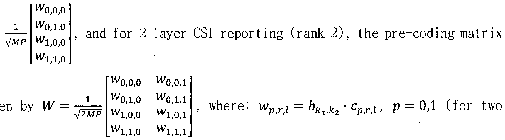
panels), r = 0,1 (for two polarizations), I = 0,1 (for two layers); bkik2 is an oversampled 2D DFT beam; and cp ii is the co-phase value for panel p, polarization r and layer /.
[0154] For rank 1, the reporting of c0;ii0,c1;0i0, and c100 are according to at least one of the following alternatives. In one example of Alt 4-OA, c000 = l, co,i,o e {I .-l'-;'} . ci,o,o e {1,7,-1,-7} and c1 0 E {!,;', -1, -;'}, where the
calculation and reporting of c010 , c1>0,0 and c1>lj0 can be SB (which requires 6 bits/SB).
[0155] In one example of Alt 4-1A, c000 = 1 , co o G — 1,—j} , c100e
{1,7,-1,-7} and c110 = c010 x c10fi, where the calculation and reporting of c010, c10,o and c110 can be SB (which requires 4 bits/SB).
[0156] In one example of Alt 4-2A, c000 = 1 , c010 G {1,7,-1,-7} , c100 =
;5π j7n
Λι,ΰ,ο^ι,ΰ,ο and ci,i,o = αι,ι,ο&ι,ι,ο where α1<Γ(0 e {eT,e 4 ,e * ,e « } and _71>T.j0 =
{e ,β }, where the calculation and reporting of co o, b100 and b110 can be SB (which requires 4 bits/SB), and the calculation and report of alfiiQ and α110 are WB (which requires 4 bits).
[0157] In one example of Alt 4-3A, c000 = 1 , c100 G {l,j , c010 = jn j3n jsn j7n
¾i,oVi,o and cl 0 = a1 0b1 0 where ap 0 G {e~,e~,e~,e~} and bp 0 E
{e *,e*}, where the calculation and reporting of c100, bo o and b1 0 can be SB (which requires 4 bits/SB), and the calculation and report of Q1Q and a110 are WB (which requires 4 bits).
[0158] In one example of Alt 4-4A, c000 = 1 , c110 G , c100 =
jm
«ι,ο,ο ^ι,ο,ο and c0 0 = a0ili0Vi.o where i,o,o- ¾i,o ^ {e , e ~, e « , e * } and ,o,o>Vi,o e ie 4>e4}, where the calculation and reporting of cllj0, όχ,ο,ο ar>d bo o can be SB (which requires 4 bits/SB), and the calculation and report of a10,o and αο,ι,ο are WB (which requires 4 bits).
7 )7π
[0159] In one example of Alt 4-5A, the codebook {ese ^T^T} and
[e ,5 ) are respectively replaced with any one of the following: aWB = {1,7,-1,-7'} (2 bit WB phase) and aSB = {1,7} (1-bi t SB phase) ; aWB = -1,-7} (2 bit WB phase) and SB = {1,-7} (1-bi t SB phase) ; aWB = {1,7, -1,-7} (2 bit WB phase)
_jn 7π J3rr jsn j7n
and a B = {e ~*,e*} (1-bit SB phase) ; aWB = {e * ,e * ,e^~,e~*~} (2 bit WB phase) and
jn jn jn j3n jSn j7n
aSB = {e" ;eT} (1-bit SB phase); aWB = {e~*le~,e~,e~} (2 bit WB phase) and
jn jm j5n ]7π
asB = {1»— } (l~bit SB phase); and aWB ={e*,e * ,e * ,e~} (2 bit WB phase) and SB— (1-bit SB phase).
[0160] In one example of Alt 4-6A, c00,0 = 1 , c0 Q £ —1, -j} , c10,0 e
and c110 = c010 x c10io» where the calculation and reporting of c10Q is WB (which requires 2 bits), and that of co o can be WB or SB (which requires 2 bits/SB).
[0161] At least one of the following embodiments may be used to support at least one of the above alternat ives . In one embodiment , only one of the alternatives is fixed in the specification (e.g. Alt 4-2A) . In another embodiment, two of these alternatives are supported in the specification (e.g. Alt 4-6A, Alt 4-2A) and one of the two is configured to the UE (RRC). In another embodiment, one of the alternatives is either configured (via higher layer RRC signaling or dynamic DCI signaling) or UE reports a preferred alternative. In yet another embodiment, Alt 4-6A is supported for both M= 2 and 4, and Alt 4-2A is supported for M= 2 only. Only one of these embodiments is specified in the specification.
[0162] For rank 2, the reporting of c0 i, cli0ii, and clj0,[ are according to at least one of the following alternatives. In one example of Alt 4-0B, cpQQ = cp,o,i'cp,i,o = ~ cp,i,i ' co,o,o = 1» co,i,o {!'.}> ci,o,o £ W>}>~ 1»— j] > c 1,1,0 = { >j>~ 1»— j) > where the calculation and reporting of c0,i,0 , c1;0,0 and cljl;0 can be SB (which requires 5 bi ts/SB) .
[0163] In one example of Alt 4- IB, cp>0i0 = cp0 ,cp 0 = -cp 1 , c000 = 1, co o 6
{l,j}, c10Q G — 1,— ;'}, c1 0 = co o ■ c100, where the calculation and reporting of c 0,1,0 and c1;o,o can be SB (which requires 3 bits/ SB).
[0164] In one example of Alt 4-2B, c o = cVi0X cp 0 = -cp 1 , c0j0i0 = 1, co o 6 jn j3n jSn j7n
. Ci,o,o = αι,ο,ο^ι,ο,ο . and ci,i,o = αι,ι,ο¾ι,ι,ο where ai,r,o = {e^,e~,e~,e~} and
_Ξ Ξ
bi,r,o = ie 4;^4}> where the calculation and reporting of c010, b100 and ύ110 can be SB (which requires 3 bits/ SB) and the calculation and report of a10,o and «ι,ι,ο are wideband (which requires 4 bits).
[0165] In one example of Alt 4-3B, cp00 = cp01,cpli0 = -cpll , c00,0 = 1, ,
;'3ir '5π ;'7π c1(o,o e , c0ilj0 = a0>i,o i.o and ci,i,o = «ι,ι,ο&ι,ι,ο where p W e {eT,eT,e eT} and &pjl)0 G {e *,e*}, where the calculation and reporting of cli0>0, &o,i,o and ^ι,ι,ο can be SB (which requires 3 bits/SB), and the calculation and report of α0 0 and ι,ι,ο are WB (which requires 4 bits).
[0166] In one example of Alt 4-4B, cp0Q = cpfiillcp 0 = -cp 1 , c000 = 1 ,
Ci o e . ci,o,o = «1,0,0^1,0,0 and co,i,o = «0,1,0*0,1,0 where jn j3n jsn j7n jn jn
αι,ο,θ' ο,ι,ο e {e~ , e~ , e~ , e~) and b1:00,b010 G {e",eT}, where the calculation and reporting of c110, b100 and b0,i,o can be SB (which requires 3 bits/SB), and the calculation and report of li0i0 and α0,ι,0 are WB (which requires 4 bits).
jn jin jsn j7n
[0167] In one example of Alt 4-5B, the codebook {e~*,e~, e~ , e~*~} and
{e *,e*} are respectively replaced with any one of the following-' aWB =
(2 bit WB phase) and aSB = {1,;} (1-bit SB phase) ; aWB = (2 bit WB phase) and aSB = (1-bit SB phase) ; aWB = {1,7,-1,-7} (2 bit WB phase)
jn jn jn j3n jsn j7n
and aSB = {e~~* , e~*} (1-bit SB phase) ; aWB = {e~*,e~,e~,e~} (2 bit WB phase) and
jn jn jn j3n jsn j7n
aSB = {e~~*,e~*} (1-bit SB phase); aWB = {e ~*, e~,e e * } (2 bit WB phase) and
jn j3n jsn jrn
aSB = (1-bit SB phase); and aWB = {e*,e ,e ,e * } (2 bit WB phase) and o-sB = {1. } (1- it SB phase).
[0168] In one example of Alt 4-6B, cp00 = cp01,cpl0 = -cpll, c000 = 1, c010 G c100 G {l, , -1,—_/'}, c1(1)0 = c010 · c100, where +the calculation and reporting of clfi0 is WB (which requires 2 bits), and that of c010 can be WB or SB (which requires 1 bi ts/SB) .
[0169] At least one of the following embodiments may be used to support at least one of the above alternatives. In one embodiment , onlyoneof the alternatives is fixed in the specif i cat ion (e.g. Alt 4-2B) . In another embodiment, two of these alternatives are supported in the specification (e.g. Alt 4-6B, Alt 4-2B) and one of the two is configured to the UE (RRC). In another embodiment, one of the alternatives is either configured (via higher layer RRC signaling or dynamic DCI signaling) or UE reports a preferred alternative. In yet another embodiment, Alt 4-6B is supported for both M- 2 and 4, and Alt 4-2B is supported for M= 2 only. Only one of these methods is specified in the specification.
jn j3n jsn j7n
[0170] An alternative expression for aWB = {e~*,e~ e~,e~) and aSB = k = 0,1,2,3} or 0,l} or aSB =

[0171] In one embodiment 4A, the PMI codebook for rank 3 and 4 CSI reporting comp d
W =

cp,r,i > P = 0,1 (for two panels), r = 0,1 (for two polarizations), / = 0,1,2,3 (for four layers); bki+ki k2+k> is an over samp led 2D DFT beam; kx = i11,k2 = i1>2 and the leading beam index (11,1,11,2) is reported wideband, where = 0, 1, ...JViOj— 1 and i12 = 0,1, ...N202 - 1, hence it requires \\og2(N101N202)] bits; for layer 0 and 1 (/ = 0, 1), the index pair (kn' , k2'l) = (0,0); for layer 2 and 3 (7 = 2, 3), the index pair ( /i,j,/c2,() is calculated and reported in a wideband manner according to at least one of the following alternatives.
[0172] One of the alternatives is supported in the specification. In one example of Alt 4A-0, the same as in LTE Release 13/14 Class A rank 3-4 codebook for Codebook-Config= 1, i.e. , (kl' k2'1) £ {(1,0), (0,1)} for 2D antenna port layouts ( > 1, N2 > 1), and Ol,i,/c2,i) e {(1,0), (2,0), (3,0)} for ID antenna port layouts ( > 1, Λ¾ = 1).
[0173] In one example of Alt 4A-1,
 e {(1,0), (0,1)} for 2D antenna port layouts ( > 1, N2 > 1), and {k[:1,k2'il) £ {(1,0), (2,0)} for ID antenna port layouts

[0174] In one example of Alt 4A-2, for > 1 and Afc > 2 and N2 > ¾:
■¾1(ky) = {(0,0),(O1,0),(0,O2),(0,2O2)} ; for Λ¾ > 1 and > 2 and N2 > /½:
 = {(0,0),(O1,0),(0,O2),(2O1,0)} ; for N2 > 1 and Ai > 1 and Λί = JV2: ι 2,ι) = {(0,0),(Ο1,0),(0,Ο2),(Ο1,Ο2)} ; and for yV2 =1:
(Xi< fe 2,i) = {(0,0),(O1,0),(2O1,0),(3O1,0)} The last two values are not applicable for 4 ports (i.e., N\ - 2) .
[0175] In one example of Alt 4A-3, for > 1 and N2 > 2 and N2 > A :
(^,i' c 2,i) = {( ,0),(O1,0),(0,O2),(0,(N2-l)O2)}; for N2> 1 and Ai > 2 and Ai > 2: (^,i^2,i) = {(°'0' oi' 0)' (°' O 2).((/i-l)O1,0)}; for Λ¾ > 1 and Ai > 1 and Ai = N2: (k1',1,k2',i) = {( ,0)l(Oll0)l . ,O2),(O1,O2)} ; and for Λ¾ =1:
(^ ' fc 2,i) = {(0,0),(Ο1,0),(2Ο1,0),(( 1- 1)Οχ,0)} . The last two values are not applicable for 4 ports (i.e., N\ - 2).
[0176] In one example of Alt 4A-4, for N2 > 1 and Ai > 1': (fciil(fc2,i) =
{(0,0),(Ο1>0),(0,Ο2),(Ο1/Ο2)} ; and for Λ¾ =1:
(Xi, /<2,i) = {(0,0),(O1,0),(2O1,0),(3O1,0)}. The last two values are not applicable for 4 ports (i.e., Ai = 2).
[0177] In one example of Alt 4A-5, for N2 > 1 and > l: (Λ^.Λ^) =
{(0,0), (01( 0), (0, 02), (01( 02)} ; and for yV2 =1 : (/c^, /c24) = {(0,0), (Ox, 0), (20lf 0), ((Λ^ - 1)0!, 0)} . The last two values are not applicable for 4 ports (i.e., Ai = 2).
[0178] cpri is the co-phase value for panel p, polarization r and layer /.
The reporting of cvx is according to the codebook in at least one of Alt 4-OA through Alt 4-5A or/and Alt 4-OB through Alt 4-5B.
[0179] In one embodiment 4B, the PMI codebook for rank 5, rank 6, rank 7, and
8 CSI reporting comprises of the following pre-coding matrices W = w0,0,0 W0,0,l W0,0,2 0,0,3 W0,0,4
W0,l,0 ^0,1,2 0,1,3 W0,l,4
V5M 1,0,0 ΜΊ,ο,ι w1,0,2 Wl,0,3 w 1,0,4
1,1,0 w 1,1,1 Wl,l,2 Wl,l,3 w1,1,4J

w0,0,0 w0,0,l ^0,0,2 w0,0,3 W0,0,4 w0,0,5 w0,0,6 w0,0,7
^0,1,0 0,1,1 0,l,2 ^0,1,3 w0,l,5 W0X6 W0,l,7
W =
VS P respectively.
wl,0,0 Wi.0,1 wl,0,2 ^1,0,3 wl,0,4 Wll0,S Wll0,6 wl,0,7
Wl.1,0 Wl,l,l W1 2 Wl,l,3 Wl,l,4 l,l,5 WlX6 Wl,l,7
[0180] In such embodiment, wvr,i = bki+ki>ik2+k2>i ■ cprl , p = 0,1 (for two panels), r = 0,1 (for two polarizations), I = 0,1,2,3,5,6,7,8 (for up to eight layers), 6¾1+^(;¾2+^( is an oversampled 2D DFT beam, ^1 = 11,1,^2 = ^1,2 and the leading beam index (ii,i,iij2) is reported wideband, where i l =0, 1, ...N101- 1 and iij2 = 0,1, ...N202 - 1, hence it requires riog2(NiOiN202)l bits.
[0181] For layer 0 and 1 (7 = 0, 1), the index pair (ku' > k2'l) = (bl0,b2i0), for layer 2 and 3 (1 = 2, 3), the index pair (/c^ ,, k2' l) = (όι,ι,^,ι) > f°r layer 4 and 5 (7 = 4, 5), the index pair ki'v k2'l)— (b12,b22), and for layer 6 and 7(7=6, 7), the index pair (ku' , k2'l) = (b13,b23) , where (blfi,b2i0) , (bi,i,b2,i)< (b12lb22) , and (^1,3^2,3) f°r different layers are determined according to at least one of the following alternatives.
[0182] In one example of Alt 4B-0, (bli0,b2i0) . (Α,ΐ' >2,ι)' (^1,2^2,2) - and
(^1,3^2,3) are determined based on fixed orthogonal beam patterns (similar to Rel. 13/14 LTE Class A rank 5-8) using higher layer RRC parameter Codebook-Config, where Code book-Con f ig = 1,2,3,4 which correspond to the orthogonal beam groups in LTE specification Class A rank 5-8.
[0183] In one example of Alt 4B-1, Alt 4B-0 in which UE reports a preferred orthogonal beam group using a 2-bit CSI reporting which is reported in a WB manner. This reporting can be separate or joint with other WB CSI reports such as (PMI
 . Alternatively, the reporting can be restricted to 1 bit.
[0184] In one example of Alt 4B-2, (b10,b20) , (b1:1,b2il),(bli2,b22) , and
(^1,3^2,3) are determined based on independent or free selection from full orthogonal DFT basis comprising of M2 orthogonal beams.
[0185] The extension of embodiment 4 to M> 2 antenna panels, for example M
= 4, is straightforward to those the skilled in the art.
[0186] In one embodiment 5, the UE is configured with the CQI reporting, in addition to RI /PMI , according to at least one of the following alternatives. In one example of Alt 5-0, a joint CQI common for all panels is reported. An example use case of this alternative is when all layers are transmitted from all panels. In one example of Alt 5-1, per panel CQI is reported, i.e. CQIs are reported in total. An example use case of this alternative is when different layers are transmitted from different panels. For example, layer 0 is transmitted from panel 0, layer 1 is transmitted from panel 1, and so on.
[0187] In one embodiment 6, the UE is configured with the RI reporting, in addition to CQI /PMI , according to at least one of the following alternatives. In one example of Alt 6-0, RI = is fixed, and hence no RI is reported. In one example of Alt 6-1, a joint RI common for all panels is reported. An example use case of this alternative is when all layers are transmitted from all panels. In one example
of Alt 5-2, per panel RI is reported, i.e. RIs are reported in total. An example use case of this alternat ive is when di f ferent layers are transmitted from different panels. For example, at least one of layer 0 and 1 is transmitted from panel 0, at least one of layer 2 and 3 is transmitted from panel 1, and so on. In this case, each reported RI can be 1 bit.
[0188] In one embodiment 7, the UE is conf igured with the CRI report ing either alone or together with CSI reports CQI/PMI/RI.
[0189] In one embodiment 8, the UE is configured the CSI reporting for hybrid beamforming architecture comprising of both radio frequency (RF) or analog beams (precoding) in addit ion to the digital or baseband precoding. In addition, the beams in the Wl codebook is used to report analog beam and W2 is used to report inter-panel or/and intra-panel phase where the W2 codebook is according to some embodiment of the present disclosure.
[0190] In one embodiment 9, the UE is configured with the SB sizes
 and K2 respectively for inter-panel co-phasing and intra-panel (inter-polarization) co-phasing. A few alternatives for
 K2) are as follows. In one example of Alt 9-0, K\ - K2. In one example of Alt 9-1, K\ = r x K2, where r is an integer, for example belonging to {1, 2, 3, 4}. In one example of Alt 9-2, K2 = r x
 where r is an integer, for example belonging to {1, 2, 3, 4}. In one example of Alt 9-3, K\ = r x K2, where r is an integer or 1 or a fraction, for example belonging to {1/4, 1/3, ½, 1, 2, 3, 4}. In one example of Alt 9-4, Alt -3 where the rvalue depends on the system bandwidth (BW). For example, for smaller BWs, r- 1, and for larger BWs, r = 2 or 4. In one example of Alt 9-5, a single (Ai, K2) according to one of Alt 9-0 to Alt 9-3 is configured either higher layer RRC or dynamic MAC CE based or DCI signaling. In one example of Alt 9-6, the Rvalue is configured via higher layer RRC or dynamic MAC CE based or DCI signaling and the Rvalue is fixed, either BW-dependent or BW- independent . In one example of Alt 9-7, the Rvalue is configured via higher layer RRC or dynamic MAC CE based or DCI signaling and the
value is fixed, either BW-dependent or BW- independent . In one example of Alt
where r is an integer, for example belonging to {1, 2, 3, 4}. In one example of Alt 9-3, K\ = r x K2, where r is an integer or 1 or a fraction, for example belonging to {1/4, 1/3, ½, 1, 2, 3, 4}. In one example of Alt 9-4, Alt -3 where the rvalue depends on the system bandwidth (BW). For example, for smaller BWs, r- 1, and for larger BWs, r = 2 or 4. In one example of Alt 9-5, a single (Ai, K2) according to one of Alt 9-0 to Alt 9-3 is configured either higher layer RRC or dynamic MAC CE based or DCI signaling. In one example of Alt 9-6, the Rvalue is configured via higher layer RRC or dynamic MAC CE based or DCI signaling and the Rvalue is fixed, either BW-dependent or BW- independent . In one example of Alt 9-7, the Rvalue is configured via higher layer RRC or dynamic MAC CE based or DCI signaling and the
value is fixed, either BW-dependent or BW- independent . In one example of Alt
9-8, a combination of at least one of Alt 9-0 through Alt 9-7.
[0191] In one embodiment, only one of the alternatives is fixed in the specification. In another embodiment , one of the alternat ives is either configured
(via higher layer RRC signal ing or dynamic DCI signal ing) or UE reports a preferred alternative
[0192] In one embodiment 10, for #=4, a UE is configured with a PMI codebook for CSI feedback according to at least one of the following alternatives. In one example of Alt 10-0 (panel selection), 2 out of 4 panels are selected, and then the PMI codebook for 2 panels is used to report PMI for the selected two panels. This panel selection can be reported either in a WB manner or per SB, where this reporting requires log2(2)l = 3 bits which can be reported either jointly with other WB/SB CSI components such as PMI 1/PMI2 or separately as a separate WB/SB CSI report. In an example, panel selection is reported using CRI (CSI-RS resource indicator) .
[0193] In one example of Alt 10-1 (panel/polar izat ion combination select ion) ,
4 out of 8 panel and polarization combinations (2 polarizations and 4 panels, hence 8 combinations) are selected, and then the PMI codebook for 2 panels (which is equivalent to 4 panel and polarization combinations) is used to report PMI for the selected four panel and polarization combinations. This panel/polar izat ion combination selection can be reported either in a WB manner or per SB, where this reporting requires [log^)] = 7 bits which can be reported either jointly with other WB/SB CSI components such as PMI1/PMI2 or separately as a separate WB/SB CSI report. In an example, panel/polar izat ion combinat ion selection is reported using CRI (CSI-RS resource indicator)
[0194] In one example of Alt 10-2, for rank 1
W2 = [co,o,o co,i,o ci,o,o ci,i,o c2,o,o c2,i,o c3,o,o c3,i,o]T. In such example, p = 0'·
co,o,o = I* c 1,1,0 e {^->h~^>~)} is reported SB (requires 2 bits for reporting), and p
jn jsn j5n j7n
> 0, r = 0,1, : cP(T.j0 = ap,r,o o where apr0 £ {e~^ ,e~ ,e~ ,e~} is reported WB and bp,r,o e ie 4 > e4} is reported SB (hence, requires 12 WB bits and 6 SB bit). In total, this alternative requires, 12 WB bits to report WB part of the phase and 8 SB bits to report SB part of the phase. For rank 2, cp01 = cp0Q and cpll =— cPilfi.
[0195] In one example of Alt 10-3, for rank 1
W2 = [ o,o,o co,i,o ci,o,o ci,i,o c2,o,o c2,i,o c3,o,o c3,i,o]T,p = 0 , 1 , 2 , 3 , andr = 0, 1:
jn jzn j5n j7n
cp,r,o = ap,r,obp,r,o where apr0 £ {e*,e * ,e ,e * } is reported WB and bpr0 £
{e is reported SB. In total, this alternative requires, 14 WB bi ts to report
WB part of the phase and 7 SB bits to report SB part of the phase. For rank 2, cp,o,i = cp,o,o and cp,l,l = — Cp,l,0-
[0196] In one example of Alt 10-4, for rank 1
W2 = [ 0,0,0 C0,l,0 Cl,0,0 C1,1,0 C2,0,0 C2,l,0 C3,0,0 c3,i,o]T, p = 0: c000 = 1, ci,i,o e y'} is reported SB (requires 2 bits for reporting), and p > 0, r =
jn j3n jSn j7n
0,1,: Cp0j0 = cp l 0 = apr 0bpr 0 where ap r 0 £ {e~*, e~~^, e~*~ , e~*~) is reported WB and bVXiQ £ {e +,e } is reported SB (hence, requires 6 WB bits and 3 SB bit) . In total, this alternative requires, 6 WB bits to report WB part of the phase and 5 SB bits to report SB part of the phase. For rank 2, cp01 = cp00 and cpll =— cplQ.
[0197] In one example of Alt 10-5, for rank 1
W2 = [co,o,o co,i,o ci,o,o ci,i,o c2,o,o c2,i,o c3,o,o c3,i,o]T,p = 0, 1, 2, 3, and r = 0,
{ jn j3n jsn j7n\
e *,e ,e~,e~t is reported WB and f _ ΖΞ ίΞ)
ftpr0 £]e ,e4 j is reported SB. In total, this alternative requires, 8 WB bits to report WB part of the phase and 4 SB bits to report SB part of the phase. For rank 2, cpo,i = cp,0,o an^ cp,i,i = ~cp,i,o-
[0198] In one embodiment 11, a UE is configured with a PMI codebook for multi panels (N5 = M> 1) for all ranks (e.g. 1-8), which can be constructed from the single panel PMI codebook (Ng =M = 1) by the following pre-coder relation: wVXii = b k2+k> · cV ix , where p = 0,1, ...,Ng— 1 (panel, where Ng denotes the number of panels), r = 0,1 (two polar izat ions) , / = 0,1, ...,/?— 1 (layers, where R denotes rank), bki+k> corresponds to a single 2D DFT beam (L = 1) in the Wi
A; codebook; where {kl't, k2' l) = (0,0) for rank 1 and 2, is according to Embodiment 4A and 4B for rank 3-8, and cprl is co-phasing coefficient between panels and polarizations. The inter-panel co-phasing payload is conf igurable via RRC. In one example of Mode 1, this mode corresponds to lower payload, and is supported for both Ng = 2 or 4. In one example of Mode 2, his mode corresponds to higher payload, and at least supported for Ng = 2. For Ng- 4, this mode can be supported with maximum 4 bits/subband according to at least one alternative in the aforementioned embodiment 10.
[0199] For rank 1, cpr0 is given as follows. In one example of Mode 1,
%o,o = 1. c0ii o £ {1,;',-1, -y'} , cp 0 £ {l , -1,-y"} and cPil)0 = c0il|0 x cPj00. In such mode, the calculation and reporting of c0,ij0 can be subband (requires 2 bits/subband). In such mode, the calculation and reporting of cp0Q is wideband (requires 2 x {Ng - i) bits).
[0200] In one example of Mode 2, c0;0,0 = 1 , c0,i,o G {1,;, -1,—j) and cp ) = jiT ]3π jsn j7n jn jn
ap,r,o x frp.r.o wnere V > 0» ap,r,o e {e 4 > e 4 > e 4 < e } and bpr 0 E [e * ,e■*} . In such mode, the calculation and reporting of c01i0 and bpx0 can be subband (2 + 2x Ng— l) bits/subband) . In such mode, the calculation and reporting of aprQ is wideband (4 x {Ng - Ϊ) bits) .
[0201] For rank 2, cprl =^x cpr0 for 1 = 1 , c010≡{l,j} , cp01 = cr,0
c o and cp X = -cp 0.cQfi = c0;1 = l,c10 = -cx l , and c1>0 G and cprfi is given
in the above rank 1 MP codebook for each mode. For ranks 3-8, the codebook in (or their extension) the aforementioned embodiments 4A and 4B can be used.
[0202] In one embodiment 12, a UE is configured with a PMI codebook for multi panels (Ng = M> 1) as follows. For 8 antenna ports (e.g. {15, 16, •■•,22}), 16 antenna ports (e.g. {15, 16, •••,30}), 32 antenna ports (e.g. {15, 16, •■•,46}), when the number of layers υ = l , each PMI value corresponds to four codebook indices »u - .2 > HA < and wnen the number of layers υ≡ {2,3,4} , each PMI value corresponds to five codebook indices iu , ;1 2 , J' 13 , i14 , i2 ■ The codebooks for 1-4 layers are given respectively in TABLES 8-11. The mapping from /13 to kx and k2 for 2-layer reporting is given in TABLE 6. The mapping from ;l3 to and kj for 3-layer and 4-layer reporting is given inTABLE 7. The quantities <pn , ap , bp , um , and v,m are
9n = e; 2
a = e p2+l/ ) = ejnHej Pl2 given by: .2πιη .2nm(N1-\)
J- Ο,Ν,
1 e N2>1
N2 = l

[0203] The values of Ng , Νλ , and N2 are conf igured with the higher-layer parameters CodebookConf ig~Ng, CodebookConf ig-Nl and CodebookConf ig-N2, respectively. The supported configurations of (Ng,N,,N2) for a given number of
CSI-RS ports and the corresponding values of (o,,o2) are given in TABLE -4. The number of CSI-RS ports, ^CSI-RS » is 2NGN N2 .
[0204] A UE may only use J' 12 =0 and may not report /,2 if the value of
CodebookConf ig~N2 is set to 1.
[0205] [Table 6]

[0206] [Table 7]

[0207] [Table 8]
Codebook-Config = 1, 7Vge{2,4}
'u \,...,NO -\ 0,l,...,N2i¾-l 0,...,4^-'-l
Ί 'Ί

[0208] [Table 8a]

[0209] [Table 9]


[0210] [Table 9a 1

[0211] [Table 10]
Codebook-Conf ig = 1 , N <≡ {2,4}
'1,2 1,4 o,i,...,NA-i 0,1,...,N2<¾-1 0 4^-'-1 0,1 (3)

p n l,m <Pp<P
•7,m
 VpVr
VpVr
<PPl<PnVl,m <PPl<PnVl , -ψρΨη
for = 4, ^mim ,„ ;P3 = P■
CSI-RS (PPl Vl,m

<Pp2<PnVl, <Pp2<PnVr,n -<Pp,<Pnvl,n. <Pp3<PnVl,
 -<Pp,<PnVl,n
[0212] [Table 10a]


[0213] [Table 11]
Codebook-Conf ig = 1 , N e {2,4}
o,i,...,N,o,-i O,1,...,N,02-1 0,...,4 0,1 ^.(4).
'Ί 'Ί 'Ί >'Ί >'Ί

for N„ = 4,

p, r, l,n, p, n r,m' - ps n l,m ~ ρ, η ηί
[0214] [Table 11a]
Codebook-Conf ig = 2, N =2
Ο,Ι,.,.,^Ο,-Ι 0,l,...,N2O2-l 0,...,15 0,...,7 W(4) vl.m Vl m m Vl',m
¾
where B¾ Pi = Pi ~ P' apbnvhm apbnv,,m, apbnvlm apbnv,,m,
apb„v,,„, -apb„vlm -apbnv,,n
n
— —
n\ = mod 2; n3 =«mod2;
4 2
[0215] In one embodiment 12A, for Code book-Con f ig = 1 , two separate codebook tables are used for Ng = 2 and Ng = 4 , as shown in TABLES 12-15 for 1-layer , 2-layer ,
3-layer, and 4-layer, respectively.
[0216] [Table 12]

[0217] [Table 12a]
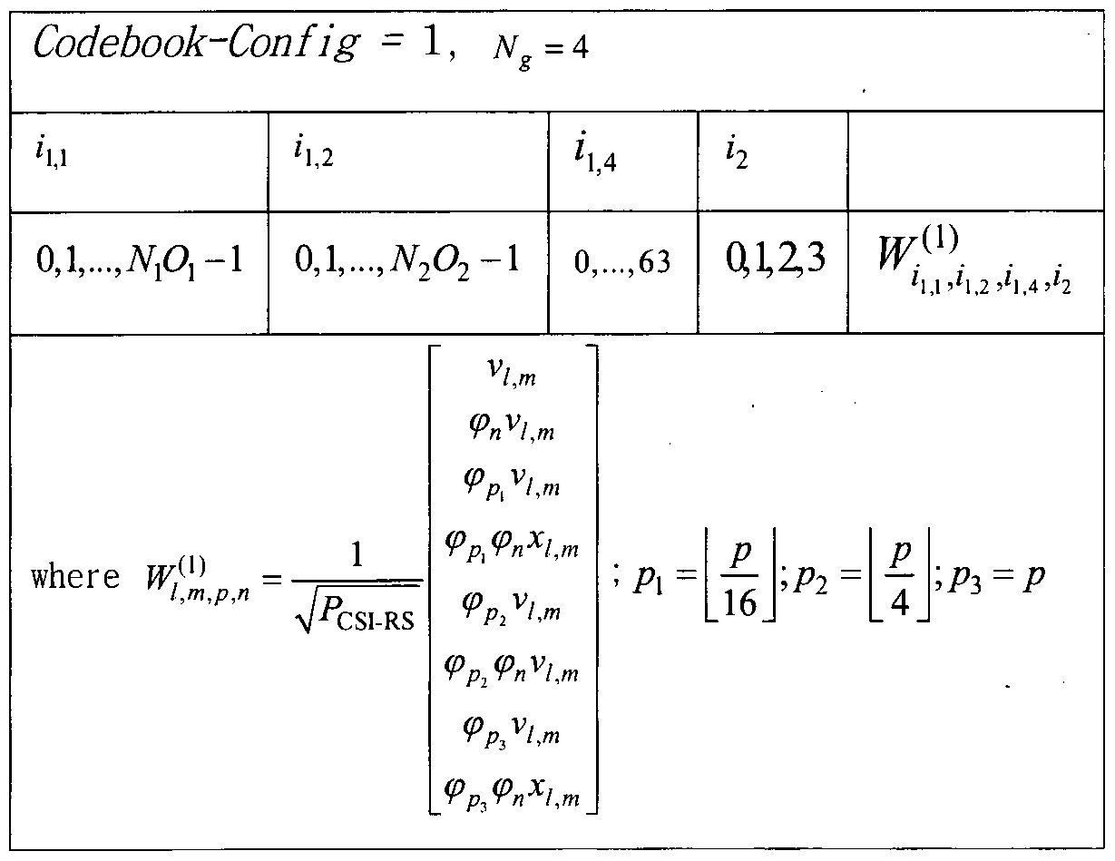
[0218] [Table 13]
Codebook-Conf i g = 1 , Ng = 2
'1,2
o,i,...,NA-i 0,1,...,N2(¾-1 0,1,2,3 0,1
V/,m V/,-'»'
where Wirmn,pn = /—
<PP vi,m <ppv „{
p<PnVl,m -(Pp<PnVr,m>_
[0219] [Table 13a]
Codebook-Conf ig = 1 4
'1,2 '1,4
o,i,...,N,a-i 0,1,...,N2(92-1 0,...,63 0,1 ^(2).
'Ί 'Ί >'l
where

[0220] [Table 14]
Codebook-Conf ig - I, NG=2 fu h o,i,-,NA-i 0,l,...,N2O2-l 0 ,2,3 0,1 w{3)
Ί >'l,l + 'Ί,2 >'l,2 +^2 >'l >*2 where
 m_
m_
[0221] [Table 14a]
Codebook-Conf ig - 1 , JV = 4
,4
o,i,...,NA-i 0,l,.,.,N2O2-l 0,...,63 F
where = P
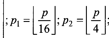

[0222] [Table 15]
Codebook-Config - 1 , Ng = 2
!'l,2 'l,4
o,i,...,NA-i 0,l,...,N2O2-l 0,1,2,3 0,1 w{4)
'Ί 'Ί >Ί
<PnvI,n,

where W Uj-V.ni.m ,.p.n—.—
V4 CSI-RS <Ppvi.m φρνίη, <pVi,m φρνΐη{
[0223] [Table 15a]

[0224] In one embodiment 12B, for Code book-Con f ig - \, and Ng=4, instead of joint reporting of pi, /¾, and /¾ using
 CSI is reported separately using indices (ή,4,ι> A,4,2, ή,4,3) or (/i, ,' A, 5, ,&) for (pi, ¾, /¾) . The codebook tables for 1-4 layers are shown in TABLES 16-19.
[0225] [Table 16]
Codebook-Config = 1 , Ng =4
'Ί,ι 'Ί,2 Zl:4,l Zl,4,2 'lA3 h
0,l,...,N,O,-l o,i,...,N2o2-i 0,1,2,3 0,1,2,3 0,1,2,3
*1,2 >'ΐ,4,1 *1 ,4,2 >'l,4,3 >l2 where l,m,p,,p2,p„n -

[0226] [Table 17]

[0227] [Table 18]
Code book-Con f ig = 1 , N = 4
'1,2 ,4.1 1,4,2 1,4,3
3)
0,1,...,N,<¾-1 O,1,...,N202-1 0,1,2,3 0,1,2,3 0,1,2,3 0,1 w (
'Ί.ι >'i,i >'i.
vr,m-
<P
 Pl Vl,m <PPl vi,m
<PPl<PnVl,m <PP]<PnVl\m' -<PPl<PnVl,,
where ff ,,' ,
CSI-RS <PPl Vl,m Pj Vl',m' <PPl VLm
<PPl9nvl,m <Pp,<PnVl m -<Pp2<PnVl,>

[0228] [Table 19]

[0229] Similarly, for Codebook-Conf i g = 2, and NG = 2 , instead of joint reporting of ¾ and /¾ using CSI is reported separately using indices ( i .4, ι ,
 and 723
using 72, CSI is reported separately using indices ( 72,1, 72,2, 72,3) or ( 72, 73, 74) . for (721, 722, ¾)· The codebook tables for 1-4 layers are shown in TABLES 20-23.
and 723
using 72, CSI is reported separately using indices ( 72,1, 72,2, 72,3) or ( 72, 73, 74) . for (721, 722, ¾)· The codebook tables for 1-4 layers are shown in TABLES 20-23.
[0230] [Table 20]

[0231] [Table 21]

[0232] [Table 22]
Code book-Con f ig - 2, Ng=2
½,2
Zl ,2
0, ,NA-1 0,l,...,N2O2-l 0,1,2,3 0,1,2,3 0,1 0,1 0,1 Ί 'Ί + kl A.l + .Ί
where w) , - , 1
V

[0233] [Table 23]

[0234] In another alternative, for Codebook-Conf ig = 2 , and NG = 2 , instead of joint reporting of /¾ and /¾ using 7li4, CSI is reported separately using indices (Λ,4,ι, Λ.4,2) or ( yli4, ylj5) for (/¾, ¾), and /31 ; Τ72, and /¾ are reported jointly using 2. The codebook tables for 1-4 layers are shown in TABLES 24-27.
[0235] [Table 24]

[0236] [Table 25]

(0237] [Table 26]

[0238] [Table 27]
Codebook-Conf ig = 2, N =2
1,4,1 1,4,2
(4)
o,i,...,N<Vi 0,l,...,N2O2-l 0,1,2,3 0,1,2,3 0,...,7 W.
, +k. > >h
m
¾,v/,m ¾, /',m- where Ww '.p2,p Γ7, 1
apAvi.m apbnv m, apbnvlm
ap,b„} vl.m «p3 ' ' ~apAVl>»>

;n2 mod2;«3 =nmod2
[0239] In another alternative, for Codebook-Conf ig = 2, and Ng=2 , ¾ and /¾ are reported jointly using Λ,4, and instead of joint reporting of n\, ¾, and /¾ using /2, CSI is reported separately using indices d'2,1, ,2, ^2,3) or (12, , ) for (m, m, ) . The codebook tables for 1-4 layers are shown in TABLE 28-31.
[0240] [Table 28]

[0241] [Table 29]
Codebook-Conf ig = 2, Ng = 2
o,i,...,NA-i 0,l,...,N2O2-l 0,...,15 0,1 0,1 0,1 '

where ,¾ =
p b
V CSI-RS a nvlm apbnv,,m, apb,h vi,m -apbnvr„,,_
[0242] [Table 30]

[0243] [Table 31]

[0245] [Table 32]


[0246] [Table 33]

[0247] [Table 34]

[0248] [Table 35]


[0249] In one embodiment 12C, for Code book-Con fig - 1 and NG = 2 , the pre-coding vector/matrix for 1 - 4 layer CSI reporting is given by one of the following alt native equations. In one example of 1- layer, equation 1: l.m.p.n [~
CSI-RS

Z CSI-RS

p n l.„, -φρφΛνίΜ vl,m
where χυ·^
<PnVl,m -ft r
[0251] In one example of 3- layer . equat i on equation

[0252] In one exam le of 4- layer, equation 1 uation 2

[0253] In one embodiment 12D, for Code book-Con fig = 1 and Ng =4 , the pre-coding vector/matr ix for 1 - 4 layer CSI reporting is given by one of the following alternative equations. In one example of 1-layer, equation 1:
Ι,ιη,ρ,η Pi =P
where
 example of 2- layer , equation
2-

[0255] In one exam le of 3- layer , equat ion
>(3)
/,/' ,m,m' ,ρ,η and equat i on 2 :


[0256] In one example of 4- layer , equat ion l:

9Pl Vl,m ΨΡι νΙ',ηί 9Pl Vl,m
<Pp2 Vl,m ΨΡ,νι·
9p *l,m <Pp,Vr,m' ΨρΧΐ,η 9P,vr,m- P_
'Pi = \Pi- =p
CSI-RS 9nVLm 9nVV,m -9nVl,n -<PnVi;m 16
9Pl9nVl',m' -9p29nVl,m

9Pi9nVl',m -9p,9nXl,m -9p,9nVr,m
Ψρ, Xl/,m,m',n
and equat i on 2- I ',m,m',p,n ;P3 = P where
4Pr CSI-RS ',n

Kl ,m,m',n
9nvl,m ¾V; ' -<PnVl,, -9nVl
[0257] In one embodiment 12E, for Codebook-Config = 2 and Ng = 2 , the pre-coding vector/matrix for 1 - 4 layer CSI reporting is given by one of the following alternative equations: 1- layer = p

mod2;n3 =wmod2; 2- layer :

w 1{,12) ,m.m , ,ρ,η 3- layer :
 v/,m vl',m'
aPl vLm ap vr.m- αρΑΆ>» ap Vl',»>'

Z;n3 =«mod2; J and 4-layer


mod2;n3 = «mod2; .
[0258] In one embodiment 12F, the four codebook indices , , 2 , /, 3 , and2 for
1-layer CSI reporting are reported as two PMIs: the first PMI , comprising three components., i.e., i =
 > and the second PMI i2 .
[0259] Similarly, the five codebook indices ¾, ,/12 , i13 , and2 for 2, 3, or 4-layer CSI reporting are reported as two PMIs: the first PMI i comprising four components, i.e.,
 the second PMI 2.
[0260] In one embodiment 12G, the codebook index ;14 is reported as a separate
(third) PMI /3 for inter-panel co-phase. The 1-layer CSI is reported as three PMIs: the first PMI , comprising two components, i.e.,■ i, = {ίΧΛ,ί\2 ) ; the second PMI i2 ', and the third PMI j3 = j .
[0261] Simi lar ly, the 2, 3, or 4-layer CSI is reported as three PMIs: the first
PMI /, comprising three components, i.e.,
 '> the second PMI i2 ', and the third PMI i3 =/ .
[0262] For Codebook-Conf ig = 1, the inter-panel co-phase Ψρ for Ng = 2 and
(<ρη,φ„ , φ„ ) for N„=4 is reported using the third PMI /, in a WB manner. For
Codebook-Conf ig= 2, the inter-panel co-phase has two components : [φρ ,φρ^ reported
in WB manner and ( „;, „J reported in a SB manner. The WB and SB components are reported according to at least one of the following alternatives. In one example of Alt 12G-0, the third PMI has two components, i.e., ¾ =(«'3,1. '3,2) , where the component /3, is reported in a WB manner to indicate (φΡι,φρ and the component /32 is reported in a SB manner to indicate {φη ,φη^.
[0263] In one example of Alt 12G-1, the third PMI /3 indicates the WB component φΡ,φρ^ , and the SB component [φ^,φ^ is reported using the second PMI i2. In one example of Alt 2, the third PMI i3 indicates the WB component [φΡΐ,φρ^ , and the SB component [φη ,φη ^ is reported using a separate fourth PMI i4. In one example of Alt 12G-3, the third PMI i3 indicates the WB component (φρ ,φρ , and the SB component (φη ,φη ^ is reported using the second component ;22 of the second PMI
½ =('2,1^2,2) - where the first component i2l indicates the SB co-phase φ .
[0264] In one embodiment 12H, the codebook indices ii and /, 4 in the codebook tables in the present disclosure are swapped. That is, i14 indicates the mapping to k\ and k in TABLE 6 and TABLE 7, and /13 indicates the WB inter-panel co-phase: ψρ for Code book-Con f ig = l, Ng = 2 > (φΡι,φΡι,φρ^ for Codebook-Conf ig = 1, Ng =4 and (φΡ2,φΡι) for Codebook-Conf ig = 2, Ng = 2.
[0265] In one embodiment 121, the codebook table for Codebook-Conf ig = 2,
Ng =4 is given by TABLES 36-39.
[0266] [Table 36]
Codebook-Config = 2, N =4
'1,2 1,4
(U...,NA-i 0,1,...,N2<¾-1 0,...,4095 a...,255 (i) where w,w
CS1-RS

/>7
n
mod 2; «3 = mod 2; n4 = mod 2; n5 = mod2;«6 = mod2;n7 =«mod2;
64 32 7] [Table 37]
Codebook-Conf ig = 2, N =4
'1,2 '1,4
o,i,..,NA-i 0,1,...,N2(¾-1 0,...,4095 a...,127 w 'Ί2)
where w ) 1
 p,bn,Vl,m
ap. Vl,m a PtKvr,m
. »7 =P;
n
i«2 mod 2; n3 = mod2;n4 = mod 2; «5 = mod2;n6 = mod 2; «7 =«mod2; 64 32 16 8] [Table 38]
Codebook-Conf ig - 2, N =A
'1,2 ,4
0,l,...,N,O,-l 0,l,...,N2O2-l 0,...,4095 0,...,127 where 07(3)

;PI =p;
n
;«2 mod 2; n3 mod 2; n4 = mod 2; «5 = mod 2; ;% = mod 2; «7 =nmod2;
64 32 9] [Table 39]
Codebook-Conf i g = 2, N =A ,2 ο,ι,...,^ο,-ι 0,l,...,N2O2-l 0.....4095 0,...,127 +k, vl,m vl m' vl,m vl m'
where W,(V ,

ap bns Vl,m ~ap -ap bn ,m
ap1 bn1 Vl,m ap ,m' -ap bn Vl,m ,m
Pi ;PT = P;
n n
mod 2; n3 = mod2;«4 = mod 2; «5 mod2;n6 mod 2; «7 =nmod2; 64 32
[0270] In one embodiment 12J, an alternative 2-layer (rank 2) codebook comprises of precoding matrices such that the DFT beams for the two layers are the same, i.e., i = i',m = m' . In this case, when the number of layers υ = 2 , each PMI value corresponds to four codebook indices , ;12 , /14 , i2 , similar to the case of υ=\ . There is no need to have the codebook index 13 to kx and ¾ mapping such as TABLE 6 for 2-layer reporting. The 2-layer codebook table is given by TABLE 40.
[0271] [Table 40]
Codebook-Config = 1 , NS = 2
'1,2 ■. l'l,4 h
0,l,...,N,O,-l 0,1,..,N2(¾-1 0,...,3 0,1 where

[0272] [Table 40a]

[0273] [Table 40b]
Codebook-Config = 2 , N = 2
where ¾'
 mod2;«3 = nmod2;
[0274] In one embodiment 12K, the higher layer codebook configuration parameter Codebook-Config in codebook tables in the present disclosure is referred to as Codebook-Mode or Mode. For example, Codebook-Config = 1 and Codebook-Config = 2 respectively are mapped to Model and Mode2.
[0275] In one embodiment 13, a UE is configured with a PMI codebook for multi panels (Ng = M > 1) as follows.
[0276] For 8 antenna ports (e.g. {15, 16, •••,22}), 16 antenna ports (e.g. {15,
16, "·,30}), 32 antenna ports (e.g. {15, 16, -",46}), and the UE configured with higher layer (e.g. RRC) parameter Mult iPanei 'Codebook set to Model or Mode2, each PMI value corresponds to the codebook indices ix and i2 , where ix is the vector given by: ¾ and υ is the associated RI value.

[0277] The values of Ng , N, , and N2 are configured with the higher-layer parameters CodebookConf ig-Ng, CodebookConf ig-Nl and CodebookConf ig-N2, respectively. The supported configurations of (Ns , N, , N2 ) for a given number of
CSI-RS ports and the corresponding values of (0,,o2) are given in Table41. The
number of CSI-RS ports, -Rs > is NgNlN2 . A UE may only use /1>2=o and may not report il2 if the value of CodebookConfig-N2 is set to.1.
[0278] [Table 41]

[0279] The mapping from 3 to k{ and ¾ for 2-layer reporting is given in
Table 6. The mapping from il} to A:, and kj for 3-layer and 4-layer reporting is given in TABLE 7. When MultiPanelCodebook is set to Model, il is given by: = |r 1,4,1 -| s . When MultiPanelCodebook is set to Mode2 (where Ng=i),
,2 ,3 Ng = 4
 [0280] The quantities ψη , ap , bn , um , and vl m are given jnnjj

[0281] Furthermore, the quant it ies w]m N p*n and w^;p N! n ( Ng e {2,4} ) are given vl,m
<Pnvl,m -<Pnvt,m
w l,,m,p,n
<PPl Vl,m <PPl Vl,m
Ψη<ΡΡι νΙ,η, -<Pn<PPl Vl,m by:

n p, l,m - n ps l,m
and the quantities 2Λ.Ν, 2,2.Ng
W l,,m,p,n and w Ι,,ηι,ρ,η ( N =2 ) are given by: vl,m
<Pn,vI,m -<Pn„Vl,m
where P = [P\ Pi]
W, W,
aP< bn,Vl,m ap,bn,Vl,m n = [n0 «| ) aPlKVl,m -a P2 b ni Vl,m
[0282] The codebooks for 1-4 layers are given respectively in TABLES 42-45.
[0283] [Table 42]
Model, Ng e {2,4}
'Ί,ι hA,g · q '=\,-,Ng-\
ΟΧ.,.,Ν -Ι 0,l,...,N2O2-\ 0.1,2,3 0,U3
Ί >Ί >'l where W^pn -- l,m,p,n '
[0284] [Table 42a]
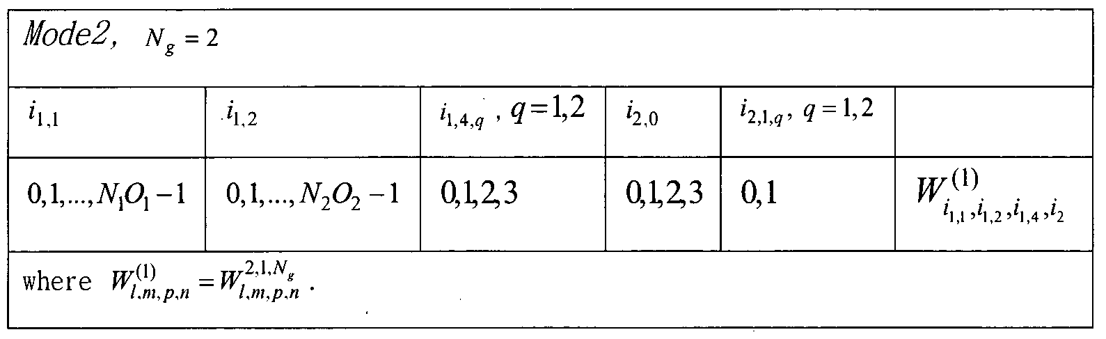
[0285] [Table 43]

[0286] [Table 43a]
Mode2, Ng = 2 ,ί» 9 = 1,2
0,l,...,NA-l 0,l,...,N2O2-l 0,U3 0,1

[0288] [Table 44a]

[0289] [Table 45]
Model, Ng e {2,4}
'1,2 'Ί q = \,-,Ng -1
o,i,...,NA-i 0,l,...,N2O2-l 0,1
^'.'.", ^1·2^ ^'·2.'Ν, 1 where _J^\_" l,m,p,n l',m',p,n l,m,p,n l',m',p,n
[0290] [Table 45a]
Mode2, NG = 2
'Ί,ι Ί.2 - <7 = 1>2 '2,0 » 9 = 2
Ο,Ι,...,Ν^-l 0,1,...,N2(¾-1 Qi¾3 0,1 'Ί 'Ί 'Ί 'Ί where _r ,N „,2,2,N TI,2,2 1
,m, . __j
, " l,m,p,n l',m',p,n l,m,p,n l',m',p,n
[0291] In one embodiment 13A, the 1-4 layer codebooks for Mode2 given respectively in TABLES 42-45 are also supported for N = 4 , where i, 4 and i2 are
['1,4,1 '1,4,2] ^ = 2
['1,4,1 '1,4,2 '1,4,3 '1,4,4 '1,4,5 '1,4,6] Ng=4
/1 ? ε{0,1,2,3}, ? = l,...,2(jVg-l)
replaced with the following: ; and the
['2,0 '2,1,1 '2,1,2] Ng=2
['2,0 '2,1,1 '2,1,2 '2,1,3 '2,1,4 '2,1,5 '2,1,6 ] Ng=4
£{0,1}, ? = !,..., 2(^-1)
quant it ies w, and for N„ = 4 are given by:
where

P = [P\ Pi Pi P4 Ps Pi]
n = [n0 «, «2 n} n n5 n6]
[0292] In one embodiment 14, a UE is configured with a PMI codebook for multi panels (Ng = M> 1) as follows. For 8 antenna ports (e.g. {15, 16, •••,22}), 16 antenna ports (e.g. {15, 16, •••,30}), 32 antenna ports (e.g. {15, 16, •••,46}), and the UE configured with higher layer parameter Mult iPanelCodebook set to Model or Mode2, where each PMI value corresponds to the codebook indices i, and i2 , where
ι. is the vector given by: ,·, and υ is the associated

RI value.
[0293] The mapping from i, 3 to kx and ¾ for 2-layer reporting is given in
TABLE 6. The mapping from 13 to &,and ¾ for 3-layer and 4- layer reporting is given in TABLE 7. The values of Ng , N, , and N2 are configured with the higher-layer parameters CodebookConf ig-Ng, CodebookConf ig-Nl and CodebookConf ig-N2, respectively. The supported configurations of (Ng,N,,N2) f°r a given number of CSI-RS ports and the corresponding values of (o,,o2) are given in Table 41. The number of CSI-RS ports, csi-Rs > * s 2NgN]N2. A UE may only use z12 = 0 and may not report il2 if the value of CodebookConf ig~N2 is set to 1.
[0294] When Multi Panel Codebook is set to Model, i is

i]Aq e {0,1,2,3}, q = 1,2,3
[0295] The quantities 9η and are given by:
<pn =e→ and w,„p°
 vl,m
vl,m
<PnVl,m -<PnVl,m w l,m2,p,n W,
<PPl vl,m
CSI-RS CSI-RS
-ψηΨΡι νΙ,,η
vl,m -<PnVl,m
( Nge{2,4} ) are given by: where
-<Pn<PPl vl,m

[0296] The Model codebooks for 1-4 layers are given respectively in TABLES 46-49.
[0297] [Table 46]

[0298] [Table 47]

[0299] [Table 48]

[0300] [Table 49]

[0301] When Mult i Panel Codebook is set to Mode2 and N =2 , /, 4 and i2 are
'1,4,2
The quantities α and ¾ are given
Furthermore, the quantities w]]^pn and w^pn ( w? =2 ) are given where p = [p' Pz]

[0302] The Mode2 codebooks for 1-4 layers are given respectively in TABLES
50-53.
[0303] [Table 50]
Ng=2
'Ί,ι ' '2,0 '2,1,9 - =
o,i,...,NM-i 0,l,...,N2O2-l 0,1,2,3 0,1
>'l,2 >'l,4 >

[0304] [Table 51]

[0305] [Table 52]

[0306] [Table 53]
Ng=2
'Ί,ι ,2 <1,4,9 ·9 = ]>2 '2,0 ' '2,1,9 > 9 = 2
Ο,Ι,..., where ΐ,ηί,ρ,η Ι,ηι,ρ,η Ι',ηι',ρ,η

[0307] In one embodiment 14A, the 1-4 layer codebooks for Mode2 given respectively in TABLES 50-53 are also supported for N =4 , where 14 and i2 are
['l,4,l 'l,4,2 ] NG=2
['Ί,4,1 'Ί,4,2 Ί,4,3 'Ί,4,4 'Ί,4,5 'l,4,6 ] ^g ~^
i1A? 6(0,1,2,3}, 9 = 1,..., 2(^-1)
replaced with the following-' and the
['2,0 '2,1,1 '2,1,2] N, =2
['2,0 '2,1,1 '2,1,2 '2,1,3 '2,1,4 '2,1,5 '2,1,6 ] NG =^
'2,ι,, ε{0,ΐ}, ? = 1,...,2(-νί-ΐ) quantities w 2,N.
l,,m,p,n and w I, ,m,p,n for N =4 are given by:
^2.1.4 where = [ρι P2 Λ p* Pi
CSI-RS n = [«Q «1 n2 "3 "4
 .
.
[0308] FIGURE 13 i 1 lustrates an example mult iple antenna panels wi th 2 ports per panel 1300 according to embodiments of the present disclosure. The embodiment of the multiple antenna panels with 2 ports per panel illustrated in FIGURE 13 is for illustration only. FIGURE 13 does not limit the scope of this disclosure to any particular implementation.
[0309] The present disclosure provides the CSI acquisition scheme for the antenna structure to which multiple antenna panels are applied, where each panel is a dual -polarized antenna ports with N\ - 1 and Hi = 1 ports in two dimensions, i.e., 2 ports per panel . As shown in FIGURE 13, there are Ng - 2, 4 antenna panels with 2 ports per panel.
[0310] In one embodiment Al, a UE is configured with the PMI codebook with pre-coder fPior 1,1)} antenna panels according to at least one

of the fol lowing al ternat ives. In one example of Alt Al-0 (common intra-panel phase) , W = c®d or d<8>c where c is an intra-panel phase vector (size 2 X 1), common for all panels, and d is an inter-panel phase vector (size Ng x 1), where c®d denotes the Kronecker product of candd which is defined as c®d = [c0d c{df where d = [d0 d ... dNg_{] ■ If W = c®d , for Ng = 2
W = [c0d0 c0dx cxd0 cxdx]T . If one of <¾ and do is fixed to 1, there may be one of the two alternate forms for W. In one instance, W = [d0 dx cxd0 c-^d-^7. In one instance, W = [c0 cQdx c dx . If both c¾ and do are fixed to 1, then

[0311] If W = c®d,f or Ng=4
W = [c0d0 c0dx c0d2 c0d3 cxd0 c dx cxd2 c1d3]r; since one of <¾ and do can be fixed to 1, thers may be one of the two alternate forms for Ψ. In one instance, W = [d0 dx d2 d3 cxd0 cxdx cxd2 cxd3]T . In one instance, W = [c0 c0dx c0d2 c0d3 cx cxd cxd2 cxd3]T . If both <¾ and do are fixed to 1, then W = [1 d d2 d3 c c d cxd2 cxd3]T .
[0312] If W = d®c, then , for Ng = 2 - W = [c0d0 cxd0 c0dx cxdx]T ; since one of Co and do can be fixed to 1, there may be one of the two alternate forms for Ψ. In one instance, W = [d0 cxd0 dx cxdx]T . In one instance, W = [c0 cx c0dx cxd ]T . If W = d®c , then, for N =4
W = [c0d0 i^o Codx cxd c0d2 cxd2 c0d3 c1d3]r; since one of Co and do can be fixed to 1, there may be one of the two alternate forms for Ψ. In one instance, = [d0 c-id0 dx cxd d2 c1d2 d3 c^]7 . In one instance, W= [c0 ct c0dx c d c0d2 c d2 c0d3 c^f .
[0313] In one example of Alt Al-1 (per panel phase):
W = [1 Ci c2 c3 - C2Ng-i]T, where { are independent phase for Ng panels and 2 polarizations. For Ng=2 : W = [1 cx c2 c3]T. For Ng=4 : 11 =
[1 cx c2 c3 c4 cs c6 c7]r.
[0314] The codebook to report the pre-coder fis at least one of BPSK {1,-1} or QPSK -J} or two stage WBbWB where aWB and aSB codebooks are according to at least one of the following-' aWB— (2 bit WB phase) and aSB = {!,;'} (1-bit SB phase); aWB = (2 bit WB phase) and aSB =
jn jn
(1-bit SB phase) ; aWB = — 1,—j} (2 bit WB phase) and aSB = {e *,e*} (1-bit SB
jn j3n jsn )7π jn jn
phase); aWB = {e*,e * ,e * ,e * } (2 bit WB phase) and aSB = {e *,e*} (1-bit SB
jn j3n jSn j7n
phase); aWB = {e~,e~, e~*~,e~] (2 bit WB phase) and aSB = (1-bit SB phase) ;
jn η jsn
and aWB = {e*,e * ,e * ,e * } (2 bit WB phase) and aSB = {l,j} (1-bit SB phase).
[0315] In one embodiment A2, the multi-panel codebook for
(Ng,N,,N2)e {(2, 1,1), (4, 1,1)} is bsed on a modular approach where the multi-panel pre-coder vector/matrix WMP is built from the single-panel pre-coder
WSP l vector/matrix M^P as follows. In one example of N =2 : Rank 1: WMP
 P)\
[0316] In one example of
P)\
[0316] In one example of
WSP
and Rank 2- WMP = n

of WSP is limited to be the same for all panels; and the inter-panel phase ej€i (/= 1 or 1-3) can be reported either WB or SB or both WB and SB; and the co-phase is reported SB.
[0317] In one embodiment A3, a UE is configured with a PMI codebook for
(NG,N,,N2)e {(2,1,1),(4,1,1)} as follows. For 4 antenna ports (e.g. {3000, 3001
•••,3003), 8 antenna ports (e.g. {3000, 3001•••,3007}), and the UE configured with higher layer parameters CodebookType set to TypeI_Mult iPanel and CodebookPar meters set to TypeI_Parameters which includes { Mu berOfPanels, CodebookConf ig-Nl, CodebookConf ig-N2 , CodebookMode). The values of NG , N, , and N2 are configured with the higher-layer parameters NumberOfPanels, CodebookConf 'ig-Nl and CodebookConf ig-N2, respectively. The number of CSI-RS ports, ¾I-RS . is 2NGNLN2 which equals 2NG if (N,,N2) = (1,1) .When NG = 2 , CodebookMode may be set to either Configl or Config2. When NG =4 , CodebookMode may be set to Configl.
[0318] Each PMI value corresponds to the codebook indices ix and i2 , where the vector given by and υ is the associated RI

'1,4,1 Ng=2 value. When CodebookMode is set to Configl, /14 is /14 =
['1,4,1 «1,4,2 '1,4,3] Ng =4 !1,4 -
[0319] When CodebookMode is set to Config2, ;14 and z2 are [' 'l,4,l Ί,4,2
¾ = [¾,0 '2,1 '2,2]
A UE may only use il2 = and may not report ;12 if the value of CodebookConf ig-Nl is set to greater than 1 and CodebookConf ig~N2 is set to 1. A UE may only use i =/12 =z', 3 =0 and may not report z',, , z' )2 , and z',3 if the value of CodebookConf ig-Nl and CodebookConf ig-N2 are set to 1.
[0320] The quantities φη , ap , bn , um , and v/m are given by φη = β^2
ap = eJ*/ eJ'"p/2
b =e-i!tl eiJinl2

[03211 Furthermore, the quantities W ,m,p,n w l,,m,p ,n , l,m,p,n and "l,m,p,n

vl,m Vl,m
<PnVLm -<PnVl,m
-<PPl Vl,m -<p Vl,m
-<Pn<Pp,Vl,m <Pn<PPi vl.m
-3,4,1 _ ■4,4.1 _
W l,,m,p,n W,
Vl,m
CSI-RS <Pp2 vl.m CSI-RS <Pp
<Pn<Pp2 Vl.m -<Pn<Pp2 vl.m
-<PPl Vl.m -Vp V m
-<Pn<Pp Vl.m <Pn<Pp,vl,m where p = L , λγ , and
[[ft ft ft] ^g=4 the quantities w 2 n l,m,p,n ^/.m,p.n ' duu vvl,m.p.n ( Λ^=2 ) are given by:
where p = [Pl p>]
n = [n0 n n2]

[0323] [Table 54]

[0324] [Table 54a]

[0325] [Table 55]

[0326] [Table 55a]
Config2, (Ng,N,,N2) = (2,1,1)
'Ί,ι ' ><? = = 0, 2
0 0 0, 3 0,1
Ί 'Ί ,'l 'Ί 'Ί
, W<2)
where rrl,l',m,m',p,n -_ ^L Ι,η,ρ,η ί',ηί,ρ,η
[0327] [Table 56]

[0328] [Table 56a]

[0329] [Table 57]
Configl, (Ng,N,,N2)e{(2,l,l),(4,l,l)}
'u 'u 'i,4,9 - q = \,-,Ng-\
0 0 0,1,2,3 0,1
'l,l >'l,l +K >'l,2 >'l,2 """"ί >'i,4 >
where ¾4 ,m >„ = t,m,p,n Ι',ιη',ρ,η Ι,ιη,ρ,η l',m',p,n
[0330] [Table 57a]

[0331] In one embodiment Α3Α, the 1-4 layer codebooks for Config2 given respectively in TABLES 54-57 are also supported for Ng=4 , where /14 and i2 are replaced with the following: ; and the

i2i,e{0,l},9 = l,...,2(jVf -l)
i2j0e {0,1,2,3} υ = \
!20 e{0,l} u = 2,3,4 wl,Nt,2 2,Ng,2 3,Ng,2 4,Ng,2 .
quant it ies l,m,p,n , yyl,m,p,n , yvi,m,p,n and wi,m,P,n ι ΐ Ng= are given by-
where

P = [P\ Pi Pi PA Pi Pi]
n = [n0 n, n2 n3 n4 «5 n6]
[03321 In one embodiment A3B, the pre-coding matrix expression in the 3 layer codebook TABLE 56 is replaced with of following
4,JV„,1
w 1°,1) ,m,m , ,ρ,η =— I w, for
1 nr'^,-2 ^2·^·2 W*>N,>2
I,! ,m,m ,ρ,η l,m,p,n l',m',p,n l,m,p,n for Config2;
(3) 1
w, 3,JV,,1 4,^,1
LI' l,m,p,n l',m',p,n l,m,p,n for Configl and
1
w3) W^N^ w^, W 4>N *'2
1{,1 ,m,m , ,ρ,η l,m,p,n i,m',p,n l,m,p,n for Config2; and
1 ^,,Ι w3,N„l w*,Nt,l
Ι,πι.ρ,η l',m',p,n l,m,p,n for Configl and
2,Ng,2 3,Ng,2 4,N,,2
,m,m ,ρ,η l,m,p,n l',m',p,n l,m,p,n for Config2.
2,Ng,l 3,^,1
[0333] In one embodiment A3C, the quantities ,ηι,ρ,η ί,ηι,ρ,η ! l,m,p,n
,^,
and w 1
Ι, 4
,τη,ρ,η for N =4 in TABLES 54-57 are given by:
 and the quantities W, l,m,p,n
3,N„2
l,m,p,n l,m,p,n and Ι,τη,ρ,η for N =4 are given by:

[0334] In one embodiment A3D, the quantities wi,m,P,n , vvl,m,p,n , wi,m,p,n
A,N„,\
and Wl,m,p,n for JV =4 in TABLES 54-57 are given
07:
CSI-RS
3.4.1
0? l.m.p.n
CSI-RS
1,^,2
 and the quant it ies Wl ,m,p,n
4,N
and the quant it ies Wl ,m,p,n
4,N
Wl 2 W^N*
,m,p l,m,p and l,m,p for N =4 are given by:

l,m,p,n w, ap b„ v

[0335] In one embodiment A4, the codebook table for (Ng,N,,N2)£ {(2, 1,1), (4,1,1)} is as shown in TABLES 58-61, respectively, for 1 - 4 layer CSI reporting, where the PMI indices and i2 are defined as in embodiment
A3, and where the quantities " p,n are given by:
 , and the

3,N„2
quantities P,n , " P,n w p:,n and Wp,n s' ( N =2 ) are given by:
where p = [p Pi
n = [n0 n, n2]

[0336] [Table 58]
Configl, (^,^2)ε{(2,1,1),(4,1,1)}
'1,4,, . q = \,...,Ng-\ h
0,1,2,3
Ί,4 >(2 where W^ =Wp lN n"[ .
[0337] [Table 58a]

[0338] [Table 59]

[0339] [Table 59a]
Config2, (Ng,Nl,N2) = (2,1,1)
,q, 9 = 0,1,2
0,1,2,3 0,1
Ί
(2) ^ " TT,l,iV ,2 TT,2,/V ,2" where =^ W ρ,η s W p,n. s
[0340] [Table 60]

[0341] [Table 60a]

[0342] [Table 61]

[0343] [Table 61a]

[0344] In one embodiment A4A, the 1-4 layer codebooks for Config2 given respectively in TABLES 58-61 are also supported for N =4 , where 14 and i2 are

iXAq {0X2,i],q = \,...,2{Ng-\) replaced with the following: ;2 = j ^2'0 A1. '"] ^-2 ; ancj the
[['2,0 '2,1 '2,2 '2,3 '2,4 '2.5 '2,6 ] Ng =
i2.? 6{0,l},9 = l,...,2( g-l)
= 1
quantities Fr^*'2 , ^2"*"2 , ^ . 8'2 and ^*"*·2 for y?=4 are given by:
V
w.
CS1-RS CSI-RS ap,b",

W1*-2 = where P = ^P] Pl Pi p* Ps ^
CSI-RS n = [n0 n, n2 n3 n4 n5 n6]

[0345] In one embodiment A4B, the pre-coding matrix expression in the 3 layer codebook 60 is replaced with one of following: w{3) for

Configl and 0^[ ··2 w%-2 w*: ] for Config2; w w N-2 Α·Ν··2λ
 J for
J for
Config2; and w^ = ±= wp 2 n N'> »W ;;«■'] for Configl and w^=-Uw2-N"2 w'-N"2 ψ*·Ν- for Config2
[0346] In one embodiment A4C, the quantities . > WP and
4 N 1
Wp ' n *' for NG =4 in TABLE 58-61 are given by-'


3,/Ve,l
[0347] In one embodiment A4D, the quant it i es " p n W p,n w p,n and P,n for N = in TABLES 58-61 are given by:

2,^,2
 and the quantities W p,,n
,ΛΤ 2
and w ρ,η N =4 are given by:


[0348] In one embodiment A5, the PMI codebook for rank 5, rank 6, rank 7, and rank 8 CSI reporting for (Ng,N,,N2)= (4,1,1) are as shown in TABLES 62-65,
respectively where the quantities ^ρ,η W 1
p,,n w - p:3,Λί
,n and ρ,η are

iven by:

N„,2
 . the quantities yvp,n w ■
p:2,
,n w p,n

[0349] [Table 62]
Configl, (Ng,Nl,N2)= (4,1,1)
,4,q ' 1 = 1>2»3
0,U3 0,1
where w% = j-[W w™-* w™>* w >* w%>>] .
[0350] [Table 62a]

[0351] [Table 63]

[0352] [Table 63a]
Config2, (Ng,Nl,N2)= (4,1,1)
0.1,2,3 0,1 where ·2 w4-N,-2 ψ5·Ν,·2 W 6-N *>2~

[0353] [Table 64]

[0354] !Table 64a]

[0355] [Table 65]
Configl, (Ng,N„N2) = (4,1,1) 1 = ''2'3
0,½3 0,1 where W^ =-^= ra^ -' ^6 1 '^
p p
p' 8
[0356] [Table 65a]

[0357] In one embodiment A5A, the pre-coding matrix expression in the 5 layer codebook TABLE 62 is replaced with one of following: Configl'- w 1 ,,N,,l wc3,Nt, wc Nt,\ ο
p(5,n) wc„N,,l wc
' p ",n - ρ,η ρ,η ρ,η ρ and Config2-
(5) 1 wc,,Ng,2. w 2,Ng,2 wc,,Ng,2 wct,Ng,2 ο,,Ν 2,2
W ρ,η ρ,η ρ,η ρ,η ρ,η where (ci,c2,...,c5) corresponds to one of =56 comb inat ions of 5 numbers out of {1,2,•••,8}.
5y
[0358] The pre-coding matrix expression in the 6 layer codebook TABLE 63 is replaced with one of following: Configl-
WW _ _[wcl,N!,l w 2,Ng,l wc„Ns, wc ,Ns, wc„Ng,l wc«,Ns,\
- W
" p,n fcl Ρ·" Ρ,η Ρ,η Ρ,η ρ,η and Config2'-
wi6} wc,.Ns,2 τ θ,.Ν,.Ι wc,.Ng,2 wct,Ng,2 5,Ng.2
p.n " p.n " p.n p.n p.n
 where (c,,c2,...,c6) corresponds to one of =28 combinations of 6 numbers out of {1,2,···, 8}.
[0359] The pre-coding matrix expression in the 7 layer codebook TABLE 64 are replaced with one of following: Configl- w?f-x] ; and Config2: p ' '-2] where (c„c2,...>c7)
 corresponds to one of =8 combinations of 7 numbers out of {1,2,···, 8}.
[0360] In one embodiment A6, the codebook table for (Ng,N,,N,)= (1,1,1) , i.e., single panel with 2 ports, is defined by PMI indices il4and i2 , and quantities φ„, ap, andb„ as defined in embodiment A3/A4/A5. The pre-coding vector/matrix for
1-2 layer CSI reporting is according to one of the following alternatives. One of these alternatives is either fixed in the standard specification or is configured via higher layer signaling.
[0361] In one example of Alt A6-0, if the UE is configured with CodebookMode
= Configl, then the quantities Wp"*'1 and ρ"* { Ng=\ ) are given by: w In such example, the pre-coding vector for

1- layer CSI reporting is given by w^. =w-u , where !|4 = 0and ;2 = 0,1,2,3 . In such example, the pre-coding matrix for 2-layer CSI reporting is given by w1 =-L\w l w2 I , where ,·.. =oand *\=o,i.
[0362] In one example of Alt A6-1, if the UE is configured with CodebookMode
- Config2, then the quantities Wp^ and W2^2 ( N =1 ) are given by: p.n W, 2 ,2 In such example, the pre-coding vector for
 V L_flA
1-layer CSI reporting is given by w =w} f , where ,-, , = 0,1,2,3 and /, = 0,1 . In such example, the pre-coding matrix for 2-layer CSI reporting is given by w . = -LlV1,1,2 ww], where ,·.. = 0,1,2,3 and 2 = o,i.
V L_flA
1-layer CSI reporting is given by w =w} f , where ,-, , = 0,1,2,3 and /, = 0,1 . In such example, the pre-coding matrix for 2-layer CSI reporting is given by w . = -LlV1,1,2 ww], where ,·.. = 0,1,2,3 and 2 = o,i.
L '''4''2 '1-4''2 J
[0363] In one example of Alt A6-2, if the UE is configured with CodebookMode
= Config3, then the quantities W1"*-3 and Wp 2 n N^ ( Ng=l ) are given by:
In such example, the pre-coding vector for

1-layer CSI reporting is given by = wuu , where i|4 = 0and /2 = o,i . In such example, the pre-coding matrix for 2-layer CSI reporting is given by w(2 =-L w 3 wli ] , where ,■ =0and /, = 0 .
[0364] In one example of Alt A6-4, if the UE is configured with CodebookMode
= Config4, then the pre-coder. vector/matrix can be either according to Alt A6-0 or Alt A6-2 for all 1-2 layers. In such example, the pre-coding vector for 1-layer CSI reporting is given by
 , where 1|4 = oand i2 = 0,1,2,3 . In such example, the pre-coding vector for 1-layer CSI reporting is given by = w}xl , where ,·., = 0 and i2 = 4,5. In such example, the pre-coding matrix for 2-layer CSI reporting is given by and /2 =0,1 · In such example, the

pre-coding matr ix for 2-layer CSI reporting is given by w2. =- [V.1'\3 w1,1;3] , where
2 L J , 4 = 0 and i2 = 2 .
[0365] In one example of Alt A6-5, if the UE is configured with CodebookMode
= Config5, then the pre-coder vector/matrix can be either according to Alt A6-1 or Alt A6-2 for all 1-2 layers. In such example, the pre-coding vector for 1-layer CSI report ing is given by W =w x , where 4 = 0,1,2,3 and ;2=o,i. In such example, the pre-coding vector for 1-layer CSI reporting is given by w^ =wx , where ;l4 = o and ;2 = 2,3. In such example, the pre-coding matrix for 2-layer CSI reporting is
given by w{2) =—^ [lV1·1·2 w2 2~ J\ , where ,·,, = o 1 2 3 and ,·, = 0,1 . In such example, the pre-coding matrix for 2-layer CSI reporting is given by w(1 = =IV''\3 ^'·1;3] . where
-Jl L '= 1 J
4 = 0 and i2 = 2 .
[0366] In one example of Alt A6~6, if the UE is configured 'with CodebookMode
= Config6, then the pre-coder vector/matrix is according to Alt A6~x for 1- layer CSI reporting and according to Alt A6-y for 2-layer CSI reporting where x ≠ y. A few examples of x and y are as follows:(x, y) = (0, 2); (x, y) = (1, 2); (x, y) = (3, 2); and (x, y) = (4, 2)
[0367] In one embodiment A6A, at least one of the proposed 2 port codebook in embodiment A6 is also used for TPMI indication (in UL-related DCI signaling) for codebook-based UL transmission. Two alternatives in this case are as follows. In one example of Alt A6A-1, the codebook is used regardless of 2 ports being either on a single panel with 2 dual -polarized antenna ports at the UE or two panels each with a single antenna port at the UE. In one example of Alt A6A-2, the codebook is only used for the case of two panels each with a single antenna port at the UE.
[0368] In one embodiment A7, the codebook table for (N?,N,,N2) = (2,1,1) , i.e., two panels each with 2 ports, is defined by PMI indices ; and i2 , and quantities φ„, αρ, andZ>„ as defined in embodiment A3A/4/A5. The pre-coding vector/matrix for
1-4 layer CSI reporting is according to one of the following alternatives. One of these alternatives is either fixed in the specification or is configured via higher layer signaling.
[0369] In one example of Alt A7-0, if the UE is configured with CodebookMode
= Configl, then the following quantities are defined as given by:
1 1
<Pn w, -<Pn
<Pp, <Pp,
ΨηΨρι
where p = px

[0370] In such example, the pre-coding vector for 1- layer CSI reporting is given by
 > where the range of values for i|4and ;2 (or/and their components) are defined as in embodiment A4 (or A4A or A4B or A4C or A4D or their combination) for 1- layer CSI reporting.
[0371] In such example, the pre-coding matrix for 2-layer CSI reporting is given by wQ2 =-7= Wl'2'] W2'2:] , where the range of values for ,14and ;2 (or/and their components) are defined as in embodiment A4 (or A4A or A4B or A4C or A4D or their combination) for 2-layer CSI reporting.
[0372] In such example, the pre-coding matrix for 3-layer CSI reporting is given by w3 l
W 2'1 W. , where the range of values for , and

(or/and their components) are defined as in embodiment A4 (or A4A or A4B or A4C or A4D or their combination) for 3-layer CSI reporting.
[0373] In such example, the pre-coding matrix for 4-layer CSI reporting is given by pr
W. where the range of values for ,·

and ;2 (or/and their components) are defined as in embodiment A4 (or A4A or A4B or A4C or A4D or their combination) for 4-layer CSI reporting.
[0374] In one example of Alt A7-1, if the UE is configured with CodebookMode
= Config2, then the following quantities are defined as given by:
where p = [Pl ρ']
n = [n0 n, n2]

[0375] In such example, the pre-coding vector for 1-layer CSI reporting is given by
 , where the range of values for i|4and /, (or/and their components) are defined as in embodiment A4 (or A4A or A4B or A4C or A4D or their combination) for 1-layer CSI reporting.
[0376] In such example, the pre-coding matrix for 2- layer CSI reporting is given by ¾ . where the range of values for 14and i2 (or/and

their components) are defined as in embodiment A4 (or A4A or A4B or A4C or A4D or their combination) for 2- layer CSI reporting.
[0377] In such example, the pre-coding matrix for 3-layer CSI reporting is
1 r . . - -i
;iven by = -r= Wx'2'2 W2'2'2 W^'2'
, Ί , where the range of values for ,l4and i2
(or/and their components) are defined as in embodiment A4 (or A4A or A4B or A4C or A4D or their combination) for 3-layer CSI reporting.
[0378] In such example, the pre-coding matrix for 4-layer CSI reporting is given by 2,2
W^._ =-j= WX 1 W. 2,2,2 w, 3, w. 4,2,2
, where the range of values for
, and i, (or/and their components) are defined as in embodiment A4 (or A4A or A4B or A4C or A4D or their combination) for 4-layer CSI reporting.
[0379] In one example of Alt A7-2, if the UE is configured with CodebookMode
- Config3, then the following quantities are defined as given by:

[0380] In such example, the pre-coding vector for 1- layer CSI reporting is given by W^ =w23 , where ; = oand ;2 = 0,1,2,3.
[0381] In such example, the pre-coding matrix for 2-layer CSI reporting is given by w{2 =-\=lwl l w2-2-3! , where ,·.. =oand /, =0,1 .
[0382] In such example, the pre-coding matrix for 3-layer CSI reporting is given by , where /14 = 0 and ί2 = Γ/20 /21Ί , where i2 =0,1 ,
is reported according to at least one of the following options: Option 0: ,20 = /21 is reported common for both panels: and Option 1: ,-20 and ,21 are reported independently for both panels.
[0383] In such example, the pre-coding matrix for 4-layer CSI reporting is given by w^ =-^w^ wg-3 w^ ^4;2·3] , where ,· = 0 and ;2 = [i2>0 <2J] , where i2 = 0,1 , is reported according to at least one of the following options: Option
0: is reported common for both panels; and Option 1: i20 and i2 l are reported independently for both panels.
[0384] In one example of Alt A7-2A, if the UE is configured with CodebookMode
= Config3A, then the following quantities are defined as given by:
-apbn
p,n
CSI-RS 0 CSI-RS 0
0 0

[0385] In such example, the pre-coding vector for 1-layer CSI reporting given by
 , where , = 0,1,2,3 and i2 = 0,1,2,3.
[0386] In such example, the pre-coding matrix for 2-layer CSI reporting given by =-= 1 W2,2,3 where /., =0,1,2,3 and =0,1
[0387] In such example, the pre-coding matrix for 3-layer CSI reporting given by ¾ ψ\,2, W 2,2,3 3,2,3
= -j= A
' > ,o where i] = [;1Λ0 /1Λ1] and where ϊ14 =0,1,2,3 and ;2 ϊ =ο,ι , are reported according to at least one of the following options: Option 0: ,|40 =,141 or/and i20 = i2 l is/are reported common for both panels; and Option 1: ,140 , ,141 , ,·20, and ,21 are reported independently for both panels.
[0388] In such example, the pre-coding matrix for 4-layer CSI reporting is given by =-j= ^1,2,3 ^2,2,3 ^3,2,3 ^4,2,3
, where ;1>4 = [t',j4j0 and 4 = o,i,2,3 and /2 = 0,1 , are reported according to at least one of the following options: Option 0: ,140 = ,141 or/and = ;2l is/are reported common for both panels; and Option 1 : ,140 , ,141 , ,20 , and ,21 are reported independently for both panels.
[0389] In one example of Alt A7-4, if the UE is configured with CodebookMode
- Config4, then the pre-coder vector/matrix can be either according to Alt A7-0 or Alt A7-2/A7-2A for all 1-4 layers.
[0390] In such example, the codebook for 1-layer CSI reporting is a union of the 1-layer codebook according to Alt A7-0 and the 1-layer codebook according to Alt A7-2/A7-2A.
[0391] In such example, the codebook for 2-layer CSI reporting is a union of the 2-layer codebook according to Alt A7-0 and the 2-layer codebook according to Alt A7-2/A7-2A.
[0392] In such example, the codebook for 3-layer CSI reporting is a union of the 3-layer codebook according to Alt A7-0 and the 3-layer codebook according to Alt A7-2/A7-2A.
[0393] In such example, the codebook for 4-layer CSI reporting is a union of the 4-layer codebook according to Alt A7-0 and the 4-layer codebook according to Alt A7-2/A7-2A.
[0394] In one example of Alt A7-5, if the UE is configured with CodebookMode
= Config5, then the pre-coder vector/matr ix can be either according to Alt A7-1 or Alt A7-2/A7-2A for all 1-4 layers.
[0395] In such example, the codebook for 1-layer CSI reporting is a union of the 1-layer codebook according to Alt A7-1 and the 1-layer codebook according to Alt A7-2/A7-2A.
[0396] In such example, the codebook for 2-layer CSI reporting is a union of the 2-layer codebook according to Alt A7-1 and the 2-layer codebook according to Alt A7-2/A7-2A.
[0397] In such example, the codebook for 3-layer CSI reporting is a union of the 3-layer codebook according to Alt A7-1 and the 3-layer codebook according to Alt A7-2/A7-2A.
[0398] In such example, the codebook for 4-layer CSI reporting is a union of the 4-layer codebook according to Alt A7-1 and the 4-layer codebook according to Alt A7-2/A7-2A.
[0399] In one example of Alt A7-6, if the UE is configured with CodebookMode
= Config6, then the pre-coder vector/matrix is according to Alt A7-x for 1 to r layer CSI reporting and according to Alt A7-y for r+1 to 4 layer CSI reporting where x ≠ y, and r = 1 or 2. A few examples of x and y are as follows: (x, y) = (0, 2) or (0, 2A); (x, y) = (1, 2) or (1, 2A) ; (x, y) = (3, 2) or (3, 2A) ; and (x, ' y) = (4, 2) or (4, 2A).
[0400] In one embodiment A7A, at least one of the proposed 4 port codebook in embodiment A7 is also used for TPMI indication (in UL-related DCI signaling) for codebook-based UL transmission. Two alternatives in this case are as follows. In one example of Alt A7A-1, the codebook is used regardless of 4 ports being either on a single panel (Ng = 1) with 4 single-polarized or dual -polarized antenna ports at the UE or on two panels (Ng = 2) each with 2 antenna ports at the UE. In one example of Alt A7A-2, the codebook is only used for the case of two panels (Ng = 2) each with 2 antenna ports at the UE.
[0401] In one embodiment A8, the codebook table for (Ng,N,,N2) = (4,1,1) , i.e., two panels each with 2 ports, is defined by PMI indices i14and i2 , and quantities φ„, ap, and¾ as defined in embodiment A3/A4/A5. The pre-coding vector/matrix for
1-4 layer CSI reporting is according to one of the following alternatives. One of these alternatives is either fixed in the specification or is configured via higher layer signaling.
[0402] In one example of Alt A8-0, if the UE is configured with CodebookMode
= Configl, then the following quantities are defined as given by:


[0403] In such example, the pre-coding vector for 1- layer CSI reporting is given by
 , where the range of values for (|4and i2 (or/and their components) are defined as in embodiment A4 (or A4A or A4B or A4C or A4D or their combination) for 1- layer CSI reporting.
[0404] In such example, the pre-coding matrix for 2-layer CSI reporting is
1 ,4,1
given by ¾ = w. 1 w. 2,4,1
where the range of values for and ίΊ
(or/and their components) are defined as in embodiment A4 (or A4A or A4B or A4C or A4D or their combination) for 2-layer CSI reporting.
[0405] In such example, the pre-coding matrix for 3-layer CSI reporting is given by =-j= j l jp
Ί Ί -Ί , where the range of values for ,· and /,
(or/and their components) are defined as in embodiment A4 (or A4A or A4B or A4C or A4D or their combination) for 3-layer CSI reporting.
[0406] In such example, the pre-coding matrix for 4-layer CSI reporting is
1
given by W\A,\ w2,4, jp 3,4,1 ^4,4,1
W>
Ί Ί ',,4,'; Ί,4.': Ί , where the range of values for and i2 (or/and their components) are defined as in embodiment A4 (or A4A or A4B or A4C or A4D or their combination) for 4-layer CSI reporting.
[0407] In one example of Alt A8-1, if the UE is configured with CodebookMode
= Config2, then the followin quantities are defined as given by:

w: 4,4,2 e/A where p = [p' Pl P} P Ps Pf>]
CSI-RS n = [n0 n n2 n3 n4 n5 n6]

[0408] In such example, the pre-coding vector for 1-layer CSI reporting is given by
 , where the range of values for ;14and ί, (or/and their components) are defined as in embodiment A4 (or A4A or A4B or A4C or A4D or their combination) for 1-layer CSI reporting.
[0409] In such example, the pre-coding matrix for 2-layer CSI reporting is given by - where the range of values for ;14and ;2

(or/and their components) are defined as in embodiment A4 (or A4A or A4B or A4C or A4D or their combination) for 2-layer CSI reporting.
[0410] In such example, the pre-coding matrix for 3-layer CSI reporting is given by where the range of values for i|4and

(or/and their components) are defined as in embodiment A4 (or A4A or A4B or A4C or A4D or their combination) for 3-layer CSI reporting.
[0411] In such example, the pre-coding matrix for 4-layer CSI reporting is
1
given by 1,4,2
W> = j .24/2 w: 3,4,2 w: 4,4,2 , where the range of values for and i2 (or/and their components) are defined as in embodiment A4 (or A4A or A4B or A4C or A4D or their combination) for 4-layer CSI reporting.
[0412] In one example of Alt A8-2, if the UE is configured with CodebookMode
= Config3, then the following quantities are defined as given by:


[0413] In such example, the pre-coding vector for 1- layer CSI reporting is given by Wt (i) 1,4,3
where ,14 = 0,1,2,3 and
[0414] In such example, the pre-coding matrix for 2-layer CSI reporting is
, W(2) =J_ 1,4,3
given by π i, 4,/2 .*> w 2,4,3
, where ,·.. = 0,1,2,3 and /, = 0,1.
[0415] In such example, the pre-coding matrix for 3-layer CSI reporting is
1,4,3 2,4,3 3,4,3
given by where iA = [ ,0 iw] and
'2 = ['2,o '2,1 ] - where 4 = 0,1,2,3 and ;2i=o,i, are reported according to at least one of the following options: Option 0: ,·140 = ,·141 or/and 20= 21 is/are reported common for the pair of 2 panels; and Option 1: ,-140 , i|41 , ;-20 , and ,21 are reported independently for the pair of 2 panels.
[0416] In such example, the pre-coding matrix for 4-layer CSI reporting is
r4,4,3
given by Ί where /,,4 = [ί|Λ0 iw and

'2 = ['2,0 i2,i ], where ih4g =0,1,2,3 and i2 q = ,\ , are reported according to at least one of the following options: Option 0: ,140 = ,141 or/and ;20 = ;21 is/are reported common for the pair of 2 panels; and Option 1 : ,140 , ,141 , ,20 , and ,21 are reported independently for the pair of 2 panels.
[0417] In one example of Alt A8-2A, if the UE is configured with CodebookMode
= Confi 3A, then the following quantities are defined as given by:

[0419] In one example, the pre-coding matrix for 2-layer CSI reporting is given by ¾2 = where lj4 = [;,j4i0 ί,Λ1] and i2 = [i2,o '2,1 '2,2] .
where = 0,1,2,3 and i2q = 0,1 .
[0420] In one example, the pre-coding matrix for 3-layer CSI reporting is
W/2,4,3 τ,.3,4,3
;iven by
«2,? = ['2,?,ο h,g,i ,q,i] > where ilj4;ijf = 0,1,2,3 and i2gr =0,1 , are reported according to at least one of the following options: Option 0: iX q 0 = ,·, iq or/and i2qfi = is/are reported common for both panels; and Option 1: il q0 , ;1Λ?>1 , i2qfi , and /2?1 are reported independently for both panels.
[0421] In one example, the pre-coding matrix for 4-layer CSI reporting is given by ¾ =^[C W *'L K'L K^L' } > WHERE 'ΊΑ, = [ o ] and i2,q=[i2,q,o >2,q,\ '24,2] > where/, 4?r = 0,1,2,3 and 2?r =0,1 , are reported according to at least one of the fol lowing options: Option 0: il4?0 = 149l or/and i2 ?0 = is/are reported common for both panels; and Option 1: ;14 0 , ί|4?1, /2 0 , and /2 , are reported independently for both panels.
[0422] In one example of Alt A8-4, if the UE is configured with CodebookMode
= Config4, then the pre-coder vector/matrix can be either according to Alt A8-0 or Alt A8-2/A8-2A for all 1-4 layers.
[0423] In such example, the codebook for 1-layer CSI reporting is a union of the 1-layer codebook according to Alt A8-0 and the 1-layer codebook according to Alt A8-2/A8-2A.
[0424] In such example, the codebook for 2-layer CSI reporting is a union of the 2-layer codebook according to Alt A8-0 and the 2-layer codebook according to Alt A8-2/A8-2A.
[0425] In such example, the codebook for 3-layer CSI reporting is a union of the 3-layer codebook according to Alt A8-0 and the 3-layer codebook according to Alt A8-2/A8-2A.
[0426] In such example, the codebook for 4-layer CSI reporting is a union of the 4-layer codebook according to Alt A8-0 and the 4-layer codebook according to Alt A8-2/A8-2A.
[0427] In one example of Alt A8-5, if the UE is configured with CodebookMode
= Config5, then the pre-coder vector/matrix can be either according to Alt A8-1 or Alt A8-2/A8-2A for all 1-4 layers.
[0428] In such example, the codebook for 1- layer CSI reporting is a union of the 1- layer codebook according to Alt A8-1 and the 1- layer codebook according to Alt A8-2/A8-2A.
[0429] In such example, rhe codebook for 2-layer CSI reporting is a union of the 2-layer codebook according to Alt A8-1 and the 2-layer codebook according to Alt A8-2/A8-2A.
[0430] In such example, the codebook for 3-layer CSI reporting is a union of the 3-layer codebook according to Alt A8-1 and the 3-layer codebook according to Alt A8-2/A8-2A.
[0431] In such example, the codebook for 4-layer CSI reporting is a union of the 4-layer codebook according to Alt A8-1 and the 4-layer codebook according to Alt A8-2/A8-2A.
[0432] In one example of Alt A8-6, if the UE is configured with CodebookMode
- Config6, then the pre-coder vector/matrix is according to Alt A8~x for 1 to r layer CSI reporting and according to Alt A8-y for r+1 to 4 layer CSI reporting where x ≠ y, and r - 1 or 2 or 4. A few examples of x and y is as follows: (x, y) = (0,
2) or (0, 2A); (x, y) = (1, 2) or (1, 2A); (x, y) = (3, 2) or (3, 2A); and (x, y) = (4, 2) or (4, 2A).
[0433] In one embodiment A8A, at least one of the proposed 4 port codebook in embodiment A8 is also used for TPMI indication (in UL-related DCI signaling) for codebook-based UL transmission. Two alternatives in this case are as follows. In one example of Alt A8A-1, the codebook is used regardless of 8 ports being either on a single panel (Ng = 1) with 8 single-polarized or dual -polarized antenna ports at the UE or 2 panels each with 4 antenna ports at the UE or on two panels (Ng - 4) each with 2 antenna ports at the UE.
[0434] In one example of Alt A8A-2, the codebook is only used for the case of four panels (Ng = 4) each with 2 antenna ports at the UE:
[0435] FIGURE 14 illustrates a flow chart of a method 1400 for CSI feedback according to embodiments of the present disclosure, as may be performed by a user equipment (UE). The embodiment of the method 1400 illustrated in FIGURE 14 is for illustration only. FIGURE 14 does not limit the scope of this disclosure to any particular implementation.
[0436] As illustrated in FIGURE 14, the method 1400 begins at step 1405. At step 1405, the UE receives, from a base station (BS), configuration information for the CSI feedback. At step 1405, the configuration information indicates a number of antenna panels (Ng) at the BS and a codebook mode, wherein Ng > 1 and each of the antenna panels comprises antenna ports with a first polarization (Pi) and antenna ports with a second polarization (P2) .
[0437] At step 1410, the UE identifies the number of antenna panels (Ng) at the BS. At step 1415, the UE identifies a codebook for the CSI feedback based on the codebook mode configured between a first codebook mode and a second codebook mode.
[0438] In one embodiment, the number of antenna panels (Ng) is two or four.
In one example, if the number of antenna panels is two (Ng- 2), one of the first
codebook mode or the second codebook mode is configured. In one example, if the number of antenna panels is four (Ng= 4) , only the first codebook mode is conf igured.
[0439] In one embodiment, the number of antenna panels is two (Ng- 2), the second codebook mode is configured, the wideband inter-panel co-phase for each polarization (P ) of a second of the two antenna panels is given by ap = ej7I^ejnp^2 , and the subband inter-panel co-phase for each polarization (P,) of the second antenna panel is given by bn =e ] 1 e where ? = 0, 1, 2, 3 and « = 0,1.
[0440] In one embodiment, a combination of (Ng, N\, Nz) , configured via the configuration information for the CSI feedback, for a given number of antenna ports and corresponding values of (ft, ft) are determined according to TABLE 66:
[0441] [Table 66]

, where and /½ respectively are a number of antenna ports with a polarization (Pi or P2) in first and second dimensions of each of the antenna panels, and ft and ft are oversampling factors in the first and second dimensions, respectively, and ΛΊ, 7½, ft and ft are used to obtain a set of two-dimensional discrete Fourier
transform (DFT) beams, v l..m where / = 0,1,..., qN, , m = 0,l,...,O2N2 , and

[0442] In various embodiments, for the first codebook mode , the codebook for enerating the CSI feedback for Ng = 2,4 is constructed using vectors:

vl.m vl.m
<Pnvl,m -<Pnvl,m
where p = Pi N =2 Vl.m <Pp Vl,m [P\ Pi Pi] Ng =4 ' <Pn<PpVl,m -<Pn<PPl vl,m
2,4,1
W, 1,4,1
l.m.p.n W l,.m.p.n
CSI-RS <Pp Vl,m CSI-RS <Pp2 Vl,m
9n9Pl vl,m -<Pn<Pp2 vl.m
<Pp,Vl,m Vp Vl.m
<Pn<Pp} vl,m -<Pn<Pp3 vl.m
and for the second codebook mode, the codebook for generating the CSI feedback for
is constructed using vectors:
W lX,m,p1,n =
where:

P = [P\ P ]
, «,«o =0,1,2,3 ; ρ:,ρ2,ρ3 =0,1,2,3 ; n,, «2=0,1 ; and ¾SI-RS is the number of n = [n0 n, n2]
<Pn = ejnnl2
a _ ]πρΐ2
antenna ports, and P
[0443] At step 1420, the UE generates the CSI feedback using the identified codebook. In one embodiment, the CSI feedback includes a pre-coding matrix indicator (PMI) that includes PMI indices
 ,3, and /
[0444] In one example for 1- layer CSI feedback: for the first codebook mode, the codebook comprises pre coding matrices: i,m,p,n l,m,p,n , and for the second codebook mode, the codebook comprises pre-coding matrices:

[0445] In one. example for 2-layer CSI feedback: for the first codebook mode , the codebook comprises pre-coding matrices: w) 1
l{,l2',m,m',p,n l,m,p,n l',m',p,n and for the second codebook mode,
■fi codebook comprises pre-coding matrices: l rrl',m',p,n

[0446] In one example for 3-layer CSI feedback: for the first codebook mode, the codebook comprises pre-coding matnces:
1 ΤwΤΛ,Ν ,1 ΤΤΛ,Ν ,1 TT,2,7V ,1
W 1{,13) ,m,m, ,ρ,η l,m,gp,n W Γ,ηΐ,ρ,η W l,m,p,n , and for the second codebook mode, the codebook compr lses pre-coding matrices:
1 X,Ng,2 1,N„2 2,Ng
W 1{,13) ,m,m, ,ρ,η l,m,p,n ϊ,ηΐ,ρ,η Ι,ηι,ρ
[0447] In one example for 4-layer CSI feedback: for the first codebook mode, the codebook comprises pre-coding matrices: η , and for the
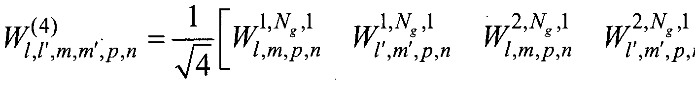
second codebook mode, the codebook comprises pre-coding matrices:
1 2, ,2
w 1{,14') ,τη,πι' ,ρ,η w Ι,,τη,ρ,η ,τη',ρ,η w Ι,,τη,ρ,η ,τη',ρ,η where: 1 = in, m
- i,2, /' = ,i + fa, m' = 7i,2 + fa, for the first codebook mode, p = , and 2 ='72, for the second codebook mode,

= 2 ' = [ Ί Λ] = ['Ί,4,ι '1.4.2 ] = 'Ί,4. and " = [«o "l ¾ ] = [¾,<) ¾,i ½,2 ] = ¾ - i and l ,2 ar e PMI indices that indicate a first beam vi ,i2 , ,3 is a PMI index that indicates a distance (TVI, T¾) of a second beam ^', , 2 + 2 with respect to the first beam , 4 is a PMI index that indicates the wideband inter-panel co-phase, and/2 is a PMI index that indicates: for the first codebook mode, a subband co-phase between two polar izat ions is common for all of the antenna panels, and for the second codebook mode, the subband co-phase between two polarizations of a first of the antenna panels (via 72,0), and the subband inter-panel co-phase for each polarization a second of the antenna panels (via 72,1, 12,2) ·
[0448] At step 1425, the UE transmits the generated CSI feedback to the BS.
In one embodiment, at step 1425, the codebook corresponding to the first codebook mode is used to generate the CSI feedback based on a wideband inter-panel co-phase that is common for a plurality of subbands configured for the CSI feedback. In one embodiment, at step 1425, the codebook corresponding to the second codebook mode is used to generate the CSI feedback based on at least one of (i) a wideband inter-panel co-phase that is common for the plurality of subbands, and (ii) a subband inter-panel co-phase for each of the plurality of subbands.
[0449] Although the present disclosure has been described with an exemplary embodiment, various changes and modifications may be suggested to one skilled in the art. It is intended that the present disclosure encompass such changes and modifications as fall within the scope of the appended claims.
[0450] None of the description in this application should be read as implying that any particular element, step, or function is an essential element that must be included in the claims scope. The scope of patented subject matter is defined only by the claims. Moreover, none of the claims are intended to invoke 35 U.S.C. § 112(f) unless the exact words "means for" are followed by a participle.
Claims
[Claim 1]
A user equipment (UE) for channel state information (CSI) feedback, the UE comprising
a transceiver configured to receive, from a base station (BS), configuration information for the CSI feedback, the configuration information indi cat ing a number of antenna panels (Ng) at the BS and a codebook mode, wherein Ng > 1 and each of the antenna panels comprises antenna ports with a first polarization (Pi) and antenna ports with a second polarization (P2) ; and
a processor operably connected to the transceiver, the processor configured to:
identify the number of antenna panels (Ng) at the BS; identify a codebook for the CSI feedback based on the codebook mode configured between a first codebook mode and a second codebook mode! and
generate the CSI feedback using the identified codebook, wherein the transceiver is further configured to transmit the generated CSI feedback to the BS,
wherein the codebook corresponding to the first codebook mode is used to generate the CSI feedback based on a wideband inter-panel co-phase that is common for a plurality of subbands configured for the CSI feedback, and
wherein the codebook corresponding to the second codebook mode is used to generate the CSI feedback based on at least one of (i) a wideband inter-panel co-phase that is common for the plurality of subbands, and (ii) a subband inter-panel co-phase for each of the plurality of subbands.
[Claim 2]
The UE of Claim 1, wherein:
the number of antenna panels (Ng) is two or four,
if the number of antenna panels is two (Ng= 2), one of the first codebook mode or the second codebook mode is configured, and
if the number of antenna panels is four (Ng = 4), only the first codebook mode is configured.
[Claim 3]
The UE of Claim 1, wherein:
the number of antenna panels is two (Ng = 2),
the second codebook mode is configured,
the wideband inter-panel co-phase for each polarization (P;) of a second of the two antenna panels is given by ap = e j7r^ej p^2 , and
the subband inter-panel co-phase for each polarization (P/) of the second antenna panel is given by b„ =e J 1 eJ
where p = 0,1,2,3 and n = 0,l.
[Claim 4]
The UE of Claim 1, wherein:
a combination of (Ng,
 N2) , configured via the configuration information for the CSI feedback, for a given number of antenna ports and corresponding values of ((¾, (¾) are determined according to:

(2,8,1) (4,1)
(4,4,1) (4,1)
32
(2,4,2) (4,4)
(4,2,2) (4,4)
Ni and N2 respectively are a number of antenna ports with a polarization (Pi or P2) in first and second dimensions of each of the antenna panels, and
ft and ft are oversampling factors in the first and second dimensions, respectively, and
Λι, Nz, ft and ft are used to obtain a set of two-dimensional discrete Fourier transform (DFT) beams, vl m ,
where / - 0,1, ...^N, , m = 0,1,...,<¾N2 , and

[Claim 5]
The UE of Claim 4, wherein:
for the first codebook mode, the codebook for generating the CSI feedback for Ng= 2,4 is constructed using vectors:


Pi N =2
where p-- and
[[Pi Pi Pi] Kg =4
for the second codebook mode, the codebook for generating the CSI feedback for N = 2 is constructed using vectors:
apl bnl Vl,m

where:
P = [P\ Pi]
n = [n0 nx n2] '
n,n0 =0,1,2,3 ; P\,p2,P^ =0,1,2,3 ; «],/¾ =0,1 ; and ¾SI-RS is the number of antenna ports, and

ap =ej7r/4ej;rp/2
[Claim 6]
The UE of Cla wherein:
the CSI feedback includes a pre-coding matrix indicator (PMI) that includes PMI indices ή,ι,
 A,4, and 12,
for 1- layer CSI feedback:
for the first codebook mode, the codebook comprises pre-coding matrices:
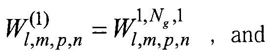
for the second codebook mode, the codebook comprises pre-coding matrices:
W ) = W l>Ns>2 .
Ι,τη,,ρρ,,ηη l l,,mm,,pp,,n, >
for 2-layer CSI feedback:
for the first codebook mode, the codebook comprises pre-coding matrices:
Ι,Ν,,ί 2,«,,1
W l,l1'),m,m',p,n Ι,ηι,ρ,η ,ηι',ρ, , and
2
for the second codebook mode, the codebook comprises pre-coding matrices:
1,1 ,m,m ,ρ,η

for 3-layer CSI feedback:
for the first codebook mode, the codebook comprises pre-coding matrices: and

for the second codebook mode, the codebook comprises pre-coding matr ices:
l,Ns,2 N 2 2,NG
W /(,/3) ,m,m , ,ρ,η =— Γ Ι,τη,ρ,η l',m,p,n l,m,p and for 4- layer CSI feedback:
for the first codebook mode, the codebook comprises pre-coding matrices: l,V ,m,m ,ρ,η n and

for the second codebook mode, the codebook comprises pre-coding matrices: ra 1'NJ 2 1N 2 I'N' 2 IΔ,N1 - 2Δ
1,1 ,m,m ,ρ,η l,m,p,n l',m',p,n Ι,τη,ρ,η ,τη',ρ,η
where:
/ = ,i, = /i,2, / ' = + k\ m' = 7*i,2 + k2, for the first codebook mode , p-
 ' and n = 12,
for the second codebook mode, Ng =2 , p = [p p2] = [iw iw ] = HA > and " = ["0 "1 "2] = ['2,0 '2,1 '2,2] = ¾ >
7*1,1 and 7*1,2 are PMI indices that indicate a first beam viul,iU2 > i,3 is a PMI index that indicates a distance
 τ¾) of a second beam
Vi, 2 +A:2 with respect to the first beam vi ,i2 ,
7*1,4 is a PMI index that indicates the wideband inter-panel co-phase, and 7*2 is a PMI index that indicates:
for the first codebook mode, a subband co-phase between two polarizations is common for all of the antenna panels, and
for the second codebook mode, the subband co-phase between two polarizations of a first of the antenna panels (via ,o) , and the subband inter-panel co-phase for each polarization of a second of the antenna panels (via
12,1, 12,2) ·
[Claim 7]
The UE of Claim 6, wherein:
k\ = 0, £2 = 0, and /i,3 is not included for the 1-layer CSI feedback, mapping of /lt3 to
 and 2 for the 2-layer CSI feedback for Ng = 2 or 4 is determined according to:

, and
mapping of /i,3'to k\ and 2 for the 3-layer or 4-layer CSI feedback for Nk = 2 or 4 is determined according to:
N,=2,N2=1 iV, =4,N2 =1 N, = 8,N2 =1 N, =2,N2 =2 jVj = 4,N2=2
'1,3
K
0 Q 0 Q 0 Q 0 Q 0 0
1 20, 0 20, 0 0 o2 0 <¼
2 3Q 0 3q 0 Q o2 Q 02
3 40, 0 20, 0
[Claim 8]
A base station (BS) , the BS comprising
a processor configured to generate configuration information for channel state information (CSI) feedback, the configuration information indicating a number of antenna panels (Ng) at the BS and a codebook mode, the codebook mode indicating a codebook for the CSI feedback and configured between a first codebook mode and a second codebook mode, wherein Ng > 1 and each of the antenna panels comprises antenna ports with a first polarization (Pi) and antenna ports with a second polarization (P2) ; and
a transceiver operably connected to the processor, the transceiver configured to:
transmit, to a user equipment (UE), the configuration information; and receive the CSI feedback from the UE generated in accordance with the indicated codebook,
wherein the codebook corresponding to the first codebook mode is used to generate the CSI feedback based on a wideband inter-panel co-phase that is common for a plurality of subbands configured for the CSI feedback, and
wherein the codebook corresponding to the second codebook mode is used to generate the CSI feedback based on at least one of (i) a wideband inter-panel co-phase that is common for the plurality of subbands, and (ii) a subband inter-panel co-phase for each of the plurality of subbands.
[Claim 9]
The BS of Claim 8, wherein:
the number of antenna panels (Ng) is two or four,
if the number of antenna panels is two (Ng= 2), one of the first codebook mode or the second codebook mode is configured, and
if the number of antenna panels is four (Ng= 4), only the first codebook mode is configured.
[Claim 10]
The BS of Claim 8, wherein:
the number of antenna panels is two (Ng= 2),
the second codebook mode is configured,
the wideband inter-panel co-phase for each polarization (Ρ;) of a second of the two antenna panels is given by ap = ejnl ej7Ip^ , and
the subband inter-panel co-phase for each polarization (Ρ;) of the second
„ ίπη/2
antenna panel is given by ¾=« «
where p = 0,1,2,3 and « = 0,1.
[Claim 11]
The BS of Claim 8, wherein:
a combination of (Ng, Ni, configured via the configuration information for the CSI feedback, for a given number of antenna ports and corresponding values of ((¾, (¾) are determined according to:
Number of
antenna ports
8 (2,2,1) (4,1)
(2,4,1) (4,1)
16 (4,2,1) (4,1)
(2,2,2) (4,4)
(2,8,1) (4,1)
32
(4,4,1) (4,1)
(2,4,2) (4,4)
(4,2,2) (4,4) and Nz respectively are a number of antenna ports with a polarization (Pi or P2) in first and second dimensions of each of the antenna panels, and
ft and ft are oversampling factors in the first and second dimensions, respectively, and
ΛΊ, N2, ft and ft are used to obtain a set of two-dimensional discrete Fourier transform (DFT) beams, vlm ,
where / = 0,1,...,0,^ , m = O,1,...,02N2 , and
Ο
1 e V2 > 1

[Claim 12]
The BS of Claim 11, wherein:
for the first codebook mode, the codebook for generating the CSI feedback for Ng= 2,4 is constructed using vectors:
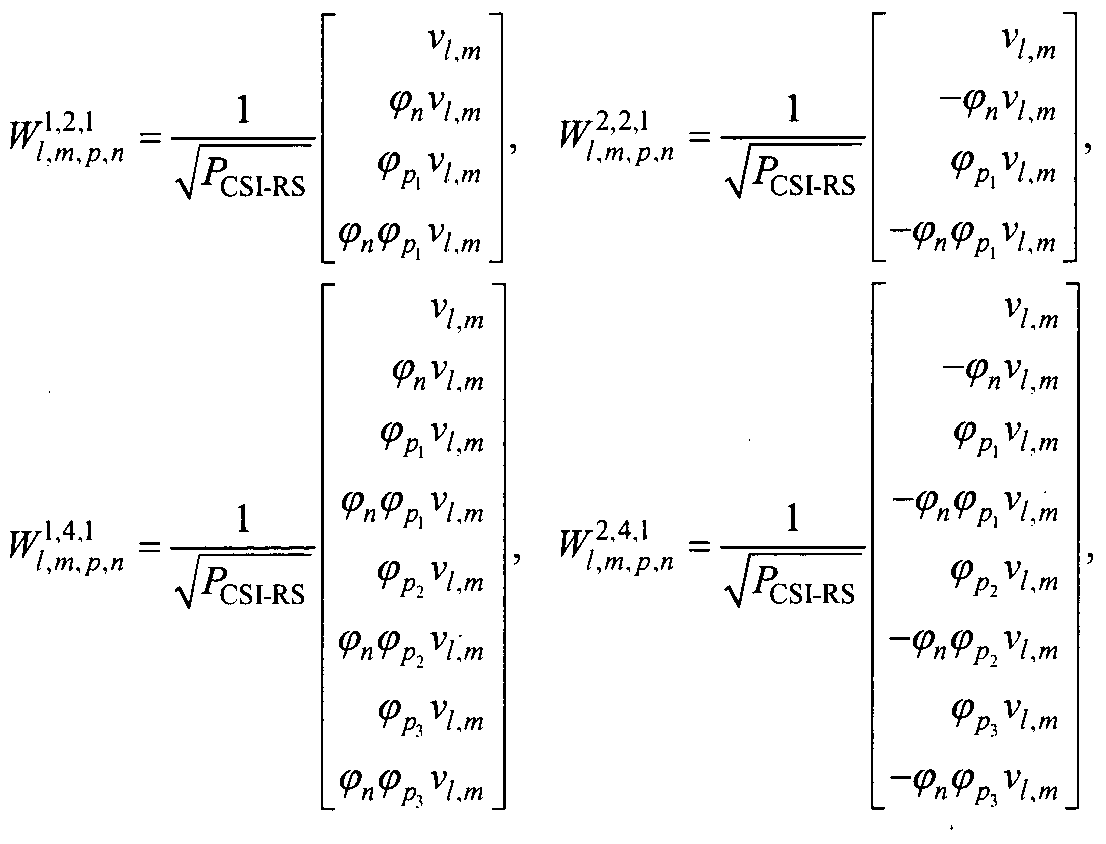
Pi
where p = and
{[PI Pi ft] Ns =4
for the second codebook mode, the codebook for generating the CSI feedback for Ng= 2 is constructed using vectors:
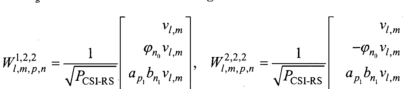 where:
P = [Pi Pi]
n = [nQ n n2] '
n,«0 =0,l,2,3 ; Ρ\,ρ2,Ρ3 = 0,1,2,3 ', «[,¾ =0,1 ; and V°CSI-RS is the number of antenna ports, and
aP e e , and
wherein:
the CSI feedback includes a pre-coding matrix indicator (PMI) that includes PMI indices /i, i , /i,2, i,3, ,4, and ,
for 1- layer CSI feedback:
for the first codebook mode, the codebook comprises pre-coding matrices:
(i) _™W ,
rrl,m,p,n - ryl,m,p,n , nd
for the second codebook mode, the codebook comprises pre-coding matrices: l,m,p,n l,m,p,n >
for 2- layer CSI feedback:
for the first codebook mode, the codebook comprises pre-coding matrices:
W l{,l1'),m,m , ,ρ,η =— ΓΖ w l,,m,p,n l',m',p,n and for the second codebook mode, the codebook comprises pre-coding matrices:

for 3- layer CSI feedback:
for the first codebook mode, the codebook comprises pre-coding matrices:
W 1{,13) ,m,m , ,ρ,η =— ΓΖ l,m,p,n. l',m',p,n W lW,m,p,n and for the second codebook mode, the codebook comprises pre-coding matrices:
l,N,,2 \,Ng,2 2,Ng,2
1,1 ,m,m ,ρ,η l,m,p,n Ι',ηΐ,ρ,η Ι,τη,ρ,η ; and for 4- layer CSI feedback:
for the first codebook mode, the codebook comprises pre-coding matrices:
W 1ff,1 ,m,m , ,ρ,η and

for the second codebook mode, the codebook comprises pre-coding matrices:
I ,m ,ρ,η

where:
1 - ,i, m = ,2, 1' = ,i+ , m' = 'i,2 + k2 for the first codebook mode , p =

for the second codebook mode, Ng = 2 , p = [px i¾] = [¾,4,i «1,4,2] = '1,4 » an^ n = [n0 n, «2] = [!2.o h,\ ¾.2] = '2 > and
 are PMI indices that indicate a first beam vil l , /'i,3 is a PMI index that indicates a distance
 τ¾) of a second beam vi\+kl,iil+k1 with respect to the first beam Vi J2 ,
;'i,4 is a PMI index that indicates the wideband inter-panel co-phase, and it is a PMI index that indicates:
for the first codebook mode, a subband co-phase between two polarizations is common for all of the antenna panels, and
for the second codebook mode, the subband co-phase between two polarizations of a first of the antenna panels (via '72,0) > and the . subband inter-panel co-phase for each polarization of a second of the antenna panels (via
72,1, 72,2) .
[Claim 13]
The BS of Claim 12, wherein:
k\ = 0, i = 0, and Ί,3 is not included for the 1-layer CSI feedback, mapping of /li3 to k\ and for the 2-layer CSI feedback for Ng = 2 or 4 is determined according to:

, and
mapping of /li3 to k\ and J¾¾ for the 3-layer or 4-layer CSI feedback for Ng = 2 or 4 is determined according to:
N, =2,N2 =1 N, = 4,N2 =1 N =8,N2 =1 N, =2,N2 =2 N =A,N2=2
'1,3
k A, \
0 0 Q 0 Q 0 0 Q 0
1 20, 0 0 0 <¼ 0 02
2 3q 0 3q 0 Q <¾ Q 02
3 40, 0 20, 0
[Claim 14]
A method for channel state information (CSI) feedback by a user equipment (UE), the method comprising
receiving, from a base station (BS), configuration information for the CSI feedback, the conf igurat ion information i ndi cat ing a number of antenna panels (Ng) at the BS and a codebook mode , wherein Ng> 1 and each of the antenna panels comprises antenna ports with a first polarization (Pi) and antenna ports with a second polarization (P2);
identifying the number of antenna panels (Ng) at the BS;
identifying a codebook for the CSI feedback based on the codebook mode configured between a first codebook mode and a second codebook mode;
generating the CSI feedback using the identified codebook; and
transmitting the generated CSI feedback to the BS,
wherein the codebook corresponding to the first codebook mode is used to generate the CSI feedback based on a wideband inter-panel co-phase that is common for a plurality of subbands configured for the CSI feedback, and
wherein the codebook corresponding to the second codebook mode is used to generate the CSI feedback based on at least one of (i) a wideband inter-panel co-phase that is common for the plurality of subbands, and (ii) a subband inter-panel co-phase for each of the plurality of subbands.
[Claim 15]
A method for receiving channel state information (CSI) feedback by a base station (BS), the method comprising
generating configuration information for channel state information (CSI) feedback, the configuration information indicating a number of antenna panels (Ng) at the BS and a codebook mode, the codebook mode indicating a codebook for the CSI feedback and configured between a first codebook mode and a second codebook mode,
wherein Ng> 1 and each of the antenna panels comprises antenna ports with a first polarization (Pi) and antenna ports with a second polarization (P2);
transmitting, to a user equipment (UE), the configuration information; and receiving the CSI feedback from the UE generated in accordance with the indicated codebook,
wherein the codebook corresponding to the first codebook mode is used to generate the CSI feedback based on a wideband inter-panel co-phase that is common for a plurality of subbands configured for the CSI feedback, and
wherein the codebook corresponding to the second codebook mode is used to generate the CSI feedback based on at least one of (i) a wideband inter-panel co-phase that is common for the plurality of subbands, and (ii) a subband inter-panel co-phase for each of the plurality of subbands.
Priority Applications (3)
| Application Number | Priority Date | Filing Date | Title |
|---|---|---|---|
| KR1020197034761A KR102511458B1 (en) | 2017-04-26 | 2018-04-25 | CSI reporting method and apparatus using multi-antenna panel in advanced wireless communication system |
| CN201880028183.4A CN110603745B (en) | 2017-04-26 | 2018-04-25 | Method and apparatus for CSI reporting using multiple antenna panels in advanced wireless communication system |
| EP18791653.1A EP3602835B1 (en) | 2017-04-26 | 2018-04-25 | Method and apparatus for csi reporting using multiple antenna panels in advanced wireless communication systems |
Applications Claiming Priority (14)
| Application Number | Priority Date | Filing Date | Title |
|---|---|---|---|
| US201762490296P | 2017-04-26 | 2017-04-26 | |
| US62/490,296 | 2017-04-26 | ||
| US201762492591P | 2017-05-01 | 2017-05-01 | |
| US62/492,591 | 2017-05-01 | ||
| US201762535584P | 2017-07-21 | 2017-07-21 | |
| US62/535,584 | 2017-07-21 | ||
| US201762539142P | 2017-07-31 | 2017-07-31 | |
| US62/539,142 | 2017-07-31 | ||
| US201762547467P | 2017-08-18 | 2017-08-18 | |
| US62/547,467 | 2017-08-18 | ||
| US201762548744P | 2017-08-22 | 2017-08-22 | |
| US62/548,744 | 2017-08-22 | ||
| US15/961,616 US10536205B2 (en) | 2017-04-26 | 2018-04-24 | Method and apparatus to CSI reporting using multiple antenna panels in advanced wireless communication systems |
| US15/961,616 | 2018-04-24 |
Publications (1)
| Publication Number | Publication Date |
|---|---|
| WO2018199625A1 true WO2018199625A1 (en) | 2018-11-01 |
Family
ID=63917592
Family Applications (1)
| Application Number | Title | Priority Date | Filing Date |
|---|---|---|---|
| PCT/KR2018/004796 WO2018199625A1 (en) | 2017-04-26 | 2018-04-25 | Method and apparatus for csi reporting using multiple antenna panels in advanced wireless communication systems |
Country Status (5)
| Country | Link |
|---|---|
| US (8) | US10536205B2 (en) |
| EP (1) | EP3602835B1 (en) |
| KR (1) | KR102511458B1 (en) |
| CN (1) | CN110603745B (en) |
| WO (1) | WO2018199625A1 (en) |
Cited By (5)
| Publication number | Priority date | Publication date | Assignee | Title |
|---|---|---|---|---|
| EP3602834A4 (en) * | 2017-04-25 | 2020-04-29 | Samsung Electronics Co., Ltd. | Method and apparatus for higher rank csi reporting in advanced wireless communication systems |
| WO2020221118A1 (en) * | 2019-04-30 | 2020-11-05 | 华为技术有限公司 | Method for indicating precoding matrix, method for determining precoding matrix, and communication device |
| CN112260736A (en) * | 2020-10-09 | 2021-01-22 | Oppo广东移动通信有限公司 | Determination method, terminal and computer storage medium |
| WO2021046617A1 (en) * | 2019-09-11 | 2021-03-18 | Monash University | A wireless communications process and access point for ultra-reliable low latency communication (urllc) |
| US11018738B2 (en) | 2017-06-16 | 2021-05-25 | Huawei Technologies Co., Ltd. | Communication method, communications apparatus, and system |
Families Citing this family (11)
| Publication number | Priority date | Publication date | Assignee | Title |
|---|---|---|---|---|
| CN108288984B (en) * | 2017-01-09 | 2022-05-10 | 华为技术有限公司 | Parameter indication and determination method, receiving end equipment and transmitting end equipment |
| US10707939B2 (en) * | 2017-10-03 | 2020-07-07 | Mediatek Inc. | Codebook-based uplink transmission in wireless communications |
| US10972166B2 (en) * | 2017-11-16 | 2021-04-06 | Lenovo (Beijing) Limited | Method and apparatus for MIMO transmission |
| CN113348634B (en) * | 2019-01-28 | 2024-05-28 | 索尼集团公司 | Multi-antenna panel uplink communication |
| DE102020107921A1 (en) | 2019-04-12 | 2020-10-15 | Samsung Electronics Co., Ltd. | ELECTRONIC DEVICE WITH MULTIPLE PLATE ANTENNAS AND OPERATING PROCEDURES FOR IT |
| US11050465B2 (en) | 2019-06-21 | 2021-06-29 | Qualcomm Incorporated | User equipment initiated channel state feedback codebook selection |
| KR20210057576A (en) * | 2019-11-12 | 2021-05-21 | 삼성전자주식회사 | Method afor signal transmission and reception for multi-modal appratus of millimeter-wave spectrum |
| WO2021097589A1 (en) * | 2019-11-18 | 2021-05-27 | Qualcomm Incorporated | Optimization of channel state feedback (csf) report |
| WO2021159316A1 (en) * | 2020-02-12 | 2021-08-19 | Apple Inc. | Type II CSI Port Selection Codebook Enhancement with Partial Reciprocity |
| WO2023206353A1 (en) * | 2022-04-29 | 2023-11-02 | Lenovo (Beijing) Limited | Methods and apparatus of codebook enhancement for coherent joint transmission |
| WO2024002095A1 (en) * | 2022-06-27 | 2024-01-04 | Mediatek Inc. | Method and apparatus for uplink signal precoding and reporting |
Citations (1)
| Publication number | Priority date | Publication date | Assignee | Title |
|---|---|---|---|---|
| WO2017014612A1 (en) * | 2015-07-23 | 2017-01-26 | 엘지전자(주) | Codebook-based signal transmission/reception method in multi-antenna wireless communication system, and device for same |
Family Cites Families (11)
| Publication number | Priority date | Publication date | Assignee | Title |
|---|---|---|---|---|
| US9178583B2 (en) * | 2013-01-08 | 2015-11-03 | Samsung Electronics Co., Ltd. | Channel state information feedback design in advanced wireless communication systems |
| EP2945414B1 (en) * | 2013-01-14 | 2018-03-07 | LG Electronics Inc. | Method for reporting channel state information for three-dimensional beamforming in wireless communication system and device therefor |
| KR102258289B1 (en) * | 2014-05-22 | 2021-05-31 | 삼성전자 주식회사 | Method and apparatus for transmitting and generating channel feedback in 2 dimensional antena mobile communication system |
| CN105706373B (en) * | 2014-05-30 | 2020-04-03 | 华为技术有限公司 | Method and device for reporting Channel State Information (CSI) and base station antenna |
| US9344172B2 (en) * | 2014-08-08 | 2016-05-17 | Samsung Electronics Co., Ltd. | Codebook design and structure for advanced wireless communication systems |
| CN105391479B (en) * | 2014-08-27 | 2019-04-09 | 中国电信股份有限公司 | Method, base station and the system of terminal feedback code book in a kind of LTE network |
| US10084579B2 (en) * | 2014-11-17 | 2018-09-25 | Samsung Electronics Co., Ltd. | CSI feedback for MIMO wireless communication systems with polarized active antenna array |
| KR102483881B1 (en) * | 2015-03-13 | 2023-01-02 | 삼성전자주식회사 | Apparatus and method for transmitting feedback and reference signal in wireless communication system |
| WO2018031807A1 (en) * | 2016-08-10 | 2018-02-15 | Idac Holdings, Inc. | Method for channel state information reporting in massive antenna system |
| US10171214B2 (en) * | 2016-09-29 | 2019-01-01 | At&T Intellectual Property I, L.P. | Channel state information framework design for 5G multiple input multiple output transmissions |
| US11038566B2 (en) * | 2017-01-06 | 2021-06-15 | Telefonaktiebolaget Lm Ericsson (Publ) | Precoding a transmission from a multi-panel antenna array |
-
2018
- 2018-04-24 US US15/961,616 patent/US10536205B2/en active Active
- 2018-04-25 WO PCT/KR2018/004796 patent/WO2018199625A1/en unknown
- 2018-04-25 EP EP18791653.1A patent/EP3602835B1/en active Active
- 2018-04-25 CN CN201880028183.4A patent/CN110603745B/en active Active
- 2018-04-25 KR KR1020197034761A patent/KR102511458B1/en active IP Right Grant
-
2019
- 2019-11-14 US US16/684,481 patent/US10944459B2/en active Active
- 2019-11-14 US US16/684,491 patent/US10944461B2/en active Active
- 2019-11-14 US US16/684,487 patent/US10944460B2/en active Active
- 2019-11-14 US US16/684,470 patent/US10938466B2/en active Active
- 2019-12-09 US US16/708,215 patent/US10958327B2/en active Active
-
2021
- 2021-02-12 US US17/175,492 patent/US11496195B2/en active Active
-
2022
- 2022-10-13 US US18/046,438 patent/US20230140316A1/en active Pending
Patent Citations (1)
| Publication number | Priority date | Publication date | Assignee | Title |
|---|---|---|---|---|
| WO2017014612A1 (en) * | 2015-07-23 | 2017-01-26 | 엘지전자(주) | Codebook-based signal transmission/reception method in multi-antenna wireless communication system, and device for same |
Non-Patent Citations (13)
| Title |
|---|
| "E-UTRA, Medium Access Control (MAC) protocol specification", 3GPP TS 36.321 |
| "E-UTRA, Multiplexing and Channel coding", 3GPP TS 36.212 |
| "E-UTRA, Physical channels and modulation", 3GPP TS 36.211 |
| "E-UTRA, Physical Layer Procedures", 3GPP TS 36.213 |
| "E-UTRA, Radio Resource Control (RRC) protocol specification", 3GPP TS 36.331 |
| 3GPP TR 22.891 |
| ERICSSON: "Type I Multi-panel CSI codebook '", R1-1702684, 3GPP TSG RAN WG1 MEETING #88, 7 February 2017 (2017-02-07), Athens , Greece, XP051221525, Retrieved from the Internet <URL:http://www.3gpp.org/ftp/tsg_ran/WG1_RL1/TSGR1_88/Docs/> * |
| HUAWEIHISILICON: "Design for Type I Feedback", 3GPP DOCUMENT RL-1705075 |
| HUAWEIHISILICON: "DL Codebook design for multi-panel structured MIMO in NR", 3GPP DOCUMENT RL-1701691 |
| INTERDIGITAL COMMUNICATIONS: "On Type I CSI feedback for Multi-panel", R1-1705509, 3GPP TSG RAN WG1 MEETING #88BIS,, 25 March 2017 (2017-03-25), Spokane, USA, XP051251966, Retrieved from the Internet <URL:http://www.3gpp.org/ftp/tsg_ran/WG1_RL1/TSGR1_88b/Docs/> * |
| NTT DOCOMO: "CSI FeedbackType I for NR MIMO", R1-1705723, 3GPP TSG RAN WG1 MEETING #88BIS, 25 March 2017 (2017-03-25), Spokane, USA, XP051252139, Retrieved from the Internet <URL:http://www.3gpp.org/ftp/tsg_ran/WG1_RL1/TSGR1_88b/Docs/> * |
| SAMSUNG: "Draft CR on CSR for CSI feedback for semi-OL transmission", R1-1705271, 3GPP TSG RAN WG1 MEETING #88BIS, 25 March 2017 (2017-03-25), Spokane, USA, XP051251850, Retrieved from the Internet <URL:http://www.3gpp.org/ftp/tsg_ran/WG1_RL1/TSGR1_88b/Docs/> * |
| See also references of EP3602835A4 |
Cited By (8)
| Publication number | Priority date | Publication date | Assignee | Title |
|---|---|---|---|---|
| EP3602834A4 (en) * | 2017-04-25 | 2020-04-29 | Samsung Electronics Co., Ltd. | Method and apparatus for higher rank csi reporting in advanced wireless communication systems |
| US11336351B2 (en) | 2017-04-25 | 2022-05-17 | Samsung Electronics Co., Ltd. | Method and apparatus for higher rank CSI reporting in advanced wireless communication systems |
| US11018738B2 (en) | 2017-06-16 | 2021-05-25 | Huawei Technologies Co., Ltd. | Communication method, communications apparatus, and system |
| EP3641149B1 (en) * | 2017-06-16 | 2024-05-15 | Huawei Technologies Co., Ltd. | Communication method, apparatus and system |
| WO2020221118A1 (en) * | 2019-04-30 | 2020-11-05 | 华为技术有限公司 | Method for indicating precoding matrix, method for determining precoding matrix, and communication device |
| WO2021046617A1 (en) * | 2019-09-11 | 2021-03-18 | Monash University | A wireless communications process and access point for ultra-reliable low latency communication (urllc) |
| CN112260736A (en) * | 2020-10-09 | 2021-01-22 | Oppo广东移动通信有限公司 | Determination method, terminal and computer storage medium |
| CN112260736B (en) * | 2020-10-09 | 2022-01-25 | Oppo广东移动通信有限公司 | Determination method, terminal and computer storage medium |
Also Published As
| Publication number | Publication date |
|---|---|
| US10944461B2 (en) | 2021-03-09 |
| US20200091983A1 (en) | 2020-03-19 |
| CN110603745B (en) | 2023-07-25 |
| US11496195B2 (en) | 2022-11-08 |
| US20200091982A1 (en) | 2020-03-19 |
| CN110603745A (en) | 2019-12-20 |
| EP3602835A4 (en) | 2020-04-15 |
| US10938466B2 (en) | 2021-03-02 |
| US20210167832A1 (en) | 2021-06-03 |
| US10944460B2 (en) | 2021-03-09 |
| EP3602835A1 (en) | 2020-02-05 |
| EP3602835B1 (en) | 2021-03-24 |
| US20230140316A1 (en) | 2023-05-04 |
| KR20190142777A (en) | 2019-12-27 |
| US20200119793A1 (en) | 2020-04-16 |
| US10958327B2 (en) | 2021-03-23 |
| KR102511458B1 (en) | 2023-03-17 |
| US20200091981A1 (en) | 2020-03-19 |
| US20200083943A1 (en) | 2020-03-12 |
| US10536205B2 (en) | 2020-01-14 |
| US20180316407A1 (en) | 2018-11-01 |
| US10944459B2 (en) | 2021-03-09 |
Similar Documents
| Publication | Publication Date | Title |
|---|---|---|
| WO2018199625A1 (en) | Method and apparatus for csi reporting using multiple antenna panels in advanced wireless communication systems | |
| EP3602834B1 (en) | Method and apparatus for higher rank csi reporting in advanced wireless communication systems | |
| CN109983712B (en) | Method and apparatus for implementing multi-resolution CSI reporting in advanced wireless communication systems | |
| CN110383710B (en) | Method and apparatus for co-party matrix feedback in advanced wireless communication systems | |
| CN110050413B (en) | Codebook for CSI reporting in advanced wireless communication systems | |
| US10868603B2 (en) | Method and apparatus to enable CSI reporting based on space-frequency compression | |
| EP3596845A1 (en) | High-resolution csi reporting based on unequal bit allocation in advanced wireless communication systems | |
| US11601170B2 (en) | Method and apparatus to enable CSI reporting in wireless communication systems | |
| WO2020175889A1 (en) | Method and apparatus for high rank csi reporting in wireless communication systems | |
| WO2019027226A1 (en) | Method and apparatus for beam selection for csi reporting in advanced wireless communication systems |
Legal Events
| Date | Code | Title | Description |
|---|---|---|---|
| 121 | Ep: the epo has been informed by wipo that ep was designated in this application |
Ref document number: 18791653 Country of ref document: EP Kind code of ref document: A1 |
|
| NENP | Non-entry into the national phase |
Ref country code: DE |
|
| ENP | Entry into the national phase |
Ref document number: 2018791653 Country of ref document: EP Effective date: 20191025 |
|
| ENP | Entry into the national phase |
Ref document number: 20197034761 Country of ref document: KR Kind code of ref document: A |