WO2018199289A1 - 燃料噴射器及びガスタービン - Google Patents
燃料噴射器及びガスタービン Download PDFInfo
- Publication number
- WO2018199289A1 WO2018199289A1 PCT/JP2018/017189 JP2018017189W WO2018199289A1 WO 2018199289 A1 WO2018199289 A1 WO 2018199289A1 JP 2018017189 W JP2018017189 W JP 2018017189W WO 2018199289 A1 WO2018199289 A1 WO 2018199289A1
- Authority
- WO
- WIPO (PCT)
- Prior art keywords
- cooling air
- fuel
- plenum
- cooling
- supply tube
- Prior art date
- Legal status (The legal status is an assumption and is not a legal conclusion. Google has not performed a legal analysis and makes no representation as to the accuracy of the status listed.)
- Ceased
Links
Images

Classifications
-
- F—MECHANICAL ENGINEERING; LIGHTING; HEATING; WEAPONS; BLASTING
- F23—COMBUSTION APPARATUS; COMBUSTION PROCESSES
- F23R—GENERATING COMBUSTION PRODUCTS OF HIGH PRESSURE OR HIGH VELOCITY, e.g. GAS-TURBINE COMBUSTION CHAMBERS
- F23R3/00—Continuous combustion chambers using liquid or gaseous fuel
- F23R3/28—Continuous combustion chambers using liquid or gaseous fuel characterised by the fuel supply
- F23R3/286—Continuous combustion chambers using liquid or gaseous fuel characterised by the fuel supply having fuel-air premixing devices
-
- F—MECHANICAL ENGINEERING; LIGHTING; HEATING; WEAPONS; BLASTING
- F23—COMBUSTION APPARATUS; COMBUSTION PROCESSES
- F23R—GENERATING COMBUSTION PRODUCTS OF HIGH PRESSURE OR HIGH VELOCITY, e.g. GAS-TURBINE COMBUSTION CHAMBERS
- F23R3/00—Continuous combustion chambers using liquid or gaseous fuel
- F23R3/28—Continuous combustion chambers using liquid or gaseous fuel characterised by the fuel supply
- F23R3/30—Continuous combustion chambers using liquid or gaseous fuel characterised by the fuel supply comprising fuel prevapourising devices
- F23R3/32—Continuous combustion chambers using liquid or gaseous fuel characterised by the fuel supply comprising fuel prevapourising devices being tubular
-
- F—MECHANICAL ENGINEERING; LIGHTING; HEATING; WEAPONS; BLASTING
- F02—COMBUSTION ENGINES; HOT-GAS OR COMBUSTION-PRODUCT ENGINE PLANTS
- F02C—GAS-TURBINE PLANTS; AIR INTAKES FOR JET-PROPULSION PLANTS; CONTROLLING FUEL SUPPLY IN AIR-BREATHING JET-PROPULSION PLANTS
- F02C7/00—Features, components parts, details or accessories, not provided for in, or of interest apart form groups F02C1/00 - F02C6/00; Air intakes for jet-propulsion plants
- F02C7/12—Cooling of plants
- F02C7/16—Cooling of plants characterised by cooling medium
- F02C7/18—Cooling of plants characterised by cooling medium the medium being gaseous, e.g. air
-
- F—MECHANICAL ENGINEERING; LIGHTING; HEATING; WEAPONS; BLASTING
- F02—COMBUSTION ENGINES; HOT-GAS OR COMBUSTION-PRODUCT ENGINE PLANTS
- F02C—GAS-TURBINE PLANTS; AIR INTAKES FOR JET-PROPULSION PLANTS; CONTROLLING FUEL SUPPLY IN AIR-BREATHING JET-PROPULSION PLANTS
- F02C7/00—Features, components parts, details or accessories, not provided for in, or of interest apart form groups F02C1/00 - F02C6/00; Air intakes for jet-propulsion plants
- F02C7/22—Fuel supply systems
-
- F—MECHANICAL ENGINEERING; LIGHTING; HEATING; WEAPONS; BLASTING
- F02—COMBUSTION ENGINES; HOT-GAS OR COMBUSTION-PRODUCT ENGINE PLANTS
- F02C—GAS-TURBINE PLANTS; AIR INTAKES FOR JET-PROPULSION PLANTS; CONTROLLING FUEL SUPPLY IN AIR-BREATHING JET-PROPULSION PLANTS
- F02C7/00—Features, components parts, details or accessories, not provided for in, or of interest apart form groups F02C1/00 - F02C6/00; Air intakes for jet-propulsion plants
- F02C7/22—Fuel supply systems
- F02C7/222—Fuel flow conduits, e.g. manifolds
-
- F—MECHANICAL ENGINEERING; LIGHTING; HEATING; WEAPONS; BLASTING
- F23—COMBUSTION APPARATUS; COMBUSTION PROCESSES
- F23R—GENERATING COMBUSTION PRODUCTS OF HIGH PRESSURE OR HIGH VELOCITY, e.g. GAS-TURBINE COMBUSTION CHAMBERS
- F23R3/00—Continuous combustion chambers using liquid or gaseous fuel
- F23R3/28—Continuous combustion chambers using liquid or gaseous fuel characterised by the fuel supply
- F23R3/283—Attaching or cooling of fuel injecting means including supports for fuel injectors, stems, or lances
-
- F—MECHANICAL ENGINEERING; LIGHTING; HEATING; WEAPONS; BLASTING
- F23—COMBUSTION APPARATUS; COMBUSTION PROCESSES
- F23R—GENERATING COMBUSTION PRODUCTS OF HIGH PRESSURE OR HIGH VELOCITY, e.g. GAS-TURBINE COMBUSTION CHAMBERS
- F23R3/00—Continuous combustion chambers using liquid or gaseous fuel
- F23R3/28—Continuous combustion chambers using liquid or gaseous fuel characterised by the fuel supply
- F23R3/34—Feeding into different combustion zones
- F23R3/346—Feeding into different combustion zones for staged combustion
-
- F—MECHANICAL ENGINEERING; LIGHTING; HEATING; WEAPONS; BLASTING
- F05—INDEXING SCHEMES RELATING TO ENGINES OR PUMPS IN VARIOUS SUBCLASSES OF CLASSES F01-F04
- F05D—INDEXING SCHEME FOR ASPECTS RELATING TO NON-POSITIVE-DISPLACEMENT MACHINES OR ENGINES, GAS-TURBINES OR JET-PROPULSION PLANTS
- F05D2240/00—Components
- F05D2240/35—Combustors or associated equipment
-
- F—MECHANICAL ENGINEERING; LIGHTING; HEATING; WEAPONS; BLASTING
- F05—INDEXING SCHEMES RELATING TO ENGINES OR PUMPS IN VARIOUS SUBCLASSES OF CLASSES F01-F04
- F05D—INDEXING SCHEME FOR ASPECTS RELATING TO NON-POSITIVE-DISPLACEMENT MACHINES OR ENGINES, GAS-TURBINES OR JET-PROPULSION PLANTS
- F05D2260/00—Function
- F05D2260/20—Heat transfer, e.g. cooling
- F05D2260/201—Heat transfer, e.g. cooling by impingement of a fluid
-
- F—MECHANICAL ENGINEERING; LIGHTING; HEATING; WEAPONS; BLASTING
- F05—INDEXING SCHEMES RELATING TO ENGINES OR PUMPS IN VARIOUS SUBCLASSES OF CLASSES F01-F04
- F05D—INDEXING SCHEME FOR ASPECTS RELATING TO NON-POSITIVE-DISPLACEMENT MACHINES OR ENGINES, GAS-TURBINES OR JET-PROPULSION PLANTS
- F05D2260/00—Function
- F05D2260/20—Heat transfer, e.g. cooling
- F05D2260/213—Heat transfer, e.g. cooling by the provision of a heat exchanger within the cooling circuit
-
- F—MECHANICAL ENGINEERING; LIGHTING; HEATING; WEAPONS; BLASTING
- F05—INDEXING SCHEMES RELATING TO ENGINES OR PUMPS IN VARIOUS SUBCLASSES OF CLASSES F01-F04
- F05D—INDEXING SCHEME FOR ASPECTS RELATING TO NON-POSITIVE-DISPLACEMENT MACHINES OR ENGINES, GAS-TURBINES OR JET-PROPULSION PLANTS
- F05D2260/00—Function
- F05D2260/20—Heat transfer, e.g. cooling
- F05D2260/221—Improvement of heat transfer
- F05D2260/2212—Improvement of heat transfer by creating turbulence
-
- F—MECHANICAL ENGINEERING; LIGHTING; HEATING; WEAPONS; BLASTING
- F05—INDEXING SCHEMES RELATING TO ENGINES OR PUMPS IN VARIOUS SUBCLASSES OF CLASSES F01-F04
- F05D—INDEXING SCHEME FOR ASPECTS RELATING TO NON-POSITIVE-DISPLACEMENT MACHINES OR ENGINES, GAS-TURBINES OR JET-PROPULSION PLANTS
- F05D2260/00—Function
- F05D2260/20—Heat transfer, e.g. cooling
- F05D2260/232—Heat transfer, e.g. cooling characterized by the cooling medium
Definitions
- the present invention relates to a fuel injector and a gas turbine.
- Patent Document 1 discloses a fuel injector that ejects a mixed gas of compressed air and fuel gas from a plurality of ejection holes regularly formed in a circular substrate. .
- the flame may become an attached flame that adheres to the outlet of the injection hole. This causes the substrate to become high temperature, and thus requires cooling of the substrate.
- the fuel injector described in Patent Document 1 the fuel injector is kept at a low temperature by reviewing the shape of the baffle provided inside the casing into which the fuel gas is introduced. As countermeasures, further countermeasures are desired.
- An object of the present invention is to provide a fuel injector and a gas turbine capable of efficiently cooling a high temperature substrate.
- the fuel injector has a tubular shape centered on the axis, and a fuel supply tube into which fuel gas is introduced from the upstream side in the axial direction in which the axis extends, and the axial direction
- a cylindrical outer surface that connects the plate, a substrate that supports downstream ends of the plurality of premixing tubes, the support plate and the substrate, and forms a plenum inside the support plate and the substrate;
- a cooling air plenum is divided into an upstream side cooling air plenum and a downstream side cooling air plenum disposed downstream of the upstream
- the cooling air introduced into the upstream side cooling air plenum is jetted toward the substrate through the cooling holes of the baffle, so that the high temperature substrate can be efficiently cooled.
- At least some of the plurality of cooling holes may be impingement holes.
- the baffle is formed between the baffle body, the cooling hole being formed, and a baffle body provided radially inward with the axis as a center, and the baffle body and the outer wall. And an inclined portion that is inclined toward the downstream side toward the outer side in the radial direction with the cooling hole not formed.
- the cooling air introduced into the upstream side cooling air plenum is jetted downstream from the plurality of cooling holes, and then cools the substrate, while radially cooling along the inclined portion. Flowing into. Cooling air introduced into the downstream cooling air plenum is directed radially outward along the baffle ramp. Accordingly, not only the substrate but also the premixing tube in the downstream side cooling air plenum can be cooled.
- the fuel injector may include a plurality of cooling air discharge holes formed in the substrate and discharging the cooling air from the downstream cooling air plenum to the downstream side of the substrate.
- a cooling air introduction hole penetrating the premixing tube in and out may be formed in a portion of the premixing tube located in the downstream side cooling air plenum.
- the cooling air supply tube may be disposed coaxially with the fuel supply tube on a radially inner side of the fuel supply tube.
- the cooling air supply tube can be connected to the plenum without being exposed to the compressed air.
- the fuel injector has a tubular shape centered on the axis, a fuel supply tube into which fuel gas is introduced from the upstream side in the axial direction in which the axis extends, and the axis
- a plurality of premixing tubes that form a tubular shape extending in the direction and into which air is introduced from the upstream side, and a support plate that supports the downstream side of the fuel supply tube and the upstream side end portions of the plurality of premixing tubes
- a substrate that supports downstream ends of the plurality of premix tubes, a cylindrical outer wall that connects the support plate and the substrate, and forms a plenum inside the support plate and the substrate;
- a partition plate that divides the plenum into a fuel plenum, the fuel plenum, and a cooling air plenum disposed downstream of the fuel plenum, and a cooling plate that supplies cooling air to the cooling air plenum.
- An air supply tube and an expansion tube provided downstream of the downstream end of the cooling air supply tube and inclined toward the downstream side toward the radially outer side centered on the axis and connected to the outer wall.
- a baffle having a diameter part, and a cooling air inflow hole into which the cooling air supplied from the cooling air supply tube is formed at a center in a radial direction centering on the axis of the enlarged diameter part, And a fuel introduction hole penetrating the premixing tube in and out is formed in a portion of the premixing tube located in the fuel plenum.
- the cooling air that has flowed into the downstream side of the baffle from the cooling air inflow hole flows radially outward along the enlarged diameter portion while cooling the vicinity of the center of the substrate. That is, the cooling air is directed radially outward along the enlarged diameter portion of the baffle.
- a gas turbine includes a compressor that generates compressed air obtained by compressing air, and any one of the fuel injectors described above, and fuel is mixed with the compressed air to produce combustion gas. , A bleed portion for extracting compressed air generated by the compressor, a forced air-cooled compressor for further compressing the extracted compressed air, and cooling air generated by the forced air-cooled compressor A cooling air introduction part for introducing the fuel into the fuel injector.
- the gas turbine may include a cooler that cools the compressed air extracted by the extraction unit. According to such a configuration, cooling air having a temperature lower than that of the extracted compressed air can be supplied by cooling the compressed air using a cooler.
- the cooling air introduced into the upstream side cooling air plenum is jetted toward the substrate through the cooling holes of the baffle, so that the high temperature substrate can be efficiently cooled.
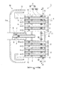
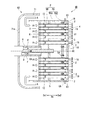
- FIG. 3 is a cross-sectional view taken along the line III-III in FIG. 2, illustrating a fuel injector according to the first embodiment of the present invention.
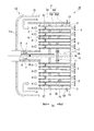
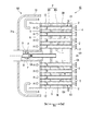
- FIG. 3 is a cross-sectional view taken along the line III-III in FIG. 2, illustrating a fuel injector according to a second embodiment of the present invention.
- FIG. 3 is a cross-sectional view taken along the line III-III in FIG. 2, illustrating a fuel injector according to a third embodiment of the present invention.
- FIG. 3 is a cross-sectional view taken along the line III-III in FIG.
- FIG. 3 is a cross-sectional view taken along the line III-III in FIG. 2, illustrating a fuel injector according to a fifth embodiment of the present invention. It is the front view which looked at another form of the fuel injector of this invention from the downstream.
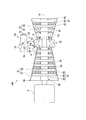
- the gas turbine 100 of the present embodiment combusts a mixed gas of a compressor 51 that compresses outside air Ao to generate compressed air A, and compressed air A and fuel gas F, thereby producing combustion gas.
- a plurality of combustors 52 that generate G, a turbine 53 that is driven by the combustion gas G, and a cooling device 54 that cools a cooling target of the gas turbine 100 are provided.
- the compressor 51 includes a compressor rotor 56 that rotates about the gas turbine axis Ar, a compressor casing 57 that rotatably covers the compressor rotor 56, and a plurality of compressor vane rows 58. .
- the compressor rotor 56 includes a compressor rotor shaft 59 extending along the gas turbine axis Ar and a plurality of compressor blade rows 60 attached to the compressor rotor shaft 59.
- the plurality of compressor rotor cascades 60 are arranged in the axial direction of the gas turbine axis Ar.
- Each compressor moving blade row 60 is composed of a plurality of moving blades arranged in the circumferential direction of the gas turbine axis Ar.
- a compressor stationary blade row 58 is disposed on each downstream side of the plurality of compressor moving blade rows 60.
- Each compressor stationary blade row 58 is fixed inside the compressor casing 57.
- Each compressor stationary blade row 58 is composed of a plurality of stationary blades arranged in the circumferential direction of the gas turbine axis Ar.
- the turbine 53 includes a turbine rotor 61 that rotates about the gas turbine axis Ar, a turbine casing 62 that rotatably covers the turbine rotor 61, and a plurality of turbine stationary blade rows 63.
- the turbine rotor 61 includes a turbine rotor shaft 64 extending along the gas turbine axis Ar, and a plurality of turbine rotor blade rows 65 attached to the turbine rotor shaft 64.
- the plurality of turbine rotor blade rows 65 are arranged in the axial direction of the gas turbine axis Ar.
- Each turbine rotor blade row 65 is composed of a plurality of rotor blades arranged in the circumferential direction of the gas turbine axis Ar.
- a turbine stationary blade row 63 is arranged on each upstream side of the plurality of turbine blade rows 65.
- Each turbine stationary blade row 63 is fixed inside the turbine casing 62.
- Each turbine stationary blade row 63 is composed of a plurality of stationary blades arranged in the circumferential direction of the gas turbine axis Ar.
- the gas turbine 100 further includes a cylindrical intermediate casing 67 around the gas turbine axis Ar.
- the intermediate casing 67 is disposed between the compressor casing 57 and the turbine casing 62 in the axial direction of the gas turbine axis Ar.
- the compressor rotor 56 and the turbine rotor 61 are located on the same gas turbine axis Ar, and are connected to each other to form a gas turbine rotor 68.
- the rotor of the generator G is connected to the gas turbine rotor 68.
- the combustor 52 generates a high-temperature and high-pressure combustion gas G by supplying the fuel gas F to the compressed air A compressed by the compressor 51.
- the plurality of combustors 52 are fixed to the intermediate casing 67 at intervals in the circumferential direction of the gas turbine axis Ar.
- the combustor 52 includes a fuel injector 1 and a combustion cylinder 69 that combusts a gas in which compressed air A and fuel gas F injected from the fuel injector 1 are mixed and guides the combustion gas G to the turbine 53. ing.
- the outside air Ao taken into the compressor 51 passes through the plurality of compressor stationary blade rows 58 and the compressor moving blade row 60 and is compressed to become high-temperature and high-pressure compressed air A.
- the compressed gas A is mixed with the fuel gas F in the combustor 52 and burned, whereby a high-temperature and high-pressure combustion gas G is generated.
- the combustion gas G passes through the turbine stationary blade row 63 and the turbine rotor blade row 65 of the turbine 53, so that the turbine rotor shaft 64 is rotationally driven, and rotational power is supplied to the generator G connected to the gas turbine rotor 68. Power is generated by granting.
- the cooling device 54 is a device that extracts a part of the compressed air A supplied to the combustor 52 and compresses it again to cool the cooling target of the gas turbine 100.
- the object to be cooled is a component that is exposed to a high temperature.
- the cooling device 54 includes an extraction unit 72 that extracts a part of the compressed air A, a cooler 73 that cools the extracted compressed air A, and further compresses the compressed air A that has been cooled by the cooler 73 to generate cooling air CA.
- the cooling air introduction part 76 is connected to the cooling air supply tube 9 of the fuel injector 1.
- one cooling system 54 is provided for one gas turbine 100, but multiple cooling systems 54 may be provided for one gas turbine 100.
- Compressed air A compressed again by the forced air-cooled compressor 74 is supplied as cooling air CA to the fuel injector 1 of the combustor 52 through the cooling air introduction section 76.
- the cooling air CA may be supplied to another cooling target of the gas turbine 100, for example, a stationary blade.
- the combustor 52 includes a cylindrical outer cylinder 71 and the fuel injector 1 disposed inside the outer cylinder 71.
- the compressed air A that has flowed in between the outer cylinder 71 and the fuel injector 1 turns 180 ° at the end wall 71 a of the outer cylinder 71 and is supplied to the fuel injector 1.
- the fuel injector 1 of the present embodiment includes a fuel supply tube 8 that supplies a fuel gas F, a plurality of premixing tubes 2, and a support plate 3 that supports an end of the upstream Da1 of the plurality of premixing tubes 2. , A substrate 4 that supports the ends of the downstream Da2 of the plurality of premixing tubes 2, a cylindrical outer wall 5 that forms a plenum P therein, and a plenum P divided into a fuel plenum PF and a cooling air plenum PA And a baffle 7 disposed on the downstream side Da2 of the partition plate 6, and a cooling air supply tube 9 for supplying the cooling air CA to the cooling air plenum PA.
- the baffle 7 divides the cooling air plenum PA into an upstream side cooling air plenum PA1 and a downstream side cooling air plenum PA2 disposed on the downstream side Da2 of the upstream side cooling air plenum PA1.
- the main surface of the support plate 3, the main surface of the partition plate 6, the main surface of the baffle 7, and the main surface of the substrate 4 are orthogonal to the axis At of the fuel supply tube 8.
- the direction in which the axis At of the fuel supply tube 8 extends is defined as the axis direction Da.
- a direction perpendicular to the axis At is defined as a radial direction, a side away from the axis At in the radial direction is referred to as a radially outer side, and a side closer to the axis At in the radial direction is referred to as a radially inner side.
- the side where the fuel gas F in the axial direction Da is introduced (the left side in FIG. 2) is the upstream side Da1
- the side where the fuel gas F in the axial direction Da is injected is the downstream side Da2. That is, in the fuel injector 1 of the present embodiment, the fuel gas F and the compressed air A circulate from the upstream Da1 toward the downstream Da2.
- the fuel gas F is introduced from the upstream side Da ⁇ b> 1 by the fuel supply tube 8.
- the fuel injector 1 mixes the introduced fuel gas F with the compressed air A through the premixing tube 2, and then injects and discharges the fuel gas F toward the downstream Da2.
- the fuel supply tube 8 distributes the fuel gas F supplied from the upstream side Da1 to the fuel plenum PF.
- the fuel supply tube 8 extends in a tubular shape centered on the axis At.
- the fuel supply tube 8 is connected to the support plate 3 on the downstream side Da2.
- the end of the downstream side Da2 of the fuel supply tube 8 opens into the fuel plenum PF. That is, the position in the axial direction Da of the end portion of the downstream side Da 2 of the fuel supply tube 8 is the downstream side Da 2 of the support plate 3 and the upstream side Da 1 of the partition plate 6.
- the cooling air supply tube 9 distributes the cooling air CA supplied from the cooling device 54 (upstream Da1) to the upstream cooling air plenum PA1.
- the cooling air supply tube 9 is arranged on the radially inner side of the fuel supply tube 8 so as to be coaxial with the fuel supply tube 8. That is, the fuel gas F flows through the radial gap between the cooling air supply tube 9 and the fuel supply tube 8.
- the end portion of the downstream side Da2 of the cooling air supply tube 9 opens into the upstream side cooling air plenum PA1. That is, the position in the axial direction Da of the end portion of the downstream side Da2 of the cooling air supply tube 9 is the downstream side Da2 of the partition plate 6 and the upstream side Da1 of the baffle 7.
- the support plate 3 has a disc shape centered on the axis At, and a circular through hole is formed at the center.
- the through hole is formed with the same diameter as the outer diameter of the fuel supply tube 8.
- the support plate 3 is connected to the fuel supply tube 8 in a state where the end of the fuel supply tube 8 is inserted into the through hole so as to protrude to the downstream side Da2.
- the support plate 3 is formed with a plurality of through holes for inserting and supporting the plurality of premixing tubes 2.
- the substrate 4 has substantially the same outer diameter as the support plate 3 and is formed in a disc shape with the axis At as the center.
- the substrate 4 is connected to the support plate 3 via the outer wall 5, thereby defining a plenum P that is a space inside with the support plate 3.
- a plurality of through holes for inserting and supporting the plurality of premixing tubes 2 are formed at positions corresponding to the through holes formed in the support plate 3.
- the outer wall 5 connects the outer periphery of the support plate 3 and the outer periphery of the substrate 4.
- the outer side wall 5 has a cylindrical shape formed with an inner diameter that is the same as the outer diameter of the support plate 3 and the substrate 4.
- the outer wall 5 is connected to the support plate 3 on the upstream side Da1.
- the outer wall 5 is connected to the substrate 4 at the end of the downstream side Da2. Therefore, a plenum P is provided as a defined space inside the support plate 3 and the substrate 4 connected by the outer wall 5.
- the partition plate 6 is a plate that partitions the plenum P into a fuel plenum PF, a fuel plenum PF, and a cooling air plenum PA disposed on the downstream side Da2 of the fuel plenum PF.
- the partition plate 6 has substantially the same outer diameter as the support plate 3 and is formed in a disc shape with the axis At as the center.
- the partition plate 6 is disposed on the downstream side Da ⁇ b> 2 of the support plate 3 and on the upstream side Da ⁇ b> 1 of the substrate 4.
- a circular through hole is formed at the center of the partition plate 6.
- the through hole is formed with the same diameter as the outer diameter of the cooling air supply tube 9.
- the partition plate 6 is connected to the cooling air supply tube 9 in a state where the end of the cooling air supply tube 9 is inserted into the through hole so as to protrude to the downstream side Da2.
- a plurality of through holes for inserting and supporting the plurality of premixing tubes 2 are formed in the partition plate 6 at positions corresponding to the through holes formed in the support plate 3.
- the baffle 7 is a plate that divides the cooling air plenum PA into an upstream cooling air plenum PA1 and a downstream cooling air plenum PA2 disposed on the downstream Da2 of the upstream cooling air plenum PA1.
- the baffle 7 has the same outer diameter as the partition plate 6 and is formed in a disc shape with the axis At as the center.
- the baffle 7 is disposed on the downstream side Da ⁇ b> 2 of the partition plate 6 and on the upstream side Da ⁇ b> 1 of the substrate 4.
- a plurality of through holes for inserting and supporting the plurality of premixing tubes 2 are formed at positions corresponding to the through holes formed in the support plate 3.
- the baffle 7 is formed with a plurality of cooling holes 11 for communicating the upstream side cooling air plenum PA1 and the downstream side cooling air plenum PA2.
- the cooling hole 11 is a hole extending in the axial direction Da. That is, the cooling air CA introduced into the upstream side cooling air plenum PA1 through the cooling air supply tube 9 is introduced into the downstream side cooling air plenum PA2 through the plurality of cooling holes 11.
- the premixing tube 2 is a tube material having a cylindrical shape extending in the axial direction Da. Compressed air A is introduced into the premixing tube 2 from the upstream side Da1, and a mixed gas of the compressed air A and the fuel gas F is discharged from the downstream side Da2. In the premixing tube 2, the end of the upstream Da 1 is supported by the support plate 3, and the end of the downstream Da 2 is supported by the substrate 4.
- the premixing tube 2 of the present embodiment is fixed so that the end of the upstream side Da1 is substantially flush without protruding from the support plate 3 to the upstream side Da1.
- the premixing tube 2 is fixed so that the end portion of the downstream side Da2 does not protrude from the substrate 4 to the downstream side Da2 and is substantially flush.
- a fuel introduction hole 12 that penetrates the premixing tube 2 inward and outward in the radial direction is formed in a portion located in the fuel plenum PF.
- the fuel introduction hole 12 is a through hole through which the fuel gas F flows into the premixing tube 2 by the plenum P.
- the fuel introduction hole 12 has a circular cross-sectional shape and penetrates the premixing tube 2 in the radial direction.
- the fuel introduction hole 12 is formed on the upstream side Da ⁇ b> 1 with respect to the partition plate 6.
- the position of the fuel introduction hole 12 in the axial direction Da is the same in all the premixing tubes 2.
- the outer wall 5 is formed with a plurality of cooling air discharge holes 13 penetrating into and out of the plenum P.
- the cooling air discharge hole 13 is formed in a portion located in the downstream side cooling air plenum PA2.
- the plurality of cooling air discharge holes 13 are formed at equal intervals in the circumferential direction around the axis At.
- a plurality of premix tubes 2 are provided for the support plate 3 and the substrate 4.
- the plurality of premixing tubes 2 are formed to have the same cross-sectional shape and the same length.
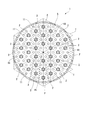
- the plurality of premixing tubes 2 are arranged such that, when viewed from the axial direction Da, the cross-sectional area of the plenum P orthogonal to the axial line At is spread with a plurality of virtual equilateral triangles T about the axial line At. When partitioned, the virtual equilateral triangle T is arranged at the vertex position.
- the virtual equilateral triangle T is an equilateral triangle that is arranged in a plurality so as to spread radially around the axis At on a virtual plane that is a cross-sectional area of the plenum P orthogonal to the axis At.
- the length of one side in the virtual equilateral triangle T is determined from the distance from the axis At where the premixing tube 2 is arranged and the distance between the premixing tubes 2 adjacent to each other.
- virtual equilateral triangles T having the same side length and the same shape are spread in the cross-sectional area of the plenum P.
- the plurality of premixing tubes 2 are arranged at the vertices of the virtual equilateral triangle T, and are arranged so that the number gradually increases in the radial direction from the axis At toward the center. .
- the plurality of cooling holes 11 are arranged at the center position of the virtual equilateral triangle T when viewed from the axial direction Da.
- the fuel gas F is introduced into the fuel plenum PF from the upstream side Da1 via the fuel supply tube 8.
- the fuel gas F introduced into the fuel plenum PF is taken into the premixing tube 2 through the fuel introduction hole 12.
- the premixing tube 2 into which the fuel gas F flows the compressed air A introduced from the upstream side Da1 and the fuel gas F are mixed, and the mixed gas is injected from the downstream side Da2.
- the cooling air CA is introduced from the upstream side Da1 to the upstream side cooling air plenum PA1 via the cooling air supply tube 9.
- the cooling air CA introduced into the upstream side cooling air plenum PA ⁇ b> 1 is jetted from the plurality of cooling holes 11 and collides with the substrate 4.
- substrate 4 can be cooled similarly to impingement cooling by injecting the cooling air CA by the cooling hole 11.
- the cooling air CA used for cooling the substrate 4 is discharged radially outward from the cooling air discharge hole 13.
- the cooling air CA introduced into the upstream side cooling air plenum PA1 is jetted toward the substrate 4 through the cooling holes 11 of the baffle 7 to efficiently cool the substrate 4 that reaches a high temperature.
- the flame generated by the injection of the fuel gas F and the compressed air A becomes an adhering flame that adheres to the outlet (injection hole) of the premixing tube 2, and the substrate 4 is actively cooled when the temperature of the substrate 4 becomes high. be able to.
- the compressed air A generated by the compressor 51 is extracted, and the compressed air A extracted by using the forced air-cooled compressor 74 of the cooling device 54 is re-pressurized, so that the pressure is higher than that of the extracted compressed air.
- Air CA can be supplied. Further, by cooling the compressed air A using the cooler 73, it is possible to supply cooling air CA having a temperature lower than that of the extracted compressed air A.
- cooling air supply tube 9 is arranged on the radially inner side of the fuel supply tube 8 so as to be coaxial with the fuel supply tube 8, an increase in the temperature of the cooling air CA can be suppressed. That is, the cooling air supply tube 9 can be connected to the plenum P without being exposed to the compressed air A that is higher in temperature than the fuel gas F.
- the fuel injector 1B of the second embodiment of the present invention will be described in detail with reference to the drawings.
- differences from the first embodiment described above will be mainly described, and description of similar parts will be omitted.
- the fuel injector 1B of the present embodiment is different from the fuel injector of the first embodiment in the shape of the baffle.
- the baffle 7 ⁇ / b> B of the present embodiment has a baffle body 15 disposed on the radially inner side and an inclined portion 16 disposed on the radially outer side of the baffle body 15.
- the diameter of the baffle body 15 is smaller than the diameter of the substrate 4.
- the diameter of the baffle body 15 can be set to about 1/3 of the diameter of the substrate 4.
- the baffle body 15 is formed with a plurality of cooling holes 11 similar to the baffle 7 of the first embodiment.
- the inclined portion 16 is a plate-like member formed so as to connect the outer periphery of the baffle body 15 and the inner peripheral surface of the outer wall 5.
- the inclined portion 16 is inclined toward the downstream side Da2 as it goes outward in the radial direction. In other words, the inclined portion 16 is formed so as to gradually increase in diameter toward the downstream side Da2.
- the cooling hole 11 is not formed in the inclined portion 16.
- the cooling air CA introduced into the upstream side cooling air plenum PA1 is jetted from the plurality of cooling holes 11 to the downstream side cooling air plenum PA2, and then cools the vicinity of the center of the substrate 4, It flows radially outward along the inclined portion 16. That is, the cooling air CA introduced into the downstream side cooling air plenum PA ⁇ b> 2 is directed radially outward along the inclined portion 16 of the baffle 7. As a result, not only the substrate 4 but also the premixing tube 2 in the downstream side cooling air plenum PA2 can be cooled.
- a fuel injector 1C according to a third embodiment of the present invention will be described in detail with reference to the drawings.
- differences from the first embodiment described above will be mainly described, and description of similar parts will be omitted.
- a second cooling air discharge hole 17 is formed in the substrate 4C of the present embodiment. That is, the fuel injector 1 of the present embodiment has the second cooling air discharge hole 17 formed in the substrate 4 in addition to the cooling air discharge hole 13 formed in the outer wall 5.
- the cooling air discharge hole 13 in the outer wall 5 may be omitted.
- the second cooling air discharge hole 17 is a through hole extending in the axial direction Da.
- the position of the second cooling air discharge hole 17 of the present embodiment viewed from the axial direction Da is different from the position of the cooling hole 11 of the baffle 7.
- the cooling air CA is discharged without colliding with the substrate 4. Can be suppressed.
- the premixing tube 2 of the fuel injector 1D of the present embodiment has a cooling air introduction hole 18 that penetrates the premixing tube 2 in and out of the premixing tube 2 at a portion located in the downstream side cooling air plenum PA2. Is formed.
- the cooling air introduction hole 18 is a through hole through which the cooling air CA flows into the premixing tube 2 by the downstream side cooling air plenum PA2.
- the cooling air introduction hole 18 has a circular cross-sectional shape and penetrates the premixing tube 2 in the radial direction.
- the fuel introduction hole 12 is formed on the downstream side Da ⁇ b> 2 with respect to the baffle 7.
- the position of the cooling air introduction hole 18 in the axial direction Da is the same in all the premixing tubes 2.
- the cooling air introduction hole 18 is oriented such that the cooling air CA flows toward the downstream side Da2. In other words, the central axis of the cooling air introduction hole 18 is inclined from the outer peripheral surface of the premixing tube 2 toward the downstream Da2 toward the inner peripheral surface of the premixing tube 2.
- a fuel injector 1E according to a fifth embodiment of the present invention will be described in detail with reference to the drawings.
- differences from the first embodiment described above will be mainly described, and description of similar parts will be omitted.
- the baffle 7 ⁇ / b> E of the present embodiment is provided on the downstream Da ⁇ b> 2 rather than the downstream Da ⁇ b> 2 end of the cooling air supply tube 9.
- the baffle 7E is not formed so as to partition the cooling air plenum PA, and a cooling air inflow hole 19 is formed at the center thereof.
- the baffle 7E is formed at the center of the diameter-enlarged portion 20 and the diameter-enlarged portion 20 that is inclined to the downstream Da2 and connected to the outer wall 5 toward the outer side in the radial direction centered on the axis At. And a cooling air inflow hole 19.
- the position in the axial direction Da of the end portion (cooling air inflow hole 19) on the upstream side Da1 of the enlarged diameter portion 20 is the same as the position of the end portion on the downstream side Da2 of the cooling air supply tube 9, or slightly downstream side Da2. .
- the diameter of the cooling air inflow hole 19 is slightly larger than the outer diameter of the cooling air supply tube 9.
- the cooling air inflow hole 19 has a circular shape, and the center is disposed on the axis At.
- the cooling air CA supplied from the cooling air supply tube 9 flows into the cooling air inflow hole 19 and then collides with the substrate 4.
- the cooling air CA introduced into the cooling air plenum PA flows from the cooling air inflow hole 19 to the downstream Da2 of the baffle 7.
- the inflowing cooling air CA flows radially outward along the enlarged diameter portion 20 while cooling the vicinity of the center of the substrate 4. That is, the cooling air CA is directed radially outward along the enlarged diameter portion 20 of the baffle 7.
- the fuel supply tube 8 and the cooling air supply tube 9 were set as the structure arrange
- the cooling air supply tube 9 may be connected to the outer wall 5 and the cooling air CA may be introduced into the cooling air plenum PA through a through hole formed in the outer wall 5.
- the one fuel injector 1 is arrange
- a plurality of fuel injectors having a cylindrical outer wall may be disposed in the combustion cylinder 69.
- the cross-sectional shape of each fuel injector need not be circular.
- a cylindrical outer wall 5A and a plurality of walls 5B that divide the inside of the outer wall 5A in the circumferential direction are provided, and a plurality of fan-like shapes are provided in one combustor 52A.
- a fuel injector 1A may be provided.
Landscapes
- Engineering & Computer Science (AREA)
- Chemical & Material Sciences (AREA)
- Combustion & Propulsion (AREA)
- Mechanical Engineering (AREA)
- General Engineering & Computer Science (AREA)
- Gas Burners (AREA)
- Turbine Rotor Nozzle Sealing (AREA)
- Fuel-Injection Apparatus (AREA)
Abstract
燃料供給チューブ(8)と、複数の予混合チューブ(2)と、燃料供給チューブ(8)及び複数の予混合チューブ(2)を支持する支持プレート(3)と、複数の予混合チューブ(8)の下流側端部を支持する基板(4)と、内部にプレナム(P)を形成する筒状の外側壁(5)と、プレナム(P)を燃料プレナム(PF)と冷却空気プレナム(PA)とに区画する仕切板(6)と、冷却空気プレナム(PA)を上流側冷却空気プレナム(PA1)と下流側冷却空気プレナム(PA2)とに区画し、複数の冷却孔(11)が形成されたバッフル(7)と、上流側冷却空気プレナム(PA1)に冷却空気を供給する冷却空気供給チューブ(9)と、を備え、燃料供給チューブ(8)の下流側の端部は、燃料プレナム(PF)内で開口され、予混合チューブ(2)の燃料プレナム(PF)に位置する部分に、予混合チューブ(2)を内外に貫通する燃料導入孔(12)が形成されている燃料噴射器(1)を提供する。
Description
本発明は、燃料噴射器及びガスタービンに関する。
本願は、2017年4月28日に出願された特願2017-090705号について優先権を主張し、その内容をここに援用する。
本願は、2017年4月28日に出願された特願2017-090705号について優先権を主張し、その内容をここに援用する。
ガスタービンでは燃料ガスを燃焼器に供給する際に、燃料噴射器によって圧縮空気と燃料ガスとを予め均一に混合させて霧状にして噴射している。
このような燃料噴射器として、例えば特許文献1には、圧縮空気と燃料ガスとの混合気体を円形の基板に規則的に形成された複数の噴出孔から噴出する燃料噴射器が開示されている。このような燃料噴射器では、火炎が噴射孔の出口に付着する付着火炎となることがあり、これにより、基板が高温となるため、基板の冷却が必要となる。
ところで、特許文献1に記載されている燃料噴射器では、燃料ガスが導入される筐体の内部に設けられるバッフルの形状の見直しにより、燃料噴射器を低温に保っているが、基板の高温化対策として、更なる対策が望まれている。
この発明は、高温となる基板を効率良く冷却することができる燃料噴射器及びガスタービンを提供することを目的とする。
本発明の第一の態様によれば、燃料噴射器は、軸線を中心とする管状をなして、前記軸線の延びる軸線方向の上流側から燃料ガスが導入される燃料供給チューブと、前記軸線方向に延在する管状をなし、上流側から空気が導入される複数の予混合チューブと、前記燃料供給チューブの前記軸線方向の下流側及び前記複数の予混合チューブの上流側端部を支持する支持プレートと、前記複数の予混合チューブの下流側端部を支持する基板と、前記支持プレートと前記基板とを連結し、かつ、前記支持プレートと前記基板とともに内部にプレナムを形成する筒状の外側壁と、前記プレナムを燃料プレナムと前記燃料プレナムと前記燃料プレナムの下流側に配置された冷却空気プレナムとに区画する仕切板と、前記仕切板の下流側に配置され、前記冷却空気プレナムを上流側冷却空気プレナムと前記上流側冷却空気プレナムの下流側に配置された下流側冷却空気プレナムとに区画し、複数の冷却孔が形成されたバッフルと、前記上流側冷却空気プレナムに冷却空気を供給する冷却空気供給チューブと、を備え、前記燃料供給チューブの下流側の端部は、前記燃料プレナム内で開口され、前記予混合チューブの前記燃料プレナムに位置する部分に、前記予混合チューブを内外に貫通する燃料導入孔が形成されている。
このような構成によれば、上流側冷却空気プレナムに導入された冷却空気がバッフルの冷却孔を介して基板に向けて噴射されて、高温となる基板を効率良く冷却することができる。
上記燃料噴射器において、複数の前記冷却孔の少なくとも一部は、インピンジ孔であってよい。
上記燃料噴射器において、前記バッフルは、前記冷却孔が形成され、前記軸線を中心とする径方向内側に設けられたバッフル本体と、前記バッフル本体と前記外側壁との間に配置され、前記軸線を中心とする径方向外側に向かうにしたがって下流側に傾斜し、前記冷却孔が形成されていない傾斜部と、を有してよい。
このような構成によれば、上流側冷却空気プレナムに導入された冷却空気は、複数の冷却孔から下流側冷却空気プレナム噴射された後、基板を冷却しつつ、傾斜部に沿って径方向外側に流れる。下流側冷却空気プレナムに導入された冷却空気は、バッフルの傾斜部に沿って径方向外側に方向付けられる。これにより、基板のみならず、下流側冷却空気プレナム内の予混合チューブも冷却することができる。
上記燃料噴射器において、前記基板に形成され、前記冷却空気を前記下流側冷却空気プレナムから前記基板の下流側に排出する複数の冷却空気排出孔を有してよい。
このような構成によれば、燃料ガス及び圧縮空気の噴射により発生する火炎が予混合チューブの出口に付着するのを抑制することができる。また、火炎が付着した場合においても、火炎自体の温度を低減することができる。
上記燃料噴射器において、前記予混合チューブの前記下流側冷却空気プレナムに位置する部分に、前記予混合チューブを内外に貫通する冷却空気導入孔が形成されてよい。
このような構成によれば、基板を冷却した冷却空気の一部を予混合チューブの内部に導入することによって、遡上してくる火炎を抑制することができる。
上記燃料噴射器において、前記冷却空気供給チューブは、前記燃料供給チューブの径方向内側に前記燃料供給チューブと同軸に配置されてよい。
このような構成によれば、冷却空気の温度の上昇を抑制することができる。即ち、冷却空気供給チューブを圧縮空気に曝すことなく、プレナムに接続することができる。
本実施形態の第二の態様によれば、燃料噴射器は、軸線を中心とする管状をなして、前記軸線の延びる軸線方向の上流側から燃料ガスが導入される燃料供給チューブと、前記軸線方向に延在する管状をなし、上流側から空気が導入される複数の予混合チューブと、前記燃料供給チューブの下流側及び前記複数の予混合チューブの上流側端部を支持する支持プレートと、前記複数の予混合チューブの下流側端部を支持する基板と、前記支持プレートと前記基板とを連結し、かつ、前記支持プレートと前記基板とともに内部にプレナムを形成する筒状の外側壁と、前記プレナムを燃料プレナムと前記燃料プレナムと前記燃料プレナムの下流側に配置された冷却空気プレナムとに区画する仕切板と、前記冷却空気プレナムに冷却空気を供給する冷却空気供給チューブと、前記冷却空気供給チューブの下流側端部よりも下流側に設けられ、記軸線を中心とする径方向外側に向かうにしたがって下流側に傾斜して前記外側壁に接続された拡径部と、前記拡径部の前記軸線を中心とする径方向の中央に形成され、前記冷却空気供給チューブから供給される前記冷却空気が流入される冷却空気流入孔と、を有するバッフルと、を備え、前記予混合チューブの前記燃料プレナムに位置する部分に、前記予混合チューブを内外に貫通する燃料導入孔が形成されている。
このような構成によれば、冷却空気流入孔からバッフルの下流側に流入した冷却空気は、基板の中央近傍を冷却しつつ、拡径部に沿って径方向外側に流れる。即ち、冷却空気は、バッフルの拡径部に沿って径方向外側に方向付けられる。これにより、高温となる基板を効率良く冷却することができるとともに、冷却空気プレナム内の予混合チューブも冷却することができる。
本発明の第三の態様によれば、ガスタービンは、空気を圧縮した圧縮空気を生成する圧縮機と、上記何れかの燃料噴射器を有し、前記圧縮空気に燃料を混合させて燃焼ガスを生成する燃焼器と、前記圧縮機によって生成された圧縮空気を抽気する抽気部と、抽気された前記圧縮空気を更に圧縮する強制空冷圧縮機と、前記強制空冷圧縮機によって生成された冷却空気を前記燃料噴射器に導入する冷却空気導入部と、を備える。
このような構成によれば、圧縮機によって生成した圧縮空気を再加圧することによって、抽気した圧縮空気よりも高い圧力の冷却空気を供給することができる。
上記ガスタービンにおいて、前記抽気部により抽気された前記圧縮空気を冷却するクーラーを有してよい。
このような構成によれば、クーラーを使用して圧縮空気を冷却することによって、抽気した圧縮空気よりも低温の冷却空気を供給することができる。
このような構成によれば、クーラーを使用して圧縮空気を冷却することによって、抽気した圧縮空気よりも低温の冷却空気を供給することができる。
本発明によれば、上流側冷却空気プレナムに導入された冷却空気がバッフルの冷却孔を介して基板に向けて噴射されて、高温となる基板を効率良く冷却することができる。
〔第一実施形態〕
以下、本発明の第一実施形態の燃料噴射器1を備えるガスタービン100について図面を参照して詳細に説明する。
図1に示すように、本実施形態のガスタービン100は、外気Aoを圧縮して圧縮空気Aを生成する圧縮機51と、圧縮空気Aと燃料ガスFとの混合気体を燃焼させて燃焼ガスGを生成する複数の燃焼器52と、燃焼ガスGにより駆動するタービン53と、ガスタービン100の冷却対象を冷却する冷却装置54と、を備えている。
以下、本発明の第一実施形態の燃料噴射器1を備えるガスタービン100について図面を参照して詳細に説明する。
図1に示すように、本実施形態のガスタービン100は、外気Aoを圧縮して圧縮空気Aを生成する圧縮機51と、圧縮空気Aと燃料ガスFとの混合気体を燃焼させて燃焼ガスGを生成する複数の燃焼器52と、燃焼ガスGにより駆動するタービン53と、ガスタービン100の冷却対象を冷却する冷却装置54と、を備えている。
圧縮機51は、ガスタービン軸線Arを中心として回転する圧縮機ロータ56と、圧縮機ロータ56を回転可能に覆う圧縮機車室57と、複数の圧縮機静翼列58と、を有している。
圧縮機ロータ56は、ガスタービン軸線Arに沿って延びる圧縮機ロータ軸59と、圧縮機ロータ軸59に取り付けられている複数の圧縮機動翼列60と、を有している。複数の圧縮機動翼列60は、ガスタービン軸線Arの軸線方向に並んでいる。各々の圧縮機動翼列60は、いずれも、ガスタービン軸線Arの周方向に並んでいる複数の動翼で構成される。複数の圧縮機動翼列60の各下流側には、圧縮機静翼列58が配置されている。各々の圧縮機静翼列58は、いずれも、圧縮機車室57の内側に固定されている。各々の圧縮機静翼列58は、いずれも、ガスタービン軸線Arの周方向に並んでいる複数の静翼で構成される。
タービン53は、ガスタービン軸線Arを中心として回転するタービンロータ61と、タービンロータ61を回転可能に覆うタービン車室62と、複数のタービン静翼列63と、を有している。タービンロータ61は、ガスタービン軸線Arに沿って延びるタービンロータ軸64と、タービンロータ軸64に取り付けられている複数のタービン動翼列65と、を有している。
複数のタービン動翼列65は、ガスタービン軸線Arの軸線方向に並んでいる。各々のタービン動翼列65は、いずれも、ガスタービン軸線Arの周方向に並んでいる複数の動翼で構成される。複数のタービン動翼列65の各上流側には、タービン静翼列63が配置されている。各々のタービン静翼列63は、タービン車室62の内側に固定されている。各々のタービン静翼列63は、いずれも、ガスタービン軸線Arの周方向に並んでいる複数の静翼で構成されている。
ガスタービン100は、さらに、ガスタービン軸線Arを中心として筒状の中間車室67を備えている。中間車室67は、ガスタービン軸線Arの軸線方向で、圧縮機車室57とタービン車室62との間に配置されている。圧縮機ロータ56とタービンロータ61とは、同一のガスタービン軸線Ar上に位置し、互いに接続されてガスタービンロータ68を成している。ガスタービンロータ68には、例えば、発電機Gのロータが接続されている。
燃焼器52は、圧縮機51で圧縮された圧縮空気Aに対して燃料ガスFを供給することで、高温・高圧の燃焼ガスGを生成するものである。
複数の燃焼器52は、ガスタービン軸線Arの周方向に互いの間隔をあけて、中間車室67に固定されている。燃焼器52は、燃料噴射器1と、燃料噴射器1から噴射される圧縮空気Aと燃料ガスFとが混合された気体を燃焼させ、燃焼ガスGをタービン53に導く燃焼筒69を有している。
複数の燃焼器52は、ガスタービン軸線Arの周方向に互いの間隔をあけて、中間車室67に固定されている。燃焼器52は、燃料噴射器1と、燃料噴射器1から噴射される圧縮空気Aと燃料ガスFとが混合された気体を燃焼させ、燃焼ガスGをタービン53に導く燃焼筒69を有している。
圧縮機51に取り込まれた外気Aoは、複数の圧縮機静翼列58と圧縮機動翼列60とを通過して圧縮されることで高温・高圧の圧縮空気Aとなる。この圧縮空気Aに対し、燃焼器52において燃料ガスFが混合されて燃焼されることで高温・高圧の燃焼ガスGが生成される。そして、燃焼ガスGがタービン53のタービン静翼列63とタービン動翼列65とを通過することでタービンロータ軸64が回転駆動され、ガスタービンロータ68に連結された発電機Gに回転動力を付与することで発電を行う。
冷却装置54は、燃焼器52へ供給される圧縮空気Aの一部を抽気し、再び圧縮してガスタービン100の冷却対象を冷却する装置である。冷却対象は、高温に曝される部品である。
冷却装置54は、圧縮空気Aの一部を抽気する抽気部72と、抽気された圧縮空気Aを冷却するクーラー73と、クーラー73によって冷却された圧縮空気Aを更に圧縮して冷却空気CAとする強制空冷圧縮機74と、強制空冷圧縮機74のサージを防止するためのアンチサージ弁75と、冷却空気CAを燃焼器52の燃料噴射器1に導入する冷却空気導入部76を有している。冷却空気導入部76は、燃料噴射器1の冷却空気供給チューブ9に接続されている。
説明のため図1では冷却装置54は1基のガスタービン100に対して1系統設けているが、1基のガスタービン100に対して複数系統の冷却装置54を設けてもよい。
冷却装置54は、圧縮空気Aの一部を抽気する抽気部72と、抽気された圧縮空気Aを冷却するクーラー73と、クーラー73によって冷却された圧縮空気Aを更に圧縮して冷却空気CAとする強制空冷圧縮機74と、強制空冷圧縮機74のサージを防止するためのアンチサージ弁75と、冷却空気CAを燃焼器52の燃料噴射器1に導入する冷却空気導入部76を有している。冷却空気導入部76は、燃料噴射器1の冷却空気供給チューブ9に接続されている。
説明のため図1では冷却装置54は1基のガスタービン100に対して1系統設けているが、1基のガスタービン100に対して複数系統の冷却装置54を設けてもよい。
強制空冷圧縮機74によって再び圧縮された圧縮空気Aは、冷却空気CAとして冷却空気導入部76を介して燃焼器52の燃料噴射器1に供給される。冷却空気CAは、ガスタービン100の他の冷却対象、例えば、静翼に供給されてよい。
図2に示すように、燃焼器52は、筒状の外筒71と、外筒71の内部に配置された燃料噴射器1と、を有している。外筒71と燃料噴射器1との間から流入した圧縮空気Aは、外筒71の端壁71aで180°転回し、燃料噴射器1に供給される。
本実施形態の燃料噴射器1は、燃料ガスFを供給する燃料供給チューブ8と、複数の予混合チューブ2と、複数の予混合チューブ2の上流側Da1の端部を支持する支持プレート3と、複数の予混合チューブ2の下流側Da2の端部を支持する基板4と、内部にプレナムPを形成する筒状の外側壁5と、プレナムPを燃料プレナムPFと冷却空気プレナムPAとに区画する仕切板6と、仕切板6の下流側Da2に配置されたバッフル7と、冷却空気プレナムPAに冷却空気CAを供給する冷却空気供給チューブ9と、を備えている。
バッフル7は、冷却空気プレナムPAを上流側冷却空気プレナムPA1と上流側冷却空気プレナムPA1の下流側Da2に配置された下流側冷却空気プレナムPA2とに区画する。支持プレート3の主面、仕切板6の主面、バッフル7の主面、及び基板4の主面は、燃料供給チューブ8の軸線Atと直交している。
バッフル7は、冷却空気プレナムPAを上流側冷却空気プレナムPA1と上流側冷却空気プレナムPA1の下流側Da2に配置された下流側冷却空気プレナムPA2とに区画する。支持プレート3の主面、仕切板6の主面、バッフル7の主面、及び基板4の主面は、燃料供給チューブ8の軸線Atと直交している。
以下の説明において、燃料供給チューブ8の軸線Atが延びている方向を軸線方向Daとする。また、軸線Atに直交する方向を径方向とし、この径方向で軸線Atから遠ざかる側を径方向外側と言い、この径方向で軸線Atに近づく側を径方向内側という。軸線方向Daの燃料ガスFが導入されてくる側(図2紙面左側)を上流側Da1、軸線方向Daの燃料ガスFが噴射される側(図2紙面右側)を下流側Da2とする。即ち、本実施形態の燃料噴射器1では、燃料ガスF及び圧縮空気Aが上流側Da1から下流側Da2に向かって流通している。
燃料噴射器1では、燃料供給チューブ8によって、上流側Da1から燃料ガスFが導入される。燃料噴射器1は、導入された燃料ガスFを予混合チューブ2で圧縮空気Aと混合した後に、下流側Da2に向かって噴射させて排出する。
燃料供給チューブ8は、上流側Da1から供給されてくる燃料ガスFを燃料プレナムPFまで流通させている。燃料供給チューブ8は、軸線Atを中心とする管状をなして延びている。燃料供給チューブ8は、下流側Da2で支持プレート3と接続されている。
燃料供給チューブ8の下流側Da2の端部は、燃料プレナムPF内に開口している。即ち、燃料供給チューブ8の下流側Da2の端部の軸線方向Daの位置は、支持プレート3の下流側Da2であって仕切板6の上流側Da1である。
燃料供給チューブ8の下流側Da2の端部は、燃料プレナムPF内に開口している。即ち、燃料供給チューブ8の下流側Da2の端部の軸線方向Daの位置は、支持プレート3の下流側Da2であって仕切板6の上流側Da1である。
冷却空気供給チューブ9は、冷却装置54(上流側Da1)から供給されてくる冷却空気CAを上流側冷却空気プレナムPA1に流通させている。冷却空気供給チューブ9は、燃料供給チューブ8の径方向内側に燃料供給チューブ8と同軸をなすように配置されている。即ち、燃料ガスFは、冷却空気供給チューブ9と燃料供給チューブ8との間の径方向の隙間を流通する。冷却空気供給チューブ9の下流側Da2の端部は、上流側冷却空気プレナムPA1内に開口している。即ち、冷却空気供給チューブ9の下流側Da2の端部の軸線方向Daの位置は、仕切板6の下流側Da2であってバッフル7の上流側Da1である。
支持プレート3は、軸線Atを中心とする円板状をなしており、中心に円形状の貫通孔が形成されている。この貫通孔は、燃料供給チューブ8の外径と同じ径で形成されている。支持プレート3は、この貫通孔に燃料供給チューブ8の端部が下流側Da2に飛び出すように挿入された状態で、燃料供給チューブ8と接続されている。支持プレート3には、複数の予混合チューブ2を挿通させて支持するための複数の貫通孔が形成されている。
基板4は、支持プレート3と略同じ外径をなし、軸線Atを中心として円板状に形成されている。基板4は、外側壁5を介して支持プレート3と連結されることで、支持プレート3とともに内側に空間であるプレナムPを画成している。基板4には、複数の予混合チューブ2を挿通させて支持するための複数の貫通孔が、支持プレート3に形成された貫通孔と対応する位置に形成されている。
外側壁5は、支持プレート3の外周と基板4の外周とを接続している。外側壁5は、支持プレート3及び基板4の外径と同じ大きさの内径で形成された円筒状をなしている。外側壁5は、上流側Da1で支持プレート3と接続されている。外側壁5は、下流側Da2の端部で基板4と接続されている。したがって、外側壁5によって接続された支持プレート3と基板4との内側に、画成された空間としてプレナムPが設けられている。
仕切板6は、プレナムPを燃料プレナムPFと燃料プレナムPFと燃料プレナムPFの下流側Da2に配置された冷却空気プレナムPAとに区画する板である。仕切板6は、支持プレート3と略同じ外径をなし、軸線Atを中心として円板状に形成されている。仕切板6は、支持プレート3の下流側Da2であって、基板4の上流側Da1に配置されている。
仕切板6の中心には、円形状の貫通孔が形成されている。貫通孔は、冷却空気供給チューブ9の外径と同じ径で形成されている。仕切板6は、この貫通孔に冷却空気供給チューブ9の端部が下流側Da2に飛び出すように挿入された状態で、冷却空気供給チューブ9と接続されている。仕切板6には、複数の予混合チューブ2を挿通させて支持するための複数の貫通孔が、支持プレート3に形成された貫通孔と対応する位置に形成されている。
バッフル7は、冷却空気プレナムPAを上流側冷却空気プレナムPA1と上流側冷却空気プレナムPA1の下流側Da2に配置された下流側冷却空気プレナムPA2とに区画する板である。バッフル7は、仕切板6と同じ外径をなし、軸線Atを中心として円板状に形成されている。バッフル7は、仕切板6の下流側Da2であって、基板4の上流側Da1に配置されている。
バッフル7には、複数の予混合チューブ2を挿通させて支持するための複数の貫通孔が、支持プレート3に形成された貫通孔と対応する位置に形成されている。
バッフル7には、上流側冷却空気プレナムPA1と下流側冷却空気プレナムPA2とを連通させる複数の冷却孔11が形成されている。冷却孔11は、軸線方向Daに延在する孔である。即ち、冷却空気供給チューブ9を介して上流側冷却空気プレナムPA1に導入された冷却空気CAは、複数の冷却孔11を介して下流側冷却空気プレナムPA2に導入される。
バッフル7には、上流側冷却空気プレナムPA1と下流側冷却空気プレナムPA2とを連通させる複数の冷却孔11が形成されている。冷却孔11は、軸線方向Daに延在する孔である。即ち、冷却空気供給チューブ9を介して上流側冷却空気プレナムPA1に導入された冷却空気CAは、複数の冷却孔11を介して下流側冷却空気プレナムPA2に導入される。
予混合チューブ2は、軸線方向Daに延在する円筒状の形状を有する管材である。予混合チューブ2には、上流側Da1から圧縮空気Aが導入され、下流側Da2から圧縮空気Aと燃料ガスFとの混合気体が排出される。予混合チューブ2は、上流側Da1の端部が支持プレート3によって支持され、下流側Da2の端部が基板4によって支持される。
本実施形態の予混合チューブ2は、上流側Da1の端部が支持プレート3から上流側Da1に突出せずに略面一となるように固定されている。予混合チューブ2は、下流側Da2の端部が基板4から下流側Da2に突出せずに略面一となるように固定されている。予混合チューブ2には、径方向に向かって予混合チューブ2を内外に貫通する燃料導入孔12が、燃料プレナムPFに位置する部分に形成されている。
燃料導入孔12は、プレナムPで燃料ガスFを予混合チューブ2内に流入させる貫通孔である。燃料導入孔12は、円形状の断面形状をなしており、予混合チューブ2を径方向に貫通している。燃料導入孔12は、仕切板6よりも上流側Da1に形成されている。燃料導入孔12の軸線方向Daの位置は、全ての予混合チューブ2で同じである。
外側壁5には、プレナムPの内外に貫通する複数の冷却空気排出孔13が形成されている。冷却空気排出孔13は、下流側冷却空気プレナムPA2に位置する部分に形成されている。複数の冷却空気排出孔13は、軸線Atを中心とした周方向に等間隔に形成されている。
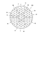
予混合チューブ2は、支持プレート3及び基板4に対して複数設けられている。複数の予混合チューブ2は、互いに同じ断面形状及び同じ長さとなるように形成されている。複数の予混合チューブ2は、図3に示すように、軸線方向Daから見た際に、軸線Atと直交するプレナムPの断面領域が軸線Atを中心として複数の仮想正三角形Tを敷き詰めるように区画された場合に、仮想正三角形Tの頂点の位置に配置されている。仮想正三角形Tは、軸線Atと直交するプレナムPの断面領域である仮想の平面上で、軸線Atを中心として放射状に広がるように複数配置される正三角形である。仮想正三角形Tにおける一辺の長さは、予混合チューブ2を配置する軸線Atから距離や近接する予混合チューブ2同士の距離から定められる。本実施形態では、辺の長さが同じ同形状の仮想正三角形TがプレナムPの断面領域に敷き詰められている。
複数の予混合チューブ2は、仮想正三角形Tの頂点に配置されることにより、軸線Atを中心に径方向外側に向かうに連れて放射状をなして徐々に数が増加するように配置されている。
複数の冷却孔11は、軸線方向Daから見た際に、仮想正三角形Tの中心の位置に配置されている。
次に、燃料噴射器1の作用について説明する。
本実施形態の燃料噴射器1では、燃料供給チューブ8を介して上流側Da1から燃料ガスFが燃料プレナムPFに導入される。燃料プレナムPFに導入された燃料ガスFは、燃料導入孔12を介して予混合チューブ2に取り込まれる。燃料ガスFが流入した予混合チューブ2内では、上流側Da1から導入された圧縮空気Aと燃料ガスFとが混合され、混合気体が下流側Da2から噴射される。
本実施形態の燃料噴射器1では、燃料供給チューブ8を介して上流側Da1から燃料ガスFが燃料プレナムPFに導入される。燃料プレナムPFに導入された燃料ガスFは、燃料導入孔12を介して予混合チューブ2に取り込まれる。燃料ガスFが流入した予混合チューブ2内では、上流側Da1から導入された圧縮空気Aと燃料ガスFとが混合され、混合気体が下流側Da2から噴射される。
本実施形態の燃料噴射器1では、冷却空気供給チューブ9を介して上流側Da1から冷却空気CAが上流側冷却空気プレナムPA1に導入される。上流側冷却空気プレナムPA1に導入された冷却空気CAは、複数の冷却孔11から噴射されて基板4に衝突する。このように、冷却孔11により冷却空気CAを噴射することで、基板4をインピンジメント冷却と同様に冷却することができる。即ち、冷却孔11の少なくとも一部は、インピンジ孔である。
基板4の冷却に使用された冷却空気CAは、冷却空気排出孔13から径方向外側に排出される。
基板4の冷却に使用された冷却空気CAは、冷却空気排出孔13から径方向外側に排出される。
上記実施形態によれば、上流側冷却空気プレナムPA1に導入された冷却空気CAがバッフル7の冷却孔11を介して基板4に向けて噴射されて、高温となる基板4を効率良く冷却することができる。即ち、燃料ガスF及び圧縮空気Aの噴射により発生する火炎が予混合チューブ2の出口(噴射孔)に付着する付着火炎となり、基板4が高温となった場合に基板4を積極的に冷却することができる。
また、圧縮機51によって生成した圧縮空気Aを抽気し、冷却装置54の強制空冷圧縮機74を用いて抽気された圧縮空気Aを再加圧することによって、抽気した圧縮空気よりも高い圧力の冷却空気CAを供給することができる。
また、クーラー73を使用して圧縮空気Aを冷却することによって、抽気した圧縮空気Aよりも低温の冷却空気CAを供給することができる。
また、クーラー73を使用して圧縮空気Aを冷却することによって、抽気した圧縮空気Aよりも低温の冷却空気CAを供給することができる。
また、冷却空気供給チューブ9が燃料供給チューブ8の径方向内側に燃料供給チューブ8と同軸をなすように配置されていることによって、冷却空気CAの温度の上昇を抑制することができる。即ち、冷却空気供給チューブ9を燃料ガスFよりも高温である圧縮空気Aに曝すことなく、プレナムPに接続することができる。
〔第二実施形態〕
以下、本発明の第二実施形態の燃料噴射器1Bについて図面を参照して詳細に説明する。なお、本実施形態では、上述した第一実施形態との相違点を中心に述べ、同様の部分についてはその説明を省略する。
図4に示すように、本実施形態の燃料噴射器1Bは、バッフルの形状が第一実施形態の燃料噴射器と相違する。
本実施形態のバッフル7Bは、径方向内側に配置されたバッフル本体15と、バッフル本体15の径方向外側に配置された傾斜部16と、を有している。
以下、本発明の第二実施形態の燃料噴射器1Bについて図面を参照して詳細に説明する。なお、本実施形態では、上述した第一実施形態との相違点を中心に述べ、同様の部分についてはその説明を省略する。
図4に示すように、本実施形態の燃料噴射器1Bは、バッフルの形状が第一実施形態の燃料噴射器と相違する。
本実施形態のバッフル7Bは、径方向内側に配置されたバッフル本体15と、バッフル本体15の径方向外側に配置された傾斜部16と、を有している。
バッフル本体15の直径は、基板4の直径よりも小さい。バッフル本体15の直径は、基板4の直径の1/3程度に設定することができる。バッフル本体15には、第一実施形態のバッフル7と同様の複数の冷却孔11が形成されている。
傾斜部16は、バッフル本体15の外周と外側壁5の内周面とを接続するように形成された板状の部材である。傾斜部16は、径方向外側に向かうにしたがって、下流側Da2に傾斜している。換言すれば、傾斜部16は、下流側Da2に向かうにしたがって漸次拡径するように形成されている。傾斜部16には、冷却孔11は形成されていない。
傾斜部16は、バッフル本体15の外周と外側壁5の内周面とを接続するように形成された板状の部材である。傾斜部16は、径方向外側に向かうにしたがって、下流側Da2に傾斜している。換言すれば、傾斜部16は、下流側Da2に向かうにしたがって漸次拡径するように形成されている。傾斜部16には、冷却孔11は形成されていない。
上記実施形態によれば、上流側冷却空気プレナムPA1に導入された冷却空気CAは、複数の冷却孔11から下流側冷却空気プレナムPA2に噴射された後、基板4の中央近傍を冷却しつつ、傾斜部16に沿って径方向外側に流れる。即ち、下流側冷却空気プレナムPA2に導入された冷却空気CAは、バッフル7の傾斜部16に沿って径方向外側に方向付けられる。これにより、基板4のみならず、下流側冷却空気プレナムPA2内の予混合チューブ2も冷却することができる。
〔第三実施形態〕
以下、本発明の第三実施形態の燃料噴射器1Cについて図面を参照して詳細に説明する。なお、本実施形態では、上述した第一実施形態との相違点を中心に述べ、同様の部分についてはその説明を省略する。
図5に示すように、本実施形態の基板4Cには、第二冷却空気排出孔17が形成されている。即ち、本実施形態の燃料噴射器1は、外側壁5に形成されている冷却空気排出孔13に加えて、基板4に形成されている第二冷却空気排出孔17を有している。なお、外側壁5の冷却空気排出孔13を省略してもよい。
以下、本発明の第三実施形態の燃料噴射器1Cについて図面を参照して詳細に説明する。なお、本実施形態では、上述した第一実施形態との相違点を中心に述べ、同様の部分についてはその説明を省略する。
図5に示すように、本実施形態の基板4Cには、第二冷却空気排出孔17が形成されている。即ち、本実施形態の燃料噴射器1は、外側壁5に形成されている冷却空気排出孔13に加えて、基板4に形成されている第二冷却空気排出孔17を有している。なお、外側壁5の冷却空気排出孔13を省略してもよい。
第二冷却空気排出孔17は、軸線方向Daに延在する貫通孔である。本実施形態の第二冷却空気排出孔17の軸線方向Daから見た位置は、バッフル7の冷却孔11の位置と異なっている。
上記実施形態によれば、燃料ガスF及び圧縮空気Aの噴射により発生する火炎が予混合チューブ2の出口に付着するのを抑制することができる。また、火炎が付着した場合においても、火炎自体の温度を低減することができる。
また、軸線方向Daから見た第二冷却空気排出孔17の位置が、バッフル7の冷却孔11の位置と異なっていることによって、冷却空気CAが基板4と衝突することなく排出されるのを抑制することができる。
〔第四実施形態〕
以下、本発明の第四実施形態の燃料噴射器1Dについて図面を参照して詳細に説明する。なお、本実施形態では、上述した第一実施形態との相違点を中心に述べ、同様の部分についてはその説明を省略する。
図6に示すように、本実施形態の燃料噴射器1Dの予混合チューブ2には、予混合チューブ2を内外に貫通する冷却空気導入孔18が、下流側冷却空気プレナムPA2に位置する部分に形成されている。冷却空気導入孔18は、下流側冷却空気プレナムPA2で、冷却空気CAを予混合チューブ2内に流入させる貫通孔である。
以下、本発明の第四実施形態の燃料噴射器1Dについて図面を参照して詳細に説明する。なお、本実施形態では、上述した第一実施形態との相違点を中心に述べ、同様の部分についてはその説明を省略する。
図6に示すように、本実施形態の燃料噴射器1Dの予混合チューブ2には、予混合チューブ2を内外に貫通する冷却空気導入孔18が、下流側冷却空気プレナムPA2に位置する部分に形成されている。冷却空気導入孔18は、下流側冷却空気プレナムPA2で、冷却空気CAを予混合チューブ2内に流入させる貫通孔である。
冷却空気導入孔18は、円形状の断面形状をなしており、予混合チューブ2を径方向に貫通している。燃料導入孔12は、バッフル7よりも下流側Da2に形成されている。冷却空気導入孔18の軸線方向Daの位置は、全ての予混合チューブ2で同じである。
冷却空気導入孔18は、冷却空気CAが、下流側Da2に向かって流れるように方向付けられている。換言すれば、冷却空気導入孔18の中心軸は、予混合チューブ2の外周面から予混合チューブ2の内周面に向かって下流側Da2に傾斜している。
冷却空気導入孔18は、冷却空気CAが、下流側Da2に向かって流れるように方向付けられている。換言すれば、冷却空気導入孔18の中心軸は、予混合チューブ2の外周面から予混合チューブ2の内周面に向かって下流側Da2に傾斜している。
上記実施形態によれば、基板4を冷却した冷却空気CAの一部を予混合チューブ2の内部に導入することによって、遡上してくる火炎を抑制することができる。
〔第五実施形態〕
以下、本発明の第五実施形態の燃料噴射器1Eについて図面を参照して詳細に説明する。なお、本実施形態では、上述した第一実施形態との相違点を中心に述べ、同様の部分についてはその説明を省略する。
図7に示すように、本実施形態のバッフル7Eは、冷却空気供給チューブ9の下流側Da2端部よりも下流側Da2に設けられている。バッフル7Eは、冷却空気プレナムPAを区画するように形成されておらず、その中央部に冷却空気流入孔19が形成されている。
バッフル7Eは、軸線Atを中心とする径方向外側に向かうにしたがって下流側Da2に傾斜して外側壁5に接続された拡径部20と、拡径部20の径方向の中央に形成されている冷却空気流入孔19と、を有している。
以下、本発明の第五実施形態の燃料噴射器1Eについて図面を参照して詳細に説明する。なお、本実施形態では、上述した第一実施形態との相違点を中心に述べ、同様の部分についてはその説明を省略する。
図7に示すように、本実施形態のバッフル7Eは、冷却空気供給チューブ9の下流側Da2端部よりも下流側Da2に設けられている。バッフル7Eは、冷却空気プレナムPAを区画するように形成されておらず、その中央部に冷却空気流入孔19が形成されている。
バッフル7Eは、軸線Atを中心とする径方向外側に向かうにしたがって下流側Da2に傾斜して外側壁5に接続された拡径部20と、拡径部20の径方向の中央に形成されている冷却空気流入孔19と、を有している。
拡径部20の上流側Da1の端部(冷却空気流入孔19)の軸線方向Daの位置は、冷却空気供給チューブ9の下流側Da2の端部の位置と同じか、やや下流側Da2である。
冷却空気流入孔19の孔径は、冷却空気供給チューブ9の外径よりもやや大きい。冷却空気流入孔19は円形をなし、中心が軸線At上に配置されている。
冷却空気流入孔19の孔径は、冷却空気供給チューブ9の外径よりもやや大きい。冷却空気流入孔19は円形をなし、中心が軸線At上に配置されている。
冷却空気供給チューブ9から供給される冷却空気CAは、冷却空気流入孔19に流入した後、基板4に衝突する。
上記実施形態によれば、冷却空気プレナムPAに導入された冷却空気CAは、冷却空気流入孔19からバッフル7の下流側Da2に流入する。流入した冷却空気CAは、基板4の中央近傍を冷却しつつ、拡径部20に沿って径方向外側に流れる。即ち、冷却空気CAは、バッフル7の拡径部20に沿って径方向外側に方向付けられる。これにより、基板4のみならず、冷却空気プレナムPA内の予混合チューブ2も冷却することができる。
以上、本発明の実施形態について図面を参照して詳述したが、各実施形態における各構成及びそれらの組み合わせ等は一例であり、本発明の趣旨から逸脱しない範囲内で、構成の付加、省略、置換、およびその他の変更が可能である。また、本発明は実施形態によって限定されることはなく、特許請求の範囲によってのみ限定される。
なお、上記実施形態では、燃料供給チューブ8と冷却空気供給チューブ9とは、同軸上に配置されている構成としたがこれに限ることはない。例えば、冷却空気供給チューブ9を外側壁5に接続して、外側壁5に形成した貫通孔を介して冷却空気プレナムPAに冷却空気CAを導入する構成としてもよい。
また、上記実施形態では、一つの燃焼筒69内に一つの燃料噴射器1が配置されているが、これに限ることはない。例えば、燃焼筒69内に、筒状の外側壁を有する複数の燃料噴射器が配置されてもよい。
また、一つの燃焼器内に複数の燃料噴射器を配置する場合、各々の燃料噴射器の断面形状を円形とする必要はない。例えば、図8に示すように、円筒形の外側壁5Aと、外側壁5Aの内部を周方向に区画する複数の複数の壁5Bとを設け、一つの燃焼器52A内に複数の扇形状の燃料噴射器1Aを設けてもよい。
また、一つの燃焼器内に複数の燃料噴射器を配置する場合、各々の燃料噴射器の断面形状を円形とする必要はない。例えば、図8に示すように、円筒形の外側壁5Aと、外側壁5Aの内部を周方向に区画する複数の複数の壁5Bとを設け、一つの燃焼器52A内に複数の扇形状の燃料噴射器1Aを設けてもよい。
1 燃料噴射器
2 予混合チューブ
3 支持プレート
4 基板
5,5A 外側壁
5B 壁
6 仕切板
7 バッフル
8 燃料供給チューブ
9 冷却空気供給チューブ
11 冷却孔
12 燃料導入孔
13 冷却空気排出孔
15 バッフル本体
16 傾斜部
17 第二冷却空気排出孔
18 冷却空気導入孔
19 冷却空気流入孔
20 拡径部
51 圧縮機
52 燃焼器
53 タービン
54 冷却装置
67 中間車室
72 抽気部
73 クーラー
74 強制空冷圧縮機
76 冷却空気導入部
100 ガスタービン
A 圧縮空気
Ar 軸線
At 軸線
CA 冷却空気
Da 軸線方向
Da1 上流側
Da2 下流側
G 燃焼ガス
F 燃料ガス
P プレナム
PF 燃料プレナム
PA 冷却空気プレナム
PA1 上流側冷却空気プレナム
PA2 下流側冷却空気プレナム
2 予混合チューブ
3 支持プレート
4 基板
5,5A 外側壁
5B 壁
6 仕切板
7 バッフル
8 燃料供給チューブ
9 冷却空気供給チューブ
11 冷却孔
12 燃料導入孔
13 冷却空気排出孔
15 バッフル本体
16 傾斜部
17 第二冷却空気排出孔
18 冷却空気導入孔
19 冷却空気流入孔
20 拡径部
51 圧縮機
52 燃焼器
53 タービン
54 冷却装置
67 中間車室
72 抽気部
73 クーラー
74 強制空冷圧縮機
76 冷却空気導入部
100 ガスタービン
A 圧縮空気
Ar 軸線
At 軸線
CA 冷却空気
Da 軸線方向
Da1 上流側
Da2 下流側
G 燃焼ガス
F 燃料ガス
P プレナム
PF 燃料プレナム
PA 冷却空気プレナム
PA1 上流側冷却空気プレナム
PA2 下流側冷却空気プレナム
Claims (9)
- 軸線を中心とする管状をなして、前記軸線の延びる軸線方向の上流側から燃料ガスが導入される燃料供給チューブと、
前記軸線方向に延在する管状をなし、上流側から空気が導入される複数の予混合チューブと、
前記燃料供給チューブの前記軸線方向の下流側及び前記複数の予混合チューブの上流側端部を支持する支持プレートと、
前記複数の予混合チューブの下流側端部を支持する基板と、
前記支持プレートと前記基板とを連結し、かつ、前記支持プレートと前記基板とともに内部にプレナムを形成する筒状の外側壁と、
前記プレナムを燃料プレナムと前記燃料プレナムの下流側に配置された冷却空気プレナムとに区画する仕切板と、
前記仕切板の下流側に配置され、前記冷却空気プレナムを上流側冷却空気プレナムと前記上流側冷却空気プレナムの下流側に配置された下流側冷却空気プレナムとに区画し、複数の冷却孔が形成されたバッフルと、
前記上流側冷却空気プレナムに冷却空気を供給する冷却空気供給チューブと、を備え、
前記燃料供給チューブの下流側の端部は、前記燃料プレナム内で開口され、
前記予混合チューブの前記燃料プレナムに位置する部分に、前記予混合チューブを内外に貫通する燃料導入孔が形成されている燃料噴射器。 - 複数の前記冷却孔の少なくとも一部は、インピンジ孔であることを特徴とする請求項1に記載の燃料噴射器。
- 前記バッフルは、
前記冷却孔が形成され、前記軸線を中心とする径方向内側に設けられたバッフル本体と、
前記バッフル本体と前記外側壁との間に配置され、前記軸線を中心とする径方向外側に向かうにしたがって下流側に傾斜し、前記冷却孔が形成されていない傾斜部と、を有する請求項1又は請求項2に記載の燃料噴射器。 - 前記基板に形成され、前記冷却空気を前記下流側冷却空気プレナムから前記基板の下流側に排出する複数の冷却空気排出孔を有する請求項1から請求項3のいずれか一項に記載の燃料噴射器。
- 前記予混合チューブの前記下流側冷却空気プレナムに位置する部分に、前記予混合チューブを内外に貫通する冷却空気導入孔が形成されている請求項1から請求項4のいずれか一項に記載の燃料噴射器。
- 前記冷却空気供給チューブは、前記燃料供給チューブの径方向内側に前記燃料供給チューブと同軸に配置されている請求項1から請求項5のいずれか一項に記載の燃料噴射器。
- 軸線を中心とする管状をなして、前記軸線の延びる軸線方向の上流側から燃料ガスが導入される燃料供給チューブと、
前記軸線方向に延在する管状をなし、上流側から空気が導入される複数の予混合チューブと、
前記燃料供給チューブの下流側及び前記複数の予混合チューブの上流側端部を支持する支持プレートと、
前記複数の予混合チューブの下流側端部を支持する基板と、
前記支持プレートと前記基板とを連結し、かつ、前記支持プレートと前記基板とともに内部にプレナムを形成する筒状の外側壁と、
前記プレナムを燃料プレナムと前記燃料プレナムの下流側に配置された冷却空気プレナムとに区画する仕切板と、
前記冷却空気プレナムに冷却空気を供給する冷却空気供給チューブと、
前記冷却空気供給チューブの下流側端部よりも下流側に設けられ、
前記軸線を中心とする径方向外側に向かうにしたがって下流側に傾斜して前記外側壁に接続された拡径部と、前記拡径部の前記軸線を中心とする径方向の中央に形成され、前記冷却空気供給チューブから供給される前記冷却空気が流入される冷却空気流入孔と、を有するバッフルと、を備え、
前記予混合チューブの前記燃料プレナムに位置する部分に、前記予混合チューブを内外に貫通する燃料導入孔が形成されている燃料噴射器。 - 空気を圧縮した圧縮空気を生成する圧縮機と、
請求項1から請求項7の何れか一項に記載の燃料噴射器を有し、前記圧縮空気に燃料を混合させて燃焼ガスを生成する燃焼器と、
前記圧縮機によって生成された圧縮空気を抽気する抽気部と、
抽気された前記圧縮空気を更に圧縮する強制空冷圧縮機と、
前記強制空冷圧縮機によって生成された冷却空気を前記燃料噴射器に導入する冷却空気導入部と、を備えるガスタービン。 - 前記抽気部により抽気された前記圧縮空気を冷却するクーラーを有する請求項8に記載のガスタービン。
Priority Applications (4)
| Application Number | Priority Date | Filing Date | Title |
|---|---|---|---|
| CN201880026932.XA CN110573801B (zh) | 2017-04-28 | 2018-04-27 | 燃料喷射器及燃气轮机 |
| KR1020197031286A KR102190537B1 (ko) | 2017-04-28 | 2018-04-27 | 연료 분사기 및 가스 터빈 |
| DE112018002222.6T DE112018002222B4 (de) | 2017-04-28 | 2018-04-27 | Brennstoffinjektor und Gasturbine |
| US16/607,968 US11079113B2 (en) | 2017-04-28 | 2018-04-27 | Fuel injector and gas turbine |
Applications Claiming Priority (2)
| Application Number | Priority Date | Filing Date | Title |
|---|---|---|---|
| JP2017090705A JP6822894B2 (ja) | 2017-04-28 | 2017-04-28 | 燃料噴射器及びガスタービン |
| JP2017-090705 | 2017-04-28 |
Publications (1)
| Publication Number | Publication Date |
|---|---|
| WO2018199289A1 true WO2018199289A1 (ja) | 2018-11-01 |
Family
ID=63918439
Family Applications (1)
| Application Number | Title | Priority Date | Filing Date |
|---|---|---|---|
| PCT/JP2018/017189 Ceased WO2018199289A1 (ja) | 2017-04-28 | 2018-04-27 | 燃料噴射器及びガスタービン |
Country Status (6)
| Country | Link |
|---|---|
| US (1) | US11079113B2 (ja) |
| JP (1) | JP6822894B2 (ja) |
| KR (1) | KR102190537B1 (ja) |
| CN (1) | CN110573801B (ja) |
| DE (1) | DE112018002222B4 (ja) |
| WO (1) | WO2018199289A1 (ja) |
Cited By (3)
| Publication number | Priority date | Publication date | Assignee | Title |
|---|---|---|---|---|
| CN112594734A (zh) * | 2019-10-01 | 2021-04-02 | 三菱动力株式会社 | 燃气轮机燃烧器 |
| EP3896341A1 (en) * | 2020-04-15 | 2021-10-20 | Marvel-Tech Ltd | Gas turbine combustor |
| CN119802674A (zh) * | 2025-02-12 | 2025-04-11 | 清华大学 | 冷却微混喷嘴、燃烧器及燃气轮机 |
Families Citing this family (25)
| Publication number | Priority date | Publication date | Assignee | Title |
|---|---|---|---|---|
| JP6979343B2 (ja) * | 2017-11-30 | 2021-12-15 | 三菱パワー株式会社 | 燃料噴射器、燃焼器、及びガスタービン |
| JP7489759B2 (ja) | 2018-11-20 | 2024-05-24 | 三菱重工業株式会社 | 燃焼器及びガスタービン |
| JP7254540B2 (ja) * | 2019-01-31 | 2023-04-10 | 三菱重工業株式会社 | バーナ及びこれを備えた燃焼器及びガスタービン |
| KR102433673B1 (ko) | 2021-01-11 | 2022-08-18 | 두산에너빌리티 주식회사 | 연료 노즐, 이를 포함하는 연료 노즐 모듈 및 연소기 |
| EP4027059A1 (en) * | 2021-01-12 | 2022-07-13 | Crosstown Power GmbH | Burner, combustor, and method for retrofitting a combustion appliance |
| KR102403750B1 (ko) * | 2021-01-15 | 2022-05-30 | 두산에너빌리티 주식회사 | 멀티 튜브를 갖는 연소기용 노즐, 연소기, 및 이를 포함하는 가스 터빈 |
| KR102437977B1 (ko) * | 2021-01-18 | 2022-08-30 | 두산에너빌리티 주식회사 | 노즐 어셈블리, 연소기 및 이를 포함하는 가스터빈 |
| KR102415892B1 (ko) | 2021-01-27 | 2022-06-30 | 두산에너빌리티 주식회사 | 마이크로 믹서 및 이를 포함하는 연소기 |
| KR102460001B1 (ko) * | 2021-02-17 | 2022-10-26 | 두산에너빌리티 주식회사 | 마이크로 믹서모듈 및 이를 포함하는 연소기 |
| DE102021110614A1 (de) * | 2021-04-26 | 2022-10-27 | Rolls-Royce Deutschland Ltd & Co Kg | Brennkammerbaugruppe für ein Triebwerk mit mindestens einem Wärmetauscherkanal für einzudüsenden Kraftstoff |
| CN113091094B (zh) * | 2021-05-13 | 2023-05-23 | 中国联合重型燃气轮机技术有限公司 | 燃气轮机燃烧室喷嘴及喷嘴中预混燃料和空气的方法 |
| CN113091095B (zh) * | 2021-05-13 | 2023-05-23 | 中国联合重型燃气轮机技术有限公司 | 燃气轮机燃烧室喷嘴及喷嘴中预混燃料和空气的方法 |
| KR102595333B1 (ko) * | 2021-09-17 | 2023-10-27 | 두산에너빌리티 주식회사 | 연소기 및 이를 포함하는 가스터빈 |
| KR20230091605A (ko) * | 2021-12-16 | 2023-06-23 | 한화에어로스페이스 주식회사 | 직교 배열되는 채널을 포함하는 연소 장치 |
| KR102663869B1 (ko) | 2022-01-18 | 2024-05-03 | 두산에너빌리티 주식회사 | 연소기용 노즐, 연소기 및 이를 포함하는 가스 터빈 |
| US11828465B2 (en) * | 2022-01-21 | 2023-11-28 | General Electric Company | Combustor fuel assembly |
| KR102619152B1 (ko) * | 2022-02-21 | 2023-12-27 | 두산에너빌리티 주식회사 | 연소기용 노즐, 연소기, 및 이를 포함하는 가스 터빈 |
| KR102599921B1 (ko) | 2022-03-21 | 2023-11-07 | 두산에너빌리티 주식회사 | 연소기용 노즐, 연소기, 및 이를 포함하는 가스 터빈 |
| JP7650843B2 (ja) * | 2022-03-30 | 2025-03-25 | 三菱重工業株式会社 | 燃焼器及びガスタービン |
| JP2023148761A (ja) * | 2022-03-30 | 2023-10-13 | 三菱重工業株式会社 | 燃焼器及びガスタービン |
| US11867400B1 (en) * | 2023-02-02 | 2024-01-09 | Pratt & Whitney Canada Corp. | Combustor with fuel plenum with mixing passages having baffles |
| DE112024000649T5 (de) * | 2023-03-29 | 2025-11-13 | Mitsubishi Heavy Industries, Ltd. | Brenneranordnung, gasturbinenbrennkammer und gasturbine |
| KR102814686B1 (ko) * | 2023-05-02 | 2025-05-28 | 두산에너빌리티 주식회사 | 연소기용 노즐, 연소기, 및 이를 포함하는 가스 터빈 |
| KR102863421B1 (ko) * | 2023-12-15 | 2025-09-22 | 두산에너빌리티 주식회사 | 연소기용 노즐, 연소기, 및 이를 포함하는 가스 터빈 |
| KR102932015B1 (ko) | 2024-01-25 | 2026-03-03 | 두산에너빌리티 주식회사 | 연소기용 노즐, 연소기, 및 이를 포함하는 가스 터빈 |
Citations (4)
| Publication number | Priority date | Publication date | Assignee | Title |
|---|---|---|---|---|
| JP2011069602A (ja) * | 2009-09-25 | 2011-04-07 | General Electric Co <Ge> | 燃料噴射器用の内部バッフル |
| JP2013139993A (ja) * | 2012-01-03 | 2013-07-18 | General Electric Co <Ge> | タービンエンジンで使用する燃焼器アセンブリ及びその組立方法 |
| JP2013250046A (ja) * | 2012-05-30 | 2013-12-12 | General Electric Co <Ge> | タービンエンジンに使用するための燃料注入組立体及びそれを組み立てる方法 |
| JP2015222023A (ja) * | 2014-05-22 | 2015-12-10 | 三菱日立パワーシステムズ株式会社 | ガスタービン設備、及び冷却装置の運転方法 |
Family Cites Families (7)
| Publication number | Priority date | Publication date | Assignee | Title |
|---|---|---|---|---|
| JP4969384B2 (ja) | 2007-09-25 | 2012-07-04 | 三菱重工業株式会社 | ガスタービン燃焼器の冷却構造 |
| US8112999B2 (en) | 2008-08-05 | 2012-02-14 | General Electric Company | Turbomachine injection nozzle including a coolant delivery system |
| US8157189B2 (en) * | 2009-04-03 | 2012-04-17 | General Electric Company | Premixing direct injector |
| JP5653705B2 (ja) | 2010-09-30 | 2015-01-14 | 三菱重工業株式会社 | 回収式空気冷却ガスタービン燃焼器冷却構造 |
| US8955327B2 (en) | 2011-08-16 | 2015-02-17 | General Electric Company | Micromixer heat shield |
| US9243803B2 (en) * | 2011-10-06 | 2016-01-26 | General Electric Company | System for cooling a multi-tube fuel nozzle |
| US8904798B2 (en) * | 2012-07-31 | 2014-12-09 | General Electric Company | Combustor |
-
2017
- 2017-04-28 JP JP2017090705A patent/JP6822894B2/ja active Active
-
2018
- 2018-04-27 CN CN201880026932.XA patent/CN110573801B/zh active Active
- 2018-04-27 WO PCT/JP2018/017189 patent/WO2018199289A1/ja not_active Ceased
- 2018-04-27 US US16/607,968 patent/US11079113B2/en active Active
- 2018-04-27 DE DE112018002222.6T patent/DE112018002222B4/de active Active
- 2018-04-27 KR KR1020197031286A patent/KR102190537B1/ko active Active
Patent Citations (4)
| Publication number | Priority date | Publication date | Assignee | Title |
|---|---|---|---|---|
| JP2011069602A (ja) * | 2009-09-25 | 2011-04-07 | General Electric Co <Ge> | 燃料噴射器用の内部バッフル |
| JP2013139993A (ja) * | 2012-01-03 | 2013-07-18 | General Electric Co <Ge> | タービンエンジンで使用する燃焼器アセンブリ及びその組立方法 |
| JP2013250046A (ja) * | 2012-05-30 | 2013-12-12 | General Electric Co <Ge> | タービンエンジンに使用するための燃料注入組立体及びそれを組み立てる方法 |
| JP2015222023A (ja) * | 2014-05-22 | 2015-12-10 | 三菱日立パワーシステムズ株式会社 | ガスタービン設備、及び冷却装置の運転方法 |
Cited By (8)
| Publication number | Priority date | Publication date | Assignee | Title |
|---|---|---|---|---|
| CN112594734A (zh) * | 2019-10-01 | 2021-04-02 | 三菱动力株式会社 | 燃气轮机燃烧器 |
| JP2021055973A (ja) * | 2019-10-01 | 2021-04-08 | 三菱パワー株式会社 | ガスタービン燃焼器 |
| US11339969B2 (en) | 2019-10-01 | 2022-05-24 | Mitsubishi Heavy Industries, Ltd. | Gas turbine combustor |
| JP7270517B2 (ja) | 2019-10-01 | 2023-05-10 | 三菱重工業株式会社 | ガスタービン燃焼器 |
| DE102020212361B4 (de) | 2019-10-01 | 2025-03-20 | Mitsubishi Heavy Industries, Ltd. | Gasturbinenverbrennungsvorrichtung |
| EP3896341A1 (en) * | 2020-04-15 | 2021-10-20 | Marvel-Tech Ltd | Gas turbine combustor |
| US11365885B2 (en) | 2020-04-15 | 2022-06-21 | Marvel-Tech Ltd. | Gas turbine combustor with fuel injector including a downstream guide member |
| CN119802674A (zh) * | 2025-02-12 | 2025-04-11 | 清华大学 | 冷却微混喷嘴、燃烧器及燃气轮机 |
Also Published As
| Publication number | Publication date |
|---|---|
| KR20190128232A (ko) | 2019-11-15 |
| US20210102703A1 (en) | 2021-04-08 |
| JP2018189285A (ja) | 2018-11-29 |
| US11079113B2 (en) | 2021-08-03 |
| DE112018002222T5 (de) | 2020-02-20 |
| JP6822894B2 (ja) | 2021-01-27 |
| CN110573801B (zh) | 2021-04-06 |
| DE112018002222B4 (de) | 2024-03-14 |
| CN110573801A (zh) | 2019-12-13 |
| KR102190537B1 (ko) | 2020-12-14 |
Similar Documents
| Publication | Publication Date | Title |
|---|---|---|
| WO2018199289A1 (ja) | 燃料噴射器及びガスタービン | |
| EP3062022B1 (en) | Gas turbine engine mixer assembly with cooling holes | |
| US10145559B2 (en) | Gas turbine engine with igniter stack or borescope mount having noncollinear cooling passages | |
| US10794595B2 (en) | Stepped heat shield for a turbine engine combustor | |
| EP1524471A1 (en) | Methods and apparatus for cooling turbine engine combuster exit temperatures | |
| US11274830B2 (en) | Combustor nozzle, combustor, and gas turbine | |
| US11242994B2 (en) | Combustion chamber for a turbomachine | |
| JP2008008612A (ja) | 空気と燃料の混合物を噴射するための装置と、このような装置を備える燃焼室およびターボ機械 | |
| KR101752114B1 (ko) | 노즐, 연소기, 및 가스 터빈 | |
| JP2018189285A5 (ja) | ||
| JP2010223577A (ja) | スワーラ、少なくとも1つのスワーラを備えたバーナにおける逆火の防止方法およびバーナ | |
| JP2010223577A6 (ja) | スワーラ、少なくとも1つのスワーラを備えたバーナにおける逆火の防止方法およびバーナ | |
| JP2010043643A (ja) | インピンジメント及びエフュージョン冷却式燃焼器部品 | |
| KR20150020135A (ko) | 버너 장치 및 버너 장치를 작동하기 위한 방법 | |
| US20160265773A1 (en) | Turbine engine combustor heat shield with multi-angled cooling apertures | |
| EP3130855B1 (en) | Combustor liner for a gas turbine with a hole arrangement | |
| KR20200002970A (ko) | 연소기 및 그 연소기를 구비하는 가스 터빈 | |
| US20220373182A1 (en) | Pilot fuel nozzle assembly with vented venturi | |
| JP2017115869A (ja) | 燃焼器組立体に使用するための燃焼ライナおよび製造方法 | |
| US11092076B2 (en) | Turbine engine with combustor | |
| US20180266690A1 (en) | Combustion chamber of a turbine engine | |
| US11300296B2 (en) | Combustion chamber of a turbomachine | |
| JP6326205B2 (ja) | 燃料ノズル、燃焼器、及びガスタービン |
Legal Events
| Date | Code | Title | Description |
|---|---|---|---|
| 121 | Ep: the epo has been informed by wipo that ep was designated in this application |
Ref document number: 18789979 Country of ref document: EP Kind code of ref document: A1 |
|
| ENP | Entry into the national phase |
Ref document number: 20197031286 Country of ref document: KR Kind code of ref document: A |
|
| 122 | Ep: pct application non-entry in european phase |
Ref document number: 18789979 Country of ref document: EP Kind code of ref document: A1 |