WO2018198363A1 - Base station device, terminal device, wireless communication system and communication method - Google Patents
Base station device, terminal device, wireless communication system and communication method Download PDFInfo
- Publication number
- WO2018198363A1 WO2018198363A1 PCT/JP2017/017064 JP2017017064W WO2018198363A1 WO 2018198363 A1 WO2018198363 A1 WO 2018198363A1 JP 2017017064 W JP2017017064 W JP 2017017064W WO 2018198363 A1 WO2018198363 A1 WO 2018198363A1
- Authority
- WO
- WIPO (PCT)
- Prior art keywords
- unit
- data
- base station
- identification information
- terminal device
- Prior art date
Links
Images


Classifications
-
- H—ELECTRICITY
- H04—ELECTRIC COMMUNICATION TECHNIQUE
- H04L—TRANSMISSION OF DIGITAL INFORMATION, e.g. TELEGRAPHIC COMMUNICATION
- H04L1/00—Arrangements for detecting or preventing errors in the information received
- H04L1/12—Arrangements for detecting or preventing errors in the information received by using return channel
- H04L1/16—Arrangements for detecting or preventing errors in the information received by using return channel in which the return channel carries supervisory signals, e.g. repetition request signals
- H04L1/18—Automatic repetition systems, e.g. Van Duuren systems
- H04L1/1806—Go-back-N protocols
-
- H—ELECTRICITY
- H04—ELECTRIC COMMUNICATION TECHNIQUE
- H04L—TRANSMISSION OF DIGITAL INFORMATION, e.g. TELEGRAPHIC COMMUNICATION
- H04L1/00—Arrangements for detecting or preventing errors in the information received
- H04L1/12—Arrangements for detecting or preventing errors in the information received by using return channel
- H04L1/16—Arrangements for detecting or preventing errors in the information received by using return channel in which the return channel carries supervisory signals, e.g. repetition request signals
- H04L1/18—Automatic repetition systems, e.g. Van Duuren systems
- H04L1/1867—Arrangements specially adapted for the transmitter end
- H04L1/1887—Scheduling and prioritising arrangements
-
- H—ELECTRICITY
- H04—ELECTRIC COMMUNICATION TECHNIQUE
- H04L—TRANSMISSION OF DIGITAL INFORMATION, e.g. TELEGRAPHIC COMMUNICATION
- H04L1/00—Arrangements for detecting or preventing errors in the information received
- H04L1/12—Arrangements for detecting or preventing errors in the information received by using return channel
- H04L1/16—Arrangements for detecting or preventing errors in the information received by using return channel in which the return channel carries supervisory signals, e.g. repetition request signals
- H04L1/1607—Details of the supervisory signal
- H04L1/1614—Details of the supervisory signal using bitmaps
-
- H—ELECTRICITY
- H04—ELECTRIC COMMUNICATION TECHNIQUE
- H04L—TRANSMISSION OF DIGITAL INFORMATION, e.g. TELEGRAPHIC COMMUNICATION
- H04L1/00—Arrangements for detecting or preventing errors in the information received
- H04L1/12—Arrangements for detecting or preventing errors in the information received by using return channel
- H04L1/16—Arrangements for detecting or preventing errors in the information received by using return channel in which the return channel carries supervisory signals, e.g. repetition request signals
- H04L1/18—Automatic repetition systems, e.g. Van Duuren systems
- H04L1/1829—Arrangements specially adapted for the receiver end
- H04L1/1854—Scheduling and prioritising arrangements
-
- H—ELECTRICITY
- H04—ELECTRIC COMMUNICATION TECHNIQUE
- H04L—TRANSMISSION OF DIGITAL INFORMATION, e.g. TELEGRAPHIC COMMUNICATION
- H04L1/00—Arrangements for detecting or preventing errors in the information received
- H04L1/12—Arrangements for detecting or preventing errors in the information received by using return channel
- H04L1/16—Arrangements for detecting or preventing errors in the information received by using return channel in which the return channel carries supervisory signals, e.g. repetition request signals
- H04L1/18—Automatic repetition systems, e.g. Van Duuren systems
- H04L1/1867—Arrangements specially adapted for the transmitter end
- H04L1/1874—Buffer management
-
- H—ELECTRICITY
- H04—ELECTRIC COMMUNICATION TECHNIQUE
- H04W—WIRELESS COMMUNICATION NETWORKS
- H04W28/00—Network traffic management; Network resource management
- H04W28/02—Traffic management, e.g. flow control or congestion control
- H04W28/0278—Traffic management, e.g. flow control or congestion control using buffer status reports
-
- H—ELECTRICITY
- H04—ELECTRIC COMMUNICATION TECHNIQUE
- H04W—WIRELESS COMMUNICATION NETWORKS
- H04W72/00—Local resource management
- H04W72/20—Control channels or signalling for resource management
- H04W72/23—Control channels or signalling for resource management in the downlink direction of a wireless link, i.e. towards a terminal
-
- H—ELECTRICITY
- H04—ELECTRIC COMMUNICATION TECHNIQUE
- H04L—TRANSMISSION OF DIGITAL INFORMATION, e.g. TELEGRAPHIC COMMUNICATION
- H04L47/00—Traffic control in data switching networks
- H04L47/50—Queue scheduling
- H04L47/62—Queue scheduling characterised by scheduling criteria
- H04L47/622—Queue service order
- H04L47/6225—Fixed service order, e.g. Round Robin
-
- H—ELECTRICITY
- H04—ELECTRIC COMMUNICATION TECHNIQUE
- H04W—WIRELESS COMMUNICATION NETWORKS
- H04W28/00—Network traffic management; Network resource management
- H04W28/02—Traffic management, e.g. flow control or congestion control
- H04W28/0268—Traffic management, e.g. flow control or congestion control using specific QoS parameters for wireless networks, e.g. QoS class identifier [QCI] or guaranteed bit rate [GBR]
Definitions
- the present invention relates to a base station device, a terminal device, a wireless communication system, and a communication method.
- mobile terminal In the current network, mobile terminal (smartphone and future phone) traffic occupies most of the network resources. In addition, the traffic used by mobile terminals tends to continue to expand.
- next generation for example, 5G (5th generation mobile communication)
- 4G (4th generation mobile communication) standard technology for example, Non-Patent Documents 1 to 11
- 3GPP working groups eg, TSG-RAN WG1, TSG-RAN WG2, etc.
- 5G is classified into eMBB (Enhanced Mobile BroadBand), Massive MTC (Machine Type Communications), and URLLC (Ultra-Reliable and Low Latency Communications) to support a wide variety of services. Assumes support for many use cases.
- eMBB Enhanced Mobile BroadBand
- Massive MTC Machine Type Communications
- URLLC Ultra-Reliable and Low Latency Communications
- HARQ hybrid automatic repeat request
- the receiving apparatus requests the transmitting apparatus side to retransmit the data that could not be correctly decoded in the processing of the layer 1 protocol layer such as LTE.
- the transmission apparatus transmits retransmission data corresponding to the original data retransmission request that could not be correctly decoded on the reception apparatus side.
- data decoding is performed by combining data that could not be correctly decoded and retransmission data.
- Non-patent Document 13 As a new HARQ feedback, it is specified that transport blocks are divided into code block groups (CBG) and HARQ feedback is performed in units of code block groups (Non-patent Document 13).
- the number of code blocks included in a code block group increases, if there is an error in one code block in the group, all the code blocks in the code block group are retransmitted, so that retransmission efficiency does not increase.
- the number of code blocks in a code block group is reduced, the number of groups is increased, and the number of bits used for HARQ feedback is increased, which increases overhead.
- the disclosed technique has been made in view of the above, and an object thereof is to enable HARQ feedback in consideration of retransmission efficiency and the number of bits used for HARQ feedback.
- the base station apparatus includes a storage unit, a reception unit, a communication control unit, and a data transmission unit.
- the storage unit stores a group indicating the unit data to be retransmitted among a predetermined number of unit data included in the transmission data to be transmitted to the terminal device, and identification information for identifying the group in association with each other.
- the receiving unit receives identification information for transmission data transmitted to the terminal device from the terminal device.
- the communication control unit refers to the storage unit based on the identification information received by the reception unit, and determines retransmission of unit data included in a group corresponding to the identification information among transmission data.
- the data transmission unit transmits the unit data included in the group determined to be retransmitted by the communication control unit to the terminal device.
- FIG. 1 is a diagram illustrating an example of a base station apparatus.
- FIG. 2 is a diagram illustrating an example of a terminal device.
- FIG. 3 is a diagram illustrating an example of a CB that is an ACK and a NAK included in the CBG.
- FIG. 4 is a diagram illustrating an example of the first feedback table.
- FIG. 5 is a diagram illustrating a retransmission rate in the example of the first feedback table.
- FIG. 6 is a diagram illustrating an example of the second feedback table.
- FIG. 7 is a diagram illustrating the retransmission rate in the example of the second feedback table.
- FIG. 8 is a diagram showing a retransmission rate in the case of 8 CB per TB.
- FIG. 9 is a diagram illustrating an example of the third feedback table.
- FIG. 10 is a diagram illustrating a retransmission rate in the third feedback table example.
- FIG. 11 is a flowchart illustrating an example of the optimal multi-level CBG search process.
- FIG. 12 is a diagram illustrating an example of a result of the optimal multi-level CBG search process.
- FIG. 13 is a diagram illustrating a retransmission rate in an example of the processing result of the optimal multilevel CBG search.
- FIG. 14 is a diagram illustrating a computer that executes an optimal multilevel CBG search program.
- FIG. 1 is a diagram illustrating an example of a base station apparatus.
- FIG. 2 is a diagram illustrating an example of a terminal device.
- the base station device 1 and the terminal device 2 transmit and receive data by wireless communication.
- the base station apparatus 1 includes a buffer information management unit 11, a buffer 12, a scheduler 13, a downlink signal baseband processing unit 14, an uplink signal baseband processing unit 15, a radio unit 16, and a feedback table 17.
- the feedback table 17 is an example of a storage unit stored in a predetermined storage device.
- the buffer information management unit 11 receives an input of data to be transmitted from the host device (not shown) to the terminal device 2. Then, the buffer information management unit 11 performs buffering of the input data divided into logical channels according to QoS (Quality of Service).
- QoS Quality of Service
- the buffer 12 is a temporary storage area for transmission data acquired by the base station device 1 and transmitted to the terminal device 2.
- the buffer 12 temporarily stores transmission data in units of a transport block (TB: Transport Block, hereinafter referred to as “TB”) which is a transmission unit of transmission data.
- TB Transport Block
- the base station apparatus 1 handles transmission data in units of TB.
- the buffer 12 may have a plurality of buffers depending on the type of data.
- the buffer information management unit 11 stores data to be transmitted in the buffer 12. Then, the buffer information management unit 11 acquires the status of the data stored in the buffer 12 and notifies the scheduler 13 of it.
- One TB includes a plurality of code blocks (CB: Code Block, hereinafter referred to as “CB”).
- CB Code Block
- a group of CBs including one or more CBs to be retransmitted from the base station apparatus 1 to the terminal apparatus 2 in one TB is referred to as a code block group (CBG). "CBG").
- the scheduler 13 receives a notification of the state of the data stored in the buffer 12 from the buffer information management unit 11. Then, when transmitting data, the scheduler 13 specifies data to be transmitted from the data stored in the buffer 12 according to a priority order such as QoS. Further, the scheduler 13 determines the TB size, MCS (Modulation and Coding Scheme) to be used, and radio resources.
- a priority order such as QoS.
- the scheduler 13 determines the TB size, MCS (Modulation and Coding Scheme) to be used, and radio resources.
- the scheduler 13 receives “HARQ-ACK bit” for each TB from the terminal device 2.
- the “HARQ-ACK bit” is identification information for specifying the CBG in the TB.
- each size is determined to be a predetermined size (for example, 6 , 144 bits) is divided into CBs having the maximum value, and encoding is performed.
- a predetermined size for example, 75,376 bits for a 1-layer TB, 149,776 bits for a 2-layer TB
- FIG. 3 is a diagram illustrating an example of a CB that is an ACK and a NAK included in the CBG.
- ACK acknowledgement
- NAK Negative AcKnowledgement
- M CB the number of CBs that have received errors (that is, NAK) in one CBG.
- the M CB CBs include M CB and Error CBs that have received errors, and M CB ⁇ M CB and Error .
- M CB and Error CBs that have received errors
- M CB ⁇ M CB and Error M CB and Error .
- FIG. 3 of the CBG including M CB pieces of CB, indicating the case where the head of the M CB, Error 2 pieces of CB is erroneously received.
- the first factor of the right side of equation (1) represents the number of combinations selected M CB, the Error number from M CB pieces of numbers. Then, the table as from equation (1), in one CBG including M CB pieces of CB, the average probability Pr CBG Error reception error (i.e. NAK) is generated (M CB) is represented by the following formula (2) Is done.
- the downlink signal baseband processing unit 14 receives input of data information to be transmitted or retransmitted, MCS information, control information, and information on radio resources to be used from the scheduler 13. Then, the downlink signal baseband processing unit 14 acquires data corresponding to information on data to be transmitted or retransmitted from the buffer 12. Then, the downlink signal baseband processing unit 14 performs an encoding process on the data and the control information acquired using the encoding rate specified by the received MCS information.
- the downlink signal baseband processing unit 14 performs modulation processing on the data and control information acquired using the modulation scheme specified by the received MCS information. Thereafter, the downlink signal baseband processing unit 14 assigns control information and data to the specified radio resource, places the control information in the PDCCH (Physical Downlink Control Channel), and places the data in the PDSCH (Physical Downlink Shared Channel). . Then, the downlink signal baseband processing unit 14 outputs control information and data to the radio unit 16.
- PDCCH Physical Downlink Control Channel
- PDSCH Physical Downlink Shared Channel
- the radio unit 16 receives control information and data input from the downlink signal baseband processing unit 14.
- the wireless unit 16 performs DA (Digital to Analog) conversion on the control information and data.
- wireless part 16 transmits a control signal and data to the terminal device 2 via an antenna using the allocated radio
- the radio unit 16 receives from the terminal device 2 a signal of “HARQ-ACK bit” stored in the “HARQ-ACK payload” transmitted via the antenna.
- the “HARQ-ACK bit” is index information for identifying the CBG included in the transmitted TB unit.
- the “HARQ-ACK payload” is a data area for storing “HARQ-ACK bits”.
- the wireless unit 16 then performs AD (Analog to Digital) conversion on the received “HARQ-ACK bit” signal. After that, the radio unit 16 outputs the received “HARQ-ACK bit” signal to the uplink signal baseband processing unit 15.
- AD Analog to Digital
- the uplink signal baseband processing unit 15 performs demodulation processing and decoding processing on the “HARQ-ACK bit” signal received from the radio unit 16 to obtain “HARQ-ACK bit”. Then, the uplink signal baseband processing unit 15 outputs the acquired “HARQ-ACK bit” to the scheduler 13 and the buffer information management unit 11.
- the buffer information management unit 11 refers to the feedback table 17 based on the “HARQ-ACK bit” received from the uplink signal baseband processing unit 15. That is, the buffer information management unit 11 acquires “information on CBG to be retransmitted” corresponding to the “HARQ-ACK bit” from the feedback table 17 in the feedback table 17.
- the buffer information management unit 11 notifies the downlink signal baseband processing unit 14 of “information of CBG to be retransmitted” read from the feedback table 17.
- the downlink signal baseband processing unit 14 refers to the buffer 12 based on the “information on CBG to be retransmitted” notified from the buffer information management unit 11, acquires the CBG to be retransmitted, and transmits the radio unit 16. Through the terminal device 2.
- the terminal apparatus 2 includes a radio unit 21, a PDCCH reception processing unit 22, a PDSCH reception processing unit 23, a generation unit 24, an uplink signal baseband processing unit 25, and a feedback table 26.
- the feedback table 26 is an example of a storage unit stored in a predetermined storage device.
- the radio unit 21 receives PDCCH and PDSCH signals including control signals and data from the base station apparatus 1 via the antenna. Then, the radio unit 21 performs AD conversion on the received signal. Thereafter, the radio unit 21 outputs the received PDCCH and PDSCH signals to the PDCCH reception processing unit 22.
- the radio unit 21 receives the “HARQ-ACK bit” signal from the uplink signal baseband processing unit 25. Then, the radio unit 21 performs DA conversion on the “HARQ-ACK bit” signal and obtains the “HARQ-ACK bit” signal. Thereafter, the radio unit 21 transmits the “HARQ-ACK payload” signal to the base station apparatus 1 via the antenna.
- the PDCCH reception processing unit 22 receives the input of the PDCCH and PDSCH signals including the control signal and data from the radio unit 21. Then, the PDCCH reception processing unit 22 performs demodulation processing and decoding processing on the PDCCH signal to obtain a control signal. Then, the PDCCH reception processing unit 22 outputs the PDSCH signal together with the control signal to the PDSCH reception processing unit 23.
- the PDSCH reception processing unit 23 receives the input of the PDSCH signal from the PDCCH reception processing unit 22 together with the control signal. Then, the PDSCH reception processing unit 23 performs demodulation processing and decoding processing for each CB on the PDCCH signal using the MCS specified by the control signal, and acquires data.
- the PDSCH reception processing unit 23 determines whether or not the data has been successfully decoded for each CB of the received TB received from the base station apparatus 1.
- the PDSCH reception processing unit 23 notifies the generation unit 24 of the successful data decoding for the CB in which the data can be decoded in the received TB.
- the generation unit 24 is notified of a data decoding failure notification.
- the generation unit 24 When the generation unit 24 receives a notification of the success or failure of data decoding for each CB of the reception TB from the PDSCH reception processing unit 23, the generation unit 24 generates an “information pattern indicating ACK / NAK”.
- the “pattern of information indicating ACK / NAK” is a pattern in which the ACK or NAK feedback information of each CB included in the received TB is arranged in the CB transmission order. Then, the generation unit 24 refers to the feedback table 26 based on the generated “pattern of information indicating ACK / NAK”, and sets the “HARQ-ACK bit” corresponding to the “pattern of information indicating ACK / NAK”. get. Then, the generation unit 24 outputs the acquired “HARQ-ACK bit” to the uplink signal baseband processing unit 25.
- the uplink signal baseband processing unit 25 performs encoding processing and modulation processing on the received “HARQ-ACK bit”. Then, the uplink signal baseband processing unit 25 arranges the data subjected to the encoding process and the modulation process in a PUCCH (Physical Uplink Control Channel) to generate a “HARQ-ACK bit” signal. Then, the uplink signal baseband processing unit 25 outputs the generated “HARQ-ACK bit” signal to the radio unit 21.
- PUCCH Physical Uplink Control Channel
- FIG. 4 is a diagram illustrating an example of the first feedback table.
- the feedback tables 17-1 and 26-1 according to the first example are tables stored in the base station apparatus 1 as the feedback table 17 and stored in the terminal apparatus 2 as the feedback table 26.
- the feedback tables 17-1 and 26-1 show an example in which four CBs CB-1 to CB-4 are used as transmission unit TBs.
- a plurality of CBs in units of rows is one TB.
- Level-1 a hierarchy in which none of CB-1 to CB-4 is included in the CBG to be retransmitted is the “Level-1” hierarchy.
- the “Level-1” layer has only one type of status in which there is no CBG including the CB to be retransmitted.
- “HARQ-ACK bit” “Index 1-1” is assigned to this one type of status.
- the hierarchy in which any one of the CB-1 to CB-4 is included in the CBG as a retransmission target is the “Level-2” hierarchy.
- the “Level-2” layer has four types of statuses in which CBGs including any one of CB-1 to CB-4 to be retransmitted exist. For example, only the CB-1 is the CBG to be retransmitted, and the “HARQ-ACK bit” “Index2-1” is assigned to the statuses in which the CB-2 to CB-4 are not to be retransmitted.
- “Index2-2” to “Index2-4” shown in FIG. 4 are the same as “Index2-1”.
- the hierarchy in which CB-1 to CB-2 or CB-3 to CB-4 are included in the CBG as retransmission targets is the “Level-3” hierarchy.
- “HARQ-ACK bit” “Index3-1” is assigned to the statuses where CB-1 to CB-2 are CBGs to be retransmitted and CB-3 to CB-4 are not to be retransmitted.
- “Index3-2” shown in FIG. 4 is the same as “Index3-1”.
- the TBs corresponding to “Index 1-1” of “Level-1” shown in the first line are all CB-1 to CB-4. “ACK”.
- ACK In the case of this ACK / NAK pattern, since none of the CBs is grouped as a CBG to be retransmitted, there is no CB to be retransmitted.
- the TB corresponding to “Index2-1” of “Level-2” shown in the second row is “NAK” for each of CB-1 to CB-4. , “ACK”, “ACK”, “ACK”.
- ACK In the case of this ACK / NAK pattern, since CB-1 is grouped as a CBG to be retransmitted, only CB-1 is retransmitted.
- the TB corresponding to “Index3-1” of “Level-3” shown in the sixth line is “NAK” for each of CB-1 to CB-4. , “NAK”, “ACK”, and “ACK”.
- this ACK / NAK pattern since CB-1 and CB-2 adjacent to each other are grouped as CBGs to be retransmitted, CB-1 and CB-2 are retransmitted.
- the TB corresponding to “Index4-1” of “Level-4” shown in the eighth line is “NAK” for each of CB-1 to CB-4. , “ACK”, “ACK”, “NAK”.
- ACK ACK
- NAK NAK
- the retransmission rate of transmission data is obtained by adding 3 bits of overhead to the data transmitted from the terminal apparatus 2 to the base station apparatus 1. Can be reduced.
- both feedback tables 17-1 and 26-1 indicate whether each of CB-1 to CB-4 of each TB is “ACK” or “NAK”.
- each of CB-1 to CB-4 is “ACK” and “NAK” in the feedback table 17-1.
- "" Can be omitted.
- one TB having a CBG including CB-1 to CB-2 corresponds to “Index 3-1”. The same applies to “Index 3-2”, “Index 3-3”, and “Index 4-1”.
- FIG. 5 is a diagram illustrating a retransmission rate in the example of the first feedback table.
- M CB is the number of CBs included in one CBG
- M is the total number of CBs included in a transmission unit TB.
- Pr CBG Error M CB, Error , M CB
- the CBG is compared with the comparison method “Bit-mapping HARQ-ACK” and the method of the present embodiment using the feedback tables 17-1 and 26-1 “Multilevel HARQ-ACK”.
- Pr CBG Error and Pr ReTx were compared for each number of retransmitted CBs (#M CB ).
- HARQ-ACK a bit indicating ACK / NAK is provided for each CB. Therefore, when four CBs CB-1 to CB-4 are used as transmission units of TB, “HARQ-ACK payload” "Is 4 bits.
- the number of bits of the “HARQ-ACK payload” is 3 bits.
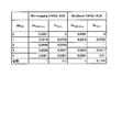
- the total retransmission rate Pr ReTx of “Bit-mapping HARQ-ACK” is 0.1
- the retransmission rate Pr ReTx of “Multilevel HARQ-ACK” is 0.1171
- the retransmission rate increased by 1.71%. That is, according to the example of the first feedback table of the embodiment, while the retransmission rate is only deteriorated by 1.71%, the number of bits of the “HARQ-ACK payload” can be reduced by 25% from 4 bits to 3 bits. . Therefore, it is possible to reduce the number of bits of the “HARQ-ACK payload” that is an overhead of transmission / reception data while suppressing deterioration of the retransmission rate.
- FIG. 6 is a diagram illustrating an example of the second feedback table.
- the feedback tables 17-2 and 26-2 according to the second example are tables stored in the base station apparatus 1 as the feedback table 17 and stored in the terminal apparatus 2 as the feedback table 26.
- the feedback tables 17-2 and 26-2 show an example in which four CBs CB-1 to CB-4 are used as transmission unit TBs.
- the hierarchy of “Level-1” and “Level-2” in the feedback tables 17-2 and 26-2 is the same as the feedback tables 17-1 and 26-1 shown in FIG.
- At least two CBs among CB-1 to CB-3 or at least two CBs among CB-2 to CB-4 are included in the CBG as retransmission targets.
- the “Level-3” layer is the layer to be stored.
- CB-1 to CB-3 are CBGs to be retransmitted, and “HARQ-ACK bit” “Index3-1” is assigned to a status that CB-4 is not to be retransmitted.
- “Index3-2” shown in FIG. 6 is the same as “Index3-1”.
- the TBs corresponding to “Index 1-1” of “Level-1” shown in the first row are all CB-1 to CB-4. “ACK”.
- ACK In the case of this ACK / NAK pattern, since none of the CBs is grouped as a CBG to be retransmitted, there is no CB to be retransmitted.
- the TB corresponding to “Index2-1” of “Level-2” shown in the second line is “NAK” for each of CB-1 to CB-4. , “ACK”, “ACK”, “ACK”.
- ACK In the case of this ACK / NAK pattern, since CB-1 is grouped as a CBG to be retransmitted, only CB-1 is retransmitted.
- the TB corresponding to “Index3-1” of “Level-3” shown in the sixth line is “NAK” for each of CB-1 to CB-4. , “NAK”, “ACK”, and “ACK”.
- this ACK / NAK pattern since CB-1 to CB-3 adjacent to each other are grouped as CBGs to be retransmitted, CB-1 to CB-3 are retransmitted.
- the TB corresponding to “Index4-1” of “Level-4” shown in the 13th row is “NAK” for each of CB-1 to CB-4. , “ACK”, “ACK”, “NAK”.
- ACK ACK
- NAK NAK
- both feedback tables 17-2 and 26-2 indicate whether each of CB-1 to CB-4 of each TB is “ACK” or “NAK”. However, as in FIG. 4, it is possible to omit the distinction between “ACK” and “NAK” for each of CB-1 to CB-4 in the feedback table 17-2. When such distinction is omitted, in the feedback table 17-2, one TB having a CBG including CB-1 to CB-3 corresponds to “Index 3-1”. The same applies to “Index3-2” and “Index4-1”.
- FIG. 7 is a diagram illustrating the retransmission rate in the example of the second feedback table.
- the CBG is compared with “Bit-mapping HARQ-ACK” which is a comparison method and “Multilevel HARQ-ACK” which is a method of this embodiment using feedback tables 17-2 and 26-2.
- Pr CBG Error and Pr ReTx were compared for each number of retransmitted CBs (#M CB ).
- the number of bits of the “HARQ-ACK payload” is 3 bits as in the case of using the feedback tables 17-1 and 26-1. Become.
- the total retransmission rate Pr ReTx of “Bit-mapping HARQ-ACK” is 0.1
- the retransmission rate Pr ReTx of “Multilevel HARQ-ACK” is 0.1146.
- the retransmission rate was increased by 1.46%.
- the retransmission rate is improved over the retransmission rate 0.1171 of the example of the first feedback table of the embodiment.
- such improvement becomes more prominent as the number of CBs in the TB and the total number of CBs included in the TB increase.
- FIG. 8 is a diagram showing a retransmission rate in the case of 8 CB per TB.
- FIG. 8 shows the retransmission rate, “HARQ-ACK payload”, and overhead when the number of bits of “HARQ-ACK payload” is changed from 4 bits to 7 bits under the assumption of 8 CB per TB.
- the trade-off relationship with (OH: Over Head) is shown.
- the retransmission rate is 0.2108, 0.1470, 0.1135, 0.1013. And drop. Then, the overhead saving rate decreases to 100%, 37.5%, 25%, and 12.5%.
- P ReTx 0.1 in the comparison method “Bit-mapping HARQ-ACK”
- FIG. 9 is a diagram illustrating an example of the third feedback table.
- “Level-1” and “Level-2” are not shown.
- the feedback tables 17-3 and 26-3 according to the third example are tables stored in the base station apparatus 1 as the feedback table 17 and stored in the terminal apparatus 2 as the feedback table 26.
- the feedback tables 17-3 and 26-3 show an example in which eight CBs CB-1 to CB-8 are used as transmission unit TBs.
- the number of each Index is as follows. That is, one in the “Level-1” layer where there is no retransmission CBG, eight retransmission CBGs including one retransmission CB each, and eight in the “Level-2” layer, all including retransmission CBs This is one in the “Level-4” layer in which the TB of the same is the retransmission CBG. Therefore, the optimization of the CBG design in the “Level-3” hierarchy including six indexes is related to the usefulness of the feedback table.
- CB-1 to CB-8 which do not correspond to any of Level-1 to Level-2 (not shown) and “Level3-1” to “Level3-3” described above.
- the layer included in the CBG to be retransmitted as a retransmission target is the “Level-4” layer.
- the “Level 4-1” layer has only one type of status in which all of CB- 1 to CB- 8 are included in the CBG to be retransmitted.
- “HARQ-ACK bit” “Index4-1” is assigned to this one type of status.
- TBs corresponding to “Index 3-1” of “Level-3” shown in the first line of FIG. 9 are CB-1 to CB ⁇ .
- Reference numeral 8 denotes “NAK”, “NAK”, “ACK”,..., “ACK”.
- CB-1 to CB-4 adjacent to each other are grouped as CBGs to be retransmitted, CB-1 to CB-4 are retransmitted.
- TBs corresponding to “Index 3-6” of “Level-3” shown in the 19th line of FIG. 9 are respectively CB-1 to CB-8.
- CB-1 and adjacent CB-6 to CB-8 are grouped as CBGs to be retransmitted, so CB-1, CB-6 to CB-8 are retransmitted.
- TBs corresponding to “Index4-1” of “Level-4” shown in the 22nd line of FIG. 9 are respectively CB-1 to CB-8.
- this ACK / NAK pattern since all adjacent CB-1 to CB-8 are grouped as CBGs to be retransmitted, all CBs from CB-1 to CB-8 are retransmitted.
- FIG. 10 is a diagram illustrating a retransmission rate in the third feedback table example.
- FIG. 10 it is assumed that eight CBs CB-1 to CB-8 are TBs of transmission units and the number of bits of the “HARQ-ACK payload” is four. Then, when the number of retransmission CBG units in “Level-3” is two (see the column “Multilevel HARQ-ACK” in FIG. 10), and when it is four (see “Suboptimal Multilevel HARQ-ACK” in FIG. 10) Compare the total retransmission rate with each (see column). Then, it can be seen that “Suboptimal Multilevel HARQ-ACK” is improved by about 3.19%.
- the optimum multilevel CBG search process is a process of searching for a “Multilevel HARQ-ACK” CBG that minimizes the retransmission probability in TB.
- the “HARQ-ACK payload” has N bits (N is a predetermined natural number), and the transmission unit TB includes M (M is a predetermined natural number) CBs. Note that M ⁇ N.
- a subset g including 2 N vectors is selected from a set G including 2 M vectors each of which is 0 or 1. That is, g ⁇ G. Therefore, the number of combinations for selecting the subset g from the set G is as shown in (4) below.
- This is a 1-vector in which the first vector in the subset g is always all 1s indicating that everything is ACK in TB.
- this is because the last vector in the subset g is always a 0-vector in which all components are 0, indicating that all are NAK in TB.
- the subset g is represented by a matrix as shown in the following equation (5) so as to cover all combinations of ACK / NAK in TB.
- the vector g k [n k, 0 , n k, 1 ,..., N k, M ⁇ 1 ], for example, in the example shown in FIG. 9, each TB corresponding to “Index3-1”
- the vector g k [0, 0, 0, 0, 1, 1, 1, 1].
- subset g is useful for mathematically expressing multilevel groups.
- the optimum multi-level CBG search process shown in FIG. 11 described later aims to find the best multi-level group.
- the set G is 2M vectors each having M components, and is mathematically represented by a matrix of the following equation (6).
- the vector G i indicates the i-th combination of each of the M CBs in TB.
- the vector g k is suitable for pointing to the vector G i .
- An inner product f (g k , G i ) of the vector g k and the vector G i is defined as a function expressed by the following equation (7).
- f (g k , G i ) 1 means that the vector g k is a candidate for the vector G i .
- one vector g k is selected as a candidate based on the minimization criterion represented by the following equation (8) regarding the CB retransmission probability.
- p is “CB error rate”, for example, 0.1.
- ⁇ i is defined by the following equation (9).
- the selected vector g k represents the vector G i and g k ⁇ i is newly introduced as a symbol constituting a new subset g ′ satisfying g′gg.
- the new subset g ′ is updated when the CB retransmission probability is further reduced after calculating the inner product expressed by the above equation (7).
- each and every vector G i is pointed to by the associated vector g k ⁇ i .
- an N-bit “HARQ-ACK payload” is guaranteed to indicate all HARQ-ACK combinations of M CBs included in a transmission unit TB. Is done.
- the best subset g of the set G is found by an exhaustive search algorithm based on a minimization criterion related to the retransmission probability of an arbitrary CB.
- the search formula is expressed as the following formula (10) or the following formula (11).
- the correlation coefficient of the variable in the vector g k is represented by a matrix of the following equation (13).
- x k, i is a random variable of CB-i (i is a natural number corresponding to the number of CBs constituting 1 to TB) in the CBG-based HARQ-ACK system.
- the reception signal x k at CB-i, and i, the received signal x k at CB-l, if it and l are independent from each other [rho (x k, i, x k, l) 0, not independent Then, ⁇ (x k, i , x k, l ) ⁇ 0.
- FIG. 11 is a flowchart illustrating an example of the optimal multi-level CBG search process. Note that the processing shown in FIG. 11 is executed by a processing device such as a CPU (Central Processing Unit) in accordance with an execution instruction. In the processing shown in FIG. 11, it is assumed that the “HARQ-ACK payload” is N bits (N is a predetermined natural number), and the transmission unit TB includes M (M is a predetermined natural number) CB. Note that M ⁇ N.
- N is a predetermined natural number
- M is a predetermined natural number
- step S11 the processing apparatus sets the number of CBs included in the transmission unit TB: M, the number of bits of the “HARQ-ACK payload”: N, and the “CB error rate”: p.
- step S12 the processing device generates a set G expressed by the above equation (6).
- step S13 the processing apparatus selects all the subsets g from the set G generated in step S12.
- step S14 the processing device selects one vector g k and one vector G i for the set G generated in step S12 and the subset g selected in step S13 based on the above equation (7). To do.
- step S14 the processing device calculates an inner product f (g k , G i ) of the selected vector g k and vector G i .
- the processing device moves the process to step S16.
- the processing apparatus moves the process to step S18.
- step S16 the processing apparatus sets the vector g k that is Yes in step S15 as a candidate.
- step S17 the vector g k ⁇ i is updated based on the above equation (8).
- step S18 the processing unit, for all vectors g k subset g of the selected group G in step S13, determines whether the processing of steps S14 ⁇ S17 is ended. Processor for all the vector g k subset g of the selected group G in step S13, if the processing in steps S14 ⁇ S17 is ended (step S18Yes), the process goes to step S19.
- step S18No the processing unit, for all vectors g k subset g of the selected group G in step S13, if the processing in steps S14 ⁇ S17 is not completed (step S18No), the process returns to step S14.
- Processor when you move the process from step S18 to step S14, selects the vector g k different untreated and vector g k processed last time.
- step S19 the processing unit, for all vectors G i of the set G generated in step S12, it is determined whether the processing of steps S14 ⁇ S18 is ended.
- the processing device moves the process to step S20.
- the processing unit for all vectors G i of the set G generated in step S12, if the processing in steps S14 ⁇ S18 is not completed (step S19No), the process goes to step S14.
- Processor when you move the process from step S19 to step S14, selects the vector G i of different unprocessed vector G i that the previously treated.
- step S20 the processing apparatus calculates the product of the inner product f (g k ⁇ i , G i ) expressed by the above expression (10) or (11) and the probability Pr k, j (ReTx) as a vector Update the summation result from 1 to 2 M ⁇ 1 for index i.
- step S21 the processing apparatus determines whether or not the processing in steps S14 to S20 has been completed for all subsets g selected in step S13. When the processing of steps S14 to S20 is completed for all the subsets g selected in step S13 (Yes in step S21), the processing device ends the optimal multilevel CBG search processing. On the other hand, if the processing in steps S14 to S20 has not been completed for all the subsets g selected in step S13 (No in step S21), the processing device returns the processing to step S14.
- FIG. 12 is a diagram illustrating an example of the processing result of the optimal multilevel CBG search.
- FIG. 12 shows an example of feedback tables 17-4 and 26-4 generated as a result of the optimal multilevel CBG search process.
- the feedback tables 17-4 and 26-4 are tables stored in the base station apparatus 1 as the feedback table 17 and stored in the terminal apparatus 2 as the feedback table 26.
- the feedback tables 17-4 and 26-4 are configured by the optimum multi-level CBG search processing shown in FIG. 11 for the TB having 4 CBs and 2 bits (or 3 bits) of “HARQ-ACK payload”. It is a feedback table.
- feedback tables 17-4 and 26-4 optimized for a TB having 4 CBs and a 2-bit (or 3-bit) “HARQ-ACK payload” are “Level”.
- a hierarchy of “ ⁇ 1” to “Level-3” is configured. “Level-1” has one status “Index-1”.
- “Level-2” has two statuses “Index2-1” and “Index2-2”.
- “Level-3” has one status “Index3-1”.
- CB-1 to CB-4 are all TBs corresponding to “Index1-1” of “Level-1” shown in the first row. “ACK”.
- ACK ACK
- CB-1 to CB-4 adjacent to each other are grouped as CBGs to be retransmitted, CB-1 to CB-4 are retransmitted.
- the TB corresponding to “Index2-1” of “Level-2” shown in the second row is “NAK” for each of CB-1 to CB-4. , “ACK”, “ACK”, “ACK”.
- ACK ACK
- ACK ACK
- CB-1 and CB-2 adjacent to each other are grouped as CBGs to be retransmitted, CB-1 and CB-2 are retransmitted.
- the TB corresponding to “Index3-1” of “Level-3” shown in the eighth line is “NAK” for each of CB-1 to CB-4. , “ACK”, “ACK”, “NAK”.
- ACK ACK
- NAK NAK
- FIG. 13 is a diagram illustrating a retransmission rate in an example of the processing result of the optimal multilevel CBG search.
- FIG. 13 shows the comparison method “Bit-mapping HARQ-ACK” (“HARQ-ACK payload” is 4 bits) and “Multilevel HARQ-ACK” (“HARQ-ACK”, which is the processing result of the optimum multilevel CBG search.
- the “payload” is 2 bits
- Pr CBG Error and Pr ReTx are compared for each number of retransmission CBs (#M CB ) in the CBG .
- the total retransmission rate Pr ReTx of Bit-mapping HARQ-ACK is 0.1, whereas the retransmission rate Pr ReTx of “Multilevel HARQ-ACK” is 0.19.
- the number of bits of the “HARQ-ACK payload” is changed from 4 bits. Since 50% can be reduced to 2 bits, it is possible to reduce the number of bits of the “HARQ-ACK payload” that is an overhead of transmission / reception data while suppressing deterioration of the retransmission rate.
- the feedback tables 17-2 and 26-2 in FIG. 6 are replaced with the second feedback table shown in FIG. In this example, the retransmission rate was optimal.
- the CBG for retransmission configured by the algorithm of the optimal multilevel CBG search processing according to the above embodiment is the HARQ-ACK of the optimal multilevel CBG having an arbitrary number of CBs in the TB and the “HARQ-ACK payload”. Useful for system construction.
- the optimum multi-level CBG according to the above embodiment can reduce the “HARQ-ACK payload”, which is an overhead of transmission / reception data, while suppressing deterioration of the retransmission rate.
- a new transmission is transmitted from the base station apparatus 1 to the terminal apparatus 2 in units of TB.
- the terminal device 2 receives the TB, detects it in CB units, and determines whether there is an error. Accordingly, a feedback table (CBG information) is searched, and the CBG information is transmitted from the terminal device 2 to the base station device 1.
- the CBG information is transmitted using, for example, a control channel (PUCCH).
- the base station apparatus 1 newly generates a TB (including a retransmission CBG and a new CBG) based on the CBG information, and performs retransmission and new transmission.
- the base station apparatus 1 transmits the status of the retransmission CBG and the new CBG, for example, by PDCCH. In short, since retransmission and new transmission are mixed, the base station apparatus 1 notifies the terminal apparatus 2.
- the present invention can also be applied to the case of retransmission from the terminal device 2 to the base station device 1.
- the case will be briefly described.
- a new transmission is transmitted from the terminal device 2 to the base station in units of TB.
- the base station apparatus 1 receives the TB, detects it in CB units, and determines whether there is an error. Accordingly, the feedback table (CBG information) is searched, and the CBG information is transmitted from the base station apparatus 1 to the terminal apparatus 2.
- CBG information is transmitted using a control channel (PDCCH), for example.
- the terminal device 2 newly generates a TB (including a retransmission CBG and a new CBG) based on the CBG information, and performs retransmission and new transmission.
- the terminal device 2 transmits the state of the retransmission CBG and the new CBG using PUCCH. In short, since retransmission and new transmission are mixed, the terminal device 2 notifies the base station device 1.
- the present invention can also be applied to the case where the terminal device 2 retransmits to the base station device 1.
- the optimum multi-level CBG can reduce the “HARQ-ACK payload” that is an overhead of transmission / reception data while suppressing deterioration of the retransmission rate.
- a static grouping technique is desirable. For example, if the data traffic amount is constant, as a result, the number of CBs in TB becomes constant. Meanwhile, the reception errors that occur between different CBs are independent isodistribution (IID). In this case, the grouping mode should not be changed but should be constant.
- IID isodistribution
- a semi-static grouping method is desirable. For example, the state of data traffic in a shopping mall differs between morning, daytime, and night. In such cases, multi-level CBGs should be defined to match such variations.
- RRC radio resource control
- a dynamic grouping technique is desirable if conditions change rapidly for a HARQ system. For example, 5G traffic associated with Ultra-Reliable and Low Latency Communications (URLLC) often occurs suddenly and needs to be transmitted immediately (1 msec delay and 10 ⁇ 5 BLER is required for 5G new wireless communications).
- URLLC Ultra-Reliable and Low Latency Communications
- eMBB enhanced Mobile Broadband
- FIG. 14 is a diagram illustrating a computer that executes a processing program for optimal multilevel CBG search.
- the computer 300 includes a CPU 310, an HDD (Hard Disk Drive) 320, and a RAM (Random Access Memory) 340. These units 310 to 340 are connected via a bus 400.
- the HDD 320 stores an optimal multi-level CBG search program 320a in advance. Note that the functions of the optimal multilevel CBG search program 320a may be appropriately divided into modules.
- the HDD 320 stores various data.
- the HDD 320 stores the OS and various data. Then, the CPU 310 reads the optimal multi-level CBG search program 320a from the HDD 320 and executes it.
- the optimum multi-level CBG search program 320a described above is not necessarily stored in the HDD 320 from the beginning.
- a program is stored in a “portable physical medium” such as a flexible disk (FD), Compact Disk Read Only Memory (CD-ROM), Digital Versatile Disk (DVD), magneto-optical disk, or IC card inserted into the computer 300.
- FD flexible disk
- CD-ROM Compact Disk Read Only Memory
- DVD Digital Versatile Disk
- magneto-optical disk or IC card
- the program is stored in “another computer (or server)” connected to the computer 300 via a public line, the Internet, a LAN, a WAN, or the like. Then, the computer 300 may read and execute the program from these.
Abstract
This base station device includes a storage unit, a communication control unit, and a data transmission unit. The storage unit stores a group which indicates unit data which is a retransmission target among the predetermined number of pieces of unit data included in transmission data to be transmitted to this terminal device in association with identification information for identifying the group. A receiving unit receives, from the terminal device, the identification information on the transmission data transmitted to the terminal device. The communication control unit refers to the storage unit on the basis of the identification information received by the receiving unit, and determines retransmission of the unit data included in the group that corresponds to the identification information among the transmission data. The data transmission unit transmits, to the terminal device, the unit data included in a group for which retransmission has been determined by the communication control unit.
Description
本発明は、基地局装置、端末装置、無線通信システム、および通信方法に関する。
The present invention relates to a base station device, a terminal device, a wireless communication system, and a communication method.
現在のネットワークは、モバイル端末(スマートフォンやフューチャーホン)のトラフィックがネットワークのリソースの大半を占めている。また、モバイル端末が使うトラフィックは、今後も拡大していく傾向にある。
In the current network, mobile terminal (smartphone and future phone) traffic occupies most of the network resources. In addition, the traffic used by mobile terminals tends to continue to expand.
一方で、IoT(Internet of a things)サービス(例えば、交通システム、スマートメータ、装置等の監視システム)の展開にあわせて、多様な要求条件を持つサービスに対応することが求められている。そのため、次世代(例えば、5G(第5世代移動体通信))の通信規格では、4G(第4世代移動体通信)の標準技術(例えば、非特許文献1~11)に加えて、さらなる高データレート化、大容量化、低遅延化を実現する技術が求められている。なお、次世代通信規格については、3GPPの作業部会(例えば、TSG-RAN WG1、TSG-RAN WG2等)で技術検討が進められている(非特許文献12~18)。
On the other hand, in response to the development of IoT (Internet of a things) services (for example, monitoring systems for traffic systems, smart meters, devices, etc.), it is required to support services with various requirements. Therefore, in the next generation (for example, 5G (5th generation mobile communication)) communication standard, in addition to the 4G (4th generation mobile communication) standard technology (for example, Non-Patent Documents 1 to 11), an even higher There is a demand for a technology that realizes a data rate, a large capacity, and a low delay. Regarding next-generation communication standards, technical studies are being conducted by 3GPP working groups (eg, TSG-RAN WG1, TSG-RAN WG2, etc.) (Non-Patent Documents 12 to 18).
上記で述べたように、多種多様なサービスに対応するために、5Gでは、eMBB(Enhanced Mobile BroadBand)、Massive MTC(Machine Type Communications)、およびURLLC(Ultra-Reliable and Low Latency Communication)に分類される多くのユースケースのサポートを想定している。
As described above, 5G is classified into eMBB (Enhanced Mobile BroadBand), Massive MTC (Machine Type Communications), and URLLC (Ultra-Reliable and Low Latency Communications) to support a wide variety of services. Assumes support for many use cases.
また、LTE(第4世代通信方式)等では、効率的なデータ伝送を実現するためにハイブリッド自動再送要求(HARQ:Hybrid Automatic Repeat reQuest)の技術が採用されている。HARQでは、受信装置は、例えばLTE等のレイヤ1プロトコル階層の処理において正しく復号できなかったデータについての再送を、送信装置側に要求する。送信装置側は、データの再送が要求されると、受信装置側において正しく復号できなかったもとのデータの再送要求に対応する再送データを送信する。受信装置側では、正しく復号できなかったデータと、再送データとを組み合わせて、データの復号が行われる。これにより、高効率かつ高精度な再送制御が実現される。
Also, in LTE (4th generation communication system) and the like, a hybrid automatic repeat request (HARQ) technology is adopted in order to realize efficient data transmission. In HARQ, the receiving apparatus requests the transmitting apparatus side to retransmit the data that could not be correctly decoded in the processing of the layer 1 protocol layer such as LTE. When retransmission of data is requested, the transmission apparatus transmits retransmission data corresponding to the original data retransmission request that could not be correctly decoded on the reception apparatus side. On the receiving device side, data decoding is performed by combining data that could not be correctly decoded and retransmission data. Thereby, highly efficient and highly accurate retransmission control is realized.
また、新たなHARQのフィードバックとして、トランスポートブロックをコードブロックグループ(Code Block Group:CBG)にわけて、コードブロックグループ単位でHARQフィードバックすることが規定されている(非特許文献13)。
Also, as a new HARQ feedback, it is specified that transport blocks are divided into code block groups (CBG) and HARQ feedback is performed in units of code block groups (Non-patent Document 13).
ところで、例えば、コードブロックグループでもグループ内に含まれるコードブロック数が多くなるとグループ内の1つのコードブロックに誤りがあるとコードブロックグループ内のすべてのコードブロックを再送するため、再送効率が上がらない。また、例えば、コードブロックグループ内のコードブロック数を少なくするとグループ数が多くなるためHARQフィードバックに用いるビット数が多くなるのでオーバヘッドが増加する。
By the way, for example, if the number of code blocks included in a code block group increases, if there is an error in one code block in the group, all the code blocks in the code block group are retransmitted, so that retransmission efficiency does not increase. . Further, for example, if the number of code blocks in a code block group is reduced, the number of groups is increased, and the number of bits used for HARQ feedback is increased, which increases overhead.
開示の技術は、上記に鑑みてなされたものであって、再送効率とHARQフィードバックに用いるビット数を考慮したHARQフィードバックをおこなうことを可能にすることを目的とする。
The disclosed technique has been made in view of the above, and an object thereof is to enable HARQ feedback in consideration of retransmission efficiency and the number of bits used for HARQ feedback.
1つの側面では、基地局装置は、記憶部、受信部、通信制御部、データ送信部を有する。記憶部は、端末装置へ送信する送信データに含まれる所定数の単位データのうち再送の対象となる単位データを示すグループと、グループを識別するための識別情報とを対応付けて記憶する。受信部は、端末装置へ送信した送信データに対する識別情報を端末装置から受信する。通信制御部は、受信部により受信された識別情報をもとに記憶部を参照し、送信データのうち識別情報に対応するグループに含まれる単位データの再送を決定する。データ送信部は、通信制御部により再送が決定されたグループに含まれる単位データを端末装置へ送信する。
In one aspect, the base station apparatus includes a storage unit, a reception unit, a communication control unit, and a data transmission unit. The storage unit stores a group indicating the unit data to be retransmitted among a predetermined number of unit data included in the transmission data to be transmitted to the terminal device, and identification information for identifying the group in association with each other. The receiving unit receives identification information for transmission data transmitted to the terminal device from the terminal device. The communication control unit refers to the storage unit based on the identification information received by the reception unit, and determines retransmission of unit data included in a group corresponding to the identification information among transmission data. The data transmission unit transmits the unit data included in the group determined to be retransmitted by the communication control unit to the terminal device.
再送効率とHARQフィードバックに用いるビット数を考慮したHARQフィードバックをおこなうことを可能にすることが出来る。
It is possible to perform HARQ feedback in consideration of retransmission efficiency and the number of bits used for HARQ feedback.
以下に、本願の開示する基地局装置、端末装置、無線通信システム、および通信方法の実施例を、図面に基づいて詳細に説明する。なお、以下の実施例は開示の技術を限定するものではない。
Hereinafter, embodiments of a base station device, a terminal device, a wireless communication system, and a communication method disclosed in the present application will be described in detail based on the drawings. The following examples do not limit the disclosed technology.
図1は、基地局装置の一例を示す図である。図2は、端末装置の一例を示す図である。無線通信システムにおいて、基地局装置1と端末装置2とは、無線通信によりデータの送受信を行う。
FIG. 1 is a diagram illustrating an example of a base station apparatus. FIG. 2 is a diagram illustrating an example of a terminal device. In the wireless communication system, the base station device 1 and the terminal device 2 transmit and receive data by wireless communication.
(基地局装置)
基地局装置1は、バッファ情報管理部11、バッファ12、スケジューラ13、下り信号ベースバンド処理部14、上り信号ベースバンド処理部15、無線部16、フィードバックテーブル17を有する。フィードバックテーブル17は、所定の記憶装置に格納される記憶部の一例である。 (Base station equipment)
Thebase station apparatus 1 includes a buffer information management unit 11, a buffer 12, a scheduler 13, a downlink signal baseband processing unit 14, an uplink signal baseband processing unit 15, a radio unit 16, and a feedback table 17. The feedback table 17 is an example of a storage unit stored in a predetermined storage device.
基地局装置1は、バッファ情報管理部11、バッファ12、スケジューラ13、下り信号ベースバンド処理部14、上り信号ベースバンド処理部15、無線部16、フィードバックテーブル17を有する。フィードバックテーブル17は、所定の記憶装置に格納される記憶部の一例である。 (Base station equipment)
The
バッファ情報管理部11は、図示しない上位装置から端末装置2へ送信するデータの入力を受信する。そして、バッファ情報管理部11は、QoS(Quality of Service)にしたがって論理チャネルに分けて入力されたデータのバッファリングを行う。
The buffer information management unit 11 receives an input of data to be transmitted from the host device (not shown) to the terminal device 2. Then, the buffer information management unit 11 performs buffering of the input data divided into logical channels according to QoS (Quality of Service).
バッファ12は、基地局装置1が取得した、端末装置2へ送信する送信データの一時的な記憶領域である。例えば、バッファ12は、送信データの送信単位であるトランスポートブロック(TB:Transport Block、以下「TB」と表記する)単位で、送信データを一時的に記憶する。基地局装置1は、送信データをTB単位で取り扱う。なお、バッファ12は、データの種類に応じて複数のバッファを有してもよい。バッファ情報管理部11は、送信するデータをバッファ12に格納する。そして、バッファ情報管理部11は、バッファ12に格納されたデータの状態を取得しスケジューラ13に通知する。
The buffer 12 is a temporary storage area for transmission data acquired by the base station device 1 and transmitted to the terminal device 2. For example, the buffer 12 temporarily stores transmission data in units of a transport block (TB: Transport Block, hereinafter referred to as “TB”) which is a transmission unit of transmission data. The base station apparatus 1 handles transmission data in units of TB. The buffer 12 may have a plurality of buffers depending on the type of data. The buffer information management unit 11 stores data to be transmitted in the buffer 12. Then, the buffer information management unit 11 acquires the status of the data stored in the buffer 12 and notifies the scheduler 13 of it.
1つのTBは、複数のコードブロック(CB:Code Block、以下「CB」と表記する)を含む。また、本実施例においては、1つのTBにおいて、基地局装置1から端末装置2へ再送する再送対象の1または複数のCBを含むCBのグループを、コードブロックグループ(CBG:Code Block Group、以下「CBG」と表記する)と言う。
One TB includes a plurality of code blocks (CB: Code Block, hereinafter referred to as “CB”). In this embodiment, a group of CBs including one or more CBs to be retransmitted from the base station apparatus 1 to the terminal apparatus 2 in one TB is referred to as a code block group (CBG). "CBG").
スケジューラ13は、バッファ12に格納されたデータの状態の通知をバッファ情報管理部11から受信する。そして、スケジューラ13は、データの送信にあたり、バッファ12に格納されたデータの中から、QoSなどの優先順位にしたがって、送信するデータを特定する。また、スケジューラ13は、TBのサイズ、使用するMCS(Modulation and Coding Scheme)、無線リソースを決定する。
The scheduler 13 receives a notification of the state of the data stored in the buffer 12 from the buffer information management unit 11. Then, when transmitting data, the scheduler 13 specifies data to be transmitted from the data stored in the buffer 12 according to a priority order such as QoS. Further, the scheduler 13 determines the TB size, MCS (Modulation and Coding Scheme) to be used, and radio resources.
スケジューラ13は、端末装置2から、TBごとの「HARQ-ACKビット」を受信する。「HARQ-ACKビット」は、TBにおいてCBGを特定するための識別情報である。
The scheduler 13 receives “HARQ-ACK bit” for each TB from the terminal device 2. The “HARQ-ACK bit” is identification information for specifying the CBG in the TB.
基地局装置1は、TBのサイズが所定のサイズ(例えば、1レイヤのTBで75,376ビット、2レイヤのTBで149,776ビット)を超える場合に、各サイズが所定のサイズ(例えば6,144ビット)を最大とするCBに分割して符号化を行う。
When the size of the TB exceeds a predetermined size (for example, 75,376 bits for a 1-layer TB, 149,776 bits for a 2-layer TB), each size is determined to be a predetermined size (for example, 6 , 144 bits) is divided into CBs having the maximum value, and encoding is performed.
図3は、CBGに含まれるACKおよびNAKとなったCBの一例を示す図である。本実施例において、“ACK”(ACKnowledgement)は、基地局装置1から送信され、端末装置2で正常受信されたCBを示す。また、“NAK”(Negative AcKnowledgement)は、基地局装置1から送信され、端末装置2で正常受信されなかったCBを示す。また、1つのCBGに含まれるCBの数をMCBとする。また、以下において、1つのCBGにおいて受信エラー(すなわちNAK)となったCBの数をMCB,Errorとする。MCB個のCBは、受信エラーとなったMCB,Error個のCBを含み、MCB≧MCB,Errorが成り立つ。図3の例では、MCB個のCBを含むCBGのうち、先頭のMCB,Error=2個のCBが受信エラーとなった場合を示す。
FIG. 3 is a diagram illustrating an example of a CB that is an ACK and a NAK included in the CBG. In the present embodiment, “ACK” (ACKnowledgement) indicates a CB transmitted from the base station apparatus 1 and normally received by the terminal apparatus 2. “NAK” (Negative AcKnowledgement) indicates a CB transmitted from the base station apparatus 1 and not normally received by the terminal apparatus 2. Further, the number of CB contained in one CBG and M CB. In the following, the number of CBs that have received errors (that is, NAK) in one CBG is referred to as M CB, Error . The M CB CBs include M CB and Error CBs that have received errors, and M CB ≧ M CB and Error . In the example of FIG. 3, of the CBG including M CB pieces of CB, indicating the case where the head of the M CB, Error = 2 pieces of CB is erroneously received.
また、以下において、MCB個のCBを含む1つのCBGにおいて、受信エラー(すなわちNAK)となったCBがMCB,Error個だけ発生する確率をPrCBG Error(MCB,Error,MCB)とする。また、1つのCBが受信エラーとなる確率をp(例えばP=0.1)とする。すると、PrCBG Error(MCB,Error,MCB)は、下記(1)式のように表される。なお、同一のTB内において、受信エラーとなるCBは、独立同分布(IID:Independent and Identically-Distributed)に従うと仮定することにより、二項分布にモデル化できる。
In the following, in one CBG including M CB pieces of CB, receive error (i.e. NAK) and became the CB M CB, Error number only probabilities Pr CBG Error generated (M CB, Error, M CB) And In addition, the probability that one CB has a reception error is p (for example, P = 0.1). Then, Pr CBG Error (M CB, Error , M CB ) is expressed as the following equation (1). Note that, in the same TB, a CB that causes a reception error can be modeled as a binomial distribution by assuming that it follows an independent and identically distributed (IID).

ここで、上記(1)式の右辺の第1因子は、MCB個の数からMCB,Error個を選択した組合せの数を表す。そして、上記(1)式から、MCB個のCBを含む1つのCBGにおいて、受信エラー(すなわちNAK)が発生する平均確率PrCBG Error(MCB)は、下記(2)式のように表される。
Here, the first factor of the right side of equation (1) represents the number of combinations selected M CB, the Error number from M CB pieces of numbers. Then, the table as from equation (1), in one CBG including M CB pieces of CB, the average probability Pr CBG Error reception error (i.e. NAK) is generated (M CB) is represented by the following formula (2) Is done.
下り信号ベースバンド処理部14は、送信または再送するデータの情報、MCSの情報、制御情報、使用する無線リソースの情報の入力をスケジューラ13から受信する。そして、下り信号ベースバンド処理部14は、送信または再送するデータの情報に応じたデータをバッファ12から取得する。そして、下り信号ベースバンド処理部14は、受信したMCSの情報で指定された符号化率を用いて取得したデータおよび制御情報に符号化処理を施す。
The downlink signal baseband processing unit 14 receives input of data information to be transmitted or retransmitted, MCS information, control information, and information on radio resources to be used from the scheduler 13. Then, the downlink signal baseband processing unit 14 acquires data corresponding to information on data to be transmitted or retransmitted from the buffer 12. Then, the downlink signal baseband processing unit 14 performs an encoding process on the data and the control information acquired using the encoding rate specified by the received MCS information.
さらに、下り信号ベースバンド処理部14は、受信したMCSの情報で指定された変調方式を用いて取得したデータおよび制御情報に変調処理を施す。その後、下り信号ベースバンド処理部14は、指定された無線リソースに制御情報およびデータを割り当て、制御情報をPDCCH(Physical Downlink Control Channel)に配置し、データをPDSCH(Physical Downlink Shared Channel)に配置する。そして、下り信号ベースバンド処理部14は、制御情報およびデータを無線部16へ出力する。
Further, the downlink signal baseband processing unit 14 performs modulation processing on the data and control information acquired using the modulation scheme specified by the received MCS information. Thereafter, the downlink signal baseband processing unit 14 assigns control information and data to the specified radio resource, places the control information in the PDCCH (Physical Downlink Control Channel), and places the data in the PDSCH (Physical Downlink Shared Channel). . Then, the downlink signal baseband processing unit 14 outputs control information and data to the radio unit 16.
無線部16は、制御情報およびデータの入力を下り信号ベースバンド処理部14から受信する。そして、無線部16は、制御情報およびデータに対してDA(Digital to Analog)変換を施す。そして、無線部16は、割り当てられた無線リソースを用いて制御信号およびデータをアンテナを介して端末装置2へ送信する。
The radio unit 16 receives control information and data input from the downlink signal baseband processing unit 14. The wireless unit 16 performs DA (Digital to Analog) conversion on the control information and data. And the radio | wireless part 16 transmits a control signal and data to the terminal device 2 via an antenna using the allocated radio | wireless resource.
また、無線部16は、アンテナを介して送信した「HARQ-ACKペイロード」に格納された「HARQ-ACKビット」の信号を端末装置2から受信する。「HARQ-ACKビット」は、送信したTB単位に含まれるCBGを識別するためのインデックス情報である。「HARQ-ACKペイロード」は、「HARQ-ACKビット」を格納するデータ領域である。そして、無線部16は、受信した「HARQ-ACKビット」の信号にAD(Analog to Digital)変換を施す。その後、無線部16は、受信した「HARQ-ACKビット」の信号を上り信号ベースバンド処理部15へ出力する。
Further, the radio unit 16 receives from the terminal device 2 a signal of “HARQ-ACK bit” stored in the “HARQ-ACK payload” transmitted via the antenna. The “HARQ-ACK bit” is index information for identifying the CBG included in the transmitted TB unit. The “HARQ-ACK payload” is a data area for storing “HARQ-ACK bits”. The wireless unit 16 then performs AD (Analog to Digital) conversion on the received “HARQ-ACK bit” signal. After that, the radio unit 16 outputs the received “HARQ-ACK bit” signal to the uplink signal baseband processing unit 15.
上り信号ベースバンド処理部15は、無線部16から受信した「HARQ-ACKビット」の信号に対して復調処理および復号化処理を施し、「HARQ-ACKビット」を取得する。そして、上り信号ベースバンド処理部15は、取得した「HARQ-ACKビット」を、スケジューラ13およびバッファ情報管理部11へ出力する。
The uplink signal baseband processing unit 15 performs demodulation processing and decoding processing on the “HARQ-ACK bit” signal received from the radio unit 16 to obtain “HARQ-ACK bit”. Then, the uplink signal baseband processing unit 15 outputs the acquired “HARQ-ACK bit” to the scheduler 13 and the buffer information management unit 11.
バッファ情報管理部11は、上り信号ベースバンド処理部15から受信した「HARQ-ACKビット」をもとに、フィードバックテーブル17を参照する。すなわち、バッファ情報管理部11は、フィードバックテーブル17において、「HARQ-ACKビット」に対応する「再送対象のCBGの情報」をフィードバックテーブル17から取得する。
The buffer information management unit 11 refers to the feedback table 17 based on the “HARQ-ACK bit” received from the uplink signal baseband processing unit 15. That is, the buffer information management unit 11 acquires “information on CBG to be retransmitted” corresponding to the “HARQ-ACK bit” from the feedback table 17 in the feedback table 17.
そして、バッファ情報管理部11は、フィードバックテーブル17から読み出した「再送対象のCBGの情報」を下り信号ベースバンド処理部14へ通知する。下り信号ベースバンド処理部14は、バッファ情報管理部11から通知された「再送対象のCBGの情報」をもとに、バッファ12を参照して、再送対象のCBGを取得し、無線部16を介して端末装置2へ再送する。
Then, the buffer information management unit 11 notifies the downlink signal baseband processing unit 14 of “information of CBG to be retransmitted” read from the feedback table 17. The downlink signal baseband processing unit 14 refers to the buffer 12 based on the “information on CBG to be retransmitted” notified from the buffer information management unit 11, acquires the CBG to be retransmitted, and transmits the radio unit 16. Through the terminal device 2.
(端末装置)
端末装置2は、無線部21、PDCCH受信処理部22、PDSCH受信処理部23、生成部24、上り信号ベースバンド処理部25、フィードバックテーブル26を有する。フィードバックテーブル26は、所定の記憶装置に格納される記憶部の一例である。 (Terminal device)
Theterminal apparatus 2 includes a radio unit 21, a PDCCH reception processing unit 22, a PDSCH reception processing unit 23, a generation unit 24, an uplink signal baseband processing unit 25, and a feedback table 26. The feedback table 26 is an example of a storage unit stored in a predetermined storage device.
端末装置2は、無線部21、PDCCH受信処理部22、PDSCH受信処理部23、生成部24、上り信号ベースバンド処理部25、フィードバックテーブル26を有する。フィードバックテーブル26は、所定の記憶装置に格納される記憶部の一例である。 (Terminal device)
The
無線部21は、アンテナを介して制御信号およびデータを含むPDCCHおよびPDSCHの信号を基地局装置1から受信する。そして、無線部21は、受信した信号にAD変換を施す。その後、無線部21は、受信したPDCCHおよびPDSCHの信号をPDCCH受信処理部22へ出力する。
The radio unit 21 receives PDCCH and PDSCH signals including control signals and data from the base station apparatus 1 via the antenna. Then, the radio unit 21 performs AD conversion on the received signal. Thereafter, the radio unit 21 outputs the received PDCCH and PDSCH signals to the PDCCH reception processing unit 22.
また、無線部21は、「HARQ-ACKビット」の信号を上り信号ベースバンド処理部25から受信する。そして、無線部21は、「HARQ-ACKビット」の信号に対してDA変換を施し、「HARQ-ACKビット」の信号を取得する。その後、無線部21は、「HARQ-ACKペイロード」の信号をアンテナを介して基地局装置1へ送信する。
Also, the radio unit 21 receives the “HARQ-ACK bit” signal from the uplink signal baseband processing unit 25. Then, the radio unit 21 performs DA conversion on the “HARQ-ACK bit” signal and obtains the “HARQ-ACK bit” signal. Thereafter, the radio unit 21 transmits the “HARQ-ACK payload” signal to the base station apparatus 1 via the antenna.
PDCCH受信処理部22は、制御信号およびデータを含むPDCCHおよびPDSCHの信号の入力を無線部21から受信する。そして、PDCCH受信処理部22は、PDCCHの信号に対して復調処理および復号化処理を施して制御信号を取得する。そして、PDCCH受信処理部22は、制御信号とともにPDSCHの信号をPDSCH受信処理部23へ出力する。
The PDCCH reception processing unit 22 receives the input of the PDCCH and PDSCH signals including the control signal and data from the radio unit 21. Then, the PDCCH reception processing unit 22 performs demodulation processing and decoding processing on the PDCCH signal to obtain a control signal. Then, the PDCCH reception processing unit 22 outputs the PDSCH signal together with the control signal to the PDSCH reception processing unit 23.
PDSCH受信処理部23は、制御信号とともにPDSCHの信号の入力をPDCCH受信処理部22から受信する。そして、PDSCH受信処理部23は、制御信号で指定されたMCSを用いてPDCCHの信号に対してCBごとに復調処理および復号化処理を施してデータを取得する。
The PDSCH reception processing unit 23 receives the input of the PDSCH signal from the PDCCH reception processing unit 22 together with the control signal. Then, the PDSCH reception processing unit 23 performs demodulation processing and decoding processing for each CB on the PDCCH signal using the MCS specified by the control signal, and acquires data.
そして、PDSCH受信処理部23は、データが正常に復号できたか否かを、基地局装置1から受信した受信TBのCBごとに判定する。受信TBのうちデータが復号できたCBについて、PDSCH受信処理部23は、データの復号の成功を生成部24へ通知する。これに対して、受信TBのうちデータの復号に失敗したCBについて、データの復号の失敗の通知を生成部24へ通知する。
Then, the PDSCH reception processing unit 23 determines whether or not the data has been successfully decoded for each CB of the received TB received from the base station apparatus 1. The PDSCH reception processing unit 23 notifies the generation unit 24 of the successful data decoding for the CB in which the data can be decoded in the received TB. On the other hand, for the CB that failed to decode data in the received TB, the generation unit 24 is notified of a data decoding failure notification.
生成部24は、受信TBのCBごとのデータ復号の成否の通知をPDSCH受信処理部23から受信すると、「ACK/NAKを示す情報のパターン」を生成する。「ACK/NAKを示す情報のパターン」とは、受信したTBに含まれる各CBのACKまたはNAKのフィードバック情報を、CBの送信順序で並べたパターンである。そして、生成部24は、生成した「ACK/NAKを示す情報のパターン」をもとにフィードバックテーブル26を参照し、「ACK/NAKを示す情報のパターン」に対応する「HARQ-ACKビット」を取得する。そして、生成部24は、取得した「HARQ-ACKビット」を上り信号ベースバンド処理部25へ出力する。
When the generation unit 24 receives a notification of the success or failure of data decoding for each CB of the reception TB from the PDSCH reception processing unit 23, the generation unit 24 generates an “information pattern indicating ACK / NAK”. The “pattern of information indicating ACK / NAK” is a pattern in which the ACK or NAK feedback information of each CB included in the received TB is arranged in the CB transmission order. Then, the generation unit 24 refers to the feedback table 26 based on the generated “pattern of information indicating ACK / NAK”, and sets the “HARQ-ACK bit” corresponding to the “pattern of information indicating ACK / NAK”. get. Then, the generation unit 24 outputs the acquired “HARQ-ACK bit” to the uplink signal baseband processing unit 25.
上り信号ベースバンド処理部25は、受信した「HARQ-ACKビット」に符号化処理および変調処理を施す。そして、上り信号ベースバンド処理部25は、符号化処理および変調処理を施したデータをPUCCH(Physical Uplink Control Channel)に配置して「HARQ-ACKビット」の信号を生成する。そして、上り信号ベースバンド処理部25は、生成した「HARQ-ACKビット」の信号を無線部21へ出力する。
The uplink signal baseband processing unit 25 performs encoding processing and modulation processing on the received “HARQ-ACK bit”. Then, the uplink signal baseband processing unit 25 arranges the data subjected to the encoding process and the modulation process in a PUCCH (Physical Uplink Control Channel) to generate a “HARQ-ACK bit” signal. Then, the uplink signal baseband processing unit 25 outputs the generated “HARQ-ACK bit” signal to the radio unit 21.
(第1のフィードバックテーブルの例)
図4は、第1のフィードバックテーブルの例を示す図である。第1の例にかかるフィードバックテーブル17-1,26-1は、フィードバックテーブル17として基地局装置1に格納され、フィードバックテーブル26として端末装置2に格納されるテーブルである。フィードバックテーブル17-1,26-1では、CB-1~CB-4の4つのCBを送信単位のTBとする例を示す。以下、フィードバックテーブルの図示において、行単位の複数のCBが1つのTBである。 (Example of first feedback table)
FIG. 4 is a diagram illustrating an example of the first feedback table. The feedback tables 17-1 and 26-1 according to the first example are tables stored in thebase station apparatus 1 as the feedback table 17 and stored in the terminal apparatus 2 as the feedback table 26. The feedback tables 17-1 and 26-1 show an example in which four CBs CB-1 to CB-4 are used as transmission unit TBs. Hereinafter, in the illustration of the feedback table, a plurality of CBs in units of rows is one TB.
図4は、第1のフィードバックテーブルの例を示す図である。第1の例にかかるフィードバックテーブル17-1,26-1は、フィードバックテーブル17として基地局装置1に格納され、フィードバックテーブル26として端末装置2に格納されるテーブルである。フィードバックテーブル17-1,26-1では、CB-1~CB-4の4つのCBを送信単位のTBとする例を示す。以下、フィードバックテーブルの図示において、行単位の複数のCBが1つのTBである。 (Example of first feedback table)
FIG. 4 is a diagram illustrating an example of the first feedback table. The feedback tables 17-1 and 26-1 according to the first example are tables stored in the
フィードバックテーブル17-1,26-1において、CB-1~CB-4のいずれも再送対象のCBGに含まれない階層が、“Level-1”の階層である。“Level-1”の階層は、再送対象のCBを含むCBGが存在しない、1種類のステータスのみを有する。フィードバックテーブル17-1,26-1において、この1種類のステータスに対して「HARQ-ACKビット」“Index1-1”が付与されている。
In the feedback tables 17-1 and 26-1, a hierarchy in which none of CB-1 to CB-4 is included in the CBG to be retransmitted is the “Level-1” hierarchy. The “Level-1” layer has only one type of status in which there is no CBG including the CB to be retransmitted. In the feedback tables 17-1 and 26-1, “HARQ-ACK bit” “Index 1-1” is assigned to this one type of status.
また、フィードバックテーブル17-1,26-1において、CB-1~CB-4のいずれか1つのCBが再送対象としてCBGに含まれる階層が、“Level-2”の階層である。“Level-2”の階層は、再送対象のCB-1~CB-4のいずれか1つのCBを含むCBGが存在する4種類のステータスを有する。例えば、CB-1のみが再送対象のCBGであり、CB-2~CB-4が再送対象ではないステータスに対して「HARQ-ACKビット」“Index2-1”が付与されている。図4に示す“Index2-2”~“Index2-4”についても“Index2-1”と同様である。
Also, in the feedback tables 17-1 and 26-1, the hierarchy in which any one of the CB-1 to CB-4 is included in the CBG as a retransmission target is the “Level-2” hierarchy. The “Level-2” layer has four types of statuses in which CBGs including any one of CB-1 to CB-4 to be retransmitted exist. For example, only the CB-1 is the CBG to be retransmitted, and the “HARQ-ACK bit” “Index2-1” is assigned to the statuses in which the CB-2 to CB-4 are not to be retransmitted. “Index2-2” to “Index2-4” shown in FIG. 4 are the same as “Index2-1”.
また、フィードバックテーブル17-1,26-1において、CB-1~CB-2、もしくは、CB-3~CB-4が再送対象としてCBGに含まれる階層が、“Level-3”の階層である。例えば、CB-1~CB-2が再送対象のCBGであり、CB-3~CB-4が再送対象ではないステータスに対して「HARQ-ACKビット」“Index3-1”が付与されている。図4に示す“Index3-2”についても“Index3-1”と同様である。
In the feedback tables 17-1 and 26-1, the hierarchy in which CB-1 to CB-2 or CB-3 to CB-4 are included in the CBG as retransmission targets is the “Level-3” hierarchy. . For example, “HARQ-ACK bit” “Index3-1” is assigned to the statuses where CB-1 to CB-2 are CBGs to be retransmitted and CB-3 to CB-4 are not to be retransmitted. “Index3-2” shown in FIG. 4 is the same as “Index3-1”.
また、フィードバックテーブル17-1,26-1において、上述の“Level-1”~“Level-3”のいずれにも該当しない、CB-1~CB-4の全てが再送対象として再送対象のCBGに含まれる階層が、“Level-4”の階層である。“Level-4”の階層は、CB-1~CB-4の全てが再送対象のCBGに含まれる、1種類のステータスのみを有する。フィードバックテーブル17-1,26-1において、この1種類のステータスに対して「HARQ-ACKビット」“Index4-1”が付与されている。
In the feedback tables 17-1 and 26-1, all of CB-1 to CB-4, which do not correspond to any of the above-mentioned “Level-1” to “Level-3”, are CBGs to be retransmitted as retransmission targets. The layer included in the “Level-4” layer. The hierarchy of “Level-4” has only one type of status in which all of CB-1 to CB-4 are included in the CBG to be retransmitted. In the feedback tables 17-1 and 26-1, “HARQ-ACK bit” “Index4-1” is assigned to this one type of status.
具体的には、フィードバックテーブル17-1,26-1において、例えば、1行目に示される“Level-1”の“Index1-1”に対応するTBは、CB-1~CB-4全てが“ACK”である。このACK/NAKのパターンである場合に、いずれのCBもが再送対象のCBGとしてグルーピングされていないので、再送されるCBが存在しない。
Specifically, in the feedback tables 17-1 and 26-1, for example, the TBs corresponding to “Index 1-1” of “Level-1” shown in the first line are all CB-1 to CB-4. “ACK”. In the case of this ACK / NAK pattern, since none of the CBs is grouped as a CBG to be retransmitted, there is no CB to be retransmitted.
また、フィードバックテーブル17-1,26-1において、例えば、2行目に示される“Level-2”の“Index2-1”に対応するTBは、CB-1~CB-4それぞれが“NAK”、“ACK”、“ACK”、“ACK”である。このACK/NAKのパターンである場合に、CB-1が再送対象のCBGとしてグルーピングされているので、CB-1のみが再送される。
In the feedback tables 17-1 and 26-1, for example, the TB corresponding to “Index2-1” of “Level-2” shown in the second row is “NAK” for each of CB-1 to CB-4. , “ACK”, “ACK”, “ACK”. In the case of this ACK / NAK pattern, since CB-1 is grouped as a CBG to be retransmitted, only CB-1 is retransmitted.
また、フィードバックテーブル17-1,26-1において、例えば、6行目に示される“Level-3”の“Index3-1”に対応するTBは、CB-1~CB-4それぞれが“NAK”、“NAK”、“ACK”、“ACK”である。このACK/NAKのパターンである場合に、隣接するCB-1およびCB-2が再送対象のCBGとしてグルーピングされているので、CB-1およびCB-2が再送される。
In the feedback tables 17-1 and 26-1, for example, the TB corresponding to “Index3-1” of “Level-3” shown in the sixth line is “NAK” for each of CB-1 to CB-4. , “NAK”, “ACK”, and “ACK”. In the case of this ACK / NAK pattern, since CB-1 and CB-2 adjacent to each other are grouped as CBGs to be retransmitted, CB-1 and CB-2 are retransmitted.
また、フィードバックテーブル17-1,26-1において、例えば、8行目に示される“Level-4”の“Index4-1”に対応するTBは、CB-1~CB-4それぞれが“NAK”、“ACK”、“ACK”、“NAK”である。このACK/NAKのパターンである場合に、隣接する全てのCB-1~CB-4が再送対象のCBGとしてグルーピングされているので、CB-1~CB-4の全てのCBが再送される。
In the feedback tables 17-1 and 26-1, for example, the TB corresponding to “Index4-1” of “Level-4” shown in the eighth line is “NAK” for each of CB-1 to CB-4. , “ACK”, “ACK”, “NAK”. In the case of this ACK / NAK pattern, since all adjacent CB-1 to CB-4 are grouped as CBGs to be retransmitted, all CBs of CB-1 to CB-4 are retransmitted.
このように、“Level-1”~“Level-4”のマルチレベルにおいて、“Index1-1”~“Index4-1”の8=23種類のステータスを特定するために、3ビットの「HARQ-ACKペイロード」を用いる。すなわち、3ビットの「HARQ-ACKペイロード」に格納される「HARQ-ACKビット」を用いることで、送信単位のTBにおける再送対象のCBGを特定できる。実施例の第1の例にかかるフィードバックテーブル17-1,26-1によれば、3ビットのオーバヘッドを端末装置2から基地局装置1へ送信するデータに付加することで、送信データの再送率を低減できる。
In this way, in order to specify three types of status of “Index 1-1” to “Index 4-1” in the multi-level “Level-1” to “Level-4”, the 3-bit “HARQ Use the “ACK payload”. That is, by using the “HARQ-ACK bit” stored in the 3-bit “HARQ-ACK payload”, the CBG to be retransmitted in the transmission unit TB can be specified. According to the feedback tables 17-1 and 26-1 according to the first example of the embodiment, the retransmission rate of transmission data is obtained by adding 3 bits of overhead to the data transmitted from the terminal apparatus 2 to the base station apparatus 1. Can be reduced.
なお、図4では、フィードバックテーブル17-1,26-1ともに、各TBのCB-1~CB-4のそれぞれが“ACK”および“NAK”のいずれであるかが示されている。しかし、基地局装置1は、各Indexに対応する「再送対象のCBGの情報」を認識できればよいことから、フィードバックテーブル17-1においてCB-1~CB-4のそれぞれが“ACK”および“NAK”のいずれであるかの区別が省略可能である。かかる区別が省略される場合には、フィードバックテーブル17-1において、CB-1~CB-2を含むCBGを有する1つのTBが、“Index3-1”に対応することになる。“Index3-2”、“Index3-3”、“Index4-1”についても同様である。
In FIG. 4, both feedback tables 17-1 and 26-1 indicate whether each of CB-1 to CB-4 of each TB is “ACK” or “NAK”. However, since the base station apparatus 1 only needs to be able to recognize “information of CBG to be retransmitted” corresponding to each index, each of CB-1 to CB-4 is “ACK” and “NAK” in the feedback table 17-1. "" Can be omitted. When such distinction is omitted, in the feedback table 17-1, one TB having a CBG including CB-1 to CB-2 corresponds to “Index 3-1”. The same applies to “Index 3-2”, “Index 3-3”, and “Index 4-1”.
(第1のフィードバックテーブルの例における再送率)
図5は、第1のフィードバックテーブルの例における再送率を示す図である。ここで、MCBを1つのCBGに含まれるCBの数、Mを送信単位のTBに含まれるCBの総数とする。そして、1つのCBGにおいて再送するCBが発生する確率PrReTxを、上述のPrCBG Error(MCB,Error,MCB)(上記(1)式参照)を用いて、下記(3)式のように定義する。 (Retransmission rate in the first feedback table example)
FIG. 5 is a diagram illustrating a retransmission rate in the example of the first feedback table. Here, M CB is the number of CBs included in one CBG, and M is the total number of CBs included in a transmission unit TB. Then, the probability Pr ReTx of occurrence of CB to be retransmitted in one CBG is expressed by the following equation (3) using the above Pr CBG Error (M CB, Error , M CB ) (see the above equation (1)). Defined in
図5に示すように、比較手法である“Bit-mapping HARQ-ACK”と、フィードバックテーブル17-1,26-1を用いた本実施例の手法である“Multilevel HARQ-ACK”とで、CBG中の再送CB数(#MCB)ごとにPrCBG ErrorおよびPrReTxを比較した。“Bit-mapping HARQ-ACK”では、CBごとにACK/NAKを示すビットを設けることから、CB-1~CB-4の4つのCBをTBの送信単位とする場合に、「HARQ-ACKペイロード」のビット数が4ビットとなる。一方、上述したように、“Multilevel HARQ-ACK”では、「HARQ-ACKペイロード」のビット数が3ビットとなる。
As shown in FIG. 5, the CBG is compared with the comparison method “Bit-mapping HARQ-ACK” and the method of the present embodiment using the feedback tables 17-1 and 26-1 “Multilevel HARQ-ACK”. Pr CBG Error and Pr ReTx were compared for each number of retransmitted CBs (#M CB ). In “Bit-mapping HARQ-ACK”, a bit indicating ACK / NAK is provided for each CB. Therefore, when four CBs CB-1 to CB-4 are used as transmission units of TB, “HARQ-ACK payload” "Is 4 bits. On the other hand, as described above, in “Multilevel HARQ-ACK”, the number of bits of the “HARQ-ACK payload” is 3 bits.
図5に示すように、“Bit-mapping HARQ-ACK”の合計の再送率PrReTxが0.1であるのに対し、“Multilevel HARQ-ACK”の再送率PrReTxは、0.1171となり、1.71%だけ再送率が高くなった。すなわち、実施例の第1のフィードバックテーブルの例によれば、再送率が1.71%だけの悪化に留まる一方、「HARQ-ACKペイロード」のビット数を4ビットから3ビットへ25%削減できる。よって、再送率の悪化を抑制しつつ、送受信データのオーバヘッドとなる「HARQ-ACKペイロード」のビット数を削減できる。
As shown in FIG. 5, the total retransmission rate Pr ReTx of “Bit-mapping HARQ-ACK” is 0.1, whereas the retransmission rate Pr ReTx of “Multilevel HARQ-ACK” is 0.1171, The retransmission rate increased by 1.71%. That is, according to the example of the first feedback table of the embodiment, while the retransmission rate is only deteriorated by 1.71%, the number of bits of the “HARQ-ACK payload” can be reduced by 25% from 4 bits to 3 bits. . Therefore, it is possible to reduce the number of bits of the “HARQ-ACK payload” that is an overhead of transmission / reception data while suppressing deterioration of the retransmission rate.
(第2のフィードバックテーブルの例)
図6は、第2のフィードバックテーブルの例を示す図である。第2の例にかかるフィードバックテーブル17-2,26-2は、フィードバックテーブル17として基地局装置1に格納され、フィードバックテーブル26として端末装置2に格納されるテーブルである。フィードバックテーブル17-2,26-2では、CB-1~CB-4の4つのCBを送信単位のTBとする例を示す。 (Example of second feedback table)
FIG. 6 is a diagram illustrating an example of the second feedback table. The feedback tables 17-2 and 26-2 according to the second example are tables stored in thebase station apparatus 1 as the feedback table 17 and stored in the terminal apparatus 2 as the feedback table 26. The feedback tables 17-2 and 26-2 show an example in which four CBs CB-1 to CB-4 are used as transmission unit TBs.
図6は、第2のフィードバックテーブルの例を示す図である。第2の例にかかるフィードバックテーブル17-2,26-2は、フィードバックテーブル17として基地局装置1に格納され、フィードバックテーブル26として端末装置2に格納されるテーブルである。フィードバックテーブル17-2,26-2では、CB-1~CB-4の4つのCBを送信単位のTBとする例を示す。 (Example of second feedback table)
FIG. 6 is a diagram illustrating an example of the second feedback table. The feedback tables 17-2 and 26-2 according to the second example are tables stored in the
フィードバックテーブル17-2,26-2における“Level-1”および“Level-2”の階層は、図4に示すフィードバックテーブル17-1,26-1と同様である。
The hierarchy of “Level-1” and “Level-2” in the feedback tables 17-2 and 26-2 is the same as the feedback tables 17-1 and 26-1 shown in FIG.
また、フィードバックテーブル17-2,26-2において、CB-1~CB-3のうち少なくとも2つのCB、もしくは、CB-2~CB-4のうちの少なくとも2つのCBが再送対象としてCBGに含まれる階層が、“Level-3”の階層である。例えば、CB-1~CB-3が再送対象のCBGであり、CB-4が再送対象でないステータスに対して「HARQ-ACKビット」“Index3-1”が付与されている。図6に示す“Index3-2”についても“Index3-1”と同様である。
In the feedback tables 17-2 and 26-2, at least two CBs among CB-1 to CB-3 or at least two CBs among CB-2 to CB-4 are included in the CBG as retransmission targets. The “Level-3” layer is the layer to be stored. For example, CB-1 to CB-3 are CBGs to be retransmitted, and “HARQ-ACK bit” “Index3-1” is assigned to a status that CB-4 is not to be retransmitted. “Index3-2” shown in FIG. 6 is the same as “Index3-1”.
また、フィードバックテーブル17-2,26-2において、上述の“Level-1”~“Leve3-2”のいずれにも該当しない、CB-1~CB-4の全てが再送対象として再送対象のCBGに含まれる階層が、“Leve4-1”の階層である。“Level4-1”の階層は、CB-1~CB-4の全てが再送対象のCBGに含まれる、1種類のステータスのみを有する。フィードバックテーブル17-2,26-2において、この1種類のステータスに対して「HARQ-ACKビット」“Index-4”が付与されている。
In the feedback tables 17-2 and 26-2, all of CB-1 to CB-4 that do not correspond to any of “Level-1” to “Level3-2” described above are CBGs to be retransmitted as retransmission targets. The hierarchy included in is the “Level 4-1” hierarchy. The hierarchy of “Level 4-1” has only one type of status in which all of CB- 1 to CB- 4 are included in the CBG to be retransmitted. In the feedback tables 17-2 and 26-2, “HARQ-ACK bit” “Index-4” is assigned to this one type of status.
具体的には、フィードバックテーブル17-2,26-2において、例えば、1行目に示される“Level-1”の“Index1-1”に対応するTBは、CB-1~CB-4全てが“ACK”である。このACK/NAKのパターンである場合に、いずれのCBもが再送対象のCBGとしてグルーピングされていないので、再送されるCBが存在しない。
Specifically, in the feedback tables 17-2 and 26-2, for example, the TBs corresponding to “Index 1-1” of “Level-1” shown in the first row are all CB-1 to CB-4. “ACK”. In the case of this ACK / NAK pattern, since none of the CBs is grouped as a CBG to be retransmitted, there is no CB to be retransmitted.
また、フィードバックテーブル17-2,26-2において、例えば、2行目に示される“Level-2”の“Index2-1”に対応するTBは、CB-1~CB-4それぞれが“NAK”、“ACK”、“ACK”、“ACK”である。このACK/NAKのパターンである場合に、CB-1が再送対象のCBGとしてグルーピングされているので、CB-1のみが再送される。
In the feedback tables 17-2 and 26-2, for example, the TB corresponding to “Index2-1” of “Level-2” shown in the second line is “NAK” for each of CB-1 to CB-4. , “ACK”, “ACK”, “ACK”. In the case of this ACK / NAK pattern, since CB-1 is grouped as a CBG to be retransmitted, only CB-1 is retransmitted.
また、フィードバックテーブル17-2,26-2において、例えば、6行目に示される“Level-3”の“Index3-1”に対応するTBは、CB-1~CB-4それぞれが“NAK”、“NAK”、“ACK”、“ACK”である。このACK/NAKのパターンである場合に、隣接するCB-1~CB-3が再送対象のCBGとしてグルーピングされているので、CB-1~CB-3が再送される。
In the feedback tables 17-2 and 26-2, for example, the TB corresponding to “Index3-1” of “Level-3” shown in the sixth line is “NAK” for each of CB-1 to CB-4. , “NAK”, “ACK”, and “ACK”. In the case of this ACK / NAK pattern, since CB-1 to CB-3 adjacent to each other are grouped as CBGs to be retransmitted, CB-1 to CB-3 are retransmitted.
また、フィードバックテーブル17-2,26-2において、例えば、13行目に示される“Level-4”の“Index4-1”に対応するTBは、CB-1~CB-4それぞれが“NAK”、“ACK”、“ACK”、“NAK”である。このACK/NAKのパターンである場合に、隣接する全てのCB-1~CB-4が再送対象のCBGとしてグルーピングされているので、CB-1~CB-4の全てのCBが再送される。
In the feedback tables 17-2 and 26-2, for example, the TB corresponding to “Index4-1” of “Level-4” shown in the 13th row is “NAK” for each of CB-1 to CB-4. , “ACK”, “ACK”, “NAK”. In the case of this ACK / NAK pattern, since all adjacent CB-1 to CB-4 are grouped as CBGs to be retransmitted, all CBs of CB-1 to CB-4 are retransmitted.
なお、図6では、フィードバックテーブル17-2,26-2ともに、各TBのCB-1~CB-4のそれぞれが“ACK”および“NAK”のいずれであるかが示されている。しかし、図4と同様に、フィードバックテーブル17-2においてCB-1~CB-4のそれぞれが“ACK”および“NAK”のいずれであるかの区別が省略可能である。かかる区別が省略される場合には、フィードバックテーブル17-2において、CB-1~CB-3を含むCBGを有する1つのTBが、“Index3-1”に対応することになる。“Index3-2”、“Index4-1”についても同様である。
In FIG. 6, both feedback tables 17-2 and 26-2 indicate whether each of CB-1 to CB-4 of each TB is “ACK” or “NAK”. However, as in FIG. 4, it is possible to omit the distinction between “ACK” and “NAK” for each of CB-1 to CB-4 in the feedback table 17-2. When such distinction is omitted, in the feedback table 17-2, one TB having a CBG including CB-1 to CB-3 corresponds to “Index 3-1”. The same applies to “Index3-2” and “Index4-1”.
(第2のフィードバックテーブルの例における再送率)
図7は、第2のフィードバックテーブルの例における再送率を示す図である。図7に示すように、比較手法である“Bit-mapping HARQ-ACK”と、フィードバックテーブル17-2,26-2を用いた本実施例の手法である“Multilevel HARQ-ACK”とで、CBG中の再送CB数(#MCB)ごとにPrCBG ErrorおよびPrReTxを比較した。フィードバックテーブル17-2,26-2を用いた“Multilevel HARQ-ACK”では、フィードバックテーブル17-1,26-1を用いた場合と同様に、「HARQ-ACKペイロード」のビット数が3ビットとなる。 (Retransmission rate in the second feedback table example)
FIG. 7 is a diagram illustrating the retransmission rate in the example of the second feedback table. As shown in FIG. 7, the CBG is compared with “Bit-mapping HARQ-ACK” which is a comparison method and “Multilevel HARQ-ACK” which is a method of this embodiment using feedback tables 17-2 and 26-2. Pr CBG Error and Pr ReTx were compared for each number of retransmitted CBs (#M CB ). In “Multilevel HARQ-ACK” using the feedback tables 17-2 and 26-2, the number of bits of the “HARQ-ACK payload” is 3 bits as in the case of using the feedback tables 17-1 and 26-1. Become.
また、図7に示すように、“Bit-mapping HARQ-ACK”の合計の再送率PrReTxが0.1であるのに対し、“Multilevel HARQ-ACK”の再送率PrReTxは、0.1146となり、1.46%だけ再送率が高くなった。また、実施例の第2のフィードバックテーブルの例によれば、実施例の第1のフィードバックテーブルの例の再送率0.1171よりも、再送率が改善された。しかし、このような改善は、TB中のCBの数やTBに含まれるCBの総数が増える程、顕著になる。
Further, as shown in FIG. 7, the total retransmission rate Pr ReTx of “Bit-mapping HARQ-ACK” is 0.1, whereas the retransmission rate Pr ReTx of “Multilevel HARQ-ACK” is 0.1146. Thus, the retransmission rate was increased by 1.46%. In addition, according to the example of the second feedback table of the embodiment, the retransmission rate is improved over the retransmission rate 0.1171 of the example of the first feedback table of the embodiment. However, such improvement becomes more prominent as the number of CBs in the TB and the total number of CBs included in the TB increase.
(1つのTBあたり8CBの場合における再送率)
図8は、1つのTBあたり8CBの場合における再送率を示す図である。図8は、1つのTBあたり8CBであるとの仮定の下、「HARQ-ACKペイロード」のビット数を4ビットから7ビットまで変化させた場合の、再送率と「HARQ-ACKペイロード」とオーバヘッド(OH:Over Head)とのトレードオフの関係を示す。 (Retransmission rate in case of 8CB per TB)
FIG. 8 is a diagram showing a retransmission rate in the case of 8 CB per TB. FIG. 8 shows the retransmission rate, “HARQ-ACK payload”, and overhead when the number of bits of “HARQ-ACK payload” is changed from 4 bits to 7 bits under the assumption of 8 CB per TB. The trade-off relationship with (OH: Over Head) is shown.
図8によれば、「HARQ-ACKペイロード」のビット数を4ビット、5ビット、6ビット、7ビットと増加させるにつれて、再送率は0.2108、0.1470、0.1135、0.1013と低下する。そして、オーバヘッドの節約率は100%、37.5%、25%、12.5%と低下する。しかし、比較手法である“Bit-mapping HARQ-ACK”における再送率PReTx=0.1と比較すると、再送率は増加するものの、オーバヘッドが減少していることが分かる。
According to FIG. 8, as the number of bits of the “HARQ-ACK payload” is increased to 4 bits, 5 bits, 6 bits, and 7 bits, the retransmission rate is 0.2108, 0.1470, 0.1135, 0.1013. And drop. Then, the overhead saving rate decreases to 100%, 37.5%, 25%, and 12.5%. However, when compared with the retransmission rate P ReTx = 0.1 in the comparison method “Bit-mapping HARQ-ACK”, it can be seen that the overhead is reduced although the retransmission rate increases.
(第3のフィードバックテーブルの例)
図9は、第3のフィードバックテーブルの例を示す図である。図9では、“Level-1”および“Level-2”の表記を省略している。第3の例にかかるフィードバックテーブル17-3,26-3は、フィードバックテーブル17として基地局装置1に格納され、フィードバックテーブル26として端末装置2に格納されるテーブルである。フィードバックテーブル17-3,26-3では、CB-1~CB-8の8つのCBを送信単位のTBとする例を示す。 (Example of third feedback table)
FIG. 9 is a diagram illustrating an example of the third feedback table. In FIG. 9, “Level-1” and “Level-2” are not shown. The feedback tables 17-3 and 26-3 according to the third example are tables stored in thebase station apparatus 1 as the feedback table 17 and stored in the terminal apparatus 2 as the feedback table 26. The feedback tables 17-3 and 26-3 show an example in which eight CBs CB-1 to CB-8 are used as transmission unit TBs.
図9は、第3のフィードバックテーブルの例を示す図である。図9では、“Level-1”および“Level-2”の表記を省略している。第3の例にかかるフィードバックテーブル17-3,26-3は、フィードバックテーブル17として基地局装置1に格納され、フィードバックテーブル26として端末装置2に格納されるテーブルである。フィードバックテーブル17-3,26-3では、CB-1~CB-8の8つのCBを送信単位のTBとする例を示す。 (Example of third feedback table)
FIG. 9 is a diagram illustrating an example of the third feedback table. In FIG. 9, “Level-1” and “Level-2” are not shown. The feedback tables 17-3 and 26-3 according to the third example are tables stored in the
例えば、CB-1~CB-8の8つのCBを送信単位のTBとし、「HARQ-ACKペイロード」のビット数を4とする場合、各Indexの数は、次のようになる。すなわち、再送CBGが存在しない“Level-1”の階層で1つ、各1つずつの再送CBを含む再送CBGが8つ存在する“Level-2”の階層で8つ、再送CBを含む全てのTBを再送CBGとする“Level-4”の階層で1つである。よって、6つのIndexを含む“Level-3”の階層におけるCBGの設計の最適化が、フィードバックテーブルの有用性に関わってくることになる。
For example, when eight CBs CB-1 to CB-8 are set as transmission unit TBs and the number of bits of the “HARQ-ACK payload” is four, the number of each Index is as follows. That is, one in the “Level-1” layer where there is no retransmission CBG, eight retransmission CBGs including one retransmission CB each, and eight in the “Level-2” layer, all including retransmission CBs This is one in the “Level-4” layer in which the TB of the same is the retransmission CBG. Therefore, the optimization of the CBG design in the “Level-3” hierarchy including six indexes is related to the usefulness of the feedback table.
CB-1~CB-8の8つのCBを送信単位のTBとし、「HARQ-ACKペイロード」が4ビットである場合、図9に示すように、“Level-3”において、6種類のIndexが存在する。すなわち、CB-1~CB-4を再送対象のCBGに含むことを示す、「HARQ-ACKビット」“Index3-1”のIndexの他、“Index3-2”~“Index3-6”の6種類のIndexである。
When 8 CBs of CB-1 to CB-8 are TBs of a transmission unit and the “HARQ-ACK payload” is 4 bits, as shown in FIG. 9, in “Level-3”, 6 types of indexes are included. Exists. That is, six types of “Index3-2” to “Index3-6” are shown in addition to “HARQ-ACK bit” and “Index3-1”, which indicate that CB-1 to CB-4 are included in the CBG to be retransmitted. Index.
また、フィードバックテーブル17-3,26-3において、図示しないLevel-1~Level-2および上述の“Leve3-1”~“Leve3-3”のいずれにも該当しない、CB-1~CB-8の全てが再送対象として再送対象のCBGに含まれる階層が、“Leve-4”の階層である。“Level4-1”の階層は、CB-1~CB-8の全てが再送対象のCBGに含まれる、1種類のステータスのみを有する。フィードバックテーブル17-3,26-3において、この1種類のステータスに対して「HARQ-ACKビット」“Index4-1”が付与されている。
Further, in the feedback tables 17-3 and 26-3, CB-1 to CB-8 which do not correspond to any of Level-1 to Level-2 (not shown) and “Level3-1” to “Level3-3” described above. The layer included in the CBG to be retransmitted as a retransmission target is the “Level-4” layer. The “Level 4-1” layer has only one type of status in which all of CB- 1 to CB- 8 are included in the CBG to be retransmitted. In the feedback tables 17-3 and 26-3, “HARQ-ACK bit” “Index4-1” is assigned to this one type of status.
具体的には、フィードバックテーブル17-3,26-3において、例えば、図9の1行目に示される“Level-3”の“Index3-1”に対応するTBは、CB-1~CB-8が“NAK”、“NAK”、“ACK”、・・・、“ACK”である。このACK/NAKのパターンである場合に、隣接するCB-1~CB-4が再送対象のCBGとしてグルーピングされているので、CB-1~CB-4が再送される。
Specifically, in the feedback tables 17-3 and 26-3, for example, TBs corresponding to “Index 3-1” of “Level-3” shown in the first line of FIG. 9 are CB-1 to CB−. Reference numeral 8 denotes “NAK”, “NAK”, “ACK”,..., “ACK”. In the case of this ACK / NAK pattern, since CB-1 to CB-4 adjacent to each other are grouped as CBGs to be retransmitted, CB-1 to CB-4 are retransmitted.
また、フィードバックテーブル17-3,26-3において、例えば、図9の19行目に示される“Level-3”の“Index3-6”に対応するTBは、CB-1~CB-8それぞれが“NAK”、“ACK”、・・・、“ACK”、“NAK”、“ACK”、“ACK”である。このACK/NAKのパターンである場合に、CB-1および隣接するCB-6~CB-8が再送対象のCBGとしてグルーピングされているので、CB-1、CB-6~CB-8が再送される。
In the feedback tables 17-3 and 26-3, for example, TBs corresponding to “Index 3-6” of “Level-3” shown in the 19th line of FIG. 9 are respectively CB-1 to CB-8. “NAK”, “ACK”,..., “ACK”, “NAK”, “ACK”, “ACK”. In the case of this ACK / NAK pattern, CB-1 and adjacent CB-6 to CB-8 are grouped as CBGs to be retransmitted, so CB-1, CB-6 to CB-8 are retransmitted. The
また、フィードバックテーブル17-3,26-3において、例えば、図9の22行目に示される“Level-4”の“Index4-1”に対応するTBは、CB-1~CB-8それぞれが“ACK”、“ACK”、“NAK”、“ACK”、・・・、“ACK”、“NAK”である。このACK/NAKのパターンである場合に、隣接する全てのCB-1~CB-8が再送対象のCBGとしてグルーピングされているので、CB-1~CB-8の全てのCBが再送される。
In the feedback tables 17-3 and 26-3, for example, TBs corresponding to “Index4-1” of “Level-4” shown in the 22nd line of FIG. 9 are respectively CB-1 to CB-8. “ACK”, “ACK”, “NAK”, “ACK”,..., “ACK”, “NAK”. In the case of this ACK / NAK pattern, since all adjacent CB-1 to CB-8 are grouped as CBGs to be retransmitted, all CBs from CB-1 to CB-8 are retransmitted.
なお、図9においても、図4、図6と同様に、フィードバックテーブル17-3においてCB-1~CB-8のそれぞれが“ACK”および“NAK”のいずれであるかの区別が省略可能である。かかる区別が省略される場合には、フィードバックテーブル17-3において、CB-1~CB-4を含むCBGを有する1つのTBが、“Index3-1”に対応することになる。“Index3-2”~“Index3-6”、“Index4-1”についても同様である。
In FIG. 9, as in FIGS. 4 and 6, it is possible to omit the distinction as to whether each of CB-1 to CB-8 is “ACK” or “NAK” in the feedback table 17-3. is there. When such distinction is omitted, in the feedback table 17-3, one TB having a CBG including CB-1 to CB-4 corresponds to “Index 3-1”. The same applies to “Index 3-2” to “Index 3-6” and “Index 4-1”.
(第3のフィードバックテーブルの例における再送率)
図10は、第3のフィードバックテーブルの例における再送率を示す図である。図10では、CB-1~CB-8の8つのCBを送信単位のTBとし、「HARQ-ACKペイロード」のビット数を4とする場合を前提とする。そして、“Level-3”における再送CBG単位を、2つとした場合(図10における“Multilevel HARQ-ACK”の列を参照)と、4つとした場合(図10における“Suboptimal Multilevel HARQ-ACK”の列を参照)とのそれぞれの合計の再送率を比較する。すると、“Suboptimal Multilevel HARQ-ACK”の方が、3.19%程度改善されていることが分かる。 (Retransmission rate in the third feedback table example)
FIG. 10 is a diagram illustrating a retransmission rate in the third feedback table example. In FIG. 10, it is assumed that eight CBs CB-1 to CB-8 are TBs of transmission units and the number of bits of the “HARQ-ACK payload” is four. Then, when the number of retransmission CBG units in “Level-3” is two (see the column “Multilevel HARQ-ACK” in FIG. 10), and when it is four (see “Suboptimal Multilevel HARQ-ACK” in FIG. 10) Compare the total retransmission rate with each (see column). Then, it can be seen that “Suboptimal Multilevel HARQ-ACK” is improved by about 3.19%.
(最適マルチレベルCBG探索の処理)
最適マルチレベルCBG探索の処理は、TBにおける再送確率を最小化する“Multilevel HARQ-ACK”のCBGを探索する処理である。「HARQ-ACKペイロード」はNビット(Nは所定の自然数)であり、送信単位のTBがM個(Mは所定の自然数)のCBを含むとする。なお、M≧Nである。 (Optimum multi-level CBG search process)
The optimum multilevel CBG search process is a process of searching for a “Multilevel HARQ-ACK” CBG that minimizes the retransmission probability in TB. The “HARQ-ACK payload” has N bits (N is a predetermined natural number), and the transmission unit TB includes M (M is a predetermined natural number) CBs. Note that M ≧ N.
先ず、各成分が0または1の2M個のベクトルを含む集合Gから、2N個のベクトルを含む部分集合gを選択する。すなわち、g⊆Gである。ゆえに、集合Gから部分集合gを選択する組合せの数は、下記(4)のようになる。これは、部分集合gにおける最初のベクトルは、常に、TBにおいて全てがACKであることを示す全成分が1である1-ベクトルである。一方、部分集合gにおける最後のベクトルは、常に、TBにおいて全てNAKであることを示す、全成分が0である0-ベクトルであるためである。
First, a subset g including 2 N vectors is selected from a set G including 2 M vectors each of which is 0 or 1. That is, g⊆G. Therefore, the number of combinations for selecting the subset g from the set G is as shown in (4) below. This is a 1-vector in which the first vector in the subset g is always all 1s indicating that everything is ACK in TB. On the other hand, this is because the last vector in the subset g is always a 0-vector in which all components are 0, indicating that all are NAK in TB.

そして、部分集合gは、TBにおけるACK/NAKの全ての組合せを網羅するように、下記(5)式のような行列で表わされる。
The subset g is represented by a matrix as shown in the following equation (5) so as to cover all combinations of ACK / NAK in TB.

ここで、上記(5)式において、行列gの各成分nk,l(k=1,・・・,2N-2、l=0,・・・,M-1)は、再送対象のCBGに含まれる場合には0であり、含まれない場合には1となる。ベクトルgk=[nk,0,nk,1,・・・,nk,M-1]とすると、例えば、図9に示す例では、“Index3-1”に対応する各TBは、ベクトルgk=[0,0,0,0,1,1,1,1]と表される。また、“Index3-3”に対応する各TBは、ベクトルgk=[1,1,0,0,0,0,1,1]と表される。ただし、1-ベクトルg0は、再送対象のCBGを有さず、0-ベクトルg*(ただし*=2N-1)は、全成分が再送対象のCBGに含まれる。
Here, in the above equation (5), each component n k, l (k = 1,..., 2 N −2, l = 0,..., M−1) of the matrix g is the retransmission target. When it is included in the CBG, it is 0, and when it is not included, it is 1. If the vector g k = [n k, 0 , n k, 1 ,..., N k, M−1 ], for example, in the example shown in FIG. 9, each TB corresponding to “Index3-1” The vector g k = [0, 0, 0, 0, 1, 1, 1, 1]. Each TB corresponding to “Index3-3” is expressed as a vector g k = [1,1,0,0,0,0,1,1]. However, the 1-vector g 0 does not have the CBG to be retransmitted, and the 0-vector g * (where * = 2 N −1) includes all components in the CBG to be retransmitted.
なお、部分集合gは、マルチレベルグループを数学的に表現するために有用であることを注意しておく。後述する図11に示す最適マルチレベルCBG探索の処理は、最良のマルチレベルグループを発見することを目的とする。
Note that the subset g is useful for mathematically expressing multilevel groups. The optimum multi-level CBG search process shown in FIG. 11 described later aims to find the best multi-level group.
また、集合Gは、各々M個の成分を持つ2M個のベクトルであり、数学的には下記(6)式の行列で表される。ここで、行列Gの各成分mi,l(i=1,・・・,2N-1、l=0,・・・,M-1)は、対応するCBが、再送を要する場合に0であり、再送を要さない場合に1である。一般的に、ベクトルGiは、TBにおけるM個のCBそれぞれのi番目の組合せを示す。
The set G is 2M vectors each having M components, and is mathematically represented by a matrix of the following equation (6). Here, each component m i, l (i = 1,..., 2 N −1, l = 0,..., M−1) of the matrix G is used when the corresponding CB requires retransmission. 0 and 1 when no retransmission is required. In general, the vector G i indicates the i-th combination of each of the M CBs in TB.

ベクトルgkは、ベクトルGiを指し示すのに適している。ベクトルgkおよびベクトルGiの内積f(gk,Gi)を下記(7)式で示される関数として定義する。
The vector g k is suitable for pointing to the vector G i . An inner product f (g k , G i ) of the vector g k and the vector G i is defined as a function expressed by the following equation (7).

上記(7)式において、f(gk,Gi)=1は、ベクトルgkがベクトルGiの候補であることを意味する。ベクトルGiの候補として複数のベクトルgkが存在する場合、CB再送確率に関する、下記(8)式で示される極小化基準にもとづき、1つのベクトルgkが候補として選択される。
In the above equation (7), f (g k , G i ) = 1 means that the vector g k is a candidate for the vector G i . When there are a plurality of vectors g k as candidates for the vector G i , one vector g k is selected as a candidate based on the minimization criterion represented by the following equation (8) regarding the CB retransmission probability.
上記(8)式において、pは「CBの誤り率」であり、例えば、0.1である。また、Λiは、下記(9)式で定義される。
In the above equation (8), p is “CB error rate”, for example, 0.1. Λ i is defined by the following equation (9).
ここで、選択されたベクトルgkが、ベクトルGiを示し、g’⊆gを満たす新たな部分集合g’を構成する記号としてgk←iを新たに導入する。新たな部分集合g’は、上記(7)式で示される内積の計算後にCBの再送確率がさらに小さくなった場合に更新される。
Here, the selected vector g k represents the vector G i and g k ← i is newly introduced as a symbol constituting a new subset g ′ satisfying g′gg. The new subset g ′ is updated when the CB retransmission probability is further reduced after calculating the inner product expressed by the above equation (7).
全てのベクトルGiそれぞれは、関連するベクトルgk←iにより指し示されることに注目すべきである。これにより、Nビットの「HARQ-ACKペイロード」がマルチレベルのCBGにもとづくHARQ-ACKシステムにおいて、送信単位のTBに含まれるM個のCBの全てのHARQ-ACKの組合せが示されることが保証される。
Note that each and every vector G i is pointed to by the associated vector g k ← i . As a result, in a HARQ-ACK system based on a multi-level CBG, an N-bit “HARQ-ACK payload” is guaranteed to indicate all HARQ-ACK combinations of M CBs included in a transmission unit TB. Is done.
集合Gの最良の部分集合gは、任意のCBの再送確率に関連する極小化基準にもとづく網羅的な探索アルゴリズムにより発見される。その探索式は、下記(10)式、または同様の下記(11)式のように表される。
The best subset g of the set G is found by an exhaustive search algorithm based on a minimization criterion related to the retransmission probability of an arbitrary CB. The search formula is expressed as the following formula (10) or the following formula (11).
(相関係数を用いた探索アルゴリズム)
上述においては、ベクトルgkにおける要素または変数は、独立同分布(IID:Independent and Identically-Distributed)に従う。実際は、多くのケースは、独立同分布に従わない。一般的に、下記(12)式で表される相関係数により、変数間の相互関係の強さが表される。ここで、下記(12)式において、Cov(x,y)は、xおよびyの共分散であり、v(x)、v(y)は、x、yそれぞれの分散である。 (Search algorithm using correlation coefficient)
In the above, the elements or variables in the vector g k follow an independent and identically-distributed (IID). In fact, many cases do not follow independent equidistribution. In general, the correlation between the variables is expressed by a correlation coefficient expressed by the following equation (12). Here, in the following equation (12), Cov (x, y) is the covariance of x and y, and v (x) and v (y) are the variances of x and y, respectively.
よって、ベクトルgkにおける変数の相関係数が、下記(13)式の行列で表される。ここで、xk,iは、CBGベースのHARQ-ACKシステムにおけるCB-i(iは1からTBを構成するCB数までに該当する自然数)の確率変数である。ここで、CB-iにおける受信信号xk,iと、CB-lにおける受信信号xk,lとが互いに独立であるならばρ(xk,i,xk,l)=0、独立でないならばρ(xk,i,xk,l)≠0である。
Therefore, the correlation coefficient of the variable in the vector g k is represented by a matrix of the following equation (13). Here, x k, i is a random variable of CB-i (i is a natural number corresponding to the number of CBs constituting 1 to TB) in the CBG-based HARQ-ACK system. Here, the reception signal x k at CB-i, and i, the received signal x k at CB-l, if it and l are independent from each other [rho (x k, i, x k, l) = 0, not independent Then, ρ (x k, i , x k, l ) ≠ 0.

最適マルチレベルCBG探索の処理において、複数のベクトルgkが上記(8)式で表される確率Prk,j
(ReTx)が同一となる候補のCBGであれば、上記(13)式に従って、CBG内の全ての相関係数を計算する。そして、下記(14)式で定義される極大化基準に従って、1つのベクトルgkを選択する。
In the optimal multilevel CBG search process, if the plurality of vectors g k are candidate CBGs having the same probability Pr k, j (ReTx) expressed by the above equation (8), according to the above equation (13), Calculate all correlation coefficients in the CBG. Then, one vector g k is selected according to the maximization criterion defined by the following equation (14).
(最適マルチレベルCBG探索の処理のフローチャート)
図11は、最適マルチレベルCBG探索の処理の一例を示すフローチャートである。なお、図11に示す処理は、実行指示に応じてCPU(Central Processing Unit)などの処理装置により実行される。図11に示す処理において、「HARQ-ACKペイロード」はNビット(Nは所定の自然数)であり、送信単位のTBがM個(Mは所定の自然数)のCBを含むとする。なお、M≧Nである。 (Flowchart of optimal multilevel CBG search processing)
FIG. 11 is a flowchart illustrating an example of the optimal multi-level CBG search process. Note that the processing shown in FIG. 11 is executed by a processing device such as a CPU (Central Processing Unit) in accordance with an execution instruction. In the processing shown in FIG. 11, it is assumed that the “HARQ-ACK payload” is N bits (N is a predetermined natural number), and the transmission unit TB includes M (M is a predetermined natural number) CB. Note that M ≧ N.
先ず、ステップS11では、処理装置は、送信単位のTBが含むCBの個数:M、「HARQ-ACKペイロード」のビット数:N、「CBの誤り率」:pをセットする。次に、ステップS12では、処理装置は、上記(6)式で示される集合Gを生成する。次に、ステップS13では、処理装置は、ステップS12で生成した集合Gから全ての部分集合gを選択する。
First, in step S11, the processing apparatus sets the number of CBs included in the transmission unit TB: M, the number of bits of the “HARQ-ACK payload”: N, and the “CB error rate”: p. Next, in step S12, the processing device generates a set G expressed by the above equation (6). Next, in step S13, the processing apparatus selects all the subsets g from the set G generated in step S12.
次に、ステップS14では、処理装置は、上記(7)式にもとづき、ステップS12で生成した集合GおよびステップS13で選択した部分集合gについて、1つのベクトルgkおよび1つのベクトルGiを選択する。そして、ステップS14では、処理装置は、選択したベクトルgkおよびベクトルGiの内積f(gk,Gi)を計算する。
Next, in step S14, the processing device selects one vector g k and one vector G i for the set G generated in step S12 and the subset g selected in step S13 based on the above equation (7). To do. In step S14, the processing device calculates an inner product f (g k , G i ) of the selected vector g k and vector G i .
次に、ステップS15では、処理装置は、ステップS14で計算した内積がf(gk,Gi)=1であるか否かを判定する。処理装置は、ステップS14で計算した内積がf(gk,Gi)=1である場合(ステップS15Yes)、ステップS16へ処理を移す。一方、処理装置は、ステップS14で計算した内積がf(gk,Gi)=1でない場合(ステップS15No)、ステップS18へ処理を移す。
Next, in step S15, the processing apparatus determines whether or not the inner product calculated in step S14 is f (g k , G i ) = 1. When the inner product calculated in step S14 is f (g k , G i ) = 1 (Yes in step S15), the processing device moves the process to step S16. On the other hand, if the inner product calculated in step S14 is not f (g k , G i ) = 1 (No in step S15), the processing apparatus moves the process to step S18.
ステップS16では、処理装置は、ステップS15でYesとなったベクトルgkを候補とする。次に、ステップS17では、上記(8)式にもとづいてベクトルgk←iを更新する。次に、ステップS18では、処理装置は、ステップS13で選択した集合Gの部分集合gの全てのベクトルgkについて、ステップS14~S17の処理が終了したか否かを判定する。処理装置は、ステップS13で選択した集合Gの部分集合gの全てのベクトルgkについて、ステップS14~S17の処理が終了した場合(ステップS18Yes)、ステップS19へ処理を移す。一方、処理装置は、ステップS13で選択した集合Gの部分集合gの全てのベクトルgkについて、ステップS14~S17の処理が終了していない場合(ステップS18No)、ステップS14へ処理を戻す。処理装置は、ステップS18からステップS14へ処理を移した場合は、前回処理したベクトルgkとは異なる未処理のベクトルgkを選択する。
In step S16, the processing apparatus sets the vector g k that is Yes in step S15 as a candidate. Next, in step S17, the vector g k ← i is updated based on the above equation (8). Next, in step S18, the processing unit, for all vectors g k subset g of the selected group G in step S13, determines whether the processing of steps S14 ~ S17 is ended. Processor for all the vector g k subset g of the selected group G in step S13, if the processing in steps S14 ~ S17 is ended (step S18Yes), the process goes to step S19. On the other hand, the processing unit, for all vectors g k subset g of the selected group G in step S13, if the processing in steps S14 ~ S17 is not completed (step S18No), the process returns to step S14. Processor, when you move the process from step S18 to step S14, selects the vector g k different untreated and vector g k processed last time.
ステップS19では、処理装置は、ステップS12で生成した集合Gの全てのベクトルGiについて、ステップS14~S18の処理が終了したか否かを判定する。処理装置は、ステップS12で生成した集合Gの全てのベクトルGiについて、ステップS14~S18の処理が終了した場合(ステップS19Yes)、ステップS20へ処理を移す。一方、処理装置は、ステップS12で生成した集合Gの全てのベクトルGiについて、ステップS14~S18の処理が終了していない場合(ステップS19No)、ステップS14へ処理を移す。処理装置は、ステップS19からステップS14へ処理を移した場合は、前回処理したベクトルGiとは異なる未処理のベクトルGiを選択する。
In step S19, the processing unit, for all vectors G i of the set G generated in step S12, it is determined whether the processing of steps S14 ~ S18 is ended. When the processing of steps S14 to S18 is completed for all vectors G i of the set G generated in step S12 (Yes in step S19), the processing device moves the process to step S20. On the other hand, the processing unit, for all vectors G i of the set G generated in step S12, if the processing in steps S14 ~ S18 is not completed (step S19No), the process goes to step S14. Processor, when you move the process from step S19 to step S14, selects the vector G i of different unprocessed vector G i that the previously treated.
ステップS20では、処理装置は、上記(10)式または(11)式で表される内積f(gk←i,Gi)と、確率Prk,j
(ReTx)との積を、ベクトルのインデックスiについて1から2M-1まで総和した結果を更新する。ステップS21では、処理装置は、ステップS13で選択した全ての部分集合gについてステップS14~S20の処理が終了したか否かを判定する。処理装置は、ステップS13で選択した全ての部分集合gについてステップS14~S20の処理が終了した場合(ステップS21Yes)、最適マルチレベルCBG探索の処理を終了する。一方、処理装置は、ステップS13で選択した全ての部分集合gについてステップS14~S20の処理が終了していない場合(ステップS21No)、ステップS14へ処理を戻す。
In step S20, the processing apparatus calculates the product of the inner product f (g k ← i , G i ) expressed by the above expression (10) or (11) and the probability Pr k, j (ReTx) as a vector Update the summation result from 1 to 2 M −1 for index i. In step S21, the processing apparatus determines whether or not the processing in steps S14 to S20 has been completed for all subsets g selected in step S13. When the processing of steps S14 to S20 is completed for all the subsets g selected in step S13 (Yes in step S21), the processing device ends the optimal multilevel CBG search processing. On the other hand, if the processing in steps S14 to S20 has not been completed for all the subsets g selected in step S13 (No in step S21), the processing device returns the processing to step S14.
(最適マルチレベルCBG探索の処理結果の一例)
図12は、最適マルチレベルCBG探索の処理結果の一例を示す図である。図12は、最適マルチレベルCBG探索の処理の結果として生成されたフィードバックテーブル17-4,26-4の例を示す。フィードバックテーブル17-4,26-4は、フィードバックテーブル17として基地局装置1に格納され、フィードバックテーブル26として端末装置2に格納されるテーブルである。 (Example of processing result of optimum multi-level CBG search)
FIG. 12 is a diagram illustrating an example of the processing result of the optimal multilevel CBG search. FIG. 12 shows an example of feedback tables 17-4 and 26-4 generated as a result of the optimal multilevel CBG search process. The feedback tables 17-4 and 26-4 are tables stored in thebase station apparatus 1 as the feedback table 17 and stored in the terminal apparatus 2 as the feedback table 26.
図12は、最適マルチレベルCBG探索の処理結果の一例を示す図である。図12は、最適マルチレベルCBG探索の処理の結果として生成されたフィードバックテーブル17-4,26-4の例を示す。フィードバックテーブル17-4,26-4は、フィードバックテーブル17として基地局装置1に格納され、フィードバックテーブル26として端末装置2に格納されるテーブルである。 (Example of processing result of optimum multi-level CBG search)
FIG. 12 is a diagram illustrating an example of the processing result of the optimal multilevel CBG search. FIG. 12 shows an example of feedback tables 17-4 and 26-4 generated as a result of the optimal multilevel CBG search process. The feedback tables 17-4 and 26-4 are tables stored in the
フィードバックテーブル17-4,26-4は、4つのCBと、2ビット(または3ビット)の「HARQ-ACKペイロード」を有するTBについて、図11に示す最適マルチレベルCBG探索の処理により構成されたフィードバックテーブルである。最適マルチレベルCBG探索の処理の結果、4つのCBと、2ビット(または3ビット)の「HARQ-ACKペイロード」を有するTBについて最適化されたフィードバックテーブル17-4,26-4は、“Level-1”~“Level-3”の階層が構成される。“Level-1”は、1つのステータス“Index-1”を有する。“Level-2”は、2つのステータス“Index2-1”および“Index2-2”を有する。“Level-3”は、1つのステータス“Index3-1”を有する。
The feedback tables 17-4 and 26-4 are configured by the optimum multi-level CBG search processing shown in FIG. 11 for the TB having 4 CBs and 2 bits (or 3 bits) of “HARQ-ACK payload”. It is a feedback table. As a result of the processing of the optimal multilevel CBG search, feedback tables 17-4 and 26-4 optimized for a TB having 4 CBs and a 2-bit (or 3-bit) “HARQ-ACK payload” are “Level”. A hierarchy of “−1” to “Level-3” is configured. “Level-1” has one status “Index-1”. “Level-2” has two statuses “Index2-1” and “Index2-2”. “Level-3” has one status “Index3-1”.
フィードバックテーブル17-4,26-4において、例えば、“Level-2”は、1つのTBにNAKが2つ含まれるACK/NAKのパターンであるが、上述の行列gのベクトルgkの表記によると、ベクトルgkは、次の6通り存在する。すなわち、ベクトルgk=[0,0,1,1]、[1,1,0,0]、[0,1,1,0]、[1,0,0,1]、[0,1,0,1]、[1,0,1,0]である。
In the feedback tables 17-4 and 26-4, for example, “Level-2” is an ACK / NAK pattern in which two NAKs are included in one TB, but by the notation of the vector g k of the matrix g described above. Then, there are six vectors g k as follows. That is, the vector g k = [0, 0, 1, 1], [1, 1, 0, 0], [0, 1, 1, 0], [1, 0, 0, 1], [0, 1 , 0, 1], [1, 0, 1, 0].
ここで、ベクトルgkは、独立同分布(IID)に従わず、変数間に相互関係が存在する。このため、上記(14)式で定義される極大化基準に従って、ベクトルgk=[0,0,1,1]、[1,1,0,0]の2つが、隣接する変数間の相互関係の強さに応じて選択される。
Here, the vector g k does not follow the independent equidistribution (IID), and there is a correlation between the variables. Therefore, in accordance with the maximization criterion defined by the above equation (14), two vectors g k = [0, 0, 1, 1] and [1, 1, 0, 0] It is selected according to the strength of the relationship.
具体的には、フィードバックテーブル17-4,26-4において、例えば、1行目に示される“Level-1”の“Index1-1”に対応するTBは、CB-1~CB-4が全て“ACK”である。このACK/NAKのパターンである場合に、隣接するCB-1~CB-4が再送対象のCBGとしてグルーピングされているので、CB-1~CB-4が再送される。
Specifically, in the feedback tables 17-4 and 26-4, for example, CB-1 to CB-4 are all TBs corresponding to “Index1-1” of “Level-1” shown in the first row. “ACK”. In the case of this ACK / NAK pattern, since CB-1 to CB-4 adjacent to each other are grouped as CBGs to be retransmitted, CB-1 to CB-4 are retransmitted.
また、フィードバックテーブル17-4,26-4において、例えば、2行目に示される“Level-2”の“Index2-1”に対応するTBは、CB-1~CB-4それぞれが“NAK”、“ACK”、“ACK”、“ACK”である。このACK/NAKのパターンである場合に、隣接するCB-1およびCB-2が再送対象のCBGとしてグルーピングされているので、CB-1およびCB-2が再送される。
In the feedback tables 17-4 and 26-4, for example, the TB corresponding to “Index2-1” of “Level-2” shown in the second row is “NAK” for each of CB-1 to CB-4. , “ACK”, “ACK”, “ACK”. In the case of this ACK / NAK pattern, since CB-1 and CB-2 adjacent to each other are grouped as CBGs to be retransmitted, CB-1 and CB-2 are retransmitted.
また、フィードバックテーブル17-4,26-4において、例えば、8行目に示される“Level-3”の“Index3-1”に対応するTBは、CB-1~CB-4それぞれが“NAK”、“ACK”、“ACK”、“NAK”である。このACK/NAKのパターンである場合に、隣接する全てのCB-1~CB-4が再送対象のCBGとしてグルーピングされているので、CB-1~CB-4の全てのCBが再送される。
In the feedback tables 17-4 and 26-4, for example, the TB corresponding to “Index3-1” of “Level-3” shown in the eighth line is “NAK” for each of CB-1 to CB-4. , “ACK”, “ACK”, “NAK”. In the case of this ACK / NAK pattern, since all adjacent CB-1 to CB-4 are grouped as CBGs to be retransmitted, all CBs of CB-1 to CB-4 are retransmitted.
なお、図4、図6、図9と同様に、図12においても、CB-1~CB-4のそれぞれが“ACK”および“NAK”のいずれであるかの区別が省略可能である。かかる区別が省略される場合には、フィードバックテーブル17-4において、CB-1~CB-2を含むCBGを有する1つのTBが、“Index2-1”に対応することになる。“Index2-2”、“Index3-1”についても同様である。
As in FIGS. 4, 6, and 9, in FIG. 12, it is possible to omit the distinction between “ACK” and “NAK” for each of CB-1 to CB-4. When such distinction is omitted, one TB having a CBG including CB-1 to CB-2 corresponds to “Index2-1” in the feedback table 17-4. The same applies to “Index 2-2” and “Index 3-1”.
(最適マルチレベルCBG探索の処理結果の一例における再送率)
図13は、最適マルチレベルCBG探索の処理結果の一例における再送率を示す図である。図13は、比較手法である“Bit-mapping HARQ-ACK”(「HARQ-ACKペイロード」が4ビット)と、最適マルチレベルCBG探索の処理結果である“Multilevel HARQ-ACK”(「HARQ-ACKペイロード」が2ビット)とで、CBG中の再送CB数(#MCB)ごとにPrCBG ErrorおよびPrReTxを比較した。 (Retransmission rate in one example of processing result of optimum multi-level CBG search)
FIG. 13 is a diagram illustrating a retransmission rate in an example of the processing result of the optimal multilevel CBG search. FIG. 13 shows the comparison method “Bit-mapping HARQ-ACK” (“HARQ-ACK payload” is 4 bits) and “Multilevel HARQ-ACK” (“HARQ-ACK”, which is the processing result of the optimum multilevel CBG search. The “payload” is 2 bits), and Pr CBG Error and Pr ReTx are compared for each number of retransmission CBs (#M CB ) in the CBG .
図13に示すように、Bit-mapping HARQ-ACK”の合計の再送率PrReTxが0.1であるのに対し、“Multilevel HARQ-ACK”の再送率PrReTxは、0.19となり、9%だけ再送率が高くなった。すなわち、実施例の第4のフィードバックテーブルの例によれば、再送率が9%だけの悪化に留まる一方、「HARQ-ACKペイロード」のビット数を4ビットから2ビットへ50%削減できるので、再送率の悪化を抑制しつつ、送受信データのオーバヘッドとなる「HARQ-ACKペイロード」のビット数を削減できる。
As shown in FIG. 13, the total retransmission rate Pr ReTx of Bit-mapping HARQ-ACK is 0.1, whereas the retransmission rate Pr ReTx of “Multilevel HARQ-ACK” is 0.19. In other words, according to the example of the fourth feedback table of the embodiment, while the retransmission rate is only deteriorated by 9%, the number of bits of the “HARQ-ACK payload” is changed from 4 bits. Since 50% can be reduced to 2 bits, it is possible to reduce the number of bits of the “HARQ-ACK payload” that is an overhead of transmission / reception data while suppressing deterioration of the retransmission rate.
なお、最適マルチレベルCBG探索の処理において、「HARQ-ACKペイロード」のビット数を3ビットとする場合、図6のフィードバックテーブル17-2,26-2が、図7に示す第2のフィードバックテーブルの例における再送率となり、最適となった。
In the optimum multi-level CBG search process, when the number of bits of the “HARQ-ACK payload” is 3 bits, the feedback tables 17-2 and 26-2 in FIG. 6 are replaced with the second feedback table shown in FIG. In this example, the retransmission rate was optimal.
以上の実施例による、最適マルチレベルCBG探索の処理のアルゴリズムにより構成された再送のためのCBGは、TBにおける任意の数のCBと「HARQ-ACKペイロード」を有する最適マルチレベルCBGのHARQ-ACKシステムの構築に有用である。そして、以上の実施例による最適マルチレベルCBGは、再送率の悪化を抑制しつつ、送受信データのオーバヘッドとなる「HARQ-ACKペイロード」を削減できる。
The CBG for retransmission configured by the algorithm of the optimal multilevel CBG search processing according to the above embodiment is the HARQ-ACK of the optimal multilevel CBG having an arbitrary number of CBs in the TB and the “HARQ-ACK payload”. Useful for system construction. The optimum multi-level CBG according to the above embodiment can reduce the “HARQ-ACK payload”, which is an overhead of transmission / reception data, while suppressing deterioration of the retransmission rate.
なお、ここまでの実施例では、基地局装置1から端末装置2に再送する場合について説明した。簡単に整理すると、基地局装置1から新規送信をTB単位で端末装置2へ送信する。端末装置2はTBを受信し、CB単位で検知し、エラーがあるかどうかを判断する。それに合わせてフィードバックテーブル(CBG情報)を探し、CBG情報を端末装置2から基地局装置1へ送信する。なお、CBG情報は、例えば、制御チャネル(PUCCH)を用いて送信される。基地局装置1はCBG情報により、新たにTB(再送CBGと新規CBGを含む)を生成し、再送信と新規送信を行う。また、同時に基地局装置1は例えば、PDCCHにより、再送CBGと新規CBGの状態を送信する。要するに、再送信と新規送信を混在するようになるため、基地局装置1から端末装置2に通知している。
In addition, in the Example so far, the case where it retransmits from the base station apparatus 1 to the terminal device 2 was demonstrated. In brief arrangement, a new transmission is transmitted from the base station apparatus 1 to the terminal apparatus 2 in units of TB. The terminal device 2 receives the TB, detects it in CB units, and determines whether there is an error. Accordingly, a feedback table (CBG information) is searched, and the CBG information is transmitted from the terminal device 2 to the base station device 1. The CBG information is transmitted using, for example, a control channel (PUCCH). The base station apparatus 1 newly generates a TB (including a retransmission CBG and a new CBG) based on the CBG information, and performs retransmission and new transmission. At the same time, the base station apparatus 1 transmits the status of the retransmission CBG and the new CBG, for example, by PDCCH. In short, since retransmission and new transmission are mixed, the base station apparatus 1 notifies the terminal apparatus 2.
また、本発明は、端末装置2から基地局装置1に再送する場合にも適応できる。その場合について簡単に説明する。まず端末装置2から新規送信をTB単位で基地局へ送信する。基地局装置1はTBを受信し、CB単位で検知し、エラーがあるかどうかを判断する。それに合わせてフィードバックテーブル(CBG情報)を探し、CBG情報を基地局装置1から端末装置2へ送信する。なお、CBG情報は、例えば、制御チャネル(PDCCH)を用いて送信される。端末装置2はCBG情報により、新たにTB(再送CBGと新規CBGを含む)を生成し、再送信と新規送信を行う。同時に端末装置2はPUCCHにより、再送CBGと新規CBGの状態を送信する。要するに再送信と新規送信を混在するので、端末装置2から基地局装置1に通知する。
Further, the present invention can also be applied to the case of retransmission from the terminal device 2 to the base station device 1. The case will be briefly described. First, a new transmission is transmitted from the terminal device 2 to the base station in units of TB. The base station apparatus 1 receives the TB, detects it in CB units, and determines whether there is an error. Accordingly, the feedback table (CBG information) is searched, and the CBG information is transmitted from the base station apparatus 1 to the terminal apparatus 2. In addition, CBG information is transmitted using a control channel (PDCCH), for example. The terminal device 2 newly generates a TB (including a retransmission CBG and a new CBG) based on the CBG information, and performs retransmission and new transmission. At the same time, the terminal device 2 transmits the state of the retransmission CBG and the new CBG using PUCCH. In short, since retransmission and new transmission are mixed, the terminal device 2 notifies the base station device 1.
以上のように端末装置2から基地局装置1に再送する場合にも適応できる。以上の実施例によると、最適マルチレベルCBGは、再送率の悪化を抑制しつつ、送受信データのオーバヘッドとなる「HARQ-ACKペイロード」を削減できる。
As described above, the present invention can also be applied to the case where the terminal device 2 retransmits to the base station device 1. According to the above embodiment, the optimum multi-level CBG can reduce the “HARQ-ACK payload” that is an overhead of transmission / reception data while suppressing deterioration of the retransmission rate.
(その他の実施例)
上述の実施例では、HARQ-ACKにもとづくマルチレベルのCBGをどのようにグルーピングするかを示す新しいシステムを提案している。また、グルーピングモードのコンフィギュレーションが、HARQ-ACKにもとづくマルチレベルのCBGのグルーピングにおいて重要である。一般的に、グルーピングモードは、静的、半静的、または動的な方法にもとづいて規定される。 (Other examples)
In the above-described embodiment, a new system is proposed that shows how to group multi-level CBGs based on HARQ-ACK. In addition, the configuration of the grouping mode is important in multi-level CBG grouping based on HARQ-ACK. Generally, grouping modes are defined based on static, semi-static, or dynamic methods.
HARQシステムのための条件が非常に安定しているならば、静的なグルーピングの手法が望ましい。例えば、データトラフィック量が一定であると、その結果、TBにおけるCB数は一定となる。その間、異なるCBの間で起こる受信エラーは、独立同分布(IID)である。この場合に、グルーピングモードは、変更されるべきではなく、一定であるべきである。
If the conditions for the HARQ system are very stable, a static grouping technique is desirable. For example, if the data traffic amount is constant, as a result, the number of CBs in TB becomes constant. Meanwhile, the reception errors that occur between different CBs are independent isodistribution (IID). In this case, the grouping mode should not be changed but should be constant.
また、HARQシステムのため条件が時間内に変化するものの十分に変化が遅いならば、半静的なグルーピングの手法が望ましい。例えば、ショッピングモールにおけるデータトラフィックの状態は、朝、昼、夜の間で異なる。このような場合に、マルチレベルCBGは、そのようなバリエーションに合致するよう規定されるべきである。かかるコンフィギュレーションは、無線リソース制御(RRC:Radio Resource Control)モードによって実行されうる。
Also, if the conditions change in time due to the HARQ system but the change is sufficiently slow, a semi-static grouping method is desirable. For example, the state of data traffic in a shopping mall differs between morning, daytime, and night. In such cases, multi-level CBGs should be defined to match such variations. Such a configuration can be executed in a radio resource control (RRC) mode.
また、HARQシステムのため条件が急速に変化するならば、動的なグルーピングの手法が望ましい。例えば、超高信頼低遅延(URLLC(Ultra-Reliable and Low Latency Communications)と関連する5Gのトラフィックは、突然発生することが多く、直ちに送信されることを要する(1msecの遅延と、10-5のBLERが5Gの新しい無線通信で必要とされている)。
Also, a dynamic grouping technique is desirable if conditions change rapidly for a HARQ system. For example, 5G traffic associated with Ultra-Reliable and Low Latency Communications (URLLC) often occurs suddenly and needs to be transmitted immediately (1 msec delay and 10 −5 BLER is required for 5G new wireless communications).
このような場合に、帯域を伝送されてきた、高速大容量モバイルブロードバンド(eMBB:enhanced Mobile Broadband)のトラフィックデータは、URLLCトラフィックデータにより必然的にパンクさせられる。従って、eMBBトラフィックを伝送するCBは、高い相関性を有するエラーパターンによって致命的なダメージを受ける。そのような状況において、マルチレベルCBGのHARQ-ACKシステムで構築された特別なCBGは、再送負荷を低減することを可能にする。例えば、1つのCBGまたはマルチCBGがURLLCパンクの用途のために予め決定される。これにより、eMBBトラフィックための再送量を制限することができた。この特別なCBGは、L1/L2コントロールモードによって規定される。
In such a case, traffic data of high-speed and large-capacity mobile broadband (eMBB: enhanced Mobile Broadband) transmitted through the band is inevitably punctured by URLLC traffic data. Therefore, a CB that transmits eMBB traffic is severely damaged by an error pattern having high correlation. In such a situation, a special CBG built with a multi-level CBG HARQ-ACK system makes it possible to reduce the retransmission load. For example, one CBG or multiple CBGs are predetermined for URLLC puncture applications. This allowed to limit the amount of retransmission for eMBB traffic. This special CBG is defined by the L1 / L2 control mode.
(最適マルチレベルCBG探索の処理プログラム)
また、上述の実施例で説明した最適マルチレベルCBG探索の処理プログラムは、予め用意されたプログラムをパーソナルコンピュータやワークステーションなどのコンピュータシステムで実行される。図14は、最適マルチレベルCBG探索の処理プログラムを実行するコンピュータを示す図である。 (Optimum multi-level CBG search processing program)
In addition, the optimum multi-level CBG search processing program described in the above embodiment is executed by a computer system such as a personal computer or a workstation. FIG. 14 is a diagram illustrating a computer that executes a processing program for optimal multilevel CBG search.
図14に示すように、コンピュータ300は、CPU310、HDD(Hard Disk Drive)320、RAM(Random Access Memory)340を有する。これら310~340の各部は、バス400を介して接続される。
As shown in FIG. 14, the computer 300 includes a CPU 310, an HDD (Hard Disk Drive) 320, and a RAM (Random Access Memory) 340. These units 310 to 340 are connected via a bus 400.
HDD320には最適マルチレベルCBG探索プログラム320aが予め記憶される。なお、最適マルチレベルCBG探索プログラム320aについては、各機能を適宜モジュール分割してもよい。
The HDD 320 stores an optimal multi-level CBG search program 320a in advance. Note that the functions of the optimal multilevel CBG search program 320a may be appropriately divided into modules.
また、HDD320は、各種データを記憶する。例えば、HDD320は、OSや各種データを記憶する。そして、CPU310が、最適マルチレベルCBG探索プログラム320aをHDD320から読み出して実行する。
Also, the HDD 320 stores various data. For example, the HDD 320 stores the OS and various data. Then, the CPU 310 reads the optimal multi-level CBG search program 320a from the HDD 320 and executes it.
なお、上述した最適マルチレベルCBG探索プログラム320aについては、必ずしも最初からHDD320に記憶させることを要しない。例えば、コンピュータ300に挿入されるフレキシブルディスク(FD)、Compact Disk Read Only Memory(CD-ROM)、Digital Versatile Disk(DVD)、光磁気ディスク、ICカードなどの「可搬用の物理媒体」にプログラムを記憶させておく。そして、コンピュータ300がこれらからプログラムを読み出して実行するようにしてもよい。
Note that the optimum multi-level CBG search program 320a described above is not necessarily stored in the HDD 320 from the beginning. For example, a program is stored in a “portable physical medium” such as a flexible disk (FD), Compact Disk Read Only Memory (CD-ROM), Digital Versatile Disk (DVD), magneto-optical disk, or IC card inserted into the computer 300. Remember. Then, the computer 300 may read and execute the program from these.
さらには、公衆回線、インターネット、LAN、WANなどを介してコンピュータ300に接続される「他のコンピュータ(もしくはサーバ)」などにプログラムを記憶させておく。そして、コンピュータ300がこれらからプログラムを読み出して実行するようにしてもよい。
Furthermore, the program is stored in “another computer (or server)” connected to the computer 300 via a public line, the Internet, a LAN, a WAN, or the like. Then, the computer 300 may read and execute the program from these.
1 基地局装置
2 端末装置
11 バッファ情報管理部
12 バッファ
13 スケジューラ
14 下り信号ベースバンド処理部
15 上り信号ベースバンド処理部
16 無線部
17、17-1、17-2、17-3、17-4 フィードバックテーブル
21 無線部
22 PDCCH受信処理部
23 PDSCH受信処理部
24 生成部
25 上り信号ベースバンド処理部
26、26-1、26-2、26-3、26-4 フィードバックテーブル
300 コンピュータ
310 CPU
320 HDD
320a 最適マルチレベルCBG探索プログラム
400 バス DESCRIPTION OFSYMBOLS 1 Base station apparatus 2 Terminal apparatus 11 Buffer information management part 12 Buffer 13 Scheduler 14 Downstream signal baseband processing part 15 Upstream signal baseband processing part 16 Radio | wireless part 17, 17-1, 17-2, 17-3, 17-4 Feedback table 21 Radio unit 22 PDCCH reception processing unit 23 PDSCH reception processing unit 24 Generation unit 25 Upstream signal baseband processing units 26, 26-1, 26-2, 26-3, 26-4 Feedback table 300 Computer 310 CPU
320 HDD
320a Optimal multi-level CBG search program 400 bus
2 端末装置
11 バッファ情報管理部
12 バッファ
13 スケジューラ
14 下り信号ベースバンド処理部
15 上り信号ベースバンド処理部
16 無線部
17、17-1、17-2、17-3、17-4 フィードバックテーブル
21 無線部
22 PDCCH受信処理部
23 PDSCH受信処理部
24 生成部
25 上り信号ベースバンド処理部
26、26-1、26-2、26-3、26-4 フィードバックテーブル
300 コンピュータ
310 CPU
320 HDD
320a 最適マルチレベルCBG探索プログラム
400 バス DESCRIPTION OF
320 HDD
320a Optimal multi-level CBG search program 400 bus
Claims (9)
- 端末装置へ送信する送信データに含まれる所定数の単位データのうち再送の対象となる単位データを示すグループと、該グループを識別するための識別情報とを対応付けて記憶する記憶部と、
前記端末装置へ送信した送信データに対する前記識別情報を前記端末装置から受信する受信部と、
前記受信部により受信された前記識別情報をもとに前記記憶部を参照し、該送信データのうち該識別情報に対応するグループに含まれる単位データの再送を決定する通信制御部と、
前記通信制御部により再送が決定されたグループに含まれる単位データを前記端末装置へ送信するデータ送信部と
を備えたことを特徴とする基地局装置。 A storage unit that stores a group indicating the unit data to be retransmitted among a predetermined number of unit data included in the transmission data to be transmitted to the terminal device, and identification information for identifying the group in association with each other;
A receiving unit for receiving the identification information for the transmission data transmitted to the terminal device from the terminal device;
A communication control unit that refers to the storage unit based on the identification information received by the reception unit, and determines retransmission of unit data included in a group corresponding to the identification information among the transmission data;
A base station apparatus comprising: a data transmission unit configured to transmit unit data included in a group determined to be retransmitted by the communication control unit to the terminal device. - 前記基地局装置は、前記端末装置へ送信する送信データが含む、再送対象の単位データと、新規送信の単位データとの混在状態を、所定の制御チャネルにより、前記端末装置に通知する
ことを特徴とする請求項1に記載の基地局装置。 The base station apparatus notifies the terminal apparatus of a mixed state of retransmission target unit data and new transmission unit data included in transmission data to be transmitted to the terminal apparatus, using a predetermined control channel. The base station apparatus according to claim 1. - 前記識別情報に対応する単位データのグループは、前記グループに0個の単位データが含まれる場合と、前記グループに0より大かつ前記所定数未満の数の単位データが含まれる場合と、前記グループに前記所定数の単位データが含まれる場合とを含んだ
ことを特徴とする請求項1または2に記載の基地局装置。 The group of unit data corresponding to the identification information includes a case where the group includes zero unit data, a case where the group includes a number of unit data greater than 0 and less than the predetermined number, and the group The base station apparatus according to claim 1, wherein the predetermined number of unit data is included in the base station apparatus. - 端末装置から受信する受信データに含まれる所定数の単位データの復号結果のパターンと、該所定数の単位データのうち再送の対象となる単位データを示すグループを識別するための識別情報とを対応付けて記憶する記憶部と、
前記端末装置から受信した受信データに含まれる各単位データの復号が成功したか否かを判定し、各単位データの復号結果のパターンをもとに前記記憶部を参照し、該復号結果のパターンに対応する識別情報を生成する生成部と、
前記生成部により生成された識別情報を前記端末装置へ送信する送信部と
を備えたことを特徴とする基地局装置。 Corresponding pattern of decoding result of predetermined number of unit data included in received data received from terminal device and identification information for identifying group indicating unit data to be retransmitted among the predetermined number of unit data A storage unit for storing information;
It is determined whether or not each unit data included in the received data received from the terminal device has been successfully decoded, and the storage unit is referred to based on the decoding result pattern of each unit data, and the decoding result pattern A generating unit for generating identification information corresponding to
A base station apparatus comprising: a transmission unit that transmits the identification information generated by the generation unit to the terminal device. - 基地局装置から受信する受信データに含まれる所定数の単位データの復号結果のパターンと、該所定数の単位データのうち再送の対象となる単位データを示すグループを識別するための識別情報とを対応付けて記憶する記憶部と、
前記基地局装置から受信した受信データに含まれる各単位データの復号が成功したか否かを判定し、各単位データの復号結果のパターンをもとに前記記憶部を参照し、該復号結果のパターンに対応する識別情報を生成する生成部と、
前記生成部により生成された識別情報を前記基地局装置へ送信する送信部と
を備えたことを特徴とする端末装置。 A decoding result pattern of a predetermined number of unit data included in received data received from a base station apparatus, and identification information for identifying a group indicating unit data to be retransmitted among the predetermined number of unit data A storage unit for storing the information in association with each other;
Determine whether each unit data included in the received data received from the base station apparatus has been successfully decoded, refer to the storage unit based on the decoding result pattern of each unit data, A generating unit that generates identification information corresponding to the pattern;
A terminal device comprising: a transmission unit that transmits the identification information generated by the generation unit to the base station device. - 基地局装置へ送信する送信データに含まれる所定数の単位データのうち再送の対象となる単位データを示すグループと、該グループを識別するための識別情報とを対応付けて記憶する記憶部と、
前記基地局装置へ送信した送信データに対する前記識別情報を前記基地局装置から受信する受信部と、
前記受信部により受信された前記識別情報をもとに前記記憶部を参照し、該送信データのうち該識別情報に対応するグループに含まれる単位データの再送を決定する通信制御部と、
前記通信制御部により再送が決定されたグループに含まれる単位データを前記基地局装置へ送信するデータ送信部と
を備えたことを特徴とする端末装置。 A storage unit for storing a group indicating unit data to be retransmitted among a predetermined number of unit data included in transmission data to be transmitted to the base station apparatus, and identification information for identifying the group in association with each other;
A receiving unit that receives the identification information for the transmission data transmitted to the base station device from the base station device;
A communication control unit that refers to the storage unit based on the identification information received by the reception unit, and determines retransmission of unit data included in a group corresponding to the identification information among the transmission data;
A terminal device comprising: a data transmission unit configured to transmit unit data included in a group determined to be retransmitted by the communication control unit to the base station device. - 前記端末装置は、前記基地局装置へ送信する送信データが含む、再送対象の単位データと、新規送信の単位データとの混在状態を、所定の制御チャネルにより、前記基地局装置に通知する
ことを特徴とする請求項5に記載の端末装置。 The terminal apparatus notifies the base station apparatus of a mixed state of unit data to be retransmitted and unit data for new transmission included in transmission data to be transmitted to the base station apparatus, using a predetermined control channel. The terminal device according to claim 5. - 基地局装置および端末装置を有する無線通信システムであって、
前記端末装置は、
前記基地局装置から受信する受信データに含まれる所定数の単位データの復号結果のパターンと、該所定数の単位データのうち再送の対象となる単位データを示すグループを識別するための識別情報とを対応付けて記憶する第1の記憶部と、
前記基地局装置から受信した受信データに含まれる各単位データの復号が成功したか否かを判定し、各単位データの復号結果のパターンをもとに前記第1の記憶部を参照し、該復号結果のパターンに対応する識別情報を生成する生成部と、
前記生成部により生成された識別情報を前記基地局装置へ送信する送信部と
を有し、
前記基地局装置は、
前記端末装置へ送信する送信データに含まれる前記所定数の単位データのうち再送の対象となる単位データを示すグループと、該グループを識別するための識別情報とを対応付けて記憶する第2の記憶部と、
前記端末装置へ送信した送信データに対する前記識別情報を前記端末装置から受信する受信部と、
前記受信部により受信された前記識別情報をもとに前記第2の記憶部を参照し、該送信データのうち該識別情報に対応するグループに含まれる単位データの再送を決定する通信制御部と、
前記通信制御部により再送が決定されたグループに含まれる単位データを前記端末装置へ送信するデータ送信部と
を備えたことを特徴とする無線通信システム。 A wireless communication system having a base station device and a terminal device,
The terminal device
A pattern of decoding results of a predetermined number of unit data included in received data received from the base station apparatus, and identification information for identifying a group indicating unit data to be retransmitted among the predetermined number of unit data; A first storage unit that stores the information in association with each other;
It is determined whether or not each unit data included in the received data received from the base station device has been successfully decoded, and the first storage unit is referred to based on a decoding result pattern of each unit data, A generating unit that generates identification information corresponding to a pattern of the decoding result;
A transmission unit for transmitting the identification information generated by the generation unit to the base station device,
The base station device
A second group that stores a group indicating the unit data to be retransmitted among the predetermined number of unit data included in the transmission data to be transmitted to the terminal device, and identification information for identifying the group in association with each other A storage unit;
A receiving unit for receiving the identification information for the transmission data transmitted to the terminal device from the terminal device;
A communication control unit that refers to the second storage unit based on the identification information received by the reception unit and determines retransmission of unit data included in a group corresponding to the identification information among the transmission data; ,
A wireless communication system, comprising: a data transmission unit that transmits unit data included in a group determined to be retransmitted by the communication control unit to the terminal device. - 基地局装置および端末装置における通信方法であって、
前記端末装置が、
前記基地局装置から受信する受信データに含まれる所定数の単位データの復号結果のパターンと、該所定数の単位データのうち再送の対象となる単位データを示すグループを識別するための識別情報とを対応付けて記憶する第1の記憶部を有し、
前記基地局装置から受信した受信データに含まれる各単位データの復号が成功したか否かを判定し、各単位データの復号結果のパターンをもとに前記第1の記憶部を参照し、該復号結果のパターンに対応する識別情報を生成し、
生成した識別情報を前記基地局装置へ送信し、
前記基地局装置が、
前記端末装置へ送信する送信データに含まれる所定数の単位データのうち再送の対象となる単位データを示すグループと、該グループを識別するための識別情報とを対応付けて記憶する第2の記憶部を有し、
前記端末装置へ送信した送信データに対する前記識別情報を前記端末装置から受信し、
受信した前記識別情報をもとに前記第2の記憶部を参照し、該送信データのうち該識別情報に対応するグループに含まれる単位データの再送を決定し、
再送を決定したグループに含まれる単位データを前記端末装置へ送信する
処理を含んだこと特徴とする通信方法。 A communication method in a base station device and a terminal device,
The terminal device is
A pattern of decoding results of a predetermined number of unit data included in received data received from the base station apparatus, and identification information for identifying a group indicating unit data to be retransmitted among the predetermined number of unit data; A first storage unit that stores the information in association with each other,
It is determined whether or not each unit data included in the received data received from the base station device has been successfully decoded, and the first storage unit is referred to based on a decoding result pattern of each unit data, Generate identification information corresponding to the pattern of the decoding result,
Send the generated identification information to the base station device,
The base station device
Second storage for storing a group indicating a unit data to be retransmitted among a predetermined number of unit data included in transmission data to be transmitted to the terminal device and identification information for identifying the group in association with each other Part
Receiving the identification information for the transmission data transmitted to the terminal device from the terminal device;
Refer to the second storage unit based on the received identification information, determine retransmission of unit data included in a group corresponding to the identification information among the transmission data,
A communication method comprising a process of transmitting unit data included in a group for which retransmission has been determined to the terminal device.
Priority Applications (3)
| Application Number | Priority Date | Filing Date | Title |
|---|---|---|---|
| PCT/JP2017/017064 WO2018198363A1 (en) | 2017-04-28 | 2017-04-28 | Base station device, terminal device, wireless communication system and communication method |
| JP2019515062A JP6822557B2 (en) | 2017-04-28 | 2017-04-28 | Base station equipment, terminal equipment, wireless communication systems, and communication methods |
| US16/661,699 US11711169B2 (en) | 2017-04-28 | 2019-10-23 | Base station device, and terminal device for retransmitting group of unit data |
Applications Claiming Priority (1)
| Application Number | Priority Date | Filing Date | Title |
|---|---|---|---|
| PCT/JP2017/017064 WO2018198363A1 (en) | 2017-04-28 | 2017-04-28 | Base station device, terminal device, wireless communication system and communication method |
Related Child Applications (1)
| Application Number | Title | Priority Date | Filing Date |
|---|---|---|---|
| US16/661,699 Continuation US11711169B2 (en) | 2017-04-28 | 2019-10-23 | Base station device, and terminal device for retransmitting group of unit data |
Publications (1)
| Publication Number | Publication Date |
|---|---|
| WO2018198363A1 true WO2018198363A1 (en) | 2018-11-01 |
Family
ID=63918873
Family Applications (1)
| Application Number | Title | Priority Date | Filing Date |
|---|---|---|---|
| PCT/JP2017/017064 WO2018198363A1 (en) | 2017-04-28 | 2017-04-28 | Base station device, terminal device, wireless communication system and communication method |
Country Status (3)
| Country | Link |
|---|---|
| US (1) | US11711169B2 (en) |
| JP (1) | JP6822557B2 (en) |
| WO (1) | WO2018198363A1 (en) |
Cited By (2)
| Publication number | Priority date | Publication date | Assignee | Title |
|---|---|---|---|---|
| CN109697113A (en) * | 2018-12-29 | 2019-04-30 | 广州华多网络科技有限公司 | Request method, apparatus, equipment and the readable storage medium storing program for executing retried |
| WO2022030069A1 (en) * | 2020-08-06 | 2022-02-10 | パナソニック インテレクチュアル プロパティ コーポレーション オブ アメリカ | Terminal, base station, and communication method |
Citations (2)
| Publication number | Priority date | Publication date | Assignee | Title |
|---|---|---|---|---|
| WO2010109521A1 (en) * | 2009-03-25 | 2010-09-30 | 富士通株式会社 | Radio communication system, mobile station device, base station device, and radio communication method in the radio communication system |
| US20160226643A1 (en) * | 2015-02-03 | 2016-08-04 | Qualcomm Incorporated | Code block cluster level harq |
Family Cites Families (8)
| Publication number | Priority date | Publication date | Assignee | Title |
|---|---|---|---|---|
| EP1700414B1 (en) * | 2003-12-29 | 2009-05-06 | Electronics and Telecommunications Research Institute | Method for creating feedback messages for arq in a mobile communication system |
| JP4774758B2 (en) * | 2005-03-02 | 2011-09-14 | 日本電気株式会社 | Mobile communication system, radio base station, and retransmission control method used therefor |
| JP5360198B2 (en) | 2009-03-31 | 2013-12-04 | 富士通株式会社 | COMMUNICATION METHOD, COMMUNICATION SYSTEM, COMMUNICATION TERMINAL DEVICE, AND COMMUNICATION BASE STATION DEVICE |
| WO2015013959A1 (en) * | 2013-08-01 | 2015-02-05 | 华为技术有限公司 | Method and device for information configuration and data receiving |
| CN108447516B (en) * | 2013-08-23 | 2020-04-24 | 慧荣科技股份有限公司 | Method for accessing memory cell in flash memory and device using the same |
| US10033505B2 (en) * | 2014-07-31 | 2018-07-24 | Qualcomm Incorporated | Transmission of uplink control channels over an unlicensed radio frequency spectrum band |
| WO2017155290A1 (en) * | 2016-03-07 | 2017-09-14 | 엘지전자(주) | Method for transmitting and receiving uplink/downlink data in wireless communication system and apparatus therefor |
| JP2018046459A (en) * | 2016-09-15 | 2018-03-22 | 株式会社東芝 | Radio communication device and radio communication method |
-
2017
- 2017-04-28 WO PCT/JP2017/017064 patent/WO2018198363A1/en active Application Filing
- 2017-04-28 JP JP2019515062A patent/JP6822557B2/en active Active
-
2019
- 2019-10-23 US US16/661,699 patent/US11711169B2/en active Active
Patent Citations (2)
| Publication number | Priority date | Publication date | Assignee | Title |
|---|---|---|---|---|
| WO2010109521A1 (en) * | 2009-03-25 | 2010-09-30 | 富士通株式会社 | Radio communication system, mobile station device, base station device, and radio communication method in the radio communication system |
| US20160226643A1 (en) * | 2015-02-03 | 2016-08-04 | Qualcomm Incorporated | Code block cluster level harq |
Non-Patent Citations (1)
| Title |
|---|
| SAMSUNG: "Discussion on partial retransmission for eMBB", 3 GPP TSG RAN WG1 MEETING NR#1 R1-1700959, 10 January 2017 (2017-01-10), XP051203252, Retrieved from the Internet <URL:http://www.3gpp.org/ftp/tsg_ran/WG1_RL1/TSGR1_AH/NR_AH_1701/Docs/R1-1700959.zip> [retrieved on 20170629] * |
Cited By (2)
| Publication number | Priority date | Publication date | Assignee | Title |
|---|---|---|---|---|
| CN109697113A (en) * | 2018-12-29 | 2019-04-30 | 广州华多网络科技有限公司 | Request method, apparatus, equipment and the readable storage medium storing program for executing retried |
| WO2022030069A1 (en) * | 2020-08-06 | 2022-02-10 | パナソニック インテレクチュアル プロパティ コーポレーション オブ アメリカ | Terminal, base station, and communication method |
Also Published As
| Publication number | Publication date |
|---|---|
| US11711169B2 (en) | 2023-07-25 |
| US20200059325A1 (en) | 2020-02-20 |
| JP6822557B2 (en) | 2021-01-27 |
| JPWO2018198363A1 (en) | 2020-02-27 |
Similar Documents
| Publication | Publication Date | Title |
|---|---|---|
| CN103081394B (en) | For being polymerized MPDU(A-MPDU) method and apparatus of numerology and MPDU group | |
| US10972228B2 (en) | Base station device, user equipment, wireless communication system, and communication method | |
| US11212036B2 (en) | Data communication method, device, and system | |
| CN111133704B (en) | Adaptive two-level downlink control channel structure for fifth generation (5G) or other next generation systems based on code block groups | |
| US20090028263A1 (en) | Mimo communication apparatus and data retransmission method | |
| WO2010115295A1 (en) | Method for requesting retransmission, method for retransmission and devices thereof | |
| WO2020042528A1 (en) | Mobile communication system, network device, terminal device, and data scheduling method | |
| CN103905149B (en) | Codebook design method, communication equipment and codebook training method | |
| EP3342073A1 (en) | Random linear network encoded data transmission | |
| WO2018202140A1 (en) | Encoding method, device and apparatus | |
| CN110166164A (en) | Data communication processing method and processing device | |
| US20190356422A1 (en) | Wireless communication system, base station device, terminal device, and wireless communication method | |
| WO2018223841A1 (en) | Downlink multi-user superposition transmission method and apparatus, storage medium and program product | |
| JP6822557B2 (en) | Base station equipment, terminal equipment, wireless communication systems, and communication methods | |
| CN109150378B (en) | Data processing method and data processing device | |
| CN104065463A (en) | Method And Apparatus For Processing Piggybacked Acknowledgemet/non-acknowledgement Field | |
| CN108809531B (en) | Data transmission method, terminal and base station | |
| CN102594535A (en) | Adaptive weighted HARQ (hybrid automatic repeat request) combination method and device | |
| KR101520575B1 (en) | Method and apparatus for transmitting and receiving using MIMO ARQ scheme based on Multi-strata space time code | |
| EP3753229A1 (en) | Devices and methods for coded caching | |
| CN111132130B (en) | Data communication method, base station, terminal, system and storage medium | |
| KR102043510B1 (en) | Method and apparatus for coding index in user equipment with limited memori state information and wireless communication method | |
| CN117134859A (en) | Data processing method, electronic device, and computer-readable storage medium | |
| JP2023520616A (en) | Method for HARQ transmission | |
| KR20230050225A (en) | Method and apparatus for ultra-reliable data transmission in communication system |
Legal Events
| Date | Code | Title | Description |
|---|---|---|---|
| 121 | Ep: the epo has been informed by wipo that ep was designated in this application |
Ref document number: 17907941 Country of ref document: EP Kind code of ref document: A1 |
|
| ENP | Entry into the national phase |
Ref document number: 2019515062 Country of ref document: JP Kind code of ref document: A |
|
| NENP | Non-entry into the national phase |
Ref country code: DE |
|
| 122 | Ep: pct application non-entry in european phase |
Ref document number: 17907941 Country of ref document: EP Kind code of ref document: A1 |