WO2018198234A1 - Liquid feeding device and fluid chromatograph - Google Patents
Liquid feeding device and fluid chromatograph Download PDFInfo
- Publication number
- WO2018198234A1 WO2018198234A1 PCT/JP2017/016566 JP2017016566W WO2018198234A1 WO 2018198234 A1 WO2018198234 A1 WO 2018198234A1 JP 2017016566 W JP2017016566 W JP 2017016566W WO 2018198234 A1 WO2018198234 A1 WO 2018198234A1
- Authority
- WO
- WIPO (PCT)
- Prior art keywords
- pump
- mobile phase
- plunger
- flow path
- liquid feeding
- Prior art date
Links
Images


Classifications
-
- F—MECHANICAL ENGINEERING; LIGHTING; HEATING; WEAPONS; BLASTING
- F04—POSITIVE - DISPLACEMENT MACHINES FOR LIQUIDS; PUMPS FOR LIQUIDS OR ELASTIC FLUIDS
- F04B—POSITIVE-DISPLACEMENT MACHINES FOR LIQUIDS; PUMPS
- F04B23/00—Pumping installations or systems
- F04B23/04—Combinations of two or more pumps
- F04B23/06—Combinations of two or more pumps the pumps being all of reciprocating positive-displacement type
-
- F—MECHANICAL ENGINEERING; LIGHTING; HEATING; WEAPONS; BLASTING
- F04—POSITIVE - DISPLACEMENT MACHINES FOR LIQUIDS; PUMPS FOR LIQUIDS OR ELASTIC FLUIDS
- F04B—POSITIVE-DISPLACEMENT MACHINES FOR LIQUIDS; PUMPS
- F04B11/00—Equalisation of pulses, e.g. by use of air vessels; Counteracting cavitation
- F04B11/005—Equalisation of pulses, e.g. by use of air vessels; Counteracting cavitation using two or more pumping pistons
- F04B11/0075—Equalisation of pulses, e.g. by use of air vessels; Counteracting cavitation using two or more pumping pistons connected in series
-
- F—MECHANICAL ENGINEERING; LIGHTING; HEATING; WEAPONS; BLASTING
- F04—POSITIVE - DISPLACEMENT MACHINES FOR LIQUIDS; PUMPS FOR LIQUIDS OR ELASTIC FLUIDS
- F04B—POSITIVE-DISPLACEMENT MACHINES FOR LIQUIDS; PUMPS
- F04B27/00—Multi-cylinder pumps specially adapted for elastic fluids and characterised by number or arrangement of cylinders
- F04B27/02—Multi-cylinder pumps specially adapted for elastic fluids and characterised by number or arrangement of cylinders having cylinders arranged oppositely relative to main shaft
-
- F—MECHANICAL ENGINEERING; LIGHTING; HEATING; WEAPONS; BLASTING
- F04—POSITIVE - DISPLACEMENT MACHINES FOR LIQUIDS; PUMPS FOR LIQUIDS OR ELASTIC FLUIDS
- F04B—POSITIVE-DISPLACEMENT MACHINES FOR LIQUIDS; PUMPS
- F04B27/00—Multi-cylinder pumps specially adapted for elastic fluids and characterised by number or arrangement of cylinders
- F04B27/08—Multi-cylinder pumps specially adapted for elastic fluids and characterised by number or arrangement of cylinders having cylinders coaxial with, or parallel or inclined to, main shaft axis
- F04B27/10—Multi-cylinder pumps specially adapted for elastic fluids and characterised by number or arrangement of cylinders having cylinders coaxial with, or parallel or inclined to, main shaft axis having stationary cylinders
- F04B27/12—Multi-cylinder pumps specially adapted for elastic fluids and characterised by number or arrangement of cylinders having cylinders coaxial with, or parallel or inclined to, main shaft axis having stationary cylinders having plural sets of cylinders or pistons
-
- F—MECHANICAL ENGINEERING; LIGHTING; HEATING; WEAPONS; BLASTING
- F04—POSITIVE - DISPLACEMENT MACHINES FOR LIQUIDS; PUMPS FOR LIQUIDS OR ELASTIC FLUIDS
- F04B—POSITIVE-DISPLACEMENT MACHINES FOR LIQUIDS; PUMPS
- F04B49/00—Control, e.g. of pump delivery, or pump pressure of, or safety measures for, machines, pumps, or pumping installations, not otherwise provided for, or of interest apart from, groups F04B1/00 - F04B47/00
- F04B49/06—Control using electricity
- F04B49/065—Control using electricity and making use of computers
-
- F—MECHANICAL ENGINEERING; LIGHTING; HEATING; WEAPONS; BLASTING
- F04—POSITIVE - DISPLACEMENT MACHINES FOR LIQUIDS; PUMPS FOR LIQUIDS OR ELASTIC FLUIDS
- F04B—POSITIVE-DISPLACEMENT MACHINES FOR LIQUIDS; PUMPS
- F04B53/00—Component parts, details or accessories not provided for in, or of interest apart from, groups F04B1/00 - F04B23/00 or F04B39/00 - F04B47/00
- F04B53/08—Cooling; Heating; Preventing freezing
-
- F—MECHANICAL ENGINEERING; LIGHTING; HEATING; WEAPONS; BLASTING
- F04—POSITIVE - DISPLACEMENT MACHINES FOR LIQUIDS; PUMPS FOR LIQUIDS OR ELASTIC FLUIDS
- F04B—POSITIVE-DISPLACEMENT MACHINES FOR LIQUIDS; PUMPS
- F04B53/00—Component parts, details or accessories not provided for in, or of interest apart from, groups F04B1/00 - F04B23/00 or F04B39/00 - F04B47/00
- F04B53/16—Casings; Cylinders; Cylinder liners or heads; Fluid connections
-
- G—PHYSICS
- G01—MEASURING; TESTING
- G01N—INVESTIGATING OR ANALYSING MATERIALS BY DETERMINING THEIR CHEMICAL OR PHYSICAL PROPERTIES
- G01N30/00—Investigating or analysing materials by separation into components using adsorption, absorption or similar phenomena or using ion-exchange, e.g. chromatography or field flow fractionation
- G01N30/02—Column chromatography
- G01N30/26—Conditioning of the fluid carrier; Flow patterns
- G01N30/28—Control of physical parameters of the fluid carrier
- G01N30/32—Control of physical parameters of the fluid carrier of pressure or speed
-
- B—PERFORMING OPERATIONS; TRANSPORTING
- B01—PHYSICAL OR CHEMICAL PROCESSES OR APPARATUS IN GENERAL
- B01D—SEPARATION
- B01D15/00—Separating processes involving the treatment of liquids with solid sorbents; Apparatus therefor
- B01D15/08—Selective adsorption, e.g. chromatography
- B01D15/26—Selective adsorption, e.g. chromatography characterised by the separation mechanism
- B01D15/40—Selective adsorption, e.g. chromatography characterised by the separation mechanism using supercritical fluid as mobile phase or eluent
-
- G—PHYSICS
- G01—MEASURING; TESTING
- G01N—INVESTIGATING OR ANALYSING MATERIALS BY DETERMINING THEIR CHEMICAL OR PHYSICAL PROPERTIES
- G01N30/00—Investigating or analysing materials by separation into components using adsorption, absorption or similar phenomena or using ion-exchange, e.g. chromatography or field flow fractionation
- G01N30/02—Column chromatography
- G01N30/26—Conditioning of the fluid carrier; Flow patterns
- G01N30/28—Control of physical parameters of the fluid carrier
- G01N30/32—Control of physical parameters of the fluid carrier of pressure or speed
- G01N2030/326—Control of physical parameters of the fluid carrier of pressure or speed pumps
Definitions
- the present invention relates to a liquid feeding device used for feeding a mobile phase in an analyzer such as a high performance liquid chromatograph (HPLC) or a supercritical fluid chromatograph (SFC), and a fluid chromatograph provided with the liquid feeding device. It relates to graphs.
- HPLC high performance liquid chromatograph
- SFC supercritical fluid chromatograph
- the liquid feeding device used in the HPLC system is required to have the ability to stably feed the mobile phase at a high pressure. Therefore, a double plunger type liquid feeding device in which two plunger pumps are connected in series or in parallel is generally used.
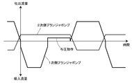
- an upstream primary plunger pump and a downstream secondary plunger pump operate in a complementary manner. There are a liquid feeding stroke by the secondary plunger pump and a liquid feeding stroke by the secondary plunger pump.
- the secondary plunger pump In the discharge stroke by the primary plunger pump, the secondary plunger pump performs a suction operation while the primary plunger pump discharges the liquid, and a part of the liquid discharged by the primary plunger pump is 2 The secondary plunger pump sucks. In the discharge stroke by the secondary plunger pump, the secondary plunger pump performs the discharge operation, and the primary plunger pump performs the suction operation during that time.
- the flow rate obtained by subtracting the suction flow rate of the secondary side plunger pump from the discharge flow rate of the primary side plunger pump becomes the liquid supply flow rate of the liquid supply device.
- the discharge flow rate of the secondary plunger pump is the liquid supply flow rate of the liquid supply device.
- Such a series-type double plunger type liquid feeding device is provided with valves for preventing backflow on the inlet side and the outlet side of the primary plunger pump.
- the inlet valve When the primary plunger pump performs a discharge operation, the inlet valve is closed and the outlet valve opens, and when the primary plunger pump performs a suction operation, the inlet valve opens and the outlet valve opens. It is supposed to close.
- the pressure in the pump chamber of the primary plunger pump after the completion of the suction operation of the primary plunger pump is the system pressure (HPLC And the pressure in the analysis flow path of the SFC).
- the primary plunger pump discharges the plunger so that the pump chamber is raised to a pressure close to the system pressure in addition to the liquid suction operation.
- a preload operation is performed to drive the motor.
- the mobile phase sucked into the pump chamber is compressed and generates heat, the temperature of the mobile phase rises and the volume expands. Thereafter, the mobile phase discharged from the pump chamber is cooled by taking heat away from the wall surface of the flow path in the course of flowing through the flow path, and the volume shrinks.
- volume shrinkage occurs, an error occurs between the actual liquid flow rate and the ideal value of the liquid flow rate obtained by the product of the plunger cross-sectional area and the plunger drive speed, resulting in a decrease in liquid feed accuracy and Causes pulsation.
- an object of the present invention is to improve the reproducibility of the cooling process of the compressed fluid discharged from the plunger pump.
- the liquid feeding device includes a pump head provided with a pump chamber therein, a plunger having a tip slidably inserted into the pump chamber, and a drive mechanism for reciprocating the plunger in the axial direction thereof.
- At least one plunger pump wherein the at least one plunger pump pressurizes a mobile phase made of a compressible fluid sucked into the pump chamber and then discharges it from the pump chamber.
- the pump head of the pressurizing pump is connected to an outlet channel from the pump chamber, and has a cooling unit that absorbs heat of the mobile phase discharged from the pump chamber and cools the mobile phase. It is what it has.
- the “pressurizing pump” in the present invention refers to a pump that discharges the mobile phase in the pump chamber after pressurizing the mobile phase sucked into the pump chamber, that is, after performing a preload operation.
- the primary side plunger pump corresponds to the “pressurizing pump” in the present invention
- both plunger pumps in the “pressurizing pump” in the present invention It corresponds to.
- a heat exchange flow path is provided in a pump head of a secondary plunger pump of an in-line double plunger type liquid delivery device, and the temperature of a mobile phase discharged from a primary plunger pump (pressure pump). Is equal to the pump head of the secondary plunger pump.
- the heat exchange flow path is provided on the pump head of the secondary plunger pump, the pipe connecting the pump head of the primary plunger pump and the pump head of the secondary plunger pump.
- the mobile phase that generates heat flows (referred to as primary side outlet piping).
- the primary side outlet pipe since the temperature of the primary side outlet pipe periodically varies due to the heated mobile phase discharged from the primary side plunger pump, the primary side outlet pipe has a small heat capacity and is also exposed to the outside air.
- the temperature of the primary side outlet pipe is unstable. In such a structure in which the mobile phase is cooled at a temperature unstable portion, it cannot be said that the reproducibility of the cooling process of the mobile phase is good.
- the pump head of the pressurizing pump that performs the preload operation is connected to the outlet flow path from the pump chamber, and the heat of the mobile phase discharged from the pump chamber is transferred to the pump head. Since a cooling unit is provided for absorbing and cooling the mobile phase, the fluid discharged from the pump chamber is cooled to substantially the same temperature as the pump head of the pressurizing pump and then sent to the outside of the pump head. It becomes liquid. As a result, the mobile phase cooled to substantially the same temperature as the pump head flows through the external piping such as the primary outlet piping connected to the pressurization pump. The cooling of the mobile phase is suppressed, and the reproducibility of the cooling process of the mobile phase is improved.
- the cooling part is constituted by a flat plate-shaped flow path in which the ratio of the internal surface area to the internal volume is larger than that of the outlet flow path.
- the cooling unit may be composed of a plurality of channels having a smaller cross-sectional area than the outlet channel, or a meandering channel having a smaller cross-sectional area than the outlet channel. Also good.
- one wall surface of the flow path forming the cooling unit is configured to generate elastic distortion according to the pressure in the flow path, and a strain detection unit that detects the amount of distortion of the wall surface, And a pressure detection unit configured to detect a pressure in the cooling unit based on a strain amount of the wall surface detected by the strain detection unit.
- the liquid feeding pressure of a pressurization pump is detectable using the cooling part provided in the pressurization pump. If the liquid feeding pressure of the pressurizing pump can be detected, the preload operation of the pressurizing pump can be controlled with high accuracy based on the detected value.
- a calorific value calculation unit that calculates the calorific value of the mobile phase in the pump chamber based on the amount of change in the pressure value detected by the pressure detection unit may be further provided.
- the heat detection amount of the mobile phase due to the preload operation can be calculated based on the pressure increase amount during the preload operation of the pressurizing pump by the pressure detection unit.
- the calorific value of the mobile phase can be calculated as ⁇ T / C p ⁇ , where the proportional coefficient between the amount of pressure increase and the calorific value is given by the thermal expansion coefficient ⁇ , temperature T, constant pressure specific heat C p and density ⁇ of the fluid.
- the discharge flow rate of the pressurization pump should be controlled as follows according to the amount of pressure increase during the preload operation of the pressurization pump. Can do.
- the compensation flow rate for setting the flow rate actually fed from the pressurization pump to a predetermined liquid feed flow rate is set large, and the discharge operation of the pressurization pump is controlled based on the compensation flow rate.
- the compensation flow rate is set small, and the discharge operation of the pressurization pump is controlled based on the compensation flow rate.
- a temperature detection unit that detects the temperature of the cooling unit may be further provided. If a temperature detection unit that detects the temperature of the cooling unit is provided, a temperature change of the mobile phase in the pump chamber of the pressurization pump can be detected.
- a calorific value calculation unit that calculates the calorific value of the mobile phase in the pump chamber based on the amount of change in temperature detected by the temperature detection unit. If the calorific value of the mobile phase in the pump chamber of the pressurizing pump can be calculated, the feedforward control of the pressurizing pump described above can be performed. Specifically, when the temperature change amount of the mobile phase during the preload operation of the pressurization pump is large, the heat generation amount of the mobile phase is predicted to be large and the volume shrinkage due to cooling of the mobile phase is expected to be large. To do. On the contrary, when the temperature change amount of the mobile phase during the preload operation is small, it is predicted that the heat generation amount of the mobile phase is small and the volume shrinkage due to the cooling of the mobile phase is small.
- each detection part can be used for calculation of the calorific value of the mobile phase as described above.
- the temperature detector can be used to correct the temperature characteristics of the strain detector. As a result, even when the temperature of the strain detector changes due to heat generation of the mobile phase, the output of the strain detector can be corrected using the temperature detected by the temperature detector, and an accurate pressure can be measured.
- the outlet pipe connected to the pump head of the pressurization pump is easily affected, whereas the pump head has a larger heat capacity than the outlet pipe, so the outlet A temperature difference occurs between the piping and the pump head. If it does so, the temperature of the mobile phase cooled to substantially the same temperature as the pump head in the cooling part provided in the pump head may change at the outlet pipe, and the reproducibility of the cooling process of the mobile phase may be impaired. .
- the outlet pipe disposed outside the pump head of the pressure pump and communicating with the outlet flow path of the pressure pump is covered with a heat insulating member. If it does so, the temperature of outlet piping will become stable and it will become difficult to produce a temperature difference between a pump head and outlet piping. Thereby, the reproducibility of the cooling process of the mobile phase can be improved.
- a fluid chromatograph includes an analysis flow path, the above-described liquid feeding device that feeds a mobile phase in the analysis flow path, a sample injection unit that injects a sample into the analysis flow path, and the analysis flow.
- a separation column that is provided downstream of the sample injection section on the road, and separates the sample injected into the analysis flow path by the sample injection section for each component; and downstream of the separation column on the analysis flow path And a detector that detects a sample component separated by the separation column.
- Fluid chromatograph means an analyzer such as HPLC or SFC that performs analysis while flowing a fluid as a mobile phase.
- the pump head of the pressurizing pump that performs the preload operation is connected to the outlet flow path from the pump chamber, and the heat of the mobile phase discharged from the pump chamber is absorbed by the pump head. Since the cooling unit for cooling the mobile phase is provided, the fluid discharged from the pump chamber is cooled to substantially the same temperature as the pump head of the pressurizing pump, and then sent to the outside of the pump head. As a result, the mobile phase cooled to substantially the same temperature as the pump head flows through the external piping such as the primary outlet piping connected to the pressurization pump. The cooling of the mobile phase is suppressed, and the reproducibility of the cooling process of the mobile phase is improved. Improved reproducibility of the mobile phase cooling process improves the reproducibility of the mobile phase volume expansion and contraction process, making it easier to control the flow rate in anticipation of mobile phase volume expansion and contraction. Become.
- liquid feeding device is used as a liquid feeding device for feeding the mobile phase, liquid feeding that is less affected by expansion and contraction of the volume of the mobile phase is performed. Thus, the accuracy and reproducibility of the analysis is improved.
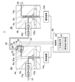
- the liquid feeding device 1 of this embodiment is of a series double plunger type in which a plunger pump 2a (hereinafter referred to as a primary side plunger pump 2a) and a plunger pump 2b (hereinafter referred to as a secondary side plunger pump 2b) are connected in series. It is a liquid feeding device.
- Pump chambers 6a and 6b, inlet channels 8a and 8b, and outlet channels 10a and 10b are provided in the pump heads 4a and 4b of the primary plunger pump 2a and the secondary plunger pump 2b, respectively.
- the tip of the plunger 12a is slidably inserted into the pump chamber 6a of the primary plunger pump 2a.
- the plunger 12a is reciprocated in the axial direction by the drive mechanism 14a.
- the distal end portion of the plunger 12b is slidably inserted into the pump chamber 6b of the primary side plunger pump 2b.
- the plunger 12b is reciprocated in the axial direction by the drive mechanism 14b.
- the drive mechanisms 14a and 14b have, for example, a cam mechanism and a motor for driving the cam mechanism, a ball screw mechanism and a motor for driving the ball screw mechanism.
- the inlet passage 8a of the primary plunger pump 2a has one end communicating with the pump chamber 6a and the other end connected to the inlet pipe 18 via the check valve 16a.
- the check valve 16a opens according to the pressure reduction in the pump chamber 6a when the plunger 12a is driven in the suction direction (the direction in which the plunger 12a is pulled out from the pump chamber 6a), and the plunger 12a is in the discharge direction (the direction in which the plunger 12a is pushed into the pump chamber 6a). It is provided so as to close in response to the pressurization in the pump chamber 6a when being driven.
- a cooling block 20 made of a heat conductive material such as metal is attached to the pump head 4a of the primary plunger pump 2a.
- a cooling unit 22 an inflow channel 24, and an outflow channel 26 are provided.
- One end of the inflow channel 24 communicates with the cooling unit 22, and the other end of the inflow channel 24 is connected to the outlet channel 10 a that communicates with the tip of the pump chamber 6 a through a joint 28.
- the pump chamber 6a and the cooling part 22 are mutually connected via the exit flow path 10a, the joint 28, and the inflow flow path 24.
- One end of the outflow channel 26 communicates with the cooling unit 22, and the other end of the outflow channel 26 is connected to the primary side outlet pipe 30.
- the inlet passage 8b of the secondary plunger pump 2b has one end communicating with the pump chamber 6b and the other end connected to the other end of the primary outlet pipe 30 via the check valve 16b.
- the check valve 16b is provided to open when the pressure in the pump chamber 6a is higher than the pressure in the pump chamber 6b, and to close when the pressure in the pump chamber 6a is lower than the pressure in the pump chamber 6b.
- One end of the outlet channel 10b communicates with the tip of the pump chamber 6b, and the other end of the outlet channel 10b is connected to the secondary outlet pipe 38.
- this liquid feeding device 1 is a serial type liquid feeding device, as shown in FIG. 3, while the primary side plunger pump 2a is performing the discharge operation, the secondary side plunger pump 2b is 1 The suction operation is performed at a flow rate smaller than the discharge flow rate of the secondary plunger pump 2a, and the secondary plunger pump 2b sucks a part of the mobile phase discharged from the primary plunger pump 2a. Therefore, while the primary side plunger pump 2a is performing the discharge operation, the flow rate obtained by subtracting the suction flow rate of the secondary side plunger pump 2b from the discharge flow rate of the primary side plunger pump 2a is passed through the secondary side outlet pipe 38. Mobile phase is delivered.
- the primary side plunger pump 2a performs the suction operation and the preload operation while the secondary side plunger pump 2b performs the discharge operation.
- the “preload operation” means that the pressure in the pump chamber 6a after the suction operation of the primary plunger pump 2a is completed is the same as the pressure in the pump chamber 6b of the secondary plunger pump 2b, that is, the system pressure. This is an action to keep it high.
- the primary plunger pump corresponds to a “pressurizing pump” that discharges after pressurizing the mobile phase.
- the temperature difference is the length of the channel from the inlet.
- a representative length necessary for cooling the mobile phase that generates heat in the pump chamber 6a of the primary plunger pump 2a is calculated.
- the discharge flow rate of the primary side plunger pump 2a is set to 2 mL / min.
- the thermal diffusivity of the mobile phase is slightly different between water and the organic solvent, but is typically in the range of 1.0 ⁇ 10 ⁇ 7 to 1.5 ⁇ 10 ⁇ 7 m 2 / s.
- the representative length required for cooling the mobile phase is calculated to be about 20 to 30 mm.
- the cross-sectional shape of the flow path was a circular pipe. It is known that this representative length does not depend on the inner diameter of the circular tube. This result means that even if the exothermic mobile phase passes through a channel having a length of about 30 mm, 37% of the exotherm still remains.
- the diameter of the pump head of a general plunger pump is 30 to 50 mm
- the length of the outlet channel is about 15 to 25 mm. This is the same as or shorter than the representative length calculated above, and is not sufficient for cooling the exothermic mobile phase. Therefore, in the prior art, the mobile phase in the state where the heat generated during the preload operation remains is sucked into the pump chamber of the secondary plunger pump through the primary outlet pipe. As a result, the cooling process becomes complicated and difficult to understand, and the effectiveness of the feedforward control of the primary plunger pump in consideration of the thermal expansion and contraction of the mobile phase is impaired.
- the cooling unit 22 is provided to cause the pump head 4a to absorb the heat of the mobile phase generated during the preload operation. Therefore, the cooling block 20 is thermally integrated with the pump head 4a, and in the cooling unit 22, the heat absorbed by the cooling block 22 from the mobile phase is released to the pump head 4a. Thereby, the mobile phase discharged from the pump chamber 6a and flowing into the cooling unit 22 is cooled to a temperature similar to that of the pump head 4a.
- being thermally integrated means, for example, that the cooling block 20 and the pump head 4a are mechanically fastened under a sufficient contact area as shown in FIG. To do.
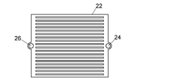
- FIG. 2 shows an example of the structure of the cooling unit 22.
- the cooling unit 22 in this example is a flat plate-shaped flow channel in which the ratio of the internal surface area to the internal volume is larger than that of the outlet flow channel 10a.
- the ratio of the internal surface area to the internal capacity increases, the efficiency with which the cooling block 20 absorbs heat from the mobile phase flowing inside the cooling unit 22 is improved.
- Such a flat channel may have a circular or oval planar shape.
- the minimum width r is 10 mm or less, more preferably 5 mm or less.
- the flow path depth h is 1 mm or less, More preferably, it is 0.5 mm or less.
- the ratio of the minimum width to the depth is preferably 2 times or more, more preferably 5 times or more, and further preferably 10 times or more.
- the internal capacity of the flat channel is preferably 20 uL or less, more preferably 10 uL or less, and further preferably 5 uL or less.
- the structure of the cooling unit 22 is not limited to the example of FIG. As shown in FIG. 5A, the cooling unit 22 may be provided with a plurality of parallel flow paths between the inflow flow path 24 and the outflow flow path 26, or as shown in FIG. 5B. As shown, the inflow channel 24 and the outflow channel 26 may be connected by a single meandering channel.
- the channel depth and channel width do not affect the representative length required for cooling, but typically can be designed in the range of 0.05 mm to 0.5 mm, more preferably 0.1 mm to 0.3 mm. It is possible to design within the range.
- the flow path depth and flow path width may be selected according to processing accuracy and internal capacity requirements.
- the internal capacity is preferably 20 uL or less, more preferably 10 uL or less, and further preferably 5 uL or less.
- the structure of the cooling unit 22 shown in FIG. 2, FIG. 5A, and FIG. 5B is obtained by machining the flow path by removal processing such as machining, etching, sand blasting, electric discharge machining, diffusion bonding, welding, or simply using a packing or gasket. Can be manufactured by sealing.
- the mobile phase discharged from the pump chamber 6a is cooled to a temperature similar to that of the pump head 4a in the cooling unit 22 and then flows through the primary outlet pipe 30 and into the pump head 4b of the secondary plunger pump 2b. be introduced. Since the heat capacity of the primary side outlet pipe 30 is smaller than that of the pump head 4a, the temperature of the primary side outlet pipe 30 is different from the temperature of the pump head 4a. There is. In that case, the temperature of the mobile phase cooled to a temperature comparable to that of the pump head 4a changes during the flow through the primary outlet pipe 30 and affects the reproducibility of the cooling process of the mobile phase.
- the primary side outlet pipe 30 is covered with the heat insulating member 46 to improve the temperature stability of the primary side outlet pipe 30.
- the heat insulating member 46 that covers the primary outlet pipe 30 include a resin coating and a foamed member.
- the primary outlet pipe 30 is accommodated in a space thermally isolated from the surroundings by a heat insulating material, or the primary outlet pipe 30 and the primary The entirety including the pump head 4a of the side plunger pump 2a and the pump head 4b of the secondary plunger pump 2b may be accommodated in such a space.
- one wall surface 32 of the cooling block 20 defining the cooling unit 22 is configured to be elastically deformed according to the pressure in the cooling unit 22.
- the wall surface 32 of the cooling block 20 is provided with a strain sensor 34 (strain detector) that detects the amount of strain of the wall surface 32, and a signal from the strain sensor 34 controls the operation of the drive mechanisms 14a and 14b. It is supposed to be taken in.
- the control unit 40 is realized by a dedicated computer or a general-purpose personal computer of the liquid delivery device 1.
- the control unit 40 is configured to obtain the pressure value in the cooling unit 22 based on the signal value from the strain sensor 34, and the mobile phase in the pump chamber 6a based on the amount of change in the pressure value.
- the calorific value calculation unit 44 is configured to calculate the calorific value of the heat.
- the control unit 40 is provided with data indicating the relationship between the signal value from the strain sensor 34 and the pressure value in the cooling unit 22, and the pressure detection unit 42 determines the pressure in the cooling unit 22 based on the data. It is configured to determine a value.
- the pressure value in the cooling unit 22 obtained by the pressure detection unit 42 is used for the preload operation of the primary side plunger pump 2a.
- the controller 40 determines that the pressure in the cooling unit 22 obtained by the pressure detector 42 is the pressure in the pump chamber 6b of the secondary plunger pump 2b (system pressure). ) Is configured to control the drive mechanism 14a so as to have a value similar to that of ().
- the control unit 40 receives a detection signal from a pressure sensor (not shown) that detects the system pressure.
- a temperature sensor 36 for detecting the temperature of the cooling unit 22 is attached to the cooling block 20, and an output signal of the temperature sensor 36 is also taken into the control unit 40.
- the temperature sensor 36 is not an essential component, the temperature of the mobile phase in the pump chamber 6a can be monitored by providing the temperature sensor 36. If the amount of change in the temperature of the mobile phase in the pump chamber 6a during the preload operation of the primary plunger pump 2a is determined, the amount of heat generated in the mobile phase in the pump chamber 6a during the preload operation can be determined. Therefore, when the temperature sensor 36 is provided, the calorific value calculation unit 44 does not use the pressure value obtained by the pressure detection unit 42 but based on the change amount of the output signal from the temperature sensor 36. The amount of generated heat may be calculated.
- both the above-described strain sensor and temperature sensor may be provided.
- each sensor can be used for calculating the heat generation amount of the mobile phase.
- the temperature sensor can also be used to correct the temperature characteristics of the strain sensor. As a result, even when the temperature of the strain sensor changes due to heat generation of the mobile phase, the output of the strain sensor can be corrected using the temperature detected by the temperature sensor, and an accurate pressure can be measured.
- the calorific value of the mobile phase in the pump chamber 6a obtained by the calorific value calculation unit 44 can be used for controlling the driving speed of the plunger 12a during the discharge operation of the primary plunger pump 2a. That is, if the heat generation amount of the mobile phase in the pump chamber 6a is known, it is possible to determine the magnitude of the liquid flow rate deficit due to the thermal expansion of the mobile phase due to the heat generation and the subsequent thermal contraction due to the cooling in the cooling unit 22. By driving the plunger 12a so as to guarantee the missing amount, the stability of the liquid feeding flow rate can be maintained.
- the liquid delivery device according to the present invention is not limited to the configuration of the above-described embodiment.
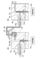
- the primary side plunger pump 102a and the secondary side plunger pump 102b are connected in series with each other, and perform the operation shown in FIG. That is, the primary side plunger pump 102a performs the suction operation and the preload operation during the discharge operation of the secondary side plunger pump 102b, and pressurizes the mobile phase in the pump chamber 106a and then discharges it. It corresponds to.
- the pump chamber 106a and the suction / discharge passage 108a are provided in the pump head 104a of the primary plunger pump 102a.
- the suction / discharge channel 108a is provided so that one end thereof communicates with the tip of the pump chamber 106a and extends from the tip of the pump chamber 106a in the axial direction of the plunger 112a.
- the cooling block 120 is attached to the tip of the pump head 104a of the primary plunger pump 102a.
- the cooling block 120 is the same as the cooling block 20 in the liquid delivery device 1 of FIG. 1, and includes a cooling unit 122, an inflow channel 124, and an outflow channel 126 therein.
- the other end of the suction / discharge channel 108 a communicates with the cooling unit 122 through the inflow channel 124, and the cooling unit 122 further communicates with the inlet channel 150 through the outflow channel 126.
- the inlet channel 150 is a channel provided in an inlet block 148 provided on the opposite side of the cooling block 120 from the pump head 104a. One end of the inlet channel 150 is connected to the inlet pipe 118 via the check valve 116a, and the other end of the inlet channel 150 is connected to the primary side outlet pipe 130 via the check valve 116b.
- the check valve 116a opens when the plunger 112a is driven in the suction direction by the drive mechanism 114a, and closes when the plunger 112a is driven in the discharge direction.
- the check valve 116b is closed when the pressure in the pump chamber 106b is higher than the pressure in the pump chamber 106a, and is opened when the pressure in the pump chamber 106a becomes higher than the pressure in the pump chamber 106b. It has become.
- the primary outlet pipe 130 is covered with the heat insulating member 146, but the heat insulating member 146 is not an essential component.
- the mobile phase flows through the cooling unit 122 in both cases where the primary plunger pump 102a performs a suction operation and a discharge operation.
- the temperature of the mobile phase sucked into the pump chamber 106a of the primary plunger pump 102a can be set to the same temperature as the pump head 104a, and the temperature of the mobile phase sucked due to room temperature fluctuation or the like varies. Even in such an environment, the temperature of the mobile phase to be fed can be further stabilized, and the stability of the liquid feeding flow rate can be further improved.
- the configuration of the secondary plunger pump 102b of the liquid delivery apparatus 100 is the same as that of the secondary plunger pump 2b of the liquid delivery apparatus 1 of FIG. 1, and pump heads 4b and 104b, pump chambers 6b and 106b, inlet flow path 8b. 108b, outlet channels 10b and 110b, plungers 12b and 112b, drive mechanisms 14b and 114b, and outlet channels 38b and 138b, respectively.
- One wall surface 132 of the cooling block 120 of the liquid feeding device 100 is elastically deformed according to the pressure in the cooling unit 122, similarly to the wall surface 32 of the cooling block 20 of the liquid feeding device 1 of FIG. It is configured.
- the cooling block 120 is provided with a strain sensor 134 that detects the amount of distortion of the wall surface 132, so that the pressure in the cooling unit 122 can be detected based on the amount of distortion of the wall surface 132. .
- the configuration of the wall surface 132 and the strain sensor 134 are not essential components.
- both plunger pumps 202a and 202b correspond to “pressure pumps” that discharge after pressurizing the mobile phase in the pump chambers 206a and 206b.
- cooling blocks 220a and 220b are attached to both of the plunger pumps 202a and 202b, respectively.
- the cooling blocks 220a and 220b are equivalent to the cooling block 20 in the liquid delivery device 1 of FIG. 1, and a cooling unit 222a for cooling the mobile phase discharged from the pump chambers 206a and 206b of the plunger pumps 202a and 202b. , 222b inside.
- a pump chamber 206a, an inlet channel 208a, an outlet channel 210a, and a post-cooling outlet channel 211a are provided in the pump head 204a of the plunger pump 202a.
- the distal end portion of the plunger 212a is slidably accommodated in the pump chamber 206a, and is configured to reciprocate in the axial direction by the drive mechanism 214a.
- the inlet channel 208a has one end communicating with the pump chamber 206a and the other end connected to the inlet pipe 218 via the check valve 216a.
- the inlet pipe 218 is also connected to the inlet channel 208b of the plunger pump 202b via the check valve 216b.
- the outlet channel 210a has one end connected to the tip of the pump chamber 206a and the other end connected to an inflow channel 224a that leads to the cooling unit 222a via a joint.
- One end of the post-cooling outlet channel 211a is connected to the outflow channel 226a of the cooling block 220a via a joint, and the other end is connected to the outlet pipe 238 via the check valve 217a.
- the outlet pipe 238 is also connected to a post-cooling outlet pipe 211b of the plunger pump 202b via a check valve 217.
- One wall surface 232a of the cooling block 220a is configured to be elastically deformed according to the pressure in the cooling section 222a, similarly to the wall surface 32 of the cooling block 20 of the liquid delivery device 1 of FIG.
- the cooling block 220a is provided with a strain sensor 234a that detects the amount of distortion of the wall surface 232a, and the pressure in the cooling unit 222a can be detected based on the amount of distortion of the wall surface 232a.
- the wall surface 232a and the strain sensor 234a are not essential components.
- the plunger pump 202b has the same configuration as that of 202a, and portions corresponding to the respective components of the plunger pump 202a are assigned the same numbers, and the reference numerals after those numbers are “a” and “ The only difference is “b”.
- the cooling heads 222a and 222b are provided in the pump heads 204a and 204b of the plunger pumps 202a and 202b, respectively, so that the heat generated during the preload operation is generated.
- the phase can be cooled to the same temperature as the pump heads 204a and 204b before being fed. Thereby, the reproducibility of the cooling process of the mobile phase sucked by each plunger pump 202a, 202b is improved.
- the pipes provided outside the pump heads 204a and 204b such as the outlet pipe 238 through which the mobile phase discharged from the plunger pumps 202a and 202b flows are shown in FIG. Similar to the outlet pipe 38, measures may be taken so as not to be affected by temperature fluctuations in the surrounding environment, such as being covered with a heat insulating member.
- FIG. 8 is a flow path configuration diagram of a liquid chromatograph which is an embodiment of a fluid chromatograph provided with the liquid delivery device 1, 100 or 200 described above.
- the liquid chromatograph of this embodiment includes an analysis flow path 302, the above-described liquid feeding device 1, 100 or 200, a sample injection unit 304, a separation column 306, a column oven 308, and a detector 310. ing.
- the liquid feeding device 1, 100, or 200 is provided for feeding the mobile phase in the analysis flow path 302.
- the sample injection unit 304 is an autosampler that automatically injects a sample into the analysis flow path 302.
- the separation column 306 is provided downstream of the sample injection unit 304 on the analysis flow path 302 and separates the sample injected by the sample injection unit 304 for each component.
- the separation column 306 is accommodated in a column oven 308, and the temperature is adjusted to a set temperature.
- the detector 310 is provided downstream of the separation column 306 on the analysis flow path 302 and detects a sample component separated in the separation column 306.
- the liquid feeding device 1, 100 or 200 is configured to feed a single mobile phase to the sample injection unit 304.
- different mobile phases fed by a plurality of liquid feeding devices may be mixed and fed to the sample injection unit 304.
- Such a configuration is commonly known as a “high pressure gradient”.
- a plurality of mobile phases are mixedly supplied to the liquid delivery device 1, 100 or 200 via a mobile phase switching valve or a proportional valve and fed to the sample injection unit 304. May be.
- Such a configuration is commonly known as a “low pressure gradient”.
- the liquid delivery apparatus 1, 100 or 200 disclosed in the present invention can be applied to liquid chromatographs having various flow path configurations, not limited to the embodiment shown in FIG.
- a liquid chromatograph is shown as an example of a fluid chromatograph, but the present invention can be similarly applied to a supercritical fluid chromatograph.
Abstract
This liquid feeding device is provided with: a pump head having a pump chamber provided therein; a plunger having a tip part that is slidably inserted into the pump chamber; and at least one plunger pump having a driving mechanism which reciprocates the plunger in the axial direction thereof. Also, the at least one plunger pump is a pressurization pump which pressurizes a mobile phase and then ejects the mobile phase from the pump chamber, wherein the mobile phase is composed of a compressible fluid suctioned into the pump chamber. At least the pump head of the pressurization pump is provided with a cooling part which is connected to an outlet flow path from the pump chamber and cools the mobile phase by absorbing into the pump head, the heat of the mobile phase ejected from the pump chamber.
Description
本発明は、例えば高速液体クロマトグラフ(HPLC)や超臨界流体クロマトグラフ(SFC)などの分析装置において移動相を送液するために用いられる送液装置と、その送液装置を備えた流体クロマトグラフに関するものである。
The present invention relates to a liquid feeding device used for feeding a mobile phase in an analyzer such as a high performance liquid chromatograph (HPLC) or a supercritical fluid chromatograph (SFC), and a fluid chromatograph provided with the liquid feeding device. It relates to graphs.
HPLCシステムに用いられる送液装置は、移動相を高圧で安定して送液する能力が求められる。そのため、2つのプランジャポンプが直列又は並列に接続されたダブルプランジャ方式の送液装置が一般的に用いられている。
The liquid feeding device used in the HPLC system is required to have the ability to stably feed the mobile phase at a high pressure. Therefore, a double plunger type liquid feeding device in which two plunger pumps are connected in series or in parallel is generally used.
例えば、2つのプランジャポンプが直列に接続された送液装置は、上流側の1次側プランジャポンプと下流側の2次側プランジャポンプが相補的に動作するものであるが、その吐出行程として1次側プランジャポンプによる送液行程と、2次側プランジャポンプによる送液行程がある。
For example, in a liquid feeding device in which two plunger pumps are connected in series, an upstream primary plunger pump and a downstream secondary plunger pump operate in a complementary manner. There are a liquid feeding stroke by the secondary plunger pump and a liquid feeding stroke by the secondary plunger pump.
1次側プランジャポンプによる吐出行程では、1次側プランジャポンプが液を吐出している間に2次側プランジャポンプは吸引動作を行ない、1次側プランジャポンプにより吐出される液の一部を2次側プランジャポンプが吸引する。2次側プランジャポンプによる吐出行程では、2次側プランジャポンプが吐出動作を行ない、その間に1次側プランジャポンプが吸引動作を行なう。
In the discharge stroke by the primary plunger pump, the secondary plunger pump performs a suction operation while the primary plunger pump discharges the liquid, and a part of the liquid discharged by the primary plunger pump is 2 The secondary plunger pump sucks. In the discharge stroke by the secondary plunger pump, the secondary plunger pump performs the discharge operation, and the primary plunger pump performs the suction operation during that time.
1次側プランジャポンプによる吐出行程では、1次側プランジャポンプの吐出流量から2次側プランジャポンプの吸引流量を差し引いた流量が送液装置の送液流量となり、2次側プランジャポンプによる吐出行程では、2次側プランジャポンプの吐出流量が送液装置の送液流量となる。
In the discharge stroke by the primary side plunger pump, the flow rate obtained by subtracting the suction flow rate of the secondary side plunger pump from the discharge flow rate of the primary side plunger pump becomes the liquid supply flow rate of the liquid supply device. The discharge flow rate of the secondary plunger pump is the liquid supply flow rate of the liquid supply device.
このような直列型ダブルプランジャ方式の送液装置は、1次側プランジャポンプの入口側と出口側のそれぞれに逆流を防止するバルブが設けられている。1次側プランジャポンプが吐出動作を行なうときは入口側のバルブが閉じて出口側のバルブが開き、1次側プランジャポンプが吸引動作を行なうときは入口側のバルブが開いて出口側のバルブが閉じるようになっている。
Such a series-type double plunger type liquid feeding device is provided with valves for preventing backflow on the inlet side and the outlet side of the primary plunger pump. When the primary plunger pump performs a discharge operation, the inlet valve is closed and the outlet valve opens, and when the primary plunger pump performs a suction operation, the inlet valve opens and the outlet valve opens. It is supposed to close.
1次側プランジャポンプの吸引動作は出口側のバルブが閉じた状態で行なわれるため、1次側プランジャポンプの吸引動作が終了した後の1次側プランジャポンプのポンプ室内の圧力がシステム圧力(HPLCやSFCの分析流路内の圧力)よりも低い状態となる。この状態で吐出動作を行なうポンプを2次側プランジャポンプから1次側プランジャポンプに切り替えると、1次側プランジャポンプのポンプ室内がシステム圧力と同じ圧力に上昇するまで1次側プランジャポンプから液が吐出されず、その結果、一時的に送液流量が低下して送液流量の安定性が低下する。
Since the suction operation of the primary plunger pump is performed with the valve on the outlet side closed, the pressure in the pump chamber of the primary plunger pump after the completion of the suction operation of the primary plunger pump is the system pressure (HPLC And the pressure in the analysis flow path of the SFC). When the pump that performs the discharge operation in this state is switched from the secondary plunger pump to the primary plunger pump, the liquid is discharged from the primary plunger pump until the pump chamber of the primary plunger pump rises to the same pressure as the system pressure. As a result, the liquid feeding flow rate is temporarily lowered and the stability of the liquid feeding flow rate is lowered.
このような問題から、2次側プランジャポンプによる吐出行程の間に、1次側プランジャポンプは液の吸引動作に加えて、ポンプ室内がシステム圧力に近い圧力にまで高められるようにプランジャを吐出方向へ駆動する予圧動作を行なうようになっていることが一般的である。
Because of these problems, during the discharge stroke by the secondary plunger pump, the primary plunger pump discharges the plunger so that the pump chamber is raised to a pressure close to the system pressure in addition to the liquid suction operation. In general, a preload operation is performed to drive the motor.
これは、2つのプランジャポンプが並列に接続された並列型ダブルプランジャ方式の送液装置においても同様であり、一方のプランジャポンプが吐出動作を行なっている間に、他方のプランジャポンプは吸引動作と予圧動作を行なうようになっている。
The same applies to a parallel-type double plunger type liquid feeding device in which two plunger pumps are connected in parallel. While one plunger pump performs a discharge operation, the other plunger pump performs a suction operation. A preload operation is performed.
予圧動作が行なわれると、ポンプ室内に吸引された移動相が圧縮されて発熱し、移動相の温度が上昇して体積が膨張する。その後、ポンプ室から吐出された移動相は流路を流れている過程において流路壁面などによって熱を奪われて冷却され、体積が収縮する。このような体積収縮が起こると、実際の送液流量とプランジャ断面積とプランジャの駆動速度の積によって求められる送液流量の理想的な値との間に誤差が生じ、送液精度の低下や脈動の原因となる。
When the preload operation is performed, the mobile phase sucked into the pump chamber is compressed and generates heat, the temperature of the mobile phase rises and the volume expands. Thereafter, the mobile phase discharged from the pump chamber is cooled by taking heat away from the wall surface of the flow path in the course of flowing through the flow path, and the volume shrinks. When such volume shrinkage occurs, an error occurs between the actual liquid flow rate and the ideal value of the liquid flow rate obtained by the product of the plunger cross-sectional area and the plunger drive speed, resulting in a decrease in liquid feed accuracy and Causes pulsation.
移動相の体積収縮による上記の問題への対策として、移動相の発熱・冷却過程の事前知識に基づいてプランジャ速度を制御するフィードフォワード制御を行なう方法や、システム圧力が目標値に等しくなるようプランジャ速度を制御するフィードバック制御を行なう方法が提案されている(特許文献1、2、3参照。)。
As countermeasures against the above-described problems caused by volume contraction of the mobile phase, there is a method of performing feedforward control for controlling the plunger speed based on prior knowledge of the heat generation / cooling process of the mobile phase, and the plunger so that the system pressure becomes equal to the target value. A method of performing feedback control for controlling the speed has been proposed (see Patent Documents 1, 2, and 3).
移動相の発熱・冷却過程の事前知識に基づいてプランジャ速度を制御するフィードフォワード制御を行なう場合には、移動相の発熱・冷却過程に再現性が求められる。特に、ポンプ室から吐出された後の移動相の冷却過程の再現性が低い場合には、吐出された後の移動相の体積収縮が不安定になり、送液精度の低下の原因となる。
When performing feedforward control for controlling the plunger speed based on prior knowledge of the heat generation / cooling process of the mobile phase, reproducibility is required for the heat generation / cooling process of the mobile phase. In particular, when the reproducibility of the cooling process of the mobile phase after being discharged from the pump chamber is low, the volumetric shrinkage of the mobile phase after being discharged becomes unstable, which causes a decrease in liquid feeding accuracy.
そこで、本発明は、プランジャポンプから吐出される圧縮状態の流体の冷却過程の再現性を向上させることを目的とするものである。
Therefore, an object of the present invention is to improve the reproducibility of the cooling process of the compressed fluid discharged from the plunger pump.
本発明に係る送液装置は、内部にポンプ室が設けられているポンプヘッド、先端部が前記ポンプ室内に摺動可能に挿入されたプランジャ、及び前記プランジャをその軸方向において往復動させる駆動機構を有する少なくとも1つのプランジャポンプを備え、少なくとも1つの前記プランジャポンプが、前記ポンプ室内に吸引した圧縮性流体からなる移動相を加圧した後で前記ポンプ室から吐出する加圧ポンプであり、少なくとも前記加圧ポンプの前記ポンプヘッドは、前記ポンプ室からの出口流路と接続され、前記ポンプ室から吐出された移動相の熱を当該ポンプヘッドに吸収させてその移動相を冷却する冷却部を備えているものである。
The liquid feeding device according to the present invention includes a pump head provided with a pump chamber therein, a plunger having a tip slidably inserted into the pump chamber, and a drive mechanism for reciprocating the plunger in the axial direction thereof. At least one plunger pump, wherein the at least one plunger pump pressurizes a mobile phase made of a compressible fluid sucked into the pump chamber and then discharges it from the pump chamber. The pump head of the pressurizing pump is connected to an outlet channel from the pump chamber, and has a cooling unit that absorbs heat of the mobile phase discharged from the pump chamber and cools the mobile phase. It is what it has.
ここで、本発明における「加圧ポンプ」とは、ポンプ室内に吸引した移動相を加圧した後で、すなわち予圧動作を行なった後で、ポンプ室内の移動相を吐出するポンプのことである。直列型ダブルプランジャ方式の送液装置では1次側プランジャポンプが本発明における「加圧ポンプ」に該当し、並列型ダブルプランジャ方式の送液装置では両方のプランジャポンプが本発明における「加圧ポンプ」に該当する。
Here, the “pressurizing pump” in the present invention refers to a pump that discharges the mobile phase in the pump chamber after pressurizing the mobile phase sucked into the pump chamber, that is, after performing a preload operation. . In the in-line type double plunger type liquid feeding device, the primary side plunger pump corresponds to the “pressurizing pump” in the present invention, and in the parallel type double plunger type liquid feeding device, both plunger pumps in the “pressurizing pump” in the present invention. It corresponds to.
特許文献4には、直列型ダブルプランジャ方式の送液装置の2次側プランジャポンプのポンプヘッドに熱交換流路を設け、1次側プランジャポンプ(加圧ポンプ)から吐出された移動相の温度を2次側プランジャポンプのポンプヘッドと等しくすることが開示されている。この開示技術では、熱交換流路が2次側プランジャポンプのポンプヘッド上に設けられているため、1次側プランジャポンプのポンプヘッドと2次側プランジャポンプのポンプヘッドとの間を接続する配管(1次側出口配管という。)を発熱した移動相が流れる。しかし、1次側プランジャポンプから吐出された発熱した移動相によって1次側出口配管の温度が周期的に変動する上、1次側出口配管は熱容量が小さく外気にも曝されていることから、1次側出口配管の温度は不安定である。このような温度的に不安定な部分で移動相が冷却されるような構造では、移動相の冷却過程の再現性が良好であるとはいえない。
In Patent Document 4, a heat exchange flow path is provided in a pump head of a secondary plunger pump of an in-line double plunger type liquid delivery device, and the temperature of a mobile phase discharged from a primary plunger pump (pressure pump). Is equal to the pump head of the secondary plunger pump. In this disclosed technology, since the heat exchange flow path is provided on the pump head of the secondary plunger pump, the pipe connecting the pump head of the primary plunger pump and the pump head of the secondary plunger pump. The mobile phase that generates heat flows (referred to as primary side outlet piping). However, since the temperature of the primary side outlet pipe periodically varies due to the heated mobile phase discharged from the primary side plunger pump, the primary side outlet pipe has a small heat capacity and is also exposed to the outside air. The temperature of the primary side outlet pipe is unstable. In such a structure in which the mobile phase is cooled at a temperature unstable portion, it cannot be said that the reproducibility of the cooling process of the mobile phase is good.
これに対し、本発明の送液装置では、予圧動作を行なう加圧ポンプのポンプヘッドに、ポンプ室からの出口流路と接続され、ポンプ室から吐出された移動相の熱を当該ポンプヘッドに吸収させてその移動相を冷却する冷却部が設けられているので、ポンプ室から吐出された流体がその加圧ポンプのポンプヘッドと実質的に同じ温度まで冷却されてからポンプヘッドの外部へ送液されるようになる。これにより、加圧ポンプに接続された一次側出口配管などの外部の配管をポンプヘッドと実質的に同じ温度にまで冷却された移動相が流れるようになり、温度的に不安定な配管での移動相の冷却が抑制され、移動相の冷却過程の再現性が向上する。
On the other hand, in the liquid delivery device of the present invention, the pump head of the pressurizing pump that performs the preload operation is connected to the outlet flow path from the pump chamber, and the heat of the mobile phase discharged from the pump chamber is transferred to the pump head. Since a cooling unit is provided for absorbing and cooling the mobile phase, the fluid discharged from the pump chamber is cooled to substantially the same temperature as the pump head of the pressurizing pump and then sent to the outside of the pump head. It becomes liquid. As a result, the mobile phase cooled to substantially the same temperature as the pump head flows through the external piping such as the primary outlet piping connected to the pressurization pump. The cooling of the mobile phase is suppressed, and the reproducibility of the cooling process of the mobile phase is improved.
好ましい実施形態では、冷却部が、内部容量に対する内部表面積の比率が前記出口流路よりも大きい平板形状の流路によって構成されている。
In a preferred embodiment, the cooling part is constituted by a flat plate-shaped flow path in which the ratio of the internal surface area to the internal volume is larger than that of the outlet flow path.
また、冷却部は、前記出口流路よりも断面積の小さい複数の流路からなるものであってもよいし、出口流路よりも断面積の小さい流路が蛇行してなるものであってもよい。
Further, the cooling unit may be composed of a plurality of channels having a smaller cross-sectional area than the outlet channel, or a meandering channel having a smaller cross-sectional area than the outlet channel. Also good.
さらに好ましい実施形態では、前記冷却部をなす流路の1つの壁面は当該流路内の圧力に応じた弾性的な歪みを生じるように構成され、その壁面の歪み量を検出する歪み検出部、及び前記歪み検出部により検出された前記壁面の歪み量に基づいて前記冷却部内の圧力を検出するように構成された圧力検出部をさらに備えている。これにより、加圧ポンプに設けられた冷却部を利用して加圧ポンプの送液圧力を検出することができる。加圧ポンプの送液圧力を検出することができれば、その検出値に基づいて加圧ポンプの予圧動作を高精度に制御することができるようになる。
In a further preferred embodiment, one wall surface of the flow path forming the cooling unit is configured to generate elastic distortion according to the pressure in the flow path, and a strain detection unit that detects the amount of distortion of the wall surface, And a pressure detection unit configured to detect a pressure in the cooling unit based on a strain amount of the wall surface detected by the strain detection unit. Thereby, the liquid feeding pressure of a pressurization pump is detectable using the cooling part provided in the pressurization pump. If the liquid feeding pressure of the pressurizing pump can be detected, the preload operation of the pressurizing pump can be controlled with high accuracy based on the detected value.
また、圧力検出部により検出された圧力値の変化量に基づいて前記ポンプ室内での移動相の発熱量を計算する発熱量計算部をさらに備えていてもよい。圧力検出部によって加圧ポンプの予圧動作中の圧力上昇量に基づいて予圧動作による移動相の発熱量を計算することができる。移動相の発熱量は、流体の熱膨張率β、温度T、定圧比熱Cp、密度ρとすると、圧力上昇量と発熱量との比例係数をβT/Cpρとして計算することができる。
In addition, a calorific value calculation unit that calculates the calorific value of the mobile phase in the pump chamber based on the amount of change in the pressure value detected by the pressure detection unit may be further provided. The heat detection amount of the mobile phase due to the preload operation can be calculated based on the pressure increase amount during the preload operation of the pressurizing pump by the pressure detection unit. The calorific value of the mobile phase can be calculated as βT / C p ρ, where the proportional coefficient between the amount of pressure increase and the calorific value is given by the thermal expansion coefficient β, temperature T, constant pressure specific heat C p and density ρ of the fluid.
移動相の発熱量に基づいて加圧ポンプをフィードフォワード制御する場合、加圧ポンプの予圧動作中の圧力上昇量の大きさに応じて、次のように加圧ポンプの吐出流量を制御することができる。
When feedforward control of the pressurization pump is performed based on the heat generation amount of the mobile phase, the discharge flow rate of the pressurization pump should be controlled as follows according to the amount of pressure increase during the preload operation of the pressurization pump. Can do.
加圧ポンプの予圧動作中の圧力上昇量が大きいときは、移動相の発熱量が大きく移動相の冷却による体積収縮が大きくなると予測される。そのため、加圧ポンプから実際に送液される流量を所定の送液流量にするための補償流量を大きく設定し、その補償流量に基づいて加圧ポンプの吐出動作を制御する。逆に、加圧ポンプの予圧動作中の圧力上昇量が小さいときは、移動相の発熱量が小さく移動相の冷却による体積収縮が小さくなると予測される。そのため、補償流量を小さく設定し、その補償流量に基づいて加圧ポンプの吐出動作を制御する。
When the amount of pressure increase during the preload operation of the pressurizing pump is large, it is predicted that the heat generation amount of the mobile phase is large and the volume shrinkage due to the cooling of the mobile phase is large. Therefore, the compensation flow rate for setting the flow rate actually fed from the pressurization pump to a predetermined liquid feed flow rate is set large, and the discharge operation of the pressurization pump is controlled based on the compensation flow rate. Conversely, when the amount of pressure increase during the preload operation of the pressurizing pump is small, it is predicted that the heat generation amount of the mobile phase is small and the volume shrinkage due to cooling of the mobile phase is small. For this reason, the compensation flow rate is set small, and the discharge operation of the pressurization pump is controlled based on the compensation flow rate.
さらに、予圧動作中の単位時間あたりの圧力変化が大きいときは、移動相の圧縮がより断熱的で移動相の発熱が大きいと推測されるので、補償流量を大きくする。逆に予圧動作中の単位時間あたりの圧力変化が小さいときは、移動相の圧縮がより等温的であり発熱が小さいと推測されるので、補償流量を小さくする。
Furthermore, when the pressure change per unit time during the preload operation is large, it is estimated that the compression of the mobile phase is more adiabatic and heat generation of the mobile phase is large, so the compensation flow rate is increased. Conversely, when the pressure change per unit time during the preload operation is small, it is estimated that the compression of the mobile phase is more isothermal and the heat generation is small, so the compensation flow rate is reduced.
また、冷却部の温度を検出する温度検出部をさらに備えていてもよい。冷却部の温度を検出する温度検出部を備えていれば、加圧ポンプのポンプ室内の移動相の温度変化を検出することができる。
Further, a temperature detection unit that detects the temperature of the cooling unit may be further provided. If a temperature detection unit that detects the temperature of the cooling unit is provided, a temperature change of the mobile phase in the pump chamber of the pressurization pump can be detected.
この場合は、温度検出部により検出された温度の変化量に基づいてポンプ室内での移動相の発熱量を計算する発熱量計算部をさらに備えていることが好ましい。加圧ポンプのポンプ室内の移動相の発熱量を計算することができれば、上述した加圧ポンプのフィードフォワード制御を行なうことができる。具体的には、加圧ポンプの予圧動作中の移動相の温度変化量が大きいときは、移動相の発熱量が大きく移動相の冷却による体積収縮が大きくなると予測されるので、補償流量を大きくする。逆に、予圧動作中の移動相の温度変化量が小さいときは、移動相の発熱量が小さく移動相の冷却による体積収縮が小さくなると予測されるので、補償流量を小さくする。
In this case, it is preferable to further include a calorific value calculation unit that calculates the calorific value of the mobile phase in the pump chamber based on the amount of change in temperature detected by the temperature detection unit. If the calorific value of the mobile phase in the pump chamber of the pressurizing pump can be calculated, the feedforward control of the pressurizing pump described above can be performed. Specifically, when the temperature change amount of the mobile phase during the preload operation of the pressurization pump is large, the heat generation amount of the mobile phase is predicted to be large and the volume shrinkage due to cooling of the mobile phase is expected to be large. To do. On the contrary, when the temperature change amount of the mobile phase during the preload operation is small, it is predicted that the heat generation amount of the mobile phase is small and the volume shrinkage due to the cooling of the mobile phase is small.
また、前述した歪み検出部と温度検出部の両方を備えていても良い。このとき、それぞれの検出部は前述したように移動相の発熱量計算に用いることができる。さらに、温度検出部は歪み検出部の温度特性を補正するためにも用いることができる。これにより、移動相の発熱により歪み検出部の温度が変化した場合でも、温度検出部で検出された温度を用いて歪み検出部の出力を補正し、正確な圧力を測定することができる。
Further, both the above-described strain detection unit and temperature detection unit may be provided. At this time, each detection part can be used for calculation of the calorific value of the mobile phase as described above. Furthermore, the temperature detector can be used to correct the temperature characteristics of the strain detector. As a result, even when the temperature of the strain detector changes due to heat generation of the mobile phase, the output of the strain detector can be corrected using the temperature detected by the temperature detector, and an accurate pressure can be measured.
ところで、加圧ポンプの周囲温度が変動した場合、加圧ポンプのポンプヘッドに接続されている出口配管はその影響を受けやすい一方で、ポンプヘッドはその出口配管に比べて熱容量が大きいため、出口配管とポンプヘッドとの間に温度差が生じる。そうすると、ポンプヘッドに設けられた冷却部においてポンプヘッドと実質的に同じ温度に冷却された移動相の温度が出口配管で変化してしまい、移動相の冷却過程の再現性が損なわれる虞がある。
By the way, when the ambient temperature of the pressurization pump fluctuates, the outlet pipe connected to the pump head of the pressurization pump is easily affected, whereas the pump head has a larger heat capacity than the outlet pipe, so the outlet A temperature difference occurs between the piping and the pump head. If it does so, the temperature of the mobile phase cooled to substantially the same temperature as the pump head in the cooling part provided in the pump head may change at the outlet pipe, and the reproducibility of the cooling process of the mobile phase may be impaired. .
そこで、加圧ポンプのポンプヘッドの外側に配置されて当該加圧ポンプの出口流路と連通する出口配管が断熱部材によって覆われていることが好ましい。そうすれば、出口配管の温度が安定し、ポンプヘッドと出口配管との間に温度差が生じにくくなる。これにより、移動相の冷却過程の再現性を向上させることができる。
Therefore, it is preferable that the outlet pipe disposed outside the pump head of the pressure pump and communicating with the outlet flow path of the pressure pump is covered with a heat insulating member. If it does so, the temperature of outlet piping will become stable and it will become difficult to produce a temperature difference between a pump head and outlet piping. Thereby, the reproducibility of the cooling process of the mobile phase can be improved.
本発明に係る流体クロマトグラフは、分析流路と、分析流路中で移動相を送液する上記の送液装置と、前記分析流路中に試料を注入する試料注入部と、前記分析流路上における前記試料注入部よりも下流に設けられ、前記試料注入部により前記分析流路中に注入された試料を成分ごとに分離する分離カラムと、前記分析流路上における前記分離カラムよりも下流に設けられ、前記分離カラムにより分離された試料成分を検出する検出器と、を少なくとも備えている。「流体クロマトグラフ」」とは、流体を移動相として流しながら分析を行なうHPLCやSFCなどの分析装置を意味する。
A fluid chromatograph according to the present invention includes an analysis flow path, the above-described liquid feeding device that feeds a mobile phase in the analysis flow path, a sample injection unit that injects a sample into the analysis flow path, and the analysis flow. A separation column that is provided downstream of the sample injection section on the road, and separates the sample injected into the analysis flow path by the sample injection section for each component; and downstream of the separation column on the analysis flow path And a detector that detects a sample component separated by the separation column. “Fluid chromatograph” means an analyzer such as HPLC or SFC that performs analysis while flowing a fluid as a mobile phase.
本発明に係る送液装置では、予圧動作を行なう加圧ポンプのポンプヘッドに、ポンプ室からの出口流路と接続され、ポンプ室から吐出された移動相の熱を当該ポンプヘッドに吸収させてその移動相を冷却する冷却部が設けられているので、ポンプ室から吐出された流体がその加圧ポンプのポンプヘッドと実質的に同じ温度まで冷却されてからポンプヘッドの外部へ送液され、それによって、加圧ポンプに接続された一次側出口配管などの外部の配管をポンプヘッドと実質的に同じ温度にまで冷却された移動相が流れるようになり、温度的に不安定な配管での移動相の冷却が抑制され、移動相の冷却過程の再現性が向上する。移動相の冷却過程の再現性が向上することで、移動相の体積の膨張と収縮の過程の再現性が向上し、移動相の体積の膨張と収縮を見越した送液流量の制御が容易になる。
In the liquid delivery device according to the present invention, the pump head of the pressurizing pump that performs the preload operation is connected to the outlet flow path from the pump chamber, and the heat of the mobile phase discharged from the pump chamber is absorbed by the pump head. Since the cooling unit for cooling the mobile phase is provided, the fluid discharged from the pump chamber is cooled to substantially the same temperature as the pump head of the pressurizing pump, and then sent to the outside of the pump head. As a result, the mobile phase cooled to substantially the same temperature as the pump head flows through the external piping such as the primary outlet piping connected to the pressurization pump. The cooling of the mobile phase is suppressed, and the reproducibility of the cooling process of the mobile phase is improved. Improved reproducibility of the mobile phase cooling process improves the reproducibility of the mobile phase volume expansion and contraction process, making it easier to control the flow rate in anticipation of mobile phase volume expansion and contraction. Become.
本発明に係る流体クロマトグラフでは、移動相を送液するための送液装置として上記の送液装置を用いているので、移動相の体積の膨張と収縮による影響の小さい送液が行われるようになり、分析の精度及び再現性が向上する。
In the fluid chromatograph according to the present invention, since the above-described liquid feeding device is used as a liquid feeding device for feeding the mobile phase, liquid feeding that is less affected by expansion and contraction of the volume of the mobile phase is performed. Thus, the accuracy and reproducibility of the analysis is improved.
以下、本発明に係る送液装置及び流体クロマトグラフについて、図面を参照しながら説明する。
Hereinafter, a liquid feeding device and a fluid chromatograph according to the present invention will be described with reference to the drawings.
まず、送液装置の一実施例について図1を用いて説明する。
First, an embodiment of the liquid feeding device will be described with reference to FIG.
この実施例の送液装置1は、プランジャポンプ2a(以下、1次側プランジャポンプ2a)とプランジャポンプ2b(以下、2次側プランジャポンプ2b)が互いに直列に接続された直列型ダブルプランジャ方式の送液装置である。1次側プランジャポンプ2aと2次側プランジャポンプ2bの各ポンプヘッド4a、4b内にはそれぞれ、ポンプ室6a、6b、入口流路8a、8b、出口流路10a、10bが設けられている。
The liquid feeding device 1 of this embodiment is of a series double plunger type in which a plunger pump 2a (hereinafter referred to as a primary side plunger pump 2a) and a plunger pump 2b (hereinafter referred to as a secondary side plunger pump 2b) are connected in series. It is a liquid feeding device. Pump chambers 6a and 6b, inlet channels 8a and 8b, and outlet channels 10a and 10b are provided in the pump heads 4a and 4b of the primary plunger pump 2a and the secondary plunger pump 2b, respectively.
1次側プランジャポンプ2aのポンプ室6aにはプランジャ12aの先端部が摺動可能に挿入されている。プランジャ12aは駆動機構14aによってその軸方向へ往復動させられる。1次側プランジャポンプ2bのポンプ室6bにはプランジャ12bの先端部が摺動可能に挿入されている。プランジャ12bは駆動機構14bによってその軸方向へ往復動させられる。駆動機構14a、14bは、例えば、カム機構やそのカム機構を駆動するためのモータを有するものや、ボールねじ機構やそのボールねじ機構を駆動するためのモータを有するものである。
The tip of the plunger 12a is slidably inserted into the pump chamber 6a of the primary plunger pump 2a. The plunger 12a is reciprocated in the axial direction by the drive mechanism 14a. The distal end portion of the plunger 12b is slidably inserted into the pump chamber 6b of the primary side plunger pump 2b. The plunger 12b is reciprocated in the axial direction by the drive mechanism 14b. The drive mechanisms 14a and 14b have, for example, a cam mechanism and a motor for driving the cam mechanism, a ball screw mechanism and a motor for driving the ball screw mechanism.
1次側プランジャポンプ2aの入口流路8aは、一端がポンプ室6aに通じ、他端がチェック弁16aを介して入口配管18と接続されている。チェック弁16aは、プランジャ12aが吸引方向(ポンプ室6aから引き抜かれる方向)へ駆動されるときのポンプ室6a内の減圧に応じて開き、プランジャ12aが吐出方向(ポンプ室6aへ押し込まれる方向)へ駆動されるときのポンプ室6a内の加圧に応じて閉じるように設けられている。
The inlet passage 8a of the primary plunger pump 2a has one end communicating with the pump chamber 6a and the other end connected to the inlet pipe 18 via the check valve 16a. The check valve 16a opens according to the pressure reduction in the pump chamber 6a when the plunger 12a is driven in the suction direction (the direction in which the plunger 12a is pulled out from the pump chamber 6a), and the plunger 12a is in the discharge direction (the direction in which the plunger 12a is pushed into the pump chamber 6a). It is provided so as to close in response to the pressurization in the pump chamber 6a when being driven.
1次側プランジャポンプ2aのポンプヘッド4aには、金属などの熱伝導性材料からなる冷却ブロック20が取り付けられている。冷却ブロック20内には、冷却部22、流入流路24及び流出流路26が設けられている。流入流路24の一端は冷却部22に通じ、流入流路24の他端はポンプ室6aの先端部に通じる出口流路10aとジョイント28を介して接続されている。これにより、ポンプ室6aと冷却部22は、出口流路10a、ジョイント28及び流入流路24を介して互いに連通している。流出流路26の一端は冷却部22に通じ、流出流路26の他端は1次側出口配管30と接続されている。
A cooling block 20 made of a heat conductive material such as metal is attached to the pump head 4a of the primary plunger pump 2a. In the cooling block 20, a cooling unit 22, an inflow channel 24, and an outflow channel 26 are provided. One end of the inflow channel 24 communicates with the cooling unit 22, and the other end of the inflow channel 24 is connected to the outlet channel 10 a that communicates with the tip of the pump chamber 6 a through a joint 28. Thereby, the pump chamber 6a and the cooling part 22 are mutually connected via the exit flow path 10a, the joint 28, and the inflow flow path 24. FIG. One end of the outflow channel 26 communicates with the cooling unit 22, and the other end of the outflow channel 26 is connected to the primary side outlet pipe 30.
2次側プランジャポンプ2bの入口流路8bは、一端がポンプ室6bに通じ、他端がチェック弁16bを介して1次側出口配管30の他端と接続されている。チェック弁16bは、ポンプ室6aの圧力がポンプ室6bの圧力よりも高いときに開き、ポンプ室6aの圧力がポンプ室6bの圧力よりも低いときに閉じるように設けられている。出口流路10bの一端はポンプ室6bの先端部に通じ、出口流路10bの他端は2次側出口配管38と接続されている。
The inlet passage 8b of the secondary plunger pump 2b has one end communicating with the pump chamber 6b and the other end connected to the other end of the primary outlet pipe 30 via the check valve 16b. The check valve 16b is provided to open when the pressure in the pump chamber 6a is higher than the pressure in the pump chamber 6b, and to close when the pressure in the pump chamber 6a is lower than the pressure in the pump chamber 6b. One end of the outlet channel 10b communicates with the tip of the pump chamber 6b, and the other end of the outlet channel 10b is connected to the secondary outlet pipe 38.
この送液装置1は直列型の送液装置であるため、図3に示されているように、1次側プランジャポンプ2aが吐出動作を行なっている間に、2次側プランジャポンプ2bが1次側プランジャポンプ2aの吐出流量よりも小さい流量で吸引動作を行ない、1次側プランジャポンプ2aから吐出された移動相の一部を2次側プランジャポンプ2bが吸引する。したがって、1次側プランジャポンプ2aが吐出動作を行なっている間は、1次側プランジャポンプ2aの吐出流量から2次側プランジャポンプ2bの吸引流量を差し引いた流量で、2次側出口配管38を通じて移動相が送液される。
Since this liquid feeding device 1 is a serial type liquid feeding device, as shown in FIG. 3, while the primary side plunger pump 2a is performing the discharge operation, the secondary side plunger pump 2b is 1 The suction operation is performed at a flow rate smaller than the discharge flow rate of the secondary plunger pump 2a, and the secondary plunger pump 2b sucks a part of the mobile phase discharged from the primary plunger pump 2a. Therefore, while the primary side plunger pump 2a is performing the discharge operation, the flow rate obtained by subtracting the suction flow rate of the secondary side plunger pump 2b from the discharge flow rate of the primary side plunger pump 2a is passed through the secondary side outlet pipe 38. Mobile phase is delivered.
一方で、2次側プランジャポンプ2bが吐出動作を行なっている間に、1次側プランジャポンプ2aは吸引動作と予圧動作を行なうようになっている。「予圧動作」とは、1次側プランジャポンプ2aの吸引動作が完了した後のポンプ室6a内の圧力を2次側プランジャポンプ2bのポンプ室6b内の圧力、すなわちシステム圧力と同程度にまで高めておくための動作である。この予圧動作中は、ポンプ室6a内の移動相が圧縮されることによって発熱し、ポンプ室6a内の圧力が上昇する。すなわち、この実施例において、1次側プランジャポンプは、移動相を加圧してから吐出する「加圧ポンプ」に該当する。
On the other hand, the primary side plunger pump 2a performs the suction operation and the preload operation while the secondary side plunger pump 2b performs the discharge operation. The “preload operation” means that the pressure in the pump chamber 6a after the suction operation of the primary plunger pump 2a is completed is the same as the pressure in the pump chamber 6b of the secondary plunger pump 2b, that is, the system pressure. This is an action to keep it high. During this preloading operation, the mobile phase in the pump chamber 6a is compressed to generate heat, and the pressure in the pump chamber 6a increases. That is, in this embodiment, the primary plunger pump corresponds to a “pressurizing pump” that discharges after pressurizing the mobile phase.
ここで、伝熱工学によれば、流路内を流れる流体が流路の入口において流路壁面(等温と仮定する)と温度差を持つ場合、その温度差は入口からの流路長さに対して指数関数的に減衰することが知られている。温度差が入口の1/e=37%となる代表長は、流量、流体の熱拡散率、流路断面形状に依存する。
Here, according to heat transfer engineering, when the fluid flowing in the channel has a temperature difference with the channel wall surface (assuming isothermal) at the inlet of the channel, the temperature difference is the length of the channel from the inlet. On the other hand, it is known to decay exponentially. The representative length at which the temperature difference is 1 / e = 37% of the inlet depends on the flow rate, the thermal diffusivity of the fluid, and the flow path cross-sectional shape.
1次側プランジャポンプ2aのポンプ室6a内で発熱した移動相が冷却されるのに必要な代表長を計算する。1次側プランジャポンプ2aの吐出流量を2mL/minとする。移動相の熱拡散率は水と有機溶媒とでやや異なるが、典型的には1.0×10-7~1.5×10-7m2/sの範囲である。これらの数値を用いて移動相の冷却に必要な代表長を計算すると、約20~30mmとなる。なお、流路断面形状は円管とした。この代表長は円管の内径には依存しないことが知られている。この結果は、発熱した移動相が約30mmの長さの流路を通過しても、なお37%の発熱が残存することを意味している。
A representative length necessary for cooling the mobile phase that generates heat in the pump chamber 6a of the primary plunger pump 2a is calculated. The discharge flow rate of the primary side plunger pump 2a is set to 2 mL / min. The thermal diffusivity of the mobile phase is slightly different between water and the organic solvent, but is typically in the range of 1.0 × 10 −7 to 1.5 × 10 −7 m 2 / s. Using these numerical values, the representative length required for cooling the mobile phase is calculated to be about 20 to 30 mm. The cross-sectional shape of the flow path was a circular pipe. It is known that this representative length does not depend on the inner diameter of the circular tube. This result means that even if the exothermic mobile phase passes through a channel having a length of about 30 mm, 37% of the exotherm still remains.
一般的なプランジャポンプのポンプヘッドの直径は30~50mmであるので、ポンプヘッドのポンプ室から垂直に出口流路を設けた場合、出口流路の長さは15~25mm程度となる。これは先に計算した代表長と同程度かそれよりも短く、発熱した移動相を冷却するには十分でない。そのため、従来技術では,予圧動作時の発熱が残存した状態の移動相が1次側出口配管を通って2次側プランジャポンプのポンプ室に吸引される。これにより、冷却過程が複雑になって理解が困難になり、移動相の熱膨張と熱収縮を考慮した1次側プランジャポンプのフィードフォワード制御の有効性が損なわれる。
Since the diameter of the pump head of a general plunger pump is 30 to 50 mm, when the outlet channel is provided vertically from the pump chamber of the pump head, the length of the outlet channel is about 15 to 25 mm. This is the same as or shorter than the representative length calculated above, and is not sufficient for cooling the exothermic mobile phase. Therefore, in the prior art, the mobile phase in the state where the heat generated during the preload operation remains is sucked into the pump chamber of the secondary plunger pump through the primary outlet pipe. As a result, the cooling process becomes complicated and difficult to understand, and the effectiveness of the feedforward control of the primary plunger pump in consideration of the thermal expansion and contraction of the mobile phase is impaired.
図1に戻って説明を続けると、冷却部22は、上記の予圧動作中に発熱した移動相の熱をポンプヘッド4aに吸熱させるために設けられている。そのため、冷却ブロック20はポンプヘッド4aと熱的に一体となっており、冷却部22において冷却ブロック22が移動相から吸収した熱をポンプヘッド4aへ逃がすようになっている。これにより、ポンプ室6aから吐出されて冷却部22に流入した移動相はポンプヘッド4aと同程度の温度にまで冷却される。ここで、熱的に一体であるとは、例えば冷却ブロック20とポンプヘッド4aとを、図1に示すように十分な接触面積のもとで機械的に締結した状態となっていることを意味する。
Referring back to FIG. 1, the description will be continued. The cooling unit 22 is provided to cause the pump head 4a to absorb the heat of the mobile phase generated during the preload operation. Therefore, the cooling block 20 is thermally integrated with the pump head 4a, and in the cooling unit 22, the heat absorbed by the cooling block 22 from the mobile phase is released to the pump head 4a. Thereby, the mobile phase discharged from the pump chamber 6a and flowing into the cooling unit 22 is cooled to a temperature similar to that of the pump head 4a. Here, being thermally integrated means, for example, that the cooling block 20 and the pump head 4a are mechanically fastened under a sufficient contact area as shown in FIG. To do.
図2は冷却部22の構造の一例を示している。この例の冷却部22は、内部容量に対する内部表面積の比率が出口流路10aよりも大きい平板形状の流路である。内部容量に対する内部表面積の比率(内部表面積/内部容量)が大きいほど、冷却ブロック20が冷却部22の内部を流れる移動相から吸熱する効率が向上する。このような平板形状の流路は、平面形状が円形又は長円形であってよい。その場合の最小幅rは10mm以下であり、さらに好ましくは5mm以下である。また、流路深さhは1mm以下であり、さらに好ましくは0.5mm以下である。深さに対する最小幅の比は、好ましくは2倍以上であり、さらに好ましくは5倍以上であり、さらに好ましくは10倍以上である。平板状の流路の内部容量は、好ましくは20uL以下であり、さらに好ましくは10uL以下であり、さらに好ましくは5uL以下である。
FIG. 2 shows an example of the structure of the cooling unit 22. The cooling unit 22 in this example is a flat plate-shaped flow channel in which the ratio of the internal surface area to the internal volume is larger than that of the outlet flow channel 10a. As the ratio of the internal surface area to the internal capacity (internal surface area / internal capacity) increases, the efficiency with which the cooling block 20 absorbs heat from the mobile phase flowing inside the cooling unit 22 is improved. Such a flat channel may have a circular or oval planar shape. In this case, the minimum width r is 10 mm or less, more preferably 5 mm or less. Moreover, the flow path depth h is 1 mm or less, More preferably, it is 0.5 mm or less. The ratio of the minimum width to the depth is preferably 2 times or more, more preferably 5 times or more, and further preferably 10 times or more. The internal capacity of the flat channel is preferably 20 uL or less, more preferably 10 uL or less, and further preferably 5 uL or less.
なお、冷却部22の構造は図2の例に限られない。図5Aに示されているように、冷却部22は、流入流路24と流出流路26との間に複数の平行な流路が設けられたものであってもよいし、図5Bに示されているように、流入流路24と流出流路26との間を1本の蛇行した流路によって接続したものであってもよい。冷却部22が図5Aや図5Bに示す構造である場合、流路長さの総和が30mm以上であれば、典型的な流量2mL/minにおいて移動相の熱量を37%まで、流路長さの総和が60mm以上であれば(37 %)2=14%まで、流路長さの総和が90mm以上であれば(37%)3=5%まで、低減することができる。流路長さの総和が120 mm以上であれば,(37%)4=2%まで低減することができる。流路深さや流路幅は冷却に必要な代表長に影響を与えないが、典型的には0.05mmから0.5mmの範囲で設計可能であり、さらに好ましくは0.1mmから0.3mmの範囲で設計可能である。流路深さや流路幅は加工精度や内部容量の要求に応じて選択すればよい。内部容量は、好ましくは20uL以下であり、さらに好ましくは10uL以下であり、さらに好ましくは5uL以下である。
The structure of the cooling unit 22 is not limited to the example of FIG. As shown in FIG. 5A, the cooling unit 22 may be provided with a plurality of parallel flow paths between the inflow flow path 24 and the outflow flow path 26, or as shown in FIG. 5B. As shown, the inflow channel 24 and the outflow channel 26 may be connected by a single meandering channel. When the cooling unit 22 has the structure shown in FIGS. 5A and 5B, if the total flow path length is 30 mm or more, the heat quantity of the mobile phase can be reduced to 37% at a typical flow rate of 2 mL / min. Can be reduced to (37%) 2 = 14%, and the total flow path length can be reduced to (37%) 3 = 5%. If the total channel length is 120 mm or more, it can be reduced to (37%) 4 = 2%. The channel depth and channel width do not affect the representative length required for cooling, but typically can be designed in the range of 0.05 mm to 0.5 mm, more preferably 0.1 mm to 0.3 mm. It is possible to design within the range. The flow path depth and flow path width may be selected according to processing accuracy and internal capacity requirements. The internal capacity is preferably 20 uL or less, more preferably 10 uL or less, and further preferably 5 uL or less.
図2や図5A、図5Bに示した冷却部22の構造は、マシニング、エッチング、サンドブラスト、放電加工などの除去加工によって流路を加工し、拡散接合、溶接、あるいは単純にパッキンやガスケットを用いて封止することで製作することができる。
The structure of the cooling unit 22 shown in FIG. 2, FIG. 5A, and FIG. 5B is obtained by machining the flow path by removal processing such as machining, etching, sand blasting, electric discharge machining, diffusion bonding, welding, or simply using a packing or gasket. Can be manufactured by sealing.
ポンプ室6aから吐出された移動相は冷却部22においてポンプヘッド4aと同程度の温度にまで冷却された後で1次側出口配管30を流れ、2次側プランジャポンプ2bのポンプヘッド4b内に導入される。1次側出口配管30の熱容量はポンプヘッド4aよりも小さいため、ポンプヘッド4aに比べて周囲温度の変動の影響を受けやすく、1次側出口配管30の温度がポンプヘッド4aの温度と異なることがある。その場合、ポンプヘッド4aと同程度の温度に冷却された移動相の温度が1次側出口配管30を流れる間に変わってしまい、移動相の冷却過程の再現性に影響を与える。
The mobile phase discharged from the pump chamber 6a is cooled to a temperature similar to that of the pump head 4a in the cooling unit 22 and then flows through the primary outlet pipe 30 and into the pump head 4b of the secondary plunger pump 2b. be introduced. Since the heat capacity of the primary side outlet pipe 30 is smaller than that of the pump head 4a, the temperature of the primary side outlet pipe 30 is different from the temperature of the pump head 4a. There is. In that case, the temperature of the mobile phase cooled to a temperature comparable to that of the pump head 4a changes during the flow through the primary outlet pipe 30 and affects the reproducibility of the cooling process of the mobile phase.
図4の実施例では、1次側出口配管30を断熱性部材46によって覆うことによって、1次側出口配管30の温度の安定性を向上させている。1次側出口配管30を覆う断熱性部材46としては、樹脂被覆、発泡部材などが挙げられる。なお、断熱性部材46と同様の効果を得るために、1次側出口配管30を断熱材で周囲と熱的に隔離された空間内に収容したり、1次側出口配管30と、1次側プランジャポンプ2aのポンプヘッド4aや2次側プランジャポンプ2bのポンプヘッド4bとを含めた全体をそのような空間内に収容したりしてもよい。
4, the primary side outlet pipe 30 is covered with the heat insulating member 46 to improve the temperature stability of the primary side outlet pipe 30. Examples of the heat insulating member 46 that covers the primary outlet pipe 30 include a resin coating and a foamed member. In order to obtain the same effect as that of the heat insulating member 46, the primary outlet pipe 30 is accommodated in a space thermally isolated from the surroundings by a heat insulating material, or the primary outlet pipe 30 and the primary The entirety including the pump head 4a of the side plunger pump 2a and the pump head 4b of the secondary plunger pump 2b may be accommodated in such a space.
図1に戻って説明を続けると、冷却部22を画する冷却ブロック20の1つの壁面32は、冷却部22内の圧力に応じて弾性的に変形するように構成されている。冷却ブロック20の壁面32には、壁面32の歪み量を検出する歪みセンサ34(歪み検出部)が取り付けられており、歪みセンサ34の信号が駆動機構14a及び14bの動作を制御する制御部40に取り込まれるようになっている。制御部40はこの送液装置1の専用のコンピュータ又は汎用のパーソナルコンピュータによって実現されるものである。
1 and continuing the description, one wall surface 32 of the cooling block 20 defining the cooling unit 22 is configured to be elastically deformed according to the pressure in the cooling unit 22. The wall surface 32 of the cooling block 20 is provided with a strain sensor 34 (strain detector) that detects the amount of strain of the wall surface 32, and a signal from the strain sensor 34 controls the operation of the drive mechanisms 14a and 14b. It is supposed to be taken in. The control unit 40 is realized by a dedicated computer or a general-purpose personal computer of the liquid delivery device 1.
制御部40は歪みセンサ34からの信号値に基づいて冷却部22内の圧力値を求めるように構成された圧力検出部42と、その圧力値の変化量に基づいてポンプ室6a内における移動相の発熱量を計算するように構成された発熱量計算部44を備えている。制御部40には、歪みセンサ34からの信号値と冷却部22内の圧力値との関係性を示すデータが用意されており、圧力検出部42はそのデータに基づいて冷却部22内の圧力値を求めるように構成されている。
The control unit 40 is configured to obtain the pressure value in the cooling unit 22 based on the signal value from the strain sensor 34, and the mobile phase in the pump chamber 6a based on the amount of change in the pressure value. The calorific value calculation unit 44 is configured to calculate the calorific value of the heat. The control unit 40 is provided with data indicating the relationship between the signal value from the strain sensor 34 and the pressure value in the cooling unit 22, and the pressure detection unit 42 determines the pressure in the cooling unit 22 based on the data. It is configured to determine a value.
圧力検出部42により求められた冷却部22内の圧力値は、1次側プランジャポンプ2aの予圧動作に使用される。制御部40は、1次側プランジャポンプ2aの予圧動作の際に、圧力検出部42により求められた冷却部22内の圧力が、2次側プランジャポンプ2bのポンプ室6b内の圧力(システム圧力)と同程度の値になるように、駆動機構14aを制御するように構成されている。制御部40には、システム圧力を検出する圧力センサ(図示は省略)からの検出信号が取り込まれるようになっている。
The pressure value in the cooling unit 22 obtained by the pressure detection unit 42 is used for the preload operation of the primary side plunger pump 2a. During the preload operation of the primary plunger pump 2a, the controller 40 determines that the pressure in the cooling unit 22 obtained by the pressure detector 42 is the pressure in the pump chamber 6b of the secondary plunger pump 2b (system pressure). ) Is configured to control the drive mechanism 14a so as to have a value similar to that of (). The control unit 40 receives a detection signal from a pressure sensor (not shown) that detects the system pressure.
また、冷却ブロック20には、冷却部22の温度を検出するための温度センサ36が取り付けられており、温度センサ36の出力信号も制御部40に取り込まれるようになっている。なお、温度センサ36は必須の構成要素ではないが、温度センサ36が設けられていることによって、ポンプ室6a内の移動相の温度を監視することができる。1次側プランジャポンプ2aの予圧動作時におけるポンプ室6a内の移動相の温度の変化量を求めれば、予圧動作時におけるポンプ室6a内の移動相の発熱量を求めることができる。したがって、発熱量計算部44は、温度センサ36が設けられている場合には、圧力検出部42により求められる圧力値を用いずに、温度センサ36からの出力信号の変化量に基づいて移動相の発熱量を求めるように構成されていてもよい。
In addition, a temperature sensor 36 for detecting the temperature of the cooling unit 22 is attached to the cooling block 20, and an output signal of the temperature sensor 36 is also taken into the control unit 40. Although the temperature sensor 36 is not an essential component, the temperature of the mobile phase in the pump chamber 6a can be monitored by providing the temperature sensor 36. If the amount of change in the temperature of the mobile phase in the pump chamber 6a during the preload operation of the primary plunger pump 2a is determined, the amount of heat generated in the mobile phase in the pump chamber 6a during the preload operation can be determined. Therefore, when the temperature sensor 36 is provided, the calorific value calculation unit 44 does not use the pressure value obtained by the pressure detection unit 42 but based on the change amount of the output signal from the temperature sensor 36. The amount of generated heat may be calculated.
また、前述した歪みセンサと温度センサの両方を備えていても良い。このとき、それぞれのセンサは前述したように移動相の発熱量計算に用いることができる。さらに、温度センサは歪みセンサの温度特性を補正するためにも用いることができる。これにより、移動相の発熱により歪みセンサの温度が変化した場合でも、温度センサで検出された温度を用いて歪みセンサの出力を補正し、正確な圧力を測定することができる。
Also, both the above-described strain sensor and temperature sensor may be provided. At this time, as described above, each sensor can be used for calculating the heat generation amount of the mobile phase. Furthermore, the temperature sensor can also be used to correct the temperature characteristics of the strain sensor. As a result, even when the temperature of the strain sensor changes due to heat generation of the mobile phase, the output of the strain sensor can be corrected using the temperature detected by the temperature sensor, and an accurate pressure can be measured.
発熱量計算部44によって求められたポンプ室6a内における移動相の発熱量は、1次側プランジャポンプ2aの吐出動作時におけるプランジャ12aの駆動速度の制御に用いることができる。すなわち、ポンプ室6aにおける移動相の発熱量がわかれば、その発熱による移動相の熱膨張とその後の冷却部22における冷却による熱収縮による送液流量の欠損量の大きさを求めることができるので、その欠損量を保証するようにプランジャ12aを駆動することで、送液流量の安定性を維持することができる。
The calorific value of the mobile phase in the pump chamber 6a obtained by the calorific value calculation unit 44 can be used for controlling the driving speed of the plunger 12a during the discharge operation of the primary plunger pump 2a. That is, if the heat generation amount of the mobile phase in the pump chamber 6a is known, it is possible to determine the magnitude of the liquid flow rate deficit due to the thermal expansion of the mobile phase due to the heat generation and the subsequent thermal contraction due to the cooling in the cooling unit 22. By driving the plunger 12a so as to guarantee the missing amount, the stability of the liquid feeding flow rate can be maintained.
なお、本発明に係る送液装置は、上述の実施例の構成のものに限定されない。
The liquid delivery device according to the present invention is not limited to the configuration of the above-described embodiment.
以下に、送液装置の他の実施例について図6及び図7を用いて説明する。
Hereinafter, another embodiment of the liquid delivery device will be described with reference to FIGS. 6 and 7.
図6の実施例の送液装置100は、図1の送液装置1と同様に、直列型ダブルプランジャ方式の送液装置である。1次側プランジャポンプ102aと2次側プランジャポンプ102bは互いに直列に接続されており、送液装置1と同様に図3に示される動作を行なうものである。すなわち、1次側プランジャポンプ102aは、2次側プランジャポンプ102bの吐出動作中に吸引動作と予圧動作を行なうものであり、ポンプ室106a内の移動相を加圧してから吐出する「加圧ポンプ」に該当する。
6 is a serial type double plunger type liquid feeding device, similar to the liquid feeding device 1 of FIG. The primary side plunger pump 102a and the secondary side plunger pump 102b are connected in series with each other, and perform the operation shown in FIG. That is, the primary side plunger pump 102a performs the suction operation and the preload operation during the discharge operation of the secondary side plunger pump 102b, and pressurizes the mobile phase in the pump chamber 106a and then discharges it. It corresponds to.
1次側プランジャポンプ102aのポンプヘッド104a内にポンプ室106aと吸引吐出流路108aが設けられている。吸引吐出流路108aは、一端がポンプ室106aの先端部に通じ、ポンプ室106aの先端部からプランジャ112aの軸方向へ伸びるように設けられている。
The pump chamber 106a and the suction / discharge passage 108a are provided in the pump head 104a of the primary plunger pump 102a. The suction / discharge channel 108a is provided so that one end thereof communicates with the tip of the pump chamber 106a and extends from the tip of the pump chamber 106a in the axial direction of the plunger 112a.
この実施例では、冷却ブロック120が1次側プランジャポンプ102aのポンプヘッド104aの先端部に装着されている。冷却ブロック120は図1の送液装置1における冷却ブロック20と同等のものであり、内部に冷却部122、流入流路124及び流出流路126を備えている。吸引吐出流路108aの他端は流入流路124を介して冷却部122と連通し、冷却部122はさらに流出流路126を介して入口流路150と連通している。
In this embodiment, the cooling block 120 is attached to the tip of the pump head 104a of the primary plunger pump 102a. The cooling block 120 is the same as the cooling block 20 in the liquid delivery device 1 of FIG. 1, and includes a cooling unit 122, an inflow channel 124, and an outflow channel 126 therein. The other end of the suction / discharge channel 108 a communicates with the cooling unit 122 through the inflow channel 124, and the cooling unit 122 further communicates with the inlet channel 150 through the outflow channel 126.
入口流路150は冷却ブロック120のポンプヘッド104aとは反対側に設けられた入口ブロック148内に設けられた流路である。入口流路150の一端はチェック弁116aを介して入口配管118と接続され、入口流路150の他端はチェック弁116bを介して1次側出口配管130と接続されている。チェック弁116aは、プランジャ112aが駆動機構114aによって吸引方向へ駆動されたときに開き、プランジャ112aが吐出方向へ駆動されたときに閉じるようになっている。他方、チェック弁116bは、ポンプ室106b内の圧力がポンプ室106a内の圧力よりも高いときに閉じ、ポンプ室106a内の圧力がポンプ室106b内の圧力よりも高くなったときに開くようになっている。
The inlet channel 150 is a channel provided in an inlet block 148 provided on the opposite side of the cooling block 120 from the pump head 104a. One end of the inlet channel 150 is connected to the inlet pipe 118 via the check valve 116a, and the other end of the inlet channel 150 is connected to the primary side outlet pipe 130 via the check valve 116b. The check valve 116a opens when the plunger 112a is driven in the suction direction by the drive mechanism 114a, and closes when the plunger 112a is driven in the discharge direction. On the other hand, the check valve 116b is closed when the pressure in the pump chamber 106b is higher than the pressure in the pump chamber 106a, and is opened when the pressure in the pump chamber 106a becomes higher than the pressure in the pump chamber 106b. It has become.
なお、この実施例では、1次側出口配管130が断熱性部材146によって覆われているが、断熱性部材146は必須の構成ではない。
In this embodiment, the primary outlet pipe 130 is covered with the heat insulating member 146, but the heat insulating member 146 is not an essential component.
この送液装置100では、1次側プランジャポンプ102aが吸引動作を行なう場合と吐出動作を行なう場合のいずれの場合にも、移動相が冷却部122を流れるようになっている。これにより、1次側プランジャポンプ102aのポンプ室106a内に吸引される移動相の温度をポンプヘッド104aと同程度の温度にすることができ、室温変動などによって吸引される移動相の温度が変動するような環境においても、送液する移動相の温度をより安定させることができ、送液流量の安定性をより向上させることができる。
In the liquid delivery device 100, the mobile phase flows through the cooling unit 122 in both cases where the primary plunger pump 102a performs a suction operation and a discharge operation. As a result, the temperature of the mobile phase sucked into the pump chamber 106a of the primary plunger pump 102a can be set to the same temperature as the pump head 104a, and the temperature of the mobile phase sucked due to room temperature fluctuation or the like varies. Even in such an environment, the temperature of the mobile phase to be fed can be further stabilized, and the stability of the liquid feeding flow rate can be further improved.
この送液装置100の2次側プランジャポンプ102bの構成は図1の送液装置1の2次側プランジャポンプ2bと同様であり、ポンプヘッド4bと104b、ポンプ室6bと106b、入口流路8bと108b、出口流路10bと110b、プランジャ12bと112b、駆動機構14bと114b、出口流路38bと138bがそれぞれ対応している。
The configuration of the secondary plunger pump 102b of the liquid delivery apparatus 100 is the same as that of the secondary plunger pump 2b of the liquid delivery apparatus 1 of FIG. 1, and pump heads 4b and 104b, pump chambers 6b and 106b, inlet flow path 8b. 108b, outlet channels 10b and 110b, plungers 12b and 112b, drive mechanisms 14b and 114b, and outlet channels 38b and 138b, respectively.
この送液装置100の冷却ブロック120の1つの壁面132は、図1の送液装置1の冷却ブロック20の壁面32と同様に、冷却部122内の圧力に応じて弾性的に変形するように構成されている。そして、冷却ブロック120には、壁面132の歪み量を検出する歪みセンサ134が取り付けられており、壁面132の歪み量に基づいて冷却部122内の圧力を検出することができるようになっている。なお、壁面132の構成や歪みセンサ134は必須の構成要素ではない。
One wall surface 132 of the cooling block 120 of the liquid feeding device 100 is elastically deformed according to the pressure in the cooling unit 122, similarly to the wall surface 32 of the cooling block 20 of the liquid feeding device 1 of FIG. It is configured. The cooling block 120 is provided with a strain sensor 134 that detects the amount of distortion of the wall surface 132, so that the pressure in the cooling unit 122 can be detected based on the amount of distortion of the wall surface 132. . The configuration of the wall surface 132 and the strain sensor 134 are not essential components.
図7の実施例の送液装置200は、2つのプランジャポンプ202aと202bが並列に接続された並列型ダブルプランジャ方式の送液装置である。プランジャポンプ202aと202bは交互に吸引動作と吐出動作を行なうものであり、一方のプランジャポンプが吐出動作を行なっている間に、他方のプランジャポンプは吸引動作と予圧動作を行なうようになっている。すなわち、この並列型の送液装置200では、両方のプランジャポンプ202aと202bが、ポンプ室206a、206b内において移動相を加圧してから吐出する「加圧ポンプ」に該当する。
7 is a parallel-type double plunger type liquid-feeding device in which two plunger pumps 202a and 202b are connected in parallel. The plunger pumps 202a and 202b alternately perform a suction operation and a discharge operation. While one plunger pump performs a discharge operation, the other plunger pump performs a suction operation and a preload operation. . That is, in this parallel-type liquid feeding device 200, both plunger pumps 202a and 202b correspond to “pressure pumps” that discharge after pressurizing the mobile phase in the pump chambers 206a and 206b.
プランジャポンプ202aと202bの両方が「加圧ポンプ」に該当するため、これらのプランジャポンプ202aと202bの両方にそれぞれ、冷却ブロック220a、220bが取り付けられている。冷却ブロック220a、220bは図1の送液装置1における冷却ブロック20と同等のものであり、各プランジャポンプ202a、202bのポンプ室206a、206bから吐出された移動相を冷却するための冷却部222a、222bを内部に備えている。
Since both the plunger pumps 202a and 202b correspond to “pressure pumps”, cooling blocks 220a and 220b are attached to both of the plunger pumps 202a and 202b, respectively. The cooling blocks 220a and 220b are equivalent to the cooling block 20 in the liquid delivery device 1 of FIG. 1, and a cooling unit 222a for cooling the mobile phase discharged from the pump chambers 206a and 206b of the plunger pumps 202a and 202b. , 222b inside.
プランジャポンプ202aのポンプヘッド204a内には、ポンプ室206a、入口流路208a、出口流路210a、及び冷却後出口流路211aが設けられている。プランジャ212aの先端部はポンプ室206a内に摺動可能に収容され、駆動機構214aによってその軸方向へ往復動するように構成されている。
A pump chamber 206a, an inlet channel 208a, an outlet channel 210a, and a post-cooling outlet channel 211a are provided in the pump head 204a of the plunger pump 202a. The distal end portion of the plunger 212a is slidably accommodated in the pump chamber 206a, and is configured to reciprocate in the axial direction by the drive mechanism 214a.
入口流路208aは、一端がポンプ室206aに通じ、他端がチェック弁216aを介して入口配管218と接続されている。入口配管218はチェック弁216bを介してプランジャポンプ202bの入口流路208bとも接続されている。
The inlet channel 208a has one end communicating with the pump chamber 206a and the other end connected to the inlet pipe 218 via the check valve 216a. The inlet pipe 218 is also connected to the inlet channel 208b of the plunger pump 202b via the check valve 216b.
出口流路210aは、一端がポンプ室206aの先端部に通じ、他端がジョイントを介して冷却部222aへ通じる流入流路224aと接続されている。冷却後出口流路211aは、一端が冷却ブロック220aの流出流路226aとジョイントを介して接続され、他端がチェック弁217aを介して出口配管238と接続されている。出口配管238は、チェック弁217を介してプランジャポンプ202bの冷却後出口配管211bとも接続されている。
The outlet channel 210a has one end connected to the tip of the pump chamber 206a and the other end connected to an inflow channel 224a that leads to the cooling unit 222a via a joint. One end of the post-cooling outlet channel 211a is connected to the outflow channel 226a of the cooling block 220a via a joint, and the other end is connected to the outlet pipe 238 via the check valve 217a. The outlet pipe 238 is also connected to a post-cooling outlet pipe 211b of the plunger pump 202b via a check valve 217.
冷却ブロック220aの1つの壁面232aは、図1の送液装置1の冷却ブロック20の壁面32と同様に、冷却部222a内の圧力に応じて弾性的に変形するように構成されている。そして、冷却ブロック220aには、壁面232aの歪み量を検出する歪みセンサ234aが取り付けられており、壁面232aの歪み量に基づいて冷却部222a内の圧力を検出することができるようになっている。なお、壁面232aや歪みセンサ234aは必須の構成要素ではない。
One wall surface 232a of the cooling block 220a is configured to be elastically deformed according to the pressure in the cooling section 222a, similarly to the wall surface 32 of the cooling block 20 of the liquid delivery device 1 of FIG. The cooling block 220a is provided with a strain sensor 234a that detects the amount of distortion of the wall surface 232a, and the pressure in the cooling unit 222a can be detected based on the amount of distortion of the wall surface 232a. . The wall surface 232a and the strain sensor 234a are not essential components.
プランジャポンプ202bは202aと同一の構成を有するものであり、プランジャポンプ202aの各構成要素に対応する箇所には同一の番号が付され、それらの番号の後に付される符号が「a」と「b」で相違しているだけである。
The plunger pump 202b has the same configuration as that of 202a, and portions corresponding to the respective components of the plunger pump 202a are assigned the same numbers, and the reference numerals after those numbers are “a” and “ The only difference is “b”.
上記実施例のように、並列型ダブルプランジャ方式の送液装置200では、各プランジャポンプ202a、202bのポンプヘッド204a、204bのそれぞれに冷却部222a、222bを設けることにより、予圧動作時に発熱した移動相を各ポンプヘッド204a、204bと同程度の温度にまで冷却してから送液することができる。これにより、各プランジャポンプ202a、202bによって吸引される移動相の冷却過程の再現性が向上する。
As in the above-described embodiment, in the parallel double plunger type liquid feeding device 200, the cooling heads 222a and 222b are provided in the pump heads 204a and 204b of the plunger pumps 202a and 202b, respectively, so that the heat generated during the preload operation is generated. The phase can be cooled to the same temperature as the pump heads 204a and 204b before being fed. Thereby, the reproducibility of the cooling process of the mobile phase sucked by each plunger pump 202a, 202b is improved.
なお、図7では特に示されていないが、各プランジャポンプ202a、202bから吐出された移動相が流れる、出口配管238などのポンプヘッド204a、204bの外側に設けられている配管は、図4の出口配管38と同様に、断熱部材によって覆われるなどして周囲環境の温度変動の影響を受けないような措置が施されていてもよい。
Although not particularly shown in FIG. 7, the pipes provided outside the pump heads 204a and 204b such as the outlet pipe 238 through which the mobile phase discharged from the plunger pumps 202a and 202b flows are shown in FIG. Similar to the outlet pipe 38, measures may be taken so as not to be affected by temperature fluctuations in the surrounding environment, such as being covered with a heat insulating member.
図8は、以上において説明した送液装置1、100又は200を備えた流体クロマトグラフの一実施例である液体クロマトグラフの流路構成図である。
FIG. 8 is a flow path configuration diagram of a liquid chromatograph which is an embodiment of a fluid chromatograph provided with the liquid delivery device 1, 100 or 200 described above.
この実施例の液体クロマトグラフは、分析流路302と、上述の送液装置1、100又は200と、試料注入部304と、分離カラム306と、カラムオーブン308と、検出器310と、を備えている。送液装置1、100又は200は、分析流路302中で移動相を送液するために設けられている。試料注入部304は、分析流路302中に試料を自動的に注入するオートサンプラである。分離カラム306は分析流路302上における試料注入部304よりも下流に設けられ、試料注入部304により注入された試料を成分ごとに分離するためのものである。分離カラム306はカラムオーブン308内に収容され、設定された温度に温度調節される。検出器310は分析流路302上における分離カラム306よりも下流に設けられ、分離カラム306において分離した試料成分を検出するためのものである。
The liquid chromatograph of this embodiment includes an analysis flow path 302, the above-described liquid feeding device 1, 100 or 200, a sample injection unit 304, a separation column 306, a column oven 308, and a detector 310. ing. The liquid feeding device 1, 100, or 200 is provided for feeding the mobile phase in the analysis flow path 302. The sample injection unit 304 is an autosampler that automatically injects a sample into the analysis flow path 302. The separation column 306 is provided downstream of the sample injection unit 304 on the analysis flow path 302 and separates the sample injected by the sample injection unit 304 for each component. The separation column 306 is accommodated in a column oven 308, and the temperature is adjusted to a set temperature. The detector 310 is provided downstream of the separation column 306 on the analysis flow path 302 and detects a sample component separated in the separation column 306.
この実施例の液体クロマトグラフでは、送液装置1、100又は200は単一の移動相を試料注入部304に送液するよう構成されている。別の実施例として、複数の送液装置で送液した異なる移動相を混合し、試料注入部304に送液するものであってもよい。このような構成は「高圧グラジエント」として一般に知られている。また、異なる別の実施例として、送液装置1、100又は200に対して移動相切替弁や比例弁を介して複数の移動相を混合供給し,試料注入部304に送液するものであってもよい。このような構成は「低圧グラジエント」として一般に知られている。本発明で開示した送液装置1、100又は200は、図8に示した実施例に限らない様々な流路構成の液体クロマトグラフにも適用することができる。
In the liquid chromatograph of this embodiment, the liquid feeding device 1, 100 or 200 is configured to feed a single mobile phase to the sample injection unit 304. As another example, different mobile phases fed by a plurality of liquid feeding devices may be mixed and fed to the sample injection unit 304. Such a configuration is commonly known as a “high pressure gradient”. Further, as another different embodiment, a plurality of mobile phases are mixedly supplied to the liquid delivery device 1, 100 or 200 via a mobile phase switching valve or a proportional valve and fed to the sample injection unit 304. May be. Such a configuration is commonly known as a “low pressure gradient”. The liquid delivery apparatus 1, 100 or 200 disclosed in the present invention can be applied to liquid chromatographs having various flow path configurations, not limited to the embodiment shown in FIG.
なお、図8では、流体クロマトグラフの一実施例として液体クロマトグラフを示したが、超臨界流体クロマトグラフに対しても同様に本発明を適用することができる。
In FIG. 8, a liquid chromatograph is shown as an example of a fluid chromatograph, but the present invention can be similarly applied to a supercritical fluid chromatograph.
1,100,200 送液装置
2a,2b,102a,102b,202a,202b プランジャポンプ
4a,4b,104a,104b,204a,204b ポンプヘッド
6a,6b,106a,106b,206a,206b ポンプ室
8a,8b,108b,208a,208b 入口流路
108a 吸引吐出流路
10a,10b,110b,210a,210b 出口流路
12a,12b,112a,112b,212a,212b プランジャ
14a,14b,114a,114b,214a,214b 駆動機構
16a,16b,116a,116b,216a,216b,217a,217b チェック弁
18,118,218 入口配管
20,120,220a,220b 冷却ブロック
22,122,222a,222b 冷却部
24,124,224a,224b 流入流路
26,126,226a,226b 流出流路
28 ジョイント
30,130 1次側出口配管
32,132,232a,232b 冷却部の壁面
34,134,234a,234b 歪みセンサ(歪み検出部)
36 温度センサ
38,138,238 出口配管
40 制御部
42 圧力検出部
44 発熱量計算部
46 断熱部材
302 分析流路
304 試料注入部
306 分離カラム
308 カラムオーブン
310 検出器 1,100,200 Liquid feeding device 2a, 2b, 102a, 102b, 202a, 202b Plunger pump 4a, 4b, 104a, 104b, 204a, 204b Pump head 6a, 6b, 106a, 106b, 206a, 206b Pump chamber 8a, 8b , 108b, 208a, 208b Inlet channel 108a Suction / discharge channel 10a, 10b, 110b, 210a, 210b Outlet channel 12a, 12b, 112a, 112b, 212a, 212b Plungers 14a, 14b, 114a, 114b, 214a, 214b Drive Mechanism 16a, 16b, 116a, 116b, 216a, 216b, 217a, 217b Check valve 18, 118, 218 Inlet piping 20, 120, 220a, 220b Cooling block 22 122, 222a, 222b Cooling section 24, 124, 224a, 224b Inflow passage 26, 126, 226a, 226b Outflow passage 28 Joint 30, 130 Primary side outlet piping 32, 132, 232a, 232b Cooling section wall 34, 134, 234a, 234b Strain sensor (strain detector)
36 Temperature sensor 38, 138, 238 Outlet piping 40 Control unit 42 Pressure detection unit 44 Heat generation amount calculation unit 46 Heat insulation member 302 Analysis flow channel 304 Sample injection unit 306 Separation column 308 Column oven 310 Detector
2a,2b,102a,102b,202a,202b プランジャポンプ
4a,4b,104a,104b,204a,204b ポンプヘッド
6a,6b,106a,106b,206a,206b ポンプ室
8a,8b,108b,208a,208b 入口流路
108a 吸引吐出流路
10a,10b,110b,210a,210b 出口流路
12a,12b,112a,112b,212a,212b プランジャ
14a,14b,114a,114b,214a,214b 駆動機構
16a,16b,116a,116b,216a,216b,217a,217b チェック弁
18,118,218 入口配管
20,120,220a,220b 冷却ブロック
22,122,222a,222b 冷却部
24,124,224a,224b 流入流路
26,126,226a,226b 流出流路
28 ジョイント
30,130 1次側出口配管
32,132,232a,232b 冷却部の壁面
34,134,234a,234b 歪みセンサ(歪み検出部)
36 温度センサ
38,138,238 出口配管
40 制御部
42 圧力検出部
44 発熱量計算部
46 断熱部材
302 分析流路
304 試料注入部
306 分離カラム
308 カラムオーブン
310 検出器 1,100,200
36
Claims (10)
- 内部にポンプ室が設けられているポンプヘッド、先端部が前記ポンプ室内に摺動可能に挿入されたプランジャ、及び前記プランジャをその軸方向において往復動させる駆動機構を有する少なくとも1つのプランジャポンプを備え、少なくとも1つの前記プランジャポンプが、前記ポンプ室内に吸引した圧縮性流体からなる移動相を加圧した後で前記ポンプ室から吐出する加圧ポンプであり、
少なくとも前記加圧ポンプの前記ポンプヘッドは、前記ポンプ室からの出口流路と接続され、前記ポンプ室から吐出された移動相の熱を当該ポンプヘッドに吸収させてその移動相を冷却する冷却部を備えている送液装置。 A pump head having a pump chamber therein; a plunger having a tip slidably inserted into the pump chamber; and at least one plunger pump having a drive mechanism for reciprocating the plunger in the axial direction thereof. And at least one of the plunger pumps is a pressurizing pump that pressurizes a mobile phase made of a compressible fluid sucked into the pump chamber and then discharges it from the pump chamber.
At least the pump head of the pressurizing pump is connected to an outlet channel from the pump chamber, and cools the mobile phase by causing the pump head to absorb the heat of the mobile phase discharged from the pump chamber. A liquid feeding device comprising: - 前記冷却部は、内部容量に対する内部表面積の比率が前記出口流路よりも大きい平板形状の流路からなるものである請求項1に記載の送液装置。 2. The liquid feeding device according to claim 1, wherein the cooling section is composed of a flat plate-shaped flow path in which a ratio of an internal surface area to an internal volume is larger than the outlet flow path.
- 前記冷却部は、前記出口流路よりも断面積の小さい複数の流路からなるものである請求項1に記載の送液装置。 The liquid feeding device according to claim 1, wherein the cooling unit is composed of a plurality of channels having a smaller cross-sectional area than the outlet channel.
- 前記冷却部は、前記出口流路よりも断面積の小さい流路が蛇行してなるものである請求項1に記載の送液装置。 The liquid feeding device according to claim 1, wherein the cooling section is formed by meandering a flow path having a smaller cross-sectional area than the outlet flow path.
- 前記冷却部をなす流路の1つの壁面は当該流路内の圧力に応じた弾性的な歪みを生じるように構成され、
その壁面の歪み量を検出する歪み検出部、及び前記歪み検出部により検出された前記壁面の歪み量に基づいて前記冷却部内の圧力を検出するように構成された圧力検出部をさらに備えている請求項2から4のいずれか一項に記載の送液装置。 One wall surface of the flow path forming the cooling unit is configured to generate an elastic strain corresponding to the pressure in the flow path,
A strain detection unit that detects the amount of strain on the wall surface, and a pressure detection unit configured to detect the pressure in the cooling unit based on the strain amount of the wall surface detected by the strain detection unit. The liquid feeding device according to any one of claims 2 to 4. - 前記冷却部の温度を検出する温度検出部をさらに備えている請求項1から5のいずれか一項に記載の送液装置。 The liquid feeding device according to any one of claims 1 to 5, further comprising a temperature detection unit that detects a temperature of the cooling unit.
- 前記圧力検出部により検出された圧力値の変化量に基づいて前記ポンプ室内での移動相の発熱量を計算する発熱量計算部をさらに備えている請求項5に記載の送液装置。 The liquid feeding device according to claim 5, further comprising a calorific value calculation unit that calculates a calorific value of the mobile phase in the pump chamber based on a change amount of the pressure value detected by the pressure detection unit.
- 前記温度検出部により検出された温度の変化量に基づいて前記ポンプ室内での移動相の発熱量を計算する発熱量計算部をさらに備えている請求項6に記載の送液装置。 The liquid feeding device according to claim 6, further comprising a calorific value calculation unit that calculates a calorific value of the mobile phase in the pump chamber based on a change in temperature detected by the temperature detection unit.
- 前記加圧ポンプの前記ポンプヘッドの外側に配置されて前記出口流路と連通する出口配管は断熱部材によって覆われている請求項1から8のいずれか一項に記載の送液装置。 The liquid delivery device according to any one of claims 1 to 8, wherein an outlet pipe disposed outside the pump head of the pressurizing pump and communicating with the outlet channel is covered with a heat insulating member.
- 分析流路と、
分析流路中で移動相を送液する請求項1から9のいずれか一項に記載の送液装置と、
前記分析流路中に試料を注入する試料注入部と、
前記分析流路上における前記試料注入部よりも下流に設けられ、前記試料注入部により前記分析流路中に注入された試料を成分ごとに分離する分離カラムと、
前記分析流路上における前記分離カラムよりも下流に設けられ、前記分離カラムにより分離された試料成分を検出する検出器と、を少なくとも備えた流体クロマトグラフ。 An analysis channel;
The liquid feeding device according to any one of claims 1 to 9, which feeds a mobile phase in an analysis flow path,
A sample injection section for injecting a sample into the analysis flow path;
A separation column that is provided downstream of the sample injection section on the analysis flow path and separates the sample injected into the analysis flow path by the sample injection section for each component;
A fluid chromatograph comprising at least a detector that is provided downstream of the separation column on the analysis flow path and detects a sample component separated by the separation column.
Priority Applications (5)
| Application Number | Priority Date | Filing Date | Title |
|---|---|---|---|
| EP17907527.0A EP3633366A4 (en) | 2017-04-26 | 2017-04-26 | Liquid feeding device and fluid chromatograph |
| JP2019514954A JP6753522B2 (en) | 2017-04-26 | 2017-04-26 | Liquid feeder and fluid chromatograph |
| CN201780089435.XA CN110494747B (en) | 2017-04-26 | 2017-04-26 | Liquid feeding device and fluid chromatograph |
| US16/496,740 US11098702B2 (en) | 2017-04-26 | 2017-04-26 | Liquid delivery device and fluid chromatograph |
| PCT/JP2017/016566 WO2018198234A1 (en) | 2017-04-26 | 2017-04-26 | Liquid feeding device and fluid chromatograph |
Applications Claiming Priority (1)
| Application Number | Priority Date | Filing Date | Title |
|---|---|---|---|
| PCT/JP2017/016566 WO2018198234A1 (en) | 2017-04-26 | 2017-04-26 | Liquid feeding device and fluid chromatograph |
Publications (1)
| Publication Number | Publication Date |
|---|---|
| WO2018198234A1 true WO2018198234A1 (en) | 2018-11-01 |
Family
ID=63918111
Family Applications (1)
| Application Number | Title | Priority Date | Filing Date |
|---|---|---|---|
| PCT/JP2017/016566 WO2018198234A1 (en) | 2017-04-26 | 2017-04-26 | Liquid feeding device and fluid chromatograph |
Country Status (5)
| Country | Link |
|---|---|
| US (1) | US11098702B2 (en) |
| EP (1) | EP3633366A4 (en) |
| JP (1) | JP6753522B2 (en) |
| CN (1) | CN110494747B (en) |
| WO (1) | WO2018198234A1 (en) |
Cited By (3)
| Publication number | Priority date | Publication date | Assignee | Title |
|---|---|---|---|---|
| JP2020101111A (en) * | 2018-12-20 | 2020-07-02 | 株式会社Ihi | Piston pump, pressure-raised liquid supply system and liquid injection device |
| CN113044582A (en) * | 2019-12-26 | 2021-06-29 | 杭州精进科技有限公司 | Continuous conveying system and method for solid-liquid mixed material |
| WO2021149325A1 (en) * | 2020-01-20 | 2021-07-29 | 株式会社日立ハイテク | Liquid feeding pump and liquid feeding method |
Families Citing this family (7)
| Publication number | Priority date | Publication date | Assignee | Title |
|---|---|---|---|---|
| CA3056449A1 (en) | 2017-05-02 | 2018-11-08 | iMFLUX Inc. | Method for controlling a rate or force of a clamp in a molding system using one or more strain gauges |
| JP6809616B2 (en) * | 2017-09-12 | 2021-01-06 | 株式会社島津製作所 | Plunger pump |
| US11709156B2 (en) | 2017-09-18 | 2023-07-25 | Waters Technologies Corporation | Use of vapor deposition coated flow paths for improved analytical analysis |
| US11709155B2 (en) | 2017-09-18 | 2023-07-25 | Waters Technologies Corporation | Use of vapor deposition coated flow paths for improved chromatography of metal interacting analytes |
| JP7157658B2 (en) * | 2018-12-27 | 2022-10-20 | 株式会社日立ハイテク | automatic analyzer |
| US11835496B2 (en) | 2019-12-23 | 2023-12-05 | Waters Technologies Corporation | Sample metering and injection for liquid chromatography |
| US11918936B2 (en) | 2020-01-17 | 2024-03-05 | Waters Technologies Corporation | Performance and dynamic range for oligonucleotide bioanalysis through reduction of non specific binding |
Citations (11)
| Publication number | Priority date | Publication date | Assignee | Title |
|---|---|---|---|---|
| JP2002207031A (en) * | 2001-01-11 | 2002-07-26 | Shimadzu Corp | Microchannel-type chip |
| JP2003207491A (en) * | 2002-01-10 | 2003-07-25 | Sumitomo Wiring Syst Ltd | Size exclusion chromatography test apparatus |
| JP2008151595A (en) * | 2006-12-15 | 2008-07-03 | Nsk Ltd | Fluidsing device |
| JP2009115627A (en) * | 2007-11-07 | 2009-05-28 | Tokyo Electric Power Co Inc:The | Dilute substance detector |
| US20100299079A1 (en) | 2009-04-20 | 2010-11-25 | Agilent Technologies, Inc. | Serial type pump comprising a heat exchanger |
| US8297936B2 (en) | 2005-03-31 | 2012-10-30 | Agilent Technologies, Inc. | Compensating temperature-induced errors during piston movement |
| US8535016B2 (en) | 2004-07-13 | 2013-09-17 | Waters Technologies Corporation | High pressure pump control |
| US20140193275A1 (en) * | 2011-08-19 | 2014-07-10 | Christoph Strobl | Device for controlling a piston pump unit for liquid chromatography |
| JP2014517179A (en) * | 2011-03-10 | 2014-07-17 | ウオーターズ・テクノロジーズ・コーポレイシヨン | System and method for cooling a chromatography pump head |
| US9360006B2 (en) | 2009-04-29 | 2016-06-07 | Agilent Technologies, Inc. | Primary piston correction during transfer |
| JP2017029136A (en) * | 2015-07-28 | 2017-02-09 | パナソニックIpマネジメント株式会社 | Micro flow channel chip, pcr method, and heating/cooling controller |
Family Cites Families (3)
| Publication number | Priority date | Publication date | Assignee | Title |
|---|---|---|---|---|
| JP2516332B2 (en) * | 1985-08-26 | 1996-07-24 | 日本分光工業 株式会社 | Fluid pump with temperature controller to keep mass flow rate constant |
| CN203809238U (en) * | 2010-05-26 | 2014-09-03 | 安捷伦科技有限公司 | Cooling system for pumping system |
| JP6432404B2 (en) | 2015-03-18 | 2018-12-05 | 株式会社島津製作所 | Liquefied carbon dioxide pump and supercritical fluid chromatograph equipped with it |
-
2017
- 2017-04-26 JP JP2019514954A patent/JP6753522B2/en active Active
- 2017-04-26 CN CN201780089435.XA patent/CN110494747B/en active Active
- 2017-04-26 WO PCT/JP2017/016566 patent/WO2018198234A1/en unknown
- 2017-04-26 EP EP17907527.0A patent/EP3633366A4/en active Pending
- 2017-04-26 US US16/496,740 patent/US11098702B2/en active Active
Patent Citations (11)
| Publication number | Priority date | Publication date | Assignee | Title |
|---|---|---|---|---|
| JP2002207031A (en) * | 2001-01-11 | 2002-07-26 | Shimadzu Corp | Microchannel-type chip |
| JP2003207491A (en) * | 2002-01-10 | 2003-07-25 | Sumitomo Wiring Syst Ltd | Size exclusion chromatography test apparatus |
| US8535016B2 (en) | 2004-07-13 | 2013-09-17 | Waters Technologies Corporation | High pressure pump control |
| US8297936B2 (en) | 2005-03-31 | 2012-10-30 | Agilent Technologies, Inc. | Compensating temperature-induced errors during piston movement |
| JP2008151595A (en) * | 2006-12-15 | 2008-07-03 | Nsk Ltd | Fluidsing device |
| JP2009115627A (en) * | 2007-11-07 | 2009-05-28 | Tokyo Electric Power Co Inc:The | Dilute substance detector |
| US20100299079A1 (en) | 2009-04-20 | 2010-11-25 | Agilent Technologies, Inc. | Serial type pump comprising a heat exchanger |
| US9360006B2 (en) | 2009-04-29 | 2016-06-07 | Agilent Technologies, Inc. | Primary piston correction during transfer |
| JP2014517179A (en) * | 2011-03-10 | 2014-07-17 | ウオーターズ・テクノロジーズ・コーポレイシヨン | System and method for cooling a chromatography pump head |
| US20140193275A1 (en) * | 2011-08-19 | 2014-07-10 | Christoph Strobl | Device for controlling a piston pump unit for liquid chromatography |
| JP2017029136A (en) * | 2015-07-28 | 2017-02-09 | パナソニックIpマネジメント株式会社 | Micro flow channel chip, pcr method, and heating/cooling controller |
Non-Patent Citations (1)
| Title |
|---|
| See also references of EP3633366A4 |
Cited By (6)
| Publication number | Priority date | Publication date | Assignee | Title |
|---|---|---|---|---|
| JP2020101111A (en) * | 2018-12-20 | 2020-07-02 | 株式会社Ihi | Piston pump, pressure-raised liquid supply system and liquid injection device |
| JP7151458B2 (en) | 2018-12-20 | 2022-10-12 | 株式会社Ihi | Piston pump, boost liquid supply system and liquid injection device |
| CN113044582A (en) * | 2019-12-26 | 2021-06-29 | 杭州精进科技有限公司 | Continuous conveying system and method for solid-liquid mixed material |
| WO2021149325A1 (en) * | 2020-01-20 | 2021-07-29 | 株式会社日立ハイテク | Liquid feeding pump and liquid feeding method |
| JP2021113539A (en) * | 2020-01-20 | 2021-08-05 | 株式会社日立ハイテク | Liquid delivery pump and liquid delivery method |
| JP7360333B2 (en) | 2020-01-20 | 2023-10-12 | 株式会社日立ハイテク | Liquid transfer pump and liquid transfer method |
Also Published As
| Publication number | Publication date |
|---|---|
| US11098702B2 (en) | 2021-08-24 |
| US20200032780A1 (en) | 2020-01-30 |
| EP3633366A1 (en) | 2020-04-08 |
| JP6753522B2 (en) | 2020-09-09 |
| CN110494747A (en) | 2019-11-22 |
| EP3633366A4 (en) | 2020-10-28 |
| CN110494747B (en) | 2021-12-28 |
| JPWO2018198234A1 (en) | 2019-11-07 |
Similar Documents
| Publication | Publication Date | Title |
|---|---|---|
| WO2018198234A1 (en) | Liquid feeding device and fluid chromatograph | |
| CN108291897B (en) | Liquid feeding device, liquid feeding control method for liquid feeding device, and liquid feeding control program for liquid feeding device | |
| US9103814B2 (en) | Solvent delivery system for liquid chromatography that maintains fluid integrity and pre-forms gradients | |
| JP4709629B2 (en) | Pump device | |
| US6648609B2 (en) | Pump as a pressure source for supercritical fluid chromatography involving pressure regulators and a precision orifice | |
| CN110809713B (en) | Liquid feeding device and fluid chromatograph | |
| JP2009198518A (en) | Hydraulic amplifier pump | |
| US20080080981A1 (en) | Compensating temperature-induced errors during piston movement | |
| JP2006017590A (en) | Liquid feed system | |
| JP2008128178A (en) | Medicinal solution supply system and medicinal solution supply control device | |
| CN110799754B (en) | Liquid feeding device | |
| US10767643B2 (en) | Method of pump operation, use of the method in HPLC, pump, pump system, and HPLC system | |
| WO2015121402A1 (en) | Pumping system for chromatography applications | |
| JP2007057539A (en) | Liquid chromatograph unit | |
| US20100299079A1 (en) | Serial type pump comprising a heat exchanger | |
| JPWO2019008617A1 (en) | Liquid sending device | |
| JP7088416B2 (en) | Liquid pump and liquid chromatograph | |
| JP2006126089A (en) | Liquid feed pump device | |
| WO2019053763A1 (en) | Plunger pump | |
| JP4936127B2 (en) | Pump system |
Legal Events
| Date | Code | Title | Description |
|---|---|---|---|
| 121 | Ep: the epo has been informed by wipo that ep was designated in this application |
Ref document number: 17907527 Country of ref document: EP Kind code of ref document: A1 |
|
| ENP | Entry into the national phase |
Ref document number: 2019514954 Country of ref document: JP Kind code of ref document: A |
|
| NENP | Non-entry into the national phase |
Ref country code: DE |
|
| ENP | Entry into the national phase |
Ref document number: 2017907527 Country of ref document: EP Effective date: 20191126 |