WO2018192511A1 - 一种图像数据处理方法和装置 - Google Patents
一种图像数据处理方法和装置 Download PDFInfo
- Publication number
- WO2018192511A1 WO2018192511A1 PCT/CN2018/083471 CN2018083471W WO2018192511A1 WO 2018192511 A1 WO2018192511 A1 WO 2018192511A1 CN 2018083471 W CN2018083471 W CN 2018083471W WO 2018192511 A1 WO2018192511 A1 WO 2018192511A1
- Authority
- WO
- WIPO (PCT)
- Prior art keywords
- target
- image data
- touch point
- sub
- grid
- Prior art date
- Legal status (The legal status is an assumption and is not a legal conclusion. Google has not performed a legal analysis and makes no representation as to the accuracy of the status listed.)
- Ceased
Links
Images



Classifications
-
- G—PHYSICS
- G06—COMPUTING OR CALCULATING; COUNTING
- G06F—ELECTRIC DIGITAL DATA PROCESSING
- G06F3/00—Input arrangements for transferring data to be processed into a form capable of being handled by the computer; Output arrangements for transferring data from processing unit to output unit, e.g. interface arrangements
- G06F3/01—Input arrangements or combined input and output arrangements for interaction between user and computer
- G06F3/048—Interaction techniques based on graphical user interfaces [GUI]
- G06F3/0484—Interaction techniques based on graphical user interfaces [GUI] for the control of specific functions or operations, e.g. selecting or manipulating an object, an image or a displayed text element, setting a parameter value or selecting a range
- G06F3/04845—Interaction techniques based on graphical user interfaces [GUI] for the control of specific functions or operations, e.g. selecting or manipulating an object, an image or a displayed text element, setting a parameter value or selecting a range for image manipulation, e.g. dragging, rotation, expansion or change of colour
-
- G—PHYSICS
- G06—COMPUTING OR CALCULATING; COUNTING
- G06F—ELECTRIC DIGITAL DATA PROCESSING
- G06F3/00—Input arrangements for transferring data to be processed into a form capable of being handled by the computer; Output arrangements for transferring data from processing unit to output unit, e.g. interface arrangements
- G06F3/01—Input arrangements or combined input and output arrangements for interaction between user and computer
- G06F3/048—Interaction techniques based on graphical user interfaces [GUI]
- G06F3/0487—Interaction techniques based on graphical user interfaces [GUI] using specific features provided by the input device, e.g. functions controlled by the rotation of a mouse with dual sensing arrangements, or of the nature of the input device, e.g. tap gestures based on pressure sensed by a digitiser
- G06F3/0488—Interaction techniques based on graphical user interfaces [GUI] using specific features provided by the input device, e.g. functions controlled by the rotation of a mouse with dual sensing arrangements, or of the nature of the input device, e.g. tap gestures based on pressure sensed by a digitiser using a touch-screen or digitiser, e.g. input of commands through traced gestures
-
- G—PHYSICS
- G06—COMPUTING OR CALCULATING; COUNTING
- G06F—ELECTRIC DIGITAL DATA PROCESSING
- G06F3/00—Input arrangements for transferring data to be processed into a form capable of being handled by the computer; Output arrangements for transferring data from processing unit to output unit, e.g. interface arrangements
- G06F3/01—Input arrangements or combined input and output arrangements for interaction between user and computer
- G06F3/048—Interaction techniques based on graphical user interfaces [GUI]
- G06F3/0487—Interaction techniques based on graphical user interfaces [GUI] using specific features provided by the input device, e.g. functions controlled by the rotation of a mouse with dual sensing arrangements, or of the nature of the input device, e.g. tap gestures based on pressure sensed by a digitiser
- G06F3/0488—Interaction techniques based on graphical user interfaces [GUI] using specific features provided by the input device, e.g. functions controlled by the rotation of a mouse with dual sensing arrangements, or of the nature of the input device, e.g. tap gestures based on pressure sensed by a digitiser using a touch-screen or digitiser, e.g. input of commands through traced gestures
- G06F3/04883—Interaction techniques based on graphical user interfaces [GUI] using specific features provided by the input device, e.g. functions controlled by the rotation of a mouse with dual sensing arrangements, or of the nature of the input device, e.g. tap gestures based on pressure sensed by a digitiser using a touch-screen or digitiser, e.g. input of commands through traced gestures for inputting data by handwriting, e.g. gesture or text
-
- G—PHYSICS
- G06—COMPUTING OR CALCULATING; COUNTING
- G06T—IMAGE DATA PROCESSING OR GENERATION, IN GENERAL
- G06T11/00—Two-dimensional [2D] image generation
- G06T11/60—Creating or editing images; Combining images with text
-
- G—PHYSICS
- G06—COMPUTING OR CALCULATING; COUNTING
- G06F—ELECTRIC DIGITAL DATA PROCESSING
- G06F2203/00—Indexing scheme relating to G06F3/00 - G06F3/048
- G06F2203/048—Indexing scheme relating to G06F3/048
- G06F2203/04803—Split screen, i.e. subdividing the display area or the window area into separate subareas
Definitions
- the present invention relates to the field of Internet technologies, and in particular, to an image data processing method and apparatus.
- the anchors in the live broadcast can only interact with the audience through shallow levels of information such as barrage information or gifts sent by the audience, so that a large number of viewers in this way are only responsible for one.
- the name of the visitor does not fully mobilize the interaction between the anchor and many viewers, and when there is more information on the barrage, the display of the text information sent by the viewer is relatively simple, so that it does not necessarily attract the attention of the anchor.
- an interaction allowing the viewer to spray a mass of paint to the anchor can be designed, that is, the anchor is required to simulate the eraser by the finger to erase the paint sprayed by the viewer.
- the pattern formed when the finger is sliding is an irregular and irregular pattern. If the area ratio of this part is calculated according to the existing technical method, the currently sprayed pigment pattern segment is converted into an approximate regular pattern, and then the complex calculation formula is used to calculate the area of each segment, and the calculation amount is extremely large. And the calculation result of the irregular image has a large error, especially when the irregular graphic is complicated, for example, when the graphic overlaps, there is a possibility of repeated calculation, so that the area ratio of the irregular graphic cannot be occupied. Accurate calculations make it impossible to restore the original interface.
- the embodiment of the invention provides an image data processing method and device, which can improve the calculation efficiency of the irregular graphic and reduce the calculation error of the clearing ratio.
- a first aspect of the present invention provides an image data processing method, including:
- the mesh information includes a plurality of sub-grids, and each sub-grid respectively corresponds to a different mesh number;
- the target image data from which the plurality of sub-image data has been deleted is completely deleted.
- a second aspect of the present invention provides an image data processing apparatus, including:
- a mesh creation module configured to acquire target image data, and create mesh information on a target display area corresponding to the target image data; the mesh information includes a plurality of sub-grids, and each sub-grid corresponds to a different one Grid number
- a trajectory acquiring module configured to acquire a sliding operation trajectory corresponding to the touch screen, and extract a touch point located on the target display area of the sliding operation trajectory as a target touch point;
- a number calculation module configured to create a position coordinate of the target touch point according to the mesh information, and calculate a clear number corresponding to the target touch point according to the mesh information and a position coordinate of the target touch point;
- An image deletion module configured to add a mesh number that is the same as the clear number to a preset number set, and delete the sub image data covered by the target touch point;
- the interface display module is configured to completely delete the target image data that has deleted the plurality of sub-image data when the number of the grid numbers in the number set satisfies a preset clearing condition.
- a third aspect of the present invention provides a computer readable storage medium storing program instructions, the processor executing one of the above methods when executing the stored program instructions.
- the target image data is acquired, and the mesh information is created on the target display area corresponding to the target image data; the mesh information includes a plurality of sub-grids, and each sub-grid corresponds to a different mesh. And obtaining a sliding operation track corresponding to the touch screen, and extracting a touch point located on the target display area of the sliding operation track as a target touch point, and then creating the target touch point according to the mesh information.
- FIG. 1 is a schematic structural diagram of a network architecture according to an embodiment of the present invention.
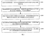
- FIG. 2 is a schematic flowchart diagram of an image data processing method according to an embodiment of the present invention.
- FIG. 3 is a schematic diagram of an interface of target image data on a current live broadcast interface according to an embodiment of the present invention
- 4a and 4b are schematic diagrams of creating grid information in a target display area according to an embodiment of the present invention.
- FIG. 5 is a schematic diagram of acquiring a clearing number corresponding to a target touch point according to an embodiment of the present invention
- FIG. 6 is a schematic flowchart diagram of another image data processing method according to an embodiment of the present invention.
- FIG. 7 is a schematic flowchart of creating a grid information according to an embodiment of the present invention.
- FIG. 8 is a schematic diagram of deleting sub-image data covered by a target touch point according to an embodiment of the present invention.
- 9a and 9b are schematic diagrams of restoring display original display interface according to an embodiment of the present invention.
- FIG. 10 is a schematic structural diagram of an image data processing apparatus according to an embodiment of the present invention.
- FIG. 11 is a schematic structural diagram of another image data processing apparatus according to an embodiment of the present invention.
- FIG. 12 is a schematic structural diagram of a mesh creation module according to an embodiment of the present invention.
- FIG. 13 is a schematic structural diagram of a number calculation module according to an embodiment of the present invention.
- FIG. 14 is a schematic structural diagram of an image deletion module according to an embodiment of the present invention.
- 15 is a schematic structural diagram of a clear area calculation module according to an embodiment of the present invention.
- FIG. 16 is a schematic structural diagram of still another image data processing apparatus according to an embodiment of the present invention.
- FIG. 1 is a schematic structural diagram of a network architecture according to an embodiment of the present invention.
- the network architecture may include an anchor terminal 3000, a server 2000, and a viewer terminal cluster.
- the audience terminal cluster may include multiple audience terminals, as shown in FIG. 1, specifically including a viewer terminal 4000a and a viewer terminal 4000b. ,..., audience terminal 4000n;
- the viewer terminal 4000a, the viewer terminal 4000b, ..., the viewer terminal 4000n may be respectively connected to the server 2000 by a network, and the server 2000 is connected to the anchor terminal 3000 by network.
- the server 2000 may filter at least one audience terminal as a target audience terminal in the audience terminal cluster (taking the target audience terminal as the audience terminal 4000a as an example), and sending the spray permission to the audience terminal 4000a.
- Target item so that the audience terminal 4000a displays the target item on the item selection interface according to the spraying permission; when the audience terminal 4000a receives the selection operation performed by the user on the target item, the audience terminal 4000a selects according to the selection
- the operation uploads target image data corresponding to the target item to the server 2000; the server 2000 forwards the target image data to the anchor terminal 3000; the anchor terminal 3000 displays the target image data, and Uploading a picture display instruction carrying the target image data to the server 2000, so that the server 2000 notifies other viewer terminals (such as the viewer terminal 4000b, ..., the viewer terminal 4000n) to synchronously display the photo according to the picture display instruction.
- Target image data such as the viewer terminal 4000b, ..., the viewer terminal 4000n
- the corresponding audience terminals of the four users include a viewer terminal 4000a, a viewer terminal 4000b, a viewer terminal 4000c, and a viewer terminal 4000d
- the female anchor broadcasts the makeup teaching video recorded by the anchor terminal 3000.
- the server 2000 selects the audience terminal 4000b as the terminal that can receive the target item (for example, the egg item), the audience terminal 4000b can obtain the corresponding target item. Spray permission.
- the audience terminal 4000b can obtain the egg props by spraying permission, and spray the paint to the female anchor through the egg props, that is, the audience terminal 4000b sends the target image data corresponding to the egg props to the
- the server 2000 further forwards the target image data to the anchor terminal 3000 by the server 2000, so that the anchor terminal 3000 displays the target image data to achieve the effect on the female anchor spray paint.
- the server 2000 can also send the target image data to the viewer terminal 4000a, the viewer terminal 4000c, and the viewer terminal 4000d, so that the viewer terminal 4000a, the viewer terminal 4000c, and the viewer terminal 4000d can also display the target on the live broadcast interface.
- the image data, that is, the viewer terminal 4000a, the viewer terminal 4000c, and the viewer terminal 4000d can also display the effect of the female anchor being sprayed with the paint.
- the anchor terminal 3000 may gradually delete the target image data according to the sliding operation of the anchor user on the display screen until the target image data is completely deleted. (The effect that the anchor terminal 3000 erases the sprayed pigment can be achieved).
- the anchor terminal 3000 may upload the deleted data to the server 2000 in real time, and then the server 2000 synchronizes the deleted data to each viewer terminal, so that each viewer The terminal can synchronously delete the deleted data in the target image data. For example, if the anchor terminal 3000 erases one of the target image data, each viewer terminal can also synchronously display that the leaf is erased.
- FIG. 2 is a schematic flowchart diagram of an image data processing method according to an embodiment of the present invention. As shown in FIG. 2, the method may include:
- the anchor terminal acquires the target image data, and displays the target image data on the original display interface (the original display interface may be an interface currently displayed by the anchor terminal), and acquires the target image data. a maximum length and a maximum width covered on the original display interface, and determining a target display area corresponding to the target image data based on the maximum length and the maximum width, and creating an initial table in the target display area And determining each of the minimum unit rectangles in the initial table as a sub-grid, and respectively configuring a corresponding grid number for each sub-grid, and determining an initial table containing the grid number as a grid information.
- the anchor terminal may be the anchor terminal 3000 in the foregoing embodiment of FIG. 1, and the process of acquiring the target image data by the anchor terminal may refer to the foregoing embodiment of FIG. 1 for the anchor terminal 3000, the server 2000, and the audience. The description of the terminal cluster is not described here.
- the anchor terminal includes a terminal device that carries a camera function, such as a personal computer, a tablet computer, a notebook computer, a smart TV, a smart phone, and the like;
- the grid information includes a plurality of sub-grids, and each sub-grid corresponds to a different grid number;
- the target image data is located in the target display area
- the spacing of each adjacent two horizontal lines in the initial table and the spacing of each adjacent two vertical lines are default touch point diameters, and each child
- the length and width of the grid are the default touch point diameters
- the viewer terminal transmits target image data (for example, a flower with leaves) to the anchor terminal according to the spray permission assigned by the server.
- target image data for example, a flower with leaves
- FIG. 3 is a schematic diagram of an interface of target image data on a current live broadcast interface according to an embodiment of the present invention.
- the current live broadcast interface is the original display interface 100a corresponding to the host broadcast terminal, and the original display interface 100a is used to display the live broadcast recorded by the anchor on the live broadcast platform.
- the viewer terminal selects an item corresponding to the target image data in the item page on the viewer terminal according to the obtained spraying permission, and sends the target image data corresponding to the item through the server (ie, a picture shown in FIG. 3a)
- the flower with leaves is given to the anchor terminal.
- the anchor terminal overwrites the received target image data as shown in FIG. 3 on the original display interface 100a, and further acquires the maximum length of the target image data covered on the original display interface 100a.
- W 6 cm
- the target image data is located in the target display area 200, and the target display area 200 including the target image data is a simulated existing area with respect to the anchor terminal; And for the viewer holding the anchor terminal or viewing the content broadcasted on the anchor terminal, the rectangular frame of the target display area 200 formed by the dotted line may be hidden and invisible.
- FIG. 4a and FIG. 4b are schematic diagrams of creating grid information in a target display area according to an embodiment of the present invention.
- the anchor terminal may first create a table composed of a plurality of sub-grids having equal side lengths and not overlapping each other according to the target display area 200 in FIG. 3 above, as the target display area 200.
- An initial table (as shown in FIG. 4a); in the target display area 200 shown in FIG.
- the initial table completely coincides with the target display area 200, and the spacing of each adjacent two horizontal lines in the initial table And the spacing between each adjacent two vertical lines is the default touch point diameter (r), that is, the length and width of each sub-grid in the initial table are the default touch point diameter (r); then, the anchor terminal can further Assigning a grid number as shown in FIG. 4b to each sub-grid in the initial table; finally, the anchor terminal may determine an initial table including a plurality of grid numbers to create a grid on the target display area. information.
- S202 Acquire a sliding operation track corresponding to the touch screen, and extract a touch point located on the target display area in the sliding operation track as a target touch point;
- the anchor terminal may acquire a touch operation of the touch screen by the user in the target display area, and acquire a slide operation track formed by the at least one touch point according to the touch operation, and further perform the slide operation track.
- the at least one touch point included is used as a target touch point.
- the touch operation includes, but is not limited to, an operation of each type of touch touch screen such as a press operation, a double tap operation, or a slide screen operation.
- the structure of the touch screen includes at least three layers: a screen glass layer, a touch panel layer, and a display panel layer.
- the screen glass layer is a protective layer
- the touch panel layer is used to sense a user's touch operation
- the display panel layer is used to display an image.
- the irregular and irregular image formed when the finger slides is the sliding operation track corresponding to the touch screen in the anchor terminal, and
- at least one touch point located on the target display area may be further extracted according to a default touch point diameter r when the finger touches the touch screen (eg, two touch points are extracted in the sliding operation track), The extracted two touch points are taken as the target touch points.
- S203 Create a position coordinate of the target touch point according to the mesh information, and calculate a clearing number corresponding to the target touch point according to the mesh information and a position coordinate of the target touch point;
- the anchor terminal creates a Cartesian coordinate system in the mesh information, calculates a position coordinate of the target touch point according to the Cartesian coordinate system, and acquires a total number of columns in the mesh information, and Calculating a clearing number corresponding to the target touch point according to a preset grid number formula, the total number of columns, the default touch point diameter, and a position coordinate of the target touch point;
- the coordinate origin of the Cartesian coordinate system created in the mesh information may be a vertex at an upper left corner or an upper right corner of the mesh information, and a straight line direction where the maximum length of the mesh information is located is the right angle
- the horizontal axis direction of the coordinate system ie, the x-axis direction
- the linear direction of the maximum width of the mesh information is the longitudinal axis direction of the rectangular coordinate system (ie, the y-axis direction);
- the total number of columns of the grid information is equal to the maximum length of the grid information divided by the side length of the single sub-grid information (the default touch point diameter);
- the total number of rows of the grid information is equal to the maximum width of the grid information divided by the side length of the single sub-grid information (the default touch point diameter);
- the clearing number corresponding to the target touch point may be further calculated according to a preset grid number formula, the total number of columns, the default touch point diameter, and the position coordinate of the target touch point;
- N is the clear number
- x is the abscissa value in the position coordinate
- y is the ordinate value in the position coordinate
- r is the default touch point diameter
- C is the grid information. The total number of columns.
- FIG. 5 is a schematic diagram of obtaining a clearing number corresponding to a target touch point according to an embodiment of the present invention.
- the vertex at the uppermost left corner of the mesh information can be used as the coordinate origin, and a Cartesian coordinate system as shown in FIG. 5 is created.
- the width is equal to the default touch point diameter of the target touch point. Therefore, in the Cartesian coordinate system, the position coordinates of the target touch point may be further acquired.
- the position coordinate may be (17, 13), that is, 17 is the abscissa value x of the target touch point in the Cartesian coordinate system. 13 is the ordinate value y of the target touch point in the Cartesian coordinate system. As shown in FIG.
- the anchor terminal may detect whether the same mesh number as the clearing number exists in a preset number set, and if the same mesh number as the clearing number does not exist in the number set, add and And clearing the grid number with the same number to the number set, and deleting the sub-image data covered by the target touch point, if the same grid number as the clear number already exists in the number set, then Adding a grid number identical to the clearing number to the number set, and deleting sub-image data covered by the target touch point;
- the default touch point diameter of the single target touch point is equal to the side length of the single sub-mesh, and the area covered by the single target touch point is equal to 78.5% of the area of the single sub-mesh, that is, a single
- the area ratio of the target touch point to the single sub-grid is 78.5%, which is the first area ratio.
- the anchor terminal detects that the first sliding operation track formed by the anchor of the anchor on the touch screen carries five touch points (for example, the five touch points are the first touch point, the second touch point, respectively) Three touch points, a fourth touch point, a fifth touch point), and the corresponding coordinate coordinates of the five touch points in the Cartesian coordinate system are (14, 3), (9, 8), (12, 7), (16, 11), (17, 13); specifically, please refer to Table 1, for the clearing number statistics table corresponding to each target touch point in the sliding track;
- the clearing number statistics table corresponding to each target touch point in a sliding track the clearing number corresponding to the first touch point is 2, the clearing number corresponding to the second touch point is 6, the third touch The clear number corresponding to the point is 12, the clear number corresponding to the fourth touch point is 8, and the clear number corresponding to the fifth touch point is 13.
- the same mesh number as the clear number can be added to the preset number set (for example, number set A), so that the same mesh as the clear number can be used. No.
- the grid number 13 is added to the number set A; however, as shown in the above-mentioned Table 1, the corresponding clearing numbers of the touch points respectively indicate that the fourth touch point and the fifth touch point have the same clearing number and have been corresponding to the fourth touch point.
- the clearing number 13 (or the same mesh number 13 as the clearing number) is added to the number set A, so the anchor terminal will not repeatedly add the clearing number corresponding to the fifth touch point, so the network in the number set A
- the grid number includes: 2, 6, 12, and 13 which are the same grid number as the clear number; thus, as long as most of the area of the target touch point falls into the subgrid with grid number 13 , The calculated clearing number corresponding to the target touch point will always be 13, so even though the anchor user performs multiple repeated sliding operations on the sub-grid with grid number 13, the anchor terminal always records. A touch point area completely in the subnet of grid number 13 to avoid duplicate recording of the same erased touch point.
- the deletion of the sub-image data covered by the target touch points carried in the other sliding operation tracks can still be referred to the erasing situation of the area areas covered by the five target touch points in the target display area in Table 1 above.
- Step S205 When the number of grid numbers in the number set satisfies a preset clearing condition, the target image data of the deleted plurality of sub-image data is completely deleted.
- the clearing condition is satisfied, when the anchoring terminal calculates that the approximate clearing area ratio P corresponding to the target image data is greater than or equal to the clearing threshold (70%) by using the preset area clearing formula, the numbering set may be further considered.
- the number of grid numbers in the middle meets the clearing condition;
- s is the number of mesh numbers stored in the number set
- p is the ratio of the area of one touch point to the area of one sub-grid, that is, the first area ratio
- K is the subnet
- the total number of cells, and the total number of sub-grids is equal to the product of the total number of rows and the total number of columns in the grid information.
- the approximate clearing area P is approximately equal to 72%, where P is greater than a clearing threshold (70%) corresponding to the target image data, so the anchor terminal may further determine that the number of grid numbers in the number set satisfies
- the clearing condition is set to further delete the target image data from which the plurality of sub-image data have been deleted.
- the target image data is displayed on the original display interface
- the original display interface needs to be displayed.
- the original display interface is originally covered with a layer of historical image data, and the target image data is overlaid on the historical image data, after the target image data of the deleted plurality of sub-image data is completely deleted,
- the original display interface displayed is equivalent to historical image data, and its actual meaning is to show that the target image data has been completely deleted, and will not cause display impact on the original display interface.
- the original display interface why not limit it.
- the embodiment of the present invention firstly acquires target image data, and creates mesh information on a target display area corresponding to the target image data; the mesh information includes a plurality of sub-grids, and each sub-grid corresponds to a different network. Secondly, acquiring a sliding operation track corresponding to the touch screen, and extracting a touch point located on the target display area in the sliding operation track as a target touch point; and then creating the target touch according to the mesh information a position coordinate of the point, and calculating a clear number corresponding to the target touch point according to the mesh information and the position coordinate of the target touch point; subsequently, adding the same mesh number as the clear number to the preset Numbering the set and deleting the sub-image data covered by the target touch point; finally, when the number of the grid numbers in the number set satisfies a preset clear condition, the target image of the plurality of sub-image data is deleted The data is completely deleted and the original display interface is displayed.
- the target image data of the deleted plurality of sub-image data may be completely deleted to display the original interface, thereby improving the calculation efficiency of the target image data corresponding to the irregular graphic and reducing the ratio of the clearing. Calculation error.
- FIG. 6 is a schematic flowchart diagram of another image data processing method according to an embodiment of the present invention. As shown in FIG. 6, the method may include:
- S601 Acquire target image data, and create mesh information on a target display area corresponding to the target image data;
- the anchor terminal acquires target image data, and displays the target image data on the original display interface, and obtains a maximum length and a maximum width covered by the target image data on the original display interface. And determining a target display area corresponding to the target image data based on the maximum length and the maximum width, and creating an initial table in the target display area, and determining each minimum unit rectangular frame in the initial table a sub-mesh, and a corresponding mesh number is configured for each sub-grid, and the initial table including the mesh number is determined as the mesh information; wherein the anchor terminal may be the corresponding embodiment of FIG. 1 above.
- the anchor terminal may be the corresponding embodiment of FIG. 1 above.
- the anchor terminal includes a terminal device that carries a camera function, such as a personal computer, a tablet computer, a notebook computer, a smart TV, a smart phone, and the like;
- the grid information includes a plurality of sub-grids, and each sub-grid corresponds to a different grid number;
- the target image data is located in the target display area
- the spacing of each adjacent two horizontal lines in the initial table and the spacing of each adjacent two vertical lines are default touch point diameters, and each child The length and width of the grid are the default touch point diameters.
- FIG. 7 is a schematic flowchart of the creation of the grid information provided by the embodiment of the present invention. As shown in FIG. 7 , the steps S701 - 704 are based on the foregoing step S601 . a specific embodiment of the creation of grid information;
- Step S701 acquiring target image data, and overlaying the target image data on the original display interface
- Step S702 acquiring a maximum length and a maximum width covered by the target image data on the original display interface, and determining a target display area corresponding to the target image data based on the maximum length and the maximum width;
- the target image data is located in the target display area, and the specific implementation manners of the steps S701 and 702 can be referred to the description of FIG. 3 in the corresponding embodiment of FIG. 1 , and details are not described herein.
- Step S703 creating an initial table in the target display area, and determining each minimum unit rectangular frame in the initial table as a sub-grid;
- the spacing of each adjacent two horizontal lines in the initial table and the spacing of each adjacent two vertical lines are default touch point diameters, and each child
- the length and width of the grid are the default touch point diameters
- Step S704 respectively configuring a corresponding grid number for each sub-grid, and determining an initial table including the grid number as grid information;
- S602 Acquire a sliding operation track corresponding to the touch screen, and extract a touch point located on the target display area in the sliding operation track as a target touch point;
- the anchor terminal may acquire a touch operation of the touch screen by the user in the target display area, and acquire a slide operation track formed by the at least one touch point according to the touch operation, and further perform the slide operation track.
- the at least one touch point included is used as a target touch point.
- the touch operations include, but are not limited to, operations of various types of touch touch screens, such as a press operation, a double tap operation, or a slide screen operation.
- the structure of the touch screen includes at least three layers: a screen glass layer, a touch panel layer, and a display panel layer.
- the screen glass layer is a protective layer
- the touch panel layer is used to sense a user's touch operation
- the display panel layer is used to display an image.
- the anchor terminal creates a Cartesian coordinate system in the mesh information, calculates a position coordinate of the target touch point according to the Cartesian coordinate system, and acquires a total number of columns in the mesh information, and Calculating a clearing number corresponding to the target touch point according to a preset grid number formula, the total number of columns, the default touch point diameter, and a position coordinate of the target touch point;
- the coordinate origin of the Cartesian coordinate system created in the mesh information may be a vertex at an upper left corner or an upper right corner of the mesh information, and a straight line direction where the maximum length of the mesh information is located is the right angle
- the horizontal axis direction of the coordinate system ie, the x-axis direction
- the linear direction of the maximum width of the mesh information is the longitudinal axis direction of the rectangular coordinate system (ie, the y-axis direction);
- the total number of columns of the grid information is equal to the maximum length of the grid information divided by the side length of the single sub-grid information (the default touch point diameter);
- the total number of rows of the grid information is equal to the maximum width of the grid information divided by the side length of the single sub-grid information (the default touch point diameter);
- the clearing number corresponding to the target touch point may be further calculated according to a preset grid number formula, the total number of columns, the default touch point diameter, and the position coordinate of the target touch point;
- N is the clear number
- x is the abscissa value in the position coordinate
- y is the ordinate value in the position coordinate
- r is the default touch point diameter
- C is the grid information. The total number of columns.
- the anchor terminal may detect whether the same mesh number as the clearing number exists in a preset number set, and if the same mesh number as the clearing number does not exist in the number set, add and And clearing the grid number with the same number to the number set, and deleting the sub-image data covered by the target touch point, if the same grid number as the clear number already exists in the number set, then Adding a grid number identical to the clearing number to the number set, and deleting sub-image data covered by the target touch point;
- the default touch point diameter of the single target touch point is equal to the side length of the single sub-mesh, and the area covered by the single target touch point is equal to 78.5% of the area of the single sub-mesh, that is, a single
- the area ratio of the target touch point to the single sub-grid is 78.5%, which is the first area ratio.
- Step S605 displaying target image data of the sub-image data covered by the target touch point is deleted, and uploading a deletion instruction carrying the sub-image data covered by the target touch point to the server, so that the server according to the Deleting an instruction to notify each terminal device of the plurality of terminal devices to synchronously delete the sub-image data covered by the target touch point;
- the anchor terminal may display a sliding operation track corresponding to the target touch point, and may further delete the sub-image data covered by the sliding operation track, and display that the sliding operation track is deleted.
- the target touches the target image data of the sub-image data covered by the target point, and uploads a deletion instruction carrying the sub-image data covered by the target touch point to a server having a network connection relationship with the anchor terminal, thereby allowing the server to pass And another network connection relationship between each of the plurality of viewer terminals, and the terminal device is notified to synchronously delete the sub-image data covered by the target touch point according to the deletion instruction.
- FIG. 8 is a schematic diagram of deleting sub-image data covered by a target touch point according to an embodiment of the present invention.
- the irregular and irregular image formed when the finger slides is the sliding operation track corresponding to the touch screen.
- the anchor terminal B may further upload a deletion instruction that carries the sub-image data covered by the target touch point to the server by using a network connection relationship with the server, so that the server notifies the multiple according to the deletion instruction.
- Each viewer terminal in the viewer terminals synchronously deletes the sub-image data covered by the target touch point.
- Step S606 accumulating the number of grid numbers in the number set as the target quantity, and obtaining the total number of sub-grids in the grid information;
- Step S607 dividing the target quantity by the total number of the sub-grids, obtaining a first value, and multiplying the first value by a preset first area ratio to obtain a second value;
- the first area ratio is a ratio of an area of one touch point to an area of a sub-grid
- P is the second value in the area clearing formula, that is, the approximate area clearing ratio obtained
- s is the number of targets in the number set in the area clearing formula, that is, the number of mesh numbers saved in the number set;
- p is the first area ratio in the area clearing formula, that is, the ratio of the area of one touch point to the area of one sub-grid;
- K is the total number of sub-grids in the area clearing formula
- the total number of sub-grids is equal to the product of the total number of rows and the total number of columns in the grid information.
- the anchor terminal may further acquire a second area ratio between the image non-coinciding area and the target display area;
- the image non-coincidence region is a non-coincidence region between the image region corresponding to the target image data and the target display region;
- the anchor terminal may divide the target quantity by the total number of the sub-grids to obtain a first value, and multiply the first value by a preset first area ratio, and then The second area ratios are added to obtain a second value.
- a transparent area that does not coincide with the target image data is regarded as an erased portion, and generally between the image area corresponding to the target image data and the target display area
- P is the second value in the area clearing formula, that is, the approximate area clearing ratio obtained
- s is the number of targets in the number set in the area clearing formula, that is, the number of mesh numbers saved in the number set;
- p is the first area ratio in the area clearing formula, that is, the ratio of the area of one touch point to the area of one sub-grid;
- K is the total number of sub-grids in the area clearing formula
- the total number of sub-grids is equal to the product of the total number of rows and the total number of columns in the grid information.
- Step S608 determining whether the second value is smaller than a clearing threshold
- the anchor terminal may further perform step S609 when the second value is less than the clear threshold; optionally, after performing step S608, the anchor terminal may further Step S610 is performed when the second value is greater than or equal to the clear threshold.
- Step S609 if it is determined that the second value is less than the clearing threshold, determining that the number of the grid numbers in the number set does not satisfy the preset clearing condition;
- Step S610 may be performed until the second value is greater than or equal to the clearing threshold.
- Step S610 if it is determined that the second value is greater than or equal to the clearing threshold, determining that the number of mesh numbers in the number set meets a preset clearing condition
- step S611 may be further performed.
- Step S611 the target image data of the deleted plurality of sub-image data is completely deleted, and the original display interface is displayed;
- the anchor can continue to slide back and forth in the target display area in the anchor terminal B using the finger simulation eraser to simulate erasure of the target sub-picture data.
- FIG. 9a and FIG. 9b is a schematic diagram of restoring and displaying the original display interface according to an embodiment of the present invention.
- the anchor terminal B can display the target image data 600 of the deleted plurality of sub-image data as shown in FIG. 9a.
- the irregular and irregular image shown in FIG. 9a is the sliding operation track after the anchor performs the sliding operation on the touch screen a plurality of times.
- the anchor terminal B further performs step S611 to further remove the target image data 600 of the deleted plurality of sub-image data.
- step S611 Completely deleted and the original display interface 200a as shown in Figure 9b is displayed.
- Step S612 sending a complete deletion instruction to the server, so that the server notifies the terminal device to synchronously delete the target image data of the deleted plurality of sub-image data according to the complete deletion instruction, and synchronously display the original UI.
- the embodiment of the present invention firstly acquires target image data, and creates mesh information on a target display area corresponding to the target image data; the mesh information includes a plurality of sub-grids, and each sub-grid corresponds to a different network. Secondly, acquiring a sliding operation track corresponding to the touch screen, and extracting a touch point located on the target display area in the sliding operation track as a target touch point; and then creating the target touch according to the mesh information a position coordinate of the point, and calculating a clear number corresponding to the target touch point according to the mesh information and the position coordinate of the target touch point; subsequently, adding the same mesh number as the clear number to the preset Numbering the set and deleting the sub-image data covered by the target touch point; finally, when the number of the grid numbers in the number set satisfies a preset clear condition, the target image of the plurality of sub-image data is deleted The data is completely deleted and the original display interface is displayed.
- the target image data of the deleted plurality of sub-image data may be completely deleted to display the original interface, and further, after the original interface is displayed, a complete deletion instruction may be sent to the server.
- the server is configured to notify the terminal device to synchronously delete the target image data of the deleted plurality of sub-image data according to the complete deletion instruction, and synchronously display the original display interface; thereby enriching the interaction mode between the anchor and the viewer. And improve the calculation efficiency of the target image data corresponding to the irregular pattern, thereby reducing the calculation error of the clearing ratio.
- FIG. 10 is a schematic structural diagram of an image data processing apparatus according to an embodiment of the present invention.
- the image data processing apparatus 1 can be applied to the anchor terminal in the corresponding embodiment of FIG. 1, the image data processing apparatus 1 includes at least: a mesh creation module 10, a track acquisition module 20, and a number.
- the mesh creation module 10 is configured to acquire target image data, and create mesh information on a target display area corresponding to the target image data;
- the image data processing apparatus 1 in the anchor terminal may be configured to acquire target image data, display the target image data on the original display interface, and acquire the target image data in the original display interface. a maximum length and a maximum width covered thereon, and determining a target display area corresponding to the target image data based on the maximum length and the maximum width, and creating an initial table in the target display area, and initializing Each minimum unit rectangle in the table is determined as a sub-grid, and a corresponding grid number is respectively configured for each sub-grid, and an initial table containing the grid number is determined as grid information;
- the anchor terminal includes a terminal device that carries a camera function, such as a personal computer, a tablet computer, a notebook computer, a smart TV, a smart phone, and the like;
- the grid information includes a plurality of sub-grids, and each sub-grid corresponds to a different grid number;
- the target image data is located in the target display area
- the spacing of each adjacent two horizontal lines in the initial table and the spacing of each adjacent two vertical lines are default touch point diameters, and each child
- the length and width of the grid are the default touch point diameters
- Grid Creation Module For a specific implementation of the Grid Creation Module, refer to the description of FIG. 3 and FIG. 4 in the corresponding embodiment of FIG. 2, and details are not described herein again.
- the trajectory obtaining module 20 is configured to acquire a sliding operation trajectory corresponding to the touch screen, and extract a touch point located on the target display area of the sliding operation trajectory as a target touch point;
- the trajectory obtaining module 20 may be configured to acquire a touch operation of the touch screen by the user in the target display area, and acquire a sliding operation track formed by the at least one touch point according to the touch operation, and further The at least one touch point included in the slide operation track is used as a target touch point.
- the touch operations include, but are not limited to, operations of various types of touch touch screens, such as a press operation, a double tap operation, or a slide screen operation.
- the structure of the touch screen includes at least three layers: a screen glass layer, a touch panel layer, and a display panel layer.
- the screen glass layer is a protective layer
- the touch panel layer is used to sense a user's touch operation
- the display panel layer is used to display an image.
- the number calculation module 30 is configured to create a position coordinate of the target touch point according to the mesh information, and calculate a clear corresponding to the target touch point according to the mesh information and the position coordinate of the target touch point. Numbering;
- the number calculation module 30 is configured to create a rectangular coordinate system in the mesh information, calculate a position coordinate of the target touch point according to the rectangular coordinate system, and acquire the grid information. a total number of columns, and calculating a clearing number corresponding to the target touch point according to a preset grid number formula, the total number of columns, the default touch point diameter, and a position coordinate of the target touch point;
- the coordinate origin of the Cartesian coordinate system created in the mesh information may be a vertex at an upper left corner or an upper right corner of the mesh information, and a straight line direction where the maximum length of the mesh information is located is the right angle
- the horizontal axis direction of the coordinate system ie, the x-axis direction
- the linear direction of the maximum width of the mesh information is the longitudinal axis direction of the rectangular coordinate system (ie, the y-axis direction);
- the total number of columns of the grid information is equal to the maximum length of the grid information divided by the side length of the single sub-grid information (the default touch point diameter);
- the total number of rows of the grid information is equal to the maximum width of the grid information divided by the side length of the single sub-grid information (the default touch point diameter);
- the clearing number corresponding to the target touch point may be further calculated according to a preset grid number formula, the total number of columns, the default touch point diameter, and the position coordinate of the target touch point;
- N is the clear number
- x is the abscissa value in the position coordinate
- y is the ordinate value in the position coordinate
- r is the default touch point diameter
- C is the grid information. The total number of columns.
- step S203 For a specific implementation of the number calculation module 30, refer to the description of step S203 in the corresponding embodiment of FIG. 2 above.
- the image deletion module 40 is configured to add a mesh number that is the same as the clearing number to a preset number set, and delete the sub-image data covered by the target touch point;
- the image deletion module 40 is configured to detect whether a mesh number that is the same as the clearing number exists in a preset number set, and if the same mesh number as the clearing number does not exist in the number set Adding the same mesh number as the clearing number to the number set, and deleting the sub-image data covered by the target touch point, if the same mesh number as the clearing number already exists in the number Collecting, not adding the same mesh number as the clearing number to the numbering set, and deleting the sub-image data covered by the target touch point;
- the default touch point diameter of the single target touch point is equal to the side length of the single sub-mesh, and the area covered by the single target touch point is equal to 78.5% of the area of the single sub-mesh, that is, a single
- the area ratio of the target touch point to the single sub-grid is 78.5%, which is the first area ratio.
- image deletion module 40 For the specific implementation of the image deletion module 40, refer to the description of the statistics of the clearing numbers in Table 1 in the corresponding embodiment in FIG. 2, and details are not described herein.
- the interface display module 50 is configured to completely delete the target image data that has deleted the plurality of sub-image data when the number of the grid numbers in the number set meets the preset clearing condition;
- the interface display module 50 can further consider that the approximate clearing area ratio P corresponding to the target image data is greater than or equal to the clearing threshold (70%) by using the preset area clearing formula.
- the number of grid numbers in the set of numbers satisfies the clearing condition;
- s is the number of mesh numbers stored in the number set
- p is the ratio of the area of one touch point to the area of one sub-grid, that is, the first area ratio
- K is the subnet
- the total number of cells, and the total number of sub-grids is equal to the product of the total number of rows and the total number of columns in the grid information.
- the image data processing apparatus 1 may further perform the above steps S202-S204.
- the anchor terminal may further notify the trajectory acquiring module 20 to acquire the sliding operation trajectory corresponding to the touch screen. .
- the image data processing device 1 first acquires target image data, and creates mesh information on a target display area corresponding to the target image data; the mesh information includes a plurality of sub-grids, and each sub-mesh The grids respectively correspond to different grid numbers; secondly, the sliding operation track corresponding to the touch screen is acquired, and the touch points located on the target display area in the sliding operation track are extracted as target touch points; and then, according to the network
- the grid information creates a position coordinate of the target touch point, and calculates a clear number corresponding to the target touch point according to the grid information and the position coordinate of the target touch point; subsequently, the same network as the clear number is
- the grid number is added to the preset number set, and the sub-image data covered by the target touch point is deleted; finally, when the number of grid numbers in the number set meets the preset clear condition, the grid number is deleted.
- the target image data of the plurality of sub image data is completely deleted. It can be seen that when deleting the sub-image data covered by the target touch point, it is not necessary to calculate the actually deleted graphic area in real time, and only the number of mesh numbers added to the number set satisfies the preset clearing. When the condition is met, the target image data of the deleted plurality of sub-image data can be completely deleted, thereby improving the calculation efficiency of the target image data corresponding to the irregular pattern and reducing the calculation error of the clearing ratio.
- FIG. 11 is a schematic structural diagram of another image data processing apparatus according to an embodiment of the present invention.
- the image data processing apparatus 1 may include the grid creation module 10, the trajectory acquisition module 20, the number calculation module 30, the image deletion module 40, and the interface display module in the embodiment corresponding to FIG. 10 described above. Further, the image data processing apparatus 1 may further include: a target quantity accumulation module 60, a clear area calculation module 70, a condition determination module 80, a second determination module 90, a first determination module 100, and an instruction transmission module 110;
- FIG. 12 is a schematic structural diagram of a mesh creation module according to an embodiment of the present invention.
- the grid information creation module 10 includes: a target image acquisition unit 101, a target region determination unit 102, a sub-grid creation unit 103, and a grid information determination unit 104;
- the target image acquiring unit 101 is configured to acquire target image data, and overlay the target image data on the original display interface;
- the target area determining unit 102 is configured to acquire a maximum length and a maximum width covered by the target image data on the original display interface, and determine, according to the maximum length and the maximum width, the target image data corresponding to Target display area; the target image data is located in the target display area;
- the sub-grid creating unit 103 is configured to create an initial table in the target display area, and determine each minimum unit rectangular frame in the initial table as a sub-grid; the initial table and the target The display areas are completely coincident, the spacing of each adjacent two horizontal lines in the initial table and the spacing of each adjacent two vertical lines are default touch point diameters, and the length and width of each sub-grid are Default touch point diameter;
- the mesh information determining unit 104 is configured to respectively configure a corresponding mesh number for each sub mesh, and determine an initial table including the mesh number as the mesh information.
- the grid information includes a plurality of sub-grids, and each sub-grid corresponds to a different grid number;
- the target image data is located in the target display area
- the spacing of each adjacent two horizontal lines in the initial table and the spacing of each adjacent two vertical lines are default touch point diameters, and each child The length and width of the grid are the default touch point diameters.
- Step S201 For the specific implementation of the Grid Creation Module 10, refer to the description of Step S201 in the corresponding embodiment of FIG. 2, and details are not described herein.
- the interface display module 50 is further configured to display the original display interface after the target image data of the plurality of sub-image data has been deleted.
- FIG. 13 is a schematic structural diagram of a number calculation module according to an embodiment of the present invention.
- the number calculation module 30 includes: a coordinate calculation unit 301 and a clear number calculation unit 302;
- the coordinate calculation unit 301 is configured to create a rectangular coordinate system in the mesh information, and calculate position coordinates of the target touch point according to the rectangular coordinate system;
- the clear number calculation unit 302 is configured to acquire a total number of columns in the grid information, and according to a preset grid number formula, the total number of columns, the default touch point diameter, and the target touch point a position coordinate, and a clearing number corresponding to the target touch point is calculated;
- the coordinate origin of the Cartesian coordinate system created in the mesh information may be a vertex at an upper left corner or an upper right corner of the mesh information, and a straight line direction where the maximum length of the mesh information is located is the right angle
- the horizontal axis direction of the coordinate system ie, the x-axis direction
- the linear direction of the maximum width of the mesh information is the longitudinal axis direction of the rectangular coordinate system (ie, the y-axis direction);
- the total number of columns of the grid information is equal to the maximum length of the grid information divided by the side length of the single sub-grid information (the default touch point diameter);
- the total number of rows of the grid information is equal to the maximum width of the grid information divided by the side length of the single sub-grid information (the default touch point diameter);
- the clearing number corresponding to the target touch point may be further calculated according to a preset grid number formula, the total number of columns, the default touch point diameter, and the position coordinate of the target touch point;
- N is the clear number
- x is the abscissa value in the position coordinate
- y is the ordinate value in the position coordinate
- r is the default touch point diameter
- C is the grid information.
- step S203 For the specific implementation of the number calculation module 30, refer to the description of step S203 in the corresponding embodiment of FIG. 2, and details are not described herein.
- FIG. 14 is a schematic structural diagram of an image deletion module according to an embodiment of the present invention.
- the image deletion module 40 includes: a number detecting unit 401, a first deleting unit 402 and a second deleting unit 403;
- the number detecting unit 401 is configured to detect whether a mesh number that is the same as the clearing number exists in a preset number set;
- the first deleting unit 402 is configured to add a mesh number that is the same as the clearing number to the number set if the same mesh number as the clearing number does not exist in the number set, and delete the Sub-image data covered by the target touch point;
- the second deleting unit 403 is configured to: if the same mesh number as the clearing number already exists in the number set, add the same mesh number as the clearing number to the number set, and delete Sub-image data covered by the target touch point;
- step S204 For a specific implementation of the image deletion module 40, refer to the description of step S204 in the corresponding embodiment of FIG. 2, and details are not described herein.
- the target quantity accumulation module 60 is configured to accumulate the number of grid numbers in the number set as the target quantity, and acquire the total number of sub-grids in the grid information;
- the clear area calculation module 70 is configured to divide the target quantity by the total number of the sub-grids to obtain a first value, and multiply the first value by a preset first area ratio to obtain a second value; the first area ratio is a ratio of an area of one touch point to an area of a sub-grid;
- the condition determining module 80 is configured to determine whether the second value is less than a clearing threshold
- the first determining module 100 is configured to determine, if the second value is greater than or equal to a clearing threshold, that the number of mesh numbers in the number set meets a preset clearing condition;
- the second determining module 90 is configured to: if it is determined that the second value is less than a clearing threshold, determine that the number of mesh numbers in the number set does not satisfy a preset clearing condition;
- the total number of sub-grids is the product of the total number of rows and the total number of columns in the grid information.
- FIG. 15 is a schematic structural diagram of a clear area calculation module according to an embodiment of the present invention.
- the clear area calculation module 70 includes: a first area calculation unit 701 and a second area calculation unit 702;
- the first area calculation unit 701 is configured to acquire a second area ratio between the image non-coincidence area and the target display area;
- the image non-coincidence area is an image area corresponding to the target image data and the a non-coincident area between the target display areas;
- the second area calculating unit 702 is configured to divide the target quantity by the total number of the sub-grids, obtain a first value, and multiply the first value by a preset first area ratio. Adding to the second area ratio to obtain a second value;
- the first area ratio is a ratio of an area of one touch point to an area of a sub-grid
- P is the second value in the area clearing formula, that is, the approximate area clearing ratio obtained
- s is the number of targets in the number set in the area clearing formula, that is, the number of mesh numbers saved in the number set;
- p is the first area ratio in the area clearing formula, that is, the ratio of the area of one touch point to the area of one sub-grid;
- K is the total number of sub-grids in the area clearing formula
- the total number of sub-grids is equal to the product of the total number of rows and the total number of columns in the grid information.
- the anchor terminal may further acquire a second area ratio between the image non-coinciding area and the target display area;
- the image non-coincidence region is a non-coincidence region between the image region corresponding to the target image data and the target display region;
- the image data processing apparatus 1 may divide the target quantity by the total number of the sub-grids to obtain a first value, and multiply the first value by a preset first area ratio. Adding to the second area ratio again yields a second value.
- a transparent area that does not coincide with the target image data is regarded as an erased portion, and generally between the image area corresponding to the target image data and the target display area
- P is the second value in the area clearing formula, that is, the approximate area clearing ratio obtained
- s is the number of targets in the number set in the area clearing formula, that is, the number of mesh numbers saved in the number set;
- p is the first area ratio in the area clearing formula, that is, the ratio of the area of one touch point to the area of one sub-grid;
- K is the total number of sub-grids in the area clearing formula
- the total number of sub-grids is equal to the product of the total number of rows and the total number of columns in the grid information.
- the instruction sending module 100 is configured to display target image data of the sub-image data covered by the target touch point, and upload a deletion instruction carrying the sub-image data covered by the target touch point to the server, to And causing the server to notify each terminal device of the plurality of terminal devices to synchronously delete the sub-image data according to the deleting instruction;
- the instruction sending module is further configured to send a complete delete instruction to the server, so that the server notifies the terminal device to synchronously delete the deleted multiple sub-image data according to the complete delete instruction.
- Target image data, and the original display interface is displayed synchronously.
- instruction sending module 110 For a specific implementation manner of the instruction sending module 110, refer to the description of the network architecture in the embodiment corresponding to FIG. 1 above, and details are not described herein.
- the image data processing device 1 first acquires target image data, and creates mesh information on a target display area corresponding to the target image data; the mesh information includes a plurality of sub-grids, and each sub-mesh The grids respectively correspond to different grid numbers; secondly, the sliding operation track corresponding to the touch screen is acquired, and the touch points located on the target display area in the sliding operation track are extracted as target touch points; and then, according to the network
- the grid information creates a position coordinate of the target touch point, and calculates a clear number corresponding to the target touch point according to the grid information and the position coordinate of the target touch point; subsequently, the same network as the clear number is
- the grid number is added to the preset number set, and the sub-image data covered by the target touch point is deleted; finally, when the number of grid numbers in the number set meets the preset clear condition, the grid number is deleted.
- the target image data of the plurality of sub-image data is completely deleted, and the original display interface is displayed. It can be seen that when deleting the sub-image data covered by the target touch point, it is not necessary to calculate the actually deleted graphic area in real time, and only the number of mesh numbers added to the number set satisfies the preset clearing.
- the target image data of the deleted plurality of sub-image data may be completely deleted to display the original interface; further, after the original interface is displayed, a complete deletion instruction may be sent to the server, so that the The server notifies the terminal device to synchronously delete the target image data of the deleted plurality of sub-image data according to the complete deletion instruction, and synchronously displays the original display interface, thereby enriching the interaction mode between the anchor and the viewer, and improving the pair.
- the calculation efficiency of the target image data corresponding to the irregular pattern and further reduces the calculation error of the clearing ratio.
- FIG. 16 is a schematic structural diagram of still another image data processing apparatus according to an embodiment of the present invention.
- the image data processing apparatus 1000 can be applied to the anchor terminal in the corresponding embodiment of FIG. 1, and the image data processing apparatus 1000 can include: at least one processor 1001, such as a CPU, at least one network interface. 1004.
- the communication bus 1002 is used to implement connection communication between these components.
- the user interface 1003 can include a display and a keyboard.
- the optional user interface 1003 can also include a standard wired interface and a wireless interface.
- the network interface 1004 can optionally include a standard wired interface, a wireless interface (such as a WI-FI interface).
- the memory 1005 may be a high speed RAM memory or a non-volatile memory such as at least one disk memory.
- the memory 1005 can also optionally be at least one storage device located remotely from the aforementioned processor 1001. As shown in FIG. 16, an operating system, a network communication module, a user interface module, and a device control application may be included in the memory 1005 as a computer storage medium.
- the network interface 1004 is mainly used to connect a name server and a service server cluster; and the user interface 1003 is mainly used to provide an input interface for the user; and the processor 1001 can be used to call the memory.
- the mesh information includes a plurality of sub-grids, and each sub-grid respectively corresponds to a different mesh number;
- the target image data from which the plurality of sub-image data has been deleted is completely deleted.
- the processor 1001 when the processor 1001 performs the acquiring target image data and creates the grid information on the target display area corresponding to the target image data, the following steps are specifically performed:
- a corresponding mesh number is separately configured for each sub-grid, and an initial table containing the mesh number is determined as the mesh information.
- the processor 1001 after the processor 1001 performs the complete deletion of the target image data that has deleted the plurality of sub-image data, the processor 1001 further performs the following steps:
- the original display interface is displayed.
- the processor 1001 completely deletes the target image data of the deleted plurality of sub-image data when the number of the grid numbers in the number set satisfies a preset clearing condition, and Before displaying the original display interface, perform the following steps:
- the total number of sub-grids is the product of the total number of rows and the total number of columns in the grid information.
- the processor 1001 divides the target number by the total number of sub-grids, obtains a first value, and multiplies the first value by an area ratio parameter. When the second value is obtained, the following steps are performed:
- the image non-coinciding area is a non-coinciding area between the image area corresponding to the target image data and the target display area;
- the processor 1001 performs the position coordinate of creating the target touch point according to the mesh information, and calculates the position according to the mesh information and the position coordinate of the target touch point.
- the target touch point corresponds to the clear number, perform the following steps:
- the preset grid numbering formula :
- N is the clear number
- x is the abscissa value in the position coordinate
- y is the ordinate value in the position coordinate
- r is the default touch point diameter
- C is the grid information. The total number of columns.
- the processor 1001 when performing the adding the same mesh number as the clearing number to a preset number set, and deleting the sub-image data covered by the target touch point, Specifically perform the following steps:
- the processor 1001 completely deletes the target image data of the deleted plurality of sub-image data when the number of the grid numbers in the number set satisfies a preset clearing condition, and After the original display interface is displayed, the following steps are also performed:
- the image data processing apparatus 1000 firstly acquires target image data, and creates mesh information on a target display area corresponding to the target image data; wherein the mesh information includes a plurality of sub-grids, and Each sub-grid respectively corresponds to a different grid number; secondly, a sliding operation track corresponding to the touch screen is acquired, and a touch point located on the target display area in the sliding operation track is extracted as a target touch point; The mesh information creates a position coordinate of the target touch point, and calculates a clear number corresponding to the target touch point according to the mesh information and the position coordinate of the target touch point; subsequently, the same as the clearing number The mesh number is added to the preset number set, and the sub-image data covered by the target touch point is deleted; finally, when the number of mesh numbers in the number set meets the preset clear condition, The target image data from which the plurality of sub image data has been deleted is completely deleted.
- the image data processing apparatus 1000 does not need to calculate the actually deleted graphic area in real time, and only needs to add to the network in the number set.
- the target image data of the deleted plurality of sub-image data can be completely deleted, thereby improving the calculation efficiency of the target image data corresponding to the irregular graph, and reducing the clearing The calculation error of the ratio.
- the storage medium may be a magnetic disk, an optical disk, a read-only memory (ROM), or a random access memory (RAM).
Landscapes
- Engineering & Computer Science (AREA)
- Theoretical Computer Science (AREA)
- General Engineering & Computer Science (AREA)
- Physics & Mathematics (AREA)
- General Physics & Mathematics (AREA)
- Human Computer Interaction (AREA)
- User Interface Of Digital Computer (AREA)
- Processing Or Creating Images (AREA)
Abstract
一种图像数据处理方法和装置以及计算机可读存储介质,所述方法包括:获取目标图像数据,并在目标图像数据对应的目标显示区域上创建网格信息(S201);获取触摸屏对应的滑动操作轨迹,并提取滑动操作轨迹中位于目标显示区域上的触摸点,作为目标触摸点(S202);根据网格信息创建目标触摸点的位置坐标,并根据网格信息和目标触摸点的位置坐标计算目标触摸点对应的清除编号(S203);将与清除编号相同的网格编号添加至预设的编号集合,并将目标触摸点所覆盖的子图像数据删除(S204);当编号集合中的网格编号的数量满足清除条件时,将已删除多个子图像数据的目标图像数据完整删除(S205)。上述方法可以提高对不规则图形的计算效率,并降低对清除比例的计算误差。
Description
本申请要求于2017年4月20日提交中国专利局、申请号为2017102628076、发明名称为“一种图像数据处理方法和装置”的中国专利申请的优先权,其全部内容通过引用结合在本申请中。
本发明涉及互联网技术领域,尤其涉及一种图像数据处理方法和装置。
随着人们的生活水平的提高,人们在物质生活得到满足的同时,也逐渐开始追求休闲生活,而网络的飞速发展以及智能手机的普及,人们喜欢将自己或者自己身边的事情,以视频、图片或文件的形式在网络上进行分享;比如,旅游心得,穿衣搭配等。于是,为了迎合人们的生活需求,衍生出了各种能帮助人们随时随地与周围的朋友进行文字、语音或视频通讯的社交软件。
比如,目前,互联网上日益兴起了一些音视频直播项目(例如,彩妆教学直播和衣品搭配直播等),因此,通过这些直播平台可为爱美的女性提供护肤和穿搭技能。然而,在众多的直播项目中,直播间的主播仅能通过观众发送的弹幕信息或刷礼物等浅层次的方式与观众进行互动,以至于这种方式下大量的观众都仅仅是担当一名看客,并不能充分调动主播与众多观众之间的互动,且当弹幕信息较多时,观众发送的文字信息的显示效果比较单一,以至于并不一定能引起主播的注意。
于是,为丰富屏幕显示效果,且增加主播与观众之间的互动,可设计一个允许观众给主播喷射一团颜料的交互,即需要主播通过手指模拟橡皮擦以擦除观众喷射的颜料。由于手指在滑动时形成的图形是一种不规则且无规律的图形。若按照现有的技术方法来计算这部分的面积占比,则需将当前喷射的颜料图形分段转成近似的规则图形,之后使用复杂的计算公式来计算每一段的面积,计算量极为庞大,且对不规则图像的计算结果存在较大误差,尤其是在无规则图形比较复杂时,比如,图形出现重叠等情况时,存在重复计算的可能, 以至于无法对不规则图形的面积占比进行准确地计算,进而无法恢复原始界面。
发明内容
本发明实施例提供一种图像数据处理方法和装置,可以提高对不规则图形的计算效率,并降低对清除比例的计算误差。
本发明第一方面提供了一种图像数据处理方法,包括:
获取目标图像数据,并在所述目标图像数据对应的目标显示区域上创建网格信息;所述网格信息包括多个子网格,且每个子网格分别对应不同的网格编号;
获取触摸屏对应的滑动操作轨迹,并提取所述滑动操作轨迹中位于所述目标显示区域上的触摸点,作为目标触摸点;
根据所述网格信息创建所述目标触摸点的位置坐标,并根据所述网格信息和所述目标触摸点的位置坐标计算所述目标触摸点对应的清除编号;
将与所述清除编号相同的网格编号添加至预设的编号集合,并将所述目标触摸点所覆盖的子图像数据删除;
当所述编号集合中的网格编号的数量满足预设的清除条件时,将已删除多个子图像数据的目标图像数据完整删除。
本发明第二方面提供了一种图像数据处理装置,包括:
网格创建模块,用于获取目标图像数据,并在所述目标图像数据对应的目标显示区域上创建网格信息;所述网格信息包括多个子网格,且每个子网格分别对应不同的网格编号;
轨迹获取模块,用于获取触摸屏对应的滑动操作轨迹,并提取所述滑动操作轨迹中位于所述目标显示区域上的触摸点,作为目标触摸点;
编号计算模块,用于根据所述网格信息创建所述目标触摸点的位置坐标,并根据所述网格信息和所述目标触摸点的位置坐标计算所述目标触摸点对应的清除编号;
图像删除模块,用于将与所述清除编号相同的网格编号添加至预设的编号集合,并将所述目标触摸点所覆盖的子图像数据删除;
界面显示模块,用于当所述编号集合中的网格编号的数量满足预设的清除条件时,将已删除多个子图像数据的目标图像数据完整删除。
本发明第三方面还提供一种计算机可读存储介质,存储有程序指令,处理器执行所存储的程序指令时执行上述任一方法中的一种。
本发明实施例通过获取目标图像数据,并在所述目标图像数据对应的目标显示区域上创建网格信息;所述网格信息包括多个子网格,且每个子网格分别对应不同的网格编号;其次,获取触摸屏对应的滑动操作轨迹,并提取所述滑动操作轨迹中位于所述目标显示区域上的触摸点,作为目标触摸点,再根据所述网格信息创建所述目标触摸点的位置坐标,并根据所述网格信息和所述目标触摸点的位置坐标计算所述目标触摸点对应的清除编号,进而将与所述清除编号相同的网格编号添加至预设的编号集合,并将所述目标触摸点所覆盖的子图像数据删除;最后,当所述编号集合中的网格编号的数量满足预设的清除条件时,将已删除多个子图像数据的目标图像数据完整删除。由此可见,在删除所述目标触摸点所覆盖的子图像数据时,无需实时计算实际已删除的图形面积,只需在添加至所述编号集合中的网格编号的数量满足预设的清除条件时,即可将已删除多个子图像数据的目标图像数据进行完整删除,进而可以提高对不规则图形所对应的目标图像数据的计算效率,并降低对清除比例的计算误差。
为了更清楚地说明本发明实施例中的技术方案,下面将对实施例描述中所需要使用的附图作简单地介绍,显而易见地,下面描述中的附图仅仅是本发明的一些实施例,对于本领域的技术人员来讲,还可以根据这些附图获得其他的附图。
图1是本发明实施例提供的一种网络架构的结构示意图;
图2是本发明实施例提供的一种图像数据处理方法的流程示意图;
图3是本发明实施例提供的一种目标图像数据在当前直播界面的界面示意图;
图4a和图4b是本发明实施例提供的一种在目标显示区域内创建网格信息的示意图;
图5是本发明实施例提供的一种获取目标触摸点对应的清除编号的示意 图;
图6是本发明实施例提供的另一种图像数据处理方法的流程示意图;
图7是本发明实施例提供的一种网格信息创建的流程示意图;
图8是本发明实施例提供的一种删除目标触摸点所覆盖的子图像数据的示意图;
图9a和图9b是本发明实施例提供的一种恢复显示原始显示界面的示意图;
图10是本发明实施例提供的一种图像数据处理装置的结构示意图;
图11是本发明实施例提供的另一种图像数据处理装置的结构示意图;
图12是本发明实施例提供的一种网格创建模块的结构示意图;
图13是本发明实施例提供的一种编号计算模块的结构示意图;
图14是本发明实施例提供的一种图像删除模块的结构示意图;
图15是本发明实施例提供的一种清除面积计算模块的结构示意图;
图16是本发明实施例提供的又一种图像数据处理装置的结构示意图。
下面将结合本发明实施例中的附图,对本发明实施例中的技术方案进行清楚、完整地描述,显然,所描述的实施例仅仅是本发明一部分实施例,而不是全部的实施例。基于本发明中的实施例,本领域普通技术人员在没有作出创造性劳动前提下所获得的所有其他实施例,都属于本发明保护的范围。
请参见图1,是本发明实施例提供的一种网络架构的结构示意图。如图1所示,所述网络架构可以包括主播终端3000、服务器2000以及观众终端集群;所述观众终端集群可以包括多个观众终端,如图1所示,具体包括观众终端4000a、观众终端4000b、…、观众终端4000n;
观众终端4000a、观众终端4000b、…、观众终端4000n可以分别与所述服务器2000进行网络连接,所述服务器2000与所述主播终端3000进行网络连接。
如图1所示,所述服务器2000可在所述观众终端集群中筛选至少一个观众终端作为目标观众终端(以目标观众终端为观众终端4000a为例),并向观 众终端4000a下发携带喷涂权限的目标道具,以使观众终端4000a根据所述喷涂权限在道具选择界面上显示所述目标道具;当观众终端4000a接收到用户对所述目标道具执行的选择操作时,观众终端4000a根据所述选择操作将与所述目标道具对应的目标图像数据上传到所述服务器2000;所述服务器2000将所述目标图像数据转发到所述主播终端3000;所述主播终端3000显示所述目标图像数据,并将携带所述目标图像数据的图片显示指令上传至所述服务器2000,以使所述服务器2000根据所述图片显示指令通知其他观众终端(如观众终端4000b、…、观众终端4000n)同步显示所述目标图像数据。
例如,在某直播平台上的直播显示界面中,有4名用户(该4名用户分别对应的观众终端包括观众终端4000a、观众终端4000b、观众终端4000c以及观众终端4000d)在线观看该直播平台中女主播通过主播终端3000录制的彩妆教学视频,此时,若服务器2000选择观众终端4000b作为可接收目标道具(例如,彩蛋道具)的终端,以使观众终端4000b可以获得与所述目标道具对应的喷涂权限。随后,在该女主播进行的直播教学过程中,观众终端4000b可以通过喷涂权限获得彩蛋道具,并通过彩蛋道具向该女主播喷涂颜料,即观众终端4000b将彩蛋道具对应的目标图像数据发送给所述服务器2000,再由所述服务器2000将目标图像数据转发到所述主播终端3000,使得所述主播终端3000显示所述目标图像数据,以实现对女主播喷涂颜料的效果。同时,所述服务器2000还可以将所述目标图像数据发送给观众终端4000a、观众终端4000c以及观众终端4000d,使得观众终端4000a、观众终端4000c以及观众终端4000d也可以在直播界面上显示所述目标图像数据,即观众终端4000a、观众终端4000c以及观众终端4000d也可以显示该女主播被喷涂颜料的效果。
此外,所述主播终端3000在获取到所述目标图像数据后,所述主播终端3000可以根据主播用户对显示屏的滑动操作,逐渐删除所述目标图像数据,直至将所述目标图像数据完全删除(即可实现所述主播终端3000将被喷涂的颜料擦除的效果)。所述主播终端3000在删除所述目标图像数据的过程中,可以将被删除的数据实时上传给所述服务器2000,再由所述服务器2000将被删除的数据同步到各观众终端,使得各观众终端可以同步删除所述目标图像数据中的被删除的数据。例如,所述主播终端3000将所述目标图像数据中的一片 叶子擦除,则各观众终端也可以同步显示该片叶子被擦除。
其中,所述主播终端3000擦除所述目标图像数据的具体过程可以参见如下图2至图8对应的实施例。
进一步地,请参见图2,是本发明实施例提供的一种图像数据处理方法的流程示意图。如图2所示,所述方法可以包括:
S201,获取目标图像数据,并在所述目标图像数据对应的目标显示区域上创建网格信息;
具体的,主播终端获取目标图像数据,并将所述目标图像数据覆盖在原始显示界面(所述原始显示界面可以为所述主播终端当前直播显示的界面)上显示,并获取所述目标图像数据在所述原始显示界面上所覆盖的最大长度和最大宽度,并基于所述最大长度和所述最大宽度确定所述目标图像数据对应的目标显示区域,并在所述目标显示区域内创建初始表格,并将所述初始表格中的每个最小单位矩形框确定为子网格,并为每个子网格分别配置对应的网格编号,并将包含所述网格编号的初始表格确定为网格信息。其中,所述主播终端可以为上述图1对应实施例中的主播终端3000,所述主播终端获取所述目标图像数据的过程可以参见上述图1对应实施例中对主播终端3000、服务器2000以及观众终端集群的描述,这里不再进行赘述。
其中,所述主播终端包括个人电脑、平板电脑、笔记本电脑、智能电视、智能手机等携带摄像功能的终端设备;
其中,所述网格信息包括多个子网格,且每个子网格分别对应不同的网格编号;
其中,所述目标图像数据位于所述目标显示区域内;
其中,所述初始表格与所述目标显示区域完全重合,所述初始表格中的每相邻两条横线的间距和每相邻两条纵线的间距均为默认触摸点直径,且每个子网格的长和宽均为所述默认触摸点直径;
例如,在某直播平台上的直播显示界面中,观众终端根据服务器分配的喷涂权限向主播终端发送目标图像数据(比如,一朵带叶的花)。具体地,请一并参见图3,是本发明实施例提供的一种目标图像数据在当前直播界面的界面示意图。如图3所示,当前直播界面即为主播终端对应的原始显示界面100a, 所述原始显示界面100a用于显示主播在该直播平台上现场录制的直播秀。其中观众终端根据所获得的喷涂权限,在本观众终端上的道具页面中选择与目标图像数据所对应的道具,并通过服务器发送所述道具对应的目标图像数据(即图3a所示的一朵带叶的花)给所述主播终端。进而所述主播终端将接收到的如图3所示的目标图像数据覆盖在所述原始显示界面100a上进行显示,并进一步获取该目标图像数据在所述原始显示界面100a上所覆盖的最大长度L(比如,L=10厘米)和最大宽度W(比如,W=6厘米),并进一步根据所述最大长度和最大宽度确定如图3所示的包围所述目标图像数据的目标显示区域200;另外,如图3所示,所述目标图像数据位于所述目标显示区域200内,该包含所述目标图像数据的目标显示区域200相对于该主播终端而言,是一个模拟存在的区域;且对于持有该主播终端的主播或者观看该主播终端上所直播内容的观众而言,用虚线构成的所述目标显示区域200的矩形框可以是隐藏而不可见的。
进一步地,请参见图4a和图4b,是本发明实施例提供的一种在目标显示区域内创建网格信息的示意图。如图4a所示,主播终端可首先根据上述图3中的目标显示区域200,进一步创建由多个边长相等,且互不重合的子网格所构成的表格,作为该目标显示区域200内的初始表格(如图4a所示);在图4a所示的目标显示区域200内,该初始表格与该目标显示区域200完全重合,且该初始表格中的每相邻两条横线的间距和每相邻两条纵线的间距均为默认触摸点直径(r),即该初始表格中每个子网格的长和宽均为默认触摸点直径(r);然后,该主播终端可进一步为该初始表格内的各子网格分别分配如图4b所示的网格编号;最后,该主播终端可将包含多个网格编号的初始表格确定为在所述目标显示区域上创建网格信息。
S202,获取触摸屏对应的滑动操作轨迹,并提取所述滑动操作轨迹中位于所述目标显示区域上的触摸点,作为目标触摸点;
具体地,所述主播终端可获取用户在所述目标显示区域中对触摸屏的触摸操作,并根据所述触摸操作获取由至少一个触摸点构成的滑动操作轨迹,并进一步将所述滑动操作轨迹中所包含的所述至少一个触摸点作为目标触摸点。
所述触摸操作包括但不限于:按压操作、双击操作或者滑屏操作等各类型 触摸触控屏的操作。通常,在具有触控屏功能的终端设备中,其触控屏的结构包括至少三层:屏幕玻璃层、触控面板层和显示面板层。其中屏幕玻璃层为保护层,触控面板层用于感知用户的触控操作,显示面板层用于显示图像。
比如,当主播使用手指在所述主播终端中的目标显示区域内来回滑动时,手指滑动时所形成的不规则、无规律的图像则为该主播终端中的触摸屏所对应的滑动操作轨迹,且在该滑动操作轨迹中,可根据手指在接触触摸屏时的默认触摸点直径r进一步提取位于所述目标显示区域上的至少一个触摸点(例如,在滑动操作轨迹中提取到两个触摸点),并将提取到的两个触摸点作为目标触摸点。
S203,根据所述网格信息创建所述目标触摸点的位置坐标,并根据所述网格信息和所述目标触摸点的位置坐标计算所述目标触摸点对应的清除编号;
具体地,所述主播终端在所述网格信息中创建直角坐标系,并根据所述直角坐标系计算所述目标触摸点的位置坐标,并获取所述网格信息中的总列数,并根据预设的网格编号公式、所述总列数、所述默认触摸点直径以及所述目标触摸点的位置坐标,计算所述目标触摸点对应的清除编号;
其中,在所述网格信息中创建的直角坐标系的坐标原点可为所述网格信息的左上角或者右上角处的顶点,且所述网格信息的最大长度所在的直线方向为该直角坐标系的横轴方向(即x轴方向),所述网格信息的最大宽度所在的直线方向为该直角坐标系的纵轴方向(即y轴方向);
其中,网格信息的总列数等于网格信息的最大长度除以单个子网格信息的边长(默认触摸点直径);
其中,网格信息的总行数等于网格信息的最大宽度除以单个子网格信息的边长(默认触摸点直径);
其中,根据预设的网格编号公式、所述总列数、所述默认触摸点直径以及所述目标触摸点的位置坐标,可进一步计算所述目标触摸点对应的清除编号;
其中,所述预设的网格编号公式:

其中,N为所述清除编号,x表示所述位置坐标中的横坐标值,y表示所述位置坐标中的纵坐标值,r为所述默认触摸点直径,C表示所述网格信息中的总列数。
比如,进一步地,请参见图5,是本发明实施例提供的一种获取目标触摸点对应的清除编号的示意图。如图5所示,在目标显示区域300内,可将该网格信息最左上角处的顶点作为坐标原点,创建如图5所示的直角坐标系。其中,该网格信息在该直角坐标系中对应的目标显示区域300的长度L=25mm、宽度W=25mm。另外,该主播终端获取到滑动操作轨迹中目标触摸点的默认触摸点直径为r=5mm,即单个子网格的边长等于该目标触摸点的默认触摸点直径,或单个子网格的长度和宽度均等于该目标触摸点的默认触摸点直径。因此,在该直角坐标系中,可进一步获取该目标触摸点的位置坐标,例如,该位置坐标可为(17,13)即17为目标触摸点在该直角坐标系中的横坐标值x,13为目标触摸点在该直角坐标系中的纵坐标值y。如图5所示,在目标显示区域300内的网格信息的总列数C=5列,总行数R=5行,于是可根据预设的网格编号公式:
 将总列数C=5,默认触摸点直径r=5mm,纵坐标值y=13,横坐标值x=17,分别代入该网格编号公式,进而可得该目标触摸点对应的清除编号N=13。
S204,将与所述清除编号相同的网格编号添加至预设的编号集合,并将所述目标触摸点所覆盖的子图像数据删除;
具体地,所述主播终端可检测与所述清除编号相同的网格编号是否存在于预设的编号集合,若与所述清除编号相同的网格编号不存在于所述编号集合,则添加与所述清除编号相同的网格编号至所述编号集合,并删除所述目标触摸点所覆盖的子图像数据,若与所述清除编号相同的网格编号已存在于所述编号集合,则不添加与所述清除编号相同的网格编号至所述编号集合,并删除所述目标触摸点所覆盖的子图像数据;
其中,由于手指接触触摸屏时,单个目标触摸点的默认触摸点直径等于单个子网格的边长,所述单个目标触摸点所覆盖的面积等于单个子网格面积的78.5%,即可将单个目标触摸点与单个子网格对应的面积比例78.5%,作为第一面积比例。鉴于此,当手指划过所述目标图像数据中的各子图像数据时,仅可擦除目标触摸点所覆盖的所述各子图像数据。
比如,主播终端检测到主播人员的手指在触摸屏上滑动时所形成的第一滑动操作轨迹中携带5个触摸点(例如,这5个触摸点分别为第一触摸点,第二 触摸点,第三触摸点,第四触摸点,第五触摸点),且这五个触摸点在直角坐标系中分别对应的位置坐标为(14,3)、(9,8)、(12,7)、(16,11)、(17,13);具体地,请参见表1,为滑动轨迹中各目标触摸点分别对应的清除编号统计情况表;

表1
如上述表1给出的一条滑动轨迹中各目标触摸点分别对应的清除编号统计情况表可知,第一触摸点对应的清除编号为2,第二触摸点对应的清除编号为6,第三触摸点对应的清除编号为12,第四触摸点对应的清除编号为8,第五触摸点对应的清除编号为13。由于手指在目标显示区域中滑动的过程中,可将与所述清除编号相同的网格编号添加至预设的编号集合(例如,编号集合A),于是,可将与清除编号相同的网格编号2添加至编号集合A,并将与清除编号相同的网格编号6添加至编号集合A,并将与清除编号相同的网格编号12添加至编号集合A,并将与清除编号相同的网格编号13添加至编号集合A;然而如上述表1列出的各触摸点分别对应的清除编号可知,第四触摸点和第五触摸点的清除编号相同,且已将与第四触摸点对应的清除编号13(或是与清除编号相同的网格编号13)添加至编号集合A,故而该主播终端将不再重复添加第五触摸点对应的清除编号,所以,该编号集合A中的网格编号包含:2,6,12和13这四个与清除编号相同的网格编号;由此可见,只要所述目标触摸点的大部分面积都落入网格编号为13的子网格中,那么所计算出的所述目标触摸点对应的清除编号将始终为13,所以尽管主播用户在网格编号为13的子网格上进行多次重复的滑动操作,所述主播终端也始终就记录一个完全处于网格编号为13的子网络中的触摸点面积,以避免重复记录同一个已擦除的触摸点。
可选地,其他滑动操作轨迹中携带的各目标触摸点所覆盖的子图像数据的 删除仍可参见上述表1中5个目标触摸点在目标显示区域中所覆盖的面积区域的擦除情况。
步骤S205,当所述编号集合中的网格编号的数量满足预设的清除条件时,将已删除多个子图像数据的目标图像数据完整删除。
其中,满足所述清除条件是指当主播终端通过预设的面积清除公式统计到与目标图像数据对应的近似清除面积比例P大于等于清除阈值(70%)时,则可进一步认为所述编号集合中的网格编号的数量满足所述清除条件;
其中,预设的面积清除公式:P=(s*p/K)*100%;
其中,s为保存至所述编号集合中网格编号的个数,p为一个触摸点的面积与一个子网格的面积的比值,即为所述第一面积比例,K为所述子网格总数量,且所述子网格总数量等于所述网格信息中的总行数和总列数的乘积。
比如,仍以上述表1给出的编号集合A为例,当添加至编号集合中网格编号的个数s为23个,且子网格总数量为25个,进而根据上述面积清除公式,可得所述近似清除面积P约等于72%,此时P大于与该目标图像数据对应的清除阈值(70%),因此主播终端可进一步确定所述编号集合中的网格编号的数量满足预设的清除条件,进而可将已删除多个子图像数据的目标图像数据完整删除。
可选的,由于目标图像数据是覆盖在原始显示界面上显示的,那么将已删除多个子图像数据的目标图像数据完整删除之后,还需要显示原始显示界面。
需要说明的是,如果原始显示界面上原本覆盖有一层历史图像数据的画面时,目标图像数据是覆盖在历史图像数据上显示的,那么将已删除多个子图像数据的目标图像数据完整删除之后,显示的原始显示界面相当于是历史图像数据,其实际意义是为了表现目标图像数据已经完全删除之后,不会对原始显示界面造成显示影响,至于原始显示界面具体为什么,不做限制。
本发明实施例通过首先获取目标图像数据,并在所述目标图像数据对应的目标显示区域上创建网格信息;所述网格信息包括多个子网格,且每个子网格分别对应不同的网格编号;其次,获取触摸屏对应的滑动操作轨迹,并提取所述滑动操作轨迹中位于所述目标显示区域上的触摸点,作为目标触摸点;然后,根据所述网格信息创建所述目标触摸点的位置坐标,并根据所述网格信息和所 述目标触摸点的位置坐标计算所述目标触摸点对应的清除编号;随后,将与所述清除编号相同的网格编号添加至预设的编号集合,并将所述目标触摸点所覆盖的子图像数据删除;最后,当所述编号集合中的网格编号的数量满足预设的清除条件时,将已删除多个子图像数据的目标图像数据完整删除,并显示原始显示界面。由此可见,在删除所述目标触摸点所覆盖的子图像数据时,无需实时计算实际已删除的图形面积,只需在添加至所述编号集合中的网格编号的数量满足预设的清除条件时,即可将已删除多个子图像数据的目标图像数据进行完整删除,以显示所述原始界面,进而可以提高对不规则图形所对应的目标图像数据的计算效率,并降低对清除比例的计算误差。
进一步地,请参见图6,是本发明实施例提供的另一种图像数据处理方法的流程示意图。如图6所示,所述方法可以包括:
S601,获取目标图像数据,并在所述目标图像数据对应的目标显示区域上创建网格信息;
具体的,主播终端获取目标图像数据,并将所述目标图像数据覆盖在所述原始显示界面上显示,并获取所述目标图像数据在所述原始显示界面上所覆盖的最大长度和最大宽度,并基于所述最大长度和所述最大宽度确定所述目标图像数据对应的目标显示区域,并在所述目标显示区域内创建初始表格,并将所述初始表格中的每个最小单位矩形框确定为子网格,并为每个子网格分别配置对应的网格编号,并将包含所述网格编号的初始表格确定为网格信息;其中,所述主播终端可以为上述图1对应实施例中的主播终端3000,所述主播终端获取所述目标图像数据的过程可以参见上述图1对应实施例中对主播终端3000、服务器2000以及观众终端集群的描述,这里不再进行赘述。
其中,所述主播终端包括个人电脑、平板电脑、笔记本电脑、智能电视、智能手机等携带摄像功能的终端设备;
其中,所述网格信息包括多个子网格,且每个子网格分别对应不同的网格编号;
其中,所述目标图像数据位于所述目标显示区域内;
其中,所述初始表格与所述目标显示区域完全重合,所述初始表格中的每相邻两条横线的间距和每相邻两条纵线的间距均为默认触摸点直径,且每个子 网格的长和宽均为所述默认触摸点直径。
其中,所述网格信息的创建可进一步参见图7,是本发明实施例提供的一种网格信息创建的流程示意图;如图7所示,步骤S701-步骤704是基于上述步骤S601所对应的网格信息创建的一个具体实施例;
步骤S701,获取目标图像数据,并将所述目标图像数据覆盖在所述原始显示界面上显示;
步骤S702,获取所述目标图像数据在所述原始显示界面上所覆盖的最大长度和最大宽度,并基于所述最大长度和所述最大宽度确定所述目标图像数据对应的目标显示区域;
其中,所述目标图像数据位于所述目标显示区域内,且步骤S701和步骤702的具体实现方式可参见上述图1所对应实施例中对图3的描述,这里不再进行赘述。
步骤S703,在所述目标显示区域内创建初始表格,并将所述初始表格中的每个最小单位矩形框确定为子网格;
其中,所述初始表格与所述目标显示区域完全重合,所述初始表格中的每相邻两条横线的间距和每相邻两条纵线的间距均为默认触摸点直径,且每个子网格的长和宽均为所述默认触摸点直径;
步骤S704,为每个子网格分别配置对应的网格编号,并将包含所述网格编号的初始表格确定为网格信息;
其中,步骤S703和步骤704的具体实现方式可参见上述图4a和图4b对应的实施例,这里不再进行赘述。
S602,获取触摸屏对应的滑动操作轨迹,并提取所述滑动操作轨迹中位于所述目标显示区域上的触摸点,作为目标触摸点;
具体地,所述主播终端可获取用户在所述目标显示区域中对触摸屏的触摸操作,并根据所述触摸操作获取由至少一个触摸点构成的滑动操作轨迹,并进一步将所述滑动操作轨迹中所包含的所述至少一个触摸点作为目标触摸点。
所述触摸操作包括但不限于:按压操作、双击操作或者滑屏操作等各类型触摸触控屏的操作。通常,在具有触控屏功能的终端设备中,其触控屏的结构包括至少三层:屏幕玻璃层、触控面板层和显示面板层。其中屏幕玻璃层为保 护层,触控面板层用于感知用户的触控操作,显示面板层用于显示图像。
S603,根据所述网格信息创建所述目标触摸点的位置坐标,并根据所述网格信息和所述目标触摸点的位置坐标计算所述目标触摸点对应的清除编号;
具体地,所述主播终端在所述网格信息中创建直角坐标系,并根据所述直角坐标系计算所述目标触摸点的位置坐标,并获取所述网格信息中的总列数,并根据预设的网格编号公式、所述总列数、所述默认触摸点直径以及所述目标触摸点的位置坐标,计算所述目标触摸点对应的清除编号;
其中,在所述网格信息中创建的直角坐标系的坐标原点可为所述网格信息的左上角或者右上角处的顶点,且所述网格信息的最大长度所在的直线方向为该直角坐标系的横轴方向(即x轴方向),所述网格信息的最大宽度所在的直线方向为该直角坐标系的纵轴方向(即y轴方向);
其中,网格信息的总列数等于网格信息的最大长度除以单个子网格信息的边长(默认触摸点直径);
其中,网格信息的总行数等于网格信息的最大宽度除以单个子网格信息的边长(默认触摸点直径);
其中,根据预设的网格编号公式、所述总列数、所述默认触摸点直径以及所述目标触摸点的位置坐标,可进一步计算所述目标触摸点对应的清除编号;
其中,所述预设的网格编号公式:

其中,N为所述清除编号,x表示所述位置坐标中的横坐标值,y表示所述位置坐标中的纵坐标值,r为所述默认触摸点直径,C表示所述网格信息中的总列数。
S604,将与所述清除编号相同的网格编号添加至预设的编号集合,并将所述目标触摸点所覆盖的子图像数据删除;
具体的,所述主播终端可检测与所述清除编号相同的网格编号是否存在于预设的编号集合,若与所述清除编号相同的网格编号不存在于所述编号集合,则添加与所述清除编号相同的网格编号至所述编号集合,并删除所述目标触摸点所覆盖的子图像数据,若与所述清除编号相同的网格编号已存在于所述编号集合,则不添加与所述清除编号相同的网格编号至所述编号集合,并删除所述目标触摸点所覆盖的子图像数据;
其中,由于手指接触触摸屏时,单个目标触摸点的默认触摸点直径等于单个子网格的边长,所述单个目标触摸点所覆盖的面积等于单个子网格面积的78.5%,即可将单个目标触摸点与单个子网格对应的面积比例78.5%,作为第一面积比例。鉴于此,当手指划过所述目标图像数据中的各子图像数据时,仅可擦除目标触摸点所覆盖的所述各子图像数据。
步骤S605,显示已删除所述目标触摸点所覆盖的子图像数据的目标图像数据,并将携带所述目标触摸点所覆盖的子图像数据的删除指令上传到服务器,以使所述服务器根据所述删除指令通知多个终端设备中的各终端设备同步删除所述目标触摸点所覆盖的子图像数据;
具体地,所述主播终端可显示与所述目标触摸点对应的滑动操作轨迹,并可进一步将所述滑动操作轨迹所覆盖的子图像数据进行删除,并显示已删除所述滑动操作轨迹中携带的目标触摸点所覆盖的子图像数据的目标图像数据,并将携带所述目标触摸点所覆盖的子图像数据的删除指令上传到与所述主播终端具有网络连接关系的服务器,进而使服务器通过与多个观众终端中的各终端设备之间的另一网络连接关系,根据所述删除指令通知所述各终端设备同步删除所述目标触摸点所覆盖的子图像数据。
进一步的,请一并参见图8,是本发明实施例提供的一种删除目标触摸点所覆盖的子图像数据的示意图。如图8所示,当主播使用手指模拟橡皮擦在主播终端B中的目标显示区域400内来回滑动时,手指滑动时所形成的不规则、无规律的图像则为触摸屏所对应的滑动操作轨迹,该不规则的滑动操作轨迹即为主播通过手指模拟擦除该目标图像数据时所形成的已删除子图像数据的区域500。由于该触摸屏感应到的默认触摸点直径r=5mm,因此,当主播的手指接触到该触摸屏时,可形成如图8所示的默认触摸点直径为5mm的滑动操作轨迹,并可进一步在该主播终端B中显示已删除该滑动操作轨迹中各目标触摸点分别覆盖的子图像数据的目标图像数据。另外,该主播终端B还可进一步通过与服务器之间的网络连接关系,将携带上述目标触摸点所覆盖的子图像数据的删除指令上传到服务器,以使所述服务器根据所述删除指令通知多个观众终端中的各观众终端同步删除所述目标触摸点所覆盖的子图像数据。
步骤S606,累计所述编号集合中网格编号的数量,作为目标数量,并获 取所述网格信息中的子网格总数量;
步骤S607,将所述目标数量与所述子网格总数量相除,得到第一数值,并将所述第一数值与预设的第一面积比例相乘,得到第二数值;
其中,所述第一面积比例为一个触摸点的面积与一个子网格的面积的比值;
其中,所述第二数值的获得可采用预设的面积清除公式,即:P=(s*p/K)*100%;
其中,P为所述面积清除公式中第二数值,即为获得的近似面积清除比例;
其中,s为所述面积清除公式中编号集合中的目标数量,即为保存至所述编号集合中网格编号的个数;
其中,p为所述面积清除公式中的第一面积比例,即为一个触摸点的面积与一个子网格的面积的比值;
其中,K为所述面积清除公式中所述子网格总数量,且所述子网格总数量等于所述网格信息中的总行数和总列数的乘积。
可选地,为了更准确的估算所述目标图像数据所对应的清除比例,所述主播终端可进一步获取图像不重合区域与所述目标显示区域之间的第二面积比例;
其中,所述图像不重合区域为所述目标图像数据所对应的图像区域与所述目标显示区域之间的不重合区域;
进一步地,所述主播终端可将所述目标数量与所述子网格总数量相除,得到第一数值,并将所述第一数值与预设的第一面积比例相乘后再与所述第二面积比例相加,得到第二数值。换言之,在目标显示区域中,将与所述目标图像数据不重合的透明区域视为已擦除的部分,且通常所述目标图像数据所对应的图像区域与所述目标显示区域之间的不重合区域的面积比例大致为30%,即所述第二面积比例为30%,因此,新的清除面积公式:P=(P1+q)=[(s*p/K)+q]*100%;
其中,P为所述面积清除公式中第二数值,即为获得的近似面积清除比例;
其中,s为所述面积清除公式中编号集合中的目标数量,即为保存至所述编号集合中网格编号的个数;
其中,p为所述面积清除公式中的第一面积比例,即为一个触摸点的面积与一个子网格的面积的比值;
其中,K为所述面积清除公式中所述子网格总数量,且所述子网格总数量等于所述网格信息中的总行数和总列数的乘积。
其中,q为所述面积清除公式中的第二面积比例,即q=30%。
步骤S608,判断所述第二数值是否小于清除阈值;
具体地,在执行完步骤S608之后,所述主播终端可进一步在所述第二数值小于清除阈值时,执行步骤S609;可选地,在执行完步骤S608之后,所述主播终端还可进一步可在所述第二数值大于或等于清除阈值时执行步骤S610。
步骤S609,若判断所述第二数值小于清除阈值,则确定所述编号集合中的网格编号的数量不满足预设的清除条件;
具体地,若所述主播终端确定所述第二数值小于清除阈值,则可确定所述编号集合中的网格编号的数量不满足预设的清除条件,并可重复执行上述步骤S601-步骤S608,直至所述第二数值大于或等于所述清除阈值,可执行步骤S610。
步骤S610,若判断所述第二数值大于或等于清除阈值,则确定所述编号集合中的网格编号的数量满足预设的清除条件;
具体地,若所述主播终端确定所述第二数值大于或等于清除阈值,则可确定所述编号集合中的网格编号数量满足所述清除条件,并可进一步执行步骤S611。
步骤S611,将已删除多个子图像数据的目标图像数据完整删除,并显示原始显示界面;
具体地,仍以上述图8为例,在删除所述已删除子图像数据的区域500时,所述主播终端B通过累计添加至编号集合中的网格编号的个数为10个。由于所述子网格编号总数量为70个,所以根据上述公式:P=(s*p/K)*100%或P=(P1+q)=[(s*p/K)+q]*100%可知,计算得到的第二数值P可为11%或者41%,但两个第二数值均未大于或等于清除阈值(70%)。于是,该主播可继续使用手指模拟橡皮擦在主播终端B中的目标显示区域内进行来回滑动,以 模拟目标子图像数据的擦除。
进一步的,请一并参见图9a和图9b,是本发明实施例提供的一种恢复显示原始显示界面的示意图。如图9a所示,当所述第二数值P大于或等于清除阈值70%时,该主播终端B可以显示如图9a所示的已删除多个子图像数据的目标图像数据600。相对于上述图8中的滑动操作轨迹,图9a所显示的不规则、无规律的图像则为该主播多次对该触摸屏执行滑动操作后的滑动操作轨迹。由于此时所述编号集合中的网格编号的数量满足预设的清除条件,因此,该主播终端B将进一步执行步骤S611,即可进一步将所述已删除多个子图像数据的目标图像数据600完整删除,并显示如图9b所示的原始显示界面200a。
步骤S612,发送完全删除指令到所述服务器,以使所述服务器根据所述完全删除指令通知所述各终端设备同步删除所述已删除多个子图像数据的目标图像数据,并同步显示所述原始显示界面。
本发明实施例通过首先获取目标图像数据,并在所述目标图像数据对应的目标显示区域上创建网格信息;所述网格信息包括多个子网格,且每个子网格分别对应不同的网格编号;其次,获取触摸屏对应的滑动操作轨迹,并提取所述滑动操作轨迹中位于所述目标显示区域上的触摸点,作为目标触摸点;然后,根据所述网格信息创建所述目标触摸点的位置坐标,并根据所述网格信息和所述目标触摸点的位置坐标计算所述目标触摸点对应的清除编号;随后,将与所述清除编号相同的网格编号添加至预设的编号集合,并将所述目标触摸点所覆盖的子图像数据删除;最后,当所述编号集合中的网格编号的数量满足预设的清除条件时,将已删除多个子图像数据的目标图像数据完整删除,并显示原始显示界面。由此可见,通过主播终端可在删除所述目标触摸点所覆盖的子图像数据时,无需实时计算实际已删除的图形面积,只需在添加至所述编号集合中的网格编号的数量满足预设的清除条件时,即可将已删除多个子图像数据的目标图像数据进行完整删除,以显示所述原始界面,此外,在显示所述原始界面后,还可发送完全删除指令给服务器,以使所述服务器根据所述完全删除指令通知所述各终端设备同步删除所述已删除多个子图像数据的目标图像数据,并同步显示所述原始显示界面;进而可丰富主播与观众的互动方式,并提高对不规则图形所对应的目标图像数据的计算效率,从而降低对清除比例的计算误 差。
进一步地,请参见图10,是本发明实施例提供的一种图像数据处理装置的结构示意图。如图10所示,所述图像数据处理装置1可以应用于上述图1对应实施例中的主播终端中,所述图像数据处理装置1至少包括:网格创建模块10,轨迹获取模块20,编号计算模块30,图像删除模块40和界面显示模块50;
所述网格创建模块10,用于获取目标图像数据,并在所述目标图像数据对应的目标显示区域上创建网格信息;
具体地,主播终端中的图像数据处理装置1,可用于获取目标图像数据,并将所述目标图像数据覆盖在所述原始显示界面上显示,并获取所述目标图像数据在所述原始显示界面上所覆盖的最大长度和最大宽度,并基于所述最大长度和所述最大宽度确定所述目标图像数据对应的目标显示区域,并在所述目标显示区域内创建初始表格,并将所述初始表格中的每个最小单位矩形框确定为子网格,并为每个子网格分别配置对应的网格编号,并将包含所述网格编号的初始表格确定为网格信息;
其中,所述主播终端包括个人电脑、平板电脑、笔记本电脑、智能电视、智能手机等携带摄像功能的终端设备;
其中,所述网格信息包括多个子网格,且每个子网格分别对应不同的网格编号;
其中,所述目标图像数据位于所述目标显示区域内;
其中,所述初始表格与所述目标显示区域完全重合,所述初始表格中的每相邻两条横线的间距和每相邻两条纵线的间距均为默认触摸点直径,且每个子网格的长和宽均为所述默认触摸点直径;
进一步地,所述网格创建模块的具体实现方式可参见上述图2所对应实施例中对图3以及图4的描述,这里均不再进行一一赘述。
所述轨迹获取模块20,用于获取触摸屏对应的滑动操作轨迹,并提取所述滑动操作轨迹中位于所述目标显示区域上的触摸点,作为目标触摸点;
具体地,所述轨迹获取模块20,可用于获取用户在所述目标显示区域中对触摸屏的触摸操作,并根据所述触摸操作获取由至少一个触摸点构成的滑动 操作轨迹,并进一步将所述滑动操作轨迹中所包含的所述至少一个触摸点作为目标触摸点。
所述触摸操作包括但不限于:按压操作、双击操作或者滑屏操作等各类型触摸触控屏的操作。通常,在具有触控屏功能的终端设备中,其触控屏的结构包括至少三层:屏幕玻璃层、触控面板层和显示面板层。其中屏幕玻璃层为保护层,触控面板层用于感知用户的触控操作,显示面板层用于显示图像。
所述编号计算模块30,用于根据所述网格信息创建所述目标触摸点的位置坐标,并根据所述网格信息和所述目标触摸点的位置坐标计算所述目标触摸点对应的清除编号;
具体地,所述编号计算模块30,可用于在所述网格信息中创建直角坐标系,并根据所述直角坐标系计算所述目标触摸点的位置坐标,并获取所述网格信息中的总列数,并根据预设的网格编号公式、所述总列数、所述默认触摸点直径以及所述目标触摸点的位置坐标,计算所述目标触摸点对应的清除编号;
其中,在所述网格信息中创建的直角坐标系的坐标原点可为所述网格信息的左上角或者右上角处的顶点,且所述网格信息的最大长度所在的直线方向为该直角坐标系的横轴方向(即x轴方向),所述网格信息的最大宽度所在的直线方向为该直角坐标系的纵轴方向(即y轴方向);
其中,网格信息的总列数等于网格信息的最大长度除以单个子网格信息的边长(默认触摸点直径);
其中,网格信息的总行数等于网格信息的最大宽度除以单个子网格信息的边长(默认触摸点直径);
其中,根据预设的网格编号公式、所述总列数、所述默认触摸点直径以及所述目标触摸点的位置坐标,可进一步计算所述目标触摸点对应的清除编号;
其中,所述预设的网格编号公式:

其中,N为所述清除编号,x表示所述位置坐标中的横坐标值,y表示所述位置坐标中的纵坐标值,r为所述默认触摸点直径,C表示所述网格信息中的总列数。
进一步地,所述编号计算模块30的具体实现方式,可参见上述图2所对应实施例中对步骤S203的描述。
所述图像删除模块40,用于将与所述清除编号相同的网格编号添加至预设的编号集合,并将所述目标触摸点所覆盖的子图像数据删除;
具体地,所述图像删除模块40,可用于检测与所述清除编号相同的网格编号是否存在于预设的编号集合,若与所述清除编号相同的网格编号不存在于所述编号集合,则添加与所述清除编号相同的网格编号至所述编号集合,并删除所述目标触摸点所覆盖的子图像数据,若与所述清除编号相同的网格编号已存在于所述编号集合,则不添加与所述清除编号相同的网格编号至所述编号集合,并删除所述目标触摸点所覆盖的子图像数据;
其中,由于手指接触触摸屏时,单个目标触摸点的默认触摸点直径等于单个子网格的边长,所述单个目标触摸点所覆盖的面积等于单个子网格面积的78.5%,即可将单个目标触摸点与单个子网格对应的面积比例78.5%,作为第一面积比例。鉴于此,当手指划过所述目标图像数据中的各子图像数据时,仅可擦除目标触摸点所覆盖的所述各子图像数据。
其中,所述图像删除模块40的具体实施方式,可参见上述图2所对应实施例中对表1中各清除编号统计情况的描述,这里不再进行赘述。
所述界面显示模块50,用于当所述编号集合中的网格编号的数量满足预设的清除条件时,将已删除多个子图像数据的目标图像数据完整删除;
其中,满足所述清除条件是指当所述界面显示模块50通过预设的面积清除公式统计到与目标图像数据对应的近似清除面积比例P大于等于清除阈值(70%)时,可进一步认为所述编号集合中的网格编号的数量满足所述清除条件;
其中,预设的面积清除公式:P=(s*p/K)*100%;
其中,s为保存至所述编号集合中网格编号的个数,p为一个触摸点的面积与一个子网格的面积的比值,即为所述第一面积比例,K为所述子网格总数量,且所述子网格总数量等于所述网格信息中的总行数和总列数的乘积。
可选地,当添加至编号集合中的网格编号的数据不满足所述预设的清除条件时,则所述图像数据处理装置1,可进一步执行上述步骤S202-步骤S204。
比如,仍以上述表1给出的编号集合A为例,当添加至编号集合中网格编号的个数s为5个,且子网格总数量为25个,进而根据上述面积清除公式, 可得所述近似清除面积P约等于15.7%,此时P小于与该目标图像数据对应的清除阈值(70%),因此主播终端可进一步通知所述轨迹获取模块20获取触摸屏对应的滑动操作轨迹。
本发明实施例通过所述图像数据处理装置1首先获取目标图像数据,并在所述目标图像数据对应的目标显示区域上创建网格信息;所述网格信息包括多个子网格,且每个子网格分别对应不同的网格编号;其次,获取触摸屏对应的滑动操作轨迹,并提取所述滑动操作轨迹中位于所述目标显示区域上的触摸点,作为目标触摸点;然后,根据所述网格信息创建所述目标触摸点的位置坐标,并根据所述网格信息和所述目标触摸点的位置坐标计算所述目标触摸点对应的清除编号;随后,将与所述清除编号相同的网格编号添加至预设的编号集合,并将所述目标触摸点所覆盖的子图像数据删除;最后,当所述编号集合中的网格编号的数量满足预设的清除条件时,将已删除多个子图像数据的目标图像数据完整删除。由此可见,在删除所述目标触摸点所覆盖的子图像数据时,无需实时计算实际已删除的图形面积,只需在添加至所述编号集合中的网格编号的数量满足预设的清除条件时,即可将已删除多个子图像数据的目标图像数据进行完整删除,进而可以提高对不规则图形所对应的目标图像数据的计算效率,并降低对清除比例的计算误差。
进一步地,请参见图11,是本发明实施例提供的另一种图像数据处理装置的结构示意图。如图11所示,所述图像数据处理装置1可以包含上述图10所对应实施例中的所述网格创建模块10,轨迹获取模块20,编号计算模块30,图像删除模块40和界面显示模块50;进一步地,所述图像数据处理装置1还可以包括:目标数量累计模块60,清除面积计算模块70,条件判断模块80,第二确定模块90,第一确定模块100和指令发送模块110;
进一步地,请参见图12,是本发明实施例提供的一种网格创建模块的结构示意图。如图12所示,所述网格信息创建模块10包括:目标图像获取单元101,目标区域确定单元102,子网格创建单元103和网格信息确定单元104;
所述目标图像获取单元101,用于获取目标图像数据,并将所述目标图像数据覆盖在所述原始显示界面上显示;
所述目标区域确定单元102,用于获取所述目标图像数据在所述原始显示 界面上所覆盖的最大长度和最大宽度,并基于所述最大长度和所述最大宽度确定所述目标图像数据对应的目标显示区域;所述目标图像数据位于所述目标显示区域内;
所述子网格创建单元103,用于在所述目标显示区域内创建初始表格,并将所述初始表格中的每个最小单位矩形框确定为子网格;所述初始表格与所述目标显示区域完全重合,所述初始表格中的每相邻两条横线的间距和每相邻两条纵线的间距均为默认触摸点直径,且每个子网格的长和宽均为所述默认触摸点直径;
所述网格信息确定单元104,用于为每个子网格分别配置对应的网格编号,并将包含所述网格编号的初始表格确定为网格信息。
其中,所述网格信息包括多个子网格,且每个子网格分别对应不同的网格编号;
其中,所述目标图像数据位于所述目标显示区域内;
其中,所述初始表格与所述目标显示区域完全重合,所述初始表格中的每相邻两条横线的间距和每相邻两条纵线的间距均为默认触摸点直径,且每个子网格的长和宽均为所述默认触摸点直径。
其中,所述网格创建模块10的具体实现方式可参见上述图2所对应实施例中对步骤S201的描述,这里不再进行赘述。
进一步地,界面显示模块50,还用于将已删除多个子图像数据的目标图像数据完整删除之后,显示所述原始显示界面。
进一步地,请参见图13,是本发明实施例提供的一种编号计算模块的结构示意图。如图13所示,所述编号计算模块30包括:坐标计算单元301和清除编号计算单元302;
所述坐标计算单元301,用于在所述网格信息中创建直角坐标系,并根据所述直角坐标系计算所述目标触摸点的位置坐标;
所述清除编号计算单元302,用于获取所述网格信息中的总列数,并根据预设的网格编号公式、所述总列数、所述默认触摸点直径以及所述目标触摸点的位置坐标,计算所述目标触摸点对应的清除编号;
其中,在所述网格信息中创建的直角坐标系的坐标原点可为所述网格信息 的左上角或者右上角处的顶点,且所述网格信息的最大长度所在的直线方向为该直角坐标系的横轴方向(即x轴方向),所述网格信息的最大宽度所在的直线方向为该直角坐标系的纵轴方向(即y轴方向);
其中,网格信息的总列数等于网格信息的最大长度除以单个子网格信息的边长(默认触摸点直径);
其中,网格信息的总行数等于网格信息的最大宽度除以单个子网格信息的边长(默认触摸点直径);
其中,根据预设的网格编号公式、所述总列数、所述默认触摸点直径以及所述目标触摸点的位置坐标,可进一步计算所述目标触摸点对应的清除编号;
其中,所述预设的网格编号公式:

其中,N为所述清除编号,x表示所述位置坐标中的横坐标值,y表示所述位置坐标中的纵坐标值,r为所述默认触摸点直径,C表示所述网格信息中的总列数;
所述编号计算模块30的具体实现方式可参见上述图2所对应实施例中对步骤S203的描述,这里不再进行赘述。
进一步地,请参见图14,是本发明实施例提供的一种图像删除模块的结构示意图。如图14所示,所述图像删除模块40包括:编号检测单元401,第一删除单元402和第二删除单元403;
所述编号检测单元401,用于检测与所述清除编号相同的网格编号是否存在于预设的编号集合;
所述第一删除单元402,用于若与所述清除编号相同的网格编号不存在于所述编号集合,则添加与所述清除编号相同的网格编号至所述编号集合,并删除所述目标触摸点所覆盖的子图像数据;
所述第二删除单元403,用于若与所述清除编号相同的网格编号已存在于所述编号集合,则不添加与所述清除编号相同的网格编号至所述编号集合,并删除所述目标触摸点所覆盖的子图像数据;
进一步地,所述图像删除模块40的具体实现方式可参见上述图2所对应实施例中对步骤S204的描述,这里不再进行赘述。
所述目标数量累计模块60,用于累计所述编号集合中网格编号的数量, 作为目标数量,并获取所述网格信息中的子网格总数量;
所述清除面积计算模块70,用于将所述目标数量与所述子网格总数量相除,得到第一数值,并将所述第一数值与预设的第一面积比例相乘,得到第二数值;所述第一面积比例为一个触摸点的面积与一个子网格的面积的比值;
所述条件判断模块80,用于判断所述第二数值是否小于清除阈值;
所述第一确定模块100,用于若判断所述第二数值大于或等于清除阈值,则确定所述编号集合中的网格编号的数量满足预设的清除条件;
所述第二确定模块90,用于若判断所述第二数值小于清除阈值,则确定所述编号集合中的网格编号的数量不满足预设的清除条件;
其中,所述子网格总数量为所述网格信息中的总行数和总列数的乘积。
进一步地,请参见图15,是本发明实施例提供的一种清除面积计算模块的结构示意图。如图15所示,所述清除面积计算模块70包括:第一面积计算单元701和第二面积计算单元702;
所述第一面积计算单元701,用于获取图像不重合区域与所述目标显示区域之间的第二面积比例;所述图像不重合区域为所述目标图像数据所对应的图像区域与所述目标显示区域之间的不重合区域;
所述第二面积计算单元702,用于将所述目标数量与所述子网格总数量相除,得到第一数值,并将所述第一数值与预设的第一面积比例相乘后再与所述第二面积比例相加,得到第二数值;
其中,所述第一面积比例为一个触摸点的面积与一个子网格的面积的比值;
其中,所述第二数值的获得可采用预设的面积清除公式,即:P=(s*p/K)*100%;
其中,P为所述面积清除公式中第二数值,即为获得的近似面积清除比例;
其中,s为所述面积清除公式中编号集合中的目标数量,即为保存至所述编号集合中网格编号的个数;
其中,p为所述面积清除公式中的第一面积比例,即为一个触摸点的面积与一个子网格的面积的比值;
其中,K为所述面积清除公式中所述子网格总数量,且所述子网格总数量 等于所述网格信息中的总行数和总列数的乘积。
可选地,为了更准确的估算所述目标图像数据所对应的清除比例,所述主播终端可进一步获取图像不重合区域与所述目标显示区域之间的第二面积比例;
其中,所述图像不重合区域为所述目标图像数据所对应的图像区域与所述目标显示区域之间的不重合区域;
进一步地,所述图像数据处理装置1可将所述目标数量与所述子网格总数量相除,得到第一数值,并将所述第一数值与预设的第一面积比例相乘后再与所述第二面积比例相加,得到第二数值。换言之,在目标显示区域中,将与所述目标图像数据不重合的透明区域视为已擦除的部分,且通常所述目标图像数据所对应的图像区域与所述目标显示区域之间的不重合区域的面积比例大致为30%,即所述第二面积比例为30%,因此,新的清除面积公式:P=(P1+q)=[(s*p/K)+q]*100%;
其中,P为所述面积清除公式中第二数值,即为获得的近似面积清除比例;
其中,s为所述面积清除公式中编号集合中的目标数量,即为保存至所述编号集合中网格编号的个数;
其中,p为所述面积清除公式中的第一面积比例,即为一个触摸点的面积与一个子网格的面积的比值;
其中,K为所述面积清除公式中所述子网格总数量,且所述子网格总数量等于所述网格信息中的总行数和总列数的乘积。
其中,q为所述面积清除公式中的第二面积比例,即q=30%。
所述指令发送模块100,用于显示已删除所述目标触摸点所覆盖的子图像数据的目标图像数据,并将携带所述目标触摸点所覆盖的子图像数据的删除指令上传到服务器,以使所述服务器根据所述删除指令通知多个终端设备中的各终端设备同步删除所述子图像数据;
可选地,所述指令发送模块,还用于发送完全删除指令到所述服务器,以使所述服务器根据所述完全删除指令通知所述各终端设备同步删除所述已删除多个子图像数据的目标图像数据,并同步显示所述原始显示界面。
具体地,所述指令发送模块110的具体实现方式请参见上述图1所对应实 施例中对网络架构的描述,这里不在进行赘述。
本发明实施例通过所述图像数据处理装置1首先获取目标图像数据,并在所述目标图像数据对应的目标显示区域上创建网格信息;所述网格信息包括多个子网格,且每个子网格分别对应不同的网格编号;其次,获取触摸屏对应的滑动操作轨迹,并提取所述滑动操作轨迹中位于所述目标显示区域上的触摸点,作为目标触摸点;然后,根据所述网格信息创建所述目标触摸点的位置坐标,并根据所述网格信息和所述目标触摸点的位置坐标计算所述目标触摸点对应的清除编号;随后,将与所述清除编号相同的网格编号添加至预设的编号集合,并将所述目标触摸点所覆盖的子图像数据删除;最后,当所述编号集合中的网格编号的数量满足预设的清除条件时,将已删除多个子图像数据的目标图像数据完整删除,并显示原始显示界面。由此可见,在删除所述目标触摸点所覆盖的子图像数据时,无需实时计算实际已删除的图形面积,只需在添加至所述编号集合中的网格编号的数量满足预设的清除条件时,即可将已删除多个子图像数据的目标图像数据进行完整删除,以显示所述原始界面;此外,在显示所述原始界面后,还可发送完全删除指令给服务器,以使所述服务器根据所述完全删除指令通知所述各终端设备同步删除所述已删除多个子图像数据的目标图像数据,并同步显示所述原始显示界面,进而可丰富主播与观众的互动方式,并提高对不规则图形所对应的目标图像数据的计算效率,并进一步降低对清除比例的计算误差。
进一步地,请参见图16,是本发明实施例提供的又一种图像数据处理装置的结构示意图。如图16所示,所述图像数据处理装置1000可以应用于上述图1对应实施例中的主播终端,所述图像数据处理装置1000可以包括:至少一个处理器1001,例如CPU,至少一个网络接口1004,用户接口1003,存储器1005,至少一个通信总线1002。其中,通信总线1002用于实现这些组件之间的连接通信。其中,用户接口1003可以包括显示屏(Display)、键盘(Keyboard),可选用户接口1003还可以包括标准的有线接口、无线接口。网络接口1004可选的可以包括标准的有线接口、无线接口(如WI-FI接口)。存储器1005可以是高速RAM存储器,也可以是非不稳定的存储器(non-volatile memory),例如至少一个磁盘存储器。存储器1005可选的还可以是至少一个 位于远离前述处理器1001的存储装置。如图16所示,作为一种计算机存储介质的存储器1005中可以包括操作系统、网络通信模块、用户接口模块以及设备控制应用程序。
在图16所示的图像数据处理装置1000中,网络接口1004主要用于连接名称服务器和业务服务器集群;而用户接口1003主要用于为用户提供输入的接口;而处理器1001可以用于调用存储器1005中存储的设备控制应用程序,以实现:
获取目标图像数据,并在所述目标图像数据对应的目标显示区域上创建网格信息;所述网格信息包括多个子网格,且每个子网格分别对应不同的网格编号;
获取触摸屏对应的滑动操作轨迹,并提取所述滑动操作轨迹中位于所述目标显示区域上的触摸点,作为目标触摸点;
根据所述网格信息创建所述目标触摸点的位置坐标,并根据所述网格信息和所述目标触摸点的位置坐标计算所述目标触摸点对应的清除编号;
将与所述清除编号相同的网格编号添加至预设的编号集合,并将所述目标触摸点所覆盖的子图像数据删除;
当所述编号集合中的网格编号的数量满足预设的清除条件时,将已删除多个子图像数据的目标图像数据完整删除。
在一个实施例中,所述处理器1001在执行所述获取目标图像数据,并在所述目标图像数据对应的目标显示区域上创建网格信息时,具体执行以下步骤:
获取目标图像数据,并将所述目标图像数据覆盖在所述原始显示界面上显示;
获取所述目标图像数据在所述原始显示界面上所覆盖的最大长度和最大宽度,并基于所述最大长度和所述最大宽度确定所述目标图像数据对应的目标显示区域;所述目标图像数据位于所述目标显示区域内;
在所述目标显示区域内创建初始表格,并将所述初始表格中的每个最小单位矩形框确定为子网格;所述初始表格与所述目标显示区域完全重合,所述初始表格中的每相邻两条横线的间距和每相邻两条纵线的间距均为默认触摸点 直径,且每个子网格的长和宽均为所述默认触摸点直径;
为每个子网格分别配置对应的网格编号,并将包含所述网格编号的初始表格确定为网格信息。
在一个实施例中,所述处理器1001在执行将已删除多个子图像数据的目标图像数据完整删除之后,还执行以下步骤:
显示所述原始显示界面。
在一个实施例中,所述处理器1001在执行所述当所述编号集合中的网格编号的数量满足预设的清除条件时,将已删除多个子图像数据的目标图像数据完整删除,并显示原始显示界面之前,还执行以下步骤:
累计所述编号集合中网格编号的数量,作为目标数量,并获取所述网格信息中的子网格总数量;
将所述目标数量与所述子网格总数量相除,得到第一数值,并将所述第一数值与预设的第一面积比例相乘,得到第二数值;所述第一面积比例为一个触摸点的面积与一个子网格的面积的比值;
判断所述第二数值是否小于清除阈值;
若判断所述第二数值大于或等于清除阈值,则确定所述编号集合中的网格编号的数量满足预设的清除条件;
若判断所述第二数值小于清除阈值,则确定所述编号集合中的网格编号的数量不满足预设的清除条件;
其中,所述子网格总数量为所述网格信息中的总行数和总列数的乘积。
在一个实施例中,所述处理器1001在执行所述将所述目标数量与所述子网格总数量相除,得到第一数值,并将所述第一数值与面积比例参数相乘,得到第二数值时,具体执行以下步骤:
获取图像不重合区域与所述目标显示区域之间的第二面积比例;所述图像不重合区域为所述目标图像数据所对应的图像区域与所述目标显示区域之间的不重合区域;
将所述目标数量与所述子网格总数量相除,得到第一数值,并将所述第一数值与预设的第一面积比例相乘后再与所述第二面积比例相加,得到第二数值。
在一个实施例中,所述处理器1001在执行所述根据所述网格信息创建所述目标触摸点的位置坐标,并根据所述网格信息和所述目标触摸点的位置坐标计算所述目标触摸点对应的清除编号时,具体执行以下步骤:
在所述网格信息中创建直角坐标系,并根据所述直角坐标系计算所述目标触摸点的位置坐标;
获取所述网格信息中的总列数,并根据预设的网格编号公式、所述总列数、所述默认触摸点直径以及所述目标触摸点的位置坐标,计算所述目标触摸点对应的清除编号。
在一个实施例中,所述预设的网格编号公式:

其中,N为所述清除编号,x表示所述位置坐标中的横坐标值,y表示所述位置坐标中的纵坐标值,r为所述默认触摸点直径,C表示所述网格信息中的总列数。
在一个实施例中,所述处理器1001在执行所述将与所述清除编号相同的网格编号添加至预设的编号集合,并将所述目标触摸点所覆盖的子图像数据删除时,具体执行以下步骤:
检测与所述清除编号相同的网格编号是否存在于预设的编号集合;
若与所述清除编号相同的网格编号不存在于所述编号集合,则添加与所述清除编号相同的网格编号至所述编号集合,并删除所述目标触摸点所覆盖的子图像数据;
若与所述清除编号相同的网格编号已存在于所述编号集合,则不添加与所述清除编号相同的网格编号至所述编号集合,并删除所述目标触摸点所覆盖的子图像数据。
在一个实施例中,所述处理器1001在执行所述将与所述清除编号相同的网格编号添加至预设的编号集合,并将所述目标触摸点所覆盖的子图像数据删除之后,还执行以下步骤:
显示已删除所述目标触摸点所覆盖的子图像数据的目标图像数据,并将携带所述目标触摸点所覆盖的子图像数据的删除指令上传到服务器,以使所述服务器根据所述删除指令通知多个终端设备中的各终端设备同步删除所述目标触摸点所覆盖的子图像数据。
在一个实施例中,所述处理器1001在执行所述当所述编号集合中的网格编号的数量满足预设的清除条件时,将已删除多个子图像数据的目标图像数据完整删除,并显示原始显示界面之后,还执行以下步骤:
发送完全删除指令到所述服务器,以使所述服务器根据所述完全删除指令通知所述各终端设备同步删除所述已删除多个子图像数据的目标图像数据,并同步显示所述原始显示界面。
本发明实施例通过所述图像数据处理装置1000首先获取目标图像数据,并在所述目标图像数据对应的目标显示区域上创建网格信息;其中,所述网格信息包括多个子网格,且每个子网格分别对应不同的网格编号;其次,获取触摸屏对应的滑动操作轨迹,并提取所述滑动操作轨迹中位于所述目标显示区域上的触摸点,作为目标触摸点;然后,根据所述网格信息创建所述目标触摸点的位置坐标,并根据所述网格信息和所述目标触摸点的位置坐标计算所述目标触摸点对应的清除编号;随后,将与所述清除编号相同的网格编号添加至预设的编号集合,并将所述目标触摸点所覆盖的子图像数据删除;最后,当所述编号集合中的网格编号的数量满足预设的清除条件时,将已删除多个子图像数据的目标图像数据完整删除。由此可见,通过所述图像数据处理装置1000可在删除所述目标触摸点所覆盖的子图像数据时,无需实时计算实际已删除的图形面积,只需在添加至所述编号集合中的网格编号的数量满足预设的清除条件时,即可将已删除多个子图像数据的目标图像数据进行完整删除,进而可以提高对不规则图形所对应的目标图像数据的计算效率,并降低对清除比例的计算误差。
本领域普通技术人员可以理解实现上述实施例方法中的全部或部分流程,是可以通过计算机程序来指令相关的硬件来完成,所述的程序可存储于一计算机可读取存储介质中,该程序在执行时,可包括如上述各方法的实施例的流程。其中,所述的存储介质可为磁碟、光盘、只读存储记忆体(Read-Only Memory,ROM)或随机存储记忆体(Random Access Memory,RAM)等。
以上所揭露的仅为本发明较佳实施例而已,当然不能以此来限定本发明之权利范围,因此依本发明权利要求所作的等同变化,仍属本发明所涵盖的范围。
Claims (18)
- 一种图像数据处理方法,其特征在于,包括:获取目标图像数据,并在所述目标图像数据对应的目标显示区域上创建网格信息;所述网格信息包括多个子网格,且每个子网格分别对应不同的网格编号;获取触摸屏对应的滑动操作轨迹,并提取所述滑动操作轨迹中位于所述目标显示区域上的触摸点,作为目标触摸点;根据所述网格信息创建所述目标触摸点的位置坐标,并根据所述网格信息和所述目标触摸点的位置坐标计算所述目标触摸点对应的清除编号;将与所述清除编号相同的网格编号添加至预设的编号集合,并将所述目标触摸点所覆盖的子图像数据删除;当所述编号集合中的网格编号的数量满足预设的清除条件时,将已删除多个子图像数据的目标图像数据完整删除。
- 根据权利要求1所述的方法,其特征在于,所述获取目标图像数据,并在所述目标图像数据对应的目标显示区域上创建网格信息,包括:获取目标图像数据,并将所述目标图像数据覆盖在原始显示界面上显示;获取所述目标图像数据在所述原始显示界面上所覆盖的最大长度和最大宽度,并基于所述最大长度和所述最大宽度确定所述目标图像数据对应的目标显示区域;所述目标图像数据位于所述目标显示区域内;在所述目标显示区域内创建初始表格,并将所述初始表格中的每个最小单位矩形框确定为子网格;所述初始表格与所述目标显示区域完全重合,所述初始表格中的每相邻两条横线的间距和每相邻两条纵线的间距均为默认触摸点直径,且每个子网格的长和宽均为所述默认触摸点直径;为每个子网格分别配置对应的网格编号,并将包含所述网格编号的初始表格确定为网格信息。
- 根据权利要求2所述的方法,其特征在于,所述将已删除多个子图像数据的目标图像数据完整删除之后,还包括:显示所述原始显示界面。
- 根据权利要求1所述的方法,其特征在于,在所述当所述编号集合中的 网格编号的数量满足预设的清除条件时,将已删除多个子图像数据的目标图像数据完整删除之前,还包括:累计所述编号集合中网格编号的数量,作为目标数量,并获取所述网格信息中的子网格总数量;将所述目标数量与所述子网格总数量相除,得到第一数值,并将所述第一数值与预设的第一面积比例相乘,得到第二数值;所述第一面积比例为一个触摸点的面积与一个子网格的面积的比值;判断所述第二数值是否小于清除阈值;若判断所述第二数值大于或等于清除阈值,则确定所述编号集合中的网格编号的数量满足预设的清除条件;若判断所述第二数值小于清除阈值,则确定所述编号集合中的网格编号的数量不满足预设的清除条件;其中,所述子网格总数量为所述网格信息中的总行数和总列数的乘积。
- 根据权利要求4所述的方法,其特征在于,所述将所述目标数量与所述子网格总数量相除,得到第一数值,并将所述第一数值与面积比例参数相乘,得到第二数值,包括:获取图像不重合区域与所述目标显示区域之间的第二面积比例;所述图像不重合区域为所述目标图像数据所对应的图像区域与所述目标显示区域之间的不重合区域;将所述目标数量与所述子网格总数量相除,得到第一数值,并将所述第一数值与预设的第一面积比例相乘后再与所述第二面积比例相加,得到第二数值。
- 根据权利要求2所述的方法,其特征在于,所述根据所述网格信息创建所述目标触摸点的位置坐标,并根据所述网格信息和所述目标触摸点的位置坐标计算所述目标触摸点对应的清除编号,包括:在所述网格信息中创建直角坐标系,并根据所述直角坐标系计算所述目标触摸点的位置坐标;获取所述网格信息中的总列数,并根据预设的网格编号公式、所述总列数、所述默认触摸点直径以及所述目标触摸点的位置坐标,计算所述目标触摸点对 应的清除编号。
- 根据权利要求6所述的方法,其特征在于,所述预设的网格编号公式:
 其中,N为所述清除编号,x表示所述位置坐标中的横坐标值,y表示所述位置坐标中的纵坐标值,r为所述默认触摸点直径,C表示所述网格信息中的总列数。
 - 根据权利要求1所述的方法,其特征在于,所述将与所述清除编号相同的网格编号添加至预设的编号集合,并将所述目标触摸点所覆盖的子图像数据删除,包括:检测与所述清除编号相同的网格编号是否存在于预设的编号集合;若与所述清除编号相同的网格编号不存在于所述编号集合,则添加与所述清除编号相同的网格编号至所述编号集合,并删除所述目标触摸点所覆盖的子图像数据;若与所述清除编号相同的网格编号已存在于所述编号集合,则不添加与所述清除编号相同的网格编号至所述编号集合,并删除所述目标触摸点所覆盖的子图像数据。
- 根据权利要求1所述的方法,其特征在于,在所述将与所述清除编号相同的网格编号添加至预设的编号集合,并将所述目标触摸点所覆盖的子图像数据删除之后,还包括:显示已删除所述目标触摸点所覆盖的子图像数据的目标图像数据,并将携带所述目标触摸点所覆盖的子图像数据的删除指令上传到服务器,以使所述服务器根据所述删除指令通知多个终端设备中的各终端设备同步删除所述目标触摸点所覆盖的子图像数据。
- 一种图像数据处理装置,其特征在于,包括:网格创建模块,用于获取目标图像数据,并在所述目标图像数据对应的目标显示区域上创建网格信息;所述网格信息包括多个子网格,且每个子网格分别对应不同的网格编号;轨迹获取模块,用于获取触摸屏对应的滑动操作轨迹,并提取所述滑动操作轨迹中位于所述目标显示区域上的触摸点,作为目标触摸点;编号计算模块,用于根据所述网格信息创建所述目标触摸点的位置坐标,并根据所述网格信息和所述目标触摸点的位置坐标计算所述目标触摸点对应的清除编号;图像删除模块,用于将与所述清除编号相同的网格编号添加至预设的编号集合,并将所述目标触摸点所覆盖的子图像数据删除;界面显示模块,用于当所述编号集合中的网格编号的数量满足预设的清除条件时,将已删除多个子图像数据的目标图像数据完整删除。
- 根据权利要求10所述的装置,其特征在于,所述网格创建模块包括:目标图像获取单元,用于获取目标图像数据,并将所述目标图像数据覆盖在原始显示界面上显示;目标区域确定单元,用于获取所述目标图像数据在所述原始显示界面上所覆盖的最大长度和最大宽度,并基于所述最大长度和所述最大宽度确定所述目标图像数据对应的目标显示区域;所述目标图像数据位于所述目标显示区域内;子网格创建单元,用于在所述目标显示区域内创建初始表格,并将所述初始表格中的每个最小单位矩形框确定为子网格;所述初始表格与所述目标显示区域完全重合,所述初始表格中的每相邻两条横线的间距和每相邻两条纵线的间距均为默认触摸点直径,且每个子网格的长和宽均为所述默认触摸点直径;网格信息确定单元,用于为每个子网格分别配置对应的网格编号,并将包含所述网格编号的初始表格确定为网格信息。
- 根据权利要求11所述的装置,其特征在于,所述界面显示模块,还用于将已删除多个子图像数据的目标图像数据完整删除之后,显示所述原始显示界面。
- 根据权利要求10所述的装置,其特征在于,还包括:目标数量累计模块,用于累计所述编号集合中网格编号的数量,作为目标数量,并获取所述网格信息中的子网格总数量;清除面积计算模块,用于将所述目标数量与所述子网格总数量相除,得到第一数值,并将所述第一数值与预设的第一面积比例相乘,得到第二数值;所述第一面积比例为一个触摸点的面积与一个子网格的面积的比值;条件判断模块,用于判断所述第二数值是否小于清除阈值;第一确定模块,用于若判断所述第二数值大于或等于清除阈值,则确定所述编号集合中的网格编号的数量满足预设的清除条件;第二确定模块,用于若判断所述第二数值小于清除阈值,则确定所述编号集合中的网格编号的数量不满足预设的清除条件;其中,所述子网格总数量为所述网格信息中的总行数和总列数的乘积。
- 根据权利要求13所述的装置,其特征在于,所述清除面积计算模块包括:第一面积计算单元,用于获取图像不重合区域与所述目标显示区域之间的第二面积比例;所述图像不重合区域为所述目标图像数据所对应的图像区域与所述目标显示区域之间的不重合区域;第二面积计算单元,用于将所述目标数量与所述子网格总数量相除,得到第一数值,并将所述第一数值与预设的第一面积比例相乘后再与所述第二面积比例相加,得到第二数值。
- 根据权利要求11所述的装置,其特征在于,所述编号计算模块包括:坐标计算单元,用于在所述网格信息中创建直角坐标系,并根据所述直角坐标系计算所述目标触摸点的位置坐标;清除编号计算单元,用于获取所述网格信息中的总列数,并根据预设的网格编号公式、所述总列数、所述默认触摸点直径以及所述目标触摸点的位置坐标,计算所述目标触摸点对应的清除编号。
- 根据权利要求15所述的装置,其特征在于,所述预设的网格编号公式:
 其中,N为所述清除编号,x表示所述位置坐标中的横坐标值,y表示所述位置坐标中的纵坐标值,r为所述默认触摸点直径,C表示所述网格信息中的总列数。
 - 根据权利要求10所述的装置,其特征在于,所述图像删除模块包括:编号检测单元,用于检测与所述清除编号相同的网格编号是否存在于预设的编号集合;第一删除单元,用于若与所述清除编号相同的网格编号不存在于所述编号 集合,则添加与所述清除编号相同的网格编号至所述编号集合,并删除所述目标触摸点所覆盖的子图像数据;第二删除单元,用于若与所述清除编号相同的网格编号已存在于所述编号集合,则不添加与所述清除编号相同的网格编号至所述编号集合,并删除所述目标触摸点所覆盖的子图像数据。
- 一种计算机可读存储介质,存储有程序指令,其特征在于,处理器执行所存储的程序指令时执行根据权利要求1至9中任一项所述的方法。
Priority Applications (1)
| Application Number | Priority Date | Filing Date | Title |
|---|---|---|---|
| US16/359,801 US10761703B2 (en) | 2017-04-20 | 2019-03-20 | Image data processing method and device |
Applications Claiming Priority (2)
| Application Number | Priority Date | Filing Date | Title |
|---|---|---|---|
| CN201710262807.6A CN107145280B (zh) | 2017-04-20 | 2017-04-20 | 一种图像数据处理方法和装置 |
| CN201710262807.6 | 2017-04-20 |
Related Child Applications (1)
| Application Number | Title | Priority Date | Filing Date |
|---|---|---|---|
| US16/359,801 Continuation US10761703B2 (en) | 2017-04-20 | 2019-03-20 | Image data processing method and device |
Publications (1)
| Publication Number | Publication Date |
|---|---|
| WO2018192511A1 true WO2018192511A1 (zh) | 2018-10-25 |
Family
ID=59774888
Family Applications (1)
| Application Number | Title | Priority Date | Filing Date |
|---|---|---|---|
| PCT/CN2018/083471 Ceased WO2018192511A1 (zh) | 2017-04-20 | 2018-04-18 | 一种图像数据处理方法和装置 |
Country Status (3)
| Country | Link |
|---|---|
| US (1) | US10761703B2 (zh) |
| CN (1) | CN107145280B (zh) |
| WO (1) | WO2018192511A1 (zh) |
Cited By (1)
| Publication number | Priority date | Publication date | Assignee | Title |
|---|---|---|---|---|
| CN113628095A (zh) * | 2021-08-04 | 2021-11-09 | 展讯通信(上海)有限公司 | 人像区域网格点信息存储方法及相关产品 |
Families Citing this family (10)
| Publication number | Priority date | Publication date | Assignee | Title |
|---|---|---|---|---|
| CN107145280B (zh) * | 2017-04-20 | 2020-04-24 | 腾讯科技(深圳)有限公司 | 一种图像数据处理方法和装置 |
| CN109118586B (zh) * | 2018-08-08 | 2023-05-02 | 珠海金山数字网络科技有限公司 | 逻辑地图的数据处理方法、装置、电子设备及存储介质 |
| CN109521906A (zh) * | 2018-10-31 | 2019-03-26 | 上海与德通讯技术有限公司 | 防误触的方法及装置、设备、可读存储介质 |
| CN110825250B (zh) * | 2019-11-14 | 2024-02-23 | 珠海金山数字网络科技有限公司 | 一种笔刷轨迹的优化方法及装置 |
| CN111737381B (zh) * | 2020-05-11 | 2023-08-25 | 江苏北斗卫星应用产业研究院有限公司 | 一种基于时空大数据的区域地块重叠识别与重叠面积计算方法 |
| CN112130739B (zh) * | 2020-10-10 | 2021-09-10 | 佳都科技集团股份有限公司 | 触摸屏显示框调整方法、装置、触摸屏设备和存储介质 |
| CN114697514B (zh) * | 2020-12-28 | 2024-12-06 | 北京小米移动软件有限公司 | 一种图像处理方法、装置、终端及存储介质 |
| CN113689384B (zh) * | 2021-07-27 | 2024-03-15 | 北京市机械施工集团有限公司 | 一种基于摄影测量的钢板余料智能统计和循环利用技术 |
| CN115035495B (zh) * | 2022-05-31 | 2025-06-13 | 浙江大华技术股份有限公司 | 一种图像处理方法及装置 |
| CN115327539B (zh) * | 2022-07-19 | 2025-09-26 | 际络科技(上海)有限公司 | 道路护栏检测方法及装置 |
Citations (5)
| Publication number | Priority date | Publication date | Assignee | Title |
|---|---|---|---|---|
| CN103268628A (zh) * | 2012-05-31 | 2013-08-28 | 微软公司 | 虚拟表面渲染 |
| CN103959244A (zh) * | 2011-09-30 | 2014-07-30 | 谷歌公司 | 用户界面上的组件的高效布局 |
| CN104391681A (zh) * | 2014-03-21 | 2015-03-04 | 贵阳朗玛信息技术股份有限公司 | 基于移动终端的图片擦除实现方法及装置 |
| CN104766361A (zh) * | 2015-04-29 | 2015-07-08 | 腾讯科技(深圳)有限公司 | 一种残影效果的实现方法,及装置 |
| CN107145280A (zh) * | 2017-04-20 | 2017-09-08 | 腾讯科技(深圳)有限公司 | 一种图像数据处理方法和装置 |
Family Cites Families (7)
| Publication number | Priority date | Publication date | Assignee | Title |
|---|---|---|---|---|
| US6160923A (en) * | 1997-11-05 | 2000-12-12 | Microsoft Corporation | User directed dust and compact anomaly remover from digital images |
| JP5172334B2 (ja) * | 2004-06-17 | 2013-03-27 | アドレア エルエルシー | タッチスクリーン上の2本指入力の使用 |
| CN102566862B (zh) * | 2010-12-21 | 2014-08-27 | 汉王科技股份有限公司 | 交互式电子白板中几何图形的擦除方法和装置 |
| CN103106029B (zh) * | 2013-01-18 | 2015-12-02 | 程抒一 | 触摸屏擦除手势识别系统 |
| US9251169B2 (en) * | 2013-01-18 | 2016-02-02 | UDC Software LLC | Systems and methods for creating photo collages |
| US9413966B2 (en) * | 2013-08-06 | 2016-08-09 | Htc Corporation | Method of previewing processed image, device using the same, and storage medium having computer program stored thereon |
| US9235711B1 (en) * | 2014-06-24 | 2016-01-12 | Voxience S.A.R.L. | Systems, methods and devices for providing visual privacy to messages |
-
2017
- 2017-04-20 CN CN201710262807.6A patent/CN107145280B/zh active Active
-
2018
- 2018-04-18 WO PCT/CN2018/083471 patent/WO2018192511A1/zh not_active Ceased
-
2019
- 2019-03-20 US US16/359,801 patent/US10761703B2/en active Active
Patent Citations (5)
| Publication number | Priority date | Publication date | Assignee | Title |
|---|---|---|---|---|
| CN103959244A (zh) * | 2011-09-30 | 2014-07-30 | 谷歌公司 | 用户界面上的组件的高效布局 |
| CN103268628A (zh) * | 2012-05-31 | 2013-08-28 | 微软公司 | 虚拟表面渲染 |
| CN104391681A (zh) * | 2014-03-21 | 2015-03-04 | 贵阳朗玛信息技术股份有限公司 | 基于移动终端的图片擦除实现方法及装置 |
| CN104766361A (zh) * | 2015-04-29 | 2015-07-08 | 腾讯科技(深圳)有限公司 | 一种残影效果的实现方法,及装置 |
| CN107145280A (zh) * | 2017-04-20 | 2017-09-08 | 腾讯科技(深圳)有限公司 | 一种图像数据处理方法和装置 |
Cited By (2)
| Publication number | Priority date | Publication date | Assignee | Title |
|---|---|---|---|---|
| CN113628095A (zh) * | 2021-08-04 | 2021-11-09 | 展讯通信(上海)有限公司 | 人像区域网格点信息存储方法及相关产品 |
| CN113628095B (zh) * | 2021-08-04 | 2022-11-01 | 展讯通信(上海)有限公司 | 人像区域网格点信息存储方法及相关产品 |
Also Published As
| Publication number | Publication date |
|---|---|
| CN107145280B (zh) | 2020-04-24 |
| CN107145280A (zh) | 2017-09-08 |
| US20190286307A1 (en) | 2019-09-19 |
| US10761703B2 (en) | 2020-09-01 |
Similar Documents
| Publication | Publication Date | Title |
|---|---|---|
| WO2018192511A1 (zh) | 一种图像数据处理方法和装置 | |
| US12079940B2 (en) | Multi-endpoint mixed-reality meetings | |
| CN111935532B (zh) | 视频的交互方法、装置、电子设备及存储介质 | |
| CN109525885B (zh) | 信息处理方法、装置、电子设备及计算机可读存储介质 | |
| US9678658B2 (en) | Method for displaying interface content and user equipment | |
| WO2020220968A1 (zh) | 一种视频数据处理方法和相关装置 | |
| CN109102560B (zh) | 三维模型渲染方法及装置 | |
| US11825177B2 (en) | Methods, systems, and media for presenting interactive elements within video content | |
| DE112016000085T5 (de) | Gerät, Verfahren und grafische Benutzerschnittstelle für die Navigation durch Medieninhalt | |
| CN110609654B (zh) | 数据同步显示方法、装置、设备以及远程会议系统 | |
| CN105872815A (zh) | 视频播放的方法及装置 | |
| WO2017063324A1 (zh) | 一种窗口显示方法及移动终端 | |
| CN112860163A (zh) | 图像编辑方法和装置 | |
| JP7635500B2 (ja) | マルチ端末連携表示更新方法及び装置 | |
| CN106371755B (zh) | 多屏互动方法与系统 | |
| WO2016006294A1 (ja) | 画像表示装置、画像処理システム、及び画像処理方法 | |
| CN104679395B (zh) | 一种文档呈现方法及用户终端 | |
| JP2014010781A (ja) | 表示装置、表示方法、制御プログラム、および、記録媒体 | |
| CN106569686B (zh) | 滚动球控制截屏的方法及相关的智能设备 | |
| CN114745579A (zh) | 基于隔空书写界面的互动方法、界面、终端及存储介质 | |
| CN113923392A (zh) | 视频录制方法、视频录制装置和电子设备 | |
| KR20200030790A (ko) | 온라인 통한 동영상 학습 방법 | |
| WO2023216771A1 (zh) | 虚拟天气交互方法、装置、电子设备、计算机可读存储介质及计算机程序产品 | |
| CN106325714A (zh) | 网格视图控件的移动控制方法及系统 | |
| CN118409667A (zh) | 书写显示方法、装置、终端设备、服务器及存储介质 |
Legal Events
| Date | Code | Title | Description |
|---|---|---|---|
| 121 | Ep: the epo has been informed by wipo that ep was designated in this application |
Ref document number: 18787371 Country of ref document: EP Kind code of ref document: A1 |
|
| NENP | Non-entry into the national phase |
Ref country code: DE |
|
| 122 | Ep: pct application non-entry in european phase |
Ref document number: 18787371 Country of ref document: EP Kind code of ref document: A1 |