WO2018190389A1 - Omnidirectional wheel - Google Patents
Omnidirectional wheel Download PDFInfo
- Publication number
- WO2018190389A1 WO2018190389A1 PCT/JP2018/015294 JP2018015294W WO2018190389A1 WO 2018190389 A1 WO2018190389 A1 WO 2018190389A1 JP 2018015294 W JP2018015294 W JP 2018015294W WO 2018190389 A1 WO2018190389 A1 WO 2018190389A1
- Authority
- WO
- WIPO (PCT)
- Prior art keywords
- support
- wheel
- plate
- fixed
- support portion
- Prior art date
Links
Images


Classifications
-
- B—PERFORMING OPERATIONS; TRANSPORTING
- B60—VEHICLES IN GENERAL
- B60B—VEHICLE WHEELS; CASTORS; AXLES FOR WHEELS OR CASTORS; INCREASING WHEEL ADHESION
- B60B19/00—Wheels not otherwise provided for or having characteristics specified in one of the subgroups of this group
- B60B19/003—Multidirectional wheels
-
- B—PERFORMING OPERATIONS; TRANSPORTING
- B60—VEHICLES IN GENERAL
- B60B—VEHICLE WHEELS; CASTORS; AXLES FOR WHEELS OR CASTORS; INCREASING WHEEL ADHESION
- B60B19/00—Wheels not otherwise provided for or having characteristics specified in one of the subgroups of this group
- B60B19/12—Roller-type wheels
-
- B—PERFORMING OPERATIONS; TRANSPORTING
- B60—VEHICLES IN GENERAL
- B60B—VEHICLE WHEELS; CASTORS; AXLES FOR WHEELS OR CASTORS; INCREASING WHEEL ADHESION
- B60B2310/00—Manufacturing methods
- B60B2310/20—Shaping
- B60B2310/213—Shaping by punching
-
- B—PERFORMING OPERATIONS; TRANSPORTING
- B60—VEHICLES IN GENERAL
- B60B—VEHICLE WHEELS; CASTORS; AXLES FOR WHEELS OR CASTORS; INCREASING WHEEL ADHESION
- B60B2310/00—Manufacturing methods
- B60B2310/30—Manufacturing methods joining
- B60B2310/302—Manufacturing methods joining by welding
-
- B—PERFORMING OPERATIONS; TRANSPORTING
- B60—VEHICLES IN GENERAL
- B60B—VEHICLE WHEELS; CASTORS; AXLES FOR WHEELS OR CASTORS; INCREASING WHEEL ADHESION
- B60B27/00—Hubs
-
- B—PERFORMING OPERATIONS; TRANSPORTING
- B60—VEHICLES IN GENERAL
- B60B—VEHICLE WHEELS; CASTORS; AXLES FOR WHEELS OR CASTORS; INCREASING WHEEL ADHESION
- B60B2900/00—Purpose of invention
- B60B2900/10—Reduction of
- B60B2900/111—Weight
Definitions
- the present invention relates to an omnidirectional wheel.
- an omnidirectional wheel a plurality of rollers that form an outer peripheral surface, a plurality of support shafts that rotatably support the plurality of rollers, and a plurality of support members that support the plurality of support shafts two by two And a pair of plate members arranged at intervals in the direction along the rotation axis of the omnidirectional wheel, each rotating around the rotation axis, and each support member formed by cutting a metal block It is known that each support member is fixed to a pair of plate members with bolts (see, for example, Patent Document 1).
- omnidirectional wheels a plurality of rollers that form an outer peripheral surface, a plurality of support frames that rotatably support the plurality of rollers, and an interval in the direction along the rotation axis of the omnidirectional wheels.
- a pair of rotating members that rotate about the rotation axis, and each support frame is formed by cutting a metal block so as to accommodate one of the plurality of rollers.
- a frame is fixed to a pair of rotating members is known (for example, see Patent Document 2).
- omnidirectional wheels a plurality of rollers that form an outer peripheral surface, a plurality of support shafts that rotatably support the plurality of rollers, and a plurality of plates that extend radially outward from the hub And a plurality of plate-like members that support the plurality of support shafts at the radially outer ends (see, for example, Patent Document 3).
- a support member or a support frame is provided according to the number of rollers.
- the support member and the support frame are formed by cutting a metal block and have a thickness dimension sufficient to withstand the impact force applied to each roller, all of the support members and the support frame are present due to the presence of a plurality of support members or support frames. The direction wheel was heavy.
- the omnidirectional wheel of Patent Document 3 supports each roller by using a plurality of plate-like members that extend radially outward from the hub.
- each plate-like member is a member whose inner end in the radial direction is fixed to the outer peripheral surface of the hub and extends toward the outer side in the radial direction. Therefore, when a force is applied to the outer end in the radial direction, Deformation tends to occur. For example, one or two of the rollers collide with the step when getting over the step with a load of a passenger, luggage, etc., and at this time each roller has a radial force along with the vehicle. A force in the width direction or the vehicle front-rear direction is also applied, and the plate-like member as in Patent Document 3 is easily deformed.
- the present invention has been made in view of such circumstances, and an object thereof is to provide an omnidirectional wheel capable of maintaining strength while reducing weight.
- an omnidirectional wheel having an outer peripheral surface formed by a plurality of rollers and rotating around a rotation axis, the first support portion rotating around the rotation axis, and the first A second support portion that is arranged around the rotation axis along with the first support portion and spaced apart in the direction along the rotation axis, and a plurality of supports that respectively support the plurality of rollers. At least a part of each of the shaft and the first support portion and the second support portion is fixed to the first support portion and the second support portion, and between the first support portion and the second support portion in the direction along the rotation axis.
- the first and second support portions are spaced apart in the direction along the rotation axis, and each support shaft is supported by each support plate between the first and second support portions. Therefore, it is advantageous in suppressing deformation of each support plate in the vehicle width direction due to the force applied to each roller, and also advantageous in suppressing deformation in the rotational direction around the radial direction of the wheel.
- At least one of the outer ends in the wheel radial direction of the first and second fixed portions of the respective support plates is the wheel radial direction of the end portion on the support plate side of the support shaft fixed to the support plate. Since it is disposed on the outer side in the wheel radial direction than the inner end of the wheel, it is advantageous in suppressing deformation of each support plate in the rotational direction around the axis extending in the vehicle width direction due to the force applied to each roller. . This structure is useful for reducing the thickness of the support plate.
- an omnidirectional wheel having an outer peripheral surface formed by a plurality of rollers and rotating around a rotation axis, the first support portion rotating around the rotation axis, and the first A second support portion that is arranged around the rotation axis along with the first support portion and spaced apart in the direction along the rotation axis, and a plurality of supports that respectively support the plurality of rollers. At least a part of each of the shaft and the first support portion and the second support portion is fixed to the first support portion and the second support portion, and between the first support portion and the second support portion in the direction along the rotation axis.
- a plurality of support plates arranged, one or a plurality of the support shafts being fixed to each of the plurality of support plates, and fixed to the first support portion in each of the support plates.
- first and second support portions are spaced apart in the direction along the rotation axis, and each support shaft is supported by each support plate between the first and second support portions. Therefore, it is advantageous in suppressing deformation of each support plate in the vehicle width direction due to the force applied to each roller, and also advantageous in suppressing deformation in the rotational direction around the radial direction of the wheel.
- the first fixed portion is disposed on the outer side in the wheel radial direction than the second fixed portion, the wheel at the end portion on the support plate side of the support shaft fixed to each support plate.
- the radial position and the position of the first fixed portion in the wheel radial direction can be brought close to or the same.
- This structure is also advantageous in suppressing deformation of each support plate in the rotational direction around the axis extending in the vehicle width direction due to the force applied to each roller.
- the position of the inner end of the first fixed portion in the wheel radial direction in the wheel radial direction and the position of the outer end of the second fixed portion in the wheel radial direction are substantially the same. May be the same. If comprised in this way, a 1st to-be-fixed part will be arrange
- the first support part is a plate-like member provided with a hole in the center
- the second support part is a plate-like member
- the outer peripheral shape of the second support part is the It is preferably smaller than the hole of the first support part. If comprised in this way, the 1st and 2nd support part will be formed by press molding, and the 2nd support part will be used using the board material punched in order to provide the hole of the center of the 1st support part in that case Can be formed. For this reason, the quantity of mill ends can be reduced and efficient manufacture can be performed.
- a said 1st support part is arrange
- the first fixed part And the support shaft of each roller are aligned in a direction along the rotational axis of the wheel. That is, the support shaft of each roller and the first fixed portion are aligned in the vehicle width direction.
- the first fixed portion when the first fixed portion is disposed outside the vehicle width direction, when the omnidirectional wheel comes into contact with an obstacle disposed outside the width direction, the first fixed portion comes before each roller. The first fixed part comes into contact with the obstacle.
- the second fixed portion when the second fixed portion is disposed radially inward with respect to the radial position of the end portion on the support plate side of the support shaft fixed to the support plate, the second fixed portion is placed on each roller. It can arrange
- the second fixed portion on the inner side in the wheel width direction than each roller.
- the second fixed portion is placed before each roller. It is possible to prevent the fixed part from contacting the obstacle as much as possible.
- a buffer member is provided between an axle that supports the omnidirectional wheel rotatably around the rotation axis, and the first support portion and the second support portion.
- the first support portion is a plate-like member having a fixing portion for fixing the first fixed portion, and the plate-like member is integrally formed with the resin member by insert molding.
- the resin member is preferably supported by the outer peripheral side of the buffer member.
- the first support portion is a plate-like member and is integrally formed with the resin member, and the resin member is supported on the outer peripheral side of the buffer member, the first support portion is made of metal for strength. Even in this case, the weight of the omnidirectional wheel can be reduced by the amount of the resin member used.
- the strength can be maintained while reducing the weight.
- FIG. 5 is a cross-sectional view taken along line VV of the omnidirectional wheel in FIG. 2. It is a figure which shows the attachment state to the electric mobility of the omnidirectional wheel of this embodiment. It is a front perspective view of the electric mobility with which the omnidirectional wheel of this embodiment was attached.
- the omnidirectional wheel 1 includes a pair of vibration isolation members 10 supported on an axle 2 via a pair of bearings 2a in the width direction, and outer peripheries of the pair of vibration isolation members 10.
- the vehicle front-rear direction of the electric mobility 100 may be referred to as the front-rear direction
- the vehicle width direction may be referred to as the width direction.
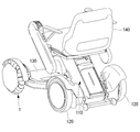
- the electric mobility includes a mobility main body 110 having an omnidirectional wheel 1 as a front wheel, a rear wheel 120, and a body 130 supported by the omnidirectional wheel 1 and the rear wheel 120;
- a seat unit (seat) 140 that is detachably attached to the mobility main body 110, and a driving device (not shown) such as a motor that is attached to the mobility main body 110 and drives at least one of the omnidirectional wheel 1 and the rear wheel 120.
- a driving device such as a motor that is attached to the mobility main body 110 and drives at least one of the omnidirectional wheel 1 and the rear wheel 120.
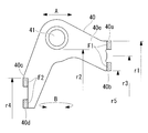
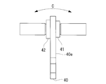
- each support plate 40 is formed by press molding (punching) and has a shape as shown in FIG. 9 in a plan view of the support plate 40. As shown in FIG. 10, each support plate 40 includes a first support shaft 41 protruding in the thickness direction from one surface in the thickness direction of the support plate 40, and the other in the thickness direction of the support plate 40. A second support shaft 42 protruding from the surface in the thickness direction is fixed.
- the central axes of the support shafts 41 and 42 are arranged in a plane perpendicular to the rotation axis of the wheel (in this embodiment, the central axis of the axle 2 shown in FIG. 6) 1a, and the radial direction of the wheel (the rotation axis 1a). It extends in a direction perpendicular to (vertical direction).
- the support plates 40 are arranged in the circumferential direction of the wheel, and two rollers 51 or two rollers 52 are supported on each support plate 40.
- the wheels are arranged alternately in the circumferential direction. That is, as shown in FIG. 2 and the like, in this omnidirectional wheel 1, a pair of rollers 51 and a pair of rollers 52 are alternately arranged in the circumferential direction of the wheel.
- each of the rollers 51 and 52 can be rotated around an axis that is disposed in a plane perpendicular to the rotation axis 1a of the wheel and that extends in a direction perpendicular to the radial direction of the wheel.
- Each roller 51 is formed so that the outer diameter gradually decreases from one to the other along the rotation axis. More specifically, each roller 51 has a substantially truncated cone shape, and the pair of rollers 51 are attached to the first and second support shafts 41 and 42 so that the end surfaces on the large diameter side face each other.
- Each roller 52 is also formed so that the outer diameter gradually decreases from one to the other along the rotation axis. More specifically, each roller 52 has a substantially truncated cone shape, and the pair of rollers 52 are attached to the first and second support shafts 41 and 42 so that the end surfaces on the large diameter side face each other. The roller 52 has a larger outer diameter than the roller 51.
- each of the rollers 51 and 52 includes metal core members 51a and 52a and outer peripheral members 51b and 52b that form outer peripheral surfaces of the respective rollers 51 and 52, and the outer peripheral members 51b and 52b. Is formed from a material having rubber-like elasticity. In addition, a plurality of grooves extending in the circumferential direction are provided on the outer peripheral surfaces of the outer peripheral members 51b and 52b (see FIG. 2 and the like). 7 and 8 do not show the grooves on the outer peripheral surfaces of the outer peripheral members 51b and 52b for reasons of drawing.
- a concave portion 52c is formed at the small diameter end of each roller 52 which is a large diameter roller, and a part of the small diameter end of the adjacent roller 51 which is a small diameter roller enters the concave portion 52c.
- the rollers 51 and 52 are supported by the support shafts 41 and 42, respectively.
- Each of the rollers 51 and 52 has a truncated cone shape, and a part of the small-diameter end of the roller 51 enters the recess 52c at the small-diameter end of the roller 52, so that the outer peripheral surface of the omnidirectional wheel 1 is nearly circular. ing.
- the first hub member 20 includes a first plate-like member (first support portion) 21 having a ring shape with a hole 21a at the center, and a first plate by insert molding. And the resin member 22 formed integrally with the shaped member 21.
- the first plate-like member 21 has a thickness of several millimeters, an outer periphery 21b having a polygonal shape (hexagonal shape in the embodiment), and a polygonal shape (6 in the present embodiment) similar to the outer periphery 21b.
- an inner periphery 21c having a square shape), and is formed by press molding (punching molding).
- the second hub member 30 includes a second plate member (second support portion) 31 having a ring shape with a hole 31a provided at the center, and a second plate by insert molding. And a resin member 32 formed integrally with the shaped member 31.
- the second plate-like member 31 has a thickness of several millimeters, and has an outer periphery 31b having a polygonal shape (hexagonal shape in the embodiment) and a polygonal shape (6 in the present embodiment) similar to the outer periphery 31b. And an inner periphery 31c having a square shape), and is formed by press molding (punching molding).
- the outer periphery 31b of the second plate member 31 is formed when the plate material is punched to form the hole 21a of the first plate member 21. That is, the second plate member 31 is formed using a plate material punched to form the hole 21 a of the first plate member 21. For this reason, the shape of the outer periphery 31 b of the second plate-shaped member 31 is smaller in the radial direction than the hole 21 a of the first plate-shaped member 21.
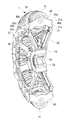
- the resin members 22 and 32 are made of reinforced plastic containing a reinforcing material such as carbon fiber and glass fiber, and as shown in FIGS. 1 and 5, inner peripheral portions 22 a and 32 a that are continuous in the circumferential direction, A plurality of outer peripheral portions 22b and 32b that are continuous in the circumferential direction and are fixed to the first or second plate-like members 21 and 31, and a plurality of connections between the inner peripheral portions 22a and 32a and the outer peripheral portions 22b and 32b. And spoke portions 22c and 32c.
- the inner peripheral portions 22a and 32a have disc portions 22d and 32d that face each other, and projecting portions 22e and 32e that extend from the disc portions 22d and 32d toward each other.
- Each anti-vibration member 10 has a cylindrical shape and is made of a metal inner ring 11, a cylindrical shape that is arranged on the outer peripheral side of the inner ring 11, a metal outer ring 12, and the inner ring 11 and the outer ring 12. And a ring-shaped cushioning member 13 made of a material having rubber-like elasticity disposed therebetween.
- the inner peripheral surface of the buffer member 13 is fixed to the inner ring 11 by vulcanization adhesion or the like, and the outer peripheral surface of the buffer member 13 is also fixed to the outer ring 12 by vulcanization adhesion or the like.
- the inner rings 11 of the pair of vibration isolation members 10 are respectively fixed to the outer rings of the bearings 2a.
- the outer ring 12 is provided with a flange portion 12a extending from the outer peripheral surface to the outer side in the radial direction of the wheel.
- the inner peripheral portions 22a and 32a of the plate-like members 21 and 31 are disposed between the flange portions 12a of the pair of vibration isolating members 10, and the inner peripheral portions 22a and 32a are provided with a plurality of bolts (fastened) between the pair of flange portions 12a. Member) It is fastened together with FM. Thereby, the 1st and 2nd hub members 20 and 30 are being fixed to the perimeter side of a pair of vibration isolator 10.
- a metal ring 3 is supported on an inner ring 11 of a pair of vibration isolating members 10, and the ring 3 is a disk-shaped protrusion 3a extending radially outward from the outer peripheral surface thereof. Is provided.
- the protrusion 3a is disposed between the portions 22e and 32e. The inner diameters of the protrusions 22e and 32e are smaller than the outer diameter of the protrusion 3a.
- the outer periphery 21b of the first plate-like member 21 is provided with a plurality of notches 21d at intervals in the circumferential direction, and the inner periphery 21c has a plurality of holes spaced at intervals in the circumferential direction. 21e is provided. Each notch 21d and each hole 21e penetrate the 1st plate-shaped member 21 in the plate
- the outer periphery 31b of the second plate-shaped member 31 is provided with a plurality of notches 31d at intervals in the circumferential direction, and the inner periphery 31c has a plurality at intervals in the circumferential direction.
- Hole 31e is provided. Each notch 31d and each hole 31e penetrate the 2nd plate-shaped member 31 in the plate
- each support plate 40 in the direction along the rotational axis 1a of the wheel two convex portions 40a and 40b are provided at intervals in the radial direction of the wheel.
- two convex portions 40c and 40d are provided at intervals in the radial direction of the wheel.
- the convex portions 40a, 40b, 40c, 40d are respectively inserted into the notches 21d, the holes 21e, the notches 31d, or the holes 31e.
- the plate-like member 21 or the second plate-like member 31 is fixed by welding or the like. That is, the convex portions 40a and 40b function as the first fixed portion F1 fixed to the first plate-like member 21 in the support plate 40, and the convex portions 40c and 40d are the second plate-like member in the support plate 40. It functions as the second fixed portion F2 fixed to 31.
- the hatched range is a range that functions as the first fixed portion F1 and the second fixed portion F2.
- the respective support shafts 41 and 42 are arranged between the first fixed portion F1 and the second fixed portion F2 in the direction along the rotation axis 1a.
- the notch 21d and the hole 21e of the first plate member 21 function as a fixing part for fixing the first fixed portion F1
- the notch 31d and the hole 31e of the second plate member 31 are It functions as a fixing part for fixing the second fixed part F2.
- the first and second plate-like members 21 and 31 are arranged at intervals in the direction along the rotation axis 1a, and each support is provided between the first and second plate-like members 21 and 31.
- the support shafts 41 and 42 are supported by the plate 40.
- the radial position r1 (the radial position with respect to the rotation axis 1a) of the outer end of the first fixed portion F1 of each support plate 40 is a support fixed to the support plate 40.
- the shafts 41 and 42 are disposed on the radially outer side than the radial position r2 of the radially inner end of the end portion on the support plate 40 side. This is advantageous in suppressing deformation of each support plate 40 in the rotational direction around the axis extending in the vehicle width direction (the direction of arrow C in FIG. 10) due to the force applied to each roller 51, 52.
- This structure is useful for reducing the thickness of the support plate 40.
- the radial position r3 of the center position in the radial direction of the first fixed part F1 (the radial direction with respect to the rotation axis 1a) is the second fixed part F2. It arrange
- the support shaft side of the support shafts 41 and 42 fixed to the respective support plates 40 is provided.
- the portion closest to the one surface 40 e in the thickness direction ( The position r2 on the inner side in the radial direction of the left end portion of the support shaft 41 shown in FIG. 10 and the position in the radial direction of the first fixed portion F1 (for example, the position of the outer end in the radial direction of the first fixed portion F1).
- This structure is advantageous in suppressing deformation of each support plate 40 in the rotational direction around the axis extending in the vehicle width direction (the direction of arrow C in FIG. 10) due to the force applied to each roller 51, 52.
- the radial position r4 of the outer end of the second fixed portion F2 is formed smaller than the radial position r5 of the inner end of the first fixed portion F1 in the radial direction.
- the radial position r5 and the radial position r4 may be the same. If comprised in this way, the 1st to-be-fixed part F1 is arrange
- the hole 21a is provided in the center of the 1st plate-shaped member 21, and the 2nd plate-shaped member 31 has a shape which enters in the hole 21a of the 1st plate-shaped member 21, it is the 1st and 2nd
- the plate-like members 21 and 31 are formed by press molding, and the second plate-like member 31 is formed using a plate material punched in order to provide the central hole 21a of the first plate-like member 21 at that time. Can do.
- the first plate-like member 21 is arranged on the inner side in the vehicle width direction than the second plate-like member 31. Since the first plate-like member 21 needs to fix the first fixed portion F1 on the outer side in the radial direction, the first plate-like member 21 is arranged on the outer side in the width direction than the rollers 51 and 52 as shown in FIG. On the other hand, since the 2nd plate-shaped member 31 can be made smaller diameter than the 1st plate-shaped member 21, as shown in FIG. 3, it arrange
- a buffer member 13 is provided between the axle 2 and the first plate member 21 and the second plate member 31. For this reason, the vibration generated between the grounding surface and each of the rollers 51 and 52 is reduced by the buffer member 13 and transmitted to the axle 2, which is advantageous in reducing the vibration of the vehicle.
- first and second plate-like members 21 and 31 are integrally formed with the resin members 22 and 32 by insert molding, and the resin members 22 and 32 are supported on the outer peripheral side of the buffer member 13. For this reason, even when the first and second plate-like members 21 and 31 are made of metal for strength, the weight of the omnidirectional wheel 1 can be reduced by the amount of use of the resin members 22 and 32.
- the radial positions of the first and second fixed portions F1, F2 of the support plate 40 that supports the roller 52, which is a large-diameter roller, are small in diameter.
- the first and second fixed portions F1 and F2 of the support plate 40 that support the roller 52, which is a roller, are respectively arranged radially inward from the radial positions.
- the roller 51 which is a small diameter roller and the roller 52 which is a large diameter roller can be supported using the several support plate 40 of the same shape.
- the support plate 40 that supports the roller 51 and the support plate 40 that supports the roller 52 can be different, it is preferable that they are the same as described above.
- the outer shape of the second plate-like member 31 may be smaller than the hole 21a of the first plate-like member 21.
- the second plate-like member 31 may be shaped so as not to enter the hole 21 a of the first plate-like member 21.
- the second hub member 30 has the same structure as the first hub member 20, and the shape of the support plate 40 can be changed so as to be adapted thereto.
- the first fixed portion F1 is composed of the convex portions 40a and 40b
- the second fixed portion F2 is composed of the convex portions 40c and 40d.
- the convex part with the shape where the convex parts 40a, 40b are connected may be the first fixed part F1
- the convex part with the shape where the convex parts 40c, 40d are connected may be the second fixed part F2. Is possible.
- the support plate 40 can be formed by other processing methods such as forging and cutting, and can also be formed using other materials such as hard plastic.
- the 1st plate-shaped member 21 and the 2nd plate-shaped member 31 showed what functions as a 1st support part and a 2nd support part, respectively.
- the entire first hub member 20 can be integrally formed by press molding, and the entire second hub member 30 can also be integrally formed by press molding.
- each support plate 40 is supported by the first and second support portions so that the support shafts 41 and 42 are disposed between the first and second support portions in the direction along the rotation axis 1a. Is done.
- a part of the support plate 40 is inserted into the notch or the hole and fixed by welding or the like.
- the part of the support plate 40 is fixed to the first and second parts by other methods. It is also possible to fix to the plate-like members 21 and 31. Further, it is possible to support the rollers 51 or the rollers 52 one by one by the support plates 40, and it is also possible to support three or more rollers 51 or the rollers 52 by the support plates 40.
- the inner peripheral surface and the outer peripheral surface of the buffer member 13 are fixed to the inner ring 11 and the outer ring 12, respectively, but are not bonded to the inner ring 11 and the outer ring 12, It is also possible to use a buffer member 13 that is only sandwiched between the inner ring 11 and the outer ring 12.
Abstract
This omnidirectional wheel is provided with: a first plate-like member (21) rotating about a rotational axis (1a); a second plate-like member (31) rotating with the first plate-like member (21); multiple support shafts each supporting multiple rollers (51, 52); and multiple support plates (40) fastened to the first and second plate-like members (21, 31), and each supporting one or more of the multiple support shafts between the first and second plate-like members (21, 31). At each support plate (40), the outside end part, relative to the radial direction of the wheel, of a first fastened part fastened to the first plate-like member (21) and/or the radially outside end part of a second fastened part fastened to the second plate-like member (31) is disposed radially outside of the radially inside edge of the end parts of the support shaft fastened to the support plates (40), the end parts of the shaft being the end parts on the side of the support plates (40).
Description
本発明は全方向車輪に関する。
The present invention relates to an omnidirectional wheel.
このような全方向車輪として、外周面を形成する複数のローラと、該複数のローラをそれぞれ回転可能に支持する複数の支軸と、該複数の支軸を2つずつ支持する複数の支持部材と、該全方向車輪の回転軸線に沿った方向に間隔をおいて配置され、それぞれ前記回転軸線周りに回転する一対のプレート部材とを備え、各支持部材が金属ブロックを削って形成されたものであり、各支持部材が一対のプレート部材にボルトで固定されたものが知られている(例えば、特許文献1参照。)。
As such an omnidirectional wheel, a plurality of rollers that form an outer peripheral surface, a plurality of support shafts that rotatably support the plurality of rollers, and a plurality of support members that support the plurality of support shafts two by two And a pair of plate members arranged at intervals in the direction along the rotation axis of the omnidirectional wheel, each rotating around the rotation axis, and each support member formed by cutting a metal block It is known that each support member is fixed to a pair of plate members with bolts (see, for example, Patent Document 1).
また、他の全方向車輪として、外周面を形成する複数のローラと、該複数のローラをそれぞれ回転可能に支持する複数の支持フレームと、該全方向車輪の回転軸線に沿った方向に間隔をおいて配置され、それぞれ前記回転軸線周りに回転する一対の回転部材とを備え、各支持フレームは前記複数のローラのうち1つを収容するように金属ブロックを削って形成されており、各支持フレームが一対の回転部材に固定されたものが知られている(例えば、特許文献2参照。)。
In addition, as other omnidirectional wheels, a plurality of rollers that form an outer peripheral surface, a plurality of support frames that rotatably support the plurality of rollers, and an interval in the direction along the rotation axis of the omnidirectional wheels. And a pair of rotating members that rotate about the rotation axis, and each support frame is formed by cutting a metal block so as to accommodate one of the plurality of rollers. One in which a frame is fixed to a pair of rotating members is known (for example, see Patent Document 2).
また、他の全方向車輪として、外周面を形成する複数のローラと、該複数のローラをそれぞれ回転可能に支持する複数の支軸と、ハブから径方向外側に向かって放射状に延びる複数の板状部材とを備え、該複数の板状部材の径方向外側端で前記複数の支軸を支持するものが知られている(例えば特許文献3参照。)。
Further, as other omnidirectional wheels, a plurality of rollers that form an outer peripheral surface, a plurality of support shafts that rotatably support the plurality of rollers, and a plurality of plates that extend radially outward from the hub And a plurality of plate-like members that support the plurality of support shafts at the radially outer ends (see, for example, Patent Document 3).
特許文献1および特許文献2の全方向車輪では、ローラの数に応じて支持部材又は支持フレームが設けられている。また、支持部材および支持フレームが金属ブロックを削って形成されており、各ローラに加わる衝撃力に耐えるように十分な厚さ寸法を有するものなので、支持部材又は支持フレームが複数存在することにより全方向車輪が重くなっていた。
In the omnidirectional wheels of Patent Document 1 and Patent Document 2, a support member or a support frame is provided according to the number of rollers. In addition, since the support member and the support frame are formed by cutting a metal block and have a thickness dimension sufficient to withstand the impact force applied to each roller, all of the support members and the support frame are present due to the presence of a plurality of support members or support frames. The direction wheel was heavy.
一方、特許文献3の全方向車輪は、ハブから径方向外側に向かって放射状に延びる複数の板状部材を使って各ローラを支持している。しかし、各板状部材は、その径方向内側端がハブの外周面に固定されると共に径方向外側に向かって延びる部材なので、径方向外側端に力が加わることにより各板状部材に撓みや変形が生じやすい。例えば、乗車者や荷物等の荷重が加わった状態で段差を乗り越える際に、各ローラのうち1つ又は2つが段差に衝突することになるが、この時に各ローラには径方向の力と共に車両幅方向や車両前後方向の力も加わり、特許文献3のような板状部材は簡単に変形してしまう。
On the other hand, the omnidirectional wheel of Patent Document 3 supports each roller by using a plurality of plate-like members that extend radially outward from the hub. However, each plate-like member is a member whose inner end in the radial direction is fixed to the outer peripheral surface of the hub and extends toward the outer side in the radial direction. Therefore, when a force is applied to the outer end in the radial direction, Deformation tends to occur. For example, one or two of the rollers collide with the step when getting over the step with a load of a passenger, luggage, etc., and at this time each roller has a radial force along with the vehicle. A force in the width direction or the vehicle front-rear direction is also applied, and the plate-like member as in Patent Document 3 is easily deformed.
本発明は、このような事情に鑑みてなされたものであって、重量低減を図りつつ強度を維持することができる全方向車輪の提供を目的とする。
The present invention has been made in view of such circumstances, and an object thereof is to provide an omnidirectional wheel capable of maintaining strength while reducing weight.
本発明の第1の態様は、外周面が複数のローラにより形成され、回転軸線周りに回転する全方向車輪であって、前記回転軸線周りに回転する第1の支持部と、該第1の支持部と前記回転軸線に沿った方向に間隔をおいて配置され、前記第1の支持部と共に前記回転軸線周りに回転する第2の支持部と、前記複数のローラをそれぞれ支持する複数の支軸と、前記第1の支持部および前記第2の支持部に固定され、前記回転軸線に沿った方向における前記第1の支持部と前記第2の支持部との間にそれぞれ少なくとも一部が配置された複数の支持プレートとを備え、前記複数の支持プレートには、それぞれ1つ又は複数の前記支軸が固定されており、当該各支持プレートにおいて、前記第1の支持部に固定された第1の被固定部の車輪径方向の外側端および前記第2の支持部に固定された第2の被固定部の前記車輪径方向の外側端の少なくとも一方が、該支持プレートに固定された前記支軸における該支持プレート側の端部の前記車輪径方向の内側端よりも前記車輪径方向の外側に配置されている。
According to a first aspect of the present invention, there is provided an omnidirectional wheel having an outer peripheral surface formed by a plurality of rollers and rotating around a rotation axis, the first support portion rotating around the rotation axis, and the first A second support portion that is arranged around the rotation axis along with the first support portion and spaced apart in the direction along the rotation axis, and a plurality of supports that respectively support the plurality of rollers. At least a part of each of the shaft and the first support portion and the second support portion is fixed to the first support portion and the second support portion, and between the first support portion and the second support portion in the direction along the rotation axis. A plurality of support plates arranged, one or a plurality of the support shafts being fixed to each of the plurality of support plates, each of the support plates being fixed to the first support portion In the wheel radial direction of the first fixed part At least one of the outer end in the wheel radial direction of the second fixed portion fixed to the side end and the second support portion is the end portion on the support plate side of the support shaft fixed to the support plate. Is arranged outside the wheel radial direction than the inner end in the wheel radial direction.
第1の態様では、第1および第2の支持部は回転軸線に沿った方向に間隔をおいて配置され、第1および第2の支持部の間において各支持プレートにより各支軸が支持されているので、各ローラに加わる力による各支持プレートの車両幅方向への変形を抑制する上で有利であり、車輪の径方向周りの回転方向への変形を抑制する上でも有利である。
In the first aspect, the first and second support portions are spaced apart in the direction along the rotation axis, and each support shaft is supported by each support plate between the first and second support portions. Therefore, it is advantageous in suppressing deformation of each support plate in the vehicle width direction due to the force applied to each roller, and also advantageous in suppressing deformation in the rotational direction around the radial direction of the wheel.
また、各支持プレートの第1および第2の被固定部の前記車輪径方向の外側端の少なくとも一方が、該支持プレートに固定された支軸における該支持プレート側の端部の前記車輪径方向の内側端よりも前記車輪径方向の外側に配置されているので、各ローラに加わる力による各支持プレートの、車両幅方向に延びる軸線周りの回転方向への変形を抑制する上でも有利である。当該構造は支持プレートの板厚を薄くする上で有用である。
Further, at least one of the outer ends in the wheel radial direction of the first and second fixed portions of the respective support plates is the wheel radial direction of the end portion on the support plate side of the support shaft fixed to the support plate. Since it is disposed on the outer side in the wheel radial direction than the inner end of the wheel, it is advantageous in suppressing deformation of each support plate in the rotational direction around the axis extending in the vehicle width direction due to the force applied to each roller. . This structure is useful for reducing the thickness of the support plate.
本発明の第2の態様は、外周面が複数のローラにより形成され、回転軸線周りに回転する全方向車輪であって、前記回転軸線周りに回転する第1の支持部と、該第1の支持部と前記回転軸線に沿った方向に間隔をおいて配置され、前記第1の支持部と共に前記回転軸線周りに回転する第2の支持部と、前記複数のローラをそれぞれ支持する複数の支軸と、前記第1の支持部および前記第2の支持部に固定され、前記回転軸線に沿った方向における前記第1の支持部と前記第2の支持部との間にそれぞれ少なくとも一部が配置された複数の支持プレートとを備え、前記複数の支持プレートには、それぞれ1つ又は複数の前記支軸が固定されており、前記各支持プレートにおいて、前記第1の支持部に固定された第1の被固定部の車輪径方向の中央位置が、前記第2の支持部に固定された第2の被固定部の前記車輪径方向の外側端よりも前記車輪径方向の外側に配置されている。
According to a second aspect of the present invention, there is provided an omnidirectional wheel having an outer peripheral surface formed by a plurality of rollers and rotating around a rotation axis, the first support portion rotating around the rotation axis, and the first A second support portion that is arranged around the rotation axis along with the first support portion and spaced apart in the direction along the rotation axis, and a plurality of supports that respectively support the plurality of rollers. At least a part of each of the shaft and the first support portion and the second support portion is fixed to the first support portion and the second support portion, and between the first support portion and the second support portion in the direction along the rotation axis. A plurality of support plates arranged, one or a plurality of the support shafts being fixed to each of the plurality of support plates, and fixed to the first support portion in each of the support plates. In the wheel radial direction of the first fixed part Central position, is arranged outside of the second fixed to the support portion a second of said wheel radial direction from the outer end of the wheel diameter direction of the fixed part.
第2の態様では、第1および第2の支持部は回転軸線に沿った方向に間隔をおいて配置され、第1および第2の支持部の間において各支持プレートにより各支軸が支持されているので、各ローラに加わる力による各支持プレートの車両幅方向への変形を抑制する上で有利であり、車輪の径方向周りの回転方向への変形を抑制する上でも有利である。
In the second aspect, the first and second support portions are spaced apart in the direction along the rotation axis, and each support shaft is supported by each support plate between the first and second support portions. Therefore, it is advantageous in suppressing deformation of each support plate in the vehicle width direction due to the force applied to each roller, and also advantageous in suppressing deformation in the rotational direction around the radial direction of the wheel.
また、第1の被固定部が第2の被固定部よりも前記車輪径方向の外側に配置されているので、各支持プレートに固定された支軸における該支持プレート側の端部の前記車輪径方向の位置と第1の被固定部の前記車輪径方向の位置とを近付ける、又は、同一とすることができる。当該構造は、各ローラに加わる力による各支持プレートの、車両幅方向に延びる軸線周りの回転方向への変形を抑制する上でも有利である。
In addition, since the first fixed portion is disposed on the outer side in the wheel radial direction than the second fixed portion, the wheel at the end portion on the support plate side of the support shaft fixed to each support plate. The radial position and the position of the first fixed portion in the wheel radial direction can be brought close to or the same. This structure is also advantageous in suppressing deformation of each support plate in the rotational direction around the axis extending in the vehicle width direction due to the force applied to each roller.
上記各態様において、前記第1の被固定部の前記車輪径方向の内側端の前記車輪径方向における位置と前記第2の被固定部の前記外側端の前記車輪径方向における位置とが実質的に同一であってもよい。
このように構成すると、第1の被固定部が第2の被固定部に対しより明確に径方向外側に配置され、各ローラに加わる力による各支持プレートの、車両幅方向に延びる軸線周りの回転方向への変形を抑制する上で有利である。 In each of the above aspects, the position of the inner end of the first fixed portion in the wheel radial direction in the wheel radial direction and the position of the outer end of the second fixed portion in the wheel radial direction are substantially the same. May be the same.
If comprised in this way, a 1st to-be-fixed part will be arrange | positioned more clearly in a radial direction outer side with respect to a 2nd to-be-fixed part, and the periphery of the axis line of each support plate by the force added to each roller extends in the vehicle width direction This is advantageous in suppressing deformation in the rotational direction.
上記各態様において、前記第1の支持部が中心に孔が設けられた板状部材であると共に、前記第2の支持部が板状部材であり、前記第2の支持部の外周形状が前記第1の支持部の前記孔よりも小さいことが好ましい。
このように構成すると、第1および第2の支持部をプレス成形により形成し、その際に第1の支持部の中心の孔を設けるために打ち抜かれた板材を用いて第2の支持部を形成することができる。このため、端材の量を低減し、効率的な製造を行うことができる。 In each of the above aspects, the first support part is a plate-like member provided with a hole in the center, the second support part is a plate-like member, and the outer peripheral shape of the second support part is the It is preferably smaller than the hole of the first support part.
If comprised in this way, the 1st and 2nd support part will be formed by press molding, and the 2nd support part will be used using the board material punched in order to provide the hole of the center of the 1st support part in that case Can be formed. For this reason, the quantity of mill ends can be reduced and efficient manufacture can be performed.
上記各態様において、前記第1の支持部が前記第2の支持部よりも車両幅方向の内側に配置されることが好ましい。
支持プレートに固定された支軸における該支持プレート側の端部の径方向の位置と、第1の被固定部の径方向の位置とを近付ける、又は、同一とすると、第1の被固定部と各ローラの支軸とが車輪の回転軸線に沿った方向に並ぶことになる。つまり、各ローラの支軸と第1の被固定部とが車両幅方向に並ぶことになる。 Each said aspect WHEREIN: It is preferable that a said 1st support part is arrange | positioned inside a vehicle width direction rather than a said 2nd support part.
When the radial position of the end on the support plate side of the support shaft fixed to the support plate and the radial position of the first fixed part are brought close to or the same, the first fixed part And the support shaft of each roller are aligned in a direction along the rotational axis of the wheel. That is, the support shaft of each roller and the first fixed portion are aligned in the vehicle width direction.
この状態で、第1の被固定部が車両幅方向の外側に配置されていると、当該全方向車輪がその幅方向外側に配置された障害物に接触する場合に、各ローラよりも先に第1の被固定部が障害物に接触することになる。一方、支持プレートに固定された支軸における該支持プレート側の端部の径方向の位置に対し、第2の被固定部を径方向内側に配置すると、第2の被固定部を各ローラの支軸と車輪の回転軸線に沿った方向に並ばないように配置することができる。
In this state, when the first fixed portion is disposed outside the vehicle width direction, when the omnidirectional wheel comes into contact with an obstacle disposed outside the width direction, the first fixed portion comes before each roller. The first fixed part comes into contact with the obstacle. On the other hand, when the second fixed portion is disposed radially inward with respect to the radial position of the end portion on the support plate side of the support shaft fixed to the support plate, the second fixed portion is placed on each roller. It can arrange | position so that it may not line up in the direction along the rotating shaft of a spindle and a wheel.
つまり、第2の被固定部を各ローラよりも車輪幅方向の内側に配置することも可能となる。この構成では、第2の被固定部が車両幅方向の外側に配置され、該全方向車輪がその幅方向外側に配置された障害物に接触する場合に、各ローラよりも先に第2の被固定部が障害物に接触することを極力防止することが可能となる。
That is, it is possible to dispose the second fixed portion on the inner side in the wheel width direction than each roller. In this configuration, when the second fixed portion is disposed outside the vehicle width direction and the omnidirectional wheel contacts an obstacle disposed outside the width direction, the second fixed portion is placed before each roller. It is possible to prevent the fixed part from contacting the obstacle as much as possible.
上記各態様において、該全方向車輪を前記回転軸線周りに回転可能に支持する車軸と前記第1の支持部および前記第2の支持部との間に緩衝部材が設けられていることが好まし。
このように構成すると、接地面と各ローラとの間等で生ずる振動が緩衝部材で低減されて車軸に伝達され、車両の振動低減を行う上で有利である。 In each of the above aspects, it is preferable that a buffer member is provided between an axle that supports the omnidirectional wheel rotatably around the rotation axis, and the first support portion and the second support portion. .
With this configuration, vibration generated between the grounding surface and each roller is reduced by the buffer member and transmitted to the axle, which is advantageous in reducing vehicle vibration.
上記各態様において、前記第1の支持部が、前記第1の被固定部を固定するための固定部を有する板状部材であり、該板状部材がインサート成形により樹脂部材と一体成形されており、前記樹脂部材が前記緩衝部材の外周側によって支持されていることが好ましい。
このように、第1の支持部が板状部材であると共に樹脂部材と一体成形され、樹脂部材が緩衝部材の外周側に支持されるので、第1の支持部を強度のために金属製とした場合でも、樹脂部材を用いる分だけ全方向車輪の重量を低減することができる。 In each of the above aspects, the first support portion is a plate-like member having a fixing portion for fixing the first fixed portion, and the plate-like member is integrally formed with the resin member by insert molding. The resin member is preferably supported by the outer peripheral side of the buffer member.
Thus, since the first support portion is a plate-like member and is integrally formed with the resin member, and the resin member is supported on the outer peripheral side of the buffer member, the first support portion is made of metal for strength. Even in this case, the weight of the omnidirectional wheel can be reduced by the amount of the resin member used.
本発明によれば、重量低減を図りつつ強度を維持することができる。
According to the present invention, the strength can be maintained while reducing the weight.
本発明の一実施形態に係る全方向車輪1を図面を参照して以下に説明する。
この全方向車輪1は、図1~図5に示すように、車軸2に幅方向一対のベアリング2aを介して支持された幅方向一対の防振部材10と、一対の防振部材10の外周側に固定された第1および第2のハブ部材20,30と、第1および第2のハブ部材20,30に固定された複数の支持プレート40と、支持プレート40に支持された複数のローラ51,52とを有し、例えば電動モビリティ100の前輪として用いられる。電動モビリティの後輪や、その他の車両の車輪として用いることもできる。以下の説明では、電動モビリティ100の車両前後方向を前後方向と称し、車両幅方向を幅方向と称する場合がある。 Anomnidirectional wheel 1 according to an embodiment of the present invention will be described below with reference to the drawings.
As shown in FIGS. 1 to 5, theomnidirectional wheel 1 includes a pair of vibration isolation members 10 supported on an axle 2 via a pair of bearings 2a in the width direction, and outer peripheries of the pair of vibration isolation members 10. First and second hub members 20, 30 fixed to the side, a plurality of support plates 40 fixed to the first and second hub members 20, 30, and a plurality of rollers supported by the support plate 40 51, 52 and used as a front wheel of the electric mobility 100, for example. It can also be used as a rear wheel of electric mobility or a wheel of other vehicles. In the following description, the vehicle front-rear direction of the electric mobility 100 may be referred to as the front-rear direction, and the vehicle width direction may be referred to as the width direction.
この全方向車輪1は、図1~図5に示すように、車軸2に幅方向一対のベアリング2aを介して支持された幅方向一対の防振部材10と、一対の防振部材10の外周側に固定された第1および第2のハブ部材20,30と、第1および第2のハブ部材20,30に固定された複数の支持プレート40と、支持プレート40に支持された複数のローラ51,52とを有し、例えば電動モビリティ100の前輪として用いられる。電動モビリティの後輪や、その他の車両の車輪として用いることもできる。以下の説明では、電動モビリティ100の車両前後方向を前後方向と称し、車両幅方向を幅方向と称する場合がある。 An
As shown in FIGS. 1 to 5, the
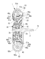
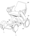
この電動モビリティは、例えば図7および図8に示すように、前輪としての全方向車輪1、後輪120、並びに全方向車輪1および後輪120により支持されたボディ130を有するモビリティ本体110と、モビリティ本体110に着脱自在に取付けられた座席ユニット(座席)140と、モビリティ本体110に取付けられ、全方向車輪1および後輪120の少なくとも一方を駆動するためのモータ等の駆動装置(図示せず)とを有する。
For example, as shown in FIGS. 7 and 8, the electric mobility includes a mobility main body 110 having an omnidirectional wheel 1 as a front wheel, a rear wheel 120, and a body 130 supported by the omnidirectional wheel 1 and the rear wheel 120; A seat unit (seat) 140 that is detachably attached to the mobility main body 110, and a driving device (not shown) such as a motor that is attached to the mobility main body 110 and drives at least one of the omnidirectional wheel 1 and the rear wheel 120. ).
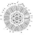
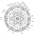
全方向車輪1の外周面は複数のローラ51,52により形成されている。各支持プレート40は、プレス成形(打ち抜き成形)により形成されており、支持プレート40の平面視で図9に示すような形状を有する。各支持プレート40には、図10に示すように、支持プレート40の厚さ方向一方の面から該厚さ方向に突出している第1の支軸41と、支持プレート40の厚さ方向他方の面から該厚さ方向に突出している第2の支軸42とが固定されている。
The outer peripheral surface of the omnidirectional wheel 1 is formed by a plurality of rollers 51 and 52. Each support plate 40 is formed by press molding (punching) and has a shape as shown in FIG. 9 in a plan view of the support plate 40. As shown in FIG. 10, each support plate 40 includes a first support shaft 41 protruding in the thickness direction from one surface in the thickness direction of the support plate 40, and the other in the thickness direction of the support plate 40. A second support shaft 42 protruding from the surface in the thickness direction is fixed.
各支軸41,42の中心軸線は、車輪の回転軸線(本実施形態では図6に示す車軸2の中心軸線)1aに対する垂直面内に配置されると共に、車輪の径方向(回転軸線1aの垂直方向)に直交する方向に延びている。
The central axes of the support shafts 41 and 42 are arranged in a plane perpendicular to the rotation axis of the wheel (in this embodiment, the central axis of the axle 2 shown in FIG. 6) 1a, and the radial direction of the wheel (the rotation axis 1a). It extends in a direction perpendicular to (vertical direction).
各支持プレート40は車輪の周方向に並んでおり、各支持プレート40には2つのローラ51又は2つのローラ52が支持されている。また、一対のローラ51を第1および第2の支軸41,42で支持する支持プレート40と、一対のローラ52を第1および第2の支軸41,42で支持する支持プレート40とが、車輪の周方向に交互に並んでいる。つまり、図2等に示すように、この全方向車輪1では一対のローラ51と一対のローラ52とが車輪の周方向に交互に並んでいる。
The support plates 40 are arranged in the circumferential direction of the wheel, and two rollers 51 or two rollers 52 are supported on each support plate 40. A support plate 40 that supports the pair of rollers 51 with the first and second support shafts 41 and 42 and a support plate 40 that supports the pair of rollers 52 with the first and second support shafts 41 and 42. The wheels are arranged alternately in the circumferential direction. That is, as shown in FIG. 2 and the like, in this omnidirectional wheel 1, a pair of rollers 51 and a pair of rollers 52 are alternately arranged in the circumferential direction of the wheel.
また、上記構成により、各ローラ51,52は、車輪の回転軸線1aに対する垂直面内に配置されると共に車輪の径方向に直交する方向に延びる軸線周りに回転することができる。
各ローラ51はその回転軸線に沿った一方から他方に向かって外径が徐々に小さくなるように形成されている。より具体的には、各ローラ51は略円錐台形状を有し、一対のローラ51は大径側の端面が互いに向き合うように第1および第2の支軸41,42に取付けられている。 Further, with the above-described configuration, each of the rollers 51 and 52 can be rotated around an axis that is disposed in a plane perpendicular to the rotation axis 1a of the wheel and that extends in a direction perpendicular to the radial direction of the wheel.
Eachroller 51 is formed so that the outer diameter gradually decreases from one to the other along the rotation axis. More specifically, each roller 51 has a substantially truncated cone shape, and the pair of rollers 51 are attached to the first and second support shafts 41 and 42 so that the end surfaces on the large diameter side face each other.
各ローラ51はその回転軸線に沿った一方から他方に向かって外径が徐々に小さくなるように形成されている。より具体的には、各ローラ51は略円錐台形状を有し、一対のローラ51は大径側の端面が互いに向き合うように第1および第2の支軸41,42に取付けられている。 Further, with the above-described configuration, each of the
Each
各ローラ52もその回転軸線に沿った一方から他方に向かって外径が徐々に小さくなるように形成されている。より具体的には、各ローラ52は略円錐台形状を有し、一対のローラ52は大径側の端面が互いに向き合うように第1および第2の支軸41,42に取付けられている。ローラ52はローラ51よりも大きな外径を有する。
Each roller 52 is also formed so that the outer diameter gradually decreases from one to the other along the rotation axis. More specifically, each roller 52 has a substantially truncated cone shape, and the pair of rollers 52 are attached to the first and second support shafts 41 and 42 so that the end surfaces on the large diameter side face each other. The roller 52 has a larger outer diameter than the roller 51.
各ローラ51,52は、図5に示すように、金属製の芯部材51a,52aと、各ローラ51,52の外周面を形成する外周部材51b,52bとを有し、外周部材51b,52bはゴム状弾性を有する材料から形成されている。また、外周部材51b,52bの外周面にはそれぞれ周方向に延びる複数の溝が設けられている(図2等参照)。なお、図7および図8には作図上の理由により外周部材51b,52bの外周面の溝は描いていない。
As shown in FIG. 5, each of the rollers 51 and 52 includes metal core members 51a and 52a and outer peripheral members 51b and 52b that form outer peripheral surfaces of the respective rollers 51 and 52, and the outer peripheral members 51b and 52b. Is formed from a material having rubber-like elasticity. In addition, a plurality of grooves extending in the circumferential direction are provided on the outer peripheral surfaces of the outer peripheral members 51b and 52b (see FIG. 2 and the like). 7 and 8 do not show the grooves on the outer peripheral surfaces of the outer peripheral members 51b and 52b for reasons of drawing.
また、図3等に示すように、大径ローラである各ローラ52の小径端には凹部52cが形成され、該凹部52cに小径ローラである隣のローラ51の小径端の一部が入り込むように、各ローラ51,52が各々の支軸41,42に支持されている。各ローラ51,52が円錐台形状を有し、ローラ52の小径端の凹部52cにローラ51の小径端の一部が入り込んでいるので、全方向車輪1の外周面が円形に近い状態となっている。
Further, as shown in FIG. 3 and the like, a concave portion 52c is formed at the small diameter end of each roller 52 which is a large diameter roller, and a part of the small diameter end of the adjacent roller 51 which is a small diameter roller enters the concave portion 52c. In addition, the rollers 51 and 52 are supported by the support shafts 41 and 42, respectively. Each of the rollers 51 and 52 has a truncated cone shape, and a part of the small-diameter end of the roller 51 enters the recess 52c at the small-diameter end of the roller 52, so that the outer peripheral surface of the omnidirectional wheel 1 is nearly circular. ing.
第1のハブ部材20は、図4に示すように、中心に孔21aが設けられたリング形状を有する第1の板状部材(第1の支持部)21と、インサート成形により第1の板状部材21と一体に形成された樹脂部材22とを有する。第1の板状部材21は、数mmの厚さ寸法を有し、多角形形状(実施形態では6角形形状)を有する外周21bと、外周21bと同様に多角形形状(本実施形態では6角形形状)を有する内周21cとを有し、プレス成形(打ち抜き成形)により形成されている。
As shown in FIG. 4, the first hub member 20 includes a first plate-like member (first support portion) 21 having a ring shape with a hole 21a at the center, and a first plate by insert molding. And the resin member 22 formed integrally with the shaped member 21. The first plate-like member 21 has a thickness of several millimeters, an outer periphery 21b having a polygonal shape (hexagonal shape in the embodiment), and a polygonal shape (6 in the present embodiment) similar to the outer periphery 21b. And an inner periphery 21c having a square shape), and is formed by press molding (punching molding).
第2のハブ部材30は、図2に示すように、中心に孔31aが設けられたリング形状を有する第2の板状部材(第2の支持部)31と、インサート成形により第2の板状部材31と一体に形成された樹脂部材32とを有する。第2の板状部材31は、数mmの厚さ寸法を有し、多角形形状(実施形態では6角形形状)を有する外周31bと、外周31bと同様に多角形形状(本実施形態では6角形形状)を有する内周31cとを有し、プレス成形(打ち抜き成形)により形成されている。
As shown in FIG. 2, the second hub member 30 includes a second plate member (second support portion) 31 having a ring shape with a hole 31a provided at the center, and a second plate by insert molding. And a resin member 32 formed integrally with the shaped member 31. The second plate-like member 31 has a thickness of several millimeters, and has an outer periphery 31b having a polygonal shape (hexagonal shape in the embodiment) and a polygonal shape (6 in the present embodiment) similar to the outer periphery 31b. And an inner periphery 31c having a square shape), and is formed by press molding (punching molding).
本実施形態では、板材を打ち抜いて第1の板状部材21の孔21aを形成する際に、第2の板状部材31の外周31bが形成される。つまり、第1の板状部材21の孔21aを形成するために打ち抜かれた板材を用いて第2の板状部材31が形成されている。このため、第2の板状部材31の外周31bの形状は第1の板状部材21の孔21aより径方向に小さい。
In this embodiment, the outer periphery 31b of the second plate member 31 is formed when the plate material is punched to form the hole 21a of the first plate member 21. That is, the second plate member 31 is formed using a plate material punched to form the hole 21 a of the first plate member 21. For this reason, the shape of the outer periphery 31 b of the second plate-shaped member 31 is smaller in the radial direction than the hole 21 a of the first plate-shaped member 21.
樹脂部材22,32は、カーボンファイバ、ガラスファイバ等の補強材を含有する強化プラスチックから成り、図1、図5等に示すように、周方向に連続している内周部22a,32aと、周方向に連続しており第1又は第2の板状部材21,31に固定された外周部22b,32bと、内周部22a,32aと外周部22b,32bとの間を接続する複数のスポーク部22c,32cとを有する。内周部22a,32aには、互いに対向する円板部22d,32dと、円板部22d,32dから互いに近付く方向に延びる突出部22e,32eとを有する。
The resin members 22 and 32 are made of reinforced plastic containing a reinforcing material such as carbon fiber and glass fiber, and as shown in FIGS. 1 and 5, inner peripheral portions 22 a and 32 a that are continuous in the circumferential direction, A plurality of outer peripheral portions 22b and 32b that are continuous in the circumferential direction and are fixed to the first or second plate- like members 21 and 31, and a plurality of connections between the inner peripheral portions 22a and 32a and the outer peripheral portions 22b and 32b. And spoke portions 22c and 32c. The inner peripheral portions 22a and 32a have disc portions 22d and 32d that face each other, and projecting portions 22e and 32e that extend from the disc portions 22d and 32d toward each other.
各防振部材10は、円筒形状であり金属製のインナーリング11と、インナーリング11の外周側に配置された円筒形状であり金属製のアウターリング12と、インナーリング11とアウターリング12との間に配置されたゴム状弾性を有する材料から成るリング形状の緩衝部材13とを有する。緩衝部材13の内周面は加硫接着等によりインナーリング11に固定され、緩衝部材13の外周面も加硫接着等によりアウターリング12に固定されている。一対の防振部材10のインナーリング11はそれぞれベアリング2aの外輪に固定されている。
Each anti-vibration member 10 has a cylindrical shape and is made of a metal inner ring 11, a cylindrical shape that is arranged on the outer peripheral side of the inner ring 11, a metal outer ring 12, and the inner ring 11 and the outer ring 12. And a ring-shaped cushioning member 13 made of a material having rubber-like elasticity disposed therebetween. The inner peripheral surface of the buffer member 13 is fixed to the inner ring 11 by vulcanization adhesion or the like, and the outer peripheral surface of the buffer member 13 is also fixed to the outer ring 12 by vulcanization adhesion or the like. The inner rings 11 of the pair of vibration isolation members 10 are respectively fixed to the outer rings of the bearings 2a.
アウターリング12にはその外周面から車輪の径方向外側に延びるフランジ部12aが設けられている。一対の防振部材10のフランジ部12aの間に板状部材21,31の内周部22a,32aが配置され、一対のフランジ部12aの間に内周部22a,32aが複数のボルト(締結部材)FMを用いて共締めされている。これにより、一対の防振部材10の外周側に第1および第2のハブ部材20,30が固定されている。
The outer ring 12 is provided with a flange portion 12a extending from the outer peripheral surface to the outer side in the radial direction of the wheel. The inner peripheral portions 22a and 32a of the plate- like members 21 and 31 are disposed between the flange portions 12a of the pair of vibration isolating members 10, and the inner peripheral portions 22a and 32a are provided with a plurality of bolts (fastened) between the pair of flange portions 12a. Member) It is fastened together with FM. Thereby, the 1st and 2nd hub members 20 and 30 are being fixed to the perimeter side of a pair of vibration isolator 10.
また、図1に示すように、一対の防振部材10のインナーリング11に金属製のリング3が支持されており、リング3はその外周面から径方向外側に延びる円板状の突出部3aが設けられている。前述のように一対の防振部材10の外周側に第1および第2のハブ部材20,30が固定されると、図5に示すように第1および第2のハブ部材20,30の突出部22e,32eの間に突出部3aが配置される。突出部22e,32eの内径は突出部3aの外径よりも小さい。
Further, as shown in FIG. 1, a metal ring 3 is supported on an inner ring 11 of a pair of vibration isolating members 10, and the ring 3 is a disk-shaped protrusion 3a extending radially outward from the outer peripheral surface thereof. Is provided. As described above, when the first and second hub members 20 and 30 are fixed to the outer peripheral sides of the pair of vibration isolation members 10, the first and second hub members 20 and 30 protrude as shown in FIG. The protrusion 3a is disposed between the portions 22e and 32e. The inner diameters of the protrusions 22e and 32e are smaller than the outer diameter of the protrusion 3a.
このように構成されているので、緩衝部材13が破損した場合でも、突出部3aに突出部22e,32eが引っ掛かり、第1および第2のハブ部材20,30の車軸2からの脱落が防止される。
一方、突出部3aと突出部22e,32eとの間には回転軸線1aに沿った方向に間隔が設けられ、緩衝部材13が緩衝のために弾性変形した際の突出部3aと突出部22e,32eとの接触が防止又は低減されている。 With this configuration, even when thebuffer member 13 is damaged, the protrusions 22e and 32e are caught by the protrusion 3a, and the first and second hub members 20 and 30 are prevented from falling off the axle 2. The
On the other hand, a space is provided between theprotrusion 3a and the protrusions 22e and 32e in the direction along the rotation axis 1a, and the protrusion 3a and the protrusion 22e when the buffer member 13 is elastically deformed for buffering. Contact with 32e is prevented or reduced.
一方、突出部3aと突出部22e,32eとの間には回転軸線1aに沿った方向に間隔が設けられ、緩衝部材13が緩衝のために弾性変形した際の突出部3aと突出部22e,32eとの接触が防止又は低減されている。 With this configuration, even when the
On the other hand, a space is provided between the
図4に示すように、第1の板状部材21の外周21bには周方向に間隔をおいて複数の切欠き21dが設けれ、内周21cには周方向に間隔をおいて複数の孔21eが設けられている。各切欠き21dおよび各孔21eは第1の板状部材21をその板厚方向に貫通している。
As shown in FIG. 4, the outer periphery 21b of the first plate-like member 21 is provided with a plurality of notches 21d at intervals in the circumferential direction, and the inner periphery 21c has a plurality of holes spaced at intervals in the circumferential direction. 21e is provided. Each notch 21d and each hole 21e penetrate the 1st plate-shaped member 21 in the plate | board thickness direction.
また、図2に示すように、第2の板状部材31の外周31bには周方向に間隔をおいて複数の切欠き31dが設けれ、内周31cには周方向に間隔をおいて複数の孔31eが設けられている。各切欠き31dおよび各孔31eは第2の板状部材31をその板厚方向に貫通している。
As shown in FIG. 2, the outer periphery 31b of the second plate-shaped member 31 is provided with a plurality of notches 31d at intervals in the circumferential direction, and the inner periphery 31c has a plurality at intervals in the circumferential direction. Hole 31e is provided. Each notch 31d and each hole 31e penetrate the 2nd plate-shaped member 31 in the plate | board thickness direction.
一方、図9および図10に示すように、各支持プレート40における車輪の回転軸線1aに沿った方向の一端には、車輪の径方向に間隔をおいて2つの凸部40a,40bが設けられ、各支持プレート40における車輪の回転軸線1aに沿った方向の他端には、車輪の径方向に間隔をおいて2つの凸部40c,40dが設けられている。
On the other hand, as shown in FIGS. 9 and 10, at one end of each support plate 40 in the direction along the rotational axis 1a of the wheel, two convex portions 40a and 40b are provided at intervals in the radial direction of the wheel. At the other end of each support plate 40 in the direction along the rotational axis 1a of the wheel, two convex portions 40c and 40d are provided at intervals in the radial direction of the wheel.
図1、図2、図4、図5等に示すように、凸部40a,40b,40c,40dはそれぞれ切欠き21d、孔21e、切欠き31d、又は孔31eに挿入され、第1の板状部材21又は第2の板状部材31に溶接等により固定される。
つまり、凸部40a,40bは支持プレート40において第1の板状部材21に固定される第1の被固定部F1として機能し、凸部40c,40dは支持プレート40において第2の板状部材31に固定される第2の被固定部F2として機能する。 As shown in FIG. 1, FIG. 2, FIG. 4, FIG. 5, etc., the convex portions 40a, 40b, 40c, 40d are respectively inserted into the notches 21d, the holes 21e, the notches 31d, or the holes 31e. The plate-like member 21 or the second plate-like member 31 is fixed by welding or the like.
That is, the convex portions 40a and 40b function as the first fixed portion F1 fixed to the first plate-like member 21 in the support plate 40, and the convex portions 40c and 40d are the second plate-like member in the support plate 40. It functions as the second fixed portion F2 fixed to 31.
つまり、凸部40a,40bは支持プレート40において第1の板状部材21に固定される第1の被固定部F1として機能し、凸部40c,40dは支持プレート40において第2の板状部材31に固定される第2の被固定部F2として機能する。 As shown in FIG. 1, FIG. 2, FIG. 4, FIG. 5, etc., the
That is, the
図9において、ハッチングした範囲が第1の被固定部F1および第2の被固定部F2として機能する範囲である。このため、回転軸線1aに沿った方向において、第1の被固定部F1と第2の被固定部F2との間に各支軸41,42が配置されている。
一方、第1の板状部材21の切欠き21dおよび孔21eは第1の被固定部F1を固定するための固定部として機能し、第2の板状部材31の切欠き31dおよび孔31eは第2の被固定部F2を固定するための固定部として機能する。 In FIG. 9, the hatched range is a range that functions as the first fixed portion F1 and the second fixed portion F2. For this reason, the respective support shafts 41 and 42 are arranged between the first fixed portion F1 and the second fixed portion F2 in the direction along the rotation axis 1a.
On the other hand, thenotch 21d and the hole 21e of the first plate member 21 function as a fixing part for fixing the first fixed portion F1, and the notch 31d and the hole 31e of the second plate member 31 are It functions as a fixing part for fixing the second fixed part F2.
一方、第1の板状部材21の切欠き21dおよび孔21eは第1の被固定部F1を固定するための固定部として機能し、第2の板状部材31の切欠き31dおよび孔31eは第2の被固定部F2を固定するための固定部として機能する。 In FIG. 9, the hatched range is a range that functions as the first fixed portion F1 and the second fixed portion F2. For this reason, the
On the other hand, the
このように構成された全方向車輪は、車輪全体が転動することにより回転軸線1aと直交する方向に転動し、各ローラ51,52が回転することにより回転軸線1aに沿った方向にも移動する。
The thus configured omnidirectional wheel rolls in a direction perpendicular to the rotation axis 1a when the entire wheel rolls, and also rotates in the direction along the rotation axis 1a as each roller 51, 52 rotates. Moving.
本実施形態では、第1および第2の板状部材21,31は回転軸線1aに沿った方向に間隔をおいて配置され、第1および第2の板状部材21,31の間において各支持プレート40により各支軸41,42が支持されている。当該構造は、各ローラ51,52に加わる力による各支持プレート40の車両幅方向(図9の矢印Aの方向)への変形を抑制する上で有利であり、車輪の径方向周りの回転方向(図9の矢印Bの方向)への変形を抑制する上でも有利である。
In the present embodiment, the first and second plate- like members 21 and 31 are arranged at intervals in the direction along the rotation axis 1a, and each support is provided between the first and second plate- like members 21 and 31. The support shafts 41 and 42 are supported by the plate 40. This structure is advantageous in suppressing deformation of each support plate 40 in the vehicle width direction (the direction of arrow A in FIG. 9) due to the force applied to each roller 51, 52, and the rotational direction around the radial direction of the wheel. This is also advantageous in suppressing deformation in the direction of arrow B in FIG.
また、図9に示すように、各支持プレート40の第1の被固定部F1の外側端の径方向位置r1(回転軸線1aに関する径方向の位置)が、該支持プレート40に固定された支軸41,42の支持プレート40側の端部の径方向の内側端の径方向位置r2よりも径方向外側に配置されている。このため、各ローラ51,52に加わる力による各支持プレート40の、車両幅方向に延びる軸線周りの回転方向(図10の矢印Cの方向)への変形を抑制する上で有利である。当該構造は支持プレート40の板厚を薄くするために有用である。
Further, as shown in FIG. 9, the radial position r1 (the radial position with respect to the rotation axis 1a) of the outer end of the first fixed portion F1 of each support plate 40 is a support fixed to the support plate 40. The shafts 41 and 42 are disposed on the radially outer side than the radial position r2 of the radially inner end of the end portion on the support plate 40 side. This is advantageous in suppressing deformation of each support plate 40 in the rotational direction around the axis extending in the vehicle width direction (the direction of arrow C in FIG. 10) due to the force applied to each roller 51, 52. This structure is useful for reducing the thickness of the support plate 40.
また、本実施形態では、図9に示すように、第1の被固定部F1の径方向(回転軸線1aに関する径方向)の中央位置の径方向位置r3が、第2の被固定部F2の径方向の外側端の径方向位置r4よりも径方向外側に配置されている。
In the present embodiment, as shown in FIG. 9, the radial position r3 of the center position in the radial direction of the first fixed part F1 (the radial direction with respect to the rotation axis 1a) is the second fixed part F2. It arrange | positions radially outside the radial direction position r4 of the outer end of radial direction.
このように、第1の被固定部F1が第2の被固定部F2よりも径方向の外側に配置されているので、各支持プレート40に固定された支軸41,42における該支持プレート側40の端部、例えば、図9および図10に示すように、支持プレート40の厚さ方向一方の面40eから突出している支軸41において、該厚さ方向一方の面40eに最も近い部分(図10にあらわれている支軸41の左端部分)の径方向内側の位置r2と第1の被固定部F1の径方向の位置(例えば第1の被固定部F1の径方向外側端の位置)とを近付ける、又は、同一とすることができる。この構造は、各ローラ51,52に加わる力による各支持プレート40の車両幅方向に延びる軸線周りの回転方向(図10の矢印Cの方向)への変形を抑制する上で有利である。
As described above, since the first fixed portion F1 is arranged on the outer side in the radial direction than the second fixed portion F2, the support shaft side of the support shafts 41 and 42 fixed to the respective support plates 40 is provided. For example, as shown in FIGS. 9 and 10, in the support shaft 41 protruding from the one surface 40 e in the thickness direction of the support plate 40, the portion closest to the one surface 40 e in the thickness direction ( The position r2 on the inner side in the radial direction of the left end portion of the support shaft 41 shown in FIG. 10 and the position in the radial direction of the first fixed portion F1 (for example, the position of the outer end in the radial direction of the first fixed portion F1). Can be close or the same. This structure is advantageous in suppressing deformation of each support plate 40 in the rotational direction around the axis extending in the vehicle width direction (the direction of arrow C in FIG. 10) due to the force applied to each roller 51, 52.
また、図9では、第1の被固定部F1の径方向の内側端の径方向位置r5に対し、第2の被固定部F2の外側端の径方向位置r4が小さく形成されているが、径方向位置r5と径方向位置r4が同一であってもよい。このように構成すると、第1の被固定部F1が第2の被固定部F2に対しより明確に径方向外側に配置され、各ローラ51,52に加わる力による各支持プレート40の、車両幅方向に延びる軸線周りの回転方向(図10の矢印Cの方向)への変形を抑制する上で有利である。
Further, in FIG. 9, the radial position r4 of the outer end of the second fixed portion F2 is formed smaller than the radial position r5 of the inner end of the first fixed portion F1 in the radial direction. The radial position r5 and the radial position r4 may be the same. If comprised in this way, the 1st to-be-fixed part F1 is arrange | positioned more clearly in the radial direction outer side with respect to the 2nd to-be-fixed part F2, and vehicle width of each support plate 40 by the force added to each roller 51,52 This is advantageous in suppressing deformation in the rotational direction (the direction of arrow C in FIG. 10) around the axis extending in the direction.
また、第1の板状部材21の中心に孔21aが設けられ、第2の板状部材31が第1の板状部材21の孔21a内に入る形状を有するので、第1および第2の板状部材21,31をプレス成形により形成し、その際に第1の板状部材21の中心の孔21aを設けるために打ち抜かれた板材を用いて第2の板状部材31を形成することができる。
Moreover, since the hole 21a is provided in the center of the 1st plate-shaped member 21, and the 2nd plate-shaped member 31 has a shape which enters in the hole 21a of the 1st plate-shaped member 21, it is the 1st and 2nd The plate- like members 21 and 31 are formed by press molding, and the second plate-like member 31 is formed using a plate material punched in order to provide the central hole 21a of the first plate-like member 21 at that time. Can do.
また、第1の板状部材21が第2の板状部材31よりも車両幅方向の内側に配置される。第1の板状部材21は第1の被固定部F1を径方向外側で固定する必要があるので、図3に示すように各ローラ51,52よりも幅方向の外側に配置される。これに対し、第2の板状部材31は第1の板状部材21よりも小径に作ることができるので、図3に示すように各ローラ51,52よりも幅方向の内側に配置されるように形成することができる。
この構成では、全方向車輪1がその幅方向外側に配置された障害物に接触する場合に、各ローラ51,52よりも先に、硬い第2の板状部材31が障害物に接触することを、極力防止することが可能となる。 Further, the first plate-like member 21 is arranged on the inner side in the vehicle width direction than the second plate-like member 31. Since the first plate-like member 21 needs to fix the first fixed portion F1 on the outer side in the radial direction, the first plate-like member 21 is arranged on the outer side in the width direction than the rollers 51 and 52 as shown in FIG. On the other hand, since the 2nd plate-shaped member 31 can be made smaller diameter than the 1st plate-shaped member 21, as shown in FIG. 3, it arrange | positions inside each width direction from each roller 51,52. Can be formed.
In this configuration, when theomnidirectional wheel 1 comes into contact with an obstacle disposed on the outer side in the width direction, the hard second plate-like member 31 comes into contact with the obstacle before each of the rollers 51 and 52. Can be prevented as much as possible.
この構成では、全方向車輪1がその幅方向外側に配置された障害物に接触する場合に、各ローラ51,52よりも先に、硬い第2の板状部材31が障害物に接触することを、極力防止することが可能となる。 Further, the first plate-
In this configuration, when the
また、車軸2と第1の板状部材21および第2の板状部材31との間に緩衝部材13が設けられている。このため、接地面と各ローラ51,52との間等で生ずる振動が緩衝部材13で低減されて車軸2に伝達され、車両の振動低減を行う上で有利である。
Further, a buffer member 13 is provided between the axle 2 and the first plate member 21 and the second plate member 31. For this reason, the vibration generated between the grounding surface and each of the rollers 51 and 52 is reduced by the buffer member 13 and transmitted to the axle 2, which is advantageous in reducing the vibration of the vehicle.
また、第1および第2の板状部材21,31がインサート成形により樹脂部材22,32と一体成形されており、樹脂部材22,32が緩衝部材13の外周側に支持されている。このため、第1および第2の板状部材21,31を強度のために金属製とした場合でも、樹脂部材22,32を用いる分だけ全方向車輪1の重量を低減することができる。
Further, the first and second plate- like members 21 and 31 are integrally formed with the resin members 22 and 32 by insert molding, and the resin members 22 and 32 are supported on the outer peripheral side of the buffer member 13. For this reason, even when the first and second plate- like members 21 and 31 are made of metal for strength, the weight of the omnidirectional wheel 1 can be reduced by the amount of use of the resin members 22 and 32.
また、図2、図4等に示されているように、大径ローラであるローラ52を支持する支持プレート40の第1および第2の被固定部F1,F2の径方向の位置は、小径ローラであるローラ52を支持する支持プレート40の第1および第2の被固定部F1,F2の径方向の位置よりも、それぞれ径方向内側に配置されている。このため、同一形状の複数の支持プレート40を用いて、小径ローラであるローラ51と大径ローラであるローラ52を支持することができる。
なお、ローラ51を支持する支持プレート40とローラ52を支持する支持プレート40とを異ならせることも可能であるが、前述のように同じである方が好ましい。 As shown in FIG. 2, FIG. 4, etc., the radial positions of the first and second fixed portions F1, F2 of thesupport plate 40 that supports the roller 52, which is a large-diameter roller, are small in diameter. The first and second fixed portions F1 and F2 of the support plate 40 that support the roller 52, which is a roller, are respectively arranged radially inward from the radial positions. For this reason, the roller 51 which is a small diameter roller and the roller 52 which is a large diameter roller can be supported using the several support plate 40 of the same shape.
Although thesupport plate 40 that supports the roller 51 and the support plate 40 that supports the roller 52 can be different, it is preferable that they are the same as described above.
なお、ローラ51を支持する支持プレート40とローラ52を支持する支持プレート40とを異ならせることも可能であるが、前述のように同じである方が好ましい。 As shown in FIG. 2, FIG. 4, etc., the radial positions of the first and second fixed portions F1, F2 of the
Although the
また、第2の板状部材31の外形が第1の板状部材21の孔21aに対しさらに小さくてもよい。一方、第2の板状部材31が第1の板状部材21の孔21aに入らない形状であってもよい。例えば、図11に示すように、第2のハブ部材30が第1のハブ部材20と同じ構造を有するものとし、それに適合するように支持プレート40の形状を変更することができる。
Further, the outer shape of the second plate-like member 31 may be smaller than the hole 21a of the first plate-like member 21. On the other hand, the second plate-like member 31 may be shaped so as not to enter the hole 21 a of the first plate-like member 21. For example, as shown in FIG. 11, it is assumed that the second hub member 30 has the same structure as the first hub member 20, and the shape of the support plate 40 can be changed so as to be adapted thereto.
また、本実施形態では、第1の被固定部F1が凸部40a,40bから成り、第2の被固定部F2が凸部40c,40dから成るものを示した。これに対し、凸部40a,40bが繋がった形状の凸部を第1の被固定部F1とし、凸部40c,40dが繋がった形状の凸部を第2の被固定部F2とすることも可能である。
In the present embodiment, the first fixed portion F1 is composed of the convex portions 40a and 40b, and the second fixed portion F2 is composed of the convex portions 40c and 40d. On the other hand, the convex part with the shape where the convex parts 40a, 40b are connected may be the first fixed part F1, and the convex part with the shape where the convex parts 40c, 40d are connected may be the second fixed part F2. Is possible.
また、支持プレート40を鍛造、切削加工等の他の加工方法により形成することも可能であり、硬質プラスチック等の他の材質を用いて形成することも可能である。
また、本実施形態では、第1の板状部材21および第2の板状部材31がそれぞれ第1の支持部および第2の支持部として機能するものを示した。これに対し、第1のハブ部材20の全体をプレス成形により一体に形成し、また、第2のハブ部材30の全体もプレス成形により一体に成形することも可能である。 Further, thesupport plate 40 can be formed by other processing methods such as forging and cutting, and can also be formed using other materials such as hard plastic.
Moreover, in this embodiment, the 1st plate-shapedmember 21 and the 2nd plate-shaped member 31 showed what functions as a 1st support part and a 2nd support part, respectively. On the other hand, the entire first hub member 20 can be integrally formed by press molding, and the entire second hub member 30 can also be integrally formed by press molding.
また、本実施形態では、第1の板状部材21および第2の板状部材31がそれぞれ第1の支持部および第2の支持部として機能するものを示した。これに対し、第1のハブ部材20の全体をプレス成形により一体に形成し、また、第2のハブ部材30の全体もプレス成形により一体に成形することも可能である。 Further, the
Moreover, in this embodiment, the 1st plate-shaped
この場合、第1のハブ部材20において切欠き21dおよび孔21eが設けられる位置が第1の支持部として機能し、第2のハブ部材30において切欠き31dおよび孔31eが設けられる位置が第2の支持部として機能する。この場合でも、回転軸線1aに沿った方向において第1および第2の支持部の間に支軸41,42が配置されるように、各支持プレート40が第1および第2の支持部に支持される。
In this case, the position where the notch 21d and the hole 21e are provided in the first hub member 20 functions as the first support portion, and the position where the notch 31d and the hole 31e are provided in the second hub member 30 is the second position. It functions as a support part. Even in this case, each support plate 40 is supported by the first and second support portions so that the support shafts 41 and 42 are disposed between the first and second support portions in the direction along the rotation axis 1a. Is done.
また、本実施形態では、切欠きや孔に支持プレート40の一部を挿入して溶接等により固定するものを示したが、他の方法により支持プレート40の一部を第1および第2の板状部材21,31に固定することも可能である。
また、各支持プレート40によってローラ51又はローラ52を1つずつ支持することも可能であり、各支持プレート40によってローラ51又はローラ52を3つ以上支持することも可能である。 In the present embodiment, a part of thesupport plate 40 is inserted into the notch or the hole and fixed by welding or the like. However, the part of the support plate 40 is fixed to the first and second parts by other methods. It is also possible to fix to the plate- like members 21 and 31.
Further, it is possible to support therollers 51 or the rollers 52 one by one by the support plates 40, and it is also possible to support three or more rollers 51 or the rollers 52 by the support plates 40.
また、各支持プレート40によってローラ51又はローラ52を1つずつ支持することも可能であり、各支持プレート40によってローラ51又はローラ52を3つ以上支持することも可能である。 In the present embodiment, a part of the
Further, it is possible to support the
また、本実施形態では緩衝部材13の内周面および外周面がそれぞれインナーリング11およびアウターリング12に接着により固定されているものを示したが、インナーリング11およびアウターリング12に接着されず、インナーリング11とアウターリング12との間に挟まっているだけの緩衝部材13を用いることも可能である。
In the present embodiment, the inner peripheral surface and the outer peripheral surface of the buffer member 13 are fixed to the inner ring 11 and the outer ring 12, respectively, but are not bonded to the inner ring 11 and the outer ring 12, It is also possible to use a buffer member 13 that is only sandwiched between the inner ring 11 and the outer ring 12.
1 全方向車輪
1a 回転軸線
2 車軸
2a ベアリング
3 リング
3a 突出部
10 防振部材
11 インナーリング
12 アウターリング
13 緩衝部材
20 第1のハブ部材
21 第1の板状部材(第1の支持部)
21d 切欠き
21e 孔
22 樹脂部材
22e 突出部
30 第2のハブ部材
31 第2の板状部材(第2の支持部)
31d 切欠き
31e 孔
32 樹脂部材
32e 突出部
40 支持プレート
40a~40d 凸部
41 第1の支軸
42 第2の支軸
51 ローラ
52 ローラ
FM ボルト(締結部材)
F1 第1の被固定部
F2 第2の被固定部 DESCRIPTION OFSYMBOLS 1 Omni-directional wheel 1a Rotating axis 2 Axle 2a Bearing 3 Ring 3a Protruding part 10 Anti-vibration member 11 Inner ring 12 Outer ring 13 Buffer member 20 First hub member 21 First plate-like member (first support part)
21d Notch 21e Hole 22 Resin member 22e Projection part 30 Second hub member 31 Second plate-like member (second support part)
31d Notch 31e Hole 32 Resin member 32e Protruding portion 40 Support plates 40a to 40d Convex portion 41 First support shaft 42 Second support shaft 51 Roller 52 Roller FM Bolt (fastening member)
F1 first fixed part F2 second fixed part
1a 回転軸線
2 車軸
2a ベアリング
3 リング
3a 突出部
10 防振部材
11 インナーリング
12 アウターリング
13 緩衝部材
20 第1のハブ部材
21 第1の板状部材(第1の支持部)
21d 切欠き
21e 孔
22 樹脂部材
22e 突出部
30 第2のハブ部材
31 第2の板状部材(第2の支持部)
31d 切欠き
31e 孔
32 樹脂部材
32e 突出部
40 支持プレート
40a~40d 凸部
41 第1の支軸
42 第2の支軸
51 ローラ
52 ローラ
FM ボルト(締結部材)
F1 第1の被固定部
F2 第2の被固定部 DESCRIPTION OF
F1 first fixed part F2 second fixed part
Claims (7)
- 外周面が複数のローラにより形成され、回転軸線周りに回転する全方向車輪であって、
前記回転軸線周りに回転する第1の支持部と、
該第1の支持部と前記回転軸線に沿った方向に間隔をおいて配置され、前記第1の支持部と共に前記回転軸線周りに回転する第2の支持部と、
前記複数のローラをそれぞれ支持する複数の支軸と、
前記第1の支持部および前記第2の支持部に固定され、前記回転軸線に沿った方向における前記第1の支持部と前記第2の支持部との間にそれぞれ少なくとも一部が配置された複数の支持プレートとを備え、
前記複数の支持プレートには、それぞれ1つ又は複数の前記支軸が固定されており、
前記各支持プレートにおいて、前記第1の支持部に固定された第1の被固定部の車輪径方向の外側端および前記第2の支持部に固定された第2の被固定部の前記車輪径方向の外側端の少なくとも一方が、該支持プレートに固定された前記支軸における該支持プレート側の端部の前記車輪径方向の内側端よりも前記車輪径方向の外側に配置されている全方向車輪。 An outer circumferential surface is formed of a plurality of rollers, and is an omnidirectional wheel that rotates around a rotation axis,
A first support that rotates about the axis of rotation;
A second support portion that is disposed at an interval in a direction along the rotation axis with the first support portion, and rotates around the rotation axis together with the first support portion;
A plurality of support shafts respectively supporting the plurality of rollers;
It is fixed to the first support part and the second support part, and at least a part is disposed between the first support part and the second support part in the direction along the rotation axis. A plurality of support plates,
One or a plurality of the supporting shafts are fixed to the plurality of supporting plates, respectively.
In each of the support plates, the wheel diameter of the second fixed portion fixed to the outer end in the wheel radial direction of the first fixed portion fixed to the first support portion and the second support portion. All directions in which at least one of the outer ends in the direction is arranged on the outer side in the wheel radial direction from the inner end in the wheel radial direction of the end portion on the support plate side of the support shaft fixed to the support plate Wheel. - 外周面が複数のローラにより形成され、回転軸線周りに回転する全方向車輪であって、
前記回転軸線周りに回転する第1の支持部と、
該第1の支持部と前記回転軸線に沿った方向に間隔をおいて配置され、前記第1の支持部と共に前記回転軸線周りに回転する第2の支持部と、
前記複数のローラをそれぞれ支持する複数の支軸と、
前記第1の支持部および前記第2の支持部に固定され、前記回転軸線に沿った方向における前記第1の支持部と前記第2の支持部との間にそれぞれ少なくとも一部が配置された複数の支持プレートとを備え、
前記複数の支持プレートには、それぞれ1つ又は複数の前記支軸が固定されており、
前記各支持プレートにおいて、前記第1の支持部に固定された第1の被固定部の車輪径方向の中央位置が、前記第2の支持部に固定された第2の被固定部の前記車輪径方向の外側端よりも前記車輪径方向の外側に配置されている全方向車輪。 An outer circumferential surface is formed of a plurality of rollers, and is an omnidirectional wheel that rotates around a rotation axis,
A first support that rotates about the axis of rotation;
A second support portion that is disposed at an interval in a direction along the rotation axis with the first support portion, and rotates around the rotation axis together with the first support portion;
A plurality of support shafts respectively supporting the plurality of rollers;
It is fixed to the first support part and the second support part, and at least a part is disposed between the first support part and the second support part in the direction along the rotation axis. A plurality of support plates,
One or a plurality of the supporting shafts are fixed to the plurality of supporting plates, respectively.
In each of the support plates, the center position of the first fixed portion fixed to the first support portion in the wheel radial direction is the wheel of the second fixed portion fixed to the second support portion. An omnidirectional wheel disposed outside the radial end of the wheel in the radial direction of the wheel. - 前記第1の被固定部の前記車輪径方向の内側端の前記車輪径方向における位置と前記第2の被固定部の前記外側端の前記車輪径方向における位置とが実質的に同一である請求項1又は2に記載の全方向車輪。 The position in the wheel radial direction of the inner end in the wheel radial direction of the first fixed portion and the position in the wheel radial direction of the outer end of the second fixed portion are substantially the same. Item 3. An omnidirectional wheel according to item 1 or 2.
- 前記第1の支持部が中心に孔が設けられた板状部材であると共に、前記第2の支持部が板状部材であり、
前記第2の支持部の外周形状が前記第1の支持部の前記孔よりも小さい請求項1~3の何れかに記載の全方向車輪。 The first support portion is a plate-like member provided with a hole in the center, and the second support portion is a plate-like member,
The omnidirectional wheel according to any one of claims 1 to 3, wherein an outer peripheral shape of the second support portion is smaller than the hole of the first support portion. - 前記第1の支持部が前記第2の支持部よりも車両幅方向の内側に配置される請求項1~4の何れかに記載の全方向車輪。 The omnidirectional wheel according to any one of claims 1 to 4, wherein the first support portion is disposed on the inner side in the vehicle width direction than the second support portion.
- 該全方向車輪を前記回転軸線周りに回転可能に支持する車軸と、前記第1の支持部および前記第2の支持部との間に、緩衝部材が設けられている請求項1~5の何れかに記載の全方向車輪。 6. A buffer member is provided between an axle that rotatably supports the omnidirectional wheel about the rotation axis, and the first support portion and the second support portion. The omnidirectional wheel described in Crab.
- 前記第1の支持部が、前記第1の被固定部を固定するための固定部を有する板状部材であり、該板状部材がインサート成形により樹脂部材と一体成形されており、
前記樹脂部材が前記緩衝部材の外周側によって支持されている請求項6に記載の全方向車輪。 The first support portion is a plate-like member having a fixing portion for fixing the first fixed portion, and the plate-like member is integrally formed with a resin member by insert molding,
The omnidirectional wheel according to claim 6, wherein the resin member is supported by an outer peripheral side of the buffer member.
Priority Applications (3)
| Application Number | Priority Date | Filing Date | Title |
|---|---|---|---|
| EP18784358.6A EP3611032A4 (en) | 2017-04-12 | 2018-04-11 | Omnidirectional wheel |
| CN201890000702.1U CN211032034U (en) | 2017-04-12 | 2018-04-11 | Omnidirectional wheel |
| US16/599,402 US11273668B2 (en) | 2017-04-12 | 2019-10-11 | Omnidirectional wheel |
Applications Claiming Priority (2)
| Application Number | Priority Date | Filing Date | Title |
|---|---|---|---|
| JP2017079204A JP6914088B2 (en) | 2017-04-12 | 2017-04-12 | Omni-directional wheels |
| JP2017-079204 | 2017-04-12 |
Related Child Applications (1)
| Application Number | Title | Priority Date | Filing Date |
|---|---|---|---|
| US16/599,402 Continuation US11273668B2 (en) | 2017-04-12 | 2019-10-11 | Omnidirectional wheel |
Publications (1)
| Publication Number | Publication Date |
|---|---|
| WO2018190389A1 true WO2018190389A1 (en) | 2018-10-18 |
Family
ID=63793184
Family Applications (1)
| Application Number | Title | Priority Date | Filing Date |
|---|---|---|---|
| PCT/JP2018/015294 WO2018190389A1 (en) | 2017-04-12 | 2018-04-11 | Omnidirectional wheel |
Country Status (5)
| Country | Link |
|---|---|
| US (1) | US11273668B2 (en) |
| EP (1) | EP3611032A4 (en) |
| JP (1) | JP6914088B2 (en) |
| CN (1) | CN211032034U (en) |
| WO (1) | WO2018190389A1 (en) |
Cited By (1)
| Publication number | Priority date | Publication date | Assignee | Title |
|---|---|---|---|---|
| US11938752B2 (en) | 2019-11-08 | 2024-03-26 | WHILL, Inc. | Omnidirectional wheel |
Families Citing this family (7)
| Publication number | Priority date | Publication date | Assignee | Title |
|---|---|---|---|---|
| WO2019107227A1 (en) * | 2017-11-28 | 2019-06-06 | 本田技研工業株式会社 | Vehicle wheel |
| USD898324S1 (en) * | 2018-08-30 | 2020-10-06 | Shark Wheel, Inc. | Pallet truck wheels |
| JPWO2021039918A1 (en) * | 2019-08-30 | 2021-03-04 | ||
| CN111873698A (en) * | 2020-07-23 | 2020-11-03 | 上海交通大学 | Omnidirectional vehicle with angle-variable omnidirectional wheels |
| CN114074500A (en) * | 2020-08-12 | 2022-02-22 | 北京无疆科技有限公司 | Omnidirectional wheel and scooter with same |
| US11878551B2 (en) | 2020-08-12 | 2024-01-23 | Anhui JBH Medical Apparatus Co., Ltd. | Omnidirectional wheel and scooter having omnidirectional wheel |
| CN113246654B (en) * | 2021-06-16 | 2021-10-19 | 江苏邦邦智能科技有限公司 | Omnidirectional wheel and mobile device |
Citations (7)
| Publication number | Priority date | Publication date | Assignee | Title |
|---|---|---|---|---|
| WO1986003132A1 (en) | 1984-11-20 | 1986-06-05 | International Texas Industries, Inc. | Omnidirectional vehicle base |
| JP2008290638A (en) | 2007-05-28 | 2008-12-04 | Fuji Seisakusho:Kk | Bidirectional rollers |
| JP2014205475A (en) * | 2013-04-16 | 2014-10-30 | 京町産業車輌株式会社 | Wheel |
| JP2015085750A (en) | 2013-10-29 | 2015-05-07 | Whill株式会社 | Omnidirectional movement wheel and omnidirectional movement vehicle equipped with same |
| JP2015093651A (en) * | 2013-11-14 | 2015-05-18 | 本田技研工業株式会社 | Wheel, wheel device, and inverted pendulum type vehicle |
| JP2015093513A (en) * | 2013-11-08 | 2015-05-18 | Whill株式会社 | Omnidirectional moving wheel and omnidirectional moving vehicle including the same |
| WO2015197198A2 (en) * | 2014-06-25 | 2015-12-30 | Innovationmakers Limited | Foldable stroller |
Family Cites Families (6)
| Publication number | Priority date | Publication date | Assignee | Title |
|---|---|---|---|---|
| CN1212213A (en) * | 1998-09-01 | 1999-03-31 | 葛尧根 | Universal wheel and movable platform using the same |
| CN202623789U (en) * | 2012-06-19 | 2012-12-26 | 杭州电子科技大学 | Novel omni-directional wheel structure |
| JP5994173B2 (en) * | 2013-10-18 | 2016-09-21 | トヨタ自動車東日本株式会社 | Wheel with rotating body and moving body |
| JP5994175B2 (en) * | 2013-12-02 | 2016-09-21 | トヨタ自動車東日本株式会社 | Wheel with rotating body and moving body |
| JP6950646B2 (en) * | 2018-08-27 | 2021-10-13 | 株式会社豊田自動織機 | Omnidirectional moving wheels |
| TWI731292B (en) * | 2019-01-17 | 2021-06-21 | 緯創資通股份有限公司 | Moveable apparatus and omnidirectional wheel thereof |
-
2017
- 2017-04-12 JP JP2017079204A patent/JP6914088B2/en active Active
-
2018
- 2018-04-11 CN CN201890000702.1U patent/CN211032034U/en active Active
- 2018-04-11 EP EP18784358.6A patent/EP3611032A4/en not_active Withdrawn
- 2018-04-11 WO PCT/JP2018/015294 patent/WO2018190389A1/en unknown
-
2019
- 2019-10-11 US US16/599,402 patent/US11273668B2/en active Active
Patent Citations (7)
| Publication number | Priority date | Publication date | Assignee | Title |
|---|---|---|---|---|
| WO1986003132A1 (en) | 1984-11-20 | 1986-06-05 | International Texas Industries, Inc. | Omnidirectional vehicle base |
| JP2008290638A (en) | 2007-05-28 | 2008-12-04 | Fuji Seisakusho:Kk | Bidirectional rollers |
| JP2014205475A (en) * | 2013-04-16 | 2014-10-30 | 京町産業車輌株式会社 | Wheel |
| JP2015085750A (en) | 2013-10-29 | 2015-05-07 | Whill株式会社 | Omnidirectional movement wheel and omnidirectional movement vehicle equipped with same |
| JP2015093513A (en) * | 2013-11-08 | 2015-05-18 | Whill株式会社 | Omnidirectional moving wheel and omnidirectional moving vehicle including the same |
| JP2015093651A (en) * | 2013-11-14 | 2015-05-18 | 本田技研工業株式会社 | Wheel, wheel device, and inverted pendulum type vehicle |
| WO2015197198A2 (en) * | 2014-06-25 | 2015-12-30 | Innovationmakers Limited | Foldable stroller |
Non-Patent Citations (1)
| Title |
|---|
| See also references of EP3611032A4 |
Cited By (1)
| Publication number | Priority date | Publication date | Assignee | Title |
|---|---|---|---|---|
| US11938752B2 (en) | 2019-11-08 | 2024-03-26 | WHILL, Inc. | Omnidirectional wheel |
Also Published As
| Publication number | Publication date |
|---|---|
| EP3611032A4 (en) | 2020-12-30 |
| JP2018176990A (en) | 2018-11-15 |
| US11273668B2 (en) | 2022-03-15 |
| EP3611032A1 (en) | 2020-02-19 |
| JP6914088B2 (en) | 2021-08-04 |
| CN211032034U (en) | 2020-07-17 |
| US20200047548A1 (en) | 2020-02-13 |
Similar Documents
| Publication | Publication Date | Title |
|---|---|---|
| WO2018190389A1 (en) | Omnidirectional wheel | |
| EP3616940B1 (en) | Omnidirectional wheel | |
| JP5687325B1 (en) | Omnidirectional moving wheel and omnidirectional moving vehicle equipped with the same | |
| EP3081468B1 (en) | Omni-wheel, frictional propulsion device and omni-directional vehicle | |
| JP2018176990A5 (en) | ||
| JP2004340242A (en) | Tapered roller bearing device for wheel | |
| JP6903159B2 (en) | Wheel | |
| WO2021090700A1 (en) | Omnidirectional wheel | |
| JP6661304B2 (en) | Omnidirectional vehicle wheels | |
| JP2012091555A (en) | Traveling wheel | |
| JP2017013782A (en) | Rubber-solid material bearing for arranging on a motor vehicle axle | |
| JP4983154B2 (en) | Manufacturing method of wheel bearing rolling bearing unit | |
| JP2010195245A (en) | Omnidirection moving wheel | |
| JP2007022254A (en) | Caster and truck | |
| JP2008024064A (en) | Bearing unit | |
| CN210792686U (en) | Mecanum omni-directional wheel | |
| KR20150019637A (en) | Tire wheel of heavy equipment vehicle | |
| JP2018034735A (en) | Wheel support rolling bearing unit | |
| JP2002349576A (en) | Rolling bearing unit for supporting wheel | |
| JP5141114B2 (en) | Rolling bearing unit for wheel support | |
| JP2012245807A (en) | Axle bearing apparatus | |
| KR20080052747A (en) | Structure for preventing hub bearing from being separated in vehicle | |
| JP2023079420A (en) | Wheel and omnidirectional movement device | |
| JP2014181786A (en) | Disc brake | |
| JP2013023113A (en) | Bearing apparatus for axle |
Legal Events
| Date | Code | Title | Description |
|---|---|---|---|
| 121 | Ep: the epo has been informed by wipo that ep was designated in this application |
Ref document number: 18784358 Country of ref document: EP Kind code of ref document: A1 |
|
| NENP | Non-entry into the national phase |
Ref country code: DE |
|
| ENP | Entry into the national phase |
Ref document number: 2018784358 Country of ref document: EP Effective date: 20191112 |