WO2018190336A1 - 送液デバイス及び送液方法 - Google Patents
送液デバイス及び送液方法 Download PDFInfo
- Publication number
- WO2018190336A1 WO2018190336A1 PCT/JP2018/015052 JP2018015052W WO2018190336A1 WO 2018190336 A1 WO2018190336 A1 WO 2018190336A1 JP 2018015052 W JP2018015052 W JP 2018015052W WO 2018190336 A1 WO2018190336 A1 WO 2018190336A1
- Authority
- WO
- WIPO (PCT)
- Prior art keywords
- liquid
- chip
- closed space
- feeding device
- liquid feeding
- Prior art date
- Legal status (The legal status is an assumption and is not a legal conclusion. Google has not performed a legal analysis and makes no representation as to the accuracy of the status listed.)
- Ceased
Links
Images





Classifications
-
- C—CHEMISTRY; METALLURGY
- C12—BIOCHEMISTRY; BEER; SPIRITS; WINE; VINEGAR; MICROBIOLOGY; ENZYMOLOGY; MUTATION OR GENETIC ENGINEERING
- C12M—APPARATUS FOR ENZYMOLOGY OR MICROBIOLOGY; APPARATUS FOR CULTURING MICROORGANISMS FOR PRODUCING BIOMASS, FOR GROWING CELLS OR FOR OBTAINING FERMENTATION OR METABOLIC PRODUCTS, i.e. BIOREACTORS OR FERMENTERS
- C12M47/00—Means for after-treatment of the produced biomass or of the fermentation or metabolic products, e.g. storage of biomass
- C12M47/04—Cell isolation or sorting
-
- C—CHEMISTRY; METALLURGY
- C12—BIOCHEMISTRY; BEER; SPIRITS; WINE; VINEGAR; MICROBIOLOGY; ENZYMOLOGY; MUTATION OR GENETIC ENGINEERING
- C12M—APPARATUS FOR ENZYMOLOGY OR MICROBIOLOGY; APPARATUS FOR CULTURING MICROORGANISMS FOR PRODUCING BIOMASS, FOR GROWING CELLS OR FOR OBTAINING FERMENTATION OR METABOLIC PRODUCTS, i.e. BIOREACTORS OR FERMENTERS
- C12M29/00—Means for introduction, extraction or recirculation of materials, e.g. pumps
- C12M29/26—Conditioning fluids entering or exiting the reaction vessel
-
- B—PERFORMING OPERATIONS; TRANSPORTING
- B01—PHYSICAL OR CHEMICAL PROCESSES OR APPARATUS IN GENERAL
- B01L—CHEMICAL OR PHYSICAL LABORATORY APPARATUS FOR GENERAL USE
- B01L3/00—Containers or dishes for laboratory use, e.g. laboratory glassware; Droppers
- B01L3/50—Containers for the purpose of retaining a material to be analysed, e.g. test tubes
- B01L3/502—Containers for the purpose of retaining a material to be analysed, e.g. test tubes with fluid transport, e.g. in multi-compartment structures
- B01L3/5027—Containers for the purpose of retaining a material to be analysed, e.g. test tubes with fluid transport, e.g. in multi-compartment structures by integrated microfluidic structures, i.e. dimensions of channels and chambers are such that surface tension forces are important, e.g. lab-on-a-chip
-
- C—CHEMISTRY; METALLURGY
- C12—BIOCHEMISTRY; BEER; SPIRITS; WINE; VINEGAR; MICROBIOLOGY; ENZYMOLOGY; MUTATION OR GENETIC ENGINEERING
- C12M—APPARATUS FOR ENZYMOLOGY OR MICROBIOLOGY; APPARATUS FOR CULTURING MICROORGANISMS FOR PRODUCING BIOMASS, FOR GROWING CELLS OR FOR OBTAINING FERMENTATION OR METABOLIC PRODUCTS, i.e. BIOREACTORS OR FERMENTERS
- C12M1/00—Apparatus for enzymology or microbiology
-
- C—CHEMISTRY; METALLURGY
- C12—BIOCHEMISTRY; BEER; SPIRITS; WINE; VINEGAR; MICROBIOLOGY; ENZYMOLOGY; MUTATION OR GENETIC ENGINEERING
- C12M—APPARATUS FOR ENZYMOLOGY OR MICROBIOLOGY; APPARATUS FOR CULTURING MICROORGANISMS FOR PRODUCING BIOMASS, FOR GROWING CELLS OR FOR OBTAINING FERMENTATION OR METABOLIC PRODUCTS, i.e. BIOREACTORS OR FERMENTERS
- C12M1/00—Apparatus for enzymology or microbiology
- C12M1/007—Flexible bags or containers
-
- C—CHEMISTRY; METALLURGY
- C12—BIOCHEMISTRY; BEER; SPIRITS; WINE; VINEGAR; MICROBIOLOGY; ENZYMOLOGY; MUTATION OR GENETIC ENGINEERING
- C12M—APPARATUS FOR ENZYMOLOGY OR MICROBIOLOGY; APPARATUS FOR CULTURING MICROORGANISMS FOR PRODUCING BIOMASS, FOR GROWING CELLS OR FOR OBTAINING FERMENTATION OR METABOLIC PRODUCTS, i.e. BIOREACTORS OR FERMENTERS
- C12M23/00—Constructional details, e.g. recesses, hinges
- C12M23/02—Form or structure of the vessel
- C12M23/12—Well or multiwell plates
-
- C—CHEMISTRY; METALLURGY
- C12—BIOCHEMISTRY; BEER; SPIRITS; WINE; VINEGAR; MICROBIOLOGY; ENZYMOLOGY; MUTATION OR GENETIC ENGINEERING
- C12M—APPARATUS FOR ENZYMOLOGY OR MICROBIOLOGY; APPARATUS FOR CULTURING MICROORGANISMS FOR PRODUCING BIOMASS, FOR GROWING CELLS OR FOR OBTAINING FERMENTATION OR METABOLIC PRODUCTS, i.e. BIOREACTORS OR FERMENTERS
- C12M23/00—Constructional details, e.g. recesses, hinges
- C12M23/40—Manifolds; Distribution pieces
-
- C—CHEMISTRY; METALLURGY
- C12—BIOCHEMISTRY; BEER; SPIRITS; WINE; VINEGAR; MICROBIOLOGY; ENZYMOLOGY; MUTATION OR GENETIC ENGINEERING
- C12M—APPARATUS FOR ENZYMOLOGY OR MICROBIOLOGY; APPARATUS FOR CULTURING MICROORGANISMS FOR PRODUCING BIOMASS, FOR GROWING CELLS OR FOR OBTAINING FERMENTATION OR METABOLIC PRODUCTS, i.e. BIOREACTORS OR FERMENTERS
- C12M27/00—Means for mixing, agitating or circulating fluids in the vessel
- C12M27/18—Flow directing inserts
- C12M27/20—Baffles; Ribs; Ribbons; Auger vanes
-
- C—CHEMISTRY; METALLURGY
- C12—BIOCHEMISTRY; BEER; SPIRITS; WINE; VINEGAR; MICROBIOLOGY; ENZYMOLOGY; MUTATION OR GENETIC ENGINEERING
- C12M—APPARATUS FOR ENZYMOLOGY OR MICROBIOLOGY; APPARATUS FOR CULTURING MICROORGANISMS FOR PRODUCING BIOMASS, FOR GROWING CELLS OR FOR OBTAINING FERMENTATION OR METABOLIC PRODUCTS, i.e. BIOREACTORS OR FERMENTERS
- C12M29/00—Means for introduction, extraction or recirculation of materials, e.g. pumps
- C12M29/14—Pressurized fluid
-
- C—CHEMISTRY; METALLURGY
- C12—BIOCHEMISTRY; BEER; SPIRITS; WINE; VINEGAR; MICROBIOLOGY; ENZYMOLOGY; MUTATION OR GENETIC ENGINEERING
- C12M—APPARATUS FOR ENZYMOLOGY OR MICROBIOLOGY; APPARATUS FOR CULTURING MICROORGANISMS FOR PRODUCING BIOMASS, FOR GROWING CELLS OR FOR OBTAINING FERMENTATION OR METABOLIC PRODUCTS, i.e. BIOREACTORS OR FERMENTERS
- C12M33/00—Means for introduction, transport, positioning, extraction, harvesting, peeling or sampling of biological material in or from the apparatus
-
- C—CHEMISTRY; METALLURGY
- C12—BIOCHEMISTRY; BEER; SPIRITS; WINE; VINEGAR; MICROBIOLOGY; ENZYMOLOGY; MUTATION OR GENETIC ENGINEERING
- C12M—APPARATUS FOR ENZYMOLOGY OR MICROBIOLOGY; APPARATUS FOR CULTURING MICROORGANISMS FOR PRODUCING BIOMASS, FOR GROWING CELLS OR FOR OBTAINING FERMENTATION OR METABOLIC PRODUCTS, i.e. BIOREACTORS OR FERMENTERS
- C12M41/00—Means for regulation, monitoring, measurement or control, e.g. flow regulation
- C12M41/06—Means for regulation, monitoring, measurement or control, e.g. flow regulation of illumination
- C12M41/08—Means for changing the orientation
Definitions
- the present invention relates to a liquid-feeding device that is placed on a chip in which a well in which fine particles such as cells are accommodated in units of particles is formed, and can form a closed space with the chip.
- a screening apparatus for fine particles has been widely used in research and inspection in the medical field as an apparatus for identifying and sorting microscopic specimens such as cells.
- a demand for research and inspection institutions to realize identification and sorting without destroying specimens and to increase the efficiency of research and inspection by performing these processes more accurately.
- identification / sorting in units of cells. Therefore, in such identification / sorting processes in units of cells, accuracy is improved and efficiency is increased. Is required.
- microchambers formed on the chip For example, as one method of identifying and sorting cells on a cell-by-cell basis and accurately and efficiently, multiple cells are housed one by one in multiple microwells called microchambers formed on the chip. The method of doing is mentioned. As a result, the measurement sensitivity of the screening device is increased, and only the target sample can be collected using a capillary that can be aspirated and discharged in units of one cell. In addition, the target sample contained in the cell suspension can be omitted. It is possible to reduce it.
- a chip in which a plurality of microwells are formed, and a channel arranged so that a microchannel is formed on the plurality of microchamber chips A forming frame, an inlet provided in the flow channel forming frame, and a flow channel forming frame provided to lead the cell suspension introduced from the inlet to the micro flow channel out of the micro flow channel.
- Patent Document 1 A device for cell deployment provided with an outlet has been proposed (Patent Document 1). In this device, a microchannel is formed on a chip, and a liquid flow substantially parallel to the top surface of the chip is generated in the microchannel.
- a liquid feeding device As another conventional liquid feeding device, it has a main body and a lid part that is detachably attached to the upper part of the main body, and a culture chamber is formed in the main body and a medium discharge channel is formed in the lid part. Furthermore, a cell culture device in which a porous filter is disposed between the main body and the lid has been proposed (Patent Document 2). In this device, when cell culture is performed by coating a scaffold (cell culture carrier) on a culture chamber, the scaffold peeled off during use can be captured by a porous filter.
- a scaffold cell culture carrier
- Patent Document 1 When delivering reagents and cleaning solutions onto the chip, the reaction will vary or the cells will not react evenly unless the reagent flow rate is increased. Since it is not possible to wash cells that are not accommodated in the cell, it is necessary to increase the flow rate on the chip. However, the technique of Patent Document 1 has a problem that if the flow rate of the liquid is increased to a certain level or more, the cells contained in the wells may float and escape, and the recovery efficiency of the cells that are the target specimen is reduced. .
- one hole provided in the main body forms a culture chamber, and a structure in which the culture chamber becomes a closed space by closing the lid is provided.
- This is basically different from the configuration in which liquid is fed onto a chip in which a plurality of wells capable of accommodating a plurality of cells one by one are formed.
- the cleaning liquid on the top surface of the chip is removed to generate a liquid flow in a direction parallel to the top surface of the chip and stored in the well. Cells that were not removed are removed.
- this method uses an open space, the cleaning liquid flows where it easily flows, so that a sufficient liquid flow is generated near the top surface of the chip with high resistance only at the moment when the liquid escapes, and the cells on the chip are removed sufficiently once. Can not do it. Therefore, it is necessary to repeatedly supply the cleaning liquid to the top surface of the chip and remove the cleaning liquid from the top surface of the chip multiple times.
- the liquid flow that is rolled up in the well due to the open space As a result, the cells contained in the well may escape. That is, since the washing power is weak, the washing is repeated, and as the washing is repeated, the number of cells accommodated in the well decreases, leading to a reduction and loss of rare cell collection efficiency.
- An object of the present invention is to provide a liquid-feeding device and a liquid-feeding method capable of improving the recovery efficiency in units of fine particles while realizing improved workability.
- the liquid feeding device of the present invention is a liquid feeding device capable of forming a closed space with the upper surface of a chip in which at least one well for accommodating fine particles is formed.
- An introduction portion that is disposed on one end side of the liquid feeding device and introduces liquid into the closed space; and a discharge portion that is disposed on the other end side of the liquid feeding device and discharges the liquid supplied to the closed space.
- An upper wall that is provided to face the upper surface of the chip and defines the closed space, and the upper wall has a narrow gap with the chip from the introduction part side toward the discharge part side. It has the slope provided so that it may become.
- the closed flow path generates a liquid flow that flows from the slope toward the upper surface of the chip.
- the inclined surface is an inclined surface having a gradient with respect to the upper surface of the chip, and a cross-sectional area of the closed space in a direction perpendicular to the inclined direction of the inclined surface is changed from the introduction portion side to the discharge portion side. It is preferable that the diameter gradually decreases.
- the chip has a plurality of wells arranged on the upper surface of the chip, and the inclined surface is formed at a position corresponding to the whole of the plurality of wells in plan view.
- the introduction unit communicates the supply port through which liquid is supplied from the outside, a chamber connected to the supply port and extending in the width direction of the closed space in a plan view, and the chamber and the closed space. And a first slit portion extending across the width direction of the closed space in plan view.
- the height of the first slit portion is smaller than the maximum height of the closed space.
- the discharge portion is connected to the closed space, and is provided between a discharge port for discharging the liquid in the closed space to the outside, and between the closed space and the discharge port, and extends upward from the closed space. 2 slit portions.
- the liquid-feeding device further includes a frame-like leg portion that is in contact with the upper surface of the chip and surrounds the closed space, and the frame-like leg portion extends from the introduction portion side to the discharge portion side.
- the intermittent portion provided in the frame-shaped leg portion constitutes the discharge port, and the discharge port is located between the pair of lateral side legs on the discharge portion side of the pair of side leg portions. Is provided.
- the surface of the liquid feeding device that is not in contact with the chip is further provided with a pressing surface that can be pressed toward the upper surface of the chip, and the pressing surface is provided on the discharge unit side.
- the liquid feeding device is preferably integrally formed of an elastic material.
- the liquid feeding method of the present invention forms a closed space into which liquid can be introduced and introduced between the top surface of the chip on which at least one well for containing fine particles is formed.
- the liquid is introduced, and a closed flow path that flows from the introduction side toward the discharge side is formed in the closed space.
- a liquid flow that flows toward the upper surface of the chip is generated by the closed flow path.
- FIG. 1 It is a perspective view which shows schematically the structure of the liquid feeding device which concerns on embodiment of this invention, (a) is the whole view seen from upper direction, (b) is the whole view seen from the downward direction, (c) is (a) 2 is a diagram showing a cross section taken along line II of FIG. It is a figure for demonstrating the closed flow path formed in the closed space on a chip
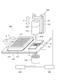
- FIG. 7 is a perspective view for explaining a screening apparatus that identifies and sorts a target specimen from cells on a chip that has been fed by the liquid feeding method of FIG. 6.
- A)-(c) is sectional drawing explaining the modification of the liquid feeding method using the liquid feeding device of FIG.
- A)-(d) is sectional drawing explaining the other modification of the liquid feeding method using the liquid feeding device of FIG.
- A)-(b) is sectional drawing explaining the modification of the liquid feeding device of FIG.
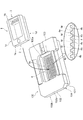
- FIG. 1 is a perspective view schematically showing a configuration of a liquid delivery device according to an embodiment of the present invention, where (a) is an overall view seen from above, (b) is an overall view seen from below, (c) ) Is a view showing a cross section taken along line II of FIG.
- the liquid feeding device 1 in FIG. 1 is a device that can form a closed space with the upper surface of a chip in which at least one well is formed.
- the structure of the liquid feeding device shown in FIG. 1 shows an example, and the liquid feeding device of the present invention is not limited to that shown in FIG.
- the liquid feeding device 1 is disposed at one end 1a (arrow A side in the drawing) of the liquid feeding device, and introduces a liquid into the closed space S. 2, disposed at the other end 1 b (the arrow B side in the drawing) of the liquid feeding device 1, so as to face the discharge portion 3 for discharging the liquid supplied to the closed space S, and the upper surface 4 a of the chip 4. And an upper wall 5 that defines a closed space S.
- the liquid feeding device 1 is integrally formed of an elastic material such as resin or elastomer.
- the elastic material is, for example, a silicone resin (PDMS: dimethylpolysiloxane).
- the chip 4 in which the liquid feeding device 1 is used has a plurality of wells 4b, 4b,... That are arranged on the upper surface 4a and can store fine particles such as cells on a one-to-one basis (see FIG. 2). ).
- the upper surface 4a indicates the side on which the fine particles are introduced in order to accommodate the fine particles.
- Examples of the aligned arrangement of the plurality of wells include a matrix shape and a honeycomb shape (honeycomb structure).
- the chip 4 is, for example, a microwell chamber or an immunochamber, and the well 4b preferably has a size corresponding to one cell.
- the ratio of well diameter / cell diameter is preferably 1.0 to 3.0, more preferably 1.5 to 2.0.
- the liquid feeding device 1 When liquid is fed to the upper surface 4a of the chip 4, the liquid feeding device 1 is disposed so as to cover the upper surface 4a of the chip 4 including the plurality of wells 4b, 4b,. A closed space S is formed between 4a and the upper wall 5 of the liquid feeding device 1.
- the introduction unit 2 is connected to the supply port 21 through which liquid is supplied from the outside, and connected to the supply port 21, and the liquid supply device 1 is placed on the chip 4 placed in plan view, that is, substantially horizontally.
- the chamber 22 extending in the width direction D of the closed space S communicates with the chamber 22 and the closed space S, and the width direction D of the closed space S in plan view. 1st slit part 23 extended over.
- the supply port 21 is a circular hole provided in one end 1a of the liquid feeding device 1 and in the upper part 1c, and a device such as a tubular member is inserted to externally provide a buffer (buffer solution), a cell suspension. Liquids such as cleaning liquids and reagents are supplied.
- the chamber 22 is a rectangular parallelepiped recess provided in the one end 1a and the lower part 1d of the liquid feeding device 1, and the upper part is connected to the supply port 21 and the side part on the other end 1b side is the first slit part. 23.
- the chamber 22 temporarily holds the liquid supplied from the supply port 21 and gradually supplies the liquid in the chamber 22 to the first slit portion 23. It is possible to do.
- the 1st slit part 23 is a recessed part provided in the one end part 1a and the lower part 1d of the liquid feeding device 1, and while the side part by the side of the one end part 1a is connected to the chamber 22, the side part by the side of the other end part 1b Is connected to the closed space S.
- the height of the first slit portion 23 from the upper surface 4 a of the chip 4 is configured to be smaller than the maximum height of the closed space S. Preferred (see FIG. 2).
- the liquid supplied from the chamber 22 is restricted when passing through the first slit portion 23, and a liquid flow F having substantially the same speed in the width direction D of the closed space S is generated in the closed space S.
- the introduction portion 2 is provided with a weir portion having a slight clearance between the top surface 4a of the chip 4 and the slight clearance between the top surface 4a of the chip 4 and the weir portion is the first slit.
- Part 23 is configured. By this weir part, the liquid flow which flows from the chamber 22 to the 1st slit part 23 is controlled.
- the size of the clearance is determined by the length in the width direction D and the resistance of the flow path. For example, if the width direction D is about 15 mm, the clearance is preferably 1 mm or less, and more preferably 0.5 mm or less.
- the discharge unit 3 is connected to the closed space S, is provided between the closed space S and the discharge port 31, the discharge port 31 that discharges the liquid in the closed space S, and extends upward from the closed space S. 2 slits 32.
- the discharge port 31 is a through-hole provided in a frame-shaped leg portion to be described later, and the liquid in the closed space S is discharged to the outside through the discharge port 31 without hindering the liquid flow in the closed space S.
- the second slit portion 32 is a through hole provided on the other end 1 b side of the liquid feeding device 1, and a lower portion thereof is connected to the closed space S and an upper portion is provided in the upper portion 1 c of the liquid feeding device 1. Connected to the recess 6. The air accumulated in the closed space S is discharged to the outside through the discharge port 31 and the second slit portion 32 as the liquid flows in the closed space S.
- the second slit portion 32 preferably extends along the width direction D of the closed space S in a plan view, and preferably extends over the entire width of the closed space S. Thereby, the air accumulated in the closed space S can be reliably discharged.
- the upper wall 5 has a slope 5a provided so that the gap with the tip 4 becomes narrower from the introduction part 2 side toward the discharge part 3 side.
- the inclined surface 5a is preferably an inclined surface having a gradient with respect to the upper surface 4a of the chip 4, and the cross-sectional area of the closed space S in the direction perpendicular to the inclined direction of the inclined surface is the introduction portion 2. It is preferable that it gradually decreases from the side toward the discharge part 3 side.
- the inclined surface 5a is composed of, for example, a uniform plane having a constant inclination or a plurality of planes having different inclinations. In this case, it is preferable that the inclinations of the plurality of planes increase in degree from the introduction part 2 side toward the discharge part 3 side. Further, the inclined surface 5a may be constituted not only by a flat surface but also by a curved surface, or both a curved surface and a flat surface, and may further be constituted by a minute uneven surface having a substantially corrugated cross section.
- the inclined surface 5a is formed in the whole of the plurality of wells 4b when the liquid feeding device 1 is viewed from the upper part 1c in a plan view, that is, in a state where the liquid feeding device 1 is placed on the chip 4 installed substantially horizontally. It is preferable to form in the corresponding position. Specifically, the inclined surface 5a is formed on the entire upper wall 5 in the direction from the introduction part 2 side to the discharge part 3 side, and is perpendicular to the direction from the introduction part 2 side to the discharge part 3 side. It is preferable that the entire upper wall 5 is formed in the direction (width direction). However, it may be formed on a part of the upper wall 5 on the condition that the chip 4 is disposed at a position corresponding to the plurality of wells 4b, that is, directly above the plurality of wells 4b.
- the liquid feeding device 1 includes a frame-like leg portion 7 that is in contact with the upper surface 4a of the chip 4 and is provided so as to surround the closed space S.
- the frame-shaped leg 7 includes a pair of side legs 71 and 71 arranged on both sides in a direction from the introduction part 2 side to the discharge part 3 side, and an introduction side leg part arranged on the introduction part 2 side. 72.
- the frame-shaped leg portion 7 functions as a seal portion that seals between the liquid-feeding device 1 and the chip 4 when the liquid-feeding device 1 is placed on the chip 4.
- the pair of side leg portions 71, 71 form a side wall that defines the width direction end portion of the closed space S
- the introduction side leg portion 72 forms a side wall that defines an end portion on the one end 1 a side of the chamber 22. I am doing.
- the discharge port 31 extends along the width direction D of the closed space S in a plan view between at least the pair of side side legs 71, 71 on the discharge part 3 side of the pair of side legs 71, 71. It is provided to extend.
- the frame-like leg portion 7 does not have a leg portion on the discharge portion 3 side (FIGS. 1A and 1B), the extension length of the discharge port 31 is reduced so that the frame-like leg portion 7 You may comprise so that it may have the discharge
- the discharge-side leg portion is provided in a bridge shape, for example, and the space below it forms the discharge port 31.
- the side view shape of the discharge port 31 may be a polygon such as a rectangle or may be an arch shape.
- the intermittent part formed intermittently regarding the extension direction of the said frame-shaped leg part 7 may be provided in the discharge part 3 side of the frame-shaped leg part 7.
- the intermittent portion provided in the frame-shaped leg portion 7 constitutes the discharge port 31, and the discharge port 31 is provided between the pair of side leg portions 71 and 71.
- FIG. 2A and 2B are diagrams for explaining a closed flow path formed in the closed space S on the chip 4 by the liquid feeding device 1 of FIG. 1, wherein FIG. 2A is a cross-sectional view, and FIG. 2B is a plan view. is there.
- FIG. 2A when the liquid feeding device 1 is placed on the upper surface 4a of the chip 4 in which the plurality of wells 4b are formed, the upper surface 4a of the chip 4 and the inclined surface 5a of the liquid feeding device 1 A closed space S is formed between them, and in this closed space S, a closed flow path 8 of liquid flowing from the introduction portion 2 side toward the discharge portion 3 side is formed.
- a liquid flow F having substantially the same speed in the width direction of the closed space S is generated from the introduction section 2 side to the discharge section 3 side (FIG. 2B).
- the liquid flow F collides with the inclined surface 5a in the closed flow path 8, and the collision causes a reaction force in a direction perpendicular to the inclined surface 5a. Occurs.
- a liquid flow f flowing from the inclined surface 5a to the upper surface 4a of the chip 4, particularly from the inclined surface 5a toward the well 4b on the chip 4 is formed.
- the liquid flow f gives a force for pushing the cell M into the well 4b from above the cell M.
- the closed flow path 8 is caused to collide with the liquid flow F and the inclined surface 5 a from the inclined surface 5 a to the chip 4.
- a liquid flow f flowing toward the upper well 4b is generated, and the cells M are pushed into the well 4b by the liquid flow f, so that they remain in the well 4b, and detachment of the cells M from the well 4b is suppressed. .
- the closed flow path 8 collides with the liquid flow F and the inclined surface 5a as in the above case.
- a liquid flow f flowing from the inclined surface 5a toward the well 4b on the chip 4 is generated. Therefore, by pushing the liquid into the well 4b by the liquid flow f, bubbles or the like in the well 4b can be pushed out of the well 4b, and the liquid is sufficiently supplied into the well 4b.
- the inclined surface 5a is provided so that the gap between the tip 4 and the tip 4 becomes narrower from the introduction part 2 side toward the discharge part 3 side, the liquid flow F of the liquid flow F increases from the introduction part 2 side toward the discharge part 3 side.
- the flow rate increases. Therefore, the cell M in the well 4b located on the downstream side can be pushed more strongly into the well 4b by the liquid flow f generated by the collision between the liquid flow F and the inclined surface 5a, and the cell M from the well 4b can be pushed. Desorption is suppressed.
- FIG. 4 is a perspective view showing a holder for fixing the liquid feeding device 1 of FIG. 1 on the chip 4.
- the holder 100 has fixing members 101 and 102 having a substantially frame structure that can be divided into two vertically, and has an opening 103 at the center in plan view.
- the outer peripheral portion 4 c of the chip 4 is sandwiched by the inner peripheral portion 100 a of the holder 100 from the vertical direction, and thereby the chip 4 is fixed so that the well 4 b is exposed in the opening 103 of the holder 100.
- the liquid feeding device 1 is supported by the chip 4 by inserting the liquid feeding device 1 into the opening 103 and placing the liquid feeding device 1 on the chip 4 fixed to the holder 100. Further, the movement of the liquid feeding device 1 in the lateral direction is restricted by the holder 100, and the liquid feeding device 1 is positioned in the in-plane direction of the chip 4.
- the liquid feeding device 1 manages and adjusts the height of the upper portion 1 c of the liquid feeding device 1 and the upper surface 102 a and the height of the fixing member 102. It is placed on the chip 4. Thereby, the upper part 1c of the liquid feeding device 1 is press-contacted with the upper surface 102a of the fixing member 102 and the fixing tool described later with an arbitrary push allowance.
- the holder 100 has a stepped portion 104 on the outer peripheral portion 100b, and the stepped portion 104 engages with a fixing device described later.
- the length and width of the fixing member 102 are larger than the length and width of the fixing member 101, and the stepped portion 104 is formed on the outer peripheral portion 100 b of the holder 100 in a state where the fixing members 101 and 102 are combined in the vertical direction.
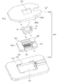
- FIG. 5 is an exploded perspective view showing a fixing device for fixing the holder 100 of FIG. 4 when the liquid is fed onto the chip 4 using the liquid feeding device 1.
- the fixing device 200 includes a base member 210 and a cover member 220 that can be divided into two vertically.
- the base member 210 is a substantially polygonal plate-like body in plan view, and has an opening 211 at the center thereof.
- the cover member 220 is a plate-like body having a polygonal rectangular shape in plan view, and has an opening 221 at the center thereof.
- the thickness of the cover member 220 increases from the one end 1a side to the other end 1b side of the liquid feeding device 1, and when the upper surface 220a of the cover member 220 is horizontally disposed, the lower surface 220b of the cover member 220 is disposed. Are arranged inclined downward.
- the base member 210 has a stepped portion 213 on its inner peripheral portion 212, and the stepped portion 213 engages with the stepped portion 104 of the holder 100 in a state where the holder 100 is inserted into the opening 211. . Thereby, the movement of the holder 100 in the lateral direction is restricted. Further, by placing the cover member 220 on the base member 210 in a state where the stepped portion 213 and the stepped portion 104 are engaged, the movement of the holder 100 in the vertical direction is restricted, and the liquid feeding device 1 Movement in the vertical direction is restricted.
- the liquid-feeding device 1 is provided on the surface of the liquid-feeding device that is not in contact with the chip 4, for example, the upper part 1 c opposite to the frame-like leg 7 of the liquid-feeding device 1, and is pressed toward the upper surface 4 a of the chip 4.
- a possible pressing surface 9 may be further provided.
- the pressing surface 9 is, for example, a frame-like surface provided corresponding to the entire frame-like leg 7, but may be provided on the discharge unit 3 side.
- the lower surface 220 b of the cover member 220 may be provided with a convex surface provided at a position corresponding to the pressing surface 9 and in contact with the pressing surface 9.
- the cover member 220 When the cover member 220 is placed on the base member 210, the pressing surface 9 is pressed with an arbitrary pressing amount by the lower surface 220 b of the cover member 220, and the liquid feeding device 1 comes into pressure contact with the chip 4.
- the discharge port 31 is provided on the discharge portion 3 side of the pair of side leg portions 71 and 71 and there is no leg portion in contact with the upper surface 4 a of the chip 4, the discharge side of the frame-like leg portion 7 is Since it bends relatively larger than the introduction side, the degree of inclination of the inclined surface 5a of the upper wall 5 with respect to the upper surface 4a of the chip 4 can be adjusted.
- the relative pressing amount may be set so that the pressing amount on the discharge portion 3 side is larger than the pressing amount on the introducing portion 2 side.
- the pressing amount on the second side may be set to 0 or substantially 0, and only the pressing amount on the discharge unit 3 side may be set.
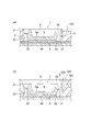
- FIG. 6A to 6E are cross-sectional views illustrating a liquid feeding method using the liquid feeding device of FIG.
- the chip 4 is fixed to the holder 100, and the holder 100 and the liquid feeding device 1 are fixed to the fixing device 200 in a state where the liquid feeding device 1 is placed on the chip 4, and the inclined surface 5a of the liquid feeding device
- the gap with the chip 4 is narrowed from the liquid introduction side (introduction part 2 side) toward the discharge side (discharge part 3 side).
- a closed space S is formed.
- the frame-like leg portion 7 of the liquid feeding device 1 is in contact with or pressed against the chip 4.
- the tubular member 301 is inserted into the supply port 21 to supply the buffer L1 to the chamber 22, and the buffer L1 is introduced into the closed space S through the first slit portion 23.
- the chamber 22, the first slit 23, and the closed space S are filled with the buffer L1.
- air or bubbles in the chamber 22, the first slit portion 23, and the closed space S are removed to the outside through the discharge port 31 or the second slit portion 32.
- the tubular member 302 is inserted into the supply port 21 to supply the cell suspension L2 containing a plurality of cells M to the chamber 22, and the cell suspension L2 is introduced into the closed space S through the first slit portion 23. (FIG. 6B).
- a plurality of cells M contained in the cell suspension L2 are accommodated one by one in the plurality of wells 4b, and the remaining cells M ′ (also referred to as cells outside the well) that are not accommodated in the well 4b are: Deposited on the upper surface 4 a of the chip 4.
- the tubular member 303 is inserted into the supply port 21 to supply the cleaning liquid L3 to the chamber 22, and the cleaning liquid L3 is introduced into the closed space S through the first slit portion 23, and the upper surface 4a of the chip 4 in the closed space S is introduced.
- a closed flow path that flows from the introduction side toward the discharge side is formed between the inclined surface and the inclined surface (FIG. 6C).
- a liquid flow f flowing from the inclined surface 5a toward the cell M is generated on the upper surface 4a of the chip 4 due to a collision between the liquid flow F by the cleaning liquid L3 and the inclined surface 5a of the upper wall 5 (see FIG. 2).
- the second slit portion 32 has a larger flow path resistance than the discharge port 31, and the cleaning liquid L3 containing a part of the cell M ′ can be discharged without flowing backward through the second slit portion 32. It is discharged to the outside through the outlet 31 and is removed from the tubular member 304 as drainage.
- the washing liquid L3 is, for example, a buffer or a cell culture solution.
- the tubular member 305 is inserted in the vicinity of the discharge port 31 to remove the cells M ′ accumulated in the discharge port 31 (FIG. 6D).
- sucking the tubular member 304 external air is introduced into the closed space S through the second slit portion 32. Thereby, the washing
- the fixing device 200 is removed, the liquid feeding device 1 is removed from the chip 4, and the buffer L1 is filled into the upper surface 4a and the well 4b (FIG. 6 (e)). Thereby, the production of the chip 4 in which the buffer L1 containing one cell M is accommodated in each well is completed.
- the supply of various liquids to the supply port 21 and the discharge from the discharge port 31 may be performed manually using a pipette or the like, or provided in equipment such as a screening apparatus described later.
- the introduced pipe / discharge pipe may be connected to the supply port 21 / discharge port 31, respectively, and various liquids may be automatically supplied to the supply port 21 and may be automatically discharged from the discharge port 31.
- the target specimen is identified and sorted from the fine particles on the chip 4 by a screening apparatus as shown in FIG.
- the screening device searches for predetermined fine particles as a target specimen based on fluorescence emitted from a plurality of fine particles such as cells in the chip 4 and selectively aspirates fine particles satisfying the collection condition from the chip 4. It is a device to collect.
- the screening apparatus 400 includes, for example, a moving unit 410, a collecting unit 420, a measuring unit 430, an image analyzing unit 440 (analyzing unit), and a control unit 450.
- the moving unit 410 includes a mounting table 411 that can move along the X direction and / or the Y direction, and the receiving plate 412 and the chip 4 on the mounting table 411 are moved in the X direction and / or the Y direction. It is possible to move and position along.
- the accommodation plate 412 is a plate-like member, and a large number of wells 413 are arranged in a matrix at equal intervals along the X direction and the Y direction on the accommodation plate 412. These wells 413 are recovery storage units that can separately collect and store the fine particles that are sequentially discharged when fine particles such as biological cells are sequentially discharged from a suction / discharge capillary described later. is there.
- the recovery unit 420 includes a base 421 fixed to the apparatus main body, and an operation unit 422 attached to the base 421 so as to be movable in the Z direction.
- the operation unit 422 includes an actuator unit 423 (pump) and a suction / discharge capillary 424 that sorts the identified fine particles as a target sample.
- the suction / discharge capillary 424 can suck one fine particle from a selected well of the plurality of wells 4b, that is, a well containing fine particles satisfying a predetermined collection condition. . Further, the suction / discharge capillary 424 can discharge the selected fine particle to a predetermined well 413 of the storage plate 412.
- the measurement unit 430 irradiates the chip 4 and the fine particles accommodated in the chip 4 with light guided from at least one light source, thereby transmitting and transmitting light, reflected light or shape and position information by fluorescence, and fluorescence / chemistry.
- Luminance information such as light emission is acquired with a resolution finer than the average size of individual fine particles, and information such as the shape of the chip 4 itself and the position coordinates and size of the well 4b on the chip 4 is acquired.
- the image analysis unit 440 analyzes the measured shape information and optical information to acquire data for confirming that there are fine particles satisfying the luminance condition that can be set by the measurer in at least each well 4b. To do. Then, the image analysis unit 440 extracts the light information from the fine particles by matching and collating the position coordinate information of the well 4b with the transmitted light or the reflected light and the light information of the fluorescence / chemiluminescence.
- the measurement unit 430 has an autofocus function, performs measurement in a focused state at a predetermined position, and determines the positional relationship between the distal end portion 424a of the suction / discharge capillary 424 and the upper surface 4a of the chip 4. Can be determined by performing autofocus on
- the control unit 450 comprehensively controls various components of the screening apparatus 400.
- the control unit 450 detects the position of the well 4b in which fine particles that emit fluorescence having the maximum luminance that satisfies the collection conditions are stored. Then, the control unit 450 gives a control drive signal to the moving unit 410 so that the well 4b of the chip 4 or the well 413 of the accommodation plate 412 is positioned directly below the distal end portion 424a of the suction / discharge capillary 424. It is possible.
- the liquid feeding device 1 to which the screening apparatus 400 is detachably attached may be provided as a constituent element, or one system including the screening apparatus 400 and the liquid feeding device may be provided.
- the liquid feeding device 1 includes the upper wall 5 provided so as to face the upper surface 4a of the chip 4 and demarcating the closed space S. Since it has the slope 5a provided so that the clearance gap with the chip
- tip 4 may become narrow toward the discharge part 3 side from the introduction part 2 side, it flows toward the discharge part 3 side from the introduction part 2 side in the closed space S.
- a closed liquid flow path 8 can be formed. Therefore, when the liquid is supplied to the closed space S, a liquid flow f is formed from the inclined surface 5a to the upper surface 4a of the well 4, particularly from the inclined surface 5a to the well 4b, and the cell M in the well 4b is moved from above by the liquid flow f.
- FIG. 8 (a) to 8 (c) are cross-sectional views illustrating a modification of the liquid feeding method using the liquid feeding device of FIG.
- the liquid feeding method has been described focusing on the washing step after the cells M are accommodated in the wells.
- the present invention is not limited to this, and as shown in FIG.
- the liquid feeding method of the present invention can also be applied when performing the surface treatment.
- the configuration of FIG. 8 is basically the same as the configuration of FIG.
- the liquid feeding device 1 is placed on the chip 4, and the upper surface 4a of the chip 4 on which the inclined surface 5a of the liquid feeding device and the plurality of wells 4b are formed.
- the closed space S is formed so that the gap with the tip 4 becomes narrower from the liquid introduction side toward the discharge side.
- the tubular member 301 is inserted into the supply port 21 to supply the buffer L1 to the chamber 22, and the buffer L1 is introduced into the closed space S through the first slit 23 (FIG. 8A).
- the chamber 22, the first slit 23, and the closed space S are filled with the buffer L1.
- the buffer L1 air or bubbles in the chamber 22, the first slit portion 23, and the closed space S are removed to the outside through the discharge port 31 or the second slit portion 32.
- the tubular member 306 is inserted into the supply port 21 to supply the reagent L4 to the chamber 22, and the reagent L4 is introduced into the closed space S through the first slit 23, and the upper surface 4a of the chip 4 in the closed space S and A closed channel that flows from the introduction side toward the discharge side is formed between the inclined surface 5a (FIG. 8B).
- the reagent L4 is, for example, a liquid containing a primary antibody immobilized on the well surface of an immunochamber, or a well surface modifying liquid for expressing hydrophilicity with respect to a cell suspension or the like.
- a liquid flow f flowing from the inclined surface 5a toward the well 4b is generated by the collision between the liquid flow F caused by the reagent L4 and the inclined surface 5a of the upper wall 5 (see FIG. 2).
- the reagent L4 can reach the inner wall surface of the well 4b, the primary antibody is sufficiently fixed to the inner wall surface of the well 4b, and the inner wall surface of the well 4b is sufficiently modified. Can do.
- the tubular member 301 is inserted into the supply port 21 to supply the buffer L1 to the chamber 22, the buffer L1 is introduced into the closed space S through the first slit 23, the inside of the closed space S is washed, The reagent L4 is removed from the closed space S (FIG. 8C). The reagent L4 is discharged to the outside through the discharge port 31, and is removed as drainage by the tubular member 307.
- the reagent L4 when the reagent L4 is introduced into the closed space S, the liquid flow f flowing from the inclined surface 5a toward the well 4b of the chip 4 is generated, and thereby, the entire inner wall surface of the well 4b is formed. Since the reagent L4 can be reached, the entire inner wall surface of the well 4b can be sufficiently surface-treated. Further, the reagent L4 can reach all the wells 4b arranged in a matrix on the chip 4. Therefore, it is possible to further suppress the recovery of the cell M as a target sample and to further improve the recovery efficiency of the cell M in a single particle unit.
- FIG. 9 (a) to 9 (d) are cross-sectional views for explaining another modification of the liquid feeding method using the liquid feeding device of FIG.
- the method for performing surface treatment by filling the well 4b with the reagent using the liquid feeding method of the present invention has been described.
- the present invention is not limited to this, and the reagent is supplied to the cells M in the well 4b.
- the liquid feeding method of the present invention can also be applied when the cells M are reacted.
- the configuration of FIG. 9 is basically the same as the configuration of FIG.
- the reagent L5 is, for example, a liquid containing a fluorescent molecule such as a fluorescent secondary antibody that binds to a product produced from a cell or the like, or a stimulant A that reacts with a specific cell. Examples include sweet extracts that stimulate the taste of cells.
- a liquid flow f flowing from the inclined surface 5a toward the well 4b is generated by the collision between the liquid flow F caused by the reagent L5 and the inclined surface 5a of the upper wall 5 (see FIG. 2). With this liquid flow f, the reagent L5 can reliably reach the cells M accommodated in the well 4b, and the cells M in the well 4b can be reacted accurately.
- the reagent L5 is a stimulant A that reacts with cells
- the same stimulus can be given to the cells M in the well 4b by measuring and analyzing optical information while feeding the stimulant A, Target cells can be identified by accurately grasping the degree of reaction.
- the tubular member 301 is inserted into the supply port 21 to supply the buffer L1 to the chamber 22, the buffer L1 is introduced into the closed space S through the first slit 23, the inside of the closed space S is washed, and the closed The reagent L5 is removed from the space S (FIG. 9 (c)). The reagent L5 is discharged to the outside through the discharge port 31.
- the tubular member 309 is inserted into the supply port 21 to supply the reagent L6 to the chamber 22, the reagent L6 is introduced into the closed space S through the first slit 23, and the closed space S is filled with the reagent L6.
- the reagent L6 is, for example, another stimulant B that reacts with specific cells, and examples of the stimulant B include sour extracts that stimulate taste to taste cells.
- the specific stimulant A and the stimulant B the target cells can be selected in a more complex manner.
- the reagent L5 when the reagent L5 is introduced into the closed space S, the liquid flow f flowing from the inclined surface 5a toward the well 4b of the chip 4 is generated, and thereby the cell M accommodated in the well 4b. Since the reagent L5 can be made to reach the cell M, the cells M in the well 4b can be reacted accurately. Further, the reagent L5 can reach all the cells M housed in the plurality of wells 4b on the chip 4 one by one. Therefore, it is possible to further suppress the recovery of the cell M as a target sample and to further improve the recovery efficiency of the cell M in a single particle unit.
- liquid feeding device and the liquid feeding method according to the present embodiment have been described above.
- the present invention is not limited to the described embodiments, and various modifications and changes can be made based on the technical idea of the present invention. is there.
- the upper wall 5 of the liquid feeding device 1 has the inclined surface 5a.
- the upper wall 5 is not limited to this, and the upper wall does not have the inclined surface.
- the wall may have a slope.
- the liquid feeding device 1 ′ is provided so as to face the upper surface 4 a of the chip 4, and includes an upper wall 5 ′ that defines a closed space S, and the upper wall 5 ′ is The surface 5 a ′ substantially parallel to the chip 4 may be provided.
- the surface 5 a ′ is substantially parallel to the upper surface 4 a of the chip 4 when placed on the chip 4 fixed to the holder 100, and the holder 100 and the liquid feeding device 1 are attached to the fixing device 200.
- the pressing surface 9 of the liquid feeding device 1 ′ is pressed downward by the cover member 220, and the discharge side of the frame-like leg portion 7 is most bent, so that the surface 5 a ′ is on the introduction portion 2 side. Is disposed obliquely so that the gap with the chip 4 becomes narrower toward the discharge unit 3 side (FIG. 10B).
Landscapes
- Health & Medical Sciences (AREA)
- Life Sciences & Earth Sciences (AREA)
- Chemical & Material Sciences (AREA)
- Engineering & Computer Science (AREA)
- Bioinformatics & Cheminformatics (AREA)
- Wood Science & Technology (AREA)
- Organic Chemistry (AREA)
- Zoology (AREA)
- Biotechnology (AREA)
- General Health & Medical Sciences (AREA)
- Genetics & Genomics (AREA)
- Microbiology (AREA)
- Sustainable Development (AREA)
- Biochemistry (AREA)
- General Engineering & Computer Science (AREA)
- Biomedical Technology (AREA)
- Clinical Laboratory Science (AREA)
- Molecular Biology (AREA)
- Medicinal Chemistry (AREA)
- Analytical Chemistry (AREA)
- Cell Biology (AREA)
- Dispersion Chemistry (AREA)
- Hematology (AREA)
- Chemical Kinetics & Catalysis (AREA)
- Apparatus Associated With Microorganisms And Enzymes (AREA)
- Automatic Analysis And Handling Materials Therefor (AREA)
Abstract
作業性の向上を実現しつつ、微細粒子の一粒子単位での回収効率を向上することができる送液デバイスを提供する。 送液デバイス(1)は、該送液デバイスの一端部(1a)に配置され、閉空間(S)に液体を導入する導入部(2)と、送液デバイス(1)の他端部(1b)に配置され、閉空間(S)に供給された液体を排出する排出部(3)と、チップ(4)の上面(4a)に対向するように設けられ、閉空間(S)を画定する上壁(5)とを備える。上壁(5)は、導入部(2)側から排出部(3)側に向かってチップ(4)との隙間が狭くなるように設けられた斜面(5a)を有する。
Description
本発明は、細胞などの微細粒子が一粒子単位で収容されるウェルが形成されたチップに載置されて、該チップとの間に閉空間を形成可能な送液デバイスに関する。
従来、微細粒子のスクリーニング装置は、細胞などの微小物検体を識別、分取するための装置として、医療分野の研究・検査などで広く使用されている。そして近年、研究・検査機関において、検体破壊を伴わない識別、分取を実現すると共に、これらの処理をより正確に行うことで研究・検査の効率を高めたいとの要望がある。特に、所定分野においては、一細胞単位で識別・分取したいとの要望が高まっていることから、このような一細胞単位での識別・分取処理においても、正確性の向上や高効率化が求められている。
例えば、細胞を一細胞単位で識別、分取処理を正確且つ効率的に行う方法の一つとして、チップ上に形成されたマイクロチャンバーと呼ばれる複数の微小なウェルに複数の細胞を一つずつ収容する方法が挙げられる。これにより、スクリーニング装置における計測感度が高くなると共に、一細胞単位で吸引・吐出可能なキャピラリを用いて目的検体のみを回収することができ、また、細胞懸濁液に含まれる目的検体の取りこぼしを少なくすることが可能となっている。
上記のようなマイクロチャンバーチップに適用される従来の送液デバイスとして、複数のマイクロウェルが形成されたチップと、複数のマイクロチャンバーチップ上にマイクロ流路が形成されるように配置された流路形成枠体と、流路形成枠体に設けられた入口部と、入口部からマイクロ流路に導入された細胞懸濁液をマイクロ流路から導出させるために流路形成枠体に設けられた出口部とを備える細胞展開用デバイスが提案されている(特許文献1)。このデバイスでは、チップ上にマイクロ流路を形成し、該マイクロ流路にてチップ上面に略平行な液流れを発生させている。
また、他の従来の送液デバイスとして、本体と、該本体の上部に着脱可能に取り付けられる蓋部とを有し、培養室が本体に形成されると共に培地排出流路が蓋部に形成され、更に多孔質フィルタが本体と蓋部の間に配置された細胞培養デバイスが提案されている(特許文献2)。このデバイスでは、培養室に足場材(細胞培養担体)をコーティングして細胞培養を行った場合に、使用中に剥離した足場材が多孔質フィルタによって捕捉できるとされている。
チップ上に試薬や洗浄液を送液する際には、試薬の流速を上げないと反応にばらつきが出たり、細胞と均一に反応せず、また、洗浄液の流速が遅いと洗浄力が弱く、ウェルに収容されなかった細胞を洗浄することができないため、チップ上で流速を上げる必要がある。しかしながら、特許文献1の技術では、液体の流速をある程度以上に上げるとウェル内に収容された細胞が浮き上がって抜け出してしまう場合があり、目的検体となる細胞の回収効率が低下するという問題がある。
また、特許文献2の技術では、本体に設けられた1つの孔部が培養室を形成しており、蓋部を閉じることで培養室が閉空間となる構造が設けられている程度であり、複数の細胞を一つずつ収容可能な複数のウェルが形成されたチップ上に送液する構成とは基本的に異なる。
特に、希少細胞を目的検体として回収する場合、例えば数十万細胞から数個しかないような細胞を回収することになるため、目的検体を回収対象とするためにはチップ上の複数のウェルに一細胞単位で収容される細胞の収容数を多くすることが非常に重要である。細胞の収容数を多くするため、通常はウェル数よりも多い例えば1.5~2倍の数の細胞を含む細胞懸濁液をチップ上に導入して、複数のウェル内に一細胞単位で収容し、ウェル内に収容されなかった残りの細胞は、チップ上面に洗浄液を導入することによりチップ上から除去される。しかしながら、上記従来技術では、チップ洗浄時に各ウェルに収容された細胞までもが洗浄液によってウェルから抜け出して除去されてしまう場合があるため、チップでの上記収容数の低下を招き、希少細胞を効率的に回収することができず、貴重な細胞を喪失してしまうという問題がある。
また、開空間にてウェル内に細胞が収容された状態でチップ上面を洗浄液で洗浄する際、チップ上面の洗浄液を抜き取ることでチップ上面に平行な方向の液流れを生じさせ、ウェル内に収容されなかったチップ上の細胞を除去している。しかしながら、この方法では開空間ゆえに流れ易いところを洗浄液が流れるため、抵抗の大きいチップ上面付近には液体が抜ける瞬間にしか十分な液流れが生じず、チップ上の細胞を1回では十分に除去することができない。そのため、再びチップ上面に洗浄液を供給し、チップ上面の洗浄液を抜き取る洗浄を複数回繰り返す必要があるが、このチップ上面への洗浄液供給の際に、開空間ゆえにウェル内では上方向に巻き上げる液流れが生じ易く、その結果ウェル内に収容された細胞が抜け出してしまう場合がある。つまり洗浄力が弱いために洗浄を繰り返し、洗浄を繰り返すほどウェルに収容される細胞の数が低下するため、希少細胞の回収効率の低下、喪失を招く。
本発明の目的は、作業性の向上を実現しつつ、微細粒子の一粒子単位での回収効率を向上することができる送液デバイス及び送液方法を提供することにある。
上記目的を達成するために、本発明の送液デバイスは、微細粒子を収容するための少なくとも1つのウェルが形成されたチップの上面との間に閉空間を形成可能な送液デバイスであって、前記送液デバイスの一端側に配置され、前記閉空間に液体を導入する導入部と、前記送液デバイスの他端側に配置され、前記閉空間に供給された液体を排出する排出部と、前記チップの上面に対向するように設けられ、前記閉空間を画定する上壁と、を備え、前記上壁は、前記導入部側から前記排出部側に向かって前記チップとの隙間が狭くなるように設けられた斜面を有することを特徴とする。
前記閉空間内に、前記導入部側から前記排出部側に向かって流れる液体の閉流路が形成される。
前記閉流路は、前記斜面から前記チップの上面に向かって流れる液流れを発生させる。
前記斜面は、前記チップの上面に対して勾配を有する傾斜面であり、前記傾斜面の傾斜方向に対して垂直な方向における前記閉空間の断面積が、前記導入部側から前記排出部側に向かって漸減しているのが好ましい。
前記チップは、前記チップの上面に整列配置された複数のウェルを有し、前記斜面が、平面視において前記複数のウェルの全体に対応する位置に形成されているのが好ましい。
前記導入部は、外部から液体が供給される供給口と、前記供給口に接続され、平面視において前記閉空間の幅方向に延出したチャンバと、前記チャンバと前記閉空間とを連通すると共に、平面視において前記閉空間の幅方向に亘って延出した第1スリット部と、を有する。
前記第1スリット部の高さが、前記閉空間の最大高さよりも小さいのが好ましい。
前記排出部は、前記閉空間に接続され、該閉空間の液体を外部に排出する排出口と、前記閉空間と前記排出口との間に設けられ、前記閉空間から上方に延出した第2スリット部と、を有する。
前記送液デバイスは、前記チップの上面に当接すると共に、前記閉空間を囲繞するように設けられた枠状脚部を更に備え、前記枠状脚部は、前記導入部側から前記排出部側に向かう方向の両側に配置された一対の側方側脚部と、前記導入部側に配置された導入側脚部とを有し、前記枠状脚部の前記排出部側に間欠部が設けられる。
前記枠状脚部に設けられた前記間欠部が前記排出口を構成し、前記排出口が、前記一対の側方側脚部の前記排出部側において、当該一対の側方側脚部の間に設けられる。
前記送液デバイスの前記チップと接していない面に、前記チップの上面に向かって押圧可能な押圧面を更に備え、前記押圧面が、前記排出部側に設けられる。
前記送液デバイスは、弾性材料で一体成形されているのが好ましい。
上記目的を達成するために、本発明の送液方法は、微細粒子を収容するための少なくとも1つのウェルが形成されたチップの上面との間に、液体を導出入可能な閉空間を形成して、前記チップの上面に液体を導入出する送液方法であって、前記液体の導入側から排出側に向かって前記チップとの隙間が狭くなるように閉空間を形成し、前記閉空間に液体を導入して、前記閉空間内に、前記導入側から前記排出側に向かって流れる閉流路を形成することを特徴とする。
前記送液方法において、前記閉流路によって前記チップの上面に向かって流れる液流れを発生させる。
本発明によれば、作業性の向上を実現しつつ、微細粒子の一粒子単位での回収効率を向上することができる。
以下、本発明の実施形態を図面を参照しながら詳細に説明する。
[送液デバイスの構成]
図1は、本発明の実施形態に係る送液デバイスの構成を概略的に示す斜視図であり、(a)は上方から見た全体図、(b)は下方から見た全体図、(c)は(a)の線I-Iに沿う断面を示す図である。図1の送液デバイス1は、少なくとも1つのウェルが形成されたチップの上面との間に閉空間を形成可能なデバイスである。尚、図1に示す送液デバイスの構成は一例を示すものであり、本発明の送液デバイスは図1に示すものに限られない。
図1は、本発明の実施形態に係る送液デバイスの構成を概略的に示す斜視図であり、(a)は上方から見た全体図、(b)は下方から見た全体図、(c)は(a)の線I-Iに沿う断面を示す図である。図1の送液デバイス1は、少なくとも1つのウェルが形成されたチップの上面との間に閉空間を形成可能なデバイスである。尚、図1に示す送液デバイスの構成は一例を示すものであり、本発明の送液デバイスは図1に示すものに限られない。
送液デバイス1は、図1(a)~(c)に示すように、該送液デバイスの一端部1a(図中の矢印A側)に配置され、閉空間Sに液体を導入する導入部2と、送液デバイス1の他端部1b(図中の矢印B側)に配置され、閉空間Sに供給された液体を排出する排出部3と、チップ4の上面4aに対向するように設けられ、閉空間Sを画定する上壁5とを備える。この送液デバイス1は、樹脂やエラストマーなどの弾性材料で一体成形されている。上記弾性材料は、例えばシリコーン樹脂(PDMS:dimethylpolysiloxane)である。
送液デバイス1が用いられるチップ4は、その上面4aに整列配置され、細胞などの微細粒子を一対一で収容可能な複数のウェル4b,4b,・・・を有している(図2参照)。ここで、上面4aは、微細粒子の収容するために微細粒子を投入する側を指す。また、複数のウェルの整列配置とは、例えばマトリックス状、蜂の巣状(ハニカム構造)などが挙げられる。このチップ4は、例えばマイクロウェルチャンバーやイムノチャンバーであり、ウェル4bは一つの細胞に対応する大きさを有しているのが好ましい。ウェル径/細胞径の比は、1.0~3.0が好ましく、1.5~2.0がより好ましい。チップ4の上面4aに液体を送液する際、送液デバイス1は、複数のウェル4b,4b,・・・を含むチップ4の上面4aを覆うように配置されることで、チップ4の上面4aと送液デバイス1の上壁5との間に閉空間Sが形成される。
導入部2は、外部から液体が供給される供給口21と、供給口21に接続され、平面視、すなわち略水平に設置されたチップ4上に送液デバイス1を載置した状態で該送液デバイス1を上部1c側から見たときに、閉空間Sの幅方向Dに延出したチャンバ22と、チャンバ22と閉空間Sとを連通すると共に、平面視において閉空間Sの幅方向Dに亘って延出した第1スリット部23とを有する。
供給口21は、送液デバイス1の一端部1aであって且つ上部1cに設けられた円形孔であり、管状部材等の器具が挿入されて、外部からバッファ(緩衝液)、細胞懸濁液、洗浄液、試薬などの液体が供給される。
チャンバ22は、送液デバイス1の一端部1a且つ下部1dに設けられた直方体の凹部であり、その上部が供給口21に接続されると共に、他端部1b側の側部が第1スリット部23に接続されている。送液デバイス1がチップ4上に載置された状態において、チャンバ22は、供給口21から供給された液体を一時的に保持し、チャンバ22内の液体を徐々に第1スリット部23に供給することが可能になっている。
第1スリット部23は、送液デバイス1の一端部1a且つ下部1dに設けられた凹部であり、一端部1a側の側部がチャンバ22に接続されると共に、他端部1b側の側部が閉空間Sに接続される。送液デバイス1がチップ4上に載置された状態において、チップ4の上面4aからの第1スリット部23の高さが、閉空間Sの最大高さよりも小さくなるように構成されるのが好ましい(図2参照)。これにより、チャンバ22から供給された液体が第1スリット部23を通過する際に規制され、閉空間S内で、該閉空間Sの幅方向Dに関してほぼ同じ速度の液流れFを発生させることが可能となっている。換言すれば、導入部2にはチップ4の上面4aとの間に僅かなクリアランスを有する堰部が設けられており、チップ4の上面4aと堰部との間の僅かなクリアランスが第1スリット部23を構成する。この堰部によって、チャンバ22から第1スリット部23に流れる液流れが規制される。クリアランスのサイズは幅方向Dの長さと流路の抵抗により決定されるが、例えば幅方向Dが15mm程度であればクリアランスは1mm以下が好ましく、0.5mm以下がより好ましい。
排出部3は、閉空間Sに接続され、該閉空間Sの液体を排出する排出口31と、閉空間Sと排出口31との間に設けられ、閉空間Sから上方に延出した第2スリット部32とを有する。
排出口31は、後述する枠状脚部に設けられた貫通孔であり、閉空間Sの液流れを妨げること無く、閉空間Sの液体が排出口31を介して外部に排出される。
第2スリット部32は、送液デバイス1の他端部1b側に設けられた貫通孔であり、その下部が閉空間Sに接続されると共に、上部が送液デバイス1の上部1cに設けられた凹部6に接続されている。閉空間S内に溜まった空気は、閉空間Sの液流れに伴って、排出口31および第2スリット部32を介して外部に排出される。第2スリット部32は、平面視において閉空間Sの幅方向Dに沿って延出しているのが好ましく、また、閉空間Sの幅全体に亘って延出しているのが好ましい。これにより、閉空間S内に溜まった空気を確実に排出することができる。
上壁5は、導入部2側から排出部3側に向かってチップ4との隙間が狭くなるように設けられた斜面5aを有する。この斜面5aは、チップ4の上面4aに対して勾配を有する傾斜面であるのが好ましく、また、該傾斜面の傾斜方向に対して垂直な方向における閉空間Sの断面積が、導入部2側から排出部3側に向かって漸減しているのが好ましい。
斜面5aは、例えば傾き一定の一様な平面や、傾きの異なる複数の平面で構成される。この場合、複数の平面の傾きは、導入部2側から排出部3側に向かって傾きの度合いが大きくなるのが好ましい。また、斜面5aは、平面のみならず、曲面、或いは曲面及び平面の双方で構成されてもよく、更には、断面略波形などの微小凹凸面で構成されてもよい。
斜面5aは、平面視、すなわち略水平に設置されたチップ4上に送液デバイス1を載置した状態で該送液デバイス1を上部1c側から見たときに、複数のウェル4bの全体に対応する位置に形成されているのが好ましい。具体的には、斜面5aは、導入部2側から排出部3側に向かう方向に関して上壁5の全体に形成され、また、導入部2側から排出部3側に向かう方向に対して垂直な方向(幅方向)に関して上壁5の全体に亘って形成されているのが好ましい。但し、チップ4上の複数のウェル4bに対応する位置、すなわち複数のウェル4bの直上に配置されていることを条件として、上壁5の一部に形成されていてもよい。
また、送液デバイス1は、チップ4の上面4aに当接すると共に、閉空間Sを囲繞するように設けられた枠状脚部7を備えている。この枠状脚部7は、導入部2側から排出部3側に向かう方向の両側に配置された一対の側方側脚部71,71と、導入部2側に配置された導入側脚部72とを有する。枠状脚部7は、送液デバイス1がチップ4上に載置されたときに、送液デバイス1とチップ4との間をシールするシール部として機能する。
一対の側方側脚部71,71は、閉空間Sの幅方向端部を画定する側壁をなしており、導入側脚部72は、チャンバ22の一端部1a側の端部を画定する側壁をなしている。排出口31は、一対の側方側脚部71,71の排出部3側において、少なくとも当該一対の側方側脚部71,71の間に、平面視において閉空間Sの幅方向Dに沿って延出して設けられている。
枠状脚部7は排出部3側に脚部を有していないが(図1(a),(b))、排出口31の延出長さを小さくして、枠状脚部7が排出部3側に配置された排出側脚部を有するように構成されてもよい。この場合、上記排出側脚部は例えば橋状に設けられて、その下方の空間が排出口31を構成する。排出口31の側面視形状は、矩形などの多角形であってもよいし、アーチ型であってもよい。
また、枠状脚部7の排出部3側に、当該枠状脚部7の延在方向に関して間欠的に形成された間欠部が設けられてもよい。この場合、枠状脚部7に設けられた間欠部が排出口31を構成し、排出口31が、一対の側方側脚部71,71の間に設けられる。
このような構成とすることで、送液デバイス1に対して上部1b側から下部1d側に向かって押圧力を加えたとき、枠状脚部7の排出部3側を導入部2側よりも弾性変形し易くすることができる。
また、枠状脚部7の排出部3側に、当該枠状脚部7の延在方向に関して間欠的に形成された間欠部が設けられてもよい。この場合、枠状脚部7に設けられた間欠部が排出口31を構成し、排出口31が、一対の側方側脚部71,71の間に設けられる。
このような構成とすることで、送液デバイス1に対して上部1b側から下部1d側に向かって押圧力を加えたとき、枠状脚部7の排出部3側を導入部2側よりも弾性変形し易くすることができる。
図2は、図1の送液デバイス1によってチップ4上の閉空間S内に形成される閉流路を説明するための図であり、(a)は断面図、(b)は平面図である。
図2(a)に示すように、複数のウェル4bが形成されたチップ4の上面4aに送液デバイス1が載置されると、チップ4の上面4aと送液デバイス1の斜面5aとの間に閉空間Sが形成され、この閉空間S内に、導入部2側から排出部3側に向かって流れる液体の閉流路8が形成される。閉流路8に液体を供給すると、導入部2側から排出部3側に向かって、閉空間Sの幅方向に関してほぼ同じ速度の液流れFが生じる(図2(b))。
図2(a)に示すように、複数のウェル4bが形成されたチップ4の上面4aに送液デバイス1が載置されると、チップ4の上面4aと送液デバイス1の斜面5aとの間に閉空間Sが形成され、この閉空間S内に、導入部2側から排出部3側に向かって流れる液体の閉流路8が形成される。閉流路8に液体を供給すると、導入部2側から排出部3側に向かって、閉空間Sの幅方向に関してほぼ同じ速度の液流れFが生じる(図2(b))。
このとき、ウェル4b近傍を微視的に見ると、図3に示すように、閉流路8において液流れFが斜面5aに衝突し、該衝突によって斜面5aに対して垂直な方向に反力が生じる。この反力の作用によって、斜面5aからチップ4の上面4a、特に斜面5aからチップ4上のウェル4bに向かって流れる液流れfが形成される。この液流れfは、細胞Mの上方から、該細胞Mをウェル4b内に押し込む力を与える。
よって、例えばチップ4の各ウェル内に細胞Mが収容された状態で閉流路8に液体を供給した場合、閉流路8は、液流れFと斜面5aとの衝突によって斜面5aからチップ4上のウェル4bに向かって流れる液流れfを発生させ、細胞Mがこの液流れfによってウェル4b内に押し込まれることでウェル4b内に留まり、ウェル4bからの細胞Mの脱離が抑制される。
また、チップ4の各ウェル内に細胞Mが収容されてない状態で閉流路8に液体を供給した場合、閉流路8は、上記の場合と同様、液流れFと斜面5aとの衝突によって斜面5aからチップ4上のウェル4bに向かって流れる液流れfを発生させる。よって、この液流れfによって当該液体をウェル4b内に押し込むことで、ウェル4b内の気泡等をウェル4b外に押し出すことができ、液体がウェル4b内に十分に供給される。
また、斜面5aが導入部2側から排出部3側に向かってチップ4との隙間が狭くなるように設けられているため、導入部2側から排出部3側に向かうに従って、液流れFの流速が大きくなる。よって、液流れFと斜面5aとの衝突によって生じる液流れfによって、下流側に位置するウェル4b内の細胞Mを、当該ウェル4b内に更に強く押し込むことができ、ウェル4bからの細胞Mの脱離が抑制される。
図4は、図1の送液デバイス1をチップ4上に固定するホルダーを示す斜視図である。
同図に示すように、ホルダー100は、上下に2分割可能な略枠体構造の固定部材101,102を有しており、平面視中央部に開口部103を有する。チップ4の外周部4cは、上下方向からホルダー100の内周部100aに挟持されており、これによりホルダー100の開口部103にウェル4bが露出するようにチップ4が固定されている。
同図に示すように、ホルダー100は、上下に2分割可能な略枠体構造の固定部材101,102を有しており、平面視中央部に開口部103を有する。チップ4の外周部4cは、上下方向からホルダー100の内周部100aに挟持されており、これによりホルダー100の開口部103にウェル4bが露出するようにチップ4が固定されている。
開口部103に送液デバイス1を挿入し、ホルダー100に固定されたチップ4上に送液デバイス1を載置することにより、送液デバイス1がチップ4に支持される。また、送液デバイス1の横方向への移動がホルダー100によって規制され、送液デバイス1がチップ4の面内方向に位置決めされる。
送液デバイス1は、該送液デバイス1とチップ4との間をシールするために、送液デバイス1の上部1cの高さと固定部材102の上面102aと高さとを管理、調節した状態で、チップ4上に載置される。これにより、送液デバイス1の上部1cが固定部材102の上面102aと後述する固定器具にて任意の押し代をもって圧接される。
また、ホルダー100は、外周部100bに段付き部104を有しており、この段付き部104が後述する固定器具と係合する。固定部材102の長さ及び幅は、固定部材101の長さ及び幅よりも大きく、固定部材101,102を上下方向に組み合わせた状態で、ホルダー100の外周部100bに段付き部104が形成される。
図5は、送液デバイス1を用いてチップ4上に送液する際に図4のホルダー100を固定する固定器具を示す分解斜視図である。
同図に示すように、固定器具200は、上下に2分割可能なベース部材210及びカバー部材220を有している。ベース部材210は、平面視略多角形の板状体であり、その中央部に開口部211を有している。カバー部材220も同様、平面視多角矩形の板状体であり、その中央部に開口部221を有している。カバー部材220の厚みは、送液デバイス1の一端部1a側から他端部1b側に向かって増大しており、カバー部材220の上面220aが水平に配置されたとき、カバー部材220の下面220bが下方に傾斜して配置される。
同図に示すように、固定器具200は、上下に2分割可能なベース部材210及びカバー部材220を有している。ベース部材210は、平面視略多角形の板状体であり、その中央部に開口部211を有している。カバー部材220も同様、平面視多角矩形の板状体であり、その中央部に開口部221を有している。カバー部材220の厚みは、送液デバイス1の一端部1a側から他端部1b側に向かって増大しており、カバー部材220の上面220aが水平に配置されたとき、カバー部材220の下面220bが下方に傾斜して配置される。
ベース部材210は、その内周部212に段付き部213を有しており、ホルダー100が開口部211に挿入された状態で、段付き部213がホルダー100の段付き部104と係合する。これによりホルダー100の横方向の移動が規制される。また、段付き部213と段付き部104を係合させた状態でベース部材210にカバー部材220を載置することで、ホルダー100の上下方向への移動が規制されると共に、送液デバイス1の上下方向の移動が規制される。
送液デバイス1は、該送液デバイスのチップ4と接していない面、例えば送液デバイス1の枠状脚部7とは反対側の上部1cに設けられ、チップ4の上面4aに向かって押圧可能な押圧面9を更に備えてもよい。押圧面9は、例えば枠状脚部7全体に対応して設けられた枠状面であるが、排出部3側に設けられてもよい。また、カバー部材220の下面220bには、押圧面9に対応する位置に設けられ且つ押圧面9に接するような凸面を備えていてもよい。ベース部材210にカバー部材220が載置されたときに、押圧面9がカバー部材220の下面220bによって任意の押圧量で押圧され、送液デバイス1がチップ4と圧接する。このとき、一対の側方側脚部71,71の排出部3側には排出口31が設けられておりチップ4の上面4aに接する脚部が無いため、枠状脚部7のうち排出側が導入側よりも相対的に大きく撓むため、チップ4の上面4aに対する上壁5の斜面5aの斜めの度合いを調整することができる。この斜面5aの斜めの度合いを調整するために、排出部3側の押圧量が導入部2側の押圧量よりも大きくなるように相対的な押圧量を設定してもよく、また、導入部2側の押圧量を0或いはほぼ0とし、排出部3側の押圧量のみを設定してもよい。
[送液デバイスを用いた送液方法]
図6(a)~(e)は、図1の送液デバイスを用いた送液方法を説明する断面図である。先ず、チップ4をホルダー100に固定すると共に、更にチップ4上に送液デバイス1を載置した状態でホルダー100と送液デバイス1を固定器具200に固定して、送液デバイスの斜面5aと複数のウェル4bが形成されたチップ4の上面4aとの間に、液体の導入側(導入部2側)から排出側(排出部3側)に向かってチップ4との隙間が狭くなるように閉空間Sを形成する。このとき、送液デバイス1の枠状脚部7がチップ4上に当接又は圧接する。
図6(a)~(e)は、図1の送液デバイスを用いた送液方法を説明する断面図である。先ず、チップ4をホルダー100に固定すると共に、更にチップ4上に送液デバイス1を載置した状態でホルダー100と送液デバイス1を固定器具200に固定して、送液デバイスの斜面5aと複数のウェル4bが形成されたチップ4の上面4aとの間に、液体の導入側(導入部2側)から排出側(排出部3側)に向かってチップ4との隙間が狭くなるように閉空間Sを形成する。このとき、送液デバイス1の枠状脚部7がチップ4上に当接又は圧接する。
次に、供給口21に管状部材301を挿通してチャンバ22にバッファL1を供給し、第1スリット部23を介して閉空間SにバッファL1を導入する。これによりチャンバ22、第1スリット部23、閉空間SにバッファL1が充填される。また、バッファL1の導入により、チャンバ22、第1スリット部23及び閉空間Sの空気或いは気泡が、排出口31または第2スリット部32を介して外部に除去される。
次いで、供給口21に管状部材302を挿通してチャンバ22に複数の細胞Mを含む細胞懸濁液L2を供給し、第1スリット部23を介して閉空間Sに細胞懸濁液L2を導入する(図6(b))。これにより、細胞懸濁液L2に含まれる複数の細胞Mが1つずつ複数のウェル4b内に収容され、ウェル4b内に収容されなかった残りの細胞M’(ウェル外細胞ともいう)は、チップ4の上面4a等に堆積する。
次いで、供給口21に管状部材303を挿通してチャンバ22に洗浄液L3を供給し、第1スリット部23を介して閉空間Sに洗浄液L3を導入し、閉空間S内におけるチップ4の上面4aと斜面との間に、上記導入側から排出側に向かって流れる閉流路を形成する(図6(c))。このとき、チップ4の上面4a上では洗浄液L3による液流れFと上壁5の斜面5aとの衝突により、斜面5aから細胞Mに向かって流れる液流れfが生じる(図2参照)。これにより、ウェル4b内に収容された細胞Mは洗浄液L3によって洗い流されることなくウェル4b内に保持され、一方、チップ4の上面4aの細胞M’は洗浄液L3によって洗い流される。第2スリット部32は排出口31に比べて流路抵抗が大きく作られており、細胞M’の一部を含む洗浄液L3は、第2スリット部32を介して外部に逆流すること無く、排出口31を介して外部に排出され、管状部材304から排液として除去される。洗浄液L3は例えばバッファや、細胞培養液である。
次に、排出口31近傍に管状部材305を挿入して、排出口31に溜まった細胞M’を除去する(図6(d))。管状部材304の吸引時には外部の空気が第2スリット部32を介して閉空間Sに導入される。これにより、閉空間S内の洗浄液L3が吸引されず、細胞Mがウェル4b内に収容された状態を維持することができる。
その後、固定器具200を取り外して送液デバイス1をチップ4上から除去し、上面4a上及びウェル4b内にバッファL1を充填する(図6(e))。これにより、各ウェルに1つの細胞Mを含むバッファL1が収容されたチップ4の作製が完了する。
尚、上記送液方法において、各種液体の供給口21への供給及び排出口31からの排出は、ピペットなどを用いて手動で行われてもよいし、後述するスクリーニング装置などの設備機器に設けられた導入管/排出管を供給口21/排出口31にそれぞれ接続し、各種液体が自動的に供給口21に供給され、また、自動的に排出口31から排出されてもよい。
[スクリーニング装置の構成]
図6に示す送液方法が実行された後、例えば図7に示すようなスクリーニング装置によってチップ4上の微細粒子から目的検体が識別・分取処理される。スクリーニング装置とは、チップ4内の細胞などの複数の微細粒子が発する蛍光に基づいて目的検体となる所定の微細粒子を探索して、回収条件を満たした微細粒子をチップ4から選択的に吸引、回収する装置である。
図6に示す送液方法が実行された後、例えば図7に示すようなスクリーニング装置によってチップ4上の微細粒子から目的検体が識別・分取処理される。スクリーニング装置とは、チップ4内の細胞などの複数の微細粒子が発する蛍光に基づいて目的検体となる所定の微細粒子を探索して、回収条件を満たした微細粒子をチップ4から選択的に吸引、回収する装置である。
スクリーニング装置400は、例えば移動部410と、回収部420と、計測部430と、画像解析部440(解析部)と、制御部450を備えている。
移動部410は、X方向および/又はY方向に沿って移動可能な搭載用テーブル411を有しており、搭載用テーブル411上の収容プレート412及びチップ4を、X方向および/又はY方向に沿って移動して位置決めすることが可能となっている。収容プレート412は、板状の部材であり、収容プレート412には多数のウェル413がX方向とY方向に沿って等間隔でマトリックス状に配列されている。これらのウェル413は、生物細胞等の微細粒子が後述する吸引・吐出キャピラリから順次排出されてくるときに、順次排出されてくる微細粒子を別々に回収して格納することができる回収格納部である。
回収部420は、装置本体に固定された基部421と、基部421にZ方向に移動可能に取り付けられた操作部422とを有している。操作部422は、アクチュエータ部423(ポンプ)と、識別された微細粒子を目的検体として分取する吸引・吐出キャピラリ424とを備えている。吸引・吐出キャピラリ424は、複数のウェル4bのうちの選択されたウェル、すなわち所定の回収条件を満たした微細粒子が収容されたウェル内から一の微細粒子を吸引することが可能となっている。また、吸引・吐出キャピラリ424は、上記選択された一の微細粒子を、収容プレート412の所定のウェル413に吐出することが可能となっている。
計測部430は、チップ4およびチップ4に収容された微細粒子に少なくとも1つ以上の光源より導かれる光を照射することによって、透過光、反射光もしくは蛍光による形状および位置情報、並びに蛍光・化学発光等の輝度情報を個々の微細粒子の平均サイズより細かい分解能で取得すると共に、チップ4自体の形状や、チップ4上のウェル4bの位置座標や大きさ等の情報を取得する。
画像解析部440は、計測された形状情報および光情報を解析することで、少なくとも各ウェル4b内に、測定者によって設定できる輝度条件を満たす微細粒子が存在することを確認するためのデータを取得する。そして、画像解析部440は、透過光もしくは反射光によるウェル4bの位置座標情報と蛍光・化学発光の光情報とを合わせ照合することにより微細粒子からの光情報を抽出する。また、計測部430はオートフォーカス機能を有しており、所定位置で合焦した状態で計測を行なうと共に、吸引・吐出キャピラリ424の先端部424aとチップ4の上面4aとの位置関係を、両者に対するオートフォーカスの実施により判断することができる。
制御部450は、スクリーニング装置400の各種構成要素を統括的に制御する。また、制御部450は、回収条件を満たした最大輝度の蛍光を発する微細粒子が収納されているウェル4bの位置を検知する。そして制御部450は、移動部410に対して制御駆動信号を与えることで、チップ4のウェル4b又は収容プレート412のウェル413を、吸引・吐出キャピラリ424の先端部424aの真下に位置させることが可能となっている。
このようなスクリーニング装置400では、スクリーニング処理を実行する際にチップ4のウェル4bにできるだけ多くの微細粒子を一対一で収容することで、目的検体となる微細粒子の回収効率を向上することが可能となる。よって、送液デバイス1を用いて上記送液方法にて数多くの微細粒子を複数のウェル4bに1つずつ収容することで、スクリーニング処理における目的検体の回収効率を向上することが可能となる。この場合、スクリーニング装置400が着脱可能に取り付けられる送液デバイス1を構成要素として備えていてもよいし、スクリーニング装置400と送液デバイスとで構成される一のシステムが設けられてもよい。
上述したように、本実施形態によれば、送液デバイス1が、チップ4の上面4aに対向するように設けられ且つ閉空間Sを画定する上壁5を備えており、上壁5は、導入部2側から排出部3側に向かってチップ4との隙間が狭くなるように設けられた斜面5aを有するので、閉空間S内に、導入部2側から排出部3側に向かって流れる液体の閉流路8を形成することができる。よって、閉空間Sに液体を供給したとき、斜面5aからウェル4の上面4a、特に斜面5aからウェル4bに向かう液流れfが形成され、この液流れfによってウェル4b内の細胞Mが上方から圧力を受けることで、当該細胞Mがウェル4bから脱離するのを抑制することができる。また、閉空間S内での液流れFの流速を上げることで、試薬と細胞Mの正確な反応を計測したり、ウェル4bに収容されなかった余分な細胞M’を強力に洗浄することができ、洗浄回数を少なくすることができる。したがって、作業性の向上を実現しつつ、目的検体となる細胞Mの一粒子単位での回収効率を向上することができる。特に、チップ4の洗浄時に各ウェルに収容された細胞Mがウェル4bから抜け出し難くなるので、希少細胞を目的検体として回収する場合に、チップ4での細胞Mの収容数を増大して、希少細胞を効率的に回収することが可能となる。
図8(a)~(c)は、図1の送液デバイスを用いた送液方法の変形例を説明する断面図である。上記実施形態では、細胞Mをウェルに収容した後の洗浄工程に着目して送液方法を説明したが、これに限らず、図8に示すように、ウェル4bに試薬を充填してチップ4の表面処理を行う際にも本発明の送液方法を適用することができる。図8の構成は基本的に図6の構成と同一であるので、重複説明を省略する。
具体的には、図6の送液方法と同様、先ずチップ4上に送液デバイス1を載置して、送液デバイスの斜面5aと複数のウェル4bが形成されたチップ4の上面4aとの間に、液体の導入側から排出側に向かってチップ4との隙間が狭くなるように閉空間Sを形成する。そして、供給口21に管状部材301を挿通してチャンバ22にバッファL1を供給し、第1スリット23を介して閉空間SにバッファL1を導入する(図8(a))。これによりチャンバ22、第1スリット部23、閉空間SにバッファL1が充填される。また、バッファL1の導入により、チャンバ22、第1スリット部23及び閉空間Sの空気或いは気泡が、排出口31または第2スリット部32を介して外部に除去される。
次いで、供給口21に管状部材306を挿通してチャンバ22に試薬L4を供給し、第1スリット23を介して閉空間Sに試薬L4を導入し、閉空間S内におけるチップ4の上面4aと斜面5aとの間に、上記導入側から排出側に向かって流れる閉流路を形成する(図8(b))。試薬L4は、例えばイムノチャンバーのウェル表面に固定される一次抗体を含む液体や、或いは細胞懸濁液等に対して親水性を発現するためのウェル表面改質用の液体である。このとき、閉空間S内では、試薬L4による液流れFと上壁5の斜面5aとの衝突により、斜面5aからウェル4bに向かって流れる液流れfが生じる(図2参照)。この液流れfより、ウェル4bの内壁面に試薬L4を到達させることができ、ウェル4bの内壁面に一次抗体を十分に固定させ、また、ウェル4bの内壁面を十分に改質処理することができる。
次に、供給口21に管状部材301を挿通してチャンバ22にバッファL1を供給し、第1スリット23を介して閉空間SにバッファL1を導入し、閉空間S内を洗浄して、該閉空間S内から試薬L4を除去する(図8(c))。試薬L4は排出口31を介して外部に排出され、管状部材307にて排液として除去される。
このように本変形例によれば、閉空間Sに試薬L4を導入した場合に、斜面5aからチップ4のウェル4bに向かって流れる液流れfが生じ、これによりウェル4bの内壁面の全体に試薬L4を到達させることができるので、ウェル4bの内壁面の全体を十分に表面処理することができる。また、チップ4上にマトリックス状に整列配置された全てのウェル4bに試薬L4を到達させることができる。したがって、目的検体となる細胞Mの取りこぼしを抑制して、細胞Mの一粒子単位での回収効率を更に向上することが可能となる。
図9(a)~(d)は、図1の送液デバイスを用いた送液方法の他の変形例を説明する断面図である。上記変形例では、本発明の送液方法を用いてウェル4b内に試薬を充填して表面処理を行う方法を説明したが、これに限らず、ウェル4b内の細胞Mに試薬を供給して細胞Mを反応させる場合にも、本発明の送液方法を適用することができる。図9の構成は基本的に図8の構成と同一であるので、重複説明を省略する。
本他の変形例では、先ず、図6(a)~(e)で示す工程と同様の工程を行い、複数のウェル4bに細胞Mが一つずつ収容された状態とする(図9(a))。その後、供給口21に管状部材306を挿通してチャンバ22に試薬L5を供給し、第1スリット23を介して閉空間Sに試薬L5を導入し、閉空間S内におけるチップ4の上面4aと斜面5aとの間に、上記導入側から排出側に向かって流れる閉流路を形成する(図9(b))。試薬L5は、例えば細胞から産生される被産生物質等に結合する蛍光付き二次抗体などの蛍光分子を含む液体や、或いは特定の細胞に反応する刺激薬Aであり、刺激薬Aは例えば味細胞に対して味覚を刺激する甘味エキスなどが挙げられる。このとき、閉空間S内では、試薬L5による液流れFと上壁5の斜面5aとの衝突により、斜面5aからウェル4bに向かって流れる液流れfが生じる(図2参照)。この液流れfにより、ウェル4bに収容されている細胞Mに試薬L5を確実に到達させることができ、ウェル4b内の細胞Mを正確に反応させることができる。例えば試薬L5が細胞に反応する刺激薬Aであった場合、刺激薬Aを送液しながら光情報を計測・解析することで、ウェル4b内の細胞Mでも同じ刺激を与えることができることから、反応の度合いを正確に捉えて目的の細胞を特定することができる。
次いで、供給口21に管状部材301を挿通してチャンバ22にバッファL1を供給し、第1スリット23を介して閉空間SにバッファL1を導入し、閉空間S内を洗浄して、該閉空間S内から試薬L5を除去する(図9(c))。試薬L5は排出口31を介して外部に排出される。
次に、供給口21に管状部材309を挿通してチャンバ22に試薬L6を供給し、第1スリット23を介して閉空間Sに試薬L6を導入し、閉空間S内に試薬L6を充填する(図8(d))。試薬L6は、例えば特定の細胞に反応する別の刺激薬Bであり、刺激薬Bは例えば味細胞に対して味覚を刺激する酸味エキスなどが挙げられる。このように、特定の刺激薬Aと刺激薬Bを用いることで、さらに複合的に目的の細胞を選定することができる。
このように本変形例によれば、閉空間Sに試薬L5を導入した場合に、斜面5aからチップ4のウェル4bに向かって流れる液流れfが生じ、これによりウェル4bに収容された細胞Mに試薬L5を到達させることができるので、ウェル4b内の細胞Mを正確に反応させることができる。また、チップ4上の複数のウェル4bに1つずつ収容された全ての細胞Mに試薬L5を到達させることができる。したがって、目的検体となる細胞Mの取りこぼしを抑制して、細胞Mの一粒子単位での回収効率を更に向上することが可能となる。
以上、本実施形態に係る送液デバイス及び送液方法について述べたが、本発明は記述の実施形態に限定されるものではなく、本発明の技術思想に基づいて各種の変形および変更が可能である。
上記実施形態では、送液デバイス1の上壁5は斜面5aを有しているが、これに限られず、上壁が斜面を有しておらず、送液デバイスが外力を受けた状態で上壁が斜面を有するように構成されてもよい。
例えば、図10(a)に示すように、送液デバイス1’は、チップ4の上面4aに対向するように設けられ、閉空間Sを画定する上壁5’を備え、上壁5’が、チップ4とほぼ平行な面5a’を有していてもよい。この送液デバイス1’において、ホルダー100に固定されたチップ4上に載置された状態では面5a’はチップ4の上面4aとほぼ平行であり、固定器具200にホルダー100及び送液デバイス1’を固定した状態では、送液デバイス1’の押圧面9がカバー部材220によって下方に押圧され、枠状脚部7のうち排出側が最も撓むことで、面5a’が、導入部2側から排出部3側に向かってチップ4との隙間が狭くなるように斜めに配置される(図10(b))。本構成によっても、閉空間S内に、導入部2側から排出部3側に向かって流れる液体の閉流路が形成され、作業性の向上を実現しつつ、目的検体となる細胞Mの一粒子単位での回収効率を向上することができる。
例えば、図10(a)に示すように、送液デバイス1’は、チップ4の上面4aに対向するように設けられ、閉空間Sを画定する上壁5’を備え、上壁5’が、チップ4とほぼ平行な面5a’を有していてもよい。この送液デバイス1’において、ホルダー100に固定されたチップ4上に載置された状態では面5a’はチップ4の上面4aとほぼ平行であり、固定器具200にホルダー100及び送液デバイス1’を固定した状態では、送液デバイス1’の押圧面9がカバー部材220によって下方に押圧され、枠状脚部7のうち排出側が最も撓むことで、面5a’が、導入部2側から排出部3側に向かってチップ4との隙間が狭くなるように斜めに配置される(図10(b))。本構成によっても、閉空間S内に、導入部2側から排出部3側に向かって流れる液体の閉流路が形成され、作業性の向上を実現しつつ、目的検体となる細胞Mの一粒子単位での回収効率を向上することができる。
1 送液デバイス
1’送液デバイス
1a 一端部
1b 他端部
1c 上部
1d 下部
2 導入部
3 排出部
4 チップ
4a 上面
4b ウェル
5 上壁
5’上壁
5a 斜面
5a’ 面6 凹部
7 枠状脚部
8 閉流路
9 押圧面
71,71 一対の側方側脚部
72 導入側脚部
21 供給口
22 チャンバ
23 第1スリット部
31 排出口
32 第2スリット部
100 ホルダー
100a 内周部
100b 外周部
101 固定部材
102 固定部材
102a 上面
103 開口部
104 段付き部
200 固定器具
210 ベース部材
211 開口部
212 内周部
213 段付き部
220 カバー部材
220a 上面
220b 下面
221 開口部
301 管状部材
302 管状部材
303 管状部材
304 管状部材
305 管状部材
306 管状部材
307 管状部材
308 管状部材
309 管状部材
400 スクリーニング装置
410 移動部
411 搭載用テーブル
412 収容プレート
413 ウェル
420 回収部
421 基部
422 操作部
423 アクチュエータ部
424 吸引・吐出キャピラリ
424a 先端部
430 計測部
440 画像解析部
450 制御部
L1 バッファ
L2 細胞懸濁液
L3 洗浄液
L4 試薬
L5 試薬
L6 試薬
F 液流れ
f 液流れ
M 細胞
M’細胞
S 閉空間
1’送液デバイス
1a 一端部
1b 他端部
1c 上部
1d 下部
2 導入部
3 排出部
4 チップ
4a 上面
4b ウェル
5 上壁
5’上壁
5a 斜面
5a’ 面6 凹部
7 枠状脚部
8 閉流路
9 押圧面
71,71 一対の側方側脚部
72 導入側脚部
21 供給口
22 チャンバ
23 第1スリット部
31 排出口
32 第2スリット部
100 ホルダー
100a 内周部
100b 外周部
101 固定部材
102 固定部材
102a 上面
103 開口部
104 段付き部
200 固定器具
210 ベース部材
211 開口部
212 内周部
213 段付き部
220 カバー部材
220a 上面
220b 下面
221 開口部
301 管状部材
302 管状部材
303 管状部材
304 管状部材
305 管状部材
306 管状部材
307 管状部材
308 管状部材
309 管状部材
400 スクリーニング装置
410 移動部
411 搭載用テーブル
412 収容プレート
413 ウェル
420 回収部
421 基部
422 操作部
423 アクチュエータ部
424 吸引・吐出キャピラリ
424a 先端部
430 計測部
440 画像解析部
450 制御部
L1 バッファ
L2 細胞懸濁液
L3 洗浄液
L4 試薬
L5 試薬
L6 試薬
F 液流れ
f 液流れ
M 細胞
M’細胞
S 閉空間
Claims (14)
- 微細粒子を収容するための少なくとも1つのウェルが形成されたチップの上面との間に閉空間を形成可能な送液デバイスであって、
前記送液デバイスの一端側に配置され、前記閉空間に液体を導入する導入部と、
前記送液デバイスの他端側に配置され、前記閉空間に供給された液体を排出する排出部と、
前記チップの上面に対向するように設けられ、前記閉空間を画定する上壁と、を備え、
前記上壁は、前記導入部側から前記排出部側に向かって前記チップとの隙間が狭くなるように設けられた斜面を有することを特徴とする、送液デバイス。 - 前記閉空間内に、前記導入部側から前記排出部側に向かって流れる液体の閉流路が形成されることを特徴とする、請求項1記載の送液デバイス。
- 前記閉流路は、前記斜面から前記チップの上面に向かって流れる液流れを発生させることを特徴とする、請求項2記載の送液デバイス。
- 前記斜面は、前記チップの上面に対して勾配を有する傾斜面であり、
前記傾斜面の傾斜方向に対して垂直な方向における前記閉空間の断面積が、前記導入部側から前記排出部側に向かって漸減していることを特徴とする、請求項1乃至3のいずれか1項に記載の送液デバイス。 - 前記チップは、前記チップの上面に整列配置された複数のウェルを有し、
前記斜面が、平面視において前記複数のウェルの全体に対応する位置に形成されていることを特徴とする、請求項1乃至4のいずれか1項に記載の送液デバイス。 - 前記導入部は、
外部から液体が供給される供給口と、
前記供給口に接続され、平面視において前記閉空間の幅方向に延出したチャンバと、
前記チャンバと前記閉空間とを連通すると共に、平面視において前記閉空間の幅方向に亘って延出した第1スリット部と、を有することを特徴とする、請求項1記載の送液デバイス。 - 前記第1スリット部の高さが、前記閉空間の最大高さよりも小さいことを特徴とする、請求項6記載の送液デバイス。
- 前記排出部は、
前記閉空間に接続され、該閉空間の液体を外部に排出する排出口と、
前記閉空間と前記排出口との間に設けられ、前記閉空間から上方に延出した第2スリット部と、を有することを特徴とする、請求項1記載の送液デバイス。 - 前記チップの上面に当接すると共に、前記閉空間を囲繞するように設けられた枠状脚部を更に備え、
前記枠状脚部は、前記導入部側から前記排出部側に向かう方向の両側に配置された一対の側方側脚部と、前記導入部側に配置された導入側脚部とを有し、
前記枠状脚部の前記排出部側に間欠部が設けられることを特徴とする、請求項8記載の送液デバイス。 - 前記枠状脚部に設けられた前記間欠部が前記排出口を構成し、
前記排出口が、前記一対の側方側脚部の間に設けられることを特徴とする、請求項9記載の送液デバイス。 - 前記送液デバイスの前記チップと接していない面に、前記チップの上面に向かって押圧可能な押圧面を更に備え、
前記押圧面が、前記排出部側に設けられることを特徴とする、請求項10記載の送液デバイス。 - 弾性材料で一体成形されていることを特徴とする、請求項1乃至11のいずれか1項に記載の送液デバイス。
- 微細粒子を収容するための少なくとも1つのウェルが形成されたチップの上面との間に、液体を導出入可能な閉空間を形成して、前記チップの上面に液体を導入出する送液方法であって、
前記液体の導入側から排出側に向かって前記チップとの隙間が狭くなるように閉空間を形成し、
前記閉空間に液体を導入して、前記閉空間内に、前記導入側から前記排出側に向かって流れる閉流路を形成することを特徴とする送液方法。 - 前記閉流路によって前記チップの上面に向かって流れる液流れを発生させることを特徴とする、請求項13記載の送液方法。
Priority Applications (3)
| Application Number | Priority Date | Filing Date | Title |
|---|---|---|---|
| JP2018544948A JP7060513B2 (ja) | 2017-04-10 | 2018-04-10 | 送液デバイス及び送液方法 |
| CN201880002480.1A CN109415671B (zh) | 2017-04-10 | 2018-04-10 | 送液装置和送液方法 |
| US16/262,316 US20190161719A1 (en) | 2017-04-10 | 2019-01-30 | Liquid feeding device and method for feeding liquid |
Applications Claiming Priority (2)
| Application Number | Priority Date | Filing Date | Title |
|---|---|---|---|
| JP2017077252 | 2017-04-10 | ||
| JP2017-077252 | 2017-04-10 |
Related Child Applications (1)
| Application Number | Title | Priority Date | Filing Date |
|---|---|---|---|
| US16/262,316 Continuation US20190161719A1 (en) | 2017-04-10 | 2019-01-30 | Liquid feeding device and method for feeding liquid |
Publications (1)
| Publication Number | Publication Date |
|---|---|
| WO2018190336A1 true WO2018190336A1 (ja) | 2018-10-18 |
Family
ID=63792521
Family Applications (1)
| Application Number | Title | Priority Date | Filing Date |
|---|---|---|---|
| PCT/JP2018/015052 Ceased WO2018190336A1 (ja) | 2017-04-10 | 2018-04-10 | 送液デバイス及び送液方法 |
Country Status (4)
| Country | Link |
|---|---|
| US (1) | US20190161719A1 (ja) |
| JP (1) | JP7060513B2 (ja) |
| CN (1) | CN109415671B (ja) |
| WO (1) | WO2018190336A1 (ja) |
Cited By (2)
| Publication number | Priority date | Publication date | Assignee | Title |
|---|---|---|---|---|
| CN111220767A (zh) * | 2018-11-23 | 2020-06-02 | 京元电子股份有限公司 | 用于生物芯片测试的弹性缓冲座及其测试模块与测试设备 |
| JP2023524187A (ja) * | 2020-05-13 | 2023-06-09 | 京東方科技集團股▲ふん▼有限公司 | マイクロ流体チップ |
Families Citing this family (1)
| Publication number | Priority date | Publication date | Assignee | Title |
|---|---|---|---|---|
| CN110331083A (zh) * | 2019-07-04 | 2019-10-15 | 江苏奥迪康医学科技股份有限公司 | 一种数字pcr芯片及其操作方法 |
Citations (4)
| Publication number | Priority date | Publication date | Assignee | Title |
|---|---|---|---|---|
| WO2008091031A1 (en) * | 2007-01-25 | 2008-07-31 | Seoul National University Industry Foundation | Method of arraying cells at single-cell level inside microfluidic channel and method of analysing cells using the same, and cell analysis chip used for carrying out the same |
| JP2009106169A (ja) * | 2007-10-26 | 2009-05-21 | Univ Soka | マイクロチャンバーアレイを用いた細胞培養方法及び該方法に用いられる細胞培養装置 |
| WO2016149639A1 (en) * | 2015-03-19 | 2016-09-22 | The Board Of Trustees Of The Leland Stanford Junior University | Devices and methods for high-throughput single cell and biomolecule analysis and retrieval in a microfluidic chip |
| WO2017056274A1 (ja) * | 2015-09-30 | 2017-04-06 | 株式会社日立製作所 | 細胞解析装置およびそれを用いた細胞解析方法 |
Family Cites Families (10)
| Publication number | Priority date | Publication date | Assignee | Title |
|---|---|---|---|---|
| US20030082632A1 (en) * | 2001-10-25 | 2003-05-01 | Cytoprint, Inc. | Assay method and apparatus |
| ITPI20040046A1 (it) * | 2004-06-18 | 2004-09-18 | Univ Pisa | Bioreattore per lo studio degli effetti sulle attivita' cellulari di stimoli imposti |
| JP4367283B2 (ja) * | 2004-08-06 | 2009-11-18 | 株式会社日立プラントテクノロジー | マイクロ流体チップ |
| DE602005023534D1 (de) * | 2005-01-25 | 2010-10-21 | Seng Entpr Ltd | Mikrofluidische vorrichtung zur untersuchung zellen |
| CN103160430A (zh) * | 2011-12-13 | 2013-06-19 | 三星电子株式会社 | 具有高的长宽比的细胞捕获过滤器 |
| US9968932B2 (en) * | 2012-10-15 | 2018-05-15 | National University Corporation Nagoya University | Microchannel chip for microparticle separation, microparticle separation method and system for microparticle separation using chip |
| JP5951138B2 (ja) * | 2014-03-07 | 2016-07-13 | 古河電気工業株式会社 | スクリーニング装置およびスクリーニング方法 |
| US20150290368A1 (en) * | 2014-04-09 | 2015-10-15 | Parsortix, Inc. | Removal of Particulates from Blood Using an Apparatus Including a Size-Differentiating Element |
| JP5825460B1 (ja) * | 2014-05-21 | 2015-12-02 | コニカミノルタ株式会社 | 細胞展開用デバイスの前処理方法、細胞展開用デバイス、および細胞展開用デバイスの前処理システム |
| US20160097028A1 (en) * | 2014-10-03 | 2016-04-07 | Academia Sinica | Microfluidic device for cell spheroid culture and analysis |
-
2018
- 2018-04-10 WO PCT/JP2018/015052 patent/WO2018190336A1/ja not_active Ceased
- 2018-04-10 JP JP2018544948A patent/JP7060513B2/ja active Active
- 2018-04-10 CN CN201880002480.1A patent/CN109415671B/zh active Active
-
2019
- 2019-01-30 US US16/262,316 patent/US20190161719A1/en not_active Abandoned
Patent Citations (4)
| Publication number | Priority date | Publication date | Assignee | Title |
|---|---|---|---|---|
| WO2008091031A1 (en) * | 2007-01-25 | 2008-07-31 | Seoul National University Industry Foundation | Method of arraying cells at single-cell level inside microfluidic channel and method of analysing cells using the same, and cell analysis chip used for carrying out the same |
| JP2009106169A (ja) * | 2007-10-26 | 2009-05-21 | Univ Soka | マイクロチャンバーアレイを用いた細胞培養方法及び該方法に用いられる細胞培養装置 |
| WO2016149639A1 (en) * | 2015-03-19 | 2016-09-22 | The Board Of Trustees Of The Leland Stanford Junior University | Devices and methods for high-throughput single cell and biomolecule analysis and retrieval in a microfluidic chip |
| WO2017056274A1 (ja) * | 2015-09-30 | 2017-04-06 | 株式会社日立製作所 | 細胞解析装置およびそれを用いた細胞解析方法 |
Non-Patent Citations (2)
| Title |
|---|
| LY, J. ET AL.: "Automated reagent-dispensing system for microfluidic cell biology assay", JOURNAL OF LABORATORY AUTOMATION, vol. 18, no. 6, December 2013 (2013-12-01), pages 530 - 541, XP055558567, ISSN: 2211-0682, Retrieved from the Internet <URL:doi:10.1177/2211068213504758> * |
| PARK, J. Y. ET AL.: "Single cell trapping in larger microwells capable of supporting cell spreading and proliferation", MICROFLUID NANOFLUID, vol. 8, no. 2, 1 February 2010 (2010-02-01), pages 263 - 268, XP055558570, ISSN: 1613-4982, Retrieved from the Internet <URL:doi:10.1007/s10404-009-0503-9> * |
Cited By (4)
| Publication number | Priority date | Publication date | Assignee | Title |
|---|---|---|---|---|
| CN111220767A (zh) * | 2018-11-23 | 2020-06-02 | 京元电子股份有限公司 | 用于生物芯片测试的弹性缓冲座及其测试模块与测试设备 |
| JP2023524187A (ja) * | 2020-05-13 | 2023-06-09 | 京東方科技集團股▲ふん▼有限公司 | マイクロ流体チップ |
| US12390809B2 (en) | 2020-05-13 | 2025-08-19 | Beijing Boe Sensor Technology Co., Ltd. | Microfluidic chip |
| JP7802654B2 (ja) | 2020-05-13 | 2026-01-20 | 京東方科技集團股▲ふん▼有限公司 | マイクロ流体チップ |
Also Published As
| Publication number | Publication date |
|---|---|
| JP7060513B2 (ja) | 2022-04-26 |
| US20190161719A1 (en) | 2019-05-30 |
| JPWO2018190336A1 (ja) | 2020-02-20 |
| CN109415671A (zh) | 2019-03-01 |
| CN109415671B (zh) | 2022-08-05 |
Similar Documents
| Publication | Publication Date | Title |
|---|---|---|
| JP7152414B2 (ja) | マイクロ流体チャネルを使用してマイクロ粒子のバルク選別を行う方法及び装置 | |
| US20240375103A1 (en) | Processing systems for isolating and enumerating cells or particles | |
| US20240344960A1 (en) | Systems, apparatuses, and methods for cell sorting and flow cytometry | |
| CN103547925B (zh) | 用于分子或粒子的超灵敏探测的系统、装置以及方法 | |
| US9709468B2 (en) | Sample preparation device, cell analyzer, and filter member | |
| EP2299253B1 (en) | Specimen identification and dispensation device and specimen identification and dispensation method | |
| US20230415153A1 (en) | Microfluidic devices and method for sampling and analysis of cells using optical forces and raman spectroscopy | |
| CN101310169B (zh) | 液滴生成运送方法和装置以及粒子操作装置 | |
| JP7060513B2 (ja) | 送液デバイス及び送液方法 | |
| WO2017086199A1 (ja) | 検査キット、検査キットを使用した送液方法及び検査装置 | |
| JP4976209B2 (ja) | 検体識別分注装置及び検体識別分注方法 | |
| JP5754190B2 (ja) | マイクロチップ、サンプル液供給装置、サンプル液供給方法及び分析装置 | |
| JP2024099796A (ja) | 流路デバイス | |
| JP4840398B2 (ja) | 抗原の分離装置並びにこれを利用した抗原の計測方法及び装置 | |
| US20200009561A1 (en) | Tools and methods for isolation and analysis of individual components from a biological sample | |
| US12607628B2 (en) | Apparatus for accelerating uniform reaction of reactants with reactants on porous substrate, system containing the apparatus, and coater | |
| KR20100091879A (ko) | 개방형 그루브 채널 칩 | |
| CN118973711A (zh) | 自动分析物测量系统及与其一起使用的试剂盒 | |
| JP2016156673A (ja) | 自動分析装置および分析方法 | |
| AU2022439197A1 (en) | Device and method to be carried out for examining and/or processing an in particular biological or medical sample |
Legal Events
| Date | Code | Title | Description |
|---|---|---|---|
| ENP | Entry into the national phase |
Ref document number: 2018544948 Country of ref document: JP Kind code of ref document: A |
|
| 121 | Ep: the epo has been informed by wipo that ep was designated in this application |
Ref document number: 18783640 Country of ref document: EP Kind code of ref document: A1 |
|
| NENP | Non-entry into the national phase |
Ref country code: DE |
|
| 122 | Ep: pct application non-entry in european phase |
Ref document number: 18783640 Country of ref document: EP Kind code of ref document: A1 |