WO2018186503A1 - Anisotropic light absorbing film and laminated body - Google Patents
Anisotropic light absorbing film and laminated body Download PDFInfo
- Publication number
- WO2018186503A1 WO2018186503A1 PCT/JP2018/014906 JP2018014906W WO2018186503A1 WO 2018186503 A1 WO2018186503 A1 WO 2018186503A1 JP 2018014906 W JP2018014906 W JP 2018014906W WO 2018186503 A1 WO2018186503 A1 WO 2018186503A1
- Authority
- WO
- WIPO (PCT)
- Prior art keywords
- group
- film
- dichroic azo
- azo dye
- anisotropic light
- Prior art date
Links
Images


Classifications
-
- G—PHYSICS
- G02—OPTICS
- G02B—OPTICAL ELEMENTS, SYSTEMS OR APPARATUS
- G02B5/00—Optical elements other than lenses
- G02B5/30—Polarising elements
- G02B5/3016—Polarising elements involving passive liquid crystal elements
-
- G—PHYSICS
- G02—OPTICS
- G02B—OPTICAL ELEMENTS, SYSTEMS OR APPARATUS
- G02B5/00—Optical elements other than lenses
- G02B5/30—Polarising elements
- G02B5/3025—Polarisers, i.e. arrangements capable of producing a definite output polarisation state from an unpolarised input state
- G02B5/3033—Polarisers, i.e. arrangements capable of producing a definite output polarisation state from an unpolarised input state in the form of a thin sheet or foil, e.g. Polaroid
- G02B5/3041—Polarisers, i.e. arrangements capable of producing a definite output polarisation state from an unpolarised input state in the form of a thin sheet or foil, e.g. Polaroid comprising multiple thin layers, e.g. multilayer stacks
- G02B5/305—Polarisers, i.e. arrangements capable of producing a definite output polarisation state from an unpolarised input state in the form of a thin sheet or foil, e.g. Polaroid comprising multiple thin layers, e.g. multilayer stacks including organic materials, e.g. polymeric layers
-
- C—CHEMISTRY; METALLURGY
- C08—ORGANIC MACROMOLECULAR COMPOUNDS; THEIR PREPARATION OR CHEMICAL WORKING-UP; COMPOSITIONS BASED THEREON
- C08K—Use of inorganic or non-macromolecular organic substances as compounding ingredients
- C08K5/00—Use of organic ingredients
- C08K5/0008—Organic ingredients according to more than one of the "one dot" groups of C08K5/01 - C08K5/59
- C08K5/0041—Optical brightening agents, organic pigments
-
- C—CHEMISTRY; METALLURGY
- C08—ORGANIC MACROMOLECULAR COMPOUNDS; THEIR PREPARATION OR CHEMICAL WORKING-UP; COMPOSITIONS BASED THEREON
- C08K—Use of inorganic or non-macromolecular organic substances as compounding ingredients
- C08K5/00—Use of organic ingredients
- C08K5/16—Nitrogen-containing compounds
- C08K5/22—Compounds containing nitrogen bound to another nitrogen atom
- C08K5/23—Azo-compounds
-
- C—CHEMISTRY; METALLURGY
- C08—ORGANIC MACROMOLECULAR COMPOUNDS; THEIR PREPARATION OR CHEMICAL WORKING-UP; COMPOSITIONS BASED THEREON
- C08K—Use of inorganic or non-macromolecular organic substances as compounding ingredients
- C08K5/00—Use of organic ingredients
- C08K5/36—Sulfur-, selenium-, or tellurium-containing compounds
- C08K5/45—Heterocyclic compounds having sulfur in the ring
- C08K5/46—Heterocyclic compounds having sulfur in the ring with oxygen or nitrogen in the ring
- C08K5/47—Thiazoles
-
- C—CHEMISTRY; METALLURGY
- C08—ORGANIC MACROMOLECULAR COMPOUNDS; THEIR PREPARATION OR CHEMICAL WORKING-UP; COMPOSITIONS BASED THEREON
- C08L—COMPOSITIONS OF MACROMOLECULAR COMPOUNDS
- C08L79/00—Compositions of macromolecular compounds obtained by reactions forming in the main chain of the macromolecule a linkage containing nitrogen with or without oxygen or carbon only, not provided for in groups C08L61/00 - C08L77/00
- C08L79/04—Polycondensates having nitrogen-containing heterocyclic rings in the main chain; Polyhydrazides; Polyamide acids or similar polyimide precursors
- C08L79/08—Polyimides; Polyester-imides; Polyamide-imides; Polyamide acids or similar polyimide precursors
-
- C—CHEMISTRY; METALLURGY
- C09—DYES; PAINTS; POLISHES; NATURAL RESINS; ADHESIVES; COMPOSITIONS NOT OTHERWISE PROVIDED FOR; APPLICATIONS OF MATERIALS NOT OTHERWISE PROVIDED FOR
- C09B—ORGANIC DYES OR CLOSELY-RELATED COMPOUNDS FOR PRODUCING DYES, e.g. PIGMENTS; MORDANTS; LAKES
- C09B31/00—Disazo and polyazo dyes of the type A->B->C, A->B->C->D, or the like, prepared by diazotising and coupling
- C09B31/02—Disazo dyes
- C09B31/04—Disazo dyes from a coupling component "C" containing a directive amino group
- C09B31/043—Amino-benzenes
-
- C—CHEMISTRY; METALLURGY
- C09—DYES; PAINTS; POLISHES; NATURAL RESINS; ADHESIVES; COMPOSITIONS NOT OTHERWISE PROVIDED FOR; APPLICATIONS OF MATERIALS NOT OTHERWISE PROVIDED FOR
- C09B—ORGANIC DYES OR CLOSELY-RELATED COMPOUNDS FOR PRODUCING DYES, e.g. PIGMENTS; MORDANTS; LAKES
- C09B31/00—Disazo and polyazo dyes of the type A->B->C, A->B->C->D, or the like, prepared by diazotising and coupling
- C09B31/02—Disazo dyes
- C09B31/12—Disazo dyes from other coupling components "C"
- C09B31/14—Heterocyclic components
- C09B31/153—Heterocyclic components containing a six-membered ring with one nitrogen atom as the only ring hetero-atom
-
- C—CHEMISTRY; METALLURGY
- C09—DYES; PAINTS; POLISHES; NATURAL RESINS; ADHESIVES; COMPOSITIONS NOT OTHERWISE PROVIDED FOR; APPLICATIONS OF MATERIALS NOT OTHERWISE PROVIDED FOR
- C09B—ORGANIC DYES OR CLOSELY-RELATED COMPOUNDS FOR PRODUCING DYES, e.g. PIGMENTS; MORDANTS; LAKES
- C09B31/00—Disazo and polyazo dyes of the type A->B->C, A->B->C->D, or the like, prepared by diazotising and coupling
- C09B31/16—Trisazo dyes
- C09B31/20—Trisazo dyes from a coupling component"D" containing a directive hydroxyl group
-
- C—CHEMISTRY; METALLURGY
- C09—DYES; PAINTS; POLISHES; NATURAL RESINS; ADHESIVES; COMPOSITIONS NOT OTHERWISE PROVIDED FOR; APPLICATIONS OF MATERIALS NOT OTHERWISE PROVIDED FOR
- C09B—ORGANIC DYES OR CLOSELY-RELATED COMPOUNDS FOR PRODUCING DYES, e.g. PIGMENTS; MORDANTS; LAKES
- C09B67/00—Influencing the physical, e.g. the dyeing or printing properties of dyestuffs without chemical reactions, e.g. by treating with solvents grinding or grinding assistants, coating of pigments or dyes; Process features in the making of dyestuff preparations; Dyestuff preparations of a special physical nature, e.g. tablets, films
- C09B67/0033—Blends of pigments; Mixtured crystals; Solid solutions
- C09B67/0041—Blends of pigments; Mixtured crystals; Solid solutions mixtures containing one azo dye
-
- C—CHEMISTRY; METALLURGY
- C09—DYES; PAINTS; POLISHES; NATURAL RESINS; ADHESIVES; COMPOSITIONS NOT OTHERWISE PROVIDED FOR; APPLICATIONS OF MATERIALS NOT OTHERWISE PROVIDED FOR
- C09B—ORGANIC DYES OR CLOSELY-RELATED COMPOUNDS FOR PRODUCING DYES, e.g. PIGMENTS; MORDANTS; LAKES
- C09B67/00—Influencing the physical, e.g. the dyeing or printing properties of dyestuffs without chemical reactions, e.g. by treating with solvents grinding or grinding assistants, coating of pigments or dyes; Process features in the making of dyestuff preparations; Dyestuff preparations of a special physical nature, e.g. tablets, films
- C09B67/0033—Blends of pigments; Mixtured crystals; Solid solutions
- C09B67/0046—Mixtures of two or more azo dyes
-
- C—CHEMISTRY; METALLURGY
- C09—DYES; PAINTS; POLISHES; NATURAL RESINS; ADHESIVES; COMPOSITIONS NOT OTHERWISE PROVIDED FOR; APPLICATIONS OF MATERIALS NOT OTHERWISE PROVIDED FOR
- C09B—ORGANIC DYES OR CLOSELY-RELATED COMPOUNDS FOR PRODUCING DYES, e.g. PIGMENTS; MORDANTS; LAKES
- C09B69/00—Dyes not provided for by a single group of this subclass
- C09B69/10—Polymeric dyes; Reaction products of dyes with monomers or with macromolecular compounds
- C09B69/106—Polymeric dyes; Reaction products of dyes with monomers or with macromolecular compounds containing an azo dye
-
- C—CHEMISTRY; METALLURGY
- C09—DYES; PAINTS; POLISHES; NATURAL RESINS; ADHESIVES; COMPOSITIONS NOT OTHERWISE PROVIDED FOR; APPLICATIONS OF MATERIALS NOT OTHERWISE PROVIDED FOR
- C09K—MATERIALS FOR MISCELLANEOUS APPLICATIONS, NOT PROVIDED FOR ELSEWHERE
- C09K19/00—Liquid crystal materials
- C09K19/04—Liquid crystal materials characterised by the chemical structure of the liquid crystal components, e.g. by a specific unit
- C09K19/06—Non-steroidal liquid crystal compounds
- C09K19/34—Non-steroidal liquid crystal compounds containing at least one heterocyclic ring
- C09K19/3491—Non-steroidal liquid crystal compounds containing at least one heterocyclic ring having sulfur as hetero atom
- C09K19/3497—Non-steroidal liquid crystal compounds containing at least one heterocyclic ring having sulfur as hetero atom the heterocyclic ring containing sulfur and nitrogen atoms
-
- C—CHEMISTRY; METALLURGY
- C09—DYES; PAINTS; POLISHES; NATURAL RESINS; ADHESIVES; COMPOSITIONS NOT OTHERWISE PROVIDED FOR; APPLICATIONS OF MATERIALS NOT OTHERWISE PROVIDED FOR
- C09K—MATERIALS FOR MISCELLANEOUS APPLICATIONS, NOT PROVIDED FOR ELSEWHERE
- C09K19/00—Liquid crystal materials
- C09K19/04—Liquid crystal materials characterised by the chemical structure of the liquid crystal components, e.g. by a specific unit
- C09K19/38—Polymers
- C09K19/3833—Polymers with mesogenic groups in the side chain
- C09K19/3838—Polyesters; Polyester derivatives
-
- C—CHEMISTRY; METALLURGY
- C09—DYES; PAINTS; POLISHES; NATURAL RESINS; ADHESIVES; COMPOSITIONS NOT OTHERWISE PROVIDED FOR; APPLICATIONS OF MATERIALS NOT OTHERWISE PROVIDED FOR
- C09K—MATERIALS FOR MISCELLANEOUS APPLICATIONS, NOT PROVIDED FOR ELSEWHERE
- C09K19/00—Liquid crystal materials
- C09K19/04—Liquid crystal materials characterised by the chemical structure of the liquid crystal components, e.g. by a specific unit
- C09K19/38—Polymers
- C09K19/3833—Polymers with mesogenic groups in the side chain
- C09K19/3842—Polyvinyl derivatives
- C09K19/3852—Poly(meth)acrylate derivatives
-
- C—CHEMISTRY; METALLURGY
- C09—DYES; PAINTS; POLISHES; NATURAL RESINS; ADHESIVES; COMPOSITIONS NOT OTHERWISE PROVIDED FOR; APPLICATIONS OF MATERIALS NOT OTHERWISE PROVIDED FOR
- C09K—MATERIALS FOR MISCELLANEOUS APPLICATIONS, NOT PROVIDED FOR ELSEWHERE
- C09K19/00—Liquid crystal materials
- C09K19/04—Liquid crystal materials characterised by the chemical structure of the liquid crystal components, e.g. by a specific unit
- C09K19/40—Liquid crystal materials characterised by the chemical structure of the liquid crystal components, e.g. by a specific unit containing elements other than carbon, hydrogen, halogen, oxygen, nitrogen or sulfur, e.g. silicon, metals
- C09K19/406—Liquid crystal materials characterised by the chemical structure of the liquid crystal components, e.g. by a specific unit containing elements other than carbon, hydrogen, halogen, oxygen, nitrogen or sulfur, e.g. silicon, metals containing silicon
- C09K19/408—Polysiloxanes
-
- C—CHEMISTRY; METALLURGY
- C09—DYES; PAINTS; POLISHES; NATURAL RESINS; ADHESIVES; COMPOSITIONS NOT OTHERWISE PROVIDED FOR; APPLICATIONS OF MATERIALS NOT OTHERWISE PROVIDED FOR
- C09K—MATERIALS FOR MISCELLANEOUS APPLICATIONS, NOT PROVIDED FOR ELSEWHERE
- C09K19/00—Liquid crystal materials
- C09K19/52—Liquid crystal materials characterised by components which are not liquid crystals, e.g. additives with special physical aspect: solvents, solid particles
- C09K19/60—Pleochroic dyes
- C09K19/601—Azoic
-
- G—PHYSICS
- G02—OPTICS
- G02B—OPTICAL ELEMENTS, SYSTEMS OR APPARATUS
- G02B1/00—Optical elements characterised by the material of which they are made; Optical coatings for optical elements
- G02B1/04—Optical elements characterised by the material of which they are made; Optical coatings for optical elements made of organic materials, e.g. plastics
-
- G—PHYSICS
- G02—OPTICS
- G02B—OPTICAL ELEMENTS, SYSTEMS OR APPARATUS
- G02B5/00—Optical elements other than lenses
- G02B5/20—Filters
- G02B5/22—Absorbing filters
-
- G—PHYSICS
- G02—OPTICS
- G02B—OPTICAL ELEMENTS, SYSTEMS OR APPARATUS
- G02B5/00—Optical elements other than lenses
- G02B5/20—Filters
- G02B5/22—Absorbing filters
- G02B5/223—Absorbing filters containing organic substances, e.g. dyes, inks or pigments
-
- G—PHYSICS
- G02—OPTICS
- G02B—OPTICAL ELEMENTS, SYSTEMS OR APPARATUS
- G02B5/00—Optical elements other than lenses
- G02B5/30—Polarising elements
- G02B5/3083—Birefringent or phase retarding elements
-
- G—PHYSICS
- G02—OPTICS
- G02F—OPTICAL DEVICES OR ARRANGEMENTS FOR THE CONTROL OF LIGHT BY MODIFICATION OF THE OPTICAL PROPERTIES OF THE MEDIA OF THE ELEMENTS INVOLVED THEREIN; NON-LINEAR OPTICS; FREQUENCY-CHANGING OF LIGHT; OPTICAL LOGIC ELEMENTS; OPTICAL ANALOGUE/DIGITAL CONVERTERS
- G02F1/00—Devices or arrangements for the control of the intensity, colour, phase, polarisation or direction of light arriving from an independent light source, e.g. switching, gating or modulating; Non-linear optics
- G02F1/01—Devices or arrangements for the control of the intensity, colour, phase, polarisation or direction of light arriving from an independent light source, e.g. switching, gating or modulating; Non-linear optics for the control of the intensity, phase, polarisation or colour
- G02F1/13—Devices or arrangements for the control of the intensity, colour, phase, polarisation or direction of light arriving from an independent light source, e.g. switching, gating or modulating; Non-linear optics for the control of the intensity, phase, polarisation or colour based on liquid crystals, e.g. single liquid crystal display cells
- G02F1/133—Constructional arrangements; Operation of liquid crystal cells; Circuit arrangements
- G02F1/1333—Constructional arrangements; Manufacturing methods
- G02F1/1335—Structural association of cells with optical devices, e.g. polarisers or reflectors
- G02F1/133528—Polarisers
-
- G—PHYSICS
- G02—OPTICS
- G02F—OPTICAL DEVICES OR ARRANGEMENTS FOR THE CONTROL OF LIGHT BY MODIFICATION OF THE OPTICAL PROPERTIES OF THE MEDIA OF THE ELEMENTS INVOLVED THEREIN; NON-LINEAR OPTICS; FREQUENCY-CHANGING OF LIGHT; OPTICAL LOGIC ELEMENTS; OPTICAL ANALOGUE/DIGITAL CONVERTERS
- G02F1/00—Devices or arrangements for the control of the intensity, colour, phase, polarisation or direction of light arriving from an independent light source, e.g. switching, gating or modulating; Non-linear optics
- G02F1/01—Devices or arrangements for the control of the intensity, colour, phase, polarisation or direction of light arriving from an independent light source, e.g. switching, gating or modulating; Non-linear optics for the control of the intensity, phase, polarisation or colour
- G02F1/13—Devices or arrangements for the control of the intensity, colour, phase, polarisation or direction of light arriving from an independent light source, e.g. switching, gating or modulating; Non-linear optics for the control of the intensity, phase, polarisation or colour based on liquid crystals, e.g. single liquid crystal display cells
- G02F1/133—Constructional arrangements; Operation of liquid crystal cells; Circuit arrangements
- G02F1/1333—Constructional arrangements; Manufacturing methods
- G02F1/1337—Surface-induced orientation of the liquid crystal molecules, e.g. by alignment layers
- G02F1/133711—Surface-induced orientation of the liquid crystal molecules, e.g. by alignment layers by organic films, e.g. polymeric films
- G02F1/133723—Polyimide, polyamide-imide
-
- C—CHEMISTRY; METALLURGY
- C09—DYES; PAINTS; POLISHES; NATURAL RESINS; ADHESIVES; COMPOSITIONS NOT OTHERWISE PROVIDED FOR; APPLICATIONS OF MATERIALS NOT OTHERWISE PROVIDED FOR
- C09K—MATERIALS FOR MISCELLANEOUS APPLICATIONS, NOT PROVIDED FOR ELSEWHERE
- C09K19/00—Liquid crystal materials
- C09K19/04—Liquid crystal materials characterised by the chemical structure of the liquid crystal components, e.g. by a specific unit
- C09K2019/0444—Liquid crystal materials characterised by the chemical structure of the liquid crystal components, e.g. by a specific unit characterized by a linking chain between rings or ring systems, a bridging chain between extensive mesogenic moieties or an end chain group
- C09K2019/0448—Liquid crystal materials characterised by the chemical structure of the liquid crystal components, e.g. by a specific unit characterized by a linking chain between rings or ring systems, a bridging chain between extensive mesogenic moieties or an end chain group the end chain group being a polymerizable end group, e.g. -Sp-P or acrylate
-
- C—CHEMISTRY; METALLURGY
- C09—DYES; PAINTS; POLISHES; NATURAL RESINS; ADHESIVES; COMPOSITIONS NOT OTHERWISE PROVIDED FOR; APPLICATIONS OF MATERIALS NOT OTHERWISE PROVIDED FOR
- C09K—MATERIALS FOR MISCELLANEOUS APPLICATIONS, NOT PROVIDED FOR ELSEWHERE
- C09K2323/00—Functional layers of liquid crystal optical display excluding electroactive liquid crystal layer characterised by chemical composition
- C09K2323/03—Viewing layer characterised by chemical composition
- C09K2323/031—Polarizer or dye
-
- G—PHYSICS
- G02—OPTICS
- G02F—OPTICAL DEVICES OR ARRANGEMENTS FOR THE CONTROL OF LIGHT BY MODIFICATION OF THE OPTICAL PROPERTIES OF THE MEDIA OF THE ELEMENTS INVOLVED THEREIN; NON-LINEAR OPTICS; FREQUENCY-CHANGING OF LIGHT; OPTICAL LOGIC ELEMENTS; OPTICAL ANALOGUE/DIGITAL CONVERTERS
- G02F2202/00—Materials and properties
- G02F2202/04—Materials and properties dye
Definitions
- the present invention relates to an anisotropic light absorbing film and a laminate.
- Patent Document 1 includes “at least one kind of thermotropic liquid crystalline dichroic dye and at least one kind of thermotropic liquid crystalline polymer, and different light absorption of the thermotropic liquid crystalline dichroic dye. "A light-absorbing anisotropic film characterized by having a mass content of 30% or more in the isotropic film” ([Claim 1]).
- the present inventors examined an anisotropic light-absorbing film containing a dichroic dye as described in Patent Document 1, and found that the dichroic dye contained in the composition used for forming the anisotropic light-absorbing film It was clarified that the light resistance of the anisotropic light-absorbing film may be insufficient depending on the type, and that the degree of orientation is lowered.
- an object of the present invention is to provide an anisotropic light-absorbing film that achieves both a high degree of orientation and high light resistance, and a laminate using the same.
- Anisotropic light formed from a composition having a first dichroic azo dye, a second dichroic azo dye, and a compound represented by the following general formula (I) or a polymer thereof An absorption membrane,
- the solution absorption maximum wavelength of the first dichroic azo dye is 400 nm or more and less than 550 nm
- the solution absorption maximum wavelength of the second dichroic azo dye is 550 nm or more and 750 nm or less
- An anisotropic light-absorbing film having an arrangement structure of the first dichroic azo dyes in the film or an arrangement structure of the second dichroic azo dyes.
- the difference between the solution absorption maximum wavelength of at least one of the first and second dichroic azo dyes and the absorption maximum wavelength of the anisotropic light absorption film is 10 nm to 100 nm, The anisotropic light-absorbing film as described in (1) above, wherein the solid content ratio of the component that gives the solution absorption maximum wavelength at 400 nm to 750 nm in the composition is 2% by mass to 20% by mass.
- the difference between the solution absorption maximum wavelength of the second dichroic azo dye and the absorption maximum wavelength of the anisotropic light absorption film is 10 nm to 100 nm, according to (1) or (2) above Anisotropic light absorbing film.
- the anisotropic light absorption film has at least two absorption maximum wavelengths, The anisotropic light-absorbing film according to any one of (1) to (3), wherein the at least two absorption maximum wavelengths are 400 nm or more and less than 550 nm and 550 nm or more and 750 nm or less, respectively.
- an anisotropic light-absorbing film that achieves both a high degree of orientation and high light resistance and a laminate using the same can be provided.
- FIG. 1-1 is an XRD spectrum (azimuth angle: 30 °) of the film 2 in Example 13.
- 1-2 is an XRD spectrum (azimuth angle: 30 °) of the film 4 in Example 13.
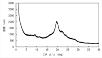
- FIG. FIG. 2-1 is an XRD spectrum (azimuth angle: 10 °) of the film 2 in Example 20.
- FIG. 2-2 is an XRD spectrum (azimuth angle: 10 °) of the film 4 in Example 20. It is typical sectional drawing which shows the example of embodiment of the laminated body of this invention.
- a numerical range expressed using “to” means a range including numerical values described before and after “to” as a lower limit value and an upper limit value.
- parallel and orthogonal do not mean parallel or orthogonal in a strict sense, but mean a range of ⁇ 5 ° from parallel or orthogonal.
- the liquid crystal composition and the liquid crystal compound include a concept that no longer exhibits liquid crystallinity due to curing or the like.
- “(meth) acrylate” is a notation representing “acrylate” or “methacrylate”
- “(meth) acryl” is a notation representing “acryl” or “methacryl”
- “(Meth) acryloyl” is a notation representing “acryloyl” or “methacryloyl”.
- the absorption maximum wavelength of the anisotropic light absorption film represents a value measured by the following method. With the light source side polarizer of the Nikon microscope ECLIPSE E600 POL inserted, the absorption spectrum in the absorption axis direction in the visible region is measured using a multi-channel spectrometer QE65000 manufactured by Ocean Optics, and the peak wavelength is absorbed in the present invention. Maximum wavelength. When a plurality of peaks are measured, each peak is regarded as the absorption maximum wavelength in the present invention. The absorption spectrum was measured in a state of being laminated with the substrate and the alignment film, and was calculated by subtracting the spectrum of only the substrate and the alignment film.
- the solution absorption maximum wavelength of the dichroic azo dye represents a value measured by the following method.
- the absorption maximum wavelength in chloroform or an alternative solvent was measured with a spectrophotometer UV-2550 (manufactured by Shimadzu Corporation).
- the LogP value is an index that expresses the hydrophilicity and hydrophobicity of a chemical structure, and is sometimes called a hydrophilicity / hydrophobicity parameter.
- the LogP value can be calculated using software such as ChemBioDraw Ultra or HSPiP (Ver. 4.1.07).
- OECD Guidelines for the Testing of Chemicals, Sections 1, Test No. It can also be obtained experimentally by the method 117 or the like.
- a value calculated by inputting a structural formula of a compound into HSPiP (Ver. 4.1.07) is adopted as the LogP value.
- the aspect ratio of the dichroic azo dye in the present invention was defined by the ratio (L / D) of the length (L) to the diameter (D) of the cylinder with the smallest diameter in contact with the molecule.
- the ratio was calculated. Note that L corresponds to Ld described later, and D corresponds to Ll described later.
- the anisotropic light absorbing film of the present invention (hereinafter also referred to as “film of the present invention”) is represented by a first dichroic azo dye, a second dichroic azo dye, and a general formula (I) described later.
- An anisotropic light-absorbing film formed from a composition having a compound or a polymer thereof.
- the solution absorption maximum wavelength of the first dichroic azo dye is 400 nm or more and less than 550 nm
- the solution absorption maximum wavelength of the second dichroic azo dye is 550 nm or more and 750 nm or less.
- the film of the present invention has an arrangement structure of the first dichroic azo dyes in the film or an arrangement structure of the second dichroic azo dyes.
- the solid content ratio of the component that is, the first dichroic azo dye and the second dichroic azo dye
- the content is preferably 2% by mass to 20% by mass.
- the “solid content ratio” represents mass% when the total solid content (components other than the solvent) is 100 mass%.
- the dichroic azo dye used in the present invention is not particularly limited as long as it has a specific solution absorption maximum wavelength. Specifically, for example, paragraphs [0067] to [0071] of JP 2013-228706 A, paragraphs [0008] to [0026] of JP 2013-227532 A, and JP 2013-209367 A [ Paragraphs [0008] to [0015], paragraphs [0045] to [0058] of JP 2013-14883, paragraphs [0012] to [0029] of JP 2013-109090, and JP 2013-101328 A.
- the first dichroic azo dye used in the present invention is a dichroic azo dye having a solution absorption maximum wavelength of 400 nm or more and less than 550 nm. Moreover, it is preferable that it is a dichroic azo dye represented by the following general formula (III) from a viewpoint that a higher degree of orientation can be achieved.
- n is an integer of 2 to 5
- the repeating unit structures of — (A 1 —N ⁇ N) — that are repeated 2 or more may be the same as or different from each other
- At least one of Q 1 and Q 2 is a radical polymerizable group, and the rest are hydrogen, alkyl having 1 to 20 carbons, alkoxy having 1 to 20 carbons, alkyl ester having 1 to 20 carbons, or amine group
- a 1 and A 2 may be the same as or different from each other, and are substituted or unsubstituted arylene having 6 to 40 carbon atoms, or substituted or unsubstituted heteroarylene having 4 to 30 carbon atoms
- B 1 and B 2 may be the same or different from each other, and are a single bond, — (C ⁇ O) O—, —O (C ⁇ O) —, substituted or unsubstituted alkylene having 1 to 20 carbons, Substituted or unsubstituted arylene having 6 to
- the 1st dichroic azo dye represented by general formula (III) satisfy
- Ld represents the molecular length of the molecular long axis of the first dichroic azo dye
- Ll represents the molecular length in the direction perpendicular to the molecular long axis of the dichroic azo dye.
- the concentration of the first dichroic azo dye in the composition is not particularly limited, but is 0.01 to 5% by mass for the reason that the effect of the present invention is more excellent. It is preferable.
- the solid content ratio of the first dichroic azo dye in the composition is not particularly limited, but is preferably 1 to 10% by mass for the reason that the effect of the present invention is more excellent.
- the content of the first dichroic azo dye is not particularly limited, but for the reason that the effect of the present invention is more excellent, the compound represented by the general formula (I) described later or 100 parts by mass of the polymer
- the content is preferably 0.3 to 10 parts by mass.
- the dichroic azo dye used in the present invention is a dichroic azo dye having a solution absorption maximum wavelength of 550 nm or more and 750 nm or less. Moreover, it is preferable that it is a dichroic azo dye represented by the following general formula (II) from a viewpoint that a higher degree of orientation can be achieved.
- R 31 to R 35 each independently represents a hydrogen atom or a substituent
- R 36 and R 37 each independently represent a hydrogen atom or an alkyl group which may have a substituent.
- Q 31 represents an optionally substituted aromatic hydrocarbon group, aromatic heterocyclic group or cyclohexane ring group;
- L 31 represents a divalent linking group;
- a 31 represents an oxygen atom or a sulfur atom; Represents.
- R 36 , R 37 and Q 31 may have a radical polymerizable group.
- R 36 and R 37 are preferably each independently an alkyl group (particularly an alkyl group having 1 to 10 carbon atoms) which may have a substituent, because the effects of the present invention are more excellent.
- the substituent is not particularly limited, but for the reason that the effect of the present invention is more excellent, a (meth) acryloyloxy group or an acyloxy group (R—CO—O— *: R is an alkyl group (particularly having 1 to 10 carbon atoms). )).
- Q 31 is preferably an aromatic hydrocarbon group, an aromatic heterocyclic group, or a cyclohexane ring group having a substituent because the effect of the present invention is more excellent.
- the substituent is not particularly limited, but is preferably a group represented by QL- * because the effect of the present invention is more excellent.
- Q is a hydrogen atom, an optionally substituted alkyl group (particularly an alkyl group having 1 to 20 carbon atoms), a (meth) acryloyloxy group, or an acyloxy group (R—CO—O—).
- R represents an alkyl group (particularly 1 to 10 carbon atoms)
- L represents a divalent linking group
- * represents a bonding position.
- L represents a single bond, a divalent aliphatic hydrocarbon group (for example, an alkylene group, preferably 1 to 20 carbon atoms), or a divalent aromatic hydrocarbon group (for example, an arylene group, preferably 6 carbon atoms).
- alkyleneoxy group —O—, —S—, —SO 2 —, —SO 3 —, —N (R) — (R: alkyl group), —CO—, —NH—, —COO— , —CONR—, —Si (R) (R ′) — (wherein R and R ′ are each an alkyl group (particularly having 1 to 10 carbon atoms)), or a combination thereof.
- the carbon atom of the alkyl group includes —O—, —CO—, —C (O) —O—, —O—C (O) —, —Si (CH 3 ) 2 —O—Si (CH 3 ) 2.
- R and R ′ are each an alkyl group (particularly 1 to 10 carbon atoms))
- the hydrogen atom bonded to the carbon atom of the alkyl group is a halogen atom, a nitro group, a cyano group, —N (R) (R ′) —, an amino group, —C (R) ⁇ C (R ′) — NO 2. , —C (R) ⁇ C (R ′) — CN, or —C (R) ⁇ C (CN) 2 .
- R and R ′ are each an alkyl group (particularly 1 to 10 carbon atoms))
- the concentration of the second dichroic azo dye in the composition is not particularly limited, but is 0.1 to 10% by mass for the reason that the effect of the present invention is more excellent. It is preferable.
- the solid content ratio of the second dichroic azo dye in the composition is not particularly limited, but is preferably 1 to 20% by mass for the reason that the effect of the present invention is more excellent.
- the content of the second dichroic azo dye is not particularly limited, but for the reason that the effect of the present invention is more excellent, the compound represented by the general formula (I) described later or 100 parts by mass of the polymer The amount is preferably 5 to 20 parts by mass.
- composition used for the film of the present invention contains a compound represented by the following general formula (I) or a polymer thereof (hereinafter, also collectively referred to as “general formula (I) compound”).
- Q5-B5-A5-B6-A6-B8-Q6 In general formula (I), at least one of Q5 and Q6 is a radical polymerizable group, and the rest are a hydrogen atom, an alkyl group having 1 to 20 carbon atoms, a cycloalkyl group having 3 to 12 carbon atoms, and a carbon number.
- a substituted or unsubstituted amine group, A5 and A6 may be the same or different from each other, and are a substituted or unsubstituted arylene group having 6 to 40 carbon atoms, a substituted or unsubstituted heteroarylene group having 4 to 30 carbon atoms, or a substituted or unsubstituted carbon.
- a cyclohexyl group of formula 6 to 40, B5, B6 and B8 may be the same or different from each other, and are a single bond, — (C ⁇ O) O—, —O (C ⁇ O) —, a substituted or unsubstituted alkylene group having 1 to 20 carbon atoms.
- the high molecular liquid crystalline compound examples include a thermotropic liquid crystalline polymer described in JP2011-237513A, and a dichroic dye polymer having a thermotropic liquid crystalline property described in JP2016-4055A. Is mentioned.
- the polymer liquid crystalline compound may have a crosslinkable group (for example, an acryloyl group and a methacryloyl group) at the terminal.
- a repeating unit represented by the following formula (1) (hereinafter, also referred to as “repeating unit (1)”) is obtained because the effect of the present invention is more excellent.
- a polymer liquid crystal compound containing (hereinafter also referred to as “specific compound”) is a preferred embodiment.
- P1 represents the main chain of the repeating unit
- L1 represents a single bond or a divalent linking group
- SP1 represents a spacer group
- M1 represents a mesogenic group
- T1 represents a terminal group.
- main chain of the repeating unit represented by P1 include groups represented by the following formulas (P1-A) to (P1-D). From the viewpoint of diversity and easy handling, a group represented by the following formula (P1-A) is preferred.
- “*” represents a bonding position with L1 in the formula (1).
- R 1 represents a hydrogen atom or a methyl group.
- R 2 represents an alkyl group.
- the group represented by the formula (P1-A) is a unit of a partial structure of poly (meth) acrylate obtained by polymerization of (meth) acrylate because the effect of the present invention is more excellent. Is preferred.
- the group represented by the formula (P1-B) is preferably an ethylene glycol unit in polyethylene glycol obtained by polymerizing ethylene glycol because the effect of the present invention is more excellent.
- the group represented by the formula (P1-C) is preferably a propylene glycol unit obtained by polymerizing propylene glycol for the reason that the effect of the present invention is more excellent.
- the group represented by the formula (P1-D) is preferably a siloxane unit of a polysiloxane obtained by polycondensation of silanol for the reason that the effect of the present invention is more excellent.
- L1 is a single bond or a divalent linking group.
- the divalent linking group represented by L1 include —C (O) O—, —OC (O) —, —O—, —S—, —C (O) NR 3 —, —NR 3 C (O). -, -SO 2- , -NR 3 R 4- and the like.
- each of R 3 and R 4 independently represents a hydrogen atom or an alkyl group having 1 to 6 carbon atoms which may have a substituent (for example, substituent W described later).
- P1 is a group represented by the formula (P1-A)
- L1 is preferably a group represented by —C (O) O— because the effect of the present invention is more excellent.
- P1 is a group represented by the formulas (P1-B) to (P1-D)
- L1 is preferably a single bond because the effect of the present invention is more excellent.
- the spacer group represented by SP1 is at least one selected from the group consisting of an oxyethylene structure, an oxypropylene structure, a polysiloxane structure, and a fluorinated alkylene structure, because it easily exhibits liquid crystallinity and the availability of raw materials. It preferably includes a seed structure.
- the oxyethylene structure represented by SP1 is preferably a group represented by * — (CH 2 —CH 2 O) n1 — *.
- n1 represents an integer of 1 to 20, and * represents a bonding position with L1 or M1 in the above formula (1).
- n1 is preferably an integer of 2 to 10, more preferably an integer of 2 to 4, and most preferably 3 for the reason that the effect of the present invention is more excellent.
- the oxypropylene structure represented by SP1 is preferably a group represented by * — (CH (CH 3 ) —CH 2 O) n2 — * because the effect of the present invention is more excellent.
- n2 represents an integer of 1 to 3, and * represents a bonding position with L1 or M1.
- the polysiloxane structure represented by SP1 is preferably a group represented by * — (Si (CH 3 ) 2 —O) n3 — * because the effect of the present invention is more excellent.
- n3 represents an integer of 6 to 10, and * represents a bonding position with L1 or M1.
- the fluorinated alkylene structure represented by SP1 is preferably a group represented by * — (CF 2 —CF 2 ) n4 — * because the effects of the present invention are more excellent.
- n4 represents an integer of 6 to 10, and * represents a bonding position with L1 or M1.
- the mesogenic group represented by M1 is a group showing the main skeleton of liquid crystal molecules that contribute to liquid crystal formation.
- the liquid crystal molecules exhibit liquid crystallinity that is an intermediate state (mesophase) between a crystalline state and an isotropic liquid state.
- the mesogenic group is not particularly limited. For example, “Flushage Kristall in Tablen II” (VEB Manual Verlag fur Grundoff Industrie, Leipzig, published in 1984). You can refer to the Liquid Crystal Handbook (Maruzen, published in 2000), especially the description in Chapter 3.
- As the mesogenic group for example, a group having at least one cyclic structure selected from the group consisting of an aromatic hydrocarbon group, a heterocyclic group, and an alicyclic group is preferable.
- the mesogenic group preferably has an aromatic hydrocarbon group, more preferably has 2 to 4 aromatic hydrocarbon groups, for the reason that the effect of the present invention is more excellent, and has 3 aromatic hydrocarbon groups. More preferably,
- the mesogenic group the following formula (M1-A) or the following formula (M1-) can be used because the liquid crystallinity expression, liquid crystal phase transition temperature adjustment, raw material availability and synthesis suitability are better and the effects of the present invention are more excellent.
- a group represented by B) is preferred, and a group represented by formula (M1-B) is more preferred.
- A1 is a divalent group selected from the group consisting of an aromatic hydrocarbon group, a heterocyclic group and an alicyclic group. These groups may be substituted with a substituent such as an alkyl group, a fluorinated alkyl group, an alkoxy group, or a substituent W described later.
- the divalent group represented by A1 is preferably a 4- to 6-membered ring.
- the divalent group represented by A1 may be monocyclic or condensed. * Represents a binding position with SP1 or T1.
- Examples of the divalent aromatic hydrocarbon group represented by A1 include a phenylene group, a naphthylene group, a fluorene-diyl group, an anthracene-diyl group, and a tetracene-diyl group.
- the variety of mesogenic skeleton designs and the availability of raw materials From the viewpoint of properties, a phenylene group or a naphthylene group is preferable, and a phenylene group is more preferable.
- the divalent heterocyclic group represented by A1 may be either aromatic or non-aromatic, but is preferably a divalent aromatic heterocyclic group from the viewpoint of improving the degree of orientation.
- Examples of atoms other than carbon constituting the divalent aromatic heterocyclic group include a nitrogen atom, a sulfur atom and an oxygen atom.
- the aromatic heterocyclic group has a plurality of atoms constituting a ring other than carbon, these may be the same or different.
- divalent aromatic heterocyclic group examples include, for example, pyridylene group (pyridine-diyl group), pyridazine-diyl group, imidazole-diyl group, thienylene (thiophene-diyl group), quinolylene group (quinoline-diyl group).
- Isoquinolylene group isoquinoline-diyl group
- oxazole-diyl group thiazole-diyl group
- oxadiazole-diyl group benzothiazole-diyl group
- benzothiadiazole-diyl group benzothiadiazole-diyl group
- phthalimido-diyl group thienothiazole-diyl group
- Thiazolothiazole-diyl group thienothiophene-diyl group
- thienoxazole-diyl group thienoxazole-diyl group.
- divalent alicyclic group represented by A1 examples include a cyclopentylene group and a cyclohexylene group.
- a1 represents an integer of 1 to 10.
- the plurality of A1s may be the same or different.
- A2 and A3 are each independently a divalent group selected from the group consisting of an aromatic hydrocarbon group, a heterocyclic group and an alicyclic group. Specific examples and preferred embodiments of A2 and A3 are the same as those of A1 in the formula (M1-A), and thus description thereof is omitted.
- a2 represents an integer of 1 to 10, and when a2 is 2 or more, a plurality of A2 may be the same or different, and a plurality of A3 may be the same or different.
- the plurality of LA1s may be the same or different.
- a2 is preferably an integer of 2 or more, more preferably 2, for the reason that the effect of the present invention is more excellent.
- LA1 is a divalent linking group.
- the plurality of LA1s are each independently a single bond or a divalent linking group, and at least one of the plurality of LA1s is a divalent linking group.
- a2 is 2, for the reason that the effect of the present invention is more excellent, it is preferable that one of the two LA1s is a divalent linking group and the other is a single bond.
- M1 include the following structures.
- Ac represents an acetyl group (the same applies hereinafter).
- Examples of the (meth) acryloyloxy group-containing group include, for example, -LA (L represents a single bond or a linking group. Specific examples of the linking group are the same as those of L1 and SP1 described above.
- A represents (meth) Group represented by acryloyloxy group).
- T1 is preferably an alkoxy group having 1 to 10 carbon atoms, more preferably an alkoxy group having 1 to 5 carbon atoms, and further preferably a methoxy group for the reason that the effect of the present invention is more excellent.
- These terminal groups may be further substituted with these groups or a polymerizable group described in JP 2010-244038 A.
- the number of atoms in the main chain of T1 is preferably 1 to 20, more preferably 1 to 15, further preferably 1 to 10, and particularly preferably 1 to 7 for the reason that the effect of the present invention is more excellent.
- the number of atoms in the main chain of T1 is 20 or less, the degree of orientation of the polarizer is further improved.
- the “main chain” in T1 means the longest molecular chain bonded to M1, and hydrogen atoms do not count in the number of atoms in the main chain of T1.
- T1 is an n-butyl group
- the number of atoms in the main chain is 4
- T1 is a sec-butyl group
- the number of atoms in the main chain is 3.
- the content of the repeating unit (1) is preferably 20 to 100% by mass, preferably 30 to 99.9% by mass with respect to 100% by mass of all the repeating units of the specific compound, because the effect of the present invention is more excellent. More preferably, it is 40 to 99.0% by mass.
- the content of each repeating unit contained in the polymer liquid crystal compound is calculated based on the charged amount (mass) of each monomer used to obtain each repeating unit.
- the repeating unit (1) may be contained singly or in combination of two or more in the specific compound. Among these, for the reason that the effect of the present invention is more excellent, it is preferable that two kinds of repeating units (1) are contained in the specific compound.
- the terminal group represented by T1 in one (repeating unit A) is an alkoxy group and the other group (repeating unit B) has T1 because the effect of the present invention is more excellent.
- the terminal group represented by is preferably a group other than an alkoxy group.
- the terminal group represented by T1 is preferably an alkoxycarbonyl group, a cyano group, or a (meth) acryloyloxy group-containing group, for the reason that the effect of the present invention is more excellent. More preferably, it is a cyano group.
- the ratio (A / B) between the content of the repeating unit A in the specific compound and the content of the repeating unit B in the specific compound is 50/50 to 95/5 because the effect of the present invention is more excellent. It is preferably 60/40 to 93/7, more preferably 70/30 to 90/10.
- the specific compound examples include a polymer liquid crystal compound represented by the following structural formula and a polymer liquid crystal compound in which the following structural formula (repeating unit) is appropriately combined.
- R represents a hydrogen atom or a methyl group.
- Me represents a methyl group (the same applies hereinafter).
- the weight average molecular weight (Mw) of the polymer of the compound represented by the general formula (I) is preferably from 1,000 to 500,000, more preferably from 2,000 to 300,000, because the effect of the present invention is more excellent.
- Mw of the polymer of the compound represented by the general formula (I) is within the above range, the polymer of the compound represented by the general formula (I) can be easily handled.
- the weight average molecular weight (Mw) of the polymer of the compound represented by formula (I) is preferably 10,000 or more, and more preferably 10,000 to 300,000.
- the weight average molecular weight (Mw) of the polymer of the compound represented by the general formula (I) is preferably less than 10,000, and more preferably 2,000 or more and less than 10,000.
- the weight average molecular weight and the number average molecular weight in the present invention are values measured by a gel permeation chromatograph (GPC) method.
- GPC gel permeation chromatograph
- the concentration of the compound of general formula (I) (concentration with respect to the whole composition including the solvent) is not particularly limited, but is 0.5 to 20% by mass for the reason that the effect of the present invention is more excellent. Preferably, it is 1 to 17% by mass, more preferably 2 to 15% by mass.
- the solid content ratio of the compound of the general formula (I) in the composition is not particularly limited, but is preferably 1 to 99% by mass and more preferably 50 to 95% by mass because the effect of the present invention is more excellent. More preferred is 70 to 93% by mass.
- composition used in the present invention may use additives as appropriate in addition to the above-described components.
- additives for example, a polymerization initiator, an interface improver, a solvent and the like can be mentioned.
- the composition used in the present invention preferably contains a polymerization initiator because the effects of the present invention are more excellent.
- a polymerization initiator It is preferable that it is a compound which has photosensitivity, ie, a photoinitiator.
- the photopolymerization initiator various compounds can be used without particular limitation. Examples of the photopolymerization initiator include ⁇ -carbonyl compounds (specifications of US Pat. Nos. 2,367,661 and 2,367,670), acyloin ether (US Pat. No. 2,448,828), ⁇ -hydrocarbon substituted aromatic acyloin. Compound (US Pat. No.
- photopolymerization initiators such as Irgacure (hereinafter abbreviated as “Irg”)-184, Irgacure-907, Irgacure-369, Irgacure-651, Irgacure-manufactured by BASF. 819, Irgacure-OXE-01, Irgacure-OXE-02, and the like.
- the composition used in the present invention preferably contains a solvent (solvent) from the viewpoint of workability and the like.
- solvent include ketones (for example, acetone, 2-butanone, methyl isobutyl ketone, cyclopentanone, and cyclohexanone), ethers (for example, dioxane, tetrahydrofuran, tetrahydropyran, dioxolane, tetrahydrofurfuryl alcohol, And cyclopentyl methyl ether), aliphatic hydrocarbons (such as hexane), alicyclic hydrocarbons (such as cyclohexane), and aromatic hydrocarbons (such as benzene, toluene, xylene, and trimethyl) Benzene), halogenated carbons (eg, dichloromethane, trichloromethane (chloroform), dichloroethane, dichlorobenzene, and chloroto-diol,
- solvents may be used alone or in combination of two or more.
- an organic solvent is preferably used, and a halogenated carbon or a ketone is more preferably used because the effect of the present invention is more excellent.
- the content of the solvent may be 70 to 99.5% by mass with respect to the total mass of the composition because the effect of the present invention is more excellent.
- the content is preferably 80 to 99% by mass, and more preferably 85 to 98% by mass.
- the composition used in the present invention preferably contains an interfacial modifier.
- the smoothness of the coated surface is improved, the degree of orientation is further improved, and the in-plane uniformity is improved by suppressing repelling and unevenness.
- the interfacial improver a compound that makes the above-mentioned dichroic azo dye and the compound represented by the above general formula (I) or a polymer thereof horizontally on the coated surface side is preferable, and [0253] of JP 2011-237513 A ] To [0293] The compounds (horizontal alignment agents) described in the paragraphs can be used.
- the content of the interface improver is such that the dichroic azo dye in the composition and the compound represented by the general formula (I) or a polymer thereof Is preferably 0.001 to 5 parts by mass, and more preferably 0.01 to 3 parts by mass with respect to 100 parts by mass in total.
- the films of the present invention typically have one or more absorption maximum wavelengths ( ⁇ max).
- the difference ( ⁇ max) between the solution absorption maximum wavelength of at least one of the first and second dichroic azo dyes described above and the absorption maximum wavelength of the film of the present invention is 10 nm because the effect of the present invention is more excellent. It is preferably ⁇ 100 nm.
- the difference ( ⁇ max) between the solution absorption maximum wavelength of the second dichroic azo dye described above and the absorption maximum wavelength of the film of the present invention is 10 nm to 100 nm. Preferably there is.
- the film of the present invention preferably has at least two absorption maximum wavelengths because the effect of the present invention is more excellent, and the at least two absorption maximum wavelengths are 400 nm or more and less than 550 nm and 550 nm or more and 750 nm or less, respectively. Is more preferable.
- ⁇ max is a difference between the solution absorption maximum wavelength of the dichroic azo dye and the closest absorption maximum wavelength of the film of the present invention.
- the anisotropic light-absorbing film of the present invention preferably has a film thickness of 0.3 to 5 ⁇ m, more preferably 0.3 to 3 ⁇ m, because the effects of the present invention are more excellent.
- About the minimum of the said film thickness it is more preferable that it is 0.8 micrometer or more from the reason for which the effect of this invention is more excellent.
- the upper limit of the film thickness is more preferably 3 ⁇ m or less because the effect of the present invention is more excellent.
- the difference between the solution absorption maximum wavelength and the absorption maximum wavelength of the anisotropic light absorption film is easy to control the difference between the solution absorption maximum wavelength and the absorption maximum wavelength of the anisotropic light absorption film (
- the anisotropic light absorption film has at least two absorption maximum wavelengths, at least one of the first and second dichroic azo dyes having a difference of 10 nm to 100 nm in the difference from the closest absorption maximum wavelength of the anisotropic light absorption film
- the difference ( ⁇ LogP) between the LogP value of (especially the second dichroic azo dye) and the LogP value of the compound represented by the general formula (I) or a polymer thereof (the general formula (I) compound) is: It is preferably 5 or more and 8 or less.
- the compatibility between the general formula (I) compound and the dichroic azo dye having a specific LogP value decreases, and anisotropic light It is considered that the dichroic azo dyes are arranged in the absorption film.
- the control of the compatibility between the compound of general formula (I) and the dichroic azo dye is also affected by the concentration of the dichroic azo dye in the composition.
- the difference in the LogP value is preferably 6 or more, and the concentration of the dichroic azo dye is 10
- the difference in the LogP value is preferably 5 or more.
- DSC differential scanning calorimeter
- T1 The melting point (T1) of Sample 1 (dichroic azo dye) is confirmed from the obtained spectrum. Subsequently, the calorimetric measurement of a sample (sample 2) obtained by casting a composition containing the compound of general formula (I) and the dichroic azo dye on glass was carried out in the same manner. The transition temperature (T2) corresponding to the reactive azo dye is confirmed.
- T1> T2 the relationship of T1> T2 is established, and the smaller the difference between T1 and T2, the smaller the dichroic azo dye and the general formula ( I) It is judged that the compatibility of the compound is lowered.
- T1 and T2 are preferably 30 ° C. or less, and more preferably 20 ° C. or less, because the effect of the present invention is more excellent.
- the anisotropic light-absorbing film of the present invention has the above-described arrangement structure (crystal structure) of the first dichroic azo dyes in the film, or the second described above.
- the dichroic azo dyes have an arrangement structure (crystal structure).
- the film of the present invention may have both the above-described arrangement structure of the first dichroic azo dyes and the above-described arrangement structure of the second dichroic azo dyes in the film.
- the film of the present invention preferably has at least the above-described arrangement structure of the second dichroic azo dyes in the film for the reason that the effect of the present invention is more excellent.
- the arrangement structure of the dichroic azo dyes may be an arrangement structure of the dichroic azo dyes after the reaction (for example, after the reaction of the radical polymerizable group).
- Film 1 Film formed from a composition having the first dichroic azo dye, the second dichroic azo dye, and the compound of general formula (I) (film of the present invention) -Film 2: a film formed from a composition having only the compound of general formula (I)-Film 3: a film formed from a composition having the first dichroic azo dye and the compound of general formula (I)- Film 4: film formed from a composition having the second dichroic azo dye and the compound of general formula (I)
- the films 1 to 4 are produced by the same method. For example, care should be taken so that the concentration and the coating conditions of the coating solution are uniform and the film area and film thickness are the same.
- the production methods of the membranes 1 to 4 are not particularly limited as long as they are similar, but when the membrane 1 contains an interface improver, the membranes 2 to 4 contain the same amount of the interface improver as the membrane 1 And
- XRD measurement is performed on the films 1 to 4 under the same conditions (for example, the film thickness, measurement area, and measurement conditions are aligned).
- XRD measurement is performed as follows.
- the films 1 to 4 are measured for X-ray diffraction using an X-ray diffractometer for thin film evaluation (trade name: “SmartLab” in-plane optical system, manufactured by Rigaku Corporation).
- SmartLab in-plane optical system, manufactured by Rigaku Corporation
- the X-ray diffraction analysis performed using the in-plane method is also referred to as “in-plane XRD”.
- In-plane XRD is performed by irradiating the surface of the polarizer layer with X-rays using a thin film X-ray diffractometer under the following conditions.
- the direction in which the compound of general formula (I) and the dichroic azo dye are aligned in the major axis direction is set to an azimuth angle ( ⁇ ) of 0 °, and in-plane XRD is performed in 15 ° increments to obtain an observed peak.
- the ⁇ scan performed on the substrate determines the direction in the substrate plane where the peak intensity is maximum.
- the XRD spectrum which will be described later, is compared using the spectrum of the in-plane measurement in the obtained direction. For the peak intensity, a value normalized as the film thickness corresponding to the X-ray penetration length at an X-ray incident angle of 0.2 ° is used.
- a measurement example of XRD measurement is shown below.
- the film is cut into a size of 40 mm ⁇ 40 mm, and the surface of the polarizer layer is irradiated with X-rays under the following conditions using an X-ray diffractometer for thin film evaluation (trade name: “SmartLab” manufactured by Rigaku Corporation). I do.
- the direction in which the compound of general formula (I) and the dichroic azo dye are oriented in the major axis direction is taken as the azimuth angle ( ⁇ ) 0 °, and in-plane measurement (2 ⁇ / ⁇ scan) is performed in 15 ° increments.
- the orientation in the plane of the substrate where the peak intensity is large is determined by the ⁇ scan performed on the peak. Both measurements are performed using CuK ⁇ at an incident angle of 0.20 °.
- the period length is obtained from the relationship between the following diffraction angle and distance.
- the peak intensity is calculated by normalizing as a film thickness corresponding to the X-ray penetration depth at an X-ray incident angle of 0.2 ° (in cps notation).
- d ⁇ / (2 ⁇ sin ⁇ ) (d: distance, ⁇ : incident X-ray wavelength (CuK ⁇ ; 1.54 ⁇ ))
- the preparation conditions of the films 1 to 4 and the measurement conditions of XRD are matched, the peaks of the XRD spectrum can be compared.
- peak 2 is an arrangement structure (crystal structure) of the second dichroic azo dyes.
- the film 1 includes, in the film, the arrangement structure of the first dichroic azo dyes described above and the second structure described above. It can be said that none of the arrangement structure of the dichroic azo dyes is present.
- Example 13 the polymer liquid crystal compound P-7 is used as the compound of the general formula (I), the dichroic azo dye Y-1 is used as the first dichroic azo dye, and the second dichroism is used.
- the azo dye dichroic azo dye C-1 is used.
- Peak 2 is a peak derived from the arrangement structure of the dichroic azo dye C-1 (second dichroic azo dye).
- the XRD spectrum of the film 1 dichroic azo dye Y-1 + dichroic azo dye C-1 + polymer liquid crystal compound P-7) is measured, the XRD spectrum of the film 1 (same as FIG. 1-2) The above-described peak 2 is observed (azimuth angle: 30 °). Therefore, it can be said that the anisotropic light-absorbing film of Example 13 has an arrangement structure (crystal structure) between the dichroic azo dyes C-1 (second dichroic azo dyes) in the film.
- Example 20 when the XRD spectrum of the film 1 (dichroic azo dye Y-1 + dichroic azo dye C-6 + polymer liquid crystal compound P-7) was measured, the XRD spectrum of the film 1 ( In the same manner as in FIG. 2-2, the above-described peak 2 is observed (azimuth angle: 10 °). Therefore, it can be said that the anisotropic light-absorbing film of Example 20 has an arrangement structure (crystal structure) of the dichroic azo dye C-6 (second dichroic azo dye) in the film.
- the half width in the ⁇ scan of the peak derived from the arrangement structure (crystal structure) between the dichroic azo dyes is preferably less than 10.0 ° because the effect of the present invention is more excellent.
- a small half-value width in ⁇ scan means that the crystallinity of the above crystal structure is high, and a higher degree of orientation becomes possible.
- the laminate 10 of the present invention is a laminate having the anisotropic light absorbing film 1 of the present invention and the alignment film 2 or the substrate 3.
- the alignment film used in the present invention is not particularly limited as long as it can align the dichroic azo dye used in the present invention, the compound represented by the general formula (I), or a polymer thereof.
- Organic compound eg, ⁇ -tricosanoic acid
- organic compound preferably polymer
- LB film Langmuir Blodget method
- Dioctadecylmethylammonium chloride, methyl stearylate can be provided by means such as accumulation.
- an alignment film in which an alignment function is generated by application of an electric field, application of a magnetic field, or light irradiation is also known.
- the alignment film used in the present invention may be an alignment film containing one or both of a polyamic acid and a polyimide compound, or a photo-alignment film containing a photoactive compound having an azo group as a photoactive group.
- Photo-alignment film> As a photo-alignment material used for a photo-alignment film containing a photo-active compound having an azo group as a photo-active group, there are many literatures. In the present invention, for example, JP-A-2006-285197, JP-A-2007-76839, JP-A-2007-138138, JP-A-2007-94071, JP-A-2007-121721, JP-A-2007. Azo compounds described in JP-A No. 140465, JP-A No. 2007-156439, JP-A No. 2007-133184, JP-A No. 2009-109831, JP-B No. 3888848, and JP-A No.
- the photo-alignment film formed from the above material is irradiated with linearly polarized light or non-polarized light to produce a photo-alignment film.
- linearly polarized light irradiation and “non-polarized light irradiation” are operations for causing a photoreaction in the photo-alignment material.
- the wavelength of light used varies depending on the photo-alignment material used, and is not particularly limited as long as it is a wavelength necessary for the photoreaction.
- the peak wavelength of light used for light irradiation is preferably 200 nm to 700 nm, and more preferably ultraviolet light having a peak wavelength of light of 400 nm or less.
- Light sources used for light irradiation include commonly used light sources such as tungsten lamps, halogen lamps, xenon lamps, xenon flash lamps, mercury lamps, mercury xenon lamps and carbon arc lamps, and various lasers [eg, semiconductor lasers, helium. Neon laser, argon ion laser, helium cadmium laser and YAG (yttrium, aluminum, garnet) laser], light emitting diode, and cathode ray tube.
- various lasers eg, semiconductor lasers, helium. Neon laser, argon ion laser, helium cadmium laser and YAG (yttrium, aluminum, garnet) laser
- a method using a polarizing plate for example, an iodine polarizing plate, a two-color dye polarizing plate, and a wire grid polarizing plate
- a prism system element for example, a Glan-Thompson prism
- a Brewster angle is used.
- a method using a reflective polarizer or a method using light emitted from a polarized laser light source can be employed.
- a method of irradiating light from the upper surface or the back surface to the alignment film surface perpendicularly or obliquely from the upper surface or the rear surface is employed.
- the incident angle of light varies depending on the photo-alignment material, but is preferably 0 to 90 ° (vertical), and preferably 40 to 90 °.
- the alignment film is irradiated with non-polarized light obliquely.
- the incident angle is preferably 10 to 80 °, more preferably 20 to 60 °, and further preferably 30 to 50 °.
- the irradiation time is preferably 1 minute to 60 minutes, and more preferably 1 minute to 10 minutes.
- a method of performing light irradiation using a photomask as many times as necessary for pattern production or a method of writing a pattern by laser beam scanning can be employed.
- the substrate used in the present invention is not particularly limited as long as it is a substrate that is usually used as a substrate for producing an optical film or the like. You may give flexibility and peelability as needed.
- the above-described alignment film may be provided on the substrate, and the anisotropic light absorption layer of the present invention may be provided thereon, and the substrate may be disposed on the opposite side of the alignment film from the anisotropic light absorption film.
- Examples include glass and polymer films.
- the light transmittance of the substrate is preferably 80% or more.
- a polymer film is used as the substrate, it is preferable to use an optically isotropic polymer film.
- the description in paragraph [0013] of JP-A-2002-22294 can be applied.
- a polymer whose expression is lowered by modifying the molecule described in International Publication No. 2000/26705 is used. You can also.
- a DMAc solution (3.3 mL) of compound P1-2 (0.8 g) and compound P9-B (0.2 g) was heated to an internal temperature of 80 ° C. in a nitrogen stream. Thereto was added a DMAc solution (0.5 mL) of 2,2′-azobis (2-methylpropionic acid) dimethyl (0.054 mmol, 0.012 g), and the mixture was stirred at 80 ° C. for 2 hours. Thereafter, disappearance of the polymerizable group was confirmed by 1 H-NMR spectrum measurement, and then cooled to room temperature. Methanol was added for filtration, and the residue was washed with methanol to obtain 0.90 g of compound P9-C as a white solid.
- Polymer liquid crystal compounds and polymerizable liquid crystal compounds other than P-1 were synthesized in the same manner as the polymer liquid crystal compound P-1 or using a known method.
- yellow azo dye Y-1 was synthesized according to the following route.
- Compound A (10 g) was synthesized according to the literature (Chem. Eur. J. 2004.10.2011).
- Compound A (10 g) was dissolved in water (300 mL) and hydrochloric acid (17 mL), cooled in an ice bath, sodium nitrite (3.3 g) was added, and the mixture was stirred for 30 min. Further, amidosulfuric acid (0.5 g) was added, m-toluidine (5.1 g) was added, and the mixture was stirred at room temperature for 1 hour. After stirring, the solid obtained by neutralization with hydrochloric acid was collected by suction filtration to obtain Compound B (3.2 g).
- Yellow azo dyes and cyanazo dyes other than Y-1 described later were synthesized in the same manner as yellow azo dye Y-1 or using a known method.
- Example 1 To 1 part by mass of photoalignment material E-1 having the following structure, 41.6 parts by mass of butoxyethanol, 41.6 parts by mass of dipropylene glycol monomethyl, and 15.8 parts by mass of pure water were added. .Pressure filtered through a 45 ⁇ m membrane filter. The obtained coating liquid for photo-alignment film was apply
- linearly polarized ultraviolet light (illuminance: 4.5 mW, irradiation amount: 300 mJ / cm 2 ) using a polarized ultraviolet light exposure apparatus to produce an alignment film 1.
- the following dichroic azo dye composition 1 was applied or spin-coated with a # 15 bar to form a coating film 1.
- the coating film 1 was heated at 140 ° C. for 90 seconds, and the coating film 1 was cooled to room temperature. Subsequently, it heated at 70 degreeC for 60 second, and cooled again to room temperature. Then, the anisotropic light absorption film 1 was produced on the alignment film 1 by irradiating for 60 seconds on irradiation conditions with an illuminance of 28 mW / cm 2 using a high-pressure mercury lamp. In this way, the laminate 1 was produced.
- the film thickness of the alignment film 1 was 45 nm, and the film thickness of the anisotropic light absorption film 1 was 2 ⁇ m.
- composition of Dichroic Azo Dye Composition 1 ⁇ Yellow azo dye Y-1 (first dichroic azo dye) 7.1 parts by mass Cyanazo dye C-1 (second dichroic azo dye) 9.1 parts by mass Polymer liquid crystal compound P- 1 (Compound of general formula (I)) 101.1 parts by mass-polymerization initiator IRGACURE819 (manufactured by BASF) 1.0 part by mass-Interface improver F-1 0.3 part by mass-cyclopentanone 617.0 parts by mass ⁇ Tetrahydrofuran (THF) 264.4 parts by mass ⁇
- Examples 2 to 12, Comparative Examples 1 to 5 In the dichroic azo dye composition 1 of Example 1, except that the type and concentration (solid content ratio) of the solvent, the general formula (I) compound, and the dichroic azo dye were changed as shown in Table 1 below, An anisotropic light-absorbing film was produced on the alignment film 1 in the same manner as in Example 1. In this manner, laminates 2 to 12 of Examples 2 to 12 and laminates 13 to 17 of Comparative Examples 1 to 5 were produced. In addition, two types of general formula (I) compounds were used for the composition used for preparation of the anisotropic light absorption film of Examples 10 and 11 (quantity ratio in Table 1 represents mass ratio). In Comparative Example 5, only the second dichroic azo dye was used as the dichroic azo dye.
- ⁇ Dichroic azo dye> The dichroic azo dyes in Table 1 are collectively shown below. As shown in Table 1 below, all of the following yellow azo dyes Y-1 to Y-5 have a solution absorption maximum wavelength of 400 nm or more and less than 550 nm, and correspond to the first dichroic azo dye described above. Further, as described in Table 1 below, all of the following cyanazo dyes C-1 to C-5 have a solution absorption maximum wavelength of 550 nm or more and 750 nm or less, and correspond to the second dichroic azo dye described above.
- composition of alignment film coating solution ⁇
- the obtained coating film was irradiated with linearly polarized ultraviolet light (illuminance: 4.5 mW, irradiation amount: 500 mJ / cm 2 ) using a polarized ultraviolet light exposure apparatus, and the alignment film 13 was produced.
- the following dichroic azo dye composition 13 was continuously applied with a # 7 wire bar to form a coating film 13.
- the coating film 13 was heated at 140 ° C. for 90 seconds, and the coating film 13 was cooled to room temperature (23 ° C.). Subsequently, it heated at 80 degreeC for 60 second, and cooled again to room temperature. Then, the anisotropic light absorption film 13 was produced on the alignment film 13 by irradiating for 60 seconds on irradiation conditions with an illuminance of 28 mW / cm 2 using a high-pressure mercury lamp.
- dichroic azo dye composition 13 Composition of dichroic azo dye composition 13 ⁇
- the following polymer liquid crystal compound P-7 (general formula (I) compound) 5.940 parts by mass
- the following dichroic azo dye Y-1 (first dichroic azo dye) 0.416 parts by mass Chromatic azo dye C-1 (second dichroic azo dye) 0.535 parts by mass
- the following interface improver F-1 0.059 parts by mass
- polymerization initiator IRGACURE 819 manufactured by BASF
- the following barrier layer forming composition 1 was continuously applied with a # 2 wire bar and dried at 40 ° C. for 90 seconds. Then, it irradiated for 10 second on irradiation conditions of illumination intensity 30mW / cm ⁇ 2 > using the high pressure mercury lamp, the resin composition was hardened, and the laminated body in which the transparent resin layer 1 was formed on the anisotropic light absorption film 13 was produced. Thus, the laminated body of Example 13 was obtained.
- the cross section of the transparent resin layer 1 was cut using a microtome cutting machine and the film thickness was measured with a scanning electron microscope (SEM), the film thickness was about 0.7 ⁇ m.
- Example 14 to 21, Comparative Examples 6 to 8 In the dichroic azo dye composition 13 of Example 13, the kind and part by mass of the dichroic azo dye, the kind and part by mass of the compound of the general formula (I), the kind and part by mass of the polymerization initiator, and the interface modifier An anisotropic light-absorbing film was produced on the alignment film 13 in the same manner as in Example 13 except that the type and part by mass, and the type and part by mass of the solvent were changed as shown in Table 2 below. Thus, each laminated body was obtained.
- ⁇ Dichroic azo dye> The dichroic azo dyes in Table 2 are collectively shown below. As shown in Table 2 below, all of Y-1 to Y-2 below have a solution absorption maximum wavelength of 400 nm or more and less than 550 nm, and correspond to the first dichroic azo dye described above. As shown in Table 2 below, all of the following C-1 to C-11 have a solution absorption maximum wavelength of 550 nm or more and 750 nm or less, and correspond to the above-described second dichroic azo dye.
- Irgcure 819 IRGACURE 819 (manufactured by BASF)
- Irgcure 820 IRGACURE 820 (BASF)
- Tz0 transmittance for polarized light in the direction of the absorption axis of the laminate
- Ty0 transmittance for polarized light in the direction of the transmission axis of the laminate
- the “liquid” column represents the solution absorption maximum wavelength of each dichroic azo dye
- the “film” column represents the absorption maximum wavelength of the anisotropic light absorption film.
- Two values in the “film” column mean that there are two absorption maximum wavelengths, the upper value is the absorption maximum wavelength on the lower wavelength side, and the lower value is the absorption on the long wavelength side. The maximum wavelength.
- the column “ ⁇ max” represents the difference between the solution absorption maximum wavelength of each dichroic azo dye and the closest absorption maximum wavelength of the anisotropic light absorption film.
- the “LogP (formula (I))” column represents the LogP value of the compound of the general formula (I), and the “LogP (dye)” column represents the LogP value of each dichroic azo dye.
- the “ ⁇ LogP” column represents the difference between the LogP value of the compound of general formula (I) and the LogP value of each dichroic azo dye.
- the column “Ld / Ll” represents Ld / Ll described above.
- the column of “Liquid” represents the solution absorption maximum wavelength of the second dichroic azo dye
- the column of “Film” represents the absorption maximum wavelength of the anisotropic light absorption film (second The absorption maximum wavelength closer to the solution absorption maximum wavelength of the dichroic azo dye.
- the column “T1” represents the melting point (T1) described above
- the column “T2” represents the transition temperature (T2) described above
- the column “Difference” It represents the difference between the melting point (T1) and the transition temperature (T2).
- the column “Dye Total Concentration” represents the total concentration (solid content ratio) of the first dichroic azo dye and the second dichroic azo dye.
- Examples 1 to 21 have the arrangement structure of the first dichroic azo dyes or the arrangement structure of the second dichroic azo dyes in the film. Exhibited a high degree of orientation and high light resistance.
- Comparative Examples 1 to 4 and Comparative Examples 6 to 8 that do not have either the arrangement structure of the first dichroic azo dyes or the arrangement structure of the second dichroic azo dyes in the film.
- Comparative Example 5 using only the second dichroic azo dye as the dichroic azo dye had insufficient light resistance.
- the difference between the solution absorption maximum wavelength of at least one of the first and second dichroic azo dyes and the closest absorption maximum wavelength of the anisotropic light absorption film is 10 nm to 100 nm. It was shown that an anisotropic light-absorbing film having a high degree of orientation and high light resistance can be obtained by using the dichroic azo dye composition to be (Example).
- Example 1 and 2 which is 0 mass% or more showed a higher degree of orientation and higher light resistance.
- Examples 1 and 4 to 5 and 8 to 11 (the solid content ratio of the first dichroic azo dye is 6.0% by mass, and the solid content ratio of the second dichroic azo dye is 7%)
- Examples 1 to 4, 5 to 8, 8 and 10 to 11 satisfying the above-mentioned formula (A) in terms of Ld / Ll of the first dichroic azo dye A high degree of orientation and polarization, and higher light resistance were exhibited.
- Examples 10 and 11 in which the compound represented by the general formula (I) and the polymer of the compound represented by the general formula (I) are used in combination as the general formula (I) compound have a higher degree of orientation. Indicated.
- Examples 16 to 17 and 20 in which the difference is 15 ° C. or less showed a higher degree of orientation.
- Examples 13 to 20 in which the half width of the peak derived from the arrangement structure of the dichroic azo dyes is less than 10.0 ° in the XRD spectrum of the anisotropic light absorbing film are as follows. It showed a higher degree of orientation and higher light resistance. In particular, Examples 13 and 15 to 20 in which the half width was less than 8.4 ° showed a higher degree of orientation. Among them, Examples 15 to 18 and 20 in which the half width was 6.0 ° or less showed a higher degree of orientation. Among them, Examples 16 to 18 and 20 in which the half width was less than 6.0 ° showed a higher degree of orientation. Among them, Examples 16 to 17 and 20 in which the half width was 5.5 ° or less showed a higher degree of orientation. Among them, Examples 16 to 17 in which the half width is less than 5.0 ° showed a higher degree of orientation.
- Example A An anisotropic light-absorbing film was produced on the alignment film 2 in the same manner as in Example 1 except that the alignment film was changed to the alignment film 2 described below. In this way, the laminate of Example A was produced.
- ⁇ Preparation of alignment film> 98 parts by mass of N-metholpyrrolidone was added to 2 parts by mass of SE-130 (manufactured by Nissan Chemical Co., Ltd.), and the resulting solution was pressure filtered through a 0.45 ⁇ m membrane filter to obtain a coating solution for an alignment film.
- the alignment film coating liquid is applied onto a polyimide substrate using a # 4 bar, and the applied alignment film coating liquid is dried at 80 ° C. for 15 minutes and then heated at 250 ° C. for 1 hour to form a coating film. did.
- the obtained coating film was rubbed once (roller rotation speed: 1000 rotations / spacer thickness 2.6 mm, stage speed 1.8 m / min) to produce an alignment film 2 on a polyimide substrate.
- Example A was evaluated in the same manner as in Example 1, and almost the same result as in Example 1 was obtained.
- the organic phase was taken out, and the organic phase was washed with 0.2% by mass aqueous ammonium nitrate solution until the washed water became neutral. Thereafter, the solvent and water were distilled off from the obtained organic phase under reduced pressure to obtain a polyorganosiloxane having an epoxy group as a viscous transparent liquid.
- the polyorganosiloxane having an epoxy group had a weight average molecular weight Mw of 2,200 and an epoxy equivalent of 186 g / mol.
- 10.1 parts by mass of the above-obtained polyorganosiloxane having an epoxy group acrylic group-containing carboxylic acid (Toa Gosei Co., Ltd., trade name “Aronix M-5300”, acrylic acid ⁇ - 0.5 parts by mass of carboxypolycaprolactone (degree of polymerization n ⁇ 2), 20 parts by mass of butyl acetate, 1.5 parts by mass of cinnamic acid derivative obtained by the method of Synthesis Example 1 of JP-A-2015-26050, and Then, 0.3 part by mass of tetrabutylammonium bromide was charged, and the resulting mixture was stirred at 90 ° C.
- composition 2Q for forming photo-alignment film ⁇ -10.67 parts by mass of the above polymer CQ-1-5.17 parts by mass of the following low molecular compound B-1-0.53 parts by mass of the following additive PQ-1 (TA-60B, manufactured by San Apro)-butyl acetate 8287 37 parts by mass ⁇ Propylene glycol monomethyl ether acetate 2071.85 parts by mass ⁇
- a coating liquid for optically anisotropic layer having the following composition was prepared.
- the groups adjacent to the acryloyloxy groups of the following liquid crystal compounds L-3 and L-4 represent propylene groups (groups in
- ⁇ Preparation of Cellulose Acylate Film 1> (Preparation of core layer cellulose acylate dope) The following composition was put into a mixing tank and stirred to dissolve each component to prepare a cellulose acetate solution used as a core layer cellulose acylate dope.
- Core layer cellulose acylate dope ⁇ -100 parts by weight of cellulose acetate having an acetyl substitution degree of 2.88-12 parts by weight of polyester compound B described in the examples of JP-A-2015-227955-2 parts by weight of the following compound F-Methylene chloride (first solvent) 430 Part by mass, methanol (second solvent) 64 parts by mass ---------------------------------------------------------------------------------------------------------------------------------------------------------------------------------------------------------------------------------------------------------------------------
- outer layer cellulose acylate dope 10 parts by mass of the following matting agent solution was added to 90 parts by mass of the core layer cellulose acylate dope to prepare a cellulose acetate solution used as an outer layer cellulose acylate dope.
- Matting agent solution ⁇ -Silica particles having an average particle size of 20 nm (AEROSIL R972, manufactured by Nippon Aerosil Co., Ltd.) 2 parts by mass-76 parts by mass of methylene chloride (first solvent)-11 parts by mass of methanol (second solvent)-The above core layer cellulose reed Rate dope 1 part by mass ⁇
- the photoalignment film composition 2Q prepared earlier was applied with a bar coater. After coating, the solvent was removed by drying on a hot plate at 120 ° C. for 1 minute to form a photoisomerized composition layer having a thickness of 0.3 ⁇ m.
- the obtained photoisomerizable composition layer was irradiated with polarized ultraviolet rays (10 mJ / cm 2 , using an ultrahigh pressure mercury lamp) to form a photo-alignment film.
- the previously prepared coating liquid for optically anisotropic layer was applied with a bar coater to form a composition layer.
- the formed composition layer was once heated to 110 ° C. on a hot plate and then cooled to 60 ° C. to stabilize the orientation. Thereafter, the orientation is fixed by irradiation with ultraviolet rays (500 mJ / cm 2 , using an ultra-high pressure mercury lamp) in a nitrogen atmosphere (oxygen concentration 100 ppm) under a nitrogen atmosphere to form an optically anisotropic layer having a thickness of 2.3 ⁇ m.
- a ⁇ / 4 retardation film 1 was prepared.
- the in-plane retardation of the obtained ⁇ / 4 retardation film 1 was 140 nm.
- cellulose acylate film 2 As a temporary support, a commercially available triacetyl cellulose film “Z-TAC” (manufactured by FUJIFILM Corporation) was used (this is referred to as cellulose acylate film 2). After passing the cellulose acylate film 2 through a dielectric heating roll having a temperature of 60 ° C. and raising the film surface temperature to 40 ° C., the coating amount of an alkali solution having the composition shown below is applied to one side of the film using a bar coater. It apply
- a coating solution for forming an alignment film having the following composition was continuously applied with a # 8 wire bar.
- the alignment film was formed by drying with warm air of 60 ° C. for 60 seconds and further with warm air of 100 ° C. for 120 seconds.
- Composition of coating solution for alignment film formation ⁇ Polyvinyl alcohol (manufactured by Kuraray, PVA103) 2.4 parts by mass Isopropyl alcohol 1.6 parts by mass Methanol 36 parts by mass Water 60 parts by mass ⁇ ⁇
- composition of coating liquid N for optically anisotropic film The following liquid crystalline compound L-1 80 parts by mass The following liquid crystalline compound L-2 20 parts by mass The following vertical alignment agent (S01) 1 part by mass Ethylene oxide modified trimethylolpropane triacrylate (V # 360, manufactured by Osaka Organic Chemical Co., Ltd.) ) 8 parts by mass Irgacure 907 (manufactured by BASF) 3 parts by mass Kayacure DETX (manufactured by Nippon Kayaku Co., Ltd.) 1 part by mass The following compound B03 0.4 parts by mass Methyl ethyl ketone 170 parts by mass Cyclohexanone 30 parts by mass ⁇ ⁇
- a circularly polarizing plate was produced by laminating the barrier layer (transparent resin layer 1) side of the laminate produced in Example 13 to the cellulose acylate film 1 side of the ⁇ / 4 retardation film 1 via an adhesive. Similarly, on the optically anisotropic layer side of the ⁇ / 4 retardation film 1, the optically anisotropic film of the positive C plate film 2 prepared as described above (formed with the coating liquid N) via an adhesive. After the cellulose acylate film 2 is removed and the cellulose acylate film 2 is removed, the barrier layer of the laminate produced in Example 13 is bonded to the cellulose acylate film 1 side of the ⁇ / 4 retardation film 1 via an adhesive. The (transparent resin layer 1) side was bonded to produce another circularly polarizing plate.
- an organic EL surface device was prepared according to the same procedure as in Example B except that the laminates of Examples 14 to 21 and Comparative Examples 6 to 8 were used instead of the laminate of Example 13, and evaluation was performed in the same manner. As a result, almost the same tendency was seen.
Abstract
Description
例えば、液晶ディスプレイ(liquid crystal display:LCD)では、表示における旋光性および複屈折性を制御するために直線偏光板および円偏光板が用いられている。また、有機発光ダイオード(Organic Light Emitting Diode:OLED)においても、外光の反射防止のために円偏光板が使用されている。 Conventionally, when an attenuation function, a polarization function, a scattering function, a light shielding function, etc. of irradiation light including laser light and natural light are required, a device that operates according to a different principle for each function has been used. For this reason, products corresponding to the above functions are also manufactured by different manufacturing processes for each function.
For example, in a liquid crystal display (LCD), a linearly polarizing plate and a circularly polarizing plate are used to control optical rotation and birefringence in display. In addition, in an organic light emitting diode (OLED), a circularly polarizing plate is used for preventing reflection of external light.
例えば、特許文献1には、「少なくとも1種のサーモトロピック液晶性二色性色素、及び少なくとも1種のサーモトロピック液晶性高分子を含有し、上記サーモトロピック液晶性二色性色素の光吸収異方性膜中における質量含有率が30%以上であることを特徴とする光吸収異方性膜。」が記載されている([請求項1])。 Conventionally, iodine has been widely used in these polarizing plates (polarizing elements) as a dichroic substance, but polarizing elements using an organic dye as a dichroic substance instead of iodine have been studied.
For example,
上記第1の二色性アゾ色素の溶液吸収極大波長が400nm以上550nm未満であり、
上記第2の二色性アゾ色素の溶液吸収極大波長が550nm以上750nm以下であり、
上記膜中に、上記第1の二色性アゾ色素同士の配列構造を有するか、又は上記第2の二色性アゾ色素同士の配列構造を有する、異方性光吸収膜。
(2) 上記第1および第2の二色性アゾ色素の少なくとも一方の溶液吸収極大波長と、上記異方性光吸収膜の吸収極大波長との差が、10nm~100nmであり、
上記組成物中の、400nm~750nmに溶液吸収極大波長を与える成分の固形分割合が2質量%~20質量%である、上記(1)に記載の異方性光吸収膜。
(3) 上記第2の二色性アゾ色素の溶液吸収極大波長と、上記異方性光吸収膜の吸収極大波長との差が、10nm~100nmである、上記(1)又は(2)に記載の異方性光吸収膜。
(4) 上記異方性光吸収膜が、少なくとも2つの吸収極大波長を有し、
上記少なくとも2つの吸収極大波長がそれぞれ、400nm以上550nm未満と550nm以上750nm以下である、上記(1)~(3)のいずれかに記載の異方性光吸収膜。
(5) 上記第2の二色性アゾ色素が、上記膜中で結晶構造を形成している、上記(1)~(4)のいずれかに記載の異方性光吸収膜。
(6) 上記異方性光吸収膜の面内方向のX線回折測定において、
上記第2の二色性アゾ色素同士の配列構造に由来するピークのφスキャンにおける半値幅が、10.0°未満である、上記(1)~(5)のいずれかに記載の異方性光吸収膜。
(7) 上記第2の二色性アゾ色素の融点T1と、上記一般式(I)で表される化合物またはその重合体と上記第2の二色性アゾ色素とを含む組成物の転移温度のうち上記第2の二色性アゾ色素に対応する転移温度T2との差が、30℃以下である、上記(1)~(6)のいずれかに記載の異方性光吸収膜。
(8) 上記第2の二色性アゾ色素が、後述する一般式(II)で表される、上記(1)~(7)のいずれかに記載の異方性光吸収膜。
(9) 膜厚が0.3μm以上5μm以下である、上記(1)~(8)のいずれかに記載の異方性光吸収膜。
(10) 溶液吸収極大波長と上記異方性光吸収膜の吸収極大波長との差が10nm~100nmである上記第1および第2の二色性アゾ色素の少なくとも一方のLogP値と、上記一般式(I)で表される化合物またはその重合体のLogP値との差が、5以上8以下である、上記(1)~(9)のいずれかに記載の異方性光吸収膜。
(11) 上記第1の二色性アゾ色素が、後述する一般式(III)で表される、上記(1)~(10)のいずれかに記載の異方性光吸収膜。
(12) 上記一般式(III)で表される第1の二色性アゾ色素が、後述する式(A)を満たす上記(11)に記載の異方性光吸収膜。
(13) 上記(1)~(12)のいずれかに記載の異方性光吸収膜と、配向膜とを有する積層体。
(14) 上記配向膜が、ポリアミック酸およびポリイミド化合物の一方または両方を含む配向膜である、上記(13)に記載の積層体。
(15) 上記配向膜が、光活性基としてアゾ基を有する光活性化合物を含む光配向膜である、上記(13)に記載の積層体。
(16) 上記(1)~(12)のいずれかに記載の異方性光吸収膜と、基板とを有する積層体。
(17) 上記(13)~(15)のいずれかに記載の積層体と、基板とを有し、
上記基板が、上記配向膜の上記異方性光吸収膜とは反対側に配置される積層体。 (1) Anisotropic light formed from a composition having a first dichroic azo dye, a second dichroic azo dye, and a compound represented by the following general formula (I) or a polymer thereof An absorption membrane,
The solution absorption maximum wavelength of the first dichroic azo dye is 400 nm or more and less than 550 nm,
The solution absorption maximum wavelength of the second dichroic azo dye is 550 nm or more and 750 nm or less,
An anisotropic light-absorbing film having an arrangement structure of the first dichroic azo dyes in the film or an arrangement structure of the second dichroic azo dyes.
(2) The difference between the solution absorption maximum wavelength of at least one of the first and second dichroic azo dyes and the absorption maximum wavelength of the anisotropic light absorption film is 10 nm to 100 nm,
The anisotropic light-absorbing film as described in (1) above, wherein the solid content ratio of the component that gives the solution absorption maximum wavelength at 400 nm to 750 nm in the composition is 2% by mass to 20% by mass.
(3) The difference between the solution absorption maximum wavelength of the second dichroic azo dye and the absorption maximum wavelength of the anisotropic light absorption film is 10 nm to 100 nm, according to (1) or (2) above Anisotropic light absorbing film.
(4) The anisotropic light absorption film has at least two absorption maximum wavelengths,
The anisotropic light-absorbing film according to any one of (1) to (3), wherein the at least two absorption maximum wavelengths are 400 nm or more and less than 550 nm and 550 nm or more and 750 nm or less, respectively.
(5) The anisotropic light-absorbing film according to any one of (1) to (4), wherein the second dichroic azo dye forms a crystal structure in the film.
(6) In the X-ray diffraction measurement in the in-plane direction of the anisotropic light absorbing film,
The anisotropic light absorption according to any one of the above (1) to (5), wherein the half-value width in the φ scan of the peak derived from the arrangement structure of the second dichroic azo dyes is less than 10.0 ° film.
(7) The transition temperature of the composition containing the melting point T1 of the second dichroic azo dye, the compound represented by the general formula (I) or a polymer thereof, and the second dichroic azo dye. The anisotropic light-absorbing film according to any one of (1) to (6), wherein the difference from the transition temperature T2 corresponding to the second dichroic azo dye is 30 ° C. or less.
(8) The anisotropic light-absorbing film according to any one of (1) to (7), wherein the second dichroic azo dye is represented by the following general formula (II).
(9) The anisotropic light absorbing film according to any one of (1) to (8), wherein the film thickness is 0.3 μm or more and 5 μm or less.
(10) The LogP value of at least one of the first and second dichroic azo dyes having a difference between the solution absorption maximum wavelength and the absorption maximum wavelength of the anisotropic light absorption film of 10 nm to 100 nm, and the general formula ( The anisotropic light-absorbing film according to any one of the above (1) to (9), wherein a difference from the LogP value of the compound represented by I) or a polymer thereof is 5 or more and 8 or less.
(11) The anisotropic light-absorbing film according to any one of (1) to (10), wherein the first dichroic azo dye is represented by a general formula (III) described later.
(12) The anisotropic light-absorbing film according to (11), wherein the first dichroic azo dye represented by the general formula (III) satisfies formula (A) described later.
(13) A laminate having the anisotropic light-absorbing film according to any one of (1) to (12) and an alignment film.
(14) The laminate according to (13), wherein the alignment film is an alignment film containing one or both of a polyamic acid and a polyimide compound.
(15) The laminate according to (13), wherein the alignment film is a photo-alignment film containing a photoactive compound having an azo group as a photoactive group.
(16) A laminate comprising the anisotropic light-absorbing film according to any one of (1) to (12) and a substrate.
(17) The laminate according to any one of (13) to (15) above and a substrate,
A laminate in which the substrate is disposed on the opposite side of the alignment film from the anisotropic light absorption film.
以下に記載する構成要件の説明は、本発明の代表的な実施態様に基づいてなされることがあるが、本発明はそのような実施態様に限定されるものではない。
なお、本明細書において、「~」を用いて表される数値範囲は、「~」の前後に記載される数値を下限値および上限値として含む範囲を意味する。
また、本明細書において、平行、直交とは厳密な意味での平行、直交を意味するのではなく、平行または直交から±5°の範囲を意味する。 Hereinafter, the present invention will be described in detail.
The description of the constituent elements described below may be made based on typical embodiments of the present invention, but the present invention is not limited to such embodiments.
In this specification, a numerical range expressed using “to” means a range including numerical values described before and after “to” as a lower limit value and an upper limit value.
Further, in this specification, parallel and orthogonal do not mean parallel or orthogonal in a strict sense, but mean a range of ± 5 ° from parallel or orthogonal.
また、本明細書において、「(メタ)アクリレート」は、「アクリレート」または「メタクリレート」を表す表記であり、「(メタ)アクリル」は、「アクリル」または「メタクリル」を表す表記であり、「(メタ)アクリロイル」は、「アクリロイル」または「メタクリロイル」を表す表記である。 In the present specification, the liquid crystal composition and the liquid crystal compound include a concept that no longer exhibits liquid crystallinity due to curing or the like.
In the present specification, “(meth) acrylate” is a notation representing “acrylate” or “methacrylate”, “(meth) acryl” is a notation representing “acryl” or “methacryl”, “ “(Meth) acryloyl” is a notation representing “acryloyl” or “methacryloyl”.
本発明において、異方性光吸収膜の吸収極大波長は下記の方法で測定した値を表す。
Nikon製顕微鏡ECLIPSE E600 POLの光源側偏光子を挿入した状態で、OceanOptics社製マルチチャンネル分光器QE65000を用いて可視域での吸収軸方向の吸収スペクトルを測定し、ピークの波長を本発明における吸収極大波長とする。また、ピークが複数測定される場合、それぞれのピークを本発明における吸収極大波長とした。なお、吸収スペクトルは、基板や配向膜と積層した状態で測定し、基板や配向膜のみのスペクトルを差し引いて算出した。 << Absorption maximum wavelength of anisotropic light absorption film >>
In the present invention, the absorption maximum wavelength of the anisotropic light absorption film represents a value measured by the following method.
With the light source side polarizer of the Nikon microscope ECLIPSE E600 POL inserted, the absorption spectrum in the absorption axis direction in the visible region is measured using a multi-channel spectrometer QE65000 manufactured by Ocean Optics, and the peak wavelength is absorbed in the present invention. Maximum wavelength. When a plurality of peaks are measured, each peak is regarded as the absorption maximum wavelength in the present invention. The absorption spectrum was measured in a state of being laminated with the substrate and the alignment film, and was calculated by subtracting the spectrum of only the substrate and the alignment film.
本発明において、二色性アゾ色素の溶液吸収極大波長は下記の方法で測定した値を表す。
クロロホルムまたはそれに代わる溶媒中の吸収極大波長を、分光光度計UV-2550(島津製作所社製)で測定した。 << Maximum wavelength of solution absorption of dichroic azo dye >>
In the present invention, the solution absorption maximum wavelength of the dichroic azo dye represents a value measured by the following method.
The absorption maximum wavelength in chloroform or an alternative solvent was measured with a spectrophotometer UV-2550 (manufactured by Shimadzu Corporation).
LogP値は、化学構造の親水性および疎水性の性質を表現する指標であり、親疎水パラメータと呼ばれることがある。LogP値は、ChemBioDraw UltraまたはHSPiP(Ver.4.1.07)などのソフトウェアを用いて計算できる。また、OECDGuidelines for the Testing of Chemicals,Sections 1,Test No.117の方法などにより、実験的に求めることもできる。本発明では特に断りのない限り、HSPiP(Ver.4.1.07)に化合物の構造式を入力して算出される値をLogP値として採用する。 << Calculation of LogP value >>
The LogP value is an index that expresses the hydrophilicity and hydrophobicity of a chemical structure, and is sometimes called a hydrophilicity / hydrophobicity parameter. The LogP value can be calculated using software such as ChemBioDraw Ultra or HSPiP (Ver. 4.1.07). In addition, OECD Guidelines for the Testing of Chemicals,
本発明における二色性アゾ色素のアスペクト比は、分子が内接する最小直径の円筒の長さ(L)と 直径(D)の比(L/D)で定義した。Gaussian09(米・ガウシアン社)を用いて、密度汎関数法(b3lyp/6-31g(d))により構造最適化計算を行った後、Winmostar(株式会社クロスアビリティ)を用いて最適化構造のアスペクト比を算出した。なお、上記Lは後述するLdに相当し、上記Dは後述するLlに相当する。 << Calculation of aspect ratio calculation of dichroic azo dye >>
The aspect ratio of the dichroic azo dye in the present invention was defined by the ratio (L / D) of the length (L) to the diameter (D) of the cylinder with the smallest diameter in contact with the molecule. After performing structure optimization calculation by density functional method (b3lyp / 6-31g (d)) using Gaussian09 (US / Gaussian), aspect of optimized structure using Winmostar (Crossability Co., Ltd.) The ratio was calculated. Note that L corresponds to Ld described later, and D corresponds to Ll described later.
本発明の異方性光吸収膜(以下、「本発明の膜」とも言う)は、第1の二色性アゾ色素と、第2の二色性アゾ色素と、後述する一般式(I)で表される化合物またはその重合体とを有する組成物から形成された異方性光吸収膜である。
ここで、上記第1の二色性アゾ色素の溶液吸収極大波長が400nm以上550nm未満であり、上記第2の二色性アゾ色素の溶液吸収極大波長が550nm以上750nm以下である。
また、本発明の膜は、膜中に、上記第1の二色性アゾ色素同士の配列構造を有するか、又は上記第2の二色性アゾ色素同士の配列構造を有する。
上記組成物中の400nm~750nmに溶液吸収極大波長を与える成分(すなわち、第1の二色性アゾ色素及び第2の二色性アゾ色素)の固形分割合は、本発明の効果がより優れる理由から、2質量%~20質量%であることが好ましい。なお、本明細書において、「固形分割合」とは、固形分(溶媒以外の成分)全体を100質量%としたときの質量%を表す。 [Anisotropic light absorbing film]
The anisotropic light absorbing film of the present invention (hereinafter also referred to as “film of the present invention”) is represented by a first dichroic azo dye, a second dichroic azo dye, and a general formula (I) described later. An anisotropic light-absorbing film formed from a composition having a compound or a polymer thereof.
Here, the solution absorption maximum wavelength of the first dichroic azo dye is 400 nm or more and less than 550 nm, and the solution absorption maximum wavelength of the second dichroic azo dye is 550 nm or more and 750 nm or less.
In addition, the film of the present invention has an arrangement structure of the first dichroic azo dyes in the film or an arrangement structure of the second dichroic azo dyes.
The solid content ratio of the component (that is, the first dichroic azo dye and the second dichroic azo dye) that gives the solution absorption maximum wavelength at 400 nm to 750 nm in the composition is more excellent in the effect of the present invention. For the reason, the content is preferably 2% by mass to 20% by mass. In the present specification, the “solid content ratio” represents mass% when the total solid content (components other than the solvent) is 100 mass%.
本発明に用いられる二色性アゾ色素は、特定の溶液吸収極大波長を有していれば特に限定はない。具体的には、例えば、特開2013-228706号公報の[0067]~[0071]段落、特開2013-227532号公報の[0008]~[0026]段落、特開2013-209367号公報の[0008]~[0015]段落、特開2013-14883号公報の[0045]~[0058]段落、特開2013-109090号公報の[0012]~[0029]段落、特開2013-101328号公報の[0009]~[0017]段落、特開2013-37353号公報の[0051]~[0065]段落、特開2012-63387号公報の[0049]~[0073]段落(、特開平11-305036号公報の[0016]~[0018]段落、特開2001-133630号公報の[0009]~[0011]段落、特開2011-215337号公報の[0030]~[0169]、特開2010-106242号公報の[0021]~[0075]段落、特開2010-215846号公報の[0011]~[0025]段落、特開2011-048311号公報の[0017]~[0069]段落、特開2011-213610号公報の[0013]~[0133]段落、特開2011-237513号公報の[0074]~[0246]段落、特願2015-001425号公報の[0022]~[0080]段落、特願2016-006502号公報の[0005]~[0051段落]、WO2016/060173号公報の[0005]~[0041]段落、WO2016/136561号公報の[0008]~[0062]段落、特願2016-044909号公報の[0014]~[0033]段落、特願2016-044910号公報の[0014]~[0033]段落、特願2016-095907号公報の[0013]~[0037]段落、特願2017-045296号公報の[0014]~[0034]段落などが挙げられる。 [Dichroic azo dye]
The dichroic azo dye used in the present invention is not particularly limited as long as it has a specific solution absorption maximum wavelength. Specifically, for example, paragraphs [0067] to [0071] of JP 2013-228706 A, paragraphs [0008] to [0026] of JP 2013-227532 A, and JP 2013-209367 A [ Paragraphs [0008] to [0015], paragraphs [0045] to [0058] of JP 2013-14883, paragraphs [0012] to [0029] of JP 2013-109090, and JP 2013-101328 A. Paragraphs [0009] to [0017], paragraphs [0051] to [0065] in JP 2013-37353 A, paragraphs [0049] to [0073] in JP 2012-63387 A (see JP 11-305036 A). [0016] to [0018] paragraphs of the publication, and [0009] to [0011] of JP 2001-133630 A. Paragraphs, [0030] to [0169] of JP 2011-215337 A, paragraphs [0021] to [0075] of JP 2010-106242 A, [0011] to [0025] of JP 2010-215846 A. Paragraphs, paragraphs [0017] to [0069] of JP 2011-048411 A, paragraphs [0013] to [0133] of JP 2011-213610 A, and [0074] to [0246] of JP 2011-237513 A. ], Paragraphs [0022] to [0080] of Japanese Patent Application No. 2015-001425, [0005] to [0051] of Japanese Patent Application No. 2016-006502, and [0005] to [0041] of WO 2016/060173. Paragraph, paragraphs [0008] to [0062] of WO2016 / 136561, Paragraphs [0014] to [0033] of Japanese Patent Application No. 2016-044909, paragraphs [0014] to [0033] of Japanese Patent Application No. 2016-044910, paragraphs [0013] to [0037] of Japanese Patent Application No. 2016-095907, Examples include paragraphs [0014] to [0034] of Japanese Patent Application No. 2017-045296.
本発明に用いられる第1の二色性アゾ色素は、溶液吸収極大波長が400nm以上550nm未満である二色性アゾ色素である。また、より高い配向度を達成できるという観点で、下記一般式(III)で表される二色性アゾ色素であることが好ましい。 <First dichroic azo dye>
The first dichroic azo dye used in the present invention is a dichroic azo dye having a solution absorption maximum wavelength of 400 nm or more and less than 550 nm. Moreover, it is preferable that it is a dichroic azo dye represented by the following general formula (III) from a viewpoint that a higher degree of orientation can be achieved.
Q1およびQ2の少なくとも一つは、ラジカル重合性基であり、残りは、水素、炭素数1乃至20のアルキル、炭素数1乃至20のアルコキシ、炭素数1乃至20のアルキルエステルまたはアミン基であり、
A1およびA2は、互いに同一でも異なっていてもよく、置換もしくは非置換の炭素数6乃至40のアリーレン、または置換もしくは非置換の炭素数4乃至30のヘテロアリーレンであり、
B1およびB2は、互いに同一でも異なっていてもよく、単結合、-(C=O)O-、-O(C=O)-、置換もしくは非置換の炭素数1乃至20のアルキレン、置換もしくは非置換の炭素数6乃至40のアリーレン、置換もしくは非置換の炭素数4乃至30のヘテロアリーレン、置換もしくは非置換の炭素数1乃至20のアルキレンオキシド、-O-、-S-、-NR1-および-PR1-からなる群より選択される1種以上が組み合わせられた2価の作用基であり、
R1は、水素または炭素数1乃至20のアルキルである。 In general formula (III), n is an integer of 2 to 5, and the repeating unit structures of — (A 1 —N═N) — that are repeated 2 or more may be the same as or different from each other,
At least one of Q 1 and Q 2 is a radical polymerizable group, and the rest are hydrogen, alkyl having 1 to 20 carbons, alkoxy having 1 to 20 carbons, alkyl ester having 1 to 20 carbons, or amine group And
A 1 and A 2 may be the same as or different from each other, and are substituted or unsubstituted arylene having 6 to 40 carbon atoms, or substituted or unsubstituted heteroarylene having 4 to 30 carbon atoms,
B 1 and B 2 may be the same or different from each other, and are a single bond, — (C═O) O—, —O (C═O) —, substituted or unsubstituted alkylene having 1 to 20 carbons, Substituted or unsubstituted arylene having 6 to 40 carbon atoms, substituted or unsubstituted heteroarylene having 4 to 30 carbon atoms, substituted or unsubstituted alkylene oxide having 1 to 20 carbon atoms, —O—, —S—, — A divalent functional group in which at least one selected from the group consisting of NR1- and -PR1- is combined;
R1 is hydrogen or alkyl having 1 to 20 carbons.
式(A)
Ld/Ll>3.2(一般式(III)中のnが2の場合)
Ld/Ll>3.6(一般式(III)中のnが3の場合)
Ld/Ll>4.0(一般式(III)中のnが4の場合)
式(A)中、Ldは第1の二色性アゾ色素の分子長軸の分子長を表し、Llは該二色性アゾ色素の分子長軸と直交する方向の分子長を表す。 Moreover, it is preferable that the 1st dichroic azo dye represented by general formula (III) satisfy | fills following formula (A) from the reason which the effect of this invention is more excellent.
Formula (A)
Ld / Ll> 3.2 (when n in general formula (III) is 2)
Ld / Ll> 3.6 (when n in general formula (III) is 3)
Ld / Ll> 4.0 (when n in the general formula (III) is 4)
In the formula (A), Ld represents the molecular length of the molecular long axis of the first dichroic azo dye, and Ll represents the molecular length in the direction perpendicular to the molecular long axis of the dichroic azo dye.
組成物中の第1の二色性アゾ色素の固形分割合は特に制限されないが、本発明の効果がより優れる理由から、1~10質量%であることが好ましい。
組成物中、第1の二色性アゾ色素の含有量は特に制限されないが、本発明の効果がより優れる理由から、後述する一般式(I)で表される化合物またはその重合体100質量部に対して、0.3~10質量部であることが好ましい。 The concentration of the first dichroic azo dye in the composition (concentration relative to the entire composition including the solvent) is not particularly limited, but is 0.01 to 5% by mass for the reason that the effect of the present invention is more excellent. It is preferable.
The solid content ratio of the first dichroic azo dye in the composition is not particularly limited, but is preferably 1 to 10% by mass for the reason that the effect of the present invention is more excellent.
In the composition, the content of the first dichroic azo dye is not particularly limited, but for the reason that the effect of the present invention is more excellent, the compound represented by the general formula (I) described later or 100 parts by mass of the polymer The content is preferably 0.3 to 10 parts by mass.
本発明に用いられる二色性アゾ色素は、溶液吸収極大波長が550nm以上750nm以下である二色性アゾ色素である。また、より高い配向度を達成できるという観点で、下記一般式(II)で表される二色性アゾ色素であることが好ましい。 <Second dichroic azo dye>
The dichroic azo dye used in the present invention is a dichroic azo dye having a solution absorption maximum wavelength of 550 nm or more and 750 nm or less. Moreover, it is preferable that it is a dichroic azo dye represented by the following general formula (II) from a viewpoint that a higher degree of orientation can be achieved.

上記置換基は特に制限されないが、本発明の効果がより優れる理由から、(メタ)アクリロイルオキシ基、又は、アシルオキシ基(R-CO-O-*:Rはアルキル基(特に炭素数1~10))であることが好ましい。 R 36 and R 37 are preferably each independently an alkyl group (particularly an alkyl group having 1 to 10 carbon atoms) which may have a substituent, because the effects of the present invention are more excellent.
The substituent is not particularly limited, but for the reason that the effect of the present invention is more excellent, a (meth) acryloyloxy group or an acyloxy group (R—CO—O— *: R is an alkyl group (particularly having 1 to 10 carbon atoms). )).
上記置換基は特に制限されないが、本発明の効果がより優れる理由から、Q-L-*で表される基であることが好ましい。
ここで、Qは、水素原子、置換基を有していてもよいアルキル基(特に炭素数1~20のアルキル基)、(メタ)アクリロイルオキシ基、又は、アシルオキシ基(R-CO-O-*:Rはアルキル基(特に炭素数1~10))を表し、Lは2価の連結基を表し、*は結合位置を表す。
上記Lとしては、単結合、2価の脂肪族炭化水素基(例えば、アルキレン基。好ましくは炭素数1~20)、2価の芳香族炭化水素基(例えば、アリーレン基。好ましくは炭素数6~12)、アルキレンオキシ基、-O-、-S-、-SO2-、-SO3-、-N(R)-(R:アルキル基)、-CO-、-NH-、-COO-、-CONR-、-Si(R)(R’)-(R及びR’はそれぞれアルキル基(特に炭素数1~10))、又はこれらを組み合わせた基などが挙げられる。
上記アルキル基の炭素原子は、-O-、-CO-、-C(O)-O-、-O-C(O)-、-Si(CH3)2-O-Si(CH3)2-、-N(R)-、-N(R)-CO-、-CO-N(R)-、-N(R)-C(O)-O-、-O-C(O)-N(R)-、-N(R)-C(O)-N(R’)-、-CH=CH-、-C≡C-、-N=N-、-C(R)=N-、-C(R)=CH-C(O)-または-O-C(O)-O-、によって置換されていてもよい。(R及びR’はそれぞれアルキル基(特に炭素数1~10))
上記アルキル基の炭素原子に結合する水素原子は、ハロゲン原子、ニトロ基、シアノ基、-N(R)(R’)-、アミノ基、-C(R)=C(R’)-NO2、-C(R)=C(R’)-CN、または、-C(R)=C(CN)2、によって置換されていてもよい。(R及びR’はそれぞれアルキル基(特に炭素数1~10)) Q 31 is preferably an aromatic hydrocarbon group, an aromatic heterocyclic group, or a cyclohexane ring group having a substituent because the effect of the present invention is more excellent.
The substituent is not particularly limited, but is preferably a group represented by QL- * because the effect of the present invention is more excellent.
Here, Q is a hydrogen atom, an optionally substituted alkyl group (particularly an alkyl group having 1 to 20 carbon atoms), a (meth) acryloyloxy group, or an acyloxy group (R—CO—O—). *: R represents an alkyl group (particularly 1 to 10 carbon atoms), L represents a divalent linking group, and * represents a bonding position.
L represents a single bond, a divalent aliphatic hydrocarbon group (for example, an alkylene group, preferably 1 to 20 carbon atoms), or a divalent aromatic hydrocarbon group (for example, an arylene group, preferably 6 carbon atoms). To 12), alkyleneoxy group, —O—, —S—, —SO 2 —, —SO 3 —, —N (R) — (R: alkyl group), —CO—, —NH—, —COO— , —CONR—, —Si (R) (R ′) — (wherein R and R ′ are each an alkyl group (particularly having 1 to 10 carbon atoms)), or a combination thereof.
The carbon atom of the alkyl group includes —O—, —CO—, —C (O) —O—, —O—C (O) —, —Si (CH 3 ) 2 —O—Si (CH 3 ) 2. -, -N (R)-, -N (R) -CO-, -CO-N (R)-, -N (R) -C (O) -O-, -O-C (O) -N (R)-, -N (R) -C (O) -N (R ')-, -CH = CH-, -C≡C-, -N = N-, -C (R) = N-, It may be substituted by —C (R) ═CH—C (O) — or —O—C (O) —O—. (R and R ′ are each an alkyl group (particularly 1 to 10 carbon atoms))
The hydrogen atom bonded to the carbon atom of the alkyl group is a halogen atom, a nitro group, a cyano group, —N (R) (R ′) —, an amino group, —C (R) ═C (R ′) — NO 2. , —C (R) ═C (R ′) — CN, or —C (R) ═C (CN) 2 . (R and R ′ are each an alkyl group (particularly 1 to 10 carbon atoms))
組成物中の第2の二色性アゾ色素の固形分割合は特に制限されないが、本発明の効果がより優れる理由から、1~20質量%であることが好ましい。
組成物中、第2の二色性アゾ色素の含有量は特に制限されないが、本発明の効果がより優れる理由から、後述する一般式(I)で表される化合物またはその重合体100質量部に対して、5~20質量部であることが好ましい。 The concentration of the second dichroic azo dye in the composition (concentration relative to the whole composition including the solvent) is not particularly limited, but is 0.1 to 10% by mass for the reason that the effect of the present invention is more excellent. It is preferable.
The solid content ratio of the second dichroic azo dye in the composition is not particularly limited, but is preferably 1 to 20% by mass for the reason that the effect of the present invention is more excellent.
In the composition, the content of the second dichroic azo dye is not particularly limited, but for the reason that the effect of the present invention is more excellent, the compound represented by the general formula (I) described later or 100 parts by mass of the polymer The amount is preferably 5 to 20 parts by mass.
本発明の膜に用いられる組成物は、下記一般式(I)で表される化合物またはその重合体(以下、まとめて「一般式(I)化合物」とも言う)を含む。 [Compound represented by formula (I) or polymer thereof]
The composition used for the film of the present invention contains a compound represented by the following general formula (I) or a polymer thereof (hereinafter, also collectively referred to as “general formula (I) compound”).
一般式(I)中、Q5およびQ6の少なくとも一つは、ラジカル重合性基であり、残りは、水素原子、炭素数1乃至20のアルキル基、炭素数3乃至12のシクロアルキル基、炭素数6乃至40のアリール基、炭素数1乃至20のアルコキシ基、炭素数1乃至20のアルキルエステル、-CN、-NO2、ハロゲン原子、または1乃至2個の炭素数1乃至6のアルキル基で置換もしくは非置換されたアミン基であり、
A5およびA6は、互いに同一でも異なっていてもよく、置換もしくは非置換の炭素数6乃至40のアリーレン基、置換もしくは非置換の炭素数4乃至30のヘテロアリーレン基、または置換もしくは非置換の炭素数6乃至40のシクロヘキシル基であり、
B5、B6およびB8は、互いに同一でも異なっていてもよく、単結合、-(C=O)O-、-O(C=O)-、置換もしくは非置換の炭素数1乃至20のアルキレン基、置換もしくは非置換の炭素数6乃至40のアリーレン基、置換もしくは非置換の炭素数4乃至30のヘテロアリーレン基、置換もしくは非置換の炭素数6乃至40のシクロヘキシル基、置換もしくは非置換の炭素数1乃至20のアルキレンオキシド基、-O-、-S-、-NR3-および-PR3-からなる群より選択される1種以上が組み合わせられた2価の作用基であり、R3は、水素原子または炭素数1乃至20のアルキル基である。
高分子液晶性化合物としては、例えば、特開2011-237513号公報に記載されているサーモトロピック液晶性高分子、特開2016-4055号公報に記載のサーモトロピック液晶性を有する二色性色素ポリマーが挙げられる。
また、高分子液晶性化合物は、末端に架橋性基(例えば、アクリロイル基およびメタクリロイル基)を有していてもよい。 Formula (I): Q5-B5-A5-B6-A6-B8-Q6
In general formula (I), at least one of Q5 and Q6 is a radical polymerizable group, and the rest are a hydrogen atom, an alkyl group having 1 to 20 carbon atoms, a cycloalkyl group having 3 to 12 carbon atoms, and a carbon number. An aryl group having 6 to 40 carbon atoms, an alkoxy group having 1 to 20 carbon atoms, an alkyl ester having 1 to 20 carbon atoms, —CN, —NO 2 , a halogen atom, or 1 to 2 alkyl groups having 1 to 6 carbon atoms; A substituted or unsubstituted amine group,
A5 and A6 may be the same or different from each other, and are a substituted or unsubstituted arylene group having 6 to 40 carbon atoms, a substituted or unsubstituted heteroarylene group having 4 to 30 carbon atoms, or a substituted or unsubstituted carbon. A cyclohexyl group of formula 6 to 40,
B5, B6 and B8 may be the same or different from each other, and are a single bond, — (C═O) O—, —O (C═O) —, a substituted or unsubstituted alkylene group having 1 to 20 carbon atoms. Substituted or unsubstituted arylene group having 6 to 40 carbon atoms, substituted or unsubstituted heteroarylene group having 4 to 30 carbon atoms, substituted or unsubstituted cyclohexyl group having 6 to 40 carbon atoms, substituted or unsubstituted carbon A divalent functional group in which one or more selected from the group consisting of an alkylene oxide group of the
Examples of the high molecular liquid crystalline compound include a thermotropic liquid crystalline polymer described in JP2011-237513A, and a dichroic dye polymer having a thermotropic liquid crystalline property described in JP2016-4055A. Is mentioned.
The polymer liquid crystalline compound may have a crosslinkable group (for example, an acryloyl group and a methacryloyl group) at the terminal.
一般式(I)で表される化合物の重合体としては、本発明の効果がより優れる理由から、下記式(1)で表される繰り返し単位(以下、「繰り返し単位(1)」とも言う)を含む高分子液晶化合物(以下、「特定化合物」とも言う)が好適な態様として挙げられる。 <Polymer of Compound Represented by General Formula (I)>
As a polymer of the compound represented by the general formula (I), a repeating unit represented by the following formula (1) (hereinafter, also referred to as “repeating unit (1)”) is obtained because the effect of the present invention is more excellent. A polymer liquid crystal compound containing (hereinafter also referred to as “specific compound”) is a preferred embodiment.


式(P1-A)で表される基は、本発明の効果がより優れる理由から、(メタ)アクリル酸エステルの重合によって得られるポリ(メタ)アクリル酸エステルの部分構造の一単位であることが好ましい。
式(P1-B)で表される基は、本発明の効果がより優れる理由から、エチレングリコールを重合して得られるポリエチレングリコールにおけるエチレングリコール単位であることが好ましい。
式(P1-C)で表される基は、本発明の効果がより優れる理由から、プロピレングリコールを重合して得られるプロピレングリコール単位であることが好ましい。
式(P1-D)で表される基は、本発明の効果がより優れる理由から、シラノールの縮重合によって得られるポリシロキサンのシロキサン単位であることが好ましい。 In the formulas (P1-A) to (P1-D), “*” represents a bonding position with L1 in the formula (1). In the formula (P1-A), R 1 represents a hydrogen atom or a methyl group. In the formula (P1-D), R 2 represents an alkyl group.
The group represented by the formula (P1-A) is a unit of a partial structure of poly (meth) acrylate obtained by polymerization of (meth) acrylate because the effect of the present invention is more excellent. Is preferred.
The group represented by the formula (P1-B) is preferably an ethylene glycol unit in polyethylene glycol obtained by polymerizing ethylene glycol because the effect of the present invention is more excellent.
The group represented by the formula (P1-C) is preferably a propylene glycol unit obtained by polymerizing propylene glycol for the reason that the effect of the present invention is more excellent.
The group represented by the formula (P1-D) is preferably a siloxane unit of a polysiloxane obtained by polycondensation of silanol for the reason that the effect of the present invention is more excellent.
L1が表す2価の連結基としては、-C(O)O-、-OC(O)-、-O-、-S-、-C(O)NR3-、-NR3C(O)-、-SO2-、および、-NR3R4-などが挙げられる。式中、R3およびR4はそれぞれ独立に、水素原子、置換基(例えば、後述する置換基W)を有していてもよい炭素数1~6のアルキル基を表わす。
P1が式(P1-A)で表される基である場合には、本発明の効果がより優れる理由から、L1は-C(O)O-で表される基が好ましい。
P1が式(P1-B)~(P1-D)で表される基である場合には、本発明の効果がより優れる理由から、L1は単結合が好ましい。 L1 is a single bond or a divalent linking group.
Examples of the divalent linking group represented by L1 include —C (O) O—, —OC (O) —, —O—, —S—, —C (O) NR 3 —, —NR 3 C (O). -, -SO 2- , -NR 3 R 4- and the like. In the formula, each of R 3 and R 4 independently represents a hydrogen atom or an alkyl group having 1 to 6 carbon atoms which may have a substituent (for example, substituent W described later).
When P1 is a group represented by the formula (P1-A), L1 is preferably a group represented by —C (O) O— because the effect of the present invention is more excellent.
When P1 is a group represented by the formulas (P1-B) to (P1-D), L1 is preferably a single bond because the effect of the present invention is more excellent.
ここで、SP1が表すオキシエチレン構造は、*-(CH2-CH2O)n1-*で表される基が好ましい。式中、n1は1~20の整数を表し、*は、上記式(1)中のL1またはM1との結合位置を表す。n1は、本発明の効果がより優れる理由から、2~10の整数であることが好ましく、2~4の整数であることがより好ましく、3であることが最も好ましい。
また、SP1が表すオキシプロピレン構造は、本発明の効果がより優れる理由から、*-(CH(CH3)-CH2O)n2-*で表される基が好ましい。式中、n2は1~3の整数を表し、*はL1またはM1との結合位置を表す。
また、SP1が表すポリシロキサン構造は、本発明の効果がより優れる理由から、*-(Si(CH3)2-O)n3-*で表される基が好ましい。式中、n3は6~10の整数を表し、*はL1またはM1との結合位置を表す。
また、SP1が表すフッ化アルキレン構造は、本発明の効果がより優れる理由から、*-(CF2-CF2)n4-*で表される基が好ましい。式中、n4は6~10の整数を表し、*はL1またはM1との結合位置を表す。 The spacer group represented by SP1 is at least one selected from the group consisting of an oxyethylene structure, an oxypropylene structure, a polysiloxane structure, and a fluorinated alkylene structure, because it easily exhibits liquid crystallinity and the availability of raw materials. It preferably includes a seed structure.
Here, the oxyethylene structure represented by SP1 is preferably a group represented by * — (CH 2 —CH 2 O) n1 — *. In the formula, n1 represents an integer of 1 to 20, and * represents a bonding position with L1 or M1 in the above formula (1). n1 is preferably an integer of 2 to 10, more preferably an integer of 2 to 4, and most preferably 3 for the reason that the effect of the present invention is more excellent.
In addition, the oxypropylene structure represented by SP1 is preferably a group represented by * — (CH (CH 3 ) —CH 2 O) n2 — * because the effect of the present invention is more excellent. In the formula, n2 represents an integer of 1 to 3, and * represents a bonding position with L1 or M1.
In addition, the polysiloxane structure represented by SP1 is preferably a group represented by * — (Si (CH 3 ) 2 —O) n3 — * because the effect of the present invention is more excellent. In the formula, n3 represents an integer of 6 to 10, and * represents a bonding position with L1 or M1.
In addition, the fluorinated alkylene structure represented by SP1 is preferably a group represented by * — (CF 2 —CF 2 ) n4 — * because the effects of the present invention are more excellent. In the formula, n4 represents an integer of 6 to 10, and * represents a bonding position with L1 or M1.
メソゲン基としては、例えば、芳香族炭化水素基、複素環基、および脂環式基からなる群より選択される少なくとも1種の環状構造を有する基が好ましい。
メソゲン基は、本発明の効果がより優れる理由から、芳香族炭化水素基を有するのが好ましく、2~4個の芳香族炭化水素基を有するのがより好ましく、3個の芳香族炭化水素基を有するのがさらに好ましい。 The mesogenic group represented by M1 is a group showing the main skeleton of liquid crystal molecules that contribute to liquid crystal formation. The liquid crystal molecules exhibit liquid crystallinity that is an intermediate state (mesophase) between a crystalline state and an isotropic liquid state. The mesogenic group is not particularly limited. For example, “Flushage Kristall in Tablen II” (VEB Deutsche Verlag fur Grundoff Industrie, Leipzig, published in 1984). You can refer to the Liquid Crystal Handbook (Maruzen, published in 2000), especially the description in
As the mesogenic group, for example, a group having at least one cyclic structure selected from the group consisting of an aromatic hydrocarbon group, a heterocyclic group, and an alicyclic group is preferable.
The mesogenic group preferably has an aromatic hydrocarbon group, more preferably has 2 to 4 aromatic hydrocarbon groups, for the reason that the effect of the present invention is more excellent, and has 3 aromatic hydrocarbon groups. More preferably,

A1で表される2価の基は、4~6員環であることが好ましい。また、A1で表される2価の基は、単環でも、縮環であってもよい。
*は、SP1またはT1との結合位置を表す。 In the formula (M1-A), A1 is a divalent group selected from the group consisting of an aromatic hydrocarbon group, a heterocyclic group and an alicyclic group. These groups may be substituted with a substituent such as an alkyl group, a fluorinated alkyl group, an alkoxy group, or a substituent W described later.
The divalent group represented by A1 is preferably a 4- to 6-membered ring. In addition, the divalent group represented by A1 may be monocyclic or condensed.
* Represents a binding position with SP1 or T1.
2価の芳香族複素環基を構成する炭素以外の原子としては、窒素原子、硫黄原子および酸素原子が挙げられる。芳香族複素環基が炭素以外の環を構成する原子を複数有する場合、これらは同一であっても異なっていてもよい。
2価の芳香族複素環基の具体例としては、例えば、ピリジレン基(ピリジン-ジイル基)、ピリダジン-ジイル基、イミダゾール-ジイル基、チエニレン(チオフェン-ジイル基)、キノリレン基(キノリン-ジイル基)、イソキノリレン基(イソキノリン-ジイル基)、オキサゾール-ジイル基、チアゾール-ジイル基、オキサジアゾール-ジイル基、ベンゾチアゾール-ジイル基、ベンゾチアジアゾール-ジイル基、フタルイミド-ジイル基、チエノチアゾール-ジイル基、チアゾロチアゾール-ジイル基、チエノチオフェン-ジイル基、および、チエノオキサゾール-ジイル基などが挙げられる。 The divalent heterocyclic group represented by A1 may be either aromatic or non-aromatic, but is preferably a divalent aromatic heterocyclic group from the viewpoint of improving the degree of orientation. .
Examples of atoms other than carbon constituting the divalent aromatic heterocyclic group include a nitrogen atom, a sulfur atom and an oxygen atom. When the aromatic heterocyclic group has a plurality of atoms constituting a ring other than carbon, these may be the same or different.
Specific examples of the divalent aromatic heterocyclic group include, for example, pyridylene group (pyridine-diyl group), pyridazine-diyl group, imidazole-diyl group, thienylene (thiophene-diyl group), quinolylene group (quinoline-diyl group). ), Isoquinolylene group (isoquinoline-diyl group), oxazole-diyl group, thiazole-diyl group, oxadiazole-diyl group, benzothiazole-diyl group, benzothiadiazole-diyl group, phthalimido-diyl group, thienothiazole-diyl group , Thiazolothiazole-diyl group, thienothiophene-diyl group, and thienoxazole-diyl group.
式(M1-B)中、a2は1~10の整数を表し、a2が2以上である場合には、複数のA2は同一でも異なっていてもよく、複数のA3は同一でも異なっていてもよく、複数のLA1は同一でも異なっていてもよい。a2は、本発明の効果がより優れる理由から、2以上の整数であることが好ましく、2であることがより好ましい。
式(M1-B)中、a2が1である場合には、LA1は2価の連結基である。a2が2以上である場合には、複数のLA1はそれぞれ独立に、単結合または2価の連結基であり、複数のLA1のうち少なくとも1つが2価の連結基である。a2が2である場合、本発明の効果がより優れる理由から、2つのLA1のうち、一方が2価の連結基であり、他方が単結合であることが好ましい。 In the formula (M1-B), A2 and A3 are each independently a divalent group selected from the group consisting of an aromatic hydrocarbon group, a heterocyclic group and an alicyclic group. Specific examples and preferred embodiments of A2 and A3 are the same as those of A1 in the formula (M1-A), and thus description thereof is omitted.
In formula (M1-B), a2 represents an integer of 1 to 10, and when a2 is 2 or more, a plurality of A2 may be the same or different, and a plurality of A3 may be the same or different. The plurality of LA1s may be the same or different. a2 is preferably an integer of 2 or more, more preferably 2, for the reason that the effect of the present invention is more excellent.
In the formula (M1-B), when a2 is 1, LA1 is a divalent linking group. When a2 is 2 or more, the plurality of LA1s are each independently a single bond or a divalent linking group, and at least one of the plurality of LA1s is a divalent linking group. When a2 is 2, for the reason that the effect of the present invention is more excellent, it is preferable that one of the two LA1s is a divalent linking group and the other is a single bond.


T1は、本発明の効果がより優れる理由から、炭素数1~10のアルコキシ基が好ましく、炭素数1~5のアルコキシがより好ましく、メトキシ基がさらに好ましい。これらの末端基は、これらの基、または、特開2010-244038号公報に記載の重合性基によって、さらに置換されていてもよい。
T1の主鎖の原子数は、本発明の効果がより優れる理由から、1~20が好ましく、1~15がより好ましく、1~10がさらに好ましく、1~7が特に好ましい。T1の主鎖の原子数が20以下であることで、偏光子の配向度がより向上する。ここで、T1おける「主鎖」とは、M1と結合する最も長い分子鎖を意味し、水素原子はT1の主鎖の原子数にカウントしない。例えば、T1がn-ブチル基である場合には主鎖の原子数は4であり、T1がsec-ブチル基である場合の主鎖の原子数は3である。 As the terminal group represented by T1, a hydrogen atom, a halogen atom, a cyano group, a nitro group, a hydroxy group, an alkyl group having 1 to 10 carbon atoms, an alkoxy group having 1 to 10 carbon atoms, an alkylthio group having 1 to 10 carbon atoms, An alkoxycarbonyloxy group having 1 to 10 carbon atoms, an alkoxycarbonyl group having 1 to 10 carbon atoms (ROC (O)-: R is an alkyl group), an acyloxy group having 1 to 10 carbon atoms, and an acylamino group having 1 to 10 carbon atoms An alkoxycarbonylamino group having 1 to 10 carbon atoms, a sulfonylamino group having 1 to 10 carbon atoms, a sulfamoyl group having 1 to 10 carbon atoms, a carbamoyl group having 1 to 10 carbon atoms, a sulfinyl group having 1 to 10 carbon atoms, and And a ureido group having 1 to 10 carbon atoms and a (meth) acryloyloxy group-containing group. Examples of the (meth) acryloyloxy group-containing group include, for example, -LA (L represents a single bond or a linking group. Specific examples of the linking group are the same as those of L1 and SP1 described above. A represents (meth) Group represented by acryloyloxy group).
T1 is preferably an alkoxy group having 1 to 10 carbon atoms, more preferably an alkoxy group having 1 to 5 carbon atoms, and further preferably a methoxy group for the reason that the effect of the present invention is more excellent. These terminal groups may be further substituted with these groups or a polymerizable group described in JP 2010-244038 A.
The number of atoms in the main chain of T1 is preferably 1 to 20, more preferably 1 to 15, further preferably 1 to 10, and particularly preferably 1 to 7 for the reason that the effect of the present invention is more excellent. When the number of atoms in the main chain of T1 is 20 or less, the degree of orientation of the polarizer is further improved. Here, the “main chain” in T1 means the longest molecular chain bonded to M1, and hydrogen atoms do not count in the number of atoms in the main chain of T1. For example, when T1 is an n-butyl group, the number of atoms in the main chain is 4, and when T1 is a sec-butyl group, the number of atoms in the main chain is 3.
本発明において、高分子液晶化合物に含まれる各繰り返し単位の含有量は、各繰り返し単位を得るために使用される各単量体の仕込み量(質量)に基づいて算出される。
繰り返し単位(1)は、特定化合物中において、1種単独で含まれていてもよいし、2種以上含まれていてもよい。なかでも、本発明の効果がより優れる理由から、繰り返し単位(1)が特定化合物中に2種含まれているのがよい。 The content of the repeating unit (1) is preferably 20 to 100% by mass, preferably 30 to 99.9% by mass with respect to 100% by mass of all the repeating units of the specific compound, because the effect of the present invention is more excellent. More preferably, it is 40 to 99.0% by mass.
In the present invention, the content of each repeating unit contained in the polymer liquid crystal compound is calculated based on the charged amount (mass) of each monomer used to obtain each repeating unit.
The repeating unit (1) may be contained singly or in combination of two or more in the specific compound. Among these, for the reason that the effect of the present invention is more excellent, it is preferable that two kinds of repeating units (1) are contained in the specific compound.
上記繰り返し単位BにおいてT1が表す末端基は、本発明の効果がより優れる理由から、アルコキシカルボニル基、シアノ基、又は、(メタ)アクリロイルオキシ基含有基であることが好ましく、アルコキシカルボニル基、又は、シアノ基であることがより好ましい。
特定化合物中の上記繰り返し単位Aの含有量と特定化合物中の上記繰り返し単位Bの含有量との割合(A/B)は、本発明の効果がより優れる理由から、50/50~95/5であることが好ましく、60/40~93/7であることがより好ましく、70/30~90/10であることがさらに好ましい。 When the specific compound contains two types of repeating units (1), the terminal group represented by T1 in one (repeating unit A) is an alkoxy group and the other group (repeating unit B) has T1 because the effect of the present invention is more excellent. The terminal group represented by is preferably a group other than an alkoxy group.
In the repeating unit B, the terminal group represented by T1 is preferably an alkoxycarbonyl group, a cyano group, or a (meth) acryloyloxy group-containing group, for the reason that the effect of the present invention is more excellent. More preferably, it is a cyano group.
The ratio (A / B) between the content of the repeating unit A in the specific compound and the content of the repeating unit B in the specific compound is 50/50 to 95/5 because the effect of the present invention is more excellent. It is preferably 60/40 to 93/7, more preferably 70/30 to 90/10.


一般式(I)で表される化合物の重合体の重量平均分子量(Mw)は、本発明の効果がより優れる理由から、1000~500000が好ましく、2000~300000がより好ましい。一般式(I)で表される化合物の重合体のMwが上記範囲内にあれば、一般式(I)で表される化合物の重合体の取り扱いが容易になる。
特に、塗布時のクラック抑制の観点から、一般式(I)で表される化合物の重合体の重量平均分子量(Mw)は、10000以上が好ましく、10000~300000がより好ましい。
また、配向度の温度ラチチュードの観点から、一般式(I)で表される化合物の重合体の重量平均分子量(Mw)は、10000未満が好ましく、2000以上10000未満が好ましい。
ここで、本発明における重量平均分子量および数平均分子量は、ゲル浸透クロマトグラフ(GPC)法により測定された値である。
・溶媒(溶離液):N-メチルピロリドン
・装置名:TOSOH HLC-8220GPC
・カラム:TOSOH TSKgelSuperAWM-H(6mm×15cm)を3本接続して使用
・カラム温度:25℃
・試料濃度:0.1質量%
・流速:0.35mL/min
・校正曲線:TOSOH製TSK標準ポリスチレン Mw=2800000~1050(Mw/Mn=1.03~1.06)までの7サンプルによる校正曲線を使用 (Weight average molecular weight)
The weight average molecular weight (Mw) of the polymer of the compound represented by the general formula (I) is preferably from 1,000 to 500,000, more preferably from 2,000 to 300,000, because the effect of the present invention is more excellent. When the Mw of the polymer of the compound represented by the general formula (I) is within the above range, the polymer of the compound represented by the general formula (I) can be easily handled.
In particular, from the viewpoint of suppressing cracks during coating, the weight average molecular weight (Mw) of the polymer of the compound represented by formula (I) is preferably 10,000 or more, and more preferably 10,000 to 300,000.
Moreover, from the viewpoint of the temperature latitude of the degree of orientation, the weight average molecular weight (Mw) of the polymer of the compound represented by the general formula (I) is preferably less than 10,000, and more preferably 2,000 or more and less than 10,000.
Here, the weight average molecular weight and the number average molecular weight in the present invention are values measured by a gel permeation chromatograph (GPC) method.
・ Solvent (eluent): N-methylpyrrolidone ・ Device name: TOSOH HLC-8220GPC
・ Column: TOSOH TSKgelSuperAWM-H (6 mm × 15 cm) is connected and used. ・ Column temperature: 25 ° C.
Sample concentration: 0.1% by mass
・ Flow rate: 0.35 mL / min
・ Calibration curve: TSK standard polystyrene made by TOSOH Mw = 2800000 to 1050 (Mw / Mn = 1.03 to 1.06) 7 calibration samples are used
また、組成物中、一般式(I)化合物の固形分割合は特に制限されないが、本発明の効果がより優れる理由から、1~99質量%であることが好ましく、50~95質量%であることがより好ましく、70~93質量%であることがさらに好ましい。 In the composition, the concentration of the compound of general formula (I) (concentration with respect to the whole composition including the solvent) is not particularly limited, but is 0.5 to 20% by mass for the reason that the effect of the present invention is more excellent. Preferably, it is 1 to 17% by mass, more preferably 2 to 15% by mass.
Further, the solid content ratio of the compound of the general formula (I) in the composition is not particularly limited, but is preferably 1 to 99% by mass and more preferably 50 to 95% by mass because the effect of the present invention is more excellent. More preferred is 70 to 93% by mass.
本発明に用いられる組成物は、上述した成分以外にも適宜添加剤等を用いても良い。例えば、重合開始剤、界面改良剤、溶媒等が挙げられる。 [Other ingredients]
The composition used in the present invention may use additives as appropriate in addition to the above-described components. For example, a polymerization initiator, an interface improver, a solvent and the like can be mentioned.
本発明に用いられる組成物は、本発明の効果がより優れる理由から、重合開始剤を含有することが好ましい。
重合開始剤としては特に制限はないが、感光性を有する化合物、すなわち光重合開始剤であることが好ましい。
光重合開始剤としては、各種の化合物を特に制限なく使用できる。光重合開始剤の例には、α-カルボニル化合物(米国特許第2367661号、同2367670号の各明細書)、アシロインエーテル(米国特許第2448828号明細書)、α-炭化水素置換芳香族アシロイン化合物(米国特許第2722512号明細書)、多核キノン化合物(米国特許第3046127号および同2951758号の各明細書)、トリアリールイミダゾールダイマーとp-アミノフェニルケトンとの組み合わせ(米国特許第3549367号明細書)、アクリジンおよびフェナジン化合物(特開昭60-105667号公報および米国特許第4239850号明細書)、オキサジアゾール化合物(米国特許第4212970号明細書)、および、アシルフォスフィンオキシド化合物(特公昭63-40799号公報、特公平5-29234号公報、特開平10-95788号公報および特開平10-29997号公報)などが挙げられる。
このような光重合開始剤としては、市販品も用いることができ、BASF社製のイルガキュア(以下、「Irg」とも略す。)-184、イルガキュア-907、イルガキュア-369、イルガキュア-651、イルガキュア-819、イルガキュア-OXE-01およびイルガキュア-OXE-02等が挙げられる。 <Polymerization initiator>
The composition used in the present invention preferably contains a polymerization initiator because the effects of the present invention are more excellent.
Although there is no restriction | limiting in particular as a polymerization initiator, It is preferable that it is a compound which has photosensitivity, ie, a photoinitiator.
As the photopolymerization initiator, various compounds can be used without particular limitation. Examples of the photopolymerization initiator include α-carbonyl compounds (specifications of US Pat. Nos. 2,367,661 and 2,367,670), acyloin ether (US Pat. No. 2,448,828), α-hydrocarbon substituted aromatic acyloin. Compound (US Pat. No. 2,722,512), polynuclear quinone compound (US Pat. Nos. 3,046,127 and 2,951,758), a combination of triarylimidazole dimer and p-aminophenyl ketone (US Pat. No. 3,549,367) ), Acridine and phenazine compounds (Japanese Patent Laid-Open No. 60-105667 and US Pat. No. 4,239,850), oxadiazole compounds (US Pat. No. 4,221,970), and acylphosphine oxide compounds (Japanese Patent Publication) 63-40799 gazette, special No. 5-29234, JP-A-10-95788 and JP-A-10-29997).
Commercially available products can be used as such photopolymerization initiators, such as Irgacure (hereinafter abbreviated as “Irg”)-184, Irgacure-907, Irgacure-369, Irgacure-651, Irgacure-manufactured by BASF. 819, Irgacure-OXE-01, Irgacure-OXE-02, and the like.
本発明に用いられる組成物は、作業性等の観点から、溶媒(溶剤)を含有するのが好ましい。
溶媒としては、例えば、ケトン類(例えば、アセトン、2-ブタノン、メチルイソブチルケトン、シクロペンタノン、および、シクロヘキサノンなど)、エーテル類(例えば、ジオキサン、テトラヒドロフラン、テトラヒドロピラン、ジオキソラン、テトラヒドロフルフリルアルコール、および、シクロペンチルメチルエーテルなど)、脂肪族炭化水素類(例えば、ヘキサンなど)、脂環式炭化水素類(例えば、シクロヘキサンなど)、芳香族炭化水素類(例えば、ベンゼン、トルエン、キシレン、および、トリメチルベンゼンなど)、ハロゲン化炭素類(例えば、ジクロロメタン、トリクロロメタン(クロロホルム)、ジクロロエタン、ジクロロベンゼン、および、クロロトルエンなど)、エステル類(例えば、酢酸メチル、酢酸エチル、および、酢酸ブチル、炭酸ジエチルなど)、アルコール類(例えば、エタノール、イソプロパノール、ブタノール、および、シクロヘキサノールなど)、セロソルブ類(例えば、メチルセロソルブ、エチルセロソルブ、および、1,2-ジメトキシエタンなど)、セロソルブアセテート類、スルホキシド類(例えば、ジメチルスルホキシドなど)、アミド類(例えば、ジメチルホルムアミド、および、ジメチルアセトアミド、N-メチルピロリドン、N-エチルピロリドン、1,3-ジメチル-2-イミダゾリジノンなど)、および、ヘテロ環化合物(例えば、ピリジンなど)などの有機溶媒、ならびに、水が挙げられる。これらの溶媒は、1種単独で用いてもよく、2種以上を併用してもよい。
これらの溶媒のうち、本発明の効果がより優れる理由から、有機溶媒を用いることが好ましく、ハロゲン化炭素類またはケトン類を用いることがより好ましい。
本発明に用いられる組成物が溶媒を含有する場合、溶媒の含有量は、本発明の効果がより優れる理由から、組成物の全質量に対して、70~99.5質量%であることが好ましく、80~99質量%であることがより好ましく、85~98質量%であることがさらに好ましい。 <Solvent>
The composition used in the present invention preferably contains a solvent (solvent) from the viewpoint of workability and the like.
Examples of the solvent include ketones (for example, acetone, 2-butanone, methyl isobutyl ketone, cyclopentanone, and cyclohexanone), ethers (for example, dioxane, tetrahydrofuran, tetrahydropyran, dioxolane, tetrahydrofurfuryl alcohol, And cyclopentyl methyl ether), aliphatic hydrocarbons (such as hexane), alicyclic hydrocarbons (such as cyclohexane), and aromatic hydrocarbons (such as benzene, toluene, xylene, and trimethyl) Benzene), halogenated carbons (eg, dichloromethane, trichloromethane (chloroform), dichloroethane, dichlorobenzene, and chlorotoluene), esters (eg, methyl acetate, ethyl acetate, Butyl acetate, diethyl carbonate, etc.), alcohols (eg, ethanol, isopropanol, butanol, and cyclohexanol), cellosolves (eg, methyl cellosolve, ethyl cellosolve, and 1,2-dimethoxyethane), Cellosolve acetates, sulfoxides (eg, dimethyl sulfoxide, etc.), amides (eg, dimethylformamide, dimethylacetamide, N-methylpyrrolidone, N-ethylpyrrolidone, 1,3-dimethyl-2-imidazolidinone, etc.) And organic solvents such as heterocyclic compounds (for example, pyridine and the like), and water. These solvents may be used alone or in combination of two or more.
Among these solvents, an organic solvent is preferably used, and a halogenated carbon or a ketone is more preferably used because the effect of the present invention is more excellent.
When the composition used in the present invention contains a solvent, the content of the solvent may be 70 to 99.5% by mass with respect to the total mass of the composition because the effect of the present invention is more excellent. The content is preferably 80 to 99% by mass, and more preferably 85 to 98% by mass.
本発明に用いられる組成物は、界面改良剤を含むことが好ましい。界面改良剤を含むことにより、塗布表面の平滑性が向上し、配向度が更に向上したり、ハジキおよびムラを抑制して、面内の均一性が向上したりする効果が見込まれる。
界面改良剤としては、上記二色性アゾ色素と上記一般式(I)で表される化合物またはその重合体を塗布表面側で水平にさせるものが好ましく、特開2011-237513号公報の[0253]~[0293]段落に記載の化合物(水平配向剤)を用いることができる。
本発明に用いられる組成物が界面改良剤を含有する場合、界面改良剤の含有量は、組成物中の上記二色性アゾ色素と上記一般式(I)で表される化合物またはその重合体との合計100質量部に対し、0.001~5質量部が好ましく、0.01~3質量部が好ましい。 <Interface improver>
The composition used in the present invention preferably contains an interfacial modifier. By including the interface improver, the smoothness of the coated surface is improved, the degree of orientation is further improved, and the in-plane uniformity is improved by suppressing repelling and unevenness.
As the interfacial improver, a compound that makes the above-mentioned dichroic azo dye and the compound represented by the above general formula (I) or a polymer thereof horizontally on the coated surface side is preferable, and [0253] of JP 2011-237513 A ] To [0293] The compounds (horizontal alignment agents) described in the paragraphs can be used.
When the composition used in the present invention contains an interface improver, the content of the interface improver is such that the dichroic azo dye in the composition and the compound represented by the general formula (I) or a polymer thereof Is preferably 0.001 to 5 parts by mass, and more preferably 0.01 to 3 parts by mass with respect to 100 parts by mass in total.
本発明の膜は、通常、1つ以上の吸収極大波長(λmax)を有する。
上述した第1および第2の二色性アゾ色素の少なくとも一方の溶液吸収極大波長と、本発明の膜の吸収極大波長との差(Δλmax)は、本発明の効果がより優れる理由から、10nm~100nmであることが好ましい。なかでも、本発明の効果がより優れる理由から、上述した第2の二色性アゾ色素の溶液吸収極大波長と、本発明の膜の吸収極大波長との差(Δλmax)が、10nm~100nmであることが好ましい。
本発明の膜は、本発明の効果がより優れる理由から、少なくとも2つの吸収極大波長を有するのが好ましく、上記少なくとも2つの吸収極大波長がそれぞれ、400nm以上550nm未満と550nm以上750nm以下であるのがより好ましい。なお、本発明の膜が少なくとも2つの吸収極大波長を有する場合、Δλmaxは、二色性アゾ色素の溶液吸収極大波長と本発明の膜の吸収極大波長の近い方との差とする。 [Absorption maximum wavelength]
The films of the present invention typically have one or more absorption maximum wavelengths (λmax).
The difference (Δλmax) between the solution absorption maximum wavelength of at least one of the first and second dichroic azo dyes described above and the absorption maximum wavelength of the film of the present invention is 10 nm because the effect of the present invention is more excellent. It is preferably ˜100 nm. Among these, because the effect of the present invention is more excellent, the difference (Δλmax) between the solution absorption maximum wavelength of the second dichroic azo dye described above and the absorption maximum wavelength of the film of the present invention is 10 nm to 100 nm. Preferably there is.
The film of the present invention preferably has at least two absorption maximum wavelengths because the effect of the present invention is more excellent, and the at least two absorption maximum wavelengths are 400 nm or more and less than 550 nm and 550 nm or more and 750 nm or less, respectively. Is more preferable. In the case where the film of the present invention has at least two absorption maximum wavelengths, Δλmax is a difference between the solution absorption maximum wavelength of the dichroic azo dye and the closest absorption maximum wavelength of the film of the present invention.
本発明の異方性光吸収膜は、本発明の効果がより優れる理由から、膜厚が0.3μm以上5μm以下であることが好ましく、0.3μm以上3μm以下であることがより好ましい。上記膜厚の下限については、本発明の効果がより優れる理由から、0.8μm以上であることがより好ましい。上記膜厚の上限については、本発明の効果がより優れる理由から、3μm以下であることがより好ましい。 [Film thickness]
The anisotropic light-absorbing film of the present invention preferably has a film thickness of 0.3 to 5 μm, more preferably 0.3 to 3 μm, because the effects of the present invention are more excellent. About the minimum of the said film thickness, it is more preferable that it is 0.8 micrometer or more from the reason for which the effect of this invention is more excellent. The upper limit of the film thickness is more preferably 3 μm or less because the effect of the present invention is more excellent.
本発明の異方性光吸収膜において、溶液吸収極大波長と、異方性光吸収膜の吸収極大波長の差を制御しやすくなる観点で、溶液吸収極大波長と異方性光吸収膜の吸収極大波長との差(異方性光吸収膜が少なくとも2つの吸収極大波長を有する場合、異方性光吸収膜の吸収極大波長の近い方との差)が10nm~100nmである第1および第2の二色性アゾ色素の少なくとも一方(特に、第2の二色性アゾ色素)のLogP値と、一般式(I)で表される化合物またはその重合体(一般式(I)化合物)のLogP値との差(ΔLogP)が、5以上8以下であることが好ましい。このようにLogP値が特定の関係にある一般式(I)化合物と二色性アゾ色素を用いた場合、一般式(I)化合物と二色性アゾ色素との相溶性が低下し、異方性光吸収膜中において二色性アゾ色素同士で配列するものと考えられる。
なお、一般式(I)化合物と二色性アゾ色素との相溶性の制御は、組成物中の二色性アゾ色素の濃度によっても影響を受ける。組成物の固形分を100質量部とした時に、二色性アゾ色素の濃度が10質量部未満の時はLogP値の差は6以上であることが好ましく、二色性アゾ色素の濃度が10質量部以上の時はLogP値の差は5以上であることが好ましい。 [Log P value]
In the anisotropic light absorption film of the present invention, the difference between the solution absorption maximum wavelength and the absorption maximum wavelength of the anisotropic light absorption film is easy to control the difference between the solution absorption maximum wavelength and the absorption maximum wavelength of the anisotropic light absorption film ( When the anisotropic light absorption film has at least two absorption maximum wavelengths, at least one of the first and second dichroic azo dyes having a difference of 10 nm to 100 nm in the difference from the closest absorption maximum wavelength of the anisotropic light absorption film The difference (ΔLogP) between the LogP value of (especially the second dichroic azo dye) and the LogP value of the compound represented by the general formula (I) or a polymer thereof (the general formula (I) compound) is: It is preferably 5 or more and 8 or less. Thus, when the general formula (I) compound and the dichroic azo dye having a specific LogP value are used, the compatibility between the general formula (I) compound and the dichroic azo dye decreases, and anisotropic light It is considered that the dichroic azo dyes are arranged in the absorption film.
The control of the compatibility between the compound of general formula (I) and the dichroic azo dye is also affected by the concentration of the dichroic azo dye in the composition. When the solid content of the composition is 100 parts by mass, when the concentration of the dichroic azo dye is less than 10 parts by mass, the difference in the LogP value is preferably 6 or more, and the concentration of the dichroic azo dye is 10 When the amount is not less than part by mass, the difference in the LogP value is preferably 5 or more.
上述のように、一般式(I)化合物と二色性アゾ色素(特に、第2の二色性アゾ色素)との相溶性が低下していることは、DSC(示差走査熱量計)により以下の方法で確かめることができる。
二色性アゾ色素をガラス上にキャストし、二色性アゾ色素の融点以上に加熱した後、室温まで冷却する。得られた二色性アゾ色素のキャスト膜から掻き取ったサンプル(サンプル1)約5mgをアルミパンに入れて蓋をし、示差走査熱量計(DSC)にセットする。
その後、10℃/分の速度で昇温させながら、熱量測定を行う。得られたスペクトルからサンプル1(二色性アゾ色素)の融点(T1)を確認する。続いて、一般式(I)化合物と二色性アゾ色素とを含有する組成物をガラス上にキャストして得られたサンプル(サンプル2)の熱量測定を同様にして行い、サンプル2の二色性アゾ色素に対応する転移温度(T2)を確認する。二色性アゾ色素と一般式(I)化合物が相溶している場合、一般的にT1>T2の関係になり、T1とT2との差が小さい程、二色性アゾ色素と一般式(I)化合物の相溶性は低下しているものと判断する。 [DSC]
As described above, the compatibility between the compound of general formula (I) and the dichroic azo dye (particularly, the second dichroic azo dye) is reduced by DSC (differential scanning calorimeter) as follows. You can check with the method.
A dichroic azo dye is cast on glass, heated to a temperature equal to or higher than the melting point of the dichroic azo dye, and then cooled to room temperature. About 5 mg of sample (sample 1) scraped from the cast film of the obtained dichroic azo dye is put in an aluminum pan, covered, and set on a differential scanning calorimeter (DSC).
Thereafter, the calorific value is measured while the temperature is raised at a rate of 10 ° C./min. The melting point (T1) of Sample 1 (dichroic azo dye) is confirmed from the obtained spectrum. Subsequently, the calorimetric measurement of a sample (sample 2) obtained by casting a composition containing the compound of general formula (I) and the dichroic azo dye on glass was carried out in the same manner. The transition temperature (T2) corresponding to the reactive azo dye is confirmed. When the dichroic azo dye and the compound of the general formula (I) are compatible, generally, the relationship of T1> T2 is established, and the smaller the difference between T1 and T2, the smaller the dichroic azo dye and the general formula ( I) It is judged that the compatibility of the compound is lowered.
上述のとおり、本発明の異方性光吸収膜(本発明の膜)は、膜中に、上述した第1の二色性アゾ色素同士の配列構造(結晶構造)を有するか、又は上述した第2の二色性アゾ色素同士の配列構造(結晶構造)を有する。本発明の膜は、膜中に、上述した第1の二色性アゾ色素同士の配列構造と、上述した第2の二色性アゾ色素同士の配列構造の両方を有していてもよい。本発明の膜は、本発明の効果がより優れる理由から、膜中に、上述した第2の二色性アゾ色素同士の配列構造を少なくとも有するのが好ましい。
なお、二色性アゾ色素同士の配列構造は、反応後(例えば、ラジカル重合性基の反応後)の二色性アゾ色素同士の配列構造であってもよい。 [Array structure]
As described above, the anisotropic light-absorbing film of the present invention (the film of the present invention) has the above-described arrangement structure (crystal structure) of the first dichroic azo dyes in the film, or the second described above. The dichroic azo dyes have an arrangement structure (crystal structure). The film of the present invention may have both the above-described arrangement structure of the first dichroic azo dyes and the above-described arrangement structure of the second dichroic azo dyes in the film. The film of the present invention preferably has at least the above-described arrangement structure of the second dichroic azo dyes in the film for the reason that the effect of the present invention is more excellent.
The arrangement structure of the dichroic azo dyes may be an arrangement structure of the dichroic azo dyes after the reaction (for example, after the reaction of the radical polymerizable group).
・膜1:第1の二色性アゾ色素と第2の二色性アゾ色素と一般式(I)化合物とを有する組成物から形成された膜(本発明の膜)
・膜2:一般式(I)化合物のみを有する組成物から形成された膜
・膜3:第1の二色性アゾ色素と一般式(I)化合物とを有する組成物から形成された膜
・膜4:第2の二色性アゾ色素と一般式(I)化合物とを有する組成物から形成された膜 The fact that the film of the present invention has the above-described arrangement structure in the film can be confirmed by comparing the following X-ray diffraction (XRD) spectra of
Film 1: Film formed from a composition having the first dichroic azo dye, the second dichroic azo dye, and the compound of general formula (I) (film of the present invention)
-Film 2: a film formed from a composition having only the compound of general formula (I)-Film 3: a film formed from a composition having the first dichroic azo dye and the compound of general formula (I)- Film 4: film formed from a composition having the second dichroic azo dye and the compound of general formula (I)
上記膜1~4は同様の方法で作製する。例えば、塗布液の濃度や塗布条件を揃え、膜の面積、及び膜厚を同じになるように注意する。
膜1~4の作製方法は同様の方法であれば特に制限されないが、膜1が界面改良剤を含有する場合には、膜2~4は膜1と同じ量の界面改良剤を含有する膜とする。 <Production of membrane>
The
The production methods of the
上記膜1~4について、同様の条件(例えば、膜厚、測定面積、測定条件を揃える)でXRD測定を行う。
例えば、以下のようにしてXRD測定を行う。
膜1~4について、薄膜評価用X線回折装置(リガク社製、商品名:「SmartLab」インプレーン光学系)を用いてX線回折の測定を行う。以下において、インプレーン法を用いて行われるX線回折分析を、「インプレーン XRD」とも記載する。インプレーン XRDは、薄膜X線回折装置を用いて、以下の条件で、偏光子層表面にX線を照射して行うものとする。そして、一般式(I)化合物及び二色性アゾ色素が長軸方向で配向した方向を方位角(φ)0°とし、15°刻みで全方向のインプレーン XRDを行い、観測されたピークに対して行ったφスキャンにより、ピーク強度が最大となる基板平面内における向きを決定する。得られた向きにおけるインプレーン測定のスペクトルを用いて、後述するXRDスペクトルの対比を行う。ピーク強度については、X線入射角0.2°におけるX線侵入長に相当する膜厚として規格化した値を用いる。 <XRD measurement>
XRD measurement is performed on the
For example, XRD measurement is performed as follows.
The
膜を40mm×40mmサイズにカットし、薄膜評価用X線回折装置(リガク社製、商品名:「SmartLab」)を用いて偏光子層表面に下記条件にてX線を照射し、インプレーン XRDを行う。
・Cu線源使用(CuKα、出力45kV、200mA)
・X線入射角0.2°
・使用光学系:平行光学系(CBO(Cross Beam Optics)(PB(Parallel Beam))
・入射側 入射スリット0.2mm 入射平行スリットIn-plane PSC(Parallel Slit Collimator) 0.5deg(degree)、長・手制限スリット 10mm
・受光側 受光スリット 20 mm、受光平行スリットIn-plane PSA(Parallel Slit Analyzer) 0.5deg
・2θχ/φスキャン Scan条件:1~40degreeの範囲を0.008degree/step、2.0degree/min(分)
・φスキャン Scan条件:-120~120degreeの範囲を0.5degree/step、9.6degree/min
一般式(I)化合物及び二色性アゾ色素が長軸方向で配向した方向を方位角(φ)0°とし、15°刻みで全方向のインプレーン測定(2θχ/φスキャン)を行い、観測されたピークに対して行ったφスキャンにより、ピーク強度が大きい基板平面内における向きを決定する。両測定とも、CuKαを用いて、入射角0.20°で実施する。配向方向(上述のとおり決定された向き)の測定から得られたピークを用いて、下記の回折角と距離の関係から周期長を求める。また、X線入射角0.2°におけるX線侵入長に相当する膜厚として規格化しピーク強度を算出する(cps表記)。
d=λ/(2×sinθ) (d:距離、λ:入射X線波長(CuKα;1.54Å)) A measurement example of XRD measurement is shown below.
The film is cut into a size of 40 mm × 40 mm, and the surface of the polarizer layer is irradiated with X-rays under the following conditions using an X-ray diffractometer for thin film evaluation (trade name: “SmartLab” manufactured by Rigaku Corporation). I do.
・ Use Cu source (CuKα, output 45kV, 200mA)
・ X-ray incident angle 0.2 °
Optical system used: Parallel optical system (CBO (Cross Beam Optics) (PB (Parallel Beam))
-Incident side Incident slit 0.2 mm Incident parallel slit In-plane PSC (Parallel Slit Collimator) 0.5 deg (degree), long / hand-restricted slit 10 mm
-Light receiving side Light receiving slit 20 mm, light receiving parallel slit In-plane PSA (Parallel Slit Analyzer) 0.5 deg
・ 2θχ / φ scan Scan condition: The range of 1 to 40 degrees is 0.008 degrees / step, 2.0 degrees / min (min)
Φ scan Scan conditions: The range of −120 to 120 degrees is 0.5 degree / step, 9.6 degrees / min.
The direction in which the compound of general formula (I) and the dichroic azo dye are oriented in the major axis direction is taken as the azimuth angle (φ) 0 °, and in-plane measurement (2θχ / φ scan) is performed in 15 ° increments. The orientation in the plane of the substrate where the peak intensity is large is determined by the φ scan performed on the peak. Both measurements are performed using CuKα at an incident angle of 0.20 °. Using the peak obtained from the measurement of the orientation direction (the direction determined as described above), the period length is obtained from the relationship between the following diffraction angle and distance. Also, the peak intensity is calculated by normalizing as a film thickness corresponding to the X-ray penetration depth at an X-ray incident angle of 0.2 ° (in cps notation).
d = λ / (2 × sin θ) (d: distance, λ: incident X-ray wavelength (CuKα; 1.54Å))
膜2(一般式(I)化合物のみ)のXRDスペクトルには、通常、一般式(I)化合物の結晶構造に由来するピークが観測される。
膜2(一般式(I)化合物のみ)のXRDスペクトルと膜3(第1の二色性アゾ色素+一般式(I)化合物)のXRDスペクトルとを対比したときに、膜3のXRDスペクトルに、膜2のXRDスペクトルに観測されたピーク以外のピークが見られる場合、該ピーク(以下、「ピーク1」とする)は第1の二色性アゾ色素同士の配列構造(結晶構造)に由来するピークと言える。
同様に、膜2(一般式(I)化合物のみ)のXRDスペクトルと膜4(第2の二色性アゾ色素+一般式(I)化合物)のXRDスペクトルとを対比したときに、膜4のXRDスペクトルに、膜2のXRDスペクトルに観測されたピーク以外のピークが見られる場合、該ピーク(以下、「ピーク2」とする)は第2の二色性アゾ色素同士の配列構造(結晶構造)に由来するピークと言える。 <Contrast of XRD spectrum>
In the XRD spectrum of film 2 (only the compound of general formula (I)), a peak derived from the crystal structure of the compound of general formula (I) is usually observed.
When the XRD spectrum of film 2 (only the compound of general formula (I)) and the XRD spectrum of film 3 (first dichroic azo dye + compound of general formula (I)) are compared, the XRD spectrum of
Similarly, when the XRD spectrum of film 2 (only the compound of general formula (I)) and the XRD spectrum of film 4 (second dichroic azo dye + compound of general formula (I)) are compared, When a peak other than the peak observed in the XRD spectrum of the
また、膜1のXRDスペクトルに上述したピーク2が観測された場合、膜1は膜中に上述した第2の二色性アゾ色素同士の配列構造を有すると言える。
一方、膜1のXRDスペクトルに膜2のXRDスペクトルに観測されたピーク以外のピークが見られない場合、又は、膜1のXRDスペクトルに膜2のXRDスペクトルに観測されたピーク以外のピークが見られるものの該ピークが上述したピーク1及びピーク2のいずれにも該当しない場合、膜1は、膜中に、上述した第1の二色性アゾ色素同士の配列構造、及び、上述した第2の二色性アゾ色素同士の配列構造のいずれも有さないと言える。 Then, XRD measurement is performed on the film 1 (first dichroic azo dye + second dichroic azo dye + compound of general formula (I)), and when the above-described
Further, when the above-described
On the other hand, when the peak other than the peak observed in the XRD spectrum of the
実施例13では、一般式(I)化合物として高分子液晶化合物P-7が使用され、第1の二色性アゾ色素として二色性アゾ色素Y-1が使用され、第2の二色性アゾ色素として二色性アゾ色素C-1が使用される。
まず、膜2(高分子液晶化合物P-7のみ)のXRDスペクトル(図1-1)と膜4(二色性アゾ色素C-1+高分子液晶化合物P-7)のXRDスペクトル(図1-2)とを対比すると、膜4のXRDスペクトルに、膜2のXRDスペクトルに観測されたピーク以外のピーク2(2θ:3.7°、半値幅:8.3°)が見られる(方位角:30°)。ピーク2は二色性アゾ色素C-1(第2の二色性アゾ色素)同士の配列構造に由来するピークである。
次に、膜1(二色性アゾ色素Y-1+二色性アゾ色素C-1+高分子液晶化合物P-7)のXRDスペクトルを測定すると、膜1のXRDスペクトル(図1-2と同じ)には上述したピーク2が観測される(方位角:30°)。
したがって、実施例13の異方性光吸収膜は、膜中に、二色性アゾ色素C-1(第2の二色性アゾ色素)同士の配列構造(結晶構造)を有すると言える。 A thirteenth embodiment which will be described later will be described specifically by way of example.
In Example 13, the polymer liquid crystal compound P-7 is used as the compound of the general formula (I), the dichroic azo dye Y-1 is used as the first dichroic azo dye, and the second dichroism is used. As the azo dye, dichroic azo dye C-1 is used.
First, the XRD spectrum (FIG. 1-1) of film 2 (polymer liquid crystal compound P-7 only) and the XRD spectrum of film 4 (dichroic azo dye C-1 + polymer liquid crystal compound P-7) (FIG. 1-). 2), peak 2 (2θ: 3.7 °, half-value width: 8.3 °) other than the peak observed in the XRD spectrum of
Next, when the XRD spectrum of the film 1 (dichroic azo dye Y-1 + dichroic azo dye C-1 + polymer liquid crystal compound P-7) is measured, the XRD spectrum of the film 1 (same as FIG. 1-2) The above-described
Therefore, it can be said that the anisotropic light-absorbing film of Example 13 has an arrangement structure (crystal structure) between the dichroic azo dyes C-1 (second dichroic azo dyes) in the film.
次に、後述する実施例20について、膜1(二色性アゾ色素Y-1+二色性アゾ色素C-6+高分子液晶化合物P-7)のXRDスペクトルを測定すると、膜1のXRDスペクトル(図2-2と同じ)には上述したピーク2が観測される(方位角:10°)。
したがって、実施例20の異方性光吸収膜は、膜中に、二色性アゾ色素C-6(第2の二色性アゾ色素)同士の配列構造(結晶構造)を有すると言える。 Similarly, for Example 20 described later, the XRD spectrum (FIG. 2-1) of film 2 (polymer liquid crystal compound P-7 only) and film 4 (dichroic azo dye C-6 + polymer liquid crystal compound P-7) ) XRD spectrum (FIG. 2-2),
Next, for Example 20 described later, when the XRD spectrum of the film 1 (dichroic azo dye Y-1 + dichroic azo dye C-6 + polymer liquid crystal compound P-7) was measured, the XRD spectrum of the film 1 ( In the same manner as in FIG. 2-2, the above-described
Therefore, it can be said that the anisotropic light-absorbing film of Example 20 has an arrangement structure (crystal structure) of the dichroic azo dye C-6 (second dichroic azo dye) in the film.
本発明の積層体10は、図3に示すように、本発明の異方性光吸収膜1と、配向膜2または基板3とを有する積層体である。 [Laminate]
As shown in FIG. 3, the
本発明に用いられる配向膜は、本発明に用いられる二色性アゾ色素、一般式(I)で表される化合物またはその重合体を配向させることのできる配向膜であれば特に限定はない。有機化合物(好ましくはポリマー)の膜表面へのラビング処理、無機化合物の斜方蒸着、マイクログルーブを有する層の形成、あるいはラングミュアブロジェット法(LB膜)による有機化合物(例、ω-トリコサン酸、ジオクタデシルメチルアンモニウムクロライド、ステアリル酸メチル)の累積のような手段で、設けることができる。さらに、電場の付与、磁場の付与あるいは光照射により、配向機能が生じる配向膜も知られている。本発明に用いられる配向膜は、ポリアミック酸およびポリイミド化合物の一方または両方を含む配向膜や、光活性基としてアゾ基を有する光活性化合物を含む光配向膜であってもよい。 (Alignment film)
The alignment film used in the present invention is not particularly limited as long as it can align the dichroic azo dye used in the present invention, the compound represented by the general formula (I), or a polymer thereof. Organic compound (eg, ω-tricosanoic acid) by rubbing treatment of organic compound (preferably polymer) film surface, oblique deposition of inorganic compound, formation of layer having microgroove, or Langmuir Blodget method (LB film) Dioctadecylmethylammonium chloride, methyl stearylate) can be provided by means such as accumulation. Furthermore, an alignment film in which an alignment function is generated by application of an electric field, application of a magnetic field, or light irradiation is also known. The alignment film used in the present invention may be an alignment film containing one or both of a polyamic acid and a polyimide compound, or a photo-alignment film containing a photoactive compound having an azo group as a photoactive group.
光活性基としてアゾ基を有する光活性化合物を含む光配向膜に用いられる光配向材料としては、多数の文献などに記載がある。本発明においては、例えば、特開2006-285197号公報、特開2007-76839号公報、特開2007-138138号公報、特開2007-94071号公報、特開2007-121721号公報、特開2007-140465号公報、特開2007-156439号公報、特開2007-133184号公報、特開2009-109831号公報、特許第3883848号、特許第4151746号に記載のアゾ化合物、特開2002-229039号公報に記載の芳香族エステル化合物、特開2002-265541号公報、特開2002-317013号公報に記載の光配向性単位を有するマレイミドおよび/またはアルケニル置換ナジイミド化合物、特許第4205195号、特許第4205198号に記載の光架橋性シラン誘導体、特表2003-520878号公報、特表2004-529220号公報、または、特許第4162850号に記載の光架橋性ポリイミド、ポリアミドもしくはエステルが好ましい例として挙げられる。より好ましくは、アゾ化合物、光架橋性ポリイミド、ポリアミド、または、エステルである。 <Photo-alignment film>
As a photo-alignment material used for a photo-alignment film containing a photo-active compound having an azo group as a photo-active group, there are many literatures. In the present invention, for example, JP-A-2006-285197, JP-A-2007-76839, JP-A-2007-138138, JP-A-2007-94071, JP-A-2007-121721, JP-A-2007. Azo compounds described in JP-A No. 140465, JP-A No. 2007-156439, JP-A No. 2007-133184, JP-A No. 2009-109831, JP-B No. 3888848, and JP-A No. 4151746, JP-A No. 2002-229039 Aromatic ester compounds described in JP-A-2002-265541, maleimide and / or alkenyl-substituted nadiimide compounds having a photo-alignment unit described in JP-A-2002-265541, JP-A-2002-317013, Patent No. 4205195, Patent No. 4205198 Photocrosslinking Silane derivatives, Kohyo 2003-520878, JP-T-2004-529220 discloses, or the like as a photo-crosslinkable polyimide, polyamide or ester are preferable examples described in Japanese Patent No. 4162850. More preferably, they are azo compounds, photocrosslinkable polyimides, polyamides, or esters.
本明細書において、「直線偏光照射」「非偏光照射」とは、光配向材料に光反応を生じせしめるための操作である。用いる光の波長は、用いる光配向材料により異なり、その光反応に必要な波長であれば特に限定されるものではない。光照射に用いる光のピーク波長は、200nm~700nmが好ましく、光のピーク波長が400nm以下の紫外光がより好ましい。 The photo-alignment film formed from the above material is irradiated with linearly polarized light or non-polarized light to produce a photo-alignment film.
In this specification, “linearly polarized light irradiation” and “non-polarized light irradiation” are operations for causing a photoreaction in the photo-alignment material. The wavelength of light used varies depending on the photo-alignment material used, and is not particularly limited as long as it is a wavelength necessary for the photoreaction. The peak wavelength of light used for light irradiation is preferably 200 nm to 700 nm, and more preferably ultraviolet light having a peak wavelength of light of 400 nm or less.
非偏光の場合には、配向膜に対して、斜めから非偏光を照射する。その入射角度は、10~80°が好ましく、20~60°がより好ましく、30~50°がさらに好ましい。
照射時間は、1分~60分が好ましく、1分~10分がより好ましい。 In the case of linearly polarized light, a method of irradiating light from the upper surface or the back surface to the alignment film surface perpendicularly or obliquely from the upper surface or the rear surface is employed. The incident angle of light varies depending on the photo-alignment material, but is preferably 0 to 90 ° (vertical), and preferably 40 to 90 °.
In the case of non-polarized light, the alignment film is irradiated with non-polarized light obliquely. The incident angle is preferably 10 to 80 °, more preferably 20 to 60 °, and further preferably 30 to 50 °.
The irradiation time is preferably 1 minute to 60 minutes, and more preferably 1 minute to 10 minutes.
本発明に用いられる基板は、通常光学フィルム等を作成する場合の基板として用いられる基板であれば特に限定はない。必要に応じて、フレキシブル性や剥離性を持たせてもよい。基板上に、前述の配向膜を設け、その上に本発明の異方性光吸収層を設け、基板が、配向膜の異方性光吸収膜とは反対側に配置される態様としてもよい。 〔substrate〕
The substrate used in the present invention is not particularly limited as long as it is a substrate that is usually used as a substrate for producing an optical film or the like. You may give flexibility and peelability as needed. The above-described alignment film may be provided on the substrate, and the anisotropic light absorption layer of the present invention may be provided thereon, and the substrate may be disposed on the opposite side of the alignment film from the anisotropic light absorption film.
基板としてポリマーフィルムを用いる場合には、光学的等方性のポリマーフィルムを用いるのが好ましい。ポリマーの具体例および好ましい態様は、特開2002-22942号公報の[0013]段落の記載を適用できる。また、従来知られているポリカーボネートやポリスルホンのような複屈折の発現しやすいポリマーであっても国際公開第2000/26705号公報に記載の分子を修飾することで発現性を低下させたものを用いることもできる。 Examples include glass and polymer films. The light transmittance of the substrate is preferably 80% or more.
When a polymer film is used as the substrate, it is preferable to use an optically isotropic polymer film. As specific examples and preferred embodiments of the polymer, the description in paragraph [0013] of JP-A-2002-22294 can be applied. Moreover, even if it is a conventionally known polymer such as polycarbonate or polysulfone that easily develops birefringence, a polymer whose expression is lowered by modifying the molecule described in International Publication No. 2000/26705 is used. You can also.
下記ステップ1~3に従い、高分子液晶化合物P-1を合成した。 <Polymer liquid crystal compound P-1>
According to the following

その後、室温まで冷却し、濃塩酸を加えて反応系を酸性に調整してから濾過および乾燥を行い、化合物P9-Aを含む白色固体を得た。
得られた白色固体を400mLのジメチルアセトアミド(DMAc)に溶解させ、氷冷下、3-クロロプロピオニルクロリド(62.0g)を滴下し、5時間攪拌した。メタノール(40mL)を加えて反応を停止した後に、水と酢酸エチルを加えた。
分液操作により洗浄した有機層を、ロータリーエバポレーターで溶媒除去し、得られた濃縮物にクロロホルムを加えた。析出した固体を濾過により取り除いた後、ロータリーエバポレーターで溶媒除去をし、酢酸エチル/クロロホルムを用いたカラムクロマトグラフィーによるに精製を行い、白色固体である化合物P9-Aを20.3g(収率29%)得た。 Sodium hydroxide (34.2 g) was dissolved in 1 L of water, and 4,4′-dihydroxybiphenyl (40.6 g) and bromoethanol (37.2 g) were added under nitrogen atmosphere, and at 95 ° C. for 10 hours. Stir.
Thereafter, the mixture was cooled to room temperature, and concentrated hydrochloric acid was added to adjust the reaction system to acidic, followed by filtration and drying to obtain a white solid containing Compound P9-A.
The obtained white solid was dissolved in 400 mL of dimethylacetamide (DMAc), and 3-chloropropionyl chloride (62.0 g) was added dropwise under ice cooling, followed by stirring for 5 hours. Methanol (40 mL) was added to stop the reaction, and water and ethyl acetate were added.
The solvent of the organic layer washed by the liquid separation operation was removed with a rotary evaporator, and chloroform was added to the resulting concentrate. The precipitated solid was removed by filtration, the solvent was removed by a rotary evaporator, and the residue was purified by column chromatography using ethyl acetate / chloroform to obtain 20.3 g (yield 29) of compound P9-A as a white solid. %)Obtained.

その後、ロータリーエバポレーターで溶媒を除去し、メタノール120mLと1M、塩酸水120mLを加えて濾過を行い、白色固体を得た。得られた白色固体を酢酸エチルと水を加えて分液を行い、集めた有機層を1N塩酸水、飽和食塩水で洗浄した後、無水硫酸ナトリウムで乾燥した。硫酸ナトリウムを濾別して、ロータリーエバポレーターで溶媒を除去し、シリカゲルクロマトグラフィによる精製を行うことで化合物P9-Bを5.4g得た(収率69%)。 4.0 g of Compound P9-A, 8.08 g of Compound P1-1 prepared in Synthesis Example 1 and 100 mL of dichloromethane were mixed and stirred at room temperature. To the mixture were added 152 mg of N, N-dimethylaminopyridine and 9.56 g of 1- (3-dimethylaminopropyl) -3-ethylcarbodiimide hydrochloride (EDCI), and the mixture was stirred at room temperature for 12 hours.
Then, the solvent was removed with a rotary evaporator, methanol 120 mL and 1 M, and hydrochloric acid water 120 mL were added and filtered to obtain a white solid. The resulting white solid was separated by adding ethyl acetate and water, and the collected organic layer was washed with 1N aqueous hydrochloric acid and saturated brine, and then dried over anhydrous sodium sulfate. Sodium sulfate was filtered off, the solvent was removed with a rotary evaporator, and purification by silica gel chromatography was performed to obtain 5.4 g of Compound P9-B (yield 69%).

後述するP-1以外の高分子液晶化合物及び重合性液晶化合物を、高分子液晶化合物P-1と同様又は公知の方法を利用して合成した。 <Polymer liquid crystal compounds and polymerizable liquid crystal compounds other than P-1>
Polymer liquid crystal compounds and polymerizable liquid crystal compounds other than P-1 described later were synthesized in the same manner as the polymer liquid crystal compound P-1 or using a known method.
まず、4-ヒドロキシブチルアクリレート(20g)およびメシルクロライド(16.8g、MsCl)を酢酸エチル(90mL)に溶解させた後、氷浴で冷却しながらトリエチルアミン(16.4g、NEt3)を滴下した。その後、室温で2時間撹拌した後、1NのHClを加え分液した。得られた有機層を減圧留去し、下記構造の化合物X(30g)を得た。 <Yellow Azo Dye Y-1>
First, 4-hydroxybutyl acrylate (20 g) and mesyl chloride (16.8 g, MsCl) were dissolved in ethyl acetate (90 mL), and then triethylamine (16.4 g, NEt 3 ) was added dropwise while cooling in an ice bath. . Then, after stirring at room temperature for 2 hours, 1N HCl was added and liquid-separated. The obtained organic layer was distilled off under reduced pressure to obtain Compound X (30 g) having the following structure.

化合物A(10g)を水(300mL)および塩酸(17mL)に溶解させて、氷浴で冷却し、亜硝酸ナトリウム(3.3g)を添加して30分撹拌した。さらにアミド硫酸(0.5g)を添加後、m-トルイジン(5.1g)を加え室温で1時間撹拌した。撹拌後、塩酸で中和し得られた固体を吸引ろ過で回収し、化合物B(3.2g)を得た。
化合物B(1g)を、テトラヒドロフラン(30mL、THF)、水(10mL)、および、塩酸(1.6mL)からなるTHF溶液に溶解させ、氷浴で冷却し、亜硝酸ナトリウム(0.3g)を添加し30分間撹拌した後、さらにアミド硫酸(0.5g)を添加した。別途、フェノール(0.4g)を炭酸カリウム(2.76g)および水(50mL)に溶解させて、氷浴で冷却した後、上記のTHF溶液を滴下し室温で1時間撹拌した。撹拌後、水(200mL)を添加し、得られた化合物C(1.7g)を吸引ろ過した。
化合物C(0.6g)、化合物X(0.8g)および炭酸カリウム(0.95g)をDMAc(30mL、ジメチルアセトアミド)に溶解させ、90℃で3.5時間撹拌した。撹拌後、水(300mL)を添加し、得られた固体を吸引ろ過し、イエローアゾ色素Y-1(0.3g)を得た。 First, Compound A (10 g) was synthesized according to the literature (Chem. Eur. J. 2004.10.2011).
Compound A (10 g) was dissolved in water (300 mL) and hydrochloric acid (17 mL), cooled in an ice bath, sodium nitrite (3.3 g) was added, and the mixture was stirred for 30 min. Further, amidosulfuric acid (0.5 g) was added, m-toluidine (5.1 g) was added, and the mixture was stirred at room temperature for 1 hour. After stirring, the solid obtained by neutralization with hydrochloric acid was collected by suction filtration to obtain Compound B (3.2 g).
Compound B (1 g) was dissolved in a THF solution consisting of tetrahydrofuran (30 mL, THF), water (10 mL), and hydrochloric acid (1.6 mL), cooled in an ice bath, and sodium nitrite (0.3 g) was added. After addition and stirring for 30 minutes, more amidosulfuric acid (0.5 g) was added. Separately, phenol (0.4 g) was dissolved in potassium carbonate (2.76 g) and water (50 mL) and cooled in an ice bath, and then the above THF solution was added dropwise and stirred at room temperature for 1 hour. After stirring, water (200 mL) was added, and the resulting compound C (1.7 g) was suction filtered.
Compound C (0.6 g), Compound X (0.8 g) and potassium carbonate (0.95 g) were dissolved in DMAc (30 mL, dimethylacetamide) and stirred at 90 ° C. for 3.5 hours. After stirring, water (300 mL) was added, and the resulting solid was subjected to suction filtration to obtain yellow azo dye Y-1 (0.3 g).
後述するY-1以外のイエローアゾ色素及びシアンアゾ色素を、イエローアゾ色素Y-1と同様又は公知の方法を利用して合成した。 <Yellow azo dyes and cyanazo dyes other than Y-1>
Yellow azo dyes and cyanazo dyes other than Y-1 described later were synthesized in the same manner as yellow azo dye Y-1 or using a known method.
下記構造の光配向材料E-1を1質量部に、ブトキシエタノール41.6質量部、及びジプロピレングリコールモノメチル41.6質量部、純水15.8質量部を加え、得られた溶液を0.45μmメンブレンフィルターで加圧ろ過した。得られた光配向膜用塗布液をポリエチレンテレフタレート基板上に塗布し、60℃で1分間乾燥した。得られた塗布膜に、偏光紫外線露光装置を用いて直線偏光紫外線(照度4.5mW、照射量300mJ/cm2)を照射し、配向膜1を作製した。 [Example 1]
To 1 part by mass of photoalignment material E-1 having the following structure, 41.6 parts by mass of butoxyethanol, 41.6 parts by mass of dipropylene glycol monomethyl, and 15.8 parts by mass of pure water were added. .Pressure filtered through a 45 μm membrane filter. The obtained coating liquid for photo-alignment film was apply | coated on the polyethylene terephthalate board | substrate, and it dried at 60 degreeC for 1 minute. The resulting coating film was irradiated with linearly polarized ultraviolet light (illuminance: 4.5 mW, irradiation amount: 300 mJ / cm 2 ) using a polarized ultraviolet light exposure apparatus to produce an

塗布膜1を140℃で90秒間加熱し、塗布膜1を室温になるまで冷却した。次いで、70℃で60秒間加熱し、再び室温になるまで冷却した。
その後、高圧水銀灯を用いて照度28mW/cm2の照射条件で60秒間照射することにより、配向膜1上に異方性光吸収膜1を作製した。この様にして、積層体1を作製した。なお、配向膜1の膜厚は45nmであり、異方性光吸収膜1の膜厚は2μmであった。 On the obtained
The
Then, the anisotropic
二色性アゾ色素組成物1の組成
――――――――――――――――――――――――――――――――――
・イエローアゾ色素Y-1(第1の二色性アゾ色素) 7.1質量部
・シアンアゾ色素C-1(第2の二色性アゾ色素) 9.1質量部
・高分子液晶化合物P-1(一般式(I)化合物) 101.1質量部
・重合開始剤IRGACURE819(BASF社製) 1.0質量部
・界面改良剤F-1 0.3質量部
・シクロペンタノン 617.0質量部
・テトラヒドロフラン(THF) 264.4質量部
―――――――――――――――――――――――――――――――――― ――――――――――――――――――――――――――――――――――
Composition of Dichroic
Yellow azo dye Y-1 (first dichroic azo dye) 7.1 parts by mass Cyanazo dye C-1 (second dichroic azo dye) 9.1 parts by mass Polymer liquid crystal compound P- 1 (Compound of general formula (I)) 101.1 parts by mass-polymerization initiator IRGACURE819 (manufactured by BASF) 1.0 part by mass-Interface improver F-1 0.3 part by mass-cyclopentanone 617.0 parts by mass・ Tetrahydrofuran (THF) 264.4 parts by mass ――――――――――――――――――――――――――――――――――


実施例1の二色性アゾ色素組成物1において、溶剤・一般式(I)化合物・二色性アゾ色素の種類、濃度(固形分割合)を下記表1に示すように変更した以外は、実施例1と同様の方法で、配向膜1上に異方性光吸収膜を作製した。この様にして、実施例2~12の積層体2~12及び比較例1~5の積層体13~17を作製した。
なお、実施例10および11の異方性光吸収膜の作製に用いた組成物には、2種類の一般式(I)化合物を用いた(表1中の量比は質量比を表す)。また、比較例5では二色性アゾ色素として第2の二色性アゾ色素のみを用いた。 [Examples 2 to 12, Comparative Examples 1 to 5]
In the dichroic
In addition, two types of general formula (I) compounds were used for the composition used for preparation of the anisotropic light absorption film of Examples 10 and 11 (quantity ratio in Table 1 represents mass ratio). In Comparative Example 5, only the second dichroic azo dye was used as the dichroic azo dye.
以下に表1中の一般式(I)化合物をまとめて示す。
なお、下記P-1~P-5はいずれも上述した一般式(I)で表される化合物またはその重合体であるため、上述した「一般式(I)化合物」に該当する。 <Compound of general formula (I)>
The general formula (I) compounds in Table 1 are collectively shown below.
In addition, since all of P-1 to P-5 below are compounds represented by the above general formula (I) or polymers thereof, they correspond to the above “general formula (I) compounds”.


以下に表1中の二色性アゾ色素をまとめて示す。
なお、下記表1に記載のとおり、下記イエローアゾ色素Y-1~Y-5はいずれも溶液吸収極大波長が400nm以上550nm未満であり、上述した第1の二色性アゾ色素に該当する。また、下記表1に記載のとおり、下記シアンアゾ色素C-1~C-5はいずれも溶液吸収極大波長が550nm以上750nm以下であり、上述した第2の二色性アゾ色素に該当する。 <Dichroic azo dye>
The dichroic azo dyes in Table 1 are collectively shown below.
As shown in Table 1 below, all of the following yellow azo dyes Y-1 to Y-5 have a solution absorption maximum wavelength of 400 nm or more and less than 550 nm, and correspond to the first dichroic azo dye described above. Further, as described in Table 1 below, all of the following cyanazo dyes C-1 to C-5 have a solution absorption maximum wavelength of 550 nm or more and 750 nm or less, and correspond to the second dichroic azo dye described above.


厚み40μmのTAC(トリアセチルセルロース)基材(TG40、富士フイルム社製)上に、下記の組成の配向膜塗布液を#8のワイヤーバーで連続的に塗布した。その後、100℃の温風で2分間乾燥することにより、TAC基材上に厚み0.8μmのポリビニルアルコール(PVA)配向膜が形成された透明支持体13が得られた。
なお、変性ポリビニルアルコールは、固形分割合が4質量%となるように配向膜塗布液中に加えた。 <Preparation of transparent support 13>
An alignment film coating solution having the following composition was continuously applied with a # 8 wire bar on a TAC (triacetylcellulose) substrate (TG40, manufactured by Fuji Film) having a thickness of 40 μm. Then, the transparent support body 13 by which the 0.8-micrometer-thick polyvinyl alcohol (PVA) oriented film was formed on the TAC base material was obtained by drying with warm air of 100 degreeC for 2 minutes.
The modified polyvinyl alcohol was added to the alignment film coating solution so that the solid content ratio was 4% by mass.
配向膜塗布液の組成
――――――――――――――――――――――――――――――――
下記の変性ポリビニルアルコール
水 70質量部
メタノール 30質量部
―――――――――――――――――――――――――――――――― ――――――――――――――――――――――――――――――――
Composition of alignment film coating solution ――――――――――――――――――――――――――――――――
The following modified polyvinyl alcohol water 70 parts by

下記構造の光配向材料E-1の1質量部に、ブトキシエタノール41.6質量部、ジプロピレングリコールモノメチル41.6質量部、および、純水15.8質量部を加え、得られた溶液を0.45μmメンブレンフィルターで加圧ろ過することで配向膜形成用組成物13を調製した。
次いで、得られた配向膜形成用組成物13を透明支持体13のPVA配向膜側に塗布し、60℃で1分間乾燥した。その後、得られた塗布膜に、偏光紫外線露光装置を用いて直線偏光紫外線(照度4.5mW、照射量500mJ/cm2)を照射し、配向膜13を作製した。 <Formation of alignment film 13>
To 1 part by mass of the photo-alignment material E-1 having the following structure, 41.6 parts by mass of butoxyethanol, 41.6 parts by mass of dipropylene glycol monomethyl, and 15.8 parts by mass of pure water were added. Alignment film forming composition 13 was prepared by pressure filtration with a 0.45 μm membrane filter.
Subsequently, the obtained composition 13 for forming an alignment film was applied to the PVA alignment film side of the transparent support 13 and dried at 60 ° C. for 1 minute. Thereafter, the obtained coating film was irradiated with linearly polarized ultraviolet light (illuminance: 4.5 mW, irradiation amount: 500 mJ / cm 2 ) using a polarized ultraviolet light exposure apparatus, and the alignment film 13 was produced.

得られた配向膜13上に、下記の二色性アゾ色素組成物13を#7のワイヤーバーで連続的に塗布し、塗布膜13を形成した。
次いで、塗布膜13を140℃で90秒間加熱し、塗布膜13を室温(23℃)になるまで冷却した。
次いで、80℃で60秒間加熱し、再び室温になるまで冷却した。
その後、高圧水銀灯を用いて照度28mW/cm2の照射条件で60秒間照射することにより、配向膜13上に異方性光吸収膜13を作製した。
――――――――――――――――――――――――――――――――――
二色性アゾ色素組成物13の組成
――――――――――――――――――――――――――――――――――
・下記高分子液晶化合物P-7(一般式(I)化合物) 5.940質量部
・下記二色性アゾ色素Y-1(第1の二色性アゾ色素) 0.416質量部
・下記二色性アゾ色素C-1(第2の二色性アゾ色素) 0.535質量部
・下記界面改良剤F-1 0.059質量部
・重合開始剤IRGACURE819(BASF社製) 0.050質量部
・シクロペンタノン 27.90質量部
・テトラヒドロフラン 65.10質量部
―――――――――――――――――――――――――――――――――― <Formation of anisotropic light absorption film 13>
On the alignment film 13 obtained, the following dichroic azo dye composition 13 was continuously applied with a # 7 wire bar to form a coating film 13.
Next, the coating film 13 was heated at 140 ° C. for 90 seconds, and the coating film 13 was cooled to room temperature (23 ° C.).
Subsequently, it heated at 80 degreeC for 60 second, and cooled again to room temperature.
Then, the anisotropic light absorption film 13 was produced on the alignment film 13 by irradiating for 60 seconds on irradiation conditions with an illuminance of 28 mW / cm 2 using a high-pressure mercury lamp.
――――――――――――――――――――――――――――――――――
Composition of dichroic azo dye composition 13 ――――――――――――――――――――――――――――――――――
The following polymer liquid crystal compound P-7 (general formula (I) compound) 5.940 parts by mass The following dichroic azo dye Y-1 (first dichroic azo dye) 0.416 parts by mass Chromatic azo dye C-1 (second dichroic azo dye) 0.535 parts by mass, the following interface improver F-1 0.059 parts by mass, polymerization initiator IRGACURE 819 (manufactured by BASF) 0.050 parts by mass・ Cyclopentanone 27.90 parts by mass Tetrahydrofuran 65.10 parts by mass ――――――――――――――――――――――――――――――――――
異方性光吸収膜13上に、下記バリア層形成用組成物1を#2のワイヤーバーで連続的に塗布し、40℃で90秒間乾燥を行った。
その後、高圧水銀灯を用いて照度30mW/cm2の照射条件で10秒間照射し、樹脂組成物を硬化させ、異方性光吸収膜13上に透明樹脂層1が形成された積層体を作製した。このようにして、実施例13の積層体を得た。
ミクロトーム切削機を用いて、透明樹脂層1の断面を切削し、走査型電子顕微鏡(Scanning Electron Microscope:SEM)観察にて膜厚を測定したところ、膜厚は約0.7μmであった。
―――――――――――――――――――――――――――――――――
バリア層形成用組成物1
―――――――――――――――――――――――――――――――――
・下記CEL2021P(ダイセル社製) 144質量部
・IRGACURE819(BASF社製) 3質量部
・CPI-100P(炭酸プロピレン溶液)(サンアプロ社製)6質量部
・メガファックRS-90(DIC製) 0.3質量部
・メチルエチルケトン(MEK) 347質量部
――――――――――――――――――――――――――――――――― <Formation of
On the anisotropic light absorption film 13, the following barrier
Then, it irradiated for 10 second on irradiation conditions of illumination intensity 30mW / cm < 2 > using the high pressure mercury lamp, the resin composition was hardened, and the laminated body in which the
When the cross section of the
―――――――――――――――――――――――――――――――――
Barrier
―――――――――――――――――――――――――――――――――
CEL2021P (manufactured by Daicel Corporation) 144 parts by mass IRGACURE819 (manufactured by BASF) 3 parts by mass CPI-100P (propylene carbonate solution) (manufactured by Sun Apro) 6 parts by mass Megafuck RS-90 (manufactured by DIC) 3 parts by mass / methyl ethyl ketone (MEK) 347 parts by mass ―――――――――――――――――――――――――――――――――


実施例13の二色性アゾ色素組成物13において、二色性アゾ色素の種類及び質量部、一般式(I)化合物の種類及び質量部、重合開始剤の種類及び質量部、界面改良剤の種類及び質量部、並びに、溶剤の種類及び質量部を下記表2に示すように変更した以外は、実施例13と同様の方法で、配向膜13上に異方性光吸収膜を作製した。このようにして各積層体を得た。 [Examples 14 to 21, Comparative Examples 6 to 8]
In the dichroic azo dye composition 13 of Example 13, the kind and part by mass of the dichroic azo dye, the kind and part by mass of the compound of the general formula (I), the kind and part by mass of the polymerization initiator, and the interface modifier An anisotropic light-absorbing film was produced on the alignment film 13 in the same manner as in Example 13 except that the type and part by mass, and the type and part by mass of the solvent were changed as shown in Table 2 below. Thus, each laminated body was obtained.
以下に表2中の一般式(I)化合物をまとめて示す。
なお、下記P-1及びP-5~P-7はいずれも上述した一般式(I)で表される化合物またはその重合体であるため、上述した「一般式(I)化合物」に該当する。 <Compound of general formula (I)>
The compounds of general formula (I) in Table 2 are collectively shown below.
In addition, since all of P-1 and P-5 to P-7 below are compounds represented by the above general formula (I) or polymers thereof, they correspond to the above “general formula (I) compounds”. .


以下に表2中の二色性アゾ色素をまとめて示す。
なお、下記表2に記載のとおり、下記Y-1~Y-2はいずれも溶液吸収極大波長が400nm以上550nm未満であり、上述した第1の二色性アゾ色素に該当する。また、下記表2に記載のとおり、下記C-1~C-11はいずれも溶液吸収極大波長が550nm以上750nm以下であり、上述した第2の二色性アゾ色素に該当する。 <Dichroic azo dye>
The dichroic azo dyes in Table 2 are collectively shown below.
As shown in Table 2 below, all of Y-1 to Y-2 below have a solution absorption maximum wavelength of 400 nm or more and less than 550 nm, and correspond to the first dichroic azo dye described above. As shown in Table 2 below, all of the following C-1 to C-11 have a solution absorption maximum wavelength of 550 nm or more and 750 nm or less, and correspond to the above-described second dichroic azo dye.


以下に表2中の界面改良剤を示す。 <Interface improver>
The interface improvers in Table 2 are shown below.
以下に表2中の重合開始剤をまとめて示す。
・Irgcure819:IRGACURE819(BASF社製)
・Irgcure820:IRGACURE820(BASF社製) <Polymerization initiator>
The polymerization initiators in Table 2 are summarized below.
・ Irgcure 819: IRGACURE 819 (manufactured by BASF)
・ Irgcure 820: IRGACURE 820 (BASF)
得られた異方性光吸収膜について上述のとおりX線回折(XRD)の測定を行った。
その結果、実施例1~21及び比較例5の異方性光吸収性膜では、いずれもピーク2が観測され、膜中に、第2の二色性アゾ色素同士の配列構造を有することが確認された。一方、比較例1~4及び比較例6~8の異方性光吸収膜では、膜1のXRDスペクトルに膜2のXRDスペクトルに観測されたピーク以外のピークが見られず、膜中に、第1の二色性アゾ色素同士の配列構造、及び、第2の二色性アゾ色素同士の配列構造のいずれも有さないことが確認された。
表2に、実施例13~21の異方性光吸収膜について、観測されたピーク2の方位角及び、phi scanにより観測されたピークに対してgauss関数でフィッティングすることで求めた半値幅を示す。 <X-ray diffraction>
The obtained anisotropic light-absorbing film was measured for X-ray diffraction (XRD) as described above.
As a result, in the anisotropic light-absorbing films of Examples 1 to 21 and Comparative Example 5,
Table 2 shows the azimuth angle of the
光学顕微鏡(株式会社ニコン製、製品名「ECLIPSE E600 POL」)の光源側に直線偏光子を挿入した状態で、サンプル台に実施例および比較例の各積層体をセットし、マルチチャンネル分光器(Ocean Optics社製、製品名「QE65000」)を用いて各積層体の吸光度を測定し、以下の式により配向度を算出した。結果を表1及び表2に示す。
配向度:S=[(Az0/Ay0)-1]/[(Az0/Ay0)+2]
Az0:積層体の吸収軸方向の偏光に対する吸光度
Ay0:積層体の透過軸方向の偏光に対する吸光度 <Orientation degree>
With the linear polarizer inserted in the light source side of an optical microscope (product name “ECLIPSE E600 POL” manufactured by Nikon Corporation), each of the laminates of Examples and Comparative Examples was set on a sample stage, and a multichannel spectrometer ( The absorbance of each laminate was measured using a product name “QE65000” manufactured by Ocean Optics, and the degree of orientation was calculated by the following equation. The results are shown in Tables 1 and 2.
Orientation degree: S = [(Az0 / Ay0) -1] / [(Az0 / Ay0) +2]
Az0: Absorbance of polarized light in the direction of the absorption axis of the laminate Ay0: Absorbance of polarized light in the direction of the transmission axis of the laminate
光学顕微鏡(株式会社ニコン製、製品名「ECLIPSE E600 POL」)の光源側に直線偏光子を挿入した状態で、サンプル台に実施例および比較例の各積層体をセットし、マルチチャンネル分光器(Ocean Optics社製、製品名「QE65000」)を用いて各積層体の透過率を測定し、以下の式により偏光度を算出した。結果を表1に示す。
偏光度:P=√[(Ty0-Tz0)/(Ty0+Tz0)]
Tz0:積層体の吸収軸方向の偏光に対する透過率
Ty0:積層体の透過軸方向の偏光に対する透過率 <Degree of polarization>
With the linear polarizer inserted in the light source side of an optical microscope (product name “ECLIPSE E600 POL” manufactured by Nikon Corporation), each of the laminates of Examples and Comparative Examples was set on a sample stage, and a multichannel spectrometer ( The transmittance of each laminate was measured using a product name “QE65000” manufactured by Ocean Optics, and the degree of polarization was calculated according to the following equation. The results are shown in Table 1.
Polarization degree: P = √ [(Ty0−Tz0) / (Ty0 + Tz0)]
Tz0: transmittance for polarized light in the direction of the absorption axis of the laminate Ty0: transmittance for polarized light in the direction of the transmission axis of the laminate
上記作製した積層体の異方性光吸収膜とは反対側から、スーパーキセノンウェザーメーター“SX-75”(スガ試験機社製、60℃、50%RH条件)にて、キセノン光を150W/m2(300-400nm)で300時間照射した。所定時間の経過後、積層体の偏光度の変化を測定した。結果を表1及び表2に示す。実用上、A又はBであることが好ましく、Aであることがより好ましい。
A:偏光度の変化が5%未満
B:偏光度の変化が5%以上10%未満
C:偏光度の変化が10%以上 <Light resistance evaluation>
From the side opposite to the anisotropic light-absorbing film of the above-mentioned laminate, super xenon weather meter “SX-75” (manufactured by Suga Test Instruments Co., Ltd., 60 ° C., 50% RH condition) was applied with 150 W / m 2 of xenon light. Irradiated at (300-400 nm) for 300 hours. After the elapse of a predetermined time, the change in the degree of polarization of the laminate was measured. The results are shown in Tables 1 and 2. Practically, it is preferably A or B, more preferably A.
A: Change in polarization degree is less than 5% B: Change in polarization degree is 5% or more and less than 10% C: Change in polarization degree is 10% or more

また、表1中、「Δλmax」の欄は各二色性アゾ色素の溶液吸収極大波長と異方性光吸収膜の吸収極大波長の近い方との差を表す。
また、表1中、「LogP(式(I))」の欄は一般式(I)化合物のLogP値を表し、「LogP(色素)」の欄は各二色性アゾ色素のLogP値を表し、「ΔLogP」の欄は一般式(I)化合物のLogP値と各二色性アゾ色素のLogP値との差を表す。
また、表1中、「Ld/Ll」の欄は上述したLd/Llを表す。 In Table 1, in the column of “λmax”, the “liquid” column represents the solution absorption maximum wavelength of each dichroic azo dye, and the “film” column represents the absorption maximum wavelength of the anisotropic light absorption film. Two values in the “film” column mean that there are two absorption maximum wavelengths, the upper value is the absorption maximum wavelength on the lower wavelength side, and the lower value is the absorption on the long wavelength side. The maximum wavelength.
In Table 1, the column “Δλmax” represents the difference between the solution absorption maximum wavelength of each dichroic azo dye and the closest absorption maximum wavelength of the anisotropic light absorption film.
In Table 1, the “LogP (formula (I))” column represents the LogP value of the compound of the general formula (I), and the “LogP (dye)” column represents the LogP value of each dichroic azo dye. The “ΔLogP” column represents the difference between the LogP value of the compound of general formula (I) and the LogP value of each dichroic azo dye.
In Table 1, the column “Ld / Ll” represents Ld / Ll described above.

また、表2中、「DSC」の欄について、「T1」の欄は上述した融点(T1)を表し、「T2」の欄は上述した転移温度(T2)を表し、「差」の欄は融点(T1)と転移温度(T2)との差を表す。
また、表2中、「色素合計濃度」の欄は、第1の二色性アゾ色素と第2の二色性アゾ色素の合計の濃度(固形分割合)を表す。 In Table 2, in the column of “λmax”, the column of “Liquid” represents the solution absorption maximum wavelength of the second dichroic azo dye, and the column of “Film” represents the absorption maximum wavelength of the anisotropic light absorption film (second The absorption maximum wavelength closer to the solution absorption maximum wavelength of the dichroic azo dye.
In Table 2, in the column “DSC”, the column “T1” represents the melting point (T1) described above, the column “T2” represents the transition temperature (T2) described above, and the column “Difference” It represents the difference between the melting point (T1) and the transition temperature (T2).
In Table 2, the column “Dye Total Concentration” represents the total concentration (solid content ratio) of the first dichroic azo dye and the second dichroic azo dye.
一方、膜中に、第1の二色性アゾ色素同士の配列構造、及び、第2の二色性アゾ色素同士の配列構造のいずれも有さない比較例1~4及び比較例6~8、並びに、二色性アゾ色素として第2の二色性アゾ色素のみを使用した比較例5は、耐光性が不十分であった。 As can be seen from Tables 1 and 2, Examples 1 to 21 have the arrangement structure of the first dichroic azo dyes or the arrangement structure of the second dichroic azo dyes in the film. Exhibited a high degree of orientation and high light resistance.
On the other hand, Comparative Examples 1 to 4 and Comparative Examples 6 to 8 that do not have either the arrangement structure of the first dichroic azo dyes or the arrangement structure of the second dichroic azo dyes in the film. In addition, Comparative Example 5 using only the second dichroic azo dye as the dichroic azo dye had insufficient light resistance.
実施例1と4~5と8~11との対比(第1の二色性アゾ色素の固形分割合が6.0質量%であり、第2の二色性アゾ色素の固形分割合が7.7質量%である態様同士の対比)から、第1の二色性アゾ色素のLd/Llが上述した式(A)を満たす実施例1、4~5、8及び10~11は、より高い配向度及び偏光度、並びに、より高い耐光性を示した。なかでも、一般式(I)化合物として一般式(I)で表される化合物と一般式(I)で表される化合物の重合体とを併用した実施例10及び11は、より高い配向度を示した。 Comparison of Examples 1 to 3 (only the polymer liquid crystal compound P1 is used as the compound of the general formula (I), the yellow azo dye Y-1 is used as the first dichroic azo dye, and the second dichroic azo dye is used. In comparison, the solid content ratio of the first dichroic azo dye and the solid content ratio of the second dichroic azo dye in the composition were 5. Example 1 and 2 which is 0 mass% or more showed a higher degree of orientation and higher light resistance.
Comparison between Examples 1 and 4 to 5 and 8 to 11 (the solid content ratio of the first dichroic azo dye is 6.0% by mass, and the solid content ratio of the second dichroic azo dye is 7%) Examples 1 to 4, 5 to 8, 8 and 10 to 11 satisfying the above-mentioned formula (A) in terms of Ld / Ll of the first dichroic azo dye A high degree of orientation and polarization, and higher light resistance were exhibited. Among them, Examples 10 and 11 in which the compound represented by the general formula (I) and the polymer of the compound represented by the general formula (I) are used in combination as the general formula (I) compound have a higher degree of orientation. Indicated.
また、実施例13~21の対比から、異方性光吸収膜のXRDスペクトルにおいて、二色性アゾ色素同士の配列構造に由来するピークの半値幅が10.0°未満である実施例13~20は、より高い配向度、及び、より高い耐光性を示した。なかでも、上記半値幅が8.4°未満である実施例13及び15~20は、さらに高い配向度を示した。そのなかでも、上記半値幅が6.0°以下である実施例15~18及び20は、さらに高い配向度を示した。そのなかでも、上記半値幅が6.0°未満である実施例16~18及び20は、さらに高い配向度を示した。そのなかでも、上記半値幅が5.5°以下である実施例16~17及び20は、さらに高い配向度を示した。そのなかでも、上記半値幅が5.0°未満である実施例16~17は、さらに高い配向度を示した。 From the comparison with Examples 13 to 21, Examples 13 to 20 in which the difference between the melting point (T1) and the transition temperature (T2) was 30 ° C. or less showed a higher degree of orientation and higher light resistance. Among them, Examples 15 to 18 and 20 in which the difference was 20 ° C. or less showed a higher degree of orientation. Among them, Examples 16 to 18 and 20 in which the difference was 18 ° C. or less showed a higher degree of orientation. Among them, Examples 16 to 17 and 20 in which the difference is 15 ° C. or less showed a higher degree of orientation.
Further, in comparison with Examples 13 to 21, Examples 13 to 20 in which the half width of the peak derived from the arrangement structure of the dichroic azo dyes is less than 10.0 ° in the XRD spectrum of the anisotropic light absorbing film are as follows. It showed a higher degree of orientation and higher light resistance. In particular, Examples 13 and 15 to 20 in which the half width was less than 8.4 ° showed a higher degree of orientation. Among them, Examples 15 to 18 and 20 in which the half width was 6.0 ° or less showed a higher degree of orientation. Among them, Examples 16 to 18 and 20 in which the half width was less than 6.0 ° showed a higher degree of orientation. Among them, Examples 16 to 17 and 20 in which the half width was 5.5 ° or less showed a higher degree of orientation. Among them, Examples 16 to 17 in which the half width is less than 5.0 ° showed a higher degree of orientation.
配向膜を下記の配向膜2に変更した以外は、実施例1と同様の方法で、配向膜2上に異方性光吸収膜を作製した。この様にして、実施例Aの積層体を作製した。 [Example A]
An anisotropic light-absorbing film was produced on the
SE-130(日産化学社製)2質量部に、N-メトルピロリドン98質量部を加え、得られた溶液を0.45μmメンブレンフィルターで加圧ろ過し、配向膜用塗布液を得た。
上記配向膜用塗布液を#4のバーを用いてポリイミド基板上に塗布し、塗布した配向膜用塗布液を80℃で15分間乾燥後、250℃で1時間加熱して、塗布膜を形成した。
得られた塗布膜にラビング処理(ローラーの回転数:1000回転/スペーサー厚2.6mm、ステージ速度1.8m/分)を1回施して、ポリイミド基板上に配向膜2を作製した。 <Preparation of alignment film>
98 parts by mass of N-metholpyrrolidone was added to 2 parts by mass of SE-130 (manufactured by Nissan Chemical Co., Ltd.), and the resulting solution was pressure filtered through a 0.45 μm membrane filter to obtain a coating solution for an alignment film.
The alignment film coating liquid is applied onto a polyimide substrate using a # 4 bar, and the applied alignment film coating liquid is dried at 80 ° C. for 15 minutes and then heated at 250 ° C. for 1 hour to form a coating film. did.
The obtained coating film was rubbed once (roller rotation speed: 1000 rotations / spacer thickness 2.6 mm, stage speed 1.8 m / min) to produce an
撹拌機、温度計、滴下漏斗および還流冷却管を備えた反応容器に、2-(3,4-エポキシシクロヘキシル)エチルトリメトキシシラン100.0質量部、メチルイソブチルケトン500質量部、および、トリエチルアミン10.0質量部を仕込み、室温で混合物を撹拌した。次に、脱イオン水100質量部を滴下漏斗より30分かけて得られた混合物に滴下した後、還流下で混合物を混合しつつ、80℃で6時間反応させた。反応終了後、有機相を取り出し、0.2質量%硝酸アンモニウム水溶液により洗浄後の水が中性になるまで有機相を洗浄した。その後、得られた有機相から減圧下で溶媒および水を留去し、エポキシ基を有するポリオルガノシロキサンを粘調な透明液体として得た。
このエポキシ基を有するポリオルガノシロキサンについて、1H-NMR(Nuclear Magnetic Resonance)分析を行ったところ、化学シフト(δ)=3.2ppm付近にオキシラニル基に基づくピークが理論強度どおりに得られ、反応中にエポキシ基の副反応が起こっていないことが確認された。このエポキシ基を有するポリオルガノシロキサンの重量平均分子量Mwは2,200、エポキシ当量は186g/モルであった。
次に、100mLの三口フラスコに、上記で得たエポキシ基を有するポリオルガノシロキサン10.1質量部、アクリル基含有カルボン酸(東亜合成株式会社、商品名「アロニックスM-5300」、アクリル酸ω-カルボキシポリカプロラクトン(重合度n≒2))0.5質量部、酢酸ブチル20質量部、特開2015-26050号公報の合成例1の方法で得られた桂皮酸誘導体1.5質量部、および、テトラブチルアンモニウムブロミド0.3質量部を仕込み、得られた混合物を90℃で12時間撹拌した。撹拌後、得られた混合物と等量(質量)の酢酸ブチルで混合物を希釈し、さらに希釈された混合物を3回水洗した。得られた混合物を濃縮し、酢酸ブチルで希釈する操作を2回繰り返し、最終的に、光配向性基を有するポリオルガノシロキサン(下記重合体CQ-1)を含む溶液を得た。この重合体CQ-1の重量平均分子量Mwは9,000であった。また、1H-NMR分析の結果、重合体CQ-1中のシンナメート基を有する成分は23.7質量%であった。 <Synthesis of Polymer CQ-1>
In a reaction vessel equipped with a stirrer, thermometer, dropping funnel and reflux condenser, 100.0 parts by mass of 2- (3,4-epoxycyclohexyl) ethyltrimethoxysilane, 500 parts by mass of methyl isobutyl ketone, and 10 parts of triethylamine 0.0 part by mass was charged and the mixture was stirred at room temperature. Next, 100 parts by mass of deionized water was added dropwise to the resulting mixture from the dropping funnel over 30 minutes, and then reacted at 80 ° C. for 6 hours while mixing the mixture under reflux. After completion of the reaction, the organic phase was taken out, and the organic phase was washed with 0.2% by mass aqueous ammonium nitrate solution until the washed water became neutral. Thereafter, the solvent and water were distilled off from the obtained organic phase under reduced pressure to obtain a polyorganosiloxane having an epoxy group as a viscous transparent liquid.
The polyorganosiloxane having an epoxy group was analyzed by 1 H-NMR (Nuclear Magnetic Resonance). As a result, a peak based on the oxiranyl group was obtained in the vicinity of the chemical shift (δ) = 3.2 ppm according to the theoretical intensity. It was confirmed that no side reaction of the epoxy group occurred. The polyorganosiloxane having an epoxy group had a weight average molecular weight Mw of 2,200 and an epoxy equivalent of 186 g / mol.
Next, in a 100 mL three-necked flask, 10.1 parts by mass of the above-obtained polyorganosiloxane having an epoxy group, acrylic group-containing carboxylic acid (Toa Gosei Co., Ltd., trade name “Aronix M-5300”, acrylic acid ω- 0.5 parts by mass of carboxypolycaprolactone (degree of polymerization n≈2), 20 parts by mass of butyl acetate, 1.5 parts by mass of cinnamic acid derivative obtained by the method of Synthesis Example 1 of JP-A-2015-26050, and Then, 0.3 part by mass of tetrabutylammonium bromide was charged, and the resulting mixture was stirred at 90 ° C. for 12 hours. After stirring, the mixture was diluted with an equal amount (mass) of butyl acetate to the obtained mixture, and the diluted mixture was washed with water three times. The operation of concentrating the obtained mixture and diluting with butyl acetate was repeated twice to finally obtain a solution containing a polyorganosiloxane having a photoalignable group (the following polymer CQ-1). The weight average molecular weight Mw of the polymer CQ-1 was 9,000. As a result of 1 H-NMR analysis, the content of the component having a cinnamate group in the polymer CQ-1 was 23.7% by mass.

以下の成分を混合して、光配向膜形成用組成物2Qを調製した。
――――――――――――――――――――――――――――――――――
・上記重合体CQ-1 10.67質量部
・下記低分子化合物B-1 5.17質量部
・下記添加剤PQ-1(TA-60B、サンアプロ社製) 0.53質量部
・酢酸ブチル 8287.37質量部
・プロピレングリコールモノメチルエーテルアセテート
2071.85質量部
―――――――――――――――――――――――――――――――――― <Preparation of composition 2Q for forming photo-alignment film>
The following components were mixed to prepare a photo-alignment film forming composition 2Q.
――――――――――――――――――――――――――――――――――
-10.67 parts by mass of the above polymer CQ-1-5.17 parts by mass of the following low molecular compound B-1-0.53 parts by mass of the following additive PQ-1 (TA-60B, manufactured by San Apro)-butyl acetate 8287 37 parts by mass ・ Propylene glycol monomethyl ether acetate 2071.85 parts by mass ――――――――――――――――――――――――――――――――――


下記組成の光学異方性層用塗布液を調製した。
―――――――――――――――――――――――――――――――――
光学異方性層用塗布液
―――――――――――――――――――――――――――――――――
・下記液晶性化合物L-3 42.00質量部
・下記液晶性化合物L-4 42.00質量部
・下記重合性化合物A-1 16.00質量部
・下記低分子化合物B-1 6.00質量部
・下記重合開始剤S-1(オキシム型) 0.50質量部
・下記レベリング剤G-1 0.20質量部
・ハイソルブMTEM(東邦化学工業社製) 2.00質量部
・NKエステルA-200(新中村化学工業社製) 1.00質量部
・メチルエチルケトン 424.8質量部
―――――――――――――――――――――――――――――――――
なお、下記液晶性化合物L-3およびL-4のアクリロイルオキシ基に隣接する基は、プロピレン基(メチル基がエチレン基に置換した基)を表し、下記液晶性化合物L-3およびL-4は、メチル基の位置が異なる位置異性体の混合物を表す。 <Preparation of coating solution for optically anisotropic layer>
A coating liquid for optically anisotropic layer having the following composition was prepared.
―――――――――――――――――――――――――――――――――
Coating liquid for optically anisotropic layer -------------
The following liquid crystalline compound L-3 42.00 parts by mass The following liquid crystalline compound L-4 42.00 parts by mass The following polymerizable compound A-1 16.00 parts by mass The following low molecular compound B-1 6.00 Parts by mass, the following polymerization initiator S-1 (oxime type) 0.50 parts by mass, the following leveling agent G-1 0.20 parts by mass, Hisolv MTEM (manufactured by Toho Chemical Co., Ltd.) 2.00 parts by mass, NK ester A -200 (manufactured by Shin-Nakamura Chemical Co., Ltd.) 1.00 parts by mass, methyl ethyl ketone 424.8 parts by mass ―――――――――――――――――――――――――――― ―――――
The groups adjacent to the acryloyloxy groups of the following liquid crystal compounds L-3 and L-4 represent propylene groups (groups in which a methyl group is substituted with an ethylene group), and the following liquid crystal compounds L-3 and L-4 Represents a mixture of positional isomers having different methyl group positions.


(コア層セルロースアシレートドープの作製)
下記の組成物をミキシングタンクに投入し、撹拌して、各成分を溶解し、コア層セルロースアシレートドープとして用いるセルロースアセテート溶液を調製した。
─────────────────────────────────
コア層セルロースアシレートドープ
─────────────────────────────────
・アセチル置換度2.88のセルロースアセテート 100質量部
・特開2015-227955号公報の実施例に
記載されたポリエステル化合物B 12質量部
・下記化合物F 2質量部
・メチレンクロライド(第1溶媒) 430質量部
・メタノール(第2溶剤) 64質量部
───────────────────────────────── <Preparation of
(Preparation of core layer cellulose acylate dope)
The following composition was put into a mixing tank and stirred to dissolve each component to prepare a cellulose acetate solution used as a core layer cellulose acylate dope.
─────────────────────────────────
Core layer cellulose acylate dope─────────────────────────────────
-100 parts by weight of cellulose acetate having an acetyl substitution degree of 2.88-12 parts by weight of polyester compound B described in the examples of JP-A-2015-227955-2 parts by weight of the following compound F-Methylene chloride (first solvent) 430 Part by mass, methanol (second solvent) 64 parts by mass ------------------------

上記のコア層セルロースアシレートドープ90質量部に下記のマット剤溶液を10質量部加え、外層セルロースアシレートドープとして用いるセルロースアセテート溶液を調製した。
─────────────────────────────────
マット剤溶液
─────────────────────────────────
・平均粒子サイズ20nmのシリカ粒子
(AEROSIL R972、日本アエロジル(株)製) 2質量部
・メチレンクロライド(第1溶媒) 76質量部
・メタノール(第2溶剤) 11質量部
・上記のコア層セルロースアシレートドープ 1質量部
───────────────────────────────── (Preparation of outer layer cellulose acylate dope)
10 parts by mass of the following matting agent solution was added to 90 parts by mass of the core layer cellulose acylate dope to prepare a cellulose acetate solution used as an outer layer cellulose acylate dope.
─────────────────────────────────
Matting agent solution ─────────────────────────────────
-Silica particles having an average particle size of 20 nm (AEROSIL R972, manufactured by Nippon Aerosil Co., Ltd.) 2 parts by mass-76 parts by mass of methylene chloride (first solvent)-11 parts by mass of methanol (second solvent)-The above core layer cellulose
上記コア層セルロースアシレートドープと上記外層セルロースアシレートドープを平均孔径34μmのろ紙および平均孔径10μmの焼結金属フィルターでろ過した後、上記コア層セルロースアシレートドープとその両側に外層セルロースアシレートドープとを3層同時に流延口から20℃のドラム上に流延した(バンド流延機)。
次いで、溶剤含有率略20質量%の状態で剥ぎ取り、フィルムの幅方向の両端をテンタークリップで固定し、横方向に延伸倍率1.1倍で延伸しつつ乾燥した。
その後、熱処理装置のロール間を搬送することにより、更に乾燥し、厚み40μmのセルロースアシレートフィルムを作製し、これをセルロースアシレートフィルム1とした。得られたセルロースアシレートフィルム1の面内レターデーションは0nmであった。 (Preparation of cellulose acylate film 1)
The core layer cellulose acylate dope and the outer layer cellulose acylate dope are filtered through a filter paper having an average pore size of 34 μm and a sintered metal filter having an average pore size of 10 μm, and then the core layer cellulose acylate dope and the outer layer cellulose acylate dope on both sides thereof 3 layers were simultaneously cast on a drum at 20 ° C. from a casting port (band casting machine).
Subsequently, it peeled off in the state of solvent content rate of about 20 mass%, the both ends of the width direction of the film were fixed with the tenter clip, and it dried, extending | stretching by the draw ratio 1.1 times in the horizontal direction.
Thereafter, the film was further dried by conveying between rolls of a heat treatment apparatus to prepare a cellulose acylate film having a thickness of 40 μm. The in-plane retardation of the obtained
作製したセルロースアシレートフィルム1の片側の面に、先に調製した光配向膜用組成物2Qをバーコーターで塗布した。
塗布後、120℃のホットプレート上で1分間乾燥して溶剤を除去し、厚さ0.3μmの光異性化組成物層を形成した。
得られた光異性化組成物層を偏光紫外線照射(10mJ/cm2、超高圧水銀ランプ使用)することで、光配向膜を形成した。
次いで、光配向膜上に、先に調製した光学異方性層用塗布液をバーコーターで塗布し、組成物層を形成した。
形成した組成物層をホットプレート上でいったん110℃まで加熱した後、60℃に冷却させて配向を安定化させた。
その後、60℃に保ち、窒素雰囲気下(酸素濃度100ppm)で紫外線照射(500mJ/cm2、超高圧水銀ランプ使用)によって配向を固定化し、厚さ2.3μmの光学異方性層を形成し、λ/4位相差フィルム1を作製した。得られたλ/4位相差フィルム1の面内レターデーションは140nmであった。 <Preparation of λ / 4
On the surface of one side of the produced
After coating, the solvent was removed by drying on a hot plate at 120 ° C. for 1 minute to form a photoisomerized composition layer having a thickness of 0.3 μm.
The obtained photoisomerizable composition layer was irradiated with polarized ultraviolet rays (10 mJ / cm 2 , using an ultrahigh pressure mercury lamp) to form a photo-alignment film.
Next, on the photo-alignment film, the previously prepared coating liquid for optically anisotropic layer was applied with a bar coater to form a composition layer.
The formed composition layer was once heated to 110 ° C. on a hot plate and then cooled to 60 ° C. to stabilize the orientation.
Thereafter, the orientation is fixed by irradiation with ultraviolet rays (500 mJ / cm 2 , using an ultra-high pressure mercury lamp) in a nitrogen atmosphere (oxygen concentration 100 ppm) under a nitrogen atmosphere to form an optically anisotropic layer having a thickness of 2.3 μm. A λ / 4
仮支持体として、市販されているトリアセチルセルロースフィルム「Z-TAC」(富士フイルム社製)を用いた(これをセルロースアシレートフィルム2とする)。
セルロースアシレートフィルム2を温度60℃の誘電式加熱ロールを通過させ、フィルム表面温度を40℃に昇温した後に、フィルムの片面に下記に示す組成のアルカリ溶液を、バーコーターを用いて塗布量14ml/m2で塗布し、110℃に加熱し、(株)ノリタケカンパニーリミテド製のスチーム式遠赤外ヒーターの下に、10秒間搬送した。
次いで、同じくバーコーターを用いて、純水を3ml/m2塗布した。
次いで、ファウンテンコーターによる水洗とエアナイフによる水切りを3回繰り返した後に、70℃の乾燥ゾーンに10秒間搬送して乾燥し、アルカリ鹸化処理したセルロースアシレートフィルム2を作製した。
─────────────────────────────────
アルカリ溶液の組成(質量部)
─────────────────────────────────
水酸化カリウム 4.7質量部
水 15.8質量部
イソプロパノール 63.7質量部
含フッ素界面活性剤SF-1
(C14H29O(CH2CH2O)20H) 1.0質量部
プロピレングリコール 14.8質量部
───────────────────────────────── <Preparation of positive
As a temporary support, a commercially available triacetyl cellulose film “Z-TAC” (manufactured by FUJIFILM Corporation) was used (this is referred to as cellulose acylate film 2).
After passing the
Next, 3 ml / m 2 of pure water was applied using the same bar coater.
Next, washing with a fountain coater and draining with an air knife were repeated three times, and then the sheet was transported to a drying zone at 70 ° C. for 10 seconds and dried to prepare an alkali saponified
─────────────────────────────────
Composition of alkaline solution (parts by mass)
─────────────────────────────────
Potassium hydroxide 4.7 parts by weight Water 15.8 parts by weight Isopropanol 63.7 parts by weight Fluorine-containing surfactant SF-1
(C 14 H 29 O (CH 2 CH 2 O) 20 H) 1.0 part by mass propylene glycol 14.8 parts by mass ────────────────────── ───────────
─────────────────────────────────
配向膜形成用塗布液の組成
─────────────────────────────────
ポリビニルアルコール(クラレ製、PVA103) 2.4質量部
イソプロピルアルコール 1.6質量部
メタノール 36質量部
水 60質量部
───────────────────────────────── Using the above-described alkali saponified
─────────────────────────────────
Composition of coating solution for alignment film formation ─────────────────────────────────
Polyvinyl alcohol (manufactured by Kuraray, PVA103) 2.4 parts by mass Isopropyl alcohol 1.6 parts by
光学異方性膜用塗布液Nの組成
─────────────────────────────────
下記液晶性化合物L-1 80質量部
下記液晶性化合物L-2 20質量部
下記垂直配向剤(S01) 1質量部
エチレンオキサイド変成トリメチロールプロパントリアクリレート
(V#360、大阪有機化学(株)製) 8質量部
イルガキュアー907(BASF製) 3質量部
カヤキュアーDETX(日本化薬(株)製) 1質量部
下記化合物B03 0.4質量部
メチルエチルケトン 170質量部
シクロヘキサノン 30質量部
───────────────────────────────── ─────────────────────────────────
Composition of coating liquid N for optically anisotropic film ──────────────────────────────────
The following liquid crystalline compound L-1 80 parts by mass The following liquid crystalline compound L-2 20 parts by mass The following vertical alignment agent (S01) 1 part by mass Ethylene oxide modified trimethylolpropane triacrylate (V # 360, manufactured by Osaka Organic Chemical Co., Ltd.) ) 8 parts by mass Irgacure 907 (manufactured by BASF) 3 parts by mass Kayacure DETX (manufactured by Nippon Kayaku Co., Ltd.) 1 part by mass The following compound B03 0.4 parts by mass Methyl ethyl ketone 170 parts by


λ/4位相差フィルム1のセルロースアシレートフィルム1側に、粘着剤を介して実施例13で作製した積層体のバリア層(透明樹脂層1)側を貼り合わせて円偏光板を作製した。
また、同様にして、λ/4位相差フィルム1の光学異方性層側に、粘着剤を介して上記で作製したポジティブCプレート膜2の光学異方性膜(上記塗布液Nにより形成された膜)側を転写し、セルロースアシレートフィルム2を除去した後、λ/4位相差フィルム1のセルロースアシレートフィルム1側に、粘着剤を介して実施例13で作製した積層体のバリア層(透明樹脂層1)側を貼り合わせて別の円偏光板を作製した。 <Production of circularly polarizing plate>
A circularly polarizing plate was produced by laminating the barrier layer (transparent resin layer 1) side of the laminate produced in Example 13 to the
Similarly, on the optically anisotropic layer side of the λ / 4
2 配向膜
3 基板
10 積層体 DESCRIPTION OF
Claims (17)
- 第1の二色性アゾ色素と、第2の二色性アゾ色素と、下記一般式(I)で表される化合物またはその重合体とを有する組成物から形成された異方性光吸収膜であって、
前記第1の二色性アゾ色素の溶液吸収極大波長が400nm以上550nm未満であり、
前記第2の二色性アゾ色素の溶液吸収極大波長が550nm以上750nm以下であり、
前記膜中に、前記第1の二色性アゾ色素同士の配列構造を有するか、又は前記第2の二色性アゾ色素同士の配列構造を有する、異方性光吸収膜。
一般式(I):Q5-B5-A5-B6-A6-B8-Q6
一般式(I)中、Q5およびQ6の少なくとも一つは、ラジカル重合性基であり、残りは、水素原子、炭素数1乃至20のアルキル基、炭素数3乃至12のシクロアルキル基、炭素数6乃至40のアリール基、炭素数1乃至20のアルコキシ基、炭素数1乃至20のアルキルエステル、-CN、-NO2、ハロゲン原子、または1乃至2個の炭素数1乃至6のアルキル基で置換もしくは非置換されたアミン基であり、
A5およびA6は、互いに同一でも異なっていてもよく、置換もしくは非置換の炭素数6乃至40のアリーレン基、置換もしくは非置換の炭素数4乃至30のヘテロアリーレン基、または置換もしくは非置換の炭素数6乃至40のシクロヘキシル基であり、
B5、B6およびB8は、互いに同一でも異なっていてもよく、単結合、-(C=O)O-、-O(C=O)-、置換もしくは非置換の炭素数1乃至20のアルキレン基、置換もしくは非置換の炭素数6乃至40のアリーレン基、置換もしくは非置換の炭素数4乃至30のヘテロアリーレン基、置換もしくは非置換の炭素数6乃至40のシクロヘキシル基、置換もしくは非置換の炭素数1乃至20のアルキレンオキシド基、-O-、-S-、-NR3-および-PR3-からなる群より選択される1種以上が組み合わせられた2価の作用基であり、R3は、水素原子または炭素数1乃至20のアルキル基である。 An anisotropic light-absorbing film formed from a composition having a first dichroic azo dye, a second dichroic azo dye, and a compound represented by the following general formula (I) or a polymer thereof: And
The solution absorption maximum wavelength of the first dichroic azo dye is 400 nm or more and less than 550 nm,
The solution absorption maximum wavelength of the second dichroic azo dye is 550 nm or more and 750 nm or less,
An anisotropic light-absorbing film having an arrangement structure of the first dichroic azo dyes or an arrangement structure of the second dichroic azo dyes in the film.
Formula (I): Q5-B5-A5-B6-A6-B8-Q6
In general formula (I), at least one of Q5 and Q6 is a radical polymerizable group, and the rest are a hydrogen atom, an alkyl group having 1 to 20 carbon atoms, a cycloalkyl group having 3 to 12 carbon atoms, and a carbon number. An aryl group having 6 to 40 carbon atoms, an alkoxy group having 1 to 20 carbon atoms, an alkyl ester having 1 to 20 carbon atoms, —CN, —NO 2 , a halogen atom, or 1 to 2 alkyl groups having 1 to 6 carbon atoms; A substituted or unsubstituted amine group,
A5 and A6 may be the same or different from each other, and are a substituted or unsubstituted arylene group having 6 to 40 carbon atoms, a substituted or unsubstituted heteroarylene group having 4 to 30 carbon atoms, or a substituted or unsubstituted carbon. A cyclohexyl group of formula 6 to 40,
B5, B6 and B8 may be the same or different from each other, and are a single bond, — (C═O) O—, —O (C═O) —, a substituted or unsubstituted alkylene group having 1 to 20 carbon atoms. Substituted or unsubstituted arylene group having 6 to 40 carbon atoms, substituted or unsubstituted heteroarylene group having 4 to 30 carbon atoms, substituted or unsubstituted cyclohexyl group having 6 to 40 carbon atoms, substituted or unsubstituted carbon A divalent functional group in which one or more selected from the group consisting of an alkylene oxide group of the formula 1 to 20, —O—, —S—, —NR 3 — and —PR 3 — is combined, and R 3 represents hydrogen An atom or an alkyl group having 1 to 20 carbon atoms. - 前記第1および第2の二色性アゾ色素の少なくとも一方の溶液吸収極大波長と、前記異方性光吸収膜の吸収極大波長との差が、10nm~100nmであり、
前記組成物中の、400nm~750nmに溶液吸収極大波長を与える成分の固形分割合が2質量%~20質量%である、請求項1に記載の異方性光吸収膜。 The difference between the solution absorption maximum wavelength of at least one of the first and second dichroic azo dyes and the absorption maximum wavelength of the anisotropic light absorption film is 10 nm to 100 nm,
The anisotropic light-absorbing film according to claim 1, wherein a solid content ratio of a component giving a solution absorption maximum wavelength at 400 nm to 750 nm in the composition is 2% by mass to 20% by mass. - 前記第2の二色性アゾ色素の溶液吸収極大波長と、前記異方性光吸収膜の吸収極大波長との差が、10nm~100nmである、請求項1又は2に記載の異方性光吸収膜。 3. The anisotropic light absorbing film according to claim 1, wherein a difference between the solution absorption maximum wavelength of the second dichroic azo dye and the absorption maximum wavelength of the anisotropic light absorption film is 10 nm to 100 nm.
- 前記異方性光吸収膜が、少なくとも2つの吸収極大波長を有し、
前記少なくとも2つの吸収極大波長がそれぞれ、400nm以上550nm未満と550nm以上750nm以下である、請求項1~3のいずれか1項に記載の異方性光吸収膜。 The anisotropic light absorbing film has at least two absorption maximum wavelengths;
The anisotropic light-absorbing film according to any one of claims 1 to 3, wherein the at least two absorption maximum wavelengths are 400 nm or more and less than 550 nm and 550 nm or more and 750 nm or less, respectively. - 前記第2の二色性アゾ色素が、前記膜中で結晶構造を形成している、請求項1~4のいずれか1項に記載の異方性光吸収膜。 The anisotropic light absorbing film according to any one of claims 1 to 4, wherein the second dichroic azo dye forms a crystal structure in the film.
- 前記異方性光吸収膜の面内方向のX線回折測定において、
前記第2の二色性アゾ色素同士の配列構造に由来するピークのφスキャンにおける半値幅が、10.0°未満である、請求項1~5のいずれか1項に記載の異方性光吸収膜。 In the X-ray diffraction measurement in the in-plane direction of the anisotropic light absorption film,
The anisotropic light-absorbing film according to any one of claims 1 to 5, wherein a half-value width in a φ scan of a peak derived from an arrangement structure of the second dichroic azo dyes is less than 10.0 °. . - 前記第2の二色性アゾ色素の融点T1と、前記一般式(I)で表される化合物またはその重合体と前記第2の二色性アゾ色素とを含む組成物の転移温度のうち前記第2の二色性アゾ色素に対応する転移温度T2との差が、30℃以下である、請求項1~6のいずれか1項に記載の異方性光吸収膜。 Of the transition temperature of the composition containing the melting point T1 of the second dichroic azo dye, the compound represented by the general formula (I) or a polymer thereof, and the second dichroic azo dye, The anisotropic light-absorbing film according to any one of claims 1 to 6, wherein a difference from the transition temperature T2 corresponding to the second dichroic azo dye is 30 ° C or less.
- 前記第2の二色性アゾ色素が、下記一般式(II)で表される、請求項1~7のいずれか1項に記載の異方性光吸収膜。
一般式(II)

Formula (II)
- 膜厚が0.3μm以上5μm以下である、請求項1~8のいずれか1項に記載の異方性光吸収膜。 The anisotropic light-absorbing film according to claim 1, wherein the film thickness is 0.3 μm or more and 5 μm or less.
- 溶液吸収極大波長と前記異方性光吸収膜の吸収極大波長との差が10nm~100nmである前記第1および第2の二色性アゾ色素の少なくとも一方のLogP値と、前記一般式(I)で表される化合物またはその重合体のLogP値との差が、5以上8以下である、請求項1~9のいずれか1項に記載の異方性光吸収膜。 The LogP value of at least one of the first and second dichroic azo dyes having a difference between the solution absorption maximum wavelength and the absorption maximum wavelength of the anisotropic light absorption film of 10 nm to 100 nm, and the general formula (I) The anisotropic light-absorbing film according to any one of claims 1 to 9, wherein a difference from the LogP value of the represented compound or polymer thereof is 5 or more and 8 or less.
- 前記第1の二色性アゾ色素が、下記一般式(III)で表される、請求項1~10のいずれか1項に記載の異方性光吸収膜。
一般式(III)

Q1およびQ2の少なくとも一つは、ラジカル重合性基であり、残りは、水素、炭素数1乃至20のアルキル、炭素数1乃至20のアルコキシ、炭素数1乃至20のアルキルエステルまたはアミン基であり、
A1およびA2は、互いに同一でも異なっていてもよく、置換もしくは非置換の炭素数6乃至40のアリーレン、または置換もしくは非置換の炭素数4乃至30のヘテロアリーレンであり、
B1およびB2は、互いに同一でも異なっていてもよく、単結合、-(C=O)O-、-O(C=O)-、置換もしくは非置換の炭素数1乃至20のアルキレン、置換もしくは非置換の炭素数6乃至40のアリーレン、置換もしくは非置換の炭素数4乃至30のヘテロアリーレン、置換もしくは非置換の炭素数1乃至20のアルキレンオキシド、-O-、-S-、-NR1-および-PR1-からなる群より選択される1種以上が組み合わせられた2価の作用基であり、
R1は、水素または炭素数1乃至20のアルキルである。 The anisotropic light-absorbing film according to any one of claims 1 to 10, wherein the first dichroic azo dye is represented by the following general formula (III).
General formula (III)
At least one of Q 1 and Q 2 is a radical polymerizable group, and the rest are hydrogen, alkyl having 1 to 20 carbons, alkoxy having 1 to 20 carbons, alkyl ester having 1 to 20 carbons, or amine group And
A 1 and A 2 may be the same as or different from each other, and are substituted or unsubstituted arylene having 6 to 40 carbon atoms, or substituted or unsubstituted heteroarylene having 4 to 30 carbon atoms,
B 1 and B 2 may be the same or different from each other, and are a single bond, — (C═O) O—, —O (C═O) —, substituted or unsubstituted alkylene having 1 to 20 carbons, Substituted or unsubstituted arylene having 6 to 40 carbon atoms, substituted or unsubstituted heteroarylene having 4 to 30 carbon atoms, substituted or unsubstituted alkylene oxide having 1 to 20 carbon atoms, —O—, —S—, — A divalent functional group in which at least one selected from the group consisting of NR1- and -PR1- is combined;
R1 is hydrogen or alkyl having 1 to 20 carbons. - 前記一般式(III)で表される第1の二色性アゾ色素が、下記式(A)を満たす請求項11に記載の異方性光吸収膜。
式(A)
Ld/Ll>3.2(一般式(III)中のnが2の場合)
Ld/Ll>3.6(一般式(III)中のnが3の場合)
Ld/Ll>4.0(一般式(III)中のnが4の場合)
式(A)中、Ldは第1の二色性アゾ色素の分子長軸の分子長を表し、Llは該二色性アゾ色素の分子長軸と直交する方向の分子長を表す。 The anisotropic light-absorbing film according to claim 11, wherein the first dichroic azo dye represented by the general formula (III) satisfies the following formula (A).
Formula (A)
Ld / Ll> 3.2 (when n in general formula (III) is 2)
Ld / Ll> 3.6 (when n in general formula (III) is 3)
Ld / Ll> 4.0 (when n in the general formula (III) is 4)
In the formula (A), Ld represents the molecular length of the molecular long axis of the first dichroic azo dye, and Ll represents the molecular length in the direction perpendicular to the molecular long axis of the dichroic azo dye. - 請求項1~12のいずれか1項に記載の異方性光吸収膜と、配向膜とを有する積層体。 A laminate comprising the anisotropic light-absorbing film according to any one of claims 1 to 12 and an alignment film.
- 前記配向膜が、ポリアミック酸およびポリイミド化合物の一方または両方を含む配向膜である、請求項13に記載の積層体。 The laminate according to claim 13, wherein the alignment film is an alignment film containing one or both of a polyamic acid and a polyimide compound.
- 前記配向膜が、光活性基としてアゾ基を有する光活性化合物を含む光配向膜である、請求項13に記載の積層体。 The laminate according to claim 13, wherein the alignment film is a photo-alignment film containing a photoactive compound having an azo group as a photoactive group.
- 請求項1~12のいずれか1項に記載の異方性光吸収膜と、基板とを有する積層体。 A laminate comprising the anisotropic light-absorbing film according to any one of claims 1 to 12 and a substrate.
- 請求項13~15のいずれか1項に記載の積層体と、基板とを有し、
前記基板が、前記配向膜の前記異方性光吸収膜とは反対側に配置される積層体。 A laminate according to any one of claims 13 to 15 and a substrate,
A laminate in which the substrate is disposed on a side of the alignment film opposite to the anisotropic light absorption film.
Priority Applications (6)
| Application Number | Priority Date | Filing Date | Title |
|---|---|---|---|
| JP2019511330A JPWO2018186503A1 (en) | 2017-04-07 | 2018-04-09 | Anisotropic light absorbing film and laminate |
| KR1020227003198A KR102513749B1 (en) | 2017-04-07 | 2018-04-09 | Anisotropic light absorbing film and laminated body |
| CN202111382226.9A CN113980319B (en) | 2017-04-07 | 2018-04-09 | Anisotropic light absorbing film and laminate |
| CN201880022150.9A CN110520769B (en) | 2017-04-07 | 2018-04-09 | Anisotropic light absorbing film and laminate |
| KR1020197028689A KR102358297B1 (en) | 2017-04-07 | 2018-04-09 | Anisotropic light absorption film and laminate |
| US16/582,372 US20200018879A1 (en) | 2017-04-07 | 2019-09-25 | Anisotropic light absorption film and laminate |
Applications Claiming Priority (4)
| Application Number | Priority Date | Filing Date | Title |
|---|---|---|---|
| JP2017076930 | 2017-04-07 | ||
| JP2017-076930 | 2017-04-07 | ||
| JP2018-074480 | 2018-04-09 | ||
| JP2018074480 | 2018-04-09 |
Related Child Applications (1)
| Application Number | Title | Priority Date | Filing Date |
|---|---|---|---|
| US16/582,372 Continuation US20200018879A1 (en) | 2017-04-07 | 2019-09-25 | Anisotropic light absorption film and laminate |
Publications (1)
| Publication Number | Publication Date |
|---|---|
| WO2018186503A1 true WO2018186503A1 (en) | 2018-10-11 |
Family
ID=63712256
Family Applications (1)
| Application Number | Title | Priority Date | Filing Date |
|---|---|---|---|
| PCT/JP2018/014906 WO2018186503A1 (en) | 2017-04-07 | 2018-04-09 | Anisotropic light absorbing film and laminated body |
Country Status (4)
| Country | Link |
|---|---|
| US (1) | US20200018879A1 (en) |
| JP (3) | JPWO2018186503A1 (en) |
| KR (2) | KR102358297B1 (en) |
| WO (1) | WO2018186503A1 (en) |
Cited By (9)
| Publication number | Priority date | Publication date | Assignee | Title |
|---|---|---|---|---|
| WO2019181888A1 (en) * | 2018-03-19 | 2019-09-26 | 三菱ケミカル株式会社 | Composition for forming anisotropic dye film, anisotropic dye film and optical element |
| JP2020042305A (en) * | 2018-03-19 | 2020-03-19 | 三菱ケミカル株式会社 | Anisotropic dye film-forming composition, anisotropic dye film, and optical element |
| WO2020122116A1 (en) * | 2018-12-14 | 2020-06-18 | 富士フイルム株式会社 | Light-absorbing anisotropic film, laminate, and image display device |
| JP2020095139A (en) * | 2018-12-12 | 2020-06-18 | 富士フイルム株式会社 | Liquid crystal composition, light absorption anisotropic film, laminate, and image display device |
| JPWO2021045192A1 (en) * | 2019-09-05 | 2021-03-11 | ||
| JPWO2019225468A1 (en) * | 2018-05-25 | 2021-06-17 | 富士フイルム株式会社 | Polarizer and image display device |
| CN113196875A (en) * | 2018-12-27 | 2021-07-30 | 夏普株式会社 | Display device and method for manufacturing display device |
| JPWO2021246148A1 (en) * | 2020-06-05 | 2021-12-09 | ||
| US20220186119A1 (en) * | 2019-09-05 | 2022-06-16 | Fujifilm Corporation | Liquid crystal composition, dichroic material, light absorption anisotropic film, laminate, and image display device |
Citations (6)
| Publication number | Priority date | Publication date | Assignee | Title |
|---|---|---|---|---|
| JP2010107975A (en) * | 2008-09-30 | 2010-05-13 | Fujifilm Corp | Dichroism pigment composition, light absorbing anisotropic film and polarization element |
| JP2013210624A (en) * | 2012-02-28 | 2013-10-10 | Sumitomo Chemical Co Ltd | Polarization film, circular polarization plate and method for manufacturing the same |
| JP2013209367A (en) * | 2012-02-28 | 2013-10-10 | Sumitomo Chemical Co Ltd | Compound, dichroic dye, and polarizing film |
| JP2016004055A (en) * | 2014-06-13 | 2016-01-12 | 富士フイルム株式会社 | Method for manufacturing polarizing film, and its application |
| JP2016216637A (en) * | 2015-05-22 | 2016-12-22 | 富士フイルム株式会社 | Coloring composition, light absorption anisotropic membrane, laminate, polarizer, picture display unit and compound |
| JP2017504050A (en) * | 2013-12-27 | 2017-02-02 | エルジー・ケム・リミテッド | Dye-type polarizer forming composition and dye-type polarizer |
Family Cites Families (12)
| Publication number | Priority date | Publication date | Assignee | Title |
|---|---|---|---|---|
| JPH11101964A (en) * | 1997-08-01 | 1999-04-13 | Sony Corp | Polarization element and display device |
| JP4614407B2 (en) * | 2001-01-05 | 2011-01-19 | 日東電工株式会社 | Polarizing film and liquid crystal display device |
| JP5566160B2 (en) * | 2010-03-31 | 2014-08-06 | 富士フイルム株式会社 | Liquid crystal compound, liquid crystal composition, light absorption anisotropic film, and liquid crystal display device |
| JP5300776B2 (en) * | 2010-03-31 | 2013-09-25 | 富士フイルム株式会社 | Polarizing film, display device, and manufacturing method thereof |
| JP5566178B2 (en) | 2010-05-07 | 2014-08-06 | 富士フイルム株式会社 | Light-absorbing anisotropic film, method for producing the same, and liquid crystal display device using the same |
| JP2012000907A (en) * | 2010-06-18 | 2012-01-05 | Fujifilm Corp | Three-dimensional image printed article, and method for manufacturing the same |
| JP6268730B2 (en) * | 2012-03-30 | 2018-01-31 | 住友化学株式会社 | Circularly polarizing plate and method for producing the same |
| WO2016035636A1 (en) * | 2014-09-01 | 2016-03-10 | 富士フイルム株式会社 | Circularly polarizing film, optical film and image display device |
| CN107193072B (en) * | 2016-03-15 | 2018-08-28 | 住友化学株式会社 | Elliptical polarization plate |
| WO2017170036A1 (en) * | 2016-03-31 | 2017-10-05 | 富士フイルム株式会社 | Colored composition, light-absorbing anisotropic film, layered product, and image display device |
| JP6771304B2 (en) * | 2016-04-26 | 2020-10-21 | 住友化学株式会社 | The composition and the optical film containing the composition |
| CN110168051B (en) * | 2016-12-28 | 2022-11-22 | 富士胶片株式会社 | Liquid crystalline composition, polymeric liquid crystal compound, light absorption anisotropic film, laminate, and image display device |
-
2018
- 2018-04-09 JP JP2019511330A patent/JPWO2018186503A1/en active Pending
- 2018-04-09 KR KR1020197028689A patent/KR102358297B1/en active IP Right Grant
- 2018-04-09 KR KR1020227003198A patent/KR102513749B1/en active IP Right Grant
- 2018-04-09 WO PCT/JP2018/014906 patent/WO2018186503A1/en active Application Filing
-
2019
- 2019-09-25 US US16/582,372 patent/US20200018879A1/en active Pending
-
2021
- 2021-02-24 JP JP2021027572A patent/JP7118191B2/en active Active
-
2022
- 2022-07-27 JP JP2022119464A patent/JP7377927B2/en active Active
Patent Citations (6)
| Publication number | Priority date | Publication date | Assignee | Title |
|---|---|---|---|---|
| JP2010107975A (en) * | 2008-09-30 | 2010-05-13 | Fujifilm Corp | Dichroism pigment composition, light absorbing anisotropic film and polarization element |
| JP2013210624A (en) * | 2012-02-28 | 2013-10-10 | Sumitomo Chemical Co Ltd | Polarization film, circular polarization plate and method for manufacturing the same |
| JP2013209367A (en) * | 2012-02-28 | 2013-10-10 | Sumitomo Chemical Co Ltd | Compound, dichroic dye, and polarizing film |
| JP2017504050A (en) * | 2013-12-27 | 2017-02-02 | エルジー・ケム・リミテッド | Dye-type polarizer forming composition and dye-type polarizer |
| JP2016004055A (en) * | 2014-06-13 | 2016-01-12 | 富士フイルム株式会社 | Method for manufacturing polarizing film, and its application |
| JP2016216637A (en) * | 2015-05-22 | 2016-12-22 | 富士フイルム株式会社 | Coloring composition, light absorption anisotropic membrane, laminate, polarizer, picture display unit and compound |
Cited By (25)
| Publication number | Priority date | Publication date | Assignee | Title |
|---|---|---|---|---|
| WO2019181888A1 (en) * | 2018-03-19 | 2019-09-26 | 三菱ケミカル株式会社 | Composition for forming anisotropic dye film, anisotropic dye film and optical element |
| JP2020042305A (en) * | 2018-03-19 | 2020-03-19 | 三菱ケミカル株式会社 | Anisotropic dye film-forming composition, anisotropic dye film, and optical element |
| JP7029529B2 (en) | 2018-05-25 | 2022-03-03 | 富士フイルム株式会社 | Polarizer and image display device |
| JP2022068164A (en) * | 2018-05-25 | 2022-05-09 | 富士フイルム株式会社 | Polarizer and image display device |
| US11921308B2 (en) | 2018-05-25 | 2024-03-05 | Fujifilm Corporation | Polarizer and image display device |
| JPWO2019225468A1 (en) * | 2018-05-25 | 2021-06-17 | 富士フイルム株式会社 | Polarizer and image display device |
| JP7291814B2 (en) | 2018-05-25 | 2023-06-15 | 富士フイルム株式会社 | Polarizer and image display device |
| JP2020095139A (en) * | 2018-12-12 | 2020-06-18 | 富士フイルム株式会社 | Liquid crystal composition, light absorption anisotropic film, laminate, and image display device |
| JP7314170B2 (en) | 2018-12-14 | 2023-07-25 | 富士フイルム株式会社 | Light absorption anisotropic film, laminate and image display device |
| CN113227850B (en) * | 2018-12-14 | 2023-04-04 | 富士胶片株式会社 | Light-absorbing anisotropic film, laminate, and image display device |
| WO2020122116A1 (en) * | 2018-12-14 | 2020-06-18 | 富士フイルム株式会社 | Light-absorbing anisotropic film, laminate, and image display device |
| CN113227850A (en) * | 2018-12-14 | 2021-08-06 | 富士胶片株式会社 | Light-absorbing anisotropic film, laminate, and image display device |
| US11822107B2 (en) | 2018-12-14 | 2023-11-21 | Fujifilm Corporation | Light absorption anisotropic film, laminate, and image display device |
| JPWO2020122116A1 (en) * | 2018-12-14 | 2021-10-21 | 富士フイルム株式会社 | Light absorption anisotropic film, laminate and image display device |
| CN113196875A (en) * | 2018-12-27 | 2021-07-30 | 夏普株式会社 | Display device and method for manufacturing display device |
| US20220186119A1 (en) * | 2019-09-05 | 2022-06-16 | Fujifilm Corporation | Liquid crystal composition, dichroic material, light absorption anisotropic film, laminate, and image display device |
| WO2021045192A1 (en) * | 2019-09-05 | 2021-03-11 | 富士フイルム株式会社 | Composition, polarizer layer, layered product, and image display device |
| CN114341274B (en) * | 2019-09-05 | 2023-08-11 | 富士胶片株式会社 | Composition, polarizer layer, laminate, and image display device |
| JP7367036B2 (en) | 2019-09-05 | 2023-10-23 | 富士フイルム株式会社 | Composition, polarizer layer, laminate, and image display device |
| JPWO2021045192A1 (en) * | 2019-09-05 | 2021-03-11 | ||
| CN114341274A (en) * | 2019-09-05 | 2022-04-12 | 富士胶片株式会社 | Composition, polarizer layer, laminate, and image display device |
| WO2021246148A1 (en) * | 2020-06-05 | 2021-12-09 | 富士フイルム株式会社 | Light-absorbing anisotropic film, laminate, and image display device |
| US11960182B2 (en) | 2020-06-05 | 2024-04-16 | Fujifilm Corporation | Light absorption anisotropic film, laminate, and image display device |
| JP7402332B2 (en) | 2020-06-05 | 2023-12-20 | 富士フイルム株式会社 | Light absorption anisotropic film, laminate and image display device |
| JPWO2021246148A1 (en) * | 2020-06-05 | 2021-12-09 |
Also Published As
| Publication number | Publication date |
|---|---|
| JP2022153544A (en) | 2022-10-12 |
| JP7377927B2 (en) | 2023-11-10 |
| KR20220020998A (en) | 2022-02-21 |
| KR102513749B1 (en) | 2023-03-24 |
| KR102358297B1 (en) | 2022-02-07 |
| JP2021103302A (en) | 2021-07-15 |
| JPWO2018186503A1 (en) | 2020-02-06 |
| JP7118191B2 (en) | 2022-08-15 |
| KR20190121839A (en) | 2019-10-28 |
| US20200018879A1 (en) | 2020-01-16 |
Similar Documents
| Publication | Publication Date | Title |
|---|---|---|
| JP7125463B2 (en) | Liquid crystalline composition, polymer liquid crystal compound, light absorption anisotropic film, laminate and image display device | |
| JP7118191B2 (en) | Anisotropic light absorbing films and laminates | |
| JP7109476B2 (en) | OPTICAL LAMINATED PRODUCTION METHOD, OPTICAL LAMINATED PRODUCT AND IMAGE DISPLAY DEVICE | |
| JP6794422B2 (en) | Optical laminate and image display device | |
| US11407944B2 (en) | Light-absorbing anisotropic film, optical laminate, and image display device | |
| JP7280229B2 (en) | Polarizer and image display device | |
| JP7314170B2 (en) | Light absorption anisotropic film, laminate and image display device | |
| JP7291814B2 (en) | Polarizer and image display device | |
| JP2022176266A (en) | Polarizer and image display device | |
| JP2019203933A (en) | Polarizing emissive film-forming composition, polarizing emissive film, optical laminate, display device, decorative member, and three-dimensional decorative member | |
| US11543697B2 (en) | Polarizer and image display device | |
| JP7320069B2 (en) | Polarizer and image display device | |
| US11173694B2 (en) | Laminate, manufacturing method of laminate, and image display device | |
| CN113980319B (en) | Anisotropic light absorbing film and laminate | |
| JP7454695B2 (en) | Composition for photo-alignment film, photo-alignment film and optical laminate | |
| WO2022176803A1 (en) | Optically anisoropic film, optical film and display device | |
| WO2019151324A1 (en) | Liquid crystalline composition, side-chain type liquid crystalline polymer compound, light-absorbing anisotropic film, laminate, and image display device |
Legal Events
| Date | Code | Title | Description |
|---|---|---|---|
| 121 | Ep: the epo has been informed by wipo that ep was designated in this application |
Ref document number: 18781565 Country of ref document: EP Kind code of ref document: A1 |
|
| ENP | Entry into the national phase |
Ref document number: 2019511330 Country of ref document: JP Kind code of ref document: A |
|
| ENP | Entry into the national phase |
Ref document number: 20197028689 Country of ref document: KR Kind code of ref document: A |
|
| NENP | Non-entry into the national phase |
Ref country code: DE |
|
| 122 | Ep: pct application non-entry in european phase |
Ref document number: 18781565 Country of ref document: EP Kind code of ref document: A1 |