WO2018181164A1 - 撮像装置及び画像処理方法 - Google Patents
撮像装置及び画像処理方法 Download PDFInfo
- Publication number
- WO2018181164A1 WO2018181164A1 PCT/JP2018/012109 JP2018012109W WO2018181164A1 WO 2018181164 A1 WO2018181164 A1 WO 2018181164A1 JP 2018012109 W JP2018012109 W JP 2018012109W WO 2018181164 A1 WO2018181164 A1 WO 2018181164A1
- Authority
- WO
- WIPO (PCT)
- Prior art keywords
- pixel
- phase difference
- pixels
- unit
- pixel value
- Prior art date
Links
Images


Classifications
-
- H—ELECTRICITY
- H04—ELECTRIC COMMUNICATION TECHNIQUE
- H04N—PICTORIAL COMMUNICATION, e.g. TELEVISION
- H04N25/00—Circuitry of solid-state image sensors [SSIS]; Control thereof
- H04N25/60—Noise processing, e.g. detecting, correcting, reducing or removing noise
- H04N25/63—Noise processing, e.g. detecting, correcting, reducing or removing noise applied to dark current
-
- H—ELECTRICITY
- H04—ELECTRIC COMMUNICATION TECHNIQUE
- H04N—PICTORIAL COMMUNICATION, e.g. TELEVISION
- H04N23/00—Cameras or camera modules comprising electronic image sensors; Control thereof
- H04N23/60—Control of cameras or camera modules
- H04N23/67—Focus control based on electronic image sensor signals
- H04N23/672—Focus control based on electronic image sensor signals based on the phase difference signals
-
- H—ELECTRICITY
- H04—ELECTRIC COMMUNICATION TECHNIQUE
- H04N—PICTORIAL COMMUNICATION, e.g. TELEVISION
- H04N23/00—Cameras or camera modules comprising electronic image sensors; Control thereof
- H04N23/80—Camera processing pipelines; Components thereof
- H04N23/84—Camera processing pipelines; Components thereof for processing colour signals
-
- H—ELECTRICITY
- H04—ELECTRIC COMMUNICATION TECHNIQUE
- H04N—PICTORIAL COMMUNICATION, e.g. TELEVISION
- H04N25/00—Circuitry of solid-state image sensors [SSIS]; Control thereof
- H04N25/10—Circuitry of solid-state image sensors [SSIS]; Control thereof for transforming different wavelengths into image signals
- H04N25/11—Arrangement of colour filter arrays [CFA]; Filter mosaics
-
- H—ELECTRICITY
- H04—ELECTRIC COMMUNICATION TECHNIQUE
- H04N—PICTORIAL COMMUNICATION, e.g. TELEVISION
- H04N25/00—Circuitry of solid-state image sensors [SSIS]; Control thereof
- H04N25/70—SSIS architectures; Circuits associated therewith
- H04N25/703—SSIS architectures incorporating pixels for producing signals other than image signals
- H04N25/704—Pixels specially adapted for focusing, e.g. phase difference pixel sets
Definitions
- the present invention relates to an imaging apparatus and an image processing method, and more particularly to an imaging apparatus and an image processing method provided with an imaging element having a phase difference detection pixel.
- the phase difference pixel is formed by covering a part of the opening of the normal pixel with a light shielding film. For example, when it is desired to detect a phase difference in the left-right (horizontal) direction on the image sensor (image sensor) surface, a pixel that shields the left side of the normal pixel (first phase difference pixel) and a pixel that shields the right side (second phase) Phase difference pixels). Phase difference detection is performed using pixel values obtained from the first phase difference pixel and the second phase difference pixel. In this way, the phase difference pixel is different from the normal pixel and has a directivity with a narrow aperture. Therefore, the dependence on the incident light angle to the image sensor is strong, and the pixel depends on the image height, F value, defocus amount, etc.
- the imaging device described in Patent Document 1 includes a first pixel row in which a plurality of G pixels that detect green (G) light are arranged in a horizontal direction (X direction) at a predetermined pitch, and a blue (B) A plurality of B pixels that detect light and an R pixel that detects red (R) light alternately have a second pixel array arranged in a horizontal direction (Y direction) at a predetermined pitch.
- the plurality of first pixel columns and second pixel columns are alternately arranged in the Y direction at a predetermined pitch.
- the first pixel column and the second pixel column are arranged so as to be shifted from each other by a half of a predetermined pitch in the Y direction.
- each side of each unit pixel of the image sensor is arranged to be inclined 45 degrees with respect to the X direction and the Y direction (FIG. 5, paragraph 0020 of Patent Document 1).
- JP 2016-208042 A Japanese Patent Laying-Open No. 2015-70432
- the imaging device described in Patent Document 1 generates a G pixel (virtual G pixel) at an intermediate position between a pair of phase difference pixels by adding and doubleing the pixel values of the pair of phase difference pixels.
- G pixel, R pixel and B pixel to which no phase difference pixel is assigned also need to add the pixel values of two adjacent pixels of the same color, There is a problem that the resolution of the recording image and the display image is halved.
- the image sensor described in Patent Document 1 has a special arrangement in which the horizontal centroid of the added phase difference pixels and the horizontal centroid of the added normal pixels do not deviate, and a virtual R formed after the addition. Since the color arrangement of the pixels, G pixels, and B pixels is a square Bayer arrangement, special imaging in which each side of each unit pixel of the imaging element is arranged to be inclined by 45 degrees with respect to the X direction and the Y direction become an element.
- Patent Document 2 describes a mean value interpolation using pixel values of a plurality of surrounding normal pixels when interpolating the pixel values of phase difference pixels, but the pixel values of a pair of phase difference pixels are When there is no idea to add and pixel values of a pair of phase difference pixels are added (when used for average value interpolation), the pair of phase difference pixels provided in the image sensor described in Patent Document 2 are adjacent to each other. Therefore, the accuracy of average value interpolation is reduced.
- An object of the present invention is to provide an imaging apparatus and an image processing method capable of performing the above.
- an imaging device includes a plurality of phase difference detection pixels and a plurality of phase difference detection pixels two-dimensionally in a first direction and a second direction orthogonal to the first direction.
- the first phase difference pixel and the second phase difference pixel are arranged adjacent to each other with their openings facing each other, and the plurality of normal pixels have a first periodic color arrangement, A first filter corresponding to the first color that contributes most to obtain a luminance signal and a plurality of second filters respectively corresponding to two or more colors other than the first color are arranged, A first filter is disposed in each of the phase difference pixel and the second phase difference pixel, or A pixel value of a first phase difference pixel and a pixel value of a second phase difference pixel in which light having a wavelength band wider than the transmission wavelength band of the first filter is incident and the apertures facing each other And a pixel value adding unit that generates an added pixel value at a pixel position between the first phase difference pixel and the second phase difference pixel, and the first phase difference pixel or the second phase difference pixel.
- a virtual pixel (a pixel having the first filter) can be created.
- the pixel value for imaging at the pixel position of the first phase difference pixel or the second phase difference pixel (target pixel) that is the correction target is calculated using the pixels around the target pixel.
- the pixel values (added pixel values) of pixels virtually created as described above are used, so that the correction accuracy of the phase difference detection pixel (target pixel) can be increased. it can.
- the interpolation accuracy which is reduced by the dense arrangement, can be compensated by using the added pixel value.
- An imaging apparatus includes an addition pixel level correction unit that multiplies the added pixel value added by the pixel value addition unit by a set level adjustment coefficient to correct the addition pixel value, and
- the interpolating unit 1 preferably uses the added pixel value corrected by the added pixel level correcting unit.
- an addition pixel value obtained by adding the pixel value of the pair of first phase difference pixels and the pixel value of the second phase difference pixel is multiplied by the level adjustment coefficient, and the addition pixel value is obtained. Since the correction is made, the pixel value of the normal pixel having the first filter and the corrected added pixel value that are obtained if they are present at the same pixel position can be completely matched.
- the first interpolation unit may use at least one pixel value of the addition pixel value and the pixel value of the normal pixel in which the first filter is arranged.
- the first interpolation unit may use only the addition pixel value for interpolation, may use both the addition pixel value and the pixel value of the normal pixel for interpolation, or only the pixel value of the normal pixel. May be used for interpolation, and which pixel value is used for interpolation can be determined as appropriate according to the mode of interpolation, the scene, and the like.
- An imaging apparatus includes a signal gradient calculation unit that calculates a signal gradient of a pixel around a pixel position of a target pixel, and the first interpolation unit is calculated from the surrounding pixels. It is preferable to interpolate the pixel value at the pixel position of the target pixel using the pixel value of the pixel selected based on the signal gradient.
- the pixel to be used for interpolation of the target pixel is selected based on the signal gradient of the pixels around the pixel position of the target pixel to be corrected.
- the signal gradient direction the first direction, the second direction, the third direction between the first direction and the second direction, and the four directions of the fourth direction are conceivable.
- the target pixel, the first phase difference pixel or the second phase difference pixel adjacent to the target pixel, and the first filter adjacent to the target pixel are generally arranged
- a saturation determination unit that determines saturation of at least one pixel of the pixels is provided, and the first interpolation unit is disposed when the saturation determination unit determines that the pixel is saturated It is preferable to use only pixel values of normal pixels.
- the addition pixel When the normal pixel in which the first filter adjacent to the target pixel is arranged is saturated, the addition pixel is also normally saturated. If the addition pixel value of the addition pixel is clipped to the saturation level, the saturated normal pixel Pixel values match and no particular problem occurs. On the other hand, if the value of the level adjustment coefficient for adjusting the addition pixel value cannot be set accurately, the addition pixel adjusted by the level adjustment coefficient may not be saturated. In this case, the adjusted addition pixel and the normal pixel may not be saturated. Signal step occurs. In such a case, the addition pixel should not be used for interpolation.
- the high-frequency light is generated by the target pixel, the first phase difference pixel adjacent to the target pixel, or the second phase difference.
- these pixels may saturate.
- the added pixel value is not reliable and the added pixel should not be used for interpolation.
- the pixel saturation means a case where a preset saturation level is exceeded, and is not necessarily limited to the maximum value that can be output from the pixel of the image sensor.
- a second interpolation unit that uses the first phase difference pixel or the second phase difference pixel as a target pixel and generates a pixel value at the pixel position of the target pixel by gain interpolation.
- a second interpolation unit that generates a pixel value at the pixel position of the target pixel by gain interpolation based on the pixel value of the target pixel and the gain interpolation information set for the pixel position of the target pixel is provided. Is preferred.
- the sensitivity of the first phase difference pixel and the second phase difference pixel is lower than that of the normal pixel because about half of the amount of light incident on the peripheral normal pixel is incident.
- “Gain interpolation” refers to interpolation that matches a signal level with a normal pixel by multiplying the pixel value of the phase difference detection pixel by predetermined gain interpolation information so as to compensate for the sensitivity reduction of the phase difference detection pixel.
- gain interpolation may be more appropriate than “average interpolation”, which uses pixels around the target pixel, depending on the shooting scene. "I do.
- the pixel value at the pixel position of the target pixel generated by the first interpolation unit and the pixel value at the pixel position of the target pixel generated by the second interpolation unit are calculated.
- a final pixel value determination unit that selects one of the two pixel values or generates a pixel value obtained by weighted addition of the two pixel values, and determines the final pixel value at the pixel position of the target pixel. It is preferable to provide.
- the obtained pixel value is set as the final pixel value at the pixel position of the target pixel.
- the first interpolation unit may be configured such that when the pixel position of the target pixel corresponds to the pixel position of the normal pixel where the second filter is disposed, It is preferable to use only the arranged normal pixels. Since the added pixel value obtained by adding the pixel value of the pair of first phase difference pixels and the pixel value of the second phase difference pixel is the pixel value of the virtual pixel having the first filter, This is because it cannot be used for interpolation of the target pixel corresponding to the filter.
- the first filter is a green filter that transmits a green wavelength band
- the plurality of second filters are a red filter and a blue filter that transmit a red wavelength band.
- the first periodic color array that is arranged in a plurality of phase difference detection pixels and a plurality of normal pixels that are two-dimensionally arranged corresponds to 3 ⁇ 3 pixels.
- a second array corresponding to 3 ⁇ 3 pixels a green filter is arranged at the center and four corners, a blue filter is arranged in the first direction across the center green filter, and the second A second array with red filters in the direction of Are alternately arranged in the first direction and the second direction, and the imaging device includes the first phase difference pixel and the second phase difference pixel at a position adjacent to the green filter in the first direction. It is preferable to have a phase difference pixel row arranged and a normal pixel row in which only normal pixels are arranged in the first direction.
- the image pickup device having the first periodic color arrangement having the above-described configuration has 2 ⁇ 2 pixels in which pixels (G pixels) having a green filter are arranged adjacent to each other.
- the first phase difference pixel and the second phase difference pixel can be arranged at the position of two G pixels adjacent to each other in the first direction of the 2 ⁇ 2 pixels. Even if two G pixels out of 2 ⁇ 2 pixels are assigned to the first phase difference pixel and the second phase difference pixel, G pixels (normal pixels) are present in the vicinity thereof, so that interpolation accuracy is high. Average value interpolation is possible.
- the first periodic color array arranged in the plurality of normal pixels is a Bayer array
- the imaging element includes the first phase difference pixel and the second position.
- the phase difference pixel row includes a phase difference pixel row in which the phase difference pixel and the normal pixel are arranged in the first direction, and a phase difference pixel row in which only the normal pixel is arranged in the first direction.
- the phase difference pixel, the second phase difference pixel, and one normal pixel are periodically arranged as one period, and the first phase difference pixel and the second phase difference pixel have a green wavelength band. It is preferable that a green filter to be transmitted is arranged.
- a Bayer arrangement is provided by providing phase difference pixel rows that are periodically arranged with three pixels of the first phase difference pixel, the second phase difference pixel, and one normal pixel as one cycle.
- a phase difference pixel row is formed in a row (GB row) in which green filters and blue filters are alternately arranged, a normal pixel (G pixel) having a green filter and a blue filter are included in the phase difference pixel row. Therefore, the average value interpolation can be performed with high accuracy.
- the image sensor having the Bayer array has a large number of G pixels corresponding to the first color that contributes most to obtain a luminance signal as compared with a normal pixel (R pixel) having a B pixel or a red filter (twice as much). ), It is possible to improve the reproduction of high-frequency components of luminance, reduce jagginess and improve the sense of resolution, and is the most common image pickup device.
- a green filter in the phase difference pixel and the second phase difference pixel, when the target pixel is in a position corresponding to the G pixel, the average value interpolation of the target pixel is performed by surrounding G pixels (a large number of G pixels). This pixel value and / or the summed pixel value can be used with high accuracy.
- an imaging optical system that forms a subject image on a light receiving surface of the imaging element, a first pixel value acquired from a first phase difference pixel of the imaging element, and a second pixel value.
- a phase difference detection unit that detects a phase difference from the second pixel value acquired from the phase difference pixel, an autofocus control unit that controls the imaging optical system based on the phase difference detected by the phase difference detection unit, It is preferable to provide.
- the distance between the pair of first phase difference pixels and the second phase difference pixels is the smallest. It has become.
- the spatial sampling frequency of the phase difference can be maximized, and the phase difference AF for the subject having a high spatial frequency can be obtained by sandwiching the normal pixel between the pair of the first phase difference pixel and the second phase difference pixel. This can be carried out better (accurately) than those arranged apart.
- the invention according to yet another aspect is an imaging device in which a plurality of phase difference detection pixels and a plurality of normal pixels are two-dimensionally arranged in a first direction and a second direction orthogonal to the first direction.
- the phase difference detection pixel has an opening for pupil division, and includes a first phase difference pixel and a second phase difference pixel, the positions of the openings being different from each other in the first direction, and
- the first phase difference pixel and the second phase difference pixel are arranged adjacent to each other with the opening portions facing each other, and the first periodic color array has a first periodic color arrangement for the plurality of normal pixels.
- a first filter corresponding to one color and a plurality of second filters corresponding to two or more colors other than the first color are arranged, and the first phase difference pixel and the second phase difference pixel Are each provided with a first filter, or from the transmission wavelength band of the first filter.
- an image processing method of an imaging apparatus including an imaging element, in which light in a wide wavelength band is incident, a pixel value of a first phase difference pixel and a pixel value of a second phase difference pixel that are adjacently arranged with an opening facing each other And generating an added pixel value at a pixel position between the first phase difference pixel and the second phase difference pixel, and an unprocessed first phase difference pixel or second phase difference pixel A pixel value at the pixel position of the selected target pixel using the pixel values of the pixels around the pixel position of the target pixel, and an interpolation step for generating the added pixel value as a peripheral pixel. And interpolating for use as the pixel value of one of the pixels.
- the method includes a step of multiplying the added pixel value by a set level adjustment coefficient to correct the added pixel value, and the interpolation step is corrected by the level adjustment coefficient. It is preferable to use the summed pixel value.
- the interpolation step uses at least one pixel value of the addition pixel value and the pixel value of the normal pixel in which the first filter is arranged.
- the method includes a step of calculating a signal gradient of pixels around the pixel position of the target pixel, and the interpolation step is based on the calculated signal gradient of the surrounding pixels. It is preferable that the pixel value at the pixel position of the target pixel is interpolated using the pixel value of the pixel selected in this way.
- the pixel value for imaging at the pixel position of the first phase difference pixel or the second phase difference pixel (target pixel) to be corrected is used as the pixel values of the pixels around the target pixel.
- the pixel values of the pair of first phase difference pixels and the pixel values of the second phase difference pixels, which are adjacently arranged with the openings facing each other are added, and the pair of first phase difference pixels is added. Since a virtual pixel is created between the first phase difference pixel and the second phase difference pixel, and the pixel value (addition pixel value) of the virtually created pixel is used for interpolation, the correction accuracy of the target pixel can be increased. . As a result, even if the phase difference detection pixels are densely arranged on the image sensor in order to ensure AF performance, the interpolation accuracy, which is reduced by the dense arrangement, can be compensated by using the added pixel value.
- FIG. 1 is a perspective view illustrating an example of an imaging apparatus.
- FIG. 2 is a rear view of the image pickup apparatus shown in FIG.
- FIG. 3 is a block diagram illustrating an example of an internal configuration of the imaging apparatus illustrated in FIG.
- FIG. 4 is a diagram showing a first embodiment of the arrangement of the color filter array of the image sensor and the phase difference detection pixels.
- FIG. 5 is a diagram in which the basic array pattern P shown in FIG. 4 is divided into 4 ⁇ 3 ⁇ 3 pixels.
- FIG. 6 is a plan view schematically showing a pair of the first phase difference pixel PR and the second phase difference pixel PL.
- FIG. 7 is an enlarged view of a main part showing the configuration of the first phase difference pixel PR and the second phase difference pixel PL.
- FIG. 1 is a perspective view illustrating an example of an imaging apparatus.
- FIG. 2 is a rear view of the image pickup apparatus shown in FIG.
- FIG. 3 is a block diagram illustrating an example of an internal configuration
- FIG. 8 is a graph showing the sensitivities of the normal pixel (G pixel), the first phase difference pixel PR, and the second phase difference pixel PL in the left-right direction of the image sensor under certain conditions.
- FIG. 9 is a block diagram showing a first embodiment of the interpolation processing unit in the image processing unit 24 shown in FIG.
- FIG. 10 is a diagram for explaining average value interpolation for the phase difference detection pixels in the image sensor according to the first embodiment.
- FIG. 11 is a block diagram showing a second embodiment of the interpolation processing unit in the image processing unit 24 shown in FIG.
- FIG. 12 is a block diagram showing a third embodiment of the interpolation processing unit in the image processing unit 24 shown in FIG. FIG.
- FIG. 13 is a block diagram showing a fourth embodiment of the interpolation processing unit in the image processing unit 24 shown in FIG.
- FIG. 14 is a diagram showing a 5 ⁇ 5 pixel window centered on the pixel of interest (first phase difference pixel PR) and a plurality of G pixels (G1 to G10) in the window.
- FIG. 15 is a flowchart showing the first embodiment of the image processing method according to the present invention.
- FIG. 16 is a flowchart showing a second embodiment of the image processing method according to the present invention.
- FIG. 17 is a diagram showing a second embodiment of the arrangement of the color filter array of the image sensor and the phase difference detection pixels.
- FIG. 18 is a diagram for explaining average value interpolation for phase difference detection pixels in the image sensor of the second embodiment.
- FIG. 19 is another diagram for explaining average value interpolation for the phase difference detection pixels in the image sensor of the second embodiment.
- FIG. 20 is a diagram illustrating an appearance of a smartphone that is an embodiment of the imaging apparatus.
- FIG. 21 is a block diagram showing an internal configuration of the smartphone 100 shown in FIG.
- Imaging device 1 and 2 are a perspective view and a rear view, respectively, showing the external appearance of an imaging apparatus according to the present invention.
- the imaging device 10 is a digital camera that receives light passing through a lens with an imaging device, converts the light into a digital signal, and records the image data as a still image or moving image data on a recording medium.
- the imaging device 10 is provided with a photographing lens 12, a strobe 1 and the like on the front, and a shutter button 2, a power / mode switch 3, a mode dial 4 and the like on the top.
- a liquid crystal monitor 30, a zoom button 5, a cross button 6, a MENU / OK button 7, a playback button 8, a BACK button 9, and the like are disposed on the back of the camera.
- the photographing lens 12 is constituted by a retractable zoom lens, and is set out from the camera body by setting the camera operation mode to the photographing mode by the power / mode switch 3.
- the strobe 1 irradiates a main subject with strobe light.
- the shutter button 2 is composed of a so-called “half-pressed” and “full-pressed” two-stroke switch, and functions as an imaging preparation instructing unit and an image recording instructing unit.
- the imaging apparatus 10 When the still image shooting mode is selected as the shooting mode and the shutter button 2 is “half-pressed”, the imaging apparatus 10 performs a shooting preparation operation for performing AF (Autofocus) / AE (Auto Exposure) control, and the shutter button 2. When is fully pressed, a still image is captured and recorded.
- AF Autofocus
- AE Automatic Exposure
- the imaging apparatus 10 starts recording the moving image, and when the shutter button 2 is “fully pressed” again, the recording is performed. Stops and enters standby mode.
- the power / mode switch 3 has both a function as a power switch for turning on / off the power of the image pickup apparatus 10 and a function as a mode switch for setting the mode of the image pickup apparatus 10. It is slidably arranged between “position” and “photographing position”. The image pickup apparatus 10 is turned on by sliding the power / mode switch 3 to the “reproduction position” or “shooting position”, and turned off by setting it to the “OFF position”. Then, the power / mode switch 3 is slid and set to “playback position” to set to “playback mode”, and to the “shooting position” to set to “shooting mode”.
- the mode dial 4 functions as a mode switching unit for setting the shooting mode of the imaging device 10, and the shooting mode of the imaging device 10 is set to various modes depending on the setting position of the mode dial 4. For example, there are “still image shooting mode” in which still image shooting is performed, “moving image shooting mode” in which moving image shooting is performed, and the like.
- the LCD monitor 30 functions as a part of a graphical user interface by displaying a live view image in the shooting mode, displaying a still image or a moving image in the playback mode, and displaying a menu screen.
- the zoom button 5 functions as zoom instruction means for instructing zooming, and includes a tele button 5T for instructing zooming to the telephoto side and a wide button 5W for instructing zooming to the wide angle side.
- the focal length of the photographic lens 12 is changed by operating the tele button 5T and the wide button 5W in the photographing mode. Further, when the tele button 5T and the wide button 5W are operated in the reproduction mode, the image being reproduced is enlarged or reduced.
- the cross button 6 is an operation unit for inputting instructions in four directions, up, down, left, and right, and is a button (cursor moving operation means) for selecting an item from a menu screen or instructing selection of various setting items from each menu.
- the left / right key functions as a frame advance (forward / reverse feed) button in the playback mode.
- the MENU / OK button 7 is an operation having a function as a menu button for instructing to display a menu on the screen of the liquid crystal monitor 30 and a function as an OK button for instructing confirmation and execution of selection contents. Button.
- the playback button 8 is a button for switching to a playback mode in which a captured still image or moving image is displayed on the liquid crystal monitor 30.
- the BACK button 9 functions as a button for instructing to cancel the input operation or return to the previous operation state.
- buttons / switches are not provided with a specific member, but a touch panel is provided to operate the buttons / switches so as to realize the functions of the buttons / switches. Also good.
- FIG. 3 is a block diagram illustrating an embodiment of the internal configuration of the imaging apparatus 10.
- the imaging device 10 records a captured image on a memory card 54, and the operation of the entire device is centrally controlled by a central processing unit (CPU: Central Processing Unit) 40.
- CPU Central Processing Unit
- the imaging device 10 includes an operation unit 38 such as a shutter button 2, a power / mode switch 3, a mode dial 4, a tele button 5T, a wide button 5W, a cross button 6, a MENU / OK button 7, a playback button 8, and a BACK button 9. Is provided.
- a signal from the operation unit 38 is input to the CPU 40, and the CPU 40 controls each circuit of the imaging device 10 based on the input signal.
- the imaging device drive control, lens drive control, aperture drive control, photographing operation control, Image processing control, image data recording / reproduction control, display control of the liquid crystal monitor 30, and the like are performed.
- the luminous flux that has passed through the photographing lens 12, the diaphragm 14, the mechanical shutter (mechanical shutter) 15 and the like forms an image on the image sensor 16 that is a CMOS (Complementary Metal-Oxide Semiconductor) type color image sensor.
- the image sensor 16 is not limited to the CMOS type, but may be an XY address type or a CCD (Charge-Coupled Device) type color image sensor.
- the image sensor 16 has a large number of light receiving elements (photodiodes) arranged two-dimensionally, and the subject image formed on the light receiving surface of each photodiode is an amount of signal voltage (or charge) corresponding to the amount of incident light. Is converted into a digital signal via an A / D (Analog / Digital) converter in the image sensor 16 and output.
- a / D Analog / Digital
- the image sensor 16 includes a plurality of photoelectric conversion elements (photodiodes) that are two-dimensionally arranged in a first direction (horizontal direction) and a second direction (vertical direction) orthogonal to the first direction.
- red (R), green (G), and blue (B) color filters are arranged in a first periodic color array exemplified below.
- the imaging element 16 includes a plurality of phase difference detection pixels and a plurality of normal pixels for imaging (pixels other than the phase difference detection pixels).
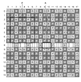
- FIG. 4 is a diagram showing a first embodiment of the arrangement of the color filter array of the image sensor 16 and the phase difference detection pixels.
- the plurality of normal pixels of the image sensor 16 include a first filter corresponding to the first color (green) and a plurality corresponding to each of two or more colors (red and blue) other than green. Any one of the second filters is arranged in the first periodic color arrangement.
- the first periodic color array of the color filters of the image sensor 16 of the first embodiment is an X-Trans (registered trademark) array.
- the X-Trans array transmits a red filter (R filter) that transmits the red (R) wavelength band, a blue filter (B filter) that transmits the blue (B) wavelength band, and a green (G) wavelength band.
- Green filters (B filters) to be arranged are arranged with a predetermined periodicity.
- the G filter corresponds to the first filter corresponding to the first color that contributes most to obtain the luminance signal in comparison with the second color (R and B colors in this embodiment),
- Each of the R filter and the B filter corresponds to a plurality of second filters corresponding to two or more colors other than the first color.
- the X-Trans array includes a basic array pattern P (pattern indicated by a thick frame) composed of a square array pattern corresponding to 6 ⁇ 6 pixels, and the basic array pattern P is repeatedly arranged in the horizontal direction and the vertical direction. .
- FIG. 5 shows a state where the basic array pattern P shown in FIG. 4 is divided into 4 ⁇ 3 ⁇ 3 pixels.
- the basic array pattern P includes a 3 ⁇ 3 pixel A array (first array) surrounded by a solid frame and a 3 ⁇ 3 pixel B array (second array) surrounded by a broken frame. Are arranged in an alternating manner in the horizontal direction and the vertical direction.
- G filters are arranged at the center and four corners of 3 ⁇ 3 pixels, an R filter is arranged in the horizontal direction across the center G filter, and a B filter is arranged in the vertical direction.
- G filters are arranged at the center and four corners of 3 ⁇ 3 pixels, B filters are arranged in the horizontal direction with the center G filter interposed therebetween, and R filters are arranged in the vertical direction.
- the basic array pattern P includes a square array G filter corresponding to 2 ⁇ 2 pixels. This is because the G filter is arranged at the four corners and the center in the 3 ⁇ 3 pixels in the A array or the B array, and the 3 ⁇ 3 pixels are alternately arranged in the horizontal direction and the vertical direction, thereby 2 ⁇ 2 pixels. This is because a square array G filter corresponding to is formed.
- the imaging device 16 has a phase difference pixel row in which phase difference detection pixels are arranged and a normal pixel row in which only normal pixels are arranged.
- the eighth row is a phase difference pixel row. It corresponds to.
- FIG. 4 only one phase difference pixel row is shown, but the phase difference pixel rows are provided on the entire surface of the sensor or a specific AF area at regular intervals (with a plurality of normal pixel rows). ing.
- phase difference pixel row is provided in a row in which two pixels (G pixels) having a G filter are continuous, and the phase difference detection pixels are arranged at the positions of the continuous G pixels.
- phase difference detection pixels phase difference detection pixels indicated by the thick frame A in FIG. 4
- phase difference pixel row (eighth row) shown in FIG. is there.
- the phase difference detection pixel has a pupil division opening, and a first phase difference pixel PR and a second phase difference pixel PL having different opening positions in the horizontal direction.
- the pair of first phase difference pixels PR and second phase difference pixels PL are arranged adjacent to each other with their openings facing each other.
- the first phase difference pixel PR is a right opening pixel having an opening in the right half of the pixel
- the second phase difference pixel PL is a left opening pixel having an opening in the left half of the pixel.
- FIG. 7 is an enlarged view of a main part showing the configuration of the first phase difference pixel PR and the second phase difference pixel PL.
- a light shielding film 16A is provided on the front side (microlens L side) of the photodiode PD of the first retardation pixel PR, while the photodiode PD of the second retardation pixel PL.
- a light shielding film 16B is disposed on the front side of the.
- the microlens L and the light shielding films 16A and 16B have a pupil division function.
- the light shielding film 16A shields the left half of the light receiving surface of the photodiode PD. Therefore, only the light beam passing through the left side of the optical axis among the light beams passing through the exit pupil of the photographing lens 12 is received by the first phase difference pixel PR.
- a G filter is disposed below the microlens L as the color filter CF.
- the light shielding film 16B shields the right half of the light receiving surface of the photodiode PD of the second phase difference pixel PL. Therefore, only the light beam that passes through the right side of the optical axis among the light beams that pass through the exit pupil of the photographing lens 12 is received by the second phase difference pixel PL. As described above, the light beam passing through the exit pupil is divided into left and right by the microlens L having the pupil division function and the light shielding films 16A and 16B, and is incident on the first phase difference pixel PR and the second phase difference pixel PL, respectively. To do.
- FIG. 8 is a graph showing the sensitivity of the normal pixel (G pixel), the first phase difference pixel PR, and the second phase difference pixel PL in the left-right direction of the image sensor 16 under certain conditions.
- the sensitivity of the normal pixel (G pixel) whose opening is not shielded is the highest, and the sensitivity of the first phase difference pixel PR and the second phase difference pixel PL is lower than that of the G pixel.
- the first phase difference pixel PR and the second phase difference pixel PL are configured such that the left half and the right half of the opening are shielded by the light shielding film.
- the first phase difference pixel PR and the second phase difference pixel PL have the same sensitivity (signal value) at the center of the sensor, and the first phase difference pixel PR has a higher sensitivity as it is located on the sensor left end side.
- the sensitivity of the first phase difference pixel PR becomes higher (the signal value becomes larger) as it is positioned on the left end side of the sensor.
- the signal values of the pair of first phase difference pixels PR and the second phase difference pixel PL substantially coincides with the signal value (G) of the normal pixel (G pixel) provided at the same position (PA ⁇ G).
- the image signal (pixel value) of the pair of first phase difference pixels PR and the image signal (pixel value) of the second phase difference pixel PL are added as shown in FIG.
- the pixel value) is substantially equal to the pixel value of the normal pixel (G pixel), and the added pixel (addition pixel) is an intermediate between the pair of first phase difference pixel PR and second phase difference pixel PL.
- the added pixel is an intermediate between the pair of first phase difference pixel PR and second phase difference pixel PL.
- the pixel value of the added pixel of the pair of first phase difference pixel PR and second phase difference pixel PL (corresponding to the pixel value of the G pixel of the normal pixel in this example) is the first phase difference pixel PR or This can be used when the pixel value of the G pixel at the pixel position of the target pixel of the second phase difference pixel PL is interpolated by average value interpolation. The details of the phase difference pixel correction will be described later.
- the image signal (image data) read from the image sensor 16 at the time of shooting a moving image or a still image is temporarily stored in a memory (SDRAM (Synchronous Dynamic Random Access Memory)) 48 via the image input controller 22. Or stored in the phase difference detector 42, the AE detector 44, or the like.
- SDRAM Serial Dynamic Random Access Memory
- the CPU 40 performs overall control of each unit of the imaging device 10 based on an operation on the operation unit 38, but always performs AF operation and AE operation during live view image shooting (display) and moving image shooting (recording). Do.
- the phase difference detection unit 42 is a part that performs phase difference AF processing, and uses each output signal of the first phase difference pixel PR and the second phase difference pixel PL acquired via the image input controller 22. Detect phase difference. Details of phase difference detection by the phase difference detection unit 42 will be described later.
- the CPU 40 When the phase difference data indicating the phase difference is input from the phase difference detection unit 42, the CPU 40 functions as a focus adjustment unit that performs phase difference AF based on the phase difference data. That is, the CPU 40 calculates a deviation amount (defocus amount) between the focus position of the photographing lens 12 and the imaging surface of the image sensor 16 based on the phase difference data, and the lens so that the calculated defocus amount becomes zero.
- the focus lens in the photographic lens 12 is moved via the drive unit 36.
- the calculation of the defocus amount may be performed by the phase difference detection unit 42.
- the AE detection unit 44 integrates image data (for example, pixel values of G pixels of the entire screen) acquired via the image input controller 22, or weights differently between the central portion and the peripheral portion of the screen. (The pixel value of the G pixel) is integrated, and the integrated value is output to the CPU 40. The CPU 40 calculates the brightness of the subject (imaging Ev value (exposure value)) from the integrated value input from the AE detection unit 44.
- image data for example, pixel values of G pixels of the entire screen
- the CPU 40 calculates the brightness of the subject (imaging Ev value (exposure value)) from the integrated value input from the AE detection unit 44.
- the shooting mode is the still image shooting mode
- the CPU 40 performs the above-described AF control again, and if the shutter button 2 is fully pressed,
- the brightness of the subject (shooting Ev value) is calculated, and based on the calculated shooting Ev value, the F value of the aperture 14 and the exposure time (shutter speed) by the mechanical shutter 15 are determined according to the program diagram, and still image shooting ( (Exposure control).
- the shooting mode is the moving image shooting mode
- the CPU 40 starts shooting and recording (recording) of the moving image.
- the mechanical shutter 15 is opened, image data is continuously read from the image sensor 16 (for example, frame rates of 30 frames / second, 60 frames / second), and phase difference AF is continuously performed.
- the brightness of the subject is calculated, and the shutter drive unit 33 controls the shutter speed (charge accumulation time by the rolling shutter) and / or the aperture 14 by the aperture drive unit 34.
- the CPU 40 moves the zoom lens forward and backward in the optical axis direction via the lens driving unit 36 in accordance with the zoom command from the zoom button 5 to change the focal length.
- Reference numeral 47 denotes a ROM (Read Only Memory) that stores various parameters and tables used for camera control programs, defect information of the image sensor 16, image processing, and the like, or EEPROM (Electrically Erasable Programmable Read-Only Memory). It is.
- ROM 47 the phase difference pixel row (including the pixel positions of the first phase difference pixel PR and the second phase difference pixel PL) of the image sensor 16, information on the normal pixel row, and gain interpolation information to be described later , And level adjustment coefficients and the like are stored.
- the image processing unit 24 reads unprocessed image data (RAW data) temporarily stored in the memory 48 via the image input controller 22 when a moving image or a still image is captured.
- the image processing unit 24 performs offset processing, pixel interpolation processing (interpolation processing of phase difference detection pixels, scratched pixels, etc.), white balance correction, gain control processing including sensitivity correction, gamma correction processing on the read RAW data, Synchronization processing (also referred to as “demosaic processing”), luminance and color difference signal generation processing, contour enhancement processing, color correction, and the like are performed.
- VRAM Video RAM Random Access memory
- the VRAM 50 includes an A area and a B area for recording image data each representing an image for one frame.
- image data representing an image for one frame is rewritten alternately in the A area and the B area.
- the written image data is read from an area other than the area where the image data is rewritten.
- the image data read from the VRAM 50 is encoded by the video encoder 28 and output to the liquid crystal monitor 30 provided on the back of the camera. As a result, a live view image showing the subject image is displayed on the liquid crystal monitor 30.
- the image data processed by the image processing unit 24 and processed as a still image or moving image for recording (luminance data (Y) and color difference data (Cb), (Cr)) is stored in the memory 48 again.
- luminance data (Y) and color difference data (Cb), (Cr) is stored in the memory 48 again.
- the compression / decompression processing unit 26 compresses the luminance data (Y) and the color difference data (Cb), (Cr) processed by the image processing unit 24 and stored in the memory 48 when recording a still image or a moving image. Apply. In the case of a still image, it is compressed in, for example, JPEG (Joint Photographic coding Experts Group) format, and in the case of a moving image, it is compressed in, for example, H.264 format.
- the compressed image data compressed by the compression / decompression processing unit 26 is recorded on the memory card 54 via the media controller 52.
- the compression / decompression processing unit 26 performs decompression processing on the compressed image data obtained from the memory card 54 via the media controller 52 in the playback mode.
- the media controller 52 performs recording and reading of compressed image data with respect to the memory card 54.
- Phase difference AF When performing phase difference AF, the CPU 40 functioning as an autofocus control unit outputs a read command for reading out image data of a phase difference pixel row in at least the AF area of the image sensor 16 to the sensor drive unit 32, and outputs from the image sensor 16. Read the corresponding image data.
- the CPU 40 When shooting and displaying a moving image (including a live view image), the CPU 40 acquires a thinning rate for thinning out and reading out image data from the image sensor 16.
- This thinning rate may be a fixed value set in advance, or may be selected by the user from a plurality of thinning rates. For example, an optimum thinning rate can be set in conjunction with the selection of the image size of the moving image or the selection of the frame rate. Note that it is preferable that the phase difference pixel rows be included in the rows to be thinned and read out.
- the CPU 40 outputs a read command indicating a thinning pattern (extraction pattern) corresponding to the thinning rate to the sensor driving unit 32, and reads out the image data from the image sensor 16.
- the phase difference detection unit 42 extracts the output data of the phase difference detection pixels (first phase difference pixel PR and second phase difference pixel PL) in the AF area from the read phase difference pixel row, The phase difference between the output data (first pixel value) of the first phase difference pixel PR and the output data (second pixel value) of the second phase difference pixel PL is detected. For example, when the correlation between the first pixel value of the pair of first phase difference pixels PR and the second pixel value of the second phase difference pixel PL is maximized (for each pixel value of the pair of phase difference pixels PL The phase difference is obtained from the shift amount in the left-right direction between the first pixel value and the second pixel value (when the integrated absolute difference value is minimized).
- phase difference calculation method is not limited to the above method, and various methods can be applied.
- the CPU 40 calculates a deviation amount (defocus amount) between the focus position by the photographing lens 12 (imaging optical system) and the imaging surface of the image sensor 16 based on the phase difference data detected by the phase difference detector 42. calculate.
- the calculation of the defocus amount may be performed by the phase difference detection unit 42.
- the CPU 40 moves the focus lens in the photographing lens 12 through the lens driving unit 36 so that the defocus amount becomes zero based on the calculated defocus amount, thereby performing phase difference AF.
- the pair of first phase difference pixels PR and the second phase difference pixels PL are disposed adjacent to each other with the opening portions facing each other.
- the interval with the phase difference pixel PL is the minimum.
- phase difference pixel rows having the phase difference detection pixels can be included in the rows read out from the image sensor 16 when the moving image is generated.
- phase difference AF can be appropriately performed even during moving image shooting.
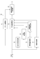
- FIG. 9 is a block diagram showing a first embodiment of the interpolation processing unit in the image processing unit 24 shown in FIG.
- the interpolation processing unit 60 of the first embodiment shown in FIG. 9 is switched to the still image shooting mode, and the phase difference detection included in the image data (RAW data) read from the image sensor 16 at the time of still image shooting. This is a part for correcting (interpolating) the pixel values of the pixels for use (first phase difference pixel PR, second phase difference pixel PL).
- the interpolation processing unit 60 includes a gain interpolation unit 61, an average value interpolation unit 62, a signal gradient calculation unit 63, a pixel value addition unit 64, and a final pixel value determination unit 65.
- phase difference detection pixels (the first phase difference pixel PR and the second phase difference pixel PL) are incident about half of the amount of light incident on the surrounding normal pixels, the sensitivity is lower than that of the normal pixels. It cannot be used as a pixel.
- the gain interpolation unit 61 functioning as the second interpolation unit multiplies the pixel value of the phase difference detection pixel by predetermined gain interpolation information so as to compensate for the sensitivity reduction of the phase difference detection pixel, Perform interpolation to match the signal level.
- the interpolation processing unit 60 is set for the pixel position of the target pixel in the RAW data.
- a gain interpolation information acquisition unit for acquiring gain interpolation information is included.
- the gain interpolation information acquisition unit may calculate gain interpolation information corresponding to the pixel position of the target pixel based on the RAW data around the target pixel, or store the gain interpolation information for each pixel position of the target pixel. (ROM 47).
- the gain interpolation information can be calculated from the ratio between the pixel value of the target pixel in the RAW data and the average pixel value of normal pixels of the same color around the target pixel.
- the average value interpolating unit 62 functioning as the first interpolating unit includes a pixel value of a normal pixel around the pixel position of the target pixel, and an addition pixel of the pair of first phase difference pixel PR and second phase difference pixel PL.
- the pixel value at the pixel position of the target pixel is generated using at least one of the pixel values of the pixel value.
- the average value interpolation unit 62 indicates the signal gradient direction calculated by the signal gradient calculation unit 63. Information and the addition pixel value of the addition pixel added by the pixel value addition unit 64 are added.
- the signal gradient calculation unit 63 calculates a signal gradient direction in which the signal gradient of the pixels around the pixel position of the target pixel is minimized.
- FIG. 10 is a diagram for explaining average value interpolation for the phase difference detection pixel (first phase difference pixel PR) in the image sensor of the first embodiment.
- G pixels G1 to G10
- G11, G12, and G13 indicate addition pixels corresponding to G pixels, respectively.
- the signal gradient calculation unit 63 uses the G pixels around the target pixel.
- the pixel value is obtained, and the horizontal signal gradient is calculated from the difference between the pixel values of two G pixels (for example, G4 and G5) in the horizontal direction (first direction) and the pixel interval, and the vertical direction (
- the signal gradient in the vertical direction is calculated from the difference between the pixel values of two G pixels in the second direction (for example, G4 and G9) and the pixel interval, and two G pixels in the +45 degree direction (third direction)
- the signal gradient in the +45 degree direction is calculated from the difference between the pixel values of G2 and G5) and the pixel interval, and the pixel values of two G pixels (for example, G1 and G4) in the ⁇ 45 degree direction (fourth direction) are calculated.
- the signal gradient in the ⁇ 45 degree direction is calculated from the difference between the two and the pixel interval. Note that the pixels used
- the signal gradient calculation unit 63 calculates the signal gradient direction that minimizes the signal gradient among the four signal gradients calculated as described above as the signal gradient direction.
- the pixel value of the G pixel is used for the calculation of the signal gradient direction.
- the pixel value of the G pixel is used to obtain the luminance signal (Y) among the pixel values of the R pixel, the G pixel, and the B pixel. This is because the signal gradient direction calculated as described above corresponds to the direction having the highest luminance correlation among the four directions.
- the pixel value adding unit 64 adds the pixel value of the pair of first phase difference pixels PR and the pixel value of the second phase difference pixel PL, and adds the pixel value of the first phase difference pixel PR and the second value.
- a pixel value of a virtual G pixel (addition pixel) at a pixel position with respect to the phase difference pixel PL is generated.
- the added pixel value (added pixel value) Is equal to the pixel value of the normal pixel (G pixel) at the same pixel position, and the addition pixel is present between the pair of first phase difference pixel PR and second phase difference pixel PL. Can be handled.
- the addition pixel value of the addition pixel generated by the pixel value addition unit 64 is output to the average value interpolation unit 62.
- the average value interpolation unit 62 is in the signal gradient direction calculated by the signal gradient calculation unit 63 and in the signal gradient direction based on the pixel position of the target pixel.
- a plurality of G pixels (including an addition pixel corresponding to the G pixel) having the same color as the pixel position of the pixel of interest existing, and detecting the pixel value of the pixel of interest by interpolating the detected pixel values of the plurality of G pixels A pixel value of the position is generated.
- the average value interpolation unit 62 interpolates the pixel values of the addition pixels (G11, G12) corresponding to the horizontal G pixels (weighted average according to the distance). Thus, the pixel value of the pixel position of the target pixel is generated.
- the signal gradient direction is the horizontal direction
- the average value interpolation unit 62 when the signal gradient direction is the vertical direction, the average value interpolation unit 62 generates a pixel value at the pixel position of the target pixel by interpolating the two G pixels (G4 and G9) in the vertical direction. In the case of the +45 degree direction, the average value interpolation unit 62 interpolates two G pixels (G5 and G6) in the +45 degree direction to generate a pixel value at the pixel position of the target pixel.
- the average value interpolation unit 62 interpolates two G pixels (G14 and G15) in the ⁇ 45 degree direction to generate a pixel value of the pixel position of the target pixel. I get out.
- the G pixels of G14 and G15 are pixels outside the range of 5 ⁇ 5 pixels centering on the pixel of interest (a relatively distant pixel), it is conceivable that the interpolation accuracy decreases.
- the average value interpolation unit 62 includes two pixels G4 and G11, three pixels G4, G11, and G6, four pixels G4, G11, G6, and G9, or ⁇
- the pixel values of the pixel position of the target pixel may be generated by interpolating the pixel values of the two sets of G1 and G7, G3 and G10 in the 45 degree direction, or the pixel value of the addition pixel (G11) is used as it is. May be.
- the average value interpolating unit 62 can interpolate the pixel value for imaging at the pixel position of the second phase difference pixel PL in the same manner as described above even when the target pixel is the second phase difference pixel PL.
- the pixels used for the average value interpolation are not limited to the above example.
- the final pixel value determination unit 65 selects one of the pixel value interpolated by the gain interpolation unit 61 and the pixel value interpolated by the average value interpolation unit 62 for the target pixel, or A pixel value obtained by weighted addition of the two pixel values is generated, and a final pixel value at the pixel position of the target pixel is determined. For example, when the image around the pixel of interest is flat, a pixel value obtained by average interpolation is preferable, and when the spatial frequency of the image around the pixel of interest is high, a pixel value obtained by gain interpolation is preferable. In an out-of-focus area, a pixel value obtained by average value interpolation is preferable.
- the interpolation processing unit 60 corrects (interpolates) the pixel value of the phase difference detection pixel included in the RAW data read from the image sensor 16 at the time of shooting a still image, and thereby uses the phase difference detection.
- RAW data of a still image in which the pixel value at the pixel position of the pixel is corrected is generated.
- FIG. 11 is a block diagram showing a second embodiment of the interpolation processing unit in the image processing unit 24 shown in FIG.
- the same reference numerals are given to the portions common to the first embodiment shown in FIG. 9, and the detailed description thereof is omitted.
- the interpolation processing unit 60 of the second embodiment shown in FIG. 11 is different from the first embodiment shown in FIG. 9 in that an addition pixel level correction unit 66 is added.
- the addition pixel level correction unit 66 reads the level adjustment coefficient (K) corresponding to the pixel position of the target pixel from a storage unit (ROM 47) that stores the level adjustment coefficient in advance, or analyzes the image data to obtain the level adjustment coefficient ( K) is calculated, and the read or calculated level adjustment coefficient (K) is multiplied by the added pixel value (PA) added by the pixel value adding unit 64 and multiplied (level adjusted).
- FIG. 12 is a block diagram showing a third embodiment of the interpolation processing unit in the image processing unit 24 shown in FIG.
- the same reference numerals are given to the portions common to the second embodiment shown in FIG. 11, and the detailed description thereof is omitted.
- the interpolation processing unit 60 of the third embodiment shown in FIG. 12 is different from the second embodiment shown in FIG. 11 in that a saturation determination unit 67 is mainly added.
- the saturation determination unit 67 includes at least one of a target pixel to be interpolated, a first phase difference pixel PR or a second phase difference pixel PL adjacent to the target pixel, and a normal pixel (G pixel) adjacent to the target pixel.
- the saturation of one pixel is determined, and the determination result is output to the average value interpolation unit 62.
- the adjusted added pixel value (PA ⁇ K) exceeds the saturation level, if the added pixel value is clipped at the saturated level, the added pixel and the G pixel coincide with each other, and no particular problem occurs. However, if the value of the level adjustment coefficient (K) for adjusting the added pixel value (PA) cannot be set accurately, the adjusted added pixel value (PA ⁇ K) exceeds the saturation level even if the G pixel is saturated. In this case, there is a signal step between the added pixel and the surrounding G pixel. In such a case, the average value interpolation unit 62 should not use the addition pixel for the average value interpolation.
- the target pixel is the first phase difference pixel PR
- the surrounding G pixels for example, G4, G5, and G6 are saturated, they are adjacent to the target pixel.
- the addition pixel to be used is not used for average value interpolation.
- the high-frequency signal pattern is photographed, even if the G pixel adjacent to the target pixel is not saturated, the high-frequency light is the target pixel, the first phase difference pixel PR or the second phase difference adjacent to the target pixel.
- the addition pixel adjacent to the target pixel is not used for the average value interpolation.
- SATLEV 65000 is set.
- the average value interpolation unit 62 includes a target pixel to be interpolated, a first phase difference pixel PR or a second phase difference pixel PL adjacent to the target pixel, and a normal pixel (G pixel) adjacent to the target pixel.
- the average value interpolation unit 62 uses the saturation determination unit 67 to interpolate the target pixel, the first phase difference pixel PR or the second phase difference pixel PL adjacent to the target pixel, and the G pixel adjacent to the target pixel. If it is determined that at least one of the pixels is saturated, only the normal pixel (G pixel) is used for the average value interpolation.
- the addition pixel when an addition pixel is used to improve the accuracy of average value interpolation, the addition pixel is used for average value interpolation under the condition that signal saturation that causes image quality degradation occurs due to the use of the addition pixel. Since it is not used, the interpolation accuracy of average value interpolation can be maintained (image quality can be maintained).
- FIG. 13 is a block diagram showing a fourth embodiment of the interpolation processing unit in the image processing unit 24 shown in FIG.
- the same reference numerals are given to the portions common to the third embodiment shown in FIG. 12, and the detailed description thereof is omitted.
- FIG. 13 is different from the third embodiment shown in FIG. 12 mainly in that 67 is added as a flatness determination unit in the fourth embodiment shown in FIG.
- the flatness determination unit 68 calculates the flatness of the image in the predetermined window based on the pixel position of the target pixel, and determines whether the image in the window is flat based on the calculated flatness.
- the flatness determination unit 68 of this example inputs information indicating signal gradients in four directions (horizontal direction, vertical direction, +45 degree direction, and ⁇ 45 degree direction) calculated by the signal gradient calculation unit 63, and receives the four directions. If the calculated maximum signal gradient is equal to or less than the threshold value (first threshold value) for determining flatness, it is determined that the image in the predetermined window is flat. .
- the flatness determination unit 68 is not limited to the above example, and a range of 5 ⁇ 5 pixels centered on the pixel of interest (the first phase difference pixel PR in FIG. 14) as shown in FIG.
- the standard deviation or variance of the pixel values of a plurality of G pixels (10 G pixels from G1 to G10) in the window is calculated, and the calculated standard deviation or variance is a threshold value for determining flatness (second Or less), the image in the window may be determined to be flat.
- the size of the window is not limited to a range of 5 ⁇ 5 pixels, but may be M ⁇ N pixels (M and N are preferably odd numbers of 3 or more).
- the average value interpolating unit 62 receives a determination result from the flatness determining unit 68 that the image in the predetermined window is flat based on the pixel position of the target pixel to be interpolated, the averaged pixel is converted to the average value interpolation. Do not use. In other words, when the flatness determination unit 68 determines that the image in the predetermined window is the average value interpolation unit 62, only the normal pixel (G pixel) is used for the average value interpolation.
- the average value interpolation unit 62 uses pixels for average value interpolation based on the signal gradient direction calculated by the signal gradient calculation unit 63. May be used, and average interpolation may be performed using all G pixels in the window or a part of G pixels.
- the addition pixel is used for the average value interpolation
- the target pixel that has been subjected to the average value interpolation is changed into a flat image.
- the pixel value is different from that of the G pixel, and is particularly noticeable in a flat image.
- the average value interpolation unit 62 performs average value interpolation without using the addition pixel.
- the weight for the addition pixel may be reduced.
- the fourth embodiment when an addition pixel is used to improve the accuracy of average value interpolation, a flat portion of an image that is easily noticeable as erroneous correction when there is a signal step between the addition pixel and the normal pixel. In this case, it is possible to prevent deterioration in image quality by performing average value interpolation using only normal pixels (or by reducing the weight of the added pixels).
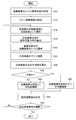
- FIG. 15 is a flowchart showing the first embodiment of the image processing method according to the present invention, and particularly shows the processing procedure in the interpolation processing unit 60 shown in FIG.
- the addition pixel level correction unit 66 shown in FIG. 12 sets the level adjustment coefficient (K) of the addition pixel (step S10).
- the addition pixel level correction unit 66 can set the level adjustment coefficient (K) set in advance, or the level adjustment coefficient (K) calculated by analyzing the RAW data.
- the gain interpolation information acquisition unit included in the gain interpolation unit 61 reads gain interpolation information from a storage unit (ROM 47) that stores gain interpolation information in advance, or calculates gain interpolation information by analyzing image data, The read or calculated gain interpolation information is set (step S12).
- the interpolation processing unit 60 selects a non-interpolated phase difference pixel (first phase difference pixel PR, second phase difference pixel PL) as a target pixel (step S14).
- the signal gradient calculation unit 63 calculates the signal gradient direction around the target pixel selected in step S14 based on the pixel values of the G pixels around the target pixel (step S16).
- the pixel value adding unit 64 adds the pixel values of the pair of first phase difference pixels PR and the second phase difference pixel PL, and the addition pixel level correction unit 66 sets the added pixel values of the addition pixels to the step.
- the level adjustment coefficient set in S10 is multiplied to adjust the level of the added pixel (step S18).
- the gain interpolation unit 61 multiplies the pixel value of the target pixel set in step S14 by the gain interpolation information set in step S12, and performs gain interpolation that matches the signal level with the normal pixel (step S20).
- the average value interpolating unit 62 determines the pixel (the target pixel, the first phase difference pixel PR or the second phase difference pixel PL adjacent to the target pixel, and the normal pixel adjacent to the target pixel based on the determination result input from the saturation determination unit 67. It is determined whether or not at least one pixel (G pixel) is saturated (step S22). If it is determined that it is not saturated (in the case of “No”), In addition to the normal pixel (G pixel), the pixel value for imaging at the pixel position of the target pixel is calculated (average value interpolation) using the added pixel whose level is adjusted in step S18 (step S24, interpolation step).
- step S26 interpolation step
- the final pixel value determination unit 65 selects, for the target pixel, one of the pixel value that has been gain-interpolated in step S20 and the pixel value that has been subjected to average value interpolation in step S24 or step S26. Alternatively, a pixel value obtained by weighting and adding two pixel values is generated, and a final interpolation value (final pixel value) at the pixel position of the target pixel is determined (step S28).
- the interpolation processing unit 60 determines whether or not the interpolation (generation of pixel values) of all the phase difference pixels (the first phase difference pixel PR and the second phase difference pixel PL) in the image sensor 16 has been completed. (Step S39) When the interpolation of all the phase difference pixels is not completed (in the case of “No”), the process returns to Step S14, and the processing from Step S14 to Step S28 is repeated to complete the interpolation of all the phase difference pixels. If it has been performed (in the case of “Yes”), the processing in the interpolation processing unit 60 is terminated.
- the accuracy of the average value interpolation can be improved by using the addition pixel, and the signal saturation that causes the image quality deterioration by using the addition pixel is generated. Since the addition pixels are not used for the average value interpolation, the interpolation accuracy of the average value interpolation can be maintained (image quality can be maintained).
- FIG. 16 is a flowchart showing a second embodiment of the image processing method according to the present invention, and particularly shows a processing procedure in the interpolation processing unit 60 shown in FIG.
- steps that are the same as those in the first embodiment shown in FIG. 15 are given the same step numbers, and detailed descriptions thereof are omitted.
- the image processing method according to the second embodiment shown in FIG. 16 is mainly different from the first embodiment in that steps S40 and S42 are performed instead of step S22 of the first embodiment shown in FIG. Is different.
- the flatness determination unit 68 shown in FIG. 13 calculates the flatness of the image in the predetermined window based on the pixel position of the target pixel (step S40), and determines whether the image in the window is flat from the calculated flatness. Is output to the average value interpolation unit 62 (step S40).
- step S24 the average value interpolation unit 62 performs the average value interpolation of the target pixel using not only the normal pixel (G pixel) around the target pixel but also the addition pixel.
- step S26 the average pixel is not used.
- the average interpolation of the target pixel is performed using only normal pixels (G pixels) around the target pixel.
- the accuracy of the average value interpolation can be improved by using the addition pixel, and if the correction is made erroneously (incorrect interpolation) by using the addition pixel, an error occurs.
- the addition pixel is not used for the average value interpolation, so that the interpolation accuracy (image quality) of the average value interpolation can be maintained.
- FIG. 17 is a diagram illustrating a second embodiment of the arrangement of the color filter array and the phase difference detection pixels of the image sensor 16.
- the first periodic color array of the color filters of the image sensor 16 of the second embodiment is a general Bayer array.
- a normal pixel row in which only normal pixels are arranged in the horizontal direction (row direction) includes a pixel having an R filter (R pixel) and a pixel having a G filter (G pixel).
- R pixel an R filter
- G pixel a pixel having a G filter
- the RG rows and GB rows are alternately arranged in the vertical direction (column direction).
- the image sensor 16 of the second embodiment includes a phase difference pixel row in which the first phase difference pixel PR and the second phase difference pixel PL are provided, and a normal pixel row in which only the normal pixels are provided. have.
- the phase difference pixel row of the image sensor 16 shown in FIG. 17 is a specific GB row in the Bayer array, and includes one pair of the first phase difference pixel PR and the second phase difference pixel PL and one normal pixel. Periodically arranged in the row direction as a cycle. Therefore, in the phase difference pixel row, the G pixel and the B pixel are alternately arranged every two pixels (a pair of the first phase difference pixel PR and the second phase difference pixel PL) in the row direction.
- the phase difference pixel row of this example is provided in GB row
- the G filter is disposed in each of the first phase difference pixel PR and the second phase difference pixel PL of the present example, for example, from the transmission wavelength band of the G filter without arranging the G filter.
- light having a wide wavelength band may be incident.
- the pixel value (added pixel value) of the added pixels is the normal pixel (G
- the added pixel (addition pixel) can be treated as existing between the pair of first phase difference pixel PR and second phase difference pixel PL. .
- the “average value interpolation” of the phase difference pixels is similar to the imaging element 16 of the second embodiment having the X-Trans arrangement, and the phase difference detection pixel (the first phase difference pixel PR or the second position) of interest. This can be performed using a plurality of normal pixels and addition pixels existing around the phase difference pixel PL).
- FIG. 18 is a diagram for explaining average value interpolation for the phase difference detection pixels in the image sensor according to the second embodiment.
- the target pixel to be interpolated shown in FIG. 18 is the first phase difference pixel PR, and the position of the target pixel corresponds to the position of the G pixel.
- the average value interpolating unit 62 shown in FIG. 9 calculates the added pixel value of the added pixel added by the pixel value adding unit 64 around the target pixel. It is used as the pixel value of one of the pixels, and the pixel value at the target pixel is interpolated.
- the average value interpolation unit 62 calculates the addition pixels (two addition pixels indicated by the thick frame in FIG. 18) corresponding to the horizontal G pixels.
- the pixel value of the pixel position of the target pixel is generated by interpolating the added pixel value (weighted average according to the distance).
- the average value interpolation unit 62 interpolates the pixel values of the G pixels in the vertical direction (two G pixels indicated by vertical arrows). Thus, the pixel value of the pixel position of the target pixel is generated.
- the average value interpolation unit 62 selects the G pixel in the +45 degree direction (two G pixels indicated by arrows in the +45 degree direction).
- the average value interpolation unit 62 displays the G pixel in the ⁇ 45 degree direction (indicated by the arrow in the ⁇ 45 degree direction). Two G pixels) are interpolated to generate a pixel value at the pixel position of the target pixel.
- FIG. 19 is another diagram for explaining the average value interpolation for the phase difference detection pixels in the image sensor of the second embodiment.
- the target pixel to be interpolated shown in FIG. 19 is the second phase difference pixel PL, and the position of the target pixel corresponds to the position of the B pixel.
- the average value interpolating unit 62 does not use the added pixel value of the added pixel added by the pixel value adding unit 64, and the B around the target pixel.
- the pixel value at the target pixel is interpolated using only the pixel. This is because the addition pixel corresponds to a virtual G pixel.
- the average value interpolation unit 62 interpolates (distances) pixel values of B pixels in the horizontal direction (two B pixels indicated by horizontal arrows). The pixel value of the pixel position of the target pixel is generated.
- the average value interpolation unit 62 interpolates the pixel values of the B pixels in the vertical direction (two B pixels indicated by the vertical arrows). Thus, the pixel value of the pixel position of the target pixel is generated.
- the average value interpolation unit 62 calculates B pixels in the +45 degree direction (two B pixels indicated by arrows in the +45 degree direction).
- the average value interpolation unit 62 displays B pixels in the ⁇ 45 degrees direction (indicated by the arrow in the ⁇ 45 degrees direction). The pixel value of the pixel position of the target pixel is generated by interpolating (two B pixels).
- the aspect of the imaging apparatus to which the present invention can be applied is not limited to the imaging apparatus 10 shown in FIG. 1, and for example, a mobile phone or a smartphone having a camera function, a PDA (Personal Digital Assistant), and a portable game machine Etc.
- a smartphone to which the present invention can be applied will be described.
- FIG. 20 is a diagram illustrating an appearance of a smartphone that is an embodiment of an imaging apparatus.
- a smartphone 100 illustrated in FIG. 20 includes a flat housing 102, and a display panel 121 as a display unit and an operation panel 122 as an input unit are integrally formed on one surface of the housing 102.
- a display input unit 120 is provided.
- the housing 102 includes a speaker 131, a microphone 132, an operation unit 140, and a camera unit 141 (imaging unit). Note that the configuration of the housing 102 is not limited thereto, and for example, a configuration in which a display unit and an input unit are provided independently, or a configuration having a folding structure or a slide mechanism may be employed.
- FIG. 21 is a block diagram showing an internal configuration of the smartphone 100 shown in FIG.
- the main components of the smartphone 100 include a wireless communication unit 110, a display input unit 120, a call unit 130, an operation unit 140, a camera unit 141, a storage unit 150, and an external input / output.
- Unit 160 output unit
- GPS global positioning system
- receiving unit 170 GPS (global positioning system) receiving unit 170
- motion sensor unit 180 motion sensor unit 180
- power supply unit 190 power supply unit 190
- main control unit 101 main control unit 101.
- a wireless communication function for performing mobile wireless communication via a base station device and a mobile communication network is provided.
- the wireless communication unit 110 performs wireless communication with a base station device connected to the mobile communication network in accordance with an instruction from the main control unit 101.
- the wireless communication is used to transmit and receive various file data such as audio data and image data, e-mail data, and receive web data and streaming data.
- the display input unit 120 is a so-called touch panel including an operation panel 122 disposed on the screen of the display panel 121, and displays images (still images and moving images), character information, and the like under the control of the main control unit 101. Then, information is visually transmitted to the user, and a user operation on the displayed information is detected.
- the operation panel 122 is also referred to as a touch panel for convenience.
- the display panel 121 uses an LCD (Liquid Crystal Display) or an OELD (Organic Electro-Luminescence Display) as a display device.
- the operation panel 122 is a device that is provided in a state where an image displayed on the display surface of the display panel 121 is visible, and detects one or a plurality of coordinates operated by a user's finger or stylus. When the device is operated by the user's finger or stylus, the operation panel 122 outputs a detection signal generated due to the operation to the main control unit 101. Next, the main control unit 101 detects an operation position (coordinates) on the display panel 121 based on the received detection signal.
- the display panel 121 and the operation panel 122 of the smartphone 100 illustrated as an example constitute the display input unit 120 so that the operation panel 122 completely covers the display panel 121.
- the operation panel 122 may have a function of detecting a user operation even in an area outside the display panel 121.
- the operation panel 122 has a detection area (hereinafter referred to as “display area”) that overlaps the display panel 121 and a detection area (hereinafter referred to as “non-display area”) that does not overlap the other display panel 121. Display area ”).
- the operation panel 122 may be provided with two sensitive areas of an outer edge part and the other inner part. Furthermore, the width of the outer edge portion is appropriately designed according to the size of the housing 102 and the like. Furthermore, examples of the position detection method employed in the operation panel 122 include a matrix switch method, a resistance film method, a surface acoustic wave method, an infrared method, an electromagnetic induction method, and a capacitance method. It may be adopted.
- the call unit 130 includes a speaker 131 and a microphone 132, converts user's voice input through the microphone 132 into voice data that can be processed by the main control unit 101, and outputs the voice data to the main control unit 101, or a wireless communication unit. 110 or the audio data received by the external input / output unit 160 is decoded and output from the speaker 131. Further, as shown in FIG. 20, for example, the speaker 131 and the microphone 132 can be mounted on the same surface as the surface on which the display input unit 120 is provided.
- the operation unit 140 is a hardware key using a key switch or the like, and receives an instruction from the user.
- the operation unit 140 is mounted on the side surface of the housing 102 of the smartphone 100 and is switched on when pressed with a finger or the like, and is switched off by a restoring force such as a spring when the finger is released. It is a push button type switch that is in a state.
- the storage unit 150 includes control programs and control data of the main control unit 101, address data that associates names and telephone numbers of communication partners, transmitted and received e-mail data, web data downloaded by web browsing, and downloaded content Data and the like are stored, and streaming data and the like are temporarily stored.
- the storage unit 150 includes an internal storage unit 151 built in the smartphone and an external storage unit 152 having a removable external memory slot.
- Each of the internal storage unit 151 and the external storage unit 152 constituting the storage unit 150 includes a flash memory type, a hard disk type, a multimedia card micro type, a card type memory, a RAM (Random Access Memory), or a ROM (Read Realized using storage media such as “Only Memory”.
- the external input / output unit 160 serves as an interface with all external devices connected to the smartphone 100, and includes communication (for example, USB (Universal Serial Bus), IEEE 1394, etc.) or a network (for example, a wireless LAN (Local Area Area). Network), Bluetooth (registered trademark), RFID (Radio Frequency Identification), Infrared Data Association (IrDA), UWB (Ultra Wideband) (registered trademark), ZigBee (registered trademark), etc. Connect directly or indirectly to other external devices.
- communication for example, USB (Universal Serial Bus), IEEE 1394, etc.
- a network for example, a wireless LAN (Local Area Area). Network), Bluetooth (registered trademark), RFID (Radio Frequency Identification), Infrared Data Association (IrDA), UWB (Ultra Wideband) (registered trademark), ZigBee (registered trademark), etc. Connect directly or indirectly to other external devices.
- an external device connected to the smartphone 100 for example, a wired / wireless headset, a wired / wireless external charger, a wired / wireless data port, a memory card connected via a card socket, a SIM (Subscriber) Identity Module Card) / UIM User Identity Module Card, external audio video equipment connected via audio / video I / O (Input / Output) terminal, external audio video equipment wired / wirelessly connected, smartphone, There are personal computers, PDAs (Personal Digital Assistants), and earphones.
- the external input / output unit 160 is configured to transmit data received from such an external device to each component inside the smartphone 100, or to transmit data inside the smartphone 100 to the external device. May be.
- the GPS receiving unit 170 receives GPS signals transmitted from the GPS satellites ST1, ST2 to STn according to instructions from the main control unit 101, executes positioning calculation processing based on the received GPS signals, and determines the latitude of the smartphone 100.
- the position information (GPS information) specified by longitude and altitude is acquired.
- the GPS receiving unit 170 can acquire position information from the wireless communication unit 110 and / or the external input / output unit 160 (for example, a wireless LAN), the GPS receiving unit 170 can also detect the position using the position information.
- the motion sensor unit 180 includes, for example, a three-axis acceleration sensor, and detects the physical movement of the smartphone 100 in accordance with an instruction from the main control unit 101. By detecting the physical movement of the smartphone 100, the moving direction and acceleration of the smartphone 100 are detected. The detection result is output to the main control unit 101.
- the power supply unit 190 supplies power stored in a battery (not shown) to each unit of the smartphone 100 in accordance with an instruction from the main control unit 101.
- the main control unit 101 includes a microprocessor, operates according to a control program and control data stored in the storage unit 150, and controls each unit of the smartphone 100 in an integrated manner. Further, the main control unit 101 includes a mobile communication control function for controlling each unit of the communication system and an application processing function in order to perform voice communication and data communication through the wireless communication unit 110.
- the application processing function is realized by the main control unit 101 operating according to the application software stored in the storage unit 150.
- Application processing functions include, for example, an infrared communication function for performing data communication with the opposite device by controlling the external input / output unit 160, an e-mail function for transmitting and receiving e-mails, and a web browsing function for browsing web pages.
- an image processing function according to the present invention.
- the main control unit 101 also has an image processing function such as displaying video on the display input unit 120 based on image data (still image or moving image data) such as received data or downloaded streaming data.
- the image processing function includes image processing performed by the image processing unit 24 shown in FIG.
- the main control unit 101 executes display control for the display panel 121 and operation detection control for detecting a user operation through the operation unit 140 or the operation panel 122.
- the main control unit 101 By executing the display control, the main control unit 101 displays an icon for starting application software, a software key such as a scroll bar, or a window for creating an e-mail.
- a software key such as a scroll bar, or a window for creating an e-mail.
- the scroll bar refers to a software key for accepting an instruction to move an image display portion of a large image that cannot fit in the display area of the display panel 121.
- the main control unit 101 detects a user operation through the operation unit 140, or accepts an operation on the icon or an input of a character string in the input field of the window through the operation panel 122. Or a display image scroll request through a scroll bar.
- the main control unit 101 causes the operation position with respect to the operation panel 122 to correspond to the overlapping portion (display area) overlapping the display panel 121 or the outer edge portion not overlapping the other display panel 121.
- a touch panel control function is provided for determining whether it corresponds to (non-display area) and controlling the sensitive area of the operation panel 122 and the display position of the software key.
- the main control unit 101 can also detect a gesture operation on the operation panel 122 and execute a preset function according to the detected gesture operation.
- Gesture operation is not a conventional simple touch operation, but an operation of drawing a trajectory with at least one position from a plurality of positions by drawing a trajectory with a finger or the like, or specifying a plurality of positions simultaneously. means.
- the camera unit 141 converts image data obtained by imaging into compressed image data such as JPEG (Joint Photographic Experts Group), and records the image data in the storage unit 150.
- the data can be output through the external input / output unit 160 or the wireless communication unit 110.
- the camera unit 141 is mounted on the same surface as the display input unit 120.
- the mounting position of the camera unit 141 is not limited to this, and the housing 102 in which the display input unit 120 is provided.
- the camera unit 141 may be mounted not on the front surface of the housing 102 but on the back surface of the housing 102, or a plurality of camera units 141 may be mounted on the housing 102.
- the camera unit 141 used for imaging may be switched and imaging may be performed by a single camera unit 141, or a plurality of camera units 141 may be used simultaneously. Imaging may be performed.
- the camera unit 141 can be used for various functions of the smartphone 100.
- an image acquired by the camera unit 141 may be displayed on the display panel 121, or an image captured and acquired by the camera unit 141 may be used as one of the operation input methods of the operation panel 122.
- the GPS receiving unit 170 detects the position, the position may be detected by referring to an image from the camera unit 141.
- the image from the camera unit 141 is referred to, and the optical axis direction of the camera unit 141 of the smartphone 100 is determined without using the triaxial acceleration sensor or in combination with the triaxial acceleration sensor. It is also possible to determine the current usage environment.
- the image from the camera unit 141 can also be used in the application software.
- the G filter is arranged in the phase difference detection pixel, but the phase difference detection pixel is configured so that light in a wavelength band wider than the transmission wavelength band of the G filter can be incident. May be.
- the phase difference detection pixel can be a transparent filter without providing a G filter. According to this, a large pixel value can be obtained even with a phase difference detection pixel having an opening smaller than that of a normal pixel (the phase difference detection pixel is made highly sensitive).
- both the pair of the first phase difference pixel PR and the second phase difference pixel are configured by periodically arranging three pixels of PL and one normal pixel as one period.
- the present invention is not limited to this, and, for example, the first embodiment of the imaging device shown in FIG. In this case, the phase difference pixel row may be configured by periodically arranging a pair of the first phase difference pixel PR and the second phase difference pixel PL and five normal pixels as one period.
- a pair of first phase difference pixel PR and second phase difference pixel PL and three normal pixels, five pixels, or first And a plurality of second filters respectively corresponding to two or more colors other than the first color It may constitute a phase difference pixel row by periodically arranging the first phase difference pixel PR and second 6 pixels of the phase difference pixel PL and four normal pixel pair as one cycle.
- the color filter arrangement is not limited to the X-Trans arrangement shown in FIG. 4 and the Bayer arrangement shown in FIG. 17, and the first filter and the first filter corresponding to the first color that contributes most to obtain the luminance signal.
- Any filter may be used as long as a plurality of second filters respectively corresponding to two or more colors other than one color are periodically arranged.
- the hardware structure of a processing unit (processing unit) that executes various types of processing such as the image processing unit 24 and the interpolation processing unit 60 includes various processors as shown below. It is.
- the circuit configuration can be changed after manufacturing a CPU (Central Processing Unit) or FPGA (Field Programmable Gate Array) that is a general-purpose processor that functions as various processing units by executing software (programs). Includes dedicated logic circuits such as programmable logic devices (Programmable Logic Devices: PLDs) and ASICs (Application Specific Specific Integrated Circuits) that have specially designed circuit configurations to execute specific processing. It is.
- programmable logic devices Programmable Logic Devices: PLDs
- ASICs Application Specific Specific Integrated Circuits
- One processing unit may be configured by one of these various processors, or may be configured by two or more processors of the same type or different types (for example, a plurality of FPGAs or a combination of CPU and FPGA). May be. Further, the plurality of processing units may be configured by one processor. As an example of configuring a plurality of processing units with one processor, first, there is a form in which one processor is configured by a combination of one or more CPUs and software, and this processor functions as a plurality of processing units. Second, as represented by a system-on-chip (SoC), a form of using a processor that realizes the functions of the entire system including a plurality of processing units with a single IC (integrated circuit) chip. is there. As described above, various processing units are configured using one or more of the various processors as a hardware structure. Furthermore, the hardware structure of these various processors is more specifically an electric circuit (circuitry) in which circuit elements such as semiconductor elements are combined.
- SoC system-on-chip
Abstract
AF性能を確保するために撮像素子に位相差検出用画素を密に配置しても、位相差検出用画素の補正精度を高くすることができる撮像装置及び画像処理方法を提供する。撮像素子は、RGBの通常画素と、水平方向に対する開口部が互いに向き合って隣接配置され、且つGフィルタが配置された第1、第2の位相差画素とを有する。画素値加算部(64)は、一対の第1、第2の位相差画素の画素値を加算し、第1、第2の位相差画素の中間の画素位置に、仮想的なG画素に相当する加算画素を生成する。第1、又は第2の位相差画素を補間対象の注目画素とすると、平均値補間部(62)は、注目画素の画素位置における画素値を補間演算する際に、注目画素の画素位置の周辺の通常画素と加算画素とを使用する。
Description
本発明は撮像装置及び画像処理方法に係り、特に位相差検出用画素を有する撮像素子を備えた撮像装置及び画像処理方法に関する。
昨今、オートフォーカス(AF:Autofocus)の高速化のために、撮像素子に位相差検出用画素として、瞳分割用の開口部の位置が互いに異なる一対の位相差画素を配置し、一対の位相差画素から得られる2組の画像信号の位相差に基づいて位相差AFを行う技術が普及している(特許文献1、2)。
位相差画素は、通常画素の開口の一部を遮光膜で覆うことで形成される。例えば、撮像素子(イメージセンサ)面上で左右(水平)方向の位相差を検出したい場合、通常画素の左側を遮光した画素(第1の位相差画素)と、右側を遮光した画素(第2の位相差画素)を形成する。これらの第1の位相差画素及び第2の位相差画素から得られた画素値を用いて位相差検出を行う。このように位相差画素は通常画素と異なり、狭開口で指向性を持つことから、イメージセンサへの入射光線角度に対する依存性が強く、像高、F値、デフォーカス量等に依存して画素値が変動する。位相差を検出するには、このような画素を像面上に一定の間隔で配置する必要がある。通常画素と位相差画素とで画素特性が異なることから、位相差画素を適切に補正した上で記録用画像や表示用画像を生成する必要がある。
特許文献1に記載の撮像素子は、緑(G)の光を検出する複数のG画素が所定のピッチで水平方向(X方向)に配列された第1の画素列と、青(B)の光を検出する複数のB画素及び赤(R)の光を検出するR画素が交互に所定のピッチで水平方向(Y方向)に配列された第2の画素列とを有する。複数の第1の画素列及び第2の画素列は、交互に所定のピッチでY方向に並置されている。また、第1の画素列及び第2の画素列は、互いにY方向に所定のピッチの半分ずれて配置されている。更に、撮像素子の各単位画素の各辺は、X方向及びY方向に対して45度傾くように配置されている(特許文献1の図5、段落0020)。
特許文献1に記載の撮像素子は、一対の位相差画素の画素値を加算して2倍にすることで、一対の位相差画素の中間位置にG画素(仮想的なG画素)を生成することが可能であるが、位相差画素以外の通常画素(位相差画素が割り当てられていないG画素、R画素及びB画素)も隣接する同色の2つの画素の画素値を加算する必要があり、記録用画像及び表示用画像の解像度が半減するという問題がある。
また、特許文献1に記載の撮像素子は、加算した位相差画素の水平重心と、加算した通常画素の水平重心がズレないような特殊配列であり、また、加算後に形成される仮想的なR画素、G画素及びB画素の色配列が正方配列のベイヤ配列となるため、撮像素子の各単位画素の各辺が、X方向及びY方向に対して45度傾くように配置された特殊な撮像素子になる。
一方、特許文献2には、位相差画素の画素値を補間する際に、周辺の複数の通常画素の画素値を使用する平均値補間に関する記載があるものの、一対の位相差画素の画素値を加算する発想がなく、仮に一対の位相差画素の画素値を加算した場合(平均値補間に用いた場合)、特許文献2に記載の撮像素子に設けられた一対の位相差画素は隣接していないため、平均値補間の精度が低下する。
本発明はこのような事情に鑑みてなされたもので、AF性能を確保するために撮像素子に位相差検出用画素を密に配置しても、位相差検出用画素の補正精度を高くすることができる撮像装置及び画像処理方法を提供することを目的とする。
上記目的を達成するために本発明の一の態様に係る撮像装置は、第1の方向及び第1の方向と直交する第2の方向に二次元的に複数の位相差検出用画素と複数の通常画素とが配置された撮像素子であって、位相差検出用画素は、瞳分割用の開口部を有し、第1の方向に対する開口部の位置が互いに異なる第1の位相差画素と第2の位相差画素とからなり、かつ第1の位相差画素と第2の位相差画素とは互いに開口部が向き合って隣接配置され、複数の通常画素には第1の周期的色配列で、輝度信号を得るために最も寄与する第1の色に対応する第1のフィルタと第1の色以外の2色以上の各色にそれぞれ対応する複数の第2のフィルタとが配置され、第1の位相差画素及び第2の位相差画素には、それぞれ第1のフィルタが配置され、又は第1のフィルタの透過波長帯域よりも広い波長帯域の光が入射する、撮像素子と、開口部が向き合って隣接配置された第1の位相差画素の画素値と第2の位相差画素の画素値とを加算し、第1の位相差画素と第2の位相差画素との間の画素位置における加算画素値を生成する画素値加算部と、第1の位相差画素又は第2の位相差画素を注目画素とし、注目画素の画素位置における画素値を、注目画素の画素位置の周辺の画素の画素値を使用して生成する第1の補間部であって、画素値加算部により加算された加算画素値を周辺の画素のうちの1つの画素の画素値として使用する第1の補間部と、を備える。
開口部が向き合って隣接配置された一対の第1の位相差画素の画素値と第2の位相差画素の画素値とを加算すると、一対の第1の位相差画素と第2の位相差画素との間に、仮想的な画素(第1のフィルタを有する画素)を作り出すことができる。
本発明の一の態様によれば、補正対象である第1の位相差画素又は第2の位相差画素(注目画素)の画素位置における撮像用の画素値を、注目画素の周辺の画素の画素値を使用して補間する際に、上記のように仮想的に作り出される画素の画素値(加算画素値)を使用するため、位相差検出用画素(注目画素)の補正精度を高くすることができる。これにより、AF性能を確保するために撮像素子に位相差検出用画素を密に配置しても、密に配置することで低下する補間精度を、加算画素値を用いることで補うことができる。
本発明の他の態様に係る撮像装置において、画素値加算部により加算された加算画素値に、設定されたレベル調整係数を乗算し、加算画素値を補正する加算画素レベル補正部を備え、第1の補間部は、加算画素レベル補正部により補正された加算画素値を使用することが好ましい。
本発明の他の態様によれば、一対の第1の位相差画素の画素値と第2の位相差画素の画素値とを加算した加算画素値にレベル調整係数を乗算し、加算画素値を補正するようにしたため、同じ画素位置に存在していれば得られる、第1のフィルタを有する通常画素の画素値と補正後の加算画素値とを完全に一致させることができる。
本発明の更に他の態様に係る撮像装置において、第1の補間部は、加算画素値及び第1のフィルタが配置された通常画素の画素値のうちの少なくとも一方の画素値を使用することが好ましい。即ち、第1の補間部は、加算画素値のみを補間に使用してもよいし、加算画素値及び通常画素の画素値の両方を補間に使用してもよいし、通常画素の画素値のみを補間に使用してもよく、いずれの画素値を補間に使用するかは、補間の態様やシーン等により適宜決定することができる。
本発明の更に他の態様に係る撮像装置において、注目画素の画素位置の周辺の画素の信号勾配を算出する信号勾配算出部を備え、第1の補間部は、周辺の画素のうちの算出された信号勾配に基づいて選択した画素の画素値を使用して注目画素の画素位置における画素値を補間演算することが好ましい。
本発明の更に他の態様によれば、補正対象の注目画素の画素位置の周辺の画素の信号勾配に基づいて注目画素の補間に使用する画素を選択するため、位相差画素の補正精度を高くすることができる。例えば、周辺の画素の信号勾配が最小になる信号勾配方向に存在する、注目画素の画素位置の色と同じ色の複数の画素を検出し、検出した複数の画素の画素値を補間に使用することで、誤補間を防止する(補間精度を向上させる)ことができる。尚、信号勾配方向としては、第1の方向、第2の方向、第1の方向と第2の方向との間の第3の方向及び第4の方向の4方向が考えられる。
本発明の更に他の態様に係る撮像装置において、注目画素、注目画素に隣接する第1の位相差画素又は第2の位相差画素、及び注目画素に隣接する第1のフィルタが配置された通常画素のうちの少なくとも1つの画素の飽和を判定する飽和判定部を備え、第1の補間部は、飽和判定部により画素が飽和していると判定されると、第1のフィルタが配置された通常画素の画素値のみを使用することが好ましい。
注目画素に隣接する第1のフィルタが配置された通常画素が飽和している場合、加算画素も通常飽和し、加算画素の加算画素値を飽和レベルにクリップすれば、飽和している通常画素の画素値が一致し、特段問題は起きない。一方、加算画素値を調整するレベル調整係数の値を正確に設定できない場合、レベル調整係数により調整された加算画素が飽和しない場合があり、この場合、調整された加算画素と通常画素との間に信号段差が発生する。このような場合、加算画素を補間に使用すべきではない。
また、注目画素に隣接する第1のフィルタが配置された通常画素が飽和していない場合でも、高周波の強い光が注目画素、注目画素に隣接する第1の位相差画素又は第2の位相差画素に入射すると、これらの画素が飽和する場合がある。この場合、加算画素値には信頼性がなく、加算画素を補間に使用すべきではない。尚、画素の飽和とは、予め設定した飽和レベルを超える場合をいい、必ずしも撮像素子の画素から出力可能な最大値に限らない。
本発明の更に他の態様に係る撮像装置において、第1の位相差画素又は第2の位相差画素を注目画素とし、注目画素の画素位置における画素値をゲイン補間により生成する第2の補間部であって、注目画素の画素値と注目画素の画素位置に対して設定されるゲイン補間情報とに基づいて注目画素の画素位置における画素値をゲイン補間により生成する第2の補間部を備えることが好ましい。
第1の位相差画素及び第2の位相差画素は、周辺の通常画素に入射する光量の約半分が入射するため、通常画素よりも感度が低下する。「ゲイン補間」は、位相差検出用画素の感度低下分を補填するように位相差検出用画素の画素値に所定のゲイン補間情報を掛けることで、通常画素と信号レベルを合わせる補間をいう。位相差検出用画素の補間を行う場合、撮影シーン等によっては注目画素の周辺の画素を使用する「平均値補間」よりもゲイン補間の方が適切な場合があり、この場合には「ゲイン補間」を行う。
本発明の更に他の態様に係る撮像装置において、第1の補間部により生成された注目画素の画素位置における画素値と、第2の補間部により生成された注目画素の画素位置における画素値の2つの画素値のうちのいずれか一方の画素値を選択し、又は2つの画素値を重み付け加算した画素値を生成し、注目画素の画素位置における最終の画素値を決定する最終画素値決定部を備えることが好ましい。第1の補間部により「平均値補間」された画素値と第2の補間部により「ゲイン補間」された画素値のうちの選択したいずれか一方の画素値、又は2つの画素値を重み付け加算した画素値を、注目画素の画素位置における最終の画素値とする。
本発明の更に他の態様に係る撮像装置において、第1の補間部は、注目画素の画素位置が、第2のフィルタが配置される通常画素の画素位置に対応する場合、第2のフィルタが配置された通常画素のみを使用することが好ましい。一対の第1の位相差画素の画素値と第2の位相差画素の画素値とを加算した加算画素値は、第1のフィルタを有する仮想的な画素の画素値であるため、第2のフィルタに対応する注目画素の補間には使用することができないからである。
本発明の更に他の態様に係る撮像装置において、第1のフィルタは、緑色の波長帯域を透過させる緑フィルタであり、複数の第2のフィルタは、赤色の波長帯域を透過させる赤フィルタ及び青色の波長帯域を透過させる青フィルタであり、二次元的に配置された複数の位相差検出用画素及び複数の通常画素に配置される第1の周期的色配列は、3×3画素に対応する第1の配列であって、中心と4隅に緑フィルタが配置され、中心の緑フィルタを挟んで第1の方向に赤フィルタが配列され、第2の方向に青フィルタが配置された第1の配列と、3×3画素に対応する第2の配列であって、中心と4隅に緑フィルタが配置され、中心の緑フィルタを挟んで第1の方向に青フィルタが配列され、第2の方向に赤フィルタが配置された第2の配列とが、交互に第1の方向及び第2の方向に配列されて構成され、撮像素子は、第1の方向に緑フィルタが隣接する位置に第1の位相差画素及び第2の位相差画素が配置された位相差画素行と、通常画素のみが第1の方向に配置された通常画素行とを有することが好ましい。
上記構成の第1の周期的色配列を有する撮像素子は、緑フィルタを有する画素(G画素)が、隣接して配置される2×2画素を有している。この2×2画素の第1の方向に隣接する2つのG画素の位置に、第1の位相差画素と第2の位相差画素とが配置することができる。2×2画素のうちの2つのG画素を、第1の位相差画素と第2の位相差画素に割り当てても、その周辺にはG画素(通常画素)が存在するため、補間精度の高い平均値補間が可能である。
本発明の更に他の態様に係る撮像装置において、複数の通常画素に配置される第1の周期的色配列は、ベイヤ配列であり、撮像素子は、第1の位相差画素及び第2の位相差画素と通常画素とが第1の方向に配置された位相差画素行と、通常画素のみが第1の方向に配置された通常画素行とを有し、位相差画素行は、第1の位相差画素及び第2の位相差画素と1つの通常画素の3画素を1周期として周期的に配列され、かつ第1の位相差画素及び第2の位相差画素には、緑色の波長帯域を透過させる緑フィルタが配置されることが好ましい。
ベイヤ配列を有する撮像素子において、第1の位相差画素及び第2の位相差画素と1つの通常画素の3画素を1周期として周期的に配列された位相差画素行を設けることで、ベイヤ配列の緑フィルタと青フィルタとが交互に配置される行(GB行)に位相差画素行が形成されている場合、位相差画素行には緑フィルタを有する通常画素(G画素)と青フィルタを有する通常画素(B画素)とが含まれることになり、平均値補間を精度よく行うことができる。
また、ベイヤ配列を有する撮像素子は、輝度信号を得るために最も寄与する第1の色に対応するG画素が、B画素又は赤フィルタを有する通常画素(R画素)に比べて多く(2倍)配置されているため、輝度の高域成分の再現を向上させ、ジャギネスを低減させるとともに、解像度感の向上を可能とすることができ、最も一般的な撮像素子であるが、第1の位相差画素及び第2の位相差画素に緑フィルタを配置することで、注目画素がG画素に対応する位置の場合、その注目画素の平均値補間を、周辺のG画素(数の多いG画素)の画素値及び/又は加算画素値を使用して精度よく行うことができる。
本発明の更に他の態様に係る撮像装置において、撮像素子の受光面に被写体像が結像させる撮像光学系と、撮像素子の第1の位相差画素から取得した第1の画素値と第2の位相差画素から取得した第2の画素値との位相差を検出する位相差検出部と、位相差検出部により検出された位相差に基づいて撮像光学系を制御するオートフォーカス制御部と、を備えることが好ましい。
一対の第1の位相差画素と第2の位相差画素とは互いに開口部が向き合って隣接配置されているため、一対の第1の位相差画素と第2の位相差画素との間隔は最小となっている。これにより、位相差の空間サンプリング周波数を最大にすることができ、空間周波数の高い被写体に対する位相差AFを、一対の第1の位相差画素と第2の位相差画素とが通常画素を挟んで離れて配置されているものに比べて良好に(精度よく)行うことができる。
更に他の態様に係る発明は、第1の方向及び第1の方向と直交する第2の方向に二次元的に複数の位相差検出用画素と複数の通常画素とが配置された撮像素子であって、位相差検出用画素は、瞳分割用の開口部を有し、第1の方向に対する開口部の位置が互いに異なる第1の位相差画素と第2の位相差画素とからなり、かつ第1の位相差画素と第2の位相差画素とは互いに開口部が向き合って隣接配置され、複数の通常画素には第1の周期的色配列で、輝度信号を得るために最も寄与する第1の色に対応する第1のフィルタと第1の色以外の2色以上の各色にそれぞれ対応する複数の第2のフィルタとが配置され、第1の位相差画素及び第2の位相差画素には、それぞれ第1のフィルタが配置され、又は第1のフィルタの透過波長帯域よりも広い波長帯域の光が入射する、撮像素子を備えた撮像装置の画像処理方法において、開口部が向き合って隣接配置された第1の位相差画素の画素値と第2の位相差画素の画素値とを加算し、第1の位相差画素と第2の位相差画素との間の画素位置における加算画素値を生成するステップと、未処理の第1の位相差画素又は第2の位相差画素を注目画素として選択するステップと、選択した注目画素の画素位置における画素値を、注目画素の画素位置の周辺の画素の画素値を使用して生成する補間ステップであって、加算画素値を周辺の画素のうちの1つの画素の画素値として使用する補間ステップと、を含む。
本発明の更に他の態様に係る画像処理方法において、加算画素値に、設定されたレベル調整係数を乗算し、加算画素値を補正するステップを含み、補間ステップは、レベル調整係数により補正された加算画素値を使用することが好ましい。
本発明の更に他の態様に係る画像処理方法において、補間ステップは、加算画素値及び第1のフィルタが配置された通常画素の画素値のうちの少なくとも一方の画素値を使用することが好ましい。
本発明の更に他の態様に係る画像処理方法において、注目画素の画素位置の周辺の画素の信号勾配を算出するステップを含み、補間ステップは、周辺の画素のうちの算出された信号勾配に基づいて選択した画素の画素値を使用して注目画素の画素位置における画素値を補間演算することが好ましい。
本発明によれば、補正対象である第1の位相差画素又は第2の位相差画素(注目画素)の画素位置における撮像用の画素値を、注目画素の周辺の画素の画素値を使用して補間する際に、互いに開口部が向き合って隣接配置された一対の第1の位相差画素の画素値と第2の位相差画素の画素値とを加算し、一対の第1の位相差画素と第2の位相差画素との間に仮想的な画素を作り出し、仮想的に作り出した画素の画素値(加算画素値)を補間に使用するため、注目画素の補正精度を高くすることができる。これにより、AF性能を確保するために撮像素子に位相差検出用画素を密に配置しても、密に配置することで低下する補間精度を、加算画素値を用いることで補うことができる。
以下、添付図面に従って本発明に係る撮像装置及び画像処理方法の好ましい実施形態について詳説する。
[撮像装置]
図1及び図2は、それぞれ本発明に係る撮像装置の外観を示す斜視図及び背面図である。この撮像装置10は、レンズを通った光を撮像素子で受け、デジタル信号に変換して静止画又は動画の画像データとして記録メディアに記録するデジタルカメラである。
図1及び図2は、それぞれ本発明に係る撮像装置の外観を示す斜視図及び背面図である。この撮像装置10は、レンズを通った光を撮像素子で受け、デジタル信号に変換して静止画又は動画の画像データとして記録メディアに記録するデジタルカメラである。
図1に示すように撮像装置10は、その正面に撮影レンズ12、ストロボ1等が配設され、上面にはシャッタボタン2、電源/モードスイッチ3、モードダイヤル4等が配設されている。一方、図2に示すように、カメラ背面には、液晶モニタ30、ズームボタン5、十字ボタン6、MENU/OKボタン7、再生ボタン8、BACKボタン9等が配設されている。
撮影レンズ12は、沈胴式のズームレンズで構成されており、電源/モードスイッチ3によってカメラの作動モードを撮影モードに設定することにより、カメラ本体から繰り出される。ストロボ1は、主要被写体にストロボ光を照射するものである。
シャッタボタン2は、いわゆる「半押し」と「全押し」とからなる2段ストローク式のスイッチで構成され、撮影準備指示部として機能するとともに、画像の記録指示部として機能する。
撮像装置10は、撮影モードとして静止画撮影モードが選択され、シャッタボタン2が「半押し」されると、AF(Autofocus)/AE(Auto Exposure)制御を行う撮影準備動作を行い、シャッタボタン2が「全押し」されると、静止画の撮像及び記録を行う。
また、撮像装置10は、撮影モードとして動画撮影モードが選択され、シャッタボタン2が「全押し」されると、動画の録画を開始し、シャッタボタン2が再度「全押し」されると、録画を停止して待機状態になる。
電源/モードスイッチ3は、撮像装置10の電源をON/OFFする電源スイッチとしての機能と、撮像装置10のモードを設定するモードスイッチとしての機能とを併せ持っており、「OFF位置」と「再生位置」と「撮影位置」との間をスライド自在に配設されている。撮像装置10は、電源/モードスイッチ3をスライドさせて、「再生位置」又は「撮影位置」に合わせることにより、電源がONになり、「OFF位置」に合わせることにより、電源がOFFになる。そして、電源/モードスイッチ3をスライドさせて、「再生位置」に合わせることにより、「再生モード」に設定され、「撮影位置」に合わせることにより、「撮影モード」に設定される。
モードダイヤル4は、撮像装置10の撮影モードを設定するモード切替部として機能し、このモードダイヤル4の設定位置により、撮像装置10の撮影モードが様々なモードに設定される。例えば、静止画撮影を行う「静止画撮影モード」、動画撮影を行う「動画撮影モード」等である。
液晶モニタ30は、撮影モード時のライブビュー画像の表示、再生モード時の静止画又は動画の表示を行うとともに、メニュー画面の表示等を行うことでグラフィカルユーザーインターフェースの一部として機能する。
ズームボタン5は、ズームを指示するズーム指示手段として機能し、望遠側へのズームを指示するテレボタン5Tと、広角側へのズームを指示するワイドボタン5Wとからなる。撮像装置10は、撮影モード時に、このテレボタン5Tとワイドボタン5Wとが操作されることにより、撮影レンズ12の焦点距離が変化する。また、再生モード時に、このテレボタン5Tとワイドボタン5Wとが操作されることにより、再生中の画像が拡大、縮小する。
十字ボタン6は、上下左右の4方向の指示を入力する操作部であり、メニュー画面から項目を選択したり、各メニューから各種設定項目の選択を指示したりするボタン(カーソル移動操作手段)として機能する。左/右キーは再生モード時のコマ送り(順方向/逆方向送り)ボタンとして機能する。
MENU/OKボタン7は、液晶モニタ30の画面上にメニューを表示させる指令を行うためのメニューボタンとしての機能と、選択内容の確定及び実行などを指令するOKボタンとしての機能とを兼備した操作ボタンである。
再生ボタン8は、撮影記録した静止画又は動画を液晶モニタ30に表示させる再生モードに切り替えるためのボタンである。
BACKボタン9は、入力操作のキャンセルや一つ前の操作状態に戻すことを指示するボタンとして機能する。
尚、本実施形態に係る撮像装置10において、ボタン/スイッチ類に対して固有の部材を設けるのではなく、タッチパネルを設けこれを操作することでそれらボタン/スイッチ類の機能を実現するようにしてもよい。
[撮像装置の内部構成]
図3は撮像装置10の内部構成の実施形態を示すブロック図である。この撮像装置10は、撮像した画像をメモリカード54に記録するもので、装置全体の動作は、中央処理装置(CPU:Central Processing Unit)40によって統括制御される。
図3は撮像装置10の内部構成の実施形態を示すブロック図である。この撮像装置10は、撮像した画像をメモリカード54に記録するもので、装置全体の動作は、中央処理装置(CPU:Central Processing Unit)40によって統括制御される。
撮像装置10には、シャッタボタン2、電源/モードスイッチ3、モードダイヤル4、テレボタン5T、ワイドボタン5W、十字ボタン6、MENU/OKボタン7、再生ボタン8、BACKボタン9等の操作部38が設けられている。この操作部38からの信号はCPU40に入力され、CPU40は入力信号に基づいて撮像装置10の各回路を制御し、例えば、撮像素子の駆動制御、レンズ駆動制御、絞り駆動制御、撮影動作制御、画像処理制御、画像データの記録/再生制御、及び液晶モニタ30の表示制御などを行う。
電源/モードスイッチ3により撮像装置10の電源がONされると、図示しない電源部から各ブロックへ給電され、撮像装置10の駆動が開始される。
撮影レンズ12、絞り14、メカシャッタ(機械的シャッタ)15等を通過した光束は、CMOS(Complementary Metal-Oxide Semiconductor)型のカラーイメージセンサである撮像素子16に結像される。尚、撮像素子16は、CMOS型に限らず、XYアドレス型、又はCCD(Charge Coupled Device)型のカラーイメージセンサでもよい。
撮像素子16は、多数の受光素子(フォトダイオード)が2次元配列されており、各フォトダイオードの受光面に結像された被写体像は、その入射光量に応じた量の信号電圧(又は電荷)に変換され、撮像素子16内のA/D(Analog/Digital)変換器を介してデジタル信号に変換されて出力される。
<撮像素子の第1の実施形態>
撮像素子16は、第1の方向(水平方向)及び第1の方向と直交する第2の方向(垂直方向)に二次元的に配列された光電変換素子(フォトダイオード)で構成される複数の画素上に、赤(R)、緑(G)及び青(B)のカラーフィルタが、以下に例示する第1の周期的色配列で配設されている。
撮像素子16は、第1の方向(水平方向)及び第1の方向と直交する第2の方向(垂直方向)に二次元的に配列された光電変換素子(フォトダイオード)で構成される複数の画素上に、赤(R)、緑(G)及び青(B)のカラーフィルタが、以下に例示する第1の周期的色配列で配設されている。
また、撮像素子16は、複数の位相差検出用画素と撮像用の複数の通常画素(位相差検出用画素以外の画素)が配置されている。
図4は、撮像素子16のカラーフィルタ配列及び位相差検出用画素の配置の第1の実施形態を示す図である。
図4に示すように撮像素子16の複数の通常画素には、第1の色(緑色)に対応する第1のフィルタ、緑色以外の2色以上の各色(赤色及び青色)にそれぞれ対応する複数の第2のフィルタのうちのいずれかのカラーフィルタが、第1の周期的色配列で配置されている。
第1の実施形態の撮像素子16のカラーフィルタの第1の周期的色配列は、X-Trans(登録商標)配列である。
X-Trans配列は、赤色(R)の波長帯域を透過させる赤フィルタ(Rフィルタ)、青色(B)の波長帯域を透過させる青フィルタ(Bフィルタ)、及び緑色(G)の波長帯域を透過させる緑フィルタ(Bフィルタ)が、所定の周期性をもって配列されている。尚、Gフィルタは、第2の色(この実施形態では、R、Bの色)と比較して輝度信号を得るために最も寄与する第1の色に対応する第1のフィルタに対応し、Rフィルタ及びBフィルタは、それぞれ第1の色以外の2色以上の各色に対応する複数の第2のフィルタに対応している。
X-Trans配列は、6×6画素に対応する正方配列パターンからなる基本配列パターンP(太枠で示したパターン)を含み、この基本配列パターンPが水平方向及び垂直方向に繰り返し配置されている。
図5は、図4に示した基本配列パターンPを、3×3画素に4分割した状態に関して示している。
図5に示すように基本配列パターンPは、実線の枠で囲んだ3×3画素のA配列(第1の配列)と、破線の枠で囲んだ3×3画素のB配列(第2の配列)とが、水平方向及び垂直方向に交互に並べられた配列となっている。
A配列は、3×3画素の中心と4隅にGフィルタが配置され、中心のGフィルタを挟んで水平方向にRフィルタが配列され、垂直方向にBフィルタが配置されている。
B配列は、3×3画素の中心と4隅にGフィルタが配置され、中心のGフィルタを挟んで水平方向にBフィルタが配列され、垂直方向にRフィルタが配置されている。
基本配列パターンPは、2×2画素に対応する正方配列のGフィルタを含んでいる。これは、Gフィルタが、A配列又はB配列における3×3画素において4隅と中央に配置され、この3×3画素が水平方向、垂直方向に交互に配置されることで、2×2画素に対応する正方配列のGフィルタが形成されるためである。
撮像素子16は、位相差検出用画素が配置された位相差画素行と、通常画素のみが配置された通常画素行とを有し、図4に示す例では、第8行が位相差画素行に対応している。尚、図4では、位相差画素行が1行のみ図示されているが、位相差画素行は一定の間隔で(複数の通常画素行を挟んで)、センサ全面又は特定のAF領域に設けられている。
また、位相差画素行は、Gフィルタを有する画素(G画素)が2画素連続する行に設けられており、位相差検出用画素は、連続するG画素の位置に配置されている。
図6は、図4に示した位相差画素行(第8行)における位相差検出用画素(図4中の太枠Aで示した位相差検出用画素)を模式的に示した平面図である。
図6に示すように、位相差検出用画素は、瞳分割用の開口部を有し、水平方向に対する開口部の位置が互いに異なる第1の位相差画素PRと第2の位相差画素PLとからなり、一対の第1の位相差画素PRと第2の位相差画素PLとは互いに開口部が向き合って隣接配置されている。
第1の位相差画素PRは、画素の右半分に開口部を有する右開口画素であり、第2の位相差画素PLは、画素の左半分に開口部を有する左開口画素である。
図7は第1の位相差画素PR及び第2の位相差画素PLの構成を示す要部拡大図である。
図7に示すように第1の位相差画素PRのフォトダイオードPDの前面側(マイクロレンズL側)には、遮光膜16Aが配設され、一方、第2の位相差画素PLのフォトダイオードPDの前面側には、遮光膜16Bが配設される。マイクロレンズL及び遮光膜16A、16Bは瞳分割機能を有し、図6上で、遮光膜16Aは、フォトダイオードPDの受光面の左半分を遮光する。そのため、第1の位相差画素PRには、撮影レンズ12の射出瞳を通過する光束のうちの光軸の左側を通過する光束のみが受光される。また、カラーフィルタCFとして、GフィルタがマイクロレンズLの下方に配置されている。
遮光膜16Bは、第2の位相差画素PLのフォトダイオードPDの受光面の右半分を遮光する。そのため、第2の位相差画素PLには、撮影レンズ12の射出瞳を通過する光束のうちの光軸の右側を通過する光束のみが受光される。このように、瞳分割機能を有するマイクロレンズL及び遮光膜16A、16Bにより、射出瞳を通過する光束が左右に分割され、それぞれ第1の位相差画素PR及び第2の位相差画素PLに入射する。
図8は、ある条件下における撮像素子16の左右方向における、通常画素(G画素)、第1の位相差画素PR及び第2の位相差画素PLの感度を示すグラフである。
図8に示すように開口部が遮光されていない通常画素(G画素)の感度が一番高く、第1の位相差画素PR及び第2の位相差画素PLの感度は、G画素よりも低い。また、第1の位相差画素PRと第2の位相差画素PLとは、開口の左半分及び右半分が遮光膜で遮光されていることから、第1の位相差画素PRと第2の位相差画素PLとの感度(信号値)は、センサ(=画像)中心を基準として左右非対称な形となる。
第1の位相差画素PRと第2の位相差画素PLとは、センサ中心で感度(信号値)が一致し、第1の位相差画素PRは、センサ左端側に位置する程、感度が高くなり(信号値が大きくなり)、一方、第1の位相差画素PRは、センサ左端側に位置する程、感度が高くなる(信号値が大きくなる)。
いま、図8上で、センサ位置xに着目すると、センサ位置xにおけるG画素の信号値(G)と、第1の位相差画素PR、第2の位相差画素PLの信号値(PR,PL)との関係は、G>PL>PRとなる。
一方、一対の第1の位相差画素PR及び第2の位相差画素PLが設けられたセンサ位置にかかわらず、一対の第1の位相差画素PRと第2の位相差画素PLの信号値(画素値)を加算した加算画素値(PA(=PL+PR))は、同じ位置に設けられた通常画素(G画素)の信号値(G)とほぼ一致する(PA≒G)。
即ち、図6に示すように一対の第1の位相差画素PRの画像信号(画素値)と第2の位相差画素PLの画像信号(画素値)とを加算すると、加算した画素値(加算画素値)は、通常画素(G画素)の画素値とほぼ等しくなり、また、加算した画素(加算画素)は、一対の第1の位相差画素PRと第2の位相差画素PLとの中間に存在するものとして扱うことができる。
一対の第1の位相差画素PRと第2の位相差画素PLとの加算画素の画素値(本例では、通常画素のG画素の画素値に相当)は、第1の位相差画素PR又は第2の位相差画素PLの注目画素の画素位置におけるG画素の画素値を、平均値補間により補間演算する場合に利用することができる。尚、位相差画素の補正の詳細については後述する。
図3に戻って、動画又は静止画の撮影時に撮像素子16から読み出された画像信号(画像データ)は、画像入力コントローラ22を介してメモリ(SDRAM(Synchronous Dynamic Random Access Memory))48に一時的に記憶され、あるいは位相差検出部42、AE検出部44等に取り込まれる。
CPU40は、操作部38での操作に基づいて撮像装置10の各部を統括制御するが、ライブビュー画像の撮影(表示)、及び動画の撮影(記録)中には、常時AF動作及びAE動作を行う。
位相差検出部42は、位相差AF処理を行う部分であり、画像入力コントローラ22を介して取得される第1の位相差画素PR、第2の位相差画素PLの各出力信号を使用して位相差を検出する。尚、位相差検出部42による位相差検出の詳細については後述する。
CPU40は、位相差検出部42から位相差を示す位相差データが入力されると、位相差データに基づいて位相差AFを行う焦点調節部として機能する。即ち、CPU40は、位相差データに基づいて撮影レンズ12によるピント位置と撮像素子16の結像面とのずれ量(デフォーカス量)を算出し、算出したデフォーカス量がゼロになるようにレンズ駆動部36を介して撮影レンズ12内のフォーカスレンズを移動させる。尚、デフォーカス量の算出は、位相差検出部42で行ってもよい。
AE検出部44は、画像入力コントローラ22を介して取得される画像データ(例えば、画面全体のG画素の画素値)を積算し、又は画面中央部と周辺部とで異なる重みづけをした画像データ(G画素の画素値)を積算し、その積算値をCPU40に出力する。CPU40は、AE検出部44から入力される積算値より被写体の明るさ(撮影Ev値(exposure value))を算出する。撮影モードが静止画撮影モードの場合には、シャッタボタン2の第1段階の押下(半押し)があると、CPU40は、前述のAF制御を再度行い、シャッタボタン2の全押しがあると、被写体の明るさ(撮影Ev値)を算出し、算出した撮影Ev値に基づいて絞り14のF値及びメカシャッタ15による露光時間(シャッタ速度)をプログラム線図にしたがって決定し、静止画の撮影(露出制御)を行う。
一方、撮影モードが動画撮影モードの場合には、シャッタボタン2の全押しがあると、CPU40は、動画の撮影及び記録(録画)を開始させる。尚、動画撮影時には、メカシャッタ15を開放し、撮像素子16から画像データを連続的に読み出し(例えば、フレームレートとして30フレーム/秒、60フレーム/秒)、連続的に位相差AFを行うとともに、被写体の明るさを算出し、シャッタ駆動部33によりシャッタ速度(ローリングシャッタによる電荷蓄積時間)及び/又は絞り駆動部34による絞り14を制御する。
CPU40は、ズームボタン5からのズーム指令に応じてレンズ駆動部36を介してズームレンズを光軸方向に進退動作させ、焦点距離を変更させる。
また、47は、カメラ制御プログラム、撮像素子16の欠陥情報、画像処理等に使用する各種のパラメータやテーブルが記憶されているROM(Read Only Memory)、又はEEPROM(Electrically Erasable Programmable Read-Only Memory)である。本例では、このROM47に、撮像素子16の位相差画素行(第1の位相差画素PR、第2の位相差画素PLの画素位置を含む)、通常画素行に関する情報、後述するゲイン補間情報、及びレベル調整係数等が記憶されている。
画像処理部24は、動画又は静止画の撮影時に画像入力コントローラ22を介してメモリ48に一時的に記憶された未処理の画像データ(RAWデータ)を読み出す。画像処理部24は、読み出したRAWデータに対してオフセット処理、画素補間処理(位相差検出用画素、傷画素等の補間処理)、ホワイトバランス補正、感度補正を含むゲインコントロール処理、ガンマ補正処理、同時化処理(「デモザイク処理」ともいう)、輝度及び色差信号生成処理、輪郭強調処理、及び色補正等を行う。
画像処理部24により処理された画像データであって、ライブビュー画像として処理された画像データは、VRAM(Video RAM Random access memory)50に入力される。
VRAM50には、それぞれが1フレーム分の画像を表す画像データを記録するA領域とB領域とが含まれている。VRAM50において1フレーム分の画像を表す画像データがA領域とB領域とで交互に書き換えられる。VRAM50のA領域及びB領域のうち、画像データが書き換えられている方の領域以外の領域から、書き込まれている画像データが読み出される。
VRAM50から読み出された画像データは、ビデオエンコーダ28においてエンコーディングされ、カメラ背面に設けられている液晶モニタ30に出力される。これにより、被写体像を示すライブビュー画像が液晶モニタ30に表示される。
画像処理部24により処理された画像データであって、記録用の静止画又は動画として処理された画像データ(輝度データ(Y)及び色差データ(Cb),(Cr))は、再びメモリ48に記憶される。
圧縮伸張処理部26は、静止画又は動画の記録時に、画像処理部24により処理され、メモリ48に格納された輝度データ(Y)及び色差データ(Cb),(Cr)に対して圧縮処理を施す。静止画の場合には、例えばJPEG(Joint Photographic coding Experts Group)形式で圧縮し、動画の場合には、例えばH.264形式で圧縮する。圧縮伸張処理部26により圧縮された圧縮画像データは、メディアコントローラ52を介してメモリカード54に記録される。
また、圧縮伸張処理部26は、再生モード時にメディアコントローラ52を介してメモリカード54から得た圧縮画像データに対して伸張処理を施す。メディアコントローラ52は、メモリカード54に対する圧縮画像データの記録及び読み出しなどを行う。
[位相差AF]
オートフォーカス制御部として機能するCPU40は、位相差AFを行う場合、撮像素子16の少なくともAF領域内の位相差画素行の画像データを読み出す読出し指令をセンサ駆動部32に出力し、撮像素子16から対応する画像データを読み出す。
オートフォーカス制御部として機能するCPU40は、位相差AFを行う場合、撮像素子16の少なくともAF領域内の位相差画素行の画像データを読み出す読出し指令をセンサ駆動部32に出力し、撮像素子16から対応する画像データを読み出す。
動画(ライブビュー画像を含む)の撮影及び表示時には、CPU40は、撮像素子16から画像データを間引き読み出しするための間引き率を取得する。この間引き率は、予め設定された固定値でもよいし、複数の間引き率からユーザにより選択できるようにしてもよい。例えば、動画の画像サイズの選択、あるいはフレームレートの選択に連動して最適な間引き率を設定することができる。尚、間引き読み出しする行には、位相差画素行が含まれるようにすることが好ましい。
CPU40は、間引き率に応じた間引きパターン(抽出パターン)を示す読出し指令をセンサ駆動部32に出力し、撮像素子16から画像データを間引き読み出しする。
位相差検出部42は、読み出された位相差画素行からAF領域内の位相差検出用画素(第1の位相差画素PR及び第2の位相差画素PL)の出力データを抽出し、第1の位相差画素PRの出力データ(第1の画素値)と第2の位相差画素PLの出力データ(第2の画素値)との位相差を検出する。例えば、一対の第1の位相差画素PRの第1の画素値と第2の位相差画素PLの第2の画素値との相関が最大になるとき(一対の位相差画素の各画素値の差分絶対値の積算値が最小になるとき)の第1の画素値と第2の画素値との間の左右方向のシフト量から位相差を求める。
そして、求めたシフト量を、一対の第1の位相差画素PRと第2の位相差画素PLとの水平方向の位置ずれ分だけ補正した値を位相差データとして算出することができる。尚、位相差の算出方法は、上記の方法に限らず、種々の方法を適用することができる。
続いて、CPU40は、位相差検出部42により検出された位相差データに基づいて撮影レンズ12(撮像光学系)によるピント位置と撮像素子16の結像面とのずれ量(デフォーカス量)を算出する。尚、デフォーカス量の算出は、位相差検出部42で行ってもよい。
CPU40は、算出したデフォーカス量に基づいてデフォーカス量がゼロになるようにレンズ駆動部36を介して撮影レンズ12内のフォーカスレンズを移動させ、これにより位相差AFを行う。
撮像素子16は、一対の第1の位相差画素PRと第2の位相差画素PLとは互いに開口部が向き合って隣接配置されているため、一対の第1の位相差画素PRと第2の位相差画素PLとの間隔は最小となっている。これにより、位相差の空間サンプリング周波数を最大にすることができ、空間周波数の高い被写体に対する位相差AFを、一対の第1の位相差画素と第2の位相差画素とが通常画素を挟んで離れて配置されているものに比べて高精度に行うことができる。
尚、動画生成時に撮像素子16から間引き読み出しされる行には、位相差検出用画素(第1の位相差画素PR及び第2の位相差画素PL)を有する位相差画素行を含めることができ、動画の撮影中においても適切に位相差AFを行うことができる。
[補間処理部]
<補間処理部の第1の実施形態>
図9は、図3に示した画像処理部24における補間処理部の第1の実施形態を示すブロック図である。
<補間処理部の第1の実施形態>
図9は、図3に示した画像処理部24における補間処理部の第1の実施形態を示すブロック図である。
図9に示す第1の実施形態の補間処理部60は、静止画撮影モードに切り替えられ、静止画の撮影時に撮像素子16から読み出された画像データ(RAWデータ)に含まれる、位相差検出用画素(第1の位相差画素PR,第2の位相差画素PL)の画素値を補正(補間)する部分である。
補間処理部60は、ゲイン補間部61、平均値補間部62、信号勾配算出部63、画素値加算部64、及び最終画素値決定部65を含んでいる。
位相差検出用画素(第1の位相差画素PR及び第2の位相差画素PL)は、周辺の通常画素に入射する光量の約半分が入射するため、通常画素よりも感度が低下し、通常画素としては使用できない。
第2の補間部として機能するゲイン補間部61は、位相差検出用画素の感度低下分を補填するように位相差検出用画素の画素値に所定のゲイン補間情報を掛けることで、通常画素と信号レベルを合わせる補間を行う。
ここで、補間処理部60は、第1の位相差画素PR又は第2の位相差画素PLのうちの補正対象を注目画素とすると、RAWデータ中の注目画素の画素位置に対して設定されるゲイン補間情報を取得するゲイン補間情報取得部を含んでいる。
ゲイン補間情報取得部は、注目画素の周辺のRAWデータに基づいて注目画素の画素位置に対応するゲイン補間情報を算出してもよいし、注目画素の画素位置毎にゲイン補間情報を記憶する記憶部(ROM47)から取得してもよい。尚、ゲイン補間情報は、RAWデータ中の注目画素の画素値と、その注目画素の周辺の同色の通常画素の平均の画素値との比により算出することができる。
第1の補間部として機能する平均値補間部62は、注目画素の画素位置の周辺の通常画素の画素値、及び一対の第1の位相差画素PR、第2の位相差画素PLの加算画素の画素値のうちの少なくとも一方を使用して、注目画素の画素位置の画素値を生成する部分であり、平均値補間部62には、信号勾配算出部63により算出された信号勾配方向を示す情報と、画素値加算部64により加算された加算画素の加算画素値が加えられている。
信号勾配算出部63は、注目画素の画素位置における画素値を生成する際に、注目画素の画素位置の周辺の画素の信号勾配が最小になる信号勾配方向を算出する。
図10は、第1の実施形態の撮像素子における位相差検出用画素(第1の位相差画素PR)に対する平均値補間を説明するための図である。
図10において、第1の位相差画素PRを注目画素とすると、注目画素を中心とする5×5画素の範囲内には、10個のG画素(G1~G10)が存在する。また、G11、G12、G13は、それぞれG画素に相当する加算画素を示している。
いま、図10に示すように、注目画素(第1の位相差画素PR)の周辺の画素に基づいて信号勾配方向を算出する場合、信号勾配算出部63は、注目画素の周辺のG画素の画素値を取得し、水平方向(第1の方向)の2つのG画素(例えば、G4とG5)の画素値の差分と画素間隔から水平方向の信号勾配を算出し、同様にして垂直方向(第2の方向)の2つのG画素(例えば、G4とG9)の画素値の差分と画素間隔から垂直方向の信号勾配を算出し、+45度方向(第3の方向)の2つのG画素(例えば、G2とG5)の画素値の差分と画素間隔から+45度方向の信号勾配を算出し、-45度方向(第4の方向)の2つのG画素(例えば、G1とG4)の画素値の差分と画素間隔から-45度方向の信号勾配を算出する。尚、信号勾配の算出に使用する画素は、上記の例に限らず、例えば、注目画素に近い2×2画素のG画素を使用してもよい。
信号勾配算出部63は、上記のようにして算出した4方向の信号勾配のうちの信号勾配が最小になる信号勾配の方向を、信号勾配方向として算出する。
ここで、信号勾配方向の算出にG画素の画素値を使用するのは、G画素の画素値は、R画素、G画素及びB画素の画素値のうち、輝度信号(Y)を得るために最も寄与するからであり、上記のようにして算出した信号勾配方向は、4つの方向のうちの輝度の相関が最も高い方向に相当する。
画素値加算部64は、一対の第1の位相差画素PRの画素値と第2の位相差画素PLの画素値とを加算し、第1の位相差画素PRの画素値と第2の位相差画素PLとの間の画素位置における仮想的なG画素(加算画素)の画素値を生成する。
図6及び図8を用いて説明したように、一対の第1の位相差画素PRの画素値と第2の位相差画素PLの画素値とを加算すると、加算した画素値(加算画素値)は、同じ画素位置における通常画素(G画素)の画素値と等しくなり、また、加算画素は、一対の第1の位相差画素PRと第2の位相差画素PLとの中間に存在するものとして扱うことができる。画素値加算部64により生成された加算画素の加算画素値は、平均値補間部62に出力される。
平均値補間部62は、注目画素の画素位置における画素値を補間演算する場合、信号勾配算出部63により算出された信号勾配方向であって、注目画素の画素位置を基準にした信号勾配方向に存在する、注目画素の画素位置の色と同じ色の複数のG画素(G画素に相当する加算画素を含む)を検出し、検出した複数のG画素の画素値を補間して注目画素の画素位置の画素値を生成する。
図10に示すように信号勾配方向が水平方向の場合、平均値補間部62は、水平方向のG画素に相当する加算画素(G11、G12)の画素値を補間(距離に応じた加重平均)して注目画素の画素位置の画素値を生成する。信号勾配方向が水平方向の場合、注目画素の水平方向には、通常画素(G画素)が存在しないため、平均値補間は、加算画素のみを使用する。
一方、信号勾配方向が垂直方向の場合、平均値補間部62は、垂直方向の2つのG画素(G4、G9)を補間して注目画素の画素位置の画素値を生成し、信号勾配方向が+45度方向の場合、平均値補間部62は、+45度方向の2つのG画素(G5、G6)を補間して注目画素の画素位置の画素値を生成する。
また、信号勾配方向が-45度方向の場合、平均値補間部62は、-45度方向の2つのG画素(G14、G15)を補間して注目画素の画素位置の画素値を生成することがでる。この場合、G14、G15のG画素は、注目画素を中心とする5×5画素の範囲外の画素(比較的離れている画素)であるため、補間精度が低下することが考えられる。
信号勾配方向が-45度方向の場合、平均値補間部62は、G4、G11の2つの画素、G4、G11、G6の3つの画素、G4、G11、G6、G9の4つの画素、又は-45度方向の2組のG1とG7、G3とG10の画素の画素値を補間して注目画素の画素位置の画素値を生成してもよいし、加算画素(G11)の画素値をそのまま採用してもよい。
尚、平均値補間部62は、注目画素が第2の位相差画素PLの場合も上記と同様にして第2の位相差画素PLの画素位置における撮像用の画素値を補間演算することができる。また、信号勾配方向に応じて平均値補間する場合、その平均値補間に使用する画素は、上記の例に限定されない。
最終画素値決定部65は、注目画素に対して、ゲイン補間部61により補間された画素値と平均値補間部62により補間された画素値のうちのいずれか一方の画素値を選択し、又は2つの画素値を重み付け加算した画素値を生成し、注目画素の画素位置における最終の画素値を決定する。例えば、注目画素の周辺の画像が平坦である場合、平均値補間した画素値が好ましく、注目画素の周辺の画像の空間周波数が高い場合、ゲイン補間した画素値が好ましい。また、ピントが合っていない領域では、平均値補間した画素値が好ましい。
上記のように補間処理部60は、静止画の撮影時に撮像素子16から読み出されたRAWデータに含まれる、位相差検出用画素の画素値を補正(補間)し、これにより位相差検出用画素の画素位置の画素値が補正された、静止画のRAWデータが生成される。
<補間処理部の第2の実施形態>
図11は、図3に示した画像処理部24における補間処理部の第2の実施形態を示すブロック図である。尚、図11において、図9に示した第1の実施形態と共通する部分には同一の符号を付し、その詳細な説明は省略する。
図11は、図3に示した画像処理部24における補間処理部の第2の実施形態を示すブロック図である。尚、図11において、図9に示した第1の実施形態と共通する部分には同一の符号を付し、その詳細な説明は省略する。
図11に示す第2の実施形態の補間処理部60は、図9に示した第1の実施形態と比較して加算画素レベル補正部66が追加されている点で相違する。
図11において、画素値加算部64により加算された一対の第1の位相差画素PRと第2の位相差画素PLの画素値を加算した加算画素値(PA(=PL+PR))は、同じ画素位置における通常画素(G画素)の画素値(G)に近い値になるが、厳密には一致しない。
加算画素レベル補正部66は、予めレベル調整係数を記憶する記憶部(ROM47)から注目画素の画素位置に対応するレベル調整係数(K)を読み出し、もしくは画像データを解析することでレベル調整係数(K)を算出し、読み出し又は算出したレベル調整係数(K)を、画素値加算部64により加算された加算画素値(PA)に乗算し、乗算された(レベル調整された)加算画素値((PA×K)=G)を、通常画素のG画素に相当する画素値(G)として平均値補間部62に出力する。
第2の実施形態によれば、一対の第1の位相差画素PRの画素値と第2の位相差画素PLの画素値とを加算した加算画素値(PA(=PL+PR))にレベル調整係数(K)を乗算し、加算画素値を調整するようにしたため、調整後の加算画素値(PA×K)を、同じ画素位置に存在していれば得られる通常画素(G画素)の画素値(G)と完全に一致させることができ、加算画素値を平均値補間に使用する場合に精度の高い補間を行うことができる。
<補間処理部の第3の実施形態>
図12は、図3に示した画像処理部24における補間処理部の第3の実施形態を示すブロック図である。尚、図12において、図11に示した第2の実施形態と共通する部分には同一の符号を付し、その詳細な説明は省略する。
図12は、図3に示した画像処理部24における補間処理部の第3の実施形態を示すブロック図である。尚、図12において、図11に示した第2の実施形態と共通する部分には同一の符号を付し、その詳細な説明は省略する。
図12に示す第3の実施形態の補間処理部60は、図11に示した第2の実施形態と比較して、主として飽和判定部67が追加されている点で相違する。
飽和判定部67は、補間対象である注目画素、注目画素に隣接する第1の位相差画素PR又は第2の位相差画素PL、及び注目画素に隣接する通常画素(G画素)のうちの少なくとも1つの画素の飽和を判定し、判定結果を平均値補間部62に出力する。
いま、注目画素に隣接するG画素に強い光が入射し、G画素が飽和する場合を考える。
G画素は飽和するが、第1の位相差画素PRと第2の位相差画素PLのいずれ一方、もしくは両方が飽和していない場合、通常、G<PA×Kとなる。調整後の加算画素値(PA×K)も飽和レベルを超える場合、飽和レベルでもって加算画素値をクリップすれば、加算画素とG画素とは一致し、特段問題は起きない。しかし、加算画素値(PA)を調整するレベル調整係数(K)の値を正確に設定できない場合、G画素が飽和していても調整後の加算画素値(PA×K)が飽和レベルを超えない場合があり、この場合には、加算画素と周辺のG画素との間に信号段差が発生する。このような場合、平均値補間部62は、平均値補間に加算画素を使用しないようにすべきである。
図14に示すように注目画素を第1の位相差画素PRとしたとき、その周辺にあるG画素、例えばG4、G5、G6のいずれか、もしくは全てが飽和している場合、注目画素に隣接する加算画素を平均値補間に使用しないようにする。
また、G=PA,又はG=PA×Kとなる前提は、G画素への入射光量と、第1の位相差画素PR及び第2の位相差画素PLへの入射光量とが一定の場合(無地の被写体を撮影した場合)である。高周波な信号パターンを撮影した場合、注目画素に隣接するG画素が飽和していない場合でも、高周波の強い光が注目画素、注目画素に隣接する第1の位相差画素PR又は第2の位相差画素PLに入射すると、これらの画素が飽和する場合があり、この場合、加算画素値には信頼性がなく、また、G=PA,又はG=PA×Kとなる前提が成り立たないため、加算画素を補間に使用すべきではない。
そこで、少なくとも第1の位相差画素PR及び第2の位相差画素PLのうちのいずれかが予め定める飽和レベルSATLEVを超える場合には、注目画素に隣接する加算画素を平均値補間に使用しないようにする。例えば、撮像素子16から出力されるRAWデータの画素の深度が16bit(0~65535まで表現)であった場合に、SATLEV = 65000などと設定する。
平均値補間部62は、補間対象である注目画素、注目画素に隣接する第1の位相差画素PR又は第2の位相差画素PL、及び注目画素に隣接する通常画素(G画素)のうちの少なくとも1つの画素が飽和しているとの判定結果を飽和判定部67から入力すると、加算画素を平均値補間に使用しないようにする。即ち、平均値補間部62は、飽和判定部67により補間対象である注目画素、注目画素に隣接する第1の位相差画素PR又は第2の位相差画素PL、及び注目画素に隣接するG画素のうちの少なくとも1つの画素が飽和していると判定されると、通常画素(G画素)のみを平均値補間に使用する。
第3の実施形態によれば、平均値補間の精度を上げるために加算画素を用いる場合において、加算画素を用いることで画質低下を招く信号飽和が発生する条件では、加算画素を平均値補間に使用しないようにしたため、平均値補間の補間精度を維持(画質を維持)することが可能となる。
<補間処理部の第4の実施形態>
図13は、図3に示した画像処理部24における補間処理部の第4の実施形態を示すブロック図である。尚、図13において、図12に示した第3の実施形態と共通する部分には同一の符号を付し、その詳細な説明は省略する。
図13は、図3に示した画像処理部24における補間処理部の第4の実施形態を示すブロック図である。尚、図13において、図12に示した第3の実施形態と共通する部分には同一の符号を付し、その詳細な説明は省略する。
図13に示す第4の実施形態の補間処理部60は、図12に示した第3の実施形態と比較して、主として平坦判定部を67が追加されている点で相違する。
平坦判定部68は、注目画素の画素位置を基準にした所定のウィンドウ内の画像の平坦度を算出し、算出した平坦度によりウィンドウ内の画像が平坦か否かを判定する。
本例の平坦判定部68は、信号勾配算出部63により算出された4つの方向(水平方向、垂直方向、+45度方向、-45度方向)の信号勾配を示す情報を入力し、4つの方向の信号勾配のうちの最大の信号勾配を算出し、算出した最大の信号勾配が、平坦を判定する閾値(第1の閾値)以下の場合、所定のウィンドウ内の画像は平坦であると判定する。
また、平坦判定部68は、上記の例に限らず、図14に示すように注目画素(図14では、第1の位相差画素PR)を中心とする5×5画素の範囲を所定のウィンドウとする場合、ウィンドウ内の複数のG画素(G1~G10の10個のG画素)の画素値の標準偏差又は分散を算出し、算出した標準偏差又は分散が、平坦を判定する閾値(第2の閾値)以下の場合、ウィンドウ内の画像が平坦であると判定してもよい。尚、ウィンドウの大きさは、5×5画素の範囲に限定されず、M×N画素(M,Nは、3以上の奇数が好ましい)とすることができる。
平均値補間部62は、補間対象である注目画素の画素位置を基準にした所定のウィンドウ内の画像が平坦であるとの判定結果を平坦判定部68から入力すると、加算画素を平均値補間に使用しないようにする。即ち、平均値補間部62は、平坦判定部68により所定のウィンドウ内の画像がであると判定されると、通常画素(G画素)のみを平均値補間に使用する。
また、平均値補間部62は、平坦判定部68により所定のウィンドウ内の画像が平坦であると判定されると、信号勾配算出部63により算出される信号勾配方向により平均値補間に使用する画素を使用しなくてもよく、ウィンドウ内の全てのG画素、又は一部のG画素を使用して平均値補間してもよい。
加算画素と通常画素(本例ではG画素)との間に信号段差が発生している場合、加算画素を平均値補間に使用すると、平均値補間にされた注目画素が、平坦な画像内のG画素と異なる画素値となり、特に平坦な画像内で目立ちやすくなる。
そこで、平均値補間部62は、平坦判定部68により所定のウィンドウ内の画像が平坦であると判定されると、加算画素を用いずに平均値補間を行う。尚、通常画素と加算画素とを重み付けして平均値補間を行う場合、加算画素に対する重みを小さくするようにしてもよい。
第4の実施形態によれば、平均値補間の精度を上げるために加算画素を用いる場合において、加算画素と通常画素との間に信号段差があった場合に誤補正として目立ちやすい画像の平坦部では、通常画素のみ使用して(又は加算画素の重みを小さくした)平均値補間を行うことにより画質低下を防止することができる。
[画像処理方法]
図15は、本発明に係る画像処理方法の第1の実施形態を示すフローチャートであり、特に図12に示した補間処理部60での処理手順に関して示している。
図15は、本発明に係る画像処理方法の第1の実施形態を示すフローチャートであり、特に図12に示した補間処理部60での処理手順に関して示している。
図15において、図12に示す加算画素レベル補正部66は、加算画素のレベル調整係数(K)の設定を行う(ステップS10)。加算画素レベル補正部66は、予め設定されたレベル調整係数(K)、もしくはRAWデータを解析することで算出したレベル調整係数(K)に設定することができる。
また、ゲイン補間部61に含まれるゲイン補間情報取得部は、予めゲイン補間情報を記憶する記憶部(ROM47)からゲイン補間情報を読み出し、又は画像データを解析することでゲイン補間情報を算出し、読み出し又は算出したゲイン補間情報の設定を行う(ステップS12)。
補間処理部60は、未補間の位相差画素(第1の位相差画素PR、第2の位相差画素PL)を注目画素として選択する(ステップS14)。
信号勾配算出部63は、ステップS14により選択された注目画素の周辺の信号勾配方向を、注目画素の周辺のG画素の画素値に基づいて算出する(ステップS16)。
また、画素値加算部64は、一対の第1の位相差画素PRと第2の位相差画素PLの画素値を加算し、加算画素レベル補正部66は、加算画素の加算画素値に、ステップS10で設定したレベル調整係数を乗算し、加算画素のレベル調整を行う(ステップS18)。
ゲイン補間部61は、ステップS14により設定された注目画素の画素値に、ステップS12で設定したゲイン補間情報を乗算し、通常画素と信号レベルを合わせるゲイン補間を行う(ステップS20)。
平均値補間部62は、飽和判定部67から入力する判定結果により画素(注目画素、注目画素に隣接する第1の位相差画素PR又は第2の位相差画素PL、及び注目画素に隣接する通常画素(G画素)のうちの少なくとも1つの画素)が飽和しているか否かを判別し(ステップS22)、飽和していないと判別すると(「No」の場合)には、注目画素の周辺の通常画素(G画素)の他、ステップS18でレベル調整した加算画素も使用して注目画素の画素位置における撮像用の画素値を算出(平均値補間)する(ステップS24、補間ステップ)。一方、飽和していると判別すると(「Yes」の場合)には、ステップS18でレベル調整した加算画素を使用せずに、注目画素の周辺の通常画素(G画素)のみを使用して注目画素の画素位置における撮像用の画素値を算出(平均値補間)する(ステップS26、補間ステップ)。
最終画素値決定部65は、注目画素に対して、ステップS20によりゲイン補間された画素値と、ステップS24又はステップS26により平均値補間された画素値のうちのいずれか一方の画素値を選択し、又は2つの画素値を重み付け加算した画素値を生成し、注目画素の画素位置における最終補間値(最終の画素値)を決定する(ステップS28)。
補間処理部60は、撮像素子16内の全ての位相差画素(第1の位相差画素PR、第2の位相差画素PL)の補間(画素値の生成)が終了したか否かを判別し(ステップS39)、全位相差画素の補間が終了していない場合(「No」の場合)には、ステップS14に戻り、ステップS14からステップS28の処理を繰り返し、全位相差画素の補間が終了した場合(「Yes」の場合)には、補間処理部60での処理を終了する。
第1の実施形態の画像処理方法によれば、加算画素を使用することにより平均値補間の精度を上げることができ、また、加算画素を用いることで画質低下を招く信号飽和が発生する条件では、加算画素を平均値補間に使用しないようにしたため、平均値補間の補間精度を維持(画質を維持)することができる。
図16は、本発明に係る画像処理方法の第2の実施形態を示すフローチャートであり、特に図13に示した補間処理部60での処理手順に関して示している。
尚、図16において、図15に示した第1の実施形態と共通するステップには同一のステップ番号を付し、その詳細な説明は省略する。
図16に示す第2の実施形態の画像処理方法は、主として図15に示した第1の実施形態のステップS22の代わりに、ステップS40及びステップS42の処理を行う点で、第1の実施形態と相違する。
図13に示す平坦判定部68は、注目画素の画素位置を基準にした所定のウィンドウ内の画像の平坦度を算出し(ステップS40)、算出した平坦度からウィンドウ内の画像が平坦か否かを示す判定結果を平均値補間部62に出力する(ステップS40)。
平均値補間部62は、平坦判定部68から入力する判定結果により、注目画素の画素位置の周辺(所定のウィンドウ内)の画像が平坦でないと判定されると(「No」の場合)、ステップS24に遷移し、画像が平坦である判定されると(「Yes」の場合)、ステップS26に遷移する(ステップS42)。平均値補間部62は、ステップS24では、注目画素の周辺の通常画素(G画素)の他、加算画素も使用して注目画素の平均値補間を行い、ステップS26では、加算画素を使用せずに、注目画素の周辺の通常画素(G画素)のみを使用して注目画素の平均値補間を行う。
第2の実施形態の画像処理方法によれば、加算画素を使用することにより平均値補間の精度を上げることができ、また、加算画素を用いることで誤補正(誤補間)された場合に誤補正が目立ちやすい画質低下を招く画像の平坦部では、加算画素を平均値補間に使用しないようにしたため、平均値補間の補間精度(画質)を維持することができる。
<撮像素子の第1の実施形態>
図17は、撮像素子16のカラーフィルタ配列及び位相差検出用画素の配置の第2の実施形態を示す図である。
図17は、撮像素子16のカラーフィルタ配列及び位相差検出用画素の配置の第2の実施形態を示す図である。
第2の実施形態の撮像素子16のカラーフィルタの第1の周期的色配列は、一般的なベイヤ配列である。
ベイヤ配列を有する撮像素子16において、通常画素のみが水平方向(行方向)に配置された通常画素行は、Rフィルタを有する画素(R画素)とGフィルタを有する画素(G画素)とが行方向に交互に配置されたRG行と、G画素とBフィルタを有する画素(B画素)とが行方向に交互に配置されたGB行とがある。また、RG行とGB行とは、垂直方向(列方向)に交互に配置されている。
また、第2の実施形態の撮像素子16は、第1の位相差画素PR及び第2の位相差画素PLが設けられた位相差画素行と、通常画素のみが設けられている通常画素行とを有している。
図17に示す撮像素子16の位相差画素行は、ベイヤ配列の特定のGB行において、一対の第1の位相差画素PR及び第2の位相差画素PLと1つの通常画素の3画素を1周期として周期的に行方向に配置されて構成されている。したがって、位相差画素行には、G画素とB画素とが行方向に2画素(一対の第1の位相差画素PR及び第2の位相差画素PL)置きに交互に配置されている。尚、本例の位相差画素行は、ベイヤ配列のGB行に設けられているが、これに限らず、RG行に設けるようにしてもよい。
また、本例の第1の位相差画素PR及び第2の位相差画素PLには、それぞれGフィルタが配置されているが、例えば、Gフィルタを配置せずに、Gフィルタの透過波長帯域よりも広い波長帯域の光が入射できるようにしてもよい。
位相差画素行における一対の第1の位相差画素PRの画素値と第2の位相差画素PLの画素値とを加算すると、加算した画素の画素値(加算画素値)は、通常画素(G画素)の画素値とほぼ等しくなり、また、加算した画素(加算画素)は、一対の第1の位相差画素PRと第2の位相差画素PLとの中間に存在するものとして扱うことができる。
位相差画素の「平均値補間」は、X-Trans配列を有する第2の実施形態の撮像素子16と同様に、注目する位相差検出用画素(第1の位相差画素PR又は第2の位相差画素PL)の周辺に存在する複数の通常画素及び加算画素を使用して行うことができる。
図18は、第2の実施形態の撮像素子における位相差検出用画素に対する平均値補間を説明するための図である。
図18に示す補間対象の注目画素は、第1の位相差画素PRであり、注目画素の位置は、G画素の位置に対応している。
図9に示す平均値補間部62は、注目画素の位置がG画素の位置に対応している場合、画素値加算部64により加算された加算画素の加算画素値を、その注目画素の周辺の画素うちの1つの画素の画素値として使用し、注目画素における画素値を補間演算する。
信号勾配算出部63により算出された信号勾配方向が水平方向の場合、平均値補間部62は、水平方向のG画素に相当する加算画素(図18の太枠で示した2つの加算画素)の加算画素値を補間(距離に応じた加重平均)して注目画素の画素位置の画素値を生成する。
また、信号勾配算出部63により算出された信号勾配方向が垂直方向の場合、平均値補間部62は、垂直方向のG画素(垂直方向の矢印で示した2つのG画素)の画素値を補間して注目画素の画素位置の画素値を生成する。
同様に、信号勾配算出部63により算出された信号勾配方向が+45度方向の場合、平均値補間部62は、+45度方向のG画素(+45度方向の矢印で示した2つのG画素)を補間して注目画素の画素位置の画素値を生成し、信号勾配方向が-45度方向の場合、平均値補間部62は、-45度方向のG画素(-45度方向の矢印で示した2つのG画素)を補間して注目画素の画素位置の画素値を生成する。
尚、注目画素の周辺の通常画素が飽和している場合、あるいは注目画素の周辺が平坦な画像の場合等では、加算画素値を平均値補間に使用しない方が好ましい。
図19は、第2の実施形態の撮像素子における位相差検出用画素に対する平均値補間を説明するための他の図である。
図19に示す補間対象の注目画素は、第2の位相差画素PLであり、注目画素の位置は、B画素の位置に対応している。
平均値補間部62は、注目画素の位置がB画素の位置に対応している場合、画素値加算部64により加算された加算画素の加算画素値は使用せず、その注目画素の周辺のB画素のみを使用して注目画素における画素値を補間演算する。加算画素が、仮想的なG画素に対応するからである。
信号勾配算出部63により算出された信号勾配方向が水平方向の場合、平均値補間部62は、水平方向のB画素(水平方向の矢印で示すした2つのB画素)の画素値を補間(距離に応じた加重平均)して注目画素の画素位置の画素値を生成する。
また、信号勾配算出部63により算出された信号勾配方向が垂直方向の場合、平均値補間部62は、垂直方向のB画素(垂直方向の矢印で示した2つのB画素)の画素値を補間して注目画素の画素位置の画素値を生成する。
同様に、信号勾配算出部63により算出された信号勾配方向が+45度方向の場合、平均値補間部62は、+45度方向のB画素(+45度方向の矢印で示した2つのB画素)を補間して注目画素の画素位置の画素値を生成し、信号勾配方向が-45度方向の場合、平均値補間部62は、-45度方向のB画素(-45度方向の矢印で示した2つのB画素)を補間して注目画素の画素位置の画素値を生成する。
本発明が適用可能な撮像装置の態様としては、図1に示した撮像装置10には限定されず、例えば、カメラ機能を有する携帯電話機やスマートフォン、PDA(Personal Digital Assistants)、及び携帯型ゲーム機等が挙げられる。以下、本発明を適用可能なスマートフォンの一例について説明する。
<スマートフォンの構成>
図20は、撮像装置の一実施形態であるスマートフォンの外観を示す図である。
図20は、撮像装置の一実施形態であるスマートフォンの外観を示す図である。
図20に示すスマートフォン100は、平板状の筐体102を有し、筐体102の一方の面に表示部としての表示パネル121と、入力部としての操作パネル122とが一体となって形成される表示入力部120が設けられる。また、その筐体102は、スピーカ131と、マイクロホン132と、操作部140と、カメラ部141(撮像部)とを備える。尚、筐体102の構成はこれに限定されず、例えば、表示部と入力部とが独立して設けられる構成を採用したり、折り畳み構造やスライド機構を有する構成を採用することもできる。
図21は、図20に示したスマートフォン100の内部構成を示すブロック図である。図21に示すように、スマートフォン100の主たる構成要素として、無線通信部110と、表示入力部120と、通話部130と、操作部140と、カメラ部141と、記憶部150と、外部入出力部160(出力部)と、GPS(global positioning system)受信部170と、モーションセンサ部180と、電源部190と、主制御部101とを備える。また、スマートフォン100の主たる機能として、基地局装置と移動通信網とを介した移動無線通信を行う無線通信機能を備える。
無線通信部110は、主制御部101の指示に従って、移動通信網に接続された基地局装置との間で無線通信を行う。その無線通信が使用されて、音声データ及び画像データ等の各種ファイルデータや電子メールデータなどの送受信、及びウェブデータやストリーミングデータなどの受信が行われる。
表示入力部120は、表示パネル121の画面上に配設された操作パネル122を備えたいわゆるタッチパネルであり、主制御部101の制御により、画像(静止画像及び動画像)や文字情報などを表示して視覚的にユーザに情報を伝達し、また表示した情報に対するユーザ操作を検出する。尚、操作パネル122を便宜上、タッチパネルとも称す。
表示パネル121は、LCD(Liquid Crystal Display)又はOELD(Organic Electro-Luminescence Display)などを表示デバイスとして用いる。操作パネル122は、表示パネル121の表示面上に表示される画像が視認可能な状態で設けられ、ユーザの指や尖筆によって操作される1又は複数の座標を検出するデバイスである。そのデバイスがユーザの指や尖筆によって操作されると、操作パネル122は、操作に起因して発生する検出信号を主制御部101に出力する。次いで、主制御部101は、受信した検出信号に基づいて、表示パネル121上の操作位置(座標)を検出する。
図20に例示されるスマートフォン100の表示パネル121と操作パネル122とは一体となって表示入力部120を構成し、操作パネル122が表示パネル121を完全に覆うような配置となっている。その配置を採用した場合、操作パネル122は、表示パネル121外の領域についても、ユーザ操作を検出する機能を備えてもよい。換言すると、操作パネル122は、表示パネル121に重なる重畳部分についての検出領域(以下、「表示領域」という)と、それ以外の表示パネル121に重ならない外縁部分についての検出領域(以下、「非表示領域」という)とを備えていてもよい。
尚、表示領域の大きさと表示パネル121の大きさとを完全に一致させてもよいが、両者を必ずしも一致させる必要はない。また、操作パネル122が、外縁部分及びそれ以外の内側部分の2つの感応領域を備えていてもよい。更に、その外縁部分の幅は、筐体102の大きさなどに応じて適宜設計されるものである。更にまた、操作パネル122で採用される位置検出方式としては、マトリクススイッチ方式、抵抗膜方式、表面弾性波方式、赤外線方式、電磁誘導方式、及び静電容量方式などが挙げられ、いずれの方式が採用されてもよい。
通話部130は、スピーカ131及びマイクロホン132を備え、マイクロホン132を通じて入力されたユーザの音声を主制御部101にて処理可能な音声データに変換して主制御部101に出力したり、無線通信部110或いは外部入出力部160により受信された音声データを復号してスピーカ131から出力したりする。また、図20に示すように、例えば、スピーカ131及びマイクロホン132を表示入力部120が設けられた面と同じ面に搭載することができる。
操作部140は、キースイッチなどを用いたハードウェアキーであって、ユーザからの指示を受け付ける。例えば、図20に示すように、操作部140は、スマートフォン100の筐体102の側面に搭載され、指などで押下されるとスイッチオン状態となり、指を離すとバネなどの復元力によってスイッチオフ状態となる押しボタン式のスイッチである。
記憶部150は、主制御部101の制御プログラムや制御データ、通信相手の名称や電話番号などを対応づけたアドレスデータ、送受信した電子メールのデータ、ウェブブラウジングによりダウンロードしたウェブデータ、及びダウンロードしたコンテンツデータ等を記憶し、またストリーミングデータなどを一時的に記憶する。
また、記憶部150は、スマートフォン内蔵の内部記憶部151と着脱自在な外部メモリスロットを有する外部記憶部152とにより構成される。尚、記憶部150を構成する内部記憶部151及び外部記憶部152のそれぞれは、フラッシュメモリタイプ、ハードディスクタイプ、マルチメディアカードマイクロタイプ、カードタイプのメモリ、RAM(Random Access Memory)、或いはROM(Read Only Memory)などの格納媒体を用いて実現される。
外部入出力部160は、スマートフォン100に連結される全ての外部機器とのインターフェースの役割を果たし、通信等(例えば、USB(Universal Serial Bus)、IEEE1394など)又はネットワーク(例えば、無線LAN(Local Area Network)、ブルートゥース(Bluetooth)(登録商標)、RFID(Radio Frequency Identification)、赤外線通信(Infrared Data Association:IrDA)、UWB(Ultra Wideband)(登録商標)、ジグビー(ZigBee)(登録商標)など)により他の外部機器に直接的又は間接的に接続する。
スマートフォン100に連結される外部機器としては、例えば、有線/無線ヘッドセット、有線/無線外部充電器、有線/無線データポート、カードソケットを介して接続されるメモリカード(Memory card)やSIM(Subscriber Identity Module Card)/UIM(User Identity Module Card)カード、オーディオ・ビデオI/O(Input/Output)端子を介して接続される外部オーディオビデオ機器、有線/無線接続される外部オーディオビデオ機器、スマートフォン、パーソナルコンピュータ、PDA(Personal Digital Assistant)、及びイヤホンなどがある。外部入出力部160は、このような外部機器から伝送を受けたデータをスマートフォン100の内部の各構成要素に伝達したり、スマートフォン100の内部のデータが外部機器に伝送されたりするように構成されてもよい。
GPS受信部170は、主制御部101の指示に従って、GPS衛星ST1、ST2~STnから送信されるGPS信号を受信し、受信した複数のGPS信号に基づく測位演算処理を実行し、スマートフォン100の緯度、経度及び高度によって特定される位置情報(GPS情報)を取得する。GPS受信部170は、無線通信部110及び/又は外部入出力部160(例えば、無線LAN)から位置情報を取得できる場合には、その位置情報を用いて位置を検出することもできる。
モーションセンサ部180は、例えば、3軸の加速度センサなどを備え、主制御部101の指示に従って、スマートフォン100の物理的な動きを検出する。スマートフォン100の物理的な動きを検出することにより、スマートフォン100の動く方向や加速度が検出される。その検出の結果は、主制御部101に出力される。
電源部190は、主制御部101の指示に従って、スマートフォン100の各部に、バッテリ(図示しない)に蓄えられる電力を供給する。
主制御部101は、マイクロプロセッサを備え、記憶部150が記憶する制御プログラムや制御データに従って動作し、スマートフォン100の各部を統括して制御する。また、主制御部101は、無線通信部110を通じて音声通信及びデータ通信を行うために、通信系の各部を制御する移動通信制御機能と、アプリケーション処理機能とを備える。
アプリケーション処理機能は、記憶部150が記憶するアプリケーションソフトウェアに従って主制御部101が動作することにより実現される。アプリケーション処理機能としては、例えば、外部入出力部160を制御することで対向機器とデータ通信を行う赤外線通信機能や、電子メールの送受信を行う電子メール機能、及びウェブページを閲覧するウェブブラウジング機能の他、本発明に係る画像処理機能などがある。
また、主制御部101は、受信データやダウンロードしたストリーミングデータなどの画像データ(静止画像や動画像のデータ)に基づいて、映像を表示入力部120に表示する等の画像処理機能を備える。また、画像処理機能には、図3に示した画像処理部24により行われる画像処理を含む。
更に、主制御部101は、表示パネル121に対する表示制御と、操作部140や操作パネル122を通じたユーザ操作を検出する操作検出制御とを実行する。
表示制御の実行により、主制御部101は、アプリケーションソフトウェアを起動するためのアイコンや、スクロールバーなどのソフトウェアキーを表示したり、或いは電子メールを作成するためのウィンドウを表示する。尚、スクロールバーとは、表示パネル121の表示領域に収まりきれない大きな画像などについて、画像の表示部分を移動する指示を受け付けるためのソフトウェアキーのことをいう。
また、操作検出制御の実行により、主制御部101は、操作部140を通じたユーザ操作を検出したり、操作パネル122を通じて、上記アイコンに対する操作や、上記ウィンドウの入力欄に対する文字列の入力を受け付けたり、或いはスクロールバーを通じた表示画像のスクロール要求を受け付ける。
更に、操作検出制御の実行により主制御部101は、操作パネル122に対する操作位置が、表示パネル121に重なる重畳部分(表示領域)に該当するか、或いはそれ以外の表示パネル121に重ならない外縁部分(非表示領域)に該当するかを判定し、操作パネル122の感応領域やソフトウェアキーの表示位置を制御するタッチパネル制御機能を備える。
また、主制御部101は、操作パネル122に対するジェスチャ操作を検出し、検出したジェスチャ操作に応じて、予め設定された機能を実行することもできる。ジェスチャ操作とは、従来の単純なタッチ操作ではなく、指などによって軌跡を描いたり、複数の位置を同時に指定したり、或いはこれらを組み合わせて、複数の位置から少なくとも1つについて軌跡を描く操作を意味する。
カメラ部141は、主制御部101の制御により、撮像によって得た画像データを例えばJPEG(Joint Photographic Experts Group)などの圧縮した画像データに変換し、その画像データを記憶部150に記録したり、外部入出力部160や無線通信部110を通じて出力したりすることができる。図20に示すようにスマートフォン100において、カメラ部141は表示入力部120と同じ面に搭載されているが、カメラ部141の搭載位置はこれに限らず、表示入力部120が設けられる筐体102の表面ではなく筐体102の背面にカメラ部141が搭載されてもよいし、或いは複数のカメラ部141が筐体102に搭載されてもよい。尚、複数のカメラ部141が搭載されている場合には、撮像に供するカメラ部141を切り替えて単独のカメラ部141によって撮像が行われてもよいし、或いは複数のカメラ部141を同時に使用して撮像が行われてもよい。
また、カメラ部141はスマートフォン100の各種機能に利用することができる。例えば、カメラ部141で取得した画像が表示パネル121に表示されてもよいし、操作パネル122の操作入力手法の一つとして、カメラ部141で撮像取得される画像が利用されてもよい。また、GPS受信部170が位置を検出する際に、カメラ部141からの画像が参照されて位置が検出されてもよい。更には、カメラ部141からの画像が参照されて、3軸の加速度センサを用いずに、或いは、3軸の加速度センサと併用して、スマートフォン100のカメラ部141の光軸方向を判断することや、現在の使用環境を判断することもできる。勿論、カメラ部141からの画像をアプリケーションソフトウェア内で利用することもできる。
その他、GPS受信部170により取得された位置情報、マイクロホン132により取得された音声情報(主制御部等により、音声テキスト変換を行ってテキスト情報となっていてもよい)、及びモーションセンサ部180により取得された姿勢情報等などを静止画又は動画の画像データに付加して得られるデータを、記憶部150に記録したり、外部入出力部160や無線通信部110を通じて出力したりすることもできる。
[その他]
本実施形態の撮像素子は、位相差検出用画素にはGフィルタが配置されているが、Gフィルタの透過波長帯域よりも広い波長帯域の光が入射できるように位相差検出用画素を構成してもよい。例えば、位相差検出用画素にはGフィルタを設けずに、透明フィルタとすることができる。これによれば、通常画素よりも開口部が小さい位相差検出用画素でも大きな画素値を取得する(位相差検出用画素を高感度にする)ことができる。
本実施形態の撮像素子は、位相差検出用画素にはGフィルタが配置されているが、Gフィルタの透過波長帯域よりも広い波長帯域の光が入射できるように位相差検出用画素を構成してもよい。例えば、位相差検出用画素にはGフィルタを設けずに、透明フィルタとすることができる。これによれば、通常画素よりも開口部が小さい位相差検出用画素でも大きな画素値を取得する(位相差検出用画素を高感度にする)ことができる。
また、図4に示した撮像素子の第1の実施形態、及び図17に示した撮像素子の第2の実施形態では、いずれも一対の第1の位相差画素PR及び第2の位相差画素PLと1つの通常画素の3画素を1周期として周期的に配置して位相差画素行が構成されているが、これに限らず、例えば、図4に示した撮像素子の第1の実施形態の場合には、一対の第1の位相差画素PR及び第2の位相差画素PLと4つの通常画素の5画素を1周期として周期的に配置して位相差画素行を構成してもよく、また、図17に示した撮像素子の第2の実施形態の場合には、一対の第1の位相差画素PR及び第2の位相差画素PLと3つの通常画素の5画素、又は第1のフィルタと前記第1の色以外の2色以上の各色にそれぞれ対応する複数の第2のフィルタと一対の第1の位相差画素PR及び第2の位相差画素PLと4つの通常画素の6画素を1周期として周期的に配置して位相差画素行を構成してもよい。
更に、カラーフィルタ配列は、図4に示したX-Trans配列及び図17に示したベイヤ配列に限らず、輝度信号を得るために最も寄与する第1の色に対応する第1のフィルタと第1の色以外の2色以上の各色にそれぞれ対応する複数の第2のフィルタとが周期的に配置されたものであれば、いかなるものでもよい。
また、本実施形態において、例えば、画像処理部24及び補間処理部60といった各種の処理を実行する処理部(processing unit)のハードウェア的な構造は、次に示すような各種のプロセッサ(processor)である。各種のプロセッサには、ソフトウェア(プログラム)を実行して各種の処理部として機能する汎用的なプロセッサであるCPU(Central Processing Unit)、FPGA(Field Programmable Gate Array)などの製造後に回路構成を変更可能なプロセッサであるプログラマブルロジックデバイス(Programmable Logic Device:PLD)、ASIC(Application Specific Integrated Circuit)などの特定の処理を実行させるために専用に設計された回路構成を有するプロセッサである専用電気回路などが含まれる。
1つの処理部は、これら各種のプロセッサのうちの1つで構成されていてもよいし、同種または異種の2つ以上のプロセッサ(例えば、複数のFPGA、あるいはCPUとFPGAの組み合わせ)で構成されてもよい。また、複数の処理部を1つのプロセッサで構成してもよい。複数の処理部を1つのプロセッサで構成する例としては、第1に、1つ以上のCPUとソフトウェアの組合せで1つのプロセッサを構成し、このプロセッサが複数の処理部として機能する形態がある。第2に、システムオンチップ(System On Chip:SoC)などに代表されるように、複数の処理部を含むシステム全体の機能を1つのIC(Integrated Circuit)チップで実現するプロセッサを使用する形態がある。このように、各種の処理部は、ハードウェア的な構造として、上記各種のプロセッサを1つ以上用いて構成される。更に、これらの各種のプロセッサのハードウェア的な構造は、より具体的には、半導体素子などの回路素子を組み合わせた電気回路(circuitry)である。
また、本発明は上述した実施形態に限定されず、本発明の精神を逸脱しない範囲で種々の変形が可能であることは言うまでもない。
1 ストロボ
2 シャッタボタン
3 電源/モードスイッチ
4 モードダイヤル
5 ズームボタン
5T テレボタン
5W ワイドボタン
6 十字ボタン
7 MENU/OKボタン
8 再生ボタン
9 BACKボタン
10 撮像装置
12 撮影レンズ
14 絞り
15 メカシャッタ
16 撮像素子
16A、16B 遮光膜
22 画像入力コントローラ
24 画像処理部
26 圧縮伸張処理部
28 ビデオエンコーダ
30 液晶モニタ
32 センサ駆動部
33 シャッタ駆動部
34 絞り駆動部
36 レンズ駆動部
38 操作部
40 CPU
42 位相差検出部
44 AE検出部
47 ROM
48 メモリ
50 VRAM
52 メディアコントローラ
54 メモリカード
60 補間処理部
61 ゲイン補間部
62 平均値補間部
63 信号勾配算出部
64 画素値加算部
65 最終画素値決定部
66 加算画素レベル補正部
67 飽和判定部
68 平坦判定部
100 スマートフォン
101 主制御部
102 筐体
110 無線通信部
120 表示入力部
121 表示パネル
122 操作パネル
130 通話部
131 スピーカ
132 マイクロホン
140 操作部
141 カメラ部
150 記憶部
151 内部記憶部
152 外部記憶部
160 外部入出力部
170 GPS受信部
180 モーションセンサ部
190 電源部
CF カラーフィルタ
L マイクロレンズ
P 基本配列パターン
PD フォトダイオード
PR 第1の位相差画素
PL 第2の位相差画素
Claims (15)
- 第1の方向及び前記第1の方向と直交する第2の方向に二次元的に複数の位相差検出用画素と複数の通常画素とが配置された撮像素子であって、
前記位相差検出用画素は、瞳分割用の開口部を有し、前記第1の方向に対する前記開口部の位置が互いに異なる第1の位相差画素と第2の位相差画素とからなり、かつ前記第1の位相差画素と前記第2の位相差画素とは互いに開口部が向き合って隣接配置され、
前記複数の通常画素には第1の周期的色配列で、輝度信号を得るために最も寄与する第1の色に対応する第1のフィルタと前記第1の色以外の2色以上の各色にそれぞれ対応する複数の第2のフィルタとが配置され、
前記第1の位相差画素及び第2の位相差画素には、それぞれ前記第1のフィルタが配置され、又は前記第1のフィルタの透過波長帯域よりも広い波長帯域の光が入射する、撮像素子と、
前記開口部が向き合って隣接配置された前記第1の位相差画素の画素値と前記第2の位相差画素の画素値とを加算し、前記第1の位相差画素と前記第2の位相差画素との間の画素位置における加算画素値を生成する画素値加算部と、
前記第1の位相差画素又は前記第2の位相差画素を注目画素とし、前記注目画素の画素位置における画素値を、前記注目画素の画素位置の周辺の画素の画素値を使用して生成する第1の補間部であって、前記画素値加算部により加算された前記加算画素値を前記周辺の画素のうちの1つの画素の画素値として使用する第1の補間部と、
を備えた撮像装置。 - 前記画素値加算部により加算された前記加算画素値に、設定されたレベル調整係数を乗算し、前記加算画素値を補正する加算画素レベル補正部を備え、
前記第1の補間部は、前記加算画素レベル補正部により補正された前記加算画素値を使用する請求項1に記載の撮像装置。 - 前記第1の補間部は、前記加算画素値及び前記第1のフィルタが配置された通常画素の画素値のうちの少なくとも一方の画素値を使用する請求項1又は2に記載の撮像装置。
- 前記注目画素の画素位置の周辺の画素の信号勾配を算出する信号勾配算出部を備え、
前記第1の補間部は、前記周辺の画素のうちの前記算出された信号勾配に基づいて選択した画素の画素値を使用して前記注目画素の画素位置における画素値を補間演算する請求項1又は2に記載の撮像装置。 - 前記注目画素、前記注目画素に隣接する前記第1の位相差画素又は前記第2の位相差画素、及び前記注目画素に隣接する前記第1のフィルタが配置された通常画素のうちの少なくとも1つの画素の飽和を判定する飽和判定部を備え、
前記第1の補間部は、前記飽和判定部により前記画素が飽和していると判定されると、前記第1のフィルタが配置された通常画素の画素値のみを使用する請求項1から4のいずれか1項に記載の撮像装置。 - 前記第1の位相差画素又は前記第2の位相差画素を注目画素とし、前記注目画素の画素位置における画素値をゲイン補間により生成する第2の補間部であって、前記注目画素の画素値と前記注目画素の画素位置に対して設定されるゲイン補間情報とに基づいて前記注目画素の画素位置における画素値をゲイン補間により生成する第2の補間部を備えた請求項1から5のいずれか1項に記載の撮像装置。
- 前記第1の補間部により生成された前記注目画素の画素位置における画素値と、前記第2の補間部により生成された前記注目画素の画素位置における画素値の2つの画素値のうちのいずれか一方の画素値を選択し、又は前記2つの画素値を重み付け加算した画素値を生成し、前記注目画素の画素位置における最終の画素値を決定する最終画素値決定部を備えた請求項6に記載の撮像装置。
- 前記第1の補間部は、前記注目画素の画素位置が、前記第2のフィルタが配置される通常画素の画素位置に対応する場合、前記第2のフィルタが配置された通常画素のみを使用する請求項1から7のいずれか1項に記載の撮像装置。
- 前記第1のフィルタは、緑色の波長帯域を透過させる緑フィルタであり、前記複数の第2のフィルタは、赤色の波長帯域を透過させる赤フィルタ及び青色の波長帯域を透過させる青フィルタであり、
前記二次元的に配置された複数の位相差検出用画素及び複数の通常画素に配置される前記第1の周期的色配列は、
3×3画素に対応する第1の配列であって、中心と4隅に前記緑フィルタが配置され、中心の前記緑フィルタを挟んで前記第1の方向に前記赤フィルタが配列され、前記第2の方向に前記青フィルタが配置された第1の配列と、3×3画素に対応する第2の配列であって、中心と4隅に前記緑フィルタが配置され、中心の前記緑フィルタを挟んで第1の方向に前記青フィルタが配列され、第2の方向に前記赤フィルタが配置された第2の配列とが、交互に第1の方向及び第2の方向に配列されて構成され、
前記撮像素子は、前記第1の方向に前記緑フィルタが隣接する位置に前記第1の位相差画素及び第2の位相差画素が配置された位相差画素行と、前記通常画素のみが前記第1の方向に配置された通常画素行とを有する請求項1から7のいずれか1項に記載の撮像装置。 - 前記複数の通常画素に配置される前記第1の周期的色配列は、ベイヤ配列であり、
前記撮像素子は、前記第1の位相差画素及び第2の位相差画素と前記通常画素とが前記第1の方向に配置された位相差画素行と、前記通常画素のみが前記第1の方向に配置された通常画素行とを有し、
前記位相差画素行は、前記第1の位相差画素及び前記第2の位相差画素と1つの前記通常画素の3画素を1周期として周期的に配列され、かつ前記第1の位相差画素及び前記第2の位相差画素には、緑色の波長帯域を透過させる緑フィルタが配置される請求項1から8のいずれか1項に記載の撮像装置。 - 前記撮像素子の受光面に被写体像が結像させる撮像光学系と、
前記撮像素子の前記第1の位相差画素から取得した第1の画素値と前記第2の位相差画素から取得した第2の画素値との位相差を検出する位相差検出部と、
前記位相差検出部により検出された位相差に基づいて前記撮像光学系を制御するオートフォーカス制御部と、
を備えた請求項1から10のいずれか1項に記載の撮像装置。 - 第1の方向及び前記第1の方向と直交する第2の方向に二次元的に複数の位相差検出用画素と複数の通常画素とが配置された撮像素子であって、
前記位相差検出用画素は、瞳分割用の開口部を有し、前記第1の方向に対する前記開口部の位置が互いに異なる第1の位相差画素と第2の位相差画素とからなり、かつ前記第1の位相差画素と前記第2の位相差画素とは互いに開口部が向き合って隣接配置され、
前記複数の通常画素には第1の周期的色配列で、輝度信号を得るために最も寄与する第1の色に対応する第1のフィルタと前記第1の色以外の2色以上の各色にそれぞれ対応する複数の第2のフィルタとが配置され、
前記第1の位相差画素及び第2の位相差画素には、それぞれ前記第1のフィルタが配置され、又は前記第1のフィルタの透過波長帯域よりも広い波長帯域の光が入射する、撮像素子を備えた撮像装置の画像処理方法において、
前記開口部が向き合って隣接配置された前記第1の位相差画素の画素値と前記第2の位相差画素の画素値とを加算し、前記第1の位相差画素と前記第2の位相差画素との間の画素位置における加算画素値を生成するステップと、
未処理の前記第1の位相差画素又は前記第2の位相差画素を注目画素として選択するステップと、
前記選択した注目画素の画素位置における画素値を、前記注目画素の画素位置の周辺の画素の画素値を使用して生成する補間ステップであって、前記加算画素値を前記周辺の画素のうちの1つの画素の画素値として使用する補間ステップと、
を含む画像処理方法。 - 前記加算画素値に、設定されたレベル調整係数を乗算し、前記加算画素値を補正するステップを含み、
前記補間ステップは、前記レベル調整係数により補正された前記加算画素値を使用する請求項12に記載の画像処理方法。 - 前記補間ステップは、前記加算画素値及び前記第1のフィルタが配置された通常画素の画素値のうちの少なくとも一方の画素値を使用する請求項12又は13に記載の画像処理方法。
- 前記注目画素の画素位置の周辺の画素の信号勾配を算出するステップを含み、
前記補間ステップは、前記周辺の画素のうちの前記算出された信号勾配に基づいて選択した画素の画素値を使用して前記注目画素の画素位置における画素値を補間演算する請求項12から14のいずれか1項に記載の画像処理方法。
Priority Applications (4)
| Application Number | Priority Date | Filing Date | Title |
|---|---|---|---|
| JP2019509792A JP6655218B2 (ja) | 2017-03-30 | 2018-03-26 | 撮像装置及び画像処理方法 |
| CN201880020595.3A CN110463193B (zh) | 2017-03-30 | 2018-03-26 | 摄像装置及图像处理方法 |
| US16/562,631 US10958824B2 (en) | 2017-03-30 | 2019-09-06 | Imaging apparatus and image processing method |
| US17/166,191 US11290635B2 (en) | 2017-03-30 | 2021-02-03 | Imaging apparatus and image processing method |
Applications Claiming Priority (2)
| Application Number | Priority Date | Filing Date | Title |
|---|---|---|---|
| JP2017068559 | 2017-03-30 | ||
| JP2017-068559 | 2017-03-30 |
Related Child Applications (1)
| Application Number | Title | Priority Date | Filing Date |
|---|---|---|---|
| US16/562,631 Continuation US10958824B2 (en) | 2017-03-30 | 2019-09-06 | Imaging apparatus and image processing method |
Publications (1)
| Publication Number | Publication Date |
|---|---|
| WO2018181164A1 true WO2018181164A1 (ja) | 2018-10-04 |
Family
ID=63675764
Family Applications (1)
| Application Number | Title | Priority Date | Filing Date |
|---|---|---|---|
| PCT/JP2018/012109 WO2018181164A1 (ja) | 2017-03-30 | 2018-03-26 | 撮像装置及び画像処理方法 |
Country Status (4)
| Country | Link |
|---|---|
| US (2) | US10958824B2 (ja) |
| JP (2) | JP6655218B2 (ja) |
| CN (1) | CN110463193B (ja) |
| WO (1) | WO2018181164A1 (ja) |
Families Citing this family (4)
| Publication number | Priority date | Publication date | Assignee | Title |
|---|---|---|---|---|
| CN110447223B (zh) | 2017-03-16 | 2021-07-27 | 富士胶片株式会社 | 摄像装置 |
| US10498947B2 (en) * | 2017-10-30 | 2019-12-03 | Taiwan Semiconductor Manufacturing Co., Ltd. | Image sensor including light shielding layer and patterned dielectric layer |
| KR20220036630A (ko) * | 2020-09-16 | 2022-03-23 | 삼성전자주식회사 | 컬러 보정을 위한 영상 처리 장치, 영상 처리 방법 및 이를 포함하는 영상 처리 시스템 |
| US11539875B1 (en) * | 2021-08-27 | 2022-12-27 | Omnivision Technologies Inc. | Image-focusing method and associated image sensor |
Citations (3)
| Publication number | Priority date | Publication date | Assignee | Title |
|---|---|---|---|---|
| JP2016028265A (ja) * | 2014-06-16 | 2016-02-25 | キヤノン株式会社 | 撮像装置、撮像装置の制御方法、及び、プログラム |
| JP2016045245A (ja) * | 2014-08-20 | 2016-04-04 | キヤノン株式会社 | 画像処理装置、画像処理方法及びプログラム |
| JP2016208042A (ja) * | 2016-07-07 | 2016-12-08 | 株式会社ニコン | 撮像素子および撮像装置 |
Family Cites Families (4)
| Publication number | Priority date | Publication date | Assignee | Title |
|---|---|---|---|---|
| JP2013125046A (ja) | 2011-12-13 | 2013-06-24 | Nikon Corp | 撮像装置及びカメラシステム |
| JP5966636B2 (ja) * | 2012-06-06 | 2016-08-10 | 株式会社ニコン | 撮像素子および撮像装置 |
| WO2013190899A1 (ja) | 2012-06-19 | 2013-12-27 | 富士フイルム株式会社 | 撮像装置及び自動焦点調節方法 |
| JP5775918B2 (ja) | 2013-09-27 | 2015-09-09 | オリンパス株式会社 | 撮像装置、画像処理方法及び画像処理プログラム |
-
2018
- 2018-03-26 CN CN201880020595.3A patent/CN110463193B/zh active Active
- 2018-03-26 WO PCT/JP2018/012109 patent/WO2018181164A1/ja active Application Filing
- 2018-03-26 JP JP2019509792A patent/JP6655218B2/ja active Active
-
2019
- 2019-09-06 US US16/562,631 patent/US10958824B2/en active Active
-
2020
- 2020-01-31 JP JP2020015223A patent/JP7060634B2/ja active Active
-
2021
- 2021-02-03 US US17/166,191 patent/US11290635B2/en active Active
Patent Citations (3)
| Publication number | Priority date | Publication date | Assignee | Title |
|---|---|---|---|---|
| JP2016028265A (ja) * | 2014-06-16 | 2016-02-25 | キヤノン株式会社 | 撮像装置、撮像装置の制御方法、及び、プログラム |
| JP2016045245A (ja) * | 2014-08-20 | 2016-04-04 | キヤノン株式会社 | 画像処理装置、画像処理方法及びプログラム |
| JP2016208042A (ja) * | 2016-07-07 | 2016-12-08 | 株式会社ニコン | 撮像素子および撮像装置 |
Also Published As
| Publication number | Publication date |
|---|---|
| JPWO2018181164A1 (ja) | 2019-12-12 |
| CN110463193B (zh) | 2021-09-03 |
| US20210160430A1 (en) | 2021-05-27 |
| JP7060634B2 (ja) | 2022-04-26 |
| CN110463193A (zh) | 2019-11-15 |
| US11290635B2 (en) | 2022-03-29 |
| US20190394408A1 (en) | 2019-12-26 |
| JP2020092431A (ja) | 2020-06-11 |
| US10958824B2 (en) | 2021-03-23 |
| JP6655218B2 (ja) | 2020-02-26 |
Similar Documents
| Publication | Publication Date | Title |
|---|---|---|
| JP5697801B2 (ja) | 撮像装置及び自動焦点調節方法 | |
| US9172927B2 (en) | Imaging device, and image processing method | |
| US9148560B2 (en) | Imaging device, and image processing method | |
| JP5937690B2 (ja) | 撮像装置及びその制御方法 | |
| JP5775977B2 (ja) | 画像処理装置、撮像装置、画像処理方法、及び画像処理プログラム | |
| JP6989630B2 (ja) | 撮像装置 | |
| JP7060634B2 (ja) | 撮像装置及び画像処理方法 | |
| WO2014006783A1 (ja) | 撮像装置及び画像処理方法 | |
| JP5740053B6 (ja) | 撮像装置及び画像処理方法 |
Legal Events
| Date | Code | Title | Description |
|---|---|---|---|
| 121 | Ep: the epo has been informed by wipo that ep was designated in this application |
Ref document number: 18777176 Country of ref document: EP Kind code of ref document: A1 |
|
| ENP | Entry into the national phase |
Ref document number: 2019509792 Country of ref document: JP Kind code of ref document: A |
|
| NENP | Non-entry into the national phase |
Ref country code: DE |
|
| 122 | Ep: pct application non-entry in european phase |
Ref document number: 18777176 Country of ref document: EP Kind code of ref document: A1 |