WO2018180225A1 - 冷凍機 - Google Patents
冷凍機 Download PDFInfo
- Publication number
- WO2018180225A1 WO2018180225A1 PCT/JP2018/008203 JP2018008203W WO2018180225A1 WO 2018180225 A1 WO2018180225 A1 WO 2018180225A1 JP 2018008203 W JP2018008203 W JP 2018008203W WO 2018180225 A1 WO2018180225 A1 WO 2018180225A1
- Authority
- WO
- WIPO (PCT)
- Prior art keywords
- lubricating oil
- refrigerant
- housing
- oil
- oil tank
- Prior art date
- Legal status (The legal status is an assumption and is not a legal conclusion. Google has not performed a legal analysis and makes no representation as to the accuracy of the status listed.)
- Ceased
Links
Images

Classifications
-
- F—MECHANICAL ENGINEERING; LIGHTING; HEATING; WEAPONS; BLASTING
- F16—ENGINEERING ELEMENTS AND UNITS; GENERAL MEASURES FOR PRODUCING AND MAINTAINING EFFECTIVE FUNCTIONING OF MACHINES OR INSTALLATIONS; THERMAL INSULATION IN GENERAL
- F16C—SHAFTS; FLEXIBLE SHAFTS; ELEMENTS OR CRANKSHAFT MECHANISMS; ROTARY BODIES OTHER THAN GEARING ELEMENTS; BEARINGS
- F16C37/00—Cooling of bearings
-
- F—MECHANICAL ENGINEERING; LIGHTING; HEATING; WEAPONS; BLASTING
- F04—POSITIVE - DISPLACEMENT MACHINES FOR LIQUIDS; PUMPS FOR LIQUIDS OR ELASTIC FLUIDS
- F04D—NON-POSITIVE-DISPLACEMENT PUMPS
- F04D29/00—Details, component parts, or accessories
- F04D29/06—Lubrication
- F04D29/063—Lubrication specially adapted for elastic fluid pumps
-
- F—MECHANICAL ENGINEERING; LIGHTING; HEATING; WEAPONS; BLASTING
- F16—ENGINEERING ELEMENTS AND UNITS; GENERAL MEASURES FOR PRODUCING AND MAINTAINING EFFECTIVE FUNCTIONING OF MACHINES OR INSTALLATIONS; THERMAL INSULATION IN GENERAL
- F16C—SHAFTS; FLEXIBLE SHAFTS; ELEMENTS OR CRANKSHAFT MECHANISMS; ROTARY BODIES OTHER THAN GEARING ELEMENTS; BEARINGS
- F16C37/00—Cooling of bearings
- F16C37/007—Cooling of bearings of rolling bearings
-
- F—MECHANICAL ENGINEERING; LIGHTING; HEATING; WEAPONS; BLASTING
- F25—REFRIGERATION OR COOLING; COMBINED HEATING AND REFRIGERATION SYSTEMS; HEAT PUMP SYSTEMS; MANUFACTURE OR STORAGE OF ICE; LIQUEFACTION SOLIDIFICATION OF GASES
- F25B—REFRIGERATION MACHINES, PLANTS OR SYSTEMS; COMBINED HEATING AND REFRIGERATION SYSTEMS; HEAT PUMP SYSTEMS
- F25B1/00—Compression machines, plants or systems with non-reversible cycle
- F25B1/04—Compression machines, plants or systems with non-reversible cycle with compressor of rotary type
- F25B1/053—Compression machines, plants or systems with non-reversible cycle with compressor of rotary type of turbine type
-
- F—MECHANICAL ENGINEERING; LIGHTING; HEATING; WEAPONS; BLASTING
- F25—REFRIGERATION OR COOLING; COMBINED HEATING AND REFRIGERATION SYSTEMS; HEAT PUMP SYSTEMS; MANUFACTURE OR STORAGE OF ICE; LIQUEFACTION SOLIDIFICATION OF GASES
- F25B—REFRIGERATION MACHINES, PLANTS OR SYSTEMS; COMBINED HEATING AND REFRIGERATION SYSTEMS; HEAT PUMP SYSTEMS
- F25B1/00—Compression machines, plants or systems with non-reversible cycle
- F25B1/10—Compression machines, plants or systems with non-reversible cycle with multi-stage compression
-
- F—MECHANICAL ENGINEERING; LIGHTING; HEATING; WEAPONS; BLASTING
- F25—REFRIGERATION OR COOLING; COMBINED HEATING AND REFRIGERATION SYSTEMS; HEAT PUMP SYSTEMS; MANUFACTURE OR STORAGE OF ICE; LIQUEFACTION SOLIDIFICATION OF GASES
- F25B—REFRIGERATION MACHINES, PLANTS OR SYSTEMS; COMBINED HEATING AND REFRIGERATION SYSTEMS; HEAT PUMP SYSTEMS
- F25B25/00—Machines, plants or systems, using a combination of modes of operation covered by two or more of the groups F25B1/00 - F25B23/00
- F25B25/005—Machines, plants or systems, using a combination of modes of operation covered by two or more of the groups F25B1/00 - F25B23/00 using primary and secondary systems
-
- F—MECHANICAL ENGINEERING; LIGHTING; HEATING; WEAPONS; BLASTING
- F25—REFRIGERATION OR COOLING; COMBINED HEATING AND REFRIGERATION SYSTEMS; HEAT PUMP SYSTEMS; MANUFACTURE OR STORAGE OF ICE; LIQUEFACTION SOLIDIFICATION OF GASES
- F25B—REFRIGERATION MACHINES, PLANTS OR SYSTEMS; COMBINED HEATING AND REFRIGERATION SYSTEMS; HEAT PUMP SYSTEMS
- F25B31/00—Compressor arrangements
- F25B31/002—Lubrication
- F25B31/004—Lubrication oil recirculating arrangements
-
- F—MECHANICAL ENGINEERING; LIGHTING; HEATING; WEAPONS; BLASTING
- F25—REFRIGERATION OR COOLING; COMBINED HEATING AND REFRIGERATION SYSTEMS; HEAT PUMP SYSTEMS; MANUFACTURE OR STORAGE OF ICE; LIQUEFACTION SOLIDIFICATION OF GASES
- F25B—REFRIGERATION MACHINES, PLANTS OR SYSTEMS; COMBINED HEATING AND REFRIGERATION SYSTEMS; HEAT PUMP SYSTEMS
- F25B31/00—Compressor arrangements
- F25B31/006—Cooling of compressor or motor
-
- F—MECHANICAL ENGINEERING; LIGHTING; HEATING; WEAPONS; BLASTING
- F25—REFRIGERATION OR COOLING; COMBINED HEATING AND REFRIGERATION SYSTEMS; HEAT PUMP SYSTEMS; MANUFACTURE OR STORAGE OF ICE; LIQUEFACTION SOLIDIFICATION OF GASES
- F25B—REFRIGERATION MACHINES, PLANTS OR SYSTEMS; COMBINED HEATING AND REFRIGERATION SYSTEMS; HEAT PUMP SYSTEMS
- F25B40/00—Subcoolers, desuperheaters or superheaters
- F25B40/02—Subcoolers
-
- F—MECHANICAL ENGINEERING; LIGHTING; HEATING; WEAPONS; BLASTING
- F25—REFRIGERATION OR COOLING; COMBINED HEATING AND REFRIGERATION SYSTEMS; HEAT PUMP SYSTEMS; MANUFACTURE OR STORAGE OF ICE; LIQUEFACTION SOLIDIFICATION OF GASES
- F25B—REFRIGERATION MACHINES, PLANTS OR SYSTEMS; COMBINED HEATING AND REFRIGERATION SYSTEMS; HEAT PUMP SYSTEMS
- F25B41/00—Fluid-circulation arrangements
- F25B41/40—Fluid line arrangements
-
- F—MECHANICAL ENGINEERING; LIGHTING; HEATING; WEAPONS; BLASTING
- F25—REFRIGERATION OR COOLING; COMBINED HEATING AND REFRIGERATION SYSTEMS; HEAT PUMP SYSTEMS; MANUFACTURE OR STORAGE OF ICE; LIQUEFACTION SOLIDIFICATION OF GASES
- F25B—REFRIGERATION MACHINES, PLANTS OR SYSTEMS; COMBINED HEATING AND REFRIGERATION SYSTEMS; HEAT PUMP SYSTEMS
- F25B43/00—Arrangements for separating or purifying gases or liquids; Arrangements for vaporising the residuum of liquid refrigerant, e.g. by heat
- F25B43/02—Arrangements for separating or purifying gases or liquids; Arrangements for vaporising the residuum of liquid refrigerant, e.g. by heat for separating lubricants from the refrigerant
-
- F—MECHANICAL ENGINEERING; LIGHTING; HEATING; WEAPONS; BLASTING
- F04—POSITIVE - DISPLACEMENT MACHINES FOR LIQUIDS; PUMPS FOR LIQUIDS OR ELASTIC FLUIDS
- F04B—POSITIVE-DISPLACEMENT MACHINES FOR LIQUIDS; PUMPS
- F04B39/00—Component parts, details, or accessories, of pumps or pumping systems specially adapted for elastic fluids, not otherwise provided for in, or of interest apart from, groups F04B25/00 - F04B37/00
- F04B39/02—Lubrication
-
- F—MECHANICAL ENGINEERING; LIGHTING; HEATING; WEAPONS; BLASTING
- F04—POSITIVE - DISPLACEMENT MACHINES FOR LIQUIDS; PUMPS FOR LIQUIDS OR ELASTIC FLUIDS
- F04B—POSITIVE-DISPLACEMENT MACHINES FOR LIQUIDS; PUMPS
- F04B39/00—Component parts, details, or accessories, of pumps or pumping systems specially adapted for elastic fluids, not otherwise provided for in, or of interest apart from, groups F04B25/00 - F04B37/00
- F04B39/06—Cooling; Heating; Prevention of freezing
-
- F—MECHANICAL ENGINEERING; LIGHTING; HEATING; WEAPONS; BLASTING
- F04—POSITIVE - DISPLACEMENT MACHINES FOR LIQUIDS; PUMPS FOR LIQUIDS OR ELASTIC FLUIDS
- F04D—NON-POSITIVE-DISPLACEMENT PUMPS
- F04D29/00—Details, component parts, or accessories
- F04D29/58—Cooling; Heating; Diminishing heat transfer
-
- F—MECHANICAL ENGINEERING; LIGHTING; HEATING; WEAPONS; BLASTING
- F25—REFRIGERATION OR COOLING; COMBINED HEATING AND REFRIGERATION SYSTEMS; HEAT PUMP SYSTEMS; MANUFACTURE OR STORAGE OF ICE; LIQUEFACTION SOLIDIFICATION OF GASES
- F25B—REFRIGERATION MACHINES, PLANTS OR SYSTEMS; COMBINED HEATING AND REFRIGERATION SYSTEMS; HEAT PUMP SYSTEMS
- F25B2339/00—Details of evaporators; Details of condensers
- F25B2339/04—Details of condensers
- F25B2339/047—Water-cooled condensers
-
- F—MECHANICAL ENGINEERING; LIGHTING; HEATING; WEAPONS; BLASTING
- F25—REFRIGERATION OR COOLING; COMBINED HEATING AND REFRIGERATION SYSTEMS; HEAT PUMP SYSTEMS; MANUFACTURE OR STORAGE OF ICE; LIQUEFACTION SOLIDIFICATION OF GASES
- F25B—REFRIGERATION MACHINES, PLANTS OR SYSTEMS; COMBINED HEATING AND REFRIGERATION SYSTEMS; HEAT PUMP SYSTEMS
- F25B2400/00—Component parts or details not otherwise provided for in this subclass
- F25B2400/13—Economisers
-
- F—MECHANICAL ENGINEERING; LIGHTING; HEATING; WEAPONS; BLASTING
- F25—REFRIGERATION OR COOLING; COMBINED HEATING AND REFRIGERATION SYSTEMS; HEAT PUMP SYSTEMS; MANUFACTURE OR STORAGE OF ICE; LIQUEFACTION SOLIDIFICATION OF GASES
- F25B—REFRIGERATION MACHINES, PLANTS OR SYSTEMS; COMBINED HEATING AND REFRIGERATION SYSTEMS; HEAT PUMP SYSTEMS
- F25B2700/00—Sensing or detecting of parameters; Sensors therefor
- F25B2700/21—Temperatures
- F25B2700/2105—Oil temperatures
Definitions
- the present invention relates to a refrigerator.
- the turbo compressor installed in the turbo refrigerator is composed of a compression mechanism, a speed increasing mechanism, and the like.
- the lubricating oil supply system includes an oil tank and an oil pump, and the lubricating oil stored in the oil tank is supplied to bearings, gears, and the like of the turbo compressor by the oil pump.
- the lubricating oil supplied to the bearings and gears is returned to the oil tank and repeatedly circulates through the lubricating oil supply system.
- An oil cooler is generally installed in the lubricating oil supply system because the lubricating oil supplied to the bearings and gears increases in temperature due to heat generation due to mechanical loss.
- the oil cooler cools the lubricating oil, and the temperature-reduced lubricating oil is supplied to the bearings and gears.
- the oil cooler installed in the above-described lubricating oil supply system is, for example, a plate type heat exchanger, and in the oil cooler, the lubricating oil exchanges heat with the refrigerant flowing through the refrigeration cycle of the turbo refrigerator to It is cooled.
- the refrigerant supplied to the oil cooler is a liquid refrigerant extracted from a condenser or a subcooler provided in the refrigeration cycle, and the liquid refrigerant passes through the expansion valve and is cooled to a low temperature and then supplied to the oil cooler.
- the refrigerant heat-exchanged with the lubricating oil by the oil cooler becomes a gas-liquid two-phase state, and is supplied to the evaporator of the refrigeration cycle.
- the present invention has been made in view of such circumstances, and it is an object of the present invention to provide a refrigerator capable of cooling lubricating oil supplied to bearings of a turbo compressor with a simple configuration. Do.
- a refrigerator includes a motor-driven compressor having a compression mechanism driven by a motor, a condenser, and an evaporator, a refrigeration cycle in which a refrigerant circulates, and an oil tank in which a lubricating oil is stored.
- the motor for driving the compression mechanism is accommodated in the first housing, and the lubricating oil is supplied from the oil tank to the first housing, whereby the lubricating oil supports the motor etc. It can be lubricated.
- the refrigerant is supplied from the condenser to the inside of the first housing, it is possible to cool the lubricating oil which is heated by lubricating the bearings and the like.
- the electric compressor further includes a speed increasing mechanism coupled to the motor and the compression mechanism, and the refrigerant and the lubricating oil are supplied from the first housing to the oil tank. It may flow into the inside of the 2nd housing which accommodates.
- the speed increasing mechanism coupled to the motor and the compression mechanism is accommodated in the second housing, and the lubricating oil flows from the first housing to the second housing, whereby the lubricating oil is accelerated.
- the gear etc. which comprise a mechanism can be lubricated.
- the lubricating oil can be cooled by lubricating the bearings, gears, and the like with the refrigerant.
- the electric compressor further includes a speed increasing mechanism coupled to the motor and the compression mechanism, and the oil supply pipe extends from the oil tank to the inside of a second housing that accommodates the speed increasing mechanism.
- the lubricating oil may be supplied.
- the speed increasing mechanism coupled to the motor and the compression mechanism is accommodated in the second housing, and the lubricating oil is supplied from the oil tank to the second housing, whereby the lubricating oil is accelerated.
- the gear etc. which comprise a mechanism can be lubricated.
- the refrigeration cycle may further include a subcooler, and the refrigerant supply pipe may supply the refrigerant from the subcooler to the inside of the first housing.
- a discharge pipe may be provided to discharge the lubricating oil and the refrigerant from the first housing to the oil tank, and a heater may be provided inside the discharge pipe disposed inside the oil tank.
- the lubricating oil and the refrigerant are discharged from the first housing to the oil tank through the discharge pipe, and the discharge pipe is disposed also inside the oil tank, and the discharge pipe is disposed inside the oil tank.
- the heater is installed. By raising the temperature of the heater, the lubricating oil and the refrigerant are heated, and the refrigerant evaporates. As a result, the kinematic viscosity of the lubricating oil diluted by the refrigerant is recovered.
- a discharge pipe may be provided to discharge the lubricating oil and the refrigerant from the second housing to the oil tank, and a heater may be provided inside the discharge pipe disposed inside the oil tank.
- the lubricating oil and the refrigerant are discharged from the second housing to the oil tank via the discharge pipe, and the discharge pipe is disposed also inside the oil tank, and the discharge pipe disposed inside the oil tank
- the heater is installed. By raising the temperature of the heater, the lubricating oil and the refrigerant are heated, and the refrigerant evaporates. As a result, the kinematic viscosity of the lubricating oil diluted by the refrigerant is recovered.
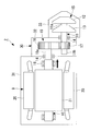
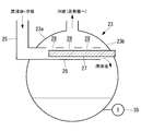
- FIG. 1 It is a block diagram which shows the turbo refrigerator concerning one embodiment of the present invention. It is a longitudinal section showing a turbo compressor of a turbo refrigerator concerning one embodiment of the present invention. It is a longitudinal section showing an oil tank of a turbo refrigerator concerning one embodiment of the present invention.
- the turbo refrigerator 1 which concerns on one Embodiment of this invention is demonstrated with reference to drawings.
- the turbo refrigerator 1 further cools the liquid refrigerant condensed in the condenser 3 and the turbo compressor 2 for compressing the refrigerant, the condenser 3 for cooling and condensing the refrigerant, and A subcooler 4 for applying cooling, a first pressure reducing valve 5 for reducing the pressure of the high pressure refrigerant to an intermediate pressure, an intermediate cooler 6 for supercooling the refrigerant, a second pressure reducing valve 7 for reducing the pressure of the refrigerant to low pressure, and a low pressure refrigerant And the like.
- the turbo compressor 2, the condenser 3, the subcooler 4, the first pressure reducing valve 5, the intercooler 6, the second pressure reducing valve 7 and the evaporator 8 constitute a refrigeration cycle
- the refrigerant is a turbo compressor 2, a condenser 3, the subcooler 4, the first pressure reducing valve 5, the intercooler 6, the second pressure reducing valve 7, and the evaporator 8 circulate in this order. Further, the refrigerant is supplied from the intercooler 6 to the turbo compressor 2.
- the turbo compressor 2 includes a housing 30 configured by integrally connecting a motor housing 31, a speed increaser housing 32, and a compressor housing 33.
- a motor 9 driven at variable speed by an inverter device is incorporated in the motor housing 31.
- One end 10 a of the motor shaft 10 of the motor 9 is projected from the motor housing 31 to the speed increaser housing 32.
- the motor 9 includes a stator 20, a rotor 21 and the like.
- the rotor 21 is fixed to the motor shaft 10, and the rotor 21 rotates inside the stator 20.
- the motor shaft 10 is supported by the rolling bearing 14 on the side of the gearbox housing 32.
- the rolling bearing 14 comprises, for example, a plurality of angular contact ball bearings.
- the rolling bearing 14 is installed in the motor housing 31 via a bearing box (not shown).
- a compression mechanism 15 having a first stage compression stage and a second stage compression stage is accommodated inside the compressor housing 33.
- the refrigerant sucked from the outside into the first stage compression stage and compressed by the first stage compression stage is sent to the second stage compression stage.
- the refrigerant sucked into the second stage compression stage and compressed by the second stage compression stage is discharged to the outside.
- the rotary shaft 11 is rotatably installed, and on one end 11a side of the rotary shaft 11, a first stage impeller 12 for a first stage compression stage, and a second stage compression stage
- the second stage impeller 13 is provided.
- the rotating shaft 11 is supported by the rolling bearing 14 on the side of the gearbox housing 32.
- the rolling bearing 14 comprises, for example, a plurality of angular contact ball bearings.
- the rolling bearing 14 is installed in the compressor housing 33 via a bearing box (not shown).
- a small diameter gear 17 is provided on the other end 11 b side of the rotary shaft 11 supported by the rolling bearing 14.
- the gear 17 is engaged with a large diameter gear 18 provided at one end 10 a of the motor shaft 10, and the gear 17, 18 constitutes a speed increasing mechanism 19.
- the speed increasing mechanism 19 is accommodated in a speed increasing device housing 32.
- Lubricating oil is supplied to the rolling bearing 14 and the gears 17 and 18 for the respective components.
- the lubricating oil supply line 22 is a pipe connecting the oil tank 23 and the turbo compressor 2.
- the lubricating oil is supplied from the oil tank 23 to the motor housing 31 and the speed increaser housing 32 of the turbo compressor 2 by an oil pump 36 provided in the lubricating oil supply line 22.
- the lubricating oil having passed through the rolling bearing 14 and the speed increasing mechanism 19 is returned to the oil tank 23 through the lubricating oil discharge line 25.
- no oil cooler is installed in the lubricating oil supply line 22 and the lubricating oil discharge line 25 according to the present embodiment.
- a lubricating oil inlet connected to the lubricating oil supply line 22 is formed in the motor housing 31 and the speed increaser housing 32, and the lubricating oil is supplied from the lubricating oil supply line 22 to the turbo compressor 2.
- the turbo compressor 2 is supplied with the liquid refrigerant extracted from the condenser 3 or the subcooler 4 constituting the refrigeration cycle.
- a liquid refrigerant inlet connected to the liquid refrigerant supply line 24 is formed in the motor housing 31, and the liquid refrigerant is supplied from the liquid refrigerant supply line 24.
- An expansion valve 37 is provided in the liquid refrigerant supply line 24, and when passing through the expansion valve 37, the temperature of the liquid refrigerant is reduced.
- the liquid refrigerant extracted from the condenser 3 or the subcooler 4 bypasses the lubricating oil system in the motor housing 31 of the turbo compressor 2 or in the speed increaser housing 32 and exchanges heat.
- the lubrication passed through the gears 17, 18 and the rolling bearing 14 in the motor housing 31 of the turbo compressor 2 and in the speed increaser housing 32.
- the oil is cooled by the liquid refrigerant extracted from the condenser 3 or the subcooler 4.
- the liquid refrigerant supplied from the condenser 3 or the subcooler 4 flows from the motor 9 side to the rolling bearing 14 side due to the differential pressure in the motor housing 31 and the speed increaser housing 32.
- between the labyrinth seal 16 and the motor shaft 10 is configured such that the liquid refrigerant passes through the labyrinth seal 16.
- the lubricating oil is cooled by the liquid refrigerant in the motor housing 31 and the speed increaser housing 32.
- the refrigerant used for cooling the lubricating oil in the motor housing 31 of the turbo compressor 2 and in the speed increaser housing 32 and the cooled lubricating oil are discharged to the oil tank 23.
- a lubricating oil outlet connected to the lubricating oil discharge line 25 is formed in the motor housing 31 and the speed increasing gear housing 32, and the motor housing 31 and the speed increasing gear housing 32 are connected to the oil tank 23 via the lubricating oil discharge line 25.
- the refrigerant and lubricating oil are discharged.
- the lubricating oil discharged to the oil tank 23 is diluted by the liquid refrigerant.
- the oil tank 23 is provided with means for evaporating the liquid refrigerant in order to increase the concentration of the diluted lubricating oil.
- the lubricating oil returns to the state before dilution and can be used repeatedly as lubricating oil to lubricate the gears 17 and 18 and the rolling bearing 14.
- the oil tank 23 is a container capable of containing lubricating oil, and the lubricating oil is stored in the lower part inside the oil tank 23.
- the oil tank 23 is formed with a lubricating oil / refrigerant inlet connected to the lubricating oil discharge line 25, and the pipe 26 of the lubricating oil discharge line 25 is extended to the inside of the oil tank 23.
- the piping 26 of the lubricating oil discharge line 25 installed inside the oil tank 23 is disposed, for example, from the side wall 23a of the oil tank 23 where the lubricating oil / refrigerant inlet is formed toward the side wall 23b opposite to the side wall 23a. Be done.
- a heater insertion port is formed in a side wall 23 b opposite to the side wall 23 a of the oil tank 23 in which the lubricating oil / refrigerant inlet is formed.
- a heater 27 is installed in the piping 26 of the lubricating oil discharge line 25 installed inside the oil tank 23. The heater 27 is inserted from the outside of the oil tank 23 into the inside of the pipe 26 through the heater insertion port.
- the heater 27 heats the liquid refrigerant and the lubricating oil flowing through the lubricating oil discharge line 25 to evaporate the liquid refrigerant.
- the refrigerant gas generated by evaporation travels to the upper side of the oil tank 23, and the lubricating oil whose content of the refrigerant whose refrigerant has evaporated is reduced falls from the end of the pipe 26 to the lower side of the oil tank 23.
- a plurality of holes 28 may be formed on the upper surface of the piping 26 of the lubricating oil discharge line 25 installed inside the oil tank 23.
- a lubricating oil outlet connected to the lubricating oil supply line 22 is formed below the oil tank 23, and the lubricating oil is supplied from the oil tank 23 to the turbo compressor 2 via the lubricating oil supply line 22. Further, a refrigerant gas outlet connected to the refrigerant gas supply line 29 is formed above the oil tank 23, and the refrigerant gas is supplied from the oil tank 23 to the evaporator 8 through the refrigerant gas supply line 29. As a result, the refrigerant supplied from the condenser 3 or the subcooler 4 to the turbo compressor 2 is returned to the refrigeration cycle.
- the lubricating oil stored inside the oil tank 23 is preferably adjusted to be maintained in a predetermined temperature range.
- the temperature of the lubricating oil is determined based on, for example, a temperature at which appropriate lubrication is exhibited in the gears 17 and 18 and the rolling bearing 14 of the turbo compressor 2 lubricated by the lubricating oil.
- the temperature of the lubricating oil stored inside the oil tank 23 is adjusted by, for example, heating by the heater 27.
- the heating by the heater 27 is controlled based on the temperature detected by the temperature detection unit 35 installed at the lower part of the oil tank 23.
- the ON / OFF of the heater 27 may be controlled based on the detected temperature to adjust the heating of the liquid refrigerant or the lubricating oil, or the set temperature of the heater 27 may be adjusted based on the detected temperature. It is also good.
- the lubricating oil is stored in an oil tank 23 and is supplied from the oil tank 23 to the turbo compressor 2 by an oil pump 36.
- the lubricating oil supplied to the turbo compressor 2 is supplied to the gears 17 and 18 and the rolling bearing 14 inside the motor housing 31 of the turbo compressor 2 and in the speed increaser housing 32.
- the lubricating oil supplied to the gears 17 and 18 and the rolling bearing 14 lubricates the gears 17 and 18 and the rolling bearing 14 and increases in temperature due to friction loss.
- the liquid refrigerant extracted from the condenser 3 or the subcooler 4 constituting the refrigeration cycle is supplied to the turbo refrigerator 1. Then, the lubricating oil in the motor housing 31 of the turbo compressor 2 or in the speed increaser housing 32 exchanges heat with the liquid refrigerant extracted from the condenser 3 or the subcooler 4. As a result, the lubricating oil that has passed through the gears 17 and 18 and the rolling bearing 14 in the motor housing 31 of the turbo compressor 2 and the step-up housing 32 is cooled by the liquid refrigerant extracted from the condenser 3 or the subcooler Ru.
- the refrigerant used for cooling the lubricating oil in the motor housing 31 of the turbo compressor 2 and in the speed increaser housing 32 and the cooled lubricating oil are discharged to the oil tank 23.
- the lubricating oil and the liquid refrigerant discharged to the oil tank 23 are heated by the heater 27 installed in the pipe 26 of the lubricating oil discharge line 25 inside the oil tank 23, and the liquid refrigerant evaporates. As a result, the kinematic viscosity of the lubricating oil diluted by the liquid refrigerant is recovered.
- the lubricating oil in which the liquid refrigerant evaporates and the content of the liquid refrigerant is reduced is stored in the lower part of the oil tank 23. Further, the refrigerant gas evaporated by the heater 27 travels to the upper side of the oil tank 23, and the refrigerant gas is supplied from the oil tank 23 to the evaporator 8 through the refrigerant gas supply line 29. As a result, the refrigerant supplied from the condenser 3 or the subcooler 4 to the turbo compressor 2 is returned to the refrigeration cycle.
- the liquid refrigerant extracted from the refrigeration cycle is supplied to the motor housing 31 and the speed increaser housing 32, and the motor housing 31 and the speed increaser housing 32
- the lubricating oil used for cooling is cooled by the liquid refrigerant. Therefore, the lubricating oil can be cooled without using the conventionally used oil cooler, and the installation of the oil cooler becomes unnecessary. As a result, according to the present embodiment, the cost due to the installation of the devices can be reduced.
- the lubricating oil diluted in the motor housing 31 and the speed increasing gear housing 32 by the liquid refrigerant is evaporated by the heater 27 provided in the oil tank 23 to recover the dynamic viscosity, and is repeatedly used as the lubricating oil It becomes possible. Furthermore, the temperature control of the heater 27 is adjusted based on the temperature of the lubricating oil stored in the oil tank 23, and the lubricating oil stored in the oil tank 23 properly lubricates the gears 17, 18 and the rolling bearing 14 The temperature is adjusted to
Landscapes
- Engineering & Computer Science (AREA)
- General Engineering & Computer Science (AREA)
- Mechanical Engineering (AREA)
- Physics & Mathematics (AREA)
- Thermal Sciences (AREA)
- Chemical & Material Sciences (AREA)
- Analytical Chemistry (AREA)
- Power Engineering (AREA)
- Structures Of Non-Positive Displacement Pumps (AREA)
Abstract
簡素な構成でターボ圧縮機の軸受等に供給される潤滑油を冷却することが可能な冷凍機を提供することを目的とする。冷凍機(1)は、モータによって駆動する圧縮機構を有するターボ圧縮機(2)と、凝縮器(3)と、蒸発器(8)を備え、冷媒が循環する冷凍サイクルと、潤滑油が貯留された油タンク(23)と、油タンク(23)からモータを収容するモータハウジング(31)内部へ潤滑油を供給する潤滑油供給ライン(22)と、凝縮器(3)からモータハウジング(31)内部へ冷媒を供給する液冷媒供給ライン(24)とを備える。
Description
本発明は、冷凍機に関するものである。
ターボ冷凍機に設置されるターボ圧縮機は、圧縮機構、増速機構などから構成される。ターボ圧縮機が安定して運転するためには、圧縮機機構の羽根車を支持する軸受や、増速機構の歯車などに対して潤滑油が適切に供給され続ける必要がある。潤滑油供給系統は、油タンク、油ポンプを備え、油タンクに貯蔵された潤滑油が、油ポンプによってターボ圧縮機の軸受や歯車などへ供給される。軸受や歯車へ供給された潤滑油は、油タンクへ戻され、潤滑油供給系統を繰り返し循環する。
軸受や歯車へ供給された潤滑油は、機械損失に基づく発熱によって温度上昇するため、潤滑油供給系統には、オイルクーラが設置されることが一般的である。オイルクーラによって、潤滑油が冷却され、温度低下した潤滑油が、軸受や歯車へ供給される。
上述した潤滑油供給系統に設置されるオイルクーラは、例えばプレート式熱交換器であり、オイルクーラにおいて、潤滑油と、ターボ冷凍機の冷凍サイクルを流れる冷媒とが熱交換して、潤滑油が冷却される。オイルクーラに供給される冷媒は、冷凍サイクルに設けられた凝縮器又はサブクーラから抽出された液冷媒であり、液冷媒は、膨張弁を通過して低温化されてからオイルクーラへ供給される。オイルクーラで潤滑油と熱交換した冷媒は、気液二相状態となり、冷凍サイクルの蒸発器へ供給される。
このような潤滑油供給系統では、潤滑油を冷却するため、オイルクーラの設置や、凝縮器又はサブクーラとオイルクーラとの間の膨張弁の設置が必要であり、ターボ冷凍機の構成が複雑になり、機器類の設置による高コスト化が生じる。
本発明は、このような事情に鑑みてなされたものであって、簡素な構成でターボ圧縮機の軸受等に供給される潤滑油を冷却することが可能な冷凍機を提供することを目的とする。
本発明の一態様に係る冷凍機は、モータによって駆動する圧縮機構を有する電動圧縮機と、凝縮器と、蒸発器を備え、冷媒が循環する冷凍サイクルと、潤滑油が貯留された油タンクと、前記油タンクから前記モータを収容する第1ハウジング内部へ前記潤滑油を供給する油供給管と、前記凝縮器から前記第1ハウジング内部へ前記冷媒を供給する冷媒供給管とを備える。
この構成によれば、圧縮機構を駆動するモータが第1ハウジングに収容されており、潤滑油が、油タンクから第1ハウジングへ供給されることによって、潤滑油は、モータを支持する軸受等を潤滑させることができる。また、第1ハウジング内部には、凝縮器から冷媒が供給されることから、軸受等を潤滑させて昇温した潤滑油を冷却できる。
上記態様において、前記電動圧縮機は、前記モータと前記圧縮機構に結合された増速機構を更に有し、前記冷媒及び前記潤滑油が、前記第1ハウジングから、前記油タンクから前記増速機構を収容する第2ハウジング内部へ流通してもよい。
この構成によれば、モータと圧縮機構に結合された増速機構が第2ハウジングに収容されており、潤滑油が、第1ハウジングから第2ハウジングへ流通することによって、潤滑油は、増速機構を構成する歯車等を潤滑させることができる。また、冷媒によって、軸受や歯車等を潤滑させて昇温した潤滑油を冷却できる。
上記態様において、前記電動圧縮機は、前記モータと前記圧縮機構に結合された増速機構を更に有し、前記油供給管は、前記油タンクから前記増速機構を収容する第2ハウジング内部へ前記潤滑油を供給してもよい。
この構成によれば、モータと圧縮機構に結合された増速機構が第2ハウジングに収容されており、潤滑油が、油タンクから第2ハウジングへ供給されることによって、潤滑油は、増速機構を構成する歯車等を潤滑させることができる。
上記態様において、前記冷凍サイクルは、サブクーラを更に備え、前記冷媒供給管は、前記サブクーラから前記第1ハウジング内部へ前記冷媒を供給してもよい。
この構成によれば、第1ハウジング内部には、サブクーラから冷媒が供給されることから、軸受等を潤滑させて昇温した潤滑油を冷却できる。
上記態様において、前記第1ハウジングから前記油タンクへ前記潤滑油及び前記冷媒を排出する排出管と、前記油タンク内部に配置された前記排出管の内部に設けられたヒータとを備えてもよい。
この構成によれば、排出管を介して、第1ハウジングから油タンクへ潤滑油及び冷媒が排出され、油タンク内部にも排出管が配置されており、油タンク内部に配置された排出管には、ヒータが設置される。ヒータが昇温することによって、潤滑油及び冷媒が加熱され、冷媒が蒸発する。その結果、冷媒によって希釈されていた潤滑油の動粘度が回復される。
上記態様において、前記第2ハウジングから前記油タンクへ前記潤滑油及び前記冷媒を排出する排出管と、前記油タンク内部に配置された前記排出管の内部に設けられたヒータとを備えてもよい。
この構成によれば、排出管を介して、第2ハウジングから油タンクへ潤滑油及び冷媒が排出され、油タンク内部にも排出管が配置されており、油タンク内部に配置された排出管には、ヒータが設置される。ヒータが昇温することによって、潤滑油及び冷媒が加熱され、冷媒が蒸発する。その結果、冷媒によって希釈されていた潤滑油の動粘度が回復される。
本発明によれば、簡素な構成でターボ圧縮機の部品類に供給される潤滑油を冷却することができる。
以下に、本発明の一実施形態に係るターボ冷凍機1について、図面を参照して説明する。
ターボ冷凍機1は、図1に示すように、冷媒を圧縮するターボ圧縮機2と、冷媒を冷却して凝縮させる凝縮器3と、凝縮器3において凝縮された液冷媒を更に冷却して過冷却を付与するサブクーラ4と、高圧冷媒を中間圧に減圧する第1減圧弁5と、冷媒に過冷却を与える中間冷却器6と、冷媒を低圧に減圧する第2減圧弁7と、低圧冷媒を蒸発させる蒸発器8などを備える。
ターボ冷凍機1は、図1に示すように、冷媒を圧縮するターボ圧縮機2と、冷媒を冷却して凝縮させる凝縮器3と、凝縮器3において凝縮された液冷媒を更に冷却して過冷却を付与するサブクーラ4と、高圧冷媒を中間圧に減圧する第1減圧弁5と、冷媒に過冷却を与える中間冷却器6と、冷媒を低圧に減圧する第2減圧弁7と、低圧冷媒を蒸発させる蒸発器8などを備える。
ターボ圧縮機2、凝縮器3、サブクーラ4、第1減圧弁5、中間冷却器6、第2減圧弁7及び蒸発器8は、冷凍サイクルを構成し、冷媒が、ターボ圧縮機2、凝縮器3、サブクーラ4、第1減圧弁5、中間冷却器6、第2減圧弁7及び蒸発器8の順に循環する。また、冷媒は、中間冷却器6からターボ圧縮機2へ供給される。
ターボ圧縮機2は、図2に示すように、モータハウジング31と、増速器ハウジング32と、圧縮機ハウジング33とを一体に結合して構成されるハウジング30を備えている。
モータハウジング31には、インバータ装置によって可変速駆動されるモータ9が組み込まれる。このモータ9のモータ軸10の一端10aは、モータハウジング31から増速器ハウジング32に突出されている。モータ9は、ステータ20と、ロータ21などを備える。モータ軸10には、ロータ21が固定され、ロータ21は、ステータ20の内部で回転する。モータ軸10は、増速器ハウジング32側で、転がり軸受14によって支持される。転がり軸受14は、例えば複数のアンギュラ玉軸受からなる。転がり軸受14は、軸受箱(図示せず。)を介してモータハウジング31に設置される。
モータハウジング31には、インバータ装置によって可変速駆動されるモータ9が組み込まれる。このモータ9のモータ軸10の一端10aは、モータハウジング31から増速器ハウジング32に突出されている。モータ9は、ステータ20と、ロータ21などを備える。モータ軸10には、ロータ21が固定され、ロータ21は、ステータ20の内部で回転する。モータ軸10は、増速器ハウジング32側で、転がり軸受14によって支持される。転がり軸受14は、例えば複数のアンギュラ玉軸受からなる。転がり軸受14は、軸受箱(図示せず。)を介してモータハウジング31に設置される。
圧縮機ハウジング33の内部には、第1段圧縮ステージと、第2段圧縮ステージを有する圧縮機構15が収容される。外部から第1段圧縮ステージに吸い込まれて、第1段圧縮ステージによって圧縮された冷媒は、第2段圧縮ステージに送られる。そして、第2段圧縮ステージに吸い込まれて、第2段圧縮ステージによって圧縮された冷媒は、外部へ吐出される。
圧縮機ハウジング33内には、回転軸11が回転自在に設置され、この回転軸11の一端11a側には、第1段圧縮ステージ用の第1段羽根車12と、第2段圧縮ステージ用の第2段羽根車13とが設けられる。回転軸11は、増速器ハウジング32側で、転がり軸受14によって支持される。転がり軸受14は、例えば複数のアンギュラ玉軸受からなる。転がり軸受14は、軸受箱(図示せず。)を介して圧縮機ハウジング33に設置される。
転がり軸受14によって支持される回転軸11の他端11b側には、小径の歯車17が設けられる。この歯車17は、モータ軸10の一端10aに設けられる大径の歯車18と噛み合わされ、これらの歯車17,18によって、増速機構19が構成される。増速機構19は、増速器ハウジング32に収容される。
転がり軸受14や、歯車17,18には、それぞれの部品に対して潤滑油が供給される。
潤滑油供給ライン22は、油タンク23及びターボ圧縮機2を結ぶ配管である。潤滑油は、潤滑油供給ライン22に設けられた油ポンプ36によって、油タンク23からターボ圧縮機2のモータハウジング31や増速器ハウジング32へ供給される。転がり軸受14及び増速機構19を通過した潤滑油は、潤滑油排出ライン25を介して油タンク23へ戻される。本実施形態に係る潤滑油供給ライン22や潤滑油排出ライン25には、従来と異なり、オイルクーラが設置されない。
モータハウジング31や増速器ハウジング32には、潤滑油供給ライン22と接続される潤滑油入口が形成され、潤滑油供給ライン22からターボ圧縮機2へ潤滑油が供給される。
ターボ圧縮機2には、冷凍サイクルを構成している凝縮器3又はサブクーラ4から抽出された液冷媒が供給される。モータハウジング31には、液冷媒供給ライン24と接続される液冷媒入口が形成され、液冷媒供給ライン24から液冷媒が供給される。液冷媒供給ライン24には、膨張弁37が設けられ、膨張弁37を通過する際、液冷媒は低温化される。
そして、凝縮器3又はサブクーラ4から抽出された液冷媒は、ターボ圧縮機2のモータハウジング31内や増速器ハウジング32内の潤滑油系統にバイパスし、熱交換する。これにより、ターボ圧縮機2のモータハウジング31内や増速器ハウジング32内では、ターボ圧縮機2のモータハウジング31内や増速器ハウジング32内の歯車17,18や転がり軸受14を通過した潤滑油は、凝縮器3又はサブクーラ4から抽出された液冷媒によって冷却される。
凝縮器3又はサブクーラ4から供給された液冷媒は、モータハウジング31内や増速器ハウジング32内において、差圧によってモータ9側から転がり軸受14側へと流れる。このとき、液冷媒が、ラビリンスシール16を通過するように、ラビリンスシール16とモータ軸10との間が構成されている。これにより、潤滑油は、モータハウジング31や増速器ハウジング32において、液冷媒によって冷却される。
ターボ圧縮機2のモータハウジング31内や増速器ハウジング32内で潤滑油の冷却に用いられた冷媒と、冷却された潤滑油は、油タンク23へ排出される。モータハウジング31や増速器ハウジング32には、潤滑油排出ライン25と接続される潤滑油出口が形成され、潤滑油排出ライン25を介してモータハウジング31や増速器ハウジング32から油タンク23へ冷媒及び潤滑油が排出される。
油タンク23へ排出される潤滑油は、液冷媒によって希釈されている。油タンク23には、希釈された潤滑油の濃度を高めるため液冷媒を蒸発させる手段が設置されている。液冷媒が蒸発することによって、潤滑油は、動粘度が希釈前の状態に戻り、歯車17,18や転がり軸受14を潤滑させる潤滑油として繰り返し用いることができる。
油タンク23は、図3に示すように、潤滑油を収容可能な容器であり、油タンク23の内部の下部に潤滑油が貯留される。油タンク23には、潤滑油排出ライン25と接続された潤滑油・冷媒入口が形成され、かつ、潤滑油排出ライン25の配管26は、油タンク23の内部にも延長して設置される。油タンク23の内部に設置された潤滑油排出ライン25の配管26は、例えば、潤滑油・冷媒入口が形成された油タンク23の側壁23aから、その側壁23aに対向する側壁23bに向けて配置される。
潤滑油・冷媒入口が形成された油タンク23の側壁23aに対向する側壁23bには、ヒータ挿入口が形成されている。油タンク23の内部に設置された潤滑油排出ライン25の配管26には、ヒータ27が設置される。ヒータ27は、ヒータ挿入口を介して油タンク23の外部から配管26内部へ挿入されて配置されている。
ヒータ27は、潤滑油排出ライン25を流れる液冷媒及び潤滑油を加熱し、液冷媒を蒸発させる。これにより、蒸発して生成された冷媒ガスは油タンク23の上方へ向かい、冷媒が蒸発した冷媒の含有量が低下した潤滑油は、配管26の端部から油タンク23の下方へ落下する。油タンク23の内部に設置された潤滑油排出ライン25の配管26には、上面に複数の孔28が形成されてもよい。これにより、蒸発した冷媒が孔28を通過して油タンク23の上方へ向かいやすくなり、配管26内部で潤滑油や加熱されて蒸発した冷媒が滞留しにくくなる。
油タンク23の下方には、潤滑油供給ライン22と接続された潤滑油出口が形成され、潤滑油供給ライン22を介して油タンク23からターボ圧縮機2へ潤滑油が供給される。また、油タンク23の上方には、冷媒ガス供給ライン29と接続された冷媒ガス出口が形成され、冷媒ガス供給ライン29を介して油タンク23から蒸発器8へ冷媒ガスが供給される。これにより、凝縮器3やサブクーラ4からターボ圧縮機2へ供給された冷媒が冷凍サイクルへ戻される。
油タンク23の内部に貯留されている潤滑油は、所定の温度範囲に維持されるように調節されることが好ましい。潤滑油の温度は、例えば、潤滑油によって潤滑されるターボ圧縮機2の歯車17,18や転がり軸受14において、適切な潤滑が発揮される温度に基づいて決定される。
油タンク23の内部に貯留されている潤滑油の温度は、例えば、ヒータ27による加熱によって調節される。ヒータ27による加熱は、油タンク23の下部に設置された温度検出部35で検出される温度に基づいて制御される。ヒータ27は、検出された温度に基づいてON/OFFが制御されて、液冷媒や潤滑油に対する加熱を調整してもよいし、検出された温度に基づいてヒータ27の設定温度が調整されてもよい。
次に、本実施形態に係るターボ冷凍機1における潤滑油の供給方法や冷却方法について説明する。
潤滑油は、油タンク23に貯留されており、油ポンプ36によって油タンク23からターボ圧縮機2へ供給される。ターボ圧縮機2へ供給された潤滑油は、ターボ圧縮機2のモータハウジング31内部や増速器ハウジング32内部で歯車17,18や転がり軸受14へ供給される。
歯車17,18や転がり軸受14へ供給された潤滑油は、歯車17,18や転がり軸受14を潤滑させつつ、摩擦損失によって温度上昇する。
ターボ冷凍機1には、潤滑油を冷却するため、冷凍サイクルを構成している凝縮器3又はサブクーラ4から抽出された液冷媒が供給される。そして、ターボ圧縮機2のモータハウジング31内や増速器ハウジング32内の潤滑油は、凝縮器3又はサブクーラ4から抽出された液冷媒と熱交換する。これにより、ターボ圧縮機2のモータハウジング31内や増速器ハウジング32内の歯車17,18や転がり軸受14を通過した潤滑油は、凝縮器3又はサブクーラ4から抽出された液冷媒によって冷却される。
その後、ターボ圧縮機2のモータハウジング31内や増速器ハウジング32内で潤滑油の冷却に用いられた冷媒と、冷却された潤滑油は、油タンク23へ排出される。
油タンク23へ排出される潤滑油と液冷媒は、油タンク23の内部における潤滑油排出ライン25の配管26に設置されたヒータ27によって加熱され、液冷媒が蒸発する。その結果、液冷媒によって希釈されていた潤滑油の動粘度が回復する。
液冷媒が蒸発し液冷媒の含有量が低下した潤滑油は、油タンク23の下部に貯留される。また、ヒータ27によって蒸発された冷媒ガスは、油タンク23の上方へ向かい、冷媒ガス供給ライン29を介して油タンク23から蒸発器8へ冷媒ガスが供給される。これにより、凝縮器3やサブクーラ4からターボ圧縮機2へ供給された冷媒が冷凍サイクルへ戻される。
以上、本実施形態によれば、冷凍サイクルから抽出された液冷媒がモータハウジング31や増速器ハウジング32に供給され、モータハウジング31や増速器ハウジング32において歯車17,18や転がり軸受14の冷却に用いられた潤滑油が、液冷媒によって冷却される。したがって、従来用いられていたオイルクーラを用いることなく潤滑油を冷却することができ、オイルクーラの設置が不要になる。その結果、本実施形態によれば、機器類の設置によるコストを低減できる。また、モータハウジング31や増速器ハウジング32において液冷媒によって希釈された潤滑油は、油タンク23に設けられたヒータ27によって、液冷媒が蒸発されて動粘度が回復し、繰り返し潤滑油として使用可能となる。さらに、油タンク23に貯蔵された潤滑油の温度に基づいて、ヒータ27の温度制御が調整されて、油タンク23に貯蔵された潤滑油は、歯車17,18や転がり軸受14を適切に潤滑させる温度に調節される。
1 :ターボ冷凍機
2 :ターボ圧縮機
3 :凝縮器
4 :サブクーラ
5 :第1減圧弁
6 :中間冷却器
7 :第2減圧弁
8 :蒸発器
9 :モータ
10 :モータ軸
11 :回転軸
12 :第1段羽根車
13 :第2段羽根車
14 :転がり軸受
15 :圧縮機構
16 :ラビリンスシール
17 :歯車
18 :歯車
19 :増速機構
20 :ステータ
21 :ロータ
22 :潤滑油供給ライン
23 :油タンク
24 :液冷媒供給ライン
25 :潤滑油排出ライン
26 :配管
27 :ヒータ
28 :孔
29 :冷媒ガス供給ライン
30 :ハウジング
31 :モータハウジング
32 :増速器ハウジング
33 :圧縮機ハウジング
35 :温度検出部
36 :油ポンプ
37 :膨張弁
2 :ターボ圧縮機
3 :凝縮器
4 :サブクーラ
5 :第1減圧弁
6 :中間冷却器
7 :第2減圧弁
8 :蒸発器
9 :モータ
10 :モータ軸
11 :回転軸
12 :第1段羽根車
13 :第2段羽根車
14 :転がり軸受
15 :圧縮機構
16 :ラビリンスシール
17 :歯車
18 :歯車
19 :増速機構
20 :ステータ
21 :ロータ
22 :潤滑油供給ライン
23 :油タンク
24 :液冷媒供給ライン
25 :潤滑油排出ライン
26 :配管
27 :ヒータ
28 :孔
29 :冷媒ガス供給ライン
30 :ハウジング
31 :モータハウジング
32 :増速器ハウジング
33 :圧縮機ハウジング
35 :温度検出部
36 :油ポンプ
37 :膨張弁
Claims (6)
- モータによって駆動する圧縮機構を有する電動圧縮機と、凝縮器と、蒸発器を備え、冷媒が循環する冷凍サイクルと、
潤滑油が貯留された油タンクと、
前記油タンクから前記モータを収容する第1ハウジング内部へ前記潤滑油を供給する油供給管と、
前記凝縮器から前記第1ハウジング内部へ前記冷媒を供給する冷媒供給管と、
を備える冷凍機。 - 前記電動圧縮機は、前記モータと前記圧縮機構に結合された増速機構を更に有し、
前記冷媒及び前記潤滑油が、前記第1ハウジングから、前記油タンクから前記増速機構を収容する第2ハウジング内部へ流通する請求項1に記載の冷凍機。 - 前記電動圧縮機は、前記モータと前記圧縮機構に結合された増速機構を更に有し、
前記油供給管は、前記油タンクから前記増速機構を収容する第2ハウジング内部へ前記潤滑油を供給する請求項1に記載の冷凍機。 - 前記冷凍サイクルは、サブクーラを更に備え、
前記冷媒供給管は、前記サブクーラから前記第1ハウジング内部へ前記冷媒を供給する請求項1から3のいずれか1項に記載の冷凍機。 - 前記第1ハウジングから前記油タンクへ前記潤滑油及び前記冷媒を排出する排出管と、
前記油タンク内部に配置された前記排出管の内部に設けられたヒータと、
を備える請求項1から4のいずれか1項に記載の冷凍機。 - 前記第2ハウジングから前記油タンクへ前記潤滑油及び前記冷媒を排出する排出管と、
前記油タンク内部に配置された前記排出管の内部に設けられたヒータと、
を備える請求項2又は3に記載の冷凍機。
Priority Applications (2)
| Application Number | Priority Date | Filing Date | Title |
|---|---|---|---|
| US16/498,281 US20200080756A1 (en) | 2017-03-29 | 2018-03-05 | Refrigeration machine |
| CN201880022556.7A CN110476025A (zh) | 2017-03-29 | 2018-03-05 | 制冷机 |
Applications Claiming Priority (2)
| Application Number | Priority Date | Filing Date | Title |
|---|---|---|---|
| JP2017064885A JP2018169059A (ja) | 2017-03-29 | 2017-03-29 | 冷凍機 |
| JP2017-064885 | 2017-03-29 |
Publications (1)
| Publication Number | Publication Date |
|---|---|
| WO2018180225A1 true WO2018180225A1 (ja) | 2018-10-04 |
Family
ID=63677095
Family Applications (1)
| Application Number | Title | Priority Date | Filing Date |
|---|---|---|---|
| PCT/JP2018/008203 Ceased WO2018180225A1 (ja) | 2017-03-29 | 2018-03-05 | 冷凍機 |
Country Status (4)
| Country | Link |
|---|---|
| US (1) | US20200080756A1 (ja) |
| JP (1) | JP2018169059A (ja) |
| CN (1) | CN110476025A (ja) |
| WO (1) | WO2018180225A1 (ja) |
Cited By (2)
| Publication number | Priority date | Publication date | Assignee | Title |
|---|---|---|---|---|
| CN111927793A (zh) * | 2020-06-15 | 2020-11-13 | 珠海格力电器股份有限公司 | 离心压缩机平衡管组件、离心压缩机和制冷系统 |
| CN113167519A (zh) * | 2018-10-31 | 2021-07-23 | 艾默生环境优化技术有限公司 | 用于气候控制系统的油控制 |
Families Citing this family (1)
| Publication number | Priority date | Publication date | Assignee | Title |
|---|---|---|---|---|
| EP4621244A1 (de) * | 2024-03-21 | 2025-09-24 | KelvinPRO AG | Verdichtereinheit, wärmetechnische anlage umfassend die verdichtereinheit, und verfahren zum betrieb einer verdichtereinheit in einer wärmetechnischen anlage |
Citations (4)
| Publication number | Priority date | Publication date | Assignee | Title |
|---|---|---|---|---|
| US4404812A (en) * | 1981-11-27 | 1983-09-20 | Carrier Corporation | Method and apparatus for controlling the operation of a centrifugal compressor in a refrigeration system |
| JP2009019601A (ja) * | 2007-07-13 | 2009-01-29 | Mitsubishi Heavy Ind Ltd | ターボ圧縮機およびターボ冷凍機 |
| JP2009293901A (ja) * | 2008-06-09 | 2009-12-17 | Ebara Refrigeration Equipment & Systems Co Ltd | 圧縮式冷凍機 |
| JP2014190616A (ja) * | 2013-03-27 | 2014-10-06 | Ebara Refrigeration Equipment & Systems Co Ltd | ターボ冷凍機の圧縮機用電動機 |
Family Cites Families (3)
| Publication number | Priority date | Publication date | Assignee | Title |
|---|---|---|---|---|
| JP5326900B2 (ja) * | 2009-07-21 | 2013-10-30 | 株式会社Ihi | ターボ圧縮機及び冷凍機 |
| JP6223696B2 (ja) * | 2013-03-06 | 2017-11-01 | 三菱重工サーマルシステムズ株式会社 | ターボ冷凍機用圧縮機のオイルタンクおよびターボ冷凍機用圧縮機 |
| JP2015190662A (ja) * | 2014-03-27 | 2015-11-02 | 荏原冷熱システム株式会社 | ターボ冷凍機 |
-
2017
- 2017-03-29 JP JP2017064885A patent/JP2018169059A/ja active Pending
-
2018
- 2018-03-05 WO PCT/JP2018/008203 patent/WO2018180225A1/ja not_active Ceased
- 2018-03-05 CN CN201880022556.7A patent/CN110476025A/zh active Pending
- 2018-03-05 US US16/498,281 patent/US20200080756A1/en not_active Abandoned
Patent Citations (4)
| Publication number | Priority date | Publication date | Assignee | Title |
|---|---|---|---|---|
| US4404812A (en) * | 1981-11-27 | 1983-09-20 | Carrier Corporation | Method and apparatus for controlling the operation of a centrifugal compressor in a refrigeration system |
| JP2009019601A (ja) * | 2007-07-13 | 2009-01-29 | Mitsubishi Heavy Ind Ltd | ターボ圧縮機およびターボ冷凍機 |
| JP2009293901A (ja) * | 2008-06-09 | 2009-12-17 | Ebara Refrigeration Equipment & Systems Co Ltd | 圧縮式冷凍機 |
| JP2014190616A (ja) * | 2013-03-27 | 2014-10-06 | Ebara Refrigeration Equipment & Systems Co Ltd | ターボ冷凍機の圧縮機用電動機 |
Cited By (4)
| Publication number | Priority date | Publication date | Assignee | Title |
|---|---|---|---|---|
| CN113167519A (zh) * | 2018-10-31 | 2021-07-23 | 艾默生环境优化技术有限公司 | 用于气候控制系统的油控制 |
| US11460224B2 (en) | 2018-10-31 | 2022-10-04 | Emerson Climate Technologies, Inc. | Oil control for climate-control system |
| CN113167519B (zh) * | 2018-10-31 | 2023-05-26 | 艾默生环境优化技术有限公司 | 用于气候控制系统的油控制 |
| CN111927793A (zh) * | 2020-06-15 | 2020-11-13 | 珠海格力电器股份有限公司 | 离心压缩机平衡管组件、离心压缩机和制冷系统 |
Also Published As
| Publication number | Publication date |
|---|---|
| US20200080756A1 (en) | 2020-03-12 |
| JP2018169059A (ja) | 2018-11-01 |
| CN110476025A (zh) | 2019-11-19 |
Similar Documents
| Publication | Publication Date | Title |
|---|---|---|
| JP6259473B2 (ja) | 潤滑および冷却システム | |
| JP3678638B2 (ja) | 冷凍装置 | |
| US11585245B2 (en) | Power generation system and method to generate power by operation of such power generation system | |
| US20180128520A1 (en) | Rolling element bearings for an oil-free liquid chiller | |
| JP6056270B2 (ja) | ターボ圧縮機及びターボ冷凍機 | |
| JP4981557B2 (ja) | ターボ圧縮機およびターボ冷凍機 | |
| WO2018180225A1 (ja) | 冷凍機 | |
| JP6799792B2 (ja) | 流体機械及び冷凍サイクル装置 | |
| US12209592B2 (en) | Compressor lubrication supply system and compressor thereof | |
| US20180252233A1 (en) | Turbo compressor and turbo chilling apparatus equipped with the turbo compressor | |
| JP4714099B2 (ja) | 圧縮式冷凍機の軸受潤滑装置 | |
| CN107780988A (zh) | 用于运行体积膨胀机的设备和方法 | |
| CN108779946B (zh) | 制冷机 | |
| EP3742069B1 (en) | Refrigeration apparatus and use thereof | |
| JP6064489B2 (ja) | ターボ冷凍機 | |
| JP2018169059A5 (ja) | ||
| JP2008014533A (ja) | 圧縮式冷凍機の油回収装置 | |
| US12473920B2 (en) | Lubrication system for compressors | |
| JP2001201195A (ja) | ターボ冷凍機、及び、ターボ冷凍機における圧縮機の潤滑方法 | |
| KR20250141826A (ko) | Hvac&r 시스템 베어링용 유체 공급 시스템 | |
| JP2007315638A (ja) | 冷凍サイクル装置 | |
| JPH07259736A (ja) | 冷凍空調装置 |
Legal Events
| Date | Code | Title | Description |
|---|---|---|---|
| 121 | Ep: the epo has been informed by wipo that ep was designated in this application |
Ref document number: 18775425 Country of ref document: EP Kind code of ref document: A1 |
|
| NENP | Non-entry into the national phase |
Ref country code: DE |
|
| 122 | Ep: pct application non-entry in european phase |
Ref document number: 18775425 Country of ref document: EP Kind code of ref document: A1 |