WO2018179280A1 - Main shaft device - Google Patents
Main shaft device Download PDFInfo
- Publication number
- WO2018179280A1 WO2018179280A1 PCT/JP2017/013401 JP2017013401W WO2018179280A1 WO 2018179280 A1 WO2018179280 A1 WO 2018179280A1 JP 2017013401 W JP2017013401 W JP 2017013401W WO 2018179280 A1 WO2018179280 A1 WO 2018179280A1
- Authority
- WO
- WIPO (PCT)
- Prior art keywords
- coolant
- temperature
- spindle
- main shaft
- bearing
- Prior art date
Links
Images


Classifications
-
- B—PERFORMING OPERATIONS; TRANSPORTING
- B23—MACHINE TOOLS; METAL-WORKING NOT OTHERWISE PROVIDED FOR
- B23Q—DETAILS, COMPONENTS, OR ACCESSORIES FOR MACHINE TOOLS, e.g. ARRANGEMENTS FOR COPYING OR CONTROLLING; MACHINE TOOLS IN GENERAL CHARACTERISED BY THE CONSTRUCTION OF PARTICULAR DETAILS OR COMPONENTS; COMBINATIONS OR ASSOCIATIONS OF METAL-WORKING MACHINES, NOT DIRECTED TO A PARTICULAR RESULT
- B23Q1/00—Members which are comprised in the general build-up of a form of machine, particularly relatively large fixed members
- B23Q1/70—Stationary or movable members for carrying working-spindles for attachment of tools or work
-
- F—MECHANICAL ENGINEERING; LIGHTING; HEATING; WEAPONS; BLASTING
- F16—ENGINEERING ELEMENTS AND UNITS; GENERAL MEASURES FOR PRODUCING AND MAINTAINING EFFECTIVE FUNCTIONING OF MACHINES OR INSTALLATIONS; THERMAL INSULATION IN GENERAL
- F16C—SHAFTS; FLEXIBLE SHAFTS; ELEMENTS OR CRANKSHAFT MECHANISMS; ROTARY BODIES OTHER THAN GEARING ELEMENTS; BEARINGS
- F16C19/00—Bearings with rolling contact, for exclusively rotary movement
- F16C19/52—Bearings with rolling contact, for exclusively rotary movement with devices affected by abnormal or undesired conditions
- F16C19/525—Bearings with rolling contact, for exclusively rotary movement with devices affected by abnormal or undesired conditions related to temperature and heat, e.g. insulation
-
- F—MECHANICAL ENGINEERING; LIGHTING; HEATING; WEAPONS; BLASTING
- F16—ENGINEERING ELEMENTS AND UNITS; GENERAL MEASURES FOR PRODUCING AND MAINTAINING EFFECTIVE FUNCTIONING OF MACHINES OR INSTALLATIONS; THERMAL INSULATION IN GENERAL
- F16C—SHAFTS; FLEXIBLE SHAFTS; ELEMENTS OR CRANKSHAFT MECHANISMS; ROTARY BODIES OTHER THAN GEARING ELEMENTS; BEARINGS
- F16C33/00—Parts of bearings; Special methods for making bearings or parts thereof
- F16C33/30—Parts of ball or roller bearings
- F16C33/66—Special parts or details in view of lubrication
-
- F—MECHANICAL ENGINEERING; LIGHTING; HEATING; WEAPONS; BLASTING
- F16—ENGINEERING ELEMENTS AND UNITS; GENERAL MEASURES FOR PRODUCING AND MAINTAINING EFFECTIVE FUNCTIONING OF MACHINES OR INSTALLATIONS; THERMAL INSULATION IN GENERAL
- F16C—SHAFTS; FLEXIBLE SHAFTS; ELEMENTS OR CRANKSHAFT MECHANISMS; ROTARY BODIES OTHER THAN GEARING ELEMENTS; BEARINGS
- F16C37/00—Cooling of bearings
- F16C37/007—Cooling of bearings of rolling bearings
-
- B—PERFORMING OPERATIONS; TRANSPORTING
- B23—MACHINE TOOLS; METAL-WORKING NOT OTHERWISE PROVIDED FOR
- B23Q—DETAILS, COMPONENTS, OR ACCESSORIES FOR MACHINE TOOLS, e.g. ARRANGEMENTS FOR COPYING OR CONTROLLING; MACHINE TOOLS IN GENERAL CHARACTERISED BY THE CONSTRUCTION OF PARTICULAR DETAILS OR COMPONENTS; COMBINATIONS OR ASSOCIATIONS OF METAL-WORKING MACHINES, NOT DIRECTED TO A PARTICULAR RESULT
- B23Q11/00—Accessories fitted to machine tools for keeping tools or parts of the machine in good working condition or for cooling work; Safety devices specially combined with or arranged in, or specially adapted for use in connection with, machine tools
- B23Q11/12—Arrangements for cooling or lubricating parts of the machine
- B23Q11/121—Arrangements for cooling or lubricating parts of the machine with lubricating effect for reducing friction
- B23Q11/123—Arrangements for cooling or lubricating parts of the machine with lubricating effect for reducing friction for lubricating spindle bearings
-
- B—PERFORMING OPERATIONS; TRANSPORTING
- B23—MACHINE TOOLS; METAL-WORKING NOT OTHERWISE PROVIDED FOR
- B23Q—DETAILS, COMPONENTS, OR ACCESSORIES FOR MACHINE TOOLS, e.g. ARRANGEMENTS FOR COPYING OR CONTROLLING; MACHINE TOOLS IN GENERAL CHARACTERISED BY THE CONSTRUCTION OF PARTICULAR DETAILS OR COMPONENTS; COMBINATIONS OR ASSOCIATIONS OF METAL-WORKING MACHINES, NOT DIRECTED TO A PARTICULAR RESULT
- B23Q11/00—Accessories fitted to machine tools for keeping tools or parts of the machine in good working condition or for cooling work; Safety devices specially combined with or arranged in, or specially adapted for use in connection with, machine tools
- B23Q11/12—Arrangements for cooling or lubricating parts of the machine
- B23Q11/126—Arrangements for cooling or lubricating parts of the machine for cooling only
- B23Q11/127—Arrangements for cooling or lubricating parts of the machine for cooling only for cooling motors or spindles
-
- F—MECHANICAL ENGINEERING; LIGHTING; HEATING; WEAPONS; BLASTING
- F16—ENGINEERING ELEMENTS AND UNITS; GENERAL MEASURES FOR PRODUCING AND MAINTAINING EFFECTIVE FUNCTIONING OF MACHINES OR INSTALLATIONS; THERMAL INSULATION IN GENERAL
- F16C—SHAFTS; FLEXIBLE SHAFTS; ELEMENTS OR CRANKSHAFT MECHANISMS; ROTARY BODIES OTHER THAN GEARING ELEMENTS; BEARINGS
- F16C2202/00—Solid materials defined by their properties
- F16C2202/20—Thermal properties
- F16C2202/22—Coefficient of expansion
-
- F—MECHANICAL ENGINEERING; LIGHTING; HEATING; WEAPONS; BLASTING
- F16—ENGINEERING ELEMENTS AND UNITS; GENERAL MEASURES FOR PRODUCING AND MAINTAINING EFFECTIVE FUNCTIONING OF MACHINES OR INSTALLATIONS; THERMAL INSULATION IN GENERAL
- F16C—SHAFTS; FLEXIBLE SHAFTS; ELEMENTS OR CRANKSHAFT MECHANISMS; ROTARY BODIES OTHER THAN GEARING ELEMENTS; BEARINGS
- F16C2206/00—Materials with ceramics, cermets, hard carbon or similar non-metallic hard materials as main constituents
- F16C2206/02—Carbon based material
- F16C2206/06—Composite carbon material, e.g. carbon fibre reinforced carbon (C/C)
-
- F—MECHANICAL ENGINEERING; LIGHTING; HEATING; WEAPONS; BLASTING
- F16—ENGINEERING ELEMENTS AND UNITS; GENERAL MEASURES FOR PRODUCING AND MAINTAINING EFFECTIVE FUNCTIONING OF MACHINES OR INSTALLATIONS; THERMAL INSULATION IN GENERAL
- F16C—SHAFTS; FLEXIBLE SHAFTS; ELEMENTS OR CRANKSHAFT MECHANISMS; ROTARY BODIES OTHER THAN GEARING ELEMENTS; BEARINGS
- F16C2233/00—Monitoring condition, e.g. temperature, load, vibration
-
- F—MECHANICAL ENGINEERING; LIGHTING; HEATING; WEAPONS; BLASTING
- F16—ENGINEERING ELEMENTS AND UNITS; GENERAL MEASURES FOR PRODUCING AND MAINTAINING EFFECTIVE FUNCTIONING OF MACHINES OR INSTALLATIONS; THERMAL INSULATION IN GENERAL
- F16C—SHAFTS; FLEXIBLE SHAFTS; ELEMENTS OR CRANKSHAFT MECHANISMS; ROTARY BODIES OTHER THAN GEARING ELEMENTS; BEARINGS
- F16C2322/00—Apparatus used in shaping articles
- F16C2322/39—General build up of machine tools, e.g. spindles, slides, actuators
-
- F—MECHANICAL ENGINEERING; LIGHTING; HEATING; WEAPONS; BLASTING
- F16—ENGINEERING ELEMENTS AND UNITS; GENERAL MEASURES FOR PRODUCING AND MAINTAINING EFFECTIVE FUNCTIONING OF MACHINES OR INSTALLATIONS; THERMAL INSULATION IN GENERAL
- F16C—SHAFTS; FLEXIBLE SHAFTS; ELEMENTS OR CRANKSHAFT MECHANISMS; ROTARY BODIES OTHER THAN GEARING ELEMENTS; BEARINGS
- F16C35/00—Rigid support of bearing units; Housings, e.g. caps, covers
- F16C35/04—Rigid support of bearing units; Housings, e.g. caps, covers in the case of ball or roller bearings
- F16C35/042—Housings for rolling element bearings for rotary movement
-
- F—MECHANICAL ENGINEERING; LIGHTING; HEATING; WEAPONS; BLASTING
- F16—ENGINEERING ELEMENTS AND UNITS; GENERAL MEASURES FOR PRODUCING AND MAINTAINING EFFECTIVE FUNCTIONING OF MACHINES OR INSTALLATIONS; THERMAL INSULATION IN GENERAL
- F16C—SHAFTS; FLEXIBLE SHAFTS; ELEMENTS OR CRANKSHAFT MECHANISMS; ROTARY BODIES OTHER THAN GEARING ELEMENTS; BEARINGS
- F16C35/00—Rigid support of bearing units; Housings, e.g. caps, covers
- F16C35/08—Rigid support of bearing units; Housings, e.g. caps, covers for spindles
- F16C35/12—Rigid support of bearing units; Housings, e.g. caps, covers for spindles with ball or roller bearings
Definitions
- the present invention relates to a spindle device attached to a machine tool.
- Machine tools are equipped with a spindle device that rotates tools or workpieces.
- the machine tool can rotate the tool about an axis.
- the machine tool can process the workpiece into a desired shape by bringing the tool into contact with the workpiece and moving the tool relative to the workpiece.
- the spindle device includes a spindle to which a tool is connected.
- the main shaft is supported by the housing via a bearing. The tool or workpiece rotates as the spindle rotates.
- a rolling bearing can be adopted as a bearing for supporting the main shaft in a main shaft device in which the main shaft rotates at a high speed.
- Japanese Patent Application Laid-Open No. 2003-056582 discloses a rotary shaft device having an axial center coolant passage and a housing coolant passage. This rotary shaft device is disclosed to control the temperature of the coolant supplied to the coolant passage of the shaft center and the coolant passage of the housing to expand the outer ring of the bearing slightly more than the inner ring of the bearing.
- a predetermined pressure is applied to the rolling bearing in the radial direction of the spindle. That is, the main shaft device is assembled so that a preload is applied to the rolling bearing. By applying pressure to the rolling bearing, desired rolling bearing characteristics can be obtained. The range of the appropriate preload magnitude is predetermined.
- the temperature of the rolling bearing rises due to friction between the rolling elements of the rolling bearing and the inner ring and friction between the rolling elements and the outer ring.
- the main shaft having a volume smaller than that of the housing is likely to rise in temperature because of its small heat capacity.
- the housing having a volume larger than that of the main shaft has a large heat capacity, so that the temperature hardly rises.
- the expansion amount of the main shaft is larger than the expansion amount of the housing.
- the amount of expansion of the main shaft in the radial direction is larger than the amount of expansion of the housing in the radial direction.
- the pressure applied to the bearing increases.
- the bearing temperature increases as the rotational speed of the main shaft increases. For this reason, when the spindle rotates at a high speed, the pressure acting on the bearing increases.
- centrifugal force acts on the inner ring. Furthermore, centrifugal force also acts on the rolling elements that rotate around the inner ring. The pressure acting on the bearing increases due to the centrifugal force of the inner ring and the rolling elements. In particular, when the main shaft rotates at a high speed, the pressure acting on the bearing increases.
- the life of the bearing may be shortened or the bearing may be damaged.
- the life of the bearing may be shortened or the bearing may be damaged.
- An object of the present invention is to provide a spindle device that suppresses pressure applied to a rolling bearing during an operation period.
- the spindle device of the present invention is attached to a machine tool and rotates a tool or a workpiece.
- the spindle device includes a spindle that supports a tool or a workpiece, and a spindle motor that rotates the spindle.
- the main shaft device includes an inner ring, a rolling element, and an outer ring, and includes a rolling bearing that supports the main shaft by the inner ring and a bearing support portion that fixes the outer ring of the rolling bearing.
- the bearing support portion is formed of a material having a larger thermal expansion coefficient than the main shaft.
- the spindle device may include a first coolant supply device that supplies the first coolant to the bearing support portion.
- the bearing support portion may have a first flow path through which the first coolant flows.
- the first flow path can be disposed on the side of the outer ring of the rolling bearing.
- the first coolant supply device has a function of adjusting the temperature of the first coolant and can supply the first coolant to the first flow path.
- the spindle device can include a control device for controlling the first coolant supply device.
- the control device can perform first temperature control for controlling the temperature of the first coolant.
- the first temperature control can include control for increasing the temperature of the first coolant as the rotational speed of the spindle motor increases.
- the spindle device can include a second coolant supply device that supplies the second coolant to the spindle.
- the main shaft can have a second flow path through which the second coolant flows.
- the second flow path can be arranged on the side of the inner ring of the rolling bearing.
- the second coolant supply device has a function of adjusting the temperature of the second coolant, and can supply the second coolant to the second flow path.
- the spindle device can include a control device for controlling the second coolant supply device.
- the control device can perform second temperature control for controlling the temperature of the second coolant.
- the second temperature control can include a control for decreasing the temperature of the second coolant as the rotational speed of the spindle motor increases.
- the spindle device according to the embodiment will be described with reference to FIGS.
- the spindle device of the present embodiment is attached to a machine tool.
- the machine tool of the present embodiment is a numerically controlled machine tool that performs machining automatically by relatively moving a tool and a workpiece based on a machining program.
- FIG. 1 shows a schematic cross-sectional view of the spindle device of the present embodiment.
- the main shaft device 10 includes a hollow housing 12 and a main shaft 14 supported by the housing 12.
- the main shaft 14 is formed in a cylindrical shape.
- the main shaft 14 supports a tool 18 via a tool holder 19.
- the main shaft 14 is rotatably supported via bearings 16a and 16b as front bearings and a bearing 17 as a rear bearing.
- the bearings 16a, 16b, and 17 of the present embodiment are rolling bearings.
- the rolling bearing includes an inner ring, an outer ring, and rolling elements arranged between the inner ring and the outer ring.
- the inner rings of the bearings 16a, 16b, and 17 support the main shaft 14.
- the main shaft device 10 includes a bearing support portion that fixes the outer rings of the bearings 16a, 16b, and 17.
- the outer rings of the bearings 16 a and 16 b are fixed to the inner surface of the housing 12.
- the portion of the housing 12 that contacts the bearings 16a and 16b functions as a bearing support portion.
- the spindle device 10 also includes a rear housing 13 fixed to the inner surface of the housing 12.
- the rear housing 13 supports the bearing 17.
- An outer ring of the bearing 17 is fixed to the rear housing 13.
- the rear housing 13 functions as a bearing support portion.
- the spindle device 10 includes a spindle motor 35 that rotates the spindle 14.
- the spindle motor 35 of the present embodiment is a built-in type motor.
- the main shaft motor 35 includes a rotor 32 fixed to the outer surface of the main shaft 14 and a stator 34 fixed to the inner surface of the housing 12.
- the spindle device 10 includes an amplifier 94 as an electricity supply device that supplies electricity to the spindle motor 35.
- a mechanism for holding and releasing the tool holder 19 is disposed inside the spindle 14.
- the spindle 14 holds the tool 18 via the tool holder 19.
- the spindle motor 35 is driven, the tool 18 rotates together with the spindle 14.
- the spindle device 10 includes an encoder 36 as a rotation angle detector for detecting the rotation speed of the spindle 14.
- the encoder 36 of the present embodiment includes a gear 36a and an encoder center 36b.
- the gear 36a of the present embodiment is disposed at the rear end of the main shaft 14.
- the encoder center 36b is fixed to the rear housing 13 so as to face the gear 36a.
- the spindle device 10 in the present embodiment is formed so that the bearings 16a, 16b, and 17 can be cooled with a coolant.
- a coolant As the cooling liquid, cooling water or cooling oil can be used.
- the housing 12 has first flow paths 21 and 23 through which the first coolant flows.
- the flow path 21 is formed corresponding to the positions of the bearings 16a and 16b.
- the channel 21 is disposed on the side of the bearings 16a and 16b.
- the flow path 21 is formed in the vicinity of the bearings 16a and 16b.
- the flow path 21 of the present embodiment is formed so as to surround the bearings 16a and 16b.
- the rear housing 13 has a first flow path 23 through which the first coolant flows.
- the flow path 23 is formed corresponding to the position of the bearing 17.
- the flow path 23 is disposed on the side of the bearing 17.
- the flow path 23 is formed in the vicinity of the bearing 17.
- the flow path 23 of the present embodiment is formed so as to surround the bearing 17.
- first coolant in the present embodiment is formed so as to cool the spindle motor 35.
- a first flow path 22 through which the first coolant flows is formed between the housing 12 and the member that supports the stator 34.
- the main shaft 14 includes second flow paths 25 and 26 through which the second coolant flows.
- the flow path 25 is formed corresponding to the positions of the bearings 16a and 16b.
- the flow path 25 is arrange
- the flow path 25 is formed in the vicinity of the bearings 16a and 16b.
- the flow path 26 is formed corresponding to the position of the bearing 17.
- the flow path 26 is disposed on the side of the bearing 17.
- the flow path 26 is formed in the vicinity of the bearing 17.
- the spindle device 10 includes a first coolant supply device 41 that supplies a first coolant to the bearing support portion.
- the first coolant supply device 41 supplies the first coolant to the first flow paths 21, 22 and 23 formed in the housing 12 and the rear housing 13.
- the first coolant supply device 41 is formed so that the temperature of the first coolant can be adjusted.
- the first coolant supply device 41 of the present embodiment includes a pump for supplying the coolant, a chiller unit for cooling the coolant, and a heater for heating the coolant.
- the chiller unit includes a compressor, an expansion valve, and a heat exchanger.
- a first temperature sensor 43 is disposed in the middle of the flow path returning from the first flow path 23 to the first coolant supply device 41. The first temperature sensor 43 detects the temperature of the coolant after cooling the housing 12 and the rear housing 13.
- the bearings 16a and 16b are cooled.
- the bearing 17 is cooled by supplying the first coolant to the first flow path 23.
- the spindle motor 35 is cooled by supplying the first coolant to the first flow path 22.
- the first flow path 22 for cooling the spindle motor 35 may be supplied with coolant from another coolant supply device. That is, the device for cooling the spindle motor 35 may be formed separately from the device for cooling the bearing.
- the spindle device 10 includes a second coolant supply device 42 that supplies the second coolant to the spindle 14.
- the second coolant supply device 42 supplies the second coolant to the second flow paths 25 and 26 formed on the main shaft 14.
- the second coolant supply device 42 is formed so that the temperature of the second coolant can be adjusted. Similar to the first coolant supply device 41, the second coolant supply device 42 of the present embodiment includes a pump for supplying the coolant and a chiller unit for cooling the coolant.
- a second temperature sensor 44 is disposed in the middle of the flow path returning from the second flow path 25 to the second coolant supply apparatus 42. The second temperature sensor 44 detects the temperature of the coolant after cooling the main shaft 14.
- the temperature sensors 43 and 44 of the present embodiment are formed so as to detect the temperature of the coolant after cooling the main shaft 14, the housing 12, and the rear housing 13, but are not limited to this form.
- the temperature sensor can be disposed at any position where the temperature of the coolant can be detected.
- the temperature sensor may be arranged so as to detect the temperature of the coolant flowing out from the coolant supply devices 41 and 42.
- the temperature sensor may be arranged so as to detect the temperature of the coolant flowing through each of the flow paths 21, 22, 23, 25, 26.
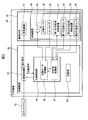
- FIG. 2 shows a block diagram of the machine tool in the present embodiment.
- machine tool 80 includes a machine main body 81 and a control device 82.
- the machine body 81 includes a spindle device 10 and a moving device 91 that moves the tool 18 relative to the workpiece.
- the moving device 91 includes a device that moves the tool in the X-axis direction and a device that moves the tool in the Y-axis direction.
- the moving device 91 includes a device that moves the table on which the workpiece is fixed in the Z-axis direction.
- the moving device 91 is not limited to this form, and any device that moves the tool relative to the workpiece can be employed.
- the control device 82 is composed of, for example, a digital computer including a CPU (Central Processing Unit), a RAM (Random Access Memory), a ROM (Read Only Memory), and the like connected to each other via a bus.
- a machining program 78 in which a procedure for machining a workpiece is set is input to the machine tool 80.
- the control device 82 controls the machine main body 81 based on the machining program 78.
- the control device 82 includes a numerical control unit 83.
- the numerical control unit 83 sends a feed command related to the feed axis to the moving device 91 based on the machining program 78.
- the moving device 91 performs relative movement between the workpiece and the tool 18 based on the feed command.
- the control device 82 includes a spindle control unit 84 for controlling the spindle device 10.
- the numerical control unit 83 sends a spindle command for controlling the spindle to the spindle control unit 84 based on the machining program 78. In the machining program 78, the rotational speed of the spindle motor 35 is determined.
- the spindle command includes, for example, a command related to the rotational speed of the spindle motor 35 and a command related to the flow rate and temperature of the coolant.
- the spindle control unit 84 controls the spindle device 10 based on the spindle command.
- the spindle control unit 84 includes a spindle motor control unit 86 that controls the spindle motor 35.
- the spindle motor control unit 86 sends an operation command for the spindle motor 35 to the amplifier 94 based on the spindle command.
- the operation command for the spindle motor 35 includes the rotational speed of the spindle motor 35.
- the amplifier 94 supplies electricity to the spindle motor 35 based on the operation command of the spindle motor.
- By driving the main shaft motor 35 the main shaft 14 rotates.
- the rotation speed of the main shaft 14 is detected by the encoder 36.
- the output of the encoder 36 is transmitted to the spindle motor control unit 86.
- the spindle motor control unit 86 can correct the operation command of the spindle motor 35 based on the output of the encoder 36.
- the spindle control unit 84 includes a coolant control unit 87 that controls the coolant supply devices 41 and 42.
- the coolant control unit 87 sends an operation command to the first coolant supply device 41 and the second coolant supply device 42. Further, the coolant control unit 87 acquires the temperature of the first coolant from the first temperature sensor 43. The coolant control unit 87 acquires the temperature of the second coolant from the second temperature sensor 44.
- the coolant control unit 87 acquires the rotation speed of the spindle motor 35 (rotation speed of the spindle 14) from the spindle motor control unit 86.
- the coolant control unit 87 controls the first coolant supply device 41 and the second coolant supply device 42 so that the coolant temperature becomes the temperature of the coolant according to the rotation speed of the spindle motor 35. For example, when the temperature of the coolant acquired from the temperature sensors 43 and 44 is higher than a predetermined target temperature, the coolant controller 87 causes the coolant supply devices 41 and 42 to decrease the temperature of the coolant. Control.
- the control device 82 includes a storage unit 85 that stores information regarding the machine tool 80.
- the storage unit 85 stores the machining program 78, the target temperature of the coolant, and the target flow rate of the coolant.
- the storage unit 85 stores the target temperature of the first coolant and the target temperature of the second coolant corresponding to the rotation speed of the spindle motor 35.
- the relationship between the rotational speed of the spindle motor 35 and the target temperature of the coolant is predetermined by a mathematical formula.
- the storage unit 85 stores this mathematical formula.
- the relationship between the rotation speed of the spindle motor 35 and the target temperature of the coolant may be determined in advance in the correspondence table.
- the storage unit 85 may store this correspondence table.
- the bearing support portion of the spindle device 10 of the present embodiment is formed of a material having a larger thermal expansion coefficient than that of the spindle 14.
- the thermal expansion coefficient of the housing 12 is larger than the thermal expansion coefficient of the main shaft 14.
- the thermal expansion coefficient of the rear housing 13 is larger than the thermal expansion coefficient of the main shaft 14.
- the main shaft 14 is made of carbon steel
- the housing 12 and the rear housing 13 are made of an aluminum alloy.
- the material of the main shaft 14 and the material of the bearing support portion are not limited to this form. Any material can be used in which the thermal expansion coefficient of the bearing support portion is larger than the thermal expansion coefficient of the main shaft.
- CFRP carbon fiber reinforced plastic
- aluminum alloy can be adopted as the material of the housing.
- Fig. 3 shows a graph of the relationship between the rotational speed of the spindle and the pressure applied to the bearing during operation.
- the pressure applied to the bearings 16a and 16b as the front bearings is illustrated, but the pressure applied to the bearing 17 as the rear bearing has the same tendency.
- the spindle device 10 is assembled so that a predetermined pressure (preload) is applied to the rolling bearing. In a state where the spindle device 10 is stopped, pressure is applied to the rolling bearing.
- preload predetermined pressure
- FIG. 3 shows a graph of a spindle device of a comparative example in which the material of the spindle and the material of the bearing support are the same.
- the spindle device of the comparative example for example, the spindle, the housing, and the rear housing are formed of carbon steel.
- the spindle device of the comparative example includes a first coolant supply device and a second coolant supply device.
- FIG. 4 shows a graph of the target temperature of the first coolant.
- FIG. 5 shows a graph of the target temperature of the second coolant.
- the horizontal axis indicates the rotational speed of the spindle motor 35, and the vertical axis indicates the target temperature of the coolant.
- the target temperature of the coolant in the graph corresponds to the target temperature stored in the storage unit 85 of the control device 82.
- the first coolant supply device 41 is controlled so that the temperature of the first coolant is constant regardless of the rotational speed.
- second cooling liquid supply device 42 is controlled so that the temperature of the second cooling liquid becomes constant regardless of the rotation speed.
- a constant temperature is referred to as a reference temperature Tr.
- Tr for example, the temperature of the room in which the machine tool is arranged or the temperature of the bed of the machine tool can be adopted.
- the reference temperature Tr of the first coolant supply device 41 and the reference temperature Tr of the second coolant supply device 42 may be the same value or different values.
- the reference temperature of the first coolant supply device 41 is indicated by Tr1
- the reference temperature of the second coolant supply device 42 is indicated by Tr2.
- Rotating the main shaft increases the temperature of the bearing due to friction between the inner ring and the rolling element of the bearing and friction between the outer ring and the rolling element.
- the temperature of the first coolant and the temperature of the second coolant are maintained constant, but the coolant channels 21, 23, 25, 26 are maintained. Is away from the bearings 16a, 16b, 17. For this reason, a difference arises between the temperature of the coolant and the temperature of the bearings 16a, 16b, and 17.
- the rotational speed of the spindle motor 35 increases, the temperature of the bearings 16a, 16b, and 17 increases.
- the spindle rotates at a high speed.
- a high rotational speed 20000 rpm or more can be illustrated, for example.
- the range of increase in pressure applied to the bearing becomes large in a high speed region.
- FIG. 3 shows an embodiment of a spindle apparatus in which the material is changed from the comparative example.
- the coolant control unit 87 performs control to maintain the temperature of the first coolant and the temperature of the second coolant constant as in the spindle device of the comparative example.
- the thermal expansion coefficient of the housing 12 and the thermal expansion coefficient of the rear housing 13 are larger than the thermal expansion coefficient of the main shaft 14. That is, the thermal expansion coefficient of the bearing support portion is larger than the thermal expansion coefficient of the main shaft.
- the expansion amount of the bearing support portion becomes larger than the expansion amount of the main shaft 14.
- the spindle device 10 in the present embodiment is suitable for a device in which the bearings 16a, 16b, and 17 are fixed to the housing 12 and the rear housing 13.
- a spring for adjusting the pressure applied to the front bearing may be disposed inside the main shaft device.
- the pressure applied to the bearing is likely to increase with the operation of the spindle device. For this reason, the effect of this invention becomes remarkable.
- the temperature of the first coolant supplied to the housing 12 and the rear housing 13 can be adjusted by the first coolant supply device 41.
- the coolant control unit 87 can perform first temperature control that changes the temperature of the coolant supplied to the first flow paths 21 to 23.
- the flow rate of the first coolant is controlled to be constant.
- the present invention is not limited to this mode, and the flow rate of the first coolant may be changed.
- the coolant control unit 87 controls the temperature of the first coolant without depending on the rotation speed in the region where the rotation speed of the spindle motor 35 is Nt or less. Implement control to keep constant. In the example here, the temperature of the first coolant is maintained at the reference temperature Tr1.
- the rotational speed Nt is determined in advance. As the rotation speed Nt, for example, a rotation speed that may damage the bearings 16a, 16b, and 17 can be employed.
- the coolant control unit 87 controls the temperature of the first coolant to increase as the rotation speed of the spindle motor 35 increases. That is, the coolant control unit 87 can perform control to increase the temperature rise width from the reference temperature Tr1 as the rotational speed of the spindle motor 35 increases.
- the first temperature control includes control for increasing the temperature of the first coolant in accordance with the rotational speed of the spindle motor 35.
- the coolant control unit 87 of the spindle control unit 84 acquires the rotation speed of the spindle motor 35 (rotation speed of the spindle 14) from the spindle motor control unit 86.
- the coolant control unit 87 acquires the rotational speed of the operation command of the spindle motor 35 that is transmitted to the amplifier 94.
- the coolant control unit 87 may acquire the output value of the encoder 36.
- the coolant control unit 87 acquires the temperature of the first coolant from the first temperature sensor 43.
- the coolant control unit 87 adjusts the temperature of the first coolant so that the temperature of the first coolant approaches the target temperature based on the rotation speed.
- the coolant control unit 87 controls the first coolant supply device 41. For example, when the temperature of the first coolant is raised, the coolant controller 87 can perform control to reduce the cooling capacity of the first coolant supply device 41. Alternatively, the heater may be driven to increase the temperature of the first coolant.
- the temperature of the housing 12 and the rear housing 13 can be increased as the rotational speed of the spindle motor 35 increases in a region where the rotational speed is higher than Nt.
- the amount of expansion of the housing 12 and the rear housing 13 can be increased.
- FIG. 3 shows a graph of an example when the first temperature control is performed in the spindle device 10 of the present embodiment.
- the temperature of the first coolant in the region where the rotation speed is higher than Nt, the temperature of the first coolant is changed while the temperature of the second coolant is maintained at the reference temperature Tr2. Expansion of the housing 12 and the rear housing 13 can be promoted in a region where the rotational speed is higher than Nt. It can be seen that by performing the first temperature control, it is possible to effectively suppress an increase in pressure applied to the bearings 16a, 16b, and 17 in a region where the rotational speed is larger than Nt.
- the temperature of the second coolant supplied to the main shaft 14 can be adjusted by the second coolant supply device 42.
- the coolant controller 87 can perform second temperature control that changes the temperature of the coolant supplied to the second flow paths 25 and 26.
- the flow rate of the second coolant is controlled to be constant.
- the present invention is not limited to this mode, and the flow rate of the second coolant may be changed.
- the coolant control unit 87 controls the temperature of the second coolant without depending on the rotation speed in the region where the rotation speed of the spindle motor 35 is Nt or less. Implement control to keep constant. In this example, the target temperature of the second coolant is maintained at the reference temperature Tr2.
- the coolant control unit 87 controls the temperature of the second coolant to be lower as the rotation speed of the spindle motor 35 is higher. That is, the coolant control unit 87 can perform control to increase the temperature drop from the reference temperature Tr2 as the rotational speed of the spindle motor 35 increases.
- the second temperature control includes control for lowering the temperature of the second coolant according to the rotational speed of the spindle motor 35.
- the coolant control unit 87 acquires the temperature of the second coolant from the second temperature sensor 44.
- the coolant control unit 87 adjusts the temperature of the second coolant so that the temperature of the second coolant approaches the target temperature.
- the coolant control unit 87 controls the second coolant supply device 42. For example, when lowering the temperature of the second coolant, the coolant controller 87 can perform control to increase the cooling capacity of the second coolant supply device 42.
- FIG. 3 shows a graph of an example when the first temperature control and the second temperature control are performed in the spindle device 10 of the present embodiment.
- the temperature of the first coolant is raised and the temperature of the second coolant is lowered.
- the difference between the temperature of the first coolant and the temperature of the second coolant increases.
- Expansion of the housing 12 and the rear housing 13 can be promoted in a region where the rotational speed is higher than Nt.
- the expansion of the main shaft 14 can be suppressed in a region where the rotational speed is higher than Nt.
- an increase in pressure applied to the bearings 16a, 16b, and 17 can be effectively suppressed.
- the spindle device 10 of the present embodiment includes the first coolant supply device 41 and the second coolant supply device 42.
- the spindle device is not limited to this configuration, and the spindle device includes the first coolant supply device and the first coolant supply device 42. At least one of the two coolant supply devices can be provided.
- the spindle device including the first coolant supply device can perform the first temperature control.
- the spindle device including the second coolant supply device can perform the second temperature control.
- the spindle device may not include the coolant supply device.
- the target temperature of the coolant is changed in a region where the rotation speed of the spindle motor 35 is larger than Nt.
- the target temperature of the coolant can be changed in the speed region.
- the target temperature of the first coolant may be increased as the rotational speed increases in all rotational speed regions.
- the target temperature of the second coolant may be decreased as the rotation speed increases in all rotation speed regions.
- rolling bearing Any type of rolling bearing can be adopted as the rolling bearing that supports the main shaft.
- rolling bearings such as angular bearings and roller bearings can be employed.
- the spindle device of the present embodiment holds a tool, but is not limited to this form.
- the spindle device may hold a workpiece.
- a lathe can be exemplified as a machine tool in which the spindle device holds a workpiece. In the lathe, the spindle device holds and rotates the workpiece, while the moving device can move the tool relative to the workpiece.
Abstract
A main shaft device (10) is attached to a work machine (80). The main shaft device (10) is provided with a main shaft (14) that supports a tool (18) or a workpiece, and a main shaft motor (35) that causes the main shaft (14) to rotate. The main shaft device (10) is provided with bearings (16a, 16b, 17) that are rolling bearings which support the main shaft in an inner race, and a housing (12) and a rear housing (13) that secure an outer race of the bearings (16a, 16b, 17). The housing (12) and the rear housing (13) are formed of a material having a coefficient of thermal expansion greater than that of the main shaft (14).
Description
本発明は、工作機械に取り付けられる主軸装置に関する。
The present invention relates to a spindle device attached to a machine tool.
工作機械は、工具またはワークを回転する主軸装置を備える。例えば、工作機械が工具を回転する主軸装置を備える場合には、工作機械は、工具を軸線の周りに回転させることができる。工作機械は、工具をワークに接触させて、ワークに対して工具を相対的に移動することにより、所望の形状にワークを加工することができる。主軸装置は、工具が連結された主軸を備える。主軸は、軸受を介してハウジングに支持されている。主軸が回転することにより、工具またはワークが回転する。
Machine tools are equipped with a spindle device that rotates tools or workpieces. For example, if the machine tool includes a spindle device that rotates the tool, the machine tool can rotate the tool about an axis. The machine tool can process the workpiece into a desired shape by bringing the tool into contact with the workpiece and moving the tool relative to the workpiece. The spindle device includes a spindle to which a tool is connected. The main shaft is supported by the housing via a bearing. The tool or workpiece rotates as the spindle rotates.
工作機械では、切削の種類に応じて工具またはワークを高速で回転させる場合がある。主軸が高速で回転する主軸装置には、主軸を支持する軸受として転がり軸受を採用することができる。
In machine tools, tools or workpieces may be rotated at high speed depending on the type of cutting. A rolling bearing can be adopted as a bearing for supporting the main shaft in a main shaft device in which the main shaft rotates at a high speed.
特開2003-056582号公報には、軸心の冷却液通路およびハウジングの冷却液通路を備える回転軸装置が開示されている。この回転軸装置は、軸心の冷却液通路およびハウジングの冷却液通路に供給する冷却液の温度を制御して、軸受の外輪を軸受の内輪よりもわずかに膨張させることが開示されている。
Japanese Patent Application Laid-Open No. 2003-056582 discloses a rotary shaft device having an axial center coolant passage and a housing coolant passage. This rotary shaft device is disclosed to control the temperature of the coolant supplied to the coolant passage of the shaft center and the coolant passage of the housing to expand the outer ring of the bearing slightly more than the inner ring of the bearing.
転がり軸受を備える主軸装置では、転がり軸受に主軸の径方向に予め定められた圧力が加えられる。すなわち、主軸装置は、転がり軸受に予圧が加えられるように組み立てられる。転がり軸受に与圧を与えることにより、所望の転がり軸受の特性が得られる。適正な予圧の大きさの範囲は予め定められている。
In a spindle device provided with a rolling bearing, a predetermined pressure is applied to the rolling bearing in the radial direction of the spindle. That is, the main shaft device is assembled so that a preload is applied to the rolling bearing. By applying pressure to the rolling bearing, desired rolling bearing characteristics can be obtained. The range of the appropriate preload magnitude is predetermined.
主軸装置が駆動して主軸が回転すると、転がり軸受の転動体と内輪との摩擦および転動体と外輪との摩擦により、転がり軸受の温度が上昇する。主軸およびハウジングは、同じ材質で形成されていても、体積が異なるために熱容量が異なる。ハウジングよりも体積が小さい主軸は、熱容量が小さいために温度が上昇しやすい。一方で、主軸よりも体積の大きいハウジングは、熱容量が大きいために温度が上昇しにくい。このために、主軸の膨張量はハウジングの膨張量よりも大きくなる。特に、主軸の径方向の膨張量は、ハウジングの径方向の膨張量よりも大きくなる。このために、主軸が回転すると、軸受に加わる圧力は増大する。主軸の回転速度が大きくなるほど、軸受の温度は上昇する。このために、主軸の高速で回転すると、軸受に作用する圧力が大きくなる。
When the main shaft device is driven and the main shaft rotates, the temperature of the rolling bearing rises due to friction between the rolling elements of the rolling bearing and the inner ring and friction between the rolling elements and the outer ring. Even if the main shaft and the housing are made of the same material, their heat capacities are different because of their different volumes. The main shaft having a volume smaller than that of the housing is likely to rise in temperature because of its small heat capacity. On the other hand, the housing having a volume larger than that of the main shaft has a large heat capacity, so that the temperature hardly rises. For this reason, the expansion amount of the main shaft is larger than the expansion amount of the housing. In particular, the amount of expansion of the main shaft in the radial direction is larger than the amount of expansion of the housing in the radial direction. For this reason, when the main shaft rotates, the pressure applied to the bearing increases. The bearing temperature increases as the rotational speed of the main shaft increases. For this reason, when the spindle rotates at a high speed, the pressure acting on the bearing increases.
また、軸受の内輪は主軸と共に回転するために、内輪には遠心力が作用する。更に、内輪の周りを回転する転動体にも遠心力が作用する。内輪および転動体の遠心力により、軸受に作用する圧力が増大する。特に、主軸が高速で回転すると、軸受に作用する圧力が大きくなる。
Also, since the inner ring of the bearing rotates with the main shaft, centrifugal force acts on the inner ring. Furthermore, centrifugal force also acts on the rolling elements that rotate around the inner ring. The pressure acting on the bearing increases due to the centrifugal force of the inner ring and the rolling elements. In particular, when the main shaft rotates at a high speed, the pressure acting on the bearing increases.
このように、主軸が回転して軸受に加わる圧力が大きくなると、軸受の寿命が短くなったり、軸受が破損したりする場合がある。特に、主軸が高速で回転すると、軸受の寿命が短くなったり、軸受が破損したりする虞がある。
As described above, when the main shaft rotates and the pressure applied to the bearing increases, the life of the bearing may be shortened or the bearing may be damaged. In particular, when the main shaft rotates at a high speed, the life of the bearing may be shortened or the bearing may be damaged.
本発明は、運転期間中に転がり軸受に加わる圧力を抑制する主軸装置を提供することを目的とする。
An object of the present invention is to provide a spindle device that suppresses pressure applied to a rolling bearing during an operation period.
本発明の主軸装置は、工作機械に取り付けられ、工具またはワークを回転する。主軸装置は、工具またはワークを支持する主軸と、主軸を回転させる主軸モータとを備える。主軸装置は、内輪、転動体、および外輪を有し、内輪にて主軸を支持する転がり軸受と、転がり軸受の外輪を固定する軸受支持部とを備える。軸受支持部は、主軸よりも熱膨張係数が大きい材質にて形成されている。
The spindle device of the present invention is attached to a machine tool and rotates a tool or a workpiece. The spindle device includes a spindle that supports a tool or a workpiece, and a spindle motor that rotates the spindle. The main shaft device includes an inner ring, a rolling element, and an outer ring, and includes a rolling bearing that supports the main shaft by the inner ring and a bearing support portion that fixes the outer ring of the rolling bearing. The bearing support portion is formed of a material having a larger thermal expansion coefficient than the main shaft.
上記発明においては、主軸装置は、軸受支持部に第1の冷却液を供給する第1の冷却液供給装置を備えることができる。軸受支持部は、第1の冷却液が流れる第1の流路を有することができる。第1の流路は、転がり軸受の外輪の側方に配置されることができる。第1の冷却液供給装置は、第1の冷却液の温度を調整する機能を有し、第1の流路に第1の冷却液を供給することができる。
In the above invention, the spindle device may include a first coolant supply device that supplies the first coolant to the bearing support portion. The bearing support portion may have a first flow path through which the first coolant flows. The first flow path can be disposed on the side of the outer ring of the rolling bearing. The first coolant supply device has a function of adjusting the temperature of the first coolant and can supply the first coolant to the first flow path.
上記発明においては、主軸装置は、第1の冷却液供給装置を制御する制御装置を備えることができる。制御装置は、第1の冷却液の温度を制御する第1の温度制御を実施することができる。第1の温度制御は、主軸モータの回転速度が高くなるほど第1の冷却液の温度を上昇させる制御を含むことができる。
In the above invention, the spindle device can include a control device for controlling the first coolant supply device. The control device can perform first temperature control for controlling the temperature of the first coolant. The first temperature control can include control for increasing the temperature of the first coolant as the rotational speed of the spindle motor increases.
上記発明においては、主軸装置は、主軸に第2の冷却液を供給する第2の冷却液供給装置を備えることができる。主軸は、第2の冷却液が流れる第2の流路を有することができる。第2の流路は、転がり軸受の内輪の側方に配置されることができる。第2の冷却液供給装置は、第2の冷却液の温度を調整する機能を有し、第2の流路に第2の冷却液を供給することができる。
In the above invention, the spindle device can include a second coolant supply device that supplies the second coolant to the spindle. The main shaft can have a second flow path through which the second coolant flows. The second flow path can be arranged on the side of the inner ring of the rolling bearing. The second coolant supply device has a function of adjusting the temperature of the second coolant, and can supply the second coolant to the second flow path.
上記発明においては、主軸装置は、第2の冷却液供給装置を制御する制御装置を備えることができる。制御装置は、第2の冷却液の温度を制御する第2の温度制御を実施することができる。第2の温度制御は、主軸モータの回転速度が高くなるほど第2の冷却液の温度を低下させる制御を含むことができる。
In the above invention, the spindle device can include a control device for controlling the second coolant supply device. The control device can perform second temperature control for controlling the temperature of the second coolant. The second temperature control can include a control for decreasing the temperature of the second coolant as the rotational speed of the spindle motor increases.
本発明によれば、運転期間中に転がり軸受に加わる圧力を抑制する主軸装置を提供することができる。
According to the present invention, it is possible to provide a spindle device that suppresses the pressure applied to the rolling bearing during the operation period.
図1から図5を参照して、実施の形態における主軸装置について説明する。本実施の形態の主軸装置は、工作機械に取り付けられている。本実施の形態の工作機械は、加工プログラムに基づいて工具とワークとを相対的に移動させて自動的に加工を行う数値制御式の工作機械である。
The spindle device according to the embodiment will be described with reference to FIGS. The spindle device of the present embodiment is attached to a machine tool. The machine tool of the present embodiment is a numerically controlled machine tool that performs machining automatically by relatively moving a tool and a workpiece based on a machining program.
図1に、本実施の形態の主軸装置の概略断面図を示す。本実施の形態では、工具18が配置されている方向を主軸装置10の前側と称し、工具18が配置されている側と反対側を後側と称する。主軸装置10は、中空状のハウジング12と、ハウジング12に支持された主軸14とを含む。主軸14は、円柱状に形成されている。主軸14は、工具ホルダ19を介して工具18を支持している。主軸14は、フロントベアリングとしての軸受16a,16bと、リアベアリングとしての軸受17を介して回転自在に支持されている。本実施の形態の軸受16a,16b,17は、転がり軸受である。転がり軸受は、内輪、外輪、および内輪と外輪との間に配置された転動体を含む。軸受16a,16b,17の内輪は、主軸14を支持する。
FIG. 1 shows a schematic cross-sectional view of the spindle device of the present embodiment. In the present embodiment, the direction in which the tool 18 is arranged is referred to as the front side of the spindle device 10, and the side opposite to the side in which the tool 18 is arranged is referred to as the rear side. The main shaft device 10 includes a hollow housing 12 and a main shaft 14 supported by the housing 12. The main shaft 14 is formed in a cylindrical shape. The main shaft 14 supports a tool 18 via a tool holder 19. The main shaft 14 is rotatably supported via bearings 16a and 16b as front bearings and a bearing 17 as a rear bearing. The bearings 16a, 16b, and 17 of the present embodiment are rolling bearings. The rolling bearing includes an inner ring, an outer ring, and rolling elements arranged between the inner ring and the outer ring. The inner rings of the bearings 16a, 16b, and 17 support the main shaft 14.
主軸装置10は、軸受16a,16b,17の外輪を固定する軸受支持部を備える。軸受16a,16bの外輪は、ハウジング12の内面に固定されている。ハウジング12の軸受16a,16bに接触する部分が軸受支持部として機能する。また、主軸装置10は、ハウジング12の内面に固定されたリアハウジング13を含む。リアハウジング13は、軸受17を支持する。軸受17の外輪は、リアハウジング13に固定されている。リアハウジング13は、軸受支持部として機能する。
The main shaft device 10 includes a bearing support portion that fixes the outer rings of the bearings 16a, 16b, and 17. The outer rings of the bearings 16 a and 16 b are fixed to the inner surface of the housing 12. The portion of the housing 12 that contacts the bearings 16a and 16b functions as a bearing support portion. The spindle device 10 also includes a rear housing 13 fixed to the inner surface of the housing 12. The rear housing 13 supports the bearing 17. An outer ring of the bearing 17 is fixed to the rear housing 13. The rear housing 13 functions as a bearing support portion.
主軸装置10は、主軸14を回転させる主軸モータ35を含む。本実施の形態の主軸モータ35は、ビルトインタイプのモータである。主軸モータ35は、主軸14の外面に固定されたロータ32と、ハウジング12の内面に固定されたステータ34とを含む。主軸装置10は、主軸モータ35に電気を供給する電気供給装置としてのアンプ94を含む。
The spindle device 10 includes a spindle motor 35 that rotates the spindle 14. The spindle motor 35 of the present embodiment is a built-in type motor. The main shaft motor 35 includes a rotor 32 fixed to the outer surface of the main shaft 14 and a stator 34 fixed to the inner surface of the housing 12. The spindle device 10 includes an amplifier 94 as an electricity supply device that supplies electricity to the spindle motor 35.
主軸14の内部は、工具ホルダ19を保持したり解放したりする機構が配置されている。ワークの加工時には、主軸14は、工具ホルダ19を介して工具18を保持する。主軸モータ35が駆動することにより、工具18が主軸14と共に回転する。
A mechanism for holding and releasing the tool holder 19 is disposed inside the spindle 14. When machining a workpiece, the spindle 14 holds the tool 18 via the tool holder 19. When the spindle motor 35 is driven, the tool 18 rotates together with the spindle 14.
主軸装置10は、主軸14の回転速度を検出するための回転角検出器としてのエンコーダ36を含む。本実施の形態のエンコーダ36は、ギヤ36aとエンコーダセンタ36bとを含む。本実施の形態のギヤ36aは、主軸14の後側の端部に配置されている。エンコーダセンタ36bは、ギヤ36aと対向するようにリアハウジング13に固定されている。
The spindle device 10 includes an encoder 36 as a rotation angle detector for detecting the rotation speed of the spindle 14. The encoder 36 of the present embodiment includes a gear 36a and an encoder center 36b. The gear 36a of the present embodiment is disposed at the rear end of the main shaft 14. The encoder center 36b is fixed to the rear housing 13 so as to face the gear 36a.
本実施の形態における主軸装置10は、軸受16a,16b,17を冷却液にて冷却可能に形成されている。冷却液としては、冷却水または冷却オイルを用いることができる。
The spindle device 10 in the present embodiment is formed so that the bearings 16a, 16b, and 17 can be cooled with a coolant. As the cooling liquid, cooling water or cooling oil can be used.
ハウジング12は、第1の冷却液が流れる第1の流路21,23を有する。流路21は、軸受16a,16bの位置に対応して形成されている。流路21は、軸受16a,16bの側方に配置されている。流路21は、軸受16a,16bの近傍に形成されている。本実施の形態の流路21は、軸受16a,16bを取り囲むように形成されている。リアハウジング13は、第1の冷却液が流れる第1の流路23を有する。流路23は、軸受17の位置に対応して形成されている。流路23は、軸受17の側方に配置されている。流路23は、軸受17の近傍に形成されている。本実施の形態の流路23は、軸受17を取り囲むように形成されている。
The housing 12 has first flow paths 21 and 23 through which the first coolant flows. The flow path 21 is formed corresponding to the positions of the bearings 16a and 16b. The channel 21 is disposed on the side of the bearings 16a and 16b. The flow path 21 is formed in the vicinity of the bearings 16a and 16b. The flow path 21 of the present embodiment is formed so as to surround the bearings 16a and 16b. The rear housing 13 has a first flow path 23 through which the first coolant flows. The flow path 23 is formed corresponding to the position of the bearing 17. The flow path 23 is disposed on the side of the bearing 17. The flow path 23 is formed in the vicinity of the bearing 17. The flow path 23 of the present embodiment is formed so as to surround the bearing 17.
また、本実施の形態における第1の冷却液は、主軸モータ35を冷却するように形成されている。ハウジング12とステータ34を支持する部材との間には、第1の冷却液が流れる第1の流路22が形成されている。
Further, the first coolant in the present embodiment is formed so as to cool the spindle motor 35. A first flow path 22 through which the first coolant flows is formed between the housing 12 and the member that supports the stator 34.
主軸14は、第2の冷却液が流れる第2の流路25,26を含む。流路25は、軸受16a,16bの位置に対応して形成されている。流路25は、軸受16a,16bの側方に配置されている。流路25は、軸受16a,16bの近傍に形成されている。流路26は、軸受17の位置に対応して形成されている。流路26は、軸受17の側方に配置されている。流路26は、軸受17の近傍に形成されている。
The main shaft 14 includes second flow paths 25 and 26 through which the second coolant flows. The flow path 25 is formed corresponding to the positions of the bearings 16a and 16b. The flow path 25 is arrange | positioned at the side of bearing 16a, 16b. The flow path 25 is formed in the vicinity of the bearings 16a and 16b. The flow path 26 is formed corresponding to the position of the bearing 17. The flow path 26 is disposed on the side of the bearing 17. The flow path 26 is formed in the vicinity of the bearing 17.
主軸装置10は、軸受支持部に第1の冷却液を供給する第1の冷却液供給装置41を備える。第1の冷却液供給装置41は、ハウジング12およびリアハウジング13に形成された第1の流路21,22,23に、第1の冷却液を供給する。第1の冷却液供給装置41は、第1の冷却液の温度を調整できるように形成されている。本実施の形態の第1の冷却液供給装置41は、冷却液を供給するためのポンプと、冷却液を冷却するためのチラーユニットと、冷却液を加熱するためのヒータとを含む。チラーユニットは、圧縮機、膨張弁、および熱交換器を含む。第1の流路23から第1の冷却液供給装置41に戻る流路の途中には、第1の温度センサ43が配置されている。第1の温度センサ43は、ハウジング12およびリアハウジング13を冷却した後の冷却液の温度を検出する。
The spindle device 10 includes a first coolant supply device 41 that supplies a first coolant to the bearing support portion. The first coolant supply device 41 supplies the first coolant to the first flow paths 21, 22 and 23 formed in the housing 12 and the rear housing 13. The first coolant supply device 41 is formed so that the temperature of the first coolant can be adjusted. The first coolant supply device 41 of the present embodiment includes a pump for supplying the coolant, a chiller unit for cooling the coolant, and a heater for heating the coolant. The chiller unit includes a compressor, an expansion valve, and a heat exchanger. A first temperature sensor 43 is disposed in the middle of the flow path returning from the first flow path 23 to the first coolant supply device 41. The first temperature sensor 43 detects the temperature of the coolant after cooling the housing 12 and the rear housing 13.
第1の流路21に第1の冷却液が供給されることにより、軸受16a,16bが冷却される。第1の流路23に第1の冷却液が供給されることにより、軸受17が冷却される。また、第1の流路22に第1の冷却液が供給されることにより、主軸モータ35が冷却される。なお、主軸モータ35を冷却するための第1の流路22には、他の冷却液供給装置から冷却液が供給されていても構わない。すなわち、主軸モータ35を冷却する装置は、軸受を冷却する装置とは別に形成されていても構わない。
When the first coolant is supplied to the first flow path 21, the bearings 16a and 16b are cooled. The bearing 17 is cooled by supplying the first coolant to the first flow path 23. In addition, the spindle motor 35 is cooled by supplying the first coolant to the first flow path 22. The first flow path 22 for cooling the spindle motor 35 may be supplied with coolant from another coolant supply device. That is, the device for cooling the spindle motor 35 may be formed separately from the device for cooling the bearing.
主軸装置10は、主軸14に第2の冷却液を供給する第2の冷却液供給装置42を備える。第2の冷却液供給装置42は、主軸14に形成された第2の流路25,26に、第2の冷却液を供給する。第2の冷却液供給装置42は、第2の冷却液の温度を調整できるように形成されている。本実施の形態の第2の冷却液供給装置42は、第1の冷却液供給装置41と同様に、冷却液を供給するためのポンプと、冷却液を冷却するためのチラーユニットとを含む。第2の流路25から第2の冷却液供給装置42に戻る流路の途中には、第2の温度センサ44が配置されている。第2の温度センサ44は、主軸14を冷却した後の冷却液の温度を検出する。
The spindle device 10 includes a second coolant supply device 42 that supplies the second coolant to the spindle 14. The second coolant supply device 42 supplies the second coolant to the second flow paths 25 and 26 formed on the main shaft 14. The second coolant supply device 42 is formed so that the temperature of the second coolant can be adjusted. Similar to the first coolant supply device 41, the second coolant supply device 42 of the present embodiment includes a pump for supplying the coolant and a chiller unit for cooling the coolant. A second temperature sensor 44 is disposed in the middle of the flow path returning from the second flow path 25 to the second coolant supply apparatus 42. The second temperature sensor 44 detects the temperature of the coolant after cooling the main shaft 14.
本実施の形態の温度センサ43,44は、主軸14、ハウジング12、およびリアハウジング13を冷却した後の冷却液の温度を検出するように形成されているが、この形態に限られない。温度センサは、冷却液の温度を検出可能な任意の位置に配置することができる。例えば、温度センサは、冷却液供給装置41,42から流出する冷却液の温度を検出するように配置されていても構わない。または、温度センサは、それぞれの流路21,22,23,25,26を流れる冷却液の温度を検出するように配置されていても構わない。
The temperature sensors 43 and 44 of the present embodiment are formed so as to detect the temperature of the coolant after cooling the main shaft 14, the housing 12, and the rear housing 13, but are not limited to this form. The temperature sensor can be disposed at any position where the temperature of the coolant can be detected. For example, the temperature sensor may be arranged so as to detect the temperature of the coolant flowing out from the coolant supply devices 41 and 42. Alternatively, the temperature sensor may be arranged so as to detect the temperature of the coolant flowing through each of the flow paths 21, 22, 23, 25, 26.
図2に、本実施の形態における工作機械のブロック図を示す。図1および図2を参照して、工作機械80は、機械本体81と制御装置82とを備える。機械本体81は、主軸装置10と、ワークに対して工具18を相対移動させる移動装置91とを含む。機械本体81には、たとえば、直線送り軸として互いに直交するX軸、Y軸およびZ軸が設定されている。移動装置91は、工具をX軸方向に移動させる装置および工具をY軸方向に移動させる装置を含む。また、移動装置91は、ワークが固定されたテーブルをZ軸方向に移動させる装置を含む。移動装置91としては、この形態に限られず、ワークに対して工具を相対的に移動させる任意の装置を採用することができる。
FIG. 2 shows a block diagram of the machine tool in the present embodiment. Referring to FIGS. 1 and 2, machine tool 80 includes a machine main body 81 and a control device 82. The machine body 81 includes a spindle device 10 and a moving device 91 that moves the tool 18 relative to the workpiece. In the machine body 81, for example, an X axis, a Y axis, and a Z axis that are orthogonal to each other are set as linear feed axes. The moving device 91 includes a device that moves the tool in the X-axis direction and a device that moves the tool in the Y-axis direction. Moreover, the moving device 91 includes a device that moves the table on which the workpiece is fixed in the Z-axis direction. The moving device 91 is not limited to this form, and any device that moves the tool relative to the workpiece can be employed.
制御装置82は、例えば、バスを介して互いに接続されたCPU(Central Processing Unit)、RAM(Random Access Memory)、およびROM(Read Only Memory)等を備えるデジタルコンピュータにて構成されている。工作機械80には、ワークを加工する手順が設定された加工プログラム78が入力される。制御装置82は、加工プログラム78に基づいて、機械本体81を制御する。
The control device 82 is composed of, for example, a digital computer including a CPU (Central Processing Unit), a RAM (Random Access Memory), a ROM (Read Only Memory), and the like connected to each other via a bus. A machining program 78 in which a procedure for machining a workpiece is set is input to the machine tool 80. The control device 82 controls the machine main body 81 based on the machining program 78.
制御装置82は、数値制御部83を含む。数値制御部83は、加工プログラム78に基づいて送り軸に関する送り指令を移動装置91に送出する。移動装置91は、送り指令に基づいてワークと工具18との相対移動を行う。制御装置82は、主軸装置10を制御するための主軸制御部84を含む。数値制御部83は、加工プログラム78に基づいて、主軸を制御する主軸指令を主軸制御部84に送出する。加工プログラム78には、主軸モータ35の回転速度が定められている。主軸指令には、例えば主軸モータ35の回転速度に関する指令および冷却液の流量および温度に関する指令が含まれる。
The control device 82 includes a numerical control unit 83. The numerical control unit 83 sends a feed command related to the feed axis to the moving device 91 based on the machining program 78. The moving device 91 performs relative movement between the workpiece and the tool 18 based on the feed command. The control device 82 includes a spindle control unit 84 for controlling the spindle device 10. The numerical control unit 83 sends a spindle command for controlling the spindle to the spindle control unit 84 based on the machining program 78. In the machining program 78, the rotational speed of the spindle motor 35 is determined. The spindle command includes, for example, a command related to the rotational speed of the spindle motor 35 and a command related to the flow rate and temperature of the coolant.
主軸制御部84は、主軸指令に基づいて、主軸装置10を制御する。主軸制御部84は、主軸モータ35を制御する主軸モータ制御部86を含む。主軸モータ制御部86は、主軸指令に基づいて、主軸モータ35の動作指令をアンプ94に送出する。主軸モータ35の動作指令には、主軸モータ35の回転速度が含まれる。アンプ94は、主軸モータの動作指令に基づいて、主軸モータ35に電気を供給する。主軸モータ35が駆動することにより、主軸14が回転する。主軸14の回転速度は、エンコーダ36にて検出される。エンコーダ36の出力は、主軸モータ制御部86に送信される。主軸モータ制御部86は、エンコーダ36の出力に基づいて主軸モータ35の動作指令を修正することができる。
The spindle control unit 84 controls the spindle device 10 based on the spindle command. The spindle control unit 84 includes a spindle motor control unit 86 that controls the spindle motor 35. The spindle motor control unit 86 sends an operation command for the spindle motor 35 to the amplifier 94 based on the spindle command. The operation command for the spindle motor 35 includes the rotational speed of the spindle motor 35. The amplifier 94 supplies electricity to the spindle motor 35 based on the operation command of the spindle motor. By driving the main shaft motor 35, the main shaft 14 rotates. The rotation speed of the main shaft 14 is detected by the encoder 36. The output of the encoder 36 is transmitted to the spindle motor control unit 86. The spindle motor control unit 86 can correct the operation command of the spindle motor 35 based on the output of the encoder 36.
主軸制御部84は、冷却液供給装置41,42を制御する冷却液制御部87を含む。冷却液制御部87は、動作指令を第1の冷却液供給装置41および第2の冷却液供給装置42に送出する。また、冷却液制御部87は第1の温度センサ43から第1の冷却液の温度を取得する。冷却液制御部87は、第2の温度センサ44から第2の冷却液の温度を取得する。
The spindle control unit 84 includes a coolant control unit 87 that controls the coolant supply devices 41 and 42. The coolant control unit 87 sends an operation command to the first coolant supply device 41 and the second coolant supply device 42. Further, the coolant control unit 87 acquires the temperature of the first coolant from the first temperature sensor 43. The coolant control unit 87 acquires the temperature of the second coolant from the second temperature sensor 44.
冷却液制御部87は、主軸モータ制御部86から主軸モータ35の回転速度(主軸14の回転速度)を取得する。冷却液制御部87は、主軸モータ35の回転速度に応じた冷却液の温度となるように、第1の冷却液供給装置41および第2の冷却液供給装置42を制御する。例えば、温度センサ43,44から取得した冷却液の温度が予め定められた目標温度よりも高い場合に、冷却液制御部87は、冷却液の温度を下げるように冷却液供給装置41,42を制御する。
The coolant control unit 87 acquires the rotation speed of the spindle motor 35 (rotation speed of the spindle 14) from the spindle motor control unit 86. The coolant control unit 87 controls the first coolant supply device 41 and the second coolant supply device 42 so that the coolant temperature becomes the temperature of the coolant according to the rotation speed of the spindle motor 35. For example, when the temperature of the coolant acquired from the temperature sensors 43 and 44 is higher than a predetermined target temperature, the coolant controller 87 causes the coolant supply devices 41 and 42 to decrease the temperature of the coolant. Control.
制御装置82は、工作機械80に関する情報を記憶する記憶部85を含む。例えば、記憶部85は、加工プログラム78、冷却液の目標温度、および冷却液の目標流量を記憶する。特に、記憶部85は、主軸モータ35の回転速度に対応する第1の冷却液の目標温度および第2の冷却液の目標温度を記憶する。主軸モータ35の回転速度と冷却液の目標温度との関係は、数式で予め定められている。記憶部85は、この数式を記憶する。または、主軸モータ35の回転速度と冷却液の目標温度との関係は、対応表にて予め定められていても構わない。記憶部85は、この対応表を記憶しても構わない。
The control device 82 includes a storage unit 85 that stores information regarding the machine tool 80. For example, the storage unit 85 stores the machining program 78, the target temperature of the coolant, and the target flow rate of the coolant. In particular, the storage unit 85 stores the target temperature of the first coolant and the target temperature of the second coolant corresponding to the rotation speed of the spindle motor 35. The relationship between the rotational speed of the spindle motor 35 and the target temperature of the coolant is predetermined by a mathematical formula. The storage unit 85 stores this mathematical formula. Alternatively, the relationship between the rotation speed of the spindle motor 35 and the target temperature of the coolant may be determined in advance in the correspondence table. The storage unit 85 may store this correspondence table.
図1を参照して、本実施の形態の主軸装置10の軸受支持部は、主軸14よりも熱膨張係数が大きい材質にて形成されている。本実施の形態においては、ハウジング12の熱膨張係数は、主軸14の熱膨張係数よりも大きい。また、リアハウジング13の熱膨張係数は、主軸14の熱膨張係数よりも大きい。本実施の形態では、主軸14は炭素鋼にて形成され、ハウジング12およびリアハウジング13は、アルミニウム合金にて形成されている。主軸14の材質および軸受支持部の材質は、この形態に限られない。軸受支持部の熱膨張係数が主軸の熱膨張係数よりも大きくなる任意の材質を採用することができる。例えば、主軸の材質として炭素繊維強化プラスチック(CFRP)を採用し、ハウジングの材質としてアルミニウム合金を採用することができる。
Referring to FIG. 1, the bearing support portion of the spindle device 10 of the present embodiment is formed of a material having a larger thermal expansion coefficient than that of the spindle 14. In the present embodiment, the thermal expansion coefficient of the housing 12 is larger than the thermal expansion coefficient of the main shaft 14. Further, the thermal expansion coefficient of the rear housing 13 is larger than the thermal expansion coefficient of the main shaft 14. In the present embodiment, the main shaft 14 is made of carbon steel, and the housing 12 and the rear housing 13 are made of an aluminum alloy. The material of the main shaft 14 and the material of the bearing support portion are not limited to this form. Any material can be used in which the thermal expansion coefficient of the bearing support portion is larger than the thermal expansion coefficient of the main shaft. For example, carbon fiber reinforced plastic (CFRP) can be adopted as the material of the main shaft, and aluminum alloy can be adopted as the material of the housing.
図3に、主軸の回転速度と運転時に軸受に加わる圧力との関係のグラフを示す。ここでは、フロントベアリングとしての軸受16a,16bに加わる圧力を例示するが、リアベアリングとしての軸受17に加わる圧力も同様の傾向を有する。主軸装置10は、転がり軸受に予め定められた圧力(予圧)が加わるように組み立てられる。主軸装置10が停止している状態において、転がり軸受には圧力が加えられている。
Fig. 3 shows a graph of the relationship between the rotational speed of the spindle and the pressure applied to the bearing during operation. Here, the pressure applied to the bearings 16a and 16b as the front bearings is illustrated, but the pressure applied to the bearing 17 as the rear bearing has the same tendency. The spindle device 10 is assembled so that a predetermined pressure (preload) is applied to the rolling bearing. In a state where the spindle device 10 is stopped, pressure is applied to the rolling bearing.
図3には、主軸の材質および軸受支持部の材質が同一の比較例の主軸装置のグラフが示されている。比較例の主軸装置は、例えば、主軸、ハウジング、およびリアハウジングが炭素鋼にて形成されている。比較例の主軸装置は、第1の冷却液供給装置および第2の冷却液供給装置を備える。
FIG. 3 shows a graph of a spindle device of a comparative example in which the material of the spindle and the material of the bearing support are the same. In the spindle device of the comparative example, for example, the spindle, the housing, and the rear housing are formed of carbon steel. The spindle device of the comparative example includes a first coolant supply device and a second coolant supply device.
図4に、第1の冷却液の目標温度のグラフを示す。図5に、第2の冷却液の目標温度のグラフを示す。図4および図5に示すグラフでは、横軸は主軸モータ35の回転速度を示し、縦軸は冷却液の目標温度を示している。グラフの冷却液の目標温度は、制御装置82の記憶部85に記憶された目標温度に対応する。
FIG. 4 shows a graph of the target temperature of the first coolant. FIG. 5 shows a graph of the target temperature of the second coolant. In the graphs shown in FIGS. 4 and 5, the horizontal axis indicates the rotational speed of the spindle motor 35, and the vertical axis indicates the target temperature of the coolant. The target temperature of the coolant in the graph corresponds to the target temperature stored in the storage unit 85 of the control device 82.
図4を参照して、比較例の主軸装置では、回転速度に関わらずに、第1の冷却液の温度が一定になるように第1の冷却液供給装置41を制御する。図5を参照して、比較例の主軸装置では、回転速度に関わらずに、第2の冷却液の温度が一定になるように第2の冷却液供給装置42を制御する。本実施の形態では、このような一定に維持する温度を基準温度Trと称する。基準温度Trは、例えば、工作機械が配置されている部屋の気温または工作機械のベッドの温度等を採用することができる。第1の冷却液供給装置41の基準温度Trと第2の冷却液供給装置42の基準温度Trは、同じ値であっても異なる値であっても構わない。以後、第1の冷却液供給装置41の基準温度をTr1にて示し、第2の冷却液供給装置42の基準温度をTr2にて示す。
Referring to FIG. 4, in the spindle device of the comparative example, the first coolant supply device 41 is controlled so that the temperature of the first coolant is constant regardless of the rotational speed. Referring to FIG. 5, in the spindle device of the comparative example, second cooling liquid supply device 42 is controlled so that the temperature of the second cooling liquid becomes constant regardless of the rotation speed. In the present embodiment, such a constant temperature is referred to as a reference temperature Tr. As the reference temperature Tr, for example, the temperature of the room in which the machine tool is arranged or the temperature of the bed of the machine tool can be adopted. The reference temperature Tr of the first coolant supply device 41 and the reference temperature Tr of the second coolant supply device 42 may be the same value or different values. Hereinafter, the reference temperature of the first coolant supply device 41 is indicated by Tr1, and the reference temperature of the second coolant supply device 42 is indicated by Tr2.
主軸が回転することにより、軸受の内輪と転動体と摩擦および外輪と転動体との摩擦により、軸受の温度が上昇する。図3を参照して、比較例の主軸装置では、第1の冷却液の温度および第2の冷却液の温度を一定に維持しているが、冷却液の流路21,23,25,26は、軸受16a,16b,17から離れている。このために、冷却液の温度と軸受16a,16b,17の温度とに差が生じる。主軸モータ35の回転速度が上昇すると、軸受16a,16b,17の温度は上昇する。さらに、主軸14が回転すると、軸受16a,16b,17の内輪に対して外側に向かう方向の遠心力が作用する。外輪は固定されているために、主軸モータ35の回転速度が上昇すると軸受16a,16b,17に加わる圧力が増大する。
Rotating the main shaft increases the temperature of the bearing due to friction between the inner ring and the rolling element of the bearing and friction between the outer ring and the rolling element. Referring to FIG. 3, in the spindle device of the comparative example, the temperature of the first coolant and the temperature of the second coolant are maintained constant, but the coolant channels 21, 23, 25, 26 are maintained. Is away from the bearings 16a, 16b, 17. For this reason, a difference arises between the temperature of the coolant and the temperature of the bearings 16a, 16b, and 17. When the rotational speed of the spindle motor 35 increases, the temperature of the bearings 16a, 16b, and 17 increases. Further, when the main shaft 14 rotates, a centrifugal force in the outward direction acts on the inner rings of the bearings 16a, 16b, and 17. Since the outer ring is fixed, when the rotational speed of the spindle motor 35 increases, the pressure applied to the bearings 16a, 16b, and 17 increases.
このように、主軸モータ35の回転速度が大きくなるほど、軸受16a,16b,17の温度が上昇して膨張量が大きくなる。また、主軸14の回転速度が大きくなるほど遠心力が大きくなる。このために、主軸モータ35の回転速度が大きくなるほど、軸受16a,16b,17に加わる圧力が増大する。
Thus, as the rotational speed of the spindle motor 35 increases, the temperature of the bearings 16a, 16b, and 17 increases and the amount of expansion increases. Further, the centrifugal force increases as the rotational speed of the main shaft 14 increases. For this reason, the pressure applied to the bearings 16a, 16b, and 17 increases as the rotational speed of the spindle motor 35 increases.
特に、本実施の形態における主軸装置10および比較例の主軸措置では、主軸が高速にて回転する。高速の回転速度としては、例えば、20000rpm以上を例示することができる。比較例の主軸装置では、高速の領域において軸受に加わる圧力の上昇幅は大きくなる。
Particularly, in the spindle device 10 and the spindle measure of the comparative example in the present embodiment, the spindle rotates at a high speed. As a high rotational speed, 20000 rpm or more can be illustrated, for example. In the spindle device of the comparative example, the range of increase in pressure applied to the bearing becomes large in a high speed region.
図3には、比較例から材質を変更した主軸装置の実施例が示されている。この主軸装置では、冷却液制御部87は、比較例の主軸装置と同様に、第1の冷却液の温度および第2の冷却液の温度を一定に維持する制御を実施している。本実施の形態における主軸装置10では、ハウジング12の熱膨張係数およびリアハウジング13の熱膨張係数が、主軸14の熱膨張係数よりも大きい。すなわち、軸受支持部の熱膨張係数は、主軸の熱膨張係数よりも大きい。同一の上昇幅にて温度が上昇すると、軸受支持部の膨張量は、主軸14の膨張量よりも大きくなる。
FIG. 3 shows an embodiment of a spindle apparatus in which the material is changed from the comparative example. In this spindle device, the coolant control unit 87 performs control to maintain the temperature of the first coolant and the temperature of the second coolant constant as in the spindle device of the comparative example. In the main shaft device 10 in the present embodiment, the thermal expansion coefficient of the housing 12 and the thermal expansion coefficient of the rear housing 13 are larger than the thermal expansion coefficient of the main shaft 14. That is, the thermal expansion coefficient of the bearing support portion is larger than the thermal expansion coefficient of the main shaft. When the temperature rises with the same increase width, the expansion amount of the bearing support portion becomes larger than the expansion amount of the main shaft 14.
軸受16a,16b,17の温度が上昇したときに、軸受支持部の径方向の膨張量は、主軸14の径方向の膨張量よりも大きくなる。このために、軸受16a,16b,17に加わる圧力の上昇を抑制することができる。材質を変更した主軸装置における軸受に加わる圧力は、比較例の主軸装置における軸受に加わる圧力よりも小さくなる。特に、主軸14を高速にて回転させた時に、軸受16a,16b,17に加わる圧力の上昇を抑制することができる。この結果、軸受16a,16b,17の破損を抑制したり、軸受16a,16b,17の寿命が短くなることを抑制したりすることができる。
When the temperature of the bearings 16a, 16b, and 17 rises, the radial expansion amount of the bearing support portion becomes larger than the radial expansion amount of the main shaft 14. For this reason, an increase in pressure applied to the bearings 16a, 16b, and 17 can be suppressed. The pressure applied to the bearing in the spindle device with the changed material is smaller than the pressure applied to the bearing in the spindle device of the comparative example. In particular, when the main shaft 14 is rotated at a high speed, an increase in pressure applied to the bearings 16a, 16b, and 17 can be suppressed. As a result, damage to the bearings 16a, 16b, and 17 can be suppressed, and shortening of the life of the bearings 16a, 16b, and 17 can be suppressed.
本実施の形態における主軸装置10は、軸受16a,16b,17が、ハウジング12およびリアハウジング13に固定されている装置に好適である。例えば、フロントベアリングに加わる圧力を調整する為のばねが主軸装置の内部に配置されている場合がある。このような主軸装置では、軸受の温度が上昇したときに、ばねにより軸受に加わる圧力の上昇を抑制することができる。一方で、軸受が軸受支持部に固定されている主軸装置では、主軸装置の運転に伴って軸受に加わる圧力が上昇しやすい。このために、本発明の効果が顕著になる。
The spindle device 10 in the present embodiment is suitable for a device in which the bearings 16a, 16b, and 17 are fixed to the housing 12 and the rear housing 13. For example, a spring for adjusting the pressure applied to the front bearing may be disposed inside the main shaft device. In such a spindle device, when the temperature of the bearing rises, an increase in pressure applied to the bearing by the spring can be suppressed. On the other hand, in the spindle device in which the bearing is fixed to the bearing support portion, the pressure applied to the bearing is likely to increase with the operation of the spindle device. For this reason, the effect of this invention becomes remarkable.
図1および図2を参照して、本実施の形態においては、第1の冷却液供給装置41により、ハウジング12およびリアハウジング13に供給する第1の冷却液の温度を調整することができる。冷却液制御部87は、第1の流路21~23に供給する冷却液の温度を変化させる第1の温度制御を実施することができる。なお、本実施の形態では、第1の冷却液の流量を一定に制御しているが、この形態に限られず、第1の冷却液の流量を変化させても構わない。
1 and 2, in the present embodiment, the temperature of the first coolant supplied to the housing 12 and the rear housing 13 can be adjusted by the first coolant supply device 41. The coolant control unit 87 can perform first temperature control that changes the temperature of the coolant supplied to the first flow paths 21 to 23. In the present embodiment, the flow rate of the first coolant is controlled to be constant. However, the present invention is not limited to this mode, and the flow rate of the first coolant may be changed.
主軸モータ35の回転速度が低い領域では、軸受が受ける圧力の上昇幅が小さいために、冷却液の温度が一定の基準温度Tr1になるように制御することができる。図4を参照して、第1の温度制御において、冷却液制御部87は、主軸モータ35の回転速度がNt以下の領域では、回転速度に依存せずに、第1の冷却液の温度を一定に維持する制御を実施する。ここでの例では、第1の冷却液の温度が基準温度Tr1に維持される。回転速度Ntは、予め定められている。回転速度Ntは、例えば、軸受16a,16b,17が損傷する虞のある回転速度を採用することができる。
In the region where the rotational speed of the main shaft motor 35 is low, the pressure rise received by the bearing is small, so that the temperature of the coolant can be controlled to be a constant reference temperature Tr1. Referring to FIG. 4, in the first temperature control, the coolant control unit 87 controls the temperature of the first coolant without depending on the rotation speed in the region where the rotation speed of the spindle motor 35 is Nt or less. Implement control to keep constant. In the example here, the temperature of the first coolant is maintained at the reference temperature Tr1. The rotational speed Nt is determined in advance. As the rotation speed Nt, for example, a rotation speed that may damage the bearings 16a, 16b, and 17 can be employed.
主軸モータ35の回転速度がNtよりも大きな領域では、冷却液制御部87は、主軸モータ35の回転速度が大きくなるほど第1の冷却液の温度が高くなるように制御する。すなわち、冷却液制御部87は、主軸モータ35の回転速度が大きくなるほど、基準温度Tr1からの温度上昇幅を大きくする制御を行うことができる。このように、第1の温度制御は、主軸モータ35の回転速度に応じて第1の冷却液の温度を上昇させる制御を含む。
In the region where the rotation speed of the spindle motor 35 is higher than Nt, the coolant control unit 87 controls the temperature of the first coolant to increase as the rotation speed of the spindle motor 35 increases. That is, the coolant control unit 87 can perform control to increase the temperature rise width from the reference temperature Tr1 as the rotational speed of the spindle motor 35 increases. Thus, the first temperature control includes control for increasing the temperature of the first coolant in accordance with the rotational speed of the spindle motor 35.
図1、図2、および図4を参照して、主軸制御部84の冷却液制御部87は、主軸モータ35の回転速度(主軸14の回転速度)を主軸モータ制御部86から取得する。冷却液制御部87は、アンプ94に送信する主軸モータ35の動作指令の回転速度を取得する。または、冷却液制御部87は、エンコーダ36の出力値を取得しても構わない。冷却液制御部87は、第1の温度センサ43から第1の冷却液の温度を取得する。
1, 2, and 4, the coolant control unit 87 of the spindle control unit 84 acquires the rotation speed of the spindle motor 35 (rotation speed of the spindle 14) from the spindle motor control unit 86. The coolant control unit 87 acquires the rotational speed of the operation command of the spindle motor 35 that is transmitted to the amplifier 94. Alternatively, the coolant control unit 87 may acquire the output value of the encoder 36. The coolant control unit 87 acquires the temperature of the first coolant from the first temperature sensor 43.
冷却液制御部87は、第1の冷却液の温度が回転速度に基づく目標温度に近づくように、第1の冷却液の温度を調整する。冷却液制御部87は、第1の冷却液供給装置41を制御する。たとえば、第1の冷却液の温度を上げる場合には、冷却液制御部87は、第1の冷却液供給装置41の冷却能力を低下させる制御を実施することができる。または、ヒータを駆動して第1の冷却液の温度を上昇させても構わない。
The coolant control unit 87 adjusts the temperature of the first coolant so that the temperature of the first coolant approaches the target temperature based on the rotation speed. The coolant control unit 87 controls the first coolant supply device 41. For example, when the temperature of the first coolant is raised, the coolant controller 87 can perform control to reduce the cooling capacity of the first coolant supply device 41. Alternatively, the heater may be driven to increase the temperature of the first coolant.
第1の温度制御により、回転速度がNtよりも大きな領域において、主軸モータ35の回転速度が大きくなるほど、ハウジング12およびリアハウジング13の温度を上昇させることができる。ハウジング12およびリアハウジング13の膨張量を大きくすることができる。
By the first temperature control, the temperature of the housing 12 and the rear housing 13 can be increased as the rotational speed of the spindle motor 35 increases in a region where the rotational speed is higher than Nt. The amount of expansion of the housing 12 and the rear housing 13 can be increased.
図3には、本実施の形態の主軸装置10において第1の温度制御を実施した時の実施例のグラフが示されている。この実施例では、回転速度がNtよりも大きな領域において、第1の冷却液の温度を変化させる一方で、第2の冷却液の温度を基準温度Tr2に維持する制御が実施されている。回転速度がNtよりも大きな領域において、ハウジング12およびリアハウジング13の膨張を促進することができる。第1の温度制御を実施することにより、回転速度がNtよりも大きな領域で、軸受16a,16b,17に加わる圧力の上昇を効果的に抑制できることが分かる。
FIG. 3 shows a graph of an example when the first temperature control is performed in the spindle device 10 of the present embodiment. In this embodiment, in the region where the rotation speed is higher than Nt, the temperature of the first coolant is changed while the temperature of the second coolant is maintained at the reference temperature Tr2. Expansion of the housing 12 and the rear housing 13 can be promoted in a region where the rotational speed is higher than Nt. It can be seen that by performing the first temperature control, it is possible to effectively suppress an increase in pressure applied to the bearings 16a, 16b, and 17 in a region where the rotational speed is larger than Nt.
図1および図2を参照して、本実施の形態においては、第2の冷却液供給装置42により、主軸14に供給する第2の冷却液の温度を調整することができる。冷却液制御部87は、第2の流路25,26に供給する冷却液の温度を変化させる第2の温度制御を実施することができる。なお、本実施の形態では、第2の冷却液の流量を一定に制御しているが、この形態に限られず、第2の冷却液の流量を変化させても構わない。
1 and 2, in the present embodiment, the temperature of the second coolant supplied to the main shaft 14 can be adjusted by the second coolant supply device 42. The coolant controller 87 can perform second temperature control that changes the temperature of the coolant supplied to the second flow paths 25 and 26. In the present embodiment, the flow rate of the second coolant is controlled to be constant. However, the present invention is not limited to this mode, and the flow rate of the second coolant may be changed.
図5を参照して、第2の温度制御において、冷却液制御部87は、主軸モータ35の回転速度がNt以下の領域では、回転速度に依存せずに、第2の冷却液の温度を一定に維持する制御を実施する。ここでの例では、第2の冷却液の目標温度が基準温度Tr2に維持される。
Referring to FIG. 5, in the second temperature control, the coolant control unit 87 controls the temperature of the second coolant without depending on the rotation speed in the region where the rotation speed of the spindle motor 35 is Nt or less. Implement control to keep constant. In this example, the target temperature of the second coolant is maintained at the reference temperature Tr2.
主軸モータ35の回転速度がNtよりも大きな領域では、冷却液制御部87は、主軸モータ35の回転速度が大きくなるほど第2の冷却液の温度が低くなるように制御する。すなわち、冷却液制御部87は、主軸モータ35の回転速度が大きくなるほど、基準温度Tr2からの温度低下幅を大きくする制御を行うことができる。このように、第2の温度制御は、主軸モータ35の回転速度に応じて第2の冷却液の温度を低下させる制御を含む。
In the region where the rotation speed of the spindle motor 35 is higher than Nt, the coolant control unit 87 controls the temperature of the second coolant to be lower as the rotation speed of the spindle motor 35 is higher. That is, the coolant control unit 87 can perform control to increase the temperature drop from the reference temperature Tr2 as the rotational speed of the spindle motor 35 increases. As described above, the second temperature control includes control for lowering the temperature of the second coolant according to the rotational speed of the spindle motor 35.
図1、図2、および図5を参照して、冷却液制御部87は、第2の温度センサ44から第2の冷却液の温度を取得する。冷却液制御部87は、第2の冷却液の温度が目標温度に近づくように、第2の冷却液の温度を調整する。冷却液制御部87は、第2の冷却液供給装置42を制御する。例えば、第2の冷却液の温度を下げる場合には、冷却液制御部87は、第2の冷却液供給装置42の冷却能力を上昇させる制御を実施することができる。
1, 2, and 5, the coolant control unit 87 acquires the temperature of the second coolant from the second temperature sensor 44. The coolant control unit 87 adjusts the temperature of the second coolant so that the temperature of the second coolant approaches the target temperature. The coolant control unit 87 controls the second coolant supply device 42. For example, when lowering the temperature of the second coolant, the coolant controller 87 can perform control to increase the cooling capacity of the second coolant supply device 42.
図3には、本実施の形態の主軸装置10において、第1の温度制御および第2の温度制御を実施した時の実施例のグラフが示されている。この実施例では、回転速度がNtよりも大きな領域において、第1の冷却液の温度を上昇させると共に第2の冷却液の温度を低下させている。回転速度が大きくなるほど、第1の冷却液の温度と第2の冷却液の温度との差が大きくなる。回転速度がNtよりも大きな領域において、ハウジング12およびリアハウジング13の膨張を促進することができる。また、回転速度がNtよりも大きな領域において、主軸14の膨張を抑制することができる。この結果、軸受16a,16b,17に加わる圧力の上昇を効果的に抑制することができる。
FIG. 3 shows a graph of an example when the first temperature control and the second temperature control are performed in the spindle device 10 of the present embodiment. In this embodiment, in the region where the rotational speed is higher than Nt, the temperature of the first coolant is raised and the temperature of the second coolant is lowered. As the rotation speed increases, the difference between the temperature of the first coolant and the temperature of the second coolant increases. Expansion of the housing 12 and the rear housing 13 can be promoted in a region where the rotational speed is higher than Nt. Further, the expansion of the main shaft 14 can be suppressed in a region where the rotational speed is higher than Nt. As a result, an increase in pressure applied to the bearings 16a, 16b, and 17 can be effectively suppressed.
本実施の形態の主軸装置10は、第1の冷却液供給装置41および第2の冷却液供給装置42を備えるが、この形態に限られず、主軸装置は、第1の冷却液供給装置および第2の冷却液供給装置のうち、少なくとも一方を備えることができる。第1の冷却液供給装置を備える主軸装置は、第1の温度制御を実施することができる。第2の冷却液供給装置を備える主軸装置は、第2の温度制御を実施することができる。または、主軸装置は、冷却液供給装置を備えていなくても構わない。
The spindle device 10 of the present embodiment includes the first coolant supply device 41 and the second coolant supply device 42. However, the spindle device is not limited to this configuration, and the spindle device includes the first coolant supply device and the first coolant supply device 42. At least one of the two coolant supply devices can be provided. The spindle device including the first coolant supply device can perform the first temperature control. The spindle device including the second coolant supply device can perform the second temperature control. Alternatively, the spindle device may not include the coolant supply device.
上記の第1の温度制御および第2の温度制御においては、主軸モータ35の回転速度がNtよりも大きな領域において冷却液の目標温度を変化させているが、この形態に限られず、任意の回転速度の領域において冷却液の目標温度を変化させることができる。例えば、第1の温度制御では、全ての回転速度の領域において、回転速度が大きくなるほど第1の冷却液の目標温度を大きくしても構わない。第2の温度制御では、全ての回転速度の領域において、回転速度が大きくなるほど第2の冷却液の目標温度を小さくしても構わない。
In the first temperature control and the second temperature control described above, the target temperature of the coolant is changed in a region where the rotation speed of the spindle motor 35 is larger than Nt. The target temperature of the coolant can be changed in the speed region. For example, in the first temperature control, the target temperature of the first coolant may be increased as the rotational speed increases in all rotational speed regions. In the second temperature control, the target temperature of the second coolant may be decreased as the rotation speed increases in all rotation speed regions.
主軸を支持する転がり軸受としては、任意の種類の転がり軸受を採用することができる。例えば、アンギュラー軸受およびコロ軸受などの転がり軸受を採用することができる。
Any type of rolling bearing can be adopted as the rolling bearing that supports the main shaft. For example, rolling bearings such as angular bearings and roller bearings can be employed.
本実施の形態の主軸装置は、工具を保持するが、この形態に限られない。主軸装置は、ワークを保持しても構わない。主軸装置がワークを保持する工作機械としては、旋盤を例示することができる。旋盤では、主軸装置がワークを保持して回転させる一方で、移動装置がワークに対して工具を相対的に移動させることができる。
The spindle device of the present embodiment holds a tool, but is not limited to this form. The spindle device may hold a workpiece. A lathe can be exemplified as a machine tool in which the spindle device holds a workpiece. In the lathe, the spindle device holds and rotates the workpiece, while the moving device can move the tool relative to the workpiece.
上記の実施の形態は、適宜組み合わせることができる。上述のそれぞれの図において、同一または相等する部分には同一の符号を付している。なお、上記の実施の形態は例示であり発明を限定するものではない。また、実施の形態においては、請求の範囲に示される形態の変更が含まれている。
The above embodiments can be combined as appropriate. In the respective drawings described above, the same or equivalent parts are denoted by the same reference numerals. In addition, said embodiment is an illustration and does not limit invention. Further, in the embodiment, changes in the form shown in the claims are included.
10 主軸装置
12 ハウジング
13 リアハウジング
14 主軸
16a,16b,17 軸受
18 工具
21,23,25,26 流路
35 主軸モータ
36 エンコーダ
41,42 冷却液供給装置
43,44 温度センサ
82 制御装置
86 主軸モータ制御部
87 冷却液制御部 DESCRIPTION OFSYMBOLS 10 Main spindle apparatus 12 Housing 13 Rear housing 14 Main spindle 16a, 16b, 17 Bearing 18 Tool 21,23,25,26 Flow path 35 Main spindle motor 36 Encoder 41,42 Coolant supply apparatus 43,44 Temperature sensor 82 Control apparatus 86 Main spindle motor Control unit 87 Coolant control unit
12 ハウジング
13 リアハウジング
14 主軸
16a,16b,17 軸受
18 工具
21,23,25,26 流路
35 主軸モータ
36 エンコーダ
41,42 冷却液供給装置
43,44 温度センサ
82 制御装置
86 主軸モータ制御部
87 冷却液制御部 DESCRIPTION OF
Claims (5)
- 工作機械に取り付けられ、工具またはワークを回転する主軸装置であって、
工具またはワークを支持する主軸と、
前記主軸を回転させる主軸モータと、
内輪、転動体、および外輪を有し、内輪にて前記主軸を支持する転がり軸受と、
転がり軸受の外輪を固定する軸受支持部とを備え、
前記軸受支持部は、前記主軸よりも熱膨張係数が大きい材質にて形成されていることを特徴とする、主軸装置。 A spindle device that is attached to a machine tool and rotates a tool or a workpiece,
A spindle that supports the tool or workpiece;
A spindle motor for rotating the spindle;
A rolling bearing having an inner ring, a rolling element, and an outer ring, and supporting the main shaft by the inner ring;
A bearing support for fixing the outer ring of the rolling bearing,
The spindle device according to claim 1, wherein the bearing support portion is formed of a material having a thermal expansion coefficient larger than that of the spindle. - 前記軸受支持部に第1の冷却液を供給する第1の冷却液供給装置を備え、
前記軸受支持部は、第1の冷却液が流れる第1の流路を有し、
第1の流路は、前記転がり軸受の外輪の側方に配置されており、
第1の冷却液供給装置は、第1の冷却液の温度を調整する機能を有し、第1の流路に第1の冷却液を供給する、請求項1に記載の主軸装置。 A first coolant supply device for supplying a first coolant to the bearing support;
The bearing support portion has a first flow path through which a first coolant flows.
The first flow path is disposed on the side of the outer ring of the rolling bearing,
2. The spindle device according to claim 1, wherein the first coolant supply device has a function of adjusting a temperature of the first coolant and supplies the first coolant to the first flow path. - 第1の冷却液供給装置を制御する制御装置を備え、
制御装置は、第1の冷却液の温度を制御する第1の温度制御を実施し、
第1の温度制御は、主軸モータの回転速度が高くなるほど第1の冷却液の温度を上昇させる制御を含む、請求項2に記載の主軸装置。 A control device for controlling the first coolant supply device;
The control device performs the first temperature control for controlling the temperature of the first coolant,
The spindle device according to claim 2, wherein the first temperature control includes control for increasing the temperature of the first coolant as the rotational speed of the spindle motor increases. - 前記主軸に第2の冷却液を供給する第2の冷却液供給装置を備え、
前記主軸は、第2の冷却液が流れる第2の流路を有し、
第2の流路は、前記転がり軸受の内輪の側方に配置されており、
第2の冷却液供給装置は、第2の冷却液の温度を調整する機能を有し、第2の流路に第2の冷却液を供給する、請求項1に記載の主軸装置。 A second coolant supply device for supplying a second coolant to the main shaft;
The main shaft has a second flow path through which a second coolant flows,
The second flow path is disposed on the side of the inner ring of the rolling bearing,
2. The spindle device according to claim 1, wherein the second coolant supply device has a function of adjusting a temperature of the second coolant and supplies the second coolant to the second flow path. - 第2の冷却液供給装置を制御する制御装置を備え、
制御装置は、第2の冷却液の温度を制御する第2の温度制御を実施し、
第2の温度制御は、主軸モータの回転速度が高くなるほど第2の冷却液の温度を低下させる制御を含む、請求項4に記載の主軸装置。 A control device for controlling the second coolant supply device;
The control device performs the second temperature control for controlling the temperature of the second coolant,
5. The spindle device according to claim 4, wherein the second temperature control includes a control for decreasing the temperature of the second coolant as the rotational speed of the spindle motor increases.
Priority Applications (5)
| Application Number | Priority Date | Filing Date | Title |
|---|---|---|---|
| CN201780086333.2A CN110325752A (en) | 2017-03-30 | 2017-03-30 | Main shaft device |
| EP17904011.8A EP3604843B1 (en) | 2017-03-30 | 2017-03-30 | Main shaft device |
| JP2019508059A JP6997763B2 (en) | 2017-03-30 | 2017-03-30 | Main shaft device |
| US16/498,702 US11148241B2 (en) | 2017-03-30 | 2017-03-30 | Main shaft device |
| PCT/JP2017/013401 WO2018179280A1 (en) | 2017-03-30 | 2017-03-30 | Main shaft device |
Applications Claiming Priority (1)
| Application Number | Priority Date | Filing Date | Title |
|---|---|---|---|
| PCT/JP2017/013401 WO2018179280A1 (en) | 2017-03-30 | 2017-03-30 | Main shaft device |
Publications (1)
| Publication Number | Publication Date |
|---|---|
| WO2018179280A1 true WO2018179280A1 (en) | 2018-10-04 |
Family
ID=63674426
Family Applications (1)
| Application Number | Title | Priority Date | Filing Date |
|---|---|---|---|
| PCT/JP2017/013401 WO2018179280A1 (en) | 2017-03-30 | 2017-03-30 | Main shaft device |
Country Status (5)
| Country | Link |
|---|---|
| US (1) | US11148241B2 (en) |
| EP (1) | EP3604843B1 (en) |
| JP (1) | JP6997763B2 (en) |
| CN (1) | CN110325752A (en) |
| WO (1) | WO2018179280A1 (en) |
Cited By (5)
| Publication number | Priority date | Publication date | Assignee | Title |
|---|---|---|---|---|
| CN110285137A (en) * | 2019-07-10 | 2019-09-27 | 安徽晨光精工机电科技有限公司 | A kind of rotational supporting structure for pressure vessel stirring device |
| JP2020133847A (en) * | 2019-02-25 | 2020-08-31 | 株式会社日立パワーソリューションズ | Bearing cooling mechanism for roll press device, bearing cooling method and roll press device |
| JP2021102244A (en) * | 2019-12-25 | 2021-07-15 | オークマ株式会社 | Main-shaft device |
| WO2023022192A1 (en) * | 2021-08-19 | 2023-02-23 | 株式会社オータマ | Rotation transmission shaft unit, and motor, inverter test bench, and emc test equipment device using said shaft unit |
| WO2023073796A1 (en) * | 2021-10-26 | 2023-05-04 | 株式会社ジェイテクト | Spindle device |
Families Citing this family (2)
| Publication number | Priority date | Publication date | Assignee | Title |
|---|---|---|---|---|
| JP7303029B2 (en) * | 2019-06-06 | 2023-07-04 | ファナック株式会社 | machine tools and systems |
| CN114939831B (en) * | 2022-07-26 | 2023-04-18 | 江苏京创先进电子科技有限公司 | Temperature control system and temperature control method for cooling water and cutting fluid |
Citations (4)
| Publication number | Priority date | Publication date | Assignee | Title |
|---|---|---|---|---|
| JPH0487704A (en) * | 1990-07-31 | 1992-03-19 | Nippondenso Co Ltd | Spindle device of machine tool |
| JPH0610949A (en) * | 1992-06-22 | 1994-01-21 | Riken Corp | Bearing mechanism |
| JP2003056582A (en) | 2001-08-13 | 2003-02-26 | Makino Milling Mach Co Ltd | Rotating shaft device |
| JP2011167799A (en) * | 2010-02-18 | 2011-09-01 | Ntn Corp | Main spindle device |
Family Cites Families (25)
| Publication number | Priority date | Publication date | Assignee | Title |
|---|---|---|---|---|
| US2538229A (en) * | 1948-05-20 | 1951-01-16 | Timken Roiler Bearing Company | Bearing mounting |
| US2523983A (en) * | 1949-05-05 | 1950-09-26 | Bryant Grinder Corp | High-speed rotor mounting |
| US3947079A (en) | 1974-11-11 | 1976-03-30 | Fag Bearings Corporation | Temperature compensated spindle |
| US4076191A (en) * | 1975-04-29 | 1978-02-28 | Rca Corporation | Spacecraft component rotation means |
| US4560289A (en) * | 1983-03-21 | 1985-12-24 | Cincinnati Milacron Inc. | Spindle mounting assembly with squeeze film damping |
| DE3722572A1 (en) * | 1987-07-08 | 1989-01-19 | Boehringer Werkzeugmaschinen | BEARING ARRANGEMENT FOR THE WORK SPINDLE OF A MACHINE TOOL |
| JP2971115B2 (en) * | 1990-10-01 | 1999-11-02 | 日本電産株式会社 | Spindle motor |
| JP2001162409A (en) * | 1999-12-14 | 2001-06-19 | Mori Seiki Co Ltd | Main shaft unit |
| DE10027750C5 (en) * | 2000-06-03 | 2010-04-22 | Fischer Precise Deutschland Gmbh | Motor spindle for a machine tool and modular unit for such |
| WO2003016733A1 (en) | 2001-08-13 | 2003-02-27 | Makino Milling Machine Co., Ltd. | Rotating shaft device |
| AU2003254779A1 (en) * | 2002-07-29 | 2004-02-16 | Nsk Ltd. | Rolling bearing, grease replenishing device, main shaft device, grease replenishing method, and grease replenishing program |
| ES2426353T3 (en) * | 2004-03-22 | 2013-10-22 | Paul Müller GmbH & Co. KG Unternehmensbeteiligungen | Spindle for a machine tool with a bearing element with a capillary feed line for lubricant feed |
| JP2008041118A (en) * | 2006-08-01 | 2008-02-21 | Denso Corp | Memory device and on-board navigation system |
| JP4264847B1 (en) * | 2008-07-17 | 2009-05-20 | 株式会社ニイガタマシンテクノ | Machine tool cooling system |
| US8303220B2 (en) * | 2009-04-22 | 2012-11-06 | Creare Incorporated | Device for axial delivery of cryogenic fluids through a machine spindle |
| DE102010002804A1 (en) * | 2010-03-12 | 2011-09-15 | Index-Werke Gmbh & Co. Kg Hahn & Tessky | Multi-spindle lathe |
| CN102120266A (en) * | 2010-12-27 | 2011-07-13 | 东莞理工学院 | High-speed precise electric spindle cooling system |
| WO2013123659A1 (en) * | 2012-02-23 | 2013-08-29 | Zhang Leizhen | Oil mist-free high-speed electric main shaft |
| CN102862092B (en) * | 2012-09-11 | 2015-07-29 | 浙江大学 | A kind of coolant jacket based on fractal runner and electro spindle |
| CN203830747U (en) * | 2014-05-27 | 2014-09-17 | 周贵英 | Efficient cooling spindle device |
| CN104108047B (en) * | 2014-07-18 | 2016-08-03 | 西安交通大学 | A kind of electro spindle shaft core cooling system |
| JP6691927B2 (en) * | 2015-02-12 | 2020-05-13 | フランツ ケスラー ゲーエムベーハー | Machine tools and machine tool units |
| CN104889424A (en) * | 2015-05-29 | 2015-09-09 | 上海大学 | Electric spindle with torque amplification function |
| KR20170082801A (en) * | 2016-01-07 | 2017-07-17 | (주)성림엔지니어링 | Pre-load change device for spindle bearing |
| DE102016119821A1 (en) * | 2016-10-18 | 2018-04-19 | Franz Kessler Gmbh | motor spindle |
-
2017
- 2017-03-30 US US16/498,702 patent/US11148241B2/en active Active
- 2017-03-30 JP JP2019508059A patent/JP6997763B2/en active Active
- 2017-03-30 WO PCT/JP2017/013401 patent/WO2018179280A1/en unknown
- 2017-03-30 CN CN201780086333.2A patent/CN110325752A/en active Pending
- 2017-03-30 EP EP17904011.8A patent/EP3604843B1/en active Active
Patent Citations (4)
| Publication number | Priority date | Publication date | Assignee | Title |
|---|---|---|---|---|
| JPH0487704A (en) * | 1990-07-31 | 1992-03-19 | Nippondenso Co Ltd | Spindle device of machine tool |
| JPH0610949A (en) * | 1992-06-22 | 1994-01-21 | Riken Corp | Bearing mechanism |
| JP2003056582A (en) | 2001-08-13 | 2003-02-26 | Makino Milling Mach Co Ltd | Rotating shaft device |
| JP2011167799A (en) * | 2010-02-18 | 2011-09-01 | Ntn Corp | Main spindle device |
Non-Patent Citations (1)
| Title |
|---|
| See also references of EP3604843A4 |
Cited By (9)
| Publication number | Priority date | Publication date | Assignee | Title |
|---|---|---|---|---|
| JP2020133847A (en) * | 2019-02-25 | 2020-08-31 | 株式会社日立パワーソリューションズ | Bearing cooling mechanism for roll press device, bearing cooling method and roll press device |
| WO2020174961A1 (en) * | 2019-02-25 | 2020-09-03 | 株式会社日立パワーソリューションズ | Bearing cooling mechanism for roll press device, bearing cooling method for roll press device, and roll-press device |
| CN110285137A (en) * | 2019-07-10 | 2019-09-27 | 安徽晨光精工机电科技有限公司 | A kind of rotational supporting structure for pressure vessel stirring device |
| CN110285137B (en) * | 2019-07-10 | 2020-12-18 | 安徽晨光精工机电科技有限公司 | Rotary supporting structure for pressure vessel stirring device |
| JP2021102244A (en) * | 2019-12-25 | 2021-07-15 | オークマ株式会社 | Main-shaft device |
| JP7340445B2 (en) | 2019-12-25 | 2023-09-07 | オークマ株式会社 | Spindle device |
| WO2023022192A1 (en) * | 2021-08-19 | 2023-02-23 | 株式会社オータマ | Rotation transmission shaft unit, and motor, inverter test bench, and emc test equipment device using said shaft unit |
| JP2023028317A (en) * | 2021-08-19 | 2023-03-03 | 株式会社オータマ | Rotation transmission shaft unit, motor using the same, inverter test bench, and emc test equipment device |
| WO2023073796A1 (en) * | 2021-10-26 | 2023-05-04 | 株式会社ジェイテクト | Spindle device |
Also Published As
| Publication number | Publication date |
|---|---|
| CN110325752A (en) | 2019-10-11 |
| US11148241B2 (en) | 2021-10-19 |
| US20210101234A1 (en) | 2021-04-08 |
| JP6997763B2 (en) | 2022-01-18 |
| JPWO2018179280A1 (en) | 2019-11-07 |
| EP3604843B1 (en) | 2022-02-09 |
| EP3604843A1 (en) | 2020-02-05 |
| EP3604843A4 (en) | 2020-12-16 |
Similar Documents
| Publication | Publication Date | Title |
|---|---|---|
| WO2018179280A1 (en) | Main shaft device | |
| US6913390B2 (en) | Rotating shaft apparatus | |
| JP5742534B2 (en) | Spindle device | |
| JP2011167799A (en) | Main spindle device | |
| US8967864B2 (en) | Main spindle device of machine tool | |
| JP2008100326A (en) | Main spindle device | |
| JPH0554565B2 (en) | ||
| JP6000453B2 (en) | Spindle device of machine tool and machine tool | |
| JP5286983B2 (en) | Rolling bearing device and method for adjusting the internal clearance of the bearing | |
| JP6131139B2 (en) | Spindle device | |
| JP2000237902A (en) | Main shaft device | |
| JP2008080434A (en) | Method and machine for processing printed board | |
| JP2014223705A (en) | Rotary shaft device | |
| JP2003053632A (en) | Rotary shaft device for machine tool | |
| JP4679493B2 (en) | Machine tool spindle equipment | |
| JP6728663B2 (en) | Machine Tools | |
| JP6645048B2 (en) | Hydrostatic bearing, method of manufacturing the same, and machine tool using the same | |
| KR20180115492A (en) | Cooling device of main spindle for machine tools | |
| JP2004036748A (en) | Spindle device and preload control method | |
| JP2003056582A (en) | Rotating shaft device | |
| JP2020049571A (en) | Cooling system of rotary machine | |
| JP2015217496A (en) | Main spindle device | |
| JPS62152643A (en) | Highly accurate machining device | |
| JP2011033170A (en) | Fluid bearing device | |
| JP2017019022A (en) | Machine tool having ball screw |
Legal Events
| Date | Code | Title | Description |
|---|---|---|---|
| 121 | Ep: the epo has been informed by wipo that ep was designated in this application |
Ref document number: 17904011 Country of ref document: EP Kind code of ref document: A1 |
|
| ENP | Entry into the national phase |
Ref document number: 2019508059 Country of ref document: JP Kind code of ref document: A |
|
| NENP | Non-entry into the national phase |
Ref country code: DE |
|
| ENP | Entry into the national phase |
Ref document number: 2017904011 Country of ref document: EP Effective date: 20191030 |