WO2018179067A1 - Communication apparatus, base station, wireless resource allocation method, and computer-readable medium - Google Patents
Communication apparatus, base station, wireless resource allocation method, and computer-readable medium Download PDFInfo
- Publication number
- WO2018179067A1 WO2018179067A1 PCT/JP2017/012444 JP2017012444W WO2018179067A1 WO 2018179067 A1 WO2018179067 A1 WO 2018179067A1 JP 2017012444 W JP2017012444 W JP 2017012444W WO 2018179067 A1 WO2018179067 A1 WO 2018179067A1
- Authority
- WO
- WIPO (PCT)
- Prior art keywords
- period
- data
- flow
- amount
- transmitted
- Prior art date
Links
Images


Classifications
-
- H—ELECTRICITY
- H04—ELECTRIC COMMUNICATION TECHNIQUE
- H04W—WIRELESS COMMUNICATION NETWORKS
- H04W28/00—Network traffic management; Network resource management
- H04W28/02—Traffic management, e.g. flow control or congestion control
- H04W28/0268—Traffic management, e.g. flow control or congestion control using specific QoS parameters for wireless networks, e.g. QoS class identifier [QCI] or guaranteed bit rate [GBR]
-
- H—ELECTRICITY
- H04—ELECTRIC COMMUNICATION TECHNIQUE
- H04W—WIRELESS COMMUNICATION NETWORKS
- H04W28/00—Network traffic management; Network resource management
- H04W28/02—Traffic management, e.g. flow control or congestion control
- H04W28/0215—Traffic management, e.g. flow control or congestion control based on user or device properties, e.g. MTC-capable devices
-
- H—ELECTRICITY
- H04—ELECTRIC COMMUNICATION TECHNIQUE
- H04W—WIRELESS COMMUNICATION NETWORKS
- H04W28/00—Network traffic management; Network resource management
- H04W28/02—Traffic management, e.g. flow control or congestion control
- H04W28/0231—Traffic management, e.g. flow control or congestion control based on communication conditions
- H04W28/0236—Traffic management, e.g. flow control or congestion control based on communication conditions radio quality, e.g. interference, losses or delay
-
- H—ELECTRICITY
- H04—ELECTRIC COMMUNICATION TECHNIQUE
- H04W—WIRELESS COMMUNICATION NETWORKS
- H04W28/00—Network traffic management; Network resource management
- H04W28/02—Traffic management, e.g. flow control or congestion control
- H04W28/10—Flow control between communication endpoints
-
- H—ELECTRICITY
- H04—ELECTRIC COMMUNICATION TECHNIQUE
- H04W—WIRELESS COMMUNICATION NETWORKS
- H04W4/00—Services specially adapted for wireless communication networks; Facilities therefor
- H04W4/90—Services for handling of emergency or hazardous situations, e.g. earthquake and tsunami warning systems [ETWS]
-
- H—ELECTRICITY
- H04—ELECTRIC COMMUNICATION TECHNIQUE
- H04W—WIRELESS COMMUNICATION NETWORKS
- H04W72/00—Local resource management
- H04W72/50—Allocation or scheduling criteria for wireless resources
- H04W72/52—Allocation or scheduling criteria for wireless resources based on load
-
- H—ELECTRICITY
- H04—ELECTRIC COMMUNICATION TECHNIQUE
- H04W—WIRELESS COMMUNICATION NETWORKS
- H04W72/00—Local resource management
- H04W72/50—Allocation or scheduling criteria for wireless resources
- H04W72/54—Allocation or scheduling criteria for wireless resources based on quality criteria
- H04W72/542—Allocation or scheduling criteria for wireless resources based on quality criteria using measured or perceived quality
-
- H—ELECTRICITY
- H04—ELECTRIC COMMUNICATION TECHNIQUE
- H04W—WIRELESS COMMUNICATION NETWORKS
- H04W72/00—Local resource management
- H04W72/50—Allocation or scheduling criteria for wireless resources
- H04W72/56—Allocation or scheduling criteria for wireless resources based on priority criteria
- H04W72/566—Allocation or scheduling criteria for wireless resources based on priority criteria of the information or information source or recipient
- H04W72/569—Allocation or scheduling criteria for wireless resources based on priority criteria of the information or information source or recipient of the traffic information
Definitions
- the present disclosure relates to a communication device, a base station, a radio resource allocation method, and a program.
- the ultra-low delay service may be, for example, an automatic driving service that transmits vehicle sensor information, traffic camera information, map information, and the like via a mobile network.
- a mobile carrier needs to guarantee SLA (Service Level Agreement) in order to provide an ultra-low latency service to users.
- SLA Service Level Agreement
- the SLA may specify a delay time guaranteed in the ultra-low delay service.
- Patent Document 1 describes that radio resources are efficiently allocated to a UE (User Equipment) in order to maintain good service quality. Specifically, it describes that the allocation of radio resources is optimized in consideration of information related to delay constraints of applications. In other words, Patent Document 1 discloses that the base station can maintain good service quality by optimizing the allocation of radio resources so that the delay time allowed when providing the application service is not exceeded. Are listed.
- the base station may preferentially allocate radio resources to the radio terminal when the radio terminal receiving the application service is likely to exceed the allowed delay time.
- data may be stored in the transmission buffer of the wireless terminal so that all data cannot be transmitted even if wireless resources are preferentially allocated to the wireless terminal. is there.
- SLA cannot be guaranteed only by preferentially allocating radio resources to radio terminals just before the end of the allowed delay time.
- An object of the present disclosure is to provide a communication device, a base station, a radio resource allocation method, and a radio resource scheduling that can efficiently perform radio resource scheduling so that a radio terminal can complete data transmission within an allowed time period. To provide a program.
- the communication apparatus can complete data transmission of the entire flow in a first period from a predetermined timing to a transmission deadline of the flow in a flow transmission period in a wireless terminal.
- the wireless terminal includes a calculation unit that calculates a data amount to be transmitted in a second period from the time of occurrence of the flow to the predetermined timing.
- the base station can complete data transmission of the entire flow in a first period from a predetermined timing to a transmission deadline of the flow in a flow transmission period in the wireless terminal.
- the wireless terminal receives from the communication device information related to the amount of data to be transmitted in the second period from the occurrence of the flow to the predetermined timing, and the wireless terminal transmits the second period.
- An allocating unit that determines a radio resource to be allocated to the flow in the second period based on the amount of data to be transmitted.
- transmission of data of the entire flow is performed in a first period from a predetermined timing to a transmission deadline of the flow in a flow transmission period in a wireless terminal.
- the wireless terminal calculates the amount of data to be transmitted in the second period from the occurrence of the flow to the predetermined timing.
- the program according to the fourth aspect of the present disclosure is capable of completing transmission of data of the entire flow in a first period from a predetermined timing to a transmission deadline of the flow in a flow transmission period in a wireless terminal. And causing the computer to calculate the amount of data to be transmitted in the second period from the occurrence of the flow to the predetermined timing.
- a communication apparatus capable of efficiently performing radio resource scheduling so that a radio terminal can complete data transmission within an allowed time. Can be provided.
- FIG. 1 is a configuration diagram of a communication apparatus according to a first embodiment.
- FIG. 3 is a configuration diagram of a communication system according to a second exemplary embodiment. It is a block diagram of the MEC server concerning Embodiment 2.
- FIG. It is a figure explaining the emergency period which overlaps with the emergency period of the control object flow concerning Embodiment 2.
- FIG. It is a block diagram of eNB concerning Embodiment 2.
- FIG. 10 is a diagram for explaining data transmission processing in a normal period of a control target flow according to the second embodiment;
- FIG. 10 is a diagram for explaining data transmission processing in a normal period of a control target flow according to the second embodiment; It is a figure which shows the flow of a calculation process of the data amount which should be transmitted in the normal period of the control object flow in the MEC server concerning Embodiment 2.
- FIG. It is a figure explaining the calculation process of the data amount which should be transmitted in the normal period of the control object flow in the MEC server concerning Embodiment 3.
- FIG. It is a block diagram of eNB concerning each embodiment. It is a block diagram of the communication apparatus and MEC server concerning each embodiment.
- the communication device 10 may be a computer device that operates when a processor executes a program stored in a memory.
- the communication device 10 may be, for example, an SCEF (Service Capability Exposure Function) entity (hereinafter referred to as SCEF) defined in 3GPP (3rd Generation Partnership Project).
- SCEF Service Capability Exposure Function
- the SCEF executes, for example, authentication processing related to an application server managed by a mobile communication carrier or an application service provider.
- SCEF communicates with eNB (evolved
- the SCEF entity transmits control data in the core network, for example.
- the control data is used, for example, for setting a communication path for transmitting user data related to the wireless terminal.
- the SCEF entity may be referred to as, for example, a CPF (C-Plane Function) entity that is a node device that transmits control data.
- CPF C-Plane Function
- the communication device 10 may be a MEC (Mobile Edge Computing) server.
- the MEC server may be arranged at a position where it can directly communicate with the base station.
- the position where direct communication is possible is a position where communication can be performed without going through the core network managed by the mobile communication carrier.
- the MEC server may be physically integrated with the base station.
- the MEC server may be arranged in the same building as the base station and connected to a LAN (Local Area Network) in the building so as to be able to communicate with the base station.
- LAN Local Area Network
- the MEC server is used, for example, to provide an ultra-low latency application service.
- the communication device 10 may be arranged in an IoT platform having a server group that provides an IoT service to a wireless terminal.
- the communication device 10 may be a server device that can communicate with a base station directly or via a network.
- the communication device 10 may have the functions of Control Plane and User Plane regardless of whether it is a device exemplified above or another device.
- the communication device 10 may be a base station.
- the communication device 10 includes a calculation unit 12.
- the calculation unit 12 may be software or a module that performs processing when the processor executes a program stored in a memory.
- the calculation unit 12 may be hardware such as a chip or a circuit.
- the calculation unit 12 is configured such that when the wireless terminal generates a flow, the wireless terminal can complete transmission of data of the entire flow in a first period from a predetermined timing to a flow transmission deadline in the flow transmission period in the wireless terminal.
- the amount of data to be transmitted in the second period from to the predetermined timing is calculated.
- the length of the first period and the predetermined timing may be different or the same in each flow.
- the first period may be determined based on an application service.
- the first period may be determined based on the degree of network congestion, for example, the traffic volume. The greater the network congestion, the longer the first period.
- the period may be determined based on the number of wireless terminals connected to the base station. The greater the number of wireless terminals connected to the base station, the longer the first period may be.
- the flow related to the wireless terminal includes, for example, one or a plurality of data transmitted in an application service provided to the wireless terminal.
- Data included in the flow may be referred to as a data packet.
- the flow related to the wireless terminal may be a flow transmitted from the wireless terminal to the base station or a flow transmitted from the base station to the wireless terminal.
- the flow related to the wireless terminal may include a flow transmitted from the wireless terminal to the base station and a flow transmitted from the base station to the wireless terminal.
- Data included in the flow transmitted from the wireless terminal to the base station is referred to as UL (Uplink) data.
- Data included in the flow transmitted from the base station to the wireless terminal is referred to as DL (Downlink) data.
- Data (for example, application data) transmitted in the application service may be image data or moving image data, for example.
- the application data may include a request message for requesting transmission of image data or the like, or a response message for responding to the request message.
- the transmission deadline means a time limit for completing transmission of a plurality of data packets included in one flow.
- the transmission deadline is required by the application.
- the transmission deadline can also be called a transmission deadline.
- the transmission deadline can be said to be the maximum transmission delay allowed by the application.
- the transmission deadline can be defined variously.
- a transmission deadline may indicate a deadline for completion of transmission by an application layer sender.
- the transmission deadline may indicate a deadline for completion of transmission by the originator of the wireless layer.
- the transmission deadline may indicate a deadline for completion of reception by an application layer receiver.
- the transmission deadline may indicate a deadline for completion of reception by radio layer receivers.
- a transmission deadline relates to a flow for which an application layer receiver has started transmitting the first data packet for a single flow and for which an application layer receiver has received a single flow.
- a time limit for completing reception of the last data packet may be indicated.
- the transmission deadline is a time limit for the wireless layer receiver to receive the last data packet for one flow after the wireless layer sender starts transmitting the first data packet for one flow. May be indicated.
- the information regarding the transmission deadline may be received by the communication device 10 from the application server.
- the communication device 10 may determine a service applied to the data that reaches the user plane of the communication device 10, and may determine a transmission deadline based on the service.
- the communication device 10 may receive information on a service applied to data from the application server, and may determine a transmission deadline based on the service.
- the communication apparatus 10 may receive information on the buffer of the eNB from the eNB and preferentially assign resource blocks to the flows accumulated in the buffer.
- the communication device 10 can calculate the amount of data to be transmitted by the wireless terminal in the second period. In other words, by causing the wireless terminal to transmit a predetermined amount of data in the second period, it is possible to avoid an event that the wireless terminal cannot complete transmission of all data in the first period. it can.
- the communication device 10 may transmit information on the amount of data that the wireless terminal should transmit in the second period to the base station.
- the base station executes scheduling for assigning radio resources to flows related to radio terminals.
- the scheduling executed in the base station may be referred to as MAC (Medium Access Control) scheduling or packet scheduling.
- the base station can determine the radio resource to be allocated to the control target flow by receiving information on the amount of data that the radio terminal should transmit in the second period from the communication device 10.
- the communication apparatus 10 may determine the radio
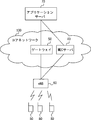
- the communication system in FIG. 2 is a communication system defined in 3GPP.
- the communication system in FIG. 2 includes an eNB 60, an application server 70, a core network 100, and a plurality of UEs 80.
- UE80 is a general term for communication terminals used in 3GPP.
- the core network 100 is a network managed by a mobile communication carrier.
- the core network 100 includes an MEC server 40 and a gateway 50.
- the MEC server 40 corresponds to the communication device 10 in FIG.
- the gateway 50 may be, for example, an SGW (Serving Gateway) or a PGW (Packet Data Network Gateway) that transmits user data related to the UE 80 in the core network 100.
- the gateway 50 may be a UPF (U-Plane Function) entity that is a node device that transmits user data related to the UE 80.
- the user data may be image data or moving image data, for example.
- the MEC server 40 is arranged in the vicinity of the eNB 60 and provides an application service to the UE 80 via the eNB 60. In addition, the MEC server 40 provides an application service to the UE 80 in cooperation with the application server 70.
- Application server 70 is a server that provides application services to UE 80. For example, the application server 70 transmits user data to the gateway 50. In addition, the application server 70 transmits to the MEC server 40 the data size of user data to be transmitted in one flow, and further information on the transmission deadline in one flow.
- the gateway 50 transmits the user data transmitted from the application server 70 to the eNB 60. Further, the gateway 50 transmits user data transmitted from the eNB 60 to the application server 70.
- the MEC server 40 uses the information transmitted from the application server 70 to calculate the amount of data that can be transmitted during the emergency period of the flow related to the UE 80 and the amount of data that should be transmitted during the normal period.
- the MEC server 40 may perform scheduling of radio resources based on the calculated result, and may transmit the calculated result to the eNB 60.
- the MEC server 40 transmits a scheduling result to the eNB 60 when scheduling of radio resources is performed.
- the emergency period corresponds to the first period in the first embodiment, and is a period from a predetermined timing to a transmission deadline of the control target flow in the transmission period of the control target flow.
- radio resources are assigned to the control flow with priority over other flows.
- the radio quality Many radio resources are allocated to a flow related to a good radio terminal. Therefore, more radio resources can be preferentially assigned to flows related to radio terminals with good radio quality than flows related to radio terminals with poor radio quality.
- the eNB 60 When the eNB 60 receives information on the amount of data to be transmitted in the normal period from the MEC server 40, the eNB 60 performs scheduling based on the received information and allocates radio resources to the UE 80 flow. Also, when receiving the scheduling result from the MEC server 40, the eNB 60 allocates radio resources to the flow of the UE 80 according to the received scheduling result.
- the MEC server 40 includes a resource allocation control unit 41, a data amount calculation unit 42, and an eNB communication unit 43.
- the constituent elements of the MEC server 40 such as the resource allocation control unit 41, the data amount calculation unit 42, and the eNB communication unit 43, are software or modules that are processed by a processor executing a program stored in a memory. May be.
- the constituent elements of the MEC server 40 may be hardware such as a circuit or a chip.
- the resource allocation control unit 41 sets a normal period and an emergency period for each of a plurality of flows generated in the eNB 60.
- the MEC server 40 acquires information regarding a plurality of flows generated in the eNB 60 from the application server 70. For example, the MEC server 40 acquires information regarding the transmission deadline and data size (data amount) of each flow.
- the resource allocation control unit 41 determines a period of a specific ratio of the transmission period from the occurrence of the flow to the transmission deadline, where the end of the period becomes the transmission deadline as an emergency period. May be.
- the emergency period may be determined as a period having a length of 10% of the transmission period.
- the resource allocation control unit 41 counts the number of flows having an emergency period overlapping with the emergency period of the control target flow.
- the emergency period that overlaps the emergency period of the control target flow will be described with reference to FIG.
- the horizontal axis indicates time.
- the straight arrows shown in FIG. 4 indicate the transmission periods from the flow generation time to the transmission deadline.
- a period indicated by a dotted line indicates an emergency period of the control target flow.
- the flow A and the flow B indicate that the control target flow and the emergency period overlap.
- Flow C and flow D indicate that the control target flow and the emergency period do not overlap.
- the resource allocation control unit 41 counts the number of flows having an emergency period overlapping the emergency period of the control target flow as three flows including the control target flow.
- the allocation period per flow is determined as emergency period [TTI] / count value.
- the emergency period is indicated in units of TTI (Transmission Time Interval).
- the count value is the number of flows having an emergency period that overlaps with the emergency period of the flow to be controlled.
- the number of RBs (Resource Block) allocated per flow is determined as the number of RBs per 1 TTI [RB / TTI] / the number of concurrent scheduling.
- the simultaneous scheduling number indicates the number of UEs and flows that can be processed simultaneously per 1 TTI. As the number of UEs and the number of flows that can be processed simultaneously, for example, the upper limit value of the number of UEs and the number of flows that can be simultaneously scheduled may be used.
- the transmission capability is the number of bits that can be transmitted per RB. For example, it is assumed that the transmission capability is determined for each MCS (Modulation and Coding Scheme).
- the transmission capability used in Equation 1 may be determined based on MCS at the time when each flow occurs, for example. Alternatively, the transmission capability used in Equation 1 may be determined in consideration of past MCS fluctuations. For example, the transmission capability used in Equation 1 may be determined based on an average value of past MCSs. Alternatively, the transmission capability used in Equation 1 may be determined based on the MCS estimated in the emergency period of each flow by analyzing whether the MCS tends to increase or decrease from the variation of the MCS.
- the resource allocation control unit 41 may count the number of flows having an emergency period overlapping the emergency period of the control target flow at the first timing within the normal period.
- the resource allocation control unit 41 may recalculate the amount of data that can be transmitted by the UE 80 during the emergency period of the control target flow using the number of flows.
- the first timing indicates an arbitrary timing within the normal period.
- Information regarding MCS at the time when the flow occurs or past MCS may be received from the eNB 60 via the eNB communication unit 43.
- the data amount calculation unit 42 calculates the data amount that the control target flow should transmit in the normal period.
- the control target flow is calculated using Equation 2 below, where Data is the amount of data to be transmitted in the normal period and Data is the data size of the control target flow.
- Data FlowSize-Estimation (Formula 2)
- the eNB communication unit 43 transmits, to the eNB 60, information related to the data amount calculated by the data amount calculation unit 42 and to be transmitted by the control target flow during the normal period.
- the eNB 60 includes a core network node communication unit 61, a radio environment acquisition unit 62, a resource allocation unit 63, and a radio unit 64.
- the components of the eNB 60 such as the core network node communication unit 61, the radio environment acquisition unit 62, the resource allocation unit 63, and the radio unit 64, are software that is processed by a processor executing a program stored in a memory, or It may be a module.
- the constituent elements of the eNB 60 may be hardware such as a circuit or a chip.
- the radio environment acquisition unit 62 uses the UL data received from the UE 80 via the radio unit 64 to measure the communication quality of the radio resource that transmits the UL data. Further, the radio environment acquisition unit 62 receives the communication quality of the radio resource transmitting the DL data measured using the DL data in the UE 80 from the UE 80. The radio environment acquisition unit 62 receives information related to the communication quality of radio resources that transmit DL data from the UE 80 via the radio unit 64.
- the radio environment acquisition unit 62 transmits the communication quality of the radio resource for transmitting UL and DL data to the MEC server 40 via the core network node communication unit 61.
- the resource allocation unit 63 receives information on the amount of data that the control target flow transmitted from the MEC server 40 via the core network node communication unit 61 should transmit in the normal period.
- the resource allocation unit 63 determines radio resources to be allocated to the control target flow in the normal period based on the received information.
- the resource allocation unit 63 can transmit the amount of data to be transmitted even when the radio quality of the UE 80 related to the control target flow is worse than the radio quality of other UEs 80 in the normal period of the control target flow. In this way, radio resources may be allocated to the control target flow. For example, the resource allocation unit 63 may allocate radio resources to the control target flow in an arbitrary period in the normal period of the control target flow in preference to other flows.
- the radio unit 64 transmits DL data to the UE 80 using the radio resource determined by the resource allocation unit 63. In addition, the radio unit 64 transmits information on radio resources used for transmitting UL data to the UE 80.
- the resource allocation unit 63 when the resource allocation unit 63 receives, from the MEC server 40, the radio resource allocation information in which the radio resource to be allocated is designated via the core network node communication unit 61, the resource allocation unit 63 allocates the control target flow according to the received information. Radio resources may be determined.
- FIG. 6 shows the transition of the remaining data amount from the occurrence of the control target flow to the transmission deadline.
- the solid line rectangle indicates the data amount of the control target flow. In other words, the solid rectangle indicates the remaining data amount of the control target flow to be transmitted before the transmission deadline.
- a dotted rectangle indicates the amount of transmitted data.
- the arrow in FIG. 6 indicates the required throughput.
- the required throughput is a value obtained by dividing the remaining data amount of data to be transmitted in the normal period by using the remaining time in the normal period.
- the remaining data amount of data to be transmitted in the normal period is the difference between the data amount to be transmitted in the normal period and the data amount transmitted between the occurrence of the control target flow and the second timing in the normal period.
- the remaining time in the normal period is the time from the second timing in the normal period to a predetermined timing that is the end of the normal period.
- the second timing indicates an arbitrary timing within the normal period.
- the upward-sloping arrows in FIG. 6 indicate that the required throughput increases with time. Furthermore, in FIG.
- radio resources are preferentially allocated to the control target flow to reduce the remaining data amount of the control target flow. A part of the data of the control target flow is transmitted and the remaining data amount is reduced, so that the required throughput is also lowered. Thereafter, the requested throughput increases in a period in which the data of the control target flow is not transmitted.
- the required throughput threshold is a value used for preferentially transmitting data during the normal period of the control target flow even when the radio quality of the control target flow is low and no radio resource is allocated to the control target flow. is there. Further, when the wireless quality of the control target flow is high, that is, when the wireless quality is good, data is transmitted before the required throughput reaches the required throughput threshold.
- FIG. 6 shows that the required throughput threshold is a constant value, but the required throughput threshold may be updated to a new value every time the remaining data amount decreases.
- the 6 may be executed by the data amount calculation unit 42 of the MEC server 40 or may be executed by the eNB 60 described later.
- the resource allocation unit 63 may allocate radio resources to the control target flow according to the timing calculated in the MEC server 40.
- the vertical axis in FIG. 7 will be described as data size, and the horizontal axis will be described as elapsed time.
- the vertical axis in FIG. 7 indicates Data calculated in Expression 2 and FlowSize of the control target flow.
- the diagonal solid line in FIG. 7 indicates the amount of data to be transmitted at each timing. Specifically, the oblique solid line in FIG. 7 indicates that the amount of data to be transmitted increases in the normal period and the emergency period with the passage of time. In other words, when radio resources are not allocated to the control target flow in the normal period and the emergency period, it indicates that the amount of data to be transmitted increases with the passage of time.
- the resource allocation unit 63 plots the amount of data transmitted in the normal period in the graph of FIG.
- the amount of data transmitted during the normal period may be the amount of data transmitted between the occurrence of the control target flow and any timing in the normal period.
- the resource allocation unit 63 may preferentially allocate the radio resource to the control target flow when the plotted position is below the oblique solid line. Further, when the plotted position is a position exceeding the oblique solid line, the resource allocation unit 63 allocates the radio resource to the control target flow when the radio quality is good without preferentially allocating the radio resource to the control target flow. You may do it.
- the MEC server 40 detects that a transmission flow has occurred in the UE 80 (S11). For example, the MEC server 40 may be notified from the application server 70 that a transmission flow has occurred in the UE 80.
- the generated transmission flow will be described as a control target flow in the following description.
- the resource allocation control unit 41 sets a normal period and an emergency period for a plurality of flows to be allocated radio resources in the eNB 60 including the control target flow (S12).
- the resource allocation control unit 41 counts the number of flows having an emergency period overlapping with the emergency period of the control target flow (S13).
- the resource allocation control unit 41 estimates the amount of data that can be transmitted by the control target flow during the emergency period of the control target flow (S14).
- the resource allocation control unit 41 may use MCS indicating the radio quality between the UE 80 and the eNB 60 at the time when the control target flow occurs when estimating the amount of data that can be transmitted by the control target flow.
- the MCS in the emergency period of the flow may be estimated and the estimated MCS may be used.
- the data amount calculation unit 42 calculates the amount of data that the control target flow should transmit in the normal period (S15).
- the data amount calculation unit 42 calculates the data amount to be transmitted in the normal period by subtracting the data amount estimated in step S14 from the data amount of the entire control target flow.
- the eNB communication unit 43 transmits information on the data amount calculated in step S15 to the eNB 60.
- the MEC server 40 can estimate the amount of data that can be transmitted in the emergency period of the control target flow. Further, the MEC server 40 can calculate the amount of data to be transmitted in the normal period so that the transmission of the control target flow can be completed in the emergency period.
- the eNB 60 can allocate radio resources to the control target flow during the normal period of the control target flow according to the data amount to be transmitted in the normal period calculated by the MEC server 40.
- the UE 80 can transmit the data amount calculated in the MEC server 40 during the normal period.
- the UE 80 can complete transmission of all data of the control target flow during the emergency period.
- the UE 80 can complete transmission of all data of the control target flow by the transmission deadline.
- the resource allocation control unit 41 counts the number of flows having an emergency period overlapping with the emergency period of the control target flow at the time T1 when the control target flow occurs.
- the resource allocation control unit 41 again counts the number of flows having an emergency period that overlaps the emergency period of the control target flow at time T2 after a predetermined period has elapsed from time T1.
- the number of flows counted at time T1 may differ from the number of flows counted at time T2.
- the timing for completing the transmission of all data of the flow A may be advanced. For example, when the transmission of the flow A is completed before the emergency period of the control target flow is started, the emergency period of the control target flow and the emergency period of the flow A do not overlap. As a result, the resource allocation control unit 41 counts the flow A at time T1, but stops counting the flow A at time T2.
- flow D may occur between time T1 and time T2.
- the resource allocation control unit 41 counts the flow D at time T2.
- the resource allocation control unit 41 When the time elapses in this way, the number of flows having an emergency period that overlaps with the emergency period of the flow to be controlled may vary.
- the resource allocation control unit 41 counts the number of flows having an emergency period that overlaps the emergency period of the control target flow at time T2, the resource allocation control unit 41 also estimates the transmittable data amount in the emergency period of the control target flow again.
- the allocation period during which radio resources are allocated to the control target flow increases. For this reason, the transmittable data amount in the emergency period of the control target flow increases, and as a result, the data amount to be transmitted in the normal period of the control target flow decreases.
- the transmission capability is determined according to the radio quality information at time T1.
- the transmission capability may be determined according to the radio quality information at time T2.
- the data amount to be transmitted in the normal period is more accurately calculated by executing the calculation process of the data amount to be transmitted in the normal period of the control target flow in the MEC server 40 according to the third embodiment. can do.
- the resource allocation control unit 41 counts the number of flows having an emergency period overlapping the emergency period of the control target flow.
- the resource allocation control unit 41 counts the number of flows in which a transmission deadline exists within the emergency period of the control target flow.
- the flow B is counted when counting the number of flows having an emergency period overlapping with the emergency period of the control target flow.
- the transmission deadline of the flow B does not exist within the emergency period of the control target flow.
- the transmission deadline of each flow in FIG. 9 is the timing at the tip of the arrow. Therefore, when counting the number of flows in which a transmission deadline exists within the emergency period of the control target flow, the flow B is not counted.
- the resource allocation control unit 41 may count the number of flows having a transmission deadline in the emergency period of the control target flow at the first timing in the normal period.
- the resource allocation control unit 41 may recalculate the amount of data that can be transmitted by the UE 80 during the emergency period of the control target flow using the number of flows.
- the flow even if the flow has an emergency period overlapping the emergency period of the control target flow, if the transmission deadline does not exist within the emergency period of the control target flow, the flow Is not counted.
- the count process according to the fourth embodiment is performed, the count number can be reduced as compared with the second and third embodiments. As a result, the period during which radio resources are allocated to the control target flow during the emergency period increases.
- the amount of data to be transmitted during the normal period of the control target flow can be reduced by increasing the period during which radio resources are allocated to the control target flow within the emergency period.
- the eNB 60 can reduce the radio resources allocated to the control target flow during the normal period, more radio resources can be allocated to the flow related to the UE 80 with better radio quality in the normal period.
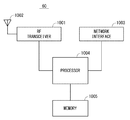
- FIG. 10 is a block diagram illustrating a configuration example of the eNB 60.
- the eNB 60 includes an RF transceiver 1001, a network interface 1003, a processor 1004, and a memory 1005.
- the RF transceiver 1001 performs analog RF signal processing to communicate with UEs.
- the RF transceiver 1001 may include multiple transceivers.
- RF transceiver 1001 is coupled to antenna 1002 and processor 1004.
- the RF transceiver 1001 receives modulation symbol data (or OFDM symbol data) from the processor 1004, generates a transmission RF signal, and supplies the transmission RF signal to the antenna 1002. Further, the RF transceiver 1001 generates a baseband received signal based on the received RF signal received by the antenna 1002, and supplies this to the processor 1004.
- the network interface 1003 is used to communicate with a network node (e.g., gateway 50).
- the network interface 1003 may include, for example, a network interface card (NIC) compliant with IEEE 802.3 series.
- NIC network interface card
- the processor 1004 performs data plane processing including digital baseband signal processing for wireless communication and control plane processing.
- the digital baseband signal processing by the processor 1004 may include MAC layer and PHY layer signal processing.
- the processor 1004 may include a plurality of processors.
- the processor 1004 may include a modem processor (e.g., DSP) that performs digital baseband signal processing, and a protocol stack processor (e.g., CPU or MPU) that performs control plane processing.
- DSP digital baseband signal processing
- protocol stack processor e.g., CPU or MPU
- the memory 1005 is configured by a combination of a volatile memory and a nonvolatile memory.
- the memory 1005 may include a plurality of physically independent memory devices.
- the volatile memory is, for example, Static Random Access Memory (SRAM), Dynamic RAM (DRAM), or a combination thereof.
- the non-volatile memory is a mask Read Only Memory (MROM), Electrically Erasable Programmable ROM (EEPROM), flash memory, hard disk drive, or any combination thereof.
- Memory 1005 may include storage located remotely from processor 1004. In this case, the processor 1004 may access the memory 1005 via the network interface 1003 or an I / O interface not shown.
- the memory 1005 may store a software module (computer program) including an instruction group and data for performing processing by the eNB 60 described in the above-described plurality of embodiments.
- the processor 1004 may be configured to perform the processing of the eNB 60 described in the above-described embodiment by reading the software module from the memory 1005 and executing the software module.
- FIG. 11 is a block diagram illustrating a configuration example of the communication device 10 and the MEC server 40.
- the communication device 10 and the MEC server 40 include a network interface 1201, a processor 1202, and a memory 1203.
- the network interface 1201 is used to communicate with a network node (e.g., base station 20).
- the network interface 1201 may include, for example, a network interface card (NIC) compliant with IEEE 802.3 series.
- NIC network interface card
- the processor 1202 reads the software (computer program) from the memory 1203 and executes it, thereby performing the processing of the communication device 10 and the MEC server 40 described with reference to the sequence diagram and the flowchart in the above-described embodiment.
- the processor 1202 may be, for example, a microprocessor, MPU, or CPU.
- the processor 1202 may include a plurality of processors.
- the processor 1202 performs data plane processing and control plane processing including digital baseband signal processing for wireless communication.
- the digital baseband signal processing by the processor 1004 may include PDCP layer, RLC layer, and MAC layer signal processing.
- the signal processing by the processor 1202 may include GTP-U • UDP / IP layer signal processing at the X2-U interface and the S1-U interface.
- the control plane processing by the processor 1004 may include processing of the X2AP protocol, the S1-MME protocol, and the RRC protocol.
- the processor 1202 may include a plurality of processors.
- the processor 1004 includes a modem processor (eg, DSP) that performs digital baseband signal processing, a processor that performs signal processing of the GTP-U / UDP / IP layer in the X2-U interface and the S1-U interface (eg, DSP) and a protocol stack processor (eg, CPU or MPU) that performs control plane processing may be included.
- DSP modem processor
- a processor that performs signal processing of the GTP-U / UDP / IP layer in the X2-U interface and the S1-U interface eg, DSP
- a protocol stack processor eg, CPU or MPU
- the memory 1203 is configured by a combination of a volatile memory and a nonvolatile memory.
- Memory 1203 may include storage located remotely from processor 1202. In this case, the processor 1202 may access the memory 1203 via an I / O interface not shown.
- the memory 1203 is used for storing software module groups.
- the processor 1202 can perform processing of the communication device 10 and the MEC server 40 described in the above-described embodiment by reading these software module groups from the memory 1203 and executing them.
- each of the processors included in the communication device 10, the MEC server 40, and the eNB 60 in the above-described embodiment causes the computer to execute the algorithm described with reference to the drawings.
- One or more programs including a group of instructions are executed.
- Non-transitory computer readable media include various types of tangible storage media (tangible storage medium).
- Examples of non-transitory computer-readable media include magnetic recording media (eg flexible disks, magnetic tapes, hard disk drives), magneto-optical recording media (eg magneto-optical discs), CD-ROMs (Read Only Memory), CD-Rs, CD-R / W, semiconductor memory (for example, mask ROM, PROM (Programmable ROM), EPROM (Erasable ROM), flash ROM, RAM (Random Access Memory)) are included.
- the program may also be supplied to the computer by various types of temporary computer-readable media. Examples of transitory computer readable media include electrical signals, optical signals, and electromagnetic waves.
- the temporary computer-readable medium can supply the program to the computer via a wired communication path such as an electric wire and an optical fiber, or a wireless communication path.
Abstract
The purpose of the present invention is to provide a communication apparatus that is capable of carrying out efficient wireless resource scheduling so as to enable a wireless terminal to complete data transmission within permitted time. A communication apparatus (10) according to the present invention is provided with: an allocation control unit (11) that determines preferential allocation of wireless resources to a flow to be controlled over other flows during an emergency period from a prescribed timing to the transmission deadline of the to-be-controlled flow in the transmission period for the to-be-controlled flow at a wireless terminal; and a calculation unit (12) that calculates the data amount to be transmitted by the wireless terminal during a normal period from the moment the to-be-controlled flow has been generated to the prescribed timing so as to enable completion of data transmission of the entire to-be-controlled flow during the emergency period.
Description
本開示は通信装置、基地局、無線リソース割当方法、及びプログラムに関する。
The present disclosure relates to a communication device, a base station, a radio resource allocation method, and a program.
現在、モバイルネットワークを介した超低遅延サービスを提供することが検討されている。超低遅延サービスは、例えば、モバイルネットワークを介して車載センサー情報、交通カメラ情報、及び地図情報等を伝送する自動運転サービスであってもよい。
Currently, providing ultra-low latency services via mobile networks is being considered. The ultra-low delay service may be, for example, an automatic driving service that transmits vehicle sensor information, traffic camera information, map information, and the like via a mobile network.
モバイルキャリア(モバイル通信事業者)は、ユーザに対して超低遅延サービスを提供するために、SLA(Service Level Agreement)を保証する必要がある。SLAは、例えば、超低遅延サービスにおいて保証する遅延時間等が規定されていてもよい。
A mobile carrier (mobile communication carrier) needs to guarantee SLA (Service Level Agreement) in order to provide an ultra-low latency service to users. For example, the SLA may specify a delay time guaranteed in the ultra-low delay service.
例えば、特許文献1には、サービス品質を良好に保つために、UE(User Equipment)に対して、無線リソースを効率的に割り当てることが記載されている。具体的には、アプリケーションの遅延制約等に関する情報を考慮して、無線リソースの割当を最適化することが記載されている。言い換えると、特許文献1には、基地局が、アプリケーションサービスを提供する際に許容される遅延時間を超えないように、無線リソースの割当を最適化することによって、サービス品質を良好に保つことが記載されている。
For example, Patent Document 1 describes that radio resources are efficiently allocated to a UE (User Equipment) in order to maintain good service quality. Specifically, it describes that the allocation of radio resources is optimized in consideration of information related to delay constraints of applications. In other words, Patent Document 1 discloses that the base station can maintain good service quality by optimizing the allocation of radio resources so that the delay time allowed when providing the application service is not exceeded. Are listed.
基地局がアプリケーションサービスを提供する際に許容される遅延時間を超えないようにする場合、次のように無線リソースを割り当てることが考えられる。例えば、基地局は、アプリケーションサービスの提供を受けている無線端末において、許容された遅延時間を超えそうな場合、その無線端末に対して優先的に無線リソースを割り当ててもよい。しかし、許容された遅延時間の終了間際に、無線端末に対して優先的に無線リソースを割り当てても全てのデータを送信することができないほど無線端末の送信バッファにデータが蓄積されていることがある。このような場合、許容された遅延時間の終了間際に、無線端末に対して優先的に無線リソースの割り当てるのみでは、SLAを保証することができないという問題が発生する。
When the base station does not exceed the allowable delay time when providing the application service, it is conceivable to allocate radio resources as follows. For example, the base station may preferentially allocate radio resources to the radio terminal when the radio terminal receiving the application service is likely to exceed the allowed delay time. However, at the end of the allowed delay time, data may be stored in the transmission buffer of the wireless terminal so that all data cannot be transmitted even if wireless resources are preferentially allocated to the wireless terminal. is there. In such a case, there is a problem that SLA cannot be guaranteed only by preferentially allocating radio resources to radio terminals just before the end of the allowed delay time.
本開示の目的は、許容された時間内において無線端末がデータ送信を完了させることができるように、効率的に無線リソースのスケジューリングを行うことができる通信装置、基地局、無線リソース割当方法、及びプログラムを提供することにある。
An object of the present disclosure is to provide a communication device, a base station, a radio resource allocation method, and a radio resource scheduling that can efficiently perform radio resource scheduling so that a radio terminal can complete data transmission within an allowed time period. To provide a program.
本開示の第1の態様にかかる通信装置は、無線端末におけるフローの送信期間のうち、所定のタイミングから前記フローの送信デッドラインまでの第1の期間に前記フロー全体のデータの送信を完了できるように、前記無線端末が前記フローの発生時から前記所定のタイミングまでの第2の期間に送信すべきデータ量を算出する算出部と、を備える。
The communication apparatus according to the first aspect of the present disclosure can complete data transmission of the entire flow in a first period from a predetermined timing to a transmission deadline of the flow in a flow transmission period in a wireless terminal. As described above, the wireless terminal includes a calculation unit that calculates a data amount to be transmitted in a second period from the time of occurrence of the flow to the predetermined timing.
本開示の第2の態様にかかる基地局は、無線端末におけるフローの送信期間のうち、所定のタイミングから前記フローの送信デッドラインまでの第1の期間に前記フロー全体のデータの送信を完了できるように、前記無線端末が前記フローの発生時から前記所定のタイミングまでの第2の期間に送信すべきデータ量に関する情報を通信装置から受信する通信部と、前記無線端末が前記第2の期間に送信すべきデータ量に基づいて前記第2の期間に前記フローに割り当てる無線リソースを決定する割当部と、を備える。
The base station according to the second aspect of the present disclosure can complete data transmission of the entire flow in a first period from a predetermined timing to a transmission deadline of the flow in a flow transmission period in the wireless terminal. As described above, the wireless terminal receives from the communication device information related to the amount of data to be transmitted in the second period from the occurrence of the flow to the predetermined timing, and the wireless terminal transmits the second period. An allocating unit that determines a radio resource to be allocated to the flow in the second period based on the amount of data to be transmitted.
本開示の第3の態様にかかる無線リソース割当方法は、無線端末におけるフローの送信期間のうち、所定のタイミングから前記フローの送信デッドラインまでの第1の期間に前記フロー全体のデータの送信を完了できるように、前記無線端末が前記フローの発生時から前記所定のタイミングまでの第2の期間に送信すべきデータ量を算出する。
In the radio resource allocation method according to the third aspect of the present disclosure, transmission of data of the entire flow is performed in a first period from a predetermined timing to a transmission deadline of the flow in a flow transmission period in a wireless terminal. In order to be completed, the wireless terminal calculates the amount of data to be transmitted in the second period from the occurrence of the flow to the predetermined timing.
本開示の第4の態様にかかるプログラムは、無線端末におけるフローの送信期間のうち、所定のタイミングから前記フローの送信デッドラインまでの第1の期間に前記フロー全体のデータの送信を完了できるように、前記無線端末が前記フローの発生時から前記所定のタイミングまでの第2の期間に送信すべきデータ量を算出することをコンピュータに実行させる。
The program according to the fourth aspect of the present disclosure is capable of completing transmission of data of the entire flow in a first period from a predetermined timing to a transmission deadline of the flow in a flow transmission period in a wireless terminal. And causing the computer to calculate the amount of data to be transmitted in the second period from the occurrence of the flow to the predetermined timing.
本開示により、許容された時間内において無線端末がデータ送信を完了させることができるように、効率的に無線リソースのスケジューリングを行うことができる通信装置、基地局、無線リソース割当方法、及びプログラムを提供することができる。
According to the present disclosure, a communication apparatus, a base station, a radio resource allocation method, and a program capable of efficiently performing radio resource scheduling so that a radio terminal can complete data transmission within an allowed time. Can be provided.
(実施の形態1)
以下、図面を参照して本開示の実施の形態について説明する。図1を用いて実施の形態1にかかる通信装置10の構成例について説明する。通信装置10は、は、プロセッサがメモリに格納されたプログラムを実行することによって動作するコンピュータ装置であってもよい。 (Embodiment 1)
Hereinafter, embodiments of the present disclosure will be described with reference to the drawings. A configuration example of thecommunication apparatus 10 according to the first embodiment will be described with reference to FIG. The communication device 10 may be a computer device that operates when a processor executes a program stored in a memory.
以下、図面を参照して本開示の実施の形態について説明する。図1を用いて実施の形態1にかかる通信装置10の構成例について説明する。通信装置10は、は、プロセッサがメモリに格納されたプログラムを実行することによって動作するコンピュータ装置であってもよい。 (Embodiment 1)
Hereinafter, embodiments of the present disclosure will be described with reference to the drawings. A configuration example of the
通信装置10は、例えば、3GPP(3rd Generation Partnership Project)において規定されているSCEF(Service Capability Exposure Function)エンティティ(以下、SCEFと称する)であってもよい。SCEFは、例えば、モバイル通信事業者もしくはアプリケーションサービスプロバイダー等が管理するアプリケーションサーバに関する認証処理等を実行する。また、SCEFは、3GPPにおいて定められたリファレンスポイントを介して基地局であるeNB(evolved NodeB)と通信する。SCEFエンティティは、例えば、コアネットワーク内において、制御データを伝送する。制御データは、例えば、無線端末に関するユーザデータを伝送する通信経路の設定等を行うために用いられる。SCEFエンティティは、例えば、制御データを伝送するノード装置であるCPF(C-Plane Function)エンティティと称されてもよい。
The communication device 10 may be, for example, an SCEF (Service Capability Exposure Function) entity (hereinafter referred to as SCEF) defined in 3GPP (3rd Generation Partnership Project). The SCEF executes, for example, authentication processing related to an application server managed by a mobile communication carrier or an application service provider. Moreover, SCEF communicates with eNB (evolved | NodeB) which is a base station via the reference point defined in 3GPP. The SCEF entity transmits control data in the core network, for example. The control data is used, for example, for setting a communication path for transmitting user data related to the wireless terminal. The SCEF entity may be referred to as, for example, a CPF (C-Plane Function) entity that is a node device that transmits control data.
また、通信装置10は、MEC(Mobile Edge Computing)サーバであってもよい。MECサーバは、基地局と直接的に通信できる位置に配置されてもよい。直接的に通信できる位置とは、モバイル通信事業者が管理するコアネットワークを介することなく通信することができる位置である。例えば、MECサーバは、基地局と物理的に統合されてもよい。もしくは、MECサーバは、基地局と同じ建物に配置され、基地局と通信できるように、建物内のLAN(Local Area Network)に接続されてもよい。MECサーバは、基地局の近傍に配置されることによって、無線端末との間の伝送遅延を短くすることができる。MECサーバは、例えば、超低遅延のアプリケーションサービスを提供するために用いられる。
Further, the communication device 10 may be a MEC (Mobile Edge Computing) server. The MEC server may be arranged at a position where it can directly communicate with the base station. The position where direct communication is possible is a position where communication can be performed without going through the core network managed by the mobile communication carrier. For example, the MEC server may be physically integrated with the base station. Alternatively, the MEC server may be arranged in the same building as the base station and connected to a LAN (Local Area Network) in the building so as to be able to communicate with the base station. By arranging the MEC server in the vicinity of the base station, the transmission delay with the wireless terminal can be shortened. The MEC server is used, for example, to provide an ultra-low latency application service.
また、通信装置10は、無線端末へIoTサービスを提供するサーバ群を有するIoTプラットフォーム内に配置されてもよい。もしくは、通信装置10は、基地局と直接もしくはネットワークを介して通信することができるサーバ装置であってもよい。通信装置10は、上記で例示した装置である場合であってもその他の装置であっても、Control PlaneおよびUser Planeいずれの機能を有していてもよい。通信装置10はさらに、基地局であってもよい。
Further, the communication device 10 may be arranged in an IoT platform having a server group that provides an IoT service to a wireless terminal. Alternatively, the communication device 10 may be a server device that can communicate with a base station directly or via a network. The communication device 10 may have the functions of Control Plane and User Plane regardless of whether it is a device exemplified above or another device. The communication device 10 may be a base station.
続いて、通信装置10の構成例について説明する。通信装置10は、算出部12を有している。算出部12は、プロセッサがメモリに格納されたプログラムを実行することによって処理が実行されるソフトウェアもしくはモジュールであってもよい。また、算出部12は、チップもしくは回路等のハードウェアであってもよい。
Subsequently, a configuration example of the communication device 10 will be described. The communication device 10 includes a calculation unit 12. The calculation unit 12 may be software or a module that performs processing when the processor executes a program stored in a memory. The calculation unit 12 may be hardware such as a chip or a circuit.
算出部12は、無線端末におけるフローの送信期間のうち、所定のタイミングからフローの送信デッドラインまでの第1の期間にフロー全体のデータの送信を完了できるように、無線端末がフローの発生時から所定のタイミングまでの第2の期間に送信すべきデータ量を算出する。第1の期間の長さおよび所定のタイミングは、各フローにおいて互いに異なってもよいし、同じであってもよい。第1の期間は例えば、アプリケーションサービスに基づいて決定されるものであってもよい。また第1の期間はネットワークの混雑度、例えばトラフィック量に基づいて決定されても良い。ネットワークの混雑度が大きいほど、第1の期間は長くなってもよい。さらに第1に期間は、基地局に接続している無線端末の数に基づいて決定されてもよい。基地局に接続している無線端末の数が多いほど、第1の期間は長くなってもよい。
The calculation unit 12 is configured such that when the wireless terminal generates a flow, the wireless terminal can complete transmission of data of the entire flow in a first period from a predetermined timing to a flow transmission deadline in the flow transmission period in the wireless terminal. The amount of data to be transmitted in the second period from to the predetermined timing is calculated. The length of the first period and the predetermined timing may be different or the same in each flow. For example, the first period may be determined based on an application service. The first period may be determined based on the degree of network congestion, for example, the traffic volume. The greater the network congestion, the longer the first period. Furthermore, firstly, the period may be determined based on the number of wireless terminals connected to the base station. The greater the number of wireless terminals connected to the base station, the longer the first period may be.
無線端末に関するフローは、例えば、無線端末に提供されるアプリケーションサービスにおいて伝送される1又は複数のデータを含む。また、フローに含まれるデータは、データパケットと称されてもよい。無線端末に関するフローは、無線端末から基地局へ送信されるフローもしくは基地局から無線端末へ送信されるフローであってもよい。もしくは、無線端末に関するフローは、無線端末から基地局へ送信されるフロー及び基地局から無線端末へ送信されるフローを含んでもよい。無線端末から基地局へ送信されるフローに含まれるデータを、UL(Uplink)データと称する。また、基地局から無線端末へ送信されるフローに含まれるデータを、DL(Downlink)データと称する。アプリケーションサービスにおいて伝送されるデータ(例えば、アプリケーションデータ)は、例えば、画像データもしくは動画データ等であってもよい。また、アプリケーションデータには、画像データ等の送信を要求する要求メッセージもしくは要求メッセージに応答する応答メッセージ等が含まれてもよい。
The flow related to the wireless terminal includes, for example, one or a plurality of data transmitted in an application service provided to the wireless terminal. Data included in the flow may be referred to as a data packet. The flow related to the wireless terminal may be a flow transmitted from the wireless terminal to the base station or a flow transmitted from the base station to the wireless terminal. Alternatively, the flow related to the wireless terminal may include a flow transmitted from the wireless terminal to the base station and a flow transmitted from the base station to the wireless terminal. Data included in the flow transmitted from the wireless terminal to the base station is referred to as UL (Uplink) data. Data included in the flow transmitted from the base station to the wireless terminal is referred to as DL (Downlink) data. Data (for example, application data) transmitted in the application service may be image data or moving image data, for example. The application data may include a request message for requesting transmission of image data or the like, or a response message for responding to the request message.
送信デッドラインは、1回のフローに含まれる複数のデータパケットの送信を完了するべき期限を意味する。送信デッドラインは、アプリケーションによって要求される。送信デッドラインは、送信期限と言うこともできる。あるいは、送信デッドラインは、アプリケーションによって許容される最大送信遅延と言うこともできる。送信デッドラインは、様々に定義することができる。例えば、送信デッドラインは、アプリケーション・レイヤの発信者(sender)による送信の完了期限を示してもよい。あるいは、送信デッドラインは、無線レイヤの発信者による送信の完了期限を示してもよい。あるいは、送信デッドラインは、アプリケーション・レイヤの受信者(receiver)による受信の完了期限を示してもよい。あるいは、送信デッドラインは、無線レイヤの受信者による受信の完了期限を示してもよい。あるいは、より具体的に、送信デッドラインは、アプリケーションレイヤの発信者(sender)が1回のフローに関する最初のデータパケットを送信開始してからアプリケーションレイヤの受信者(receiver)が1回のフローに関する最後のデータパケットを受信完了する期限を示してもよい。あるいは、また、送信デッドラインは、無線レイヤの発信者が1回のフローに関する最初のデータパケットを送信開始してから無線レイヤの受信者が1回のフローに関する最後のデータパケットを受信完了する期限を示してもよい。
The transmission deadline means a time limit for completing transmission of a plurality of data packets included in one flow. The transmission deadline is required by the application. The transmission deadline can also be called a transmission deadline. Alternatively, the transmission deadline can be said to be the maximum transmission delay allowed by the application. The transmission deadline can be defined variously. For example, a transmission deadline may indicate a deadline for completion of transmission by an application layer sender. Alternatively, the transmission deadline may indicate a deadline for completion of transmission by the originator of the wireless layer. Alternatively, the transmission deadline may indicate a deadline for completion of reception by an application layer receiver. Alternatively, the transmission deadline may indicate a deadline for completion of reception by radio layer receivers. Or, more specifically, a transmission deadline relates to a flow for which an application layer receiver has started transmitting the first data packet for a single flow and for which an application layer receiver has received a single flow. A time limit for completing reception of the last data packet may be indicated. Alternatively, the transmission deadline is a time limit for the wireless layer receiver to receive the last data packet for one flow after the wireless layer sender starts transmitting the first data packet for one flow. May be indicated.
送信デッドラインに関する情報は、通信装置10がアプリケーションサーバから受信してもよい。通信装置10は、通信装置10のユーザープレーンに届くデータについて、そのデータに適用されるサービスを判断し、そのサービスに基づいて送信デッドラインを判断してもよい。また通信装置10は、アプリケーションサーバから、データに適用されるサービスの情報を受信し、そのサービスに基づいて送信デッドラインを判断してもよい。なお通信装置10は、eNBのバッファの情報をeNBから受け取り、バッファに溜まっているフローには優先的にリソースブロックを割り当ててもよい。
The information regarding the transmission deadline may be received by the communication device 10 from the application server. The communication device 10 may determine a service applied to the data that reaches the user plane of the communication device 10, and may determine a transmission deadline based on the service. The communication device 10 may receive information on a service applied to data from the application server, and may determine a transmission deadline based on the service. Note that the communication apparatus 10 may receive information on the buffer of the eNB from the eNB and preferentially assign resource blocks to the flows accumulated in the buffer.
以上説明したように、通信装置10は、第2の期間において、無線端末が送信すべきデータ量を算出することができる。つまり、第2の期間において無線端末が所定のデータ量の送信を行っておくことによって、無線端末が第1の期間において全てのデータの送信を完了することができないとの事象を回避することができる。
As described above, the communication device 10 can calculate the amount of data to be transmitted by the wireless terminal in the second period. In other words, by causing the wireless terminal to transmit a predetermined amount of data in the second period, it is possible to avoid an event that the wireless terminal cannot complete transmission of all data in the first period. it can.
また、通信装置10は、無線端末が第2の期間に送信すべきデータ量に関する情報を、基地局へ送信してもよい。基地局は、無線端末に関するフローに無線リソースを割り当てるスケジューリングを実行する。基地局において実行されるスケジューリングは、MAC(Medium Access Control)スケジューリング、もしくはパケットスケジューリング等と称されてもよい。基地局は、通信装置10から無線端末が第2の期間に送信すべきデータ量に関する情報を受信することによって、制御対象フローに割り当てる無線リソースを決定することができる。もしくは、通信装置10は、基地局の代わりに、無線端末が第2の期間に送信すべきデータ量に基づいて、制御対象フローに割り当てる無線リソースを決定してもよい。
Further, the communication device 10 may transmit information on the amount of data that the wireless terminal should transmit in the second period to the base station. The base station executes scheduling for assigning radio resources to flows related to radio terminals. The scheduling executed in the base station may be referred to as MAC (Medium Access Control) scheduling or packet scheduling. The base station can determine the radio resource to be allocated to the control target flow by receiving information on the amount of data that the radio terminal should transmit in the second period from the communication device 10. Or the communication apparatus 10 may determine the radio | wireless resource allocated to a control object flow based on the data amount which a radio | wireless terminal should transmit in a 2nd period instead of a base station.
(実施の形態2)
続いて、図2を用いて本開示の実施の形態2にかかる通信システムの構成例について説明する。図2の通信システムは、3GPPにおいて規定されている通信システムを示している。図2の通信システムは、eNB60、アプリケーションサーバ70、コアネットワーク100、及び複数のUE80を有している。UE80は、3GPPにおいて用いられる通信端末の総称である。コアネットワーク100は、モバイル通信事業者が管理するネットワークである。コアネットワーク100は、MECサーバ40及びゲートウェイ50を有している。MECサーバ40は、図1の通信装置10に相当する。 (Embodiment 2)
Subsequently, a configuration example of the communication system according to the second embodiment of the present disclosure will be described with reference to FIG. The communication system in FIG. 2 is a communication system defined in 3GPP. The communication system in FIG. 2 includes aneNB 60, an application server 70, a core network 100, and a plurality of UEs 80. UE80 is a general term for communication terminals used in 3GPP. The core network 100 is a network managed by a mobile communication carrier. The core network 100 includes an MEC server 40 and a gateway 50. The MEC server 40 corresponds to the communication device 10 in FIG.
続いて、図2を用いて本開示の実施の形態2にかかる通信システムの構成例について説明する。図2の通信システムは、3GPPにおいて規定されている通信システムを示している。図2の通信システムは、eNB60、アプリケーションサーバ70、コアネットワーク100、及び複数のUE80を有している。UE80は、3GPPにおいて用いられる通信端末の総称である。コアネットワーク100は、モバイル通信事業者が管理するネットワークである。コアネットワーク100は、MECサーバ40及びゲートウェイ50を有している。MECサーバ40は、図1の通信装置10に相当する。 (Embodiment 2)
Subsequently, a configuration example of the communication system according to the second embodiment of the present disclosure will be described with reference to FIG. The communication system in FIG. 2 is a communication system defined in 3GPP. The communication system in FIG. 2 includes an
ゲートウェイ50は、例えば、コアネットワーク100内において、UE80に関するユーザデータを伝送するSGW(Serving Gateway)もしくはPGW(Packet Data Network Gateway)であってもよい。もしくは、ゲートウェイ50は、UE80に関するユーザデータを伝送するノード装置である、UPF(U-Plane Function)エンティティであってもよい。ユーザデータは、例えば、画像データもしくは動画データ等であってもよい。
The gateway 50 may be, for example, an SGW (Serving Gateway) or a PGW (Packet Data Network Gateway) that transmits user data related to the UE 80 in the core network 100. Alternatively, the gateway 50 may be a UPF (U-Plane Function) entity that is a node device that transmits user data related to the UE 80. The user data may be image data or moving image data, for example.
MECサーバ40は、eNB60の近傍に配置され、eNB60を介してUE80へアプリケーションサービスを提供する。また、MECサーバ40は、アプリケーションサーバ70と連携して、アプリケーションサービスをUE80へ提供する。
The MEC server 40 is arranged in the vicinity of the eNB 60 and provides an application service to the UE 80 via the eNB 60. In addition, the MEC server 40 provides an application service to the UE 80 in cooperation with the application server 70.
アプリケーションサーバ70は、UE80へアプリケーションサービスを提供するサーバである。アプリケーションサーバ70は、例えば、ユーザデータをゲートウェイ50へ送信する。また、アプリケーションサーバ70は、1回のフローにおいて送信するユーザデータのデータサイズ、さらに、1回のフローにおける送信デッドラインに関する情報をMECサーバ40へ送信する。
Application server 70 is a server that provides application services to UE 80. For example, the application server 70 transmits user data to the gateway 50. In addition, the application server 70 transmits to the MEC server 40 the data size of user data to be transmitted in one flow, and further information on the transmission deadline in one flow.
ゲートウェイ50は、アプリケーションサーバ70から送信されたユーザデータをeNB60へ送信する。また、ゲートウェイ50は、eNB60から送信されたユーザデータをアプリケーションサーバ70へ送信する。
The gateway 50 transmits the user data transmitted from the application server 70 to the eNB 60. Further, the gateway 50 transmits user data transmitted from the eNB 60 to the application server 70.
MECサーバ40は、アプリケーションサーバ70から送信された情報を用いて、UE80に関するフローの緊急期間に送信可能なデータ量及び通常期間に送信すべきデータ量を算出する。MECサーバ40は、算出した結果に基づいて無線リソースのスケジューリングを行ってもよく、算出した結果をeNB60へ送信してもよい。MECサーバ40は、無線リソースのスケジューリングを行った場合、スケジューリング結果をeNB60へ送信する。
The MEC server 40 uses the information transmitted from the application server 70 to calculate the amount of data that can be transmitted during the emergency period of the flow related to the UE 80 and the amount of data that should be transmitted during the normal period. The MEC server 40 may perform scheduling of radio resources based on the calculated result, and may transmit the calculated result to the eNB 60. The MEC server 40 transmits a scheduling result to the eNB 60 when scheduling of radio resources is performed.
緊急期間は、実施の形態1における第1の期間に相当し、制御対象フローの送信期間のうち、所定のタイミングから制御対象フローの送信デッドラインまでの期間である。制御対象フローの緊急期間においては、制御フローに対して他のフローよりも優先的に無線リソースが割り当てられる。また、緊急期間の前の期間(実施の形態1における第2の期間に相当)、つまり、制御対象フローの発生時から所定のタイミングまでの期間(以下、通常期間とする)においては、無線品質の良好な無線端末に関するフローに多くの無線リソースが割り当てられる。そのため、無線品質が良好ではない無線端末に関するフローよりも、無線品質の良好な無線端末に関するフローに多くの無線リソースが優先的に割り当てられることが可能となる。
The emergency period corresponds to the first period in the first embodiment, and is a period from a predetermined timing to a transmission deadline of the control target flow in the transmission period of the control target flow. In the emergency period of the control target flow, radio resources are assigned to the control flow with priority over other flows. In addition, in the period before the emergency period (corresponding to the second period in the first embodiment), that is, the period from the occurrence of the control target flow to the predetermined timing (hereinafter referred to as a normal period), the radio quality Many radio resources are allocated to a flow related to a good radio terminal. Therefore, more radio resources can be preferentially assigned to flows related to radio terminals with good radio quality than flows related to radio terminals with poor radio quality.
eNB60は、MECサーバ40から通常期間に送信すべきデータ量に関する情報を受信した場合、受信した情報に基づいてスケジューリングを行い、UE80のフローに対して無線リソースを割り当てる。また、eNB60は、MECサーバ40からスケジューリング結果を受信した場合、受信したスケジューリング結果に従いUE80のフローに対して無線リソースを割り当てる。
When the eNB 60 receives information on the amount of data to be transmitted in the normal period from the MEC server 40, the eNB 60 performs scheduling based on the received information and allocates radio resources to the UE 80 flow. Also, when receiving the scheduling result from the MEC server 40, the eNB 60 allocates radio resources to the flow of the UE 80 according to the received scheduling result.
続いて、図3を用いて実施の形態2にかかるMECサーバ40の構成例について説明する。MECサーバ40は、リソース割当制御部41、データ量算出部42、及びeNB通信部43を有している。リソース割当制御部41、データ量算出部42、及びeNB通信部43等のMECサーバ40の構成要素は、プロセッサがメモリに格納されたプログラムを実施することによって処理が実行されるソフトウェアもしくはモジュールであってもよい。また、MECサーバ40の構成要素は、回路もしくはチップ等のハードウェアであってもよい。
Subsequently, a configuration example of the MEC server 40 according to the second embodiment will be described with reference to FIG. The MEC server 40 includes a resource allocation control unit 41, a data amount calculation unit 42, and an eNB communication unit 43. The constituent elements of the MEC server 40, such as the resource allocation control unit 41, the data amount calculation unit 42, and the eNB communication unit 43, are software or modules that are processed by a processor executing a program stored in a memory. May be. The constituent elements of the MEC server 40 may be hardware such as a circuit or a chip.
リソース割当制御部41は、eNB60において発生している複数のフローのそれぞれについて、通常期間と緊急期間とを設定する。MECサーバ40は、アプリケーションサーバ70から、eNB60において発生している複数のフローに関する情報を取得している。例えば、MECサーバ40は、それぞれのフローの送信デッドライン及びデータサイズ(データ量)に関する情報を取得している。
The resource allocation control unit 41 sets a normal period and an emergency period for each of a plurality of flows generated in the eNB 60. The MEC server 40 acquires information regarding a plurality of flows generated in the eNB 60 from the application server 70. For example, the MEC server 40 acquires information regarding the transmission deadline and data size (data amount) of each flow.
例えば、リソース割当制御部41は、フローが発生してから送信デッドラインまでの間の送信期間の特定の割合の期間であって、その期間の終期が送信デッドラインとなる期間を緊急期間と定めてもよい。具体的には、緊急期間は、送信期間の10%の長さの期間と定められてもよい。
For example, the resource allocation control unit 41 determines a period of a specific ratio of the transmission period from the occurrence of the flow to the transmission deadline, where the end of the period becomes the transmission deadline as an emergency period. May be. Specifically, the emergency period may be determined as a period having a length of 10% of the transmission period.
さらに、リソース割当制御部41は、制御対象フローの緊急期間と重複する緊急期間を有するフロー数をカウントする。
Furthermore, the resource allocation control unit 41 counts the number of flows having an emergency period overlapping with the emergency period of the control target flow.
制御対象フローの緊急期間と重複する緊急期間について、図4を用いて説明する。図4は、横軸が時間を示している。図4に示す直線の矢印は、それぞれフローの発生時期から送信デッドラインまでの送信期間を示している。点線にて示される期間は、制御対象フローの緊急期間を示している。図4においては、フローA及びフローBが、制御対象フローと緊急期間が重複していることを示している。また、フローC及びフローDは、制御対象フローと緊急期間が重複していないことを示している。
The emergency period that overlaps the emergency period of the control target flow will be described with reference to FIG. In FIG. 4, the horizontal axis indicates time. The straight arrows shown in FIG. 4 indicate the transmission periods from the flow generation time to the transmission deadline. A period indicated by a dotted line indicates an emergency period of the control target flow. In FIG. 4, the flow A and the flow B indicate that the control target flow and the emergency period overlap. Flow C and flow D indicate that the control target flow and the emergency period do not overlap.
図4に示すフローの場合、リソース割当制御部41は、制御対象フローの緊急期間と重複する緊急期間を有するフロー数は、制御対象フローも含めて3フローとカウントする。
In the case of the flow shown in FIG. 4, the resource allocation control unit 41 counts the number of flows having an emergency period overlapping the emergency period of the control target flow as three flows including the control target flow.
次に、リソース割当制御部41は、制御対象フローの緊急期間に、UE80が制御対象フローによって送信可能なデータ量を推定する。制御対象フローが送信可能なデータ量をEstimation[bit]とすると、Estimationは、下記の式1を用いて算出される。
Estimation[bit]=1フローあたりの割り当て期間×1フローあたりの割り当てRB数×送信能力・・・(式1) Next, the resourceallocation control unit 41 estimates the amount of data that can be transmitted by the UE 80 through the control target flow during the emergency period of the control target flow. Assuming that the amount of data that can be transmitted by the control target flow is Estimation [bit], Estimation is calculated using Equation 1 below.
Estimation [bit] = Allocation period per flow x Number of RBs allocated per flow x Transmission capability ... (Equation 1)
Estimation[bit]=1フローあたりの割り当て期間×1フローあたりの割り当てRB数×送信能力・・・(式1) Next, the resource
Estimation [bit] = Allocation period per flow x Number of RBs allocated per flow x Transmission capability ... (Equation 1)
1フローあたりの割り当て期間は、緊急期間[TTI]/カウント値、として定められる。緊急期間は、TTI(Transmission Time Interval)を単位として示される。カウント値は、制御対象フローの緊急期間と重複する緊急期間を有するフロー数である。
The allocation period per flow is determined as emergency period [TTI] / count value. The emergency period is indicated in units of TTI (Transmission Time Interval). The count value is the number of flows having an emergency period that overlaps with the emergency period of the flow to be controlled.
1フローあたりの割り当てRB(Resource Block)数は、1TTIあたりのRB数[RB/TTI]/同時可能スケジューリング数、として定められる。同時可能スケジューリング数は、1TTIあたりに同時に処理可能なUE数やフロー数を指している。同時に処理可能なUE数やフロー数としては、例えば同時にスケジューリング可能なUE数やフロー数の上限値であってもよい。
The number of RBs (Resource Block) allocated per flow is determined as the number of RBs per 1 TTI [RB / TTI] / the number of concurrent scheduling. The simultaneous scheduling number indicates the number of UEs and flows that can be processed simultaneously per 1 TTI. As the number of UEs and the number of flows that can be processed simultaneously, for example, the upper limit value of the number of UEs and the number of flows that can be simultaneously scheduled may be used.
送信能力は、1RBあたりに送信可能なbit数である。例えば、送信能力は、MCS(Modulation and Coding Scheme)毎に定められているとする。式1において用いられる送信能力は、例えば、それぞれのフローが発生した時点におけるMCSに基づいて決定されてもよい。もしくは、式1において用いられる送信能力は、過去のMCSの変動を考慮して決定されてもよい。例えば、式1において用いられる送信能力は、過去のMCSの平均値に基づいて決定されてもよい。もしくは、式1において用いられる送信能力は、MCSの変動から、MCSが上昇もしくは下降傾向にあるかを分析し、それぞれのフローの緊急期間において推定されるMCSに基づいて決定されてもよい。
リソース割当制御部41は、通常期間内の第1のタイミングに、制御対象フローの緊急期間と重複する緊急期間を有するフロー数をカウントしてもよい。リソース割当制御部41はそのフロー数を用いて、制御対象フローの緊急期間にUE80が送信可能なデータ量を再計算してもよい。第1のタイミングとは、通常期間内の任意のタイミングを示す。 The transmission capability is the number of bits that can be transmitted per RB. For example, it is assumed that the transmission capability is determined for each MCS (Modulation and Coding Scheme). The transmission capability used in Equation 1 may be determined based on MCS at the time when each flow occurs, for example. Alternatively, the transmission capability used in Equation 1 may be determined in consideration of past MCS fluctuations. For example, the transmission capability used in Equation 1 may be determined based on an average value of past MCSs. Alternatively, the transmission capability used in Equation 1 may be determined based on the MCS estimated in the emergency period of each flow by analyzing whether the MCS tends to increase or decrease from the variation of the MCS.
The resourceallocation control unit 41 may count the number of flows having an emergency period overlapping the emergency period of the control target flow at the first timing within the normal period. The resource allocation control unit 41 may recalculate the amount of data that can be transmitted by the UE 80 during the emergency period of the control target flow using the number of flows. The first timing indicates an arbitrary timing within the normal period.
リソース割当制御部41は、通常期間内の第1のタイミングに、制御対象フローの緊急期間と重複する緊急期間を有するフロー数をカウントしてもよい。リソース割当制御部41はそのフロー数を用いて、制御対象フローの緊急期間にUE80が送信可能なデータ量を再計算してもよい。第1のタイミングとは、通常期間内の任意のタイミングを示す。 The transmission capability is the number of bits that can be transmitted per RB. For example, it is assumed that the transmission capability is determined for each MCS (Modulation and Coding Scheme). The transmission capability used in Equation 1 may be determined based on MCS at the time when each flow occurs, for example. Alternatively, the transmission capability used in Equation 1 may be determined in consideration of past MCS fluctuations. For example, the transmission capability used in Equation 1 may be determined based on an average value of past MCSs. Alternatively, the transmission capability used in Equation 1 may be determined based on the MCS estimated in the emergency period of each flow by analyzing whether the MCS tends to increase or decrease from the variation of the MCS.
The resource
フローが発生した時点におけるMCSもしくは過去のMCSに関する情報は、eNB通信部43を介してeNB60から受信してもよい。
Information regarding MCS at the time when the flow occurs or past MCS may be received from the eNB 60 via the eNB communication unit 43.
次に、データ量算出部42は、制御対象フローが、通常期間において送信すべきデータ量を算出する。制御対象フローが、通常期間において送信すべきデータ量をDataとし、制御対象フローのデータ量をFlowSizeとすると、下記の式2を用いて算出される。
Data=FlowSize-Estimation・・・(式2) Next, the data amountcalculation unit 42 calculates the data amount that the control target flow should transmit in the normal period. The control target flow is calculated using Equation 2 below, where Data is the amount of data to be transmitted in the normal period and Data is the data size of the control target flow.
Data = FlowSize-Estimation (Formula 2)
Data=FlowSize-Estimation・・・(式2) Next, the data amount
Data = FlowSize-Estimation (Formula 2)
eNB通信部43は、データ量算出部42において算出された、制御対象フローが通常期間において送信すべきデータ量に関する情報をeNB60へ送信する。
The eNB communication unit 43 transmits, to the eNB 60, information related to the data amount calculated by the data amount calculation unit 42 and to be transmitted by the control target flow during the normal period.
続いて、図5を用いてeNB60の構成例について説明する。eNB60は、コアネットワークノード通信部61、無線環境取得部62、リソース割当部63、及び無線部64を有している。コアネットワークノード通信部61、無線環境取得部62、リソース割当部63、及び無線部64等のeNB60の構成要素は、プロセッサがメモリに格納されたプログラムを実行することによって処理が実行されるソフトウェアもしくはモジュールであってもよい。または、eNB60の構成要素は、回路もしくはチップ等のハードウェアであってもよい。
Subsequently, a configuration example of the eNB 60 will be described with reference to FIG. The eNB 60 includes a core network node communication unit 61, a radio environment acquisition unit 62, a resource allocation unit 63, and a radio unit 64. The components of the eNB 60, such as the core network node communication unit 61, the radio environment acquisition unit 62, the resource allocation unit 63, and the radio unit 64, are software that is processed by a processor executing a program stored in a memory, or It may be a module. Alternatively, the constituent elements of the eNB 60 may be hardware such as a circuit or a chip.
無線環境取得部62は、UE80から無線部64を介して受信したULデータを用いて、ULデータを伝送する無線リソースの通信品質を測定する。また、無線環境取得部62は、UE80においてDLデータを用いて測定されたDLデータを伝送する無線リソースの通信品質を、UE80から受信する。無線環境取得部62は、UE80から無線部64を介してDLデータを伝送する無線リソースの通信品質に関する情報を受信する。
The radio environment acquisition unit 62 uses the UL data received from the UE 80 via the radio unit 64 to measure the communication quality of the radio resource that transmits the UL data. Further, the radio environment acquisition unit 62 receives the communication quality of the radio resource transmitting the DL data measured using the DL data in the UE 80 from the UE 80. The radio environment acquisition unit 62 receives information related to the communication quality of radio resources that transmit DL data from the UE 80 via the radio unit 64.
無線環境取得部62は、UL及びDLデータを送信する無線リソースの通信品質を、コアネットワークノード通信部61を介してMECサーバ40へ送信する。
The radio environment acquisition unit 62 transmits the communication quality of the radio resource for transmitting UL and DL data to the MEC server 40 via the core network node communication unit 61.
リソース割当部63は、コアネットワークノード通信部61を介してMECサーバ40から送信された制御対象フローが通常期間において送信すべきデータ量に関する情報を受信する。リソース割当部63は、受信した情報に基づいて、通常期間において制御対象フローに割り当てる無線リソースを決定する。
The resource allocation unit 63 receives information on the amount of data that the control target flow transmitted from the MEC server 40 via the core network node communication unit 61 should transmit in the normal period. The resource allocation unit 63 determines radio resources to be allocated to the control target flow in the normal period based on the received information.
例えば、リソース割当部63は、制御対象フローの通常期間において、制御対象フローに関するUE80の無線品質が他のUE80の無線品質と比較して悪い場合であっても、送信すべきデータ量を送信できるように、制御対象フローに対して無線リソースを割り当ててもよい。例えば、リソース割当部63は、制御対象フローの通常期間における任意の期間に、他のフローに優先して制御対象フローに無線リソースを割り当ててもよい。
For example, the resource allocation unit 63 can transmit the amount of data to be transmitted even when the radio quality of the UE 80 related to the control target flow is worse than the radio quality of other UEs 80 in the normal period of the control target flow. In this way, radio resources may be allocated to the control target flow. For example, the resource allocation unit 63 may allocate radio resources to the control target flow in an arbitrary period in the normal period of the control target flow in preference to other flows.
無線部64は、リソース割当部63において決定された無線リソースを用いて、DLデータをUE80へ送信する。また、無線部64は、UE80に対して、ULデータの送信に用いる無線リソースに関する情報をUE80へ送信する。
The radio unit 64 transmits DL data to the UE 80 using the radio resource determined by the resource allocation unit 63. In addition, the radio unit 64 transmits information on radio resources used for transmitting UL data to the UE 80.
ここで、リソース割当部63は、コアネットワークノード通信部61を介して、MECサーバ40から、割り当てる無線リソースが指定された無線リソースの割当情報を受信した場合、受信した情報に従って制御対象フローに割り当てる無線リソースを決定してもよい。
Here, when the resource allocation unit 63 receives, from the MEC server 40, the radio resource allocation information in which the radio resource to be allocated is designated via the core network node communication unit 61, the resource allocation unit 63 allocates the control target flow according to the received information. Radio resources may be determined.
ここで、図6を用いてリソース割当部63における制御対象フローの通常期間におけるデータ送信処理の一つの例について説明する。図6の縦軸をデータサイズとし、横軸を経過時間として説明する。図6は、制御対象フローが発生してから送信デッドラインまでの間の残りデータ量の推移を示している。実線の長方形は、制御対象フローのデータ量を示している。言い換えると、実線の長方形は、送信デッドラインまでに送信すべき制御対象フローの残りデータ量を示している。また、点線の長方形は、送信済みのデータ量を示している。
Here, an example of the data transmission process in the normal period of the control target flow in the resource allocation unit 63 will be described with reference to FIG. The vertical axis in FIG. 6 will be described as data size, and the horizontal axis will be described as elapsed time. FIG. 6 shows the transition of the remaining data amount from the occurrence of the control target flow to the transmission deadline. The solid line rectangle indicates the data amount of the control target flow. In other words, the solid rectangle indicates the remaining data amount of the control target flow to be transmitted before the transmission deadline. A dotted rectangle indicates the amount of transmitted data.
図6の矢印は、要求スループットを示している。要求スループットは、通常期間において送信すべきデータの残りデータ量を通常期間における残り時間を用いて除算した値である。通常期間において送信すべきデータの残りデータ量は、通常期間において送信すべきデータ量と、制御対象フローの発生時から通常期間における第2のタイミングまでの間に送信したデータ量との差である。また通常期間における残り時間は、通常期間における上記の第2のタイミングから、通常期間の終端である所定のタイミングまでの時間である。なお第2のタイミングとは、通常期間内の任意のタイミングを示す。図6における右肩上がりの矢印は、時間の経過とともに、要求スループットが上昇していることを示している。さらに、図6においては、要求スループットが要求スループット閾値に達した場合に、制御対象フローに優先的に無線リソースを割り当てて制御対象フローの残りデータ量を減少させるようにしている。制御対象フローのデータの一部が送信され、残りデータ量が減少することによって、要求スループットも低下する。その後、制御対象フローのデータが送信されない期間においては、要求スループットは上昇する。
The arrow in FIG. 6 indicates the required throughput. The required throughput is a value obtained by dividing the remaining data amount of data to be transmitted in the normal period by using the remaining time in the normal period. The remaining data amount of data to be transmitted in the normal period is the difference between the data amount to be transmitted in the normal period and the data amount transmitted between the occurrence of the control target flow and the second timing in the normal period. . The remaining time in the normal period is the time from the second timing in the normal period to a predetermined timing that is the end of the normal period. The second timing indicates an arbitrary timing within the normal period. The upward-sloping arrows in FIG. 6 indicate that the required throughput increases with time. Furthermore, in FIG. 6, when the requested throughput reaches the requested throughput threshold, radio resources are preferentially allocated to the control target flow to reduce the remaining data amount of the control target flow. A part of the data of the control target flow is transmitted and the remaining data amount is reduced, so that the required throughput is also lowered. Thereafter, the requested throughput increases in a period in which the data of the control target flow is not transmitted.
要求スループット閾値は、制御対象フローの無線品質が低く制御対象フローに無線リソースが割り当てられない場合であっても、制御対象フローの通常期間に、データを優先的に送信するために用いられる値である。また、制御対象フローの無線品質が高い、つまり、無線品質が良好である場合、要求スループットが要求スループット閾値に達する前に、データが送信される。
The required throughput threshold is a value used for preferentially transmitting data during the normal period of the control target flow even when the radio quality of the control target flow is low and no radio resource is allocated to the control target flow. is there. Further, when the wireless quality of the control target flow is high, that is, when the wireless quality is good, data is transmitted before the required throughput reaches the required throughput threshold.
図6においては、要求スループット閾値が一定の値であることを示しているが、要求スループット閾値は、残りデータ量が減少するたびに新たな値に更新されてもよい。
FIG. 6 shows that the required throughput threshold is a constant value, but the required throughput threshold may be updated to a new value every time the remaining data amount decreases.
図6における制御対象フローの通常期間におけるデータ送信処理は、MECサーバ40のデータ量算出部42において実行されてもよく、後述するeNB60において実行されてもよい。
6 may be executed by the data amount calculation unit 42 of the MEC server 40 or may be executed by the eNB 60 described later.
図6における要求スループット閾値を用いたデータの送信タイミングは、MECサーバ40において算出され、リソース割当部63は、MECサーバ40において算出されたタイミングに従って制御対象フローに無線リソースを割り当ててもよい。
6 may be calculated in the MEC server 40, and the resource allocation unit 63 may allocate radio resources to the control target flow according to the timing calculated in the MEC server 40.
続いて、図7を用いて、図6とは異なるデータ送信処理の一つの例について説明する。図7の縦軸をデータサイズとし、横軸を経過時間として説明する。図7の縦軸には、式2において算出されたDataと制御対象フローのFlowSizeが示されている。図7の斜めの実線は、それぞれのタイミングにおいて送信すべきデータ量を示している。具体的には、図7の斜めの実線は、時間の経過とともに、通常期間及び緊急期間において送信すべきデータ量が上昇していることを示している。言い換えると、通常期間及び緊急期間において制御対象フローに無線リソースが割り当てられない場合、時間の経過とともに送信すべきデータ量が上昇していることを示している。
Subsequently, an example of data transmission processing different from that in FIG. 6 will be described with reference to FIG. The vertical axis in FIG. 7 will be described as data size, and the horizontal axis will be described as elapsed time. The vertical axis in FIG. 7 indicates Data calculated in Expression 2 and FlowSize of the control target flow. The diagonal solid line in FIG. 7 indicates the amount of data to be transmitted at each timing. Specifically, the oblique solid line in FIG. 7 indicates that the amount of data to be transmitted increases in the normal period and the emergency period with the passage of time. In other words, when radio resources are not allocated to the control target flow in the normal period and the emergency period, it indicates that the amount of data to be transmitted increases with the passage of time.
リソース割当部63は、通常期間において送信したデータ量を図7のグラフにプロットする。通常期間において送信したデータ量はとりわけ、制御対象フローの発生時から通常期間における任意のタイミングまでの間に送信したデータ量であってもよい。この時、リソース割当部63は、プロットした位置が斜めの実線を下回る位置の場合、制御対象フローに優先的に無線リソースを割り当てるようにしてもよい。また、リソース割当部63は、プロットした位置が斜めの実線を上回る位置の場合、制御対象フローに優先的に無線リソースを割り当てることなく、無線品質が良好な場合に制御対象フローに無線リソースに割り当てるようにしてもよい。
The resource allocation unit 63 plots the amount of data transmitted in the normal period in the graph of FIG. The amount of data transmitted during the normal period may be the amount of data transmitted between the occurrence of the control target flow and any timing in the normal period. At this time, the resource allocation unit 63 may preferentially allocate the radio resource to the control target flow when the plotted position is below the oblique solid line. Further, when the plotted position is a position exceeding the oblique solid line, the resource allocation unit 63 allocates the radio resource to the control target flow when the radio quality is good without preferentially allocating the radio resource to the control target flow. You may do it.
続いて、図8を用いてMECサーバ40における制御対象フローの通常期間における送信すべきデータ量の算出処理の流れについて説明する。はじめに、MECサーバ40は、UE80において送信フローが発生したことを検出する(S11)。例えば、MECサーバ40は、UE80において送信フローが発生したことを、アプリケーションサーバ70から通知されてもよい。発生した送信フローを、以降の説明において制御対象フローとして説明する。
Subsequently, a flow of processing for calculating the amount of data to be transmitted in the normal period of the control target flow in the MEC server 40 will be described with reference to FIG. First, the MEC server 40 detects that a transmission flow has occurred in the UE 80 (S11). For example, the MEC server 40 may be notified from the application server 70 that a transmission flow has occurred in the UE 80. The generated transmission flow will be described as a control target flow in the following description.
次に、リソース割当制御部41は、制御対象フローを含む、eNB60において無線リソースの割当対象となる複数のフローについて、通常期間と緊急期間とを設定する(S12)。
Next, the resource allocation control unit 41 sets a normal period and an emergency period for a plurality of flows to be allocated radio resources in the eNB 60 including the control target flow (S12).
次に、リソース割当制御部41は、制御対象フローの緊急期間と重複する緊急期間を有するフロー数をカウントする(S13)。次に、リソース割当制御部41は、制御対象フローの緊急期間に、制御対象フローが送信可能なデータ量を推定する(S14)。リソース割当制御部41は、制御対象フローが送信可能なデータ量を推定する際に、制御対象フローが発生した時点におけるUE80とeNB60との間の無線品質を示すMCSを用いてもよく、制御対象フローの緊急期間におけるMCSを推定し、推定されたMCSを用いてもよい。
Next, the resource allocation control unit 41 counts the number of flows having an emergency period overlapping with the emergency period of the control target flow (S13). Next, the resource allocation control unit 41 estimates the amount of data that can be transmitted by the control target flow during the emergency period of the control target flow (S14). The resource allocation control unit 41 may use MCS indicating the radio quality between the UE 80 and the eNB 60 at the time when the control target flow occurs when estimating the amount of data that can be transmitted by the control target flow. The MCS in the emergency period of the flow may be estimated and the estimated MCS may be used.
次に、データ量算出部42は、制御対象フローが、通常期間において送信すべきデータ量を算出する(S15)。データ量算出部42は、制御対象フロー全体のデータ量から、ステップS14において推定したデータ量を減算することによって、通常期間において送信すべきデータ量を算出する。
Next, the data amount calculation unit 42 calculates the amount of data that the control target flow should transmit in the normal period (S15). The data amount calculation unit 42 calculates the data amount to be transmitted in the normal period by subtracting the data amount estimated in step S14 from the data amount of the entire control target flow.
次に、eNB通信部43は、ステップS15において算出されたデータ量に関する情報をeNB60へ送信する。
Next, the eNB communication unit 43 transmits information on the data amount calculated in step S15 to the eNB 60.
以上説明したように、実施の形態2にかかるMECサーバ40は、制御対象フローの緊急期間において送信可能なデータ量を推定することができる。さらに、MECサーバ40は、緊急期間において、制御対象フローの送信を完了することができるように、通常期間において送信すべきデータ量を算出することができる。
As described above, the MEC server 40 according to the second embodiment can estimate the amount of data that can be transmitted in the emergency period of the control target flow. Further, the MEC server 40 can calculate the amount of data to be transmitted in the normal period so that the transmission of the control target flow can be completed in the emergency period.
さらに、eNB60は、MECサーバ40において算出された通常期間において送信すべきデータ量に従って、制御対象フローの通常期間に、制御対象フローに対する無線リソースの割当を行うことができる。その結果、UE80は、MECサーバ40において算出されたデータ量を通常期間に送信することができる。これより、UE80は、緊急期間に制御対象フローの全てのデータの送信を完了することができる。その結果、UE80は、送信デッドラインまでに制御対象フローの全てのデータの送信を完了することができる。
Furthermore, the eNB 60 can allocate radio resources to the control target flow during the normal period of the control target flow according to the data amount to be transmitted in the normal period calculated by the MEC server 40. As a result, the UE 80 can transmit the data amount calculated in the MEC server 40 during the normal period. Thus, the UE 80 can complete transmission of all data of the control target flow during the emergency period. As a result, the UE 80 can complete transmission of all data of the control target flow by the transmission deadline.
(実施の形態3)
続いて、図9を用いて実施の形態3にかかるMECサーバ40における制御対象フローの通常期間における送信すべきデータ量の算出処理について説明する。 (Embodiment 3)
Next, the calculation processing of the data amount to be transmitted in the normal period of the control target flow in theMEC server 40 according to the third embodiment will be described with reference to FIG.
続いて、図9を用いて実施の形態3にかかるMECサーバ40における制御対象フローの通常期間における送信すべきデータ量の算出処理について説明する。 (Embodiment 3)
Next, the calculation processing of the data amount to be transmitted in the normal period of the control target flow in the
実施の形態2においては、リソース割当制御部41が、制御対象フローが発生した時刻T1の時点において、制御対象フローの緊急期間と重複する緊急期間を有するフロー数をカウントすることについて説明した。実施の形態3においては、さらに、時刻T1から所定期間経過後の時刻T2に、リソース割当制御部41が、制御対象フローの緊急期間と重複する緊急期間を有するフロー数を再度カウントする。
In the second embodiment, it has been described that the resource allocation control unit 41 counts the number of flows having an emergency period overlapping with the emergency period of the control target flow at the time T1 when the control target flow occurs. In the third embodiment, the resource allocation control unit 41 again counts the number of flows having an emergency period that overlaps the emergency period of the control target flow at time T2 after a predetermined period has elapsed from time T1.
時刻T1においてカウントされたフロー数と、時刻T2においてカウントされたフロー数とが異なる場合がある。例えば、図9のフローAについて、時刻T1から時刻T2の間に多くの無線リソースが割り当てられた結果、フローAの全てのデータの送信を完了するタイミングが早くなることがある。例えば、制御対象フローの緊急期間が開始される前に、フローAの送信が完了した場合、制御対象フローの緊急期間とフローAの緊急期間とは重複しなくなる。その結果、時刻T1においては、リソース割当制御部41は、フローAをカウントしていたが、時刻T2においてはフローAをカウントしなくなる。
The number of flows counted at time T1 may differ from the number of flows counted at time T2. For example, with respect to the flow A in FIG. 9, as a result of allocating many radio resources between the time T1 and the time T2, the timing for completing the transmission of all data of the flow A may be advanced. For example, when the transmission of the flow A is completed before the emergency period of the control target flow is started, the emergency period of the control target flow and the emergency period of the flow A do not overlap. As a result, the resource allocation control unit 41 counts the flow A at time T1, but stops counting the flow A at time T2.
また、時刻T1においては、フローDが発生していなかった場合であっても、時刻T1から時刻T2の間にフローDが発生していることがある。ここで、フローDの緊急期間と、制御対象フローの緊急期間とが図9のように重複している場合、時刻T2において、リソース割当制御部41は、フローDをカウントする。
In addition, at time T1, even if flow D has not occurred, flow D may occur between time T1 and time T2. Here, when the emergency period of the flow D and the emergency period of the control target flow overlap as shown in FIG. 9, the resource allocation control unit 41 counts the flow D at time T2.
このように時刻が経過した場合に、制御対象フローの緊急期間と重複する緊急期間を有するフロー数が変動することがある。リソース割当制御部41は、時刻T2において制御対象フローの緊急期間と重複する緊急期間を有するフロー数をカウントした場合、制御対象フローの緊急期間における送信可能データ量についても再度推定する。
When the time elapses in this way, the number of flows having an emergency period that overlaps with the emergency period of the flow to be controlled may vary. When the resource allocation control unit 41 counts the number of flows having an emergency period that overlaps the emergency period of the control target flow at time T2, the resource allocation control unit 41 also estimates the transmittable data amount in the emergency period of the control target flow again.
例えば、時刻T2におけるフロー数の方が時刻T1におけるフロー数よりも少ない場合、制御対象フローに無線リソースが割り当てられる割り当て期間は増加する。そのため、制御対象フローの緊急期間における送信可能データ量は増加し、その結果、制御対象フローの通常期間に送信すべきデータ量は減少する。
For example, when the number of flows at time T2 is smaller than the number of flows at time T1, the allocation period during which radio resources are allocated to the control target flow increases. For this reason, the transmittable data amount in the emergency period of the control target flow increases, and as a result, the data amount to be transmitted in the normal period of the control target flow decreases.
また、制御対象フローの緊急期間に送信可能なデータ量を推定する際に、時刻T1時点における無線品質情報に従って送信能力を決定しているとする。このような場合、時刻T2時点における無線品質情報に従って送信能力を決定してもよい。
In addition, when estimating the amount of data that can be transmitted in the emergency period of the control target flow, it is assumed that the transmission capability is determined according to the radio quality information at time T1. In such a case, the transmission capability may be determined according to the radio quality information at time T2.
以上説明したように、実施の形態3にかかるMECサーバ40における制御対象フローの通常期間における送信すべきデータ量の算出処理を実行することによって、通常期間における送信すべきデータ量をより正確に算出することができる。
As described above, the data amount to be transmitted in the normal period is more accurately calculated by executing the calculation process of the data amount to be transmitted in the normal period of the control target flow in the MEC server 40 according to the third embodiment. can do.
(実施の形態4)
続いて、実施の形態4にかかるフロー数のカウント処理について説明する。実施の形態2及び3においては、リソース割当制御部41は、制御対象フローの緊急期間と重複する緊急期間を有するフロー数をカウントした。これに対して、実施の形態4においては、リソース割当制御部41は、制御対象フローの緊急期間内に送信デッドラインが存在するフロー数をカウントする。 (Embodiment 4)
Next, the flow number counting process according to the fourth embodiment will be described. In the second and third embodiments, the resourceallocation control unit 41 counts the number of flows having an emergency period overlapping the emergency period of the control target flow. On the other hand, in the fourth embodiment, the resource allocation control unit 41 counts the number of flows in which a transmission deadline exists within the emergency period of the control target flow.
続いて、実施の形態4にかかるフロー数のカウント処理について説明する。実施の形態2及び3においては、リソース割当制御部41は、制御対象フローの緊急期間と重複する緊急期間を有するフロー数をカウントした。これに対して、実施の形態4においては、リソース割当制御部41は、制御対象フローの緊急期間内に送信デッドラインが存在するフロー数をカウントする。 (Embodiment 4)
Next, the flow number counting process according to the fourth embodiment will be described. In the second and third embodiments, the resource
例えば、図9において、フローBは、制御対象フローの緊急期間と重複する緊急期間を有するフロー数をカウントする場合、カウントの対象となる。一方、フローBの送信デッドラインは、制御対象フローの緊急期間内に存在しない。図9のそれぞれのフローの送信デッドラインは、矢印の先端のタイミングである。そのため、制御対象フローの緊急期間内に送信デッドラインが存在するフロー数をカウントする場合、フローBはカウントされない。リソース割当制御部41は、通常期間内の第1のタイミングに、制御対象フローの緊急期間内に送信デッドラインが存在するフロー数をカウントしてもよい。リソース割当制御部41はそのフロー数を用いて、制御対象フローの緊急期間にUE80が送信可能なデータ量を再計算してもよい。
For example, in FIG. 9, the flow B is counted when counting the number of flows having an emergency period overlapping with the emergency period of the control target flow. On the other hand, the transmission deadline of the flow B does not exist within the emergency period of the control target flow. The transmission deadline of each flow in FIG. 9 is the timing at the tip of the arrow. Therefore, when counting the number of flows in which a transmission deadline exists within the emergency period of the control target flow, the flow B is not counted. The resource allocation control unit 41 may count the number of flows having a transmission deadline in the emergency period of the control target flow at the first timing in the normal period. The resource allocation control unit 41 may recalculate the amount of data that can be transmitted by the UE 80 during the emergency period of the control target flow using the number of flows.
以上説明したように、実施の形態4においては、制御対象フローの緊急期間と重複する緊急期間を有するフローであっても、送信デッドラインが制御対象フローの緊急期間内に存在しない場合、そのフローはカウントされない。これより、実施の形態4にかかるカウント処理を行った場合、実施の形態2及び3と比べてカウント数を減少させることができる。その結果、緊急期間に制御対象フローに無線リソースが割り当てられる期間が増加する。
As described above, in the fourth embodiment, even if the flow has an emergency period overlapping the emergency period of the control target flow, if the transmission deadline does not exist within the emergency period of the control target flow, the flow Is not counted. Thus, when the count process according to the fourth embodiment is performed, the count number can be reduced as compared with the second and third embodiments. As a result, the period during which radio resources are allocated to the control target flow during the emergency period increases.
制御対象フローに無線リソースが割り当てられる期間が緊急期間内で増加することによって、制御対象フローの通常期間に送信すべきデータ量を減少させることができる。その結果、eNB60が、通常期間に制御対象フローに割り当てる無線リソースを減少させることができるため、通常期間においては、より無線品質な良好なUE80に関するフローにより多くの無線リソースを割り当てることができる。
The amount of data to be transmitted during the normal period of the control target flow can be reduced by increasing the period during which radio resources are allocated to the control target flow within the emergency period. As a result, since the eNB 60 can reduce the radio resources allocated to the control target flow during the normal period, more radio resources can be allocated to the flow related to the UE 80 with better radio quality in the normal period.
続いて以下では、上述の複数の実施形態で説明された、通信装置10、MECサーバ40、及びeNB60の構成例について説明する。図10は、eNB60の構成例を示すブロック図である。図10を参照すると、eNB60は、RFトランシーバ1001、ネットワークインターフェース1003、プロセッサ1004、及びメモリ1005を含む。RFトランシーバ1001は、UEsと通信するためにアナログRF信号処理を行う。RFトランシーバ1001は、複数のトランシーバを含んでもよい。RFトランシーバ1001は、アンテナ1002及びプロセッサ1004と結合される。RFトランシーバ1001は、変調シンボルデータ(又はOFDMシンボルデータ)をプロセッサ1004から受信し、送信RF信号を生成し、送信RF信号をアンテナ1002に供給する。また、RFトランシーバ1001は、アンテナ1002によって受信された受信RF信号に基づいてベースバンド受信信号を生成し、これをプロセッサ1004に供給する。
Subsequently, configuration examples of the communication device 10, the MEC server 40, and the eNB 60 described in the above-described embodiments will be described below. FIG. 10 is a block diagram illustrating a configuration example of the eNB 60. Referring to FIG. 10, the eNB 60 includes an RF transceiver 1001, a network interface 1003, a processor 1004, and a memory 1005. The RF transceiver 1001 performs analog RF signal processing to communicate with UEs. The RF transceiver 1001 may include multiple transceivers. RF transceiver 1001 is coupled to antenna 1002 and processor 1004. The RF transceiver 1001 receives modulation symbol data (or OFDM symbol data) from the processor 1004, generates a transmission RF signal, and supplies the transmission RF signal to the antenna 1002. Further, the RF transceiver 1001 generates a baseband received signal based on the received RF signal received by the antenna 1002, and supplies this to the processor 1004.
ネットワークインターフェース1003は、ネットワークノード(e.g., ゲートウェイ50)と通信するために使用される。ネットワークインターフェース1003は、例えば、IEEE 802.3 seriesに準拠したネットワークインターフェースカード(NIC)を含んでもよい。
The network interface 1003 is used to communicate with a network node (e.g., gateway 50). The network interface 1003 may include, for example, a network interface card (NIC) compliant with IEEE 802.3 series.
プロセッサ1004は、無線通信のためのデジタルベースバンド信号処理を含むデータプレーン処理とコントロールプレーン処理を行う。例えば、LTEおよびLTE-Advancedの場合、プロセッサ1004によるデジタルベースバンド信号処理は、MACレイヤ、およびPHYレイヤの信号処理を含んでもよい。
The processor 1004 performs data plane processing including digital baseband signal processing for wireless communication and control plane processing. For example, in the case of LTE and LTE-Advanced, the digital baseband signal processing by the processor 1004 may include MAC layer and PHY layer signal processing.
プロセッサ1004は、複数のプロセッサを含んでもよい。例えば、プロセッサ1004は、デジタルベースバンド信号処理を行うモデム・プロセッサ(e.g., DSP)、及びコントロールプレーン処理を行うプロトコルスタック・プロセッサ(e.g., CPU又はMPU)を含んでもよい。
The processor 1004 may include a plurality of processors. For example, the processor 1004 may include a modem processor (e.g., DSP) that performs digital baseband signal processing, and a protocol stack processor (e.g., CPU or MPU) that performs control plane processing.
メモリ1005は、揮発性メモリ及び不揮発性メモリの組み合わせによって構成される。メモリ1005は、物理的に独立した複数のメモリデバイスを含んでもよい。揮発性メモリは、例えば、Static Random Access Memory(SRAM)若しくはDynamic RAM(DRAM)又はこれらの組み合わせである。不揮発性メモリは、マスクRead Only Memory(MROM)、Electrically Erasable Programmable ROM(EEPROM)、フラッシュメモリ、若しくはハードディスクドライブ、又はこれらの任意の組合せである。メモリ1005は、プロセッサ1004から離れて配置されたストレージを含んでもよい。この場合、プロセッサ1004は、ネットワークインターフェース1003又は図示されていないI/Oインタフェースを介してメモリ1005にアクセスしてもよい。
The memory 1005 is configured by a combination of a volatile memory and a nonvolatile memory. The memory 1005 may include a plurality of physically independent memory devices. The volatile memory is, for example, Static Random Access Memory (SRAM), Dynamic RAM (DRAM), or a combination thereof. The non-volatile memory is a mask Read Only Memory (MROM), Electrically Erasable Programmable ROM (EEPROM), flash memory, hard disk drive, or any combination thereof. Memory 1005 may include storage located remotely from processor 1004. In this case, the processor 1004 may access the memory 1005 via the network interface 1003 or an I / O interface not shown.
メモリ1005は、上述の複数の実施形態で説明されたeNB60による処理を行うための命令群およびデータを含むソフトウェアモジュール(コンピュータプログラム)を格納してもよい。いくつかの実装において、プロセッサ1004は、当該ソフトウェアモジュールをメモリ1005から読み出して実行することで、上述の実施形態で説明されたeNB60の処理を行うよう構成されてもよい。
The memory 1005 may store a software module (computer program) including an instruction group and data for performing processing by the eNB 60 described in the above-described plurality of embodiments. In some implementations, the processor 1004 may be configured to perform the processing of the eNB 60 described in the above-described embodiment by reading the software module from the memory 1005 and executing the software module.
図11は、通信装置10及びMECサーバ40の構成例を示すブロック図である。図11を参照すると、通信装置10及びMECサーバ40は、ネットワークインターフェース1201、プロセッサ1202、及びメモリ1203を含む。ネットワークインターフェース1201は、ネットワークノード(e.g., 基地局20)と通信するために使用される。ネットワークインターフェース1201は、例えば、IEEE 802.3 seriesに準拠したネットワークインタフェースカード(NIC)を含んでもよい。
FIG. 11 is a block diagram illustrating a configuration example of the communication device 10 and the MEC server 40. Referring to FIG. 11, the communication device 10 and the MEC server 40 include a network interface 1201, a processor 1202, and a memory 1203. The network interface 1201 is used to communicate with a network node (e.g., base station 20). The network interface 1201 may include, for example, a network interface card (NIC) compliant with IEEE 802.3 series.
プロセッサ1202は、メモリ1203からソフトウェア(コンピュータプログラム)を読み出して実行することで、上述の実施形態においてシーケンス図及びフローチャートを用いて説明された通信装置10及びMECサーバ40の処理を行う。プロセッサ1202は、例えば、マイクロプロセッサ、MPU、又はCPUであってもよい。プロセッサ1202は、複数のプロセッサを含んでもよい。
The processor 1202 reads the software (computer program) from the memory 1203 and executes it, thereby performing the processing of the communication device 10 and the MEC server 40 described with reference to the sequence diagram and the flowchart in the above-described embodiment. The processor 1202 may be, for example, a microprocessor, MPU, or CPU. The processor 1202 may include a plurality of processors.
プロセッサ1202は、無線通信のためのデジタルベースバンド信号処理を含むデータプレーン処理とコントロールプレーン処理を行う。例えば、LTEおよびLTE-Advancedの場合、プロセッサ1004によるデジタルベースバンド信号処理は、PDCPレイヤ、RLCレイヤ、およびMACレイヤの信号処理を含んでもよい。さらに、プロセッサ1202による信号処理は、X2-Uインタフェース及びS1-UインタフェースでのGTP-U・UDP/IPレイヤの信号処理を含んでもよい。また、プロセッサ1004によるコントロールプレーン処理は、X2APプロトコル、S1-MMEプロトコルおよびRRCプロトコルの処理を含んでもよい。
The processor 1202 performs data plane processing and control plane processing including digital baseband signal processing for wireless communication. For example, in LTE and LTE-Advanced, the digital baseband signal processing by the processor 1004 may include PDCP layer, RLC layer, and MAC layer signal processing. Further, the signal processing by the processor 1202 may include GTP-U • UDP / IP layer signal processing at the X2-U interface and the S1-U interface. Further, the control plane processing by the processor 1004 may include processing of the X2AP protocol, the S1-MME protocol, and the RRC protocol.
プロセッサ1202は、複数のプロセッサを含んでもよい。例えば、プロセッサ1004は、デジタルベースバンド信号処理を行うモデム・プロセッサ(e.g., DSP)、X2-Uインタフェース及びS1-UインタフェースでのGTP-U・UDP/IPレイヤの信号処理を行うプロセッサ(e.g., DSP)、及びコントロールプレーン処理を行うプロトコルスタック・プロセッサ(e.g., CPU又はMPU)を含んでもよい。
The processor 1202 may include a plurality of processors. For example, the processor 1004 includes a modem processor (eg, DSP) that performs digital baseband signal processing, a processor that performs signal processing of the GTP-U / UDP / IP layer in the X2-U interface and the S1-U interface (eg, DSP) and a protocol stack processor (eg, CPU or MPU) that performs control plane processing may be included.
メモリ1203は、揮発性メモリ及び不揮発性メモリの組み合わせによって構成される。メモリ1203は、プロセッサ1202から離れて配置されたストレージを含んでもよい。この場合、プロセッサ1202は、図示されていないI/Oインタフェースを介してメモリ1203にアクセスしてもよい。
The memory 1203 is configured by a combination of a volatile memory and a nonvolatile memory. Memory 1203 may include storage located remotely from processor 1202. In this case, the processor 1202 may access the memory 1203 via an I / O interface not shown.
図11の例では、メモリ1203は、ソフトウェアモジュール群を格納するために使用される。プロセッサ1202は、これらのソフトウェアモジュール群をメモリ1203から読み出して実行することで、上述の実施形態において説明された通信装置10及びMECサーバ40の処理を行うことができる。
In the example of FIG. 11, the memory 1203 is used for storing software module groups. The processor 1202 can perform processing of the communication device 10 and the MEC server 40 described in the above-described embodiment by reading these software module groups from the memory 1203 and executing them.
図10及び図11を用いて説明したように、上述の実施形態における通信装置10、MECサーバ40、及びeNB60が有するプロセッサの各々は、図面を用いて説明されたアルゴリズムをコンピュータに行わせるための命令群を含む1又は複数のプログラムを実行する。
As described with reference to FIGS. 10 and 11, each of the processors included in the communication device 10, the MEC server 40, and the eNB 60 in the above-described embodiment causes the computer to execute the algorithm described with reference to the drawings. One or more programs including a group of instructions are executed.
上述の例において、プログラムは、様々なタイプの非一時的なコンピュータ可読媒体(non-transitory computer readable medium)を用いて格納され、コンピュータに供給することができる。非一時的なコンピュータ可読媒体は、様々なタイプの実体のある記録媒体(tangible storage medium)を含む。非一時的なコンピュータ可読媒体の例は、磁気記録媒体(例えばフレキシブルディスク、磁気テープ、ハードディスクドライブ)、光磁気記録媒体(例えば光磁気ディスク)、CD-ROM(Read Only Memory)、CD-R、CD-R/W、半導体メモリ(例えば、マスクROM、PROM(Programmable ROM)、EPROM(Erasable PROM)、フラッシュROM、RAM(Random Access Memory))を含む。また、プログラムは、様々なタイプの一時的なコンピュータ可読媒体(transitory computer readable medium)によってコンピュータに供給されてもよい。一時的なコンピュータ可読媒体の例は、電気信号、光信号、及び電磁波を含む。一時的なコンピュータ可読媒体は、電線及び光ファイバ等の有線通信路、又は無線通信路を介して、プログラムをコンピュータに供給できる。
In the above example, the program can be stored using various types of non-transitory computer-readable media and supplied to a computer. Non-transitory computer readable media include various types of tangible storage media (tangible storage medium). Examples of non-transitory computer-readable media include magnetic recording media (eg flexible disks, magnetic tapes, hard disk drives), magneto-optical recording media (eg magneto-optical discs), CD-ROMs (Read Only Memory), CD-Rs, CD-R / W, semiconductor memory (for example, mask ROM, PROM (Programmable ROM), EPROM (Erasable ROM), flash ROM, RAM (Random Access Memory)) are included. The program may also be supplied to the computer by various types of temporary computer-readable media. Examples of transitory computer readable media include electrical signals, optical signals, and electromagnetic waves. The temporary computer-readable medium can supply the program to the computer via a wired communication path such as an electric wire and an optical fiber, or a wireless communication path.
なお、本開示は上記実施の形態に限られたものではなく、趣旨を逸脱しない範囲で適宜変更することが可能である。また、本開示は、それぞれの実施の形態を適宜組み合わせて実施されてもよい。
In addition, this indication is not restricted to the said embodiment, It can change suitably in the range which does not deviate from the meaning. In addition, the present disclosure may be implemented by appropriately combining the respective embodiments.
10 通信装置
11 割当制御部
12 算出部
40 MECサーバ
41 リソース割当制御部
42 データ量算出部
43 eNB通信部
50 ゲートウェイ
60 eNB
61 コアネットワークノード通信部
62 無線環境取得部
63 リソース割当部
64 無線部
70 アプリケーションサーバ
80 UE DESCRIPTION OFSYMBOLS 10 Communication apparatus 11 Allocation control part 12 Calculation part 40 MEC server 41 Resource allocation control part 42 Data amount calculation part 43 eNB communication part 50 Gateway 60 eNB
61 Core networknode communication unit 62 Wireless environment acquisition unit 63 Resource allocation unit 64 Wireless unit 70 Application server 80 UE
11 割当制御部
12 算出部
40 MECサーバ
41 リソース割当制御部
42 データ量算出部
43 eNB通信部
50 ゲートウェイ
60 eNB
61 コアネットワークノード通信部
62 無線環境取得部
63 リソース割当部
64 無線部
70 アプリケーションサーバ
80 UE DESCRIPTION OF
61 Core network
Claims (21)
- 無線端末におけるフローの送信期間のうち、所定のタイミングから前記フローの送信デッドラインまでの第1の期間に前記フロー全体のデータの送信を完了できるように、前記無線端末が前記フローの発生時から前記所定のタイミングまでの第2の期間に送信すべきデータ量を算出する算出手段と、を備える通信装置。 From the time of occurrence of the flow, the wireless terminal can complete transmission of data of the entire flow in a first period from a predetermined timing to a transmission deadline of the flow in a flow transmission period in the wireless terminal. A communication device comprising: a calculation unit that calculates an amount of data to be transmitted in a second period until the predetermined timing.
- 前記第1の期間において、前記無線端末における制御対象フローに対して他のフローよりも優先的に無線リソースを割り当てることを決定する割当制御手段を有する、請求項1に記載の通信装置。 2. The communication apparatus according to claim 1, further comprising an assignment control unit configured to determine that a radio resource is preferentially assigned to a control target flow in the radio terminal over other flows in the first period.
- 前記割当制御手段は、
前記無線端末が前記第1の期間に送信可能なデータ量を算出し、
前記算出手段は、
前記フロー全体のデータ量から前記第1の期間に送信可能なデータ量を減算して前記第2の期間に送信すべきデータ量を算出する、請求項2に記載の通信装置。 The allocation control means includes
Calculating the amount of data that the wireless terminal can transmit in the first period;
The calculating means includes
The communication apparatus according to claim 2, wherein a data amount to be transmitted in the second period is calculated by subtracting a data amount that can be transmitted in the first period from a data amount of the entire flow. - 前記割当制御手段は、
制御対象フローの前記第1の期間と重複する期間が存在する第1の期間を有するフローの数を用いて、前記無線端末が前記制御対象フローの前記第1の期間に送信可能なデータ量を算出する、請求項3に記載の通信装置。 The allocation control means includes
Using the number of flows having a first period in which there is a period overlapping with the first period of the control target flow, the amount of data that the wireless terminal can transmit in the first period of the control target flow is determined. The communication device according to claim 3, wherein the communication device calculates. - 前記割当制御手段は、
前記第2の期間内の第1のタイミングに、制御対象フローの前記第1の期間と重複する期間が存在する第1の期間を有するフローの数を算出し、算出したフローの数を用いて、前記無線端末が前記制御対象フローの前記第1の期間に送信可能なデータ量を再計算する、請求項4に記載の通信装置。 The allocation control means includes
The number of flows having a first period in which there is a period overlapping with the first period of the control target flow at the first timing in the second period is calculated, and the calculated number of flows is used. The communication apparatus according to claim 4, wherein the wireless terminal recalculates an amount of data that can be transmitted in the first period of the control target flow. - 前記割当制御手段は、
制御対象フローの前記第1の期間内に送信デッドラインが存在するフローの数を用いて、前記無線端末が前記制御対象フローの前記第1の期間に送信可能なデータ量を算出する、請求項3に記載の通信装置。 The allocation control means includes
The amount of data that the wireless terminal can transmit in the first period of the control target flow is calculated using the number of flows in which a transmission deadline exists within the first period of the control target flow. 3. The communication device according to 3. - 前記割当制御手段は、
前記第2の期間内の第1のタイミングに、前記制御対象フローの前記第1の期間内に送信デッドラインが存在するフローの数を算出し、算出されたフローの数を用いて、前記無線端末が前記制御対象フローの前記第1の期間に送信可能なデータ量を再計算する、請求項6に記載の通信装置。 The allocation control means includes
The number of flows in which a transmission deadline exists in the first period of the control target flow at the first timing in the second period is calculated, and the wireless flow is calculated using the calculated number of flows. The communication apparatus according to claim 6, wherein the terminal recalculates an amount of data that can be transmitted in the first period of the control target flow. - 前記算出手段は、
前記第2の期間内の第1のタイミングに算出されたフローの数を用いて再計算された前記第1の期間に送信可能なデータ量に基づいて、前記第2の期間に送信すべきデータ量を再計算する、請求項5又は7に記載の通信装置。 The calculating means includes
Data to be transmitted in the second period based on the amount of data that can be transmitted in the first period recalculated using the number of flows calculated at the first timing in the second period The communication device according to claim 5 or 7, wherein the quantity is recalculated. - 前記算出手段は、前記第2の期間において送信すべき前記データ量と、前記フローの発生時から前記第2の期間内の第2のタイミングまでの間に送信したデータ量との差を算出し、
前記第2のタイミングから前記所定のタイミングまでの時間で前記差を除算した値が予め設定された閾値以上である場合に、前記無線端末における制御対象フローに対して他のフローよりも優先的に無線リソースを割り当てることを決定する割当制御手段を有する、請求項1乃至8のいずれか1項に記載の通信装置。
The calculating means calculates a difference between the amount of data to be transmitted in the second period and the amount of data transmitted between the time of occurrence of the flow and a second timing within the second period. ,
When the value obtained by dividing the difference by the time from the second timing to the predetermined timing is equal to or greater than a preset threshold value, the control flow in the wireless terminal is given priority over other flows. The communication apparatus according to claim 1, further comprising an allocation control unit that determines allocation of radio resources.
- 前記フローの発生時から前記第2の期間内の第2のタイミングまでの間に送信したデータ量が、前記第2の期間において送信すべき前記データ量を下回っている場合に、前記無線端末における制御対象フローに対して他のフローよりも優先的に無線リソースを割り当てることを決定する割当制御手段を有する、請求項1乃至8のいずれか1項に記載の通信装置。 When the amount of data transmitted between the time of occurrence of the flow and the second timing in the second period is less than the amount of data to be transmitted in the second period, the wireless terminal The communication apparatus according to claim 1, further comprising an allocation control unit that determines to allocate a radio resource to a control target flow with priority over other flows.
- 前記第2の期間において送信すべき前記データ量は、時間の経過に従って変化する、請求項1乃至10のいずれか1項に記載の通信装置。 The communication device according to any one of claims 1 to 10, wherein the amount of data to be transmitted in the second period changes as time elapses.
- 前記割当制御手段は、
さらに、前記無線端末に割り当てられる無線リソースの無線品質情報を用いて、前記無線端末が制御対象フローの前記第1の期間に送信可能なデータ量を算出する、請求項3乃至10のいずれか1項に記載の通信装置。 The allocation control means includes
Furthermore, using the radio | wireless quality information of the radio | wireless resource allocated to the said radio | wireless terminal, the data amount which the said radio | wireless terminal can transmit in the said 1st period of a control object flow is calculated. The communication device according to item. - 前記割当制御手段は、
前記制御対象フローが発生した時点における前記無線リソースの無線品質情報もしくは前記第1の期間の無線品質情報として推定される無線品質情報を用いて、前記無線端末が制御対象フローの前記第1の期間に送信可能なデータ量を算出する、請求項12に記載の通信装置。 The allocation control means includes
The radio terminal uses the radio quality information estimated as the radio quality information of the radio resource or the radio quality information of the first period when the control target flow is generated, so that the radio terminal performs the first period of the control target flow. The communication device according to claim 12, wherein the amount of data that can be transmitted to the device is calculated. - 前記無線端末が前記第2の期間に送信すべきデータ量に関する情報を基地局へ送信する、請求項1乃至13のいずれかに記載の通信装置。 The communication apparatus according to any one of claims 1 to 13, wherein the wireless terminal transmits information on a data amount to be transmitted in the second period to a base station.
- 無線端末におけるフローの送信期間のうち、所定のタイミングから前記フローの送信デッドラインまでの第1の期間に前記フロー全体のデータの送信を完了できるように、前記無線端末が前記フローの発生時から前記所定のタイミングまでの第2の期間に送信すべきデータ量に関する情報を通信装置から受信する通信手段と、
前記無線端末が前記第2の期間に送信すべきデータ量に基づいて前記第2の期間に前記フローに割り当てる無線リソースを決定する割当手段と、を備える基地局。 From the time of occurrence of the flow, the wireless terminal can complete transmission of data of the entire flow in a first period from a predetermined timing to a transmission deadline of the flow in a flow transmission period in the wireless terminal. Communication means for receiving information on the amount of data to be transmitted in the second period until the predetermined timing from a communication device;
An allocating unit configured to determine a radio resource to be allocated to the flow in the second period based on an amount of data to be transmitted by the radio terminal in the second period; - 無線端末におけるフローの送信期間のうち、所定のタイミングから前記フローの送信デッドラインまでの第1の期間に前記フロー全体のデータの送信を完了できるように、前記無線端末が前記フローの発生時から前記所定のタイミングまでの第2の期間に送信すべきデータ量を算出する、無線リソース割当方法。 From the time of occurrence of the flow, the wireless terminal can complete transmission of data of the entire flow in a first period from a predetermined timing to a transmission deadline of the flow in a flow transmission period in the wireless terminal. A radio resource allocation method for calculating a data amount to be transmitted in a second period until the predetermined timing.
- 前記第1の期間において、前記無線端末における制御対象フローに対して他のフローよりも優先的に無線リソースを割り当てることを決定する、請求項16に記載の無線リソース割当方法。 The radio resource allocation method according to claim 16, wherein, in the first period, it is determined to allocate radio resources preferentially to the control target flow in the radio terminal over other flows.
- 前記無線端末が前記第1の期間に送信可能なデータ量を算出し、前記フロー全体のデータ量から前記第1の期間に送信可能なデータ量を減算して前記第2の期間に送信すべきデータ量を算出する、請求項16または17に記載の無線リソース割当方法。 The amount of data that can be transmitted by the wireless terminal in the first period should be calculated, and the amount of data that can be transmitted in the first period should be subtracted from the data amount of the entire flow and transmitted in the second period The radio | wireless resource allocation method of Claim 16 or 17 which calculates data amount.
- 前記無線端末が前記第1の期間に送信可能なデータ量を算出する際に、
制御対象フローの前記第1の期間と重複する期間が存在する第1の期間を有するフローの数を用いて、前記無線端末が前記制御対象フローの第1の期間に送信可能なデータ量を算出する、請求項18に記載の無線リソース割当方法。 When the wireless terminal calculates the amount of data that can be transmitted in the first period,
The amount of data that the wireless terminal can transmit in the first period of the control target flow is calculated using the number of flows having the first period in which there is a period overlapping with the first period of the control target flow The radio resource allocation method according to claim 18. - 前記無線端末が前記第1の期間に送信可能なデータ量を算出する際に、
制御対象フローの第1の期間内に送信デッドラインが存在するフローの数を用いて、前記無線端末が前記制御対象フローの第1の期間に送信可能なデータ量を算出する、請求項18に記載の無線リソース割当方法。 When the wireless terminal calculates the amount of data that can be transmitted in the first period,
The amount of data that the wireless terminal can transmit in the first period of the control target flow is calculated using the number of flows in which a transmission deadline exists within the first period of the control target flow. The radio resource allocation method described. - 無線端末におけるフローの送信期間のうち、所定のタイミングから前記フローの送信デッドラインまでの第1の期間に前記フロー全体のデータの送信を完了できるように、前記無線端末が前記フローの発生時から前記所定のタイミングまでの第2の期間に送信すべきデータ量を算出することをコンピュータに実行させるプログラムが格納された非一時的なコンピュータ可読媒体。 From the time of occurrence of the flow, the wireless terminal can complete transmission of data of the entire flow in a first period from a predetermined timing to a transmission deadline of the flow in a flow transmission period in the wireless terminal. A non-transitory computer-readable medium storing a program for causing a computer to calculate the amount of data to be transmitted in a second period until the predetermined timing.
Priority Applications (4)
| Application Number | Priority Date | Filing Date | Title |
|---|---|---|---|
| PCT/JP2017/012444 WO2018179067A1 (en) | 2017-03-27 | 2017-03-27 | Communication apparatus, base station, wireless resource allocation method, and computer-readable medium |
| US16/496,691 US11368872B2 (en) | 2017-03-27 | 2017-03-27 | Communication apparatus, base station, radio resource allocation method, and computer readable medium |
| JP2019508365A JP6819772B2 (en) | 2017-03-27 | 2017-03-27 | Communication equipment, base station, and radio resource allocation method |
| US17/745,078 US20220279376A1 (en) | 2017-03-27 | 2022-05-16 | Communication apparatus, base station, radio resource allocation method, and computer readable medium |
Applications Claiming Priority (1)
| Application Number | Priority Date | Filing Date | Title |
|---|---|---|---|
| PCT/JP2017/012444 WO2018179067A1 (en) | 2017-03-27 | 2017-03-27 | Communication apparatus, base station, wireless resource allocation method, and computer-readable medium |
Related Child Applications (2)
| Application Number | Title | Priority Date | Filing Date |
|---|---|---|---|
| US16/496,691 A-371-Of-International US11368872B2 (en) | 2017-03-27 | 2017-03-27 | Communication apparatus, base station, radio resource allocation method, and computer readable medium |
| US17/745,078 Continuation US20220279376A1 (en) | 2017-03-27 | 2022-05-16 | Communication apparatus, base station, radio resource allocation method, and computer readable medium |
Publications (1)
| Publication Number | Publication Date |
|---|---|
| WO2018179067A1 true WO2018179067A1 (en) | 2018-10-04 |
Family
ID=63677971
Family Applications (1)
| Application Number | Title | Priority Date | Filing Date |
|---|---|---|---|
| PCT/JP2017/012444 WO2018179067A1 (en) | 2017-03-27 | 2017-03-27 | Communication apparatus, base station, wireless resource allocation method, and computer-readable medium |
Country Status (3)
| Country | Link |
|---|---|
| US (2) | US11368872B2 (en) |
| JP (1) | JP6819772B2 (en) |
| WO (1) | WO2018179067A1 (en) |
Families Citing this family (2)
| Publication number | Priority date | Publication date | Assignee | Title |
|---|---|---|---|---|
| WO2018179067A1 (en) * | 2017-03-27 | 2018-10-04 | 日本電気株式会社 | Communication apparatus, base station, wireless resource allocation method, and computer-readable medium |
| US10609546B2 (en) * | 2018-08-08 | 2020-03-31 | Verizon Patent And Licensing Inc. | Unified radio access network (RAN)/multi-access edge computing (MEC) platform |
Citations (3)
| Publication number | Priority date | Publication date | Assignee | Title |
|---|---|---|---|---|
| WO2003085934A1 (en) * | 2002-04-08 | 2003-10-16 | Mitsubishi Denki Kabushiki Kaisha | Data transmission apparatus and data transmission method |
| JP2016136653A (en) * | 2015-01-23 | 2016-07-28 | 日本電気株式会社 | Data aggregation system, data aggregation program, and data aggregation method |
| JP2017017655A (en) * | 2015-07-06 | 2017-01-19 | 日本電気株式会社 | Wireless access network node, edge server, policy management node, and method for them |
Family Cites Families (48)
| Publication number | Priority date | Publication date | Assignee | Title |
|---|---|---|---|---|
| US7065060B2 (en) * | 2000-06-21 | 2006-06-20 | Samsung Electronics Co., Ltd. | Apparatus and method for gating transmission of a data rate control channel in an HDR mobile communication system |
| JP3530118B2 (en) * | 2000-08-29 | 2004-05-24 | 松下電器産業株式会社 | Base station apparatus and wireless communication method |
| JP3898965B2 (en) * | 2002-03-06 | 2007-03-28 | 株式会社エヌ・ティ・ティ・ドコモ | Radio resource allocation method and base station |
| KR100678184B1 (en) * | 2004-05-19 | 2007-02-02 | 삼성전자주식회사 | Method and?apparatus?for scheduling of enhanced uplink dedicated channel in a mobile telecommunication system |
| US7974253B2 (en) * | 2005-03-08 | 2011-07-05 | Qualcomm Incorporated | Methods and apparatus for implementing and using a rate indicator |
| US8363625B2 (en) * | 2005-08-26 | 2013-01-29 | Electronics And Telecommunications Research Institute | Method for requesting resource and scheduling for uplink traffic in mobile communication and apparatus thereof |
| US8179855B2 (en) * | 2006-02-07 | 2012-05-15 | Research In Motion Limited | Method, and associated apparatus, for communicating data at reduced transmission latency in radio communication system having slotted interface |
| KR100943615B1 (en) * | 2006-02-16 | 2010-02-24 | 삼성전자주식회사 | Apparatus and method for apparatus and method for sub-channel allocation in a wireless communication system |
| JP4788436B2 (en) * | 2006-03-29 | 2011-10-05 | 日本電気株式会社 | Radio resource allocation method, radio resource allocation apparatus using the same, and base station |
| JP5083411B2 (en) * | 2008-10-02 | 2012-11-28 | 日本電気株式会社 | Wireless base station, scheduling system, allocation control method, and recording medium |
| US8432805B2 (en) * | 2008-11-10 | 2013-04-30 | Viasat, Inc. | Bandwidth allocation across beams in a multi-beam system |
| KR101530218B1 (en) * | 2008-11-26 | 2015-06-22 | 삼성전자주식회사 | Apparatus and method for controlling data taransmission rate in a broadband wireless communication system |
| JP5157995B2 (en) * | 2009-03-31 | 2013-03-06 | 日本電気株式会社 | Wireless base station apparatus, base station scheduling setting method, and scheduling setting program |
| JP5292206B2 (en) * | 2009-07-06 | 2013-09-18 | 株式会社日立製作所 | Wireless communication device or system |
| US8675545B2 (en) * | 2009-08-24 | 2014-03-18 | Electronics & Telecommunications Research Institute | Method and apparatus for allocating traffic resources in multi-beam satellite communication system |
| JP5138724B2 (en) * | 2010-04-15 | 2013-02-06 | 株式会社エヌ・ティ・ティ・ドコモ | Base station and method in mobile communication system |
| JP5338747B2 (en) * | 2010-05-12 | 2013-11-13 | 富士通株式会社 | Mobile radio communication system including uplink radio resource allocation function |
| TW201233108A (en) * | 2011-01-31 | 2012-08-01 | Ind Tech Res Inst | Systems and methods for adaptive channel access |
| WO2012126081A1 (en) * | 2011-03-24 | 2012-09-27 | Research In Motion Limited | Device-empowered radio resource assignment |
| EP2530988B1 (en) | 2011-06-04 | 2015-09-16 | Alcatel Lucent | A scheduling concept |
| CN103797876B (en) * | 2012-03-30 | 2017-07-21 | 日电(中国)有限公司 | The method and apparatus configured for dynamic regulation uplink |
| JP6087370B2 (en) * | 2012-10-29 | 2017-03-01 | 京セラ株式会社 | User terminal, processor, and communication control method |
| US9119204B2 (en) * | 2013-03-14 | 2015-08-25 | Verizon Patent And Licensing Inc. | User based network component analytics |
| CN103281733B (en) * | 2013-05-22 | 2016-12-28 | 华为技术有限公司 | Downlink transmission method and control equipment, base station and heterogeneous system in heterogeneous network |
| US9191325B2 (en) * | 2013-10-29 | 2015-11-17 | Solana Networks Inc. | Method and system for processing network traffic flow data |
| GB201321148D0 (en) * | 2013-11-29 | 2014-01-15 | Bridgeworks Ltd | Data transfer |
| US9398598B2 (en) * | 2014-02-14 | 2016-07-19 | Broadcom Corporation | Overall MU-MIMO capacity for users with unequal packet lengths in an MU-MIMO frame |
| US9491575B2 (en) * | 2014-06-13 | 2016-11-08 | Qualcomm Incorporated | Positioning beacons with wireless backhaul |
| US9253681B1 (en) * | 2014-06-18 | 2016-02-02 | Sprint Spectrum L.P. | Physical resource block allocation for TTI bundling |
| US10085277B2 (en) * | 2014-09-19 | 2018-09-25 | Telecom Italia S.P.A. | Scheduling method and system for fourth generation radio mobile networks |
| EP3046298A1 (en) * | 2015-01-15 | 2016-07-20 | Alcatel Lucent | Earliest deadline first scheduling system |
| WO2016119160A1 (en) * | 2015-01-29 | 2016-08-04 | 华为技术有限公司 | Data transmission method and device |
| WO2016163859A1 (en) * | 2015-04-09 | 2016-10-13 | 엘지전자 주식회사 | Method, carried out by user equipment, for transmitting priority information in wireless communication system and user equipment utilizing the method |
| EP3306997B1 (en) * | 2015-07-27 | 2020-03-11 | Huawei Technologies Co., Ltd. | Data packet transmission method and device |
| CN110098889B (en) * | 2015-08-07 | 2021-06-08 | 三菱电机株式会社 | Transmission device, reception device, and transmission method |
| AU2015416504B2 (en) * | 2015-12-11 | 2019-09-12 | Motorola Solutions, Inc. | Method and apparatus for server-based scheduling of network traffic to a mobile device |
| JP6775163B2 (en) * | 2015-12-11 | 2020-10-28 | パナソニックIpマネジメント株式会社 | Wireless base stations, wireless terminals, wireless communication systems and audio signal communication methods |
| BR112018011973A2 (en) * | 2015-12-15 | 2018-12-11 | Huawei Technologies Co., Ltd. | Scheduling resource allocation method, device and user equipment, base station |
| WO2017127000A1 (en) * | 2016-01-20 | 2017-07-27 | Telefonaktiebolaget Lm Ericsson (Publ) | Methods, system and user equipment of a wireless communication network for determining transmission conditions for a real-time media flow |
| US10291494B2 (en) * | 2016-04-20 | 2019-05-14 | Cisco Technology, Inc. | Distributing data analytics in a hierarchical network based on computational complexity |
| WO2018016915A1 (en) * | 2016-07-22 | 2018-01-25 | Samsung Electronics Co., Ltd. | Methods and systems for transmission control in network supporting mission critical services |
| US10080215B2 (en) * | 2016-08-05 | 2018-09-18 | Nokia Technologies Oy | Transportation of user plane data across a split fronthaul interface |
| US10523592B2 (en) * | 2016-10-10 | 2019-12-31 | Cisco Technology, Inc. | Orchestration system for migrating user data and services based on user information |
| GB2556090B (en) * | 2016-11-18 | 2019-07-17 | Bluwireless Tech Ltd | Apparatus and method for scheduling communications in a wireless communication system |
| EP3767868B1 (en) * | 2017-01-06 | 2024-01-24 | Sony Group Corporation | Wireless telecommunications apparatuses and methods |
| KR20180090658A (en) * | 2017-02-03 | 2018-08-13 | 삼성전자주식회사 | Method and apparatus for processing a security key in a handover using multiple connections in a mobile communication system |
| KR102318284B1 (en) * | 2017-03-14 | 2021-10-28 | 삼성전자주식회사 | Congestion detection method for data transmission and device therefor |
| WO2018179067A1 (en) * | 2017-03-27 | 2018-10-04 | 日本電気株式会社 | Communication apparatus, base station, wireless resource allocation method, and computer-readable medium |
-
2017
- 2017-03-27 WO PCT/JP2017/012444 patent/WO2018179067A1/en active Application Filing
- 2017-03-27 US US16/496,691 patent/US11368872B2/en active Active
- 2017-03-27 JP JP2019508365A patent/JP6819772B2/en active Active
-
2022
- 2022-05-16 US US17/745,078 patent/US20220279376A1/en not_active Abandoned
Patent Citations (3)
| Publication number | Priority date | Publication date | Assignee | Title |
|---|---|---|---|---|
| WO2003085934A1 (en) * | 2002-04-08 | 2003-10-16 | Mitsubishi Denki Kabushiki Kaisha | Data transmission apparatus and data transmission method |
| JP2016136653A (en) * | 2015-01-23 | 2016-07-28 | 日本電気株式会社 | Data aggregation system, data aggregation program, and data aggregation method |
| JP2017017655A (en) * | 2015-07-06 | 2017-01-19 | 日本電気株式会社 | Wireless access network node, edge server, policy management node, and method for them |
Also Published As
| Publication number | Publication date |
|---|---|
| US20220279376A1 (en) | 2022-09-01 |
| US20200037198A1 (en) | 2020-01-30 |
| US11368872B2 (en) | 2022-06-21 |
| JP6819772B2 (en) | 2021-01-27 |
| JPWO2018179067A1 (en) | 2020-01-23 |
Similar Documents
| Publication | Publication Date | Title |
|---|---|---|
| RU2565247C1 (en) | Method and assembly for processing scheduling request | |
| JP6593527B2 (en) | Radio access network node, external node, and methods thereof | |
| JP5413631B2 (en) | Load estimation to meet specified service quality | |
| US11412526B2 (en) | Communication apparatus, communication system, communication method, and non-transitory computer readable medium | |
| JP7367838B2 (en) | Sidelink scheduling request triggering method, device and system | |
| PT2094047E (en) | Monitor period for asynchronous wireless communication | |
| JP6469831B2 (en) | Scheduling based on media or channel detection | |
| WO2018078678A1 (en) | Communication device, communication system, communication method and non-transitory computer readable medium | |
| US20220279376A1 (en) | Communication apparatus, base station, radio resource allocation method, and computer readable medium | |
| JP6627966B2 (en) | Radio access network node, external node, and methods thereof | |
| US20220232618A1 (en) | Methods, communications devices, and infrastructure equipment | |
| JP7040602B2 (en) | Management server, wireless access node, communication method, and resource management method | |
| US20150163809A1 (en) | Base station apparatus, communication control method, and non-transitory computer readable medium storing communication control program | |
| US20180279322A1 (en) | Service Data Packet Processing Method And Apparatus | |
| JP7188505B2 (en) | Server device and server device method | |
| US9253681B1 (en) | Physical resource block allocation for TTI bundling | |
| US20220141848A1 (en) | Communications device, infrastructure equipment and methods | |
| JP2010193080A (en) | Wireless communication system, wireless base station, and wireless communication method | |
| WO2018047738A1 (en) | Base station device, wireless communication control system, wireless communication control method, and recording medium having base station control program stored therein |
Legal Events
| Date | Code | Title | Description |
|---|---|---|---|
| 121 | Ep: the epo has been informed by wipo that ep was designated in this application |
Ref document number: 17903522 Country of ref document: EP Kind code of ref document: A1 |
|
| ENP | Entry into the national phase |
Ref document number: 2019508365 Country of ref document: JP Kind code of ref document: A |
|
| NENP | Non-entry into the national phase |
Ref country code: DE |
|
| 122 | Ep: pct application non-entry in european phase |
Ref document number: 17903522 Country of ref document: EP Kind code of ref document: A1 |