WO2018173285A1 - 無線通信装置、無線通信システム及び無線通信方法 - Google Patents
無線通信装置、無線通信システム及び無線通信方法 Download PDFInfo
- Publication number
- WO2018173285A1 WO2018173285A1 PCT/JP2017/012138 JP2017012138W WO2018173285A1 WO 2018173285 A1 WO2018173285 A1 WO 2018173285A1 JP 2017012138 W JP2017012138 W JP 2017012138W WO 2018173285 A1 WO2018173285 A1 WO 2018173285A1
- Authority
- WO
- WIPO (PCT)
- Prior art keywords
- control information
- dci
- unit
- wireless communication
- radio frame
- Prior art date
- Legal status (The legal status is an assumption and is not a legal conclusion. Google has not performed a legal analysis and makes no representation as to the accuracy of the status listed.)
- Ceased
Links
Images







Definitions
- the present invention relates to a wireless communication device, a wireless communication system, and a wireless communication method.
- the LTE radio frame has a control channel area in which PDCCH (Physical Downlink Control Channel) used for transmission of control information is arranged, and a data area in which PDSCH (Physical Downlink Shared Channel) used for subsequent data transmission is arranged. is there.
- PDCCH Physical Downlink Control Channel
- PDSCH Physical Downlink Shared Channel
- the control information includes, for example, scheduling information that enables data to be demodulated at the receiving mobile station, and downlink control information (DCI: Downlink Control Information) such as data modulation and channel coding rate.
- DCI Downlink Control Information
- the mobile station executes a blind detection process for determining whether there is a PDCCH addressed to the mobile station from the search space in the radio frame.
- a CCE Control Channel Element
- CRC Cyclic Redundancy Check
- the mobile station can determine whether or not there is a PDCCH addressed to itself in the radio frame by executing the blind detection process.
- the mobile station captures the bit string of that portion as the PDCCH addressed to the mobile station. The mobile station detects the DCI addressed to itself by executing the blind detection process.
- FIG. 13 is an explanatory diagram showing an example of the arrangement configuration of the first DCI and the second DCI in the radio frame.
- the first DCI 211 is arranged in the PDCCH 201
- the second DCI 212 is arranged in the data area 203 in which the PDSCH 202 is arranged.
- the processing load on the mobile station side when performing blind detection processing for detecting DCI addressed to the local station from the radio frame is large.
- the mobile station executes blind detection processing on the first DCI and the second DCI, respectively. It will be. As a result, the processing load on the receiving side becomes larger.
- an object is to provide a wireless communication device or the like that can reduce the processing burden on the receiving side even when DCI is divided.
- the wireless communication device includes a detection unit, an extraction unit, and a reception unit.
- the detection unit detects the first control information from the first region by executing a blind detection process on the first region in the radio frame received from another radio communication device.
- the extraction unit extracts a predetermined parameter based on the first control information.
- the reception unit executes reception processing for receiving second control information from the second region in the radio frame using the predetermined parameter extracted by the extraction unit.
- the processing burden on the receiving side can be reduced even when DCI is divided.
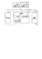
- FIG. 1 is an explanatory diagram of an example of a wireless communication system according to the first embodiment.
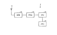
- FIG. 2 is a block diagram illustrating an example of a hardware configuration of the base station.
- FIG. 3 is a block diagram illustrating an example of a functional configuration of the base station.
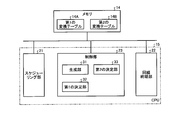
- FIG. 4 is a block diagram illustrating an example of a functional configuration in the CPU of the base station.
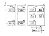
- FIG. 5 is a block diagram illustrating an example of a hardware configuration of the mobile station.
- FIG. 6 is a block diagram illustrating an example of a functional configuration of the mobile station.
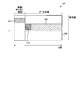
- FIG. 7 is an explanatory diagram showing an example of the arrangement configuration of the first DCI and the second DCI in the radio frame.
- FIG. 1 is an explanatory diagram of an example of a wireless communication system according to the first embodiment.
- FIG. 2 is a block diagram illustrating an example of a hardware configuration of the base station.
- FIG. 3 is a block diagram illustrating an example of a functional configuration of the base station.
- FIG. 8 is a flowchart showing an example of the processing operation of the base station involved in the first base station side transmission processing.
- FIG. 9 is a flowchart showing an example of the processing operation of the mobile station related to the mobile station side reception processing.
- FIG. 10 is a block diagram illustrating an example of a functional configuration in the CPU of the base station according to the second embodiment.
- FIG. 11 is an explanatory diagram of an example of the third conversion table.
- FIG. 12 is a flowchart illustrating an example of the processing operation of the base station related to the second base station side transmission processing.
- FIG. 13 is an explanatory diagram showing an example of the arrangement configuration of the first DCI and the second DCI in the radio frame.
- FIG. 1 is an explanatory diagram illustrating an example of a wireless communication system 1 according to the first embodiment.
- a radio communication system 1 shown in FIG. 1 is, for example, an LTE (Long Term Evolution) communication system having a base station 2 and a plurality of mobile stations 3.
- the base station 2 is a wireless communication device that transmits and receives, for example, a TDD (Time Division Duplex) wireless signal to and from the mobile station 3.
- the base station 2 transmits a DL (Down Link) signal of a radio signal to the mobile station 3.
- the base station 2 receives a radio link UL (Up Link) signal from the mobile station 3.
- FIG. 2 is a block diagram showing an example of the hardware configuration of the base station 2.
- the base station 2 shown in FIG. 2 includes a radio antenna 11, an RF (Radio Frequency) unit 12, an FPGA (Field Programmable Gate Array) 13, a memory 14, and a CPU (Central Processing Unit) 15.
- RF Radio Frequency
- FPGA Field Programmable Gate Array
- CPU Central Processing Unit
- FIG. 3 is a block diagram illustrating an example of a functional configuration of the base station 2.
- the RF unit 12 illustrated in FIG. 3 includes a transmission RF unit 12A and a reception RF unit 12B.
- the FPGA 13 includes a baseband transmission unit 13A and a baseband reception unit 13B.
- the CPU 15 includes a scheduling unit 21 and a line termination unit 22.
- the reception RF unit 12B removes a carrier wave from the UL signal received from the wireless antenna 11 and generates a reception baseband signal.
- the baseband receiving unit 13B performs demodulation and decoding processing based on scheduling information on the reception baseband signal from the reception RF 12B to generate reception data. Further, the baseband receiving unit 13B outputs the generated received data to the line terminating unit 22.
- the line terminating unit 22 outputs the received data from the baseband receiving unit 13B to the upper network and outputs the data received from the upper network to the baseband transmitting unit 13A.
- the scheduling unit 21 notifies the baseband transmission unit 13A and the baseband reception unit 13B of scheduling information for allocating radio resources for each mobile station 3 based on the radio quality of the DL signal and the UL signal.
- the baseband transmission unit 13A Based on the scheduling information of the scheduling unit 21, the baseband transmission unit 13A generates a transmission baseband signal by encoding and modulating data in the DL direction, and outputs the transmission baseband signal to the transmission RF unit 12A.
- the transmission RF unit 12A modulates the baseband signal to generate a DL signal, and wirelessly outputs the DL signal to the mobile station 3 through the radio antenna 11.
- FIG. 4 is a block diagram illustrating an example of a functional configuration in the CPU 15 of the base station 2.
- the CPU 15 illustrated in FIG. 4 includes a control unit 23 in addition to the scheduling unit 21 and the line termination unit 22.
- the control unit 23 controls the entire CPU 15.
- the memory 14 includes a first conversion table 14A and a second conversion table 14B.
- the first conversion table 14A is a table that manages the association level applied to the first DCI in association with each average radio quality for each mobile station 3.
- the first DCI is information that makes it possible to identify whether or not there is a PDCCH addressed to the mobile station 3 on the mobile station 3 side, and first information of index information such as arrangement information of the second DCI arranged in the data area. Control information.
- the combination level corresponds to an aggregation level corresponding to the number of CCEs assigned to the first DCI.
- the second conversion table 14B is a table that manages the connection level applied to the second DCI in association with the connection level applied to the first DCI.
- the second DCI is a second control of detailed information such as data modulation and channel coding rate on the mobile station 3 side to be searched when the mobile station 3 side determines that there is a PDCCH addressed to itself. Information.
- the coupling level corresponds to an aggregation level corresponding to the number of CCEs assigned to the second DCI. In the first embodiment, for convenience of explanation, the coupling level applied to the first DCI and the coupling level applied to the second DCI are the same level.
- the control unit 23 includes a generation unit 31, a first determination unit 32, and a second determination unit 33.
- the generation unit 31 generates a first DCI and a second DCI for each mobile station 3.
- the first determination unit 32 calculates the average radio quality for each mobile station 3 in the own station cell, and extracts from the first conversion table 14A the combination level to be applied to the first DCI corresponding to the average radio quality. .
- the first determination unit 32 determines a coupling level to be applied to the first DCI for each mobile station 3.
- the second determination unit 33 determines the coupling level to be applied to the first DCI level of the mobile station 3.
- the second determination unit 33 applies the second DCI corresponding to the coupling level to be applied to the first DCI of the mobile station 3.
- the combination level is extracted from the second conversion table 14B. Then, the second determination unit 33 determines the coupling level applied to the second DCI of the mobile station 3.
- FIG. 5 is a block diagram illustrating an example of a hardware configuration of the mobile station 3.
- the mobile station 3 illustrated in FIG. 5 includes a wireless antenna 41, an RF unit 42, an LSI (Large Scaled Integrated) 43, a memory 44, and a CPU 45.
- LSI Large Scaled Integrated
- FIG. 6 is a block diagram illustrating an example of a functional configuration of the mobile station 3.
- the RF unit 42 illustrated in FIG. 6 includes a transmission RF unit 42A and a reception RF unit 42B.
- the LSI 43 includes a baseband transmission unit 43A and a baseband reception unit 43B.
- the reception RF unit 42B removes a carrier wave from the DL signal received from the wireless antenna 41 and generates a reception baseband signal.
- the baseband reception unit 43B performs demodulation and decoding processing based on scheduling information on the reception baseband signal from the reception RF 42B, generates reception data, and outputs the reception data.
- the baseband transmission unit 43A encodes and modulates data in the UL direction to generate a transmission baseband signal, and outputs the transmission baseband signal to the transmission RF unit 42A.
- the transmission RF unit 42 ⁇ / b> A modulates the transmission baseband signal with a carrier wave to generate a UL signal, and wirelessly outputs the UL signal to the base station 2 through the wireless antenna 41.
- the CPU 45 includes a detection unit 51, a first extraction unit 52, a reception unit 53, a second extraction unit 54, and a data reception unit 55.
- the detection unit 51 performs a blind detection process on the first DCI, and detects the first DCI addressed to the own station from the search space in the radio frame of the DL signal.
- a CCE (Control Channel Element) sequence is constructed from a bit sequence in an area where a plurality of PDCCHs can be arranged in the search space.
- CRC Cyclic Redundancy Check
- the detection unit 51 can determine whether or not there is a PDCCH addressed to the own station in the radio frame by executing the blind detection process. Then, when there is a PDCCH addressed to the own station, the detection unit 51 takes in the bit string of that portion as the PDCCH addressed to the own station. As a result, the detection unit 51 detects the first DCI addressed to the local station by capturing the PDCCH addressed to the local station.
- the first extraction unit 52 extracts the first parameter for receiving the second DCI addressed to the own station from the first DCI.
- the first extraction unit 52 extracts a coupling level applied to the first DCI as a first parameter.
- the reception unit 53 receives the second DCI addressed to the own station from the data area in the radio frame.
- the second extraction unit 54 extracts the second parameter from the received second DCI addressed to the own station.
- the data reception unit 55 receives data addressed to the own station from the data area in the radio frame.
- the memory 44 stores a conversion table 44A.
- the conversion table 44A is a table that manages the association level applied to the second DCI in association with the association level applied to the first DCI.
- the first extraction unit 52 refers to the conversion table 44A, and extracts the coupling level applied to the second DCI corresponding to the coupling level applied to the first DCI as the first parameter.
- FIG. 7 is an explanatory diagram showing an example of the arrangement configuration of the first DCI and the second DCI in the radio frame.
- the first DCI 111 is arranged in the PDCCH 101 that is the first area
- the second DCI 112 is arranged in the data area 103 that is the second area in which the PDSCH 102 is arranged. .
- FIG. 8 is a flowchart showing an example of the processing operation of the base station 2 related to the first base station side transmission processing.
- the scheduling unit 21 in the base station 2 selects a user of the mobile station 3 in the cell for each TTI (Transmission Time Interval) (step S11), and allocates radio resources to be used for the data channel of the selected user ( Step S12).
- TTI Transmission Time Interval
- the scheduling unit 21 determines the MCS (Modulation Code Scheme) of the selected user (step S13).
- the generation unit 31 generates the first DCI and the second DCI of the selected user based on the MCS of the selected user.
- the first determination unit 32 in the control unit 23 specifies an unspecified selected user in the cell (step S14), and calculates the average radio quality of the specified selected user (step S15).
- the first determination unit 32 refers to the first conversion table 14A and determines a combination level to be applied to the first DCI corresponding to the average radio quality of the designated selected user (step S16). Note that the first determination unit 32 notifies the baseband transmission unit 13A of the combination level to be applied to the first DCI of the selected user.
- the second determination unit 33 in the control unit 23 refers to the second conversion table 14B and determines a coupling level to be applied to the second DCI corresponding to the coupling level to be applied to the first DCI (step S17). ). Note that the first determination unit 32 notifies the baseband transmission unit 13A of the combination level to be applied to the second DCI of the selected user.
- the second determination unit 33 determines whether there is an unspecified selected user (step S18). If there is an unspecified selected user (Yes at Step S18), the second determination unit 33 proceeds to Step S14 to designate an unspecified selected user.
- the baseband transmission unit 13A clears the designation of the selected user (Step S19) and designates the undesignated selected user (Step S20).
- the baseband transmission unit 13A executes the first DCI encoding / modulation process based on the combination level applied to the first DCI of the designated selected user (step S21). Further, the baseband transmission unit 13A executes the second DCI encoding / modulation process based on the combination level applied to the second DCI of the designated selected user (step S22). Further, the baseband transmission unit 13A performs encoding / modulation processing on the data of the designated selected user based on the first DCI and the second DCI (step S23), and whether there is an undesignated selected user or not. Is determined (step S24).
- Step S24 When there is an unspecified selected user (Yes at Step S24), the baseband transmission unit 13A proceeds to Step S20 to designate an unspecified selected user. Further, when there is no unspecified selected user (No at Step S24), the baseband transmission unit 13A executes the first DCI, second DCI, and data transmission processing of all the selected users (Step S25). The processing operation shown in FIG.
- the base station 2 that executes the first base station side transmission processing divides the DCI for each selected user into a first DCI and a second DCI, the first DCI is index information, and the second DCI is detailed information. And The base station 2 assigns the first DCI to the PDCCH in the radio frame and the second DCI to the data area in the radio frame. Then, the base station 2 determines the coupling level of the first DCI with a coupling level corresponding to the average radio quality of the selected user, and the second DCI with a coupling level corresponding to the coupling level applied to the first DCI. Determine the join level to apply to.
- the base station 2 wirelessly outputs to the mobile station 3 a radio frame to which the first DCI and the second DCI having the same coupling level are assigned.
- the base station 2 since the DCI for each selected user is divided into the first DCI and the second DCI, the amount of bits of the first DCI can be reduced, so that the mobile station 3 performs the operation for the first DCI in the radio frame.
- the processing burden when executing the blind detection process can be greatly reduced.
- FIG. 9 is a flowchart showing an example of the processing operation of the mobile station 3 related to the reception processing on the mobile station side.
- the detection unit 51 in the mobile station 3 performs a blind detection process for the first DCI in the search space (step S31). After executing the blind detection process for the first DCI, the detection unit 51 determines whether or not the first DCI addressed to itself is detected (step S32).
- the first extraction unit 52 in the mobile station 3 detects the first DCI addressed to the own station (Yes at Step S32), the first extraction unit 52 refers to the conversion table 44A and selects the second DCI corresponding to the coupling level of the first DCI.
- the coupling level applied to the DCI is extracted as a first parameter (step S33).
- the receiving unit 53 in the mobile station 3 performs the second DCI reception process based on the first parameter, that is, the coupling level applied to the first DCI (step S34).
- the second DCI reception process is at the same level as the coupling level applied to the first DCI, so that the processing load required for the reception process can be reduced.
- the second extraction unit 54 in the mobile station 3 extracts the second parameter from the second DCI after executing the second DCI reception process (step S35). Based on the second parameter, the data receiving unit 55 in the mobile station 3 executes a process for receiving data addressed to itself (step S36), and ends the processing operation shown in FIG. Furthermore, when the first DCI addressed to the own station is not detected (No at Step S32), the detection unit 51 ends the processing operation illustrated in FIG.
- the mobile station 3 When the mobile station 3 detects the first DCI addressed to itself by executing the blind detection process of the first DCI in the radio frame, the mobile station 3 corresponds to the first level corresponding to the coupling level applied to the first DCI.
- the second DCI addressed to the local station is received based on the coupling level applied to the second DCI.
- the processing load required for the reception process of the second DCI addressed to itself can be made efficient.
- the DCI is divided into a first DCI and a second DCI, index information for identifying whether or not there is a DCI addressed to the own station in the first DCI, data modulation and a channel addressed to the own station in the second DCI Allocate detailed information such as coding rate.
- the mobile station 3 can reduce the processing load when receiving the second DCI because the coupling level applied to the second DCI is the same level as the coupling level applied to the first DCI.
- the mobile station 3 does not execute the second DCI reception process when the first DCI addressed to itself is not detected by executing the first DCI blind detection process in the radio frame. As a result, the mobile station 3 can reduce the processing load required for the reception processing of the second DCI that is not addressed to the mobile station 3.
- the base station 2 of the first embodiment sets the coupling level applied to the second DCI to the same level as the coupling level applied to the first DCI
- the coupling level applied to the second DCI is set to the first level.
- the coupling level may be lower than that applied to the DCI.
- the second DCI can be transmitted with better characteristics than the first DCI
- the second DCI can be transmitted at a higher coding rate than the first DCI.
- the number of bits of the second DCI can be reduced.
- the second determination unit 33 in the base station 2 determines the coupling level to be applied to the first DCI, and then refers to the second conversion table 14B and corresponds to the coupling level to be applied to the first DCI.
- the binding level applied to the DCI of 2 was determined. However, it is not limited to this, and can be changed as appropriate. Therefore, the embodiment will be described below as Example 2.
- the same components as those in the wireless communication system 1 according to the first embodiment are denoted by the same reference numerals, and the description of the overlapping configuration and operation is omitted.
- FIG. 10 is an explanatory diagram illustrating an example of a functional configuration in the CPU 15 of the base station 2 according to the second embodiment.
- the memory 14 has a third conversion table 14C instead of the second conversion table 14B.
- FIG. 11 is an explanatory diagram showing an example of the third conversion table 14C.
- the third conversion table 14C shown in FIG. 11 is a table for managing the MDS identifier, the TBS (Transport Block Size) value, and the coupling level in association with each other.
- the coupling level is a coupling level applied to the second DCI.
- control unit 23 ⁇ / b> A includes a third determination unit 34 instead of the second determination unit 33.
- the third determination unit 34 refers to the third conversion table 14C, extracts a combination level to be applied to the second DCI corresponding to the MCS value of the selected user, and combines to be applied to the second DCI of the selected user. Determine the level.
- FIG. 12 is a flowchart showing an example of the processing operation of the base station 2 related to the second base station side transmission processing.
- the third determination unit 34 in the base station 2 refers to the third conversion table 14C after determining the coupling level to be applied to the first DCI of the designated selected user in step S16. Then, the third determining unit 34 extracts and determines the coupling level applied to the second DCI corresponding to the designated selected user's MCS (step S17A). After determining the combination level to be applied to the second DCI of the designated selected user, the third determining unit 34 proceeds to step S18 to determine whether there is an undesignated selected user.
- the base station 2 that executes the second base station side transmission process divides the DCI for each selected user into a first DCI and a second DCI, the first DCI is index information, and the second DCI is detailed information. And Furthermore, the base station 2 assigns the first DCI to the PDCCH in the radio frame and the second DCI to the data area in the radio frame. Then, the base station 2 determines the first DCI combination level at the combination level corresponding to the average radio quality of the selected user, and also determines the second DCI combination level at the combination level corresponding to the MCS. Then, the base station 2 wirelessly outputs to the mobile station 3 a radio frame to which the first DCI and the second DCI are assigned.
- the DCI for each selected user is divided into the first DCI and the second DCI, the amount of bits of the first DCI can be reduced, so that the mobile station 3 performs the operation for the first DCI in the radio frame.
- the processing burden when executing the blind detection process can be greatly reduced.
- the base station 2 determines the coupling level to be applied to the second DCI according to the MCS of the selected user, the processing load when setting the coupling level to be applied to the second DCI can be reduced.
- the coupling level applied to the second DCI corresponding to the MCS is determined.
- the coupling level applied to the second DCI may be specified in the first DCI. good.
- the mobile station 3 can extract a coupling level to be applied to the second DCI from a predetermined location addressed to itself in the first DCI.
- the coupling level applied to the first DCI is exemplified as the first parameter.
- wireless quality such as coding rate and channel size may be used, and the setting can be changed as appropriate. is there.
- the coupling level of the second DCI is exemplified as the second parameter, for example, wireless quality such as a coding rate and a channel size may be applied, and the setting can be changed as appropriate.
- the wireless communication system 1 to which LTE is applied has been illustrated, but the wireless communication method to be applied is not limited to this, for example, time-sharing such as HSDPA (High Speed Downlink Packet Access). Any resource allocation may be used.
- time-sharing such as HSDPA (High Speed Downlink Packet Access). Any resource allocation may be used.
- the mobile station 3 is assumed to be a mobile phone, a smartphone, or a PDA (Personal Digital Assistant).
- the present invention is not limited to the mobile station 3 and communicates with the base station 2. It can be applied to various communication devices to be performed.
- each component of the base station 2 does not necessarily need to be physically configured as illustrated. That is, the specific mode of distribution / integration of each device is not limited to the illustrated one, and all or a part thereof is functionally or physically distributed in an arbitrary unit according to various loads or usage conditions. -It can also be integrated and configured.
- the baseband transmission unit 13A and the transmission RF unit 12A of the base station 2 or the baseband reception unit 13B and the reception RF unit 12B of the base station 2 may be integrated as one component.
- the baseband transmission unit 13A and the baseband reception unit 13B that control wireless communication and the line termination unit 22 that controls wired communication may be a single communication unit.
- the memory 14 may be connected as an external device of the base station 2 via a network or a cable.
- each component of each part illustrated does not necessarily need to be physically configured as illustrated.
- the specific form of distribution / integration of each part is not limited to the one shown in the figure, and all or a part thereof may be functionally or physically distributed / integrated in arbitrary units according to various loads and usage conditions. Can be configured.
- each device is all or any part of it on a CPU (Central Processing Unit) (or a micro computer such as MPU (Micro Processing Unit) or MCU (Micro Controller Unit)). You may make it perform.
- CPU Central Processing Unit
- MPU Micro Processing Unit
- MCU Micro Controller Unit
- Various processing functions may be executed entirely or arbitrarily on a program that is analyzed and executed by a CPU (or a microcomputer such as an MPU or MCU) or hardware based on wired logic. Needless to say.
Landscapes
- Mobile Radio Communication Systems (AREA)
Abstract
移動局(3)は、検出部(51)と、抽出部(52)と、受信部(53)とを有する。検出部は、基地局(2)から受信した無線フレーム内の第1の領域(101)に対してブラインドディテクション処理を実行することで、第1の領域から第1の制御情報(111)を検出する。抽出部は、第1の制御情報を検出した場合に、第1の制御情報に基づき、所定パラメータを抽出する。受信部は、抽出された所定パラメータを用いて、無線フレーム内の第2の領域(103)から第2の制御情報(112)を受信する受信処理を実行する。
Description
本発明は、無線通信装置、無線通信システム及び無線通信方法に関する。
近年、LTE(Long Term Evolution)の無線通信システムが広く普及している。LTEの無線フレームには、制御情報の送信に使用するPDCCH(Physical Downlink Control Channel)を配置する制御チャネル領域と、それに続くデータ送信に使用するPDSCH(Physical Downlink Shared Channel)を配置するデータ領域とがある。
制御情報には、例えば、受信側の移動局でデータを復調可能となるスケジューリング情報、データ変調及びチャネル符号化率等のダウンリンク制御情報(DCI:Downlink Control Information)がある。通常、DCIは、PDCCH内に配置されることになる。
移動局は、基地局からの無線フレームを受信した場合、無線フレーム内のサーチスペースから自局宛のPDCCHがあるか否かを判定するブラインドディテクション処理を実行する。ブラインドディテクション処理は、サーチスペース内の複数のPDCCHが配置可能な領域内のビット列からCCE(Control Channel Element)列を構築する。更に、ブラインドディテクション処理は、CCE列に対してCRC(Cyclic Redundancy Check)を実行し、CRCがOKのCCEを自局宛のPDCCHとして認識する。従って、移動局は、ブラインドディテクション処理を実行することで、無線フレーム内に自局宛のPDCCHがあるか否かを判定できる。更に、移動局は、自局宛のPDCCHがある場合、その部分のビット列を自局宛のPDCCHとして取り込む。移動局は、ブラインドディテクション処理を実行することで、自局宛のDCIを検出することになる。
また、3GPPでは、DCIを第1のDCI及び第2のDCIに分割し、第1のDCI及び第2のDCIを無線フレーム内に配置する方法が議論されている。図13は、無線フレーム内の第1のDCI及び第2のDCIの配置構成の一例を示す説明図である。図13に示す無線フレーム200には、第1のDCI211をPDCCH201に配置し、第2のDCI212を、PDSCH202を配置するデータ領域203に配置している。
3GPP,R1-1612717,"Discussion on multiple-stepDCI for NR", NTT DOCOMO,INC., TSG RAN WG1 #87, Nov.,2016
3GPP,R1-166102, "Overview of frame structure for NR", Huawei, HiSilicon, TSG RAN WG1 #86, Aug., 2016
無線フレームから自局宛のDCIを検出するブラインドディテクション処理を実行する際の移動局側の処理負担が大である。しかも、DCIを第1のDCI及び第2のDCIに分割して無線フレームに割り当てられた場合に、移動局は、第1のDCI及び第2のDCIに対してブラインドディテクション処理を夫々実行することになる。その結果、受信側の処理負担は、益々大きくなる。
一つの側面では、DCIを分割した場合でも、受信側の処理負担を軽減できる無線通信装置等を提供することを目的とする。
一つの態様の無線通信装置は、検出部と、抽出部と、受信部とを有する。検出部は、他の無線通信装置から受信した無線フレーム内の第1の領域に対してブラインドディテクション処理を実行することで、第1の領域から第1の制御情報を検出する。抽出部は、第1の制御情報を検出した場合に、第1の制御情報に基づき、所定パラメータを抽出する。受信部は、抽出部にて抽出された所定パラメータを用いて、無線フレーム内の第2の領域から第2の制御情報を受信する受信処理を実行する。
一つの態様では、DCIを分割した場合でも、受信側の処理負担を軽減できる。
以下、図面に基づいて、本願の開示する無線通信装置、無線通信システム及び無線通信方法の実施例を詳細に説明する。尚、各実施例により、開示技術が限定されるものではない。また、以下に示す各実施例は、矛盾を起こさない範囲で適宜組み合わせても良い。
図1は、実施例1の無線通信システム1の一例を示す説明図である。図1に示す無線通信システム1は、基地局2と、複数の移動局3とを有する、例えば、LTE(Long Term Evolution)通信システムである。基地局2は、移動局3との間で、例えば、TDD(Time Division Duplex)方式の無線信号を送受信する無線通信装置である。基地局2は、無線信号のDL(Down Link)信号を移動局3に送信する。基地局2は、無線信号のUL(Up Link)信号を移動局3から受信する。
図2は、基地局2のハードウェア構成の一例を示すブロック図である。図2に示す基地局2は、無線アンテナ11と、RF(Radio Frequency)部12と、FPGA(Field Programmable Gate Array)13と、メモリ14と、CPU(Central Processing Unit)15とを有する。
図3は、基地局2の機能構成の一例を示すブロック図である。図3に示すRF部12は、送信RF部12Aと、受信RF部12Bとを有する。FPGA13は、ベースバンド送信部13Aと、ベースバンド受信部13Bとを有する。CPU15は、スケジューリング部21と、回線終端部22とを有する。受信RF部12Bは、無線アンテナ11から受信したUL信号に対して搬送波を除去して受信ベースバンド信号を生成する。ベースバンド受信部13Bは、受信RF12Bからの受信ベースバンド信号に対して、スケジューリング情報に基づく復調及び復号処理を実行して受信データを生成する。更に、ベースバンド受信部13Bは、生成した受信データを回線終端部22に出力する。回線終端部22は、ベースバンド受信部13Bから受信データを上位ネットワークに出力すると共に、上位ネットワークから受信したデータをベースバンド送信部13Aに出力する。
スケジューリング部21は、DL信号及びUL信号の無線品質に基づき、移動局3毎の無線リソースを割当てるスケジューリング情報をベースバンド送信部13A及びベースバンド受信部13Bに通知する。ベースバンド送信部13Aは、スケジューリング部21のスケジューリング情報に基づき、DL方向のデータを符号化及び変調することで送信ベースバンド信号を生成し、送信ベースバンド信号を送信RF部12Aに出力する。送信RF部12Aは、ベースバンド信号を搬送波変調してDL信号を生成し、DL信号を、無線アンテナ11を通じて移動局3に無線出力する。
図4は、基地局2のCPU15内の機能構成の一例を示すブロック図である。図4に示すCPU15は、スケジューリング部21及び回線終端部22の他に、制御部23を有する。制御部23は、CPU15全体を制御する。更に、メモリ14には、第1の変換テーブル14Aと、第2の変換テーブル14Bとを有する。
第1の変換テーブル14Aは、移動局3毎の平均無線品質毎に、第1のDCIに適用する結合レベルを対応付けて管理するテーブルである。第1のDCIは、移動局3側で自局宛のPDCCHがあるか否かを識別可能にする情報及び、データ領域内に配置された第2のDCIの配置情報等のインデックス情報の第1の制御情報である。結合レベルは、第1のDCIに割り当てられるCCE数に対応したAggregation Levelに相当する。
第2の変換テーブル14Bは、第1のDCIに適用する結合レベル毎に第2のDCIに適用する結合レベルを対応付けて管理するテーブルである。第2のDCIは、移動局3側で自局宛のPDCCHがあると判定された場合に探索されるべき、移動局3側のデータ変調及びチャネル符号化率等の詳細情報の第2の制御情報である。結合レベルは、第2のDCIに割り当てられるCCE数に対応したAggregation Levelに相当する。尚、実施例1では、説明の便宜上、第1のDCIに適用する結合レベルと第2のDCIに適用する結合レベルとは同一レベルとする。
制御部23は、生成部31と、第1の決定部32と、第2の決定部33とを有する。生成部31は、移動局3毎の第1のDCI及び第2のDCIを生成する。第1の決定部32は、自局セル内の移動局3毎の平均無線品質を算出し、平均無線品質に対応する第1のDCIに適用する結合レベルを第1の変換テーブル14Aから抽出する。第1の決定部32は、移動局3毎の第1のDCIに適用する結合レベルを決定する。
第2の決定部33は、移動局3の第1のDCIレベルに適用する結合レベルを決定した場合、移動局3の第1のDCIに適用する結合レベルに対応する第2のDCIに適用する結合レベルを第2の変換テーブル14Bから抽出する。そして、第2の決定部33は、移動局3の第2のDCIに適用する結合レベルを決定する。
図5は、移動局3のハードウェア構成の一例を示すブロック図である。図5に示す移動局3は、無線アンテナ41と、RF部42と、LSI(Large Scaled Integrated)43と、メモリ44と、CPU45とを有する。
図6は、移動局3の機能構成の一例を示すブロック図である。図6に示すRF部42は、送信RF部42Aと、受信RF部42Bとを有する。LSI43は、ベースバンド送信部43Aと、ベースバンド受信部43Bとを有する。受信RF部42Bは、無線アンテナ41から受信したDL信号に対して搬送波を除去して受信ベースバンド信号を生成する。ベースバンド受信部43Bは、受信RF42Bからの受信ベースバンド信号に対して、スケジューリング情報に基づく復調及び復号処理を実行して受信データを生成して出力する。ベースバンド送信部43Aは、スケジューリング情報に基づき、UL方向のデータを符号化及び変調することで送信ベースバンド信号を生成し、送信ベースバンド信号を送信RF部42Aに出力する。送信RF部42Aは、送信ベースバンド信号を搬送波変調してUL信号を生成し、UL信号を、無線アンテナ41を通じて基地局2に無線出力する。
CPU45は、検出部51と、第1の抽出部52と、受信部53と、第2の抽出部54と、データ受信部55とを有する。検出部51は、第1のDCIに対するブラインドディテクション処理を実行し、DL信号の無線フレーム内のサーチスペースから自局宛の第1のDCIを検出する。尚、ブラインドディテクション処理は、サーチスペース内の複数のPDCCHが配置可能な領域内のビット列からCCE(Control Channel Element)列を構築する。更に、ブラインドディテクション処理は、CCE列に対してCRC(Cyclic Redundancy Check)を実行し、CRCがOKのCCEを自局宛のPDCCHとして認識する。検出部51は、ブラインドディテクション処理を実行することで、無線フレーム内に自局宛のPDCCHがあるか否かを判定できる。そして、検出部51は、自局宛のPDCCHがある場合、その部分のビット列を自局宛のPDCCHとして取り込む。その結果、検出部51は、自局宛のPDCCHを取り込むことで自局宛の第1のDCIを検出する。
第1の抽出部52は、第1のDCIから自局宛の第2のDCIを受信するための第1のパラメータを抽出する。第1の抽出部52は、第1のDCIに適用する結合レベルを第1のパラメータとして抽出する。受信部53は、第1の抽出部52で抽出した第1のパラメータに基づき、無線フレーム内のデータ領域から自局宛の第2のDCIを受信する。第2の抽出部54は、受信した自局宛の第2のDCIから第2のパラメータを抽出する。データ受信部55は、第2の抽出部54に抽出された第2のパラメータに基づき、無線フレーム内のデータ領域から自局宛のデータを受信する。
メモリ44は、変換テーブル44Aを記憶している。変換テーブル44Aは、第1のDCIに適用する結合レベル毎に第2のDCIに適用する結合レベルを対応付けて管理するテーブルである。第1の抽出部52は、変換テーブル44Aを参照し、第1のDCIに適用する結合レベルに対応する第2のDCIに適用する結合レベルを第1のパラメータとして抽出する。
図7は、無線フレーム内の第1のDCI及び第2のDCIの配置構成の一例を示す説明図である。図7に示す無線フレーム100には、第1のDCI111を第1の領域であるPDCCH101に配置し、第2のDCI112を、PDSCH102を配置する第2の領域であるデータ領域103に配置している。
次に実施例1の無線通信システム1の動作について説明する。図8は、第1の基地局側送信処理に関わる基地局2の処理動作の一例を示すフローチャートである。図8において基地局2内のスケジューリング部21は、TTI(Transmission Time Interval)毎にセル内の移動局3のユーザを選択し(ステップS11)、選択ユーザのデータチャネルに使用する無線リソースを割当てる(ステップS12)。
スケジューリング部21は、選択ユーザのMCS(Modulation Code Scheme)を決定する(ステップS13)。尚、生成部31は、選択ユーザのMCSに基づき、選択ユーザの第1のDCI及び第2のDCIを生成する。制御部23内の第1の決定部32は、セル内の未指定の選択ユーザを指定し(ステップS14)、指定の選択ユーザの平均無線品質を算出する(ステップS15)。第1の決定部32は、第1の変換テーブル14Aを参照し、指定の選択ユーザの平均無線品質に対応する第1のDCIに適用する結合レベルを決定する(ステップS16)。尚、第1の決定部32は、選択ユーザの第1のDCIに適用する結合レベルをベースバンド送信部13Aに通知する。
制御部23内の第2の決定部33は、第2の変換テーブル14Bを参照し、第1のDCIに適用する結合レベルに対応した第2のDCIに適用する結合レベルを決定する(ステップS17)。尚、第1の決定部32は、選択ユーザの第2のDCIに適用する結合レベルをベースバンド送信部13Aに通知する。第2の決定部33は、未指定の選択ユーザがあるか否かを判定する(ステップS18)。第2の決定部33は、未指定の選択ユーザがある場合(ステップS18肯定)、未指定の選択ユーザを指定すべく、ステップS14に移行する。
ベースバンド送信部13Aは、未指定の選択ユーザがない場合(ステップS18否定)、選択ユーザの指定をクリアにし(ステップS19)、未指定の選択ユーザを指定する(ステップS20)。
ベースバンド送信部13Aは、指定の選択ユーザの第1のDCIに適用する結合レベルに基づき、第1のDCIの符号化・変調処理を実行する(ステップS21)。更に、ベースバンド送信部13Aは、指定の選択ユーザの第2のDCIに適用する結合レベルに基づき、第2のDCIの符号化・変調処理を実行する(ステップS22)。更に、ベースバンド送信部13Aは、第1のDCI及び第2のDCIに基づき、指定の選択ユーザのデータに対する符号化・変調処理を実行し(ステップS23)、未指定の選択ユーザがあるか否かを判定する(ステップS24)。
ベースバンド送信部13Aは、未指定の選択ユーザがある場合(ステップS24肯定)、未指定の選択ユーザを指定すべく、ステップS20に移行する。更に、ベースバンド送信部13Aは、未指定の選択ユーザがない場合(ステップS24否定)、全選択ユーザの第1のDCI、第2のDCI及びデータの送信処理を実行し(ステップS25)、図8に示す処理動作を終了する。
第1の基地局側送信処理を実行する基地局2は、選択ユーザ毎のDCIを第1のDCI及び第2のDCIに分割し、第1のDCIをインデックス情報、第2のDCIを詳細情報とする。基地局2は、無線フレーム内のPDCCHに第1のDCIを、無線フレーム内のデータ領域に第2のDCIを割当てる。そして、基地局2は、選択ユーザの平均無線品質に対応する結合レベルで第1のDCIの結合レベルを決定すると共に、第1のDCIに適用する結合レベルに対応する結合レベルで第2のDCIに適用する結合レベルを決定する。そして、基地局2は、同一結合レベルの第1のDCI及び第2のDCIが割り当てられた無線フレームを移動局3に無線出力する。その結果、選択ユーザ毎のDCIを第1のDCI及び第2のDCIに分割したので、第1のDCIのビット量が少なくて済むため、移動局3は、無線フレーム内の第1のDCIに対するブラインドディテクション処理を実行する際の処理負担が大幅に軽減できる。
図9は、移動局側受信処理に関わる移動局3の処理動作の一例を示すフローチャートである。図9において移動局3内の検出部51は、サーチスペース内の第1のDCIに対するブラインドディテクション処理を実行する(ステップS31)。検出部51は、第1のDCIに対するブラインドディテクション処理実行後、自局宛の第1のDCIを検出したか否かを判定する(ステップS32)。
移動局3内の第1の抽出部52は、自局宛の第1のDCIを検出した場合(ステップS32肯定)、変換テーブル44Aを参照し、第1のDCIの結合レベルに対応する第2のDCIに適用する結合レベルを第1のパラメータとして抽出する(ステップS33)。移動局3内の受信部53は、第1のパラメータ、すなわち第1のDCIに適用する結合レベルに基づき、第2のDCIの受信処理を実行する(ステップS34)。尚、第2のDCIの受信処理は、第1のDCIに適用する結合レベルと同一レベルであるため、受信処理に要する処理負担を軽減できる。
移動局3内の第2の抽出部54は、第2のDCIの受信処理を実行した後、第2のDCIから第2のパラメータを抽出する(ステップS35)。移動局3内のデータ受信部55は、第2のパラメータに基づき、自局宛のデータの受信処理を実行し(ステップS36)、図9に示す処理動作を終了する。更に、検出部51は、自局宛の第1のDCIを検出しなかった場合(ステップS32否定)、図9に示す処理動作を終了する。
移動局3は、無線フレーム内の第1のDCIのブラインドディテクション処理を実行することで、自局宛の第1のDCIを検出した場合に第1のDCIに適用する結合レベルに対応する第2のDCIに適用する結合レベルに基づき、自局宛の第2のDCIを受信する。その結果、移動局3は、第1のDCIの結合レベルと同一レベルであるため、自局宛の第2のDCIの受信処理に要する処理負担を効率化できる。
DCIを第1のDCI及び第2のDCIに分割し、第1のDCIに自局宛のDCIがあるか否かを識別するインデックス情報を、第2のDCIに自局宛のデータ変調及びチャネル符号化率等の詳細情報を割当てる。その結果、第1のDCIのビット量が少なくて済むため、移動局3は、無線フレーム内の第1のDCIに対するブラインドディテクション処理を実行する際の処理負担を大幅に軽減できる。
移動局3は、第2のDCIに適用する結合レベルが第1のDCIに適用する結合レベルと同一レベルであるため、第2のDCIを受信する際の処理負担を軽減できる。
移動局3は、無線フレーム内の第1のDCIのブラインドディテクション処理を実行することで、自局宛の第1のDCIを検出しなかった場合に第2のDCIの受信処理を実行しない。その結果、移動局3は、自局宛がない第2のDCIの受信処理に要する処理負担を軽減できる。
尚、上記実施例1の基地局2は、第2のDCIに適用する結合レベルを第1のDCIに適用する結合レベルと同一レベルとしたが、第2のDCIに適用する結合レベルを第1のDCIに適用する結合レベル以下にしても良い。例えば、第2のDCIを第1のDCIよりも特性が良い状態で送信できる場合、第1のDCIの符号化率よりも第2のDCIの符号化率を高く送信できる。第2のDCIのビット数を小さくできる。
基地局2内の第2の決定部33は、第1のDCIに適用する結合レベルを決定した後、第2の変換テーブル14Bを参照し、第1のDCIに適用する結合レベルに対応する第2のDCIに適用する結合レベルを決定した。しかしながら、これに限定されるものではなく、適宜変更可能である。そこで、その実施の形態につき、実施例2として以下に説明する。尚、実施例1の無線通信システム1と同一の構成には同一符号を付すことで、その重複する構成及び動作の説明については省略する。
図10は、実施例2の基地局2のCPU15内の機能構成の一例を示す説明図である。メモリ14には、第2の変換テーブル14Bの代わりに第3の変換テーブル14Cを有する。図11は、第3の変換テーブル14Cの一例を示す説明図である。図11に示す第3の変換テーブル14Cは、MCS毎に、変調方式の識別子、TBS(Transport Block Size) 値及び結合レベルを対応付けて管理するテーブルである。結合レベルは、第2のDCIに適用する結合レベルである。
また、制御部23Aは、第2の決定部33の代わりに第3の決定部34を有する。第3の決定部34は、第3の変換テーブル14Cを参照し、選択ユーザのMCS値に対応する第2のDCIに適用する結合レベルを抽出し、選択ユーザの第2のDCIに適用する結合レベルを決定する。
次に実施例2の無線通信システム1の動作について説明する。図12は、第2の基地局側送信処理に関わる基地局2の処理動作の一例を示すフローチャートである。
基地局2内の第3の決定部34は、ステップS16にて指定の選択ユーザの第1のDCIに適用する結合レベルを決定した後、第3の変換テーブル14Cを参照する。そして、第3の決定部34は、指定の選択ユーザのMCSに対応する第2のDCIに適用する結合レベルを抽出して決定する(ステップS17A)。第3の決定部34は、指定の選択ユーザの第2のDCIに適用する結合レベルを決定した後、未指定の選択ユーザがあるか否かを判定すべく、ステップS18に移行する。
第2の基地局側送信処理を実行する基地局2は、選択ユーザ毎のDCIを第1のDCI及び第2のDCIに分割し、第1のDCIをインデックス情報、第2のDCIを詳細情報とする。更に、基地局2は、無線フレーム内のPDCCHに第1のDCIを、無線フレーム内のデータ領域に第2のDCIを割当てる。そして、基地局2は、選択ユーザの平均無線品質に対応する結合レベルで第1のDCIの結合レベルを決定すると共に、MCSに対応する結合レベルで第2のDCIの結合レベルを決定する。そして、基地局2は、第1のDCI及び第2のDCIが割り当てられた無線フレームを移動局3に無線出力する。その結果、選択ユーザ毎のDCIを第1のDCI及び第2のDCIに分割したので、第1のDCIのビット量が少なくて済むため、移動局3は、無線フレーム内の第1のDCIに対するブラインドディテクション処理を実行する際の処理負担が大幅に軽減できる。
更に、基地局2は、選択ユーザのMCSに応じて第2のDCIに適用する結合レベルを決定したので、その第2のDCIに適用する結合レベルを設定する際の処理負担が軽減できる。
上記実施例2の基地局2では、MCSに対応する第2のDCIに適用する結合レベルを決定したが、例えば、第1のDCI内に第2のDCIに適用する結合レベルを明記しても良い。この場合、移動局3は、第1のDCIのブラインドディテクション処理を実行した後、第1のDCI内の自局宛の所定箇所から第2のDCIに適用する結合レベルを抽出できる。
尚、上記実施例では、第1のパラメータとして第1のDCIに適用する結合レベルを例示したが、例えば、符号化率やチャネルサイズ等の無線品質を使用しても良く、適宜設定変更可能である。
また、第2のパラメータとして第2のDCIの結合レベルを例示したが、例えば、符号化率やチャネルサイズ等の無線品質を適用しても良く、適宜設定変更可能である。
また、上記各実施例では、LTEが適用された無線通信システム1を例示したが、適用される無線通信方式は、これに限らず、例えば、HSDPA(High Speed Downlink Packet Access)等、時分割のリソース割当てを行うものであればよい。
上記各実施例では、移動局3として、携帯電話、スマートフォン、PDA(Personal Digital Assistant)を想定して説明したが、本発明は、移動局3に限らず、基地局2との間で通信を行う様々な通信機器に対して適用可能である。
また、基地局2の各構成要素は、必ずしも物理的に図示の如く構成されていることを要しない。すなわち、各装置の分散・統合の具体的態様は、図示のものに限らず、その全部又は一部を、各種の負荷や使用状況等に応じて、任意の単位で機能的又は物理的に分散・統合して構成することもできる。例えば、基地局2のベースバンド送信部13Aと送信RF部12A、あるいは、基地局2のベースバンド受信部13Bと受信RF部12Bをそれぞれ1つの構成要素として統合してもよい。また、無線通信を制御するベースバンド送信部13A及びベースバンド受信部13Bと、有線通信を制御する回線終端部22とを1つの通信部としてもよい。更に、メモリ14を、基地局2の外部装置としてネットワークやケーブル経由で接続するようにしてもよい。
また、図示した各部の各構成要素は、必ずしも物理的に図示の如く構成されていることを要しない。すなわち、各部の分散・統合の具体的形態は図示のものに限られず、その全部又は一部を、各種の負荷や使用状況等に応じて、任意の単位で機能的又は物理的に分散・統合して構成することができる。
更に、各装置で行われる各種処理機能は、CPU(Central Processing Unit)(又はMPU(Micro Processing Unit)、MCU(Micro Controller Unit)等のマイクロ・コンピュータ)上で、その全部又は任意の一部を実行するようにしても良い。また、各種処理機能は、CPU(又はMPU、MCU等のマイクロ・コンピュータ)で解析実行するプログラム上、又はワイヤードロジックによるハードウェア上で、その全部又は任意の一部を実行するようにしても良いことは言うまでもない。
1 無線通信システム
2 基地局
3 移動局
13A ベースバンド送信部
21 スケジューリング部
31 生成部
32 第1の決定部
33 第2の決定部
51 検出部
52 第1の抽出部
53 受信部
101 PDCCH
103 データ領域
111 第1のDCI
112 第2のDCI
2 基地局
3 移動局
13A ベースバンド送信部
21 スケジューリング部
31 生成部
32 第1の決定部
33 第2の決定部
51 検出部
52 第1の抽出部
53 受信部
101 PDCCH
103 データ領域
111 第1のDCI
112 第2のDCI
Claims (11)
- 他の無線通信装置から受信した無線フレーム内の第1の領域に対してブラインドディテクション処理を実行することで、前記第1の領域から第1の制御情報を検出する検出部と、
前記第1の制御情報を検出した場合に、前記第1の制御情報に基づき、所定パラメータを抽出する抽出部と、
前記抽出部にて抽出された前記所定パラメータを用いて、前記無線フレーム内の第2の領域から第2の制御情報を受信する受信処理を実行する受信部と
を有することを特徴とする無線通信装置。 - 前記受信部は、
前記抽出部にて抽出された前記所定パラメータと同一のパラメータを用いて、前記受信処理を実行することを特徴とする請求項1に記載の無線通信装置。 - 前記受信部は、
前記抽出部にて抽出された前記第1の制御情報に含まれる前記所定パラメータを用いて、前記受信処理を実行することを特徴とする請求項1に記載の無線通信装置。 - 前記受信処理は、
ブラインドディテクション処理であることを特徴とする請求項1~3の何れか一つに記載の無線通信装置。 - 前記所定パラメータは、
前記第1の制御情報を伝達するチャネルの結合レベルであることを特徴とする請求項1~4の何れか一つに記載の無線通信装置。 - 前記所定パラメータは、
前記第1の制御情報を伝達するチャネルのサイズを表す指標であることを特徴とする請求項1~4の何れか一つに記載の無線通信装置。 - 前記所定パラメータは、
前記第2の領域から前記第2の制御情報を受信する際に使用する結合レベルに対応づけられた変調・符号化方式を示す値であることを特徴とする請求項1~4の何れか一つに記載の無線通信装置。 - 前記ブラインドディテクション処理は、
前記無線フレーム内の前記第1の領域内のビット列の誤り訂正結果に基づき、自局宛の第1の制御情報を検出する処理であることを特徴とする請求項1~3の何れか一つに記載の無線通信装置。 - 他の無線通信装置側で受信した無線フレーム内の第1の領域に対するブラインドディテクション処理を実行した場合に検出可能にする第1の制御情報と、前記他の無線通信装置側で前記第1の制御情報を検出した場合に、前記第1の制御情報に基づき、抽出可能にする所定パラメータを用いて、前記無線フレーム内の第2の領域から受信可能にする第2の制御情報とを生成する生成部と、
前記第1の制御情報を前記第1の領域に割当てると共に、前記第2の制御情報を前記第2の領域に割当てる割当部と、
前記第1の制御情報及び前記第2の制御情報が割り当てられた前記無線フレームを前記他の無線通信装置に送信する送信部と
を有することを特徴とする無線通信装置。 - 基地局装置と、前記基地局装置との間で無線フレームを送受信する移動局装置とを有する無線通信システムであって、
前記基地局装置は、
前記移動局装置側で受信した無線フレーム内の第1の領域に対するブラインドディテクション処理を実行した場合に検出可能にする第1の制御情報と、前記移動局装置側で前記第1の制御情報を検出した場合に、前記第1の制御情報に基づき、抽出可能にする所定パラメータを用いて、前記無線フレーム内の第2の領域から受信可能にする第2の制御情報とを生成する生成部と、
前記第1の制御情報を前記第1の領域に割当てると共に、前記第2の制御情報を前記第2の領域に割当てる割当部と、
前記第1の制御情報及び前記第2の制御情報が割り当てられた前記無線フレームを前記移動局装置に送信する送信部と
を有し、
前記移動局装置は、
前記基地局装置から受信した無線フレーム内の第1の領域に対してブラインドディテクション処理を実行することで、前記第1の領域から第1の制御情報を検出する検出部と、
前記第1の制御情報を検出した場合に、前記第1の制御情報に基づき、所定パラメータを抽出する抽出部と、
前記抽出部にて抽出された前記所定パラメータを用いて、前記無線フレーム内の第2の領域から第2の制御情報を受信する受信処理を実行する受信部と
を有することを特徴とする無線通信システム。 - 他の無線通信装置から受信した無線フレーム内の第1の領域に対してブラインドディテクション処理を実行することで、前記第1の領域から第1の制御情報を検出し、
前記第1の制御情報を検出した場合に、前記第1の制御情報に基づき、所定パラメータを抽出し、
抽出された前記所定パラメータを用いて、前記無線フレーム内の第2の領域から第2の制御情報を受信する受信処理を実行する
処理を実行することを特徴とする無線通信方法。
Priority Applications (1)
| Application Number | Priority Date | Filing Date | Title |
|---|---|---|---|
| PCT/JP2017/012138 WO2018173285A1 (ja) | 2017-03-24 | 2017-03-24 | 無線通信装置、無線通信システム及び無線通信方法 |
Applications Claiming Priority (1)
| Application Number | Priority Date | Filing Date | Title |
|---|---|---|---|
| PCT/JP2017/012138 WO2018173285A1 (ja) | 2017-03-24 | 2017-03-24 | 無線通信装置、無線通信システム及び無線通信方法 |
Publications (1)
| Publication Number | Publication Date |
|---|---|
| WO2018173285A1 true WO2018173285A1 (ja) | 2018-09-27 |
Family
ID=63585968
Family Applications (1)
| Application Number | Title | Priority Date | Filing Date |
|---|---|---|---|
| PCT/JP2017/012138 Ceased WO2018173285A1 (ja) | 2017-03-24 | 2017-03-24 | 無線通信装置、無線通信システム及び無線通信方法 |
Country Status (1)
| Country | Link |
|---|---|
| WO (1) | WO2018173285A1 (ja) |
-
2017
- 2017-03-24 WO PCT/JP2017/012138 patent/WO2018173285A1/ja not_active Ceased
Non-Patent Citations (1)
| Title |
|---|
| HUAWEI ET AL.: "Summary of email discussion on sTTI scheduling", 3GPP TSG RAN WG1 MEETING #88, R1-1703674, 15 February 2017 (2017-02-15), XP051222135, Retrieved from the Internet <URL:http://www.3gpp.org/ftp/tsg_ran/WG1_RL1/TSGR1_88/Docs/R1-1703674.zip> * |
Similar Documents
| Publication | Publication Date | Title |
|---|---|---|
| US11240805B2 (en) | Radio communication method, terminal, and base station | |
| US10674503B2 (en) | PUSCH transmission method and apparatus | |
| KR101955864B1 (ko) | 무선 통신 시스템의 다운링크를 통해 데이터 정보 메시지를 전송하기 위한 시스템 및 방법 | |
| CN109075916B (zh) | 针对上行数据传输的反馈方法及装置 | |
| US20150319742A1 (en) | Resource allocation methods for control channels | |
| CN111435897A (zh) | 信息传输的方法和通信装置 | |
| RU2588600C1 (ru) | Способ передачи информации управления нисходящей линии связи, устройство на основе сети и пользовательское оборудование | |
| CN102045849A (zh) | 一种pdcch信息的发送方法、pdcch搜索空间的确定方法及装置 | |
| KR102261777B1 (ko) | 짧은 물리 다운링크 제어 채널(sPDCCH) 매핑 설계 | |
| US11139854B2 (en) | Method for spread spectrum communication, user equipment and base station | |
| JP2020022210A (ja) | 通信装置、通信方法及び集積回路 | |
| CN116349180B (zh) | 用户装备、处理器和基站 | |
| JP6644916B2 (ja) | 信号伝送方法、信号復号化方法、基地局、及びユーザ端末 | |
| CN109075917B (zh) | 针对上行数据传输的反馈方法及装置 | |
| CN112636886B (zh) | 无线通信的方法、芯片和通信装置 | |
| CN114567420A (zh) | 接收装置和接收方法 | |
| CN115004828A (zh) | 通信方法和通信装置 | |
| US11211970B2 (en) | Communication method and corresponding user terminal, and base station | |
| US11050602B2 (en) | Methods and communication apparatuses for bit-to-symbol mapping | |
| US11317429B2 (en) | Method for transmitting and receiving scheduling information in communication system | |
| WO2020062064A1 (zh) | 由用户设备、基站执行的方法以及用户设备和基站 | |
| WO2018171538A1 (zh) | 数据传输方法、网络设备及终端设备 | |
| WO2018173285A1 (ja) | 無線通信装置、無線通信システム及び無線通信方法 | |
| US11296746B2 (en) | Method for selecting spreading sequences, a method for adjusting a transmission power and communication apparatuses | |
| US20250380265A1 (en) | Downlink transmission method and apparatus, and device and storage medium |
Legal Events
| Date | Code | Title | Description |
|---|---|---|---|
| 121 | Ep: the epo has been informed by wipo that ep was designated in this application |
Ref document number: 17901867 Country of ref document: EP Kind code of ref document: A1 |
|
| NENP | Non-entry into the national phase |
Ref country code: DE |
|
| 122 | Ep: pct application non-entry in european phase |
Ref document number: 17901867 Country of ref document: EP Kind code of ref document: A1 |
|
| NENP | Non-entry into the national phase |
Ref country code: JP |