WO2018171759A1 - Procédé et appareil de transmission d'informations - Google Patents
Procédé et appareil de transmission d'informations Download PDFInfo
- Publication number
- WO2018171759A1 WO2018171759A1 PCT/CN2018/080340 CN2018080340W WO2018171759A1 WO 2018171759 A1 WO2018171759 A1 WO 2018171759A1 CN 2018080340 W CN2018080340 W CN 2018080340W WO 2018171759 A1 WO2018171759 A1 WO 2018171759A1
- Authority
- WO
- WIPO (PCT)
- Prior art keywords
- indication
- power headroom
- phr
- uplink
- uplink transmission
- Prior art date
Links
- 230000005540 biological transmission Effects 0.000 title claims abstract description 301
- 238000000034 method Methods 0.000 title claims abstract description 110
- 230000015654 memory Effects 0.000 claims description 54
- 230000006870 function Effects 0.000 claims description 46
- 125000004122 cyclic group Chemical group 0.000 claims description 13
- 238000004590 computer program Methods 0.000 claims description 11
- 238000004364 calculation method Methods 0.000 claims description 7
- 230000008859 change Effects 0.000 claims description 6
- 230000004044 response Effects 0.000 claims description 6
- 238000004891 communication Methods 0.000 abstract description 59
- 238000012545 processing Methods 0.000 description 36
- 230000008569 process Effects 0.000 description 28
- 238000010586 diagram Methods 0.000 description 12
- 230000011664 signaling Effects 0.000 description 11
- 230000001960 triggered effect Effects 0.000 description 10
- 238000013461 design Methods 0.000 description 9
- 239000013598 vector Substances 0.000 description 8
- 238000013475 authorization Methods 0.000 description 6
- 238000005516 engineering process Methods 0.000 description 6
- 230000008878 coupling Effects 0.000 description 5
- 238000010168 coupling process Methods 0.000 description 5
- 238000005859 coupling reaction Methods 0.000 description 5
- 230000010267 cellular communication Effects 0.000 description 4
- 238000007726 management method Methods 0.000 description 4
- 238000010295 mobile communication Methods 0.000 description 4
- 230000000737 periodic effect Effects 0.000 description 4
- 230000009471 action Effects 0.000 description 3
- 230000002776 aggregation Effects 0.000 description 3
- 238000004220 aggregation Methods 0.000 description 3
- 230000001413 cellular effect Effects 0.000 description 3
- 230000009977 dual effect Effects 0.000 description 3
- LKKMLIBUAXYLOY-UHFFFAOYSA-N 3-Amino-1-methyl-5H-pyrido[4,3-b]indole Chemical compound N1C2=CC=CC=C2C2=C1C=C(N)N=C2C LKKMLIBUAXYLOY-UHFFFAOYSA-N 0.000 description 2
- 102100031413 L-dopachrome tautomerase Human genes 0.000 description 2
- 101710093778 L-dopachrome tautomerase Proteins 0.000 description 2
- 238000004422 calculation algorithm Methods 0.000 description 2
- 230000000694 effects Effects 0.000 description 2
- 238000005259 measurement Methods 0.000 description 2
- 230000008520 organization Effects 0.000 description 2
- 238000013439 planning Methods 0.000 description 2
- 238000013468 resource allocation Methods 0.000 description 2
- 230000011218 segmentation Effects 0.000 description 2
- 238000012546 transfer Methods 0.000 description 2
- 208000037918 transfusion-transmitted disease Diseases 0.000 description 2
- 230000000903 blocking effect Effects 0.000 description 1
- 239000003795 chemical substances by application Substances 0.000 description 1
- 239000012141 concentrate Substances 0.000 description 1
- 238000010276 construction Methods 0.000 description 1
- 238000013500 data storage Methods 0.000 description 1
- 230000003247 decreasing effect Effects 0.000 description 1
- 230000001419 dependent effect Effects 0.000 description 1
- 238000011161 development Methods 0.000 description 1
- 230000018109 developmental process Effects 0.000 description 1
- 239000000835 fiber Substances 0.000 description 1
- 230000000977 initiatory effect Effects 0.000 description 1
- 230000010354 integration Effects 0.000 description 1
- 210000003127 knee Anatomy 0.000 description 1
- 230000007774 longterm Effects 0.000 description 1
- 230000007246 mechanism Effects 0.000 description 1
- 230000006855 networking Effects 0.000 description 1
- 230000003287 optical effect Effects 0.000 description 1
- 239000004065 semiconductor Substances 0.000 description 1
- 239000007787 solid Substances 0.000 description 1
- 238000001228 spectrum Methods 0.000 description 1
- 238000006467 substitution reaction Methods 0.000 description 1
- 238000011144 upstream manufacturing Methods 0.000 description 1
- 239000002699 waste material Substances 0.000 description 1
Images


Classifications
-
- H—ELECTRICITY
- H04—ELECTRIC COMMUNICATION TECHNIQUE
- H04W—WIRELESS COMMUNICATION NETWORKS
- H04W52/00—Power management, e.g. Transmission Power Control [TPC] or power classes
- H04W52/04—Transmission power control [TPC]
- H04W52/30—Transmission power control [TPC] using constraints in the total amount of available transmission power
- H04W52/36—Transmission power control [TPC] using constraints in the total amount of available transmission power with a discrete range or set of values, e.g. step size, ramping or offsets
- H04W52/365—Power headroom reporting
-
- H—ELECTRICITY
- H04—ELECTRIC COMMUNICATION TECHNIQUE
- H04W—WIRELESS COMMUNICATION NETWORKS
- H04W28/00—Network traffic management; Network resource management
- H04W28/02—Traffic management, e.g. flow control or congestion control
- H04W28/0278—Traffic management, e.g. flow control or congestion control using buffer status reports
-
- H—ELECTRICITY
- H04—ELECTRIC COMMUNICATION TECHNIQUE
- H04W—WIRELESS COMMUNICATION NETWORKS
- H04W52/00—Power management, e.g. Transmission Power Control [TPC] or power classes
- H04W52/04—Transmission power control [TPC]
- H04W52/18—TPC being performed according to specific parameters
- H04W52/24—TPC being performed according to specific parameters using SIR [Signal to Interference Ratio] or other wireless path parameters
- H04W52/242—TPC being performed according to specific parameters using SIR [Signal to Interference Ratio] or other wireless path parameters taking into account path loss
-
- H—ELECTRICITY
- H04—ELECTRIC COMMUNICATION TECHNIQUE
- H04W—WIRELESS COMMUNICATION NETWORKS
- H04W72/00—Local resource management
- H04W72/04—Wireless resource allocation
- H04W72/044—Wireless resource allocation based on the type of the allocated resource
- H04W72/046—Wireless resource allocation based on the type of the allocated resource the resource being in the space domain, e.g. beams
-
- H—ELECTRICITY
- H04—ELECTRIC COMMUNICATION TECHNIQUE
- H04W—WIRELESS COMMUNICATION NETWORKS
- H04W72/00—Local resource management
- H04W72/20—Control channels or signalling for resource management
- H04W72/21—Control channels or signalling for resource management in the uplink direction of a wireless link, i.e. towards the network
-
- H—ELECTRICITY
- H04—ELECTRIC COMMUNICATION TECHNIQUE
- H04W—WIRELESS COMMUNICATION NETWORKS
- H04W72/00—Local resource management
- H04W72/20—Control channels or signalling for resource management
- H04W72/23—Control channels or signalling for resource management in the downlink direction of a wireless link, i.e. towards a terminal
-
- H—ELECTRICITY
- H04—ELECTRIC COMMUNICATION TECHNIQUE
- H04W—WIRELESS COMMUNICATION NETWORKS
- H04W76/00—Connection management
- H04W76/20—Manipulation of established connections
- H04W76/27—Transitions between radio resource control [RRC] states
-
- H—ELECTRICITY
- H04—ELECTRIC COMMUNICATION TECHNIQUE
- H04W—WIRELESS COMMUNICATION NETWORKS
- H04W72/00—Local resource management
- H04W72/04—Wireless resource allocation
- H04W72/044—Wireless resource allocation based on the type of the allocated resource
-
- H—ELECTRICITY
- H04—ELECTRIC COMMUNICATION TECHNIQUE
- H04W—WIRELESS COMMUNICATION NETWORKS
- H04W72/00—Local resource management
- H04W72/12—Wireless traffic scheduling
- H04W72/1221—Wireless traffic scheduling based on age of data to be sent
Definitions
- the present application relates to the field of communications technologies, and in particular, to an information transmission method and apparatus.
- the next-generation mobile communication system is required to support the transmission of multiple types of services, such as large-bandwidth services, high-reliability services, low-latency services, and small-packet services.
- Multi-numerology technologies are proposed to support the transmission of multiple types of services, among which
- the numerology refers to a parameter set composed of parameters such as a subcarrier spacing, a cyclic prefix (CP) length, and a transmission time interval (TTI) length.
- CP cyclic prefix
- TTI transmission time interval
- Different numerologies can be understood as being in the foregoing parameter set. The difference in at least one of the included parameters.
- PHR power headroom report
- BSR buffer status report
- the embodiment of the invention provides a method and a device for transmitting information, a network device and a terminal device, so that the reporting of some parameters can be applied to the scenario of multiple numerology.
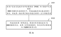
- an embodiment of the present invention provides a method for information transmission, including:
- the terminal device receives a first indication from the network device, where the first indication is used to indicate the first uplink transmission resource of the terminal device, where the terminal device is in a trigger state of a power headroom report (PHR),
- PHR power headroom report
- the uplink transmission resource is used by the terminal device to perform uplink transmission to the network device;
- the terminal device maintains a trigger state of the power headroom report during the first time period, and cancels a trigger state of the power headroom report when the first time period expires.
- the first time period is:
- the The second indication is used to indicate the second uplink transmission resource of the terminal device.
- the fifth duration being a default value, or from the network device.
- the method includes:
- the terminal device When the terminal device is in a trigger state of a buffer status report (BSR), the terminal device receives a first indication from the network device, where the first indication is used to indicate the first uplink transmission resource of the terminal device, where The uplink transmission resource is used by the terminal device to perform uplink transmission to the network device;
- BSR buffer status report
- the terminal device maintains the trigger state of the BSR in the first time period, and cancels the trigger state of the BSR when the first time period expires.
- the first time period is:
- the second indication is the fourth time period at which the BSR is generated based on the second indication, and the second indication is used. Instructing the second uplink transmission resource of the terminal device; or
- the fifth duration being a default value, or from the network device.
- the first time period includes the receiving time of the first indication as described above.
- the generation of the above PHR may include generation of a PHR at a Medium Access Control (MAC) layer, such as generation of a MAC Control Element (CE) including a PHR.
- the generation of the foregoing BSR may include generation of a BSR at a Medium Access Control (MAC) layer, such as generation of a MAC Control Element (CE) including a BSR.
- MAC Medium Access Control
- CE MAC Control Element
- the cancellation of the trigger state of the PHR and/or the BSR is not simply performed when the MAC CE including the PHR and/or the BSR is generated, but is improved at the time of canceling the trigger state of the PHR and/or the BSR.
- the trigger state of the PHR and/or BSR more adaptable to multiple numerology and/or multi-beam scenarios.
- the first time period includes the foregoing time.
- the first time period does not include the foregoing time.
- the fifth duration from the network device may be dynamically configured, such as carrying the fifth duration by using downlink control information, or semi-statically configured, such as by using radio resource control signaling. Carrying the fifth duration.
- the second uplink transmission resource includes a second time domain resource, where the first uplink transmission resource includes a first time domain resource, and the first time domain resource and the second time domain resource may partially overlap, or may be completely different.
- the PHR and/or the BSR may be included in a MAC CE, where the uplink transmission resource may include a time-frequency resource of the MAC CE, and may further include a beam resource.
- the first indication may include the modulation and coding mode, a hybrid automatic repeat request (HARQ) process, configured to indicate whether the MAC CE is a new or a retransmission, and the MAC CE One or more of the redundancy versions, etc.
- HARQ hybrid automatic repeat request
- the first indication or the second indication that is used to indicate the first uplink transmission resource of the terminal device is a message that carries uplink authorization information.
- the message carrying the uplink authorization information may be an uplink authorization message.
- the first indication or the second indication that is used to indicate the first uplink transmission resource of the terminal device is carried in the downlink control information.
- the first indication may be obtained by scrambling a cell temporary identifier.
- the first indication is related to a parameter set, and/or is related to a beam.
- the first indication and/or the second indication is an indication for a new transmission.
- the new biography can also be called the first pass.
- the first time period includes at least one time unit, where the time unit may be a sub-frame, a symbol, a transmission time interval (TTI), and a slot. At least one of them.
- the time unit may be a sub-frame, a symbol, a transmission time interval (TTI), and a slot. At least one of them.
- TTI transmission time interval
- the first indication is that after the terminal device enters a trigger state of the power headroom report, the first received indication corresponding to the longer transmission time interval is used to indicate the uplink transmission resource of the terminal device. .
- the first indication is an indication that the first terminal device receives the uplink transmission resource corresponding to the longer transmission time interval after the terminal device enters the trigger state of the buffer status report.
- the first uplink transmission resource has a first parameter set, where the parameter set is composed of a subcarrier interval, a cyclic prefix length, and a transmission time interval, or the parameter set includes a subcarrier interval and/or a cyclic prefix.
- a length wherein the parameter set may further include a symbol length and/or a time slot length, or the parameter set is composed of a subcarrier interval and/or a cyclic prefix length; and/or,
- the first uplink transmission resource includes a first uplink beam, or a first uplink beam set, and the uplink beam set includes at least one uplink beam.
- the second uplink transmission resource has a second parameter set, where the second parameter set is different from the first parameter set, where the difference is three parameters included in the parameter set: subcarrier spacing
- the cyclic prefix length is different from at least one of the transmission time intervals, or the difference is that the two parameters included in the parameter set are different from at least one of a subcarrier interval and a cyclic prefix length, or the difference is At least one of the parameters included in the set of parameters is different; and/or,
- the second uplink transmission resource includes a second uplink beam, or a second uplink beam set, the uplink beam set includes at least one uplink beam, the second uplink beam is different from the first uplink beam, and the second uplink beam set is The first uplink beam set is different.
- the terminal device enters a trigger state of the power headroom report when the trigger condition is met, where the trigger condition includes any one of the following:
- the first timer expires or has timed out, and the path loss change value of the reference activated serving cell is greater than the first threshold, the first threshold is a default value, or is configured by a radio resource control (RRC) layer.
- RRC radio resource control
- the second timer expires, the second timer is used to periodically trigger the PHR, the duration of the second timer is a default value, or is configured by the RRC layer, and the second timer is for media access control (MAC) entity configuration;
- SCell configured secondary cell
- the first timer expires or has timed out, the uplink transmission of the activated serving cell occurs with a transmission power back-off, and the power back-off value exceeds the second threshold;
- the first timer expires or has timed out, and the path loss of at least one reference service downlink beam of the serving cell exceeds a third threshold, and the third threshold is a default value, or Configured by a network device;
- At least one serving uplink beam of the serving cell is activated, or configured, or increased;
- the first timer expires or has timed out, and at least one serving uplink beam power is used for reference backoff, and the backoff value exceeds a fourth threshold;
- the third timer is timed out, and the third timer is configured to periodically trigger the PHR, and is configured for a beam, where the duration of the third timer is a default value, or is configured by a network device;
- the first timer expires or has timed out, and the path loss of the at least one numerology used for reference exceeds a fifth threshold, the fifth threshold is a default value, or is configured by the network device;
- At least one numerology of the serving cell is activated, or added, or configured;
- the fourth timer expires, the fourth timer is used to periodically trigger the PHR, and for the numerology configuration, the duration of the fourth timer is a default value, or is configured by the network device;
- the first timer expires or has timed out, and at least one of the numerology used for reference has a power backoff, and the backoff value exceeds a sixth threshold, wherein the sixth threshold is a default value, or, It is configured by the network device.
- the serving cell is a cell that establishes an RRC layer connection with the terminal device.
- the trigger status of the power headroom report refers to a state in which the terminal device is allowed to generate a power headroom report.
- the method further includes:
- a power headroom report for indicating, in the first time period, an indication of an uplink transmission resource indicated by an indication of an uplink transmission resource of the terminal device, where the terminal device is used to indicate the terminal device
- the indication of the uplink transmission resource includes the first indication.
- the terminal device may further generate a power headroom report for indicating the uplink transmission resource of the terminal device in the first time period before the expiration of the first time period. After the expiration of the first time period, if the terminal device has not generated a power headroom report for some indication of the uplink transmission resource for indicating the terminal device in the first time period, the terminal device no longer generates the indication for the indication. Power headroom report. That is, the terminal device generates a power headroom report when it is in the power headroom report trigger state.
- the method further includes:
- the indication of the uplink transmission resource includes the first indication.
- the terminal device may further generate a buffer status report for indicating an uplink transmission resource of the terminal device in the first time period before the expiration of the first time period.
- the terminal device After the expiration of the first time period, if the terminal device has not generated a buffer status report for some indication of the uplink transmission resource for indicating the terminal device in the first time period, the terminal device no longer generates a buffer for the indication. status report. That is, the terminal device generates a buffer status report when it is in the buffer status report trigger status.
- the method further includes:
- the terminal device receives a third indication from the network device, where the third indication is used to indicate whether an indication for indicating an uplink transmission resource of the terminal device is used to trigger generation of a power headroom report, where the terminal device receives
- the indication for indicating the uplink transmission resource of the terminal device includes the first indication
- an indication for indicating the uplink transmission resource of the terminal device for generating the power headroom report Generate a power headroom report.
- the method further includes:
- the terminal device receives a fourth indication from the network device, where the fourth indication is used to indicate whether an indication of the uplink transmission resource used to indicate the terminal device is used to trigger generation of a buffer status report, and the terminal device receives
- the indication for indicating the uplink transmission resource of the terminal device includes the first indication
- the terminal device generates a buffer for indicating an indication of the uplink transmission resource of the terminal device according to the fourth indication, according to the fourth indication, in a trigger state of the buffer status report. status report.
- the power headroom report includes power headroom information of the activated serving cell of the terminal device, where the power headroom information of the activated serving cell includes a service uplink beam and/or service of the terminal device. Power headroom information for the parameter set.
- the serving uplink beam is an uplink beam that can be used for data transmission between the network device and the terminal device, and is generally configured by the network device, and the serving uplink beam may also be referred to as an activated uplink beam.
- the terminal device supports five uplink beams, and the network device configures two uplink beams for data transmission between the network device and the terminal device.
- the two uplink beams are used between the network device and the terminal device.
- the uplink beam for data transmission.
- the serviceable parameter set is a set of parameters that can be used for data transmission between the network device and the terminal device, and can generally be configured by a network device, and the service parameter set can also be referred to as an activated parameter set.
- the terminal device supports three parameter sets, and the network device configures two types of parameter sets for data transmission between the network device and the terminal device. The two parameter sets are used between the network device and the terminal device. A collection of parameters for data transfer.
- the calculation of the power headroom information of the service uplink beam and/or the service parameter set is based on an uplink data channel and/or on a time domain resource occupied by the power headroom report when the power headroom report is generated. Or the power of the uplink control channel.
- the uplink data channel and/or the uplink control channel on the time domain resource occupied by the power headroom report when the power headroom report is generated refers to that the user terminal knows when generating the power headroom report.
- the power headroom report includes an uplink beam identifier and/or a parameter set identifier.
- an embodiment of the present invention further provides an information transmission method, including:
- the terminal device determines whether the trigger condition is met
- the terminal device enters a trigger state of the power headroom report when the trigger condition is met;
- the triggering condition includes any one of the following:
- the first timer expires or has timed out, and the path loss of at least one reference service downlink beam of the serving cell exceeds a third threshold, and the third threshold is a default value, or Configured by a network device;
- At least one serving uplink beam of the serving cell is activated, or configured, or increased;
- the first timer expires or has timed out, and at least one serving uplink beam power is used for reference backoff, and the backoff value exceeds a fourth threshold;
- the third timer expires, the third timer is used to periodically trigger the PHR, and is configured for the beam, the duration of the third timer is a default value, or is configured by the network device;
- the first timer expires or has timed out, and the path loss of the at least one numerology used for reference exceeds a fifth threshold, and the fifth threshold is a default value, or is configured by the network device;
- At least one numerology of the serving cell is activated, or added, or configured;
- the fourth timer expires, the fourth timer is used to periodically trigger the PHR, and for the numerology configuration, the duration of the fourth timer is a default value, or is configured by the network device;
- the first timer expires or has timed out, and at least one of the numerology used for reference has a power backoff, and the backoff value exceeds a sixth threshold, wherein the sixth threshold is a default value, or, It is configured by the network device.
- the trigger status of the power headroom report refers to a state in which the terminal device is allowed to generate a power headroom report.
- an embodiment of the present invention further provides an information transmission method, including:
- the terminal device receives a third indication from the network device, where the third indication is used to indicate whether an indication of the uplink transmission resource used to indicate the terminal device is used to trigger generation of a power headroom report;
- the terminal device generates power according to the third indication, according to the third indication, for indicating an uplink transmission resource of the terminal device, which is generated for triggering a power headroom report, in a trigger state of a power headroom report.
- Balance report for indicating an uplink transmission resource of the terminal device, which is generated for triggering a power headroom report, in a trigger state of a power headroom report.
- the terminal device receives a fourth indication from the network device, where the fourth indication is used to indicate whether an indication of the uplink transmission resource used to indicate the terminal device is used to trigger generation of a buffer status report;
- the terminal device generates a buffer status report according to the fourth indication, according to the fourth indication, for generating an indication of an uplink transmission resource of the terminal device, according to the fourth indication, in a trigger state of the buffer status report. .
- the network device sends a third indication to the terminal device, where the third indication is used to indicate whether the indication for indicating the uplink transmission resource of the terminal device is used for triggering generation of a power headroom report;
- the network device sends a fourth indication to the terminal device, where the fourth indication is used to indicate whether the indication for indicating the uplink transmission resource of the terminal device is used to trigger generation of the buffer status report.
- the indication that is used to indicate the uplink transmission resource of the terminal device may be used by default to trigger generation of a power headroom report and/or a buffer status report, where the third indication may be used to indicate the terminal.
- An indication of the uplink transmission resource of the device is not used to trigger the generation of the power headroom report, and the fourth indication may indicate that some indication of the uplink transmission resource used to indicate the terminal device is not used to trigger the generation of the buffer status report.
- the indication that is used to indicate the uplink transmission resource of the terminal device is not used by the default to trigger the generation of the power headroom report and/or the buffer status report, and the third indication may be used to indicate the terminal device.
- Some indication of the uplink transmission resource is used to trigger the generation of the power headroom report, and the fourth indication may indicate that some indication of the uplink transmission resource used to indicate the terminal device is used to trigger the generation of the buffer status report.
- a fourth indication indicating that the uplink transmission resource of the terminal device is used to trigger generation of a buffer status report may be indicated by a fourth indication, and some indication is not used to trigger generation of a buffer status report.
- an embodiment of the present invention further provides an information transmission method, including:
- the terminal device generates the power headroom report based on the indication, where the power headroom report includes power headroom information of the activated serving cell of the terminal device, where the power headroom information of the activated serving cell includes The power headroom information of the serving uplink beam and/or the service parameter set of the terminal device.
- the calculation of the power headroom information of the serving uplink beam and/or the service parameter set is based on an uplink data channel and/or uplink on the time domain resource occupied by the power headroom report when the power headroom report is generated. Control the power of the channel.
- the power headroom report includes an uplink beam identifier and/or a parameter set identifier.
- the method further includes:
- the terminal device sends the power headroom report on the uplink transmission resource.
- first to fourth aspects may be independent of each other, or may be combined with each other according to the methods provided by at least two of the first aspect to the fourth aspect.
- the content involved can also be referred to each other and will not be described here.
- an apparatus including a processor and a memory
- the memory is for storing instructions for executing the memory stored instructions, the apparatus for performing the description as described in the first to fourth aspects when the processor executes the instructions stored by the memory Any of the methods involved in the terminal device.
- the device may further comprise a transceiver.
- the device may be a terminal device or a chip that can be disposed in the terminal device.
- an apparatus including a processor and a memory
- the memory is for storing instructions for executing the memory stored instructions, the apparatus for performing the description as described in the first to fourth aspects when the processor executes the instructions stored by the memory Any of the methods involved in the network device.
- the device may further comprise a transceiver.
- the device may be a network device or a chip that can be disposed in the network device.
- an apparatus for information transmission including a module for implementing any one of the methods involved in the foregoing terminal device.
- the specific modules may correspond to the method steps, and are not described herein.
- the above apparatus includes one or more processors and communication units.
- the one or more processors are configured to support the apparatus to perform the corresponding functions of the terminal device in the above method. For example, during the first time period, the trigger state of the power headroom report is maintained, and when the first time period expires, the trigger state of the power headroom report is cancelled.
- the communication unit is configured to support the device to communicate with other devices to implement receiving and/or transmitting functions. For example, receiving a first indication from a network device.
- the apparatus may further comprise one or more memories for coupling with the processor, which store program instructions and/or data necessary for the device.
- the one or more memories may be integrated with the processor or may be separate from the processor. This application is not limited.
- the device may be a smart terminal or a wearable device or the like, and the communication unit may be a transceiver or a transceiver circuit.
- the transceiver may also be an input/output circuit or an interface.
- the device can also be a communication chip.
- the communication unit may be an input/output circuit or interface of a communication chip.
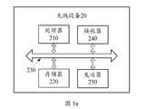
- the above apparatus includes a transceiver, a processor, and a memory.
- the processor is configured to control a transceiver or an input/output circuit for transmitting and receiving signals, the memory for storing a computer program for executing a computer program in the memory, such that the apparatus performs the first aspect, the second aspect, and the third aspect
- the method of the fourth aspect, or the method performed by the terminal device in any one of the possible implementations of any of the first to fourth aspects.
- an apparatus for information transmission including modules for implementing any of the methods involved in the foregoing network device.
- the specific modules may correspond to the method steps, and are not described herein.
- the above apparatus includes one or more processors and communication units.
- the one or more processors are configured to support the apparatus to perform the corresponding functions of the network device in the above method.
- the communication unit is configured to support the device to communicate with other devices to implement receiving and/or transmitting functions. For example, the first indication is sent.
- the apparatus may further comprise one or more memories for coupling with the processor, which store program instructions and/or data necessary for the wireless network device.
- the one or more memories may be integrated with the processor or may be separate from the processor. This application is not limited.
- the device may be a base station, a gNB or a TRP, etc.
- the communication unit may be a transceiver, or a transceiver circuit.
- the transceiver may also be an input/output circuit or an interface.
- the device can also be a communication chip.
- the communication unit may be an input/output circuit or interface of a communication chip.
- the above apparatus includes a transceiver, a processor, and a memory.
- the processor is configured to control a transceiver or an input/output circuit for transmitting and receiving signals, the memory for storing a computer program for executing a computer program in the memory, such that the apparatus performs the first aspect, the second aspect, and the third aspect, A method of network device completion in any one of any of the possible implementations of any of the first to fourth aspects.
- a computer storage medium is provided for storing instructions that, when executed, can perform any of the methods involved in the foregoing terminal device or network device.
- a computer program product for storing a program or an instruction, and when the program or the instruction is executed, any one of the foregoing terminal devices or network devices may be completed.
- the eleventh aspect further provides a communication system, comprising the user equipment provided in the foregoing fifth or seventh aspect, and the network device provided in the sixth aspect or the eighth aspect.
- 3GPP Third Generation Partnership Project
- 3GPP Third Generation Partnership Project
- 3GPP related organization is referred to as a 3GPP organization.
- a wireless communication network is a network that provides wireless communication functions.
- the wireless communication network may adopt different communication technologies, such as code division multiple access (CDMA), wideband code division multiple access (WCDMA), and time division multiple access (time division multiple access).
- TDMA code division multiple access
- FDMA frequency division multiple access
- OFDMA orthogonal frequency-division multiple access
- SC-FDMA single carrier frequency division multiple access
- the network can be classified into 2G (generation) network, 3G network, 4G network, or future evolution network, such as 5G network, according to factors such as capacity, rate, and delay of different networks.
- a typical 2G network includes a global system for mobile communications/general packet radio service (GSM) network or a general packet radio service (GPRS) network.
- GSM general packet radio service
- GPRS general packet radio service
- a typical 3G network includes a universal mobile communication system (universal mobile communication system).
- a typical 4G network includes a long term evolution (LTE) network.
- the UMTS network may also be referred to as a universal terrestrial radio access network (UTRAN).
- the LTE network may also be referred to as an evolved universal terrestrial radio access network (E-).
- E- evolved universal terrestrial radio access network
- UTRAN Universal Terrestriality
- it can be divided into a cellular communication network and a wireless local area network (WLAN), wherein the cellular communication network is dominated by scheduling, and the WLAN is dominant.
- WLAN wireless local area network
- the aforementioned 2G, 3G and 4G networks are all cellular communication networks.
- the cellular communication network is a type of wireless communication network, which adopts a cellular wireless networking mode, and is connected between the terminal device and the network device through a wireless channel, thereby enabling users to communicate with each other during activities. Its main feature is the mobility of the terminal, and it has the function of handoff and automatic roaming across the local network.
- a user equipment is a terminal device, which may be a mobile terminal device or a non-mobile terminal device.
- the device is mainly used to receive or send business data.
- User equipment can be distributed in the network.
- User equipments have different names in different networks, such as: terminals, mobile stations, subscriber units, stations, cellular phones, personal digital assistants, wireless modems, wireless communication devices, handheld devices, knees.
- the user equipment can communicate with one or more core networks via a radio access network (RAN) (access portion of the wireless communication network), such as exchanging voice and/or data with the radio access network.
- RAN radio access network
- a base station (BS) device also referred to as a base station, is a device deployed in a wireless access network to provide wireless communication functions.
- a device that provides a base station function in a 2G network includes a base transceiver station (BTS) and a base station controller (BSC), and the device that provides the base station function in the 3G network includes a Node B (English NodeB) and A radio network controller (RNC), which provides a base station function in a 4G network, includes an evolved NodeB (eNB).
- a device that provides a base station function is an access point.
- AP access point.
- devices providing base station functions include Node B (gNB), TRP (transmission and reception point), or TP (transmission point). point).
- gNB Node B
- TRP transmission and reception point
- TP transmission point
- the TRP or TP may not include the baseband portion, only the radio frequency portion, and may also include the baseband portion and the radio frequency portion.
- a wireless device refers to a device that is located in a wireless communication network and that can communicate wirelessly.
- the device may be a base station, a user equipment, or other network elements.
- a network-side device is a device located on the network side in a wireless communication network, and may be an access network element, such as a base station or a controller (if any), or may be a core network element or other network. yuan.
- NR new radio refers to a new generation of wireless access network technology that can be applied to future evolved networks, such as 5G networks.
- Wireless local area networks refer to local area networks that use radio waves as a data transmission medium.
- the transmission distance is generally only a few tens of meters.
- RRC radio resource control
- the RRC processes the third layer information of the control plane between the UE and the radio access network.
- the RRC processes the third layer information of the control plane between the UE and the radio access network.
- Usually contains at least one of the following features:
- the information provided by the non-access stratum of the broadcast core network is responsible for broadcasting the network system information to the UE.
- System information is usually repeated according to certain basic rules, and RRC is responsible for execution planning, segmentation, and repetition. It also supports the broadcast of upper layer information.
- the RRC is responsible for broadcasting the network system information to the UE.
- System information is usually repeated according to certain basic rules, and RRC is responsible for execution planning, segmentation, and repetition.
- an RRC connection is established by the higher layer of the UE.
- the RRC connection setup procedure includes several steps of reselection of available cells, access grant control, and establishment of a layer 2 signal link.
- the RRC connection release is also requested by the upper layer to tear down the last signal connection; or when the RRC link fails, it is initiated by the RRC layer. If the connection fails, the UE will request to re-establish an RRC connection. If the RRC connection fails, the RRC releases the allocated resources.
- the functionality of the RRC may also change, and the description herein is not limiting.
- a medium access control control element is a kind of control signaling, which is carried in a MAC layer message and can be used to implement effective data transmission.
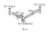
- FIG. 1a is a schematic diagram of service beam path loss changes in a multi-beam scenario
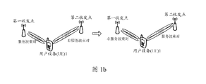
- FIG. 1b is a schematic diagram of service beam switching in a multi-beam scenario
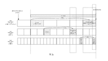
- 2a is a schematic diagram of triggering and generating timing of a PHR in a multi-cell multi-numerology scenario
- 2b is a schematic flowchart of an information transmission method according to an embodiment of the present invention.
- 2c is a schematic diagram of triggering and generating timing of a PHR in a multi-cell multi-numerology scenario
- FIG. 3 is a schematic flowchart of an information transmission method according to an embodiment of the present disclosure
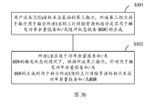
- 3b is a schematic flowchart of an information transmission method according to an embodiment of the present invention.
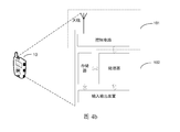
- FIG. 4a is a schematic diagram of an apparatus (such as a user equipment) for information transmission according to an embodiment of the present invention
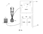
- FIG. 4b is a schematic structural diagram of a user equipment according to an embodiment of the present disclosure.
- 5a is a schematic diagram of another apparatus (such as a wireless network device) for information transmission according to an embodiment of the present invention
- FIG. 5 is a schematic structural diagram of a wireless network device according to an embodiment of the present disclosure.
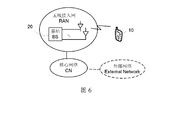
- Figure 6 is a schematic diagram of one possible system network.
- a component can be, but is not limited to being, a process running on a processor, a processor, an object, an executable, a thread in execution, a program, and/or a computer.
- an application running on a computing device and the computing device can be a component.
- One or more components can reside within a process and/or thread of execution, and a component can be located in a computer and/or distributed between two or more computers. Moreover, these components can execute from various computer readable media having various data structures thereon.
- These components may be passed, for example, by having one or more data packets (eg, data from one component that interacts with the local system, another component of the distributed system, and/or signaled through, such as the Internet)
- the network interacts with other systems to communicate in a local and/or remote process.
- the present application may describe various aspects in connection with a wireless network device, where the wireless network device is one type of wireless device, and the wireless device may also be a terminal device.
- the wireless network device may be a base station, the base station may be used to communicate with one or more user equipments, or may be used to communicate with one or more base stations having partial user equipment functions (such as a macro base station and a micro base station, such as Incoming, communication between the two); the wireless device can also be a user equipment, the user equipment can be used for communication (such as D2D communication) of one or more user equipments, and can also be used for communication with one or more base stations.
- partial user equipment functions such as a macro base station and a micro base station, such as Incoming, communication between the two
- the wireless device can also be a user equipment, the user equipment can be used for communication (such as D2D communication) of one or more user equipments, and can also be used for communication with one or more base stations.
- User equipment may also be referred to as user terminals and may include systems, subscriber units, subscriber stations, mobile stations, mobile wireless terminals, mobile devices, nodes, devices, remote stations, remote terminals, terminals, wireless communication devices, wireless communication devices, or Some or all of the features of the user agent.
- User equipment can be cellular phones, cordless phones, Session Initiation Protocol (SIP) phones, smart phones, wireless local loop (WLL) stations, personal digital assistants (PDAs), laptop computers, handheld communication devices, handheld computing Devices, satellite wireless devices, wireless modem cards, and/or other processing devices for communicating over wireless systems.
- SIP Session Initiation Protocol
- WLL wireless local loop
- PDAs personal digital assistants
- laptop computers handheld communication devices
- handheld computing Devices satellite wireless devices
- wireless modem cards wireless modem cards
- a base station may also be referred to as an access point, a node, a Node B, an evolved Node B (eNB), a gNB, a Transceiver Point (TRP), a Transmission Point (TP), or some other network entity, and may include the functions of the above network entities. Some or all of the features.
- the base station can communicate with the wireless terminal over the air interface. This communication can be done by one or more sectors.
- the base station can act as a router between the wireless terminal and the rest of the access network by converting the received air interface frame to an IP packet, wherein the access network includes an Internet Protocol (IP) network.
- IP Internet Protocol
- the base station can also coordinate the management of air interface attributes and can also be a gateway between the wired network and the wireless network.
- the application will present various aspects, embodiments, or features in a system that can include multiple devices, components, modules, and the like. It is to be understood and appreciated that the various systems may include additional devices, components, modules, etc. and/or may not include all of the devices, components, modules, etc. discussed in connection with the figures. In addition, a combination of these schemes can also be used.
- the word "exemplary” is used to mean an example, an illustration, or a description. Any embodiment or design described as “example” in this application should not be construed as preferred or advantageous over other embodiments or designs. Rather, the term use examples is intended to present concepts in a concrete manner.
- Embodiments of the present invention may form the subject of the non-typo as W1, while not emphasize the difference, to express their meaning is the same.
- the network architecture and the service scenario described in the embodiments of the present invention are used to more clearly illustrate the technical solutions of the embodiments of the present invention, and do not constitute a limitation of the technical solutions provided by the embodiments of the present invention.
- the technical solutions provided by the embodiments of the present invention are equally applicable to similar technical problems.
- the embodiment of the present invention can be applied to a time division duplex (TDD) scenario or a frequency division duplex (FDD) scenario.
- TDD time division duplex
- FDD frequency division duplex
- FIG. 6 shows a schematic diagram of a possible system network according to an embodiment of the present invention.
- a radio access network RAN
- the RAN includes at least one base station (BS), and for the sake of clarity, only one base station and one UE are shown.
- the RAN is connected to a core network (CN).
- the CN may be coupled to one or more external networks, such as the Internet, a public switched telephone network (PSTN), and the like.
- PSTN public switched telephone network
- the embodiments of the present invention can be applied to a traditional typical network or to a UE-centric network in the future.
- the UE-centric network introduces a non-cell network architecture, that is, deploys a large number of small stations in a specific area to form a hyper cell, and each station is a transmission point of the Hyper cell ( Transmission Point, TP) or TRP, and connected to a centralized controller.
- TP Transmission Point
- TRP Transmission Point
- the network side device selects a new sub-cluster (sub-cluster) for the UE to serve, thereby avoiding true cell handover and achieving continuity of the UE service.
- the network side device includes a wireless network device.
- the network device is a device with a wireless transceiver function or a chip that can be set on the device, and the device includes but is not limited to: an evolved Node B (eNB), a radio network controller (radio network) Controller, RNC), Node B (NB), base station controller (BSC), base transceiver station (BTS), home base station (for example, home evolved NodeB, or home Node B, HNB), baseband unit (BBU), access point (AP) in wireless fidelity (WIFI) system, wireless relay node, wireless backhaul node, transmission point (transmission and reception) Point, TRP or transmission point, TP), etc., may also be 5G, such as NR, gNB in the system, or transmission point (TRP or TP), one or a group of base stations in a 5G system (including multiple antennas) The panel) or the antenna panel, or a network node constituting a gNB or a transmission point, such as a baseband unit (B
- the gNB may include a centralized unit (CU) and a DU.
- the gNB may also include a radio unit (RU).
- the CU implements some functions of the gNB, and the DU implements some functions of the gNB.
- the CU implements radio resource control (RRC), the function of the packet data convergence protocol (PDCP) layer, and the DU implements the wireless chain.
- RRC radio resource control
- PDCP packet data convergence protocol
- the DU implements the wireless chain.
- the functions of the radio link control (RLC), the media access control (MAC), and the physical (PHY) layer Since the information of the RRC layer eventually becomes information of the PHY layer or is transformed by the information of the PHY layer, high-level signaling, such as RRC layer signaling or PHCP layer signaling, can also be used in this architecture.
- the network device can be a CU node, or a DU node, or a device including a CU node and a DU node.
- the CU may be divided into network devices in the access network RAN, and the CU may be divided into network devices in the core network CN, which is not limited herein.
- different base stations may be base stations with different identifiers, or may be base stations deployed in different geographical locations with the same identifier.
- the base station, or the baseband chip should support the method provided by the embodiment of the present invention before deployment, because the base station does not know whether it will involve the scenario applied by the embodiment of the present invention before the base station is deployed.
- the foregoing base station with different identifiers may be a base station identifier, or may be a cell identifier or other identifier.
- the scenario in the embodiment of the present invention is described by taking the scenario of the NR network in the wireless communication network as an example. It should be noted that the solution in the embodiment of the present invention may also be applied to other wireless communication networks, and the corresponding names may also be used in other scenarios. The name of the corresponding function in the wireless communication network is replaced.
- the method or apparatus in the embodiments of the present invention may be applied between a wireless network device and a user equipment, and may also be applied between a wireless network device and a wireless network device (such as a macro base station and a micro base station), and may also be Between the user equipment and the user equipment (such as a D2D scenario), in all embodiments of the present invention, the communication between the wireless network device and the UE is taken as an example for description.
- PH Power Headroom
- PUSCH physical uplink shared channel
- PH UEAllowedMaxTransPower-PuschPower. It indicates how much transmission power the UE can use in addition to the transmission power used for the current PUSCH transmission. Since the calculation of the PH requires the transmission power of the PUSCH, the power headroom can be calculated only in the transmission time unit of the PUSCH, such as a subframe.
- the meaning of the time unit is a time domain resource whose granularity is the time unit in which the PUSCH is scheduled, where the time unit may be a subframe, a time slot, or a symbol.
- PH radio block
- this reference is based on the algorithm design, or It is determined by the algorithm of each device manufacturer that the PH affects the scheduling of the eNB. For example, if the PH value is negative, the current PUSCH transmission power has exceeded the maximum transmission power allowed by the UE, and the UE may be considered to be reduced in the next scheduling.
- the concept of power headroom report (PHR) is defined accordingly, and the power headroom reporting procedure is defined accordingly.
- the PHR the UE may provide the network device with the difference information between the maximum transmission power of the UE and the estimated transmission power value of the uplink data channel of the activated serving cell, and also provides the maximum UE.
- the difference information between the transmission power and the transmission power estimation value of the uplink data channel and the transmission power estimation value of the uplink control channel where the uplink data channel may include an uplink data channel of at least one of the PCell, the PSCell, and the PUCCH SCell, and the uplink data channel
- the data channel may include an uplink shared channel UL-SCH.
- the value of this power headroom can be sent through the control unit (also called control element, CE, control element) of the media access control (MAC) layer, so the MAC control unit associated with this process is also called As a PHR control unit.
- the serving cell is a cell that can be used to provide radio resources for the connected UE.
- the connected UE has only one serving cell; if the connected UE is configured with carrier aggregation (carrier aggregation) , CA) and/or dual connectivity (DC), the serving cell is at least one cell, including the primary cell and all secondary cells SCell.
- the primary cell (PCell) is a primary frequency, and the UE may perform an initial connection establishment procedure or initiate a connection re-establishment process, or a cell indicated as a primary cell in the handover process.
- a secondary cell (SCell) which is a cell operating at a secondary frequency, provides additional radio resources for the connected UE.
- the activated serving cell is a serving cell available for data transmission.
- the primary secondary cell (PSCell) is a cell that can initiate random access when the secondary cell of the secondary base station changes.
- the PUCCH SCell is an SCell configured with a PUCCH.
- the serving cell may support at least one numerology.
- the serving cell may further include at least one beam.
- the serving cell may include multiple beams.
- a beam can be understood as a spatial resource, and can refer to a transmitting or receiving precoding vector having energy transmission directivity.
- the transmitting or receiving precoding vector can be identified by index information.
- the energy transmission directivity may refer to precoding processing of a signal to be transmitted by using the precoding vector, and the signal processed by the precoding has a certain spatial directivity, and the precoding is performed by the precoding vector.
- the received signal has better received power, such as meeting the received demodulation signal to noise ratio, etc.; the energy transmission directivity may also mean that the same signal transmitted from different spatial locations is received by the precoding vector to have different received power.
- the same communication device may have different precoding vectors, and different devices may also have different precoding vectors, that is, corresponding to different beams.
- one communication device can use one or more of a plurality of different precoding vectors at the same time, that is, one beam or multiple beams can be formed at the same time.
- the beam information may be identified by the index information.
- the index information may correspond to a resource identifier (ID) of the UE.
- the index information may correspond to a configured channel state information reference signal (Channel status information Reference).
- the ID or resource of the Signal, CSI-RS may also be the ID or resource of the corresponding uplink sounding reference signal (SRS).
- the index information may also be index information that is displayed or implicitly carried by a beam-bearing signal or channel.
- the index information includes, but is not limited to, a synchronization signal sent by a beam or a broadcast channel indicating the Index information of the beam.
- the beam pair may include a transmit beam (Tx beam) at the transmitting end and a receive beam (Rx beam) at the receiving end, or may also be referred to as an uplink beam or a downlink beam.
- the beam pair may include a gNB Tx beam transmission beam or a UE Rx beam reception beam, or a UE Tx beam transmission beam or a gNB Rx beam reception beam, where the transmission beam may also be understood as a transmission beam.
- the reporting conditions of the PHR may include:
- a UL grant allocated by the base station where the UL grant is used to allocate an uplink transmission resource, including a physical resource block, a modulation and coding scheme, one or more of a new data indication (NDI), and optionally, a HARQ process ID. , redundancy version and other content.
- NDI new data indication
- HARQ process ID redundancy version and other content.
- a possible situation is: when the UE enters the trigger state of the PHR and is in the trigger state of the PHR, the UL grant is used to allocate the uplink transmission resource of the serving cell as long as the UL grant sent by the base station is received.
- the UE may generate a PHR MAC CE according to the UL grant, and send the PHR MAC CE to the base station according to the UL grant.
- the reporting conditions of the PHR may include:
- a UL grant allocated by the base station where the UL grant is used to allocate an uplink transmission resource, including a physical resource block, a modulation and coding scheme, one or more of a new data indication (NDI), and optionally, a HARQ process ID. , redundancy version, etc.;
- NDI new data indication
- the UL grant is used to trigger the generation of the PHR.
- a possible situation is that the UE receives the UL grant sent by the base station after the UE enters the trigger state of the PHR and is in the trigger state of the PHR, and the UL grant is used to allocate the uplink transmission resource of the serving cell.
- the UE determines that the UL grant is used to trigger the generation of the PHR, and the UE may generate a PHR MAC CE according to the UL grant, and send the PHR MAC CE to the base station according to the UL grant. If the UE determines that the UL grant is not used to trigger the generation of the PHR, the PHR is not generated for the UL grant.
- the embodiment of the present invention also provides a related design of a buffer status report (BSR) in a multi-numerology and/or multi-beam scenario.
- BSR buffer status report
- the BSR is used to report how much data is waiting for transmission in the current uplink buffer of the UE.
- the base station allocates uplink transmission resources according to the BSR reported by the UE.
- the UE may establish multiple radio bearers. Each radio bearer corresponds to one logical channel. If the UE reports a BSR for each logical channel, it will bring a lot of signaling overhead.
- LTE introduces the concept of logical channel group (LCG) (four in total) and puts each logical channel into one LCG. Instead of reporting a BSR for each logical channel, the UE reports the BSR based on the LCG.
- LCG logical channel group
- the logical channels are grouped in order to provide a better BSR reporting mechanism. Logical channels with similar scheduling requirements are placed in the same LCG, and their data buffer status is reported through the short BSR.
- the triggering mode of the BSR may include at least one of the following situations:
- the uplink data buffer of the UE is empty and new data arrives.
- the UE will trigger the BSR to report. For example, the UE sends uplink data for the first time. This BSR is called "Regular BSR";
- Padding resource utilization When the UE has uplink resources and finds that the data to be sent is insufficient to fill the resource, the extra bits are used to fill the Padding. These resources can be used to pass BSR these useful data.
- the retxBSR-Timer timer expires, and the data of any one of the LCGs of the UE can be sent.
- the retxBSR-Timer timer is used to trigger the BSR once the UE sends the BSR MAC CE but does not receive the scheduling resource within the timer time.
- the following is a cancellation of the trigger state of the PHR and/or the BSR, the generation of the PHR in the multi-numerology and/or the multi-beam scenario, the triggering condition of the trigger state of the UE entering the PHR in the multi-numerology and/or multi-beam scenario, and the above PHR and/or Or the BSR reporting conditions and the like are specifically described. It can be understood that one or more of these aspects may be independently applied to the communication system, or may be applied to the communication system in combination with each other.
- the trigger status of the UE entering the PHR is as follows:
- a Power Headroom Report shall be triggered if any of the following events occur:
- -prohibitPHR-Timer expires or has expired and the path loss has changed more than dl-PathlossChange dB for at least one activated Serving Cell of any MAC entity which is used as a pathloss reference since the last transmission of a PHR in this MAC entity when The MAC entity has UL resources for new transmission;
- the trigger condition for the UE to enter the trigger state of the PHR (ie, the condition for triggering the PHR) is:
- the terminal device enters a trigger state of the power headroom report when the trigger condition is met, and the trigger condition includes any one of the following:
- the first timer expires or has timed out, and the path loss change value of the reference activated serving cell is greater than the first threshold, the first threshold is a default value, or is determined by a radio resource control (RRC) layer.
- RRC radio resource control
- the second timer expires, the second timer is used to periodically trigger the PHR, the duration of the second timer is a default value, or is configured by the RRC layer, and the second timer is for media access control (MAC) entity configuration;
- SCell configured secondary cell
- the first timer expires or has timed out, the uplink transmission of the activated serving cell occurs with a transmission power back-off, and the power back-off value exceeds the second threshold;
- the primary cell in the primary scenario or the dual-connected primary base station in the CA scenario may be referred to as a PCell, and the secondary cell of the dual-connected secondary base station is referred to as a PSCell, the secondary cell in the CA scenario, and the primary base station in the dual connectivity.
- the secondary cell may be referred to as an SCell.
- the above trigger condition can be used as a baseline for triggering the PHR.
- the base station and the UE can support operation of multiple beams in one cell, for example, the UE can communicate with the base station through multiple beam pairs in one cell. .
- a possible scenario with beamforming is a scenario of a high frequency cell.
- a high frequency cell can be understood as a working frequency band of the cell greater than or equal to 6 GHz.
- the path loss is large.
- the high-frequency cell will introduce beamforming technology, which does not need to be distributed in all directions, but concentrates on one of the required ones.
- the direction/beam forms a narrow beam aligned with the UE, and the transmission energy is directed to the target UE, thereby improving the demodulation signal-to-noise ratio of the target UE and improving the cell edge user experience.
- the UE and the base station may be in the same time unit and may perform data transmission in at least one beam pair.
- the so-called beam pair such as gNB Tx beam and UE Rx beam, UE Tx beam and gNB Rx beam.
- the UE may maintain a connection of multiple downlink and/or uplink service beam pairs of one cell with at least one TRP.
- the service beam pair provides a beam pair of radio resources for the connected or activated UE.
- the UE in the connected state is a UE that maintains an RRC connection between the UE and the access network device and a connection between the access network device and the core network device.
- the UE in the active state is a UE that maintains the connection between the access network device and the core network device, and has no RRC connection between the UE and the access network device.
- the idle state UE is a UE that has no connection between the access network device and the core network device and an RRC connection between the UE and the access network device.
- At least one TRP may be located in different geographic locations to expand coverage of the cell. Therefore, in some scenarios, the channel conditions of the service downlink beam pair connection between different TRPs and UEs may be independent, then when the UE moves to a new location, it is possible that the channel quality of some service beam pairs, For example, the path loss is reduced due to some temporary blocking, such as the blockage of the tree, while at the same time, the channel quality of some other service beams is still good.
- the service beam or the service beam pair is a beam or beam pair that can provide a radio resource for the UE in the connected state or the UE in the active state, and the service beam includes the serving uplink beam and/or the serving downlink beam.
- a service beam pair can be understood as a service beam. As shown in the example shown in Figure 1a, the service downlink beam connection of TRP1 is blocked, while the service downlink beam connection of TRP2 is still good. Since the path loss measurement for uplink power control can be based on at least one of the downlink reference signals used for beam measurement, and the support of beam specific power control, it is very important to report the beam pair connection related information, One of the information may be power headroom information.
- the base station can consider the beam-related path loss as early as possible when selecting an appropriate scheduling policy to achieve effective utilization of the beam-specific resources.
- the UE may trigger the PHR when the beam-dependent path loss change of the connected at least one serving beam pair of the activated serving cell exceeds the third threshold, ie enter the trigger state of the PHR.
- This third threshold can be configured by the network side in consideration of the flexibility of the base station.
- the PHR can be triggered when the SCell with the configured uplink transmission is activated, so that the base station can consider the PHR as early as possible for subsequent scheduling.
- the NR cell with beam operation supports beam management, and the available service beam pairs may change due to the UE's movement, as shown in Figure Ib. Therefore, in some scenarios, if at least one new service beam pair is configured during the beam management process, for example, in the scenario of FIG. 1b, the service beam pair is switched from between the UE and the TRP1 to between the UE and the TRP2, If the UE triggers the PHR, it will facilitate the scheduling of the base station.
- the embodiment of the present invention provides that the triggering condition may include any one of the following in addition to the triggering conditions in the foregoing LTE.
- the PHR may be triggered, that is, the UE is allowed to enter. Trigger status of PHR:
- the first timer expires or has timed out, and the path loss of at least one reference service downlink beam of the serving cell exceeds a third threshold, and the third threshold is a default value, or Configured by a network device;
- At least one serving uplink beam of the serving cell is activated, or configured, or increased;
- the first timer expires or has timed out, the at least one serving uplink beam power is used for reference backoff, and the backoff value exceeds a fourth threshold, wherein the third threshold is a default value, Or, is configured by a network device;
- the third timer expires.
- the third timer is used to periodically trigger the PHR, and is configured for the beam.
- the duration of the third timer is a default value, or is configured by the network device.
- a cell in the NR can support multiple numerologies, and the UE can also support multiple cells.
- the scheduling of the UE by the base station is related to the numerology for transmission.
- the channel quality of different numerologies of a cell may also be different.
- the channel quality corresponding to the numerology may be considered.
- the triggering condition may include any one of the following in addition to the triggering conditions in the LTE.
- the first timer expires or has timed out, and the path loss of the at least one numerology used for reference exceeds the fifth threshold, and the fifth threshold is a default value, or is configured by the network device;
- At least one numerology of the serving cell is activated, or added, or configured;
- the fourth timer expires, the fourth timer is used to periodically trigger the PHR, and for the numerology configuration, the duration of the fourth timer is a default value, or is configured by the network device;
- the first timer expires or has timed out, and at least one of the numerology used for reference has a power backoff, and the backoff value exceeds a sixth threshold, wherein the sixth threshold is a default value, or, It is configured by the network device.
- the communication between the base station and the UE may also have multiple serving cells, multiple beams, and multiple numerology scenarios, the above triggering conditions for multiple serving cells (as described in LTE above), multi-beam
- the trigger condition, the trigger condition of multiple numerology can be used as the trigger condition for the UE to enter the trigger state of the PHR.
- the UL Grant can be received on the activated serving cell, all the numerologies (if there are multiple), and all the beams (if any). Generate a PHR.
- the UE may also be received on certain eligible serving cells or numerology or beam according to a certain rule or an indication from the base station.
- the UL Grant generates or constructs a PHR.
- the trigger status is a MAC entity level, not a cell level, or a beam or numerology level. It can be understood that when the UE enters the trigger state of the PHR, the UL grant of the serving cell under the MAC entity is received and the UL grant can be used to trigger the generation of the PHR, which can be used to trigger the generation of the PHR, where the service
- the UL grant of the cell can also be used to indicate the uplink radio resource of the beam or the radio resource of the numerology. If the UE is configured with a DC, the UE can maintain two MAC entities.
- the UE may report the PHs of all the activated serving cells to the base station through the PHR.
- the PH reports different types of PHs according to whether the UE supports or configures an uplink control channel, such as a physical uplink control channel (PUCCH), and an uplink data channel, such as a physical uplink data channel (PUSCH). If the simultaneous transmission is supported or configured, the PH of type 2 (type 2) is reported. If the simultaneous transmission is not supported or not configured, the type 1PH is reported.
- the UE When the UE generates the PHR, if there is no scheduling resource on a certain cell, the UE reports a virtual type1 or type2PH.
- the real type1 or type2PH is reported. .
- a PHR such as a PHR MAC CE
- the trigger state of the PHR is cancelled.
- the physical layer of the UE calculates the PH and delivers the calculated PH to the MAC layer of the UE.
- the MAC layer of the UE completes the generation or construction of the PHR based on the delivered PH.
- the UE cancels the triggering state of the PHR, which may cause the PH value included in the reported PHR to be unresponsive to the uplink channel resources.
- the base station cannot obtain a more accurate PH for scheduling, which in turn affects the reliability of the communication.
- the UE cancels the triggering state of the BSR once the BSR is generated, which may cause the BS value included in the reported BSR to fail to reflect the UE.
- the real situation of the data cache makes it impossible for the base station to obtain a more accurate BS for scheduling, thereby causing waste of radio resources.
- ⁇ uses numerology1 and 2
- Cell2 uses numerology3
- UL grant1 is delivered by Cell1's numerology1.
- the UL grant2 is delivered by the numerology2 of Cell1
- the UL grant3 is delivered by the numerology3 of Cell2.
- the numerology 1, 2 and 3 have different TTIs, of which the longest of numerology1 and the shortest of numerology3.
- the time domain resources of the uplink transmission scheduled by the UL grant3 and the time domain resources of the uplink transmission scheduled by the UL grant1 partially overlap.
- the base station cannot know the real PH on the uplink transmission time domain resource, affecting its scheduling. Reliability.
- an embodiment of the present invention provides a method for information transmission, including:
- the UE receives a first indication from a base station, where the first indication is used to indicate a first uplink transmission resource of the UE, where the UE is in a trigger state of a power headroom report (PHR).
- the uplink transmission resource is used by the UE to perform uplink transmission to the base station;
- the first indication is that after the UE enters the trigger state of the PHR, the first received indication for indicating the uplink transmission resource or the first uplink transmission resource according to the chronological order, the first one
- the uplink transmission resources may be pre-allocated by the base station, such as semi-statically scheduled resources or contention-based uplink resources.
- S102 The UE maintains a trigger state of the power headroom report in the first time period, and cancels a trigger state of the power headroom report when the first time period expires.
- the trigger state of the PHR is not cancelled, so that the UE can continue to generate a PHR, such as a PHR MAC CE.
- the TTI length of the first uplink transmission resource is the first TTI length
- the trigger state of the PHR is not canceled in the first time period
- the TTI of the other uplink transmission resource is used when the UE has other uplink transmission resources.
- the length is less than the first TTI length, and the UE can continue to generate the PHR.
- the PHR is generated in the embodiment of the present invention. It can also be understood that the PHR is configured to generate the PHR MAC CE including the PHR as an example, but is not limited to the MAC CE, and the PHR may also be included in the MAC CE. In addition to other signaling.
- the first time period is:
- the The second indication is used to indicate the second uplink transmission resource of the UE;
- a fifth time period having a fifth duration Starting with the receiving time of the first indication, a fifth time period having a fifth duration, the fifth duration being a default value, or from the base station.
- the embodiment of the present invention provides a method for information transmission, including:
- the UE in a case that the UE is in a trigger state of the BSR, the UE receives a first indication from the base station, where the first indication is used to indicate a first uplink transmission resource of the UE, and the uplink transmission resource is used.
- the UE performs uplink transmission to the base station;
- the first indication is an indication that is first received to indicate an uplink transmission resource after the UE enters a trigger state of the BSR.
- the UE maintains the trigger state of the BSR in the first time period, and cancels the trigger state of the BSR when the first time period expires.
- the triggered BSR is not cancelled, so that the UE can continue to generate a BSR, such as a BSR MAC CE.
- the BSR is generated in the embodiment of the present invention to generate a BSR MAC CE including a BSR.
- the BSR is not limited to the MAC CE, and the BSR may also be included in other signalings than the MAC CE.
- the first time period is:
- the second indication is the fourth time period at which the BSR is generated based on the second indication, and the second indication is used. Instructing the second uplink transmission resource of the UE; or
- a fifth time period having a fifth duration Starting with the receiving time of the first indication, a fifth time period having a fifth duration, the fifth duration being a default value, or from the base station.
- the first time period includes the receiving time of the first indication as described above.
- the generation or configuration of the above PHR may include generation of a PHR at a Medium Access Control (MAC) layer, such as generation of a MAC Control Element (CE) including a PHR.
- the generation of the above BSR may include generation of a BSR at a Medium Access Control (MAC) layer, such as generation of a MAC Control Element (CE) including a BSR.
- MAC Medium Access Control
- CE MAC Control Element
- the cancellation of the trigger state of the PHR is not simply performed when the MAC CE including the PHR is generated, but is improved at the time of canceling the trigger state of the PHR, so that the trigger state of the PHR is more suitable for the scenario of multiple numerology. It can also improve the accuracy of the PH reported in the multi-numerology scenario, further improve the accuracy of the base station scheduling, and improve the reliability of the communication.
- the foregoing may ensure the correct reception of the PHR by receiving the third time period from the base station for the time when the response signal indicating that the data is successfully received for the data sent by the first uplink transmission resource. To further improve the reliability of communication.
- the power consumption margin of the UE may be more accurately known based on the fourth time period in which the generation time of the power headroom report is based on the second indication.
- it can be applied to a high frequency cell (HF cell) scenario.
- HF cell high frequency cell
- the TTI of the HF cell is generally short, but the amount of data to be transmitted is large, so the scheduling of the HR cell by the PHR is important.
- the first time period includes the foregoing time.
- the first time period does not include the foregoing time.
- the fifth duration is from a manner that the base station may be dynamically configured, for example, carrying the fifth duration by using downlink control information, or may be semi-statically configured, for example, by using radio resource control signaling.
- the fifth time period is from a manner that the base station may be dynamically configured, for example, carrying the fifth duration by using downlink control information, or may be semi-statically configured, for example, by using radio resource control signaling.
- the uplink transmission resource includes a time-frequency resource, and at least one of: a modulation and coding scheme, a HARQ process, indicating whether a new transmission or a retransmission, or a redundancy version.
- the UE has triggered at least one PHR and/or BSR (ie, at least one of the trigger conditions is met) before receiving the first indication, and the at least one PHR and/or the BSR are not cancelled by the UE.
- the first indication may be uplink grant information (UL Grant).
- the first indication may be that the UE first receives the triggering condition after receiving the triggering time (if multiple UL grants are received at the same time, then any one of the UL grants) indicates the newly transmitted.
- An indication for indicating an uplink transmission resource such as a UL grant, with a longer TTI.
- the second uplink transmission resource includes a second time domain resource, where the first uplink transmission resource includes a first time domain resource, and the first time domain resource and the second time domain resource may partially overlap, or may be completely different.
- the power headroom report may be included in a MAC CE, where the uplink transmission resource may include a time-frequency resource of the MAC CE, and may further include a beam resource.
- the buffer status report may be included in a MAC CE, where the uplink transmission resource may include a time-frequency resource of the MAC CE, and may further include a beam resource.
- the first indication may include the modulation and coding mode, and the HARQ process is used to indicate that the MAC CE is one or more of a new transmission or a retransmission, a redundancy version of the MAC CE, and the like.
- the first indication or the second indication that is used to indicate the first uplink transmission resource of the UE is a message that carries uplink authorization information.
- the message carrying the uplink authorization information may be an uplink authorization message.
- the first indication or the second indication used to indicate the first uplink transmission resource of the UE is carried in the downlink control information.
- the first indication may be obtained by scrambling a cell temporary identifier.
- the first indication is related to a parameter set, and/or is related to a beam.
- the first indication and/or the second indication is an indication for a new transmission.
- the new biography can also be called the first pass.
- the first time period includes at least one time unit, where the time unit may be a sub-frame, a symbol, a transmission time interval (TTI), and a slot. At least one of them.
- the time unit may be a sub-frame, a symbol, a transmission time interval (TTI), and a slot. At least one of them.
- TTI transmission time interval
- the first indication is an indication that the first uplink information corresponding to the longer transmission time interval is used to indicate the uplink transmission resource of the UE after the UE enters a trigger state of the power headroom report.
- the first indication is an indication of the uplink transmission resource that is first received to indicate the UE, corresponding to a longer transmission time interval, after the UE enters a trigger state of the buffer status report.
- the first uplink transmission resource has a first parameter set, where the parameter set is composed of a subcarrier interval, a cyclic prefix length, and a transmission time interval; and/or,
- the first uplink transmission resource includes a first uplink beam, or a first uplink beam set, and the uplink beam set includes at least one uplink beam.
- the second uplink transmission resource has a second parameter set, where the second parameter set is different from the first parameter set, where the difference is three parameters included in the parameter set: subcarrier spacing , the cyclic prefix length, and at least one of the transmission time intervals are different; and/or,
- the second uplink transmission resource includes a second uplink beam, or a second uplink beam set, the uplink beam set includes at least one uplink beam, the second uplink beam is different from the first uplink beam, and the second uplink beam set is The first uplink beam set is different.
- the trigger state of the PHR can also be understood as the triggered PHR.
- the first PHR such as the first PHR MAC CE
- the first PHR MAC CE is generated or constructed according to the first indication and the trigger state of the UE in the PHR. And transmitting, according to the first indication, the first PHR MAC CE to the base station in the time-frequency resource included in the first uplink transmission resource indicated by the first indication.
- the UE starts or restarts a PHR period timer, such as at least one of a second timer, a third timer, a fourth timer, and/or the foregoing first timing, when the time unit corresponding to the first PHR MAC CE is sent.
- a PHR period timer such as at least one of a second timer, a third timer, a fourth timer, and/or the foregoing first timing
- the UE receives the at least one UL grant sent by the base station (in the embodiment of the present invention, the indication used to indicate the uplink transmission resource becomes a UL grant), the at least one UL The grants all indicate a new transmission; if the uplink transmission resource indicated by the at least one UL grant (mainly refers to a time domain resource location) is located in the first time period, the UE generates at least one according to the at least one UL grant.
- the PHR and/or the BSR MAC CE may also be understood that each of the at least one UL grant generates a PHR and/or a BSR MAC CE and sends the PHR and/or the BSR MAC CE to the base station. These PHRs and/or BSR MAC CEs are not sent together and are sent separately. The time domain locations they send can be completely different or partially overlapped.
- the UE may select one of the multiple UL grants according to the UL grant, and according to The selected UL grant, and the UE is in a trigger state of the PHR and/or the BSR, generates a PHR and/or a BSR MAC CE, and sends a PHR and/or a BSR MAC CE to the base station, and the PHR and/or the BSR MAC CE may pass
- the uplink transmission resource indicated by one of the plurality of UL grants is sent, and the UL grant may be specifically selected by the base station, or the terminal device may be arbitrarily implemented, and may also be understood as if multiple UL grants are used.
- the terminal device If the time domain resources of the indicated uplink transmission resources are the same or the time for receiving the multiple UL grants is the same, the terminal device generates only one PHR and/or BSR MAC CE for the multiple UL grants, so as to save the overhead of the radio resources.
- the at least one UL grant includes a UL grant of at least one wireless air interface, and the at least one UL grant is used to indicate an uplink resource of at least one wireless air interface of the at least one serving cell.
- the wireless air interface which may also be referred to as a numerology, may be understood as a parameter set of at least one of a subcarrier spacing, a cyclic prefix CP length, and a TTI length.
- the subcarrier spacing is 15 kHz*2 n , where n is an integer.
- one serving cell can support at least one numerology.
- the first indication is used to indicate an uplink transmission of a longer TTI
- the UL grant of the at least one UL grant except the first indication may indicate an uplink transmission of a shorter TTI.
- the first indication is used to indicate that the TTI length of the uplink transmission is 1 ms
- the at least one UL grant is used to indicate that the TTI length of the uplink transmission is at least one of 0.1 ms/0.5 ms/0.2 ms.
- a second timer is further introduced in the UE, where the second timer is used to control whether a UL grant (indicating a new transmission) of at least one numerology can generate a PHR and/or a BSR MAC CE, and may also be understood as a UE.
- Different second timers may be required for different numerologies, and the durations of the second timers of different numerologies may be the same or different.
- the duration of the timer may be configured by the base station, or a value pre-defined by the protocol (ie, a default value).
- the PHR and/or the BSR MAC CE are not generated; if the second timer is not in operation, The PHR is triggered and not cancelled, and the terminal device receives the UL grant of the at least one numerology, and the PHR and/or the BSR MAC CE are generated.
- the UE After the UE generates a PHR and/or BSR MAC CE, such as a time unit transmitting the PHR and/or the BSR MAC CE, a corresponding second timer is started.
- the UE may also start or restart a periodic timer, such as one or more of a second timer, a third timer, and a fourth timer, and/or, Prohibit a timer, such as a first timer.
- a periodic timer such as one or more of a second timer, a third timer, and a fourth timer, and/or, Prohibit a timer, such as a first timer.
- the first time period may be controlled by a timer.
- the UE After receiving the first indication, the UE starts a timer with a duration of a first time period, and when the first timer expires or after, cancels the PHR and / or the trigger status of the BSR.
- the duration of the timer may be indicated by the base station, or may be calculated in advance according to the foregoing pre-specified conditions according to the protocol, such as the foregoing cancellation of the PHR trigger state.
- the counting unit of the first timer may be at least one of a subframe, a symbol, a TTI, and a time slot.
- the above method is specifically described by taking PHR combined with multi-numerology and multi-cell scenarios as an example.
- Cell1, Cell2, and Cell3 are configured with different numerology
- Cell1 uses numerology1
- Cell2 uses numerology2
- Cell3 uses numerology3
- UL grant1 is delivered by Cell1's numerology1
- UL grant2 is delivered by Cell2's numerology2.
- UL grant3 is issued through Cell3's numerology3.
- the numerology 1, 2 and 3 have different TTIs, of which the longest of numerology1 and the shortest of numerology3.
- the time domain resources of the uplink transmission scheduled by the UL grant 3 and the time domain resources of the uplink transmission scheduled by the UL grant 1 overlap.
- the order in which the UE receives these UL grants is UL grant1, UL grant2, and UL grant3.
- These UL grants are all instructions for new transmissions.
- the UE receives the UL grant1 sent by the base station, and determines the first time period. Since the uplink resource allocated by the UL grant 1/2/3 is located in the range of the first time period, the terminal device can generate three PHR MAC CEs, that is, one PHR MAC CE is generated for each UL grant, and the base station is generated. Send these 3 PHR MAC CEs.
- the PH included in the PHR is the PH value of all activated serving cells on the uplink transmission time domain resource scheduled by the UL grant corresponding to the PHR, and one cell is configured with multiple numerologies.
- multi-beam which PHs are included in the PHR, and based on what is calculated, this is an urgent problem to be solved.
- an embodiment of the present invention provides a method for information transmission, including:
- the UE receives an indication from a base station, where the indication is used to indicate an uplink transmission resource of the UE, where the uplink transmission resource is used by the UE to the base station, in a trigger state of a power headroom report. Perform uplink transmission;
- the UE generates the power headroom report according to the indication, where the power headroom report includes power headroom information of an activated serving cell of the UE, where the power headroom information of the activated serving cell includes Power headroom information of the serving uplink beam and/or service parameter set of the UE.
- the calculation of the power headroom information of the serving uplink beam and/or the service parameter set is based on an uplink data channel and/or uplink on the time domain resource occupied by the power headroom report when the power headroom report is generated. Control the power of the channel.
- the power headroom report includes a cell index.
- the power headroom report includes an uplink beam identifier and/or a parameter set identifier.
- the method further includes:
- the UE sends the power headroom report on the uplink transmission resource.
- the trigger status of the power headroom report refers to a state in which the UE is allowed to generate a power headroom report.
- the service uplink beam is an uplink beam that can be used for data transmission between the base station and the UE. It can also be understood that the uplink beam of the radio resource can be provided for the UE, which is generally configured by the base station, and the service uplink beam can also be called Activated upstream beam.
- the UE supports five uplink beams, and the base station configures two of the uplink beams for data transmission between the base station and the UE.
- the two uplink beams are uplink beams used for data transmission between the base station and the UE. .
- the set of service parameters is a set of parameters that can be used for data transmission between the base station and the UE.
- the parameter set of the radio resources can be provided to the UE, which can be generally configured by the base station, and the service parameter set can also be referred to as an activated parameter. set.
- the UE supports three parameter sets, and the base station configures two of the parameter sets for data transmission between the base station and the UE.
- the two parameter sets are parameter sets for data transmission between the base station and the UE. .
- the UE may generate the first MAC CE according to the first indication and the trigger state of the UE in the PHR.
- the first indication indicates a time-frequency resource location, where the time domain resource is located in the first cell.
- the terminal device performs the process of generating or constructing a MAC PDU according to the first indication, such as a logical channel priority (LCP)
- LCP logical channel priority
- the time unit of the time domain resource indicated by the first indication is determined to correspond to another activated serving cell or Service numerology or service beam (beam), with uplink data (such as uplink data channel and / or uplink control channel) transmission, then these other activated service cells or service numerology or service beam (beam) report real type1PH or
- the type 2PH specifically, the physical layer of the UE calculates the PH of the real, and submits it to the MAC layer of the UE, so that the MAC layer of the UE generates or constructs the first MAC CE in time; if it determines the time domain resource indicated
- the UE receives at least one UL grant, and the uplink time domain resource location indicated by the at least one first indication is located in the first time period.
- the at least one first indication may be received at a different time.
- the UE can process the UL grants in order from the first to the last according to the order of receiving time, and generate corresponding PHRs.
- the calculation principle of PH in each PHR can be as described above.
- the length of the TTI corresponding to the first air interface is the first TTI
- the length of the TTI corresponding to the second air interface is the second TTI
- the length of the TTI corresponding to the third air interface is the third TTI.
- the TTI length length sequence is assumed as follows: first TTI>second TTI>third TTI.
- the UL grant receiving time sequence is: UL grant1, UL grant2, and UL grant3.
- the UL grant processing order of the UE is also: UL grant1, UL grant2, and UL grant3.
- the UE When the UE is processing the UL grant1, it is not known that the UL grant3 is received, and the time domain resources of the uplink transmission resources indicated by the UL grants 1 and 3 have overlapping regions. At this time, the UE generates the PHR according to the UL grant1.
- the PH of Cell1 or numerology1 is real PH
- the PH of Cell3 or numerology3 is virtual PH
- Cell 2 or numerology 2 has no uplink transmission due to the time domain location of the uplink transmission resource indicated by UL grant1, then Cell 2 Or the pH of the numerology 2 is virtual PH.
- the UE does not receive the UL grant3 when processing the UL grant2, the UE calculates the PH of Cell 1 and 3, or the numerology 1 and 3 as the virtual PH, and calculates the PH of Cell 2 or numerology 2 before generating the PHRMAC CE according to the UL grant 2.
- the PH of Cell 1 or numerology1 is real PH
- the PH of Cell3 or numerology3 is virtual PH
- Cell 2 or numerology 2 has no uplink transmission due to the time domain location of the uplink transmission resource indicated by UL grant1
- Cell 2 or numerology 2 is virtual PH.
- the UE calculates the PH of Cell 1 and 3, or the numerology 1 and 3 as the virtual PH
- the UE When processing the UL grant3, the UE knows that the uplink transmission time domain resources of the uplink resource domain UL grant1 of the uplink grant of the UL grant3 overlap in advance, and calculates the Cell 1 and 3 or the numerology 1 according to the PHRMAC CE generated according to the UL grant 3.
- the PH of 3 is real PH. Since Cell2 is not scheduled at this time, the PH of Cell 2 or numerology 2 is calculated as vitual PH.
- the PH included in one PHR cannot effectively correspond to the numerology and/or beam on the base station side, which is disadvantageous for the base station side to learn each numerology and/or Or the PH of the beam.
- the base station may configure a beam identifier for the UE in advance, such as a beam index and a cell identifier, such as a cell index, and associate a specific UL beam with a beam index, or ULbeam. And DL beam, or UL beam, associate a specific Cell with a cell index. Then, when the UE reports the PH, it can carry the corresponding beam index and cell index, and then the base station can know which PH of the cell is the PH in the PHR through the beam index and the cell index.
- a beam identifier for the UE in advance, such as a beam index and a cell identifier, such as a cell index
- DL beam, or UL beam associate a specific Cell with a cell index.
- the UE when the UE generates or constructs a PHR MAC CE according to the first indication sent by the base station and the trigger state of the UE in the PHR, and the UE reports the PHR MAC CE, the UE needs to calculate and report at least the activated serving cell of the UE.
- a TRP transmitting and receiving point
- a cell may include at least one TRP, and the UE may perform data communication with at least one TRP.
- the at least one active UL beam may be configured by the base station.
- the UE may determine the UL beam according to the DL beam. For example, the UL beam is determined according to the DL beam with better measured signal strength. In this way, the UE sends a PHR MAC CE to the base station, and the PHR MAC CE may include beam information or TRP information to which the PH belongs.
- the UE can transmit data through multiple beams of the cell, the PHs of all service beams of all activated serving cells can be reported by the PHR, so that the base station can know which downlink path loss has decreased.
- the base station may configure a numerology identifier for the UE in advance, such as a numerology index and a cell identifier, such as a cell index, a numerology index associated with a specific numerology, and a cell index associated with the specific Cell. Then, the UE can carry the corresponding numerology index and cell index when reporting the PH, and then the base station can know which PH of the cell is the PH of the cell in the PHR through the numerology index and the cell index.
- a numerology identifier for the UE in advance, such as a numerology index and a cell identifier, such as a cell index, a numerology index associated with a specific numerology, and a cell index associated with the specific Cell. Then, the UE can carry the corresponding numerology index and cell index when reporting the PH, and then the base station can know which PH of the cell is the PH of the cell in the PHR through the numerology index and the cell index.
- the UE may also cancel the trigger state of the PHR that is triggered by the UE triggered by the numerology of the first numerology after the numerology, such as the first numerology, and the corresponding PHR.
- the numerology identifier such as a numerology ID or an association between an index and a numerology
- a beam identifier such as an association between an index and a beam
- TRP identifier and a TRP may be configured by a base station, or The determination is made by the UE according to rules specified by a protocol consistent with the base station.
- the UE when the UE generates the PHR MAC CE according to the first indication sent by the base station and the trigger state of the UE in the PHR, and the UE reports the PHR MAC CE, the UE needs to calculate and report at least the activated serving cell of the UE.
- the UE sends a PHR MAC CE to the base station, and the PHR MAC CE may include the numerology information to which the PH belongs.
- the base station is further configured to obtain the numerology information and/or the beam information of the PH included in the PHR, for example, by reporting the PHs of different numerology and/or beam according to rules learned by the base station and the UE. For example, a certain time sequence, or a certain resource occupancy rule, etc., will not be described here.
- a possible way is that, in the case that the UE is in the trigger state of the PHR, the service numerology of the activated serving cell and the UL grant of the service beam (if any) can trigger the generation of the PHR.
- the base station may receive more PHR information, and the PHR has a larger overhead. Similar problems exist in the reporting of BSR.
- the embodiment of the present invention provides a method for information transmission, including:
- the UE receives a third indication from a base station, where the third indication is used to indicate whether an indication for indicating an uplink transmission resource of the UE is used to trigger generation of a power headroom report.
- the UE generates power according to the third indication, according to the third indication, for indicating an uplink transmission resource of the UE, which is used to trigger the generation of the power headroom report, in a case that the UE is in a trigger state of the power headroom report.
- Balance report for indicating an uplink transmission resource of the UE, which is used to trigger the generation of the power headroom report, in a case that the UE is in a trigger state of the power headroom report.
- the embodiment of the present invention provides a method for information transmission, including:
- the UE receives a fourth indication from the base station, where the fourth indication is used to indicate whether an indication for indicating an uplink transmission resource of the UE is used to trigger generation of a BSR;
- S302' when the UE is in a trigger state of the BSR, generates, according to the fourth indication, a BSR for indicating an uplink transmission resource of the UE for triggering generation of the BSR.
- an indication that the uplink transmission resource used to indicate the UE may be used by default may be used to trigger generation of a power headroom report and/or a buffer status report, where the third indication may be used to indicate the UE.
- a certain indication of the uplink transmission resource is not used to trigger the generation of the power headroom report, and the fourth indication may indicate that some indication of the uplink transmission resource used to indicate the UE is not used to trigger the generation of the buffer status report.
- the indication that is used to indicate the uplink transmission resource of the UE is not used by the default to trigger the generation of the power headroom report and/or the buffer status report, and the third indication may be used to indicate the uplink of the UE.
- a certain indication of the transmission resource is used to trigger the generation of the power headroom report, and the fourth indication may indicate that some indication of the uplink transmission resource used to indicate the UE is used to trigger the generation of the buffer status report.
- a fourth indication indicating that the uplink transmission resource of the UE is used to trigger generation of a buffer status report may be indicated by a fourth indication, and some indication is not used to trigger generation of a buffer status report.
- the UE receives the first indication sent by the base station, where the first indication is used to indicate an uplink transmission resource, where the uplink transmission resource is located in the first numerology, or the first serving cell.
- the first indication may be a DCI or a UL grant, which may be scrambled by the cell temporary identifier C-RNTI and sent through a downlink control channel.
- the first indication may be transmitted through the first numerology or transmitted through the first serving cell. Numerology can be understood as a set of at least one parameter of subcarrier spacing, cyclic prefix CP length, and TTI length.
- the subcarrier spacing is 15 kHz*2 n , where n is an integer.
- a serving cell can support at least one numerology.
- the UE receives the first information sent by the base station, where the first information is used to indicate whether the UE can report the PHR.
- the first information may be carried in the reserved field of the first indication, and the UE may obtain the first information by reading the reserved field of the first indication.
- the reserved field is specified by the protocol.
- the first information indicates whether the UL grant received by the UE is used to trigger the reporting of the PHR.
- the UL grant of a specific serving cell or a specific numerology or a specific beam is used to trigger the reporting of the PHR.
- the first information may also not be included in the first indication, such as by sending in a dynamic manner such as DCI or semi-static.
- the UE If the first information indicates that the UE is allowed to report the PHR, the UE generates the first PHR MAC CE according to the first indication, the first information (the first indication may include the first information), and the UE is in the trigger state of the PHR.
- the UE If the first information indicates that the UE is not allowed to report the PHR, the UE generates the first data according to the first indication and the first information, where the first data does not include the PHR MAC CE, and may also be understood as, when the first data is generated. , does not generate PHR MAC CE.
- the first indication may further include a time-frequency resource of the first PHR MAC CE, a modulation and coding scheme of the first PHR MAC CE, and a HARQ process (optional) of the first PHR MAC CE, where Indicates whether the first PHR MAC CE is one or more of a new transmission or a retransmission, a redundancy version of the first PHR MAC CE, and the like.
- the UE sends the first PHR MAC CE or the first data to the base station according to the first indicated time-frequency resource.
- the UE may start or restart a periodic timer and/or a prohibit timer in a time unit corresponding to the first PHR MAC CE, where the periodic timer is used to periodically trigger the PHR, and the prohibit timer is used to control the triggering of the PHR. For example, to prevent continuous triggering of PHR.
- the UE does not cancel the trigger state of the PHR.
- the UE may cancel the trigger state of the PHR.
- the base station indicates in the UL grants 1 and 2 that the UE is not allowed to report the PHR, and the generated TB1 and 2 do not include the PHR MAC CE.
- the base station indicates that the terminal device is allowed to report the PHR in the UL grant 3.
- the PHR MAC CE needs to be included, and the PHR MAC CE is sent to the base station.
- the reporting of the PHR for the serving cell or the numerology or the beam may also be determined by the UE according to the rules consistent with the base station, without the indication of the base station.
- the UL grant that receives the shortest TTI of the configured TTI length triggers the generation of the PHR
- the UL grant of the numerology and/or beam whose channel quality is below a certain threshold triggers the generation of the PHR.
- an embodiment of the present invention further provides an apparatus for information transmission.
- the device can be a wireless device 10 or a chip that can be placed in the wireless device 10.
- the wireless device 10 can correspond to a user device in the above method.
- the apparatus can include a processor 110 and a memory 120. Further, the apparatus may further include a receiver 140 and a transmitter 150. Further, the apparatus may further include a bus system 130, wherein the processor 110, the memory 120, the receiver 140, and the transmitter 150 may be connected by the bus system 130.
- the memory 120 is configured to store instructions for executing the instructions stored by the memory 120 to control the receiver 140 to receive signals and to control the transmitter 150 to transmit signals to perform the steps of the user equipment in the above method.
- the receiver 140 and the transmitter 150 may be the same or different physical entities. When they are the same physical entity, they can be collectively referred to as transceivers.
- the memory 220 may be integrated in the processor 210 or may be provided separately from the processor 210.
- the functions of the receiver 140 and the transmitter 150 can be implemented by a dedicated chip through a transceiver circuit or a transceiver.
- the processor 110 can be implemented by a dedicated processing chip, a processing circuit, a processor, or a general purpose chip.
- a wireless device provided by an embodiment of the present invention may be implemented by using a general-purpose computer.
- the program code that is to implement the functions of the processor 110, the receiver 140 and the transmitter 150 is stored in a memory, and the general purpose processor implements the functions of the processor 110, the receiver 140 and the transmitter 150 by executing the code in the memory.
- FIG. 4b is a schematic structural diagram of a terminal device, such as a user equipment UE.
- the UE may be adapted for use in the system illustrated in Figure 6 and/or in the scenario illustrated in Figures 1a and 1b.
- Figure 4b shows only the main components of the user equipment.
- the user equipment 100 includes a processor, a memory, a control circuit, an antenna, and an input and output device.
- the processor is mainly used for processing the communication protocol and the communication data, and controlling the entire user equipment, executing the software program, and processing the data of the software program, for example, for supporting the UE to perform at least one of the parts of FIG. 2b, 3a or 3b. The action described.
- the memory is primarily used to store software programs and data, such as the codebooks described in the above embodiments.
- the control circuit is mainly used for converting baseband signals and radio frequency signals and processing radio frequency signals.
- the control circuit together with the antenna can also be called a transceiver, and is mainly used for transmitting and receiving RF signals in the form of electromagnetic waves.
- Input and output devices such as touch screens, display screens, keyboards, etc., are primarily used to receive user input data and output data to the user.
- the processor can read the software program in the storage unit, interpret and execute the instructions of the software program, and process the data of the software program.
- the processor performs baseband processing on the data to be sent, and then outputs the baseband signal to the radio frequency circuit.
- the radio frequency circuit performs radio frequency processing on the baseband signal, and then sends the radio frequency signal to the outside through the antenna in the form of electromagnetic waves.
- the RF circuit receives the RF signal through the antenna, converts the RF signal into a baseband signal, and outputs the baseband signal to the processor, which converts the baseband signal into data and processes the data.
- FIG. 4b shows only one memory and processor for ease of illustration. In an actual user device, there may be multiple processors and memories.
- the memory may also be referred to as a storage medium or a storage device, and the like.
- the processor may include a baseband processor and a central processing unit, and the baseband processor is mainly used to process communication protocols and communication data, and the central processing unit is mainly used to control and execute the entire user equipment.
- the processor in FIG. 4b integrates the functions of the baseband processor and the central processing unit.
- the baseband processor and the central processing unit can also be independent processors and interconnected by technologies such as a bus.
- the user equipment may include a plurality of baseband processors to accommodate different network standards, and the user equipment may include a plurality of central processors to enhance its processing capabilities, and various components of the user equipment may be connected through various buses.
- the baseband processor can also be expressed as a baseband processing circuit or a baseband processing chip.
- the central processing unit can also be expressed as a central processing circuit or a central processing chip.
- the functions of processing the communication protocol and the communication data may be built in the processor, or may be stored in the storage unit in the form of a software program, and the processor executes the software program to implement the baseband processing function.
- the antenna and control circuit having the transceiving function can be regarded as the transceiving unit 101 of the UE 10, and the processor having the processing function is regarded as the processing unit 102 of the UE 10.
- the UE 10 includes a transceiver unit 101 and a processing unit 102.
- the transceiver unit can also be referred to as a transceiver, a transceiver, a transceiver, and the like.
- the device for implementing the receiving function in the transceiver unit 101 can be regarded as a receiving unit, and the device for implementing the sending function in the transceiver unit 101 is regarded as a sending unit, that is, the transceiver unit 101 includes a receiving unit and a sending unit.
- the receiving unit may also be referred to as a receiver, a receiver, a receiving circuit, etc.
- the transmitting unit may be referred to as a transmitter, a transmitter, or a transmitting circuit.
- the embodiment of the present invention further provides another device for information transmission.
- the device may be a wireless device 20 or a chip that may be disposed in the wireless device 20, the wireless device 20 corresponding to the first wireless network device of the above methods.
- the second wireless device can also be other devices, which is not limited herein.
- the apparatus can include a processor 210 and a memory 220. Further, the device may further include a receiver 240 and a transmitter 250. Still further, the apparatus can also include a bus system 230.
- the processor 210, the memory 220, the receiver 240 and the transmitter 250 are connected by a bus system 230 for storing instructions for executing instructions stored in the memory 220 to control the receiver 240 to receive. Signaling, and controlling the transmitter 250 to transmit a signal, completes the steps of the first wireless network device in the above method.
- the receiver 240 and the transmitter 250 may be the same or different physical entities. When they are the same physical entity, they can be collectively referred to as transceivers.
- the memory 220 may be integrated in the processor 210 or may be provided separately from the processor 210.
- the functions of the receiver 240 and the transmitter 250 can be implemented by a dedicated chip through a transceiver circuit or a transceiver.
- the processor 210 can be implemented by a dedicated processing chip, a processing circuit, a processor, or a general purpose chip.
- a wireless device provided by an embodiment of the present invention may be implemented by using a general-purpose computer.
- the program code that is to implement the functions of the processor 210, the receiver 240 and the transmitter 250 is stored in a memory, and the general purpose processor implements the functions of the processor 210, the receiver 240, and the transmitter 250 by executing code in the memory.
- an embodiment of the present invention further provides a schematic structural diagram of a wireless network device, such as a base station.
- the base station can be applied to the system as shown in Figure 6 and/or to the scenario shown in Figures 1a and 1b.
- the base station 20 includes one or more radio frequency units, such as a remote radio unit (RRU) 201 and one or more baseband units (BBUs) (also referred to as digital units, DUs) 202.
- RRU remote radio unit
- BBUs baseband units
- the RRU 201 may be referred to as a transceiver unit, a transceiver, a transceiver circuit, or a transceiver, etc., which may include at least one antenna 2011 and a radio frequency unit 2012.
- the RRU 201 is mainly used for transmitting and receiving radio frequency signals and converting radio frequency signals and baseband signals, for example, for transmitting signaling indications and/or reference signals described in the foregoing embodiments to user equipment.
- the BBU 202 part is mainly used for performing baseband processing, controlling a base station, and the like.
- the RRU 201 and the BBU 202 may be physically disposed together or physically separated, that is, distributed base stations.
- the BBU 202 is a control center of a base station, and may also be referred to as a processing unit, and is mainly used to perform baseband processing functions such as channel coding, multiplexing, modulation, spread spectrum, and the like.
- the BBU Processed Unit
- the BBU can be used to control the base station to perform the flow shown in at least one of Figures 2b, 3a and 3b.
- the BBU 202 may be composed of one or more boards, and multiple boards may jointly support a single access standard radio access network (such as an LTE network), or may separately support different access modes of wireless. Access Network.
- the BBU 202 also includes a memory 2021 and a processor 2022.
- the memory 2021 is used to store necessary instructions and data.
- the memory 2021 stores the correspondence between the information of the transmission delay difference and the transmission delay difference in the above embodiment.
- the processor 2022 is configured to control the base station to perform the necessary actions, such as for controlling the actions of the base station as shown in at least one of the portions of Figures 2b, 3a and 3b.
- the memory 2021 and the processor 2022 can serve one or more boards. That is, the memory and processor can be individually set on each board. It is also possible that multiple boards share the same memory and processor. In addition, the necessary circuits can be set on each board.
- the embodiment of the present invention further provides a communication system, including the foregoing first wireless network device and one or more user devices.
- the processor may be a central processing unit (“CPU"), and the processor may also be other general-purpose processors, digital signal processors (DSPs), and dedicated integration. Circuit (ASIC), off-the-shelf programmable gate array (FPGA) or other programmable logic device, discrete gate or transistor logic device, discrete hardware component, etc.
- the general purpose processor may be a microprocessor or the processor or any conventional processor or the like.
- the memory can include read only memory and random access memory and provides instructions and data to the processor.
- a portion of the memory may also include a non-volatile random access memory.
- the bus system may include a power bus, a control bus, and a status signal bus in addition to the data bus.
- a power bus may include a power bus, a control bus, and a status signal bus in addition to the data bus.
- the various buses are labeled as bus systems in the figure.
- each step of the above method may be completed by an integrated logic circuit of hardware in a processor or an instruction in a form of software.
- the steps of the method disclosed in the embodiments of the present invention may be directly implemented as a hardware processor, or may be performed by a combination of hardware and software modules in the processor.
- the software module can be located in a conventional storage medium such as random access memory, flash memory, read only memory, programmable read only memory or electrically erasable programmable memory, registers, and the like.
- the storage medium is located in the memory, and the processor reads the information in the memory and combines the hardware to complete the steps of the above method. To avoid repetition, it will not be described in detail here.
- At least one means one or more, and "a plurality” means two or more.
- At least one of the following or a similar expression thereof refers to any combination of these items, including any combination of a single item or a plurality of items.
- at least one of a, b, or c may represent: a, b, c, ab, ac, bc, or abc, where a, b, c may be single or multiple .
- the size of the sequence numbers of the above processes does not mean the order of execution, and the order of execution of each process should be determined by its function and internal logic, and should not be taken to the embodiments of the present invention.
- the implementation process constitutes any limitation.
- the disclosed systems, devices, and methods may be implemented in other manners.
- the device embodiments described above are merely illustrative.
- the division of the unit is only a logical function division.
- there may be another division manner for example, multiple units or components may be combined or Can be integrated into another system, or some features can be ignored or not executed.
- the mutual coupling or direct coupling or communication connection shown or discussed may be an indirect coupling or communication connection through some interface, device or unit, and may be in an electrical, mechanical or other form.
- the units described as separate components may or may not be physically separated, and the components displayed as units may or may not be physical units, that is, may be located in one place, or may be distributed to multiple network units. Some or all of the units may be selected according to actual needs to achieve the purpose of the solution of the embodiment.
- each functional unit in each embodiment of the present invention may be integrated into one processing unit, or each unit may exist physically separately, or two or more units may be integrated into one unit.
- the above embodiments it may be implemented in whole or in part by software, hardware, firmware, or any combination thereof.
- software it may be implemented in whole or in part in the form of a computer program product.
- the computer program product includes one or more computer instructions.
- the computer program instructions When the computer program instructions are loaded and executed on a computer, the processes or functions described in accordance with embodiments of the present invention are generated in whole or in part.
- the computer can be a general purpose computer, a special purpose computer, a computer network, or other programmable device.
- the computer instructions can be stored in a computer readable storage medium or transferred from one computer readable storage medium to another computer readable storage medium, for example, the computer instructions can be from a website site, computer, server or data center Transfer to another website site, computer, server, or data center by wire (eg, coaxial cable, fiber optic, digital subscriber line (DSL), or wireless (eg, infrared, wireless, microwave, etc.).
- the computer readable storage medium can be any available media that can be accessed by a computer or a data storage device such as a server, data center, or the like that includes one or more available media.
- the usable medium may be a magnetic medium (eg, a floppy disk, a hard disk, a magnetic tape), an optical medium (eg, a DVD), or a semiconductor medium (such as a solid state disk (SSD)).
Landscapes
- Engineering & Computer Science (AREA)
- Computer Networks & Wireless Communication (AREA)
- Signal Processing (AREA)
- Mobile Radio Communication Systems (AREA)
Abstract
Selon ses modes de réalisation, la présente invention concerne un procédé de transmission d'informations comprenant les étapes suivantes : lorsqu'il se trouve dans un état déclencheur de déclaration de marge de sécurité de puissance (PHR), un dispositif terminal reçoit une première instruction d'un équipement de réseau, la première instruction servant à indiquer une première ressource de transmission en liaison montante pour le dispositif terminal, et la première ressource de transmission en liaison montante permettant au dispositif terminal de procéder à une transmission en liaison montante vers l'équipement de réseau ; l'équipement terminal maintient l'état déclencheur de la PHR pendant une première durée et annule l'état déclencheur de la PHR lorsque la première durée expire, la première durée étant une deuxième durée qui commence dès l'instant où la première instruction est reçue et qui prend fin lorsque le domaine de temps de la première ressource de transmission en liaison montante indiquée par la première instruction prend fin. Ainsi, la fiabilité de PHR peut être améliorée, améliorant ainsi la fiabilité de communication.
Priority Applications (2)
| Application Number | Priority Date | Filing Date | Title |
|---|---|---|---|
| EP18771950.5A EP3576452B1 (fr) | 2017-03-24 | 2018-03-23 | Procédé et appareil de transmission d'informations pour le signalement de l'espace de puissance dans un scenario multi-numerologie ou multi-faisceaux |
| US16/578,994 US11122523B2 (en) | 2017-03-24 | 2019-09-23 | Information transmission method and apparatus |
Applications Claiming Priority (2)
| Application Number | Priority Date | Filing Date | Title |
|---|---|---|---|
| CN201710184876.XA CN108632891B (zh) | 2017-03-24 | 2017-03-24 | 一种信息传输方法和装置 |
| CN201710184876.X | 2017-03-24 |
Related Child Applications (1)
| Application Number | Title | Priority Date | Filing Date |
|---|---|---|---|
| US16/578,994 Continuation US11122523B2 (en) | 2017-03-24 | 2019-09-23 | Information transmission method and apparatus |
Publications (1)
| Publication Number | Publication Date |
|---|---|
| WO2018171759A1 true WO2018171759A1 (fr) | 2018-09-27 |
Family
ID=63584897
Family Applications (1)
| Application Number | Title | Priority Date | Filing Date |
|---|---|---|---|
| PCT/CN2018/080340 WO2018171759A1 (fr) | 2017-03-24 | 2018-03-23 | Procédé et appareil de transmission d'informations |
Country Status (4)
| Country | Link |
|---|---|
| US (1) | US11122523B2 (fr) |
| EP (1) | EP3576452B1 (fr) |
| CN (1) | CN108632891B (fr) |
| WO (1) | WO2018171759A1 (fr) |
Cited By (3)
| Publication number | Priority date | Publication date | Assignee | Title |
|---|---|---|---|---|
| CN113475128A (zh) * | 2019-07-19 | 2021-10-01 | Oppo广东移动通信有限公司 | 一种信息传输方法及装置、通信设备 |
| CN114303425A (zh) * | 2019-08-15 | 2022-04-08 | 中兴通讯股份有限公司 | 用于传送信号的系统和方法 |
| WO2022205430A1 (fr) * | 2021-04-02 | 2022-10-06 | Zte Corporation | Procédé et système d'activation d'état de faisceau dans un mac ce |
Families Citing this family (43)
| Publication number | Priority date | Publication date | Assignee | Title |
|---|---|---|---|---|
| CN105991250B (zh) * | 2015-02-10 | 2020-08-07 | 华为技术有限公司 | 一种基站、用户终端及载波调度指示方法和装置 |
| WO2017166245A1 (fr) | 2016-03-31 | 2017-10-05 | 华为技术有限公司 | Procédé de gestion de ressource et équipement associé |
| WO2017222327A1 (fr) * | 2016-06-22 | 2017-12-28 | 엘지전자 주식회사 | Procédé pour effectuer un accès aléatoire et terminal pour la mise en œuvre du procédé |
| WO2018203684A1 (fr) * | 2017-05-03 | 2018-11-08 | Lg Electronics Inc. | Appareil et procédé de transmission d'un rapport d'état de tampon |
| US11284358B2 (en) * | 2017-07-10 | 2022-03-22 | Lg Electronics Inc. | Method for transmitting a power headroom reporting in wireless communication system and a device therefor |
| US10979984B2 (en) * | 2017-08-10 | 2021-04-13 | Panasonic Intellectual Property Corporation Of America | Terminal and communication method |
| CN109548080B (zh) * | 2017-08-11 | 2023-05-16 | 夏普株式会社 | 用于媒体接入控制层组包的相关方法、用户设备和基站 |
| WO2019059673A1 (fr) * | 2017-09-20 | 2019-03-28 | 삼성전자 주식회사 | Procédé et appareil d'émission et de réception de données dans un système de communication sans fil |
| US11956789B2 (en) * | 2017-11-14 | 2024-04-09 | Interdigital Patent Holdings, Inc. | Supplementary uplink transmissions in wireless systems |
| US10750456B2 (en) * | 2018-09-07 | 2020-08-18 | T-Mobile Usa, Inc. | Systems and methods for managing cellular multi-connectivity |
| CN111278112B (zh) * | 2018-12-05 | 2023-03-24 | 华为技术有限公司 | 一种功率余量的上报方法及装置 |
| CN109543860B (zh) * | 2018-12-07 | 2021-12-07 | 河南省华诺锅炉有限公司 | 一种用于智能化车间的锅炉快速报修方法及装置 |
| CN112997526A (zh) | 2019-01-11 | 2021-06-18 | Oppo广东移动通信有限公司 | 一种信息处理方法及终端设备 |
| CN111278099B (zh) * | 2019-01-18 | 2021-04-30 | 维沃移动通信有限公司 | 一种功率控制方法、终端及网络侧设备 |
| CN111726867B (zh) * | 2019-03-21 | 2024-01-02 | 华为技术有限公司 | 一种通信方法及相关设备 |
| CN111726856B (zh) * | 2019-03-21 | 2021-11-19 | 华为技术有限公司 | 功率余量报告触发方法及设备 |
| CN109873687B (zh) * | 2019-03-29 | 2022-01-11 | 深圳职业技术学院 | 一种物联网中基于信噪比的信息处理方法、系统及存储介质 |
| WO2020218900A1 (fr) * | 2019-04-25 | 2020-10-29 | 엘지전자 주식회사 | Procédé permettant de rapporter des informations de puissance dans un système de communication sans fil et dispositif associé |
| CN112399619A (zh) * | 2019-08-16 | 2021-02-23 | 华为技术有限公司 | 信号发送方法和信号发送装置 |
| US20220295441A1 (en) * | 2019-09-26 | 2022-09-15 | Nokia Technologies Oy | Method for rapid location reporting between ue and base station |
| WO2021062730A1 (fr) * | 2019-09-30 | 2021-04-08 | 华为技术有限公司 | Procédé et dispositif de communication sans fil |
| CN112752350B (zh) * | 2019-10-31 | 2024-11-12 | 中兴通讯股份有限公司 | 一种数据传输的方法、装置及系统 |
| CN112788714B (zh) * | 2019-11-07 | 2023-03-31 | Oppo(重庆)智能科技有限公司 | 一种终端的功耗控制方法、装置及存储介质 |
| CN118175579A (zh) * | 2019-11-08 | 2024-06-11 | 荣耀终端有限公司 | 一种数据传输方法及装置 |
| CN113330793A (zh) * | 2019-12-31 | 2021-08-31 | 中兴通讯股份有限公司 | 用于确定指示取消的信息的系统和方法 |
| CN113365336B (zh) * | 2020-03-06 | 2023-09-05 | 维沃移动通信有限公司 | 功率余量报告上报方法及终端 |
| CN111447639B (zh) * | 2020-03-27 | 2022-08-16 | 佛山科学技术学院 | 一种网络连接控制方法、终端及存储介质 |
| WO2021196229A1 (fr) * | 2020-04-03 | 2021-10-07 | Oppo广东移动通信有限公司 | Procédé de commande de puissance d'émission, dispositif de terminal et dispositif de réseau |
| CN115211186A (zh) * | 2020-04-09 | 2022-10-18 | 中兴通讯股份有限公司 | 一种用于功率余量报告的系统和方法 |
| CN113541892B (zh) * | 2020-04-15 | 2024-08-09 | 维沃移动通信有限公司 | 一种csi处理方法、处理装置及ue |
| WO2022000259A1 (fr) * | 2020-06-30 | 2022-01-06 | Qualcomm Incorporated | Signalisation d'assistance pour des retransmissions de contrôle de liaison radio |
| US12185160B2 (en) * | 2020-08-06 | 2024-12-31 | Apple Inc. | User equipment (UE) supplemental BSR for reduced latency in high-propagation-delay networks |
| CN116097804B (zh) * | 2020-10-22 | 2024-10-22 | Oppo广东移动通信有限公司 | 一种信号传输方法、电子设备及存储介质 |
| CN114625553B (zh) * | 2020-12-11 | 2024-09-06 | 大唐移动通信设备有限公司 | 一种调度参数提取方法、装置及计算机可读存储介质 |
| CN115134750A (zh) * | 2021-03-24 | 2022-09-30 | 中国移动通信有限公司研究院 | 非地面网络的功率控制方法、装置、设备及可读存储介质 |
| EP4307776A4 (fr) * | 2021-05-11 | 2024-05-01 | Guangdong Oppo Mobile Telecommunications Corp., Ltd. | Procédé et appareil de communication |
| CN115604804A (zh) * | 2021-06-28 | 2023-01-13 | 中兴通讯股份有限公司(Cn) | Phr的上报方法、基站、终端、电子设备及存储介质 |
| WO2023011563A1 (fr) * | 2021-08-05 | 2023-02-09 | FG Innovation Company Limited | Équipement utilisateur et procédé de transmission de rapport de marge de puissance |
| CN116506930A (zh) * | 2022-01-18 | 2023-07-28 | 华为技术有限公司 | 一种功率余量上报方法和装置 |
| CN115413039B (zh) * | 2022-08-15 | 2024-07-05 | 中国联合网络通信集团有限公司 | 通信方法、网络设备及存储介质 |
| US20240214038A1 (en) * | 2022-12-22 | 2024-06-27 | Red Hat, Inc. | Wireless network for object and pattern detection |
| WO2024138698A1 (fr) * | 2022-12-30 | 2024-07-04 | 北京小米移动软件有限公司 | Procédé et appareil de rapport d'informations de puissance, dispositif et support d'enregistrement |
| WO2024188204A1 (fr) * | 2023-03-15 | 2024-09-19 | 上海朗帛通信技术有限公司 | Procédé utilisé dans un système nouvelle radio, et appareil |
Citations (4)
| Publication number | Priority date | Publication date | Assignee | Title |
|---|---|---|---|---|
| US20100093364A1 (en) * | 2008-09-12 | 2010-04-15 | Nokia Corporation | Method and apparatus for providing interference measurements for device-to-device communication |
| CN102577488A (zh) * | 2009-10-21 | 2012-07-11 | 三星电子株式会社 | 用于无线通信系统的功率余量报告方法和设备 |
| CN104780600A (zh) * | 2009-03-17 | 2015-07-15 | 三星电子株式会社 | 在无线通信系统中发送和接收功率余量报告的方法和装置 |
| US20160337087A1 (en) * | 2015-05-12 | 2016-11-17 | Qualcomm Incorporated | Two-stage transmission of feedback for a downlink transmission |
Family Cites Families (7)
| Publication number | Priority date | Publication date | Assignee | Title |
|---|---|---|---|---|
| US8537767B2 (en) * | 2010-04-06 | 2013-09-17 | Sunplus Technology Co., Ltd | Method for performing power headroom reporting procedure and PHR MAC control element |
| CN101895923B (zh) * | 2010-06-11 | 2013-05-08 | 新邮通信设备有限公司 | 载波聚合通信系统中的功率余量报告方法和用户设备 |
| KR20120018041A (ko) * | 2010-08-20 | 2012-02-29 | 주식회사 팬택 | 다중 요소 반송파 시스템에서 잉여전력에 관한 정보의 전송장치 및 방법 |
| CN102118786B (zh) * | 2010-09-29 | 2015-07-22 | 电信科学技术研究院 | 一种载波聚合系统下phr的处理方法和设备 |
| US9723626B2 (en) | 2013-01-17 | 2017-08-01 | Sun Patent Trust | Dynamic TDD uplink/downlink configuration using DCI |
| WO2016171419A1 (fr) * | 2015-04-18 | 2016-10-27 | Lg Electronics Inc. | Procédé d'attribution d'indice de cellule pour réseau wlan pour système d'agrégation lte-wlan et dispositif à cet effet |
| US10200164B2 (en) * | 2015-09-22 | 2019-02-05 | Comcast Cable Communications, Llc | Carrier activation in a multi-carrier wireless network |
-
2017
- 2017-03-24 CN CN201710184876.XA patent/CN108632891B/zh active Active
-
2018
- 2018-03-23 WO PCT/CN2018/080340 patent/WO2018171759A1/fr unknown
- 2018-03-23 EP EP18771950.5A patent/EP3576452B1/fr active Active
-
2019
- 2019-09-23 US US16/578,994 patent/US11122523B2/en active Active
Patent Citations (4)
| Publication number | Priority date | Publication date | Assignee | Title |
|---|---|---|---|---|
| US20100093364A1 (en) * | 2008-09-12 | 2010-04-15 | Nokia Corporation | Method and apparatus for providing interference measurements for device-to-device communication |
| CN104780600A (zh) * | 2009-03-17 | 2015-07-15 | 三星电子株式会社 | 在无线通信系统中发送和接收功率余量报告的方法和装置 |
| CN102577488A (zh) * | 2009-10-21 | 2012-07-11 | 三星电子株式会社 | 用于无线通信系统的功率余量报告方法和设备 |
| US20160337087A1 (en) * | 2015-05-12 | 2016-11-17 | Qualcomm Incorporated | Two-stage transmission of feedback for a downlink transmission |
Cited By (7)
| Publication number | Priority date | Publication date | Assignee | Title |
|---|---|---|---|---|
| CN113475128A (zh) * | 2019-07-19 | 2021-10-01 | Oppo广东移动通信有限公司 | 一种信息传输方法及装置、通信设备 |
| EP3979724A4 (fr) * | 2019-07-19 | 2022-06-22 | Guangdong Oppo Mobile Telecommunications Corp., Ltd. | Procédé et appareil de transmission d'informations et dispositif de communication |
| CN113475128B (zh) * | 2019-07-19 | 2024-04-16 | Oppo广东移动通信有限公司 | 一种信息传输方法及装置、通信设备 |
| US12088525B2 (en) | 2019-07-19 | 2024-09-10 | Guangdong Oppo Mobile Telecommunications Corp., Ltd. | Information transmission method and apparatus and communication device |
| CN114303425A (zh) * | 2019-08-15 | 2022-04-08 | 中兴通讯股份有限公司 | 用于传送信号的系统和方法 |
| CN114303425B (zh) * | 2019-08-15 | 2024-04-30 | 中兴通讯股份有限公司 | 用于传送信号的系统和方法 |
| WO2022205430A1 (fr) * | 2021-04-02 | 2022-10-06 | Zte Corporation | Procédé et système d'activation d'état de faisceau dans un mac ce |
Also Published As
| Publication number | Publication date |
|---|---|
| CN108632891B (zh) | 2021-05-18 |
| EP3576452A1 (fr) | 2019-12-04 |
| US11122523B2 (en) | 2021-09-14 |
| CN108632891A (zh) | 2018-10-09 |
| US20200022094A1 (en) | 2020-01-16 |
| EP3576452A4 (fr) | 2020-07-22 |
| EP3576452B1 (fr) | 2023-10-04 |
Similar Documents
| Publication | Publication Date | Title |
|---|---|---|
| US11122523B2 (en) | Information transmission method and apparatus | |
| US11246068B2 (en) | Communication method between a terminal and base stations for cell handover | |
| US11303343B2 (en) | Method, terminal device, and network device for beam failure management and beam recovery | |
| CN114071776B (zh) | 通信方法、用户设备、网络设备及电子设备 | |
| WO2018126952A1 (fr) | Procédé de communication, dispositif de réseau et dispositif terminal | |
| US10623981B2 (en) | Information transmission method, apparatus, and system | |
| TWI688302B (zh) | 重新導向通訊裝置的裝置及方法 | |
| US12213111B2 (en) | Resource multiplexing method and apparatus | |
| WO2021056702A1 (fr) | Procédé et appareil de transmission de signal de liaison montante, et procédé et appareil de réception de signal de liaison montante | |
| WO2019191949A1 (fr) | Procédé de communication, appareil de communication, et système | |
| JP2024503648A (ja) | リソース選択方法、装置及びシステム | |
| WO2020248143A1 (fr) | Procédé de commande de puissance, dispositif terminal et dispositif de réseau | |
| JP2014533451A (ja) | 方法及び装置 | |
| US20230318784A1 (en) | Wireless communication method and device | |
| US12143985B2 (en) | Data transmission method and apparatus | |
| WO2023004756A1 (fr) | Procédé et appareil d'accès aléatoire, dispositif, et support de stockage | |
| WO2023030443A1 (fr) | Procédé de communication sans fil et appareil de communication | |
| WO2021114103A1 (fr) | Procédé d'établissement de double connectivité et appareil de communication | |
| CN115836489A (zh) | 装置、方法和计算机程序 | |
| WO2024065528A1 (fr) | Procédé de réception d'informations, procédé d'envoi d'informations et appareil | |
| WO2024065538A1 (fr) | Procédé de commande de commutateur, procédé d'indication d'informations, répéteur et dispositif de réseau | |
| US20240276407A1 (en) | Method and apparatus for maintenance of uplink time alignment | |
| WO2024113124A1 (fr) | Procédé et appareil de transmission d'informations, et dispositif et support de stockage lisible | |
| WO2024178548A1 (fr) | Procédé de communication et appareils de communication | |
| US20240098594A1 (en) | Method for cell handover, and terminal device |
Legal Events
| Date | Code | Title | Description |
|---|---|---|---|
| 121 | Ep: the epo has been informed by wipo that ep was designated in this application |
Ref document number: 18771950 Country of ref document: EP Kind code of ref document: A1 |
|
| ENP | Entry into the national phase |
Ref document number: 2018771950 Country of ref document: EP Effective date: 20190828 |
|
| NENP | Non-entry into the national phase |
Ref country code: DE |