WO2018168919A1 - Radial foil bearing - Google Patents
Radial foil bearing Download PDFInfo
- Publication number
- WO2018168919A1 WO2018168919A1 PCT/JP2018/009943 JP2018009943W WO2018168919A1 WO 2018168919 A1 WO2018168919 A1 WO 2018168919A1 JP 2018009943 W JP2018009943 W JP 2018009943W WO 2018168919 A1 WO2018168919 A1 WO 2018168919A1
- Authority
- WO
- WIPO (PCT)
- Prior art keywords
- foil
- piece
- radial
- back foil
- peak
- Prior art date
Links
Images


Classifications
-
- F—MECHANICAL ENGINEERING; LIGHTING; HEATING; WEAPONS; BLASTING
- F16—ENGINEERING ELEMENTS AND UNITS; GENERAL MEASURES FOR PRODUCING AND MAINTAINING EFFECTIVE FUNCTIONING OF MACHINES OR INSTALLATIONS; THERMAL INSULATION IN GENERAL
- F16C—SHAFTS; FLEXIBLE SHAFTS; ELEMENTS OR CRANKSHAFT MECHANISMS; ROTARY BODIES OTHER THAN GEARING ELEMENTS; BEARINGS
- F16C17/00—Sliding-contact bearings for exclusively rotary movement
- F16C17/02—Sliding-contact bearings for exclusively rotary movement for radial load only
- F16C17/024—Sliding-contact bearings for exclusively rotary movement for radial load only with flexible leaves to create hydrodynamic wedge, e.g. radial foil bearings
-
- F—MECHANICAL ENGINEERING; LIGHTING; HEATING; WEAPONS; BLASTING
- F16—ENGINEERING ELEMENTS AND UNITS; GENERAL MEASURES FOR PRODUCING AND MAINTAINING EFFECTIVE FUNCTIONING OF MACHINES OR INSTALLATIONS; THERMAL INSULATION IN GENERAL
- F16C—SHAFTS; FLEXIBLE SHAFTS; ELEMENTS OR CRANKSHAFT MECHANISMS; ROTARY BODIES OTHER THAN GEARING ELEMENTS; BEARINGS
- F16C27/00—Elastic or yielding bearings or bearing supports, for exclusively rotary movement
- F16C27/02—Sliding-contact bearings
-
- F—MECHANICAL ENGINEERING; LIGHTING; HEATING; WEAPONS; BLASTING
- F16—ENGINEERING ELEMENTS AND UNITS; GENERAL MEASURES FOR PRODUCING AND MAINTAINING EFFECTIVE FUNCTIONING OF MACHINES OR INSTALLATIONS; THERMAL INSULATION IN GENERAL
- F16C—SHAFTS; FLEXIBLE SHAFTS; ELEMENTS OR CRANKSHAFT MECHANISMS; ROTARY BODIES OTHER THAN GEARING ELEMENTS; BEARINGS
- F16C43/00—Assembling bearings
- F16C43/02—Assembling sliding-contact bearings
-
- F—MECHANICAL ENGINEERING; LIGHTING; HEATING; WEAPONS; BLASTING
- F16—ENGINEERING ELEMENTS AND UNITS; GENERAL MEASURES FOR PRODUCING AND MAINTAINING EFFECTIVE FUNCTIONING OF MACHINES OR INSTALLATIONS; THERMAL INSULATION IN GENERAL
- F16C—SHAFTS; FLEXIBLE SHAFTS; ELEMENTS OR CRANKSHAFT MECHANISMS; ROTARY BODIES OTHER THAN GEARING ELEMENTS; BEARINGS
- F16C2226/00—Joining parts; Fastening; Assembling or mounting parts
- F16C2226/50—Positive connections
- F16C2226/70—Positive connections with complementary interlocking parts
- F16C2226/76—Positive connections with complementary interlocking parts with tongue and groove or key and slot
-
- F—MECHANICAL ENGINEERING; LIGHTING; HEATING; WEAPONS; BLASTING
- F16—ENGINEERING ELEMENTS AND UNITS; GENERAL MEASURES FOR PRODUCING AND MAINTAINING EFFECTIVE FUNCTIONING OF MACHINES OR INSTALLATIONS; THERMAL INSULATION IN GENERAL
- F16C—SHAFTS; FLEXIBLE SHAFTS; ELEMENTS OR CRANKSHAFT MECHANISMS; ROTARY BODIES OTHER THAN GEARING ELEMENTS; BEARINGS
- F16C2240/00—Specified values or numerical ranges of parameters; Relations between them
- F16C2240/40—Linear dimensions, e.g. length, radius, thickness, gap
- F16C2240/60—Thickness, e.g. thickness of coatings
-
- F—MECHANICAL ENGINEERING; LIGHTING; HEATING; WEAPONS; BLASTING
- F16—ENGINEERING ELEMENTS AND UNITS; GENERAL MEASURES FOR PRODUCING AND MAINTAINING EFFECTIVE FUNCTIONING OF MACHINES OR INSTALLATIONS; THERMAL INSULATION IN GENERAL
- F16C—SHAFTS; FLEXIBLE SHAFTS; ELEMENTS OR CRANKSHAFT MECHANISMS; ROTARY BODIES OTHER THAN GEARING ELEMENTS; BEARINGS
- F16C2300/00—Application independent of particular apparatuses
- F16C2300/20—Application independent of particular apparatuses related to type of movement
- F16C2300/22—High-speed rotation
Definitions
- a radial bearing used by being extrapolated to a rotating shaft.
- a radial bearing a thin plate-like top foil that forms a bearing surface, a back foil that elastically supports the top foil, a cylindrical bearing housing that houses the top foil and the back foil.
- Radial foil bearings with are well known.
- a back foil of the radial foil bearing a bump foil obtained by forming a thin plate into a corrugated plate is mainly used.
- an intermediate foil is inserted between the top foil and the back foil for the purpose of “improvement of damping effect due to friction between foils” and “reinforcement of rigidity of the top foil” (for example, , See Patent Document 1).
- This intermediate foil is formed in a thin plate shape, elastically contacts the top of the crest of the corrugated bump foil, causes energy dissipation due to friction due to sliding with the top, and attenuates film pressure fluctuations. That is, the damping effect can suppress the shaft vibration (self-excited vibration) of the rotating shaft and make the shaft vibration easily settled.
- This disclosure is intended to improve the damping effect caused by the friction between the intermediate foil and the back foil described above.
- a radial foil bearing has an insertion hole, and a pair of engagement grooves extending radially outward from the inner peripheral edge of the insertion hole.
- a housing provided separately on the surface, a back foil disposed on the inner peripheral surface of the insertion hole, an intermediate foil supported by the back foil, and a pair of engaging legs engaged with the pair of engaging grooves
- an engaging member having a connecting portion that connects the pair of engaging legs, and the intermediate foil is provided with a recess that protrudes and projects toward the back foil, and the connecting portion is Are disposed in the recess.
- the back foil is formed in a corrugated plate shape, and the top portion of any one crest portion of the corrugated plate shape of the back foil and a crest adjacent to the crest portion.
- the said recessed part may be arrange
- a side surface of the corrugated crest portion of the back foil may be a curved surface, and a contact surface of the concave portion in contact with the side surface may be a slope.
- each of the intermediate foil and the back foil may include a notch that engages the pair of engagement legs at both axial ends.
- FIG. 3 is a development view of a top foil provided in the radial foil bearing shown in FIG. 2.
- FIG. 3 is a side view showing a flat top foil of the radial foil bearing shown in FIG. 2.
- FIG. 3 is a diagram schematically showing a main part of the radial foil bearing shown in FIG.
- FIG. 3 is a side view showing a main part of the radial foil bearing shown in FIG. It is an enlarged view of the principal part shown to FIG.
- FIG. 5B It is a figure which shows 2nd Embodiment of the radial foil bearing of this indication, and is a figure which planarizes and shows the principal part of a radial foil bearing typically. It is a figure which shows 2nd Embodiment of the radial foil bearing of this indication, and is a side view which planarizes and shows the principal part of a radial foil bearing.
- FIG. 7B is an enlarged sectional view taken along line AA in FIG. 7A. It is a figure which shows 3rd Embodiment of the radial foil bearing of this indication, and is a figure which planarizes and shows the principal part of a radial foil bearing typically.
- FIG. 9B is an enlarged sectional view taken along line BB of FIG. 9A.
- FIG. 1 is a side view showing an example of a turbomachine to which the radial foil bearing of the present disclosure is applied.
- reference numeral 1 denotes a rotating shaft
- reference numeral 2 denotes an impeller provided at one end of the rotating shaft in the axial direction
- reference numeral 3 denotes a radial foil bearing according to the present disclosure.
- two radial foil bearings are provided in the axial direction of the rotating shaft 1 to constitute a support structure for the rotating shaft 1. . Therefore, also in this embodiment, two radial foil bearings 3 are provided.
- a radial foil bearing 3 is externally inserted (inserted) into the rotary shaft 1.
- a thrust collar 4 is provided between the impeller 2 of the rotating shaft 1 and the radial foil bearing 3.
- Thrust bearings 5 facing the thrust collar 4 are disposed (inserted) on both axial sides of the thrust collar 4.
- the impeller 2 is disposed in a housing 6 on the stationary side, and a chip clearance 7 is provided between the impeller 2 and the housing 6.
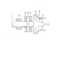
- FIG. 2 is a diagram illustrating a first embodiment of the present disclosure.
- the radial foil bearing 3 of the first embodiment is a bearing including a cylindrical insertion hole 12 a that is externally inserted into the rotating shaft 1 and supports the rotating shaft 1.
- a direction parallel to the central axis of the radial foil bearing 3 (that is, the central axis of the insertion hole 12a) is referred to as an axial direction, a direction intersecting the central axis is referred to as a radial direction, and a direction around the central axis is referred to as a circumferential direction.
- the radial foil bearing 3 includes a cylindrical top foil 9 (that is, a top foil 9 surrounding the circumferential side surface of the rotating shaft 1) disposed to face the circumferential side surface (outer circumferential surface) of the rotating shaft 1; An intermediate foil 10 disposed radially outside the top foil 9, a back foil 11 disposed radially outward of the intermediate foil 10, and a bearing housing 12 (housing) disposed radially outward of the back foil 11 ).
- a cylindrical top foil 9 that is, a top foil 9 surrounding the circumferential side surface of the rotating shaft 1
- An intermediate foil 10 disposed radially outside the top foil 9, a back foil 11 disposed radially outward of the intermediate foil 10, and a bearing housing 12 (housing) disposed radially outward of the back foil 11 ).
- the bearing housing 12 is a cylindrical member that constitutes the outermost part of the radial foil bearing 3.
- An insertion hole 12a (a hole communicating the bottom surface and the upper surface of the cylindrical member) is provided on the side surface of the bearing housing 12, and the rotary shaft 1 is inserted into the insertion hole 12a.
- the back foil 11, the intermediate foil 10, and the top foil 9 are arranged in this order from the radially outer side to the inner side. That is, the back foil 11, the intermediate foil 10, and the top foil 9 are accommodated in the insertion hole 12 a of the bearing housing 12. Therefore, the back foil 11 is supported by the inner peripheral surface of the insertion hole 12 a, the intermediate foil 10 is supported by the back foil 11, and the top foil 9 is supported by the intermediate foil 10.
- the bearing housing 12 may be a member other than a cylinder (for example, a prismatic member) as long as the insertion hole 12a is provided.
- a groove 14 is formed in the insertion hole 12a of the bearing housing 12 along the axial direction of the bearing housing 12 on the inner peripheral surface thereof. That is, a groove 14 is formed on the inner peripheral surface of the bearing housing 12 over the entire axial length of the bearing housing 12. That is, in the cross section of the bearing housing 12 orthogonal to the axial direction of the insertion hole 12a, a concave portion that is recessed radially outward is provided on the inner peripheral surface.
- the groove 14 can accommodate the end of the top foil 9.
- a pair of engagement grooves 15 extending from the inner peripheral edge of the insertion hole 12a toward the radially outer side are formed on both side surfaces (both end surfaces in the axial direction) of the bearing housing 12, respectively.
- the engagement groove 15 of the present embodiment is formed at a position where the side surface of the bearing housing 12 is substantially divided into three in the circumferential direction. That is, the bearing housing 12 of this embodiment is provided with three pairs of engaging grooves 15.
- the engagement grooves 15 are engaged with engagement members 30 described later.
- the groove 14 is disposed between two pairs of the engagement grooves 15 of the three pairs of engagement grooves 15. Further, the pair of engaging grooves 15 are opposed to the grooves 14 in the radial direction.
- the engagement groove 15 In order to form the engagement groove 15, cutting by an end mill, electrolytic machining, wire cut electric discharge machining, or the like can be selected as appropriate. Further, the engagement groove 15 may not be formed to penetrate from the inner peripheral edge to the outer peripheral edge of the bearing housing 12. For example, the engagement groove 15 may be opened only on the inner peripheral surface of the bearing housing 12.
- the top foil 9 is wound in a cylindrical shape along the inner surface of the intermediate foil 10, and the first uneven portion 23a formed on one end side and the second uneven portion formed on the other end side.
- the concavo-convex portions 23 b are disposed so as to engage with the grooves 14 formed in the bearing housing 12, respectively.
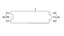
- FIG. 3A which is a development view of the top foil 9, a rectangular metal foil having a long side in the bearing circumferential direction and a short side in the bearing long direction (axial direction) is a side view thereof. It is formed by being wound in a cylindrical shape in the direction of the arrow in FIG. 3B (long side length direction; bearing circumferential direction).
- the top foil 9 is formed with a first uneven portion 23a having one convex portion 21a and two concave portions 22a on one side (short side).
- a second concavo-convex part 23b having two convex parts 21b and one concave part 22b is formed.
- the concave portion 22b of the second concave-convex portion 23b is formed corresponding to the convex portion 21a of the first concave-convex portion 23a, and the concave portion 22a of the first concave-convex portion 23a corresponds to the convex portion 21b of the second concave-convex portion 23b. Is formed.
- the recessed portion 22b of the second uneven portion 23b has a protruding portion 21a. Is formed to pass through.
- the concave portion 22a of the first uneven portion 23a is formed so that the convex portion 21b passes through the concave portion 22a when the top foil 9 is wound in a cylindrical shape.
- the convex portions 21a and 21b that have passed through the concave portions 22b and 22a are respectively drawn out to the bearing housing 12 side as shown in FIG. 2, and their tip portions are accommodated in the grooves 14 of the bearing housing 12 (the tip of the top foil 9 is , Abutted against and held by the inner wall surface of the groove 14). That is, both ends of the top foil 9 in the circumferential direction are held on the inner peripheral surface of the insertion hole 12 a of the bearing housing 12.
- the top foil 9 is disposed so that the end thereof is in contact with the inner surface of the groove 14.
- the top foil 9 is formed on the side where the first uneven portion 23a is formed (one side) and the side where the second uneven portion 23b is formed (the other side).
- a thin portion 24 that is thinner (thin) than the central portion between them is formed. As shown in FIG. 2, these thin portions 24 are formed to be thin (thinned) so that the outer peripheral surface (the surface on the bearing housing 12 side) is recessed from the outer peripheral surface of the central portion. .
- both end portions of the top foil 9 are controlled to the order of 10 ⁇ m to form a desired thickness (thinness) by, for example, etching. Specifically, when the bearing diameter is 35 mm, when the thickness of the top foil 9 is 100 ⁇ m, the thickness of the thin portion 24 is about 80 ⁇ m.
- the circumferential length L of the thin portion 24 shown in FIG. 3B is a length corresponding to the groove 13 and one peak portion 11c at the end of the back foil 11, as shown in FIG. .
- the length L of the circumferential direction of the thin part 24 it replaces with the example shown in FIG. 2, and is a length corresponding to about three minutes of the groove
- FIG. 2 It is good.
- the back foil 11 is disposed on the inner peripheral surface of the insertion hole 12 a of the bearing housing 12.
- the back foil 11 is formed of a foil (thin plate) and elastically supports the intermediate foil 10 and the top foil 9.
- Examples of such a back foil 11 include a bump foil, a spring foil described in Japanese Patent Application Laid-Open No. 2006-57652, Japanese Patent Application Laid-Open No. 2004-270904, and Japanese Patent Application Laid-Open No. 2009-299748.
- a back foil or the like is used.
- a bump foil is used as the back foil 11.
- the spring foil or the back foil may be used as the back foil of the present disclosure.
- the back foil 11 is configured by three (a plurality of) back foil pieces 11 a arranged along the circumferential direction of the bearing housing 12.
- a foil thin plate
- the side surface seen from the axial direction is formed into a substantially arc shape as a whole.
- the three back foil pieces 11a are all formed in the same shape and dimensions. Therefore, these back foil pieces 11 a are arranged by dividing the inner peripheral surface of the bearing housing 12 into approximately three parts. In addition, you may change suitably the number of the back foil pieces which comprise the back foil 11.
- the “corrugated plate shape” in the present embodiment is not limited to a shape (for example, a sine wave shape) constituted only by a curved surface, and a radially convex portion and a radially convex portion are circumferential directions.
- a part of the flat part that is, a part extending linearly when viewed in the axial direction may be provided, or a plurality of flat parts may be combined.
- the back foil pieces 11a are arranged with a certain gap at a position where the groove 14 is sandwiched. On the other hand, at other positions, the end portions of each other are arranged close to each other (shorter than the gap sandwiching the groove 14). That is, the back foil piece 11a does not extend to the circumferential position of the groove 14. With such a configuration, the three back foil pieces 11 a are formed in a substantially cylindrical shape as a whole, and are arranged along the inner peripheral surface of the bearing housing 12.
- a peak portion 11c that protrudes radially inward and a trough portion 11b that protrudes radially outward when viewed from the peak portion 11c are provided in the circumferential direction. It is formed alternately.
- the valley in this embodiment includes a flat valley 11 b that faces the bearing housing 12.
- the flat valley portion 11b can abut on the inner peripheral surface of the insertion hole 12a.
- the peak part 11c can contact
- the back foil piece 11a elastically supports the top foil 9 via the intermediate foil piece 10a, in particular, by the crest portion 11c contacting the intermediate foil piece 10a (intermediate foil 10).
- a fluid passage is formed by the crests 11 c and the troughs 11 b in the axial direction of the radial foil bearing 3.
- both the circumferential direction both ends of the back foil piece 11a of this embodiment are trough parts.
- FIG. 5A is a diagram schematically showing the main part of FIG. 2 flattened.
- notches 16 are separately formed at both peripheral edges in the axial direction of the circumferential position between the circumferential ends (the central portion in the direction along the circumferential direction of the bearing housing 12). . That is, there is a recess that is recessed toward the intermediate position in the axial direction at the circumferential position between the circumferential ends of the edge along the circumferential direction of the back foil piece 11a.
- This notch 16 is formed in the trough part 11b of the back foil piece 11a as shown in FIG.
- the notch 16 of the present embodiment is formed by cutting a valley portion 11b and a region including the root portions of the mountain portions 11c and 11c adjacent to each other across the valley portion 11b toward the axial center of the bearing housing 12. Has been. That is, the notch 16 is formed over the circumferential position including the valley 11b. The notch 16 is formed at a position corresponding to the engagement groove 15 of the bearing housing 12, that is, a position overlapping the engagement groove 15. Further, the circumferential width of the notch 16 is formed to be the same as the circumferential width of the engagement groove 15.
- the intermediate foil 10 is disposed between the back foil 11 formed of three back foil pieces 11 a and the top foil 9. In this embodiment, it is comprised by the three intermediate
- the intermediate foil piece 10a can come into contact with the peak portion 11c at the circumferential position closest to both ends in the circumferential direction of the back foil piece 11a. Further, the circumferential separation interval between the adjacent back foil pieces 11a without sandwiching the groove 14 corresponds to the back foil piece 11a and is compared with the circumferential separation interval between the intermediate foils 10 positioned radially inside. It is narrower.
- the radial foil bearing 3 of the present embodiment includes a top foil 9 formed of one foil, a back foil 11 formed of three foils, and three foils. Intermediate foil 10 to be formed. In addition, you may change suitably the number of the intermediate foil pieces which comprise the intermediate foil 10. FIG.
- the intermediate foil piece 10a includes a flat portion 10b in contact with the top of the peak portion 11c of the back foil 11, and a concave portion 10c (projecting) that is recessed (projects) radially outward also by the flat portion 10b. Projecting portion).
- the recess 10c is formed so as to be recessed from the radially inner surface of the intermediate foil piece 10a toward the radially outer side and to protrude radially outward from the radially outer surface of the intermediate foil piece 10a. That is, the recess 10 c is separated from the top foil 9. As shown in FIG.
- the recess 10c is formed at a circumferential position between the circumferential ends of the intermediate foil piece 10a.
- the concave portion 10c in the present embodiment has a bottom portion that is located on the outer side in the radial direction and is flat along the circumferential direction, and a tapered portion that is located at both ends in the circumferential direction of the bottom portion and extends radially inward. That is, the recessed part 10c is extended so that it may go to a radial inside from a bottom part as it distances from the bottom part to the circumferential direction.
- the interval in the circumferential direction of the tapered portion of the recess 10c is gradually reduced from the inner side toward the outer side in the radial direction.
- the circumferential width of the bottom of the recess 10c is larger than the circumferential width of the valley 11b of the back foil piece 11a.
- the valley portion 11b is formed flat.
- the circumferential width of the valley portion 11b in the present disclosure is the peak of the peak portion 11c.
- the outer shape of the intermediate foil piece 10a is substantially equal to the outer shape of the back foil piece 11a. All of these intermediate foil pieces 10a are formed in the same shape and size. Therefore, these intermediate foil pieces 10a are arranged by dividing the inner peripheral surface of the bearing housing 12 into approximately three parts.
- intermediate foil pieces 10a are arranged at positions corresponding to the back foil pieces 11a, and are arranged with some gaps at positions sandwiching the grooves 14, and at other positions, the end portions are close to each other. Is arranged. That is, in this embodiment, the trough portions 11b located at both ends of the back foil piece 11a do not reach the circumferential position of the groove 14. Similarly, the intermediate foil piece does not reach the circumferential position of the groove 14.
- the thickness of the intermediate foil piece 10a is smaller than the thickness of the back foil piece 11a.
- the rigidity of the intermediate foil 10 is less than half of the rigidity of the back foil 11. With such a configuration, the three intermediate foil pieces 10 a are formed in a substantially cylindrical shape as a whole, and are supported and arranged on the back foil 11 along the inner peripheral surface of the bearing housing 12.
- the circumferential positions between both ends in the circumferential direction are arranged on both axial peripheral edges.
- a notch 17 is formed. That is, there is a dent that is recessed toward the intermediate position in the axial direction at the circumferential position between the circumferential ends of the edge along the circumferential direction of the intermediate foil piece 10a. This notch 17 is formed in the recess 10c of the intermediate foil piece 10a as shown in FIG.
- the notch 17 of the present embodiment is formed by cutting a part of the bottom of the recess 10c formed between the flat portions 10b and 10b from the side periphery toward the axial center of the bearing housing 12. Yes.
- the notch 17 is formed at a position corresponding to the engagement groove 15 of the bearing housing 12 and the notch 16 of the back foil piece 11a, that is, a position overlapping the engagement groove 15 and the notch 16, and the circumferential width thereof is engaged.
- the groove 15 and the notch 16 are formed to have the same width in the circumferential direction.
- the engagement member 30 is engaged with the engagement groove 15 and the notches 16 and 17.
- the engagement member 30 includes a pair of engagement legs 31 extending outward in the radial direction and a connection portion 32 extending in the axial direction, and the pair of engagement legs 31 is connected to the connection portion 32. Connect.
- One engagement leg 31 engages with the engagement groove 15 on one side surface of the radial foil bearing 3 and the notches 16 and 17, and the other engagement leg 31 engages with the engagement groove on the other side surface of the radial foil bearing 3. 15 and the notches 16 and 17 are engaged. That is, the engagement leg 31 is inserted into the engagement groove 15. As shown in FIG.
- the radial length of the engaging leg 31 is substantially equal to the sum of the thickness of the bearing housing 12, the thickness of the back foil piece 11a, and the thickness of the intermediate foil piece 10a.
- the width of the engaging leg 31 is substantially equal to the width of the engaging groove 15 and the notches 16 and 17. That is, as shown in FIG. 4, the connection part 32 is arrange
- the engagement member 30 is engaged with the engagement groove 31 of the bearing housing 12, the notch 16 of the back foil piece 11a, and the notch 17 of the intermediate foil piece 10a.
- the intermediate foil piece 10 a and the back foil piece 11 a function as a holding member (holding tool) that holds the bearing housing 12.
- the connecting member 32 of the engaging member 30 is covered with the top foil 9. In other words, the connection portion 32 is held between the bottom portion of the recess 10 c of the intermediate foil 10 and the top foil 9.
- the engagement leg 31 and the connection part 32 of the engagement member 30 may be a rectangular column shape as shown in FIG. 4 or may be a columnar shape (round bar shape).
- the thickness (thickness) of the engaging member 30 is such that the connecting portion 32 is disposed away from the top foil 9 without contacting the top foil 9.
- Such an engaging member 30 can be formed by etching a metal foil made of, for example, stainless steel into a U-shape. It can also be formed by bending a wire-like metal bar.
- the intermediate foil piece 10 a and the back foil piece 11 a are arranged on both sides of the engaging member 30 in the portion where the engaging member 30 is arranged. They can abut each other in position. That is, the intermediate foil piece 10a is in contact with a place other than the top of the peak portion 11c of the back foil piece 11a in the concave portion 10c, in addition to the contact point P1 that is in contact with the top portion of the peak portion 11c of the back foil piece 11a in the plane portion 10b. A contact point P2 is formed.
- the recess 10 c of the intermediate foil piece 10 a is located on both sides of the bottom surface 11 b 1 with the engaging member 30, as shown in FIG. 6, on the side surface 11 c 1 of the peak portion 11 c of the back foil piece 11 a. Touching.
- the side surface 11c1 is located on both sides in the circumferential direction of the top of the peak portion 11c and on the radially outer side than the top. That is, the recessed part 10c is arrange
- the corrugated plate shape of the back foil piece 11a at the position corresponding to the top of any one peak 11c and the top of another peak 11c adjacent to the peak 11c in the circumferential direction.
- the recess 10c is disposed.
- the side surface 11c1 of the mountain portion 11c is a curved surface, and the side wall surface 10c1 (contact surface, the radially outer surface of the tapered portion) of the recess 10c that contacts the side surface 11c1 is a slope.
- interval of the circumferential direction of a pair of side wall surface 10c1 is shrink
- the side surface 11c1 of the peak portion 11c and the side wall surface 10c1 of the recess 10c are in contact at one point of the contact point P2, and are separated at other points, and energy dissipation due to friction at the contact point P2 is likely to occur. Yes. In this way, two contact points P ⁇ b> 2 are formed by one engagement member 30.
- the side surface 11c1 of the peak portion 11c is a curved surface that bulges inward in the radial direction when viewed in the axial direction, but may extend linearly when viewed in the axial direction.
- the side wall surface 10c1 of the recess 10c extends linearly when viewed in the axial direction, but may be a curved surface that bulges radially outward when viewed in the axial direction. If at least one of the side surface 11c1 and the side wall surface 10c1 is a curved surface that bulges toward the other, they can contact at one contact point and be separated at the other part.
- the operation of the radial foil bearing 3 having such a configuration will be described.
- the top foil 9 is urged toward the rotating shaft 1 by the back foil 11 (three back foil pieces 11a) via the intermediate foil 10 (three intermediate foil pieces 10a). It is in close contact with the rotating shaft 1.
- both end portions of the top foil 9 are thin portions 24, the thin portion 24 hardly generates a force (local preload) for tightening the rotating shaft 1.
- the rotating shaft 1 when the rotating shaft 1 is started in the direction of arrow P in FIG. 2, it starts rotating at a low speed first, and then gradually accelerates and rotates at a high speed. Then, as indicated by an arrow Q in FIG. 2, ambient fluid is drawn from one end side of the top foil 9, the intermediate foil 10, and the back foil 11 and flows between the top foil 9 and the rotating shaft 1. Thereby, a fluid lubricating film is formed between the top foil 9 and the rotating shaft 1.
- the film pressure of the fluid lubricating film acts on the top foil 9 and presses the individual peak portions 11c of the back foil piece 11a through the intermediate foil 10 in contact with the top foil 9. Then, when the back foil piece 11a is pressed by the intermediate foil 10, the peak portion 11c is pushed and spread, and thereby the back foil piece 11a starts to move on the bearing housing 12 in the circumferential direction. That is, since the back foil piece 11a (back foil 11) elastically supports the top foil 9 via the intermediate foil 10, when it receives a load from the top foil 9, it is deformed in its circumferential direction. The top foil 9 and the intermediate foil 10 are allowed to bend and are supported.
- the backfoil piece 11a is engaged with the engagement leg 31 of the engagement member 30 inserted into the notch 16 provided on the side peripheral edge thereof. It functions as a detent between the two. Accordingly, each peak portion 11c of the back foil piece 11a deforms (moves) in the circumferential direction with the notch 16 with which the engaging member 30 is engaged as a fixed point (fixed end), but the back foil piece 11a itself is The center does not deviate from the fixed position.
- the back foil piece 11a when the back foil piece 11a is deformed (moved) in the circumferential direction, the back foil piece 11a is affected by friction between the bearing housing 12 and the intermediate foil 10, and therefore is easily deformed (moved) at both ends thereof, that is, the free end side.
- the free end side it is difficult to be deformed on the fixed point (fixed end) side. Therefore, there may be a difference in the support rigidity of the back foil piece 11a between the free end side and the fixed end side.
- the fixing point by the engaging member 30 becomes the circumferential center of the back foil piece 11a, and the fixed end and the free end Since the distance between the two is shortened, the difference in the support rigidity is reduced. Furthermore, in this embodiment, since the back foil 11 is divided into three back foil pieces 11a, the distance between the fixed end and the free end is smaller than when the back foil 11 is formed of a single foil. Therefore, the difference in support rigidity between the free end side and the fixed end side is smaller.
- the engaging member 30 is restrained from moving in the axial direction of the back foil piece 11a when the rotating shaft 1 is rotating at a high speed, the back foil piece 11a can be used even when an unexpected impact or the like is applied. Does not fall off from the bearing housing 12.
- the intermediate foil piece 10a is formed with a recess 10c in which the connection portion 32 of the engagement member 30 is disposed, and the engagement leg 31 of the engagement member 30 is disposed in the notch 17 formed in the recess 10c. Since it engages with the engaging groove 15 via the member 30, even if an unexpected impact or the like is applied, the bearing housing 12 is moved in the axial direction without rotating in the bearing housing 12. Is suppressed. Further, since the radial direction is covered with the top foil 9, the engagement member 30 is prevented from falling off. As a result, the intermediate foil piece 10 a is suppressed from falling off the radial foil bearing 3.
- position the connection part 32 of the engaging member 30 is formed in the intermediate
- the recess 10c is in contact with the side surface 11c1 of the peak portion 11c of the back foil 11 at positions on both sides of the bottom surface 11b1 of the valley portion 11b of the back foil 11. Therefore, the intermediate foil 10 and the back foil 11 come into contact not only with the flat portion 10b but also with the concave portion 10c, and the contact area between the two increases, so that the damping effect due to friction between the intermediate foil 10 and the back foil 11 is increased.
- the stability when the rotating shaft 1 rotating at high speed is supported can be further increased.
- two contact points P2 are formed per one engaging member 30, and in this embodiment, as shown in FIG. 2, the intermediate foil piece 10a and the back foil piece 11a are formed. Therefore, the contact area between the intermediate foil 10 and the back foil 11 can be increased by six contact points P2 in addition to the contact point P1. Further, since the side surface 11c1 of the crest portion 11c of the back foil 11 is a curved surface, and the side wall surface 10c1 of the recess 10c that contacts the side surface 11c1 is a slope, both contact at one point at the contact point P2, and at other portions. Since they are separated from each other, the intermediate foil 10 and the back foil 11 are not easily restrained, and the “slip” between the two becomes easy to occur.
- FIG. 7A and 7B are views showing a radial foil bearing 3A according to a second embodiment applied to the turbo machine shown in FIG. 1, and FIG. 7A schematically shows a main portion of the radial foil bearing 3A flattened.
- FIG. 7B is a side view thereof.
- the second embodiment is different from the above embodiment in that the intermediate foil 10A (intermediate foil piece 10a) is provided with a branch piece 40 (protruding portion) branched from the flat surface portion 10b. That is, a portion projecting radially outward is extended from the radially outer surface of the intermediate foil piece 10a.
- the branch piece 40 is formed by forming a slit 41 in the flat surface portion 10b and projecting (cutting and raising) a portion surrounded by the slit 41 so as to protrude outward in the radial direction.
- the slit 41 is formed by two cuts parallel to the circumferential direction and one cut parallel to the axial direction connecting the ends of the two cuts.
- a rectangular branch piece 40 surrounded by the slit 41 projects obliquely so as to protrude outward in the radial direction. That is, the branch piece 40 extends from the end of the two parallel cuts that are not connected to the cut parallel to the axial direction (the end opposite to the cut parallel to the axial direction).
- the branch piece 40 is spaced apart in the circumferential direction from the end not connected to the cut parallel to the axial direction, and is spaced radially outward. That is, the branch piece 40 is radially outward as the two parallel cuts proceed in the circumferential direction from the end opposite to the cut parallel to the axial direction toward the cut parallel to the axial direction. It extends toward. In other words, the radial position is monotonously increased outward in the radial direction while being spaced apart from the end not connected to the cut parallel to the axial direction in the circumferential direction. That is, the branch piece 40 of the present embodiment extends linearly when viewed in the axial direction.
- the branch piece 40 has a corrugated shape of the back foil piece 11a at a circumferential position between the top of at least one peak 11c and the top of the peak 11c adjacent to the peak 11c. It protrudes to the back foil piece 11a side.
- the branch pieces 40 are provided in pairs so as to sandwich the mountain portion 11c of the back foil piece 11a in the circumferential direction. That is, as shown in FIG. 7A, the slits 41 are formed on both sides in the circumferential direction at positions corresponding to the crests 11c of the back foil piece 11a, and the sets of branch pieces 40 cut and raised from these slits 41 are separated from each other. Stretched to do. That is, two pairs of cuts parallel to the circumferential direction separated from each other in the circumferential direction are provided so as to overlap with the circumferential position of one peak portion 11c.
- the distance in the circumferential direction between the pair of branch pieces 40 protruding toward one peak portion 11c gradually increases from the inner side toward the outer side in the radial direction.
- an incision parallel to the axial direction extends from the end portion on the side away from each other.
- the two branch pieces 40 (a set of branch pieces) provided so as to sandwich the peak portion 11c of the back foil piece 11a in the circumferential direction are connected to the peak portion 11c of the back foil piece 11a from both sides in the circumferential direction. It contacts with the peak part 11c so that it may pinch
- slits 41 are provided in the circumferential direction in two rows on the flat portion 10b, and four branch pieces 40 are in contact with one peak portion 11c.
- the slits 41 (branching pieces 40) may be provided in a single row or three or more rows in the circumferential direction.
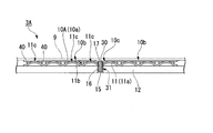
- FIG. 8 is an enlarged cross-sectional view taken along line AA of the main part shown in FIG. 7A.
- a back foil 11 is provided on the flat surface portion 10b of the intermediate foil 10 (a portion located on a plane obtained by tracing a substantially circular closed curve that does not include a branch and is surrounded in the circumferential direction in the axial width of the intermediate foil 10).
- the plane portion 10b includes a branch position 43 (a left branch position 43 shown in FIG.
- a second branch position 43 (a right branch position 43 shown in FIG. 8) is provided at a different position. That is, two branch pieces 40 are formed between the top of the first peak 11c and the top of the second peak 11c that are adjacent in the circumferential direction of the back foil 11. In other words, two (a set) of branch positions 43 are provided in the circumferential direction between the valley portions 11b adjacent in the circumferential direction.
- the intermediate foil piece 10a and the back foil piece 11a are separated from each other in the radial direction at the radial position of the branch position 43 when the inserted rotary shaft 1 is not rotating. .
- the intermediate foil piece 10 a and the back foil piece 11 a are separated from each other in the radial direction at a position equivalent to the branch position 43 in the circumferential direction when the inserted rotary shaft 1 is not rotating. is doing.
- a pair of branch pieces 40 that open in directions away from each other are in contact with positions (side surfaces 11c1) on both sides in the circumferential direction across the top of the mountain portion 11c. That is, the intermediate foil piece 10a has a contact point P1 in contact with the top of the peak portion 11c of the back foil piece 11a in the plane portion 10b, and a location other than the top of the peak portion 11c of the back foil piece 11a in the branch piece 40.
- a contact point P3 that is in contact is formed.
- no contact point is configured between the two contact points P3 sandwiching the top of the peak portion 11c.
- the radially outer surface of the branch piece 40 extends from the top side of the peak portion 11c to the valley portion 11b adjacent to the peak portion 11c and extends beyond the contact point P3. However, it does not reach the radial position of the valley portion 11b adjacent to the peak portion 11c.
- the side surface 11c1 of the peak portion 11c is a curved surface, and the branch piece 40 that contacts the side surface 11c1 is planar. That is, the side surface 11c1 of the peak portion 11c and the branch piece 40 are in contact at one point of the contact point P3 and are separated at other places, and slippage at the contact point P3 is likely to occur.
- the branch piece 40 is from the plane part 10b.
- the branching position 43 and the 2nd branching position 43 which branch are provided, and the branch piece 40 is contacting the places other than the top part of the peak part 11c of the back foil 11, as shown in FIG.
- the intermediate foil 10A and the back foil 11 come into contact not only with the flat portion 10b and the recess 10c but also with the branch piece 40 branched from the flat portion 10b, and the contact position between the two increases, so that the intermediate foil 10A and The damping effect due to friction with the back foil 11 is increased. That is, two contact points P3 are further formed per one peak portion 11c.
- the branch piece 40 is provided in pairs so as to sandwich the crest portion 11c of the back foil 11 in the circumferential direction, the back piece 11 is deformed so as to expand or contract in the circumferential direction.
- the contact state with the peak portion 11c can always be maintained, and the damping effect due to the friction between the intermediate foil 10A and the back foil 11 can be enhanced.
- FIGS. 9A and 9B are views showing a radial foil bearing 3B according to a third embodiment applied to the turbo machine shown in FIG. 1, and FIG. 9A schematically shows a main portion of the radial foil bearing 3B flattened.
- FIG. 9B is a side view thereof.
- the third embodiment is different from the first and second embodiments in that the intermediate foil 10B (intermediate foil piece 10a) is provided with a branch piece 40B (projecting portion) branched from the flat surface portion 10b.
- the branch piece 40B is formed by forming a slit 41B in the flat surface portion 10b and projecting a portion surrounded by the slit 41B so as to protrude radially outward. That is, the branch piece 40B of the present embodiment protrudes radially outward from the flat portion 10b along the circumferential direction, and further extends radially inward beyond the peak of the protrusion.
- the slit 41B is formed in an H-shape, and the two branch pieces 40B formed by the slit 41B project into a curved shape so as to protrude radially outward to form a corrugated plate shape. Yes. That is, when viewed in the radial direction (see FIG.
- the branch pieces 40B are directed from the sides at both ends in the circumferential direction of the rectangular region in which the H-shaped slit 41B is disposed toward the other end side. Stretched. And the front-end
- the branch piece 40B is disposed at a position corresponding to the valley portion 11b of the back foil piece 11a.
- the branch piece 40B includes a position facing the trough portion 11b in the radial direction and extends to the crest portions 11c adjacent to both sides in the circumferential direction of the trough portion 11b.
- the tip of the branch piece 40B is located closer to the valley portion 11b than the apex of the peak portion 11c. Therefore, the branch piece 40B extends to the circumferential position of the adjacent peak portion 11c including one peak portion 11c.
- the central portion of the slit 41B has a region where the back foil 11 is exposed as viewed from the radial direction.
- a position corresponding to the top of the peak portion 11c of the back foil piece 11a is exposed.
- the set of branch pieces 40B cut and raised from the slit 41B is deformed into a curved shape so as to be separated from each other, and as shown in FIG. 9B, the peak portion 11c arranged at a position corresponding to the central portion of the slit 41B. It contacts with the crests 11c and 11c arranged on both sides. That is, the crests 11c sandwiched from both sides in the circumferential direction by the branch pieces 40B and the crests 11c not sandwiched from both sides in the circumferential direction by the branch pieces 40B are alternately arranged in the circumferential direction.
- the peak of the peak portion 11c of the back foil piece 11a and the peak of the branch piece 40B appear alternately in the circumferential direction.
- the peak of one branch piece 40B is provided between the top of the peak 11c and the peak of the adjacent peak 11c.
- the peak said here is a part which protrudes in the radial direction peak, ie, radial direction outer side.
- the flat surface portion 10b has a first peak portion 11c adjacent to the top portion of the back foil 11 in the circumferential direction.
- a branch position 43B from which the branch piece 40B branches is provided between the top of the two peak portions 11c. That is, one branch piece 40B is formed between the top of the first peak 11c and the top of the second peak 11c adjacent in the circumferential direction of the back foil 11.
- the branch piece 40B includes a separation portion 40B1 that is spaced radially outward from the flat surface portion 10b, and a proximity portion that extends from the separation portion 40B1 (the radially outer end of the separation portion 40B1) and is radially inward toward the flat surface portion 10b.
- 40B2 and a distal end portion 40B3 extending from the proximity portion 40B2 (the radially inner end of the proximity portion 40B2) and extending along the flat surface portion 10b.
- the separation portion 40B1 and the proximity portion 40B2 have a smooth curved surface shape with the same curvature radius. That is, the separation portion 40B1 and the proximity portion 40B2 are formed as curved surfaces that bulge outward in the radial direction as a whole.
- the separation portion 40B1 and the proximity portion 40B2 may be configured by combining a linear shape and a linear shape, or may be configured by combining a linear shape and a curved shape when viewed in the axial direction.
- the separation portion 40B1 of the branch piece 40B is in contact with the side surface 11c1 of the mountain portion 11c. That is, the intermediate foil piece 10a has a top portion of the crest portion 11c of the back foil piece 11a at the separation portion 40B1 of the branch piece 40B, in addition to the contact point P1 that contacts the crest portion 11c of the back foil piece 11a in the plane portion 10b. A contact point P4 in contact with a place other than is formed.
- the side surface 11c1 of the peak portion 11c is a curved surface
- the separation portion 40B1 of the branch piece 40B that contacts the side surface 11c1 is a curved surface that protrudes toward each other.
- the side surface 11c1 of the peak portion 11c and the separation portion 40B1 of the branch piece 40B are in contact at one point of the contact point P4 and are separated at other places, and slippage at the contact point P4 is likely to occur. That is, in the present embodiment, a contact point P4 is formed by the two branch pieces 40B that sandwich the top of one peak portion 11c in the circumferential direction.
- the peak part 11c adjacent to the peak part 11c is configured not to have a contact point with the branch piece 40B.
- the length from the contact point P4 to the tip of the branch piece 40B is longer than the length between the branch position 43B of the branch piece 40B and the contact point P4. That is, in this embodiment, the length from the contact point P4 to the tip of the branch piece 40B is longer than the length from the top of the peak portion 11P sandwiched between the contact points P4 to the contact point P4.
- the branch piece 40B is from the plane part 10b.
- a branch position 43B for branching is provided, and the branch piece 40B is in contact with a place other than the top of the peak portion 11c of the back foil 11 as shown in FIG. Therefore, the intermediate foil 10B and the back foil 11 come into contact not only with the flat surface portion 10b and the concave portion 10c but also with the branch piece 40B branched from the flat surface portion 10b. The damping effect due to friction with the back foil 11 is increased.
- the backfoil 11 can be crested in any case that deforms so as to extend or contract in the circumferential direction. It is possible to contact the part 11c.
- the branch piece 40B has a corrugated plate shape including a separation portion 40B1 that is spaced radially outward from the flat surface portion 10b, and a proximity portion 40B2 that extends from the separation portion 40B1 and is radially inward toward the flat surface portion 10b.
- an annular flange may be integrally formed in one side surface or both side surfaces, and the whole may be formed in a substantially cylindrical shape. By forming the flange, it is possible to easily attach the turbomachine to a housing or the like.
Abstract
Description
本願は、2017年3月15日に日本に出願された特願2017-050127号に基づき優先権を主張し、その内容をここに援用する。 The present disclosure relates to radial foil bearings.
This application claims priority based on Japanese Patent Application No. 2017-050127 filed in Japan on March 15, 2017, the contents of which are incorporated herein by reference.
また、インペラ2は静止側となるハウジング6内に配置されており、ハウジング6との間にチップクリアランス7が設けられている。 A radial foil bearing 3 is externally inserted (inserted) into the
The
図2は、本開示の第1実施形態を示す図である。この第1実施形態のラジアルフォイル軸受3は、図2に示すように、回転軸1に外挿されて該回転軸1を支持する円筒状の、挿通孔12aを備える軸受である。ラジアルフォイル軸受3の中心軸(すなわち挿通孔12aの中心軸)に平行な方向を軸方向といい、前記中心軸と交差する方向を径方向といい、前記中心軸回りの方向を周方向という。このラジアルフォイル軸受3は、回転軸1の周方向側面(外周面)に対向して配置される円筒状のトップフォイル9(すなわち、回転軸1の周方向側面を取り囲むトップフォイル9)と、該トップフォイル9の径方向外側に配置される中間フォイル10と、該中間フォイル10の径方向外側に配置されるバックフォイル11と、該バックフォイル11の径方向外側に配置される軸受ハウジング12(ハウジング)と、を備えて構成されている。 “First Embodiment”
FIG. 2 is a diagram illustrating a first embodiment of the present disclosure. As shown in FIG. 2, the radial foil bearing 3 of the first embodiment is a bearing including a
また、ラジアルフォイル軸受3の軸方向に、山部11cや谷部11bによる流体の通路を形成している。また、本実施形態のバックフォイル片11aの周方向両端は、いずれも谷部となっている。 The valley in this embodiment includes a
Further, a fluid passage is formed by the
つまり、中間フォイル片10aは、バックフォイル片11aの周方向両端に最も近い周方向位置にある山部11cと当接可能になっている。また、溝14を挟まずに隣り合うバックフォイル片11a同士の周方向の離隔間隔は、当該バックフォイル片11aに対応し、径方向内側に位置する中間フォイル10同士の周方向の離隔間隔と比べ狭くなっている。
ここまでの開示からわかるように、本実施形態のラジアルフォイル軸受3は、1枚のフォイルで形成されるトップフォイル9と、3枚のフォイルで形成されるバックフォイル11と、3枚のフォイルで形成される中間フォイル10と、を備えている。なお、中間フォイル10を構成する中間フォイル片の数は、適宜変更してもよい。 As shown in FIG. 2, the
That is, the
As can be seen from the disclosure so far, the radial foil bearing 3 of the present embodiment includes a
凹部10cは、中間フォイル片10aの径方向内面から径方向外側に向けて窪み、かつ中間フォイル片10aの径方向外面から径方向外側に向けて突出して形成されている。
すなわち、この凹部10cは、トップフォイル9から離隔している。凹部10cは、図5Aに示すように、中間フォイル片10aの周方向両端の間の周方向位置に形成されている。本実施形態における凹部10cは、径方向外側に位置し周方向に沿って平坦な底部と、底部の周方向両端に位置し径方向内側に延伸するテーパ部と、を有する。つまり、凹部10cは、底部から周方向に離隔するに従い、底部から径方向内側に向かうように延びている。凹部10cのテーパ部の周方向の間隔は、径方向内側から外側に向かうに従い次第に縮小している。また、凹部10cの底部の周方向の幅は、バックフォイル片11aの谷部11bの周方向の幅より大きくなっている。本実施形態では、谷部11bが平坦に形成されている。しかし、山部11cと谷部11bがともに一つのピークを持って周期的に(すなわち正弦波状に)形成される場合は、本開示における谷部11bの周方向の幅は、山部11cのピークと谷部11bのピークとの径方向位置の中間の径方向位置における、バックフォイル片11aの谷部11bの間隔であるとする。この中間フォイル片10aの外形は、バックフォイル片11aの外形と略等しい大きさを有する。これら中間フォイル片10aは、3つが全て同じ形状・寸法に形成されている。したがって、これら中間フォイル片10aは、軸受ハウジング12の内周面をほぼ3分割して配置されている。 As shown in FIGS. 5A and 5B, the
The
That is, the
切欠17は、軸受ハウジング12の係合溝15及びバックフォイル片11aの切欠16に対応する位置、すなわち係合溝15及び切欠16と重なる位置に形成されており、その周方向の幅が係合溝15及び切欠16の周方向の幅と同じに形成されている。 Further, in these
The
係合脚31の径方向長さは、図5Bに示すように、軸受ハウジング12の厚さとバックフォイル片11aの厚さと中間フォイル片10aの厚さの和に、ほぼ等しくなっている。また、係合脚31の幅は、係合溝15及び切欠16,17の幅とほぼ等しくなっている。つまり、接続部32は、図4に示すように、バックフォイル片11aの周方向中央部の谷部11b内と、中間フォイル片10aの凹部10c内に配置されている。 An
As shown in FIG. 5B, the radial length of the
回転軸1が停止した状態では、トップフォイル9はバックフォイル11(3つのバックフォイル片11a)によって中間フォイル10(3つの中間フォイル片10a)を介して回転軸1側に付勢されることで回転軸1に密着している。なお、本実施形態では、トップフォイル9の両端部が薄肉部24となっているので、これら薄肉部24では回転軸1を締め付ける力(局所的なプリロード)がほとんど生じない。 Next, the operation of the radial foil bearing 3 having such a configuration will be described.
In a state where the
そのため、自由端側と固定端側とでは、バックフォイル片11aによる支持剛性に差が生じる場合がある。しかし、本実施形態では、切欠16をバックフォイル片11aの周方向中央部に形成しているので、係合部材30による固定点がバックフォイル片11aの周方向中央部となり、固定端と自由端との間の距離が短くなるため、前記の支持剛性の差が小さくなる。
さらに、本実施形態では、バックフォイル11を3つのバックフォイル片11aに分割しているため、バックフォイル11を単一のフォイルで形成した場合に比べ、固定端と自由端との間の距離が短くなっており、したがって自由端側と固定端側との間の支持剛性の差がより小さくなっている。 Further, when the
Therefore, there may be a difference in the support rigidity of the
Furthermore, in this embodiment, since the
次に、本開示のラジアルフォイル軸受の第2実施形態を説明する。以下の説明において、上述の実施形態と同一又は同等の構成については同一の符号を付し、その説明を簡略若しくは省略する。 “Second Embodiment”
Next, a second embodiment of the radial foil bearing of the present disclosure will be described. In the following description, the same or equivalent components as those in the above-described embodiment are denoted by the same reference numerals, and the description thereof is simplified or omitted.
この第2実施形態では、中間フォイル10A(中間フォイル片10a)に、平面部10bから分岐した分岐片40(突出部)が設けられている点で、上記実施形態と異なる。すなわち、中間フォイル片10aの径方向外側の面に対し、径方向外側に突出する部位が延接されている。 7A and 7B are views showing a radial foil bearing 3A according to a second embodiment applied to the turbo machine shown in FIG. 1, and FIG. 7A schematically shows a main portion of the radial foil bearing 3A flattened. FIG. 7B is a side view thereof.
The second embodiment is different from the above embodiment in that the
すなわち、分岐片40は、平行な2本の切込の、軸方向に平行な切込みと逆側の端部から、軸方向に平行な前記切込みに向けて周方向に進むに従い、径方向外側に向けて延びている。
言い換えれば、軸方向に平行な切込みと接続しない端部から周方向に離隔するとともに、径方向位置が径方向外側に単調増加している。すなわち、本実施形態の分岐片40は、軸方向視において直線状に延びている。この分岐片40は、バックフォイル片11aの波板状のうち、少なくともいずれか一つの山部11cの頂部と、該山部11cと隣り合う山部11cの頂部との間の周方向位置において、バックフォイル片11a側に突出している。 As shown in FIG. 7A, the
That is, the
In other words, the radial position is monotonously increased outward in the radial direction while being spaced apart from the end not connected to the cut parallel to the axial direction in the circumferential direction. That is, the
すなわち、ラジアルフォイル軸受3は、挿通された回転軸1が回転していない状態では、周方向において分岐位置43と同等の位置において、中間フォイル片10aとバックフォイル片11aとが径方向に互いに離間している。 FIG. 8 is an enlarged cross-sectional view taken along line AA of the main part shown in FIG. 7A. A
That is, in the radial foil bearing 3, the
ここで、挿通された回転軸1が回転していない状態では、山部11cの頂部を挟んだ2つの接触点P3の間に、接触点が構成されていない場合もありうる。その場合でも、挿通された回転軸1が回転することで、山部11cの頂部を挟んだ2つの接触点P3の間に接触点P1が生じる。また、分岐片40の径方向外側の面は、山部11cの頂部側から当該山部11cに隣り合う谷部11bに向かい、接触点P3を越えて延伸している。ただし、当該山部11cに隣り合う谷部11bの径方向位置までは達していない。
山部11cの側面11c1は、曲面であり、この側面11c1と接触する分岐片40は、平面状である。すなわち、山部11cの側面11c1と分岐片40は、接触点P3の1点で接触し、その他の場所で離間しており、接触点P3におけるすべりが発生し易くなっている。 A pair of
Here, in a state where the inserted
The side surface 11c1 of the
次に、本開示のラジアルフォイル軸受の第3実施形態を説明する。以下の説明において、上述の実施形態と同一又は同等の構成については同一の符号を付し、その説明を簡略若しくは省略する。 “Third Embodiment”
Next, a third embodiment of the radial foil bearing of the present disclosure will be described. In the following description, the same or equivalent components as those in the above-described embodiment are denoted by the same reference numerals, and the description thereof is simplified or omitted.
この第3実施形態では、中間フォイル10B(中間フォイル片10a)に、平面部10bから分岐した分岐片40B(突出部)が設けられている点で、上記第1、第2実施形態と異なる。 9A and 9B are views showing a radial foil bearing 3B according to a third embodiment applied to the turbo machine shown in FIG. 1, and FIG. 9A schematically shows a main portion of the radial foil bearing 3B flattened. FIG. 9B is a side view thereof.
The third embodiment is different from the first and second embodiments in that the
このとき、分岐片40Bの先端部40B3と、トップフォイル9との間においても「滑り」が生じ得るため、摩擦による減衰効果がさらに高くなる。 Further, since the
At this time, since “slip” can occur between the tip 40B3 of the
例えば、トップフォイル9や中間フォイル10、バックフォイル11を保持するための溝や保持具の構成や数については、前記実施形態に限定されることなく、種々の構成を採用することができる。
また、前記実施形態では、軸受ハウジング12を円筒状に形成したが、一方の側面又は両方の側面に環状のフランジを一体に形成し、全体を略円筒状に形成してもよい。フランジを形成することにより、ターボ機械のハウジングなどへの取り付けを容易にすることができる。 As mentioned above, although embodiment of this indication was described referring an accompanying drawing, this indication is not limited to the above-mentioned embodiment. The various shapes and combinations of the constituent members shown in the above embodiment are merely examples, and additions, omissions, substitutions, and other modifications of the configuration are possible based on design requirements and the like without departing from the gist of the present disclosure. It is.
For example, the configuration and number of grooves and holders for holding the
Moreover, in the said embodiment, although the bearing
3 ラジアルフォイル軸受
3A ラジアルフォイル軸受
3B ラジアルフォイル軸受
10 中間フォイル
10A 中間フォイル
10B 中間フォイル
10a 中間フォイル片
10b 平面部
10c 凹部(突出部)
10c1 側壁面(接触面)
11 バックフォイル
11b 谷部
11b1 底面
11c 山部(第1の山部、第2の山部)
11c1 側面
12 軸受ハウジング
12a 挿通孔
15 係合溝
16 切欠
17 切欠
30 係合部材
31 係合脚
32 接続部
40 分岐片(突出部)
40B 分岐片(突出部)
40B1 離隔部
40B2 近接部
43 分岐位置(第2の分岐位置)
43B 分岐位置
50 蓋体
P1 接触点
P2 接触点
P3 接触点
P4 接触点 DESCRIPTION OF
10c1 Side wall surface (contact surface)
11
40B Branch piece (protrusion)
40B1 Separation part
43B Branch position 50 Lid P1 Contact point P2 Contact point P3 Contact point P4 Contact point
Claims (4)
- 挿通孔を有するとともに、該挿通孔の内周縁から径方向外側に向かって延伸する一対の係合溝が軸方向両端面に設けられたハウジングと、
前記挿通孔の内周面に配置されたバックフォイルと、
前記バックフォイルに支持される中間フォイルと、
前記一対の係合溝に係合する一対の係合脚、及び該一対の係合脚を接続する接続部を有する係合部材と、を備え、
前記中間フォイルには、前記バックフォイル側に向けて窪み且つ突出する凹部が設けられており、
前記接続部が、前記凹部内に配置されている、ラジアルフォイル軸受。 A housing having an insertion hole and a pair of engagement grooves provided on both end surfaces in the axial direction extending radially outward from the inner periphery of the insertion hole;
A back foil disposed on the inner peripheral surface of the insertion hole;
An intermediate foil supported by the back foil;
A pair of engagement legs that engage with the pair of engagement grooves, and an engagement member that has a connection portion that connects the pair of engagement legs,
The intermediate foil is provided with a recess that protrudes and projects toward the back foil,
A radial foil bearing, wherein the connecting portion is disposed in the recess. - 前記バックフォイルは、波板状に形成されており、
前記バックフォイルの波板状のうち、いずれか一つの山部の頂部と、該山部と隣り合う山部の頂部との間の周方向位置に、前記凹部が配置されている、請求項1に記載のラジアルフォイル軸受。 The back foil is formed in a corrugated plate shape,
The said recessed part is arrange | positioned in the circumferential direction position between the top part of any one peak part among the corrugated sheet shape of the said back foil, and the peak part adjacent to this peak part. The radial foil bearing described in 1. - 前記バックフォイルの波板状の山部の側面は、曲面であり、
前記側面と接する前記凹部の接触面は、斜面である、請求項2に記載のラジアルフォイル軸受。 The side surface of the corrugated ridge of the back foil is a curved surface,
The radial foil bearing according to claim 2, wherein a contact surface of the concave portion in contact with the side surface is an inclined surface. - 前記中間フォイル及び前記バックフォイルの各々は、軸方向両端に、前記一対の係合脚が係合する切欠を備える、請求項1~3のいずれか一項に記載のラジアルフォイル軸受。 The radial foil bearing according to any one of claims 1 to 3, wherein each of the intermediate foil and the back foil includes a notch with which the pair of engagement legs are engaged at both axial ends.
Priority Applications (6)
| Application Number | Priority Date | Filing Date | Title |
|---|---|---|---|
| EP18767663.0A EP3597945B1 (en) | 2017-03-15 | 2018-03-14 | Radial foil bearing |
| CN201880017645.2A CN110431320B (en) | 2017-03-15 | 2018-03-14 | Radial foil bearing |
| JP2019506216A JP6658959B2 (en) | 2017-03-15 | 2018-03-14 | Radial foil bearing |
| US16/493,138 US10781853B2 (en) | 2017-03-15 | 2018-03-14 | Radial foil bearing |
| CA3056364A CA3056364A1 (en) | 2017-03-15 | 2018-03-14 | Radial foil bearing |
| KR1020197019811A KR102148018B1 (en) | 2017-03-15 | 2018-03-14 | Radial foil bearing |
Applications Claiming Priority (2)
| Application Number | Priority Date | Filing Date | Title |
|---|---|---|---|
| JP2017-050127 | 2017-03-15 | ||
| JP2017050127 | 2017-03-15 |
Publications (1)
| Publication Number | Publication Date |
|---|---|
| WO2018168919A1 true WO2018168919A1 (en) | 2018-09-20 |
Family
ID=63523935
Family Applications (1)
| Application Number | Title | Priority Date | Filing Date |
|---|---|---|---|
| PCT/JP2018/009943 WO2018168919A1 (en) | 2017-03-15 | 2018-03-14 | Radial foil bearing |
Country Status (7)
| Country | Link |
|---|---|
| US (1) | US10781853B2 (en) |
| EP (1) | EP3597945B1 (en) |
| JP (1) | JP6658959B2 (en) |
| KR (1) | KR102148018B1 (en) |
| CN (1) | CN110431320B (en) |
| CA (1) | CA3056364A1 (en) |
| WO (1) | WO2018168919A1 (en) |
Families Citing this family (3)
| Publication number | Priority date | Publication date | Assignee | Title |
|---|---|---|---|---|
| JP7013951B2 (en) * | 2018-03-07 | 2022-02-15 | 株式会社Ihi | Radial foil bearing |
| KR102166622B1 (en) * | 2020-05-08 | 2020-10-16 | 주식회사 뉴로스 | Air foil journal bearing |
| US11852153B1 (en) * | 2023-01-31 | 2023-12-26 | Copeland Lp | Foil bearing assembly including perforated inner foil assembly and compressor including same |
Citations (9)
| Publication number | Priority date | Publication date | Assignee | Title |
|---|---|---|---|---|
| EP0490443A1 (en) * | 1990-12-13 | 1992-06-17 | Abg Semca S.A. | Hydrodynamic foil bearing |
| JP2001227535A (en) * | 1999-12-03 | 2001-08-24 | Mitsubishi Heavy Ind Ltd | Foil gas bearing |
| JP2004270904A (en) | 2003-03-12 | 2004-09-30 | Honda Motor Co Ltd | Foil type fluid bearing |
| JP2006057652A (en) | 2004-08-17 | 2006-03-02 | Kawasaki Heavy Ind Ltd | Dynamic pressure fluid bearing |
| JP2008261496A (en) * | 2007-04-12 | 2008-10-30 | Hamilton Sundstrand Corp | Hydrodynamic fluid film journal bearing assembly and its manufacturing method |
| JP2009299748A (en) | 2008-06-12 | 2009-12-24 | Ihi Corp | Foil bearing |
| WO2013018505A1 (en) * | 2011-08-01 | 2013-02-07 | 株式会社Ihi | Radial foil bearing |
| JP2014020463A (en) | 2012-07-18 | 2014-02-03 | Ihi Corp | Radial foil bearing |
| JP2017050127A (en) | 2015-09-01 | 2017-03-09 | アール・ビー・コントロールズ株式会社 | Lighting device |
Family Cites Families (15)
| Publication number | Priority date | Publication date | Assignee | Title |
|---|---|---|---|---|
| US5658079A (en) | 1995-06-05 | 1997-08-19 | United Technologies Corporation | Hydrodynamic fluid film journal bearing |
| US5634723A (en) * | 1995-06-15 | 1997-06-03 | R & D Dynamics Corporation | Hydrodynamic fluid film bearing |
| US5902049A (en) | 1997-03-28 | 1999-05-11 | Mohawk Innovative Technology, Inc. | High load capacity compliant foil hydrodynamic journal bearing |
| JP4287021B2 (en) | 2000-04-10 | 2009-07-01 | 本田技研工業株式会社 | Foil type hydrodynamic bearing |
| JP4502548B2 (en) | 2001-06-12 | 2010-07-14 | 本田技研工業株式会社 | Foil type hydrodynamic bearing |
| JP4299625B2 (en) | 2003-10-03 | 2009-07-22 | 本田技研工業株式会社 | Foil type hydrodynamic bearing |
| JP2007113775A (en) | 2005-10-21 | 2007-05-10 | Shigeto Matsuo | Ring foil gas bearing |
| KR101187892B1 (en) | 2007-01-05 | 2012-10-04 | 삼성테크윈 주식회사 | Air foil bearing |
| JP4961485B2 (en) | 2010-03-30 | 2012-06-27 | 本田技研工業株式会社 | Dynamic pressure type foil type gas bearing |
| US8419283B2 (en) | 2010-07-28 | 2013-04-16 | Hamilton Sundstrand Corporation | Journal air bearing |
| JP5751062B2 (en) | 2011-07-22 | 2015-07-22 | 株式会社Ihi | Radial foil bearing |
| KR20130091445A (en) | 2012-02-08 | 2013-08-19 | 엘지전자 주식회사 | Gas foil journal bearing and chiller system including the same |
| JP5929626B2 (en) * | 2012-08-14 | 2016-06-08 | 株式会社Ihi | Radial foil bearing |
| CN104632871A (en) | 2015-03-17 | 2015-05-20 | 湖南大学 | Minitype foil aerodynamic pressure bearing |
| US10385915B2 (en) | 2016-08-16 | 2019-08-20 | Hamilton Sundstrand Corporation | High load capacity hybrid foil bearing |
-
2018
- 2018-03-14 WO PCT/JP2018/009943 patent/WO2018168919A1/en unknown
- 2018-03-14 CN CN201880017645.2A patent/CN110431320B/en active Active
- 2018-03-14 EP EP18767663.0A patent/EP3597945B1/en active Active
- 2018-03-14 KR KR1020197019811A patent/KR102148018B1/en active IP Right Grant
- 2018-03-14 JP JP2019506216A patent/JP6658959B2/en active Active
- 2018-03-14 CA CA3056364A patent/CA3056364A1/en not_active Abandoned
- 2018-03-14 US US16/493,138 patent/US10781853B2/en active Active
Patent Citations (9)
| Publication number | Priority date | Publication date | Assignee | Title |
|---|---|---|---|---|
| EP0490443A1 (en) * | 1990-12-13 | 1992-06-17 | Abg Semca S.A. | Hydrodynamic foil bearing |
| JP2001227535A (en) * | 1999-12-03 | 2001-08-24 | Mitsubishi Heavy Ind Ltd | Foil gas bearing |
| JP2004270904A (en) | 2003-03-12 | 2004-09-30 | Honda Motor Co Ltd | Foil type fluid bearing |
| JP2006057652A (en) | 2004-08-17 | 2006-03-02 | Kawasaki Heavy Ind Ltd | Dynamic pressure fluid bearing |
| JP2008261496A (en) * | 2007-04-12 | 2008-10-30 | Hamilton Sundstrand Corp | Hydrodynamic fluid film journal bearing assembly and its manufacturing method |
| JP2009299748A (en) | 2008-06-12 | 2009-12-24 | Ihi Corp | Foil bearing |
| WO2013018505A1 (en) * | 2011-08-01 | 2013-02-07 | 株式会社Ihi | Radial foil bearing |
| JP2014020463A (en) | 2012-07-18 | 2014-02-03 | Ihi Corp | Radial foil bearing |
| JP2017050127A (en) | 2015-09-01 | 2017-03-09 | アール・ビー・コントロールズ株式会社 | Lighting device |
Non-Patent Citations (1)
| Title |
|---|
| See also references of EP3597945A4 |
Also Published As
| Publication number | Publication date |
|---|---|
| JP6658959B2 (en) | 2020-03-04 |
| JPWO2018168919A1 (en) | 2019-11-07 |
| US10781853B2 (en) | 2020-09-22 |
| CA3056364A1 (en) | 2018-09-20 |
| EP3597945A1 (en) | 2020-01-22 |
| CN110431320A (en) | 2019-11-08 |
| EP3597945B1 (en) | 2022-05-18 |
| CN110431320B (en) | 2021-02-26 |
| US20200025245A1 (en) | 2020-01-23 |
| KR20190089070A (en) | 2019-07-29 |
| KR102148018B1 (en) | 2020-08-25 |
| EP3597945A4 (en) | 2021-01-13 |
Similar Documents
| Publication | Publication Date | Title |
|---|---|---|
| US8944687B2 (en) | Radial foil bearing | |
| JP5929626B2 (en) | Radial foil bearing | |
| WO2014014036A1 (en) | Radial foil bearing | |
| WO2018168919A1 (en) | Radial foil bearing | |
| WO2018168932A1 (en) | Radial wheel bearing | |
| US11306772B2 (en) | Radial foil bearing | |
| US20200408246A1 (en) | Radial foil bearing | |
| US11940005B2 (en) | Radial foil bearing | |
| JP6947242B1 (en) | Radial foil bearing |
Legal Events
| Date | Code | Title | Description |
|---|---|---|---|
| 121 | Ep: the epo has been informed by wipo that ep was designated in this application |
Ref document number: 18767663 Country of ref document: EP Kind code of ref document: A1 |
|
| ENP | Entry into the national phase |
Ref document number: 2019506216 Country of ref document: JP Kind code of ref document: A |
|
| ENP | Entry into the national phase |
Ref document number: 20197019811 Country of ref document: KR Kind code of ref document: A |
|
| NENP | Non-entry into the national phase |
Ref country code: DE |
|
| ENP | Entry into the national phase |
Ref document number: 2018767663 Country of ref document: EP Effective date: 20191015 |