WO2018168293A1 - 重み符号固定学習装置 - Google Patents
重み符号固定学習装置 Download PDFInfo
- Publication number
- WO2018168293A1 WO2018168293A1 PCT/JP2018/004786 JP2018004786W WO2018168293A1 WO 2018168293 A1 WO2018168293 A1 WO 2018168293A1 JP 2018004786 W JP2018004786 W JP 2018004786W WO 2018168293 A1 WO2018168293 A1 WO 2018168293A1
- Authority
- WO
- WIPO (PCT)
- Prior art keywords
- voltage line
- neuron
- neural network
- positive
- negative
- Prior art date
- Legal status (The legal status is an assumption and is not a legal conclusion. Google has not performed a legal analysis and makes no representation as to the accuracy of the status listed.)
- Ceased
Links
Images


Classifications
-
- G—PHYSICS
- G06—COMPUTING OR CALCULATING; COUNTING
- G06N—COMPUTING ARRANGEMENTS BASED ON SPECIFIC COMPUTATIONAL MODELS
- G06N3/00—Computing arrangements based on biological models
- G06N3/02—Neural networks
- G06N3/06—Physical realisation, i.e. hardware implementation of neural networks, neurons or parts of neurons
- G06N3/063—Physical realisation, i.e. hardware implementation of neural networks, neurons or parts of neurons using electronic means
- G06N3/065—Analogue means
-
- G—PHYSICS
- G06—COMPUTING OR CALCULATING; COUNTING
- G06N—COMPUTING ARRANGEMENTS BASED ON SPECIFIC COMPUTATIONAL MODELS
- G06N3/00—Computing arrangements based on biological models
- G06N3/02—Neural networks
- G06N3/04—Architecture, e.g. interconnection topology
-
- G—PHYSICS
- G06—COMPUTING OR CALCULATING; COUNTING
- G06N—COMPUTING ARRANGEMENTS BASED ON SPECIFIC COMPUTATIONAL MODELS
- G06N3/00—Computing arrangements based on biological models
- G06N3/02—Neural networks
- G06N3/04—Architecture, e.g. interconnection topology
- G06N3/045—Combinations of networks
-
- G—PHYSICS
- G06—COMPUTING OR CALCULATING; COUNTING
- G06N—COMPUTING ARRANGEMENTS BASED ON SPECIFIC COMPUTATIONAL MODELS
- G06N3/00—Computing arrangements based on biological models
- G06N3/02—Neural networks
- G06N3/04—Architecture, e.g. interconnection topology
- G06N3/045—Combinations of networks
- G06N3/0455—Auto-encoder networks; Encoder-decoder networks
-
- G—PHYSICS
- G06—COMPUTING OR CALCULATING; COUNTING
- G06N—COMPUTING ARRANGEMENTS BASED ON SPECIFIC COMPUTATIONAL MODELS
- G06N3/00—Computing arrangements based on biological models
- G06N3/02—Neural networks
- G06N3/04—Architecture, e.g. interconnection topology
- G06N3/0464—Convolutional networks [CNN, ConvNet]
-
- G—PHYSICS
- G06—COMPUTING OR CALCULATING; COUNTING
- G06N—COMPUTING ARRANGEMENTS BASED ON SPECIFIC COMPUTATIONAL MODELS
- G06N3/00—Computing arrangements based on biological models
- G06N3/02—Neural networks
- G06N3/04—Architecture, e.g. interconnection topology
- G06N3/048—Activation functions
-
- G—PHYSICS
- G06—COMPUTING OR CALCULATING; COUNTING
- G06N—COMPUTING ARRANGEMENTS BASED ON SPECIFIC COMPUTATIONAL MODELS
- G06N3/00—Computing arrangements based on biological models
- G06N3/02—Neural networks
- G06N3/04—Architecture, e.g. interconnection topology
- G06N3/0495—Quantised networks; Sparse networks; Compressed networks
-
- G—PHYSICS
- G06—COMPUTING OR CALCULATING; COUNTING
- G06N—COMPUTING ARRANGEMENTS BASED ON SPECIFIC COMPUTATIONAL MODELS
- G06N3/00—Computing arrangements based on biological models
- G06N3/02—Neural networks
- G06N3/08—Learning methods
- G06N3/088—Non-supervised learning, e.g. competitive learning
-
- G—PHYSICS
- G06—COMPUTING OR CALCULATING; COUNTING
- G06N—COMPUTING ARRANGEMENTS BASED ON SPECIFIC COMPUTATIONAL MODELS
- G06N3/00—Computing arrangements based on biological models
- G06N3/02—Neural networks
- G06N3/08—Learning methods
- G06N3/0895—Weakly supervised learning, e.g. semi-supervised or self-supervised learning
-
- G—PHYSICS
- G06—COMPUTING OR CALCULATING; COUNTING
- G06N—COMPUTING ARRANGEMENTS BASED ON SPECIFIC COMPUTATIONAL MODELS
- G06N3/00—Computing arrangements based on biological models
- G06N3/02—Neural networks
- G06N3/08—Learning methods
- G06N3/084—Backpropagation, e.g. using gradient descent
Definitions
- the present invention belongs to the technical field of a weight code fixed learning device including a neural network circuit, and more specifically, a self-learning type weight code fixed learning device including an analog neural network circuit corresponding to a brain function. It belongs to the technical field.
- This patent document 1 is a neural network circuit configured by analog circuits (that is, an analog type), and has resistance values corresponding to respective weights for all of the input side neurons and all of the output side neurons.
- a so-called full connection (FC) type neural network circuit for deep learning which is connected in a one-to-one relationship by a connection unit having a synthesizer, is disclosed.
- the weighting in this case is weighting corresponding to the brain function to be supported by the neural network circuit.
- the resistance value of each connection portion is configured by a variable resistance element. This corresponds to the weighting.
- Such an FC type neural network circuit can be used as a part of another type of neural network circuit such as a neighborhood coupling type or a larger scale neural network circuit. Reduction of circuit scale (occupied area) is desired.
- the resistance value as the connection portion is constant (that is, the resistance value is fixed) in each connection portion. Therefore, when both the positive weighting and the negative weighting are realized by such a connection unit, an input signal corresponding to input data corresponding to one neuron on the input side is changed to a positive input signal having the same absolute value. It is necessary to divide the input signal into negative input signals and to selectively input these two input signals to two resistors having the same resistance value.
- “selectively input” means inputting only a positive input signal when realizing positive weighting, and inputting only a negative input signal when realizing negative weighting. Means. If positive weighting is realized, the negative input signal resistance is not used as a result, and if negative weighting is realized, the positive input signal is provided as a result. Is not used, but whether to achieve positive weighting or negative weighting differs for each neural network circuit depending on the corresponding brain function, so in order to realize versatility as a circuit, input It is necessary to make the two resistors in advance for each connection portion that connects one neuron on the side and one neuron on the output side. In this case, since one connecting portion is constituted by the two resistors, the circuit scale (occupied area) as the connecting portion is doubled as a result, and the occupied area can be reduced. There was no problem.
- the problem is that in the FC type neural network circuit that requires the number of connections multiplied by the number of neurons on the input side and the number of neurons on the output side, the occupied area increases as the number of connections increases. Leads to the problem of becoming more serious.
- the present invention has been made in view of the above problems, and an example of the problem is a self-learning weight that can significantly reduce the area occupied by the connection in the FC type neural network circuit.
- the object is to provide a code-fixed learning device.
- a self-learning function is executed by controlling the weight code fixed learning device so that the data output from the input unit matches the original input data as a result of the input.
- a control unit such as a learning control unit, and the (n ⁇ m) connection units include a positive dedicated connection unit that is the connection unit corresponding only to the positive weighting function as the brain function, and the brain function And a negative dedicated connection portion that is the connection portion corresponding only to the negative weighting function.
- connection parts are constituted by a positive-only connection part and a negative-only connection part. Therefore, since each connection part is comprised from the positive exclusive connection part and the negative exclusive connection part, the occupation area of the connection part in a neural network circuit can be reduced significantly.
- the invention according to claim 2 is configured such that in the weight code fixed learning device according to claim 1, the number of the positive dedicated connection units and the number of the negative dedicated connection units are the same. Is done.
- the invention according to claim 3 is the weight code fixed learning device according to claim 1 or 2, wherein the positive dedicated connection unit and the negative dedicated connection unit are (n Xm) It is configured to be uniformly distributed in the number of the connecting portions.
- the positive exclusive connection portion and the negative exclusive connection portion are equal in (n ⁇ m) connection portions. Since they are distributed in a random manner, the occupied area of the connection portion can be greatly reduced while maintaining both the learning ability and the generalization ability similar to the conventional one.
- the invention according to claim 4 is the weight code fixed learning apparatus according to claim 1 or 2, wherein the positive dedicated connection unit and the negative dedicated connection unit are (n Xm) It is configured to be distributed regularly in the number of the connecting portions.
- the positive-only connection part and the negative-only connection part are regulated in (n ⁇ m) connection parts. Therefore, the area occupied by the connecting portion can be greatly reduced while maintaining the same learning ability as in the prior art.
- n input units, m output units, (n ⁇ m) connection units, and control means for executing a self-learning function are provided, and (n ⁇ m) units are provided.
- the connecting portion is composed of a positive dedicated connecting portion and a negative dedicated connecting portion.
- each connection part is composed of a positive-only connection part and a negative-only connection part, the occupied area of the connection part in the self-learning type weight code fixed learning device equipped with the analog type neural network circuit is greatly reduced. can do.
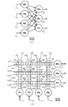
- FIG. 1 It is a figure which shows the unit which modeled one neuron. It is a figure which shows the neural network circuit which concerns on 1st Embodiment. It is a figure which shows a part of neural network circuit etc. which concern on 1st Embodiment, (a) is a figure which shows the said part, (b) is a neural network circuit at the time of comprising the said part with an analog circuit FIG. It is a figure which shows the neural network circuit which concerns on 2nd Embodiment.
- FIGS. 1 is a diagram showing a unit in which one neuron is modeled
- FIG. 2 is a diagram showing a neural network circuit according to the first embodiment
- FIG. 3 is a part of the neural network circuit.
- a neural network is a model that attempts to realize brain functions in a computer by modeling transmission and reception of electrical signals between neurons in the brain.
- a plurality of input data I 1 , input data I 2 ,..., And input data I n (n is a natural number; the same applies hereinafter) input from the outside.
- Multiplication processing, addition processing, and activation function application processing are executed centering on a neuron NR as one unit, and the result is output data O from that neuron NR, so that one neuron in the brain function is Model the transmission and reception of the electrical signal.
- the activation function application processing is simply referred to as “activation processing”.
- a plurality of input data I 1, the input data I 2, ..., the input data I n is set in advance in correspondence to the respective (i.e.
- the multiplication process is executed by multiplying respectively the input data I n. Then, the input data I 1, the input data I 2, ..., the addition process for adding the respective results of the multiplication process is executed for the neurons NR to the input data I n. Then, the activation process for applying the predetermined activation function F to the result of the addition process is executed, and the result is output to the NR as one or more neurons as the output data ⁇ ⁇ ⁇ ⁇ ⁇ .
- weighting factor W 1 the weighting factor W 2, ..., the weighting coefficient W n input data I 1, the input data I 2, ..., multiplication processing that multiplies to the input data I n, the electric between neurons NR This corresponds to the action of the synapse in signal exchange.
- FIG. 1 (B) Neural Network Circuit According to First Embodiment Next, a neural network circuit SS according to the first embodiment provided with a plurality of neurons NR illustrated in FIG. 1 will be described with reference to FIG.
- This neural network circuit SS corresponds to an example of a “learning device” according to the present invention.
- the entire brain is modeled as a neural network NW by gathering a large number of one neuron NR (one unit) illustrated in FIG. 1 and connecting them together by synapses.
- input data I when describing common matters in the input data I 1 to the input data I n, simply referred to as "input data I”.
- output data O when describing common matters in the output data O 1 to the output data O n, simply referred to as “output data O”.
- weighting coefficient W when describing common matters in the weighting coefficient W 1 to the weighting coefficient W n is described, it is simply referred to as “weighting coefficient W”.
- the neural network circuit SS includes a self-learning control unit C that controls a self-learning function in the neural network NW.
- the data output from the input side as a result of re-inputting the output data O of the entire neural network NW from the output side to the neural network NW is the original input data I.
- the neural network NW is controlled so as to coincide with the self-learning function as the neural network circuit SS.
- This self-learning control unit C corresponds to an example of a “control unit” according to the present invention.
- the input side neuron NR i1 is connected to all of the output side neurons NR o1 to neuron NR o3
- the input side neuron NR i2 is also connected to all of the neurons NR o1 to neuron NR o3
- the input-side neuron NR i3 is also connected to all of the neurons NR o1 to NR o3
- the input-side neuron NR i4 is also connected to all of the neurons NR o1 to NR o3 .
- neuroon NR when the common items of the neurons NR i1 to NR i4 and the neurons NR o1 to NR o3 are described, they are simply referred to as “neuron NR”.
- the arrows shown between the neurons NR i1 to NR i4 and the neurons NR o1 to NR o3 correspond to the weighting coefficient W between the neurons NR.
- neuron NR i1 to neuron NR i4 corresponds to an example of the "input portion" of the present invention
- the neuron NR o1 to neuron NR o3 corresponds to an example of the "output part" of the present invention.
- the neural network circuit SS is connected to the neurons NR i1 to neuron NR i4 and has positive voltages corresponding to the input data I 1 to input data I 4.
- four of four of the positive voltage line Li1 + to a positive voltage line Li4 + the applied negative voltage corresponding to the respective inputs are connected to the neuron NR i1 to neuron NR i4 data I 1 to the input data I 4 is applied negative voltage line of the Li1- to the negative voltage line Li4-, neuron NR o1 to the neuron NR o3 three positive voltage lines respectively connected to the Lo1 + to the positive voltage line Lo3 +, respectively neuron NR o1 to neurons NR o3 Three negative voltage lines Lo1- to negative voltage line Lo3- are connected.
- the positive voltage line Li1 + to the positive voltage line Li4 +, the negative voltage line Li1- to the negative voltage line Li4-, the positive voltage line Lo1 + to the positive voltage line Lo3 +, the negative voltage line Lo1- to the negative voltage line Lo3- are formed in separate layers, for example, by photolithography.
- a connection portion CN11 connecting the neuron NR i1 and the neuron NR o1 is formed by a positive voltage line Li1 +, a negative voltage line Li1-, a positive voltage line Lo1 +, and a negative voltage line Lo1-.
- a connection portion CN12 that connects NR i1 and neuron NR o2 is formed by a positive voltage line Li1 +, a negative voltage line Li1-, a positive voltage line Lo2 +, and a negative voltage line Lo2-, and connects neuron NR i1 and neuron NR o3.
- connection portion CN13 is formed by a positive voltage line Li1 +, a negative voltage line Li1-, a positive voltage line Lo3 +, and a negative voltage line Lo3-.
- a connection portion CN21 connecting the neuron NR i2 and the neuron NR o1 is formed by the positive voltage line Li2 +, the negative voltage line Li2-, the positive voltage line Lo1 +, and the negative voltage line Lo1-, and the neuron NR i2 and the neuron NR o2 connecting portions CN22 connecting the positive voltage line Li2 + and the negative voltage line Li2-, is formed by the positive voltage line Lo2 + and the negative voltage line Lo2-, connecting portions CN23 to connect the neuron NR i2 and neuron NR o3 positive voltage line It is formed by Li2 +, negative voltage line Li2-, positive voltage line Lo3 + and negative voltage line Lo3-.
- connection part CN31 connecting the neuron NR i3 and the neuron NR o1 is formed by the positive voltage line Li3 +, the negative voltage line Li3-, the positive voltage line Lo1 +, and the negative voltage line Lo1-, and the neuron NR i3 and the neuron NR o2 Is connected by a positive voltage line Li3 +, a negative voltage line Li3-, a positive voltage line Lo2 +, and a negative voltage line Lo2-, and a connection part CN33 connecting the neuron NR i3 and the neuron NR o3 is a positive voltage line. It is formed by Li3 +, negative voltage line Li3-, positive voltage line Lo3 +, and negative voltage line Lo3-.
- connection portion CN41 connecting the neuron NR i4 and the neuron NR o1 is formed by the positive voltage line Li4 +, the negative voltage line Li4-, the positive voltage line Lo1 +, and the negative voltage line Lo1-, and the neuron NR i4 and the neuron NR o2 connecting portions CN42 connecting the positive voltage line Li4 + a, negative voltage line Li4-, is formed by the positive voltage line Lo2 + and the negative voltage line Lo2-, connecting portions CN43 to connect the neuron NR i4 and neuron NR o3 positive voltage line It is formed by Li4 +, negative voltage line Li4-, positive voltage line Lo3 + and negative voltage line Lo3-.
- connection portion CN In each connection portion CN, positive voltage lines (for example, positive voltage line Li1 + and positive voltage line Lo1 +; the same applies hereinafter) or negative voltage lines (for example, negative voltage line Li1- and negative voltage line Lo1-). Only one of them is connected by a resistance element having a resistance value corresponding to each of the weighting coefficients W corresponding thereto.
- positive voltage lines for example, positive voltage line Li1 + and positive voltage line Lo1 +; the same applies hereinafter
- negative voltage lines for example, negative voltage line Li1- and negative voltage line Lo1-
- connection part CN11 and the like connected to each other and the number of connection parts CN13 and the like to which negative voltage lines are connected are the same for the entire neural network circuit SS, and further, the connection part CN11 and the like to which positive voltage lines are connected. Then, the connection part CN13 or the like to which the negative voltage lines are connected is determined in advance so as to be distributed uniformly and randomly (that is, randomly) over the entire neural network circuit SS.
- the positive voltage lines are connected to each other even when only one of the positive voltage lines or the negative voltage lines is connected by a resistance element in each connection portion CN11 or the like by the research of the inventors of the present application.
- the number of the connected parts CN11 and the like and the number of the connected parts CN11 and the like to which the negative voltage lines are connected are the same for the entire neural network circuit SS, and they are uniformly random for the whole neural network circuit SS. This is because it has been found that the same performance as the conventional one is secured in the learning function and the generalization function of the entire neural network circuit SS.
- the generalization function is a function for correctly classifying the unlearned input data I.
- connection part CN11 or the like in which only the positive voltage lines are connected corresponds to an example of the “positive exclusive connection part” according to the present invention
- connection part CN13 or the like in which only the negative voltage lines are connected is the present invention. It corresponds to an example of the “negative dedicated connection part”.
- the resistance element R1 in the connection portion CN11 corresponds to the positive weighting coefficient W when the neuron NR i1 and the neuron NR o1 are connected.
- the variable resistance element described in FIG. 1 or FIG. 3 of the above-mentioned Patent Document 1 is specifically used as the connection mode between the positive voltage line Li1 + and the positive voltage line Lo1 + by the resistance element R1. This is basically the same as the connection mode of the voltage lines (the same applies to each connection portion CN below).
- connection part CN12 only the positive voltage line Li1 + and the positive voltage line Lo2 + are connected by the resistor element R5, and the resistance value of the resistor element R5 is the positive value when the neuron NR i1 and the neuron NR o2 are connected. This corresponds to the weighting coefficient W.
- connection portion CN13 only the negative voltage line Li1- and the negative voltage line Lo3- are connected by the resistance element R9, and the resistance value of the resistance element R9 is the above when the neuron NR i1 and the neuron NR o3 are connected. Corresponds to a negative weighting factor W.
- connection part CN21 only the negative voltage line Li2- and the negative voltage line Lo1- are connected by the resistance element R2, and the resistance value of the resistance element R2 is used when the neuron NR i2 and the neuron NR o1 are connected. This corresponds to the negative weighting coefficient W.
- connection part CN22 only the positive voltage line Li2 + and the positive voltage line Lo2 + are connected by the resistance element R6, and the resistance value of the resistance element R6 is the positive value when the neuron NR i2 and the neuron NR o2 are connected. This corresponds to the weighting coefficient W.
- connection part CN23 only the positive voltage line Li2 + and the positive voltage line Lo3 + are connected by the resistance element R10, and the resistance value of the resistance element R10 is the positive value when the neuron NR i2 and the neuron NR o3 are connected. This corresponds to the weighting coefficient W.
- connection part CN31 only the positive voltage line Li3 + and the positive voltage line Lo1 + are connected by the resistance element R3, and the resistance value of the resistance element R3 is the above when the neuron NR i3 and the neuron NR o1 are connected. Corresponds to a positive weighting factor W.
- connection part CN32 only the negative voltage line Li3- and the negative voltage line Lo2- are connected by the resistance element R7, and the resistance value of the resistance element R7 is the above when the neuron NR i3 and the neuron NR o2 are connected. Corresponds to a negative weighting factor W.
- connection part CN33 only the positive voltage line Li3 + and the positive voltage line Lo3 + are connected by the resistor element R11, and the resistance value of the resistor element R11 is the positive value when the neuron NR i3 and the neuron NR o3 are connected. This corresponds to the weighting coefficient W. Furthermore, in the connection part CN41, only the negative voltage line Li4- and the negative voltage line Lo1- are connected by the resistor element R4, and the resistance value of the resistor element R4 is the above when the neuron NR i4 and the neuron NR o1 are connected. Corresponds to a negative weighting factor W.
- connection part CN42 only the negative voltage line Li4- and the negative voltage line Lo2- are connected by the resistance element R8, and the resistance value of the resistance element R8 is the above when the neuron NR i4 and the neuron NR o2 are connected. Corresponds to a negative weighting factor W. Finally in the connecting portion CN43 and only the negative voltage line Li4- the negative voltage line Lo3- it is connected by the resistor element R12, when a resistance value of the resistive element R12 is connected to the neuron NR i4 and neuron NR o3 This corresponds to the negative weighting coefficient W.
- the neuron NR i1 to neuron NR i4 on the input side, the neuron NR o1 to neuron NR o3 on the output side, and the connection unit CN A self-learning control unit C, and each control unit CN includes a connection unit CN11 and the like in which only positive voltage lines are connected to each other, and a connection unit CN13 and the like in which only negative voltage lines are connected to each other. Yes. Therefore, the area occupied by the connection portion CN in the neural network circuit SS can be greatly reduced.
- connection portions CN11 and the like to which only the positive voltage lines are connected is the same as the number of connection parts CN13 and the like to which only the negative voltage lines are connected, the learning ability as the neural network circuit SS The area occupied by the connection portion CN can be greatly reduced while improving the above.
- connection part CN11 etc. in which only the positive voltage lines are connected and the connection part CN13 etc. in which only the negative voltage lines are connected are uniformly distributed in a random manner, The area occupied by the connection portion CN can be significantly reduced while maintaining the generalization capability together.
- the pattern overlap (that is, the restoration rate of the numerical pattern learned by the above-mentioned encoder) is about 91% (more specifically 91.4% (the input side neuron NR is 784, the output side The value is obtained when the neuron NR is 293 and the weighting coefficient of 30 percent is updated at random by the perceptron learning rule)), for example, the conventional method (91.1% using the technique described in Patent Document 1 above) ) And the same restoration rate was obtained.
- the inventors of the present application manufactured a two-dimensional convolutional encoder using the configuration of the neural network circuit SS according to the first embodiment, and performed a similar experiment.
- the pattern overlap is about 97% (more specifically, 97.0% (the input side neuron NR and the output side neuron NR are both 784, the convolution stride is 1, and the weighting coefficient is 30%) )), And the restoration rate was higher than that of the conventional method (91.4%).
- the inventors of the present application conducted an experiment for further multilayering, and finally performed a similar experiment with the addition of a three-layer backpropagation algorithm. It has been confirmed that high functionality can be expected if sufficient time is spent for learning.
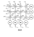
- FIG. 4 is a diagram showing a neural network circuit according to the second embodiment.
- the same components as those of the neural network circuit SS according to the first embodiment are denoted by the same member numbers, and detailed description thereof is omitted.
- the neural network circuit SS1 is connected to the input-side neuron NR i1 and neuron NR i3 , respectively, and has positive voltages corresponding to the input data I 1 and the input data I 3 , respectively.
- negatively positive voltage line Li1 + and the positive voltage line Li3 +, a negative voltage corresponding to each are connected to the input side of the neuron NR i2 and neuronal NR i4 input data I 2 and the input data I 4 is applied to the applied Voltage line Li2- and negative voltage line Li4-, and voltage line Lo1 to voltage line Lo3 respectively connected to output side neurons NR o1 to neuron NR o3 are provided.
- the positive voltage line Li1 + and the positive voltage line Li3 +, the negative voltage line Li2- and the negative voltage line Li4-, and the voltage line Lo1 to the voltage line Lo3 are respectively in separate layers by the photolithography technique, for example. It is formed.
- a connection portion CN11 connecting the neuron NR i1 and the neuron NR o1 is formed by the positive voltage line Li1 + and the voltage line Lo1
- a connection portion CN12 connecting the neuron NR i1 and the neuron NR o2 is connected to the positive voltage line Li1 +.
- a connection portion CN13 formed by the voltage line Lo2 and connecting the neuron NR i1 and the neuron NR o3 is formed by the positive voltage line Li1 + and the voltage line Lo3.
- connection part CN21 connecting the neuron NR i2 and the neuron NR o1 is formed by the negative voltage line Li2- and the voltage line Lo1
- a connection part CN22 connecting the neuron NR i2 and the neuron NR o2 is formed by the negative voltage line Li2-.
- a voltage line Lo2 and a connection CN23 that connects the neuron NR i2 and the neuron NR o3 is formed by the negative voltage line Li2 ⁇ and the voltage line Lo3.
- connection part CN31 connecting the neuron NR i3 and the neuron NR o1 is formed by the positive voltage line Li3 + and the voltage line Lo1
- a connection part CN32 connecting the neuron NR i3 and the neuron NR o2 is connected to the positive voltage line Li3 + and the voltage.
- a connection portion CN33 formed by the line Lo2 and connecting the neuron NR i3 and the neuron NR o3 is formed by the positive voltage line Li3 + and the voltage line Lo3.
- connection part CN41 connecting the neuron NR i4 and the neuron NR o1 is formed by the negative voltage line Li4- and the voltage line Lo1
- a connection part CN42 connecting the neuron NR i4 and the neuron NR o2 is formed by the negative voltage line Li4- and is formed by a voltage line Lo2
- connecting portions CN43 to connect the neuron NR i4 and neuron NR o3 is formed by the negative voltage line Li4- and voltage line Lo3.
- the voltage lines which comprise each are connected by the resistance element of the resistance value respectively corresponding to the said weighting coefficient W as each connection part CN.
- the number of connections CN to which Li2- and the negative voltage line Li4- and the voltage lines Lo1 to Lo3 are connected is the same for the entire neural network circuit SS1, and further, the positive voltage line Li1 + and the positive voltage line A connection portion CN to which Li3 + and the voltage lines Lo1 to Lo3 are connected; a connection portion CN to which the negative voltage line Li2 ⁇ and the negative voltage line Li4 ⁇ and the voltage lines Lo1 to voltage line Lo3 are connected; Is determined in advance so as to be distributed regularly over the entire neural network circuit SS1.
- connection portions CN11 and the like in which the positive voltage line and the voltage line Lo1 are connected to each other and the number of connection portions CN21 and the like in which the negative voltage line and the voltage line Lo1 and the like are connected to each other are a neural network. It has been found that the same number is obtained for the entire circuit SS1, and further, if they are regularly distributed for the entire neural network circuit SS1, the learning function of the entire neural network circuit SS1 ensures the same performance as before. It depends.
- the positive voltage line Li1 + and the voltage line Lo1 are connected by the resistance element R20 in the connection portion CN11, and the resistance value of the resistance element R20.
- the positive voltage line Li1 + and the voltage line Lo2 are connected by the resistance element R24, and the resistance value of the resistance element R24 is the positive weighting coefficient when the neuron NR i1 and the neuron NR o2 are connected. It corresponds to W.
- connection CN13 and the positive voltage line Li1 + a voltage line Lo3 are connected by the resistor element R28, the positive weighting coefficients when the resistance value of the resistive element R28 is connected to the neuron NR i1 and neuron NR o3 It corresponds to W.
- the negative voltage line Li2- and the voltage line Lo1 are connected by the resistance element R21, and the resistance value of the resistance element R21 is the negative value when the neuron NR i2 and the neuron NR o1 are connected. This corresponds to the weighting coefficient W.
- connection CN22 has a negative voltage line Li2- and voltage line Lo2 are connected by the resistor element R25, the negative weighting when the resistance value of the resistive element R25 is connected to the neuron NR i2 and neuron NR o2 This corresponds to the coefficient W.
- connection CN23 has a negative voltage line Li2- and voltage line Lo3 are connected by the resistor element R29, the negative weighting when the resistance value of the resistive element R29 is connected to the neuron NR i2 and neuron NR o3 This corresponds to the coefficient W.
- connection part CN31 the positive voltage line Li3 + and the voltage line Lo1 are connected by the resistance element R22, and the resistance value of the resistance element R22 is the positive value when the neuron NR i3 and the neuron NR o1 are connected.
- W the weighting coefficient W.
- the positive voltage line Li3 + and the voltage line Lo2 are connected by a resistance element R26, and the resistance value of the resistance element R26 is the positive weighting coefficient when the neuron NR i3 and the neuron NR o2 are connected. It corresponds to W.
- connection part CN33 the positive voltage line Li3 + and the voltage line Lo3 are connected by the resistance element R30, and the resistance value of the resistance element R30 is the positive weighting coefficient when the neuron NR i3 and the neuron NR o3 are connected. It corresponds to W.
- a negative voltage line Li4- and voltage line Lo1 is at connection CN41 is a resistive element R23, the negative weighting when the resistance value of the resistive element R23 is connected to the neuron NR i4 and neuron NR o1 This corresponds to the coefficient W.
- connection part CN42 the negative voltage line Li4- and the voltage line Lo2 are connected by the resistance element R27, and the negative weight when the resistance value of the resistance element R27 connects the neuron NR i4 and the neuron NR o2. This corresponds to the coefficient W.
- the negative voltage line Li4- and the voltage line Lo3 are connected by the resistance element R31, and the resistance value of the resistance element R31 is the negative value when the neuron NR i4 and the neuron NR o3 are connected. This corresponds to the weighting coefficient W.
- a neuron NR i1 to neurons NR i4 input side a neuron NR o1 to neurons NR o3 the output side, and a connecting portion CN
- each control unit CN includes a connection unit CN11 to which a positive voltage line is connected and a connection unit CN21 to which a negative voltage line is connected. Therefore, the area occupied by the connection portion CN in the neural network circuit SS1 can be significantly reduced.
- connection parts CN11 to which the positive voltage line is connected is the same as the number of connection parts CN21 to which the negative voltage line is connected, the learning ability as the neural network circuit SS1 is improved.
- the area occupied by the connection CN can be greatly reduced.
- connection part CN11 to which the positive voltage line is connected and the connection part CN21 to which the negative voltage line is connected are regularly distributed, the connection part is maintained while maintaining the same learning ability as in the prior art.
- the occupied area of CN can be greatly reduced.
- the present invention can be used in the field of neural network circuits, and particularly when applied to the field of learning devices including such neural network circuits, a particularly remarkable effect can be obtained.
- C self-learning controller SS SS1 neural network circuit I 1, I 2, I n input data NR, NR i1, NR i2, NR i3, NR i4, NRo 1, NRo 2, NRo 3 neurons W 1, W 2, W n Weighting coefficient O, O 1 , O 2 , O 3
- Output data NW Neural network Li1 +, Li2 +, Li3 +, Li4 +, Lo1 +, Lo2 +, Lo3 + Positive voltage lines Li1-, Li2-, Li3-, Li4-, Lo1-, Lo2-, Lo3- negative voltage lines Lo1, Lo2, Lo3 voltage lines CN11, CN12, CN13, CN21, CN22, CN23, CN31, CN32, CN33, CN41, CN42, CN43 connections R1, R2, R3, R4, R5, R6, R7, R8, R9, R10, R11, R12, R20, R21, R22, R23, R24, R25, R26, R
Landscapes
- Engineering & Computer Science (AREA)
- Physics & Mathematics (AREA)
- Theoretical Computer Science (AREA)
- Health & Medical Sciences (AREA)
- Life Sciences & Earth Sciences (AREA)
- Biomedical Technology (AREA)
- Biophysics (AREA)
- General Health & Medical Sciences (AREA)
- General Physics & Mathematics (AREA)
- Evolutionary Computation (AREA)
- Computational Linguistics (AREA)
- Molecular Biology (AREA)
- Computing Systems (AREA)
- General Engineering & Computer Science (AREA)
- Data Mining & Analysis (AREA)
- Mathematical Physics (AREA)
- Software Systems (AREA)
- Artificial Intelligence (AREA)
- Neurology (AREA)
- Image Analysis (AREA)
- Feedback Control In General (AREA)
Abstract
FC型ニューラルネットワーク回路における接続部の占有面積を大幅に低減することが可能なニューラルネットワーク回路を提供する。 自己学習機能を有する学習装置を構成し且つ脳機能に対応したアナログ型のニューラルネットワーク回路SSにおいて、複数(n個)の入力側のニューロンNRと、複数(m個且つn=mの場合を含む)の出力側のニューロンNRと、一の入力側ニューロンNRと一の出力側ニューロンNRとをそれぞれ接続する(n×m)個の接続部CNと、自己学習制御部Cと、を備え、(n×m)個の接続部CNは、脳機能としての正の重み付け機能のみに対応した接続部CNと、当該脳機能としての負の重み付け機能のみに対応した接続部CNと、により構成されている。
Description
本発明は、ニューラルネットワーク回路を備えた重み符号固定学習装置の技術分野に属し、より詳細には、脳機能に対応するアナログ型のニューラルネットワーク回路を備えた自己学習型の重み符号固定学習装置の技術分野に属する。
近年、人の脳機能に対応したニューラルネットワーク回路を用いた深層学習機能(いわゆるディープラーニング機能)に関連する研究開発が盛んに行われている。このとき、ニューラルネットワーク回路を具体的に実現する場合には、デジタル回路が用いられる場合とアナログ回路が用いられる場合とがある。ここで、前者は処理能力としては高いが大規模なハードウェア構成が必要となると共に消費電力が大きくなるため、例えばデータセンタ等において用いられる。これに対して後者は、処理能力はデジタル回路が用いられる場合より劣るものの、ハードウェア構成としての最小化及び消費電力の低減が期待できるため、例えば上記データセンタ等に接続される端末装置用として利用されることが多い。そして、後者に関する先行技術としては、例えば下記特許文献1に開示されている技術が挙げられる。
この特許文献1には、アナログ回路により構成された(即ちアナログ型の)ニューラルネットワーク回路であって、入力側のニューロンの全てと出力側のニューロンの全てとを、それぞれの重み付けに対応した抵抗値を有する接続部により一対一に接続する、深層学習用のいわゆる全結合(FC(Full Connection))型ニューラルネットワーク回路が開示されている。この場合の重み付けとは、当該ニューラルネットワーク回路が対応すべき脳機能に対応した重み付けであり、特許文献1に開示されているニューラルネットワーク回路では、各接続部の抵抗値を可変抵抗素子により構成することで当該重み付けに対応させている。このようなFC型ニューラルネットワーク回路は、例えば近傍結合型等の他の形式のニューラルネットワーク回路や、より大規模なニューラルネットワーク回路の一部として活用できるため、それ自体の更なる処理能力の向上と共に、回路規模(占有面積)の縮小化が望まれる。
ここで、上記ニューラルネットワーク回路の機能を脳機能により近付けるためには、一般に、上記重み付けとして、正の重み付けに加えて負の重み付けを用いることが必要となる。一方、上記接続部としての抵抗値は、各接続部において一定(即ち抵抗値固定式)である。よって、このような接続部により上記正の重み付けと負の重み付けとを共に実現しようとすると、入力側の一ニューロンに対応する入力データに相当する入力信号を、絶対値が等しい正の入力信号と負の入力信号とに分け、同じ抵抗値を有する二つの抵抗にこれら二つの入力信号を選択的に入力する構成とする必要がある。このとき、上記「選択的に入力する」とは、正の重み付けを実現する場合には正の入力信号のみを入力し、負の重み付けを実現する場合には負の入力信号のみを入力することを意味する。なお、正の重み付けを実現する場合には、結果的に負の入力信号用の抵抗は使用されないことになり、また負の重み付けを実現する場合には、結果的に正の入力信号用の提供は使用されないことになるが、正の重み付けを実現するか負の重み付けを実現するかは、対応させる脳機能によりニューラルネットワーク回路ごとに異なるため、回路としての汎用性を実現するためには、入力側の一のニューロンと出力側の一のニューロンとを接続する一の接続部ごとに上記二つの抵抗を予め造っておく必要がある。そしてこの場合には、当該二つの抵抗により一つの接続部が構成されることから、接続部としての回路規模(占有面積)が結果として二倍となってしまい、当該占有面積の縮小化が図れないという問題点があった。
そしてこの問題点は、入力側のニューロンの数と出力側のニューロンの数とを乗じた数だけ接続部が必要となるFC型ニューラルネットワーク回路では、接続部の多数化に伴い、占有面積の増大がより深刻化するという問題点に繋がる。
そこで本発明は、上記の各問題点に鑑みて為されたもので、その課題の一例は、FC型ニューラルネットワーク回路における接続部の占有面積を大幅に低減することが可能な自己学習型の重み符号固定学習装置を提供することにある。
上記の課題を解決するために、請求項1に記載の発明は、脳機能に対応したアナログ型のニューラルネットワーク回路を備えた自己学習型の重み符号固定学習装置において、前記ニューラルネットワーク回路は、入力データに相当する入力信号がそれぞれ入力される複数(n個)の入力部と、出力データに相当する出力信号がそれぞれ出力される複数(m個且つn=mの場合を含む)の出力部と、一の前記入力部と一の前記出力部とをそれぞれ接続する(n×m)個の接続部と、により構成されており、前記出力データを前記出力部から前記重み符号固定学習装置に再入力した結果として前記入力部から出力されるデータが元の前記入力データと一致するように当該重み符号固定学習装置を制御して、前記自己学習の機能を実行させる自己学習制御部等の制御手段を備え、(n×m)個の前記接続部は、前記脳機能としての正の重み付け機能のみに対応した前記接続部である正専用接続部と、当該脳機能としての負の重み付け機能のみに対応した前記接続部である負専用接続部と、により構成されている。
請求項1に記載の発明は、n個の入力部と、m個の出力部と、(n×m)個の接続部と、自己学習の機能を実行させる制御手段と、を備え、(n×m)個の接続部が正専用接続部及び負専用接続部により構成されている。よって、正専用接続部及び負専用接続部から各接続部が構成されているので、ニューラルネットワーク回路における接続部の占有面積を大幅に低減することができる。
上記の課題を解決するために、請求項2に記載の発明は、請求項1に記載の重み符号固定学習装置において、前記正専用接続部と前記負専用接続部とが同数であるように構成される。
請求項2に記載の発明によれば、請求項1に記載の発明の作用に加えて、正専用接続部と負専用接続部とが同数であるので、重み符号固定学習装置としての学習能力を向上させつつ、接続部の占有面積を大幅に低減することができる。
上記の課題を解決するために、請求項3に記載の発明は、請求項1又は請求項2に記載の重み符号固定学習装置において、前記正専用接続部及び前記負専用接続部が、(n×m)個の前記接続部において一様乱数的に分布しているように構成される。
請求項3に記載の発明によれば、請求項1又は請求項2に記載の発明の作用に加えて、正専用接続部及び負専用接続部が、(n×m)個の接続部において一様乱数的に分布しているので、従来と同様の学習能力及び汎化能力を共に維持しつつ、接続部の占有面積を大幅に低減することができる。
上記の課題を解決するために、請求項4に記載の発明は、請求項1又は請求項2に記載の重み符号固定学習装置において、前記正専用接続部及び前記負専用接続部が、(n×m)個の前記接続部において規則的に分布しているように構成される。
請求項4に記載の発明によれば、請求項1又は請求項2に記載の発明の作用に加えて、正専用接続部及び負専用接続部が、(n×m)個の接続部において規則的に分布しているので、従来と同様の学習能力を維持しつつ、接続部の占有面積を大幅に低減することができる。
本発明によれば、n個の入力部と、m個の出力部と、(n×m)個の接続部と、自己学習機能を実行させる制御手段と、を備え、(n×m)個の接続部が正専用接続部及び負専用接続部により構成されている。
従って、正専用接続部及び負専用接続部から各接続部が構成されているので、アナログ型のニューラルネットワーク回路を備えた自己学習型の重み符号固定学習装置における接続部の占有面積を大幅に低減することができる。
次に、本発明に係る実施形態について、図面に基づいてそれぞれ説明する。なお以下に説明する各実施形態は、人の脳機能をアナログ型のニューラルネットワーク回路によりモデル化する場合について本発明を適用した場合の実施形態等である。
(I)第1実施形態
初めに、本発明に係る第1実施形態について、図1乃至図3を用いて説明する。なお、図1は一つのニューロンをモデル化したユニットを示す図であり、図2は第1実施形態に係るニューラルネットワーク回路を示す図であり、図3は当該ニューラルネットワーク回路の一部等を示す図である。
初めに、本発明に係る第1実施形態について、図1乃至図3を用いて説明する。なお、図1は一つのニューロンをモデル化したユニットを示す図であり、図2は第1実施形態に係るニューラルネットワーク回路を示す図であり、図3は当該ニューラルネットワーク回路の一部等を示す図である。
(A)ニューラルネットワークについて
先ず、上記脳機能をモデル化したニューラルネットワークについて、図1を用いて一般的に説明する。
先ず、上記脳機能をモデル化したニューラルネットワークについて、図1を用いて一般的に説明する。
一般に人の脳の中には、多数のニューロン(神経細胞)が存在しているとされている。脳の中で各ニューロンは、多数の他のニューロンからの電気信号を受信し、また更に他の多数のニューロンへ電気信号を送信している。そして脳は、各ニューロン間のこれら電気信号の流れによって、様々な情報処理を行っているとされている。このとき、各ニューロン間における電気信号の送受信は、シナプスと呼ばれる細胞を介して行われる。そして、脳における上記ニューロン間の電気信号の送受信をモデル化してコンピュータ内に脳機能を実現しようとしたものが、ニューラルネットワークである。
より具体的にニューラルネットワークでは図1に例示するように、外部から入力される複数の入力データI1、入力データI2、…、入力データIn(nは自然数。以下同様。)のそれぞれに対する乗算処理、加算処理及び活性化関数の適用処理が、一つのユニットとしてのニューロンNRを中心として実行され、その結果をそのニューロンNRからの出力データOとすることで、脳機能における一つのニューロンに対する上記電気信号の送受信をモデル化する。なお以下の説明において、上記活性化関数の適用処理を、単に「活性化処理」と称する。このとき一つのニューロンNRについて、複数の入力データI1、入力データI2、…、入力データInそれぞれに対応して予め設定された(つまり既定の)重み付け係数W1、重み付け係数W2、…、重み付け係数Wnを当該入力データI1、入力データI2、…、入力データInに対してそれぞれ乗算することで上記乗算処理が実行される。その後、各入力データI1、入力データI2、…、入力データInに対する上記乗算処理の結果のそれぞれを加算する上記加算処理が当該ニューロンNRについて実行される。そして次に、上記加算処理の結果に既定の活性化関数Fを適用する上記活性化処理が実行され、その結果を上記出力データΟとして他の一又は複数のニューロンにNRに出力する。上述した一連の乗算処理、加算処理及び活性化処理を数式で表すと、図1に示す式(1)となる。このとき、重み付け係数W1、重み付け係数W2、…、重み付け係数Wnを入力データI1、入力データI2、…、入力データInにそれぞれ乗算する乗算処理が、ニューロンNR間の上記電気信号のやり取りにおける上記シナプスの作用に相当する。
(B)第1実施形態に係るニューラルネットワーク回路について
次に、図1に例示するニューロンNRを複数備えた第1実施形態に係るニューラルネットワーク回路SSについて、図2を用いて説明する。このニューラルネットワーク回路SSが本発明に係る「学習装置」の一例に相当する。
次に、図1に例示するニューロンNRを複数備えた第1実施形態に係るニューラルネットワーク回路SSについて、図2を用いて説明する。このニューラルネットワーク回路SSが本発明に係る「学習装置」の一例に相当する。
図2に示すように、図1に例示する一つのニューロンNR(一ユニット)が多数集まってシナプスにより互いに接続されることにより、脳全体がニューラルネットワークNWとしてモデル化される。なお以下の説明において、入力データI1乃至入力データInに共通の事項を説明する場合、単に「入力データI」と称する。また同様に、出力データO1乃至出力データOnに共通の事項を説明する場合、単に「出力データO」と称する。更に同様に、重み付け係数W1乃至重み付け係数Wnに共通の事項を説明する場合、単に「重み付け係数W」と称する。
一方第1実施形態に係るニューラルネットワーク回路SSは、上記ニューラルネットワークNWに加えて、当該ニューラルネットワークNWにおける自己学習機能を制御する自己学習制御部Cを備える。第1実施形態に係る自己学習制御部Cは、ニューラルネットワークNW全体としての出力データOをその出力側からニューラルネットワークNWに再入力した結果としてその入力側から出力されるデータが元の入力データIと一致するようにニューラルネットワークNWを制御して、ニューラルネットワーク回路SSとしての自己学習機能を実行させる。この自己学習制御部Cが本発明に係る「制御手段」の一例に相当する。
次に、第1実施形態に係るニューラルネットワーク回路SSの一部の構成を、アナログ型のニューラルネットワーク回路を用いて具体化した構成について、図3を用いて説明する。なお以下の説明では、図3(a)に示す七つのニューロンNRにより構成されるニューラルネットワーク回路SSの一部を用いて、第1実施形態に係るアナログ型のニューラルネットワーク回路SSの構成を説明する。また図3では、図2に示した自己学習制御部Cの記載を省略している。
このとき図3(a)においては、入力データI1乃至入力データI4がそれぞれ入力される入力側のニューロンNRi1乃至ニューロンNRi4と、出力データO1乃至出力データO3がそれぞれ出力される出力側のニューロンNRo1乃至ニューロンNRo3と、が、それぞれ相互に接続されている。即ち、入力側のニューロンNRi1は出力側のニューロンNRo1乃至ニューロンNRo3の全てに接続されており、入力側のニューロンNRi2も当該ニューロンNRo1乃至ニューロンNRo3の全てに接続されており、入力側のニューロンNRi3も当該ニューロンNRo1乃至ニューロンNRo3の全てに接続されており、入力側のニューロンNRi4も当該ニューロンNRo1乃至ニューロンNRo3の全てに接続されている。なお以下の説明において、ニューロンNRi1乃至ニューロンNRi4及びニューロンNRo1乃至ニューロンNRo3について共通の事項を説明する場合、単に「ニューロンNR」と称する。そして、図3(a)においてニューロンNRi1乃至ニューロンNRi4とニューロンNRo1乃至ニューロンNRo3との間に示されている矢印が、各ニューロンNR間の上記重み付け係数Wに対応している。また、ニューロンNRi1乃至ニューロンNRi4が本発明に係る「入力部」の一例に相当し、ニューロンNRo1乃至ニューロンNRo3が本発明に係る「出力部」の一例に相当する。
そして図3(b)に示すように、第1実施形態に係るニューラルネットワーク回路SSは、ニューロンNRi1乃至ニューロンNRi4にそれぞれ接続され且つ入力データI1乃至入力データI4に対応した正電圧が印加される四本の正電圧線Li1+乃至正電圧線Li4+と、ニューロンNRi1乃至ニューロンNRi4にそれぞれ接続されて入力データI1乃至入力データI4のそれぞれに対応した負電圧が印加される四本の負電圧線Li1-乃至負電圧線Li4-と、ニューロンNRo1乃至ニューロンNRo3にそれぞれ接続された三本の正電圧線Lo1+乃至正電圧線Lo3+と、ニューロンNRo1乃至ニューロンNRo3にそれぞれ接続された三本の負電圧線Lo1-乃至負電圧線Lo3-と、を備えている。このとき、正電圧線Li1+乃至正電圧線Li4+と、負電圧線Li1-乃至負電圧線Li4-と、正電圧線Lo1+乃至正電圧線Lo3+と、負電圧線Lo1-乃至負電圧線Lo3-と、は、例えばフォトリソグラフィ技術により各々別個の層内に形成されている。
そして図3(b)においては、ニューロンNRi1とニューロンNRo1とを接続する接続部CN11が正電圧線Li1+、負電圧線Li1-、正電圧線Lo1+及び負電圧線Lo1-により形成され、ニューロンNRi1とニューロンNRo2とを接続する接続部CN12が正電圧線Li1+、負電圧線Li1-、正電圧線Lo2+及び負電圧線Lo2-により形成され、ニューロンNRi1とニューロンNRo3とを接続する接続部CN13が正電圧線Li1+、負電圧線Li1-、正電圧線Lo3+及び負電圧線Lo3-により形成される。また、ニューロンNRi2とニューロンNRo1とを接続する接続部CN21が正電圧線Li2+、負電圧線Li2-、正電圧線Lo1+及び負電圧線Lo1-により形成され、ニューロンNRi2とニューロンNRo2とを接続する接続部CN22が正電圧線Li2+、負電圧線Li2-、正電圧線Lo2+及び負電圧線Lo2-により形成され、ニューロンNRi2とニューロンNRo3とを接続する接続部CN23が正電圧線Li2+、負電圧線Li2-、正電圧線Lo3+及び負電圧線Lo3-により形成される。また、ニューロンNRi3とニューロンNRo1とを接続する接続部CN31が正電圧線Li3+、負電圧線Li3-、正電圧線Lo1+及び負電圧線Lo1-により形成され、ニューロンNRi3とニューロンNRo2とを接続する接続部CN32が正電圧線Li3+、負電圧線Li3-、正電圧線Lo2+及び負電圧線Lo2-により形成され、ニューロンNRi3とニューロンNRo3とを接続する接続部CN33が正電圧線Li3+、負電圧線Li3-、正電圧線Lo3+及び負電圧線Lo3-により形成される。更に、ニューロンNRi4とニューロンNRo1とを接続する接続部CN41が正電圧線Li4+、負電圧線Li4-、正電圧線Lo1+及び負電圧線Lo1-により形成され、ニューロンNRi4とニューロンNRo2とを接続する接続部CN42が正電圧線Li4+、負電圧線Li4-、正電圧線Lo2+及び負電圧線Lo2-により形成され、ニューロンNRi4とニューロンNRo3とを接続する接続部CN43が正電圧線Li4+、負電圧線Li4-、正電圧線Lo3+及び負電圧線Lo3-により形成される。なお以下の説明において、上記接続部CN11乃至上記接続部CN13、上記接続部CN21乃至上記接続部CN23、上記接続部CN31乃至上記接続部CN33、及び上記接続部CN41乃至上記接続部CN43に共通する事項を説明する場合、単に「接続部CN」と称する。そして、各接続部CNのそれぞれにおいては、正電圧線同士(例えば正電圧線Li1+と正電圧線Lo1+。以下、同様。)又は負電圧線同士(例えば負電圧線Li1-と負電圧線Lo1-。以下、同様)のいずれか一方のみが、それが対応する上記重み付け係数Wにそれぞれ対応する抵抗値の抵抗素子により接続される。
そして図3(b)に示す第1実施形態に係るニューラルネットワーク回路SSでは、各接続部CNに含まれる各電圧線のいずれが上記抵抗素子により接続されるかは、正電圧線同士が接続されている接続部CN11等の数と負電圧線同士が接続されている接続部CN13等の数とが当該ニューラルネットワーク回路SS全体について同数となり、更に、正電圧線同士が接続された接続部CN11等と、負電圧線同士が接続された接続部CN13等が、当該ニューラルネットワーク回路SS全体について一様乱数的に(即ちランダムに)分布するように、予め決定される。これは、本願の発明者らの研究により、各接続部CN11等において正電圧線同士又は負電圧線同士のいずれか一方のみを抵抗素子により接続する場合であっても、正電圧線同士が接続されている接続部CN11等の数と負電圧線同士が接続されている接続部CN11等の数とがニューラルネットワーク回路SS全体について同数となり、更に、それらがニューラルネットワーク回路SS全体について一様乱数的に分布していれば、ニューラルネットワーク回路SS全体の学習機能及び汎化機能において従来と同様の性能が担保されることが発見されたことによる。ここで上記汎化機能とは、未学習の入力データIを正しく分類する機能をいう。また、正電圧線同士のみが接続されている接続部CN11等が本発明に係る「正専用接続部」の一例に相当し、負電圧線同士のみが接続されている接続部CN13等が本発明に係る「負専用接続部」の一例に相当する。
ここで、図3(b)に例示する第1実施形態に係るニューラルネットワーク回路SSでは、接続部CN11においては正電圧線Li1+と正電圧線Lo1+のみが抵抗素子R1により接続されており、当該抵抗素子R1の抵抗値がニューロンNRi1とニューロンNRo1とを接続する際の上記正の重み付け係数Wに対応している。なお、正電圧線Li1+と正電圧線Lo1+との抵抗素子R1による接続の態様は、具体的には、例えば上記特許文献1の第1図又は第3図に記載されている可変抵抗素子を用いた電圧線の接続態様と基本的に同一である(以下の各接続部CNにおいて同様)。また接続部CN12においては正電圧線Li1+と正電圧線Lo2+のみが抵抗素子R5により接続されており、当該抵抗素子R5の抵抗値がニューロンNRi1とニューロンNRo2とを接続する際の上記正の重み付け係数Wに対応している。また接続部CN13においては負電圧線Li1-と負電圧線Lo3-のみが抵抗素子R9により接続されており、当該抵抗素子R9の抵抗値がニューロンNRi1とニューロンNRo3とを接続する際の上記負の重み付け係数Wに対応している。更に、接続部CN21においては負電圧線Li2-と負電圧線Lo1-のみが抵抗素子R2により接続されており、当該抵抗素子R2の抵抗値がニューロンNRi2とニューロンNRo1とを接続する際の上記負の重み付け係数Wに対応している。また接続部CN22においては正電圧線Li2+と正電圧線Lo2+のみが抵抗素子R6により接続されており、当該抵抗素子R6の抵抗値がニューロンNRi2とニューロンNRo2とを接続する際の上記正の重み付け係数Wに対応している。また接続部CN23においては正電圧線Li2+と正電圧線Lo3+のみが抵抗素子R10により接続されており、当該抵抗素子R10の抵抗値がニューロンNRi2とニューロンNRo3とを接続する際の上記正の重み付け係数Wに対応している。
更にまた、接続部CN31においては正電圧線Li3+と正電圧線Lo1+のみが抵抗素子R3により接続されており、当該抵抗素子R3の抵抗値がニューロンNRi3とニューロンNRo1とを接続する際の上記正の重み付け係数Wに対応している。また接続部CN32においては負電圧線Li3-と負電圧線Lo2-のみが抵抗素子R7により接続されており、当該抵抗素子R7の抵抗値がニューロンNRi3とニューロンNRo2とを接続する際の上記負の重み付け係数Wに対応している。また接続部CN33においては正電圧線Li3+と正電圧線Lo3+のみが抵抗素子R11により接続されており、当該抵抗素子R11の抵抗値がニューロンNRi3とニューロンNRo3とを接続する際の上記正の重み付け係数Wに対応している。更に接続部CN41においては負電圧線Li4-と負電圧線Lo1-のみが抵抗素子R4により接続されており、当該抵抗素子R4の抵抗値がニューロンNRi4とニューロンNRo1とを接続する際の上記負の重み付け係数Wに対応している。また接続部CN42においては負電圧線Li4-と負電圧線Lo2-のみが抵抗素子R8により接続されており、当該抵抗素子R8の抵抗値がニューロンNRi4とニューロンNRo2とを接続する際の上記負の重み付け係数Wに対応している。最後に接続部CN43においては負電圧線Li4-と負電圧線Lo3-のみが抵抗素子R12により接続されており、当該抵抗素子R12の抵抗値がニューロンNRi4とニューロンNRo3とを接続する際の上記負の重み付け係数Wに対応している。
以上説明したように、第1実施形態に係るニューラルネットワーク回路SSの構成によれば、入力側のニューロンNRi1乃至ニューロンNRi4と、出力側のニューロンNRo1乃至ニューロンNRo3と、接続部CNと、自己学習制御部Cと、を備え、各制御部CNが、正電圧線同士のみが接続されている接続部CN11等と負電圧線同士のみが接続されている接続部CN13等により構成されている。よって、ニューラルネットワーク回路SSにおける接続部CNの占有面積を大幅に低減することができる。
また、正電圧線同士のみが接続されている接続部CN11等の数と負電圧線同士のみが接続されている接続部CN13等の数とが同数であるので、ニューラルネットワーク回路SSとしての学習能力を向上させつつ、接続部CNの占有面積を大幅に低減することができる。
更に、正電圧線同士のみが接続されている接続部CN11等及び負電圧線同士のみが接続されている接続部CN13等が一様乱数的に分布しているので、従来と同様の学習能力及び汎化能力を共に維持しつつ、接続部CNの占有面積を大幅に低減することができる。
(C)第1実施形態に係るニューラルネットワーク回路の構成による学習効果等について
次に、本願の発明者ら研究による、第1実施形態に係るニューラルネットワーク回路SSの構成による学習効果等について、以下に(a)乃至(c)として説明する。
(a)本願の発明者らは、第1実施形態に係るニューラルネットワーク回路SSの構成を用いて、入力側のニューロンNRを784個とし、出力側のニューロンNRを293個としたニューラルネットワーク回路SSを含む一層のオードエンコーダを製作し、手書き数字の認識に関する実験を行った。この結果、パターンオーバーラップ(即ち、上記オードエンコーダに学習させた数字パターンの復元率)が約91%(より具体的には91.4%(入力側のニューロンNRを784個とし、出力側のニューロンNRを293個とし、更に30パーセントの重み付け係数をパーセプトロン学習則でランダムに更新した場合の値))となり、例えば上記特許文献1に記載されている技術を用いた従来法(91.1%)と変わらない復元率が得られた。
(b)また本願の発明者らは、第1実施形態に係るニューラルネットワーク回路SSの構成を用いて二次元畳み込みオードエンコーダを製作し、同様の実験を行った。この結果、パターンオーバーラップが約97%(より具体的には97.0%(入力側のニューロンNR及び出力側のニューロンNRを共に784個とし、畳み込みストライドを1とし、更に30パーセントの重み付け係数をパーセプトロン学習則でランダムに更新した場合の値))となり、従来法(91.4%)を上回る復元率が得られた。
(c)本願の発明者らは更なる多層化の実験を行い、最終的に三層のバックプロパゲーションアルゴリズムを付加して同様の実験を行ったところ、いずれの総数でもパターンオーバーラップが約91%以上となり、十分な時間をかけて学習を行えば高機能化が期待できることを確認した。
次に、本願の発明者ら研究による、第1実施形態に係るニューラルネットワーク回路SSの構成による学習効果等について、以下に(a)乃至(c)として説明する。
(a)本願の発明者らは、第1実施形態に係るニューラルネットワーク回路SSの構成を用いて、入力側のニューロンNRを784個とし、出力側のニューロンNRを293個としたニューラルネットワーク回路SSを含む一層のオードエンコーダを製作し、手書き数字の認識に関する実験を行った。この結果、パターンオーバーラップ(即ち、上記オードエンコーダに学習させた数字パターンの復元率)が約91%(より具体的には91.4%(入力側のニューロンNRを784個とし、出力側のニューロンNRを293個とし、更に30パーセントの重み付け係数をパーセプトロン学習則でランダムに更新した場合の値))となり、例えば上記特許文献1に記載されている技術を用いた従来法(91.1%)と変わらない復元率が得られた。
(b)また本願の発明者らは、第1実施形態に係るニューラルネットワーク回路SSの構成を用いて二次元畳み込みオードエンコーダを製作し、同様の実験を行った。この結果、パターンオーバーラップが約97%(より具体的には97.0%(入力側のニューロンNR及び出力側のニューロンNRを共に784個とし、畳み込みストライドを1とし、更に30パーセントの重み付け係数をパーセプトロン学習則でランダムに更新した場合の値))となり、従来法(91.4%)を上回る復元率が得られた。
(c)本願の発明者らは更なる多層化の実験を行い、最終的に三層のバックプロパゲーションアルゴリズムを付加して同様の実験を行ったところ、いずれの総数でもパターンオーバーラップが約91%以上となり、十分な時間をかけて学習を行えば高機能化が期待できることを確認した。
(II)第2実施形態
次に、本発明に係る他の実施形態である第2実施形態について、図4を用いて説明する。なお、図4は第2実施形態に係るニューラルネットワーク回路を示す図である。また図4において、第1実施形態に係るニューラルネットワーク回路SSと同一の構成部材については、同一の部材番号を付して細部の説明を省略する。
次に、本発明に係る他の実施形態である第2実施形態について、図4を用いて説明する。なお、図4は第2実施形態に係るニューラルネットワーク回路を示す図である。また図4において、第1実施形態に係るニューラルネットワーク回路SSと同一の構成部材については、同一の部材番号を付して細部の説明を省略する。
図4に示すように、第2実施形態に係るニューラルネットワーク回路SS1は、入力側のニューロンNRi1及びニューロンNRi3にそれぞれ接続されて入力データI1及び入力データI3に対応した正電圧がそれぞれ印加される正電圧線Li1+及び正電圧線Li3+と、入力側のニューロンNRi2及びニューロンNRi4にそれぞれ接続されて入力データI2及び入力データI4のそれぞれに対応した負電圧が印加される負電圧線Li2-及び負電圧線Li4-と、出力側のニューロンNRo1乃至ニューロンNRo3にそれぞれ接続された電圧線Lo1乃至電圧線Lo3と、を備えている。このとき、正電圧線Li1+及び正電圧線Li3+と、負電圧線Li2-及び負電圧線Li4-と、電圧線Lo1乃至電圧線Lo3と、は、例えば上記フォトリソグラフィ技術により各々別個の層内に形成される。
そして、ニューロンNRi1とニューロンNRo1とを接続する接続部CN11が正電圧線Li1+と電圧線Lo1とにより形成され、ニューロンNRi1とニューロンNRo2とを接続する接続部CN12が正電圧線Li1+と電圧線Lo2とにより形成され、ニューロンNRi1とニューロンNRo3とを接続する接続部CN13が正電圧線Li1+と電圧線Lo3とにより形成される。また、ニューロンNRi2とニューロンNRo1とを接続する接続部CN21が負電圧線Li2-と電圧線Lo1により形成され、ニューロンNRi2とニューロンNRo2とを接続する接続部CN22が負電圧線Li2-と電圧線Lo2により形成され、ニューロンNRi2とニューロンNRo3とを接続する接続部CN23が負電圧線Li2-と電圧線Lo3により形成される。また、ニューロンNRi3とニューロンNRo1とを接続する接続部CN31が正電圧線Li3+と電圧線Lo1により形成され、ニューロンNRi3とニューロンNRo2とを接続する接続部CN32が正電圧線Li3+と電圧線Lo2により形成され、ニューロンNRi3とニューロンNRo3とを接続する接続部CN33が正電圧線Li3+と電圧線Lo3により形成される。更に、ニューロンNRi4とニューロンNRo1とを接続する接続部CN41が負電圧線Li4-と電圧線Lo1により形成され、ニューロンNRi4とニューロンNRo2とを接続する接続部CN42が負電圧線Li4-と電圧線Lo2により形成され、ニューロンNRi4とニューロンNRo3とを接続する接続部CN43が負電圧線Li4-と電圧線Lo3により形成される。そして、各接続部CNのそれぞれにおいては、それぞれを構成する電圧線同士が、各接続部CNとしての上記重み付け係数Wにそれぞれ対応した抵抗値の抵抗素子により接続される。
そして図4に示す第2実施形態に係るニューラルネットワーク回路SS1では、正電圧線Li1+及び正電圧線Li3+と電圧線Lo1乃至電圧線Lo3とが接続されている接続部CNの数と、負電圧線Li2-及び負電圧線Li4-と電圧線Lo1乃至電圧線Lo3とが接続されている接続部CNの数と、が当該ニューラルネットワーク回路SS1全体について同数となり、更に、正電圧線Li1+及び正電圧線Li3+と電圧線Lo1乃至電圧線Lo3とが接続されている接続部CNと、負電圧線Li2-及び負電圧線Li4-と電圧線Lo1乃至電圧線Lo3とが接続されている接続部CNと、が、当該ニューラルネットワーク回路SS1全体について規則的に分布するように、予め決定される。これは、本願の発明者らの研究により、各接続部CNにおいて正電圧線と電圧線Lo1等同士、又は負電圧線と電圧線Lo1等同士のいずれか一方を抵抗素子により接続する場合であっても、正電圧線等と電圧線Lo1等同士が接続されている接続部CN11等の数と、負電圧線と電圧線Lo1等同士が接続されている接続部CN21等の数とがニューラルネットワーク回路SS1全体について同数となり、更に、それらがニューラルネットワーク回路SS1全体について規則的に分布していれば、ニューラルネットワーク回路SS1全体の学習機能においては従来と同様の性能が担保されることが発見されたことによる。
ここで、図4に例示する第2実施形態に係るニューラルネットワーク回路SS1では、接続部CN11においては正電圧線Li1+と電圧線Lo1が抵抗素子R20により接続されており、当該抵抗素子R20の抵抗値がニューロンNRi1とニューロンNRo1とを接続する際の上記正の重み付け係数Wに対応している。また接続部CN12においては正電圧線Li1+と電圧線Lo2が抵抗素子R24により接続されており、当該抵抗素子R24の抵抗値がニューロンNRi1とニューロンNRo2とを接続する際の上記正の重み付け係数Wに対応している。また接続部CN13においては正電圧線Li1+と電圧線Lo3が抵抗素子R28により接続されており、当該抵抗素子R28の抵抗値がニューロンNRi1とニューロンNRo3とを接続する際の上記正の重み付け係数Wに対応している。更に、接続部CN21においては負電圧線Li2-と電圧線Lo1が抵抗素子R21により接続されており、当該抵抗素子R21の抵抗値がニューロンNRi2とニューロンNRo1とを接続する際の上記負の重み付け係数Wに対応している。また接続部CN22においては負電圧線Li2-と電圧線Lo2が抵抗素子R25により接続されており、当該抵抗素子R25の抵抗値がニューロンNRi2とニューロンNRo2とを接続する際の上記負の重み付け係数Wに対応している。また接続部CN23においては負電圧線Li2-と電圧線Lo3が抵抗素子R29により接続されており、当該抵抗素子R29の抵抗値がニューロンNRi2とニューロンNRo3とを接続する際の上記負の重み付け係数Wに対応している。
更にまた、接続部CN31においては正電圧線Li3+と電圧線Lo1が抵抗素子R22により接続されており、当該抵抗素子R22の抵抗値がニューロンNRi3とニューロンNRo1とを接続する際の上記正の重み付け係数Wに対応している。また接続部CN32においては正電圧線Li3+と電圧線Lo2が抵抗素子R26により接続されており、当該抵抗素子R26の抵抗値がニューロンNRi3とニューロンNRo2とを接続する際の上記正の重み付け係数Wに対応している。また接続部CN33においては正電圧線Li3+と電圧線Lo3が抵抗素子R30により接続されており、当該抵抗素子R30の抵抗値がニューロンNRi3とニューロンNRo3とを接続する際の上記正の重み付け係数Wに対応している。更に接続部CN41においては負電圧線Li4-と電圧線Lo1が抵抗素子R23により接続されており、当該抵抗素子R23の抵抗値がニューロンNRi4とニューロンNRo1とを接続する際の上記負の重み付け係数Wに対応している。また接続部CN42においては負電圧線Li4-と電圧線Lo2が抵抗素子R27により接続されており、当該抵抗素子R27の抵抗値がニューロンNRi4とニューロンNRo2とを接続する際の上記負の重み付け係数Wに対応している。最後に接続部CN43においては負電圧線Li4-と電圧線Lo3が抵抗素子R31により接続されており、当該抵抗素子R31の抵抗値がニューロンNRi4とニューロンNRo3とを接続する際の上記負の重み付け係数Wに対応している。
以上説明したように、第2実施形態に係るニューラルネットワーク回路SS1の構成によれば、入力側のニューロンNRi1乃至ニューロンNRi4と、出力側のニューロンNRo1乃至ニューロンNRo3と、接続部CNと、自己学習制御部Cと、を備え、各制御部CNが、正電圧線が接続されている接続部CN11等と負電圧線が接続されている接続部CN21等により構成されている。よって、ニューラルネットワーク回路SS1における接続部CNの占有面積を大幅に低減することができる。
また、正電圧線が接続されている接続部CN11等の数と負電圧線が接続されている接続部CN21等の数とが同数であるので、ニューラルネットワーク回路SS1としての学習能力を向上させつつ、接続部CNの占有面積を大幅に低減することができる。
更に、正電圧線が接続されている接続部CN11等及び負電圧線が接続されている接続部CN21等が規則的に分布しているので、従来と同様の学習能力を維持しつつ、接続部CNの占有面積を大幅に低減することができる。
以上それぞれ説明したように、本発明はニューラルネットワーク回路の分野に利用することが可能であり、特に当該ニューラルネットワーク回路を含む学習装置の分野に適用すれば特に顕著な効果が得られる。
C 自己学習制御部
SS、SS1 ニューラルネットワーク回路
I1、I2、In 入力データ
NR、NRi1、NRi2、NRi3、NRi4、NRo1、NRo2、NRo3 ニューロン
W1、W2、Wn 重み付け係数
O、O1、O2、O3 出力データ
NW ニューラルネットワーク
Li1+、Li2+、Li3+、Li4+、Lo1+、Lo2+、Lo3+ 正電圧線
Li1-、Li2-、Li3-、Li4-、Lo1-、Lo2-、Lo3- 負電圧線
Lo1、Lo2、Lo3 電圧線
CN11、CN12、CN13、CN21、CN22、CN23、CN31、CN32、CN33、CN41、CN42、CN43 接続部
R1、R2、R3、R4、R5、R6、R7、R8、R9、R10、R11、R12、R20、R21、R22、R23、R24、R25、R26、R27、R28、R29、R30、R31 抵抗素子
SS、SS1 ニューラルネットワーク回路
I1、I2、In 入力データ
NR、NRi1、NRi2、NRi3、NRi4、NRo1、NRo2、NRo3 ニューロン
W1、W2、Wn 重み付け係数
O、O1、O2、O3 出力データ
NW ニューラルネットワーク
Li1+、Li2+、Li3+、Li4+、Lo1+、Lo2+、Lo3+ 正電圧線
Li1-、Li2-、Li3-、Li4-、Lo1-、Lo2-、Lo3- 負電圧線
Lo1、Lo2、Lo3 電圧線
CN11、CN12、CN13、CN21、CN22、CN23、CN31、CN32、CN33、CN41、CN42、CN43 接続部
R1、R2、R3、R4、R5、R6、R7、R8、R9、R10、R11、R12、R20、R21、R22、R23、R24、R25、R26、R27、R28、R29、R30、R31 抵抗素子
Claims (4)
- 脳機能に対応したアナログ型のニューラルネットワーク回路を備えた自己学習型の重み符号固定学習装置において、
前記ニューラルネットワーク回路は、
入力データに相当する入力信号がそれぞれ入力される複数(n個)の入力部と、
出力データに相当する出力信号がそれぞれ出力される複数(m個且つn=mの場合を含む)の出力部と、
一の前記入力部と一の前記出力部とをそれぞれ接続する(n×m)個の接続部と、
により構成されており、
前記出力データを前記出力部から前記重み符号固定学習装置に再入力した結果として前記入力部から出力されるデータが元の前記入力データと一致するように当該重み符号固定学習装置を制御して、前記自己学習の機能を実行させる制御手段を備え、
(n×m)個の前記接続部は、前記脳機能としての正の重み付け機能のみに対応した前記接続部である正専用接続部と、当該脳機能としての負の重み付け機能のみに対応した前記接続部である負専用接続部と、により構成されていることを特徴とする重み符号固定学習装置。 - 請求項1に記載の重み符号固定学習装置において、
前記正専用接続部と前記負専用接続部とが同数であることを特徴とする重み符号固定学習装置。 - 請求項1又は請求項2に記載の重み符号固定学習装置において、
前記正専用接続部及び前記負専用接続部が、(n×m)個の前記接続部において一様乱数的に分布していることを特徴とする重み符号固定学習装置。 - 請求項1又は請求項2に記載の重み符号固定学習装置において、
前記正専用接続部及び前記負専用接続部が、(n×m)個の前記接続部において規則的に分布していることを特徴とする重み符号固定学習装置。
Priority Applications (2)
| Application Number | Priority Date | Filing Date | Title |
|---|---|---|---|
| JP2019505784A JP6901163B2 (ja) | 2017-03-14 | 2018-02-13 | 重み符号固定学習装置 |
| US16/493,889 US11625593B2 (en) | 2017-03-14 | 2018-02-13 | Fixed-weighting-code learning device |
Applications Claiming Priority (2)
| Application Number | Priority Date | Filing Date | Title |
|---|---|---|---|
| JP2017048421 | 2017-03-14 | ||
| JP2017-048421 | 2017-03-14 |
Publications (1)
| Publication Number | Publication Date |
|---|---|
| WO2018168293A1 true WO2018168293A1 (ja) | 2018-09-20 |
Family
ID=63522926
Family Applications (1)
| Application Number | Title | Priority Date | Filing Date |
|---|---|---|---|
| PCT/JP2018/004786 Ceased WO2018168293A1 (ja) | 2017-03-14 | 2018-02-13 | 重み符号固定学習装置 |
Country Status (3)
| Country | Link |
|---|---|
| US (1) | US11625593B2 (ja) |
| JP (1) | JP6901163B2 (ja) |
| WO (1) | WO2018168293A1 (ja) |
Cited By (2)
| Publication number | Priority date | Publication date | Assignee | Title |
|---|---|---|---|---|
| WO2020162241A1 (ja) * | 2019-02-04 | 2020-08-13 | ソニー株式会社 | 演算装置、及び積和演算システム |
| WO2020162141A1 (ja) * | 2019-02-04 | 2020-08-13 | ソニー株式会社 | 演算装置、積和演算システム及び設定方法 |
Family Cites Families (4)
| Publication number | Priority date | Publication date | Assignee | Title |
|---|---|---|---|---|
| GB9109685D0 (en) * | 1991-05-03 | 1991-06-26 | Marconi Gec Ltd | Neural networks |
| US5538915A (en) * | 1992-06-05 | 1996-07-23 | The Regents Of The University Of California | Process for forming synapses in neural networks and resistor therefor |
| JP5160304B2 (ja) | 2008-05-22 | 2013-03-13 | シャープ株式会社 | 抵抗変化型可変抵抗素子を備えた積演算装置、及び積和演算装置、これらの装置を各ニューロン素子に備えるニューラルネットワーク、並びに積演算方法 |
| US11836746B2 (en) * | 2014-12-02 | 2023-12-05 | Fair Isaac Corporation | Auto-encoder enhanced self-diagnostic components for model monitoring |
-
2018
- 2018-02-13 JP JP2019505784A patent/JP6901163B2/ja active Active
- 2018-02-13 US US16/493,889 patent/US11625593B2/en active Active
- 2018-02-13 WO PCT/JP2018/004786 patent/WO2018168293A1/ja not_active Ceased
Non-Patent Citations (2)
| Title |
|---|
| HASAN, RAQIBUL ET AL.: "Enabling Back Propagation Training of Memristor Crossbar Neuromorphic Processors", 2014 INTERNATIONAL JOINT CONFERENCE ON NEURAL NETWORKS, 4 September 2014 (2014-09-04), pages 21 - 28, XP055609109, Retrieved from the Internet <URL:https://ieeexplore.ieee.org/document/6889893> [retrieved on 20180427] * |
| YAKOPCIC, CHRIS ET AL.: "Memristor Crossbar Deep Network Implementation Based on a Convolutional Neural Network", 2016 INTERNATIONAL JOINT CONFERENCE ON NEURAL NETWORKS, 3 November 2016 (2016-11-03), pages 963 - 970, XP032992268, Retrieved from the Internet <URL:https://ieeexplore.ieee.org/document/7727302> [retrieved on 20180427] * |
Cited By (6)
| Publication number | Priority date | Publication date | Assignee | Title |
|---|---|---|---|---|
| WO2020162241A1 (ja) * | 2019-02-04 | 2020-08-13 | ソニー株式会社 | 演算装置、及び積和演算システム |
| WO2020162141A1 (ja) * | 2019-02-04 | 2020-08-13 | ソニー株式会社 | 演算装置、積和演算システム及び設定方法 |
| CN113383341A (zh) * | 2019-02-04 | 2021-09-10 | 索尼集团公司 | 算术设备以及乘积-累加算术系统 |
| CN113383341B (zh) * | 2019-02-04 | 2023-08-04 | 索尼集团公司 | 算术设备以及乘积-累加算术系统 |
| US11836461B2 (en) | 2019-02-04 | 2023-12-05 | Sony Group Corporation | Arithmetic apparatus, multiply-accumulate system, and setting method |
| US11941370B2 (en) | 2019-02-04 | 2024-03-26 | Sony Group Corporation | Arithmetic apparatus and multiply-accumulate system |
Also Published As
| Publication number | Publication date |
|---|---|
| JP6901163B2 (ja) | 2021-07-14 |
| US20200125940A1 (en) | 2020-04-23 |
| JPWO2018168293A1 (ja) | 2020-05-14 |
| US11625593B2 (en) | 2023-04-11 |
Similar Documents
| Publication | Publication Date | Title |
|---|---|---|
| Xiao et al. | Passivity and passification of fuzzy memristive inertial neural networks on time scales | |
| US9082079B1 (en) | Proportional-integral-derivative controller effecting expansion kernels comprising a plurality of spiking neurons associated with a plurality of receptive fields | |
| CN103620624B (zh) | 用于导致稀疏连通性的局部竞争性学习规则的方法和装置 | |
| Payvand et al. | On-chip error-triggered learning of multi-layer memristive spiking neural networks | |
| CN104916313A (zh) | 基于忆阻器件的神经网络突触结构及突触权重构建方法 | |
| Higuchi et al. | Evolvable hardware chips for industrial applications | |
| JP2018200627A (ja) | 畳み込みニューラルネットワーク | |
| WO2018168293A1 (ja) | 重み符号固定学習装置 | |
| CN110651330A (zh) | 二分忆阻网络中的深度学习 | |
| CN109086881A (zh) | 卷积神经网络及具有其的神经网络系统 | |
| CN113906446A (zh) | 存储器中的人工神经网络 | |
| CN109146069A (zh) | 运算装置、运算方法和芯片 | |
| WO2023128792A1 (en) | Transformations, optimizations, and interfaces for analog hardware realization of neural networks | |
| CN116400598B (zh) | 一种惯性cg神经网络的同步控制方法 | |
| Löhr et al. | Complex neuron dynamics on the IBM TrueNorth neurosynaptic system | |
| CN107862380A (zh) | 人工神经网络运算电路 | |
| JPH03250243A (ja) | 神経回路網演算装置 | |
| Theeten et al. | The Lneuro-chip: a digital VLSI with on-chip learning mechanism | |
| RU2168713C2 (ru) | Способы обучения в двоичных системах | |
| KR20210113722A (ko) | 트랜스포즈 매트릭스 곱셈이 가능한 매트릭스 곱셈기 구조 및 곱셈방법 | |
| JPH11338844A (ja) | 発火数制御型神経回路装置 | |
| Ansari | Non-linear feedback neural networks: VLSI implementations and applications | |
| De Carvalho et al. | Fast linear system solution by neural networks | |
| Coelho et al. | A fuzzy-based multi-objective optimization applied to analog circuits for fuzzy systems | |
| Bo et al. | A self-learning analog neural processor |
Legal Events
| Date | Code | Title | Description |
|---|---|---|---|
| 121 | Ep: the epo has been informed by wipo that ep was designated in this application |
Ref document number: 18766589 Country of ref document: EP Kind code of ref document: A1 |
|
| DPE2 | Request for preliminary examination filed before expiration of 19th month from priority date (pct application filed from 20040101) | ||
| ENP | Entry into the national phase |
Ref document number: 2019505784 Country of ref document: JP Kind code of ref document: A |
|
| NENP | Non-entry into the national phase |
Ref country code: DE |
|
| 122 | Ep: pct application non-entry in european phase |
Ref document number: 18766589 Country of ref document: EP Kind code of ref document: A1 |