WO2018168214A1 - Imaging device, signal processing method for imaging device and signal processing program for imaging device - Google Patents
Imaging device, signal processing method for imaging device and signal processing program for imaging device Download PDFInfo
- Publication number
- WO2018168214A1 WO2018168214A1 PCT/JP2018/002190 JP2018002190W WO2018168214A1 WO 2018168214 A1 WO2018168214 A1 WO 2018168214A1 JP 2018002190 W JP2018002190 W JP 2018002190W WO 2018168214 A1 WO2018168214 A1 WO 2018168214A1
- Authority
- WO
- WIPO (PCT)
- Prior art keywords
- lens
- angle
- view
- image data
- lens group
- Prior art date
Links
Images


Classifications
-
- G—PHYSICS
- G02—OPTICS
- G02B—OPTICAL ELEMENTS, SYSTEMS OR APPARATUS
- G02B15/00—Optical objectives with means for varying the magnification
- G02B15/14—Optical objectives with means for varying the magnification by axial movement of one or more lenses or groups of lenses relative to the image plane for continuously varying the equivalent focal length of the objective
- G02B15/16—Optical objectives with means for varying the magnification by axial movement of one or more lenses or groups of lenses relative to the image plane for continuously varying the equivalent focal length of the objective with interdependent non-linearly related movements between one lens or lens group, and another lens or lens group
- G02B15/163—Optical objectives with means for varying the magnification by axial movement of one or more lenses or groups of lenses relative to the image plane for continuously varying the equivalent focal length of the objective with interdependent non-linearly related movements between one lens or lens group, and another lens or lens group having a first movable lens or lens group and a second movable lens or lens group, both in front of a fixed lens or lens group
- G02B15/167—Optical objectives with means for varying the magnification by axial movement of one or more lenses or groups of lenses relative to the image plane for continuously varying the equivalent focal length of the objective with interdependent non-linearly related movements between one lens or lens group, and another lens or lens group having a first movable lens or lens group and a second movable lens or lens group, both in front of a fixed lens or lens group having an additional fixed front lens or group of lenses
- G02B15/173—Optical objectives with means for varying the magnification by axial movement of one or more lenses or groups of lenses relative to the image plane for continuously varying the equivalent focal length of the objective with interdependent non-linearly related movements between one lens or lens group, and another lens or lens group having a first movable lens or lens group and a second movable lens or lens group, both in front of a fixed lens or lens group having an additional fixed front lens or group of lenses arranged +-+
-
- H—ELECTRICITY
- H04—ELECTRIC COMMUNICATION TECHNIQUE
- H04N—PICTORIAL COMMUNICATION, e.g. TELEVISION
- H04N23/00—Cameras or camera modules comprising electronic image sensors; Control thereof
- H04N23/80—Camera processing pipelines; Components thereof
-
- G—PHYSICS
- G02—OPTICS
- G02B—OPTICAL ELEMENTS, SYSTEMS OR APPARATUS
- G02B13/00—Optical objectives specially designed for the purposes specified below
- G02B13/18—Optical objectives specially designed for the purposes specified below with lenses having one or more non-spherical faces, e.g. for reducing geometrical aberration
-
- G—PHYSICS
- G02—OPTICS
- G02B—OPTICAL ELEMENTS, SYSTEMS OR APPARATUS
- G02B15/00—Optical objectives with means for varying the magnification
- G02B15/14—Optical objectives with means for varying the magnification by axial movement of one or more lenses or groups of lenses relative to the image plane for continuously varying the equivalent focal length of the objective
- G02B15/144—Optical objectives with means for varying the magnification by axial movement of one or more lenses or groups of lenses relative to the image plane for continuously varying the equivalent focal length of the objective having four groups only
- G02B15/1441—Optical objectives with means for varying the magnification by axial movement of one or more lenses or groups of lenses relative to the image plane for continuously varying the equivalent focal length of the objective having four groups only the first group being positive
- G02B15/144109—Optical objectives with means for varying the magnification by axial movement of one or more lenses or groups of lenses relative to the image plane for continuously varying the equivalent focal length of the objective having four groups only the first group being positive arranged +--+
-
- G—PHYSICS
- G02—OPTICS
- G02B—OPTICAL ELEMENTS, SYSTEMS OR APPARATUS
- G02B15/00—Optical objectives with means for varying the magnification
- G02B15/14—Optical objectives with means for varying the magnification by axial movement of one or more lenses or groups of lenses relative to the image plane for continuously varying the equivalent focal length of the objective
- G02B15/16—Optical objectives with means for varying the magnification by axial movement of one or more lenses or groups of lenses relative to the image plane for continuously varying the equivalent focal length of the objective with interdependent non-linearly related movements between one lens or lens group, and another lens or lens group
- G02B15/163—Optical objectives with means for varying the magnification by axial movement of one or more lenses or groups of lenses relative to the image plane for continuously varying the equivalent focal length of the objective with interdependent non-linearly related movements between one lens or lens group, and another lens or lens group having a first movable lens or lens group and a second movable lens or lens group, both in front of a fixed lens or lens group
- G02B15/167—Optical objectives with means for varying the magnification by axial movement of one or more lenses or groups of lenses relative to the image plane for continuously varying the equivalent focal length of the objective with interdependent non-linearly related movements between one lens or lens group, and another lens or lens group having a first movable lens or lens group and a second movable lens or lens group, both in front of a fixed lens or lens group having an additional fixed front lens or group of lenses
- G02B15/17—Optical objectives with means for varying the magnification by axial movement of one or more lenses or groups of lenses relative to the image plane for continuously varying the equivalent focal length of the objective with interdependent non-linearly related movements between one lens or lens group, and another lens or lens group having a first movable lens or lens group and a second movable lens or lens group, both in front of a fixed lens or lens group having an additional fixed front lens or group of lenses arranged +--
-
- G—PHYSICS
- G03—PHOTOGRAPHY; CINEMATOGRAPHY; ANALOGOUS TECHNIQUES USING WAVES OTHER THAN OPTICAL WAVES; ELECTROGRAPHY; HOLOGRAPHY
- G03B—APPARATUS OR ARRANGEMENTS FOR TAKING PHOTOGRAPHS OR FOR PROJECTING OR VIEWING THEM; APPARATUS OR ARRANGEMENTS EMPLOYING ANALOGOUS TECHNIQUES USING WAVES OTHER THAN OPTICAL WAVES; ACCESSORIES THEREFOR
- G03B17/00—Details of cameras or camera bodies; Accessories therefor
- G03B17/02—Bodies
- G03B17/12—Bodies with means for supporting objectives, supplementary lenses, filters, masks, or turrets
- G03B17/14—Bodies with means for supporting objectives, supplementary lenses, filters, masks, or turrets interchangeably
-
- G—PHYSICS
- G03—PHOTOGRAPHY; CINEMATOGRAPHY; ANALOGOUS TECHNIQUES USING WAVES OTHER THAN OPTICAL WAVES; ELECTROGRAPHY; HOLOGRAPHY
- G03B—APPARATUS OR ARRANGEMENTS FOR TAKING PHOTOGRAPHS OR FOR PROJECTING OR VIEWING THEM; APPARATUS OR ARRANGEMENTS EMPLOYING ANALOGOUS TECHNIQUES USING WAVES OTHER THAN OPTICAL WAVES; ACCESSORIES THEREFOR
- G03B3/00—Focusing arrangements of general interest for cameras, projectors or printers
- G03B3/10—Power-operated focusing
-
- H—ELECTRICITY
- H04—ELECTRIC COMMUNICATION TECHNIQUE
- H04N—PICTORIAL COMMUNICATION, e.g. TELEVISION
- H04N23/00—Cameras or camera modules comprising electronic image sensors; Control thereof
- H04N23/50—Constructional details
- H04N23/55—Optical parts specially adapted for electronic image sensors; Mounting thereof
-
- H—ELECTRICITY
- H04—ELECTRIC COMMUNICATION TECHNIQUE
- H04N—PICTORIAL COMMUNICATION, e.g. TELEVISION
- H04N23/00—Cameras or camera modules comprising electronic image sensors; Control thereof
- H04N23/60—Control of cameras or camera modules
- H04N23/69—Control of means for changing angle of the field of view, e.g. optical zoom objectives or electronic zooming
-
- G—PHYSICS
- G03—PHOTOGRAPHY; CINEMATOGRAPHY; ANALOGOUS TECHNIQUES USING WAVES OTHER THAN OPTICAL WAVES; ELECTROGRAPHY; HOLOGRAPHY
- G03B—APPARATUS OR ARRANGEMENTS FOR TAKING PHOTOGRAPHS OR FOR PROJECTING OR VIEWING THEM; APPARATUS OR ARRANGEMENTS EMPLOYING ANALOGOUS TECHNIQUES USING WAVES OTHER THAN OPTICAL WAVES; ACCESSORIES THEREFOR
- G03B2205/00—Adjustment of optical system relative to image or object surface other than for focusing
- G03B2205/0046—Movement of one or more optical elements for zooming
Abstract
The present invention provides an imaging device capable of capturing a high-quality image by a compact configuration, a signal processing method for the imaging device and a signal processing program for the imaging device. An imaging lens 10A comprises, in order from the object side, a first lens group G1 that is fixed during magnification change, a second lens group G2 and a third lens group G3 that move during magnification change, and a fourth lens group G4 that is fixed during magnification change. The first lens group G1 comprises, in order from the object side, a first-a lens group G1a that is fixed during focusing, a first-b lens group G1b that moves during focusing, and a first lens group rear group G1c that is fixed during focusing. A change in angle of view caused by focusing is corrected by image processing.
Description
本発明は、撮像装置、撮像装置の信号処理方法及び撮像装置の信号処理プログラムに係り、特に画像処理によってフォーカスブリージングを補正する撮像装置、撮像装置の信号処理方法及び撮像装置の信号処理プログラムに関する。
The present invention relates to an imaging apparatus, a signal processing method for the imaging apparatus, and a signal processing program for the imaging apparatus, and more particularly to an imaging apparatus that corrects focus breathing by image processing, a signal processing method for the imaging apparatus, and a signal processing program for the imaging apparatus.
ズームレンズにおける課題の一つとして、フォーカスブリージングが知られている。フォーカスブリージングとは、フォーカシングに伴って画角が変動する現象のことである。画角の変動により、撮像範囲が変動する。
¡Focus breathing is known as one of the problems with zoom lenses. Focus breathing is a phenomenon in which the angle of view fluctuates with focusing. The imaging range changes due to the change in the angle of view.
特許文献1から5には、画像処理によってフォーカスブリージングを補正する技術が提案されている。特許文献1から5では、撮像により得られた画像データを拡縮処理(電子ズーム、デジタルズームなどともいう。)することにより、フォーカスブリージングを補正している。
Patent Documents 1 to 5 propose techniques for correcting focus breathing by image processing. In Patent Documents 1 to 5, focus breathing is corrected by performing enlargement / reduction processing (also referred to as electronic zoom, digital zoom, etc.) on image data obtained by imaging.
しかしながら、従来は、単に画像処理によってフォーカスブリージングを補正しているだけのため、撮像レンズを含めた撮像装置全体として捉えた場合に、装置が適切に構成できていなかった。
However, conventionally, since the focus breathing is merely corrected by image processing, the apparatus cannot be appropriately configured when viewed as the entire imaging apparatus including the imaging lens.
本発明は、このような事情に鑑みてなされたもので、コンパクトな構成で高品質な画像を撮像できる撮像装置、撮像装置の信号処理方法及び撮像装置の信号処理プログラムを提供することを目的とする。
The present invention has been made in view of such circumstances, and an object thereof is to provide an imaging apparatus capable of capturing a high-quality image with a compact configuration, a signal processing method for the imaging apparatus, and a signal processing program for the imaging apparatus. To do.
上記課題を解決するための手段は、次のとおりである。
Measures for solving the above problems are as follows.
(1)物体側から順に、変倍の際に固定の第1レンズ群と、変倍の際に移動する複数の移動レンズ群と、変倍の際に固定の最終レンズ群と、を備え、かつ、第1レンズ群が、物体側から順に、フォーカシングの際に固定の第1aレンズ群と、フォーカシングの際に移動する第1bレンズ群と、を備えるズームレンズと、ズームレンズにより結像された像を撮像するイメージセンサと、イメージセンサから出力される信号であって、正常な画像を撮像できる領域として設定される有効領域から出力される信号を処理して原画像データを生成する原画像データ生成部と、有効領域内に設定された出力領域の画像データを原画像データから抽出して出力する画像出力部と、原画像データを拡縮処理して、出力領域の画像データの画角を補正する画角補正部であって、フォーカシングにより出力領域の画像データの画角が変動する場合に、フォーカシングに連動して原画像データを拡縮処理し、出力領域の画像データの画角を焦点距離ごとに定められた基準画角に補正する画角補正部と、を備えた撮像装置。
(1) In order from the object side, a first lens group fixed at the time of zooming, a plurality of moving lens groups that move at the time of zooming, and a final lens group fixed at the time of zooming, In addition, the first lens group is imaged in order from the object side by a zoom lens including a first lens group that is fixed during focusing and a first lens group that moves during focusing, and a zoom lens. Image sensor that captures an image and original image data that is a signal output from the image sensor and that generates a source image data by processing a signal output from an effective area set as an area where a normal image can be captured A generation unit, an image output unit that extracts and outputs the image data of the output area set in the effective area from the original image data, and corrects the angle of view of the image data of the output area by scaling the original image data Painting When the angle of view of the image data in the output area varies due to focusing, the correction unit scales the original image data in conjunction with the focus, and the angle of view of the image data in the output area is determined for each focal length. And an angle-of-view correction unit that corrects the reference angle of view.
本態様によれば、ズームレンズが、物体側から順に、変倍の際に固定の第1レンズ群と、変倍の際に移動する複数の移動レンズ群と、変倍の際に固定の最終レンズ群と、を備えて構成される。また、第1レンズ群が、物体側から順に、フォーカシングの際に固定の第1aレンズ群と、フォーカシングの際に移動する第1bレンズ群と、を備えて構成される。これにより、フォーカス操作及び変倍操作によって、全長の変わらないズームレンズを構成できる。また、第1レンズ群の構成を簡素化でき、ズームレンズの軽量化及びコンパクト化が図れる。
According to this aspect, the zoom lens includes, in order from the object side, the first lens group fixed at the time of zooming, the plurality of moving lens groups that move at the time of zooming, and the final lens fixed at the time of zooming. And a lens group. In addition, the first lens group includes, in order from the object side, a first 1a lens group that is fixed during focusing and a 1b lens group that moves during focusing. Thereby, a zoom lens whose total length does not change can be configured by a focus operation and a zooming operation. In addition, the configuration of the first lens group can be simplified, and the zoom lens can be reduced in weight and size.
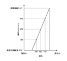
一方、このようにズームレンズを構成することによりフォーカスブリージングが発生するが、フォーカスブリージングは画像処理によって補正される。すなわち、フォーカシングに連動して原画像データが拡縮処理され、フォーカシングに伴い発生する画角の変動が補正される。ここで、拡縮処理とは、画像データを画像処理によって拡大又は縮小することであり、電子ズーム、デジタルズームなどとも称される処理である。画角は、焦点距離ごとに定められた基準画角に補正される。これにより、各焦点距離において、フォーカス操作しても、画角が一定に維持され、高品質な画像を撮像できる。
On the other hand, when the zoom lens is configured in this manner, focus breathing occurs, but the focus breathing is corrected by image processing. In other words, the original image data is enlarged / reduced in conjunction with the focusing, and the variation in the angle of view that occurs with the focusing is corrected. Here, the enlargement / reduction processing is enlargement or reduction of image data by image processing, and is also called electronic zoom, digital zoom, or the like. The angle of view is corrected to a reference angle of view determined for each focal length. As a result, even if a focus operation is performed at each focal length, the angle of view is maintained constant, and a high-quality image can be captured.
なお、画角は、出力領域の画角が補正される。出力領域とは、撮像した画像として出力する領域のことであり、有効領域内に設定される。有効領域とは、イメージセンサで正常な画像を撮像できる領域のことである。有効領域は、イメージセンサの有効画素領域及びズームレンズのイメージサークルによって設定される。イメージセンサの有効画素領域とは、イメージセンサにおいて、実際に画像を撮像できる領域のことである。ズームレンズのイメージサークルのサイズが、イメージセンサの有効画素領域よりも大きければ、有効領域が有効画素領域と一致する。出力領域は、有効領域と一致させることもできる。
Note that the angle of view is corrected for the angle of view of the output area. The output area is an area that is output as a captured image, and is set within the effective area. The effective area is an area where a normal image can be captured by the image sensor. The effective area is set by the effective pixel area of the image sensor and the image circle of the zoom lens. The effective pixel area of the image sensor is an area where an image can be actually captured in the image sensor. If the size of the image circle of the zoom lens is larger than the effective pixel area of the image sensor, the effective area matches the effective pixel area. The output area can also coincide with the effective area.
(2)基準画角が、各焦点距離において、フォーカシングにより変動する出力領域の画像データの画角の中で最小の画角に設定され、画角補正部は、拡大処理によって出力領域の画像データの画角を補正する、上記(1)の撮像装置。
(2) The reference field angle is set to the minimum field angle of the image data of the output area that varies due to focusing at each focal length, and the field angle correction unit performs image processing of the output area by enlarging processing. The imaging device according to (1), wherein the angle of view is corrected.
本態様によれば、基準画角がフォーカシングにより変動する画角の中で最小の画角に設定される。なお、ここでの「最小の画角」には、その近傍の画角も含まれる。すなわち、ここでの「最小の画角」は、最小とみなせる範囲の画角を含む概念のものである。画角補正部は、拡大処理によって画角を補正する。たとえば、出力領域が有効領域と一致する場合などは、本態様のように、拡大処理によって画角を補正し、フォーカスブリージングを補正する。
According to this aspect, the reference angle of view is set to the minimum angle of view that varies due to focusing. Here, the “minimum field angle” includes the field angle in the vicinity thereof. That is, the “minimum angle of view” here is a concept including an angle of view in a range that can be regarded as the minimum. The angle of view correction unit corrects the angle of view through enlargement processing. For example, when the output area matches the effective area, the angle of view is corrected by the enlargement process and the focus breathing is corrected as in this aspect.
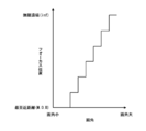
(3)基準画角が、各焦点距離において、フォーカシングにより変動する出力領域の画像データの画角の中で最大の画角に設定され、画角補正部は、縮小処理によって出力領域の画像データの画角を補正する、上記(1)の撮像装置。
(3) The reference angle of view is set to the maximum angle of view of the image data of the output area that varies due to focusing at each focal length, and the angle of view correction unit reduces the image data of the output area by reduction processing. The imaging device according to (1), wherein the angle of view is corrected.
本態様によれば、基準画角がフォーカシングにより変動する画角の中で最大の画角に設定される。なお、ここでの「最大の画角」には、その近傍の画角も含まれる。すなわち、ここでの「最大の画角」は、最大とみなせる範囲の画角を含む概念のものである。画角補正部は、縮小処理によって画角を補正する。たとえば、出力領域が有効領域内に設定されている場合などには、出力領域の周囲に余白領域が存在する。このような場合は、拡大処理によって画角を補正し、フォーカスブリージングを補正する。
According to this aspect, the reference field angle is set to the maximum field angle among the field angles that vary due to focusing. Here, the “maximum angle of view” includes the angle of view in the vicinity thereof. That is, the “maximum angle of view” here is a concept including an angle of view in a range that can be regarded as the maximum. The angle of view correction unit corrects the angle of view by the reduction process. For example, when the output area is set within the effective area, a blank area exists around the output area. In such a case, the angle of view is corrected by enlargement processing, and focus breathing is corrected.
(4)基準画角が、各焦点距離において、フォーカシングにより変動する有効領域の画角の中で最小の画角に設定され、画角補正部は、フォーカシングにより出力領域の画像データの画角が基準画角よりも縮小する場合は、縮小処理によって出力領域の画像データの画角を補正し、フォーカシングにより出力領域の画像データの画角が基準画角よりも拡大する場合は、拡大処理によって出力領域の画像データの画角を補正する、上記(1)の撮像装置。
(4) The reference angle of view is set to the smallest angle of view of the effective area that varies due to focusing at each focal length, and the angle of view correction unit determines the angle of view of the image data in the output area by focusing. If the angle of view is smaller than the reference angle of view, the angle of view of the image data in the output area is corrected by the reduction process, and if the angle of view of the image data in the output area is larger than the reference angle of view by focusing, the image is output by the enlargement process The imaging apparatus according to (1), wherein the angle of view of the image data of the area is corrected.
本態様によれば、基準画角が、フォーカシングにより変動する有効領域の画角の中で最小の画角に設定される。画角補正部は、フォーカシングにより出力領域の画像データの画角が基準画角よりも縮小する場合は、縮小処理によって出力領域の画像データの画角を補正する。また、フォーカシングにより出力領域の画像データの画角が基準画角よりも拡大する場合は、拡大処理によって出力領域の画像データの画角を補正する。これにより、たとえば、出力領域が有効領域内に設定されている場合において、可能な限り縮小処理によって、フォーカスブリージングを補正できる。拡大処理による補正は、MTF(MTF:Modulation Transfer Function)の劣化など画像品質の低下を引き起こすが、縮小処理による補正は、画像品質の低下を防止できる。よって、可能な限り縮小処理によって、フォーカスブリージングを補正できることにより、画像品質の低下を防止できる。なお、ここでの「最小の画角」には、その近傍の画角も含まれる。すなわち、ここでの「最小の画角」とは、最小とみなせる範囲の画角を含む概念のものである。
According to this aspect, the reference field angle is set to the smallest field angle among the field angles of the effective area that varies due to focusing. The view angle correction unit corrects the view angle of the image data in the output area by a reduction process when the view angle of the image data in the output area is reduced from the reference view angle by focusing. Further, when the angle of view of the image data in the output area is larger than the reference angle of view by focusing, the angle of view of the image data in the output area is corrected by the enlargement process. Thereby, for example, when the output area is set within the effective area, the focus breathing can be corrected by the reduction process as much as possible. The correction by the enlargement process causes a decrease in image quality such as the degradation of MTF (MTF: Modulation Transfer Function), but the correction by the reduction process can prevent a decrease in image quality. Accordingly, it is possible to correct the focus breathing by the reduction process as much as possible, thereby preventing the image quality from being deteriorated. Here, the “minimum field angle” includes the field angle in the vicinity thereof. That is, the “minimum angle of view” here is a concept including an angle of view in a range that can be regarded as the minimum.
(5)ズームレンズは、装着した撮像装置本体からイメージセンサのサイズの情報を取得する撮像装置情報取得部と、ズームレンズのイメージサークルのサイズの情報及びイメージセンサのサイズの情報に基づいて、有効領域及び出力領域を設定する領域設定部と、を更に備えた上記(1)から(4)のいずれか一の撮像装置。
(5) The zoom lens is effective based on the imaging device information acquisition unit that acquires the size information of the image sensor from the mounted imaging device body, the size information of the image circle of the zoom lens, and the size information of the image sensor. The imaging apparatus according to any one of (1) to (4), further including an area setting unit that sets an area and an output area.
本態様によれば、ズームレンズのイメージサークルのサイズの情報及びイメージセンサのサイズの情報に基づいて、有効領域及び出力領域が、ズームレンズ側で自動的に設定される。なお、イメージセンサのサイズとは、イメージセンサの有効画素領域のサイズのことである。
According to this aspect, the effective area and the output area are automatically set on the zoom lens side based on the information on the size of the image circle of the zoom lens and the information on the size of the image sensor. The size of the image sensor is the size of the effective pixel area of the image sensor.
(6)ズームレンズが交換可能な場合において、装着されたズームレンズからイメージサークルのサイズの情報を取得するレンズ情報取得部と、装着されたズームレンズのイメージサークルのサイズの情報及びイメージセンサのサイズの情報に基づいて、有効領域及び出力領域を設定する領域設定部と、を更に備えた上記(1)から(4)のいずれか一の撮像装置。
(6) When the zoom lens can be replaced, a lens information acquisition unit that acquires information about the size of the image circle from the attached zoom lens, information about the size of the image circle of the attached zoom lens, and the size of the image sensor The imaging apparatus according to any one of (1) to (4), further including: an area setting unit that sets an effective area and an output area based on the information.
本態様によれば、ズームレンズのイメージサークルのサイズの情報及びイメージセンサのサイズの情報に基づいて、有効領域及び出力領域が自動的に設定される。
According to this aspect, the effective area and the output area are automatically set based on the information on the size of the image circle of the zoom lens and the information on the size of the image sensor.
(7)物体側から順に、変倍の際に固定の第1レンズ群と、変倍の際に移動する複数の移動レンズ群と、変倍の際に固定の最終レンズ群と、を備え、かつ、第1レンズ群が、物体側から順に、フォーカシングの際に固定の第1aレンズ群と、フォーカシングの際に移動する第1bレンズ群と、を備えるズームレンズと、ズームレンズにより結像された像を撮像するイメージセンサと、を備えた撮像装置の信号処理方法であって、イメージセンサから出力される信号であって、正常な画像を撮像できる領域として設定される有効領域から出力される信号を処理して原画像データを生成するステップと、有効領域内に設定された出力領域の画像データを原画像データから抽出して出力するステップと、原画像データを拡縮処理して、出力領域の画像データの画角を補正するステップであって、フォーカシングにより出力領域の画像データの画角が変動する場合に、フォーカシングに連動して原画像データを拡縮処理し、出力領域の画像データの画角を焦点距離ごとに定められた基準画角に補正するステップと、を含む撮像装置の信号処理方法。
(7) In order from the object side, a first lens group fixed during zooming, a plurality of moving lens groups that move during zooming, and a final lens group fixed during zooming, In addition, the first lens group is imaged in order from the object side by a zoom lens including a first lens group that is fixed during focusing and a first lens group that moves during focusing, and a zoom lens. A signal processing method of an imaging apparatus including an image sensor that captures an image, and a signal output from an image sensor and output from an effective area set as an area where a normal image can be captured To generate original image data, to extract and output the image data of the output area set in the effective area from the original image data, to enlarge / reduce the original image data, This step corrects the angle of view of the image data. When the angle of view of the image data in the output area varies due to focusing, the original image data is enlarged / reduced in conjunction with the focusing, and the angle of view of the image data in the output area Correcting to a reference angle of view determined for each focal length, and a signal processing method for an imaging apparatus.
本態様によれば、ズームレンズが、物体側から順に、変倍の際に固定の第1レンズ群と、変倍の際に移動する複数の移動レンズ群と、変倍の際に固定の最終レンズ群と、を備えて構成される。また、第1レンズ群が、物体側から順に、フォーカシングの際に固定の第1aレンズ群と、フォーカシングの際に移動する第1bレンズ群と、を備えて構成される。フォーカス操作によって出力画像の画角が変動する場合は、原画像データを拡縮処理することにより、画角が補正される。画角は、焦点距離ごとに定められた基準画角に補正される。
According to this aspect, the zoom lens includes, in order from the object side, the first lens group fixed at the time of zooming, the plurality of moving lens groups that move at the time of zooming, and the final lens fixed at the time of zooming. And a lens group. In addition, the first lens group includes, in order from the object side, a first 1a lens group that is fixed during focusing and a 1b lens group that moves during focusing. When the angle of view of the output image varies due to the focus operation, the angle of view is corrected by scaling the original image data. The angle of view is corrected to a reference angle of view determined for each focal length.
(8)物体側から順に、変倍の際に固定の第1レンズ群と、変倍の際に移動する複数の移動レンズ群と、変倍の際に固定の最終レンズ群と、を備え、かつ、第1レンズ群が、物体側から順に、フォーカシングの際に固定の第1aレンズ群と、フォーカシングの際に移動する第1bレンズ群と、を備えるズームレンズと、ズームレンズにより結像された像を撮像するイメージセンサと、を備えた撮像装置の信号処理プログラムであって、イメージセンサから出力される信号であって、正常な画像を撮像できる領域として設定される有効領域から出力される信号を処理して原画像データを生成する機能と、有効領域内に設定された出力領域の画像データを原画像データから抽出して出力する機能と、原画像データを拡縮処理して、出力領域の画像データの画角を補正する機能であって、フォーカシングにより出力領域の画像データの画角が変動する場合に、フォーカシングに連動して原画像データを拡縮処理し、出力領域の画像データの画角を焦点距離ごとに定められた基準画角に補正する機能と、をコンピュータに実現させる撮像装置の信号処理プログラム。
(8) In order from the object side, a first lens group fixed at the time of zooming, a plurality of moving lens groups that move at the time of zooming, and a final lens group fixed at the time of zooming, In addition, the first lens group is imaged in order from the object side by a zoom lens including a first lens group that is fixed during focusing and a first lens group that moves during focusing, and a zoom lens. A signal processing program of an imaging apparatus including an image sensor that captures an image, and a signal output from an image sensor and output from an effective area set as an area where a normal image can be captured To generate original image data by processing, a function to extract and output image data of the output area set in the effective area from the original image data, and enlargement / reduction processing of the original image data, Picture This function corrects the angle of view of the data. When the angle of view of the image data in the output area changes due to focusing, the original image data is enlarged or reduced in conjunction with the focusing, and the angle of view of the image data in the output area is reduced. A signal processing program for an imaging apparatus that causes a computer to realize a function of correcting to a reference field angle determined for each focal length.
本態様によれば、ズームレンズが、物体側から順に、変倍の際に固定の第1レンズ群と、変倍の際に移動する複数の移動レンズ群と、変倍の際に固定の最終レンズ群と、を備えて構成される。また、第1レンズ群が、物体側から順に、フォーカシングの際に固定の第1aレンズ群と、フォーカシングの際に移動する第1bレンズ群と、を備えて構成される。フォーカス操作によって出力画像の画角が変動する場合は、原画像データを拡縮処理することにより、画角が補正される。画角は、焦点距離ごとに定められた基準画角に補正される。
According to this aspect, the zoom lens includes, in order from the object side, the first lens group fixed at the time of zooming, the plurality of moving lens groups that move at the time of zooming, and the final lens fixed at the time of zooming. And a lens group. In addition, the first lens group includes, in order from the object side, a first 1a lens group that is fixed during focusing and a 1b lens group that moves during focusing. When the angle of view of the output image varies due to the focus operation, the angle of view is corrected by scaling the original image data. The angle of view is corrected to a reference angle of view determined for each focal length.
本発明によれば、コンパクトな構成で高品質な画像を撮像できる撮像装置、撮像装置の信号処理方法及び撮像装置の信号処理プログラムを提供することができる。
According to the present invention, it is possible to provide an imaging apparatus capable of capturing a high-quality image with a compact configuration, a signal processing method for the imaging apparatus, and a signal processing program for the imaging apparatus.
以下、添付図面に従って本発明を実施するための好ましい形態について詳説する。
Hereinafter, preferred embodiments for carrying out the present invention will be described in detail with reference to the accompanying drawings.
◆◆第1の実施の形態◆◆
[装置構成]
図1は、本発明が適用された撮像装置の一実施形態を示す概略構成図である。 ◆◆ First embodiment ◆◆
[Device configuration]
FIG. 1 is a schematic configuration diagram showing an embodiment of an imaging apparatus to which the present invention is applied.
[装置構成]
図1は、本発明が適用された撮像装置の一実施形態を示す概略構成図である。 ◆◆ First embodiment ◆◆
[Device configuration]
FIG. 1 is a schematic configuration diagram showing an embodiment of an imaging apparatus to which the present invention is applied.
同図に示すように、撮像装置1は、主として、撮像レンズ10Aと、撮像装置本体100と、を備えて構成される。撮像レンズ10Aは、撮像装置本体100に対して着脱自在であり、マウントを介して撮像装置本体100に着脱自在に装着される。すなわち、本実施の形態の撮像装置1では、撮像レンズ10Aが交換可能である。
As shown in the figure, the imaging apparatus 1 is mainly configured by including an imaging lens 10A and an imaging apparatus body 100. The imaging lens 10A is detachable from the imaging apparatus main body 100, and is detachably attached to the imaging apparatus main body 100 via a mount. That is, in the imaging device 1 of the present embodiment, the imaging lens 10A can be replaced.
《撮像レンズ》
〈レンズ構成〉
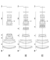
図2は、撮像レンズのレンズ構成を示す断面図である。なお、同図は、左側が物体側、右側が像側として図示している。また、同図は、無限遠物体に合焦している場合の広角端におけるレンズ配置を示している。 <Imaging lens>
<Lens configuration>
FIG. 2 is a cross-sectional view showing the lens configuration of the imaging lens. In the figure, the left side is shown as the object side, and the right side is shown as the image side. The figure also shows the lens arrangement at the wide-angle end when focusing on an object at infinity.
〈レンズ構成〉
図2は、撮像レンズのレンズ構成を示す断面図である。なお、同図は、左側が物体側、右側が像側として図示している。また、同図は、無限遠物体に合焦している場合の広角端におけるレンズ配置を示している。 <Imaging lens>
<Lens configuration>
FIG. 2 is a cross-sectional view showing the lens configuration of the imaging lens. In the figure, the left side is shown as the object side, and the right side is shown as the image side. The figure also shows the lens arrangement at the wide-angle end when focusing on an object at infinity.
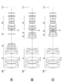
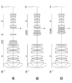
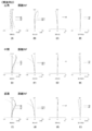
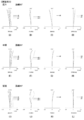
図3は、図2に示す撮像レンズを変倍操作した場合の各レンズの移動状態を示す図である。なお、同図は、無限遠物体に合焦している場合の変倍の際のレンズの移動状態を示している。
FIG. 3 is a diagram showing a moving state of each lens when the imaging lens shown in FIG. The figure shows the lens moving state during zooming when focusing on an object at infinity.
図3において、(A)は、広角端でのレンズ配置を示している。また、(B)は、中間焦点距離状態でレンズ配置を示している。また、(C)は、望遠端でのレンズ配置を示している。
3A shows the lens arrangement at the wide-angle end. (B) shows the lens arrangement in the intermediate focal length state. (C) shows the lens arrangement at the telephoto end.
本実施の形態の撮像レンズ10Aは、ズームレンズであり、実質的に4つのレンズ群で構成される。具体的には、物体側から順に、正の屈折力を有する第1レンズ群G1と、負の屈折力を有する第2レンズ群G2と、負の屈折力を有する第3レンズ群G3と、正の屈折力を有する第4レンズ群G4とが配列されて構成される。
The imaging lens 10A of the present embodiment is a zoom lens, and is substantially composed of four lens groups. Specifically, in order from the object side, a first lens group G1 having a positive refractive power, a second lens group G2 having a negative refractive power, a third lens group G3 having a negative refractive power, And a fourth lens group G4 having a refractive power of 5 are arranged.
撮像レンズ10Aは、撮像レンズ10Aを装着する撮像装置本体の構成に応じて、光学系と像面Simとの間にカバーガラス、並びに、赤外線カットフィルタ、ローパスフィルタなどの各種フィルタを配置することが好ましい。このため、図1及び図2に示す例では、これらの光学部材を想定した平行平板状の光学部材PP1、PP2をレンズ系と像面Simとの間に配置した例を示している。
In the imaging lens 10A, a cover glass, and various filters such as an infrared cut filter and a low-pass filter may be disposed between the optical system and the image plane Sim according to the configuration of the imaging apparatus body on which the imaging lens 10A is mounted. preferable. For this reason, in the example shown in FIG.1 and FIG.2, the example which has arrange | positioned the parallel-plate-shaped optical members PP1 and PP2 which assumed these optical members between the lens system and the image surface Sim is shown.
撮像レンズ10Aは、変倍する際、像面Simに対して、第1レンズ群G1及び第4レンズ群G4が、光軸方向について固定され、第2レンズ群G2及び第3レンズ群G3が、光軸方向に移動する。第2レンズ群G2は、広角端から望遠端に変倍する際、光軸Zに沿って像側へ移動する。第3レンズ群G3は、第2レンズ群G2に連動して移動し、第2レンズ群G2の移動による像面の変動を補正する。図2には、広角端から望遠端へ変倍する際の第2レンズ群G2及び第3レンズ群G3の概略的な移動軌跡を各レンズ群の下方に実線の矢印で示している。なお、第3レンズ群G3は、たとえば、広角端から望遠端に変倍する際、物体側へ移動した後、像側へ移動するように構成してもよい。このように構成した場合、変倍の際に必要とされる第3レンズ群G3の移動空間を少なくでき、光軸方向の小型化に貢献できる。
When the imaging lens 10A is zoomed, the first lens group G1 and the fourth lens group G4 are fixed in the optical axis direction with respect to the image plane Sim, and the second lens group G2 and the third lens group G3 are Move in the direction of the optical axis. The second lens group G2 moves toward the image side along the optical axis Z when zooming from the wide-angle end to the telephoto end. The third lens group G3 moves in conjunction with the second lens group G2, and corrects image plane variation due to the movement of the second lens group G2. In FIG. 2, a schematic movement locus of the second lens group G2 and the third lens group G3 when zooming from the wide-angle end to the telephoto end is indicated by a solid arrow below each lens group. The third lens group G3 may be configured to move to the image side after moving to the object side, for example, when zooming from the wide-angle end to the telephoto end. When configured in this way, the movement space of the third lens group G3 required for zooming can be reduced, which can contribute to miniaturization in the optical axis direction.
〔第1レンズ群〕
第1レンズ群G1は、フォーカシングレンズ群である。第1レンズ群G1は、物体側から順に、負の屈折力を有する第1aレンズ群G1aと、正の屈折力を有する第1bレンズ群G1bと、正の屈折力を有する第1レンズ群後群G1cと、が配置されて構成される。 [First lens group]
The first lens group G1 is a focusing lens group. The first lens group G1 includes, in order from the object side, a first a lens group G1a having a negative refractive power, a first b lens group G1b having a positive refractive power, and a rear group of the first lens group having a positive refractive power. G1c is arranged.
4群構成のズームレンズにおいて、第1レンズ群G1をこのような3つのレンズ群で構成することにより、フォーカシングに伴う画角の変動を抑制できる。
In a zoom lens having a four-group configuration, by configuring the first lens group G1 with such three lens groups, fluctuations in the angle of view due to focusing can be suppressed.
第1aレンズ群G1aは、物体側から入射した周辺光束を屈折させて、第1aレンズ群G1aから射出される周辺光束と光軸Zとのなす角が小さくなるように作用する。この作用により、第1bレンズ群G1bにおける周辺光束の光線高の変化量を少なくできる。その一方で、軸上光束については、第1レンズ群G1で光線高が高くなり、球面収差の発生量が大きくなりやすい。このため、第1レンズ群後群G1cにより、球面収差を補正する構成としている。
The first-a lens group G1a acts to refract the peripheral light beam incident from the object side so that the angle formed by the peripheral light beam emitted from the first-a lens group G1a and the optical axis Z becomes small. By this action, the amount of change in the light beam height of the peripheral luminous flux in the 1b lens group G1b can be reduced. On the other hand, with respect to the axial light beam, the light ray height is increased in the first lens group G1, and the amount of spherical aberration is likely to increase. For this reason, spherical aberration is corrected by the first lens group rear group G1c.
本実施の形態の撮像レンズ10Aは、いわゆるインナーフォーカス方式を採用しており、フォーカシングの際に移動させるレンズ群を第1bレンズ群G1bのみとしている。図2には、第1bレンズ群G1bの下方に、これを示すための両矢印を記載している。周辺光束の光線高の変化量の少ない第1bレンズ群G1bのみを光軸方向に移動させてフォーカシングすることにより、フォーカシングの際の画角の変動及び収差の変動を少なくでき、フォーカシングによる性能変化を抑制できる。
The imaging lens 10A of the present embodiment employs a so-called inner focus method, and the lens group to be moved during focusing is only the first lens group G1b. In FIG. 2, a double arrow is shown below the 1b lens group G1b. By focusing only by moving the 1b lens group G1b having a small amount of change in the light flux of the peripheral light beam in the optical axis direction, fluctuations in the angle of view and aberrations during focusing can be reduced, and performance changes due to focusing can be reduced. Can be suppressed.
第1aレンズ群G1aは、第1aレンズ群の一例である。第1aレンズ群G1aは、物体側から順に、負のレンズL11と、負のレンズL12と、正のレンズL13と、が配置されて構成される。第1レンズ群G1の最も物体側のレンズ群をこのように構成することにより、第1レンズ群G1の径を小型化できる。
The 1a lens group G1a is an example of a 1a lens group. The first-a lens group G1a includes a negative lens L11, a negative lens L12, and a positive lens L13 arranged in order from the object side. By configuring the lens group closest to the object side of the first lens group G1 in this way, the diameter of the first lens group G1 can be reduced.
第1bレンズ群G1bは、第1bレンズ群の一例である。第1bレンズ群G1bは、負のレンズL14及び正のレンズL15が接合された1組の接合レンズにより構成される。第1bレンズ群G1bをこのような構成することにより、構成をコンパクト化しつつ、フォーカシングの際の色収差の変動を抑制できる。
The 1b lens group G1b is an example of a 1b lens group. The 1b lens group G1b includes a pair of cemented lenses in which a negative lens L14 and a positive lens L15 are cemented. By configuring the 1b lens group G1b in this way, it is possible to suppress variations in chromatic aberration during focusing while reducing the size of the configuration.
なお、第1bレンズ群G1bを1組の接合レンズで構成する場合は、物体側から順に、負レンズ、正レンズの配置とすることが好ましい。このように構成することにより、物体距離が変動した場合の色収差を容易に補正できる。更に、これらのレンズは、それぞれ物体側に凸面を向けた負メニスカスレンズ、両凸レンズとすることが好ましい。このように構成することにより、物体距離が変動した場合の色収差を更に容易に補正できる。
In addition, when the 1b lens group G1b is composed of a pair of cemented lenses, it is preferable to arrange a negative lens and a positive lens in order from the object side. With this configuration, it is possible to easily correct chromatic aberration when the object distance varies. Further, these lenses are preferably a negative meniscus lens and a biconvex lens each having a convex surface facing the object side. With this configuration, it is possible to more easily correct chromatic aberration when the object distance varies.
第1レンズ群後群G1cは、物体側から順に、両凹形状のレンズL16及び両凸形状のレンズL17が接合された接合レンズと、両凸形状のレンズL18と、正メニスカス形状のレンズL19とが配置されて構成される。第1レンズ群後群G1cをこのように構成することにより、望遠側の球面収差の発生量を少なくできる。
The first lens group rear group G1c includes, in order from the object side, a cemented lens in which a biconcave lens L16 and a biconvex lens L17 are cemented, a biconvex lens L18, and a positive meniscus lens L19. Are arranged and configured. By configuring the first lens group rear group G1c in this manner, the amount of spherical aberration on the telephoto side can be reduced.
第1レンズ群G1を上記のようなレンズL11からL19で構成し、第1レンズ群G1内のパワー配置を好適に設定することで、フォーカシングの際の画角の変動を抑制できる。なお、全系に対するパワー配分も重要であり、諸収差を良好に収差補正しつつ、軽量かつコンパクトな構成にできるように、全系に対する第1レンズ群G1のパワー配分を設定することが好ましい。
The first lens group G1 is configured by the lenses L11 to L19 as described above, and the power distribution in the first lens group G1 is suitably set, so that fluctuations in the angle of view during focusing can be suppressed. The power distribution for the entire system is also important, and it is preferable to set the power distribution of the first lens group G1 for the entire system so that various aberrations can be corrected satisfactorily and a lightweight and compact configuration can be achieved.
〔第2レンズ群及び第3レンズ群〕
第2レンズ群G2及び第3レンズ群G3は、複数の移動レンズ群の一例であり、ズームレンズ群を構成する。第2レンズ群G2及び第3レンズ群G3は、第2レンズ群G2は、バリエータレンズ群を構成し、第3レンズ群G3がコンペンセータレンズ群を構成する。 [Second lens group and third lens group]
The second lens group G2 and the third lens group G3 are an example of a plurality of moving lens groups, and constitute a zoom lens group. In the second lens group G2 and the third lens group G3, the second lens group G2 constitutes a variator lens group, and the third lens group G3 constitutes a compensator lens group.
第2レンズ群G2は、物体側から順に、負のレンズL21、負のレンズL22、正のレンズL23、負のレンズL24が配置されて構成される。なお、負のレンズL22及び正のレンズL23は接合されていてもよい。また、レンズL21の少なくとも一方の面を非球面としてもよい。このように構成した場合は、変倍の際の収差の変動を抑制することが容易になる。
The second lens group G2 includes a negative lens L21, a negative lens L22, a positive lens L23, and a negative lens L24 arranged in this order from the object side. Note that the negative lens L22 and the positive lens L23 may be cemented. Further, at least one surface of the lens L21 may be an aspherical surface. When configured in this way, it becomes easy to suppress fluctuations in aberrations during zooming.
図2に示す例では、全系において非球面が形成されているのは、第2レンズ群G2のレンズL21の物体側の面のみであり、その他のレンズ面は、すべて球面である。非球面を形成する面を大径の第1レンズ群G1ではなく、第2レンズ群G2に持たせることで、低コスト化が図れる。なお、非球面を設ける面は、上記の例に限定されず、たとえば、更に他の面を非球面としてもよい。その場合は、より良好に収差補正を行うことができる。
In the example shown in FIG. 2, the aspherical surface is formed in the entire system only on the object side surface of the lens L21 of the second lens group G2, and the other lens surfaces are all spherical. Costs can be reduced by providing the second lens group G2 instead of the large-diameter first lens group G1 with the surface forming the aspherical surface. The surface on which the aspheric surface is provided is not limited to the above example, and for example, another surface may be an aspheric surface. In that case, aberration correction can be performed more favorably.
第3レンズ群G3は、1枚の負のレンズL31で構成される。変倍の際に移動する第3レンズ群G3を単レンズ構成とすることで、駆動機構を簡素化でき、撮像レンズ10Aをコンパクト化及び軽量化できる。
The third lens group G3 includes one negative lens L31. Since the third lens group G3 that moves during zooming has a single lens configuration, the drive mechanism can be simplified, and the imaging lens 10A can be made compact and lightweight.
〔第4レンズ群〕
第4レンズ群G4は、最終レンズ群の一例であり、リレーレンズ群を構成する。第4レンズ群G4は、物体側から順に、正のレンズL41、正のレンズL42、正のレンズL43、正のレンズL44、正のレンズL45、負のレンズL46、正のレンズL47、負のレンズL48、正のレンズL49、負のレンズL50、正のレンズL51を配置した11枚のレンズで構成される。 [Fourth lens group]
The fourth lens group G4 is an example of a final lens group and constitutes a relay lens group. The fourth lens group G4 includes, in order from the object side, a positive lens L41, a positive lens L42, a positive lens L43, a positive lens L44, a positive lens L45, a negative lens L46, a positive lens L47, and a negative lens. L11, 11 positive lenses L49, 11 negative lenses L50, and 11 positive lenses L51 are arranged.
〔開口絞り〕
開口絞りStは、第3レンズ群G3より像側に配置され、変倍の際に固定されていることが好ましい。このような構成とすることで、変倍の際にFナンバーを一定にできる。たとえば、図2に示す例では、開口絞りStは、第3レンズ群G3と第4レンズ群G4との間に配置されている。 (Aperture stop)
The aperture stop St is preferably disposed on the image side with respect to the third lens group G3 and is fixed during zooming. By adopting such a configuration, the F number can be made constant during zooming. For example, in the example shown in FIG. 2, the aperture stop St is disposed between the third lens group G3 and the fourth lens group G4.
なお、図2に示す開口絞りStは、必ずしも大きさや形状を表すものではなく、光軸Z上の位置を示すものである。
Note that the aperture stop St shown in FIG. 2 does not necessarily indicate the size or shape, but indicates the position on the optical axis Z.
本実施の形態の撮像レンズ10Aは、以上のように構成される。なお、撮像レンズ10Aが、厳しい環境において使用される場合には、保護用の多層膜コートを施すことが好ましい。更に、保護用コート以外にも、使用の際のゴースト光低減等のための反射防止コートを施すようにしてもよい。
The imaging lens 10A of the present embodiment is configured as described above. When the imaging lens 10A is used in a severe environment, it is preferable to apply a protective multilayer coating. In addition to the protective coat, an antireflection coat for reducing ghost light during use may be applied.
また、図2に示す例では、レンズ系と結像面との間に光学部材PP1、PP2を配置した例を示したが、光学部材PP1、PP2は、各レンズの間に配置してもよい。あるいは、いずれかのレンズのレンズ面に各光学部材PP1、PP2と同様の作用を有するコートを施してもよい。
In the example shown in FIG. 2, the optical members PP1 and PP2 are disposed between the lens system and the imaging surface. However, the optical members PP1 and PP2 may be disposed between the lenses. . Or you may give the coat | court which has the effect | action similar to each optical member PP1, PP2 to the lens surface of either lens.
以上のように、本実施の形態の撮像レンズ10Aは、先頭レンズ群である第1aレンズ群G1a及び最終レンズ群である第4レンズ群G4が、変倍の際及びフォーカシングの際に固定である。すなわち、本実施の形態の撮像レンズ10Aは、フォーカス操作及び変倍操作によって、全長の変わらないズームレンズである。
As described above, in the imaging lens 10A of the present embodiment, the first lens group G1a, which is the first lens group, and the fourth lens group G4, which is the final lens group, are fixed at the time of zooming and focusing. . In other words, the imaging lens 10A of the present embodiment is a zoom lens whose total length does not change by a focus operation and a magnification operation.
〈レンズの駆動系〉
図1に示すように、撮像レンズ10Aは、その駆動系として、フォーカシングレンズ群を駆動するフォーカシングレンズ駆動部20と、フォーカシングレンズ群の位置を検出するフォーカシングレンズ位置検出部22と、バリエータレンズ群を駆動するバリエータレンズ駆動部24と、バリエータレンズ群の位置を検出するバリエータレンズ位置検出部26と、コンペンセータレンズ群を駆動するコンペンセータレンズ駆動部28と、コンペンセータレンズ群の位置を検出するコンペンセータレンズ位置検出部30と、開口絞りStを駆動する絞り駆動部32と、撮像レンズ10Aの動作を制御するレンズ制御部40と、を備える。 <Lens drive system>
As shown in FIG. 1, theimaging lens 10A includes, as its drive system, a focusing lens driving unit 20 that drives the focusing lens group, a focusing lens position detection unit 22 that detects the position of the focusing lens group, and a variator lens group. A variator lens driving unit 24 for driving, a variator lens position detecting unit 26 for detecting the position of the variator lens group, a compensator lens driving unit 28 for driving the compensator lens group, and a compensator lens position detection for detecting the position of the compensator lens group. And an aperture drive unit 32 that drives the aperture stop St, and a lens control unit 40 that controls the operation of the imaging lens 10A.
図1に示すように、撮像レンズ10Aは、その駆動系として、フォーカシングレンズ群を駆動するフォーカシングレンズ駆動部20と、フォーカシングレンズ群の位置を検出するフォーカシングレンズ位置検出部22と、バリエータレンズ群を駆動するバリエータレンズ駆動部24と、バリエータレンズ群の位置を検出するバリエータレンズ位置検出部26と、コンペンセータレンズ群を駆動するコンペンセータレンズ駆動部28と、コンペンセータレンズ群の位置を検出するコンペンセータレンズ位置検出部30と、開口絞りStを駆動する絞り駆動部32と、撮像レンズ10Aの動作を制御するレンズ制御部40と、を備える。 <Lens drive system>
As shown in FIG. 1, the
〔フォーカシングレンズ駆動部〕
上記のように、フォーカシングレンズ群は、第1レンズ群G1によって構成される。第1レンズ群G1は、第1bレンズ群G1bのみを移動させて、フォーカシングする。フォーカシングレンズ駆動部20は、第1bレンズ群G1bを光軸Zに沿って移動させる。フォーカシングレンズ駆動部20は、たとえば、第1bレンズ群G1bの移動をガイドするガイド機構と、第1bレンズ群G1bを光軸Zに沿って前後移動させるモータと、そのモータの駆動回路と、を備えて構成される。モータは、たとえば、リニアモータで構成される。 [Focusing lens drive unit]
As described above, the focusing lens group is constituted by the first lens group G1. The first lens group G1 moves and focuses only the first b lens group G1b. The focusinglens driving unit 20 moves the 1b lens group G1b along the optical axis Z. The focusing lens driving unit 20 includes, for example, a guide mechanism that guides the movement of the first b lens group G1b, a motor that moves the first b lens group G1b back and forth along the optical axis Z, and a drive circuit for the motor. Configured. The motor is composed of, for example, a linear motor.
上記のように、フォーカシングレンズ群は、第1レンズ群G1によって構成される。第1レンズ群G1は、第1bレンズ群G1bのみを移動させて、フォーカシングする。フォーカシングレンズ駆動部20は、第1bレンズ群G1bを光軸Zに沿って移動させる。フォーカシングレンズ駆動部20は、たとえば、第1bレンズ群G1bの移動をガイドするガイド機構と、第1bレンズ群G1bを光軸Zに沿って前後移動させるモータと、そのモータの駆動回路と、を備えて構成される。モータは、たとえば、リニアモータで構成される。 [Focusing lens drive unit]
As described above, the focusing lens group is constituted by the first lens group G1. The first lens group G1 moves and focuses only the first b lens group G1b. The focusing
〔フォーカシングレンズ位置検出部〕
フォーカシングレンズ位置検出部22は、あらかじめ設定されたフォーカシング原点を基準として、第1bレンズ群G1bの位置を検出する。フォーカシング原点は、第1bレンズ群G1bの移動範囲内に設定される。フォーカシングレンズ位置検出部22は、たとえば、第1bレンズ群G1bがフォーカシング原点に位置したことを検出する原点検出センサと、第1bレンズ群G1bのフォーカシング原点からの移動量を検出する移動量検出センサと、を備えて構成される。原点検出センサは、たとえば、フォトインタラプタで構成される。移動量検出センサは、たとえば、磁気スケールと、磁気センサとで構成される。 [Focusing lens position detector]
The focusing lensposition detection unit 22 detects the position of the first lens group G1b with reference to a preset focusing origin. The focusing origin is set within the moving range of the 1b lens group G1b. The focusing lens position detection unit 22 includes, for example, an origin detection sensor that detects that the 1b lens group G1b is positioned at the focusing origin, and a movement amount detection sensor that detects a movement amount of the first b lens group G1b from the focusing origin. , And is configured. The origin detection sensor is composed of, for example, a photo interrupter. The movement amount detection sensor includes, for example, a magnetic scale and a magnetic sensor.
フォーカシングレンズ位置検出部22は、あらかじめ設定されたフォーカシング原点を基準として、第1bレンズ群G1bの位置を検出する。フォーカシング原点は、第1bレンズ群G1bの移動範囲内に設定される。フォーカシングレンズ位置検出部22は、たとえば、第1bレンズ群G1bがフォーカシング原点に位置したことを検出する原点検出センサと、第1bレンズ群G1bのフォーカシング原点からの移動量を検出する移動量検出センサと、を備えて構成される。原点検出センサは、たとえば、フォトインタラプタで構成される。移動量検出センサは、たとえば、磁気スケールと、磁気センサとで構成される。 [Focusing lens position detector]
The focusing lens
〔バリエータレンズ駆動部〕
上記のように、バリエータレンズ群は、第2レンズ群G2によって構成される。バリエータレンズ駆動部24は、第2レンズ群G2を光軸Zに沿って移動させる。バリエータレンズ駆動部24は、たとえば、第2レンズ群G2の移動をガイドするガイド機構と、第2レンズ群G2を光軸Zに沿って前後移動させるモータと、そのモータの駆動回路と、を備えて構成される。モータは、たとえば、リニアモータで構成される。 [Variator lens drive unit]
As described above, the variator lens group is configured by the second lens group G2. The variatorlens driving unit 24 moves the second lens group G2 along the optical axis Z. The variator lens driving unit 24 includes, for example, a guide mechanism that guides the movement of the second lens group G2, a motor that moves the second lens group G2 back and forth along the optical axis Z, and a drive circuit for the motor. Configured. The motor is composed of, for example, a linear motor.
上記のように、バリエータレンズ群は、第2レンズ群G2によって構成される。バリエータレンズ駆動部24は、第2レンズ群G2を光軸Zに沿って移動させる。バリエータレンズ駆動部24は、たとえば、第2レンズ群G2の移動をガイドするガイド機構と、第2レンズ群G2を光軸Zに沿って前後移動させるモータと、そのモータの駆動回路と、を備えて構成される。モータは、たとえば、リニアモータで構成される。 [Variator lens drive unit]
As described above, the variator lens group is configured by the second lens group G2. The variator
〔バリエータレンズ位置検出部〕
バリエータレンズ位置検出部26は、あらかじめ設定されたバリエータ原点を基準として、第2レンズ群G2の位置を検出する。バリエータ原点は、第2レンズ群G2の移動範囲内に設定される。バリエータレンズ位置検出部26は、たとえば、第2レンズ群G2がバリエータ原点に位置したことを検出する原点検出センサと、第2レンズ群G2のバリエータ原点からの移動量を検出する移動量検出センサと、を備えて構成される。原点検出センサは、たとえば、フォトインタラプタで構成される。移動量検出センサは、たとえば、磁気スケールと、磁気センサとで構成される。 [Variator lens position detector]
The variatorlens position detector 26 detects the position of the second lens group G2 with reference to a preset variator origin. The variator origin is set within the moving range of the second lens group G2. The variator lens position detection unit 26 includes, for example, an origin detection sensor that detects that the second lens group G2 is positioned at the variator origin, and a movement amount detection sensor that detects a movement amount of the second lens group G2 from the variator origin. , And is configured. The origin detection sensor is composed of, for example, a photo interrupter. The movement amount detection sensor includes, for example, a magnetic scale and a magnetic sensor.
バリエータレンズ位置検出部26は、あらかじめ設定されたバリエータ原点を基準として、第2レンズ群G2の位置を検出する。バリエータ原点は、第2レンズ群G2の移動範囲内に設定される。バリエータレンズ位置検出部26は、たとえば、第2レンズ群G2がバリエータ原点に位置したことを検出する原点検出センサと、第2レンズ群G2のバリエータ原点からの移動量を検出する移動量検出センサと、を備えて構成される。原点検出センサは、たとえば、フォトインタラプタで構成される。移動量検出センサは、たとえば、磁気スケールと、磁気センサとで構成される。 [Variator lens position detector]
The variator
〔コンペンセータレンズ駆動部〕
上記のように、コンペンセータレンズ群は、第3レンズ群G3によって構成される。コンペンセータレンズ駆動部28は、第3レンズ群G3を光軸Zに沿って移動させる。コンペンセータレンズ駆動部28は、たとえば、第3レンズ群G3の移動をガイドするガイド機構と、第3レンズ群G3を光軸Zに沿って前後移動させるモータと、そのモータの駆動回路と、を備えて構成される。モータは、たとえば、リニアモータで構成される。 [Compensator lens drive unit]
As described above, the compensator lens group is configured by the third lens group G3. The compensatorlens driving unit 28 moves the third lens group G3 along the optical axis Z. The compensator lens driving unit 28 includes, for example, a guide mechanism that guides the movement of the third lens group G3, a motor that moves the third lens group G3 back and forth along the optical axis Z, and a drive circuit for the motor. Configured. The motor is composed of, for example, a linear motor.
上記のように、コンペンセータレンズ群は、第3レンズ群G3によって構成される。コンペンセータレンズ駆動部28は、第3レンズ群G3を光軸Zに沿って移動させる。コンペンセータレンズ駆動部28は、たとえば、第3レンズ群G3の移動をガイドするガイド機構と、第3レンズ群G3を光軸Zに沿って前後移動させるモータと、そのモータの駆動回路と、を備えて構成される。モータは、たとえば、リニアモータで構成される。 [Compensator lens drive unit]
As described above, the compensator lens group is configured by the third lens group G3. The compensator
〔コンペンセータレンズ位置検出部〕
コンペンセータレンズ位置検出部30は、あらかじめ設定されたコンペンセータ原点を基準として、第3レンズ群G3の位置を検出する。コンペンセータ原点は、第3レンズ群G3の移動範囲内に設定される。コンペンセータレンズ位置検出部30は、たとえば、第3レンズ群G3がコンペンセータ原点に位置したことを検出する原点検出センサと、第3レンズ群G3のコンペンセータ原点からの移動量を検出する移動量検出センサと、を備えて構成される。原点検出センサは、たとえば、フォトインタラプタで構成される。移動量検出センサは、たとえば、磁気スケールと、磁気センサとで構成される。 [Compensator lens position detector]
The compensator lensposition detection unit 30 detects the position of the third lens group G3 with reference to a preset compensator origin. The origin of the compensator is set within the moving range of the third lens group G3. The compensator lens position detection unit 30 includes, for example, an origin detection sensor that detects that the third lens group G3 is located at the compensator origin, and a movement amount detection sensor that detects a movement amount of the third lens group G3 from the compensator origin. , And is configured. The origin detection sensor is composed of, for example, a photo interrupter. The movement amount detection sensor includes, for example, a magnetic scale and a magnetic sensor.
コンペンセータレンズ位置検出部30は、あらかじめ設定されたコンペンセータ原点を基準として、第3レンズ群G3の位置を検出する。コンペンセータ原点は、第3レンズ群G3の移動範囲内に設定される。コンペンセータレンズ位置検出部30は、たとえば、第3レンズ群G3がコンペンセータ原点に位置したことを検出する原点検出センサと、第3レンズ群G3のコンペンセータ原点からの移動量を検出する移動量検出センサと、を備えて構成される。原点検出センサは、たとえば、フォトインタラプタで構成される。移動量検出センサは、たとえば、磁気スケールと、磁気センサとで構成される。 [Compensator lens position detector]
The compensator lens
〔絞り駆動部〕
絞り駆動部32は、開口絞りStを駆動する。開口絞りStは、たとえば、虹彩絞りで構成される。絞り駆動部32は、その絞り羽根を拡縮させるモータと、そのモータの駆動回路と、を備えて構成される。 (Aperture drive unit)
Theaperture drive unit 32 drives the aperture stop St. The aperture stop St is constituted by, for example, an iris stop. The diaphragm drive unit 32 includes a motor that expands and contracts the diaphragm blades, and a drive circuit for the motor.
絞り駆動部32は、開口絞りStを駆動する。開口絞りStは、たとえば、虹彩絞りで構成される。絞り駆動部32は、その絞り羽根を拡縮させるモータと、そのモータの駆動回路と、を備えて構成される。 (Aperture drive unit)
The
〔レンズ制御部〕
レンズ制御部40は、撮像レンズ10Aの動作を統括制御する。レンズ制御部40は、CPU(CPU:Central Processing Unit/中央処理装置)、ROM(ROM:Read Only Memory)、RAM(RAM:Random Access Memory)を備えたマイクロコンピュータで構成される。すなわち、マイクロコンピュータが、所定のプログラムを実行することにより、レンズ制御部40としての各種機能を提供する。マイクロコンピュータが実行するプログラムは、ROMに格納される。 [Lens control unit]
Thelens control unit 40 performs overall control of the operation of the imaging lens 10A. The lens control unit 40 includes a microcomputer including a CPU (CPU: Central Processing Unit), a ROM (ROM: Read Only Memory), and a RAM (RAM: Random Access Memory). That is, the microcomputer provides various functions as the lens control unit 40 by executing a predetermined program. A program executed by the microcomputer is stored in the ROM.
レンズ制御部40は、撮像レンズ10Aの動作を統括制御する。レンズ制御部40は、CPU(CPU:Central Processing Unit/中央処理装置)、ROM(ROM:Read Only Memory)、RAM(RAM:Random Access Memory)を備えたマイクロコンピュータで構成される。すなわち、マイクロコンピュータが、所定のプログラムを実行することにより、レンズ制御部40としての各種機能を提供する。マイクロコンピュータが実行するプログラムは、ROMに格納される。 [Lens control unit]
The
レンズ制御部40は、撮像装置本体100から与えられる指令に基づいて、撮像レンズ10Aの各部の駆動を制御する。たとえば、撮像装置本体100から与えられるフォーカス指令に基づいて、フォーカシングレンズ駆動部20の駆動を制御し、第1bレンズ群G1bを動作させる。また、撮像装置本体100から与えられるズーム指令に基づいて、バリエータレンズ駆動部24及びコンペンセータレンズ駆動部28の駆動を制御し、第2レンズ群G2及び第3レンズ群G3を動作させる。更に、撮像装置本体100から与えられる絞り指令に基づいて、絞り駆動部32の駆動を制御し、開口絞りStを動作させる。
The lens control unit 40 controls driving of each unit of the imaging lens 10A based on a command given from the imaging apparatus main body 100. For example, based on a focus command given from the imaging apparatus main body 100, the driving of the focusing lens driving unit 20 is controlled to operate the first b lens group G1b. Further, based on a zoom command given from the imaging apparatus main body 100, the driving of the variator lens driving unit 24 and the compensator lens driving unit 28 is controlled to operate the second lens group G2 and the third lens group G3. Furthermore, based on the aperture command given from the imaging apparatus main body 100, the drive of the aperture drive unit 32 is controlled to operate the aperture stop St.
また、レンズ制御部40は、フォーカシングレンズ位置検出部22で検出される第1bレンズ群G1bの現在位置の情報、バリエータレンズ位置検出部26で検出される第2レンズ群G2の現在位置の情報及びコンペンセータレンズ位置検出部30で検出される第3レンズ群G3の現在位置の情報を撮像装置本体100に送信する。
The lens control unit 40 also includes information on the current position of the first lens group G1b detected by the focusing lens position detection unit 22, information on the current position of the second lens group G2 detected by the variator lens position detection unit 26, and Information on the current position of the third lens group G3 detected by the compensator lens position detector 30 is transmitted to the imaging apparatus main body 100.
《撮像装置本体》
図1に示すように、撮像装置本体100は、撮像手段としてのイメージセンサ110と、イメージセンサ110から出力される信号を処理して、出力用の画像データを生成する信号処理部120と、信号処理部120で生成された画像データを表示する画像表示部130と、信号処理部120で生成された画像データを出力する画像出力端子132と、各種操作を行う操作部134と、撮像装置本体100の動作を制御する撮像装置本体制御部140と、を備える。 << Imaging device body >>
As illustrated in FIG. 1, the imaging apparatusmain body 100 includes an image sensor 110 serving as an imaging unit, a signal processing unit 120 that processes a signal output from the image sensor 110 and generates image data for output, and a signal The image display unit 130 that displays the image data generated by the processing unit 120, the image output terminal 132 that outputs the image data generated by the signal processing unit 120, the operation unit 134 that performs various operations, and the imaging apparatus main body 100. An image pickup apparatus main body control unit 140 that controls the operation of the image pickup apparatus.
図1に示すように、撮像装置本体100は、撮像手段としてのイメージセンサ110と、イメージセンサ110から出力される信号を処理して、出力用の画像データを生成する信号処理部120と、信号処理部120で生成された画像データを表示する画像表示部130と、信号処理部120で生成された画像データを出力する画像出力端子132と、各種操作を行う操作部134と、撮像装置本体100の動作を制御する撮像装置本体制御部140と、を備える。 << Imaging device body >>
As illustrated in FIG. 1, the imaging apparatus
〈イメージセンサ〉
イメージセンサ110は、撮像レンズ10Aにより結像された像を撮像する。イメージセンサ110は、たとえば、所定のカラーフィルタ配列を有するCMOS(CMOS: Complementary Metal Oxide Semiconductor)、CCD(CCD: Charged Coupled Device)等の固体撮像素子で構成される。 <Image sensor>
Theimage sensor 110 captures an image formed by the imaging lens 10A. The image sensor 110 is configured by a solid-state imaging device such as a CMOS (Complementary Metal Oxide Semiconductor) having a predetermined color filter array and a CCD (CCD: Charged Coupled Device).
イメージセンサ110は、撮像レンズ10Aにより結像された像を撮像する。イメージセンサ110は、たとえば、所定のカラーフィルタ配列を有するCMOS(CMOS: Complementary Metal Oxide Semiconductor)、CCD(CCD: Charged Coupled Device)等の固体撮像素子で構成される。 <Image sensor>
The
〈信号処理部〉
信号処理部120は、イメージセンサ110から出力される信号を処理して、出力用の画像データを生成する。この際、フォーカスブリージングの補正処理も行う。信号処理部
120の具体的な処理内容については、後に詳述する。 <Signal processing section>
Thesignal processing unit 120 processes a signal output from the image sensor 110 to generate output image data. At this time, correction processing for focus breathing is also performed. Specific processing contents of the signal processing unit 120 will be described in detail later.
信号処理部120は、イメージセンサ110から出力される信号を処理して、出力用の画像データを生成する。この際、フォーカスブリージングの補正処理も行う。信号処理部
120の具体的な処理内容については、後に詳述する。 <Signal processing section>
The
〈画像表示部〉
画像表示部130は、信号処理部120で生成された出力用の画像データを表示する。画像表示部130は、たとえば、液晶モニタで構成される。 <Image display section>
Theimage display unit 130 displays the output image data generated by the signal processing unit 120. The image display unit 130 is composed of, for example, a liquid crystal monitor.
画像表示部130は、信号処理部120で生成された出力用の画像データを表示する。画像表示部130は、たとえば、液晶モニタで構成される。 <Image display section>
The
〈画像出力端子〉
画像出力端子132は、信号処理部120で生成された出力用の画像データを出力する。 <Image output terminal>
Theimage output terminal 132 outputs image data for output generated by the signal processing unit 120.
画像出力端子132は、信号処理部120で生成された出力用の画像データを出力する。 <Image output terminal>
The
〈操作部〉
操作部134は、フォーカスデマンド、ズームデマンド等の各種操作部材と、その操作信号を撮像装置本体制御部140に出力する操作回路と、を含んで構成される。 <Operation unit>
Theoperation unit 134 includes various operation members such as a focus demand and a zoom demand, and an operation circuit that outputs an operation signal thereof to the imaging apparatus main body control unit 140.
操作部134は、フォーカスデマンド、ズームデマンド等の各種操作部材と、その操作信号を撮像装置本体制御部140に出力する操作回路と、を含んで構成される。 <Operation unit>
The
《撮像装置本体制御部》
撮像装置本体制御部140は、撮像装置本体100を含む撮像装置全体の動作を統括制御する。撮像装置本体制御部140は、CPU、ROM、RAMを備えたマイクロコンピュータで構成される。すなわち、マイクロコンピュータが、所定のプログラムを実行することにより、撮像装置本体制御部140としての各種機能を提供する。マイクロコンピュータが実行するプログラムは、ROMに格納される。 << Imaging device main body control unit >>
The imaging device mainbody control unit 140 performs overall control of the operation of the entire imaging device including the imaging device main body 100. The imaging apparatus main body control unit 140 is configured by a microcomputer including a CPU, a ROM, and a RAM. That is, the microcomputer provides various functions as the imaging device main body control unit 140 by executing a predetermined program. A program executed by the microcomputer is stored in the ROM.
撮像装置本体制御部140は、撮像装置本体100を含む撮像装置全体の動作を統括制御する。撮像装置本体制御部140は、CPU、ROM、RAMを備えたマイクロコンピュータで構成される。すなわち、マイクロコンピュータが、所定のプログラムを実行することにより、撮像装置本体制御部140としての各種機能を提供する。マイクロコンピュータが実行するプログラムは、ROMに格納される。 << Imaging device main body control unit >>
The imaging device main
撮像装置本体制御部140は、操作部134の操作に基づいて、撮像装置本体100を制御し、かつ、撮像レンズ10Aを制御する。たとえば、操作部134によるフォーカス操作に基づいて、撮像レンズ10Aにフォーカス指令を出力する。また、操作部134によるズーム操作に基づいて、撮像レンズ10Aにズーム指令を出力する。
The imaging device main body control unit 140 controls the imaging device main body 100 and controls the imaging lens 10 </ b> A based on the operation of the operation unit 134. For example, based on a focus operation by the operation unit 134, a focus command is output to the imaging lens 10A. Further, a zoom command is output to the imaging lens 10 </ b> A based on a zoom operation by the operation unit 134.
また、撮像装置本体制御部140は、撮像レンズ10Aからイメージサークルのサイズの情報を取得する処理、取得したイメージサークルのサイズの情報及びイメージセンサ110のサイズの情報に基づいて、有効領域及び出力領域を設定する処理、現在設定されている撮像レンズ10Aのフォーカス位置の情報を取得する処理、現在設定されている撮像レンズ10Aの焦点距離の情報を取得する処理等を行う。これらの処理の詳細については、後述する。
In addition, the imaging apparatus main body control unit 140 obtains the effective area and the output area based on the process of acquiring the image circle size information from the imaging lens 10A, the acquired image circle size information, and the image sensor 110 size information. , A process for obtaining information on the focus position of the imaging lens 10A that is currently set, a process for obtaining information on the focal length of the imaging lens 10A that is currently set, and the like. Details of these processes will be described later.
《信号処理部の詳細》
上記のように、信号処理部120は、イメージセンサ110から出力される信号を処理して、出力用の画像データを生成する。この際、フォーカスブリージングの補正処理も行う。 <Details of signal processing unit>
As described above, thesignal processing unit 120 processes the signal output from the image sensor 110 to generate image data for output. At this time, correction processing for focus breathing is also performed.
上記のように、信号処理部120は、イメージセンサ110から出力される信号を処理して、出力用の画像データを生成する。この際、フォーカスブリージングの補正処理も行う。 <Details of signal processing unit>
As described above, the
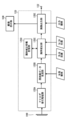
図4は、信号処理部が提供する機能のブロック図である。
FIG. 4 is a block diagram of functions provided by the signal processing unit.
同図に示すように、信号処理部120は、アナログ信号処理部120A、原画像データ生成部120B、画角補正部120C、画角補正情報記憶部120D及び画像出力部120Eを備える。
As shown in the figure, the signal processing unit 120 includes an analog signal processing unit 120A, an original image data generation unit 120B, an angle of view correction unit 120C, an angle of view correction information storage unit 120D, and an image output unit 120E.
〈アナログ信号処理部〉
アナログ信号処理部120Aは、イメージセンサ110から出力されるアナログの画像信号に対して、CDS処理(CDS:Correlated Double Sampling/相関二重サンプリング)、AGC処理(AGC:Automatic Gain Control/オートゲインコントロール)、クランプ処理等の所要の信号処理を施し、処理後のアナログの画像信号をデジタルの画像信号に変換して出力する。 <Analog signal processor>
The analogsignal processing unit 120A performs CDS processing (CDS: Correlated Double Sampling) and AGC processing (AGC: Automatic Gain Control) on the analog image signal output from the image sensor 110. Then, necessary signal processing such as clamping processing is performed, and the processed analog image signal is converted into a digital image signal and output.
アナログ信号処理部120Aは、イメージセンサ110から出力されるアナログの画像信号に対して、CDS処理(CDS:Correlated Double Sampling/相関二重サンプリング)、AGC処理(AGC:Automatic Gain Control/オートゲインコントロール)、クランプ処理等の所要の信号処理を施し、処理後のアナログの画像信号をデジタルの画像信号に変換して出力する。 <Analog signal processor>
The analog
〈原画像データ生成部〉
原画像データ生成部120Bは、アナログ信号処理部120Aから出力されるデジタルの画像信号に対して、ホワイトバランス調整、ガンマ補正、シャープネス補正等の各種補正処理、同時化処理(R、G、Bの画像信号に色補間処理を施すことにより、イメージセンサ110の各画素から出力される一組の画像信号(R信号、G信号、B信号)を生成する処理)、YCrCb変換処理(同時化処理された画素ごとのR、G、B信号を輝度信号Yと色差信号Cr、Cbとに変換する処理)等の所要の信号処理を施し、画像データ(原画像データ)を生成する。 <Original image data generator>
The original imagedata generation unit 120B performs various correction processes such as white balance adjustment, gamma correction, sharpness correction, and synchronization processes (R, G, B) on the digital image signal output from the analog signal processing unit 120A. By performing color interpolation processing on the image signal, a set of image signals (R signal, G signal, B signal) output from each pixel of the image sensor 110), YCrCb conversion processing (simultaneous processing is performed) Necessary signal processing such as conversion of the R, G, and B signals for each pixel into luminance signal Y and color difference signals Cr and Cb) is performed to generate image data (original image data).
原画像データ生成部120Bは、アナログ信号処理部120Aから出力されるデジタルの画像信号に対して、ホワイトバランス調整、ガンマ補正、シャープネス補正等の各種補正処理、同時化処理(R、G、Bの画像信号に色補間処理を施すことにより、イメージセンサ110の各画素から出力される一組の画像信号(R信号、G信号、B信号)を生成する処理)、YCrCb変換処理(同時化処理された画素ごとのR、G、B信号を輝度信号Yと色差信号Cr、Cbとに変換する処理)等の所要の信号処理を施し、画像データ(原画像データ)を生成する。 <Original image data generator>
The original image
ここで、原画像データ生成部120Bで処理対象とする画像信号は、イメージセンサ110の有効領域から出力される画像信号である。
Here, the image signal to be processed by the original image data generation unit 120B is an image signal output from the effective area of the image sensor 110.
イメージセンサ110の有効領域とは、イメージセンサ110で正常な画像を撮像できる領域のことである。有効領域は、イメージセンサ110の有効画素領域及び撮像レンズ10Aのイメージサークルによって設定される。
The effective area of the image sensor 110 is an area where the image sensor 110 can capture a normal image. The effective area is set by the effective pixel area of the image sensor 110 and the image circle of the imaging lens 10A.
イメージセンサ110の有効画素領域とは、イメージセンサ110において、実際に画像を撮像できる領域のことである。撮像レンズ10Aのイメージサークルのサイズが、イメージセンサ110の有効画素領域よりも大きければ、有効領域が有効画素領域と一致する。
The effective pixel area of the image sensor 110 is an area where the image sensor 110 can actually capture an image. If the size of the image circle of the imaging lens 10A is larger than the effective pixel area of the image sensor 110, the effective area matches the effective pixel area.
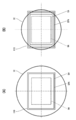
図5は、有効領域、有効画素領域及び出力領域の関係を示す図である。なお、同図(A)は、撮像レンズ10Aのイメージサークルのサイズが有効画素領域よりも大きい場合の例を示しており、同図(B)は、撮像レンズ10Aのイメージサークルのサイズが有効画素領域よりも小さい場合の例を示している。
FIG. 5 is a diagram showing the relationship between the effective area, the effective pixel area, and the output area. FIG. 4A shows an example in which the size of the image circle of the imaging lens 10A is larger than the effective pixel area, and FIG. 4B shows the case where the size of the image circle of the imaging lens 10A is an effective pixel. An example in which the area is smaller than the area is shown.
図5(A)に示すように、撮像レンズ10AのイメージサークルICのサイズが、イメージセンサ110の有効画素領域EPAよりも大きい場合、有効領域EAは、有効画素領域EPAと一致する。
As shown in FIG. 5A, when the size of the image circle IC of the imaging lens 10A is larger than the effective pixel area EPA of the image sensor 110, the effective area EA matches the effective pixel area EPA.
一方、図5(B)に示すように、撮像レンズ10AのイメージサークルICのサイズが、イメージセンサ110の有効画素領域EPAよりも小さい場合、有効領域EAは、有効画素領域EPA内に設定される。
On the other hand, as shown in FIG. 5B, when the size of the image circle IC of the imaging lens 10A is smaller than the effective pixel area EPA of the image sensor 110, the effective area EA is set within the effective pixel area EPA. .
なお、イメージサークルICのサイズは、イメージサークルICの直径で規定され、有効画素領域EPAのサイズは、有効画素領域EPAの対角の長さで規定される。有効画素領域EPAのサイズが、イメージセンサ110のサイズとなる。
Note that the size of the image circle IC is defined by the diameter of the image circle IC, and the size of the effective pixel area EPA is defined by the diagonal length of the effective pixel area EPA. The size of the effective pixel area EPA is the size of the image sensor 110.
図5において、破線で示す枠OAは、出力領域を示す枠である。出力領域とは、撮像装置1が、撮像した画像として画像出力部120Eから出力する領域のことである。出力領域OAは、必ず有効領域EAの内側に設定される。
In FIG. 5, a frame OA indicated by a broken line is a frame indicating an output area. The output area is an area that the imaging apparatus 1 outputs from the image output unit 120E as a captured image. The output area OA is always set inside the effective area EA.
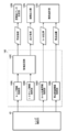
有効領域及び出力領域は、撮像装置本体制御部140が設定する。図6は、撮像装置本体制御部が提供する一部の機能のブロック図である。
The effective area and the output area are set by the imaging apparatus main body control unit 140. FIG. 6 is a block diagram of some functions provided by the imaging apparatus main body control unit.
撮像装置本体制御部140は、装着された撮像レンズ10Aからイメージサークルのサイズの情報を取得し、取得したイメージサークルのサイズの情報及びイメージセンサ110のサイズの情報に基づいて、有効領域及び出力領域を設定する。このため、撮像装置本体制御部140には、装着された撮像レンズ10Aからイメージサークルのサイズの情報を取得する機能、イメージセンサ110のサイズの情報を取得する機能、及び、取得したイメージサークルのサイズの情報及びイメージセンサ110のサイズの情報に基づいて、有効領域及び出力領域を設定する機能が備えられる。
The imaging device main body control unit 140 acquires image circle size information from the mounted imaging lens 10 </ b> A, and based on the acquired image circle size information and image sensor 110 size information, an effective area and an output area Set. For this reason, the imaging apparatus main body control unit 140 has a function for acquiring information about the size of the image circle from the mounted imaging lens 10A, a function for acquiring information about the size of the image sensor 110, and the size of the acquired image circle. And a function for setting the effective area and the output area based on the information on the size of the image sensor 110 and the information on the size of the image sensor 110.
装着された撮像レンズ10Aからイメージサークルのサイズの情報を取得する機能は、レンズ情報取得部140Aによって提供され、イメージセンサ110のサイズの情報を取得する機能は、イメージセンササイズ情報取得部140Bによって提供され、取得したイメージサークルのサイズの情報及びイメージセンサ110のサイズの情報に基づいて、有効領域及び出力領域を設定する機能は、領域設定部140Cによって提供される。
The function of acquiring image circle size information from the mounted imaging lens 10A is provided by the lens information acquisition unit 140A, and the function of acquiring image sensor size information is provided by the image sensor size information acquisition unit 140B. The function of setting the effective area and the output area based on the acquired image circle size information and the image sensor 110 size information is provided by the area setting unit 140C.
レンズ情報取得部140Aは、撮像装置本体100に撮像レンズ10Aが装着されると、レンズ制御部40と通信して、レンズ制御部40からレンズ情報を取得する。
When the imaging lens 10A is attached to the imaging apparatus main body 100, the lens information acquisition unit 140A communicates with the lens control unit 40 and acquires lens information from the lens control unit 40.
ここで、レンズ情報とは、撮像レンズの仕様を示す情報である。撮像レンズ10Aのイメージサークルのサイズの情報は、このレンズ情報に含まれる。レンズ情報には、この他、たとえば、レンズ機種データ、レンズ特性データ、レンズ特性補正データ等が含まれる。レンズ機種データには、レンズ機種名、焦点距離、開放F値、メーカー名等が含まれる。レンズ特性データには、輝度シェーディングデータ、色シェーディングデータ、ディストーションデータ、収差データ等が含まれる。レンズ特性補正データには、輝度シェーディング補正データ、色シェーディング補正データ、ディストーション補正データ、収差補正データ等が含まれる。
Here, the lens information is information indicating the specifications of the imaging lens. Information on the size of the image circle of the imaging lens 10A is included in this lens information. In addition to this, the lens information includes, for example, lens model data, lens characteristic data, lens characteristic correction data, and the like. The lens model data includes the lens model name, focal length, open F value, manufacturer name, and the like. The lens characteristic data includes luminance shading data, color shading data, distortion data, aberration data, and the like. The lens characteristic correction data includes luminance shading correction data, color shading correction data, distortion correction data, aberration correction data, and the like.
レンズ情報は、レンズ制御部40のROMに格納される。レンズ制御部40は、ROMからレンズ情報を読み出して、撮像装置本体制御部140に送信する。
Lens information is stored in the ROM of the lens control unit 40. The lens control unit 40 reads lens information from the ROM and transmits the lens information to the imaging apparatus main body control unit 140.
イメージセンササイズ情報取得部140Bは、撮像装置本体制御部140のROMからイメージセンサ110のサイズの情報を読み出して取得する。撮像装置本体制御部140のROMには、あらかじめイメージセンサ110のサイズの情報が格納される。
The image sensor size information acquisition unit 140B reads out and acquires the size information of the image sensor 110 from the ROM of the imaging apparatus main body control unit 140. Information on the size of the image sensor 110 is stored in advance in the ROM of the imaging apparatus main body control unit 140.
領域設定部140Cは、撮像レンズ10Aのイメージサークルのサイズ及びイメージセンサ110のサイズ(有効画素領域のサイズ)の情報に基づいて、有効領域及び出力領域を設定する。
The area setting unit 140C sets the effective area and the output area based on the information about the size of the image circle of the imaging lens 10A and the size of the image sensor 110 (size of the effective pixel area).
上記のように、撮像レンズ10Aのイメージサークルのサイズが、イメージセンサ110のサイズ(有効画素領域のサイズ)よりも大きい場合、有効領域は、有効画素領域と同じ領域に設定される(図5(A)参照)。すなわち、イメージセンサ110の有効画素領域が有効領域に設定される。
As described above, when the size of the image circle of the imaging lens 10A is larger than the size of the image sensor 110 (size of the effective pixel area), the effective area is set to the same area as the effective pixel area (FIG. 5 ( A)). That is, the effective pixel area of the image sensor 110 is set as the effective area.
一方、撮像レンズ10Aのイメージサークルのサイズが、イメージセンサ110のサイズ(有効画素領域のサイズ)よりも小さい場合、有効領域は、有効画素領域の内側に設定され、かつ、イメージサークルの内側に設定される(図5(B)参照)。この際、有効領域は、所定のアスペクト比で設定され、かつ、可能な限り大きなサイズで設定される。
On the other hand, when the size of the image circle of the imaging lens 10A is smaller than the size of the image sensor 110 (size of the effective pixel area), the effective area is set inside the effective pixel area and set inside the image circle. (See FIG. 5B). At this time, the effective area is set with a predetermined aspect ratio and set as large as possible.
出力領域は、有効領域の内側に設定される。出力領域は、有効領域内であれば任意に設定でき、その最大の範囲は、有効領域と同じ領域である。出力領域は、あらかじめ定められ、撮像装置本体制御部140のROMに格納される。領域設定部140Cは、ROMから出力領域の情報を読み出して、出力領域を設定する。
The output area is set inside the effective area. The output area can be arbitrarily set as long as it is within the effective area, and the maximum range is the same area as the effective area. The output area is determined in advance and stored in the ROM of the imaging apparatus main body control unit 140. The area setting unit 140C reads output area information from the ROM and sets the output area.
なお、装着する撮像レンズ10Aによっては、出力領域のサイズが、有効領域のサイズよりも大きくなる場合がある。この場合は、たとえば、警告がなされてもよい。警告は、たとえば、画像表示部130に警告メッセージを表示することにより行われる。
Note that, depending on the imaging lens 10A to be mounted, the size of the output area may be larger than the size of the effective area. In this case, for example, a warning may be given. The warning is performed by displaying a warning message on the image display unit 130, for example.
領域設定部140Cによって設定された有効領域の情報は、原画像データ生成部120Bに加えられる。原画像データ生成部120Bは、取得した有効領域の情報に基づいて、アナログ信号処理部120Aから出力される画像信号を処理し、画像データを生成する。この原画像データ生成部120Bで生成される画像データを原画像データと称する。原画像データは、イメージセンサ110の有効領域から出力される信号を処理して生成される画像データである。
The information on the effective area set by the area setting unit 140C is added to the original image data generation unit 120B. The original image data generation unit 120B processes the image signal output from the analog signal processing unit 120A based on the acquired information on the effective area, and generates image data. The image data generated by the original image data generation unit 120B is referred to as original image data. The original image data is image data generated by processing a signal output from the effective area of the image sensor 110.
領域設定部140Cによって設定された出力領域の情報は、画像出力部120Eに加えられる。画像出力部120Eは、取得した出力領域の情報に基づいて、出力領域に相当する領域の画像データを原画像データから抽出して出力する。画像出力部120Eから出力する画像データを出力画像データと称する。出力画像データは、出力領域の画像データに相当する。画像出力部120Eの詳細については、後述する。
The information of the output area set by the area setting unit 140C is added to the image output unit 120E. The image output unit 120E extracts and outputs image data of an area corresponding to the output area from the original image data based on the acquired output area information. The image data output from the image output unit 120E is referred to as output image data. The output image data corresponds to image data in the output area. Details of the image output unit 120E will be described later.
〈画角補正部及び画角補正情報記憶部〉
画角補正部120Cは、原画像データを拡縮処理して、出力領域の画像データの画角を補正する。この際、画角補正部120Cは、フォーカシングに連動して原画像データを拡縮処理し、出力画像データの画角を焦点距離ごとに定められた基準画角に補正する。これにより、フォーカシングに伴う画角変動を補正できる。 <Field angle correction unit and field angle correction information storage unit>
The angle-of-view correction unit 120C corrects the angle of view of the image data in the output area by scaling the original image data. At this time, the angle-of-view correction unit 120C scales the original image data in conjunction with focusing, and corrects the angle of view of the output image data to a reference angle of view determined for each focal length. Thereby, it is possible to correct the angle of view variation accompanying the focusing.
画角補正部120Cは、原画像データを拡縮処理して、出力領域の画像データの画角を補正する。この際、画角補正部120Cは、フォーカシングに連動して原画像データを拡縮処理し、出力画像データの画角を焦点距離ごとに定められた基準画角に補正する。これにより、フォーカシングに伴う画角変動を補正できる。 <Field angle correction unit and field angle correction information storage unit>
The angle-of-
画角補正情報記憶部120Dは、画角補正部120Cが、原画像データを拡縮処理する際に必要な画角の補正情報を記憶する。画角補正情報記憶部120Dは、たとえば、ROMで構成される。
The angle-of-view correction information storage unit 120D stores angle-of-view correction information necessary when the angle-of-view correction unit 120C enlarges or reduces the original image data. The angle-of-view correction information storage unit 120D is configured by a ROM, for example.
図7は、フォーカス位置と出力画像データの画角との関係を示すグラフである。同図において、縦軸はフォーカス位置、横軸は出力画像データの画角である。なお、同図に示す例では、説明を簡単にするため、フォーカス位置と画角との関係を直線で示しているが、フォーカス位置を変化させた場合に、どのように画角が変化するかは、撮像レンズによって異なる。また、同じ撮像レンズであっても、焦点距離によって、画角の変化の仕方は異なる。
FIG. 7 is a graph showing the relationship between the focus position and the angle of view of the output image data. In the figure, the vertical axis represents the focus position, and the horizontal axis represents the angle of view of the output image data. In the example shown in the figure, the relationship between the focus position and the angle of view is shown by a straight line for the sake of simplicity. However, how the angle of view changes when the focus position is changed. Depends on the imaging lens. Even with the same imaging lens, the way of changing the angle of view varies depending on the focal length.
図7に示すように、フォーカス位置に応じて画角が変化する。したがって、フォーカス位置に応じて画像データを拡縮処理(電子ズーム、デジタルズームともいう。)することにより、画角の変動を補正でき、フォーカスブリージングを補正できる。
As shown in FIG. 7, the angle of view changes according to the focus position. Therefore, by performing the enlargement / reduction processing (also referred to as electronic zoom or digital zoom) on the image data in accordance with the focus position, it is possible to correct the change in the angle of view and correct the focus breathing.
たとえば、図7に示す例において、フォーカス位置が点FP2から至近端側の点FP1に移動したとする。この場合、画角は、FA2からFA1に変化し、その差分だけ縮小する。すなわち、撮像される範囲が縮小する。したがって、この場合は画角が縮小した分だけ画像データを縮小処理することにより、画角の変動を相殺できる。
For example, in the example shown in FIG. 7, it is assumed that the focus position has moved from the point FP2 to the point FP1 on the closest end side. In this case, the angle of view changes from FA2 to FA1, and is reduced by the difference. That is, the imaged range is reduced. Therefore, in this case, the fluctuation of the angle of view can be offset by reducing the image data by the amount that the angle of view is reduced.
また、図7に示す例において、フォーカス位置が点FP2から無限遠側の点FP3に移動したとする。この場合、画角は、FA2からFA3に変化し、その差分だけ拡大する。すなわち、撮像される範囲が拡大する。したがって、この場合は画角が拡大した分だけ画像データを拡大処理することにより、画角の変動を相殺できる。
In the example shown in FIG. 7, it is assumed that the focus position has moved from the point FP2 to the point FP3 on the infinity side. In this case, the angle of view changes from FA2 to FA3 and is enlarged by the difference. That is, the imaged range is enlarged. Therefore, in this case, fluctuations in the angle of view can be offset by enlarging the image data by the amount that the angle of view is enlarged.
図8は、拡縮処理による画角補正の概念図である。同図(A)は、出力画像データの画角が基準画角に対して縮小した場合の原画像(原画像データが表わす画像)の例を示している。同図(B)は、出力画像データの画角が基準画角の場合の原画像の例を示している。同図(C)は、出力画像データの画角が基準画角に対して拡大した場合の原画像の例を示している。なお、同図(A)から(C)において、実線で示す枠EAの内側の領域が有効領域であり、破線で示す枠OAの内側の領域が出力領域である。
FIG. 8 is a conceptual diagram of field angle correction by enlargement / reduction processing. FIG. 3A shows an example of an original image (an image represented by the original image data) when the angle of view of the output image data is reduced with respect to the reference angle of view. FIG. 5B shows an example of the original image when the angle of view of the output image data is the reference angle of view. FIG. 3C shows an example of the original image when the angle of view of the output image data is enlarged with respect to the reference angle of view. In FIGS. 3A to 3C, an area inside the frame EA indicated by a solid line is an effective area, and an area inside the frame OA indicated by a broken line is an output area.
図8(A)に示すように、フォーカスブリージングにより、出力画像データの画角が基準画角よりも縮小すると、原画像は拡大する。この場合、原画像データを縮小処理し、出力画像データの画角を基準画角に補正する。
As shown in FIG. 8A, when the angle of view of the output image data is reduced from the reference angle of view by focus breathing, the original image is enlarged. In this case, the original image data is reduced, and the angle of view of the output image data is corrected to the reference angle of view.
一方、図8(C)に示すように、フォーカスブリージングにより、出力画像データの画角が基準画角よりも拡大すると、原画像は縮小する。この場合、原画像データを拡大処理し、出力画像データの画角を基準画角に補正する。
On the other hand, as shown in FIG. 8C, when the angle of view of the output image data is larger than the reference angle of view due to focus breathing, the original image is reduced. In this case, the original image data is enlarged and the angle of view of the output image data is corrected to the reference angle of view.
このように、原画像データを拡縮処理することにより、出力画像データの画角の変動を補正でき、フォーカスブリージングを補正できる。
In this way, by performing the enlargement / reduction processing of the original image data, it is possible to correct the change in the angle of view of the output image data and to correct the focus breathing.
画角補正部120Cは、フォーカス位置に応じて画像データを拡縮処理することにより、出力画像データの画角の変動を補正し、フォーカスブリージングを補正する。
The angle-of-view correction unit 120C corrects the variation in the angle of view of the output image data and corrects the focus breathing by enlarging / reducing the image data according to the focus position.
ここで、画角補正部120Cで拡縮処理する対象は、原画像データである。原画像データを拡縮処理することにより、原画像データから抽出される出力画像データも拡縮処理される。
Here, the object to be enlarged / reduced by the angle-of-view correction unit 120C is original image data. By scaling the original image data, the output image data extracted from the original image data is also scaled.
画角補正部120Cは、フォーカス位置ごとに定められた拡大縮小率で原画像データを拡縮処理し、出力画像データの画角を一定に維持する。一定に維持する画角を基準画角とする。基準画角は、焦点距離ごとに定められる。すなわち、画角補正部120Cは、焦点距離ごとに定められた基準画角を維持するように、原画像データを拡縮処理する。したがって、拡大縮小率は、基準画角に補正するための画角の補正量の情報として規定される。拡大縮小率は、各焦点距離においてフォーカス位置ごとに定められる。画角補正情報記憶部120Dには、画角の補正量の情報として、各焦点距離においてフォーカス位置ごとに定められた拡大縮小率の情報が記憶される。
The angle-of-view correction unit 120C enlarges / reduces the original image data at an enlargement / reduction ratio determined for each focus position, and maintains the angle of view of the output image data. The angle of view that is maintained constant is set as the reference angle of view. The reference angle of view is determined for each focal length. That is, the angle-of-view correction unit 120C enlarges or reduces the original image data so as to maintain the reference angle of view determined for each focal length. Therefore, the enlargement / reduction ratio is defined as information on the correction amount of the angle of view for correcting the reference angle of view. The enlargement / reduction ratio is determined for each focus position at each focal length. In the angle-of-view correction information storage unit 120D, information on the enlargement / reduction ratio determined for each focus position at each focal length is stored as information on the amount of field angle correction.
なお、基準画角の設定の仕方によって、フォーカス位置ごとに定められる拡大縮小率も変わる。各焦点距離において基準画角をどのように設定するかについては、後述する。
Note that the enlargement / reduction ratio determined for each focus position varies depending on how the reference angle of view is set. How to set the reference angle of view at each focal length will be described later.
画角補正部120Cは、画角補正情報記憶部120Dに記憶されている情報を参照し、現在のフォーカス位置及び焦点距離に基づいて、拡大縮小率を決定する。画角補正部120Cは、決定した拡大縮小率で原画像データを拡縮処理して、出力画像データの画角を補正する。
The angle-of-view correction unit 120C refers to the information stored in the angle-of-view correction information storage unit 120D, and determines the enlargement / reduction ratio based on the current focus position and focal length. The angle-of-view correction unit 120C corrects the angle of view of the output image data by enlarging / reducing the original image data at the determined enlargement / reduction ratio.
なお、現在のフォーカス位置及び焦点距離の情報は、撮像装置本体制御部140から取得する。撮像装置本体制御部140は、撮像レンズ10Aから現在のフォーカス位置及び焦点距離の情報を取得する。このため、撮像装置本体制御部140には、撮像レンズ10Aから現在のフォーカス位置の情報を取得する機能、及び、現在の焦点距離の情報を取得する機能が備えられる。
Note that information on the current focus position and focal length is acquired from the imaging apparatus main body control unit 140. The imaging device main body control unit 140 acquires information on the current focus position and focal length from the imaging lens 10A. For this reason, the imaging apparatus main body control unit 140 includes a function of acquiring information on the current focus position from the imaging lens 10A and a function of acquiring information on the current focal length.
図6に示すように、撮像レンズ10Aから現在のフォーカス位置の情報を取得する機能は、フォーカス位置情報取得部140Dによって提供され、現在の焦点距離の情報を取得する機能は、焦点距離情報取得部140Eによって提供される。
As shown in FIG. 6, the function of acquiring the current focus position information from the imaging lens 10 </ b> A is provided by the focus position information acquisition unit 140 </ b> D, and the function of acquiring the current focal distance information is the focal length information acquisition unit. Provided by 140E.
フォーカス位置情報取得部140Dは、レンズ制御部40と通信して、レンズ制御部40から第1bレンズ群G1bの位置の情報(フォーカシングレンズ群の位置の情報)を取得する。フォーカス位置情報取得部140Dは、取得した第1bレンズ群G1bの位置の情報に基づいてフォーカス位置を特定し、特定したフォーカス位置の情報を画角補正部120Cに出力する。
The focus position information acquisition unit 140D communicates with the lens control unit 40, and acquires information on the position of the 1b lens group G1b (information on the position of the focusing lens group) from the lens control unit 40. The focus position information acquisition unit 140D specifies the focus position based on the acquired position information of the first b lens group G1b, and outputs the specified focus position information to the field angle correction unit 120C.
焦点距離情報取得部140Eは、レンズ制御部40と通信して、レンズ制御部40から第2レンズ群G2の位置の情報(ズームレンズの位置の情報)を取得する。焦点距離情報取得部140Eは、取得した第2レンズ群G2の情報に基づいて焦点距離を特定し、特定した焦点距離の情報を画角補正部120Cに出力する。
The focal length information acquisition unit 140E communicates with the lens control unit 40, and acquires information on the position of the second lens group G2 (information on the position of the zoom lens) from the lens control unit 40. The focal length information acquisition unit 140E specifies the focal length based on the acquired information of the second lens group G2, and outputs information on the specified focal length to the angle of view correction unit 120C.
画角補正部120Cは、撮像装置本体制御部140から現在のフォーカス位置及び焦点距離の情報を取得し、画角補正情報記憶部120Dに記憶された情報に基づいて拡大縮小率を決定し、決定した拡大縮小率で原画像データを拡縮処理して、出力画像データの画角を補正する。
The angle-of-view correction unit 120C acquires information on the current focus position and focal length from the imaging apparatus main body control unit 140, and determines an enlargement / reduction ratio based on the information stored in the angle-of-view correction information storage unit 120D. The original image data is enlarged / reduced at the enlarged / reduced rate to correct the angle of view of the output image data.
なお、画角補正部120Cにおいて、縮小処理ができるのは、出力領域が有効領域よりも小さく設定されている場合に限られる。縮小処理とは、画角を拡大する処理なので、出力領域の画角よりも大きな画角の画像が存在しなければ、画像を縮小できない。このため、縮小処理ができるのは、出力領域が有効領域よりも小さく設定されている場合に限られる。
In the angle of view correction unit 120C, the reduction process can be performed only when the output area is set smaller than the effective area. The reduction process is a process for enlarging the angle of view, and therefore an image cannot be reduced unless there is an image with an angle of view larger than the angle of view of the output area. Therefore, the reduction process can be performed only when the output area is set smaller than the effective area.
〈画像出力部〉
画像出力部120Eは、画角補正後の原画像データから出力領域の画像データを出力画像データとして抽出する。 <Image output section>
Theimage output unit 120E extracts the image data of the output area as output image data from the original image data after the angle of view correction.
画像出力部120Eは、画角補正後の原画像データから出力領域の画像データを出力画像データとして抽出する。 <Image output section>
The
図9は、画像出力部における画像抽出の概念図である。同図(A)は、原画像の例を示し、同図(B)は、出力画像の例を示している。
FIG. 9 is a conceptual diagram of image extraction in the image output unit. FIG. 4A shows an example of an original image, and FIG. 4B shows an example of an output image.
図9(A)において、実線で示す枠EAの内側の領域が有効領域であり、破線で示す枠OAの内側の領域が出力領域である。
9A, the area inside the frame EA indicated by a solid line is an effective area, and the area inside the frame OA indicated by a broken line is an output area.
図9(A)及び(B)に示すように、画像出力部120Eは、画角補正後の原画像データから出力領域OAの画像データを出力画像データとして抽出する。
9A and 9B, the image output unit 120E extracts the image data of the output area OA as output image data from the original image data after the angle of view correction.
なお、図9に示す例では、出力領域OAが有効領域EAよりも小さい場合を示しているが、出力領域OAが有効領域EAと一致する場合、有効領域EAの画像データ、すなわち、原画像データがそのまま出力画像データとして出力される。
In the example shown in FIG. 9, the output area OA is smaller than the effective area EA. However, when the output area OA matches the effective area EA, the image data of the effective area EA, that is, the original image data Are output as output image data as they are.
抽出された出力画像データは、画像出力端子132から出力され、また、画像表示部130に加えられて、再生表示される。
The extracted output image data is output from the image output terminal 132, added to the image display unit 130, and reproduced and displayed.
《基準画角の設定》
基準画角は、たとえば、次のように設定できる。すなわち、各焦点距離において、フォーカシングにより変動する出力画像データ(出力領域の画像データ)の画角の中で最小の画角、又は、最大の画角を基準画角として設定する。以下、最小の画角を基準画角として設定する場合及び最大の画角を基準画角として設定する場合を分けて説明する。 <Setting the standard angle of view>
For example, the reference angle of view can be set as follows. In other words, at each focal length, the minimum field angle or the maximum field angle among the field angles of the output image data (image data of the output area) that varies due to focusing is set as the reference field angle. Hereinafter, a case where the minimum field angle is set as the reference field angle and a case where the maximum field angle is set as the reference field angle will be described separately.
〈最小の画角を基準画角として設定する場合〉
各焦点距離において、フォーカシングにより変動する出力画像データの画角の中で最小の画角を基準画角として設定する。この場合、フォーカシングによって画角が変動した場合であっても、出力画像データの画角が基準画角を下回ることはない。すなわち、変動の下限が、基準画角となる。 <When setting the minimum angle of view as the standard angle of view>
At each focal length, the smallest angle of view of the output image data that varies due to focusing is set as the reference angle of view. In this case, even when the angle of view varies due to focusing, the angle of view of the output image data does not fall below the reference angle of view. That is, the lower limit of variation is the reference field angle.
この場合、画角補正部120Cは、常に原画像データを拡大処理して、出力画像データの画角を補正する。すなわち、本例の場合、出力画像データの画角は、常に基準画角から拡大する方向に変化する。したがって、画角補正部120Cは、基準画角から拡大する画角を基準画角に戻すため、原画像データを拡大処理する。
In this case, the view angle correction unit 120C always enlarges the original image data to correct the view angle of the output image data. That is, in the case of this example, the angle of view of the output image data always changes in the direction of enlarging from the reference angle of view. Accordingly, the angle-of-view correction unit 120C enlarges the original image data in order to return the angle of view that is enlarged from the reference angle of view to the reference angle of view.
出力領域が有効領域と一致している場合など、原画像データに対して縮小処理ができない場合は、本例のように、基準画角を設定することで、すべてのフォーカス位置及び焦点距離において適切にフォーカスブリージングを補正できる。
If the original image data cannot be reduced, such as when the output area matches the valid area, set the reference field angle as shown in this example, so that it is appropriate for all focus positions and focal lengths. Focus breathing can be corrected.
なお、本例における「最小の画角」には、その近傍の画角も含まれる。すなわち、ここでの「最小の画角」は、最小とみなせる範囲の画角(=ほぼ最小の画角)を含む概念のものである。
In addition, the “minimum field angle” in this example includes the field angle in the vicinity. That is, the “minimum angle of view” here is a concept including an angle of view in a range that can be regarded as the minimum (= approximately the minimum angle of view).
各焦点距離において、フォーカシングにより変動する出力画像データの画角の中で最小の画角を基準画角として設定する場合、画角補正情報記憶部120Dには、各フォーカス位置において、基準画角に補正するための拡大縮小率の情報が補正量の情報として記憶される。この情報は、焦点距離ごとに記憶される。
When the minimum angle of view of the output image data that varies due to focusing at each focal length is set as the reference angle of view, the angle of view correction information storage unit 120D sets the reference angle of view at each focus position. Information on the enlargement / reduction ratio for correction is stored as correction amount information. This information is stored for each focal length.
〈最大の画角を基準画角として設定する場合〉
各焦点距離において、フォーカシングにより変動する出力領域の画像データの画角の中で最大の画角を基準画角として設定する。この場合、フォーカシングによって画角が変動した場合であっても、出力画像データの画角が基準画角を上回ることはない。すなわち、変動の上限が、基準画角となる。 <When setting the maximum angle of view as the standard angle of view>
At each focal length, the maximum field angle among the field angles of the image data in the output area that varies due to focusing is set as the reference field angle. In this case, even if the angle of view varies due to focusing, the angle of view of the output image data does not exceed the reference angle of view. That is, the upper limit of variation is the reference field angle.
この場合、画角補正部120Cは、常に原画像データを縮小処理して、出力画像データの画角を補正する。すなわち、本例の場合、出力画像データの画角は、常に基準画角から縮小する方向に変化する。したがって、画角補正部120Cは、基準画角から縮小する画角を基準画角に戻すため、原画像データを縮小処理する。
In this case, the view angle correction unit 120C always reduces the original image data to correct the view angle of the output image data. That is, in the case of this example, the angle of view of the output image data always changes in the direction of reduction from the reference angle of view. Therefore, the angle-of-view correction unit 120C reduces the original image data in order to return the angle of view reduced from the reference angle of view to the reference angle of view.
出力領域が有効領域よりも小さく設定されて、出力領域の周囲に余白領域が存在し、すべてのフォーカス位置及び焦点距離で原画像データを縮小処理できる場合は、本例のように基準画角を設定することで、すべてのフォーカス位置及び焦点距離において適切にフォーカスブリージングを補正できる。
If the output area is set smaller than the effective area and there is a margin area around the output area, and the original image data can be reduced at all focus positions and focal lengths, the reference angle of view is set as shown in this example. By setting, focus breathing can be appropriately corrected at all focus positions and focal lengths.
また、本例のように、常に縮小処理によって画角を補正することにより、出力画像データの劣化を防止できる。すなわち、拡大処理による補正は、MTFの劣化など画像品質の低下を引き起こすが、縮小処理による補正は、このような弊害がない。よって、常に縮小処理によって画角を補正することにより、出力画像データの劣化を防止できる。
Also, as in this example, by always correcting the angle of view by the reduction process, it is possible to prevent deterioration of the output image data. That is, the correction by the enlargement process causes a decrease in image quality such as the degradation of the MTF, but the correction by the reduction process does not have such an adverse effect. Therefore, it is possible to prevent deterioration of the output image data by always correcting the angle of view by the reduction process.
なお、本例における「最大の画角」には、その近傍の画角も含まれる。すなわち、ここでの「最大の画角」は、最大とみなせる範囲の画角(=ほぼ最大の画角)を含む概念のものである。
Note that the “maximum angle of view” in this example includes the angle of view in the vicinity. That is, the “maximum angle of view” here is a concept including an angle of view in a range that can be regarded as the maximum (= approximately the maximum angle of view).
各焦点距離において、フォーカシングにより変動する出力画像データの画角の中で最大の画角を基準画角として設定する場合、画角補正情報記憶部120Dには、各フォーカス位置において、基準画角に補正するための拡大縮小率の情報が補正量の情報として記憶される。この情報は、焦点距離ごとに記憶される。
When the maximum angle of view of the output image data that varies due to focusing at each focal length is set as the reference angle of view, the angle of view correction information storage unit 120D sets the reference angle of view at each focus position. Information on the enlargement / reduction ratio for correction is stored as correction amount information. This information is stored for each focal length.
〈選択基準〉
基準画角を最小の画角で設定するか、最大の画角で設定するかは、主として、有効領域と出力領域との関係によって定められる。 <Selection criteria>
Whether the reference field angle is set at the minimum field angle or the maximum field angle is mainly determined by the relationship between the effective area and the output area.
基準画角を最小の画角で設定するか、最大の画角で設定するかは、主として、有効領域と出力領域との関係によって定められる。 <Selection criteria>
Whether the reference field angle is set at the minimum field angle or the maximum field angle is mainly determined by the relationship between the effective area and the output area.
出力領域と有効領域とが一致している場合などには、縮小処理はできないので、必然的に最小の画角が基準画角に設定される。また、出力領域が有効領域よりも小さく設定されている場合であっても、画角を補正できるほどの余裕がない場合も同様に最小の画角が基準画角に設定される。
When the output area and the effective area match, the reduction process cannot be performed, so the minimum angle of view is inevitably set as the reference angle of view. Even when the output area is set to be smaller than the effective area, the minimum field angle is set as the reference field angle when there is not enough room to correct the field angle.
一方、出力領域が、余裕をもって設定され、どのフォーカス位置及び焦点距離においても、縮小処理で画角を補正できる場合は、最大の画角を基準画角に設定することが好ましい。これにより、画像劣化を防止でき、高品質な出力画像を提供できる。
On the other hand, when the output area is set with a margin and the angle of view can be corrected by the reduction process at any focus position and focal length, it is preferable to set the maximum angle of view as the reference angle of view. Thereby, image degradation can be prevented and a high-quality output image can be provided.
[作用]
次に、本実施の形態の撮像装置の動作について説明する。 [Action]
Next, the operation of the imaging apparatus according to the present embodiment will be described.
次に、本実施の形態の撮像装置の動作について説明する。 [Action]
Next, the operation of the imaging apparatus according to the present embodiment will be described.
《初期設定》
撮像装置本体100に撮像レンズ10Aが装着されると、撮像装置本体制御部140において、有効領域及び出力領域を設定する処理が行われる。 "Initial setting"
When theimaging lens 10A is attached to the imaging apparatus main body 100, the imaging apparatus main body control unit 140 performs processing for setting an effective area and an output area.
撮像装置本体100に撮像レンズ10Aが装着されると、撮像装置本体制御部140において、有効領域及び出力領域を設定する処理が行われる。 "Initial setting"
When the
図10は、有効領域及び出力領域の設定処理の手順を示すフローチャートである。
FIG. 10 is a flowchart showing the procedure for setting the effective area and the output area.
まず、撮像装置本体制御部140は、撮像レンズ10Aからイメージサークルのサイズの情報を取得する(ステップS1)。撮像装置本体制御部140は、レンズ制御部40と通信し、レンズ制御部40からレンズ情報を取得して、撮像レンズ10Aのイメージサークルのサイズの情報を取得する。
First, the imaging apparatus main body control unit 140 acquires information about the size of the image circle from the imaging lens 10A (step S1). The imaging device main body control unit 140 communicates with the lens control unit 40, acquires lens information from the lens control unit 40, and acquires information on the size of the image circle of the imaging lens 10A.
次に、撮像装置本体制御部140は、イメージセンサ110のサイズの情報を取得する(ステップS2)。イメージセンサ110のサイズの情報はROMから取得する。上記のように、イメージセンサ110のサイズが、イメージセンサ110の有効画素領域のサイズとなる。
Next, the imaging apparatus main body control unit 140 acquires information on the size of the image sensor 110 (step S2). Information on the size of the image sensor 110 is obtained from the ROM. As described above, the size of the image sensor 110 is the size of the effective pixel area of the image sensor 110.
次に、撮像装置本体制御部140は、取得したイメージサークルのサイズの情報及びイメージセンサ110のサイズの情報に基づいて、有効領域を決定する(ステップS3)。
Next, the imaging device main body control unit 140 determines an effective area based on the acquired information on the size of the image circle and the information on the size of the image sensor 110 (step S3).
上記のように、撮像レンズ10Aのイメージサークルのサイズが、イメージセンサ110のサイズ(有効画素領域のサイズ)よりも大きい場合、有効領域は、有効画素領域と同じ領域に設定される(図5(A)参照)。すなわち、イメージセンサ110の有効画素領域が有効領域に設定される。
As described above, when the size of the image circle of the imaging lens 10A is larger than the size of the image sensor 110 (size of the effective pixel area), the effective area is set to the same area as the effective pixel area (FIG. 5 ( A)). That is, the effective pixel area of the image sensor 110 is set as the effective area.
一方、撮像レンズ10Aのイメージサークルのサイズが、イメージセンサ110のサイズ(有効画素領域のサイズ)よりも小さい場合、有効領域は、有効画素領域の内側に設定され、かつ、イメージサークルの内側に設定される(図5(B)参照)。この際、有効領域は、所定のアスペクト比で設定され、かつ、可能な限り大きなサイズで設定される。
On the other hand, when the size of the image circle of the imaging lens 10A is smaller than the size of the image sensor 110 (size of the effective pixel area), the effective area is set inside the effective pixel area and set inside the image circle. (See FIG. 5B). At this time, the effective area is set with a predetermined aspect ratio and set as large as possible.
次に、撮像装置本体制御部140は、設定する出力領域が、有効領域以下か否かを判定する(ステップS4)。設定する出力領域の情報は、ROMから読み出して取得する。
Next, the imaging apparatus main body control unit 140 determines whether or not the output area to be set is equal to or less than the effective area (step S4). Information on the output area to be set is obtained by reading from the ROM.
設定する出力領域が有効領域以下の場合、撮像装置本体制御部140は、定められた領域に出力領域を設定する(ステップS5)。
When the output area to be set is equal to or smaller than the effective area, the imaging device main body control unit 140 sets the output area in the determined area (step S5).
一方、設定する出力領域が有効領域を超える場合、撮像装置本体制御部140は、警告を発する(ステップS6)。警告は、たとえば、画像表示部130に警告メッセージを表示することにより行われる。ユーザは、この警告メッセージに基づいて対処する。
On the other hand, when the output area to be set exceeds the effective area, the imaging apparatus main body control unit 140 issues a warning (step S6). The warning is performed by displaying a warning message on the image display unit 130, for example. The user takes action based on this warning message.
以上一連の工程で有効領域及び出力領域が設定される。設定された有効領域の情報は、原画像データ生成部120Bに出力される。また、設定された出力領域の情報は、画像出力部120Eに出力される。
The effective area and output area are set by the above process. The information on the set effective area is output to the original image data generation unit 120B. Further, information on the set output area is output to the image output unit 120E.
《フォーカスブリージングの補正処理》
次の本実施の形態の撮像装置1で撮像中に実施されるフォーカスブリージングの補正処理の動作について説明する。 <Focus breathing correction processing>
Next, the operation of the focus breathing correction process performed during imaging by theimaging apparatus 1 according to the present embodiment will be described.
次の本実施の形態の撮像装置1で撮像中に実施されるフォーカスブリージングの補正処理の動作について説明する。 <Focus breathing correction processing>
Next, the operation of the focus breathing correction process performed during imaging by the
図11は、撮像中に実施されるフォーカスブリージングの補正処理の手順を示すフローチャートである。
FIG. 11 is a flowchart showing a procedure of focus breathing correction processing performed during imaging.
まず、レンズ操作の有無が判定される(ステップS10)。ここで、レンズ操作とは、撮像レンズ10Aに対するフォーカス操作及びズーム操作である。
First, the presence / absence of lens operation is determined (step S10). Here, the lens operation is a focus operation and a zoom operation on the imaging lens 10A.
レンズ操作があると、撮像装置本体制御部140は、撮像レンズ10Aからフォーカス位置の情報及び焦点距離の情報を取得する(ステップS11)。取得後、撮像装置本体制御部140は、取得したフォーカス位置の情報及び焦点距離の情報を画角補正部120Cに出力する。
When there is a lens operation, the imaging apparatus main body control unit 140 acquires focus position information and focal length information from the imaging lens 10A (step S11). After the acquisition, the imaging apparatus main body control unit 140 outputs the acquired focus position information and focal length information to the field angle correction unit 120C.
画角補正部120Cは、撮像装置本体制御部140から出力されたフォーカス位置の情報及び焦点距離の情報に基づいて、画角補正情報記憶部120Dから画角の補正量の情報を取得する(ステップS12)。すなわち、拡縮処理によって画角を基準画角に補正するための拡大縮小率の情報を取得する。
The angle-of-view correction unit 120C acquires the information on the correction amount of the angle of view from the angle-of-view correction information storage unit 120D based on the focus position information and the focal length information output from the imaging device main body control unit 140 (Step S1). S12). That is, information on the enlargement / reduction ratio for correcting the angle of view to the reference angle of view by enlargement / reduction processing is acquired.
画角補正部120Cは、画角補正情報記憶部120Dから取得した拡大縮小率で原画像データを拡縮処理し、出力領域の画像データの画角を基準画角に補正する(ステップS13)。
The angle-of-view correction unit 120C enlarges / reduces the original image data with the enlargement / reduction ratio acquired from the angle-of-view correction information storage unit 120D, and corrects the angle of view of the image data in the output area to the reference angle of view (step S13).
画角補正された原画像データは、画像出力部120Eに加えられる。画像出力部120Eは、画角補正後の原画像データから出力領域の画像データを抽出する。画像出力部120Eは、抽出した画像データを出力画像データとして、画像表示部130及び画像出力端子132に出力する(ステップS14)。
The original image data whose angle of view has been corrected is added to the image output unit 120E. The image output unit 120E extracts the image data of the output area from the original image data after the angle of view correction. The image output unit 120E outputs the extracted image data as output image data to the image display unit 130 and the image output terminal 132 (step S14).
この後、撮像装置本体制御部140は、撮像が終了したか否かを判定する(ステップS15)。撮像が終了していない場合は、ステップS10に戻り、上記の処理を再度実行する。一方、撮像が終了した場合は、処理を終了する。
Thereafter, the imaging apparatus main body control unit 140 determines whether or not imaging has been completed (step S15). If the imaging has not ended, the process returns to step S10 and the above processing is executed again. On the other hand, when the imaging is finished, the process is finished.
[効果]
本実施の形態の撮像装置1によれば、ズームレンズである撮像レンズ10Aが、物体側から順に、変倍の際に固定の第1レンズ群G1と、変倍の際に移動する第2レンズ群G2及び第3レンズ群G3と、変倍の際に固定の第4レンズ群(最終レンズ群)G4と、が配置されて構成され、かつ、フォーカシングレンズ群である第1レンズ群G1が、物体側から順に、フォーカシングの際に固定の第1aレンズ群G1aと、フォーカシングの際に移動する第1bレンズ群G1bと、フォーカシングの際に固定の第1レンズ群後群G1cと、が配置されて構成される。これにより、フォーカス操作及び変倍操作によって、全長の変わらない撮像レンズ10Aを構成できる。 [effect]
According to theimaging apparatus 1 of the present embodiment, the imaging lens 10A, which is a zoom lens, in order from the object side, the first lens group G1 that is fixed during zooming and the second lens that moves during zooming. A first lens group G1 that is configured by a group G2 and a third lens group G3, and a fourth lens group (final lens group) G4 that is fixed during zooming, and that is a focusing lens group, In order from the object side, a first lens group G1a fixed during focusing, a first lens group G1b that moves during focusing, and a rear first lens group G1c fixed during focusing are arranged. Composed. Thereby, the imaging lens 10A with the same total length can be configured by the focus operation and the zooming operation.
本実施の形態の撮像装置1によれば、ズームレンズである撮像レンズ10Aが、物体側から順に、変倍の際に固定の第1レンズ群G1と、変倍の際に移動する第2レンズ群G2及び第3レンズ群G3と、変倍の際に固定の第4レンズ群(最終レンズ群)G4と、が配置されて構成され、かつ、フォーカシングレンズ群である第1レンズ群G1が、物体側から順に、フォーカシングの際に固定の第1aレンズ群G1aと、フォーカシングの際に移動する第1bレンズ群G1bと、フォーカシングの際に固定の第1レンズ群後群G1cと、が配置されて構成される。これにより、フォーカス操作及び変倍操作によって、全長の変わらない撮像レンズ10Aを構成できる。 [effect]
According to the
また、本実施の形態の撮像装置1によれば、画像処理でフォーカスブリージングを補正することにより、撮像レンズ側において、フォーカスブリージングの設計値の制約を緩和できる。すなわち、撮像レンズ側において、ある程度フォーカスブリージングの発生が許容される。これにより、設計的にフォーカスブリージング抑制のために使用していたパワーを他の収差の補正に使用でき、全体の性能の向上が図れる。また、これにより、フォーカスブリージング性能を満たしつつ、高画素の撮像で要求される性能も満足できる。
Further, according to the imaging apparatus 1 of the present embodiment, the restriction of the focus breathing design value can be relaxed on the imaging lens side by correcting the focus breathing by image processing. That is, the occurrence of focus breathing is allowed to some extent on the imaging lens side. As a result, the power that has been used for suppressing focus breathing in design can be used to correct other aberrations, and the overall performance can be improved. This also satisfies the performance required for high pixel imaging while satisfying the focus breathing performance.
[変形例]
《基準画角》
基準画角は、焦点距離ごとに定められる。上記実施の形態では、各焦点距離において、フォーカシングにより変動する出力画像データの画角の中で最小の画角、又は、最大の画角を基準画角として設定する場合を例に説明した。基準画角の設定方法は、これに限定されるものではない。たとえば、出力領域が有効領域よりも小さく設定され、縮小処理が可能な場合は、次のように設定することができる。すなわち、各焦点距離において、フォーカシングにより変動する有効領域の画角の中で最小の画角を基準画角として設定する。これにより、可能な限り縮小処理によって画角を補正できる。すなわち、縮小処理できる場合は縮小処理によって画角を補正し、縮小処理できない場合にのみ拡大処理によって画角を補正する構成にできる。 [Modification]
《Standard angle of view》
The reference angle of view is determined for each focal length. In the above-described embodiment, an example has been described in which, at each focal length, the minimum field angle or the maximum field angle among the field angles of output image data that varies due to focusing is set as the reference field angle. The method for setting the reference angle of view is not limited to this. For example, when the output area is set smaller than the effective area and reduction processing is possible, it can be set as follows. In other words, at each focal length, the smallest field angle among the field angles of the effective region that varies due to focusing is set as the reference field angle. Thereby, the angle of view can be corrected by the reduction process as much as possible. That is, when the reduction process can be performed, the angle of view can be corrected by the reduction process, and only when the reduction process cannot be performed, the angle of view can be corrected by the enlargement process.
図12は、フォーカシングにより変動する有効領域の画角の中で最小の画角に基準画角を設定する場合の設定の概念図である。
FIG. 12 is a conceptual diagram of the setting when the reference field angle is set to the minimum field angle among the field angles of the effective region that varies due to focusing.
同図は、ある焦点距離における有効領域及び出力領域のフォーカスブリージングによる画角変動を示している。
This figure shows the angle of view variation due to focus breathing in the effective area and output area at a certain focal length.
図12において、バーBeaは、最至近距離(M.O.D.:Minimum Object Distance)から無限遠端(inf:infinite)までフォーカス位置を変化させた場合の有効領域の画角の変動範囲を示している。また、バーBoaは、最至近距離から無限遠端までフォーカス位置を変化させた場合の出力領域の画角の変動範囲を示している。なお、図12に示す例では、理解を容易にするため、最至近距離から無限遠端までフォーカス位置を変化させた場合に画角が単調に拡大する場合を例に示している。また、図12に示す例では、無限遠端(inf)の画角が大きく、最至近距離(M.O.D.)の画角が小さい例で記載しているが、この関係は必ずしも一般的な関係ではなく、逆転する場合も存在する。このため、適宜読み替えが必要となる。
In FIG. 12, the bar Bea indicates the range of change in the field angle of the effective area when the focus position is changed from the closest distance (M.O.D .: MinimumMiniObject Distance) to the infinity end (inf: infinite). The bar Boa indicates the range of change in the angle of view of the output area when the focus position is changed from the closest distance to the infinity end. In the example illustrated in FIG. 12, in order to facilitate understanding, an example in which the angle of view monotonously increases when the focus position is changed from the closest distance to the infinity end is illustrated. In the example shown in FIG. 12, the field angle at the infinity end (inf) is large and the field angle at the closest distance (MOD) is small. However, this relationship is not necessarily a general relationship. In some cases, it will reverse. For this reason, it is necessary to replace the reading as appropriate.
図12に示すように、フォーカシングにより変動する有効領域の画角の中で最小の画角に基準画角が設定される。
As shown in FIG. 12, the reference field angle is set to the smallest field angle among the field angles of the effective area that varies due to focusing.
画角補正部120Cは、次のように原画像データを拡縮処理して、出力画像データの画角を補正する。すなわち、フォーカシングにより出力画像データの画角が、基準画角よりも縮小する場合は、縮小処理によって出力画像データの画角を補正する。一方、フォーカシングにより出力画像データの画角が、基準画角よりも拡大する場合は、拡大処理によって出力画像データの画角を補正する。これにより、可能な限り縮小処理によって、画角の変動を補正できる。
The angle of view correction unit 120C corrects the angle of view of the output image data by scaling the original image data as follows. That is, when the angle of view of the output image data is reduced from the reference angle of view by focusing, the angle of view of the output image data is corrected by the reduction process. On the other hand, when the angle of view of the output image data is larger than the reference angle of view by focusing, the angle of view of the output image data is corrected by the enlargement process. Thereby, the variation in the angle of view can be corrected by the reduction process as much as possible.
なお、有効領域の画角は、焦点距離によって変動する。したがって、基準画角は、焦点距離ごとに定められる。
Note that the angle of view of the effective area varies depending on the focal length. Therefore, the reference field angle is determined for each focal length.
図13は、焦点距離ごとに定められる基準画角と、焦点距離ごとに実施される画角補正との関係を示す概念図である。同図において、横軸は焦点距離を示し、縦軸は、フォーカスブリージングによる画角変動を示している。なお、図13に示す例では、理解を容易にするため、各焦点距離において、最至近距離から無限遠端までフォーカス位置を変化させた場合に画角が単調に拡大する場合を例に示している。
FIG. 13 is a conceptual diagram showing a relationship between a reference field angle determined for each focal length and a field angle correction performed for each focal length. In the figure, the horizontal axis indicates the focal length, and the vertical axis indicates the angle of view variation due to focus breathing. In the example shown in FIG. 13, for ease of understanding, an example is shown in which the angle of view monotonously increases when the focus position is changed from the closest distance to the infinity end at each focal length. Yes.
図13において、各焦点距離でフォーカス位置を最至近距離から無限遠端まで変化させると、曲線MODと曲線INFとの間の範囲で出力画像データの画角が変動する。ここで、曲線MODは、各焦点距離における最至近距離での出力画像データの画角を示し、曲線INFは、各焦点距離における無限遠端での出力画像データの画角を示す。また、図13において、破線で示す曲線Xは、各焦点距離での基準画角を示す。
In FIG. 13, when the focus position is changed from the closest distance to the infinity end at each focal length, the angle of view of the output image data varies in a range between the curve MOD and the curve INF. Here, the curve MOD indicates the angle of view of the output image data at the closest distance at each focal length, and the curve INF indicates the angle of view of the output image data at the infinity end at each focal length. In FIG. 13, a curved line X indicated by a broken line indicates a reference angle of view at each focal length.
各焦点距離において、出力画像データの画角が、基準画角Xよりも小さくなる場合、画角補正部120Cは、原画像データを縮小処理して、出力画像データの画角を基準画角に補正する。
When the angle of view of the output image data is smaller than the reference angle of view X at each focal length, the angle of view correction unit 120C reduces the original image data so that the angle of view of the output image data becomes the reference angle of view. to correct.
また、各焦点距離において、出力画像データの画角が、基準画角Xよりも大きくなる場合、画角補正部120Cは、原画像データを拡大処理して、出力画像データの画角を基準画角に補正する。
In addition, when the angle of view of the output image data becomes larger than the reference angle of view X at each focal length, the angle of view correction unit 120C enlarges the original image data to change the angle of view of the output image data to the reference image. Correct to corners.
このように、本例では、有効領域の画角を基準にして、基準画角を設定する。なお、出力領域が有効領域と一致している場合は、常に拡大処理によって画角が補正される。
In this way, in this example, the reference field angle is set based on the field angle of the effective area. If the output area matches the effective area, the angle of view is always corrected by the enlargement process.
なお、本例での「最小の画角」には、その近傍の画角も含まれる。すなわち、ここでの「最小の画角」とは、最小とみなせる範囲の画角を含む概念のものである。
It should be noted that the “minimum field angle” in this example includes the field angle in the vicinity. That is, the “minimum angle of view” here is a concept including an angle of view in a range that can be regarded as the minimum.
《出力領域》
出力領域については、ユーザが任意に設定できる構成としてもよい。たとえば、撮像装置本体又は撮像レンズに出力領域を設定する手段を設けて、ユーザが手動で任意に出力領域を設定できるようにしてもよい。この場合、あらかじめ用意された複数の候補の中からユーザが選択して設定するようにしてよい。あるいは、ユーザが、直接数値を指定して設定するようにしてもよい。 <Output area>
The output area may be configured to be arbitrarily set by the user. For example, a means for setting an output area may be provided in the imaging apparatus main body or the imaging lens so that the user can arbitrarily set the output area manually. In this case, the user may select and set from a plurality of candidates prepared in advance. Alternatively, the user may directly set the numerical value.
《装着された撮像レンズのイメージサークルのサイズの情報の取得方法》
上記実施の形態では、撮像装置本体が撮像レンズと通信して、撮像レンズからそのイメージサークルのサイズの情報を取得する構成とされているが、装着された撮像レンズのイメージサークルのサイズの情報を取得する方法は、これに限定されるものではない。たとえば、撮像装置本体が、撮像レンズのデータベースを保持し、そのデータベースを参照して、装着された撮像レンズの情報を撮像レンズのイメージサークルのサイズの情報を取得する構成としてもよい。この場合、データベースには、撮像装置本体に装着可能な撮像レンズの固体情報(たとえば、レンズ機種名)と、そのイメージサークルのサイズの情報とが関連付けられて記録される。撮像装置本体は、装着された撮像レンズの固体情報を撮像レンズから取得し、データベースを参照して、対応するイメージサークルのサイズの情報を取得する。あるいは、装着された撮像レンズの固体情報をユーザから取得し、データベースを参照して、対応するイメージサークルのサイズの情報を取得する。ユーザは、撮像装置本体に備えられた操作部を利用して、撮像レンズの固体情報を撮像装置本体に入力する。 <Acquisition method of image circle size information of attached imaging lens>
In the above embodiment, the imaging apparatus main body communicates with the imaging lens to acquire information on the size of the image circle from the imaging lens. However, information on the size of the image circle of the mounted imaging lens is obtained. The acquisition method is not limited to this. For example, the imaging apparatus main body may be configured to hold a database of imaging lenses and refer to the database to acquire information about the mounted imaging lens and information about the size of the image circle of the imaging lens. In this case, in the database, the solid-state information (for example, the lens model name) of the imaging lens that can be attached to the imaging apparatus main body and the information on the size of the image circle are recorded in association with each other. The main body of the imaging apparatus acquires solid information of the mounted imaging lens from the imaging lens, and acquires information on the size of the corresponding image circle with reference to the database. Alternatively, the solid-state information of the mounted imaging lens is acquired from the user, and information on the size of the corresponding image circle is acquired with reference to the database. The user inputs solid-state information of the imaging lens into the imaging apparatus body using an operation unit provided in the imaging apparatus body.
また、撮像装置本体に装着した撮像レンズのイメージサークルのサイズの情報をユーザが撮像装置本体に直接入力してもよい。ユーザは、撮像装置本体に備えられた操作部を利用して、撮像レンズの固体情報を撮像装置本体に入力する。
In addition, the user may directly input information on the size of the image circle of the imaging lens attached to the imaging apparatus body to the imaging apparatus body. The user inputs solid-state information of the imaging lens into the imaging apparatus body using an operation unit provided in the imaging apparatus body.
《焦点距離》
フォーカスブリージングを補正する際の拡大縮小率は、フォーカス位置ごとに設定され、かつ、焦点距離ごとに設定されるが、焦点距離については、ズーム倍率(変倍率)で置き換えることができる。たとえば、広角端を基準としたズーム倍率で置き換えることができる。この場合、フォーカスブリージングを補正する際の拡大縮小率は、フォーカス位置ごとに設定され、かつ、ズーム倍率ごとに定められる。 "Focal length"
The enlargement / reduction ratio at the time of correcting the focus breathing is set for each focus position and for each focal distance, but the focal distance can be replaced with a zoom magnification (variable magnification). For example, it can be replaced with a zoom magnification based on the wide-angle end. In this case, the enlargement / reduction ratio at the time of correcting the focus breathing is set for each focus position and determined for each zoom magnification.
《撮像レンズの駆動系》
上記実施の形態では、第1bレンズ群G1b、第2レンズ群G2及び第3レンズ群G3をモータで駆動する構成としているが、手動で移動させる構成とすることもできる(いわゆるマニュアルフォーカス、マニュアルズーム)。 《Imaging lens drive system》
In the above embodiment, the first lens group G1b, the second lens group G2, and the third lens group G3 are configured to be driven by a motor, but may be configured to be moved manually (so-called manual focus, manual zoom). ).
また、上記実施の形態では、第2レンズ群G2及び第3レンズ群G3を独立して駆動する構成としているが、公知のカム機構を利用して、1つの駆動源で駆動する構成とすることもできる。
In the above embodiment, the second lens group G2 and the third lens group G3 are driven independently. However, the driving mechanism is driven by a single drive source using a known cam mechanism. You can also.
《レンズ構成》
撮像レンズの構成要素には、上記のレンズ群及びレンズ以外に、実質的にパワーを有さないレンズ、絞り、カバーガラス等のレンズ以外の光学要素、レンズフランジ、レンズバレル、撮像素子、手ぶれ補正機構等の機構部分等を含むことができる。 <Lens configuration>
In addition to the lens group and lens described above, the imaging lens includes optical elements other than lenses that have substantially no power, a diaphragm, a cover glass, a lens flange, a lens barrel, an image sensor, and image stabilization. A mechanism portion such as a mechanism can be included.
なお、レンズ群とは、必ずしも複数のレンズから構成されるものだけでなく、1枚のレンズのみで構成されるものも含むものとする。
It should be noted that the lens group includes not only a lens composed of a plurality of lenses but also a lens group composed of only one lens.
《信号処理部》
信号処理部120については、たとえば、原画像データ生成部120B、画角補正部120C及び画像出力部120Eをマイクロコンピュータで構成することができる。この場合、所定の信号処理プログラムによって、マイクロコンピュータを原画像データ生成部120B、画角補正部120C及び画像出力部120Eとして機能させる。 《Signal processing unit》
For thesignal processing unit 120, for example, the original image data generation unit 120B, the angle of view correction unit 120C, and the image output unit 120E can be configured by a microcomputer. In this case, the microcomputer functions as the original image data generation unit 120B, the angle of view correction unit 120C, and the image output unit 120E by a predetermined signal processing program.
信号処理部120については、たとえば、原画像データ生成部120B、画角補正部120C及び画像出力部120Eをマイクロコンピュータで構成することができる。この場合、所定の信号処理プログラムによって、マイクロコンピュータを原画像データ生成部120B、画角補正部120C及び画像出力部120Eとして機能させる。 《Signal processing unit》
For the
また、原画像データ生成部120B、画角補正部120C及び画像出力部120Eをマイクロコンピュータで構成する場合、撮像装置本体制御部140と共に1つのマイクロコンピュータで構成することができる。
Further, when the original image data generation unit 120B, the angle-of-view correction unit 120C, and the image output unit 120E are configured by a microcomputer, they can be configured by a single microcomputer together with the imaging device main body control unit 140.
《撮像レンズ及び撮像装置本体を一体化する構成》
上記実施の形態では、撮像レンズを撮像装置本体に対して交換可能としているが、撮像レンズを撮像装置本体に対して交換不能に一体的に組み込む構成としてもよい。 << Configuration for integrating imaging lens and imaging apparatus body >>
In the above-described embodiment, the imaging lens can be replaced with the imaging apparatus main body, but the imaging lens may be integrated with the imaging apparatus main body so as not to be replaced.
《撮像レンズ側で有効領域及び出力領域を設定する構成》
上記実施の形態では、撮像装置本体が、有効領域及び出力領域を設定する構成としているが、撮像レンズが、有効領域及び出力領域を設定する構成とすることもできる。この場合、撮像レンズには、装着した撮像装置本体からイメージセンサのサイズの情報を取得する撮像装置情報取得部と、取得したイメージセンサのサイズの情報及び自身のイメージサークルの情報に基づいて、有効領域及び出力領域を設定する領域設定部と、が備えられる。撮像装置情報取得部及び領域設定部の機能は、レンズ制御部の機能として備えることができる。また、自身のイメージサークルの情報は、レンズ制御部のROM等に格納し、ROMから読み出して取得できる。 《Configuration to set the effective area and output area on the imaging lens side》
In the above-described embodiment, the imaging apparatus main body is configured to set the effective area and the output area, but the imaging lens may be configured to set the effective area and the output area. In this case, the imaging lens is effective based on the imaging device information acquisition unit that acquires the size information of the image sensor from the mounted imaging device main body, the acquired size information of the image sensor, and the information of the own image circle. A region setting unit that sets a region and an output region. The functions of the imaging device information acquisition unit and the region setting unit can be provided as functions of the lens control unit. Also, information about the image circle of the user can be stored in a ROM or the like of the lens control unit and read out from the ROM.
また、この場合、撮像装置本体制御部は、撮像レンズから有効領域及び出力領域の情報を取得して、原画像データの生成処理、画角補正処理、画像出力処理等を実施する。
In this case, the imaging apparatus main body control unit acquires information on the effective area and the output area from the imaging lens, and performs original image data generation processing, field angle correction processing, image output processing, and the like.
《フォーカシング》
フォーカシングの方式として、フォーカス位置を段階的に変化させる方式を採用することもできる。 《Focusing》
As a focusing method, a method of changing the focus position stepwise can also be adopted.
フォーカシングの方式として、フォーカス位置を段階的に変化させる方式を採用することもできる。 《Focusing》
As a focusing method, a method of changing the focus position stepwise can also be adopted.
図14は、フォーカス位置を段階的に変化させる場合のフォーカス位置と出力画像データの画角との関係を示すグラフである。
FIG. 14 is a graph showing the relationship between the focus position and the angle of view of the output image data when the focus position is changed stepwise.
フォーカス位置を段階的に変化させる場合、出力画像データの画角も段階的に変化する。この場合もフォーカス位置ごとに定められた拡大縮小率で原画像データを拡縮処理し、出力画像データの画角を基準画角に補正する。
¡When changing the focus position step by step, the angle of view of the output image data also changes step by step. Also in this case, the original image data is enlarged / reduced at an enlargement / reduction ratio determined for each focus position, and the angle of view of the output image data is corrected to the reference angle of view.
◆◆第2の実施の形態◆◆
本実施の形態の撮像装置は、使用する撮像レンズ(ズームレンズ)が異なる。したがって、ここでは、撮像レンズのレンズ構成についてのみ説明する。 ◆◆ Second embodiment ◆◆
The imaging device of the present embodiment is different in the imaging lens (zoom lens) to be used. Therefore, only the lens configuration of the imaging lens will be described here.
本実施の形態の撮像装置は、使用する撮像レンズ(ズームレンズ)が異なる。したがって、ここでは、撮像レンズのレンズ構成についてのみ説明する。 ◆◆ Second embodiment ◆◆
The imaging device of the present embodiment is different in the imaging lens (zoom lens) to be used. Therefore, only the lens configuration of the imaging lens will be described here.
図15は、ズームレンズである撮像レンズのレンズ構成を示す断面図である。なお、同図は、左側が物体側、右側が像側として図示している。また、同図は、無限遠物体に合焦している場合の広角端におけるレンズ配置を示している。
FIG. 15 is a cross-sectional view showing the lens configuration of an imaging lens that is a zoom lens. In the figure, the left side is shown as the object side, and the right side is shown as the image side. The figure also shows the lens arrangement at the wide-angle end when focusing on an object at infinity.
図16は、図15に示す撮像レンズを変倍操作した場合の各レンズの移動状態を示す図である。なお、同図は、無限遠物体に合焦している場合の変倍の際のレンズの移動状態を示している。
FIG. 16 is a diagram showing a moving state of each lens when the imaging lens shown in FIG. The figure shows the lens moving state during zooming when focusing on an object at infinity.
図16において、(A)は、広角端でのレンズ配置を示している。また、(B)は、中間焦点距離状態でレンズ配置を示している。また、(C)は、望遠端でのレンズ配置を示している。
16A shows the lens arrangement at the wide-angle end. (B) shows the lens arrangement in the intermediate focal length state. (C) shows the lens arrangement at the telephoto end.
図15に示すように、本実施の形態の撮像レンズ10Bは、光軸Zに沿って、物体側から順に、正の屈折力を有する第1レンズ群G1と、負の屈折力を有する第2レンズ群G2と、負の屈折力を有する第3レンズ群G3と、正の屈折力を有する第4レンズ群(最終レンズ群)G4と、が配置されて構成される。また、本実施の形態の撮像レンズ10Bは、第4レンズ群G4中に開口絞りStが配置される。なお、図15及び図16に示す開口絞りStは、必ずしも大きさや形状を表すものではなく、光軸Z上の位置を示すものである。
As shown in FIG. 15, the imaging lens 10B of the present embodiment includes a first lens group G1 having a positive refractive power and a second lens having a negative refractive power in order from the object side along the optical axis Z. A lens group G2, a third lens group G3 having negative refractive power, and a fourth lens group (final lens group) G4 having positive refractive power are arranged. In the imaging lens 10B of the present embodiment, the aperture stop St is disposed in the fourth lens group G4. Note that the aperture stop St shown in FIGS. 15 and 16 does not necessarily indicate the size or shape, but indicates the position on the optical axis Z.
撮像レンズ10Bは、撮像レンズ10Bを装着する撮像装置本体の構成に応じて、光学系と像面Simとの間にカバーガラス、並びに、赤外線カットフィルタ、ローパスフィルタなどの各種フィルタを配置することが好ましい。このため、図15及び図16に示す例では、これらの光学部材を想定した平行平板状の光学部材PPをレンズ系と像面Simとの間に配置した例を示している。
In the imaging lens 10B, various types of filters such as a cover glass, an infrared cut filter, and a low-pass filter may be disposed between the optical system and the image plane Sim according to the configuration of the imaging apparatus body to which the imaging lens 10B is attached. preferable. For this reason, in the example shown in FIG.15 and FIG.16, the example which has arrange | positioned between the lens system and the image surface Sim the parallel plate-shaped optical member PP which assumed these optical members is shown.
本実施の形態の撮像レンズ10Bは、変倍に際して、第1レンズ群G1及び第4レンズ群G4が像面Simに対して固定され、第2レンズ群G2及び第3レンズ群G3が移動する。第2レンズ群G2及び第3レンズ群G3は、広角端から望遠端への変倍に際して、第3レンズ群G3が、光軸Zに沿って物体側から像側へ単調に移動し、第2レンズ群G2が、変倍に伴う像面変動を補正するために光軸Zに沿って移動する。すなわち、本実施の形態の撮像レンズ10Bは、第3レンズ群G3がバリエータレンズ群を構成し、第2レンズ群G2がコンペンセータレンズ群を構成する。図15には、第2レンズ群G2及び第3レンズ群G3の下にそれぞれ、広角端から望遠端への変倍に際しての各レンズ群の移動軌跡を矢印で模式的に示している。
In the imaging lens 10B of the present embodiment, during zooming, the first lens group G1 and the fourth lens group G4 are fixed with respect to the image plane Sim, and the second lens group G2 and the third lens group G3 move. In the second lens group G2 and the third lens group G3, the third lens group G3 moves monotonously from the object side to the image side along the optical axis Z when zooming from the wide-angle end to the telephoto end. The lens group G2 moves along the optical axis Z in order to correct image plane fluctuations accompanying zooming. That is, in the imaging lens 10B of the present embodiment, the third lens group G3 constitutes a variator lens group, and the second lens group G2 constitutes a compensator lens group. In FIG. 15, the movement trajectory of each lens group at the time of zooming from the wide-angle end to the telephoto end is schematically shown by arrows below the second lens group G2 and the third lens group G3.
物体側から順に、正の屈折力を有する第1レンズ群、負の屈折力を有する第2レンズ群、正または負の屈折力を有する第3レンズ群、正の屈折力を有する第4レンズ群を配してなる4群ズームレンズでは、通常、広角端から望遠端への変倍に際して、第2レンズ群をバリエータレンズ群として物体側から像側へ移動させ、第3レンズ群はコンペンセータレンズ群とすることが一般的である。
In order from the object side, a first lens group having a positive refractive power, a second lens group having a negative refractive power, a third lens group having a positive or negative refractive power, and a fourth lens group having a positive refractive power In the case of a four-group zoom lens having a zoom lens, the second lens group is moved from the object side to the image side as a variator lens group during zooming from the wide-angle end to the telephoto end, and the third lens group is a compensator lens group It is common to do.
これに対して、本実施の形態の撮像レンズ10Bでは、第3レンズ群G3をバリエータレンズ群とし、第2レンズ群G2をコンペンセータレンズ群とすることにより、広角端から望遠端への変倍の際の第2レンズ群G2の光軸方向の移動量を、上記の一般的な構成の4群ズームレンズよりも少なくできる。この結果、特に望遠端において第1レンズ群G1と第2レンズ群G2とを合成した光学系の後側主点位置(像側主点位置)を物体側に寄せることができる。これにより、レンズ系の全長の短縮化に有利となる。
On the other hand, in the imaging lens 10B of the present embodiment, the third lens group G3 is a variator lens group and the second lens group G2 is a compensator lens group, so that zooming from the wide-angle end to the telephoto end is possible. The amount of movement of the second lens group G2 in the optical axis direction can be smaller than that of the four-group zoom lens having the above-described general configuration. As a result, the rear principal point position (image side principal point position) of the optical system that combines the first lens group G1 and the second lens group G2 can be brought closer to the object side, particularly at the telephoto end. This is advantageous for shortening the overall length of the lens system.
《第1レンズ群》
第1レンズ群G1は、フォーカシングレンズ群を構成するレンズ群である。第1レンズ群G1は、物体側から順に、フォーカシングの際に像面Simに対して固定される正の屈折力を有する第1aレンズ群G1aと、フォーカシングの際に移動する正の屈折力を有する第1bレンズ群G1bと、が配置されて構成される。 <First lens group>
The first lens group G1 is a lens group constituting a focusing lens group. The first lens group G1 has, in order from the object side, a first a lens group G1a having a positive refractive power that is fixed with respect to the image plane Sim at the time of focusing, and a positive refractive power that moves at the time of focusing. The first b lens group G1b is arranged.
第1aレンズ群G1aは、物体側から順に、像側に凹面を向けた負メニスカス形状のレンズL11と、両凸形状のレンズL12と、が配置されて構成される。
The first-a lens group G1a includes, in order from the object side, a negative meniscus lens L11 having a concave surface facing the image side and a biconvex lens L12.
第1bレンズ群G1bは、物体側から順に、像側に凹面を向けた負メニスカス形状のレンズL13と、物体側に凸面を向けた正のレンズL14と、物体側に凸面を向けた正のレンズL15と、が配置されて構成される。レンズL13及びレンズL14は接合されている。
The 1b lens group G1b includes, in order from the object side, a negative meniscus lens L13 having a concave surface facing the image side, a positive lens L14 having a convex surface facing the object side, and a positive lens having a convex surface facing the object side L15 is arranged. The lens L13 and the lens L14 are cemented.
《第2レンズ群及び第3レンズ群》
第2レンズ群G2及び第3レンズ群G3は、複数の移動レンズ群の一例であり、ズームレンズ群を構成する。上記のように、第2レンズ群G2及び第3レンズ群G3は、第3レンズ群G3がバリエータレンズ群を構成し、第2レンズ群G2がコンペンセータレンズ群を構成する。 << 2nd lens group and 3rd lens group >>
The second lens group G2 and the third lens group G3 are an example of a plurality of moving lens groups, and constitute a zoom lens group. As described above, in the second lens group G2 and the third lens group G3, the third lens group G3 constitutes a variator lens group, and the second lens group G2 constitutes a compensator lens group.
第2レンズ群G2は、物体側から順に、近軸領域で両凹形状のレンズL21と、像側に凸面を向けた正のレンズL22と、物体側に凹面を向けた負のレンズL23と、が配置されて構成される。レンズL22及びレンズL23は、接合されている。全系において、非球面はレンズL21の物体側の面のみに設けられている。
The second lens group G2, in order from the object side, includes a biconcave lens L21 in the paraxial region, a positive lens L22 having a convex surface on the image side, and a negative lens L23 having a concave surface on the object side. Are arranged and configured. The lens L22 and the lens L23 are cemented. In the entire system, the aspherical surface is provided only on the object side surface of the lens L21.
第3レンズ群G3は、物体側から順に、像側に凹面を向けた負のレンズL31と、物体側に凸面を向けた正メニスカス形状のレンズL32と、両凹形状のレンズL33と、像側に凹面を向けた負メニスカス形状のレンズL34と、が配置されて構成される。レンズL31及びレンズL32は接合されている。また、レンズL33及びレンズL34は接合されている。
In order from the object side, the third lens group G3 includes a negative lens L31 having a concave surface directed toward the image side, a positive meniscus lens L32 having a convex surface directed toward the object side, a biconcave lens L33, and an image side. And a negative meniscus lens L34 having a concave surface facing the lens. The lens L31 and the lens L32 are cemented. The lens L33 and the lens L34 are cemented.
《第4レンズ群》
第4レンズ群G4は、最終レンズ群の一例である。第4レンズ群G4は、物体側から順に、正の屈折力を有する第4aレンズ群G4aと、開口絞りStと、第4bレンズ群G4bと、が配置されて構成される。 << 4th lens group >>
The fourth lens group G4 is an example of a final lens group. The fourth lens group G4 includes, in order from the object side, a fourth a lens group G4a having a positive refractive power, an aperture stop St, and a fourth b lens group G4b.
第4bレンズ群G4bは、物体側から順に、近接撮影のフォーカシングの際に像面Simに対して固定される負の屈折力を有する第4b1レンズ群G4b1と、近接撮影のフォーカシングの際に移動する正の屈折力を有する第4b2レンズ群G4b2と、が配置されて構成される。
The fourth b lens group G4b moves in order from the object side to the fourth b1 lens group G4b1 having a negative refractive power fixed with respect to the image plane Sim at the time of focusing for close-up shooting, and at the time of focusing for close-up shooting. And a fourth b2 lens group G4b2 having a positive refractive power.
第4aレンズ群G4aは、物体側から順に、両凸形状のレンズL41と、物体側に凸面を向けた正のレンズL42と、両凸形状のレンズL43と、両凹形状のレンズL44と、が配置されて構成される。レンズL43及びレンズL44は接合されている。
The 4a lens group G4a includes, in order from the object side, a biconvex lens L41, a positive lens L42 having a convex surface facing the object side, a biconvex lens L43, and a biconcave lens L44. Arranged and configured. The lens L43 and the lens L44 are cemented.
第4b1レンズ群G4b1は、物体側から順に、像側に凸面を向けた正のレンズL45と、両凹形状のレンズL46と、が配置されて構成される。レンズL45及びレンズL46は接合されている。
The fourth b1 lens group G4b1 includes, in order from the object side, a positive lens L45 having a convex surface facing the image side and a biconcave lens L46. The lens L45 and the lens L46 are cemented.
第4b2レンズ群G4b2は、物体側から順に、両凸形状のレンズL47と、物体側に凹面を向けた負のレンズL48と、両凸形状のレンズL49と、両凹形状のレンズL50と、両凸形状のレンズL51と、が配置されて構成される。レンズL47及びレンズL48は接合されている。また、レンズL49及びレンズL50は接合されている。
In order from the object side, the fourth b2 lens group G4b2 includes a biconvex lens L47, a negative lens L48 having a concave surface directed toward the object side, a biconvex lens L49, a biconcave lens L50, and both And a convex lens L51. The lens L47 and the lens L48 are cemented. The lens L49 and the lens L50 are cemented.
本実施の形態の撮像レンズ10Bも上記第1の実施の形態の撮像レンズ10Aと同様にフォーカス操作及び変倍操作によって、全長の変わらないズームレンズを構成できる。
As with the imaging lens 10A of the first embodiment, the imaging lens 10B of the present embodiment can also be configured as a zoom lens that does not change its overall length by a focus operation and a magnification operation.
また、本実施の形態の撮像レンズ10Bでは、第3レンズ群G3をバリエータレンズ群とし、第2レンズ群G2をコンペンセータレンズ群とすることにより、レンズ系の全長を短縮化できる。
In the imaging lens 10B of the present embodiment, the entire length of the lens system can be shortened by using the third lens group G3 as a variator lens group and the second lens group G2 as a compensator lens group.
更に、本実施の形態の撮像レンズ10Bは、第1レンズ群G1を2群のレンズ群(第1aレンズ群G1a及び第1bレンズ群G1b)で構成しているため、第1の実施の形態の撮像レンズ10Aに比して、全長をより短縮化でき、よりコンパクトな構成にできる。また、レンズ枚数も少なくできるので、より軽量化できる。
Furthermore, since the imaging lens 10B of the present embodiment includes the first lens group G1 as two lens groups (the first a lens group G1a and the first b lens group G1b), the imaging lens 10B of the first embodiment. Compared to the imaging lens 10A, the overall length can be further shortened and a more compact configuration can be achieved. Further, since the number of lenses can be reduced, the weight can be further reduced.
一方、第1の実施の形態の撮像レンズ10Aに比してフォーカシングに伴う画角変動が大きくなるが、フォーカスブリージングについては、画像処理にて補正できるので、高品質な画像を撮像できる。
On the other hand, although the angle of view variation due to focusing is larger than that of the imaging lens 10A of the first embodiment, since focus breathing can be corrected by image processing, a high-quality image can be captured.
◆◆第3の実施の形態◆◆
本実施の形態の撮像装置は、使用する撮像レンズ(ズームレンズ)が異なる。したがって、ここでは、撮像レンズのレンズ構成についてのみ説明する。 ◆◆ Third embodiment ◆◆
The imaging device of the present embodiment is different in the imaging lens (zoom lens) to be used. Therefore, only the lens configuration of the imaging lens will be described here.
本実施の形態の撮像装置は、使用する撮像レンズ(ズームレンズ)が異なる。したがって、ここでは、撮像レンズのレンズ構成についてのみ説明する。 ◆◆ Third embodiment ◆◆
The imaging device of the present embodiment is different in the imaging lens (zoom lens) to be used. Therefore, only the lens configuration of the imaging lens will be described here.
図17は、ズームレンズである撮像レンズのレンズ構成を示す断面図である。なお、同図は、左側が物体側、右側が像側として図示している。また、同図は、無限遠物体に合焦している場合の広角端におけるレンズ配置を示している。
FIG. 17 is a cross-sectional view showing the lens configuration of an imaging lens that is a zoom lens. In the figure, the left side is shown as the object side, and the right side is shown as the image side. The figure also shows the lens arrangement at the wide-angle end when focusing on an object at infinity.
図18は、図17に示す撮像レンズを変倍操作した場合の各レンズの移動状態を示す図である。なお、同図は、無限遠物体に合焦している場合の変倍の際のレンズの移動状態を示している。
FIG. 18 is a diagram showing a moving state of each lens when the imaging lens shown in FIG. The figure shows the lens moving state during zooming when focusing on an object at infinity.
図18において、(A)は、広角端でのレンズ配置を示している。また、(B)は、中間焦点距離状態でレンズ配置を示している。また、(C)は、望遠端でのレンズ配置を示している。
18A shows the lens arrangement at the wide-angle end. (B) shows the lens arrangement in the intermediate focal length state. (C) shows the lens arrangement at the telephoto end.
本実施の形態の撮像レンズ10Cは、光軸Zに沿って、物体側から順に、変倍の際に固定される正の屈折力を有する第1レンズ群G1と、変倍の際に移動する負の屈折力を有する第2レンズ群G2と、変倍の際に移動する正の屈折力を有する第3レンズ群G3と、変倍の際に移動する負の屈折力を有する第4レンズ群G4と、変倍の際に固定される正の屈折力を有する第5レンズ群(最終レンズ群)G5と、が配置された5群構成のズームレンズである。なお、図17及び図18に示す開口絞りStは、必ずしも大きさや形状を表すものではなく、光軸Z上の位置を示すものである。
The imaging lens 10C of the present embodiment moves along the optical axis Z in order from the object side to the first lens group G1 having a positive refractive power that is fixed at the time of zooming and at the time of zooming. The second lens group G2 having negative refractive power, the third lens group G3 having positive refractive power that moves during zooming, and the fourth lens group having negative refractive power that moves during zooming This is a zoom lens having a five-group configuration in which G4 and a fifth lens group (final lens group) G5 having a positive refractive power that is fixed upon zooming are arranged. Note that the aperture stop St shown in FIGS. 17 and 18 does not necessarily indicate the size or shape, but indicates the position on the optical axis Z.
撮像レンズ10Cは、撮像レンズ10Cを装着する撮像装置本体の構成に応じて、光学系と像面Simの間にカバーガラス、並びに、赤外線カットフィルタ、ローパスフィルタなどの各種フィルタを配置することが好ましい。このため、図17及び図18に示す例では、これらの光学部材を想定した平行平面板状の光学部材PPをレンズ系と像面Simとの間に配置した例を示している。
In the imaging lens 10C, it is preferable to arrange a cover glass and various filters such as an infrared cut filter and a low-pass filter between the optical system and the image plane Sim according to the configuration of the imaging apparatus main body to which the imaging lens 10C is attached. . For this reason, in the example shown in FIG.17 and FIG.18, the example which has arrange | positioned the optical member PP of the plane parallel plate shape which assumed these optical members between the lens system and the image surface Sim is shown.
第1レンズ群G1は、フォーカシングレンズ群である。第1レンズ群G1は、物体側から順に、負の屈折力を有する第1aレンズ群G1aと、正の屈折力を有する第1bレンズ群G1bと、正の屈折力を有する第1レンズ群後群G1cと、が配置されて構成される。第1レンズ群G1をこのような3つのレンズ群で構成することにより、フォーカシングに伴う画角の変動を抑制できる。
The first lens group G1 is a focusing lens group. The first lens group G1 includes, in order from the object side, a first a lens group G1a having a negative refractive power, a first b lens group G1b having a positive refractive power, and a rear group of the first lens group having a positive refractive power. G1c is arranged. By configuring the first lens group G1 with such three lens groups, fluctuations in the angle of view accompanying focusing can be suppressed.
本実施の形態の撮像レンズ10Cは、いわゆるインナーフォーカス方式を採用しており、フォーカシングの際に移動させるレンズ群を第1bレンズ群G1bのみとしている。図18には、第1bレンズ群G1bの下方に、これを示すための両矢印を記載している。
The imaging lens 10C of the present embodiment employs a so-called inner focus method, and the lens group to be moved during focusing is only the first lens group G1b. In FIG. 18, a double-headed arrow for indicating this is shown below the 1b lens group G1b.
第1aレンズ群G1aは、第1aレンズ群の一例であり、フォーカシングの際に固定のレンズ群である。第1aレンズ群G1aは、物体側から順に、レンズL11と、レンズL12と、レンズL13と、レンズL14と、レンズL15と、が配置されて構成される。
The 1a lens group G1a is an example of a 1a lens group, and is a fixed lens group during focusing. The first-a lens group G1a includes a lens L11, a lens L12, a lens L13, a lens L14, and a lens L15 arranged in this order from the object side.
第1bレンズ群G1bは、第1bレンズ群の一例であり、フォーカシングの際に移動するレンズ群である。第1bレンズ群G1bは、物体側から順に、レンズL16と、レンズL17と、レンズL18と、レンズL19と、が配置されて構成される。レンズL16及びレンズL17は接合されている。また、レンズL18及びレンズL19は接合されている。
The 1b lens group G1b is an example of the 1b lens group, and is a lens group that moves during focusing. The 1b lens group G1b is configured by arranging a lens L16, a lens L17, a lens L18, and a lens L19 in this order from the object side. The lens L16 and the lens L17 are cemented. The lens L18 and the lens L19 are cemented.
第1レンズ群後群G1cは、フォーカシングの際に固定のレンズ群であり、物体側から順に、レンズL110と、レンズL111と、が配置されて構成される。
The first lens group rear group G1c is a fixed lens group at the time of focusing, and includes a lens L110 and a lens L111 arranged in order from the object side.
本実施形態の撮像レンズ10Cは、複数の移動レンズ群として、物体側から順に、負の屈折力を有する第2レンズ群G2、正の屈折力を有する第3レンズ群G3及び負の屈折力を有する第4レンズ群G4を備える。第2レンズ群G2は、物体側から順にレンズL21と、レンズL22と、が配置されて構成される。第3レンズ群G3は、レンズL31で構成される。第4レンズ群G4は、物体側から順にレンズL41と、レンズL42と、が配置されて構成される。レンズL41及びレンズL42は接合されている。
The imaging lens 10C of the present embodiment includes, as a plurality of moving lens groups, a second lens group G2 having a negative refractive power, a third lens group G3 having a positive refractive power, and a negative refractive power in order from the object side. And a fourth lens group G4. The second lens group G2 includes a lens L21 and a lens L22 arranged in order from the object side. The third lens group G3 includes a lens L31. The fourth lens group G4 includes a lens L41 and a lens L42 arranged in this order from the object side. The lens L41 and the lens L42 are cemented.
また、本実施の形態の撮像レンズ10Cは、最終レンズ群として、変倍の際に固定の第
5レンズ群G5を備える。第5レンズ群G5は、物体側から順に、レンズL51と、レンズL52と、レンズL53と、レンズL54と、レンズL55と、レンズL56と、レンズL57と、レンズL58と、レンズL59と、が配置されて構成される。レンズL52及びレンズL53は接合されている。また、レンズL55及びレンズL56は接合されている。また、レンズL57及びレンズL58は接合されている。 Further, theimaging lens 10C of the present embodiment includes a fifth lens group G5 that is fixed at the time of zooming as the final lens group. The fifth lens group G5 includes, in order from the object side, a lens L51, a lens L52, a lens L53, a lens L54, a lens L55, a lens L56, a lens L57, a lens L58, and a lens L59. Configured. The lens L52 and the lens L53 are cemented. The lens L55 and the lens L56 are cemented. The lens L57 and the lens L58 are cemented.
5レンズ群G5を備える。第5レンズ群G5は、物体側から順に、レンズL51と、レンズL52と、レンズL53と、レンズL54と、レンズL55と、レンズL56と、レンズL57と、レンズL58と、レンズL59と、が配置されて構成される。レンズL52及びレンズL53は接合されている。また、レンズL55及びレンズL56は接合されている。また、レンズL57及びレンズL58は接合されている。 Further, the
本実施の形態の撮像レンズ10Cも上記第1の実施の形態の撮像レンズ10Aと同様にフォーカス操作及び変倍操作によって、全長の変わらないズームレンズを構成できる。
As with the imaging lens 10A of the first embodiment, the imaging lens 10C of the present embodiment can also be configured as a zoom lens that does not change its overall length by a focus operation and a magnification operation.
また、本実施の形態の撮像レンズ10Cも上記第1の実施の形態の撮像レンズ10Aと同様にフォーカスブリージングの設計値の制約を緩和できる。これにより、設計的にフォーカスブリージング抑制のために使用していたパワーを他の収差の補正に使用でき、全体の性能の向上が図れる。また、これにより、フォーカスブリージング性能を満たしつつ、高画素の撮像で要求される性能も満足できる。
Also, the imaging lens 10C of the present embodiment can relax the restriction on the design value of the focus breathing similarly to the imaging lens 10A of the first embodiment. As a result, the power that has been used for suppressing focus breathing in design can be used to correct other aberrations, and the overall performance can be improved. This also satisfies the performance required for high pixel imaging while satisfying the focus breathing performance.
◆◆その他の実施の形態◆◆
上記実施の形態では、レンズ制御部40及び撮像装置本体制御部140をマイクロコンピュータで構成しているが、レンズ制御部40及び撮像装置本体制御部140を実現するためのハードウェア的な構成は、これに限定されるものではない。原画像データ生成部120B、画角補正部120C、画像出力部120E等の各処理部についても同様である。これらの制御部、処理部等は、各種のプロセッサーで構成できる。各種のプロセッサーには、ソフトウェア(プログラム)を実行して各種の処理を行う処理部として機能する汎用的なプロセッサーであるCPU、FPGA(FPGA:Field Programmable Gate Array)などの製造後に回路構成を変更可能なプロセッサーであるPLD(PLD:Programmable Logic Device)、ASIC(ASIC:Application Specific Integrated Circuit)などの特定の処理を実行させるために専用に設計された回路構成を有するプロセッサーである専用電気回路などが含まれる。 ◆◆ Other embodiments ◆◆
In the above embodiment, thelens control unit 40 and the imaging device main body control unit 140 are configured by a microcomputer, but the hardware configuration for realizing the lens control unit 40 and the imaging device main body control unit 140 is as follows. It is not limited to this. The same applies to each processing unit such as the original image data generation unit 120B, the angle of view correction unit 120C, and the image output unit 120E. These control units, processing units, and the like can be composed of various processors. For various processors, the circuit configuration can be changed after manufacturing a CPU, FPGA (FPGA: Field Programmable Gate Array), which is a general-purpose processor that functions as a processing unit that executes various types of processing by executing software (programs). Includes a dedicated electrical circuit that is a processor having a circuit configuration specifically designed to execute specific processing such as PLD (PLD: Programmable Logic Device) and ASIC (Application Specific Integrated Circuit) It is.
上記実施の形態では、レンズ制御部40及び撮像装置本体制御部140をマイクロコンピュータで構成しているが、レンズ制御部40及び撮像装置本体制御部140を実現するためのハードウェア的な構成は、これに限定されるものではない。原画像データ生成部120B、画角補正部120C、画像出力部120E等の各処理部についても同様である。これらの制御部、処理部等は、各種のプロセッサーで構成できる。各種のプロセッサーには、ソフトウェア(プログラム)を実行して各種の処理を行う処理部として機能する汎用的なプロセッサーであるCPU、FPGA(FPGA:Field Programmable Gate Array)などの製造後に回路構成を変更可能なプロセッサーであるPLD(PLD:Programmable Logic Device)、ASIC(ASIC:Application Specific Integrated Circuit)などの特定の処理を実行させるために専用に設計された回路構成を有するプロセッサーである専用電気回路などが含まれる。 ◆◆ Other embodiments ◆◆
In the above embodiment, the
一つの処理部は、これら各種のプロセッサーのうちの一つで構成されていてもよいし、同種又は異種の二つ以上のプロセッサーで構成されていてもよい。たとえば、複数のFPGAで構成されてもよいし、CPU及びFPGAの組み合わせで構成されてもよい。
One processing unit may be composed of one of these various processors, or may be composed of two or more processors of the same type or different types. For example, it may be composed of a plurality of FPGAs or a combination of a CPU and FPGA.
また、複数の処理部を一つのプロセッサーで構成してもよい。複数の処理部を一つのプロセッサーで構成する例としては、第1に、クライアント、サーバなどのコンピュータに代表されるように、一つ以上のCPUとソフトウェアとの組合せで一つのプロセッサーを構成し、このプロセッサーが複数の処理部として機能する形態がある。第2に、システムオンチップ(SoC:System On Chip)などに代表されるように、複数の処理部を含むシステム全体の機能を一つのICチップ(IC:Integrated Circuit)で実現するプロセッサーを使用する形態がある。このように、各種の処理部は、ハードウェア的な構造として、上記各種のプロセッサーを一つ以上用いて構成される。
In addition, a plurality of processing units may be configured with one processor. As an example of configuring a plurality of processing units with one processor, first, as represented by a computer such as a client or server, one processor is configured with a combination of one or more CPUs and software, There is a form in which this processor functions as a plurality of processing units. Second, as represented by system-on-chip (SoC), a processor that implements the functions of the entire system including multiple processing units with a single IC chip (IC: Integrated Circuit) is used. There is a form. As described above, the various processing units are configured by using one or more of the various processors as a hardware structure.
更に、これらの各種のプロセッサーのハードウェア的な構造は、より具体的には、半導体素子などの回路素子を組み合わせた電気回路である。
Furthermore, the hardware structure of these various processors is more specifically an electric circuit in which circuit elements such as semiconductor elements are combined.
上記第1の実施の形態の撮像レンズ10Aの数値実施例を実施例1、第2の実施の形態の撮像レンズ10Bの数値実施例を実施例2、第3の実施の形態の撮像レンズ10Cの数値実施例を実施例3として、以下に説明する。
A numerical example of the imaging lens 10A of the first embodiment is shown in Example 1, a numerical example of the imaging lens 10B of the second embodiment is shown in Example 2, and the imaging lens 10C of the third embodiment is shown. A numerical example will be described below as Example 3.
[実施例1]
実施例1の撮像レンズの各種データを図19から図22に示す。 [Example 1]
Various data of the imaging lens of Example 1 are shown in FIGS.
実施例1の撮像レンズの各種データを図19から図22に示す。 [Example 1]
Various data of the imaging lens of Example 1 are shown in FIGS.
なお、図19から図22に示す表では、所定の桁で丸めた数値を記載している。また、図19から図22に示す表のデータは、角度の単位として「度」を使用し、長さの単位として「mm」を使用している。ただし、光学系は、比例拡大又は比例縮小して使用することが可能なため、他の適当な単位を用いることもできる。
In the tables shown in FIG. 19 to FIG. 22, numerical values rounded by a predetermined digit are shown. The data in the tables shown in FIGS. 19 to 22 uses “degree” as the unit of angle and “mm” as the unit of length. However, since the optical system can be used with proportional expansion or proportional reduction, other appropriate units can also be used.
図19は、実施例1の撮像レンズが無限遠物体に合焦した場合の基本レンズデータを示す表である。
FIG. 19 is a table showing basic lens data when the imaging lens of Example 1 is focused on an object at infinity.
同図に示す表おいて、「面番号」の欄は、最も物体側の構成要素の物体側の面を1番目として像側に向かうに従い順次増加するi番目(i=1、2、3、…)の面番号を示している。また、「曲率半径」の欄は、i番目の面の曲率半径を示している。また、「面間隔」の欄は、i番目の面とi+1番目の面との光軸Z上の面間隔を示している。ただし、面間隔の最下欄の数値は、表中の最終面と像面Simとの面間隔を示している。なお、曲率半径の符号は、面形状が物体側に凸の場合を正、像側に凸の場合を負としている。
In the table shown in the figure, the “surface number” column indicates the i-th (i = 1, 2, 3,...) That sequentially increases toward the image side with the object-side surface of the most object-side component as the first. ...). The column of “curvature radius” indicates the radius of curvature of the i-th surface. In addition, the “surface interval” column indicates the surface interval on the optical axis Z between the i-th surface and the i + 1-th surface. However, the numerical value in the lowest column of the surface interval indicates the surface interval between the final surface in the table and the image surface Sim. The sign of the radius of curvature is positive when the surface shape is convex on the object side and negative when the surface shape is convex on the image side.
また、同図に示す表において、「Nd」の欄は、最も物体側の構成要素を1番目として像側に向かうに従い順次増加するj番目(j=1、2、3、…)の構成要素のd線(波長587.6nm)に対する屈折率を示している。また、「νd」の欄は、j番目の構成要素のd線に対するアッベ数を示している。また、「θg,f」の欄は、j番目の構成要素のg線(波長435.8nm)とf線間の部分分散比を示している。g線とf線間の部分分散比とは、g線における屈折率をNgとし、f線(波長486.1nm)における屈折率をNFとし、C線(波長656.3nm)における屈折率をNCとした場合に(Ng-NF)/(NF-NC)で表されるものである。
In the table shown in the figure, the column “Nd” is the j-th component (j = 1, 2, 3,...) That increases sequentially toward the image side, with the most object-side component being the first. The refractive index with respect to d-line (wavelength 587.6 nm) is shown. The column “νd” indicates the Abbe number for the d-line of the j-th component. The column “θg, f” indicates the partial dispersion ratio between the g-line (wavelength 435.8 nm) and the f-line of the j-th component. The partial dispersion ratio between the g-line and the f-line is the refractive index at the g-line is Ng, the refractive index at the f-line (wavelength 486.1 nm) is NF, and the refractive index at the C-line (wavelength 656.3 nm) is NC. Is represented by (Ng-NF) / (NF-NC).
なお、同図に示す基本レンズデータには、開口絞りStと光学部材PP1、PP2も含めて示しており、開口絞りStに相当する面の面番号の欄には(絞り)という語句も合わせて記載している。
The basic lens data shown in the figure includes the aperture stop St and the optical members PP1 and PP2, and the term “aperture” is also included in the surface number column of the surface corresponding to the aperture stop St. It is described.
第1レンズ群G1及び第2レンズ群G2の間隔、第2レンズ群G2及び第3レンズ群G3の間隔、第3レンズ群G3及び開口絞りStの間隔は、変倍の際に変化し、同図に示す表では、これらに対応する面間隔の欄に、それぞれDD[16]、DD[23]、DD[25]と記載している。
The distance between the first lens group G1 and the second lens group G2, the distance between the second lens group G2 and the third lens group G3, and the distance between the third lens group G3 and the aperture stop St change during zooming. In the table shown in the figure, DD [16], DD [23], and DD [25] are respectively described in the surface spacing column corresponding to these.
また、同図に示す表では、非球面の面番号に*印を付しており、非球面の曲率半径として近軸の曲率半径の数値を示している。
In the table shown in the figure, the surface number of the aspheric surface is marked with *, and the paraxial curvature radius is shown as the curvature radius of the aspheric surface.
図20は、実施例1の撮像レンズの広角端、中間焦点距離状態及び望遠端のそれぞれにおける諸元を示す表である。
FIG. 20 is a table showing specifications at the wide-angle end, intermediate focal length state, and telephoto end of the imaging lens of Example 1.
同図に示す諸元の表は、実施例1の撮像レンズの広角端、中間焦点距離状態及び望遠端のそれぞれにおけるズーム倍率(変倍比)、全系の焦点距離f’、バックフォーカスBf’(空気換算距離)、FナンバーFNo.、半画角ωの値を示している。同図に示す諸元の表の値は、d線に関するものである。
The table of specifications shown in the figure shows the zoom magnification (magnification ratio) at the wide-angle end, intermediate focal length state, and telephoto end of the imaging lens of Example 1, the focal length f ′ of the entire system, and the back focus Bf ′. (Air conversion distance), F number FNo., And half angle of view ω are shown. The values in the specification table shown in FIG.
図21は、実施例1の撮像レンズの広角端、中間焦点距離状態及び望遠端のそれぞれにおけるズーム間隔を示す表である。
FIG. 21 is a table showing zoom intervals at the wide-angle end, the intermediate focal length state, and the telephoto end of the imaging lens of the first embodiment.
同図に示すズーム間隔の表は、上記のDD[16]、DD[23]、DD[25]の各面間隔の値を示している。
The zoom interval table shown in the figure shows the values of the surface intervals of DD [16], DD [23], and DD [25].
図22は、実施例1の撮像レンズの非球面の面番号及びその非球面の非球面係数を示す表である。
FIG. 22 is a table showing the aspheric surface number of the imaging lens of Example 1 and the aspheric coefficient of the aspheric surface.
同図に示す表の非球面係数の数値の「E-n」(n:整数)は、「×10-n」を意味し、「E+n」(n:整数)は、「×10n」を意味する。非球面係数は、下記の非球面式における各係数KA、Am(m=4次以上の係数)の値である。
The numerical value “E−n” (n: integer) of the aspheric coefficient in the table shown in the figure means “× 10 −n ”, and “E + n” (n: integer) means “× 10 n ”. means. The aspheric coefficient is a value of each coefficient KA, Am (m = fourth-order or higher coefficient) in the following aspheric expression.

ただし、
Zd:非球面深さ(高さhの非球面上の点から、非球面頂点が接する光軸に垂直な平面に下ろした垂線の長さ)
h:高さ(光軸からのレンズ面までの距離)
C:近軸曲率半径の逆数
KA、Am:非球面係数(m=4次以上の係数)
である。 However,
Zd: Depth of aspheric surface (length of a perpendicular line drawn from a point on the aspherical surface at height h to a plane perpendicular to the optical axis where the aspherical vertex contacts)
h: Height (distance from the optical axis to the lens surface)
C: Reciprocal of paraxial radius of curvature KA, Am: aspheric coefficient (m = 4th or higher order coefficient)
It is.
実施例1の撮像レンズは、光軸Zに沿って、物体側から順に、正の屈折力を有する第1レンズ群G1と、負の屈折力を有する第2レンズ群G2と、負の屈折力を有する第3レンズ群G3と、正の屈折力を有する第4レンズ群G4と、を備え、広角端から望遠端に変倍する際に、像面Simに対して、第1レンズ群G1及び第4レンズ群G4は、光軸方向について固定されており、第2レンズ群G2は光軸Zに沿って像側へ移動し、第3レンズ群G3は第2レンズ群G2の移動による像面の変動を補正するよう光軸方向に移動する構成とされている。
The imaging lens of Example 1 includes, in order from the object side along the optical axis Z, a first lens group G1 having a positive refractive power, a second lens group G2 having a negative refractive power, and a negative refractive power. And a fourth lens group G4 having a positive refractive power, and when zooming from the wide-angle end to the telephoto end, the first lens group G1 and the first lens group G1 The fourth lens group G4 is fixed in the optical axis direction, the second lens group G2 moves to the image side along the optical axis Z, and the third lens group G3 has an image plane due to the movement of the second lens group G2. It is configured to move in the optical axis direction so as to correct the fluctuations.
また、実施例1の撮像レンズは、第1レンズ群G1が、物体側から順に、負の屈折力を有し、物体側から順に2枚の負レンズ、1枚の正レンズからなる第1aレンズ群G1aと、正の屈折力を有する第1bレンズ群G1bと、正の屈折力を有する第1レンズ群後群G1cとの3つのレンズ群と、を備え、第1bレンズ群G1bのみを光軸方向に移動させてフォーカシングする構成とされている。
In the imaging lens of Example 1, the first lens group G1 has a negative refractive power in order from the object side, and is a first a lens composed of two negative lenses and one positive lens in order from the object side. Three lens groups, a group G1a, a first lens group G1b having a positive refractive power, and a rear lens group G1c having a positive refractive power, and only the first lens group G1b is an optical axis. The focusing is performed by moving in the direction.
図23は、実施例1の撮像レンズの各収差図である。
FIG. 23 is a diagram showing aberrations of the imaging lens of Example 1.
同図の(A)から(D)は、実施例1の撮像レンズの広角端における球面収差、非点収差、歪曲収差(ディストーション)、倍率色収差(倍率の色収差)を示している。
(A) to (D) in the figure show spherical aberration, astigmatism, distortion (distortion), and chromatic aberration of magnification (chromatic aberration of magnification) at the wide-angle end of the imaging lens of Example 1.
また、同図の(E)から(H)は、実施例1の撮像レンズの中間焦点距離状態における球面収差、非点収差、歪曲収差、倍率色収差を示している。
Also, (E) to (H) in the figure show spherical aberration, astigmatism, distortion, and lateral chromatic aberration in the intermediate focal length state of the imaging lens of Example 1.
また、同図の(I)から(L)は、実施例1の撮像レンズの望遠端における球面収差、非点収差、歪曲収差、倍率色収差を示している。
Also, (I) to (L) in the figure show spherical aberration, astigmatism, distortion, and lateral chromatic aberration at the telephoto end of the imaging lens of Example 1.
収差図は、すべて無限遠物体に合焦した場合のものである。
All aberration diagrams are for focusing on an object at infinity.
各収差図は、d線を基準としたものである。ただし、球面収差図では、g線、C線に関する収差も示している。また、倍率色収差図では、d線を基準とした場合のg線、C線に関する収差を示している。また、非点収差図では、サジタル方向を実線で示し、タンジェンシャル方向を破線で示している。球面収差図のFNo.は、Fナンバーを意味し、その他の収差図のωは半画角を意味する。
Each aberration diagram is based on the d-line. In the spherical aberration diagram, however, aberrations relating to the g-line and C-line are also shown. Further, the magnification chromatic aberration diagram shows aberrations with respect to g-line and C-line when d-line is used as a reference. In the astigmatism diagram, the sagittal direction is indicated by a solid line, and the tangential direction is indicated by a broken line. FNo. In the spherical aberration diagram means the F number, and ω in the other aberration diagrams means the half angle of view.
[実施例2]
実施例2の撮像レンズの各種データを図24から図27に示す。 [Example 2]
Various data of the imaging lens of Example 2 are shown in FIGS.
実施例2の撮像レンズの各種データを図24から図27に示す。 [Example 2]
Various data of the imaging lens of Example 2 are shown in FIGS.
実施例1の撮像レンズと同様に、図24から図27に示す表では、所定の桁で丸めた数値を記載している。また、図24から図27に示す表のデータは、角度の単位として「度」を使用し、長さの単位として「mm」を使用している。ただし、光学系は、比例拡大又は比例縮小して使用することが可能なため、他の適当な単位を用いることもできる。
As with the imaging lens of Example 1, the tables shown in FIGS. 24 to 27 show values rounded at predetermined digits. The data in the tables shown in FIGS. 24 to 27 uses “degree” as the unit of angle and “mm” as the unit of length. However, since the optical system can be used with proportional expansion or proportional reduction, other appropriate units can also be used.
図24は、実施例2の撮像レンズが無限遠物体に合焦した場合の基本レンズデータを示す表である。
FIG. 24 is a table showing basic lens data when the imaging lens of Example 2 is focused on an object at infinity.
図25は、実施例2の撮像レンズの広角端、中間焦点距離状態及び望遠端のそれぞれにおける諸元を示す表である。
FIG. 25 is a table showing specifications at the wide-angle end, intermediate focal length state, and telephoto end of the imaging lens of Example 2.
図26は、実施例2の撮像レンズの広角端、中間焦点距離状態及び望遠端のそれぞれにおけるズーム間隔を示す表である。
FIG. 26 is a table showing zoom intervals at the wide-angle end, the intermediate focal length state, and the telephoto end of the imaging lens of the second embodiment.
図27は、実施例2の撮像レンズの非球面の面番号と、その非球面の非球面係数を示す表である。
FIG. 27 is a table showing the aspheric surface number of the imaging lens of Example 2 and the aspheric coefficient of the aspheric surface.
実施例2の撮像レンズは、光軸Zに沿って、物体側から順に、正の屈折力を有する第1レンズ群G1と、負の屈折力を有する第2レンズ群G2と、負の屈折力を有する第3レンズ群G3と、正の屈折力を有する第4レンズ群G4と、を備え、広角端から望遠端に変倍する際に、像面Simに対して、第1レンズ群G1及び第4レンズ群G4は、光軸方向について固定されており、第3レンズ群G3は光軸Zに沿って像側へ移動し、第2レンズ群G2は第3レンズ群G3の移動による像面の変動を補正するよう光軸方向に移動する構成とされている。
The imaging lens of Example 2 includes, in order from the object side along the optical axis Z, a first lens group G1 having a positive refractive power, a second lens group G2 having a negative refractive power, and a negative refractive power. And a fourth lens group G4 having a positive refractive power, and when zooming from the wide-angle end to the telephoto end, the first lens group G1 and the first lens group G1 The fourth lens group G4 is fixed in the optical axis direction, the third lens group G3 moves to the image side along the optical axis Z, and the second lens group G2 has an image plane due to the movement of the third lens group G3. It is configured to move in the optical axis direction so as to correct the fluctuations.
また、実施例2の撮像レンズは、第1レンズ群G1が、物体側から順に、フォーカシングの際に像面Simに対して固定される正の屈折力を有する第1aレンズ群G1aと、フォーカシングの際に移動する正の屈折力を有する第1bレンズ群G1bと、を備え、第1bレンズ群のみを光軸方向に移動させてフォーカシングする構成とされている。
The imaging lens of Example 2 includes a first lens group G1a having a positive refractive power that is fixed with respect to the image plane Sim at the time of focusing, in order from the object side. The first b lens group G1b having positive refractive power that moves at the same time, and only the first b lens group is moved in the optical axis direction for focusing.
図28は、実施例2の撮像レンズの各収差図である。
FIG. 28 is a diagram showing aberrations of the imaging lens of Example 2.
同図の(A)から(D)は、実施例2の撮像レンズの広角端における球面収差、非点収差、歪曲収差、倍率色収差を示している。
(A) to (D) in the figure show spherical aberration, astigmatism, distortion, and lateral chromatic aberration at the wide-angle end of the imaging lens of Example 2.
また、同図の(E)から(H)は、実施例2の撮像レンズの中間焦点距離状態における球面収差、非点収差、歪曲収差、倍率色収差を示している。
Also, (E) to (H) in the figure show spherical aberration, astigmatism, distortion, and lateral chromatic aberration in the intermediate focal length state of the imaging lens of Example 2.
また、同図の(I)から(L)は、実施例2の撮像レンズの望遠端における球面収差、非点収差、歪曲収差、倍率色収差を示している。
Also, (I) to (L) in the figure show spherical aberration, astigmatism, distortion, and lateral chromatic aberration at the telephoto end of the imaging lens of Example 2.
収差図は、すべて無限遠物体に合焦した場合のものである。
All aberration diagrams are for focusing on an object at infinity.
[実施例3]
実施例3の撮像レンズの各種データを図29から図32に示す。 [Example 3]
Various data of the imaging lens of Example 3 are shown in FIGS.
実施例3の撮像レンズの各種データを図29から図32に示す。 [Example 3]
Various data of the imaging lens of Example 3 are shown in FIGS.
上記実施例1の撮像レンズと同様に、図29から図32に示す表では、所定の桁で丸めた数値を記載している。また、図29から図32に示す表のデータは、角度の単位として「度」を使用し、長さの単位として「mm」を使用している。ただし、光学系は、比例拡大又は比例縮小して使用することが可能なため、他の適当な単位を用いることもできる。
Similarly to the imaging lens of the first embodiment, the tables shown in FIGS. 29 to 32 show numerical values rounded at predetermined digits. The data in the tables shown in FIGS. 29 to 32 uses “degree” as the unit of angle and “mm” as the unit of length. However, since the optical system can be used with proportional expansion or proportional reduction, other appropriate units can also be used.
図29は、実施例3の撮像レンズが無限遠物体に合焦した場合の基本レンズデータを示す表である。
FIG. 29 is a table showing basic lens data when the imaging lens of Example 3 is focused on an object at infinity.
図30は、実施例3の撮像レンズの広角端、中間焦点距離状態及び望遠端のそれぞれにおける諸元を示す表である。
FIG. 30 is a table showing specifications at the wide-angle end, intermediate focal length state, and telephoto end of the imaging lens of Example 3.
図31は、実施例3の撮像レンズの広角端、中間焦点距離状態及び望遠端のそれぞれにおけるズーム間隔を示す表である。
FIG. 31 is a table showing zoom intervals at the wide-angle end, the intermediate focal length state, and the telephoto end of the imaging lens of the third embodiment.
図32は、実施例3の撮像レンズの非球面の面番号と、その非球面の非球面係数を示す表である。
FIG. 32 is a table showing the aspheric surface number of the imaging lens of Example 3 and the aspheric coefficient of the aspheric surface.
実施例3の撮像レンズは、光軸Zに沿って、物体側から順に、変倍の際に固定される正の屈折力を有する第1レンズ群G1と、変倍の際に移動する負の屈折力を有する第2レンズ群G2と、変倍の際に移動する正の屈折力を有する第3レンズ群G3と、変倍の際に移動する負の屈折力を有する第4レンズ群G4と、変倍の際に固定される正の屈折力を有する第5レンズ群(最終レンズ群)G5とからなる5群構成のズームレンズである。
The imaging lens of Example 3 includes, in order from the object side along the optical axis Z, a first lens group G1 having a positive refractive power that is fixed during zooming, and a negative lens that moves during zooming. A second lens group G2 having a refractive power; a third lens group G3 having a positive refractive power that moves during zooming; and a fourth lens group G4 having a negative refractive power that moves during zooming; The zoom lens has a five-group configuration including a fifth lens group (final lens group) G5 having a positive refractive power that is fixed during zooming.
また、実施例3の撮像レンズは、第1レンズ群G1が、物体側から順に、負の屈折力を有し、物体側から順に2枚の負レンズ、1枚の正レンズからなる第1aレンズ群G1aと、正の屈折力を有する第1bレンズ群G1bと、正の屈折力を有する第1レンズ群後群G1cとの3つのレンズ群と、を備え、第1bレンズ群G1bのみを光軸方向に移動させてフォーカシングする構成とされている。
In the imaging lens of Example 3, the first lens group G1 has negative refracting power in order from the object side, and is a first a lens including two negative lenses and one positive lens in order from the object side. Three lens groups, a group G1a, a first lens group G1b having a positive refractive power, and a rear lens group G1c having a positive refractive power, and only the first lens group G1b is an optical axis. The focusing is performed by moving in the direction.
図33は、実施例3の撮像レンズの各収差図である。
FIG. 33 is a diagram showing aberrations of the imaging lens of Example 3.
同図の(A)から(D)は、実施例3の撮像レンズの広角端における球面収差、非点収差、歪曲収差、倍率色収差を示している。
(A) to (D) in the figure show spherical aberration, astigmatism, distortion, and lateral chromatic aberration at the wide-angle end of the imaging lens of Example 3.
また、同図の(E)から(H)は、実施例3の撮像レンズの中間焦点距離状態における球面収差、非点収差、歪曲収差、倍率色収差を示している。
Also, (E) to (H) in the figure show spherical aberration, astigmatism, distortion, and lateral chromatic aberration in the intermediate focal length state of the imaging lens of Example 3.
また、同図の(I)から(L)は、実施例3の撮像レンズの望遠端における球面収差、非点収差、歪曲収差、倍率色収差を示している。
Also, (I) to (L) in the figure show spherical aberration, astigmatism, distortion, and lateral chromatic aberration at the telephoto end of the imaging lens of Example 3.
収差図は、すべて無限遠物体に合焦した場合のものである。
All aberration diagrams are for focusing on an object at infinity.
[本発明を適用することによるレンズ設計上の効果]
図34は、本発明を適用することによるレンズ設計上の効果を未適用の撮像レンズとの比較で示した表である。 [Effects of lens design by applying the present invention]
FIG. 34 is a table showing lens design effects obtained by applying the present invention in comparison with an unapplied imaging lens.
図34は、本発明を適用することによるレンズ設計上の効果を未適用の撮像レンズとの比較で示した表である。 [Effects of lens design by applying the present invention]
FIG. 34 is a table showing lens design effects obtained by applying the present invention in comparison with an unapplied imaging lens.
図34に示す表において、「レンズ構成」は、フォーカシングレンズ群である第1レンズ群、ズームレンズ群である第2レンズ群及び第3レンズ群、最終レンズ群である第4レンズ群のパワー配置を示している。表内の「P」は正の屈折力を示し、「-」は負の屈折力を示している。
In the table shown in FIG. 34, the “lens configuration” indicates the power arrangement of the first lens group that is the focusing lens group, the second and third lens groups that are the zoom lens group, and the fourth lens group that is the final lens group. Is shown. “P” in the table indicates positive refractive power, and “−” indicates negative refractive power.
「第1レンズ群の構成」は、第1レンズ群を構成するレンズ群のパワー配置を示している。表内の「正」は正の屈折力を示し、「負」は負の屈折力を示している。
“Configuration of the first lens group” indicates the power arrangement of the lens groups constituting the first lens group. “Positive” in the table indicates positive refractive power, and “negative” indicates negative refractive power.
「重量」は、撮像レンズ全体の重さの比較を示している。ここでは、相対的に重量が重い場合を「BAD」、軽い場合を「GOOD」として評価している。
“Weight” indicates a comparison of the weight of the entire imaging lens. Here, the case where the weight is relatively heavy is evaluated as “BAD”, and the case where the weight is light is evaluated as “GOOD”.
「設計距離性能」は、ある一つの被写体距離に対する解像性能の比較を示している。ある一つの被写体距離に対する解像性能は、ある一つのフォーカス位置に対する解像性能を示す。ここでは、相対的に解像性能が悪い場合を「BAD」、良い場合を「GOOD」、特に良い場合を「VERYGODD」として評価している。
“Design distance performance” indicates a comparison of resolution performance with respect to a certain subject distance. The resolution performance with respect to a certain subject distance indicates the resolution performance with respect to a certain focus position. Here, a case where the resolution performance is relatively poor is evaluated as “BAD”, a case where the resolution is good is “GOOD”, and a case where the resolution is particularly good is evaluated as “VERYGODD”.
「距離変動」は、被写体距離が変化することによる光学性能の変化の比較を示している。被写体距離が変化することによる光学性能の変化は、フォーカス位置が変化することによる光学性能の変化を示す。ここでは、相対的に変化が大きい場合を「BAD」、小さい場合を「GOOD」としている。
“Distance variation” indicates a comparison of changes in optical performance due to changes in subject distance. A change in optical performance due to a change in subject distance indicates a change in optical performance due to a change in focus position. Here, the case where the change is relatively large is “BAD”, and the case where the change is small is “GOOD”.
「フォーカスブリージング量」は、フォーカス位置を無限遠から最至近距離(M.O.D.)まで変化させた場合の画角変動の比較を示している。ここでは、画家変動が大きい場合を「BAD」、小さい場合を「GOOD」として評価している。なお、実施例1から3における、「設計値」とは、設計上のフォーカスブリージング量を示し、「本発明適用」とは、本発明を適用した場合のフォーカスブリージング量を示している。すなわち、画像処理によってフォーカスブリージングを補正した場合のフォーカスブリージング量を示している。
“Focus breathing amount” indicates a comparison of field angle fluctuation when the focus position is changed from infinity to the closest distance (M.O.D.). Here, the case where the painter variation is large is evaluated as “BAD”, and the case where the painter variation is small is evaluated as “GOOD”. In Examples 1 to 3, “design value” indicates a design focus breathing amount, and “application of the present invention” indicates a focus breathing amount when the present invention is applied. That is, the focus breathing amount when the focus breathing is corrected by image processing is shown.
比較例1は、実施例1と同じレンズ構成の撮像レンズであり、比較例2は、実施例2と同じレンズ構成の撮像レンズである。
Comparative Example 1 is an imaging lens having the same lens configuration as that of Example 1, and Comparative Example 2 is an imaging lens having the same lens configuration as that of Example 2.
比較例1は、元々フォーカスブリージング量は小さいが、実施例1のように、画像処理によるフォーカスブリージング補正を前提とすることにより、フォーカスブリージングを抑制するために使用していたパワーを他の収差の補正に使用できる。このため、実施例1では、フォーカスブリージング性能の要件を満たしつつ、高画素の撮像に対応できる性能が向上する。具体的には、設計距離性能を向上できる。実施例3も同様であり、画像処理によるフォーカスブリージング補正を前提とすることにより、フォーカスブリージングを抑制するために使用していたパワーを他の収差の補正に使用できるので、フォーカスブリージング性能の要件を満たしつつ、高画素の撮像に対応できる性能(たとえば、設計距離性能)を向上させることができる。
Although the comparative example 1 originally has a small amount of focus breathing, the power used to suppress the focus breathing can be used for other aberrations by assuming the focus breathing correction by image processing as in the first embodiment. Can be used for correction. For this reason, in Example 1, the performance which can respond to imaging of a high pixel improves, satisfy | filling the requirement of focus breathing performance. Specifically, the design distance performance can be improved. The same applies to the third embodiment. By assuming focus breathing correction by image processing, the power used to suppress focus breathing can be used to correct other aberrations. While satisfying, performance (for example, design distance performance) that can cope with high-pixel imaging can be improved.
比較例2は、比較例1に対して、第1レンズ群の構成を簡素化できる。これにより、軽量コンパクト化が可能になる。その一方で比較例2は、フォーカスブリージング量が大きくなる。実施例2は、この点を解消できる。
Comparative Example 2 can simplify the configuration of the first lens group compared to Comparative Example 1. This makes it possible to reduce the weight and size. On the other hand, the comparative example 2 has a large focus breathing amount. The second embodiment can eliminate this point.
1 撮像装置
10A 撮像レンズ
10B 撮像レンズ
10C 撮像レンズ
20 フォーカシングレンズ駆動部
22 フォーカシングレンズ位置検出部
24 バリエータレンズ駆動部
26 バリエータレンズ位置検出部
28 コンペンセータレンズ駆動部
30 コンペンセータレンズ位置検出部
32 絞り駆動部
40 レンズ制御部
100 撮像装置本体
110 イメージセンサ
120 信号処理部
120A アナログ信号処理部
120B 原画像データ生成部
120C 画角補正部
120D 画角補正情報記憶部
120E 画像出力部
130 画像表示部
132 画像出力端子
134 操作部
140 撮像装置本体制御部
140A レンズ情報取得部
140B イメージセンササイズ情報取得部
140C 領域設定部
140D フォーカス位置情報取得部
140E 焦点距離情報取得部
G1 第1レンズ群
G1a 、第1aレンズ群
G1b 、第1bレンズ群
G1c 第1レンズ群後群
G2 第2レンズ群
G3 第3レンズ群
G4 第4レンズ群
G4a 第4aレンズ群
G4b 第4bレンズ群
G4b1 第4b1レンズ群
G4b2 第4b2レンズ群
L11 レンズ
L110 レンズ
L111 レンズ
L12 レンズ
L13 レンズ
L14 レンズ
L15 レンズ
L16 レンズ
L17 レンズ
L18 レンズ
L19 レンズL21 レンズ
L22 レンズ
L23 レンズ
L24 レンズ
L31 レンズ
L32 レンズ
L33 レンズ
L34 レンズ
L41 レンズ
L42 レンズ
L43 レンズ
L44 レンズ
L45 レンズ
L46 レンズ
L47 レンズ
L48 レンズ
L49 レンズ
L50 レンズ
L51 レンズ
Sim 像面
St 開口絞り
PP 光学部材
PP1 光学部材
PP2 光学部材
Bea 画角の変動範囲を示すバー
Boa 画角の変動範囲を示すバー
EA 有効領域
EPA 有効画素領域
OA 出力領域
S1~S6 有効領域及び出力領域の設定処理の手順
S10~S15 撮像中に実施されるフォーカスブリージングの補正処理の手順
X 基準画角 DESCRIPTION OF SYMBOLS 1 Imaging device 10A Imaging lens 10B Imaging lens 10C Imaging lens 20 Focusing lens drive part 22 Focusing lens position detection part 24 Variator lens drive part 26 Variator lens position detection part 28 Compensator lens drive part 30 Compensator lens position detection part 32 Aperture drive part 40 Lens control unit 100 Imaging device body 110 Image sensor 120 Signal processing unit 120A Analog signal processing unit 120B Original image data generation unit 120C View angle correction unit 120D View angle correction information storage unit 120E Image output unit 130 Image display unit 132 Image output terminal 134 Operation unit 140 Imaging device body control unit 140A Lens information acquisition unit 140B Image sensor size information acquisition unit 140C Region setting unit 140D Focus position information acquisition unit 140E Acquisition of focal length information G1 1st lens group G1a, 1a lens group G1b, 1b lens group G1c 1st lens group rear group G2 2nd lens group G3 3rd lens group G4 4th lens group G4a 4a lens group G4b 4b lens group G4b1 4b1 lens group G4b2 4b2 lens group L11 lens L110 lens L111 lens L12 lens L13 lens L14 lens L15 lens L16 lens L17 lens L18 lens L19 lens L21 lens L22 lens L23 lens L24 lens L31 lens L32 lens L33 lens L42 lens L42 lens L41 lens Lens L43 Lens L44 Lens L45 Lens L46 Lens L47 Lens L48 Lens L49 Lens L50 Lens L51 Lens Sim Image surface St Aperture stop PP Optical member PP1 Optical member PP2 Optical member Bea Bar indicating the range of change of the angle of view Boa Bar indicating the range of change of the angle of view EA Effective area EPA Effective pixel area OA Output areas S1 to S6 Procedures for setting the effective area and the output area S10 to S15 Focus breathing correction procedure X Reference angle of view
Claims (8)
- 物体側から順に、変倍の際に固定の第1レンズ群と、変倍の際に移動する複数の移動レンズ群と、変倍の際に固定の最終レンズ群と、を備え、かつ、第1レンズ群が、物体側から順に、フォーカシングの際に固定の第1aレンズ群と、フォーカシングの際に移動する第1bレンズ群と、を備えるズームレンズと、
前記ズームレンズにより結像された像を撮像するイメージセンサと、
前記イメージセンサから出力される信号であって、正常な画像を撮像できる領域として設定される有効領域から出力される信号を処理して原画像データを生成する原画像データ生成部と、
前記有効領域内に設定された出力領域の画像データを前記原画像データから抽出して出力する画像出力部と、
前記原画像データを拡縮処理して、前記出力領域の画像データの画角を補正する画角補正部であって、フォーカシングにより前記出力領域の画像データの画角が変動する場合に、フォーカシングに連動して前記原画像データを拡縮処理し、前記出力領域の画像データの画角を焦点距離ごとに定められた基準画角に補正する画角補正部と、
を備えた撮像装置。 In order from the object side, a first lens group fixed at the time of zooming, a plurality of moving lens groups that move at the time of zooming, and a final lens group fixed at the time of zooming, and A zoom lens including a first lens group that is fixed during focusing and a first lens group that moves during focusing in order from the object side;
An image sensor that captures an image formed by the zoom lens;
An original image data generation unit that generates a source image data by processing a signal that is output from the image sensor and that is output from an effective region set as a region where a normal image can be captured;
An image output unit that extracts and outputs image data of an output area set in the effective area from the original image data;
An angle-of-view correction unit that enlarges / reduces the original image data and corrects the angle of view of the image data in the output area. When the angle of view of the image data in the output area varies due to focusing, the angle is corrected. An angle-of-view correction unit that enlarges / reduces the original image data and corrects the angle of view of the image data in the output area to a reference angle of view determined for each focal length;
An imaging apparatus comprising: - 前記基準画角が、各焦点距離において、フォーカシングにより変動する前記出力領域の画像データの画角の中で最小の画角に設定され、
前記画角補正部は、拡大処理によって前記出力領域の画像データの画角を補正する、
請求項1に記載の撮像装置。 The reference field angle is set to the minimum field angle among the field angles of the image data of the output area that varies due to focusing at each focal length,
The angle-of-view correction unit corrects the angle of view of the image data in the output area by enlargement processing;
The imaging device according to claim 1. - 前記基準画角が、各焦点距離において、フォーカシングにより変動する前記出力領域の画像データの画角の中で最大の画角に設定され、
前記画角補正部は、縮小処理によって前記出力領域の画像データの画角を補正する、
請求項1に記載の撮像装置。 The reference field angle is set to the maximum field angle among the field angles of the image data of the output area that varies due to focusing at each focal length.
The angle-of-view correction unit corrects the angle of view of the image data in the output area by a reduction process;
The imaging device according to claim 1. - 前記基準画角が、各焦点距離において、フォーカシングにより変動する前記有効領域の画角の中で最小の画角に設定され、
前記画角補正部は、フォーカシングにより前記出力領域の画像データの画角が前記基準画角よりも縮小する場合は、縮小処理によって前記出力領域の画像データの画角を補正し、フォーカシングにより前記出力領域の画像データの画角が前記基準画角よりも拡大する場合は、拡大処理によって前記出力領域の画像データの画角を補正する、
請求項1に記載の撮像装置。 The reference field angle is set to the minimum field angle among the field angles of the effective area that varies due to focusing at each focal length,
The angle of view correction unit corrects the angle of view of the image data in the output area by reduction processing when the angle of view of the image data in the output area is smaller than the reference angle of view by focusing, and the output by focusing When the angle of view of the image data of the area is larger than the reference angle of view, the angle of view of the image data of the output area is corrected by the enlargement process.
The imaging device according to claim 1. - 前記ズームレンズは、
装着した撮像装置本体から前記イメージセンサのサイズの情報を取得する撮像装置情報取得部と、
前記ズームレンズのイメージサークルのサイズの情報及び前記イメージセンサのサイズの情報に基づいて、前記有効領域及び前記出力領域を設定する領域設定部と、
を更に備えた請求項1から4のいずれか1項に記載の撮像装置。 The zoom lens is
An imaging device information acquisition unit that acquires information on the size of the image sensor from the mounted imaging device body;
An area setting unit that sets the effective area and the output area based on information on the size of the image circle of the zoom lens and information on the size of the image sensor;
The imaging device according to any one of claims 1 to 4, further comprising: - 前記ズームレンズが交換可能な場合において、
装着された前記ズームレンズからイメージサークルのサイズの情報を取得するレンズ情報取得部と、
装着された前記ズームレンズのイメージサークルのサイズの情報及び前記イメージセンサのサイズの情報に基づいて、前記有効領域及び前記出力領域を設定する領域設定部と、
を更に備えた請求項1から4のいずれか1項に記載の撮像装置。 When the zoom lens is replaceable,
A lens information acquisition unit that acquires information about the size of the image circle from the mounted zoom lens;
An area setting unit for setting the effective area and the output area based on the information on the size of the image circle of the mounted zoom lens and the information on the size of the image sensor;
The imaging device according to any one of claims 1 to 4, further comprising: - 物体側から順に、変倍の際に固定の第1レンズ群と、変倍の際に移動する複数の移動レンズ群と、変倍の際に固定の最終レンズ群と、を備え、かつ、第1レンズ群が、物体側から順に、フォーカシングの際に固定の第1aレンズ群と、フォーカシングの際に移動する第1bレンズ群と、を備えるズームレンズと、前記ズームレンズにより結像された像を撮像するイメージセンサと、を備えた撮像装置の信号処理方法であって、
前記イメージセンサから出力される信号であって、正常な画像を撮像できる領域として設定される有効領域から出力される信号を処理して原画像データを生成するステップと、
前記有効領域内に設定された出力領域の画像データを前記原画像データから抽出して出力するステップと、
前記原画像データを拡縮処理して、前記出力領域の画像データの画角を補正するステップであって、フォーカシングにより前記出力領域の画像データの画角が変動する場合に、フォーカシングに連動して前記原画像データを拡縮処理し、前記出力領域の画像データの画角を焦点距離ごとに定められた基準画角に補正するステップと、
を含む撮像装置の信号処理方法。 In order from the object side, a first lens group fixed at the time of zooming, a plurality of moving lens groups that move at the time of zooming, and a final lens group fixed at the time of zooming, and A zoom lens including a first lens group that is fixed during focusing and a first lens group that moves during focusing in order from the object side, and an image formed by the zoom lens. An image sensor for imaging, and a signal processing method for an imaging apparatus comprising:
Processing the signal output from the image sensor, which is output from an effective area set as an area where a normal image can be captured, to generate original image data;
Extracting and outputting image data of an output area set in the effective area from the original image data; and
The step of enlarging / reducing the original image data to correct the angle of view of the image data in the output area, and when the angle of view of the image data in the output area varies due to focusing, Scaling the original image data and correcting the angle of view of the image data in the output area to a reference angle of view determined for each focal length;
A signal processing method for an imaging apparatus including: - 物体側から順に、変倍の際に固定の第1レンズ群と、変倍の際に移動する複数の移動レンズ群と、変倍の際に固定の最終レンズ群と、を備え、かつ、第1レンズ群が、物体側から順に、フォーカシングの際に固定の第1aレンズ群と、フォーカシングの際に移動する第1bレンズ群と、を備えるズームレンズと、前記ズームレンズにより結像された像を撮像するイメージセンサと、を備えた撮像装置の信号処理プログラムであって、
前記イメージセンサから出力される信号であって、正常な画像を撮像できる領域として設定される有効領域から出力される信号を処理して原画像データを生成する機能と、
前記有効領域内に設定された出力領域の画像データを前記原画像データから抽出して出力する機能と、
前記原画像データを拡縮処理して、前記出力領域の画像データの画角を補正する機能であって、フォーカシングにより前記出力領域の画像データの画角が変動する場合に、フォーカシングに連動して前記原画像データを拡縮処理し、前記出力領域の画像データの画角を焦点距離ごとに定められた基準画角に補正する機能と、
をコンピュータに実現させる撮像装置の信号処理プログラム。 In order from the object side, a first lens group fixed at the time of zooming, a plurality of moving lens groups that move at the time of zooming, and a final lens group fixed at the time of zooming, and A zoom lens including a first lens group that is fixed during focusing and a first lens group that moves during focusing in order from the object side, and an image formed by the zoom lens. A signal processing program for an imaging apparatus including an image sensor for imaging,
A function of generating original image data by processing a signal output from the image sensor and processing a signal output from an effective area set as an area where a normal image can be captured;
A function of extracting and outputting image data of an output area set in the effective area from the original image data;
A function of enlarging / reducing the original image data to correct the angle of view of the image data in the output area, and when the angle of view of the image data in the output area varies due to focusing, A function of enlarging / reducing the original image data and correcting the angle of view of the image data in the output area to a reference angle of view determined for each focal length;
A signal processing program for an imaging apparatus that causes a computer to realize the above.
Priority Applications (3)
| Application Number | Priority Date | Filing Date | Title |
|---|---|---|---|
| CN201880016017.2A CN110383816B (en) | 2017-03-14 | 2018-01-25 | Image pickup apparatus, signal processing method for image pickup apparatus, and storage medium storing signal processing program for image pickup apparatus |
| JP2019505744A JP6722346B2 (en) | 2017-03-14 | 2018-01-25 | Imaging device, signal processing method for imaging device, and signal processing program for imaging device |
| US16/549,522 US10880473B2 (en) | 2017-03-14 | 2019-08-23 | Imaging apparatus with focus breathing correction |
Applications Claiming Priority (2)
| Application Number | Priority Date | Filing Date | Title |
|---|---|---|---|
| JP2017048728 | 2017-03-14 | ||
| JP2017-048728 | 2017-03-14 |
Related Child Applications (1)
| Application Number | Title | Priority Date | Filing Date |
|---|---|---|---|
| US16/549,522 Continuation US10880473B2 (en) | 2017-03-14 | 2019-08-23 | Imaging apparatus with focus breathing correction |
Publications (1)
| Publication Number | Publication Date |
|---|---|
| WO2018168214A1 true WO2018168214A1 (en) | 2018-09-20 |
Family
ID=63523485
Family Applications (1)
| Application Number | Title | Priority Date | Filing Date |
|---|---|---|---|
| PCT/JP2018/002190 WO2018168214A1 (en) | 2017-03-14 | 2018-01-25 | Imaging device, signal processing method for imaging device and signal processing program for imaging device |
Country Status (4)
| Country | Link |
|---|---|
| US (1) | US10880473B2 (en) |
| JP (1) | JP6722346B2 (en) |
| CN (1) | CN110383816B (en) |
| WO (1) | WO2018168214A1 (en) |
Cited By (2)
| Publication number | Priority date | Publication date | Assignee | Title |
|---|---|---|---|---|
| JP2020194056A (en) * | 2019-05-28 | 2020-12-03 | キヤノン株式会社 | Zoom lens and image capturing device |
| WO2023037632A1 (en) * | 2021-09-09 | 2023-03-16 | ソニーグループ株式会社 | Lens device and imaging device |
Families Citing this family (3)
| Publication number | Priority date | Publication date | Assignee | Title |
|---|---|---|---|---|
| JP7086571B2 (en) * | 2017-11-16 | 2022-06-20 | キヤノン株式会社 | Image pickup device, lens device and control method thereof |
| JP7369935B2 (en) * | 2019-09-05 | 2023-10-27 | パナソニックIpマネジメント株式会社 | Imaging device |
| US11736819B2 (en) | 2019-09-05 | 2023-08-22 | Panasonic Intellectual Property Management Co., Ltd. | Imaging apparatus and image scaling timing in relation to thinned-out frame |
Citations (5)
| Publication number | Priority date | Publication date | Assignee | Title |
|---|---|---|---|---|
| JP2001116993A (en) * | 1999-10-19 | 2001-04-27 | Canon Inc | Zoom lens |
| JP2002182302A (en) * | 2000-12-13 | 2002-06-26 | Fuji Photo Optical Co Ltd | View angle correction device for photographic lens |
| JP2003018449A (en) * | 2001-06-28 | 2003-01-17 | Canon Inc | Electronic camera, aspect ratio conversion method, image size estimate method, program, and storage medium |
| JP2007037176A (en) * | 2006-09-11 | 2007-02-08 | Olympus Corp | Imaging apparatus |
| JP2008160622A (en) * | 2006-12-26 | 2008-07-10 | Sanyo Electric Co Ltd | Field angle compensation device, method and imaging apparatus |
Family Cites Families (10)
| Publication number | Priority date | Publication date | Assignee | Title |
|---|---|---|---|---|
| JP3925751B2 (en) | 1997-06-30 | 2007-06-06 | フジノン株式会社 | Angle correction device for taking lens |
| JP3900282B2 (en) | 2002-03-14 | 2007-04-04 | ソニー株式会社 | Imaging device and zoom lens |
| JP2006129211A (en) | 2004-10-29 | 2006-05-18 | Olympus Corp | Image pickup device |
| JP5013705B2 (en) * | 2005-11-21 | 2012-08-29 | 三星電子株式会社 | Imaging device, screen display method, focus adjustment method, exposure adjustment method, and computer program |
| JP2008042405A (en) | 2006-08-03 | 2008-02-21 | Olympus Imaging Corp | Digital camera |
| JP2008252461A (en) * | 2007-03-30 | 2008-10-16 | Olympus Corp | Imaging apparatus |
| EP2648401B1 (en) * | 2010-12-01 | 2015-08-26 | NEC Corporation | Mobile terminal, image processing method and program |
| JP5959989B2 (en) * | 2012-08-17 | 2016-08-02 | キヤノン株式会社 | Zoom lens and imaging apparatus having the same |
| US9992423B2 (en) * | 2015-10-14 | 2018-06-05 | Qualcomm Incorporated | Constant field of view for image capture |
| JP2017098631A (en) * | 2015-11-18 | 2017-06-01 | オリンパス株式会社 | Image combination processing device |
-
2018
- 2018-01-25 JP JP2019505744A patent/JP6722346B2/en active Active
- 2018-01-25 WO PCT/JP2018/002190 patent/WO2018168214A1/en active Application Filing
- 2018-01-25 CN CN201880016017.2A patent/CN110383816B/en active Active
-
2019
- 2019-08-23 US US16/549,522 patent/US10880473B2/en active Active
Patent Citations (5)
| Publication number | Priority date | Publication date | Assignee | Title |
|---|---|---|---|---|
| JP2001116993A (en) * | 1999-10-19 | 2001-04-27 | Canon Inc | Zoom lens |
| JP2002182302A (en) * | 2000-12-13 | 2002-06-26 | Fuji Photo Optical Co Ltd | View angle correction device for photographic lens |
| JP2003018449A (en) * | 2001-06-28 | 2003-01-17 | Canon Inc | Electronic camera, aspect ratio conversion method, image size estimate method, program, and storage medium |
| JP2007037176A (en) * | 2006-09-11 | 2007-02-08 | Olympus Corp | Imaging apparatus |
| JP2008160622A (en) * | 2006-12-26 | 2008-07-10 | Sanyo Electric Co Ltd | Field angle compensation device, method and imaging apparatus |
Cited By (3)
| Publication number | Priority date | Publication date | Assignee | Title |
|---|---|---|---|---|
| JP2020194056A (en) * | 2019-05-28 | 2020-12-03 | キヤノン株式会社 | Zoom lens and image capturing device |
| JP7263122B2 (en) | 2019-05-28 | 2023-04-24 | キヤノン株式会社 | Zoom lens and imaging device |
| WO2023037632A1 (en) * | 2021-09-09 | 2023-03-16 | ソニーグループ株式会社 | Lens device and imaging device |
Also Published As
| Publication number | Publication date |
|---|---|
| JP6722346B2 (en) | 2020-07-15 |
| US20190377166A1 (en) | 2019-12-12 |
| JPWO2018168214A1 (en) | 2019-12-12 |
| CN110383816A (en) | 2019-10-25 |
| US10880473B2 (en) | 2020-12-29 |
| CN110383816B (en) | 2021-07-06 |
Similar Documents
| Publication | Publication Date | Title |
|---|---|---|
| WO2018168214A1 (en) | Imaging device, signal processing method for imaging device and signal processing program for imaging device | |
| US7990438B2 (en) | Imaging apparatus adapted to implement electrical image restoration processing | |
| JP5455572B2 (en) | Zoom lens and imaging apparatus having the same | |
| JP6029159B1 (en) | Observation optical system, observation imaging apparatus, observation imaging system, imaging lens system, and adjustment method of observation optical system | |
| JP4909089B2 (en) | Zoom lens and imaging apparatus having the same | |
| US9057869B2 (en) | Positive-lead type zoom lens and image pickup apparatus equipped with the same | |
| US8045274B2 (en) | Zoom lens and image pickup apparatus using the same | |
| JPWO2006001431A1 (en) | Zoom lens system, imaging device and camera | |
| JP5774055B2 (en) | Zoom lens and imaging apparatus having the same | |
| JP2017223755A (en) | Imaging optical system | |
| JP2020160262A (en) | Zoom lens and image capturing device | |
| KR20150006936A (en) | Zoom lens and photographing lens having the same | |
| JP2011076040A (en) | Image projection apparatus | |
| JP2005242014A (en) | Zoom lens and photographic device using the same | |
| US8248703B2 (en) | Zoom lens and optical apparatus having the zoom lens | |
| JP2005331641A (en) | Zoom lens and imaging apparatus having same | |
| JP6745430B2 (en) | Zoom lens system, imaging device | |
| US10948683B2 (en) | Imaging lens, camera, and portable information terminal device | |
| JPWO2013031180A1 (en) | Zoom lens and imaging device | |
| US10432870B2 (en) | Zoom lens and imaging apparatus | |
| JP3003226B2 (en) | Zoom lens | |
| JP5649622B2 (en) | Optical system and imaging apparatus | |
| JP2000292699A (en) | Zoom lens, and video camera using zoom lens | |
| JP2012088518A (en) | Optical correction type zoom lens and projection type display device using the same | |
| JP2002072086A (en) | Aspherical zoom lens and video camera using the same |
Legal Events
| Date | Code | Title | Description |
|---|---|---|---|
| 121 | Ep: the epo has been informed by wipo that ep was designated in this application |
Ref document number: 18767623 Country of ref document: EP Kind code of ref document: A1 |
|
| ENP | Entry into the national phase |
Ref document number: 2019505744 Country of ref document: JP Kind code of ref document: A |
|
| NENP | Non-entry into the national phase |
Ref country code: DE |
|
| 122 | Ep: pct application non-entry in european phase |
Ref document number: 18767623 Country of ref document: EP Kind code of ref document: A1 |