WO2018163591A1 - Power conversion device, motor drive unit, and electric power steering device - Google Patents
Power conversion device, motor drive unit, and electric power steering device Download PDFInfo
- Publication number
- WO2018163591A1 WO2018163591A1 PCT/JP2018/000251 JP2018000251W WO2018163591A1 WO 2018163591 A1 WO2018163591 A1 WO 2018163591A1 JP 2018000251 W JP2018000251 W JP 2018000251W WO 2018163591 A1 WO2018163591 A1 WO 2018163591A1
- Authority
- WO
- WIPO (PCT)
- Prior art keywords
- separation
- phase
- inverter
- separation relay
- turned
- Prior art date
Links
Images


Classifications
-
- H—ELECTRICITY
- H02—GENERATION; CONVERSION OR DISTRIBUTION OF ELECTRIC POWER
- H02P—CONTROL OR REGULATION OF ELECTRIC MOTORS, ELECTRIC GENERATORS OR DYNAMO-ELECTRIC CONVERTERS; CONTROLLING TRANSFORMERS, REACTORS OR CHOKE COILS
- H02P27/00—Arrangements or methods for the control of AC motors characterised by the kind of supply voltage
- H02P27/04—Arrangements or methods for the control of AC motors characterised by the kind of supply voltage using variable-frequency supply voltage, e.g. inverter or converter supply voltage
- H02P27/06—Arrangements or methods for the control of AC motors characterised by the kind of supply voltage using variable-frequency supply voltage, e.g. inverter or converter supply voltage using dc to ac converters or inverters
- H02P27/08—Arrangements or methods for the control of AC motors characterised by the kind of supply voltage using variable-frequency supply voltage, e.g. inverter or converter supply voltage using dc to ac converters or inverters with pulse width modulation
-
- B—PERFORMING OPERATIONS; TRANSPORTING
- B62—LAND VEHICLES FOR TRAVELLING OTHERWISE THAN ON RAILS
- B62D—MOTOR VEHICLES; TRAILERS
- B62D5/00—Power-assisted or power-driven steering
- B62D5/04—Power-assisted or power-driven steering electrical, e.g. using an electric servo-motor connected to, or forming part of, the steering gear
- B62D5/0457—Power-assisted or power-driven steering electrical, e.g. using an electric servo-motor connected to, or forming part of, the steering gear characterised by control features of the drive means as such
- B62D5/046—Controlling the motor
- B62D5/0463—Controlling the motor calculating assisting torque from the motor based on driver input
-
- B—PERFORMING OPERATIONS; TRANSPORTING
- B62—LAND VEHICLES FOR TRAVELLING OTHERWISE THAN ON RAILS
- B62D—MOTOR VEHICLES; TRAILERS
- B62D5/00—Power-assisted or power-driven steering
- B62D5/04—Power-assisted or power-driven steering electrical, e.g. using an electric servo-motor connected to, or forming part of, the steering gear
- B62D5/0457—Power-assisted or power-driven steering electrical, e.g. using an electric servo-motor connected to, or forming part of, the steering gear characterised by control features of the drive means as such
- B62D5/0481—Power-assisted or power-driven steering electrical, e.g. using an electric servo-motor connected to, or forming part of, the steering gear characterised by control features of the drive means as such monitoring the steering system, e.g. failures
- B62D5/0484—Power-assisted or power-driven steering electrical, e.g. using an electric servo-motor connected to, or forming part of, the steering gear characterised by control features of the drive means as such monitoring the steering system, e.g. failures for reaction to failures, e.g. limp home
-
- H—ELECTRICITY
- H02—GENERATION; CONVERSION OR DISTRIBUTION OF ELECTRIC POWER
- H02M—APPARATUS FOR CONVERSION BETWEEN AC AND AC, BETWEEN AC AND DC, OR BETWEEN DC AND DC, AND FOR USE WITH MAINS OR SIMILAR POWER SUPPLY SYSTEMS; CONVERSION OF DC OR AC INPUT POWER INTO SURGE OUTPUT POWER; CONTROL OR REGULATION THEREOF
- H02M7/00—Conversion of ac power input into dc power output; Conversion of dc power input into ac power output
- H02M7/42—Conversion of dc power input into ac power output without possibility of reversal
- H02M7/44—Conversion of dc power input into ac power output without possibility of reversal by static converters
- H02M7/48—Conversion of dc power input into ac power output without possibility of reversal by static converters using discharge tubes with control electrode or semiconductor devices with control electrode
- H02M7/53—Conversion of dc power input into ac power output without possibility of reversal by static converters using discharge tubes with control electrode or semiconductor devices with control electrode using devices of a triode or transistor type requiring continuous application of a control signal
- H02M7/537—Conversion of dc power input into ac power output without possibility of reversal by static converters using discharge tubes with control electrode or semiconductor devices with control electrode using devices of a triode or transistor type requiring continuous application of a control signal using semiconductor devices only, e.g. single switched pulse inverters
- H02M7/5387—Conversion of dc power input into ac power output without possibility of reversal by static converters using discharge tubes with control electrode or semiconductor devices with control electrode using devices of a triode or transistor type requiring continuous application of a control signal using semiconductor devices only, e.g. single switched pulse inverters in a bridge configuration
- H02M7/53871—Conversion of dc power input into ac power output without possibility of reversal by static converters using discharge tubes with control electrode or semiconductor devices with control electrode using devices of a triode or transistor type requiring continuous application of a control signal using semiconductor devices only, e.g. single switched pulse inverters in a bridge configuration with automatic control of output voltage or current
-
- H—ELECTRICITY
- H02—GENERATION; CONVERSION OR DISTRIBUTION OF ELECTRIC POWER
- H02P—CONTROL OR REGULATION OF ELECTRIC MOTORS, ELECTRIC GENERATORS OR DYNAMO-ELECTRIC CONVERTERS; CONTROLLING TRANSFORMERS, REACTORS OR CHOKE COILS
- H02P25/00—Arrangements or methods for the control of AC motors characterised by the kind of AC motor or by structural details
- H02P25/16—Arrangements or methods for the control of AC motors characterised by the kind of AC motor or by structural details characterised by the circuit arrangement or by the kind of wiring
- H02P25/18—Arrangements or methods for the control of AC motors characterised by the kind of AC motor or by structural details characterised by the circuit arrangement or by the kind of wiring with arrangements for switching the windings, e.g. with mechanical switches or relays
-
- H—ELECTRICITY
- H02—GENERATION; CONVERSION OR DISTRIBUTION OF ELECTRIC POWER
- H02P—CONTROL OR REGULATION OF ELECTRIC MOTORS, ELECTRIC GENERATORS OR DYNAMO-ELECTRIC CONVERTERS; CONTROLLING TRANSFORMERS, REACTORS OR CHOKE COILS
- H02P25/00—Arrangements or methods for the control of AC motors characterised by the kind of AC motor or by structural details
- H02P25/16—Arrangements or methods for the control of AC motors characterised by the kind of AC motor or by structural details characterised by the circuit arrangement or by the kind of wiring
- H02P25/22—Multiple windings; Windings for more than three phases
-
- H—ELECTRICITY
- H02—GENERATION; CONVERSION OR DISTRIBUTION OF ELECTRIC POWER
- H02P—CONTROL OR REGULATION OF ELECTRIC MOTORS, ELECTRIC GENERATORS OR DYNAMO-ELECTRIC CONVERTERS; CONTROLLING TRANSFORMERS, REACTORS OR CHOKE COILS
- H02P27/00—Arrangements or methods for the control of AC motors characterised by the kind of supply voltage
- H02P27/04—Arrangements or methods for the control of AC motors characterised by the kind of supply voltage using variable-frequency supply voltage, e.g. inverter or converter supply voltage
- H02P27/06—Arrangements or methods for the control of AC motors characterised by the kind of supply voltage using variable-frequency supply voltage, e.g. inverter or converter supply voltage using dc to ac converters or inverters
-
- B—PERFORMING OPERATIONS; TRANSPORTING
- B62—LAND VEHICLES FOR TRAVELLING OTHERWISE THAN ON RAILS
- B62D—MOTOR VEHICLES; TRAILERS
- B62D5/00—Power-assisted or power-driven steering
- B62D5/04—Power-assisted or power-driven steering electrical, e.g. using an electric servo-motor connected to, or forming part of, the steering gear
- B62D5/0409—Electric motor acting on the steering column
-
- H—ELECTRICITY
- H02—GENERATION; CONVERSION OR DISTRIBUTION OF ELECTRIC POWER
- H02M—APPARATUS FOR CONVERSION BETWEEN AC AND AC, BETWEEN AC AND DC, OR BETWEEN DC AND DC, AND FOR USE WITH MAINS OR SIMILAR POWER SUPPLY SYSTEMS; CONVERSION OF DC OR AC INPUT POWER INTO SURGE OUTPUT POWER; CONTROL OR REGULATION THEREOF
- H02M1/00—Details of apparatus for conversion
- H02M1/0067—Converter structures employing plural converter units, other than for parallel operation of the units on a single load
- H02M1/008—Plural converter units for generating at two or more independent and non-parallel outputs, e.g. systems with plural point of load switching regulators
-
- H—ELECTRICITY
- H02—GENERATION; CONVERSION OR DISTRIBUTION OF ELECTRIC POWER
- H02M—APPARATUS FOR CONVERSION BETWEEN AC AND AC, BETWEEN AC AND DC, OR BETWEEN DC AND DC, AND FOR USE WITH MAINS OR SIMILAR POWER SUPPLY SYSTEMS; CONVERSION OF DC OR AC INPUT POWER INTO SURGE OUTPUT POWER; CONTROL OR REGULATION THEREOF
- H02M1/00—Details of apparatus for conversion
- H02M1/32—Means for protecting converters other than automatic disconnection
- H02M1/325—Means for protecting converters other than automatic disconnection with means for allowing continuous operation despite a fault, i.e. fault tolerant converters
Definitions
- the present disclosure relates to a power conversion device, a motor drive unit, and an electric power steering device.
- Patent Document 1 discloses a motor drive device having a first system and a second system.
- the first system is connected to the first winding set of the motor and includes a first inverter unit, a power supply relay, a reverse connection protection relay, and the like.
- the second system is connected to the second winding set of the motor and includes a second inverter unit, a power supply relay, a reverse connection protection relay, and the like.
- the power relay is connected to the failed system or from the power source. The power supply to the system connected to the winding set is cut off. It is possible to continue motor driving using the other system that has not failed.
- Patent Documents 2 and 3 also disclose a motor drive device having a first system and a second system. Even if one system or one winding set fails, motor drive can be continued by a system that does not fail.
- Embodiments of the present disclosure provide a power conversion device that can appropriately perform motor driving according to a failure pattern.
- An exemplary power conversion device converts power from a power source into power supplied to an n-phase (n is an integer of 3 or more) motor having a first coil group and a second coil group.
- a first inverter connectable to at least one of the first and second coil groups, a second inverter connectable to at least one of the first and second coil groups, and the first inverter
- a first separation relay circuit connected to the first separation relay circuit for switching connection / disconnection of the first inverter and the first and second coil groups for each phase
- the second inverter A second separation relay circuit connected to the second separation relay circuit for switching connection / disconnection of the second inverter and the first and second coil groups for each phase, and the first separation relay circuit.
- Relay circuit and said first A third separation relay circuit that is connected between the first and second inverters and the first coil group, and is switched between connection and non-connection for each phase; and the second separation relay circuit And a fourth separation relay circuit that is connected between the first and second inverters and the second coil group, and switches between connection and disconnection for each phase, and N connection lines connecting n nodes between the first and third separation relay circuits and n nodes between the second and fourth separation relay circuits for each phase.
- the first to fourth separation relay circuits and the connection lines can appropriately drive the motor according to the failure pattern, and the motor having the power conversion device A drive unit and an electric power steering apparatus having the motor drive unit are provided.
- FIG. 1 is a block diagram showing a typical block configuration of a motor drive unit 1000 according to an exemplary embodiment 1.
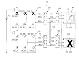
- FIG. 2 is a circuit diagram showing a typical circuit configuration of the power conversion apparatus 100 according to the exemplary embodiment 1.
- FIG. 3A is a schematic diagram illustrating a configuration of the bidirectional switch SW_2W.
- FIG. 3B is a schematic diagram illustrating a configuration of the one-way switch SW_1W.
- FIG. 4 is a block diagram showing a typical block configuration of the control circuit 300.
- FIG. 1 is a block diagram showing a typical block configuration of a motor drive unit 1000 according to an exemplary embodiment 1.
- FIG. 2 is a circuit diagram showing a typical circuit configuration of the power conversion apparatus 100 according to the exemplary embodiment 1.
- FIG. 3A is a schematic diagram illustrating a configuration of the bidirectional switch SW_2W.
- FIG. 3B is a schematic diagram illustrating a configuration of the one-way switch SW_1W.
- FIG. 4 is a block diagram
- FIG. 5 is a graph illustrating a current waveform (sine wave) obtained by plotting the current values flowing through the U-phase, V-phase, and W-phase windings in each of the first and second coil groups 210 and 220. It is.
- FIG. 6 is a diagram illustrating a failure state of the switch element in the bridge circuit due to the failure pattern 1.
- FIG. 7 is a diagram illustrating an example of a failure state of the switch element in the bridge circuit due to the failure pattern 2.
- FIG. 8 is a diagram illustrating an example of a failure state of the switch element in the bridge circuit due to the failure pattern 3.
- FIG. 9A is a diagram illustrating an example of a failure state of the switch element in the bridge circuit due to the failure pattern 4.
- FIG. 6 is a diagram illustrating a failure state of the switch element in the bridge circuit due to the failure pattern 1.
- FIG. 7 is a diagram illustrating an example of a failure state of the switch element in the bridge circuit due to the failure pattern 2.
- FIG. 8
- FIG. 9B is a diagram illustrating another state of the failure of the switch element in the bridge circuit due to the failure pattern 4.
- FIG. 10 is a diagram illustrating an example of a failure state of the switch element in the bridge circuit due to the failure pattern 5.
- FIG. 11 is a diagram illustrating an example of a failure state of the switch element in the bridge circuit due to the failure pattern 6.
- FIG. 12 is a circuit diagram illustrating a typical circuit configuration of the power conversion device 100A according to the exemplary embodiment 2.
- FIG. 13 is a circuit diagram illustrating another circuit configuration of the power conversion device 100A according to the exemplary embodiment 2.
- FIG. 14 is a circuit diagram illustrating a typical circuit configuration of the power conversion device 100B according to Exemplary Embodiment 3.
- FIG. 15 is a schematic diagram illustrating a typical configuration of an electric power steering apparatus 2000 according to Exemplary Embodiment 4.
- FIG. 1 schematically shows a typical block configuration of a motor drive unit 1000 according to the present embodiment.
- the motor drive unit 1000 typically includes the power conversion device 100, the motor 200, the control circuit 300, and the angle sensor 500. Depending on the motor control method (for example, sensorless control), the angle sensor 500 may be unnecessary. *
- the motor drive unit 1000 is modularized and can be manufactured and sold as a motor module having a motor, a sensor, a driver, and a controller, for example.
- the motor drive unit 1000 will be described by taking a system having the motor 200 as a component as an example.
- the motor drive unit 1000 may be a system for driving the motor 200 that does not include the motor 200 as a component.
- the power conversion device 100 includes a first inverter 110, a first separation relay circuit 120, a third separation relay circuit 130, a second inverter 140, a second separation relay circuit 150, a fourth separation relay circuit 160, and a current sensor 400.
- the power conversion device 100 can convert the power from the power source 101 into the power supplied to the motor 200.
- the first and second inverters 110 and 140 can convert DC power into three-phase AC power that is a pseudo sine wave of U phase, V phase, and W phase. *
- the first inverter 110 can be connected to at least one of the first coil group 210 and the second coil group 220, and the second inverter 140 is connected to at least one of the first coil group 210 and the second coil group 220.
- connection between components (components) mainly means electrical connection.
- the motor 200 is, for example, a three-phase AC motor.
- the motor 200 has a first coil group 210 and a second coil group 220.
- Each of first coil group 210 and second coil group 220 has U-phase, V-phase, and W-phase windings.
- the winding connection is, for example, a star connection or a delta connection.
- the control circuit 300 includes a microcontroller and the like.
- the control circuit 300 controls the power conversion device 100 based on input signals from the current sensor 400 and the angle sensor 500. Examples of the control method include vector control, pulse width modulation (PWM), and direct torque control (DTC). *
- the angle sensor 500 is, for example, a resolver or a Hall IC.
- the angle sensor 500 is also realized by a combination of an MR sensor having a magnetoresistive (MR) element and a sensor magnet.
- the angle sensor 500 detects the rotation angle of the rotor of the motor 200 (hereinafter referred to as “rotation signal”) and outputs the rotation signal to the control circuit 300.
- rotation signal the rotation angle of the rotor of the motor 200
- FIG. 2 schematically shows a typical circuit configuration of the power conversion apparatus 100 according to the present embodiment.
- the power supply 101 generates a predetermined power supply voltage (for example, 12V).
- a DC power source is used as the power source 101.
- the power source 101 may be an AC-DC converter, a DC-DC converter, or a battery (storage battery).
- the power source 101 may be a single power source common to the first and second inverters 110 and 140, or may include a first power source for the first inverter 110 and a second power source for the second inverter 140. Also good. *
- the first fuse 102 is connected between the power source 101 and the first inverter 110.
- the first fuse 102 can block a large current that can flow from the power source 101 to the first inverter 110.
- the second fuse 103 is connected between the power source 101 and the second inverter 140.
- the second fuse 103 can block a large current that can flow from the power source 101 to the second inverter 140.
- a relay or the like may be used instead of the fuse. *
- a coil is provided between the power source 101 and the power converter 100.
- the coil functions as a noise filter, and smoothes the high frequency noise included in the voltage waveform supplied to each inverter or the high frequency noise generated by each inverter so as not to flow out to the power supply 101 side.
- a capacitor is connected to the power supply terminal of each inverter.
- the capacitor is a so-called bypass capacitor and suppresses voltage ripple.
- the capacitor is, for example, an electrolytic capacitor, and the capacity and the number to be used are appropriately determined according to design specifications. *
- the first inverter 110 has a bridge circuit composed of three legs. Each leg has a high-side switch element and a low-side switch element.
- the U-phase leg includes a high-side switch element SW_A1H and a low-side switch element SW_A1L.
- the V-phase leg includes a high-side switch element SW_B1H and a low-side switch element SW_B1L.
- the W-phase leg includes a high-side switch element SW_C1H and a low-side switch element SW_C1L.
- a field effect transistor typically MOSFET
- IGBT insulated gate bipolar transistor
- the first inverter 110 uses, for example, a shunt resistor (not shown) as a current sensor 400 (see FIG. 1) for detecting the current flowing through the windings of the U-phase, V-phase, and W-phase.
- the current sensor 400 includes a current detection circuit (not shown) that detects a current flowing through each shunt resistor.
- a shunt resistor can be connected between the low side switch element and ground at each leg.
- the resistance value of the shunt resistor is, for example, about 0.5 m ⁇ to 1.0 m ⁇ . *
- the number of shunt resistors is not limited to three.
- the number of shunt resistors to be used and the arrangement of the shunt resistors are appropriately determined in consideration of the product cost and design specifications. *
- the second inverter 140 has a bridge circuit composed of three legs.
- the U-phase leg includes a high-side switch element SW_A2H and a low-side switch element SW_A2L.
- the V-phase leg includes a high-side switch element SW_B2H and a low-side switch element SW_B2L.
- the W-phase leg includes a high-side switch element SW_C2H and a low-side switch element SW_C2L.
- the second inverter 140 has, for example, a shunt resistor in each leg. *
- the first separation relay circuit 120 is connected to the first inverter 110, and can switch connection / disconnection between the first inverter 110 and the first coil group 210 and the second coil group 220 for each phase.
- the first separation relay circuit 120 has three first separation relays that switch connection / disconnection of the first inverter 110 and the first coil group 210 and the second coil group 220 for each phase.
- the first separation relay circuit 120 includes a first separation relay 120A for U phase, a first separation relay 120B for V phase, and a first separation relay 120C for W phase. *
- First separation relay 120 ⁇ / b> B is connected to the V-phase leg of first inverter 110.
- First separation relay 120 ⁇ / b> C is connected to the W-phase leg of first inverter 110.
- the isolation relay for example, a semiconductor switch such as a MOSFET or an IGBT can be used. Other semiconductor switches such as analog switch ICs or mechanical relays may be used. *
- the second separation relay circuit 150 is connected to the second inverter 140 and can switch connection / disconnection between the second inverter 140 and the first coil group 210 and the second coil group 220 for each phase.
- the second separation relay circuit 150 includes three second separation relays that switch connection / disconnection of the second inverter 140 and the first coil group 210 and the second coil group 220 for each phase. More specifically, the second separation relay circuit 150 includes a U-phase second separation relay 150A, a V-phase second separation relay 150B, and a W-phase second separation relay 150C. *
- Second separation relay 150 ⁇ / b> A is connected to the U-phase leg of second inverter 140.
- Second separation relay 150 ⁇ / b> B is connected to the V-phase leg of second inverter 140.
- Second separation relay 150 ⁇ / b> C is connected to the W-phase leg of second inverter 140.
- the third separation relay circuit 130 is connected between the first separation relay circuit 120 and the first coil group 210, and connection / disconnection of the first inverter 110 and the second inverter 140 and the first coil group 210 is connected. Can be switched for each phase.
- the third separation relay circuit 130 includes three third separation relays that switch connection / disconnection of the first inverter 110 and the second inverter 140 and the first coil group 210 for each phase.
- the third separation relay circuit 130 includes a third separation relay 130A for U phase, a third separation relay 130B for V phase, and a third separation relay 130C for W phase. *
- Third separation relay 130 ⁇ / b> A is connected to first separation relay 120 ⁇ / b> A and U-phase winding 211 in first coil group 210.
- Third separation relay 130 ⁇ / b> B is connected to first separation relay 120 ⁇ / b> B and V-phase winding 212 in first coil group 210.
- Third separation relay 130 ⁇ / b> C is connected to first separation relay 120 ⁇ / b> C and W-phase winding 213 in first coil group 210.
- the fourth separation relay circuit 160 is connected between the second separation relay circuit 150 and the second coil group 220, and connection / disconnection of the first inverter 110 and the second inverter 140 and the second coil group 220 is connected. Can be switched for each phase.
- the fourth separation relay circuit 160 includes three fourth separation relays that switch connection / disconnection of the first inverter 110 and the second inverter 140 and the second coil group 220 for each phase.
- the fourth separation relay circuit 160 includes a fourth separation relay 160A for U phase, a fourth separation relay 160B for V phase, and a fourth separation relay 160C for W phase. *
- the fourth separation relay 160A is connected to the second separation relay 150A and the U-phase winding 221 in the second coil group 220.
- the fourth separation relay 160B is connected to the second separation relay 150B and the V-phase winding 222 in the second coil group 220.
- Fourth separation relay 160 ⁇ / b> C is connected to second separation relay 150 ⁇ / b> C and W-phase winding 223 in second coil group 220.
- connection lines 170 connect three nodes between the first and third isolation relay circuits 120 and 130 and three nodes between the second and fourth isolation relay circuits 150 and 160. Connect every time. More specifically, a node between the first separation relay 120A and the third separation relay 130A and a node between the second separation relay 150A and the fourth separation relay 160A are connected to the U-phase connection line 170. Connected by. A node between the first separation relay 120B and the third separation relay 130B and a node between the second separation relay 150B and the fourth separation relay 160B are connected by a V-phase connection line 170. A node between the first separation relay 120C and the third separation relay 130C and a node between the second separation relay 150C and the fourth separation relay 160C are connected by a W-phase connection line 170. *
- FIG. 3A schematically shows the configuration of the bidirectional switch SW_2W.
- FIG. 3B schematically shows the configuration of the one-way switch SW_1W. *
- the bidirectional switch shown in FIG. 3A can be used as the three first separation relays 120A, 120B, 120C, and the three second separation relays 150A, 150B, and 150C.
- the three third separation relays 130A, 130B, and 130C and the three fourth separation relays 160A, 160B, and 160C the one-way switch shown in FIG. 3B can be used. All the separation relays of the first separation relay circuit 120, the second separation relay circuit 150, the third separation relay circuit 130, and the fourth separation relay circuit 160 may be bidirectional switches.
- FIG. 4 shows a typical block configuration of the control circuit 300. *
- the control circuit 300 includes, for example, a power supply circuit 310, an input circuit 320, a microcontroller 330, a drive circuit 340, and a ROM 350.
- the control circuit 300 is connected to the power conversion device 100.
- the control circuit 300 includes the first inverter 110, the first separation relay circuit 120, the third separation relay circuit 130, the second inverter 140, the second separation relay circuit 150, and the fourth separation.
- the motor 200 is driven by controlling the relay circuit 160 (see FIG. 1).
- the control circuit 300 can perform the closed loop control by controlling the target motor torque and rotation speed. *
- the power supply circuit 310 generates a DC voltage (for example, 3V, 5V) necessary for each block in the circuit. *
- the input circuit 320 receives a motor current value detected by the current sensor 400 (hereinafter referred to as “actual current value”).
- the input circuit 320 converts the actual current value level to the input level of the microcontroller 330 as necessary, and outputs the actual current value to the microcontroller 330.
- the input circuit 320 is an analog / digital conversion circuit. *
- the microcontroller 330 receives the rotor rotation signal detected by the angle sensor 500.
- the microcontroller 330 sets a target current value according to the actual current value and the rotation signal of the rotor, generates a PWM signal, and outputs it to the drive circuit 340.
- the microcontroller 330 generates a PWM signal for controlling the switching operation (turn-on or turn-off) of each switch element in the first and second inverters 110 and 140 of the power conversion device 100.
- the microcontroller 330 generates a signal that determines the on / off state of each separation relay in each separation relay circuit of the power conversion device 100.
- the drive circuit 340 is typically a gate driver.
- the drive circuit 340 generates a control signal (for example, a gate control signal) for controlling the switching operation of each switch element in the first and second inverters 110 and 140 according to the PWM signal, and gives the control signal to each switch element. Further, the drive circuit 340 generates a control signal (analog signal) for turning on / off each separation relay according to a signal from the microcontroller 330 that determines the on / off state of each separation relay, The control signal can be given.
- the microcontroller 330 may have the function of the drive circuit 340. In that case, the drive circuit 340 is not required. *
- the ROM 350 is, for example, a writable memory (for example, PROM), a rewritable memory (for example, flash memory), or a read-only memory.
- the ROM 350 stores a control program including a command group for causing the microcontroller 330 to control the power conversion apparatus 100.
- the control program is temporarily expanded in a RAM (not shown) at the time of booting.
- the control of the power conversion apparatus 100 includes normal and abnormal control.
- the control circuit 300 (mainly the microcontroller 330) can switch the control of the power conversion apparatus 100 from normal control to abnormal control.
- the on / off states of the respective separation relays of the first separation relay circuit 120, the second separation relay circuit 150, the third separation relay circuit 130, and the fourth separation relay circuit 160 are determined according to a failure pattern described later. *
- the first inverter 110 When the first separation relay 120 is turned on and the third separation relay circuit 130 is turned on, the first inverter 110 is connected to the first coil group 210. When the first separation relay 120 is turned on and the fourth separation relay circuit 160 is turned on, the first inverter 110 is connected to the second coil group 220. When the first separation relay 120 is turned off, the first inverter 110 is electrically disconnected from the first and second coil groups 210 and 220.
- “the separation relay circuit is turned on” means that all the separation relays in the separation relay circuit are turned on
- the separation relay circuit is turned off means that the separation relay circuit is turned on. This means that all the separation relays in the are turned off.
- the second inverter 140 When the second separation relay circuit 150 is turned on and the third separation relay circuit 130 is turned on, the second inverter 140 is connected to the first coil group 210. When the second separation relay circuit 150 is turned on and the fourth separation relay circuit 160 is turned on, the second inverter 140 is connected to the second coil group 220. When the second separation relay circuit 150 is turned off, the second inverter 140 is electrically disconnected from the first and second coil groups 210 and 220.
- the third separation relay circuit 130 When the third separation relay circuit 130 is turned on and the first separation relay circuit 120 is turned on, the first coil group 210 is connected to the first inverter 110. When the third separation relay circuit 130 is turned on and the second separation relay circuit 150 is turned on, the first coil group 210 is connected to the second inverter 140. When the third separation relay circuit 130 is turned off, the first coil group 210 is electrically disconnected from the first and second inverters 110 and 140.
- the fourth separation relay circuit 160 When the fourth separation relay circuit 160 is turned on and the first separation relay circuit 120 is turned on, the second coil group 220 is connected to the first inverter 110. When the fourth separation relay circuit 160 is turned on and the second separation relay circuit 150 is turned on, the second coil group 220 is connected to the second inverter 140. When the fourth separation relay circuit 160 is turned off, the second coil group 220 is electrically disconnected from the first and second inverters 110 and 140.
- each isolation relay By turning on or off each isolation relay in each isolation relay circuit, the electrical connection between the first and second inverters 110 and 140 and the first and second coil groups 210 and 220 described above is phase-by-phase. It is possible to switch to *
- “normal” indicates that no failure has occurred in the first inverter 110, the second inverter 140, the first coil group 210, and the second coil group 220. “Abnormal” means that a failure occurs in the switching element in the bridge circuit of the inverter and a failure occurs in the winding of the motor.
- the failure of a switch element mainly refers to an open fault and a short fault of a semiconductor switch element (FET).
- FET semiconductor switch element
- Open failure refers to a failure in which the source-drain of the FET is opened (in other words, the source-drain resistance rds becomes high impedance)
- “short failure” refers to the failure between the source-drain of the FET. Refers to a short circuit failure.
- the failure of the winding is, for example, disconnection of the winding. *
- the control circuit 300 (mainly the microcontroller 330) turns on the four first separation relay circuits 120, the second separation relay circuit 150, the third separation relay circuit 130, and the fourth separation relay circuit 160. To do.
- the first inverter 110 is connected to the first coil group 210 and the second coil group 220
- the second inverter 140 is connected to the first coil group 210 and the second coil group 220.
- the first inverter 110 is substantially connected to the first coil group 210, and the second inverter 140 is connected to the second coil group 220. In this connected state, the first coil group 210 can be energized using the first inverter 110 and the second coil group 220 can be energized using the second inverter 140.
- FIG. 5 illustrates a current waveform (sine wave) obtained by plotting the current values flowing in the U-phase, V-phase, and W-phase windings in each of the first and second coil groups 210 and 220.
- the horizontal axis indicates the motor electrical angle (deg), and the vertical axis indicates the current value (A).
- the sum of the currents flowing through the three-phase windings becomes “0” for each motor electrical angle.
- the control circuit 300 controls the switching operation of each switch element of the first inverter 110 so that the pseudo sine wave shown in FIG. 5 is obtained.
- the control circuit 300 further controls the switching operation of each switch element of the second inverter 140 so that the pseudo sine wave shown in FIG. 5 is obtained.
- the drive circuit 340 detects the failure of the switch element by monitoring the drain-source voltage Vds of the switch element (eg, FET) and comparing the predetermined threshold voltage with Vds. .
- the threshold voltage is set in the drive circuit 340 by, for example, data communication with an external IC (not shown) and external components.
- the drive circuit 340 is connected to a port of the microcontroller 330 and notifies the microcontroller 330 of a failure detection signal. For example, when detecting a failure of the switch element, the drive circuit 340 asserts a failure detection signal.
- the microcontroller 330 receives the asserted failure detection signal, the microcontroller 330 can read the internal data of the drive circuit 340 and determine which of the plurality of switch elements in the two inverters has failed. Is possible. *
- the microcontroller 330 can also detect a failure of the switch element based on the difference between the actual current value of the motor and the target current value. Furthermore, the microcontroller 330 can detect whether or not the winding of the motor 200 is disconnected based on the difference between the actual current value of the motor and the target current value, for example.
- failure detection is not limited to these methods, and known methods relating to failure detection can be widely used.
- the microcontroller 330 switches the control of the power conversion apparatus 100 from normal control to abnormal control.
- the timing for switching control from normal to abnormal is about 10 msec to 30 msec after the failure detection signal is asserted.
- FIG. 6 illustrates the state of failure of the switch element in the bridge circuit due to the failure pattern 1.
- the first and second coil groups 210 and 220 can be energized by branching the current from the second inverter 140 through the common line 170. Therefore, it is possible to suppress an increase in copper loss of the motor 200.
- FIG. 7 illustrates the state of failure of the switch elements in the bridge circuit due to the failure pattern 2.
- the control circuit 300 turns off the first separation relay 120A connected to the leg including the failed high-side switch element SW_A1H among the three first separation relays, and the other two first separation relays. 120B and 120C are turned on, and the second separation relay 150B connected to the leg including the failed high-side switch element SW_B2H among the three second separation relays is turned off, and the other two second separation relays The relays 150A and 150C are turned on, and the third and fourth separation relay circuits 130 and 160 are turned on.
- one phase switching element of the three phases fails, and in the other inverter, one phase switching element different from the failed phase exists. Even if a failure occurs, the motor drive unit 1000 can be continuously driven. In the prior art, when the failure pattern 2 occurs, the motor drive device must be stopped because no current flows through the two-phase winding of the three phases. Thus, it can be said that the prior art does not have resistance against two failures that occur simultaneously in two inverters. On the other hand, as described above, the power conversion device according to the present disclosure has such resistance. *
- FIG. 8 illustrates the state of failure of the switch element in the bridge circuit due to the failure pattern 3.
- the control circuit 300 turns off the first separation relay 120A connected to the leg including the failed high-side switch element SW_A1H among the three first separation relays, and the other two first separation relays. 120B and 120C are turned on, and the second separation relay circuit 150, the third separation relay circuit 130, and the fourth separation relay circuit 160 are turned on. With this control, it is possible to continue supplying power to the first and second coil groups 210 and 220 using the two legs in which the first inverter 110 has not failed and the second inverter 140. *
- the motor drive unit 1000 is continuously driven even when one bridge circuit of the two inverters includes a faulty switch element in one of the three phases. Can be made.
- FIG. 9A illustrates the state of the failure of the switch element in the bridge circuit due to the failure pattern 4.
- the control circuit 300 turns off the first and third separation relay circuits 120 and 130 and turns on the second and fourth separation relay circuits 150 and 160.
- the non-failed second inverter 140 and the non-failed second coil group 220 can be connected. It becomes possible to continue supplying power to the second coil group 220 using the second inverter 140.
- FIG. 9B illustrates another state of the failure of the switch element in the bridge circuit due to the failure pattern 4. *
- the control circuit 300 turns off the first and fourth separation relay circuits 120 and 160 and turns on the second separation relay circuit 150 and the third separation relay circuit 130.
- the non-failed second inverter 140 and the non-failed first coil group 210 can be connected. It becomes possible to continue supplying power to the first coil group 210 using the second inverter 140.
- the motor drive unit 1000 can be continuously driven even when one of the two inverter circuits and one of the two coil groups simultaneously fail. .
- the failure pattern 4 as shown in FIG. 9B occurs, power is not supplied to both winding sets, so the motor drive device must be stopped.
- FIG. 10 illustrates a state of a switch element failure in the bridge circuit due to the failure pattern 5.
- the control circuit 300 turns off the third separation relay 130A connected to the failed winding 211 among the three third separation relays, and turns on the other two third separation relays 130B and 130C.
- the first, second and fourth separation relay circuits 120, 150 and 160 are turned on.
- the first and second inverters 110 and 140 are used to power the non-failed V-phase and W-phase windings 212 and 213 and the second coil group 220 in the first coil group 210. Can continue to be supplied.
- the motor drive unit 1000 can be continuously driven.
- FIG. 11 illustrates the state of failure of the switch element in the bridge circuit due to the failure pattern 6.
- the U-phase winding 211 of the three-phase windings 211, 212, and 213 in the first coil group 210 fails and the three-phase windings 221, 222 in the second coil group 220 are broken. And 223 of V-phase winding 222 simultaneously fail.
- the control circuit 300 turns off the third separation relay 130A connected to the failed winding 211 among the three third separation relays, and turns on the other two third separation relays 130B and 130C.
- the fourth separation relay 160B connected to the failed winding 222 is turned off, the other two fourth separation relays 160A and 160C are turned on, and The first and second separation relay circuits 120 and 150 are turned on.
- the first and second inverters 110 and 140 are used, and the non-failed V-phase and W-phase windings 212 and 213 in the first coil group 210 and the second coil group 220 It is possible to continue supplying power to the U-phase and W-phase windings 221 and 223 that have not failed.
- one of the three-phase windings in the first coil group fails, and the three-phase winding in the second coil group Even if another one-phase winding different from one phase breaks down, the motor drive unit 1000 can be continuously driven.
- the power conversion device 100A according to the present embodiment is different from the power conversion device 100 according to the first embodiment in that it further includes a third inverter 180 connected to the connection line 170.
- a third inverter 180 connected to the connection line 170.
- FIG. 12 schematically shows a typical circuit configuration of the power conversion device 100A according to the present embodiment. *
- the power conversion device 100 ⁇ / b> A further includes a third inverter 180.
- the third inverter 180 has the same structure as the first and second inverters 110 and 140.
- the third inverter 180 is connected to three connection lines.
- the third inverter 180 can be connected to the first and second coil groups 210 and 220 via the three connection lines 170. *
- the third inverter 180 can be used instead of the failed inverter to continue the motor drive without reducing the torque. it can.
- FIG. 13 schematically shows another circuit configuration of the power conversion device 100A according to the present embodiment. *
- the power conversion device 100A further includes a fifth separation relay circuit 181 in addition to the third inverter 180. *
- the fifth separation relay circuit 181 includes three fifth separation relays that switch connection / disconnection of the third inverter 180 and the three connection lines 170 for each phase. More specifically, the U-phase leg of the third inverter 180 is connected to the U-phase connection line 170 via the fifth separation relay 181A. The V-phase leg of the third inverter 180 is connected to the V-phase connection line 170 via the fifth separation relay 181B. The W-phase leg of the third inverter 180 is connected to the W-phase connection line 170 via the fifth separation relay 181C. *
- the power conversion device 100B according to the present embodiment is different from the power conversion device 100 according to the first embodiment in that it further includes a sixth separation relay circuit 190 disposed on the three connection lines 170.
- a sixth separation relay circuit 190 disposed on the three connection lines 170.
- FIG. 14 schematically shows a typical circuit configuration of the power conversion device 100B according to the present embodiment. *
- the power conversion device 100 ⁇ / b> B further includes a sixth separation relay circuit 190 disposed on the three connection lines 170.
- the sixth separation relay circuit 190 has three sixth separation relays that switch connection / disconnection between the three nodes for each phase.
- the sixth separation relay circuit 190 is connected to three nodes between the first and third separation relay circuits 120 and 130 and three nodes between the second and fourth separation relay circuits 150 and 160. Switch non-connection for each phase.
- the sixth separation relay 190A switches connection / disconnection between the U-phase nodes.
- the sixth separation relay 190B switches connection / disconnection between the V-phase nodes.
- the sixth separation relay 190C switches connection / disconnection between the W-phase nodes.
- Each of the sixth separation relays 190A, 190B, and 190C is a bidirectional switch. *
- connection line 170 compared to the circuit configuration according to the first embodiment, the current flowing through the connection line 170 can be controlled more appropriately.
- FIG. 15 schematically shows a typical configuration of the electric power steering apparatus 2000 according to the present embodiment.
- a vehicle such as an automobile generally has an electric power steering (EPS) device.
- the electric power steering apparatus 2000 includes a steering system 520 and an auxiliary torque mechanism 540 that generates auxiliary torque.
- the electric power steering apparatus 2000 generates auxiliary torque that assists the steering torque of the steering system that is generated when the driver operates the steering wheel. The burden of operation by the driver is reduced by the auxiliary torque.
- the steering system 520 includes, for example, a steering handle 521, a steering shaft 522, universal shaft joints 523A and 523B, a rotating shaft 524, a rack and pinion mechanism 525, a rack shaft 526, left and right ball joints 552A and 552B, tie rods 527A and 527B, and a knuckle. 528A and 528B, and left and right steering wheels 529A and 529B. *
- the auxiliary torque mechanism 540 includes, for example, a steering torque sensor 541, an automotive electronic control unit (ECU) 542, a motor 543, a speed reduction mechanism 544, and the like.
- the steering torque sensor 541 detects the steering torque in the steering system 520.
- the ECU 542 generates a drive signal based on the detection signal of the steering torque sensor 541.
- the motor 543 generates an auxiliary torque corresponding to the steering torque based on the drive signal.
- the motor 543 transmits the generated auxiliary torque to the steering system 520 via the speed reduction mechanism 544. *
- the ECU 542 includes, for example, the microcontroller 330 and the drive circuit 340 according to the first embodiment.
- an electronic control system with an ECU as a core is constructed.
- a motor drive unit is constructed by the ECU 542, the motor 543, and the inverter 545.
- the motor drive unit 1000 according to the first embodiment can be suitably used for the system. *
- the embodiment of the present disclosure is also suitably used for motor control systems such as X-by-wire such as shift-by-wire, steering-by-wire, and brake-by-wire, and a traction motor.
- a motor control system according to an embodiment of the present disclosure may be installed in an autonomous vehicle that complies with levels 0 to 4 (automation standards) defined by the Japanese government and the US Department of Transportation Road Traffic Safety Administration (NHTSA).
- Embodiments of the present disclosure can be widely used in various devices including various motors such as a vacuum cleaner, a dryer, a ceiling fan, a washing machine, a refrigerator, and an electric power steering device.
- various motors such as a vacuum cleaner, a dryer, a ceiling fan, a washing machine, a refrigerator, and an electric power steering device.
Abstract
A power conversion device 100 having: a first and a second inverter 110, 140, which can be connected to at least one of a first and a second coil group 210, 220; a first separation relay circuit 120 connected to the first inverter; a second separation relay circuit 150 connected to the second inverter; a third separation relay circuit 130 connected between the first separation relay circuit and the first coil group; a fourth separation relay circuit 160 connected between the second separation relay circuit and the second coil group; and n (where n is an integer equal to or greater than 3) connection wires connecting, for each phase, n nodes between the first and third separation relay circuits and n nodes between the second and fourth separation relay circuits.
Description
本開示は、電力変換装置、モータ駆動ユニットおよび電動パワーステアリング装置に関する。
The present disclosure relates to a power conversion device, a motor drive unit, and an electric power steering device.
近年、電動モータ(以下、単に「モータ」と表記する。)、電力変換装置およびECUが一体化された機電一体型モータが開発されている。特に車載分野において、安全性の観点から高い品質保証が要求される。そのため、部品の一部が故障した場合でも安全動作を継続できる冗長設計が取り入れられている。冗長設計の一例として、1つのモータに対して2つの電力変換装置を設けることが検討されている。他の一例として、メインのマイクロコントローラにバックアップ用マイクロコントローラを設けることが検討されている。
In recent years, an electromechanical integrated motor in which an electric motor (hereinafter simply referred to as “motor”), a power converter, and an ECU are integrated has been developed. Particularly in the in-vehicle field, high quality assurance is required from the viewpoint of safety. Therefore, a redundant design that can continue safe operation even when a part of the component fails is adopted. As an example of a redundant design, it is considered to provide two power conversion devices for one motor. As another example, it is considered to provide a backup microcontroller in the main microcontroller. *
特許文献1は、第1系統および第2系統を有するモータ駆動装置を開示する。第1系統は、モータの第1巻線組に接続され、第1インバータ部、電源リレーおよび逆接続保護リレーなどを有する。第2系統は、モータの第2巻線組に接続され、第2インバータ部、電源リレーおよび逆接続保護リレーなどを有する。モータ駆動装置に故障が生じていないとき、第1系統および第2系統の両方を用いてモータを駆動することが可能である。これに対し、第1系統および第2系統の一方、または、第1巻線組および第2巻線組の一方に故障が生じたとき、電源リレーは、電源から、故障した系統、または、故障した巻線組に接続された系統への電力供給を遮断する。故障していない他方の系統を用いてモータ駆動を継続させることが可能である。
Patent Document 1 discloses a motor drive device having a first system and a second system. The first system is connected to the first winding set of the motor and includes a first inverter unit, a power supply relay, a reverse connection protection relay, and the like. The second system is connected to the second winding set of the motor and includes a second inverter unit, a power supply relay, a reverse connection protection relay, and the like. When there is no failure in the motor drive device, it is possible to drive the motor using both the first system and the second system. On the other hand, when a failure occurs in one of the first system and the second system, or one of the first winding group and the second winding group, the power relay is connected to the failed system or from the power source. The power supply to the system connected to the winding set is cut off. It is possible to continue motor driving using the other system that has not failed. *
特許文献2および3も、第1系統および第2系統を有するモータ駆動装置を開示する。一方の系統または一方の巻線組が故障したとしても、故障していない系統によってモータ駆動を継続させることができる。
Patent Documents 2 and 3 also disclose a motor drive device having a first system and a second system. Even if one system or one winding set fails, motor drive can be continued by a system that does not fail.
上述した従来の技術では、異常時におけるモータ駆動のさらなる向上が求められていた。例えば、特許文献1のモータ駆動装置において、一方の系統が故障した場合、それに接続された、故障していない巻線組も、その故障した系統と共にモータ駆動に関与しなくなる。故障パターンに応じた適切なモータ駆動が望まれる。
In the above-described conventional technology, further improvement in motor driving at the time of abnormality has been demanded. For example, in the motor drive device of Patent Document 1, when one of the systems fails, the non-failed winding set connected to the system does not participate in motor driving together with the failed system. An appropriate motor drive according to the failure pattern is desired. *
本開示の実施形態は、モータ駆動を故障パターンに応じて適切に行うことが可能な電力変換装置を提供する。
Embodiments of the present disclosure provide a power conversion device that can appropriately perform motor driving according to a failure pattern.
本開示の例示的な電力変換装置は、電源からの電力を、第1コイル群および第2コイル群を有するn相(nは3以上の整数)のモータに供給する電力に変換する電力変換装置であって、前記第1および第2コイル群の少なくとも1つに接続可能な第1インバータと、前記第1および第2コイル群の少なくとも1つに接続可能な第2インバータと、前記第1インバータと接続された第1分離リレー回路であって、前記第1インバータと、前記第1および第2コイル群と、の接続・非接続を相毎に切替える第1分離リレー回路と、前記第2インバータと接続された第2分離リレー回路であって、前記第2インバータと、前記第1および第2コイル群と、の接続・非接続を相毎に切替える第2分離リレー回路と、前記第1分離リレー回路と前記第1コイル群との間に接続され、かつ、前記第1および第2インバータと、前記第1コイル群と、の接続・非接続を相毎に切替える第3分離リレー回路と、前記第2分離リレー回路と前記第2コイル群との間に接続され、かつ、前記第1および第2インバータと、前記第2コイル群と、の接続・非接続を相毎に切替える第4分離リレー回路と、前記第1および第3分離リレー回路の間のn個のノードと、前記第2および第4分離リレー回路の間のn個のノードと、を相毎に接続するn本の接続線と、を有する。
An exemplary power conversion device according to the present disclosure converts power from a power source into power supplied to an n-phase (n is an integer of 3 or more) motor having a first coil group and a second coil group. A first inverter connectable to at least one of the first and second coil groups, a second inverter connectable to at least one of the first and second coil groups, and the first inverter A first separation relay circuit connected to the first separation relay circuit for switching connection / disconnection of the first inverter and the first and second coil groups for each phase; and the second inverter A second separation relay circuit connected to the second separation relay circuit for switching connection / disconnection of the second inverter and the first and second coil groups for each phase, and the first separation relay circuit. Relay circuit and said first A third separation relay circuit that is connected between the first and second inverters and the first coil group, and is switched between connection and non-connection for each phase; and the second separation relay circuit And a fourth separation relay circuit that is connected between the first and second inverters and the second coil group, and switches between connection and disconnection for each phase, and N connection lines connecting n nodes between the first and third separation relay circuits and n nodes between the second and fourth separation relay circuits for each phase.
本開示の例示的な実施形態によると、第1から第4分離リレー回路および接続線によって、モータ駆動を故障パターンに応じて適切に行うことが可能な電力変換装置、当該電力変換装置を有するモータ駆動ユニット、および、当該モータ駆動ユニットを有する電動パワーステアリング装置が提供される。
According to the exemplary embodiment of the present disclosure, the first to fourth separation relay circuits and the connection lines can appropriately drive the motor according to the failure pattern, and the motor having the power conversion device A drive unit and an electric power steering apparatus having the motor drive unit are provided.
以下、添付の図面を参照しながら、本開示の電力変換装置、モータ駆動ユニットおよび電動パワーステアリング装置の実施形態を詳細に説明する。但し、以下の説明が不必要に冗長になるのを避け、当業者の理解を容易にするため、必要以上に詳細な説明は省略する場合がある。例えば、既によく知られた事項の詳細説明や実質的に同一の構成に対する重複説明を省略する場合がある。
Hereinafter, embodiments of a power conversion device, a motor drive unit, and an electric power steering device of the present disclosure will be described in detail with reference to the accompanying drawings. However, in order to avoid the following description from being unnecessarily redundant and to facilitate understanding by those skilled in the art, a more detailed description than necessary may be omitted. For example, detailed descriptions of already well-known matters and repeated descriptions for substantially the same configuration may be omitted. *
本願明細書において、電源からの電力を、三相(U相、V相、W相)の巻線を有する三相モータに供給する電力に変換する電力変換装置を例にして、本開示の実施形態を説明する。ただし、電源からの電力を、四相または五相などのn相(nは4以上の整数)の巻線を有するn相モータに供給する電力に変換する電力変換装置も本開示の範疇である。
In the specification of the present application, implementation of the present disclosure will be described by taking as an example a power conversion device that converts power from a power source into power supplied to a three-phase motor having three-phase (U-phase, V-phase, and W-phase) windings. A form is demonstrated. However, a power conversion device that converts power from a power source into power supplied to an n-phase motor having an n-phase winding (n is an integer of 4 or more) such as four-phase or five-phase is also included in the scope of the present disclosure. . *
(実施形態1)
〔モータ駆動ユニット1000および電力変換装置100の構造〕
図1は、本実施形態によるモータ駆動ユニット1000の典型的なブロック構成を模式的に示す。
(Embodiment 1)
[Structure ofMotor Drive Unit 1000 and Power Conversion Device 100]
FIG. 1 schematically shows a typical block configuration of amotor drive unit 1000 according to the present embodiment.
〔モータ駆動ユニット1000および電力変換装置100の構造〕
図1は、本実施形態によるモータ駆動ユニット1000の典型的なブロック構成を模式的に示す。
(Embodiment 1)
[Structure of
FIG. 1 schematically shows a typical block configuration of a
モータ駆動ユニット1000は、典型的に、電力変換装置100、モータ200、制御回路300および角度センサ500を有する。モータ制御手法(例えばセンサレス制御)によっては、角度センサ500は不要な場合がある。
The motor drive unit 1000 typically includes the power conversion device 100, the motor 200, the control circuit 300, and the angle sensor 500. Depending on the motor control method (for example, sensorless control), the angle sensor 500 may be unnecessary. *
モータ駆動ユニット1000は、モジュール化され、例えば、モータ、センサ、ドライバおよびコントローラを有するモータモジュールとして製造および販売され得る。本明細書では、構成要素としてモータ200を有するシステムを例に、モータ駆動ユニット1000を説明する。ただし、モータ駆動ユニット1000は、構成要素としてモータ200を有しない、モータ200を駆動するためのシステムであってもよい。
The motor drive unit 1000 is modularized and can be manufactured and sold as a motor module having a motor, a sensor, a driver, and a controller, for example. In this specification, the motor drive unit 1000 will be described by taking a system having the motor 200 as a component as an example. However, the motor drive unit 1000 may be a system for driving the motor 200 that does not include the motor 200 as a component. *
電力変換装置100は、第1インバータ110、第1分離リレー回路120、第3分離リレー回路130、第2インバータ140、第2分離リレー回路150、第4分離リレー回路160および電流センサ400を有する。電力変換装置100は、電源101からの電力をモータ200に供給する電力に変換することが可能である。例えば、第1および第2インバータ110、140は、直流電力を、U相、V相およびW相の擬似正弦波である三相交流電力に変換することが可能である。
The power conversion device 100 includes a first inverter 110, a first separation relay circuit 120, a third separation relay circuit 130, a second inverter 140, a second separation relay circuit 150, a fourth separation relay circuit 160, and a current sensor 400. The power conversion device 100 can convert the power from the power source 101 into the power supplied to the motor 200. For example, the first and second inverters 110 and 140 can convert DC power into three-phase AC power that is a pseudo sine wave of U phase, V phase, and W phase. *
第1インバータ110は、第1コイル群210および第2コイル群220の少なくとも1つに接続可能であり、第2インバータ140は、第1コイル群210および第2コイル群220の少なくとも1つに接続可能である。本願明細書において、部品(構成要素)同士の間の「接続」とは、主に電気的な接続を意味する。
The first inverter 110 can be connected to at least one of the first coil group 210 and the second coil group 220, and the second inverter 140 is connected to at least one of the first coil group 210 and the second coil group 220. Is possible. In the present specification, “connection” between components (components) mainly means electrical connection. *
モータ200は、例えば三相交流モータである。モータ200は、第1コイル群210および第2コイル群220を有する。第1コイル群210および第2コイル群220の各々は、U相、V相およびW相の巻線を有する。各コイル群において、巻線の結線は、例えば、スター結線またはデルタ結線である。
The motor 200 is, for example, a three-phase AC motor. The motor 200 has a first coil group 210 and a second coil group 220. Each of first coil group 210 and second coil group 220 has U-phase, V-phase, and W-phase windings. In each coil group, the winding connection is, for example, a star connection or a delta connection. *
制御回路300は、マイクロコントローラなどから構成される。制御回路300は、電流センサ400および角度センサ500からの入力信号に基づいて電力変換装置100を制御する。その制御手法として、例えばベクトル制御、パルス幅変調(PWM)および直接トルク制御(DTC)がある。
The control circuit 300 includes a microcontroller and the like. The control circuit 300 controls the power conversion device 100 based on input signals from the current sensor 400 and the angle sensor 500. Examples of the control method include vector control, pulse width modulation (PWM), and direct torque control (DTC). *
角度センサ500は、例えばレゾルバまたはホールICである。角度センサ500は、磁気抵抗(MR)素子を有するMRセンサとセンサマグネットとの組み合わせによっても実現される。角度センサ500は、モータ200のロータの回転角(以下、「回転信号」と表記する。)を検出し、回転信号を制御回路300に出力する。
The angle sensor 500 is, for example, a resolver or a Hall IC. The angle sensor 500 is also realized by a combination of an MR sensor having a magnetoresistive (MR) element and a sensor magnet. The angle sensor 500 detects the rotation angle of the rotor of the motor 200 (hereinafter referred to as “rotation signal”) and outputs the rotation signal to the control circuit 300. *
図2を参照して、電力変換装置100の具体的な回路構成を説明する。
A specific circuit configuration of the power conversion apparatus 100 will be described with reference to FIG. *
図2は、本実施形態による電力変換装置100の典型的な回路構成を模式的に示す。
FIG. 2 schematically shows a typical circuit configuration of the power conversion apparatus 100 according to the present embodiment. *
電源101は所定の電源電圧(例えば12V)を生成する。電源101として、例えば直流電源が用いられる。ただし、電源101は、AC-DCコンバータまたはDC―DCコンバータであってもよいし、バッテリー(蓄電池)であってもよい。電源101は、第1および第2インバータ110、140に共通の単一電源であってもよいし、第1インバータ110用の第1電源および第2インバータ140用の第2電源を有していてもよい。
The power supply 101 generates a predetermined power supply voltage (for example, 12V). As the power source 101, for example, a DC power source is used. However, the power source 101 may be an AC-DC converter, a DC-DC converter, or a battery (storage battery). The power source 101 may be a single power source common to the first and second inverters 110 and 140, or may include a first power source for the first inverter 110 and a second power source for the second inverter 140. Also good. *
第1ヒューズ102が、電源101と第1インバータ110との間に接続される。第1ヒューズ102は、電源101から第1インバータ110に流れ得る大電流を遮断することができる。第2ヒューズ103が、電源101と第2インバータ140との間に接続される。第2ヒューズ103は、電源101から第2インバータ140に流れ得る大電流を遮断することができる。ヒューズの代わりにリレーなどを用いてもよい。
The first fuse 102 is connected between the power source 101 and the first inverter 110. The first fuse 102 can block a large current that can flow from the power source 101 to the first inverter 110. The second fuse 103 is connected between the power source 101 and the second inverter 140. The second fuse 103 can block a large current that can flow from the power source 101 to the second inverter 140. A relay or the like may be used instead of the fuse. *
図示されていないが、電源101と電力変換装置100との間にコイルが設けられる。コイルは、ノイズフィルタとして機能し、各インバータに供給する電圧波形に含まれる高周波ノイズ、または各インバータで発生する高周波ノイズを電源101側に流出させないように平滑化する。また、各インバータの電源端子には、コンデンサが接続される。コンデンサは、いわゆるバイパスコンデンサであり、電圧リプルを抑制する。コンデンサは、例えば電解コンデンサであり、容量および使用する個数は設計仕様などによって適宜決定される。
Although not shown, a coil is provided between the power source 101 and the power converter 100. The coil functions as a noise filter, and smoothes the high frequency noise included in the voltage waveform supplied to each inverter or the high frequency noise generated by each inverter so as not to flow out to the power supply 101 side. A capacitor is connected to the power supply terminal of each inverter. The capacitor is a so-called bypass capacitor and suppresses voltage ripple. The capacitor is, for example, an electrolytic capacitor, and the capacity and the number to be used are appropriately determined according to design specifications. *
第1インバータ110は、3個のレグから構成されるブリッジ回路を有する。各レグは、ハイサイドスイッチ素子およびローサイドスイッチ素子を有する。U相用レグは、ハイサイドスイッチ素子SW_A1Hおよびローサイドスイッチ素子SW_A1Lを有する。V相用レグは、ハイサイドスイッチ素子SW_B1Hおよびローサイドスイッチ素子SW_B1Lを有する。W相用レグは、ハイサイドスイッチ素子SW_C1Hおよびローサイドスイッチ素子SW_C1Lを有する。スイッチ素子として、例えば電界効果トランジスタ(典型的にはMOSFET)または絶縁ゲートバイポーラトランジスタ(IGBT)を用いることができる。
The first inverter 110 has a bridge circuit composed of three legs. Each leg has a high-side switch element and a low-side switch element. The U-phase leg includes a high-side switch element SW_A1H and a low-side switch element SW_A1L. The V-phase leg includes a high-side switch element SW_B1H and a low-side switch element SW_B1L. The W-phase leg includes a high-side switch element SW_C1H and a low-side switch element SW_C1L. As the switch element, for example, a field effect transistor (typically MOSFET) or an insulated gate bipolar transistor (IGBT) can be used. *
第1インバータ110は、例えば、U相、V相およびW相の各相の巻線に流れる電流を検出するための電流センサ400(図1を参照)として、シャント抵抗(不図示)を各レグに有する。電流センサ400は、各シャント抵抗に流れる電流を検出する電流検出回路(不図示)を有する。例えば、シャント抵抗は、各レグにおいて、ローサイドスイッチ素子とグランドとの間に接続され得る。シャント抵抗の抵抗値は、例えば0.5mΩ~1.0mΩ程度である。
The first inverter 110 uses, for example, a shunt resistor (not shown) as a current sensor 400 (see FIG. 1) for detecting the current flowing through the windings of the U-phase, V-phase, and W-phase. Have. The current sensor 400 includes a current detection circuit (not shown) that detects a current flowing through each shunt resistor. For example, a shunt resistor can be connected between the low side switch element and ground at each leg. The resistance value of the shunt resistor is, for example, about 0.5 mΩ to 1.0 mΩ. *
シャント抵抗の数は3つに限られない。例えば、U相、V相用の2つのシャント抵抗、V相、W相用の2つのシャント抵抗、および、U相、W相用の2つのシャント抵抗を用いることが可能である。使用するシャント抵抗の数およびシャント抵抗の配置は、製品コストおよび設計仕様などを考慮して適宜決定される。
The number of shunt resistors is not limited to three. For example, it is possible to use two shunt resistors for U phase and V phase, two shunt resistors for V phase and W phase, and two shunt resistors for U phase and W phase. The number of shunt resistors to be used and the arrangement of the shunt resistors are appropriately determined in consideration of the product cost and design specifications. *
第2インバータ140は、3個のレグから構成されるブリッジ回路を有する。U相用レグは、ハイサイドスイッチ素子SW_A2Hおよびローサイドスイッチ素子SW_A2Lを有する。V相用レグは、ハイサイドスイッチ素子SW_B2Hおよびローサイドスイッチ素子SW_B2Lを有する。W相用レグは、ハイサイドスイッチ素子SW_C2Hおよびローサイドスイッチ素子SW_C2Lを有する。第1インバータ110と同様に、第2インバータ140は、例えば、シャント抵抗を各レグに有する。
The second inverter 140 has a bridge circuit composed of three legs. The U-phase leg includes a high-side switch element SW_A2H and a low-side switch element SW_A2L. The V-phase leg includes a high-side switch element SW_B2H and a low-side switch element SW_B2L. The W-phase leg includes a high-side switch element SW_C2H and a low-side switch element SW_C2L. Similar to the first inverter 110, the second inverter 140 has, for example, a shunt resistor in each leg. *
第1分離リレー回路120は、第1インバータ110と接続され、第1インバータ110と、第1コイル群210および第2コイル群220と、の接続・非接続を相毎に切替えることができる。第1分離リレー回路120は、第1インバータ110と、第1コイル群210および第2コイル群220と、の接続・非接続を相毎に切替える3個の第1分離リレーを有する。具体的に説明すると、第1分離リレー回路120は、U相用の第1分離リレー120A、V相用の第1分離リレー120B、および、W相用の第1分離リレー120Cを有する。
The first separation relay circuit 120 is connected to the first inverter 110, and can switch connection / disconnection between the first inverter 110 and the first coil group 210 and the second coil group 220 for each phase. The first separation relay circuit 120 has three first separation relays that switch connection / disconnection of the first inverter 110 and the first coil group 210 and the second coil group 220 for each phase. Specifically, the first separation relay circuit 120 includes a first separation relay 120A for U phase, a first separation relay 120B for V phase, and a first separation relay 120C for W phase. *
第1分離リレー120Aは、第1インバータ110のU相用レグ(ハイサイドスイッチ素子およびローサイドスイッチ素子の間のノード)に接続される。第1分離リレー120Bは、第1インバータ110のV相用レグに接続される。第1分離リレー120Cは、第1インバータ110のW相用レグに接続される。分離リレーとして、例えば、MOSFETまたはIGBTなどの半導体スイッチを用いてことができる。アナログスイッチICなどの他の半導体スイッチまたはメカニカルリレーを用いても構わない。
120 A of 1st isolation | separation relays are connected to the leg for U phases (the node between a high side switch element and a low side switch element) of the 1st inverter 110. FIG. First separation relay 120 </ b> B is connected to the V-phase leg of first inverter 110. First separation relay 120 </ b> C is connected to the W-phase leg of first inverter 110. As the isolation relay, for example, a semiconductor switch such as a MOSFET or an IGBT can be used. Other semiconductor switches such as analog switch ICs or mechanical relays may be used. *
第2分離リレー回路150は、第2インバータ140と接続され、第2インバータ140と、第1コイル群210および第2コイル群220と、の接続・非接続を相毎に切替えることができる。第2分離リレー回路150は、第2インバータ140と、第1コイル群210および第2コイル群220と、の接続・非接続を相毎に切替える3個の第2分離リレーを有する。具体的に説明すると、第2分離リレー回路150は、U相用の第2分離リレー150A、V相用の第2分離リレー150B、および、W相用の第2分離リレー150Cを有する。
The second separation relay circuit 150 is connected to the second inverter 140 and can switch connection / disconnection between the second inverter 140 and the first coil group 210 and the second coil group 220 for each phase. The second separation relay circuit 150 includes three second separation relays that switch connection / disconnection of the second inverter 140 and the first coil group 210 and the second coil group 220 for each phase. More specifically, the second separation relay circuit 150 includes a U-phase second separation relay 150A, a V-phase second separation relay 150B, and a W-phase second separation relay 150C. *
第2分離リレー150Aは、第2インバータ140のU相用レグに接続される。第2分離リレー150Bは、第2インバータ140のV相用レグに接続される。第2分離リレー150Cは、第2インバータ140のW相用レグに接続される。
Second separation relay 150 </ b> A is connected to the U-phase leg of second inverter 140. Second separation relay 150 </ b> B is connected to the V-phase leg of second inverter 140. Second separation relay 150 </ b> C is connected to the W-phase leg of second inverter 140. *
第3分離リレー回路130は、第1分離リレー回路120と第1コイル群210との間に接続され、第1インバータ110および第2インバータ140と、第1コイル群210と、の接続・非接続を相毎に切替えることができる。第3分離リレー回路130は、第1インバータ110および第2インバータ140と、第1コイル群210と、の接続・非接続を相毎に切替える3個の第3分離リレーを有する。具体的に説明すると、第3分離リレー回路130は、U相用の第3分離リレー130A、V相用の第3分離リレー130B、および、W相用の第3分離リレー130Cを有する。
The third separation relay circuit 130 is connected between the first separation relay circuit 120 and the first coil group 210, and connection / disconnection of the first inverter 110 and the second inverter 140 and the first coil group 210 is connected. Can be switched for each phase. The third separation relay circuit 130 includes three third separation relays that switch connection / disconnection of the first inverter 110 and the second inverter 140 and the first coil group 210 for each phase. Specifically, the third separation relay circuit 130 includes a third separation relay 130A for U phase, a third separation relay 130B for V phase, and a third separation relay 130C for W phase. *
第3分離リレー130Aは、第1分離リレー120Aと、第1コイル群210の中のU相巻線211と、に接続される。第3分離リレー130Bは、第1分離リレー120Bと、第1コイル群210の中のV相巻線212と、に接続される。第3分離リレー130Cは、第1分離リレー120Cと、第1コイル群210の中のW相巻線213と、に接続される。
Third separation relay 130 </ b> A is connected to first separation relay 120 </ b> A and U-phase winding 211 in first coil group 210. Third separation relay 130 </ b> B is connected to first separation relay 120 </ b> B and V-phase winding 212 in first coil group 210. Third separation relay 130 </ b> C is connected to first separation relay 120 </ b> C and W-phase winding 213 in first coil group 210. *
第4分離リレー回路160は、第2分離リレー回路150と第2コイル群220との間に接続され、第1インバータ110および第2インバータ140と、第2コイル群220と、の接続・非接続を相毎に切替えることができる。第4分離リレー回路160は、第1インバータ110および第2インバータ140と、第2コイル群220と、の接続・非接続を相毎に切替える3個の第4分離リレーを有する。具体的に説明すると、第4分離リレー回路160は、U相用の第4分離リレー160A、V相用の第4分離リレー160B、および、W相用の第4分離リレー160Cを有する。
The fourth separation relay circuit 160 is connected between the second separation relay circuit 150 and the second coil group 220, and connection / disconnection of the first inverter 110 and the second inverter 140 and the second coil group 220 is connected. Can be switched for each phase. The fourth separation relay circuit 160 includes three fourth separation relays that switch connection / disconnection of the first inverter 110 and the second inverter 140 and the second coil group 220 for each phase. Specifically, the fourth separation relay circuit 160 includes a fourth separation relay 160A for U phase, a fourth separation relay 160B for V phase, and a fourth separation relay 160C for W phase. *
第4分離リレー160Aは、第2分離リレー150Aと、第2コイル群220の中のU相巻線221と、に接続される。第4分離リレー160Bは、第2分離リレー150Bと、第2コイル群220の中のV相巻線222と、に接続される。第4分離リレー160Cは、第2分離リレー150Cと、第2コイル群220の中のW相巻線223と、に接続される。
The fourth separation relay 160A is connected to the second separation relay 150A and the U-phase winding 221 in the second coil group 220. The fourth separation relay 160B is connected to the second separation relay 150B and the V-phase winding 222 in the second coil group 220. Fourth separation relay 160 </ b> C is connected to second separation relay 150 </ b> C and W-phase winding 223 in second coil group 220. *
3本の接続線170が、第1および第3分離リレー回路120、130の間の3個のノードと、第2および第4分離リレー回路150、160の間の3個のノードと、を相毎に接続する。具体的に説明すると、第1分離リレー120Aと第3分離リレー130Aとの間のノードと、第2分離リレー150Aと第4分離リレー160Aとの間のノードとが、U相用の接続線170によって接続される。第1分離リレー120Bと第3分離リレー130Bとの間のノードと、第2分離リレー150Bと第4分離リレー160Bとの間のノードとが、V相用の接続線170によって接続される。第1分離リレー120Cと第3分離リレー130Cとの間のノードと、第2分離リレー150Cと第4分離リレー160Cとの間のノードとが、W相用の接続線170によって接続される。
Three connection lines 170 connect three nodes between the first and third isolation relay circuits 120 and 130 and three nodes between the second and fourth isolation relay circuits 150 and 160. Connect every time. More specifically, a node between the first separation relay 120A and the third separation relay 130A and a node between the second separation relay 150A and the fourth separation relay 160A are connected to the U-phase connection line 170. Connected by. A node between the first separation relay 120B and the third separation relay 130B and a node between the second separation relay 150B and the fourth separation relay 160B are connected by a V-phase connection line 170. A node between the first separation relay 120C and the third separation relay 130C and a node between the second separation relay 150C and the fourth separation relay 160C are connected by a W-phase connection line 170. *
図3Aは、双方向スイッチSW_2Wの構成を模式的に示す。図3Bは、一方向スイッチSW_1Wの構成を模式的に示す。
FIG. 3A schematically shows the configuration of the bidirectional switch SW_2W. FIG. 3B schematically shows the configuration of the one-way switch SW_1W. *
例えば、3個の第1分離リレー120A、120B、120C、3個の第2分離リレー150A、150Bおよび150Cとして、図3Aに示される双方向スイッチを用いることができる。例えば、3個の第3分離リレー130A、130B、130C、3個の第4分離リレー160A、160Bおよび160Cとして、図3Bに示される一方向スイッチを用いることができる。
第1分離リレー回路120、第2分離リレー回路150、第3分離リレー回路130および第4分離リレー回路160の全ての分離リレーは、双方向スイッチであってもよい。 For example, the bidirectional switch shown in FIG. 3A can be used as the three first separation relays 120A, 120B, 120C, and the three second separation relays 150A, 150B, and 150C. For example, as the three third separation relays 130A, 130B, and 130C and the three fourth separation relays 160A, 160B, and 160C, the one-way switch shown in FIG. 3B can be used.
All the separation relays of the firstseparation relay circuit 120, the second separation relay circuit 150, the third separation relay circuit 130, and the fourth separation relay circuit 160 may be bidirectional switches.
第1分離リレー回路120、第2分離リレー回路150、第3分離リレー回路130および第4分離リレー回路160の全ての分離リレーは、双方向スイッチであってもよい。 For example, the bidirectional switch shown in FIG. 3A can be used as the three first separation relays 120A, 120B, 120C, and the three second separation relays 150A, 150B, and 150C. For example, as the three third separation relays 130A, 130B, and 130C and the three fourth separation relays 160A, 160B, and 160C, the one-way switch shown in FIG. 3B can be used.
All the separation relays of the first
図4は、制御回路300の典型的なブロック構成を示す。
FIG. 4 shows a typical block configuration of the control circuit 300. *
制御回路300は、例えば、電源回路310と、入力回路320と、マイクロコントローラ330と、駆動回路340と、ROM350とを備える。制御回路300は、電力変換装置100に接続される。制御回路300は、電力変換装置100を、具体的には、第1インバータ110、第1分離リレー回路120、第3分離リレー回路130、第2インバータ140、第2分離リレー回路150および第4分離リレー回路160(図1を参照)を制御することにより、モータ200を駆動する。制御回路300は、目的とするモータトルクおよび回転速度を制御してクローズドループ制御を行うことができる。
The control circuit 300 includes, for example, a power supply circuit 310, an input circuit 320, a microcontroller 330, a drive circuit 340, and a ROM 350. The control circuit 300 is connected to the power conversion device 100. The control circuit 300 includes the first inverter 110, the first separation relay circuit 120, the third separation relay circuit 130, the second inverter 140, the second separation relay circuit 150, and the fourth separation. The motor 200 is driven by controlling the relay circuit 160 (see FIG. 1). The control circuit 300 can perform the closed loop control by controlling the target motor torque and rotation speed. *
電源回路310は、回路内の各ブロックに必要なDC電圧(例えば3V、5V)を生成する。
The power supply circuit 310 generates a DC voltage (for example, 3V, 5V) necessary for each block in the circuit. *
入力回路320は、電流センサ400によって検出されたモータ電流値(以下、「実電流値」と表記する。)を受け取る。入力回路320は、マイクロコントローラ330の入力レベルに実電流値のレベルを必要に応じて変換し、実電流値をマイクロコントローラ330に出力する。入力回路320は、アナログデジタル変換回路である。
The input circuit 320 receives a motor current value detected by the current sensor 400 (hereinafter referred to as “actual current value”). The input circuit 320 converts the actual current value level to the input level of the microcontroller 330 as necessary, and outputs the actual current value to the microcontroller 330. The input circuit 320 is an analog / digital conversion circuit. *
マイクロコントローラ330は、角度センサ500によって検出されたロータの回転信号を受信する。マイクロコントローラ330は、実電流値およびロータの回転信号などに従って目標電流値を設定してPWM信号を生成し、それを駆動回路340に出力する。
The microcontroller 330 receives the rotor rotation signal detected by the angle sensor 500. The microcontroller 330 sets a target current value according to the actual current value and the rotation signal of the rotor, generates a PWM signal, and outputs it to the drive circuit 340. *
例えば、マイクロコントローラ330は、電力変換装置100の第1および第2インバータ110、140における各スイッチ素子のスイッチング動作(ターンオンまたはターンオフ)を制御するためのPWM信号を生成する。マイクロコントローラ330は、電力変換装置100の各分離リレー回路内の各分離リレーのオン・オフの状態を決定する信号を生成する。
For example, the microcontroller 330 generates a PWM signal for controlling the switching operation (turn-on or turn-off) of each switch element in the first and second inverters 110 and 140 of the power conversion device 100. The microcontroller 330 generates a signal that determines the on / off state of each separation relay in each separation relay circuit of the power conversion device 100. *
駆動回路340は、典型的にはゲートドライバである。駆動回路340は、第1および第2インバータ110、140における各スイッチ素子のスイッチング動作を制御する制御信号(例えば、ゲート制御信号)をPWM信号に従って生成し、各スイッチ素子に制御信号を与える。さらに、駆動回路340は、マイクロコントローラ330からの、各分離リレーのオン・オフの状態を決定する信号に従って、各分離リレーをオン・オフする制御信号(アナログ信号)を生成し、各分離リレーにその制御信号を与えることが可能である。マイクロコントローラ330は、駆動回路340の機能を有していてもよい。その場合、駆動回路340は必要とされない。
The drive circuit 340 is typically a gate driver. The drive circuit 340 generates a control signal (for example, a gate control signal) for controlling the switching operation of each switch element in the first and second inverters 110 and 140 according to the PWM signal, and gives the control signal to each switch element. Further, the drive circuit 340 generates a control signal (analog signal) for turning on / off each separation relay according to a signal from the microcontroller 330 that determines the on / off state of each separation relay, The control signal can be given. The microcontroller 330 may have the function of the drive circuit 340. In that case, the drive circuit 340 is not required. *
ROM350は、例えば書き込み可能なメモリ(例えばPROM)、書き換え可能なメモリ(例えばフラッシュメモリ)または読み出し専用のメモリである。ROM350は、マイクロコントローラ330に電力変換装置100を制御させるための命令群を含む制御プログラムを格納する。例えば、制御プログラムはブート時にRAM(不図示)に一旦展開される。
The ROM 350 is, for example, a writable memory (for example, PROM), a rewritable memory (for example, flash memory), or a read-only memory. The ROM 350 stores a control program including a command group for causing the microcontroller 330 to control the power conversion apparatus 100. For example, the control program is temporarily expanded in a RAM (not shown) at the time of booting. *
電力変換装置100の制御に、正常時および異常時の制御がある。制御回路300(主としてマイクロコントローラ330)は、電力変換装置100の制御を正常時の制御から異常時の制御に切替えることができる。後述する故障パターンに応じて、第1分離リレー回路120、第2分離リレー回路150、第3分離リレー回路130および第4分離リレー回路160の各分離リレーのオン・オフの状態が決定される。
The control of the power conversion apparatus 100 includes normal and abnormal control. The control circuit 300 (mainly the microcontroller 330) can switch the control of the power conversion apparatus 100 from normal control to abnormal control. The on / off states of the respective separation relays of the first separation relay circuit 120, the second separation relay circuit 150, the third separation relay circuit 130, and the fourth separation relay circuit 160 are determined according to a failure pattern described later. *
以下、各分離リレー回路のオン・オフ状態、および、オン・オフ状態における、第1および第2インバータ110、140と、第1および第2コイル群210、220との電気的な接続関係を詳細に説明する。
Hereinafter, the electrical connection relationship between the first and second inverters 110 and 140 and the first and second coil groups 210 and 220 in the on / off state and the on / off state of each separation relay circuit will be described in detail. Explained. *
第1分離リレー120がオンし、かつ、第3分離リレー回路130がオンすると、第1インバータ110は、第1コイル群210に接続される。第1分離リレー120がオンし、かつ、第4分離リレー回路160がオンすると、第1インバータ110は、第2コイル群220に接続される。第1分離リレー120がオフすると、第1インバータ110は、第1および第2コイル群210、220から電気的に切り離される。本明細書において、「分離リレー回路がオンする」とは、その分離リレー回路内の全ての分離リレーがオンすることを意味し、「分離リレー回路がオフする」とは、その分離リレー回路内の全ての分離リレーがオフすることを意味する。
When the first separation relay 120 is turned on and the third separation relay circuit 130 is turned on, the first inverter 110 is connected to the first coil group 210. When the first separation relay 120 is turned on and the fourth separation relay circuit 160 is turned on, the first inverter 110 is connected to the second coil group 220. When the first separation relay 120 is turned off, the first inverter 110 is electrically disconnected from the first and second coil groups 210 and 220. In this specification, “the separation relay circuit is turned on” means that all the separation relays in the separation relay circuit are turned on, and “the separation relay circuit is turned off” means that the separation relay circuit is turned on. This means that all the separation relays in the are turned off. *
第2分離リレー回路150がオンし、かつ、第3分離リレー回路130がオンすると、第2インバータ140は、第1コイル群210に接続される。第2分離リレー回路150がオンし、かつ、第4分離リレー回路160がオンすると、第2インバータ140は、第2コイル群220に接続される。第2分離リレー回路150がオフすると、第2インバータ140は、第1および第2コイル群210、220から電気的に切り離される。
When the second separation relay circuit 150 is turned on and the third separation relay circuit 130 is turned on, the second inverter 140 is connected to the first coil group 210. When the second separation relay circuit 150 is turned on and the fourth separation relay circuit 160 is turned on, the second inverter 140 is connected to the second coil group 220. When the second separation relay circuit 150 is turned off, the second inverter 140 is electrically disconnected from the first and second coil groups 210 and 220. *
第3分離リレー回路130がオンし、かつ、第1分離リレー回路120がオンすると、第1コイル群210は、第1インバータ110に接続される。第3分離リレー回路130がオンし、かつ、第2分離リレー回路150がオンすると、第1コイル群210は、第2インバータ140に接続される。第3分離リレー回路130がオフすると、第1コイル群210は、第1および第2インバータ110、140から電気的に切り離される。
When the third separation relay circuit 130 is turned on and the first separation relay circuit 120 is turned on, the first coil group 210 is connected to the first inverter 110. When the third separation relay circuit 130 is turned on and the second separation relay circuit 150 is turned on, the first coil group 210 is connected to the second inverter 140. When the third separation relay circuit 130 is turned off, the first coil group 210 is electrically disconnected from the first and second inverters 110 and 140. *
第4分離リレー回路160がオンし、かつ、第1分離リレー回路120がオンすると、第2コイル群220は、第1インバータ110に接続される。第4分離リレー回路160がオンし、かつ、第2分離リレー回路150がオンすると、第2コイル群220は、第2インバータ140に接続される。第4分離リレー回路160がオフすると、第2コイル群220は、第1および第2インバータ110、140から電気的に切り離される。
When the fourth separation relay circuit 160 is turned on and the first separation relay circuit 120 is turned on, the second coil group 220 is connected to the first inverter 110. When the fourth separation relay circuit 160 is turned on and the second separation relay circuit 150 is turned on, the second coil group 220 is connected to the second inverter 140. When the fourth separation relay circuit 160 is turned off, the second coil group 220 is electrically disconnected from the first and second inverters 110 and 140. *
各分離リレー回路内の各分離リレーをオンまたはオフにすることにより、上述した第1および第2インバータ110、140と、第1および第2コイル群210、220との電気的な接続を相毎に切替えることが可能となる。
By turning on or off each isolation relay in each isolation relay circuit, the electrical connection between the first and second inverters 110 and 140 and the first and second coil groups 210 and 220 described above is phase-by-phase. It is possible to switch to *
〔モータ駆動ユニット1000の動作〕
以下、モータ駆動ユニット1000の動作の具体例を説明し、主として電力変換装置100の動作の具体例を説明する。
[Operation of Motor Drive Unit 1000]
Hereinafter, a specific example of the operation of themotor drive unit 1000 will be described, and a specific example of the operation of the power conversion apparatus 100 will be mainly described.
以下、モータ駆動ユニット1000の動作の具体例を説明し、主として電力変換装置100の動作の具体例を説明する。
[Operation of Motor Drive Unit 1000]
Hereinafter, a specific example of the operation of the
(1.正常時の制御)
先ず、電力変換装置100の正常時の制御方法の具体例を説明する。 (1. Control during normal operation)
First, a specific example of a control method when thepower conversion apparatus 100 is normal will be described.
先ず、電力変換装置100の正常時の制御方法の具体例を説明する。 (1. Control during normal operation)
First, a specific example of a control method when the
本明細書において、「正常」とは、第1インバータ110、第2インバータ140、第1コイル群210および第2コイル群220に故障が生じていないことを指す。「異常」とは、インバータのブリッジ回路内のスイッチ素子において故障が発生すること、および、モータの巻線に故障が発生することを指す。スイッチ素子の故障は、主として半導体スイッチ素子(FET)の、オープン故障およびショート故障を指す。「オープン故障」は、FETのソース-ドレイン間が開放する故障(換言すると、ソース-ドレイン間の抵抗rdsがハイインピーダンスになること)を指し、「ショート故障」は、FETのソース-ドレイン間が短絡する故障を指す。巻線の故障とは、例えば巻線の断線である。
In this specification, “normal” indicates that no failure has occurred in the first inverter 110, the second inverter 140, the first coil group 210, and the second coil group 220. “Abnormal” means that a failure occurs in the switching element in the bridge circuit of the inverter and a failure occurs in the winding of the motor. The failure of a switch element mainly refers to an open fault and a short fault of a semiconductor switch element (FET). “Open failure” refers to a failure in which the source-drain of the FET is opened (in other words, the source-drain resistance rds becomes high impedance), and “short failure” refers to the failure between the source-drain of the FET. Refers to a short circuit failure. The failure of the winding is, for example, disconnection of the winding. *
正常時の制御において、制御回路300(主にマイクロコントローラ330)は、4つの第1分離リレー回路120、第2分離リレー回路150、第3分離リレー回路130および第4分離リレー回路160をオンにする。この制御により、第1インバータ110は、第1コイル群210および第2コイル群220に接続され、第2インバータ140は、第1コイル群210および第2コイル群220に接続される。
In the normal control, the control circuit 300 (mainly the microcontroller 330) turns on the four first separation relay circuits 120, the second separation relay circuit 150, the third separation relay circuit 130, and the fourth separation relay circuit 160. To do. By this control, the first inverter 110 is connected to the first coil group 210 and the second coil group 220, and the second inverter 140 is connected to the first coil group 210 and the second coil group 220. *
正常時の制御において、例えば、U相に対し、第1分離リレー120Aと第3分離リレー130Aとの間のノードと、第2分離リレー150Aと第4分離リレー160Aとの間のノードとの間の電位差はゼロになる。他の二相の2つのノードの間の電位差もゼロになる。そのため、3本の接続線に電流は流れない。従って、実質的には、第1インバータ110は、第1コイル群210に接続され、第2インバータ140は、第2コイル群220に接続される。この接続状態において、第1インバータ110を用いて第1コイル群210を通電し、かつ、第2インバータ140を用いて第2コイル群220を通電することができる。
In normal control, for example, for the U phase, between the node between the first separation relay 120A and the third separation relay 130A and the node between the second separation relay 150A and the fourth separation relay 160A. The potential difference becomes zero. The potential difference between the two other two-phase nodes is also zero. Therefore, no current flows through the three connecting lines. Accordingly, the first inverter 110 is substantially connected to the first coil group 210, and the second inverter 140 is connected to the second coil group 220. In this connected state, the first coil group 210 can be energized using the first inverter 110 and the second coil group 220 can be energized using the second inverter 140. *
図5は、第1および第2コイル群210、220の各々の中のU相、V相およびW相の巻線に流れる電流値をプロットして得られる電流波形(正弦波)を例示する。横軸は、モータ電気角(deg)を示し、縦軸は電流値(A)を示している。この電流波形において、三相の巻線に流れる電流の総和はモータ電気角毎に「0」になる。
FIG. 5 illustrates a current waveform (sine wave) obtained by plotting the current values flowing in the U-phase, V-phase, and W-phase windings in each of the first and second coil groups 210 and 220. The horizontal axis indicates the motor electrical angle (deg), and the vertical axis indicates the current value (A). In this current waveform, the sum of the currents flowing through the three-phase windings becomes “0” for each motor electrical angle. *
制御回路300は、図5に示される擬似正弦波が得られるように第1インバータ110の各スイッチ素子のスイッチング動作を制御する。制御回路300は、さらに、図5に示される擬似正弦波が得られるように第2インバータ140の各スイッチ素子のスイッチング動作を制御する。図5に例示した正弦波以外に、例えば矩形波を用いてモータ200を駆動することは可能である。
The control circuit 300 controls the switching operation of each switch element of the first inverter 110 so that the pseudo sine wave shown in FIG. 5 is obtained. The control circuit 300 further controls the switching operation of each switch element of the second inverter 140 so that the pseudo sine wave shown in FIG. 5 is obtained. In addition to the sine wave illustrated in FIG. 5, it is possible to drive the motor 200 using, for example, a rectangular wave. *
(2.異常時の制御)
電力変換装置100を長期間使用すると、各インバータのスイッチ素子またはモータ200の巻線に故障が起こる可能性がある。これらの故障は、製造時に発生し得る製造故障とは異なる。そのような故障が発生すると、上述した正常時の制御は不可能となる。 (2. Control in case of abnormality)
If thepower conversion device 100 is used for a long period of time, a failure may occur in the switch element of each inverter or the winding of the motor 200. These failures are different from manufacturing failures that can occur during manufacturing. When such a failure occurs, the normal control described above becomes impossible.
電力変換装置100を長期間使用すると、各インバータのスイッチ素子またはモータ200の巻線に故障が起こる可能性がある。これらの故障は、製造時に発生し得る製造故障とは異なる。そのような故障が発生すると、上述した正常時の制御は不可能となる。 (2. Control in case of abnormality)
If the
故障検知の一例として、駆動回路340は、スイッチ素子(例えば、FET)のドレイン-ソース間の電圧Vdsを監視し、所定の閾値電圧とVdsとを比較することによって、スイッチ素子の故障を検知する。閾値電圧は、例えば外部IC(不図示)とのデータ通信および外付け部品によって駆動回路340に設定される。駆動回路340は、マイクロコントローラ330のポートと接続され、故障検知信号をマイクロコントローラ330に通知する。例えば、駆動回路340は、スイッチ素子の故障を検知すると、故障検知信号をアサートする。マイクロコントローラ330は、アサートされた故障検知信号を受信すると、駆動回路340の内部データを読み出して、2つのインバータにおける複数のスイッチ素子の中でどのスイッチ素子が故障しているのかを判別することが可能である。
As an example of failure detection, the drive circuit 340 detects the failure of the switch element by monitoring the drain-source voltage Vds of the switch element (eg, FET) and comparing the predetermined threshold voltage with Vds. . The threshold voltage is set in the drive circuit 340 by, for example, data communication with an external IC (not shown) and external components. The drive circuit 340 is connected to a port of the microcontroller 330 and notifies the microcontroller 330 of a failure detection signal. For example, when detecting a failure of the switch element, the drive circuit 340 asserts a failure detection signal. When the microcontroller 330 receives the asserted failure detection signal, the microcontroller 330 can read the internal data of the drive circuit 340 and determine which of the plurality of switch elements in the two inverters has failed. Is possible. *
故障検知の他の一例として、マイクロコントローラ330は、モータの実電流値と目標電流値との差に基づいてスイッチ素子の故障を検知することも可能である。さらに、マイクロコントローラ330は、例えば、モータの実電流値と目標電流値との差に基づいて、モータ200の巻線が断線したかどうかを検知することも可能である。ただし、故障検知は、これらの手法に限られず、故障検知に関する公知の手法を広く用いることができる。
As another example of failure detection, the microcontroller 330 can also detect a failure of the switch element based on the difference between the actual current value of the motor and the target current value. Furthermore, the microcontroller 330 can detect whether or not the winding of the motor 200 is disconnected based on the difference between the actual current value of the motor and the target current value, for example. However, failure detection is not limited to these methods, and known methods relating to failure detection can be widely used. *
マイクロコントローラ330は、故障検知信号がアサートされると、電力変換装置100の制御を正常時の制御から異常時の制御に切替える。例えば、正常時から異常時に制御を切替えるタイミングは、故障検知信号がアサートされてから10msec~30msec程度である。
When the failure detection signal is asserted, the microcontroller 330 switches the control of the power conversion apparatus 100 from normal control to abnormal control. For example, the timing for switching control from normal to abnormal is about 10 msec to 30 msec after the failure detection signal is asserted. *
電力変換装置100の故障には様々な故障パターンが存在する。以下、代表的な故障パターンを挙げ、各分離リレー回路内の各分離リレーの制御方法を故障パターン毎に説明する。
There are various failure patterns for the failure of the power conversion device 100. Hereinafter, typical failure patterns will be listed, and a method for controlling each separation relay in each separation relay circuit will be described for each failure pattern. *
〔故障パターン1〕
図6は、故障パターン1によるブリッジ回路内のスイッチ素子の故障の様子を例示する。
[Failure pattern 1]
FIG. 6 illustrates the state of failure of the switch element in the bridge circuit due to thefailure pattern 1.
図6は、故障パターン1によるブリッジ回路内のスイッチ素子の故障の様子を例示する。
[Failure pattern 1]
FIG. 6 illustrates the state of failure of the switch element in the bridge circuit due to the
例えば、2つのインバータのうちの片側(第1インバータ110)において、全てのハイサイドスイッチ素子SW_A1H、SW_B1HおよびSW_C1Hが故障したとする。その場合、制御回路300は、第1分離リレー回路120をオフして、第2分離リレー回路150、第3分離リレー回路130および第4分離リレー回路160をオンする。これにより、故障した第1インバータ110は、モータ200から電気的に切り離される。当然に、第2インバータ140が故障した場合、上記と同様な制御が成立する。
For example, it is assumed that all the high-side switch elements SW_A1H, SW_B1H, and SW_C1H fail on one side (first inverter 110) of the two inverters. In that case, the control circuit 300 turns off the first separation relay circuit 120 and turns on the second separation relay circuit 150, the third separation relay circuit 130, and the fourth separation relay circuit 160. Thereby, the failed first inverter 110 is electrically disconnected from the motor 200. Naturally, when the second inverter 140 fails, the same control as described above is established. *
例えば、特許文献1のモータ駆動装置では、故障したインバータの電源リレーをオープンにすることによって、その故障したインバータに接続された巻線組への電流の供給は、突然に遮断される。その場合、三相の巻線の間の電圧の大小関係によって、モータ200に意図しない大電流が流れるおそれがある。これにより、ブレーキトルクが生じる可能性がある。
For example, in the motor drive device disclosed in Patent Document 1, the power supply relay of the failed inverter is opened, whereby the supply of current to the winding set connected to the failed inverter is suddenly cut off. In this case, an unintended large current may flow through the motor 200 due to the magnitude relationship of the voltages between the three-phase windings. Thereby, a brake torque may be generated. *
上述した制御方法によると、第1インバータ110が三相のうちの少なくとも一相に故障したレグを含んでいても、第2インバータ140から接続線170を介して第1コイル群210に電力が継続して供給されるため、ブレーキトルクの発生を抑制することが可能となる。故障が生じても、モータ駆動ユニット1000を継続して駆動させることができる。
According to the control method described above, power continues to the first coil group 210 from the second inverter 140 via the connection line 170 even if the first inverter 110 includes a leg that has failed in at least one of the three phases. Therefore, it is possible to suppress the generation of brake torque. Even if a failure occurs, the motor drive unit 1000 can be continuously driven. *
例えば、特許文献1のモータ駆動装置では、両方の系統が正常であるときのモータトルクを故障時において維持しようとすると、故障していない系統に接続された巻線組に2倍の電流を流す必要がある。その結果、例えば、モータ全体の銅損が増大するといった問題が生じる。一方、本実施形態によると、第2インバータ140からの電流を、共通線170を介して分岐させることにより、第1および第2コイル群210、220を通電することができる。そのため、モータ200の銅損の増加を抑制することが可能となる。
For example, in the motor drive device disclosed in Patent Document 1, if it is attempted to maintain the motor torque when both systems are normal in the event of a failure, a current that is twice as large is passed through the winding set connected to the system that is not in failure. There is a need. As a result, for example, there arises a problem that the copper loss of the entire motor increases. On the other hand, according to the present embodiment, the first and second coil groups 210 and 220 can be energized by branching the current from the second inverter 140 through the common line 170. Therefore, it is possible to suppress an increase in copper loss of the motor 200. *
〔故障パターン2〕
図7は、故障パターン2によるブリッジ回路内のスイッチ素子の故障の様子を例示する。
[Failure pattern 2]
FIG. 7 illustrates the state of failure of the switch elements in the bridge circuit due to thefailure pattern 2.
図7は、故障パターン2によるブリッジ回路内のスイッチ素子の故障の様子を例示する。
[Failure pattern 2]
FIG. 7 illustrates the state of failure of the switch elements in the bridge circuit due to the
例えば、第1インバータ110のU相用レグのハイサイドスイッチ素子SW_A1H、および、第2インバータ140のV相用レグのハイサイドスイッチ素子SW_B2Hが同時に故障したとする。その場合、制御回路300は、3個の第1分離リレーうちの、故障したハイサイドスイッチ素子SW_A1Hを含むレグに接続された第1分離リレー120Aをオフし、他の2個の第1分離リレー120B、120Cをオンし、かつ、3個の第2分離リレーうちの、故障したハイサイドスイッチ素子SW_B2Hを含むレグに接続された第2分離リレー150Bをオフし、他の2個の第2分離リレー150A、150Cをオンし、かつ、第3および第4分離リレー回路130、160をオンする。この制御により、第1および第2インバータ110、140の中の故障していないレグを用いて、第1および第2コイル群210、220に電力を供給し続けることが可能となる。故障したUおよびV相において、2つのインバータのうちの故障していないインバータから2つのコイル群に接続線170を通って電流が分岐するために、トルクは低下するものの、モータ駆動ユニット1000を継続して駆動させることができる。
For example, it is assumed that the U-phase leg high-side switch element SW_A1H of the first inverter 110 and the V-phase leg high-side switch element SW_B2H of the second inverter 140 fail simultaneously. In that case, the control circuit 300 turns off the first separation relay 120A connected to the leg including the failed high-side switch element SW_A1H among the three first separation relays, and the other two first separation relays. 120B and 120C are turned on, and the second separation relay 150B connected to the leg including the failed high-side switch element SW_B2H among the three second separation relays is turned off, and the other two second separation relays The relays 150A and 150C are turned on, and the third and fourth separation relay circuits 130 and 160 are turned on. With this control, it is possible to continue supplying power to the first and second coil groups 210 and 220 using the non-failed legs in the first and second inverters 110 and 140. In the failed U and V phases, the current branches from the non-failed inverter of the two inverters through the connection line 170 to the two coil groups, so that the torque decreases, but the motor drive unit 1000 is continued. Can be driven. *
上述した制御方法によると、2つのインバータのうちの一方において、三相のうちの一相のスイッチ素子が故障し、かつ、他方のインバータにおいて、その故障した相とは異なる一相のスイッチ素子がさらに故障したとしても、モータ駆動ユニット1000を継続して駆動させることができる。従来技術では、故障パターン2が発生した場合、三相のうちの二相の巻線に電流が流れない状態となるので、モータ駆動装置は停止せざるを得ない。このように、従来技術は、2個のインバータにおいて同時に発生する2個の故障に対する耐性を有していないと言える。これに対し、上述したように、本開示による電力変換装置は、そのような耐性を有する。
According to the control method described above, in one of the two inverters, one phase switching element of the three phases fails, and in the other inverter, one phase switching element different from the failed phase exists. Even if a failure occurs, the motor drive unit 1000 can be continuously driven. In the prior art, when the failure pattern 2 occurs, the motor drive device must be stopped because no current flows through the two-phase winding of the three phases. Thus, it can be said that the prior art does not have resistance against two failures that occur simultaneously in two inverters. On the other hand, as described above, the power conversion device according to the present disclosure has such resistance. *
〔故障パターン3〕
図8は、故障パターン3によるブリッジ回路内のスイッチ素子の故障の様子を例示する。
[Failure pattern 3]
FIG. 8 illustrates the state of failure of the switch element in the bridge circuit due to the failure pattern 3.
図8は、故障パターン3によるブリッジ回路内のスイッチ素子の故障の様子を例示する。
[Failure pattern 3]
FIG. 8 illustrates the state of failure of the switch element in the bridge circuit due to the failure pattern 3.
例えば、第1インバータ110のU相用レグのハイサイドスイッチ素子SW_A1Hが故障したとする。その場合、制御回路300は、3個の第1分離リレーうちの、故障したハイサイドスイッチ素子SW_A1Hを含むレグに接続された第1分離リレー120Aをオフし、他の2個の第1分離リレー120B、120Cをオンし、かつ、第2分離リレー回路150、第3分離リレー回路130および第4分離リレー回路160をオンする。この制御により、第1インバータ110の故障していない2個のレグと、第2インバータ140を用いて、第1および第2コイル群210、220に電力を供給し続けることが可能となる。
For example, it is assumed that the high-side switch element SW_A1H of the U-phase leg of the first inverter 110 has failed. In that case, the control circuit 300 turns off the first separation relay 120A connected to the leg including the failed high-side switch element SW_A1H among the three first separation relays, and the other two first separation relays. 120B and 120C are turned on, and the second separation relay circuit 150, the third separation relay circuit 130, and the fourth separation relay circuit 160 are turned on. With this control, it is possible to continue supplying power to the first and second coil groups 210 and 220 using the two legs in which the first inverter 110 has not failed and the second inverter 140. *
上述した制御方法によると、2つのインバータのうちの一方のブリッジ回路が、三相のうちの一相のレグに故障したスイッチ素子を含む場合であっても、モータ駆動ユニット1000を継続して駆動させることができる。
According to the control method described above, the motor drive unit 1000 is continuously driven even when one bridge circuit of the two inverters includes a faulty switch element in one of the three phases. Can be made. *
〔故障パターン4〕
図9Aは、故障パターン4によるブリッジ回路内のスイッチ素子の故障の様子を例示する。
[Failure pattern 4]
FIG. 9A illustrates the state of the failure of the switch element in the bridge circuit due to the failure pattern 4.
図9Aは、故障パターン4によるブリッジ回路内のスイッチ素子の故障の様子を例示する。
[Failure pattern 4]
FIG. 9A illustrates the state of the failure of the switch element in the bridge circuit due to the failure pattern 4.
例えば、2つのインバータのうちの片側(第1インバータ110)において、全てのハイサイドスイッチ素子SW_A1H、SW_B1HおよびSW_C1Hが故障し、かつ、第1コイル群210、例えば、三相の巻線全てが同時に故障したとする。その場合、制御回路300は、第1および第3分離リレー回路120、130をオフし、かつ、第2および第4分離リレー回路150、160をオンする。この制御により、故障していない第2インバータ140と、故障していない第2コイル群220とを接続することができる。第2インバータ140を用いて、第2コイル群220に電力を供給し続けることが可能となる。
For example, on one side of the two inverters (first inverter 110), all the high-side switch elements SW_A1H, SW_B1H, and SW_C1H fail, and the first coil group 210, for example, all three-phase windings are all simultaneously Suppose that it breaks down. In that case, the control circuit 300 turns off the first and third separation relay circuits 120 and 130 and turns on the second and fourth separation relay circuits 150 and 160. By this control, the non-failed second inverter 140 and the non-failed second coil group 220 can be connected. It becomes possible to continue supplying power to the second coil group 220 using the second inverter 140. *
図9Bは、故障パターン4によるブリッジ回路内のスイッチ素子の故障の他の様子を例示する。
FIG. 9B illustrates another state of the failure of the switch element in the bridge circuit due to the failure pattern 4. *
例えば、2つのインバータのうちの片側(第1インバータ110)において、全てのハイサイドスイッチ素子SW_A1H、SW_B1HおよびSW_C1Hが故障し、かつ、第2コイル群220、例えば、三相の巻線全てが同時に故障したとする。その場合、制御回路300は、第1および第4分離リレー回路120、160をオフし、かつ、第2分離リレー回路150および第3分離リレー回路130をオンする。この制御により、故障していない第2インバータ140と、故障していない第1コイル群210とを接続することができる。第2インバータ140を用いて、第1コイル群210に電力を供給し続けることが可能となる。
For example, on one side of the two inverters (first inverter 110), all the high-side switch elements SW_A1H, SW_B1H, and SW_C1H fail, and the second coil group 220, for example, all three-phase windings are all simultaneously Suppose that it breaks down. In that case, the control circuit 300 turns off the first and fourth separation relay circuits 120 and 160 and turns on the second separation relay circuit 150 and the third separation relay circuit 130. By this control, the non-failed second inverter 140 and the non-failed first coil group 210 can be connected. It becomes possible to continue supplying power to the first coil group 210 using the second inverter 140. *
上述した制御方法によると、2つのインバータのうちの一方のブリッジ回路および2つのコイル群のうちの一方が、同時に故障した場合であっても、モータ駆動ユニット1000を継続して駆動させることができる。従来技術では、図9Bに示されるような故障パターン4が発生した場合、両方の巻線組に電力は供給されないため、モータ駆動装置は停止せざるを得ない。
According to the control method described above, the motor drive unit 1000 can be continuously driven even when one of the two inverter circuits and one of the two coil groups simultaneously fail. . In the prior art, when the failure pattern 4 as shown in FIG. 9B occurs, power is not supplied to both winding sets, so the motor drive device must be stopped. *
〔故障パターン5〕
図10は、故障パターン5によるブリッジ回路内のスイッチ素子の故障の様子を例示する。
[Failure pattern 5]
FIG. 10 illustrates a state of a switch element failure in the bridge circuit due to the failure pattern 5.
図10は、故障パターン5によるブリッジ回路内のスイッチ素子の故障の様子を例示する。
[Failure pattern 5]
FIG. 10 illustrates a state of a switch element failure in the bridge circuit due to the failure pattern 5.
例えば、第1コイル群210の中の三相の巻線211、212および213のうちのU相巻線211が断線したとする。その場合、制御回路300は、3個の第3分離リレーうちの、故障した巻線211に接続された第3分離リレー130Aをオフし、他の2個の第3分離リレー130B、130Cをオンし、かつ、第1、第2および第4分離リレー回路120、150および160をオンする。この制御により、第1および第2インバータ110、140を用いて、第1コイル群210の中の故障していないV相およびW相の巻線212、213と、第2コイル群220とに電力を供給し続けることが可能となる。
For example, it is assumed that the U-phase winding 211 of the three- phase windings 211, 212, and 213 in the first coil group 210 is disconnected. In that case, the control circuit 300 turns off the third separation relay 130A connected to the failed winding 211 among the three third separation relays, and turns on the other two third separation relays 130B and 130C. In addition, the first, second and fourth separation relay circuits 120, 150 and 160 are turned on. With this control, the first and second inverters 110 and 140 are used to power the non-failed V-phase and W- phase windings 212 and 213 and the second coil group 220 in the first coil group 210. Can continue to be supplied. *
上述した制御方法によると、2つのコイル群の一方の中の三相の巻線のうちの一相の巻線が故障したとしても、モータ駆動ユニット1000を継続して駆動させることができる。
According to the control method described above, even if one-phase winding of the three-phase windings in one of the two coil groups fails, the motor drive unit 1000 can be continuously driven. *
〔故障パターン6〕
図11は、故障パターン6によるブリッジ回路内のスイッチ素子の故障の様子を例示する。
[Failure pattern 6]
FIG. 11 illustrates the state of failure of the switch element in the bridge circuit due to the failure pattern 6.
図11は、故障パターン6によるブリッジ回路内のスイッチ素子の故障の様子を例示する。
[Failure pattern 6]
FIG. 11 illustrates the state of failure of the switch element in the bridge circuit due to the failure pattern 6.
例えば、第1コイル群210の中の三相の巻線211、212および213のうちのU相巻線211が故障し、かつ、第2コイル群220の中の三相の巻線221、222および223のうちのV相巻線222が同時に故障したとする。その場合、制御回路300は、3個の第3分離リレーうちの、故障した巻線211に接続された第3分離リレー130Aをオフし、他の2個の第3分離リレー130B、130Cをオンし、かつ、3個の第4分離リレーうちの、故障した巻線222に接続された第4分離リレー160Bをオフし、他の2個の第4分離リレー160A、160Cをオンし、かつ、第1および第2分離リレー回路120、150をオンする。この制御により、第1および第2インバータ110、140を用いて、第1コイル群210の中の故障していないV相およびW相の巻線212、213と、第2コイル群220の中の故障していないU相およびW相の巻線221、223とに電力を供給し続けることが可能となる。
For example, the U-phase winding 211 of the three- phase windings 211, 212, and 213 in the first coil group 210 fails and the three- phase windings 221, 222 in the second coil group 220 are broken. And 223 of V-phase winding 222 simultaneously fail. In that case, the control circuit 300 turns off the third separation relay 130A connected to the failed winding 211 among the three third separation relays, and turns on the other two third separation relays 130B and 130C. And, of the three fourth separation relays, the fourth separation relay 160B connected to the failed winding 222 is turned off, the other two fourth separation relays 160A and 160C are turned on, and The first and second separation relay circuits 120 and 150 are turned on. By this control, the first and second inverters 110 and 140 are used, and the non-failed V-phase and W- phase windings 212 and 213 in the first coil group 210 and the second coil group 220 It is possible to continue supplying power to the U-phase and W- phase windings 221 and 223 that have not failed. *
上述した制御方法によると、第1コイル群の中の三相の巻線のうちの一相の巻線が故障し、かつ、第2コイル群の中の三相の巻線のうちの、その一相とは異なる他の一相の巻線が故障したとしても、モータ駆動ユニット1000を継続して駆動させることができる。
According to the control method described above, one of the three-phase windings in the first coil group fails, and the three-phase winding in the second coil group Even if another one-phase winding different from one phase breaks down, the motor drive unit 1000 can be continuously driven. *
(実施形態2)
本実施形態による電力変換装置100Aは、接続線170に接続された第3インバータ180をさらに有する点で第1実施形態による電力変換装置100とは異なる。以下、第1実施形態による電力変換装置100との差異点を主として説明する。 (Embodiment 2)
Thepower conversion device 100A according to the present embodiment is different from the power conversion device 100 according to the first embodiment in that it further includes a third inverter 180 connected to the connection line 170. Hereinafter, differences from the power conversion device 100 according to the first embodiment will be mainly described.
本実施形態による電力変換装置100Aは、接続線170に接続された第3インバータ180をさらに有する点で第1実施形態による電力変換装置100とは異なる。以下、第1実施形態による電力変換装置100との差異点を主として説明する。 (Embodiment 2)
The
図12は、本実施形態による電力変換装置100Aの典型的な回路構成を模式的に示す。
FIG. 12 schematically shows a typical circuit configuration of the power conversion device 100A according to the present embodiment. *
電力変換装置100Aは、第3インバータ180をさらに有する。第3インバータ180は、第1および第2インバータ110、140と同じ構造を備える。第3インバータ180は、3本の接続線に接続される。第3インバータ180は、3本の接続線170を介して、第1および第2コイル群210、220に接続可能である。
The power conversion device 100 </ b> A further includes a third inverter 180. The third inverter 180 has the same structure as the first and second inverters 110 and 140. The third inverter 180 is connected to three connection lines. The third inverter 180 can be connected to the first and second coil groups 210 and 220 via the three connection lines 170. *
本実施形態によると、第1インバータ110または第2インバータ140が故障した場合においても、その故障したインバータの代わりに第3インバータ180を用いて、トルクを低下させることなくモータ駆動を継続することができる。
According to this embodiment, even when the first inverter 110 or the second inverter 140 fails, the third inverter 180 can be used instead of the failed inverter to continue the motor drive without reducing the torque. it can. *
図13は、本実施形態による電力変換装置100Aの他の回路構成を模式的に示す。
FIG. 13 schematically shows another circuit configuration of the power conversion device 100A according to the present embodiment. *
電力変換装置100Aは、第3インバータ180に加え、第5分離リレー回路181をさらに有する。
The power conversion device 100A further includes a fifth separation relay circuit 181 in addition to the third inverter 180. *
第5分離リレー回路181は、第3インバータ180と3本の接続線170との接続・非接続を相毎に切替える3個の第5分離リレーを有する。具体的に説明すると、第3インバータ180のU相用レグは、第5分離リレー181Aを介してU相用の接続線170に接続される。第3インバータ180のV相用レグは、第5分離リレー181Bを介してV相用の接続線170に接続される。第3インバータ180のW相用レグは、第5分離リレー181Cを介してW相用の接続線170に接続される。
The fifth separation relay circuit 181 includes three fifth separation relays that switch connection / disconnection of the third inverter 180 and the three connection lines 170 for each phase. More specifically, the U-phase leg of the third inverter 180 is connected to the U-phase connection line 170 via the fifth separation relay 181A. The V-phase leg of the third inverter 180 is connected to the V-phase connection line 170 via the fifth separation relay 181B. The W-phase leg of the third inverter 180 is connected to the W-phase connection line 170 via the fifth separation relay 181C. *
(実施形態3)
本実施形態による電力変換装置100Bは、3本の接続線170に配置された第6分離リレー回路190をさらに有する点で第1実施形態による電力変換装置100とは異なる。以下、第1実施形態による電力変換装置100との差異点を主として説明する。 (Embodiment 3)
Thepower conversion device 100B according to the present embodiment is different from the power conversion device 100 according to the first embodiment in that it further includes a sixth separation relay circuit 190 disposed on the three connection lines 170. Hereinafter, differences from the power conversion device 100 according to the first embodiment will be mainly described.
本実施形態による電力変換装置100Bは、3本の接続線170に配置された第6分離リレー回路190をさらに有する点で第1実施形態による電力変換装置100とは異なる。以下、第1実施形態による電力変換装置100との差異点を主として説明する。 (Embodiment 3)
The
図14は、本実施形態による電力変換装置100Bの典型的な回路構成を模式的に示す。
FIG. 14 schematically shows a typical circuit configuration of the power conversion device 100B according to the present embodiment. *
電力変換装置100Bは、3本の接続線170に配置された第6分離リレー回路190をさらに有する。
Thepower conversion device 100 </ b> B further includes a sixth separation relay circuit 190 disposed on the three connection lines 170.
The
第6分離リレー回路190は、3個のノードの間の接続・非接続を相毎に切替える3個の第6分離リレーを有する。第6分離リレー回路190は、第1および第3分離リレー回路120、130の間の3個のノードと、第2および第4分離リレー回路150、160の間の3個のノードとの接続・非接続を相毎に切替える。
The sixth separation relay circuit 190 has three sixth separation relays that switch connection / disconnection between the three nodes for each phase. The sixth separation relay circuit 190 is connected to three nodes between the first and third separation relay circuits 120 and 130 and three nodes between the second and fourth separation relay circuits 150 and 160. Switch non-connection for each phase. *
第6分離リレー190Aは、U相のノードの間の接続・非接続を切替える。第6分離リレー190Bは、V相のノードの間の接続・非接続を切替える。第6分離リレー190Cは、W相のノードの間の接続・非接続を切替える。第6分離リレー190A、190Bおよび190Cの各々は、双方向スイッチである。
The sixth separation relay 190A switches connection / disconnection between the U-phase nodes. The sixth separation relay 190B switches connection / disconnection between the V-phase nodes. The sixth separation relay 190C switches connection / disconnection between the W-phase nodes. Each of the sixth separation relays 190A, 190B, and 190C is a bidirectional switch. *
本実施形態によると、実施形態1による回路構成と比べて、接続線170を流れる電流をより適切に制御することが可能となる。
According to the present embodiment, compared to the circuit configuration according to the first embodiment, the current flowing through the connection line 170 can be controlled more appropriately. *
(実施形態4)
図15は、本実施形態による電動パワーステアリング装置2000の典型的な構成を模式的に示す。
(Embodiment 4)
FIG. 15 schematically shows a typical configuration of the electricpower steering apparatus 2000 according to the present embodiment.
図15は、本実施形態による電動パワーステアリング装置2000の典型的な構成を模式的に示す。
(Embodiment 4)
FIG. 15 schematically shows a typical configuration of the electric
自動車等の車両は一般に、電動パワーステアリング(EPS)装置を有する。本実施形態による電動パワーステアリング装置2000は、ステアリングシステム520、および補助トルクを生成する補助トルク機構540を有する。電動パワーステアリング装置2000は、運転者がステアリングハンドルを操作することによって発生するステアリングシステムの操舵トルクを補助する補助トルクを生成する。補助トルクにより、運転者の操作の負担は軽減される。
A vehicle such as an automobile generally has an electric power steering (EPS) device. The electric power steering apparatus 2000 according to the present embodiment includes a steering system 520 and an auxiliary torque mechanism 540 that generates auxiliary torque. The electric power steering apparatus 2000 generates auxiliary torque that assists the steering torque of the steering system that is generated when the driver operates the steering wheel. The burden of operation by the driver is reduced by the auxiliary torque. *
ステアリングシステム520は、例えば、ステアリングハンドル521、ステアリングシャフト522、自在軸継手523A、523B、回転軸524、ラックアンドピニオン機構525、ラック軸526、左右のボールジョイント552A、552B、タイロッド527A、527B、ナックル528A、528B、および左右の操舵車輪529A、529Bから構成され得る。
The steering system 520 includes, for example, a steering handle 521, a steering shaft 522, universal shaft joints 523A and 523B, a rotating shaft 524, a rack and pinion mechanism 525, a rack shaft 526, left and right ball joints 552A and 552B, tie rods 527A and 527B, and a knuckle. 528A and 528B, and left and right steering wheels 529A and 529B. *
補助トルク機構540は、例えば、操舵トルクセンサ541、自動車用電子制御ユニット(ECU)542、モータ543および減速機構544などから構成される。操舵トルクセンサ541は、ステアリングシステム520における操舵トルクを検出する。ECU542は、操舵トルクセンサ541の検出信号に基づいて駆動信号を生成する。モータ543は、駆動信号に基づいて操舵トルクに応じた補助トルクを生成する。モータ543は、減速機構544を介してステアリングシステム520に、生成した補助トルクを伝達する。
The auxiliary torque mechanism 540 includes, for example, a steering torque sensor 541, an automotive electronic control unit (ECU) 542, a motor 543, a speed reduction mechanism 544, and the like. The steering torque sensor 541 detects the steering torque in the steering system 520. The ECU 542 generates a drive signal based on the detection signal of the steering torque sensor 541. The motor 543 generates an auxiliary torque corresponding to the steering torque based on the drive signal. The motor 543 transmits the generated auxiliary torque to the steering system 520 via the speed reduction mechanism 544. *
ECU542は、例えば、実施形態1によるマイクロコントローラ330および駆動回路340などを有する。自動車ではECUを核とした電子制御システムが構築される。電動パワーステアリング装置2000では、例えば、ECU542、モータ543およびインバータ545によって、モータ駆動ユニットが構築される。そのシステムに、実施形態1によるモータ駆動ユニット1000を好適に用いることができる。
The ECU 542 includes, for example, the microcontroller 330 and the drive circuit 340 according to the first embodiment. In an automobile, an electronic control system with an ECU as a core is constructed. In the electric power steering apparatus 2000, for example, a motor drive unit is constructed by the ECU 542, the motor 543, and the inverter 545. The motor drive unit 1000 according to the first embodiment can be suitably used for the system. *
本開示の実施形態は、シフトバイワイヤ、ステアリングバイワイヤ、ブレーキバイワイヤなどのエックスバイワイヤおよびトラクションモータなどのモータ制御システムにも好適に用いられる。例えば、本開示の実施形態によるモータ制御システムは、日本政府および米国運輸省道路交通安全局(NHTSA)によって定められたレベル0から4(自動化の基準)に対応した自動運転車に搭載され得る。
The embodiment of the present disclosure is also suitably used for motor control systems such as X-by-wire such as shift-by-wire, steering-by-wire, and brake-by-wire, and a traction motor. For example, a motor control system according to an embodiment of the present disclosure may be installed in an autonomous vehicle that complies with levels 0 to 4 (automation standards) defined by the Japanese government and the US Department of Transportation Road Traffic Safety Administration (NHTSA).
本開示の実施形態は、掃除機、ドライヤ、シーリングファン、洗濯機、冷蔵庫および電動パワーステアリング装置などの、各種モータを備える多様な機器に幅広く利用され得る。
Embodiments of the present disclosure can be widely used in various devices including various motors such as a vacuum cleaner, a dryer, a ceiling fan, a washing machine, a refrigerator, and an electric power steering device.
100、100A、100B:電力変換装置、101:電源、102、103:ヒューズ、110:第1インバータ、120:第1分離リレー回路、120A、120B、120C:第1分離リレー、130:第3分離リレー回路、130A、130B、130C:第3分離リレー、140:第2インバータ、150:第2分離リレー回路、150A、150B、150C:第2分離リレー、160:第3分離リレー回路、160A、160B、160C:第4分離リレー、200:モータ、300:制御回路、310:電源回路、320:入力回路、330:マイクロコントローラ、340:駆動回路、350:ROM、400:電流センサ、500:角度センサ、1000:モータ駆動ユニット、2000:電動パワーステアリング装置
100, 100A, 100B: power converter, 101: power supply, 102, 103: fuse, 110: first inverter, 120: first isolation relay circuit, 120A, 120B, 120C: first isolation relay, 130: third isolation Relay circuit, 130A, 130B, 130C: third separation relay, 140: second inverter, 150: second separation relay circuit, 150A, 150B, 150C: second separation relay, 160: third separation relay circuit, 160A, 160B , 160C: fourth separation relay, 200: motor, 300: control circuit, 310: power supply circuit, 320: input circuit, 330: microcontroller, 340: drive circuit, 350: ROM, 400: current sensor, 500: angle sensor 1000: Motor drive unit, 2000: Electric power steering device
Claims (19)
- 電源からの電力を、第1コイル群および第2コイル群を有するn相(nは3以上の整数)のモータに供給する電力に変換する電力変換装置であって、
前記第1および第2コイル群の少なくとも1つに接続可能な第1インバータと、
前記第1および第2コイル群の少なくとも1つに接続可能な第2インバータと、
前記第1インバータと接続された第1分離リレー回路であって、前記第1インバータと、前記第1および第2コイル群と、の接続・非接続を相毎に切替える第1分離リレー回路と、
前記第2インバータと接続された第2分離リレー回路であって、前記第2インバータと、前記第1および第2コイル群と、の接続・非接続を相毎に切替える第2分離リレー回路と、
前記第1分離リレー回路と前記第1コイル群との間に接続され、かつ、前記第1および第2インバータと、前記第1コイル群と、の接続・非接続を相毎に切替える第3分離リレー回路と、
前記第2分離リレー回路と前記第2コイル群との間に接続され、かつ、前記第1および第2インバータと、前記第2コイル群と、の接続・非接続を相毎に切替える第4分離リレー回路と、
前記第1および第3分離リレー回路の間のn個のノードと、前記第2および第4分離リレー回路の間のn個のノードと、を相毎に接続するn本の接続線と、
を有する電力変換装置。
A power conversion device that converts power from a power source into power supplied to an n-phase (n is an integer of 3 or more) motor having a first coil group and a second coil group,
A first inverter connectable to at least one of the first and second coil groups;
A second inverter connectable to at least one of the first and second coil groups;
A first separation relay circuit connected to the first inverter, wherein the first separation relay circuit switches connection / disconnection between the first inverter and the first and second coil groups for each phase;
A second separation relay circuit connected to the second inverter, the second separation relay circuit switching connection / disconnection of the second inverter and the first and second coil groups for each phase;
A third separation connected between the first separation relay circuit and the first coil group, and switching connection / disconnection of the first and second inverters and the first coil group for each phase. A relay circuit;
Fourth separation connected between the second separation relay circuit and the second coil group, and switching connection / disconnection of the first and second inverters and the second coil group for each phase. A relay circuit;
N connection lines connecting the n nodes between the first and third isolation relay circuits and the n nodes between the second and fourth isolation relay circuits for each phase;
A power conversion device.
- 前記第1分離リレー回路は、前記第1インバータと、前記第1および第2コイル群と、の接続・非接続を相毎に切替えるn個の第1分離リレーを有し、
前記第2分離リレー回路は、前記第2インバータと、前記第1および第2コイル群と、の接続・非接続を相毎に切替えるn個の第2分離リレーを有し、
前記第3分離リレー回路は、前記第1および第2インバータと、前記第1コイル群と、の接続・非接続を相毎に切替えるn個の第3分離リレーを有し、
前記第4分離リレー回路は、前記第1および第2インバータと、前記第2コイル群と、の接続・非接続を相毎に切替えるn個の第4分離リレーを有する、請求項1に記載の電力変換装置。
The first separation relay circuit has n first separation relays that switch connection / disconnection for each phase between the first inverter and the first and second coil groups,
The second separation relay circuit has n second separation relays that switch connection / disconnection for each phase between the second inverter and the first and second coil groups,
The third separation relay circuit includes n third separation relays that switch connection / disconnection of the first and second inverters and the first coil group for each phase,
2. The fourth separation relay circuit according to claim 1, wherein the fourth separation relay circuit includes n fourth separation relays that switch connection / disconnection of the first and second inverters and the second coil group for each phase. Power conversion device.
- 前記n個の第1分離リレーおよび前記n個の第2分離リレーの各々は、双方向スイッチであり、前記n個の第3分離リレーおよび前記n個の第4分離リレーの各々は、一方向スイッチである、請求項2に記載の電力変換装置。
Each of the n first separation relays and the n second separation relays is a bidirectional switch, and each of the n third separation relays and the n fourth separation relays is unidirectional. The power converter according to claim 2 which is a switch.
- 前記電源と前記第1インバータとの間に接続された第1ヒューズと、
前記電源と前記第2インバータとの間に接続された第2ヒューズと、
をさらに有する、請求項1から3のいずれかに記載の電力変換装置。
A first fuse connected between the power source and the first inverter;
A second fuse connected between the power source and the second inverter;
The power converter according to any one of claims 1 to 3, further comprising:
- 前記n本の接続線に接続され、前記第1および第2コイル群の少なくとも1つに接続可能な第3インバータをさらに有する、請求項1から4のいずれかに記載の電力変換装置。
5. The power conversion device according to claim 1, further comprising a third inverter connected to the n connection lines and connectable to at least one of the first and second coil groups.
- 前記n本の接続線と前記第3インバータとの接続・非接続を相毎に切替える第5分離リレー回路をさらに有する、請求項5に記載の電力変換装置。
The power converter according to claim 5, further comprising a fifth separation relay circuit that switches connection / disconnection between the n connection lines and the third inverter for each phase.
- 前記第5分離リレー回路は、前記第3インバータと前記n本の接続線との接続・非接続を相毎に切替えるn個の第5分離リレーを有する、請求項6に記載の電力変換装置。
The power converter according to claim 6, wherein the fifth separation relay circuit includes n fifth separation relays that switch connection / disconnection of the third inverter and the n connection lines for each phase.
- 前記n本の接続線に配置された第6分離リレー回路であって、前記第1および第3分離リレー回路の間の前記n個のノードと、前記第2および第4分離リレー回路の間の前記n個のノードとの接続・非接続を相毎に切替える第6分離リレー回路をさらに有する、請求項1から7のいずれかに記載の電力変換装置。
A sixth separation relay circuit disposed on the n connection lines, between the n nodes between the first and third separation relay circuits and between the second and fourth separation relay circuits; 8. The power conversion device according to claim 1, further comprising a sixth separation relay circuit that switches connection / disconnection with the n nodes for each phase.
- 前記第6分離リレー回路は、前記第1および第3分離リレー回路の間の前記n個のノードと、前記第2および第4分離リレー回路の間の前記n個のノードとの接続・非接続を相毎に切替えるn個の第6分離リレーを有する、請求項8に記載の電力変換装置。
The sixth separation relay circuit is connected / disconnected between the n nodes between the first and third separation relay circuits and the n nodes between the second and fourth separation relay circuits. The power conversion device according to claim 8, further comprising n sixth separation relays for switching the phase by phase.
- 前記n個の第6分離リレーの各々は、双方向スイッチである、請求項9に記載の電力変換装置。
The power conversion device according to claim 9, wherein each of the n sixth separation relays is a bidirectional switch.
- 前記第1インバータが故障したとき、前記第1分離リレー回路がオフして、前記第2、第3および第4分離リレー回路がオンする、請求項1から10のいずれかに記載の電力変換装置。
11. The power conversion device according to claim 1, wherein when the first inverter fails, the first separation relay circuit is turned off and the second, third, and fourth separation relay circuits are turned on. .
- 前記第1および第2インバータの各ブリッジ回路は、各々がハイサイドスイッチ素子およびローサイドスイッチ素子を有するn個のレグを備え、
前記第1インバータのブリッジ回路が、n相のうちの一相のレグに故障したスイッチ素子を含み、かつ、前記第2インバータのブリッジ回路が、n相のうちの他の一相のレグに故障したスイッチ素子を含むとき、
n個の第1分離リレーのうちの、前記故障したスイッチ素子を含むレグに接続された第1分離リレーはオフし、他のn-1個の第1分離リレーはオンし、
n個の第2分離リレーのうちの、前記故障したスイッチ素子を含むレグに接続された第2分離リレーはオフし、他のn-1個の第2分離リレーはオンし、
前記第3および第4分離リレー回路はオンする、請求項2または3に記載の電力変換装置。
Each bridge circuit of the first and second inverters includes n legs each having a high side switch element and a low side switch element;
The bridge circuit of the first inverter includes a switch element that has failed in one of the n-phase legs, and the bridge circuit of the second inverter has failed in one of the n-phase legs. Including the switch element
Of the n first separation relays, the first separation relay connected to the leg including the failed switch element is turned off, and the other n−1 first separation relays are turned on.
Of the n second separation relays, the second separation relays connected to the leg including the failed switch element are turned off, and the other n−1 second separation relays are turned on.
The power converter according to claim 2 or 3, wherein the third and fourth separation relay circuits are turned on.
- 前記第1および第2インバータの各ブリッジ回路は、各々がハイサイドスイッチ素子およびローサイドスイッチ素子を有するn個のレグを備え、
前記第1インバータのブリッジ回路が、n相のうちの一相のレグに故障したスイッチ素子を含むとき、n個の第1分離リレーのうちの、前記故障したスイッチ素子を含むレグに接続された第1分離リレーはオフし、他のn-1個の第1分離リレーはオンし、かつ、前記第2、第3および第4分離リレー回路はオンする、請求項2または3に記載の電力変換装置。
Each bridge circuit of the first and second inverters includes n legs each having a high side switch element and a low side switch element;
When the bridge circuit of the first inverter includes a failed switch element in one of the n-phase legs, the first inverter is connected to the leg of the n first separation relays including the failed switch element. 4. The power according to claim 2, wherein the first separation relay is turned off, the other n−1 first separation relays are turned on, and the second, third, and fourth separation relay circuits are turned on. Conversion device.
- 前記第1インバータおよび前記第1コイル群が故障したとき、前記第1および第3分離リレー回路がオフし、前記第2および第4分離リレー回路がオンする、請求項1から10のいずれかに記載の電力変換装置。
11. The device according to claim 1, wherein when the first inverter and the first coil group fail, the first and third separation relay circuits are turned off, and the second and fourth separation relay circuits are turned on. The power converter described.
- 前記第1インバータおよび前記第2コイル群が故障したとき、前記第1および第4分離リレー回路がオフし、前記第2および第3分離リレー回路がオンする、請求項1から10のいずれかに記載の電力変換装置。
11. The device according to claim 1, wherein when the first inverter and the second coil group fail, the first and fourth separation relay circuits are turned off, and the second and third separation relay circuits are turned on. The power converter described.
- 前記第1コイル群の中のn相のコイルのうちの一相のコイルが故障したとき、n個の第3分離リレーうちの、前記故障したコイルに接続された第3分離リレーはオフし、他のn-1個の第3分離リレーはオンし、かつ、前記第1、第2および第4分離リレー回路はオンする、請求項2または3に記載の電力変換装置。
When one phase coil of the n-phase coils in the first coil group fails, the third separation relay connected to the failed coil among the n third separation relays is turned off, The power conversion device according to claim 2 or 3, wherein the other n-1 third separation relays are turned on, and the first, second, and fourth separation relay circuits are turned on.
- 前記第1コイル群の中のn相のコイルのうちの一相のコイルが故障し、かつ、前記第2コイル群の中のn相のコイルのうちの、前記一相とは異なる他の一相のコイルが故障したとき、
n個の第3分離リレーのうちの、前記故障したコイルに接続された第3分離リレーはオフし、他のn-1個の第3分離リレーはオンし、
n個の第4分離リレーのうちの、前記故障したコイルに接続された第4分離リレーはオフし、他のn-1個の第4分離リレーはオンし、
前記第1および第2分離リレー回路はオンする、請求項2または3に記載の電力変換装置。
One of the n-phase coils in the first coil group fails, and the other one of the n-phase coils in the second coil group is different from the one phase. When the phase coil fails
Of the n third separation relays, the third separation relay connected to the failed coil is turned off, and the other n-1 third separation relays are turned on.
Of the n fourth separation relays, the fourth separation relay connected to the failed coil is turned off, and the other n−1 fourth separation relays are turned on.
The power converter according to claim 2 or 3, wherein the first and second separation relay circuits are turned on.
- 前記モータと、 請求項1から17のいずれかに記載の電力変換装置と、
前記電力変換装置を制御する制御回路と、
を有するモータ駆動ユニット。
The motor, the power conversion device according to any one of claims 1 to 17,
A control circuit for controlling the power converter;
A motor drive unit.
- 請求項18に記載のモータ駆動ユニットを有する電動パワーステアリング装置。 An electric power steering apparatus comprising the motor drive unit according to claim 18.
Priority Applications (4)
| Application Number | Priority Date | Filing Date | Title |
|---|---|---|---|
| US16/485,210 US10862418B2 (en) | 2017-03-08 | 2018-01-10 | Power conversion device, motor drive unit, and electric power steering device |
| DE112018001213.1T DE112018001213T5 (en) | 2017-03-08 | 2018-01-10 | Power conversion device, motor drive unit and electric power steering device |
| JP2019504350A JP7010281B2 (en) | 2017-03-08 | 2018-01-10 | Power converter, motor drive unit and electric power steering device |
| CN201880016105.2A CN110383676B (en) | 2017-03-08 | 2018-01-10 | Power conversion device, motor drive unit, and electric power steering device |
Applications Claiming Priority (2)
| Application Number | Priority Date | Filing Date | Title |
|---|---|---|---|
| JP2017-043630 | 2017-03-08 | ||
| JP2017043630 | 2017-03-08 |
Publications (1)
| Publication Number | Publication Date |
|---|---|
| WO2018163591A1 true WO2018163591A1 (en) | 2018-09-13 |
Family
ID=63447387
Family Applications (1)
| Application Number | Title | Priority Date | Filing Date |
|---|---|---|---|
| PCT/JP2018/000251 WO2018163591A1 (en) | 2017-03-08 | 2018-01-10 | Power conversion device, motor drive unit, and electric power steering device |
Country Status (5)
| Country | Link |
|---|---|
| US (1) | US10862418B2 (en) |
| JP (1) | JP7010281B2 (en) |
| CN (1) | CN110383676B (en) |
| DE (1) | DE112018001213T5 (en) |
| WO (1) | WO2018163591A1 (en) |
Cited By (4)
| Publication number | Priority date | Publication date | Assignee | Title |
|---|---|---|---|---|
| JP2020072572A (en) * | 2018-10-31 | 2020-05-07 | 日本電産株式会社 | Power conversion device and power conversion system |
| JP2021023061A (en) * | 2019-07-30 | 2021-02-18 | 三菱電機株式会社 | Rotary electric machine and electrically-driven power steering device |
| KR102318200B1 (en) * | 2020-06-03 | 2021-10-28 | 한국생산기술연구원 | Steering system with steering failure handling function and operation method thereof |
| WO2024009707A1 (en) * | 2022-07-05 | 2024-01-11 | 日立Astemo株式会社 | Motor control device, motor device, and steering system |
Families Citing this family (8)
| Publication number | Priority date | Publication date | Assignee | Title |
|---|---|---|---|---|
| KR101924492B1 (en) * | 2017-06-26 | 2018-12-03 | 고려대학교 산학협력단 | Medical light irradiation and monitoring equipment |
| WO2019138698A1 (en) * | 2018-01-10 | 2019-07-18 | 日本電産株式会社 | Power conversion device, motor module, and electric power steering device |
| WO2019244194A1 (en) * | 2018-06-18 | 2019-12-26 | 三菱電機株式会社 | Motor drive device and refrigeration cycle application device |
| CN111717358A (en) * | 2020-06-04 | 2020-09-29 | 中船邮轮科技发展有限公司 | Double-winding electric propulsion system and ship |
| DE102021112819A1 (en) | 2021-05-18 | 2022-11-24 | Schaeffler Technologies AG & Co. KG | Control device for controlling a redundant actuator with two partial actuators |
| KR20220164343A (en) * | 2021-06-04 | 2022-12-13 | 현대자동차주식회사 | Motor driving apparatus and method for controlling the same |
| WO2023213955A2 (en) | 2022-05-05 | 2023-11-09 | Thomas Leiber | Driving dynamics system, vehicle and method for operating a driving dynamics system |
| DE102022207600A1 (en) * | 2022-07-26 | 2024-02-01 | Robert Bosch Gesellschaft mit beschränkter Haftung | Machine system and method for operating the machine system |
Citations (3)
| Publication number | Priority date | Publication date | Assignee | Title |
|---|---|---|---|---|
| JP2014201199A (en) * | 2013-04-04 | 2014-10-27 | トヨタ自動車株式会社 | Electric power steering device |
| WO2015156090A1 (en) * | 2014-04-10 | 2015-10-15 | 日立オートモティブシステムズ株式会社 | Electric motor control device and control method |
| JP2015189442A (en) * | 2014-03-28 | 2015-11-02 | トヨタ自動車株式会社 | power steering system |
Family Cites Families (9)
| Publication number | Priority date | Publication date | Assignee | Title |
|---|---|---|---|---|
| JP2008132919A (en) | 2006-11-29 | 2008-06-12 | Nsk Ltd | Electric power steering control device |
| DE202012101974U1 (en) * | 2012-02-14 | 2012-10-17 | Lti Drives Gmbh | Power feeding device and power feeding system |
| JP5594312B2 (en) * | 2012-04-02 | 2014-09-24 | 株式会社デンソー | Motor drive device |
| JP5614661B2 (en) * | 2012-10-09 | 2014-10-29 | 株式会社デンソー | Rotating electrical machine control device and electric power steering device using the same |
| CN105934879B (en) | 2014-03-11 | 2018-09-14 | 日本精工株式会社 | Controller for motor, electric power-assisted steering apparatus and vehicle using the controller for motor |
| JP2016032977A (en) | 2014-07-31 | 2016-03-10 | 株式会社デンソー | Electric power steering system and vehicle control system |
| JP6179476B2 (en) | 2014-07-31 | 2017-08-16 | 株式会社デンソー | DRIVE DEVICE AND ELECTRIC POWER STEERING DEVICE USING THE SAME |
| JP2016096709A (en) * | 2014-11-05 | 2016-05-26 | 日本電産エレシス株式会社 | Motor drive device and electric power steering device |
| CN105048925B (en) * | 2015-08-18 | 2018-06-19 | 重庆大学 | A kind of method for handover control based on permanent magnet synchronous motor winding change-over switch |
-
2018
- 2018-01-10 JP JP2019504350A patent/JP7010281B2/en active Active
- 2018-01-10 DE DE112018001213.1T patent/DE112018001213T5/en active Pending
- 2018-01-10 US US16/485,210 patent/US10862418B2/en active Active
- 2018-01-10 WO PCT/JP2018/000251 patent/WO2018163591A1/en active Application Filing
- 2018-01-10 CN CN201880016105.2A patent/CN110383676B/en active Active
Patent Citations (3)
| Publication number | Priority date | Publication date | Assignee | Title |
|---|---|---|---|---|
| JP2014201199A (en) * | 2013-04-04 | 2014-10-27 | トヨタ自動車株式会社 | Electric power steering device |
| JP2015189442A (en) * | 2014-03-28 | 2015-11-02 | トヨタ自動車株式会社 | power steering system |
| WO2015156090A1 (en) * | 2014-04-10 | 2015-10-15 | 日立オートモティブシステムズ株式会社 | Electric motor control device and control method |
Cited By (4)
| Publication number | Priority date | Publication date | Assignee | Title |
|---|---|---|---|---|
| JP2020072572A (en) * | 2018-10-31 | 2020-05-07 | 日本電産株式会社 | Power conversion device and power conversion system |
| JP2021023061A (en) * | 2019-07-30 | 2021-02-18 | 三菱電機株式会社 | Rotary electric machine and electrically-driven power steering device |
| KR102318200B1 (en) * | 2020-06-03 | 2021-10-28 | 한국생산기술연구원 | Steering system with steering failure handling function and operation method thereof |
| WO2024009707A1 (en) * | 2022-07-05 | 2024-01-11 | 日立Astemo株式会社 | Motor control device, motor device, and steering system |
Also Published As
| Publication number | Publication date |
|---|---|
| JP7010281B2 (en) | 2022-01-26 |
| CN110383676A (en) | 2019-10-25 |
| US20190393823A1 (en) | 2019-12-26 |
| US10862418B2 (en) | 2020-12-08 |
| DE112018001213T5 (en) | 2019-11-28 |
| JPWO2018163591A1 (en) | 2019-12-26 |
| CN110383676B (en) | 2022-12-27 |
Similar Documents
| Publication | Publication Date | Title |
|---|---|---|
| WO2018163591A1 (en) | Power conversion device, motor drive unit, and electric power steering device | |
| CN109104887B (en) | Power conversion device, motor drive unit, and electric power steering device | |
| US10998842B2 (en) | Power conversion device, motor drive unit, and electric power steering device | |
| WO2018173424A1 (en) | Power conversion device, motor drive unit, and electric power steering device | |
| JP7014183B2 (en) | Power converter, motor drive unit and electric power steering device | |
| CN111034023B (en) | Motor control method and module, power conversion device, and electric power steering device | |
| JP7136110B2 (en) | Power conversion device, motor drive unit and electric power steering device | |
| US11114969B2 (en) | Power converter, motor driving unit, and electric power steering device | |
| JP6947184B2 (en) | Power converter, motor drive unit and electric power steering device | |
| US11095233B2 (en) | Electric power conversion apparatus, motor drive unit and electric motion power steering apparatus | |
| WO2018173425A1 (en) | Power conversion device, motor drive unit, and electric power steering device | |
| CN110392977B (en) | Power conversion device, motor drive unit, and electric power steering device | |
| JP7052801B2 (en) | Power converters, motor modules and electric power steering devices | |
| WO2019049449A1 (en) | Electric power converting device, motor module, and electric power steering device | |
| WO2019159663A1 (en) | Power conversion device, motor module, and electric power steering device | |
| WO2019159664A1 (en) | Power conversion device, motor module, and electric power steering device | |
| WO2019044106A1 (en) | Power conversion device, motor drive unit and electric power steering device |
Legal Events
| Date | Code | Title | Description |
|---|---|---|---|
| 121 | Ep: the epo has been informed by wipo that ep was designated in this application |
Ref document number: 18763601 Country of ref document: EP Kind code of ref document: A1 |
|
| ENP | Entry into the national phase |
Ref document number: 2019504350 Country of ref document: JP Kind code of ref document: A |
|
| 122 | Ep: pct application non-entry in european phase |
Ref document number: 18763601 Country of ref document: EP Kind code of ref document: A1 |