WO2018159170A1 - 表示制御装置、表示装置、及び表示制御方法 - Google Patents
表示制御装置、表示装置、及び表示制御方法 Download PDFInfo
- Publication number
- WO2018159170A1 WO2018159170A1 PCT/JP2018/002397 JP2018002397W WO2018159170A1 WO 2018159170 A1 WO2018159170 A1 WO 2018159170A1 JP 2018002397 W JP2018002397 W JP 2018002397W WO 2018159170 A1 WO2018159170 A1 WO 2018159170A1
- Authority
- WO
- WIPO (PCT)
- Prior art keywords
- target time
- display control
- time zone
- display
- unit
- Prior art date
- Legal status (The legal status is an assumption and is not a legal conclusion. Google has not performed a legal analysis and makes no representation as to the accuracy of the status listed.)
- Ceased
Links
Images




Classifications
-
- G—PHYSICS
- G04—HOROLOGY
- G04G—ELECTRONIC TIME-PIECES
- G04G11/00—Producing optical signals at preselected times
-
- G—PHYSICS
- G09—EDUCATION; CRYPTOGRAPHY; DISPLAY; ADVERTISING; SEALS
- G09G—ARRANGEMENTS OR CIRCUITS FOR CONTROL OF INDICATING DEVICES USING STATIC MEANS TO PRESENT VARIABLE INFORMATION
- G09G5/00—Control arrangements or circuits for visual indicators common to cathode-ray tube indicators and other visual indicators
-
- G—PHYSICS
- G09—EDUCATION; CRYPTOGRAPHY; DISPLAY; ADVERTISING; SEALS
- G09G—ARRANGEMENTS OR CIRCUITS FOR CONTROL OF INDICATING DEVICES USING STATIC MEANS TO PRESENT VARIABLE INFORMATION
- G09G5/00—Control arrangements or circuits for visual indicators common to cathode-ray tube indicators and other visual indicators
- G09G5/02—Control arrangements or circuits for visual indicators common to cathode-ray tube indicators and other visual indicators characterised by the way in which colour is displayed
-
- G—PHYSICS
- G09—EDUCATION; CRYPTOGRAPHY; DISPLAY; ADVERTISING; SEALS
- G09G—ARRANGEMENTS OR CIRCUITS FOR CONTROL OF INDICATING DEVICES USING STATIC MEANS TO PRESENT VARIABLE INFORMATION
- G09G5/00—Control arrangements or circuits for visual indicators common to cathode-ray tube indicators and other visual indicators
- G09G5/10—Intensity circuits
-
- H—ELECTRICITY
- H04—ELECTRIC COMMUNICATION TECHNIQUE
- H04N—PICTORIAL COMMUNICATION, e.g. TELEVISION
- H04N5/00—Details of television systems
- H04N5/66—Transforming electric information into light information
-
- H—ELECTRICITY
- H04—ELECTRIC COMMUNICATION TECHNIQUE
- H04N—PICTORIAL COMMUNICATION, e.g. TELEVISION
- H04N9/00—Details of colour television systems
- H04N9/12—Picture reproducers
Definitions
- the present invention relates to a display control device for adjusting the intensity of a specific wavelength in a display image.
- LEDs are widely used in backlights of display devices such as televisions and portable terminals as described in Patent Documents 1 to 4. Yes.
- LEDs have strong blue wavelength light compared to other light sources, and that light causes problems such as eye fatigue and disturbance of biological rhythm.
- an apparatus for adjusting the intensity of a specific wavelength such as blue in a display image has been developed.
- Patent Document 5 in an image display device that controls an image displayed on a display unit, when it is desired to obtain an awakening effect based on time information, the intensity of blue is relatively increased and the calming effect is achieved.
- An image display control device is described in which a biological rhythm is adjusted by providing a hue control unit that relatively weakens the intensity of blue when desired.
- Patent Document 6 an illumination unit that emits awakening light, an alarm unit, a control unit, a calculation unit, an interface unit that enables various settings, a clock unit, and a body movement of a sleeper are detected.
- a wake-up system including a body motion detecting unit is described.
- the present invention has been made in view of the above-described problems, and the purpose of the present invention is the user's living body even when the user travels to a destination with a time difference or returns from the destination.
- the purpose is to adjust the rhythm appropriately.
- a display control device includes a display control unit that adjusts the intensity of a specific wavelength in a display image to be displayed on a display unit in a target time zone, and the target time.
- a target time zone changing unit that changes the zone in stages with reference to the adjustment target time difference and the number of days.
- the display control method includes a target time zone change in which a target time zone for adjusting the intensity of a specific wavelength in a display image displayed on the display unit is changed with reference to the adjustment target time difference and the number of days. And a display control step of adjusting the intensity of a specific wavelength in the display video displayed on the display unit in the target time zone changed in the target time zone changing step.
- the user's biological rhythm can be suitably adjusted even when the user travels to a destination with a time difference or returns from the destination.
- FIG. 1 is a block diagram showing a configuration of the television 1 according to the present embodiment.
- FIG. 2 is a front view showing the appearance of the television 1.
- the television 1 receives the video signal transmitted from the broadcast station and displays the video on the display unit 10.
- the television 1 includes a display unit 10, a display control device 11, and an operation unit 12.
- the display unit 10 displays an image according to an instruction from the display control unit 110 described later.
- the display unit 10 includes a display element such as an LCD, an EL (Electroluminescence) display, and a PDP (Plasma Display Panel), and a driver circuit that drives the display element based on the received video signal.
- Display control device 11 The display control device 11 controls a display image displayed on the display unit 10.
- the display control device 11 includes a display control unit 110, an external information acquisition unit 111, and a video signal acquisition unit 112.
- the external information acquisition unit 111 and the video signal acquisition unit 112 are not indispensable configurations for the display control device 11, and the television 1 is external to the display control device 11 and the external information acquisition unit 111 and the video signal acquisition unit 112. It is good also as a structure provided with.
- the display control device 11 is provided in the television 1, but is not limited to this in the present embodiment.
- the display control device 11 can be provided in a recorder, a player, an STB (Set Top Box), and the like.
- Display control unit 110 The display control part 110 adjusts the intensity
- the display control unit 110 adjusts the intensity of the blue wavelength in the display image displayed on the display unit 10 so as to increase in the target time zone. That is, here, the target time zone means a time zone in which the intensity of the blue wavelength is strong.
- the display control unit 110 transmits the adjusted video data to the display unit 10.
- the display control unit 110 includes a target time zone changing unit 1100 that changes the target time zone.
- the target time zone changing unit 1100 changes the target time zone, and the display control unit 110 changes the intensity of the blue wavelength in the display video in the target time zone.
- the display control unit 110 displays the intensity of the blue wavelength in the display image in a suitable target time zone. Can be adjusted.
- the display control device 11 including the display control unit 110 suitably adjusts the user's biological rhythm even when the user travels to a destination with a time difference or returns from the destination. Can do.
- the display control unit 110 adjusts the intensity of the blue wavelength in the target time zone, but the present embodiment is not limited to this. In the present embodiment, the intensity of wavelengths other than blue may be adjusted. Even when the display control unit 110 adjusts the intensity of wavelengths other than blue, for example, adjusting the biological rhythm of the user by performing stepwise dimming change, stepwise dimming change, and the like. Can do.
- the display control unit 110 acquires external information from the external information acquisition unit 111, and changes the chromaticity and brightness of the video data received from the video signal acquisition unit 112 according to time, place, weather, and the like. Therefore, the user's biological rhythm may be adjusted.
- the target time zone changing unit 1100 changes the target time zone in stages with reference to the adjustment target time difference and the time difference adjustment days before travel.
- time difference adjustment days before travel refers to, for example, a standard number of days that can reduce time difference blur when a user travels to a travel destination.
- FIG. 3 (A) of FIG. 3 is a figure which shows the object time zone of Japanese standard.
- the display control unit 110 sets the target time zone of the Japanese standard before the change to a time zone (from 6 o'clock to 18 o'clock) that is assumed to watch TV in the daytime. ing. That is, in FIG. 3A, the intensity of the blue wavelength in the display image displayed on the display unit 10 is strong between 6:00 and 18:00, and the intensity of the blue wavelength is weak at other times. It has become.
- FIG. 3 (B) of FIG. 3 is a figure which shows the object time zone of Paris standard.
- the target time zone changing unit 1100 changes the target time zone so that the target time zone is 6 o'clock to 18 o'clock on the basis of the destination Paris.
- the target time zone changing unit 1100 has the time value on the horizontal axis in FIG. Change the target time zone so that In other words, the target time zone changing unit 1100 actually converts the Paris-based target time zone into the Japanese-standard target time zone, as shown in FIG. 4D, from 14:00 to 2 o'clock. Change as follows.
- the display control unit 110 sets the target time zone in the display image so that the intensity of the blue wavelength becomes strong in the same time zone (for example, 6:00 to 18:00) as the time zone in which the natural light intensity is strong. Set. Further, the target time zone changing unit 1100 changes the target time zone so that the target time zone is 6 o'clock to 18 o'clock based on Paris.
- the display control apparatus 11 including the display control unit 110 and the target time zone changing unit 1100 changes the blue wavelength intensity in advance so that the target time zone is based on Paris before the user travels. Strengthen. Thereby, the display control apparatus 11 can adjust beforehand so that a user's biological rhythm (circadian rhythm) may become natural in Paris of a travel destination before a user's travel. As a result, even when the user travels to Paris, the time difference blur in the destination Paris can be reduced.
- information on the Japanese standard target time zone can be input to the display control unit 110 via the operation unit 12 at the time of initial setting of the television 1, for example. Accordingly, the display control unit 110 can calculate the target time zone at the destination by referring to the time difference adjustment days before travel and the time difference for adjustment input from the operation unit 12. As a result, the target time zone changing unit 1100 can change the target time zone so that the target time zone is based on the destination.
- the display control unit 110 changes the target time zone by the target time zone changing unit 1100 so that the intensity of the blue wavelength becomes strong at 6 o'clock to 18 o'clock of the national standard.
- the display control unit 110 can set the target time zone in an arbitrary time zone in accordance with the biological rhythm of the user.
- the user inputs information on the time difference adjustment days before travel through the operation unit 12, but the present embodiment is not limited to this.
- the display control unit 110 may automatically set the time difference adjustment days before travel according to the adjustment target time difference.
- the display control unit 110 may set the time difference adjustment days before travel to one day if the adjustment target time difference is 1 to 2 hours. In addition, the display control unit 110 sets the time difference adjustment days before travel to 2 days if the adjustment target time difference is 3 to 4 hours, and sets the time difference adjustment days before travel to 3 days if the adjustment target time difference is 5 to 6 hours. May be set. In this manner, the display control unit 110 may automatically set the time difference adjustment days before travel so as to have a positive correlation with the adjustment target time difference.
- FIG. 4A is a diagram when the target time zone is shifted backward for one day (2 hours).
- (b) to (d) of FIG. 4 are diagrams when the target time zone is shifted backward from the Japanese standard target time zone by two days, three days, four days, respectively.
- the target time zone changing unit 1100 shifts the target time zone back by 2 hours per day, and shifts the target time zone back by 8 hours, which is the time difference between Japan and Paris, for 4 days. Yes.
- the target time zone changing unit 1100 is 2 hours, which is obtained by dividing the adjustment target time difference of 8 hours between Paris and Japan of the travel destination by 4 days before the travel time adjustment time per day.
- the target time zone is changed by minutes.
- the target time zone changing unit 1100 shifts the target time zone little by little for a certain time every day instead of once, and the display control unit 110 adjusts the intensity of a specific wavelength such as blue.
- a specific wavelength such as blue.
- the target time zone changing unit 1100 changes the target time zone per day by the time obtained by dividing the adjustment target time difference by the time difference adjustment days before travel.
- the target time zone changing unit 1100 may change the target time zone step by step with reference to the adjustment target time difference and the time difference adjustment days before travel.
- the target time zone changing unit 1100 performs 3 hours for the first day, 2 hours for the second day, and 3 days. It is also possible to change the target time zone for 1 hour and 2 hours on the 4th day, and shift it back 8 hours in total for 4 days.
- the target time zone changing unit 1100 is stored in the display control unit 110, and the display control unit 110 also functions as the target time zone changing unit 1100.
- the present embodiment is not limited to this.
- Each of the display control unit 110 and the target time zone changing unit 1100 can perform the above-described functions, and if it is in the display control device 11, the target time zone changing unit 1100 is provided outside the display control unit 110. It may be done.
- the external information acquisition unit 111 acquires external information (for example, time, place, and weather) from a sensor (not shown) included in the television 1 and the Internet, and transmits the external information to the display control unit 110.
- external information for example, time, place, and weather
- Video signal acquisition unit 112 The video signal acquisition unit 112 acquires a broadcast video signal from a broadcasting station or the like, and transmits it to the display control unit 110.
- the operation unit 12 accepts an input operation by a user, and can include, for example, a remote control.
- the operation unit 12 receives an input operation of information on a travel destination, a time difference between the current location and the travel destination (adjustment target time difference), and time difference adjustment days before travel.
- FIG. 5 is a flowchart showing the flow of the display control method.
- the television 1 performs display control processing by executing steps S101 to S103 described below.
- Step S101 First, the display control unit 110 acquires information on the travel destination, the adjustment target time difference, and the pre-travel time difference adjustment days via the operation unit 12.
- Step S102 target time zone changing step: Next, the display control unit 110 adjusts the target time zone for adjusting the intensity of a specific wavelength in the display image displayed on the display unit 10 by the target time zone changing unit 1100. Change by referring to the target time difference and the time difference adjustment days before travel. As a result, the target time zone is gradually changed from the target time zone of the Japanese standard to the target time zone of the destination standard.
- Step S103 display control step: The display control unit 110 increases the intensity of the blue wavelength in the display image displayed on the display unit 10 in the target time zone changed in the target time zone changing step.
- Step S104 The display control unit 110 determines whether or not the time difference adjustment days before travel has been reached. If the time difference adjustment days before travel has been reached (YES in step S104), the process proceeds to step S105. If the pre-travel time difference adjustment days have not been reached (NO in step S104), the process returns to step S102, and steps S102 to S104 are repeated.
- Step S105 When the display control unit 110 determines that the time difference adjustment days before travel has been reached, the display control unit 110 ends the display control process.
- the target time zone changing unit 1100 of the display control device 11 changes the target time zone in advance before traveling from Japan to the destination.
- the display control device 13 uses the target time zone changing unit 1300 in place of the function of the target time zone changing unit 1100 or in addition to the function of the target time zone changing unit 1100.
- the time zone may be changed after returning from the destination.
- Embodiment 2 will be described with reference to FIGS.
- members having the same functions as those described in the first embodiment are denoted by the same reference numerals and description thereof is omitted.
- FIG. 6 is a block diagram showing a main configuration of the television 2 according to the present embodiment.
- the television 2 according to the present embodiment includes a display control device 13 instead of the display control device 11.
- the display control device 13 includes a display control unit 130 instead of the display control unit 110. Except for this point, the display control device 13 has the same configuration as the display control device 11.
- the display control unit 130 in the display control device 13 includes a target time zone changing unit 1300.
- the target time zone changing unit 1300 replaces the function of the target time zone changing unit 1100 or, in addition to the function of the target time zone changing unit 1100, after returning from the travel destination such as Paris, the target time zone changing unit 1300 Change in stages.
- the target time zone after returning from the destination and before the change is the Paris standard time zone from 6am to 6pm (Japanese standard time zone). 14: 00-2pm).
- the Paris-based target time zone is calculated by the display control unit 130 based on information on the Japanese-standard target time zone stored in the display control unit 130 and the adjustment target time difference input from the operation unit 12. be able to.
- the target time zone changing unit 1300 changes the target time zone step by step so that the target time zone becomes a Japanese standard target time zone, as shown in FIG.
- FIGS. 7B to 7D after returning from Paris, the target time zone is shifted forward by two days, three days, four days from the target time zone based on Paris.
- FIG. 7A is a figure when the target time zone is shifted forward by one day (2 hours) from the Paris-based target time zone after returning from Paris.
- FIGS. 7B to 7D after returning from Paris, the target time zone is shifted forward by two days, three days, four days from the target time zone based on Paris.
- the target time zone changing unit 1300 shifts the target time zone forward by 2 hours per day, and shifts the target time zone by 8 hours, which is the time difference between Japan and Paris, in four days. Yes.
- the target time zone changing unit 1300 is 2 hours, which is obtained by dividing the time difference of 8 hours to be adjusted between Paris and the destination country for Japan by the time difference adjustment days of 4 days after returning home.
- the target time zone is changed by minutes.
- time difference adjustment days after returning to home refers to, for example, the standard number of days to be taken to eliminate the time difference blur when the user returns from the destination.
- the target time zone changing unit 1300 shifts the target time zone little by little for a certain time every day, not once.
- the intensity of a specific wavelength in the display image can be adjusted in accordance with the change in the biological rhythm of the user.
- the user's time difference blur can be reduced.
- the user inputs information about the time difference adjustment days after returning home via the operation unit 12, but the present embodiment is not limited to this.
- the display control unit 110 may automatically set the time difference adjustment days after returning according to the adjustment target time difference.
- the display control unit 130 may set the time difference adjustment days after returning to 1 day.
- the display control unit 130 sets the time difference adjustment days after returning to 2 days if the adjustment target time difference is 3 to 4 hours, and sets the time difference adjustment days after return to 3 days if the adjustment target time difference is 5 to 6 hours. May be set. In this way, the display control unit 130 may automatically set the time difference adjustment days after returning so as to have a positive correlation with the adjustment target time difference.
- FIG. 8 is a flowchart showing the flow of the display control method.
- the television 2 performs display control processing by executing steps S201 to S205 described below.
- steps S203 and S205 in FIG. 8 are the same as steps S103 and S105 in FIG. 5, the description thereof is omitted here.
- Step S201 The display control unit 130 acquires information on the destination, the adjustment target time difference, and the post-return time difference adjustment days via the operation unit 12.
- Step S202 target time zone changing step: Next, the display control unit 130 adjusts the target time zone for adjusting the intensity of a specific wavelength in the display image displayed on the display unit 10 by the target time zone changing unit 1300. Change by referring to the target time difference and the time difference adjustment days after returning to Japan. As a result, the target time zone is gradually changed from the target time zone of the destination standard to the target time zone of the Japanese standard.
- Step S204 The display control unit 130 determines whether the time difference adjustment days have been reached after returning home. If the time difference adjustment days have been reached after returning (YES in step S204), the process proceeds to step S205. If the time difference adjustment days have not been reached after returning (NO in step S204), the process returns to step S202, and steps S202 to S204 are repeated.
- the display control units 110 and 130 of the display control devices 11 and 13 acquire information on the destination and the number of days via the operation unit 12.
- the display control unit 140 of the display control device 14 may acquire information on the destination and the number of days via the input screen 150 in the display unit 15 instead of the operation unit 12.
- Embodiment 3 will be described with reference to FIGS.
- members having the same functions as those described in the above-described embodiment are denoted by the same reference numerals and description thereof is omitted.
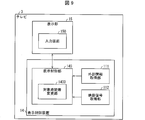
- FIG. 9 is a block diagram illustrating a main configuration of the television 3 according to the present embodiment.
- the display unit 15 further includes an input screen 150 instead of the operation unit 12.
- the display control unit 140 increases the intensity of the blue wavelength in the display video in the target time zone according to the input result of the input screen 150.
- the television 3 has the same configuration as the television 1 according to the first embodiment and the television 2 according to the second embodiment.
- the display control device 14 includes a display control unit 140, an external information acquisition unit 111, and a video signal acquisition unit 112.
- the display control unit 140 displays the input screen 150 on the display unit 15 and calculates an adjustment target time difference with reference to the travel destination input via the input screen 150. Thereby, the input of the time difference for direct adjustment by the user can be omitted. Therefore, the display control device 14 can perform display control processing more efficiently.
- the display unit 15 displays an input screen 150 that accepts user input related to the travel destination.
- the input screen 150 will be described with reference to FIG. FIG. 10A shows the input screen 150 before input by the user, and FIG. 10B shows the input screen 150 after information related to the travel destination by the user is input.
- the input screen 150 is a touch panel on which information can be input with a user's finger or pen.
- the display unit 15 displays an input screen 150 having a “o” button for selecting whether to travel or after returning home.
- the user can select by touching the “O” button after the trip or after returning home.
- the display unit 15 may be configured to display a screen such as a keyboard of a personal computer on the input screen 150 when the user touches a blank space for the travel destination. As a result, the user can directly input the travel destination by touching the keyboard on the input screen 150.
- the display unit 15 may display a list of countries around the world on the input screen 150, for example, when the user touches the blank space of the destination. Thereby, the user can touch and select a travel destination from a list of countries around the world.
- the display control unit 140 calculates the adjustment target time difference between the travel destination and the current location, and causes the input screen 150 to display the adjustment target time difference. For example, as shown in FIG. 10B, when the travel destination is selected as Paris and the current location is Japan, the display control unit 140 calculates the adjustment target time difference, ⁇ 8 hours, and displays it on the input screen 150. Display.
- the input screen 150 accepts user input of the number of days (time difference adjustment days before travel) for reducing the time difference blur. As shown in FIG. 10B, the user touches an “OK” button displayed on the upper right of the input screen 150 after inputting the destination and the number of days for reducing the time difference blur.
- the display control unit 140 refers to the travel destination, the time difference to be adjusted, and the number of days for reducing the time difference blur (the time difference adjustment days before the travel) input to the input screen 150 by the target time zone changing unit 1400. And change the target time zone step by step. In addition, the display control unit 140 increases the intensity of the blue wavelength according to the changed target time zone.
- the input screen 150 can accept user input of the destination and the number of days. Therefore, the display control unit 140 can acquire the information on the destination and the number of days via the input screen 150 more efficiently. Thereby, the display control unit 140 can more efficiently increase the intensity of a specific wavelength such as blue in the target time zone.
- the display control process can be performed in the same manner as when the user selects the “O” button scheduled to travel, and thus the description is omitted.
- the display control unit 140 calculates the adjustment target time difference with reference to the travel destination input via the input screen 150, but the present embodiment is not limited to this.
- the user may input the adjustment target time difference directly on the input screen 150.
- the display unit 15 may display, for example, a world map screen on the input screen 150 in which the time difference between the current location and the destination is recorded.
- the user touches and selects a country in the world map displayed on the input screen 150 the travel destination and the adjustment target time difference are once set as in the input screen 150 shown in FIG. Is displayed.
- the display unit 15 displays the input screen 150 so that the user can efficiently check the destination, the time difference for adjustment, and the number of days that the user has input. Control processing can be performed.
- the input screen 150 accepts user input of the number of days for reducing the time difference blur and the number of days for eliminating the time difference blur.
- the display control unit 140 automatically calculates the number of days for reducing the time difference blur (the time difference adjustment days before the travel) and the number of days to eliminate the time difference blur (the time difference adjustment days after returning home) according to the adjustment target time difference. It may be set. In other words, the display unit 15 does not have to display on the input screen 150 the number of days for reducing the time difference blur and the blank for the number of days for eliminating the time difference blur.
- the input screen 150 may further accept user input for the planned travel date in the travel plan column and the planned return date in the post-return column.
- the display control unit 140 may increase the intensity of the blue wavelength while changing the target time zone automatically and stepwise until the planned travel date or from the planned return date. .
- the user can reserve a schedule for performing the display control process via the input screen 150. Therefore, the display control device 14 can perform display control processing more efficiently.
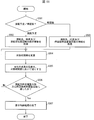
- FIG. 11 is a flowchart showing the flow of the display control method.
- Step S301 The display unit 15 displays an input screen 150 having a “ ⁇ ” button for selecting whether the user is planning to travel or after returning home.
- the display unit 15 causes the user to touch and select the “O” button after the trip or after returning home.
- step S301 When the user selects the “ ⁇ ” button scheduled for travel (schedule for travel in step S301), the process proceeds to step S302.
- step S303 When the user selects the “ ⁇ ” button after returning home (after returning home in step S301), the process proceeds to step S303.
- Step S302 The display unit 15 causes the user to input the travel destination and the number of days for reducing the time difference blur (the time difference adjustment days before the travel) on the input screen 150.
- the display control unit 140 acquires information on the travel destination and the time difference adjustment days before travel through the input screen 150. Further, the display control unit 140 refers to the travel destination input on the input screen 150 and calculates the adjustment target time difference.
- Step S303 The display unit 15 causes the user to input the travel destination and the number of days required to clear the time difference blur (the time difference adjustment days after returning home) on the input screen 150.
- the display control unit 140 acquires information on the destination and the time difference adjustment days after returning through the input screen 150. Further, the display control unit 140 refers to the travel destination input on the input screen 150 and calculates the adjustment target time difference.
- control blocks (particularly the display control units 110, 130, and 140) of the display control devices 11, 13, and 14 may be realized by a logic circuit (hardware) formed in an integrated circuit (IC chip) or the like, or a CPU It may be realized by software using (Central Processing Unit).
- the display control devices 11, 13, and 14 include a CPU that executes instructions of a program that is software that realizes each function, and a ROM (in which the program and various data are recorded so as to be readable by a computer (or CPU)).
- Read Only Memory or a storage device (these are referred to as “recording media"), a RAM (Random Access Memory) for expanding the program, and the like.
- the objective of this invention is achieved when a computer (or CPU) reads the said program from the said recording medium and runs it.
- a “non-temporary tangible medium” such as a tape, a disk, a card, a semiconductor memory, a programmable logic circuit, or the like can be used.
- the program may be supplied to the computer via an arbitrary transmission medium (such as a communication network or a broadcast wave) that can transmit the program.
- an arbitrary transmission medium such as a communication network or a broadcast wave
- one embodiment of the present invention can also be realized in the form of a data signal embedded in a carrier wave, in which the program is embodied by electronic transmission.
- the display control device (11, 13, 14) adjusts the intensity of a specific wavelength in the display image displayed on the display unit (10, 15) in the target time zone (110). , 130, 140) and a target time zone changing unit (1100, 1300, 1400) that changes the target time zone in steps with reference to the adjustment target time difference and the number of days.
- the target time zone changing unit (1100, 1300, 1400) changes the target time zone step by step with reference to the adjustment target time difference and the number of days.
- the blue wavelength in the display image is suitable in the suitable target time zone.
- the intensity of the can be adjusted.
- the display control device (11, 13, 14) including the display control unit (110, 130, 140) travels to a destination with a time difference or returns from the destination, A biological rhythm can be adjusted suitably.
- the target time zone changing unit (1100, 1300, 1400) The time difference obtained by dividing the adjustment target time difference by the number of days may be changed.
- the target time zone changing unit (1100, 1300, 1400) shifts the target time zone little by little for a certain time every day, not once.
- the wavelength of a specific wavelength such as blue in the display image is adjusted in accordance with the change of the user's biological rhythm.
- the strength can be adjusted.
- the user's time difference blur can be reduced.
- the display control unit (140) displays on the display unit (15) an input screen (150) for accepting user input relating to a travel destination.
- the adjustment target time difference may be calculated by referring to the travel destination input via the input screen (150).
- the input screen (150) can accept the user input of the travel destination input screen (150). Therefore, the display control unit (140) can acquire the information on the destination more efficiently via the input screen (150). Further, the display control unit (140) calculates the adjustment target time difference with reference to the travel destination input via the input screen (150). Therefore, the input of the adjustment target time difference by the user can be omitted. Accordingly, the display control unit (140) can more efficiently adjust the intensity of the specific wavelength in the target time zone.
- the input screen (150) may further accept user input related to the number of days referred to by the display control apparatus (14).
- a display control part (140) acquires the information of days more efficiently via an input screen (150) because the input screen (150) receives the user input regarding a number of days. Can do. Thereby, the display control part (140) can adjust the intensity
- a display device (TVs 1, 2, 3) according to aspect 5 of the present invention includes a display control device (11, 13, 14) and a display unit (10, 15) according to any one of the above aspects 1 to 4. And.
- FIG. 1 According to said structure, there can exist an effect similar to the display control apparatus (11, 13, 14) of the said aspect 1.
- the display control method is a target for changing the target time zone for adjusting the intensity of a specific wavelength in the display image displayed on the display unit (10, 15) with reference to the adjustment target time difference and the number of days.
- FIG. 1 According to said structure, there can exist an effect similar to the display control apparatus (11, 13, 14) of the said aspect 1.
- the display control device (11, 13, 14) may be realized by a computer.
- each unit (software) included in the display control device (11, 13, 14) is provided.
Landscapes
- Engineering & Computer Science (AREA)
- Physics & Mathematics (AREA)
- General Physics & Mathematics (AREA)
- Computer Hardware Design (AREA)
- Theoretical Computer Science (AREA)
- Multimedia (AREA)
- Signal Processing (AREA)
- Controls And Circuits For Display Device (AREA)
- Electric Clocks (AREA)
- Transforming Electric Information Into Light Information (AREA)
- Video Image Reproduction Devices For Color Tv Systems (AREA)
Abstract
表示制御装置(11)は、表示部(10)に表示させる表示映像における特定の波長の強度を、対象時間帯において調整する表示制御部(110)と、対象時間帯を、調整対象時差及び日数を参照して、段階的に変更する対象時間帯変更部(1100)とを備えている。
Description
本発明は、表示映像における特定の波長の強度を調整する表示制御装置等に関する。
近年、照明装置は白熱灯及び蛍光灯から消費電力の少ないLEDへの置き換えが進んでいる。また、小型化及び省エネを実現することができることから、特許文献1~4に記載されているようなテレビ及び携帯端末等の表示装置のバックライトにもLEDが広く使用されるようになってきている。
一方で、LEDは他の光源に比べて青色の波長の光が強く、その光は目の疲れ及び生体リズムの乱れ等の問題を引き起こすことが報告されている。このような問題を防ぐため、表示映像において、青色等の特定の波長の強度を調整する装置が開発されている。
例えば、特許文献5には、表示部に表示される画像を制御する画像表示装置において、時間情報に基づいて、覚醒の効果を得たいときには青の強度を相対的に強くし、沈静の効果を得たいときには青の強度を相対的に弱くする色合い制御部を備えることで生体リズムを調整することを特徴とする画像表示制御装置が記載されている。
また、特許文献6には、覚醒光を照射する照明部と、アラーム部と、制御部と、演算部と、各種設定を可能とするインタフェース部と、時計部と、睡眠者の体動を検出する体動検出部とを備えている覚醒システムが記載されている。
ところで、表示装置のユーザの渡航先が時差のある地域である場合、渡航に伴い、ユーザの生体リズムが変化する。
しかし、上述のような従来技術では、ユーザが時差のある渡航先に渡航したり、当該渡航先から帰ってきたりした場合には、ユーザの生体リズムを好適に調整することができない。
本発明は、上述の問題点に鑑みてなされたものであり、その目的は、ユーザが時差のある渡航先に渡航したり、当該渡航先から帰ってきたりする場合であっても、ユーザの生体リズムを好適に調整することにある。
上記の課題を解決するために、本発明の一態様に係る表示制御装置は、表示部に表示させる表示映像における特定の波長の強度を、対象時間帯において調整する表示制御部と、上記対象時間帯を、調整対象時差及び日数を参照して、段階的に変更する対象時間帯変更部とを備えている。
また、本発明の一態様に係る表示制御方法は、表示部に表示させる表示映像における特定の波長の強度を調整する対象時間帯を、調整対象時差及び日数を参照して変更する対象時間帯変更工程と、上記対象時間帯変更工程にて変更した対象時間帯において、表示部に表示させる表示映像における特定の波長の強度を調整する表示制御工程とを含んでいる。
本発明の一態様によれば、ユーザが時差のある渡航先に渡航したり、当該渡航先から帰ってきたりする場合であっても、ユーザの生体リズムを好適に調整することができる。
以下、本発明の実施形態について、詳細に説明する。ただし、以下の実施形態に記載されている構成は、特に特定的な記載がない限り、この発明の範囲をそれのみに限定する趣旨ではなく、単なる説明例に過ぎない。
<実施形態1>
〔テレビ1〕
本発明の実施形態1に係るテレビ(表示装置)1について、図1~5を参照して説明する。
〔テレビ1〕
本発明の実施形態1に係るテレビ(表示装置)1について、図1~5を参照して説明する。
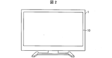
図1は、本実施形態に係るテレビ1の構成を示すブロック図である。図2は、テレビ1の外観を示す正面図である。テレビ1は、放送局から送信された映像信号を受信して、表示部10に映像を表示する。
図1に示すように、テレビ1は、表示部10、表示制御装置11及び操作部12を備えている。
〔表示部10〕
表示部10は、後述の表示制御部110からの指示に従い、映像を表示する。表示部10は、LCD、EL(Electroluminescence)ディスプレイ及びPDP(Plasma Display Panel)等の表示素子と、受信した映像信号に基づいて表示素子を駆動するドライバ回路とを備える構成である。
表示部10は、後述の表示制御部110からの指示に従い、映像を表示する。表示部10は、LCD、EL(Electroluminescence)ディスプレイ及びPDP(Plasma Display Panel)等の表示素子と、受信した映像信号に基づいて表示素子を駆動するドライバ回路とを備える構成である。
〔表示制御装置11〕
表示制御装置11は、表示部10に表示させる表示映像を制御するものである。
表示制御装置11は、表示部10に表示させる表示映像を制御するものである。
図1に示すように、表示制御装置11は、表示制御部110、外部情報取得部111及び映像信号取得部112を備えている。
なお、外部情報取得部111及び映像信号取得部112は、表示制御装置11としては必須の構成ではなく、テレビ1が、表示制御装置11の外部に、外部情報取得部111及び映像信号取得部112を備える構成としてもよい。
また、上述の例では、表示制御装置11は、テレビ1に備えられているが、本実施形態ではこれに限定されない。例えば、表示制御装置11は、レコーダ、プレーヤ、及び、STB(Set Top Box)等に備えることもできる。
[表示制御部110]
表示制御部110は、表示部10に表示させる表示映像における特定の波長の強度を、対象時間帯において調整するものである。
表示制御部110は、表示部10に表示させる表示映像における特定の波長の強度を、対象時間帯において調整するものである。
より具体的には、表示制御部110は、表示部10に表示させる表示映像における青色の波長の強度を、対象時間帯において強くするように調整する。すなわち、ここでは、対象時間帯とは、青色の波長の強度が強い時間帯のことを意味する。表示制御部110は、調整した映像データを表示部10に送信する。
ここで、図1に示すように、表示制御部110は、対象時間帯を変更する対象時間帯変更部1100を備えている。対象時間帯変更部1100は対象時間帯を変更し、表示制御部110は表示映像における青色の波長の強度を対象時間帯において変更する。
これにより、表示制御部110は、ユーザが時差のある渡航先に渡航したり、当該渡航先から帰ってきたりした場合であっても、好適な対象時間帯において表示映像における青色の波長の強度を調整することができる。その結果、表示制御部110を備える表示制御装置11は、ユーザが時差のある渡航先に渡航したり、渡航先から帰ってきたりした場合であっても、ユーザの生体リズムを好適に調整することができる。
なお、上述の例では、表示制御部110は、青色の波長の強度を対象時間帯において調整しているが、本実施形態ではこれに限定されない。本実施形態では、青色以外の波長の強度を調整してもよい。表示制御部110が、青色以外の波長の強度を調整する場合であっても、例えば、段階的な調光変化及び段階的な調光変化等を施すことによって、ユーザの生体リズムを調整することができる。
また、表示制御部110は、外部情報取得部111から外部情報を取得し、時間、場所及び天候等に応じて、映像信号取得部112から受信した映像データの色度及び明るさを変更することによって、ユーザの生体リズム調整をする構成としてもよい。
(対象時間帯変更部1100)
対象時間帯変更部1100は、対象時間帯を、調整対象時差及び渡航前時差調整日数を参照して、段階的に変更する。
対象時間帯変更部1100は、対象時間帯を、調整対象時差及び渡航前時差調整日数を参照して、段階的に変更する。
なお、調整対象時差、及び、渡航前時差調整日数の情報は、ユーザが操作部12を介して入力することによって得られる。
また、上述の渡航前時差調整日数とは、例えば、ユーザが渡航先に渡航した場合に時差ボケを軽減することができる標準的な日数のことを指す。
以下に、対象時間帯変更部1100が、日本からパリ等の渡航先に渡航する前に、調整対象時差及び渡航前時差調整日数を参照して対象時間帯を変更する例について図3及び図4を用いて説明する。
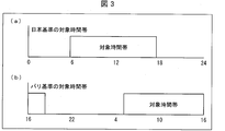
まず、日本基準の対象時間帯、及び、パリ基準の対象時間帯について図3の(a)及び(b)を用いて説明する。
図3の(a)は、日本基準の対象時間帯を示す図である。図3の(a)に示すように、表示制御部110は、変更前の日本基準の対象時間帯を、昼間にテレビを視聴する場合を想定した時間帯(6時~18時)に設定している。すなわち、図3の(a)では、6時~18時の間、表示部10に表示される表示映像における青色の波長の強度が強くなっており、他の時間においては、青色の波長の強度が弱くなっている。
図3の(b)は、パリ基準の対象時間帯を示す図である。図3の(b)に示すように、対象時間帯変更部1100は、対象時間帯が渡航先のパリ基準で6時~18時となるように対象時間帯を変更する。
ただし、パリは日本に比べて8時間遅れていることから、対象時間帯変更部1100は、図3の(a)の横軸の時間の値を8ずつ引いたとき、6時~18時となるように対象時間帯を変更する。すなわち、実際には、対象時間帯変更部1100は、パリ基準の対象時間帯を、日本基準の対象時間帯に換算すると、図4の(d)に示すように、14時~2時となるように変更する。
このように、表示制御部110は、表示映像において、自然光の強度が強い時間帯と同じ時間帯(例えば、6時~18時)に青色の波長の強度が強くなるように、対象時間帯を設定する。また、対象時間帯変更部1100は、対象時間帯がパリ基準で6時~18時となるように対象時間帯を変更する。
このように、表示制御部110及び対象時間帯変更部1100を備えた表示制御装置11は、ユーザの渡航前に、予めパリ基準の対象時間帯となるように変更し、青色の波長の強度を強くする。これにより、表示制御装置11は、ユーザの渡航前に、予め、渡航先のパリにおいて、ユーザの生体リズム(サーカディアンリズム)が自然になるように調整することができる。その結果、ユーザは、パリに渡航した場合であっても、渡航先のパリでの時差ボケを軽減することができる。
なお、本実施形態では、日本基準の対象時間帯の情報を、例えば、テレビ1の初期設定の際に、操作部12を介して表示制御部110に入力することができる。これにより、表示制御部110は、操作部12から入力された渡航前時差調整日数及び調整対象時差を参照することにより、渡航先での対象時間帯を算出することができる。その結果、対象時間帯変更部1100は、渡航先基準の対象時間帯となるように対象時間帯を変更することができる。
また、上述の例では、表示制御部110は、各国基準の6時~18時に青色の波長の強度が強くなるように、対象時間帯変更部1100によって対象時間帯を変更している。ただし、表示制御部110は、ユーザの生体リズムに合わせて、任意の時間帯に対象時間帯を設定することができる。
また、上述の例では、渡航前時差調整日数の情報を、ユーザが操作部12を介して入力しているが、本実施形態ではこれに限定されない。本実施形態では、表示制御部110は、渡航前時差調整日数を調整対象時差に応じて自動的に設定してもよい。
例えば、表示制御部110は、調整対象時差が1~2時間であれば渡航前時差調整日数を1日に設定してもよい。また、表示制御部110は、調整対象時差が3~4時間であれば渡航前時差調整日数を2日に設定し、調整対象時差が5~6時間であれば渡航前時差調整日数を3日に設定してもよい。このように、表示制御部110は、調整対象時差と正の相関を有するように渡航前時差調整日数を自動的に設定してもよい。
(対象時間帯の変更方法)
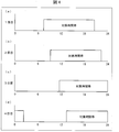
次に、対象時間帯変更部1100が、調整対象時差及び渡航前時差調整日数を参照して、対象時間帯を段階的に変更する対象時間帯の変更方法の一例を、図4を用いて具体的に説明する。
次に、対象時間帯変更部1100が、調整対象時差及び渡航前時差調整日数を参照して、対象時間帯を段階的に変更する対象時間帯の変更方法の一例を、図4を用いて具体的に説明する。
図4の(a)~(d)は、対象時間帯変更部1100が1日目~4日目の各日において変更した対象時間帯を説明する図である。図4の(a)は、1日分(2時間)、対象時間帯を後ろにずらしたときの図である。同様に、図4の(b)~(d)は、日本基準の対象時間帯から、それぞれ2日分、3日分、4日分、対象時間帯を後ろにずらしたときの図である。
上述のように、対象時間帯変更部1100は、1日につき、2時間ずつ対象時間帯を後ろにずらし、4日間で対象時間帯を日本とパリとの時差である8時間分後ろにずらしている。すなわち、対象時間帯変更部1100は、1日につき、渡航先のパリと、日本との調整対象時差8時間分を、渡航前時差調整日数4日で除算して得られる時間分である2時間分だけ対象時間帯を変更している。
このように、対象時間帯変更部1100は、一度ではなく、毎日、一定の時間分少しずつ対象時間帯をずらし、表示制御部110は、青色等の特定の波長の強度を調整する。これにより、外国等の時差のある渡航先に行く前に、予めユーザの生体リズムを渡航先の生体リズムに合うように調整することができる。その結果、ユーザが時差のある渡航先に行って表示映像を見たとしても、ユーザの時差ボケを軽減することができる。
なお、上述の例では、対象時間帯変更部1100は、1日につき、対象時間帯を、調整対象時差を渡航前時差調整日数で除算して得られる時間分変更しているが、本実施形態ではこれに限定されない。本実施形態では、対象時間帯変更部1100は、対象時間帯を、調整対象時差及び渡航前時差調整日数を参照して、段階的に変更すればよい。
例えば、調整対象時差が8時間で、渡航前時差調整日数が4日だとした場合、対象時間帯変更部1100は、1日目に3時間分、2日目に2時間分、3日目に1時間分、4日目に2時間分、対象時間帯を変更し、4日の合計で8時間後ろにずらすようにしてもよい。
また、上述の例では、対象時間帯変更部1100が表示制御部110の内部に格納されており、表示制御部110が対象時間帯変更部1100としても機能する形態について説明している。ただし、本実施形態ではこれに限定されない。表示制御部110及び対象時間帯変更部1100の各々が、上述した機能を発揮することができ、表示制御装置11内にあれば、対象時間帯変更部1100は、表示制御部110の外部に備えられていてもよい。
(外部情報取得部111)
外部情報取得部111は、テレビ1が備えているセンサ(図示せず)及びインターネット等から外部情報(例えば、時間、場所及び天候)を取得し、表示制御部110に送信する。
外部情報取得部111は、テレビ1が備えているセンサ(図示せず)及びインターネット等から外部情報(例えば、時間、場所及び天候)を取得し、表示制御部110に送信する。
(映像信号取得部112)
映像信号取得部112は、放送局等の放送の映像信号を取得し、表示制御部110に送信する。
映像信号取得部112は、放送局等の放送の映像信号を取得し、表示制御部110に送信する。
〔操作部12〕
操作部12は、ユーザによる入力操作を受け付けるものであり、例えば、リモコン等を挙げることができる。特に、本実施形態においては、操作部12は、渡航先、現在地と渡航先との時差(調整対象時差)、及び、渡航前時差調整日数の情報の入力操作を受け付ける。
操作部12は、ユーザによる入力操作を受け付けるものであり、例えば、リモコン等を挙げることができる。特に、本実施形態においては、操作部12は、渡航先、現在地と渡航先との時差(調整対象時差)、及び、渡航前時差調整日数の情報の入力操作を受け付ける。
〔表示制御方法〕
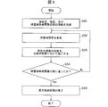
本実施形態に係るテレビ1により実行される表示制御方法の流れを、図5を参照して説明する。図5は、表示制御方法の流れを示すフローチャートである。
本実施形態に係るテレビ1により実行される表示制御方法の流れを、図5を参照して説明する。図5は、表示制御方法の流れを示すフローチャートである。
本実施形態に係るテレビ1は、以下に説明するステップS101~S103を実行することによって、表示制御処理を行う。
ステップS101:まず、表示制御部110は、操作部12を介して、渡航先、調整対象時差、及び渡航前時差調整日数の情報を取得する。
ステップS102(対象時間帯変更工程):次に、表示制御部110は、対象時間帯変更部1100によって、表示部10に表示させる表示映像における特定の波長の強度を調整する対象時間帯を、調整対象時差及び渡航前時差調整日数を参照して変更する。これにより、日本基準の対象時間帯から渡航先基準の対象時間帯へと対象時間帯が段階的に変更される。
ステップS103(表示制御工程):表示制御部110は、対象時間帯変更工程にて変更した対象時間帯において、表示部10に表示させる表示映像における青色の波長の強度を強くする。
ステップS104:表示制御部110は、渡航前時差調整日数に達したか否かを判定する。渡航前時差調整日数に達した場合(ステップS104のYES)、ステップS105に進む。渡航前時差調整日数に達していない場合(ステップS104のNO)、ステップS102に戻り、ステップS102~S104を繰り返す。
ステップS105:渡航前時差調整日数に達したと表示制御部110が判断した場合、表示制御部110は、表示制御処理を終了する。
<実施形態2>
実施形態1では、表示制御装置11の対象時間帯変更部1100は、日本から渡航先に渡航する前に、予め対象時間帯を変更している。ただし、実施形態2のように、表示制御装置13は、対象時間帯変更部1100の有する機能の代わりに、又は、対象時間帯変更部1100の有する機能に加えて、対象時間帯変更部1300によって、渡航先から帰国した後に、対象時間帯を変更してもよい。
実施形態1では、表示制御装置11の対象時間帯変更部1100は、日本から渡航先に渡航する前に、予め対象時間帯を変更している。ただし、実施形態2のように、表示制御装置13は、対象時間帯変更部1100の有する機能の代わりに、又は、対象時間帯変更部1100の有する機能に加えて、対象時間帯変更部1300によって、渡航先から帰国した後に、対象時間帯を変更してもよい。
実施形態2について、図6~8を参照して説明する。なお、説明の便宜上、実施形態1にて説明した部材と同じ機能を有する部材については、同じ符号を付記し、その説明を省略する。
〔テレビ2〕
図6は、本実施形態に係るテレビ2の要部構成を示すブロック図である。図6に示すように、本実施形態に係るテレビ2は、表示制御装置11の代わりに、表示制御装置13を備えている。また、表示制御装置13は、表示制御部110の代わりに、表示制御部130を備えている。この点以外は、表示制御装置13は、表示制御装置11と同様の構成である。
図6は、本実施形態に係るテレビ2の要部構成を示すブロック図である。図6に示すように、本実施形態に係るテレビ2は、表示制御装置11の代わりに、表示制御装置13を備えている。また、表示制御装置13は、表示制御部110の代わりに、表示制御部130を備えている。この点以外は、表示制御装置13は、表示制御装置11と同様の構成である。
〔表示制御装置13〕
図6に示すように、表示制御装置13における表示制御部130は、対象時間帯変更部1300を備えている。
図6に示すように、表示制御装置13における表示制御部130は、対象時間帯変更部1300を備えている。
対象時間帯変更部1300は、対象時間帯変更部1100の有する機能の代わりに、又は、対象時間帯変更部1100の有する機能に加えて、パリ等の渡航先から帰国した後に、対象時間帯を段階的に変更する。
以下、対象時間帯変更部1300が有する機能のうち、パリ等の渡航先から帰国した後に、対象時間帯を段階的に変更する機能について説明する。
ここで、渡航先から帰国した後であって変更前の対象時間帯は、図3の(b)に示すように、パリ基準の対象時間帯で6時~18時(日本基準の対象時間帯で14時~2時)となっている。当該パリ基準の対象時間帯は、表示制御部130内に保存されている日本基準の対象時間帯と、操作部12から入力される調整対象時差との情報に基づき、表示制御部130によって算出することができる。対象時間帯変更部1300は、図3の(a)に示すように、日本基準の対象時間帯となるように、対象時間帯を段階的に変更する。
以下、対象時間帯変更部1300が、調整対象時差及び帰国後時差調整日数を参照して、対象時間帯を段階的に変更する対象時間帯の変更方法の一例を、図7を用いて具体的に説明する。
図7の(a)~(d)は、対象時間帯変更部1300が1日目~4日目の各日において変更した対象時間帯を説明する図である。図7の(a)は、パリから帰ってきた後、パリ基準の対象時間帯から1日分(2時間)、対象時間帯を前にずらしたときの図である。同様に、図7の(b)~(d)は、それぞれ、パリから帰ってきた後、パリ基準の対象時間帯から2日分、3日分、4日分、対象時間帯を前にずらしたときの図である。
上述のように、対象時間帯変更部1300は、1日につき、2時間ずつ対象時間帯を前にずらし、4日間で対象時間帯を日本とパリとの時差である8時間分前にずらしている。すなわち、対象時間帯変更部1300は、1日につき、渡航先のパリと、日本との調整対象時差8時間分を、帰国後時差調整日数4日で除算して得られる時間分である2時間分だけ対象時間帯を変更している。
ここで、上述の帰国後時差調整日数とは、例えば、ユーザが渡航先から帰国した場合に時差ボケ解消にかける標準的な日数のことを指す。
このように、対象時間帯変更部1300は、一度でなく、毎日一定の時間分少しずつ対象時間帯をずらしている。これにより、ユーザが外国等の時差のある渡航先から日本に帰ってきた場合であっても、ユーザの生体リズムの変化に合わせながら表示映像における特定の波長の強度を調整することができる。その結果、ユーザが時差のある渡航先から日本に帰ってきて表示映像を視聴したとしても、ユーザの時差ボケを軽減することができる。
なお、上述の例では、帰国後時差調整日数の情報を、ユーザが操作部12を介して入力しているが、本実施形態ではこれに限定されない。本実施形態では、表示制御部110は、帰国後時差調整日数を調整対象時差に応じて自動的に設定してもよい。
例えば、表示制御部130は、調整対象時差が1~2時間であれば帰国後時差調整日数を1日に設定してもよい。また、表示制御部130は、調整対象時差が3~4時間であれば帰国後時差調整日数を2日に設定し、調整対象時差が5~6時間であれば帰国後時差調整日数を3日に設定してもよい。このように、表示制御部130は、調整対象時差と正の相関を有するように帰国後時差調整日数を自動的に設定してもよい。
〔表示制御方法〕
本実施形態に係るテレビ2により実行される、渡航先から帰国した後における表示制御方法の流れを、図8を参照して説明する。図8は、表示制御方法の流れを示すフローチャートである。
本実施形態に係るテレビ2により実行される、渡航先から帰国した後における表示制御方法の流れを、図8を参照して説明する。図8は、表示制御方法の流れを示すフローチャートである。
本実施形態に係るテレビ2は、以下に説明するステップS201~S205を実行することによって、表示制御処理を行う。
図8におけるステップS203及びS205は、図5におけるステップS103及びS105と同様であるため、ここではその説明を省略する。
ステップS201:表示制御部130は、操作部12を介して、渡航先、調整対象時差及び帰国後時差調整日数の情報を取得する。
ステップS202(対象時間帯変更工程):次に、表示制御部130は、対象時間帯変更部1300によって、表示部10に表示させる表示映像における特定の波長の強度を調整する対象時間帯を、調整対象時差及び帰国後時差調整日数を参照して変更する。これにより、渡航先基準の対象時間帯から日本基準の対象時間帯へと対象時間帯が段階的に変更される。
ステップS204:表示制御部130は、帰国後時差調整日数に達したか否かを判定する。帰国後時差調整日数に達した場合(ステップS204のYES)、ステップS205に進む。帰国後時差調整日数に達していない場合(ステップS204のNO)、ステップS202に戻り、ステップS202~S204を繰り返す。
<実施形態3>
実施形態1及び2では、表示制御装置11及び13の表示制御部110及び130は、操作部12を介して渡航先及び日数の情報を取得している。ただし、実施形態3のように、表示制御装置14の表示制御部140は、操作部12の代わりに、表示部15における入力画面150を介して渡航先及び日数の情報を取得してもよい。
実施形態1及び2では、表示制御装置11及び13の表示制御部110及び130は、操作部12を介して渡航先及び日数の情報を取得している。ただし、実施形態3のように、表示制御装置14の表示制御部140は、操作部12の代わりに、表示部15における入力画面150を介して渡航先及び日数の情報を取得してもよい。
実施形態3について、図9~11を参照して説明する。なお、説明の便宜上、上述の実施形態にて説明した部材と同じ機能を有する部材については、同じ符号を付記し、その説明を省略する。
〔テレビ3〕
図9は、本実施形態に係るテレビ3の要部構成を示すブロック図である。図9に示すように、本実施形態に係るテレビ3は、操作部12がない代わりに、表示部15が入力画面150をさらに備えている。また、表示制御部140は、当該入力画面150の入力結果に応じて、表示映像における青色の波長の強度を、対象時間帯において強くする。この点以外は、テレビ3は、実施形態1に係るテレビ1及び実施形態2に係るテレビ2と同様の構成である。
図9は、本実施形態に係るテレビ3の要部構成を示すブロック図である。図9に示すように、本実施形態に係るテレビ3は、操作部12がない代わりに、表示部15が入力画面150をさらに備えている。また、表示制御部140は、当該入力画面150の入力結果に応じて、表示映像における青色の波長の強度を、対象時間帯において強くする。この点以外は、テレビ3は、実施形態1に係るテレビ1及び実施形態2に係るテレビ2と同様の構成である。
〔表示制御装置14〕
図9に示すように、表示制御装置14は、表示制御部140、外部情報取得部111、及び、映像信号取得部112を備えている。
図9に示すように、表示制御装置14は、表示制御部140、外部情報取得部111、及び、映像信号取得部112を備えている。
表示制御部140は、入力画面150を表示部15に表示させ、入力画面150を介して入力された渡航先を参照して調整対象時差を算出する。これにより、ユーザによる直接調整対象時差の入力を省略することができる。そのため、表示制御装置14は、より効率的に表示制御処理を行うことができる。
〔表示部15〕
表示部15は、渡航先に関するユーザ入力を受け付ける入力画面150を表示する。入力画面150について、図10を用いて説明する。図10の(a)は、ユーザによる入力前の入力画面150を示しており、図10の(b)は、ユーザによる渡航先に関する情報を入力後の入力画面150を示している。入力画面150は、ユーザの指又はペン等により、情報の入力が可能なタッチパネルとなっている。
表示部15は、渡航先に関するユーザ入力を受け付ける入力画面150を表示する。入力画面150について、図10を用いて説明する。図10の(a)は、ユーザによる入力前の入力画面150を示しており、図10の(b)は、ユーザによる渡航先に関する情報を入力後の入力画面150を示している。入力画面150は、ユーザの指又はペン等により、情報の入力が可能なタッチパネルとなっている。
図10の(a)に示すように、表示部15は、渡航予定であるか、帰国後であるかを選択する「○」ボタンがある入力画面150を表示する。ユーザは、渡航予定又は帰国後の「○」ボタンをタッチして選択することができる。
以下、ユーザが渡航予定の「○」ボタンを選択した場合における入力画面150への入力方法について具体的に説明する。
(入力画面150への入力方法)
まず、ユーザは、渡航予定の「○」ボタンを選択した後、渡航先を空欄に入力する。例えば、表示部15は、ユーザが渡航先の空欄をタッチすると、入力画面150にパソコンのキーボードのような画面を表示するようになっていてもよい。これにより、ユーザは、入力画面150上のキーボードをタッチして直接渡航先を入力することができる。
まず、ユーザは、渡航予定の「○」ボタンを選択した後、渡航先を空欄に入力する。例えば、表示部15は、ユーザが渡航先の空欄をタッチすると、入力画面150にパソコンのキーボードのような画面を表示するようになっていてもよい。これにより、ユーザは、入力画面150上のキーボードをタッチして直接渡航先を入力することができる。
また、表示部15は、ユーザが渡航先の空欄にタッチした場合、例えば、世界各国のリスト等を入力画面150に表示するようになっていてもよい。これにより、ユーザは、世界各国のリストから、渡航先をタッチして選択することができる。
このようにして、ユーザが渡航先を決定した場合、表示制御部140は、渡航先と現在地との調整対象時差を算出し、当該調整対象時差を入力画面150に表示させる。例えば、図10の(b)に示すように、渡航先をパリに選択し、現在地が日本であった場合、表示制御部140は、調整対象時差、-8時間を算出し、入力画面150に表示させる。
ユーザが渡航先を選択した後、入力画面150は、時差ボケを軽減するための日数(渡航前時差調整日数)のユーザ入力を受け付ける。ユーザは、図10の(b)に示すように、渡航先及び時差ボケを軽減するための日数を入力した後、入力画面150の右上に表示された「OK」ボタンをタッチする。
これにより、表示制御部140は、対象時間帯変更部1400によって、入力画面150に入力された渡航先、調整対象時差、及び、時差ボケを軽減するための日数(渡航前時差調整日数)を参照させ、対象時間帯を段階的に変更する。また、表示制御部140は、変更された対象時間帯に応じて、青色の波長の強度を強くする。
このように、入力画面150は、渡航先及び日数のユーザ入力を受け付けることができる。そのため、表示制御部140は、入力画面150を介して、より効率的に渡航先及び日数の情報を取得することができる。これにより、表示制御部140は、より効率的に、青色等の特定の波長の強度を対象時間帯において強くすることができる。
なお、ユーザが帰国後の「○」ボタンを選択した場合でも、ユーザが渡航予定の「○」ボタンを選択した場合と同様に表示制御処理を行うことができるため、説明を省略する。
また、上述の例では、表示制御部140は、入力画面150を介して入力された渡航先を参照して調整対象時差を算出しているが、本実施形態ではこれに限定されない。
本実施形態では、ユーザが入力画面150に直接調整対象時差を入力するようにしてもよい。また、表示部15は、例えば、現在地と渡航先との時差を記した世界地図の画面を入力画面150に表示してもよい。これにより、ユーザが入力画面150に表示された世界地図のうちのある国をタッチして選択したとき、図10の(b)に示す入力画面150のように渡航先と調整対象時差とが一度に表示される。
いずれの場合であっても、表示部15が入力画面150を表示することで、ユーザにとっても、自身が入力した渡航先、調整対象時差、及び、日数を確認しやすくしつつ、効率的に表示制御処理を行うことができる。
また、上述の例では、入力画面150は、時差ボケを軽減するための日数及び時差ボケ解消にかける日数のユーザ入力を受け付けているが、本実施形態ではこれに限定されない。本実施形態では、表示制御部140は、時差ボケを軽減するための日数(渡航前時差調整日数)及び時差ボケ解消にかける日数(帰国後時差調整日数)を調整対象時差に応じて自動的に設定してもよい。すなわち、表示部15は、入力画面150に、時差ボケを軽減するための日数及び時差ボケ解消にかける日数の空欄を表示しなくてもよい。
また、入力画面150は、渡航予定の欄に渡航予定日、及び、帰国後の欄に帰国予定日のユーザ入力をさらに受け付けてもよい。この場合、表示制御部140は、渡航予定日までの間、又は、帰国予定日から、対象時間帯を自動的且つ段階的に変更しながら、青色の波長の強度を強くなるようにしてもよい。これにより、ユーザは入力画面150を介して表示制御処理を行う日程を予約することができる。そのため、表示制御装置14は、より効率的に表示制御処理を行うことができる。
〔表示制御方法〕
次に、本実施形態に係るテレビ3により実行される表示制御方法の流れを、図11を用いて説明する。図11は、表示制御方法の流れを示すフローチャートである。
次に、本実施形態に係るテレビ3により実行される表示制御方法の流れを、図11を用いて説明する。図11は、表示制御方法の流れを示すフローチャートである。
図11におけるステップS304~S307は、図5におけるステップS102~S105又は図8におけるステップS202~S205と同様であるため、ここではその説明を省略する。
ステップS301:表示部15は、渡航予定であるか、帰国後であるかどうか選択する「○」ボタンがある入力画面150を表示する。表示部15は、ユーザに、渡航予定又は帰国後の「○」ボタンをタッチさせ、選択させる。
ユーザが渡航予定の「○」ボタンを選択した場合(ステップS301の渡航予定)、ステップS302に進む。ユーザが帰国後の「○」ボタンを選択した場合(ステップS301の帰国後)、ステップS303に進む。
ステップS302:表示部15は、ユーザに渡航先及び時差ボケを軽減するための日数(渡航前時差調整日数)を入力画面150に入力させる。表示制御部140は、入力画面150を介して、渡航先及び渡航前時差調整日数の情報を取得する。また、表示制御部140は、入力画面150に入力された渡航先を参照して調整対象時差を算出する。
ステップS303:表示部15は、ユーザに渡航先及び時差ボケ解消にかける日数(帰国後時差調整日数)を入力画面150に入力させる。表示制御部140は、入力画面150を介して、渡航先及び帰国後時差調整日数の情報を取得する。また、表示制御部140は、入力画面150に入力された渡航先を参照して調整対象時差を算出する。
〔ソフトウェアによる実現例〕
表示制御装置11、13及び14の制御ブロック(特に表示制御部110、130及び140)は、集積回路(ICチップ)等に形成された論理回路(ハードウェア)によって実現してもよいし、CPU(Central Processing Unit)を用いてソフトウェアによって実現してもよい。
表示制御装置11、13及び14の制御ブロック(特に表示制御部110、130及び140)は、集積回路(ICチップ)等に形成された論理回路(ハードウェア)によって実現してもよいし、CPU(Central Processing Unit)を用いてソフトウェアによって実現してもよい。
後者の場合、表示制御装置11、13及び14は、各機能を実現するソフトウェアであるプログラムの命令を実行するCPU、上記プログラム及び各種データがコンピュータ(またはCPU)で読み取り可能に記録されたROM(Read Only Memory)または記憶装置(これらを「記録媒体」と称する)、上記プログラムを展開するRAM(Random Access Memory)などを備えている。そして、コンピュータ(またはCPU)が上記プログラムを上記記録媒体から読み取って実行することにより、本発明の目的が達成される。上記記録媒体としては、「一時的でない有形の媒体」、例えば、テープ、ディスク、カード、半導体メモリ、プログラマブルな論理回路などを用いることができる。また、上記プログラムは、該プログラムを伝送可能な任意の伝送媒体(通信ネットワークや放送波等)を介して上記コンピュータに供給されてもよい。なお、本発明の一態様は、上記プログラムが電子的な伝送によって具現化された、搬送波に埋め込まれたデータ信号の形態でも実現され得る。
〔まとめ〕
本発明の態様1に係る表示制御装置(11、13、14)は、表示部(10、15)に表示させる表示映像における特定の波長の強度を、対象時間帯において調整する表示制御部(110、130、140)と、上記対象時間帯を、調整対象時差及び日数を参照して、段階的に変更する対象時間帯変更部(1100、1300、1400)とを備えている。
本発明の態様1に係る表示制御装置(11、13、14)は、表示部(10、15)に表示させる表示映像における特定の波長の強度を、対象時間帯において調整する表示制御部(110、130、140)と、上記対象時間帯を、調整対象時差及び日数を参照して、段階的に変更する対象時間帯変更部(1100、1300、1400)とを備えている。
上記の構成によれば、対象時間帯変更部(1100、1300、1400)が対象時間帯を調整対象時差及び日数を参照して、段階的に変更する。これにより、表示制御部(110、130、140)は、時差のある渡航先に渡航したり、渡航先から帰ってきたりした場合であっても、好適な対象時間帯において表示映像における青色の波長の強度を調整することができる。その結果、表示制御部(110、130、140)を備える表示制御装置(11、13、14)は、時差のある渡航先に渡航したり、渡航先から帰ってきたりした場合であっても、生体リズムを好適に調整することができる。
本発明の態様2に係る表示制御装置(11、13、14)では、上記態様1において、上記対象時間帯変更部(1100、1300、1400)は、1日につき、上記対象時間帯を、上記調整対象時差を上記日数で除算して得られる時間分変更してもよい。
上記の構成によれば、対象時間帯変更部(1100、1300、1400)は、一度ではなく、毎日一定の時間分少しずつ対象時間帯をずらす。これにより、ユーザが外国等の時差のある渡航先に行ったり、当該渡航先から帰ってきたりする場合であっても、ユーザの生体リズムの変化に合わせながら表示映像における青色等の特定の波長の強度を調整することができる。その結果、ユーザが時差のある渡航先で表示映像を見たとしても、ユーザの時差ボケを軽減することができる。
本発明の態様3に係る表示制御装置(14)では、上記態様1又は2において、上記表示制御部(140)は、渡航先に関するユーザ入力を受け付ける入力画面(150)を表示部(15)に表示させ、上記入力画面(150)を介して入力された渡航先を参照して上記調整対象時差を算出してもよい。
上記の構成によれば、入力画面(150)は、渡航先を入力画面(150)のユーザ入力を受け付けることができる。そのため、表示制御部(140)は、入力画面(150)を介して、より効率的に渡航先の情報を取得することができる。また、表示制御部(140)は、入力画面(150)を介して入力された渡航先を参照して調整対象時差を算出する。そのため、ユーザによる調整対象時差の入力を省略することができる。これらにより、表示制御部(140)は、より効率的に、特定の波長の強度を対象時間帯において調整することができる。
本発明の態様4に係る表示制御装置(14)では、上記態様3において、上記入力画面(150)は、上記表示制御装置(14)が参照する上記日数に関するユーザ入力を更に受け付けてもよい。
上記の構成によれば、入力画面(150)が日数に関するユーザ入力を受け付けることで、表示制御部(140)は、入力画面(150)を介して、より効率的に日数の情報を取得することができる。これにより、表示制御部(140)は、より効率的に、特定の波長の強度を対象時間帯において調整することができる。
本発明の態様5に係る表示装置(テレビ1、2、3)は、上記態様1から4の何れか1つの態様における表示制御装置(11、13、14)と、表示部(10、15)とを備えている。
上記の構成によれば、上記態様1の表示制御装置(11、13、14)と同様の効果を奏することができる。
本発明の態様6に関わる表示制御方法は、表示部(10、15)に表示させる表示映像における特定の波長の強度を調整する対象時間帯を、調整対象時差及び日数を参照して変更する対象時間帯変更工程と、上記対象時間帯変更工程にて変更した対象時間帯において、表示部(10、15)に表示させる表示映像における特定の波長の強度を調整する表示制御工程とを含んでいる。
上記の構成によれば、上記態様1の表示制御装置(11、13、14)と同様の効果を奏することができる。
本発明の各態様に係る表示制御装置(11、13、14)は、コンピュータによって実現してもよく、この場合には、コンピュータを上記表示制御装置(11、13、14)が備える各部(ソフトウェア要素)として動作させることにより上記表示制御装置(11、13、14)をコンピュータにて実現させる表示制御装置(11、13、14)のプログラム、及びそれを記録したコンピュータ読み取り可能な記録媒体も、本発明の範疇に入る。
本発明は上述した各実施形態に限定されるものではなく、請求項に示した範囲で種々の変更が可能であり、異なる実施形態にそれぞれ開示された技術的手段を適宜組み合わせて得られる実施形態についても本発明の技術的範囲に含まれる。さらに、各実施形態にそれぞれ開示された技術的手段を組み合わせることにより、新しい技術的特徴を形成することができる。
1、2、3 テレビ
10、15 表示部
11、13、14 表示制御装置
12 操作部
110、130、140 表示制御部
111 外部情報取得部
112 映像信号取得部
150 入力画面
1100、1300、1400 対象時間帯変更部
10、15 表示部
11、13、14 表示制御装置
12 操作部
110、130、140 表示制御部
111 外部情報取得部
112 映像信号取得部
150 入力画面
1100、1300、1400 対象時間帯変更部
Claims (6)
- 表示部に表示させる表示映像における特定の波長の強度を、対象時間帯において調整する表示制御部と、
上記対象時間帯を、調整対象時差及び日数を参照して、段階的に変更する対象時間帯変更部と
を備えていることを特徴とする表示制御装置。 - 上記対象時間帯変更部は、1日につき、上記対象時間帯を、上記調整対象時差を上記日数で除算して得られる時間分変更することを特徴とする請求項1に記載の表示制御装置。
- 上記表示制御部は、
渡航先に関するユーザ入力を受け付ける入力画面を表示部に表示させ、
上記入力画面を介して入力された渡航先を参照して上記調整対象時差を算出する
ことを特徴とする請求項1又は2に記載の表示制御装置。 - 上記入力画面は、上記表示制御装置が参照する上記日数に関するユーザ入力を更に受け付ける
ことを特徴とする請求項3に記載の表示制御装置。 - 請求項1から4の何れか1項に記載の表示制御装置と
表示部と
を備えていることを特徴とする表示装置。 - 表示部に表示させる表示映像における特定の波長の強度を調整する対象時間帯を、調整対象時差及び日数を参照して変更する対象時間帯変更工程と、
上記対象時間帯変更工程にて変更した対象時間帯において、表示部に表示させる表示映像における特定の波長の強度を調整する表示制御工程と
を含んでいることを特徴とする表示制御方法。
Applications Claiming Priority (2)
| Application Number | Priority Date | Filing Date | Title |
|---|---|---|---|
| JP2017039395A JP6510576B2 (ja) | 2017-03-02 | 2017-03-02 | 表示制御装置、表示装置、及び表示制御方法 |
| JP2017-039395 | 2017-03-02 |
Publications (1)
| Publication Number | Publication Date |
|---|---|
| WO2018159170A1 true WO2018159170A1 (ja) | 2018-09-07 |
Family
ID=63370346
Family Applications (1)
| Application Number | Title | Priority Date | Filing Date |
|---|---|---|---|
| PCT/JP2018/002397 Ceased WO2018159170A1 (ja) | 2017-03-02 | 2018-01-26 | 表示制御装置、表示装置、及び表示制御方法 |
Country Status (2)
| Country | Link |
|---|---|
| JP (1) | JP6510576B2 (ja) |
| WO (1) | WO2018159170A1 (ja) |
Families Citing this family (1)
| Publication number | Priority date | Publication date | Assignee | Title |
|---|---|---|---|---|
| KR102927265B1 (ko) * | 2019-11-12 | 2026-02-13 | 삼성전자주식회사 | 디스플레이의 속성을 변경하기 위한 전자 장치 및 전자 장치에서의 동작 방법 |
Citations (5)
| Publication number | Priority date | Publication date | Assignee | Title |
|---|---|---|---|---|
| JP2000294388A (ja) * | 1999-04-09 | 2000-10-20 | Sekisui House Ltd | 照明制御方法および照明システム |
| JP2005309360A (ja) * | 2004-03-26 | 2005-11-04 | Sharp Corp | 画像表示制御装置 |
| JP2009037148A (ja) * | 2007-08-03 | 2009-02-19 | Sony Corp | 画像表示装置 |
| JP2014143090A (ja) * | 2013-01-24 | 2014-08-07 | Mitsubishi Chemicals Corp | 空間制御システム、空間制御端末、及び空間制御装置 |
| JP2016040601A (ja) * | 2014-08-12 | 2016-03-24 | 大日本印刷株式会社 | 画像処理装置、表示装置並びに画像処理方法及び画像処理用プログラム |
-
2017
- 2017-03-02 JP JP2017039395A patent/JP6510576B2/ja active Active
-
2018
- 2018-01-26 WO PCT/JP2018/002397 patent/WO2018159170A1/ja not_active Ceased
Patent Citations (5)
| Publication number | Priority date | Publication date | Assignee | Title |
|---|---|---|---|---|
| JP2000294388A (ja) * | 1999-04-09 | 2000-10-20 | Sekisui House Ltd | 照明制御方法および照明システム |
| JP2005309360A (ja) * | 2004-03-26 | 2005-11-04 | Sharp Corp | 画像表示制御装置 |
| JP2009037148A (ja) * | 2007-08-03 | 2009-02-19 | Sony Corp | 画像表示装置 |
| JP2014143090A (ja) * | 2013-01-24 | 2014-08-07 | Mitsubishi Chemicals Corp | 空間制御システム、空間制御端末、及び空間制御装置 |
| JP2016040601A (ja) * | 2014-08-12 | 2016-03-24 | 大日本印刷株式会社 | 画像処理装置、表示装置並びに画像処理方法及び画像処理用プログラム |
Also Published As
| Publication number | Publication date |
|---|---|
| JP2018148309A (ja) | 2018-09-20 |
| JP6510576B2 (ja) | 2019-05-08 |
Similar Documents
| Publication | Publication Date | Title |
|---|---|---|
| KR102170246B1 (ko) | 영상 정보를 표시하기 위한 전자 장치 및 방법 | |
| TWI599943B (zh) | 根據使用者配置文件或標準之階層之顯示模式選擇 | |
| CN111627406B (zh) | 显示装置、包括该显示装置的电子设备以及操作该电子设备的方法 | |
| CN105469746B (zh) | 一种液晶屏背光控制装置、液晶电视及mcu芯片 | |
| KR102163893B1 (ko) | 영상 표시 장치 및 그것의 제어 방법 | |
| US10825420B2 (en) | Image display apparatus | |
| US20210304689A1 (en) | Display device and operating method thereof | |
| TW200930078A (en) | Image processing and controlling system | |
| KR102268047B1 (ko) | 영상 처리 장치 및 그 방법 | |
| US10720113B2 (en) | Image display apparatus capable of improving contrast | |
| CN111557098B (zh) | 电子装置及其显示方法 | |
| CN102769726B (zh) | 一种图像效果调整方法及智能装置 | |
| WO2018159170A1 (ja) | 表示制御装置、表示装置、及び表示制御方法 | |
| CN102447855B (zh) | 一种液晶电视亮度调节系统及方法 | |
| KR20210086242A (ko) | 액정 표시 장치 및 그 동작 방법 | |
| EP1804230B1 (en) | Liquid crystal display and method of driving the same | |
| KR102224634B1 (ko) | 영상표시장치 | |
| US20080174542A1 (en) | Liquid crystal display device and method of controlling the same | |
| KR101682287B1 (ko) | 휘도 제어방법과 일체형 컴퓨터 | |
| JP2014182193A (ja) | 表示装置、及び表示装置のバックライト制御方法 | |
| JP5535283B2 (ja) | テレビジョン受信装置 | |
| JP2007178889A (ja) | 液晶テレビ受像機、液晶表示装置、電気機器、液晶プロジェクタ装置、および、液晶表示制御方法 | |
| KR20250032586A (ko) | 영상표시장치 | |
| KR20120106281A (ko) | 입체영상출력방법, 이를 수행하는 전자기기 및 입체영상출력시스템 | |
| WO2018061248A1 (ja) | 番組表生成装置およびテレビジョン受像機 |
Legal Events
| Date | Code | Title | Description |
|---|---|---|---|
| 121 | Ep: the epo has been informed by wipo that ep was designated in this application |
Ref document number: 18761199 Country of ref document: EP Kind code of ref document: A1 |
|
| NENP | Non-entry into the national phase |
Ref country code: DE |
|
| 122 | Ep: pct application non-entry in european phase |
Ref document number: 18761199 Country of ref document: EP Kind code of ref document: A1 |