WO2018155277A1 - 電波状態解析方法、管理装置およびプログラム - Google Patents
電波状態解析方法、管理装置およびプログラム Download PDFInfo
- Publication number
- WO2018155277A1 WO2018155277A1 PCT/JP2018/005045 JP2018005045W WO2018155277A1 WO 2018155277 A1 WO2018155277 A1 WO 2018155277A1 JP 2018005045 W JP2018005045 W JP 2018005045W WO 2018155277 A1 WO2018155277 A1 WO 2018155277A1
- Authority
- WO
- WIPO (PCT)
- Prior art keywords
- radio wave
- acoustic signal
- sound
- sound collection
- collection device
- Prior art date
- Legal status (The legal status is an assumption and is not a legal conclusion. Google has not performed a legal analysis and makes no representation as to the accuracy of the status listed.)
- Ceased
Links
Images





Classifications
-
- H—ELECTRICITY
- H04—ELECTRIC COMMUNICATION TECHNIQUE
- H04B—TRANSMISSION
- H04B17/00—Monitoring; Testing
- H04B17/30—Monitoring; Testing of propagation channels
- H04B17/309—Measuring or estimating channel quality parameters
- H04B17/318—Received signal strength
-
- H—ELECTRICITY
- H04—ELECTRIC COMMUNICATION TECHNIQUE
- H04B—TRANSMISSION
- H04B1/00—Details of transmission systems, not covered by a single one of groups H04B3/00 - H04B13/00; Details of transmission systems not characterised by the medium used for transmission
- H04B1/02—Transmitters
- H04B1/04—Circuits
-
- H—ELECTRICITY
- H04—ELECTRIC COMMUNICATION TECHNIQUE
- H04B—TRANSMISSION
- H04B17/00—Monitoring; Testing
- H04B17/30—Monitoring; Testing of propagation channels
- H04B17/391—Modelling the propagation channel
-
- H—ELECTRICITY
- H04—ELECTRIC COMMUNICATION TECHNIQUE
- H04R—LOUDSPEAKERS, MICROPHONES, GRAMOPHONE PICK-UPS OR LIKE ACOUSTIC ELECTROMECHANICAL TRANSDUCERS; ELECTRIC HEARING AIDS; PUBLIC ADDRESS SYSTEMS
- H04R3/00—Circuits for transducers
Definitions
- the present invention relates to a technique for analyzing a radio wave state at a place where a receiving device for receiving an acoustic signal from a sound collecting device wirelessly is installed.
- An acoustic system including a receiving device that wirelessly receives an acoustic signal from a sound collection device has been proposed.
- a space such as a hall where the acoustic system is installed, a point where the intensity of the radio wave reaching the receiving device becomes abnormal (insufficient or excessive) due to radio wave interference, reflection, or interference (hereinafter referred to as “radio wave abnormal point”). ”) May occur.
- radio wave abnormal point a point where the intensity of the radio wave reaching the receiving device becomes abnormal (insufficient or excessive) due to radio wave interference
- radio wave abnormal point a point where the intensity of the radio wave reaching the receiving device becomes abnormal (insufficient or excessive) due to radio wave interference, reflection, or interference
- Non-Patent Document 1 measures the reception intensity by the reception device in parallel with the movement of the worker carrying the sound collection device, and displays the temporal change of the reception intensity (RF History Plot). Displaying on a device is disclosed. It is possible to grasp the point where the worker is located when the reception intensity is reduced on the time axis as a radio wave abnormality point.
- Non-Patent Document 1 it is necessary to specify the position of the worker at the time when the reception strength is reduced. Specifically, it is necessary to check the position of the worker at any time while monitoring the occurrence of a decrease in strength by visually recognizing the change in reception strength over time. Therefore, there is a problem that the work load for checking the radio wave condition (particularly the position of the radio wave abnormal point) is heavy.
- a preferred aspect of the present invention aims to reduce the work load for checking the radio wave condition at a place where the sound collection device and the reception device are installed.
- a radio wave state analysis method is such that a reception device receives from a sound collection device in parallel with movement of the sound collection device that transmits a radio wave representing an acoustic signal.
- An indicator that acquires the radio wave intensity of the radio wave records the acoustic signal collected by the sound collection device in parallel with the movement of the sound collection device, and indicates the time change of the radio wave intensity and a specific time point in the time change Is displayed, and the portion corresponding to the specific time point in the recorded acoustic signal is reproduced.
- the management device includes an acquisition unit that acquires the radio field intensity of the radio wave received from the sound collection device by the reception device in parallel with the movement of the sound collection device that transmits the radio wave representing the acoustic signal.
- a recording unit that records in the storage device an acoustic signal collected by the sound collection device in parallel with the movement of the sound collection device, and an indicator that indicates a time change of the radio wave intensity and a specific time point in the time change Are displayed on a display device, and a playback control unit is configured to play back a portion of the recorded acoustic signal corresponding to the specific time point.
- a program for acquiring a radio wave intensity of a radio wave received from a sound collection device by a reception device in parallel with movement of the sound collection device that transmits a radio wave representing an acoustic signal A recording process for recording an acoustic signal collected by the sound pickup device in parallel with the movement of the sound pickup device, and a time change of the radio wave intensity and an indicator indicating a specific time point in the time change are displayed on the display device.
- the computer executes a display control process to be performed and a reproduction control process to cause the reproduction apparatus to reproduce a portion corresponding to the specific time point in the recorded acoustic signal.
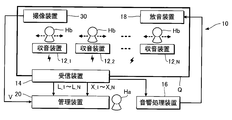
- FIG. 1 is a block diagram illustrating the configuration of an acoustic system 10 according to the first embodiment of the invention.
- the acoustic system 10 of the first embodiment includes N (N is a natural number) sound collecting devices 12_1 to 12_N, a receiving device 14, an acoustic processing device 16, and a sound emitting device 18.
- N is a natural number
- the acoustic system 10 is installed in a space Q (indoor or outdoor) such as a hall where an event such as a concert or lecture is held.
- the frequency band of the radio wave used by the sound collection device 12_n to transmit the acoustic signal X_n is set so that the N sound collection devices 12_1 to 12_N do not overlap each other.
- FIG. 2 is a block diagram illustrating the configuration of one arbitrary sound collection device 12_n. As illustrated in FIG. 2, each sound collection device 12_n collects surrounding sound and generates an acoustic signal X_n corresponding to the sound, and an acoustic signal X_n generated by the sound collection unit 122. And a transmitter 124 that transmits a radio wave modulated digitally or analogly.
- the specific form of the sound collection device 12_n is arbitrary, but for example, a body pack type in which a sound collection unit 122 and a transmission unit 124 configured separately from each other are connected by wire or wirelessly, or a user
- a hand-held type in which the sound collection unit 122 and the transmission unit 124 are accommodated in a single case that can be gripped by the user is suitable.
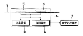
- FIG. 3 is a block diagram illustrating the configuration of the receiving device 14.
- the reception device 14 of the first embodiment includes a plurality of antennas 142 that receive radio waves from each of the N sound collection devices 12_1 to 12_N, a demodulation device 144, and a measurement device 146. It has.
- the plurality of antennas 142 are installed in the space Q.
- the demodulator 144 can demodulate the N systems of acoustic signals X_1 to X_N from the radio waves received by the plurality of antennas 142 based on, for example, radio waves in good reception for each channel.
- the receiving device 14 may automatically select a radio wave having a good reception state, or may be manually selected by a user.
- a plurality of radio waves may be selected for each channel, and one acoustic signal X_n may be demodulated from the selected plurality of radio waves.
- the measuring device 146 measures the intensity (hereinafter referred to as “radio wave intensity”) L_n of the radio wave received by the antenna 142 from each sound collecting device 12_n.
- the receiving device 14 of the first embodiment demodulates the acoustic signal X_n and the radio wave intensity L_n for each of the N channels corresponding to the N different sound collecting devices 12_1 to 12_N. Make measurements.
- the acoustic signal X_n received by the receiving device 14 is supplied to the acoustic processing device 16.
- the 1 is a mixer that mixes N systems of acoustic signals X_1 to X_N supplied from the receiving device.
- a configuration in which the sound processing device 16 adjusts the volume or frequency characteristic of each acoustic signal X_n, or a configuration in which the sound processing device 16 imparts various acoustic effects to each acoustic signal X_n may be employed.
- the sound emitting device 18 (for example, a speaker) is installed in the space Q and reproduces sound represented by the acoustic signal processed by the acoustic processing device 16.
- the sound processing device 16 may further include a multitrack recorder that records and reproduces part or all of the sound signals X_1 to X_N.
- the radio wave abnormality point is a point where the sound collection device 12_n is located in a state where the intensity of the radio wave reaching the reception device 14 from the sound collection device 12_n is abnormal (insufficient or excessive).
- the management apparatus 20 illustrated in FIG. 1 is a computer system used by a user (hereinafter referred to as “manager”) Ha of the acoustic system 10 in order to grasp the radio wave abnormality point in the space Q.
- the management device 20 and the receiving device 14 can communicate with each other via, for example, a LAN (Local Area Network).
- LAN Local Area Network
- various information devices such as a personal computer can be used as the management device 20.
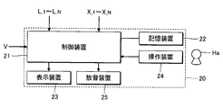
- FIG. 4 is a block diagram illustrating the configuration of the management apparatus 20.
- the management device 20 includes a control device 21, a storage device 22, a display device 23, an operation device 24, and a sound emission device 25.
- the control device 21 is a processing circuit including a CPU (Central Processing Unit), for example, and controls the entire management device 20 in an integrated manner.
- the storage device 22 is composed of a known recording medium such as a magnetic recording medium or a semiconductor recording medium, and stores a program executed by the control device 21 and various data used by the control device 21. Note that the storage device 22 may be realized by a plurality of recording media of the same type or different types.
- a storage device 22 (for example, cloud storage) separate from the management device 20 is prepared, and the control device 21 executes writing and reading to the storage device 22 via a mobile communication network or a communication network such as the Internet. May be. That is, the storage device 22 may be omitted from the management device 20.
- the display device 23 (for example, a liquid crystal display panel) displays various images under the control of the control device 21.
- the operation device 24 is an input device that receives an instruction from the administrator Ha. For example, a plurality of operators that can be operated by the administrator Ha or a touch panel that detects contact with the display surface of the display device 23 is preferably used as the operation device 24.
- the sound emitting device 25 includes, for example, an amplifier circuit and a speaker, and reproduces sound corresponding to the acoustic signal supplied from the control device 21.
- an imaging device 30 is connected to the management device 20.
- the imaging device 30 (for example, a USB camera or a web camera) is installed in the space Q, and generates an image signal V by imaging the inside of the space Q.
- the image signal V is a signal representing a moving image in the space Q.
- the imaging device 30 may be configured integrally with the management device 20.
- the management apparatus 20 operates in any one of the measurement mode and the evaluation mode.
- the administrator Ha can select either the measurement mode or the evaluation mode by operating the operation device 24.
- the measurement mode is an operation mode in which the radio wave intensity L_n is measured and recorded for each of the N channels, and the acoustic signal X_n and the image signal V are recorded.
- each of the N workers Hb carrying each sound pickup device 12 moves in the space Q, and in parallel with the movement of the worker Hb.
- the reception device 14 measures the radio field intensity L_n of the radio wave received from the sound collection device 12_n for each of the N channels.
- the radio wave intensity L_n of each channel varies from moment to moment depending on the position of the sound pickup device 12_n due to reflection and interference of radio waves in the space Q. For example, when the sound pickup device 12_n moves to a radio wave abnormality point in the space Q, the radio wave intensity L_n rapidly increases or decreases.
- the management device 20 also records the acoustic signal X_n and the image signal V under the above-described situation in which N workers Hb move in the space Q. That is, the acoustic signal X_n and the image signal V are recorded in parallel with the recording of each radio wave intensity L_n.
- each worker Hb moves while pronouncing words (for example, words such as “stage right back” and “stage center”) representing his / her position in the space Q. That is, the sound of the portion corresponding to an arbitrary time point in the time change of the radio wave intensity L_n in the acoustic signal X_n represents the position of the sound collecting device 12_n at the time point.
- the administrator can confirm the state (for example, position) of the sound pickup device 12_n at the point in time in the space Q. .
- the evaluation mode is an operation mode that is selected after the operation in the measurement mode described above, and the administrator Ha investigates the presence or absence of radio wave abnormal points in the space Q using the measurement results in the measurement mode. Or it is the operation mode for confirmation. Specifically, by listening to the sound of the portion corresponding to an arbitrary time point in the time change of the radio wave intensity L_n in the acoustic signal X_n, or by viewing the image of the portion corresponding to the time point in the image signal V. The administrator Ha can grasp the position of the worker Hb at that time (the position of the sound collection device 12_n).
- the administrator Ha can grasp the position of the radio wave abnormality point in the space Q by listening to the sound of the portion corresponding to the time point when the radio wave intensity L_n of the acoustic signal X_n decreases. Further, by visually recognizing the image of the portion corresponding to the time point when the radio wave intensity L_n of the image signal V decreases, the administrator Ha can grasp the position of the point where the radio wave intensity L_n decreases in the space Q. It is.
- the administrator Ha appropriately adjusts the frequency band of the radio wave transmitted by each sound collection device 12_n or the position and direction of the antenna 142, It is possible to eliminate or reduce radio wave abnormal points in the space Q.
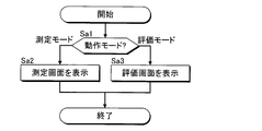
- FIG. 5 is a flowchart of processing executed by the control device 21 for selecting an operation mode.
- the process of FIG. 5 is started when the administrator Ha instructs selection of an operation mode by an operation on the operation device 24.
- the control device 21 determines the operation mode selected by the administrator Ha (Sa1).
- the control device 21 displays the measurement screen Ga of FIG. 6 on the display device 23 (Sa2).
- the control device 21 displays the evaluation screen Gb of FIG. 10 on the display device 23 (Sa3).
- the operation in each of the measurement mode and the evaluation mode will be described in detail below, focusing on the image displayed on the display device 23.
- ⁇ Measurement mode> As illustrated in FIG. 6, when the measurement mode is selected, the measurement screen Ga including the operation area 42, the recording area 44, the recording area 46, and the adjustment area 48 is displayed on the display device 23.
- the administrator Ha can operate each element in the measurement screen Ga using the operation device 24.
- the operation area 42 includes an operator for the administrator Ha to instruct the start and stop of recording of each radio wave intensity L_n. Specifically, the operation area 42 includes an operation element 422 for the administrator Ha to instruct the start of recording of each radio wave intensity L_n, and an operation for the administrator Ha to instruct the end of recording of each radio wave intensity L_n. And a child 424.
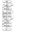
- FIG. 7 is a flowchart of processing executed by the control device 21 for recording each radio wave intensity L_n in the measurement mode.
- the processing of FIG. 7 is executed under the situation where each worker Hb carrying the sound collection device 12_n moves in the space Q.
- the control device 21 determines whether or not the start of recording has been instructed, that is, whether or not the operation element 422 has been operated (Sb1).
- the control device 21 instructs the receiving device 14 to start recording of the radio wave strengths L_1 to L_N in the N channels (Sb2).
- the receiving device 14 may always measure the radio field strengths L_1 to L_N. In this case, in step Sb2, the reception device 14 is instructed not to start measurement but to start transmission of radio field intensity.
- the receiving device 14 When the start of measurement is instructed from the management device 20, the receiving device 14 starts measuring the radio field intensity L_n of the radio waves received from each of the N sound collecting devices 12_1 to 12_N.
- the receiving device 14 (specifically, the measuring device 146) measures the N radio field intensities L_1 to L_N at a predetermined period and sequentially transmits them to the management device 20.
- the control device 21 of the management device 20 newly creates one intensity file in the storage device 22, acquires the N radio field strengths L_1 to L_N transmitted from the receiving device 14 (Sb3), and obtains the current time (ie, It is stored in the intensity file in the storage device 22 together with the measurement start time (Sb4).
- the control device 21 acquires the radio field intensity L_n of the radio wave received from the sound collection device 12_n by the reception device 14 in parallel with the movement of each sound collection device 12_n. That is, step Sb3 in FIG. 7 is an example of “acquisition step”.
- the control device 21 executes step Sb3 (an example of an acquisition process)
- the control device 21 functions as an acquisition unit that acquires the radio wave intensity L_n.
- the control device 21 determines whether or not the operation element 424 has been operated (Sb5). When the operator 424 is operated (Sb5: YES / strength recording stop instruction), the control device 21 instructs the receiving device 14 to end the measurement (Sb6). The receiving device 14 ends the measurement and transmission of the N radio field strengths L_1 to L_N according to the instruction from the management device 20. The control device 21 calculates the time length of the period during which the radio wave intensities L_1 to L_N of the N channels are measured (hereinafter referred to as “measurement period”) and stores it in the intensity file of the storage device 22 (Sb7).
- the measurement period of the first embodiment is a period from when the operating element 422 is operated to when the operating element 424 is operated. It should be noted that the processing may be shifted to step Sb1 after execution of step Sb7 to wait for the next intensity recording start instruction.
- the control device 21 shifts the processing to step Sb3. That is, until the administrator Ha operates the operation element 424, the control device 21 repeatedly acquires the N radio field strengths L_1 to L_N measured by the receiving device 14. Therefore, the time change of the radio field intensity L_n during the measurement period (that is, a time series in which a plurality of radio field intensity L_n is arranged) is stored in the intensity file of the storage device 22 for each of the N channels. Note that a period from when the operation element 422 is operated until a predetermined time elapses may be defined as a measurement period.
- the recording area 44 includes N unit areas U_1 to U_N corresponding to N different channels.
- One arbitrary unit area U_n is an area for the administrator Ha to instruct recording of the acoustic signal X_n of the nth channel.
- a channel number (CHn) and a frequency band (xx MHz), an intensity image 442 and a volume image 444, and an operator 446 (REC) are arranged.
- the intensity image 442 of the unit region U_n is a meter image (specifically, a bar graph indicating the radio wave intensity L_n) representing the radio wave intensity L_n measured by the receiving device 14 for the nth channel.
- the volume image 444 of the unit region U_n is a meter image (specifically, a bar graph) representing the volume of the acoustic signal X_n.
- An operator 446 in the unit area U_n is a software key for the administrator Ha to instruct the start and end of recording of the acoustic signal X_n. Each time the operation is performed by the administrator Ha, the operation element 446 is changed from one of the selected state and the released state to the other. The display state of the operation element 446 is different between the selected state and the released state.
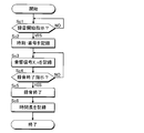
- FIG. 8 is a flowchart of processing executed by the control device 21 for recording the acoustic signal X_n in the measurement mode.
- the control device 21 determines whether any of the operators 446 in the N unit areas U_1 to U_N has been operated by the administrator Ha (Sc1).
- the control device 21 newly creates one audio file in the storage device 22.
- the current time (that is, the recording start time) and the channel number n are stored in the audio file in the storage device 22 (Sc2), and the acoustic signal X_n supplied from the receiving device 14 is recorded in the audio file.
- Start (Sc3).
- the adjustment area 48 in FIG. 6 includes two slider operators for the administrator Ha to adjust the recording level of the acoustic signal X_n.
- the control device 21 determines whether or not the operator 446 in the selected state has been operated by the administrator Ha (Sc4). When the administrator Ha does not operate the operation element 446 (Sc4: NO), the control device 21 proceeds to Step Sc3 and continues recording the acoustic signal X_n for the audio file. On the other hand, when the operator 446 transitions from the selected state to the released state by the operation of the administrator Ha (Sc4: YES / recording stop instruction), the control device 21 finishes recording the acoustic signal X_n for the audio file (Sc5).
- the acoustic signal X_n is stored in the audio file in the storage device 22 during the period in which the operation element 446 is in the selected state (hereinafter referred to as “recording period”).
- the control device 21 calculates the time length of the recording period in which the acoustic signal X_n is recorded, and adds it to the acoustic signal X_n of the storage device 22 (Sc6).
- the control device 21 records the acoustic signal X_n collected by the sound collecting device 12_n in parallel with the movement of the sound collecting device 12_n. That is, step Sc3 in FIG.
- Step 8 is an example of “recording step”.
- the control device 21 executes Step Sc3 (an example of a recording process)
- the control device 21 functions as a recording unit that records the acoustic signal X_n in the storage device 22. It should be noted that the processing may be shifted to step Sc1 after execution of step Sc6 and wait for the next recording start instruction.
- the control device 21 records each of the plurality of acoustic signals X_n corresponding to the unit area U_n in which the operation element 446 is selected in each audio file of the storage device 22 in parallel.
- the 6 includes an operator for the administrator Ha to instruct recording (that is, recording) of the image signal V.
- the recording area 46 includes an operation element 462 and an image area 464.
- the operation element 462 is a software key for the administrator Ha to instruct the start and end of recording of the image signal V generated by the imaging device 30. Similar to the operator 446, the operator 462 is changed from one of the selected state and the released state to the other for each operation by the administrator Ha.
- an image represented by the image signal V generated by the imaging device 30 is displayed in real time (so-called live view display).
- FIG. 9 is a flowchart of processing executed by the control device 21 for recording the image signal V in the measurement mode. The processing of FIG. 9 is executed in parallel with the operation of displaying the image of the image signal V supplied from the imaging device 30 in the image area 464.
- the control device 21 determines whether or not the operator 462 of the recording area 46 has been operated by the administrator Ha (Sd1). When the operation element 462 is operated to change from the released state to the selected state (Sd1: YES / recording start instruction), the control device 21 newly creates one image file in the storage device 22 and starts recording the current time. The time is stored in the image file of the storage device 22 (Sd2), and the operation of recording the image signal V supplied from the imaging device 30 in the image file is started (Sd3).
- the control device 21 determines whether or not the operation element 462 in the selected state has been operated (Sd4). When the operator 462 is not operated (Sd4: NO), the control device 21 proceeds to step Sd3 and continues recording the image signal V. On the other hand, when the operator 462 transitions from the selected state to the released state by the operation of the administrator Ha (Sd4: YES / recording stop instruction), the control device 21 ends the recording of the image signal V (Sd5). That is, the image signal V is stored in the storage device 22 during a period in which the operation element 462 is in a selected state (hereinafter referred to as “recording period”).
- the control device 21 calculates the time length of the recording period in which the image signal V is recorded and adds it to the image signal V (Sd6).
- the control device 21 records an image signal V representing an image obtained by photographing the location of the sound pickup device 12_n in parallel with the movement of the sound pickup device 12_n. That is, step Sd3 in FIG. 9 is an example of “recording step”.
- Step Sd3 an example of a recording process
- the control device 21 functions as a recording unit that records the image signal V in the storage device 22. Note that the processing may be shifted to step Sd1 after step Sd6 and the next recording start instruction may be awaited.
- the recording of the acoustic signal X_n (FIG. 8) or the recording of the image signal V (FIG. 9) can be executed in parallel with the acquisition of the N radio field strengths L_1 to L_N (FIG. 7). Specifically, the recording of the acoustic signal X_n or the recording of the image signal V is executed in at least a part of the measurement period in which each radio wave intensity L_n is recorded. Note that a configuration may be adopted in which the operation of the operation element 446 (instruction to start recording of the acoustic signal X_n) and the operation of the operation element 446 (instruction to start recording of the image signal V) are permitted only within the measurement period.
- the evaluation mode uses the result of the operation in the measurement mode described above (recording of the radio wave intensity L_n and recording of the acoustic signal X_n or the image signal V) to determine whether there is an abnormal point in the space Q.
- This is an operation mode for the administrator Ha to investigate.
- the control device 21 displays the evaluation screen Gb of FIG. 10 on the display device 23 (Sa3).
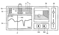
- the evaluation screen Gb includes a time area 52, a result area 54, an operation area 56, a reproduction area 58, and an adjustment area 60.
- the administrator Ha can operate each element in the evaluation screen Gb using the operation device 24.
- the time area 52 and the result area 54 are displayed for one channel (hereinafter referred to as “selected channel”) selected by the administrator Ha by the operation on the operation device 24 among the N channels.
- the time region 52 displays the measurement period Tl in which the radio field intensity L_n is recorded in the intensity file for the selected channel, and if there is an audio file in which the acoustic signal X_n is recorded for the selected channel and the measurement period T1. If there is an image file in which the image signal V is recorded, the recording period Tv is an image for displaying the recording period Tv on the same time axis as the radio wave intensity.
- the measurement period Tl is defined by the measurement start time recorded in step Sb4 in each intensity file and the time length recorded in step Sb7.
- the recording period Tx is defined by the recording start time recorded in step Sc3 and the time length recorded in step Sc6 in each audio file.
- the recording period Tv is defined by the recording start time recorded in step Sd2 in each image file and the time length recorded in step d6.
- a target range 522 is set in the time region 52.
- the target range 522 means a period on the time axis.
- the position and time length of the target range 522 on the time axis can be changed according to an instruction from the administrator Ha to the operation device 24.
- an image showing the time change of the radio wave intensity L_n recorded in the measurement mode for the selected channel is displayed.
- a graph representing a time series of the radio wave intensity L_n within the target range 522 is displayed in the result area 54 with the horizontal direction as a time axis.
- An indicator 542 is displayed in the result area 54 of the first embodiment.
- the indicator 542 is an image showing a specific time point (hereinafter referred to as “specific point”) P on the time axis with respect to the time change of the radio wave intensity L_n.
- specific point a broken line in the vertical direction perpendicular to the time axis is illustrated as the indicator 542.
- step Sa3 in FIG. 5 is an example of a display step for displaying the time change of the radio wave intensity L_n and the indicator 542 indicating the specific point P on the time axis. That is, when the control device 21 executes Step Sa3 (an example of display control processing), the control device 21 functions as a display control unit that causes the display device 23 to display the time change of the radio wave intensity L_n and the indicator 542. .
- the operation area 56 is an image for the administrator Ha to instruct the reproduction of the acoustic signal X_n or the image signal V.
- the operation area 56 includes an operation element 562 for the administrator Ha to instruct the start of reproduction of the sound signal X_n or the image signal V, and an operation element 564 for the administrator Ha to instruct the end of reproduction. It is comprised including.
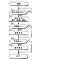
- FIG. 11 is a flowchart of processing executed by the control device 21 for reproducing audio or images in the evaluation mode.
- the control device 21 determines whether or not the operation element 562 is operated (Sf1).
- the control device 21 records the audio signal X_n of the selected channel at the specific point P indicated by the current-stage instruction element 542, or Then, an image file in which the image signal V is recorded is searched (Sf2).
- the search target in step Sf2 is not limited to the audio file recorded by the control device 21.
- the audio file recorded by another device can be included in the search target.
- the sound signal of each take of each channel n recorded by the multitrack recorder of the sound processing device 16 may be acquired as one sound file, and the sound file of each take may be included in the search range.
- individual audio files recorded by a portable recorder connected to the sound collecting device 12_n for channel n may be included in the search range.
- the time of the other device needs to be synchronized with the time of the control device 21 in advance by some method such as using a time server.
- the portion corresponding to the specific point P is searched for in the image signal V of the image file.
- An image (moving image) in a predetermined range for example, several seconds to several tens of seconds
- the administrator Ha can confirm the position of the sound collection device 12 at the specific point P by visually recognizing the image displayed on the display device 23.
- the image signal V is not recorded in any image file at the current specific point P (Sf3: NO)
- the reproduction of the image represented by the image signal V is not executed.
- control device 21 when the control device 21 executes step Sf4 (an example of the reproduction control process), the control device 21 causes the portion corresponding to the specific point P in the image signal V to be displayed on the display device 23. It functions as a playback control unit for display.
- the portion corresponding to the specific point P in the audio signal X_n of the audio file And the sound of the corresponding part is emitted by the sound emitting device 25 (Sf6). That is, of the N channels, the sound in a predetermined range (for example, several seconds to several tens of seconds) before and after the time corresponding to the specific point P for the selected channel in which the time change of the radio wave intensity L_n is displayed in the result area 54. Played.
- the administrator Ha can confirm the position of the sound collecting device 12 at the specific point P by listening to the sound emitted from the sound emitting device 25.
- the sound signal X_n of the selected channel is not recorded in any sound file at the specific point P at the current stage (Sf5: NO)
- the sound represented by the sound signal X_n is not reproduced.
- the adjustment area 60 in FIG. 10 is an image for adjusting the reproduction level of the acoustic signal X_n reproduced in step Sf6.
- the number of seconds before and after the specific point P from which the image or sound is reproduced may be fixed, or may be designated by the administrator Ha. Good.
- control device 21 when the control device 21 executes step Sf6 (an example of the reproduction control process), the control device 21 extracts the portion corresponding to the specific point P in the acoustic signal X_n as the sound emission device 25. It functions as a playback control unit that emits sound.
- the display device 23 and the sound emitting device 25 are specific examples of a reproducing device that reproduces (specifically, emits or displays) a portion corresponding to the specific point P in the acoustic signal X_n or the image signal V.
- the display of the image represented by the image signal V (Sf4) and the sound emission of the sound represented by the acoustic signal X_n (Sf6) are executed in parallel in different processes.
- a playback pointer indicating the current playback position of the image or sound may be displayed along with the time change of the radio wave intensity L_n displayed in the result area 54, and may be moved as the playback progresses. .
- the administrator Ha visually observes the time change of the radio wave intensity L_n displayed in the result area 54, and the radio wave intensity L_n is an abnormal value (sufficiently compared with an assumed range). Search for a point where the value is low or high.
- the administrator Ha moves the indicator 542 to the time point by operating the operation device 24. That is, the point in time when the radio wave intensity L_n becomes an abnormal value is designated as the specific point P by the administrator Ha.
- the administrator Ha operates the operation element 562
- an image of a portion of the image signal V corresponding to the time when the radio wave intensity L_n becomes an abnormal value is displayed in the reproduction area 58, and the acoustic signal X_n.
- the administrator Ha can specify the position of the radio wave abnormal point in the space Q. Specifically, before and after the time when the radio wave intensity L_n becomes an abnormal value, a point where the sound collecting device 12 of the selected channel is present in the image displayed by the display device 23 is specified as a radio wave abnormal point. In addition, before and after the time when the radio wave intensity L_n becomes an abnormal value, the point indicated by the sound emitted from the sound emitting device 25 is specified as the radio wave abnormal point.
- the recording of the radio wave intensity L_n and the recording of the acoustic signal X_n or the image signal V are performed in parallel with the movement of the sound collection device 12_n, and a specific change in the time change of the radio wave intensity is performed.
- the part of the sound or image corresponding to the time is played. That is, it is possible to evaluate the radio wave state (the position of the radio wave abnormal point) in the space Q by viewing audio or an image. Therefore, as compared with the technique of Non-Patent Document 1 in which it is necessary to confirm the position of the worker in parallel with the monitoring of the time variation of the reception intensity, the work load for confirming the radio wave state in the space Q is reduced. Is possible.
- the time change of the radio wave intensity L_n is displayed for any of the N channels, and the sound of the selected channel on which the time change of the radio wave intensity L_n is displayed is reproduced. Therefore, it is possible to selectively confirm the radio wave condition including the position of the radio wave abnormal point for a specific channel among the N channels assumed to be used in the acoustic system 10.
- the specific point P as the time point designated by the administrator Ha
- the relationship between the radio wave intensity L_n and the position of the sound pickup device 12_n at the desired time point of the administrator Ha It is possible to confirm.
- Second Embodiment A second embodiment of the present invention will be described.
- the configuration in which the administrator Ha designates the specific point P by operating the operation device 24 is exemplified.
- the control apparatus 21 of 2nd Embodiment designates the time according to the time change of the electromagnetic wave intensity L_n of a selection channel as the specific point P.
- FIG. about the element which an effect
- FIG. 12 is a flowchart of processing executed by the control device 21 for setting the specific point P and displaying the indicator 542 in step Sa3 (illustration of the display step) for displaying the evaluation screen Gb.
- the control device 21 sets the specific point P from the time change of the radio field intensity L_n of the selected channel (Sg1). Specifically, the time point at which the radio wave intensity L_n satisfies a predetermined condition is specified as the specific point P.
- FIG. 13 is an explanatory diagram of processing (Sg1) in which the control device 21 sets the specific point P.
- the control device 21 specifies the time point when the radio wave intensity L_n changes across the threshold as the specific point P. Specifically, the control device 21 specifies, as the specific point P, the point in time when the radio wave intensity L_n has increased from a value below the threshold L1 to a value above the threshold L1.
- the control device 21 identifies the specific point P when the radio wave intensity L_n has decreased from a value above the threshold L2 to a value below the threshold L2.
- the threshold value L2 is a predetermined value lower than the threshold value L1.
- the time point at which the radio wave intensity L_n becomes an abnormal value is specified as the specific point P.
- a plurality of specific points P can be specified within the measurement period Tl.
- the control device 21 displays the indicator 542 indicating the specific point P in the result area 54 as in the first embodiment (Sg2). Specifically, the control device 21 displays the indicator 542 at the position of the specific point P selected by the administrator Ha by the operation on the operation device 24 among the plurality of specific points P within the measurement period Tl.
- the administrator Ha appropriately selects the specific point P displayed in the result area 54 from a plurality of candidates by appropriately operating the operation device 24 (that is, the portion where the radio wave intensity L_n is an abnormal value). Cue) is possible.
- the operation of reproducing the sound of the portion corresponding to the specific point P indicated by the indicator 542 in the acoustic signal X_n (Sf6) and the image of the portion corresponding to the specific point P indicated by the indicator 542 of the image signal V are reproduced.
- the operation (Sf4) is the same as in the first embodiment. That is, when the administrator Ha operates the operation element 562 of the evaluation screen Gb, an image of a portion corresponding to the time point when the radio wave intensity L_n becomes an abnormal value in the image signal V is displayed in the reproduction area 58, and the acoustic signal X_n The sound of the part corresponding to the time when the radio wave intensity L_n becomes an abnormal value is emitted from the sound emitting device 25. Therefore, by viewing the image displayed on the display device 23 or the sound emitted from the sound emitting device 25, the administrator Ha can specify the position of the radio wave abnormal point in the space Q.
- the same effect as in the first embodiment is realized.
- the point in time at which the radio wave intensity L_n satisfies a predetermined condition is set as the specific point P, so that the administrator Ha does not need to search for the point in time when the radio wave intensity L_n becomes an abnormal value. Therefore, the effect of reducing the work load for checking the radio wave state in the space Q is particularly remarkable.
- the time point when the radio wave intensity L_n changes across the threshold is specified as the specific point P.
- the method of setting the specific point P according to the time change of the radio wave intensity L_n is not limited to the above examples. .
- a configuration in which the time point at which the radio wave intensity L_n becomes a maximum value exceeding the threshold value L1 is set as the specific point P, or a configuration in which the time point at which the radio wave intensity L_n becomes a minimum value below the threshold value L2 is set as the specific point P is also adopted. obtain.
- the image of the portion after the specific point P in the image signal V is reproduced.
- the portion to be reproduced in the image signal V is not limited to the above examples.
- an image of a portion after the time point ahead of the specific point P in the image signal V by a predetermined time may be reproduced. According to the above configuration, since the image in the space Q can be confirmed from the time point before the sound collection device 12 actually reaches the radio wave abnormality point, there is an advantage that the radio wave abnormality point can be identified accurately and easily.
- a configuration that reproduces an image of a portion corresponding to the specific point P in the image signal V is preferable, and from the viewpoint of confirming the sound collecting device 12 that is actually located at the radio wave abnormal point.
- a configuration that reproduces an image within a period including the specific point P is particularly suitable.
- the portion to be reproduced in the acoustic signal X_n is not limited to the portion after the specific point P.
- a portion of the audio signal X_n may be reproduced after a predetermined time from the specific point P for a predetermined time.
- the measurement of the radio field intensity (Sb2 to Sb4), the recording of the acoustic signal X_n (Sc3), and the recording of the image signal V (Sd3) are performed in accordance with instructions from the administrator Ha.
- the start time or trigger of each operation is not limited to the above examples.
- recording of the acoustic signal X_n and the image signal V may be started simultaneously with the start of the measurement of the radio wave intensity L_n. That is, the instruction to start recording the acoustic signal X_n or the image signal V can be omitted.
- the acoustic signal X_n or the image signal V is recorded for at least a part of the measurement period Tl of the radio wave intensity L_n (the recording period Tx, the recording period Tv).
- both the image signal V and the sound signal X_n are recorded and reproduced.
- only one of the image signal V and the sound signal X_n may be recorded and reproduced.
- the management device is realized by cooperation between the control device and the program.
- the program according to a preferred aspect of the present invention can be provided in a form stored in a computer-readable recording medium and installed in the computer.
- the recording medium is, for example, a non-transitory recording medium, and an optical recording medium (optical disk) such as a CD-ROM is a good example, but a known arbitrary one such as a semiconductor recording medium or a magnetic recording medium This type of recording medium can be included.
- the non-transitory recording medium includes an arbitrary recording medium excluding a transient propagation signal (transitory, “propagating signal”) and does not exclude a volatile recording medium.
- the program may be provided to the computer in the form of distribution via a communication network.
- the radio wave condition analysis method is the radio wave intensity of the radio wave received from the sound collection device by the reception device in parallel with the movement of the sound collection device that transmits the radio wave representing the acoustic signal. Is recorded in parallel with the movement of the sound collection device, and a time change of the radio wave intensity and an indicator indicating a specific time point in the time change are displayed. The portion corresponding to the specific time point is reproduced from the recorded acoustic signal.
- the acquisition of the radio wave intensity and the recording of the acoustic signal are performed in parallel with the movement of the sound collection device, and the sound corresponding to a specific time point in the time change of the radio wave intensity is reproduced.
- an image signal obtained by photographing a place where the sound collecting device is located is recorded in parallel with the movement of the sound collecting device, and the recorded sound is reproduced in the reproduction of the portion.
- a portion corresponding to the specific time point is reproduced.
- the acquisition of the radio wave intensity and the recording of the acoustic signal are performed in parallel with the movement of the sound collection device, and the sound corresponding to a specific time point in the time change of the radio wave intensity is reproduced.
- the plurality of sound collecting devices correspond to a plurality of channels
- the acquisition of the radio field intensity includes a plurality of channels.
- Radio wave intensity is acquired for each of the plurality of channels
- the acoustic signal is recorded for each of the plurality of channels
- the time change of the radio wave intensity and the indicator are displayed, the plurality of channels are acquired.
- the time change of the radio wave intensity is displayed, and in the reproduction of the portion, the sound signal of the channel on which the time change of the radio wave intensity is displayed is reproduced.
- the time change of the radio wave intensity is displayed for any of the plurality of channels, and the acoustic signal of the channel on which the time change of the radio wave intensity is displayed is reproduced. Therefore, in a situation where the use of a plurality of channels is assumed, it is possible to selectively confirm the radio wave condition including the position of the radio wave abnormal point for any of the plurality of channels.
- the user designates the time change of the radio wave intensity and the display of the indicator in the time change of the displayed radio wave intensity.
- the indicator is displayed with the time as the specific time.
- the acoustic signal is reproduced with the time specified by the user as the specific time. Therefore, it is possible to confirm the relationship between the radio wave intensity and the position of the sound collection device at a user's desired time.
- a time point at which the time change of the radio wave intensity satisfies a predetermined condition is detected in the time change of the radio wave intensity and the display of the indicator. Then, the indicator is displayed with the detected time as the specific time.
- the acoustic signal is reproduced with the time point corresponding to the time change of the radio wave intensity as the specific time point, for example, the user does not need to search for the time point when the radio wave intensity becomes an abnormal value. Therefore, the effect of reducing the work load for checking the radio wave condition is particularly remarkable.
- the acquisition of the radio field intensity is performed for a part of the period during which the radio field intensity is acquired. Independently records an acoustic signal, and in the reproduction of the portion, if the acoustic signal at the specific time is recorded, the acoustic signal is reproduced. If the acoustic signal is not recorded, the acoustic signal is reproduced. Do not perform playback.
- the acoustic signal is recorded for at least a part of the period during which the radio wave intensity is measured. Therefore, there is an advantage that an acoustic signal can be recorded during a period in which the necessity of confirming the radio wave state is particularly high in the period during which the radio wave intensity is measured.
- the radio wave state analysis method is the radio wave intensity of the radio wave received by the receiving device from the sound collecting device in parallel with the movement of the sound collecting device that transmits the radio wave representing the acoustic signal.
- an image signal obtained by photographing the place where the sound pickup device is recorded is recorded, and a time change of the radio wave intensity and an indicator indicating a specific time point in the time change are provided. A portion corresponding to the specific time point is reproduced from the recorded image signal.
- the acquisition of the radio wave intensity and the recording of the image signal are executed in parallel with the movement of the sound collection device, and an image of a part corresponding to a specific time point in the time change of the radio wave intensity is reproduced.
- the management device acquires the radio wave intensity of the radio wave received from the sound collection device by the reception device in parallel with the movement of the sound collection device that transmits the radio wave representing the acoustic signal.
- An acquisition unit that performs recording, a recording unit that records an acoustic signal collected by the sound collection device in parallel with the movement of the sound collection device, and a time change of the radio wave intensity and a specific time point in the time change.
- a display control unit that displays an indicator to be displayed on a display device, and a reproduction control unit that reproduces a reproduction device that reproduces a portion of the recorded acoustic signal corresponding to the specific time point.
- the program according to a preferred aspect (the ninth aspect) of the present invention acquires the radio wave intensity of the radio wave received from the sound collection device by the reception device in parallel with the movement of the sound collection device that transmits the radio wave representing the acoustic signal.
Landscapes
- Engineering & Computer Science (AREA)
- Signal Processing (AREA)
- Physics & Mathematics (AREA)
- Computer Networks & Wireless Communication (AREA)
- Electromagnetism (AREA)
- Quality & Reliability (AREA)
- Acoustics & Sound (AREA)
- Circuit For Audible Band Transducer (AREA)
Abstract
管理装置(20)は、音響信号(X_n)を表す電波を送信する収音装置(12_n)の移動に並行して受信装置(14)が収音装置(12_n)から受信した電波の電波強度(L_n)を取得し、収音装置(12_n)の移動に並行して当該収音装置(12_n)が収音した音響信号(X_n)を記録し、電波強度L_nの時間変化と当該時間変化における特定の時点を示す指示子とを表示し、記録した音響信号(X_n)のうち特定の時点に対応する部分を再生する。
Description
本発明は、音響信号を無線で収音装置から受信する受信装置が設置される場所の電波状態を解析する技術に関する。
音響信号を収音装置から無線で受信する受信装置を含む音響システム(ワイヤレスマイクロホンシステム)が従来から提案されている。音響システムが設置されるホール等の空間内には、電波の妨害、反射および干渉に起因して、受信装置に到達する電波の強度が異常(不足または過大)となる地点(以下「電波異常点」という)が発生し得る。収音装置が電波異常点に位置する場合には、収音装置から送信された音響信号が充分な強度で受信装置に到達しない状態、または、収音装置から受信装置に到達する電波の強度が高過ぎる状態となるから、音響システムの再生音に音切れまたは雑音が発生し得る。したがって、音響システムの使用時には空間内の電波異常点を事前に把握することが重要である。
以上の事情を背景として、例えば非特許文献1には、収音装置を携帯した作業者の移動に並行して受信装置による受信強度を測定し、受信強度の時間変化(RF History Plot)を表示装置に表示することが開示されている。時間軸上で受信強度が低下した時点で作業者が位置していた地点を電波異常点として把握することが可能である。
"AXIENT/WIRELESS MANAGEMENT NETWORK/SYSTEM GUIDE", Shure Incorporated,2013
非特許文献1の技術では、受信強度が低下した時点における作業者の位置を特定する必要がある。具体的には、受信強度の時間変化を視認することで強度低下の発生を監視しながら、作業者の位置を随時に確認する必要がある。したがって、電波状態(特に電波異常点の位置)を確認する作業の負荷が大きいという問題がある。以上の事情を考慮して、本発明の好適な態様は、収音装置と受信装置とが設置される場所での電波状態を確認する作業の負荷を軽減することを目的とする。
以上の課題を解決するために、本発明の好適な態様に係る電波状態解析方法は、音響信号を表す電波を送信する収音装置の移動に並行して受信装置が前記収音装置から受信した電波の電波強度を取得し、前記収音装置の移動に並行して当該収音装置が収音した音響信号を記録し、前記電波強度の時間変化と当該時間変化における特定の時点を示す指示子とを表示し、前記記録した前記音響信号のうち前記特定の時点に対応する部分を再生する。
また、本発明の好適な態様に係る管理装置は、音響信号を表す電波を送信する収音装置の移動に並行して受信装置が前記収音装置から受信した電波の電波強度を取得する取得部と、前記収音装置の移動に並行して当該収音装置が収音した音響信号を記憶装置に記録する記録部と、前記電波強度の時間変化と当該時間変化における特定の時点を示す指示子とを表示装置に表示させる表示制御部と、前記記録した前記音響信号のうち前記特定の時点に対応する部分を再生する再生装置に再生させる再生制御部とを具備する。
本発明の好適な態様に係るプログラムは、音響信号を表す電波を送信する収音装置の移動に並行して受信装置が前記収音装置から受信した電波の電波強度を取得する取得処理と、前記収音装置の移動に並行して当該収音装置が収音した音響信号を記録する記録処理と、前記電波強度の時間変化と当該時間変化における特定の時点を示す指示子とを表示装置に表示させる表示制御処理と、前記記録した前記音響信号のうち前記特定の時点に対応する部分を再生装置に再生させる再生制御処理とをコンピュータに実行させる。
また、本発明の好適な態様に係る管理装置は、音響信号を表す電波を送信する収音装置の移動に並行して受信装置が前記収音装置から受信した電波の電波強度を取得する取得部と、前記収音装置の移動に並行して当該収音装置が収音した音響信号を記憶装置に記録する記録部と、前記電波強度の時間変化と当該時間変化における特定の時点を示す指示子とを表示装置に表示させる表示制御部と、前記記録した前記音響信号のうち前記特定の時点に対応する部分を再生する再生装置に再生させる再生制御部とを具備する。
本発明の好適な態様に係るプログラムは、音響信号を表す電波を送信する収音装置の移動に並行して受信装置が前記収音装置から受信した電波の電波強度を取得する取得処理と、前記収音装置の移動に並行して当該収音装置が収音した音響信号を記録する記録処理と、前記電波強度の時間変化と当該時間変化における特定の時点を示す指示子とを表示装置に表示させる表示制御処理と、前記記録した前記音響信号のうち前記特定の時点に対応する部分を再生装置に再生させる再生制御処理とをコンピュータに実行させる。
<第1実施形態>
図1は、本発明の第1実施形態に係る音響システム10の構成を例示するブロック図である。図1に例示される通り、第1実施形態の音響システム10は、N個(Nは自然数)の収音装置12_1~12_Nと受信装置14と音響処理装置16と放音装置18とを具備するNチャンネルのワイヤレスマイクロホンシステムである。音響システム10は、演奏会または講演会等のイベントが開催されるホール等の空間Q(屋内または屋外)に設置される。
図1は、本発明の第1実施形態に係る音響システム10の構成を例示するブロック図である。図1に例示される通り、第1実施形態の音響システム10は、N個(Nは自然数)の収音装置12_1~12_Nと受信装置14と音響処理装置16と放音装置18とを具備するNチャンネルのワイヤレスマイクロホンシステムである。音響システム10は、演奏会または講演会等のイベントが開催されるホール等の空間Q(屋内または屋外)に設置される。
N個の収音装置12_1~12_Nの各々は、音声の波形を表す音響信号X_n(n=1~N)を収音(ピックアップ)し、当該音響信号X_nで変調された電波を無線により送信する携帯型のワイヤレスマイクロホンである。収音装置12_nが音響信号X_nの送信に使用する電波の周波数帯域は、N個の収音装置12_1~12_Nについて相互に重複しないように設定される。
図2は、任意の1個の収音装置12_nの構成を例示するブロック図である。図2に例示される通り、各収音装置12_nは、周囲の音声を収音して当該音声に対応した音響信号X_nを生成する収音部122と、収音部122が生成した音響信号X_nをデジタル的またはアナログ的に変調した電波を送信する送信部124とを含んで構成される。収音装置12_nの具体的な形態は任意であるが、例えば、相互に別体で構成された収音部122と送信部124とが有線または無線で接続されたボディパック型、または、利用者が把持可能な単体の筐体に収音部122と送信部124とを収容したハンドヘルド型が好適である。
図1の受信装置14は、N個の収音装置12_1~12_Nの各々が送信した電波を受信する。図3は、受信装置14の構成を例示するブロック図である。第1実施形態の受信装置14は、図3に例示される通り、N個の収音装置12_1~12_Nの各々からの電波を受信する複数のアンテナ142と、復調装置144および測定装置146とを具備する。複数のアンテナ142は空間Q内に設置される。復調装置144は、複数のアンテナ142が受信した電波から、例えばチャンネル毎に受信状態が良好な電波に基づいてN系統の音響信号X_1~X_Nを復調することが可能である。なお、電波の受信状態が良好であるとは、受信強度が高い、ノイズが少ない、安定度が高い等を意味する。受信装置14が、受信状態が良好な電波を自動的に選択するようにしてもよいし、利用者が手動で選択するようにしてもよい。チャンネル毎に複数の電波を選択して、選択した複数の電波からひとつの音響信号X_nを復調してもよい。
測定装置146は、各収音装置12_nからアンテナ142が受信した電波の強度(以下「電波強度」という)L_nを測定する。以上の説明から理解される通り、第1実施形態の受信装置14は、相異なるN個の収音装置12_1~12_Nに対応するN個のチャンネルの各々について音響信号X_nの復調と電波強度L_nの測定とを実行する。受信装置14が受信した音響信号X_nは音響処理装置16に供給される。
図1の音響処理装置16は、受信装置14から供給されるN系統の音響信号X_1~X_Nを混合するミキサである。音響処理装置16が各音響信号X_nの音量もしくは周波数特性を調整する構成、または、音響処理装置16が各音響信号X_nに各種の音響効果を付与する構成も採用され得る。放音装置18(例えばスピーカ)は、空間Q内に設置され、音響処理装置16による処理後の音響信号が表す音声を再生する。音響処理装置16は、さらに、音響信号X_1~X_Nの一部または全部を録音および再生するマルチトラックレコーダを含んでいてもよい。
ところで、収音装置12_nから送信された電波の障害物による妨害、壁面での反射、または複数の反射波による干渉等の様々な要因に起因して、空間Q内には電波異常点(例えばデッドポイント等)が発生し得る。電波異常点は、収音装置12_nから受信装置14に到達する電波の強度が異常(不足または過大)となる状態において、当該収音装置12_nが位置する地点である。図1に例示された管理装置20は、空間Q内の電波異常点を把握するために音響システム10の利用者(以下「管理者」という)Haが使用するコンピュータシステムである。管理装置20と受信装置14とは、例えばLAN(Local Area Network)を介して相互に通信可能である。例えばパーソナルコンピュータ等の各種の情報機器が管理装置20として利用され得る。
図4は、管理装置20の構成を例示するブロック図である。図4に例示される通り、管理装置20は、制御装置21と記憶装置22と表示装置23と操作装置24と放音装置25とを具備する。制御装置21は、例えばCPU(Central Processing Unit)を含む処理回路であり、管理装置20の全体を統括的に制御する。記憶装置22は、例えば磁気記録媒体または半導体記録媒体等の公知の記録媒体で構成され、制御装置21が実行するプログラムと制御装置21が使用する各種のデータとを記憶する。なお、同種または異種の複数の記録媒体で記憶装置22を実現してもよい。なお、管理装置20とは別体の記憶装置22(例えばクラウドストレージ)を用意し、移動体通信網またはインターネット等の通信網を介して制御装置21が記憶装置22に対する書込および読出を実行してもよい。すなわち、記憶装置22を管理装置20から省略してもよい。
表示装置23(例えば液晶表示パネル)は、制御装置21による制御のもとで各種の画像を表示する。操作装置24は、管理者Haからの指示を受付ける入力機器である。例えば、管理者Haが操作可能な複数の操作子、または、表示装置23の表示面に対する接触を検知するタッチパネルが、操作装置24として好適に利用される。放音装置25は、例えば増幅回路とスピーカとを含んで構成され、制御装置21から供給される音響信号に応じた音声を再生する。
図1に例示される通り、管理装置20には撮像装置30が接続される。撮像装置30(例えばUSBカメラまたはウェブカメラ)は、空間Q内に設置され、空間Qの内部を撮像することで画像信号Vを生成する。画像信号Vは、空間Q内の様子の動画像を表す信号である。なお、撮像装置30を管理装置20と一体に構成してもよい。
第1実施形態の管理装置20は、測定モードおよび評価モードの何れかの動作モードで動作する。管理者Haは、操作装置24を操作することで測定モードと評価モードの何れかを選択することが可能である。
測定モードは、N個のチャンネルの各々について電波強度L_nを測定および記録するとともに、音響信号X_nと画像信号Vとを記録する動作モードである。測定モードが選択された状態では、図1に例示される通り、各収音装置12を携帯したN人の作業者Hbの各々が空間Q内で移動し、作業者Hbの移動に並行して、受信装置14は、収音装置12_nから受信した電波の電波強度L_nをN個のチャンネルの各々について測定する。各チャンネルの電波強度L_nは、空間Q内での電波の反射および干渉に起因して、収音装置12_nの位置に応じて刻々と変動する。例えば、収音装置12_nが空間Q内の電波異常点に移動すると電波強度L_nは急激に上昇または低下する。
第1実施形態の測定モードにおいて、管理装置20では、N人の作業者Hbが空間Q内で移動する前述の状況のもとで音響信号X_nおよび画像信号Vの記録も実行される。すなわち、各電波強度L_nの記録に並行して、音響信号X_nおよび画像信号Vが記録される。例えば、各作業者Hbは、空間Q内における自身の位置を表す言葉(例えば「ステージ右奥」「ステージ中央」等の語句)を発音しながら移動する。すなわち、音響信号X_nのうち電波強度L_nの時間変化における任意の時点に対応する部分の音声は、当該時点における収音装置12_nの位置を表す。また、画像信号Vのうち電波強度L_nの時間変化における任意の時点に対応する部分の画像から、管理者は、空間Q内での当該時点における収音装置12_nの状態(例えば位置)を確認できる。
他方、評価モードは、以上に説明した測定モードによる動作後に選択される動作モードであり、測定モードでの測定の結果を利用して、空間Q内の電波異常点の有無を管理者Haが調査または確認するための動作モードである。具体的には、音響信号X_nのうち電波強度L_nの時間変化における任意の時点に対応する部分の音声を聴取し、または、画像信号Vのうち当該時点に対応する部分の画像を視認することで、管理者Haは、当該時点における作業者Hbの位置(収音装置12_nの位置)を把握することが可能である。例えば、音響信号X_nのうち電波強度L_nが低下した時点に対応する部分の音声を聴取することで、管理者Haは、空間Q内の電波異常点の位置を把握することが可能である。また、画像信号Vのうち電波強度L_nが低下した時点に対応する部分の画像を視認することで、管理者Haは、空間Q内で電波強度L_nが低下する地点の位置を把握することが可能である。評価モードで空間Q内に電波異常点が発見された場合、管理者Haは、各収音装置12_nが送信する電波の周波数帯域、または、アンテナ142の位置および方向を適宜に調整することで、空間Q内の電波異常点を解消ないし低減することが可能である。
図5は、動作モードの選択について制御装置21が実行する処理のフローチャートである。例えば、操作装置24に対する操作で管理者Haが動作モードの選択を指示した場合に図5の処理が開始される。図5に例示される通り、制御装置21は、管理者Haが選択した動作モードを判定する(Sa1)。管理者Haが測定モードを選択した場合、制御装置21は、図6の測定画面Gaを表示装置23に表示させる(Sa2)。他方、管理者Haが評価モードを選択した場合、制御装置21は、図10の評価画面Gbを表示装置23に表示させる(Sa3)。表示装置23が表示する画像に着目して、測定モードおよび評価モードの各々における動作を以下に詳述する。
<測定モード>
図6に例示される通り、測定モードが選択された場合には、操作領域42と録音領域44と録画領域46と調整領域48とを含む測定画面Gaが表示装置23に表示される。管理者Haは、操作装置24を利用して測定画面Ga内の各要素を操作することが可能である。
図6に例示される通り、測定モードが選択された場合には、操作領域42と録音領域44と録画領域46と調整領域48とを含む測定画面Gaが表示装置23に表示される。管理者Haは、操作装置24を利用して測定画面Ga内の各要素を操作することが可能である。
操作領域42は、各電波強度L_nの記録の開始と停止とを管理者Haが指示するための操作子を含む。具体的には、操作領域42は、各電波強度L_nの記録の開始を管理者Haが指示するための操作子422と、各電波強度L_nの記録の終了を管理者Haが指示するための操作子424とを含んで構成される。
図7は、測定モードにおける各電波強度L_nの記録について制御装置21が実行する処理のフローチャートである。収音装置12_nを携帯する各作業者Hbが空間Q内で移動する状況のもとで図7の処理が実行される。まず、制御装置21は、記録の開始が指示されたか否か、すなわち、操作子422が操作されたか否かを判定する(Sb1)。管理者Haが操作子422を操作すると(Sb1:YES/強度記録開始指示)、制御装置21は、N個のチャンネルにおける電波強度L_1~L_Nの記録開始を受信装置14に対して指示する(Sb2)。なお、受信装置14が電波強度L_1~L_Nを常時測定してもよい。その場合、ステップSb2では、測定の開始ではなく、電波強度の送信の開始が受信装置14に対して指示される。
管理装置20から測定開始が指示されると、受信装置14は、N個の収音装置12_1~12_Nの各々から受信した電波の電波強度L_nの測定を開始する。受信装置14(具体的には測定装置146)は、N個の電波強度L_1~L_Nを所定の周期で測定して管理装置20に順次に送信する。管理装置20の制御装置21は、記憶装置22に1個の強度ファイルを新規に作成し、受信装置14から送信されるN個の電波強度L_1~L_Nを取得し(Sb3)、現在時刻(すなわち測定開始時刻)とともに記憶装置22の強度ファイルに格納する(Sb4)。以上の説明から理解される通り、制御装置21は、各収音装置12_nの移動に並行して受信装置14が収音装置12_nから受信した電波の電波強度L_nを取得する。すなわち、図7のステップSb3は「取得ステップ」の例示である。制御装置21がステップSb3(取得処理の一例)を実行することで、制御装置21は、電波強度L_nを取得する取得部として機能する。
制御装置21は、操作子424が操作されたか否かを判定する(Sb5)。操作子424が操作された場合(Sb5:YES/強度記録停止指示)、制御装置21は、受信装置14に対して測定終了を指示する(Sb6)。受信装置14は、管理装置20からの指示に応じてN個の電波強度L_1~L_Nの測定および送信を終了する。制御装置21は、N個のチャンネルの電波強度L_1~L_Nが測定された期間(以下「測定期間」という)の時間長を算定して記憶装置22の強度ファイルに格納する(Sb7)。第1実施形態の測定期間は、操作子422が操作されてから操作子424が操作されるまでの期間である。なお、ステップSb7の実行後に処理をステップSb1に移行し、次の強度記録の開始指示を待機してもよい。
他方、操作子424が操作されていない場合(Sb5:NO)、制御装置21はステップSb3に処理を移行する。すなわち、管理者Haが操作子424を操作するまで、制御装置21は、受信装置14が測定したN個の電波強度L_1~L_Nを反復的に取得する。したがって、測定期間における電波強度L_nの時間変化(すなわち、複数の電波強度L_nを配列した時系列)が、N個のチャンネルの各々について記憶装置22の強度ファイルに記憶される。なお、操作子422の操作の時点から所定の時間が経過するまでの期間を測定期間として画定してもよい。
図6の録音領域44は、N個のチャンネルの何れかについて、管理者Haが、音響信号X_nの記録(すなわち録音)を指示するための操作子を含む。録音領域44は、相異なるN個のチャンネルに対応するN個の単位領域U_1~U_Nを包含する。任意の1個の単位領域U_nは、第n番目のチャンネルの音響信号X_nの記録を管理者Haが指示するための領域である。具体的には、各単位領域U_nには、チャンネルの番号(CHn)および周波数帯域(xx MHz)と、強度画像442および音量画像444と、操作子446(REC)とが配置される。単位領域U_nの強度画像442は、受信装置14が第n番目のチャンネルについて測定した電波強度L_nを表すメーター画像(具体的には電波強度L_nを表す棒グラフ)である。単位領域U_nの音量画像444は、音響信号X_nの音量を表すメーター画像(具体的には棒グラフ)である。単位領域U_nの操作子446は、音響信号X_nの記録の開始および終了を管理者Haが指示するためのソフトウェアキーである。管理者Haによる操作毎に、操作子446は選択状態および解除状態の一方から他方に変更される。選択状態と解除状態とでは操作子446の表示態様が相違する。
図8は、測定モードにおける音響信号X_nの記録について制御装置21が実行する処理のフローチャートである。制御装置21は、N個の単位領域U_1~U_Nの何れかの操作子446が、管理者Haにより操作されたか否かを判定する(Sc1)。任意の1個の単位領域U_nの操作子446が操作されて解除状態から選択状態に遷移すると(Sc1:YES/録音開始指示)、制御装置21は、記憶装置22に1個の音声ファイルを新規に作成し、現在時刻(すなわち録音開始時刻)とチャンネルの番号nとを記憶装置22の音声ファイルに記憶し(Sc2)、受信装置14から供給される音響信号X_nを音声ファイルに記録する動作を開始する(Sc3)。図6の調整領域48は、管理者Haが音響信号X_nの録音レベルを調整するための2個のスライダー操作子を含む。
制御装置21は、選択状態にある操作子446が、管理者Haにより操作されたか否かを判定する(Sc4)。管理者Haが操作子446を操作しない場合(Sc4:NO)、制御装置21はステップSc3に処理を移行し、音声ファイルに対する音響信号X_nの記録を継続する。他方、管理者Haによる操作で操作子446が選択状態から解除状態に遷移した場合(Sc4:YES/録音停止指示)、制御装置21は、音声ファイルに対する音響信号X_nの記録を終了する(Sc5)。すなわち、操作子446が選択状態にある期間(以下「録音期間」という)内において音響信号X_nが記憶装置22の音声ファイルに格納される。音響信号X_nの記録を終了すると、制御装置21は、音響信号X_nを記録した録音期間の時間長を算定して記憶装置22の音響信号X_nに付加する(Sc6)。以上の説明から理解される通り、制御装置21は、収音装置12_nの移動に並行して収音装置12_nが収音した音響信号X_nを記録する。すなわち、図8のステップSc3は「記録ステップ」の例示である。制御装置21がステップSc3(記録処理の一例)を実行することで、制御装置21は、音響信号X_nを記憶装置22に記録する記録部として機能する。なお、ステップSc6の実行後に処理をステップSc1に移行し、次の録音開始指示を待機してもよい。
なお、管理者Haは、N個の単位領域U_nの各々における操作子446を、並行して2個まで選択状態に遷移させることが可能である。制御装置21は、操作子446が選択状態にある単位領域U_nに対応する複数の音響信号X_nの各々を並列に記憶装置22の各々の音声ファイルに記録する。
図6の録画領域46は、画像信号Vの記録(すなわち録画)を管理者Haが指示するための操作子を含む。録画領域46は、操作子462と画像領域464とを包含する。操作子462は、撮像装置30が生成した画像信号Vの記録の開始および終了を管理者Haが指示するためのソフトウェアキーである。操作子446と同様に、操作子462は、管理者Haによる操作毎に選択状態および解除状態の一方から他方に変更される。画像領域464には、撮像装置30が生成した画像信号Vが表す画像が実時間的に表示(いわゆるライブビュー表示)される。
図9は、測定モードにおける画像信号Vの記録について制御装置21が実行する処理のフローチャートである。撮像装置30から供給される画像信号Vの画像を画像領域464に表示させる動作に並行して図9の処理が実行される。
制御装置21は、録画領域46の操作子462が、管理者Haにより操作されたか否かを判定する(Sd1)。操作子462が操作されて解除状態から選択状態に遷移すると(Sd1:YES/録画開始指示)、制御装置21は、記憶装置22に1個の画像ファイルを新規に作成し、現在時刻を録画開始時刻として記憶装置22の画像ファイルに記憶し(Sd2)、撮像装置30から供給される画像信号Vを画像ファイルに記録する動作を開始する(Sd3)。
制御装置21は、選択状態にある操作子462が操作されたか否かを判定する(Sd4)。操作子462が操作されない場合(Sd4:NO)、制御装置21はステップSd3に処理を移行し、画像信号Vの記録を継続する。他方、管理者Haによる操作で操作子462が選択状態から解除状態に遷移した場合(Sd4:YES/録画停止指示)、制御装置21は、画像信号Vの記録を終了する(Sd5)。すなわち、操作子462が選択状態にある期間(以下「録画期間」という)内において画像信号Vが記憶装置22に格納される。画像信号Vの記録を終了すると、制御装置21は、画像信号Vを記録した録画期間の時間長を算定して画像信号Vに付加する(Sd6)。以上の説明から理解される通り、制御装置21は、収音装置12_nの移動に並行して収音装置12_nの場所を撮影した画像を表す画像信号Vを記録する。すなわち、図9のステップSd3は「記録ステップ」の例示である。制御装置21がステップSd3(記録処理の一例)を実行することで、制御装置21は、画像信号Vを記憶装置22に記録する記録部として機能する。なお、ステップSd6の実行後に処理をステップSd1に移行し、次の録音開始指示を待機してもよい。
測定モードにおいては、音響信号X_nの記録(図8)または画像信号Vの記録(図9)が、N個の電波強度L_1~L_Nの取得(図7)に並行して実行され得る。具体的には、各電波強度L_nが記録される測定期間のうち少なくとも一部の期間において音響信号X_nの記録または画像信号Vの記録が実行される。なお、操作子446の操作(音響信号X_nの記録の開始指示)と操作子446の操作(画像信号Vの記録の開始指示)とを測定期間内に限定して許可する構成も採用され得る。
<評価モード>
前述の通り、評価モードは、以上に説明した測定モードでの動作(電波強度L_nの記録および音響信号X_nまたは画像信号Vの記録)の結果を利用して空間Q内の電波異常点の有無を管理者Haが調査するための動作モードである。管理者Haが評価モードを選択すると、制御装置21は、図10の評価画面Gbを表示装置23に表示させる(Sa3)。図10に例示される通り、評価画面Gbは、時間領域52と結果領域54と操作領域56と再生領域58と調整領域60とを含んで構成される。管理者Haは、操作装置24を利用して評価画面Gb内の各要素を操作することが可能である。
前述の通り、評価モードは、以上に説明した測定モードでの動作(電波強度L_nの記録および音響信号X_nまたは画像信号Vの記録)の結果を利用して空間Q内の電波異常点の有無を管理者Haが調査するための動作モードである。管理者Haが評価モードを選択すると、制御装置21は、図10の評価画面Gbを表示装置23に表示させる(Sa3)。図10に例示される通り、評価画面Gbは、時間領域52と結果領域54と操作領域56と再生領域58と調整領域60とを含んで構成される。管理者Haは、操作装置24を利用して評価画面Gb内の各要素を操作することが可能である。
時間領域52および結果領域54は、N個のチャンネルのうち、操作装置24に対する操作で管理者Haが選択した1個のチャンネル(以下「選択チャンネル」という)について表示される。時間領域52は、選択チャンネルについて、強度ファイルに電波強度L_nが記録された測定期間Tlを表示し、さらに、選択チャンネルとその測定期間T1とについて、音響信号X_nが記録された音声ファイルがあれば、その録音期間Txを、画像信号Vが記録された画像ファイルがあれば、その録画期間Tvを、それぞれ電波強度と共通の時間軸のもとで表示する画像である。測定期間Tlは、各強度ファイルにステップSb4で記録された測定開始時刻とステップSb7で記録された時間長とにより画定される。録音期間Txは、各音声ファイルにステップSc3で記録された録音開始時刻とステップSc6で記録された時間長とにより規定される。録画期間Tvは、各画像ファイルにステップSd2で記録された録画開始時刻ととステップd6で記録された時間長とにより規定される。該当する音声ファイルまたは画像ファイルが複数ある場合、時間領域52には、それに応じて録音期間Txまたは録画期間Tvをそれぞれ複数表示する。
前述の通り、音響信号X_nの記録または画像信号Vの記録は、N個の電波強度L_1~L_Nの記録に並行して実行されるから、図10に例示される通り、1個以上の録音期間Txまたは1個以上の録画期間Tvとが、時間軸上で測定期間Tlと重複する。図10に例示される通り、時間領域52には対象範囲522が設定される。対象範囲522は、時間軸上の期間を意味する。対象範囲522の時間軸上の位置および時間長は、操作装置24に対する管理者Haからの指示に応じて変更され得る。
図10の結果領域54には、選択チャンネルについて測定モードで記録された電波強度L_nの時間変化を示す画像が表示される。具体的には、対象範囲522内における電波強度L_nの時系列を表すグラフが、横方向を時間軸として結果領域54内に表示される。また、第1実施形態の結果領域54には指示子542が表示される。指示子542は、電波強度L_nの時間変化について時間軸上の特定の時点(以下「特定点」という)Pを示す画像である。図10では、時間軸に直交する縦方向の破線が指示子542として例示されている。操作装置24に対する管理者Haからの指示に応じて、指示子542は時間軸の方向に移動する。すなわち、時間軸上における特定点Pの位置は管理者Haからの指示に応じて変更され得る。以上の説明から理解される通り、図5のステップSa3は、電波強度L_nの時間変化と時間軸上の特定点Pを示す指示子542とを表示する表示ステップの例示である。すなわち、制御装置21がステップSa3(表示制御処理の一例)を実行することで、制御装置21は、電波強度L_nの時間変化と指示子542とを表示装置23に表示させる表示制御部として機能する。
図10の再生領域58は、測定モードにおいて記録された画像信号Vが表す画像を表示するための領域である。また、操作領域56は、音響信号X_nまたは画像信号Vの再生を管理者Haが指示するための画像である。具体的には、操作領域56は、音響信号X_nまたは画像信号Vの再生の開始を管理者Haが指示するための操作子562と、再生の終了を管理者Haが指示するための操作子564とを含んで構成される。
図11は、評価モードにおける音声または画像の再生について制御装置21が実行する処理のフローチャートである。制御装置21は、操作子562が操作されたか否かを判定する(Sf1)。管理者Haが操作子562を操作すると(Sf1:YES/再生開始指示)、制御装置21は、現段階の指示子542が示す特定点Pについて選択チャンネルの音響信号X_nを記録した音声ファイル、または、画像信号Vを記録した画像ファイルを探索する(Sf2)。なお、ステップSf2での探索対象は、制御装置21で記録された音声ファイルに限定されない。例えば、音響信号とともにチャンネル番号nと録音開始時刻と時間長とが記録された音声ファイルであれば、他の装置で記録された音声ファイルも探索対象に含めることができる。例えば、音響処理装置16のマルチトラックレコーダで記録された各チャンネルnの各テイクの音響信号を、それぞれ1つの音声ファイルとして取得し、それら各テイクの音声ファイルを探索範囲に含めてもよい。また、チャンネルnの収音装置12_nに接続されたポータブルレコーダで録音した個々の音声ファイルを探索範囲に含めてもよい。なお、他の装置の時刻は、タイムサーバーを使う等の何らかの方法で、予め制御装置21の時刻と同期させる必要がある。
特定点Pについて画像信号Vが記憶装置22の何れかの画像ファイルに記録されている場合(Sf3:YES)、その画像ファイルの画像信号Vのうち特定点Pに対応する部分を探索して当該部分の前後の所定範囲(例えば数秒から数十秒)の画像(動画)を表示装置23に表示させる(Sf4)。したがって、管理者Haは、表示装置23が表示する画像を視認することで、特定点Pにおける収音装置12の位置を確認することが可能である。他方、現段階の特定点Pについて何れの画像ファイルにも画像信号Vが記録されていない場合(Sf3:NO)、画像信号Vが表す画像の再生は実行されない。以上の説明から理解される通り、制御装置21がステップSf4(再生制御処理の一例)を実行することで、制御装置21は、画像信号Vのうち特定点Pに対応する部分を表示装置23に表示させる再生制御部として機能する。
また、特定点Pについて選択チャンネルの音響信号X_nが記憶装置22の何れかの音声ファイルに記録されている場合(Sf5:YES)、その音声ファイルの音響信号X_nのうち特定点Pに対応する部分を探索して当該部分の音声を放音装置25に放音させる(Sf6)。すなわち、N個のチャンネルのうち、結果領域54に電波強度L_nの時間変化が表示された選択チャンネルについて、特定点Pに対応する時刻の前後の所定範囲(例えば数秒から数十秒)の音声が再生される。したがって、管理者Haは、放音装置25から放音される音声を聴取することで、特定点Pにおける収音装置12の位置を確認することが可能である。他方、現段階の特定点Pについて何れの音声ファイルにも選択チャンネルの音響信号X_nが記録されていない場合(Sf5:NO)、音響信号X_nが表す音声の再生は実行されない。図10の調整領域60は、ステップSf6で再生される音響信号X_nの再生レベルを調整するための画像である。なお、ステップSf4またはステップSf6において、画像または音声を、特定点Pの何秒前から何秒後まで再生するかは、固定であってもよいし、管理者Haがそれぞれ指定できるようにしてもよい。以上の説明から理解される通り、制御装置21がステップSf6(再生制御処理の一例)を実行することで、制御装置21は、音響信号X_nのうち特定点Pに対応する部分を放音装置25に放音させる再生制御部として機能する。表示装置23および放音装置25は、音響信号X_nまたは画像信号Vのうち特定点Pに対応する部分を再生(具体的には放音または表示)する再生装置の具体例である。
画像信号Vが表す画像の表示(Sf4)と、音響信号X_nが表す音声の放音(Sf6)とは、相異なるプロセスで並列に実行される。なお、結果領域54に表示された電波強度L_nの時間変化に、指示子542とは別に、画像または音声の現在の再生位置を示す再生ポインタを表示して、再生の進行とともに移動させてもよい。
実際に管理装置20を使用する場面では、管理者Haは、結果領域54に表示された電波強度L_nの時間変化を目視して、電波強度L_nが異常値(想定される範囲と比較して充分に低い数値または高い数値)となる時点を探索する。管理者Haは、操作装置24を操作することで指示子542を当該時点に移動する。すなわち、管理者Haにより、電波強度L_nが異常値となる時点が特定点Pとして指定される。以上の状態のもとで、管理者Haが操作子562を操作すると、画像信号Vのうち電波強度L_nが異常値となる時点に対応する部分の画像が再生領域58に表示され、音響信号X_nのうち電波強度L_nが異常値となる時点に対応する部分の音声が放音装置25から放音される。したがって、表示装置23が表示する画像または放音装置25が放音する音声を視聴することで、管理者Haは、空間Q内の電波異常点の位置を特定することが可能である。具体的には、電波強度L_nが異常値となる時点の前後において、表示装置23が表示する画像のなかで選択チャンネルの収音装置12が存在する地点が電波異常点として特定される。また、電波強度L_nが異常値となる時点の前後において、放音装置25から放音される音声が示す地点が電波異常点として特定される。
以上に説明した通り、第1実施形態では、電波強度L_nの記録と音響信号X_nまたは画像信号Vの記録とが収音装置12_nの移動に並行して実行され、電波強度の時間変化における特定の時点に対応する部分の音声または画像が再生される。すなわち、音声または画像を視聴することで、空間Q内での電波状態(電波異常点の位置)を評価することが可能である。したがって、受信強度の時間変化の監視に並行して作業者の位置を確認する必要がある非特許文献1の技術と比較して、空間Q内の電波状態を確認する作業の負荷を軽減することが可能である。
第1実施形態では、N個のチャンネルの何れかについて電波強度L_nの時間変化が表示され、電波強度L_nの時間変化が表示された選択チャンネルの音声が再生される。したがって、音響システム10において使用が想定されるN個のチャンネルのうち特定のチャンネルについて、電波異常点の位置を含む電波状態を選択的に確認することが可能である。また、第1実施形態では、管理者Haが指定した時点を特定点Pとして音声または画像が再生されるから、管理者Haの所望の時点について電波強度L_nと収音装置12_nの位置との関係を確認することが可能である。
<第2実施形態>
本発明の第2実施形態を説明する。第1実施形態では、操作装置24に対する操作で管理者Haが特定点Pを指定する構成を例示した。第2実施形態の制御装置21は、選択チャンネルの電波強度L_nの時間変化に応じた時点を特定点Pとして指定する。なお、以下に例示する各形態において作用または機能が第1実施形態と同様である要素については、第1実施形態の説明で使用した符号を流用して各々の詳細な説明を適宜に省略する。
本発明の第2実施形態を説明する。第1実施形態では、操作装置24に対する操作で管理者Haが特定点Pを指定する構成を例示した。第2実施形態の制御装置21は、選択チャンネルの電波強度L_nの時間変化に応じた時点を特定点Pとして指定する。なお、以下に例示する各形態において作用または機能が第1実施形態と同様である要素については、第1実施形態の説明で使用した符号を流用して各々の詳細な説明を適宜に省略する。
図12は、評価画面Gbを表示するステップSa3(表示ステップの例示)において、制御装置21が特定点Pの設定および指示子542の表示について実行する処理のフローチャートである。図12に例示される通り、制御装置21は、選択チャンネルの電波強度L_nの時間変化から特定点Pを設定する(Sg1)。具体的には、電波強度L_nが所定の条件を充足する時点が特定点Pとして特定される。
図13は、制御装置21が特定点Pを設定する処理(Sg1)の説明図である。図13から理解される通り、制御装置21は、電波強度L_nが閾値を跨いで変化する時点を特定点Pとして特定する。具体的には、制御装置21は、閾値L1を下回る数値から閾値L1を上回る数値に電波強度L_nが上昇した時点を特定点Pとして特定する。また、制御装置21は、閾値L2を上回る数値から閾値L2を下回る数値に電波強度L_nが低下した時点を特定点Pとして特定する。閾値L2は、閾値L1を下回る所定値である。以上の説明から理解される通り、電波強度L_nが異常値となる時点が特定点Pとして特定される。図13に例示される通り、測定期間Tl内には複数の特定点Pが特定され得る。
以上の処理で特定点Pを特定すると、制御装置21は、第1実施形態と同様に、特定点Pを示す指示子542を結果領域54内に表示させる(Sg2)。具体的には、制御装置21は、測定期間Tl内の複数の特定点Pのうち、操作装置24に対する操作で管理者Haが選択した特定点Pの位置に指示子542を表示させる。管理者Haは、操作装置24を適宜に操作することで、結果領域54内に表示される特定点Pを複数の候補から任意に選択すること(すなわち、電波強度L_nが異常値となる部分の頭出し)が可能である。
音響信号X_nのうち指示子542が示す特定点Pに対応する部分の音声を再生する動作(Sf6)、および、画像信号Vのうち指示子542が示す特定点Pに対応する部分の画像を再生する動作(Sf4)は、第1実施形態と同様である。すなわち、評価画面Gbの操作子562を管理者Haが操作すると、画像信号Vのうち電波強度L_nが異常値となる時点に対応する部分の画像が再生領域58に表示され、音響信号X_nのうち電波強度L_nが異常値となる時点に対応する部分の音声が放音装置25から放音される。したがって、表示装置23が表示する画像または放音装置25が放音する音声を視聴することで、管理者Haは、空間Q内の電波異常点の位置を特定することが可能である。
第2実施形態においても第1実施形態と同様の効果が実現される。また、第2実施形態では、電波強度L_nが所定の条件を充足する時点が特定点Pとして設定されるから、電波強度L_nが異常値となる時点を管理者Haが探索する必要がない。したがって、空間Q内の電波状態を確認する作業の負荷を軽減できるという効果は格別に顕著である。
なお、以上の説明では、電波強度L_nが閾値を跨いで変化する時点を特定点Pとして特定したが、電波強度L_nの時間変化に応じて特定点Pを設定する方法は以上の例示に限定されない。例えば、電波強度L_nが閾値L1を上回る極大値となる時点を特定点Pとして設定する構成、または、電波強度L_nが閾値L2を下回る極小値となる時点を特定点Pとして設定する構成も採用され得る。
<変形例>
以上に例示した各態様は多様に変形され得る。具体的な変形の態様を以下に例示する。以下の例示から任意に選択された2個以上の態様は、相互に矛盾しない範囲で適宜に併合され得る。
以上に例示した各態様は多様に変形され得る。具体的な変形の態様を以下に例示する。以下の例示から任意に選択された2個以上の態様は、相互に矛盾しない範囲で適宜に併合され得る。
(1)前述の各形態では、画像信号Vのうち特定点P以降の部分の画像を再生したが、画像信号Vのうち再生対象となる部分は以上の例示に限定されない。例えば、画像信号Vのうち特定点Pから所定の時間だけ前方の時点以降の部分の画像を再生してもよい。以上の構成によれば、収音装置12が実際に電波異常点に到達する以前の時点から空間Q内の画像を確認できるから、電波異常点を正確かつ容易に特定できるという利点がある。以上の説明から理解される通り、画像信号Vのうち特定点Pに対応する部分の画像を再生する構成が好適であり、実際に電波異常点に位置する収音装置12を確認する観点からは、特定点Pを内包する期間内の画像を再生する構成が格別に好適である。
同様に、音響信号X_nのうち再生対象となる部分は特定点P以降の部分に限定されない。例えば、音響信号X_nのうち特定点Pから所定の時間だけ前方の時点以降の部分の音声を再生してもよい。以上の構成によれば、収音装置12が実際に電波異常点に到達する以前の時点から空間Q内の音声を確認できるから、電波異常点を正確かつ容易に特定できるという利点がある。以上の説明から理解される通り、音響信号X_nのうち特定点Pに対応する部分の音声を再生する構成が好適であり、実際に電波異常点に位置する収音装置12を確認する観点からは、特定点Pを内包する期間内の音声を再生する構成が格別に好適である。
(2)前述の各形態では、電波強度の測定(Sb2~Sb4)と音響信号X_nの記録(Sc3)と画像信号Vの記録(Sd3)とが、管理者Haからの指示に応じた別個の時点で開始される場合を例示したが、各動作の開始の時点または契機は以上の例示に限定されない。例えば、電波強度L_nの測定の開始と同時に音響信号X_nおよび画像信号Vの記録を開始してもよい。すなわち、音響信号X_nまたは画像信号Vの記録開始の指示は省略され得る。なお、前述の各形態では、電波強度L_nの測定期間Tlのうち少なくとも一部の期間(録音期間Tx,録画期間Tv)について音響信号X_nまたは画像信号Vが記録されるから、測定期間Tlのうち電波状態の確認の必要性が特に高い期間について音響信号X_nまたは画像信号Vを記録できるという利点がある。
(3)前述の各形態では、画像信号Vおよび音響信号X_nの双方を記録および再生したが、画像信号Vおよび音響信号X_nの一方のみを記録および再生してもよい。
(4)前述の各形態で例示した通り、管理装置は、制御装置とプログラムとの協働で実現される。本発明の好適な態様に係るプログラムは、コンピュータが読取可能な記録媒体に格納された形態で提供されてコンピュータにインストールされ得る。記録媒体は、例えば非一過性(non-transitory)の記録媒体であり、CD-ROM等の光学式記録媒体(光ディスク)が好例であるが、半導体記録媒体または磁気記録媒体等の公知の任意の形式の記録媒体を包含し得る。なお、非一過性の記録媒体とは、一過性の伝搬信号(transitory, propagating signal)を除く任意の記録媒体を含み、揮発性の記録媒体を除外するものではない。また、通信網を介した配信の形態でプログラムをコンピュータに提供してもよい。
(5)以上に例示した形態から、例えば以下の態様が把握される。
本発明の好適な態様(第1態様)に係る電波状態解析方法は、音響信号を表す電波を送信する収音装置の移動に並行して受信装置が前記収音装置から受信した電波の電波強度を取得し、前記収音装置の移動に並行して当該収音装置が収音した音響信号を記録し、前記電波強度の時間変化と当該時間変化における特定の時点を示す指示子とを表示し、前記記録した前記音響信号のうち前記特定の時点に対応する部分を再生する。以上の態様では、電波強度の取得と音響信号の記録とが収音装置の移動に並行して実行され、電波強度の時間変化における特定の時点に対応する部分の音声が再生される。以上の構成では、再生される音声を聴取することで、電波異常点の位置を含む電波状態を確認することが可能である。したがって、電波強度の時間変化の監視に並行して作業者の位置を確認する必要がある非特許文献1の技術と比較して、電波状態を確認する作業の負荷を軽減することが可能である。
本発明の好適な態様(第1態様)に係る電波状態解析方法は、音響信号を表す電波を送信する収音装置の移動に並行して受信装置が前記収音装置から受信した電波の電波強度を取得し、前記収音装置の移動に並行して当該収音装置が収音した音響信号を記録し、前記電波強度の時間変化と当該時間変化における特定の時点を示す指示子とを表示し、前記記録した前記音響信号のうち前記特定の時点に対応する部分を再生する。以上の態様では、電波強度の取得と音響信号の記録とが収音装置の移動に並行して実行され、電波強度の時間変化における特定の時点に対応する部分の音声が再生される。以上の構成では、再生される音声を聴取することで、電波異常点の位置を含む電波状態を確認することが可能である。したがって、電波強度の時間変化の監視に並行して作業者の位置を確認する必要がある非特許文献1の技術と比較して、電波状態を確認する作業の負荷を軽減することが可能である。
第1態様の好適例(第2態様)では、前記収音装置の移動に並行して当該収音装置がある場所を撮影した画像信号を記録し、前記部分の再生において、前記記録した前記音響信号および前記画像信号の各々のうち前記特定の時点に対応する部分を再生する。以上の態様では、電波強度の取得と音響信号の記録とが収音装置の移動に並行して実行され、電波強度の時間変化における特定の時点に対応する部分の音声が再生される。以上の構成では、再生される画像を視認することで、電波異常点の位置を含む電波状態を確認することが可能である。
第1態様または第2態様の好適例(第3態様)では、前記収音装置は複数であり、複数の収音装置は複数のチャンネルに対応し、前記電波強度の取得においては、複数のチャンネルの各々について電波強度を取得し、前記音響信号の記録においては、前記複数のチャンネルの各々について前記音響信号を記録し、前記電波強度の時間変化および前記指示子の表示においては、前記複数のチャンネルの何れかについて前記電波強度の時間変化を表示し、前記部分の再生においては、前記電波強度の時間変化が表示されたチャンネルの音響信号を再生する。以上の態様では、複数のチャンネルの何れかについて電波強度の時間変化が表示され、電波強度の時間変化が表示されたチャンネルの音響信号が再生される。したがって、複数のチャンネルの利用が想定される状況において、複数のチャンネルのうちの何れかについて、電波異常点の位置を含む電波状態を選択的に確認することが可能である。
第1態様から第3態様の何れかの好適例(第4態様)では、前記電波強度の時間変化および前記指示子の表示においては、表示された前記電波強度の時間変化において利用者が指定した時点を前記特定の時点として前記指示子を表示する。以上の態様では、利用者が指定した時点を特定の時点として音響信号が再生される。したがって、利用者の所望の時点について電波強度と収音装置の位置との関係を確認することが可能である。
第1態様から第3態様の何れかの好適例(第5態様)では、前記電波強度の時間変化および前記指示子の表示においては、前記電波強度の時間変化が所定の条件を満たす時点を検出し、その検出された時点を前記特定の時点として前記指示子を表示する。以上の態様では、電波強度の時間変化に応じた時点を特定の時点として音響信号が再生されるから、例えば電波強度が異常値となる時点を利用者が探索する必要がない。したがって、電波状態を確認する作業の負荷を軽減できるという効果は格別に顕著である。
第1態様から第5態様の何れかの好適例(第6態様)では、前記音響信号の記録においては、前記電波強度が取得される期間の一部の期間内について、前記電波強度の取得とは独立して、音響信号を記録し、前記部分の再生においては、前記特定の時点における音響信号が記録されていれば、その音響信号を再生し、記録されていない場合には、前記音響信号の再生を実行しない。以上の態様では、電波強度が測定される期間のうち少なくとも一部の期間について音響信号が記録される。したがって、電波強度が測定される期間のうち電波状態の確認の必要性が特に高い期間について音響信号を記録できるという利点がある。
本発明の好適な態様(第7態様)に係る電波状態解析方法は、音響信号を表す電波を送信する収音装置の移動に並行して受信装置が前記収音装置から受信した電波の電波強度を取得し、前記収音装置の移動に並行して当該収音装置がある場所を撮影した画像信号を記録し、前記電波強度の時間変化と当該時間変化における特定の時点を示す指示子とを表示し、前記記録した前記画像信号のうち前記特定の時点に対応する部分を再生する。以上の態様では、電波強度の取得と画像信号の記録とが収音装置の移動に並行して実行され、電波強度の時間変化における特定の時点に対応する部分の画像が再生される。以上の構成では、再生される画像を視認することで、電波異常点の位置を含む電波状態を確認することが可能である。したがって、電波強度の時間変化の監視に並行して作業者の位置を確認する必要がある非特許文献1の技術と比較して、電波状態を確認する作業の負荷を軽減することが可能である。
本発明の好適な態様(第8態様)に係る管理装置は、音響信号を表す電波を送信する収音装置の移動に並行して受信装置が前記収音装置から受信した電波の電波強度を取得する取得部と、前記収音装置の移動に並行して当該収音装置が収音した音響信号を記憶装置に記録する記録部と、前記電波強度の時間変化と当該時間変化における特定の時点を示す指示子とを表示装置に表示させる表示制御部と、前記記録した前記音響信号のうち前記特定の時点に対応する部分を再生する再生装置に再生させる再生制御部とを具備する。
本発明の好適な態様(第9態様)に係るプログラムは、音響信号を表す電波を送信する収音装置の移動に並行して受信装置が前記収音装置から受信した電波の電波強度を取得する取得処理と、前記収音装置の移動に並行して当該収音装置が収音した音響信号を記録する記録処理と、前記電波強度の時間変化と当該時間変化における特定の時点を示す指示子とを表示装置に表示させる表示制御処理と、前記記録した前記音響信号のうち前記特定の時点に対応する部分を再生装置に再生させる再生制御処理とをコンピュータに実行させる。
10…音響システム、12_n(12_1~12_N)…収音装置、122…収音部、124…送信部、14…受信装置、142…アンテナ、144…復調装置、146…測定装置、16…音響処理装置、18…放音装置、20…管理装置、21…制御装置、22…記憶装置、23…表示装置、24…操作装置、25…放音装置、30…撮像装置、Ga…測定画面、Gb…評価画面。
Claims (9)
- 音響信号を表す電波を送信する収音装置の移動に並行して受信装置が前記収音装置から受信した電波の電波強度を取得し、
前記収音装置の移動に並行して当該収音装置が収音した音響信号を記録し、
前記電波強度の時間変化と当該時間変化における特定の時点を示す指示子とを表示し、
前記記録した前記音響信号のうち前記特定の時点に対応する部分を再生する
電波状態解析方法。 - 前記収音装置の移動に並行して当該収音装置がある場所を撮影した画像信号を記録し、
前記部分の再生においては、前記記録した前記音響信号および前記画像信号の各々のうち前記特定の時点に対応する部分を再生する
請求項1の電波状態解析方法。 - 前記収音装置は複数であり、複数の収音装置は複数のチャンネルに対応し、
前記電波強度の取得においては、前記複数のチャンネルの各々について電波強度を取得し、
前記音響信号の記録においては、前記複数のチャンネルの各々について前記音響信号を記録し、
前記電波強度の時間変化および前記指示子の表示においては、前記複数のチャンネルの何れかについて前記電波強度の時間変化を表示し、
前記部分の再生においては、前記電波強度の時間変化が表示されたチャンネルの音響信号を再生する
請求項1または請求項2の電波状態解析方法。 - 前記電波強度の時間変化および前記指示子の表示においては、表示された前記電波強度の時間変化において利用者が指定した時点を前記特定の時点として前記指示子を表示する
請求項1から請求項3の何れかの電波状態解析方法。 - 前記電波強度の時間変化および前記指示子の表示においては、前記電波強度の時間変化が所定の条件を満たす時点を検出し、その検出された時点を前記特定の時点として前記指示子を表示する
請求項1から請求項3の何れかの電波状態解析方法。 - 前記音響信号の記録においては、前記電波強度が取得される期間の一部の期間内について、前記電波強度の取得とは独立して、音響信号を記録し、
前記部分の再生においては、前記特定の時点における音響信号が記録されていれば、その音響信号を再生し、記録されていない場合には、前記音響信号の再生を実行しない
請求項1から請求項5の何れかの電波状態解析方法。 - 音響信号を表す電波を送信する収音装置の移動に並行して受信装置が前記収音装置から受信した電波の電波強度を取得し、
前記収音装置の移動に並行して当該収音装置がある場所を撮影した画像信号を記録し、
前記電波強度の時間変化と当該時間変化における特定の時点を示す指示子とを表示し、
前記記録した前記画像信号のうち前記特定の時点に対応する部分を再生する
電波状態解析方法。 - 音響信号を表す電波を送信する収音装置の移動に並行して受信装置が前記収音装置から受信した電波の電波強度を取得する取得部と、
前記収音装置の移動に並行して当該収音装置が収音した音響信号を記憶装置に記録する記録部と、
前記電波強度の時間変化と当該時間変化における特定の時点を示す指示子とを表示装置に表示させる表示制御部と、
前記記録した前記音響信号のうち前記特定の時点に対応する部分を再生する再生装置に再生させる再生制御部と
を具備する管理装置。 - 音響信号を表す電波を送信する収音装置の移動に並行して受信装置が前記収音装置から受信した電波の電波強度を取得する取得処理と、
前記収音装置の移動に並行して当該収音装置が収音した音響信号を記録する記録処理と、
前記電波強度の時間変化と当該時間変化における特定の時点を示す指示子とを表示装置に表示させる表示制御処理と、
前記記録した前記音響信号のうち前記特定の時点に対応する部分を再生装置に再生させる再生制御処理と
をコンピュータに実行させるプログラム。
Applications Claiming Priority (2)
| Application Number | Priority Date | Filing Date | Title |
|---|---|---|---|
| JP2017-031305 | 2017-02-22 | ||
| JP2017031305A JP2018137635A (ja) | 2017-02-22 | 2017-02-22 | 電波状態解析方法 |
Publications (1)
| Publication Number | Publication Date |
|---|---|
| WO2018155277A1 true WO2018155277A1 (ja) | 2018-08-30 |
Family
ID=63252592
Family Applications (1)
| Application Number | Title | Priority Date | Filing Date |
|---|---|---|---|
| PCT/JP2018/005045 Ceased WO2018155277A1 (ja) | 2017-02-22 | 2018-02-14 | 電波状態解析方法、管理装置およびプログラム |
Country Status (2)
| Country | Link |
|---|---|
| JP (1) | JP2018137635A (ja) |
| WO (1) | WO2018155277A1 (ja) |
Citations (5)
| Publication number | Priority date | Publication date | Assignee | Title |
|---|---|---|---|---|
| JPH0716441U (ja) * | 1993-08-31 | 1995-03-17 | 八重洲無線株式会社 | 多バンド無線通信機 |
| JP2003101488A (ja) * | 2001-09-20 | 2003-04-04 | Clarion Co Ltd | 無線品質測定装置 |
| JP2003283407A (ja) * | 2002-03-27 | 2003-10-03 | Hitachi Mobile Co Ltd | 移動体通信電界状況測定システム及び移動通信端末の性能検査方法。 |
| JP2004214757A (ja) * | 2002-12-27 | 2004-07-29 | Audio Technica Corp | 受信機の受信レベル表示方法およびその装置 |
| JP2006287709A (ja) * | 2005-04-01 | 2006-10-19 | Tamura Seisakusho Co Ltd | 駅用無線管理装置 |
-
2017
- 2017-02-22 JP JP2017031305A patent/JP2018137635A/ja active Pending
-
2018
- 2018-02-14 WO PCT/JP2018/005045 patent/WO2018155277A1/ja not_active Ceased
Patent Citations (5)
| Publication number | Priority date | Publication date | Assignee | Title |
|---|---|---|---|---|
| JPH0716441U (ja) * | 1993-08-31 | 1995-03-17 | 八重洲無線株式会社 | 多バンド無線通信機 |
| JP2003101488A (ja) * | 2001-09-20 | 2003-04-04 | Clarion Co Ltd | 無線品質測定装置 |
| JP2003283407A (ja) * | 2002-03-27 | 2003-10-03 | Hitachi Mobile Co Ltd | 移動体通信電界状況測定システム及び移動通信端末の性能検査方法。 |
| JP2004214757A (ja) * | 2002-12-27 | 2004-07-29 | Audio Technica Corp | 受信機の受信レベル表示方法およびその装置 |
| JP2006287709A (ja) * | 2005-04-01 | 2006-10-19 | Tamura Seisakusho Co Ltd | 駅用無線管理装置 |
Also Published As
| Publication number | Publication date |
|---|---|
| JP2018137635A (ja) | 2018-08-30 |
Similar Documents
| Publication | Publication Date | Title |
|---|---|---|
| US20210250713A1 (en) | Method and system for sound monitoring over a network | |
| US20150146874A1 (en) | Signal processing for audio scene rendering | |
| JP2017135539A (ja) | 収録データ処理方法 | |
| EP1093245B1 (en) | Method for testing car equipment having reception capabilities | |
| US12302137B2 (en) | Monitoring, analyzing and generating radio frequency (RF) environments utilizing distributed devices | |
| JP3920226B2 (ja) | 共鳴周波数検出方法、共鳴周波数選択方法、および、共鳴周波数検出装置 | |
| JP2014220741A (ja) | 通信システム、復調装置及び変調信号生成装置 | |
| JP7295732B2 (ja) | 音響測定装置およびプログラム | |
| WO2018155277A1 (ja) | 電波状態解析方法、管理装置およびプログラム | |
| US20150063070A1 (en) | Estimating distances between devices | |
| US8570368B2 (en) | Wireless audio transmission system, receiver, video camera and audio mixer | |
| US9300267B2 (en) | Digital gain control device and method for controlling an analog amplifier with a digital processor to prevent clipping | |
| US20170223453A1 (en) | First recording device, second recording device, recording system, first recording method, second recording method, first computer program product, and second computer program product | |
| WO2021255095A1 (en) | A sound output unit and a method of operating it | |
| JP4875530B2 (ja) | 無線通信システム | |
| JP6197662B2 (ja) | 残響時間解析装置 | |
| CN113514819B (zh) | 梯控主控模块安装位置确定方法、系统、装置及存储介质 | |
| KR20160103380A (ko) | 분할 대역 간섭 신호 제어 장치 및 방법 | |
| KR101241693B1 (ko) | 오디오 신호를 이용한 원격 제어 시스템 | |
| JP2652929B2 (ja) | 鉄道走行列車の騒音及び/又は振動の測定方法 | |
| JP6790817B2 (ja) | 電波状態解析方法 | |
| JP2016136357A (ja) | 情報提供システム | |
| JP3934545B2 (ja) | 超音波ドプラ診断装置 | |
| CN114286272A (zh) | 真无线耳机的时延测试系统、方法及相关装置 | |
| JP6881477B2 (ja) | 情報提供システム、情報提供方法およびプログラム |
Legal Events
| Date | Code | Title | Description |
|---|---|---|---|
| 121 | Ep: the epo has been informed by wipo that ep was designated in this application |
Ref document number: 18756895 Country of ref document: EP Kind code of ref document: A1 |
|
| NENP | Non-entry into the national phase |
Ref country code: DE |
|
| 122 | Ep: pct application non-entry in european phase |
Ref document number: 18756895 Country of ref document: EP Kind code of ref document: A1 |