WO2018150760A1 - Photoelectric conversion element, dye-sensitized solar cell, metal complex dye, dye composition, and oxide semiconductor electrode - Google Patents
Photoelectric conversion element, dye-sensitized solar cell, metal complex dye, dye composition, and oxide semiconductor electrode Download PDFInfo
- Publication number
- WO2018150760A1 WO2018150760A1 PCT/JP2018/000146 JP2018000146W WO2018150760A1 WO 2018150760 A1 WO2018150760 A1 WO 2018150760A1 JP 2018000146 W JP2018000146 W JP 2018000146W WO 2018150760 A1 WO2018150760 A1 WO 2018150760A1
- Authority
- WO
- WIPO (PCT)
- Prior art keywords
- group
- dye
- metal complex
- substituent
- alkyl group
- Prior art date
Links
Images

Classifications
-
- C—CHEMISTRY; METALLURGY
- C09—DYES; PAINTS; POLISHES; NATURAL RESINS; ADHESIVES; COMPOSITIONS NOT OTHERWISE PROVIDED FOR; APPLICATIONS OF MATERIALS NOT OTHERWISE PROVIDED FOR
- C09B—ORGANIC DYES OR CLOSELY-RELATED COMPOUNDS FOR PRODUCING DYES, e.g. PIGMENTS; MORDANTS; LAKES
- C09B23/00—Methine or polymethine dyes, e.g. cyanine dyes
- C09B23/14—Styryl dyes
- C09B23/145—Styryl dyes the ethylene chain carrying an heterocyclic residue, e.g. heterocycle-CH=CH-C6H5
-
- H—ELECTRICITY
- H01—ELECTRIC ELEMENTS
- H01G—CAPACITORS; CAPACITORS, RECTIFIERS, DETECTORS, SWITCHING DEVICES OR LIGHT-SENSITIVE DEVICES, OF THE ELECTROLYTIC TYPE
- H01G9/00—Electrolytic capacitors, rectifiers, detectors, switching devices, light-sensitive or temperature-sensitive devices; Processes of their manufacture
- H01G9/20—Light-sensitive devices
- H01G9/2059—Light-sensitive devices comprising an organic dye as the active light absorbing material, e.g. adsorbed on an electrode or dissolved in solution
- H01G9/2063—Light-sensitive devices comprising an organic dye as the active light absorbing material, e.g. adsorbed on an electrode or dissolved in solution comprising a mixture of two or more dyes
-
- C—CHEMISTRY; METALLURGY
- C09—DYES; PAINTS; POLISHES; NATURAL RESINS; ADHESIVES; COMPOSITIONS NOT OTHERWISE PROVIDED FOR; APPLICATIONS OF MATERIALS NOT OTHERWISE PROVIDED FOR
- C09B—ORGANIC DYES OR CLOSELY-RELATED COMPOUNDS FOR PRODUCING DYES, e.g. PIGMENTS; MORDANTS; LAKES
- C09B57/00—Other synthetic dyes of known constitution
- C09B57/008—Triarylamine dyes containing no other chromophores
-
- C—CHEMISTRY; METALLURGY
- C09—DYES; PAINTS; POLISHES; NATURAL RESINS; ADHESIVES; COMPOSITIONS NOT OTHERWISE PROVIDED FOR; APPLICATIONS OF MATERIALS NOT OTHERWISE PROVIDED FOR
- C09B—ORGANIC DYES OR CLOSELY-RELATED COMPOUNDS FOR PRODUCING DYES, e.g. PIGMENTS; MORDANTS; LAKES
- C09B57/00—Other synthetic dyes of known constitution
- C09B57/10—Metal complexes of organic compounds not being dyes in uncomplexed form
-
- H—ELECTRICITY
- H01—ELECTRIC ELEMENTS
- H01G—CAPACITORS; CAPACITORS, RECTIFIERS, DETECTORS, SWITCHING DEVICES OR LIGHT-SENSITIVE DEVICES, OF THE ELECTROLYTIC TYPE
- H01G9/00—Electrolytic capacitors, rectifiers, detectors, switching devices, light-sensitive or temperature-sensitive devices; Processes of their manufacture
- H01G9/20—Light-sensitive devices
- H01G9/2022—Light-sensitive devices characterized by he counter electrode
-
- H—ELECTRICITY
- H01—ELECTRIC ELEMENTS
- H01G—CAPACITORS; CAPACITORS, RECTIFIERS, DETECTORS, SWITCHING DEVICES OR LIGHT-SENSITIVE DEVICES, OF THE ELECTROLYTIC TYPE
- H01G9/00—Electrolytic capacitors, rectifiers, detectors, switching devices, light-sensitive or temperature-sensitive devices; Processes of their manufacture
- H01G9/20—Light-sensitive devices
- H01G9/2027—Light-sensitive devices comprising an oxide semiconductor electrode
-
- H—ELECTRICITY
- H01—ELECTRIC ELEMENTS
- H01G—CAPACITORS; CAPACITORS, RECTIFIERS, DETECTORS, SWITCHING DEVICES OR LIGHT-SENSITIVE DEVICES, OF THE ELECTROLYTIC TYPE
- H01G9/00—Electrolytic capacitors, rectifiers, detectors, switching devices, light-sensitive or temperature-sensitive devices; Processes of their manufacture
- H01G9/20—Light-sensitive devices
- H01G9/2059—Light-sensitive devices comprising an organic dye as the active light absorbing material, e.g. adsorbed on an electrode or dissolved in solution
-
- H—ELECTRICITY
- H10—SEMICONDUCTOR DEVICES; ELECTRIC SOLID-STATE DEVICES NOT OTHERWISE PROVIDED FOR
- H10K—ORGANIC ELECTRIC SOLID-STATE DEVICES
- H10K85/00—Organic materials used in the body or electrodes of devices covered by this subclass
- H10K85/30—Coordination compounds
- H10K85/341—Transition metal complexes, e.g. Ru(II)polypyridine complexes
- H10K85/344—Transition metal complexes, e.g. Ru(II)polypyridine complexes comprising ruthenium
-
- H—ELECTRICITY
- H01—ELECTRIC ELEMENTS
- H01G—CAPACITORS; CAPACITORS, RECTIFIERS, DETECTORS, SWITCHING DEVICES OR LIGHT-SENSITIVE DEVICES, OF THE ELECTROLYTIC TYPE
- H01G9/00—Electrolytic capacitors, rectifiers, detectors, switching devices, light-sensitive or temperature-sensitive devices; Processes of their manufacture
- H01G9/20—Light-sensitive devices
- H01G9/2027—Light-sensitive devices comprising an oxide semiconductor electrode
- H01G9/2031—Light-sensitive devices comprising an oxide semiconductor electrode comprising titanium oxide, e.g. TiO2
-
- Y—GENERAL TAGGING OF NEW TECHNOLOGICAL DEVELOPMENTS; GENERAL TAGGING OF CROSS-SECTIONAL TECHNOLOGIES SPANNING OVER SEVERAL SECTIONS OF THE IPC; TECHNICAL SUBJECTS COVERED BY FORMER USPC CROSS-REFERENCE ART COLLECTIONS [XRACs] AND DIGESTS
- Y02—TECHNOLOGIES OR APPLICATIONS FOR MITIGATION OR ADAPTATION AGAINST CLIMATE CHANGE
- Y02E—REDUCTION OF GREENHOUSE GAS [GHG] EMISSIONS, RELATED TO ENERGY GENERATION, TRANSMISSION OR DISTRIBUTION
- Y02E10/00—Energy generation through renewable energy sources
- Y02E10/50—Photovoltaic [PV] energy
- Y02E10/542—Dye sensitized solar cells
-
- Y—GENERAL TAGGING OF NEW TECHNOLOGICAL DEVELOPMENTS; GENERAL TAGGING OF CROSS-SECTIONAL TECHNOLOGIES SPANNING OVER SEVERAL SECTIONS OF THE IPC; TECHNICAL SUBJECTS COVERED BY FORMER USPC CROSS-REFERENCE ART COLLECTIONS [XRACs] AND DIGESTS
- Y02—TECHNOLOGIES OR APPLICATIONS FOR MITIGATION OR ADAPTATION AGAINST CLIMATE CHANGE
- Y02E—REDUCTION OF GREENHOUSE GAS [GHG] EMISSIONS, RELATED TO ENERGY GENERATION, TRANSMISSION OR DISTRIBUTION
- Y02E10/00—Energy generation through renewable energy sources
- Y02E10/50—Photovoltaic [PV] energy
- Y02E10/549—Organic PV cells
Definitions
- the present invention relates to a photoelectric conversion element, a dye-sensitized solar cell, a metal complex dye, a dye composition, and an oxide semiconductor electrode.
- Photoelectric conversion elements are used in various photosensors, photocopiers, photoelectrochemical cells such as solar cells, and the like.
- Various methods such as a method using a metal, a method using a semiconductor, a method using an organic pigment or a dye, or a combination of these methods have been put to practical use for this photoelectric conversion element.
- a solar cell using non-depleting solar energy does not require fuel, and full-scale practical use is highly expected as it uses inexhaustible clean energy.
- silicon-based solar cells have been researched and developed for a long time, and are spreading due to the policy considerations of each country.
- silicon is an inorganic material, there is a limit to improving throughput and cost.
- Patent Document 1 discloses that two pyridine rings each have a 4-dialkylaminostyryl skeleton or a 4-diphenylaminostyryl skeleton, a 4,4′-dicarboxybipyridine ligand, two Dyes (such as D-1 to D-3) having isothiocyanate ligands are described.
- Patent Document 2 discloses that a bipyridine ligand or a 4-di- (4-di (n-butyl) aminophenyl) aminostyryl skeleton in which each of two pyridine rings has a 4-diphenylaminostyryl skeleton, Dyes (compound numbers 21, 56, etc.) are described having a 4′-dicarboxybipyridine ligand and two isothiocyanate ligands bonded in trans position to the metal ion.
- the performance required for photoelectric conversion elements and dye-sensitized solar cells has increased, as well as photoelectric conversion efficiency, heat resistance and durability to stably maintain the initial conversion efficiency even in a high temperature environment exceeding room temperature, Further improvement is desired.
- the present invention relates to a photoelectric conversion element and a dye-sensitized solar cell excellent in photoelectric conversion efficiency, external quantum efficiency in long wavelength light, and heat resistance durability, and metal complex dyes, dye compositions and oxide semiconductors used in these It is an object to provide an electrode.
- the present inventors provide a bipyridine ligand formed by bonding two pyridine rings having a specific substituent to a ring-constituting carbon atom at the 4-position with respect to a ring-constituting nitrogen atom, and a pyridine ring having a carboxyl group or a salt thereof.
- a metal complex dye having a bipyridine ligand formed by bonding two and two monodentate ligands is used in combination with geometric isomers of a six-coordinate complex structure, not only the photoelectric conversion efficiency, It has been found that both external quantum efficiency and heat durability in long wavelength light can be improved.
- a photoelectric conversion element having a conductive support, a photoreceptor layer containing an electrolyte, a charge transfer layer containing an electrolyte, and a counter electrode The photoelectric conversion element in which a photoreceptor layer has the semiconductor fine particle by which the metal complex dye represented by following formula (1) and the metal complex dye represented by following formula (2) were carry
- M represents a metal ion.
- R 1 and R 2 each independently represents an alkenyl group, an alkynyl group, an aryl group or a heteroaryl group.
- R P1 and R P2 each independently represent an alkyl group, an alkoxy group, an alkylthio group, an aryl group, a heteroaryl group, an amino group, or a halogen atom.
- n P1 and n P2 are each independently an integer of 0 to 3.
- X 1 and X 2 each independently represent a monodentate ligand.
- M 1 and M 2 each independently represent a proton, a metal cation, or a non-metal cation.
- R 1 and R 2 are each independently represented by any of the following formulas (3-1) to (3-4).
- R 3 to R 6 each independently represent a hydrogen atom, an alkyl group, an alkenyl group, an alkynyl group, an alkoxy group, an alkylthio group, an aryl group, a heteroaryl group, an amino group, or a halogen atom.
- R 7 to R 10 each independently represents an alkyl group, an alkenyl group, an alkynyl group, an alkoxy group, an alkylthio group, an aryl group, a heteroaryl group, an amino group, or a halogen atom.
- n 1 and n 3 are each independently an integer of 0 to 4, and n 2 and n 4 are each independently an integer of 0 to 2.
- X 3 and X 4 each independently represent a sulfur atom or an oxygen atom. * Shows the coupling
- X 1 and X 2 each independently represent an isothiocyanate group or a thiocyanate group.
- R 1 and R 2 are each independently represented by the following formula (4).
- L 1 represents a single bond or an ethenylene group.
- Ar 11 and Ar 12 are each independently selected from an aryl group having at least one substituent selected from the following substituent group S Ar , or an unsubstituted heteroaryl group or the following substituent group S Ar A heteroaryl group having at least one substituent is shown.
- the alkyl group is a linear alkyl group having 3 or more carbon atoms or a branched alkyl group.
- L 1 is an ethenylene group and the aryl group has a mono- or dialkylamino group as a substituent
- at least one alkyl group in the alkylamino group is a linear alkyl group having 5 or more carbon atoms, or It is a branched alkyl group.
- R 11 represents an alkyl group, an alkoxy group, an alkylthio group, an aryl group, a heteroaryl group, an amino group or a halogen atom.
- n 11 is an integer of 0 to 4. * Shows the coupling
- ⁇ Substituent group S Ar > Alkyl group, alkoxy group, aryloxy group, alkylthio group, arylthio group, aryl group, heteroaryl group, amino group, halogen atom or cyano group
- R 21 represents an alkyl group, an alkoxy group, an aryl group, a heteroaryl group or a halogen atom.
- R 21 represents a hydrogen atom, an alkyl group, an alkoxy group, an aryl group, a heteroaryl group or a halogen atom, and at least one of R 21 is an alkyl group, An alkoxy group, an aryl group, a heteroaryl group or a halogen atom is shown.
- the alkyl group is a linear alkyl group having 3 or more carbon atoms or a branched alkyl group. * A bond part with a nitrogen atom in Formula (4) is shown.
- ⁇ 6> The photoelectric conversion device according to any one of ⁇ 1> to ⁇ 5>, wherein the semiconductor fine particles carry a metal complex dye represented by the following formula (6).
- M represents a metal ion.
- R 1 to R 4 each independently represents an alkenyl group, an alkynyl group, an aryl group or a heteroaryl group.
- R P1 to R P4 each independently represents an alkyl group, an alkoxy group, an alkylthio group, an aryl group, a heteroaryl group, an amino group or a halogen atom.
- n P1 to n P4 are each independently an integer of 0 to 3.
- X 1 and X 2 each independently represent a monodentate ligand.
- a photoelectric conversion element having a conductive support, a photoreceptor layer containing an electrolyte, a charge transfer layer containing an electrolyte, and a counter electrode The photoelectric conversion element in which a photoreceptor layer has the semiconductor fine particle by which the metal complex pigment
- M represents a metal ion.
- R 1A and R 2A each independently represent a group represented by the following formula (4).
- R P1A and R P2A each independently represent an alkyl group, an alkoxy group, an alkylthio group, an aryl group, a heteroaryl group, an amino group, or a halogen atom.
- n P1A and n P2A are each independently an integer of 0 to 3.
- X 1A and X 2A each independently represent a monodentate ligand.
- M 1A and M 2A each independently represent a proton, a metal cation, or a non-metal cation.
- L 1 represents a single bond or an ethenylene group.
- Ar 11 and Ar 12 are each independently selected from an aryl group having at least one substituent selected from the following substituent group S Ar , or an unsubstituted heteroaryl group or the following substituent group S Ar A heteroaryl group having at least one substituent is shown.
- the alkyl group is a linear alkyl group having 3 or more carbon atoms or a branched alkyl group.
- L 1 is an ethenylene group and the aryl group has a mono- or dialkylamino group as a substituent
- at least one alkyl group in the alkylamino group is a linear alkyl group having 5 or more carbon atoms, or It is a branched alkyl group.
- R 11 represents an alkyl group, an alkoxy group, an alkylthio group, an aryl group, a heteroaryl group, an amino group or a halogen atom.
- n 11 is an integer of 0 to 4.
- ⁇ Substituent group S Ar > Alkyl group, alkoxy group, aryloxy group, alkylthio group, arylthio group, aryl group, heteroaryl group, amino group, halogen atom or cyano group
- ⁇ 8> The photoelectric conversion element according to any one of ⁇ 1> to ⁇ 7>, wherein a metal oxide film is provided on at least one surface of the conductive support and the semiconductor fine particles.
- ⁇ 9> A dye-sensitized solar cell including the photoelectric conversion element according to any one of ⁇ 1> to ⁇ 8>.
- a dye composition comprising a metal complex dye represented by the formula (1) and a metal complex dye represented by the following formula (2).
- M represents a metal ion.
- R 1 and R 2 each independently represents an alkenyl group, an alkynyl group, an aryl group or a heteroaryl group.
- R P1 and R P2 each independently represent an alkyl group, an alkoxy group, an alkylthio group, an aryl group, a heteroaryl group, an amino group, or a halogen atom.
- n P1 and n P2 are each independently an integer of 0 to 3.
- X 1 and X 2 each independently represent a monodentate ligand.
- M 1 and M 2 each independently represent a proton, a metal cation, or a non-metal cation.
- R 1 and R 2 are each independently represented by the following formula (4).
- L 1 represents a single bond or an ethenylene group.
- Ar 11 and Ar 12 are each independently selected from an aryl group having at least one substituent selected from the following substituent group S Ar , or an unsubstituted heteroaryl group or the following substituent group S Ar A heteroaryl group having at least one substituent is shown.
- the alkyl group is a linear alkyl group having 3 or more carbon atoms or a branched alkyl group.
- L 1 is an ethenylene group and the aryl group has a mono- or dialkylamino group as a substituent
- at least one alkyl group in the alkylamino group is a linear alkyl group having 5 or more carbon atoms, or It is a branched alkyl group.
- R 11 represents an alkyl group, an alkoxy group, an alkylthio group, an aryl group, a heteroaryl group, an amino group or a halogen atom.
- n 11 is an integer of 0 to 4. * Shows the coupling
- Substituent group S Ar > Alkyl group, alkoxy group, aryloxy group, alkylthio group, arylthio group, aryl group, heteroaryl group, amino group, halogen atom or cyano group
- M represents a metal ion.
- R 1 to R 4 each independently represents an alkenyl group, an alkynyl group, an aryl group or a heteroaryl group.
- R P1 to R P4 each independently represents an alkyl group, an alkoxy group, an alkylthio group, an aryl group, a heteroaryl group, an amino group or a halogen atom.
- n P1 to n P4 are each independently an integer of 0 to 3.
- X 1 and X 2 each independently represent a monodentate ligand.
- the total of metal cations and nonmetal cations are 0.
- An oxide semiconductor electrode comprising the dye composition according to any one of ⁇ 10> to ⁇ 14>.
- M represents a metal ion.
- R 1A and R 2A each independently represent a group represented by the following formula (4).
- R P1A and R P2A each independently represent an alkyl group, an alkoxy group, an alkylthio group, an aryl group, a heteroaryl group, an amino group, or a halogen atom.
- n P1A and n P2A are each independently an integer of 0 to 3.
- X 1A and X 2A each independently represent a monodentate ligand.
- M 1A and M 2A each independently represent a proton, a metal cation, or a non-metal cation.
- L 1 represents a single bond or an ethenylene group.
- Ar 11 and Ar 12 are each independently selected from an aryl group having at least one substituent selected from the following substituent group S Ar , or an unsubstituted heteroaryl group or the following substituent group S Ar A heteroaryl group having at least one substituent is shown.
- the alkyl group is a linear alkyl group having 3 or more carbon atoms or a branched alkyl group.
- L 1 is an ethenylene group and the aryl group has a mono- or dialkylamino group as a substituent
- at least one alkyl group in the alkylamino group is a linear alkyl group having 5 or more carbon atoms, or It is a branched alkyl group.
- R 11 represents an alkyl group, an alkoxy group, an alkylthio group, an aryl group, a heteroaryl group, an amino group or a halogen atom.
- n 11 is an integer of 0 to 4. * Represents a bond to the pyridine ring in formula (2A).
- Substituent group S Ar > Alkyl group, alkoxy group, aryloxy group, alkylthio group, arylthio group, aryl group, heteroaryl group, amino group, halogen atom or cyano group
- the double bond may be either E-type or Z-type in the molecule, or a mixture thereof.
- substituents linking groups, ligands, etc. (hereinafter referred to as substituents, etc.) indicated by a specific symbol or formula, or when a plurality of substituents etc. are specified simultaneously, there is no special notice.
- substituents linking groups, ligands, etc.
- substituents etc.
- each substituent it may be the same or different.
- the definition of the number of substituents and the like when a plurality of substituents and the like are close to each other (especially when they are adjacent to each other), they may be connected to each other to form a ring unless otherwise specified.
- rings such as alicyclic rings, aromatic rings, and heterocyclic rings may be further condensed to form a condensed ring.
- the display of a compound is used to mean not only the compound itself but also its salt and its ion. Moreover, it is the meaning including what changed a part of structure in the range which does not impair the effect of this invention. Furthermore, it is the meaning which may have arbitrary substituents in the range which does not impair the effect of this invention about the compound which does not specify substitution or unsubstituted. The same applies to substituents, linking groups and ligands.
- a numerical range represented by using “to” means a range including numerical values described before and after “to” as a lower limit value and an upper limit value.
- the present invention can provide a photoelectric conversion element and a dye-sensitized solar cell which are excellent in photoelectric conversion efficiency, external quantum efficiency in long wavelength light, and heat durability. Moreover, this invention can provide the metal complex pigment
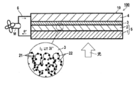
- FIG. 1 is a cross-sectional view schematically showing an enlarged view of a circular portion in a layer in a system in which the photoelectric conversion element according to the first aspect of the present invention is applied to a battery.
- FIG. 2 is a cross-sectional view schematically showing a dye-sensitized solar cell including the photoelectric conversion element according to the second aspect of the present invention.
- the photoelectric conversion element of the present invention has a conductive support, a photoreceptor layer containing an electrolyte, a charge transfer body layer containing an electrolyte, and a counter electrode (counter electrode).
- the photosensitive layer, the charge transfer layer, and the counter electrode are provided on the conductive support in this order.
- the semiconductor fine particles forming the photoreceptor layer are, as sensitizing dyes, a metal complex dye represented by formula (1) and a metal complex dye represented by formula (2), which will be described later. Or a metal complex dye represented by the formula (2A) to be described later.
- the term “metal complex dye” means a dye supported on semiconductor fine particles unless otherwise specified.
- the metal complex dye represented by Formula (1), the metal complex dye represented by Formula (2), the metal complex dye represented by Formula (2A), or two or more of these Means a combination of
- the aspect in which the metal complex dye is supported on the surface of the semiconductor fine particle is an aspect in which it is adsorbed on the surface of the semiconductor fine particle, an aspect in which the metal complex dye is deposited on the surface of the semiconductor fine particle, or an association or mutual interaction with the metal complex dye adsorbed on the surface of the semiconductor fine particle.
- Adsorption includes chemical adsorption and physical adsorption.
- the photoreceptor layer contains an electrolyte.
- the electrolyte contained in the photoreceptor layer is synonymous with the electrolyte that the charge transfer layer described later has, and preferred ones are also the same.
- the electrolyte contained in the photoreceptor layer may be the same as or different from the electrolyte of the charge transfer layer, but is preferably the same.
- the photoelectric conversion element of the present invention is not particularly limited in structure other than the structure defined in the present invention, and a known structure relating to the photoelectric conversion element can be adopted.
- Each of the layers constituting the photoelectric conversion element of the present invention is designed according to the purpose, and may be formed in a single layer or multiple layers, for example. Moreover, you may have layers other than said each layer if needed.
- the dye-sensitized solar cell of the present invention uses the photoelectric conversion element of the present invention.
- preferred embodiments of the photoelectric conversion element and the dye-sensitized solar cell of the present invention will be described.
- a system 100 shown in FIG. 1 is an application of the photoelectric conversion element 10 according to the first aspect of the present invention to a battery application in which an operation means M (for example, an electric motor) is caused to work by an external circuit 6.
- the photoelectric conversion element 10 includes a conductive support 1, semiconductor fine particles 22 sensitized by supporting a dye (metal complex dye) 21, and a photoreceptor layer 2 containing an electrolyte between the semiconductor fine particles 22, It consists of a charge transfer layer 3 that is a hole transport layer and a counter electrode 4.
- the photoreceptor layer 2 is also referred to as an oxide semiconductor electrode, in which a metal complex dye is adsorbed on the semiconductor fine particles 22.
- the light receiving electrode 5 has a conductive support 1 and a photoreceptor layer 2 and functions as a working electrode.
- the light incident on the photoreceptor layer 2 excites the metal complex dye 21.
- the excited metal complex dye 21 has high energy electrons, and the electrons are passed from the metal complex dye 21 to the conduction band of the semiconductor fine particles 22 and further reach the conductive support 1 by diffusion.
- the metal complex dye 21 is an oxidant (cation). While the electrons that have reached the conductive support 1 work in the external circuit 6, they reach the oxidant of the metal complex dye 21 via the counter electrode 4 and the charge transfer layer 3, and this oxidant is reduced.
- the system 100 functions as a solar cell.
- the dye-sensitized solar cell 20 shown in FIG. 2 is configured by the photoelectric conversion element of the second aspect of the present invention.
- the photoelectric conversion element used as the dye-sensitized solar cell 20 differs with respect to the photoelectric conversion element shown in FIG. Except for this point, the photoelectric conversion element 10 is configured in the same manner as the photoelectric conversion element 10 shown in FIG. That is, the conductive support 41 has a two-layer structure including a substrate 44 and a transparent conductive film 43 formed on the surface of the substrate 44.
- the photoreceptor layer 42 has a two-layer structure including a semiconductor layer 45 and a light scattering layer 46 formed adjacent to the semiconductor layer 45.
- the photoreceptor layer 42 is also referred to as an oxide semiconductor electrode, in which a metal complex dye is adsorbed on at least semiconductor fine particles forming the photoreceptor layer 42.
- a spacer S is provided between the conductive support 41 and the counter electrode 48.
- reference numeral 40 denotes a light receiving electrode
- 47 denotes a charge transfer body layer.
- the dye-sensitized solar cell 20 functions as a solar cell when light enters the photoreceptor layer 42 as in the system 100 to which the photoelectric conversion element 10 is applied.
- the photoelectric conversion element and the dye-sensitized solar cell of the present invention have excellent photoelectric conversion efficiency and long wavelength light both under irradiation of (pseudo) sunlight and under the irradiation of artificial light from a lighting device such as a fluorescent lamp.
- the external quantum efficiency and heat-resistant durability in are shown.
- the photoelectric conversion element and the dye-sensitized solar cell of the present invention have a light absorption capability in the long wavelength region as described later, and so on under irradiation of (pseudo) sunlight including light in the long wavelength region. , Photoelectric conversion efficiency, external quantum efficiency in long-wavelength light, and high heat resistance durability are improved.
- the photoelectric conversion element and the dye-sensitized solar cell of the present invention are not limited to the above-described preferred embodiments, and the configuration of each embodiment can be appropriately combined between the embodiments without departing from the gist of the present invention.
- materials and members used for the photoelectric conversion element or the dye-sensitized solar cell can be prepared by a usual method.
- the metal complex dye is adsorbed on the semiconductor fine particles in the following dye adsorption mode.
- dye represented by following formula (1) (henceforth a metal complex pigment
- the metal complex dye (2) may be a metal complex dye (2A) which is a preferable mode thereof.
- a second dye adsorption mode is a metal complex dye represented by the following formula (2A) (hereinafter sometimes referred to as metal complex dye (2A)).
- the metal complex dye (2A) and the metal complex dye (1) or the metal complex dye (6) can be used in combination. In this case, the dye is classified into the first dye adsorption mode.
- dye (2A) can also be used together among metal complex pigment
- a metal complex dye other than the metal complex dye may be used in combination.
- the metal complex dye (1) is one of the geometric isomers of the hexacoordinate complex structure, and is a cis in which two monodentate ligands X 1 and X 2 are coordinated side by side. Is the body.
- the metal complex dyes (2) and (2A) are another one of geometric isomers for the hexacoordinate complex structure, and the two monodentate ligands X 1 and X 2 are in a back-to-back direction (on a straight line) ) In the trans form (coordinated to the trans position).
- the metal complex dyes (1), (2), and (2A) are optical isomers, geometric isomers other than geometric isomers for hexacoordination complex structures, bond isomers, ionized isomers, etc. Any of these isomers or a mixture of these isomers may be used.
- the metal complex dye (1) and the metal complex dye (2) have a geometric isomer relationship with respect to the monodentate ligand in the six-coordinate complex structure.
- the details of the reason why the above-described excellent performance can be imparted to the photoelectric conversion element and the dye-sensitized solar cell when the metal complex dye (1) and the metal complex dye (2) are used in combination Although it is not certain, it is thought as follows. In the photoelectric conversion element or the dye-sensitized solar cell, when the metal complex dye (1) and the metal complex dye (2) are adsorbed, the metal complex dye (1) is used alone. The association of the dyes is effectively prevented, and the light absorption ability in the long wavelength region is increased.
- both the photoelectric conversion efficiency and the external quantum efficiency in the long wavelength light are further improved.
- the adsorption state of these metal complex dyes on the semiconductor fine particles changes from the adsorption state when the metal complex dye (1) is used alone, thereby improving the heat resistance and durability.
- the metal complex dye (1) and the metal complex dye (2) are used in combination with the metal complex dye (6), the association between the metal complex dyes is effectively suppressed and adsorbed to the semiconductor fine particles in a more stable state. I think that. Thereby, the improvement effect of heat resistance durability becomes still higher, maintaining the improvement of photoelectric conversion efficiency and external quantum efficiency.
- the metal complex dye (2A) when used, details of the reason why the above-described excellent performance can be imparted to the photoelectric conversion element and the dye-sensitized solar cell are not yet clear, but are considered as follows. That is, the trans-metal complex dye (2A) has a longer wavelength of light to be absorbed than the corresponding cis-metal complex dye (1), so that "external quantum efficiency in the long wavelength region" is improved. To do. In addition, the metal complex dye (2A) has a small influence on the potential (energy level) of the lowest unoccupied orbital (LUMO) due to the above-described long wavelength with respect to the cis isomer having the same ligand. “Photoelectric conversion efficiency” equal to or higher than that. Further, when the metal complex dye (2A) has an aromatic aminophenyl group, the absorption coefficient on the long wavelength side of the metal complex dye (2A) is greatly increased, and the “external quantum efficiency in the long wavelength region” is improved. Becomes prominent.
- the structural elements (substituents, atoms, cations or ligands forming the metal complex dye, etc.) represented by the same symbols in each formula ) May be the same or different between the metal complex dyes used in combination, and are preferably the same.
- R 1 focusing on the substituent R 1, and R 1 metal complex dye (1), R 1 and may be different even for the same metal complex dye (2). This point is the same even if the substituent R 1 has a structure represented by the formula (3-1) or the formula (4) described later.
- the said point is the same also in the case where the metal complex dye (6) mentioned later is used together between the metal complex dyes used together.
- the two bipyridine ligands may be the same or different, and are preferably the same.
- the metal complex dyes (1), (2) and (2A) preferably have no acidic group or salt thereof other than —COOM 1 and —COOM 2 respectively. Moreover, it is preferable that a metal complex pigment
- an acidic group is a substituent having a dissociative proton and a pKa of 11 or less. The pKa of the acidic group is determined by J.M. Phys. Chem. A2011, 115, p.
- the acidic group examples include a carboxy group (—COOH), a phosphonyl group (—PO (OH) 2 ), a phosphoryl group (—O—PO (OH) 2 ), a sulfo group (—SO 3 H), and a boric acid group. , (Phenolic) hydroxyl group, (phenolic) thiol group (mercapto group) or sulfonamide group.
- the salt of the acidic group may be a metal salt or a nonmetal salt.
- the counter ion when the acidic group becomes a salt is not particularly limited, and examples thereof include a metal cation or a nonmetal cation that can be used as M 1 and M 2 .
- M represents a metal ion, and examples include ions of each element of Groups 6 to 12 on the long periodic table.
- metal ions include Ru, Fe, Os, Cu, W, Cr, Mo, Ni, Pd, Pt, Co, Ir, Rh, Re, Mn, and Zn.
- the metal ion M may be one kind of ion or two or more kinds of ions.
- the metal ion M is preferably Os 2+ , Ru 2+ or Fe 2+ , more preferably Os 2+ or Ru 2+ , and particularly preferably Ru 2+ .
- the valence of M may change due to an oxidation-reduction reaction with surrounding materials.
- R 1 and R 2 each represent an alkenyl group, an alkynyl group, an aryl group, or a heteroaryl group.
- R 1 and R 2 are each preferably an alkenyl group, an aryl group or a heteroaryl group, more preferably an alkenyl group or an aryl group, and even more preferably an alkenyl group.
- the alkenyl group that can be adopted as R 1 and R 2 is not particularly limited, and examples thereof include an alkenyl group in the substituent group T described later. Of these, an ethenyl group is preferable.
- the alkynyl group that can be adopted as R 1 and R 2 is not particularly limited, and examples thereof include an alkynyl group in the substituent group T described later. Of these, an ethynyl group is preferable.
- Examples of the aryl group that can be adopted as R 1 and R 2 include a monocyclic aromatic hydrocarbon ring group and a cyclic group that is formed by condensation of two or more monocyclic hydrocarbon rings (condensed polycyclic). Ring aromatic hydrocarbon ring group).
- the monocyclic hydrocarbon ring includes a monocyclic aromatic hydrocarbon ring and a hydrocarbon ring that does not exhibit aromaticity such as cyclopentadiene.
- a monocyclic aromatic hydrocarbon ring group is preferable.
- the monocyclic aromatic hydrocarbon ring group is not particularly limited, and a benzene ring group is preferable.
- the condensed polycyclic aromatic hydrocarbon ring group is not particularly limited, and a group obtained by condensing at least two rings selected from a benzene ring and a cyclopentadiene ring is preferable.
- the number of members of the condensed hydrocarbon ring is not particularly limited, preferably 4 to 8 members, more preferably 5 or 6 members.
- the number of hydrocarbon rings to be condensed is not particularly limited, but is preferably 2 to 5, more preferably 2 to 3, and still more preferably 2.
- Examples of the condensed polycyclic aromatic hydrocarbon ring group include naphthalene ring, anthracene ring, phenanthrene ring, triphenylene ring, chrysene ring, picene ring, pyrene ring, fluorene ring, and azulene ring.
- the number of ring-constituting atoms of the aryl group that can be adopted as R 1 and R 2 is not particularly limited, but is preferably 6 to 30, more preferably 6 to 10, and still more preferably 6.
- the condensed polycyclic aromatic hydrocarbon ring group can be interpreted as a group formed by combining a (monocyclic) aromatic hydrocarbon ring and another group, it is not interpreted in this way.
- a fluorene ring is a benzene ring having a methyl group and a phenyl group as substituents, and can be interpreted as a ring in which two substituents are bonded to each other to form a condensed ring together with the benzene ring. Does not interpret this way. This also applies to the condensed polycyclic aromatic heterocyclic group described later.
- the heteroaryl group that can be taken as R 1 and R 2 is formed by condensing a monocyclic aromatic heterocyclic group and a plurality of monocycles containing a heterocycle (including those not showing aromaticity). It includes a cyclic group exhibiting aromaticity (fused polycyclic aromatic heterocyclic group).
- the monocycle forming the condensed polycyclic aromatic heterocyclic group includes a monocyclic aromatic heterocycle and a monocyclic hydrocarbon ring.
- the monocyclic hydrocarbon ring has the same meaning as the monocyclic hydrocarbon ring in the aryl group.
- As the heteroaryl group a monocyclic aromatic heterocyclic group is preferable.
- the monocyclic aromatic heterocyclic group is not particularly limited, and a carbon atom and at least one hetero atom (for example, a nitrogen atom, an oxygen atom, a sulfur atom, a silicon atom, a selenium atom, or a phosphorus atom) are used as a ring constituent atom.
- An aromatic heterocyclic group is preferred.
- the monocyclic aromatic heterocyclic group is not particularly limited, and a 5-membered or 6-membered ring group is preferable.
- Examples of the monocyclic aromatic heterocyclic group include thiophene ring, furan ring, pyrrole ring, selenophene ring, thiazole ring, oxazole ring, isothiazole ring, isoxazole ring, imidazole ring, pyrazole ring, thiadiazole ring, oxadi
- An azole ring, a triazole ring, a silole ring, a phosphole ring, a pyridine ring, a pyrazine ring, a pyrimidine ring, a pyridazine ring, a triazine ring or a tetrazine ring, and a thiophene ring or a furan ring are preferred, and a thiophene ring group Is more preferable.
- the condensed polycyclic aromatic heterocyclic group is not particularly limited, and examples thereof include a cyclic group bonded to the pyridine ring in formula (1) with a monocyclic aromatic heterocyclic group. Examples thereof include a ring group formed by condensing a plurality of monocyclic aromatic heterocycles, a ring group formed by condensing a plurality of monocyclic aromatic heterocycles and monocyclic hydrocarbon rings, and the like.
- the number of monocyclic rings and the number of monocycles to be condensed are not particularly limited.
- the number of hydrocarbon rings to be condensed and carbonization The number is the same as the number of hydrogen rings, and the preferred range is also the same.
- Examples of the condensed polycyclic aromatic heterocyclic group include benzofuran ring, isobenzofuran ring, benzothiophene ring, benzoisothiophene ring, indazole ring, indole ring, isoindole ring, indolizine ring, carbazole ring (dibenzopyrrole ring) , Quinoline ring, isoquinoline ring, benzoxazole ring, benzoisoxazole ring, benzothiazole ring, benzoisothiazole ring, benzimidazole ring, benzotriazole ring, dibenzofuran ring, dibenzothiophene ring, thienopyridine ring, silafluorene ring (dibenz
- R 1 and R 2 may or may not have a substituent, but preferably has a substituent.
- the substituent is not particularly limited, and examples thereof include a group selected from the substituent group T described later, or a group formed by combining groups selected from the substituent group T.
- the group selected from the substituent group T is not particularly limited, and is an alkyl group, alkenyl group, alkynyl group, alkoxy group, aryloxy group, alkylthio group, arylthio group, aryl group, heteroaryl group, amino group, halogen atom.
- a cyano group is preferable, and an alkyl group, an alkoxy group, an aryloxy group, an alkylthio group, an arylthio group, an aryl group, a heteroaryl group, an amino group, a halogen atom, or a cyano group is more preferable.
- the alkyl group that can be taken as the substituent that R 1 and R 2 may have is the same as the alkyl group in the substituent group T described later, except for the number of carbon atoms.
- the linear alkyl group or branched alkyl group preferably has 1 to 30 carbon atoms, more preferably 2 to 26, still more preferably 3 to 20, and particularly preferably 3 to 12.
- the cyclic alkyl group preferably has 3 to 30 carbon atoms, more preferably 5 to 30 carbon atoms, still more preferably 6 to 26 carbon atoms, and particularly preferably 6 to 20 carbon atoms.
- the aryl group, heteroaryl group, alkenyl group and alkynyl group that can be taken as the substituents that R 1 and R 2 may have have the same meanings as the corresponding groups that can be taken as R 1 and R 2 , respectively. There are also preferred ones.
- the alkoxy group that can be taken as a substituent that R 1 and R 2 may have and the alkyl part of the alkylthio group are synonymous with the alkyl group that can be taken as the substituent, and the preferred ones are also the same.
- the aryloxy group and arylthio group that can be taken as the substituents that R 1 and R 2 may have include a heteroaryloxy group in addition to an aromatic hydrocarbon ring oxy group and an aromatic hydrocarbon ring thio group, respectively. And a heteroarylthio group.
- the aromatic hydrocarbon ring group in the aryloxy group and arylthio group has the same meaning as the aryl group (monocyclic aromatic hydrocarbon ring group and condensed polycyclic aromatic hydrocarbon ring group) that can be taken as R 1 and R 2 above. is there.
- the heteroaryl ring group in the aryloxy group and the arylthio group has the same meaning as the heteroaryl group (monocyclic aromatic heterocyclic group and condensed polycyclic aromatic heterocyclic group) that can be adopted as the above R 1 and R 2.
- the carbon number of the aryloxy group and arylthio group is preferably 3 to 30, more preferably 3 to 25, still more preferably 3 to 20, and particularly preferably 3 to 16.
- Examples of the halogen atom that can be taken as the substituent that R 1 and R 2 may have include a corresponding group in the substituent group T described later, and preferable ones are also the same.
- the amino group that can be taken as a substituent that R 1 and R 2 may have includes an alkylamino group, an arylamino group, or a heteroarylamino group in addition to an unsubstituted amino group (—NH 2 ).
- the alkylamino group includes an N-alkylamino group and an N, N-dialkylamino group.
- the arylamino group includes an N-arylamino group, an N-alkyl-N-arylamino group and an N, N-diarylamino group.
- the arylamino group at least one of the aryl groups bonded to the nitrogen atom preferably has a substituent, and more preferably the two aryl groups have the same or different substituents. Details (restrictions) of preferred substituents and substitution positions of the aryl group will be described later.
- the heteroarylamino group includes an N-heteroarylamino group, an N-alkyl-N-heteroarylamino group, an N-aryl-N-heteroarylamino group and an N, N-diheteroarylamino group.
- an N, N-dialkylamino group, an N, N-diarylamino group or an N, N-diheteroarylamino group is preferable, and an N, N-diarylamino group is more preferable.
- the alkyl group, aryl group, and heteroaryl group of the nitrogen atom in the amino group are not particularly limited, and are synonymous with the alkyl group, aryl group, and heteroaryl group that can be adopted as R 1 and R 2 , and preferable ones are also included. The same.
- R NR includes, for example, a hydrogen atom or a group selected from the substituent group T, preferably an alkyl group.
- the group formed as a combination that can be taken as a substituent that R 1 and R 2 may have is not particularly limited as long as it is a combination of groups selected from the substituent group T.
- Examples of the group formed in combination include groups represented by formulas (3-1) to (3-4) described later, a group represented by formula (4) described later, or an alkyl group substituted with a halogen atom. (Halogenated alkyl group) and the like, and groups represented by formulas (3-1) to (3-4) or a group represented by formula (4) described later are preferable.
- the groups represented by formulas (3-1) to (3-4) and formula (4) are shown as groups containing R 1 or R 2 .
- the number of groups to be combined is not particularly limited as long as it is 2 or more, preferably 2 to 16, and more preferably 2 to 8.
- R 1 and R 2 each preferably has, as a substituent, a group formed by combining a group selected from the substituent group T and a group selected from the substituent group T among the group selected from the substituent group T and the group combined.
- R 1 and R 2 having a substituent groups represented by any of the following formulas (3-1) to (3-4) are preferable. * In each formula represents a bonding portion with the pyridine ring in the above formulas (1) and (2).
- R 3 to R 6 are each a hydrogen atom, alkyl group, alkenyl group, alkynyl group, alkoxy group, alkylthio group, aryl group, heteroaryl group, amino group Or a halogen atom is shown. Among these, an alkyl group, an alkoxy group, an alkylthio group, an aryl group, a heteroaryl group or an amino group is preferable, and an amino group is more preferable.
- Each of the above groups that can be taken as R 3 to R 6 has the same meaning as the above group that can be taken as a substituent that R 1 and R 2 may have, and preferred ones are also the same.
- Each of the above groups that can be taken as R 3 to R 6 may be the above group alone, or may be selected from a group formed by combining the above groups that can be taken as R 3 to R 6 , or a substituent group T. It may be a group formed by combining groups other than the above groups.
- R 7 to R 10 are each an alkyl group, an alkenyl group, an alkynyl group, an alkoxy group, an alkylthio group, an aryl group, a heteroaryl group, an amino group, or a halogen atom. Indicates an atom. Among these, an alkyl group or an alkoxy group is preferable.
- the above groups that can be taken as R 7 to R 10 have the same meanings as the corresponding groups that can be taken as the substituents that R 1 and R 2 may have, and the preferred ones are also the same.
- Each of the above groups that can be employed as R 7 to R 10 may further have a substituent. Examples of such a substituent include a group selected from the substituent group T, and among them, a substituent that R 1 and R 2 may have is preferable.
- n 1 and n 3 are each an integer of 0 to 4, preferably an integer of 0 to 2, more preferably 0 or 1, and further 0 preferable.
- n 2 and n 4 are each an integer of 0 to 2, preferably 0 or 1, and more preferably 0.
- X 3 and X 4 each represent a sulfur atom or an oxygen atom, preferably a sulfur atom.
- R 1 and R 2 is more preferably a group represented by the following formula (4). * In a formula shows the coupling
- L 1 represents a single bond or an ethenylene group, preferably an ethenylene group.
- Ar 11 and Ar 12 are each selected from an aryl group having at least one substituent selected from the following substituent group S Ar , an unsubstituted heteroaryl group, or the following substituent group S Ar.
- a heteroaryl group having at least one substituent is shown.
- ⁇ Substituent group S Ar > Alkyl group, alkoxy group, aryloxy group, alkylthio group, arylthio group, aryl group, heteroaryl group, amino group, halogen atom or cyano group
- the aryl group that can be employed as Ar 11 and Ar 12 (before being substituted with a substituent) is not particularly limited, and is the same as the aryl group that can be employed as R 1 and R 2 , and the preferred ones are also the same.
- the aryl group that can be adopted as Ar 11 and Ar 12 preferably has no condensed ring structure.
- the heteroaryl group that can be employed as Ar 11 and Ar 12 (unsubstituted or before being substituted with a substituent) is not particularly limited, and is the same as the heteroaryl group that can be employed as R 1 and R 2 .
- the preferred ones are the same.
- Ar 11 and Ar 12 among others, an aryl group preferably having at least one substituent selected from the substituent group S Ar, has at least one phenyl group a substituent selected from the substituent group S Ar Is more preferable.
- Ar 11 and Ar 12 may be bonded to each other directly or via a linking group.
- the linking group is not particularly limited, and is as described for the amino group.
- Ar 11 and Ar 12 are preferably not bonded to each other.
- the substituent selected from the substituent group S Ar is preferably an alkyl group, an alkoxy group, an aryl group, a heteroaryl group or a halogen atom, and more preferably an alkyl group or an alkoxy group.
- the above-mentioned groups included in the substituent group S Ar have the same meanings as the above-mentioned groups that can be taken as the substituents that R 1 and R 2 may have, and the preferred ones are also the same.
- L 1 is an ethenylene group and an aryl group that can be taken as Ar 11 and Ar 12 (particularly a phenyl group) has an alkyl group as a substituent (when Ar 11 and Ar 12 are alkylaryl groups)
- the alkyl group forming the alkylaryl group is a linear alkyl group having 3 or more carbon atoms or a branched alkyl group.
- the linear alkyl group and the branched alkyl group are respectively synonymous with the alkyl group that can be employed as the substituent that R 1 and R 2 may have except that the lower limit of the number of carbon atoms is 3, and preferably The same is true.
- the branched alkyl group preferably has 4 or more carbon atoms.
- L 1 is ethenylene group, if the aryl group can take as Ar 11 and Ar 12 (particularly phenyl group) have a monoalkylamino group or dialkylamino group as a substituent (Ar 11 and Ar 12 is monoalkylamino In the case of an aryl group or dialkylaminoaryl group), at least one of the alkyl groups forming the alkylamino group is a linear alkyl group having 5 or more carbon atoms or a branched alkyl group. This linear alkyl group is synonymous with the alkyl group which can be taken as the substituent which R 1 and R 2 may have except that the lower limit of the carbon number is 5, and the preferable one is also the same. Branched alkyl group has the same meaning as the alkyl group R 1 and R 2 can take a substituent which may have a preferable also the same.
- the number of substituents is not particularly limited, preferably 1 to 4, more preferably 1 or 2.
- these substituents may be the same or different.
- the position at which the substituent is substituted is not particularly limited.
- the 2-position (ortho-position), the 3-position (meta-position), or the 4-position (para-position) with respect to the ring carbon atom bonded to the N atom 3) or 3rd or 4th is preferable.
- the substitution positions are preferably the 2nd and 4th positions, or both the 3rd position.
- Each of the groups included in the substituent group S Ar may have a substituent.
- a substituent is not particularly limited, and examples thereof include a group selected from substituent group T described later.
- the aryl groups having at least one substituent selected from the substituent group S Ar that can be adopted as Ar 11 and Ar 12 are each represented by any of the following formulas (5-1) to (5-5).
- Preferred are the groups A group represented by the following formula (5-1) or the following formula (5-2) is more preferable, and a group represented by the following formula (5-1) is more preferable.
- * represents a bond portion with the nitrogen atom in the formula (4).
- R 21 represents an alkyl group, an alkoxy group, an aryl group, a heteroaryl group, or a halogen atom.
- R 21 represents a hydrogen atom, an alkyl group, an alkoxy group, an aryl group, a heteroaryl group or a halogen atom, and at least one of R 21 is an alkyl group Represents an alkoxy group, an aryl group, a heteroaryl group or a halogen atom.
- the group that can be adopted as R 21 is preferably an alkyl group, an alkoxy group, an aryl group, or a halogen atom, and more preferably an alkyl group or an alkoxy group.
- Each of the above groups that can be adopted as R 21 has the same meaning as the corresponding group included in the substituent group S Ar , and preferred ones are also the same.
- L 1 is an ethenylene group
- the alkyl group is a linear alkyl group having 3 or more carbon atoms or a branched alkyl group.
- two R 21 s may be the same or different.
- R 11 represents an alkyl group, an alkoxy group, an alkylthio group, an aryl group, a heteroaryl group, an amino group, or a halogen atom. Among these, an alkyl group or an alkoxy group is preferable.
- Each of the above groups that can be taken as R 11 has the same meaning as the group that can be taken as R 7 , and preferred ones are also the same.
- n 11 is an integer of 0-4. n 11 has the same meaning as n 1, and preferred ones are also the same.
- R P1 and R P2 each represent an alkyl group, an alkoxy group, an alkylthio group, an aryl group, a heteroaryl group, an amino group, or a halogen atom.
- an alkyl group, an alkoxy group, an aryl group or a halogen atom is preferable, and an alkyl group or an aryl group is more preferable.
- Examples of the respective groups can take as R P1 and R P2, respectively, include the corresponding groups in the substituent group T described below, it is preferable also the same.
- R P1 and R P2 may be the same or different.
- Each of the above groups that can be employed as R P1 and R P2 may further have a substituent.
- substituent that may be included is not particularly limited, and a substituent selected from the substituent group T described later is preferable.
- each group can take as R P1 and R P2 are preferably does not have an acidic group or a salt thereof described above.
- n P1 and n P2 are each an integer of 0 to 3, preferably 0 or 1, and more preferably 0.
- X 1 and X 2 each represent a monodentate ligand.
- the monodentate ligand that can be adopted as X 1 and X 2 is not particularly limited, and examples thereof include an acyloxy group, a thioacylthio group, an acylaminooxy group, a dithiocarbamate group, a dithiocarbonate group, a trithiocarbonate group, and a thiocyanate group.
- the ligand contains an alkyl group, alkenyl group, alkynyl group, alkylene group or the like in the molecule, these may be linear or branched, and may be substituted or unsubstituted. Moreover, when an aryl group, a heterocyclic group, a cycloalkyl group, or the like is included, they may be substituted or unsubstituted, and may be monocyclic or condensed.
- the monodentate ligand is preferably an acyloxy group, acylaminooxy group, dithiocarbamate group, thiocyanate group, isothiocyanate group, cyanate group, isocyanate group, cyano group, arylthio group, halogen atom, 1,3-diketone or Thiourea, more preferably a dithiocarbamate group, a thiocyanate group, an isothiocyanate group, a cyanate group, an isocyanate group, a halogen atom or a 1,3-diketone, and still more preferably a dithiocarbamate group, a thiocyanate group, an isothiocyanate Group, a 1,3-diketone, particularly preferably an isothiocyanate group or a thiocyanate group, and most preferably an isothiocyanate group.
- X 1 and X 2 may be the same or different.
- M 1 and M 2 each represent a proton (hydrogen atom), a metal cation, or a nonmetal cation.
- M 1 and M 2 are preferably non-metallic cations from the viewpoint of improving photoelectric conversion efficiency, external quantum efficiency, and heat resistance durability.
- the metal cation that can be taken as M 1 and M 2 is not particularly limited, and examples thereof include alkali metal ions, alkaline earth metal ions, and metal complex ions. Among them, alkali metal ions or alkaline earth metal ions are preferable, alkali metal ions are more preferable, lithium ions, sodium ions, or potassium ions are further preferable, and sodium ions or potassium ions are particularly preferable.
- Non-metallic cations that can be taken as M 1 and M 2 are not particularly limited, and inorganic or organic ammonium ions (for example, trialkylammonium ions or tetraalkylammonium ions), phosphonium ions (for example, tetraalkylphosphonium ions, Alkyltriphenylphosphonium ions, etc.), pyridinium ions, imidazolium ions, amidinium ions, guanidinium ions, and the like.
- inorganic or organic ammonium ions for example, trialkylammonium ions or tetraalkylammonium ions
- phosphonium ions for example, tetraalkylphosphonium ions, Alkyltriphenylphosphonium ions, etc.
- pyridinium ions imidazolium ions, amidinium ions, guanidinium ions, and the like.
- organic ammonium ions tetraethylammonium ion, tetraethylammonium ion, tetrabutylammonium ion, tetrahexylammonium ion, tetraoctylammonium ion, tetradecylammonium ion or tetradodecylammonium ion
- pyridinium ion imidazolium ion, or amino
- It is preferably a dinium ion, more preferably an organic ammonium ion, pyridinium ion, imidazolium ion or amidinium ion, more preferably an organic ammonium ion, pyridinium ion or imidazolium ion.
- an ammonium ion is particularly preferred.
- M 1 and M 2 when the metal cations and non-metallic cations are mixed, which of M 1 and M 2 may be a proton.
- metal complex dye (2) is represented by the following formula (2).
- the metal complex dye (2) is the same as the metal complex dye (1) except that it is a geometric isomer of X 1 and X 2 of the metal complex dye (1).
- M, R 1 , R 2 , R P1 , R P2 , n P1 , n P2 , X 1 , X 2 , M 1 and M 2 are the same as those in the above formula (1), respectively. It is synonymous and the preferable one is also the same.
- each of the two pyridine rings has a substituent (R 3 Or a metal complex dye (not considering geometric isomerism) further having a bipyridine ligand having R 4 ).
- the metal complex dye (6) has two bipyridine ligands each having two substituents (R 1 to R 4 ) unless geometric isomerism is taken into consideration, and —COOM 1 and — It is the same as the metal complex dye (1) except that it does not have a bipyridine ligand having COOM 2 .
- M, R 1 , R 2 , R P1 , R P2 , n P1 , n P2 , X 1 and X 2 are synonymous with those in the above formula (1), and preferred ones are also the same. It is. R 3 and R 4 have the same meanings as R 1 and R 2 in the above formula (1), and preferred ones are also the same. R P3 and R P4 have the same meaning as R P1 in the above formula (1), and preferred ones are also the same. Further, n P3 and n P4 has the same meaning as n P1 in the formula (1), it is preferable also the same.
- the metal complex dye (6) when there are isomers such as optical isomers, geometric isomers, bond isomers or ionized isomers, the metal complex dye (6) may be any of these isomers.
- the metal complex dye (6) does not need to particularly distinguish geometric isomers for a hexacoordinate complex structure, and may be a cis isomer or a trans isomer, or a mixture thereof. Good.
- the metal complex dye (2A) is a metal complex dye used in the first and second dye adsorption modes, and is represented by the following formula (2A). As shown below, this metal complex dye (2A) is the same as the metal complex dye (2) except that R 1A and R 2A are groups each represented by the following formula (4). That is, the metal complex dye (2A) is a metal complex dye in which R 1 and R 2 of the metal complex dye (2) are limited to a group represented by the following formula (4). Parts. This metal complex dye (2A) is a trans isomer for X 1A and X 2A .
- M, R P1A , R P2A , n P1A , n P2A , X 1A , X 2A , M 1A and M 2A are respectively M, R P1 , R P2 in the above formula (1). , N P1 , n P2 , X 1 , X 2 , M 1 and M 2 , and preferable ones are also the same.
- R 1A and R 2A are each a group represented by the following formula (4), and the group represented by the following formula (4) is the group described in the metal complex dye (1). And the preferred ones are also the same.
- Ar 11, Ar 12, L 1, R 11 and n 11 are the groups represented by the above formula can take as R 1 and R 2 in Formula (2) (4), Ar 11, Ar 12, L 1, have the same meanings as R 11 and n 11, it is preferable also the same.
- * indicates a bond portion with the pyridine ring in the formula (2A).
- the maximum absorption wavelength in the solution is preferably in the range of 300 to 1000 nm.
- the range is preferably 350 to 950 nm, and particularly preferably 370 to 900 nm.
- the dye composition including at least the metal complex dye (2) or the metal complex dye (2A) has an absorption spectrum that extends to a long wavelength region of, for example, 700 nm or more.
- the metal complex dye (1) can be synthesized by, for example, the method described in Patent Document 1 or Patent Document 2, the above-described Patent Document relating to solar cells, a known method, or a method based thereon.
- the metal complex dye (2), the metal complex dye (2A), and the metal complex dye (6) can be obtained in the synthesis of the metal complex dye (1), respectively.
- the production amount of the metal complex dye (2), the metal complex dye (2A) and the metal complex dye (6) can be changed by changing the synthesis conditions (reaction conditions) and the like. .
- metal complex dye (2), metal complex dye (2A), or metal complex dye (6) produced can be increased or decreased by changing the heating temperature or the heating time or the solvent to be used.
- Each metal complex dye can be obtained by isolating and purifying a crude product (mixture of metal complex dyes) obtained by changing the reaction conditions by an ordinary method such as silica gel column chromatography.
- substituents include groups selected from the following substituent group T.
- this substituent group T when only described as a substituent, this substituent group T is referred to, and each group, for example, an alkyl group, is only described. The preferred ranges and specific examples in the corresponding group of the substituent group T are applied.
- an alkyl group when an alkyl group is described separately from a cyclic (cyclo) alkyl group, the alkyl group is used in a sense including a linear alkyl group and a branched alkyl group.
- the alkyl group is not described separately from the cyclic alkyl group (when simply described as an alkyl group), and unless otherwise specified, the alkyl group is a linear alkyl group or a branched alkyl group. And cycloalkyl group.
- a compound containing a group (an alkoxy group, an alkylthio group, an alkenyloxy group, etc.) containing a group that can take a cyclic structure (an alkyl group, an alkenyl group, an alkynyl group, etc.) or a group containing a group that can take a cyclic structure. is there.
- substituent group for example, in order to clarify a linear or branched group and a cyclic group such as an alkyl group and a cycloalkyl group, they may be described separately. is there.
- the group included in the substituent group T includes the following group or a group formed by combining a plurality of the following groups.
- An alkyl group preferably having 1 to 20 carbon atoms, more preferably 1 to 12 carbon atoms such as methyl, ethyl, n-propyl, i-propyl, n-butyl, t-butyl, pentyl, heptyl, 1-ethylpentyl, benzyl) , 2-ethoxyethyl, 1-carboxymethyl or trifluoromethyl
- an alkenyl group preferably having a carbon number of 2 to 20, more preferably 2 to 12, such as vinyl, allyl or oleyl
- an alkynyl group preferably a carbon 2 to 20, more preferably 2 to 12, for example, ethynyl, butynyl or phenylethynyl
- cycloalkyl group preferably having 3 to 20 carbon atoms
- An alkoxycarbonyl group (preferably having a carbon number of 2 to 20), a cycloalkoxycarbonyl group (preferably having a carbon number of 4 to 20), an aryloxycarbonyl group (preferably having a carbon number of 6 to 20), an amino group (preferably having a carbon number of 0 to 20, an alkylamino group, an alkenylamino group, an alkynylamino group, a cycloalkylamino group, a cycloalkenylamino group, an arylamino group, a heterocyclic amino group (when the heterocyclic ring is an aromatic ring, it is referred to as a heteroarylamino group)
- An acylamino group (preferably having a carbon number of 1 to 20), a sulfonamide group (preferably having a carbon number of 0 to 20 and an alkyl, cycloalkyl or aryl sulfonamide group), an alkylthio group (preferably having a carbon number of 1 to 20, More preferably 1 to 12, for example, methylthio, ethylthio, isopropylthio or benzylthio), a cycloalkylthio group (preferably having 3 to 20 carbon atoms), an arylthio group (preferably having 6 to 26 carbon atoms), a heterocyclic thio group ( When the heterocycle is an aromatic ring, it is referred to as a heteroarylthio group (preferably having 2 to 20 carbon atoms), an alkyl, cycloalkyl or arylsulfonyl group (preferably having 1 to 20 carbon atoms),
- a silyl group preferably a silyl group having 1 to 20 carbon atoms and substituted with alkyl, aryl, alkoxy and aryloxy
- a silyloxy group preferably having 1 to 20 carbon atoms, alkyl, aryl, alkoxy and aryloxy are A substituted silyloxy group is preferred
- a hydroxy group preferably a silyl group having 1 to 20 carbon atoms and substituted with alkyl, aryl, alkoxy and aryloxy
- a silyloxy group preferably having 1 to 20 carbon atoms, alkyl, aryl, alkoxy and aryloxy are A substituted silyloxy group is preferred
- a hydroxy group preferably, a cyano group, a nitro group, a halogen atom (for example, fluorine atom, chlorine atom, bromine atom or iodine atom), carboxy group, sulfo group, phosphonyl group,
- the group selected from the substituent group T is more preferably a group other than an acidic group or a salt thereof, and more preferably an alkyl group, an alkenyl group, a cycloalkyl group, an aryl group, a heterocyclic group, an alkoxy group, or a cycloalkoxy group.
- a compound or a substituent when a compound or a substituent includes an alkyl group, an alkenyl group, etc., these may be substituted or unsubstituted.
- an aryl group, a heterocyclic group and the like when included, they may be monocyclic or condensed and may be substituted or unsubstituted.
- metal complex dyes Specific examples of the metal complex dye (1), metal complex dye (2), metal complex dye (2A) and metal complex dye (6) are shown below, but the present invention is not limited to these metal complex dyes.
- the metal complex dye (1), the metal complex dye (2), and the metal complex dye (2A) are collectively shown by the structural formula (without considering the three-dimensional structure). Therefore, the following metal complex dye D-1 includes the metal complex dye (1) and the metal complex dye (2).
- the metal complex dye is represented by “Dn”. Here, n is a serial number of the metal complex dye.
- M represents the metal ion (preferably Ru 2+ ).
- “*” In the L 1 and L 2 columns represents a bond to D 1 or D 2, and “**” represents a bond to the pyridine ring.
- “*” in the D 1 column and the D 2 column represents a bonding portion with L 1 or L 2 , respectively.
- Me represents methyl.
- Specific examples of the metal complex dye (6) are not clearly shown by the following structural formula, but in each of the following specific examples of the metal complex dye (1), the metal complex dye (2), and the metal complex dye (2A), —COOM A metal complex dye in which a bipyridine ligand having 1 and -COOM 2 is replaced with a bipyridine ligand having -L 1 -D 1 and -L 2 -D 2 , and specific examples thereof are shown. Shall.
- the dye composition of the present invention contains at least a metal complex dye (1) and a metal complex dye (2), and preferably a metal complex dye (1), a metal complex dye (2), and a metal complex dye (6). Containing.
- each of the metal complex dye (1), the metal complex dye (2), and the metal complex dye (6) may be one kind or two or more kinds.
- the metal complex dye (1), the metal complex dye (2), and the metal complex dye (6) are as described above.
- M, R 1 , R 2 , R P1 , R P2 , n P1 , n P2 , X 1 in the metal complex dye (1), the metal complex dye (2), and the metal complex dye (6) respectively.
- R 3 , R 4 , R P3 , R P4 , n P3 and n P4 in the metal complex dye (6) are R 1 , R 2 , and R 1 in the metal complex dye (1) and the metal complex dye (2), respectively.
- R P1 , R P2 , n P1 and n P2 may be the same or different.
- the same metal complex dyes (1) and (2) other than the arrangement of X 1 and X 2 can be used in combination.
- the metal complex dyes (1) and (2), and R 3 and R 4 can be used.
- a bipyridine ligand having a metal complex dye (1) and / or the same metal complex dye (6) as (2) can be used in combination.
- the metal complex dye (2) includes the metal complex dye (2A). Therefore, in the pigment
- the content ratio (adsorption ratio) of the metal complex dye (1), the metal complex dye (2), and the metal complex dye (6) is not particularly limited.
- the content ratio is as follows: metal complex dye (1): metal complex dye ( 2):
- the molar amount of the metal complex dye (6) (total of 100%) is preferably 0.1 to 99.9%: 0.1 to 99.9%: 0 to 10%, preferably 40 to 99 9.9%: 0.1 to 50%: 0 to 10% is more preferable, and 65 to 99.9%: 0.1 to 25%: 0 to 5% is still more preferable.
- the lower limit of the content ratio of the metal complex dye (6) is not particularly limited, but can be, for example, 0.01 mol%.
- the content of the metal complex dye (2A) in the metal complex dye (2) is not particularly limited and is preferably as high as possible, for example, 50 to 100 More preferred is mol%, and still more preferred is 80 to 100 mol%.
- the content ratio and content rate can be determined using high performance liquid chromatography (HPLC) as described later.
- the metal complex dye (1) and the metal complex dye (2) have protons and at least one of a metal cation and a nonmetal cation as M 1 and M 2
- the abundance ratio of the nonmetallic cation is not particularly limited.
- a total of 0.000001 to The content is preferably 1.5 mol, more preferably 0.000001 to 1.2 mol, and still more preferably 0.000001 to 1.0 mol.
- Any metal complex dye may have a proton, and a plurality of metal complex dyes may have a proton. Further, either M 1 or M 2 may be a proton, and both may be protons.
- the dye composition of the present invention preferably contains a solvent (in the present invention, the dye composition containing a solvent is also referred to as a dye solution).
- dye composition may contain other components, such as the pigment
- the conductive support is not particularly limited as long as it has conductivity and can support the photoreceptor layer 2 and the like.
- the conductive support is made of a conductive material, for example, a conductive support 1 made of a metal described later, or a glass or plastic substrate 44 and a transparent conductive film 43 formed on the surface of the substrate 44.
- the electroconductive support body 41 which has is preferable.
- the conductive support 41 having the metal oxide transparent conductive film 43 on the surface of the substrate 44 is more preferable.
- Such a conductive support 41 is obtained by applying a conductive metal oxide to the surface of the substrate 44 to form a transparent conductive film 43.
- the substrate 44 made of plastic include a transparent polymer film described in paragraph No. 0153 of JP-A-2001-291534.
- ceramic Japanese Patent Laid-Open No. 2005-135902
- conductive resin Japanese Patent Laid-Open No. 2001-160425
- tin oxide As the metal oxide, tin oxide (TO) is preferable, and fluorine-doped tin oxide such as indium-tin oxide (tin-doped indium oxide; ITO) and fluorine-doped tin oxide (FTO) is particularly preferable.
- the coating amount of the metal oxide at this time is preferably 0.1 to 100 g per 1 m 2 of the surface area of the substrate 44.
- light is preferably incident from the substrate 44 side.
- the conductive supports 1 and 41 are preferably substantially transparent. “Substantially transparent” means that the transmittance of light (wavelength 300 to 1200 nm) is 10% or more, preferably 50% or more, and particularly preferably 80% or more. .
- the thickness of the conductive supports 1 and 41 is not particularly limited and is preferably 0.05 ⁇ m to 10 mm, more preferably 0.1 ⁇ m to 5 mm, and particularly preferably 0.3 ⁇ m to 4 mm. .
- the thickness of the transparent conductive film 43 is preferably 0.01 to 30 ⁇ m, more preferably 0.03 to 25 ⁇ m, and particularly preferably 0.05 to 20 ⁇ m. .
- the conductive supports 1 and 41 preferably have a metal oxide film made of a metal oxide on the surface thereof.
- the metal oxide the metal oxides that form the transparent conductive film 43 and the metal oxides exemplified in the semiconductor fine particles described later can be used, and the metal oxides exemplified in the semiconductor fine particles are preferable.
- the metal oxide may be the same type of metal oxide as that of the metal oxide or the semiconductive fine particles forming the transparent conductive film 43, or may be a different type of metal oxide. Good.
- This metal oxide film is usually formed as a thin film, and preferably has a thickness of 0.01 to 100 nm, for example.
- a metal oxide film is not specifically limited, The method similar to the formation method of the layer which the semiconductor fine particle mentioned later forms is mentioned.
- a metal oxide film can be formed by applying and heating (baking) a liquid containing a metal oxide or a precursor thereof (for example, a halide or an alkoxide).
- the conductive supports 1 and 41 may have a light management function on the surface.
- a light management function on the surface.
- an antireflection film in which high refractive films and low refractive index oxide films described in JP-A-2003-123859 are alternately laminated may be provided on the surface, as described in JP-A-2002-260746.
- the light guide function may be provided.
- Photoreceptor layer Other configurations are not particularly limited as long as the photoreceptor layer includes the semiconductor fine particles 22 on which the dye 21 is supported and an electrolyte.
- the photoreceptor layer 2 and the photoreceptor layer 42 are used.
- the semiconductor fine particles 22 are preferably fine particles of a metal chalcogenide (eg, oxide, sulfide, selenide, etc.) or a compound having a perovskite crystal structure.
- a metal chalcogenide eg, oxide, sulfide, selenide, etc.
- the metal chalcogenide include titanium, tin, zinc, tungsten, zirconium, hafnium, strontium, indium, cerium, yttrium, lanthanum, vanadium, niobium or tantalum oxide, cadmium sulfide, and cadmium selenide.
- Preferred examples of the compound having a perovskite crystal structure include strontium titanate and calcium titanate. Of these, titanium oxide (titania), zinc oxide, tin oxide, and tungsten oxide are particularly preferable.
- titania examples include anatase type, brookite type, and rutile type, and anatase type and brookite type are preferable. Titania nanotubes, nanowires, and nanorods can be used alone or mixed with titania fine particles.
- the particle diameters of the semiconductor fine particles 22 are 0.001 to 1 ⁇ m as primary particles and 0.01 to 100 ⁇ m as the average particle diameter of the dispersion in terms of the average particle diameter when the projected area is converted into a circle. Is preferred.
- the semiconductor fine particles 22 preferably have a large surface area so that a large amount of the dye 21 can be adsorbed.
- the surface area thereof is preferably 10 times or more, more preferably 100 times or more the projected area.
- This upper limit is not particularly limited, and is usually about 5000 times.
- the greater the thickness of the layer (photoreceptor layer) formed by semiconductor fine particles the higher the amount of dye 21 that can be carried per unit area and the higher the light absorption efficiency, but the longer the diffusion distance of the generated electrons, the higher the charge. Loss due to recombination also increases.
- the thickness of the layer formed by the semiconductor fine particles is not unique depending on the use of the photoelectric conversion element, but is typically preferably 0.1 to 100 ⁇ m, more preferably 1 to 50 ⁇ m, and further preferably 3 to 30 ⁇ m.
- the layer of the semiconductor fine particles 22 can be formed, for example, by applying the semiconductor fine particles 22 to the conductive support 1 or 41 and then baking at a temperature of 100 to 800 ° C. for 10 minutes to 10 hours. Thereby, the semiconductor fine particles can be brought into close contact with each other, which is preferable.
- Examples of the method for coating the semiconductor fine particles 22 on the conductive support 1 or 41 include a wet method, a dry method, and other methods.
- the coating amount of the semiconductor fine particles 22 per 1 m 2 of the surface area of the conductive support is preferably 0.5 to 500 g, more preferably 5 to 100 g.
- the film forming temperature is preferably 60 to 600 ° C. when glass is used as the material of the conductive support 1 or the substrate 44.
- the light scattering layer is different from the semiconductor layer in that it has a function of scattering incident light.
- the light scattering layer 46 preferably contains rod-like or plate-like metal oxide fine particles.
- the metal oxide used in the light scattering layer 46 include the chalcogenide (oxide) of the metal described as the compound that forms the semiconductor fine particles.
- the thickness of the light scattering layer is preferably 10 to 50% of the thickness of the photoreceptor layer.
- the light scattering layer 46 is preferably a light scattering layer described in JP-A No. 2002-289274, and the description of JP-A No. 2002-289274 is preferably incorporated in this specification as it is.
- the semiconductor fine particles (including those forming the semiconductor layer 45 and the light scattering layer 46) forming the photoreceptor layer preferably have a metal oxide film on the surface thereof.
- the metal oxide for forming the metal oxide film the metal oxides mentioned above for the semiconductor fine particles can be used. May be.
- This metal oxide film is usually formed as a thin film, and preferably has a thickness of 0.1 to 100 nm, for example.
- the metal complex dye is adsorbed on the semiconductor fine particles through the metal oxide film.
- the method for forming the metal oxide film is as described above.
- each metal oxide film may be formed of the same type of metal oxide or may be formed of different types of metal oxide.
- the metal complex dye is adsorbed in the dye adsorption mode as a sensitizing dye.
- the dye adsorption mode includes the first dye adsorption mode that adsorbs at least the metal complex dye (1) and the metal complex dye (2), and the second dye that adsorbs at least the metal complex dye (2A). Adsorption mode.
- the metal complex dye in each of the dye adsorption modes, the combination thereof, and the like are as described above.
- each metal complex dye may be one type or two or more types.
- the structural elements represented by the symbols in each formula may be the same or different.
- the content ratio (adsorption ratio) of the metal complex dye adsorbed on the semiconductor fine particles (in the photoreceptor layer) is not particularly limited. This content ratio can be quantified by the method described later.
- the said content ratio is a metal complex pigment
- the molar amount of (6) (total 100%) is preferably 0.1 to 99.9%: 0.1 to 99.9%: 0 to 10%, and 40 to 99.9%: 0.0. 1 to 50%: 0 to 10% is more preferable, and 65 to 99.9%: 0.1 to 25%: 0 to 5% is still more preferable.
- the content of the metal complex dye (2A) in the metal complex dye (2) is not particularly limited and is preferably as high as possible, for example, 50 to 100 More preferred is mol%, and still more preferred is 80 to 100 mol%.
- the content of the metal complex dye (2A) is 50 to 100 with respect to the entire metal complex dye in terms of photoelectric conversion efficiency, external quantum efficiency in long wavelength light, and heat durability.
- the mol% is preferable, and 80 to 100 mol% is particularly preferable.
- the semiconductor fine particles may carry other dyes together with the metal complex dye (1), the metal complex dye (2) and the metal complex dye (6).
- the dye that can be used in combination is not particularly limited, and is a Ru complex dye other than the metal complex dye (1), metal complex dye (2), and metal complex dye (6), squarylium cyanine dye, organic dye, porphyrin dye, and phthalocyanine dye. Etc.
- the dye that can be used in combination the Ru complex dye, squarylium cyanine dye, or organic dye is preferable.
- the amount (total amount) of the dye used cannot be determined unconditionally, but is preferably 0.01 to 100 mmol, more preferably 0.1 to 50 mmol, and particularly preferably per 1 m 2 of the surface area of the conductive support 1 or 41. 0.1 to 10 mmol. Further, the adsorption amount of the dye to the semiconductor fine particles is preferably 0.001 to 1 mmol, more preferably 0.1 to 0.5 mmol, with respect to 1 g of the semiconductor fine particles. By using such a dye amount, the sensitizing effect in the semiconductor fine particles can be sufficiently obtained.
- the metal complex dye (1), the metal complex dye (2), and the metal complex dye (6) are used in combination with another dye, the metal complex dye (1), the metal complex dye (2), and the metal complex dye (6)
- the ratio of the total mass / the mass of other dyes is preferably 95/5 to 10/90, more preferably 95/5 to 50/50, still more preferably 95/5 to 60/40, and 95/5 to 65 / 35 is particularly preferable, and 95/5 to 70/30 is most preferable.
- Electrolytes The electrolyte contained in the photoreceptor layer is as described above.
- the semiconductor fine particles carry a coadsorbent together with the metal complex dye (1), the metal complex dye (2), the metal complex dye (6) or a dye used in combination if necessary.
- a co-adsorbent having at least one acidic group (preferably a carboxy group or a salt thereof) is preferable, and examples thereof include a compound having a fatty acid or a steroid skeleton.
- the fatty acid may be a saturated fatty acid or an unsaturated fatty acid, and examples thereof include butanoic acid, hexanoic acid, octanoic acid, decanoic acid, hexadecanoic acid, dodecanoic acid, palmitic acid, stearic acid, oleic acid, linoleic acid, and linolenic acid.
- Examples of the compound having a steroid skeleton include cholic acid, glycocholic acid, chenodeoxycholic acid, hyocholic acid, deoxycholic acid, lithocholic acid, and ursodeoxycholic acid.
- Preferred is cholic acid, deoxycholic acid or chenodeoxycholic acid, and more preferred is deoxycholic acid or chenodeoxycholic acid.
- Preferable coadsorbents include compounds represented by the formula (CA) described in paragraphs 0125 to 0129 of JP 2014-82187 A, and descriptions of paragraphs 0125 to 0129 of JP 2014-82187 A. Are preferably incorporated in the present specification as they are.
- the co-adsorbent has the effect of suppressing inefficient association of the metal complex dye by adsorbing to the semiconductor fine particles and the effect of preventing reverse electron transfer from the surface of the semiconductor fine particles to the redox system in the electrolyte.
- the amount of the co-adsorbent used is not particularly limited, and is preferably 0.1 to 200 mol, more preferably 1 to 100, with respect to 1 mol of the metal complex dye, from the viewpoint of effectively expressing the above action. Mol, particularly preferably 2 to 50 mol.
- the surface of the semiconductor fine particles may be treated with an amine compound.
- Preferable amine compounds include pyridine compounds (for example, 4-t-butylpyridine or polyvinylpyridine). In the case of a liquid, these may be used as they are, or may be used after being dissolved in an organic solvent.
- the charge transfer body layers 3 and 47 used in the photoelectric conversion element of the present invention are layers having a function of replenishing electrons to the oxidant of the dye 21, and between the light receiving electrode 5 or 40 and the counter electrode 4 or 48. Provided.
- the charge transfer body layers 3 and 47 contain an electrolyte.
- “the charge transfer layer includes an electrolyte” means to include both of an embodiment in which the charge transfer layer is composed only of an electrolyte and an embodiment that contains an electrolyte and a substance other than the electrolyte.
- the charge transfer layer 3 and 47 may be solid, liquid, gel, or a mixed state thereof.
- Electrolytes examples include a liquid electrolyte in which a redox couple is dissolved in an organic solvent, a molten salt containing a redox couple, and a so-called gel electrolyte in which a polymer matrix is impregnated with a liquid in which a redox couple is dissolved in an organic solvent. .
- a liquid electrolyte is preferable in terms of photoelectric conversion efficiency.
- iodine and iodide As an oxidation-reduction pair, for example, iodine and iodide (iodide salt, ionic liquid is preferable, lithium iodide, tetrabutylammonium iodide, tetrapropylammonium iodide, methylpropylimidazolium iodide are preferable)
- iodine and iodide iodide salt, ionic liquid is preferable
- lithium iodide, tetrabutylammonium iodide, tetrapropylammonium iodide, methylpropylimidazolium iodide are preferable
- a combination of an alkyl viologen eg, methyl viologen chloride, hexyl viologen bromide, benzyl viologen tetrafluoroborate
- polyhydroxybenzene e
- the cobalt complex is preferably a complex represented by the formula (CC) described in paragraphs 0144 to 0156 of JP2014-82189A, and described in paragraphs 0144 to 0156 of JP2014-82189A. It is preferably incorporated in the present specification as it is.
- iodine and iodide When a combination of iodine and iodide is used as the electrolyte, it is preferable to further use an iodine salt of a 5-membered or 6-membered nitrogen-containing aromatic cation.
- the organic solvent used for the liquid electrolyte and the gel electrolyte is not particularly limited, and is an aprotic polar solvent (for example, acetonitrile, propylene carbonate, ethylene carbonate, dimethylformamide, dimethyl sulfoxide, sulfolane, 1,3-dimethylimidazolinone or 3 -Methyloxazolidinone etc.) are preferred.
- the organic solvent used for the liquid electrolyte is preferably a nitrile compound, an ether compound or an ester compound, more preferably a nitrile compound, and particularly preferably acetonitrile or methoxypropionitrile.
- molten salt or gel electrolyte those described in Paragraph No. 0205 and Paragraph Nos. 0208 to 0213 of JP-A No. 2014-139931 are preferable, and those of Paragraph No. 0205 and Paragraph Nos. 0208 to 0213 of JP-A No. 2014-139931 are preferable.
- the description is preferably incorporated herein as it is.
- electrolytes include aminopyridine compounds, benzimidazole compounds, aminotriazole compounds and aminothiazole compounds, imidazole compounds, aminotriazine compounds, urea compounds, amide compounds, pyrimidines as additives. It may contain a compound or a nitrogen-free heterocycle.
- Preferred methods for controlling moisture include a method for controlling the concentration and a method in which a dehydrating agent is allowed to coexist. It is preferable to adjust the water content (content ratio) of the electrolytic solution to 0 to 0.1% by mass.
- Iodine can also be used as an inclusion compound of iodine and cyclodextrin. Cyclic amidine may be used, and an antioxidant, a hydrolysis inhibitor, a decomposition inhibitor, or zinc iodide may be added.
- a solid charge transport layer such as a p-type semiconductor or a hole transport material, for example, CuI or CuNCS can be used. Also, Nature, vol. 486, p. The electrolyte described in 487 (2012) or the like may be used.
- An organic hole transport material may be used as the solid charge transport layer.
- the organic hole transport material the material described in paragraph No. 0214 of JP-A No. 2014-139931 is preferable, and the description of paragraph No. 0214 of JP-A No. 2014-139931 is preferably incorporated into the present specification as it is.
- the redox couple becomes an electron carrier, it is preferably contained at a certain concentration.
- a preferable concentration is 0.01 mol / L or more in total, more preferably 0.1 mol / L or more, and particularly preferably 0.3 mol / L or more.
- the upper limit in this case is not particularly limited, but is usually about 5 mol / L.
- the counter electrodes 4 and 48 preferably function as positive electrodes of the dye-sensitized solar cell.
- the counter electrodes 4 and 48 can usually have the same configuration as that of the conductive support 1 or 41, but the substrate 44 is not necessarily required in a configuration in which the strength is sufficiently maintained.
- the conductive material forming the counter electrode in addition to the materials described for the conductive support 41, metals such as platinum, gold, nickel, copper, silver, indium, ruthenium, palladium, rhodium, iridium, osnium or aluminum are used. , Carbon materials or conductive polymers.
- the structure of the counter electrodes 4 and 48 is preferably a structure having a high current collecting effect.
- the conductive support 1 or 41 and the counter electrode 4 or 48 must be substantially transparent.
- the conductive support 1 or 41 is transparent and sunlight is incident from the conductive support 1 or 41 side.
- the counter electrodes 4 and 48 have a property of reflecting light.
- glass or plastic on which a metal or a conductive oxide is vapor-deposited is preferable, and glass on which platinum is vapor-deposited is particularly preferable.
- the thickness of the counter electrode is not particularly limited, but is preferably 0.01 to 100 ⁇ m, more preferably 0.01 to 10 ⁇ m, and particularly preferably 0.01 to 1 ⁇ m.
- the photoelectric conversion element or the dye-sensitized solar cell it is preferable to seal the side surface of the photoelectric conversion element or the dye-sensitized solar cell with a polymer, an adhesive, or the like in order to prevent transpiration of the constituents.
- the dye-sensitized solar cell of the present invention is configured using the above-described photoelectric conversion element.
- a dye-sensitized solar cell can be obtained by connecting a conductive support of a photoelectric conversion element and a counter electrode with an external circuit 6.
- an external circuit 6 a known circuit can be used without particular limitation.
- the photoelectric conversion element and the dye-sensitized solar cell carry a metal complex dye in the above-described dye adsorption mode.
- a metal complex dye in any dye adsorption mode, high photoelectric conversion efficiency, high external quantum efficiency in long-wavelength light, and high thermal stability (heat resistance durability) are exhibited.
- excellent characteristics of having a higher level of photoelectric conversion efficiency, external quantum efficiency, and heat resistance durability are exhibited.
- the photoelectric conversion element or the dye-sensitized solar cell in which the metal complex dye (2A) is adsorbed in the second dye adsorption mode has the intended effect as described above, and the photoelectric conversion element or the dye-sensitized solar cell. Functions as a battery.
- the photoelectric conversion element and the dye-sensitized solar cell of the present invention are preferably produced using a composition containing the dye composition (dye solution) or metal complex dye (2A) of the present invention.
- the dye solution of the present invention is a solution in which a metal complex dye (1) and a metal complex dye (2), preferably a metal complex dye (6), and further, if necessary, the above-mentioned dyes that can be used in combination are dissolved in a solvent. .
- the dye solution may further contain other components as necessary.
- the composition (solution) containing the metal complex dye (2A) comprises the metal complex dye (2A) and, if necessary, a metal complex dye (2) other than the metal complex dye (2A) or the above-mentioned dyes that can be used in combination. In a solvent.
- the composition containing the metal complex dye (2A) may further contain other components as necessary.
- the solution includes a suspension, a dispersion, a paste, or the like in addition to a solution in which a metal complex dye or the like is dissolved in a solvent. Further, in the solution, a part of the metal complex dye may be precipitated (precipitated).
- a dye solution when simply referred to as a dye solution, it means the dye solution of the present invention and a solution containing a metal complex dye (2A). The same applies to the dye composition.
- the solvent examples include, but are not limited to, the solvents described in JP-A No. 2001-291534.
- an organic solvent is preferable, and an alcohol solvent, an amide solvent, a nitrile solvent, a ketone solvent, a hydrocarbon solvent, and a mixed solvent of two or more of these are more preferable.
- a mixed solvent of an alcohol solvent and a solvent selected from an amide solvent, a nitrile solvent, a ketone solvent and a hydrocarbon solvent is preferable.
- it is a mixed solvent of an alcohol solvent and an amide solvent, a mixed solvent of an alcohol solvent and a hydrocarbon solvent, a mixed solvent of an alcohol solvent and a nitrile solvent, particularly preferably a mixed solvent of an alcohol solvent and an amide solvent, an alcohol solvent and a nitrile.
- It is a mixed solvent of solvents. Specifically, a mixed solvent of at least one of methanol, ethanol, propanol and t-butanol and at least one of dimethylformamide and dimethylacetamide, at least one of methanol, ethanol, propanol and t-butanol, and acetonitrile
- the mixed solvent is preferable.
- the dye solution preferably contains a co-adsorbent, and the co-adsorbent is preferably the above-mentioned co-adsorbent.
- the dye solution is preferably a dye solution in which the concentrations of the metal complex dye and the co-adsorbent are adjusted so that the solution can be used as it is when a photoelectric conversion element or a dye-sensitized solar cell is produced.
- the dye solution preferably contains 0.001 to 0.1% by mass of the above-mentioned metal complex dye in total. The amount of coadsorbent used is as described above.
- the dye solution preferably has a low moisture content in terms of dye adsorption.
- the water content is preferably adjusted to 0 to 0.1% by mass at least during use.
- the water content can be adjusted by a usual method at least at the time of use.
- a photoreceptor layer can be produced by supporting a semiconductor complex fine particle on the surface of the semiconductor fine particle on the surface of the semiconductor fine particle on the semiconductor fine particle using the dye composition, preferably the above dye solution.
- the photoreceptor layer is preferably formed by applying the above dye composition to a semiconductor fine particle provided on a conductive support (including a dipping method), and drying or curing.
- the present invention in which the metal complex dye is adsorbed in the intended dye adsorption mode by further providing a charge transfer layer and a counter electrode on the light-receiving electrode having the photoreceptor layer thus prepared by a usual method. Can be obtained.
- the dye-sensitized solar cell can be manufactured by connecting the external circuit 6 to the conductive support 1 and the counter electrode 4 of the photoelectric conversion element manufactured as described above.
- the metal complex dye is referred to as “metal complex dye D-nX”.
- n means the compound number of the metal complex dye
- X means the element symbol or abbreviation of the cation species when M 1 or M 2 is a cation
- M 1 or M 2 is a proton
- the description is omitted.
- the metal complex dye (6) cannot be represented by the same chemical formula as the metal complex dye (1) or the like, but has two bipyridine ligands having the same substituents as the metal complex dye (1), so that it is convenient. This will be described by including it in the metal complex dye Dn.
- metal complex dye D-nX (1) the one corresponding to the metal complex dye (1)
- metal complex dye (2) and the metal complex dye (6) They are referred to as metal complex dye D-nX (2) and metal complex dye D-nX (6).
- metal complex dye (2A) is a preferred embodiment of the metal complex dye (2), it will be described as being included in the metal complex dye (2). This also applies to the synthetic intermediate of the metal complex dye.
- Example 1 Synthesis of metal complex dye
- the metal complex dye of the present invention and the synthesis method thereof will be described in detail, but the starting materials, dye intermediates and synthesis route are not limited to these.
- room temperature means 25 ° C.
- the metal complex dye synthesized in this example is shown below.
- n Bu represents normal butyl.
- metal complex dyes D-5, D-7, D-11, and D-28 are metal complexes of a preferred embodiment in which R 1 and R 2 are groups represented by the above formula (4) It corresponds to a dye (a metal complex dye represented by the formula (2A) in the case of a trans form).
- metal complex dye D-5 was synthesized according to the method of the following scheme. (Iv) Synthesis of ester compounds D-5 (1S) and D-5 (2S) and metal complex dye D-5 (6)
- metal complex dye D-5 ⁇ Identification of metal complex dye D-5>
- the obtained metal complex dyes D-5 (1) and D-5 (2) were measured by LC-MS (liquid chromatograph mass spectrometry) and MALDI-MS (matrix-assisted laser desorption ionization mass spectrometry). The result confirmed that it was the same molecular weight. Further, from the measurement results of NMR (nuclear magnetic resonance) spectrum, it was identified that the metal complex dyes D-5 (1) and D-5 (2) are geometric isomers with respect to the six-coordinate complex structure. Moreover, it was confirmed and identified that the metal complex dye D-5 (6) had the above-described structure based on the MALDI-MS measurement result.
- Metal complex dye D-5 (1) 13.2 to 13.5 minutes
- Metal complex dye D-5 (2) 13.6 to 13.9 minutes
- Metal complex dye D-5 (6) 18.0 to 18.5 minutes
- HPLC measurement conditions Column: YMC-Triart C18 (150 mm ⁇ 4.6 mm.D., particle size 5 ⁇ m, pore size 12 nm)
- Liquid A 0.1% TFA, 40% THF / 60% H 2 O (volume ratio)
- Liquid B 0.1% TFA, 100% THF (volume ratio)
- Time program (0-20 min) Bconc. 30% ⁇ 80% (gradient), (20-30 min) Bconc. 30%
- Flow rate 1.0 mL / min
- Oven temperature 40 ° C
- Detection wavelength 254 nm
- Sample injection volume 5 ⁇ L
- metal complex dye D-5K was synthesized.
- the abundance ratio of potassium ions was 1.0 mol out of the total molar amount of M 1 and M 2 .
- metal complex dyes D-5TBA, D-5Na, D-28K and D-28Na were respectively synthesized.
- the abundance ratio of the salt was 1.0 mol out of the total molar amount of M 1 and M 2 .
- Metal complex dyes D-7, D-11, D-5K, D-5TBA, D-5Na, D-28K, D-28Na, D-44, D-49, D-51 synthesized as described above D-77 was confirmed and identified by mass spectrometry, NMR spectrum and HPLC measurement in the same manner as metal complex dye D-5.
- the HPLC retention time is the shortest for the metal complex dye D-nX (1), followed by the metal complex dye D-nX (2), as with the metal complex dye D-5. It was confirmed that the metal complex dye D-nX (6) was the longest.
- metal complex dyes D-C1 to D-C4 In the same manner as the synthesis of metal complex dye D-5, metal complex dyes D-C1 to D-C3 were synthesized. All of these metal complex dyes correspond to the metal complex dye (1) and the metal complex dye (2), but their trans form does not correspond to the metal complex dye (2A). In this example, since these metal complex dyes are used for comparison with the second dye adsorption mode, they are referred to as metal complex dyes D-C1 to D-C3. However, as described above, these metal complex dyes correspond to the metal complex dye (1) and the metal complex dye (2) and are not excluded from the present invention.
- the metal complex dye D-C4 is the same as the metal complex dye D-5 except that the compound d-2-9 was used instead of the compound d-2-6 in the synthesis of the metal complex dye D-5. And synthesized.
- the synthesized metal complex dye is shown below.
- Example 2 (Production of dye-sensitized solar cell) Using the metal complex dye synthesized in Example 1, the dye-sensitized solar cell 20 (5 mm ⁇ 5 mm scale) shown in FIG. 2 was produced according to the following procedure, and the following performance was evaluated. The results are shown in Table 1-1 to Table 1-5 (collectively referred to as Table 1).
- a conductive substrate 41 was prepared by forming a fluorine-doped SnO 2 conductive film (transparent conductive film 43, film thickness: 500 nm) on a glass substrate (substrate 44, thickness 4 mm). Then, the glass substrate obtained by forming the SnO 2 conductive film was immersed for 30 minutes in an aqueous titanium tetrachloride solution of 40 mM, ultrapure water, washed with ethanol, followed by firing at 450 ° C., SnO 2 conductive film A thin film layer of titanium oxide (metal oxide film, not shown in FIG. 2) was formed thereon.
- a titania paste “18NR-T” (manufactured by DyeSol) was screen-printed and dried at 120 ° C., and then the titania paste “18NR-T” was screen-printed again and dried at 120 ° C. for 1 hour. I let you. Thereafter, the dried titania paste was baked at 500 ° C. In this way, a semiconductor layer 45 (film thickness: 10 ⁇ m) was formed. Further, a titania paste “18NR-AO” (manufactured by DyeSol) is screen-printed on the semiconductor layer 45 and dried at 120 ° C. for 1 hour, and then the dried titania paste is baked at 500 ° C.
- a light scattering layer 46 (film thickness: 5 ⁇ m) was formed on 45. Further, the glass substrate is immersed in a 20 mM aqueous solution of titanium tetrachloride and washed with ultrapure water and then with ethanol, so that a titanium oxide layer (18NR-AO) is sintered on the surface of the layer formed by sintering. A metal oxide film (not shown in FIG. 2) was formed. By the above operation, a photoreceptor layer 42 (light receiving surface area: 5 mm ⁇ 5 mm, film thickness: 15 ⁇ m) was formed on the SnO 2 conductive film, and a light receiving electrode precursor not carrying a metal complex dye was produced. .
- each metal complex dye synthesized in Example 1 was supported on the photoreceptor layer 42 not supporting the metal complex dye as follows.
- a solvent-free dye composition was prepared. That is, each metal complex pigment
- the metal complex dyes D-5K, D-5TBA, and D-5Na the metal complex dye D-5 (6) was used as the metal complex dye D-5X (6).
- the metal complex dyes D-28K and D-28Na the metal complex dye D-28 (6) was used as the metal complex dye D-28X (6).
- Dye compositions (for example, 13 types, sample numbers 1 to 12 and c1) prepared using the same metal complex dye Dn and having different metal complex dye content ratios as described above as one group , Sometimes referred to as a dye composition group.
- a dye solution was prepared using the obtained dye composition. That is, each obtained dye composition was mixed in a 1: 1 (volume ratio) mixed solvent of t-butanol and acetonitrile so that the total concentration of the metal complex dye was 2 ⁇ 10 ⁇ 4 mol / L. did. Further, 10 moles of chenodeoxycholic acid as a co-adsorbent was added to 1 mole of the above metal complex dye to prepare each dye solution.
- the light-receiving electrode precursor is immersed in each dye solution thus prepared at 25 ° C. for 5 hours, pulled up from the dye solution, and then dried, so that the light-receiving electrode precursor carries a metal complex dye (dye composition). Electrodes 40 were produced respectively.
- a platinum electrode (Pt thin film thickness: 100 nm) having the same shape and size as the conductive support 41 was prepared.
- an electrolytic solution iodine 0.1M (mol / L), lithium iodide 0.1M, 4-t-butylpyridine 0.005M and 1,2-dimethyl-3-propylimidazolium iodide 0.6M were used.
- a liquid electrolyte was prepared by dissolving in acetonitrile.
- a spacer S (trade name: “Surlin”) manufactured by DuPont having a shape corresponding to the size of the photoreceptor layer 42 was prepared.
- each of the light receiving electrodes 40 and the counter electrode 48 manufactured as described above was thermocompression bonded so as to face each other with the spacer S interposed therebetween. Thereafter, the liquid electrolyte was filled between the photoreceptor layer 42 and the counter electrode 48 from the electrolyte solution injection port to form the charge transfer layer 47.
- the outer periphery and electrolyte inlet of the battery thus produced were sealed and cured using Resin XNR-5516 manufactured by Nagase Chemtech, and each dye-sensitized solar cell (sample numbers 1 to 140 and c1 to c22). ) was manufactured.
- the dye-sensitized solar cell may be a group obtained by using the same metal complex dye Dn as a group and may be referred to as a dye-sensitized solar cell group.
- the content ratio of each metal complex dye adsorbed on the semiconductor fine particles was measured.
- the photoreceptor layer of each dye-sensitized solar cell was immersed in a methanol solution of tetrabutylammonium hydroxide to elute the metal complex dye.
- the elution solution was subjected to HPLC measurement under the above measurement conditions to determine the amount of adsorption of each metal complex dye adsorbed on the semiconductor fine particles of each dye-sensitized solar cell.
- the content ratio of the metal complex dye was calculated based on the amount of adsorption of the metal complex dye (1), the metal complex dye (2), and the metal complex dye (6). As a result, in each dye-sensitized solar cell, the content ratio of the metal complex dye almost coincided with the content ratio of the metal complex dye in the used dye composition.
- a dye sample obtained by elution from a dye-sensitized solar cell was weighed, 5 mL of nitric acid and 1 mL of hydrochloric acid were added, and then a Teflon (registered trademark) container. And incinerated with microwaves. Water was added to the residue to make up to 40 mL, and the content of the metal cation was quantified by Inductively Coupled Plasma Optical Emission Spectroscopy (ICP-OES). Further, the content of the nonmetallic cation was quantified by dissolving the dye sample in dimethyl sulfoxide-d6 (DMSO-d6) and measuring the 1 H-NMR spectrum.
- DMSO-d6 dimethyl sulfoxide-d6
- conversion efficiency [A] The obtained photoelectric conversion efficiency is referred to as conversion efficiency [A].
- the relative value of each conversion efficiency [A] obtained with respect to the conversion efficiency [A (1) ] of the dye-sensitized solar cell in which only the metal complex dye (1) was adsorbed was determined. . Which of these relative ranks included these relative values was determined.
- the evaluation of conversion efficiency [A] is practically required to have an evaluation rank C or higher, and preferably S, A, and B.
- S More than 1.3 times
- A More than 1.2 times and less than 1.3 times
- B More than 1.1 times and less than 1.2 times C: 1 .0 times and 1.1 times or less
- D 0.9 times and 1.0 times or less
- CL 1.0 (standard)
- the photoelectric conversion efficiency was determined by measuring the current-voltage characteristics of each dye-sensitized solar cell irradiated with light with adjusted illuminance, using a source meter “Keithley 2401” (manufactured by Tektronix). The obtained photoelectric conversion efficiency is referred to as conversion efficiency [B].
- conversion efficiency [B] the relative value of each conversion efficiency [B] obtained with respect to the conversion efficiency [B (1) ] of the dye-sensitized solar cell in which only the metal complex dye (1) was adsorbed was determined. . Which of these relative ranks included these relative values was determined.
- the evaluation of conversion efficiency [B] is practically required to have an evaluation rank C or higher, and preferably S, A, and B.
- IPCE action spectrum
- each IPCE [C obtained for IPCE (external quantum yield) [C (1) ] at a wavelength of 750 nm of the dye-sensitized solar cell in which only the metal complex dye (1) is adsorbed. ] was determined. Which of these relative ranks included these relative values was determined.
- evaluation of IPCE (external quantum yield) [C] at a wavelength of 750 nm is practically required to have an evaluation rank C or higher, and preferably S, A, and B.
- the IPCE (external quantum yield) [C] at a wavelength of 750 nm of each of the dye-sensitized solar cells of sample numbers 1 to 140 sufficiently functioned as a dye-sensitized solar cell.
- each dye-sensitized solar cell was measured for the conversion efficiency [A] described above and then allowed to stand in a dark environment at a temperature of 85 ° C. for 1000 hours. Thereafter, the conversion efficiency [D] after 85 ° C. heat resistance aging was measured in the same manner as the conversion efficiency [A].
- the relative value of each conversion efficiency [D] obtained with respect to the conversion efficiency [D (1) ] of the dye-sensitized solar cell in which only the metal complex dye (1) was adsorbed was determined. . Which of these relative ranks included these relative values was determined.
- the evaluation of conversion efficiency [D] is practically required to have an evaluation rank B or higher, preferably S and A.
- the dye-sensitized solar cells of sample numbers 10, 22, 34, 46, 58, 70, 82 and 94 carry the metal complex dye (2A) as the sensitizing dye, and the second This corresponds to an example of the dye adsorption mode.
- the dye-sensitized solar cell other than the second dye adsorption mode carries the metal complex dye (1) and the metal complex dye (2) as the sensitizing dye. This corresponds to an example of the first dye adsorption mode.
- the dye-sensitized solar cell (sample numbers c19 to c21) supporting the metal complex dye D-C4 not corresponding to any of the metal complex dyes (1), (2) and (6) has at least conversion efficiency and heat resistance. Durability is not enough.
- the dye-sensitized solar cells (sample numbers 1 to 140) of the present invention are all excellent in photoelectric conversion efficiency, external quantum efficiency in long wavelength light, and heat durability regardless of the dye adsorption mode. Yes.
- a metal complex dye is supported in the first dye adsorption mode with respect to a dye-sensitized solar cell (sample numbers c1 to c11) supporting only the metal complex dye (1).
- the dye-sensitized solar cell had high conversion efficiency [A] and [B], high external quantum efficiency in long-wavelength light, and excellent heat resistance and durability.
- the conversion efficiency, the external quantum efficiency in long wavelength light, and the heat resistance durability are further improved. A tendency to increase was confirmed.
- Dye-sensitized solar cells (sample numbers c13, c15, and c17) carrying metal complex dyes D-C1 to D-C3 that are included in metal complex dye (2) but not included in metal complex dye (2A) are:
- the dye-sensitized solar cell (sample numbers c14, c16 and c18) carrying only the metal complex dye (1), the conversion efficiency [A] and [B] are improved, and the heat durability is improved. Is not enough.
- the dye-sensitized solar cell carrying the metal complex dye (2A) in the second dye adsorption mode is not as large as the first dye adsorption mode.
- the improvement effect of conversion efficiency [A] and [B] but the sufficient improvement effect is shown also about the external quantum efficiency and heat-resistant durability in long wavelength light.
- Photoreceptor layer (oxide semiconductor electrode) 21 Dye 22 Semiconductor Fine Particles 3, 47 Charge Transfer Layer 4, 48 Counter Electrode 5, 40 Photosensitive Electrode 6 Circuit 10 Photoelectric Conversion Element 100 System M Applying Photoelectric Conversion Element to Battery Use Operating means (for example, electric motor) 20 Dye-sensitized solar cell 43 Transparent conductive film 44 Substrate 45 Semiconductor layer 46 Light scattering layer S Spacer
Landscapes
- Engineering & Computer Science (AREA)
- Chemical & Material Sciences (AREA)
- Power Engineering (AREA)
- Microelectronics & Electronic Packaging (AREA)
- Organic Chemistry (AREA)
- Materials Engineering (AREA)
- Crystallography & Structural Chemistry (AREA)
- Inorganic Chemistry (AREA)
- Hybrid Cells (AREA)
- Photovoltaic Devices (AREA)
Abstract
Provided are: a photoelectric conversion element and a dye-sensitized solar cell having exceptional photoelectric conversion efficiency, external quantum efficiency in long-wavelength light, and heat durability; and a metal complex dye, a dye composition, and an oxide semiconductor electrode. The photoelectric conversion element has an electroconductive support body, a photoreceptor layer containing an electrolyte, a charge transfer layer containing an electrolyte, and a counter electrode. The photoreceptor layer has semiconductor microparticles carrying a metal complex dye represented by a specific formula.
Description
本発明は、光電変換素子、色素増感太陽電池、金属錯体色素、色素組成物及び酸化物半導体電極に関する。
The present invention relates to a photoelectric conversion element, a dye-sensitized solar cell, a metal complex dye, a dye composition, and an oxide semiconductor electrode.
光電変換素子は、各種の光センサー、複写機、太陽電池等の光電気化学電池等に用いられている。この光電変換素子には、金属を用いた方式、半導体を用いた方式、有機顔料若しくは色素を用いた方式、又は、これらを組み合わせた方式等の様々な方式が実用化されている。特に、非枯渇性の太陽エネルギーを利用した太陽電池は、燃料が不要であり、無尽蔵のクリーンエネルギーを利用するものとして、その本格的な実用化が大いに期待されている。その中でも、シリコン系太陽電池は古くから研究開発が進められ、各国の政策的な配慮もあって普及が進んでいる。しかし、シリコンは無機材料であり、スループット及びコスト等の改良には自ずと限界がある。
Photoelectric conversion elements are used in various photosensors, photocopiers, photoelectrochemical cells such as solar cells, and the like. Various methods such as a method using a metal, a method using a semiconductor, a method using an organic pigment or a dye, or a combination of these methods have been put to practical use for this photoelectric conversion element. In particular, a solar cell using non-depleting solar energy does not require fuel, and full-scale practical use is highly expected as it uses inexhaustible clean energy. Among them, silicon-based solar cells have been researched and developed for a long time, and are spreading due to the policy considerations of each country. However, since silicon is an inorganic material, there is a limit to improving throughput and cost.
そこで、金属錯体色素を用いた光電気化学電池(色素増感太陽電池ともいう)の研究が精力的に行われている。特にその契機となったのは、スイス ローザンヌ工科大学のGraetzel等の研究成果である。彼らは、ポーラス酸化チタン膜の表面にルテニウム錯体からなる色素を固定した構造を採用し、アモルファスシリコン並の光電変換効率を実現した。これにより、高価な真空装置を使用しなくても製造できる色素増感太陽電池が一躍世界の研究者から注目を集めるようになった。
Therefore, research on photoelectrochemical cells (also called dye-sensitized solar cells) using metal complex dyes has been vigorously conducted. In particular, it was the research results of Graetzel, etc., Lausanne University of Technology, Switzerland. They adopted a structure in which a dye composed of a ruthenium complex was fixed on the surface of a porous titanium oxide film, realizing photoelectric conversion efficiency comparable to that of amorphous silicon. As a result, dye-sensitized solar cells that can be manufactured without using an expensive vacuum apparatus have attracted attention from researchers all over the world.
現在までに、色素増感太陽電池に使用される金属錯体色素として、一般的に、N3、N719、N749(ブラックダイともいう)、Z907及びJ2と呼ばれる色素等が開発されている。
また、これらの金属錯体色素以外にも、各種の金属錯体色素が研究されている。
例えば、特許文献1には、2つのピリジン環それぞれが4-ジアルキルアミノスチリル骨格若しくは4-ジフェニルアミノスチリル骨格を持つビピリジン配位子と、4,4’-ジカルボキシビピリジン配位子と、2つのイソチオシアネート配位子とを有する色素(D-1~D-3等)が記載されている。また、特許文献2には、2つのピリジン環それぞれが4-ジフェニルアミノスチリル骨格を持つビピリジン配位子若しくは4-ジ-(4-ジ(n-ブチル)アミノフェニル)アミノスチリル骨格と、4,4’-ジカルボキシビピリジン配位子と、金属イオンに対してトランス位置に結合した2つのイソチオシアネート配位子とを有する色素(化合物番号21、56等)が記載されている。 To date, dyes called N3, N719, N749 (also referred to as black dye), Z907 and J2 have been developed as metal complex dyes used in dye-sensitized solar cells.
In addition to these metal complex dyes, various metal complex dyes have been studied.
For example, Patent Document 1 discloses that two pyridine rings each have a 4-dialkylaminostyryl skeleton or a 4-diphenylaminostyryl skeleton, a 4,4′-dicarboxybipyridine ligand, two Dyes (such as D-1 to D-3) having isothiocyanate ligands are described.Patent Document 2 discloses that a bipyridine ligand or a 4-di- (4-di (n-butyl) aminophenyl) aminostyryl skeleton in which each of two pyridine rings has a 4-diphenylaminostyryl skeleton, Dyes (compound numbers 21, 56, etc.) are described having a 4′-dicarboxybipyridine ligand and two isothiocyanate ligands bonded in trans position to the metal ion.
また、これらの金属錯体色素以外にも、各種の金属錯体色素が研究されている。
例えば、特許文献1には、2つのピリジン環それぞれが4-ジアルキルアミノスチリル骨格若しくは4-ジフェニルアミノスチリル骨格を持つビピリジン配位子と、4,4’-ジカルボキシビピリジン配位子と、2つのイソチオシアネート配位子とを有する色素(D-1~D-3等)が記載されている。また、特許文献2には、2つのピリジン環それぞれが4-ジフェニルアミノスチリル骨格を持つビピリジン配位子若しくは4-ジ-(4-ジ(n-ブチル)アミノフェニル)アミノスチリル骨格と、4,4’-ジカルボキシビピリジン配位子と、金属イオンに対してトランス位置に結合した2つのイソチオシアネート配位子とを有する色素(化合物番号21、56等)が記載されている。 To date, dyes called N3, N719, N749 (also referred to as black dye), Z907 and J2 have been developed as metal complex dyes used in dye-sensitized solar cells.
In addition to these metal complex dyes, various metal complex dyes have been studied.
For example, Patent Document 1 discloses that two pyridine rings each have a 4-dialkylaminostyryl skeleton or a 4-diphenylaminostyryl skeleton, a 4,4′-dicarboxybipyridine ligand, two Dyes (such as D-1 to D-3) having isothiocyanate ligands are described.
光電変換素子及び色素増感太陽電池に求められる性能は高くなってきており、光電変換効率はもちろん、室温を超える高温環境においても初期の変換効率を安定して維持するという耐熱耐久性についても、更なる向上が望まれている。これだけではなく、光電変換素子に入射した光を有効に利用する観点から、700nmよりも長い波長の光を照射したときの外部量子効率の向上も望まれている。
The performance required for photoelectric conversion elements and dye-sensitized solar cells has increased, as well as photoelectric conversion efficiency, heat resistance and durability to stably maintain the initial conversion efficiency even in a high temperature environment exceeding room temperature, Further improvement is desired. In addition to this, from the viewpoint of effectively using light incident on the photoelectric conversion element, it is desired to improve external quantum efficiency when irradiated with light having a wavelength longer than 700 nm.
本発明は、光電変換効率、長波長光における外部量子効率及び耐熱耐久性に優れた光電変換素子及び色素増感太陽電池、並びに、これらに用いられる、金属錯体色素、色素組成物及び酸化物半導体電極を提供することを課題とする。
The present invention relates to a photoelectric conversion element and a dye-sensitized solar cell excellent in photoelectric conversion efficiency, external quantum efficiency in long wavelength light, and heat resistance durability, and metal complex dyes, dye compositions and oxide semiconductors used in these It is an object to provide an electrode.
本発明者らは、環構成窒素原子に対して4位の環構成炭素原子に特定の置換基を有するピリジン環2つが結合してなるビピリジン配位子と、カルボシキ基若しくはその塩を有するピリジン環2つが結合してなるビピリジン配位子と、2つの単座配位子とを有する金属錯体色素について、6配位錯体構造についての幾何異性体同士を組み合わせて用いると、光電変換効率だけではなく、長波長光における外部量子効率も耐熱耐久性も改善できることを見出した。更なる検討を進めたところ、上記金属錯体色素の中でも、上記環構成炭素原子に置換基としてジ(ヘテロ)アリールアミノフェニル基を含む基を導入し、かつ2つの単座配位子についてトランス構造とした金属錯体色素を、単独で用いても、光電変換効率、長波長光における外部量子効率及び耐熱耐久性のいずれも改善できることを見出した。本発明はこれらの知見に基づき、更に検討を重ね、完成されるに至ったものである。
The present inventors provide a bipyridine ligand formed by bonding two pyridine rings having a specific substituent to a ring-constituting carbon atom at the 4-position with respect to a ring-constituting nitrogen atom, and a pyridine ring having a carboxyl group or a salt thereof. When a metal complex dye having a bipyridine ligand formed by bonding two and two monodentate ligands is used in combination with geometric isomers of a six-coordinate complex structure, not only the photoelectric conversion efficiency, It has been found that both external quantum efficiency and heat durability in long wavelength light can be improved. As a result of further studies, among the above metal complex dyes, a group containing a di (hetero) arylaminophenyl group as a substituent was introduced into the ring-constituting carbon atom, and a trans structure was obtained for two monodentate ligands. It has been found that even when the metal complex dye used is used alone, it is possible to improve all of photoelectric conversion efficiency, external quantum efficiency in long wavelength light, and heat durability. The present invention has been further studied and completed based on these findings.
すなわち、本発明の課題は、以下の手段によって達成された。
<1>導電性支持体と、電解質を含む感光体層と、電解質を含む電荷移動体層と、対極とを有する光電変換素子であって、
感光体層が、下記式(1)で表される金属錯体色素と、下記式(2)で表される金属錯体色素とが担持された半導体微粒子を有する光電変換素子。

式中、Mは金属イオンを示す。
R1及びR2は、各々独立に、アルケニル基、アルキニル基、アリール基又はヘテロアリール基を示す。
RP1及びRP2は、各々独立に、アルキル基、アルコキシ基、アルキルチオ基、アリール基、ヘテロアリール基、アミノ基又はハロゲン原子を示す。nP1及びnP2は各々独立に0~3の整数である。
X1及びX2は、各々独立に、単座配位子を示す。
M1及びM2は、各々独立に、プロトン、金属カチオン及び非金属カチオンのいずれかを示す。 That is, the subject of this invention was achieved by the following means.
<1> A photoelectric conversion element having a conductive support, a photoreceptor layer containing an electrolyte, a charge transfer layer containing an electrolyte, and a counter electrode,
The photoelectric conversion element in which a photoreceptor layer has the semiconductor fine particle by which the metal complex dye represented by following formula (1) and the metal complex dye represented by following formula (2) were carry | supported.
In the formula, M represents a metal ion.
R 1 and R 2 each independently represents an alkenyl group, an alkynyl group, an aryl group or a heteroaryl group.
R P1 and R P2 each independently represent an alkyl group, an alkoxy group, an alkylthio group, an aryl group, a heteroaryl group, an amino group, or a halogen atom. n P1 and n P2 are each independently an integer of 0 to 3.
X 1 and X 2 each independently represent a monodentate ligand.
M 1 and M 2 each independently represent a proton, a metal cation, or a non-metal cation.
<1>導電性支持体と、電解質を含む感光体層と、電解質を含む電荷移動体層と、対極とを有する光電変換素子であって、
感光体層が、下記式(1)で表される金属錯体色素と、下記式(2)で表される金属錯体色素とが担持された半導体微粒子を有する光電変換素子。
式中、Mは金属イオンを示す。
R1及びR2は、各々独立に、アルケニル基、アルキニル基、アリール基又はヘテロアリール基を示す。
RP1及びRP2は、各々独立に、アルキル基、アルコキシ基、アルキルチオ基、アリール基、ヘテロアリール基、アミノ基又はハロゲン原子を示す。nP1及びnP2は各々独立に0~3の整数である。
X1及びX2は、各々独立に、単座配位子を示す。
M1及びM2は、各々独立に、プロトン、金属カチオン及び非金属カチオンのいずれかを示す。 That is, the subject of this invention was achieved by the following means.
<1> A photoelectric conversion element having a conductive support, a photoreceptor layer containing an electrolyte, a charge transfer layer containing an electrolyte, and a counter electrode,
The photoelectric conversion element in which a photoreceptor layer has the semiconductor fine particle by which the metal complex dye represented by following formula (1) and the metal complex dye represented by following formula (2) were carry | supported.
In the formula, M represents a metal ion.
R 1 and R 2 each independently represents an alkenyl group, an alkynyl group, an aryl group or a heteroaryl group.
R P1 and R P2 each independently represent an alkyl group, an alkoxy group, an alkylthio group, an aryl group, a heteroaryl group, an amino group, or a halogen atom. n P1 and n P2 are each independently an integer of 0 to 3.
X 1 and X 2 each independently represent a monodentate ligand.
M 1 and M 2 each independently represent a proton, a metal cation, or a non-metal cation.
<2>R1及びR2が、各々独立に、下記式(3-1)~(3-4)のいずれかで表される<1>に記載の光電変換素子。

式中、R3~R6は、各々独立に、水素原子、アルキル基、アルケニル基、アルキニル基、アルコキシ基、アルキルチオ基、アリール基、ヘテロアリール基、アミノ基又はハロゲン原子を示す。
R7~R10は、各々独立に、アルキル基、アルケニル基、アルキニル基、アルコキシ基、アルキルチオ基、アリール基、ヘテロアリール基、アミノ基又はハロゲン原子を示す。n1及びn3は各々独立に0~4の整数であり、n2及びn4は各々独立に0~2の整数である。
X3及びX4は、各々独立に、硫黄原子又は酸素原子を示す。
*は式(1)及び式(2)中のピリジン環との結合部を示す。 <2> The photoelectric conversion device according to <1>, wherein R 1 and R 2 are each independently represented by any of the following formulas (3-1) to (3-4).
In the formula, R 3 to R 6 each independently represent a hydrogen atom, an alkyl group, an alkenyl group, an alkynyl group, an alkoxy group, an alkylthio group, an aryl group, a heteroaryl group, an amino group, or a halogen atom.
R 7 to R 10 each independently represents an alkyl group, an alkenyl group, an alkynyl group, an alkoxy group, an alkylthio group, an aryl group, a heteroaryl group, an amino group, or a halogen atom. n 1 and n 3 are each independently an integer of 0 to 4, and n 2 and n 4 are each independently an integer of 0 to 2.
X 3 and X 4 each independently represent a sulfur atom or an oxygen atom.
* Shows the coupling | bond part with a pyridine ring in Formula (1) and Formula (2).
<3>X1及びX2が、各々独立に、イソチオシアネート基又はチオシアネート基を示す<1>又は<2>に記載の光電変換素子。
<3> The photoelectric conversion element according to <1> or <2>, in which X 1 and X 2 each independently represent an isothiocyanate group or a thiocyanate group.
<4>R1及びR2が、各々独立に、下記式(4)で表される<1>~<3>のいずれか1つに記載の光電変換素子。

式中、L1は単結合又はエテニレン基を示す。
Ar11及びAr12は、各々独立に、下記置換基群SArから選択される置換基を少なくとも1つ有するアリール基、又は、無置換のヘテロアリール基若しくは下記置換基群SArから選択される置換基を少なくとも1つ有するヘテロアリール基を示す。
ただし、L1がエテニレン基であり、アリール基が置換基としてアルキル基を有する場合、アルキル基は炭素数3以上の直鎖アルキル基、又は分岐アルキル基である。また、L1がエテニレン基であり、アリール基が置換基としてモノ若しくはジアルキルアミノ基を有する場合、このアルキルアミノ基中の少なくとも1つのアルキル基は、炭素数5以上の直鎖アルキル基、又は、分岐アルキル基である。
R11は、アルキル基、アルコキシ基、アルキルチオ基、アリール基、ヘテロアリール基、アミノ基又はハロゲン原子を示す。n11は、0~4の整数である。
*は式(1)及び式(2)中のピリジン環との結合部を示す。
<置換基群SAr>
アルキル基、アルコキシ基、アリールオキシ基、アルキルチオ基、アリールチオ基、アリール基、ヘテロアリール基、アミノ基、ハロゲン原子又はシアノ基 <4> The photoelectric conversion element according to any one of <1> to <3>, in which R 1 and R 2 are each independently represented by the following formula (4).
In the formula, L 1 represents a single bond or an ethenylene group.
Ar 11 and Ar 12 are each independently selected from an aryl group having at least one substituent selected from the following substituent group S Ar , or an unsubstituted heteroaryl group or the following substituent group S Ar A heteroaryl group having at least one substituent is shown.
However, when L 1 is an ethenylene group and the aryl group has an alkyl group as a substituent, the alkyl group is a linear alkyl group having 3 or more carbon atoms or a branched alkyl group. Further, when L 1 is an ethenylene group and the aryl group has a mono- or dialkylamino group as a substituent, at least one alkyl group in the alkylamino group is a linear alkyl group having 5 or more carbon atoms, or It is a branched alkyl group.
R 11 represents an alkyl group, an alkoxy group, an alkylthio group, an aryl group, a heteroaryl group, an amino group or a halogen atom. n 11 is an integer of 0 to 4.
* Shows the coupling | bond part with a pyridine ring in Formula (1) and Formula (2).
<Substituent group S Ar >
Alkyl group, alkoxy group, aryloxy group, alkylthio group, arylthio group, aryl group, heteroaryl group, amino group, halogen atom or cyano group
<5>Ar11及びAr12が、各々独立に、下記式(5-1)~式(5-5)のいずれかで表される<4>に記載の光電変換素子。

式(5-1)~式(5-3)中、R21は、アルキル基、アルコキシ基、アリール基、ヘテロアリール基又はハロゲン原子を示す。
式(5-1)~式(5-3)中、R21は、水素原子、アルキル基、アルコキシ基、アリール基、ヘテロアリール基又はハロゲン原子を示し、R21の少なくとも1つはアルキル基、アルコキシ基、アリール基、ヘテロアリール基又はハロゲン原子を示す。
ただし、L1がエテニレン基である場合、アルキル基は炭素数3以上の直鎖アルキル基、又は分岐アルキル基である。*は式(4)中の窒素原子との結合部を示す。 <5> The photoelectric conversion element according to <4>, wherein Ar 11 and Ar 12 are each independently represented by any of the following formulas (5-1) to (5-5):
In formulas (5-1) to (5-3), R 21 represents an alkyl group, an alkoxy group, an aryl group, a heteroaryl group or a halogen atom.
In formulas (5-1) to (5-3), R 21 represents a hydrogen atom, an alkyl group, an alkoxy group, an aryl group, a heteroaryl group or a halogen atom, and at least one of R 21 is an alkyl group, An alkoxy group, an aryl group, a heteroaryl group or a halogen atom is shown.
However, when L 1 is an ethenylene group, the alkyl group is a linear alkyl group having 3 or more carbon atoms or a branched alkyl group. * A bond part with a nitrogen atom in Formula (4) is shown.
<6>半導体微粒子が、下記式(6)で表される金属錯体色素を担持している<1>~<5>のいずれか1つに記載の光電変換素子。

式中、Mは金属イオンを示す。
R1~R4は、各々独立に、アルケニル基、アルキニル基、アリール基又はヘテロアリール基を示す。
RP1~RP4は、各々独立に、アルキル基、アルコキシ基、アルキルチオ基、アリール基、ヘテロアリール基、アミノ基又はハロゲン原子を示す。nP1~nP4は各々独立に0~3の整数である。
X1及びX2は各々独立に単座配位子を示す。 <6> The photoelectric conversion device according to any one of <1> to <5>, wherein the semiconductor fine particles carry a metal complex dye represented by the following formula (6).
In the formula, M represents a metal ion.
R 1 to R 4 each independently represents an alkenyl group, an alkynyl group, an aryl group or a heteroaryl group.
R P1 to R P4 each independently represents an alkyl group, an alkoxy group, an alkylthio group, an aryl group, a heteroaryl group, an amino group or a halogen atom. n P1 to n P4 are each independently an integer of 0 to 3.
X 1 and X 2 each independently represent a monodentate ligand.
<7>導電性支持体と、電解質を含む感光体層と、電解質を含む電荷移動体層と、対極とを有する光電変換素子であって、
感光体層が、下記式(2A)で表される金属錯体色素が担持された半導体微粒子を有する光電変換素子。

式(2A)中、Mは金属イオンを示す。
R1A及びR2Aは、各々独立に、下記式(4)で表される基を示す。
RP1A及びRP2Aは、各々独立に、アルキル基、アルコキシ基、アルキルチオ基、アリール基、ヘテロアリール基、アミノ基又はハロゲン原子を示す。nP1A及びnP2Aは各々独立に0~3の整数である。
X1A及びX2Aは、各々独立に、単座配位子を示す。
M1A及びM2Aは、各々独立に、プロトン、金属カチオン及び非金属カチオンのいずれかを示す。

式(4)中、L1は、単結合又はエテニレン基を示す。
Ar11及びAr12は、各々独立に、下記置換基群SArから選択される置換基を少なくとも1つ有するアリール基、又は、無置換のヘテロアリール基若しくは下記置換基群SArから選択される置換基を少なくとも1つ有するヘテロアリール基を示す。
ただし、L1がエテニレン基であり、アリール基が置換基としてアルキル基を有する場合、アルキル基は炭素数3以上の直鎖アルキル基、又は分岐アルキル基である。また、L1がエテニレン基であり、アリール基が置換基としてモノ若しくはジアルキルアミノ基を有する場合、このアルキルアミノ基中の少なくとも1つのアルキル基は、炭素数5以上の直鎖アルキル基、又は、分岐アルキル基である。
R11は、アルキル基、アルコキシ基、アルキルチオ基、アリール基、ヘテロアリール基、アミノ基又はハロゲン原子を示す。n11は、0~4の整数である。
*は式(2A)中のピリジン環との結合部を示す。
<置換基群SAr>
アルキル基、アルコキシ基、アリールオキシ基、アルキルチオ基、アリールチオ基、アリール基、ヘテロアリール基、アミノ基、ハロゲン原子又はシアノ基 <7> A photoelectric conversion element having a conductive support, a photoreceptor layer containing an electrolyte, a charge transfer layer containing an electrolyte, and a counter electrode,
The photoelectric conversion element in which a photoreceptor layer has the semiconductor fine particle by which the metal complex pigment | dye represented by following formula (2A) was carry | supported.
In formula (2A), M represents a metal ion.
R 1A and R 2A each independently represent a group represented by the following formula (4).
R P1A and R P2A each independently represent an alkyl group, an alkoxy group, an alkylthio group, an aryl group, a heteroaryl group, an amino group, or a halogen atom. n P1A and n P2A are each independently an integer of 0 to 3.
X 1A and X 2A each independently represent a monodentate ligand.
M 1A and M 2A each independently represent a proton, a metal cation, or a non-metal cation.
In formula (4), L 1 represents a single bond or an ethenylene group.
Ar 11 and Ar 12 are each independently selected from an aryl group having at least one substituent selected from the following substituent group S Ar , or an unsubstituted heteroaryl group or the following substituent group S Ar A heteroaryl group having at least one substituent is shown.
However, when L 1 is an ethenylene group and the aryl group has an alkyl group as a substituent, the alkyl group is a linear alkyl group having 3 or more carbon atoms or a branched alkyl group. Further, when L 1 is an ethenylene group and the aryl group has a mono- or dialkylamino group as a substituent, at least one alkyl group in the alkylamino group is a linear alkyl group having 5 or more carbon atoms, or It is a branched alkyl group.
R 11 represents an alkyl group, an alkoxy group, an alkylthio group, an aryl group, a heteroaryl group, an amino group or a halogen atom. n 11 is an integer of 0 to 4.
* Represents a bond to the pyridine ring in formula (2A).
<Substituent group S Ar >
Alkyl group, alkoxy group, aryloxy group, alkylthio group, arylthio group, aryl group, heteroaryl group, amino group, halogen atom or cyano group
感光体層が、下記式(2A)で表される金属錯体色素が担持された半導体微粒子を有する光電変換素子。
式(2A)中、Mは金属イオンを示す。
R1A及びR2Aは、各々独立に、下記式(4)で表される基を示す。
RP1A及びRP2Aは、各々独立に、アルキル基、アルコキシ基、アルキルチオ基、アリール基、ヘテロアリール基、アミノ基又はハロゲン原子を示す。nP1A及びnP2Aは各々独立に0~3の整数である。
X1A及びX2Aは、各々独立に、単座配位子を示す。
M1A及びM2Aは、各々独立に、プロトン、金属カチオン及び非金属カチオンのいずれかを示す。
式(4)中、L1は、単結合又はエテニレン基を示す。
Ar11及びAr12は、各々独立に、下記置換基群SArから選択される置換基を少なくとも1つ有するアリール基、又は、無置換のヘテロアリール基若しくは下記置換基群SArから選択される置換基を少なくとも1つ有するヘテロアリール基を示す。
ただし、L1がエテニレン基であり、アリール基が置換基としてアルキル基を有する場合、アルキル基は炭素数3以上の直鎖アルキル基、又は分岐アルキル基である。また、L1がエテニレン基であり、アリール基が置換基としてモノ若しくはジアルキルアミノ基を有する場合、このアルキルアミノ基中の少なくとも1つのアルキル基は、炭素数5以上の直鎖アルキル基、又は、分岐アルキル基である。
R11は、アルキル基、アルコキシ基、アルキルチオ基、アリール基、ヘテロアリール基、アミノ基又はハロゲン原子を示す。n11は、0~4の整数である。
*は式(2A)中のピリジン環との結合部を示す。
<置換基群SAr>
アルキル基、アルコキシ基、アリールオキシ基、アルキルチオ基、アリールチオ基、アリール基、ヘテロアリール基、アミノ基、ハロゲン原子又はシアノ基 <7> A photoelectric conversion element having a conductive support, a photoreceptor layer containing an electrolyte, a charge transfer layer containing an electrolyte, and a counter electrode,
The photoelectric conversion element in which a photoreceptor layer has the semiconductor fine particle by which the metal complex pigment | dye represented by following formula (2A) was carry | supported.
In formula (2A), M represents a metal ion.
R 1A and R 2A each independently represent a group represented by the following formula (4).
R P1A and R P2A each independently represent an alkyl group, an alkoxy group, an alkylthio group, an aryl group, a heteroaryl group, an amino group, or a halogen atom. n P1A and n P2A are each independently an integer of 0 to 3.
X 1A and X 2A each independently represent a monodentate ligand.
M 1A and M 2A each independently represent a proton, a metal cation, or a non-metal cation.
In formula (4), L 1 represents a single bond or an ethenylene group.
Ar 11 and Ar 12 are each independently selected from an aryl group having at least one substituent selected from the following substituent group S Ar , or an unsubstituted heteroaryl group or the following substituent group S Ar A heteroaryl group having at least one substituent is shown.
However, when L 1 is an ethenylene group and the aryl group has an alkyl group as a substituent, the alkyl group is a linear alkyl group having 3 or more carbon atoms or a branched alkyl group. Further, when L 1 is an ethenylene group and the aryl group has a mono- or dialkylamino group as a substituent, at least one alkyl group in the alkylamino group is a linear alkyl group having 5 or more carbon atoms, or It is a branched alkyl group.
R 11 represents an alkyl group, an alkoxy group, an alkylthio group, an aryl group, a heteroaryl group, an amino group or a halogen atom. n 11 is an integer of 0 to 4.
* Represents a bond to the pyridine ring in formula (2A).
<Substituent group S Ar >
Alkyl group, alkoxy group, aryloxy group, alkylthio group, arylthio group, aryl group, heteroaryl group, amino group, halogen atom or cyano group
<8>導電性支持体及び半導体微粒子の少なくとも一方の表面に金属酸化物被膜を有する<1>~<7>のいずれか1つに記載の光電変換素子。
<9>上記<1>~<8>のいずれか1つに記載の光電変換素子を備えた色素増感太陽電池。 <8> The photoelectric conversion element according to any one of <1> to <7>, wherein a metal oxide film is provided on at least one surface of the conductive support and the semiconductor fine particles.
<9> A dye-sensitized solar cell including the photoelectric conversion element according to any one of <1> to <8>.
<10>式(1)で表される金属錯体色素と、下記式(2)で表される金属錯体色素とを含有する色素組成物。

式中、Mは金属イオンを示す。
R1及びR2は、各々独立に、アルケニル基、アルキニル基、アリール基又はヘテロアリール基を示す。
RP1及びRP2は、各々独立に、アルキル基、アルコキシ基、アルキルチオ基、アリール基、ヘテロアリール基、アミノ基又はハロゲン原子を示す。nP1及びnP2は各々独立に0~3の整数である。
X1及びX2は、各々独立に、単座配位子を示す。
M1及びM2は、各々独立に、プロトン、金属カチオン及び非金属カチオンのいずれかを示す。 <10> A dye composition comprising a metal complex dye represented by the formula (1) and a metal complex dye represented by the following formula (2).
In the formula, M represents a metal ion.
R 1 and R 2 each independently represents an alkenyl group, an alkynyl group, an aryl group or a heteroaryl group.
R P1 and R P2 each independently represent an alkyl group, an alkoxy group, an alkylthio group, an aryl group, a heteroaryl group, an amino group, or a halogen atom. n P1 and n P2 are each independently an integer of 0 to 3.
X 1 and X 2 each independently represent a monodentate ligand.
M 1 and M 2 each independently represent a proton, a metal cation, or a non-metal cation.
<11>R1及びR2が、各々独立に、下記式(4)で表される<10>に記載の色素組成物。

式中、L1は、単結合又はエテニレン基を示す。
Ar11及びAr12は、各々独立に、下記置換基群SArから選択される置換基を少なくとも1つ有するアリール基、又は、無置換のヘテロアリール基若しくは下記置換基群SArから選択される置換基を少なくとも1つ有するヘテロアリール基を示す。
ただし、L1がエテニレン基であり、アリール基が置換基としてアルキル基を有する場合、アルキル基は炭素数3以上の直鎖アルキル基、又は分岐アルキル基である。また、L1がエテニレン基であり、アリール基が置換基としてモノ若しくはジアルキルアミノ基を有する場合、このアルキルアミノ基中の少なくとも1つのアルキル基は、炭素数5以上の直鎖アルキル基、又は、分岐アルキル基である。
R11は、アルキル基、アルコキシ基、アルキルチオ基、アリール基、ヘテロアリール基、アミノ基又はハロゲン原子を示す。n11は、0~4の整数である。
*は式(1)及び式(2)中のピリジン環との結合部を示す。
<置換基群SAr>
アルキル基、アルコキシ基、アリールオキシ基、アルキルチオ基、アリールチオ基、アリール基、ヘテロアリール基、アミノ基、ハロゲン原子又はシアノ基 <11> The dye composition according to <10>, wherein R 1 and R 2 are each independently represented by the following formula (4).
In the formula, L 1 represents a single bond or an ethenylene group.
Ar 11 and Ar 12 are each independently selected from an aryl group having at least one substituent selected from the following substituent group S Ar , or an unsubstituted heteroaryl group or the following substituent group S Ar A heteroaryl group having at least one substituent is shown.
However, when L 1 is an ethenylene group and the aryl group has an alkyl group as a substituent, the alkyl group is a linear alkyl group having 3 or more carbon atoms or a branched alkyl group. Further, when L 1 is an ethenylene group and the aryl group has a mono- or dialkylamino group as a substituent, at least one alkyl group in the alkylamino group is a linear alkyl group having 5 or more carbon atoms, or It is a branched alkyl group.
R 11 represents an alkyl group, an alkoxy group, an alkylthio group, an aryl group, a heteroaryl group, an amino group or a halogen atom. n 11 is an integer of 0 to 4.
* Shows the coupling | bond part with a pyridine ring in Formula (1) and Formula (2).
<Substituent group S Ar >
Alkyl group, alkoxy group, aryloxy group, alkylthio group, arylthio group, aryl group, heteroaryl group, amino group, halogen atom or cyano group
<12>下記式(6)で表される金属錯体色素を含有する<10>又は<11>に記載の色素組成物。

式中、Mは金属イオンを示す。
R1~R4は、各々独立に、アルケニル基、アルキニル基、アリール基又はヘテロアリール基を示す。
RP1~RP4は、各々独立に、アルキル基、アルコキシ基、アルキルチオ基、アリール基、ヘテロアリール基、アミノ基又はハロゲン原子を示す。nP1~nP4は各々独立に0~3の整数である。
X1及びX2は各々独立に単座配位子を示す。 <12> The dye composition according to <10> or <11>, which contains a metal complex dye represented by the following formula (6).
In the formula, M represents a metal ion.
R 1 to R 4 each independently represents an alkenyl group, an alkynyl group, an aryl group or a heteroaryl group.
R P1 to R P4 each independently represents an alkyl group, an alkoxy group, an alkylthio group, an aryl group, a heteroaryl group, an amino group or a halogen atom. n P1 to n P4 are each independently an integer of 0 to 3.
X 1 and X 2 each independently represent a monodentate ligand.
<13>式(1)で表される金属錯体色素及び式(2)で表される金属錯体色素が有するM1及びM2の総モル量のうち、金属カチオン及び非金属カチオンを合計で0.000001~1.5モル含有する<10>~<12>のいずれか1つに記載の色素組成物。
<14>溶媒を含有する<10>~<13>のいずれか1つに記載の色素組成物。
<15>上記<10>~<14>のいずれか1つに記載の色素組成物を含む酸化物半導体電極。 <13> Of the total molar amount of M 1 and M 2 possessed by the metal complex dye represented by formula (1) and the metal complex dye represented by formula (2), the total of metal cations and nonmetal cations are 0. The dye composition according to any one of <10> to <12>, which contains 0.000001 to 1.5 mol.
<14> The dye composition according to any one of <10> to <13>, containing a solvent.
<15> An oxide semiconductor electrode comprising the dye composition according to any one of <10> to <14>.
<16>下記式(2A)で表される金属錯体色素。

式(2A)中、Mは金属イオンを示す。
R1A及びR2Aは、各々独立に、下記式(4)で表される基を示す。
RP1A及びRP2Aは、各々独立に、アルキル基、アルコキシ基、アルキルチオ基、アリール基、ヘテロアリール基、アミノ基又はハロゲン原子を示す。nP1A及びnP2Aは各々独立に0~3の整数である。
X1A及びX2Aは、各々独立に、単座配位子を示す。
M1A及びM2Aは、各々独立に、プロトン、金属カチオン及び非金属カチオンのいずれかを示す。

式(4)中、L1は、単結合又はエテニレン基を示す。
Ar11及びAr12は、各々独立に、下記置換基群SArから選択される置換基を少なくとも1つ有するアリール基、又は、無置換のヘテロアリール基若しくは下記置換基群SArから選択される置換基を少なくとも1つ有するヘテロアリール基を示す。
ただし、L1がエテニレン基であり、アリール基が置換基としてアルキル基を有する場合、アルキル基は炭素数3以上の直鎖アルキル基、又は分岐アルキル基である。また、L1がエテニレン基であり、アリール基が置換基としてモノ若しくはジアルキルアミノ基を有する場合、このアルキルアミノ基中の少なくとも1つのアルキル基は、炭素数5以上の直鎖アルキル基、又は、分岐アルキル基である。
R11は、アルキル基、アルコキシ基、アルキルチオ基、アリール基、ヘテロアリール基、アミノ基又はハロゲン原子を示す。n11は、0~4の整数である。
*は式(2A)中のピリジン環との結合部を示す。
<置換基群SAr>
アルキル基、アルコキシ基、アリールオキシ基、アルキルチオ基、アリールチオ基、アリール基、ヘテロアリール基、アミノ基、ハロゲン原子又はシアノ基 <16> A metal complex dye represented by the following formula (2A).
In formula (2A), M represents a metal ion.
R 1A and R 2A each independently represent a group represented by the following formula (4).
R P1A and R P2A each independently represent an alkyl group, an alkoxy group, an alkylthio group, an aryl group, a heteroaryl group, an amino group, or a halogen atom. n P1A and n P2A are each independently an integer of 0 to 3.
X 1A and X 2A each independently represent a monodentate ligand.
M 1A and M 2A each independently represent a proton, a metal cation, or a non-metal cation.
In formula (4), L 1 represents a single bond or an ethenylene group.
Ar 11 and Ar 12 are each independently selected from an aryl group having at least one substituent selected from the following substituent group S Ar , or an unsubstituted heteroaryl group or the following substituent group S Ar A heteroaryl group having at least one substituent is shown.
However, when L 1 is an ethenylene group and the aryl group has an alkyl group as a substituent, the alkyl group is a linear alkyl group having 3 or more carbon atoms or a branched alkyl group. Further, when L 1 is an ethenylene group and the aryl group has a mono- or dialkylamino group as a substituent, at least one alkyl group in the alkylamino group is a linear alkyl group having 5 or more carbon atoms, or It is a branched alkyl group.
R 11 represents an alkyl group, an alkoxy group, an alkylthio group, an aryl group, a heteroaryl group, an amino group or a halogen atom. n 11 is an integer of 0 to 4.
* Represents a bond to the pyridine ring in formula (2A).
<Substituent group S Ar >
Alkyl group, alkoxy group, aryloxy group, alkylthio group, arylthio group, aryl group, heteroaryl group, amino group, halogen atom or cyano group
式(2A)中、Mは金属イオンを示す。
R1A及びR2Aは、各々独立に、下記式(4)で表される基を示す。
RP1A及びRP2Aは、各々独立に、アルキル基、アルコキシ基、アルキルチオ基、アリール基、ヘテロアリール基、アミノ基又はハロゲン原子を示す。nP1A及びnP2Aは各々独立に0~3の整数である。
X1A及びX2Aは、各々独立に、単座配位子を示す。
M1A及びM2Aは、各々独立に、プロトン、金属カチオン及び非金属カチオンのいずれかを示す。
式(4)中、L1は、単結合又はエテニレン基を示す。
Ar11及びAr12は、各々独立に、下記置換基群SArから選択される置換基を少なくとも1つ有するアリール基、又は、無置換のヘテロアリール基若しくは下記置換基群SArから選択される置換基を少なくとも1つ有するヘテロアリール基を示す。
ただし、L1がエテニレン基であり、アリール基が置換基としてアルキル基を有する場合、アルキル基は炭素数3以上の直鎖アルキル基、又は分岐アルキル基である。また、L1がエテニレン基であり、アリール基が置換基としてモノ若しくはジアルキルアミノ基を有する場合、このアルキルアミノ基中の少なくとも1つのアルキル基は、炭素数5以上の直鎖アルキル基、又は、分岐アルキル基である。
R11は、アルキル基、アルコキシ基、アルキルチオ基、アリール基、ヘテロアリール基、アミノ基又はハロゲン原子を示す。n11は、0~4の整数である。
*は式(2A)中のピリジン環との結合部を示す。
<置換基群SAr>
アルキル基、アルコキシ基、アリールオキシ基、アルキルチオ基、アリールチオ基、アリール基、ヘテロアリール基、アミノ基、ハロゲン原子又はシアノ基 <16> A metal complex dye represented by the following formula (2A).
In formula (2A), M represents a metal ion.
R 1A and R 2A each independently represent a group represented by the following formula (4).
R P1A and R P2A each independently represent an alkyl group, an alkoxy group, an alkylthio group, an aryl group, a heteroaryl group, an amino group, or a halogen atom. n P1A and n P2A are each independently an integer of 0 to 3.
X 1A and X 2A each independently represent a monodentate ligand.
M 1A and M 2A each independently represent a proton, a metal cation, or a non-metal cation.
In formula (4), L 1 represents a single bond or an ethenylene group.
Ar 11 and Ar 12 are each independently selected from an aryl group having at least one substituent selected from the following substituent group S Ar , or an unsubstituted heteroaryl group or the following substituent group S Ar A heteroaryl group having at least one substituent is shown.
However, when L 1 is an ethenylene group and the aryl group has an alkyl group as a substituent, the alkyl group is a linear alkyl group having 3 or more carbon atoms or a branched alkyl group. Further, when L 1 is an ethenylene group and the aryl group has a mono- or dialkylamino group as a substituent, at least one alkyl group in the alkylamino group is a linear alkyl group having 5 or more carbon atoms, or It is a branched alkyl group.
R 11 represents an alkyl group, an alkoxy group, an alkylthio group, an aryl group, a heteroaryl group, an amino group or a halogen atom. n 11 is an integer of 0 to 4.
* Represents a bond to the pyridine ring in formula (2A).
<Substituent group S Ar >
Alkyl group, alkoxy group, aryloxy group, alkylthio group, arylthio group, aryl group, heteroaryl group, amino group, halogen atom or cyano group
本明細書において、特段の断りがない限り、二重結合については、分子内にE型及びZ型が存在する場合、そのいずれであっても、またこれらの混合物であってもよい。
特定の符号若しくは式で表示された置換基、連結基若しくは配位子等(以下、置換基等という)が複数あるとき、又は、複数の置換基等を同時に規定するときには、特段の断りがない限り、それぞれの置換基等は互いに同一でも異なっていてもよい。このことは、置換基等の数の規定についても同様である。また、複数の置換基等が近接するとき(特に、隣接するとき)には、特段の断りがない限り、それらが互いに連結して環を形成してもよい。また、特段の断りがない限り、環、例えば脂環、芳香族環、ヘテロ環は更に縮環して縮合環を形成していてもよい。 In the present specification, unless otherwise specified, the double bond may be either E-type or Z-type in the molecule, or a mixture thereof.
When there are a plurality of substituents, linking groups, ligands, etc. (hereinafter referred to as substituents, etc.) indicated by a specific symbol or formula, or when a plurality of substituents etc. are specified simultaneously, there is no special notice. As long as each substituent is the same, it may be the same or different. The same applies to the definition of the number of substituents and the like. Further, when a plurality of substituents and the like are close to each other (especially when they are adjacent to each other), they may be connected to each other to form a ring unless otherwise specified. Unless otherwise specified, rings such as alicyclic rings, aromatic rings, and heterocyclic rings may be further condensed to form a condensed ring.
本明細書において、化合物(錯体及び色素を含む)の表示については、化合物そのもののほか、その塩、そのイオンを含む意味に用いる。また、本発明の効果を損なわない範囲で、構造の一部を変化させたものを含む意味である。更に、置換又は無置換を明記していない化合物については、本発明の効果を損なわない範囲で、任意の置換基を有していてもよい意味である。このことは、置換基、連結基及び配位子についても同様である。
In the present specification, the display of a compound (including a complex and a dye) is used to mean not only the compound itself but also its salt and its ion. Moreover, it is the meaning including what changed a part of structure in the range which does not impair the effect of this invention. Furthermore, it is the meaning which may have arbitrary substituents in the range which does not impair the effect of this invention about the compound which does not specify substitution or unsubstituted. The same applies to substituents, linking groups and ligands.
また、本明細書において「~」を用いて表される数値範囲は、「~」前後に記載される数値を下限値及び上限値として含む範囲を意味する。
In addition, in the present specification, a numerical range represented by using “to” means a range including numerical values described before and after “to” as a lower limit value and an upper limit value.
本発明は、光電変換効率、長波長光における外部量子効率及び耐熱耐久性に優れた光電変換素子及び色素増感太陽電池を提供できる。また、本発明は、上述の優れた特性を示す光電変換素子及び色素増感太陽電池に好適に用いられる、金属錯体色素、色素組成物及び酸化物半導体電極を提供できる。
The present invention can provide a photoelectric conversion element and a dye-sensitized solar cell which are excellent in photoelectric conversion efficiency, external quantum efficiency in long wavelength light, and heat durability. Moreover, this invention can provide the metal complex pigment | dye, pigment | dye composition, and oxide semiconductor electrode which are used suitably for the photoelectric conversion element and dye-sensitized solar cell which show the above-mentioned outstanding characteristic.
[光電変換素子及び色素増感太陽電池]
本発明の光電変換素子は、導電性支持体と、電解質を含む感光体層と、電解質を含む電荷移動体層と、対極(対向電極)とを有する。感光体層と電荷移動体層と対極とがこの順で導電性支持体上に設けられている。 [Photoelectric conversion element and dye-sensitized solar cell]
The photoelectric conversion element of the present invention has a conductive support, a photoreceptor layer containing an electrolyte, a charge transfer body layer containing an electrolyte, and a counter electrode (counter electrode). The photosensitive layer, the charge transfer layer, and the counter electrode are provided on the conductive support in this order.
本発明の光電変換素子において、その感光体層を形成する半導体微粒子は、増感色素として、後述する、式(1)で表される金属錯体色素と式(2)で表される金属錯体色素とを組み合わせて、又は、後述する式(2A)で表される金属錯体色素を、それぞれ、担持している。
本発明において、金属錯体色素というときは、特段の断りがない限り、半導体微粒子に担持される色素を意味する。具体的には、式(1)で表される金属錯体色素、式(2)で表される金属錯体色素又は式(2A)で表される金属錯体色素のいずれか、又は、これら2種以上の組み合わせを意味する。
ここで、金属錯体色素が半導体微粒子の表面に担持される態様は、半導体微粒子の表面に吸着する態様、半導体微粒子の表面に堆積する態様、半導体微粒子の表面に吸着した金属錯体色素と会合若しくは相互作用する態様、及び、これらが混在した態様等を包含する。吸着は化学吸着と物理吸着とを含む。 In the photoelectric conversion element of the present invention, the semiconductor fine particles forming the photoreceptor layer are, as sensitizing dyes, a metal complex dye represented by formula (1) and a metal complex dye represented by formula (2), which will be described later. Or a metal complex dye represented by the formula (2A) to be described later.
In the present invention, the term “metal complex dye” means a dye supported on semiconductor fine particles unless otherwise specified. Specifically, one of the metal complex dye represented by Formula (1), the metal complex dye represented by Formula (2), the metal complex dye represented by Formula (2A), or two or more of these Means a combination of
Here, the aspect in which the metal complex dye is supported on the surface of the semiconductor fine particle is an aspect in which it is adsorbed on the surface of the semiconductor fine particle, an aspect in which the metal complex dye is deposited on the surface of the semiconductor fine particle, or an association or mutual interaction with the metal complex dye adsorbed on the surface of the semiconductor fine particle. The aspect which acts, the aspect in which these were mixed, etc. are included. Adsorption includes chemical adsorption and physical adsorption.
また、感光体層は電解質を含む。感光体層に含まれる電解質は、後述する電荷移動体層が有する電解質と同義であり、好ましいものも同じである。感光体層に含まれる電解質は、電荷移動体層が有する電解質と同種でも異種であってもよいが、同種であることが好ましい。
The photoreceptor layer contains an electrolyte. The electrolyte contained in the photoreceptor layer is synonymous with the electrolyte that the charge transfer layer described later has, and preferred ones are also the same. The electrolyte contained in the photoreceptor layer may be the same as or different from the electrolyte of the charge transfer layer, but is preferably the same.
本発明の光電変換素子は、本発明で規定する構成以外の構成は特に限定されず、光電変換素子に関する公知の構成を採用できる。本発明の光電変換素子を構成する上記各層は、目的に応じて設計され、例えば、単層に形成されても、複層に形成されてもよい。また、必要により上記各層以外の層を有してもよい。
The photoelectric conversion element of the present invention is not particularly limited in structure other than the structure defined in the present invention, and a known structure relating to the photoelectric conversion element can be adopted. Each of the layers constituting the photoelectric conversion element of the present invention is designed according to the purpose, and may be formed in a single layer or multiple layers, for example. Moreover, you may have layers other than said each layer if needed.
本発明の色素増感太陽電池は、本発明の光電変換素子を用いてなる。
以下、本発明の光電変換素子及び色素増感太陽電池の好ましい実施形態について説明する。 The dye-sensitized solar cell of the present invention uses the photoelectric conversion element of the present invention.
Hereinafter, preferred embodiments of the photoelectric conversion element and the dye-sensitized solar cell of the present invention will be described.
図1に示されるシステム100は、本発明の第1態様の光電変換素子10を、外部回路6で動作手段M(例えば電動モーター)に仕事をさせる電池用途に応用したものである。
光電変換素子10は、導電性支持体1と、色素(金属錯体色素)21が担持されることにより増感された半導体微粒子22、及び、半導体微粒子22間に電解質を含む感光体層2と、正孔輸送層である電荷移動体層3と、対極4とからなる。
光電変換素子10において、感光体層2は、半導体微粒子22に金属錯体色素が吸着されており、酸化物半導体電極ともいう。また、受光電極5は、導電性支持体1及び感光体層2を有し、作用電極として機能する。 Asystem 100 shown in FIG. 1 is an application of the photoelectric conversion element 10 according to the first aspect of the present invention to a battery application in which an operation means M (for example, an electric motor) is caused to work by an external circuit 6.
Thephotoelectric conversion element 10 includes a conductive support 1, semiconductor fine particles 22 sensitized by supporting a dye (metal complex dye) 21, and a photoreceptor layer 2 containing an electrolyte between the semiconductor fine particles 22, It consists of a charge transfer layer 3 that is a hole transport layer and a counter electrode 4.
In thephotoelectric conversion element 10, the photoreceptor layer 2 is also referred to as an oxide semiconductor electrode, in which a metal complex dye is adsorbed on the semiconductor fine particles 22. The light receiving electrode 5 has a conductive support 1 and a photoreceptor layer 2 and functions as a working electrode.
光電変換素子10は、導電性支持体1と、色素(金属錯体色素)21が担持されることにより増感された半導体微粒子22、及び、半導体微粒子22間に電解質を含む感光体層2と、正孔輸送層である電荷移動体層3と、対極4とからなる。
光電変換素子10において、感光体層2は、半導体微粒子22に金属錯体色素が吸着されており、酸化物半導体電極ともいう。また、受光電極5は、導電性支持体1及び感光体層2を有し、作用電極として機能する。 A
The
In the
光電変換素子10を応用したシステム100において、感光体層2に入射した光は、金属錯体色素21を励起する。励起された金属錯体色素21はエネルギーの高い電子を有しており、この電子が金属錯体色素21から半導体微粒子22の伝導帯に渡され、更に拡散によって導電性支持体1に到達する。このとき金属錯体色素21は酸化体(カチオン)となっている。導電性支持体1に到達した電子が外部回路6で仕事をしながら、対極4、電荷移動体層3を経由して金属錯体色素21の酸化体に到達し、この酸化体が還元される。このような、上記金属錯体色素の励起及び電子移動のサイクルを繰り返すことにより、システム100が太陽電池として機能する。
In the system 100 to which the photoelectric conversion element 10 is applied, the light incident on the photoreceptor layer 2 excites the metal complex dye 21. The excited metal complex dye 21 has high energy electrons, and the electrons are passed from the metal complex dye 21 to the conduction band of the semiconductor fine particles 22 and further reach the conductive support 1 by diffusion. At this time, the metal complex dye 21 is an oxidant (cation). While the electrons that have reached the conductive support 1 work in the external circuit 6, they reach the oxidant of the metal complex dye 21 via the counter electrode 4 and the charge transfer layer 3, and this oxidant is reduced. By repeating such a cycle of excitation and electron transfer of the metal complex dye, the system 100 functions as a solar cell.
図2に示される色素増感太陽電池20は、本発明の第2態様の光電変換素子により構成されている。
色素増感太陽電池20となる光電変換素子は、図1に示す光電変換素子に対して、導電性支持体41及び感光体層42の構成、及び、スペーサーSを有する点で異なるが、それらの点以外は図1に示す光電変換素子10と同様に構成されている。すなわち、導電性支持体41は、基板44と、基板44の表面に成膜された透明導電膜43とからなる2層構造を有している。また、感光体層42は、半導体層45と、半導体層45に隣接して成膜された光散乱層46とからなる2層構造を有している。この感光体層42は、少なくとも感光体層42を形成する半導体微粒子に金属錯体色素が吸着されており、酸化物半導体電極ともいう。導電性支持体41と対極48との間にはスペーサーSが設けられている。色素増感太陽電池20において、40は受光電極であり、47は電荷移動体層である。 The dye-sensitized solar cell 20 shown in FIG. 2 is configured by the photoelectric conversion element of the second aspect of the present invention.
Although the photoelectric conversion element used as the dye-sensitized solar cell 20 differs with respect to the photoelectric conversion element shown in FIG. Except for this point, thephotoelectric conversion element 10 is configured in the same manner as the photoelectric conversion element 10 shown in FIG. That is, the conductive support 41 has a two-layer structure including a substrate 44 and a transparent conductive film 43 formed on the surface of the substrate 44. The photoreceptor layer 42 has a two-layer structure including a semiconductor layer 45 and a light scattering layer 46 formed adjacent to the semiconductor layer 45. The photoreceptor layer 42 is also referred to as an oxide semiconductor electrode, in which a metal complex dye is adsorbed on at least semiconductor fine particles forming the photoreceptor layer 42. A spacer S is provided between the conductive support 41 and the counter electrode 48. In the dye-sensitized solar cell 20, reference numeral 40 denotes a light receiving electrode, and 47 denotes a charge transfer body layer.
色素増感太陽電池20となる光電変換素子は、図1に示す光電変換素子に対して、導電性支持体41及び感光体層42の構成、及び、スペーサーSを有する点で異なるが、それらの点以外は図1に示す光電変換素子10と同様に構成されている。すなわち、導電性支持体41は、基板44と、基板44の表面に成膜された透明導電膜43とからなる2層構造を有している。また、感光体層42は、半導体層45と、半導体層45に隣接して成膜された光散乱層46とからなる2層構造を有している。この感光体層42は、少なくとも感光体層42を形成する半導体微粒子に金属錯体色素が吸着されており、酸化物半導体電極ともいう。導電性支持体41と対極48との間にはスペーサーSが設けられている。色素増感太陽電池20において、40は受光電極であり、47は電荷移動体層である。 The dye-sensitized solar cell 20 shown in FIG. 2 is configured by the photoelectric conversion element of the second aspect of the present invention.
Although the photoelectric conversion element used as the dye-sensitized solar cell 20 differs with respect to the photoelectric conversion element shown in FIG. Except for this point, the
色素増感太陽電池20は、光電変換素子10を応用したシステム100と同様に、感光体層42に光が入射することにより、太陽電池として機能する。
The dye-sensitized solar cell 20 functions as a solar cell when light enters the photoreceptor layer 42 as in the system 100 to which the photoelectric conversion element 10 is applied.
本発明の光電変換素子及び色素増感太陽電池は、(擬似)太陽光の照射下においても、蛍光灯等の照明装置からの人工光の照射下においても、優れた光電変換効率、長波長光における外部量子効率及び耐熱耐久性を示す。特に、本発明の光電変換素子及び色素増感太陽電池は、後述するように長波長領域の光吸収能が高くなること等により、長波長領域の光を含む(擬似)太陽光の照射下において、光電変換効率、長波長光における外部量子効率及び耐熱耐久性の高い向上効果を示す。
The photoelectric conversion element and the dye-sensitized solar cell of the present invention have excellent photoelectric conversion efficiency and long wavelength light both under irradiation of (pseudo) sunlight and under the irradiation of artificial light from a lighting device such as a fluorescent lamp. The external quantum efficiency and heat-resistant durability in are shown. In particular, the photoelectric conversion element and the dye-sensitized solar cell of the present invention have a light absorption capability in the long wavelength region as described later, and so on under irradiation of (pseudo) sunlight including light in the long wavelength region. , Photoelectric conversion efficiency, external quantum efficiency in long-wavelength light, and high heat resistance durability are improved.
本発明の光電変換素子及び色素増感太陽電池は、上記の好ましい態様に限定されず、各態様の構成等は、本発明の趣旨を逸脱しない範囲で、各態様間で適宜組み合わせることができる。
The photoelectric conversion element and the dye-sensitized solar cell of the present invention are not limited to the above-described preferred embodiments, and the configuration of each embodiment can be appropriately combined between the embodiments without departing from the gist of the present invention.
本発明において、光電変換素子又は色素増感太陽電池に用いられる材料及び各部材は通常の方法により調製することができる。例えば、米国特許第4,927,721号明細書、米国特許第4,684,537号明細書、米国特許第5,084,365号明細書、米国特許第5,350,644号明細書、米国特許第5,463,057号明細書、米国特許第5,525,440号明細書、特開平7-249790号公報、特開2001-185244号公報、特開2001-210390号公報、特開2003-217688号公報、特開2004-220974号公報、特開2008-135197号公報を参照することができる。
In the present invention, materials and members used for the photoelectric conversion element or the dye-sensitized solar cell can be prepared by a usual method. For example, US Pat. No. 4,927,721, US Pat. No. 4,684,537, US Pat. No. 5,084,365, US Pat. No. 5,350,644, U.S. Pat. No. 5,463,057, U.S. Pat. No. 5,525,440, JP-A-7-249790, JP-A 2001-185244, JP-A 2001-210390, JP Reference can be made to JP2003-217688A, JP2004220974A, and JP2008-135197A.
<金属錯体色素>
本発明の光電変換素子ないしは色素増感太陽電池は、下記の色素吸着態様で金属錯体色素が半導体微粒子に吸着されている。
第1の色素吸着態様として、下記式(1)で表される金属錯体色素(以下、金属錯体色素(1)ということがある。)と、下記式(2)で表される金属錯体色素(以下、金属錯体色素(2)ということがある。)との組み合わせであり、好ましくは、金属錯体色素(1)と、金属錯体色素(2)と、後述する、式(6)で表される金属錯体色素(以下、金属錯体色素(6)ということがある。)との組み合わせである。この色素吸着態様においては、金属錯体色素(2)を、その好ましい態様である金属錯体色素(2A)とすることもできる。
第2の色素吸着態様として、下記式(2A)で表される金属錯体色素(以下、金属錯体色素(2A)ということがある。)である。この色素吸着態様においては、金属錯体色素(2A)と金属錯体色素(1)又は金属錯体色素(6)とを併用することもできるが、この場合、上記第1の色素吸着態様に分類する。また、第2の色素吸着態様においては、金属錯体色素(2)のうち金属錯体色素(2A)以外のものを併用することもできる。
上記各色素吸着態様においては、上記金属錯体色素以外の金属錯体色素を更に組み合わせて用いてもよい。 <Metal complex dye>
In the photoelectric conversion element or the dye-sensitized solar cell of the present invention, the metal complex dye is adsorbed on the semiconductor fine particles in the following dye adsorption mode.
As a 1st pigment | dye adsorption aspect, the metal complex pigment | dye represented by following formula (1) (henceforth a metal complex pigment | dye (1)), and the metal complex pigment | dye represented by following formula (2) ( Hereinafter, it may be referred to as a metal complex dye (2)), and is preferably represented by the following formula (6): metal complex dye (1), metal complex dye (2), and A combination with a metal complex dye (hereinafter sometimes referred to as metal complex dye (6)). In this dye adsorption mode, the metal complex dye (2) may be a metal complex dye (2A) which is a preferable mode thereof.
A second dye adsorption mode is a metal complex dye represented by the following formula (2A) (hereinafter sometimes referred to as metal complex dye (2A)). In this dye adsorption mode, the metal complex dye (2A) and the metal complex dye (1) or the metal complex dye (6) can be used in combination. In this case, the dye is classified into the first dye adsorption mode. Moreover, in the 2nd pigment | dye adsorption aspect, things other than a metal complex pigment | dye (2A) can also be used together among metal complex pigment | dye (2).
In each of the above dye adsorption modes, a metal complex dye other than the metal complex dye may be used in combination.

各式における符号の詳細は後述する。
Details of symbols in each expression will be described later.
上記金属錯体色素(1)は、上記のように、6配位錯体構造についての幾何異性体の1つであって、2つの単座配位子X1及びX2が隣り合って配位したシス体である。
上記金属錯体色素(2)及び(2A)は、6配位錯体構造についての幾何異性体の別の1つであって、2つの単座配位子X1及びX2が背中合わせの方向(一直線上)に(トランス位置に)配位したトランス体である。
本発明において、金属錯体色素(1)、(2)及び(2A)は、それぞれ、光学異性体、6配位錯体構造についての幾何異性体以外の幾何異性体、結合異性体又はイオン化異性体等の異性体が存在する場合、これらの異性体のいずれであってもよく、またこれらの異性体の混合物であってもよい。 As described above, the metal complex dye (1) is one of the geometric isomers of the hexacoordinate complex structure, and is a cis in which two monodentate ligands X 1 and X 2 are coordinated side by side. Is the body.
The metal complex dyes (2) and (2A) are another one of geometric isomers for the hexacoordinate complex structure, and the two monodentate ligands X 1 and X 2 are in a back-to-back direction (on a straight line) ) In the trans form (coordinated to the trans position).
In the present invention, the metal complex dyes (1), (2), and (2A) are optical isomers, geometric isomers other than geometric isomers for hexacoordination complex structures, bond isomers, ionized isomers, etc. Any of these isomers or a mixture of these isomers may be used.
上記のように、金属錯体色素(1)と金属錯体色素(2)とは、6配位錯体構造において、単座配位子についての幾何異性体の関係にある。このような関係にある、金属錯体色素(1)と金属錯体色素(2)とを組み合わせて用いると、光電変換素子及び色素増感太陽電池に上記優れた性能を付与できる理由の詳細についてはまだ定かではないが次のように考えられる。
光電変換素子ないしは色素増感太陽電池において、金属錯体色素(1)と金属錯体色素(2)とが吸着していると、金属錯体色素(1)を単独で用いた場合に対して、金属錯体色素の会合が効果的に防止され、かつ長波長領域の光吸収能が高くなる。これにより、光電変換効率及び長波長光における外部量子効率のいずれもが更に向上すると考えられる。しかも、半導体微粒子へのこれら金属錯体色素の吸着状態が、金属錯体色素(1)を単独で用いたときの吸着状態から変化すると考えられ、これによって、耐熱耐久性も向上する。
更に、金属錯体色素(1)及び金属錯体色素(2)に金属錯体色素(6)を組み合わせて用いると、金属錯体色素同士の会合が効果的に抑制され、より安定な状態で半導体微粒子へ吸着すると考えられる。これにより、光電変換効率及び外部量子効率の向上を維持しつつ、耐熱耐久性の向上効果が更に高くなる。 As described above, the metal complex dye (1) and the metal complex dye (2) have a geometric isomer relationship with respect to the monodentate ligand in the six-coordinate complex structure. Regarding the details of the reason why the above-described excellent performance can be imparted to the photoelectric conversion element and the dye-sensitized solar cell when the metal complex dye (1) and the metal complex dye (2) are used in combination. Although it is not certain, it is thought as follows.
In the photoelectric conversion element or the dye-sensitized solar cell, when the metal complex dye (1) and the metal complex dye (2) are adsorbed, the metal complex dye (1) is used alone. The association of the dyes is effectively prevented, and the light absorption ability in the long wavelength region is increased. Thereby, it is considered that both the photoelectric conversion efficiency and the external quantum efficiency in the long wavelength light are further improved. Moreover, it is considered that the adsorption state of these metal complex dyes on the semiconductor fine particles changes from the adsorption state when the metal complex dye (1) is used alone, thereby improving the heat resistance and durability.
Further, when the metal complex dye (1) and the metal complex dye (2) are used in combination with the metal complex dye (6), the association between the metal complex dyes is effectively suppressed and adsorbed to the semiconductor fine particles in a more stable state. I think that. Thereby, the improvement effect of heat resistance durability becomes still higher, maintaining the improvement of photoelectric conversion efficiency and external quantum efficiency.
一方、金属錯体色素(2A)を用いた場合に、光電変換素子及び色素増感太陽電池に上記優れた性能を付与できる理由の詳細についてはまだ定かではないが次のように考えられる。すなわち、トランス体の金属錯体色素(2A)は、対応するシス体の金属錯体色素(1)に比べて吸収する光の波長が長波長化するため、「長波長領域の外部量子効率」が向上する。また、金属錯体色素(2A)は、同一の配位子を有するシス体に対して、上記長波長化による、最低空軌道(LUMO)の電位(エネルギー準位)への影響は小さく、シス体同等以上の「光電変換効率」を示す。更に、金属錯体色素(2A)が芳香族アミノフェニル基を有すると、金属錯体色素(2A)の長波長側の吸光係数が大幅に増加し、「長波長領域の外部量子効率」が向上する効果が顕著になる。
On the other hand, when the metal complex dye (2A) is used, details of the reason why the above-described excellent performance can be imparted to the photoelectric conversion element and the dye-sensitized solar cell are not yet clear, but are considered as follows. That is, the trans-metal complex dye (2A) has a longer wavelength of light to be absorbed than the corresponding cis-metal complex dye (1), so that "external quantum efficiency in the long wavelength region" is improved. To do. In addition, the metal complex dye (2A) has a small influence on the potential (energy level) of the lowest unoccupied orbital (LUMO) due to the above-described long wavelength with respect to the cis isomer having the same ligand. “Photoelectric conversion efficiency” equal to or higher than that. Further, when the metal complex dye (2A) has an aromatic aminophenyl group, the absorption coefficient on the long wavelength side of the metal complex dye (2A) is greatly increased, and the “external quantum efficiency in the long wavelength region” is improved. Becomes prominent.
金属錯体色素(1)、(2)及び(2A)等を組み合わせて用いる場合、各式において同一の符号で示される構造要素(金属錯体色素を形成する置換基、原子、カチオンないしは配位子等)は、併用される金属錯体色素間において、それぞれ、同じであっても異なっていてもよく、同じであることが好ましい。例えば、置換基R1に着目すると、金属錯体色素(1)のR1と、金属錯体色素(2)のR1とが同一であっても異なっていてもよい。この点は、置換基R1が後述する式(3-1)又は式(4)等で表される構造を有していても同じである。
また、上記点は、後述する金属錯体色素(6)を併用する場合についても、併用される金属錯体色素間において、同じである。更に、金属錯体色素(6)において、2つのビピリジン配位子は、同一でも異なっていてもよく、同一であることが好ましい。 When the metal complex dyes (1), (2), (2A), etc. are used in combination, the structural elements (substituents, atoms, cations or ligands forming the metal complex dye, etc.) represented by the same symbols in each formula ) May be the same or different between the metal complex dyes used in combination, and are preferably the same. For example, focusing on the substituent R 1, and R 1 metal complex dye (1), R 1 and may be different even for the same metal complex dye (2). This point is the same even if the substituent R 1 has a structure represented by the formula (3-1) or the formula (4) described later.
Moreover, the said point is the same also in the case where the metal complex dye (6) mentioned later is used together between the metal complex dyes used together. Furthermore, in the metal complex dye (6), the two bipyridine ligands may be the same or different, and are preferably the same.
金属錯体色素(1)、(2)及び(2A)は、それぞれ、-COOM1及び-COOM2以外に酸性基又はその塩を有していないことが好ましい。また、金属錯体色素(6)は、酸性基又はその塩を有していないことが好ましい。特に、金属錯体色素(1)、(2)及び(2A)それぞれにおいて、R1及びR2を有するビピリジン配位子は酸性基又はその塩を有さないことが好ましい。
本発明において、酸性基とは、解離性のプロトンを有する置換基であり、pKaが11以下の置換基をいう。酸性基のpKaは、J.Phys.Chem.A2011,115,p.6641-6645に記載の「SMD/M05-2X/6-31G*」方法に従って求めることができる。酸性基としては、例えば、カルボキシ基(-COOH)、ホスホニル基(-PO(OH)2)、ホスホリル基(-O-PO(OH)2)、スルホ基(-SO3H)、ホウ酸基、(フェノール性)水酸基、(フェノール性)チオール基(メルカプト基)又はスルホンアミド基等が挙げられる。
酸性基の塩としては、金属塩でも非金属塩でもよい。酸性基が塩となるときの対イオンとしては、特に限定されず、M1及びM2として採りうる金属カチオン又は非金属カチオンが挙げられる。 The metal complex dyes (1), (2) and (2A) preferably have no acidic group or salt thereof other than —COOM 1 and —COOM 2 respectively. Moreover, it is preferable that a metal complex pigment | dye (6) does not have an acidic group or its salt. In particular, in each of the metal complex dyes (1), (2) and (2A), it is preferable that the bipyridine ligand having R 1 and R 2 does not have an acidic group or a salt thereof.
In the present invention, an acidic group is a substituent having a dissociative proton and a pKa of 11 or less. The pKa of the acidic group is determined by J.M. Phys. Chem. A2011, 115, p. It can be determined according to the “SMD / M05-2X / 6-31G * ” method described in 6641-6645. Examples of the acidic group include a carboxy group (—COOH), a phosphonyl group (—PO (OH) 2 ), a phosphoryl group (—O—PO (OH) 2 ), a sulfo group (—SO 3 H), and a boric acid group. , (Phenolic) hydroxyl group, (phenolic) thiol group (mercapto group) or sulfonamide group.
The salt of the acidic group may be a metal salt or a nonmetal salt. The counter ion when the acidic group becomes a salt is not particularly limited, and examples thereof include a metal cation or a nonmetal cation that can be used as M 1 and M 2 .
- 式(1)で表される金属錯体色素 -
この金属錯体色素(1)は、下記式(1)で表される。 -Metal complex dye represented by formula (1)-
This metal complex dye (1) is represented by the following formula (1).
この金属錯体色素(1)は、下記式(1)で表される。 -Metal complex dye represented by formula (1)-
This metal complex dye (1) is represented by the following formula (1).

上記式(1)において、Mは、金属イオンを示し、長周期律表上6~12族の各元素のイオンが挙げられる。このような金属イオンとしては、例えば、Ru、Fe、Os、Cu、W、Cr、Mo、Ni、Pd、Pt、Co、Ir、Rh、Re、Mn及びZnの各イオンが挙げられる。金属イオンMは、1種のイオンであっても2種以上のイオンであってもよい。
本発明においては、金属イオンMは、Os2+、Ru2+又はFe2+が好ましく、Os2+又はRu2+がより好ましく、中でもRu2+が特に好ましい。
光電変換素子中に組み込まれた状態においては、Mの価数は、周囲の材料との酸化還元反応により変化することがある。 In the above formula (1), M represents a metal ion, and examples include ions of each element of Groups 6 to 12 on the long periodic table. Examples of such metal ions include Ru, Fe, Os, Cu, W, Cr, Mo, Ni, Pd, Pt, Co, Ir, Rh, Re, Mn, and Zn. The metal ion M may be one kind of ion or two or more kinds of ions.
In the present invention, the metal ion M is preferably Os 2+ , Ru 2+ or Fe 2+ , more preferably Os 2+ or Ru 2+ , and particularly preferably Ru 2+ .
In the state incorporated in the photoelectric conversion element, the valence of M may change due to an oxidation-reduction reaction with surrounding materials.
R1及びR2は、それぞれ、アルケニル基、アルキニル基、アリール基又はヘテロアリール基を示す。R1及びR2は、それぞれ、アルケニル基、アリール基又はヘテロアリール基が好ましく、アルケニル基又はアリール基がより好ましく、アルケニル基が更に好ましい。
R 1 and R 2 each represent an alkenyl group, an alkynyl group, an aryl group, or a heteroaryl group. R 1 and R 2 are each preferably an alkenyl group, an aryl group or a heteroaryl group, more preferably an alkenyl group or an aryl group, and even more preferably an alkenyl group.
R1及びR2として採りうるアルケニル基としては、特に限定されず、例えば、後述する置換基群Tにおけるアルケニル基が挙げられる。中でも、エテニル基が好ましい。
R1及びR2として採りうるアルキニル基としては、特に限定されず、例えば、後述する置換基群Tにおけるアルキニル基が挙げられる。中でも、エチニル基が好ましい。 The alkenyl group that can be adopted as R 1 and R 2 is not particularly limited, and examples thereof include an alkenyl group in the substituent group T described later. Of these, an ethenyl group is preferable.
The alkynyl group that can be adopted as R 1 and R 2 is not particularly limited, and examples thereof include an alkynyl group in the substituent group T described later. Of these, an ethynyl group is preferable.
R1及びR2として採りうるアリール基としては、単環の芳香族炭化水素環基、及び、単環の炭化水素環が2個以上縮合してなる、芳香族性を示す環基(縮合多環芳香族炭化水素環基)を含む。単環の炭化水素環は、単環の芳香族炭化水素環と、シクロペンタジエン等の芳香族性を示さない炭化水素環とを含む。
アリール基としては、単環の芳香族炭化水素環基が好ましい。
単環の芳香族炭化水素環基としては、特に限定されず、ベンゼン環基が好ましい。
縮合多環芳香族炭化水素環基としては、特に限定されず、ベンゼン環及びシクロペンタジエン環から選択される少なくとも2個の環が縮合してなる基が好ましい。縮合多環芳香族炭化水素環基において、縮合する炭化水素環の環員数は、特に限定されず、4~8員が好ましく、5員又は6員がより好ましい。また、縮合する炭化水素環の数は、特に限定されず、2~5個であることが好ましく、2~3個であることがより好ましく、2個であることが更に好ましい。縮合多環芳香族炭化水素環基としては、例えば、ナフタレン環、アントラセン環、フェナントレン環、トリフェニレン環、クリセン環、ピセン環、ピレン環、フルオレン環又はアズレン環の各基が挙げられる。
R1及びR2として採りうるアリール基の環構成原子数は、特に限定されないが、6~30が好ましく、6~10がより好ましく、6が更に好ましい。 Examples of the aryl group that can be adopted as R 1 and R 2 include a monocyclic aromatic hydrocarbon ring group and a cyclic group that is formed by condensation of two or more monocyclic hydrocarbon rings (condensed polycyclic). Ring aromatic hydrocarbon ring group). The monocyclic hydrocarbon ring includes a monocyclic aromatic hydrocarbon ring and a hydrocarbon ring that does not exhibit aromaticity such as cyclopentadiene.
As the aryl group, a monocyclic aromatic hydrocarbon ring group is preferable.
The monocyclic aromatic hydrocarbon ring group is not particularly limited, and a benzene ring group is preferable.
The condensed polycyclic aromatic hydrocarbon ring group is not particularly limited, and a group obtained by condensing at least two rings selected from a benzene ring and a cyclopentadiene ring is preferable. In the condensed polycyclic aromatic hydrocarbon ring group, the number of members of the condensed hydrocarbon ring is not particularly limited, preferably 4 to 8 members, more preferably 5 or 6 members. Further, the number of hydrocarbon rings to be condensed is not particularly limited, but is preferably 2 to 5, more preferably 2 to 3, and still more preferably 2. Examples of the condensed polycyclic aromatic hydrocarbon ring group include naphthalene ring, anthracene ring, phenanthrene ring, triphenylene ring, chrysene ring, picene ring, pyrene ring, fluorene ring, and azulene ring.
The number of ring-constituting atoms of the aryl group that can be adopted as R 1 and R 2 is not particularly limited, but is preferably 6 to 30, more preferably 6 to 10, and still more preferably 6.
本発明において、縮合多環芳香族炭化水素環基が、(単環の)芳香族炭化水素環と他の基とを組み合わせてなる基と解釈できる場合であっても、このように解釈せず、縮合多環芳香族炭化水素環と解釈する。例えば、フルオレン環は、メチル基及びフェニル基を置換基として有するベンゼン環であって、2つの置換基が互いに結合してベンゼン環と共に縮合環を形成してなる環と解釈できるが、本発明においては、このように解釈しない。この点は、後述する縮合多環芳香族ヘテロ環基についても同様である。
In the present invention, even when the condensed polycyclic aromatic hydrocarbon ring group can be interpreted as a group formed by combining a (monocyclic) aromatic hydrocarbon ring and another group, it is not interpreted in this way. Is interpreted as a condensed polycyclic aromatic hydrocarbon ring. For example, a fluorene ring is a benzene ring having a methyl group and a phenyl group as substituents, and can be interpreted as a ring in which two substituents are bonded to each other to form a condensed ring together with the benzene ring. Does not interpret this way. This also applies to the condensed polycyclic aromatic heterocyclic group described later.
R1及びR2として採りうるヘテロアリール基は、単環の芳香族ヘテロ環基、及び、ヘテロ環を含む複数の単環(芳香族性を示さないものを含む。)が縮合してなる、芳香族性を示す環基(縮合多環芳香族ヘテロ環基)を含む。縮合多環芳香族ヘテロ環基を形成する単環は、単環の芳香族ヘテロ環及び単環の炭化水素環等を含む。単環の炭化水素環は、上記アリール基における単環の炭化水素環と同義である。
ヘテロアリール基としては、単環の芳香族ヘテロ環基が好ましい。
単環の芳香族ヘテロ環基としては、特に限定されず、炭素原子と少なくとも1つのヘテロ原子(例えば、窒素原子、酸素原子、硫黄原子、ケイ素原子、セレン原子又はリン原子)とを環構成原子とする芳香族ヘテロ環基が好ましい。単環の芳香族ヘテロ環基としては、特に限定されず、5員環又は6員環の基が好ましい。
単環の芳香族ヘテロ環基としては、例えば、チオフェン環、フラン環、ピロール環、セレノフェン環、チアゾール環、オキサゾール環、イソチアゾール環、イソオキサゾール環、イミダゾール環、ピラゾール環、チアジアゾール環、オキサジアゾール環、トリアゾール環、シロール環、ホスホール環、ピリジン環、ピラジン環、ピリミジン環、ピリダジン環、トリアジン環又はテトラジン環の各基が挙げられ、チオフェン環又はフラン環の各基が好ましく、チオフェン環基がより好ましい。 The heteroaryl group that can be taken as R 1 and R 2 is formed by condensing a monocyclic aromatic heterocyclic group and a plurality of monocycles containing a heterocycle (including those not showing aromaticity). It includes a cyclic group exhibiting aromaticity (fused polycyclic aromatic heterocyclic group). The monocycle forming the condensed polycyclic aromatic heterocyclic group includes a monocyclic aromatic heterocycle and a monocyclic hydrocarbon ring. The monocyclic hydrocarbon ring has the same meaning as the monocyclic hydrocarbon ring in the aryl group.
As the heteroaryl group, a monocyclic aromatic heterocyclic group is preferable.
The monocyclic aromatic heterocyclic group is not particularly limited, and a carbon atom and at least one hetero atom (for example, a nitrogen atom, an oxygen atom, a sulfur atom, a silicon atom, a selenium atom, or a phosphorus atom) are used as a ring constituent atom. An aromatic heterocyclic group is preferred. The monocyclic aromatic heterocyclic group is not particularly limited, and a 5-membered or 6-membered ring group is preferable.
Examples of the monocyclic aromatic heterocyclic group include thiophene ring, furan ring, pyrrole ring, selenophene ring, thiazole ring, oxazole ring, isothiazole ring, isoxazole ring, imidazole ring, pyrazole ring, thiadiazole ring, oxadi An azole ring, a triazole ring, a silole ring, a phosphole ring, a pyridine ring, a pyrazine ring, a pyrimidine ring, a pyridazine ring, a triazine ring or a tetrazine ring, and a thiophene ring or a furan ring are preferred, and a thiophene ring group Is more preferable.
縮合多環芳香族ヘテロ環基としては、特に限定されず、単環の芳香族ヘテロ環基で式(1)中のピリジン環に結合する環基が挙げられる。例えば、単環の芳香族ヘテロ環が複数縮合してなる環基、単環の芳香族ヘテロ環と単環の炭化水素環が複数縮合してなる環基等が挙げられる。縮合多環芳香族ヘテロ環基において、縮合する単環の環員数及び単環の数は、特に限定されず、縮合多環芳香族炭化水素環基において、縮合する炭化水素環の環員数及び炭化水素環の数と同義であり、好ましい範囲も同じである。
縮合多環芳香族ヘテロ環基としては、例えば、ベンゾフラン環、イソベンゾフラン環、ベンゾチオフェン環、ベンゾイソチオフェン環、インダゾール環、インドール環、イソインドール環、インドリジン環、カルバゾール環(ジベンゾピロール環)、キノリン環、イソキノリン環、ベンゾオキサゾール環、ベンゾイソオキサゾール環、ベンゾチアゾール環、ベンゾイソチアゾール環、ベンゾイミダゾール環、ベンゾトリアゾール環、ジベンゾフラン環、ジベンゾチオフェン環、チエノピリジン環、シラフルオレン環(ジベンゾシロール環)、チエノチオフェン環、トリチオフェン環、シクロペンタジチオフェン環、シクロペンタジフラン環、ベンゾジフラン環、ベンゾジチオフェン環、ジチエノピロール環、ジチエノフラン環、ジチエノシロール環の各基が挙げられる。
R1及びR2として採りうるヘテロアリール基の環構成炭素原子数は、特に限定されず、0~24であることが好ましく、1~18であることがより好ましい。 The condensed polycyclic aromatic heterocyclic group is not particularly limited, and examples thereof include a cyclic group bonded to the pyridine ring in formula (1) with a monocyclic aromatic heterocyclic group. Examples thereof include a ring group formed by condensing a plurality of monocyclic aromatic heterocycles, a ring group formed by condensing a plurality of monocyclic aromatic heterocycles and monocyclic hydrocarbon rings, and the like. In the condensed polycyclic aromatic heterocyclic group, the number of monocyclic rings and the number of monocycles to be condensed are not particularly limited. In the condensed polycyclic aromatic hydrocarbon ring group, the number of hydrocarbon rings to be condensed and carbonization The number is the same as the number of hydrogen rings, and the preferred range is also the same.
Examples of the condensed polycyclic aromatic heterocyclic group include benzofuran ring, isobenzofuran ring, benzothiophene ring, benzoisothiophene ring, indazole ring, indole ring, isoindole ring, indolizine ring, carbazole ring (dibenzopyrrole ring) , Quinoline ring, isoquinoline ring, benzoxazole ring, benzoisoxazole ring, benzothiazole ring, benzoisothiazole ring, benzimidazole ring, benzotriazole ring, dibenzofuran ring, dibenzothiophene ring, thienopyridine ring, silafluorene ring (dibenzosilole ring) ), Thienothiophene ring, trithiophene ring, cyclopentadithiophene ring, cyclopentadifuran ring, benzodifuran ring, benzodithiophene ring, dithienopyrrole ring, dithienofuran ring, dithienoshiro Include each group Le ring.
The number of carbon atoms constituting the heteroaryl group that can be adopted as R 1 and R 2 is not particularly limited, but is preferably 0 to 24, and more preferably 1 to 18.
R1及びR2は、それぞれ、置換基を有していてもいなくてもよいが、置換基を有していることが好ましい。置換基としては、特に限定されず、後述する置換基群Tから選ばれる基、又は、置換基群Tから選ばれる基を組み合わせてなる基が挙げられる。
置換基群Tから選ばれる基としては、特に限定されず、アルキル基、アルケニル基、アルキニル基、アルコキシ基、アリールオキシ基、アルキルチオ基、アリールチオ基、アリール基、ヘテロアリール基、アミノ基、ハロゲン原子又はシアノ基が好ましく、アルキル基、アルコキシ基、アリールオキシ基、アルキルチオ基、アリールチオ基、アリール基、ヘテロアリール基、アミノ基、ハロゲン原子又はシアノ基がより好ましい。 Each of R 1 and R 2 may or may not have a substituent, but preferably has a substituent. The substituent is not particularly limited, and examples thereof include a group selected from the substituent group T described later, or a group formed by combining groups selected from the substituent group T.
The group selected from the substituent group T is not particularly limited, and is an alkyl group, alkenyl group, alkynyl group, alkoxy group, aryloxy group, alkylthio group, arylthio group, aryl group, heteroaryl group, amino group, halogen atom. Alternatively, a cyano group is preferable, and an alkyl group, an alkoxy group, an aryloxy group, an alkylthio group, an arylthio group, an aryl group, a heteroaryl group, an amino group, a halogen atom, or a cyano group is more preferable.
R1及びR2が有していてもよい置換基として採りうるアルキル基としては、炭素数以外は、後述する置換基群Tにおけるアルキル基と同義である。アルキル基のうち、直鎖アルキル基又は分岐アルキル基の炭素数は、1~30が好ましく、2~26がより好ましく、3~20が更に好ましく、3~12が特に好ましい。環状アルキル基の炭素数は、3~30が好ましく、5~30がより好ましく、6~26が更に好ましく、6~20が特に好ましい。
R1及びR2が有していてもよい置換基として採りうる、アリール基、ヘテロアリール基、アルケニル基及びアルキニル基としては、それぞれ、R1及びR2として採り得る、対応する基と同義であり、好ましいものも同じである。
R1及びR2が有していてもよい置換基として採りうるアルコキシ基及びアルキルチオ基のアルキル部分は上記置換基として採りうるアルキル基と同義であり、好ましいものも同じである。
R1及びR2が有していてもよい置換基として採りうるアリールオキシ基及びアリールチオ基は、それぞれ、芳香族炭化水素環オキシ基及び芳香族炭化水素環チオ基に加えて、ヘテロアリールオキシ基及びヘテロアリールチオ基を含む。アリールオキシ基及びアリールチオ基における芳香族炭化水素環基は、上記R1及びR2として採りうるアリール基(単環の芳香族炭化水素環基及び縮合多環芳香族炭化水素環基)と同義である。また、アリールオキシ基及びアリールチオ基におけるヘテロアリール環基は、上記R1及びR2として採りうるヘテロアリール基(単環の芳香族ヘテロ環基及び縮合多環芳香族ヘテロ環基)と同義である。アリールオキシ基及びアリールチオ基の炭素数は3~30が好ましく、3~25がより好ましく、3~20が更に好ましく、3~16が特に好ましい。
R1及びR2が有していてもよい置換基として採りうるハロゲン原子としては、それぞれ、後述する置換基群Tにおける対応する基が挙げられ、好ましいものも同じである。 The alkyl group that can be taken as the substituent that R 1 and R 2 may have is the same as the alkyl group in the substituent group T described later, except for the number of carbon atoms. Of the alkyl groups, the linear alkyl group or branched alkyl group preferably has 1 to 30 carbon atoms, more preferably 2 to 26, still more preferably 3 to 20, and particularly preferably 3 to 12. The cyclic alkyl group preferably has 3 to 30 carbon atoms, more preferably 5 to 30 carbon atoms, still more preferably 6 to 26 carbon atoms, and particularly preferably 6 to 20 carbon atoms.
The aryl group, heteroaryl group, alkenyl group and alkynyl group that can be taken as the substituents that R 1 and R 2 may have have the same meanings as the corresponding groups that can be taken as R 1 and R 2 , respectively. There are also preferred ones.
The alkoxy group that can be taken as a substituent that R 1 and R 2 may have and the alkyl part of the alkylthio group are synonymous with the alkyl group that can be taken as the substituent, and the preferred ones are also the same.
The aryloxy group and arylthio group that can be taken as the substituents that R 1 and R 2 may have include a heteroaryloxy group in addition to an aromatic hydrocarbon ring oxy group and an aromatic hydrocarbon ring thio group, respectively. And a heteroarylthio group. The aromatic hydrocarbon ring group in the aryloxy group and arylthio group has the same meaning as the aryl group (monocyclic aromatic hydrocarbon ring group and condensed polycyclic aromatic hydrocarbon ring group) that can be taken as R 1 and R 2 above. is there. The heteroaryl ring group in the aryloxy group and the arylthio group has the same meaning as the heteroaryl group (monocyclic aromatic heterocyclic group and condensed polycyclic aromatic heterocyclic group) that can be adopted as the above R 1 and R 2. . The carbon number of the aryloxy group and arylthio group is preferably 3 to 30, more preferably 3 to 25, still more preferably 3 to 20, and particularly preferably 3 to 16.
Examples of the halogen atom that can be taken as the substituent that R 1 and R 2 may have include a corresponding group in the substituent group T described later, and preferable ones are also the same.
R1及びR2が有していてもよい置換基として採りうるアミノ基は、無置換のアミノ基(-NH2)の他に、アルキルアミノ基、アリールアミノ基又はヘテロアリールアミノ基を含む。
ここで、アルキルアミノ基は、N-アルキルアミノ基及びN,N-ジアルキルアミノ基を含む。アリールアミノ基は、N-アリールアミノ基、N-アルキル-N-アリールアミノ基及びN,N-ジアリールアミノ基を含む。アリールアミノ基は、窒素原子に結合するアリール基の少なくとも1つが置換基を有することが好ましく、2つのアリール基が同一又は異なる置換基を有することがより好ましい。アリール基が有する好ましい置換基の詳細(限定)及び置換位置等は後述する。ヘテロアリールアミノ基は、N-ヘテロアリールアミノ基、N-アルキル-N-ヘテロアリールアミノ基、N-アリール-N-ヘテロアリールアミノ基及びN,N-ジヘテロアリールアミノ基を含む。
アミノ基としては、N,N-ジアルキルアミノ基、N,N-ジアリールアミノ基又はN,N-ジヘテロアリールアミノ基が好ましく、N,N-ジアリールアミノ基がより好ましい。
アミノ基中の窒素原子が有するアルキル基、アリール基及びヘテロアリール基は、特に限定されず、R1及びR2として採りうる、アルキル基、アリール基及びヘテロアリール基と同義であり、好ましいものも同じである。 The amino group that can be taken as a substituent that R 1 and R 2 may have includes an alkylamino group, an arylamino group, or a heteroarylamino group in addition to an unsubstituted amino group (—NH 2 ).
Here, the alkylamino group includes an N-alkylamino group and an N, N-dialkylamino group. The arylamino group includes an N-arylamino group, an N-alkyl-N-arylamino group and an N, N-diarylamino group. In the arylamino group, at least one of the aryl groups bonded to the nitrogen atom preferably has a substituent, and more preferably the two aryl groups have the same or different substituents. Details (restrictions) of preferred substituents and substitution positions of the aryl group will be described later. The heteroarylamino group includes an N-heteroarylamino group, an N-alkyl-N-heteroarylamino group, an N-aryl-N-heteroarylamino group and an N, N-diheteroarylamino group.
As the amino group, an N, N-dialkylamino group, an N, N-diarylamino group or an N, N-diheteroarylamino group is preferable, and an N, N-diarylamino group is more preferable.
The alkyl group, aryl group, and heteroaryl group of the nitrogen atom in the amino group are not particularly limited, and are synonymous with the alkyl group, aryl group, and heteroaryl group that can be adopted as R 1 and R 2 , and preferable ones are also included. The same.
アミノ基が窒素原子に結合するアルキル基、アリール基又はヘテロアリール基を合計で2個有する場合、これらの基は、直接又は連結基を介して、互いに結合していてもよい。このような連結基としては、特に限定されず、例えば、-O-、-S-、-NRNR-、-C(RNR)2-又は-Si(RNR)2-が挙げられる。ここで、RNRは、例えば、水素原子、又は、置換基群Tから選ばれる基が挙げられ、好ましくはアルキル基が挙げられる。
When the amino group has a total of two alkyl groups, aryl groups, or heteroaryl groups bonded to the nitrogen atom, these groups may be bonded to each other directly or via a linking group. Such a linking group is not particularly limited, and examples thereof include —O—, —S—, —NR NR —, —C (R NR ) 2 —, and —Si (R NR ) 2 —. Here, R NR includes, for example, a hydrogen atom or a group selected from the substituent group T, preferably an alkyl group.
R1及びR2が有していてもよい置換基として採りうる上記各基以外の置換基は、後述する置換基群Tにおける基と同義であり、好ましいものも同じである。
Substituents other than the above groups that can be employed as substituents that R 1 and R 2 may have are the same as those in the substituent group T described later, and preferred ones are also the same.
R1及びR2が有していてもよい置換基として採りうる上記組み合わせてなる基としては、置換基群Tから選ばれる基を組み合わせたものであれば特に限定されない。組み合わせてなる基としては、例えば、後述する式(3-1)~(3-4)で表される基、後述する式(4)で表される基、又は、ハロゲン原子で置換したアルキル基(ハロゲン化アルキル基)等が挙げられ、式(3-1)~(3-4)で表される基又は後述する式(4)で表される基が好ましい。なお、式(3-1)~(3-4)及び式(4)で表される基は、R1又はR2を含む基として示されている。組み合わされる基の数は、2個以上であれば特に限定されず、2~16個が好ましく、2~8個がより好ましい。
The group formed as a combination that can be taken as a substituent that R 1 and R 2 may have is not particularly limited as long as it is a combination of groups selected from the substituent group T. Examples of the group formed in combination include groups represented by formulas (3-1) to (3-4) described later, a group represented by formula (4) described later, or an alkyl group substituted with a halogen atom. (Halogenated alkyl group) and the like, and groups represented by formulas (3-1) to (3-4) or a group represented by formula (4) described later are preferable. The groups represented by formulas (3-1) to (3-4) and formula (4) are shown as groups containing R 1 or R 2 . The number of groups to be combined is not particularly limited as long as it is 2 or more, preferably 2 to 16, and more preferably 2 to 8.
R1及びR2は、それぞれ、上記置換基群Tから選ばれる基及び上記組み合わせてなる基の中でも、置換基群Tから選ばれる基を組み合わせてなる基を、置換基として有することが好ましい。
置換基を有するR1及びR2としては、それぞれ、下記式(3-1)~(3-4)のいずれかで表される基が好ましい。各式中の*は、上記式(1)及び式(2)におけるピリジン環との結合部を示す。 R 1 and R 2 each preferably has, as a substituent, a group formed by combining a group selected from the substituent group T and a group selected from the substituent group T among the group selected from the substituent group T and the group combined.
As R 1 and R 2 having a substituent, groups represented by any of the following formulas (3-1) to (3-4) are preferable. * In each formula represents a bonding portion with the pyridine ring in the above formulas (1) and (2).

式(3-1)~(3-4)において、R3~R6は、それぞれ、水素原子、アルキル基、アルケニル基、アルキニル基、アルコキシ基、アルキルチオ基、アリール基、ヘテロアリール基、アミノ基又はハロゲン原子を示す。中でも、アルキル基、アルコキシ基、アルキルチオ基、アリール基、ヘテロアリール基又はアミノ基が好ましく、アミノ基がより好ましい。
R3~R6として採りうる上記各基は、R1及びR2が有していてもよい置換基として採りうる上述の基と同義であり、好ましいものも同じである。
R3~R6として採りうる上記各基は、それぞれ、上記の基単独であってもよく、R3~R6として採りうる上記各基を組み合わせてなる基、又は、置換基群Tから選ばれる上記各基以外の基を組み合わせてなる基であってもよい。 In the formulas (3-1) to (3-4), R 3 to R 6 are each a hydrogen atom, alkyl group, alkenyl group, alkynyl group, alkoxy group, alkylthio group, aryl group, heteroaryl group, amino group Or a halogen atom is shown. Among these, an alkyl group, an alkoxy group, an alkylthio group, an aryl group, a heteroaryl group or an amino group is preferable, and an amino group is more preferable.
Each of the above groups that can be taken as R 3 to R 6 has the same meaning as the above group that can be taken as a substituent that R 1 and R 2 may have, and preferred ones are also the same.
Each of the above groups that can be taken as R 3 to R 6 may be the above group alone, or may be selected from a group formed by combining the above groups that can be taken as R 3 to R 6 , or a substituent group T. It may be a group formed by combining groups other than the above groups.
上記式(3-1)~(3-4)において、R7~R10は、それぞれ、アルキル基、アルケニル基、アルキニル基、アルコキシ基、アルキルチオ基、アリール基、ヘテロアリール基、アミノ基又はハロゲン原子を示す。中でも、アルキル基又はアルコキシ基が好ましい。
R7~R10として採りうる上記各基は、R1及びR2が有していてもよい置換基として採りうる対応する基と同義であり、好ましいものも同じである。
R7~R10として採りうる上記各基は、それぞれ、更に置換基を有していてもよい。このような置換基としては、置換基群Tから選ばれる基が挙げられ、中でも、R1及びR2が有していてもよい置換基が好ましい。 In the above formulas (3-1) to (3-4), R 7 to R 10 are each an alkyl group, an alkenyl group, an alkynyl group, an alkoxy group, an alkylthio group, an aryl group, a heteroaryl group, an amino group, or a halogen atom. Indicates an atom. Among these, an alkyl group or an alkoxy group is preferable.
The above groups that can be taken as R 7 to R 10 have the same meanings as the corresponding groups that can be taken as the substituents that R 1 and R 2 may have, and the preferred ones are also the same.
Each of the above groups that can be employed as R 7 to R 10 may further have a substituent. Examples of such a substituent include a group selected from the substituent group T, and among them, a substituent that R 1 and R 2 may have is preferable.
上記式(3-1)~(3-4)において、n1及びn3は、それぞれ、0~4の整数であり、0~2の整数が好ましく、0又は1がより好ましく、0が更に好ましい。
n2及びn4は、それぞれ、0~2の整数であり、0又は1が好ましく、0がより好ましい。 In the above formulas (3-1) to (3-4), n 1 and n 3 are each an integer of 0 to 4, preferably an integer of 0 to 2, more preferably 0 or 1, and further 0 preferable.
n 2 and n 4 are each an integer of 0 to 2, preferably 0 or 1, and more preferably 0.
n2及びn4は、それぞれ、0~2の整数であり、0又は1が好ましく、0がより好ましい。 In the above formulas (3-1) to (3-4), n 1 and n 3 are each an integer of 0 to 4, preferably an integer of 0 to 2, more preferably 0 or 1, and further 0 preferable.
n 2 and n 4 are each an integer of 0 to 2, preferably 0 or 1, and more preferably 0.
上記式(3-1)~(3-4)において、X3及びX4は、それぞれ、硫黄原子又は酸素原子を示し、硫黄原子が好ましい。
In the above formulas (3-1) to (3-4), X 3 and X 4 each represent a sulfur atom or an oxygen atom, preferably a sulfur atom.
R1及びR2は、それぞれ、下記式(4)で表される基が更に好ましい。式中の*は、上記式(1)及び式(2)におけるピリジン環との結合部を示す。
Each of R 1 and R 2 is more preferably a group represented by the following formula (4). * In a formula shows the coupling | bond part with the pyridine ring in the said Formula (1) and Formula (2).

上記式(4)において、L1は、単結合又はエテニレン基を示し、エテニレン基が好ましい。
In the above formula (4), L 1 represents a single bond or an ethenylene group, preferably an ethenylene group.
Ar11及びAr12は、それぞれ、下記置換基群SArから選択される置換基を少なくとも1つ有するアリール基、又は、無置換のヘテロアリール基、若しくは、下記置換基群SArから選択される置換基を少なくとも1つ有するヘテロアリール基を示す。
<置換基群SAr>
アルキル基、アルコキシ基、アリールオキシ基、アルキルチオ基、アリールチオ基、アリール基、ヘテロアリール基、アミノ基、ハロゲン原子又はシアノ基 Ar 11 and Ar 12 are each selected from an aryl group having at least one substituent selected from the following substituent group S Ar , an unsubstituted heteroaryl group, or the following substituent group S Ar. A heteroaryl group having at least one substituent is shown.
<Substituent group S Ar >
Alkyl group, alkoxy group, aryloxy group, alkylthio group, arylthio group, aryl group, heteroaryl group, amino group, halogen atom or cyano group
Ar11及びAr12として採りうる(置換基で置換される前の)アリール基としては、特に限定されず、R1及びR2として採りうるアリール基と同義であり、好ましいものも同じである。ただし、Ar11及びAr12として採りうるアリール基は縮環構造を有していないことが好ましい。
Ar11及びAr12として採りうる(無置換の、又は、置換基で置換される前の)ヘテロアリール基としては、特に限定されず、R1及びR2として採りうるヘテロアリール基と同義であり、好ましいものも同じである。
Ar11及びAr12は、中でも、上記置換基群SArから選択される置換基を少なくとも1つ有するアリール基が好ましく、上記置換基群SArから選択される置換基を少なくとも1つ有するフェニル基がより好ましい。 The aryl group that can be employed as Ar 11 and Ar 12 (before being substituted with a substituent) is not particularly limited, and is the same as the aryl group that can be employed as R 1 and R 2 , and the preferred ones are also the same. However, the aryl group that can be adopted as Ar 11 and Ar 12 preferably has no condensed ring structure.
The heteroaryl group that can be employed as Ar 11 and Ar 12 (unsubstituted or before being substituted with a substituent) is not particularly limited, and is the same as the heteroaryl group that can be employed as R 1 and R 2 . The preferred ones are the same.
Ar 11 and Ar 12, among others, an aryl group preferably having at least one substituent selected from the substituent group S Ar, has at least one phenyl group a substituent selected from the substituent group S Ar Is more preferable.
Ar11とAr12は、互いに直接、又は連結基を介して、互いに結合していてもよい。連結基としては、特に限定されず、上記アミノ基で説明した通りである。本発明においては、Ar11とAr12は互いに結合していないことが好ましい。
Ar 11 and Ar 12 may be bonded to each other directly or via a linking group. The linking group is not particularly limited, and is as described for the amino group. In the present invention, Ar 11 and Ar 12 are preferably not bonded to each other.
置換基群SArから選択された置換基としては、アルキル基、アルコキシ基、アリール基、ヘテロアリール基又はハロゲン原子が好ましく、アルキル基又はアルコキシ基であることがより好ましい。
The substituent selected from the substituent group S Ar is preferably an alkyl group, an alkoxy group, an aryl group, a heteroaryl group or a halogen atom, and more preferably an alkyl group or an alkoxy group.
上記置換基群SArに含まれる上記各基は、R1及びR2が有していてもよい置換基として採りうる上記各基と同義であり、好ましいものも同じである。
ただし、L1がエテニレン基であり、Ar11及びAr12として採りうるアリール基(特にフェニル基)が置換基としてアルキル基を有する場合(Ar11及びAr12がアルキルアリール基である場合)、このアルキルアリール基を形成するアルキル基は、炭素数3以上の直鎖アルキル基、又は、分岐アルキル基である。この直鎖アルキル基及び分岐アルキル基は、それぞれ、炭素数の下限が3であること以外は、R1及びR2が有していてもよい置換基として採りうるアルキル基と同義であり、好ましいものも同じである。上記分岐アルキル基の炭素数は4以上とすることが好ましい。
また、L1がエテニレン基であり、Ar11及びAr12として採りうるアリール基(特にフェニル基)が置換基としてモノアルキルアミノ基若しくはジアルキルアミノ基を有する場合(Ar11及びAr12がモノアルキルアミノアリール基若しくはジアルキルアミノアリール基である場合)、このアルキルアミノ基を形成するアルキル基の少なくとも1つは、炭素数5以上の直鎖アルキル基、又は、分岐アルキル基である。この直鎖アルキル基は、炭素数の下限が5であること以外は、R1及びR2が有していてもよい置換基として採りうるアルキル基と同義であり、好ましいものも同じである。分岐アルキル基は、R1及びR2が有していてもよい置換基として採りうるアルキル基と同義であり、好ましいものも同じである。 The above-mentioned groups included in the substituent group S Ar have the same meanings as the above-mentioned groups that can be taken as the substituents that R 1 and R 2 may have, and the preferred ones are also the same.
However, when L 1 is an ethenylene group and an aryl group that can be taken as Ar 11 and Ar 12 (particularly a phenyl group) has an alkyl group as a substituent (when Ar 11 and Ar 12 are alkylaryl groups), The alkyl group forming the alkylaryl group is a linear alkyl group having 3 or more carbon atoms or a branched alkyl group. The linear alkyl group and the branched alkyl group are respectively synonymous with the alkyl group that can be employed as the substituent that R 1 and R 2 may have except that the lower limit of the number of carbon atoms is 3, and preferably The same is true. The branched alkyl group preferably has 4 or more carbon atoms.
Further, L 1 is ethenylene group, if the aryl group can take as Ar 11 and Ar 12 (particularly phenyl group) have a monoalkylamino group or dialkylamino group as a substituent (Ar 11 and Ar 12 is monoalkylamino In the case of an aryl group or dialkylaminoaryl group), at least one of the alkyl groups forming the alkylamino group is a linear alkyl group having 5 or more carbon atoms or a branched alkyl group. This linear alkyl group is synonymous with the alkyl group which can be taken as the substituent which R 1 and R 2 may have except that the lower limit of the carbon number is 5, and the preferable one is also the same. Branched alkyl group has the same meaning as the alkyl group R 1 and R 2 can take a substituent which may have a preferable also the same.
Ar11及びAr12が上記置換基を有する場合、置換基数は、特に限定されず、1~4つが好ましく、1つ又は2つが更に好ましい。複数の置換基を有する場合、これらの置換基は同じでも異なってもよい。
When Ar 11 and Ar 12 have the above substituents, the number of substituents is not particularly limited, preferably 1 to 4, more preferably 1 or 2. When having a plurality of substituents, these substituents may be the same or different.
Ar11及びAr12が置換基を有する場合、置換基が置換する位置は、特に限定されない。例えば、Ar11及びAr12として採りうるアリール基又はヘテロアリール基において、N原子に結合する環構成炭素原子に対して、2位(オルト位)、3位(メタ位)又は4位(パラ位)のいずれでもよく、3位又は4位が好ましい。2つの置換基等で置換される場合、置換位置は、2位及び4位、又は、2つとも3位が好ましい。
When Ar 11 and Ar 12 have a substituent, the position at which the substituent is substituted is not particularly limited. For example, in the aryl group or heteroaryl group that can be adopted as Ar 11 and Ar 12 , the 2-position (ortho-position), the 3-position (meta-position), or the 4-position (para-position) with respect to the ring carbon atom bonded to the N atom 3) or 3rd or 4th is preferable. In the case of substitution with two substituents or the like, the substitution positions are preferably the 2nd and 4th positions, or both the 3rd position.
上記置換基群SArに含まれる上記各基は、置換基を有していてもよい。このような置換基としては、特に限定されないが、後述する置換基群Tから選ばれる基が挙げられる。
Each of the groups included in the substituent group S Ar may have a substituent. Such a substituent is not particularly limited, and examples thereof include a group selected from substituent group T described later.
Ar11及びAr12として採りうる、置換基群SArから選択される置換基を少なくとも1つ有するアリール基は、それぞれ、下記式(5-1)~式(5-5)のいずれかで表される基が好ましい。より好ましくは下記式(5-1)又は下記式(5-2)で表される基であり、更に好ましくは下記式(5-1)で表される基である。各式において、*は上記式(4)中の窒素原子との結合部を示す。
The aryl groups having at least one substituent selected from the substituent group S Ar that can be adopted as Ar 11 and Ar 12 are each represented by any of the following formulas (5-1) to (5-5). Preferred are the groups A group represented by the following formula (5-1) or the following formula (5-2) is more preferable, and a group represented by the following formula (5-1) is more preferable. In each formula, * represents a bond portion with the nitrogen atom in the formula (4).
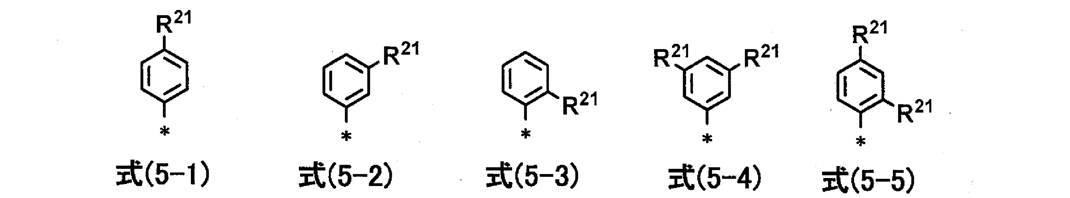
上記式(5-1)~式(5-3)において、R21は、アルキル基、アルコキシ基、アリール基、ヘテロアリール基又はハロゲン原子を示す。上記式(5-4)~式(5-5)において、R21は、水素原子、アルキル基、アルコキシ基、アリール基、ヘテロアリール基又はハロゲン原子を示し、R21の少なくとも1つはアルキル基、アルコキシ基、アリール基、ヘテロアリール基又はハロゲン原子を示す。
R21として採りうる基としては、アルキル基、アルコキシ基、アリール基又はハロゲン原子であることが好ましく、アルキル基又はアルコキシ基であることがより好ましい。
R21として採りうる上記各基は、上記置換基群SArに含まれる対応する基と同義であり、好ましいものも同じである。ただし、L1がエテニレン基である場合、アルキル基は炭素数3以上の直鎖アルキル基、又は分岐アルキル基である。
式(5-4)及び式(5-5)において、2つのR21は、同一でも異なっていてもよい。 In the above formulas (5-1) to (5-3), R 21 represents an alkyl group, an alkoxy group, an aryl group, a heteroaryl group, or a halogen atom. In the above formulas (5-4) to (5-5), R 21 represents a hydrogen atom, an alkyl group, an alkoxy group, an aryl group, a heteroaryl group or a halogen atom, and at least one of R 21 is an alkyl group Represents an alkoxy group, an aryl group, a heteroaryl group or a halogen atom.
The group that can be adopted as R 21 is preferably an alkyl group, an alkoxy group, an aryl group, or a halogen atom, and more preferably an alkyl group or an alkoxy group.
Each of the above groups that can be adopted as R 21 has the same meaning as the corresponding group included in the substituent group S Ar , and preferred ones are also the same. However, when L 1 is an ethenylene group, the alkyl group is a linear alkyl group having 3 or more carbon atoms or a branched alkyl group.
In formula (5-4) and formula (5-5), two R 21 s may be the same or different.
上記式(4)において、R11は、アルキル基、アルコキシ基、アルキルチオ基、アリール基、ヘテロアリール基、アミノ基又はハロゲン原子を示す。中でも、アルキル基又はアルコキシ基が好ましい。
R11として採りうる上記各基は、R7として採りうる基と同義であり、好ましいものも同じである。 In the above formula (4), R 11 represents an alkyl group, an alkoxy group, an alkylthio group, an aryl group, a heteroaryl group, an amino group, or a halogen atom. Among these, an alkyl group or an alkoxy group is preferable.
Each of the above groups that can be taken as R 11 has the same meaning as the group that can be taken as R 7 , and preferred ones are also the same.
上記式(4)において、n11は0~4の整数である。n11はn1と同義であり、好ましいものも同じである。
In the above formula (4), n 11 is an integer of 0-4. n 11 has the same meaning as n 1, and preferred ones are also the same.
上記式(1)において、RP1及びRP2は、それぞれ、アルキル基、アルコキシ基、アルキルチオ基、アリール基、ヘテロアリール基、アミノ基又はハロゲン原子を示す。中でも、アルキル基、アルコキシ基、アリール基又はハロゲン原子が好ましく、アルキル基又はアリール基がより好ましい。
RP1及びRP2として採りうる上記各基としては、それぞれ、後述する置換基群Tにおける対応する基が挙げられ、好ましいものも同じである。
RP1及びRP2は、同一でも異なっていてもよい。
RP1及びRP2として採りうる上記各基は、更に置換基を有していてもよい。更に有していてもよい置換基としては、特に限定されず、後述する置換基群Tから選ばれる置換基が好ましい。また、RP1及びRP2として採りうる上記各基は、上述の酸性基又はその塩を有していないことが好ましい。 In the above formula (1), R P1 and R P2 each represent an alkyl group, an alkoxy group, an alkylthio group, an aryl group, a heteroaryl group, an amino group, or a halogen atom. Among these, an alkyl group, an alkoxy group, an aryl group or a halogen atom is preferable, and an alkyl group or an aryl group is more preferable.
Examples of the respective groups can take as R P1 and R P2, respectively, include the corresponding groups in the substituent group T described below, it is preferable also the same.
R P1 and R P2 may be the same or different.
Each of the above groups that can be employed as R P1 and R P2 may further have a substituent. Further, the substituent that may be included is not particularly limited, and a substituent selected from the substituent group T described later is preferable. Further, each group can take as R P1 and R P2 are preferably does not have an acidic group or a salt thereof described above.
上記式(1)において、nP1及びnP2は、それぞれ、0~3の整数であり、0又は1であることが好ましく、0であることがより好ましい。
In the above formula (1), n P1 and n P2 are each an integer of 0 to 3, preferably 0 or 1, and more preferably 0.
上記式(1)において、X1及びX2は、それぞれ、単座配位子を示す。
X1及びX2として採りうる単座配位子としては、特に限定されず、例えば、アシルオキシ基、チオアシルチオ基、アシルアミノオキシ基、ジチオカルバメート基、ジチオカルボネート基、トリチオカルボネート基、チオシアネート基(-SCN、チオシアネートアニオン)、イソチオシアネート基(-NCS、イソチオシアネートアニオン)、イソセレノシアネート基、シアネート基、イソシアネート基、シアノ基、アルキルチオ基、アリールチオ基、アルコキシ基及びアリールオキシ基からなる群から選ばれた基で配位する配位子(以下、単にXXX基という)、又は、ハロゲン原子、カルボニル、1,3-ジケトン若しくはチオ尿素からなる配位子が挙げられる。
上記配位子が分子内にアルキル基、アルケニル基、アルキニル基又はアルキレン基等を含む場合、それらは直鎖状でも分岐状でもよく、置換されていても無置換でもよい。またアリール基、ヘテロ環基又はシクロアルキル基等を含む場合、それらは置換されていても無置換でもよく、単環でも縮環していてもよい。 In the above formula (1), X 1 and X 2 each represent a monodentate ligand.
The monodentate ligand that can be adopted as X 1 and X 2 is not particularly limited, and examples thereof include an acyloxy group, a thioacylthio group, an acylaminooxy group, a dithiocarbamate group, a dithiocarbonate group, a trithiocarbonate group, and a thiocyanate group. (—SCN, thiocyanate anion), isothiocyanate group (—NCS, isothiocyanate anion), isoselenocyanate group, cyanate group, isocyanate group, cyano group, alkylthio group, arylthio group, alkoxy group, and aryloxy group Examples thereof include a ligand coordinated with a selected group (hereinafter simply referred to as XXX group), or a ligand composed of a halogen atom, carbonyl, 1,3-diketone or thiourea.
When the ligand contains an alkyl group, alkenyl group, alkynyl group, alkylene group or the like in the molecule, these may be linear or branched, and may be substituted or unsubstituted. Moreover, when an aryl group, a heterocyclic group, a cycloalkyl group, or the like is included, they may be substituted or unsubstituted, and may be monocyclic or condensed.
単座配位子としては、好ましくは、アシルオキシ基、アシルアミノオキシ基、ジチオカルバメート基、チオシアネート基、イソチオシアネート基、シアネート基、イソシアネート基、シアノ基、アリールチオ基、ハロゲン原子、1,3-ジケトン又はチオ尿素であり、より好ましくは、ジチオカルバメート基、チオシアネート基、イソチオシアネート基、シアネート基、イソシアネート基、ハロゲン原子又は1,3-ジケトンであり、更に好ましくは、ジチオカルバメート基、チオシアネート基、イソチオシアネート基又は1,3-ジケトンであり、特に好ましくはイソチオシアネート基又はチオシアネート基であり、最も好ましくはイソチオシアネート基である。
The monodentate ligand is preferably an acyloxy group, acylaminooxy group, dithiocarbamate group, thiocyanate group, isothiocyanate group, cyanate group, isocyanate group, cyano group, arylthio group, halogen atom, 1,3-diketone or Thiourea, more preferably a dithiocarbamate group, a thiocyanate group, an isothiocyanate group, a cyanate group, an isocyanate group, a halogen atom or a 1,3-diketone, and still more preferably a dithiocarbamate group, a thiocyanate group, an isothiocyanate Group, a 1,3-diketone, particularly preferably an isothiocyanate group or a thiocyanate group, and most preferably an isothiocyanate group.
X1及びX2は、同一であっても異なっていてもよい。
X 1 and X 2 may be the same or different.
上記式(1)において、M1及びM2は、それぞれ、プロトン(水素原子)、金属カチオン及び非金属カチオンのいずれかを示す。M1及びM2は、光電変換効率、外部量子効率及び耐熱耐久性の向上の観点からは、非金属カチオンであることが好ましい。
In the above formula (1), M 1 and M 2 each represent a proton (hydrogen atom), a metal cation, or a nonmetal cation. M 1 and M 2 are preferably non-metallic cations from the viewpoint of improving photoelectric conversion efficiency, external quantum efficiency, and heat resistance durability.
M1及びM2として採りうる金属カチオンとしては、特に限定されず、アルカリ金属イオン、アルカリ土類金属イオン又は金属錯体イオンが挙げられる。中でも、アルカリ金属イオン又はアルカリ土類金属イオンが好ましく、アルカリ金属イオンがより好ましく、リチウムイオン、ナトリウムイオン又はカリウムイオンであることが更に好ましく、ナトリウムイオン又はカリウムイオンであることが特に好ましい。
The metal cation that can be taken as M 1 and M 2 is not particularly limited, and examples thereof include alkali metal ions, alkaline earth metal ions, and metal complex ions. Among them, alkali metal ions or alkaline earth metal ions are preferable, alkali metal ions are more preferable, lithium ions, sodium ions, or potassium ions are further preferable, and sodium ions or potassium ions are particularly preferable.
M1及びM2として採りうる非金属カチオンとしては、特に限定されず、無機若しくは有機のアンモニウムイオン(例えば、トリアルキルアンモニウムイオン又はテトラアルキルアンモニウムイオン等)、ホスホニウムイオン(例えば、テトラアルキルホスホニウムイオン、アルキルトリフェニルホスホニウムイオン等)、ピリジニウムイオン、イミダゾリウムイオン、アミジニウムイオン又はグアニジニウムイオン等が挙げられる。
中でも、有機のアンモニウムイオン(テトラエチルアンモニウムイオン、テトラエチルアンモニウムイオン、テトラブチルアンモニウムイオン、テトラヘキシルアンモニウムイオン、テトラオクチルアンモニウムイオン、テトラデシルアンモニウムイオン若しくはテトラドデシルアンモニウムイオン等)、ピリジニウムイオン、イミダゾリウムイオン又はアミジニウムイオンであることが好ましく、有機のアンモニウムイオン、ピリジニウムイオン、イミダゾリウムイオン又はアミジニウムイオンであることがより好ましく、有機のアンモニウムイオン、ピリジニウムイオン又はイミダゾリウムイオンであることが更に好ましく、有機のアンモニウムイオンであることが特に好ましい。 Non-metallic cations that can be taken as M 1 and M 2 are not particularly limited, and inorganic or organic ammonium ions (for example, trialkylammonium ions or tetraalkylammonium ions), phosphonium ions (for example, tetraalkylphosphonium ions, Alkyltriphenylphosphonium ions, etc.), pyridinium ions, imidazolium ions, amidinium ions, guanidinium ions, and the like.
Among them, organic ammonium ions (tetraethylammonium ion, tetraethylammonium ion, tetrabutylammonium ion, tetrahexylammonium ion, tetraoctylammonium ion, tetradecylammonium ion or tetradodecylammonium ion), pyridinium ion, imidazolium ion, or amino It is preferably a dinium ion, more preferably an organic ammonium ion, pyridinium ion, imidazolium ion or amidinium ion, more preferably an organic ammonium ion, pyridinium ion or imidazolium ion. Particularly preferred is an ammonium ion.
金属錯体色素(1)において、M1及びM2としてプロトン、金属カチオン及び非金属カチオンが混在する場合、M1及びM2のいずれがプロトンであってもよい。
In the metal complex dye (1), proton as M 1 and M 2, when the metal cations and non-metallic cations are mixed, which of M 1 and M 2 may be a proton.
- 式(2)で表される金属錯体色素 -
この金属錯体色素(2)は、下記式(2)で表される。
金属錯体色素(2)は、上記のように、上記金属錯体色素(1)の、X1及びX2についての幾何異性体であること以外は、金属錯体色素(1)と同じである。 -Metal complex dye represented by formula (2)-
This metal complex dye (2) is represented by the following formula (2).
As described above, the metal complex dye (2) is the same as the metal complex dye (1) except that it is a geometric isomer of X 1 and X 2 of the metal complex dye (1).

上記式(2)において、M、R1、R2、RP1、RP2、nP1、nP2、X1、X2、M1及びM2は、それぞれ、上記式(1)におけるものと同義であり、好ましいものも同じである。
In the above formula (2), M, R 1 , R 2 , R P1 , R P2 , n P1 , n P2 , X 1 , X 2 , M 1 and M 2 are the same as those in the above formula (1), respectively. It is synonymous and the preferable one is also the same.
- 式(6)で表される金属錯体色素 -
この金属錯体色素(6)は、下記式(6)で表される。
金属錯体色素(6)は、下記に示すように、金属錯体色素(1)において、-COOM1及び-COOM2を有するビピリジン配位子に代えて、2つのピリジン環それぞれが置換基(R3又はR4)を有するビピリジン配位子を更に有する金属錯体色素(幾何異性は考慮しない)である。すなわち、金属錯体色素(6)は、幾何異性を考慮しなければ、2つのピリジン環それぞれが置換基(R1~R4)を有するビピリジン配位子を2つ有し、-COOM1及び-COOM2を有するビピリジン配位子を有さないこと以外は、金属錯体色素(1)と同じである。 -Metal complex dye represented by formula (6)-
This metal complex dye (6) is represented by the following formula (6).
In the metal complex dye (6), as shown below, in the metal complex dye (1), instead of the bipyridine ligand having —COOM 1 and —COOM 2 , each of the two pyridine rings has a substituent (R 3 Or a metal complex dye (not considering geometric isomerism) further having a bipyridine ligand having R 4 ). That is, the metal complex dye (6) has two bipyridine ligands each having two substituents (R 1 to R 4 ) unless geometric isomerism is taken into consideration, and —COOM 1 and — It is the same as the metal complex dye (1) except that it does not have a bipyridine ligand having COOM 2 .

上記式(6)において、M、R1、R2、RP1、RP2、nP1、nP2、X1及びX2は、上記式(1)におけるものと同義であり、好ましいものも同じである。また、R3及びR4は上記式(1)におけるR1及びR2と同義であり、好ましいものも同じである。
RP3及びRP4は上記式(1)におけるRP1と同義であり、好ましいものも同じである。また、nP3及びnP4は上記式(1)におけるnP1と同義であり、好ましいものも同じである。 In the above formula (6), M, R 1 , R 2 , R P1 , R P2 , n P1 , n P2 , X 1 and X 2 are synonymous with those in the above formula (1), and preferred ones are also the same. It is. R 3 and R 4 have the same meanings as R 1 and R 2 in the above formula (1), and preferred ones are also the same.
R P3 and R P4 have the same meaning as R P1 in the above formula (1), and preferred ones are also the same. Further, n P3 and n P4 has the same meaning as n P1 in the formula (1), it is preferable also the same.
本発明において、金属錯体色素(6)は、光学異性体、幾何異性体、結合異性体又はイオン化異性体等の異性体が存在する場合、これらの異性体のいずれであってもよく、またこれらの異性体の混合物であってもよい。例えば、金属錯体色素(6)は、6配位錯体構造についての幾何異性体を特に区別する必要はなく、シス体であってもトランス体であってよく、また、これらの混合物であってもよい。
In the present invention, when there are isomers such as optical isomers, geometric isomers, bond isomers or ionized isomers, the metal complex dye (6) may be any of these isomers. A mixture of isomers of For example, the metal complex dye (6) does not need to particularly distinguish geometric isomers for a hexacoordinate complex structure, and may be a cis isomer or a trans isomer, or a mixture thereof. Good.
- 式(2A)で表される金属錯体色素 -
金属錯体色素(2A)は、上記第1及び第2の色素吸着態様に用いる金属錯体色素であり、下記式(2A)で表される。この金属錯体色素(2A)は、下記に示すように、R1A及びR2Aがそれぞれ下記式(4)で表される基であること以外は、金属錯体色素(2)と同じである。すなわち、金属錯体色素(2A)は、金属錯体色素(2)のR1及びR2を下記式(4)で表される基に限定した金属錯体色素であり、金属錯体色素(2)の一部を構成する。この金属錯体色素(2A)はX1A及びX2Aについてのトランス体である。 -Metal complex dye represented by formula (2A)-
The metal complex dye (2A) is a metal complex dye used in the first and second dye adsorption modes, and is represented by the following formula (2A). As shown below, this metal complex dye (2A) is the same as the metal complex dye (2) except that R 1A and R 2A are groups each represented by the following formula (4). That is, the metal complex dye (2A) is a metal complex dye in which R 1 and R 2 of the metal complex dye (2) are limited to a group represented by the following formula (4). Parts. This metal complex dye (2A) is a trans isomer for X 1A and X 2A .

上記式(2A)において、M、RP1A、RP2A、nP1A、nP2A、X1A、X2A、M1A及びM2Aは、それぞれ、上記式(1)における、M、RP1、RP2、nP1、nP2、X1、X2、M1及びM2と同義であり、好ましいものも同じである。
式(2A)において、R1A及びR2Aは、それぞれ、下記式(4)で表される基であり、下記式(4)で表される基は金属錯体色素(1)において説明した上記基と同義であり、好ましいものも同じである。 In the above formula (2A), M, R P1A , R P2A , n P1A , n P2A , X 1A , X 2A , M 1A and M 2A are respectively M, R P1 , R P2 in the above formula (1). , N P1 , n P2 , X 1 , X 2 , M 1 and M 2 , and preferable ones are also the same.
In the formula (2A), R 1A and R 2A are each a group represented by the following formula (4), and the group represented by the following formula (4) is the group described in the metal complex dye (1). And the preferred ones are also the same.

式(4)において、Ar11、Ar12、L1、R11及びn11は、式(2)におけるR1及びR2として採りうる上記式(4)で表される基の、Ar11、Ar12、L1、R11及びn11と同義であり、好ましいものも同じである。
式(4)において、*は、式(2A)中のピリジン環との結合部を示す。 In the formula (4), Ar 11, Ar 12, L 1, R 11 and n 11 are the groups represented by the above formula can take as R 1 and R 2 in Formula (2) (4), Ar 11, Ar 12, L 1, have the same meanings as R 11 and n 11, it is preferable also the same.
In the formula (4), * indicates a bond portion with the pyridine ring in the formula (2A).
- 金属錯体色素の物性 -
金属錯体色素(1)、金属錯体色素(2)、金属錯体色素(2A)及び金属錯体色素(6)において、溶液における極大吸収波長は、いずれも、好ましくは300~1000nmの範囲であり、より好ましくは350~950nmの範囲であり、特に好ましくは370~900nmの範囲である。
金属錯体色素(2)又は金属錯体色素(2A)を少なくとも含む色素組成物は、吸収スペクトルが、例えば700nm以上の長波長領域まで広がる。 -Physical properties of metal complex dyes-
In the metal complex dye (1), the metal complex dye (2), the metal complex dye (2A) and the metal complex dye (6), the maximum absorption wavelength in the solution is preferably in the range of 300 to 1000 nm. The range is preferably 350 to 950 nm, and particularly preferably 370 to 900 nm.
The dye composition including at least the metal complex dye (2) or the metal complex dye (2A) has an absorption spectrum that extends to a long wavelength region of, for example, 700 nm or more.
- 金属錯体色素の合成 -
金属錯体色素(1)は、例えば、特許文献1若しくは特許文献2に記載の方法、太陽電池に関する上記特許文献、公知の方法、又は、これらに準じた方法により、合成することができる。
金属錯体色素(2)、金属錯体色素(2A)及び金属錯体色素(6)は、それぞれ、金属錯体色素(1)の合成に際して得ることができる。金属錯体色素(1)の合成において、その合成条件(反応条件)等を変更することで、金属錯体色素(2)、金属錯体色素(2A)及び金属錯体色素(6)の生成量を変更できる。例えば、反応条件の中でも、R1及びR2を有するビピリジン配位子と、-COOM1及び-COOM2を有するビピリジン配位子とを金属イオンに配位させる際(後述する実施例におけるエステル化合物の合成時)の加熱温度若しくは加熱時間又は使用する溶媒等を変更すると、金属錯体色素(2)、金属錯体色素(2A)又は金属錯体色素(6)の生成量を増加又は減少させることができる。反応条件を変更して得られる粗生成物(金属錯体色素の混合物)を、通常の方法、例えばシリカゲルカラムクロマトグラフィーにより、単離、精製することによって、各金属錯体色素を得ることができる。 -Synthesis of metal complex dyes-
The metal complex dye (1) can be synthesized by, for example, the method described in Patent Document 1 orPatent Document 2, the above-described Patent Document relating to solar cells, a known method, or a method based thereon.
The metal complex dye (2), the metal complex dye (2A), and the metal complex dye (6) can be obtained in the synthesis of the metal complex dye (1), respectively. In the synthesis of the metal complex dye (1), the production amount of the metal complex dye (2), the metal complex dye (2A) and the metal complex dye (6) can be changed by changing the synthesis conditions (reaction conditions) and the like. . For example, among the reaction conditions, when a bipyridine ligand having R 1 and R 2 and a bipyridine ligand having —COOM 1 and —COOM 2 are coordinated to a metal ion (the ester compound in Examples described later) The amount of metal complex dye (2), metal complex dye (2A), or metal complex dye (6) produced can be increased or decreased by changing the heating temperature or the heating time or the solvent to be used. . Each metal complex dye can be obtained by isolating and purifying a crude product (mixture of metal complex dyes) obtained by changing the reaction conditions by an ordinary method such as silica gel column chromatography.
金属錯体色素(1)は、例えば、特許文献1若しくは特許文献2に記載の方法、太陽電池に関する上記特許文献、公知の方法、又は、これらに準じた方法により、合成することができる。
金属錯体色素(2)、金属錯体色素(2A)及び金属錯体色素(6)は、それぞれ、金属錯体色素(1)の合成に際して得ることができる。金属錯体色素(1)の合成において、その合成条件(反応条件)等を変更することで、金属錯体色素(2)、金属錯体色素(2A)及び金属錯体色素(6)の生成量を変更できる。例えば、反応条件の中でも、R1及びR2を有するビピリジン配位子と、-COOM1及び-COOM2を有するビピリジン配位子とを金属イオンに配位させる際(後述する実施例におけるエステル化合物の合成時)の加熱温度若しくは加熱時間又は使用する溶媒等を変更すると、金属錯体色素(2)、金属錯体色素(2A)又は金属錯体色素(6)の生成量を増加又は減少させることができる。反応条件を変更して得られる粗生成物(金属錯体色素の混合物)を、通常の方法、例えばシリカゲルカラムクロマトグラフィーにより、単離、精製することによって、各金属錯体色素を得ることができる。 -Synthesis of metal complex dyes-
The metal complex dye (1) can be synthesized by, for example, the method described in Patent Document 1 or
The metal complex dye (2), the metal complex dye (2A), and the metal complex dye (6) can be obtained in the synthesis of the metal complex dye (1), respectively. In the synthesis of the metal complex dye (1), the production amount of the metal complex dye (2), the metal complex dye (2A) and the metal complex dye (6) can be changed by changing the synthesis conditions (reaction conditions) and the like. . For example, among the reaction conditions, when a bipyridine ligand having R 1 and R 2 and a bipyridine ligand having —COOM 1 and —COOM 2 are coordinated to a metal ion (the ester compound in Examples described later) The amount of metal complex dye (2), metal complex dye (2A), or metal complex dye (6) produced can be increased or decreased by changing the heating temperature or the heating time or the solvent to be used. . Each metal complex dye can be obtained by isolating and purifying a crude product (mixture of metal complex dyes) obtained by changing the reaction conditions by an ordinary method such as silica gel column chromatography.
<置換基群T>
本発明において、好ましい置換基としては、下記置換基群Tから選ばれる基が挙げられる。
また、本明細書において、単に置換基としてしか記載されていない場合は、この置換基群Tを参照するものであり、また、各々の基、例えば、アルキル基、が記載されているのみの場合は、この置換基群Tの対応する基における好ましい範囲、具体例が適用される。
更に、本明細書において、アルキル基を環状(シクロ)アルキル基と区別して記載している場合、アルキル基は、直鎖アルキル基及び分岐アルキル基を包含する意味で用いる。一方、アルキル基を環状アルキル基と区別して記載していない場合(単に、アルキル基と記載されている場合)、及び、特段の断りがない場合、アルキル基は、直鎖アルキル基、分岐アルキル基及びシクロアルキル基を包含する意味で用いる。このことは、環状構造を採りうる基(アルキル基、アルケニル基、アルキニル基等)を含む基(アルコキシ基、アルキルチオ基、アルケニルオキシ基等)、環状構造を採りうる基を含む化合物についても同様である。下記置換基群の説明においては、例えば、アルキル基とシクロアルキル基のように、直鎖又は分岐構造の基と環状構造の基とを明確にするため、これらを分けて記載していることもある。 <Substituent group T>
In the present invention, preferred substituents include groups selected from the following substituent group T.
In the present specification, when only described as a substituent, this substituent group T is referred to, and each group, for example, an alkyl group, is only described. The preferred ranges and specific examples in the corresponding group of the substituent group T are applied.
Furthermore, in the present specification, when an alkyl group is described separately from a cyclic (cyclo) alkyl group, the alkyl group is used in a sense including a linear alkyl group and a branched alkyl group. On the other hand, when the alkyl group is not described separately from the cyclic alkyl group (when simply described as an alkyl group), and unless otherwise specified, the alkyl group is a linear alkyl group or a branched alkyl group. And cycloalkyl group. The same applies to a compound containing a group (an alkoxy group, an alkylthio group, an alkenyloxy group, etc.) containing a group that can take a cyclic structure (an alkyl group, an alkenyl group, an alkynyl group, etc.) or a group containing a group that can take a cyclic structure. is there. In the following description of the substituent group, for example, in order to clarify a linear or branched group and a cyclic group such as an alkyl group and a cycloalkyl group, they may be described separately. is there.
置換基群Tに含まれる基としては、下記の基、又は、下記の基を複数組み合わせてなる基を含む。
アルキル基(好ましくは炭素数1~20、より好ましくは1~12で、例えばメチル、エチル、n-プロピル、i-プロピル、n-ブチル、t-ブチル、ペンチル、ヘプチル、1-エチルペンチル、ベンジル、2-エトキシエチル、1-カルボキシメチル又はトリフルオロメチル)、アルケニル基(好ましくは炭素数2~20、より好ましくは2~12で、例えば、ビニル、アリル又はオレイル)、アルキニル基(好ましくは炭素数2~20、より好ましくは2~12で、例えば、エチニル、ブチニル又はフェニルエチニル)、シクロアルキル基(好ましくは炭素数3~20)、シクロアルケニル基(好ましくは炭素数5~20)、アリール基(好ましくは炭素数6~26で、例えば、フェニル、1-ナフチル、4-メトキシフェニル、2-クロロフェニル、3-メチルフェニル、ジフルオロフェニル又はテトラフルオロフェニル)、ヘテロ環基(好ましくは炭素数2~20で、少なくとも1つの酸素原子、硫黄原子若しくは窒素原子を有する5員環若しくは6員環のヘテロ環基がより好ましい。ヘテロ環には芳香族環及び脂肪族環を含む。芳香族ヘテロ環基(ヘテロアリール基)として次の基が挙げられる。例えば、2-ピリジル、4-ピリジル、2-イミダゾリル、2-ベンゾイミダゾリル、2-チエニル、2-フラニル、2-チアゾリル又は2-オキサゾリル)、アルコキシ基(好ましくは炭素数1~20、より好ましくは1~12で、例えば、メトキシ、エトキシ、イソプロピルオキシ又はベンジルオキシ)、アルケニルオキシ基(好ましくは炭素数2~20、より好ましくは2~12)、アルキニルオキシ基(好ましくは炭素数2~20、より好ましくは2~12)、シクロアルキルオキシ基(好ましくは炭素数3~20)、アリールオキシ基(好ましくは炭素数6~26)、ヘテロ環オキシ基(ヘテロ環が芳香族環である場合、ヘテロアリールオキシ基という。好ましくは炭素数2~20)、 The group included in the substituent group T includes the following group or a group formed by combining a plurality of the following groups.
An alkyl group (preferably having 1 to 20 carbon atoms, more preferably 1 to 12 carbon atoms such as methyl, ethyl, n-propyl, i-propyl, n-butyl, t-butyl, pentyl, heptyl, 1-ethylpentyl, benzyl) , 2-ethoxyethyl, 1-carboxymethyl or trifluoromethyl), an alkenyl group (preferably having a carbon number of 2 to 20, more preferably 2 to 12, such as vinyl, allyl or oleyl), an alkynyl group (preferably a carbon 2 to 20, more preferably 2 to 12, for example, ethynyl, butynyl or phenylethynyl), cycloalkyl group (preferably having 3 to 20 carbon atoms), cycloalkenyl group (preferably having 5 to 20 carbon atoms), aryl Groups (preferably having 6 to 26 carbon atoms such as phenyl, 1-naphthyl, 4-methoxyphenyl, 2- Chlorophenyl, 3-methylphenyl, difluorophenyl, or tetrafluorophenyl), a heterocyclic group (preferably a 5- or 6-membered heterocycle having 2 to 20 carbon atoms and having at least one oxygen atom, sulfur atom, or nitrogen atom) The heterocyclic group includes an aromatic ring and an aliphatic ring, and examples of the aromatic heterocyclic group (heteroaryl group) include the following groups: 2-pyridyl, 4-pyridyl, 2- Imidazolyl, 2-benzimidazolyl, 2-thienyl, 2-furanyl, 2-thiazolyl or 2-oxazolyl), an alkoxy group (preferably having 1 to 20 carbon atoms, more preferably 1 to 12 carbon atoms such as methoxy, ethoxy, isopropyloxy Or benzyloxy), an alkenyloxy group (preferably having 2 to 20 carbon atoms, more preferred) 2-12), an alkynyloxy group (preferably 2-20 carbon atoms, more preferably 2-12), a cycloalkyloxy group (preferably 3-20 carbon atoms), an aryloxy group (preferably 6-6 carbon atoms). 26), a heterocyclic oxy group (when the hetero ring is an aromatic ring, it is referred to as a heteroaryloxy group, preferably having 2 to 20 carbon atoms),
アルコキシカルボニル基(好ましくは炭素数2~20)、シクロアルコキシカルボニル基(好ましくは炭素数4~20)、アリールオキシカルボニル基(好ましくは炭素数6~20)、アミノ基(好ましくは炭素数0~20で、アルキルアミノ基、アルケニルアミノ基、アルキニルアミノ基、シクロアルキルアミノ基、シクロアルケニルアミノ基、アリールアミノ基、ヘテロ環アミノ基(ヘテロ環が芳香族環である場合、ヘテロアリールアミノ基という)を含み、例えば、アミノ、N,N-ジメチルアミノ、N,N-ジエチルアミノ、N-エチルアミノ、N-アリルアミノ、N-(2-プロピニル)アミノ、N-シクロヘキシルアミノ、N-シクロヘキセニルアミノ、アニリノ、ピリジルアミノ、イミダゾリルアミノ、ベンゾイミダゾリルアミノ、チアゾリルアミノ、ベンゾチアゾリルアミノ又はトリアジニルアミノ)、スルファモイル基(好ましくは炭素数0~20で、アルキル、シクロアルキル若しくはアリールのスルファモイル基が好ましい)、アシル基(好ましくは炭素数1~20)、アシルオキシ基(好ましくは炭素数1~20)、カルバモイル基(好ましくは炭素数1~20で、アルキル、シクロアルキル若しくはアリールのカルバモイル基が好ましい)、
An alkoxycarbonyl group (preferably having a carbon number of 2 to 20), a cycloalkoxycarbonyl group (preferably having a carbon number of 4 to 20), an aryloxycarbonyl group (preferably having a carbon number of 6 to 20), an amino group (preferably having a carbon number of 0 to 20, an alkylamino group, an alkenylamino group, an alkynylamino group, a cycloalkylamino group, a cycloalkenylamino group, an arylamino group, a heterocyclic amino group (when the heterocyclic ring is an aromatic ring, it is referred to as a heteroarylamino group) For example, amino, N, N-dimethylamino, N, N-diethylamino, N-ethylamino, N-allylamino, N- (2-propynyl) amino, N-cyclohexylamino, N-cyclohexenylamino, anilino , Pyridylamino, imidazolylamino, benzimidazolyl , Thiazolylamino, benzothiazolylamino or triazinylamino), a sulfamoyl group (preferably an alkyl, cycloalkyl or aryl sulfamoyl group having 0 to 20 carbon atoms), an acyl group (preferably having a carbon number of 1 to 20) an acyloxy group (preferably having a carbon number of 1 to 20), a carbamoyl group (preferably a carbamoyl group having a carbon number of 1 to 20, preferably alkyl, cycloalkyl or aryl),
アシルアミノ基(好ましくは炭素数1~20)、スルホンアミド基(好ましくは炭素数0~20で、アルキル、シクロアルキル若しくはアリールのスルホンアミド基が好ましい)、アルキルチオ基(好ましくは炭素数1~20、より好ましくは1~12で、例えば、メチルチオ、エチルチオ、イソプロピルチオ又はベンジルチオ)、シクロアルキルチオ基(好ましくは炭素数3~20)、アリールチオ基(好ましくは炭素数6~26)、ヘテロ環チオ基(ヘテロ環が芳香族環である場合、ヘテロアリールチオ基という。好ましくは炭素数2~20)、アルキル、シクロアルキル若しくはアリールスルホニル基(好ましくは炭素数1~20)、
An acylamino group (preferably having a carbon number of 1 to 20), a sulfonamide group (preferably having a carbon number of 0 to 20 and an alkyl, cycloalkyl or aryl sulfonamide group), an alkylthio group (preferably having a carbon number of 1 to 20, More preferably 1 to 12, for example, methylthio, ethylthio, isopropylthio or benzylthio), a cycloalkylthio group (preferably having 3 to 20 carbon atoms), an arylthio group (preferably having 6 to 26 carbon atoms), a heterocyclic thio group ( When the heterocycle is an aromatic ring, it is referred to as a heteroarylthio group (preferably having 2 to 20 carbon atoms), an alkyl, cycloalkyl or arylsulfonyl group (preferably having 1 to 20 carbon atoms),
シリル基(好ましくは炭素数1~20で、アルキル、アリール、アルコキシ及びアリールオキシが置換したシリル基が好ましい)、シリルオキシ基(好ましくは炭素数1~20で、アルキル、アリール、アルコキシ及びアリールオキシが置換したシリルオキシ基が好ましい)、ヒドロキシ基、シアノ基、ニトロ基、ハロゲン原子(例えば、フッ素原子、塩素原子、臭素原子又はヨウ素原子)、カルボキシ基、スルホ基、ホスホニル基、ホスホリル基、あるいは、ホウ酸基が挙げられる。
A silyl group (preferably a silyl group having 1 to 20 carbon atoms and substituted with alkyl, aryl, alkoxy and aryloxy), a silyloxy group (preferably having 1 to 20 carbon atoms, alkyl, aryl, alkoxy and aryloxy are A substituted silyloxy group is preferred), a hydroxy group, a cyano group, a nitro group, a halogen atom (for example, fluorine atom, chlorine atom, bromine atom or iodine atom), carboxy group, sulfo group, phosphonyl group, phosphoryl group, or boron An acid group is mentioned.
置換基群Tから選ばれる基は、より好ましくは酸性基若しくはその塩以外の基であり、更に好ましくはアルキル基、アルケニル基、シクロアルキル基、アリール基、ヘテロ環基、アルコキシ基、シクロアルコキシ基、アリールオキシ基、アルコキシカルボニル基、シクロアルコキシカルボニル基、アミノ基、アシルアミノ基、シアノ基又はハロゲン原子であり、特に好ましくはアルキル基、アルケニル基、ヘテロ環基、アルコキシ基、アルコキシカルボニル基、アミノ基、アシルアミノ基又はシアノ基である。
化合物ないし置換基等がアルキル基、アルケニル基等を含むとき、これらは置換されていても置換されていなくてもよい。またアリール基、ヘテロ環基等を含むとき、それらは単環でも縮環でもよく、置換されていても置換されていなくてもよい。 The group selected from the substituent group T is more preferably a group other than an acidic group or a salt thereof, and more preferably an alkyl group, an alkenyl group, a cycloalkyl group, an aryl group, a heterocyclic group, an alkoxy group, or a cycloalkoxy group. , Aryloxy group, alkoxycarbonyl group, cycloalkoxycarbonyl group, amino group, acylamino group, cyano group or halogen atom, particularly preferably alkyl group, alkenyl group, heterocyclic group, alkoxy group, alkoxycarbonyl group, amino group , An acylamino group or a cyano group.
When a compound or a substituent includes an alkyl group, an alkenyl group, etc., these may be substituted or unsubstituted. When an aryl group, a heterocyclic group and the like are included, they may be monocyclic or condensed and may be substituted or unsubstituted.
- 金属錯体色素の具体例 -
金属錯体色素(1)、金属錯体色素(2)、金属錯体色素(2A)及び金属錯体色素(6)の具体例を以下に示すが、本発明はこれらの金属錯体色素に限定されない。
下記具体例では、金属錯体色素(1)、金属錯体色素(2)及び金属錯体色素(2A)を、構造式(立体構造を考慮しない)により、まとめて、示す。したがって、下記金属錯体色素D-1には、金属錯体色素(1)と金属錯体色素(2)とが含まれる。
下記具体例において、金属錯体色素を「D-n」で表記とする。ここで、nは金属錯体色素の通し番号である。
下記具体例において、Mは上記金属イオン(好ましくはRu2+)を示す。L1及びL2欄の「*」はD1又はD2との結合部を表し、「**」はピリジン環との結合部を表す。また、D1欄及びD2欄の「*」は、それぞれ、L1又はL2との結合部を表す。更に、Meはメチルを示す。
金属錯体色素(6)の具体例は、下記構造式により明確に示さないが、金属錯体色素(1)、金属錯体色素(2)及び金属錯体色素(2A)の下記具体例それぞれにおいて、-COOM1及び-COOM2を有するビピリジン配位子を、-L1-D1及び-L2-D2を有するビピリジン配位子に代えた金属錯体色素であり、これにより、その具体例が示されるものとする。 -Specific examples of metal complex dyes-
Specific examples of the metal complex dye (1), metal complex dye (2), metal complex dye (2A) and metal complex dye (6) are shown below, but the present invention is not limited to these metal complex dyes.
In the following specific examples, the metal complex dye (1), the metal complex dye (2), and the metal complex dye (2A) are collectively shown by the structural formula (without considering the three-dimensional structure). Therefore, the following metal complex dye D-1 includes the metal complex dye (1) and the metal complex dye (2).
In the following specific examples, the metal complex dye is represented by “Dn”. Here, n is a serial number of the metal complex dye.
In the following specific examples, M represents the metal ion (preferably Ru 2+ ). “*” In the L 1 and L 2 columns represents a bond to D 1 or D 2, and “**” represents a bond to the pyridine ring. In addition, “*” in the D 1 column and the D 2 column represents a bonding portion with L 1 or L 2 , respectively. Me represents methyl.
Specific examples of the metal complex dye (6) are not clearly shown by the following structural formula, but in each of the following specific examples of the metal complex dye (1), the metal complex dye (2), and the metal complex dye (2A), —COOM A metal complex dye in which a bipyridine ligand having 1 and -COOM 2 is replaced with a bipyridine ligand having -L 1 -D 1 and -L 2 -D 2 , and specific examples thereof are shown. Shall.
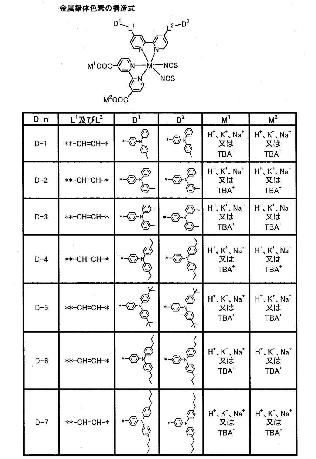

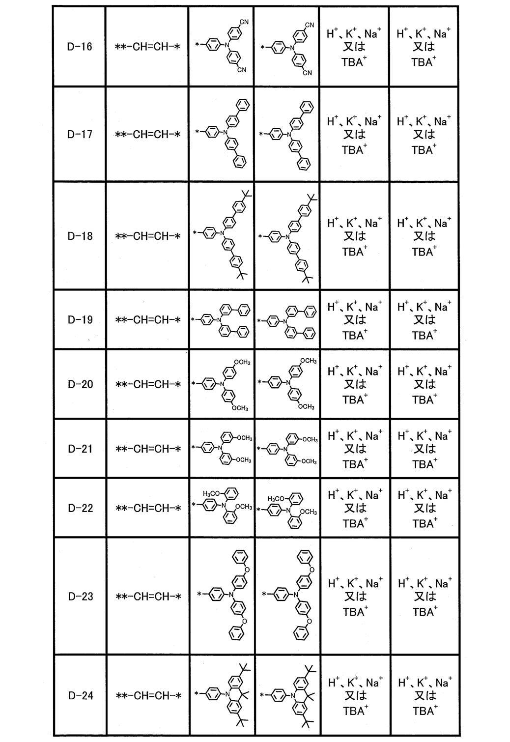

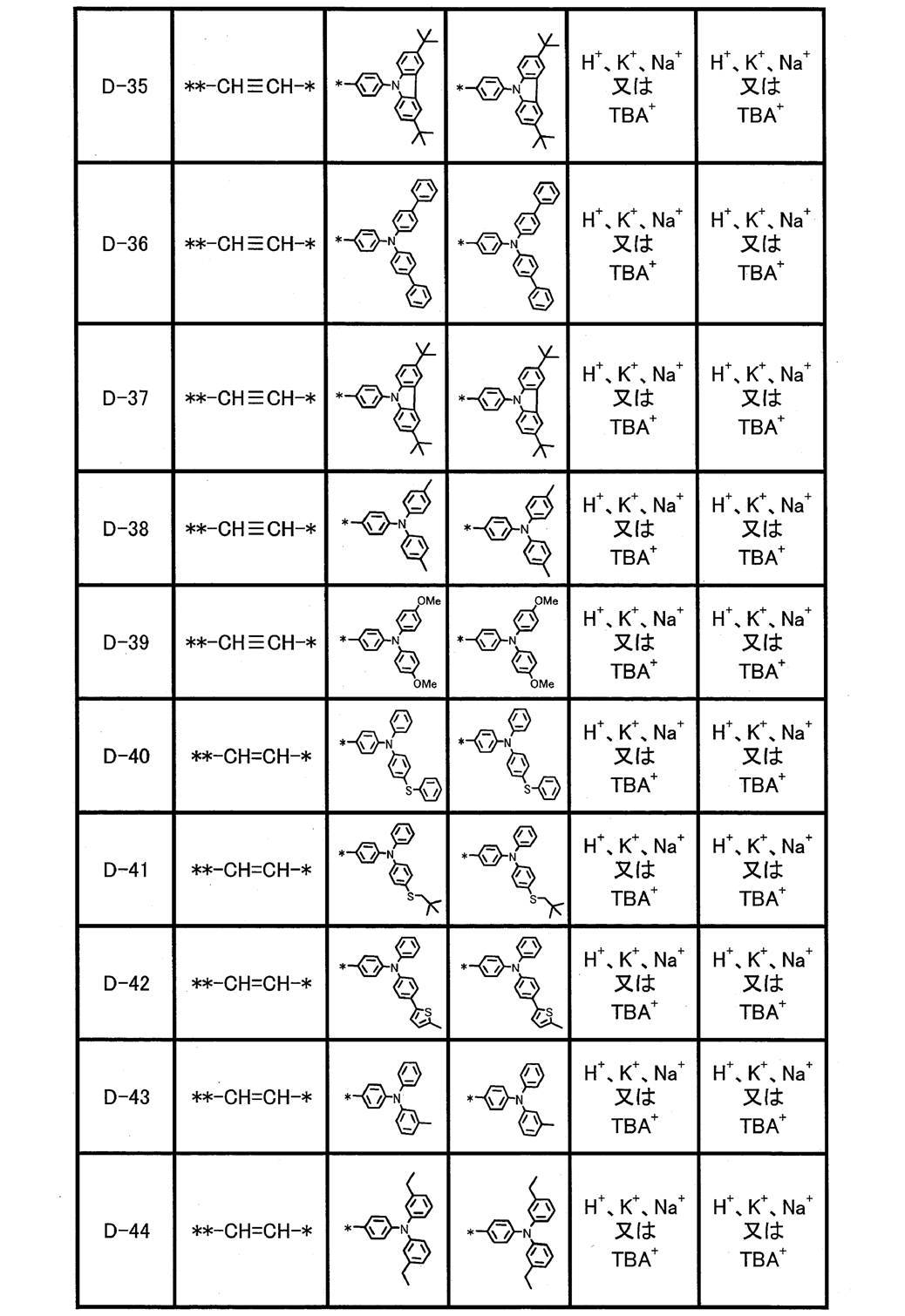
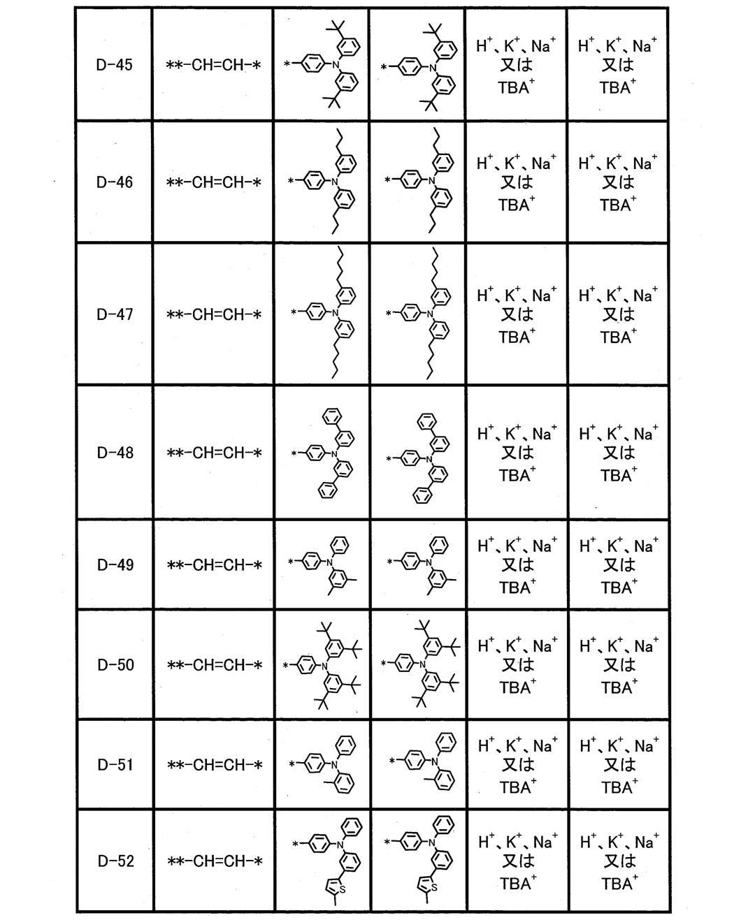
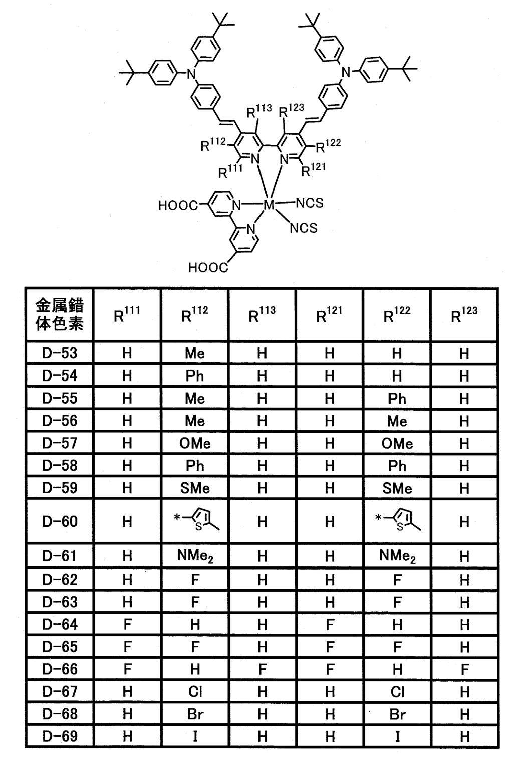
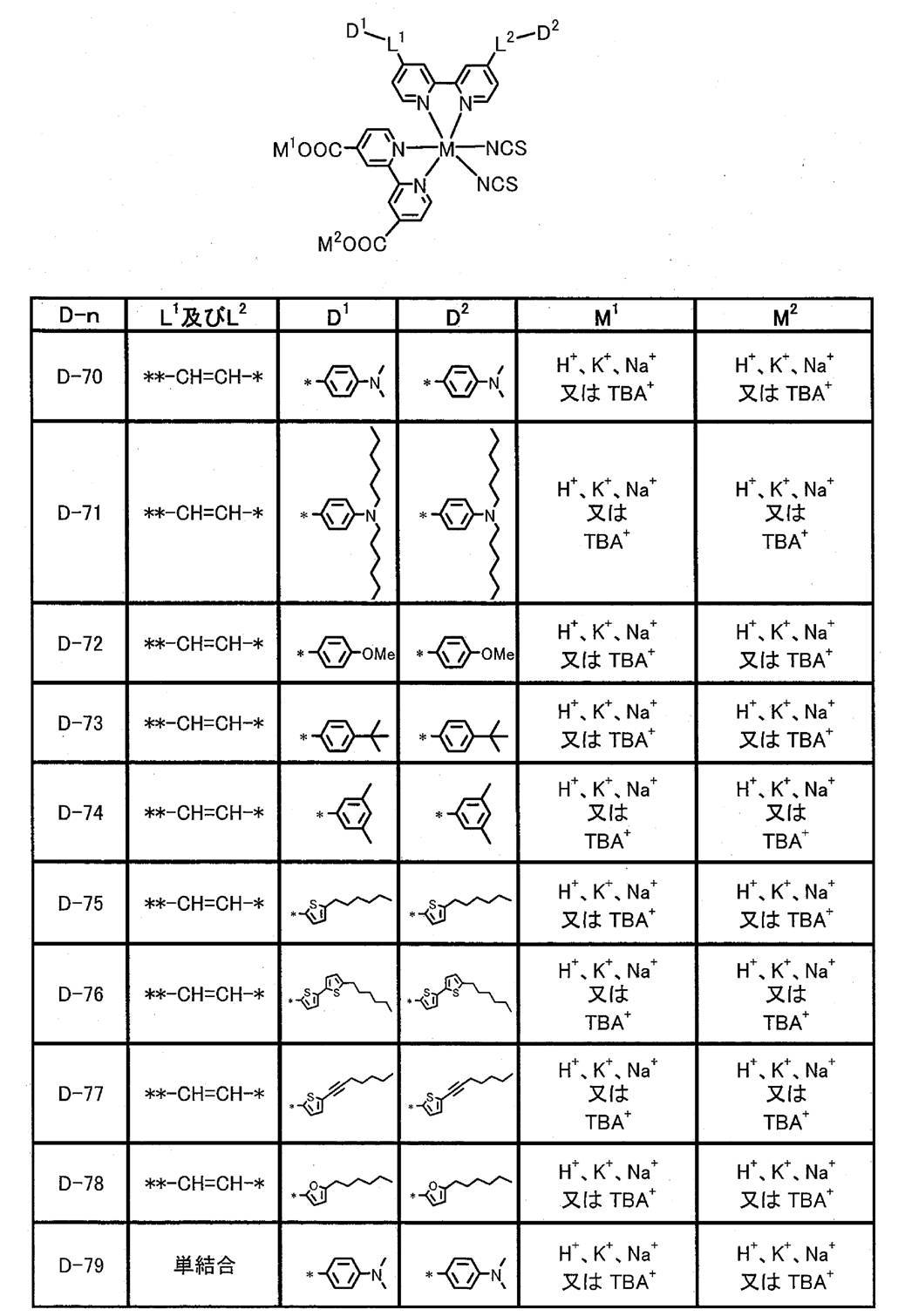

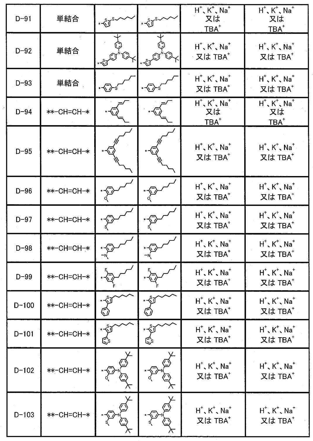

<色素組成物>
本発明の色素組成物は、少なくとも、金属錯体色素(1)及び金属錯体色素(2)を含有し、好ましくは、金属錯体色素(1)、金属錯体色素(2)及び金属錯体色素(6)を含有する。色素組成物において、金属錯体色素(1)、金属錯体色素(2)及び金属錯体色素(6)は、それぞれ、1種でも2種以上でもよい。
金属錯体色素(1)、金属錯体色素(2)及び金属錯体色素(6)は、それぞれ、上述の通りである。
色素組成物において、金属錯体色素(1)、金属錯体色素(2)及び金属錯体色素(6)それぞれにおける、M、R1、R2、RP1、RP2、nP1、nP2、X1、X2、M1及びM2は、それぞれ、同じであっても異なっていてもよい。また、金属錯体色素(6)におけるR3、R4、RP3、RP4、nP3及びnP4は、それぞれ、金属錯体色素(1)及び金属錯体色素(2)のR1、R2、RP1、RP2、nP1及びnP2と同じであっても異なっていてもよい。例えば、X1及びX2の配置以外は同じ金属錯体色素(1)及び(2)を組み合わせて用いることができ、更に、金属錯体色素(1)及び(2)と、R3及びR4を有するビピリジン配位子が金属錯体色素(1)及び/又は(2)と同じ金属錯体色素(6)とを組み合わせて用いることができる。 <Dye composition>
The dye composition of the present invention contains at least a metal complex dye (1) and a metal complex dye (2), and preferably a metal complex dye (1), a metal complex dye (2), and a metal complex dye (6). Containing. In the dye composition, each of the metal complex dye (1), the metal complex dye (2), and the metal complex dye (6) may be one kind or two or more kinds.
The metal complex dye (1), the metal complex dye (2), and the metal complex dye (6) are as described above.
In the dye composition, M, R 1 , R 2 , R P1 , R P2 , n P1 , n P2 , X 1 in the metal complex dye (1), the metal complex dye (2), and the metal complex dye (6), respectively. , X 2 , M 1 and M 2 may be the same or different. In addition, R 3 , R 4 , R P3 , R P4 , n P3 and n P4 in the metal complex dye (6) are R 1 , R 2 , and R 1 in the metal complex dye (1) and the metal complex dye (2), respectively. R P1 , R P2 , n P1 and n P2 may be the same or different. For example, the same metal complex dyes (1) and (2) other than the arrangement of X 1 and X 2 can be used in combination. Further, the metal complex dyes (1) and (2), and R 3 and R 4 can be used. A bipyridine ligand having a metal complex dye (1) and / or the same metal complex dye (6) as (2) can be used in combination.
上記のように、金属錯体色素(2)は金属錯体色素(2A)を含む。したがって、本発明の色素組成物においては、金属錯体色素(2)の一態様として金属錯体色素(2A)を含んでいてもよい。
As described above, the metal complex dye (2) includes the metal complex dye (2A). Therefore, in the pigment | dye composition of this invention, the metal complex pigment | dye (2A) may be included as one aspect | mode of a metal complex pigment | dye (2).
本発明の色素組成物において、金属錯体色素(1)、金属錯体色素(2)及び金属錯体色素(6)の含有比(吸着割合)は、特に限定されない。光電変換素子ないしは色素増感太陽電池に、優れた光電変換効率、長波長光における外部量子効率及び耐熱耐久性を付与できる点で、上記含有比は、金属錯体色素(1):金属錯体色素(2):金属錯体色素(6)のモル量(合計100%)で、0.1~99.9%:0.1~99.9%:0~10%であることが好ましく、40~99.9%:0.1~50%:0~10%であることがより好ましく、65~99.9%:0.1~25%:0~5%であることが更に好ましい。
色素組成物が金属錯体色素(6)を含有する態様において、金属錯体色素(6)の含有比の下限は、特に限定されないが、例えば0.01モル%とすることができる。
金属錯体色素(2)が金属錯体色素(2A)を含む場合、金属錯体色素(2)中の金属錯体色素(2A)の含有率は、特に限定されず、高いほど好ましく、例えば、50~100モル%がより好ましく、80~100モル%が更に好ましい。
上記含有比及び含有率は、後述するように、高速液体クロマトグラフィー(HPLC)を用いて、求めることができる。 In the dye composition of the present invention, the content ratio (adsorption ratio) of the metal complex dye (1), the metal complex dye (2), and the metal complex dye (6) is not particularly limited. In terms of being able to impart excellent photoelectric conversion efficiency, external quantum efficiency in long-wavelength light and heat resistance durability to a photoelectric conversion element or dye-sensitized solar cell, the content ratio is as follows: metal complex dye (1): metal complex dye ( 2): The molar amount of the metal complex dye (6) (total of 100%) is preferably 0.1 to 99.9%: 0.1 to 99.9%: 0 to 10%, preferably 40 to 99 9.9%: 0.1 to 50%: 0 to 10% is more preferable, and 65 to 99.9%: 0.1 to 25%: 0 to 5% is still more preferable.
In the embodiment in which the dye composition contains the metal complex dye (6), the lower limit of the content ratio of the metal complex dye (6) is not particularly limited, but can be, for example, 0.01 mol%.
When the metal complex dye (2) contains the metal complex dye (2A), the content of the metal complex dye (2A) in the metal complex dye (2) is not particularly limited and is preferably as high as possible, for example, 50 to 100 More preferred is mol%, and still more preferred is 80 to 100 mol%.
The content ratio and content rate can be determined using high performance liquid chromatography (HPLC) as described later.
本発明の色素組成物において、金属錯体色素(1)及び金属錯体色素(2)がM1及びM2として、プロトンと、金属カチオン及び非金属カチオンの少なくとも1種とを有する場合、金属カチオン及び非金属カチオンの存在比としては、特に限定されない。例えば、金属錯体色素(1)及び金属錯体色素(2)が有するM1及びM2の総モル量(2.0モル)のうち、金属カチオン及び非金属カチオンを、合計で、0.000001~1.5モル含有することが好ましく、0.000001~1.2モル含有することがより好ましく、0.000001~1.0モル含有することが更に好ましい。
プロトンは、いずれの金属錯体色素が有していてもよく、複数の金属錯体色素が有していてもよい。また、M1及びM2のいずれがプロトンであってもよく、両方がプロトンであってもよい。 In the dye composition of the present invention, when the metal complex dye (1) and the metal complex dye (2) have protons and at least one of a metal cation and a nonmetal cation as M 1 and M 2 , The abundance ratio of the nonmetallic cation is not particularly limited. For example, among the total molar amount (2.0 mol) of M 1 and M 2 possessed by the metal complex dye (1) and the metal complex dye (2), a total of 0.000001 to The content is preferably 1.5 mol, more preferably 0.000001 to 1.2 mol, and still more preferably 0.000001 to 1.0 mol.
Any metal complex dye may have a proton, and a plurality of metal complex dyes may have a proton. Further, either M 1 or M 2 may be a proton, and both may be protons.
本発明の色素組成物は、好ましくは、溶媒を含む(本発明において、溶媒を含む色素組成物を色素溶液ともいう)。また、この色素組成物は、後述する併用できる色素等の他の成分を含有していてもよい。溶媒、併用できる色素、他の成分及び色素溶液の詳細については後述する。
The dye composition of the present invention preferably contains a solvent (in the present invention, the dye composition containing a solvent is also referred to as a dye solution). Moreover, this pigment | dye composition may contain other components, such as the pigment | dye which can be used together mentioned later. Details of the solvent, the dye that can be used in combination, other components, and the dye solution will be described later.
次に、光電変換素子及び色素増感太陽電池の主たる部材の好ましい態様について説明する。
Next, preferred embodiments of the main members of the photoelectric conversion element and the dye-sensitized solar cell will be described.
<導電性支持体>
導電性支持体は、導電性を有し、感光体層2等を支持できるものであれば特に限定されない。導電性支持体は、導電性を有する材料、例えば後述する金属で形成された導電性支持体1、又は、ガラス若しくはプラスチックの基板44とこの基板44の表面に成膜された透明導電膜43とを有する導電性支持体41が好ましい。 <Conductive support>
The conductive support is not particularly limited as long as it has conductivity and can support thephotoreceptor layer 2 and the like. The conductive support is made of a conductive material, for example, a conductive support 1 made of a metal described later, or a glass or plastic substrate 44 and a transparent conductive film 43 formed on the surface of the substrate 44. The electroconductive support body 41 which has is preferable.
導電性支持体は、導電性を有し、感光体層2等を支持できるものであれば特に限定されない。導電性支持体は、導電性を有する材料、例えば後述する金属で形成された導電性支持体1、又は、ガラス若しくはプラスチックの基板44とこの基板44の表面に成膜された透明導電膜43とを有する導電性支持体41が好ましい。 <Conductive support>
The conductive support is not particularly limited as long as it has conductivity and can support the
中でも、基板44の表面に、金属酸化物の透明導電膜43を有する導電性支持体41が更に好ましい。このような導電性支持体41は、基板44の表面に導電性の金属酸化物を塗布して透明導電膜43を成膜することにより、得られる。プラスチックで形成された基板44としては、例えば、特開2001-291534号公報の段落番号0153に記載の透明ポリマーフィルムが挙げられる。また、基板44を形成する材料は、ガラス及びプラスチックの他にも、セラミック(特開2005-135902号公報)、導電性樹脂(特開2001-160425号公報)を用いることができる。金属酸化物としては、スズ酸化物(TO)が好ましく、インジウム-スズ酸化物(スズドープ酸化インジウム;ITO)、フッ素をドープした酸化スズ(FTO)等のフッ素ドープスズ酸化物が特に好ましい。このときの金属酸化物の塗布量は、基板44の表面積1m2当たり0.1~100gが好ましい。導電性支持体41を用いる場合、光は基板44側から入射させることが好ましい。
Among these, the conductive support 41 having the metal oxide transparent conductive film 43 on the surface of the substrate 44 is more preferable. Such a conductive support 41 is obtained by applying a conductive metal oxide to the surface of the substrate 44 to form a transparent conductive film 43. Examples of the substrate 44 made of plastic include a transparent polymer film described in paragraph No. 0153 of JP-A-2001-291534. In addition to glass and plastic, ceramic (Japanese Patent Laid-Open No. 2005-135902) or conductive resin (Japanese Patent Laid-Open No. 2001-160425) can be used as a material for forming the substrate 44. As the metal oxide, tin oxide (TO) is preferable, and fluorine-doped tin oxide such as indium-tin oxide (tin-doped indium oxide; ITO) and fluorine-doped tin oxide (FTO) is particularly preferable. The coating amount of the metal oxide at this time is preferably 0.1 to 100 g per 1 m 2 of the surface area of the substrate 44. When the conductive support 41 is used, light is preferably incident from the substrate 44 side.
導電性支持体1及び41は、実質的に透明であることが好ましい。「実質的に透明である」とは、光(波長300~1200nm)の透過率が10%以上であることを意味し、50%以上であることが好ましく、80%以上であることが特に好ましい。
導電性支持体1及び41の厚みは、特に限定されず、0.05μm~10mmであることが好ましく、0.1μm~5mmであることが更に好ましく、0.3μm~4mmであることが特に好ましい。
透明導電膜43を有する場合、透明導電膜43の厚みは、0.01~30μmであることが好ましく、0.03~25μmであることが更に好ましく、0.05~20μmであることが特に好ましい。 The conductive supports 1 and 41 are preferably substantially transparent. “Substantially transparent” means that the transmittance of light (wavelength 300 to 1200 nm) is 10% or more, preferably 50% or more, and particularly preferably 80% or more. .
The thickness of the conductive supports 1 and 41 is not particularly limited and is preferably 0.05 μm to 10 mm, more preferably 0.1 μm to 5 mm, and particularly preferably 0.3 μm to 4 mm. .
When the transparentconductive film 43 is provided, the thickness of the transparent conductive film 43 is preferably 0.01 to 30 μm, more preferably 0.03 to 25 μm, and particularly preferably 0.05 to 20 μm. .
導電性支持体1及び41の厚みは、特に限定されず、0.05μm~10mmであることが好ましく、0.1μm~5mmであることが更に好ましく、0.3μm~4mmであることが特に好ましい。
透明導電膜43を有する場合、透明導電膜43の厚みは、0.01~30μmであることが好ましく、0.03~25μmであることが更に好ましく、0.05~20μmであることが特に好ましい。 The conductive supports 1 and 41 are preferably substantially transparent. “Substantially transparent” means that the transmittance of light (wavelength 300 to 1200 nm) is 10% or more, preferably 50% or more, and particularly preferably 80% or more. .
The thickness of the conductive supports 1 and 41 is not particularly limited and is preferably 0.05 μm to 10 mm, more preferably 0.1 μm to 5 mm, and particularly preferably 0.3 μm to 4 mm. .
When the transparent
導電性支持体1及び41は、その表面に、金属酸化物からなる金属酸化物被膜を有することが好ましい。金属酸化物としては、透明導電膜43を形成する上記金属酸化物、後述する半導体微粒子で挙げた金属酸化物を用いることができ、半導体微粒子で挙げた金属酸化物が好ましい。金属酸化物は、透明導電膜43を形成する上記金属酸化物又は半導電性微粒子で挙げた金属酸化物と同じ種類の金属酸化物であってもよく、異なる種類の金属酸化物であってもよい。この金属酸化物被膜は、通常、薄膜に形成され、例えば、0.01~100nmの厚みが好ましい。金属酸化物被膜の形成方法は、特に限定されず、後述する半導体微粒子が形成する層の形成方法と同様の方法が挙げられる。例えば、金属酸化物又はその前駆体(例えば、ハロゲン化物、アルコキシド)を含む液を塗布、加熱(焼成)することにより、金属酸化物被膜を形成できる。
The conductive supports 1 and 41 preferably have a metal oxide film made of a metal oxide on the surface thereof. As the metal oxide, the metal oxides that form the transparent conductive film 43 and the metal oxides exemplified in the semiconductor fine particles described later can be used, and the metal oxides exemplified in the semiconductor fine particles are preferable. The metal oxide may be the same type of metal oxide as that of the metal oxide or the semiconductive fine particles forming the transparent conductive film 43, or may be a different type of metal oxide. Good. This metal oxide film is usually formed as a thin film, and preferably has a thickness of 0.01 to 100 nm, for example. The formation method of a metal oxide film is not specifically limited, The method similar to the formation method of the layer which the semiconductor fine particle mentioned later forms is mentioned. For example, a metal oxide film can be formed by applying and heating (baking) a liquid containing a metal oxide or a precursor thereof (for example, a halide or an alkoxide).
導電性支持体1及び41は、表面に光マネージメント機能を有してもよい。例えば、表面に、特開2003-123859号公報に記載の高屈折膜及び低屈折率の酸化物膜を交互に積層した反射防止膜を有してもよく、特開2002-260746号公報に記載のライトガイド機能を有してもよい。
The conductive supports 1 and 41 may have a light management function on the surface. For example, an antireflection film in which high refractive films and low refractive index oxide films described in JP-A-2003-123859 are alternately laminated may be provided on the surface, as described in JP-A-2002-260746. The light guide function may be provided.
<感光体層>
感光体層は、上記色素21が担持された半導体微粒子22及び電解質を有していれば、その他の構成は特に限定されない。好ましくは、上記感光体層2及び上記感光体層42が挙げられる。 <Photoreceptor layer>
Other configurations are not particularly limited as long as the photoreceptor layer includes thesemiconductor fine particles 22 on which the dye 21 is supported and an electrolyte. Preferably, the photoreceptor layer 2 and the photoreceptor layer 42 are used.
感光体層は、上記色素21が担持された半導体微粒子22及び電解質を有していれば、その他の構成は特に限定されない。好ましくは、上記感光体層2及び上記感光体層42が挙げられる。 <Photoreceptor layer>
Other configurations are not particularly limited as long as the photoreceptor layer includes the
- 半導体微粒子(半導体微粒子が形成する層) -
半導体微粒子22は、好ましくは金属のカルコゲニド(例えば酸化物、硫化物、セレン化物等)又はペロブスカイト型結晶構造を有する化合物の微粒子である。金属のカルコゲニドとしては、好ましくはチタン、スズ、亜鉛、タングステン、ジルコニウム、ハフニウム、ストロンチウム、インジウム、セリウム、イットリウム、ランタン、バナジウム、ニオブ若しくはタンタルの酸化物、硫化カドミウム、セレン化カドミウム等が挙げられる。ペロブスカイト型結晶構造を有する化合物としては、好ましくはチタン酸ストロンチウム、チタン酸カルシウム等が挙げられる。これらのうち酸化チタン(チタニア)、酸化亜鉛、酸化スズ、酸化タングステンが特に好ましい。 -Semiconductor fine particles (layers formed by semiconductor fine particles)-
Thesemiconductor fine particles 22 are preferably fine particles of a metal chalcogenide (eg, oxide, sulfide, selenide, etc.) or a compound having a perovskite crystal structure. Preferred examples of the metal chalcogenide include titanium, tin, zinc, tungsten, zirconium, hafnium, strontium, indium, cerium, yttrium, lanthanum, vanadium, niobium or tantalum oxide, cadmium sulfide, and cadmium selenide. Preferred examples of the compound having a perovskite crystal structure include strontium titanate and calcium titanate. Of these, titanium oxide (titania), zinc oxide, tin oxide, and tungsten oxide are particularly preferable.
半導体微粒子22は、好ましくは金属のカルコゲニド(例えば酸化物、硫化物、セレン化物等)又はペロブスカイト型結晶構造を有する化合物の微粒子である。金属のカルコゲニドとしては、好ましくはチタン、スズ、亜鉛、タングステン、ジルコニウム、ハフニウム、ストロンチウム、インジウム、セリウム、イットリウム、ランタン、バナジウム、ニオブ若しくはタンタルの酸化物、硫化カドミウム、セレン化カドミウム等が挙げられる。ペロブスカイト型結晶構造を有する化合物としては、好ましくはチタン酸ストロンチウム、チタン酸カルシウム等が挙げられる。これらのうち酸化チタン(チタニア)、酸化亜鉛、酸化スズ、酸化タングステンが特に好ましい。 -Semiconductor fine particles (layers formed by semiconductor fine particles)-
The
チタニアの結晶構造としては、アナターゼ型、ブルッカイト型、又はルチル型が挙げられ、アナターゼ型、ブルッカイト型が好ましい。チタニアナノチューブ、ナノワイヤー、ナノロッドは、単独で、又は、チタニア微粒子に混合して、用いることができる。
Examples of the crystal structure of titania include anatase type, brookite type, and rutile type, and anatase type and brookite type are preferable. Titania nanotubes, nanowires, and nanorods can be used alone or mixed with titania fine particles.
半導体微粒子22の粒径は、投影面積を円に換算したときの直径を用いた平均粒径で1次粒子として0.001~1μm、分散物の平均粒径として0.01~100μmであることが好ましい。
The particle diameters of the semiconductor fine particles 22 are 0.001 to 1 μm as primary particles and 0.01 to 100 μm as the average particle diameter of the dispersion in terms of the average particle diameter when the projected area is converted into a circle. Is preferred.
半導体微粒子22は多くの色素21を吸着することができるように表面積の大きいものが好ましい。例えば半導体微粒子22を導電性支持体1又は41上に塗設した状態で、その表面積が投影面積に対して10倍以上であることが好ましく、100倍以上であることがより好ましい。この上限には特に制限はなく、通常5000倍程度である。一般に、半導体微粒子が形成する層(感光体層)の厚みが大きいほど単位面積当たりに担持できる色素21の量が増えるため光の吸収効率が高くなるが、発生した電子の拡散距離が増すため電荷再結合によるロスも大きくなる。
The semiconductor fine particles 22 preferably have a large surface area so that a large amount of the dye 21 can be adsorbed. For example, in a state where the semiconductor fine particles 22 are coated on the conductive support 1 or 41, the surface area thereof is preferably 10 times or more, more preferably 100 times or more the projected area. This upper limit is not particularly limited, and is usually about 5000 times. In general, the greater the thickness of the layer (photoreceptor layer) formed by semiconductor fine particles, the higher the amount of dye 21 that can be carried per unit area and the higher the light absorption efficiency, but the longer the diffusion distance of the generated electrons, the higher the charge. Loss due to recombination also increases.
半導体微粒子が形成する層の厚みは、光電変換素子の用途によって一義的なものではないが、典型的には0.1~100μmが好ましく、1~50μmがより好ましく、3~30μmが更に好ましい。
The thickness of the layer formed by the semiconductor fine particles is not unique depending on the use of the photoelectric conversion element, but is typically preferably 0.1 to 100 μm, more preferably 1 to 50 μm, and further preferably 3 to 30 μm.
半導体微粒子22の層は、例えば、導電性支持体1又は41に半導体微粒子22を塗布した後に、100~800℃の温度で10分~10時間焼成して、形成できる。これにより、半導体微粒子同士を密着させることができ、好ましい。
半導体微粒子22を導電性支持体1又は41上に塗設する方法として、湿式法、乾式法、その他の方法が挙げられる。半導体微粒子22の、導電性支持体の表面積1m2当たりの塗布量は0.5~500g、更には5~100gが好ましい。
成膜温度は、導電性支持体1又は基板44の材料としてガラスを用いる場合、60~600℃が好ましい。 The layer of thesemiconductor fine particles 22 can be formed, for example, by applying the semiconductor fine particles 22 to the conductive support 1 or 41 and then baking at a temperature of 100 to 800 ° C. for 10 minutes to 10 hours. Thereby, the semiconductor fine particles can be brought into close contact with each other, which is preferable.
Examples of the method for coating thesemiconductor fine particles 22 on the conductive support 1 or 41 include a wet method, a dry method, and other methods. The coating amount of the semiconductor fine particles 22 per 1 m 2 of the surface area of the conductive support is preferably 0.5 to 500 g, more preferably 5 to 100 g.
The film forming temperature is preferably 60 to 600 ° C. when glass is used as the material of the conductive support 1 or the substrate 44.
半導体微粒子22を導電性支持体1又は41上に塗設する方法として、湿式法、乾式法、その他の方法が挙げられる。半導体微粒子22の、導電性支持体の表面積1m2当たりの塗布量は0.5~500g、更には5~100gが好ましい。
成膜温度は、導電性支持体1又は基板44の材料としてガラスを用いる場合、60~600℃が好ましい。 The layer of the
Examples of the method for coating the
The film forming temperature is preferably 60 to 600 ° C. when glass is used as the material of the conductive support 1 or the substrate 44.
- 光散乱層 -
本発明において、光散乱層は、入射光を散乱させる機能を有する点で、半導体層と異なる。
色素増感太陽電池20において、光散乱層46は、好ましくは、棒状又は板状の金属酸化物微粒子を含有する。光散乱層46に用いられる金属酸化物としては、例えば、上記半導体微粒子を形成する化合物として説明した上記金属のカルコゲニド(酸化物)が挙げられる。光散乱層46を設ける場合、光散乱層の厚みは感光体層の厚みの10~50%とすることが好ましい。
光散乱層46は、特開2002-289274号公報に記載されている光散乱層が好ましく、特開2002-289274号公報の記載が、そのまま本明細書に好ましく取り込まれる。 -Light scattering layer-
In the present invention, the light scattering layer is different from the semiconductor layer in that it has a function of scattering incident light.
In the dye-sensitized solar cell 20, the light scattering layer 46 preferably contains rod-like or plate-like metal oxide fine particles. Examples of the metal oxide used in the light scattering layer 46 include the chalcogenide (oxide) of the metal described as the compound that forms the semiconductor fine particles. When the light scattering layer 46 is provided, the thickness of the light scattering layer is preferably 10 to 50% of the thickness of the photoreceptor layer.
The light scattering layer 46 is preferably a light scattering layer described in JP-A No. 2002-289274, and the description of JP-A No. 2002-289274 is preferably incorporated in this specification as it is.
- 金属酸化物層被膜 -
本発明において、感光体層を形成する半導体微粒子(半導体層45及び光散乱層46を形成するものを含む)は、その表面に金属酸化物被膜を有することが好ましい。金属酸化物被膜を形成する金属酸化物としては、上記半導体微粒子で挙げた金属酸化物を用いることができ、上記半導体微粒子と同じ種類の金属酸化物であっても異なる種類の金属酸化物であってもよい。この金属酸化物被膜は、通常、薄膜に形成され、例えば0.1~100nmの厚みが好ましい。本発明において、半導体微粒子が金属酸化物被膜を有する場合、金属錯体色素は金属酸化物被膜を介して半導体微粒子に吸着される。金属酸化物被膜の形成方法は上記した通りである。
本発明においては、特に、導電性支持体及び半導体微粒子の表面それぞれに金属酸化物被膜を有することが好ましい。この場合、それぞれの金属酸化物被膜は同じ種類の金属酸化物で形成されていてもよく、異なる種類の金属酸化物で形成されていてもよい。 -Metal oxide layer coating-
In the present invention, the semiconductor fine particles (including those forming thesemiconductor layer 45 and the light scattering layer 46) forming the photoreceptor layer preferably have a metal oxide film on the surface thereof. As the metal oxide for forming the metal oxide film, the metal oxides mentioned above for the semiconductor fine particles can be used. May be. This metal oxide film is usually formed as a thin film, and preferably has a thickness of 0.1 to 100 nm, for example. In the present invention, when the semiconductor fine particles have a metal oxide film, the metal complex dye is adsorbed on the semiconductor fine particles through the metal oxide film. The method for forming the metal oxide film is as described above.
In the present invention, it is particularly preferable to have a metal oxide film on each of the surfaces of the conductive support and the semiconductor fine particles. In this case, each metal oxide film may be formed of the same type of metal oxide or may be formed of different types of metal oxide.
本発明において、感光体層を形成する半導体微粒子(半導体層45及び光散乱層46を形成するものを含む)は、その表面に金属酸化物被膜を有することが好ましい。金属酸化物被膜を形成する金属酸化物としては、上記半導体微粒子で挙げた金属酸化物を用いることができ、上記半導体微粒子と同じ種類の金属酸化物であっても異なる種類の金属酸化物であってもよい。この金属酸化物被膜は、通常、薄膜に形成され、例えば0.1~100nmの厚みが好ましい。本発明において、半導体微粒子が金属酸化物被膜を有する場合、金属錯体色素は金属酸化物被膜を介して半導体微粒子に吸着される。金属酸化物被膜の形成方法は上記した通りである。
本発明においては、特に、導電性支持体及び半導体微粒子の表面それぞれに金属酸化物被膜を有することが好ましい。この場合、それぞれの金属酸化物被膜は同じ種類の金属酸化物で形成されていてもよく、異なる種類の金属酸化物で形成されていてもよい。 -Metal oxide layer coating-
In the present invention, the semiconductor fine particles (including those forming the
In the present invention, it is particularly preferable to have a metal oxide film on each of the surfaces of the conductive support and the semiconductor fine particles. In this case, each metal oxide film may be formed of the same type of metal oxide or may be formed of different types of metal oxide.
- 色素 -
光電変換素子10及び色素増感太陽電池20においては、増感色素として、上記金属錯体色素を上記の色素吸着態様で吸着している。色素吸着態様は、上述のように、少なくとも上記金属錯体色素(1)及び金属錯体色素(2)を吸着する第1の色素吸着態様と、少なくとも金属錯体色素(2A)を吸着する第2の色素吸着態様とが挙げられる。
上記各色素吸着態様における金属錯体色素、及び、その組み合わせ等については、上述の通りである。上記各色素吸着態様において、各金属錯体色素は1種でも2種以上でもよい。
半導体微粒子に担持されている各金属錯体色素において、各式中の符号で表される構造要素は、それぞれ、同じであっても異なっていてもよい。 -Dye-
In thephotoelectric conversion element 10 and the dye-sensitized solar cell 20, the metal complex dye is adsorbed in the dye adsorption mode as a sensitizing dye. As described above, the dye adsorption mode includes the first dye adsorption mode that adsorbs at least the metal complex dye (1) and the metal complex dye (2), and the second dye that adsorbs at least the metal complex dye (2A). Adsorption mode.
The metal complex dye in each of the dye adsorption modes, the combination thereof, and the like are as described above. In each of the above dye adsorption modes, each metal complex dye may be one type or two or more types.
In each metal complex dye supported on the semiconductor fine particles, the structural elements represented by the symbols in each formula may be the same or different.
光電変換素子10及び色素増感太陽電池20においては、増感色素として、上記金属錯体色素を上記の色素吸着態様で吸着している。色素吸着態様は、上述のように、少なくとも上記金属錯体色素(1)及び金属錯体色素(2)を吸着する第1の色素吸着態様と、少なくとも金属錯体色素(2A)を吸着する第2の色素吸着態様とが挙げられる。
上記各色素吸着態様における金属錯体色素、及び、その組み合わせ等については、上述の通りである。上記各色素吸着態様において、各金属錯体色素は1種でも2種以上でもよい。
半導体微粒子に担持されている各金属錯体色素において、各式中の符号で表される構造要素は、それぞれ、同じであっても異なっていてもよい。 -Dye-
In the
The metal complex dye in each of the dye adsorption modes, the combination thereof, and the like are as described above. In each of the above dye adsorption modes, each metal complex dye may be one type or two or more types.
In each metal complex dye supported on the semiconductor fine particles, the structural elements represented by the symbols in each formula may be the same or different.
半導体微粒子に吸着されている(感光体層中における)金属錯体色素の含有比(吸着割合)は、特に限定されない。この含有比は、後述する方法で定量することができる。
The content ratio (adsorption ratio) of the metal complex dye adsorbed on the semiconductor fine particles (in the photoreceptor layer) is not particularly limited. This content ratio can be quantified by the method described later.
第1の色素吸着態様においては、光電変換効率、長波長光における外部量子効率及び耐熱耐久性の点で、上記含有比は、金属錯体色素(1):金属錯体色素(2):金属錯体色素(6)のモル量(合計100%)で、0.1~99.9%:0.1~99.9%:0~10%であることが好ましく、40~99.9%:0.1~50%:0~10%であることがより好ましく、65~99.9%:0.1~25%:0~5%であることが更に好ましい。
金属錯体色素(2)が金属錯体色素(2A)を含む場合、金属錯体色素(2)中の金属錯体色素(2A)の含有率は、特に限定されず、高いほど好ましく、例えば、50~100モル%がより好ましく、80~100モル%が更に好ましい。 In the 1st pigment | dye adsorption aspect, the said content ratio is a metal complex pigment | dye (1): metal complex pigment | dye (2): metal complex pigment | dye at the point of photoelectric conversion efficiency, the external quantum efficiency in long wavelength light, and heat-resistant durability. The molar amount of (6) (total 100%) is preferably 0.1 to 99.9%: 0.1 to 99.9%: 0 to 10%, and 40 to 99.9%: 0.0. 1 to 50%: 0 to 10% is more preferable, and 65 to 99.9%: 0.1 to 25%: 0 to 5% is still more preferable.
When the metal complex dye (2) contains the metal complex dye (2A), the content of the metal complex dye (2A) in the metal complex dye (2) is not particularly limited and is preferably as high as possible, for example, 50 to 100 More preferred is mol%, and still more preferred is 80 to 100 mol%.
第2の色素吸着態様においては、光電変換効率、長波長光における外部量子効率及び耐熱耐久性の点で、金属錯体色素(2A)の含有率は、金属錯体色素全体に対して、50~100モル%であることが好ましく、80~100モル%であることが特に好ましい。
In the second dye adsorption mode, the content of the metal complex dye (2A) is 50 to 100 with respect to the entire metal complex dye in terms of photoelectric conversion efficiency, external quantum efficiency in long wavelength light, and heat durability. The mol% is preferable, and 80 to 100 mol% is particularly preferable.
本発明において、半導体微粒子は、金属錯体色素(1)、金属錯体色素(2)及び金属錯体色素(6)と併せて、他の色素を担持していてもよい。併用できる色素としては、特に限定されず、上記金属錯体色素(1)、金属錯体色素(2)及び金属錯体色素(6)以外のRu錯体色素、スクアリリウムシアニン色素、有機色素、ポルフィリン色素、フタロシアニン色素等が挙げられる。併用できる色素としては、上記Ru錯体色素、スクアリリウムシアニン色素又は有機色素が好ましい。
In the present invention, the semiconductor fine particles may carry other dyes together with the metal complex dye (1), the metal complex dye (2) and the metal complex dye (6). The dye that can be used in combination is not particularly limited, and is a Ru complex dye other than the metal complex dye (1), metal complex dye (2), and metal complex dye (6), squarylium cyanine dye, organic dye, porphyrin dye, and phthalocyanine dye. Etc. As the dye that can be used in combination, the Ru complex dye, squarylium cyanine dye, or organic dye is preferable.
色素の使用量(総量)は、一概には決定できないが、導電性支持体1又は41の表面積1m2当たり0.01~100ミリモルが好ましく、より好ましくは0.1~50ミリモル、特に好ましくは0.1~10ミリモルである。また、色素の半導体微粒子に対する吸着量は1gの半導体微粒子に対して0.001~1ミリモルが好ましく、より好ましくは0.1~0.5ミリモルである。このような色素量とすることによって、半導体微粒子における増感効果が十分に得られる。
The amount (total amount) of the dye used cannot be determined unconditionally, but is preferably 0.01 to 100 mmol, more preferably 0.1 to 50 mmol, and particularly preferably per 1 m 2 of the surface area of the conductive support 1 or 41. 0.1 to 10 mmol. Further, the adsorption amount of the dye to the semiconductor fine particles is preferably 0.001 to 1 mmol, more preferably 0.1 to 0.5 mmol, with respect to 1 g of the semiconductor fine particles. By using such a dye amount, the sensitizing effect in the semiconductor fine particles can be sufficiently obtained.
金属錯体色素(1)、金属錯体色素(2)及び金属錯体色素(6)と他の色素を併用する場合、金属錯体色素(1)、金属錯体色素(2)及び金属錯体色素(6)の合計質量/他の色素の質量の比は、95/5~10/90が好ましく、95/5~50/50がより好ましく、95/5~60/40が更に好ましく、95/5~65/35が特に好ましく、95/5~70/30が最も好ましい。
When the metal complex dye (1), the metal complex dye (2), and the metal complex dye (6) are used in combination with another dye, the metal complex dye (1), the metal complex dye (2), and the metal complex dye (6) The ratio of the total mass / the mass of other dyes is preferably 95/5 to 10/90, more preferably 95/5 to 50/50, still more preferably 95/5 to 60/40, and 95/5 to 65 / 35 is particularly preferable, and 95/5 to 70/30 is most preferable.
- 電解質 -
感光体層が含む電解質については、上述の通りである。 - Electrolytes -
The electrolyte contained in the photoreceptor layer is as described above.
感光体層が含む電解質については、上述の通りである。 - Electrolytes -
The electrolyte contained in the photoreceptor layer is as described above.
- 共吸着剤 -
本発明においては、半導体微粒子は、金属錯体色素(1)、金属錯体色素(2)及び金属錯体色素(6)又は必要により併用する色素とともに、共吸着剤を担持していることが好ましい。このような共吸着剤としては酸性基(好ましくは、カルボキシ基又はその塩)を1つ以上有する共吸着剤が好ましく、脂肪酸やステロイド骨格を有する化合物が挙げられる。
脂肪酸は、飽和脂肪酸でも不飽和脂肪酸でもよく、例えば、ブタン酸、ヘキサン酸、オクタン酸、デカン酸、ヘキサデカン酸、ドデカン酸、パルミチン酸、ステアリン酸、オレイン酸、リノール酸又はリノレン酸等が挙げられる。
ステロイド骨格を有する化合物として、コール酸、グリココール酸、ケノデオキシコール酸、ヒオコール酸、デオキシコール酸、リトコール酸又はウルソデオキシコール酸等が挙げられる。好ましくはコール酸、デオキシコール酸又はケノデオキシコール酸であり、更に好ましくはデオキシコール酸又はケノデオキシコール酸である。 -Coadsorbent-
In the present invention, it is preferable that the semiconductor fine particles carry a coadsorbent together with the metal complex dye (1), the metal complex dye (2), the metal complex dye (6) or a dye used in combination if necessary. As such a co-adsorbent, a co-adsorbent having at least one acidic group (preferably a carboxy group or a salt thereof) is preferable, and examples thereof include a compound having a fatty acid or a steroid skeleton.
The fatty acid may be a saturated fatty acid or an unsaturated fatty acid, and examples thereof include butanoic acid, hexanoic acid, octanoic acid, decanoic acid, hexadecanoic acid, dodecanoic acid, palmitic acid, stearic acid, oleic acid, linoleic acid, and linolenic acid. .
Examples of the compound having a steroid skeleton include cholic acid, glycocholic acid, chenodeoxycholic acid, hyocholic acid, deoxycholic acid, lithocholic acid, and ursodeoxycholic acid. Preferred is cholic acid, deoxycholic acid or chenodeoxycholic acid, and more preferred is deoxycholic acid or chenodeoxycholic acid.
好ましい共吸着剤として、特開2014-82187号公報の段落番号0125~0129に記載の式(CA)で表される化合物が挙げられ、特開2014-82187号公報の段落番号0125~0129の記載が、そのまま本明細書に好ましく取り込まれる。
Preferable coadsorbents include compounds represented by the formula (CA) described in paragraphs 0125 to 0129 of JP 2014-82187 A, and descriptions of paragraphs 0125 to 0129 of JP 2014-82187 A. Are preferably incorporated in the present specification as they are.
上記共吸着剤は、半導体微粒子に吸着させることにより、金属錯体色素の非効率な会合を抑制する効果及び半導体微粒子表面から電解質中のレドックス系への逆電子移動を防止する効果がある。共吸着剤の使用量は、特に限定されず、上記の作用を効果的に発現させる観点から、上記金属錯体色素1モルに対して、好ましくは0.1~200モル、更に好ましくは1~100モル、特に好ましくは2~50モルである。
The co-adsorbent has the effect of suppressing inefficient association of the metal complex dye by adsorbing to the semiconductor fine particles and the effect of preventing reverse electron transfer from the surface of the semiconductor fine particles to the redox system in the electrolyte. The amount of the co-adsorbent used is not particularly limited, and is preferably 0.1 to 200 mol, more preferably 1 to 100, with respect to 1 mol of the metal complex dye, from the viewpoint of effectively expressing the above action. Mol, particularly preferably 2 to 50 mol.
- アミン化合物 -
色素を半導体微粒子に担持させた後に、アミン化合物を用いて半導体微粒子の表面を処理してもよい。好ましいアミン化合物としてピリジン化合物(例えば4-t-ブチルピリジン又はポリビニルピリジン)等が挙げられる。これらは液体の場合はそのまま用いてもよいし、有機溶媒に溶解して用いてもよい。 -Amine compounds-
After the dye is supported on the semiconductor fine particles, the surface of the semiconductor fine particles may be treated with an amine compound. Preferable amine compounds include pyridine compounds (for example, 4-t-butylpyridine or polyvinylpyridine). In the case of a liquid, these may be used as they are, or may be used after being dissolved in an organic solvent.
<電荷移動体層>
本発明の光電変換素子に用いられる電荷移動体層3及び47は、色素21の酸化体に電子を補充する機能を有する層であり、受光電極5又は40と、対極4又は48との間に設けられる。
電荷移動体層3及び47は電解質を含む。ここで、「電荷移動体層が電解質を含む」とは、電荷移動体層が電解質のみからなる態様、及び、電解質と電解質以外の物質を含有する態様の、両態様を含む意味である。
電荷移動体層3及び47は、固体状、液体状、ゲル状又はこれら混合状態のいずれであってもよい。 <Charge transfer layer>
The charge transfer body layers 3 and 47 used in the photoelectric conversion element of the present invention are layers having a function of replenishing electrons to the oxidant of thedye 21, and between the light receiving electrode 5 or 40 and the counter electrode 4 or 48. Provided.
The charge transfer body layers 3 and 47 contain an electrolyte. Here, “the charge transfer layer includes an electrolyte” means to include both of an embodiment in which the charge transfer layer is composed only of an electrolyte and an embodiment that contains an electrolyte and a substance other than the electrolyte.
Thecharge transfer layer 3 and 47 may be solid, liquid, gel, or a mixed state thereof.
本発明の光電変換素子に用いられる電荷移動体層3及び47は、色素21の酸化体に電子を補充する機能を有する層であり、受光電極5又は40と、対極4又は48との間に設けられる。
電荷移動体層3及び47は電解質を含む。ここで、「電荷移動体層が電解質を含む」とは、電荷移動体層が電解質のみからなる態様、及び、電解質と電解質以外の物質を含有する態様の、両態様を含む意味である。
電荷移動体層3及び47は、固体状、液体状、ゲル状又はこれら混合状態のいずれであってもよい。 <Charge transfer layer>
The charge transfer body layers 3 and 47 used in the photoelectric conversion element of the present invention are layers having a function of replenishing electrons to the oxidant of the
The charge transfer body layers 3 and 47 contain an electrolyte. Here, “the charge transfer layer includes an electrolyte” means to include both of an embodiment in which the charge transfer layer is composed only of an electrolyte and an embodiment that contains an electrolyte and a substance other than the electrolyte.
The
- 電解質 -
電解質の例としては、酸化還元対を有機溶媒に溶解した液体電解質、酸化還元対を含有する溶融塩及び酸化還元対を有機溶媒に溶解した液体をポリマーマトリクスに含浸したいわゆるゲル電解質等が挙げられる。中でも、液体電解質が光電変換効率の点で好ましい。 - Electrolytes -
Examples of the electrolyte include a liquid electrolyte in which a redox couple is dissolved in an organic solvent, a molten salt containing a redox couple, and a so-called gel electrolyte in which a polymer matrix is impregnated with a liquid in which a redox couple is dissolved in an organic solvent. . Among these, a liquid electrolyte is preferable in terms of photoelectric conversion efficiency.
酸化還元対として、例えばヨウ素とヨウ化物(ヨウ化物塩、ヨウ化イオン性液体が好ましく、ヨウ化リチウム、ヨウ化テトラブチルアンモニウム、ヨウ化テトラプロピルアンモニウム、ヨウ化メチルプロピルイミダゾリウムが好ましい)との組み合わせ、アルキルビオローゲン(例えばメチルビオローゲンクロリド、ヘキシルビオローゲンブロミド、ベンジルビオローゲンテトラフルオロボレート)とその還元体との組み合わせ、ポリヒドロキシベンゼン(例えばハイドロキノン、ナフトハイドロキノン等)とその酸化体との組み合わせ、2価と3価の鉄錯体の組み合わせ(例えば赤血塩と黄血塩の組み合わせ)、2価と3価のコバルト錯体の組み合わせ等が挙げられる。これらのうち、ヨウ素とヨウ化物との組み合わせ、又は2価と3価のコバルト錯体の組み合わせが好ましく、ヨウ素とヨウ化物との組み合わせが特に好ましい。
As an oxidation-reduction pair, for example, iodine and iodide (iodide salt, ionic liquid is preferable, lithium iodide, tetrabutylammonium iodide, tetrapropylammonium iodide, methylpropylimidazolium iodide are preferable) A combination of an alkyl viologen (eg, methyl viologen chloride, hexyl viologen bromide, benzyl viologen tetrafluoroborate) and a reduced form thereof, a combination of polyhydroxybenzene (eg, hydroquinone, naphthohydroquinone, etc.) and an oxidized form thereof, A combination of trivalent iron complexes (for example, a combination of red blood salt and yellow blood salt), a combination of divalent and trivalent cobalt complexes, and the like. Among these, a combination of iodine and iodide or a combination of divalent and trivalent cobalt complexes is preferable, and a combination of iodine and iodide is particularly preferable.
上記コバルト錯体は、特開2014-82189号公報の段落番号0144~0156に記載の式(CC)で表される錯体が好ましく、特開2014-82189号公報の段落番号0144~0156の記載が、そのまま本明細書に好ましく取り込まれる。
The cobalt complex is preferably a complex represented by the formula (CC) described in paragraphs 0144 to 0156 of JP2014-82189A, and described in paragraphs 0144 to 0156 of JP2014-82189A. It is preferably incorporated in the present specification as it is.
電解質として、ヨウ素とヨウ化物との組み合わせを用いる場合、5員環又は6員環の含窒素芳香族カチオンのヨウ素塩を更に併用するのが好ましい。
When a combination of iodine and iodide is used as the electrolyte, it is preferable to further use an iodine salt of a 5-membered or 6-membered nitrogen-containing aromatic cation.
液体電解質及びゲル電解質に用いる有機溶媒としては、特に限定されず、非プロトン性の極性溶媒(例えばアセトニトリル、炭酸プロピレン、炭酸エチレン、ジメチルホルムアミド、ジメチルスルホキシド、スルホラン、1,3-ジメチルイミダゾリノン又は3-メチルオキサゾリジノン等)が好ましい。
特に、液体電解質に用いる有機溶媒としては、ニトリル化合物、エーテル化合物又はエステル化合物等が好ましく、ニトリル化合物がより好ましく、アセトニトリル又はメトキシプロピオニトリルが特に好ましい。 The organic solvent used for the liquid electrolyte and the gel electrolyte is not particularly limited, and is an aprotic polar solvent (for example, acetonitrile, propylene carbonate, ethylene carbonate, dimethylformamide, dimethyl sulfoxide, sulfolane, 1,3-dimethylimidazolinone or 3 -Methyloxazolidinone etc.) are preferred.
In particular, the organic solvent used for the liquid electrolyte is preferably a nitrile compound, an ether compound or an ester compound, more preferably a nitrile compound, and particularly preferably acetonitrile or methoxypropionitrile.
溶融塩又はゲル電解質としては、特開2014-139931号公報の段落番号0205及び段落番号0208~0213に記載のものが好ましく、特開2014-139931号公報の段落番号0205及び段落番号0208~0213の記載が、そのまま本明細書に好ましく取り込まれる。
As the molten salt or gel electrolyte, those described in Paragraph No. 0205 and Paragraph Nos. 0208 to 0213 of JP-A No. 2014-139931 are preferable, and those of Paragraph No. 0205 and Paragraph Nos. 0208 to 0213 of JP-A No. 2014-139931 are preferable. The description is preferably incorporated herein as it is.
電解質は、添加物として、4-t-ブチルピリジン等のピリジン化合物の他、アミノピリジン化合物、ベンズイミダゾール化合物、アミノトリアゾール化合物及びアミノチアゾール化合物、イミダゾール化合物、アミノトリアジン化合物、尿素化合物、アミド化合物、ピリミジン化合物又は窒素を含まない複素環を含有していてもよい。
In addition to pyridine compounds such as 4-t-butylpyridine, electrolytes include aminopyridine compounds, benzimidazole compounds, aminotriazole compounds and aminothiazole compounds, imidazole compounds, aminotriazine compounds, urea compounds, amide compounds, pyrimidines as additives. It may contain a compound or a nitrogen-free heterocycle.
また、光電変換効率を向上させるために、電解液の水分を制御する方法をとってもよい。水分を制御する好ましい方法としては、濃度を制御する方法や脱水剤を共存させる方法を挙げることができる。電解液の水分含有量(含有率)を0~0.1質量%に調整することが好ましい。
ヨウ素は、ヨウ素とシクロデキストリンとの包接化合物として使用することもできる。また環状アミジンを用いてもよく、酸化防止剤、加水分解防止剤、分解防止剤又はヨウ化亜鉛を加えてもよい。 Moreover, in order to improve photoelectric conversion efficiency, you may take the method of controlling the water | moisture content of electrolyte solution. Preferred methods for controlling moisture include a method for controlling the concentration and a method in which a dehydrating agent is allowed to coexist. It is preferable to adjust the water content (content ratio) of the electrolytic solution to 0 to 0.1% by mass.
Iodine can also be used as an inclusion compound of iodine and cyclodextrin. Cyclic amidine may be used, and an antioxidant, a hydrolysis inhibitor, a decomposition inhibitor, or zinc iodide may be added.
以上の液体電解質及び擬固体電解質(ゲル電解質)の代わりに、p型半導体又はホール輸送材料等の固体電荷輸送層、例えば、CuI又はCuNCS等を用いることができる。また、Nature,vol.486,p.487(2012)等に記載の電解質を用いてもよい。固体電荷輸送層として有機ホール輸送材料を用いてもよい。有機ホール輸送材料としては、特開2014-139931号公報の段落番号0214に記載のものが好ましく、特開2014-139931号公報の段落番号0214の記載が、そのまま本明細書に好ましく取り込まれる。
Instead of the above liquid electrolyte and quasi-solid electrolyte (gel electrolyte), a solid charge transport layer such as a p-type semiconductor or a hole transport material, for example, CuI or CuNCS can be used. Also, Nature, vol. 486, p. The electrolyte described in 487 (2012) or the like may be used. An organic hole transport material may be used as the solid charge transport layer. As the organic hole transport material, the material described in paragraph No. 0214 of JP-A No. 2014-139931 is preferable, and the description of paragraph No. 0214 of JP-A No. 2014-139931 is preferably incorporated into the present specification as it is.
酸化還元対は、電子のキャリアになるので、ある程度の濃度で含有するのが好ましい。好ましい濃度としては合計で0.01モル/L以上であり、より好ましくは0.1モル/L以上であり、特に好ましくは0.3モル/L以上である。この場合の上限は特に制限はないが、通常5モル/L程度である。
Since the redox couple becomes an electron carrier, it is preferably contained at a certain concentration. A preferable concentration is 0.01 mol / L or more in total, more preferably 0.1 mol / L or more, and particularly preferably 0.3 mol / L or more. The upper limit in this case is not particularly limited, but is usually about 5 mol / L.
<対極>
対極4及び48は、色素増感太陽電池の正極として働くものであることが好ましい。対極4及び48は、通常、上記導電性支持体1又は41と同じ構成とすることもできるが、強度が十分に保たれるような構成では基板44は必ずしも必要でない。
対極を形成する導電性を有する材料としては、導電性支持体41で説明したものの他に、白金、金、ニッケル、銅、銀、インジウム、ルテニウム、パラジウム、ロジウム、イリジウム、オスニウム若しくはアルミニウム等の金属、カーボン材料又は導電性ポリマー等が挙げられる。
対極4及び48の構造としては、集電効果が高い構造が好ましい。感光体層2及び42に光が到達するためには、上記導電性支持体1又は41と対極4又は48との少なくとも一方は実質的に透明でなければならない。本発明の色素増感太陽電池においては、導電性支持体1又は41が透明であって太陽光を導電性支持体1又は41側から入射させるのが好ましい。この場合、対極4及び48は光を反射する性質を有することが更に好ましい。色素増感太陽電池の対極4及び48としては、金属若しくは導電性の酸化物を蒸着したガラス又はプラスチックが好ましく、白金を蒸着したガラスが特に好ましい。
対極の膜厚は、特に限定されず、0.01~100μmが好ましく、0.01~10μmが更に好ましく、0.01~1μmが特に好ましい。 <Counter electrode>
Thecounter electrodes 4 and 48 preferably function as positive electrodes of the dye-sensitized solar cell. The counter electrodes 4 and 48 can usually have the same configuration as that of the conductive support 1 or 41, but the substrate 44 is not necessarily required in a configuration in which the strength is sufficiently maintained.
As the conductive material forming the counter electrode, in addition to the materials described for the conductive support 41, metals such as platinum, gold, nickel, copper, silver, indium, ruthenium, palladium, rhodium, iridium, osnium or aluminum are used. , Carbon materials or conductive polymers.
The structure of thecounter electrodes 4 and 48 is preferably a structure having a high current collecting effect. In order for light to reach the photoreceptor layers 2 and 42, at least one of the conductive support 1 or 41 and the counter electrode 4 or 48 must be substantially transparent. In the dye-sensitized solar cell of the present invention, it is preferable that the conductive support 1 or 41 is transparent and sunlight is incident from the conductive support 1 or 41 side. In this case, it is more preferable that the counter electrodes 4 and 48 have a property of reflecting light. As the counter electrodes 4 and 48 of the dye-sensitized solar cell, glass or plastic on which a metal or a conductive oxide is vapor-deposited is preferable, and glass on which platinum is vapor-deposited is particularly preferable.
The thickness of the counter electrode is not particularly limited, but is preferably 0.01 to 100 μm, more preferably 0.01 to 10 μm, and particularly preferably 0.01 to 1 μm.
対極4及び48は、色素増感太陽電池の正極として働くものであることが好ましい。対極4及び48は、通常、上記導電性支持体1又は41と同じ構成とすることもできるが、強度が十分に保たれるような構成では基板44は必ずしも必要でない。
対極を形成する導電性を有する材料としては、導電性支持体41で説明したものの他に、白金、金、ニッケル、銅、銀、インジウム、ルテニウム、パラジウム、ロジウム、イリジウム、オスニウム若しくはアルミニウム等の金属、カーボン材料又は導電性ポリマー等が挙げられる。
対極4及び48の構造としては、集電効果が高い構造が好ましい。感光体層2及び42に光が到達するためには、上記導電性支持体1又は41と対極4又は48との少なくとも一方は実質的に透明でなければならない。本発明の色素増感太陽電池においては、導電性支持体1又は41が透明であって太陽光を導電性支持体1又は41側から入射させるのが好ましい。この場合、対極4及び48は光を反射する性質を有することが更に好ましい。色素増感太陽電池の対極4及び48としては、金属若しくは導電性の酸化物を蒸着したガラス又はプラスチックが好ましく、白金を蒸着したガラスが特に好ましい。
対極の膜厚は、特に限定されず、0.01~100μmが好ましく、0.01~10μmが更に好ましく、0.01~1μmが特に好ましい。 <Counter electrode>
The
As the conductive material forming the counter electrode, in addition to the materials described for the conductive support 41, metals such as platinum, gold, nickel, copper, silver, indium, ruthenium, palladium, rhodium, iridium, osnium or aluminum are used. , Carbon materials or conductive polymers.
The structure of the
The thickness of the counter electrode is not particularly limited, but is preferably 0.01 to 100 μm, more preferably 0.01 to 10 μm, and particularly preferably 0.01 to 1 μm.
<その他の構成>
導電性支持体1又は41と感光体層2又は42との間には、感光体層2又は42が含む電解質と導電性支持体1又は41が直接接触することによる逆電流を防止するため、短絡防止層を形成することが好ましい。
また、受光電極5又は40と対極4又は48の接触を防ぐために、スペーサーS(図2参照)及び/又はセパレータを用いることが好ましい。
更に、光電変換素子又は色素増感太陽電池において、構成物の蒸散等を防止するために、光電変換素子又は色素増感太陽電池の側面をポリマー、接着剤等で密封することが好ましい。 <Other configurations>
Between the conductive support 1 or 41 and thephotoreceptor layer 2 or 42, in order to prevent reverse current due to direct contact between the electrolyte contained in the photoreceptor layer 2 or 42 and the conductive support 1 or 41, It is preferable to form a short-circuit prevention layer.
In order to prevent contact between thelight receiving electrode 5 or 40 and the counter electrode 4 or 48, it is preferable to use a spacer S (see FIG. 2) and / or a separator.
Furthermore, in the photoelectric conversion element or the dye-sensitized solar cell, it is preferable to seal the side surface of the photoelectric conversion element or the dye-sensitized solar cell with a polymer, an adhesive, or the like in order to prevent transpiration of the constituents.
導電性支持体1又は41と感光体層2又は42との間には、感光体層2又は42が含む電解質と導電性支持体1又は41が直接接触することによる逆電流を防止するため、短絡防止層を形成することが好ましい。
また、受光電極5又は40と対極4又は48の接触を防ぐために、スペーサーS(図2参照)及び/又はセパレータを用いることが好ましい。
更に、光電変換素子又は色素増感太陽電池において、構成物の蒸散等を防止するために、光電変換素子又は色素増感太陽電池の側面をポリマー、接着剤等で密封することが好ましい。 <Other configurations>
Between the conductive support 1 or 41 and the
In order to prevent contact between the
Furthermore, in the photoelectric conversion element or the dye-sensitized solar cell, it is preferable to seal the side surface of the photoelectric conversion element or the dye-sensitized solar cell with a polymer, an adhesive, or the like in order to prevent transpiration of the constituents.
本発明の色素増感太陽電池は、上述の光電変換素子を用いて構成される。例えば、図1に示されるように、光電変換素子の導電性支持体と対極とを外部回路6で接続して色素増感太陽電池とすることができる。外部回路6は、公知のものを特に制限されることなく、用いることができる。
The dye-sensitized solar cell of the present invention is configured using the above-described photoelectric conversion element. For example, as shown in FIG. 1, a dye-sensitized solar cell can be obtained by connecting a conductive support of a photoelectric conversion element and a counter electrode with an external circuit 6. As the external circuit 6, a known circuit can be used without particular limitation.
光電変換素子及び色素増感太陽電池は、上記の色素吸着態様で金属錯体色素を担持している。これにより、上述のように、いずれの色素吸着態様であっても、高い光電変換効率と、長波長光における高い外部量子効率と、高い熱安定性(耐熱耐久性)を示す。特に、上記第1の色素吸着態様で金属錯体色素を担持していると、光電変換効率、外部量子効率及び耐熱耐久性をより高い水準で兼ね備えるという優れた特性を示す。
上記第2の色素吸着態様で金属錯体色素(2A)を吸着している光電変換素子ないしは色素増感太陽電池は、上述のように目的とする作用効果を奏し、光電変換素子ないしは色素増感太陽電池として機能する。 The photoelectric conversion element and the dye-sensitized solar cell carry a metal complex dye in the above-described dye adsorption mode. Thereby, as mentioned above, in any dye adsorption mode, high photoelectric conversion efficiency, high external quantum efficiency in long-wavelength light, and high thermal stability (heat resistance durability) are exhibited. In particular, when a metal complex dye is supported in the first dye adsorption mode, excellent characteristics of having a higher level of photoelectric conversion efficiency, external quantum efficiency, and heat resistance durability are exhibited.
The photoelectric conversion element or the dye-sensitized solar cell in which the metal complex dye (2A) is adsorbed in the second dye adsorption mode has the intended effect as described above, and the photoelectric conversion element or the dye-sensitized solar cell. Functions as a battery.
[光電変換素子及び色素増感太陽電池の製造方法]
本発明の光電変換素子及び色素増感太陽電池は、本発明の色素組成物(色素溶液)又は金属錯体色素(2A)を含有する組成物を用いて、製造することが好ましい。 [Method for producing photoelectric conversion element and dye-sensitized solar cell]
The photoelectric conversion element and the dye-sensitized solar cell of the present invention are preferably produced using a composition containing the dye composition (dye solution) or metal complex dye (2A) of the present invention.
本発明の色素溶液は、金属錯体色素(1)及び金属錯体色素(2)と、好ましくは金属錯体色素(6)、更に必要に応じて上述の併用できる色素とを溶媒に溶解した溶液である。この色素溶液は、更に必要により他の成分を含んでもよい。
金属錯体色素(2A)を含有する組成物(溶液)は、金属錯体色素(2A)と、必要に応じて、上記金属錯体色素(2A)以外の金属錯体色素(2)又は上述の併用できる色素とを溶媒に溶解した溶液である。金属錯体色素(2A)を含有する組成物は更に必要により他の成分を含んでもよい。
上記の溶液は、溶媒に金属錯体色素等が溶解している液の他にも、懸濁液、分散液又はペースト等を包含する。また、溶液において、金属錯体色素の一部が析出(沈殿)していてもよい。
以下、特段の断りがない限り、単に色素溶液というときは、本発明の色素溶液と、金属錯体色素(2A)を含有する溶液とを意味する。色素組成物についても同様である。 The dye solution of the present invention is a solution in which a metal complex dye (1) and a metal complex dye (2), preferably a metal complex dye (6), and further, if necessary, the above-mentioned dyes that can be used in combination are dissolved in a solvent. . The dye solution may further contain other components as necessary.
The composition (solution) containing the metal complex dye (2A) comprises the metal complex dye (2A) and, if necessary, a metal complex dye (2) other than the metal complex dye (2A) or the above-mentioned dyes that can be used in combination. In a solvent. The composition containing the metal complex dye (2A) may further contain other components as necessary.
The solution includes a suspension, a dispersion, a paste, or the like in addition to a solution in which a metal complex dye or the like is dissolved in a solvent. Further, in the solution, a part of the metal complex dye may be precipitated (precipitated).
Hereinafter, unless otherwise specified, when simply referred to as a dye solution, it means the dye solution of the present invention and a solution containing a metal complex dye (2A). The same applies to the dye composition.
溶媒としては、特開2001-291534号公報に記載の溶媒を挙げることができるが、特にこれに限定されない。本発明においては有機溶媒が好ましく、更にアルコール溶媒、アミド溶媒、ニトリル溶媒、ケトン溶媒、炭化水素溶媒、及び、これらの2種以上の混合溶媒がより好ましい。混合溶媒としては、アルコール溶媒と、アミド溶媒、ニトリル溶媒、ケトン溶媒及び炭化水素溶媒から選ばれる溶媒との混合溶媒が好ましい。更に好ましくは、アルコール溶媒とアミド溶媒の混合溶媒、アルコール溶媒と炭化水素溶媒の混合溶媒、アルコール溶媒とニトリル溶媒の混合溶媒であり、特に好ましくはアルコール溶媒とアミド溶媒の混合溶媒、アルコール溶媒とニトリル溶媒の混合溶媒である。具体的にはメタノール、エタノール、プロパノール及びt-ブタノールの少なくとも1種と、ジメチルホルムアミド及びジメチルアセトアミドの少なくとも1種との混合溶媒、メタノール、エタノール、プロパノール及びt-ブタノールの少なくとも1種と、アセトニトリルとの混合溶媒が好ましい。
Examples of the solvent include, but are not limited to, the solvents described in JP-A No. 2001-291534. In the present invention, an organic solvent is preferable, and an alcohol solvent, an amide solvent, a nitrile solvent, a ketone solvent, a hydrocarbon solvent, and a mixed solvent of two or more of these are more preferable. As the mixed solvent, a mixed solvent of an alcohol solvent and a solvent selected from an amide solvent, a nitrile solvent, a ketone solvent and a hydrocarbon solvent is preferable. More preferably, it is a mixed solvent of an alcohol solvent and an amide solvent, a mixed solvent of an alcohol solvent and a hydrocarbon solvent, a mixed solvent of an alcohol solvent and a nitrile solvent, particularly preferably a mixed solvent of an alcohol solvent and an amide solvent, an alcohol solvent and a nitrile. It is a mixed solvent of solvents. Specifically, a mixed solvent of at least one of methanol, ethanol, propanol and t-butanol and at least one of dimethylformamide and dimethylacetamide, at least one of methanol, ethanol, propanol and t-butanol, and acetonitrile The mixed solvent is preferable.
色素溶液は共吸着剤を含有することが好ましく、共吸着剤としては、上記の共吸着剤が好ましい。
ここで、色素溶液は、光電変換素子又は色素増感太陽電池を製造する際に、この溶液をこのまま使用できるように、金属錯体色素及び共吸着剤の濃度が調整されている色素溶液が好ましい。本発明においては、色素溶液は、上記金属錯体色素を、合計で、0.001~0.1質量%含有することが好ましい。共吸着剤の使用量は上記した通りである。 The dye solution preferably contains a co-adsorbent, and the co-adsorbent is preferably the above-mentioned co-adsorbent.
Here, the dye solution is preferably a dye solution in which the concentrations of the metal complex dye and the co-adsorbent are adjusted so that the solution can be used as it is when a photoelectric conversion element or a dye-sensitized solar cell is produced. In the present invention, the dye solution preferably contains 0.001 to 0.1% by mass of the above-mentioned metal complex dye in total. The amount of coadsorbent used is as described above.
色素溶液は、色素吸着の点で、水分の含有率が少ないことが好ましい。例えば、水分含有量は、少なくとも使用時に、0~0.1質量%に調整することが好ましい。水分含有率は、少なくとも使用時に、通常の方法で調整することができる。
The dye solution preferably has a low moisture content in terms of dye adsorption. For example, the water content is preferably adjusted to 0 to 0.1% by mass at least during use. The water content can be adjusted by a usual method at least at the time of use.
本発明においては、色素組成物、好ましくは上記色素溶液を用いて、半導体微粒子表面に、目的の色素吸着態様となる金属錯体色素を半導体微粒子に担持させることにより、感光体層を作製することが好ましい。すなわち、感光体層は、導電性支持体上に設けた半導体微粒子に上記色素組成物を塗布(ディップ法を含む。)し、乾燥又は硬化させて、形成することが好ましい。
このようにして作製した感光体層を備えた受光電極に、更に電荷移動体層及び対極等を通常の方法により設けることで、目的とする上記色素吸着態様で金属錯体色素を吸着させた本発明の光電変換素子を得ることができる。
更に、上記のようにして作製した光電変換素子の導電性支持体1及び対極4に外部回路6を接続して、色素増感太陽電池を製造することができる。 In the present invention, a photoreceptor layer can be produced by supporting a semiconductor complex fine particle on the surface of the semiconductor fine particle on the surface of the semiconductor fine particle on the semiconductor fine particle using the dye composition, preferably the above dye solution. preferable. That is, the photoreceptor layer is preferably formed by applying the above dye composition to a semiconductor fine particle provided on a conductive support (including a dipping method), and drying or curing.
The present invention in which the metal complex dye is adsorbed in the intended dye adsorption mode by further providing a charge transfer layer and a counter electrode on the light-receiving electrode having the photoreceptor layer thus prepared by a usual method. Can be obtained.
Furthermore, the dye-sensitized solar cell can be manufactured by connecting the external circuit 6 to the conductive support 1 and the counter electrode 4 of the photoelectric conversion element manufactured as described above.
以下に実施例に基づき、本発明について更に詳細に説明するが、本発明はこれに限定さない。
実施例において、金属錯体色素を「金属錯体色素D-nX」と称する。ここで、nは金属錯体色素の化合物番号を意味し、Xは、M1又はM2がカチオンである場合、カチオン種の元素記号又は略号を意味し、M1又はM2がプロトンである場合、記載を省略する。
金属錯体色素(6)は、金属錯体色素(1)等と同一の化学式で表すことができないが、金属錯体色素(1)と同一の置換基を有するビピリジン配位子を2つ有するので、便宜上、金属錯体色素D-nに含めて、説明する。この場合、金属錯体色素(1)に相当するものを金属錯体色素D-nX(1)と称し、同様に、金属錯体色素(2)及び金属錯体色素(6)に相当するものを、それぞれ、金属錯体色素D-nX(2)及び金属錯体色素D-nX(6)と称する。金属錯体色素(2A)は金属錯体色素(2)の好ましい態様であるので、金属錯体色素(2)に含めて説明する。
また、この点は金属錯体色素の合成中間体についても同様である。 Hereinafter, the present invention will be described in more detail based on examples, but the present invention is not limited thereto.
In the examples, the metal complex dye is referred to as “metal complex dye D-nX”. Here, n means the compound number of the metal complex dye, X means the element symbol or abbreviation of the cation species when M 1 or M 2 is a cation, and M 1 or M 2 is a proton The description is omitted.
The metal complex dye (6) cannot be represented by the same chemical formula as the metal complex dye (1) or the like, but has two bipyridine ligands having the same substituents as the metal complex dye (1), so that it is convenient. This will be described by including it in the metal complex dye Dn. In this case, the one corresponding to the metal complex dye (1) is referred to as metal complex dye D-nX (1), and similarly, the one corresponding to the metal complex dye (2) and the metal complex dye (6), They are referred to as metal complex dye D-nX (2) and metal complex dye D-nX (6). Since the metal complex dye (2A) is a preferred embodiment of the metal complex dye (2), it will be described as being included in the metal complex dye (2).
This also applies to the synthetic intermediate of the metal complex dye.
実施例1(金属錯体色素の合成)
本発明の金属錯体色素の実施例化合物及びその合成方法を詳しく説明するが、出発物質、色素中間体及び合成ルートはこれらに限定されない。
本発明において、室温とは25℃を意味する。
本例で合成した金属錯体色素を以下に示す。下記金属錯体色素D-5TBA中、nBuはノルマルブチルを表す。 Example 1 (Synthesis of metal complex dye)
Examples of the metal complex dye of the present invention and the synthesis method thereof will be described in detail, but the starting materials, dye intermediates and synthesis route are not limited to these.
In the present invention, room temperature means 25 ° C.
The metal complex dye synthesized in this example is shown below. In the following metal complex dye D-5TBA, n Bu represents normal butyl.
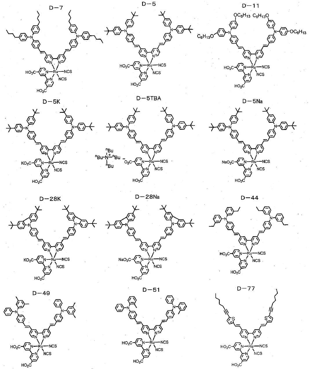
上記金属錯体色素のうち、金属錯体色素D-5、D-7、D-11及びD-28は、R1及びR2が上記式(4)で示される基である好適な態様の金属錯体色素(トランス体であれば式(2A)で表される金属錯体色素)に相当する。
Among the above metal complex dyes, metal complex dyes D-5, D-7, D-11, and D-28 are metal complexes of a preferred embodiment in which R 1 and R 2 are groups represented by the above formula (4) It corresponds to a dye (a metal complex dye represented by the formula (2A) in the case of a trans form).
<金属錯体色素D-5の合成>
まず、下記のスキームの方法に従って、化合物d-2-6及びd-2-9を合成した。
スキーム中、tBuはターシャリーブチルを、Acはアセチルをそれぞれ表す。 <Synthesis of Metal Complex Dye D-5>
First, compounds d-2-6 and d-2-9 were synthesized according to the method of the following scheme.
In the scheme, t Bu represents tertiary butyl, and Ac represents acetyl.
まず、下記のスキームの方法に従って、化合物d-2-6及びd-2-9を合成した。
スキーム中、tBuはターシャリーブチルを、Acはアセチルをそれぞれ表す。 <Synthesis of Metal Complex Dye D-5>
First, compounds d-2-6 and d-2-9 were synthesized according to the method of the following scheme.
In the scheme, t Bu represents tertiary butyl, and Ac represents acetyl.

(i)化合物d-2-3の合成
50gの化合物d-2-1、27.6gの化合物d-2-2、tert-ブトキシナトリウム16.4gをトルエン400mL中、室温で攪拌し、脱気した。そこへ、dppf(1,1’-ビス(ジフェニルホスフィノ)フェロセン)1.97g及び酢酸パラジウム(II)0.8gを添加し、脱気した。その後、得られた混合液を100℃で1時間攪拌した。得られた混合物を放冷後、水400mL、酢酸エチル80mL及びメタノール24mLを加えて、抽出、分液した。分液した有機層に飽和食塩水を加えて分液した。得られた有機層をセライトろ過し、ろ液を濃縮して、得られた粗生成物をシリカゲルカラムクロマトグラフィーで精製することで、40gの化合物d-2-3を得た。 (I) Synthesis of Compound d-2-3 50 g of Compound d-2-1, 27.6 g of Compound d-2-2, and 16.4 g of tert-butoxy sodium were stirred in 400 mL of toluene at room temperature, and deaerated. did. Thereto, 1.97 g of dppf (1,1′-bis (diphenylphosphino) ferrocene) and 0.8 g of palladium (II) acetate were added and deaerated. Thereafter, the obtained mixed solution was stirred at 100 ° C. for 1 hour. The resulting mixture was allowed to cool, and then 400 mL of water, 80 mL of ethyl acetate, and 24 mL of methanol were added, followed by extraction and liquid separation. Saturated brine was added to the separated organic layer for liquid separation. The obtained organic layer was filtered through Celite, the filtrate was concentrated, and the obtained crude product was purified by silica gel column chromatography to obtain 40 g of compound d-2-3.
50gの化合物d-2-1、27.6gの化合物d-2-2、tert-ブトキシナトリウム16.4gをトルエン400mL中、室温で攪拌し、脱気した。そこへ、dppf(1,1’-ビス(ジフェニルホスフィノ)フェロセン)1.97g及び酢酸パラジウム(II)0.8gを添加し、脱気した。その後、得られた混合液を100℃で1時間攪拌した。得られた混合物を放冷後、水400mL、酢酸エチル80mL及びメタノール24mLを加えて、抽出、分液した。分液した有機層に飽和食塩水を加えて分液した。得られた有機層をセライトろ過し、ろ液を濃縮して、得られた粗生成物をシリカゲルカラムクロマトグラフィーで精製することで、40gの化合物d-2-3を得た。 (I) Synthesis of Compound d-2-3 50 g of Compound d-2-1, 27.6 g of Compound d-2-2, and 16.4 g of tert-butoxy sodium were stirred in 400 mL of toluene at room temperature, and deaerated. did. Thereto, 1.97 g of dppf (1,1′-bis (diphenylphosphino) ferrocene) and 0.8 g of palladium (II) acetate were added and deaerated. Thereafter, the obtained mixed solution was stirred at 100 ° C. for 1 hour. The resulting mixture was allowed to cool, and then 400 mL of water, 80 mL of ethyl acetate, and 24 mL of methanol were added, followed by extraction and liquid separation. Saturated brine was added to the separated organic layer for liquid separation. The obtained organic layer was filtered through Celite, the filtrate was concentrated, and the obtained crude product was purified by silica gel column chromatography to obtain 40 g of compound d-2-3.
(ii)化合物d-2-6の合成
4.5gの化合物d-2-4を窒素ガス雰囲気下、-10℃でTHF(テラヒドロフラン)135mLに溶解し、LDA(リチウムジイソプロピルアミド)の2M(mol/L)溶液25.7mLを滴下し、10分攪拌した。その後、得られた反応液に、19.8gの化合物d-2-3をTHF68mLに溶解した溶液を滴下し、-5℃で10分攪拌し、更に室温で40分攪拌した。得られた液に飽和塩化アンモニウム水溶液150mLを添加後、分液を行い、有機層を濃縮乾固した。
こうして得られた粗生成物(化合物d-2-5を含む。)及びPPTS(ピリジニウムパラトルエンスルホン酸)12.3gを、トルエン300mLに加え、窒素ガス雰囲気下で1時間加熱還流した。得られた反応液に酢酸エチル、水及び飽和重曹水を加えて分液し、有機層を濃縮した。得られた粗生成物をシリカゲルカラムクロマトグラフィーで精製することで、11gの化合物d-2-6を得た。 (Ii) Synthesis of compound d-2-6 4.5 g of compound d-2-4 was dissolved in 135 mL of THF (terahydrofuran) at −10 ° C. under a nitrogen gas atmosphere, and 2M of LDA (lithium diisopropylamide) was dissolved. 25.7 mL of (mol / L) solution was added dropwise and stirred for 10 minutes. Thereafter, a solution of 19.8 g of compound d-2-3 dissolved in 68 mL of THF was added dropwise to the resulting reaction solution, and the mixture was stirred at −5 ° C. for 10 minutes and further stirred at room temperature for 40 minutes. After adding 150 mL of saturated ammonium chloride aqueous solution to the obtained liquid, liquid separation was performed and the organic layer was concentrated to dryness.
The crude product thus obtained (including compound d-2-5) and 12.3 g of PPTS (pyridinium paratoluenesulfonic acid) were added to 300 mL of toluene, and the mixture was heated to reflux for 1 hour in a nitrogen gas atmosphere. Ethyl acetate, water, and saturated aqueous sodium hydrogen carbonate were added to the obtained reaction solution for liquid separation, and the organic layer was concentrated. The obtained crude product was purified by silica gel column chromatography to obtain 11 g of compound d-2-6.
(iii)化合物d-2-9の合成
30.6gの化合物d-2-7、及び、30.0gの化合物d-2-8をEtOH(エタノール)中で2時間加熱攪拌した後、濃縮することで、60.6gの化合物d-2-9を得た。 (Iii) Synthesis of Compound d-2-9 30.6 g of Compound d-2-7 and 30.0 g of Compound d-2-8 are heated and stirred in EtOH (ethanol) for 2 hours and then concentrated. This gave 60.6 g of compound d-2-9.
30.6gの化合物d-2-7、及び、30.0gの化合物d-2-8をEtOH(エタノール)中で2時間加熱攪拌した後、濃縮することで、60.6gの化合物d-2-9を得た。 (Iii) Synthesis of Compound d-2-9 30.6 g of Compound d-2-7 and 30.0 g of Compound d-2-8 are heated and stirred in EtOH (ethanol) for 2 hours and then concentrated. This gave 60.6 g of compound d-2-9.
次いで、下記スキームの方法に従って、金属錯体色素D-5を合成した。
(iv)エステル化合物D-5(1S)及びD-5(2S)並びに金属錯体色素D-5(6)の合成 Next, metal complex dye D-5 was synthesized according to the method of the following scheme.
(Iv) Synthesis of ester compounds D-5 (1S) and D-5 (2S) and metal complex dye D-5 (6)
(iv)エステル化合物D-5(1S)及びD-5(2S)並びに金属錯体色素D-5(6)の合成 Next, metal complex dye D-5 was synthesized according to the method of the following scheme.
(Iv) Synthesis of ester compounds D-5 (1S) and D-5 (2S) and metal complex dye D-5 (6)
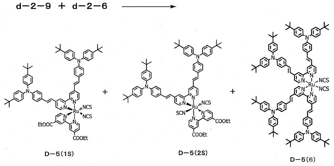
1gの化合物d-2-9、及び、1.48gの化合物d-2-6をDMF(N,N-ジメチルホルムアミド)20mL中にて、所定温度で所定時間加熱攪拌した。得られた反応液を濃縮後、水を加えて、ろ過した。次いで、捕集した析出物をジエチルエーテルで洗浄した。得られた粗生成物をシリカゲルカラムクロマトグラフィーで精製することで、所定量のエステル化合物D-5(1S)及びD-5(2S)と、金属錯体色素D-5(6)とをそれぞれ得た。エステル化合物D-5(1S)及びD-5(2S)と金属錯体色素D-5(6)との生成比は反応条件を制御することにより調整することが可能である。
1 g of compound d-2-9 and 1.48 g of compound d-2-6 were stirred in 20 mL of DMF (N, N-dimethylformamide) at a predetermined temperature for a predetermined time. The obtained reaction solution was concentrated, water was added, and the mixture was filtered. Next, the collected precipitate was washed with diethyl ether. The obtained crude product is purified by silica gel column chromatography to obtain predetermined amounts of ester compounds D-5 (1S) and D-5 (2S) and metal complex dye D-5 (6), respectively. It was. The production ratio of the ester compounds D-5 (1S) and D-5 (2S) and the metal complex dye D-5 (6) can be adjusted by controlling the reaction conditions.
(v)金属錯体色素D-5(1)及びD-5(2)の合成
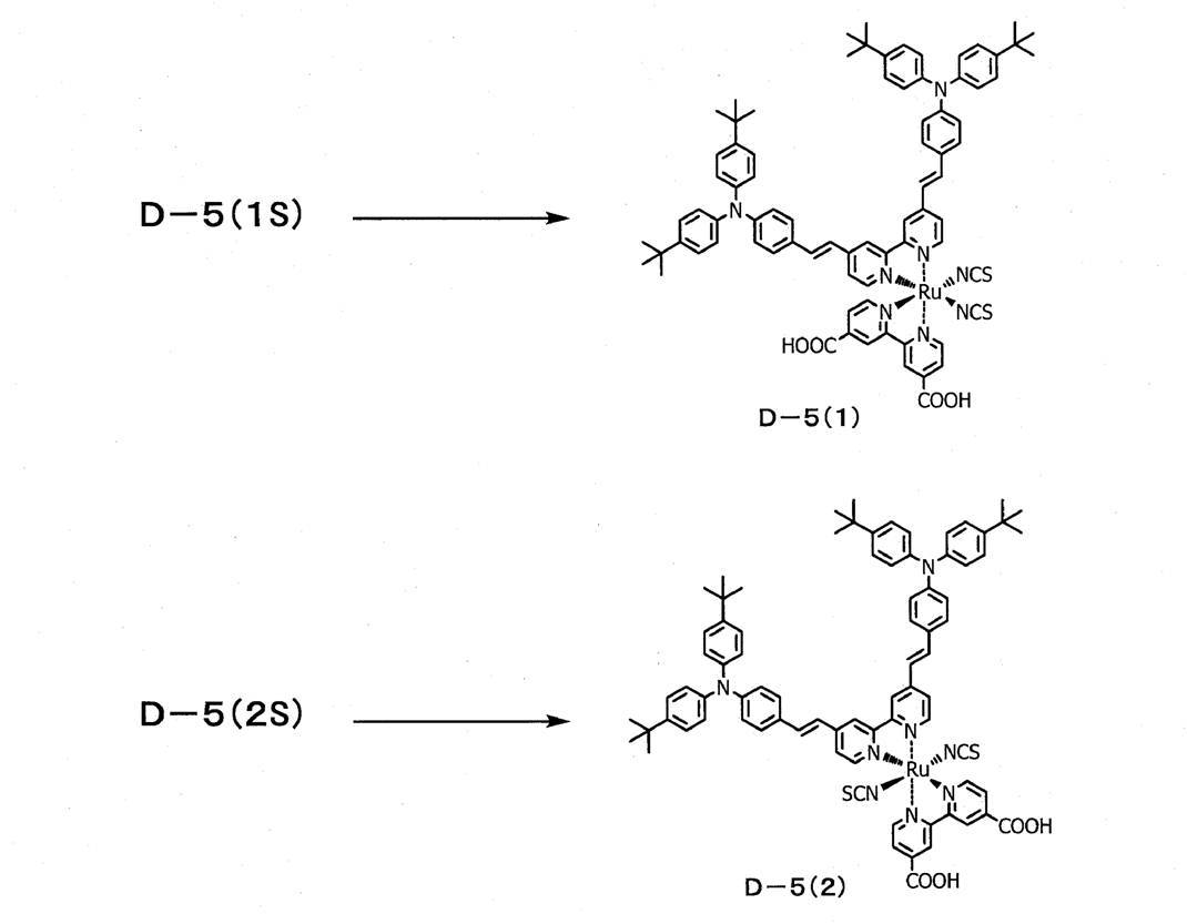
(V) Synthesis of metal complex dyes D-5 (1) and D-5 (2)
1.3gの化合物D-5(1S)にDMF80mL、水4mL及び3N-水酸化ナトリウム水溶液1.6mLを加え、30℃で1時間攪拌した。そこへ、1N-トリフルオロメタンスルホン酸水溶液を滴下し、pH3.0とした。これをろ過して、析出物として金属錯体色素D-5(1)を1.1g得た。
金属錯体色素D-5(1)の合成と同様にして、金属錯体色素D-5(2)を合成した。
このようにして、金属錯体色素D-5を合成した。 To 1.3 g of compound D-5 (1S), 80 mL of DMF, 4 mL of water, and 1.6 mL of 3N sodium hydroxide aqueous solution were added, and the mixture was stirred at 30 ° C. for 1 hour. Thereto, 1N-trifluoromethanesulfonic acid aqueous solution was dropped to adjust the pH to 3.0. This was filtered to obtain 1.1 g of metal complex dye D-5 (1) as a precipitate.
In the same manner as in the synthesis of metal complex dye D-5 (1), metal complex dye D-5 (2) was synthesized.
In this way, a metal complex dye D-5 was synthesized.
<金属錯体色素D-5の同定>
得られた金属錯体色素D-5(1)及びD-5(2)は、LC-MS(液体クロマトグラフ質量分析)、及び、MALDI-MS(マトリックス支援レーザー脱離イオン化法質量分析)の測定結果により、同一分子量であることを確認した。また、NMR(核磁気共鳴)スペクトルの測定結果により、金属錯体色素D-5(1)とD-5(2)が互いに、6配位錯体構造についての幾何異性体であることを同定した。
また、金属錯体色素D-5(6)は、MALDI-MS測定結果により、上記構造を有していることを、確認、同定した。 <Identification of metal complex dye D-5>
The obtained metal complex dyes D-5 (1) and D-5 (2) were measured by LC-MS (liquid chromatograph mass spectrometry) and MALDI-MS (matrix-assisted laser desorption ionization mass spectrometry). The result confirmed that it was the same molecular weight. Further, from the measurement results of NMR (nuclear magnetic resonance) spectrum, it was identified that the metal complex dyes D-5 (1) and D-5 (2) are geometric isomers with respect to the six-coordinate complex structure.
Moreover, it was confirmed and identified that the metal complex dye D-5 (6) had the above-described structure based on the MALDI-MS measurement result.
更に、合成した金属錯体色素D-5(1)、D-5(2)及びD-5(6)を、下記測定条件でのHPLC測定により、確認した。
各金属錯体色素の保持時間を示す。
金属錯体色素D-5(1):13.2~13.5分
金属錯体色素D-5(2):13.6~13.9分
金属錯体色素D-5(6):18.0~18.5分
HPLC測定条件:
カラム:YMC-Triart C18(150mm×4.6mml.D.、粒子径5μm、細孔径12nm)
A液:0.1%TFA、40%THF/60%H2O(体積比)
B液:0.1%TFA、100%THF(体積比)
タイムプログラム:(0-20min)Bconc.30%→80%(グラジエント)、(20-30min)Bconc.30%
流速:1.0mL/min
オーブン温度:40℃
検出波長:254nm
サンプル注入量:5μL Furthermore, the synthesized metal complex dyes D-5 (1), D-5 (2) and D-5 (6) were confirmed by HPLC measurement under the following measurement conditions.
The retention time of each metal complex dye is shown.
Metal complex dye D-5 (1): 13.2 to 13.5 minutes Metal complex dye D-5 (2): 13.6 to 13.9 minutes Metal complex dye D-5 (6): 18.0 to 18.5 minutes HPLC measurement conditions:
Column: YMC-Triart C18 (150 mm × 4.6 mm.D., particle size 5 μm, pore size 12 nm)
Liquid A: 0.1% TFA, 40% THF / 60% H 2 O (volume ratio)
Liquid B: 0.1% TFA, 100% THF (volume ratio)
Time program: (0-20 min) Bconc. 30% → 80% (gradient), (20-30 min) Bconc. 30%
Flow rate: 1.0 mL / min
Oven temperature: 40 ° C
Detection wavelength: 254 nm
Sample injection volume: 5 μL
また、得られた金属錯体色素D-5(2)とD-5(6)の溶液吸収スペクトル(溶媒:テトラブチルアンモニウムヒドロキシド(メタノール溶液))を測定したところ、550~600nmのモル吸光係数(ε)が、金属錯体色素(1)に対して、約1.1~2倍向上することが確認された。
Further, when the solution absorption spectra (solvent: tetrabutylammonium hydroxide (methanol solution)) of the obtained metal complex dyes D-5 (2) and D-5 (6) were measured, the molar extinction coefficient of 550 to 600 nm was measured. It was confirmed that (ε) was improved about 1.1 to 2 times with respect to the metal complex dye (1).
<金属錯体色素D-7、D-11、D-28、D-44、D-49、D-51及びD-77の合成>
金属錯体色素D-5の合成と同様にして、金属錯体色素D-7、D-11、D-28、D-44、D-49、D-51及びD-77を合成した。 <Synthesis of Metal Complex Dyes D-7, D-11, D-28, D-44, D-49, D-51 and D-77>
In the same manner as the synthesis of the metal complex dye D-5, metal complex dyes D-7, D-11, D-28, D-44, D-49, D-51 and D-77 were synthesized.
金属錯体色素D-5の合成と同様にして、金属錯体色素D-7、D-11、D-28、D-44、D-49、D-51及びD-77を合成した。 <Synthesis of Metal Complex Dyes D-7, D-11, D-28, D-44, D-49, D-51 and D-77>
In the same manner as the synthesis of the metal complex dye D-5, metal complex dyes D-7, D-11, D-28, D-44, D-49, D-51 and D-77 were synthesized.
<金属錯体色素D-5K、D-5TBA、D-5Na、D-28K及びD-28Naの合成>
(i)金属錯体色素D-5Kの合成
上記のようにして合成した金属錯体色素D-5(1)をメタノール5mL中にて、室温で攪拌した。そこへ、金属錯体色素D-5(1)と等モルの水酸化カリウム水溶液を加えて、混合物を1時間攪拌した。反応液に窒素ガスをバブリングして溶媒を留去し、乾燥させて、金属錯体色素D-5K(1)を得た。
また、金属錯体色素D-5K(1)の合成と同様にして、金属錯体色素D-5K(2)を合成した。
このようにして、金属錯体色素D-5Kを合成した。
金属錯体色素D-5Kにおいて、カリウムイオンの存在比は、M1及びM2の総モル量のうち1.0モルであった。
(ii)金属錯体色素D-5Kの合成と同様にして、金属錯体色素D-5TBA、D-5Na、D-28K及びD-28Naを、それぞれ、合成した。
得られた上記金属錯体色素において、塩の存在比は、M1及びM2の総モル量のうち1.0モルであった。 <Synthesis of metal complex dyes D-5K, D-5TBA, D-5Na, D-28K and D-28Na>
(I) Synthesis of Metal Complex Dye D-5K The metal complex dye D-5 (1) synthesized as described above was stirred in 5 mL of methanol at room temperature. Thereto were added metal complex dye D-5 (1) and an equimolar aqueous potassium hydroxide solution, and the mixture was stirred for 1 hour. Nitrogen gas was bubbled through the reaction solution to distill off the solvent, followed by drying to obtain a metal complex dye D-5K (1).
Further, a metal complex dye D-5K (2) was synthesized in the same manner as the synthesis of the metal complex dye D-5K (1).
In this way, metal complex dye D-5K was synthesized.
In the metal complex dye D-5K, the abundance ratio of potassium ions was 1.0 mol out of the total molar amount of M 1 and M 2 .
(Ii) In the same manner as the synthesis of the metal complex dye D-5K, metal complex dyes D-5TBA, D-5Na, D-28K and D-28Na were respectively synthesized.
In the obtained metal complex dye, the abundance ratio of the salt was 1.0 mol out of the total molar amount of M 1 and M 2 .
<金属錯体色素の同定>
上記のようにして合成した金属錯体色素D-7、D-11、D-5K、D-5TBA、D-5Na、D-28K、D-28Na、D-44、D-49、D-51及びD-77を、金属錯体色素D-5と同様にして、質量分析、NMRスペクトル及びHPLC測定により、確認、同定した。
各金属錯体色素D-nXにおける、HPLCの保持時間は、金属錯体色素D-5と同様に、金属錯体色素D-nX(1)が最も短く、次いで金属錯体色素D-nX(2)が短く、金属錯体色素D-nX(6)が最も長いことが確認された。 <Identification of metal complex dye>
Metal complex dyes D-7, D-11, D-5K, D-5TBA, D-5Na, D-28K, D-28Na, D-44, D-49, D-51 synthesized as described above D-77 was confirmed and identified by mass spectrometry, NMR spectrum and HPLC measurement in the same manner as metal complex dye D-5.
In each metal complex dye D-nX, the HPLC retention time is the shortest for the metal complex dye D-nX (1), followed by the metal complex dye D-nX (2), as with the metal complex dye D-5. It was confirmed that the metal complex dye D-nX (6) was the longest.
<金属錯体色素D-C1~D-C4の合成>
金属錯体色素D-5の合成と同様にして、金属錯体色素D-C1~D-C3を合成した。これらの金属錯体色素は、いずれも、金属錯体色素(1)及び金属錯体色素(2)に相当するが、そのトランス体は金属錯体色素(2A)には相当しないものである。本実施例においては、これらの金属錯体色素を第2の色素吸着態様に対する対比に用いているため、金属錯体色素D-C1~D-C3と称する。しかし、これらの金属錯体色素は、上述のように、金属錯体色素(1)及び金属錯体色素(2)に相当するものであり、本発明から除外するものではない。
金属錯体色素D-C4は、金属錯体色素D-5の合成において、化合物d-2-6の代わりに化合物d-2-9を用いたこと以外は、金属錯体色素D-5の合成と同様にして、合成した。
合成した金属錯体色素を以下に示す。 <Synthesis of metal complex dyes D-C1 to D-C4>
In the same manner as the synthesis of metal complex dye D-5, metal complex dyes D-C1 to D-C3 were synthesized. All of these metal complex dyes correspond to the metal complex dye (1) and the metal complex dye (2), but their trans form does not correspond to the metal complex dye (2A). In this example, since these metal complex dyes are used for comparison with the second dye adsorption mode, they are referred to as metal complex dyes D-C1 to D-C3. However, as described above, these metal complex dyes correspond to the metal complex dye (1) and the metal complex dye (2) and are not excluded from the present invention.
The metal complex dye D-C4 is the same as the metal complex dye D-5 except that the compound d-2-9 was used instead of the compound d-2-6 in the synthesis of the metal complex dye D-5. And synthesized.
The synthesized metal complex dye is shown below.
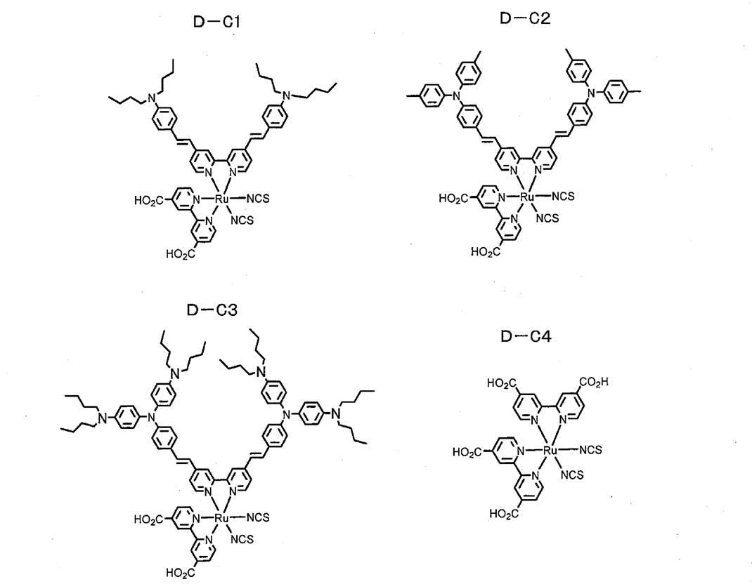
実施例2(色素増感太陽電池の製造)
実施例1で合成した金属錯体色素を用いて、以下に示す手順により、図2に示す色素増感太陽電池20(5mm×5mmのスケール)を製造し、下記性能を評価した。結果を表1-1~表1-5(併せて表1と称する。)に示す。 Example 2 (Production of dye-sensitized solar cell)
Using the metal complex dye synthesized in Example 1, the dye-sensitized solar cell 20 (5 mm × 5 mm scale) shown in FIG. 2 was produced according to the following procedure, and the following performance was evaluated. The results are shown in Table 1-1 to Table 1-5 (collectively referred to as Table 1).
(受光電極前駆体の作製)
ガラス基板(基板44、厚み4mm)上にフッ素ドープされたSnO2導電膜(透明導電膜43、膜厚;500nm)を形成して、導電性支持体41を作製した。そして、このSnO2導電膜を形成させたガラス基板を、40mMの四塩化チタン水溶液に30分間浸漬して、超純水、エタノールで洗浄した後、450℃で焼成することにより、SnO2導電膜上に酸化チタンの薄膜層(金属酸化物被膜、図2において図示しない。)を形成した。この薄膜層上に、チタニアペースト「18NR-T」(DyeSol社製)をスクリーン印刷し、120℃で乾燥させ、次いで、チタニアペースト「18NR-T」を再度スクリーン印刷し、120℃で1時間乾燥させた。その後、乾燥させたチタニアペーストを500℃で焼成した。このようにして、半導体層45(膜厚:10μm)を成膜した。更に、この半導体層45上に、チタニアペースト「18NR-AO」(DyeSol社製)をスクリーン印刷し、120℃で1時間乾燥させた後に、乾燥させたチタニアペーストを500℃で焼成し、半導体層45上に光散乱層46(膜厚:5μm)を成膜した。更に、このガラス基板を20mMの四塩化チタン水溶液に浸漬して、超純水、次いでエタノールで洗浄することにより、チタニアペースト「18NR-AO」を焼結してなる層の表面に酸化チタン層(金属酸化物被膜、図2において図示しない。)を形成した。以上の操作により、SnO2導電膜上に、感光体層42(受光面の面積:5mm×5mm、膜厚:15μm)を形成し、金属錯体色素を担持していない受光電極前駆体を作製した。 (Preparation of light receiving electrode precursor)
A conductive substrate 41 was prepared by forming a fluorine-doped SnO 2 conductive film (transparentconductive film 43, film thickness: 500 nm) on a glass substrate (substrate 44, thickness 4 mm). Then, the glass substrate obtained by forming the SnO 2 conductive film was immersed for 30 minutes in an aqueous titanium tetrachloride solution of 40 mM, ultrapure water, washed with ethanol, followed by firing at 450 ° C., SnO 2 conductive film A thin film layer of titanium oxide (metal oxide film, not shown in FIG. 2) was formed thereon. On this thin film layer, a titania paste “18NR-T” (manufactured by DyeSol) was screen-printed and dried at 120 ° C., and then the titania paste “18NR-T” was screen-printed again and dried at 120 ° C. for 1 hour. I let you. Thereafter, the dried titania paste was baked at 500 ° C. In this way, a semiconductor layer 45 (film thickness: 10 μm) was formed. Further, a titania paste “18NR-AO” (manufactured by DyeSol) is screen-printed on the semiconductor layer 45 and dried at 120 ° C. for 1 hour, and then the dried titania paste is baked at 500 ° C. A light scattering layer 46 (film thickness: 5 μm) was formed on 45. Further, the glass substrate is immersed in a 20 mM aqueous solution of titanium tetrachloride and washed with ultrapure water and then with ethanol, so that a titanium oxide layer (18NR-AO) is sintered on the surface of the layer formed by sintering. A metal oxide film (not shown in FIG. 2) was formed. By the above operation, a photoreceptor layer 42 (light receiving surface area: 5 mm × 5 mm, film thickness: 15 μm) was formed on the SnO 2 conductive film, and a light receiving electrode precursor not carrying a metal complex dye was produced. .
ガラス基板(基板44、厚み4mm)上にフッ素ドープされたSnO2導電膜(透明導電膜43、膜厚;500nm)を形成して、導電性支持体41を作製した。そして、このSnO2導電膜を形成させたガラス基板を、40mMの四塩化チタン水溶液に30分間浸漬して、超純水、エタノールで洗浄した後、450℃で焼成することにより、SnO2導電膜上に酸化チタンの薄膜層(金属酸化物被膜、図2において図示しない。)を形成した。この薄膜層上に、チタニアペースト「18NR-T」(DyeSol社製)をスクリーン印刷し、120℃で乾燥させ、次いで、チタニアペースト「18NR-T」を再度スクリーン印刷し、120℃で1時間乾燥させた。その後、乾燥させたチタニアペーストを500℃で焼成した。このようにして、半導体層45(膜厚:10μm)を成膜した。更に、この半導体層45上に、チタニアペースト「18NR-AO」(DyeSol社製)をスクリーン印刷し、120℃で1時間乾燥させた後に、乾燥させたチタニアペーストを500℃で焼成し、半導体層45上に光散乱層46(膜厚:5μm)を成膜した。更に、このガラス基板を20mMの四塩化チタン水溶液に浸漬して、超純水、次いでエタノールで洗浄することにより、チタニアペースト「18NR-AO」を焼結してなる層の表面に酸化チタン層(金属酸化物被膜、図2において図示しない。)を形成した。以上の操作により、SnO2導電膜上に、感光体層42(受光面の面積:5mm×5mm、膜厚:15μm)を形成し、金属錯体色素を担持していない受光電極前駆体を作製した。 (Preparation of light receiving electrode precursor)
A conductive substrate 41 was prepared by forming a fluorine-doped SnO 2 conductive film (transparent
(色素吸着方法)
次に、金属錯体色素を担持していない感光体層42に実施例1で合成した各金属錯体色素を以下のようにして担持させた。
まず、溶媒無含有の色素組成物を調製した。すなわち、表1に示す各金属錯体色素を、表1に示すモル量(モル%)で、それぞれ混合して、色素組成物を調製した。ただし、金属錯体色素D-5K、D-5TBA及びD-5Naにおいては、金属錯体色素D-5X(6)として、金属錯体色素D-5(6)を用いた。金属錯体色素D-28K及びD-28Naにおいても、同様に、金属錯体色素D-28X(6)として、金属錯体色素D-28(6)を用いた。
上記のようにして、同じ金属錯体色素D-nを用いて調製した、金属錯体色素の含有比が異なる色素組成物(例えば、13種、試料番号1~12及びc1)を、1つの群として、色素組成物群ということがある。
次いで、得られた色素組成物を用いて色素溶液を調製した。すなわち、得られた色素組成物それぞれを、t-ブタノールとアセトニトリルとの1:1(体積比)の混合溶媒に、金属錯体色素の合計濃度が2×10⁻⁴モル/Lとなるように混合した。更にそこへ共吸着剤としてケノデオキシコール酸を上記金属錯体色素1モルに対して10モル加え、各色素溶液を調製した。
このようにして調製した各色素溶液に受光電極前駆体を25℃で5時間浸漬し、色素溶液から引き上げ後に乾燥させることにより、受光電極前駆体に金属錯体色素(色素組成物)が担持した受光電極40をそれぞれ作製した。 (Dye adsorption method)
Next, each metal complex dye synthesized in Example 1 was supported on the photoreceptor layer 42 not supporting the metal complex dye as follows.
First, a solvent-free dye composition was prepared. That is, each metal complex pigment | dye shown in Table 1 was mixed with the molar amount (mol%) shown in Table 1, respectively, and the pigment | dye composition was prepared. However, in the metal complex dyes D-5K, D-5TBA, and D-5Na, the metal complex dye D-5 (6) was used as the metal complex dye D-5X (6). Similarly, in the metal complex dyes D-28K and D-28Na, the metal complex dye D-28 (6) was used as the metal complex dye D-28X (6).
Dye compositions (for example, 13 types, sample numbers 1 to 12 and c1) prepared using the same metal complex dye Dn and having different metal complex dye content ratios as described above as one group , Sometimes referred to as a dye composition group.
Next, a dye solution was prepared using the obtained dye composition. That is, each obtained dye composition was mixed in a 1: 1 (volume ratio) mixed solvent of t-butanol and acetonitrile so that the total concentration of the metal complex dye was 2 × 10 −4 mol / L. did. Further, 10 moles of chenodeoxycholic acid as a co-adsorbent was added to 1 mole of the above metal complex dye to prepare each dye solution.
The light-receiving electrode precursor is immersed in each dye solution thus prepared at 25 ° C. for 5 hours, pulled up from the dye solution, and then dried, so that the light-receiving electrode precursor carries a metal complex dye (dye composition).Electrodes 40 were produced respectively.
次に、金属錯体色素を担持していない感光体層42に実施例1で合成した各金属錯体色素を以下のようにして担持させた。
まず、溶媒無含有の色素組成物を調製した。すなわち、表1に示す各金属錯体色素を、表1に示すモル量(モル%)で、それぞれ混合して、色素組成物を調製した。ただし、金属錯体色素D-5K、D-5TBA及びD-5Naにおいては、金属錯体色素D-5X(6)として、金属錯体色素D-5(6)を用いた。金属錯体色素D-28K及びD-28Naにおいても、同様に、金属錯体色素D-28X(6)として、金属錯体色素D-28(6)を用いた。
上記のようにして、同じ金属錯体色素D-nを用いて調製した、金属錯体色素の含有比が異なる色素組成物(例えば、13種、試料番号1~12及びc1)を、1つの群として、色素組成物群ということがある。
次いで、得られた色素組成物を用いて色素溶液を調製した。すなわち、得られた色素組成物それぞれを、t-ブタノールとアセトニトリルとの1:1(体積比)の混合溶媒に、金属錯体色素の合計濃度が2×10⁻⁴モル/Lとなるように混合した。更にそこへ共吸着剤としてケノデオキシコール酸を上記金属錯体色素1モルに対して10モル加え、各色素溶液を調製した。
このようにして調製した各色素溶液に受光電極前駆体を25℃で5時間浸漬し、色素溶液から引き上げ後に乾燥させることにより、受光電極前駆体に金属錯体色素(色素組成物)が担持した受光電極40をそれぞれ作製した。 (Dye adsorption method)
Next, each metal complex dye synthesized in Example 1 was supported on the photoreceptor layer 42 not supporting the metal complex dye as follows.
First, a solvent-free dye composition was prepared. That is, each metal complex pigment | dye shown in Table 1 was mixed with the molar amount (mol%) shown in Table 1, respectively, and the pigment | dye composition was prepared. However, in the metal complex dyes D-5K, D-5TBA, and D-5Na, the metal complex dye D-5 (6) was used as the metal complex dye D-5X (6). Similarly, in the metal complex dyes D-28K and D-28Na, the metal complex dye D-28 (6) was used as the metal complex dye D-28X (6).
Dye compositions (for example, 13 types, sample numbers 1 to 12 and c1) prepared using the same metal complex dye Dn and having different metal complex dye content ratios as described above as one group , Sometimes referred to as a dye composition group.
Next, a dye solution was prepared using the obtained dye composition. That is, each obtained dye composition was mixed in a 1: 1 (volume ratio) mixed solvent of t-butanol and acetonitrile so that the total concentration of the metal complex dye was 2 × 10 −4 mol / L. did. Further, 10 moles of chenodeoxycholic acid as a co-adsorbent was added to 1 mole of the above metal complex dye to prepare each dye solution.
The light-receiving electrode precursor is immersed in each dye solution thus prepared at 25 ° C. for 5 hours, pulled up from the dye solution, and then dried, so that the light-receiving electrode precursor carries a metal complex dye (dye composition).
(色素増感太陽電池の組み立て)
対極48として、上記の導電性支持体41と同様の形状と大きさを有する白金電極(Pt薄膜の厚さ:100nm)を作製した。また、電解液として、ヨウ素0.1M(モル/L)、ヨウ化リチウム0.1M、4-t-ブチルピリジン0.005M及び1,2-ジメチル-3-プロピルイミダゾリウムヨージド0.6Mをアセトニトリルに溶解して、液体電解質を調製した。更に、感光体層42の大きさに合わせた形状を有するデュポン社製のスペーサーS(商品名:「サーリン」)を準備した。
上記のようにして作製した受光電極40それぞれと対極48とを、上記スペーサーSを介して、対向させて熱圧着させた。その後に、感光体層42と対極48との間に電解液注入口から上記液体電解質を充填して、電荷移動体層47を形成した。このようにして作製した電池の外周及び電解液注入口を、ナガセケムテック製レジンXNR-5516を用いて、封止、硬化し、各色素増感太陽電池(試料番号1~140及びc1~c22)を製造した。
色素増感太陽電池についても、色素組成物と同様に、同じ金属錯体色素D-nを用いて得られたものを、1つの群として、色素増感太陽電池群ということがある。 (Assembly of dye-sensitized solar cell)
As thecounter electrode 48, a platinum electrode (Pt thin film thickness: 100 nm) having the same shape and size as the conductive support 41 was prepared. In addition, as an electrolytic solution, iodine 0.1M (mol / L), lithium iodide 0.1M, 4-t-butylpyridine 0.005M and 1,2-dimethyl-3-propylimidazolium iodide 0.6M were used. A liquid electrolyte was prepared by dissolving in acetonitrile. Furthermore, a spacer S (trade name: “Surlin”) manufactured by DuPont having a shape corresponding to the size of the photoreceptor layer 42 was prepared.
Each of thelight receiving electrodes 40 and the counter electrode 48 manufactured as described above was thermocompression bonded so as to face each other with the spacer S interposed therebetween. Thereafter, the liquid electrolyte was filled between the photoreceptor layer 42 and the counter electrode 48 from the electrolyte solution injection port to form the charge transfer layer 47. The outer periphery and electrolyte inlet of the battery thus produced were sealed and cured using Resin XNR-5516 manufactured by Nagase Chemtech, and each dye-sensitized solar cell (sample numbers 1 to 140 and c1 to c22). ) Was manufactured.
Similarly to the dye composition, the dye-sensitized solar cell may be a group obtained by using the same metal complex dye Dn as a group and may be referred to as a dye-sensitized solar cell group.
対極48として、上記の導電性支持体41と同様の形状と大きさを有する白金電極(Pt薄膜の厚さ:100nm)を作製した。また、電解液として、ヨウ素0.1M(モル/L)、ヨウ化リチウム0.1M、4-t-ブチルピリジン0.005M及び1,2-ジメチル-3-プロピルイミダゾリウムヨージド0.6Mをアセトニトリルに溶解して、液体電解質を調製した。更に、感光体層42の大きさに合わせた形状を有するデュポン社製のスペーサーS(商品名:「サーリン」)を準備した。
上記のようにして作製した受光電極40それぞれと対極48とを、上記スペーサーSを介して、対向させて熱圧着させた。その後に、感光体層42と対極48との間に電解液注入口から上記液体電解質を充填して、電荷移動体層47を形成した。このようにして作製した電池の外周及び電解液注入口を、ナガセケムテック製レジンXNR-5516を用いて、封止、硬化し、各色素増感太陽電池(試料番号1~140及びc1~c22)を製造した。
色素増感太陽電池についても、色素組成物と同様に、同じ金属錯体色素D-nを用いて得られたものを、1つの群として、色素増感太陽電池群ということがある。 (Assembly of dye-sensitized solar cell)
As the
Each of the
Similarly to the dye composition, the dye-sensitized solar cell may be a group obtained by using the same metal complex dye Dn as a group and may be referred to as a dye-sensitized solar cell group.
<色素増感太陽電池における金属錯体色素の含有比>
製造した色素増感太陽電池(試料番号1~140)それぞれにおいて、半導体微粒子に吸着された各金属錯体色素の含有比を測定した。具体的には、各色素増感太陽電池の感光体層をテトラブチルアンモニウムヒドロキシドのメタノール溶液に浸漬して、金属錯体色素を溶出させた。この溶出溶液を、上記測定条件でHPLCを測定して、各色素増感太陽電池の半導体微粒子に吸着されていた金属錯体色素それぞれの吸着量を求めた。金属錯体色素(1)、金属錯体色素(2)及び金属錯体色素(6)の吸着量に基づいて、金属錯体色素の含有比を算出した。その結果、各色素増感太陽電池において、金属錯体色素の含有比は、用いた色素組成物における金属錯体色素の含有比とほぼ一致した。 <Content ratio of metal complex dye in dye-sensitized solar cell>
In each of the produced dye-sensitized solar cells (sample numbers 1 to 140), the content ratio of each metal complex dye adsorbed on the semiconductor fine particles was measured. Specifically, the photoreceptor layer of each dye-sensitized solar cell was immersed in a methanol solution of tetrabutylammonium hydroxide to elute the metal complex dye. The elution solution was subjected to HPLC measurement under the above measurement conditions to determine the amount of adsorption of each metal complex dye adsorbed on the semiconductor fine particles of each dye-sensitized solar cell. The content ratio of the metal complex dye was calculated based on the amount of adsorption of the metal complex dye (1), the metal complex dye (2), and the metal complex dye (6). As a result, in each dye-sensitized solar cell, the content ratio of the metal complex dye almost coincided with the content ratio of the metal complex dye in the used dye composition.
<色素増感太陽電池における金属カチオン及び非金属カチオンの存在比>
製造した各色素増感太陽電池D-5K、D-5TBA、D-5Na、D-28K及びD-28Naについて、以下のようにして得られた金属カチオン及び非金属カチオンの含有量から、金属カチオン及び非金属カチオンの存在比を測定した。その結果、上記合成時の比率とほぼ一致した。
上述の金属錯体色素の含有比と同様にして、色素増感太陽電池から溶出させて得た色素試料0.01gを秤量し、硝酸5mL及び塩酸1mLを添加した後、テフロン(登録商標)製容器に入れてマイクロウェーブで灰化処理を行った。残留物に水を加えて40mLにメスアップし、誘導結合プラズマ発光分光分析(Inductively Coupled Plasma Optical Emission Spectroscopy:ICP-OES)により、金属カチオンの含有量を定量した。
また、上記色素試料をジメチルスルホキシド-d6(DMSO-d6)に溶解して、1H-NMRスペクトルを測定することにより、非金属カチオンの含有量を定量した。 <Abundance ratio of metal cation and nonmetal cation in dye-sensitized solar cell>
For each of the dye-sensitized solar cells D-5K, D-5TBA, D-5Na, D-28K and D-28Na produced, the metal cation was obtained from the contents of the metal cation and non-metal cation obtained as follows. And the abundance ratio of non-metallic cations was measured. As a result, it almost coincided with the ratio at the time of synthesis.
In the same manner as the content ratio of the metal complex dye described above, 0.01 g of a dye sample obtained by elution from a dye-sensitized solar cell was weighed, 5 mL of nitric acid and 1 mL of hydrochloric acid were added, and then a Teflon (registered trademark) container. And incinerated with microwaves. Water was added to the residue to make up to 40 mL, and the content of the metal cation was quantified by Inductively Coupled Plasma Optical Emission Spectroscopy (ICP-OES).
Further, the content of the nonmetallic cation was quantified by dissolving the dye sample in dimethyl sulfoxide-d6 (DMSO-d6) and measuring the 1 H-NMR spectrum.
<光電変換効率の評価~評価方法[A](高照度環境:太陽光)>
製造した色素増感太陽電池それぞれを用いて電池特性試験を行った。電池特性試験は、ソーラーシミュレーター「PEC-L15」(ペクセル・テクノロジーズ社製)を用い、AM1.5Gフィルタを通したキセノンランプから1000W/m2(10万ルクス)の擬似太陽光を各色素増感太陽電池に照射することにより行った。光電変換効率は、ソースメーター「Keithley2401」(テクトロニクス社製)を用いて、擬似太陽光を照射した各色素増感太陽電池の電流-電圧特性を測定することにより、求めた。得られた光電変換効率を変換効率[A]という。
色素増感太陽電池群それぞれにおいて、金属錯体色素(1)のみを吸着させた色素増感太陽電池の変換効率[A(1)]に対する得られた各変換効率[A]の相対値を求めた。
これらの相対値が、以下の評価ランクのいずれに含まれるかを判定した。
本試験において、変換効率[A]の評価は、評価ランクC以上が実用上求められ、好ましくはS、A及びBである。
S:1.3倍を越えていたもの
A:1.2倍を越え、1.3倍以下であったもの
B:1.1倍を越え、1.2倍以下であったもの
C:1.0倍を越え、1.1倍以下であったもの
D:0.9倍を越え、1.0倍以下であったもの
CL:1.0(基準) <Evaluation of photoelectric conversion efficiency to evaluation method [A] (high illumination environment: sunlight)>
A battery characteristic test was performed using each of the produced dye-sensitized solar cells. The battery characteristics test uses a solar simulator “PEC-L15” (Peccell Technologies) to sensitize 1000 W / m 2 (100,000 lux) of simulated sunlight from a xenon lamp through an AM1.5G filter to each dye. This was done by irradiating the solar cell. The photoelectric conversion efficiency was determined by measuring the current-voltage characteristics of each dye-sensitized solar cell irradiated with simulated sunlight using a source meter “Keithley 2401” (manufactured by Tektronix). The obtained photoelectric conversion efficiency is referred to as conversion efficiency [A].
In each dye-sensitized solar cell group, the relative value of each conversion efficiency [A] obtained with respect to the conversion efficiency [A (1) ] of the dye-sensitized solar cell in which only the metal complex dye (1) was adsorbed was determined. .
Which of these relative ranks included these relative values was determined.
In this test, the evaluation of conversion efficiency [A] is practically required to have an evaluation rank C or higher, and preferably S, A, and B.
S: More than 1.3 times A: More than 1.2 times and less than 1.3 times B: More than 1.1 times and less than 1.2 times C: 1 .0 times and 1.1 times or less D: 0.9 times and 1.0 times or less CL: 1.0 (standard)
試料番号1~140の各色素増感太陽電池の変換効率[A]は、いずれも、色素増感太陽電池として十分に機能するものであった。
The conversion efficiencies [A] of the dye-sensitized solar cells of sample numbers 1 to 140 all functioned satisfactorily as dye-sensitized solar cells.
<光電変換効率の評価~評価方法[B](低照度環境:屋内光)>
製造した色素増感太陽電池それぞれを用いて電池特性試験を行った。電池特性試験は、東芝製の白色発光ダイオード(LED)(型番:LDA8N-G-K/D/60W)を用いて行った。照度調整(300μW/cm2(1000ルクス))は、渋谷光学社から販売されているNDフィルター(ND1~ND80)を用いて行った。調整した照度の測定は、オーシャンフォトニクス社製の分光器USB4000用いて確認した。
光電変換効率は、ソースメーター「Keithley2401」(テクトロニクス社製)を用いて、照度を調整した光を照射した各色素増感太陽電池の電流-電圧特性を測定することにより、求めた。得られた光電変換効率を変換効率[B]という。
色素増感太陽電池群それぞれにおいて、金属錯体色素(1)のみを吸着させた色素増感太陽電池の変換効率[B(1)]に対する得られた各変換効率[B]の相対値を求めた。
これらの相対値が、以下の評価ランクのいずれに含まれるかを判定した。
本試験において、変換効率[B]の評価は、評価ランクC以上が実用上求められ、好ましくはS、A及びBである。
S:1.3倍を越えていたもの
A:1.2倍を越え、1.3倍以下であったもの
B:1.1倍を越え、1.2倍以下であったもの
C:1.0倍を越え、1.1倍以下であったもの
D:0.9倍を越え、1.0倍以下であったもの
E:0.8倍を越え、0.9倍以下であったもの
CL:1.0(基準) <Evaluation of photoelectric conversion efficiency to evaluation method [B] (low illumination environment: indoor light)>
A battery characteristic test was performed using each of the produced dye-sensitized solar cells. The battery characteristic test was performed using a white light emitting diode (LED) manufactured by Toshiba (model number: LDA8N-GK / D / 60W). The illuminance adjustment (300 μW / cm 2 (1000 lux)) was performed using ND filters (ND1 to ND80) sold by Shibuya Optical Co., Ltd. The measurement of the adjusted illuminance was confirmed using a spectroscope USB4000 manufactured by Ocean Photonics.
The photoelectric conversion efficiency was determined by measuring the current-voltage characteristics of each dye-sensitized solar cell irradiated with light with adjusted illuminance, using a source meter “Keithley 2401” (manufactured by Tektronix). The obtained photoelectric conversion efficiency is referred to as conversion efficiency [B].
In each dye-sensitized solar cell group, the relative value of each conversion efficiency [B] obtained with respect to the conversion efficiency [B (1) ] of the dye-sensitized solar cell in which only the metal complex dye (1) was adsorbed was determined. .
Which of these relative ranks included these relative values was determined.
In this test, the evaluation of conversion efficiency [B] is practically required to have an evaluation rank C or higher, and preferably S, A, and B.
S: More than 1.3 times A: More than 1.2 times and less than 1.3 times B: More than 1.1 times and less than 1.2 times C: 1 D: over 0.9 and 1.1 times or less D: over 0.9 times and 1.0 times or less E: over 0.8 times and 0.9 times or less Things CL: 1.0 (standard)
試料番号1~140の各色素増感太陽電池の変換効率[B]は、いずれも、色素増感太陽電池として十分に機能するものであった。
The conversion efficiencies [B] of the dye-sensitized solar cells of sample numbers 1 to 140 all functioned satisfactorily as dye-sensitized solar cells.
<作用スペクトルの測定>
製造した色素増感太陽電池それぞれについて、作用スペクトル(IPCEスペクトル)を測定した。
作用スペクトル(IPCE)測定装置:PEC-S20(商品名、ペクセル・テクノロジーズ社製)を用いて、AM1.5Gフィルタを通した150Wのキセノンランプから100mW/cm2の擬似太陽光を各色素増感太陽電池に照射して、作用スペクトルを得た。得られた作用スペクトルにおいて、波長750nmにおけるIPCE(外部量子収率)[C]を求めた。
色素増感太陽電池群それぞれにおいて、金属錯体色素(1)のみを吸着させた色素増感太陽電池の波長750nmにおけるIPCE(外部量子収率)[C(1)]に対する得られた各IPCE[C]の相対値を求めた。
これらの相対値が、以下の評価ランクのいずれに含まれるかを判定した。
本試験において、波長750nmにおけるIPCE(外部量子収率)[C]の評価は、評価ランクC以上が実用上求められ、好ましくはS、A及びBである。
S:3.0倍を越えていたもの
A:2.0倍を越え、3.0倍以下であったもの
B:1.1倍を越え、2.0倍以下であったもの
C:1.0倍を越え、1.1倍以下であったもの
D:0.9倍を越え、1.0倍以下であったもの
E:0.8倍を越え、0.9倍以下であったもの
CL:1.0(基準) <Measurement of action spectrum>
The action spectrum (IPCE spectrum) was measured for each of the produced dye-sensitized solar cells.
Working spectrum (IPCE) measuring apparatus: PEC-S20 (trade name, manufactured by Pexel Technologies) was used to sensitize each dye with 100 mW / cm 2 simulated sunlight from a 150 W xenon lamp through an AM1.5G filter. A solar cell was irradiated to obtain an action spectrum. In the obtained action spectrum, IPCE (external quantum yield) [C] at a wavelength of 750 nm was determined.
In each of the dye-sensitized solar cell groups, each IPCE [C obtained for IPCE (external quantum yield) [C (1) ] at a wavelength of 750 nm of the dye-sensitized solar cell in which only the metal complex dye (1) is adsorbed. ] Was determined.
Which of these relative ranks included these relative values was determined.
In this test, evaluation of IPCE (external quantum yield) [C] at a wavelength of 750 nm is practically required to have an evaluation rank C or higher, and preferably S, A, and B.
S: More than 3.0 times A: More than 2.0 times and less than 3.0 times B: More than 1.1 times and less than 2.0 times C: 1 D: over 0.9 and 1.1 times or less D: over 0.9 times and 1.0 times or less E: over 0.8 times and 0.9 times or less Things CL: 1.0 (standard)
試料番号1~140の各色素増感太陽電池の波長750nmにおけるIPCE(外部量子収率)[C]は、いずれも、色素増感太陽電池として十分に機能するものであった。
The IPCE (external quantum yield) [C] at a wavelength of 750 nm of each of the dye-sensitized solar cells of sample numbers 1 to 140 sufficiently functioned as a dye-sensitized solar cell.
<耐熱耐久性の評価>
上記のようにして、各色素増感太陽電池について、上述の変換効率[A]を測定した後に、温度85℃の暗所環境下に1000時間静置した。その後、上記変換効率[A]と同様にして、85℃耐熱経時後の変換効率[D]を測定した。
色素増感太陽電池群それぞれにおいて、金属錯体色素(1)のみを吸着させた色素増感太陽電池の変換効率[D(1)]に対する得られた各変換効率[D]の相対値を求めた。
これらの相対値が、以下の評価ランクのいずれに含まれるかを判定した。
本試験において、変換効率[D]の評価は、評価ランクB以上が実用上求められ、好ましくはS及びAである。
S:1.025倍以上であったもの
A:1.020倍以上1.025倍未満であったもの
B:1.015倍以上1.020倍未満であったもの
C:1.010倍以上1.015倍未満であったもの
CL:1.0(基準) <Evaluation of heat durability>
As described above, each dye-sensitized solar cell was measured for the conversion efficiency [A] described above and then allowed to stand in a dark environment at a temperature of 85 ° C. for 1000 hours. Thereafter, the conversion efficiency [D] after 85 ° C. heat resistance aging was measured in the same manner as the conversion efficiency [A].
In each dye-sensitized solar cell group, the relative value of each conversion efficiency [D] obtained with respect to the conversion efficiency [D (1) ] of the dye-sensitized solar cell in which only the metal complex dye (1) was adsorbed was determined. .
Which of these relative ranks included these relative values was determined.
In this test, the evaluation of conversion efficiency [D] is practically required to have an evaluation rank B or higher, preferably S and A.
S: 1.025 times or more A: 1.020 times or more and less than 1.025 times B: 1.015 times or more and less than 1.020 times C: 1.010 times or more What was less than 1.015 times CL: 1.0 (standard)
試料番号1~140の各色素増感太陽電池の変換効率[D]は、いずれも、色素増感太陽電池として十分に機能するものであった。
The conversion efficiency [D] of each of the dye-sensitized solar cells of sample numbers 1 to 140 sufficiently functioned as the dye-sensitized solar cell.


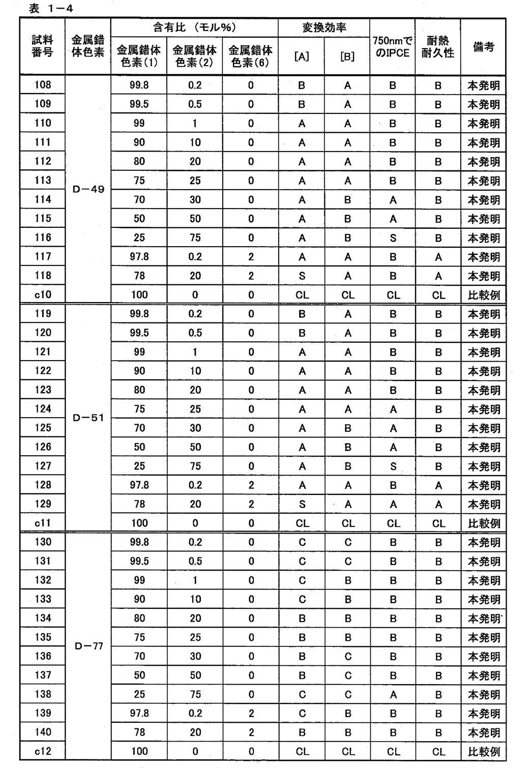

上記表1において、試料番号10、22、34、46、58、70、82及び94の色素増感太陽電池は、増感色素として、金属錯体色素(2A)を担持しており、上記第2の色素吸着態様の実施例に相当する。
また、表1において、試料番号1~140のうち、上記第2の色素吸着態様以外の色素増感太陽電池は、増感色素として、金属錯体色素(1)及び金属錯体色素(2)を担持しており、上記第1の色素吸着態様の実施例に相当する。 In Table 1 above, the dye-sensitized solar cells of sample numbers 10, 22, 34, 46, 58, 70, 82 and 94 carry the metal complex dye (2A) as the sensitizing dye, and the second This corresponds to an example of the dye adsorption mode.
In Table 1, among sample numbers 1 to 140, the dye-sensitized solar cell other than the second dye adsorption mode carries the metal complex dye (1) and the metal complex dye (2) as the sensitizing dye. This corresponds to an example of the first dye adsorption mode.
また、表1において、試料番号1~140のうち、上記第2の色素吸着態様以外の色素増感太陽電池は、増感色素として、金属錯体色素(1)及び金属錯体色素(2)を担持しており、上記第1の色素吸着態様の実施例に相当する。 In Table 1 above, the dye-sensitized solar cells of
In Table 1, among sample numbers 1 to 140, the dye-sensitized solar cell other than the second dye adsorption mode carries the metal complex dye (1) and the metal complex dye (2) as the sensitizing dye. This corresponds to an example of the first dye adsorption mode.
表1の結果から、以下のことが分かった。
上記金属錯体色素(1)、(2)及び(6)のいずれにも相当しない金属錯体色素D-C4を担持した色素増感太陽電池(試料番号c19~c21)は、少なくとも、変換効率及び耐熱耐久性が十分なものではない。
これに対して、本発明の色素増感太陽電池(試料番号1~140)は、いずれも、色素吸着態様にかかわらず、光電変換効率、長波長光における外部量子効率及び耐熱耐久性に優れている。 From the results in Table 1, the following was found.
The dye-sensitized solar cell (sample numbers c19 to c21) supporting the metal complex dye D-C4 not corresponding to any of the metal complex dyes (1), (2) and (6) has at least conversion efficiency and heat resistance. Durability is not enough.
In contrast, the dye-sensitized solar cells (sample numbers 1 to 140) of the present invention are all excellent in photoelectric conversion efficiency, external quantum efficiency in long wavelength light, and heat durability regardless of the dye adsorption mode. Yes.
各色素増感太陽電池群において、金属錯体色素(1)のみを担持している色素増感太陽電池(試料番号c1~c11)に対して、第1の色素吸着態様で金属錯体色素を担持している色素増感太陽電池は、変換効率[A]及び[B]も、長波長光における外部量子効率も高く、しかも耐熱耐久性にも優れていた。特に、金属錯体色素(1)、金属錯体色素(2)及び金属錯体色素(6)の3種を組み合わせて用いると、変換効率、長波長光における外部量子効率及び耐熱耐久性の改善効果が更に高くなる傾向が確認できた。
In each dye-sensitized solar cell group, a metal complex dye is supported in the first dye adsorption mode with respect to a dye-sensitized solar cell (sample numbers c1 to c11) supporting only the metal complex dye (1). The dye-sensitized solar cell had high conversion efficiency [A] and [B], high external quantum efficiency in long-wavelength light, and excellent heat resistance and durability. In particular, when three types of metal complex dye (1), metal complex dye (2), and metal complex dye (6) are used in combination, the conversion efficiency, the external quantum efficiency in long wavelength light, and the heat resistance durability are further improved. A tendency to increase was confirmed.
金属錯体色素(2)に包含されるが金属錯体色素(2A)には包含されない金属錯体色素D-C1~D-C3を担持した色素増感太陽電池(試料番号c13、c15及びc17)は、金属錯体色素(1)のみを担持している色素増感太陽電池(試料番号c14、c16及びc18)に対して、変換効率[A]及び[B]の改善効果も、耐熱耐久性の改善効果も十分なものではない。
これに対して、各色素増感太陽電池群において、第2の色素吸着態様で金属錯体色素(2A)を担持している色素増感太陽電池は、第1の色素吸着態様程ではないものの、変換効率[A]及び[B]の改善効果だけでなく、長波長光における外部量子効率及び耐熱耐久性についても十分な改善効果を示している。 Dye-sensitized solar cells (sample numbers c13, c15, and c17) carrying metal complex dyes D-C1 to D-C3 that are included in metal complex dye (2) but not included in metal complex dye (2A) are: For the dye-sensitized solar cell (sample numbers c14, c16 and c18) carrying only the metal complex dye (1), the conversion efficiency [A] and [B] are improved, and the heat durability is improved. Is not enough.
In contrast, in each dye-sensitized solar cell group, the dye-sensitized solar cell carrying the metal complex dye (2A) in the second dye adsorption mode is not as large as the first dye adsorption mode. Not only the improvement effect of conversion efficiency [A] and [B] but the sufficient improvement effect is shown also about the external quantum efficiency and heat-resistant durability in long wavelength light.
1、41 導電性支持体
2、42 感光体層(酸化物半導体電極)
21 色素
22 半導体微粒子
3、47 電荷移動体層
4、48 対極
5、40 受光電極
6 回路
10 光電変換素子
100 光電変換素子を電池用途に応用したシステム
M 動作手段(例えば電動モーター)
20 色素増感太陽電池
43 透明導電膜
44 基板
45 半導体層
46 光散乱層
S スペーサー
1, 41Conductive support 2, 42 Photoreceptor layer (oxide semiconductor electrode)
21Dye 22 Semiconductor Fine Particles 3, 47 Charge Transfer Layer 4, 48 Counter Electrode 5, 40 Photosensitive Electrode 6 Circuit 10 Photoelectric Conversion Element 100 System M Applying Photoelectric Conversion Element to Battery Use Operating means (for example, electric motor)
20 Dye-sensitizedsolar cell 43 Transparent conductive film 44 Substrate 45 Semiconductor layer 46 Light scattering layer S Spacer
2、42 感光体層(酸化物半導体電極)
21 色素
22 半導体微粒子
3、47 電荷移動体層
4、48 対極
5、40 受光電極
6 回路
10 光電変換素子
100 光電変換素子を電池用途に応用したシステム
M 動作手段(例えば電動モーター)
20 色素増感太陽電池
43 透明導電膜
44 基板
45 半導体層
46 光散乱層
S スペーサー
1, 41
21
20 Dye-sensitized
Claims (16)
- 導電性支持体と、電解質を含む感光体層と、電解質を含む電荷移動体層と、対極とを有する光電変換素子であって、
前記感光体層が、下記式(1)で表される金属錯体色素と、下記式(2)で表される金属錯体色素とが担持された半導体微粒子を有する光電変換素子。
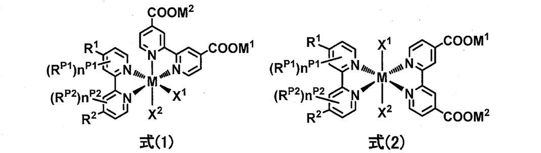
式中、Mは金属イオンを示す。
R1及びR2は、各々独立に、アルケニル基、アルキニル基、アリール基又はヘテロアリール基を示す。
RP1及びRP2は、各々独立に、アルキル基、アルコキシ基、アルキルチオ基、アリール基、ヘテロアリール基、アミノ基又はハロゲン原子を示す。nP1及びnP2は各々独立に0~3の整数である。
X1及びX2は、各々独立に、単座配位子を示す。
M1及びM2は、各々独立に、プロトン、金属カチオン及び非金属カチオンのいずれかを示す。 A photoelectric conversion element having a conductive support, a photoreceptor layer containing an electrolyte, a charge transfer layer containing an electrolyte, and a counter electrode,
The photoelectric conversion element in which the said photoreceptor layer has the semiconductor fine particle by which the metal complex dye represented by following formula (1) and the metal complex dye represented by following formula (2) were carry | supported.
In the formula, M represents a metal ion.
R 1 and R 2 each independently represents an alkenyl group, an alkynyl group, an aryl group or a heteroaryl group.
R P1 and R P2 each independently represent an alkyl group, an alkoxy group, an alkylthio group, an aryl group, a heteroaryl group, an amino group, or a halogen atom. n P1 and n P2 are each independently an integer of 0 to 3.
X 1 and X 2 each independently represent a monodentate ligand.
M 1 and M 2 each independently represent a proton, a metal cation, or a non-metal cation. - 前記R1及びR2が、各々独立に、下記式(3-1)~(3-4)のいずれかで表される請求項1に記載の光電変換素子。

式中、R3~R6は、各々独立に、水素原子、アルキル基、アルケニル基、アルキニル基、アルコキシ基、アルキルチオ基、アリール基、ヘテロアリール基、アミノ基又はハロゲン原子を示す。
R7~R10は、各々独立に、アルキル基、アルケニル基、アルキニル基、アルコキシ基、アルキルチオ基、アリール基、ヘテロアリール基、アミノ基又はハロゲン原子を示す。n1及びn3は各々独立に0~4の整数であり、n2及びn4は各々独立に0~2の整数である。
X3及びX4は、各々独立に、硫黄原子又は酸素原子を示す。
*は前記式(1)及び式(2)中のピリジン環との結合部を示す。 2. The photoelectric conversion element according to claim 1, wherein R 1 and R 2 are each independently represented by any of the following formulas (3-1) to (3-4).
In the formula, R 3 to R 6 each independently represent a hydrogen atom, an alkyl group, an alkenyl group, an alkynyl group, an alkoxy group, an alkylthio group, an aryl group, a heteroaryl group, an amino group, or a halogen atom.
R 7 to R 10 each independently represents an alkyl group, an alkenyl group, an alkynyl group, an alkoxy group, an alkylthio group, an aryl group, a heteroaryl group, an amino group, or a halogen atom. n 1 and n 3 are each independently an integer of 0 to 4, and n 2 and n 4 are each independently an integer of 0 to 2.
X 3 and X 4 each independently represent a sulfur atom or an oxygen atom.
* Represents a bonding part with the pyridine ring in the formulas (1) and (2). - 前記X1及びX2が、各々独立に、イソチオシアネート基又はチオシアネート基を示す請求項1又は2に記載の光電変換素子。 The photoelectric conversion element according to claim 1, wherein X 1 and X 2 each independently represent an isothiocyanate group or a thiocyanate group.
- 前記R1及びR2が、各々独立に、下記式(4)で表される請求項1~3のいずれか1項に記載の光電変換素子。

式中、L1は、単結合又はエテニレン基を示す。
Ar11及びAr12は、各々独立に、下記置換基群SArから選択される置換基を少なくとも1つ有するアリール基、又は、無置換のヘテロアリール基若しくは下記置換基群SArから選択される置換基を少なくとも1つ有するヘテロアリール基を示す。
ただし、前記L1がエテニレン基であり、前記アリール基が前記置換基としてアルキル基を有する場合、前記アルキル基は炭素数3以上の直鎖アルキル基、又は分岐アルキル基である。また、前記L1がエテニレン基であり、前記アリール基が前記置換基としてモノ若しくはジアルキルアミノ基を有する場合、前記アルキルアミノ基中の少なくとも1つのアルキル基は、炭素数5以上の直鎖アルキル基、又は、分岐アルキル基である。
R11は、アルキル基、アルコキシ基、アルキルチオ基、アリール基、ヘテロアリール基、アミノ基又はハロゲン原子を示す。n11は、0~4の整数である。
*は前記式(1)及び式(2)中のピリジン環との結合部を示す。
<置換基群SAr>
アルキル基、アルコキシ基、アリールオキシ基、アルキルチオ基、アリールチオ基、アリール基、ヘテロアリール基、アミノ基、ハロゲン原子又はシアノ基 The photoelectric conversion device according to any one of claims 1 to 3, wherein R 1 and R 2 are each independently represented by the following formula (4).
In the formula, L 1 represents a single bond or an ethenylene group.
Ar 11 and Ar 12 are each independently selected from an aryl group having at least one substituent selected from the following substituent group S Ar , or an unsubstituted heteroaryl group or the following substituent group S Ar A heteroaryl group having at least one substituent is shown.
However, when L 1 is an ethenylene group and the aryl group has an alkyl group as the substituent, the alkyl group is a linear alkyl group having 3 or more carbon atoms or a branched alkyl group. When L 1 is an ethenylene group and the aryl group has a mono- or dialkylamino group as the substituent, at least one alkyl group in the alkylamino group is a linear alkyl group having 5 or more carbon atoms. Or a branched alkyl group.
R 11 represents an alkyl group, an alkoxy group, an alkylthio group, an aryl group, a heteroaryl group, an amino group or a halogen atom. n 11 is an integer of 0 to 4.
* Represents a bonding part with the pyridine ring in the formulas (1) and (2).
<Substituent group S Ar >
Alkyl group, alkoxy group, aryloxy group, alkylthio group, arylthio group, aryl group, heteroaryl group, amino group, halogen atom or cyano group - 前記Ar11及びAr12が、各々独立に、下記式(5-1)~式(5-5)のいずれかで表される請求項4に記載の光電変換素子。

式(5-1)~式(5-3)中、R21は、アルキル基、アルコキシ基、アリール基、ヘテロアリール基又はハロゲン原子を示す。
式(5-4)~式(5-5)中、R21は、水素原子、アルキル基、アルコキシ基、アリール基、ヘテロアリール基又はハロゲン原子を示し、R21の少なくとも1つはアルキル基、アルコキシ基、アリール基、ヘテロアリール基又はハロゲン原子を示す。
ただし、前記L1がエテニレン基である場合、前記アルキル基は炭素数3以上の直鎖アルキル基、又は分岐アルキル基である。*は式(4)中の窒素原子との結合部を示す。 The photoelectric conversion element according to claim 4, wherein Ar 11 and Ar 12 are each independently represented by any one of the following formulas (5-1) to (5-5).
In formulas (5-1) to (5-3), R 21 represents an alkyl group, an alkoxy group, an aryl group, a heteroaryl group or a halogen atom.
In formulas (5-4) to (5-5), R 21 represents a hydrogen atom, an alkyl group, an alkoxy group, an aryl group, a heteroaryl group or a halogen atom, and at least one of R 21 is an alkyl group, An alkoxy group, an aryl group, a heteroaryl group or a halogen atom is shown.
However, when L 1 is an ethenylene group, the alkyl group is a linear alkyl group having 3 or more carbon atoms or a branched alkyl group. * A bond part with a nitrogen atom in Formula (4) is shown. - 前記半導体微粒子が、下記式(6)で表される金属錯体色素を担持している請求項1~5のいずれか1項に記載の光電変換素子。

式中、Mは金属イオンを示す。
R1~R4は、各々独立に、アルケニル基、アルキニル基、アリール基又はヘテロアリール基を示す。
RP1~RP4は、各々独立に、アルキル基、アルコキシ基、アルキルチオ基、アリール基、ヘテロアリール基、アミノ基又はハロゲン原子を示す。nP1~nP4は各々独立に0~3の整数である。
X1及びX2は各々独立に単座配位子を示す。 6. The photoelectric conversion element according to claim 1, wherein the semiconductor fine particles carry a metal complex dye represented by the following formula (6).
In the formula, M represents a metal ion.
R 1 to R 4 each independently represents an alkenyl group, an alkynyl group, an aryl group or a heteroaryl group.
R P1 to R P4 each independently represents an alkyl group, an alkoxy group, an alkylthio group, an aryl group, a heteroaryl group, an amino group or a halogen atom. n P1 to n P4 are each independently an integer of 0 to 3.
X 1 and X 2 each independently represent a monodentate ligand. - 導電性支持体と、電解質を含む感光体層と、電解質を含む電荷移動体層と、対極とを有する光電変換素子であって、
前記感光体層が、下記式(2A)で表される金属錯体色素が担持された半導体微粒子を有する光電変換素子。

式(2A)中、Mは金属イオンを示す。
R1A及びR2Aは、各々独立に、下記式(4)で表される基を示す。
RP1A及びRP2Aは、各々独立に、アルキル基、アルコキシ基、アルキルチオ基、アリール基、ヘテロアリール基、アミノ基又はハロゲン原子を示す。nP1A及びnP2Aは各々独立に0~3の整数である。
X1A及びX2Aは、各々独立に、単座配位子を示す。
M1A及びM2Aは、各々独立に、プロトン、金属カチオン及び非金属カチオンのいずれかを示す。

式(4)中、L1は、単結合又はエテニレン基を示す。
Ar11及びAr12は、各々独立に、下記置換基群SArから選択される置換基を少なくとも1つ有するアリール基、又は、無置換のヘテロアリール基若しくは下記置換基群SArから選択される置換基を少なくとも1つ有するヘテロアリール基を示す。
ただし、前記L1がエテニレン基であり、前記アリール基が前記置換基としてアルキル基を有する場合、前記アルキル基は炭素数3以上の直鎖アルキル基、又は分岐アルキル基である。また、前記L1がエテニレン基であり、前記アリール基が前記置換基としてモノ若しくはジアルキルアミノ基を有する場合、前記アルキルアミノ基中の少なくとも1つのアルキル基は、炭素数5以上の直鎖アルキル基、又は、分岐アルキル基である。
R11は、アルキル基、アルコキシ基、アルキルチオ基、アリール基、ヘテロアリール基、アミノ基又はハロゲン原子を示す。n11は、0~4の整数である。
*は前記式(2A)中のピリジン環との結合部を示す。
<置換基群SAr>
アルキル基、アルコキシ基、アリールオキシ基、アルキルチオ基、アリールチオ基、アリール基、ヘテロアリール基、アミノ基、ハロゲン原子又はシアノ基 A photoelectric conversion element having a conductive support, a photoreceptor layer containing an electrolyte, a charge transfer layer containing an electrolyte, and a counter electrode,
The photoelectric conversion element in which the said photoreceptor layer has the semiconductor fine particle by which the metal complex pigment | dye represented by following formula (2A) was carry | supported.
In formula (2A), M represents a metal ion.
R 1A and R 2A each independently represent a group represented by the following formula (4).
R P1A and R P2A each independently represent an alkyl group, an alkoxy group, an alkylthio group, an aryl group, a heteroaryl group, an amino group, or a halogen atom. n P1A and n P2A are each independently an integer of 0 to 3.
X 1A and X 2A each independently represent a monodentate ligand.
M 1A and M 2A each independently represent a proton, a metal cation, or a non-metal cation.
In formula (4), L 1 represents a single bond or an ethenylene group.
Ar 11 and Ar 12 are each independently selected from an aryl group having at least one substituent selected from the following substituent group S Ar , or an unsubstituted heteroaryl group or the following substituent group S Ar A heteroaryl group having at least one substituent is shown.
However, when L 1 is an ethenylene group and the aryl group has an alkyl group as the substituent, the alkyl group is a linear alkyl group having 3 or more carbon atoms or a branched alkyl group. When L 1 is an ethenylene group and the aryl group has a mono- or dialkylamino group as the substituent, at least one alkyl group in the alkylamino group is a linear alkyl group having 5 or more carbon atoms. Or a branched alkyl group.
R 11 represents an alkyl group, an alkoxy group, an alkylthio group, an aryl group, a heteroaryl group, an amino group or a halogen atom. n 11 is an integer of 0 to 4.
* Represents a bonding part with the pyridine ring in the formula (2A).
<Substituent group S Ar >
Alkyl group, alkoxy group, aryloxy group, alkylthio group, arylthio group, aryl group, heteroaryl group, amino group, halogen atom or cyano group - 前記導電性支持体及び前記半導体微粒子の少なくとも一方の表面に金属酸化物被膜を有する請求項1~7のいずれか1項に記載の光電変換素子。 The photoelectric conversion element according to any one of claims 1 to 7, further comprising a metal oxide film on at least one surface of the conductive support and the semiconductor fine particles.
- 請求項1~8のいずれか1項に記載の光電変換素子を備えた色素増感太陽電池。 A dye-sensitized solar cell comprising the photoelectric conversion element according to any one of claims 1 to 8.
- 下記式(1)で表される金属錯体色素と、下記式(2)で表される金属錯体色素とを含有する色素組成物。

式中、Mは金属イオンを示す。
R1及びR2は、各々独立に、アルケニル基、アルキニル基、アリール基又はヘテロアリール基を示す。
RP1及びRP2は、各々独立に、アルキル基、アルコキシ基、アルキルチオ基、アリール基、ヘテロアリール基、アミノ基又はハロゲン原子を示す。nP1及びnP2は各々独立に0~3の整数である。
X1及びX2は、各々独立に、単座配位子を示す。
M1及びM2は、各々独立に、プロトン、金属カチオン及び非金属カチオンのいずれかを示す。 The pigment | dye composition containing the metal complex pigment | dye represented by following formula (1), and the metal complex pigment | dye represented by following formula (2).
In the formula, M represents a metal ion.
R 1 and R 2 each independently represents an alkenyl group, an alkynyl group, an aryl group or a heteroaryl group.
R P1 and R P2 each independently represent an alkyl group, an alkoxy group, an alkylthio group, an aryl group, a heteroaryl group, an amino group, or a halogen atom. n P1 and n P2 are each independently an integer of 0 to 3.
X 1 and X 2 each independently represent a monodentate ligand.
M 1 and M 2 each independently represent a proton, a metal cation, or a non-metal cation. - 前記R1及びR2が、各々独立に、下記式(4)で表される請求項10に記載の色素組成物。

式中、L1は、単結合又はエテニレン基を示す。
Ar11及びAr12は、各々独立に、下記置換基群SArから選択される置換基を少なくとも1つ有するアリール基、又は、無置換のヘテロアリール基若しくは下記置換基群SArから選択される置換基を少なくとも1つ有するヘテロアリール基を示す。
ただし、前記L1がエテニレン基であり、前記アリール基が前記置換基としてアルキル基を有する場合、前記アルキル基は炭素数3以上の直鎖アルキル基、又は分岐アルキル基である。また、前記L1がエテニレン基であり、前記アリール基が前記置換基としてモノ若しくはジアルキルアミノ基を有する場合、前記アルキルアミノ基中の少なくとも1つのアルキル基は、炭素数5以上の直鎖アルキル基、又は、分岐アルキル基である。
R11は、アルキル基、アルコキシ基、アルキルチオ基、アリール基、ヘテロアリール基、アミノ基又はハロゲン原子を示す。n11は、0~4の整数である。
*は前記式(1)及び式(2)中のピリジン環との結合部を示す。
<置換基群SAr>
アルキル基、アルコキシ基、アリールオキシ基、アルキルチオ基、アリールチオ基、アリール基、ヘテロアリール基、アミノ基、ハロゲン原子又はシアノ基 The dye composition according to claim 10, wherein R 1 and R 2 are each independently represented by the following formula (4).
In the formula, L 1 represents a single bond or an ethenylene group.
Ar 11 and Ar 12 are each independently selected from an aryl group having at least one substituent selected from the following substituent group S Ar , or an unsubstituted heteroaryl group or the following substituent group S Ar A heteroaryl group having at least one substituent is shown.
However, when L 1 is an ethenylene group and the aryl group has an alkyl group as the substituent, the alkyl group is a linear alkyl group having 3 or more carbon atoms or a branched alkyl group. When L 1 is an ethenylene group and the aryl group has a mono- or dialkylamino group as the substituent, at least one alkyl group in the alkylamino group is a linear alkyl group having 5 or more carbon atoms. Or a branched alkyl group.
R 11 represents an alkyl group, an alkoxy group, an alkylthio group, an aryl group, a heteroaryl group, an amino group or a halogen atom. n 11 is an integer of 0 to 4.
* Represents a bonding part with the pyridine ring in the formulas (1) and (2).
<Substituent group S Ar >
Alkyl group, alkoxy group, aryloxy group, alkylthio group, arylthio group, aryl group, heteroaryl group, amino group, halogen atom or cyano group - 下記式(6)で表される金属錯体色素を含有する請求項10又は11に記載の色素組成物。

式中、Mは金属イオンを示す。
R1~R4は、各々独立に、アルケニル基、アルキニル基、アリール基又はヘテロアリール基を示す。
RP1~RP4は、各々独立に、アルキル基、アルコキシ基、アルキルチオ基、アリール基、ヘテロアリール基、アミノ基又はハロゲン原子を示す。nP1~nP4は各々独立に0~3の整数である。
X1及びX2は各々独立に単座配位子を示す。 The pigment | dye composition of Claim 10 or 11 containing the metal complex pigment | dye represented by following formula (6).
In the formula, M represents a metal ion.
R 1 to R 4 each independently represents an alkenyl group, an alkynyl group, an aryl group or a heteroaryl group.
R P1 to R P4 each independently represents an alkyl group, an alkoxy group, an alkylthio group, an aryl group, a heteroaryl group, an amino group or a halogen atom. n P1 to n P4 are each independently an integer of 0 to 3.
X 1 and X 2 each independently represent a monodentate ligand. - 前記式(1)で表される金属錯体色素及び前記式(2)で表される金属錯体色素が有する前記M1及びM2の総モル量のうち、金属カチオン及び非金属カチオンを合計で0.000001~1.5モル含有する請求項10~12のいずれか1項に記載の色素組成物。 Of the total molar amount of M 1 and M 2 possessed by the metal complex dye represented by the formula (1) and the metal complex dye represented by the formula (2), the total number of metal cations and nonmetal cations is 0. The dye composition according to any one of claims 10 to 12, which contains 0.000001 to 1.5 mol.
- 溶媒を含有する請求項10~13のいずれか1項に記載の色素組成物。 The dye composition according to any one of claims 10 to 13, which contains a solvent.
- 請求項10~14のいずれか1項に記載の色素組成物を含む酸化物半導体電極。 An oxide semiconductor electrode comprising the dye composition according to any one of claims 10 to 14.
- 下記式(2A)で表される金属錯体色素。

式(2A)中、Mは金属イオンを示す。
R1A及びR2Aは、各々独立に、下記式(4)で表される基を示す。
RP1A及びRP2Aは、各々独立に、アルキル基、アルコキシ基、アルキルチオ基、アリール基、ヘテロアリール基、アミノ基又はハロゲン原子を示す。nP1A及びnP2Aは各々独立に0~3の整数である。
X1A及びX2Aは、各々独立に、単座配位子を示す。
M1A及びM2Aは、各々独立に、プロトン、金属カチオン及び非金属カチオンのいずれかを示す。

式(4)中、L1は、単結合又はエテニレン基を示す。
Ar11及びAr12は、各々独立に、下記置換基群SArから選択される置換基を少なくとも1つ有するアリール基、又は、無置換のヘテロアリール基若しくは下記置換基群SArから選択される置換基を少なくとも1つ有するヘテロアリール基を示す。
ただし、前記L1がエテニレン基であり、前記アリール基が前記置換基としてアルキル基を有する場合、前記アルキル基は炭素数3以上の直鎖アルキル基、又は分岐アルキル基である。また、前記L1がエテニレン基であり、前記アリール基が前記置換基としてモノ若しくはジアルキルアミノ基を有する場合、前記アルキルアミノ基中の少なくとも1つのアルキル基は、炭素数5以上の直鎖アルキル基、又は、分岐アルキル基である。
R11は、アルキル基、アルコキシ基、アルキルチオ基、アリール基、ヘテロアリール基、アミノ基又はハロゲン原子を示す。n11は、0~4の整数である。
*は前記式(2A)中のピリジン環との結合部を示す。
<置換基群SAr>
アルキル基、アルコキシ基、アリールオキシ基、アルキルチオ基、アリールチオ基、アリール基、ヘテロアリール基、アミノ基、ハロゲン原子又はシアノ基
A metal complex dye represented by the following formula (2A).
In formula (2A), M represents a metal ion.
R 1A and R 2A each independently represent a group represented by the following formula (4).
R P1A and R P2A each independently represent an alkyl group, an alkoxy group, an alkylthio group, an aryl group, a heteroaryl group, an amino group, or a halogen atom. n P1A and n P2A are each independently an integer of 0 to 3.
X 1A and X 2A each independently represent a monodentate ligand.
M 1A and M 2A each independently represent a proton, a metal cation, or a non-metal cation.
In formula (4), L 1 represents a single bond or an ethenylene group.
Ar 11 and Ar 12 are each independently selected from an aryl group having at least one substituent selected from the following substituent group S Ar , or an unsubstituted heteroaryl group or the following substituent group S Ar A heteroaryl group having at least one substituent is shown.
However, when L 1 is an ethenylene group and the aryl group has an alkyl group as the substituent, the alkyl group is a linear alkyl group having 3 or more carbon atoms or a branched alkyl group. When L 1 is an ethenylene group and the aryl group has a mono- or dialkylamino group as the substituent, at least one alkyl group in the alkylamino group is a linear alkyl group having 5 or more carbon atoms. Or a branched alkyl group.
R 11 represents an alkyl group, an alkoxy group, an alkylthio group, an aryl group, a heteroaryl group, an amino group or a halogen atom. n 11 is an integer of 0 to 4.
* Represents a bonding part with the pyridine ring in the formula (2A).
<Substituent group S Ar >
Alkyl group, alkoxy group, aryloxy group, alkylthio group, arylthio group, aryl group, heteroaryl group, amino group, halogen atom or cyano group
Priority Applications (4)
| Application Number | Priority Date | Filing Date | Title |
|---|---|---|---|
| JP2018568038A JP6831404B2 (en) | 2017-02-17 | 2018-01-09 | Photoelectric conversion elements, dye-sensitized solar cells, metal complex dyes, dye compositions and oxide semiconductor electrodes |
| EP18754668.4A EP3584814A4 (en) | 2017-02-17 | 2018-01-09 | Photoelectric conversion element, dye-sensitized solar cell, metal complex dye, dye composition, and oxide semiconductor electrode |
| CN201880005801.3A CN110178193B (en) | 2017-02-17 | 2018-01-09 | Photoelectric conversion element, dye-sensitized solar cell, metal complex dye, dye composition, and oxide semiconductor electrode |
| US16/439,117 US11094474B2 (en) | 2017-02-17 | 2019-06-12 | Photoelectric conversion element, dye-sensitized solar cell, metal complex dye, dye composition, and oxide semiconductor electrode |
Applications Claiming Priority (2)
| Application Number | Priority Date | Filing Date | Title |
|---|---|---|---|
| JP2017-027494 | 2017-02-17 | ||
| JP2017027494 | 2017-02-17 |
Related Child Applications (1)
| Application Number | Title | Priority Date | Filing Date |
|---|---|---|---|
| US16/439,117 Continuation US11094474B2 (en) | 2017-02-17 | 2019-06-12 | Photoelectric conversion element, dye-sensitized solar cell, metal complex dye, dye composition, and oxide semiconductor electrode |
Publications (1)
| Publication Number | Publication Date |
|---|---|
| WO2018150760A1 true WO2018150760A1 (en) | 2018-08-23 |
Family
ID=63169809
Family Applications (1)
| Application Number | Title | Priority Date | Filing Date |
|---|---|---|---|
| PCT/JP2018/000146 WO2018150760A1 (en) | 2017-02-17 | 2018-01-09 | Photoelectric conversion element, dye-sensitized solar cell, metal complex dye, dye composition, and oxide semiconductor electrode |
Country Status (5)
| Country | Link |
|---|---|
| US (1) | US11094474B2 (en) |
| EP (1) | EP3584814A4 (en) |
| JP (1) | JP6831404B2 (en) |
| CN (1) | CN110178193B (en) |
| WO (1) | WO2018150760A1 (en) |
Citations (28)
| Publication number | Priority date | Publication date | Assignee | Title |
|---|---|---|---|---|
| JPS60249790A (en) | 1984-05-14 | 1985-12-10 | ニトロ・ノベル・アーベー | Means for splice-joining two pipe |
| US4684537A (en) | 1984-04-30 | 1987-08-04 | R. E. Stiftung | Process for the sensitization of an oxidation/reduction photocatalyst, and photocatalyst thus obtained |
| US4927721A (en) | 1988-02-12 | 1990-05-22 | Michael Gratzel | Photo-electrochemical cell |
| US5350644A (en) | 1990-04-17 | 1994-09-27 | Ecole Polytechnique, Federale De Lausanne | Photovoltaic cells |
| JPH07249790A (en) | 1994-03-11 | 1995-09-26 | Ishihara Sangyo Kaisha Ltd | Semiconductor photoelectric conversion material |
| US5463057A (en) | 1992-08-21 | 1995-10-31 | Ecole Polytechnique Federale De Lausanne, (Epfl) | Bi-pyridyl-rumetal complexes |
| US5525440A (en) | 1992-03-11 | 1996-06-11 | Ecole Polytechnique Federale De Lausanne (Epfl) | Method for the manufacture of a photo-electrochemical cell and a cell made by this method |
| JP2001160425A (en) | 1999-12-02 | 2001-06-12 | Japan Gore Tex Inc | Optical semiconductor electrode and its manufacturing method |
| JP2001185244A (en) | 1999-12-27 | 2001-07-06 | Sharp Corp | Pigment sensitized solar battery and preparation method of the same, and solar battery module |
| JP2001210390A (en) | 2000-01-26 | 2001-08-03 | Sharp Corp | Dye-sensitization type solar battery which uses solid electrolyte and its preparation method |
| JP2001291534A (en) | 2000-01-31 | 2001-10-19 | Fuji Photo Film Co Ltd | Photoelectric conversion element and photocell and metal complex pigment |
| JP2002260746A (en) | 2001-02-28 | 2002-09-13 | Toyota Central Res & Dev Lab Inc | Dye sensitized solar battery and dye sensitized solar battery module |
| JP2002289274A (en) | 2001-03-27 | 2002-10-04 | Toyota Central Res & Dev Lab Inc | Photoelectrode and pigment sensitized solar cell comprising it |
| JP2003123859A (en) | 2001-10-19 | 2003-04-25 | Bridgestone Corp | Organic dye sensitized metal oxide semiconductor electrode, and solar battery having the semiconductor electrode |
| JP2003217688A (en) | 2002-01-18 | 2003-07-31 | Sharp Corp | Dye-sensitized photoelectric converter |
| JP2004220974A (en) | 2003-01-16 | 2004-08-05 | Toyo Ink Mfg Co Ltd | Optical functional material |
| CN1202113C (en) * | 2000-12-21 | 2005-05-18 | 中国科学院感光化学研究所 | Ru-polypyridine complex and its synthesizing process and use |
| JP2005135902A (en) | 2003-10-06 | 2005-05-26 | Ngk Spark Plug Co Ltd | Dye-sensitized solar cell |
| JP2008021496A (en) | 2006-07-12 | 2008-01-31 | Nippon Kayaku Co Ltd | Dye-sensitized photoelectric conversion element |
| JP2008135197A (en) | 2006-11-27 | 2008-06-12 | Konica Minolta Business Technologies Inc | Dye sensitized photoelectric conversion element, and dye sensitized solar cell |
| JP2010146864A (en) * | 2008-12-19 | 2010-07-01 | Nippon Kayaku Co Ltd | Dye-sensitized photoelectric conversion element |
| JP2011228276A (en) * | 2010-03-31 | 2011-11-10 | Fujifilm Corp | Photoelectric conversion element and photoelectrochemical cell |
| JP2012131906A (en) * | 2010-12-22 | 2012-07-12 | Toyo Ink Sc Holdings Co Ltd | Dye and dye sensitized solar cell |
| JP2012212533A (en) * | 2011-03-30 | 2012-11-01 | Fujifilm Corp | Photoelectric conversion element and photoelectrochemical cell |
| JP2012216496A (en) * | 2011-03-31 | 2012-11-08 | Fujifilm Corp | Photoelectric conversion element and dye-sensitization solar battery |
| JP2014082189A (en) | 2012-09-28 | 2014-05-08 | Fujifilm Corp | Metal complex pigment, photoelectric conversion element, dye-sensitized solar cell, dye solution and dye adsorption electrode |
| JP2014082187A (en) | 2012-09-28 | 2014-05-08 | Fujifilm Corp | Photoelectric conversion element and dye-sensitized solar cell |
| JP2014139931A (en) | 2012-12-17 | 2014-07-31 | Fujifilm Corp | Photoelectric conversion element, dye-sensitized solar cell, metal complex dye, dye solution, dye-adsorbed electrode, and method for manufacturing dye-sensitized solar cell |
Family Cites Families (7)
| Publication number | Priority date | Publication date | Assignee | Title |
|---|---|---|---|---|
| ATE342573T1 (en) * | 2000-08-15 | 2006-11-15 | Fuji Photo Film Co Ltd | PHOTOELECTRIC CELL AND PRODUCTION METHOD |
| US20070017569A1 (en) * | 2005-07-25 | 2007-01-25 | General Electric Company | Metal complex compositions and use thereof in dye sensitized solar cells |
| US8143399B2 (en) * | 2008-02-19 | 2012-03-27 | National Central University | Photosensitizer dye |
| CN101585972B (en) * | 2008-05-23 | 2013-04-10 | 国立中央大学 | Light-sensitive coloring agent |
| JP5306354B2 (en) * | 2008-08-22 | 2013-10-02 | 日本化薬株式会社 | Dye-sensitized photoelectric conversion element |
| CN102660135A (en) * | 2012-04-25 | 2012-09-12 | 天津大学 | Photosensitive dye with triphenylamine bridging bipyridyl ruthenium complex and preparation method for photosensitive dye |
| CN103665047A (en) * | 2012-09-26 | 2014-03-26 | 张勇 | Application of novel ligand compound in dye-sensitized solar cell |
-
2018
- 2018-01-09 CN CN201880005801.3A patent/CN110178193B/en active Active
- 2018-01-09 JP JP2018568038A patent/JP6831404B2/en active Active
- 2018-01-09 EP EP18754668.4A patent/EP3584814A4/en active Pending
- 2018-01-09 WO PCT/JP2018/000146 patent/WO2018150760A1/en unknown
-
2019
- 2019-06-12 US US16/439,117 patent/US11094474B2/en active Active
Patent Citations (30)
| Publication number | Priority date | Publication date | Assignee | Title |
|---|---|---|---|---|
| US4684537A (en) | 1984-04-30 | 1987-08-04 | R. E. Stiftung | Process for the sensitization of an oxidation/reduction photocatalyst, and photocatalyst thus obtained |
| JPS60249790A (en) | 1984-05-14 | 1985-12-10 | ニトロ・ノベル・アーベー | Means for splice-joining two pipe |
| US4927721A (en) | 1988-02-12 | 1990-05-22 | Michael Gratzel | Photo-electrochemical cell |
| US5084365A (en) | 1988-02-12 | 1992-01-28 | Michael Gratzel | Photo-electrochemical cell and process of making same |
| US5350644A (en) | 1990-04-17 | 1994-09-27 | Ecole Polytechnique, Federale De Lausanne | Photovoltaic cells |
| US5525440A (en) | 1992-03-11 | 1996-06-11 | Ecole Polytechnique Federale De Lausanne (Epfl) | Method for the manufacture of a photo-electrochemical cell and a cell made by this method |
| US5463057A (en) | 1992-08-21 | 1995-10-31 | Ecole Polytechnique Federale De Lausanne, (Epfl) | Bi-pyridyl-rumetal complexes |
| JPH07249790A (en) | 1994-03-11 | 1995-09-26 | Ishihara Sangyo Kaisha Ltd | Semiconductor photoelectric conversion material |
| JP2001160425A (en) | 1999-12-02 | 2001-06-12 | Japan Gore Tex Inc | Optical semiconductor electrode and its manufacturing method |
| JP2001185244A (en) | 1999-12-27 | 2001-07-06 | Sharp Corp | Pigment sensitized solar battery and preparation method of the same, and solar battery module |
| JP2001210390A (en) | 2000-01-26 | 2001-08-03 | Sharp Corp | Dye-sensitization type solar battery which uses solid electrolyte and its preparation method |
| JP2001291534A (en) | 2000-01-31 | 2001-10-19 | Fuji Photo Film Co Ltd | Photoelectric conversion element and photocell and metal complex pigment |
| JP4874454B2 (en) | 2000-01-31 | 2012-02-15 | 富士フイルム株式会社 | Photoelectric conversion element and photovoltaic cell |
| CN1202113C (en) * | 2000-12-21 | 2005-05-18 | 中国科学院感光化学研究所 | Ru-polypyridine complex and its synthesizing process and use |
| JP2002260746A (en) | 2001-02-28 | 2002-09-13 | Toyota Central Res & Dev Lab Inc | Dye sensitized solar battery and dye sensitized solar battery module |
| JP2002289274A (en) | 2001-03-27 | 2002-10-04 | Toyota Central Res & Dev Lab Inc | Photoelectrode and pigment sensitized solar cell comprising it |
| JP2003123859A (en) | 2001-10-19 | 2003-04-25 | Bridgestone Corp | Organic dye sensitized metal oxide semiconductor electrode, and solar battery having the semiconductor electrode |
| JP2003217688A (en) | 2002-01-18 | 2003-07-31 | Sharp Corp | Dye-sensitized photoelectric converter |
| JP2004220974A (en) | 2003-01-16 | 2004-08-05 | Toyo Ink Mfg Co Ltd | Optical functional material |
| JP2005135902A (en) | 2003-10-06 | 2005-05-26 | Ngk Spark Plug Co Ltd | Dye-sensitized solar cell |
| JP2008021496A (en) | 2006-07-12 | 2008-01-31 | Nippon Kayaku Co Ltd | Dye-sensitized photoelectric conversion element |
| JP2008135197A (en) | 2006-11-27 | 2008-06-12 | Konica Minolta Business Technologies Inc | Dye sensitized photoelectric conversion element, and dye sensitized solar cell |
| JP2010146864A (en) * | 2008-12-19 | 2010-07-01 | Nippon Kayaku Co Ltd | Dye-sensitized photoelectric conversion element |
| JP2011228276A (en) * | 2010-03-31 | 2011-11-10 | Fujifilm Corp | Photoelectric conversion element and photoelectrochemical cell |
| JP2012131906A (en) * | 2010-12-22 | 2012-07-12 | Toyo Ink Sc Holdings Co Ltd | Dye and dye sensitized solar cell |
| JP2012212533A (en) * | 2011-03-30 | 2012-11-01 | Fujifilm Corp | Photoelectric conversion element and photoelectrochemical cell |
| JP2012216496A (en) * | 2011-03-31 | 2012-11-08 | Fujifilm Corp | Photoelectric conversion element and dye-sensitization solar battery |
| JP2014082189A (en) | 2012-09-28 | 2014-05-08 | Fujifilm Corp | Metal complex pigment, photoelectric conversion element, dye-sensitized solar cell, dye solution and dye adsorption electrode |
| JP2014082187A (en) | 2012-09-28 | 2014-05-08 | Fujifilm Corp | Photoelectric conversion element and dye-sensitized solar cell |
| JP2014139931A (en) | 2012-12-17 | 2014-07-31 | Fujifilm Corp | Photoelectric conversion element, dye-sensitized solar cell, metal complex dye, dye solution, dye-adsorbed electrode, and method for manufacturing dye-sensitized solar cell |
Non-Patent Citations (3)
| Title |
|---|
| J. PHYS. CHEM. A, vol. 115, 2011, pages 6641 - 6645 |
| NATURE, vol. 486, 2012, pages 487 |
| See also references of EP3584814A4 |
Also Published As
| Publication number | Publication date |
|---|---|
| EP3584814A1 (en) | 2019-12-25 |
| CN110178193B (en) | 2021-11-30 |
| US20190295779A1 (en) | 2019-09-26 |
| JP6831404B2 (en) | 2021-02-17 |
| CN110178193A (en) | 2019-08-27 |
| US11094474B2 (en) | 2021-08-17 |
| JPWO2018150760A1 (en) | 2019-08-08 |
| EP3584814A4 (en) | 2020-12-16 |
Similar Documents
| Publication | Publication Date | Title |
|---|---|---|
| KR101718198B1 (en) | Metal complex dye, photoelectric conversion element, dye-sensitized solar cell, dye adsorption liquid composition for dye-sensitized solar cell, semiconductor electrode for dye-sensitized solar cell, and method for producing dye-sensitized solar cell | |
| JP6375451B2 (en) | Photoelectric conversion element, dye-sensitized solar cell, dye composition and oxide semiconductor electrode | |
| JP6616907B2 (en) | Photoelectric conversion element, dye-sensitized solar cell, metal complex dye, dye solution, and oxide semiconductor electrode | |
| JP6371908B2 (en) | Photoelectric conversion element, dye-sensitized solar cell, metal complex dye, dye solution, and oxide semiconductor electrode | |
| JP6831404B2 (en) | Photoelectric conversion elements, dye-sensitized solar cells, metal complex dyes, dye compositions and oxide semiconductor electrodes | |
| JP6591691B2 (en) | Photoelectric conversion element, dye-sensitized solar cell, and dipyrromethene complex compound | |
| TW201605845A (en) | Photoelectric conversion element, dye-sensitized solar cell, ruthenium complex dye, dye solution, and bipyridine compound | |
| JP6308152B2 (en) | Photoelectric conversion element, dye-sensitized solar cell, and dye solution | |
| JP6410669B2 (en) | Photoelectric conversion element, dye-sensitized solar cell, metal complex dye and dye solution | |
| JP6574051B2 (en) | Dye solution for photoelectric conversion element, dye solution preparation kit, and method for producing photoelectric conversion element | |
| JP6265551B2 (en) | Photoelectric conversion element, dye-sensitized solar cell, and dye solution | |
| WO2017169200A1 (en) | Dye solution for photoelectric conversion elements, kit for preparing dye solution, and method for producing photoelectric conversion element | |
| WO2016148101A1 (en) | Photoelectric conversion element, dye-sensitized solar cell, ruthenium complex dye, and dye solution | |
| JPWO2016148098A1 (en) | Photoelectric conversion element, dye-sensitized solar cell, metal complex dye, metal complex dye mixture and dye solution |
Legal Events
| Date | Code | Title | Description |
|---|---|---|---|
| 121 | Ep: the epo has been informed by wipo that ep was designated in this application |
Ref document number: 18754668 Country of ref document: EP Kind code of ref document: A1 |
|
| ENP | Entry into the national phase |
Ref document number: 2018568038 Country of ref document: JP Kind code of ref document: A |
|
| NENP | Non-entry into the national phase |
Ref country code: DE |
|
| ENP | Entry into the national phase |
Ref document number: 2018754668 Country of ref document: EP Effective date: 20190917 |